Embed Size (px)
Citation preview
DOI: 10.1002/cplu.201402021
A Microsized Cagelike Sulfur/Carbon Composite fora Lithium/Sulfur Battery with Excellent PerformanceMeiri Wang, Yining Zhang,* Hongzhang Zhang, and Huamin Zhang*[a]
A sulfur/carbon composite with a hollow cagelike configura-tion is synthesized and employed as a lithium/sulfur battery.The material provides a hierarchical porous structure withsmall pores in local regions and large pores connected to eachother throughout the electrode. It exhibits a good polysulfideretention ability, promotes the efficient transfer of electronsand ions, and suppresses the redistribution of active materialduring cycles. Thus, the battery shows an improved rate per-formance, as well as a superior cycling stability of 94 % capaci-ty retention, after 100 cycles at 0.5 C.
There is no doubt that the development of advanced energy-storage devices with higher energy densities is critical for elec-trical energy storage, ranging from portable electronics to elec-tric vehicles.[1] Among the best candidates for the next genera-tion of high-energy-storage systems, rechargeable lithium/sulfur batteries exhibit a high theoretical energy density of2600 Wh kg�1, which make them especially attractive.[2–4] Al-though great progress has been achieved, the commercializa-tion of lithium/sulfur batteries is facing many obstacles, for ex-ample, low active material utilization, low coulombic efficiency,and short cycle life, as a result of the insulating nature of sulfur(5 � 10�30 S cm�1 at 25 8C) and the high solubility of polysulfidesin organic electrolyte solutions. Among those, cycling stabilityis the key challenge for developing lithium/sulfur batteries.
To resolve these problems, considerable efforts have beendevoted to designing porous composite cathodes that are ca-pable of delivering electrons efficiently to the sulfur particlesas well as trapping soluble polysulfides, such as sulfur/carboncomposites[3, 5–14] and conducting polymer–sulfur compo-sites.[15–17] Porous carbon combines a high adsorption capacitywith good conductivity, and thus, it is regarded as the bestcathode sorbent. Furthermore, it has been proven that the ex-istence of small pores (<3 nm) is beneficial to polysulfide re-tention. Nazar’s group first succeeded in immobilizing sulfur in3 nm ordered carbon pores and achieved promising cycle sta-bility.[3] Liang’s group fabricated a cathode made of sulfur onmesoporous carbon with a high retention capacity, which wasattributed to the creation of small mesopores.[18] Apart from
cycle stability, another issue of great importance is rate per-formance, especially for practical applications. Efficient transferof electrons and ions in the electrode is required, especially forLi+ . During electrode reactions, the generation of polysulfideswill increase the viscosity of the electrolyte, which will increasethe Li+ transfer resistance.[19] Because Li+ transfer is mainly re-alized through electrolyte soaked in the electrode pores, thepore structure properties also have a great effect on the rateperformance. Generally, constructing large pores is effective.
On the other hand, owing to the solubility of intermediateproducts, the distribution of active sulfur in the electrode willchange through the cycle and normally this will have a nega-tive effect on sulfur utilization. The situation may be evenworse at high rates. Cheon et al. found that the dischargeproduct layer, Li2S, on the surface of the cathode turned thick-er with increasing current density; this would enlarge the elec-tron-transfer resistance from carbon to the electrochemical re-action interface.[20] More seriously, the electrode pores wouldbe blocked more easily, leaving decreased space for the elec-trolyte. Thus, it is worth exploring what effect the pore struc-ture will have on product deposition at high current density,especially for small pores. Although small pores can preventdiffusion of the polysulfides;[21] this does not mean that theycan also suppress sulfur redistribution during long cycles.
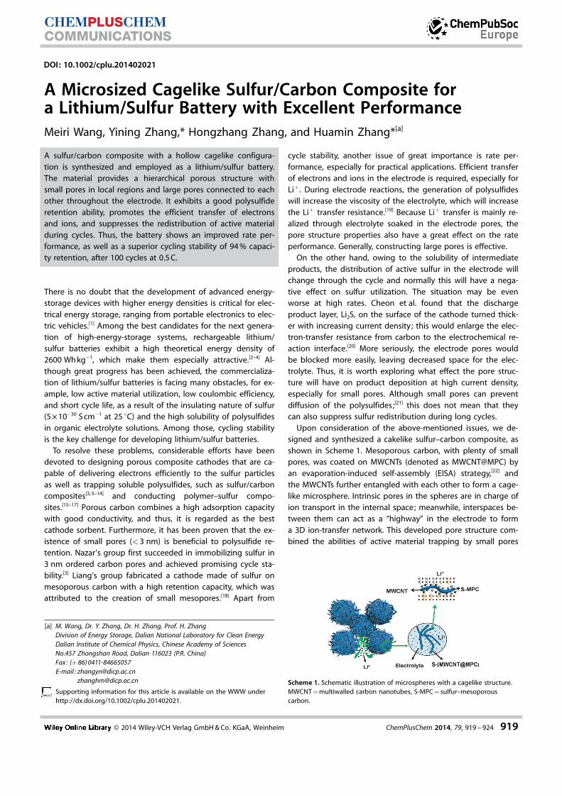
Upon consideration of the above-mentioned issues, we de-signed and synthesized a cakelike sulfur–carbon composite, asshown in Scheme 1. Mesoporous carbon, with plenty of smallpores, was coated on MWCNTs (denoted as MWCNT@MPC) byan evaporation-induced self-assembly (EISA) strategy,[22] andthe MWCNTs further entangled with each other to form a cage-like microsphere. Intrinsic pores in the spheres are in charge ofion transport in the internal space; meanwhile, interspaces be-tween them can act as a “highway” in the electrode to forma 3D ion-transfer network. This developed pore structure com-bined the abilities of active material trapping by small pores
Scheme 1. Schematic illustration of microspheres with a cagelike structure.MWCNT = multiwalled carbon nanotubes, S-MPC = sulfur–mesoporouscarbon.
[a] M. Wang, Dr. Y. Zhang, Dr. H. Zhang, Prof. H. ZhangDivision of Energy Storage, Dalian National Laboratory for Clean EnergyDalian Institute of Chemical Physics, Chinese Academy of SciencesNo.457 Zhongshan Road, Dalian 116023 (P.R. China)Fax: (+ 86) 0411-84665057E-mail : [email protected]
Supporting information for this article is available on the WWW underhttp://dx.doi.org/10.1002/cplu.201402021.
� 2014 Wiley-VCH Verlag GmbH & Co. KGaA, Weinheim ChemPlusChem 2014, 79, 919 – 924 919
CHEMPLUSCHEMCOMMUNICATIONS
and efficient ion transfer by large pores. For comparison, thesame preparation process was performed apart from CNT addi-tion to obtain a carbon material (denoted as MPC) that pos-sessed the same pore parameters as MPC coated on MWCNTsin MWCNT@MPC. After sulfur incorporation, the S-(MWCNT@MPC) composite showed an improved electrochemi-cal performance relative to pristine S-MPC in both rate capacityand cycle stability. The mechanism for the formation of the 3Dcagelike architecture was proposed by investigating the syn-thetic process and the relationship between the material struc-ture and its performance was analyzed based on chemical andphysical characterizations.
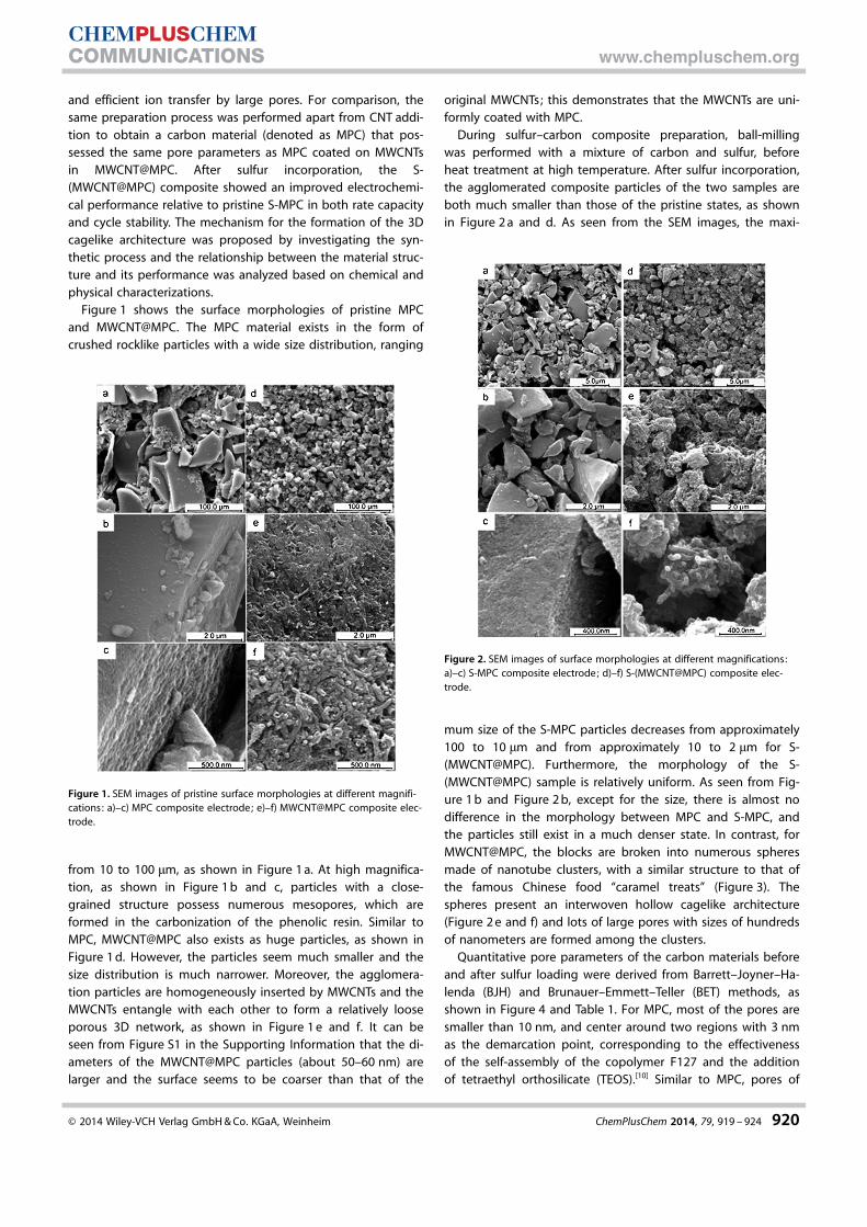
Figure 1 shows the surface morphologies of pristine MPCand MWCNT@MPC. The MPC material exists in the form ofcrushed rocklike particles with a wide size distribution, ranging
from 10 to 100 mm, as shown in Figure 1 a. At high magnifica-tion, as shown in Figure 1 b and c, particles with a close-grained structure possess numerous mesopores, which areformed in the carbonization of the phenolic resin. Similar toMPC, MWCNT@MPC also exists as huge particles, as shown inFigure 1 d. However, the particles seem much smaller and thesize distribution is much narrower. Moreover, the agglomera-tion particles are homogeneously inserted by MWCNTs and theMWCNTs entangle with each other to form a relatively looseporous 3D network, as shown in Figure 1 e and f. It can beseen from Figure S1 in the Supporting Information that the di-ameters of the MWCNT@MPC particles (about 50–60 nm) arelarger and the surface seems to be coarser than that of the
original MWCNTs; this demonstrates that the MWCNTs are uni-formly coated with MPC.
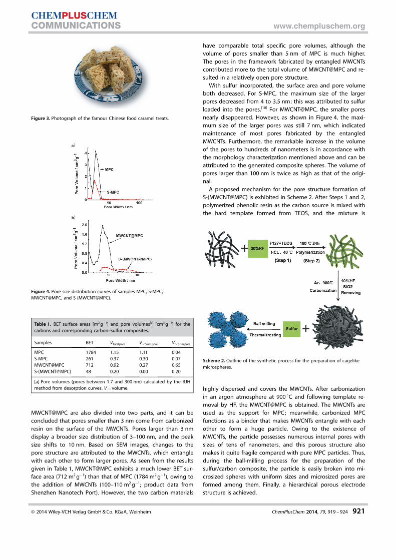
During sulfur–carbon composite preparation, ball-millingwas performed with a mixture of carbon and sulfur, beforeheat treatment at high temperature. After sulfur incorporation,the agglomerated composite particles of the two samples areboth much smaller than those of the pristine states, as shownin Figure 2 a and d. As seen from the SEM images, the maxi-
mum size of the S-MPC particles decreases from approximately100 to 10 mm and from approximately 10 to 2 mm for S-(MWCNT@MPC). Furthermore, the morphology of the S-(MWCNT@MPC) sample is relatively uniform. As seen from Fig-ure 1 b and Figure 2 b, except for the size, there is almost nodifference in the morphology between MPC and S-MPC, andthe particles still exist in a much denser state. In contrast, forMWCNT@MPC, the blocks are broken into numerous spheresmade of nanotube clusters, with a similar structure to that ofthe famous Chinese food “caramel treats” (Figure 3). Thespheres present an interwoven hollow cagelike architecture(Figure 2 e and f) and lots of large pores with sizes of hundredsof nanometers are formed among the clusters.
Quantitative pore parameters of the carbon materials beforeand after sulfur loading were derived from Barrett–Joyner–Ha-lenda (BJH) and Brunauer–Emmett–Teller (BET) methods, asshown in Figure 4 and Table 1. For MPC, most of the pores aresmaller than 10 nm, and center around two regions with 3 nmas the demarcation point, corresponding to the effectivenessof the self-assembly of the copolymer F127 and the additionof tetraethyl orthosilicate (TEOS).[10] Similar to MPC, pores of
Figure 1. SEM images of pristine surface morphologies at different magnifi-cations: a)–c) MPC composite electrode; e)–f) MWCNT@MPC composite elec-trode.
Figure 2. SEM images of surface morphologies at different magnifications:a)–c) S-MPC composite electrode; d)–f) S-(MWCNT@MPC) composite elec-trode.
� 2014 Wiley-VCH Verlag GmbH & Co. KGaA, Weinheim ChemPlusChem 2014, 79, 919 – 924 920
CHEMPLUSCHEMCOMMUNICATIONS www.chempluschem.org
MWCNT@MPC are also divided into two parts, and it can beconcluded that pores smaller than 3 nm come from carbonizedresin on the surface of the MWCNTs. Pores larger than 3 nmdisplay a broader size distribution of 3–100 nm, and the peaksize shifts to 10 nm. Based on SEM images, changes to thepore structure are attributed to the MWCNTs, which entanglewith each other to form larger pores. As seen from the resultsgiven in Table 1, MWCNT@MPC exhibits a much lower BET sur-face area (712 m2 g�1) than that of MPC (1784 m2 g�1), owing tothe addition of MWCNTs (100–110 m2 g�1; product data fromShenzhen Nanotech Port). However, the two carbon materials
have comparable total specific pore volumes, although thevolume of pores smaller than 5 nm of MPC is much higher.The pores in the framework fabricated by entangled MWCNTscontributed more to the total volume of MWCNT@MPC and re-sulted in a relatively open pore structure.
With sulfur incorporated, the surface area and pore volumeboth decreased. For S-MPC, the maximum size of the largerpores decreased from 4 to 3.5 nm; this was attributed to sulfurloaded into the pores.[10] For MWCNT@MPC, the smaller poresnearly disappeared. However, as shown in Figure 4, the maxi-mum size of the larger pores was still 7 nm, which indicatedmaintenance of most pores fabricated by the entangledMWCNTs. Furthermore, the remarkable increase in the volumeof the pores to hundreds of nanometers is in accordance withthe morphology characterization mentioned above and can beattributed to the generated composite spheres. The volume ofpores larger than 100 nm is twice as high as that of the origi-nal.
A proposed mechanism for the pore structure formation ofS-(MWCNT@MPC) is exhibited in Scheme 2. After Steps 1 and 2,polymerized phenolic resin as the carbon source is mixed withthe hard template formed from TEOS, and the mixture is
highly dispersed and covers the MWCNTs. After carbonizationin an argon atmosphere at 900 8C and following template re-moval by HF, the MWCNT@MPC is obtained. The MWCNTs areused as the support for MPC; meanwhile, carbonized MPCfunctions as a binder that makes MWCNTs entangle with eachother to form a huge particle. Owing to the existence ofMWCNTs, the particle possesses numerous internal pores withsizes of tens of nanometers, and this porous structure alsomakes it quite fragile compared with pure MPC particles. Thus,during the ball-milling process for the preparation of thesulfur/carbon composite, the particle is easily broken into mi-crosized spheres with uniform sizes and microsized pores areformed among them. Finally, a hierarchical porous electrodestructure is achieved.
Figure 3. Photograph of the famous Chinese food caramel treats.
Figure 4. Pore size distribution curves of samples MPC, S-MPC,MWCNT@MPC, and S-(MWCNT@MPC).
Table 1. BET surface areas [m2 g�1] and pore volumes[a] [cm3 g�1] for thecarbons and corresponding carbon–sulfur composites.
Samples BET Vtotal pore V<5 nm pore V>5 nm pore
MPC 1784 1.15 1.11 0.04S-MPC 261 0.37 0.30 0.07MWCNT@MPC 712 0.92 0.27 0.65S-(MWCNT@MPC) 48 0.20 0.00 0.20
[a] Pore volumes (pores between 1.7 and 300 nm) calculated by the BJHmethod from desorption curves. V = volume.
Scheme 2. Outline of the synthetic process for the preparation of cagelikemicrospheres.
� 2014 Wiley-VCH Verlag GmbH & Co. KGaA, Weinheim ChemPlusChem 2014, 79, 919 – 924 921
CHEMPLUSCHEMCOMMUNICATIONS www.chempluschem.org
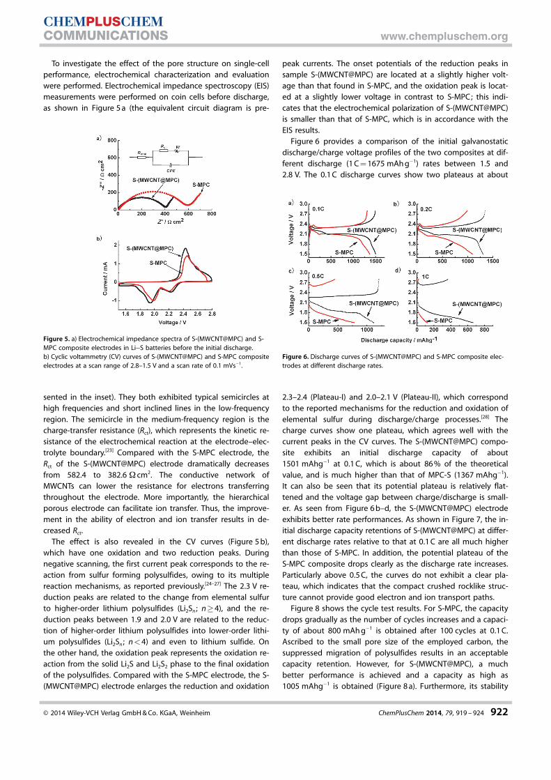
To investigate the effect of the pore structure on single-cellperformance, electrochemical characterization and evaluationwere performed. Electrochemical impedance spectroscopy (EIS)measurements were performed on coin cells before discharge,as shown in Figure 5 a (the equivalent circuit diagram is pre-
sented in the inset). They both exhibited typical semicircles athigh frequencies and short inclined lines in the low-frequencyregion. The semicircle in the medium-frequency region is thecharge-transfer resistance (Rct), which represents the kinetic re-sistance of the electrochemical reaction at the electrode–elec-trolyte boundary.[23] Compared with the S-MPC electrode, theRct of the S-(MWCNT@MPC) electrode dramatically decreasesfrom 582.4 to 382.6 W cm2. The conductive network ofMWCNTs can lower the resistance for electrons transferringthroughout the electrode. More importantly, the hierarchicalporous electrode can facilitate ion transfer. Thus, the improve-ment in the ability of electron and ion transfer results in de-creased Rct.
The effect is also revealed in the CV curves (Figure 5 b),which have one oxidation and two reduction peaks. Duringnegative scanning, the first current peak corresponds to the re-action from sulfur forming polysulfides, owing to its multiplereaction mechanisms, as reported previously.[24–27] The 2.3 V re-duction peaks are related to the change from elemental sulfurto higher-order lithium polysulfides (Li2Sn ; n�4), and the re-duction peaks between 1.9 and 2.0 V are related to the reduc-tion of higher-order lithium polysulfides into lower-order lithi-um polysulfides (Li2Sn ; n<4) and even to lithium sulfide. Onthe other hand, the oxidation peak represents the oxidation re-action from the solid Li2S and Li2S2 phase to the final oxidationof the polysulfides. Compared with the S-MPC electrode, the S-(MWCNT@MPC) electrode enlarges the reduction and oxidation
peak currents. The onset potentials of the reduction peaks insample S-(MWCNT@MPC) are located at a slightly higher volt-age than that found in S-MPC, and the oxidation peak is locat-ed at a slightly lower voltage in contrast to S-MPC; this indi-cates that the electrochemical polarization of S-(MWCNT@MPC)is smaller than that of S-MPC, which is in accordance with theEIS results.
Figure 6 provides a comparison of the initial galvanostaticdischarge/charge voltage profiles of the two composites at dif-ferent discharge (1 C = 1675 mAh g�1) rates between 1.5 and2.8 V. The 0.1 C discharge curves show two plateaus at about
2.3–2.4 (Plateau-I) and 2.0–2.1 V (Plateau-II), which correspondto the reported mechanisms for the reduction and oxidation ofelemental sulfur during discharge/charge processes.[28] Thecharge curves show one plateau, which agrees well with thecurrent peaks in the CV curves. The S-(MWCNT@MPC) compo-site exhibits an initial discharge capacity of about1501 mAhg�1 at 0.1 C, which is about 86 % of the theoreticalvalue, and is much higher than that of MPC-S (1367 mAhg�1).It can also be seen that its potential plateau is relatively flat-tened and the voltage gap between charge/discharge is small-er. As seen from Figure 6 b–d, the S-(MWCNT@MPC) electrodeexhibits better rate performances. As shown in Figure 7, the in-itial discharge capacity retentions of S-(MWCNT@MPC) at differ-ent discharge rates relative to that at 0.1 C are all much higherthan those of S-MPC. In addition, the potential plateau of theS-MPC composite drops clearly as the discharge rate increases.Particularly above 0.5 C, the curves do not exhibit a clear pla-teau, which indicates that the compact crushed rocklike struc-ture cannot provide good electron and ion transport paths.
Figure 8 shows the cycle test results. For S-MPC, the capacitydrops gradually as the number of cycles increases and a capaci-ty of about 800 mAh g�1 is obtained after 100 cycles at 0.1 C.Ascribed to the small pore size of the employed carbon, thesuppressed migration of polysulfides results in an acceptablecapacity retention. However, for S-(MWCNT@MPC), a muchbetter performance is achieved and a capacity as high as1005 mAhg�1 is obtained (Figure 8 a). Furthermore, its stability
Figure 5. a) Electrochemical impedance spectra of S-(MWCNT@MPC) and S-MPC composite electrodes in Li�S batteries before the initial discharge.b) Cyclic voltammetry (CV) curves of S-(MWCNT@MPC) and S-MPC compositeelectrodes at a scan range of 2.8–1.5 V and a scan rate of 0.1 mVs�1.
Figure 6. Discharge curves of S-(MWCNT@MPC) and S-MPC composite elec-trodes at different discharge rates.
� 2014 Wiley-VCH Verlag GmbH & Co. KGaA, Weinheim ChemPlusChem 2014, 79, 919 – 924 922
CHEMPLUSCHEMCOMMUNICATIONS www.chempluschem.org
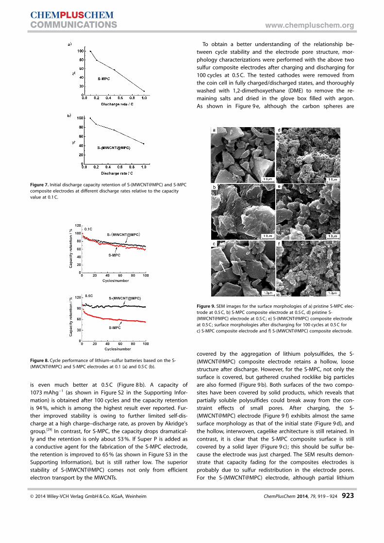
is even much better at 0.5 C (Figure 8 b). A capacity of1073 mAhg�1 (as shown in Figure S2 in the Supporting Infor-mation) is obtained after 100 cycles and the capacity retentionis 94 %, which is among the highest result ever reported. Fur-ther improved stability is owing to further limited self-dis-charge at a high charge–discharge rate, as proven by Akridge’sgroup.[29] In contrast, for S-MPC, the capacity drops dramatical-ly and the retention is only about 53 %. If Super P is added asa conductive agent for the fabrication of the S-MPC electrode,the retention is improved to 65 % (as shown in Figure S3 in theSupporting Information), but is still rather low. The superiorstability of S-(MWCNT@MPC) comes not only from efficientelectron transport by the MWCNTs.
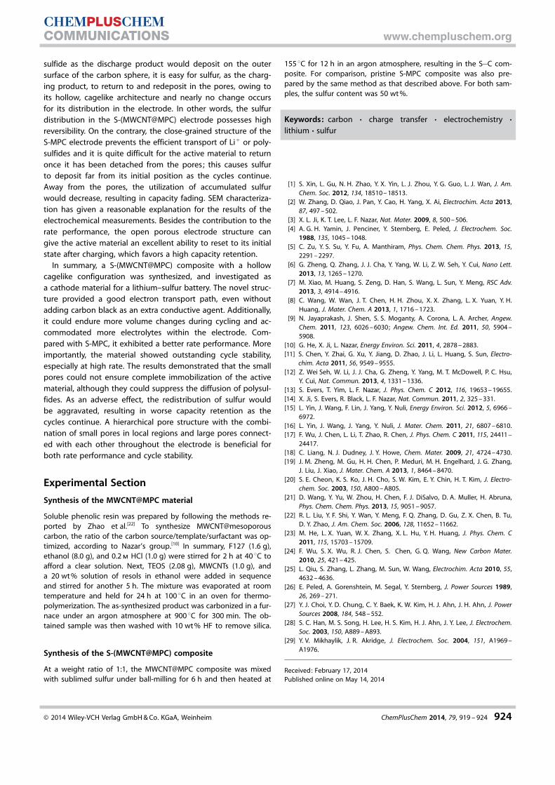
To obtain a better understanding of the relationship be-tween cycle stability and the electrode pore structure, mor-phology characterizations were performed with the above twosulfur composite electrodes after charging and discharging for100 cycles at 0.5 C. The tested cathodes were removed fromthe coin cell in fully charged/discharged states, and thoroughlywashed with 1,2-dimethoxyethane (DME) to remove the re-maining salts and dried in the glove box filled with argon.As shown in Figure 9 e, although the carbon spheres are
covered by the aggregation of lithium polysulfides, the S-(MWCNT@MPC) composite electrode retains a hollow, loosestructure after discharge. However, for the S-MPC, not only thesurface is covered, but gathered crushed rocklike big particlesare also formed (Figure 9 b). Both surfaces of the two compo-sites have been covered by solid products, which reveals thatpartially soluble polysulfides could break away from the con-straint effects of small pores. After charging, the S-(MWCNT@MPC) electrode (Figure 9 f) exhibits almost the samesurface morphology as that of the initial state (Figure 9 d), andthe hollow, interwoven, cagelike architecture is still retained. Incontrast, it is clear that the S-MPC composite surface is stillcovered by a solid layer (Figure 9 c); this should be sulfur be-cause the electrode was just charged. The SEM results demon-strate that capacity fading for the composites electrodes isprobably due to sulfur redistribution in the electrode pores.For the S-(MWCNT@MPC) electrode, although partial lithium
Figure 7. Initial discharge capacity retention of S-(MWCNT@MPC) and S-MPCcomposite electrodes at different discharge rates relative to the capacityvalue at 0.1 C.
Figure 8. Cycle performance of lithium–sulfur batteries based on the S-(MWCNT@MPC) and S-MPC electrodes at 0.1 (a) and 0.5 C (b).
Figure 9. SEM images for the surface morphologies of a) pristine S-MPC elec-trode at 0.5 C, b) S-MPC composite electrode at 0.5 C, d) pristine S-(MWCNT@MPC) electrode at 0.5 C; e) S-(MWCNT@MPC) composite electrodeat 0.5 C; surface morphologies after discharging for 100 cycles at 0.5 C forc) S-MPC composite electrode and f) S-(MWCNT@MPC) composite electrode.
� 2014 Wiley-VCH Verlag GmbH & Co. KGaA, Weinheim ChemPlusChem 2014, 79, 919 – 924 923
CHEMPLUSCHEMCOMMUNICATIONS www.chempluschem.org
sulfide as the discharge product would deposit on the outersurface of the carbon sphere, it is easy for sulfur, as the charg-ing product, to return to and redeposit in the pores, owing toits hollow, cagelike architecture and nearly no change occursfor its distribution in the electrode. In other words, the sulfurdistribution in the S-(MWCNT@MPC) electrode possesses highreversibility. On the contrary, the close-grained structure of theS-MPC electrode prevents the efficient transport of Li+ or poly-sulfides and it is quite difficult for the active material to returnonce it has been detached from the pores; this causes sulfurto deposit far from its initial position as the cycles continue.Away from the pores, the utilization of accumulated sulfurwould decrease, resulting in capacity fading. SEM characteriza-tion has given a reasonable explanation for the results of theelectrochemical measurements. Besides the contribution to therate performance, the open porous electrode structure cangive the active material an excellent ability to reset to its initialstate after charging, which favors a high capacity retention.
In summary, a S-(MWCNT@MPC) composite with a hollowcagelike configuration was synthesized, and investigated asa cathode material for a lithium–sulfur battery. The novel struc-ture provided a good electron transport path, even withoutadding carbon black as an extra conductive agent. Additionally,it could endure more volume changes during cycling and ac-commodated more electrolytes within the electrode. Com-pared with S-MPC, it exhibited a better rate performance. Moreimportantly, the material showed outstanding cycle stability,especially at high rate. The results demonstrated that the smallpores could not ensure complete immobilization of the activematerial, although they could suppress the diffusion of polysul-fides. As an adverse effect, the redistribution of sulfur wouldbe aggravated, resulting in worse capacity retention as thecycles continue. A hierarchical pore structure with the combi-nation of small pores in local regions and large pores connect-ed with each other throughout the electrode is beneficial forboth rate performance and cycle stability.
Experimental Section
Synthesis of the MWCNT@MPC material
Soluble phenolic resin was prepared by following the methods re-ported by Zhao et al.[22] To synthesize MWCNT@mesoporouscarbon, the ratio of the carbon source/template/surfactant was op-timized, according to Nazar’s group.[10] In summary, F127 (1.6 g),ethanol (8.0 g), and 0.2 m HCl (1.0 g) were stirred for 2 h at 40 8C toafford a clear solution. Next, TEOS (2.08 g), MWCNTs (1.0 g), anda 20 wt % solution of resols in ethanol were added in sequenceand stirred for another 5 h. The mixture was evaporated at roomtemperature and held for 24 h at 100 8C in an oven for thermo-polymerization. The as-synthesized product was carbonized in a fur-nace under an argon atmosphere at 900 8C for 300 min. The ob-tained sample was then washed with 10 wt % HF to remove silica.
Synthesis of the S-(MWCNT@MPC) composite
At a weight ratio of 1:1, the MWCNT@MPC composite was mixedwith sublimed sulfur under ball-milling for 6 h and then heated at
155 8C for 12 h in an argon atmosphere, resulting in the S�C com-posite. For comparison, pristine S-MPC composite was also pre-pared by the same method as that described above. For both sam-ples, the sulfur content was 50 wt %.
Keywords: carbon · charge transfer · electrochemistry ·lithium · sulfur
[1] S. Xin, L. Gu, N. H. Zhao, Y. X. Yin, L. J. Zhou, Y. G. Guo, L. J. Wan, J. Am.Chem. Soc. 2012, 134, 18510 – 18513.
[2] W. Zhang, D. Qiao, J. Pan, Y. Cao, H. Yang, X. Ai, Electrochim. Acta 2013,87, 497 – 502.
[3] X. L. Ji, K. T. Lee, L. F. Nazar, Nat. Mater. 2009, 8, 500 – 506.[4] A. G. H. Yamin, J. Penciner, Y. Sternberg, E. Peled, J. Electrochem. Soc.
1988, 135, 1045 – 1048.[5] C. Zu, Y. S. Su, Y. Fu, A. Manthiram, Phys. Chem. Chem. Phys. 2013, 15,
2291 – 2297.[6] G. Zheng, Q. Zhang, J. J. Cha, Y. Yang, W. Li, Z. W. Seh, Y. Cui, Nano Lett.
2013, 13, 1265 – 1270.[7] M. Xiao, M. Huang, S. Zeng, D. Han, S. Wang, L. Sun, Y. Meng, RSC Adv.
2013, 3, 4914 – 4916.[8] C. Wang, W. Wan, J. T. Chen, H. H. Zhou, X. X. Zhang, L. X. Yuan, Y. H.
Huang, J. Mater. Chem. A 2013, 1, 1716 – 1723.[9] N. Jayaprakash, J. Shen, S. S. Moganty, A. Corona, L. A. Archer, Angew.
Chem. 2011, 123, 6026 – 6030; Angew. Chem. Int. Ed. 2011, 50, 5904 –5908.
[10] G. He, X. Ji, L. Nazar, Energy Environ. Sci. 2011, 4, 2878 – 2883.[11] S. Chen, Y. Zhai, G. Xu, Y. Jiang, D. Zhao, J. Li, L. Huang, S. Sun, Electro-
chim. Acta 2011, 56, 9549 – 9555.[12] Z. Wei Seh, W. Li, J. J. Cha, G. Zheng, Y. Yang, M. T. McDowell, P. C. Hsu,
Y. Cui, Nat. Commun. 2013, 4, 1331 – 1336.[13] S. Evers, T. Yim, L. F. Nazar, J. Phys. Chem. C 2012, 116, 19653 – 19655.[14] X. Ji, S. Evers, R. Black, L. F. Nazar, Nat. Commun. 2011, 2, 325 – 331.[15] L. Yin, J. Wang, F. Lin, J. Yang, Y. Nuli, Energy Environ. Sci. 2012, 5, 6966 –
6972.[16] L. Yin, J. Wang, J. Yang, Y. Nuli, J. Mater. Chem. 2011, 21, 6807 – 6810.[17] F. Wu, J. Chen, L. Li, T. Zhao, R. Chen, J. Phys. Chem. C 2011, 115, 24411 –
24417.[18] C. Liang, N. J. Dudney, J. Y. Howe, Chem. Mater. 2009, 21, 4724 – 4730.[19] J. M. Zheng, M. Gu, H. H. Chen, P. Meduri, M. H. Engelhard, J. G. Zhang,
J. Liu, J. Xiao, J. Mater. Chem. A 2013, 1, 8464 – 8470.[20] S. E. Cheon, K. S. Ko, J. H. Cho, S. W. Kim, E. Y. Chin, H. T. Kim, J. Electro-
chem. Soc. 2003, 150, A800 – A805.[21] D. Wang, Y. Yu, W. Zhou, H. Chen, F. J. DiSalvo, D. A. Muller, H. Abruna,
Phys. Chem. Chem. Phys. 2013, 15, 9051 – 9057.[22] R. L. Liu, Y. F. Shi, Y. Wan, Y. Meng, F. Q. Zhang, D. Gu, Z. X. Chen, B. Tu,
D. Y. Zhao, J. Am. Chem. Soc. 2006, 128, 11652 – 11662.[23] M. He, L. X. Yuan, W. X. Zhang, X. L. Hu, Y. H. Huang, J. Phys. Chem. C
2011, 115, 15703 – 15709.[24] F. Wu, S. X. Wu, R. J. Chen, S. Chen, G. Q. Wang, New Carbon Mater.
2010, 25, 421 – 425.[25] L. Qiu, S. Zhang, L. Zhang, M. Sun, W. Wang, Electrochim. Acta 2010, 55,
4632 – 4636.[26] E. Peled, A. Gorenshtein, M. Segal, Y. Sternberg, J. Power Sources 1989,
26, 269 – 271.[27] Y. J. Choi, Y. D. Chung, C. Y. Baek, K. W. Kim, H. J. Ahn, J. H. Ahn, J. Power
Sources 2008, 184, 548 – 552.[28] S. C. Han, M. S. Song, H. Lee, H. S. Kim, H. J. Ahn, J. Y. Lee, J. Electrochem.
Soc. 2003, 150, A889 – A893.[29] Y. V. Mikhaylik, J. R. Akridge, J. Electrochem. Soc. 2004, 151, A1969 –
A1976.
Received: February 17, 2014Published online on May 14, 2014
� 2014 Wiley-VCH Verlag GmbH & Co. KGaA, Weinheim ChemPlusChem 2014, 79, 919 – 924 924
CHEMPLUSCHEMCOMMUNICATIONS www.chempluschem.org