Embed Size (px)
Citation preview
A Functional Verification Methodology forHighly Parametrizable, Continuously OperatingSafety-Critical FPGA Designs: Applied to the
CERN RadiatiOn Monitoring Electronics(CROME)
Katharina Ceesay-Seitz�[0000−0001−8398−2705], Hamza Boukabache, and DanielPerrin[0000−0003−4340−8551]
CERN, European Organisation for Nuclear Research, 1211 Geneva 23, Switzerlandhttps://home.cern/
{katharina.ceesay-seitz,hamza.boukabache,daniel.perrin}@cern.ch
Abstract. Electronic systems that are related to human safety needto comply to strict international standards such as the IEC 61508. Wepresent a functional verification methodology for highly parametrizable,continuously operating, safety-critical real-time systems implemented inFPGAs. It is compliant to IEC 61508 and extends it in several ways.We focus on independence between design and verification. Natural lan-guage properties and the functional coverage model build the connec-tion between system safety requirements and verification results, provid-ing forward and backward traceability. Our main verification method isFormal Property Verification (FPV), even for Safety Integrity Level 1and 2. Further, we use constrained-random simulation in SystemVerilogwith the Universal Verification Methodology and a design independentC reference model. When faults are discovered, the coverage model isextended to avoid regressions. Automation allows the reproduction ofresults and the reuse of verification code. We evaluate our methodol-ogy on a subset of the newly developed CERN RadiatiOn MonitoringElectronics (CROME). We present the challenges we faced and proposesolutions. Although it is impossible to simulate the full design exhaus-tively, several formal properties have been fully proven. With FPV wefound some safety-critical faults that would have been extremely hard tofind in simulation.
Keywords: Functional verification · Safety · Formal property verifica-tion · Constrained-random simulation · Natural language properties ·Functional coverage · Regression coverage
Published in: Casimiro A., Ortmeier F., Bitsch F., Ferreira P. (eds) Computer Safety,Reliability, and Security. SAFECOMP 2020. Lecture Notes in Computer Science,vol 12234. Springer, Cham. The final authenticated version is available online athttps://doi.org/10.1007/978-3-030-54549-9_5.

2 K. Ceesay-Seitz et al.
1 Introduction
When electronic systems are related to human safety, their whole life cycleneeds to comply with strict domain-specific standards [1,2,3,4]. The generalstandard for functional safety of electrical/electronic/programmable electronicsafety-related systems is the IEC 61508 [5]. Its latest version dates back to 2010.The ISO 26262 automotive standard is the most modern one. Its latest versionis from 2018 [1]. One very strict, but also quite old standard for safety-criticalhardware is the DO-254 from 2000 [2]. The IEC 60532 standard for radiationprotection instrumentation assigns Safety Integrity Levels (SILs) to certain ra-diation protection functions [3]. These SILs and corresponding requirements forthe design and verification of safety-related electronic systems are defined in theIEC 61508 [5]. Since 2010, verification methodologies and electronic design au-tomation tools for digital design verification have progressed at a rapid pace. Ourmethodology adds modern verification techniques to the IEC 61508’s V-modelflow.
The most common technique for functionally verifying the Hardware De-scription Language (HDL) code for Field Programmable Gate Arrays (FPGAs)is still simulation with directed tests [6]. Stimuli are applied to the inputs ofthe Design Under Verification (DUV) and the values at the outputs are exam-ined. For highly parametrizable systems that have many input parameters oflarge bit-widths it would be extremely time consuming to manually specify allinteresting combinations and calculate the expected output values. More flexibletechniques like constrained-random simulation are available [7]. But even withthis method it can be infeasible to simulate all possibilities for certain designs.Let’s imagine we could simulate one combination at each CPU clock cycle of theworkstation which executes the simulation tool. It would take roughly 146 yearsto simulate each of the possible input combinations of a single 64-bit vector. Inreality, many CPU clock cycles will pass until the simulator applies a new stim-ulus. While in many cases it might be sufficient to simulate only representativevalues, it is often hard to tell which value ranges are representative enough tocatch all corner cases. These might be rare inputs or combinations of extremevalues of mathematical functions or boundary values [8]. Furthermore, for someinput values it might be necessary to verify all possible combinations. Therefore,additional verification techniques need to be applied.
We propose a functional verification methodology that combines the state-of-the-art verification techniques of the semiconductor industry: Formal Prop-erty Verification (FPV) and constrained-random simulation using the UniversalVerification Methodology (UVM) [9], both with functional and structural cov-erage collection, while complying to IEC 61508. We evaluate them for a highlyparametrizable, continuously operating safety-critical real-time system. We pro-pose a workflow that extends the verification process required by IEC 61508 withthe following concepts (see also Table 1):
– Independence between design and verification engineers– Semi-formal methods during verification planning and requirements review

A Functional Verification Methodology for Safety-Critical FPGA Designs 3
– Formal methods as main verification method even for SIL 1 and SIL 2.– Constrained-random inputs for (expanded) functional black-box testing– Coverage for regression test cases– Traceability from requirements over coverage model and Natural Language
Properties (NLPs) to verification results and backwards– Repeatability of the results
Section 2 summarises related work and background. Section 3 provides an overviewof our methodology. Section 4 is an in-depth case study of applying our method-ology to the CERN RadiatiOn Monitoring Electronics (CROME). Section 5concludes the paper.
2 Related Work and Background
Independence between verification and design is very important in our method-ology. Engineers are more likely to find faults in code written by other peoplethan in their own [10]. The IEC 61508 does not mandate it, it only refers toapplication specific standards [5]. It is required e.g. by the DO-254 [2].
Formal Property Verification (FPV), also called assertion-based verification,can exhaustively proof that a property holds on a design. Many engineers stillhesitate to use formal verification because of its perceived complexity [6,11]. Acampaign was launched at Intel to convince engineers of its benefits [11]. Aswe will also demonstrate, additional faults can be found with FPV in designsthat had already been verified by simulation [11,12]. Often it is only used forsimple designs or control paths [13,8]. In [14], each design was first classified assuitable or not for FPV. A design with our characteristics would not be suitableaccording to their criteria. Opposed to that we decided to use FPV as mainverification method for a complex continuously operating safety-critical designand got indispensable results. Our methodology shows how to integrate it intoa safety-standard compliant process.
Requirements-based testing is required by e.g. DO-254 [2] and ISO 26262 [1].In [15], this method was extended with constrained-random simulation for ro-bustness testing, or in IEC 61508 terms “expanded functional testing” [5]. Re-searchers in [11] mentioned the difficulty of tracking verification progress inFPV. We use the functional coverage model and Natural Language Properties(NLPs) [16] as connection between system safety requirements and test results.The methodology in [14] uses templates instead of NLPs that are automaticallytranslated into SystemVerilog Assertions (SVA) by a proprietary tool. The im-portance of a consistent translation from properties in easily reviewable form toformal languages was also shown in [17]. The lack of such methods can lead toincorrect translations and additional iterations. In [18], each requirement wasrelated to a test case and coverage model item. Encountered faults were addedto a fault database, related to requirements and if necessary, the coverage modelwas extended. We call the extension of the coverage model ”regression coverage”.Our approach (detailed in section 3.2) was prior to that described in [19].

4 K. Ceesay-Seitz et al.
An advantage of FPV with SVA is that properties are proven directly on theHDL code. Several formal verification methodologies for FPGAs exist that re-quire a translation from HDL to a formal model in a tool-specific language [20,13].To comply to safety standards, it would be necessary to derive this model fromthe HDL code [17]. Any used tools need to be qualified [5]. We decided for SVA,for which several qualified tools are available [17].
Constrained-random simulation is very useful for highly parametrizable sys-tems. A large number of stimuli can be applied without the need to explicitlyspecifying them. Weighted constraints can be used to guide the randomizationin order to increase chances of generating scenarios of interest while also test-ing unusual input combinations. This technique typically finds more faults thandirected testing [8,15]. SystemVerilog provides many features to ease the devel-opment of flexible testbenches as well as properties and sequences which can beused both in simulation and FPV [7]. The SystemVerilog UVM library facilitatesabstraction into transactions and verification code reuse. UVM was released in2011, after the publication of the IEC 61508. It has been standardized in 2017 [9].
It can be distinguished between functional and structural coverage. The func-tional coverage model states which scenarios are of verification interest. It isdefined by the verification engineers. Structural coverage measures how manypercentage of the Hardware Description Language (HDL) code have been cov-ered [8]. A very effective coverage metric is Modified Condition/Decision Cover-age (MC/DC), where each condition has to affect the condition outcome at leastonce. It is required by the DO-178 standard for software in avionics industry [4].Simulation tools provide this metric as well for HDL code [15]. SystemVerilogcovergroups, cover properties or assertions could also be added by the design-ers to ensure that simulation test benches cover important implementation de-tails [8,12]. This would not violate the concept of independence [12].
In this article we solely focus on functional verification. Measures for avoid-ing failures due to random hardware faults need to be considered additionallyfor any safety-critical design [5].
3 Our Functional Verification Methodology
IEC 61508 lists several techniques that can be chosen for verifying FPGAs.Table 1 lists the techniques that we chose plus some techniques that we added(A). The last 4 columns show the level of recommendation by IEC 61508 perSIL. Due to the large number of inputs (∼ 200) of our design and our positiveexperience with FPV that we will highlight in later sections, we decided touse it as main verification method. We complement it with constrained-randomsimulation using the UVM. For software, the IEC 61508 requires traceabilityfrom system safety requirements to verification results and vice versa, as well asrepeatability of the verification activities. We adopt these points for FPGAs.
A ... Additionally added to our methodology, - ... No recommendation for or againstthe method by the standard, R ... Recommended, HR ... Highly recommended

A Functional Verification Methodology for Safety-Critical FPGA Designs 5
Table 1. E/E/EP system verification requirements and techniques
Sections inIEC 61508:2010
- Part 2Techniques
Required by
SIL 1 SIL 2 SIL 3 SIL 47.9.2.1-4Verification planning Semi-formal methods A A A A7.9.2.5 Conformanceto safety requirements Requirements traceability A A A A7.9.2.7, Table B.1Verification of systemdesign requirements
Inspection of specification - HR HR HR
Semi-formal methods R R HR HR
7.9.2.8, Table B.2,Table B.5, Table F.2Verication of the systemdesign and development
Simulation - R R RFormal methods - - R RFunctional testingon module level HR HR HR HRExpanded functional testing - HR HR HRBlack-box testing R R R RConstrained-random input A A A ACoverage of theverification scenarios R R HR HRCoverage for regression testing A A A A
7.9.2.6, 7.9.2.10 Verificationresults documentation Requirements traceability A A A A
3.1 Verification Planning
Our workflow, detailed in Fig. 1, starts based on the system safety requirements,design requirements and the specification. Consistency between the first and thelast two needs to be verified [5]. Each verification requirements is related to atleast one system requirement. If we encounter undocumented design decisionsduring verification, we report them first to the requirements engineers ratherthan the designers, to keep independence high. After consensus, requirements,specification and verification items are updated by the responsible persons.
In our methodology, the functional coverage model builds the connection be-tween the verification requirements and the results. Each verification requirementneeds to be described by at least one SystemVerilog covergroup or cover propertyfor simulation or by at least one NLP [16]. Within each method the MutuallyExclusive and Collectively Exhaustive (MECE) principle should be followed [21].For our kind of design we identified the following grouping inspired by [21] asuseful: use cases, interesting scenarios, temporal relations, value ranges, stresstests, negated requirements. Input values should only be covered if they had aneffect and verification passes [8].
The analysis of uncovered items might reveal internal design details. In orderto keep independence high, we suggest that the design engineers should analysethe structural coverage reports and disclose as little information as possible tothe verification engineers. The goal should be 100% functional and structural

6 K. Ceesay-Seitz et al.
Verification Requirements***
System SafetyRequirements*
Design Requirements& Specification**
Coverage Model***Reference Model***
Natural LanguageProperties***
HDL Design**Simulation using
UVM***Formal PropertyVerification***
Verification Results& Documentation***
define
develop
define
inputinputinput
verify verify
generate generate
Requirements engineers*
Design engineers**
Verification engineers***
Requirements trace - - >
Fig. 1. Verification Workflow
coverage. If it can not be reached, an analysis should be performed and it shouldbe justified why less than 100% are acceptable [15].
Natural Language Properties (NLPs) [16] are our coverage model items forFPV. They are a semi-formal notation where natural language snippets are trans-lated into SystemVerilog property snippets with a fixed N:1 mapping. E.g. onecan use different natural language expressions to describe the same formal state-ment. ”Expr implies that Seq” and ”Every time when Expr: Seq” can be bothtranslated into and implication ”Expr |->Seq”. Technical details can be hiddenby application specific NLPs, e.g. ”Cycle is the start of a measurement cycle”is translated into ”($rose(mtValidxDI))”. That way an unambiguous connectionbetween a NLP and a formal property is established. The NLPs can be easilyreviewed by requirements engineers unfamiliar with SVA. We use this reviewstep to increase independence between design and verification.
For formal verification we calculate functional coverage as follows:
Functional coverage[%] =Nr. of proven properties
Nr. of properties∗ 100.00 (1)
Or with weights, similar to SystemVerilog covergroup coverage [7]:
Weighted functional coverage[%] =
∑i(wi ∗ pi)∑
i wi∗ 100.00 (2)
wi = weight per property, pi = 1 if property was proven, 0 otherwise

A Functional Verification Methodology for Safety-Critical FPGA Designs 7
3.2 Automated Verification
Formal Property Verification (FPV) Our main verification method is FPVwith SVA [22]. We use as little formal assumptions, i.e. constraints, as possible,therefore even allowing scenarios that are outside the current specification. Whenthe specification changes, the same properties can be reused for verification.This reduces the logic in the Cone-of-Influence of the formal properties, whichmakes it easier for formal tools to conclude. The properties can be validated insimulation by including the SystemVerilog file that contains the properties insidethe SystemVerilog DUV interface.
The number of states of continuously operating designs grows exponentiallywith the number of input bits and necessary clock cycles for a proof. We modelcomplex calculations with 64-bit operands in auxiliary code and use propertiesto proof the equivalence of the DUV’s outputs with the modelled calculations.
We start with black-box verification, which means that we do not modify oraccess internal signals and describe properties only in terms of input and outputrelations. If these properties are inconclusive, we apply abstraction techniqueslike inserting cut points on internal registers. That means that logic which drivesthese registers is cut away. This reduces the complexity of the proof calculationand therefore it is easier for the formal tool to conclude. A proof is valid for allvalues that are possible within the bit-widths of these registers. This includesthe values that can be generated by the logic which is cut off. Therefore it is alogically safe transformation that might introduce false negatives, but never falsepositives [22]. Such techniques require the verification engineer to gain knowledgeabout the code, thus violating the principle of independence. Therefore, we applythese methods only after all independent black-box verification activities havebeen completed.
Constrained-Random Simulation We use constrained-random simulationwith the SystemVerilog UVM library whenever formal tools can’t deliver resultswithin reasonable time. Verification engineers develop a reference model basedon the requirements, independent from the design engineers. SystemVerilog cancommunicate with a C or C++ model through its Direct Programming Interface(DPI). The test bench simultaneously sends UVM transaction to the DesignUnder Verification (DUV) and the reference model and compares the outputs.
Regression Coverage Whenever a fault is found with simulation-based or formalverification that occurs in a scenario that is not yet part of the coverage modelfor simulation, we add it in the following way:
1. Identify input and output signal traces and their relationships that revealedthe fault. Add a new covergroup, coverpoint or coverpoint bin. If a sequenceof stimuli is needed to uniquely identify the scenario, use e.g. value transitionor expression coverpoint bins or cover properties. Internal signals can be usedif provided by the design engineer. We call these “regression covergroups/-bins”.
8 K. Ceesay-Seitz et al.
2. Rerun the failing test and check that the new regression bin is covered inthe same simulation time step in which the test failed.
3. Rerun all other test cases and check that the new coverage item is not coveredby any other test that passes. If it is, the coverage item does not model aunique scenario. Either add step 6 or modify the coverage item and start atstep 1.
4. The design engineer removes the fault of the DUV.5. Rerun the failing test with the updated DUV. Check that the bin is still
covered in the same simulation time step. Check that the verification passes.6. Optionally: Copy the failing UVM test and UVM sequence class. Rename
them to match the regression coverpoint bin and implement a stop condition.The test can stop when it has covered its corresponding bin. Add this testcase to the regression test suite and do not modify it anymore.
Regarding point 3: In a continuously operating system, a unique scenario thatleads to a fault might have to be described by long and complex signal traces andtheir relationships. Sometimes it can be more efficient in terms of engineeringtime to describe a signal relationship with a higher level of abstraction, which isnot uniquely identifying the faulty scenario, but which includes it.Regarding point 6: As long as the calls to randomisation functions in the regres-sion test case are not altered, it can be used to reproduce the same scenario.SystemVerilog provides random stability as long as the order of new requests forrandom values is not altered within a thread [7].
Documentation, Traceability and Reproducibility Forward tracing asshown by the arrows in Fig. 1 and backward tracing (by following the arrows inreversed direction) of verification items is used to measure verification progressand to provide verification evidence. All verification activities are documentedin a version control system and can be reconstructed and reproduced.
4 Application to the CERN RadiatiOn MonitoringElectronics (CROME)
4.1 CERN RadiatiOn Monitoring Electronics (CROME)
CERN, the European Organisation for Nuclear Research, operates the world’smost powerful particle accelerators. Particle collisions produce ionizing radiation.The radiation protection group is responsible for protecting humans from anyunjustified radiation exposure. The CERN RadiatiOn Monitoring Electronics(CROME) are the new generation of instruments used for measuring ionizingradiation levels and triggering alarms and machine interlocks based on thesemeasurements [23]. Several hundred units will be installed.
The CROME Measuring and Processing Unit consists of a radiation detectorand an electronic system for data communication and storage, signal processingand safety-related decision taking. The latter contains a heterogeneous Zynq-7000 System-on-Chip (SoC) consisting of an ARM core and an FPGA. The ARM

A Functional Verification Methodology for Safety-Critical FPGA Designs 9
core executes an embedded Linux and an application that receives around 100parameters with ranges up to 64 bit over the network, which it transfers to theFPGA. The FPGA performs the radiation dose and dose rate calculations. Basedon that, it autonomously triggers alarms and machine interlocks. It contains allsafety-critical code, implemented in VHDL. Triple Modular Redundancy andSoft Error Mitigation are used for detecting random hardware faults [24].
The devices can be used in areas with very different radiation levels, e.g.in service caverns close to the particle detectors as well as at the fences of theCERN site. To that end they were kept very generic and parametrizable. Peri-ods of uninterrupted operation can last several months or years. These systemattributes lead to high numbers of possible input values and deep internal statesthat are challenging for verification.
The calculation of the radiation dose consists of 3 additions with 64-bitoperands, 1 multiplication with 32-bit operands and logic for rounding. It iscalculated from the measured input current (fA - nA) and it is the base forone of the system’s alarms. The dose is accumulated over a configurable period,which can last several years. Internal registers track the state. The calculationcan be influenced at run-time by sending 6 parameters of up to 64 bit lengthfrom the CERN control room to a CROME device. The dose alarm decisionis based on the outcome of 7 conditions, sampled on 2 real-time measurementcycles that can be thousands of clock cycles apart.
The alarm and interlock matrix block implements a complex configurablelogical formula which drive the safety-critical outputs of the system. These out-puts are connected to the alarm units, which provide visual and audible alarmsand to the machine interlocks, which stop the particle accelerators in case of atoo high radiation level. The formula can be configured by 200 2-bit wide pa-rameters. In total the block has 2451 possible input values. Some of its outputsare fed back to the logical formula as input. Apart from that the block does notstore an internal state and therefore results are available after a few clock cycles.
4.2 Verification Planning
We derived 76 verification requirements for the radiation dose calculation fromonly 26 system-level requirements, which were written with a very high level ofabstraction and some ambiguities. The latter were discussed directly with the re-quirements engineers for increasing independence. 8 statements that were addedand 10 statements that were only partially contained in the design specificationlead to further verification requirements. The analysis lead to 12 updates of ei-ther requirements, specification or verification code. Verification planning leadto a more complete documentation of the whole project, which is very impor-tant to comply with safety standards [5]. We specified 52 cover properties and 4covergroups that contained 56 coverpoints, as well as 30 NLPs.
During the review of the NLPs we discovered one very critical misunder-standing regarding the triggering of the radiation dose alarm. The design andverification engineers interpreted a requirement in the same way, but differentlythan the requirements engineers. This could not have been discovered with any
10 K. Ceesay-Seitz et al.
automated verification technique. It shows the importance of independence andreviews. The detailed example has been reported in [16].
4.3 Automated Verification
Simulation and FPV were executed on a CentOS 7 workstation with 4GHz CPUand 32GB RAM. The single-threaded Questa Sim simulator, version 10.7, wasused for simulation. Questa PropCheck, version 10.7c, was used for FPV with 8hardware threads on 4 processor cores.
Formal Property Verification
Radiation Ambient Equivalent Dose Calculation The dose calculation was mod-elled with auxiliary code. Properties compare the outputs of both models. Sofar, the dose calculation could be proven with the following constraints:
– 101 different calculation period lengths from 0 to 100, where 0 stands for anunlimited period
– Operands of additions restricted to 8 possible values or calculation periodrestricted to 2 real-time measurement cycles
– Time counting register restricted to 13.6 years in 100ms unity, which there-fore also limits the maximum period length to 13.6 years.
We allowed arbitrary values in the reset state by using a netlist constraint thatsets the initial values of input ports to X. That means proofs cover every possiblestarting state, which includes the actual reset state.
A cutpoint was inserted at the register etxDN that normally loads the timecounting register etxDP with a new calculated value. That means that the formaltool treats etxDN as an input and generates a proof for all possible values. Ifcutpoints are enabled, the auxiliary code also uses etxDP. That ensures that theformal tool uses the same value inside the DUV and the auxiliary model duringone round of calculation. etxDN cannot be used in the model, as its value canbe arbitrary in any clock cycles. The DUV and the model can perform theircalculations in different clock cycles. The properties proof that, after a definednumber of clock cycles following the start of one round, the outputs of bothmodels are equivalent.
This way the unlimited number of consecutive calculations that keep trackof an internal state is reduced to a smaller sequence of recurring operations. Theelapsed time tracking register needs to be verified in a separate proof.
Proven: 8 properties could be fully proven, without any constraints on pa-rameter values. Most importantly they include the proof of correct triggering ofradiation dose alarms. The triggering is decided by 7 conditions at 2 consecutivereal-time cycles with configurable distance.Undocumented design decision found: One fault happened only with veryspecific input bit combinations when an internal calculation result was negative

A Functional Verification Methodology for Safety-Critical FPGA Designs 11
and rounded. Even though thousands of inputs had already been simulated, thisscenario had not been covered. To cover it, very tightly constrained simulationtest cases were needed. The rounding mechanism was not documented. The cov-erage model had to be updated.Fault that happens after 7 years of continuous device operation: In thedivision of the elapsed time value, one of the operands was treated as a signedvalue. The calculation was only wrong, when the most significant bit had value’1’. This fault could have never been found by black-box simulation because itwould have required to simulate 7 years of device operation to discover it. For en-vironmental radiation monitors it is a realistic scenario to operate continuouslyfor such a long time. FPV revealed the fault within 1 second.
Alarm and Interlock Matrix The logical formulas of the matrix were modelledwith auxiliary code. Properties were used to prove the equivalence of the calcu-lated values with the DUV’s outpus.Proven: The alarm and interlock matrix was fully proven with 46 properties.Fault in radiation dose alert: In one very specific input combination, theradiation dose alert was not triggered due to a wrongly specified range of apartially used VHDL vector. Many stimuli had already been simulated by thedesigner and user tests with the programmed FPGA had passed. Only FPV re-vealed the fault.Output not in safe state in case of invalid inputs: The system require-ments allowed 3 different values for certain inputs that were stored as 2 bits.The 4th possible value is illegal and not expected. No specific measures were im-plemented to handle that case, so the outputs would have been in inconsistentstates and not in their safe state.
Constrained-Random Simulation
Table 2. Functional Coverage of the Radiation Dose Calculation
Cover typeCovered -all tests
Covered -passed tests
Nr. ofcoverpoints
Nr. ofbins
Nr. ofstimuliapplied
Cover properties 100.00% 100.00% - - 16355
cgIntConditions 100.00% 93.98% 28 466 324647
cgIntRegression 100.00% 100.00% 3 3 250
cgIntValueRanges 91.95% 73.02% 17 656 249327
cgIntRobustness 7.15% 6.02% 8 392 280977
Total 79.82% 74.60% 56 1517 454200
Radiation Ambient Equivalent Dose Calculation Table 2 shows the number ofstimuli that were applied to reach ca. 80% of coverage with constrained-random

12 K. Ceesay-Seitz et al.
inputs. The goal was not to find the minimum number of stimuli necessary toreach full coverage, but rather to simulate large numbers of stimuli in the prox-imity of interesting scenarios and corner cases in order to increase the chancesof finding faults in operation conditions that have not even been considered.
A coverage bin can be a value, value range, value transition or a conditionoutcome. An additional condition for coverage sampling can be specified. E.g.sampling a value for radiation dose calculation period is only valid, when thewhole period has been simulated. It is not meaningful to sample it already whenit has been applied to the input. The period can span thousands of clock cycles orin real-time: days, months or years. Some faults only appear after a long sequenceof applied inputs and internal state changes, like e.g. the fault that would havehappened after 7 years of operation that we found with formal verification.
We did not reach 100% functional coverage for all covergroups. This showsthe shortcomings of simulation for continuously operating devices. The last twogroups contain values and expressions that are related to the radiation dosecalculation period. Since simulation is even slower than real time, it is impossibleto simulate these scenarios with purely design independent black-box techniques.Code coverage confirmed that the only bits that were never toggled were thehigher-order bits of registers that store time values. Toggle coverage reachedonly 78%. The rest was fully covered.
It is possible to access any internal signals from within the SystemVerilogtestbench. The internal state, e.g. the elapsed time register, could be manipulatedto simulate different real time values and reach full coverage. As discussed forcutpoints, to keep independence high, this technique should only be applied afterindependent black-box verification has reached its limits.
In a first attempt the simulation that created the coverage shown in Table 2ran nearly 40 hours. The cause for that long runtime were the cover properties.They contained many sequences that spanned over a large number of clock cy-cles, using SystemVerilog constructs like ##[1:$], which means that somethinghappens after 1 or an arbitrary number of clock cycles. As long as a propertyor sequence is not yet covered, the simulator has to create a new instance of itat each clock cycle and check in each following clock cycle whether it has beencovered. This construct is very useful to intersect different sequences at arbitrarytimes, but it comes with the cost of runtime increase. A more efficient alternativeturned out to be covergroups that use expression coverage with value transitionbins. The covergroup sampling did not add any significant overhead.
We tracked the test cases that actually contributed to the coverage of thecover properties. We ran each of them until its contribution to coverage of coverproperties stagnated. Once all properties were covered, we executed the restof the test suite with cover properties disabled. This approach led to a totalsimulation runtime of 3 hours.
4.4 Results Summary
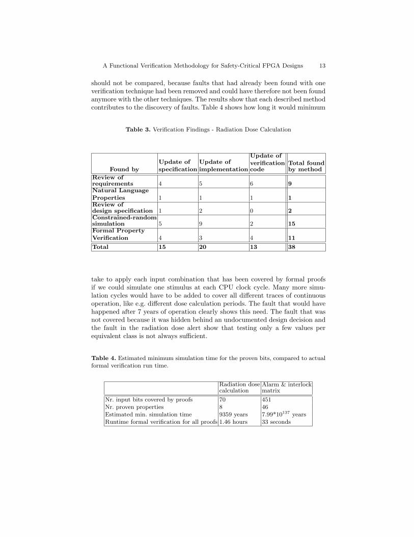
Table 3 shows the faults that we found in the radiation dose calculation. Somefindings caused updates of multiple artefacts. The total numbers per method
A Functional Verification Methodology for Safety-Critical FPGA Designs 13
should not be compared, because faults that had already been found with oneverification technique had been removed and could have therefore not been foundanymore with the other techniques. The results show that each described methodcontributes to the discovery of faults. Table 4 shows how long it would minimum
Table 3. Verification Findings - Radiation Dose Calculation
Found byUpdate ofspecification
Update ofimplementation
Update ofverificationcode
Total foundby method
Review ofrequirements 4 5 6 9Natural LanguageProperties 1 1 1 1Review ofdesign specification 1 2 0 2Constrained-randomsimulation 5 9 2 15Formal PropertyVerification 4 3 4 11
Total 15 20 13 38
take to apply each input combination that has been covered by formal proofsif we could simulate one stimulus at each CPU clock cycle. Many more simu-lation cycles would have to be added to cover all different traces of continuousoperation, like e.g. different dose calculation periods. The fault that would havehappened after 7 years of operation clearly shows this need. The fault that wasnot covered because it was hidden behind an undocumented design decision andthe fault in the radiation dose alert show that testing only a few values perequivalent class is not always sufficient.
Table 4. Estimated minimum simulation time for the proven bits, compared to actualformal verification run time.
Radiation dosecalculation
Alarm & interlockmatrix
Nr. input bits covered by proofs 70 451Nr. proven properties 8 46Estimated min. simulation time 9359 years 7.99*10137 yearsRuntime formal verification for all proofs 1.46 hours 33 seconds

14 K. Ceesay-Seitz et al.
Documentation, Traceability and Reproducibility We use the versioncontrol system Git to communicate design and verification artefact updates. Itcan be easily forgotten to update a version number inside the DUV or verificationcode. Git generates unique hashes for each commit. We used these hashes to trackthe faulty and updated versions, log files, planning and results documentation.Any state of the test bench can be checked out and results can be reproduced.
5 Conclusion and Future Work
We presented a functional verification methodology for highly parametrizable,continuously operating, safety-critical real-time systems implemented in FPGAs.The methodology can also be applied to digital Application Specific IntegratedCircuits (ASICs). We started with a discussion of our methodology in comparisonto the requirements of the IEC 61508 and related work. We defined a workflowthat starts with the system safety requirements as input and verification resultsas output. Forward and backward traceability between these artefacts is pro-vided via functional coverage items. We applied our technique of NLPs [16] toaid the requirements review. Our main verification method is Formal PropertyVerification (FPV). This decision was supported by the discovery of several in-teresting faults and successful proofs. Additionally we apply constrained-randomsimulation with the UVM. For both methods we use functional and structuralcoverage as a metric for progress tracking.
The methodology was demonstrated on a subset of the CERN RadiatiOnMonitoring Electronics (CROME). We will further apply it to that system anduse it for future FPGA or ASIC projects. There is still potential for furtherautomation and usage of the UVM’s concepts for reusability from block to FPGAsystem level. Fault injection will have to be added to address random hardwarefaults. Then we intend to extend the methodology to include SoC system levelverification that also includes the software running on the ARM core. We arealso working on unifying the reference model for simulation with the auxiliarycode for formal verification to reduce effort.
References
1. ISO 26262: Road vehicles Functional safety, International Organisation for Stan-dardisation (ISO) (2018)
2. DO-254 - Design Assurance Guidance for Airborne Electronic Hardware, RadioTechnical Commission for Aeronautics, Washington, USA (2011)
3. IEC 60532: Radiation protection instrumentation, International ElectrotechnicalCommission (IEC), Geneva, Switzerland (2010)
4. DO-178 - Software Considerations in Airborne Systems and Equipment Certifica-tion, Radio Technical Commission for Aeronautics, Washington, USA (2000)
5. IEC 61508: Functional safety of electrical/electronic/programmable electronicsafety-related systems. The International Electrotechnical Commission (2010)

A Functional Verification Methodology for Safety-Critical FPGA Designs 15
6. Foster, H.D.: 2018 FPGA Functional Verification Trends. In: Proceedings of 201819th International Workshop on Microprocessor and SOC Test, Security and Verifi-cation (MTV), Austin, TX, USA (2019) https://doi.org/10.1109/MTV.2018.00018
7. IEEE Std 1800-2017: IEEE Standard for SystemVerilog - Unified Hardware Design,Specification and Verification Language, IEEE Computer Society (2018)
8. Bergeron, J., Cerny, E., Nightingale, A.: Verification Methodology Manual for Sys-temVerilog. Springer (2005)
9. IEEE Std 1800.2-2017: IEEE Standard for Universal Verification Methodology Lan-guage Reference Manual, IEEE (2017)
10. Arthur, J. D., Groner, M. K., Hayhurst, K. J., Holloway, C. M.: Evaluating the ef-fectiveness of independent verification and validation. Computer 32(10), 7983 (1999)https://doi.org/10.1109/2.796141
11. Achutha KiranKumar, M.V., Bindumadhava, S.S., Abhijith Bharadwaj, A.: Mak-ing Formal Property Verification Mainstream: An Intel Graphics Experience. In:Proceedings of Design and Verification Conference and Exhibition United States,DVCon United States, San Jose, CA, USA (2017)
12. Butka, B.: Advanced verification methods and safety critical hardware. In: 2012Integrated Communications, Navigation and Surveillance Conference, pp. K3-1-K3-9. IEEE, Herndon, VA (2012)
13. Grimm, T., Lettnin, D., Huebner, M.: A Survey on Formal Verication Techniquesfor Safety-Critical Systems-on-Chip. Electronics 7(6), 81 (2018)
14. Devarajegowda, K., Servadei, L., Han, Z., Werner, M., Ecker, W.: FormalVerification Methodology in an Industrial Setup. In: 22nd Euromicro Con-ference on Digital System Design (DSD), pp. 610–614. IEEE, Greece (2019)https://doi.org/10.1109/DSD.2019.00094
15. Butka, B.: Is the current DO-254 verification process adequate forthe future? In: 2012 IEEE/AIAA 31st Digital Avionics Systems Con-ference (DASC), pp. 6A6-1-6A6-11. IEEE, Williamsburg, VA (2012)https://doi.org/10.1109/DASC.2012.6382383
16. Ceesay-Seitz, K., Boukabache, H., Perrin, D.:Semi-formal Reformulation of Re-quirements for Formal Property Verification. In: Proceedings of Design and Verifi-cation Conference and Exhibition Europe, DVCon Europe, Munich (2019)
17. John, A. K., Bhattacharjee, A. K.: Qualication of Hardware Descrip-tion Language Designs for Safety Critical Applications in Nuclear PowerPlants. IEEE Transactions on Nuclear Science 67(3), 502–507 (2020)https://doi.org/10.1109/TNS.2020.2972903
18. Carter, H., Williams, P., Fitzpatrick, T.: Foliations of Coverage: Intro-ducing Functional Coverage to DO-254 Verification Projects. In: Proceed-ings of 2019 IEEE Aerospace Conference, Big Sky, MT, USA (2019)https://doi.org/10.1109/AERO.2019.8741814
19. Ceesay-Seitz, K.: Automated verification of a System-on-Chip for radiation pro-tection fulfilling Safety Integrity Level 2. CERN-THESIS-2019-022, Geneva, CERN(2019) https://cds.cern.ch/record/2672187/
20. Jabeen, S., Srinivasan, S., Shuja, S.: Formal verification methodology for real-timeField Programmable Gate Array. IET Comput. & Digit. Tech. 11(5), 197–203 (2017)
21. Sprott, J., Marriott, P., Graham, M.: Navigating The Functional Coverage BlackHole: Be More Effective At Functional Coverage Modeling. In: Proceedings of Designand Verification Conference and Exhibition United States, DVCon United States,San Jose, CA, USA (2015)
22. Seligman, E., Schubert, T., Achutha KiranKumar, M.: Formal Verification AnEssential Toolkit for Modern VLSI Design. Elsevier Inc., MA 02451, USA (2015)
16 K. Ceesay-Seitz et al.
23. Boukabache, H.: TOWARDS A NOVEL MODULAR ARCHITECTURE FORCERN RADIATION MONITORING. Radiation Protection Dosimetry 173(1-3),240-244 (2016) https://doi.org/10.1093/rpd/ncw308
24. Toner, C., Boukabache, H., Ducos, G., Pangallo, M., Danzeca, S., Widorski, M.,Roesler, S., Perrin, D.: Fault resilient FPGA design for 28 nm ZYNQ system-on-chipbased radiation monitoring system at CERN. Microelectronics Reliability, 100-101.(2019) https://doi.org/10.1016/j.microrel.2019.113492