Embed Size (px)
Citation preview
MODELLING AND VERIFICATION OF INTERWORKING
BETWEEN SIP AND H.323
Ligang Wang
A thesis
in
The Department
of
Computer Science
Presented in Partial Fulfillment of the Requirements
For the Degree of Master of Computer Science
Concordia University
Montreal, Quebec, Canada
April 2002
c© Ligang Wang, 2002
Concordia University
School of Graduate Studies
This is to certify that the thesis prepared
By: Ligang Wang
Entitled: Modelling and Verification of Interworking between SIP
and H.323
and submitted in partial fulfillment of the requirements for the degree of
Master of Computer Science
complies with the regulations of this University and meets the accepted standards
with respect to originality and quality.
Signed by the final examining commitee:
Chair
Examiner
Examiner
Examiner
Supervisor
Co-supervisor
ApprovedChair of Department or Graduate Program Director
20
Dr. Nabil Esmail, Dean
Faculty of Engineering and Computer Science
Abstract
Modelling and Verification of Interworking between SIP and H.323
Ligang Wang
Various standards organizations have considered signaling for voice and video
over IP from different approaches. There are currently two standards for signaling
and control of Internet telephone calls, namely ITU-T Recommendation H.323 and
the IETF Session Initiation Protocol (SIP).
H.323 is an umbrella standard that provides a well-defined system architecture
and implementation guidelines that cover the entire call set-up, call control, and the
media used in the call. SIP is a text-based protocol that was designed to work hand
in hand with other core Internet protocols such as HTTP.
Both protocols provide comparable functionality using different mechanisms and
provide similar quality of service. While SIP is more flexible and scalable, H.323
offers better network management and interoperability. Although there are numerous
industry debates about the merits of the two protocols, the truth is that both of them,
along with other complementary protocols, are necessary to provide universal access
and to support IP-based enhanced services.
Both protocols have been widely deployed, so interworking between SIP and H.323
is essential to ensure full end-to-end connectivity. Because of the inherent differences
between H.323 and SIP, accommodation must be made to allow interworking between
the two protocols.
In this thesis, a new system model is established for simulating and verifying
interworking between SIP and H.323. Five main components of this system are
modelled by SDL/MSC: H.323 endpoint, H.323 gatekeeper, SIP-H.323 interworking
facility, SIP server, SIP endpoint. Two configurations have been used in this model.
One is that both protocols work within the same administrative domain, the other one
is that both protocols are operating in separate administrative domains. Using a series
of scenarios, it has been shown that the model meets the functional specifications
outlined in SIP-H323-Interworking specification documents.
iii

Acknowledgments
Great thanks must go to my supervisors, Dr. J.W. Atwood and Dr. Anjali Agarwal,
for their knowledgeable input and guidance throughout the duration of this research.
It is they who had patiently lead me into this area. I still remember the first time I
meet with Dr. Atwood and Dr. Agarwal.
Two years ago, I knew nothing about my research. It is really a challenge and hard
work for me to model such a large system. However, when I review what I have
done, I found the whole procedure that I have experienced becomes an unforgetable
treasure of my life.
I also wish to thank Dr. Ferhat Khendek. I got the basic training on how to design
and verify a concrete protocol from his course.
I would also like to thank my parents and my sister for their patience and encourage-
ment. They all have always encouraged me, believed in me, and supported me when
I needed it. Especially my parents, who encourage me to overcome difficulty.
I would also like to thank all my friends at Concordia University.
iv
Contents
List of Figures viii
List of Tables xi
1 Introduction 1
1.1 Motivation . . . . . . . . . . . . . . . . . . . . . . . . . . . . . . . . . 1
1.2 Thesis Contributions . . . . . . . . . . . . . . . . . . . . . . . . . . . 2
2 VoIP related protocols and its perspective 5
2.1 Overview of VoIP related protocols . . . . . . . . . . . . . . . . . . . 5
2.2 MGCP & System Modeling (A starting point) . . . . . . . . . . . . . 9
2.2.1 MGCP . . . . . . . . . . . . . . . . . . . . . . . . . . . . . . . 9
2.2.2 System Modeling (A starting point) . . . . . . . . . . . . . . . 11
2.3 H.323 . . . . . . . . . . . . . . . . . . . . . . . . . . . . . . . . . . . 16
2.4 SIP . . . . . . . . . . . . . . . . . . . . . . . . . . . . . . . . . . . . . 17
2.4.1 What is SIP? . . . . . . . . . . . . . . . . . . . . . . . . . . . 17
2.4.2 The Role of SIP . . . . . . . . . . . . . . . . . . . . . . . . . . 19
2.4.3 SIP URL and URI . . . . . . . . . . . . . . . . . . . . . . . . 19
2.4.4 SIP Operation . . . . . . . . . . . . . . . . . . . . . . . . . . . 20
2.4.5 Relation with other IETF protocols . . . . . . . . . . . . . . . 24
2.5 Comparison of H.323, MGCP, SIP . . . . . . . . . . . . . . . . . . . . 24
2.6 Interworking between SIP and H.323 . . . . . . . . . . . . . . . . . . 26
2.7 Perspective of Next Generation Network . . . . . . . . . . . . . . . . 29
3 Formal Methods 31
3.1 Introduction . . . . . . . . . . . . . . . . . . . . . . . . . . . . . . . . 31
v
3.2 Informal Method vs. Formal Method . . . . . . . . . . . . . . . . . . 31
3.3 Roles of Formal Methods . . . . . . . . . . . . . . . . . . . . . . . . . 32
3.4 Benefits of Formal Specifications . . . . . . . . . . . . . . . . . . . . . 33
3.5 Models . . . . . . . . . . . . . . . . . . . . . . . . . . . . . . . . . . . 35
3.6 Model Checking . . . . . . . . . . . . . . . . . . . . . . . . . . . . . . 36
3.7 Application of Formal Method in SDLC . . . . . . . . . . . . . . . . 36
3.8 Languages & Tools of Formal Methods in Telecommunication Systems 37
4 SDL/MSC & ObjectGEODE 39
4.1 History . . . . . . . . . . . . . . . . . . . . . . . . . . . . . . . . . . . 39
4.2 Characteristics of SDL . . . . . . . . . . . . . . . . . . . . . . . . . . 40
4.3 MSC . . . . . . . . . . . . . . . . . . . . . . . . . . . . . . . . . . . . 42
4.4 ObjectGEODE . . . . . . . . . . . . . . . . . . . . . . . . . . . . . . 43
5 System Model 45
5.1 Function Requirement . . . . . . . . . . . . . . . . . . . . . . . . . . 45
5.2 Requirement Analysis . . . . . . . . . . . . . . . . . . . . . . . . . . . 46
5.3 Architectural Design . . . . . . . . . . . . . . . . . . . . . . . . . . . 49
5.4 Detailed Design . . . . . . . . . . . . . . . . . . . . . . . . . . . . . . 52
5.4.1 H.323 Endpoint Super Block Type . . . . . . . . . . . . . . . 54
5.4.2 H.323 Endpoint Block . . . . . . . . . . . . . . . . . . . . . . 67
5.4.3 SIP Endpoint Block . . . . . . . . . . . . . . . . . . . . . . . 71
5.4.4 IWF Block . . . . . . . . . . . . . . . . . . . . . . . . . . . . 74
5.4.5 H.323 Gatekeeper . . . . . . . . . . . . . . . . . . . . . . . . . 80
5.4.6 SIP Server . . . . . . . . . . . . . . . . . . . . . . . . . . . . . 83
5.4.7 Network . . . . . . . . . . . . . . . . . . . . . . . . . . . . . . 85
6 Simulation & Verification 88
6.1 Configuration 1 (without H.323 Gatekeeper or SIP Server) . . . . . . 89
6.1.1 A scenario that a call is initiated from H.323 EP to the SIP EP 90
6.1.2 A scenario that a call is initiated from SIP EP to H.323 EP . 90
6.2 Configuration 2 (with H.323 Gatekeeper, and SIP Server) . . . . . . . 93
6.2.1 A scenario that a call is initiated from H.323 EP to the SIP EP 94
6.2.2 A scenario that a call is initiated from SIP EP to H323 EP . . 96
6.3 Comparison between Configuration 1 and Configuration 2 . . . . . . . 98
vi

7 Conclusion & Future Work 100
7.1 Conclusion . . . . . . . . . . . . . . . . . . . . . . . . . . . . . . . . . 100
7.2 Future Work . . . . . . . . . . . . . . . . . . . . . . . . . . . . . . . . 101
vii

List of Figures
1 MGCP Service Primitives . . . . . . . . . . . . . . . . . . . . . . . . 10
2 MGCP System Model . . . . . . . . . . . . . . . . . . . . . . . . . . 12
3 MG block . . . . . . . . . . . . . . . . . . . . . . . . . . . . . . . . . 13
4 CA block . . . . . . . . . . . . . . . . . . . . . . . . . . . . . . . . . 15
5 H.323 Protocols . . . . . . . . . . . . . . . . . . . . . . . . . . . . . . 18
6 Protocol Exchange for SIP Proxy Server [3] . . . . . . . . . . . . . . . 22
7 Protocol Exchange for SIP Redirect Server [3] . . . . . . . . . . . . . 23
8 A System using MGCP and SIP . . . . . . . . . . . . . . . . . . . . . 25
9 Configurations of Interworking between SIP and H.323 . . . . . . . . 28
10 Using Formal Specifications in Different Stages of Development Life
Cycle [10] . . . . . . . . . . . . . . . . . . . . . . . . . . . . . . . . . 34
11 H.323 Endpoint Use Case Diagram . . . . . . . . . . . . . . . . . . . 47
12 SIP Endpoint Use Case Diagram . . . . . . . . . . . . . . . . . . . . 48
13 H.323 Gatekeeper Use Case Diagram . . . . . . . . . . . . . . . . . . 48
14 SIP Server Use Case Diagram . . . . . . . . . . . . . . . . . . . . . . 49
15 SIP-H.323 IWF Use Case Diagram . . . . . . . . . . . . . . . . . . . 50
16 SIP-H.323 Interworking Configuration 1 Interconnection Diagram . . 51
17 SIP-H.323 Interworking Configuration 2 Interconnection Diagram . . 53
18 Inheritance . . . . . . . . . . . . . . . . . . . . . . . . . . . . . . . . 54
19 the Internal Structure of H.323 EP Super Block Type . . . . . . . . . 55
20 H.323 EP Super Block Type described by SDL . . . . . . . . . . . . . 56
21 the Primitives among the MSDSE process, the MSDSE User, and its
Peer Entity . . . . . . . . . . . . . . . . . . . . . . . . . . . . . . . . 58
22 the Finite State Machine of MSDSE process . . . . . . . . . . . . . . 59
23 the Primitives among the outgoing CESE, the incoming CESE, and
their user . . . . . . . . . . . . . . . . . . . . . . . . . . . . . . . . . 60
viii
24 the Finite State Machine of outgoing CESE process and incoming
CESE process . . . . . . . . . . . . . . . . . . . . . . . . . . . . . . . 61
25 the Primitives among the outgoing LCSE, the incoming LCSE, and
their users . . . . . . . . . . . . . . . . . . . . . . . . . . . . . . . . . 61
26 the Finite State Machine of outgoing LCSE process and incoming
LCSE process . . . . . . . . . . . . . . . . . . . . . . . . . . . . . . . 63
27 the Primitives between the H245ControlCenter and H245ControlCenter
user, and its peer entity . . . . . . . . . . . . . . . . . . . . . . . . . 64
28 the Finite State Machine of H245ControlCenter Process . . . . . . . . 65
29 the Primitives among the RAS process, the RAS User, and its Peer
Entity . . . . . . . . . . . . . . . . . . . . . . . . . . . . . . . . . . . 66
30 the Finite State Machine of RAS Process . . . . . . . . . . . . . . . . 66
31 the Primitives among the Q931, the Q931 User, and its Peer Entity . 67
32 the Finite State Machine of Q931 Process . . . . . . . . . . . . . . . 68
33 the Internal Structure of H323 Endpoint Block . . . . . . . . . . . . . 69
34 H323 Endpoint Block described by SDL . . . . . . . . . . . . . . . . 70
35 the Primitives between the EPController and the EPController User,
and its Peer Entity . . . . . . . . . . . . . . . . . . . . . . . . . . . . 71
36 the Finite State Machine of EPController in H.323 EP . . . . . . . . 72
37 SIP Endpoint Block . . . . . . . . . . . . . . . . . . . . . . . . . . . . 73
38 the Primitives between the CommandController process and the Com-
mandController user, and its peer entity . . . . . . . . . . . . . . . . 75
39 the Finite State Machine of the CommandController process . . . . . 75
40 the Internal Structure of SIP-H.323 IWF Block . . . . . . . . . . . . 76
41 SIP-H.323 IWF Block described by SDL . . . . . . . . . . . . . . . . 77
42 the Primitives between the IWF Controller Process and its Peer Entity 79
43 the Finite State Machine of EP Controller in IWF . . . . . . . . . . . 81
44 H.323 Gatekeeper Block . . . . . . . . . . . . . . . . . . . . . . . . . 82
45 SIP Server Block . . . . . . . . . . . . . . . . . . . . . . . . . . . . . 84
46 Network1 Block . . . . . . . . . . . . . . . . . . . . . . . . . . . . . . 86
47 Network2 Block . . . . . . . . . . . . . . . . . . . . . . . . . . . . . . 87
48 Successful Scenario 1 Under Configuration 1 [1] . . . . . . . . . . . . 91
49 Successful Scenario 2 Under Configuration 1 . . . . . . . . . . . . . . 92
ix

50 Successful Scenario 1 Under Configuration 2 . . . . . . . . . . . . . . 95
51 Successful Scenario 2 Under Configuration 2 . . . . . . . . . . . . . . 97
x

List of Tables
xi
Chapter 1
Introduction
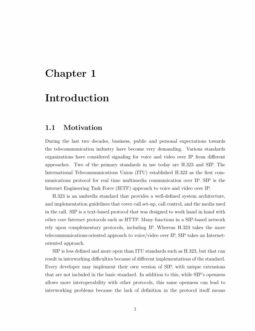
1.1 Motivation
During the last two decades, business, public and personal expectations towards
the telecommunication industry have become very demanding. Various standards
organizations have considered signaling for voice and video over IP from different
approaches. Two of the primary standards in use today are H.323 and SIP. The
International Telecommunications Union (ITU) established H.323 as the first com-
munications protocol for real time multimedia communication over IP. SIP is the
Internet Engineering Task Force (IETF) approach to voice and video over IP.
H.323 is an umbrella standard that provides a well-defined system architecture,
and implementation guidelines that cover call set-up, call control, and the media used
in the call. SIP is a text-based protocol that was designed to work hand in hand with
other core Internet protocols such as HTTP. Many functions in a SIP-based network
rely upon complementary protocols, including IP. Whereas H.323 takes the more
telecommunications-oriented approach to voice/video over IP, SIP takes an Internet-
oriented approach.
SIP is less defined and more open than ITU standards such as H.323, but that can
result in interworking difficulties because of different implementations of the standard.
Every developer may implement their own version of SIP, with unique extensions
that are not included in the basic standard. In addition to this, while SIP’s openness
allows more interoperability with other protocols, this same openness can lead to
interworking problems because the lack of definition in the protocol itself means
1
there are a number of different interpretations, each of which may have difficulty
interoperating with others.
There will very likely not be a “winner” or a “loser” in the SIP versus H.323
debate. Both H.323 and SIP protocol provide comparable functionality using different
mechanisms. Both protocols offer strengths and weaknesses. Each protocol handles
call set up, call control, and media in different ways. H.323 defines all of these;
SIP defines call set up and uses other protocols, such as Media Gateway Control
Protocol (MGCP), for call control and media. Call control and call set up are handled
separately from media.
While SIP is more flexible and scalable, H.323 offers better network management
and interoperability. The differences between the two protocols are diminishing with
each new version. Although there are numerous industry debates about the merits of
the two protocols, the truth is that both of them, along with other complementary
protocols, are necessary to provide universal access and to support IP-based enhanced
services.
Since both protocols have been widely deployed, interworking between SIP and
H.323 is essential to ensure full end-to-end connectivity. Because of the inherent dif-
ferences between H.323 and SIP, accommodation must be made to allow interworking
between the two protocols.
Instead of concentrating on one standard versus another, the voice/video over IP
community is working on better ways of ensuring interoperability between standards
to provide end-to-end connectivity throughout the network and to offer the value-
added IP-centric services that will demonstrate the power of IP-based communica-
tions. This thesis is a contribution to this effort. The specifications for interworking
are given in the SIP-H.323 Interworking Internet Draft [1].
1.2 Thesis Contributions
H.323, defined by the International Telecommunications Union(ITU), specifies a com-
plete, vertically integrated system. The different entities that make up an H.323
network include gateways, terminals, along with a gatekeeper. Each component in
the H.323 architecture has its own function. Gateways translate protocols, convert
media formats and transfer information. The terminal is an endpoint on the network,
2
which provides for real-time, two-way communications with another H.323 terminal,
gateway. Gatekeepers are used for addresses resolution, and other control and man-
agement functions.
SIP is part of an Internet Engineering Task Force (IETF) proposal to replace parts
of H.323. The SIP architecture includes user agents that may operate as a client or a
server, and servers. User agent can initiate a SIP transaction with a request. Servers
are either proxy servers to route calls to other entities, or redirect servers that accept
a SIP request and return other servers’ addresses to the client.
Currently H.323 is the most widely used protocol for PC-based conferences, while
carrier networks using IP telephones seem to be built based on SIP. H.323 and SIP
protocols both provide mechanisms for call control. Interworking between the two
protocols is desirable in order to achieve universal connectivity. Interworking will
include two types of endpoints: H.323 terminals and SIP user agents. Other entities
may include SIP-H.323 Interworking Function (IWF), H.323 gatekeeper (GK), and
SIP server.
SIP is not as strictly defined as a complete system as H.323. Many aspects of the
SIP architecture are left open to interpretation. SIP can integrate with other Internet
protocols, such as the Media Gateway Control Protocol (MGCP), to constitute a
complete system.
As a starting point before we model the SIP-H.323 Interworking system, we try to
model a small system using a VoIP related protocol. MGCP, defined by the IETF, is
such a suitable protocol between media gateway controller or call agent (MGC or CA)
and media gateway (MG). Its main application areas are in Voice over IP to build
large gateways that separate the signaling from the media-handling because removing
the signaling to a fast server is more practical than integrating it into the MG. From
the MGCP system model, we can conclude MGCP can not constitute a complete
system. A session initiation protocol, such as SIP, is required between media gateway
controllers (MGC).
The major goal of this thesis is to formally specify the SIP-H.323 Interworking,
as defined in the Internet Draft of IETF [1], using SDL/MSC.
In this thesis, a new system model is established for simulating and verifying inter-
working between SIP and H.323. Five main components of this system are modeled
by SDL/MSC: H323 endpoint, H323 gatekeeper, Interworking Function (IWF), SIP
3
server, and SIP endpoint. We design and define the internal structure and behavior
for each component. From the point of view of modeling, our model is expected
to accommodate potential further changes in standards. The current model can be
easily extended and modified to support advanced requirements. The second major
part of our work concentrates on simulation and verification of our model. We have
simulated successful scenarios and failure scenarios. We have conducted experiments
and simulations to remove errors from the specification, and gathered evidence of
correct protocol operation. Two configrations have been used in this model. One is
that both protocols work within the same administrative domain. In this simplest
scenario, call setup messages must be translated, then RTP can be used for media
communication directly between a SIP endpoint and an H.323 endpint. The other is
that both protocols are operating in separate administrative domains. The scenario
becomes more complex under this configuration. A gateway is required to translate
messages, as well as information on how to find addresses of destination endpoints
and convert those addresses so they can be interpreted by the other protocol. Using a
series of scenarios, it has been shown that the model meets the function specifications
outlined in the SIP-H323-Interworking specification documents.
4
Chapter 2
VoIP related protocols and its
perspective
2.1 Overview of VoIP related protocols
Internet Telephony is now one of the most important and fastest growing technologies
on the Internet, providing a viable technical and economical alternative to current
telecommunication networks. Network providers and major companies are thus in-
vestigating how this emerging technology can be implemented, and at what cost and
savings, in their organizations.
Over the next few years, the Internet industry also is tackling the problems about
Internet Telephony such as bandwidth limitation, network reliability and sound qual-
ity. Call Control and Signaling are main issues on which standards-setting efforts are
focusing.
VoIP signaling protocols began to be defined by the International Telecommu-
nications Union (ITU) in May 1995. In May 1996, the ITU-T ratified the H.323
specification, which defines how voice, data, and video traffic will be transported
over IP-based local area networks; it also incorporates the T.120 data-conferencing
standard. The recommendation is based on the real-time protocol/real-time control
protocol (RTP/RTCP) for managing audio and video signals, which had previously
been designed by the IETF. In December 1996, Study Group 16 passed the H.323
v.1, a standard for real-time videoconferencing over non-guaranteed quality of service
5
LANs. This recommendation describes components of H.323; terminals and other en-
tities (Gatekeepers, Gateways, Multi-point Control Units) that provide multimedia
communication over packet based networks.
Some existing protocols (e.g. RTP [2]) were reused directly (the ITU-T had no
control over these IETF protocols); others (H.245, H.225.0-CC) were derived from
the ITU-T H.320 protocol suite while the RAS (Registration, Admission and Status)
protocol had to be designed from scratch. H.323 v.1 defines the basic call control
and signaling for setting up multipoint multimedia conferences. The basic call proce-
dure comprises RAS signaling functions and call signaling functions. RAS signaling
functions are required for endpoint registration, admission control and address res-
olution. Call signaling functions include connection setup, capability exchange and
open logical channel procedures. Approved in January 1998, version 2 of the H.323
standard addresses many deficiencies in version 1 and introduces new functionality
within existing protocols, such as H.245 and H.225, as well as new protocols. Version
2 of H.323 enables enhanced services on top of H.323. ITU-T SG16 evolved the H.450
series recommendations in order to support supplementary services over IP-networks.
H.450.1 defines a generic functional protocol on top of H.225.0-CC for all supple-
mentary services. It also defines the control procedures for the terminal equipment
involved in handling the protocol messages. The most important features have been
standardized already and new features are being added in an ongoing process. The
transport protocol RTP, on which the H.323 recommendation is based, essentially is a
new protocol layer for real-time applications; RTP-compliant equipment will include
control mechanisms for synchronizing different traffic streams. However, RTP does
not have any mechanisms for ensuring the on-time delivery of traffic signals or for
recovering lost packets. RTP also does not address the so-called quality of service
(QoS) issue related to guaranteed bandwidth availability for specific applications.
The Session Initiation Protocol (SIP) [3] has its origins in late 1996 as a component
of the Mbone set of utilities and protocols. The Mbone, or multicast backbone, was
an experimental multicast network overlayed on top of the public Internet. One
of its essential components was a mechanism for inviting users to listen in on an
ongoing or future multimedia session on the Internet. As an Mbone tool (and as a
product of the IETF), SIP was designed with certain assumptions in mind. First, was
scalability: since users could reside anywhere on the Internet, the protocol needed
6
to work wide-area from day one. Users could be invited to lots of sessions, so the
protocol needed to scale in both directions. A second assumption was component
reuse: Rather than inventing new protocol tools, those already developed within the
IETF would be used. That included things like MIME, URLs, and SDP [4] (already
used for other protocols, such as SAP [5]). This resulted in a protocol that integrated
well with other IP applications (such as web and e-mail). Interoperability was another
key goal, although not one specific to SIP. Interoperability is at the heart of IETF’s
process and operation, as a forum attended by implementers and operational experts
who actually build and deploy the technologies they design.
Despite its historical strengths, SIP saw relatively slow progress throughout 1996
and 1997. That’s about when interest in Internet telephony began to take off. People
began to see SIP as a technology that would also work for VoIP, not just Mbone
sessions. The result was an intensified effort towards completing the specification in
late 1998, and completion by the end of the year. In 1999, SIP was specified by the
IETF Multiparty Multimedia Session Control Working Group (MMUSIC WG) as a
proposed standard (IETF RFC 2543). SIP provides advanced signaling and control
functionality for a large range of multimedia communications. The main functions are:
location of resources/parties, invitation to service sessions, and negotiation of session
parameters. To fulfill this functionality, SIP provides a small number of textbased
messages to be exchanged between the SIP peer entities (SIP user agent in a user
terminal). Network entities, such as proxy servers or redirect servers that can be
traversed by the messages, are used for support, e.g., for address resolution.
In addition to the baseline SIP RFC, several IETF drafts complete the archi-
tecture regarding, e.g., call control supplementary services. There is no standard
for supplementary call control services other than some proposals in IETF Internet
Drafts, which are classified as “work in progress”, not as standards. The SIP base-
line protocol provides some limited support for call control, such as call hold, media
stream modification, or call termination, but the use of these features cannot explic-
itly be signaled as supplementary services. The IETF has generally recognized the
importance of advanced call control supplementary services. In July 2000, the SIP
WG issued a Draft describing a framework for SIP call control extensions. Up to
now some supplementary services have been described based on this proposal. Also,
the IETF IPTEL WG proposes several possibilities for the programming of services
7
either for administrators or for the users themselves.
SIP has gained tremendous market acceptance for signaling communications ser-
vices on the Internet, industry acceptance of SIP grew exponentially. Its scalability,
extensibility, and—most important—flexibility appealed to service providers and ven-
dors who had needs that a vertically integrated protocol, such as H.323, could not
address.
MGCP [6] (Media Gateway Control Protocol) is the third protocol related to
VoIP. It appeared that the industry was beginning to converge on one protocol when
the decomposed gateway concept has wide applicability. MGCP is a combination of
two earlier protocols, Simple Gateway Control Protocol (SGCP) and IP Device Con-
trol (IPDC). The Media Gateway Control Protocol (MGCP) specifies communication
between call control elements and telephony gateways. It was conceived partly to ad-
dress some of the perceived inadequacies of H.323 at the level of centralized network
infrastructure.
MGCP’s central goal is to remain simple. It puts call signaling, control and
processing intelligence in call agents or media gateway controllers. Media gateways
are telephony gateways that serve as multi-service packet networks, converting audio
signals and data packets. They include trunking, voice over ATM, residential, access
and business gateways, network access servers and circuit switches. The MGCP call
agent performs all the same call routing functions as a gatekeeper in H.323, but has
much tighter control. It is a master/slave protocol, where the gateways are expected
to execute commands sent by the call agents.
Megaco working group of the International Engineering Task Force (IETF) is also
working on a standard (Megaco) that uses the same architecture and baseline as
MGCP.
In general, as telephony moves toward the world of IP, legacy call control pro-
tocols (RBS/SS7) need to be supplemented by new protocols designed to operate
in the IP world. It is not precise to refer to all of these as Call Control protocols.
They should be categorized as two types of protocols, one is Device Control Pro-
tocols (MGCP/MEGACO), which are used by Call Control elements (Call agents;
Softswitches; Media Gateway Controllers) to control and manage media devices. The
media device converts media signals (voice) between circuits and packets. The in-
telligence (Call setup, etc.) is separated from the media function. It is called a
8
Master/Slave protocol. The master keeps up with all call states and gives directions
to the slave for each step of a call establishment while the slave just provides dial
tone/call progress tones or ring the phone under the instruction from the Master.
The other type is Call Control Protocols (SIP/H.323), which are used to set up calls
between call control elements. These protocols are peer-to-peer. SS7 is the same type
of protocol providing for the establishment of calls and call features (call redirects
etc.) between call control elements of today’s PSTN including Class 4/5 switches.
2.2 MGCP & System Modeling (A starting point)
2.2.1 MGCP
MGCP is media gateway control protocol, defined by the IETF for controlling Tele-
phony Gateways from external call control elements called media gateway controllers
or call agents. It allows a media gateway controller or call agent (MGC or CA) to in-
struct a media gateway (MG), which converts circuit-switched voice to packet-based
traffic, to connect streams coming from outside a packet or cell data network onto
a packet or cell stream such as the Real-Time Transport Protocol (RTP). MGCP
assumes a call control architecture where the call control “intelligence” is outside
the gateways and handled by external call control elements. The MGCP assumes
that these call control elements, or Call Agents, will synchronize with each other to
send coherent commands to the gateways under their control. Its main application
areas are in VoIP to build large gateways that separate the signaling from the media-
handling because of the density of the interconnections (which may have OC-3 or
even OC-12 connections). Removing the signaling to a fast server is more practical
than trying to integrate it into the MG.
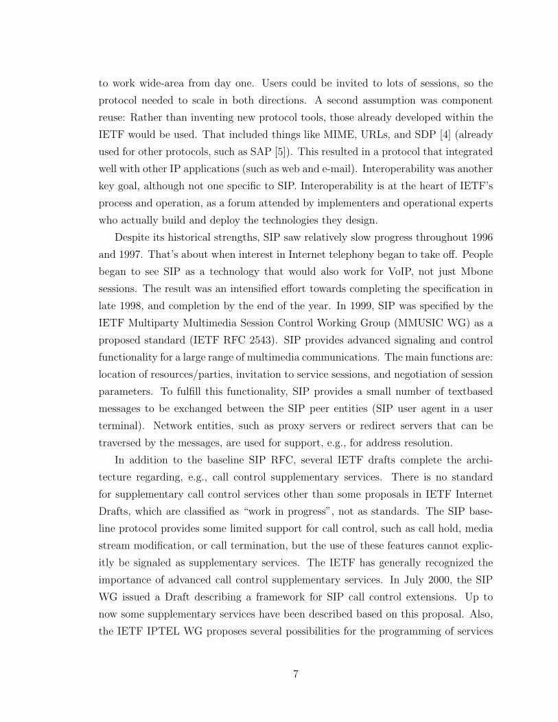
Endpoint and connection are the core concepts of MGCP. MGCP assumes a con-
nection model where the basic constructs are endpoints and connections. Endpoints
are sources or sinks of data and could be physical or virtual. Connections may be
either point to point or multipoint. A point to point connection is an association be-
tween two endpoints with the purpose of transmitting data between these endpoints.
Once this association is established for both endpoints, data transfer between these
endpoints can take place. A multipoint connection is established by connecting the
endpoint to a multipoint session. Endpoints are classified as different types. MGCP
9
MG CA
RSIP.REQNTFY.REQ
RQNT.INDCRCX.INDMDCX.INDDLCX.IND
RQNT.REQCRCX.REQMDCX.REQDLCX.REQ
RSIP.IND
UDP
ACK
ACK ACK
ACKNTFY.IND
Figure 1: MGCP Service Primitives
simply assumes that media gateways support collections of endpoints. The type of the
endpoint determines its functionalities. Connections are grouped into calls. One or
more connections can belong to one call. Calls are identified by unique identifiers, in-
dependent of the underlying platforms or agents. These identifiers are created by the
Call Agent. Connection identifiers are created by the gateway when it is requested to
create a connection. They identify the connection within the context of an endpoint.
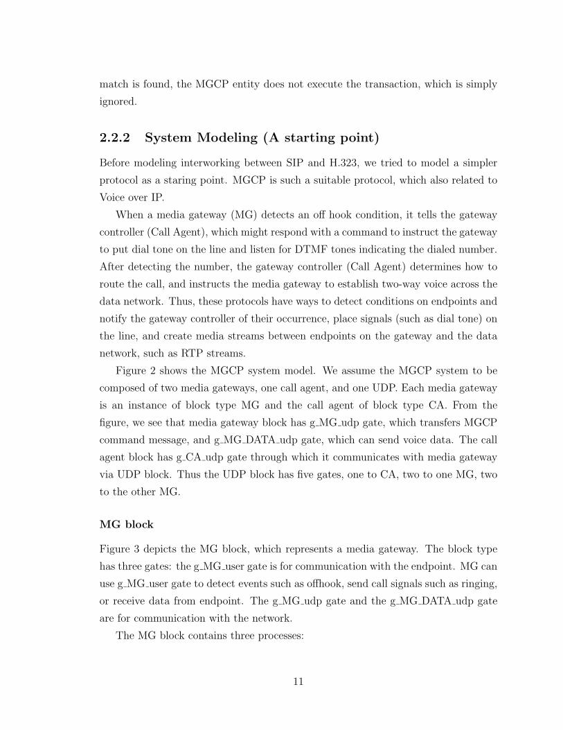
A CA can instruct a MG to create, modify, and disconnect a connection. It also
asks MG for notification when one of a list of required event occurs. Figure 1 shows
the MGCP service primitives implemented in the MGCP system.
The media gateway control protocol is organized as a set of transactions, each
of which is composed of a command and a response, commonly referred to as an
acknowledgement. MGCP uses a transaction identifier to correlate commands and
responses to provide the At-Most-Once functionality. MGCP messages, being carried
over UDP, may be subject to loss. In the absence of a timely response, commands
are repeated. Most MGCP commands are not idempotent. The state of the gateway
would become unpredictable. MGCP entities are expected to keep in memory a list of
the responses that they sent to recent transactions and a list of the transactions that
are currently being executed. The transaction identifiers of incoming commands are
compared to the transaction identifiers of the recent responses. If a match is found,
the MGCP entity does not execute the transaction, but simply repeats the response.
The remaining commands will be compared to the list of current transactions. If a
10
match is found, the MGCP entity does not execute the transaction, which is simply
ignored.
2.2.2 System Modeling (A starting point)
Before modeling interworking between SIP and H.323, we tried to model a simpler
protocol as a staring point. MGCP is such a suitable protocol, which also related to
Voice over IP.
When a media gateway (MG) detects an off hook condition, it tells the gateway
controller (Call Agent), which might respond with a command to instruct the gateway
to put dial tone on the line and listen for DTMF tones indicating the dialed number.
After detecting the number, the gateway controller (Call Agent) determines how to
route the call, and instructs the media gateway to establish two-way voice across the
data network. Thus, these protocols have ways to detect conditions on endpoints and
notify the gateway controller of their occurrence, place signals (such as dial tone) on
the line, and create media streams between endpoints on the gateway and the data
network, such as RTP streams.
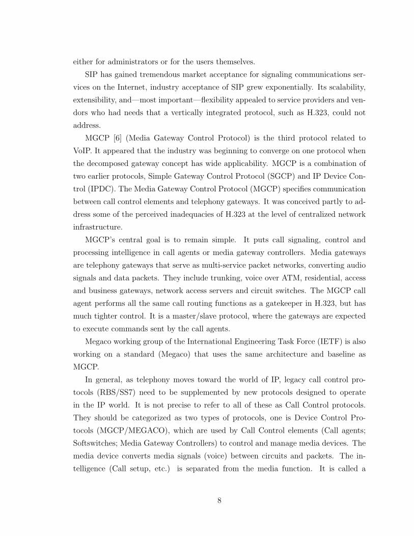
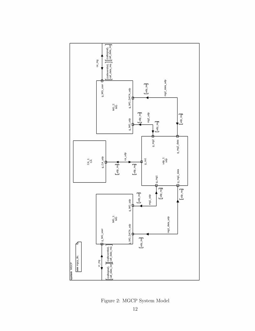
Figure 2 shows the MGCP system model. We assume the MGCP system to be
composed of two media gateways, one call agent, and one UDP. Each media gateway
is an instance of block type MG and the call agent of block type CA. From the
figure, we see that media gateway block has g MG udp gate, which transfers MGCP
command message, and g MG DATA udp gate, which can send voice data. The call
agent block has g CA udp gate through which it communicates with media gateway
via UDP block. Thus the UDP block has five gates, one to CA, two to one MG, two
to the other MG.
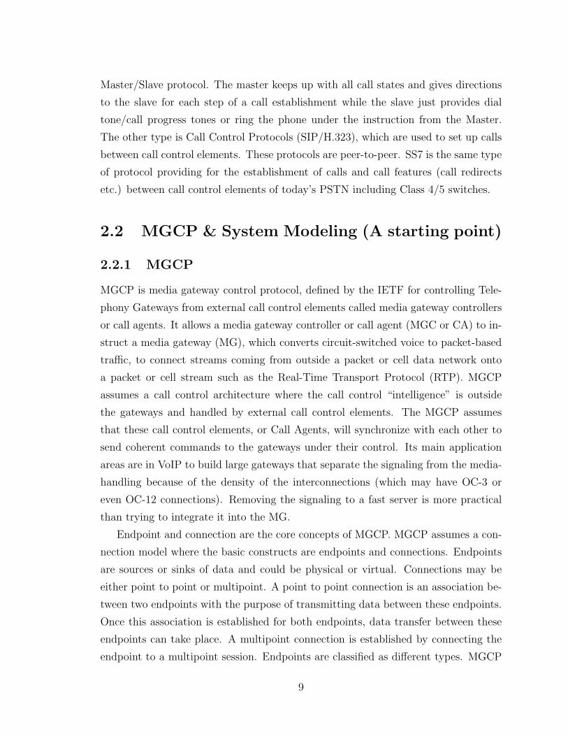
MG block
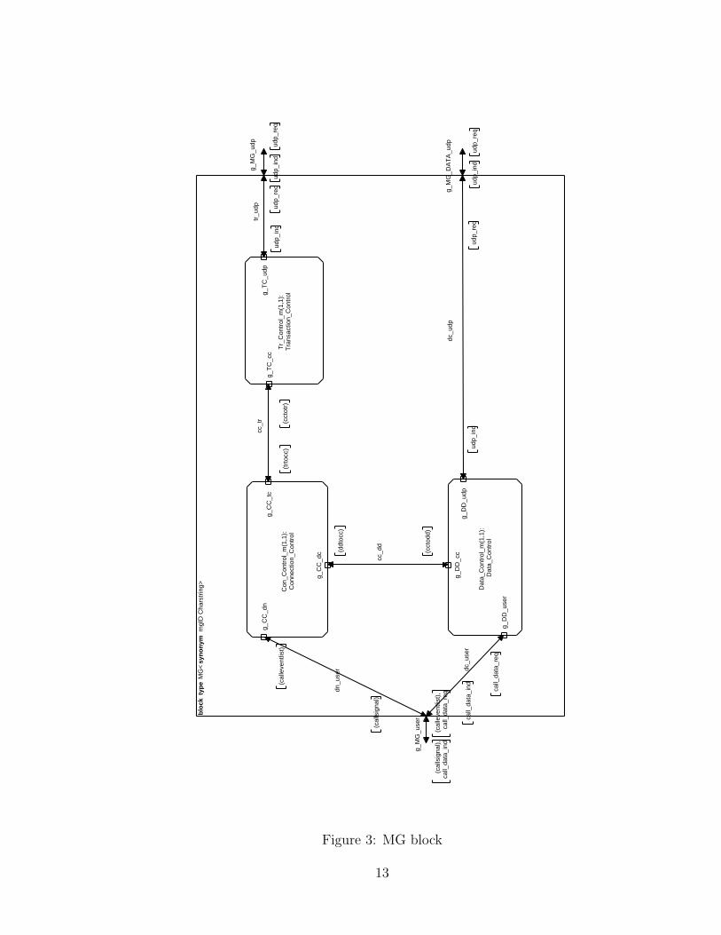
Figure 3 depicts the MG block, which represents a media gateway. The block type
has three gates: the g MG user gate is for communication with the endpoint. MG can
use g MG user gate to detect events such as offhook, send call signals such as ringing,
or receive data from endpoint. The g MG udp gate and the g MG DATA udp gate
are for communication with the network.
The MG block contains three processes:
11
syst
em M
GC
P
use
mgc
p_lib
;
cr_m
g
(cal
lsig
nal),
call_
data
_ind
(cal
leve
ntlis
t),
call_
data
_req
ca_u
dp
udp_
req
udp_
ind
mg1
_udp ud
p_re
q
udp_
ind
mg2
_udp
udp_
requd
p_in
d
mg1
_dat
a_ud
p
udp_
req
udp_
ind
mg2
_dat
a_ud
p
udp_
req
udp_
ind
ce_m
g
(cal
leve
ntlis
t),
call_
data
_req
(cal
lsig
nal),
call_
data
_ind
MG
_1:
MG
g_M
G_u
dp
g_M
G_u
ser
g_M
G_D
AT
A_u
dp
MG
_2:
MG
g_M
G_u
dp
g_M
G_u
ser
g_M
G_D
AT
A_u
dp
CA
_1:
CA
g_C
A_u
dp
udp_
1:ud
p
g_m
g1
g_ca
1
g_m
g2
g_m
g1_d
ata
g_m
g2_d
ata
Figure 2: MGCP System Model
12
blo
ck t
ype
MG
<sy
no
nym
mgI
D C
hars
trin
g>
g_M
G_u
ser
(cal
leve
ntlis
t),
call_
data
_req
(cal
lsig
nal),
call_
data
_ind
g_M
G_u
dp
udp_
ind
udp_
req
g_M
G_D
AT
A_u
dp
udp_
ind
udp_
req
tr_u
dp
udp_
ind
udp_
req
cc_t
r
(trt
occ)
(cct
otr)
dc_u
ser
call_
data
_req
call_
data
_ind
dc_u
dp
udp_
req
udp_
ind
dn_u
ser
(cal
leve
ntlis
t)
(cal
lsig
nal)
cc_d
d
(cct
odd)
(ddt
occ)
Tr_
Con
trol
_m(1
,1):
Tra
nsac
tion_
Con
trolg_
TC
_udp
g_T
C_c
c
Con
_Con
trol
_m(1
,1):
Con
nect
ion_
Con
trol
g_C
C_t
cg_
CC
_dn
g_C
C_d
c
Dat
a_C
ontr
ol_m
(1,1
):D
ata_
Con
trol
g_D
D_u
ser
g_D
D_u
dpg_
DD
_cc
Figure 3: MG block
13
• Transaction Control: it is used for transaction management. It keeps in memory
a list of the responses that were sent to recent transactions and a list of the
transactions that are currently being executed. If the transaction identifier
of an incoming command message is not in the list, forwards the message to
the Connection Control process, otherwise it just repeats the response to the
command. MGCP uses the transaction identifier to correlate command and
response to provide At-Most-Once functionality. It is responsible to forward
the MGCP message from Connection Control to network. It is also responsible
for the timer management and re-sending the command message when timeout
occurs.
• Connection Control: it is involved in detecting event from endpoint and sending
a notify command to CA. It maintains the endpoint’s state on the MG’s side.
It is also responsible for forwarding the message of connection establishment to
the Data Control process.
• Data Control: It is involved in responding to the connection related commands
from Connection Control with connection identifier and connection address to
Connection Control. It is also responsible for forwarding the data from the
network to the endpoint, and vice versa.
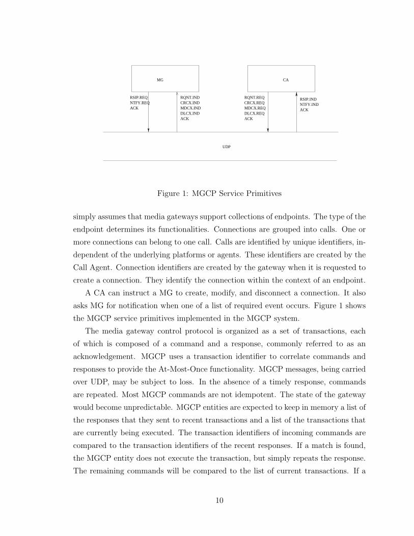
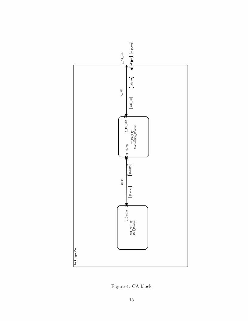
CA block
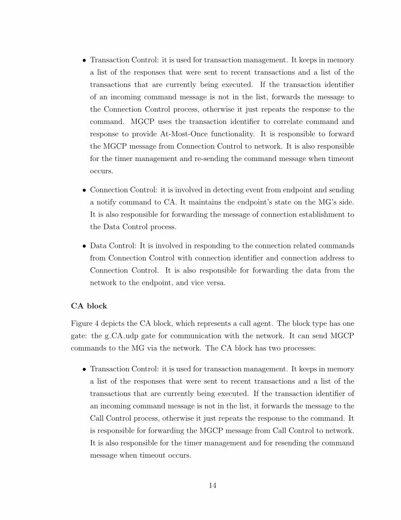
Figure 4 depicts the CA block, which represents a call agent. The block type has one
gate: the g CA udp gate for communication with the network. It can send MGCP
commands to the MG via the network. The CA block has two processes:
• Transaction Control: it is used for transaction management. It keeps in memory
a list of the responses that were sent to recent transactions and a list of the
transactions that are currently being executed. If the transaction identifier of
an incoming command message is not in the list, it forwards the message to the
Call Control process, otherwise it just repeats the response to the command. It
is responsible for forwarding the MGCP message from Call Control to network.
It is also responsible for the timer management and for resending the command
message when timeout occurs.
14
blo
ck t
ype
CA
g_C
A_u
dp
udp_
ind
udp_
req
tr_u
dp
udp_
ind
udp_
req
cc_t
r
(trt
occ)
(cct
otr)
Tr_
CA
(1,1
):T
rans
actio
n_C
ontr
ol
g_T
C_c
cg_
TC
_udp
Cal
l_C
r(1,
1):
Cal
l_C
ontr
olg_C
aC_t
c
Figure 4: CA block
15
• Call Control: It is the core component for coordinating MG to create connection.
It keeps track of the endpoint state of MG on the CA’s side. It receives the
notification message from MG and sends MGCP command according to the
current state of the endpoint.
I have verified the SDL model of the MGCP protocol using ObjectGEODE val-
idation tools against the general properties, mainly deadlocks. I have chosen some
scenarios to validate the model. I also have covered all the protocol primitives specifed
as well as all important scenarios, but not all possible scenarios. Furthermore, I have
decided to send data along the connection path when the connections are all created.
In general, I have got basic experience that how to model properly a practical
protocol using SDL/MSC from modeling MGCP protocol. The results of this study
were published by IEEE Canada (CCECE 2001) [7].
2.3 H.323
H.323 [8] covers the technical requirements for multimedia communications systems
in those situations where the underlying transport is a packet based network (PBN)
that may not provide a guaranteed Quality Of Service (QOS). These packet-based
networks may include Local Area Networks, Enterprise Area Networks, Metropolitan
Area Networks, Intra-Networks, and Inter-Networks (including the Internet).
H.323 is not an individual protocol, but rather a complete, vertically-integrated
suite of protocols that describes the components of an H.323 system: terminals,
gateways, gatekeepers, Multipoint Control Units (MCUs) and other feature servers.
Each component in the H.323 architecture has its own function. Gateways are used
to link LAN-based H.323 endpoints to endpoints in the PSTN and other networks.
These gateways translate protocols, convert media formats and transfer information.
Gatekeepers are used for address resolution, LAN bandwidth allocation and other
control and management functions. Gatekeepers are the cores of an H.323 network
and act like SIP servers. Multipoint control units mix and distribute conference media
streams for three or more H.323 terminals.
In contrast to SIP, a simple protocol that specifies only what it needs to, H.323
uses a number of protocols for call control and signaling: Q.931 [17] for call setup,
16
H.225 for call signaling, H.245 for exchanging terminal capabilities and creation of me-
dia channels, RAS for registration and admission control, RTP/RTCP for sequencing
audio and video packets, G.711/712 for codec specification, T.120 for data conferenc-
ing. All these protocols must be negotiated to set up a simple point-to-point voice
call.
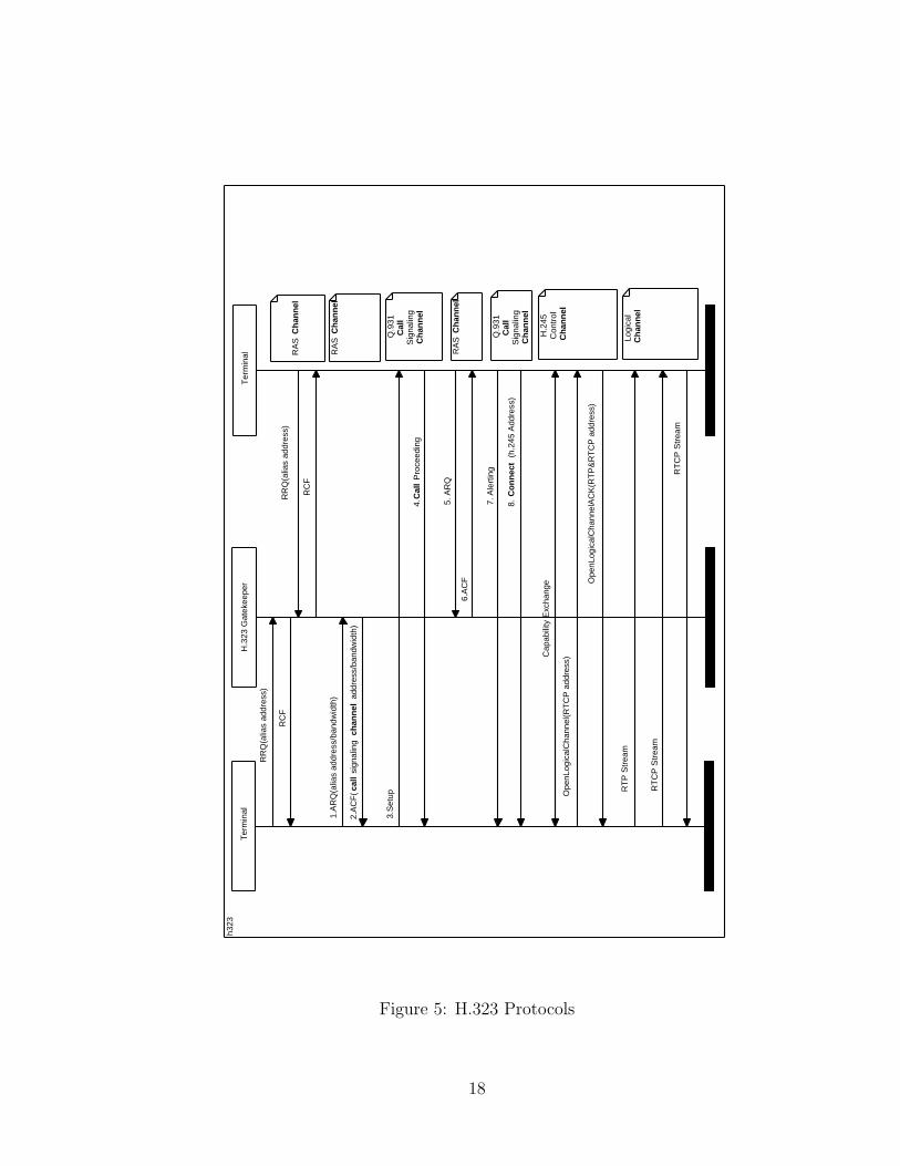
Figure 5 shows how the H.323 components correlate with each other using those
protocols. First of all, a supported client queries an H.323 gatekeeper for the address
of a new user using RAS. The gatekeeper retrieves the address and forwards it to the
client, which then establishes a session with the new client using H.225. Once the
session is established, another H.323 protocol, H.245, negotiates the available features
of each client. Because H.323 must establish a session before it negotiates the features
and functions of that session, call setup can take a long time. The amount of delay
will depend upon the type of network.
2.4 SIP
2.4.1 What is SIP?
SIP [3] is part of an Internet Engineering Task Force (IETF) proposal to replace parts
of H.323. Just as H.323 is a collection of protocols, SIP is one of several protocols
that will work together to complete calls.
SIP is an application layer control (signaling) protocol for creating, modifying
and terminating sessions with one or more participants. These sessions may include
Internet multimedia conferences, distance learning, and Internet telephone calls and
multimedia distribution. SIP can invite persons and “robots”, such as media storage
services, to participate in a call.
Callers and call receivers are identified by SIP addresses. A caller first locates the
appropriate server, then sends a SIP request (probably an invite). In a perfect world,
the request arrives at its destination, where the client accepts the call by returning a
SIP response code 200. Then the originating caller sends an acknowledgement back
to the recipient, which is a bit unusual because the station that initiates the call also
sends the acknowledgement.
SIP uses a variety of servers, each with its own purpose. There are user agent
servers, proxy servers, redirect servers, and registrars. There is also something called
17
h323
RA
S C
han
nel
RA
S C
han
nel
Q
.931
Cal
l
S
igna
ling
Ch
ann
el
RA
S C
han
nel
Q
.931
Cal
l
S
igna
ling
Ch
ann
el
Log
ical
Ch
ann
el
H
.245
C
ontr
ol
C
han
nel
RR
Q(a
lias
addr
ess)
RC
F
1.A
RQ
(alia
s ad
dres
s/ba
ndw
idth
)
2.A
CF
(cal
l si
gnal
ing
chan
nel
add
ress
/ban
dwid
th)
3.S
etup
4.C
all
Pro
ceed
ing
7. A
lert
ing
8. C
on
nec
t (
h.24
5 A
ddre
ss)
Cap
abili
ty E
xcha
nge
Ope
nLog
ical
Cha
nnel
(RT
CP
add
ress
)
Ope
nLog
ical
Cha
nnel
AC
K(R
TP
&R
TC
P a
ddre
ss)
RT
P S
trea
m
RT
CP
Str
eam
RT
CP
Str
eam
RR
Q(a
lias
addr
ess)
RC
F
5. A
RQ
6.A
CF
Ter
min
alH
.323
Gat
ekee
per
Ter
min
al
Figure 5: H.323 Protocols
18
a location server running a location service, which may be co-located with a SIP
server.
2.4.2 The Role of SIP
SIP supports five facets of establishing and terminating multimedia communications:
User location for determination of the end system to be used for communication;
User capabilities for determination of the media and media parameters to be used;
User availability for determination of the willingness of the called party to engage in
communications; Call setup for “ringing”, establishment of call parameters at both
called and calling party; Call handling for including transfer and termination of calls.
The protocol may be used to initiate sessions, invite members to sessions ad-
vertised by other means or initiate multiparty calls using a multipoint control unit.
SIP transparently supports name mapping and redirection services, allowing the im-
plementation of ISDN and intelligent network telephony subscriber services such as
personal mobility. These facilities also enable personal mobility, the ability of end
users to originate and receive calls and access subscribed telecommunication services
on any terminal in any location, and the ability of the network to identify end users
as they move.
SIP invitations used to create sessions carry session descriptions, which allow
participants to agree on a set of compatible media types. SIP supports user mobility
by proxying and redirecting requests to the user’s current location. Users can register
their current location. SIP is not tied to any particular conference control protocol.
SIP is designed to be independent of the lower-layer transport protocol and can be
extended with additional capabilities.
2.4.3 SIP URL and URI
In SIP, the objects addressed by SIP are users at hosts. Those users are identified by
a SIP URL [14], which takes a form similar to a mailto or telnet URL, i.e., user@host.
The user part is a user name or a telephone number. The host part is a domain name
or IP address. A user’s SIP address can be obtained out-of-band, can be learned via
existing media agents, can be included in some mailers’ message headers, or can be
recorded during previous invitation interactions. In many cases, a user’s SIP URL
19
can be guessed from their email address.
A SIP URL address can designate an individual (possibly located at one of several
end systems), the first available person from a group of individuals or a whole group.
A Uniform Resource Identifier (URI) [15] is a compact string of characters for
identifying an abstract or physical resource. URI provide a simple and extensible
means for identifying a resource. There is some confusion in the web community over
the relationship among the concepts of URL and URI. A URI can be classified as
a locator, a name, or both. The term “Uniform Resource Locator” (URL) refers to
the subset of URI that identify resources via a representation of their primary access
mechanism (e.g., their network “location”).
2.4.4 SIP Operation
SIP is a request-response protocol with requests sent by clients and received by servers.
A SIP request and the appropriate response are grouped into a SIP transaction. There
are several fields that contain identical values on one SIP transaction to facilitate
pairing a request with its response. A single implementation typically combines both
client and server functionality. SIP requests can be sent using any reliable or unreli-
able protocol, including UDP, and TCP. Protocol operation is largely independent of
the lower-layer transport protocol.
SIP defines six SIP request methods as follows.
• INVITE to initiate sessions. The INVITE method indicates that the user or
service is being invited to participate in a session.
• ACK to confirm session establishment. The ACK request confirms that the
client has received a final response to an INVITE request. The ACK request
does not generate responses for any transport protocol.
• OPTIONS to request information about capabilities.
• BYE to terminate a session. The user agent client uses BYE to indicate to the
server that it wishes to release the call leg. A BYE request is forwarded by the
server like an INVITE request and may be issued by either caller or callee.
• CANCEL to cancel a pending session, i.e., the CANCEL request cancels a
pending request.
20
• REGISTER allows a client to bind a permanent SIP URL to a temporary SIP
URL reflecting the current network location. A client uses the REGISTER
method to bind the address listed in the To header field with a SIP server to
one or more URL where the client can be reached.
SIP requests can be sent directly from a user agent client to a user agent server, or
they can traverse one or more proxy servers along the way. User agents send requests
either directly to the address indicated in the SIP URI or to a designated proxy
(“outbound proxy”), independent of the destination address. The current destination
address is carried in the Request-URI. Each proxy can forward the request based on
local policy and information contained in the SIP request. The proxy may rewrite
the request URI.
A session is initiated with the INVITE request. A successful SIP invitation con-
sists of two requests, INVITE followed by ACK. The INVITE request asks the callee
to join a particular conference or establish a two-party conversation. After the callee
has agreed to participate in the call, the caller confirms that it has received that
response by sending an ACK request.
The INVITE request typically contains a session description, for example, writ-
ten in SDP format, that provides the called party with enough information to join
the session. If the callee wishes to accept the call, it responds to the invitation by
returning a similar description listing the media it wishes to use.
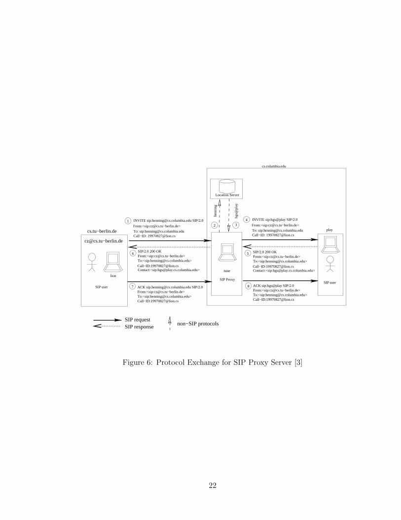
The protocol exchanges for the INVITE method are shown in Figure 6 for a proxy
server.
In Figure 6, the proxy server accepts the INVITE request (step 1), contacts the
location service with all or parts of the address (step 2) and obtains a more precise
location (step 3). The proxy server then issues a SIP INVITE request to the ad-
dress(es) returned by the location service (step 4). The user agent server alerts the
user (step 5) and returns a success indication to the proxy server (step 6). The proxy
server then returns the success result to the original caller (step 7). The receipt of this
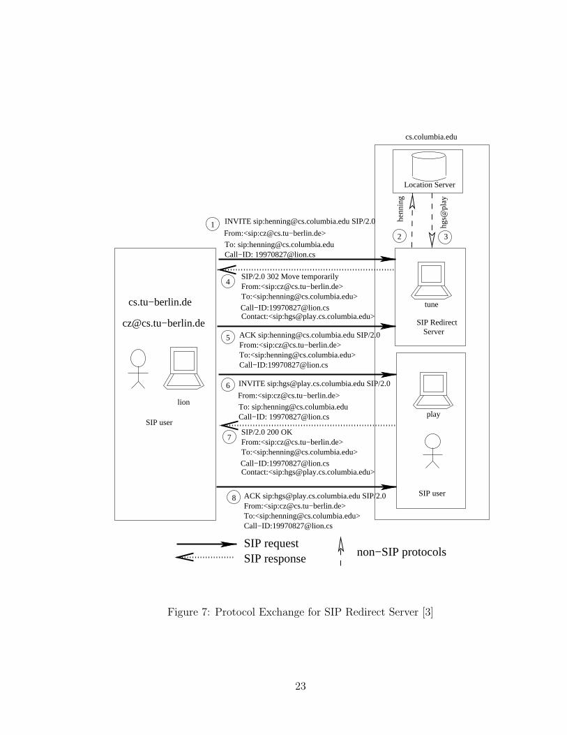
message is confirmed by the caller using an ACK request. Figure 7 is for a redirect
server.
21
1 INVITE sip:[email protected] SIP/2.0
To: sip:[email protected]−ID: [email protected]
From:<sip:[email protected]−berlin.de>
6
Call−ID:[email protected]
SIP/2.0 200 OK
To:<sip:[email protected]>
Contact:<sip:[email protected]>
From:<sip:[email protected]−berlin.de>
2 3
SIP Proxy
Location Server
SIP user
Call−ID:[email protected]
SIP/2.0 200 OK
To:<sip:[email protected]>
Contact:<sip:[email protected]>
From:<sip:[email protected]−berlin.de>5
4
To: sip:[email protected]−ID: [email protected]
INVITE sip:hgs@play SIP/2.0
From:<sip:[email protected]−berlin.de>
7 ACK sip:[email protected] SIP/2.0From:<sip:[email protected]−berlin.de>To:<sip:[email protected]>Call−ID:[email protected]
8From:<sip:[email protected]−berlin.de>To:<sip:[email protected]>Call−ID:[email protected]
ACK sip:hgs@play SIP/2.0
SIP requestSIP response non−SIP protocols
cs.columbia.edu
cs.tu−berlin.de
[email protected]−berlin.de
SIP user
henn
ing
hgs@
play
tune
play
lion
Figure 6: Protocol Exchange for SIP Proxy Server [3]
22
SIP requestSIP response non−SIP protocols
Location Server
2 3
INVITE sip:[email protected] SIP/2.0
To: sip:[email protected]−ID: [email protected]
From:<sip:[email protected]−berlin.de>1
Call−ID:[email protected]
To:<sip:[email protected]>
Contact:<sip:[email protected]>
From:<sip:[email protected]−berlin.de>SIP/2.0 302 Move temporarily
4
ACK sip:[email protected] SIP/2.0From:<sip:[email protected]−berlin.de>To:<sip:[email protected]>Call−ID:[email protected]
5
6
To: sip:[email protected]−ID: [email protected]
From:<sip:[email protected]−berlin.de>
INVITE sip:[email protected] SIP/2.0
Call−ID:[email protected]
SIP/2.0 200 OK
To:<sip:[email protected]>From:<sip:[email protected]−berlin.de>
Contact:<sip:[email protected]>
7
8
cs.tu−berlin.de
[email protected]−berlin.de
SIP user
lionhe
nnin
g
hgs@
play
cs.columbia.edu
tune
play
SIP user
From:<sip:[email protected]−berlin.de>To:<sip:[email protected]>Call−ID:[email protected]
ACK sip:[email protected] SIP/2.0
SIP RedirectServer
Figure 7: Protocol Exchange for SIP Redirect Server [3]
23
2.4.5 Relation with other IETF protocols
SIP is designed as part of the overall IETF multimedia data and control architecture
currently incorporating protocols such as RSVP [12] for reserving network resources,
the real-time transport protocol (RTP) [2] for transporting real-time data and pro-
viding QOS feedback, the real-time streaming protocol (RTSP) [13] for controlling
delivery of streaming media, the session announcement protocol (SAP) [5] for adver-
tising multimedia sessions via multicast and the session description protocol (SDP) [4]
for describing multimedia sessions. However, the functionality and operation of SIP
does not depend on any of these protocols.
2.5 Comparison of H.323, MGCP, SIP
MGCP/MEGACO are useful protocols for internally controlling an IP telephony gate-
way. MGCP is prevalent among such devices as media gateways, ATM routers, cable
modems, and set-top boxes. However, when they are used as control protocols for
delivering services across the wide network, they have several limitations. MGCP
will become the protocol of choice for the multi-node public network while H.323 will
probably become the protocol of choice for the enterprise and smaller debit-card type
telephony providers. MGCP (and its relatives) was conceived as a tool for decom-
posing a telephony gateway into a controlling signaling component and a controlled
media component. MGCP performs a very different function from the function of
SIP. In fact, a complete system can not be built with MGCP alone. An initiation
protocol is still needed between separate controllers. MGCP/Megaco and SIP are
not peers; they can and will coexist in converged networks. MGCP/Megaco does
not constitute a complete system: a session initiation protocol is required between
gateway controllers. SIP is eminently suitable and is a requisite where there is more
than one softswitch. The details of combining the two in a system are still being
fleshed out. MGCP is a device control protocol, where a slave (gateway (MG)) is
controlled by a master (media gateway controller (MGC), call agent). SIP may be
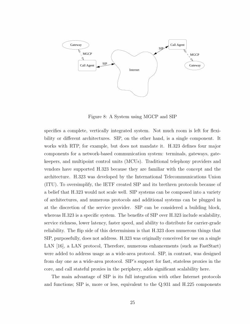
used between controllers, in a peer-to-peer relationship. Figure 8 illustrates a system
using MGCP and SIP.
There are numerous differences between SIP and H.323. The first is scope; H.323
24
Gateway
Call Agent
Call Agent
GatewayInternet
MGCP
SIP
SIP
MGCP
Figure 8: A System using MGCP and SIP
specifies a complete, vertically integrated system. Not much room is left for flexi-
bility or different architectures. SIP, on the other hand, is a single component. It
works with RTP, for example, but does not mandate it. H.323 defines four major
components for a network-based communication system: terminals, gateways, gate-
keepers, and multipoint control units (MCUs). Traditional telephony providers and
vendors have supported H.323 because they are familiar with the concept and the
architecture. H.323 was developed by the International Telecommunications Union
(ITU). To oversimplify, the IETF created SIP and its brethren protocols because of
a belief that H.323 would not scale well. SIP systems can be composed into a variety
of architectures, and numerous protocols and additional systems can be plugged in
at the discretion of the service provider. SIP can be considered a building block,
whereas H.323 is a specific system. The benefits of SIP over H.323 include scalability,
service richness, lower latency, faster speed, and ability to distribute for carrier-grade
reliability. The flip side of this determinism is that H.323 does numerous things that
SIP, purposefully, does not address. H.323 was originally conceived for use on a single
LAN [16], a LAN protocol, Therefore, numerous enhancements (such as FastStart)
were added to address usage as a wide-area protocol. SIP, in contrast, was designed
from day one as a wide-area protocol. SIP’s support for fast, stateless proxies in the
core, and call stateful proxies in the periphery, adds significant scalability here.
The main advantage of SIP is its full integration with other Internet protocols
and functions; SIP is, more or less, equivalent to the Q.931 and H.225 components
25
of H.323. These protocols are responsible for call setup and call signalling. Conse-
quently, both SIP and H.323 can be used as signalling protocols in IP networks.
2.6 Interworking between SIP and H.323
H.323 and SIP protocols both provide mechanisms for call establishment and tear-
down, call control and supplementary services, and capability exchange. Currently
H.323 is the most widely used protocol for PC-based conferences, while carrier net-
works using so-called soft switches and IP telephones seem to be built based on SIP.
In order to achieve universal connectivity, interworking between the two protocols
is desirable. Interworking between the protocols is made simpler since both operate
over IP (Internet Protocol) and use RTP for transferring real-time audio/video data,
reducing the task of interworking between these protocols translation of the signaling
protocols and session description.
Interworking between SIP and H323 [1] is based on H.323 version 2.0 and SIP
version 2.0. The goal of interworking between SIP and H.323 requires transparent
support of signaling and session descriptions between the SIP and H.323 entities [9].
The server providing this translation of SIP-H.323 is called the interworking function
(IWF). The interworking function (IWF) that will allow interworking between the SIP
and H.323 network architecture can be architected in a variety of ways. Co-existence
with H.323 gatekeeper (GK) and/or SIP server, or stand-alone. Interworking between
SIP and H.323 may involve in the following entities:
• Endpoint (EP): This is an entity from which the media originates or finally
terminates. This can either be H.323 terminal or SIP user agent.
• H.323 Gatekeeper (GK) : The Gatekeeper (GK) is an OPTIONAL H.323 entity
on the network that provides address translation and controls access to the
network for H.323 terminals, Gateways and MCUs. The Gatekeeper may also
provide other services to the terminals, Gateways and MCUs such as bandwidth
management and locating Gateways.
• H.323 Terminal: A H.323 Terminal is an endpoint on the network, which pro-
vides the real-time, two-way communications with another H.323 terminal,
26
Gateway, or Multipoint Control Unit. This communication consists of con-
trol, indications, audio, moving color video pictures, and/or data between the
two terminals. A terminal may provide speech only, speech and data, speech
and video, or speech, data and video.
• Interworking Function (IWF): It allows interworking between the H.323 and SIP
networks. The H.323 side of the IWF is the part of the IWF that terminates
and originates H.323 signaling from and to the H.323 network respectively. The
SIP side of the IWF is the part of the IWF that terminates and originates SIP
signaling from and to the SIP network respectively.
• SIP User Agent (UA): A logical entity that can act as both SIP user agent client
and SIP user agent server.
• SIP Server: This can be either SIP Proxy, Redirect, Location or Registrar
server.
• SIP Proxy Server: A logical entity that acts as both server and a client. SIP
messages will be processed and passed to other SIP entities. A SIP proxy server
interprets, and, if necessary, rewrites a SIP message before forwarding it.
The IWF supports the address resolution schemes of both H.323 and SIP proto-
col and registers itself to the H.323 gatekeeper (GK) and the SIP server (Register,
Redirect, Proxy).
When the IWF receives call signaling messages from an H.323 entity, it performs
the necessary translation and sends the corresponding equivalent messages to the
SIP entity on the SIP side of the IWF and vice versa. The IWF provides signaling
translation for all phases of a call. The IWF has a table of reference for lookup to
resolve H.323 and SIP addresses to IP addresses. It keeps the address resolution
information to itself if H.323 GKs or SIP servers are not available.
It may contain the functions like Call sequence mapping, Address resolution, Ter-
minal Capability transactions, Opening and closing of media channels, Mapping me-
dia algorithms for H.323 and SIP network, Call resource reservation and release,
Ability to provide the state of a call, Call state machine, Mid Call signal processing,
and Service Interoperability Logic. No media processing will be done within the IWF.
27
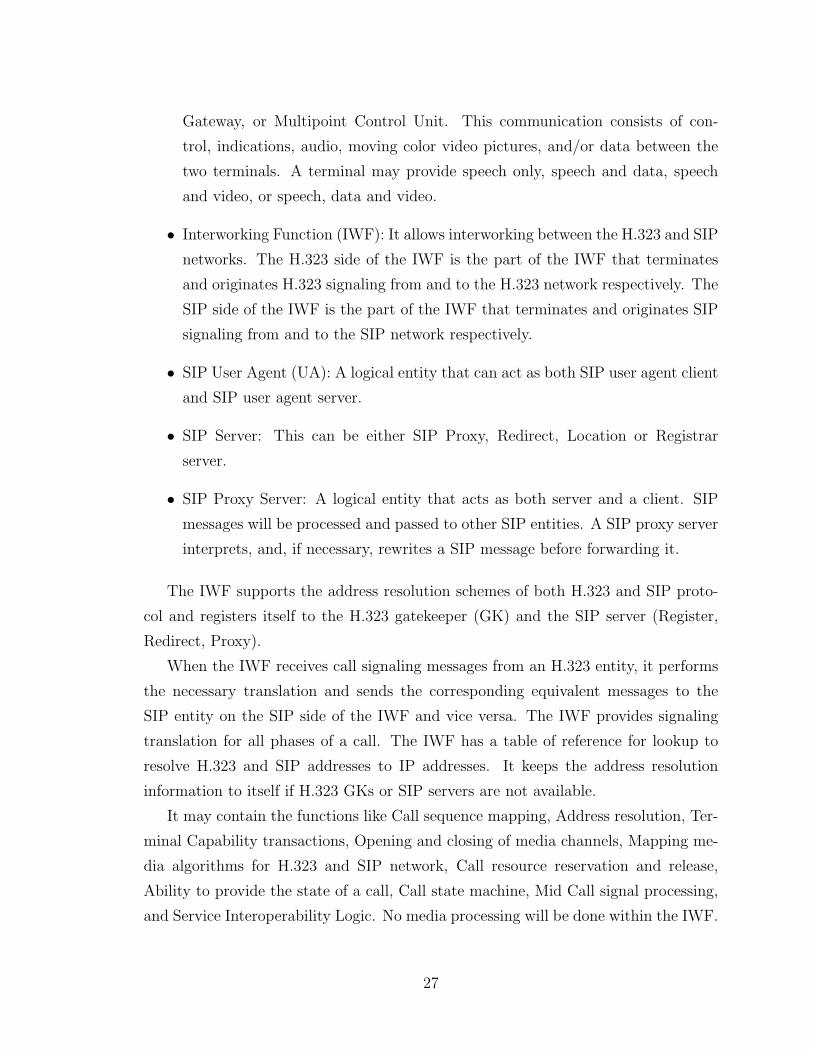
H.323 EP IWF SIP UA
H.323 EP H.323 GK IWF SIP UA
H.323 EP IWF SIP UASIP Server
H.323 GK SIP ServerIWFH.323 EP SIP UA
Configuration 1 : IWF without H.323 GK and SIP Server
Configuration 2 : IWF with H.323 GK and without SIP Server
Configuration 3 : IWF with SIP Server and without H.323 Server
Configuration 4 : IWF with H.323 Server and SIP Server
Figure 9: Configurations of Interworking between SIP and H.323
IWF maintains call message sequence on both sides in such a way that neither
H.323 terminal nor SIP UA is aware of the IWF presence. The IWF provides seamless
interworking between the call flows of the two protocols. The messages that do not
have a match on the other side should be terminated on the IWF, and IWF takes the
necessary action on them. The messages and parameters, which do not have direct
mapping on the other side are to be generated by the IWF with default parameters in
most cases. The IWF conforms to the call signaling procedures recommended for the
SIP side independent of the H.323 side. Also, the IWF conforms to the call signaling
procedures recommended for the H.323 side independent of the SIP side.
There are several types of configuration where SIP-H323 IWF can be placed with
different network elements in the SIP and H.323 networks. The way the messages are
generated during a call establishment between H.323 EP and a SIP UA, is different
depending on the configuration.
Figure 9 shows the types of configuration. Configuration 1 is a basic configuration,
which has no H.323 gatekeeper and SIP server. IWF has to keep lookup table for
both sides. The other three configurations contains one H.323 gatekeeper, or one SIP
server, or both. In that case, IWF does not have to keep lookup table for both sides,
since H.323 gatekeeper or/and SIP server can assist IWF for address resolution.
28
2.7 Perspective of Next Generation Network
The current network application and infrastructure are experiencing a revolution.
The existing network architecture has prevented the realization of more and more
new applications and services (such as IP-based voice, the Web, instant messaging,
presence) on Internet.
How to face with the conflict between new emerging services and relatively obso-
lete network infrastructure? How to handle the smooth transition to overall IP-based
multimedia (voice, audio, etc.) network architecture encompassing wireless network,
i.e., Packet Switching Data Network (PSDN) from traditional Public Switched Tele-
phony Network (PSTN)? How will the Internet next generation architecture support
applications with advanced service requirement, e.g., QoS, personal mobility and secu-
rity requirement on Internet? Of all the above questions, the protocols are the bridge
of network infrastructure and multiple services. Therefore, the choice of protocols is
the focus of discussion. However, there is a variety of protocol standards, such as
H323, MGCP/Megaco, and SIP. The three protocols in VoIP Signalling Protocols are
three major standards that are presently being debated as candidates.
As voice and data converge, the network infrastructure is moving from circuit-
based technologies to packet-based technologies. Internet protocols will become the
standard upon which all services are built.
The Public Switched Telephone Network (PSTN) and Next Generation Network
(NGN) are significantly different from each other. Nevertheless, legacy technologies
are still in place within the network. Service providers and carriers have made sub-
stantial investments in existing infrastructures; therefore, resistance to change can be
strong. To protect their future investments, service providers and carriers will need
products that offer high performance, scalability, high availability, flexibility, open ar-
chitectures and the ability to interoperate with a broad range of network technologies
and protocols. Therefore, the need to provide such functionality between networks,
e.g., gateway functionality, also makes the technology and standards required to sup-
port these opportunities complex and changing.
The signaling and data protocols used to deliver the content (data, audio, video)
through the network will continue to evolve and change. The effective and widespread
deployment of multimedia and other services will depend on the successful implemen-
tation of the SIP, H.323, MGCP/MEGACO/H.248 and SS7 over IP protocols. SIP
29
and H.323 will provide the mechanisms for connection setup and media mapping.
MGCP and SS7 over IP will be used between the softswitches and gateways provid-
ing the interworking functions between the Internet and the PSTN. SIP has been
adopted by The 3rd Generation Partnership Project (3GPP) as the Signalling pro-
tocol for 3G networks. The exact signaling and call control protocols are defined in
3GPP Technical Specification 3G TS 24.228: “Signalling flows for the IP multimedia
call control based on SIP and SDP” and 3GPP Technical Specification 3G TS 24.229:
“IP Multimedia Call Control Protocol based on SIP and SDP”. In fact, one of the
brightest hopes of the next-generation network is the ability to unlock the power of
service creation and place it in the hands of service providers and ultimately their
customers. The next-generation network also has the opportunity to revolutionize
the interaction between end users and their telecommunications needs. End users
will be empowered to self-provision features and services via the web, personal digital
assistants (PDAs), and other wireless interfaces.
One challenge in implementing services is that they must be implemented across
all protocols uniformly, consistently, and reliably. Call waiting must work the same in
SIP as it does in H.323 as it does in MGCP, and it must interact with other features,
i.e., caller I.D., in the same way across all protocols, and it must work well across all
protocols.
The era of convergence brings with it many promises as well as challenges. En-
hanced service creation, easy self-provisioning, and more flexible billing and usage
options are just a few examples. But the road to convergence is long and filled with
pitfalls. Next-generation communications platform vendors are challenged to meet
or exceed the PSTN in reliability, scalability, and performance; provide any-to-any
protocol and end point interoperability; and empower service creation through robust
service creation engines and open APIs. Ultimately, true convergence will come when
next-generation vendors solve all the above problems.
30
Chapter 3
Formal Methods
3.1 Introduction
In order to improve telecommunications software quality, Formal Description Tech-
niques (FDT) applied to protocols was first introduced by the International Orga-
nization for Standardization (ISO) in the 1980’s. Prior to FDT usage, only natural
language descriptions and diagrams were used to describe protocols, but this did not
suffice to specify the exact requirements for large software systems, such as protocol
software systems.
In technology enterprise today, the balance between quality and feature enhance-
ment favors the latter. As our economy, our safety, and our way of life grows ever
more dependent on information systems, quality will inevitably assert itself. Formal
methods are a significant avenue in the pursuit of higher quality through better design
methods. The need for better design methods grows increasingly urgent as technology
pervades all aspects of modern life.
In short, the status of formal methods is that both its importance and the aware-
ness of that importance are increasing.
3.2 Informal Method vs. Formal Method
In the software industry, system requirements, near the end of the system analysis
phase, usually lack clarity, and confidence. The requirements might be incomplete,
inconsistent, or ambiguous or include unnecessary information about design choices
31
and implementation details.
In addition, informal protocol design methods rely on the instinct and experience
of the designer. Informal descriptions fail to reflect high degree of complexity of
protocols, and may lead to mistakes in their implementation. Requirements written
in informal notations can be neither rigorously analyzed for properties nor used as
prototypes. These defects affect activities throughout the software development life
cycle (SDLC). This leads to software maintenance, an expensive and time-consuming
process, to incorporate the new and changed requirements.
On the other hand, because formal description is less likely to cause misunder-
standings, and may be automatically verified with the help of a computer, formal
methods have gained some acceptance in the software development industry, and
formal specification, which refers to a mathematical description of the system’s re-
quirements, can greatly benefit requirements specification.
3.3 Roles of Formal Methods
Formal Methods refers to the use of techniques from formal logic and discrete math-
ematics in the specification, design, and construction of computer systems and soft-
ware. That is, formal methods make it possible to calculate the internal consistency
of a system. These calculations provide ways of reducing or in some cases replacing
the subjectivity of informal review and inspection processes with a repeatable exer-
cise. Systematic checking of these calculations of formal methods based on reasoning
methods may be automated.
A formal method may also be used to determine whether certain properties are
consequences of proposed requirements, whether one level of design implements an-
other, or whether one design is preferable to another. In such cases, the focus of formal
methods use is largely analytical. Besides, formal methods may have a primarily de-
scriptive focus, for example, to clarify or document requirements or high-level design.
Furthermore, formal methods may be used to satisfy standards or to provide assur-
ance or certification data, in which case the role of formal methods, as well as the
analytic or descriptive content of the formal methods product is prescribed. The
intended role or roles specified for a particular application of formal methods serves
to constrain the set of techniques and strategies appropriate for that project.
32
3.4 Benefits of Formal Specifications
Rigorous mathematics, aided by protyping and proofs, leads to early requirements
problem detection [11]. Tools can benefit from formal specifications for code genera-
tion, refinement, and test generation.
Typically, a systems analyst produces the informal use requirements specifica-
tion (URS) document, whereas a specification designer effectively applies the formal
specification technology to prepare formal specifications based on the URS. Next,
the specification designer must construct formal specifications that are readable, well
structured, reusable, validated, and correlated with the URS.
It is possible to apply formal methods to the industrial development processes by
balancing the expected benefits against the costs and problems. Most applications,
even apart from safety-critical, mission-critical, and real-time systems, do contain
some core critical requirements that will likely benefit from formal specifications,
although building formal specifications can also lead to a somewhat longer analysis
phase.
A common model of the formal development process [10] is shown in Figure 10.
When we include formal specifications in the development process, developers must
define expectations of and ways to use the formal specifications in the development
process, keeping track of the changes to the URS based on the inputs from formal
specifications. We must also define the criteria for validating the formal specifications,
whether through reviews, prototypes, proofs of properties, or model checking. The
development team must also define how formal specifications will apply to the rest
of the development process. The team should decide how to refine the formal speci-
fications, how to use the code generated from the formal specifications and interface
it with the remaining manually developed components.
The benefits of formal specifications could be listed as follows:
• Formal specifications eliminate much of the ambiguity that is found inevitably in
informal specifications. It also removes subjectivity from requirement analysis.
Thus, it’s likely for all requirement writers and readers to have a consistent
understanding of the requirements and verify that the requirements will be
implemented correctly by using formal specifications.
33
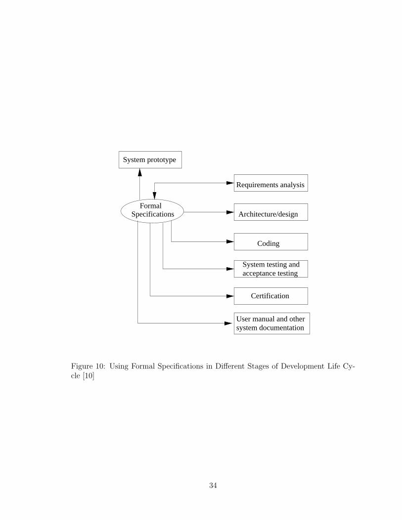
System testing andacceptance testing
User manual and othersystem documentation
System prototype
FormalSpecifications
Requirements analysis
Architecture/design
Coding
Certification
Figure 10: Using Formal Specifications in Different Stages of Development Life Cy-cle [10]
34
• The use of formal specifications and formal proofs provides a systematic, repeat-
able approach to analysis. It can also be tailored to the level of rigor appropriate
to the needs of a project.
• Formal specifications and proofs can be applied at any life cycle phase, includ-
ing early in the life cycle where better analysis approaches are currently most
needed. Detecting and fixing defects earlier in the process is far cheaper than
finding them later in the process.
• Formal specifications and proofs can be supported by computer-based tools.
This provides automation for tasks such as consistency checking and the prepa-
ration of proofs. This is an important benefit that provides an additional level
of assurance as well as reducing the cost of certain aspects of the analysis. These
tools greatly enhance the repeatability of the analysis by allowing proofs to be
re-executed.
• Formal specifications and proofs complement the existing testing approach.
They complement testing by providing a precise specification from which better
test plans can be derived.
In summary, formal methods enable defects in requirements to be detected earlier
than otherwise, and can greatly reduce the incidence of mistakes in interpreting,
formalizing, and implementing correct requirements. Furthermore, used early in the
life cycle, formal methods yield formalized statements that can be analyzed and their
consequences calculated in a repeatable manner. When used judiciously and skillfully
on suitable applications, formal methods provide compelling evidence of correctness
early enough to be useful, cheaply enough to be feasible, and on the basis of modeling
that is simple enough to be credible.
3.5 Models
Formal modeling of a system usually entails translating a description of the system
from a nonmathematical model (data-flow diagrams, object diagrams, scenarios, En-
glish text, etc.) into a formal specification, using one of several formal languages.
Formal methods tools can then be employed to logically evaluate this specification
35
to reach conclusions about the completeness and consistency of the system’s require-
ments or design.
Manual analyses (e.g., peer reviews) of the formal model are used as an effective
first check to assure the general reasonableness of the model. These are followed
by tool-based analyses, which raise the level of reliability and confidence in the sys-
tem specification even further. Formal methods analysis techniques are based on
deductive rather than inductive reasoning about system descriptions, allowing entire
classes of issues to be resolved before requirements are committed to the design and
implementation phases.
3.6 Model Checking
Model checking is a formal method widely used in computer science for verification
of concurrent systems, e.g., communication protocols. The method requires that a
system is given with a graph, which describes the system behavior in terms of states
and actions. In comparison with statistical formulas, a graph is much more trans-
parent, understandable and supports more precise specifications. Each component of
the given system can be represented with its own graph, which enables modeling of
specialties and exceptions.
Using model checking, the properties of the system are given as a set of logic
formulas. The requirements are expressed as propositions, the validity of which can
be checked in the given system. Model checking is automatic and does not need an
interaction with the user. Thus, the user can concentrate in specifying the model and
properties.
3.7 Application of Formal Method in SDLC
Formal methods techniques and tools can be applied to the specification and verifi-
cation of products from each software development life cycle (SDLC): requirements,
high-level and low-level design, and implementation.
The application of formal specifications at the requirements life cycle phase will
help ensure that the resulting software is verifiable. The addition of formal methods
will usually add a certain amount of cost to these phases while saving cost in later
36
phases and during maintenance of the work products.
The process of applying formal methods to requirements or design differs mainly
in the level of detail at which the techniques are applied. These techniques include:
writing formal specifications, internal checking (e.g., parsing and type correctness),
traceability checking, specification animation, and proof of assertions. Only a subset
of the techniques is chosen for application. This enables the project to choose a level
of verification rigor appropriate to the development team’s technical needs.
Formal methods can also be used to establish and maintain strict traceability
between system descriptions across different life cycle phases. Formal methods can
help demonstrate that requirements are correctly reflected in a subsequent design and
that design features are correctly reflected in a subsequent implementation. Formal
methods complement early development phases, which are currently less automated
and less tightly coupled to specific languages and notations, and are typically less
effectively analyzed than those of later development stages.
In general, formal methods compensate for these limitations without intruding on
the existing software development process.
3.8 Languages & Tools of Formal Methods in Tele-
communication Systems
Communications and Distributed Systems are active research topics. Two standard-
ised formal methods, SDL (Specification and Description Language, ITU-T Z.100)
and LOTOS (Language Of Temporal Ordering Specification, ISO 8807), are mainly
used as they are of most interest to industry and have good tool support.
Research has been undertaken on methods of structuring communications services.
Contributions were made to ISO on the systematisation and formalisation of the ODP
(Open Distributed Processing, ISO 10026) architecture. LOTOS continues to provide
inspiration for a variety of new applications. The EASEL project (Evaluating And
Standardising Enhanced LOTOS) has provided an international framework to make
contributions to develop the new ISO standard for assessing the technical capabilities
of E-LOTOS. The LOTOS sub-group has been developing applications in a number
of new areas including bus protocols, hardware description, object-oriented analysis
and design, Quality of Service, and telecommunications services.
37
Languages and techniques developed for protocols can also be successfully ex-
tended and exploited for hardware. Again the two main methods used in communi-
cations, SDL and LOTOS, have been applied. In the DILL project (Digital Logic in
LOTOS), LOTOS and its variants have been used to analyse and solve a variety of
design problems in constructing hardware. As a relative newcomer to the hardware
description field, LOTOS has shown its ability to make a distinctive contribution.
The application of SDL to hardware description is also relatively unusual, but has
given risen to novel techniques and tools.
Besides, standardized formal methods (LOTOS and SDL) have been used on
Rigorous Object-Oriented Analysis and Design, which reflects the important of OO
methods and the interest in sound and properly structured designs. A comprehensive
method called ROOA (Rigorous Object-Oriented Analysis) has been developed in
conjunction with the New University of Lisbon. Interestingly, the method is relatively
independent of the underlying formalism. To prove this, LOTOS-oriented and SDL-
oriented versions of ROOA have been created.
Other formal languages and tools such as Estelle, Promela/SPIN are also widely
used in a variety of application domains.
38
Chapter 4
SDL/MSC & ObjectGEODE
4.1 History
SDL [18] (Specification and Description Language) is an ITU-T (International Telecom-
munications Union - Telecommunication sector) recommendation, referenced Z.100.
The development of SDL started in 1972. A 15-member study group within telecom-
munications union ITU-T (CCITT at that time) representing several countries and
large telecom companies such as Bellcore, Ericsson, and Motorola began research on
a standard specification language for the telecommunications industry. The first ver-
sion of the language was issued in 1976. The latest versions expanded the language
considerably and simplified interfacing. Today SDL is a complete language in all
senses.
The language has been evolving since the first Z.100 Recommendation in 1980
with updates in 1984, 1988, 1992, 1996 and 1999. Object Oriented features were
included in the language in 1992, named SDL-92, which is a stable version and a
superset of SDL-88. Most popular tools now support SDL-92 features. In 1996 a few
updates were made to the language in an addendum to the SDL defined by the 1992
Z.100 standard. The addendum make SDL easier to use in an even more flexible way
by relaxing a number of rules. Object modeling and code generation in SDL was
strengthened and better supported in the latest version (SDL-2000). In particular
the data model was revised to give such features as global data and referenced data
objects. The structuring features (blocks and processes) were harmonized into an
agent concept. Support for ASN.1 was strengthened so that the use of ASN.1 modules
39
with SDL no longer requires much change.
SDL is used worldwide for the development of all kinds of complex, communicating
systems. In the telecommunications field, SDL is the language of choice for the
development of a broad range of software and hardware. Examples are 3G products,
cellular phones, switches, WAP stacks, Bluetooth devices, GPRS systems, DECT
phones, radio systems, network management platforms and network services systems.
Other strong examples are telecommunication standards like UMTS, GSM, ISDN,
V5.2, INAP etc.
Message Sequence Charts [19](MSCs) have been used informally for a long time
by ITU (former CCITT) Study Groups in their recommendations and in industry.
Their standardization was suggested at the 4th SDL Forum October 1989 in Lisbon
and agreed upon at the ITU-meeting Helsinki, June 1990. At the closing session of
the ITU study period 1989-1992 in Geneva, May 1992, the new MSC recommendation
Z.120 was approved. As a major achievement, a formal semantics for MSCs based on
process algebra has been standardized.
MSC are a widespread means for the visualization of selected system runs (traces)
within communication systems. They can be viewed as a special trace language,
which mainly concentrates on message interchange by communicating entities (such
as SDL services, processes, blocks) and their environment. A main advantage of an
MSC is its clear graphical layout, which immediately gives an intuitive understanding
of the described system behavior. The reason to standardize MSCs was to allow
systematic tool support, to facilitate the exchange between different tools, and to
ease the mapping to and from SDL specifications. Due to the standardization, the
importance of MSCs for system engineering has increased considerably.
4.2 Characteristics of SDL
SDL (Specification and Description Language) is an object-oriented, formal, and high-
level programming language, which can describe systems using graphical representa-
tions as well as textual representations. SDL is intended for the description of com-
plex, event-driven, real-time, and communicating systems. SDL is a design and imple-
mentation language dedicated to advanced technical systems (i.e., real-time systems,
distributed systems, and generic event-driven systems where parallel activities and
40
communication are involved). Typical application areas are high- and low-level tele-
com systems, aerospace systems, and distributed or highly complex mission-critical
systems.
SDL provides structuring concepts that facilitate the specification of large and/or
complex systems. An SDL system comprises four main hierarchical levels: system,
blocks, processes, and procedures. Systems described in SDL consist of many pro-
cesses running simultaneously, which communicate with each other via signals. A set
of processes can be logically grouped into a block. The dynamic behavior in an SDL
system is described in the processes. Each process is described by an extended finite
state machine (FSM). The state machines are labeled “extended” since variables and
timers can also be defined in processes.
The basic theoretical model of an SDL system consists of a set of extended finite
state machines (FSMs) that run in parallel. These machines are independent of each
other and communicate with discrete signals.
A transition in SDL from one state to another is triggered by the reception of a
signal. For each process, SDL describes the actions the process is allowed to take and
which events are expected to happen. SDL defines clear interfaces between blocks
and processes by means of a combined channel and signal route architecture. This
communication architecture with formally clear signal interfaces simplifies large team
development and ensures consistency between different parts of a system. In SDL, a
system is divided into building blocks that communicate using channels. Blocks are
composed of processes. Processes (within a block) are connected using routes. Each
process has its own infinite queue and is assumed to operate independently from
all other processes. Also, SDL processes have separate memory spaces (i.e., data is
local to a process or procedure). This is a highly important aspect that dramatically
reduces the number of deficiencies and increases robustness.
SDL defines time and timers in a clever and abstract manner. Time is an impor-
tant aspect in all real-time systems but also in most distributed systems. To measure
and control response times from other processes and systems, an SDL process can set
timers that expire within certain time periods to implement time-outs when excep-
tions occur. When an SDL timer expires, the process that started the timer receives
a notification (signal) in the same way as it receives any other signal. Actually an ex-
pired timer is treated in exactly the same way as a signal. SDL time is abstract in the
41
sense that it can be efficiently mapped to the time of the target system. This makes
it possible to simulate time in SDL models before the target system is available.
SDL accepts two ways of describing data, abstract data type (ADT) and ASN.1.
The integration of ASN.1 enables sharing of data between languages, as well as the
reuse of existing data structures.
The ADT concept used within SDL is very well suited to a specification language.
An abstract data type is a data type with no specified data structure. Instead, it
specifies a set of values, a set of operations allowed, and a set of equations that the
operations must fulfill. This approach makes it simple to map an SDL data type to
data types used in other high-level languages.
SDL has a number of advantages compared to other high-level languages and to
traditional low-level languages such as C, C++, or Java. SDL has a rich grammar
that describes behavior and is unambiguous. Therefore, it is possible to build tools for
the simulation of SDL systems and for the validation of formal characteristics, such as
deadlock avoidance. In short, this means that errors are detected at a very early stage.
SDL is graphical, and its diagrams are easily understood even by non-technicians.
This translates into greatly improved communication between system designer and
client, and ensures that the process from requirements capture to implementation is
reliable.
4.3 MSC
Scenario-based specifications such as Message Sequence Chart (MSC) are a graphical
and textual language used to show interactions between system components. The
main area of application for Message Sequence Charts is as an overview specification
of the communication behavior of real-time systems. MSC diagrams provide a clear
description of system communication in the form of message flows. The notation is
an international standard defined in ITU-T Recommendation Z.120. MSCs are often
used in combination with SDL.
A set of MSC diagrams covers partial system behavior. Each MSC diagram repre-
sents one scenario of either a typical or an exceptional exchange of messages between
system parts. It merely expresses one execution trace. A collection of Message Se-
quence Charts may be used to give a more detailed specification of a system. The
42
complete Message Sequence Chart language includes all constructs that are necessary
in order to specify the pure message flow. These language constructs are instance,
message, environment, action, timer set, timer reset, time-out, instance creation, in-
stance stop, and condition. The most fundamental constructs of MSCs are instances
and messages describing the communication events. A Message Sequence Chart con-
tains the description of the asynchronous communication between instances. The
instances would correspond to any part of the SDL specification (an SDL system, a
block or a process). The information interchange is carried out by sending messages
from one instance to another. Timer handling in MSCs encloses the setting of a
timer and a subsequent time-out (timer expiration) or the setting of a timer and a
subsequent timer reset (time supervision).
The language is particularly effective when distributed processing must be man-
aged at several interfaces. For instance, it can be used very effectively in describ-
ing basic scenarios of calls and the establishment of connections. Message Sequence
Charts may be used for requirement specification, simulation and validation, test-case
specification and documentation of real-time systems. The standardized MSC lan-
guage offers a powerful complement to SDL in describing the communication between
different blocks and processes of an SDL-system. Its graphical representation is well
suited for presenting a complex dynamic behavior in a clear and unambiguous way
that is easy to understand.
In contrast to SDL, the set of specified MSCs usually covers a partial system
behavior only since each MSC represents exactly one scenario. In all cases, the
strength of MSCs lies in the clear and intuitive description of selected system runs
whereas SDL is used for a complete system specification. MSC may represent test
purposes for the automatic generation of test cases.
4.4 ObjectGEODE
Already heavily used in the Telecom market, ObjectGeode [21] is a toolset dedicated
to analysis, design, verification and validation through simulation, code generation
and testing of real-time and distributed applications. Such applications are used
in many fields such as telecommunications, aerospace, defense, automotive, process
43
control or medical systems. ObjectGeode supports a coherent integration of comple-
mentary object-oriented and real-time approaches based on the UML, SDL and MSC
standards languages.
ObjectGEODE helps software designers get the design right the first time through
rapid prototyping, verification, and validation techniques. Rapid prototyping verifies
that the system works as expected in a limited number of nominal cases. The aim of
verification is to determine whether the SDL model will run reliably. ObjectGEODE’s
powerful code generator allows software architecture exploration. The generated code
is readable and fully executable.
The ObjectGEODE toolset provides the tools required at every step of the soft-
ware engineering process: Modeling tools for analysis and design such as UML Class
Diagram Editor, MSC Editor, UML Statechart Editor, SDL Editor and SDL&MSC
Checker. Simulation tools such as SDL&MSC Interactive Simulator and SDL&MSC
Exhaustive Simulator. Targeting tools such as UML C++ Code generator, SDL C
Code Generator, SDL C Run-Time Libraries. Testing tool such as DesignTracer.
The analysis phase of the ObjectGeode process begins with the construction of a
UML object model of the system to be developed. A use case model is built to specify
the requirements regarding the system dynamics. The MSC language can be used for
identifying the scenarios corresponding to use cases. The architecture of the system
is designed using the SDL concepts of system, block and process that structure the
system through composition links. The various components of the system architec-
ture communicate using signals (carried by channels). They are refined iteratively
reinforcing the modularity of the architecture. At the last iteration level, processes
are identified: an SDL process is an active class with its own thread of control and is
described by a state machine. Once a system has been partially or completely mod-
eled, interactive debugging of the concurrent parts of the system are easily performed
using the ObjectGeode Simulator, SDL tracking, MSC tracking. Model verification
is achieved by enabling the developer to run the model automatically. Errors such as
deadlocks, live locks or dead code are highlighted. The C source code is generated
from the SDL model according to the deployment defined by the designer.
44
Chapter 5
System Model
5.1 Function Requirement
Interworking between SIP and H.323 is based on H.323 version 2.0 and SIP version
2.0. Since both operate over IP (Internet Protocol) and use RTP for transferring
real-time audio/video data, the goal of interworking between SIP and H.323 just
requires transparent translation of signaling and session descriptions between the SIP
and H.323 entities. The component providing this translation of SIP-H.323 is called:
interworking function (IWF).
When the IWF receives call signaling messages from an H.323 entity, it performs
the necessary translation, sends the corresponding equivalent messages to the SIP
entity on the SIP side of the IWF and vice versa. The IWF provides signaling
translation for all phases of a call.
If the H.323 gatekeeper and the SIP server exist, the IWF will register itself with
the H.323 gatekeeper (GK) and the SIP server, and support the address resolution
schemes of both H.323 and SIP. In H.323, registration is the process by which an
endpoint joins a zone, and informs the Gatekeeper of its transport address and alias
addresses. Registration will occur before any calls are attempted. An endpoint will
also send a Registration Request (RRQ) message to a Gatekeeper. The Gatekeeper
will respond with either a Registration Confirmation (RCF) or a Registration Reject
(RRJ) message. In SIP, the REGISTER request allows a client to let a proxy or
redirect server know its current address.
If the H.323 gatekeeper and SIP server do not exist, the IWF will have the look-up
45
tables for SIP and H.323 address resolution.
In general, the IWF will contain the functions such as: call sequence mapping,
address resolution, terminal capability transactions, opening and closing of media
channels, mapping media algorithms for H.323 and SIP network, call resource reser-
vation and release, ability to provide the state of a call, call state machine, mid call
signal processing, and service interoperability logic. No media processing will be done
within the IWF. It is assumed that the same transport protocols (e.g., RTP, TCP,
UDP, etc.) will be used in both H.323 and SIP networks for carrying media.
Interworking between SIP and H.323 may involve in two types of Endpoints: H.323
Terminal and SIP User Agents. Other entities may include SIP-H.323 Interworking
Function (IWF), H.323 Gatekeeper (GK), and SIP Server.
SIP-H.323 IWF can be architected in various ways. This may include coexistence
of H.323 gatekeeper or SIP servers with IWF. In case where SIP server or H.323
gatekeeper coexists with IWF, they will still be treated as separate logical entities.
All call flow diagrams will therefore show IWF as a separate logical entity and include
call message mapping between IWF and H.323 gatekeeper/SIP server.
In the following sections, we will focus on two configurations for the call scenarios.
Basic configuration contains H.323 EP, IWF, and SIP EP. H.323 GK and SIP server
are included together in advanced configuration. Other configurations, such as the
existence of only one H.323 GK or one SIP server with IWF, are to be considered
as a combination of the above two configurations. The hierarchy of multiple H.323
gatekeepers or multiple SIP servers is out of scope of our topic. However, such issues
can be studied further.
5.2 Requirement Analysis
We apply UML to analyze the function modules of each component. The following
are use cases for each component of interworking.
Figure 11 shows use case diagram for H.323 endpoint. H.323 EP should have
some basic modules. RAS module is used to register with H.323 gatekeeper, and
acquire the address resolution from H.323 gatekeeper. Q.931 module is for H.225.0
call signaling to establish a connection between two H.323 endpoints. H.245 control
module is for capability exchange, master-slave determination, opening and closing
46
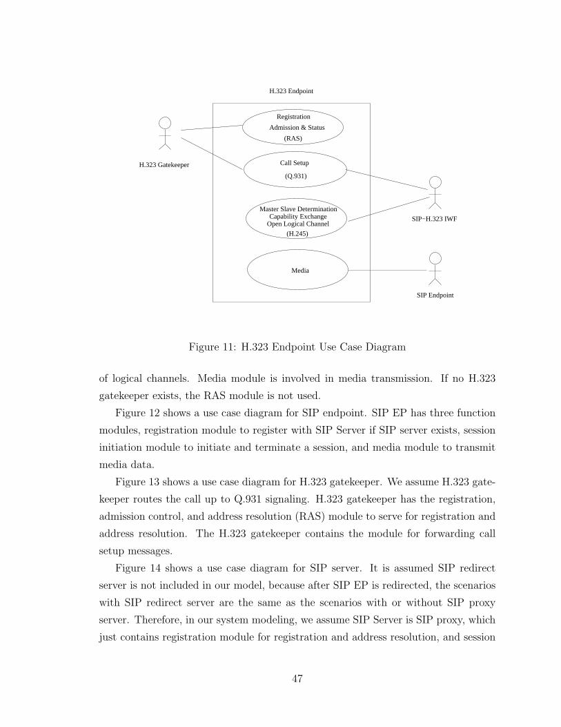
Registration
Admission & Status
(RAS)
(Q.931)
Call Setup
(H.245)
Master Slave DeterminationCapability Exchange
Open Logical ChannelSIP−H.323 IWF
Media
SIP Endpoint
H.323 Gatekeeper
H.323 Endpoint
Figure 11: H.323 Endpoint Use Case Diagram
of logical channels. Media module is involved in media transmission. If no H.323
gatekeeper exists, the RAS module is not used.
Figure 12 shows a use case diagram for SIP endpoint. SIP EP has three function
modules, registration module to register with SIP Server if SIP server exists, session
initiation module to initiate and terminate a session, and media module to transmit
media data.
Figure 13 shows a use case diagram for H.323 gatekeeper. We assume H.323 gate-
keeper routes the call up to Q.931 signaling. H.323 gatekeeper has the registration,
admission control, and address resolution (RAS) module to serve for registration and
address resolution. The H.323 gatekeeper contains the module for forwarding call
setup messages.
Figure 14 shows a use case diagram for SIP server. It is assumed SIP redirect
server is not included in our model, because after SIP EP is redirected, the scenarios
with SIP redirect server are the same as the scenarios with or without SIP proxy
server. Therefore, in our system modeling, we assume SIP Server is SIP proxy, which
just contains registration module for registration and address resolution, and session
47
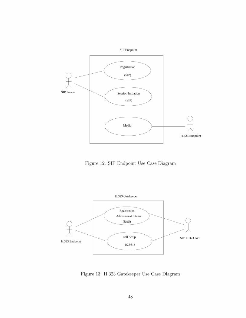
Registration
(SIP)
Session Initiation
(SIP)
Media
SIP Endpoint
SIP Server
H.323 Endpoint
Figure 12: SIP Endpoint Use Case Diagram
Registration
Admission & Status
(RAS)
Call Setup
(Q.931)H.323 Endpoint
SIP−H.323 IWF
H.323 Gatekeeper
Figure 13: H.323 Gatekeeper Use Case Diagram
48
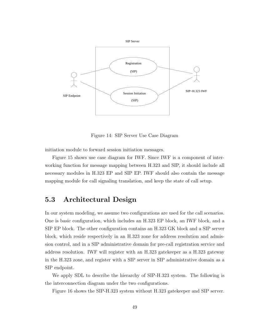
Session Initiation
(SIP)
Registration
(SIP)
SIP Endpoint
SIP−H.323 IWF
SIP Server
Figure 14: SIP Server Use Case Diagram
initiation module to forward session initiation messages.
Figure 15 shows use case diagram for IWF. Since IWF is a component of inter-
working function for message mapping between H.323 and SIP, it should include all
necessary modules in H.323 EP and SIP EP. IWF should also contain the message
mapping module for call signaling translation, and keep the state of call setup.
5.3 Architectural Design
In our system modeling, we assume two configurations are used for the call scenarios.
One is basic configuration, which includes an H.323 EP block, an IWF block, and a
SIP EP block. The other configuration contains an H.323 GK block and a SIP server
block, which reside respectively in an H.323 zone for address resolution and admis-
sion control, and in a SIP administrative domain for pre-call registration service and
address resolution. IWF will register with an H.323 gatekeeper as a H.323 gateway
in the H.323 zone, and register with a SIP server in SIP administrative domain as a
SIP endpoint.
We apply SDL to describe the hierarchy of SIP-H.323 system. The following is
the interconnection diagram under the two configurations.
Figure 16 shows the SIP-H.323 system without H.323 gatekeeper and SIP server.
49
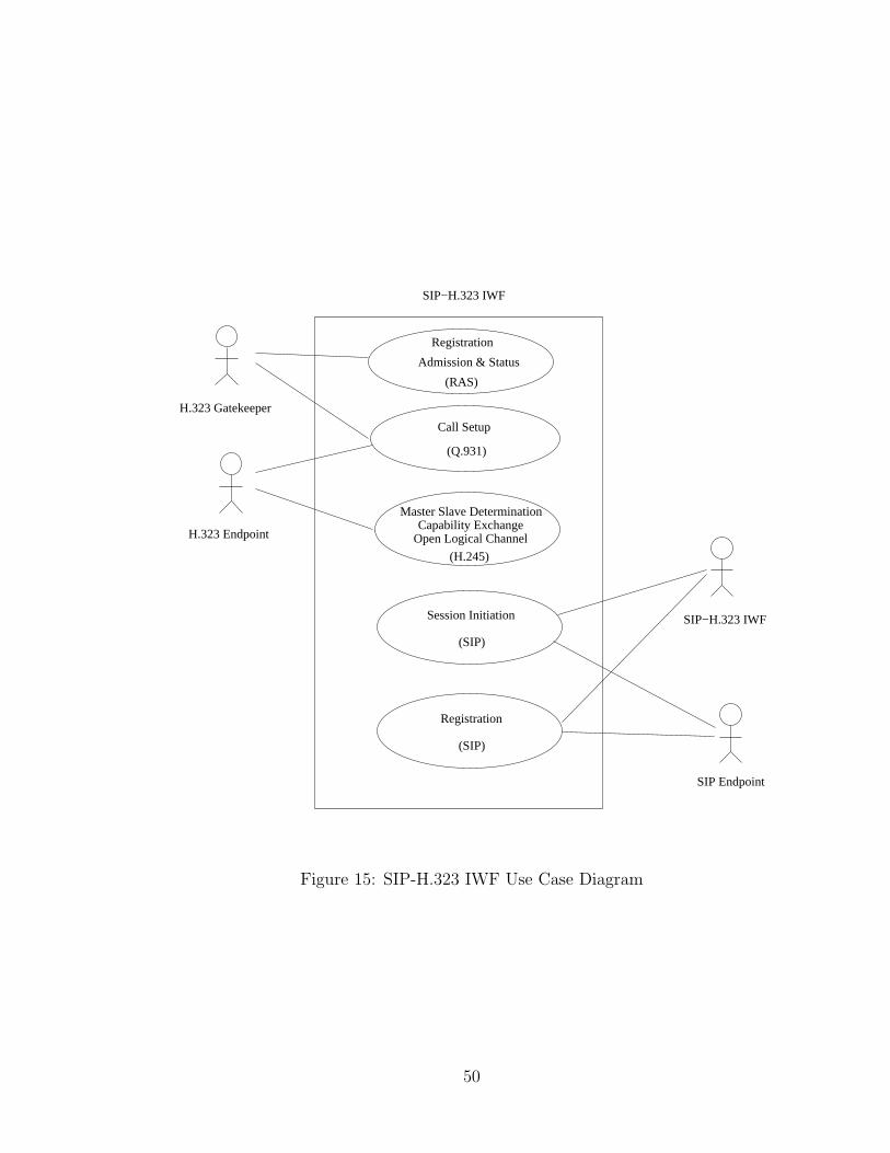
Registration
Admission & Status
(RAS)
(Q.931)
Call Setup
(H.245)
Master Slave DeterminationCapability Exchange
Open Logical Channel
Session Initiation
(SIP)
SIP−H.323 IWF
(SIP)
Registration
H.323 Gatekeeper
SIP−H.323 IWF
SIP Endpoint
H.323 Endpoint
Figure 15: SIP-H.323 IWF Use Case Diagram
50
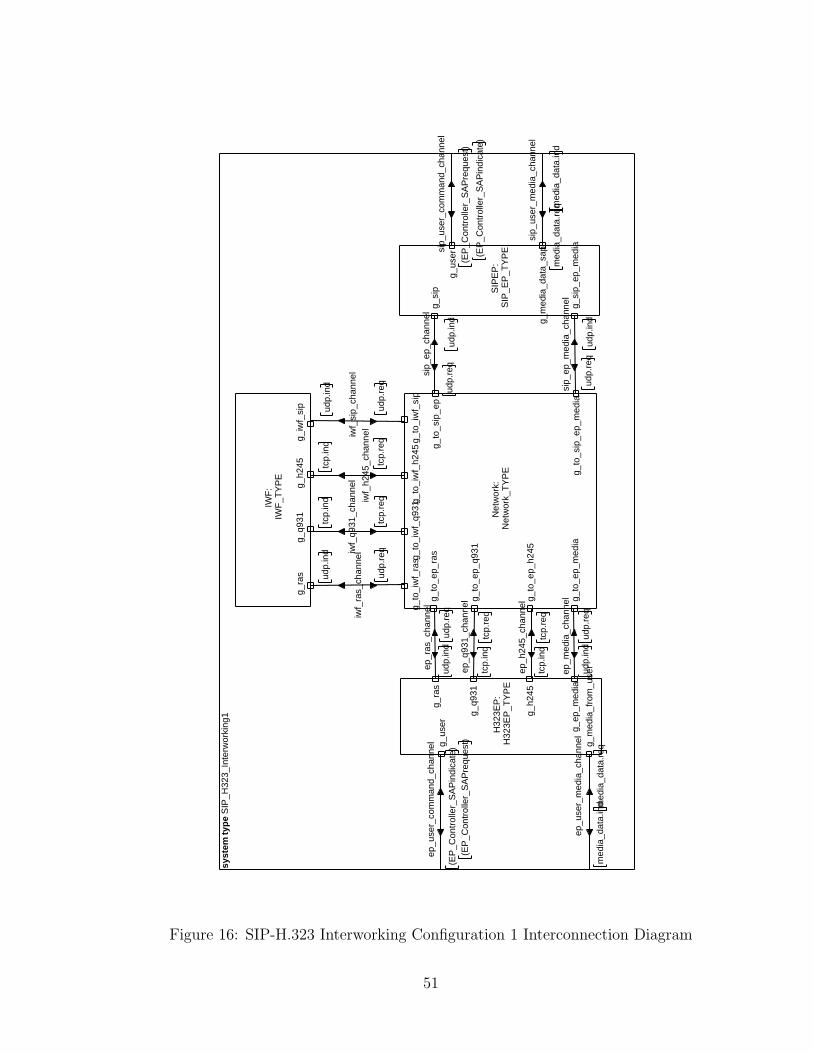
syst
em t
ype
SIP
_H32
3_In
terw
orki
ng1
ep_r
as_c
hann
el
udp.
req
udp.
ind
ep_q
931_
chan
nel
tcp.
req
tcp.
ind
ep_h
245_
chan
nel
tcp.
req
tcp.
ind
ep_m
edia
_cha
nnel
udp.
req
udp.
ind
sip_
ep_c
hann
el
udp.
ind
udp.
req
sip_
ep_m
edia
_cha
nnel
udp.
ind
udp.
req
iwf_
ras_
chan
nel
udp.
req
udp.
ind iw
f_q9
31_c
hann
el
tcp.
req
tcp.
ind iw
f_h2
45_c
hann
el
tcp.
ind
tcp.
req
iwf_
sip_
chan
nel
udp.
ind
udp.
req
ep_u
ser_
med
ia_c
hann
el
med
ia_d
ata.
ind m
edia
_dat
a.re
q
ep_u
ser_
com
man
d_ch
anne
l
(EP
_Con
trol
ler_
SA
Pre
ques
t)(E
P_C
ontr
olle
r_S
AP
indi
cate
)
sip_
user
_med
ia_c
hann
el
med
ia_d
ata.
ind
med
ia_d
ata.
req
sip_
user
_com
man
d_ch
anne
l
(EP
_Con
trol
ler_
SA
Pin
dica
te)
(EP
_Con
trol
ler_
SA
Pre
ques
t)
Net
wor
k:N
etw
ork_
TY
PE
g_to
_ep_
q931
g_to
_ep_
ras
g_to
_ep_
h245
g_to
_ep_
med
ia
g_to
_iw
f_ra
sg_t
o_iw
f_q9
31g_
to_i
wf_
h245
g_to
_iw
f_si
p
g_to
_sip
_ep
g_to
_sip
_ep_
med
ia
H32
3EP
:H
323E
P_T
YP
E
g_ra
s
g_q9
31
g_h2
45
g_ep
_med
ia
g_m
edia
_fro
m_u
ser
g_us
er
SIP
EP
:S
IP_E
P_T
YP
E
g_si
p
g_si
p_ep
_med
ia
g_m
edia
_dat
a_sa
p
g_us
er
IWF
:IW
F_T
YP
E
g_ra
sg_
q931
g_h2
45g_
iwf_
sip
Figure 16: SIP-H.323 Interworking Configuration 1 Interconnection Diagram
51
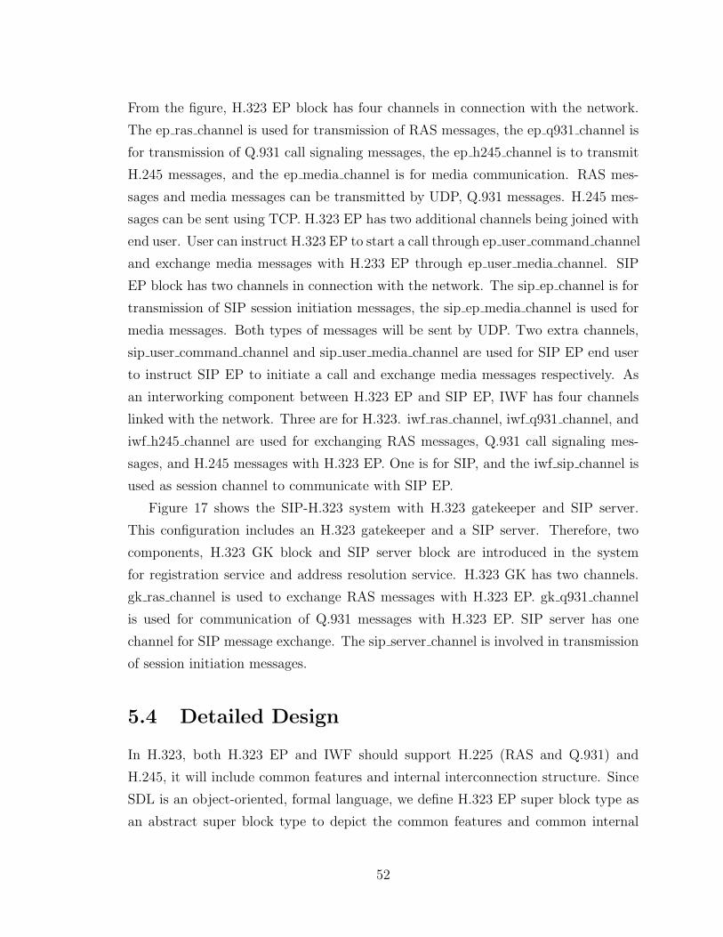
From the figure, H.323 EP block has four channels in connection with the network.
The ep ras channel is used for transmission of RAS messages, the ep q931 channel is
for transmission of Q.931 call signaling messages, the ep h245 channel is to transmit
H.245 messages, and the ep media channel is for media communication. RAS mes-
sages and media messages can be transmitted by UDP, Q.931 messages. H.245 mes-
sages can be sent using TCP. H.323 EP has two additional channels being joined with
end user. User can instruct H.323 EP to start a call through ep user command channel
and exchange media messages with H.233 EP through ep user media channel. SIP
EP block has two channels in connection with the network. The sip ep channel is for
transmission of SIP session initiation messages, the sip ep media channel is used for
media messages. Both types of messages will be sent by UDP. Two extra channels,
sip user command channel and sip user media channel are used for SIP EP end user
to instruct SIP EP to initiate a call and exchange media messages respectively. As
an interworking component between H.323 EP and SIP EP, IWF has four channels
linked with the network. Three are for H.323. iwf ras channel, iwf q931 channel, and
iwf h245 channel are used for exchanging RAS messages, Q.931 call signaling mes-
sages, and H.245 messages with H.323 EP. One is for SIP, and the iwf sip channel is
used as session channel to communicate with SIP EP.
Figure 17 shows the SIP-H.323 system with H.323 gatekeeper and SIP server.
This configuration includes an H.323 gatekeeper and a SIP server. Therefore, two
components, H.323 GK block and SIP server block are introduced in the system
for registration service and address resolution service. H.323 GK has two channels.
gk ras channel is used to exchange RAS messages with H.323 EP. gk q931 channel
is used for communication of Q.931 messages with H.323 EP. SIP server has one
channel for SIP message exchange. The sip server channel is involved in transmission
of session initiation messages.
5.4 Detailed Design
In H.323, both H.323 EP and IWF should support H.225 (RAS and Q.931) and
H.245, it will include common features and internal interconnection structure. Since
SDL is an object-oriented, formal language, we define H.323 EP super block type as
an abstract super block type to depict the common features and common internal
52
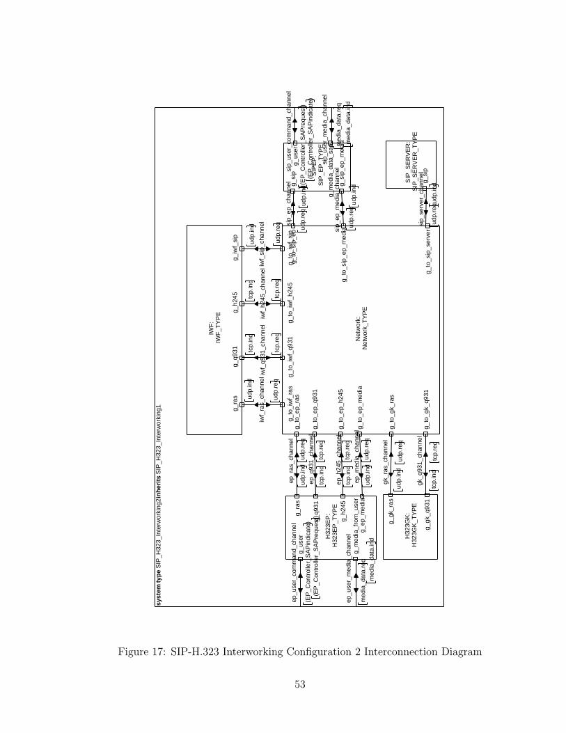
syst
em t
ype
SIP
_H32
3_In
terw
orki
ng2
inh
erit
s S
IP_H
323_
Inte
rwor
king
1
gk_r
as_c
hann
el
udp.
req
udp.
ind
gk_q
931_
chan
nel
tcp.
req
tcp.
ind
sip_
serv
er_c
hann
el
udp.
ind
udp.
req
ep_u
ser_
com
man
d_ch
anne
l
(EP
_Con
trol
ler_
SA
Pre
ques
t)(E
P_C
ontr
olle
r_S
AP
indi
cate
)
ep_u
ser_
med
ia_c
hann
el
med
ia_d
ata.
ind
med
ia_d
ata.
req
ep_r
as_c
hann
el
udp.
req
udp.
ind
ep_q
931_
chan
nel
tcp.
req
tcp.
ind
ep_h
245_
chan
nel
tcp.
req
tcp.
ind
ep_m
edia
_cha
nnel
udp.
req
udp.
ind
iwf_
ras_
chan
nel
udp.
req
udp.
ind
iwf_
q931
_cha
nnel
tcp.
req
tcp.
ind
iwf_
h245
_cha
nnel
tcp.
ind
tcp.
req
iwf_
sip_
chan
nel
udp.
ind
udp.
req si
p_ep
_cha
nnel
udp.
ind
udp.
req
sip_
ep_m
edia
_cha
nnel
udp.
ind
udp.
req
sip_
user
_com
man
d_ch
anne
l
(EP
_Con
trol
ler_
SA
Pin
dica
te)
(EP
_Con
trol
ler_
SA
Pre
ques
t)
sip_
user
_med
ia_c
hann
el
med
ia_d
ata.
ind
med
ia_d
ata.
req
IWF
:IW
F_T
YP
E
g_ra
sg_
q931
g_h2
45g_
iwf_
sip
H32
3EP
:H
323E
P_T
YP
E
g_ra
s
g_q9
31
g_h2
45
g_ep
_med
ia
g_us
er
g_m
edia
_fro
m_u
ser
H32
3GK
:H
323G
K_T
YP
E
g_gk
_ras
g_gk
_q93
1
Net
wor
k:N
etw
ork_
TY
PE
g_to
_gk_
q931
g_to
_gk_
ras
g_to
_sip
_ser
ver
g_to
_ep_
ras
g_to
_ep_
q931
g_to
_ep_
h245
g_to
_ep_
med
ia
g_to
_iw
f_ra
sg_
to_i
wf_
q931
g_to
_iw
f_h2
45g_
to_i
wf_
sip
g_to
_sip
_ep
g_to
_sip
_ep_
med
ia
SIP
EP
:S
IP_E
P_T
YP
E
g_si
p
g_si
p_ep
_med
ia
g_us
er
g_m
edia
_dat
a_sa
p
SIP
_SE
RV
ER
:S
IP_S
ER
VE
R_T
YP
E
g_si
p
Figure 17: SIP-H.323 Interworking Configuration 2 Interconnection Diagram
53
H.323_SUPEREP
SIP−H.323 IWFH.323 EP
Figure 18: Inheritance
interconnection structure of H.323 EP and IWF. H.323 EP block and IWF block
can inherit from H.323 EP super block type. Both can extend its own feature and
structure by adding new processes and new channels. Also, their internal behavior
can also be extended by redefining the behavior of each internal process in order to
replace the behavior of their super block.
Figure 18 shows the relationship of inheritance.
5.4.1 H.323 Endpoint Super Block Type
Figure 19 depicts the internal structure of H.323 EP Super Block type. Figure 20
depicts H.323 EP Super Block type by SDL. H323EP SUPERTYPE includes com-
mon functions module for both H.323 EP and IWF, such as H.225 (RAS, Q.931), and
H.245. From the figure, we find H323EP SUPERTYPE has 12 processes. RAS and
RAS Deliver processes are responsible for transmission of RAS messages. The RAS
process mainly focuses on receiving RAS commands from the EP Controller process
and timer control since RAS messages, being carried over UDP, may be subject to
loss, while the RAS Deliver process mainly focuses on forwarding RAS messages to the
network. The Q931 and Q931 deliver processes are responsible for collecting Q.931
commands and their parameters from the EP Controller. The Q931 process mainly
focuses on Q931 message flows, and returns the result back to EP Controller, while
54
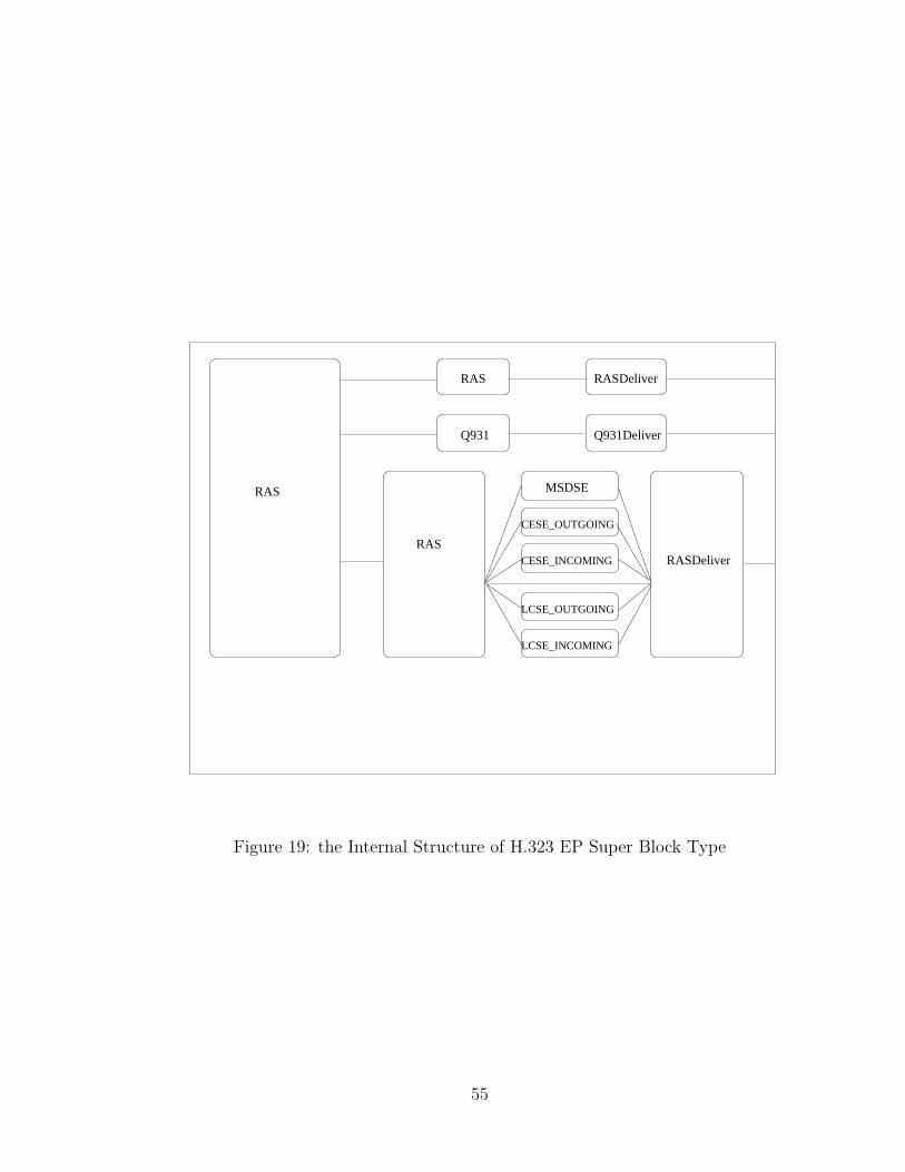
RAS RASDeliver
RASRASDeliver
RAS
Q931 Q931Deliver
CESE_OUTGOING
MSDSE
LCSE_INCOMING
LCSE_OUTGOING
CESE_INCOMING
Figure 19: the Internal Structure of H.323 EP Super Block Type
55
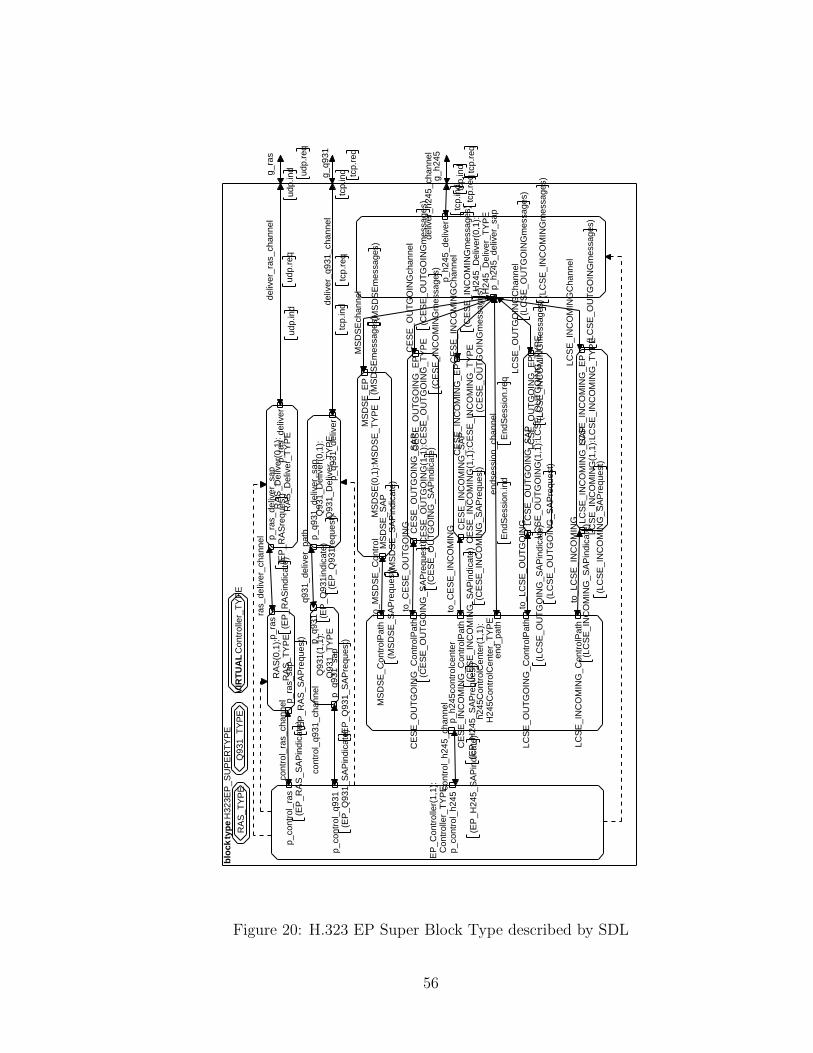
blo
ck t
ype
H32
3EP
_SU
PE
RT
YP
E
g_ra
s
udp.
ind ud
p.re
q
g_q9
31
tcp.
ind tcp.
req
g_h2
45
tcp.
ind tcp.
req
cont
rol_
h245
_cha
nnel
(EP
_H24
5_S
AP
requ
est)
(EP
_H24
5_S
AP
indi
cate
)
to_M
SD
SE
_Con
trol
(MS
DS
E_S
AP
requ
est) (M
SD
SE
_SA
Pin
dica
te)
to_C
ES
E_O
UT
GO
ING
(CE
SE
_OU
TG
OIN
G_S
AP
requ
est)
(CE
SE
_OU
TG
OIN
G_S
AP
indi
cate
)
to_C
ES
E_I
NC
OM
ING
(CE
SE
_IN
CO
MIN
G_S
AP
requ
est)
(CE
SE
_IN
CO
MIN
G_S
AP
indi
cate
)
to_L
CS
E_O
UT
GO
ING
(LC
SE
_OU
TG
OIN
G_S
AP
requ
est)
(LC
SE
_OU
TG
OIN
G_S
AP
indi
cate
)
to_L
CS
E_I
NC
OM
ING
(LC
SE
_IN
CO
MIN
G_S
AP
requ
est)
(LC
SE
_IN
CO
MIN
G_S
AP
indi
cate
)
ras_
deliv
er_c
hann
el
(EP
_RA
Sre
ques
t)(E
P_R
AS
indi
cate
)
q931
_del
iver
_pat
h
(EP
_Q93
1req
uest
)(E
P_Q
931i
ndic
ate)
deliv
er_r
as_c
hann
el
udp.
req
udp.
ind
deliv
er_q
931_
chan
nel
tcp.
req
tcp.
ind
deliv
er_h
245_
chan
nel
tcp.
req
tcp.
ind
MS
DS
Ech
anne
l
(MS
DS
Em
essa
ges)
(MS
DS
Em
essa
ges)
CE
SE
_OU
TG
OIN
Gch
anne
l
(CE
SE
_OU
TG
OIN
Gm
essa
ges)
(CE
SE
_IN
CO
MIN
Gm
essa
ges)
CE
SE
_IN
CO
MIN
GC
hann
el
(CE
SE
_IN
CO
MIN
Gm
essa
ges)
(CE
SE
_OU
TG
OIN
Gm
essa
ges)
LCS
E_O
UT
GO
ING
Cha
nnel
(LC
SE
_OU
TG
OIN
Gm
essa
ges)
(LC
SE
_IN
CO
MIN
Gm
essa
ges)
LCS
E_I
NC
OM
ING
Cha
nnel
(LC
SE
_IN
CO
MIN
Gm
essa
ges)
(LC
SE
_OU
TG
OIN
Gm
essa
ges)
cont
rol_
ras_
chan
nel
(EP
_RA
S_S
AP
requ
est)
(EP
_RA
S_S
AP
indi
cate
)
cont
rol_
q931
_cha
nnel
(EP
_Q93
1_S
AP
requ
est)
(EP
_Q93
1_S
AP
indi
cate
)
ends
essi
on_c
hann
elE
ndS
essi
on.r
eqE
ndS
essi
on.in
d
RA
S_T
YP
EQ
931_
TY
PE
VIR
TU
AL
Con
trol
ler_
TY
PE
EP
_Con
trol
ler(
1,1)
:C
ontr
olle
r_T
YP
E
p_co
ntro
l_ra
s
p_co
ntro
l_q9
31
p_co
ntro
l_h2
45
RA
S(0
,1):
RA
S_T
YP
Ep_ra
s
p_ra
s_sa
p
Q93
1(1,
1):
Q93
1_T
YP
E
p_q9
31
p_q9
31_s
ap
h245
Con
trol
Cen
ter(
1,1)
:H
245C
ontr
olC
ente
r_T
YP
E
MS
DS
E_C
ontr
olP
ath
CE
SE
_OU
TG
OIN
G_C
ontr
olP
ath
CE
SE
_IN
CO
MIN
G_C
ontr
olP
ath
LCS
E_O
UT
GO
ING
_Con
trol
Pat
h
LCS
E_I
NC
OM
ING
_Con
trol
Pat
h
p_h2
45co
ntro
lcen
ter
end_
path
LCS
E_O
UT
GO
ING
(1,1
):LC
SE
_OU
TG
OIN
G_T
YP
ELC
SE
_OU
TG
OIN
G_S
AP
LCS
E_O
UT
GO
ING
_EP
MS
DS
E(0
,1):
MS
DS
E_T
YP
EM
SD
SE
_SA
P
MS
DS
E_E
P
CE
SE
_OU
TG
OIN
G(1
,1):
CE
SE
_OU
TG
OIN
G_T
YP
EC
ES
E_O
UT
GO
ING
_SA
PC
ES
E_O
UT
GO
ING
_EP
CE
SE
_IN
CO
MIN
G(1
,1):
CE
SE
_IN
CO
MIN
G_T
YP
EC
ES
E_I
NC
OM
ING
_SA
PC
ES
E_I
NC
OM
ING
_EP
LCS
E_I
NC
OM
ING
(1,1
):LC
SE
_IN
CO
MIN
G_T
YP
ELC
SE
_IN
CO
MIN
G_S
AP
LCS
E_I
NC
OM
ING
_EP
RA
S_D
eliv
er(0
,1):
RA
S_D
eliv
er_T
YP
E
p_ra
s_de
liver
_sap
p_ra
s_de
liver
Q93
1_D
eliv
er(0
,1):
Q93
1_D
eliv
er_T
YP
E
p_q9
31_d
eliv
er_s
ap
p_q9
31_d
eliv
er
H24
5_D
eliv
er(0
,1):
H24
5_D
eliv
er_T
YP
Ep_
h245
_del
iver
_sap
p_h2
45_d
eliv
er
Figure 20: H.323 EP Super Block Type described by SDL
56
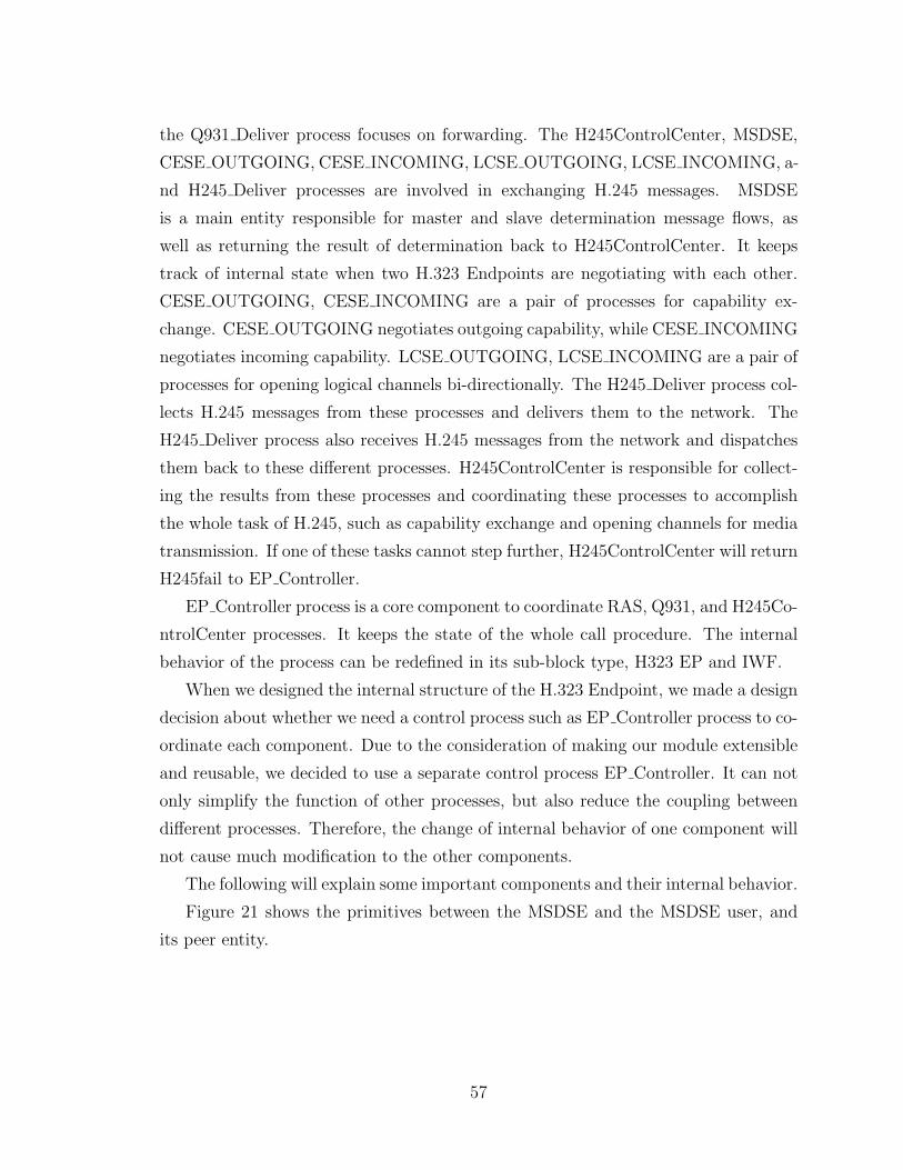
the Q931 Deliver process focuses on forwarding. The H245ControlCenter, MSDSE,
CESE OUTGOING, CESE INCOMING, LCSE OUTGOING, LCSE INCOMING, a-
nd H245 Deliver processes are involved in exchanging H.245 messages. MSDSE
is a main entity responsible for master and slave determination message flows, as
well as returning the result of determination back to H245ControlCenter. It keeps
track of internal state when two H.323 Endpoints are negotiating with each other.
CESE OUTGOING, CESE INCOMING are a pair of processes for capability ex-
change. CESE OUTGOING negotiates outgoing capability, while CESE INCOMING
negotiates incoming capability. LCSE OUTGOING, LCSE INCOMING are a pair of
processes for opening logical channels bi-directionally. The H245 Deliver process col-
lects H.245 messages from these processes and delivers them to the network. The
H245 Deliver process also receives H.245 messages from the network and dispatches
them back to these different processes. H245ControlCenter is responsible for collect-
ing the results from these processes and coordinating these processes to accomplish
the whole task of H.245, such as capability exchange and opening channels for media
transmission. If one of these tasks cannot step further, H245ControlCenter will return
H245fail to EP Controller.
EP Controller process is a core component to coordinate RAS, Q931, and H245Co-
ntrolCenter processes. It keeps the state of the whole call procedure. The internal
behavior of the process can be redefined in its sub-block type, H323 EP and IWF.
When we designed the internal structure of the H.323 Endpoint, we made a design
decision about whether we need a control process such as EP Controller process to co-
ordinate each component. Due to the consideration of making our module extensible
and reusable, we decided to use a separate control process EP Controller. It can not
only simplify the function of other processes, but also reduce the coupling between
different processes. Therefore, the change of internal behavior of one component will
not cause much modification to the other components.
The following will explain some important components and their internal behavior.
Figure 21 shows the primitives between the MSDSE and the MSDSE user, and
its peer entity.
57
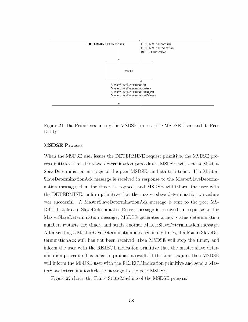
MSDSE
DETERMINE.confirmDETERMINE.indicationREJECT.indication
MasterSlaveDeterminationMasterSlaveDeterminationAckMasterSlaveDeterminationRejectMasterSlaveDeterminationRelease
DETERMINATION.request
Figure 21: the Primitives among the MSDSE process, the MSDSE User, and its PeerEntity
MSDSE Process
When the MSDSE user issues the DETERMINE.request primitive, the MSDSE pro-
cess initiates a master slave determination procedure. MSDSE will send a Master-
SlaveDetermination message to the peer MSDSE, and starts a timer. If a Master-
SlaveDeterminationAck message is received in response to the MasterSlaveDetermi-
nation message, then the timer is stopped, and MSDSE will inform the user with
the DETERMINE.confirm primitive that the master slave determination procedure
was successful. A MasterSlaveDeterminationAck message is sent to the peer MS-
DSE. If a MasterSlaveDeterminationReject message is received in response to the
MasterSlaveDetermination message, MSDSE generates a new status determination
number, restarts the timer, and sends another MasterSlaveDetermination message.
After sending a MasterSlaveDetermination message many times, if a MasterSlaveDe-
terminationAck still has not been received, then MSDSE will stop the timer, and
inform the user with the REJECT.indication primitive that the master slave deter-
mination procedure has failed to produce a result. If the timer expires then MSDSE
will inform the MSDSE user with the REJECT.indication primitive and send a Mas-
terSlaveDeterminationRelease message to the peer MSDSE.
Figure 22 shows the Finite State Machine of the MSDSE process.
58
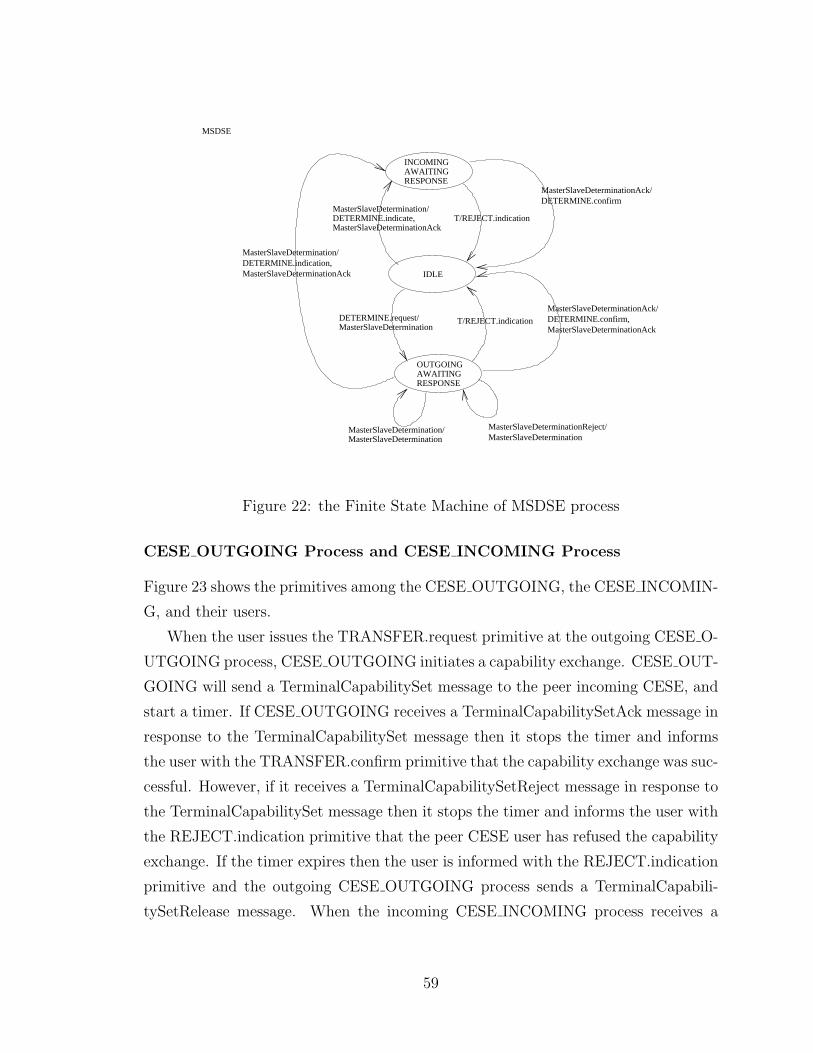
MSDSE
RESPONSEAWAITINGINCOMING
IDLE
OUTGOINGAWAITINGRESPONSE
MasterSlaveDetermination/DETERMINE.indicate,MasterSlaveDeterminationAck
MasterSlaveDeterminationDETERMINE.request/
T/REJECT.indication
T/REJECT.indication
MasterSlaveDetermination/DETERMINE.indication,MasterSlaveDeterminationAck
MasterSlaveDeterminationAck/DETERMINE.confirm
MasterSlaveDeterminationAck/DETERMINE.confirm,MasterSlaveDeterminationAck
MasterSlaveDetermination/MasterSlaveDetermination
MasterSlaveDeterminationReject/MasterSlaveDetermination
Figure 22: the Finite State Machine of MSDSE process
CESE OUTGOING Process and CESE INCOMING Process
Figure 23 shows the primitives among the CESE OUTGOING, the CESE INCOMIN-
G, and their users.
When the user issues the TRANSFER.request primitive at the outgoing CESE O-
UTGOING process, CESE OUTGOING initiates a capability exchange. CESE OUT-
GOING will send a TerminalCapabilitySet message to the peer incoming CESE, and
start a timer. If CESE OUTGOING receives a TerminalCapabilitySetAck message in
response to the TerminalCapabilitySet message then it stops the timer and informs
the user with the TRANSFER.confirm primitive that the capability exchange was suc-
cessful. However, if it receives a TerminalCapabilitySetReject message in response to
the TerminalCapabilitySet message then it stops the timer and informs the user with
the REJECT.indication primitive that the peer CESE user has refused the capability
exchange. If the timer expires then the user is informed with the REJECT.indication
primitive and the outgoing CESE OUTGOING process sends a TerminalCapabili-
tySetRelease message. When the incoming CESE INCOMING process receives a
59
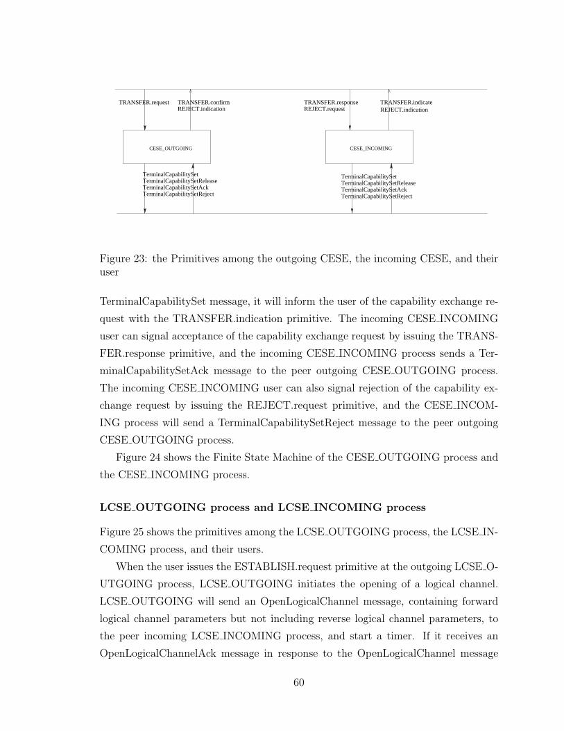
TerminalCapabilitySetTerminalCapabilitySetReleaseTerminalCapabilitySetAckTerminalCapabilitySetReject
CESE_OUTGOING
TerminalCapabilitySetTerminalCapabilitySetReleaseTerminalCapabilitySetAckTerminalCapabilitySetReject
TRANSFER.request TRANSFER.confirmREJECT.indication
TRANSFER.responseREJECT.request
TRANSFER.indicateREJECT.indication
CESE_INCOMING
Figure 23: the Primitives among the outgoing CESE, the incoming CESE, and theiruser
TerminalCapabilitySet message, it will inform the user of the capability exchange re-
quest with the TRANSFER.indication primitive. The incoming CESE INCOMING
user can signal acceptance of the capability exchange request by issuing the TRANS-
FER.response primitive, and the incoming CESE INCOMING process sends a Ter-
minalCapabilitySetAck message to the peer outgoing CESE OUTGOING process.
The incoming CESE INCOMING user can also signal rejection of the capability ex-
change request by issuing the REJECT.request primitive, and the CESE INCOM-
ING process will send a TerminalCapabilitySetReject message to the peer outgoing
CESE OUTGOING process.
Figure 24 shows the Finite State Machine of the CESE OUTGOING process and
the CESE INCOMING process.
LCSE OUTGOING process and LCSE INCOMING process
Figure 25 shows the primitives among the LCSE OUTGOING process, the LCSE IN-
COMING process, and their users.
When the user issues the ESTABLISH.request primitive at the outgoing LCSE O-
UTGOING process, LCSE OUTGOING initiates the opening of a logical channel.
LCSE OUTGOING will send an OpenLogicalChannel message, containing forward
logical channel parameters but not including reverse logical channel parameters, to
the peer incoming LCSE INCOMING process, and start a timer. If it receives an
OpenLogicalChannelAck message in response to the OpenLogicalChannel message
60
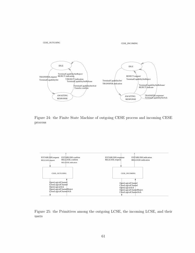
CESE_OUTGOING CESE_INCOMING
IDLE
TRANSFER.request/
TerminalCapabilitySet
RESPONSE
TerminalCapabilitySetReject/REJECT.indication,
T/REJECT.indicationTerminalCapabilitySetRelease
TerminalCapabilitySetAck/Transfer.confirm
AWAITING
RESPONSE
AWAITING
IDLE
TerminalCapabilitySetAckTRANSFER.response/
TerminalCapabilitySet/
TRANSFER.indication
REJECT.request/
TerminalCapabilitySetReject
TerminalCapabilitySetRelease/REJECT.indicate
Figure 24: the Finite State Machine of outgoing CESE process and incoming CESEprocess
CESE_OUTGOING CESE_INCOMING
ESTABLISH.requestRELEASE.request
ESTABLISH.confirmRELEASE.confirmRELEASE.indication
ESTABLISH.responseRELEASE.request
ESTABLISH.indicationRELEASE.indication
OpenLogicalChannelCloseLogicalChannelOpenLogicalAckOpenLogicalChannelReject
OpenLogicalChannelCloseLogicalChannelOpenLogicalAckOpenLogicalChannelRejectCloseLogicalChannelAckCloseLogicalChannelAck
Figure 25: the Primitives among the outgoing LCSE, the incoming LCSE, and theirusers
61
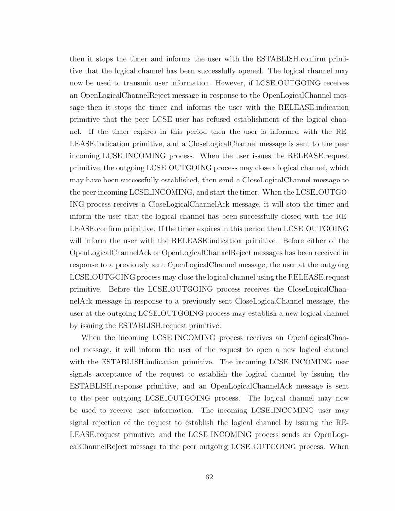
then it stops the timer and informs the user with the ESTABLISH.confirm primi-
tive that the logical channel has been successfully opened. The logical channel may
now be used to transmit user information. However, if LCSE OUTGOING receives
an OpenLogicalChannelReject message in response to the OpenLogicalChannel mes-
sage then it stops the timer and informs the user with the RELEASE.indication
primitive that the peer LCSE user has refused establishment of the logical chan-
nel. If the timer expires in this period then the user is informed with the RE-
LEASE.indication primitive, and a CloseLogicalChannel message is sent to the peer
incoming LCSE INCOMING process. When the user issues the RELEASE.request
primitive, the outgoing LCSE OUTGOING process may close a logical channel, which
may have been successfully established, then send a CloseLogicalChannel message to
the peer incoming LCSE INCOMING, and start the timer. When the LCSE OUTGO-
ING process receives a CloseLogicalChannelAck message, it will stop the timer and
inform the user that the logical channel has been successfully closed with the RE-
LEASE.confirm primitive. If the timer expires in this period then LCSE OUTGOING
will inform the user with the RELEASE.indication primitive. Before either of the
OpenLogicalChannelAck or OpenLogicalChannelReject messages has been received in
response to a previously sent OpenLogicalChannel message, the user at the outgoing
LCSE OUTGOING process may close the logical channel using the RELEASE.request
primitive. Before the LCSE OUTGOING process receives the CloseLogicalChan-
nelAck message in response to a previously sent CloseLogicalChannel message, the
user at the outgoing LCSE OUTGOING process may establish a new logical channel
by issuing the ESTABLISH.request primitive.
When the incoming LCSE INCOMING process receives an OpenLogicalChan-
nel message, it will inform the user of the request to open a new logical channel
with the ESTABLISH.indication primitive. The incoming LCSE INCOMING user
signals acceptance of the request to establish the logical channel by issuing the
ESTABLISH.response primitive, and an OpenLogicalChannelAck message is sent
to the peer outgoing LCSE OUTGOING process. The logical channel may now
be used to receive user information. The incoming LCSE INCOMING user may
signal rejection of the request to establish the logical channel by issuing the RE-
LEASE.request primitive, and the LCSE INCOMING process sends an OpenLogi-
calChannelReject message to the peer outgoing LCSE OUTGOING process. When
62
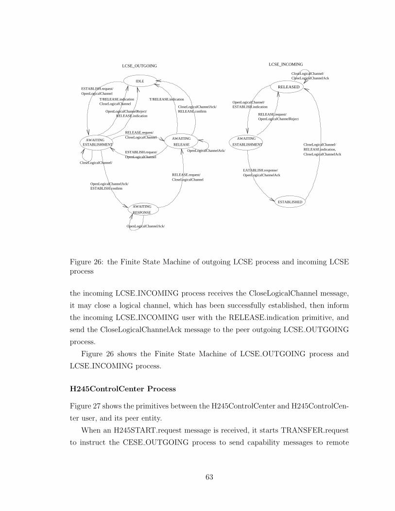
IDLE
AWAITING
RESPONSE
AWAITINGESTABLISHMENT
AWAITING
RELEASE
ESTABLISH.request/OpenLogicalChannel
CloseLogicalChannelT/RELEASE.indication
OpenLogicalChannelReject/RELEASE.indication
RELEASE.request/CloseLogicalChannel
ESTABLISH.request/OpenLogicalChannel
T/RELEASE.indication
CloseLogicalChannelAck/RELEASE.confirm
CloseLogicalChannel/
OpenLogicalChannelAck/ESTABLISH.confirm
OpenLogicalChannelAck/
RELEASE.request/CloseLogicalChannel
OpenLogicalChannelAck/
ESTABLISHMENT
AWAITING
ESTABLISHED
RELEASED
CloseLogicalChannelAckCloseLogicalChannel/
OpenLogicalChannel/ESTABLISH.indication
RELEASE.request/OpenLogicalChannelReject
EATABLISH.response/OpenLogicalChannelAck
CloseLogicalChannel/
CloseLogicalChannelAckRELEASE.indication,
LCSE_INCOMINGLCSE_OUTGOING
Figure 26: the Finite State Machine of outgoing LCSE process and incoming LCSEprocess
the incoming LCSE INCOMING process receives the CloseLogicalChannel message,
it may close a logical channel, which has been successfully established, then inform
the incoming LCSE INCOMING user with the RELEASE.indication primitive, and
send the CloseLogicalChannelAck message to the peer outgoing LCSE OUTGOING
process.
Figure 26 shows the Finite State Machine of LCSE OUTGOING process and
LCSE INCOMING process.
H245ControlCenter Process
Figure 27 shows the primitives between the H245ControlCenter and H245ControlCen-
ter user, and its peer entity.
When an H245START.request message is received, it starts TRANSFER.request
to instruct the CESE OUTGOING process to send capability messages to remote
63
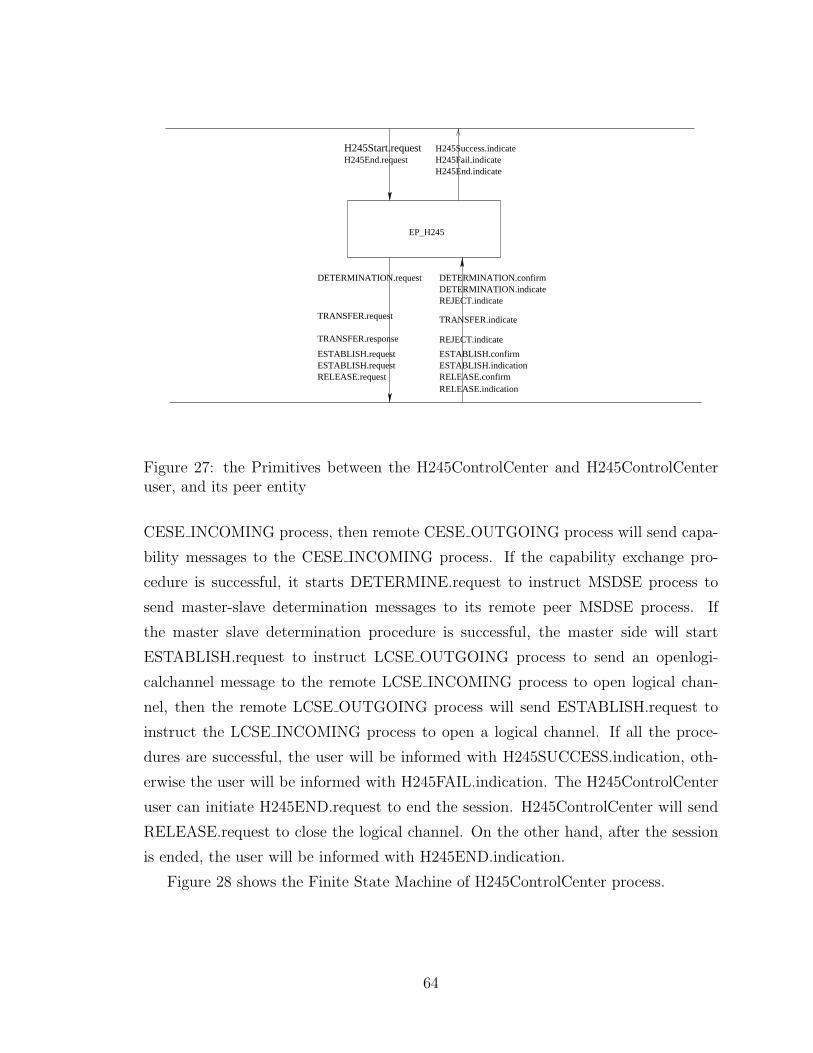
H245Start.requestH245End.request
H245Success.indicateH245Fail.indicateH245End.indicate
REJECT.indicate
DETERMINATION.confirmDETERMINATION.indicateREJECT.indicate
TRANSFER.indicate
ESTABLISH.confirmESTABLISH.indication
DETERMINATION.request
TRANSFER.request
TRANSFER.response
ESTABLISH.requestESTABLISH.requestRELEASE.request
RELEASE.indicationRELEASE.confirm
EP_H245
Figure 27: the Primitives between the H245ControlCenter and H245ControlCenteruser, and its peer entity
CESE INCOMING process, then remote CESE OUTGOING process will send capa-
bility messages to the CESE INCOMING process. If the capability exchange pro-
cedure is successful, it starts DETERMINE.request to instruct MSDSE process to
send master-slave determination messages to its remote peer MSDSE process. If
the master slave determination procedure is successful, the master side will start
ESTABLISH.request to instruct LCSE OUTGOING process to send an openlogi-
calchannel message to the remote LCSE INCOMING process to open logical chan-
nel, then the remote LCSE OUTGOING process will send ESTABLISH.request to
instruct the LCSE INCOMING process to open a logical channel. If all the proce-
dures are successful, the user will be informed with H245SUCCESS.indication, oth-
erwise the user will be informed with H245FAIL.indication. The H245ControlCenter
user can initiate H245END.request to end the session. H245ControlCenter will send
RELEASE.request to close the logical channel. On the other hand, after the session
is ended, the user will be informed with H245END.indication.
Figure 28 shows the Finite State Machine of H245ControlCenter process.
64
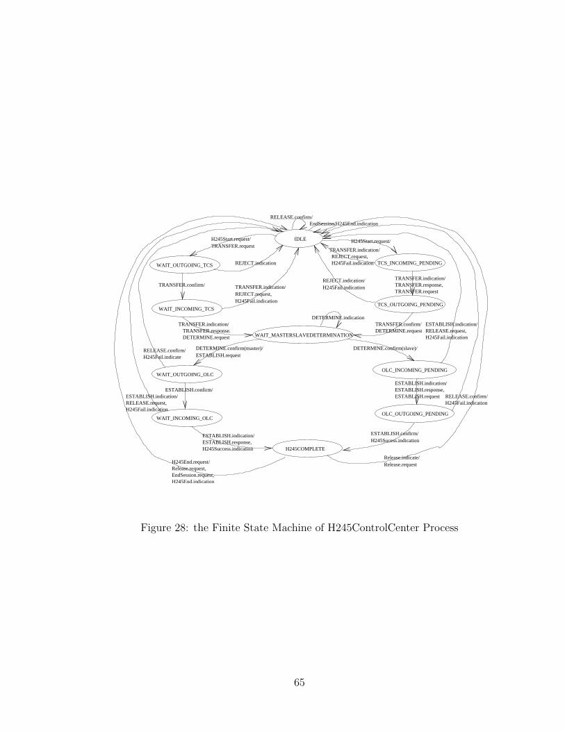
IDLEH245Start.request/TRANSFER.request
WAIT_OUTGOING_TCS TCS_INCOMING_PENDING
WAIT_INCOMING_TCSTCS_OUTGOING_PENDING
REJECT.indication
TRANSFER.confirm/
WAIT_MASTERSLAVEDETERMINATION
TRANSFER.indication/TRANSFER.response,TRANSFER.request
TRANSFER.indication/TRANSFER.response.DETERMINE.request
TRANSFER.indication/REJECT.request,H245Fail.indication
TRANSFER.indication/REJECT.request,H245Fail.indication
REJECT.indication/H245Fail.indication
TRANSFER.confirm/DETERMINE.request
DETERMINE.indication
DETERMINE.confirm(master)/ESTABLISH.request
WAIT_OUTGOING_OLCOLC_INCOMING_PENDING
DETERMINE.confirm(slave)/
WAIT_INCOMING_OLCOLC_OUTGOING_PENDING
ESTABLISH.confirm/H245Sucess.indication
H245Start.request/
ESTABLISH.indication/RELEASE.request,H245Fail.indication
ESTABLISH.indication/ESTABLISH.response,ESTABLISH.request
H245Fail.indicationRELEASE.confirm/
H245Fail.indicateRELEASE.confirm/
ESTABLISH.confirm/ESTABLISH.indication/RELEASE.request,H245Fail.indication
ESTABLISH.indication/ESTABLISH.response,H245Success.indication H245COMPLETE
H245End.request/Release.request,
H245End.indication
Release.indicate/Release.request
EndSession.request,
RELEASE.confirm/EndSession/H245End.indication
Figure 28: the Finite State Machine of H245ControlCenter Process
65
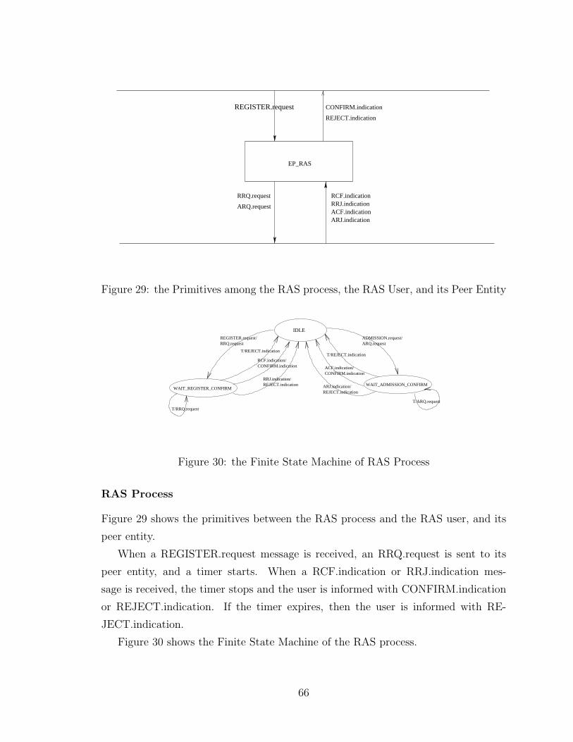
REGISTER.request
EP_RAS
CONFIRM.indication
REJECT.indication
RCF.indicationRRJ.indicationACF.indicationARJ.indication
RRQ.request
ARQ.request
Figure 29: the Primitives among the RAS process, the RAS User, and its Peer Entity
IDLE
REGISTER.request/RRQ.request
T/REJECT.indication
RCF.indication/CONFIRM.indication
RRJ.indication/REJECT.indication
T/RRQ.request
ADMISSION.request/ARQ.request
T/REJECT.indication
ACF.indication/CONFIRM.indication
ARJ.indication/REJECT.indication
WAIT_REGISTER_CONFIRMWAIT_ADMISSION_CONFIRM
T/ARQ.request
Figure 30: the Finite State Machine of RAS Process
RAS Process
Figure 29 shows the primitives between the RAS process and the RAS user, and its
peer entity.
When a REGISTER.request message is received, an RRQ.request is sent to its
peer entity, and a timer starts. When a RCF.indication or RRJ.indication mes-
sage is received, the timer stops and the user is informed with CONFIRM.indication
or REJECT.indication. If the timer expires, then the user is informed with RE-
JECT.indication.
Figure 30 shows the Finite State Machine of the RAS process.
66
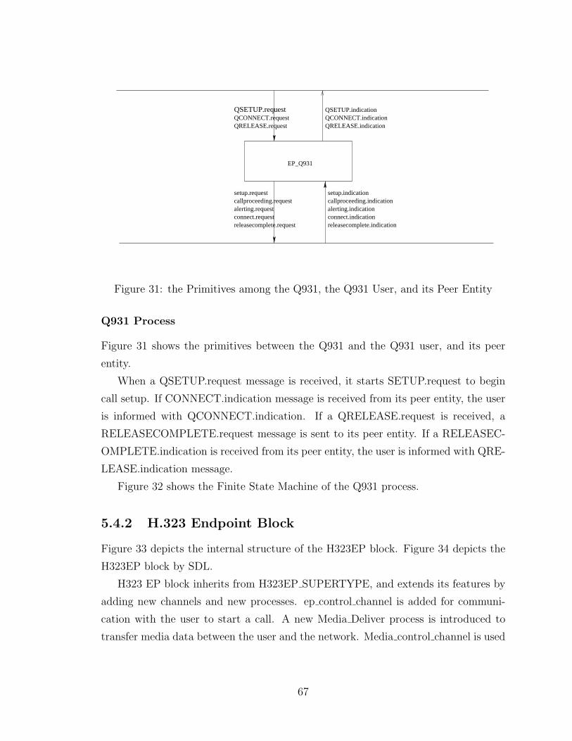
QRELEASE.requestQCONNECT.requestQSETUP.request QSETUP.indication
QCONNECT.indicationQRELEASE.indication
EP_Q931
setup.requestcallproceeding.requestalerting.requestconnect.requestreleasecomplete.request
setup.indicationcallproceeding.indicationalerting.indicationconnect.indicationreleasecomplete.indication
Figure 31: the Primitives among the Q931, the Q931 User, and its Peer Entity
Q931 Process
Figure 31 shows the primitives between the Q931 and the Q931 user, and its peer
entity.
When a QSETUP.request message is received, it starts SETUP.request to begin
call setup. If CONNECT.indication message is received from its peer entity, the user
is informed with QCONNECT.indication. If a QRELEASE.request is received, a
RELEASECOMPLETE.request message is sent to its peer entity. If a RELEASEC-
OMPLETE.indication is received from its peer entity, the user is informed with QRE-
LEASE.indication message.
Figure 32 shows the Finite State Machine of the Q931 process.
5.4.2 H.323 Endpoint Block
Figure 33 depicts the internal structure of the H323EP block. Figure 34 depicts the
H323EP block by SDL.
H323 EP block inherits from H323EP SUPERTYPE, and extends its features by
adding new channels and new processes. ep control channel is added for communi-
cation with the user to start a call. A new Media Deliver process is introduced to
transfer media data between the user and the network. Media control channel is used
67
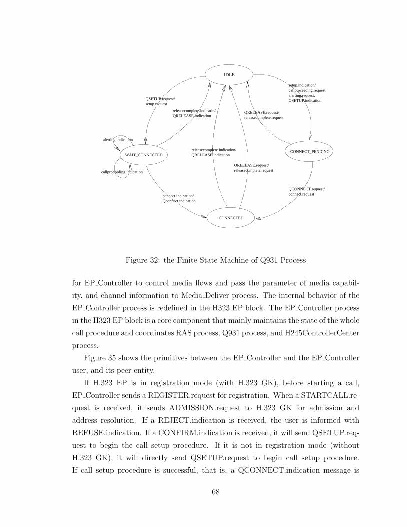
IDLE
QSETUP.request/setup.request
releasecomplete.indicatin/QRELEASE.indication
callproceeding.indication
alerting.indication
Qconnect.indicationconnect.indication/
setup.indication/callproceeding.request,alerting.request,QSETUP.indication
QRELEASE.request/releasecomplete.request
QCONNECT.request/connect.request
releasecomplete.indication/QRELEASE.indication
QRELEASE.request/releasecomplete.request
WAIT_CONNECTEDCONNECT_PENDING
CONNECTED
Figure 32: the Finite State Machine of Q931 Process
for EP Controller to control media flows and pass the parameter of media capabil-
ity, and channel information to Media Deliver process. The internal behavior of the
EP Controller process is redefined in the H323 EP block. The EP Controller process
in the H323 EP block is a core component that mainly maintains the state of the whole
call procedure and coordinates RAS process, Q931 process, and H245ControllerCenter
process.
Figure 35 shows the primitives between the EP Controller and the EP Controller
user, and its peer entity.
If H.323 EP is in registration mode (with H.323 GK), before starting a call,
EP Controller sends a REGISTER.request for registration. When a STARTCALL.re-
quest is received, it sends ADMISSION.request to H.323 GK for admission and
address resolution. If a REJECT.indication is received, the user is informed with
REFUSE.indication. If a CONFIRM.indication is received, it will send QSETUP.req-
uest to begin the call setup procedure. If it is not in registration mode (without
H.323 GK), it will directly send QSETUP.request to begin call setup procedure.
If call setup procedure is successful, that is, a QCONNECT.indication message is
68
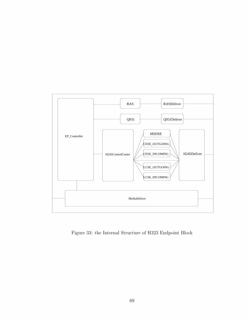
RAS RASDeliver
Q931 Q931Deliver
CESE_OUTGOING
MSDSE
LCSE_INCOMING
LCSE_OUTGOING
CESE_INCOMING H245DeliverH245ControlCenter
MediaDeliver
EP_Controller
Figure 33: the Internal Structure of H323 Endpoint Block
69
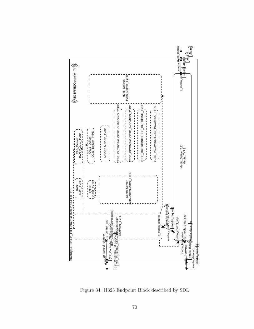
blo
ck t
ype
H32
3EP
_TY
PE
inh
erit
s H
323E
P_S
UP
ER
TY
PE
g_ep
_med
ia
udp.
ind
udp.
req
g_us
er
(EP
_Con
trol
ler_
SA
Pre
ques
t)(E
P_C
ontr
olle
r_S
AP
indi
cate
)
g_m
edia
_fro
m_u
ser
med
ia_d
ata.
req
med
ia_d
ata.
ind
ep_c
ontr
ol_c
hann
el
(EP
_Con
trol
ler_
SA
Pre
ques
t)(E
P_C
ontr
olle
r_S
AP
indi
cate
)
med
ia_c
ontr
ol_c
hann
el(m
edia
_req
uest
)
(med
ia_i
ndic
ate)
med
ia_f
rom
_use
r
med
ia_d
ata.
req
med
ia_d
ata.
ind
med
ia_t
o
udp.
req
udp.
ind
RE
DE
FIN
ED C
ontr
olle
r_T
YP
E
EP
_Con
trol
ler:
Con
trol
ler_
TY
PE
p_co
ntro
l_sa
p
p_m
edia
_con
trol
RA
S:
RA
S_T
YP
E
Q93
1:Q
931_
TY
PE
Con
trol
Cen
ter:
H24
5Con
trol
Cen
ter_
TY
PE
LCS
E_O
UT
GO
ING
:LC
SE
_OU
TG
OIN
G_T
YP
E
MS
DS
E:M
SD
SE
_TY
PE
CE
SE
_OU
TG
OIN
G:C
ES
E_O
UT
GO
ING
_TY
PE
CE
SE
_IN
CO
MIN
G:C
ES
E_I
NC
OM
ING
_TY
PE
LCS
E_I
NC
OM
ING
:LC
SE
_IN
CO
MIN
G_T
YP
E
RA
S_D
eliv
er:
RA
S_D
eliv
er_T
YP
E
Q93
1_D
eliv
er:
Q93
1_D
eliv
er_T
YP
E
H24
5_D
eliv
er:
H24
5_D
eliv
er_T
YP
E
Med
ia_D
eliv
er(0
,1):
Med
ia_T
YP
E
p_m
edia
_con
trol
_sap
p_m
edia
_dat
a_sa
pp_
med
ia_o
ut
Figure 34: H323 Endpoint Block described by SDL
70
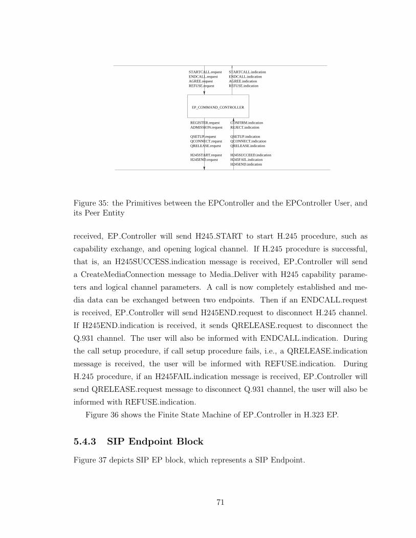
EP_COMMAND_CONTROLLER
REGISTER.requestADMISSION.request
QSETUP.requestQCONNECT.requestQRELEASE.request
H245START.requestH245END.request
CONFIRM.indicationREJECT.indication
QSETUP.indicationQCONNECT.indicationQRELEASE.indication
H245SUCCEED.indicationH245FAIL.indicationH245END.indication
STARTCALL.requestENDCALL.requestAGREE.requestREFUSE.request
STARTCALL.indicationENDCALL.indicationAGREE.indicationREFUSE.indication
Figure 35: the Primitives between the EPController and the EPController User, andits Peer Entity
received, EP Controller will send H245 START to start H.245 procedure, such as
capability exchange, and opening logical channel. If H.245 procedure is successful,
that is, an H245SUCCESS.indication message is received, EP Controller will send
a CreateMediaConnection message to Media Deliver with H245 capability parame-
ters and logical channel parameters. A call is now completely established and me-
dia data can be exchanged between two endpoints. Then if an ENDCALL.request
is received, EP Controller will send H245END.request to disconnect H.245 channel.
If H245END.indication is received, it sends QRELEASE.request to disconnect the
Q.931 channel. The user will also be informed with ENDCALL.indication. During
the call setup procedure, if call setup procedure fails, i.e., a QRELEASE.indication
message is received, the user will be informed with REFUSE.indication. During
H.245 procedure, if an H245FAIL.indication message is received, EP Controller will
send QRELEASE.request message to disconnect Q.931 channel, the user will also be
informed with REFUSE.indication.
Figure 36 shows the Finite State Machine of EP Controller in H.323 EP.
5.4.3 SIP Endpoint Block
Figure 37 depicts SIP EP block, which represents a SIP Endpoint.
71
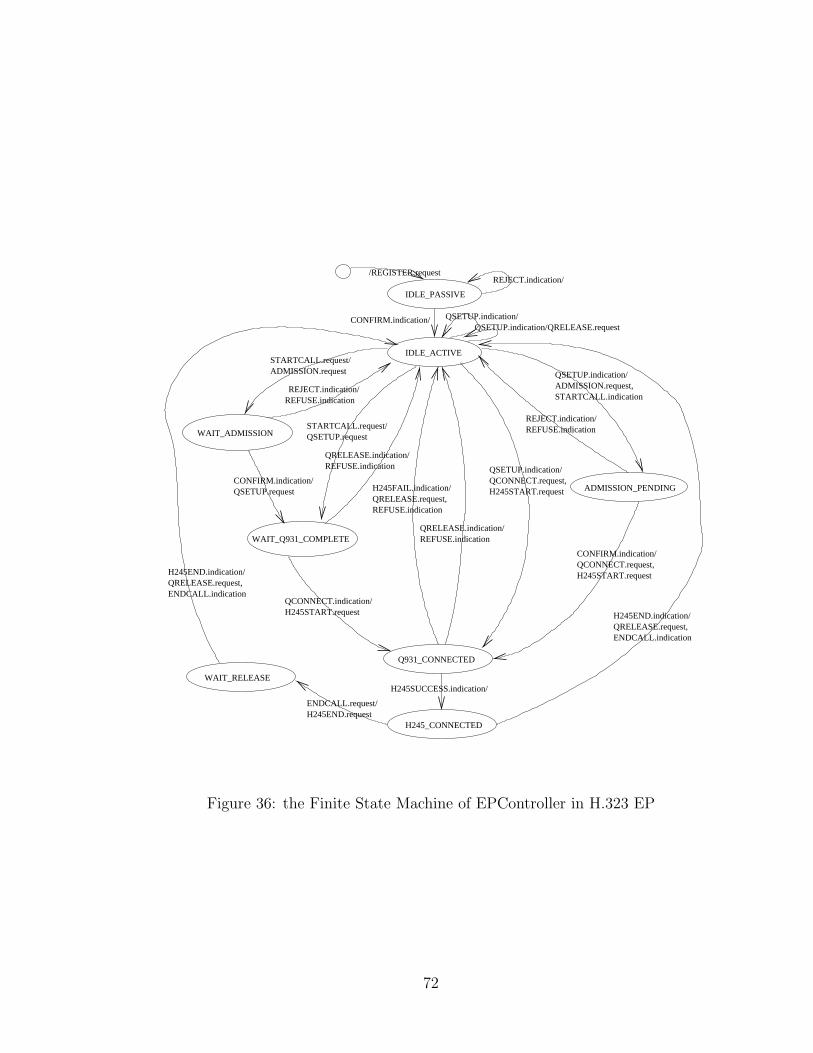
/REGISTER.requestREJECT.indication/
IDLE_PASSIVE
IDLE_ACTIVE
WAIT_ADMISSION
WAIT_Q931_COMPLETE
CONFIRM.indication/QSETUP.request
STARTCALL.request/ADMISSION.request
H245_CONNECTED
Q931_CONNECTED
REJECT.indication/REFUSE.indication
STARTCALL.request/QSETUP.request
QRELEASE.indication/REFUSE.indication
QCONNECT.indication/H245START.request
ADMISSION_PENDINGH245FAIL.indication/QRELEASE.request,REFUSE.indication
QRELEASE.indication/REFUSE.indication
QSETUP.indication/QCONNECT.request,H245START.request
QSETUP.indication/ADMISSION.request,STARTCALL.indication
REJECT.indication/REFUSE.indication
CONFIRM.indication/QCONNECT.request,H245START.request
H245SUCCESS.indication/WAIT_RELEASE
H245END.indication/QRELEASE.request,ENDCALL.indication
ENDCALL.request/H245END.request
H245END.indication/QRELEASE.request,ENDCALL.indication
QSETUP.indication/QSETUP.indication/QRELEASE.request
CONFIRM.indication/
Figure 36: the Finite State Machine of EPController in H.323 EP
72
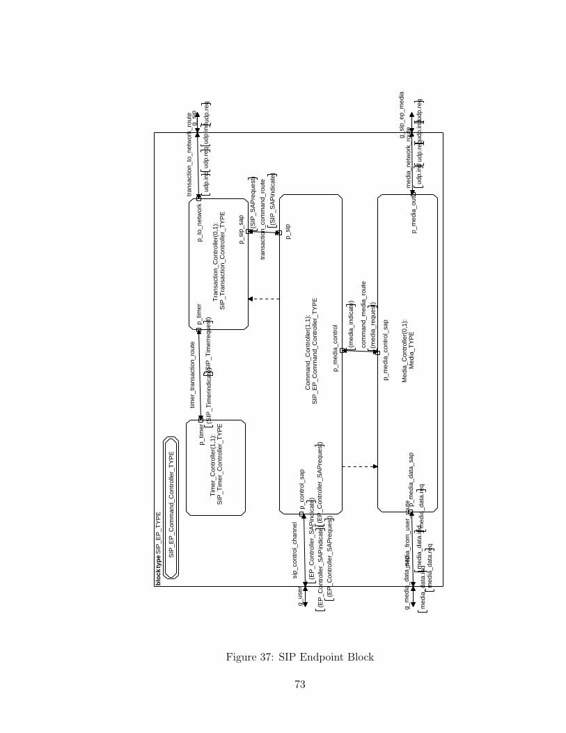
blo
ck t
ype
SIP
_EP
_TY
PE
g_m
edia
_dat
a_sa
p
med
ia_d
ata.
req
med
ia_d
ata.
ind
g_si
p_ep
_med
ia
udp.
ind u
dp.r
eq
g_us
er
(EP
_Con
trol
ler_
SA
Pre
ques
t)(E
P_C
ontr
olle
r_S
AP
indi
cate
)
g_si
p
udp.
ind
udp.
req
com
man
d_m
edia
_rou
te
(med
ia_r
eque
st)
(med
ia_i
ndic
ate)
med
ia_f
rom
_use
r_ro
ute
med
ia_d
ata.
req
med
ia_d
ata.
ind
med
ia_n
etw
ork_
rout
e
udp.
req
udp.
ind
sip_
cont
rol_
chan
nel (E
P_C
ontr
olle
r_S
AP
requ
est)
(EP
_Con
trol
ler_
SA
Pin
dica
te)
timer
_tra
nsac
tion_
rout
e
(SIP
_Tim
erre
ques
t)(S
IP_T
imer
indi
cate
)
tran
sact
ion_
to_n
etw
ork_
rout
e
udp.
req
udp.
ind
tran
sact
ion_
com
man
d_ro
ute
(SIP
_SA
Pin
dica
te)
(SIP
_SA
Pre
ques
t)
SIP
_EP
_Com
man
d_C
ontr
olle
r_T
YP
E
Tim
er_C
ontr
olle
r(1,
1):
SIP
_Tim
er_C
ontr
olle
r_T
YP
E
p_tim
er
Tra
nsac
tion_
Con
trol
ler(
0,1)
:S
IP_T
rans
actio
n_C
ontr
olle
r_T
YP
E
p_tim
erp_
to_n
etw
ork
p_si
p_sa
p
Com
man
d_C
ontr
olle
r(1,
1):
SIP
_EP
_Com
man
d_C
ontr
olle
r_T
YP
E
p_m
edia
_con
trol
p_co
ntro
l_sa
p
p_si
p
Med
ia_C
ontr
olle
r(0,
1):
Med
ia_T
YP
E
p_m
edia
_con
trol
_sap
p_m
edia
_dat
a_sa
pp_
med
ia_o
ut
Figure 37: SIP Endpoint Block
73
The block type has four gates, The g user and g media data are used for com-
munication with the user. The g sip and g sip ep media are for communication with
the network. SIP EP can receive a user command and initiate a session to invite
a peer endpoint by sending SIP messages. SIP has four processes. The Transac-
tion Controller process is used for transaction management. It receives SIP com-
mands from the Command Controller process. It keeps in memory a list of SIP com-
mands and SIP responses. It also sends a timer-start message to the Timer Controller
process for starting a timer when a SIP command is sent to the network. When
the final response of the SIP command is received from network, it sends a timer-
stop message to disable the timer. When a timeout message is received from the
Timer Controller process, it resends the SIP commands since the SIP commands
may be lost because it is carried over UDP. When a timer-expiration message is
received from Timer Controller process, it sends a response with error to the Com-
mand Controllers. The Timer Controller process is responsible for maintaining the
timer. It also receives timer control messages from the Transaction Controller pro-
cess. When a timer timeouts or expires, it sends timer-timeout and timer-expiration
messages to the Transaction Controller process. Command Controller process in SIP
EP Block is a core process that is responsible for keeping all state of the whole pro-
cedure of session initiation. It receives SIP messages from the Transaction Controller
process and sends response of SIP messages to the Transaction Controller process.
Figure 38 shows the primitives between the Command Controller process and the
Command Controller user, and its peer entity.
Figure 39 shows the Finite State Machine of the Command Controller process.
5.4.4 IWF Block
Figure 40 depicts the internal structure of the IWF block. Figure 41 depicts the IWF
block by SDL.
IWF block inherits from H323EP SUPERTYPE, and extends its features by
adding new channels and new processes. The Transaction Controller process is in-
troduced for transaction management of SIP messages. It receives SIP commands
from the EP Controller process, keeps in memory a list of SIP commands and SIP
responses, and sends timer control messages to the Timer Controller process. The
Timer Controller process is introduced to maintain the timer. It receives timer control
74
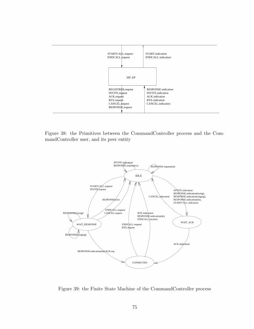
SIP_EP
STARTCALL.requestENDCALL.request
START.indicationENDCALL.indication
REGISTRER.requestINVITE.requestACK.requestBYE.requestCANCEL.requestRESPONSE.request
RESPONSE.indicationINVITE.indicationACK.indicationBYE.indicationCANCEL.indication
Figure 38: the Primitives between the CommandController process and the Com-mandController user, and its peer entity
IDLE
WAIT_RESPONSEWAIT_ACK
CONNECTED
INVITE.request
CANCEL.requestRESPONSE(trying)/
RESPONSE(ringing)
INVITE.indication/
RESPONSE.indication(ok)/ACK.req
BYE.request
BYE.indication/
RESPONSE.request(ok)
ACK.indication/
INVITE.indication/RESPONSE.indication(trying),RESPONSE.indication(ringing),
RESPONSE.request(err)
CANCEL.indication/RESPONSE.indication(ok),
RESPONSE.indication(ok),ENDCALL.incation
ENDCALL.request/
STARTCALL.indication
STARTCALL.request/
ENDCALL.request/
RESPONSE(err)/
Figure 39: the Finite State Machine of the CommandController process
75
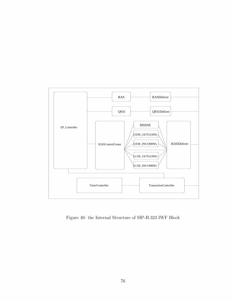
RAS RASDeliver
Q931 Q931Deliver
CESE_OUTGOING
MSDSE
LCSE_INCOMING
LCSE_OUTGOING
CESE_INCOMING H245DeliverH245ControlCenter
EP_Controller
TransactionControllerTimerController
Figure 40: the Internal Structure of SIP-H.323 IWF Block
76
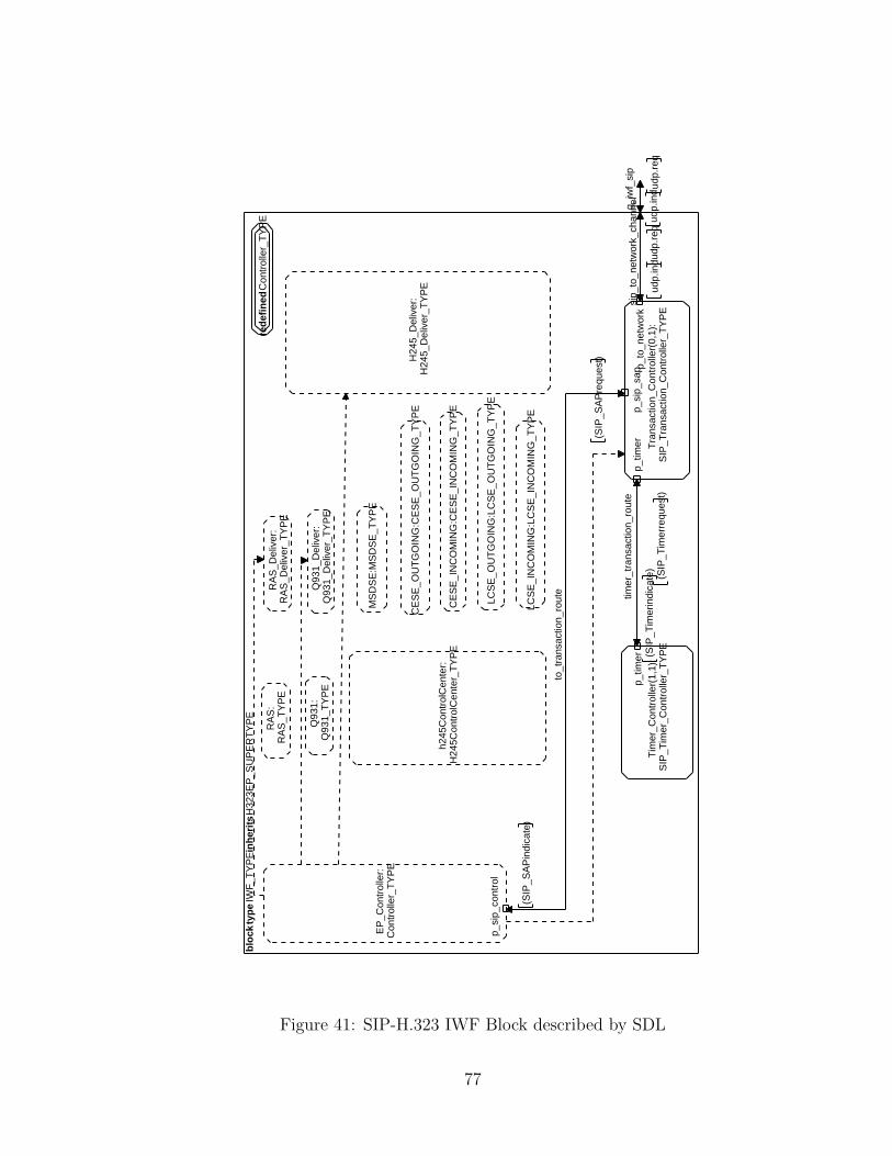
blo
ck t
ype
IWF
_TY
PE
inh
erit
s H
323E
P_S
UP
ER
TY
PE
g_iw
f_si
p
udp.
ind
udp.
req
to_t
rans
actio
n_ro
ute
(SIP
_SA
Pre
ques
t)
(SIP
_SA
Pin
dica
te)
timer
_tra
nsac
tion_
rout
e
(SIP
_Tim
erre
ques
t)(S
IP_T
imer
indi
cate
)
sip_
to_n
etw
ork_
chan
nel
udp.
req
udp.
ind
red
efin
ed C
ontr
olle
r_T
YP
E
EP
_Con
trol
ler:
Con
trol
ler_
TY
PE
p_si
p_co
ntro
l
RA
S:
RA
S_T
YP
ER
AS
_Del
iver
:R
AS
_Del
iver
_TY
PE
Q93
1:Q
931_
TY
PE
Q93
1_D
eliv
er:
Q93
1_D
eliv
er_T
YP
E
h245
Con
trol
Cen
ter:
H24
5Con
trol
Cen
ter_
TY
PE
MS
DS
E:M
SD
SE
_TY
PE
CE
SE
_OU
TG
OIN
G:C
ES
E_O
UT
GO
ING
_TY
PE
CE
SE
_IN
CO
MIN
G:C
ES
E_I
NC
OM
ING
_TY
PE
LCS
E_O
UT
GO
ING
:LC
SE
_OU
TG
OIN
G_T
YP
E
LCS
E_I
NC
OM
ING
:LC
SE
_IN
CO
MIN
G_T
YP
E
H24
5_D
eliv
er:
H24
5_D
eliv
er_T
YP
E
Tim
er_C
ontr
olle
r(1,
1):
SIP
_Tim
er_C
ontr
olle
r_T
YP
E
p_tim
erT
rans
actio
n_C
ontr
olle
r(0,
1):
SIP
_Tra
nsac
tion_
Con
trol
ler_
TY
PE
p_tim
erp_
to_n
etw
ork
p_si
p_sa
p
Figure 41: SIP-H.323 IWF Block described by SDL
77
messages from the Transaction Controller process and sends timer-timeout and timer-
expiration messages to the Transaction Controller process. The to transaction route
channel is added for communication of SIP messages between the EP Controller pro-
cess and the Transaction Controller process. The time transaction route channel is
added to connect the Timer Controller process and the Transaction Controller process
for exchanging timer control messages. The sip to network channel channel is added
for communication with the network. The g iwf sip gate is added to be used for com-
munication of SIP messages with the network. The internal behavior of EP Controller
process is redefined in the IWF block. The EP Controller process in IWF block is
a core component that not only maintains the state of the whole call procedure and
coordinates RAS process, Q931 process, and H245Controller Center process, but is
also responsible for message mapping between SIP and H.323.
In the draft of Interworking between SIP and H.323, it mentions two finite state
machines for message mapping from H.323 to SIP and from SIP to H.323 respectively.
There are two options for designing our model for the message mapping. One option
is to use two processes; one process is for mapping messages from H.323 side to SIP
side, and the other one process is for mapping messages from SIP side to H.323 side.
The disadvantage is as follows: When H.323 side finishes initiating the call procedure
for establishing call connection and the SIP side needs to terminate the session, we
have to use two extra processes to inform both processes for state transition. The
other option to use only one process to integrate the two finite state machines into one
finite state machine. Although the first option makes each process become simpler,
it makes the whole model become complex because we have to add four processes;
two are used for message mapping, the other two are used for informing both sides.
Therefore, we choose the latter option. It is possible because there is no identical
state during call setup procedure or session initiation. Only after the call procedure
is finished from both directions, can it be merged into one state. Starting from the
state, the process can accept termination messages from both sides and return to
its initial state. We use EP Controller process as the core component for message
mapping.
Figure 42 shows the primitives between the EP Controller process and its peer
entity.
To simplify our model and mainly focus on the basic message mapping function
78
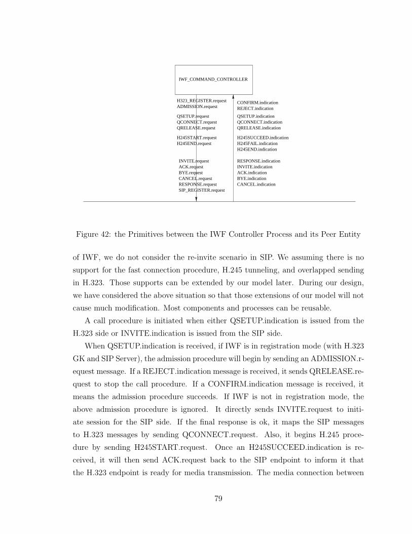
QRELEASE.request
H245START.requestH245END.request
CONFIRM.indicationREJECT.indication
QSETUP.indicationQCONNECT.indicationQRELEASE.indication
H245SUCCEED.indicationH245FAIL.indicationH245END.indication
RESPONSE.indicationINVITE.indicationACK.indicationBYE.indicationCANCEL.indication
IWF_COMMAND_CONTROLLER
INVITE.requestACK.requestBYE.requestCANCEL.requestRESPONSE.request
QCONNECT.requestQSETUP.request
ADMISSION.request
SIP_REGISTER.request
H323_REGISTER.request
Figure 42: the Primitives between the IWF Controller Process and its Peer Entity
of IWF, we do not consider the re-invite scenario in SIP. We assuming there is no
support for the fast connection procedure, H.245 tunneling, and overlapped sending
in H.323. Those supports can be extended by our model later. During our design,
we have considered the above situation so that those extensions of our model will not
cause much modification. Most components and processes can be reusable.
A call procedure is initiated when either QSETUP.indication is issued from the
H.323 side or INVITE.indication is issued from the SIP side.
When QSETUP.indication is received, if IWF is in registration mode (with H.323
GK and SIP Server), the admission procedure will begin by sending an ADMISSION.r-
equest message. If a REJECT.indication message is received, it sends QRELEASE.re-
quest to stop the call procedure. If a CONFIRM.indication message is received, it
means the admission procedure succeeds. If IWF is not in registration mode, the
above admission procedure is ignored. It directly sends INVITE.request to initi-
ate session for the SIP side. If the final response is ok, it maps the SIP messages
to H.323 messages by sending QCONNECT.request. Also, it begins H.245 proce-
dure by sending H245START.request. Once an H245SUCCEED.indication is re-
ceived, it will then send ACK.request back to the SIP endpoint to inform it that
the H.323 endpoint is ready for media transmission. The media connection between
79
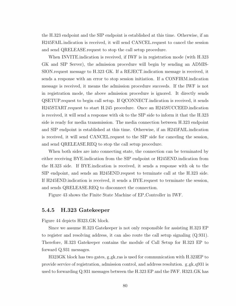
the H.323 endpoint and the SIP endpoint is established at this time. Otherwise, if an
H245FAIL.indication is received, it will send CANCEL.request to cancel the session
and send QRELEASE.request to stop the call setup procedure.
When INVITE.indication is received, if IWF is in registration mode (with H.323
GK and SIP Server), the admission procedure will begin by sending an ADMIS-
SION.request message to H.323 GK. If a REJECT.indication message is received, it
sends a response with an error to stop session initiation. If a CONFIRM.indication
message is received, it means the admission procedure succeeds. If the IWF is not
in registration mode, the above admission procedure is ignored. It directly sends
QSETUP.request to begin call setup. If QCONNECT.indication is received, it sends
H245START.request to start H.245 procedure. Once an H245SUCCEED.indication
is received, it will send a response with ok to the SIP side to inform it that the H.323
side is ready for media transmission. The media connection between H.323 endpoint
and SIP endpoint is established at this time. Otherwise, if an H245FAIL.indication
is received, it will send CANCEL.request to the SIP side for canceling the session,
and send QRELEASE.REQ to stop the call setup procedure.
When both sides are into connecting state, the connection can be terminated by
either receiving BYE.indication from the SIP endpoint or H245END.indication from
the H.323 side. If BYE.indication is received, it sends a response with ok to the
SIP endpoint, and sends an H245END.request to terminate call at the H.323 side.
If H245END.indication is received, it sends a BYE.request to terminate the session,
and sends QRELEASE.REQ to disconnect the connection.
Figure 43 shows the Finite State Machine of EP Controller in IWF.
5.4.5 H.323 Gatekeeper
Figure 44 depicts H323 GK block.
Since we assume H.323 Gatekeeper is not only responsible for assisting H.323 EP
to register and resolving address, it can also route the call setup signaling (Q.931).
Therefore, H.323 Gatekeeper contains the module of Call Setup for H.323 EP to
forward Q.931 messages.
H323GK block has two gates, g gk ras is used for communication with H.323EP to
provide service of registration, admission control, and address resolution. g gk q931 is
used to forwarding Q.931 messages between the H.323 EP and the IWF. H323 GK has
80
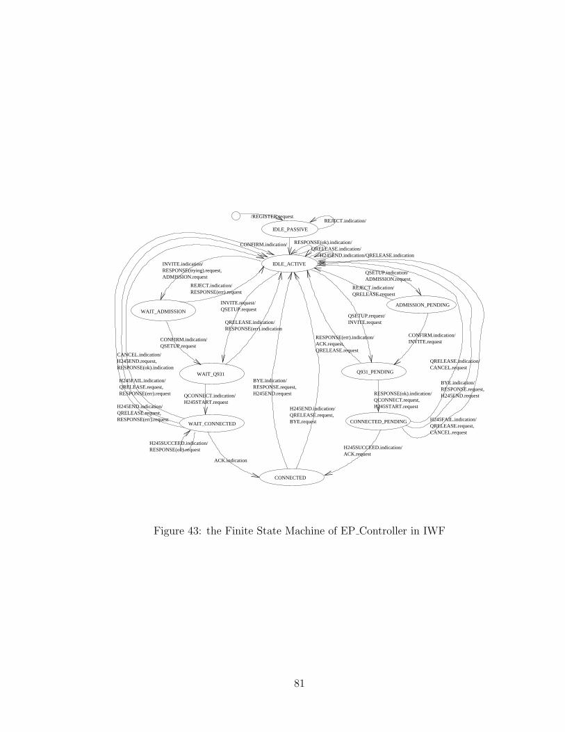
/REGISTER.requestREJECT.indication/
IDLE_PASSIVE
IDLE_ACTIVE
CONFIRM.indication/
ADMISSION.requestRESPONSE(trying).request,INVITE.indication/
RESPONSE(err).requestREJECT.indication/
INVITE.request/QSETUP.request
QRELEASE.indication/RESPONSE(err).indication
WAIT_Q931
QCONNECT.indication/H245START.request
RESPONSE(ok).indication/QRELEASE.indication/
H245END.indication/QRELEASE.indication
ADMISSION_PENDING
QSETUP.request/INVITE.request
RESPONSE(err).indication/ACK.request,QRELEASE.request
CONFIRM.indication/INVITE.request
Q931_PENDING
RESPONSE(ok).indication/QCONNECT.request,H245START.request
CONNECTED_PENDINGWAIT_CONNECTED
H245SUCCEED.indication/RESPONSE(ok).request
CONNECTED
BYE.indication/RESPONSE.request,H245END.request
H245END.indication/QRELEASE.request,BYE.request
H245SUCCEED.indication/ACK.request
ACK.indication
CONFIRM.indication/QSETUP.request
QRELEASE.requestREJECT.indication/
ADMISSION.request,QSETUP.indication/
QRELEASE.indication/CANCEL.request
RESPONSE.request,H245END.request
BYE.indication/
H245FAIL.indication/QRELEASE.request,CANCEL.request
WAIT_ADMISSION
CANCEL.indication/H245END.request,RESPONSE(ok).indication
H245FAIL.indication/QRELEASE.request,RESPONSE(err).request
H245END.indication/QRELEASE.request,RESPONSE(err).request
Figure 43: the Finite State Machine of EP Controller in IWF
81
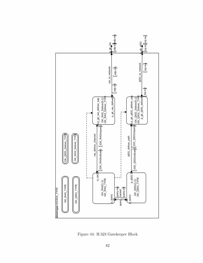
blo
ck t
ype
H32
3GK
_TY
PE
g_gk
_ras
udp.
indu
dp.r
eq
g_gk
_q93
1
tcp.
ind
tcp.
req
ras_
to_n
etw
ork
udp.
req
udp.
ind
q931
_to_
netw
ork
tcp.
req
tcp.
ind
ras_
deliv
er_c
hann
el
(GK
_RA
Sre
ques
t)(G
K_R
AS
indi
cate
)
q931
_del
iver
_pat
h
(GK
_Q93
1req
uest
)(G
K_Q
931i
ndic
ate)
quer
y_ch
anne
lqu
ery.
ind
quer
y.re
q
GK
_RA
S_T
YP
E
GK
_Q93
1_T
YP
E
GK
_Q93
1_D
eliv
er_T
YP
E
GK
_RA
S_D
eliv
er_T
YP
E
GK
_RA
S(1
,1):
GK
_RA
S_T
YP
Ep_ra
s
p_qu
ery G
K_Q
931(
1,1)
:G
K_Q
931_
TY
PE
p_q9
31p_
quer
y
GK
_RA
S_D
eliv
er(0
,1):
GK
_RA
S_D
eliv
er_T
YP
E
p_gk
_ras
_del
iver
_sap
p_gk
_ras
_del
iver
GK
_Q93
1_D
eliv
er(0
,1):
GK
_Q93
1_D
eliv
er_T
YP
E
p_gk
_q93
1_de
liver
_sap
p_gk
_q93
1_de
liver
Figure 44: H.323 Gatekeeper Block
82
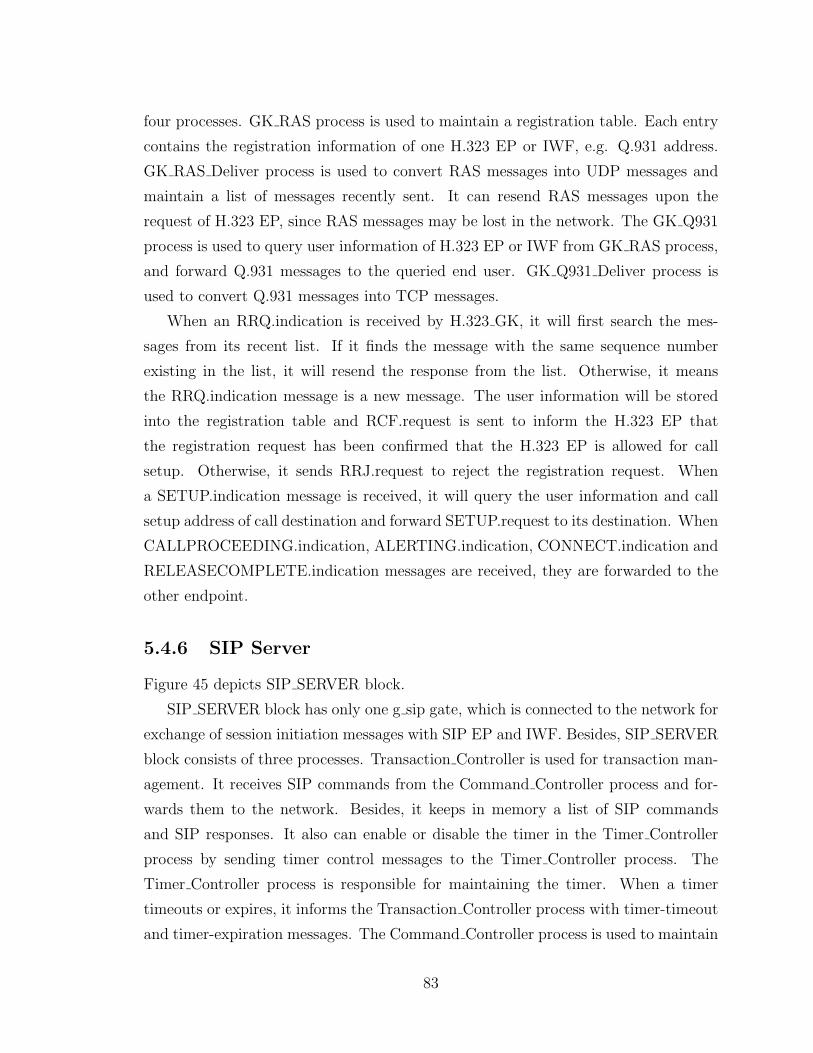
four processes. GK RAS process is used to maintain a registration table. Each entry
contains the registration information of one H.323 EP or IWF, e.g. Q.931 address.
GK RAS Deliver process is used to convert RAS messages into UDP messages and
maintain a list of messages recently sent. It can resend RAS messages upon the
request of H.323 EP, since RAS messages may be lost in the network. The GK Q931
process is used to query user information of H.323 EP or IWF from GK RAS process,
and forward Q.931 messages to the queried end user. GK Q931 Deliver process is
used to convert Q.931 messages into TCP messages.
When an RRQ.indication is received by H.323 GK, it will first search the mes-
sages from its recent list. If it finds the message with the same sequence number
existing in the list, it will resend the response from the list. Otherwise, it means
the RRQ.indication message is a new message. The user information will be stored
into the registration table and RCF.request is sent to inform the H.323 EP that
the registration request has been confirmed that the H.323 EP is allowed for call
setup. Otherwise, it sends RRJ.request to reject the registration request. When
a SETUP.indication message is received, it will query the user information and call
setup address of call destination and forward SETUP.request to its destination. When
CALLPROCEEDING.indication, ALERTING.indication, CONNECT.indication and
RELEASECOMPLETE.indication messages are received, they are forwarded to the
other endpoint.
5.4.6 SIP Server
Figure 45 depicts SIP SERVER block.
SIP SERVER block has only one g sip gate, which is connected to the network for
exchange of session initiation messages with SIP EP and IWF. Besides, SIP SERVER
block consists of three processes. Transaction Controller is used for transaction man-
agement. It receives SIP commands from the Command Controller process and for-
wards them to the network. Besides, it keeps in memory a list of SIP commands
and SIP responses. It also can enable or disable the timer in the Timer Controller
process by sending timer control messages to the Timer Controller process. The
Timer Controller process is responsible for maintaining the timer. When a timer
timeouts or expires, it informs the Transaction Controller process with timer-timeout
and timer-expiration messages. The Command Controller process is used to maintain
83
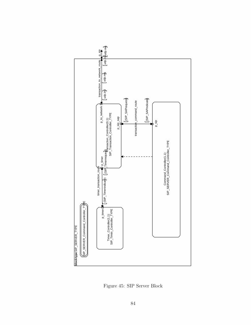
blo
ck ty
pe
SIP
_SE
RV
ER
_TY
PE
g_si
p
udp.
ind
udp.
req
timer
_tra
nsac
tion_
rout
e
(SIP
_Tim
erre
ques
t)(S
IP_T
imer
indi
cate
)
tran
sact
ion_
com
man
d_ro
ute
(SIP
_SA
Pin
dica
te)
(SIP
_SA
Pre
ques
t)
tran
sact
ion_
to_n
etw
ork_
rout
e
udp.
req
udp.
ind
SIP
_SE
RV
ER
_Com
man
d_C
ontr
olle
r_T
YP
E
Tim
er_C
ontr
olle
r(1,
1):
SIP
_Tim
er_C
ontr
olle
r_T
YP
E
p_tim
er
Tra
nsac
tion_
Con
trol
ler(
0,1)
:S
IP_T
rans
actio
n_C
ontr
olle
r_T
YP
E
p_tim
er
p_si
p_sa
p
p_to
_net
wor
k
Com
man
d_C
ontr
olle
r(1,
1):
SIP
_SE
RV
ER
_Com
man
d_C
ontr
olle
r_T
YP
E
p_si
p
Figure 45: SIP Server Block
84
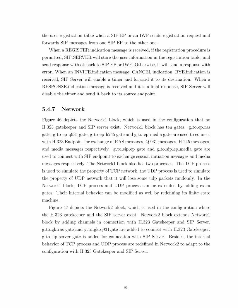
the user registration table when a SIP EP or an IWF sends registration request and
forwards SIP messages from one SIP EP to the other one.
When a REGISTER.indication message is received, if the registration procedure is
permitted, SIP SERVER will store the user information in the registration table, and
send response with ok back to SIP EP or IWF. Otherwise, it will send a response with
error. When an INVITE.indication message, CANCEL.indication, BYE.indication is
received, SIP Server will enable a timer and forward it to its destination. When a
RESPONSE.indication message is received and it is a final response, SIP Server will
disable the timer and send it back to its source endpoint.
5.4.7 Network
Figure 46 depicts the Network1 block, which is used in the configuration that no
H.323 gatekeeper and SIP server exist. Network1 block has ten gates. g to ep ras
gate, g to ep q931 gate, g to ep h245 gate and g to ep media gate are used to connect
with H.323 Endpoint for exchange of RAS messages, Q.931 messages, H.245 messages,
and media messages respectively. g to sip ep gate and g to sip ep media gate are
used to connect with SIP endpoint to exchange session initiation messages and media
messages respectively. The Network1 block also has two processes. The TCP process
is used to simulate the property of TCP network, the UDP process is used to simulate
the property of UDP network that it will lose some udp packets randomly. In the
Network1 block, TCP process and UDP process can be extended by adding extra
gates. Their internal behavior can be modified as well by redefining its finite state
machine.
Figure 47 depicts the Network2 block, which is used in the configuration where
the H.323 gatekeeper and the SIP server exist. Network2 block extends Network1
block by adding channels in connection with H.323 Gatekeeper and SIP Server.
g to gk ras gate and g to gk q931gate are added to connect with H.323 Gatekeeper.
g to sip server gate is added for connection with SIP Server. Besides, the internal
behavior of TCP process and UDP process are redefined in Network2 to adapt to the
configuration with H.323 Gatekeeper and SIP Server.
85
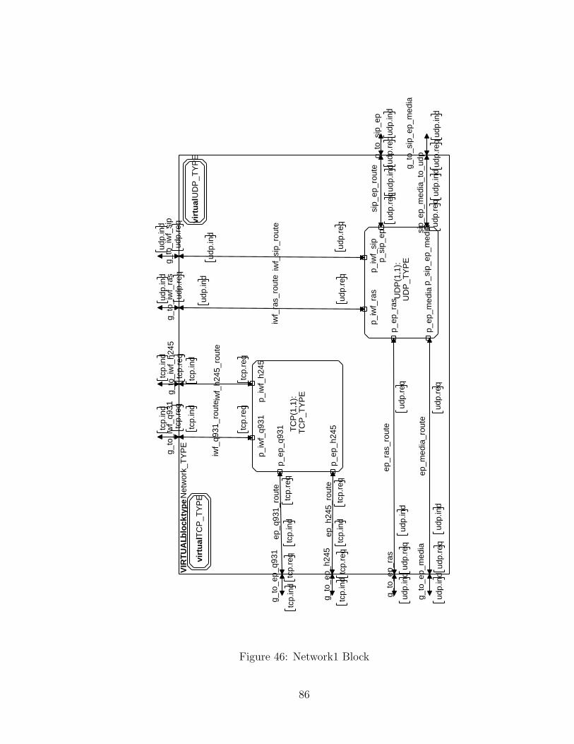
VIR
TU
AL b
lock
typ
e N
etw
ork_
TY
PE
g_to
_ep_
ras
udp.
req
udp.
ind
g_to
_ep_
q931
tcp.
req
tcp.
ind
g_to
_ep_
h245
tcp.
req
tcp.
ind
g_to
_ep_
med
ia
udp.
req
udp.
ind
g_to
_sip
_ep
udp.
req
udp.
ind
g_to
_sip
_ep_
med
ia
udp.
req
udp.
ind
g_to
_iw
f_q9
31tc
p.re
q
tcp.
ind
g_to
_iw
f_h2
45tc
p.re
q
tcp.
ind
g_to
_iw
f_ra
sud
p.re
q
udp.
ind
g_to
_iw
f_si
pud
p.re
q
udp.
ind
ep_q
931_
rout
etc
p.re
qtc
p.in
d
ep_h
245_
rout
etc
p.re
qtc
p.in
d
ep_r
as_r
oute
udp.
req
udp.
ind
ep_m
edia
_rou
te
udp.
req
udp.
ind
sip_
ep_r
oute
udp.
ind
udp.
req
sip_
ep_m
edia
_to_
udp
udp.
ind
udp.
req
iwf_
q931
_rou
te
tcp.
ind
tcp.
req
iwf_
h245
_rou
te
tcp.
ind
tcp.
req
iwf_
ras_
rout
e
udp.
ind
udp.
req
iwf_
sip_
rout
e
udp.
ind
udp.
req
virt
ual
TC
P_T
YP
Evi
rtu
al U
DP
_TY
PE
TC
P(1
,1):
TC
P_T
YP
E
p_ep
_q93
1
p_ep
_h24
5
p_iw
f_q9
31p_
iwf_
h245
UD
P(1
,1):
UD
P_T
YP
E
p_ep
_ras
p_ep
_med
ia
p_si
p_ep
p_si
p_ep
_med
ia
p_iw
f_ra
sp_
iwf_
sip
Figure 46: Network1 Block
86
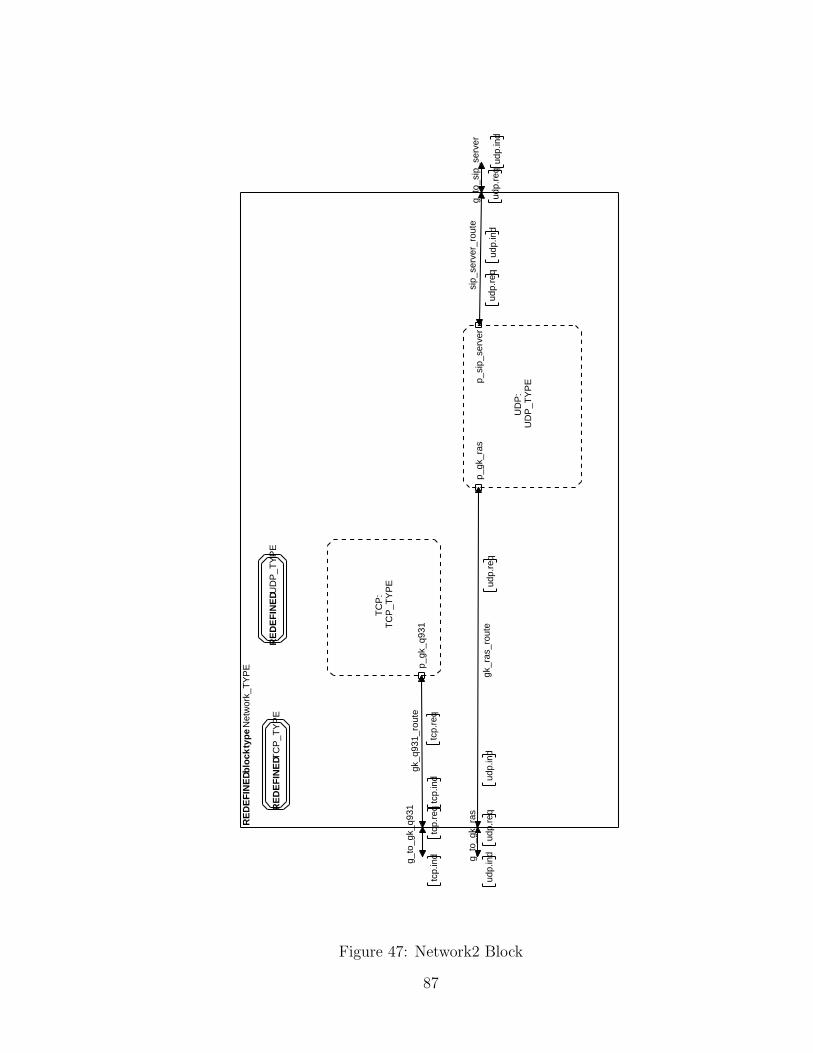
RE
DE
FIN
ED b
lock
typ
e N
etw
ork_
TY
PE
g_to
_gk_
q931
tcp.
req
tcp.
ind g_
to_g
k_ra
s
udp.
req
udp.
ind
g_to
_sip
_ser
ver
udp.
req
udp.
ind
gk_q
931_
rout
e
tcp.
ind
tcp.
req
gk_r
as_r
oute
udp.
req
udp.
ind
sip_
serv
er_r
oute
udp.
ind
udp.
req
RE
DE
FIN
ED T
CP
_TY
PE
RE
DE
FIN
ED U
DP
_TY
PE
TC
P:
TC
P_T
YP
E
p_gk
_q93
1
UD
P:
UD
P_T
YP
E
p_gk
_ras
p_si
p_se
rver
Figure 47: Network2 Block
87
Chapter 6
Simulation & Verification
We used ObjectGEODE as a simulation and verification tool. ObjectGEODE pro-
vides several techniques for simulation and verification: static checking, interactive
simulation, and exhaustive simulation. Static checking is provided to check the SDL
model against SDL static sematics: data type checking, connection checking. Static
checking can also use MSC models to check against the SDL model from the point of
view of static sematics. The limitation of static checking is that it cannot detect dead-
locks, unknown or multiple receiver, etc. Interactive simulation can provide dynamic
checking under the control of the user. The user plays the role of the environment
to send external signals. Interactive simulation can provide a step-by-step way to
simulate a model, and interactive simulation can generate MSC. Exhausive simula-
tion provides automatic and random execution of state transitions and generates long
simulation scenarios.
There are two solutions for modeling the environment: open model and closed
model. In case of open models, the user must define how the signals can be sent
to the model. The disadvantage is that the user must send the signals manually
in interactive mode. Besides, the automatic “feeding”, i.e., automatic sending of
model’s inputs of the model must be declared in exhaustive mode. Another solution
is to transform the open model into a closed model by introducing new processes
or blocks within the model to feed it with signal inputs. In our model, we use the
later solution by introducing TCP, UDP processes and network blocks to model the
network environment.
We use two configurations to simulate the system of interworking between H.323
88
and SIP. One configuration is without the assistance of H.323 gatekeeper and SIP
server. i.e., no registration procedure is needed on either side. The other configura-
tion includes H.323 gatekeeper and SIP server. Under this configuration, the H.323
endpoint and the SIP endpoint need to register in their administration domain area
respectively before any call setup is atempted. We also assume the IWF should also
register with both the H.323 gatekeeper and the SIP server before it can be involved in
any call setup or session initiation procedure. In this case, the IWF can be considered
as an H.323 gateway in H.323 and a SIP endpoint in SIP.
In our simulation, we use interactive simulation to simulate most successful sce-
narios and some of failure scenarios under the different configuration, such as the
procedure of H.245 fails. We use those scenarios as a case study to validate our
design against some of the specific properties of our model.
With the following scenarios, we have covered all the protocol primitives specified
as well as all important scenarios, but not all possible scenarios. Furthermore, we
have decided to send data along the media channel to verify that the call and media
connection have been successfully established between the H.323 EP and the SIP
EP, and that the session description has been successfully negotiated and exchanged
between the H.323 EP and the SIP EP via the IWF.
We generate a number of MSC for these scenario case studies to check the system
protocol functionality at each stage. We also trace the exchange of signals between
the processes. From the MSC, we are concerned with checking that the proper signal
is being produced and transmitted from the module involved, e.g., IWF translates
H.225 (Q.931) call signaling message into session initiation messages. We verify the
message mapping and state transition mentioned in the draft of interworking between
H.323 and SIP. We find that none was violated.
6.1 Configuration 1 (without H.323 Gatekeeper or
SIP Server)
We use the system SIP H323 Interwork1 to simulate our model. The system consists
of one H.323 Endpoint block, one SIP Endpoint block, and one IWF block. We also
include one network block as modeling of the environment. Thus, the whole system
is regarded as a closed system. The call establishment procedure can be initiated
89
from both directions. In the interworking draft, it gives some successful scenarios
for basic configuration and the configuration using both H.323 GK and SIP Server.
Those scenarios contain simple call, or other calls using advance feature of H.245
tunneling, early H.245, fast connect, and overlapped sending from H.323 endpoint to
SIP endpoint. We chose the following two scenarios for simple call to validate the
model.
6.1.1 A scenario that a call is initiated from H.323 EP to the
SIP EP
Figure 48 shows one successful scenario case under configuration 1 [1].
• H323 EP initiates a call setup to IWF to establish a media connection between
H323 EP and SIP EP.
• IWF translates the call setup signaling messages and initiates a session initiation
INVITE message to inform SIP EP.
• SIP EP accepts the session and sends response to IWF.
• IWF negotiates with H323 EP and coordinates H323 EP and SIP EP messages
to exchange the address and other parameters for establishing media connection
between H323 EP and SIP EP.
• H323 EP and SIP EP can communicate with each other through media channel.
• H323 EP informs IWF of releasing call control connection to terminate current
call with H.245 messages.
• IWF then follows the call termination procedure on H.323 side, and informs
SIP EP with SIP BYE messages to terminate session.
6.1.2 A scenario that a call is initiated from SIP EP to H.323
EP
Figure 49 shows one successful scenario case under configuration 1 [1].
90
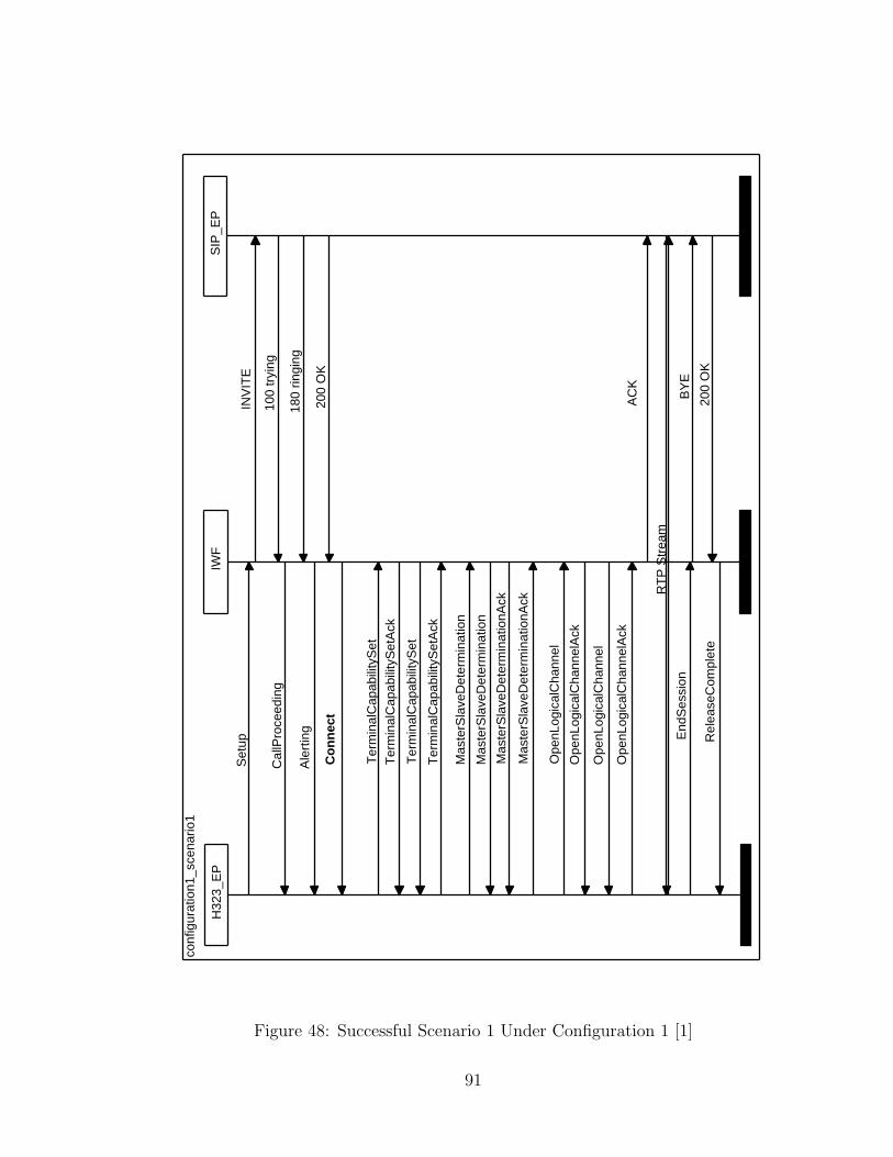
conf
igur
atio
n1_s
cena
rio1
Set
up
Cal
lPro
ceed
ing
Ale
rtin
g
Co
nn
ect
Ter
min
alC
apab
ility
Set
Ter
min
alC
apab
ility
Set
Ack
Ter
min
alC
apab
ility
Set
Ter
min
alC
apab
ility
Set
Ack
Mas
terS
lave
Det
erm
inat
ion
Mas
terS
lave
Det
erm
inat
ion
Mas
terS
lave
Det
erm
inat
ionA
ck
Mas
terS
lave
Det
erm
inat
ionA
ck
Ope
nLog
ical
Cha
nnel
Ope
nLog
ical
Cha
nnel
Ack
Ope
nLog
ical
Cha
nnel
Ope
nLog
ical
Cha
nnel
Ack
RT
P S
trea
m
End
Ses
sion
Rel
ease
Com
plet
e
INV
ITE
100
tryi
ng
180
ringi
ng
200
OK
AC
K
BY
E
200
OK
H32
3_E
PIW
FS
IP_E
P
Figure 48: Successful Scenario 1 Under Configuration 1 [1]
91
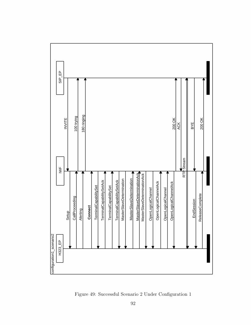
conf
igur
atio
n1_s
cena
rio2
Set
up
Cal
lPro
ceed
ing
Ale
rtin
g
Co
nn
ect
Ter
min
alC
apab
ility
Set
Ter
min
alC
apab
ility
Set
Ack
Ter
min
alC
apab
ility
Set
Ter
min
alC
apab
ility
Set
Ack
Mas
terS
lave
Det
erm
inat
ion
Mas
terS
lave
Det
erm
inat
ion
Mas
terS
lave
Det
erm
inat
ionA
ckM
aste
rSla
veD
eter
min
atio
nAck
Ope
nLog
ical
Cha
nnel
Ope
nLog
ical
Cha
nnel
Ack
Ope
nLog
ical
Cha
nnel
Ope
nLog
ical
Cha
nnel
Ack
RT
P S
trea
m
End
Ses
sion
Rel
ease
Com
plet
e
INV
ITE
100
tryi
ng
180
ringi
ng
200
OK
AC
K
BY
E
200
OK
H32
3_E
PIW
FS
IP_E
P
Figure 49: Successful Scenario 2 Under Configuration 1
92
• SIP EP initiates a session initiation INVITE message to IWF to establish a
media connection between SIP EP and H323 EP.
• IWF translates the session initiation messages and starts a call setup message
to inform H323 EP.
• H323 EP accepts the call and negotiates with IWF.
• IWF coordinates H323 EP and SIP EP messages to exchange the address and
other parameters of media for establishing media connection between H323 EP
and SIP EP.
• H323 EP and SIP EP can communicate with each other through the media
channel.
• SIP EP informs IWF to terminate the current session.
• IWF terminates the current session, and inform H.323EP of releasing call control
connection to terminate current call with H.245 messages.
• H.323 EP follows the termination procedure in H.323 side.
6.2 Configuration 2 (with H.323 Gatekeeper, and
SIP Server)
We use the system SIP H323 Interwork2, which inherits from SIP H323 Interwork1,
to simulate our model. The internal structure and behavior are extended or redefined
in SIP H323 Interwork2, e.g., H323 EP and SIP EP are configured as registration
mode so that both can send registration messages to H323 GK and SIP SERVER
respectively. Aside from one H.323 Endpoint block, one SIP Endpoint block, one
IWF block and one Network block, the system contains one H323 GK block and
one SIP SERVER block. The Network block is extended to support H323 GK and
SIP SERVER. The whole system is still regarded as a closed system. The call es-
tablishment procedure can be started from either direction. We also have chosen the
following two scenarios to validate the model.
93
6.2.1 A scenario that a call is initiated from H.323 EP to the
SIP EP
Figure 50 shows one successful scenario case under configuration 2.
• H323 EP and IWF register with H323 GK respectively.
• SIP EP and IWF register with SIP SERVER respectively.
• H323 EP acquires admission and address resolution from H323 GK before it
starts a call.
• H323 EP initiates a call setup and sends a call setup message to H323 GK to
establish a call between H323 EP and SIP EP.
• H323 GK routes call setup messages to IWF.
• IWF acquires admission and address resolution from H323 GK.
• IWF translates the call setup signaling message and initiates a session initiation
INVITE message to inform SIP SERVER.
• SIP SERVER resolves the destination address and forwards the session messages
to SIP EP.
• SIP EP accepts the session request from SIP SERVER and sends a response to
SIP SERVER.
• SIP SERVER routes responses from SIP EP to IWF.
• IWF then negotiates session description with H323 EP routed by H323 GK and
coordinates call procedure between both sides to establish media connection
between H323 EP and SIP EP.
• H323 EP and SIP EP can communicate with each other by media channel.
• H323 EP informs H323GK to release call connection to terminate current call
with H.245 releasecomplete message.
• H323 GK routes the H.245 messages from H323 EP to IWF.
94
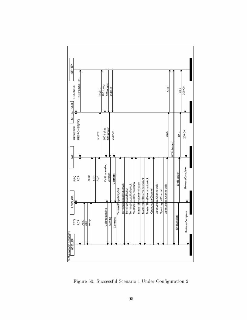
conf
igur
atio
n2_s
cena
rio1
RR
Q
RC
F
AR
QA
CF
setu
p
Cal
lPro
ceed
ing
Ale
rtin
g
Co
nn
ect
Ter
min
alC
apab
ility
Set
Ter
min
alC
apab
ility
Set
Ack
Ter
min
alC
apab
ility
Set
Ter
min
alC
apab
ility
Set
Ack
Mas
terS
lave
Det
erm
inat
ion
Mas
terS
lave
Det
erm
inat
ion
Mas
terS
lave
Det
erm
inat
ionA
ck
Mas
terS
lave
Det
erm
inat
ionA
ck
Ope
nLog
ical
Cha
nnel
Ope
nLog
ical
Cha
nnel
Ack
Ope
nLog
ical
Cha
nnel
Ope
nLog
ical
Cha
nnel
Ack
RT
P S
trea
m
End
Ses
sion
Rel
ease
Com
plet
e
RR
QR
CF
setu
p
AR
QA
CF
Cal
lPro
ceed
ing
Ale
rtin
g
Co
nn
ect
End
Ses
sion
Rel
ease
Com
plet
e
RE
GIS
TE
R
RE
SP
ON
SE
(OK
)
INV
ITE
100
tryi
ng18
0 rin
ging
200
OK
AC
K
BY
E
200
OK
RE
GIS
TE
R
RE
SP
ON
SE
(OK
)
INV
ITE
100
tryi
ng18
0 rin
ging
200
OK
AC
K
BY
E20
0 O
K
H32
3_E
PH
323_
GK
IWF
SIP
_SE
RV
ER
SIP
_EP
Figure 50: Successful Scenario 1 Under Configuration 2
95
• IWF then follows the termination procedure to terminate call connection on
H.323 side, and informs SIP SERVER with SIP BYE messages to terminate
the session.
• SIP SERVER routes the session messages from IWF to SIP EP.
• SIP EP terminates session and sends response indirectly to IWF routed by
SIP SERVER.
6.2.2 A scenario that a call is initiated from SIP EP to H323
EP
Figure 51 shows the above successful scenario case under configuration 2.
• SIP EP and IWF register with SIP SERVER respectively.
• H323 EP and IWF register with H323 GK respectively.
• SIP EP starts a call session by sending INVITE message to its SIP SERVER
to establish a media connection between SIP EP and H323 EP.
• SIP SERVER forwards the message to IWF.
• IWF acquires admission permission from H323 GK.
• IWF translates the session initiation messages and starts a call by sending call
setup message to H323 GK.
• H323 GK resolves the destination address and forwards the call setup message
to H323 EP.
• H323 EP acquires admission permission from H323 GK before it accepts the
call.
• H323 EP accepts the call and sends a response to IWF indirectly routed by
H323 GK.
• IWF negotiates with H.323 EP indirectly routed by H323 GK and coordinates
H323 EP and SIP EP messages to establish media connection between H323 EP
and SIP EP.
96
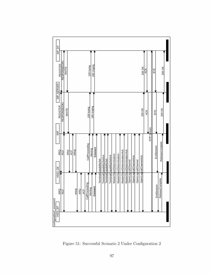
conf
igur
atio
n2_s
cean
rio2
RR
QR
CF
setu
p
AR
Q
AC
FC
allP
roce
edin
gA
lert
ing
Co
nn
ect
Ter
min
alC
apab
ility
Set
Ter
min
alC
apab
ility
Set
Ack
Ter
min
alC
apab
ility
Set
Ter
min
alC
apab
ility
Set
Ack
Mas
terS
lave
Det
erm
inat
ion
Mas
terS
lave
Det
erm
inat
ion
Mas
terS
lave
Det
erm
inat
ionA
ck
Mas
terS
lave
Det
erm
inat
ionA
ckO
penL
ogic
alC
hann
el
Ope
nLog
ical
Cha
nnel
Ack
Ope
nLog
ical
Cha
nnel
Ope
nLog
ical
Cha
nnel
Ack
RT
P S
trea
m
End
Ses
sion
Rel
ease
Com
plet
e
RR
QR
CF
AR
QA
CF
setu
p
Cal
lPro
ceed
ing
Ale
rtin
g
Co
nn
ect
End
Ses
sion
Rel
ease
Com
plet
e
RE
GIS
TE
RR
ES
PO
NS
E(O
K)
INV
ITE
100
tryi
ng
180
ringi
ng
200
OK
AC
K
BY
E
200
OK
RE
GIS
TE
RR
ES
PO
NS
E(O
K)
INV
ITE
100
tryi
ng
180
ringi
ng
200
OK
AC
K
BY
E
200
OK
H32
3_E
PH
323_
GK
IWF
SIP
_SE
RV
ER
SIP
_EP
Figure 51: Successful Scenario 2 Under Configuration 2
97
• H323 EP and SIP EP can communicate with media channel.
• SIP EP informs IWF indirectly routed by SIP SERVER to terminate current
session with SIP BYE messages.
• IWF sends a response to SIP EP via SIP SERVER, and terminates current call
with H.245 releasecomplete message in H.323 side.
• H323 EP follows the termination procedure to terminate the call.
6.3 Comparison between Configuration 1 and Con-
figuration 2
In functionality, IWF can be considered as an H.323 gateway in the H.323 zone and
a SIP endpoint in the SIP administration domain. In all cases, IWF should provide
message mapping function module between H.323 and SIP. In addition, in H.323 side,
IWF should provide basic function module of call signaling (Q.931). It also includes
function module of master/slave determination, capability negotiation, and opening
logical channel (H.245). In SIP side, IWF should provide basic function module
similar to SIP endpoint.
However, its other function may depend on the existence of H.323 gatekeeper
and SIP server. In order to compare with the function of IWF in different situa-
tions coexisting or not coexisting with H.323 gatekeeper and SIP server, we use two
configurations to simulate the system of interworking between H.323 and SIP. The
registration and address resolution issue is the main point to compare with. When
the system does not contain H.323 gatekeeper and SIP server, IWF is responsible
for address resolution in both H.323 zone and SIP administration domain. Therefore,
IWF should maintain a look-up table to provide address resolution for H.323 endpoint
and SIP endpoint, which can be statically configured if no registration service can
be provided for H.323 endpoint and SIP endpoint. Since no registration procedure is
needed in configuration 1, RAS function module is not used in configuration 1.
When IWF is configured to work with H.323 gatekeeper and SIP server, IWF has
no need to maintain a look-up table on its own, because it can get assistance from
H.323 gatekeeper and SIP server. However, it should first register itself with both
98
the H.323 gatekeeper and the SIP server. The registration information of two types
of endpoints are stored in H.323 gatekeeper and SIP server respectively. Moreover,
under this configuration, IWF does not have to translate the registration request
and pass the request from the H.323 zone to the SIP domain or vice versa. In the
H.323 side, when the H.323 endpoint initiates a call setup message, IWF will first
obtain admission from the H.323 gatekeeper, map to SIP INVITE message, and send
it to the SIP server, since all SIP messages are routed by SIP server. On the other
hand, in SIP side, when the SIP endpoint initiates a session message, IWF will first
obtain admission and address resolution from the H.323 gatekeeper, map to call setup
message, and send it to the H.323 gatekeeper, since all H.323 messages are routed by
the H.323 gatekeeper. From the above, we can see IWF does not have to maintain
address table for both sides when the system is configured with H.323 gatekeeper and
SIP server. Furthermore, because we assume all the calls are routed by the H.323
gatekeeper, IWF does not have to support location request message (LRQ) of RAS to
get address information of the H.323 destination endpoint in H.323 side. When IWF
sends an admission request messge (ARQ) for admission from the H.323 gatekeeper,
the H.323 gatekeeper just returns its own call signaling address. Therefore, when
the IWF receives session initiation messages from the SIP endpoint and sends call
setup messages to the H.323 gatekeeper, the H.323 gatekeeper will resolve destination
address and forward it to the H.323 destination endpoint. Likewise, in SIP side, the
IWF does not have to support the OPTIONS message to query the SIP server about
the destination’s address because all SIP session messages from the SIP endpoint or
the IWF are routed through SIP server. When the IWF receives call setup message
from the H.323 endpoint and sends SIP session initiation messages to the SIP server,
the SIP server will resolve destination address and forward it to the SIP endpoint.
99
Chapter 7
Conclusion & Future Work
7.1 Conclusion
In this paper, we have modeled and verified the system of interworking between
H.323 and SIP with two different configurations using SDL and MSC. Although de-
scribing protocols in a precise, yet understandable way is a very difficult task, SDL
as a formal description language for communications protocol modeling has provided
enough features to accomplish the above task. In our system modeling, the sim-
plicity and scalability of SDL are being completely evaluated in our model. We use
H323EP SUPERTYPE as a super block type of H323 EP block type and IWF block
type. H323 EP block type and IWF can inherit its internal structure and behavior
from H323EP SUPERTYPE for simplicity. Both blocks can also be extended by in-
troducing new channels and new processes or by redefining the internal behavior of
processes in super block type to provide scalability. We have found that the struc-
ture of SDL made the process of model enhancement easy. For example, since sys-
tem type SIP H323 Interworking2 inherits from system type SIP H323 Interworking1,
SDL provides same scalability and enhancement capability in the system type level.
From our work, we conclude that the fact of our design for the system of interworking
between SIP and H.323 is good by using SDL, which is proved as a simple and very
efficient method to verify and validate protocols. Furthermore, we make our own
contribution to describe all critical components in SIP-H.323 Interworking network,
which not only includes the IWF, but also the H.323 endpoint, the SIP endpoint, the
H.323 gatekeeper, and the SIP server. We define all internal behavior of our processes
100
by converting finite state machine mentioned in the Internet Drafts for SIP-H323 in-
terworking into SDL. Moreover, we use interactive simulation to simulate and verify
the property of our model. We have verified most of the succeessful scenarios and
some of the failure scenarios. Besides, we use MSC to help the verification of dynamic
behavior of our system model. Finally, we identited that the advanced feature of IWF
and advanced service based on SIP-H.323 system is a hot research topic and being
currently investigated.
7.2 Future Work
We have laid the foundation for the modeling of basic feature of SIP-H.323 system.
Due to extensibility of SDL and our design, our system can be expanded to enhance
the advanced feature of IWF to support H.323 fast start, H.245 tunneling, and over-
lapped sending in H.323. In addition, our system can be expanded to enhance the
SIP re-invite feature in SIP. Furthermore, our system can be expanded for collabo-
ration with multiple H.323 gatekeepers and multiple SIP servers. Moreover, we can
integrate the different models into a single, but much larger system. For example, we
can integrate MGCP system model and SIP-h323 Interworking system model into a
larger system to find more useful property. Finally, our model can be also a starting
point to begin the research of 3GPP network since SIP has been defined as signaling
protocol in next generation network architecture.
101
Bibliography
[1] Hemant Agrawal, Radhika R Roy, Vipin Palawat, Alan Johnston, Charles Agboh,
David Wang, Henning Schulzrinne, Kundan Singh, and Joon Maeng, SIP-H.323
Interworking, Internet Draft, Internet Engineering Task Force, July 13, 2001,
work in progress.
[2] H. Schulzrinne, S. Casner, R. Frederick, and V. Jacobson, RTP: a transport
protocol for real-time applications, Request for Comments (Proposed Standard)
1889, Internet Engineering Task Force, Jan. 1996.
[3] M. Handley, H. Schulzrinne, E. Schooler, and J. Rosenberg, SIP: session initiation
protocol, Request for Comments (Proposed Standard) 2543, Internet Engineering
Task Force, May 29, 2001.
[4] M. Handley and V. Jacobson, SDP: session description protocol, Request for
Comments 2327, Internet Engineering Task Force, Apr.1998.
[5] M. Handley, C. Perkins, and E. Whelan, Session announcement protocol, Request
for Comments 2974, Internet Engineering Task Force, Oct. 2000.
[6] M. Arango et al., Media Gateway Control Protocol, version 1.0, Request for
Comments 2705, Internet Engineering Task Force, OCT 1999.
[7] Ligang Wang, Anjali Agarwal, and J.William Atwood, Description and Valida-
tion of the Media Gateway Control Protocol (MGCP) Using SDL/MSC, IEEE
Canada, (CCECE2001), ISDN: 0-7803-6715-4/01,May 13-16, 2001.
[8] International Telecommunication Union, Packet based multimedia communica-
tion systems, Recommendation H.323, Telecommunication Standardization Sec-
tor of ITU, Geneva, Switzerland, Feb. 1998.
102
[9] K. Singh and H. Schulzrinne, Interworking between SIP/SDP and H.323, Internet
Draft, Internet Engineering Task Force, Jan. 2000. Work in progress.
[10] Girish Keshav Palshikar, Applying Formal Specificaitions to Real-World Software
Development, IEEE Software, November/December 2001, pp. 89-94.
[11] NASA, Formal Methods Specification and Verification Guidebook for Software
and Computer Systems Volume I: Planning and Technology Insertion, NASA-
GB-002, December,1998.
[12] R. Braden, Ed., L. Zhang, S. Berson, S. Herzog, and S. Jamin, Resource ReSerVa-
tion protocol (RSVP) – version 1 functional specification, Request for Comments
2205, Internet Engineering Task Force, Sept. 1997.
[13] H. Schulzrinne, A. Rao, and R. Lanphier, Real time streaming protocol (RTSP),
Request for Comments 2326, Internet Engineering Task Force, Apr. 1998.
[14] T. Berners-Lee, L. Masinter, and M. McCahill, Uniform resource locators (URL),
Request for Comments 1738, Internet Engineering Task Force, Dec. 1994.
[15] T. Berners-Lee, R. Fielding,and L. Masinter, Uniform Resource Identifiers (URI),
Request for Comments 2396, Internet Engineering Task Force, August 1998
[16] H. Schulzrinne and J. Rosenberg, A comparison of SIP and H.323 for internet
telephony, International Workshop on Network and Operating, System Support
for Digital Audio and Video (NOSSDAV), pp. 83-86, July 1998.
[17] International Telecommunication Union, Digital subscriber signalling system
no. 1 (dss 1) - isdn user-network interface layer 3 specification for basic call
control, Recommendation Q.931, Telecommunication Standardization Sector of
ITU, Geneva, Switzerland, Mar. 1993.
[18] CCITT, Recommendation Z.100 — Specification and Description Language
(SDL), 1993.
[19] CCITT, Recommendation Z.120 — Message Sequence Charts (MSC), 1996.
[20] A. Olsen et al., Systems Engineering using SDL-92, North-Holland, 1994.
[21] Verilog, Toulouse, France, ObjectGeode, 1996.
103