Embed Size (px)
Citation preview
A Framework for Enabling Fault Tolerance inReconfigurable Architectures
Kostas Siozios1, Dimitrios Soudris1 and Dionisios Pnevmatikatos2
1 School of Elect. & Computer Eng., National Technical University of Athens, Greece2 Electronic & Computer Eng. Department, Technical University of Crete, Greece
Abstract. Fault tolerance is a pre-request not only for safety criticalsystems, but almost for the majority of applications. However, the ad-ditional hardware elements impose performance degradation. In this pa-per we propose a software-supported methodology for protecting recon-figurable architectures against Single Event Upsets (SEUs), even if thetarget device is not aware about this feature. This methodology initiallypredicts areas of the target architecture where faults are most possible tooccur and then inserts selectively redundancy only there. Based on ex-perimental results, we show that our proposed selectively fault-toleranceresults to a better tradeoff between desired level of reliability and area,delay, power overhead.
1 Introduction
SRAM-based Field-Programmable Gate Arrays (FPGAs) are arrays of Con-figurable Logic Blocks (CLBs) and programmable interconnect resources, sur-rounded by programmable input/output pads on the periphery. Even thoughtheir programmability feature makes them suitable for widely application im-plementation, a number of design issues have to be tackled. Among others, relia-bility issue becomes worse as devices have evolved. For instance, as the transistorgeometry and core voltages decrease, while the numbers of transistors per chipand the switching frequency increase, the target architectures become more sus-ceptible to incur faults (i.e., flipped bit or a transient within a combinatoriallogic path). Consequently, mechanisms that handle faults detection and correc-tion during device operation are required, even for non critical safety systems.
The last ten years many discussions were done about the design of reliablearchitectures with fault tolerant features. More specifically, the term fault tol-erant corresponds to a design which is able to continue operation, possibly ata reduced level, rather than failing completely, when some part of the systemfails [1, 3, 4, 5, 6, 8, 9, 10, 11, 12, 13, 14]. These solutions include fabrica-tion process-based techniques (i.e. epitaxial CMOS processes) [10], design-basedtechniques (i.e. hardware replicas, time redundancy, error detection coding, self-checker techniques) [4], mitigation techniques (i.e. multiple redundancy withvoting, error detection and correction coding) [5], and recovery techniques (i.e.reconfiguration scrubbing, partial configuration, rerouting design) [11].

Even though fault tolerance is a well known technique, up to now it wasmostly studied for ASIC designs. However FPGAs poses new constraints (i.e.higher power density, more logic and interconnection resources, etc), while theexisting fault models are not necessarily applicable. To make matters worse,faults in FPGAs can alter the design, not just user data. In addition to that,the FPGA designs utilize only a subset of the fabricated resources, and henceonly a subset of the occurred faults may result to faulty operation. Consequently,FPGA-specific mitigation techniques are required, that can provide a reasonablebalance among the desired fault prevention, the performance degradation, thepower consumption and the area overhead due to the additional hardware.
Up to now there are two approaches for preventing faults occurring on FP-GAs. The first of them deals with the design of new hardware elements which arefault tolerant enabled [2, 4, 12, 15]. These resources can either replace existinghardware blocks in FPGAs, or new architectures can be designed to improverobustness. On the other hand, it is possible to use an existing FPGA deviceand provide the fault tolerance at higher level with CAD tools [2, 3, 4, 8, 13,14].
Both of these approaches have advantages and disadvantages, which need tobe carefully concerned. More specifically, the first approach results to a morecomplex architecture design, while the derived FPGA provides a static (i.e. de-fined at design time) fault tolerant mechanism. On the other hand, the imple-mentations belonging on second approach potentially are able to combine therequired dependability level, offered by fault tolerant architectures, with the lowcost of commodity devices. However, this scenario imposes that the designer isresponsible for protecting his/her own design.
In [12] a fault tolerant interconnection structure is discussed, where the faultsare corrected by spare routing channels which are not used during place and route(P&R). A similar work is discussed in [13], where a defect map is taken as inputto P&R tool and then application’s functionalities are not placed in the faultyblocks. In another approach [14], EDA tools take as input a generic defect map(which may be different from the real defect map of the chip) and generate aP&R according to this. A work that deals with a yield enhancement schemebased on the usage of spare interconnect resources in each routing channel inorder to tolerate functional faults, is discussed in [15]. The only known com-mercial approach for supporting fault tolerance in FPGAs can be found in [8].This implementation inserts two replica blocks for each of the application’s logicblocks, which are working in parallel, while the output is derived by comparingtheir outputs with a majority voting. Table 1 gives a qualitative comparison interms of supported features for a number of fault tolerant approaches found inrelevant references.
In this paper we propose a software supported methodology that improvesapplication’s reliability, without inserting excessive amount of redundancy overthe entire FPGA architecture. More specifically, we identify sensitive sub-circuits(where faults are most possible to occur) and we apply the proposed fault toleranttechnique only at these critical regions rather than inserting redundancy in the

entire device. Such an approach results to better tradeoff between desired faultcoverage and area, delay and power consumption.
Table 1. Qualitative comparison among fault tolerant approaches.
Feature [8] [12] [13] [14] [15] Proposed
Fault tolerantTMR Spare Defect Defect Spare TMR &
routing map map routing fault mapProtects Logic Routing Logic Logic Routing LogicModifies HDL Hardware HDL HDL Hardware HDLApplied uniformly Yes Yes No No Yes No
Onlinefault management No No No No No Yes
Multiple faulttolerant techniques No No Yes No No YesSoftware support Yes No Yes Yes No YesPublic available No No No No No YesComplete framework Yes No No No No Yes
The main contributions of this paper are summarized, as follows:
1. We introduce a novel methodology for supporting on-line fault detection andcorrection for FPGA devices.
2. We identify sensitive sub-circuits (where faults are most possible to occur)and we apply the proposed fault tolerant technique only at these points,rather than inserting redundancy in the entire device.
3. We developed a tool that automates the introduction of redundancy intocertain portions of an HDL design.
4. The derived application implementations are validated with a new platformsimulator.
The rest paper is organized as follows: In section 2 we discuss the motivationof this paper, while section 3 describes the implemented fault tolerant technique.The proposed methodology, as well as its evaluation is discussed in detail insections 4 and 5, respectively. Finally, conclusions are summarized in section 6.
2 Motivation
The source of errors in ICs can be traced to three main categories: (i) dueto internal to the component (i.e. component failure, damage to equipment,cross-talk on wires), (ii) generally external causes (i.e. lightning disturbances,radiation effects, electromagnetic fields), and (iii) either internal or external (i.e.power disturbances, various kinds of electrical noise). Classifying the source ofthe disturbance is useful in order to minimize its strength, decrease its frequencyof occurrence, or change its other characteristics to make it less disturbing tothe hardware component.

The first step in order to build a reliable system is to identify possible re-gions with increased probability of failure. Throughout this paper we study faultsrelated to power, thermal, as well as random effects. More specifically, the in-creased switching activity results to higher power consumption and consequentlyto higher on-chip temperatures. In [17], Black mentioned that the mean time tofailure (MTTF ) of aluminum interconnects exponentially decreases as the tem-perature (T ) of a chip increases. Equation 1 gives the mathematical expressionthat describes this phenomenon.
MTTF ∝ eEakT
Jndc
(1)
where Ea is the enable energy (its value is defined experimentally), Jdc denotesthe threshold of electromigration current, while n and k are constants. Theswitching activity of an application is a property which does not depend either tothe target platform, or the employed toolset that performs application mapping.However, the employed toolset introduce some constraints regarding the spatialdistribution of regions with excessive high (or low) values and consequently withincreased (or decreased) probability of failure [18]. Regarding the random faults,they exhibit a distribution of independent (non-correlated) failures.
By combining the spatial variation of these values of the three parametersover the FPGA device, we are able to identify regions with increased failureprobability. In order to show that different applications result to different distri-butions of failure probabilities (even for the same P&R algorithms), Fig.1 plotsthis variation over an 64×64 FPGA array regarding the s298 and frisc bench-marks, without considering yet any redundancy. In this figure, different colorsdenote different failure probabilities, while as closer to red color a region is, thehigher probability for this region to occur a fault.
Increased failure probability
Reduced failure probability
100%80%60%40%20%0%
10 20 30 40 50 60
10
20
30
40
50
60
10 20 30 40 50 60
10
20
30
40
50
60
(a) (b)
Fig. 1. Spatial distribution of failure probability for (a) s298 and (b) frisc benchmarks.

Based on these maps, it is evident that the failure probability is not constantacross the FPGA or among different applications, since it varies between twoarbitrary points (x1,y1) and (x2,y2) of device. Based on this distribution it isfeasible to determine regions on the device with excessive high values of failureprobability (regions of importance), where we have to pay effort in order toincrease the fault tolerance. Consequently, the challenge, with which a designeris faced up, is to choose only the actually needed redundancy level, consideringthe associated spatial information from the distribution graph.
A second important conclusion is drawn from Fig.1: although the majority ofexisting fault tolerant techniques exhibits a homogeneous and regular structure,the actually critical for failure resources provide a non − homogeneous andirregular picture. Consequently, careful analysis of the points of failure mustbe performed, while the target system implementation needs to combine regionswith different density of fault tolerance.
3 Proposed Fault Tolerant Technique
Our target is a generic recent FPGA device similar to the Xilinx Virtex architec-ture, consisting of an array of configurable logic blocks (CLBs), memories, DSPcores and programmable input and output blocks (placed on its periphery). Weassume that the logic blocks are formed by a number of Basic Logic Elements(BLEs), each of which is composed of a set of programmable Look-Up Tables(LUTs), multiplexers, and flip-flops. The communication among these hardwareblocks is provided by a hierarchical interconnection network of fast and versatilerouting resources. More info regarding the architecture of target FPGA can befound in [19].
In order to provide fault tolerance, we incorporate an R-fold modular redun-dancy (RMR) technique. Such a mechanism can effectively mask faults if onlyless than ((R+ 1)/2) replicas are faulty (either on combinational and sequentiallogic), but the faults present in different register locations and the voter worksproperly. This approach was first studied by J. Neumann [16], while the onlycommercial software product [8] for supporting fault tolerance in FPGAs is alsobased on this technique.
The main advantages of incorporating an RMR-based technique are summa-rized, as follows: (i) the corrective action is immediate, since the faulty modulenever affects the circuit, (ii) there is no need for fault detection procedures,and (iii) the conversion of a non-redundant system to a redundant one is easilyundertaken without hardware modifications. On the other hand, this approachcannot recover faults occurred on routing fabric. If these faults are also requiredto be detected and repaired, another technique (usually based on spare routingresources) must be incorporated in conjunction.
At the RMR-based technique, the reconfigurable platform is encoded as aM -of-N system, consisting of N hardware blocks where at least M (M<=N) ofthem are required for proper device operation. Let’s assume that different blocksfail with statistically independent order and if a block fails then it remains non-
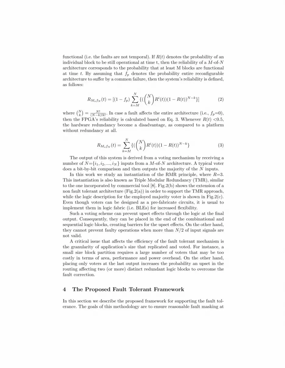
functional (i.e. the faults are not temporal). If R(t) denotes the probability of anindividual block to be still operational at time t, then the reliability of a M -of-Narchitecture corresponds to the probability that at least M blocks are functionalat time t. By assuming that fp denotes the probability entire reconfigurablearchitecture to suffer by a common failure, then the system’s reliability is defined,as follows:
RMofN (t) = [(1− fp)
N∑k=M
{((N
k
)Ri(t))(1−R(t))N−k}] (2)
where(Nk
)= N !
(N−k)!k! . In case a fault affects the entire architecture (i.e., fp=0),
then the FPGA’s reliability is calculated based on Eq. 3. Whenever R(t) <0.5,the hardware redundancy become a disadvantage, as compared to a platformwithout redundancy at all.
RMofN (t) =
N∑k=M
{((N
k
)Ri(t))(1−R(t))N−k} (3)
The output of this system is derived from a voting mechanism by receiving anumber of N={i1, i2, ..., iN} inputs from a M -of-N architecture. A typical voterdoes a bit-by-bit comparison and then outputs the majority of the N inputs.
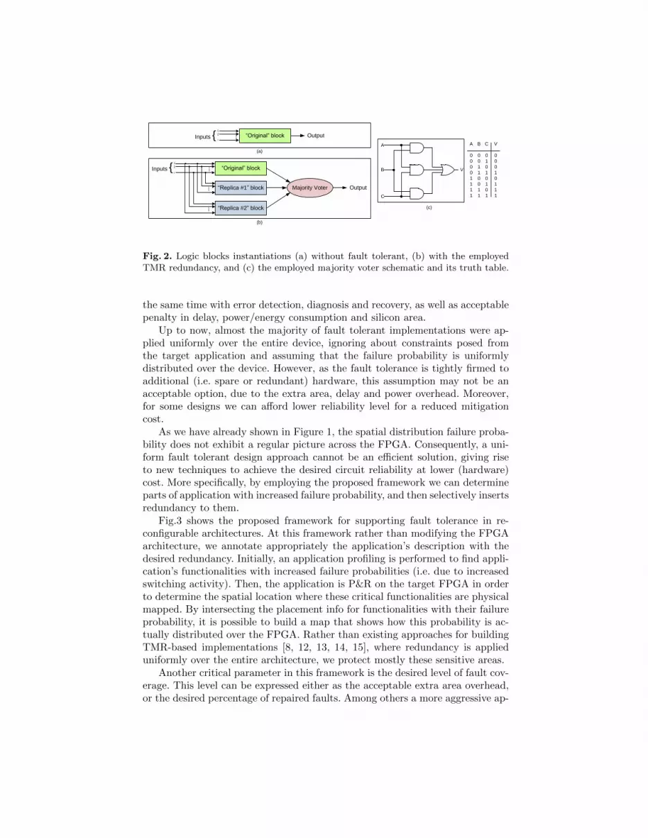
In this work we study an instantiation of the RMR principle, where R=3.This instantiation is also known as Triple Modular Redundancy (TMR), similarto the one incorporated by commercial tool [8]. Fig.2(b) shows the extension of anon fault tolerant architecture (Fig.2(a)) in order to support the TMR approach,while the logic description for the employed majority voter is shown in Fig.2(c).Even though voters can be designed as a pre-fabricate circuits, it is usual toimplement them in logic fabric (i.e. BLEs) for increased flexibility.
Such a voting scheme can prevent upset effects through the logic at the finaloutput. Consequently, they can be placed in the end of the combinational andsequential logic blocks, creating barriers for the upset effects. On the other hand,they cannot prevent faulty operations when more than N/2 of input signals arenot valid.
A critical issue that affects the efficiency of the fault tolerant mechanism isthe granularity of application’s size that replicated and voted. For instance, asmall size block partition requires a large number of voters that may be toocostly in terms of area, performance and power overhead. On the other hand,placing only voters at the last output increases the probability an upset in therouting affecting two (or more) distinct redundant logic blocks to overcome thefault correction.
4 The Proposed Fault Tolerant Framework
In this section we describe the proposed framework for supporting the fault tol-erance. The goals of this methodology are to ensure reasonable fault masking at
“Original” block OutputInputs {1
2
i
(a)
(b)
“Original” block
“Replica #1” block
“Replica #2” block
Majority Voter Output
Inputs {1
2
i
A
B
C
V
A
0
0
0
0
1
1
1
1
B
0
0
1
1
0
0
1
1
C
0
1
0
1
0
1
0
1
V
0
0
0
1
0
1
1
1
(c)
Fig. 2. Logic blocks instantiations (a) without fault tolerant, (b) with the employedTMR redundancy, and (c) the employed majority voter schematic and its truth table.
the same time with error detection, diagnosis and recovery, as well as acceptablepenalty in delay, power/energy consumption and silicon area.
Up to now, almost the majority of fault tolerant implementations were ap-plied uniformly over the entire device, ignoring about constraints posed fromthe target application and assuming that the failure probability is uniformlydistributed over the device. However, as the fault tolerance is tightly firmed toadditional (i.e. spare or redundant) hardware, this assumption may not be anacceptable option, due to the extra area, delay and power overhead. Moreover,for some designs we can afford lower reliability level for a reduced mitigationcost.
As we have already shown in Figure 1, the spatial distribution failure proba-bility does not exhibit a regular picture across the FPGA. Consequently, a uni-form fault tolerant design approach cannot be an efficient solution, giving riseto new techniques to achieve the desired circuit reliability at lower (hardware)cost. More specifically, by employing the proposed framework we can determineparts of application with increased failure probability, and then selectively insertsredundancy to them.
Fig.3 shows the proposed framework for supporting fault tolerance in re-configurable architectures. At this framework rather than modifying the FPGAarchitecture, we annotate appropriately the application’s description with thedesired redundancy. Initially, an application profiling is performed to find appli-cation’s functionalities with increased failure probabilities (i.e. due to increasedswitching activity). Then, the application is P&R on the target FPGA in orderto determine the spatial location where these critical functionalities are physicalmapped. By intersecting the placement info for functionalities with their failureprobability, it is possible to build a map that shows how this probability is ac-tually distributed over the FPGA. Rather than existing approaches for buildingTMR-based implementations [8, 12, 13, 14, 15], where redundancy is applieduniformly over the entire architecture, we protect mostly these sensitive areas.
Another critical parameter in this framework is the desired level of fault cov-erage. This level can be expressed either as the acceptable extra area overhead,or the desired percentage of repaired faults. Among others a more aggressive ap-
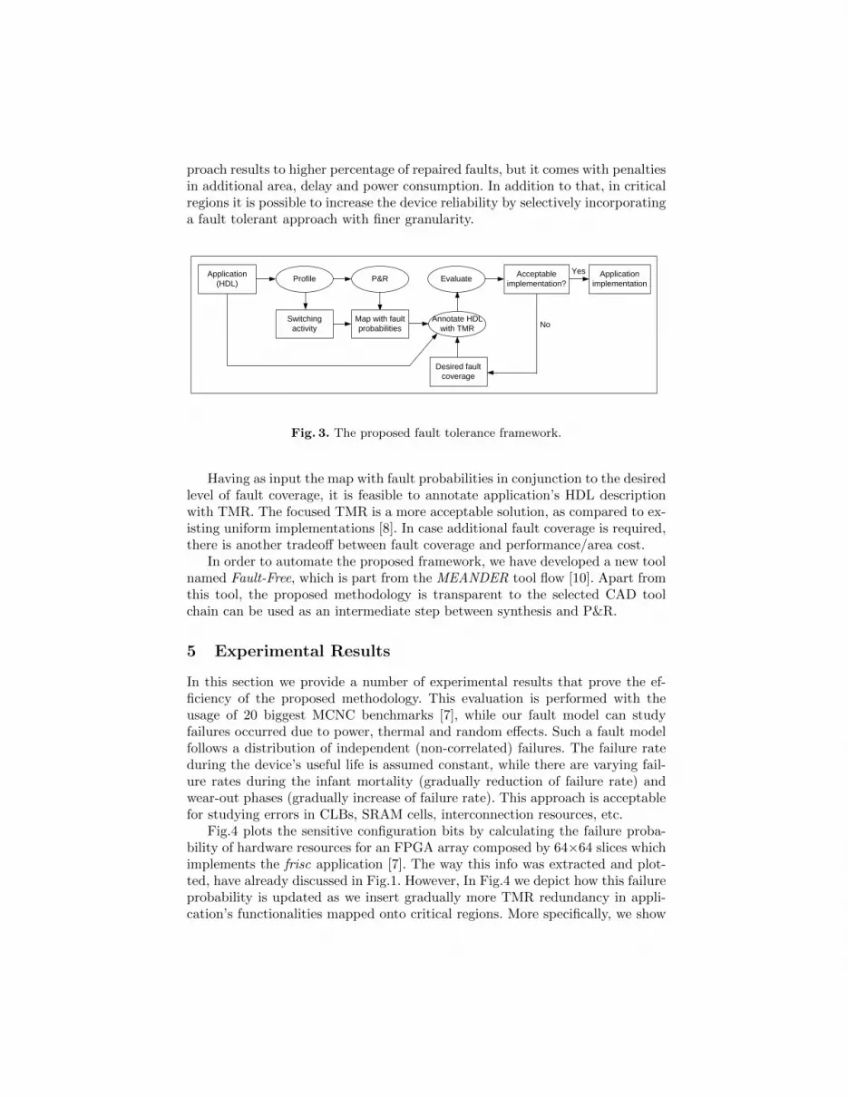
proach results to higher percentage of repaired faults, but it comes with penaltiesin additional area, delay and power consumption. In addition to that, in criticalregions it is possible to increase the device reliability by selectively incorporatinga fault tolerant approach with finer granularity.
Application (HDL) Profile
Switching activity
Desired fault coverage
Map with fault probabilities
Annotate HDL with TMR
P&R
No
EvaluateYes Application
implementationAcceptable
implementation?
Fig. 3. The proposed fault tolerance framework.
Having as input the map with fault probabilities in conjunction to the desiredlevel of fault coverage, it is feasible to annotate application’s HDL descriptionwith TMR. The focused TMR is a more acceptable solution, as compared to ex-isting uniform implementations [8]. In case additional fault coverage is required,there is another tradeoff between fault coverage and performance/area cost.
In order to automate the proposed framework, we have developed a new toolnamed Fault-Free, which is part from the MEANDER tool flow [10]. Apart fromthis tool, the proposed methodology is transparent to the selected CAD toolchain can be used as an intermediate step between synthesis and P&R.
5 Experimental Results
In this section we provide a number of experimental results that prove the ef-ficiency of the proposed methodology. This evaluation is performed with theusage of 20 biggest MCNC benchmarks [7], while our fault model can studyfailures occurred due to power, thermal and random effects. Such a fault modelfollows a distribution of independent (non-correlated) failures. The failure rateduring the device’s useful life is assumed constant, while there are varying fail-ure rates during the infant mortality (gradually reduction of failure rate) andwear-out phases (gradually increase of failure rate). This approach is acceptablefor studying errors in CLBs, SRAM cells, interconnection resources, etc.
Fig.4 plots the sensitive configuration bits by calculating the failure proba-bility of hardware resources for an FPGA array composed by 64×64 slices whichimplements the frisc application [7]. The way this info was extracted and plot-ted, have already discussed in Fig.1. However, In Fig.4 we depict how this failureprobability is updated as we insert gradually more TMR redundancy in appli-cation’s functionalities mapped onto critical regions. More specifically, we show

results about D=30% and D=45% redundant hardware blocks, as compared toimplementation without redundancy (i.e. D=0%) and the existing TMR whichis applied uniformly over the device (D=100%) [8].
Based on Fig.4, a number of conclusion may be derived. Among others, aswe apply more redundancy (i.e. increase D), the failure probability decreases.However, this decrease is not linear, since the improvement in failure probabilityfrom D=0% to D=30% is much higher as compared to the case where D rangefrom 45% up to 100%. In addition to that, even for the case where TMR is applieduniformly over the FPGA (i.e. D=100%), there is still a failure probability dueto errors occurred at the interconnection network.
(b) D=30% redundant hardware(a) Without TMR (D=0%)
(c) D=45% redundant hardware
10 20 30 40 50 60
10
20
30
40
50
60
(d) D=100% redundant hardware [8]
Increased failure probability
Reduced failure probability
100%80%60%40%20%0%
10 20 30 40 50 60
10
20
30
40
50
60
10 20 30 40 50 60
10
20
30
40
50
60
10 20 30 40 50 60
10
20
30
40
50
60
10 20 30 40 50 60
10
20
30
40
50
60
Fig. 4. Resource map with increased failure probability about frisc benchmark fordifferent percentages of TMR redundancy.
The efficiency for the alternative TMR-based implementations discussed inthis paper can be found in Fig.5, where we study the percentage of repairedover the injected faults. More specifically, in order to make this experiment, foreach of the curves we calculate the bitstream file for frisc application. This sizeranges from B=865 Kbits (D=0%) up to B=1382 Kbits (D =100%), while eachof these files remains constant along the corresponding curve. Then, we inject

randomly a number of faulty bits in this configuration data. The amount of faultyinjected bits, mention with F , ranges from 5% up to 20% of the configuration’sfile size. We assume that the faults are randomly distributed between logic andinterconnection resources. If a single fault occurred at logic block (i.e. CLB) thatincorporates TMR mechanism, the fault is repaired. Otherwise (i.e. more thanone faults on logic or fault(s) in routing fabric), these faults cannot be eliminatedand reported in the Fig.5. The horizontal axis of this figure corresponds to
Percentage of injected faults
5% 10% 15% 20% 25%
Pe
rce
nta
ge
of
rem
ain
ing
fa
ult
ty b
its
in c
on
fig
ura
tio
n d
ata
0%
10%
20%
30%
40%
50%
60%
70%
80%
90%
100%
Realistic
scenarios
D=0%
D=15%
D=30%
D=45%
D=100% [8]
5%
22%20%
13%
D = 0%
D = 45%
D=100% [8]
D = 30%
D = 15%
Fig. 5. Percentage of faulty bits for different injection rates regarding the frisc appli-cation.
the percentage of injected faulty bits over the size of configuration data, whilethe vertical one shows the percentage of faulty bits over the total injected bitsthat remain faulty after applying the recovery mechanism. In other words, thevertical axis plots the efficiency to repair faults for the alternative redundantimplementations. As a reference point we use the scenario without redundancy,denoted as D=0%. Also, in this graph we highlight the values affecting resonablescenarios about the expected percentages of occurring faults in real-life or exotic(i.e. space, military) applications.
Based on Fig.5 we can conclude that the proposed methodology results tosignificant error prevention, even for the cases with small area overhead (i.e.D=30%). More specifically, such a redundancy scheme results about to 65% er-ror correction in case where F=5%. In case a more aggressive implementation isassumed (i.e. D=45%), then the error correction is about 88%, as compared toan implementation without redundancy (D=0%). The existing TMR approach[8] results to an additional improvement of 5%, but this impose 55% more re-dundancy. Also, we have to mention that even when all the functionalities arereplicated with TMR (D=100%), there is still a failure probability, since TMRdoes not prevent faults in routing infrastructure.
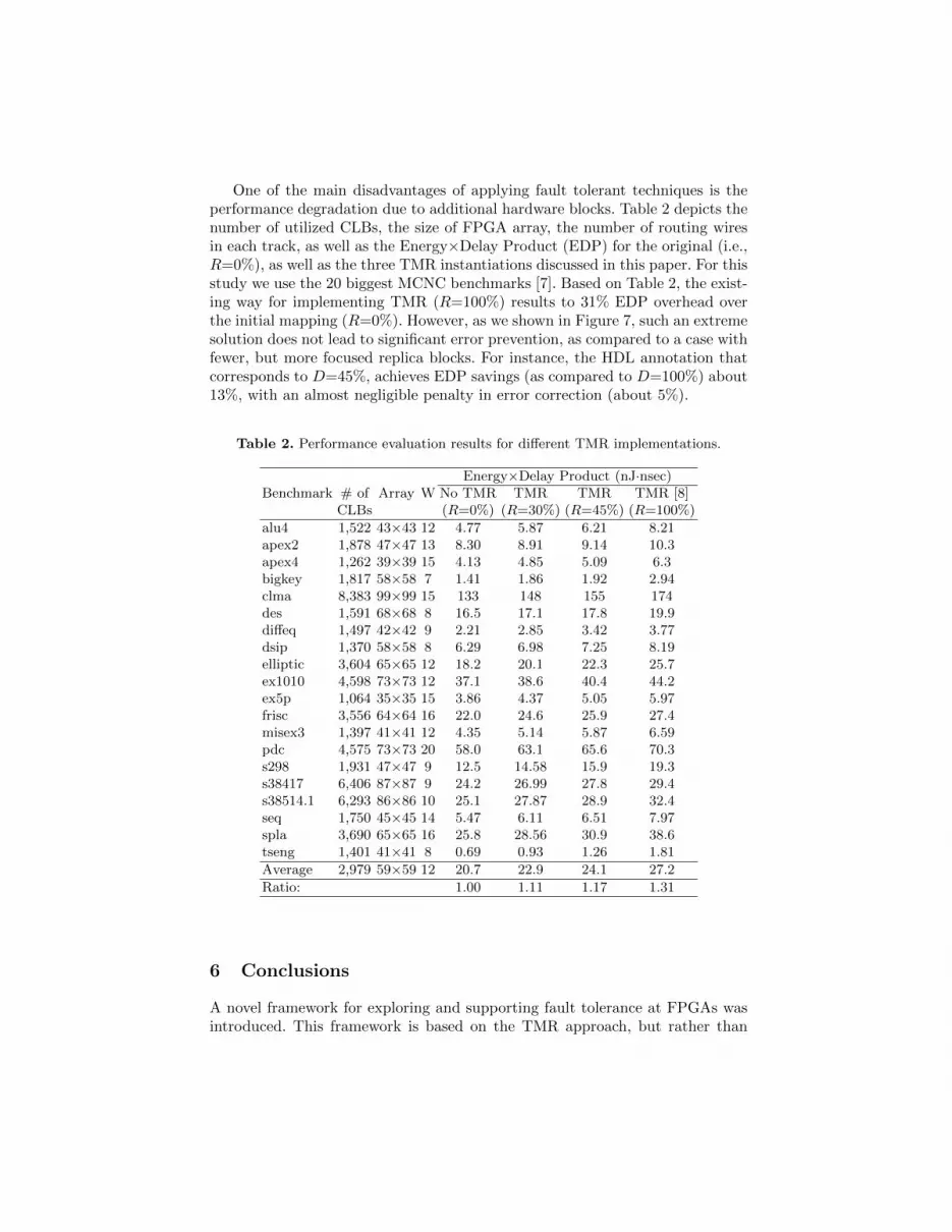
One of the main disadvantages of applying fault tolerant techniques is theperformance degradation due to additional hardware blocks. Table 2 depicts thenumber of utilized CLBs, the size of FPGA array, the number of routing wiresin each track, as well as the Energy×Delay Product (EDP) for the original (i.e.,R=0%), as well as the three TMR instantiations discussed in this paper. For thisstudy we use the 20 biggest MCNC benchmarks [7]. Based on Table 2, the exist-ing way for implementing TMR (R=100%) results to 31% EDP overhead overthe initial mapping (R=0%). However, as we shown in Figure 7, such an extremesolution does not lead to significant error prevention, as compared to a case withfewer, but more focused replica blocks. For instance, the HDL annotation thatcorresponds to D=45%, achieves EDP savings (as compared to D=100%) about13%, with an almost negligible penalty in error correction (about 5%).
Table 2. Performance evaluation results for different TMR implementations.
Energy×Delay Product (nJ·nsec)Benchmark # of Array W No TMR TMR TMR TMR [8]
CLBs (R=0%) (R=30%) (R=45%) (R=100%)
alu4 1,522 43×43 12 4.77 5.87 6.21 8.21apex2 1,878 47×47 13 8.30 8.91 9.14 10.3apex4 1,262 39×39 15 4.13 4.85 5.09 6.3bigkey 1,817 58×58 7 1.41 1.86 1.92 2.94clma 8,383 99×99 15 133 148 155 174des 1,591 68×68 8 16.5 17.1 17.8 19.9diffeq 1,497 42×42 9 2.21 2.85 3.42 3.77dsip 1,370 58×58 8 6.29 6.98 7.25 8.19elliptic 3,604 65×65 12 18.2 20.1 22.3 25.7ex1010 4,598 73×73 12 37.1 38.6 40.4 44.2ex5p 1,064 35×35 15 3.86 4.37 5.05 5.97frisc 3,556 64×64 16 22.0 24.6 25.9 27.4misex3 1,397 41×41 12 4.35 5.14 5.87 6.59pdc 4,575 73×73 20 58.0 63.1 65.6 70.3s298 1,931 47×47 9 12.5 14.58 15.9 19.3s38417 6,406 87×87 9 24.2 26.99 27.8 29.4s38514.1 6,293 86×86 10 25.1 27.87 28.9 32.4seq 1,750 45×45 14 5.47 6.11 6.51 7.97spla 3,690 65×65 16 25.8 28.56 30.9 38.6tseng 1,401 41×41 8 0.69 0.93 1.26 1.81
Average 2,979 59×59 12 20.7 22.9 24.1 27.2
Ratio: 1.00 1.11 1.17 1.31
6 Conclusions
A novel framework for exploring and supporting fault tolerance at FPGAs wasintroduced. This framework is based on the TMR approach, but rather than

annotating the whole application’s description with redundancy, we replicateonly application’s functionalities implemented onto regions with increased fail-ure probability. Since our framework does not require dedicated hardware blocksfor supporting fault tolerance, it leads to increased flexibility, while it can bealso applied to commercial devices as an additional step between synthesis andP&R. Moreover, our approach can provide a tradeoff between the desired reli-ability level and the extra overhead due to extra hardware resources. Based onexperimental results, we shown that the proposed fault tolerant technique is notso much expensive in term of area, delay and energy dissipation, as comparedto existing TMR solutions, while it leads to almost similar error correction.
References
1. Lach, J., Mangione-Smith, W. , Potkonjak, M.: Efficiently Supporting Fault-Tolerance in FPGAs. Int. Symp. on FPGAs (1998) 105–115
2. Nikolic, K., Sadek, A., Forshaw, M.: Fault-tolerant techniques for nanocomputers.Nanotechnology 13 (2002) 357–362
3. Bhaduri, D., Shukla, S.: NANOPRISM: A Tool for Evaluating Granularity vs. Re-liability Trade-offs in Nano Architectures. GLS-VLSI (2004) 109–112
4. Kastensmidt, F., Carro, L., Reis, R.: Fault-Tolerance Techniques for SRAM-BasedFPGAs. (2006) Springer
5. Pratt, B., et.al.: Improving FPGA Design Robustness with Partial TMR. Interna-tional Reliability Physics Symposium (2006) 226–232
6. Sterpone, L., et.al: On the design of tunable fault tolerant circuits on SRAM-basedFPGAs for safety critical applications. DATE Conference (2008) 336–341
7. S.Yang: Logic Synthesis and Optimization Benchmarks, Tech. Report (1991)8. Xilinx TMR Tool (available at http://www.xilinx.com/quickstart/tmrq.htm)9. Ziegler, J., et.al: IBM Experiments in Soft Fails in Computer Electronics (1978-
1994). IBM Journal of Research and Development vol. 40, no.1 (1996) 3–1810. 2D MEANDER Framework (available at http://proteas.microlab.ntua.gr)11. Colinge, J.: Silicon-on-Insulator Technology: Overview and Device Physics. IEEE
Nuclear Space Radiation Effects Conference 200112. Yu, J., et.al: Defect Tolerant FPGA Switch Block and Connection Block with Fine
Grain Redundancy for Yield Enhancement. FPGA (2005) 255–26213. Jain, R., Mukherjee, A., Paul, K.: Defect Aware Design Paradigm for Reconfig-
urable Architectures. Computer Society Annual Symposium on VLSI (2006) 91–9614. Doumar, A., Ito, H.: Defect and Fault tolerance FPGAs by shifting the configura-
tion data. IEEE Symposium on Defect and Fault-tolerance (1999) 377–38515. Camregher, N., et.al.: Analysis of Yield Loss due to Random Photolithographic
Defects in the Interconnect Structure of FPGAs. FPGA (2005) 138–14816. Neumann, J.: Probabilistic logics and the synthesis of reliable organisms from
unreliable components. Automata Studies (1956) 43–9817. Black, J.: Electromigration - A Brief Survey and Some Recent Results. IEEE Trans-
action on Electron Devices, ED-16 (1974) 338–34718. Siozios, K. Soudris, D.: A Power-Aware Placement and Routing Algorithm Tar-
geting 3D FPGAs. Journal of Low-Power Electronics, vol. 4, no. 3 (2008) 275–28919. D. Soudris, et.al.: AMDREL: A Novel Low-Energy FPGA Architecture and Sup-
porting CAD Tool Design Flow. Fine and Coarse-Grain Reconfigurable Systems(2007) 152–180


