Embed Size (px)
Citation preview
8. Troubleshooting
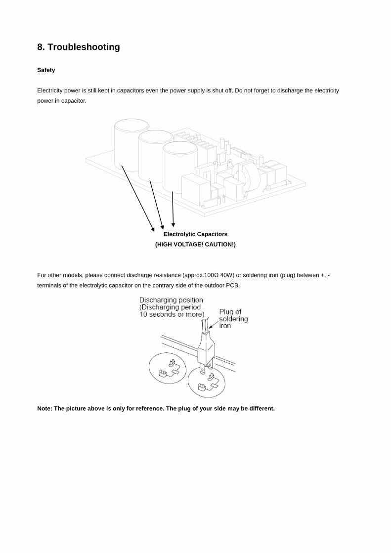
Safety
Electricity power is still kept in capacitors even the power supply is shut off. Do not forget to discharge the electricity
power in capacitor.
Electrolytic Capacitors
(HIGH VOLTAGE! CAUTION!)
For other models, please connect discharge resistance (approx.100Ω 40W) or soldering iron (plug) between +, -
terminals of the electrolytic capacitor on the contrary side of the outdoor PCB.
Note: The picture above is only for reference. The plug of your side may be different.
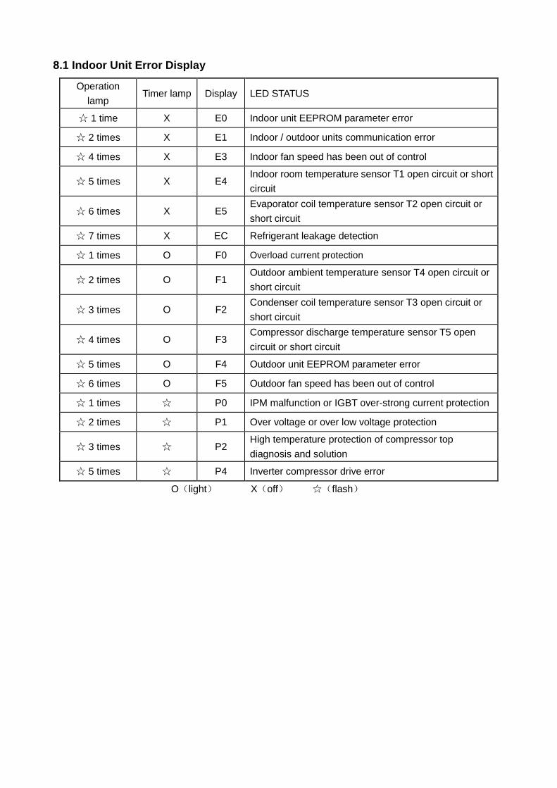
8.1 Indoor Unit Error Display
Operation
lamp Timer lamp Display LED STATUS
☆ 1 time X E0 Indoor unit EEPROM parameter error
☆ 2 times X E1 Indoor / outdoor units communication error
☆ 4 times X E3 Indoor fan speed has been out of control
☆ 5 times X E4 Indoor room temperature sensor T1 open circuit or short
circuit
☆ 6 times X E5 Evaporator coil temperature sensor T2 open circuit or
short circuit
☆ 7 times X EC Refrigerant leakage detection
☆ 1 times O F0 Overload current protection
☆ 2 times O F1 Outdoor ambient temperature sensor T4 open circuit or
short circuit
☆ 3 times O F2 Condenser coil temperature sensor T3 open circuit or
short circuit
☆ 4 times O F3 Compressor discharge temperature sensor T5 open
circuit or short circuit
☆ 5 times O F4 Outdoor unit EEPROM parameter error
☆ 6 times O F5 Outdoor fan speed has been out of control
☆ 1 times ☆ P0 IPM malfunction or IGBT over-strong current protection
☆ 2 times ☆ P1 Over voltage or over low voltage protection
☆ 3 times ☆ P2 High temperature protection of compressor top
diagnosis and solution
☆ 5 times ☆ P4 Inverter compressor drive error
O(light) X(off) ☆(flash)
8.2 Trouble shooting
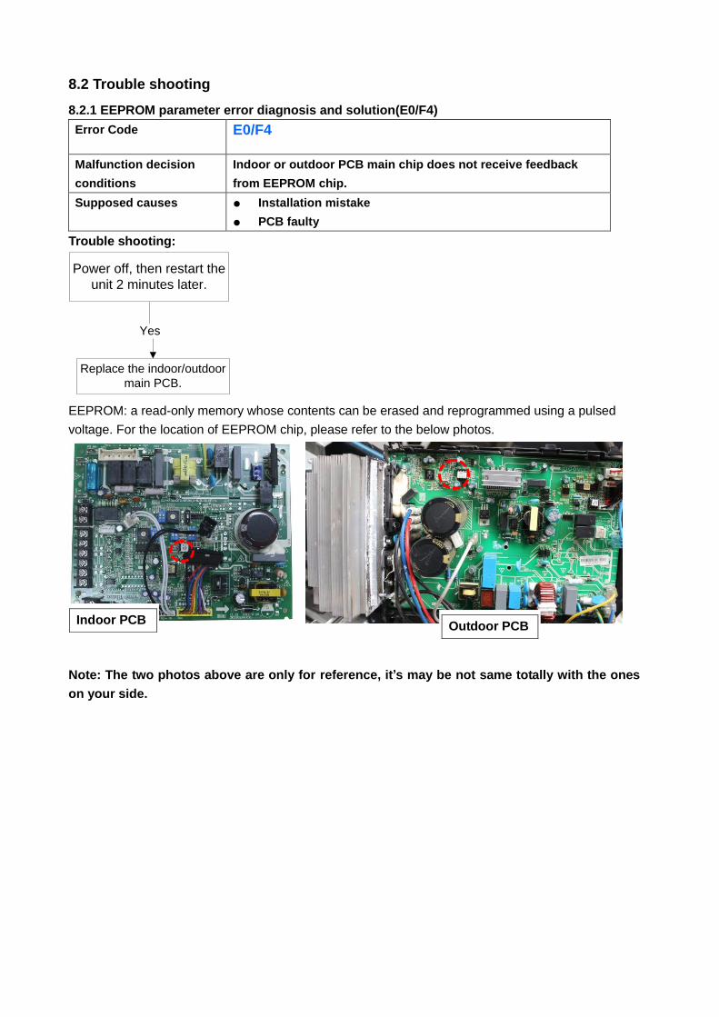
8.2.1 EEPROM parameter error diagnosis and solution(E0/F4)
Error Code E0/F4
Malfunction decision
conditions
Indoor or outdoor PCB main chip does not receive feedback
from EEPROM chip.
Supposed causes ● Installation mistake
● PCB faulty
Trouble shooting:
Yes
Replace the indoor/outdoor
main PCB.
Power off, then restart the
unit 2 minutes later.
EEPROM: a read-only memory whose contents can be erased and reprogrammed using a pulsed
voltage. For the location of EEPROM chip, please refer to the below photos.
Note: The two photos above are only for reference, it’s may be not same totally with the ones
on your side.
Indoor PCB Outdoor PCB
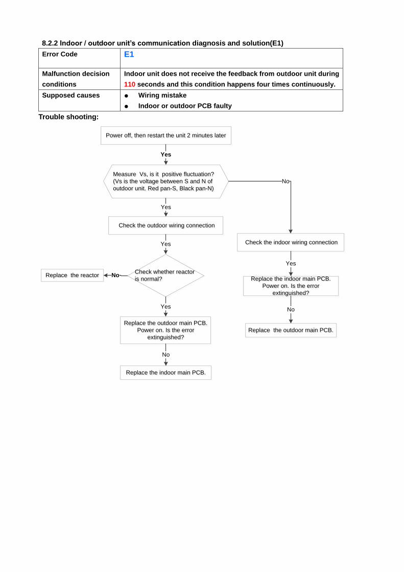
8.2.2 Indoor / outdoor unit’s communication diagnosis and solution(E1)
Error Code E1
Malfunction decision
conditions
Indoor unit does not receive the feedback from outdoor unit during
110 seconds and this condition happens four times continuously.
Supposed causes ● Wiring mistake
● Indoor or outdoor PCB faulty
Trouble shooting:
Measure Vs, is it positive fluctuation?
(Vs is the voltage between S and N of
outdoor unit. Red pan-S, Black pan-N)
Measure Vs, is it positive fluctuation?
(Vs is the voltage between S and N of
outdoor unit. Red pan-S, Black pan-N)
Yes
Power off, then restart the unit 2 minutes laterPower off, then restart the unit 2 minutes later
No
Replace the outdoor main PCB.
Power on. Is the error
extinguished?
Replace the outdoor main PCB.
Power on. Is the error
extinguished?
Check the outdoor wiring connection Check the outdoor wiring connection
Replace the indoor main PCB.
Power on. Is the error
extinguished?
Replace the indoor main PCB.
Power on. Is the error
extinguished?
Yes
Replace the outdoor main PCB.Replace the outdoor main PCB.
No
Replace the indoor main PCB.Replace the indoor main PCB.
No
Check the indoor wiring connection Check the indoor wiring connectionYes
Yes
Check whether reactor
is normal?
Check whether reactor
is normal?
Yes
Replace the reactorReplace the reactor No
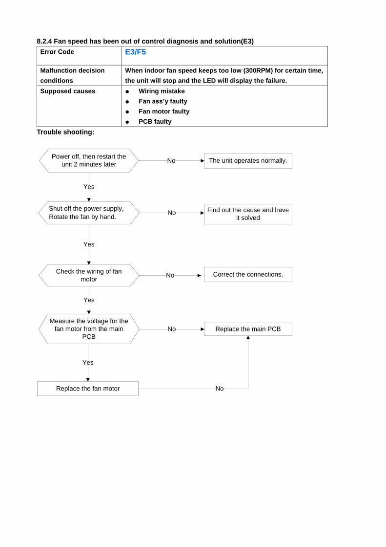
8.2.4 Fan speed has been out of control diagnosis and solution(E3)
Error Code E3/F5
Malfunction decision
conditions
When indoor fan speed keeps too low (300RPM) for certain time,
the unit will stop and the LED will display the failure.
Supposed causes ● Wiring mistake
● Fan ass’y faulty
● Fan motor faulty
● PCB faulty
Trouble shooting:
Power off, then restart the
unit 2 minutes later
Shut off the power supply,
Rotate the fan by hand.
The unit operates normally.
Find out the cause and have
it solved
Check the wiring of fan
motor
No
Yes
No
Correct the connections.No
NoReplace the fan motor
Yes
Yes
Measure the voltage for the
fan motor from the main
PCB
Yes
Replace the main PCBNo
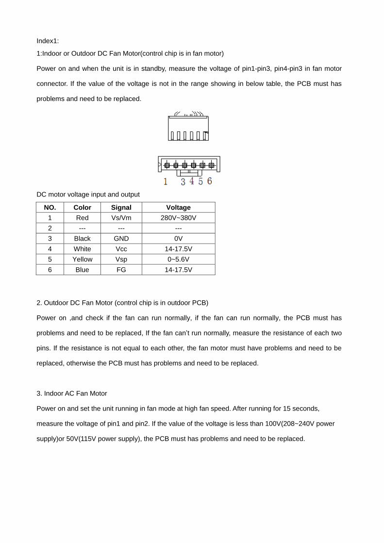
Index1:
1:Indoor or Outdoor DC Fan Motor(control chip is in fan motor)
Power on and when the unit is in standby, measure the voltage of pin1-pin3, pin4-pin3 in fan motor
connector. If the value of the voltage is not in the range showing in below table, the PCB must has
problems and need to be replaced.
DC motor voltage input and output
NO. Color Signal Voltage
1 Red Vs/Vm 280V~380V
2 --- --- ---
3 Black GND 0V
4 White Vcc 14-17.5V
5 Yellow Vsp 0~5.6V
6 Blue FG 14-17.5V
2. Outdoor DC Fan Motor (control chip is in outdoor PCB)
Power on ,and check if the fan can run normally, if the fan can run normally, the PCB must has
problems and need to be replaced, If the fan can’t run normally, measure the resistance of each two
pins. If the resistance is not equal to each other, the fan motor must have problems and need to be
replaced, otherwise the PCB must has problems and need to be replaced.
3. Indoor AC Fan Motor
Power on and set the unit running in fan mode at high fan speed. After running for 15 seconds,
measure the voltage of pin1 and pin2. If the value of the voltage is less than 100V(208~240V power
supply)or 50V(115V power supply), the PCB must has problems and need to be replaced.
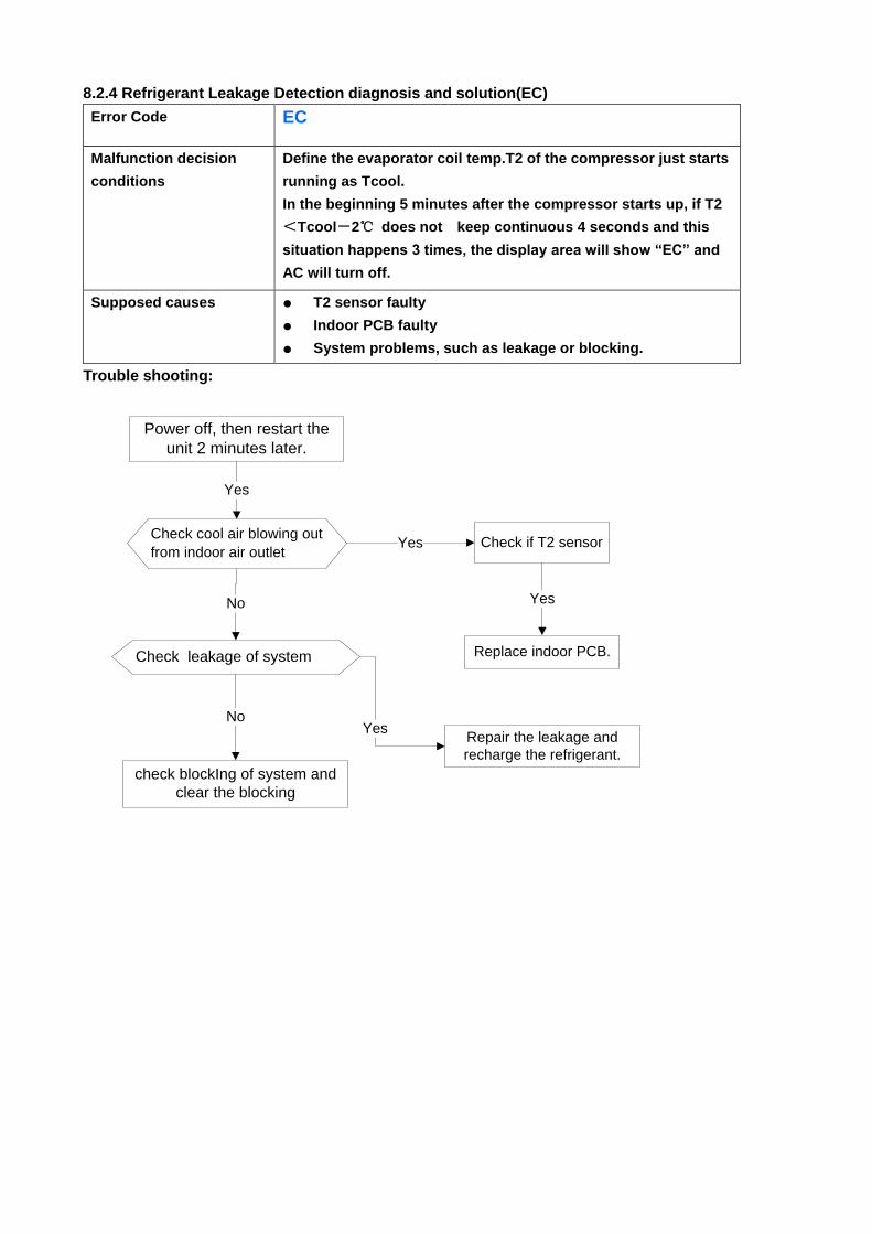
8.2.4 Refrigerant Leakage Detection diagnosis and solution(EC)
Error Code EC
Malfunction decision
conditions
Define the evaporator coil temp.T2 of the compressor just starts
running as Tcool.
In the beginning 5 minutes after the compressor starts up, if T2
<Tcool-2℃ does not keep continuous 4 seconds and this
situation happens 3 times, the display area will show “EC” and
AC will turn off.
Supposed causes ● T2 sensor faulty
● Indoor PCB faulty
● System problems, such as leakage or blocking.
Trouble shooting:
Check cool air blowing out
from indoor air outlet
Yes
Yes Check if T2 sensor
No
Check leakage of system
No
Power off, then restart the
unit 2 minutes later.
Replace indoor PCB.
Yes
Repair the leakage and
recharge the refrigerant.
Yes
check blockIng of system and
clear the blocking
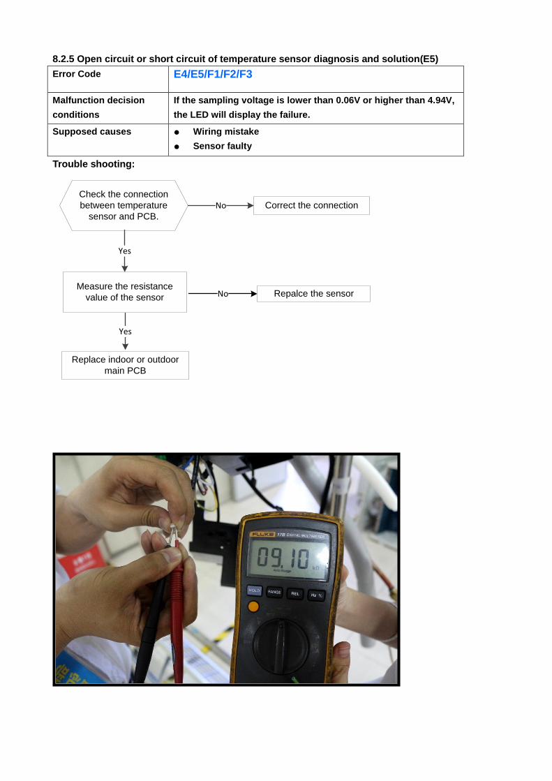
8.2.5 Open circuit or short circuit of temperature sensor diagnosis and solution(E5)
Error Code E4/E5/F1/F2/F3
Malfunction decision
conditions
If the sampling voltage is lower than 0.06V or higher than 4.94V,
the LED will display the failure.
Supposed causes ● Wiring mistake
● Sensor faulty
● PCB faulty Trouble shooting:
Check the connection
between temperature
sensor and PCB.
Correct the connectionNo
Yes
Replace indoor or outdoor
main PCB
Measure the resistance
value of the sensor Repalce the sensorNo
Yes
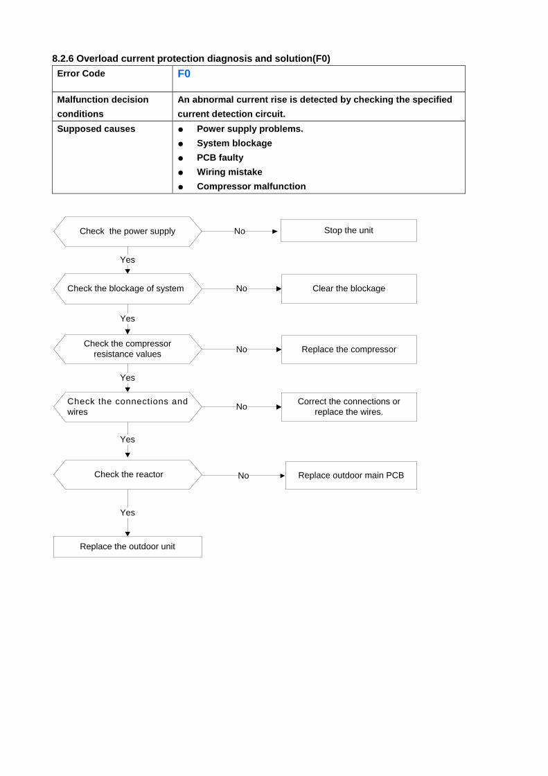
8.2.6 Overload current protection diagnosis and solution(F0)
Error Code F0
Malfunction decision
conditions
An abnormal current rise is detected by checking the specified
current detection circuit.
Supposed causes ● Power supply problems.
● System blockage
● PCB faulty
● Wiring mistake
● Compressor malfunction
Check the power supply
Check the connections and
wires
Stop the unitNo
Yes
NoCorrect the connections or
replace the wires.
Yes
Replace the outdoor unit
Yes
Check the reactor No Replace outdoor main PCB
Check the blockage of system
Yes
No Clear the blockage
Check the compressor
resistance values
Yes
No Replace the compressor
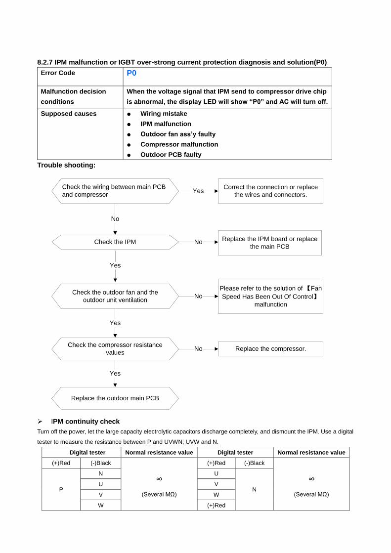
8.2.7 IPM malfunction or IGBT over-strong current protection diagnosis and solution(P0)
Error Code P0
Malfunction decision
conditions
When the voltage signal that IPM send to compressor drive chip
is abnormal, the display LED will show “P0” and AC will turn off.
Supposed causes ● Wiring mistake
● IPM malfunction
● Outdoor fan ass’y faulty
● Compressor malfunction
● Outdoor PCB faulty
Trouble shooting:
Check the wiring between main PCB
and compressor
Correct the connection or replace
the wires and connectors.Yes
No
Check the IPM No
Yes
Replace the IPM board or replace
the main PCB
Check the outdoor fan and the
outdoor unit ventilationNo
Please refer to the solution of 【Fan
Speed Has Been Out Of Control】malfunction
Yes
Check the compressor resistance
valuesNo Replace the compressor.
Yes
Replace the outdoor main PCB
IPM continuity check
Turn off the power, let the large capacity electrolytic capacitors discharge completely, and dismount the IPM. Use a digital
tester to measure the resistance between P and UVWN; UVW and N.
Digital tester Normal resistance value Digital tester Normal resistance value
(+)Red (-)Black
∞
(Several MΩ)
(+)Red (-)Black
∞
(Several MΩ) P
N U
N U V
V W
W (+)Red
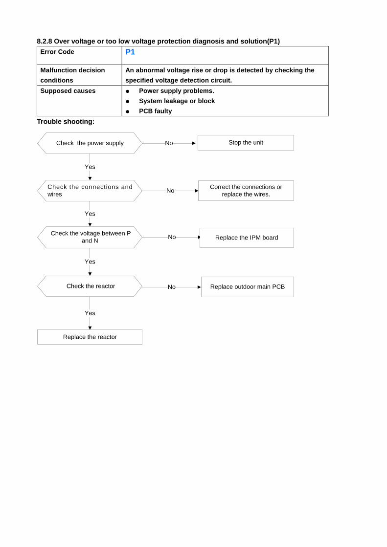
8.2.8 Over voltage or too low voltage protection diagnosis and solution(P1)
Error Code P1
Malfunction decision
conditions
An abnormal voltage rise or drop is detected by checking the
specified voltage detection circuit.
Supposed causes ● Power supply problems.
● System leakage or block
● PCB faulty
Trouble shooting:
Check the power supply
Check the connections and
wires
Stop the unitNo
Yes
NoCorrect the connections or
replace the wires.
Yes
Replace the reactor
Yes
No Replace the IPM board Check the voltage between P
and N
Check the reactor
Yes
No Replace outdoor main PCB
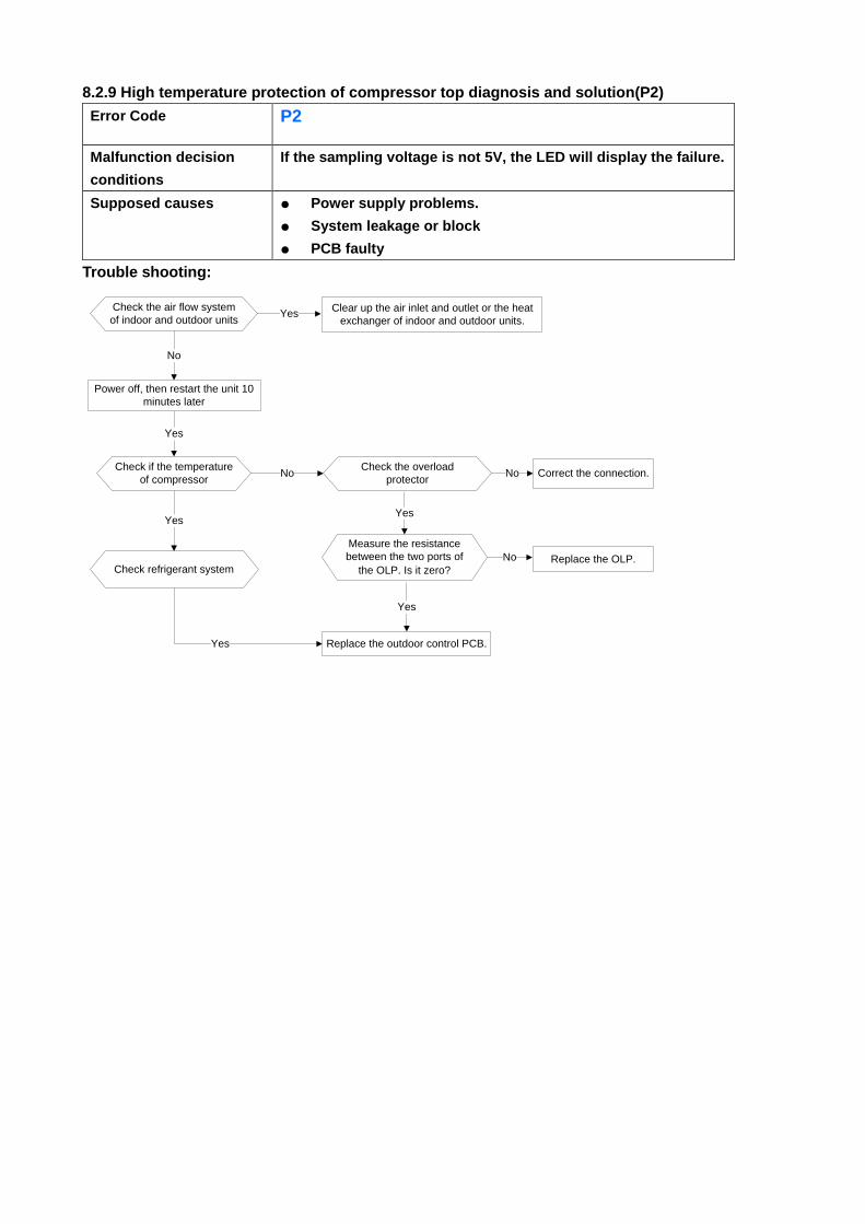
8.2.9 High temperature protection of compressor top diagnosis and solution(P2)
Error Code P2
Malfunction decision
conditions
If the sampling voltage is not 5V, the LED will display the failure.
Supposed causes ● Power supply problems.
● System leakage or block
● PCB faulty
Trouble shooting:
Check the air flow system
of indoor and outdoor units Clear up the air inlet and outlet or the heat
exchanger of indoor and outdoor units.Yes
No
Yes
Yes
Power off, then restart the unit 10
minutes later
Check if the temperature
of compressor No
Check refrigerant system
Yes
Check the overload
protectorCorrect the connection.No
Measure the resistance
between the two ports of
the OLP. Is it zero?
Yes
Replace the OLP.No
Replace the outdoor control PCB.
Yes
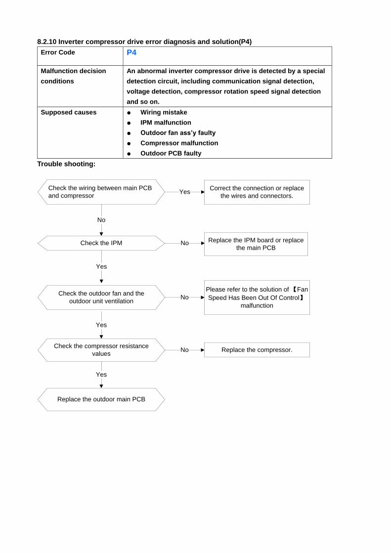
8.2.10 Inverter compressor drive error diagnosis and solution(P4)
Error Code P4
Malfunction decision
conditions
An abnormal inverter compressor drive is detected by a special
detection circuit, including communication signal detection,
voltage detection, compressor rotation speed signal detection
and so on.
Supposed causes ● Wiring mistake
● IPM malfunction
● Outdoor fan ass’y faulty
● Compressor malfunction
● Outdoor PCB faulty
Trouble shooting:
Check the wiring between main PCB
and compressor
Correct the connection or replace
the wires and connectors.Yes
No
Check the IPM No
Yes
Replace the IPM board or replace
the main PCB
Check the outdoor fan and the
outdoor unit ventilationNo
Please refer to the solution of 【Fan
Speed Has Been Out Of Control】malfunction
Yes
Check the compressor resistance
valuesNo Replace the compressor.
Yes
Replace the outdoor main PCB
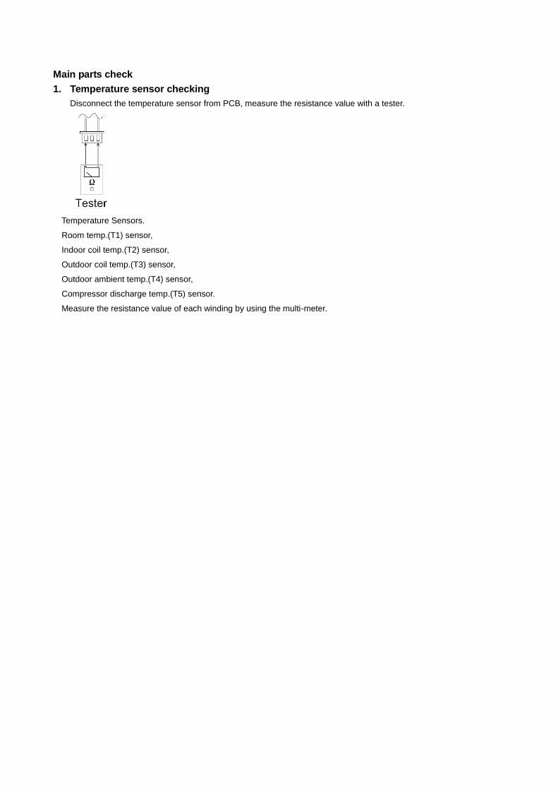
Main parts check
1. Temperature sensor checking
Disconnect the temperature sensor from PCB, measure the resistance value with a tester.
Temperature Sensors.
Room temp.(T1) sensor,
Indoor coil temp.(T2) sensor,
Outdoor coil temp.(T3) sensor,
Outdoor ambient temp.(T4) sensor,
Compressor discharge temp.(T5) sensor.
Measure the resistance value of each winding by using the multi-meter.
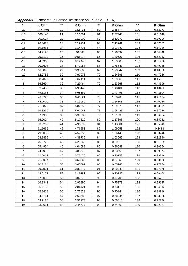
Appendix 1 Temperature Sensor Resistance Value Table (℃--K)
℃ K Ohm ℃ K Ohm ℃ K Ohm ℃ K Ohm
-20 115.266 20 12.6431 60 2.35774 100 0.62973
-19 108.146 21 12.0561 61 2.27249 101 0.61148
-18 101.517 22 11.5000 62 2.19073 102 0.59386
-17 96.3423 23 10.9731 63 2.11241 103 0.57683
-16 89.5865 24 10.4736 64 2.03732 104 0.56038
-15 84.2190 25 10.000 65 1.96532 105 0.54448
-14 79.3110 26 9.55074 66 1.89627 106 0.52912
-13 74.5360 27 9.12445 67 1.83003 107 0.51426
-12 70.1698 28 8.71983 68 1.76647 108 0.49989
-11 66.0898 29 8.33566 69 1.70547 109 0.48600
-10 62.2756 30 7.97078 70 1.64691 110 0.47256
-9 58.7079 31 7.62411 71 1.59068 111 0.45957
-8 56.3694 32 7.29464 72 1.53668 112 0.44699
-7 52.2438 33 6.98142 73 1.48481 113 0.43482
-6 49.3161 34 6.68355 74 1.43498 114 0.42304
-5 46.5725 35 6.40021 75 1.38703 115 0.41164
-4 44.0000 36 6.13059 76 1.34105 116 0.40060
-3 41.5878 37 5.87359 77 1.29078 117 0.38991
-2 39.8239 38 5.62961 78 1.25423 118 0.37956
-1 37.1988 39 5.39689 79 1.21330 119 0.36954
0 35.2024 40 5.17519 80 1.17393 120 0.35982
1 33.3269 41 4.96392 81 1.13604 121 0.35042
2 31.5635 42 4.76253 82 1.09958 122 0.3413
3 29.9058 43 4.57050 83 1.06448 123 0.33246
4 28.3459 44 4.38736 84 1.03069 124 0.32390
5 26.8778 45 4.21263 85 0.99815 125 0.31559
6 25.4954 46 4.04589 86 0.96681 126 0.30754
7 24.1932 47 3.88673 87 0.93662 127 0.29974
8 22.5662 48 3.73476 88 0.90753 128 0.29216
9 21.8094 49 3.58962 89 0.87950 129 0.28482
10 20.7184 50 3.45097 90 0.85248 130 0.27770
11 19.6891 51 3.31847 91 0.82643 131 0.27078
12 18.7177 52 3.19183 92 0.80132 132 0.26408
13 17.8005 53 3.07075 93 0.77709 133 0.25757
14 16.9341 54 2.95896 94 0.75373 134 0.25125
15 16.1156 55 2.84421 95 0.73119 135 0.24512
16 15.3418 56 2.73823 96 0.70944 136 0.23916
17 14.6181 57 2.63682 97 0.68844 137 0.23338
18 13.9180 58 2.53973 98 0.66818 138 0.22776
19 13.2631 59 2.44677 99 0.64862 139 0.22231
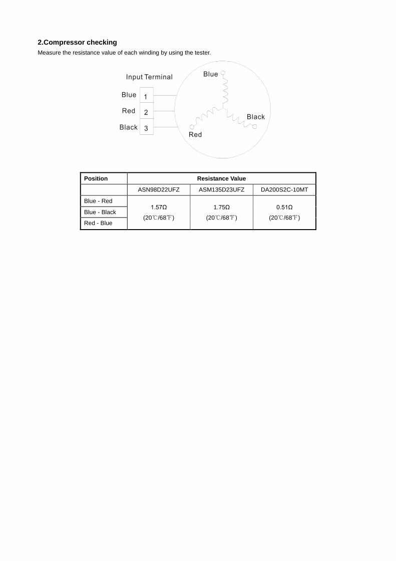
2.Compressor checking
Measure the resistance value of each winding by using the tester.
Position Resistance Value
ASN98D22UFZ ASM135D23UFZ DA200S2C-10MT
Blue - Red 1.57Ω
(20℃/68℉)
1.75Ω
(20℃/68℉)
0.51Ω
(20℃/68℉) Blue - Black
Red - Blue