Embed Size (px)
Citation preview
Surgical Technique
COMPASS PIPProximal Interphalangeal Joint Hinge
Compass™ PIP Proximal Interphalangeal Joint Hinge
Table of Contents
Introduction 3Design Rationale 4Design Features 5Surgical Technique 6Components 16
Nota Bene: The technique description herein is made available to the healthcare professional to illustrate the author’ssuggested treatment for the uncomplicated procedures. In the final analysis, the preferred treatment is that which addressesthe needs of the specific patient.
Surgical Technique Described by:Robert N. Hotchkiss, M.D.Chief of Hand Surgery, The Hospital for Special SurgeryAssistant Professor, Orthopaedic SurgeryCornell Medical CollegeNew York, New York
Illustrations byVirginia Ferrante, Medical IllustratorThe Hospital for Special SurgeryNew York, New YorkCopyright 1993
3
Introduction
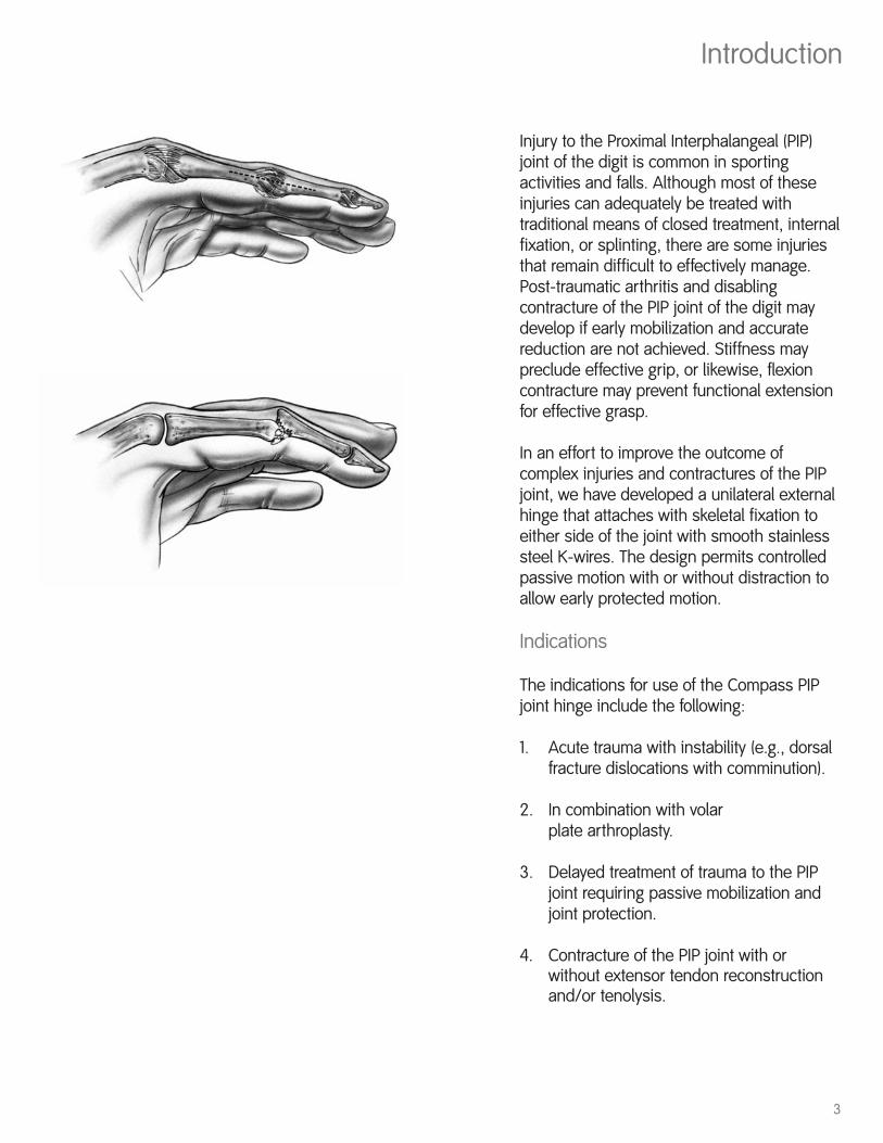
Injury to the Proximal Interphalangeal (PIP)joint of the digit is common in sportingactivities and falls. Although most of theseinjuries can adequately be treated withtraditional means of closed treatment, internalfixation, or splinting, there are some injuriesthat remain difficult to effectively manage.Post-traumatic arthritis and disablingcontracture of the PIP joint of the digit maydevelop if early mobilization and accuratereduction are not achieved. Stiffness maypreclude effective grip, or likewise, flexioncontracture may prevent functional extensionfor effective grasp.
In an effort to improve the outcome ofcomplex injuries and contractures of the PIPjoint, we have developed a unilateral externalhinge that attaches with skeletal fixation toeither side of the joint with smooth stainlesssteel K-wires. The design permits controlledpassive motion with or without distraction toallow early protected motion.
Indications
The indications for use of the Compass PIPjoint hinge include the following:
1. Acute trauma with instability (e.g., dorsalfracture dislocations with comminution).
2. In combination with volar plate arthroplasty.
3. Delayed treatment of trauma to the PIP joint requiring passive mobilization and joint protection.
4. Contracture of the PIP joint with or without extensor tendon reconstruction and/or tenolysis.
4
Design Rationale
The PIP joint of the digit functions as aginglymus or hinge. Only slight movement ofthe instant center of rotation occurs (in contrastto the metacarpophalangeal joint).
The Compass hinge takes advantage of this bycentering the mechanical axis of the externalhinge at the axis of the joint. Because the hingebody is fabricated from radiolucent plastic(Ultem®), the metallic rotational bearing can beradiologically aligned with the mechanical axisof the PIP joint.
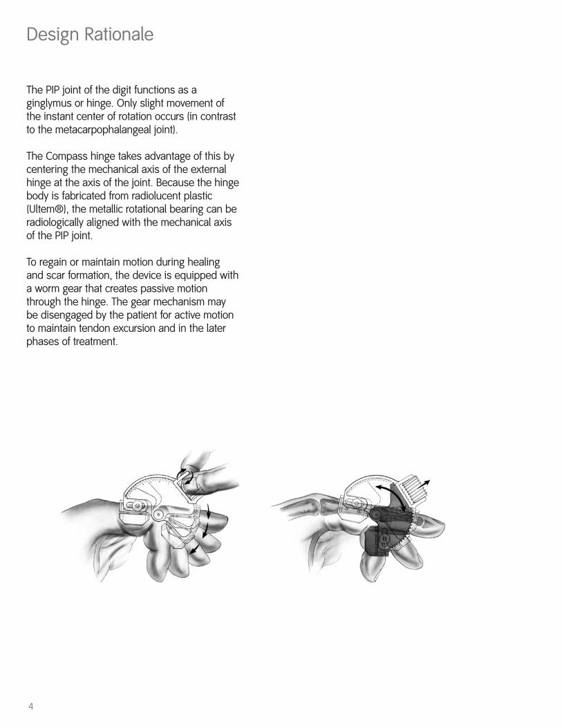
To regain or maintain motion during healingand scar formation, the device is equipped witha worm gear that creates passive motionthrough the hinge. The gear mechanism maybe disengaged by the patient for active motionto maintain tendon excursion and in the laterphases of treatment.
5
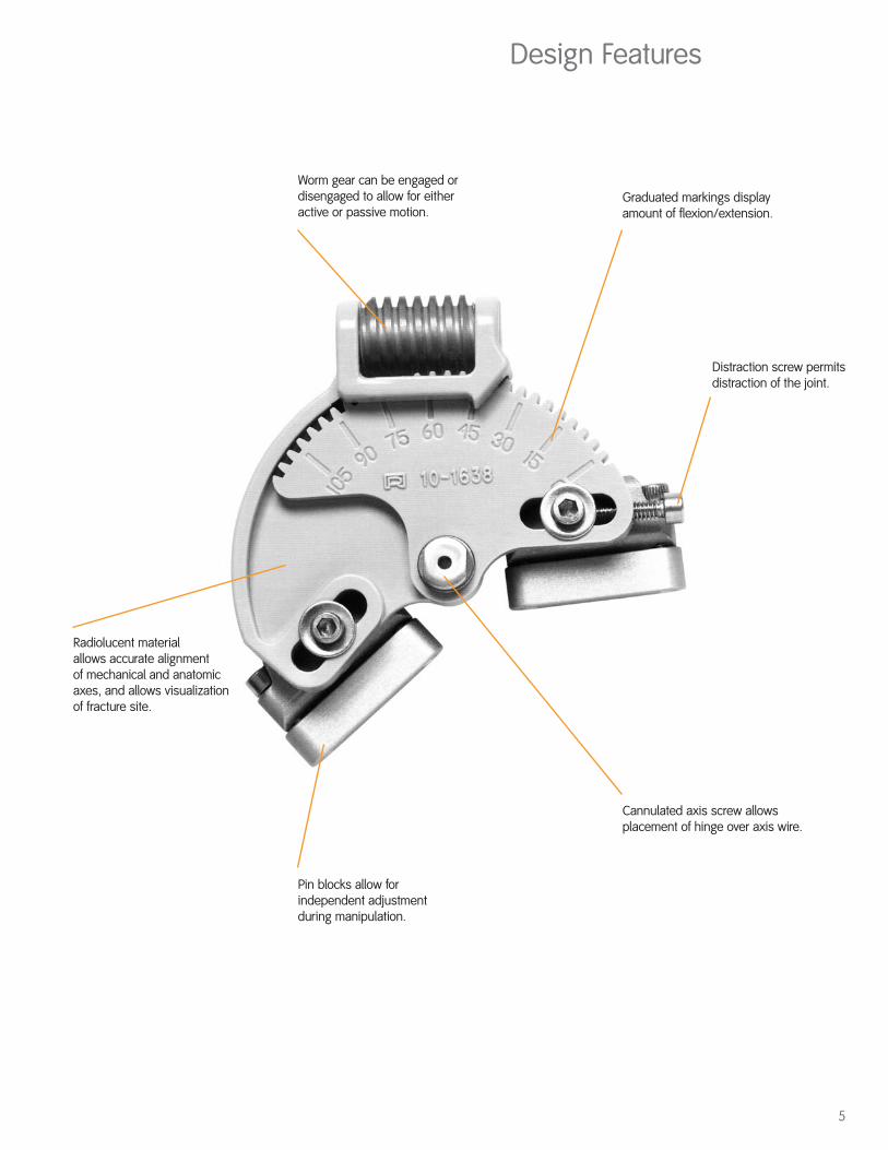
Design Features
Worm gear can be engaged ordisengaged to allow for eitheractive or passive motion.
Radiolucent material allows accurate alignment of mechanical and anatomicaxes, and allows visualizationof fracture site.
Pin blocks allow forindependent adjustmentduring manipulation.
Graduated markings displayamount of flexion/extension.
Distraction screw permitsdistraction of the joint.
Cannulated axis screw allowsplacement of hinge over axis wire.
Surgical Technique
6
Preoperative Planning
Before placing the hinge on a patient, it is helpful todiscuss with the patient the rationale and use of thedevice. Even in the emergency situation, informationabout the length of treatment, potential problems, andcomplications should be discussed with the patient.
Fractures
For comminuted fractures of the middle or proximalphalanx, the surgeon should carefully plan internalfixation placement, assess the potential need for bonegraft, and determine optimal surgical exposure.
Screw fixation, tension band wire, and smooth K-wirefixation can be used in combination with the PIP hinge.
Each fracture or dislocation must be managedindividually. Some patients tolerate motion at an earlypoint in treatment, others have more swelling and pain.By slowing increasing the amount of flexion orextension, using incremental passive displacement,gains in range of motion can usually occur.
Volar Plate Arthroplasty
When using the hinge with volar plate arthroplasty, theprinciples as stated by Eaton must still be followed. Thecollateral ligaments should be excised as part of theprocedure. The suture through the volar plate, securingit to the button on the dorsum of the digit, should not betied until the PIP hinge is properly aligned andtightened. Once the joint is reduced and the hinge is inplace, the finger can be slightly flexed and the knotthrough the button secured.
The joint is held in nearly full extension without flexionfor the first two weeks. Then, gentle flexion is initiated,incrementally increasing the range of flexion over thesubsequent weeks. Try to increase the amount offlexion of the frame by approximately 20° to 30° per
7
week. When not moving the joint passively oractively, the joint is held in nearly fullextension. It is also important to check lateralX-rays on a weekly basis to ensure reductionof the joint.
Before frame removal, try to achieve as much flexion as possible.
Contractures
For patients with contractures of the joint,tenolysis may need to be considered as part of the treatment. If there is doubt as to thedegree of tendon adherence, it may beadvantageous to perform the capsular releasefirst, regaining requisite passive motion, anddelay the tenolysis or reconstruction. Thereare occasions where a small zone of flexoradherence is present and tenolysis could beperformed as a part of the contracturerelease and hinge placement.
The extensor mechanism may be attenuatedin patients with long-standing flexioncontractures of greater than 50°. In thissituation, a boutonniere reconstruction maybe needed to provide an active extensormechanism.
For active boutonniere reconstructions, thehinge should be left in an extended positionfor at least three weeks. From then, a gradualand incremental program of passive flexion isstarted, preventing full flexion for six weeks.When not flexing the joint, the hinge shouldbe left in full extension, especially overnight.Each week, 10-20° of flexion are added to theprogram. Active flexion and extension shouldbe cautiously initiated to limit attenuation ofthe reconstructed extensor mechanism.Some permanent extensor lag should beexpected in all of these patients.
8
Surgical Technique
Application of the Hinge
Introduction:
As previously stated, there are situations suchas volar plate arthroplasty where theapplication of the hinge should be performedbefore the completion of the commonlyprescribed procedure. In other settings, suchas contracture release, application of the hingemay be the last part of the operation. Thetiming of hinge application is individuallyvariable.
Equipment Needed:
• Small image intensifier• K-wire driver
Equipment Provided in Kit:
• PIP hinge• Pin blocks (two large)• .045 K-wires (six included)• Hex driver
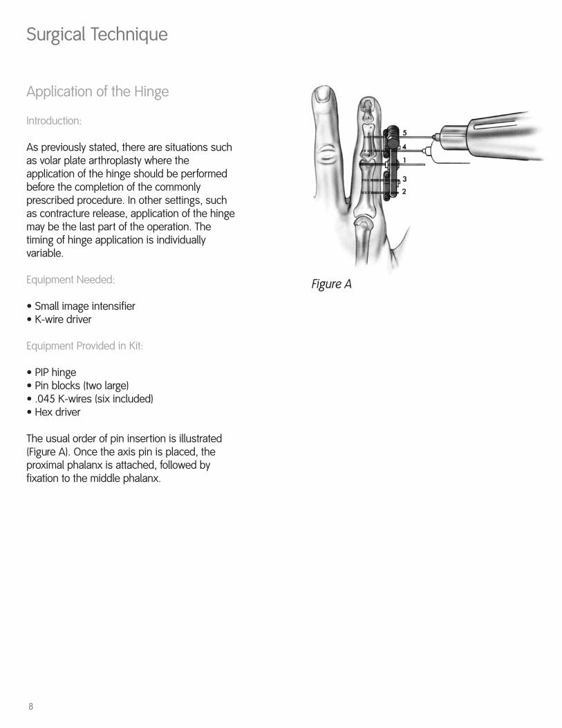
The usual order of pin insertion is illustrated(Figure A). Once the axis pin is placed, theproximal phalanx is attached, followed byfixation to the middle phalanx.
Figure A
9
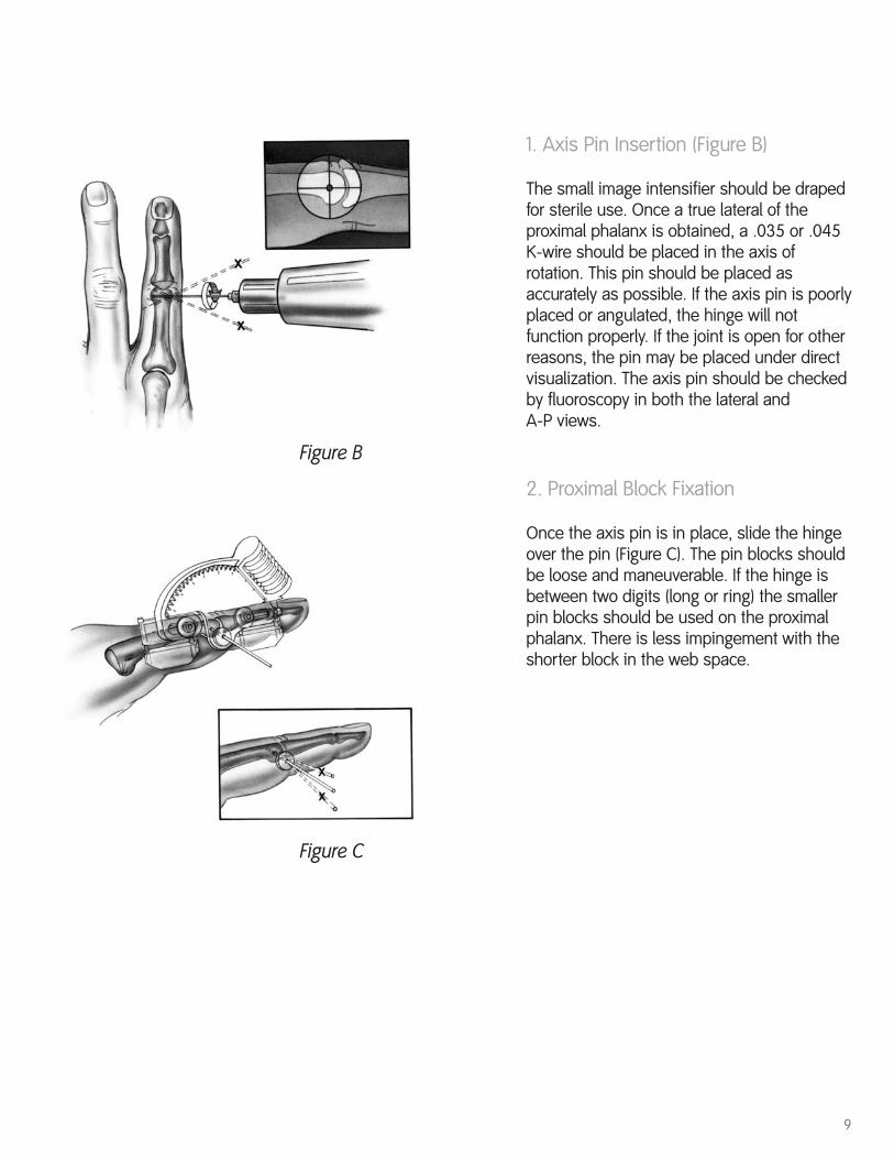
1. Axis Pin Insertion (Figure B)
The small image intensifier should be drapedfor sterile use. Once a true lateral of theproximal phalanx is obtained, a .035 or .045K-wire should be placed in the axis ofrotation. This pin should be placed asaccurately as possible. If the axis pin is poorlyplaced or angulated, the hinge will notfunction properly. If the joint is open for otherreasons, the pin may be placed under directvisualization. The axis pin should be checkedby fluoroscopy in both the lateral and A-P views.
2. Proximal Block Fixation
Once the axis pin is in place, slide the hingeover the pin (Figure C). The pin blocks shouldbe loose and maneuverable. If the hinge isbetween two digits (long or ring) the smallerpin blocks should be used on the proximalphalanx. There is less impingement with theshorter block in the web space.
Figure B
Figure C
10
Surgical Technique
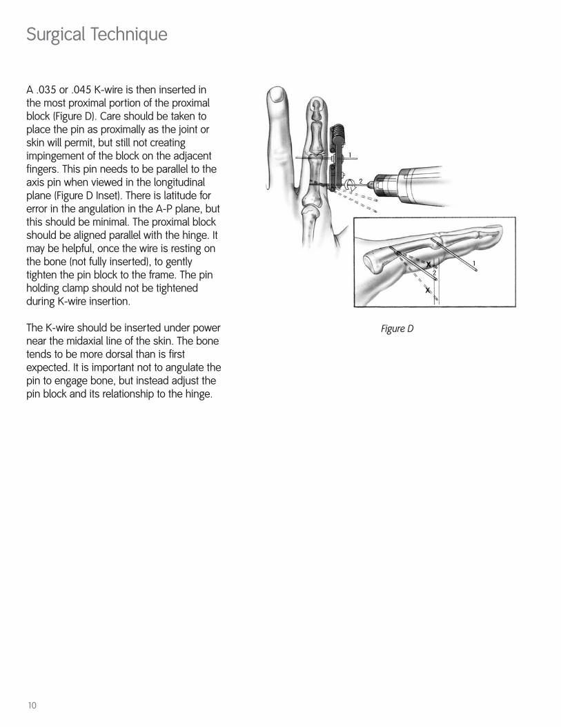
Figure D
A .035 or .045 K-wire is then inserted inthe most proximal portion of the proximalblock (Figure D). Care should be taken toplace the pin as proximally as the joint orskin will permit, but still not creatingimpingement of the block on the adjacentfingers. This pin needs to be parallel to theaxis pin when viewed in the longitudinalplane (Figure D Inset). There is latitude forerror in the angulation in the A-P plane, butthis should be minimal. The proximal blockshould be aligned parallel with the hinge. Itmay be helpful, once the wire is resting onthe bone (not fully inserted), to gentlytighten the pin block to the frame. The pinholding clamp should not be tightenedduring K-wire insertion.
The K-wire should be inserted under powernear the midaxial line of the skin. The bonetends to be more dorsal than is firstexpected. It is important not to angulate thepin to engage bone, but instead adjust thepin block and its relationship to the hinge.
11
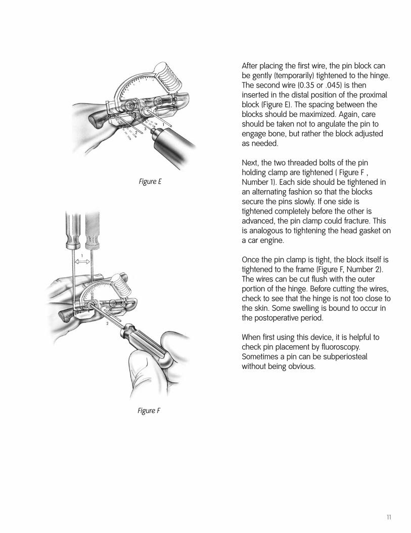
Figure E
Figure F
After placing the first wire, the pin block canbe gently (temporarily) tightened to the hinge.The second wire (0.35 or .045) is theninserted in the distal position of the proximalblock (Figure E). The spacing between theblocks should be maximized. Again, careshould be taken not to angulate the pin toengage bone, but rather the block adjustedas needed.
Next, the two threaded bolts of the pinholding clamp are tightened ( Figure F ,Number 1). Each side should be tightened inan alternating fashion so that the blockssecure the pins slowly. If one side istightened completely before the other isadvanced, the pin clamp could fracture. Thisis analogous to tightening the head gasket ona car engine.
Once the pin clamp is tight, the block itself istightened to the frame (Figure F, Number 2).The wires can be cut flush with the outerportion of the hinge. Before cutting the wires,check to see that the hinge is not too close tothe skin. Some swelling is bound to occur inthe postoperative period.
When first using this device, it is helpful tocheck pin placement by fluoroscopy.Sometimes a pin can be subperiostealwithout being obvious.
12
Surgical Technique
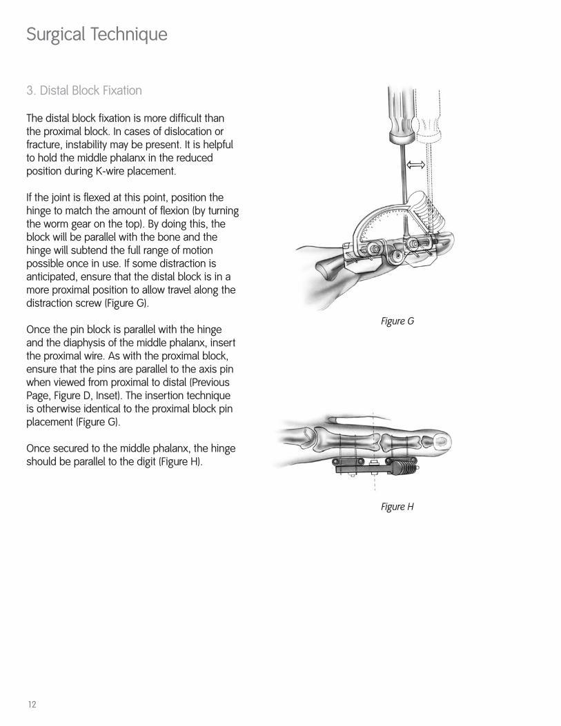
Figure G
3. Distal Block Fixation
The distal block fixation is more difficult thanthe proximal block. In cases of dislocation orfracture, instability may be present. It is helpfulto hold the middle phalanx in the reducedposition during K-wire placement.
If the joint is flexed at this point, position thehinge to match the amount of flexion (by turningthe worm gear on the top). By doing this, theblock will be parallel with the bone and thehinge will subtend the full range of motionpossible once in use. If some distraction isanticipated, ensure that the distal block is in amore proximal position to allow travel along thedistraction screw (Figure G).
Once the pin block is parallel with the hingeand the diaphysis of the middle phalanx, insertthe proximal wire. As with the proximal block,ensure that the pins are parallel to the axis pinwhen viewed from proximal to distal (PreviousPage, Figure D, Inset). The insertion techniqueis otherwise identical to the proximal block pinplacement (Figure G).
Once secured to the middle phalanx, the hingeshould be parallel to the digit (Figure H).
Figure H
13
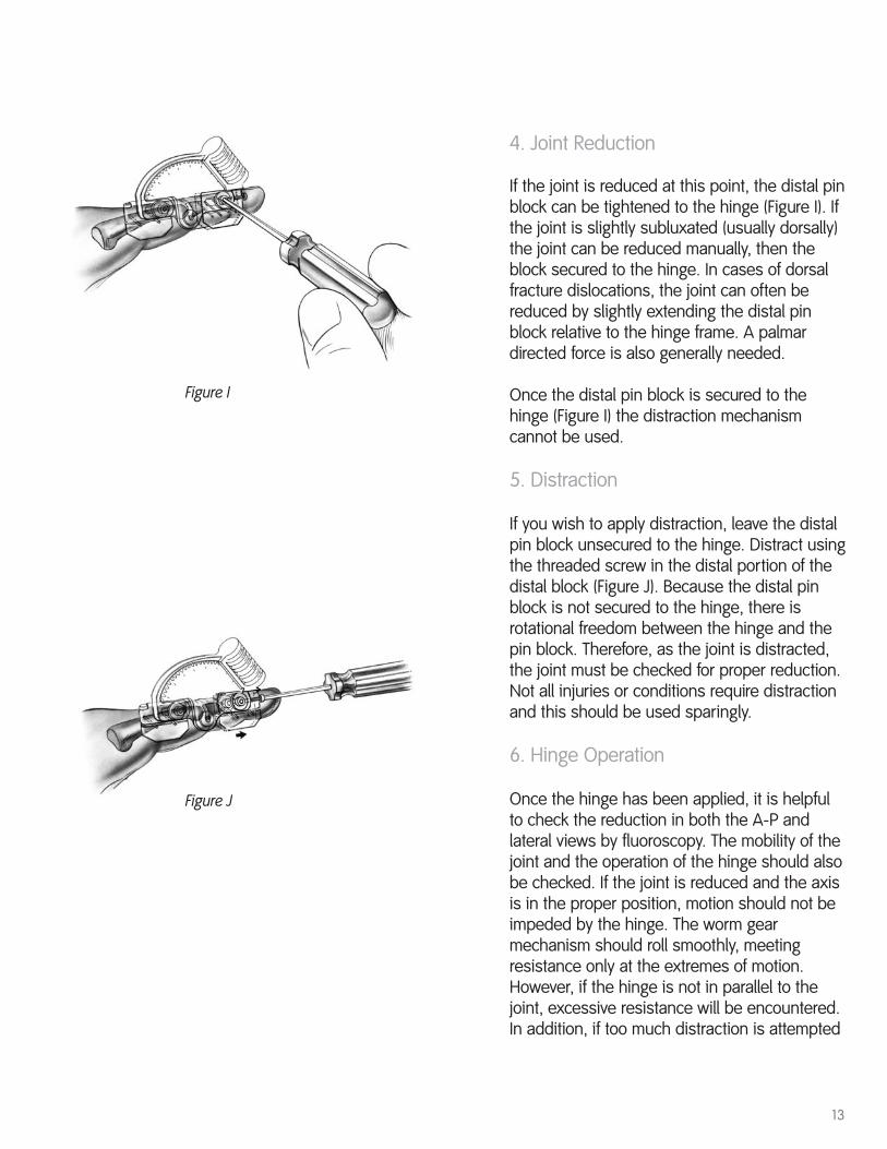
4. Joint Reduction
If the joint is reduced at this point, the distal pinblock can be tightened to the hinge (Figure I). Ifthe joint is slightly subluxated (usually dorsally)the joint can be reduced manually, then theblock secured to the hinge. In cases of dorsalfracture dislocations, the joint can often bereduced by slightly extending the distal pinblock relative to the hinge frame. A palmardirected force is also generally needed.
Once the distal pin block is secured to thehinge (Figure I) the distraction mechanismcannot be used.
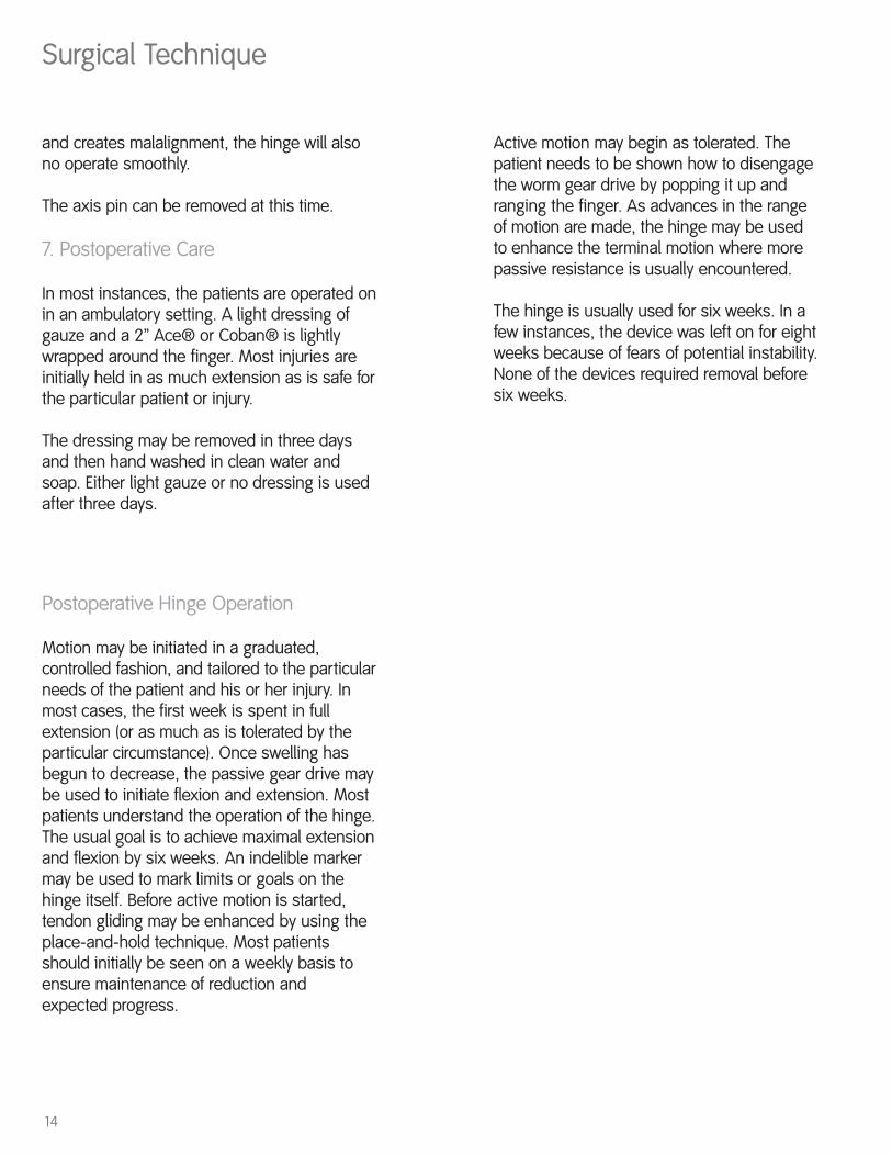
5. Distraction
If you wish to apply distraction, leave the distalpin block unsecured to the hinge. Distract usingthe threaded screw in the distal portion of thedistal block (Figure J). Because the distal pinblock is not secured to the hinge, there isrotational freedom between the hinge and thepin block. Therefore, as the joint is distracted,the joint must be checked for proper reduction.Not all injuries or conditions require distractionand this should be used sparingly.
6. Hinge Operation
Once the hinge has been applied, it is helpfulto check the reduction in both the A-P andlateral views by fluoroscopy. The mobility of thejoint and the operation of the hinge should alsobe checked. If the joint is reduced and the axisis in the proper position, motion should not beimpeded by the hinge. The worm gearmechanism should roll smoothly, meetingresistance only at the extremes of motion.However, if the hinge is not in parallel to thejoint, excessive resistance will be encountered.In addition, if too much distraction is attempted
Figure I
Figure J
14
Surgical Technique
Postoperative Hinge Operation
Motion may be initiated in a graduated,controlled fashion, and tailored to the particularneeds of the patient and his or her injury. Inmost cases, the first week is spent in fullextension (or as much as is tolerated by theparticular circumstance). Once swelling hasbegun to decrease, the passive gear drive maybe used to initiate flexion and extension. Mostpatients understand the operation of the hinge.The usual goal is to achieve maximal extensionand flexion by six weeks. An indelible markermay be used to mark limits or goals on thehinge itself. Before active motion is started,tendon gliding may be enhanced by using theplace-and-hold technique. Most patientsshould initially be seen on a weekly basis toensure maintenance of reduction and expected progress.
Active motion may begin as tolerated. Thepatient needs to be shown how to disengagethe worm gear drive by popping it up andranging the finger. As advances in the rangeof motion are made, the hinge may be usedto enhance the terminal motion where morepassive resistance is usually encountered.
The hinge is usually used for six weeks. In afew instances, the device was left on for eightweeks because of fears of potential instability.None of the devices required removal beforesix weeks.
and creates malalignment, the hinge will alsono operate smoothly.
The axis pin can be removed at this time.
7. Postoperative Care
In most instances, the patients are operated onin an ambulatory setting. A light dressing ofgauze and a 2” Ace® or Coban® is lightlywrapped around the finger. Most injuries areinitially held in as much extension as is safe forthe particular patient or injury.
The dressing may be removed in three daysand then hand washed in clean water andsoap. Either light gauze or no dressing is usedafter three days.
15
4. Pin Loosening
After the hinge has been in place for severalweeks, the K-wires may begin to loosen.Since this usually occurs at the end oftreatment, it does not require pin reinsertion.
Removal of the Hinge
The hinge may be removed in the officesetting by simply releasing the pin holdingclamps and sliding the hinge off. The K-wiresare removed in a routine fashion.
In many cases, the patients will need furtherhand therapy to optimize outcome. Some donot, and are able to begin a home program ofcontinued stretching and strengthening. Aresting extension splint and a dynamic flexionsplint may be needed. The continued use ofCoban or edema reducing materials isrecommended for several weeks.
Potential Complications
1. Loss of Reduction
If the joint shows signs of subluxation ordislocation, X-rays should be taken. True lateralfilms are essential, centered over the PIP joint.
First check to see that the distal pin block hasnot loosened from the hinge. If this is not thecase, the axis should be examined formovement. In most cases, the adjustmentsneeded can be made without returning to theoperating room or reinserting K-wires. Digitalblock anesthesia may be needed.
2. Pin Tract Infection
At some point in the treatment, one or more ofthe K-wires may become inflamed and infected.In those circumstances, we usually prescribeoral antibiotics for 7-10 days, as with any K-wireinfection. If drainage or inflammation persists,the pin may need to be exchanged if it is earlyin the course of treatment. In initial clinicaltrials, only 1.25% of pins needed to be removedduring treatment.
3. Decreased PIP Motion
In most of the chronic cases, the extensormechanism is not normal, and some loss of PIPjoint motion is present. The application of thePIP hinge can temporarily reduce the mobility ofthe DIP joint. During treatment, attention shouldbe paid to passive and active mobilization ofthe DIP joint. We have observed that once theframe is removed, motion returns.
16
Components
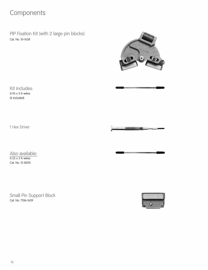
PIP Fixation Kit (with 2 large pin blocks)Cat. No. 10-1638
Kit includes:0.45 x 5 K-wires(6 included)
1 Hex Driver
Also available:0.35 x 5 K-wiresCat. No. 12-8020
Small Pin Support BlockCat. No. 7106-1639

17

18
Notes

19

OrthopaedicsSmith & Nephew, Inc.1450 Brooks RoadMemphis, TN 38116USA
Telephone: 901-396-2121Information: 1-800-821-5700Orders/Inquiries: 1-800-238-7538
30036203002 7108-0300 11/04
www.smith-nephew.com
™Trademark of Smith & Nephew, Reg. U.S. Pat & Tm. Off.


![PUBLIC INVESTMENT PLAN [PIP] FY2012/13 – 2014/15](https://img.dokumen.tips/doc/110x75/6317cb589076d1dcf80bf333/public-investment-plan-pip-fy201213-201415.jpg)


