Embed Size (px)
Citation preview
TELANGANA STATE POWER GENERATION CORPORATION
LIMITED (TSGENCO)
4X270 MW BHADRADRI THERMAL POWER PROJECT
*****************************
VOLUME – II B & III
***************************
TECHNICAL SPECIFICATION FOR
SEWAGE TREATMENT PLANT
*****************************************
SPECIFICATION NO. PE-TS-411-673A-A001, R0
************************
BHARAT HEAVY ELECTRICALS LIMITED POWER SECTOR
PROJECT ENGINEERING MANAGEMENT NOIDA, INDIA

TITLE SPECIFICATION NO. PE‐TS‐411‐673A‐A001
4 X 270 MW BHADRADRI TPS VOLUME: II B & III
TECHNICAL SPECIFICATION FOR REV 00
SEWAGE TREATMENT PLANT SHEET 1 of 2
INDEX
VOLUME – IIB
SECTIONS TITLE PAGE NO.
SECTION‐A INTENT OF SPECIFICATIONS 1‐3
SECTION‐B PROJECT INFORMATION WITH WIND AND SEISMIC DESIGN CRITERIA
4‐6
SECTION‐C SPECIFIC TECHNICAL REQUIREMENT
SECTION‐C1 – A SCOPE OF SUPPLY & SERVICES, EXCLUSION AND TERMINAL POINTS ETC.
9‐25
SECTION‐C1 – B GENERAL REQUIREMENT 26‐99
SECTION‐C1 – C FUNCTIONAL / PERFROMANCE / DEMOSTARTION GUARANTEE
100‐101
SECTION‐C1 ‐ D QUALITY ASSURANCE 102‐133
SECTION‐C1 ‐ E PAINTING SPECIFICATION 134‐146
SECTION‐C1 ‐ F DATASHEET – A 147‐155
SECTION‐C2 TECHNICAL SPECIFICATION FOR ELECTRICAL 156‐164
SECTION‐C3 TECHNICAL SPECIFICATION FOR CONTROL AND INSTRUMENTATION
165‐169
ANNEXURES
i) ANNEXURE‐I: LIST OF MAKES 171‐182
ii) ANNEXURE‐II: MANDATORY SPARE LIST 182‐189
iii) ANNEXURE‐III: RAW WATER ANALYSIS AND CLARIFIED WATER ANALYSIS
190‐191
iv) ANNEXURE‐IV: LIST OF TOOLS & TACKLES 192‐193
v) ANNEXURE‐V: DRAWING / DOCUMENT SUBMISSION SCHEDULE
194‐196
vi) ANNEXURE‐VI: MAIN DRAWING LIST WITH SCHEDULE OF SUBMISSION
197‐200
vii) ANNEXURE‐VII: FORMAT FOR OPERATION AND MAINTENANCE MANUAL
201‐204
x) ANNEXURE‐VIII: SITE STORAGE AND PRESERVATION 205‐219
xi ANNEXURE‐IX: INPUT DRAWING 220‐223
SECTION‐D STANDARD TECHNICAL SPECIFICATIONS
SECTION D1 STANDARD TECHNICAL SPECIFICATION FOR MECHANICAL 225‐293
SECTION D2 STANDARD TECHNICAL SPECIFICATION FOR ELECTRICAL 294‐305
SECTION D3 STANDARD TECHNICAL SPECIFICATION FOR CONTROL AND INSTRUMENTATION
306‐425

TITLE SPECIFICATION NO. PE‐TS‐411‐673A‐A001
4 X 270 MW BHADRADRI TPS VOLUME: II B & III
TECHNICAL SPECIFICATION FOR REV 00
SEWAGE TREATMENT PLANT SHEET 2 of 2
VOLUME‐III
S. NO. TITLE PAGE NO.
1 LIST OF DOCUMENTS TO BE SUBMITTED WITH BID 427
2 COMPLIANCE CUM CONFIRMATION CERTIFICATE 428
3 PRE BID CLARIFICATION SCHEDULE 429
4 SCHEDULE OF TECHNICAL DEVIATION 430
5 SUGGESTIVE PRICE FORMAT 431

TITLE SPECIFICATION NO.
PE‐TS‐411‐673A‐A001
4 X 270 MW BHADRADRI TPS VOLUME: II B
TECHNICAL SPECIFICATION FOR REV 00
SEWAGE TREATMENT PLANT SHEET 1 of 3
SECTION - A
INTENT OF SPECIFICATIONS
Page 1 of 431

TITLE SPECIFICATION NO.
PE‐TS‐411‐673A‐A001
4 X 270 MW BHADRADRI TPS VOLUME: II B
TECHNICAL SPECIFICATION FOR REV 00
SEWAGE TREATMENT PLANT SHEET 2 of 3
1.0 SCOPE: 1.1 SEWAGE TREATMENT PLANT (STP)
This specification is intended to cover design, engineering, manufacture, fabrication, assembly, inspection & testing at manufacturer’s works, delivery at site including start up and commissioning spares, mandatory spares, properly packed for transportation, unloading / handling and storage at site, in site transportation, assembly, erection and commissioning, preparation and submission of “As Built” drawings, site testing, carrying out demonstration tests at site and handover of SEWAGE TREATMENT PLANT as per details in different sections / volumes of this specification for 4X270 MW BHADRADRI TPS.
2.0 GENERAL TECHNICAL INSTRUCTIONS 2.1 The contractor shall be responsible for providing all material, equipment & services, which are
required to fulfil the intent of ensuring operability, maintainability, reliability and complete safety of the complete work covered under this specification, irrespective of whether it has been specifically listed herein or not. Omission of specific reference to any component / accessory necessary for proper performance of the equipment shall not relieve the vendor from the responsibility of providing such facilities to complete the supply and erection & commissioning of STP.
2.2 It is not the intent to specify herein all the details of design and manufacture. However, the
equipment shall conform in all respects to high standards of design, engineering and workmanship and shall be capable of performing the required duties in a manner acceptable to purchaser who will interpret the meaning of drawings and specifications and shall be entitled to reject any work or material which in his judgment is not in full accordance herewith.
2.3 The extent of supply under the contract includes all items shown in the drawings, notwithstanding the fact that such items may have been omitted from the specification or schedules. Similarly, the extent of supply also includes all items mentioned in the specification and /or schedules, notwithstanding the fact that such items may have been omitted in the drawing.
2.4 The general term and conditions, instructions to tenderer and other attachment referred to
elsewhere are made part of the tender specification. The equipment materials and works covered by this specification are subject to compliance to all attachments referred in the specification. The bidder shall be responsible for and governed by all requirements stipulated herein.
2.5 While all efforts have been made to make the specification requirement complete & unambiguous,
it shall be bidders’ responsibility to ask for missing information, ensure completeness of specification, to bring out any contradictory / conflicting requirement in different sections of the specification and within a section itself to the notice of BHEL and to seek any clarification on specification requirement in the format enclosed under VOL-III of the specification. In absence of any such clarifications, in case of any contradictory requirement, the more stringent requirement as per interpretation of Purchaser / Customer shall prevail and shall be complied by the bidder without any commercial implication on account of the same. Further in case of any missing information in the specification not brought out by the prospective bidders as part of pre-bid clarification, the same shall be furnished by Purchaser/ Customer as and when brought to their notice either by the bidder or by purchaser/ customer themselves. However, such requirements shall be binding on the successful bidder without any commercial & delivery implication to BHEL / Customer.
2.6 Deviations along with cost of withdrawal (positive or negative), if any, should be very clearly
brought out clause by clause in the enclosed schedule; otherwise, it will be presumed that the
Page 2 of 431

TITLE SPECIFICATION NO.
PE‐TS‐411‐673A‐A001
4 X 270 MW BHADRADRI TPS VOLUME: II B
TECHNICAL SPECIFICATION FOR REV 00
SEWAGE TREATMENT PLANT SHEET 3 of 3
vendor's offer is strictly in line with tender specification & there is no deviation. (Price to be given in sealed envelope only.)
2.7 In case all above requirements are not complied with, the offer may be considered as incomplete and would become liable for rejection.
2.8 Unless specified otherwise, all through the specification, the word contractor shall have same meaning as successful bidder / vendor and Customer / Purchaser / Employer will mean BHEL and /or TELANGANA STATE POWER GENERATION CORPORATION LIMITED (TSGENCO), HYDERABAD.
2.9 The equipment covered under this specification shall not dispatch unless the same have been
finally inspected, accepted and shipping release issue by BHEL/Customer.
2.10 BHEL’s/Customer’s representative shall be given full access to the shop in which the equipments are being manufactured or tested and all test records shall be made available to him.
Page 3 of 431

TITLE SPECIFICATION NO.
PE‐TS‐411‐673A‐A001
4 X 270 MW BHADRADRI TPS VOLUME: II B
TECHNICAL SPECIFICATION FOR REV 00
SEWAGE TREATMENT PLANT SHEET 1 of 3
SECTION - B
PROJECT INFORMATION WITH WIND AND SEISMIC DESIGN CRITERIA
Page 4 of 431

TITLE SPECIFICATION NO.
PE‐TS‐411‐673A‐A001
4 X 270 MW BHADRADRI TPS VOLUME: II B
TECHNICAL SPECIFICATION FOR REV 00
SEWAGE TREATMENT PLANT SHEET 2 of 3
INTRODUCTION
4x270 MW Bhadradri TPS is being set up by Telangana State Electricity Corporation Limited (TSGENCO) at Manuguru in the district of Khammam, Telangana, India. The Bidder shall acquaint himself by a visit to the site, if felt necessary, with the conditions prevailing at site before submission of the bid. The information given here in under is for general guidance and shall not be contractually binding on BHEL/Owner. All relevant site data /information as may be necessary shall have to be obtained /collected by the Bidder.
APPROACH TO SITE The distance from Manuguru to Major cities in state:
City Km Hyderabad 345 Warangal 180 Bhadrachalam 38 Kothagudem 70 Khammam 130 Vijayawada 195
District : KHAMMAM State : TELANGANA Nearest Airport: The nearest airport is Vijayawada Airport but the most used airport is the Hyderabad International Airport. Nearest Railway Station: Manuguru railway station is 10KM from nearby town. However Warangal/Vijaywada railway Station is major railway station near to Manuguru. 1. Owner : TSGENCO
2. Project Title : 4X270 MW Bhadradri TPS
3. Location : 16 Km from Manuguru Railway station
4. Nearest Railway Stn. : Manuguru
5. Temperature
a. Mean daily minimum ambient temperature during oldest month of the year: 11.5
Deg.C
b. Mean daily minimum ambient temperature during hottest month of the year: 45.1
Deg.C
6. Rainfall: Intensity of rainfall @ 50 mm/hr considering heaviest fall in 24 hrs
7. Wind Data: Basic wind speed at 10m height : 44 m/sec
Page 5 of 431

TITLE SPECIFICATION NO.
PE‐TS‐411‐673A‐A001
4 X 270 MW BHADRADRI TPS VOLUME: II B
TECHNICAL SPECIFICATION FOR REV 00
SEWAGE TREATMENT PLANT SHEET 3 of 3
8. Wind pressure As per IS: 875 Part III- 1987
9. Seismic Zone: Zone III as defined in IS:1893 (part-1)-2002 according to Indian Standard
Seismic Zoning Map
10 Power Supply : The power supplies for distribution and auxiliaries shall be as under:
a) In plant generation 16.5kV 5% , 3ph, 50Hz 5%, high resistance earthed.
b) MV distribution 6.6kV 6 %, 3ph, 3w , 50 Hz, + 5 % to – 5%, Non-effectively earthed
c) LT distribution 415V 10%, 3ph, 4W, 50Hz + 5% to –5%, Effectively earthed
d) Motor rated above 160kW 6.6kV 6 %, 3 ph 50Hz +5% to -5%.
e) Motor rated 160kW and below all motorized
actuators. 415V 10%, 3 ph, 50Hz +5% to -5%.
f) For motors equal and below 30kW winding
heating
24V AC 10, 50 Hz %, [to be generated in 415V switchgear by vendor]
g) DC Motors 220V DC + 10% to - 15%, 2 wire ungrounded system
h) Control supply for relay panel/ 6.6kV
breakers/415V breakers and DC emergency lighting.
220V DC + 10% to - 15%, 2 wire ungrounded system
i) UPS for instrumentation & Control system 240V AC 1 %, 1 ph ,50Hz 0.5% 2 Wire AC system
j) Control supply for 415V Motor contactors/AC
Control circuits [to be generated in MCC /panel by vendor]
110V AC 10%, 50Hz + 5% to –5%.
k) Diesel Generator emergency supply 415V 10%, 3ph,3W, 50Hz +5%to –5%.
11 Fault levels
a) 400kV 40kA rms for 1 sec
b) 6.6kV 40 kA rms for 1 sec.
c) 415V
50 kA rms for 1 sec.
d) DC Supply 25 kA
Page 6 of 431

TITLE SPECIFICATION NO.
PE‐TS‐411‐673A‐A001
4 X 270 MW BHADRADRI TPS VOLUME: II B
TECHNICAL SPECIFICATION FOR REV 00
SEWAGE TREATMENT PLANT SHEET 1 of 1
SECTION – C
SPECIFIC TECHNICAL REQUIREMENTS
SECTION – C1: SPECIFIC TECHNICAL REQUIREMENTS FOR MECHANICAL
SECTION – C2: SPECIFIC TECHNICAL REQUIREMENTS FOR ELECTRICAL
SECTION – C3: SPECIFIC TECHNICAL REQUIREMENTS FOR CONTROL AND
INSTRUMENTATION
Page 7 of 431

TITLE SPECIFICATION NO.
PE‐TS‐411‐673A‐A001
4 X 270 MW BHADRADRI TPS VOLUME: II B
TECHNICAL SPECIFICATION FOR REV 00
SEWAGE TREATMENT PLANT SHEET 1 of 1
SECTION – C1
SPECIFIC TECHNICAL REQUIREMENTS FOR MECHANICAL SECTION C1 – A – SCOPE OF SUPPLY & SERVICES, EXCLUSION AND TERMINAL POINTS ETC. SECTION C1 – B – GENERAL REQUIREMENT SECTION C1 – C – FUNCTIONAL / PERFORMANCE / DEMONATRATION GUARANTEE SECTION C1 – D – QUALITY ASSURANCE SECTION C1 – E – PAINTING SPECIFICATION SECTION C1 – F – DATASHEET A
Page 8 of 431

TITLE SPECIFICATION NO.
PE‐TS‐411‐673A‐A001
4 X 270 MW BHADRADRI TPS VOLUME: II B
TECHNICAL SPECIFICATION FOR REV 00
SEWAGE TREATMENT PLANT SHEET 1 of 17
SECTION C1 – A
SCOPE OF SUPPLY & SERVICES, EXCLUSION AND TERMINAL POINTS ETC.
Page 9 of 431

TITLE SPECIFICATION NO.
PE‐TS‐411‐673A‐A001
4 X 270 MW BHADRADRI TPS VOLUME: II B
TECHNICAL SPECIFICATION FOR REV 00
SEWAGE TREATMENT PLANT SHEET 2 of 17
SEWAGE TREATMENT PLANT
1.0 GENERAL
This specification is intended to cover design, engineering, manufacturing, inspection and testing at manufacturer's works of all equipments and foundations, packing, shipment and delivery to power station site, unloading, storage, handling at site, site testing, erection and commissioning, trail run, demonstration test and handing over plant to customer complete with all accessories including start up, commissioning and mandatory spares as required for Sewage Treatment Plant as per technical specification number PE-TS-411-673A-A001 for 4X270 MW BHADRADRI TPS.
2.0 SCOPE OF SUPPLY
2.1 SCOPE OF SUPPLY FOR MECHANICAL
(REFER P & ID OF SEWAGE TREATMENT PLANT) 2.1.1 Two (2) Nos. (1W+1S) submersible grinding type sewage transfer pumps for sewage sump (S1)
complete with all instrumentation, valves, piping etc. 2.1.2 Two (2) Nos. (1W+1S) submersible grinding type sewage transfer pumps for sewage sump (S2)
complete with all instrumentation, valves, piping etc. 2.1.3 Two (2) Nos. (1W+1S) submersible grinding type sewage transfer pumps for sewage sump (S3)
complete with all instrumentation, valves, piping etc. 2.1.4 Two (2) Nos. (1W+1S) submersible grinding type sewage transfer pumps for sewage sump (S4)
complete with all instrumentation, valves, piping etc. 2.1.5 Two (2) Nos. (1W+1S) submersible grinding type sewage transfer pumps for sewage sump (S5)
complete with all instrumentation, valves, piping etc. 2.1.6 Two (2) Nos. (1W+1S) submersible grinding type sewage transfer pumps for sewage sump (S6)
complete with all instrumentation, valves, piping etc. 2.1.7 Two (2) Nos. (1W+1S) submersible grinding type sewage transfer pumps for sewage sump (S7)
complete with all instrumentation, valves, piping etc. 2.1.8 Two (2) Nos. (1W+1S) submersible grinding type sewage transfer pumps for sewage sump (S8)
complete with all instrumentation, valves, piping etc. 2.1.9 Two (2) Nos. (1W+1S) submersible grinding type sewage transfer pumps for sewage sump (S9)
complete with all instrumentation, valves, piping etc. 2.1.10 Two (2) Nos. (1W+1S) submersible grinding type sewage transfer pumps for sewage sump (S10)
complete with all instrumentation, valves, piping etc. 2.1.11 Two (2) Nos. (1W+1S) submersible grinding type sewage transfer pumps for Common sewage
collection sump complete with all instrumentation, valves, piping etc. 2.1.12 All instrumentation and accessories in sewage sump S1 (RCC work in BHEL scope). 2.1.13 All instrumentation and accessories in sewage sump S2 (RCC work in BHEL scope). 2.1.14 All instrumentation and accessories in sewage sump S3 (RCC work in BHEL scope). 2.1.15 All instrumentation and accessories in sewage sump S4 (RCC work in BHEL scope). 2.1.16 All instrumentation and accessories in sewage sump S5 (RCC work in BHEL scope). 2.1.17 All instrumentation and accessories in sewage sump S6 (RCC work in BHEL scope). 2.1.18 All instrumentation and accessories in sewage sump S7 (RCC work in BHEL scope). 2.1.19 All instrumentation and accessories in sewage sump S8 (RCC work in BHEL scope). 2.1.20 All instrumentation and accessories in sewage sump S9 (RCC work in BHEL scope). 2.1.21 All instrumentation and accessories in sewage sump S10 (RCC work in BHEL scope). 2.1.22 All instrumentation and accessories in Common sewage collection sump (RCC work in BHEL
scope) located in STP area. 2.1.23 One no. above ground aeration tank of RCC construction (RCC work in BHEL scope) of minimum
retention time of 12 hours.
Page 10 of 431

TITLE SPECIFICATION NO.
PE‐TS‐411‐673A‐A001
4 X 270 MW BHADRADRI TPS VOLUME: II B
TECHNICAL SPECIFICATION FOR REV 00
SEWAGE TREATMENT PLANT SHEET 3 of 17
2.1.24 One no. above ground RCC hopper bottom secondary clarifier (RCC work in BHEL scope) along
with RCC flocculation tank (RCC in BHEL scope) with minimum capacity of 60 m3/day with an average flow of 6 m3/hr. Clarifier internals is in bidder’s scope.
2.1.25 One no. agitator of SS 316 construction in flocculation tank. 2.1.26 One no. RCC clear water collection tank (RCC work in BHEL scope) complete with all
instrumentation and accessories. 2.1.27 Two (2) nos. horizontal centrifugal pump for clear water transfer with 50 m hose pipe. 2.1.28 One no. RCC sludge drying bed (RCC work in BHEL scope) in three compartment of adequate
capacity having recovery of water from bottom for recycle to common sewage collection sump. 2.1.29 Two (2) Nos. (1W+1S) sludge recycle pumps complete with instrumentation and accessories to
recycle the sewage of hopper bottom secondary clarifier to aeration tank and flocculation tank. 2.1.30 Two (2) nos. (1W + 1S) oil free type air blowers with electric motor drives for supplying air required
for aeration tank and common sewage collection sump. Each blower shall be complete with motor, V-belt drive with belt guard, inlet filter/silencer, flexible couplings and discharge snubber, all mounted on a single base. Relief valve(s) shall be provided as required. Acoustic hood for air blowers shall also be provided by the bidder.
2.1.31 One (1) no. sodium hypochlorite dosing tank of minimum 24 hour storage capacity for dosing chemical to clear water tank complete with instrumentation, dissolving basket and slow speed agitator of SS 316 construction. MOC of dissolving basket will be SS 316.
2.1.32 Two nos. sodium hypochlorite dosing pumps along with instrumentation and accessories. 2.1.33 Necessary piping, valves, fitting, instruments etc. as per P&ID for sewage treatment plant enclosed
with this technical specification. 2.1.34 The scope of supply and erection shall include all interconnecting piping, fittings, supports, valves,
instruments etc. 2.1.35 One no. PLC based control system located inside STP area 2.1.36 One no. common RIO panel is in bidder’s scope for all sewage lifting sumps located outside
boundary of STP area. 2.1.37 2.5 km fiber optical cable are in bidder’s scope for communication between RIO panel and PLC
located in STP area. 2.1.38 Bidder to take care the length of piping as included elsewhere in specification of Sewage
Treatment plant. Pipe routing shall be decided during detailed engineering, however bidder will consider 10 m static head + 10% margin during pump selection for outside STP area and clear water Transfer Pumps.
2.1.39 The pipe shall run on pipe pedestals. All auxiliary steel structures (U-clamps, nuts, bolts, channels etc.) for fixing the pipe on the pedestal or trestles shall be in the scope of bidder. If buried piping is required, Wrapping, coating and protection of all the buried pipe is also in bidder’s scope & shall be as per IS 10221.
2.1.40 All steel inserts plates with lugs, rungs, ladder, puddle pipes, bolts, edge angle in desired shape, nuts, sleeves, and all other embedding components etc as required to grout in BHEL civil works and to support/hold the equipments being supplied under this specification shall be in bidder’s scope.
2.1.41 Any statutory clearance required for the system from MOEF or local pollution control board in bidder’s scope.
2.1.42 Initial charge of all lubricants & grease in bidder’s scope. 2.1.43 The pipe sizes indicated in the tender specification/ P & I diagram are minimum. Wherever pipe
sizes are not indicated, the same shall be selected based on the specification requirement and shall be subject to BHEL / customer approval during detailing engineering. All pipes shall be carbon steel unless exclusively mentioned.
2.1.44 All necessary drains, vents and sampling points with valves as specified and as required are in bidder’s scope.
2.1.45 Monitoring gadgets, instruments and equipments required for maintenance (till PG test & plant handover).
2.1.46 Associated piping, instrumentation and valves required for the system.
Page 11 of 431

TITLE SPECIFICATION NO.
PE‐TS‐411‐673A‐A001
4 X 270 MW BHADRADRI TPS VOLUME: II B
TECHNICAL SPECIFICATION FOR REV 00
SEWAGE TREATMENT PLANT SHEET 4 of 17
2.1.47 All necessary instruments and controls required for easy and safe operation of the system.
2.1.48 Wherever terminal points between BHEL and bidder indicated, bidder shall provide pipes with counter flange.
2.1.49 All pipes, fittings etc. required for hand railing, platforms, and ladders shall be in the scope of bidder. All ladders shall be non-civil work. All insert plates, nuts and bolts, counter flanges wherever applicable shall be in the scope of bidder. Supply and erection of Hand railing as desired for safety purpose will be in bidder’s scope.
2.1.50 All the sumps, tanks, reservoirs and other water retaining structures shall be provided with access ladders/rungs from operating platforms/ground level as the case may be and de-watering pits one for each section (civil work by BHEL).
2.1.51 Instrumentation, valves etc. indicated in P & ID of sewage treatment plant are bare minimum requirement, however bidder has to provide complete system for trouble free operation meeting technical specification requirement.
2.1.52 Sewage sumps S1, S2, S3, S4, S5, S6, S7, S8, S9 and S10 shall be located outside STP area however rest facilities indicated in P & ID of STP shall be located inside STP area provided in plot plan included in this specification.
2.1.53 All blank flanges/counter flanges, isolations valves, tees etc. to interconnect the pipes at all terminal points.
2.1.54 Chain Pulley blocks for sewage sumps. 2.1.55 Media for sludge drying bed. 2.1.56 PIPING
a) Complete piping indicated in P & ID of Sewage treatment plant is in bidder’s scope of supply and
erection. In addition, any additional piping required to make the system complete inside STP area shall be in bidder’s scope. Pipe length inside STP area has to be considered by bidder in their scope as per approved equipment layout and piping layout during detailed engineering.
b) Pipe distances from sumps outside STP area upto STP area are given below:
SL. NO. FROM TO DISTANCE (In meters)
1. Sewage sump (S1) STP area 280 2. Sewage sump (S2) Sewage sump (S4) 310 3. Sewage sump (S3) Sewage sump (S1) 290 4. Sewage sump (S4) Sewage sump (S1) 250 5. Sewage sump (S5) Sewage sump (S4) 400 6. Sewage sump (S6) Sewage sump (S5) 260 7. Sewage sump (S7) Sewage sump (S8) 370 8. Sewage sump (S8) Sewage sump (S6) 260 9. Sewage sump (S9) Sewage sump (S3) 480 10. Sewage sump (S10) Sewage sump (S9) 460
Bidder to note that no commercial settlement / adjustment shall be entertained for variation upto +/- 15% of pipe lengths tabulated above during detailed engineering. Bidder to note that above piping distances are in bidder’s scope. Distances given above are from one area to other area only, however inside piping in respective area shall be in bidder’s scope which is not included in above distances.
Page 12 of 431

TITLE SPECIFICATION NO.
PE‐TS‐411‐673A‐A001
4 X 270 MW BHADRADRI TPS VOLUME: II B
TECHNICAL SPECIFICATION FOR REV 00
SEWAGE TREATMENT PLANT SHEET 5 of 17
c) Piping from clear water disposal pumps upto nearest plant drain approx. 25 meters shall be in bidder’s scope. In addition, 100 meter of hose pipe shall be in bidder’s scope for horticulture purpose.
2.1.57 Mandatory spares as per list attached in ANNEXURE II. 2.1.58 Special tools and tackles as required for the system. 2.1.59 All special tools necessary for proper maintenance or adjustment of the equipment packaged in
permanent box. Finish paints for touch-up painting of equipment after erection at site in sealed container.
2.1.60 Start-up and commissioning spares as required. 2.1.61 All the first fill and one Year's topping requirements of consumable such as greases, oil, lubricants,
servo fluids/control fluids, gases and etc. which will be required to put the equipment covered under the scope of specifications, into successful commissioning / initial operation and to establish completion of facilities shall be furnished by the bidder. Suitable standard lubricants as available in India are desired. Efforts should be made to limit the variety of lubricants to minimum.
2.2 SCOPE OF SUPPLY (ELECTRICAL)
Complete electrical as per specification / details indicated in Section C2 and D2. 2.3 SCOPE OF SUPPLY (C&I)
Complete C&I as per specification / details indicated in Section C3 and D3.
2.4 SCOPE OF SUPPLY (CIVIL)
Total Civil is in BHEL Scope of work, however Civil Input drawing shall be provided by bidder.
3.0 SCOPE OF SERVICE
The bidder’s scope also includes following services for scope under this specification:
a. Unloading, Storage, handling and transportation at site.
b. Minor civil work like chipping of foundation, grouting below base plate for all structures, equipment, grouting of anchor bolts wherever these are not placed in the foundation during casting of foundation itself, excavation & filling of earth for buried pipes if and as required. To the extent possible, vendor shall ensure to supply all foundation bolts timely so as to facilitate placement of these bolts while casting the foundation. Wrapping, coating and protection of all the buried pipe shall be as per IS 10221.
c. Pre- Commissioning work such as flushing, hydraulic testing etc. Necessary consumables and instrumentation as required for inspection and testing at works as well as at site including pre-commissioning activities shall be arranged by the successful bidder at their own cost.
d. Erection and Commissioning of entire Sewage Treatment Plant.
e. Arrangement of all lubricants, instruments, reagents for carrying out trial run, commissioning and
demonstration test.
f. Monitoring gadgets, instruments and equipment required for maintenance (till demonstration test & Plant Hand over).
g. All personnel required during commissioning, trial run and demonstration Test.
Page 13 of 431

TITLE SPECIFICATION NO.
PE‐TS‐411‐673A‐A001
4 X 270 MW BHADRADRI TPS VOLUME: II B
TECHNICAL SPECIFICATION FOR REV 00
SEWAGE TREATMENT PLANT SHEET 6 of 17
h. Trial run for requisite period.
i. Performance testing.
j. Training of plant Owner’s personnel, O&M operators’ personnel on plant operation and maintenance.
k. All other facilities/ services as described in section on site services in specification and related to sewage Treatment Plant scope of work.
l. Relevant requirements as per GTR, GCC, ECC & SCC.
m. Any other service required for making the installation complete in all respect within battery limits
and for satisfactory erection & commissioning of the system as well as to meet any statutory requirement relevant to the package, unless specifically excluded from scope of services.
n. Painting as per enclosed painting schedule ANNEXURE C1 E. However, any variation in the painting schedule as finally approved by customer / BHEL shall be taken care by bidder without any commercial and delivery implication. Colour-coding scheme shall be intimated to vendor during detailed engineering.
4.0 TERMINAL POINTS
a. Service water line (50 NB) will be provided by BHEL at 5 m distance from STP area. Further distribution
inside STP area will be in bidder’s scope. Bidder to note that pressure available at terminal point for service water will be 2 kg/cm2 approx (max.); hence bidder will take care for their pump lubrication / cooling accordingly.
b. All drains of STP plant shall be connected to common sewage collection sump inside STP area. c. Hard Sludge generated in sludge drying bed will be manually disposed by customer.
5.0 EXCLUSIONS
6.1 All civil works including foundation of equipment, excavation & back filling. However complete
grouting for equipment, fixing and any concreting inside vessels and lining shall be in the scope of the bidder. Civil works including operating / maintenance platforms and interconnection platforms (if any) with ladders / stairs & handrails, structural supports and hangers for pipes / ducts, all embedments and inserts with lugs including anchor fasteners, bolts etc., dressing of foundations, grouting of pockets and underpinning of base plates for equipment / structures and fixing supports, filling and finishing of openings in walls, floors, cladding, roof and trenches shall be in Bidder’s scope.
6.2 Main pipe trestles. 6.3 Air conditioning, ventilation & fire fighting facilities. 6.4 Other exclusions are mentioned in the electrical & C&I parts of this specification. 6.5 Service water up to terminal points. 6.6 Chemicals. 6.0 QP AND SUBVENDOR APPROVAL: 6.1 Minimum QP requirements are specified as C1 D. However any additional comments as given by
BHEL/Customer shall be adhered by the bidder without any commercial & delivery implication to BHEL.
6.2 The sub vendor list (Annexure- I) enclosed is indicative only and is subject to BHEL and Customer approval during detailed engineering stage without any commercial & delivery implication to BHEL.
6.3 Bidder to propose sub vendor list with following back up documents within 4 weeks of placement of LOI/LOA. Thereafter no request for additional sub-vendor shall be entertained. The subvendor list
Page 14 of 431

TITLE SPECIFICATION NO.
PE‐TS‐411‐673A‐A001
4 X 270 MW BHADRADRI TPS VOLUME: II B
TECHNICAL SPECIFICATION FOR REV 00
SEWAGE TREATMENT PLANT SHEET 7 of 17
shall subject to BHEL and Customer approval during detailed engineering stage without any commercial & delivery implication to BHEL.
6.4 Bidder to assess the capability of their proposed sub-vendors in terms of preparation of drawings, calculations, documents, quality assurance, supply of material etc. as per project schedule before placing the order on them.
6.5 Dealers are not acceptable for any item of the package. Bidder shall procure all items including plates, structural, flanges; counter flanges etc. from approved sub vendor only.
7.0 DESIGN /CONSTRUCTION
In addition to the requirements of Section C & D the following shall also be complied under scope of this specification. The P&I diagram is enclosed herein in this section for bidders compliance. The material of construction specified in data sheet-A are minimum requirements and material of construction for other components not specified shall be similarly selected by the bidder for intended duty which shall be subject to BHEL / Customer approval during detail engineering without any commercial & delivery implication to BHEL.
8.0 PAINTING
Painting shall be C1 E of technical specification. Internal painting of the equipments shall be suitable for withstanding effect of sewage. Outer painting shall be as per technical specifications. Supporting documents shall be furnished in support of suitability of the lining offered for the duty conditions by bidder during detailed engineering.
9.0 INFLUENT QUALITY AND OUTLET GUARANTEE PARAMETERS: 9.1 INFLUENT QUALITY:
Persons Envisaged : 1200 Flow Rate : 60 M3/day (Max). BOD5 : 300 mg/l. COD : 600 mg/l. TSS : 450 mg/l. pH : 7 – 8. Temperature : Ambient.
9.2 OUTLET GUARANTEE PARAMETERS:
BOD5 : 20 mg/l COD : 100 mg/l TSS : 30 mg/l pH : 7 – 8 Temperature : Ambient
10.0 DRAWING/DOCUMENTS REQUIREMENT
10.1 For the Drawings/Documents distribution Procedure, please refer attached Annexure-V. Bidder has to submit the revised drawing/document along with the compliance sheet indicating enumerate reply to all BHEL and customer comments or observations. Without compliance sheet the submission of the drawings/documents will not be considered and the delay on this account will be solely on
Page 15 of 431

TITLE SPECIFICATION NO.
PE‐TS‐411‐673A‐A001
4 X 270 MW BHADRADRI TPS VOLUME: II B
TECHNICAL SPECIFICATION FOR REV 00
SEWAGE TREATMENT PLANT SHEET 8 of 17
bidder’s side only. The numbers of soft copies & hard copies of drawing/documents to be submitted by the bidder shall be as per enclosed Annexure-V.
10.2 After award of LOI/LOA, drawing/documents to be submitted by the bidder for BHEL/Customer approval has been indicated in Annexure VI. However any additional drawing/document if found necessary for completion of the engineering, the same shall be submitted by bidder without any commercial & delivery implication to BHEL.
10.3 Bidder to note that the successful bidder, during detail engineering, will submit the drg/doc through web based Document Management System in addition to hard copies to be submitted as per the Annexure III of this specification. Bidder would be provided access to the DMS for drg/doc approval and adequate training for the same. Detailed methodology would be finalized during the kick-off meeting. Bidder to ensure following at their end:
Internet explorer version – Minimum Internet Explorer 7
Internet speed – 2 mbps (Minimum preferred)
Pop ups from our external DMS IP (124.124.36.198) should not be blocked
Vendor’s Internal proxy setting should not block DMS application’s link (http://124.124.36.198/wrenchwebaccess/login.aspx)”
DMS user manuals to be used by BHEL PEM vendors for uploading, viewing, revising, commenting and tracking documents on PEM’s DMS have been uploaded on PEM internet website (www.bhelpem.com) under the Vendor session.
For quick access bidder may refer the link http://bhelpem.com/DMSManuals/DMSManuals.html
11.0 SPARES
The Bidder shall include in his scope of supply all the necessary Mandatory spares, start up and commissioning spares as indicated in the relevant sections of specifications. The general requirements pertaining to the supply of these spares is given below:-
11.1 MANDATORY SPARES
a. The list of mandatory spares which is to be considered by bidder in their scope are indicated in
Annexure II.
b. All mandatory spares shall be delivered at site at least two months before scheduled date of initial operation of the first unit. However, spares shall not be dispatched before dispatch of corresponding main equipments.
c. Wherever quantity is specified both as a percentage and a value, the Bidder has to supply the higher quantity until and unless specified otherwise.
d. e. Inspection of mandatory spares shall be in line with the approved quality plans for the respective
items/equipments. The inspection categorization of mandatory spares shall also be in line with the approved Categorization plan for the respective items/equipment.
11.2 START-UP & COMMISSIONING SPARES
a. Start-up and commissioning spares are those spares which are required during the start-up and
commissioning of the equipment/system. All spares used till the plant is handed over to the
Page 16 of 431

TITLE SPECIFICATION NO.
PE‐TS‐411‐673A‐A001
4 X 270 MW BHADRADRI TPS VOLUME: II B
TECHNICAL SPECIFICATION FOR REV 00
SEWAGE TREATMENT PLANT SHEET 9 of 17
BHEL/Customer shall come under this category. The Bidder shall provide for an adequate stock of such start up and commissioning spares to be brought by him to the site for the plant erection and commissioning. They must be available at site before the equipments are energized. The unused spares, if any, should be removed from there only after the issue of Taking Over certificate. All start up spares which remain unused at the time shall remain the property of the Bidder.
b. The Bidder shall indicate the service expectancy period for the spares under normal operating conditions before replacement is necessary.
c. All spares supplied under this contract shall be strictly inter changeable with the parts for which they are intended for replacements. The spares shall be treated and packed for long storage under the climatic conditions prevailing at the site e.g. small items shall be packed in sealed transparent plastic with desecrator packs as necessary.
d. All the spares (mandatory) shall be manufactured along with the main equipment components as a continuous operation as per same specification and quality plan.
e. Each spares part shall be clearly marked or labelled on the outside of the packing with its description. When more than one spares part is packed in a single case, a general description of the content shall be shown on the outside of such case and a detailed list enclosed. All cases, containers and other packages must be suitably marked and numbered for the purposes of identification.
f. All cases, containers or other packages are to be opened for such examination as may be considered necessary by BHEL / Customer.
g. The Bidder will provide the BHEL/Customer with all the addresses and particulars of his sub suppliers while placing the order on vendors for items/components/equipments covered under the contract and will further ensure with his vendors that the BHEL/Customer, if so desires, will have the right to place order for spares directly on them on mutually agreed terms based on offers of such vendors.
h. The Bidder shall warrant that all spares supplied will be new and in accordance with the contract Documents and will be free from defects in design, material and workmanship.
i. The bidder to provide datasheets/assembly drawings of the manufacturer/ any other relevant document showing Bill of Material(s), Make, Model Number, Part Number etc. through which the mandatory spares to be supplied can be uniquely identified.
12.0 ADDITIONAL REQUIREMENT
Chemical dosing system shall be housed in the shed inside STP area, Control panel shall be
located in RCC building. RCC building shall have toilet blocks for ladies and gents. Bidder to submit BBU during detailed engineering after approval of Basic documents. BBU shall be
equal to BOQ for the package and there shall be no price and delivery implication is applicable to BHEL / customer for the same. None of the items supplied for the project as non-billable. Incomplete BBU shall not be review by BHEL.
Any statutory requirement / clearance required for the package from government / local body shall be in bidder’s scope.
All interconnecting piping, valves, fittings including dosing piping, drain piping from tanks to nearby drain, flushing lines from nearest available water source, valves, fittings and accessories is also in bidder’s scope.
Page 17 of 431

TITLE SPECIFICATION NO.
PE‐TS‐411‐673A‐A001
4 X 270 MW BHADRADRI TPS VOLUME: II B
TECHNICAL SPECIFICATION FOR REV 00
SEWAGE TREATMENT PLANT SHEET 10 of 17
Document approval by customer under Approval category or information category shall not absolve the vendor of their contractual obligations of completing the work as per specification requirement. Any deviation from specified requirement shall be reported by the vendor in writing and require written approval shall be taken from BHEL. Unless any change in specified requirement has been brought out by the vendor during detail engineering in writing while submitting the document to customer for approval, approved document (with implicit deviation) will not be cited as a reason for not following the specification requirement.
KKS numbering if required, as per BHEL/Customer requirement shall be provided by the Bidder during detailed engineering stage without any commercial/delivery implication to BHEL.
Any item/work either supply of equipment or erection material which have not been specifically mentioned but are necessary to complete the works for trouble free and efficient operation of the plant shall be deemed to be included within the scope of this specification. The bidder without any extra charge shall provide the same.
Buried piping shall be protected as under (as per IS-10221). Surface cleaning by wire brush, power tool cleaning etc. Apply one coat of coaltar/primer/enamel. Apply one layer of tape comprising of coaltar. Application of tape shall conform to AWWA C-
203/IS 10221 (appendix-B) with Minimum thickness of tape as 4MM +10% All drawings/documents shall be approved by BHEL/Customer during detailed engineering stage.
Successful Bidder shall comply with the comment of the customer/BHEL without price & delivery implication.
Successful bidder shall furnish detailed erection manual for each of the equipment as well as complete system supplied under this contract at least 3 months before the scheduled erection of the concerned equipment / component or along with supply of concerned equipment / component whichever is earlier.
Final Electrical Load list will be submitted by the successful bidder as per agreed drawing/ doc submission schedule. Thereafter any change in the electrical load list shall be entertained only subject to its feasibility, and BHEL reserves the right to debit the vendor cost of any changes necessitated in the switch gear /MCC on account of changed loads.
Wherever CIVIL works is excluded from the bidder’s scope, successful bidder shall furnish civil assignment / scope drawings. The corresponding CIVIL drawing prepared by BHEL / CIVIL agency, based on civil assignment drawing of bidder will be furnished to the successful bidder for concurrence. In case any modification is required in the civil work already carried out based on final civil inputs given by bidder, BHEL reserves the right to debit cost of such rework to bidder.
In case vendor submits revised drawing after approval of the corresponding drawing, any delay in approval of revised drawing shall be to vendor’s account and shall not be used as a reason for extension in contract completion.
Bidders shall make Site visit in order to familiarize themselves with existing condition of site before submitting the bid in order to make their offer complete. During detail engineering also, the successful bidder shall be responsible for the correctness of details w.r.t. existing facility at site. Customer approval on any drawing having details of existing facility shall not be cited by the successful bidder a valid reason for any shortcoming in the work by them. BHEL shall also not entertain any cost implication for any lack of input data with regard to site during detail engineering.
13.0 PLANT OPERATION AND CONTROL
Sewage treatment plant shall be controlled from PLC.
The control philosophy of various systems are described below. However for all the systems, following basic process related interlocks, alarms /pre-warning signals shall be implemented in the control system as per system requirement.
a) Among the equipments, it shall be possible to select a specific pump or tank or sump for working/standby/ maintenance etc through control system.
Page 18 of 431
TITLE SPECIFICATION NO.
PE‐TS‐411‐673A‐A001
4 X 270 MW BHADRADRI TPS VOLUME: II B
TECHNICAL SPECIFICATION FOR REV 00
SEWAGE TREATMENT PLANT SHEET 11 of 17
b) Permissive & Interlocks:
(i) Starting & tripping of pumps with respect to liquid level in the respective sump/tanks or liquid pressure in the suction lines.
(ii) Starting & tripping of agitators with respect to liquid level in the respective sump/tanks.
(iii) Starting & tripping of pumps (which are provided with forced water lubrication) with respect to lubricating water flow (through low pressure/ low flow signal as the case may be).
(iv) Tripping of pumps when the discharge pressure is very high to avoid operation of the pump under shutoff head.
(v) Stopping/ tripping of equipments due to abnormal parameters related to safety of equipments like high vibration, very high bearing lubrication water (and /or oil) temperature to the drive/pumps, very high bearing temperature of the of pump/drive etc as applicable based on the recommendations of Equipment Supplier.
(vi) Automatic opening of the re-circulation valve to pre-set percentage, in case of failure of opening of pump(s) discharge valve to ensure minimum flow through the pump, as per the recommendation of manufacturer.
(vii) Automatic starting of standby pumps upon failure of starting of selected pump or tripping of running pump as the case may be.
(viii) Capacity of the metering pump shall be controllable from 10-100% continuously by adjusting the stroke length manually by a micro meter dial calibrated for 0–100% of pump capacity integral with the pump.
(ix) Various annunciations related to low level of the chemical tanks & sumps shall be provided.
c) Alarms /Signals
(i) Abnormal parameters such as low & high level in tanks/sumps, high pressure at pump discharge, low header pressure, low lubrication water flow to pumps (provided with forced water lubrication system) etc.
(ii) Failure of starting of equipments such as pumps, blowers etc. upon start command.
(iii) Tripping of equipments due to protection logic.
In addition, the control system shall facilitate the operator to know the status of various equipments (Whether equipment is running or stopped or tripped etc, whether the equipment is selected for operation/ standby duty /maintenance mode etc as the case may be).
MATERIAL HANDLING EQUIPMENTS
1.0 ELECTRIC HOIST AND MANUAL HOIST (CHAIN PULLEY BLOCK)
Required number of electric hoist / manual hoist of adequate capacity, to meet the erection and maintenance requirements are to be provided for the various areas where handling weight is more than 500 kg. Manual hoists (hand operated) shall be designed to duty class 2 as per IS 3832 and electric wire rope hoist shall be designed as per lS: 3938 (latest).
Page 19 of 431

TITLE SPECIFICATION NO.
PE‐TS‐411‐673A‐A001
4 X 270 MW BHADRADRI TPS VOLUME: II B
TECHNICAL SPECIFICATION FOR REV 00
SEWAGE TREATMENT PLANT SHEET 12 of 17
The stipulations of all statutory codes like Indian Electricity Act, Indian Electricity Rules, Factory Acts, Local Municipality act etc. shall however prevail over the specification requirements, in case any conflict arises between this specification and the statutory codes. Maintenance tools and tackles shall be as per data sheet attached. DESIGN CRITERIA For the hoists with more than 2.0 tonne lifting capacity and/ or more than 10.0 M lift i.e. either capacity or lift is more than 2T or 10 m, Electrical hoist shall be provided. Less than or equal to 2T and lift < 10m hoist blocks shall be of hand operated type for both travel and lift. However, all monorails coming out of the building shall be provided with electric hoist block, irrespective of load and lift. Capacity of electric and manual (Chain pulley block) hoists shall be decided keeping 25% margin over heaviest equipment to be handled. For hand operated hoists, the hoists shall be suitable for operation from floor level. Hand chain shall be provided for long travel of trolley and the Hoisting mechanism. For electric hoist, operator shall be able to control the movement of the electrical hoist with the help of floor operated pendant
Note; 1. Area, type, capacity mentioned are minimum requirement and shall be finalized during detail
engineering without any commercial implication 2. Travel and Lift are layout dependent and shall be finalized during detail engineering without any
commercial implication 3. Additional electric/manual hoist required during detail engineering shall be provided as per design
criteria given above without any commercial implication. 2.0 SCOPE OF SUPPLIES
Equipment and services to be furnished by the bidder for the ELECTRIC HOIST/ MANUAL HOIST with accessories as per the details given in the technical specification and data sheet A. Any equipment / accessories not specified in the specification but required to make the ELECTRIC HOIST/ MANUAL HOIST complete and efficient operation shall also be under the bidder’s scope of work.
Compliance with this specification shall not relieve the bidder of the responsibility of furnishing material and workmanship to meet the specified working/duty conditions.
2.1.0 ELECTRIC HOIST
Electric hoist shall include but not be limited to the following: - a. Hoisting and CT drive arrangement b. All electrical equipment including cables (as per electrical scope matrix) and panels. c. PVC insulated shrouded bus bar DSL d. Earthing arrangement. e. Fill of lubricant till commissioning / handling over to customer. f. Painting of electric hoist and accessories. g. Maintenance tools & Tackles h. Erection & Commissioning spares i. Isolating switch in enclosure at operating floor for disconnecting supply to DSL while
maintaining the electric hoist. j. Mandatory spares
Page 20 of 431

TITLE SPECIFICATION NO.
PE‐TS‐411‐673A‐A001
4 X 270 MW BHADRADRI TPS VOLUME: II B
TECHNICAL SPECIFICATION FOR REV 00
SEWAGE TREATMENT PLANT SHEET 13 of 17
2.2.0 MANUAL HOIST (CHAIN PULLEY BLOCK)
Manual hoist shall include but not be limited to the following: a. Chain pulley blocks with/without traveling trolleys b. Maintenance Tools and Tackles c. Mandatory spares
2.3.0 Erection and Commissioning spares (ELECTRIC HOIST) The Bidder shall also supply erection & commissioning spares along with his main equipment as
per his experience, for replacement of damaged or unserviceable parts during the execution of the project at site, to avoid delay in the project schedule. This shall form part of the main equipment supply. The Purchaser shall retain the unutilized commissioning spares. The initial fill of lubricants, oil etc. shall also be supplied by the bidder.
2.4.0 Services to be provided by the bidder Packing, forwarding and transportation to site, storage and handling at site.
2.5.0 Erection and Commissioning 2.6.0 Functional test (Overload testing, load testing at rated speed, travel and hoisting motion checks as
per relevant Indian standards) 2.7.0 Obtaining clearance and acceptance certificate from the concerned competent authority after site
test as applicable. Necessary fees/expenditure as required shall be borne by the supplier. 3.0 Inspection and Testing
Inspection and testing shall be carried out as per enclosed standard quality plan approved QAP and as per IS 3938 (latest revision). Prime inspection agency shall be NBPPL/End Customer. Equipment supplied shall be strictly in accordance with nomenclature & technical specification. Any additional testing requirement/ CHP(Customer Hold Point) at any stage of inspection deemed necessary by Customer/NBPPL during detailed engineering shall be carried out without any commercial or technical implication.
4.0 Works Excluded
Supply of ISMB monorail.
5.0 PAINTING SPECIFICATION
As per painting details specified elsewhere in specification. ELECTRIC HOIST COLOR SHADE: Color shade: Structure: Golden Yellow, RAL 1004 Panel : paint shade RAL-9002 for complete panel except on end covers whose shade shall be RAL-5012. However, same shall be finalized during detail engineering) MANUAL HOIST COLOR SHADE: Trolley: Lemmon yellow (Shade 355 as per IS 5) Hook: Light grey (Shade 631 as per IS 5)
6.0 PACKING
As per packing details specified elsewhere in specification.
7.0 DEMONSTRATION TEST
Hoist along with its drives, controls and other accessories shall be demonstrated for the rated capacity against the rated speed of motions and for the service conditions specified as specified in QAP and as per IS 3938 for electric hoist and IS 3832 for manual hoist.
Page 21 of 431

TITLE SPECIFICATION NO.
PE‐TS‐411‐673A‐A001
4 X 270 MW BHADRADRI TPS VOLUME: II B
TECHNICAL SPECIFICATION FOR REV 00
SEWAGE TREATMENT PLANT SHEET 14 of 17
The bidder shall have the full responsibility for the safe and efficient operation of the hoist with associated accessories as a single unit. If the shop/site performance tests indicate the failure of any of the components to achieve the guaranteed performance, the deficiency shall be made good at bidder’s cost. Demonstration tests shall be carried out each time after the rectification /modification is carried out.
8.0 MAKE OF SUB - VENDOR ITEMS
Makes of bought out items will be as per list specified in the specification. No other make will be acceptable, until and unless specifically got it approved by the purchaser/ end client.
9.0 TESTING AT SITE
A) ELECTRIC HOIST: As required for statutory clearance for operating at site i.e., overload test, load test and other tests as per IS 3938. Test for Operation -After the supply has been connected, tests shall be carried out to prove the following: a) The satisfactory operation of each controller, switch, contactor, relay and other control devices and in particular the correct operation of all limit switches under the most unfavorable conditions; b) The correctness of all circuits and interlocks and sequence of operation; and c) The satisfactory operation of all protective devices. Overload Test -After test but before the hoist is put into service, it shall be tested with overload relays appropriately set, to lift and sustain a test load of 125 percent of the working load. During the overload test, the hoist shall sustain the load under full control. The specified speeds need not be attained but the hoist shall show itself capable of dealing with the overload without difficulty. B) MANUAL HOIST: As required for statutory clearance for operating at site with following minimum test i.e., overload and load test.
10.0 Maintenance Tools and Tackles
One (1) complete unused new set of special purpose tools, tackles and accessories along with detailed instructions and maintenance manual shall be supplied for each EH/CPB. Tools shall be of suitable sizes for maintenance of electric hoist of each type and capacity. Each tool shall be stamped so as to be identified easy for its use. The tools shall be supplied in steel toolbox. The items supplied shall be of the best quality, specially protected against rusting. The following shall be provided as minimum requirement: S-No. Description Qty. 1 Complete set of ring spanners (Indicate the sizes offered) 1 Set 2 Complete set of screwdrivers (Indicate the sizes) 1 Set 3. Adjustable Spanner 1 No. 4. Insulated plier 1 No. 5. Grease gun 1 No. 6. Oil gun 1 No. 7. Line tester 1 No.
Page 22 of 431

TITLE SPECIFICATION NO.
PE‐TS‐411‐673A‐A001
4 X 270 MW BHADRADRI TPS VOLUME: II B
TECHNICAL SPECIFICATION FOR REV 00
SEWAGE TREATMENT PLANT SHEET 15 of 17
Note:- Bidder shall ensure that the tools & tackles mentioned in above list are sufficient to handle all sizes/capacities of hoists & in case any other /additional tool is required for handling/maintenance any size/capacity of hoist the same shall be included in this list. 11.0 DRAWING/DOCUMENT SUBMISSION The successful bidder shall submit the following drawings / documents during detail engineering for
customer’s approval /information:
A) ELECTRIC HOIST Sl. No. BHEL DRG.NO DRAWING TITLE
1 PE-V0-XXX-563-A100 Manufacturing Quality Plan with Sub vendor list 2 PE-V0-XXX-563-A101 GA Drawing for Electric Hoist, DSL arrangement and
painting details 3 PE-V0-XXX-563-A102 Schematic Circuit Diagram
4 PE-V0-XXX-563-A103 Mechanism Sizing Calculation
5 PE-V0-XXX-563-A104 Detailed BOM/BOQ for EH
6 PE-V0-XXX-563-A105 O & M Manual including Erection procedure
7 PE-V0-XXX-563-A106 Mandatory spare parts list
A) MANUAL HOIST (CHAIN PULLEY BLOCK): Sl. No. BHEL DRG.NO DRAWING TITLE
1 PE-V0-XXX-563-A200 Manufacturing Quality Plan
2 PE-V0-XXX-563-A201 GA Drawing for Chain Pulley Block with detail BOM with painting details
3 PE-V0-XXX-563-A202 O & M Manual including Erection procedure Notes;
1. The above drawing list is tentative and shall be finalized with the successful bidder after placement of order.
2. Drawings shall be prepared in Auto-Cad latest edition. Required no. of hard and soft copies (editable) of the drawings shall be furnished as per requirement specified elsewhere in the specification.
3. All the drawings and documents including general arrangement drawing, data sheet, calculation etc. to be furnished to the customer during detailed engineering stage shall include / indicate the following details for clarity w.r.t. Inspection, construction, erection and maintenance etc.:-
a) All drawings and documents shall indicate the list of all reference drawings including general arrangement.
b) All drawings shall include / show plan, elevation, side view, cross - section, skin section, blow - up view; all major self-manufactured and bought out items shall be labeled and included in BOQ / BOM in tabular form.
c) Painting schedule shall also be made as a part of general arrangement drawing of each equipment / items indicating at least 3 trade names.
Page 23 of 431

TITLE SPECIFICATION NO.
PE‐TS‐411‐673A‐A001
4 X 270 MW BHADRADRI TPS VOLUME: II B
TECHNICAL SPECIFICATION FOR REV 00
SEWAGE TREATMENT PLANT SHEET 16 of 17
d) All the drawings required to be furnished to customer during detailed engineering stage shall include technical parameters, details of paints and lubrication, hardness and BOQ / BOM in tabular form indicating all major components including bought out items and their quantity, material of construction indicating its applicable code / standard, weight, make etc.
e) Drawings/ documents to be submitted for purchasers review/ approval shall be under Revision A, B, C… etc. while drawings /documents to be submitted thereafter for customer’s approval after purchaser’s approval shall be under R-0, 1, 2, 3 ….etc.
12.0 MAKES: MAKES OF ELECTRIC HOIST AND CHAIN PULLEY BLOCK AS PER LIST BELOW:
Note: No other make will be acceptable, until and unless specifically got approved by BHEL/Customer / Customer’s consultant during detail engineering only. Acceptance/non acceptance of same shall not have any impact on manufacturing, delivery schedule and on cost of the Electric hoists MAKES OF SUB VENDORS ITEMS AS APPLICABLE TO ELECTRIC HOIST: Sl no. ITEM MAKES 1.0 STEEL SAIL/IISCO/TATA STEEL / JINDAL 2.0 HOOKS MOOZUMDAR / SIMRITI FORGING / HARMAN MOHTA /
STEEL FORGING & ENGG. CO., KOLKATA / 3.0 GEAR COUPLINGS ALLIANCE / HICLIFF / OEM 4.0 WIRE ROPE USHA MARTIN Black / BOMBAY WIRE ROPES / FORT
WILLIAMS / UNITED WIRE ROPE/BHARAT WIRE ROPES. 5.0 BEARINGS SKF/ FAG 6.0 MOTORS SIEMEN/ ABB /NGEF/ CROMPTON /KIRLOSKAR /GECA /
BHARAT BIJLI / MARATHON / LHP. 7.0 BRAKES STROM CRAFT/ ELECTROMAG /SPEED-O- CONTROL /
Package Name Vendor Name
ELECTRIC HOIST
Alpha Services CONSOLIDATED HOISTS PVT LTD CENTURY CRANE ENGINEERS PVT. LTD. EDDY CRANES PVT. LTD. Grip Engineers Pvt. Ltd., GLOBAL TECHNOLOGIES HERCULES HOISTS LTD. LIFTING EQUIPMENTS and ACCESSORIES Mangla Hoists Pvt Ltd REVA INDUSTRIES LTD. ROCKWELL HOISTO CRANES PVT. LTD. SAFEX ENERGY PVT. LTD. TUOBRO FURGUSON (INDIA) PVT LTD
CHAIN PULLEY BLOCK
ARMSEL MHE PVT. LTD HERCULES HOISTS LTD. LIFTING EQUIPMENTS and ACCESSORIES TUOBRO FURGUSON (INDIA) PVT LTD TRACTEL TIRFOR INDIA PVT. LTD.
Page 24 of 431

TITLE SPECIFICATION NO.
PE‐TS‐411‐673A‐A001
4 X 270 MW BHADRADRI TPS VOLUME: II B
TECHNICAL SPECIFICATION FOR REV 00
SEWAGE TREATMENT PLANT SHEET 17 of 17
EMCO LENZE 8.0 CONTACTOR SIEMENS / L&T /TELE MECHANIQUE / BCH 9.0 OVER LOAD RELAYS SIEMENS / L&T / TELE MACHANIQUE / ABB 10.0 HRC FUSES SIEMENS / L&T/ ENGLISH ELECTRIC/GE Power 11.0 ISOLATING SWITCH SIEMENS/ L&T / CONTROL & SWITCH GEAR 12.0 SWITCH FUSE UNITS SIEMENS/ L&T/ CONTROL/ & SWITCH GEAR/ GEC A 13.0 TIME DELAY RELAYS SIEMENS/ L&T/ ABB/ BCH/ GEC A 14.0 TRANSFORMERS INDCOIL/AE / LOGICSTAT/ PRAGATI / KAPPA /
SOUTHERN ELECTRIC 15.0 BULB & FLOURESCENT
TUBES/FITTINGS PHILIPS/ BAJAJ/ CROMPTON
16.0 CABLE LUGS (HEAVY DUTY) DOWELLS 17.0 CABLES a) POWER CABLES NICCO / UNIVERSAL / INCAB / FORT GLOSTER
TORRENT / CCI / ICL / RADIANT / FINOLEX/ POLYCAB/KEI/HAVELL
b) CONTROL CABLES NICCO / UNIVERSAL / INCAB / FORT GLOSTER / DELTON / FINOLEX / TORRENT / CCI / ICL / RADIANT POLYCAB / KEI/ HAVELL.
c) TRAILING CABLE UNIVERSAL/ FGL/CCL/HVP/KEI/RADIANT. 18.0 CABLE GLAND COMMET / SIEMEN / SUNIL&CO. 19.0 PUSH BUTTONS SIEMENS / L&T / BCH /TEKNIC/VAISHNO 20.0 LIMIT SWITCHES SPEED-O-CONTROL / ELECTROMAG / JAI BALA JI /
KAYCEE / BCH 21 SELECTOR SWITCHES KAYCEE/ SULZER 22 PENDENT PUSH BUTTON
STATION OEM
23 INDICATING LAMPS TECKNIC / BCH / SIEMENS / STANDARD/ VAISHNO 24 MCB MDS / INDO COPP / STANDARD 25 PANELS OEM/BCH 26 DSL SUSHEEL/STROMAG 27 TERMINAL BLOCKS ELMEX/CONNECTWELL/WAGO ( FOR CONTROL ONLY) 28 VVVF YASAKAWA(L&T)/ABB/SIEMENS/SCHNIDER 29 CASTING KOLHAPUR STEEL / GNAT FOUNDARY / KIRTI ALLOYS 30 Tools & tackles Reputed make Note : 1 All the trailing cables shall be sourced from only one sub-vendor from the list
2 No other make will be acceptable, until and unless specifically got approved by BHEL/Customer / Customer’s consultant during detail engineering only. Acceptance/non acceptance of same shall not have any impact on manufacturing, delivery schedule and on cost of the Electric hoists/ CPB.
Page 25 of 431

TITLE SPECIFICATION NO.
PE‐TS‐411‐673A‐A001
4 X 270 MW BHADRADRI TPS VOLUME: II B
TECHNICAL SPECIFICATION FOR REV 00
SEWAGE TREATMENT PLANT SHEET 1 of 1
SECTION C1 – B
GENERAL REQUIREMENT
Page 26 of 431

Telangana State Power Generation Corporation Ltd. EPC Bid Document1x800 MW Kothagudem TPS e-PCT/TS/K/02/2014-15
DEVELOPMENT CONSULTANTS(e-PCT-TS-K-02-2014-15-Vol. IIA-4.docx)
CONTENT
CLAUSE NO. DESCRIPTION
1.00.00 CODES AND STANDARDS
2.00.00 RESPONSIBILITY FOR DESIGN
3.00.00 NAME PLATES (RATING PLATES)
4.00.00 SAFETY AND SECURITY
5.00.00 GUARDS
6.00.00 LOCATION AND LAYOUT REQUIREMENTS
7.00.00 OPERATION, MAINTENANCE ANDAVAILABILITY CONSIDERATIONS
8.00.00 MATERIALS
9.00.00 LUBRICATION
10.00.00 LUBRICANTS & CONTROL FLUIDS
11.00.00 OPERATION AND MAINTENANCE
12.00.00 PLANT LIFE AND MODE OF OPERATION
13.00.00 PACKAGING & MARKING
14.00.00 PROTECTION
15.00.00 ENVIRONMENT PROTECTION AND NOISE LEVEL REQUIREMENT
16.00.00 INSPECTION AND TESTING
17.00.00 TRAINING OF OWNER'S PERSONNEL
18.00.00 DEVIATIONS
ATTACHMENTS
ANNEXURE-I LIST OF STANDARDS FOR REFERENCE
ANNEXURE-II CRITERIA FOR LAYOUT
THIS IS A PART OF TECHNICAL SPECIFICATION NO. PE-TS-411-673A-A001
Page 27 of 431

Telangana State Power Generation Corporation Ltd. EPC Bid Document1x800 MW Kothagudem TPS e-PCT/TS/K/02/2014-15
DEVELOPMENT CONSULTANTS V.IIA/S-4 : 1(e-PCT-TS-K-02-2014-15-Vol. IIA-4.docx)
VOLUME : IIA
SECTION-IV
GENERAL TECHNICAL REQUIREMENTS
1.00.00 CODES AND STANDARDS
1.01.00 Except where otherwise specified, the Plant shall comply with the appropriate Indian Standard or an agreed internationally accepted Standard Specification as listed in the annexure to this Section and mentioned in detailed specifications, each incorporating the latest revisions at the time of tendering. Where no internationally accepted standard is applicable, the Bidder shall give all particulars and details as necessary; to enable the Owner to identify all of the Plant in the same detail as would be possible had there been a Standard Specification.
1.02.00 Where the Bidder proposes alternative codes or standards he shall include in his tender one copy (in English) of each Standard Specification to which materials offered shall comply. In such case, the adopted alternative standard shall be equivalent or superior to the standards mentioned in the specification.
1.03.00 The plant will be designed in compliance with applicable National and International Codes and Standards such as ASME, ASTM, DIN, BS, IEC, IEEE, IS, etc. Wherever specified or required the Plant shall conform to various statutory regulations such as Indian Boiler Regulations, Indian Explosives Act,Indian Factories Act, Indian Electricity Act, Environmental Regulations, etc.Wherever required, approval for the plant supplied under the specification from statutory authorities shall be the responsibility of the Contractor.
1.04.00 In the event of any conflict between the codes and standards referred above, and the requirements of this specification, the requirements, which are more stringent, shall govern.
1.05.00 In case of any change of code, standards and regulations between the date of purchase order and the date the Contractor proceeds with manufacturing the Owner shall have the option to incorporate the changed requirements. It shall be the responsibility of the Contractor to advise Owner of the resulting effect.
1.06.00 Successful Bidder to furnish two (2) sets of latest of national/inter-national codes and standards to owner.
2.00.00 RESPONSIBILITY FOR DESIGN
2.01.00 The Contractor shall assume full responsibility for the design of the whole and every portion of the Plant, whether or not the design work was undertaken specifically in relation to the Contract and whether or not the Contractor was directly involved in the design work.
THIS IS A PART OF TECHNICAL SPECIFICATION NO. PE-TS-411-673A-A001
Page 28 of 431

Telangana State Power Generation Corporation Ltd. EPC Bid Document1x800 MW Kothagudem TPS e-PCT/TS/K/02/2014-15
DEVELOPMENT CONSULTANTS V.IIA/S-4 : 2(e-PCT-TS-K-02-2014-15-Vol. IIA-4.docx)
2.02.00 Notwithstanding the Owner's wish to receive the benefits of new, advanced and improved technologies, a prime requirement is that all the systems and components proposed shall have been already adequately developed and shall have demonstrated good reliability under similar, or more arduous conditions elsewhere, at least for continuous 2 years in two different power station.
2.03.00 The successful bidder shall have to carry out surge analysis, BFP transient analysis and other transient condition studies as may be necessary and as required by the Owner as per proven engineering practice.
2.04.00 The Bid shall include a detailed discussion on the development status of, and the reasons for any changes made in proposed systems or components for the Plant, as compared with similar items previously supplied in other installations cited by the bidder as reference plants.
2.05.00 The Bidder may also make alternate offers, provided such offers are superior in his opinion in which case adequate technical information, operating feed back, etc. are to be enclosed with the offer, to enable the Owner to assess the superiority and reliability of the alternatives offered. In case of each alternative offer, its implications on the performance, guaranteed efficiency, auxiliary power consumptions, etc. shall be clearly brought out to the Owner to make an overall assessment. In any case, the base offer shall necessarily be in line with the specifications i.e. Base offer shall be as per the technical specifications and the same will be considered for techno-commercial evaluation.
3.00.00 NAME PLATES (RATING PLATES)
3.01.00 Instruction plates, name plates or labels shall be permanently attached to each main and auxiliary item of plant in a conspicuous position. These plates shall be engraved with the identifying name, type and manufacturers serial number, together with the loading conditions under which the item of plant has been designed to operate.
3.02.00 Items such as valves, etc. which are subject to hand operation, shall be provided with nameplates so constructed as to remain clearly legible throughout the life of the plant giving due consideration to the difficult climatic conditions to be encountered. Nameplates shall be securely mounted where they will not be obscured in service by insulation, cladding, actuators or other equipment. Direction of flow is also to be engraved.
3.03.00 All trade nameplates and labels shall be in English language. All measurements shall be in M.K.S. Units.
3.04.00 The size and location of nameplates shall be subject to Approval of the Engineer.
4.00.00 SAFETY AND SECURITY
4.01.00 The design shall incorporate every reasonable precaution and provision for the safety of all personnel and for the safety and security of all persons and
THIS IS A PART OF TECHNICAL SPECIFICATION NO. PE-TS-411-673A-A001
Page 29 of 431

Telangana State Power Generation Corporation Ltd. EPC Bid Document1x800 MW Kothagudem TPS e-PCT/TS/K/02/2014-15
DEVELOPMENT CONSULTANTS V.IIA/S-4 : 3(e-PCT-TS-K-02-2014-15-Vol. IIA-4.docx)
property. The design shall comply with all appropriate statutory regulations relating to safety. All structures and equipment shall be designed and constructed to withstand every foreseeable static and dynamic loading condition, including loading under earthquake conditions, with an adequate margin of safety.
4.02.00 Ready and safe access with clear head room shall be provided to all parts of the plant for operation, inspection, cleaning and maintenance.
4.03.00 Escape routes and clear ways shall be provided to allow speedy evacuation of the plant in the event of fire or explosion, and the plant layout shall allow for ease of access to all parts of the Works by rescue and fire fighting teams. The plant layout shall be designed to localise and minimise the effects of any fire or explosion. The recommendations of NFPA, OSHA, and TAC etc. as necessary shall be followed in all respects.
4.04.00 The use of corrosive, explosive, toxic or otherwise hazardous materials shall be kept to a minimum during construction and the design of the plant shall minimise the requirement for such materials during operation and maintenance. Where such materials must be used, all necessary precautions shall be taken in the design, manufacture and layout of equipment to minimise the resulting hazard, and all equipment necessary for the protection and first-aid treatment of personnel in the event of accidents shall be provided. Particular attention is drawn to avoid the use of materials containing asbestos in any form.
5.00.00 GUARDS
5.01.00 Effective guards and fences must be provided to prevent injury to operators through accident or malpractice.
5.02.00 Mesh guards which allow visual inspection of equipment with the guard in place are generally preferable. The guards shall be constructed of mesh attached to a rigid framework of mild steel rod, tube, or angle and the whole galvanised to prevent loss of strength by rusting or corrosion. The guards shall be designed to facilitate removal and replacement during maintenance.
5.03.00 All drive belts, couplings, gears, sharp metallic edges and chains must be safely guarded. Any lubricating nipple requiring attention during normal running must be positioned where they can be reached without moving the guards.
5.04.00 Guards for couplings and rotating shafts shall be in accordance with BS 5304-1975 or similar approved standard. All rotating shafts and parts of shafts must be covered.
5.05.00 Suitable fencing shall be provided to enclose all openings or doorways used for the hoisting and lowering of machinery etc. This fencing must be securely fixed but quickly detachable when required. A secure hand hold must be provided on each side of the opening or doorway.
THIS IS A PART OF TECHNICAL SPECIFICATION NO. PE-TS-411-673A-A001
Page 30 of 431
Telangana State Power Generation Corporation Ltd. EPC Bid Document1x800 MW Kothagudem TPS e-PCT/TS/K/02/2014-15
DEVELOPMENT CONSULTANTS V.IIA/S-4 : 4(e-PCT-TS-K-02-2014-15-Vol. IIA-4.docx)
6.00.00 LOCATION AND LAYOUT REQUIREMENTS
The majority of plant and equipment (excluding steam generator and some other auxiliaries) shall all be of indoor installation. A broad list of buildings housing such equipment is given elsewhere in this specification. Layout should facilitate access for operation-maintenance and inspection of any one or more equipment/components at a time without disturbing the operation or installation of rest of the plant. Further, Bidder should comply with the criteria given under the various equipment and system specifications as well as those stipulated in Annexure-II attached to this section.
Enclosed General Layout and other tender layout drawings show the location of major installations and auxiliary buildings. The Bidder shall try to retain these locations as far as practicable. The layout of equipment within the power house as shown in the tender drawings is indicative. The Bidder may, subject to Owner's approval alter the same to suit the space requirement of the equipment offered.
Bidder may give as an alternative his own preferred layout clearly indicating the advantages and other implications, if any. Such alternative will not be considered for evaluating the bid, but may be considered with the successful Bidder if Owner/Engineer finds the proposal more attractive in terms of techno-economic consideration.
While developing the layout of buildings the following criteria shall be given effect :
a) The minimum width of clear access corridors around equipment shall be 1.2 meter.
b) Each building shall have an identified vacant space for equipment unloading and maintenance and preferably a separate bay altogether in buildings housing heavy equipment. Provision for handling equipment by monorail hoist and/or overhead crane shall be made as specified.
c) The minimum clear height available between two consecutive floor slabs shall not be less than five (5) meters. A clear head room of 2.5mshall be maintained between the floor and any overhead piping/ cables or other obstruction. Adequate provision for natural ventilation and illumination shall be made as per good engineering practices.
d) There shall be at least two (2) nos. main access doors, one on either side of each building, of which one shall be minimum 3 meters wide with rolling shutters for equipment entry. For multistoried buildings, at least two (2) nos. regular staircases diagonally opposite to each other shall be provided connecting all the floors and roof. These minimum requirements shall be augmented as required depending on the floor area, statutory requirements and TAC recommendations.
e) All buildings shall have provision for toilet and associated effluent discharge system together with facility for drinking water. The criteria for ventilation, fire protection and illumination of building spaces specified
THIS IS A PART OF TECHNICAL SPECIFICATION NO. PE-TS-411-673A-A001
Page 31 of 431

Telangana State Power Generation Corporation Ltd. EPC Bid Document1x800 MW Kothagudem TPS e-PCT/TS/K/02/2014-15
DEVELOPMENT CONSULTANTS V.IIA/S-4 : 5(e-PCT-TS-K-02-2014-15-Vol. IIA-4.docx)
elsewhere in this specification shall be complied with.
f) All rail/road crossings for pipe/cable racks shall be done with minimum 8 meters headroom from top of rail/road to bottom of rack. Similarly top cover over underground pipes/cables shall be minimum one (1) meter. For other detail refer to Annexure-II.
g) Cubicle for operating personnel shall be located at safe place near the equipment.
h) Interplant cable routing will be on overhead cable trays on pipe cum cable trestle or on cable trestle except where approved by purchaser/consultant. In exceptional case, small stretch of outdoor run of interplant cable routing may be taken through cable trench only with the Employer’s prior approval.
i) Concept of various mechanical and electrical equipment location and building dimensions (including column-row spacing) as shown in Plot Plan/Floor Plan drawing are to be adhered to. Any departure from this suggestive layout is primarily not recommended.
7.00.00 OPERATION, MAINTENANCE & AVAILABILITY CONSIDERATIONS
7.01.00 Equipment/works offered shall be designed for high availability, high reliability, low maintenance and ease of operation & maintenance. The Bidder shall specifically state the design features incorporated to achieve high degree of reliability, availability, operability and ease of maintenance. He shall also furnish details of availability records in plants stated in his experience list.
7.02.00 Ample space for ease of operation and maintenance including equipment removal, tube bundle/cartridge/rotor pulling etc. shall be provided. All valves, gates, dampers and other devices shall be located and oriented in such a way that they are accessible from operating floor levels. Where this cannot be adhered to, platforms and walkways with access ladders shall be provided to facilitate operation and maintenance.
7.03.0 Motorised lifting devices, i.e. hoists, chain pulleys, jacks, etc. shall be provided for handling and carrying out maintenance of any equipment and/or part having weight in excess of 3000 Kg. Suitable beams, hooks etc. for this purpose shall be provided in the buildings.
No lifting arrangement is necessary for part having weight less than 500 Kg. Hoist shall be well protected by environment. Suitable painting and coating covering hoist at outdoor shall be provided.
Lifting devices like lifting tackles, slings, etc. to be connected to hook of the hoist/crane shall be provided by the Bidder for lifting the equipment, accessories covered under this specification.
7.04.00 All similar parts of the equipment shall be made to gauge and shall be interchangeable with and shall be made of same material and workmanship as the corresponding parts of the equipment. Where feasible common
2000
THIS IS A PART OF TECHNICAL SPECIFICATION NO. PE-TS-411-673A-A001
Page 32 of 431

Telangana State Power Generation Corporation Ltd. EPC Bid Document1x800 MW Kothagudem TPS e-PCT/TS/K/02/2014-15
DEVELOPMENT CONSULTANTS V.IIA/S-4 : 6(e-PCT-TS-K-02-2014-15-Vol. IIA-4.docx)
components shall be employed in different pieces of equipment in order to optimize the spares inventory and utilization.
8.00.00 MATERIALS
8.01.00 In selecting materials of construction of equipment, the Contractor shall pay particular attention to the atmospheric conditions existing at the Site and the nature of material/fluid handled. Wherever deviations are taken in respect of materials specified, the reasons shall be spelt out clearly in the proposal.
All materials shall be new, and shall be of the quality most suited to the proposed application.
8.02.00 In as far as is possible; materials shall be in accordance with Indian or international standard specifications and shall be used in accordance with Indian or international codes of practice. Where such standards or codes of practice are not available sufficient information shall be provided to allow the Owner to assess the suitability of the material for the particular application.
All materials used shall have performed lengthy satisfactory service in similar or more arduous conditions to those proposed by the Contractor.
8.03.00 All parts which could deteriorate or corrode under the influence of the atmospheric, meteorological or soil conditions at the Site, or under the influence of the working conditions shall be suitably and effectively protected so that such deterioration or corrosion is a minimum over the life of the plant.
9.00.00 LUBRICATION
9.01.00 Provision shall be made for suitable efficient lubrication where necessary to ensure smooth operation free from undue wear.
9.02.00 Non ferrous capillary tubing shall be used throughout.
9.03.00 Gear boxes and oil baths shall be provided with filling and drain plugs, both of adequate size. An approved means of oil indication including level switches and temperature indication shall be provided.
9.04.00 All high speed gears shall be oil bath lubricated. Low speed gears shall be lubricated by means of soft grease. Removable and accessible drip pans shall be provided to collect lubricant which may drop from operating parts.
9.05.00 All lubrication points shall be conveniently situated for maintenance purposes. It must be possible to carry out lubrication from a gangway or landing and without the removal of guarding or having to insert the hand into it. Where accessibility to a bearing for oiling purposes would be difficult a method of remote lubrication shall be fitted.
9.06.00 The Contractor shall supply grease gun equipment suitable to service each type of nipple fitted.
THIS IS A PART OF TECHNICAL SPECIFICATION NO. PE-TS-411-673A-A001
Page 33 of 431

Telangana State Power Generation Corporation Ltd. EPC Bid Document1x800 MW Kothagudem TPS e-PCT/TS/K/02/2014-15
DEVELOPMENT CONSULTANTS V.IIA/S-4 : 7(e-PCT-TS-K-02-2014-15-Vol. IIA-4.docx)
10.00.00 LUBRICANTS AND CONTROL FLUIDS
10.01.00 The Contractor shall provide a detailed and comprehensive specification for all lubricating oils, greases and control fluids required for the entire plant. A sufficient supply of these shall be provided by the Contractor for initial commissioning, first fill and till COD of the unit.
10.02.00 The Contractor shall supply a detailed schedule giving the lubricant testing, cleaning and replacement procedures. All equipment and facilities necessary for the testing, cleaning and changing of lubricants and control fluids shall be provided. The Contractor shall endeavor to reduce the varieties and grades of required lubricants and control fluids to a minimum, matching them where possible to those already in use in the generating station in order to simplify procurement and minimise storage requirements. All lubricants and control fluids shall be of internationally recognised standards and shall be easily obtainable from a large number of Indian suppliers. Bidder shall also indicate the equivalent Indian Standard for the above for easy procurement in future.
10.03.00 No lubricant or control fluid shall have toxic or other harmful effects on personnel or on the environment.
11.00.00 OPERATION AND MAINTENANCE
11.01.00 The plant shall be designed and constructed so that operation and maintenance manpower requirements are minimised.
The design and layout shall facilitate inspection, cleaning, maintenance and repair. The importance of continuity of operation is second only to that of safety.
11.02.00 Spare parts for equipment shall be interchangeable with the original components and, so far as possible, be of common design and manufacture.
11.03.00 All similar standard components/parts of similar standard equipment provided shall be interchangeable with one another. Further identical equipments shall be provided for similar duties so that the same are interchangeable with one another in totality and component wise.
11.04.00 All heavy parts (500 Kg and above) must be provided with a convenient arrangement for slinging and handling during erection and overhaul. Any item of plant normally stripped or lifted during periods of maintenance and weighing one tonne or above, shall be clearly marked with its weight.
11.05.00 On completion of commissioning, a complete set of tools for the maintenance of the entire plant shall be provided by the Contractor. This shall include all necessary spanners, special wrenches, extraction equipment and any special tools reasonably required by the Engineer. Tools used during erection and commissioning shall not be accepted except with the specific approval of the Engineer.
11.06.00 All equipment and major valves should be provided with adequate maintenance approach and facility.
THIS IS A PART OF TECHNICAL SPECIFICATION NO. PE-TS-411-673A-A001
Page 34 of 431

Telangana State Power Generation Corporation Ltd. EPC Bid Document1x800 MW Kothagudem TPS e-PCT/TS/K/02/2014-15
DEVELOPMENT CONSULTANTS V.IIA/S-4 : 8(e-PCT-TS-K-02-2014-15-Vol. IIA-4.docx)
12.00.00 PLANT LIFE AND MODE OF OPERATION
The complete plant including all the equipment and systems individually and collectively shall be designed for continuous operation for an economic service life of thirty (30) years under the prevailing site conditions and for the type of duty intended.
The critical components of the Steam Generator, Turbine-Generator and Auxiliary equipment, the life of which is limited by time and temperature dependent mechanisms such as thermal stress, creep and low cycle fatigue, are to be designed considering expected (hot, warm and cold) start-up, shut-down and cyclic load variations.
The allowable stresses shall be reduced so that life expectancy to minimum 2,00,000 hours of operation can be achieved. The Bidder shall discuss this aspect in his technical proposal.
The unit would be operated on base load with cyclic load variation. The load variation is expected to be as per schedule depending on power demand.
The expected start-ups should be considered as minimum(Based on HPT metal temperature)
Cold start-up ( >72 hrs. shutdown) : 6 per year
Warm start-up (between 10 to 72 hrs. of shutdown) : 40 per year
Hot start-up (Iess than 10 hrs. shutdown) : 160 per year
13.00.00 PACKAGING & MARKING
All the equipment shall be suitably protected, coated, covered or boxed and crated to prevent damage or deterioration during transit, handling and storage at site till the time of erection. While packing all the materials, the limitations from the point of view of availability of railway wagon sizes in India should be taken account of. The details of various wagons normally available with Indian Railways for transportation of heavy equipment shall be considered by the Bidder. The Contractor shall be responsible for all loss or damage during transportation, handling and storage due to improper packing.
As per the information available, the dimensions of OD consignment for transportation of the equipment by rail (if any equipment to be handled through rail transportation) are as below :
a) Width of the Package : 3.2 Meters(from centre-line of rails- 1.6 metres on both sides)
b) Height of the package from rail top : 4.47 Meters
The above indicates the dimensions which can be normally transported on the
THIS IS A PART OF TECHNICAL SPECIFICATION NO. PE-TS-411-673A-A001
Page 35 of 431

Telangana State Power Generation Corporation Ltd. EPC Bid Document1x800 MW Kothagudem TPS e-PCT/TS/K/02/2014-15
DEVELOPMENT CONSULTANTS V.IIA/S-4 : 9(e-PCT-TS-K-02-2014-15-Vol. IIA-4.docx)
wagons without infringement of the "moving gauge". This is however not indicative of the consignment which can be carried out with infringement of "moving gauge" duly authorised and approved by the Indian Railways. There may be difference between the "moving gauge" and the "fixed structure gauge" and consignments infringing the "moving gauge" can be moved after investigation regarding possible infringement with the fixed structures. As the critical fixed structures in each route are different, consignments infringing moving dimensions have to be individually investigated to select a route and also determine the restrictions under which such movement is to be carried out. Such routes selected or other mode of transport envisaged is to be clearly brought out in the proposal wherever transport of over dimensional equipment is involved.
Bidder to consider unloading of material delivered through rail transportation, at near by railway station/ site unloading siding. The subsequent transportation up to project work place shall be considered by road only. All unloading and handling equipment both at railway station siding and at project site shall be arranged by the Bidder. Necessary arrangement to be organized with the railway authority for such purpose shall also be under the scope of services of the Bidder. Bidder may consider entire material delivered up to site through rail transportation only.
The identification marking indicating the name and address of the consignee shall be clearly marked in indelible ink on two opposite sides and top of each of the packages. In addition the Contractor shall include in the marking gross and net weight, outer dimension and cubic measurement. Each package shall be accompanied by a packing note (in weather proof paper) quoting specifically the name of the Contractor, the number and date of contract and names of the office placing the contract, nomenclature of contents and Bill of Material.
For imported equipment and material, suitable port facilities may be used in which case material may be transported from the port by tractor-trailer. Bidder may consider this aspect.
14.00.00 PROTECTION
Equipment having antifriction or sleeve bearings shall be protected by weather-tight enclosures. Coated surfaces shall be protected against impact, abrasion, discoloration and other damages. Surfaces that are damaged shall be repainted.
Electrical equipment, controls and insulations shall be protected against moisture and water damages. All external gasket surfaces and flange faces, couplings, rotating equipment shafts, bearings and like items shall be thoroughly cleaned and coated with rust preventive compound as specified above and protected with suitable wood, metal or other substantial type covering to ensure their full protection. All exposed threaded parts shall be greased and protected with metallic or other substantial type protectors.
All piping, tubing and conduit connections on equipment and other equipment openings shall be closed with rough usage covers or plugs. Female threaded openings shall be closed with rough usage covers or forged steel plugs. The closures shall be taped to seal the interior of the equipment. Open ends of
THIS IS A PART OF TECHNICAL SPECIFICATION NO. PE-TS-411-673A-A001
Page 36 of 431

Telangana State Power Generation Corporation Ltd. EPC Bid Document1x800 MW Kothagudem TPS e-PCT/TS/K/02/2014-15
DEVELOPMENT CONSULTANTS V.IIA/S-4 : 10(e-PCT-TS-K-02-2014-15-Vol. IIA-4.docx)
piping, tubing and conduit shall be sealed and taped.
Returnable containers and special shipping devices shall be returned by the manufacturer's field representative at the Contractor's expense.
15.00.00 ENVIRONMENT PROTECTION AND NOISE LEVEL REQUIREMENT
15.01.00 Environment Protection
The plant shall be designed for installation and operation in harmony with the surrounding environment and all measures of pollution control shall be ensured by the Bidder to restrict pollution from the liquid effluent and stack emission within the limits as given below with due consideration of Environment (Protection) Rules 1986 as amended till date.
In case the Ministry of Environment & Forest stipulate any other conditions not specified hereunder while clearing the project shall be complied with the plant by the contractor.
15.01.01 For Liquid Effluent
a) Provision laid down in schedule-I for Thermal Power Plants and also in Schedule-VI. General Standards for discharge of Environmental pollutants Part-A : Effects of Environmental (protection) Rules 1986, as amended till date.
b) Any specific requirement of State Pollution Authorities over and above the above stipulation.
15.01.02 For Air Emission
a) Suspended Particulate Matter i.e. dust burden at chimney outlet -Maximum 50 mg/Nm3 (with worst coal and one field out at TMCR).
b) NOx - 365 ppm Max. or 750 mg/Nm3 (Equivalent NO2).
c) SO2 - Concentration based standard 2000 mg/Nm3. Load based standard 0.2 metric tonne /MWe/day (for first 500 MW and 0.1 metric tonne/MWe/day for rest of the capacity above 500 MW)
In absence of Indian Standard for emission from power plants as on date, for certain gaseous effluents, the internationally accepted World Bank Standard is to be followed. Indian Standard for emission of power plants are under formulation. Should this standard is published before finalisation of the contract, the bidder has to comply the more stringent of the above norm or the new Indian Standard.
The bidder shall include in his scope all necessary equipment and measuring instruments to comply with above requirements. Location and accessibility of the instruments shall be properly coordinated.
THIS IS A PART OF TECHNICAL SPECIFICATION NO. PE-TS-411-673A-A001
Page 37 of 431

Telangana State Power Generation Corporation Ltd. EPC Bid Document1x800 MW Kothagudem TPS e-PCT/TS/K/02/2014-15
DEVELOPMENT CONSULTANTS V.IIA/S-4 : 11(e-PCT-TS-K-02-2014-15-Vol. IIA-4.docx)
15.02.00 Noise Level Requirement
The plant will be designed, constructed and provided with suitable acoustic measures to ensure the noise level criteria as per the following stipulations.
a) Maximum noise level shall not exceed 85 dB (A) when measured at 1.0M away from the noise emission source.
b) Maximum noise level from its source within the premises shall not exceed 70 dB (A) as per Environment (Protection) Rules 1986, Schedule-III, `Ambient Air Quality Standards’ in respect of noise.
c) Any statutory changes in stipulations regarding noise limitation that may occur in future according to State Pollution Control Board or Central pollution Control Board or Ministry of Environment & Forest regulation during tenure of the contract, the contractor shall comply with the requirement.
An exception will be made for the plant at startup operations and other big pressure reducing devices operating during emergency periods and for the safety valves.
16.00.00 INSPECTION AND TESTING
16.01.00 Inspection and Tests during Manufacture
16.01.01 The method and techniques to be used by the Contractor for the control of quality during manufacture of all plant and equipment shall be agreed with theOwner prior to the Award of Contract.
16.01.02 The Owner’s general requirements with respect to quality control and the required shop tests are set out elsewhere in this specification.
16.01.03 Before any item of plant or equipment leaves its place of manufacture the Owner shall be given the option of witnessing inspections and tests for compliance with the specification and related standards.
16.01.04 Advance notice shall be given to the Owner as agreed in the Contract, prior to the stage of manufacture being reached, and the piece of plant must be held at this stage until the Owner has inspected the piece, or has advised in writing that inspection is waived. If having consulted the Owner and given reasonable notice in writing of the date on which the piece of plant will be available for inspection, the Owner does not attend the Contractor may proceed with manufacture having forwarded to the Owner duly certified copies of his own inspection and test results.
The Contractor shall forthwith forward to the engineer duly certified copies of the Test Certificates in six copies (one to the Purchaser and five to the Consulting Engineer) for approval. Distribution of six (6) copies of Test Certificates for approval will be two(2) copies to owner and four(4) copies to consultant. These four(4) copies will be further distributed by consultant after approval to owner, site and bidder. One copy will be retained with the
THIS IS A PART OF TECHNICAL SPECIFICATION NO. PE-TS-411-673A-A001
Page 38 of 431

Telangana State Power Generation Corporation Ltd. EPC Bid Document1x800 MW Kothagudem TPS e-PCT/TS/K/02/2014-15
DEVELOPMENT CONSULTANTS V.IIA/S-4 : 12(e-PCT-TS-K-02-2014-15-Vol. IIA-4.docx)
consultant for record purpose.
Further, nine (9) copies of Shop Test Certificates shall be bound with Instruction Manuals referred to elsewhere. Distribution of nine (9) copies of Shop Test Certificates for approval will be Two (2) copies to owner, Three (3) copies to site, Two (2) copies to consultant, Two (2) copies to owner’s library / record.
16.01.05 Under no circumstances any repair or welding of castings be carried out without the consent of the Owner’s Engineer. Proof of the effectiveness of each repair by radiographic and/or other non-destructive testing technique, shall be provided to the Engineer along with Defect Map.
16.01.06 All the individual and assembled rotating parts shall be statically and dynamically balanced in the works.
Where accurate alignment is necessary for component parts of machinery normally assembled on site, the Contractor shall allow for trial assembly prior to despatch from place of manufacture.
16.01.07 All materials used for the manufacture of equipment covered under this specification shall be of tested quality. Relevant test certificates shall be made available to the Purchaser. The certificates shall include tests for mechanical properties and chemical analysis of representative material or any other test as required by approved QAP/ Material specification.
16.01.08 All pressure parts connected to pumping main shall be subjected to hydraulic testing at a pressure of 150% of shut-off head for a period not less than one hour. Other parts shall be tested for one and half times the maximum operating pressure or as required by design code of that part, for a period not less than one hour.
16.01.09 All necessary non-destructive examinations shall be performed to meet the applicable code requirements.
16.01.10 All welding procedures adopted for performing welding work shall be qualified in accordance with the requirements of Section-IX of ASME code or IBR as applicable. All welded joints for pressure parts shall be tested by liquid penetrant examination according to the method outlined in ASME Boiler and Pressure Vessel code. Radiography, magnetic particle examination magnuflux and ultrasonic testing shall be employed wherever necessary/recommended by the applicable code. At least 10% of all major butt welding joints shall be radiographed.
16.01.11 Statutory payments in respect of IBR approvals including inspection for design and manufacturer of equipment shall be made by the Bidder. All payment for erection and testing at site (i.e. under IBR jurisdiction) shall also be made by the Bidder. In such case Contractor’s scope shall also be extended to preparation of all necessary documents, co-ordination and follow-up with IBR authorities for above approval.
16.02.00 Performance Tests at Site
THIS IS A PART OF TECHNICAL SPECIFICATION NO. PE-TS-411-673A-A001
Page 39 of 431

Telangana State Power Generation Corporation Ltd. EPC Bid Document1x800 MW Kothagudem TPS e-PCT/TS/K/02/2014-15
DEVELOPMENT CONSULTANTS V.IIA/S-4 : 13(e-PCT-TS-K-02-2014-15-Vol. IIA-4.docx)
16.02.01 The full requirements for testing the system shall be agreed between the Owner and the Bidder prior to Award of Contract. The completely erected System shall be tested by the Contractor on site under normal operating conditions. The Contractor shall also ensure the correct performance of the System under abnormal conditions, i.e. the correct working of the various emergency and safety devices, interlocks, etc.
16.02.02 The Bidder shall provide complete details of his normal procedures for testing, for the quality of erection and for the performance of the erected plant. These tests shall include site pressure test on all erected pipe work to demonstrate the quality of the piping and the adequacy of joints made at site.
16.02.03 The Contractor shall furnish the quality procedures to be adopted for assuring quality from the receipt of material at site, during storage, erection, pre-commissioning to tests on completion and commissioning of the complete system/equipment.
16.03.00 For details of specific tests required on individual equipment refer to respective section of this specification.
17.00.00 TRAINING OF OWNER'S PERSONNEL
The Contractor shall extend all possible assistance and co-operation to the Purchaser regarding the transfer of technology and developing expertise in the area of engineering operation and maintenance of the Plant.
Number of man-days of training as mentioned below shall be included in his Tender.
17.01.00 Training at Contractor's Premises
The Contractor shall conduct training of sixty (60) engineers of the Owner on engineering, operation and maintenance of the Plant at the Contractor's or Associates or Sub-contractor's premises where adequate training facilities are available during the design and manufacturing stage of the Contractor.
The total man-months for training of engineers shall be maximum sixty (60), having following indicative break-up :
Discipline No. of Engineers No. of Man-month
Operation 20 heads 20
Maintenance 20 heads 20Boiler, Turbine, Mechanical
Electrical Maintenance 8 heads 4
Control & Instrumentation 8 heads 4
Maintenance Planning 4 heads 2------------- --------
THIS IS A PART OF TECHNICAL SPECIFICATION NO. PE-TS-411-673A-A001
Page 40 of 431

Telangana State Power Generation Corporation Ltd. EPC Bid Document1x800 MW Kothagudem TPS e-PCT/TS/K/02/2014-15
DEVELOPMENT CONSULTANTS V.IIA/S-4 : 14(e-PCT-TS-K-02-2014-15-Vol. IIA-4.docx)
60 heads 60------------- --------
However, the details of the training programme will be discussed and finalised with the successful Bidder.
The training may also be arranged by the Contractor in any Plant where the equipment manufactured by the Contractor or his Associates is under installation, operation or testing to enable the trainees to become familiar with the equipment being furnished by the Contractor. All expenses inherently related to the training shall be borne by the Contractor and shall include but not limited to travel expenses (international and inland fares), lodging and per diem charges as well as medical insurance, instructors fee, programme and miscellaneous cost to be incurred during the training.
The training programme shall be adequate for the trainees to acquire the necessary expertise and competence in the area of engineering, operation and maintenance and as trainers for in-house technology transfer programme of the Purchaser.
The Contractor shall be responsible for the development of the Training Module and Programme Schedule which shall be submitted to the Purchaser for approval.
The components of the training modules shall include but not be limited to the training procedures/methodology, instructional materials such as audio visual materials, CDs and slides and manuals for each trainee.
Three (3) sets of the materials included in the training modules shall be handed over to the Purchaser upon completion of the training. An evaluation shall be jointly undertaken by the Contractor and the Purchaser's representative on the adequacy, appropriateness and relevance of the training and the programme effectiveness after the training. The training material shall be in English language only.
The content of the training programme shall include but not be limited to:
1. Coal fired thermal plant principles in management and practice for operators, technicians and maintenance personnel.
2. Plant operation and systems training for operators including simulator training as applicable.
3. Maintenance training programme covering electrical, mechanical and instrumentation and control.
Said training programme shall be submitted to the Purchaser for approval.
The timing of the training should be such that the participants will be conversant with sufficient know-how to participate in the pre-commissioning and commissioning tests of the Plant.
The Contractor shall provide qualified English speaking instructors and training
THIS IS A PART OF TECHNICAL SPECIFICATION NO. PE-TS-411-673A-A001
Page 41 of 431

Telangana State Power Generation Corporation Ltd. EPC Bid Document1x800 MW Kothagudem TPS e-PCT/TS/K/02/2014-15
DEVELOPMENT CONSULTANTS V.IIA/S-4 : 15(e-PCT-TS-K-02-2014-15-Vol. IIA-4.docx)
coordinator(s) during the tenure of the training programme.
17.02.00 Operation and Maintenance Training at Site
The Contractor shall provide a comprehensive training programme related to design application, plant management, operation and maintenance, including trouble shooting, of the Contractor's supplied system and equipment at the Site starting from Start of Commissioning and thereafter up to the Final Acceptance of the first Unit.
The following instructors shall be at the Site continuously during the training :
a) One (1) for Steam Generator and Auxiliaries ;
b) One (1) for Turbine Generator and Auxiliaries ;
c) One (1) for Electrical Works ;
d) One (1) for Instrumentation and Control (Boiler and Auxiliaries) ;
e) One (1) for Instrumentation and Control (Turbine and Auxiliaries).
17.03.00 On-the-Job Training
During the period of pre-commissioning, commissioning and trial operation, the Purchaser shall provide operation and maintenance personnel to assist the Contractor in the operation and maintenance of his supply and work under the direction of the Contractor for the purpose of on-the-job training.
The Purchaser shall have the right to send to the Site his employees later intended to operate and maintain the equipment supplied under this Contract. The Contractor shall, without additional cost, use his site staff to instruct these employees on the operation and maintenance of the equipment. All instructions shall be in the English language.
17.04.00 For detail C&I training refer to Volume-VI, Section-9.
18.00.00 DEVIATIONS
The Bidder is required to submit with his proposal in the relevant schedules a detail list of any and all deviations taken by him clearly without any ambiguity. In the absence of such a list it will be understood and agreed that the Bidder's proposal is based on strict conformance to this specification and no post-contract negotiations would be allowed in this regard.
Unless otherwise specifically indicated in the deviation list, it will be construed and agreed that details indicated in documents & drawings furnished by the Bidder along with the offer is in-line with the specification requirement.
THIS IS A PART OF TECHNICAL SPECIFICATION NO. PE-TS-411-673A-A001
Page 42 of 431

Telangana State Power Generation Corporation Ltd. EPC Bid Document1x800 MW Kothagudem TPS e-PCT/TS/K/02/2014-15
DEVELOPMENT CONSULTANTS V.IIA/S-4 : 16(e-PCT-TS-K-02-2014-15-Vol. IIA-4.docx)
ANNEXURE-I
LIST OF STANDARDS FOR REFERENCE
a) International Standards Organisation (ISO).
b) International Electro-technical Commission (IEC).
c) American Society of Mechanical Engineers (ASME).
d) American National Standards Institute (ANSI).
e) American Society for Testing and Materials (ASTM).
f) American Institute of Steel Construction (AISC).
g) American Welding Society (AWS).
h) Architecture Institute of Japan (AIJ).
i) National Fire Protection Association (NFPA).
j) National Electrical Manufacturer's Association (NEMA).
k) Japanese Electro-technical Committee (JEC).
l) Institute of Electrical and Electronics Engineers (IEEE).
m) Federal Occupational Safety and Health Regulations (OSHA).
n) Instrument Society of America (ISA).
o) National Electric Code (NEC).
p) Heat Exchanger Institute (HEI).
q) Tubular Exchanger Manufacturer's Association (TEMA).
r) Hydraulic Institute (HIS).
s) International Electro-Technical Commission (IEC) Publications.
t) Power Test Code for Steam Turbines (PTC).
u) Applicable German Standards (DIN).
v) Applicable British Standards (BS).
w) Applicable Japanese Standards (JIS).
THIS IS A PART OF TECHNICAL SPECIFICATION NO. PE-TS-411-673A-A001
Page 43 of 431

Telangana State Power Generation Corporation Ltd. EPC Bid Document1x800 MW Kothagudem TPS e-PCT/TS/K/02/2014-15
DEVELOPMENT CONSULTANTS V.IIA/S-4 : 17(e-PCT-TS-K-02-2014-15-Vol. IIA-4.docx)
x) Electric Power Research Institute (EPRI).
y) Standards of Manufacturer's Standardization Society (MSS).
z) Bureau of Indian Standards Institution (BIS).
aa) Indian Electricity Rules.
bb) Indian Boiler Regulations (IBR).
cc) Indian Explosives Act.
dd) Indian Factories Act.
ee) Tariff Advisory Committee (TAC) rules.
ff) Emission regulation of Central Pollution Control Board (CPCB).
gg) Pollution Control regulations of Dept. of Environment, Govt. of India
hh) Central Board of Irrigation and Power (CBIP) Publications.
ii) The Air Prevention and Control of Pollution Act.
jj) The Environmental Protection Act
kk) The Public Liability Insurance Act.
ll) The Forest Conservation Act
mm) The Wildlife protection Act.
nn) The EIA Notification, 1994.
oo) IS: 14665-Specification for Electric Traction Lift
pp) Any other statutory Codes/Standards/Regulations
THIS IS A PART OF TECHNICAL SPECIFICATION NO. PE-TS-411-673A-A001
Page 44 of 431

Telangana State Power Generation Corporation Ltd. EPC Bid Document1x800 MW Kothagudem TPS e-PCT/TS/K/02/2014-15
DEVELOPMENT CONSULTANTS V.IIA/S-4 : 18(e-PCT-TS-K-02-2014-15-Vol. IIA-4.docx)
ANNEXURE-II
CRITERIA FOR LAYOUT
PLOT PLAN LAYOUT REQUIREMENTS
ITEM SPECIFICATION REQUIREMENT
A. Site conditions to be considered
1. Prevalent wind direction See wind-rose in plot plan.Also refer Metrological Data.
B. Layout Requirements
1. Maximum permissible slope in
a) Rail track 1 in 400
b) Road 1 in 30
c) Sides of unpaved embankment 1 in 2
2. Required road width
a) Main roads Refer VII-A, B, C.
b) Auxiliary interconnections Refer VII-A, B, C.
c) Road to the power house unloading bay :
• Only for entry to the unloading bay Yes
• To pass through the unloading bay No
3. Required minimum horizontal distance between the nearest points of
a) Plant boundary and the boundary of (Local municipality/factory rule)residential area
b) Electrical transformer and any other As per the Tariff Advisorybuilding/facility Committee/ LPA Rules
c) Fire water supply installation and any As per the Tariff Advisory building/facility subject to fire risk. Committee/ LPA Rules
d) Inflammable liquid (fuel oil, etc.) storage Rules of the Indian Explosive& handling installation and their fencing (Indian Explosives Act) andand other buildings/facilities. Indian Petroleum Code
As per Civil DBR
THIS IS A PART OF TECHNICAL SPECIFICATION NO. PE-TS-411-673A-A001
Page 45 of 431

Telangana State Power Generation Corporation Ltd. EPC Bid Document1x800 MW Kothagudem TPS e-PCT/TS/K/02/2014-15
DEVELOPMENT CONSULTANTS V.IIA/S-4 : 19(e-PCT-TS-K-02-2014-15-Vol. IIA-4.docx)
ITEM SPECIFICATION REQUIREMENT
4. Required minimum vertical clearance
a) Under pipes/cable racks at road crossings 8.0 Metres
b) Soil coverage over underground pipes 1.0 Metre (minimum)
5. Railway Wagon clearance Rules of the Indian Railways
6. Minimum Clearance between any road edge 3 Metresand building/structure/ any fixed installation.
7. Required level, above the local developed grade level, of
a) top of all roads 150 mm above FGL
b) all outdoor paved areas 100 mm above FGL
c) Temporary storage areas, workshops, offices, residence etc. required at thetime of erection work. Yes
d) Green belt around power plant area As per environmental guidelines of MOEF, Govt. of India.
BUILDING/ EQUIPMENT LAYOUT REQUIREMENTS
A. Minimum clear space required at all working and walking areas for operating & maintenance personnel
1. Horizontal, in all directions
a) Adjacent to any electrical equipment, electrical cables, running (rotating/reciprocating) equipment, safety valve or vent/drain pipe outlet, pipe/ equipment of surface temperature exceeding 60�C. 1200 mm
b) Adjacent to any other plant facilities (including walls/structures) 1000 mm
2. Vertical (head-room clearance)
a) Under any pipe/equipment surface of temperature exceeding 60�C and any electrical cables or other electrical items. 2.5 Metre
b) Under any other plant facilities (including structures, pipes etc.) 2.5 Metre
THIS IS A PART OF TECHNICAL SPECIFICATION NO. PE-TS-411-673A-A001
Page 46 of 431

Telangana State Power Generation Corporation Ltd. EPC Bid Document1x800 MW Kothagudem TPS e-PCT/TS/K/02/2014-15
DEVELOPMENT CONSULTANTS V.IIA/S-4 : 20(e-PCT-TS-K-02-2014-15-Vol. IIA-4.docx)
ITEM SPECIFICATION REQUIREMENT
3. For all areas where any equipment (including Minimum 500 mm trucks, trolleys and other material handling clear in all direction equipment) will move or maneuver. from the outer edges of the
equipment
4. Minimum clear hand space required for
a) The application of thermal insulation 100 mm
b) Welding work 150 mm
c) Bolt tightening 150 mm
B. Floors, platforms, staircase, ladders, walls, doors & windows
1. Statutory Requirement As per the regulations of Tariff Advisory Committee, Indian National Building Code, Indian Factories Act, Local Municipal Rules, etc.
2. Operation & Maintenance Requirement
a) Adequate floor space shall be kept to permit
dismantling, temporary storing and in-situ maintenance of plant & equipment parts, satis-fying the clear space requirements stated above. A separate unloading bay for such purpose is required. Yes
b) Floors or fixed/portable platforms with stairs/ladders shall be provided for easy approach to any plant item, including valves, instruments,etc. to be operated, observed and/or to be frequently (more than once a month) maintained. Yes
3. Plinth level of all buildings, above 500 mm the finished grade level
4. Minimum access opening required 3.5M wide x 4M high or,(with rolling shutter) for transportation, more depending upon thewherever entry of truck for material equipment size to be handled.handling is envisaged
THIS IS A PART OF TECHNICAL SPECIFICATION NO. PE-TS-411-673A-A001
Page 47 of 431

Telangana State Power Generation Corporation Ltd. EPC Bid Document1x800 MW Kothagudem TPS e-PCT/TS/K/02/2014-15
DEVELOPMENT CONSULTANTS V.IIA/S-4 : 21(e-PCT-TS-K-02-2014-15-Vol. IIA-4.docx)
ITEM SPECIFICATION REQUIREMENT
C. Other Maintenance Requirement
1. Generator stator handlingIn case the Generator stator cannot be handled by the turbine house crane, all provisions for its overhauling, including the arrangement to slide the stator on the turbine house floor, the foundation work for stator jacking /lowering assembly, dismantling of building end walls/structures etc. shall be kept. Yes
2. Maintenance of the internals/impellers of Shall be possible withoutall important equipment, like boiler feed pumps, disconnecting or dismant-feed water heaters, Surface Condenser, fans ling any piping/ducting.of the boiler draft plant, Intake and circulating water pumps, cooling water pumps, coal mills,compressors, blowers, heat exchangers, fuel oil pumps, filters etc.
3. Overhauling and handling of the casings for the Shall be possible without above items disturbing/dismantling any
piping/ducting not directly connected to them.
4. Crane Approach
Wherever required the unobstructed approach of the crane hook/other hoisting equipment hook to various plant & equipment shall be possible. Yes
D. Central Control Room
All electronic equipment other than those directly associated with control, operation or presentation of displays shall be mounted external to the control room in air conditioned control equipment room. Yes
The bidder shall describe in his bid the proposed layout philosophy of the Central Control Room and Control Equipment Room and the arrangement of equipment best suited for the system offered by him and as per good ergonomically consideration.
However, as a guide line, following features are given :
a) False ceiling and false flooring shall be provided.
b) Uniform height, colouring schemes for cabinets etc. shall be available.
THIS IS A PART OF TECHNICAL SPECIFICATION NO. PE-TS-411-673A-A001
Page 48 of 431

Telangana State Power Generation Corporation Ltd. EPC Bid Document1x800 MW Kothagudem TPS e-PCT/TS/K/02/2014-15
DEVELOPMENT CONSULTANTS V.IIA/S-4 : 22(e-PCT-TS-K-02-2014-15-Vol. IIA-4.docx)
ITEM SPECIFICATION REQUIREMENT
c) The total area of floor space covered by Control Consoles/Panels in the Control Room shall not exceed 15% of floor area.
d) No opening shall be provided from Boiler side.
e) Two double leaf doors, suitably located for entering the Control room shall be provided with opening towards the turbine floor.
f) Cable entry for the panels/consoles shall be from bottom and suitable openings shall be provided.
g) The Control Room lighting shall be designed to provide a glare free uniform illumination. The level of illumination shall be minimum 400 LUX.
h) Necessary Air Conditioning shall be provided for Central Control room, Control Equipment Room and SWAS room etc.
i) Basic amenities like toilet, Tiffin rooms, wash basins, rest rooms etc. shall be provided nearthe Control Room.
E. Toilet and drinking water facility Required in all buildings and on all floors wherever operating personnel are to be deployed.
THIS IS A PART OF TECHNICAL SPECIFICATION NO. PE-TS-411-673A-A001
Page 49 of 431

Telangana State Power Generation Corporation Ltd. EPC Bid Document1x800 MW Kothagudem TPS e-PCT/TS/K/02/2014-15
(DEVELOPMENT CONSULTANTS(e-PCT-TS-K-02-2014-15-Vol. IIA-5.docx)
VOLUME : IIA
SECTION-V
PROJECT MANAGEMENT AND SITE SERVICES
THIS IS A PART OF TECHNICAL SPECIFICATION NO. PE-TS-411-673A-A001
Page 50 of 431

Telangana State Power Generation Corporation Ltd. EPC Bid Document1x800 MW Kothagudem TPS e-PCT/TS/K/02/2014-15
(DEVELOPMENT CONSULTANTS(e-PCT-TS-K-02-2014-15-Vol. IIA-5.docx)
CONTENT
CLAUSE NO. DESCRIPTION
1.00.00 PROJECT MANAGEMENT SERVICES
2.00.00 SITE SERVICES
3.00.00 PROJECT INFORMATION AND MANAGEMENT SYSTEM, INCLUDING DCOUMENT MANAGMENT SERVER (DMS)
THIS IS A PART OF TECHNICAL SPECIFICATION NO. PE-TS-411-673A-A001
Page 51 of 431

Telangana State Power Generation Corporation Ltd. EPC Bid Document1x800 MW Kothagudem TPS e-PCT/TS/K/02/2014-15
(DEVELOPMENT CONSULTANTS V.IIA/S-5 : 1(e-PCT-TS-K-02-2014-15-Vol. IIA-5.docx)
VOLUME : IIA
SECTION-V
PROJECT MANAGEMENT AND SITE SERVICES
1.00.00 PROJECT MANAGEMENT SERVICES
1.01.00 Responsibility
The Bidder shall identify a separate and independent project management team headed by a Project Manager for the execution of this project. Responsibilities of this project Management team shall cover the areas listed below :
a) Planning and Monitoring
b) Engineering Management
c) Contracts Management
d) Project Safety Management
e) Quality Assurance, Inspection & Expediting
f) Construction Management
g) Spares Management
h) Erection & Commissioning Management
Detailed responsibilities in the above areas are discussed below :
1.02.00 Organisation
1.02.01 Headquarters
The headquarters of the project management team shall be headed by a senior level executive designated as the Project Manager who shall be responsible to Owner for the execution of the project. He should have adequate financial power and authority to give decision.
Separately, designated leaders shall be identified for each of the areas mentioned under 1.01.00, who, in turn, will report to the Project Manager for all matters relative to this contract.
1.02.02 Central Co-ordination Cell
The central coordination cell shall have sufficient technical personnel to coordinate technical matters and to quickly resolve day to day queries or
THIS IS A PART OF TECHNICAL SPECIFICATION NO. PE-TS-411-673A-A001
Page 52 of 431

Telangana State Power Generation Corporation Ltd. EPC Bid Document1x800 MW Kothagudem TPS e-PCT/TS/K/02/2014-15
(DEVELOPMENT CONSULTANTS V.IIA/S-5 : 2(e-PCT-TS-K-02-2014-15-Vol. IIA-5.docx)
references made by Owner and his Consultants without having the need to refer to his headquarters each time.
1.02.03 Site Organisation
The site should have a competent construction manager for all site operations with adequate financial power and sufficient level of authority to take site decisions. The organisation chart for site should indicate the various levels of experts to be posted for supervision in the various fields in civil construction, erection, commissioning etc.
1.02.04 Organisation Chart
The Bidder shall furnish a detailed organisation chart for the project management team, clearly identifying the key personnel in each of the areas mentioned at 1.01.00 above. The expected number of executives at different levels shall also be indicated, separately for headquarters, central coordination cell and site organisation.
1.03.00 Implementation Schedule
The schedule for the completion of the Project would be as follows :
Period in Months from Zero date (Taken as advance payment date of EPC Package)
a) Boiler Hydro-test By Bidder
b) Boiler light up By Bidder
e) Commercial operation 50
To achieve these targets, the Contractor shall furnish to the Owner, various schedules as defined below:
1.03.01 Engineering Schedules
These schedules shall cover various design submissions indicating different engineering activities to be performed. Such schedules shall be furnished by the Bidder for each and every plant/systems/ equipment item covered in the scope of this specification.
1.03.02 Manufacturing Schedule
The Contractor shall submit to the Engineer his manufacturing and delivery schedules for all equipment within thirty (30) days from the date of issue of the Letter of Intent (LOI). Such schedules shall be in line with the detailed network for all phases of the work of the Contractor. Such schedules shall be reviewed, updated and submitted to the Engineer, once in every two months thereafter, by the Contractor. Schedules shall also include the materials and equipment purchased from outside suppliers.
As per project specific special condition of contract.
THIS IS A PART OF TECHNICAL SPECIFICATION NO. PE-TS-411-673A-A001
Page 53 of 431

Telangana State Power Generation Corporation Ltd. EPC Bid Document1x800 MW Kothagudem TPS e-PCT/TS/K/02/2014-15
(DEVELOPMENT CONSULTANTS V.IIA/S-5 : 3(e-PCT-TS-K-02-2014-15-Vol. IIA-5.docx)
1.03.03 Erection Schedules
In order to achieve the overall completion schedule, the Contractor shall provide the Owner all the information covering erection sequence, testing and commissioning activities. These schedules may be based on the recommended erection procedures and will be subject to discussions/agreements with the Owner subsequent to the award of contract.
1.03.04 The successful Bidder shall have to provide all the above schedules (i.e. 1.03.01, 1.03.02 & 1.03.03) in a tabular form in addition to that in the form of L2 & L3 networks and these shall necessarily include information not limited to the earliest and latest dates for various activities/submissions and also any related constraints. However, the Bidder shall include in his proposal a Level-1 (L-1) network showing the major activities and various milestones to achieve the above mentioned completion schedule.
1.03.05 The Contractor shall provide the Owner the original disc/software for all such schedules alongwith requisite no. of copies (as required by the Owner) within an agreed time schedule. This time schedule will be agreed between Owner/Bidder at the time of award of contract. The Contractor's project management software shall be compatible with that of the Owner and the input data shall be furnished to the Owner in a manner compatible with Owner's project management software, SAP.
1.04.00 Detailed Responsibilities
1.04.01 Planning & Monitoring
a) Planning
The Bidder shall prepare a Master Network Schedule in the form of PERT network.
The network shall be prepared on a Work Breakdown Structure for the project which sub-divides the project into a set of manageable systems/sub-systems. The master network will identify milestones of key events for each system/package in the areas of engineering, procurement, manufacture and despatch and erection and commissioning. The master network shall represent the Level-I plan and will form the basis for development of detailed second and third tier execution plans. The master network shall conform to the overall schedule prescribed by Owner.
The master network should be submitted along with the bid which would be mutually discussed and finalised before the Award of Contract. This master network would clearly indicate the responsibility of the Bidder and project management team. This master network would form a part of the contract. The master network shall also identify a complete list of inputs to be furnished by the Owner which may be required for proper interfacing and tie-up. Scheduled dates for providing such inputs shall also be indicated, which will be mutually discussed and finalised.
THIS IS A PART OF TECHNICAL SPECIFICATION NO. PE-TS-411-673A-A001
Page 54 of 431

Telangana State Power Generation Corporation Ltd. EPC Bid Document1x800 MW Kothagudem TPS e-PCT/TS/K/02/2014-15
(DEVELOPMENT CONSULTANTS V.IIA/S-5 : 4(e-PCT-TS-K-02-2014-15-Vol. IIA-5.docx)
b) Monitoring & Progress Reporting
The progress reports would be emanated every month, one from the head office of the Contractor and another from the site office. The progress report emanating from the head office should necessarily include the following sections:
i) Report on key milestones.
ii) Management summary indicating critical areas with details of actions initiated and effect of any on the project.
iii) Action needing attention of the Owner/Consultant.
iv) Detailed packagewise status of engineering submissions, quality plan submissions and approval, procurement manufacture and despatch.
The monthly report generated from the site office should necessarily include:
i) Report on key milestones.
ii) Management summary indicating critical areas with details of actions initiated and effect if any on the project.
iii) Action needing attention of the Owner/Consultant.
iv) This report would also cover the areas pertaining to the receipt of the equipment at the port, port clearance, transport, receipt at site, erection and commissioning.
In addition to the above, as the project execution progresses, the Contractor shall also be responsible for generating more frequent reports in the form of fax/e-mail information on progress in critical areas so that actions can be expedited. The exact format of the progress report shall be finalised after award of Contract.
1.04.02 Engineering Management
Based on the master network for the project (L-1) the Contractor will prepare an exhaustive list of engineering activities for the equipment/systems covered in his scope and a detailed programme of accomplishing the same within the time frame specified in the master network. This schedule will form theLevel-2 (L-2) network for engineering activities.
Based on (L-2) network, the Contractor shall further develop the Level-3 (L-3) network for engineering activities which will indicate schedule for data availability, drawing release date and document submission dates.
THIS IS A PART OF TECHNICAL SPECIFICATION NO. PE-TS-411-673A-A001
Page 55 of 431

Telangana State Power Generation Corporation Ltd. EPC Bid Document1x800 MW Kothagudem TPS e-PCT/TS/K/02/2014-15
(DEVELOPMENT CONSULTANTS V.IIA/S-5 : 5(e-PCT-TS-K-02-2014-15-Vol. IIA-5.docx)
Detailed (L-2) and (L-3) networks would be submitted sequentially by the Contractor within two months from the date of issue of Letter of Intent and finalised within one (1) month thereafter.
All such networks shall be provided in MS PROJECT software as well as in other format / software suitable to Owner.
The engineering management team should also co-ordinate all interface engineering activity between the Contractor and the equipment sub-vendors so as to ensure the correctness and completeness of related engineering documentation before the same is submitted to the Owner.
TSGENCO is implementing SAP ERP. Hence the bidder apart from submission of the hard copies shall upload all the documents, drawings etc. in soft format in the relevant C- folder environment (web based) and comply with the additional requirements, if any.
1.04.03 Contracts Management
Based on the master network, the Contractor shall submit L-2 programmes of manufacture and despatch. In addition, the master network shall also include periods considered for site activities viz. erection, commissioning etc. These L-2 programmes would be submitted in 2 months time from the date of award of contract and finalised within one (1) month thereafter. The Contractor will also submit site mobilisation plan. This programme would be submitted at the time of finalisation of award of contract and agreed immediately thereafter so that immediate development of the various activities at site could take place.
The Contractor should also submit L-3 programmes for the manufacturing, despatch of the various items. These networks shall also show the customer hold points (CHP) which have to be cleared by Owner or their authorised representative(s) before further manufacture can take place. These L-3programmes for the manufacture and despatch would clearly identify responsibilities of the Contractor, sub-Contractor and Owner. These networks shall be submitted within one (1) month of the date of finalisation of the various sub-contracts by the Contractor.
In case all the manufacture is being done by the Contractor then the L-2programmes would be themselves amplified to cover details of themanufacture, inspection, clearance by Owner and despatch.
The Contractor shall also submit the programme for procurement of boughtout items, detailed shipping schedule and cash flow statement for Owner's approval.
1.04.04 Quality Assurance, Inspection and Expediting
The Contractor shall submit the list of manufacturers/sub-vendors from whom the equipment are expected to be procured and the quality assurance plans thereof for the manufacture shall be approved by the QA group of Owner before the manufacture is commenced. The list of major suppliers would be submitted along with the bid and this shall be mutually discussed and approval will be given by the Owner during contract negotiation meeting prior
THIS IS A PART OF TECHNICAL SPECIFICATION NO. PE-TS-411-673A-A001
Page 56 of 431

Telangana State Power Generation Corporation Ltd. EPC Bid Document1x800 MW Kothagudem TPS e-PCT/TS/K/02/2014-15
(DEVELOPMENT CONSULTANTS V.IIA/S-5 : 6(e-PCT-TS-K-02-2014-15-Vol. IIA-5.docx)
to placement of Letter of Intent. This approved list will be binding to the bidder. In the said list, Owner reserves the right to include reputed/reliable vendors of his own choice. Regarding the various other sub-vendors, the list would be submitted within six (6) months of the award of the contract that shall be scrutinized by the Owner to accord approval. In such list Owner reserves the right to include vendors of his own choice. No further vendor approval will be given after twelve (12) months. On the quality plans, the customer hold points will also be identified based on which Owner would give clearance for the manufacture to proceed further.
Quality assurance/Inspection group of Owner or its representative would issue a material despatch clearance certificate (MDCC) after the inspection clearance which will enable the Contractor to despatch the equipment and claim the payment. In the despatch programme, the Contractor shall indicate a schedule of estimated programme, tonnages specifically identifying various oversize dimensioned consignments (ODC). Further the Contractor will also be required to ensure at all stages of shipment that packing of all shipments despatched are suitable for ocean freight to India, handling at the port of entry, inland transportation and preservation at site upto erection. All despatch details & item lists shall be made available to both Owner & site immediately after shipping.
The Contractor shall also expedite all despatches from their own works/works of their sub-vendors, so as to match with the various activities mentioned at 1.04.03 above.
1.04.05 Construction Management
Based on the L-1 Master Network Programme, within two (2) months of the issue of Letter of Intent, the Contractor shall submit a programme of construction/ erection/ commissioning, either in continuation with the manufacture and despatch or separately for the implementation. These programmes would be amplified showing when the civil drawings shall be released by him and construction of civil works shall be completed by him to facilitate start of erection and subsequent activities and shall form the basis for site execution and detailed monitoring. The three monthly rolling programme with the first month's programme being tentative based on the site conditions would be prepared based on these L-3 programmes. The Contractor shall also be involved along with the Owner to tie up detailed resource mobilisation plan over the period of time of the contract matching with the performance targets.
The L-3 programme would be jointly finalised by the site in charge of the Contractor with the Owner's project coordinator as well as the site planning representative. The erection programme will also identify the sequential erectable tonnages that are required for various equipment which should be taken care of in the despatch programmes.
Erection and commissioning of the equipment shall also be done under the supervision of experts from the respective equipment/ system supplier.
1.04.06 Spares Management
THIS IS A PART OF TECHNICAL SPECIFICATION NO. PE-TS-411-673A-A001
Page 57 of 431
Telangana State Power Generation Corporation Ltd. EPC Bid Document1x800 MW Kothagudem TPS e-PCT/TS/K/02/2014-15
(DEVELOPMENT CONSULTANTS V.IIA/S-5 : 7(e-PCT-TS-K-02-2014-15-Vol. IIA-5.docx)
Alongwith the proposal for the plant and equipment, the Contractor shall also submit proposals/schedule for the following:
a) Mandatory spares
b) Recommended spares
While the award for mandatory spares will be finalised at the time of the award of contract, recommended spares will be finalised thereafter.
1.05.00 Project Progress Review Meetings
Keeping in mind the overall responsibility of the Contractor it is intended that periodic progress reviews on the entire activities of execution of the projectwill be held initially at least once in two (2) months at Hyderabad/site/ at the discretion of the Owner.. During peak period it may be held once in a month. These meetings will be attended by reasonably higher officials of the Contractor and their leading sub- contractors and will be used as a forum for discussing all areas where progress needs to be speeded up. Actions will be placed on the concerned agencies and decisions will be taken to expedite/speed up the progress. Minutes of such meetings will be issued reflecting the major discussions and decisions taken and circulated to all concerned for reference and action. The Contractor shall be further responsible for ensuring that suitable steps are taken to meet various targets decided upon such meetings.
In addition to the above, and to streamline the construction and erection at site, a suitable frequency and forum of periodic meetings between the Contractor and the Owner will be decided upon as part of erection coordination procedure. Site co-ordination meeting may be held on weekly basis.
1.06.00 Owner's Consultant
The Owner would appoint a consultant to assist him in some of the areas mentioned at 1.01.00 above. The details of interaction and procedures for coordination between Owner / Owner’s Consultant and Contractor/Contractor's project management team shall be finalised during contractnegotiations.
1.07.00 Commissioning Management
1.07.01 For commissioning of the various equipment/system covered under the scope of contract, Owner will form an organisation structure which may consist of the following committees. The Contractor shall nominate his representative on one or more of the committee as decided by the Owner:
a) Steering Committee b) Commissioning Panel. c) Working Partiesd) Testing Teams.
1.07.02 Commissioning documents shall be prepared by the Contractor in the
THIS IS A PART OF TECHNICAL SPECIFICATION NO. PE-TS-411-673A-A001
Page 58 of 431

Telangana State Power Generation Corporation Ltd. EPC Bid Document1x800 MW Kothagudem TPS e-PCT/TS/K/02/2014-15
(DEVELOPMENT CONSULTANTS V.IIA/S-5 : 8(e-PCT-TS-K-02-2014-15-Vol. IIA-5.docx)
following manner and submitted for Owner's approval :
a) Field Quality Plan
This document shall be prepared for the various equipment/ systems under commissioning and shall have the following objectives to fulfill and shall be submitted for Owner's approval at least six (6) months before their actual commissioning :
i) Establish design data against which Plant Performance will be compared.
ii) Set-out the testing objectives and proposals.
iii) Define the documentation required.
b) Testing/Commissioning Schedule
These shall be prepared for the various equipment/systems under consideration and shall contain sections like detailed testing method, programme, safety, individual responsibility and results.
c) Standard Check Lists
Standard check lists are intended for use at the completion of erection to ensure correct erection, testing and to a limited extent operation for repetitive items.
1.07.03 Test Reports
After the completion of commissioning activity of equipment/ systems, the Contractor shall prepare the test reports which shall include all the relevant information related to various commissioning checks, tests carried out, any deviations/commissions noticed with respect to the intended design requirements, sequence of various commissioning activities as actually adopted vis-a-vis as recommended in the procedures, programme schedules achieved and any other such information as required. These test reports shall be submitted in requisite number of copies to the Owner and this should be duly signed jointly by the Owner/Consultant and the Contractor/Equipment supplier, who are involved during the commissioning activities.
2.00.00 SITE SERVICES
These services shall be rendered by the Bidder as part of the overall project management service. The services shall broadly include but not be limited to the following :
2.01.00 Arranging material despatch from the shop by rail/road and/or sea as applicable.
2.02.00 Monitoring movement of materials & follow-up as necessary with Railways, road transport, port clearance etc. from the time of despatch F.O.R. works/F.O.B. port of shipment by Contractor till receipt of the same at site.
THIS IS A PART OF TECHNICAL SPECIFICATION NO. PE-TS-411-673A-A001
Page 59 of 431
Telangana State Power Generation Corporation Ltd. EPC Bid Document1x800 MW Kothagudem TPS e-PCT/TS/K/02/2014-15
(DEVELOPMENT CONSULTANTS V.IIA/S-5 : 9(e-PCT-TS-K-02-2014-15-Vol. IIA-5.docx)
2.03.00 Unloading of materials at Railway Station/Railway Siding inside project area/Road Transportation, transportation to site store, assessment of lost/damaged items in transit and arranging insurance claims and replacement of lost/damaged items. The Contractor shall submit to the Engineer a report detailing all the receipts during the week as well as storing, preservation of material at site.
2.04.00 Issuing materials from site store/open yard from time to time for erection as per the construction programme. The Contractor shall be the custodian of all the materials issued till the plant is officially taken over by the Owner after complete erection and successful trial run & commissioning.
2.05.00 Transportation of materials to their respective places of erection and erection of the complete plant & equipment as supplied under this specification.
2.06.00 Trial run and commissioning of individual equipment/sub-systems and the plant as a whole to the satisfaction of the Owner, including supply of temporary equipment & services for chemical cleaning, steam blowing as well as performance guarantee tests.
Apart from Boiler, proper chemical cleaning shall be carried out in following pipe lines/equipment before commissioning
a) Deaerator
b) Boiler feed suction, recirculation leak-off lines
c) Boiler Feed discharge line by passing heaters
d) Attemperation lines
e) Condensate suction & discharge piping upto deaerator by passing the feed water heaters.
f) Fuel oil lines.
Provision for preservation of individual equipment after trial run and commissioning e.g. Nitrogen blanketing etc. as necessary shall also be in the scope of the Bidder.
Safe disposal of effluent after chemical cleaning shall be done by the contractor.
2.07.00 Supply and application of the final paints and first fill lubricants on all the equipment to be erected under this specification. Supply of chemicals, lub oils and other consumables upto COD.
2.08.00 For the purpose of erection and commissioning the Contractor's scope of work shall include but not be limited to the following :
2.08.01 Deployment of all skilled and unskilled manpower required for erection, supervision of erection, watch & ward, commissioning and other services to
THIS IS A PART OF TECHNICAL SPECIFICATION NO. PE-TS-411-673A-A001
Page 60 of 431

Telangana State Power Generation Corporation Ltd. EPC Bid Document1x800 MW Kothagudem TPS e-PCT/TS/K/02/2014-15
(DEVELOPMENT CONSULTANTS V.IIA/S-5 : 10(e-PCT-TS-K-02-2014-15-Vol. IIA-5.docx)
be rendered under this specification.
2.08.02 Deployment of all erection tools & tackle, construction machinery, transportation vehicles and all other implements in adequate number and size, appropriate for the erection work to be handled under the scope of this specification.
2.08.03 Supply of all consumables, e.g. welding electrodes, cleaning agents, diesel oil, grease, lubricant etc. as well as materials required for temporary supports, scaffolding etc. as necessary for such erection work except those listed under exclusion elsewhere in this specification.
2.08.04 Construction of all civil/structural/architectural works, including construction of foundation for all equipment supplied as required, grouting of equipment on foundation after alignment, and all other incidental civil activities as detailed elsewhere.
2.08.05 All structural steel fabrication and erection work as detailed elsewhere in the specification.
2.08.06 Providing support services for the Contractor's erection staff e.g. construction of site offices, temporary stores, residential accommodation and transport to work site for erection personnel, insurance cover, watch & ward for security and safety of the materials under the Contractor's custody etc. as required.
2.08.07 Maintaining proper documentation of all the site activities undertaken by the Contractor as per the proforma mutually agreed with the Owner; submitting monthly progress reports as also any such document as and when desired by the Owner; taking approval of all statutory authorities e.g. Boiler Inspector, Factory Inspector, Inspector of Explosives, Electrical Inspector etc. for respective portions of work under the jurisdiction of such statutes or laws.
2.08.08 The Contractor shall provide `Industrial Relations' unit and `Medical' unit to take care of his erection staff and the Owner shall have no obligation in the regard.
2.08.09 The successful Bidder shall arrange for Tower cranes of adequate capacity for speedy erection activities.
2.09.00 Site Organisation
The Contractor shall maintain a site organisation of adequate strength in respect of manpower, construction machinery and other implements at all times for smooth execution of the contract. This organisation shall be reinforced from time to time, as required, to make up for slippages from the schedule without any commercial implication to the Owner. The site organisation shall be headed by a competent construction manager having sufficient authority to take decisions at site.
On award of contract, the Contractor shall submit to the Owner a site organisation chart indicating the various levels of experts to be deployed on the job. The Owner reserves the right to reject or approve the list of personnel
THIS IS A PART OF TECHNICAL SPECIFICATION NO. PE-TS-411-673A-A001
Page 61 of 431

Telangana State Power Generation Corporation Ltd. EPC Bid Document1x800 MW Kothagudem TPS e-PCT/TS/K/02/2014-15
(DEVELOPMENT CONSULTANTS V.IIA/S-5 : 11(e-PCT-TS-K-02-2014-15-Vol. IIA-5.docx)
proposed by the Contractor. The persons, whose bio-data have been approved by the Owner, will have to be posted at site and deviations in this regard will not generally be permitted.
The Contractor shall also submit to the Owner for approval a list of construction equipment, erection tools, tackle etc. prior to commencement of site activities. These tools & tackle shall not be removed from site without written permission of the Owner.
2.10.00 General Guidelines for Field Activities
2.10.01 The Contractor shall execute the works in a professional manner so as to achieve the target schedule without any sacrifice on quality and maintaining highest standards of safety and cleanliness.
2.10.02 The Contractor shall co-operate with the Owner and other Contractors working in site and arrange to perform his work in a manner so as to minimise interference with other Contractors' works. The Owner's engineer shall be notified promptly of any defect in other Contractor's works that could affect the Contractor's work. If rescheduling of Contractor's work is requested by the Owner's engineer in the interest of overall site activities, the same shall be complied with by the Contractor. In all cases of controversy, the decision of the Owner shall be final and binding on the Contractor without any commercial implication.
2.10.03 The Engineer shall hold weekly meetings of all the Contractors working at Site at a time and a place to be designated by the Engineer. The Contractor shall attend such meetings and take notes of discussions during the meeting and the decisions of the Engineer and shall strictly adhere to those decisions in performing his Work. In addition to the above weekly meeting, Engineer may call for other meetings either with individual contractors or with selected number of contractors and in such a case the Contractor, if called will also attend such meetings.
2.10.04 Time is the essence of the Contract and the Contractor shall be responsible for performance of his Work in accordance with the specified construction schedule. If at any time the Contractor is falling behind the schedule, he shall take necessary action to make good of such delays by increasing his work force or by working overtime or otherwise accelerate the progress of the work to comply with the schedule and shall communicate such action in writing to the Engineer, satisfying that his action will compensate for the delay. The Contractor shall not be allowed any extra compensation for such action.
2.10.05 The Engineer shall however not be responsible for provision of additional labour and or materials or supply or any other services to the Contractor except for the co-ordination work between various Contractors as set out earlier.
2.10.06 The works under execution shall be open to inspection & supervision by the Owner's engineer at all times. The Contractor shall give reasonable notice to the Owner before covering up or otherwise placing beyond the reach of inspection any work in order that same may be verified, if so desired by the Owner.
THIS IS A PART OF TECHNICAL SPECIFICATION NO. PE-TS-411-673A-A001
Page 62 of 431

Telangana State Power Generation Corporation Ltd. EPC Bid Document1x800 MW Kothagudem TPS e-PCT/TS/K/02/2014-15
(DEVELOPMENT CONSULTANTS V.IIA/S-5 : 12(e-PCT-TS-K-02-2014-15-Vol. IIA-5.docx)
2.10.07 Every effort shall be made to maintain the highest quality of workmanship by stringent supervision and inspection at every stage of execution. Manufacturer's instruction manual and guidelines on sequence of erection and precautions shall be strictly followed. Should any error or ambiguity be discovered in such documents, the same shall be brought to the notice of the Owner's engineer. Manufacturer's interpretation in such cases shall be binding on the Contractor.
2.10.08 The Contractor shall comply with all the rules and regulations of the local authorities, all statutory laws including Minimum Wages, Workmen Compensation etc. All registration and statutory inspection fees, if any, in respect of the work executed by the Contractor shall be to his account.
2.10.09 All the works such as cleaning, checking, leveling, blue matching, aligning, assembling, temporary erection for alignment, opening, dismantling of certain equipments for checking and cleaning, surface preparation, edge preparation, fabrication of tubes and pipes as per general engineering practice at site, cutting grinding, straightening, chamfering, filling, chipping, drilling, reaming, scrapping, shaping, fitting-up bolting/welding, etc., as may be applicable in such erection and are necessary to complete the work satisfactorily, are to betreated as incidental and the same shall be carried out by the Contractor as part of the work.
2.10.10 In case of any class of work for which there is no such specification as laid down in the contract such as, blue matching, welding of stainless steel parts, etc., the work shall be carried out in accordance with the instructions and requirements of the Engineer and as per the Standards.
2.10.11 It may sometimes be necessary to remove some of the erected structural members to facilitate erection of bigger/pre-assembled equipment. In such cases, the removal and re-erection of such members, which are essential, and if so agreed by the Engineer, will have to be done by the Contractor.
2.10.12 Attachment welding of necessary instrumentation tapping points, thermocouple pads, root valves, condensing vessels, flow nozzles and control valves etc., both for regular measurement and performance testing to be provided on equipment, its auxiliaries or pipelines covered within the scope of this tender, will also be the responsibility of the Contractor and the same will be done as per the instructions of Engineer. The erection and welding of all above items will be the Contractor's responsibility, even if :
a) Product groups under which these items are re-leased are not covered in the scope of this tender.
b) Items are supplied by an agency other than the Contractor.
2.10.13 Preservation of all materials/equipment under custody of the Contractor during storage, pre-assembly & erection, commissioning etc., shall be the responsibility of the Contractor. All necessary preservatives and consumables like paints, etc., shall be arranged by the Contractor. Necessary touch up painting, periodic application of preservatives/paints on pressure parts/other equipment even after erection until completion of work shall be carried out by
THIS IS A PART OF TECHNICAL SPECIFICATION NO. PE-TS-411-673A-A001
Page 63 of 431
Telangana State Power Generation Corporation Ltd. EPC Bid Document1x800 MW Kothagudem TPS e-PCT/TS/K/02/2014-15
(DEVELOPMENT CONSULTANTS V.IIA/S-5 : 13(e-PCT-TS-K-02-2014-15-Vol. IIA-5.docx)
the Contractor. The Contractor shall fabricate piping, install lub oil systems and carry out the acid cleaning of fabricated piping. The Contractor shall also service the lub. oil system, carryout the hydraulic test of oil coolers, etc.
2.10.14 It is responsibility of the Contractor to do the alignment etc. if necessary, repeatedly to satisfy Engineer, with all the necessary tools & tackle, manpower, etc. The alignment will be complete only when jointly certified so, by the Contractor's Engineer & Owner. Also the Contractor should ensure that the alignment is not disturbed afterwards.
2.10.15 Additional platforms for approaching different equipment as per site requirement, which may not be indicated in drawings, shall be fabricated and erected by the Contractor. The materials required for these works shall be supplied by the Contractor and he will have to fabricate them to suit the requirement.
2.10.16 Equipment and material which are wrongly installed shall be removed and reinstalled to comply with the design requirement at the Contractor's expense, to the satisfaction of the Owner/ Consultant.
2.10.17 Before erection of any equipment on a foundation, the Contractor shall check and undertake if necessary rectification of foundation bolts, reaming of holes, drilling of dowels, matching of bolts and nuts, making new dowel pin, etc.
2.10.18 Assistance for calibrating/testing the power cylinders, valves, gauges, instruments, etc., and setting of actuators coming under various groups shall be provided by Contractor.
2.10.19 It shall be the responsibility of the Contractor to provide ladders on columns for initial works till such time stairways are completed. For this, the ladder should not be welded on the column and should be prefabricated clamping type. No temporary welding on any structural member is permitted except under special circumstances with the approval of Owner.
2.10.20 Structural materials required for the supporting/operating platforms required for the valves at various levels for the same operation of valves will be arranged by the Contractor.
2.10.21 For civil, structural and architectural works, volume VII-A, VII-B, VII-C may be referred. For Instrumentation and Electrical works Vol. VI, V-A and V-B may be referred.
2.11.00 Safety
Safety and overall cleanliness of work site shall be given top priority.
2.11.01 The Contractor shall ensure the safety of all workmen, materials and equipment either belonging to him or to others working at site. He shall observe safety rules & codes applied by the Owner at site without exception.
2.11.02 The Contractor shall notify the Owner of his intention to bring to site any equipment or material which may create hazard. The Owner shall have the right to prescribe the conditions under which such equipment or material may be
THIS IS A PART OF TECHNICAL SPECIFICATION NO. PE-TS-411-673A-A001
Page 64 of 431

Telangana State Power Generation Corporation Ltd. EPC Bid Document1x800 MW Kothagudem TPS e-PCT/TS/K/02/2014-15
(DEVELOPMENT CONSULTANTS V.IIA/S-5 : 14(e-PCT-TS-K-02-2014-15-Vol. IIA-5.docx)
handled and the Contractor shall adhere to such instructions. The Owner may prohibit the use of any construction machinery, which according to him is unsafe. No claim for compensation due to such prohibition will be entertained by the Owner.
2.11.03 Storage of petroleum products & explosives for construction work shall be as per rules and regulation laid down in Petroleum Act, Explosive Act and Petroleum and Carbide of Calcium Manual. Approvals as necessary from Chief Inspector of Explosives or other statutory authorities shall be the responsibility of the Contractor.
2.11.04 The Contractor shall be responsible for safe storage of his and his sub-contractor's radioactive sources.
2.11.05 All requisite tests & inspection of handling equipment, lifting tools & tackle shall be done by the Contractor and certified copies shall be supplied to the Owner. Defective equipment shall be removed from service. Any equipment shall not be loaded in excess of its recommended safe working load.
2.11.06 All combustible waste and rubbish shall be collected and removed from the worksite at least once each day. Use of undercoated canvas paper, corrugated paper, fabricated carton, plastic or other flammable materials shall be restricted to the minimum and promptly removed.
2.11.07 The Contractor shall provide adequate number of fire protection equipment of the required types for his stores, office, temporary structures, labour colony etc. Personnel trained for fire-fighting shall be made available by the Contractor at site during the entire period of the Contract.
2.11.08 All electrical appliances used in the work shall be in good working condition and shall be properly earthed. No maintenance work shall be carried out on live equipment. The Contractor shall maintain adequate number of qualified electricians to maintain his temporary electrical installation.
2.11.09 All workmen of the Contractor working in construction site shall wear safety helmets, safety boots and safety belts. The Contractor shall take appropriate insurance cover against accidents for his workmen as well as third party.
2.11.10 All the worksites shall be provided with adequate lighting facilities e.g. flood lighting, hand lamps, area lighting etc. by the Contractor for proper working environment during night times.
2.11.11 All safety precautions shall be taken for welding and cutting operations as per IS-818.
2.11.12 All safety precautions shall be taken for foundation and other excavation marks as per IS-3764.
2.12.00 Taking Delivery & Storage
2.12.01 The Contractor shall arrange issue of all equipment and materials to be erected under the contract from the stores/open yard at site by signing on standard indent forms. After completion of work, detailed auditing of the
THIS IS A PART OF TECHNICAL SPECIFICATION NO. PE-TS-411-673A-A001
Page 65 of 431

Telangana State Power Generation Corporation Ltd. EPC Bid Document1x800 MW Kothagudem TPS e-PCT/TS/K/02/2014-15
(DEVELOPMENT CONSULTANTS V.IIA/S-5 : 15(e-PCT-TS-K-02-2014-15-Vol. IIA-5.docx)
materials so issued shall be submitted to the Owner.
2.12.02 The Contractor shall arrange for proper and safe storage of materials till the same are taken over by the Owner as per terms of the contract. Manufacturer's instructions for preservation shall be strictly followed.
2.12.03 All empty containers, packing materials, gunny bags, transport frames and also surplus and unused materials reconciliation prior to completion of contract shall be the property of the Owner and returned to the Owner by the Contractor.
2.13.00 Site Welding & Heat Treatment
2.13.01 Welding shall be done in accordance with IS-813, IS-816, IS-9595 & otherrelevant IS/International standards and as per instructions of Contractor. Only those welders, who are qualified as per IS-817 for ordinary welds and as per IBR/ASME Section-IX for high pressure welds, shall be employed in the job.
2.13.02 All welders shall be tested and approved by Engineer before they are actually engaged on the work even though they may possess the requisite certificates. The Owner reserves the right to reject any welder without assigning any reason. The welder identification code as approved by the Engineer shall be stamped by the welder on each joint done by them. The Contractor will be responsible for the periodic renewal, re-testing of the welders as demanded by Owner.
2.13.03 The Engineer is entitled to stop Contractor's any welder from his work if his work is unsatisfactory for any technical reason or there is a high percentage of the rejection of joints welded by him, which in the opinion of Engineer will adversely affect the quality of welding even though the welder has earlierpassed the tests. The welders having passed the tests do not relieve the Contractor from his contractual obligations, to check the performance of the welders.
2.13.04 All charges for testing of welders including destructive and non- destructive tests if conducted by Owner or by the inspection authority at site shall have to be borne by the Contractor. The necessary test materials and consumables will have to be arranged by the Contractor and all testing facility made available, as required.
2.13.05 All welded joints shall be subject to acceptance by Engineer. Inspection of welds shall be in accordance with IS-822 or equivalent code.
2.13.06 Preheating/post heating and stress relieving after welding are part of fabrication and erection work and shall be performed by the Contractor in accordance with the instruction of Engineer. Contractor shall arrange to supply heating equipment with automatic recording devices. Also the Contractor shall have to arrange for the labour, heating elements, thermocouples, compensating cables, insulation materials like mineral wools, asbestos cloth, ceramic beads, asbestos rope, etc. required for the heat-treatment and stress relieving works. During pre- heat/stress relieving operations, the temperature shall be measured at one or more points as required by attaching thermocouples and recorded on a continuous printing
THIS IS A PART OF TECHNICAL SPECIFICATION NO. PE-TS-411-673A-A001
Page 66 of 431

Telangana State Power Generation Corporation Ltd. EPC Bid Document1x800 MW Kothagudem TPS e-PCT/TS/K/02/2014-15
(DEVELOPMENT CONSULTANTS V.IIA/S-5 : 16(e-PCT-TS-K-02-2014-15-Vol. IIA-5.docx)
type recorder. All the record graphs for the heat treatment works carried out shall be got signed by the Engineer prior to the commencement of each cycle and handed over to Engineer on completion. The graphs will be the property of Owner. The Contractor has to provide thermo-chalks temperature recorders, thermocouple attachments, units, graph sheets, etc. required for the job and maintain them in good condition.
2.13.07 All electrodes shall be baked and dried in the electric/electrode drying oven to the required temperature and for the period specified by the Engineer before they are used in erection work. The electrodes used shall be as per IS-814, IS-815, IS-1442, IS-7280 and other codes as applicable, and shall be of approved reputed manufacture. The electrodes shall meet the requirement of the pipe material. No electrode manufactured more than 12 months ago and the type covered under certificate issued after conducting tests more than 6 months ago shall be used. All electrodes shall be preserved at works and at site as per manufacturer's recommendations.
2.13.08 Oxy-acetylene flame or Exothermic chemical heating for stress relieving is not permitted. Heating shall be by means, of electric induction coil or electric resistance coil.
2.13.09 It may become necessary to adopt inter layer radiography/MPT/UT depending upon the site/technical requirement necessitating interruptions in continuation of the work and making necessary arrangement for carrying out the above work.
2.13.10 Gas tungsten arc welding process (TIG) shall be adopted for all root pass welds except for structural works until 4.75 mm thickness is deposited. Subsequent welding after root pass can be carried out by manual metal arc welding with coated electrodes. For pipes of thickness less than 6 mm the entire welding has to be carried out by TIG welding.
Fillet weld shall be made by shielded metal arc process as per applicable codes.
However, the Engineer will have the option of changing the method of welding as per site requirement. The method adopted for manual arc welding shall be weaving technique and the width of weaving shall not exceed 1.5 times of the dia. of the electrode.
In case of deviation from welding process and electrodes, the Contractor shall take approval of the Owner prior to adoption of same.
2.13.11 The root pass for butt joints shall be such as to achieve full penetration with complete fusion of root edges.
2.13.12 Each pass shall be cleared and freed of slag before the next pass is deposited.
2.13.13 On completion of each run, craters, weld irregularities, slag etc. shall be removed by grinding or chipping.
2.13.14 Each layer of welding shall have an even and smooth appearance.
THIS IS A PART OF TECHNICAL SPECIFICATION NO. PE-TS-411-673A-A001
Page 67 of 431

Telangana State Power Generation Corporation Ltd. EPC Bid Document1x800 MW Kothagudem TPS e-PCT/TS/K/02/2014-15
(DEVELOPMENT CONSULTANTS V.IIA/S-5 : 17(e-PCT-TS-K-02-2014-15-Vol. IIA-5.docx)
2.13.15 Welding sequence shall be adjusted in such a way that distortion due to welding shrinkage is minimised. Further any movement, shock or vibration during welding shall be avoided to prevent weld cracks.
2.13.16 Proper protection of welders and the work shall be taken during periods of rain. No welding shall be carried out when surface to be welded are wet from any cause.
2.13.17 Following will be stages of inspection during welding :
a) Two pieces to be joined shall be individually checked for the weld edge preparation and profile dimensionally and to the template. Dye penetrant check shall be carried out on edge prepared surfaces at random. The percentage will depend upon on criticality as specified by Engineer.
b) Joint fit up will be a stage of inspection. Misalignment after fit up may vary from 0.3 mm to 1.6 mm depending on outside diameter and thickness.
c) All joints shall be offered for visual inspection after root run. Subsequent welding should be made only after the approval of root run.
2.13.18 All welded joints shall be painted with anti-corrosive paint immediately on completion of radiography and stress-relieving.
2.14.00 For further details on procedures of work at site on civil, architectural, electrical and instrumentation & control services, refer Volume : V, VI & VII of this specification.
3.00.00 PROJECT INFORMATION AND MANAGEMENT SYSTEM, INCLUDING DCOUMENT MANAGMENT SERVER (DMS)
3.01.00 Contractor shall submit as part of its Work Scope detailed documentation asoutlined in this section and / or required by the Technical Requirements. Thecontent and format of the documentation to be submitted are subject to Owner’s approval.
3.02.00 Contractor shall utilise a computer based system for control and managementof project documentation. The system must be capable of producing customized reports and information on demand. This control system should have been successfully applied to similar projects and be familiar to the project control personnel selected. Contractor’s detailed project documentation plan shall identify all documentation requirements for the project, the party responsible for production of the document, the basic content of the document and the required timing for issue. This plan shall include, but not be limited to the details of all Drawings to be produced, plant specification / definition documentation, equipment orders and manuals. The documentation identified shall be entered into the computer based control system The database thus created shall be capable of being sorted and
THIS IS A PART OF TECHNICAL SPECIFICATION NO. PE-TS-411-673A-A001
Page 68 of 431

Telangana State Power Generation Corporation Ltd. EPC Bid Document1x800 MW Kothagudem TPS e-PCT/TS/K/02/2014-15
(DEVELOPMENT CONSULTANTS V.IIA/S-5 : 18(e-PCT-TS-K-02-2014-15-Vol. IIA-5.docx)
ordered on a variety of selected parameters such as document type, subject description, responsible party, start date and finish date, to enable review and update to be conducted only on those documents which are relevant.
3.03.00 Regular documentation control progress reports shall be prepared by theContractor to record the status of documentation. In the event either Party orEngineer expresses concern with the content of such progress reports, theaccuracy of progress reports, status of documentation production and other such matters, the concern will be identified to the Project Manager. Within five days of notification of this concern, the Project Manager will attend a meeting with relevant Owner Representatives and provide details of specific actions to be initiated to satisfactorily overcome the difficulties identified. It will be the Project Manger,s responsibility to initiate whatever action is necessary to ensure that the production of documentation is completely in accordance withProject Information Management System (PIMS).
3.04.00 Within 90 days after Effective Date of Contract, the Contractor shall establish an integrated PIMS which will support the needs of Project and management, detail design and engineering, procurement, construction and operation, and maintenance.
PIMS shall utilise software which links various software and databaseprograms to form a composite system. The typical scope of PIMS shallinclude, but not be limited to, the following:
(a) Power plant systems and equipment data, from which Project specific flow diagrams, data sheets and other integrated data are derived. The Power plant systems and equipment data, from which Project specific flow diagrams, data sheets and other integrated data are derived. This data shall include, but not be limited to, the following:
(i) System descriptions and design requirements and design criteria
(ii) Equipment and material technical specifications for all engineeringdisciplines
(b) Detail engineering data to create flow diagrams, plant arrangements,piping configurations, equipment layout and design, electrical andinstrumentation systems, structures, and other systems. The software tool used shall be capable of manipulation and storage of plant layout and design information. The 3D model of the plant shall also contain details of the various components like pipe, structural steel work, etc., and relevant information shall be available on-line from relevant data base. Software shall be multi-user, multi-access nature allowing the designers of Contractor and major Sub-Contractors, if required, to work in interactive real time environment and software shall be capable of interference checking. The software shall allow access to different types of information held in the database. It shall estimate the type and quantity of materials required to build the plant and it shall be possible for such data to be taken off the system at any time.
THIS IS A PART OF TECHNICAL SPECIFICATION NO. PE-TS-411-673A-A001
Page 69 of 431

Telangana State Power Generation Corporation Ltd. EPC Bid Document1x800 MW Kothagudem TPS e-PCT/TS/K/02/2014-15
(DEVELOPMENT CONSULTANTS V.IIA/S-5 : 19(e-PCT-TS-K-02-2014-15-Vol. IIA-5.docx)
(c) Construction data to monitor and manage site activities, including material control, scheduling and progress, quality control, start-up and testing, operation, maintenance, training, and all other site functions.
(d) Plant design and construction records to provide data for safe andefficient maintenance and operation. Records to include may bemaintenance schedule, man power tracking, tools, spare parts, and test equipment inventory, equipment list, drawing, control, technicalspecifications, and equipment instruction manuals.
3.05.00 The PIMS shall be installed in a distributed processing array system andoperated through personal computer work stations at the Contractor’s siteoffice. A complete integrated system shall be implemented. This system shall be utilised by Contractor during the Project execution.
THIS IS A PART OF TECHNICAL SPECIFICATION NO. PE-TS-411-673A-A001
Page 70 of 431

Telangana State Power Generation Corporation Ltd. EPC Bid Document1x800 MW Kothagudem TPS e-PCT/TS/K/02/2014-15
DEVELOPMENT CONSULTANTS(e-PCT-TS-K-02-2014-15-Vol. IIA-6&7.doc)
ENGINEERING SERVICES
THIS IS A PART OF TECHNICAL SPECIFICATION NO. PE-TS-411-673A-A001
Page 71 of 431

Telangana State Power Generation Corporation Ltd. EPC Bid Document1x800 MW Kothagudem TPS e-PCT/TS/K/02/2014-15
DEVELOPMENT CONSULTANTS(e-PCT-TS-K-02-2014-15-Vol. IIA-6&7.doc)
CONTENT
CLAUSE NO. DESCRIPTION
1.00.00 GENERAL
2.00.00 DESIGN COORDINATION MEETING
3.00.00 CO-OPERATION WITH OTHERCONTRACTORS AND CONSULTING ENGINEERS
4.00.00 GUIDELINES FOR ENGINEERINGSERVICES
5.00.00 OPERATING MANUALS AND MAINTENANCE INSTRUCTIONS
6.00.00 PLANT HANDBOOK
7.00.00 CONTRACT STAGE DOCUMENTSUBMISSION AND APPROVAL PROCEDURE
8.00.00 TENDER STAGE DOCUMENT SUBMISSION
ATTACHMENTS
ANNEXURE-1 DISTRIBUTION SCHEDULE
THIS IS A PART OF TECHNICAL SPECIFICATION NO. PE-TS-411-673A-A001
Page 72 of 431

Telangana State Power Generation Corporation Ltd. EPC Bid Document1x800 MW Kothagudem TPS e-PCT/TS/K/02/2014-15
DEVELOPMENT CONSULTANTS V.IIA/S-6 : 1(e-PCT-TS-K-02-2014-15-Vol. IIA-6&7.doc)
VOLUME : IIA
SECTION-VI
ENGINEERING SERVICES
1.00.00 GENERAL
1.01.00 As part of the overall project management activity, the Contractor shall be responsible for proper engineering and co-ordination of activities during various phases of execution of the contract. The Contractor shall identify a person, designated as Project Manager, with whom the Owner, the Consulting Engineer or the Review Consultant shall interact on matters related to engineering as well as execution of the contract. The Project Manager shall be the single-point contact person on behalf of the Contractor and shall be responsible for all engineering co-ordination. The Owner/Consultant/Review Consultant shall interact with the Project Manager only on all matters of co-ordination between the Owner and the Contractor or on matters involving the Contractor, his manufacturing units and sub-vendors. For the purpose of expediting the Owner or his representative may sometimes interact with the manufacturing units or sub-vendors of the contractors. However such interaction will not, under any circumstance, dilute the responsibility of the Contractor to provide a fully engineered and co-ordinated package under this contract.
1.02.00 On finalization of the contract, a procedure for exchange of engineering information will be mutually agreed and finalized between the Owner and the Contractor.
2.00.00 DESIGN COORDINATION MEETING
The Contractor and his sub-vendors will be called upon to attend design co-ordination meetings with the Engineer, other Contractors and the Consultants of the Owner during the period of execution of contract. The Contractor including his sub-vendors shall attend such meetings at their own cost at Owner's or Consultant’s office in Kolkata or at mutually agreed venue as and when required and fully cooperate with such persons and agencies involved during those discussions.
3.00.00 CO-OPERATION WITH OTHER CONTRACTORS AND CONSULTING ENGINEERS
The Contractor shall agree to cooperate with the Owner's other Contractors and Consulting Engineers and freely exchange with them such technical information as is necessary to obtain the most efficient and economical design and to avoid unnecessary duplication of efforts. The Engineer shall be provided with copies of all correspondences addressed by the Contractor to other Sub- contractors and Consulting Engineers in respect of such exchange of technical information.
THIS IS A PART OF TECHNICAL SPECIFICATION NO. PE-TS-411-673A-A001
Page 73 of 431

Telangana State Power Generation Corporation Ltd. EPC Bid Document1x800 MW Kothagudem TPS e-PCT/TS/K/02/2014-15
DEVELOPMENT CONSULTANTS V.IIA/S-6 : 2(e-PCT-TS-K-02-2014-15-Vol. IIA-6&7.doc)
4.00.00 GUIDELINES FOR ENGINEERING SERVICES
4.01.00 Prior to commencement of the engineering work as part of design submissions, all aspects of design viz., criteria for selection and sizing of all equipment and systems, design margins etc. including that for structural steel and civil work shall be outlined and these shall form the basis for the detailed engineering work.
4.02.00 Engineering work shall be performed on modern and proven concepts and internationally accepted good engineering practices but fully compatible with the Indian environments. Owner shall have the right to review and approve the engineering work by themselves and/or through consultant and ask for any clarifications and changes/modifications to the work performed by Contractor.
4.03.00 At any stage during the performance of assignment, the Contractor may be required to make certain changes/modification/improvements in design/ drawing/other documents which are applicable to 800 MW Unit, which in the opinion of the Owner could result in better improved design, layout, operability, plant availability, maintainability, reliability or economy of the plantand its systems/sub-systems in view of revised and more accurate information/data available at a later date(s) or feedback(s) received during execution / operation of similar units. Such changes / modifications/ improvements required could be identified by Owner and/or consultant and mutually discussed. Owner requires the Bidder to incorporate such action in the subject assignment appropriately without any additional cost liability and time implication to the Owner and same shall be within the responsibilities and scope of the Contractor.
4.04.00 During the course of review of detailed engineering stages, it may be essential in the opinion of Owner to obtain certain classified data for review purposes only. In case Owner so desires, the Bidder shall submit such data to Owner.
4.05.00 During the course of review of detailed engineering, it may be essential in Owner's opinion to obtain data and information on similar equipment and plants engineered by the Bidder. In case Owner so desires the Bidder shall submit such data and information to the Owner.
4.06.00 It is not the intent to give details of every single task covered in the total engineering work to be carried out by Contractor, however, all engineering work required for the satisfactory completion of the plant/systems as specified shall be carried out by the Contractor. Broadly, the following are the minimum requirements in respect of scope of major items of work:
4.06.01 Preparation, updating and finalisation of scheme drawings, control and interlock diagrams, detailed and fully dimensioned layout drawings (plant layout and equipment layout detailed plan, elevation and cross-sectional drawings at different elevations / floor levels) covering all mechanical, electrical, C&I, civil and structural items, equipment, systems and facilities. Drawings and Schedules prepared by the Contractor from time to time, as detailed designs are developed, shall be submitted for Owner's / Consultant's
THIS IS A PART OF TECHNICAL SPECIFICATION NO. PE-TS-411-673A-A001
Page 74 of 431

Telangana State Power Generation Corporation Ltd. EPC Bid Document1x800 MW Kothagudem TPS e-PCT/TS/K/02/2014-15
DEVELOPMENT CONSULTANTS V.IIA/S-6 : 3(e-PCT-TS-K-02-2014-15-Vol. IIA-6&7.doc)
approval before the work is taken up. Revisions, corrections, additions to drawings and schedules shall not be considered to change the scope of work.
4.06.02 Preparation of detailed technical specifications including data sheets, tender drawings and bill of material for all bought out items, as also finalisation of corresponding sub-contractors.
4.06.03 Review of sub-contractor's data, drawings, design calculations, schedules, bill of materials, instruction manuals etc. for all equipment, before forwarding them to Owner/Consultant for approval.
4.06.04 Preparation of civil construction drawings for all equipment showing foundation details and full details regarding equipment loads, floor openings, details of embedments etc. required for preparation of civil construction drawings and also as referred at relevant sections of Scope, Terminal Points & Exclusions. These documents shall be preceded by appropriate design calculations, static and dynamic analysis as necessary.
4.06.05 Preparation and finalisation of process piping and instrumentation diagrams and schematics, complete in all respects for all systems/packages of the power plant.
4.06.06 Preparation of consolidated schedules and bills of materials, including line numbers, tag numbers, source of supply, service conditions, specifications, materials, types and connections details, quantities for items of the plant including dampers, steam traps, strainers, instrumentations, ducting.
4.06.07 Sizing of all piping and equipment as per the stipulated design criteria; carrying out of flexibility analysis/dynamic analysis as necessary; hangers & support engineering.
4.06.08 Final revision of all documents including preparation and compilation of Instruction Manuals for installation, commissioning, operation and maintenance for all equipment and systems. Refer clause 5.00.00 for the specific requirement in this regard.
4.06.09 Certification and submission of final as-built drawings for all areas.
4.06.10 Preparation and compilation of all drawings, schedules and instructions which may be required at site, whether separately mentioned or not.
4.06.11 All erection and assembly drawings which may be required at site.
4.06.12 For all bought out item packages, the Contractor shall provide complete material / component list along with detail specification, drawings, component part no. etc. during detail engineering stage prior to final approval. Such approved drawing/document shall be made available at site in adequate number prior to commencement of work. Moreover, such document/drawing shall be provided in soft form (CD)
4.06.13 Preparation of necessary documentation, design calculations etc. required for submission to statutory authorities like IBR, Chief Electric Inspector, Factory Inspector etc.
THIS IS A PART OF TECHNICAL SPECIFICATION NO. PE-TS-411-673A-A001
Page 75 of 431

Telangana State Power Generation Corporation Ltd. EPC Bid Document1x800 MW Kothagudem TPS e-PCT/TS/K/02/2014-15
DEVELOPMENT CONSULTANTS V.IIA/S-6 : 4(e-PCT-TS-K-02-2014-15-Vol. IIA-6&7.doc)
5.00.00 OPERATING MANUALS AND MAINTENANCE INSTRUCTIONS
5.01.00 The Contractor shall provide at least six (6) months before the time of commissioning and before taking over of the plant and equipment, all necessary maintenance manuals and operating instructions. The instruction manual shall be submitted in the form of one (1) soft copy in CD and 15 hard copies as per distribution schedule (Annexure-1).
5.02.00 The information provided, which shall be contained in loose leaf stiff backed covers, shall include :
a) A complete inventory of all main items of plant, with identification details.
b) Service manuals for all plant and equipment giving full descriptions of the main items and auxiliary items such as power packs, hydraulic equipment, actuators, lubricating pumps, etc.
c) A separate electrical manual covering items such as switchgear, cabling, instrumentation, controls, cabling layouts and wiring diagrams.
d) A schedule of recommendations for routine maintenance of all electrical and mechanical equipment, recommended inspection point, information on detection, cause and rectifications of troubles & faults.
e) A lubrication schedule with all necessary drawings diagrams to identify the lubrication points.
f) Manufacturer's literature.
5.03.00 The instruction manual shall be subject to the approval of Owner.
6.00.00 PLANT HANDBOOK
The Contractor shall submit to the Engineer, a preliminary plant handbook preferably in A-4 size sheets which shall contain the design and performance data of various plant, equipment and systems covering the complete project including single line flow diagrams, within twenty four (24) months from the date of his acceptance of the Letter of Intent. The final plant handbook complete in all respects shall be submitted by the Contractor six (6) months before start-up and commissioning activities. The plant handbook shall be submitted as per distribution schedule.
7.00.00 CONTRACT STAGE DOCUMENT SUBMISSION AND APPROVAL PROCEDURE
7.01.00 Within fifteen (15) days to one month of issue of Letter of Intent (LOI) by the Owner, the Contractor shall furnish a schedule of drawings and design
THIS IS A PART OF TECHNICAL SPECIFICATION NO. PE-TS-411-673A-A001
Page 76 of 431

Telangana State Power Generation Corporation Ltd. EPC Bid Document1x800 MW Kothagudem TPS e-PCT/TS/K/02/2014-15
DEVELOPMENT CONSULTANTS V.IIA/S-6 : 5(e-PCT-TS-K-02-2014-15-Vol. IIA-6&7.doc)
document to be submitted by him to the Owner/Engineer indicating dates against each document.
The documents shall be divided into two categories : a) for approval and b) for information/further engineering and co-ordination by the Owner.
In preparing this schedule, the Contractor shall allow two (2) weeks from date of receipt for review and comments by the Owner/Engineer for each submission of a document.
This document submission schedule shall require approval by the Owner/ Engineer.
7.02.00 All contract documents shall be marked, without fail, with the name of the Owner, the Project, the specification title and number and the unit designation.
All dimensions shall be in metric units.
All notes, markings etc. shall be in English.
7.03.00 Documents/Drawings, submitted during tender stage, shall be revalidated or revised as required and submitted as certified contract document for approval / information of the Owner/Engineer.
7.04.00 Unless specified otherwise, the following categories of documents/drawings would require approval of the Owner/Engineer:
a) List of sub-vendors (from Owner only)
b) System scheme and instrumentation diagrams
c) Design basis justifying selection of equipment & process parameters where not specified in the Contract
d) Equipment data sheets and general arrangement drawings
e) Materials of construction
f) Layout drawings.
g) Operation logic diagrams.
h) Typical control circuit.
i) Drawings of Instrumentation and control.
7.05.00 Unless specified otherwise, the following categories of documents/ drawings would be treated for information/further engineering by the Owner/Engineer. The Contractor shall, however, incorporate all additional information and clarifications in these documents / drawings as and when desired by the Owner/Engineer.
THIS IS A PART OF TECHNICAL SPECIFICATION NO. PE-TS-411-673A-A001
Page 77 of 431

Telangana State Power Generation Corporation Ltd. EPC Bid Document1x800 MW Kothagudem TPS e-PCT/TS/K/02/2014-15
DEVELOPMENT CONSULTANTS V.IIA/S-6 : 6(e-PCT-TS-K-02-2014-15-Vol. IIA-6&7.doc)
a) Equipment foundation drawings.
b) Equipment cross-section drawings, product literature etc. which are of proprietary nature.
c) Predicted performance curves of equipment.
d) Various bills of quantity, schedules etc.
e) Piping fabrication drawings, isometrics etc.
f) Panel wiring diagrams.
g) Instruction/Operation manuals.
h) Service manuals and trouble shooting guide for C & I system including field instruments.
i) Cable schedule and interconnection chart.
j) Drive/feederwise control scheme showing all external interfaces.
In essence, the Contractor is solely responsible for corrections and adequacy of design & engineering for documents under this category.
7.06.00 Upon review, the Owner/Engineer shall put his remarks and one of the following action stamps on the drawing/document:
a) A - Drawing submitted as approved, proceed with fabrication
b) B - Drawing approved subject to comments noted, proceed with fabrication, considering our comments. Correct as necessary and resubmit for record.
c) C - See attached memo.
d) D - Correct your original drawing incorporating our comments and resubmit for approval.
e) E - Information furnished is noted.
f) F - Prints not enclosed
For action stamps in category (c) & (d), documents must be resubmitted for review by the Owner/Engineer. For action stamp in category (b), further review by Owner/Engineer would not be necessary provided the Contractor agrees & incorporates the comments made on the document.
Except for action stamp under category (c) & (d), the Contractor can proceed with manufacturing and other sequential activities for those areas of a drawing/document which do not have any review comment by the Owner/ Engineer.
THIS IS A PART OF TECHNICAL SPECIFICATION NO. PE-TS-411-673A-A001
Page 78 of 431

Telangana State Power Generation Corporation Ltd. EPC Bid Document1x800 MW Kothagudem TPS e-PCT/TS/K/02/2014-15
DEVELOPMENT CONSULTANTS V.IIA/S-6 : 7(e-PCT-TS-K-02-2014-15-Vol. IIA-6&7.doc)
The Owner/Engineer may accord approval in category (c) or (d) in more than one submission of a document till he is satisfied that the intent of the specification has been fully complied with. The Contractor shall be responsible for delay in such cases and no extension of time shall ordinarily be allowed on such grounds. Approval of contract documents by the Owner/ Engineer shall not relieve the Contractor of his responsibility for any errors and fulfillment of contract requirements.
The Contractor's work shall be in strict accordance with the finally approved drawings and no deviation shall be permitted without written approval of the Owner/Engineer.
7.07.00 Except key plan/general yard plan, any layout drawing requiring scrutiny shall not be drawn to a scale less than 1:50.
7.08.00 For review by the Consulting Engineer, the Contractor shall furnish soft copies of drawings & documents and three (3) prints of each drawing/ document. Two (2) prints of such submission shall also be sent to the Owner. After review, comment/approval will be sent to the Contractor. Upon action under category (a) or (e), the Contractor shall directly distribute the documents to the various offices of the Owner and other agencies in number of copies as specified in the contract document. Such distribution copies shall be marked with the reference and date of the letter by which the Owner/ Engineer has accorded his final approval. Penal action shall be taken against the Contractor for any unauthorised revision in the drawings so distributed from the drawings approved by the Owner/Engineer. The contractor shall furnish three (3) CDs of all as built/final drawings for Owner/Consultant site.
7.09.00 In case of contradiction between the stipulations above and those stated elsewhere in the specification, the stipulations herein shall prevail.
7.10.00 For details of documentation for Civil, Structural and Architectural works, VII-A, VII-B and VII-C may be referred.
8.00.00 TENDER STAGE DOCUMENT SUBMISSION
8.01.00 The Bidder shall submit along with his bid all documents/drawings as requested in respective specifications. The documents shall include but not be limited to the following :
a) All Bid proposal sheets duly filled up.
b) Detailed experience list and financial resources of the prime bidder his collaborators/associates in this bid as well as the sub-vendors proposed.
c) Scheme drawings indicating scope of supply and service as offered by the Bidder indicating clearly exclusions, if any.
d) List of terminal points of the package offered together with quality and quantity of various input (i.e. water, air, electricity etc.) as required from the Owner at such interfaces.
THIS IS A PART OF TECHNICAL SPECIFICATION NO. PE-TS-411-673A-A001
Page 79 of 431

Tela
ngan
a St
ate
Pow
er G
ener
atio
n C
orpo
ratio
n Lt
d.
EPC
Bid
Doc
umen
t1x
800
MW
Kot
hagu
dem
TPS
e-
PCT/
TS/K
/02/
2014
-15
DEV
ELO
PMEN
T C
ON
SULT
ANTS
V.IIA
/S-6
Anx-
1:1
(e-P
CT-
TS-K
-02-
2014
-15-
Vol.
IIA-6
Ann
x.do
cx)
AN
NEX
UR
E-1
DIS
TRIB
UTI
ON
SC
HED
ULE
S. No
Des
crip
tion
TSG
ENC
OM
/S D
CP
L, K
OLK
ATA
Equi
pmen
t Ve
ndor
Rem
arks
Dire
ctor
Proj
ects
Dire
ctor
Te
chni
cal
CE/C
ivil
Ther
mal
Proj
ects
H
yd.
CE/
TPC-
I,H
ydCE
/ O
&M
/KT
PS
SE/
Civi
lKT
PS
SE/E
&M
/KT
PSD
E Co
nstr
. KT
PS
Kolk
ata
HYD
KTPS
ALe
tter
Of
Inte
nt o
r C
ontr
act
Doc
um
ents
11
1S
12
21
11
12
BV
endo
r D
raw
ings
1.Pr
elim
inar
y1
11
21
12
212
1-
S2.
Retu
rn p
relim
inar
y w
ith
com
men
ts-
-1
21
11
1S
1-
1
3.Fi
nal a
nd a
ny r
evis
ion
ther
eof
a. C
ivil
11
6+1T
11
6+1T
1-
2+1T
11
Sb.
E&
M1
11
6+1T
11
6+1T
12+
1T1
1S
C.D
esig
n D
raw
ings
1.Pr
elim
inar
ya.
Civ
il1
12
11
21
14
11
Sb.
E&
M1
11
21
12
14
11
S2.
Rele
ased
for
con
stru
ctio
na.
Civ
il1
12
11
61
11
12
Sb.
E&
M1
11
12
16
11
12
S3.
Retu
rn m
arke
d ‘A
s bu
ilt’
a. C
ivil
--
1-
-1
--
11
S1
b. E
&M
--
-1
--
11
11
S1
4.As
bui
lt dr
awin
gsa.
Civ
il-
-1+
1T-
2+1T
5+1T
-1
1+1T
-1
Sb.
E&
M-
-1
2+1T
2+1T
-5+
1T1+
1T1+
1T-
1S
Con
sulta
nt
BTP
S
THIS IS A PART OF TECHNICAL SPECIFICATION NO. PE-TS-411-673A-A001
Page 80 of 431

Tela
ngan
a St
ate
Pow
er G
ener
atio
n C
orpo
ratio
n Lt
d.
EPC
Bid
Doc
umen
t1x
800
MW
Kot
hagu
dem
TPS
e-
PCT/
TS/K
/02/
2014
-15
DEV
ELO
PMEN
T C
ON
SULT
ANTS
V.IIA
/S-6
Anx
-1:2
(e
-PC
T-TS
-K-0
2-20
14-1
5-Vo
l. IIA
-6 A
nnx.
docx
)
S.
No
Des
crip
tion
TSG
ENC
OM
/S D
CP
L, K
OLK
ATA
Equi
pmen
t Ve
ndor
Rem
arks
Dire
ctor
Proj
ects
Dire
ctor
Te
chni
cal
CE/C
ivil
Ther
mal
Proj
ects
H
yd.
CE/
TPC-
I,H
ydCE
/ O
&M
/KT
PS
SE/
Civi
lKT
PS
SE/E
&M
/ KT
PSD
E Co
nstr
. KT
PS
HYD
KTPS
D
Prog
ress
Rep
ort
Mon
thly
1.Eq
uipm
ent
vend
or1
1 1
2 1
1 2
1 1
1 1
S2.
M/s
DCP
L, K
olka
ta1
1 2
2 1
1 2
1 S
1 1
Nil
ETe
st &
Ins
pect
ion
Repo
rts
1.Eq
uipm
ent
man
ufac
ture
ra.
Civ
il1
1 1
2 1
1 1
- 11
1 1
Ss
b. E
&M
1 1
- 2
1 -
1 1
111
1 S
2.M
/s D
CPL,
Kol
kata
1 1
- 2
1 -
1 1
S-
1 -
F In
stru
ctio
n M
anua
ls/D
ata
Book
s1.
Equi
pmen
t m
anuf
actu
rer
a. C
ivil
1 1
1+1T
1 1
6+1T
1 1
2+1T
1 1
Sb.
E&
M1
1 -
3+1T
1 -
6+1T
2 3+
1T1
1 S
2.M
/s D
CPL,
Kol
kata
1 1
- 10
+1T
1 -
15+
1T-
S1
1 N
ilG
M
/s D
CPL,
Kol
kata
Crite
ria1
1 1
8+1T
1 1
2 1
1 1
1 S
HD
esig
n Ca
lcul
atio
ns1
11
8+1T
11
21
11
1S
IFi
nal c
onsu
lting
En
gine
erin
g Re
port
11
110
11
21
S1
1N
il
S –
Sour
ce, T
– T
rans
pare
ncy
& S
oft
Copy
on
CD,
TSG
ENCO
:
Tela
ngan
a St
ate
Pow
er G
ener
atio
n Co
rpor
atio
n Li
mite
d
Dire
ctor
, Pro
ject
s, H
yd
:
Dire
ctor
/ Pr
ojec
ts, T
SGEN
CO, V
idyu
t So
udha
, Hyd
erab
ad –
500
082
Con
sulta
nt
BTP
S
Con
sulta
nt
Con
sulta
nt
Con
sulta
ntC
onsu
ltant
THIS IS A PART OF TECHNICAL SPECIFICATION NO. PE-TS-411-673A-A001
Page 81 of 431

Telangana State Power Generation Corporation Ltd. EPC Bid Document1x800 MW Kothagudem TPS e-PCT/TS/K/02/2014-15
DEVELOPMENT CONSULTANTS(e-PCT-TS-K-02-2014-15-Vol. IIA-6&7.doc)
VOLUME : IIA
SECTION-VII
QUALITY ASSURANCE REQUIREMENTS
THIS IS A PART OF TECHNICAL SPECIFICATION NO. PE-TS-411-673A-A001
Page 82 of 431

Telangana State Power Generation Corporation Ltd. EPC Bid Document1x800 MW Kothagudem TPS e-PCT/TS/K/02/2014-15
DEVELOPMENT CONSULTANTS(e-PCT-TS-K-02-2014-15-Vol. IIA-6&7.doc)
CONTENT
CLAUSE NO. DESCRIPTION
1.00.00 QUALITY ASSURANCE PROGRAMME
2.00.00 GENERAL REQUIREMENTS QUALITYASSURANCE
3.00.00 QUALITY ASSURANCE DOCUMENTS
4.00.00 INSPECTION, TESTING & INSPECTIONCERTIFICATES
ATTACHMENTS
ANNEXURE-I FORMAT OF QUALITY ASSURANCEPROGRAMME
ANNEXURE-II FIELD WELDING SCHEDULE
THIS IS A PART OF TECHNICAL SPECIFICATION NO. PE-TS-411-673A-A001
Page 83 of 431

Telangana State Power Generation Corporation Ltd. EPC Bid Document1x800 MW Kothagudem TPS e-PCT/TS/K/02/2014-15
DEVELOPMENT CONSULTANTS V.IIA/S-7 : 1(e-PCT-TS-K-02-2014-15-Vol. IIA-6&7.doc)
VOLUME : IIA
SECTION-VII
QUALITY ASSURANCE REQUIREMENTS
1.00.00 QUALITY ASSURANCE PROGRAMME
1.01.00 To ensure that the equipment and services under the scope of Contract whether manufactured or performed within the Contractor's works or at his Sub-contractor's premises or at the Owner's site or at any other place or work are in accordance with the specifications, the Contractor shall adopt suitable quality assurance programme to control such activities at all points, as necessary. Such programmes shall be outlined by the Contractor and shall be finally accepted by the Owner/Authorised representative after discussions before the award of contract. A quality assurance programme of the Contractor shall generally cover the following :
a) His organisation structure for the management and implementation of the proposed quality assurance programme.
b) Documentation control system.
c) Qualification data for Bidder's key personnel.
d) The procedure for purchase of materials, parts, components and selection of Sub-contractor's services including vendor analysis, source inspection, incoming raw-material inspection, verification of materials purchased etc.
e) System for shop manufacturing and site erection control including process controls and fabrication and assembly controls.
f) Control of non-conforming items and system for corrective actions.
g) Inspection and test procedure both for manufacture and all site related works.
h) Control of calibration and testing of measuring and testing equipments.
i) System for quality audit.
j) System for indication and appraisal of inspection status.
k) System for authorising release of manufactured product to the Owner.
l) System for handling storage and delivery.
m) System for maintenance of records.
THIS IS A PART OF TECHNICAL SPECIFICATION NO. PE-TS-411-673A-A001
Page 84 of 431

Telangana State Power Generation Corporation Ltd. EPC Bid Document1x800 MW Kothagudem TPS e-PCT/TS/K/02/2014-15
DEVELOPMENT CONSULTANTS V.IIA/S-7 : 2(e-PCT-TS-K-02-2014-15-Vol. IIA-6&7.doc)
n) Furnishing of quality plans for manufacturing and field activities detailing out the specific quality control procedure adopted for controlling the quality characteristics relevant to each item of equipment/component as per format enclosed at Annexure-I to this section for Owners approval
o) Internal standards, if referred in the quality plans shall generally be compatible with National / International standards and shall be mentioned in the quality plans. Alternatively bidder shall furnish extracts of the internal standards detailing out acceptance norm for the product / material.
2.00.00 GENERAL REQUIREMENTS - QUALITY ASSURANCE
2.01.00 All materials, components and equipment covered under this specification shall be procured, manufactured, erected, commissioned and tested at all the stages, as per a comprehensive Quality Assurance Programme. An indicative programme of inspection/tests to be carried out by the Contractor for some of the major items is given in the respective technical specification. This is however, not intended to form a comprehensive programme as it is the Contractor's responsibility to draw up and implement such programme duly approved by the Owner/Consultant. The detailed Quality Plans for manufacturing and field activities should be drawn up by the Bidder, separately in the format attached at Annexure-I and will be submitted to Owner/Authorised representative for approval. Schedule of finalisation of such quality plans will be finalised before award.
Contractor shall furnish list of Manufacturing Quality Plans of major equipments indicating proposed inspection catagorisation indicating items that will be offered for Owner’s inspection etc and the Field Quality Plans
2.02.00 Manufacturing Quality Plan for all the major equipment will detail out their respective important components, their in-process various tests/inspection &final inspection / tests, to be carried out as per the requirements of this specification and standards mentioned therein and quality practices and procedures followed by Contractor's Quality Control organization. Therelevant reference documents and standards, acceptance norms, inspection documents raised etc., during all stages of materials procurement, manufacture, assembly and final testing/performance testing are to be comprehensibly documented by Contractor.
Manufacturing Quality Plan for all major equipments/ items will be approved by owner. In these approved quality plans, Owner / Authorised representative shall identify customer hold points (CHP), test / checks which shall be carried out in presence of the Owners Engineer or his authorised representative and beyond which the work shall not proceed without consent of Owner / Authorised representative in writing. Inspection/ Test reports are to be submitted to owner as specified in final approved Manufacturing Quality Plans.
2.03.00 Field Quality Plans / Procedures for all field activities shall be submitted to
THIS IS A PART OF TECHNICAL SPECIFICATION NO. PE-TS-411-673A-A001
Page 85 of 431

Telangana State Power Generation Corporation Ltd. EPC Bid Document1x800 MW Kothagudem TPS e-PCT/TS/K/02/2014-15
DEVELOPMENT CONSULTANTS V.IIA/S-7 : 3(e-PCT-TS-K-02-2014-15-Vol. IIA-6&7.doc)
owner for review / approval. These Quality Plans / procedures will detail out,for all equipment, the quality practices and procedures etc. to be followed by the Contractor's site Quality Control organisation, during various stages of site activities from receipt of materials/ equipment at site.
2.04.00 The Bidder shall also furnish copies of the reference documents/plant standards/acceptance norms/tests and inspection procedure etc., as referred in Quality Plans along with Quality Plans. These Quality plans and reference documents/standards etc. will be subject to Owner's approval without which manufacture shall not proceed. These approved documents shall form a part of the contract. In these approved quality plans, Owner/Authorised representative shall identify customer hold points (CHP), test/checks which shall be carried out in presence of the Owners Engineer or his authorised representative and beyond which the work will not proceed without consent ofOwner/Authorised representative in writing. All deviations to this specification, approved quality plans and applicable standards must be documented and major deviations in the form of Non Conformity Report shall be referred to Owner/Authorised representative for approval and dispositioning.
2.05.00 No material shall be despatched from the manufacturer's works before the same is accepted subsequent to pre-despatch final inspection including verification of records of all previous tests/inspections by Owner's Engineer/ Authorised representative for “CHP” and “W” points marked in quality plans ,and duly authorised for despatch by issuance of Material Despatch Clearance Certificate (MDCC). For items which is not under owner’s inspection the contractor shall apply for despatch clearance (MDCC) from owner by submitting their internal inspection reports and quality records
2.06.00 All materials used or supplied shall be accompanied by valid and approved materials certificates and tests and inspection report. These certificates and reports shall indicate the sheet serial numbers or other such acceptable identification numbers of the material. The material certified shall also have the identification details stamped on it.
2.07.00 Castings and forgings used for construction shall be of tested quality. Details of results of chemical analysis, heat treatment record, mechanical property test results shall be furnished.
2.08.00 All welding and brazing shall be carried out as per procedure drawn and qualified in accordance with requirements of ASME Section - IX (latest edition) or other International equivalent standard acceptable to the Owner.
All brazers, welders etc. employed on any part of the contract at Contractor's/ Sub-Contractor's works or at site shall be qualified as per ASME Section-IX (latest edition) or equivalent international standard approved by the Owner. Such qualification tests shall be conducted in presence of Owner / his authorised representative or owner approved Third Party Inspection Agency(TPIA). Previously qualified WPS & PQR shall be acceptable if witnessed by owner’s approved TPIA.
For welding of pressure parts and high pressure piping coming under IBR purview, the requirements of IBR shall also be complied with.
THIS IS A PART OF TECHNICAL SPECIFICATION NO. PE-TS-411-673A-A001
Page 86 of 431

Telangana State Power Generation Corporation Ltd. EPC Bid Document1x800 MW Kothagudem TPS e-PCT/TS/K/02/2014-15
DEVELOPMENT CONSULTANTS V.IIA/S-7 : 4(e-PCT-TS-K-02-2014-15-Vol. IIA-6&7.doc)
2.09.00 All non-destructive examination (NDT) shall be carried out in accordance with LIST OF STANDARDS FOR REFERENCE as given below in this section.
The NDT operator shall be qualified as per SNT-TC-IA (of American Society of non- destructive examination). Results of NDT for the list major equipments / items identified for owner’s inspection shall be properly recorded and submitted for review and approval. Other items not covered under owner’s inspection, contractor shall review and approve the NDT results and such reports shall be submitted to owner in the final documentation of the items / equipments
2.10.00 All the sub-vendors proposed by the Contractor for procurement of major bought out items including castings, forgings, semi-finished and finished components/equipment list of which shall be drawn up by the Contractor and finalised with the Owner shall be subject to Owner's approval. Quality Plans of the successful vendors shall be discussed, finalised and approved by the Owner/Authorised representative and form part of the Purchase Order between the Contractor and the Vendor.
2.11.00 All the purchase specifications for the major bought-out items, list of which shall be drawn up by the Contractor and finalised with the Owner shall be furnished to the Owner for comments and subsequent approval before orders are placed.
Owner reserves the right to carry out quality audit and quality surveillance of the systems and procedures of the Contractor's or their sub-vendor's quality management and control activities. The Contractor shall provide all necessary assistance to enable the Owner carry out such audit and surveillance.
Quality audit/approval of the results of tests and inspection will not prejudice the right of the Owner to reject equipment not giving the desired performance after erection and shall not in no way limit the liabilities and responsibilities of the Contractor in earning satisfactory performance of equipment as per specification.
2.12.00 Quality requirements for main equipment shall equally apply for spares and replacement items.
2.13.00 Repair/rectification procedures to be adopted to make any job acceptable shall be subject to the approval of the Owner.
2.14.00 For quality assurance of all civil works refer to the specifications for civil works.
3.00.00 QUALITY ASSURANCE DOCUMENTS
3.01.00 The Contractor shall be required to submit two (2) copies and two (2) sets of microfilms / CDs of the following Quality Assurance documents within three (3) weeks after despatch of the equipment:
a) Material mill test reports on components as specified by the specification.
THIS IS A PART OF TECHNICAL SPECIFICATION NO. PE-TS-411-673A-A001
Page 87 of 431

Telangana State Power Generation Corporation Ltd. EPC Bid Document1x800 MW Kothagudem TPS e-PCT/TS/K/02/2014-15
DEVELOPMENT CONSULTANTS V.IIA/S-7 : 5(e-PCT-TS-K-02-2014-15-Vol. IIA-6&7.doc)
b) The inspection plan with verification, inspection plan check points, verification sketches, if used and methods used to verify that the inspection and testing points in the inspection plan were performed satisfactorily.
c) Non-destructive examination results /reports including radiography interpretation reports.
d) Factory tests results for testing required as per applicable codes and standards referred in the specification.
e) Welder identification list listing welder's and welding operator's qualification procedure and welding identification symbols.
f) Sketches and drawings used for indicating the method of traceability of the radiographs to the location on the equipment.
g) Stress relief time temperature charts.
h) Inspection reports duly signed by QA personnel of the Owner and Contractor for the agreed inspection hold points. During the course of inspection, the following will also be recorded :
i) When some important repair work is involved to make the job acceptable.
ii) The repair work remains part of the accepted product quality.
i) Letter of conformity certifying that the requirement is in compliance with finalised specification requirements.
4.00.00 INSPECTION, TESTING AND INSPECTION CERTIFICATES
4.01.00 The Owner’s Engineer, or his duly authorised representative and/or an outside inspection agency acting on behalf of the Owner shall have access inside the workshops, test labs, establishments at all reasonable times to inspect and examine the materials and workmanship of the works during its manufacture or erection and if part of the works is being manufactured or assembled on other premises or works, the Contractor shall obtain for the Owner’s Engineer and for his duly authorised representative permission to inspect as if the works were manufactured or assembled on the Contractor's own premises or works.
4.02.00 The Contractor shall give the Owner’s Engineer/ Authorized Inspector twenty one (21) days written notice for “CHP” / “W” points of any material being ready for testing by owner’ engineer / Authorized inspector. Such tests shall be to the Contractor's account except for the expenses of the Inspector. The Engineer/ Inspector, unless the witnessing of the tests is virtually waived, will attend such tests within fifteen (15) days of the date on which the equipment is notified as being ready for test/inspection. If owner’s Engineer / Authorised Inspector fail to attend the inspection, next mutually convenient date for test shall be agreed with Contractor. Contractor shall, in
THIS IS A PART OF TECHNICAL SPECIFICATION NO. PE-TS-411-673A-A001
Page 88 of 431

Telangana State Power Generation Corporation Ltd. EPC Bid Document1x800 MW Kothagudem TPS e-PCT/TS/K/02/2014-15
DEVELOPMENT CONSULTANTS V.IIA/S-7 : 6(e-PCT-TS-K-02-2014-15-Vol. IIA-6&7.doc)
no case proceed with the test without owner or his authorized inspectors, unless the witnessing is officially waived and advised Contactor to proceed with the test. Contractor shall forthwith forward duly certified completed test report and a product quality certificate in six (6) copies to owner upon completion of such test.
4.03.00 The Engineer or Inspector shall within fifteen (15) days from the date of Inspection as defined herein give notice in writing to the Contractor, or any objection to any drawings and all or any equipment and workmanship which is in his opinion not in accordance with the contract / QAP or other approved quality documents. The Contractor shall give due consideration to such objections and shall either make modifications that may be necessary to meet the said objections or shall confirm in writing to the Engineer/Inspector giving reasons therein, that no modifications are necessary to comply with thecontract / QAP or other approved quality documents.
4.04.00 When the factory tests have been completed at the Contractor's or sub-contractor's works, the Engineer/Inspector shall issue a certificate to this effect fifteen (15) days after completion of tests excluding the test completion date subject to submission of all certified documents related to the test, If the tests are not witnessed by the Engineer/Inspectors, the certificate shall be issued within fifteen (15) days of the receipt of the Contractor's test certificate by the Engineer/Inspector. Failure of the owner’s Engineer/Inspector to issue such a certificate shall not prevent the Contractor from proceeding with the works. The completion of these tests, or the issue of the certificates shall notbind the Owner to accept the equipment should it, on further tests after erection be found not to comply with the contract / QAP or other approved quality documents.
4.05.00 In all cases where the contract provides for tests whether at the premises or works of the Contractor or any sub-contractor, the Contractor, except where otherwise specified shall provide free of charge such items as labour, materials, electricity, fuel, water, stores, apparatus and instruments as may be reasonably demanded by the owner’s Engineer/Inspector or his authorised representatives to carry out effectively such tests on the equipment in accordance with the Contract / QAP or other approved quality documents.Contractor and shall give facilities to the owner’s Engineer/ Inspector or to his authorised representative to accomplish testing.
4.06.00 To facilitate advance planning of inspection in addition to giving inspection notice as per Clause 4.02.00, the Contractor shall furnish quarterly inspection programme indicating proposed schedule dates of inspection at customer hold point and final inspection stages. Updated quarterly inspection plans will be made for each three consecutive months and shall be furnished before beginning of each calendar month.
THIS IS A PART OF TECHNICAL SPECIFICATION NO. PE-TS-411-673A-A001
Page 89 of 431

Telangana State Power Generation Corporation Ltd. EPC Bid Document1x800 MW Kothagudem TPS e-PCT/TS/K/02/2014-15
DEVELOPMENT CONSULTANTS V.IIA/S-7 : 7(e-PCT-TS-K-02-2014-15-Vol. IIA-6&7.doc)
LIST OF STANDARDS FOR REFERENCE
a) International Standards Organisation (ISO).
b) International Electro-technical Commission (IEC).
c) American Society of Mechanical Engineers(ASME)
d) American National Standards Institute (ANSI).
e) American Society for Testing and Materials (ASTM).
f) American Institute of Steel Construction (AISC).
g) American Welding Society (AWS).
h) Architecture Institute of Japan (AIJ).
i) National Fire Protection Association (NFPA).
j) National Electrical Manufacturer's Association (NEMA).
k) Japanese Electro-technical Committee (JEC).
l) Institute of Electrical and Electronics Engineers (IEEE).
m) Federal Occupational Safety and Health Regulations (OSHA).
n) Instrument Society of America (ISA).
o) National Electric Code (NEC).
p) Heat Exchanger Institute (HEI).
q) Tubular Exchanger Manufacturer's Association (TEMA).
r) Hydraulic Institute (HIS).
s) International Electro-Technical Commission Publications.
t) Power Test Code for Steam Turbines (PTC).
u) Applicable German Standards (DIN).
v) Applicable British Standards (BS).
w) Applicable Japanese Standards (JIS).
x) Electric Power Research Institute (EPRI).
y) Standards of Manufacturer's Standardization Society (MSS)
THIS IS A PART OF TECHNICAL SPECIFICATION NO. PE-TS-411-673A-A001
Page 90 of 431

Telangana State Power Generation Corporation Ltd. EPC Bid Document1x800 MW Kothagudem TPS e-PCT/TS/K/02/2014-15
DEVELOPMENT CONSULTANTS V.IIA/S-7 : 8(e-PCT-TS-K-02-2014-15-Vol. IIA-6&7.doc)
z) Bureau of Indian Standards Institution (BIS).
aa) Indian Electricity Rules.
bb) Indian Boiler Regulations (IBR).
cc) Indian Explosives Act.
dd) Indian Factories Act.
ee) Tariff Advisory Committee (TAC) rules.
ff) Emission regulation of Central Pollution Control Board (CPCB).
gg) Pollution Control regulations of Dept. of Environment, Govt. of India
hh) Central Board of Irrigation and Power (CBIP) Publications
THIS IS A PART OF TECHNICAL SPECIFICATION NO. PE-TS-411-673A-A001
Page 91 of 431

Tela
ngan
a St
ate
Pow
er G
ener
atio
n C
orpo
ratio
n Lt
d.
EPC
Bid
Doc
umen
t1x
800
MW
Kot
hagu
dem
TPS
e-
PCT/
TS/K
/02/
2014
-15
DEV
ELO
PMEN
T C
ON
SULT
ANTS
V.IIA
/S-7
: 9
(e-P
CT-
TS-K
-02-
2014
-15-
Vol.
IIA-6
&7.
doc)
ANN
EXU
RE-
IFO
RM
AT O
F Q
UAL
ITY
ASSU
RAN
CE
PRO
GR
AM
ME
VEN
DO
R'S
LO
GO
, N
AME
&
AD
DR
ESS
MA
NU
FAC
TUR
ING
QU
ALI
TY A
SSU
RA
NC
E P
LAN
DO
C N
O:
XXX
XX-C
AL-
QA
P-M
-000
1
REV
NO
: 0
12
34
ITEM
:
DAT
E
:C
LIEN
T
:
LO
CAT
ION
:
PRO
JEC
T
:R
EFER
ENC
E PU
RC
HAS
E O
RD
ER N
O. &
DT
:VE
ND
OR
:R
EFER
ENC
E AP
PRO
VED
DAT
A SH
EET
:SU
B V
END
OR
:
REF
EREN
CE
APPR
OVE
D D
RAW
ING
. NO
. :
AB
BR
EVIA
TIO
NS
:AG
ENC
Y :
GEN
ERA
L R
EMA
RK
S
QAP
-Q
UAL
ITY
ASSU
RAN
CE
PLAN
,M
ATL
-M
ATER
IAL,
1-
DC
PL/P
RO
JEC
T AU
THO
RIT
Y1
THE
IT
EM
S
WH
ICH
A
RE
FA
LLIN
G
UN
DE
R
AN
Y
STA
TUTO
RY
AU
THO
RIT
Y’S
(LI
KE
I.B
.R. E
TC.)
SC
OP
E S
HA
LL
BE
SU
BJE
CTE
D
TO
THA
T S
TATU
TOR
Y A
UTH
OR
ITY'
S
INS
PE
CTI
ON
CLE
AR
EN
CE
.C
R
-C
RIT
ICAL
,AP
P
- A
PPR
OVE
D,
2-
SUPP
LIER
MA
-M
AJO
R,
DW
G
- D
RAW
ING
,3
-SU
B-S
UPP
LIER
MI
-M
INO
RSU
PL -
SU
PPLI
ER,
4-
MAN
UFA
CTU
RER
SPEC
-SP
ECIF
ICAT
ION
,PR
OC
-
PRO
CED
UR
E 5
-TH
IRD
PAR
TY IN
SPEC
TIO
N A
GEN
CY
TC
-TE
ST C
ERTI
FIC
ATES
P
-PER
FOR
Mw
-W
ITN
ESS
V
-
VER
IFY
CH
P
-C
UST
OM
ER H
OLD
PO
INT
NO
TES:
1. E
XAC
T M
ATE
RIA
L / P
RO
CES
S /
INS
PEC
TIO
N /
TEST
S FO
LLO
WE
D B
Y T
HE
MA
NU
FAC
TUR
ER
SH
ALL
BE
SPE
CIF
IED
2. E
XAC
T R
EFE
RE
NC
E D
OC
UM
EN
T/A
CC
EPT
AN
CE
STA
ND
AR
D S
HA
LL B
E SP
EC
IFIE
D
3.
IN C
ASE
SPE
CIF
IED
AC
CE
PTA
NC
E S
TAN
DA
RD
/ N
OR
MS
IS O
THE
R T
HA
N N
ATI
ON
AL
/ IN
TER
NA
TIO
NA
L ST
AN
DA
RD
S
.
STA
ND
AR
D /
CO
PY
OF
THE
AC
CE
PTA
NC
E N
OR
MS
FO
LLO
WE
D B
Y T
HE
MA
NU
FAC
TUR
ER
SH
ALL
BE
SU
BM
ITTE
D F
OR
R
EVIE
W R
EC
OR
D4
FIN
AL
INS
PEC
TIO
N D
OSS
IER
SH
ALL
BE
PR
EPA
RE
D B
Y M
ANU
FAC
TUR
ER
& S
HA
LL B
E E
ND
OR
SE
D B
Y IN
SPE
CTI
ON
TIO
N
AG
EN
CY
Prep
ared
by
Che
cked
by
Appr
oved
By
Rev
isio
nR
0R
1R
2R
0R
1R
2R
0R
1R
2D
ATE
THIS IS A PART OF TECHNICAL SPECIFICATION NO. PE-TS-411-673A-A001
Page 92 of 431

Tela
ngan
a St
ate
Pow
er G
ener
atio
n C
orpo
ratio
n Lt
d.
EPC
Bid
Doc
umen
t1x
800
MW
Kot
hagu
dem
TPS
e-
PCT/
TS/K
/02/
2014
-15
DEV
ELO
PMEN
T C
ON
SULT
ANTS
V.IIA
/S-7
: 10
(e-P
CT-
TS-K
-02-
2014
-15-
Vol.
IIA-6
&7.
doc)
VEN
DO
R'S
LO
GO
, NAM
E &
AD
DR
ESS
ITEM
:
DO
C N
O:
REV
NO
:R
0R
1R
2
DAT
E
:
SL N
O.
DES
CR
IPTI
ON
CH
ECK
SC
ATE
GO
RY
REF
DO
CS
AC
CEP
TAN
CE
NO
RM
FOR
MA
T O
F R
ECO
RD
AG
ENC
YR
EMA
RK
S
TYPE
MET
HO
DQ
UA
NTU
MP
WV
12
34
56
78
912
1314
15
1.00
Not
es:
Prep
ared
by
Che
cked
by
Appr
oved
By
Rev
isio
nR
0R
1R
2R
0R
1R
2R
0R
1R
2D
ATE
THIS IS A PART OF TECHNICAL SPECIFICATION NO. PE-TS-411-673A-A001
Page 93 of 431
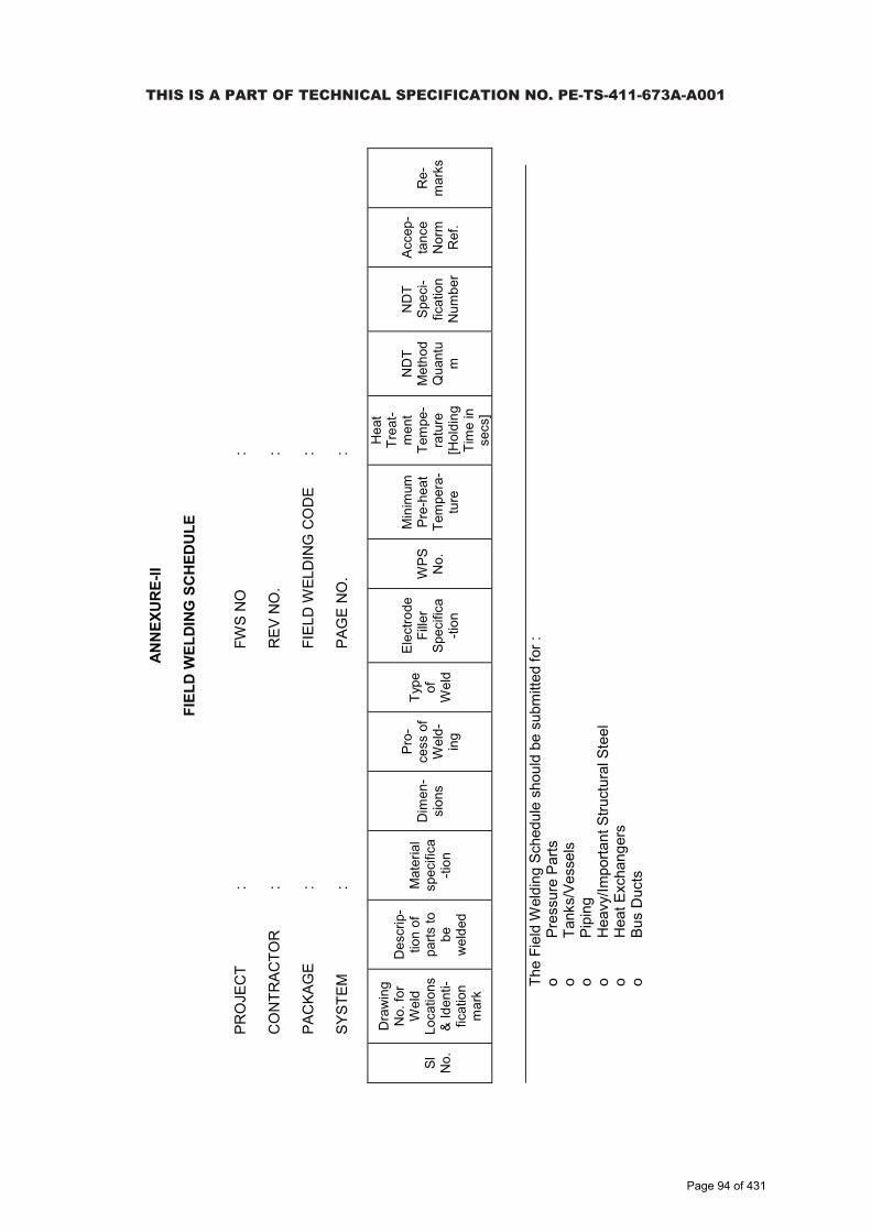
Tela
ngan
a St
ate
Pow
er G
ener
atio
n C
orpo
ratio
n Lt
d.
EPC
Bid
Doc
umen
t1x
800
MW
Kot
hagu
dem
TPS
e-
PCT/
TS/K
/02/
2014
-15
DEV
ELO
PMEN
T C
ON
SULT
ANTS
V.IIA
/S-7
:11
(e-P
CT-
TS-K
-02-
2014
-15-
Vol.
IIA-6
&7.
doc)
ANN
EXU
RE-
II
FIEL
D W
ELD
ING
SC
HED
ULE
PRO
JEC
T:
FWS
NO
:
CO
NTR
ACTO
R:
REV
NO
.:
PAC
KAG
E:
FIEL
D W
ELD
ING
CO
DE
:
SYST
EM:
PAG
EN
O.
:
Sl
No.
Dra
win
g N
o. fo
r W
eld
Loca
tions
&
Iden
ti-fic
atio
n m
ark
Des
crip
-tio
n of
pa
rts to
be
wel
ded
Mat
eria
l sp
ecifi
ca-ti
on
Dim
en-
sion
s
Pro-
cess
of
Wel
d-in
g
Type
of
W
eld
Elec
trode
Fi
ller
Spec
ifica
-tion
WPS
N
o.
Min
imum
Pr
e-he
at
Tem
pera
-tu
re
Hea
t Tr
eat-
men
t Te
mpe
-ra
ture
[H
oldi
ng
Tim
e in
se
cs]
ND
T M
etho
d Q
uant
um
ND
T Sp
eci-
ficat
ion
Num
ber
Acce
p-ta
nce
Nor
mR
ef.
Re-
mar
ks
____
____
____
____
____
____
____
____
____
____
____
____
____
____
____
____
____
____
____
____
____
____
____
____
____
____
____
____
The
Fiel
d W
eldi
ng S
ched
ule
shou
ld b
e su
bmitt
ed fo
r :o
Pres
sure
Par
tso
Tank
s/Ve
ssel
so
Pipi
ngo
Hea
vy/Im
porta
nt S
truct
ural
Ste
elo
Hea
t Exc
hang
ers
oBu
s D
ucts
THIS IS A PART OF TECHNICAL SPECIFICATION NO. PE-TS-411-673A-A001
Page 94 of 431

Telangana State Power Generation Corporation Ltd. EPC Bid Document1x800 MW Kothagudem TPS e-PCT/TS/K/02/2014-15
DEVELOPMENT CONSULTANTS(e-PCT-TS-K-02-2014-15-Vol. IIA-8.docx)
VOLUME : IIA
SECTION-VIII
REQUIREMENTS OF SPARES, TOOLS & TACKLE,LUBRICANTS/OIL/CONSUMABLES
THIS IS A PART OF TECHNICAL SPECIFICATION NO. PE-TS-411-673A-A001
Page 95 of 431

Telangana State Power Generation Corporation Ltd. EPC Bid Document1x800 MW Kothagudem TPS e-PCT/TS/K/02/2014-15
DEVELOPMENT CONSULTANTS(e-PCT-TS-K-02-2014-15-Vol. IIA-8.docx)
CONTENT
CLAUSE NO. DESCRIPTION
1.00.00 TOOLS AND TACKLE
2.00.00 SPARES
ATTACHMENT
ANNEXURE-I MANDATORY SPARE LIST
THIS IS A PART OF TECHNICAL SPECIFICATION NO. PE-TS-411-673A-A001
Page 96 of 431

Telangana State Power Generation Corporation Ltd. EPC Bid Document1x800 MW Kothagudem TPS e-PCT/TS/K/02/2014-15
DEVELOPMENT CONSULTANTS V.IIA/S-8 : 1(e-PCT-TS-K-02-2014-15-Vol. IIA-8.docx)
VOLUME : IIA
SECTION-VIII
REQUIREMENTS OF SPARES, TOOLS & TACKLE,LUBRICANTS/OIL/CONSUMABLES
1.00.00 TOOLS & TACKLE
The Contractor shall supply with the equipment one complete set of special tools and tackle as required for the erection, assembly, dismantling & maintenance of the equipment. These special tools will also include special material handling equipment, jigs & fixtures for maintenance and calibration/ readjustment, checking & measurement aids etc. A list of such tools & tackle shall be submitted by the Bidder along with the offer. Detailed description of each tools/tackle, its function along with the equipment/part for which it is meant for and the price of each tools/tackle shall also be indicated in the offer. These tools & tackle shall be separately packed and sent to site before the first unit commissioning. The Bidder shall also ensure that these tools are not used for erection purpose.
2.00.00 SPARES
2.01.00 General
The Bidder shall indicate and include in his scope of supply all the necessary start-up, commissioning and recommended spares in addition to mandatory spares as specified elsewhere in the specification. The Owner reserves the right to buy any or all mandatory and recommended spares. The Contractor shall also state for each item of spares both mandatory and recommended, the normal expected service life.
2.01.01 All spares supplied under this contract shall be strictly interchangeable with the parts for which they are intended to replace. The spares shall be treated and packed for long storage under the climatic conditions prevailing at the site, e.g. small items shall be packed in sealed transparent plastic bags with dessicator packs as necessary.
2.01.02 Each spare part shall be clearly marked or labelled on the outside of the packing with the description. When more than one spare part is packed in a single case, a general description of the contents shall be shown on the outside and a detailed list enclosed. All cases, containers and other packages must be suitably marked and numbered for the purposes of identification.
2.01.03 All cases, containers or other packages are liable to be opened for examination as may be considered necessary by the Engineer.
2.01.04 All mandatory spares shall be delivered to site within one to three months prior to the scheduled date of the trial operation of the plant. However, they shall not be despatched before the despatch of the associated main equipment.
THIS IS A PART OF TECHNICAL SPECIFICATION NO. PE-TS-411-673A-A001
Page 97 of 431

Telangana State Power Generation Corporation Ltd. EPC Bid Document1x800 MW Kothagudem TPS e-PCT/TS/K/02/2014-15
DEVELOPMENT CONSULTANTS V.IIA/S-8 : 2(e-PCT-TS-K-02-2014-15-Vol. IIA-8.docx)
2.01.05 The Bidder shall also guarantee supply of spare parts, which will be made, based on manufacturer's drawings on special order from the Purchaser for 30years after commissioning of the plant.
2.01.06 Warranty period for all kinds of spares shall be six thousand (6000) hours of operation, except normal wear or eighteen (18) months from the date of receipt at site, whichever is earlier. In case of failure or non-conformance to specifications, the Contractor shall replace them free of cost.
2.02.00 Recommended Spares
2.02.01 The Contractor shall provide a list of recommended spares giving unit prices and total prices for 2 years of normal operation of the plant for spares of indigenous origin, and for 5 years of normal operation for spares of non-indigenous origin. This list shall take into consideration the mandatory spares specified elsewhere in the specification and should be a separate list.
2.02.02 The price of recommended spares will not be used for the evaluation of bids. The price of these spares shall remain valid for a period as specified elsewhere in the specification from the date of Award of the Contract. Where the recommended spares are the same as mandatory spares, the prices shall be the same. The prices of any recommended spares, which are not common with mandatory spares, shall be subject to review by the Owner, and shall be finalised after mutual discussion.
2.03.00 Start-up Commissioning Spares
2.03.01 Start-up commissioning spares are those spares which may be required during the start-up and commissioning of the equipment/system. All spares used until the plant is handed over to the Owner shall come under this category. Said spares, properly marked, shall be supplied together with the main equipment and shall be used by the Contractor, if needed, during erection & commissioning stage. All such spares which remain unused till issuance of Taking Over Certificate by the Owner, along with an equipment-wise quantitative consumption report shall be returned to the Owner during time of handover. The list of commissioning spares to be brought by the Contractor to ensure smooth commissioning of the plant shall be subject to the Engineer's approval.
2.03.02 The Contractor shall submit a complete BBU list inclusive of recommended, mandatory, initial start-up and commissioning spares. Costs of the above spares, which are consumed before the handing-over of the plant, shall be deemed to have been included in the lump sum proposal price of the package, and the Contractor shall have no claim on this account to the Owner.
2.04.00 Mandatory Spare Parts
2.04.01 The Owner considers some of the spares are essential for running the equipment irrespective of whether they are included in the list of recommended spares by the Bidder as mentioned above.
Since the components involved can not be foreseen at the bidding stage, only
THIS IS A PART OF TECHNICAL SPECIFICATION NO. PE-TS-411-673A-A001
Page 98 of 431

Telangana State Power Generation Corporation Ltd. EPC Bid Document1x800 MW Kothagudem TPS e-PCT/TS/K/02/2014-15
DEVELOPMENT CONSULTANTS V.IIA/S-8 : 3(e-PCT-TS-K-02-2014-15-Vol. IIA-8.docx)
broad requirements of the Owner in this respect are outlined hereinafter. The bidder shall include his proposal, on the basis of this guideline, an item-wise list of all components and the quantity, unit prices & total price thereof, offered as mandatory spares for each and every equipment. This list shall be separate from the list of recommended spares and shall be used for bid evaluation purposes. Any clarification in this respect may be obtained by the Bidder at the pre-bidding stage.
2.04.02 The mandatory spares should be supplied to the Owner at least one month before the trial run. The despatch programme is subject to approval of the Owner/Consultant after award of contract.
2.04.03.1 Criteria for selection of Quantity of Mandatory Spares :
For Mandatory Spares refer Annexure-I.
2.04.04 Purchaser will have the option to procure any or all of the mandatory spares at his discretion.
THIS IS A PART OF TECHNICAL SPECIFICATION NO. PE-TS-411-673A-A001
Page 99 of 431

TITLE SPECIFICATION NO.
PE‐TS‐411‐673A‐A001
4 X 270 MW BHADRADRI TPS VOLUME: II B
TECHNICAL SPECIFICATION FOR REV 00
SEWAGE TREATMENT PLANT SHEET 1 of 2
SECTION – C1-C
FUNCTIONAL / PERFORMANCE / DEMONSTRATION GUARANTEE
Page 100 of 431

TITLE SPECIFICATION NO.
PE‐TS‐411‐673A‐A001
4 X 270 MW BHADRADRI TPS VOLUME: II B
TECHNICAL SPECIFICATION FOR REV 00
SEWAGE TREATMENT PLANT SHEET 2 of 2
The Bidder shall guarantee that the equipment offered shall meet the rating and performance requirements stipulated for various equipment covered in this specifications. The guaranteed performance parameters furnished by the bidder in his offer, shall be without any tolerance values and all margins required for instrument inaccuracies and other uncertainties shall be deemed to have been included in the guaranteed figures. The bidder shall demonstrate all the guarantees covered herein during demonstration test / PG test. The various tests which are to be carried out during demonstration tests are listed in the specification. The guarantee tests shall be conducted by the bidder at site in presence of BHEL/ CUSTOMER. All costs associated with the tests shall be included in the bid price. In case during demonstration test /PG test, it is found that the equipment/system has failed to meet the guarantees, the bidder shall carry out all necessary modifications and/or replacements to make the equipment/system comply with the guaranteed requirements at no extra cost to the BHEL/ CUSTOMER and re-conduct the demonstration test(s) / PG test with BHEL/ CUSTOMER’s consent.
I. TECHNICAL GUARANTEES
SEWAGE TREATMENT PLANT
Out let quality to be demonstrated by bidder should meet the latest environmental norms by state government / MOEF / PCB or below mentioned desired quality whichever is stringent.
BOD5 : 20 mg/l COD : 100 mg/l TSS : 30 mg/l pH : 7 – 8 Temperature : Ambient
In addition to the above all equipments / items shall be demonstrated by bidder for its rated capacity at site.
Page 101 of 431

TITLE SPECIFICATION NO.
PE‐TS‐411‐673A‐A001
4 X 270 MW BHADRADRI TPS VOLUME: II B
TECHNICAL SPECIFICATION FOR REV 00
SEWAGE TREATMENT PLANT SHEET 1 of 1
SECTION C1 – D
QUALITY ASSURANCE
Page 102 of 431

CLA
USE
NO
. Q
UA
LITY
ASS
UR
AN
CE
NO
RTH
KA
RA
NPU
RA
STP
P (3
X660
MW
) EP
C P
AC
KA
GE
TEC
HN
ICA
L SP
ECIF
ICA
TIO
N
SEC
TIO
N-V
I, PA
RT-
B
BID
DO
C N
O.:C
S-44
10-0
01-2
SUB
-SEC
TIO
N -
IIIE-
23
WA
TER
PR
E-TR
EATM
ENT
PLA
NT
PAG
E 1
OF
2
Wat
er P
re-T
reat
men
t Pla
nt
Test
s/C
heck
Item
s / C
ompo
nent
s
Material Test
WPS/PQR/Welder Qualification
DPT/MPI
Assembly Fit up
Dimension
RT
Hydraulic / Water Fill
Performance Test
Test as per relevant Std/ Appd. DataSheetsOther Tests
Remarks
1. H
oriz
onta
l Cen
trifu
gal
Pum
ps
Y Y
Y1Y
LEG
END
S:Y
A
pplic
able
Ya
One
per
Hea
t/Hea
t Tre
atm
ent b
atch
./Lot
Yb O
n m
achi
ned
surfa
ces
only
. Als
o 10
0% o
n B
utt W
elds
& 1
0% o
n Fi
llet W
elds
. Yc U
T sh
all b
e do
ne fo
r sha
fts w
ith D
ia 5
0 m
m o
r abo
ve &
Pla
tes
of T
hick
ness
20
mm
or a
bove
. Yd D
ynam
ic B
alan
cing
per
ISO
: 194
0, G
rade
6.3
min
imum
.
Y1A
s pe
r HIS
, US
A.
Y210
% R
T to
be
cond
ucte
d on
but
t wel
ds fo
r Thk
>10
mm
. Y3
Sea
t Lea
kage
Tes
t for
act
uato
r ope
rate
d va
lves
sha
ll be
don
e by
clo
sing
the
valv
e w
ith jo
b ac
tuat
or.
Y4Te
sts
on R
ubbe
r Dia
phra
gms
per b
atch
of R
ubbe
r mix
suc
h as
Ten
sile
, E
long
atio
n, H
ardn
ess,
Thi
ckne
ss, B
leed
Res
ista
nce,
Fle
x Te
st fo
r 150
0 cy
cles
etc
. sha
ll be
con
duct
ed.
In a
dditi
on, T
ype
Test
for 5
0,00
0 cy
cles
for
each
type
of d
iaph
ragm
sha
ll al
so b
e co
nduc
ted,
if n
ot c
arrie
d ou
t ear
lier.
Y5S
eat L
eaka
ge T
est i
s re
quire
d to
be
done
in b
oth
dire
ctio
ns. D
isc
stre
ngth
te
st a
s pe
r rel
evan
t cod
e sh
all b
e ca
rried
out
. Y
6B
lue
Mat
chin
g, W
ear T
rave
l for
Gat
e V
alve
s, re
duce
d pr
essu
re te
st fo
r che
ck
valv
es s
hall
be c
ondu
cted
per
rele
vant
sta
ndar
ds.
1.1
. C
asin
g Y
a
Yb
Y
1.2
. Im
pelle
r Y
a
Yb
Yd
1.3
. S
haft
Ya
Y
Yc
2. V
ertic
al P
umps
Y Y
Y1Y
2.1
. C
asin
g Y
a
Yb
Y
2.2
. Im
pelle
r Y
a
Yb
Yd
2.3
. S
haft
Ya
Y
Yc
2.4
. Fa
bric
ated
Par
ts
Ya
Y Yb
Y2Y
3. D
osin
g/ M
eter
ing
Pum
ps
YaY
Y1 Y
4.
Gat
e/ G
lobe
/ Che
ck V
alve
s Ya
Yb
Y
Y Y
Y Y6
5. D
ual P
late
Che
ck V
alve
s Ya
Yb
Y
Y Y
Y Y12
6 D
iaph
ragm
Val
ves
Ya
Y Y3
Y
Y4
6. B
utte
rfly
Val
ves
(Low
Pr.)
Y
Y Y3
YY5
7.1B
ody
(Cas
t) Y
aYb
7.2D
isc
(Cas
t) Ya
Yb
7.3
Sha
ft Ya
Yb
Yc
8. P
lug/
Bal
l Val
ves
(Low
Pr.)
Ya
Yb
Y Y
Y Y
Y
9. B
low
ers
Ya
YbY
Y Y
Y Y
Ydc
10. A
tmos
pher
ic S
tora
ge
Tank
s/ P
ress
ure
Vess
els
Ya Y
YbY
Y Y8
Y
YcY7
THIS
IS A
PA
RT
OF
TEC
HN
ICA
L SP
ECIF
ICA
TIO
N N
O. P
E-TS
-411
-673
A-A
001
Page 103 of 431
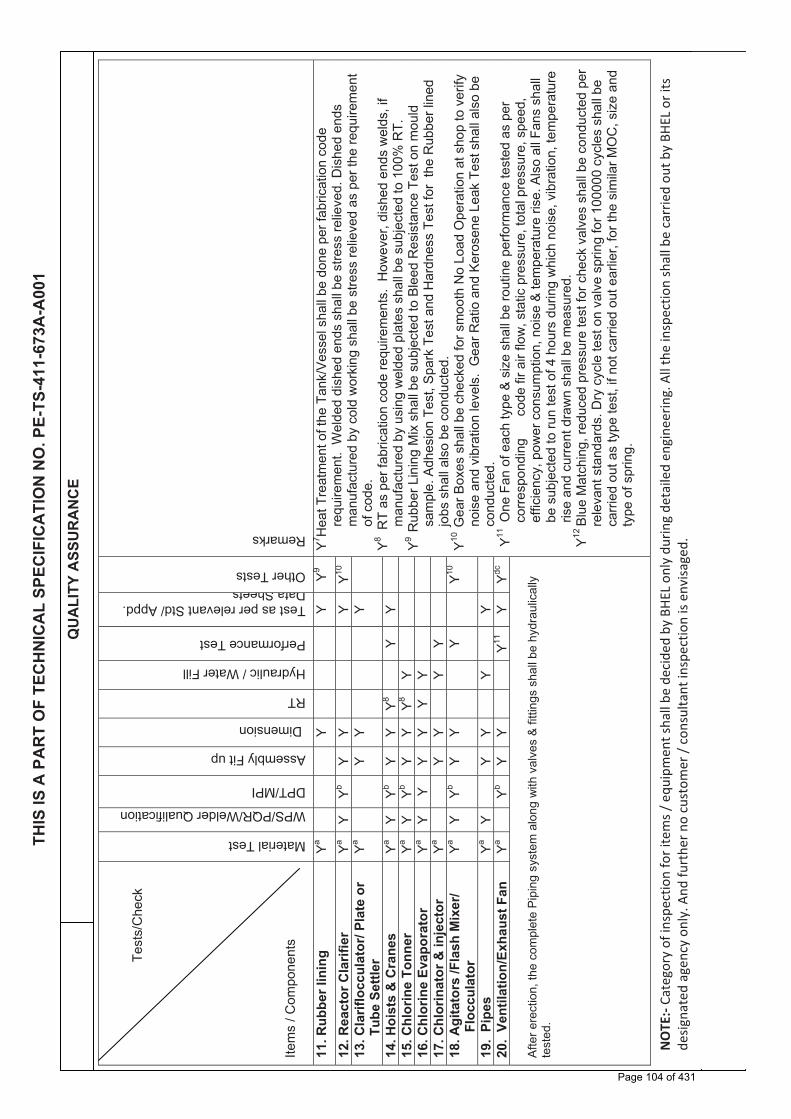
CLA
USE
NO
. Q
UA
LITY
ASS
UR
AN
CE
NO
RTH
KA
RA
NPU
RA
STP
P (3
X660
MW
) EP
C P
AC
KA
GE
TEC
HN
ICA
L SP
ECIF
ICA
TIO
N
SEC
TIO
N-V
I, PA
RT-
B
BID
DO
C N
O.:C
S-44
10-0
01-2
SUB
-SEC
TIO
N -
IIIE-
23
WA
TER
PR
E-TR
EATM
ENT
PLA
NT
PAG
E 2
OF
2
Te
sts/
Che
ck
Item
s / C
ompo
nent
s Material Test
WPS/PQR/Welder Qualification
DPT/MPI
Assembly Fit up
Dimension
RT
Hydraulic / Water Fill
Performance Test
Test as per relevant Std/ Appd. DataSheetsOther Tests
Remarks
11. R
ubbe
r lin
ing
Ya
Y
Y
Y9 Y7 H
eat T
reat
men
t of t
he T
ank/
Ves
sel s
hall
be d
one
per f
abric
atio
n co
de
requ
irem
ent.
Wel
ded
dish
ed e
nds
shal
l be
stre
ss re
lieve
d. D
ishe
d en
ds
man
ufac
ture
d by
col
d w
orki
ng s
hall
be s
tress
relie
ved
as p
er th
e re
quire
men
t of
cod
e.
Y8R
T as
per
fabr
icat
ion
code
requ
irem
ents
. H
owev
er, d
ishe
d en
ds w
elds
, if
man
ufac
ture
d by
usi
ng w
elde
d pl
ates
sha
ll be
sub
ject
ed to
100
% R
T.
Y9R
ubbe
r Lin
ing
Mix
sha
ll be
sub
ject
ed to
Ble
ed R
esis
tanc
e Te
st o
n m
ould
sa
mpl
e. A
dhes
ion
Test
, Spa
rk T
est a
nd H
ardn
ess
Test
for
the
Rub
ber l
ined
jo
bs s
hall
also
be
cond
ucte
d.
Y10G
ear B
oxes
sha
ll be
che
cked
for s
moo
th N
o Lo
ad O
pera
tion
at s
hop
to v
erify
no
ise
and
vibr
atio
n le
vels
. G
ear R
atio
and
Ker
osen
e Le
ak T
est s
hall
also
be
cond
ucte
d.
Y11 O
ne F
an o
f eac
h ty
pe &
siz
e sh
all b
e ro
utin
e pe
rform
ance
test
ed a
s pe
r co
rresp
ondi
ng
co
de fi
r air
flow
, sta
tic p
ress
ure,
tota
l pre
ssur
e, s
peed
, ef
ficie
ncy,
pow
er c
onsu
mpt
ion,
noi
se &
tem
pera
ture
rise
. Als
o al
l Fan
s sh
all
be s
ubje
cted
to ru
n te
st o
f 4 h
ours
dur
ing
whi
ch n
oise
, vib
ratio
n, te
mpe
ratu
re
rise
and
curre
nt d
raw
n sh
all b
e m
easu
red.
Y12
Blu
e M
atch
ing,
redu
ced
pres
sure
test
for c
heck
val
ves
shal
l be
cond
ucte
d pe
r re
leva
nt s
tand
ards
. Dry
cyc
le te
st o
n va
lve
sprin
g fo
r 100
000
cycl
es s
hall
be
carri
ed o
ut a
s ty
pe te
st, i
f not
car
ried
out e
arlie
r, fo
r the
sim
ilar M
OC
, siz
e an
d ty
pe o
f spr
ing.
12. R
eact
or C
larif
ier
Ya Y
YbY
Y
Y
Y10
13. C
larif
locc
ulat
or/ P
late
or
Tube
Set
tler
Ya
Y
Y
Y
14. H
oist
s &
Cra
nes
Ya Y
YbY
Y Y8
Y
Y
15. C
hlor
ine
Tonn
er
Ya Y
YbY
Y Y8
Y
16. C
hlor
ine
Evap
orat
or
Ya Y
Y Y
Y Y
Y
17. C
hlor
inat
or &
inje
ctor
Ya
Y Y
Y
Y
18
. Agi
tato
rs /F
lash
Mix
er/
Flo
ccul
ator
Ya
Y Yb
Y Y
Y
Y10
19.
Pipe
sYa
Y Y
Y Y
Y
20
. Ve
ntila
tion/
Exha
ust F
an
Ya
YbY
Y
Y11
Y Ydc
Afte
r ere
ctio
n, th
e co
mpl
ete
Pip
ing
syst
em a
long
with
val
ves
& fi
tting
s sh
all b
e hy
drau
lical
ly
test
ed.
THIS
IS A
PA
RT
OF
TEC
HN
ICA
L SP
ECIF
ICA
TIO
N N
O. P
E-TS
-411
-673
A-A
001
NOTE:-
Cate
gory
of i
nspe
ctio
n fo
r ite
ms /
equ
ipm
ent s
hall
be d
ecid
ed b
y BH
EL o
nly
durin
g de
taile
d en
gine
erin
g. A
ll th
e in
spec
tion
shal
l be
carr
ied
out b
y BH
EL o
r its
de
signa
ted
agen
cy o
nly.
And
furt
her n
o cu
stom
er /
cons
ulta
nt in
spec
tion
is en
visa
ged.
Page 104 of 431
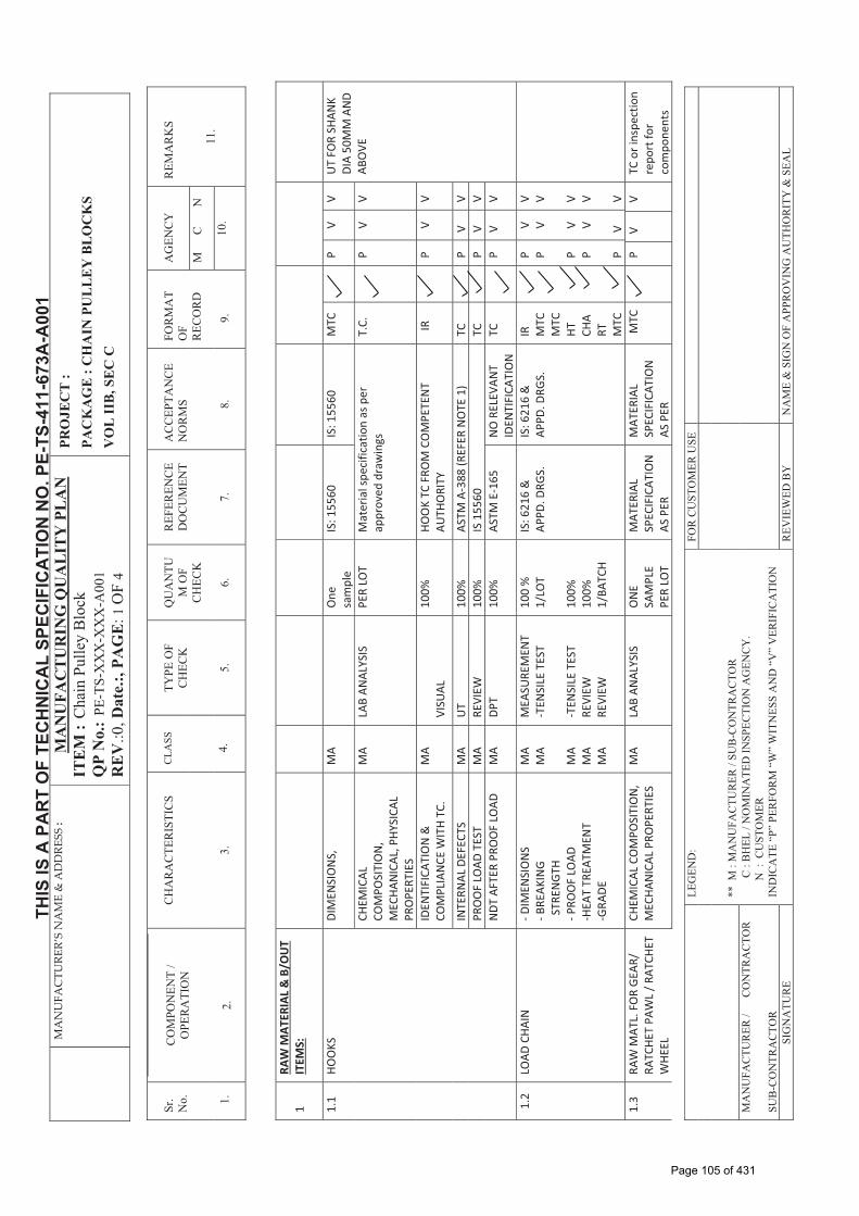
MANUFA
CTU
RER’S�NAME�&�ADDRE
SS�:�
MA
NU
FAC
TU
RIN
G Q
UA
LIT
Y P
LA
NIT
EM
:C
hain
Pul
ley
Blo
ckQ
P N
o.:
PE-T
S-X
XX
-XX
X-A
001
RE
V.:0
, Dat
e.:,
PAG
E:1
OF
4
PRO
JEC
T :
PA
CK
AG
E :
CH
AIN
PU
LL
EY
BL
OC
KS
V
OL
IIB
, SE
C C
Sr.
No. 1.
CO
MPO
NEN
T /
OPE
RA
TIO
N
2.
CH
AR
AC
TER
ISTI
CS
3.
CLA
SS
4
.
TYPE
OF
CH
ECK
5.
QU
AN
TUM
OF
CH
ECK
6.
REF
EREN
CE
DO
CU
MEN
T
7.
AC
CEP
TAN
CE
NO
RM
S
8
.
FOR
MA
T O
FR
ECO
RD
9.
AG
ENC
YR
EMA
RK
S
11.
M
C
N
10.
LEG
END
:FO
R C
UST
OM
ER U
SE
** M
: M
AN
UFA
CTU
RER
/ SU
B-C
ON
TRA
CTO
R
MA
NU
FAC
TUR
ER /
C
ON
TRA
CTO
R
C :
BH
EL /
NO
MIN
ATE
D IN
SPEC
TIO
N A
GEN
CY
.
N :
CU
STO
MER
SU
B-C
ON
TRA
CTO
R
IND
ICA
TE “
P” P
ERFO
RM
“W
” W
ITN
ESS
AN
D “
V”
VER
IFIC
ATI
ON
SIG
NA
TUR
E R
EVIE
WED
BY
N
AM
E &
SIG
N O
F A
PPR
OV
ING
AU
THO
RIT
Y &
SEA
L
� 1�RA
W�M
ATER
IAL�&�B/O
UT�
ITEM
S:�
�
��
��
��
��
�
1.1�
HOO
KS�
DIM
ENSI
ON
S,�
MA�
��O
ne�
sam
ple�
IS:�1
5560
�IS
:�155
60�
MTC
��
P�V�
V��
UT�
FOR�
SHAN
K�DI
A�50
MM
�AN
D�AB
OVE
�CH
EMIC
AL��
COM
POSI
TIO
N,�
MEC
HAN
ICAL
,�PHY
SICA
L�PR
OPE
RTIE
S�
MA�
�LA
B�AN
ALYS
IS�
PER�
LOT�
�M
ater
ial�s
peci
ficat
ion�
as�p
er�
appr
oved
�dra
win
gs�
T.C.
���
P� �V� �
V� �
IDEN
TIFI
CATI
ON
�&�
COM
PLIA
NCE
�WIT
H�TC
.�M
A����
����
������
������
������
�����
VISU
AL���
������
��10
0%�
HOO
K�TC
�FRO
M�C
OM
PETE
NT�
AUTH
ORI
TY�
��IR�
�P� �
V� �V� �
INTE
RNAL
�DEF
ECTS
�M
A�U
T����
�����
100%
�AS
TM�A
�388
�(REF
ER�N
OTE
�1)�
TC�
�P�
V�V�
PRO
OF�
LOAD
�TES
T�M
A�RE
VIEW
�10
0%�
IS�1
5560
�TC
��
P�V�
V�N
DT�A
FTER
�PRO
OF�
LOAD
�M
A�DP
T�10
0%�
ASTM
�E�1
65�
NO
�REL
EVAN
T�ID
ENTI
FICA
TIO
N�
TC�
�P�
V�V�
1.2�
LOAD
�CHA
IN��
��DIM
ENSI
ON
S���B
REAK
ING�
��STR
ENGT
H���P
ROO
F�LO
AD�
�HEA
T�TR
EATM
ENT�
�GRA
DE�
MA�
MA�
� MA�
MA�
MA�
MEA
SURE
MEN
T��T
ENSI
LE�T
EST�
� �TEN
SILE
�TES
T�RE
VIEW
�RE
VIEW
�
100�
%�
1/LO
T�� 10
0%�
100%
�1/
BATC
H�
IS:�6
216�
&�
APPD
.�DRG
S.�
�
IS:�6
216�
&�
APPD
.�DRG
S.�
�
IR�
MTC
�M
TC�
HT�
CHA
RT�
MTC
�
� � �
P� P� �� P� P� �� P����
V� V� � V� V� � V�
V��
V��
� V���
V��
� V�
�
1.3�
RAW
�MAT
L.�F
OR�
GEA
R/�
RATC
HET�
PAW
L�/�R
ATCH
ET�
WHE
EL���
������
������
������
������
������
�
CHEM
ICAL
�CO
MPO
SITI
ON
,��M
ECHA
NIC
AL�P
ROPE
RTIE
S�M
A�� �
LAB�
ANAL
YSIS
��
ON
E�SA
MPL
E�PE
R�LO
T�
MAT
ERIA
L�SP
ECIF
ICAT
ION
�AS
�PER
�
MAT
ERIA
L�SP
ECIF
ICAT
ION
�AS
�PER
�
�MTC
��
P� � �
V� � �
V���
� �
TC�o
r�ins
pect
ion�
repo
rt�fo
r�co
mpo
nent
s�
THIS
IS A
PA
RT
OF
TEC
HN
ICA
L SP
ECIF
ICA
TIO
N N
O. P
E-TS
-411
-673
A-A
001
Page 105 of 431

MANUFA
CTU
RER’S�NAME�&�ADDRE
SS�:�
MA
NU
FAC
TU
RIN
G Q
UA
LIT
Y P
LA
NIT
EM
:C
hain
Pul
ley
Blo
ckQ
P N
o.:
PE-T
S-X
XX
-XX
X-A
001
RE
V.:0
, Dat
e.:,
PAG
E:2
OF
4
PRO
JEC
T :
PA
CK
AG
E :
CH
AIN
PU
LL
EY
BL
OC
KS
V
OL
IIB
, SE
C C
Sr.
No. 1.
CO
MPO
NEN
T /
OPE
RA
TIO
N
2.
CH
AR
AC
TER
ISTI
CS
3.
CLA
SS
4
.
TYPE
OF
CH
ECK
5.
QU
AN
TUM
OF
CH
ECK
6.
REF
EREN
CE
DO
CU
MEN
T
7.
AC
CEP
TAN
CE
NO
RM
S
8
.
FOR
MA
T O
FR
ECO
RD
9.
AG
ENC
YR
EMA
RK
S
11.
M
C
N
10.
LEG
END
:FO
R C
UST
OM
ER U
SE
** M
: M
AN
UFA
CTU
RER
/ SU
B-C
ON
TRA
CTO
R
MA
NU
FAC
TUR
ER /
C
ON
TRA
CTO
R
C :
BH
EL /
NO
MIN
ATE
D IN
SPEC
TIO
N A
GEN
CY
.
N :
CU
STO
MER
SU
B-C
ON
TRA
CTO
R
IND
ICA
TE “
P” P
ERFO
RM
“W
” W
ITN
ESS
AN
D “
V”
VER
IFIC
ATI
ON
SIG
NA
TUR
E R
EVIE
WED
BY
N
AM
E &
SIG
N O
F A
PPR
OV
ING
AU
THO
RIT
Y &
SEA
L
�AP
PRO
VED�
DRAW
ING
�AP
PRO
VED�
DRAW
ING
�sh
all�b
e�gi
ven.
�
� INTE
RNAL
�DEF
ECTS
�M
A�U
T�10
%�
ASTM
�A�3
88�(R
EFER
�NO
TE�1
)�IR
�P�
V�V�
���
�
1.4.
�� � � �
1.5� �
LOAD
�CHA
IN�W
HEEL
S�� � � � BE
ARIN
GS�
� � �
��CHE
MIC
AL���
COM
POSI
TIO
N���
������
������
������
�����
MEC
HAN
ICAL
�PRO
PERT
IES�
� � MAK
E,�T
YPE,
�CAT
ALO
GU
E�N
O.�
MA�
� MA�
� � MA�
CHEM
ICAL
������
����
� MEC
HAN
ICAL
�PR
OPE
RTIE
S�� � VI
SUAL
�
ON
E�SA
MPL
E�PE
R�LO
T����
� � RAN
DOM
������
��
APPD
.�DRG
.��� � � � AP
P�DR
G�/�
MFR
” S�CA
TALO
GUE�
������
��
APPD
.�DRG
.�� � � � AP
P�DR
G�/�
MFR
” S�CA
TALO
GUE�
�����
����
������
������
������
������
������
��
� MTC
�� � � IR
��
� � � � � � �
P� � � � � P� � �
V� � � � � V� � �
V� � � � � V� � �
� � � � � �
1.6�
HAN
D�CH
AIN
�WHE
EL�
CHEM
ICAL
�M
ECHA
NIC
AL�P
ROPE
RTIE
S�M
A�CH
EMIC
AL�
MEC
HAN
ICAL
�PR
OPE
RTIE
S�
ON
E�SA
MPL
E�PE
R�LO
T�
AS�P
ER�
DRAW
ING
�AS
�PER
�DR
AWIN
G�
MTC
��
P� �V� �
V� ��
1.7�
HAN
D�CH
AIN
�GR
ADE/
�DIM
ENSI
ON
�M
A�G
RADE
��DI
MEN
SIO
N�
100�
%�
AS�P
ER�
DRAW
ING
�AS
�PER
�DR
AWIN
G�
MTC
��
P�V�
V��
1.8�
�TR
OLL
EY�G
EARS
,�PI
NIO
N,W
HEEL
S,�A
XLE�
CHEM
ICAL
�&�M
ECHA
NIC
AL�
MA�
LAB�
ANAL
YSIS
,�10
0%�
APPV
D�DR
GS�
APPV
D�DR
GS�
IR/T
C��
P�V�
V��
2�IN�PRO
CESS�
��
��
��
��
��
2.1�
RATC
HET�
�PAW
L�/�
RATC
HET�
WHE
EL�
�HAR
DNES
S��
MA�
�HA
RDN
ESS�
�10
0%�
�IS
:383
2�/�A
PPD�
DRG
.�IS
:383
2/�
APPD
.�DRG
.�IR
���
� �P� �
V� �V� �
�
THIS
IS A
PA
RT
OF
TEC
HN
ICA
L SP
ECIF
ICA
TIO
N N
O. P
E-TS
-411
-673
A-A
001
Page 106 of 431

MANUFA
CTU
RER’S�NAME�&�ADDRE
SS�:�
MA
NU
FAC
TU
RIN
G Q
UA
LIT
Y P
LA
NIT
EM
:C
hain
Pul
ley
Blo
ckQ
P N
o.:
PE-T
S-X
XX
-XX
X-A
001
RE
V.:0
, Dat
e.:,
PAG
E:3
OF
4
PRO
JEC
T :
PA
CK
AG
E :
CH
AIN
PU
LL
EY
BL
OC
KS
V
OL
IIB
, SE
C C
Sr.
No. 1.
CO
MPO
NEN
T /
OPE
RA
TIO
N
2.
CH
AR
AC
TER
ISTI
CS
3.
CLA
SS
4
.
TYPE
OF
CH
ECK
5.
QU
AN
TUM
OF
CH
ECK
6.
REF
EREN
CE
DO
CU
MEN
T
7.
AC
CEP
TAN
CE
NO
RM
S
8
.
FOR
MA
T O
FR
ECO
RD
9.
AG
ENC
YR
EMA
RK
S
11.
M
C
N
10.
LEG
END
:FO
R C
UST
OM
ER U
SE
** M
: M
AN
UFA
CTU
RER
/ SU
B-C
ON
TRA
CTO
R
MA
NU
FAC
TUR
ER /
C
ON
TRA
CTO
R
C :
BH
EL /
NO
MIN
ATE
D IN
SPEC
TIO
N A
GEN
CY
.
N :
CU
STO
MER
SU
B-C
ON
TRA
CTO
R
IND
ICA
TE “
P” P
ERFO
RM
“W
” W
ITN
ESS
AN
D “
V”
VER
IFIC
ATI
ON
SIG
NA
TUR
E R
EVIE
WED
BY
N
AM
E &
SIG
N O
F A
PPR
OV
ING
AU
THO
RIT
Y &
SEA
L
�SU
RFAC
E�CR
ACK�
��
MA�
DPT�
�10
0�%
��
� ASTM
�E16
5�� N
O�D
EFEC
T�IR
��
� �P� �
V� �V� �
�
2.2�
GEAR
S�AN
D�PI
NIO
NS�
AFTE
R�M
ACHI
NIN
G�
SURF
ACE�
HARD
NES
S�HE
AT�T
REAT
MEN
T,�
SURF
ACE�
CRAC
K,�
CASE
�DEP
TH��
MA�
HARD
NES
S�� HT
�CHA
RT,�D
PT�
FOR�
SURF
ACE�
CRAC
K�
RAN
DOM
�� AS
TM�E
�16
5�FO
R�DP
T�
MFG
��ST
ANDA
RD�
� NO
�DEF
ECT�
MFG
�ST
ANDA
RD�
IR�
� � IR�
� � � �
P� � � P�
V� � � V�
V� � � V�
�
3.0� �
FINAL
�INSPEC
TION�
��
���
��
��
��
3.1�
COM
PLET
E��A
SSEM
BLY�
OVE
RALL
�DIM
ENSI
ON
��
MA�
�M
EASU
REM
ENT�
100�
%�
�IS
:383
2�/A
PPD�
DRG
��IS
:383
2�/A
PPD�
DRG
��IR
��
��P
�W
�V�
� �PR
OO
F�LO
AD�T
EST�
�CR
��
� LOAD
�TES
T��
100%
��
�DO
������
������
������
���
No�
crac
ks,�f
law
s�&
�oth
er�d
efec
ts�
IR�
��
�P�
W�
V�
LIGH
T�LO
AD�T
EST�
�M
A�� LO
AD�T
EST
100%
�IS
�383
2�IS
�383
2�IR
��
�P�
W�
V�
HEIG
HT�O
F�LI
FT�
MA�
MEA
SURE
ME�
NT�
100%
��D
O���
�DO
�–�
IR���
���� �
�P�
W�
V�
SWIV
ELIN
G�O
F�HO
OK�
��
MA�
�VI
SUAL
��
100�
%�
��D
O��
��D
O��
�IR
��
��P
�W
�V�
EFFO
RT�
MA�
������
�PU
LL�O
N�C
HAIN
�����
100%
��D
O��
�DO
��IR
�� �
�P�
W�
V�
3.2�
PAIN
TIN
G��C
LEAN
ING
�M
A�VI
SUAL
�AT
�RA
NDO
M�
APPR
OVE
D��
APPR
OVE
D��
IR�
�� P�
������
�
��SHA
DE�&
�DFT
�OF�
�PAI
NT�
(Blu
e�/�B
lack
)�M
I�VI
SUAL
�AT
�RA
NDO
M�
DRAW
ING
/�SP
ECIF
ICAT
ION
�DR
AWIN
G/�
SPEC
IFIC
ATIO
N�
IR�
�� P� �
� W�
�
� �� �
THIS
IS A
PA
RT
OF
TEC
HN
ICA
L SP
ECIF
ICA
TIO
N N
O. P
E-TS
-411
-673
A-A
001
Page 107 of 431

MANUFA
CTU
RER’S�NAME�&�ADDRE
SS�:�
MA
NU
FAC
TU
RIN
G Q
UA
LIT
Y P
LA
NIT
EM
:C
hain
Pul
ley
Blo
ckQ
P N
o.:
PE-T
S-X
XX
-XX
X-A
001
RE
V.:0
, Dat
e.:,
PAG
E:4
OF
4
PRO
JEC
T :
PA
CK
AG
E :
CH
AIN
PU
LL
EY
BL
OC
KS
V
OL
IIB
, SE
C C
Sr.
No. 1.
CO
MPO
NEN
T /
OPE
RA
TIO
N
2.
CH
AR
AC
TER
ISTI
CS
3.
CLA
SS
4
.
TYPE
OF
CH
ECK
5.
QU
AN
TUM
OF
CH
ECK
6.
REF
EREN
CE
DO
CU
MEN
T
7.
AC
CEP
TAN
CE
NO
RM
S
8
.
FOR
MA
T O
FR
ECO
RD
9.
AG
ENC
YR
EMA
RK
S
11.
M
C
N
10.
LEG
END
:FO
R C
UST
OM
ER U
SE
** M
: M
AN
UFA
CTU
RER
/ SU
B-C
ON
TRA
CTO
R
MA
NU
FAC
TUR
ER /
C
ON
TRA
CTO
R
C :
BH
EL /
NO
MIN
ATE
D IN
SPEC
TIO
N A
GEN
CY
.
N :
CU
STO
MER
SU
B-C
ON
TRA
CTO
R
IND
ICA
TE “
P” P
ERFO
RM
“W
” W
ITN
ESS
AN
D “
V”
VER
IFIC
ATI
ON
SIG
NA
TUR
E R
EVIE
WED
BY
N
AM
E &
SIG
N O
F A
PPR
OV
ING
AU
THO
RIT
Y &
SEA
L
��
3.3�
NAM
E�PL
ATE�
VERI
FICA
TIO
N�
MA�
VISU
AL�
100%
��
�IR
��
P�V� �
��� ��
3.4�
PACK
ING�
�VER
IFIC
ATIO
N�
MI�
VISU
AL�
100%
�SP
ECS.
�SP
ECS.
�IR
��
P���� �
�� ��
3.5� �
REVI
EW�O
F�Q
A�DO
CUM
ENTA
TIO
N�
VERI
FICA
TIO
N�
MA�
VISU
AL�
100%
�AP
PD.�Q
P�AP
PD.�Q
P��
�V�
V�V�
����
�
� CR�–
�CRI
TICA
L,���
MA�
–�M
AJO
R���,
���M
I�–�M
INO
R�N
OTE
1: B
AC
K W
ALL
EC
HO
SH
ALL
BE
AD
JUST
ED T
O 1
00%
OF
FULL
SC
REE
N H
EIG
HT
IN S
OU
ND
(DEF
ECT
FREE
) AR
EA. D
EFEC
T EC
HO
HEI
GH
T M
OR
E TH
AN
20%
OF
SCR
EEN
HEI
GH
T SH
ALL
BE
TREA
TED
AS
UN
AC
CEP
TAB
LE. B
AC
K W
ALL
EC
HO
SH
ALL
NO
T B
E LE
SS T
HA
N 8
0% O
F SC
REE
N H
EIG
HT
IN A
NY
CA
SE.
NO
TE 2
: REC
OR
DS
IDEN
TIFI
ED W
ITH
TIC
K S
HA
LL B
E ES
SEN
TIA
LLY
INLC
UD
ED IN
QA
DO
CU
MEN
TATI
ON
.
THIS
IS A
PA
RT
OF
TEC
HN
ICA
L SP
ECIF
ICA
TIO
N N
O. P
E-TS
-411
-673
A-A
001
Page 108 of 431

ITE
M:
QP
NO
RE
V0
DA
TE
PAG
E1
of 4
Sl.N
oC
OM
PON
EN
T &
O
PER
ATI
ON
SC
HA
RA
CTE
RIS
TIC
SC
ATE
GO
RY
TYPE
OF
CH
EC
KR
EFE
RE
NC
E D
OC
UM
EN
TA
CC
EPT
AN
CE
N
OR
MS
RE
MA
RK
S
D*
MC
N1
23
45
67
89
**10
111.
0R
AW
-MA
TER
IALS
1.1
a) S
TRU
CTU
RA
L M
ATE
RIA
L
b) R
AW
MA
TER
IAL
FOR
H
OIS
T A
ND
GE
AR
BO
X
HO
USE
ING
, TR
OLL
EY
PLA
TE
(AS
APP
LIC
AB
LE)
ME
CH
. , C
HE
M. P
RO
PSM
AC
HE
MIC
AL
CO
MPO
SITI
ON
A
ND
TE
NSI
LE
STR
EN
GTH
1 /
lot
APP
D. D
RG
./ D
ATA
SH
EE
TA
PPD
. DR
G./
D
ATA
SH
EE
TM
ill.s
TC
�V
VV
Test
sha
ll be
car
ried
ou
t in
ab
senc
e of
mill
TC
1.2
GE
AR
S, S
HA
FT/A
XLE
S,
WH
EE
LS
ME
CH
, C
HE
M. P
RO
PSM
AC
HE
MIC
AL
CO
MPO
SITI
ON
, H
AR
DN
ESS
(D
UR
ING
IN
-PR
OC
ESS
)
I /
LOT
APP
D. D
RG
./ D
ATA
SH
EE
TA
PPD
. DR
G./
D
ATA
SH
EE
T /
IS:3
938
LAB
. RE
POR
T
/ MA
NU
FAC
TUR
ER
'S T
EST
C
ER
TIFI
CA
T E
�P
VV
In c
ase
the
item
s ar
e no
t m
anu
fact
ure
d in
-hou
se,
the
man
ufa
ctu
rer's
tes
t ce
rtifi
cate
sha
ll be
su
bmit
ted
for
chem
ical
U
.T F
OR
DIA
/TH
K >
50m
mC
RN
DT
100%
AST
M A
388
NO
TE 4
INSP
N.
RE
POR
T�
P V
V
Dim
ensi
onal
CH
EC
KM
ID
ia.
100%
APP
D. D
RG
./ D
ATA
SH
EE
TA
PPD
. DR
G./
D
ATA
SH
EE
TM
FRS’
TE
ST
CE
RT.
�P
VV
BR
EA
KIN
G L
OA
D
CA
PAC
ITY
CR
BR
EA
KIN
G
LOA
D10
0%A
PPR
OV
ED
DR
G/D
ATA
SH
EE
T /
IS:3
938
/ I
S: 2
266
APP
RO
VE
D
DR
G/D
ATA
SH
EE
T A
ND
/
IS:3
938
/
MFR
S’ T
EST
C
ER
T.�
PV
V
1.4
HO
OK
S P
HYS
./ M
EC
H.
, CH
EM
. PR
OPS
.M
AC
HE
MIC
AL
CO
MPO
SITI
ON
, H
AR
DN
ESS
I /
LO
TA
PPR
OV
ED
DR
G/D
ATA
SH
EE
T /
IS:3
938
/
IS:1
5560
APP
RO
VE
D
DR
G/D
ATA
SH
EE
T /
IS:3
938
/
IS:1
5560
MFR
S’ T
EST
C
ER
T.�
PV
V
U.T
IF
SHA
NK
DIA
> 5
0mm
CR
ND
T10
0%A
STM
A 3
88N
OTE
1IN
SPN
. R
EPO
RT
�P
WV
SHA
NK
PO
RTI
ON
ON
LY
PRO
OF
LOA
D C
APA
CIT
YC
RPR
OO
F LO
AD
TE
ST10
0%A
PPR
OV
ED
DR
G/D
ATA
SH
EE
T /
IS:3
938
/ I
S:15
560
APP
RO
VE
D
DR
G/D
ATA
SH
EE
T /
IS:3
938
/
IS:
1556
0
INSP
N.
RE
POR
T�
PW
V
DP
AFT
ER
PR
OO
F LO
AD
CR
ND
T10
0%A
STM
E-1
65N
O C
RA
CK
SIN
SPN
. R
EPO
RT
�P
V/W
V
2.0
IN-P
RO
CE
SS
2.1*
WE
LDIN
G P
RO
CE
DU
RE
SP
EC
IFIC
ATI
ON
CO
RR
EC
TNE
SSM
ASC
RU
TIN
Y10
0%IS
:730
7 /
ASM
E S
EC
IX
IS:7
307
/ A
SME
SE
C I
XFO
RM
AT
OF
IS
/ A
SME
SE
C
IX
PV
V
2.2*
PRO
CE
DU
RE
& W
ELD
ER
Q
UA
LIFI
CA
TIO
NW
ED
LIN
G P
AR
AM
ETR
ES
MA
PHYS
. TE
STS/
RT
100%
IS:7
310
/ A
SME
SE
C I
XIS
:731
0 /
ASM
E
SEC
IX
AS
PER
ASM
E
SEC
IX
�P
WW
IN C
ASE
OF
LLO
YDS
/
EIL
/ T
PL Q
UA
LIFI
ED
W
ELD
ER
S A
VA
ILA
BLE
, R
EQ
UA
LIFI
CA
TIO
N O
F W
ELD
ER
IS
NO
T R
EQ
UIR
ED
LEG
ND
S
** M
: MA
NU
FAC
TUR
ER
/SU
BC
ON
TRA
CTO
R
CO
NTR
AC
TOR
C: C
ON
TRA
CTO
R N
OM
INA
TED
IN
SPE
CTI
ON
AG
EN
CY(
BH
EL)
N: C
UST
OM
E
RE
VIE
WE
D B
Y
WIR
E R
OPE
1.3
MA
NU
FAC
TUR
ER
/ S
UB
C
ON
TRA
CTO
R
* R
EC
OR
DS
IND
EN
TIFI
ED
WIT
H 'T
ICK
'( ��
) SH
ALL
BE
ESS
EN
TIA
LLY
INC
LUD
ED
BY
CO
NTR
AC
TOR
IN
QA
DO
CU
ME
NTA
TIO
N
IND
ICA
TE 'P
' PE
RFO
RM
"W"
WIT
NE
SS A
ND
"V
" V
ER
IFIC
ATI
ON
AS
APP
RO
PRIA
TE "
CH
P" C
UST
OM
ER
SH
ALL
ID
EN
TIFY
IN
CO
LUM
N"N
"
FOR
MA
T O
F R
EC
OR
DA
GE
NC
Y
STA
ND
AR
D Q
UA
LITY
PLA
N
WIR
E R
OPE
ELE
CTR
IC H
OIS
T
BH
EL
EX
TEN
T O
F C
HE
CK
PRO
JEC
T
PAC
KA
GE
CO
NTR
AC
T N
o
CO
NTR
AC
TOR
MA
NU
FAC
TUR
ER
S N
AM
E &
AD
DR
ESS
AS
PER
APP
RO
VE
D V
EN
DO
R L
IST
ELE
CTR
IC
WIR
E
RO
PE
SIG
NA
TUR
EN
AM
E &
SIG
N O
F A
PPR
OV
ING
AU
THO
RIT
Y &
SEA
L
THIS
IS A
PA
RT
OF
TEC
HN
ICA
L SP
ECIF
ICA
TIO
N N
O. P
E-TS
-411
-673
A-A
001
Page 109 of 431

ITE
M:
QP
NO
RE
V0
DA
TE
PAG
E1
of 4
Sl.N
oC
OM
PON
EN
T &
O
PER
ATI
ON
SC
HA
RA
CTE
RIS
TIC
SC
ATE
GO
RY
TYPE
OF
CH
EC
KR
EFE
RE
NC
E D
OC
UM
EN
TA
CC
EPT
AN
CE
N
OR
MS
RE
MA
RK
S
D*
MC
N1
23
45
67
89
**10
11
FOR
MA
T O
F R
EC
OR
DA
GE
NC
Y
STA
ND
AR
D Q
UA
LITY
PLA
N
WIR
E R
OPE
ELE
CTR
IC H
OIS
T
BH
EL
EX
TEN
T O
F C
HE
CK
PRO
JEC
T
PAC
KA
GE
CO
NTR
AC
T N
o
CO
NTR
AC
TOR
MA
NU
FAC
TUR
ER
S N
AM
E &
AD
DR
ESS
AS
PER
APP
RO
VE
D V
EN
DO
R L
IST
ELE
CTR
IC
WIR
E
RO
PE
2.3*
WE
LD S
ET
UPS
DIM
EN
SIO
NS
MA
ME
AS.
, V
ISU
AL
100%
WPS
, APP
D. D
RG
.W
PS,
APP
D.
DR
G.
INSP
N.
RE
POR
TP
V
2.4*
WE
LDM
EN
TS –
FIN
AL
RU
NSU
RFA
CE
DE
FEC
TSM
APT
100%
IS:3
658
/ A
STM
E:1
65A
SME
SE
C. V
III
DIV
. IIN
SPN
. R
EPO
RT
�P
VV
2.5
TRU
NIO
N /
TR
OLL
EY
WH
EE
LS, G
EA
RS
PIN
ION
SUR
FAC
E &
IN
TER
NA
L FL
AW
S (F
OR
DIA
. /
THIC
KN
ESS
>50
MM
)
MA
PT /
UT
100%
AST
ME
:165
NO
LIN
EA
R
DE
FEC
TS /
NO
TE-
4
INSP
N.
RE
POR
T�
PW
V
2.6
ND
T O
F LO
AD
BE
AR
ING
B
UTT
WE
LDS
(IF A
NY)
WE
LD Q
UA
LITY
OF
a)
Bu
tt w
eld
on t
ensi
on
100%
RT
and
100%
DPT
b)B
utt
wel
d on
com
pres
sion
10
% R
T an
d 10
0% D
PT
c)
Bu
tt w
eld
on r
ope
dru
m
100%
RT
and
100%
DPT
d)
Fill
et w
eld
- R
ando
m 1
0%
DPT
CR
PT &
RT
100%
ASM
E S
EC
. VII
I D
IV. I
ASM
E S
EC
. VII
I D
IV. 4
. C
LUW
-51
FOR
RT
APP
EN
DIX
-8
FOR
PT
INSP
N.
RE
POR
T N
D
FILM
�P
VV
FILM
S TO
BE
RE
VIE
WE
D
BY
BH
EL
& C
ust
omer
. D
PT S
HA
LL B
E C
HP
FOR
C
ust
omer
& B
HE
L
2.7
GE
AR
BO
XE
S
CO
MPL
ETE
ASS
EM
BLY
OV
ER
ALL
DIM
EN
SIO
NS
MA
ME
AS.
100%
MFG
. DR
G.
MFG
. DR
G.
INSP
N.
RE
POR
T�
PV
Gea
r sh
all b
e ch
ecke
d fo
r re
duct
ion
rati
o, b
ackl
ash
&
cont
act
patt
ern.
CH
EC
K F
OR
OIL
LE
AK
AG
E, V
IBR
ATI
ON
, N
OIS
E T
EM
P. R
ISE
MA
NO
LO
AD
R
UN
NIN
G F
OR
TW
O H
OU
RS
100%
MFG
. DR
G.
MFG
. STD
.
- D
O -
�P
VV
2.8
ELE
CTR
ICA
LS
1M
OTO
RS
TYP
E T
EST
S ( I
NC
LUD
ING
D
EG
RE
E O
F PR
OTE
CTI
ON
)M
ATY
PE
TEST
S
1 /
TYPE
, 10
0%IS
:393
8IS
:393
8M
FRS’
TE
ST
CE
RT.
, IN
SPN
R
EPO
RT
�P
VV
RO
UTI
NE
TE
STS
RO
UTI
NE
TE
STS
100%
IS 3
25IS
325
DO
�P
VV
2 R
ESI
STA
NC
ES
(IF
APP
LIC
AB
LE)
TEM
PER
ATU
RE
RIS
EM
AV
ER
TIFI
CA
TIO
N
OF
MN
FRS’
TE
ST
CE
RT.
100%
IS:3
938,
RE
LV. I
SS I
S:39
38, R
ELV
. IS
SM
FRS’
TE
ST
CE
RT.
�P
VV
3C
ON
TRO
LLE
R, L
IMIT
SW
ITC
HE
S (IF
APP
LIC
AB
LE)
RO
UTI
NE
TE
STS
MA
RO
UTI
NE
TE
ST10
0%IS
:697
5/TE
CH
. SPE
C.,
IS:6
875/
TEC
H.
SPE
C.,
MFR
S’ T
EST
C
ER
T.�
PV
VR
atin
g an
d m
ake
to b
e
veri
fied.
4 B
RA
KE
SR
OU
TIN
E T
EST
SM
AR
OU
TIN
E T
EST
100%
TEC
H. S
PEC
. / I
S:15
560
IS:3
938/
TEC
H.
SPE
C.
MFR
S’ T
EST
C
ER
T.�
PV
V
5B
RA
KE
DR
UM
(IF
APP
LIC
AB
LE)
VE
RIF
ICA
TIO
N O
F H
T C
HA
RTS
, HA
RD
NE
SS (I
F A
PPLI
CA
BLE
)
MA
VIS
UA
L,
HA
RD
NE
SS
TEST
100%
APP
D. D
RG
S./T
EC
H. S
PC.
APP
D.
DR
GS.
/TE
CH
. SP
EC
.
HT.
CH
AR
T /I
NSP
N.
RE
POR
T
�P
VV
6C
ON
TAC
TOR
RO
UTI
NE
TE
STS
MA
RO
UTI
NE
TE
ST10
0%IS
:295
9 A
ND
TE
CH
. SPE
C.,
IS:6
547
/ IS
:393
8IS
:295
9 A
ND
TE
CH
. SPE
C.,
IS:6
547
/ IS
:393
3
INSP
N.
RE
POR
T�
PV
VR
atin
g an
d m
ake
to b
e
veri
fied.
7 C
ON
TRO
L PA
NE
L, P
EN
DA
NT
SWIT
CH
* F
IXIN
G O
F C
OM
PON
EN
TS W
IRIN
G
MA
RK
ING
CO
NTI
NU
ITY
*
FUN
CTI
ON
AL
TEST
* I
R &
H.V
. TE
ST
*
IP
- PR
OTE
CTI
ON
TE
ST
*
PA
INT
SHA
DE
, TH
ICK
NE
SS, S
HE
ET
THIC
HK
NE
SS
MA
VIS
UA
L10
0%A
PPD
.DR
G. W
IRIN
G
DIA
GR
AM
, A
PPD
. DR
G.
WIR
ING
D
IAG
RA
M,
INSP
N.
RE
POR
T�
PV
VB
OU
GH
T O
UT
ITE
MS
AS
PER
BH
EL
/ C
UST
OM
ER
A
PPR
OV
AL
LIST
LEG
ND
S
** M
: MA
NU
FAC
TUR
ER
/SU
BC
ON
TRA
CTO
R
CO
NTR
AC
TOR
C: C
ON
TRA
CTO
R N
OM
INA
TED
IN
SPE
CTI
ON
AG
EN
CY(
BH
EL)
N: C
UST
OM
E
RE
VIE
WE
D B
Y
MA
NU
FAC
TUR
ER
/ S
UB
C
ON
TRA
CTO
RIN
DIC
ATE
'P' P
ER
FOR
M"W
" W
ITN
ESS
AN
D "
V"
VE
RIF
ICA
TIO
N A
S A
PPR
OPR
IATE
" C
HP"
CU
STO
ME
R S
HA
LL I
DE
NTI
FY I
N C
OLU
MN
"N"
SIG
NA
TUR
EN
AM
E &
SIG
N O
F A
PPR
OV
ING
AU
THO
RIT
Y &
SEA
L
* R
EC
OR
DS
IND
EN
TIFI
ED
WIT
H 'T
ICK
'( �
) S
HA
LL B
E E
SSE
NTI
ALL
Y IN
CLU
DE
D B
Y C
ON
TRA
CTO
R I
N Q
A D
OC
UM
EN
TATI
ON
THIS
IS A
PA
RT
OF
TEC
HN
ICA
L SP
ECIF
ICA
TIO
N N
O. P
E-TS
-411
-673
A-A
001
Page 110 of 431

ITE
M:
QP
NO
RE
V0
DA
TE
PAG
E1
of 4
Sl.N
oC
OM
PON
EN
T &
O
PER
ATI
ON
SC
HA
RA
CTE
RIS
TIC
SC
ATE
GO
RY
TYPE
OF
CH
EC
KR
EFE
RE
NC
E D
OC
UM
EN
TA
CC
EPT
AN
CE
N
OR
MS
RE
MA
RK
S
D*
MC
N1
23
45
67
89
**10
11
FOR
MA
T O
F R
EC
OR
DA
GE
NC
Y
STA
ND
AR
D Q
UA
LITY
PLA
N
WIR
E R
OPE
ELE
CTR
IC H
OIS
T
BH
EL
EX
TEN
T O
F C
HE
CK
PRO
JEC
T
PAC
KA
GE
CO
NTR
AC
T N
o
CO
NTR
AC
TOR
MA
NU
FAC
TUR
ER
S N
AM
E &
AD
DR
ESS
AS
PER
APP
RO
VE
D V
EN
DO
R L
IST
ELE
CTR
IC
WIR
E
RO
PE
8C
AB
LES
TYPE
AN
D R
OU
TIN
E T
EST
SM
ATY
PE &
R
OU
TIN
E T
EST
S10
0%A
S PE
R T
EC
H. S
PEC
. IS
:155
4/IS
:996
8- P
AR
T -
I /
IS:6
94 /
RE
LEV
AN
T IS
FO
R
FRLS
CA
BLE
S
AS
PER
TE
CH
. SP
EC
. IS
:155
4/IS
:996
8-
PAR
T -
I /
IS:6
94
MN
FRS’
TE
ST
CE
RT.
ÖP
VV
3.0
FIN
AL
INSP
EC
TIO
N
3.1
CO
MPL
ETE
LY A
SSE
MB
LED
H
OIS
T1.
CO
MPL
ETE
NE
SS,
CO
RR
EC
TNE
SS, O
VE
RA
LL
DIM
EN
SIO
NS
MA
VIS
UA
L,
ME
AS
100%
AP
PD
. DR
G.
AP
PD
. DR
G.
MN
FRS
’ TE
ST
CE
RT.
�P
WV
3.2
ASS
EM
BLE
D H
OIS
T PE
RFO
RM
AN
CE
1.
LO
AD
TE
STC
RLO
AD
TE
ST a
t SW
L10
0%IS
:654
7 /
IS:3
938
IS:6
547
/ IS
:393
8M
NFR
S’ T
ES
T C
ER
T.�
PW
V
2.
HO
ISTI
NG
&
LOW
ER
ING
SPE
ED
, PE
RFO
RM
AN
CE
OF
CO
NTR
OLL
ER
S SW
ITC
HE
S C
ON
TRA
CTO
RS,
RE
LAYS
A
ND
OTH
ER
CO
NTR
OL
DE
VIC
ES
CO
RR
ELA
TIO
NS
OF
CIR
CU
ITS
AN
D
INTE
RLO
CK
S A
ND
SE
QU
EN
CE
S O
F O
PER
ATI
ON
CR
ME
AS
& V
ISU
AL
100%
IS:6
547
/ IS
:393
8, T
EC
H
SPE
C.
TEC
H S
PEC
.M
NFR
S’ T
ES
T C
ER
T.�
PW
V
3. O
PER
ATI
ON
OF
ALL
PR
OTE
CTI
VE
DE
VIC
ES
CR
VIS
UA
L10
0%TE
CH
SPE
CTE
CH
SPE
C.
MN
FRS
’ TE
ST
CE
RT.
�P
WV
3.3
OV
ER
LO
AD
TE
ST1.
OV
ER
LO
AD
C
RTE
ST A
T 12
5 %
O
F SW
L10
0%IS
:654
7/IS
:393
8IS
:654
7/IS
:393
8IN
SPN
. R
EPO
RT
�P
WV
4PA
INTI
NG
1 P
RIM
ER
& F
INIS
HIN
G A
ND
SH
AD
E1.
TO
RE
LEV
AN
T IS
MI
CO
RR
EC
TNE
SS
OF
MFG
. TE
ST
CE
RT.
EA
CH
C
ON
SIG
NM
EN
T
DR
G. &
DA
TA S
HE
ET
&
RE
LV. I
S SP
EC
.D
RG
. & D
ATA
SH
EE
T &
RE
LV.
IS S
PEC
.
MN
FRS’
TE
ST C
ER
T.P
V
NO
TE:
LEG
ND
S
** M
: MA
NU
FAC
TUR
ER
/SU
BC
ON
TRA
CTO
R
CO
NTR
AC
TOR
C: C
ON
TRA
CTO
R N
OM
INA
TED
IN
SPE
CTI
ON
AG
EN
CY(
BH
EL)
N: C
UST
OM
E
RE
VIE
WE
D B
Y
* R
EC
OR
DS
IND
EN
TIFI
ED
WIT
H 'T
ICK
'( �
) S
HA
LL B
E E
SSE
NTI
ALL
Y IN
CLU
DE
D B
Y C
ON
TRA
CTO
R I
N Q
A D
OC
UM
EN
TATI
ON
MA
NU
FAC
TUR
ER
/ S
UB
C
ON
TRA
CTO
RIN
DIC
ATE
'P' P
ER
FOR
M"W
" W
ITN
ESS
AN
D "
V"
VE
RIF
ICA
TIO
N A
S A
PPR
OPR
IATE
" C
HP"
CU
STO
ME
R S
HA
LL I
DE
NTI
FY I
N C
OLU
MN
"N"
SIG
NA
TUR
EN
AM
E &
SIG
N O
F A
PPR
OV
ING
AU
THO
RIT
Y &
SEA
L
2.0
Bac
k W
all E
cho
shal
l be
adju
sted
to 1
00%
of F
ull S
cree
n H
eigh
t in
soun
d (D
efec
t Fre
e) A
rea.
D
efec
t Ech
o H
eigh
t mor
e th
an 2
0% o
f Scr
een
Hei
ght s
hall
be tr
eate
d as
una
ccep
tabl
e. B
ack
Wal
l E
cho
shal
l not
be
less
than
80%
of S
cree
n H
eigh
t in
any
case
.
* 1.
0 C
laus
e fr
om 2
.1 to
2.4
shal
l be
appl
icab
le fo
r lo
ad b
eari
ng w
elde
d jo
ints
.
THIS
IS A
PA
RT
OF
TEC
HN
ICA
L SP
ECIF
ICA
TIO
N N
O. P
E-TS
-411
-673
A-A
001
Page 111 of 431

CU
STO
ME
R :
P
RO
JEC
TS
PE
CIF
ICA
TIO
N :
TITL
EN
UM
BE
R :
QU
ALIT
Y PL
AN
BID
DE
R/
:
QU
ALI
TY P
LAN
SP
EC
IFIC
ATI
ON
:
VE
ND
OR
NU
MB
ER
PE
D-5
06-0
0-Q
-007
, RE
V-0
3TI
TLE
S
HE
ET
1 O
F 9
SYS
TEM
ITE
M: A
C E
LEC
T. M
OTO
RS
55
KW
& A
BO
VE
(LV
& M
V)
SE
CTI
ON
V
OLU
ME
III
SL.
CO
MP
ON
EN
T/O
PE
RA
TIO
NC
HA
RA
CTE
RIS
TIC
CA
T.TY
PE
/E
XTE
NT
OF
RE
FER
EN
CE
AC
CE
PTA
NC
E
FOR
MA
T A
GE
NC
YR
EM
AR
KS
NO
.C
HE
CK
ME
THO
D O
FC
HE
CK
DO
CU
ME
NT
NO
RM
OF
RE
CO
RD
CH
EC
KP
WV
13
45
67
89
111.
0R
AW
MA
TER
IAL
& B
OU
GH
T O
UT
CO
NTR
OL
1.1
SH
EE
T S
TEE
L, P
LATE
S,
1.S
UR
FAC
EM
AV
ISU
AL
100%
-FR
EE
FR
OM
LOG
BO
OK
3
--
SE
CTI
ON
, EYE
BO
LTS
CO
ND
ITIO
NB
LIN
KS
,C
RA
CK
S,
WA
VIN
ES
SE
TC
2.D
IME
NS
ION
SM
AM
EA
SU
RE
ME
NT
SA
MP
LEM
AN
FR'S
MA
NFR
'S-D
O-
3-
-D
RG
./SP
EC
DR
G./S
PE
C
3.P
RO
OF
LOA
DM
AM
EC
H. T
ES
T-D
O-
-DO
--D
O-
INS
PE
C.
3-
2TE
ST
(EYE
RE
PO
RT
BO
LT)
1.2
HA
RD
WA
RE
S1.
SU
RFA
CE
MA
VIS
UA
L10
0%FR
EE
FR
OM
-D
O-
3-
-C
ON
DIT
ION
CR
AC
KS
, UN
-E
VE
NN
ES
SE
TC.
2.P
RO
PE
RTY
MA
VIS
UA
LS
AM
PLE
SM
AN
FR'S
RE
LEV
EN
TS
UP
PLI
ER
S3
-2
PR
OP
ER
TY C
LAS
S
CLA
SS
DR
G./S
PE
CIS
/SP
EC
.TC
& L
OG
MA
RK
ING
SH
ALL
BE
BO
OK
CH
EC
KE
D B
Y TH
EV
EN
DO
R
1.3
CA
STI
NG
1.S
UR
FAC
EM
AV
ISU
AL
100%
FRE
E F
RO
MLO
G B
OO
K3
-2
CO
ND
ITIO
NC
RA
CK
S,
BLO
W H
OLE
SE
TC.
2.C
HE
M. &
MA
CH
EM
& M
EC
H1/
HE
AT
NO
.M
AN
FR'S
RE
LEV
EN
TS
UP
PLI
ER
'S3
-2
HE
AT
NO
. SH
ALL
BE
PH
Y. P
RO
P.
TES
TD
RG
./SP
EC
IS/
TCV
ER
IFIE
D
3.D
IME
NS
ION
SM
AM
EA
SU
RE
ME
NT
100%
MA
NU
FR'S
M
AN
UFR
'S
LOG
BO
OK
3-
2D
RG
.D
RG
.
1.4
PA
INT
& V
AR
NIS
H1.
MA
KE
, SH
AD
E,
MA
VIS
UA
L10
0%M
AN
FR'S
MA
NFR
'SLO
G B
OO
K3
-2
SH
ELF
LIF
E &
CO
NTI
NU
OU
SD
RG
./SP
EC
DR
G./S
PE
CTY
PE
BH
ELPA
RTI
CU
LAR
SB
IDD
ER/V
END
OR
NAM
ESI
GN
ATU
RE
DAT
EB
IDD
ER
'S/V
EN
DO
RS
CO
MP
AN
Y S
EA
L
210
THIS
IS A
PA
RT
OF
TEC
HN
ICA
L SP
ECIF
ICA
TIO
N N
O. P
E-TS
-411
-673
A-A
001
Page 112 of 431

CU
STO
ME
R :
P
RO
JEC
TS
PE
CIF
ICA
TIO
N :
TITL
EN
UM
BE
R :
QU
ALIT
Y PL
AN
BID
DE
R/
:
QU
ALI
TY P
LAN
SP
EC
IFIC
ATI
ON
:
VE
ND
OR
NU
MB
ER
PE
D-5
06-0
0-Q
-007
, RE
V-0
3TI
TLE
S
HE
ET
2 O
F 9
SYS
TEM
ITE
M: A
C E
LEC
T. M
OTO
RS
55
KW
& A
BO
VE
(LV
& M
V)
SE
CTI
ON
V
OLU
ME
III
SL.
CO
MP
ON
EN
T/O
PE
RA
TIO
NC
HA
RA
CTE
RIS
TIC
CA
T.TY
PE
/E
XTE
NT
OF
RE
FER
EN
CE
AC
CE
PTA
NC
E
FOR
MA
T A
GE
NC
YR
EM
AR
KS
NO
.C
HE
CK
ME
THO
D O
FC
HE
CK
DO
CU
ME
NT
NO
RM
OF
RE
CO
RD
CH
EC
KP
WV
13
45
67
89
11
1.5
SH
AFT
1. S
UR
FAC
EM
AV
ISU
AL
100%
-FR
EE
FR
OM
-DO
-3
--
VE
ND
OR
'S A
PP
RO
VA
L(F
OR
GE
D O
R R
OLL
ED
)C
ON
D.
VIS
UA
L ID
EN
TIFI
CA
TIO
N S
HA
LL B
ED
EFE
CTS
MA
INTA
INE
D
2. C
HE
M. &
MA
CH
EM
. &1/
HE
AT
NO
.M
FG. D
RG
.R
ELE
VA
NT
SU
PP
LIE
R'S
3-
2P
HYS
ICA
LP
HYS
ICA
LO
R H
EA
TS
PE
C.
ISTC
PR
OP
ER
TIE
STE
STS
TRE
ATM
EN
TB
ATC
H N
O
3. D
IME
NS
ION
SM
AM
EA
SU
RE
ME
NT
100%
-DO
-M
AN
UFR
'S
LOG
BO
OK
3-
2D
RG
.
4.IN
TER
NA
L C
RU
T-D
O-
AS
TM-A
388
MA
NU
FR'S
-DO
-3
21
FOR
DIA
OF
55 M
M &
FL
AW
SS
PE
C.
AB
OV
EB
HE
L S
PE
C.
1.6
SP
AC
E H
EA
TER
S, C
ON
NE
C-
1. M
AK
E &
MA
VIS
UA
L-D
O-
MA
NU
FR'S
MA
NU
FR'S
-DO
-3
-2
TOR
S, T
ER
MIN
AL
BLO
CK
S,
RA
TIN
GD
RG
. S
PE
C.
DR
G.
SP
EC
.C
AB
LES
, CA
BLE
LU
GS
,C
AR
BO
N B
RU
SH
TE
MP
.D
ETE
CTO
RS
, RTD
, BTD
'S
2. P
HYS
ICA
LM
A-D
O-
-DO
--
NO
PH
YS. D
AM
AG
E,-
DO
-3
-2
CO
ND
.N
O E
LEC
TRIC
AL
DIS
CO
NTI
NU
ITY
3.D
IME
NS
ION
SM
AM
EA
SU
RE
ME
NT
SA
MP
LEM
AN
UFR
'SM
AN
UFR
'S-D
O-
3-
2(W
HE
RE
VE
RD
RG
./ S
PE
C.
DR
G. /
SP
EC
.A
PP
LIC
AB
LE)
4.P
ER
FOR
MA
NC
E/
MA
TES
T10
0%-D
O-
-DO
-IN
SP
.3
-2
CA
LIB
RA
TIO
NR
EP
OR
T
BH
ELPA
RTI
CU
LAR
SB
IDD
ER/V
END
OR
NAM
ESI
GN
ATU
RE
DAT
EB
IDD
ER
'S/V
EN
DO
RS
CO
MP
AN
Y S
EA
L
102
THIS
IS A
PA
RT
OF
TEC
HN
ICA
L SP
ECIF
ICA
TIO
N N
O. P
E-TS
-411
-673
A-A
001
Page 113 of 431

CU
STO
ME
R :
P
RO
JEC
TS
PE
CIF
ICA
TIO
N :
TITL
EN
UM
BE
R :
QU
ALIT
Y PL
AN
BID
DE
R/
:
QU
ALI
TY P
LAN
SP
EC
IFIC
ATI
ON
: V
EN
DO
RN
UM
BE
R P
ED
-506
-00-
Q-0
07, R
EV
-03
TITL
E
S
HE
ET
3 O
F 9
SYS
TEM
ITE
M: A
C E
LEC
T. M
OTO
RS
55
KW
& A
BO
VE
(LV
& M
V)
SE
CTI
ON
V
OLU
ME
III
SL.
CO
MP
ON
EN
T/O
PE
RA
TIO
NC
HA
RA
CTE
RIS
TIC
CA
T.TY
PE
/E
XTE
NT
OF
RE
FER
EN
CE
AC
CE
PTA
NC
E
FOR
MA
T A
GE
NC
YR
EM
AR
KS
NO
.C
HE
CK
ME
THO
D O
FC
HE
CK
DO
CU
ME
NT
NO
RM
OF
RE
CO
RD
CH
EC
KP
WV
13
45
67
89
11
1.7
OTH
ER
INS
ULA
TIN
G
1. S
UR
FAC
E
MA
VIS
UA
L10
0%-
NO
VIS
UA
LIN
SP
T.3
-2
MA
TER
IALS
LIK
E S
LEE
VE
S,
CO
ND
. ETC
.D
EFE
CTS
RE
PO
RT
BIN
DIN
GS
CO
RD
S, P
AP
ER
S,
PR
ES
S B
OA
RD
S E
TC.
2. O
THE
RC
HA
RA
CTE
RIS
TIC
SM
ATE
ST
SA
MP
LEM
AN
UF'
SM
AN
UF'
SLO
G B
OO
K3
-2
SP
EC
.S
PE
C.
AN
D O
RS
UP
PLI
ER
'S
TC
1.8
SH
EE
T S
TAM
PIN
G
1. S
UR
FAC
E
MA
VIS
UA
L10
0%-
NO
VIS
UA
LLO
G B
OO
K3
--
(PU
NC
HE
D)
CO
ND
.D
EFE
CTS
(FR
EE
FR
OM
B
UR
S)
2.D
IME
NS
ION
SM
AM
EA
SU
RE
ME
NT
SA
MP
LEM
AN
UFR
'SM
AN
UFR
'S-D
O-
3-
2FO
R M
V M
OTO
R IN
SU
LA-
INC
LUD
ING
BU
RS
DR
G.
.D
RG
. TI
ON
/VA
RN
ISH
TH
ICK
NE
SS
HE
IGH
TS
HA
LL B
E M
OR
E T
HA
NTH
E B
UR
S H
EIG
HT
3. A
CC
EP
TAN
CE
MA
ELE
CT.
& M
EC
H-D
O-
MA
NU
F'S
RE
LEV
AN
TS
UP
PLI
ER
'S
3-
2TE
STS
TES
TSS
PE
C./
ISTC
RE
LEV
AN
TIS
1.9
CO
ND
UC
TOR
S1.
SU
RFA
CE
MA
VIS
UA
L10
0%-
FRE
E F
RO
MLO
G B
OO
K3*
-2*
FIN
ISH
VIS
UA
L D
EFE
CTS
2.E
LEC
T. P
RO
P, &
MA
ELE
CT.
&S
AM
PLE
SR
ELE
VA
NT
IS/
RE
LEV
AN
T IS
/S
UP
PLI
ER
S3
-2
ME
CH
. PR
OP
ME
CH
.TE
ST
BS
OR
B
S O
R
TC &
O
THE
RO
THE
RV
EN
DO
R'S
STA
ND
AR
DS
STA
ND
AR
DS
INS
PN
.R
EP
OR
TS
BH
ELPA
RTI
CU
LAR
SB
IDD
ER/V
END
OR
NAM
ESI
GN
ATU
RE
DAT
EB
IDD
ER
'S/V
EN
DO
RS
CO
MP
AN
Y S
EA
L
102
* MO
TOR
MA
NU
FAC
TUR
ER
TO
C
ON
DU
CT
VIS
UA
L C
HE
CK
FO
R
SU
RFA
CE
FIN
ISH
ON
RA
ND
OM
B
AS
IS (1
0% S
AM
PLE
) AT
HIS
W
OR
KS
AN
D M
AIN
TAIN
R
EC
OR
D F
OR
VE
RIF
ICA
TIO
N
BY
BH
EL/
CU
STO
ME
R.
THIS
IS A
PA
RT
OF
TEC
HN
ICA
L SP
ECIF
ICA
TIO
N N
O. P
E-TS
-411
-673
A-A
001
Page 114 of 431

CU
STO
ME
R :
P
RO
JEC
TS
PE
CIF
ICA
TIO
N :
TITL
EN
UM
BE
R :
QU
ALIT
Y PL
AN
BID
DE
R/
:
QU
ALI
TY P
LAN
SP
EC
IFIC
ATI
ON
:
V
EN
DO
RN
UM
BE
R P
ED
-506
-00-
Q-0
07, R
EV
-03
TITL
E
S
HE
ET
4 O
F 9
SYS
TEM
ITE
M: A
C E
LEC
T. M
OTO
RS
55
KW
& A
BO
VE
(LV
& M
V)
SE
CTI
ON
V
OLU
ME
III
SL.
CO
MP
ON
EN
T/O
PE
RA
TIO
NC
HA
RA
CTE
RIS
TIC
CA
T.TY
PE
/E
XTE
NT
OF
RE
FER
EN
CE
AC
CE
PTA
NC
E
FOR
MA
T A
GE
NC
YR
EM
AR
KS
NO
.C
HE
CK
ME
THO
D O
FC
HE
CK
DO
CU
ME
NT
NO
RM
OF
RE
CO
RD
CH
EC
KP
WV
13
45
67
89
11
3.D
IME
NS
ION
SM
AM
EA
SU
RE
ME
NT
-DO
--D
O-
-DO
-Lo
g B
ook
3-
2
1.10
BE
AR
ING
S1.
MA
KE
& T
YPE
MA
VIS
UA
L10
0%M
AN
FR'S
DR
G./
AP
PR
OV
ED
DA
TAS
HE
ET
MA
NFR
'S D
RG
./ A
PP
RO
VE
DD
ATA
SH
EE
T-D
O-
3-
2
2.D
IME
NS
ION
SM
AM
EA
SU
RE
ME
NT
SA
MP
LEB
HE
L D
ATA
BH
EL
DA
TA-D
O-
3-
2S
HE
ET
SH
EE
T B
EA
RIN
GM
AN
UF'
SC
ATA
LOG
UE
S
3.S
UR
FAC
EM
AV
ISU
AL
100%
-FR
EE
FR
OM
-DO
-3
-2
FIN
ISH
VIS
UA
L D
EFE
CTS
1.11
SLI
P R
ING
1.S
UR
FAC
EM
AV
ISU
AL
100%
--D
O-
-DO
-3
--
(WH
ER
EV
ER
AP
PLI
CA
BLE
)C
ON
D.
2.D
IME
NS
ION
SM
AM
EA
SU
RE
ME
NT
SA
MP
LEM
AN
UF'
SM
AN
UF'
S-D
O-
3-
-D
RG
DR
G
3.TE
MP
.WIT
H-
MA
ELE
CT.
TES
T-D
O-
MA
NU
F'S
MA
NU
F'S
-DO
-3
-2
STA
ND
CA
PA
CIT
YS
PE
C./
BH
EL
SP
EC
.S
PE
C./
BH
EL
SP
EC
.
4.H
V/IR
MA
-DO
-10
0%-D
O-
-DO
--D
O-
3-
2
1.12
OIL
SE
ALS
& G
AS
KE
TS1.
MA
TER
IAL
OF
MA
VIS
UA
L10
0%M
AN
UF'
SM
AN
UF'
S-D
O-
3-
-G
AS
KE
TD
RG
/SP
EC
SD
RG
./ S
PE
CS
.
2.S
UR
FAC
EM
AV
ISU
AL
100%
-FR
EE
FR
OM
-DO
-3
--
CO
ND
.V
ISU
AL
DE
FEC
TS
3.D
IME
NS
ION
SM
AM
EA
SU
RE
ME
NT
SA
MP
LEM
AN
UF'
SM
AN
UF'
S-D
O-
3-
-D
RG
DR
G
BH
ELPA
RTI
CU
LAR
SB
IDD
ER/V
END
OR
NAM
ESI
GN
ATU
RE
DAT
EB
IDD
ER
'S/V
EN
DO
RS
CO
MP
AN
Y S
EA
L
102
THIS
IS A
PA
RT
OF
TEC
HN
ICA
L SP
ECIF
ICA
TIO
N N
O. P
E-TS
-411
-673
A-A
001
Page 115 of 431

CU
STO
ME
R :
P
RO
JEC
TS
PE
CIF
ICA
TIO
N :
TITL
EN
UM
BE
R :
QU
ALIT
Y PL
AN
BID
DE
R/
:
QU
ALI
TY P
LAN
SP
EC
IFIC
ATI
ON
:
VE
ND
OR
NU
MB
ER
PE
D-5
06-0
0-Q
-007
, RE
V-0
3TI
TLE
S
HE
ET
5 O
F 9
SYS
TEM
ITE
M: A
C E
LEC
T. M
OTO
RS
55
KW
& A
BO
VE
(LV
& M
V)
SE
CTI
ON
V
OLU
ME
III
SL.
CO
MP
ON
EN
T/O
PE
RA
TIO
NC
HA
RA
CTE
RIS
TIC
CA
T.TY
PE
/E
XTE
NT
OF
RE
FER
EN
CE
AC
CE
PTA
NC
E
FOR
MA
T A
GE
NC
YR
EM
AR
KS
NO
.C
HE
CK
ME
THO
D O
FC
HE
CK
DO
CU
ME
NT
NO
RM
OF
RE
CO
RD
CH
EC
KP
WV
13
45
67
89
11
2.0
IN P
RO
CE
SS
2.1
STA
TOR
FR
AM
E W
ELD
ING
1.W
OR
KM
AN
SH
IPM
AV
ISU
AL
100%
-DO
-G
OO
D F
INIS
HLO
G B
OO
K3/
22
-(IN
CA
SE
OF
FAB
RIC
ATE
D&
CLE
AN
NE
SS
STA
TOR
)
2.D
IME
NS
ION
SM
AM
EA
SU
RE
ME
NT
-DO
-M
AN
UF'
SM
AN
UF'
S-D
O-
2-
-D
RG
DR
G
2.2
MA
CH
ININ
G1.
FIN
ISH
MA
VIS
UA
L10
0%-D
O-
GO
OD
FIN
ISH
LOG
BO
OK
2-
-
2.D
IME
NS
ION
SM
AM
EA
SU
RE
ME
NT
-DO
-M
AN
UF'
SM
AN
UF'
S-D
O-
2-
-D
RG
DR
G
3.S
HA
FT S
UR
FAC
EM
AP
T-D
O-
RE
LEV
EN
TM
AN
UFR
'S-D
O-
2-
1FL
OW
SS
PE
C./
SP
EC
./A
STM
-E16
5B
HE
L S
PE
C./
2.3
PA
INTI
NG
1.S
UR
FAC
EM
AV
ISU
AL
100%
MA
NFR
'SB
HE
LLO
G B
OO
K2
--
PR
EP
AR
ATI
ON
SP
EC
/BH
EL
SP
EC
.S
PE
C./
SA
ME
AS
RE
LEV
AN
TC
OL.
7S
TAN
D
2.P
AIN
T TH
ICK
NE
SS
MA
ME
AS
UR
EM
EN
TS
AM
PLE
-DO
--D
O-
-DO
-2
--
(BO
TH P
RIM
ER
&B
Y E
LCO
ME
TER
FIN
ISH
CO
AT)
3.S
HA
DE
MA
VIS
UA
L-D
O-
-DO
--D
O-
Log
Boo
k2
--
4.A
DH
ES
ION
MA
CR
OS
S-D
O-
-DO
--D
O-
Log
Boo
k2
--
CU
TTIN
G &
TAP
E T
ES
T
BH
ELPA
RTI
CU
LAR
SB
IDD
ER/V
END
OR
NAM
ESI
GN
ATU
RE
DAT
EB
IDD
ER
'S/V
EN
DO
RS
CO
MP
AN
Y S
EA
L
102
THIS
IS A
PA
RT
OF
TEC
HN
ICA
L SP
ECIF
ICA
TIO
N N
O. P
E-TS
-411
-673
A-A
001
Page 116 of 431

CU
STO
ME
R :
P
RO
JEC
TS
PE
CIF
ICA
TIO
N :
TITL
EN
UM
BE
R :
QU
ALIT
Y PL
AN
BID
DE
R/
:
QU
ALI
TY P
LAN
SP
EC
IFIC
ATI
ON
:
VE
ND
OR
NU
MB
ER
PE
D-5
06-0
0-Q
-007
, RE
V-0
3TI
TLE
S
HE
ET
6 O
F 9
SYS
TEM
ITE
M: A
C E
LEC
T. M
OTO
RS
55
KW
& A
BO
VE
(LV
& M
V)
SE
CTI
ON
V
OLU
ME
III
SL.
CO
MP
ON
EN
T/O
PE
RA
TIO
NC
HA
RA
CTE
RIS
TIC
CA
T.TY
PE
/E
XTE
NT
OF
RE
FER
EN
CE
AC
CE
PTA
NC
E
FOR
MA
T A
GE
NC
YR
EM
AR
KS
NO
.C
HE
CK
ME
THO
D O
FC
HE
CK
DO
CU
ME
NT
NO
RM
OF
RE
CO
RD
CH
EC
KP
WV
13
45
67
89
11
2.4
SH
EE
T S
TAC
KIN
G1.
CO
MP
LETE
NE
SS
MA
ME
AS
UR
EM
EN
TS
AM
PLE
MA
NU
FR'S
MA
NU
FR'S
Log
Boo
k2
--
SP
EC
.S
PE
C.
2.C
OM
PR
ES
SIO
NM
AM
EA
SU
RE
ME
NT
100%
-DO
--D
O-
Log
Boo
k2
--
& T
IGH
TEN
ING
3.C
OR
E L
OS
S &
MA
ELE
CT.
TES
T-D
O-
-DO
--D
O-
Log
Boo
k2
1*1
HO
TSP
OT
2.5
WIN
DIN
G1.
CO
MP
LETE
NE
SS
CR
VIS
UA
L10
0%M
AN
UFR
'SM
AN
UFR
'SLo
g B
ook
2-
-S
PE
C./B
HE
L S
PE
C./B
HE
L S
PE
C.
SP
EC
.
2.C
LEA
NLI
NE
SS
CR
-DO
--D
O-
-DO
--D
O-
Log
Boo
k2
--
3.IR
-HV
-IRC
RE
LEC
T. T
ES
T-D
O-
-DO
--D
O-
Log
Boo
k2
-1
4.R
ES
ISTA
NC
EC
R-D
O-
-DO
--D
O-
-DO
-Lo
g B
ook
2-
1
5.IN
TER
TUR
NC
R-D
O-
-DO
--D
O-
-DO
-Lo
g B
ook
2-
-IN
SU
LATI
ON
6.S
UR
GE
WIT
HC
R-D
O-
-DO
--D
O-
-DO
-Lo
g B
ook
2-
1FO
R M
V M
OTO
RS
TAN
D A
ND
TAN
. DE
LTA
TES
T
2.6
IMP
RE
GN
ATI
ON
1.V
ISC
OS
CIT
YM
AP
HY.
TE
ST
AT
STA
RTI
NG
-DO
--D
O-
Log
Boo
k2
--
2.TE
MP
.M
AP
RO
CE
SS
CO
NTI
NU
OU
S-D
O-
-DO
-Lo
g B
ook
2-
-P
RE
SS
UR
EC
HE
CK
VA
CC
UM
3.N
O. O
F D
IPS
MA
-DO
--D
O-
-DO
--D
O-
Log
Boo
k2
-1
THR
EE
DIP
S T
O B
E
GIV
EN
BH
ELPA
RTI
CU
LAR
SB
IDD
ER/V
END
OR
NAM
ESI
GN
ATU
RE
DAT
EB
IDD
ER
'S/V
EN
DO
RS
CO
MP
AN
Y S
EA
L
102
(FO
R M
OTO
RS
OF
2MW
AN
D
AB
OV
E)
* O
N 1
0% R
AN
DO
M S
AM
PLE
THIS
IS A
PA
RT
OF
TEC
HN
ICA
L SP
ECIF
ICA
TIO
N N
O. P
E-TS
-411
-673
A-A
001
Page 117 of 431

CU
STO
ME
R :
P
RO
JEC
TS
PE
CIF
ICA
TIO
N :
TITL
EN
UM
BE
R :
QU
ALIT
Y PL
AN
BID
DE
R/
:
QU
ALI
TY P
LAN
SP
EC
IFIC
ATI
ON
:
VE
ND
OR
NU
MB
ER
PE
D-5
06-0
0-Q
-007
, RE
V-0
3TI
TLE
S
HE
ET
7 O
F 9
SYS
TEM
ITE
M: A
C E
LEC
T. M
OTO
RS
55
KW
& A
BO
VE
(LV
& M
V)
SE
CTI
ON
V
OLU
ME
III
SL.
CO
MP
ON
EN
T/O
PE
RA
TIO
NC
HA
RA
CTE
RIS
TIC
CA
T.TY
PE
/E
XTE
NT
OF
RE
FER
EN
CE
AC
CE
PTA
NC
E
FOR
MA
T A
GE
NC
YR
EM
AR
KS
NO
.C
HE
CK
ME
THO
D O
FC
HE
CK
DO
CU
ME
NT
NO
RM
OF
RE
CO
RD
CH
EC
KP
WV
13
45
67
89
11
4.D
UR
ATI
ON
MA
-DO
--D
O-
-DO
--D
O-
Log
Boo
k2
-1
2.7
CO
MP
LETE
STA
TOR
1.C
OM
PA
CTN
ES
SM
AV
ISU
AL
100%
-DO
--D
O-
Log
Boo
k2
--
AS
SE
MB
LY&
CLE
AN
LIN
ES
S
2.8
BR
AZI
NG
/CO
MP
RE
SS
ION
1.C
OM
PLE
TEN
ES
SC
R-D
O-
-DO
--D
O-
-DO
-Lo
g B
ook
2-
-JO
INT
2.S
OU
ND
NE
SS
CR
MA
LLE
T TE
ST
-DO
--D
O-
-DO
-Lo
g B
ook
21
& U
T
3.H
VM
AE
LEC
T. T
ES
T-D
O-
-DO
--D
O-
Log
Boo
k2
1
2.9
CO
MP
LETE
RO
TOR
1.R
ES
IDU
AL
CR
DYN
. BA
LAN
CE
-DO
-M
FG S
PE
C./
MFG
. DW
G.
Log
Boo
k2
1V
ER
IFIC
ATI
ON
FO
R M
VA
SS
EM
BLY
UN
BA
LAN
CE
ISO
194
0M
OTO
R O
NLY
2.S
OU
ND
NE
SS
C
RE
LEC
T.-D
O-
MFG
. SP
EC
.M
FG. S
PE
C.
Log
Boo
k2
1O
F D
IE(G
RO
WLE
RC
AS
TIN
GTE
ST)
2.10
AS
SE
MB
LY1.
ALI
GN
ME
NT
MA
ME
AS
.-D
O-
-DO
--D
O-
Log
Boo
k2
--
2.W
OR
KM
AN
SH
IPM
AV
ISU
AL
-DO
--D
O-
-DO
-Lo
g B
ook
2-
-
3.A
XIA
L P
LAY
MA
ME
AS
.-D
O-
-DO
--D
O-
Log
Boo
k2
-1
4.D
IME
NS
ION
SM
A-D
O-
-DO
-M
FG.D
RG
./M
FG. D
RG
/Lo
g B
ook
2-
-M
FG S
PE
C.
RE
LEV
AN
T IS
5.C
OR
RE
CTN
ES
S,
MA
VIS
UA
L10
0%M
FG S
PE
C.
MFG
SP
EC
.Lo
g B
ook
2-
-C
OM
PLE
TEN
ES
SR
ELE
VA
NT
ISR
ELE
VA
NT
ISTE
RM
INA
TIO
NS
/M
AR
KIN
G/
CO
LOU
R C
OD
E
6. R
TD, B
TD &
SP
AC
E
MA
VIS
UA
L10
0%M
FG S
PE
C.
MFG
SP
EC
.Lo
g B
ook
21
HE
ATE
R M
OU
NTI
NG
.R
ELE
VA
NT
ISR
ELE
VA
NT
IS
BH
ELPA
RTI
CU
LAR
SB
IDD
ER/V
END
OR
NAM
ESI
GN
ATU
RE
DAT
EB
IDD
ER
'S/V
EN
DO
RS
CO
MP
AN
Y S
EA
L
102
THIS
IS A
PA
RT
OF
TEC
HN
ICA
L SP
ECIF
ICA
TIO
N N
O. P
E-TS
-411
-673
A-A
001
Page 118 of 431

CU
STO
ME
R :
P
RO
JEC
TS
PE
CIF
ICA
TIO
N :
TITL
EN
UM
BE
R :
QU
ALIT
Y PL
AN
BID
DE
R/
:
QU
ALI
TY P
LAN
SP
EC
IFIC
ATI
ON
: V
EN
DO
RN
UM
BE
R P
ED
-506
-00-
Q-0
07, R
EV
-03
TITL
E
S
HE
ET
8 O
F 9
SYS
TEM
ITE
M: A
C E
LEC
T. M
OTO
RS
55
KW
& A
BO
VE
(LV
& M
V)
SE
CTI
ON
V
OLU
ME
III
SL.
CO
MP
ON
EN
T/O
PE
RA
TIO
NC
HA
RA
CTE
RIS
TIC
CA
T.TY
PE
/E
XTE
NT
OF
RE
FER
EN
CE
AC
CE
PTA
NC
E
FOR
MA
T A
GE
NC
YR
EM
AR
KS
NO
.C
HE
CK
ME
THO
D O
FC
HE
CK
DO
CU
ME
NT
NO
RM
OF
RE
CO
RD
CH
EC
KP
WV
13
45
67
89
11
3.0
TES
TS1.
TYP
E T
ES
TSM
AE
LEC
T.TE
ST
1/TY
PE
/SIZ
EIS
-325
/IS
-325
/TE
ST
21*
1* N
OTE
- 1
INC
LUD
ING
BH
EL
SP
EC
./B
HE
L S
PE
C./
RE
PO
RT
SP
EC
IAL
DA
TA S
HE
ET
DA
TA S
HE
ET
TES
TS A
S P
ER
BH
EL
SP
EC
.
2.R
OU
TIN
EM
A-D
O-
100%
-DO
--D
O-
-DO
-2
1$1
$N
OTE
- 2
TES
TS IN
CLU
DIN
GS
PE
CIA
L TE
ST
AS
PE
R B
HE
LS
PE
C.
3.V
IBR
ATI
ON
&
MA
-DO
-10
0%IS
-120
75 &
IS-1
2075
&-D
O-
21$
1$
NO
TE -
2N
OIS
E L
EV
EL
IS-1
2065
IS-1
2065
4.O
VE
RA
LLM
AM
EA
SU
RE
ME
NT
100%
AP
PR
OV
ED
AP
PR
OV
ED
INS
PC
.2
1-
DIM
EN
SIO
NS
& V
ISU
AL
DR
G/D
ATA
DR
G/D
ATA
RE
PO
RT
AN
D O
RIE
NTA
TIO
NS
HE
ET
SH
EE
T &
RE
LEV
AN
T IS
5.D
EG
RE
E O
F M
AE
LEC
T. &
1/TY
PE
/R
ELE
VA
NT
ISB
HE
L S
PE
C.
TC2
-1
PR
OTE
CTI
ON
ME
CH
. TE
ST
SIZ
EA
ND
DA
TAS
HE
ET
6. M
EA
SU
RE
ME
NT
OF
MA
-DO
-10
0%-D
O-
-DO
--D
O-
21$
1$ N
OTE
- 2
RE
SIS
TAN
CE
OF
RTD
&
BTD
7. M
EA
SU
RE
ME
NT
OF
MA
-DO
-10
0%-D
O-
-DO
--D
O-
21$
1$ N
OTE
- 2
RE
SIS
TAN
CE
, IR
OF
SP
AC
E H
EA
TER
8. N
AM
EP
LATE
MA
VIS
UA
L10
0%IS
-325
&IS
-325
&IN
SP
C.
21$
1$ N
OTE
- 2
DE
TAIL
SD
ATA
SH
EE
TD
ATA
SH
EE
TR
EP
OR
T
9.E
XPLO
SIO
NM
AE
XPLO
SIO
N1/
TYP
EIS
-368
2IS
-368
2TC
2-
1FL
AM
E P
RO
OF
FLA
ME
PR
OO
FIS
-823
9IS
-823
9N
ES
S (I
FTE
ST
IS-8
240
IS-8
240
SP
EC
IFIE
D)
10. P
AIN
T S
HA
DE
,M
AV
ISU
AL
&S
AM
PLE
BH
EL
SP
EC
.B
HE
L S
PE
C.
TC2
1$1
SA
MP
LIN
G P
LAN
TO
BE
THIC
KN
ES
SM
EA
SU
RE
ME
NT
& D
ATA
& D
ATA
DE
CID
ED
BY
INS
PE
CTI
ON
& F
INIS
HB
Y E
LKO
ME
TER
SH
EE
TS
HE
ET
AG
EN
CY
$ NO
TE -
2
BH
ELPA
RTI
CU
LAR
SB
IDD
ER/V
END
OR
NAM
ESI
GN
ATU
RE
DAT
EB
IDD
ER
'S/V
EN
DO
RS
CO
MP
AN
Y S
EA
L
102
TC F
RO
M A
N IN
DE
PE
ND
EN
T LA
BO
RA
TOR
Y, R
EFE
R N
OTE
-3
TC F
RO
M A
N IN
DE
PE
ND
EN
T LA
BO
RA
TOR
Y, R
EFE
R N
OTE
-3
THIS
IS A
PA
RT
OF
TEC
HN
ICA
L SP
ECIF
ICA
TIO
N N
O. P
E-TS
-411
-673
A-A
001
Page 119 of 431

CU
STO
ME
R :
P
RO
JEC
TS
PE
CIF
ICA
TIO
N :
TITL
EN
UM
BE
R :
QU
ALIT
Y PL
AN
BID
DE
R/
:
QU
ALI
TY P
LAN
SP
EC
IFIC
ATI
ON
:
V
EN
DO
RN
UM
BE
R P
ED
-506
-00-
Q-0
07, R
EV
-03
TITL
E
S
HE
ET
9 O
F 9
SYS
TEM
ITE
M: A
C E
LEC
T. M
OTO
RS
55
KW
& A
BO
VE
(LV
& M
V)
SE
CTI
ON
V
OLU
ME
III
SL.
CO
MP
ON
EN
T/O
PE
RA
TIO
NC
HA
RA
CTE
RIS
TIC
CA
T.TY
PE
/E
XTE
NT
OF
RE
FER
EN
CE
AC
CE
PTA
NC
E
FOR
MA
T A
GE
NC
YR
EM
AR
KS
NO
.C
HE
CK
ME
THO
D O
FC
HE
CK
DO
CU
ME
NT
NO
RM
OF
RE
CO
RD
CH
EC
KP
WV
13
45
67
89
11
NO
TES
:
1D
EP
EN
DIN
G U
PO
N T
HE
SIZ
E A
ND
CR
ITIC
ALL
Y, W
ITN
ES
SIN
G B
Y B
HE
L S
HA
LL B
E D
EC
IDE
D.
2R
OU
TIN
E T
ES
TS O
N 1
00%
MO
TOR
S S
HA
LL B
E D
ON
E B
Y TH
E V
EN
DO
R. H
OW
EV
ER
, BH
EL
SH
ALL
WIT
NE
SS
RO
UTI
NE
TE
STS
ON
RA
ND
OM
SA
MP
LES
.TH
E S
AM
PLI
NG
PLA
N S
HA
LL B
E M
UTU
ALL
Y A
GR
EE
D U
PO
N.
3IN
CA
SE
TE
ST
CE
RTI
FIC
ATE
S F
OR
TH
ES
E T
ES
TS O
N S
IMIL
AR
TYP
E, S
IZE
AN
D D
ES
IGN
OF
MO
TOR
FR
OM
IND
EP
EN
DE
NT
LAB
OR
ATO
RY
AR
E A
VA
ILA
BLE
,TH
ES
E T
ES
T M
AY
NO
T B
E R
EP
EA
TED
.
4W
HE
RE
VE
R C
US
TOM
ER
IS IN
VO
LVE
D IN
INS
PE
CTI
ON
, AG
EN
CY
(1) S
HA
LL M
EA
N B
HE
L A
ND
CU
STO
ME
RS
BO
TH T
OG
ETH
ER
.
Lege
nds
for I
nspe
ctio
n ag
ency
1. B
HE
L/C
US
TOM
ER
2. V
EN
DO
R (M
OTO
R M
AN
UFA
CTU
RE
R)
3. S
UB
-VE
ND
OR
(RA
W M
ATE
RIA
L/C
OM
PO
NE
NTS
SU
PP
LIE
R)
P. P
ER
FOR
MW
. WIT
NE
SS
V. V
ER
IFY
BH
ELPA
RTI
CU
LAR
SB
IDD
ER/V
END
OR
NAM
ESI
GN
ATU
RE
DAT
EB
IDD
ER
'S/V
EN
DO
RS
CO
MP
AN
Y S
EA
L
102
THIS
IS A
PA
RT
OF
TEC
HN
ICA
L SP
ECIF
ICA
TIO
N N
O. P
E-TS
-411
-673
A-A
001
Page 120 of 431

TITL
EN
UM
BE
R:
Q
UA
LITY
PLA
N
BID
DE
R/
:
QU
ALI
TY P
LAN
SP
EC
IFIC
ATI
ON
V
EN
DO
RN
UM
BE
R
PE
-QP
-411
-158
-A00
1R
ev-0
TITL
ES
HE
ET
1 O
F 2
SY
STE
MIT
EM
AC
ELE
CT.
MO
TOR
S B
ELO
W 5
5KW
(LV
)S
EC
TIO
N
VO
LUM
E II
CS
L.C
OM
PO
NE
NT/
OP
ER
ATI
ON
CH
AR
AC
TER
ISTI
CS
CA
T.TY
PE
/E
XTE
NT
OF
RE
FER
EN
CE
AC
CE
PTA
NC
E
FOR
MA
T A
GE
NC
YR
EM
AR
KS
NO
.C
HE
CK
ME
THO
D O
FC
HE
CK
DO
CU
ME
NT
NO
RM
OF
RE
CO
RD
CH
EC
KP
WV
13
45
67
89
1011
1.0
AS
SE
MB
LY1.
WO
RK
MA
NS
HIP
MA
VIS
UA
L10
0%M
AN
UF'
S S
PE
CM
AN
UF'
S S
PE
C-D
O-
2-
-
2.D
IME
NS
ION
SM
A-D
O-
-DO
-M
FG. D
RG
./M
FG. D
RG
./-D
O-
2-
-M
FG. S
PE
C.
MFG
. SP
EC
.
3.C
OR
RE
CTN
ES
SM
AV
ISU
AL
100%
MFG
.SP
EC
./M
FG.S
PE
C.
-DO
-2
--
CO
MP
LETE
NE
SS
RE
LEV
AN
T IS
RE
LEV
AN
T IS
TER
MIN
ATI
ON
S/
MA
RK
ING
/CO
LOU
RC
OD
E
2.0
PA
INTI
NG
1.S
HA
DE
MA
VIS
UA
LS
AM
PLE
MA
NU
FR'S
BH
EL
SP
EC
.LO
G B
OO
K2
--
SP
EC
/BH
EL
SA
ME
AS
SP
EC
./RE
LEV
AN
TC
OL.
7S
TAN
DA
RD
3.0
TES
TS1.
RO
UTI
NE
MA
-DO
-10
0%IS
-325
/S
AM
E A
STE
ST
21
NO
TE -1
TES
T IN
CLU
DIN
GB
HE
L S
PE
C./
CO
L.7
RE
PO
RT
&S
PE
CIA
L TE
ST
DA
TA S
HE
ET
NO
TE-3
AS
PE
R B
HE
L S
PE
C.
2.O
VE
RA
LLM
AM
EA
SU
RE
ME
NT
100%
AP
PR
OV
ED
AP
PR
OV
ED
INS
PN
.2
1-
NO
TE -1
DIM
EN
SIO
NS
&&
DR
G/D
ATA
DR
G/D
ATA
RE
PO
RT
&O
RIE
NTA
TIO
NV
ISU
AL
SH
EE
TS
HE
ET
NO
TE-3
& R
ELE
VA
NT
IS
BH
ELPA
RTI
CU
LAR
SB
IDD
ER/V
END
OR
NA
ME
SIG
NA
TUR
EC
US
TOM
ER
:
Q
UA
LITY
PLA
N
TITL
EP
reTr
eatm
entP
lant
NU
MB
ER
:PE
-TS
-411
-158
-A00
1B
IDD
ER
/
:Q
UA
LITY
PLA
NS
PE
CIF
ICA
TIO
N :
VE
ND
OR
NU
MB
ER
PE
-QP
-411
-158
-A00
1R
ev-0
TITL
E :
SH
EE
T 2
OF
2S
YS
TEM
ITE
M A
C E
LEC
T. M
OTO
RS
BE
LOW
55K
W (L
V)
SE
CTI
ON
V
OLU
ME
IIC
SP
EC
IFIC
ATI
ON
:
2
SP
EC
IFIC
ATI
ON
:
CU
STO
ME
R :
P
RO
JEC
T 4
x 27
0 M
W B
HA
DR
AD
RI T
PS
PR
OJE
CT
4 x
270
MW
BH
AD
RA
DR
I TP
S
THIS
IS A
PA
RT
OF
TEC
HN
ICA
L SP
ECIF
ICA
TIO
N N
O. P
E-TS
-411
-673
A-A
001
Page 121 of 431

SL.
CO
MP
ON
EN
T/O
PE
RA
TIO
NC
HA
RA
CTE
RIS
TIC
SC
AT.
TYP
E/
EX
TEN
T O
FR
EFE
RE
NC
EA
CC
EP
TAN
CE
FO
RM
AT
AG
EN
CY
RE
MA
RK
SN
O.
CH
EC
KM
ETH
OD
OF
CH
EC
KD
OC
UM
EN
TN
OR
MO
F R
EC
OR
DC
HE
CK
PW
V
13
45
67
89
1011
3.N
AM
EP
LATE
MA
VIS
UA
L10
0%IS
-325
&IS
-325
&IN
SP
N.
21
-D
ETA
ILS
DA
TA S
HE
ET
DA
TA S
HE
ET
RE
PO
RT
NO
TES
:
1R
OU
TIN
E T
ES
TS O
N 1
00%
MO
TOR
S S
HA
LL B
E D
ON
E B
Y T
HE
VE
ND
OR
. HO
WE
VE
R, B
HE
L S
HA
LL W
ITN
ES
S R
OU
TIN
E T
ES
TS O
N R
AN
DO
M S
AM
PLE
S.
THE
SA
MP
LIN
G P
LAN
SH
ALL
BE
MU
TUA
LLY
AG
RE
ED
UP
ON
2W
HE
RE
EV
ER
CU
STO
ME
R IS
INV
OLV
ED
IN IN
SP
EC
TIO
N, (
1) S
HA
LL M
EA
N B
HE
L A
ND
CU
STO
ME
RS
BO
TH T
OG
ETH
ER
.3
FOR
EX
HA
US
T/V
EN
TILA
TIO
N F
AN
MO
TOR
S O
F R
ATI
NG
UP
TO 1
.5K
W ,
ON
LY R
OU
TIN
E T
ES
T C
ER
TIFI
CA
TES
SH
ALL
BE
FU
RN
ISH
ED
FO
R S
CR
UTI
NY
.
Lege
nds
for I
nspe
ctio
n ag
ency
1. B
HE
L/C
US
TOM
ER
2. V
EN
DO
R (M
OTO
R M
AN
UFA
CTU
RE
R)
3. S
UB
-VE
ND
OR
(RA
W M
ATE
RIA
L/C
OM
PO
NE
NTS
SU
PP
LIE
R)
P. P
ER
FOR
MW
. WIT
NE
SS
V. V
ER
IFY
BH
ELPA
RTI
CU
LAR
SB
IDD
ER/V
END
OR
NA
ME
SIG
NA
TUR
ED
ATE
BID
DE
R'S
/VE
ND
OR
S C
OM
PA
NY
SE
AL
2
THIS
IS A
PA
RT
OF
TEC
HN
ICA
L SP
ECIF
ICA
TIO
N N
O. P
E-TS
-411
-673
A-A
001
Page 122 of 431

������������ ��
���
����
����
��
� ��
����������
��������
��� ��
��
������� �� ����
�������
������������������
���
��������������������������
� ����
��
�
���
����
�� ���
���
���
���
����
���!�
���"
#�$�
���
%#"#
���"
$&�$�
&��
%��'
�(�
)��
#��
��"�
�
*���
!+��
%�(�
�,�
�%�
�'�
�/��
���
�,�
�%�
�'�
2�,
�"��
���
(��5
���
�&�
���
���#
����
��"
�&�
8�"�
#��
�,�
2��
�"(&
���
9�
:�2
��#"
'&�
�������
)��!�"#$#%&'%(&"&%$)"#*$#%*
���
������
�����
!�+),%-)"./"0#,+$()�)*$
�!� ��
��!�&1/"%(&"&%$)"#*$#%*
2!�+),%-2#$,)**#,+$()�)*$
�!�),3/"
��
!�#,/"%(&"&%$)"#*$#%*
�
!�+),%-�)"#.-#,+$()�)*$
4!�56!7),3/"
����
+#�
�"$#
�&�
!���
����
��&�
��
��
��
��
��
�
� �
&,)'*��/,$"/'
�)*8*
(-*#%&'�,*9)%$#/,./"
�#0),*#/,*:&#,$#,+:�5$/5$*:
�#.$#,+;�/%8#,+�""&,+)0),$*:
�/09/,),$*:�"&<#,+/%8)$:
�/5,$#,+&%%)**/"#)*:'#,$(�
��&3*:�&6')�'&,3'&$)*:
&"3<&")*: #,+)*:�/57)"*�
�#'$)"*:�&,*�&,)'�&09*
���#*5&
'���=
�/,$"&%$
*9)%#.#%&$#/,*:
�99"/7)3��
�"&<#,+*:���
�*9)"").
3/%50),$*
�/9(-*#%&'
3&0&+)
� ��
�5&'#$-
�,*9)%$#/,
�)9/"$
4;��
�
� �
/<)"�599'-;&%8*:
�&$$)"-��&$$)"-
%(&"+)":�"&,*./"0)":
��
(-*#%&'�,*9)%$#/,
(-*#%&'�&0&+)*
�#0),*#/,*
�/5,$#,+�%%)**/"#)*
���#*5&
'���=
�/,$"&%$
*9)%#.#%&$#/,*:
���
�*9)"
").)"),%)
3/%50),$*:
�)*$�)9/"$
� ��
�5&'#$-
�,*9)%$#/,
�)9/"$
4;��
�
� 4
�,3#%&$#,+�&09:
�,,5,%#&$/":�)$)"*:
�"&,*35%)"*:�#+,&'
�/,7)"$)"*:
�,*$"50),$*:�#,+')
�//9�/,$"/'')"*
(-*#%&'�)"#.#%&$#/,
(-*#%&'�&0&+)*
�#0),*#/,*
�%%)**/"#)*
���#*5&
'���=
�/,$"&%$
*9)%#.#%&$#/,*:
���
�*9)"").
3/%50),$*
�/9(-*#%&'
3&0&+) �)*$;
�&'#6"&$#/,
")9/"$
� ��
�5&'#$-
�,*9)%$#/,
�)9/"$
4;��
�
� �
��9"/%)**/"*:
�;�0/35')*:/<)"
�599'-0/35')*:
�/005,#%&$#/,
0/35')*:�/5,$#,+
�&%8*:�$()",)$
(-*#%&'�,*9)%$#/,
���3),$#.#%&$#/,�&6)'*
��(-*#%&'�&0&+)*
���5&,$#$-
���9&")�&9&%#$-
���#*5&
'���=
"/35%$
�&$&'/+5):�&$&
*())$*:
�99"/7)3
�/,.#+5"&$#/,
3#&+"&0:���
�*9)"").
3/%50),$*
�)*$�)"$#.#%&$)*
� ��
�5&'#$-
�,*9)%$#/,
�)9/"$
4;��
�
THIS
IS A
PA
RT
OF
TEC
HN
ICA
L SP
ECIF
ICA
TIO
N N
O. P
E-TS
-411
-673
A-A
001
0
C1-D
Page 123 of 431

������������ ��
���
����
����
��
� ��
����������
��������
��� ��
��
������� �� ����
�������
������������������
���
��������������������������
� ����
��
�
���
����
�� ���
���
���
���
����
���!�
���"
#�$�
���
%#"#
���"
$&�$�
&��
%��'
�(�
)��
#��
��"�
�
*���
!+��
%�(�
�,�
�%�
�'�
�/��
���
�,�
�%�
�'�
2�,
�"��
���
(��5
���
�&�
���
���#
����
��"
�&�
8�"�
#��
�,�
2��
�"(&
���
9�
:�2
��#"
'&�
�������
)��!�"#$#%&'%(&"&%$)"#*$#%*
���
������
�����
!�+),%-)"./"0#,+$()�)*$
�!� ��
��!�&1/"%(&"&%$)"#*$#%*
2!�+),%-2#$,)**#,+$()�)*$
�!�),3/"
��
!�#,/"%(&"&%$)"#*$#%*
�
!�+),%-�)"#.-#,+$()�)*$
4!�56!7),3/"
� A
��:�/,#$/":
B)-6/&"3:�/5*):
���"#7)*:"#,$)"*:
��:�-*$)0
�/.$<&"):
�,+#,))"#,+*/.$<&")
#,$()./"0/.
�#%),*)3�� �
(-*#%&'�,*9)%$#/,
�3),$#.#%&$#/,�&6)'*:�)%(
�9)%#.#%&$#/,
(-*#%&'�&0&+)*
�%%)**/"#)*
�,*$&''&$#/,&""&,+)0),$*./"
�/095$)"*�"#,$)"*
��
�#*5&'
���=
�/,$"&%$
*9)%#.#%&$#/,*:
"/35%$
�&$&'/+5):
�99"/7)3��;
�/,.#+5"&$#/,
3"&<#,+:���
�*9)"
").)"),%)
3/%50),$*
� ��
�5&'#$-
�,*9)%$#/,
�)9/"$
4;��
�
THIS
IS A
PA
RT
OF
TEC
HN
ICA
L SP
ECIF
ICA
TIO
N N
O. P
E-TS
-411
-673
A-A
001
0
C1-D
Page 124 of 431

������������ ��
���
����
����
��
� ��
����������
��������
��� ��
��
������� �� ����
�������
������������������
���
��������������������������
� ���4
��
�
���
����
�� ���
���
���
���
����
���!�
���"
#�$�
���
%#"#
���"
$&�$�
&��
%��'
�(�
)��
#��
��"�
�
*���
!+��
%�(�
�,�
�%�
�'�
�/��
���
�,�
�%�
�'�
2�,
�"��
���
(��5
���
�&�
���
���#
����
��"
�&�
8�"�
#��
�,�
2��
�"(&
���
9�
:�2
��#"
'&�
�������
)��!�"#$#%&'%(&"&%$)"#*$#%*
���
������
�����
!�+),%-)"./"0#,+$()�)*$
�!� ��
��!�&1/"%(&"&%$)"#*$#%*
2!�+),%-2#$,)**#,+$()�)*$
�!�),3/"
��
!�#,/"%(&"&%$)"#*$#%*
�
!�+),%-�)"#.-#,+$()�)*$
4!�56!7),3/"
;�
���
&&��
<���
� �
�5,%$#/,&'�)*$./"
��;�2�3)7#%)*
*5%(&*�/,#$/"*:
B)-6/&"3*:�/5*):
"#,$)"*)$%
�9)"&$#/,
��
�5,%$#/,&'
���=
�99"/7)3
�/,.#+5"&$#/,
�#&+"&0����
&,3���
�/"")%$
�9)"&$#/,/.
#,$)"%/,,)%$)3
�)7#%)*/. ��
*-*$)0
� ��
�5&'#$-
�,*9)%$#/,
�)9/"$
��
�
� �
&"3<&")�5,%$#/,&'
�)"#.#%&$#/,
(-*#%&'&""&,+)0),$:2#"#,+
%()%8�'&6)'#,+:�/,$#,5#$-
�()%8#,+:��� �$)*$
��
�#*5&';
�')%$"#%&'
���=
�99"/7)3��
�"&<#,+:&,)'
2#"#,+�#&+"&0:
��� �&*9)"
")')7&,$
�,$)",&$#/,&'
*$&,3&"3
�)*$
�)"$#.#%&$#/,
� ��
�5&'#$-
�,*9)%$#/,
�)9/"$
��
�
� 4/
<)"#,+�9
)&'$(#,)**/.&''$()
0/35')*;)E5#90),$:&**/%#&$)3
<#$(/<)"#,+/.��*-*$)0
��
�#*5&'
;�')%$"#%&'
���=
�99"/7)39/<)"
*599'-*%()0)
�'')E5#90),$$/
6)()&'$(-/,
9/<)"��
� ��
�5&'#$-
�,*9)%$#/,
�)9/"$
��
�
� �
�5",#,$)*$./"��
0/35')*
)&'$(#,)**/.��0/35')*/,
�/,$#,5/5*�,)"+#*&$#/,:
�)09)"&$5")0&#,$),&,%)
��
�#*5&';
�')%$"#%&'
���=
���"/%)35")
�)*$%)"$#.#%&$#/,
&*9)"���
� ��
�5&'#$-
�,*9)%$#/,
�)9/"$
��
�
�
�
�
THIS
IS A
PA
RT
OF
TEC
HN
ICA
L SP
ECIF
ICA
TIO
N N
O. P
E-TS
-411
-673
A-A
001
0
Page 125 of 431

������������ ��
���
����
����
��
� ��
����������
��������
��� ��
��
������� �� ����
�������
������������������
���
��������������������������
� ����
��
�
���
����
�� ���
���
���
���
����
���!�
���"
#�$�
���
%#"#
���"
$&�$�
&��
%��'
�(�
)��
#��
��"�
�
*���
!+��
%�(�
�,�
�%�
�'�
�/��
���
�,�
�%�
�'�
2�,
�"��
���
(��5
���
�&�
���
���#
����
��"
�&�
8�"�
#��
�,�
2��
�"(&
���
9�
:�2
��#"
'&�
�������
)��!�"#$#%&'%(&"&%$)"#*$#%*
���
������
�����
!�+),%-)"./"0#,+$()�)*$
�!� ��
��!�&1/"%(&"&%$)"#*$#%*
2!�+),%-2#$,)**#,+$()�)*$
�!�),3/"
��
!�#,/"%(&"&%$)"#*$#%*
�
!�+),%-�)"#.-#,+$()�)*$
4!�56!7),3/"
����
8#��
�"��
���
���#
����
*�&�
�=8
�*>
��
��
��
��
��
��
4 �
�,95$�5$95$
�5,%$#/,&'
�)"#.#%&$#/,
�;�%/,.#+5"&$#/,:�;�/9)"&$#/,
��
�#*5&';
�')$"#%&'
���=
���"/%)35")
��9)"���
� ��
�5&'#$-
�,*9)%$#/,
�)9/"$
��
�
4 �
"/%)**/"
�)"#.#%&$#/,
"/%)**/"%/,.#+5"&$#/,:
/<)"#,+59:*$&,36-/9)"&$#/,
F&*&99'#%&6')G&,3�/&3#,+
��
�#*5&'
���=
���"/%)35")
��9)"���
� ��
�5&'#$-
�,*9)%$#/,
�)9/"$
��
�
4 4
/<)"�599'-�/35')
�)"#.#%&$#/,�
�)35,3&,%-�9)"&$#/,
��
�')%$"#%&'
���=
���"/%)35")
��9)"���
� ��
�5&'#$-
�,*9)%$#/,
�)9/"$
��
�
4 �
�/005,#%&$#/,
�-*$)0
�)"#.#%&$#/,
�)35,3&,%-/9)"&$#/,/.
�/005,#%&$#/,�-*$)0:
�)&*5")0),$/.�)*9/,*)
�#0):�/005,#%&$#/,<#$($(#"3
9&"$-*-*$)0
��
�')%$"#%&'
���=
���"/%)35")
��9)"���
� ��
�5&'#$-
�,*9)%$#/,
�)9/"$
��
�
4 A
�#&+,/*$#%
�)"#.#%&$#/,
�)'.�#&+,/*$#%.)&$5")*/.��
*-*$)0
��
�#*5&'
���=
���"/%)35")
��9)"���
� ��
�5&'#$-
�,*9)%$#/,
�)9/"$
��
�
4 H
�/,$"/'&,)';�)*8
�)"#.#%&$#/,
�9)"&$#/,/.��3"#7),
&,,5,%#&$#/,*-*$)0:�/*&#%:
5*(65$$/,*�*)')%$/"
*<#$%()*:�,3#%&$#,+'&09*
��
�#*5&'
���=
���"/%)35")
��9)"���
� ��
�5&'#$-
�,*9)%$#/,
�)9/"$
��
�
4 �
�/.$<&")
�)"#.#%&$#/,
F#G�/,$"/'�/+#%*F##G
�,+#,))"#,+�)&$5")*F###G ��
�)&$5")*
��
�#*5&'
���=
���"/%)35")
��9)"���
� ��
�5&'#$-
�,*9)%$#/,
�)9/"$
��
�
THIS
IS A
PA
RT
OF
TEC
HN
ICA
L SP
ECIF
ICA
TIO
N N
O. P
E-TS
-411
-673
A-A
001
0
Page 126 of 431

PE
M ::
C&
I
STA
ND
AR
D Q
UA
LITY
PLA
N
FOR
LOC
AL
CO
NTR
OL
PA
NE
L
STD
QU
ALI
TY P
LAN
NO
.: P
E-Q
P-99
9-14
5-I0
56VO
LUM
E
IIB
SE
CTI
ON
D
R
EV
. NO
. 01
DA
TE:
22-0
2-20
08S
HE
ET
1 O
F 7
Sl.
No.
Com
pone
nt /
oper
atio
n C
hara
cter
istic
s C
heck
ed
*C
ate
gory
Type
/Met
hod
of
Che
ck
Exte
nt
of
Che
ck
Ref
eren
cedo
cum
ents
Acc
epta
nce
Nor
ms
Form
at
of
Rec
ords
Age
ncy
$
Rem
arks
P
W
V
LEG
END
: *
CR
-
Crit
ical
cha
ract
eris
tics
$
P
- A
genc
y Pe
rform
ing
the
Test
. 1
- B
HEL
MA
-
Maj
or c
hara
cter
istic
s
W
-
Age
ncy
Witn
essi
ng th
e Te
st.
2 -
Ven
dor
M
I -
Min
or c
hara
cter
istic
s
V
-
Age
ncy
Verif
ying
the
Test
. 3
- S
ub-v
endo
r
INC
OM
ING
1.0
Shee
t Ste
el (C
RC
A &
H
R)
1.
Che
mic
al C
ompo
sitio
n M
A
Che
mic
al
anal
ysis
Sa
mpl
e IS
:107
9 IS
:513
IS
:107
9 IS
:513
Te
st
Cer
tific
ate
3 ---
2
2.
Ben
d Te
st
CR
M
ech.
test
S
ampl
e IS
:107
9 IS
:513
IS
:107
9 IS
:513
Lo
g B
ook
2 ---
---
3.
Sur
face
fini
sh
MA
V
isua
l 10
0%
Fact
ory
Stan
dard
/ S
ampl
e
Fact
ory
Stan
dard
/ Sa
mpl
e
Log
Boo
k 2
---
---
4.
Wav
ines
s M
A
Vis
ual
100%
Fa
ctor
y St
anda
rd
No
Wav
ines
s Lo
g B
ook
2 --
- --
-
5.
Thic
knes
s M
A
Mea
sure
men
t 10
0%
BH
EL
Spe
c.
BH
EL
Spe
c.
Log
Boo
k 2
---
---
6.
Mill
mar
king
M
A
Vis
ual
100%
Fa
ctor
y St
anda
rd
Fact
ory
Stan
dard
Lo
g B
ook
2 ---
1
2.0
Flat
s / A
ngle
s /
Cha
nnel
s 1.
D
imen
sion
s M
A
Mea
sure
men
t Sa
mpl
e IS
:206
2IS
:206
2 Lo
g B
ook
2 ---
---
2.
Sur
face
Def
ects
M
A
Vis
ual
100%
Fa
ctor
y St
anda
rd /
Sam
ple
Fact
ory
Stan
dard
/Sa
mpl
e
Log
Boo
k 2
---
---
3.
Stra
ight
ness
M
A
Mea
sure
men
t 10
0%
Fact
ory
Std
. Fa
ctor
y S
td.
Log
Boo
k 2
---
---
4.
Mill
mar
king
M
A
Vis
ual
100%
IS
:206
2IS
:206
2 Lo
g B
ook
2 ---
1
3.0
Cab
les
/ Wire
s 1.
V
isua
l / S
urfa
ce d
efec
ts
MA
V
isua
l 10
0%
BH
EL
Spe
c.
and
IS:1
554
or
IS:6
94
BHEL
Spe
c.
and
IS:1
554
or
IS:6
94
Log
Boo
k 2
---
---
2.
IR a
nd H
V
MA
E
lect
rical
10
0%
BH
EL
Spe
c.
and
IS:1
554
or
IS:6
94
BHEL
Spe
c.
and
IS:1
554
or
IS:6
94
Log
Boo
k 2
---
---
Rele
vant
st
anda
rdRe
leva
nt
stan
dard
Rele
vant
st
anda
rdRe
leva
nt
stan
dard
Rele
vant
st
anda
rdRe
leva
nt
stan
dard
Rele
vant
st
anda
rdRe
leva
nt
stan
dard
and
Rele
vant
st
anda
rdan
d Re
leva
nt
stan
dard
and
Rele
vant
st
anda
rdan
d Re
leva
nt
stan
dard
THIS IS A PART OF TECHNICAL SPECIFICATION NO. PE-TS-411-673A-A001
Page 127 of 431

PE
M ::
C&
I
STA
ND
AR
D Q
UA
LITY
PLA
N
FOR
LOC
AL
CO
NTR
OL
PA
NE
L
STD
QU
ALI
TY P
LAN
NO
.: P
E-Q
P-99
9-14
5-I0
56VO
LUM
E
IIB
SE
CTI
ON
D
R
EV
. NO
. 01
DA
TE:
22-0
2-20
08S
HE
ET
2 O
F 7
Sl.
No.
Com
pone
nt /
oper
atio
n C
hara
cter
istic
s C
heck
ed
*C
ate
gory
Type
/Met
hod
of
Che
ck
Exte
nt
of
Che
ck
Ref
eren
cedo
cum
ents
Acc
epta
nce
Nor
ms
Form
at
of
Rec
ords
Age
ncy
$
Rem
arks
P
W
V
LEG
END
: *
CR
-
Crit
ical
cha
ract
eris
tics
$
P
- A
genc
y Pe
rform
ing
the
Test
. 1
- B
HEL
MA
-
Maj
or c
hara
cter
istic
s
W
-
Age
ncy
Witn
essi
ng th
e Te
st.
2 -
Ven
dor
M
I -
Min
or c
hara
cter
istic
s
V
-
Age
ncy
Verif
ying
the
Test
. 3
- S
ub-v
endo
r
3.
Con
duct
or
a)
Res
ista
nce
b)
Siz
e c)
S
heet
col
our
MA
M
A
MA
Elec
trica
l M
easu
rem
ent
Vis
ual
100%
10
0%
100%
BH
EL
Spe
c.
and
IS:1
554
or
IS:6
94
BHEL
Spe
c.
and
IS:1
554
or
IS:6
94
Log
Boo
k 2
------
4.
Type
/ R
outin
e Te
st
Cer
tific
ates
M
A
Ver
ifica
tion
100%
B
HE
L S
pec.
an
d IS
:155
4 or
IS
:694
BHEL
Spe
c.
and
IS:1
554
or
IS:6
94
Log
Boo
k 3
---
2
4.0
Elec
trica
l C
ompo
nent
s lik
e An
nunc
iato
r Tr
ansf
orm
ers
Lam
ps
Sw
itche
s PB
sC
onta
ctor
s R
elay
s Ti
mer
sS
pace
Hea
ters
Th
erm
osta
t In
dica
ting
met
ers
etc.
1.
Verif
icat
ion
at m
ake
and
Type
C
R
Vis
ual
Sam
ple
BH
EL
Spe
c.
and
BOM
BH
EL S
pec.
an
d B
OM
Lo
g B
ook
2 ---
---
2.
V
erifi
catio
n of
Tes
t C
ertif
icat
es
CR
S
crut
iny
of
Type
/ R
outin
e T.
Cs.
100%
R
elev
ant I
S
Rel
evan
t IS
Lo
g B
ook
2 ---
---
3.
O
pera
tion
/ Fun
ctio
nal
chec
k C
R
Elec
trica
l Sa
mpl
e+10
0%@
Rel
evan
t Ind
ian
Std
& C
atal
ogue
R
elev
ant I
ndia
n S
td &
Cat
alog
ue
Log
Boo
k 2
---
---
+ fo
r rel
ay &
co
ntac
tors
on
ly
4.
I.R
. M
A
Ele
ctric
al
100%
R
elev
ant I
ndia
n S
td &
Cat
alog
ue
Rel
evan
t Ind
ian
Std
& C
atal
ogue
Lo
g B
ook
2 ---
---
@
for a
ll co
mpo
nent
s ex
cept
rela
ys
& c
onta
ctor
s.
5.
H
.V.
MA
E
lect
rical
10
0%
Rel
evan
t Ind
ian
Std
& C
atal
ogue
R
elev
ant I
ndia
n S
td &
Cat
alog
ue
Log
Boo
k 2
---
---
6.
Cal
ibra
tion
MA
E
lect
rical
10
0%
Rel
evan
t Ind
ian
Std
& C
atal
ogue
R
elev
ant I
ndia
n S
td &
Cat
alog
ue
Log
Boo
k 2
---
1
7.
Pic
k up
/ D
rop
off V
olta
ge
MA
E
lect
rical
10
0%
Rel
evan
t Ind
ian
Std
& C
atal
ogue
R
elev
ant I
ndia
n S
td &
Cat
alog
ue
Log
Boo
k 2
---
---
and
Rele
vant
st
anda
rdan
d Re
leva
nt
stan
dard
and
Rele
vant
st
anda
rdan
d Re
leva
nt
stan
dard
Rele
vant
st
anda
rdRe
leva
nt
stan
dard
Rele
vant
stan
dard
&
Cat
alog
ue
Rele
vant
stan
dard
&
Cat
alog
ue
Rele
vant
stan
dard
&
Cat
alog
ue
Rele
vant
stan
dard
&
Cat
alog
ue
Rele
vant
stan
dard
&
Cat
alog
ue
Rele
vant
stan
dard
&
Cat
alog
ue
Rele
vant
stan
dard
&
Cat
alog
ue
Rele
vant
stan
dard
&
Cat
alog
ue
Rele
vant
stan
dard
&
Cat
alog
ue
Rele
vant
stan
dard
&
Cat
alog
ue
THIS IS A PART OF TECHNICAL SPECIFICATION NO. PE-TS-411-673A-A001
Page 128 of 431

PE
M ::
C&
I
STA
ND
AR
D Q
UA
LITY
PLA
N
FOR
LOC
AL
CO
NTR
OL
PA
NE
L
STD
QU
ALI
TY P
LAN
NO
.: P
E-Q
P-99
9-14
5-I0
56VO
LUM
E
IIB
SE
CTI
ON
D
R
EV
. NO
. 01
DA
TE:
22-0
2-20
08S
HE
ET
3 O
F 7
Sl.
No.
Com
pone
nt /
oper
atio
n C
hara
cter
istic
s C
heck
ed
*C
ate
gory
Type
/Met
hod
of
Che
ck
Exte
nt
of
Che
ck
Ref
eren
cedo
cum
ents
Acc
epta
nce
Nor
ms
Form
at
of
Rec
ords
Age
ncy
$
Rem
arks
P
W
V
LEG
END
: *
CR
-
Crit
ical
cha
ract
eris
tics
$
P
- A
genc
y Pe
rform
ing
the
Test
. 1
- B
HEL
MA
-
Maj
or c
hara
cter
istic
s
W
-
Age
ncy
Witn
essi
ng th
e Te
st.
2 -
Ven
dor
M
I -
Min
or c
hara
cter
istic
s
V
-
Age
ncy
Verif
ying
the
Test
. 3
- S
ub-v
endo
r
5.0
Mis
c. C
ompo
nent
s lik
e G
aske
ts,
Term
inal
Blo
cks
etc.
1.
Ver
ifica
tion
of T
ype
/ Mak
e M
A
Vis
ual
Sam
ple
BH
EL
Spe
c. &
M
frs. C
atal
ogue
BH
EL S
pec.
&
Mfrs
. Cat
alog
ue
Log
Boo
k 2
---
---
2.
S
urfa
ce d
efec
ts
MA
V
isua
l S
ampl
e B
HE
L S
pec.
&
Mfrs
. Cat
alog
ue
BHEL
Spe
c. &
M
frs. C
atal
ogue
Lo
g B
ook
2 ---
--
-
3.
IR
/ H
V o
n Te
rmin
al B
lock
s M
A
Ele
ctric
al
Sam
ple
BH
EL
Spe
c. &
M
frs. C
atal
ogue
BH
EL S
pec.
&
Mfrs
. Cat
alog
ue
Log
Boo
k 2
---
---
IN P
RO
CES
S
6.0
Bla
nkin
g / B
endi
ng /
Form
ing
1.
Dim
ensi
ons
MI
Mea
sure
men
t 10
0%
App
rove
d M
fr.
drgs
. A
ppro
ved
Mfr.
dr
gs.
Log
Boo
k 2
---
---
2.
Surfa
ce d
efec
ts a
fter
bend
ing
MA
V
isua
l 10
0%
Fact
ory
Stan
dard
Fa
ctor
y St
anda
rdLo
g B
ook
2 ---
--
-
7.0
Nib
blin
g / P
unch
ing
1.
Cut
out S
izes
M
I M
easu
rem
ent
100%
A
ppro
ved
Mfr.
dr
gs.
App
rove
d M
fr.
drgs
. Lo
g B
ook
2 ---
--
-
2.
Deb
urrin
g M
A
Vis
ual
100%
A
ppro
ved
Mfr.
dr
gs.
App
rove
d M
fr.
drgs
. Lo
g B
ook
2 ---
--
-
ASS
EMB
LY
8.0
Fram
e A
ssem
bly
&
Shee
t fix
ing
1.
Dim
ensi
ons
MA
M
easu
rem
ent
100%
Ap
prov
ed d
rg. /
M
fr. S
tand
ards
A
ppro
ved
drg.
/ M
fr. S
tand
ards
Lo
g Bo
ok
2 ---
2
2.
Alig
nmen
t M
A
Mea
sure
men
t 10
0%
App
rove
d dr
g. /
Mfr.
Sta
ndar
ds
App
rove
d dr
g. /
Mfr.
Sta
ndar
ds
Log
Book
2
---
2
3.
Wel
ding
Qua
lity
MA
V
isua
l 10
0%
App
rove
d dr
g. /
Mfr.
Sta
ndar
ds
App
rove
d dr
g. /
Mfr.
Sta
ndar
ds
Log
Book
2
---
2
4.
Sur
face
def
ects
M
A
Vis
ual
100%
A
ppro
ved
drg.
/M
fr. S
tand
ards
A
ppro
ved
drg.
/M
fr. S
tand
ards
Lo
g Bo
ok
2 --
-2
THIS IS A PART OF TECHNICAL SPECIFICATION NO. PE-TS-411-673A-A001
Page 129 of 431

PE
M ::
C&
I
STA
ND
AR
D Q
UA
LITY
PLA
N
FOR
LOC
AL
CO
NTR
OL
PA
NE
L
STD
QU
ALI
TY P
LAN
NO
.: P
E-Q
P-99
9-14
5-I0
56VO
LUM
E
IIB
SE
CTI
ON
D
R
EV
. NO
. 01
DA
TE:
22-0
2-20
08S
HE
ET
4 O
F 7
Sl.
No.
Com
pone
nt /
oper
atio
n C
hara
cter
istic
s C
heck
ed
*C
ate
gory
Type
/Met
hod
of
Che
ck
Exte
nt
of
Che
ck
Ref
eren
cedo
cum
ents
Acc
epta
nce
Nor
ms
Form
at
of
Rec
ords
Age
ncy
$
Rem
arks
P
W
V
LEG
END
: *
CR
-
Crit
ical
cha
ract
eris
tics
$
P
- A
genc
y Pe
rform
ing
the
Test
. 1
- B
HEL
MA
-
Maj
or c
hara
cter
istic
s
W
-
Age
ncy
Witn
essi
ng th
e Te
st.
2 -
Ven
dor
M
I -
Min
or c
hara
cter
istic
s
V
-
Age
ncy
Verif
ying
the
Test
. 3
- S
ub-v
endo
r
9.0
Pre
-trea
tmen
t and
Pa
intin
g 1.
P
retre
atm
ent P
roce
ss
MA
V
isua
l 10
0%
Fact
ory
Stan
dard
&
IS
: 600
5
Fact
ory
Stan
dard
&
IS
: 600
5
Log
Boo
k 2
---
1
2.
Pro
cess
par
amet
ers
like
bath
tem
p. c
once
ntra
tion
etc.
MA
M
easu
rem
ent
Per
iodi
c Fa
ctor
y St
anda
rd &
IS: 6
005
Fact
ory
Stan
dard
&
IS
: 600
5
Log
Boo
k 2
---
1
3.
Dip
ping
/ R
emov
al T
ime
MA
M
easu
rem
ent
100%
Fa
ctor
y St
anda
rd &
IS: 6
005
Fact
ory
Stan
dard
&
IS
: 600
5
Log
Book
2 ---
1
4.
Surfa
ce q
ualit
y af
ter e
very
di
p M
A
Vis
ual
100%
Fa
ctor
y St
anda
rd &
IS: 6
005
Fact
ory
Stan
dard
&
IS
: 600
5
Log
Boo
k 2
---
1
5.
Prim
er a
fter p
hosp
hatin
g M
A
Vis
ual,
Thic
knes
s 10
0%
Fact
ory
Stan
dard
&
IS
: 600
5
Fact
ory
Stan
dard
&
IS
: 600
5
Log
Boo
k 2
---
1
6.
Put
ty A
pplic
atio
n &
R
ubbi
ngaf
ter p
rimer
MA
V
isua
l 10
0%
Fact
ory
Stan
dard
&
IS
: 600
5
Fact
ory
Stan
dard
&
IS
: 600
5
Log
Boo
k 2
---
1
7.
Pai
nt fi
rst c
oat
MA
V
isua
l, Th
ickn
ess
100%
Fa
ctor
y St
anda
rd &
IS: 6
005
Fact
ory
Stan
dard
&
IS
: 600
5
Log
Boo
k 2
---
1
8.
Put
ty A
pplic
atio
n an
d R
ubbi
ng a
fter f
irst c
oat o
f pa
int
MA
V
isua
l 10
0%
Fact
ory
Stan
dard
&
IS
: 600
5
Fact
ory
Stan
dard
&
IS
: 600
5
Log
Boo
k 2
---
1
9.
Pai
nt s
econ
d co
at
MA
V
isua
l, Th
ickn
ess,
S
crat
ch te
st
Col
our
adhe
sion
100%
Fa
ctor
y St
anda
rd &
IS: 6
005
Fact
ory
Stan
dard
&
IS
: 600
5
Log
Boo
k 2
---
1
Rele
vant
stan
dard
Rele
vant
stan
dard
Rele
vant
stan
dard
Rele
vant
stan
dard
Rele
vant
stan
dard
Rele
vant
stan
dard
Rele
vant
stan
dard
Rele
vant
stan
dard
Rele
vant
stan
dard
Rele
vant
stan
dard
Rele
vant
stan
dard
Rele
vant
stan
dard
Rele
vant
stan
dard
Rele
vant
stan
dard
Rele
vant
stan
dard
Rele
vant
stan
dard
Rele
vant
stan
dard
Rele
vant
stan
dard
THIS IS A PART OF TECHNICAL SPECIFICATION NO. PE-TS-411-673A-A001
Page 130 of 431

PE
M ::
C&
I
STA
ND
AR
D Q
UA
LITY
PLA
N
FOR
LOC
AL
CO
NTR
OL
PA
NE
L
STD
QU
ALI
TY P
LAN
NO
.: P
E-Q
P-99
9-14
5-I0
56VO
LUM
E
IIB
SE
CTI
ON
D
R
EV
. NO
. 01
DA
TE:
22-0
2-20
08S
HE
ET
5 O
F 7
Sl.
No.
Com
pone
nt /
oper
atio
n C
hara
cter
istic
s C
heck
ed
*C
ate
gory
Type
/Met
hod
of
Che
ck
Exte
nt
of
Che
ck
Ref
eren
cedo
cum
ents
Acc
epta
nce
Nor
ms
Form
at
of
Rec
ords
Age
ncy
$
Rem
arks
P
W
V
LEG
END
: *
CR
-
Crit
ical
cha
ract
eris
tics
$
P
- A
genc
y Pe
rform
ing
the
Test
. 1
- B
HEL
MA
-
Maj
or c
hara
cter
istic
s
W
-
Age
ncy
Witn
essi
ng th
e Te
st.
2 -
Ven
dor
M
I -
Min
or c
hara
cter
istic
s
V
-
Age
ncy
Verif
ying
the
Test
. 3
- S
ub-v
endo
r
10.
Pan
el W
iring
1.
W
iring
Lay
out
MA
V
isua
l 10
0%
App
rove
d dr
gs.
& S
pecs
. A
ppro
ved
drgs
. &
Spe
cs.
Log
Boo
k 2
---
---
2.
Wiri
ng T
erm
inat
ion
(Crim
ped
Lugs
) M
A
Visu
al
100%
Ap
prov
ed d
rgs.
&
Spe
cs.
App
rove
d dr
gs.
& S
pecs
. Lo
g B
ook
2 ---
--
-
3.
Ferru
le n
umbe
rs
MA
V
isua
l 10
0%
App
rove
d dr
gs.
& S
pecs
. A
ppro
ved
drgs
. &
Spe
cs.
Log
Boo
k 2
---
---
4.
Col
our o
f wiri
ng
MA
V
isua
l 10
0%
App
rove
d dr
gs.
& S
pecs
. A
ppro
ved
drgs
. &
Spe
cs.
Log
Boo
k 2
---
1
5.
Size
of C
ondu
ctor
M
A
Mea
sure
men
t 10
0%
App
rove
d dr
gs.
& S
pecs
. A
ppro
ved
drgs
. &
Spe
cs.
Log
Boo
k 2
---
1
11.
Com
pone
nt M
ount
ing
1.
Cor
rect
com
pone
nts
MA
Vi
sual
10
0%
Appr
oved
drg
s.,
Spe
cs. &
BO
M
App
rove
d dr
gs.,
Spec
s. &
BO
M
Log
Boo
k 2
---
---
2.
Fixi
ng
MA
Vi
sual
10
0%
Appr
oved
drg
s.,
Spe
cs. &
BO
M
App
rove
d dr
gs.,
Spec
s. &
BO
M
Log
Boo
k 2
---
---
FIN
AL
12.
Fina
l Ins
pect
ion
1.
Wor
kman
ship
M
A
Vis
ual
100%
Fa
ctor
y St
anda
rd
Fact
ory
Stan
dard
Insp
ectio
n R
epor
t2
1 1
At R
ando
m
by B
HE
L,
base
d on
10
0 %
in
tern
al te
st
repo
rts b
y M
fr.
2.
Com
pone
nt la
yout
(n
eatn
ess,
acc
essi
bilit
y &
sa
fety
) Mou
ntin
g / P
rope
r fix
ing
of a
ll co
mpo
nent
s
MA
V
isua
l 10
0%
BH
EL
appr
oved
dr
g. /
Spe
c.
BH
EL
appr
oved
dr
g. /
Spec
. In
spec
tion
Rep
ort
2 1
1
3.
Com
pone
nts
iden
tific
atio
n M
arki
ng /
Nam
e pl
ates
M
A
Vis
ual
100%
B
HE
L ap
prov
ed
drg.
/ S
pec.
BH
EL
appr
oved
dr
g. /
Spec
.In
spec
tion
Rep
ort
2 1
1
THIS IS A PART OF TECHNICAL SPECIFICATION NO. PE-TS-411-673A-A001
Page 131 of 431

PE
M ::
C&
I
STA
ND
AR
D Q
UA
LITY
PLA
N
FOR
LOC
AL
CO
NTR
OL
PA
NE
L
STD
QU
ALI
TY P
LAN
NO
.: P
E-Q
P-99
9-14
5-I0
56VO
LUM
E
IIB
SE
CTI
ON
D
R
EV
. NO
. 01
DA
TE:
22-0
2-20
08S
HE
ET
6 O
F 7
Sl.
No.
Com
pone
nt /
oper
atio
n C
hara
cter
istic
s C
heck
ed
*C
ate
gory
Type
/Met
hod
of
Che
ck
Exte
nt
of
Che
ck
Ref
eren
cedo
cum
ents
Acc
epta
nce
Nor
ms
Form
at
of
Rec
ords
Age
ncy
$
Rem
arks
P
W
V
LEG
END
: *
CR
-
Crit
ical
cha
ract
eris
tics
$
P
- A
genc
y Pe
rform
ing
the
Test
. 1
- B
HEL
MA
-
Maj
or c
hara
cter
istic
s
W
-
Age
ncy
Witn
essi
ng th
e Te
st.
2 -
Ven
dor
M
I -
Min
or c
hara
cter
istic
s
V
-
Age
ncy
Verif
ying
the
Test
. 3
- S
ub-v
endo
r
5.
Dim
ensi
ons
MA
M
easu
rem
ent
100%
B
HE
L ap
prov
ed
drg.
/ S
pec.
, B
OM
BH
EL
appr
oved
dr
g. /
Spec
., B
OM
Insp
ectio
n R
epor
t2
1 1
At R
ando
m
by B
HE
L,
base
d on
10
0 %
in
tern
al te
st
repo
rts b
y M
fr.
6.
Doo
r fun
ctio
ning
M
A
Func
tiona
l 10
0%
BH
EL
appr
oved
dr
g. /
Spe
c.B
HE
L ap
prov
ed
drg.
/ Sp
ec.
Insp
ectio
n R
epor
t2
1 1
7.
Pai
nt S
hade
C
R
Vis
ual
100%
B
HE
L ap
prov
ed
drg.
/ S
pec.
BH
EL
appr
oved
dr
g. /
Spec
.In
spec
tion
Rep
ort
2 1
1
8.
Pai
nt T
hick
ness
C
R
Mea
sure
men
t 10
0%
BH
EL
appr
oved
dr
g. /
Spe
c.B
HE
L ap
prov
ed
drg.
/ Sp
ec.
Insp
ectio
n R
epor
t2
1 1
9.
Wor
kman
ship
of G
aske
ts
MA
V
isua
l 10
0%
Fact
ory
Stan
dard
Fa
ctor
y St
anda
rdIn
spec
tion
Rep
ort
2 1
1
10.
Wiri
ng L
ayou
t M
A
Vis
ual
100%
B
HE
L ap
prov
ed
drg.
B
HE
L ap
prov
ed
drg.
Insp
ectio
n R
epor
t2
1 1
11.
Wire
Ter
min
atio
nM
A
Pulli
ng
man
ually
S
ampl
e ---
-- Fi
rm te
rmin
atio
nIn
spec
tion
Rep
ort
2 1
1
12.
Con
tinui
ty
MA
E
lect
rical
10
0%
-----
Con
tinui
ty O
K
Insp
ectio
n R
epor
t2
1 1
THIS IS A PART OF TECHNICAL SPECIFICATION NO. PE-TS-411-673A-A001
Page 132 of 431

PE
M ::
C&
I
STA
ND
AR
D Q
UA
LITY
PLA
N
FOR
LOC
AL
CO
NTR
OL
PA
NE
L
STD
QU
ALI
TY P
LAN
NO
.: P
E-Q
P-99
9-14
5-I0
56VO
LUM
E
IIB
SE
CTI
ON
D
R
EV
. NO
. 01
DA
TE:
22-0
2-20
08S
HE
ET
7 O
F 7
Sl.
No.
Com
pone
nt /
oper
atio
n C
hara
cter
istic
s C
heck
ed
*C
ate
gory
Type
/Met
hod
of
Che
ck
Exte
nt
of
Che
ck
Ref
eren
cedo
cum
ents
Acc
epta
nce
Nor
ms
Form
at
of
Rec
ords
Age
ncy
$
Rem
arks
P
W
V
LEG
END
: *
CR
-
Crit
ical
cha
ract
eris
tics
$
P
- A
genc
y Pe
rform
ing
the
Test
. 1
- B
HEL
MA
-
Maj
or c
hara
cter
istic
s
W
-
Age
ncy
Witn
essi
ng th
e Te
st.
2 -
Ven
dor
M
I -
Min
or c
hara
cter
istic
s
V
-
Age
ncy
Verif
ying
the
Test
. 3
- S
ub-v
endo
r
13.
TYP
E T
ES
T D
egre
e of
Pro
tect
ion
CR
M
ech.
P
rote
ctio
nS
ampl
e B
HE
L ap
prov
ed
spec
., dr
g re
leva
nt IS
-13
947
Par
t-1,
IS-2
148.
BH
EL
appr
oved
sp
ec.,
drg
rele
vant
IS-
1394
7 P
art-1
, IS
-214
8.
Type
Tes
t C
ertif
icat
e 3
---
1
14
RO
UTI
NE
TE
ST
IR b
efor
e &
afte
r HV
Tes
t C
R
Ele
ctric
al
100%
B
HE
L ap
prov
ed
spec
., dr
g., B
OM
&
rele
vant
IS.
BH
EL
appr
oved
sp
ec.,
drg.
, BO
M&
rele
vant
IS.
Test
Rep
ort
2 1
1
15
FUC
TIO
NA
L TE
ST
1.
Con
trol L
ogic
Ope
ratio
n C
R
Ele
ctric
al
100%
B
HE
L ap
prov
ed
spec
. / d
rg.
BH
EL
appr
oved
sp
ec. /
drg
. In
spec
tion
Rep
ort
2 1
1
2.
Inst
rum
ent C
alib
ratio
C
R
Ele
ctric
al
10%
B
HE
L ap
prov
ed
spec
. / d
rg.
BH
EL
appr
oved
sp
ec. /
drg
. In
spec
tion
Rep
ort
2 1
1
3.
Tem
pera
ture
rise
C
R
Elec
trica
l 10
0%
BH
EL
appr
oved
sp
ec/d
rg. &
re
leva
nt IS
.
BH
EL
appr
oved
sp
ec/d
rg &
re
leva
nt IS
.
Insp
ectio
n R
epor
t2
1 1
rele
vant
IE
C-60
947,
IE
C-60
079
rele
vant
IE
C-60
947,
IE
C-60
079
& re
leva
nt
stan
dard
& re
leva
nt
stan
dard
rele
vant
stan
dard
rele
vant
stan
dard
THIS IS A PART OF TECHNICAL SPECIFICATION NO. PE-TS-411-673A-A001
Page 133 of 431

TITLE SPECIFICATION NO.
PE‐TS‐411‐673A‐A001
4 X 270 MW BHADRADRI TPS VOLUME: II B
TECHNICAL SPECIFICATION FOR REV 00
SEWAGE TREATMENT PLANT SHEET 1 of 1
SECTION C1 – E
PAINTING SPECIFICATION
Page 134 of 431

Telangana State Power Generation Corporation Ltd. EPC Bid Document 1x800 MW Kothagudem TPS e-PCT/TS/K/02/2014-15
DEVELOPMENT CONSULTANTS V.III-C/S-XIII: 1 (e-PCT-TS-K-02-2014-15-V-IIIC-Sec-XIII.doc)
SECTION-XIII
TECHNICAL SPECIFICATION
FOR
PROTECTIVE LINING AND PAINTING
1.00.00 INTENT OF SPECIFICATION
1.01.00 This specification addresses the requirements of all labour, material, and
appliances necessary with reference to preparations for lining / painting, application as well as finishing of all lining / painting for all mechanical and electrical equipment, piping and valves, structures etc. included under the scope of this Package.
1.02.00 The Bidder shall furnish and apply all lining, primers including wash primers if required, under-coats, finish coats and colour bands as described hereinafter or necessary to complete the work in all respects.
2.00.00 CODES & STANDARDS
2.01.00 The Bidder shall follow relevant Indian and International Standards wherever applicable in cleaning of surface, selection of lining material / paints and their application. The entire work shall conform to the following standards / specifications (latest revision or as specified).
a) SSPC SP 10 / NACE 2 / S 2½
: Near White Blast Cleaning b) SSPC PA 2 : Measurement of dry film Coating Thickness
with magnetic gauges. c) ASTM D 4541 : Method for pull off strength using portable
Adhesion Tester. d) NACE RP 0274 – 2004 : High-Voltage Electrical Inspection of Pipeline
Coatings e) NACE SP 0188 – 2006 : Discontinuity (Holiday) Testing of New
Protective Coatings on Conductive Substrates
THIS IS A PART OF TECHNICAL SPECIFICATION NO. PE-TS-411-673A-A001
Page 135 of 431

Telangana State Power Generation Corporation Ltd. EPC Bid Document 1x800 MW Kothagudem TPS e-PCT/TS/K/02/2014-15
DEVELOPMENT CONSULTANTS V.III-C/S-XIII: 2 (e-PCT-TS-K-02-2014-15-V-IIIC-Sec-XIII.doc)
f) NACE RP 0169 – 2002 : Control of External Corrosion on Underground or Submerged Metallic Piping Systems
g) AWWA C 210 – 2007 : Liquid-Epoxy Coating Systems for the Interior and Exterior of Steel Water Pipelines
h) IS 3589:2001 Annexure B
: Steel Pipes for Water and Sewage Specification.
i) AWWA C222-2000 : Polyurethane Coating for the Interior and Exterior of Steel Water Pipe and Fittings.
j) IS 13213 : 2000 : Polyurethane Full Gloss Enamel (Two pack)
3.00.00 GENERAL REQUIREMENTS
3.01.00 The steel surface preparation prior to actual commencement of coating shall conform to SSPC SP 10 / NACE 2 / Sa2½ (near white metal) with sand blasting.
3.02.00 The contractor shall submit a detailed written description in the form of a manual covering coating equipment, procedures, materials inspection test, and repair etc. to Owner/Consultant for approval.
3.03.00 The contractor shall also provide copies of test reports from NABL approved laboratory (like National Test House, Kolkata) in support of the paint/primer materials to be used shall conform to the specification requirement.
3.04.00 The contractor shall also provide certificates from paint/primer manufacturer mentioning the batch numbers, date of manufacture and shelf life etc. of the materials to be used. In addition to that Manufacturing Quality Plan (MQP) and Field Quality Plan (FQP) shall also be submitted prior to commencement of supply of material and field application.
3.05.00 Paint/coating application work at site shall be done either by paint manufacturer or by their authorized applicator. The authorized applicator shall have proper training & certification from manufacturer. Applicator shall possess all the necessary specialized equipment and manpower experienced in similar job.
THIS IS A PART OF TECHNICAL SPECIFICATION NO. PE-TS-411-673A-A001
Page 136 of 431

Telangana State Power Generation Corporation Ltd. EPC Bid Document 1x800 MW Kothagudem TPS e-PCT/TS/K/02/2014-15
DEVELOPMENT CONSULTANTS V.III-C/S-XIII: 3 (e-PCT-TS-K-02-2014-15-V-IIIC-Sec-XIII.doc)
3.06.00 Applied coating shall be tested for dry film thickness, holiday (electrical inspection for continuity) and adhesion as per relevant standard such as SSPC PA 2, NACE RP 0274 and ASTM D 4541.
3.07.00 If necessary, the material may be heated and applied by airless spray / plural component spray system.
3.08.00 Manufacturer's specific recommendation, if any, shall be followed during
application of lining / paints.
3.09.00 In areas where there is danger of spotting automobiles or other finally finished equipment or building by wind borne particles from paint spraying, a Purchaser approved method shall be adopted.
3.10.00 The colour scheme of the entire Plant, covered under this specification shall be approved by the Purchaser in advance before application.
3.11.00 All indoor and outdoor piping, insulated as well as uninsulated will have approved colour bands painted on the pipes at conspicuous places throughout the system, as approved by Purchaser.
3.12.00 Inside surfaces of vessels / tanks shall be protected by anticorrosive paints or rubber lining as required / specified elsewhere in the specification. External surfaces of all vessels / tanks shall be protected by anti corrosive painting.
3.13.00 For vessels / tanks requiring lining and epoxy painting all inside surface shall be blast cleaned using non-siliceous abrasive after usual wire brushing.
3.14.00 Natural rubber lining shall be provided on the inside of vessels / tanks as required / specified elsewhere in the specification, in three layers resulting in a total thickness not less than 4.5 mm.
3.15.00 Surface hardness of rubber lining shall be 65 +/- 5 deg. A (shore).
3.16.00 After the lining is completed, the vessels / tanks shall not be subjected to any prolonged exposure to direct sunlight in course of its transportation, erection etc. They shall not be stored in direct sunlight. No further lining or burning shall be carried out on the vessel, after application of the lining.
THIS IS A PART OF TECHNICAL SPECIFICATION NO. PE-TS-411-673A-A001
Page 137 of 431

Telangana State Power Generation Corporation Ltd. EPC Bid Document 1x800 MW Kothagudem TPS e-PCT/TS/K/02/2014-15
DEVELOPMENT CONSULTANTS V.III-C/S-XIII: 4 (e-PCT-TS-K-02-2014-15-V-IIIC-Sec-XIII.doc)
3.17.00 All lining projecting outside of the vessel shall be protected adequately from mechanical damages during shipment, handling storage etc.
3.18.00 Suitable warnings, indicating the special care that must be taken with respect to these lined vessels shall be stenciled on their outside surface with the letters at least 12 mm high.
3.19.00 All insulated piping shall have aluminium sheet jacketing.
4.00.00 EQUIPMENT, MATERIAL AND SERVICES TO BE FURNISHED BY THE BIDDER
4.01.00 After erection at site, the outside surfaces of all equipment having a shop coat shall be given further priming coat and finished coats of paint as detailed in following clauses. However, if the painting system is such that the shop coat and primer coat to be applied at site are not compatible, then shop coat has to be removed from the surface of equipment before application of primer coat with prior blasting.
All factory finished paints shall be touched up at site as required. All uninsulated piping shall be finished with final paintings after use of proper
wash primer and primer. Aluminium sheet jacketed piping need not be painted. Colour bands of Purchaser's approved shade shall however be applied on jacketed piping near walls or partitions, at all junctions, near valves and all other places as instructed by the Purchaser. All structures shall be painted with approved paint.
4.02.00 Surface Preparation 4.02.01 Unless mentioned otherwise, all rust and mill scale shall be removed by blasting
to Sa 2-1/2 Swiss Standard before applying the primer. 4.02.02 Special care shall be taken to remove grease and oil by means of suitable
solvents like Trichloroethylene or Carbon Tetrachloride. 4.02.03 The minimum degree of surface preparations for all equipment, piping, fittings,
valves, structures etc. shall be "Near White" according to Steel Structure, Painting Council-SSPC-SP-10 before application of any primer/paint.
4.03.00 Painting
THIS IS A PART OF TECHNICAL SPECIFICATION NO. PE-TS-411-673A-A001
Page 138 of 431

Telangana State Power Generation Corporation Ltd. EPC Bid Document 1x800 MW Kothagudem TPS e-PCT/TS/K/02/2014-15
DEVELOPMENT CONSULTANTS V.III-C/S-XIII: 5 (e-PCT-TS-K-02-2014-15-V-IIIC-Sec-XIII.doc)
4.03.01 Specification for application of paints for external surfaces protection of vessels / tanks / equipment / piping / fittings / valves etc. to be installed indoor shall be as follows :
a) Surface preparation shall be done either manually or by any other approved
method.
b) Primer Coat shall consist of one coat (minimum DFT of 50 microns) of chlorinated rubber based zinc phosphate.
c) Intermediate Coat (or Under Coat) shall consist of one coat (minimum DFT of 50 microns) of chlorinated rubber based paint pigmented with Titanium Dioxide.
d) Top Coat shall consist of one coat (minimum DFT of 50 microns) of
chlorinated rubber paint of approved shade and colour with glossy finish.
e) Total DFT of paint system shall not be less than 150 microns. 4.03.02 Specification for application of paints for external surfaces protection of vessels /
tanks / equipment / piping / fittings / valves etc to be installed outdoor shall be as follows :
a) Surface preparation shall be done by means of sand blasting, which shall
conform to Sa 2-1/2 Swiss Standard.
b) Primer Coat shall consist of one coat (minimum DFT of 100 microns) of epoxy resin based zinc phosphate primer.
c) Intermediate Coat (or Under Coat) shall consist of one coat (minimum DFT of
100 microns) epoxy resin based paint pigmented with Titanium Dioxide.
d) Top Coat shall consist of one coat (minimum DFT of 75 microns) of epoxy paint of approved shade and colour with glossy finish. Additional one coat (minimum DFT of 25 microns) of Finish Coat of polyurethane shall be provided.
e) Total DFT of paint system shall not be less than 300 microns.
4.03.03 Specification for application of paints for external surfaces protection of steel
pipes and fittings which are buried underground / laid inside a hume pipe &or submerged Under Water and laid under Pipe Trenches (in road/rail/pipe or trench crossings) shall be as follows :
THIS IS A PART OF TECHNICAL SPECIFICATION NO. PE-TS-411-673A-A001
Page 139 of 431

Telangana State Power Generation Corporation Ltd. EPC Bid Document 1x800 MW Kothagudem TPS e-PCT/TS/K/02/2014-15
DEVELOPMENT CONSULTANTS V.III-C/S-XIII: 6 (e-PCT-TS-K-02-2014-15-V-IIIC-Sec-XIII.doc)
External surface of the pipe, fittings, specialties etc. handling raw water/clarified water/filter water shall be painted with one coat of two part chemically cured polyurethane primer of min 50 micron dry film thickness followed by three or maximum four coats of two part solvent less polyurethane to build up coating of dry film thickness of 2000 micron including primer coat.
4.03.04 Specification for application of paints for internal surface protection of large
diameter pipes (sizes above 600 mm NB and above) if any, shall be as follows :
a) All Internal surfaces of steel pipes, fittings, specialties etc. buried underground or located within pipe trenches shall be given epoxy coating to protect them from (except for drinking water service, where the compatible painting shall be so selected to meet relevant quality standards) corrosion.
b) Internal surface of the pipe should be coated with one coat of two part epoxy
primer with not less than 50 micron DFT (dry film thickness) followed by two part polyamide cured solvent less epoxy.
c) The minimum dry film thickness (DFT) of internal lining shall be 600 micron.
4.03.05 Specification for application of paints for protection of internal surfaces of DM Water Storage Tank(s) shall be as follows :
a) Primer - One coat of epoxy primer containing high level of Zinc Phosphate
anticorrosive pigment. Total Dry Film Thickness (DFT) of primer shall not be less than 125 microns.
b) Finish Paint - Three (3) coats Polyamine HB Epoxy Paint. Total Dry Film
Thickness (DFT) of finish paint shall not be less than 125 microns per coat.
c) Total thickness of primer and paint should not be less than 500 microns. 4.03.06 All motors, local push button stations, cable racks, structures used for supports
etc. are to be painted with acid proof paint.
4.03.07 The following surfaces shall not be painted - stainless steel, galvanized steel, aluminum, copper, brass, bronze and other nonferrous materials.
4.03.08 No painting or filler shall be applied until all repairs, hydrostatic tests and final
shop inspection are completed.
THIS IS A PART OF TECHNICAL SPECIFICATION NO. PE-TS-411-673A-A001
Page 140 of 431

Telangana State Power Generation Corporation Ltd. EPC Bid Document 1x800 MW Kothagudem TPS e-PCT/TS/K/02/2014-15
DEVELOPMENT CONSULTANTS V.III-C/S-XIII: 7 (e-PCT-TS-K-02-2014-15-V-IIIC-Sec-XIII.doc)
4.03.09 All machined surfaces shall have two (2) coats of water repellant grease after
thorough cleaning.
5.00.00 COATING PROCEDURE AND APPLICATION
5.01.00 Surface Preparation :
Pipe shall be blast cleaned by sand. The cleanliness achieved prior to application shall be in accordance with the requirement of SSPC SP 10 / NACE 2 / Sa2½ of ISO 8501 (near white metal)
a) The blast pattern or profile depth shall be 40 to 100 micron and shall be
measured by dial micrometer.
b) Before sand blasting is started or during blasting or coating, temperature of the pipe surface should be more than 3°C above dew point temperature. Blast cleaned surface should be primed within 4 hours and shall be protected from rainfall or surface moisture and shall not be allowed to flash rust. If the rust occurs, the surface again to be prepared by sand blasting or wire brushing.
5.02.00 Application of Epoxy Coating
a) Coating shall be applied when
i) When the pipe surface temperature shall be atleast 3°C above dew point temperature.
ii) The temperature of mixed coating material and the pipe at the time of application shall not be lower than 10°C or greater that 50°C.
b) Material preparation shall be in accordance with manufacturer’s
recommendations.
c) Application of epoxy coating system :
The epoxy coating system shall be applied as per recommendation of the manufacturer and shall be applied by airless spray / plural component spray machine. For more than one coat, the second shall be applied with the time limits as recommended by the manufacturer.
5.03.00 Application of PU Coating
THIS IS A PART OF TECHNICAL SPECIFICATION NO. PE-TS-411-673A-A001
Page 141 of 431

Telangana State Power Generation Corporation Ltd. EPC Bid Document 1x800 MW Kothagudem TPS e-PCT/TS/K/02/2014-15
DEVELOPMENT CONSULTANTS V.III-C/S-XIII: 8 (e-PCT-TS-K-02-2014-15-V-IIIC-Sec-XIII.doc)
a) PU coating shall be applied when the pipe surface temperature atleast 3°C above dew point temperature (when R.H is more than 85%).
b) Material preparation and application shall be done as per manufacturer
recommendation.
6.00.00 TEST REQUIREMENTS :
6.01.00 Measurement of dry film thickness
Measurement of dry film thickness of coating : Coating thickness shall be in the range of ±20% and as per SSPC PA 2.
6.01.01 Apparatus / Instrument:-
The instrument used for dry film thickness may be Type 1 pull of gauges or Type 2 electronic gauges.
6.01.02 Procedures:-
a) Number of measurements: For 100 square feet (9.29 square meters), five (5) spots per test area (each spot is 3.8 cm) in diameter. Three gauge readings per spot (average becomes the spot measurement).
b) If the structure is less than 300 square feet, each 100 square feet should be
measured.
c) If the structure is between 300 and 1000 sq ft, select 3 random 100 square feet test areas and measure.
d) For structure exceeding 1000 square feet, select 3 random 100 square feet
testing areas for the first 1000 sq ft and select 1 random 100 square feet testing area for each additional 1000 square feet
e) Coating thickness Tolerance: Individual reading taken to get a representative
measurement for the spot are unrestricted (usually low or high readings are discarded). Spot measurements (the average of 3 gauge readings) must be within 80% of the minimum thickness and 120% of the maximum thickness. Area measurement must be within specified range.
6.02.00 Electrical Inspection (Holiday) Test
THIS IS A PART OF TECHNICAL SPECIFICATION NO. PE-TS-411-673A-A001
Page 142 of 431
Telangana State Power Generation Corporation Ltd. EPC Bid Document 1x800 MW Kothagudem TPS e-PCT/TS/K/02/2014-15
DEVELOPMENT CONSULTANTS V.III-C/S-XIII: 9 (e-PCT-TS-K-02-2014-15-V-IIIC-Sec-XIII.doc)
6.02.01 All the coated / lined pipes shall be tested with an approved high voltage holiday detector preferably equipped with an audio visual signaling device to indicate any faults, holes, breaks or conductive particles in the protective coating.
6.02.02 The applied output voltage of holiday detector shall have a spark discharge of thickness equal to at least twice the thickness of the coating to assure adequate inspection voltage and compensate for any variation in coating thickness. The electrode shall be passed over the coated surface at approximately half the spark discharge distance from the coated surface only one time at the rate of approximately 10 to 20m/min. The edge effect shall be ignored. Excessive voltage shall be avoided as it tends to induce holiday in the coated surface thereby giving erroneous readings.
6.02.03 While selecting test voltages, consideration should be given to the tolerance on coating thickness and voltage should be selected on the basis of maximum coating thickness likely to be encountered during testing of a particular pipe.
The testing voltage shall be calculated by using following formula. (as per NACE 0274 : 2004)
Testing Voltage V = 7900 �T ± 10 percent where T is the average coating
thickness in mm.
6.02.04 Any audio visual sound or spark leads to indicate pinhole, break or conductive particle.
6.03.00 Adhesion Pull off Test : After holiday the coated surface is subjected to adhesion pull off test as per ASTMD 4541.
6.03.01 Apparatus / Instrument: Adhesion tester consists of three basic components:
A hand wheel, a black column containing a dragging indicator pin and scale in the middle and a base containing three legs and a pulling “Jaw” at the bottom and also dollies.
6.03.02 Prepare the test surface :
Once test area is selected, test area shall be free of grease, oil, dirt, water. The area should be flat surfaces and large enough to accommodate the specified number of replicate test.
6.03.03 Prepare Dolly (Test Pull Stub) :
THIS IS A PART OF TECHNICAL SPECIFICATION NO. PE-TS-411-673A-A001
Page 143 of 431

Telangana State Power Generation Corporation Ltd. EPC Bid Document 1x800 MW Kothagudem TPS e-PCT/TS/K/02/2014-15
DEVELOPMENT CONSULTANTS V.III-C/S-XIII: 10 (e-PCT-TS-K-02-2014-15-V-IIIC-Sec-XIII.doc)
The dolly is a round, two sided aluminium fixture. Both sides of the dolly looks same, however, one side sloped on top surface while flat on bottom surface. As the surface of the dolly is polished aluminium, roughen the same using a coarse sand paper.
6.03.04 Select an adhesive:
Use araldite, a 100% solid epoxy adhesive. This adhesive requires at least 24 hours at room temperature to cure.
6.03.05 Attach the dolly to the surface.
a) Using a wooden stick, apply an even layer of adhesive to the entire contact surface area of the dolly.
b) Carefully remove the excessive adhesive by using a cotton swab. Allow the
adhesive to fully cure before performing the adhesion test.
c) Attach the dolly to the coated surface and gently push downward to displace any excessive adhesive.
d) Push the dolly inward against the surface, then apply tape across the head
of the dolly.
6.03.06 Adhesion Test Procedure
a) Attach the adhesion tester to the dolly by rotating the hand wheel counter clockwise to lower the jaw of the device.
b) Slide the jaw completely under the head of the dolly. Position the three legs
of the instruments so that they are sitting flat on the coated surface.
c) Slide the dragging indicator pin on the black column to zero by pushing it downward.
d) Firmly hold the base of the instrument in one hand and rotate the handwheel
clockwise to raise the jaw of the device that is attached to the head of the dolly. The dragging indicator pin will move upward on the black column as the force is increased and will hold the reading. Apply the tension using a moderate speed. Continue to increase the tension on the head of the dolly until (a) the minimum PSI/MPa/Kg/cm² required by project specification is exceeded and the test is discontinued, (b) the maximum PSI/MPa/Kg/cm² of adhesion tester has been achieved and dolly is still attached, (c) The force applied by the adhesion tester causes the dolly to dislodge.
THIS IS A PART OF TECHNICAL SPECIFICATION NO. PE-TS-411-673A-A001
Page 144 of 431

Telangana State Power Generation Corporation Ltd. EPC Bid Document 1x800 MW Kothagudem TPS e-PCT/TS/K/02/2014-15
DEVELOPMENT CONSULTANTS V.III-C/S-XIII: 11 (e-PCT-TS-K-02-2014-15-V-IIIC-Sec-XIII.doc)
e) Read the scale and record the adhesion value.
6.04.00 Coating Repair
Defective Coating shall be repaired in accordance with the following subsections.
6.04.01 Surface Preparation:
Accessible areas of pipe requiring coating repairs shall be cleaned to remove debris and damaged coating using surface grinders or other means. The adjacent coating shall be feathered by sanding, grinding or other method. Accumulated debris shall be removed by blowing with contaminant free air or wiping with clean rags.
6.04.02 Areas not accessible for coating repair such as interior surfaces of small diameter pipe shall be reprocessed and recoated.
6.04.03 Coating Application :
The coating system shall be applied to the prepared areas in accordance with procedure.
6.04.04 Repair Inspection :
Repaired portion shall be electrically inspected using a holiday detector.
6.05.00 Welded Field Joints
6.05.01 Preparation :
The weld joints shall be cleaned so as to be free from mud, oil, grease, welding flux, weld spatter and other foreign contaminants. The cleaned metal surfaces of the weld joint shall then be blasted or abraded using rotary abrading pads. The adjacent liquid Epoxy / PU coating shall be feathered by abrading the coating surface for a distance of 25 mm.
6.05.02 Electrical Inspection :
After curing the coating system applied to the welding joints shall be holiday tested. Any holidays indicated by the detector shall be marked with chalk to identify the area of repair.
THIS IS A PART OF TECHNICAL SPECIFICATION NO. PE-TS-411-673A-A001
Page 145 of 431

Telangana State Power Generation Corporation Ltd. EPC Bid Document 1x800 MW Kothagudem TPS e-PCT/TS/K/02/2014-15
DEVELOPMENT CONSULTANTS V.III-C/S-XIII: 12 (e-PCT-TS-K-02-2014-15-V-IIIC-Sec-XIII.doc)
7.00.00 INFORMATION/DATA REQUIRED The Bidder shall submit complete list of paints and primers proposed, giving
detail information, such as, chemical composition, drying time etc. and also unit rates for application of each type of paint along with supply shall be furnished.
THIS IS A PART OF TECHNICAL SPECIFICATION NO. PE-TS-411-673A-A001
Page 146 of 431

TITLE SPECIFICATION NO.
PE‐TS‐411‐673A‐A001
4 X 270 MW BHADRADRI TPS VOLUME: II B
TECHNICAL SPECIFICATION FOR REV 00
SEWAGE TREATMENT PLANT SHEET 1 of 9
SECTION C1 – F
DATASHEET A
Page 147 of 431

TITLE SPECIFICATION NO.
PE‐TS‐411‐673A‐A001
4 X 270 MW BHADRADRI TPS VOLUME: II B
TECHNICAL SPECIFICATION FOR REV 00
SEWAGE TREATMENT PLANT SHEET 2 of 9
DATASHEET A FOR STP
SL. NO. DESCRIPTION
1. Capacity of STP 60 m3/day with an average flow of 6 m3/hr
2. SEWAGE PUMPS
2.1 Type Submersible grinder type
2.2 Quantity per sump 2 X 100 %
2.3 Capacity As per P & ID of Sewage Treatment plant
2.4 MOC casing Cast Iron to IS 210 FG 260
2.5 MOC impeller Stainless Steel AISI 304
2.6 MOC shaft SS 410
3. AERATION TANK
3.1 Quantity One (1)
3.2 MOC RCC
3.3 Type Extended type aeration tank above ground
3.4 Size As per 12 hour retention time (Minimum 12 m3)
with an average flow of 6 m3/hr
4. HOPPER BOTTOM SECONDARY CLARIFIER
4.1 Quantity / Capacity One (1) / 60 m3/day
4.2 MOC RCC
4.3 Type Hopper bottom (Above ground) with tube settlers
4.4 Size To suit the sewage inflow of 60 m3/day with an
average flow of 6 m3/hr
4.5 Rise rate Less than 0.5 m3/hr/m2
5. SLUDGE DRYING BED
5.1 Type Above ground in three compartments
(1W+2S/Under disposal/ under drying)
5.2 MOC RCC
5.3 Capacity Suitable for STP capacity
6. CLEAR WATER TRANSFER PUMP
6.1 Type Horizontal centrifugal
6.2 Quantity Two (2) Nos. (1W+1S)
6.3 Capacity Suitable to empty the clear water sump in one hour
or 4 m3/hr (min.) whichever is higher
6.4 MOC Casing CI to IS 210 Gr. FG 260
Page 148 of 431

TITLE SPECIFICATION NO.
PE‐TS‐411‐673A‐A001
4 X 270 MW BHADRADRI TPS VOLUME: II B
TECHNICAL SPECIFICATION FOR REV 00
SEWAGE TREATMENT PLANT SHEET 3 of 9
6.5 MOC Casing Impeller / shaft / shaft sleeve SS316 / SS410
6.6 Other fasteners CS
6.7 Base plate / mounting plate MS as per IS 2062
7. SEWAGE RECYCLE PUMP
7.1 Type Horizontal centrifugal
7.2 Quantity Two (2) Nos. (1W+1S)
7.3 Capacity To suit system requirement or minimum 1 m3/hr
whichever is higher
7.4 MOC Casing CI to IS 210 Gr. FG 260
7.5 MOC Casing Impeller / shaft / shaft sleeve SS316 / SS410
7.6 Other fasteners CS
7.7 Base plate / mounting plate MS as per IS 2062
8. AIR BLOWER (Common for aeration tank and Common sewage collection sump)
8.1 Type Twin lobe rotary
8.2 Quantity Two(2) Nos.(1W+1S)
8.3 Capacity To suit system requirement
8.4 MOC casing CI to IS 210 Gr. FG 260
8.5 Side plates / gear cover CI to IS 210 Gr. FG 260
8.6 Impeller SS 304
8.7 Diffuser EPDM
9. SODIUM HYPOCHLORITE DOSING TANK
9.1 Type Vertical cylindrical
9.2 Quantity One (1)
9.3 Capacity Minimum One day requirement
9.4 Material of construction HDPE
10. SODIUM HYPOCHLORITE DOSING PUMP
10.1 Quantity 2X100 %
10.2 Capacity and head As per requirement
10.3 Material of construction PP
11. FLOCCULATION TANK
11.1 Quantity One (1)
11.2 MOC RCC
11.3 Capacity As per system requirement or 1 m3 whichever is
higher
Page 149 of 431

TITLE SPECIFICATION NO.
PE‐TS‐411‐673A‐A001
4 X 270 MW BHADRADRI TPS VOLUME: II B
TECHNICAL SPECIFICATION FOR REV 00
SEWAGE TREATMENT PLANT SHEET 4 of 9
11.4 Agitator One (1), MOC SS 316
12. PIPING
12.1 Sewage transfer piping CI
12.2 Air CS
12.3 Hypochlorite piping PVC (Sch. 20 min.)
13. CLEAR WATER TANK
13.1 Quantity One (1)
13.2 MOC RCC
13.3 Capacity As per system requirement or 4 m3 whichever is
higher
14. VALVES
14.1 Butterfly Valve
Type : Wafer / double flanged Body : CI to IS 210 GF 260 + Epoxy Disc : SGI Bonnet Seat : EPDM
14.2 Diaphragm Valve
Body : CI to IS 210 GF 260 Bonnet : CI to IS 210 GF 260 (sealed Type) Compressor : SS 304 Stem : AISI 410 Diaphragm : Neoprene rubber 65+/-5 Shore A / Back butyl 65+/-5 Shore A Lining: EBONITE LINED TO 3.0mm THK.(UP TO 80NB) & 4.0mm THK.(HDNB & ABOVE) HARDNESS: 90 TO 100 SHORE A Hand wheel MOC : SG IRON
14.3 Gate valve
Body: CI 210 Gr FG 260. Type :Outside screw and rising stem type Stem, seat ring and wedge facing ring: SS, Rating: PN 10 (min). Other parts of the valve: As per IS: 14846.
14.4 Ball valve/plug valve
Type :Full bore Rating: PN 10 (min). Body: cast Iron/carbon steel Ball: stainless steel Seat ring: PTFE Stem: Stainless steel Seat: Nitrile rubber,PTFE
14.5 Non return valve
These valves shall be swing check type or dual plate type Swing check type (non corrosive application) Body and disc: Cast iron. Hinge pin and door/disc pin: Cast steel ASTM A216 Gr.WCB Disc facing ring: stainless steel Body Seat ring: Stainless steel
15. SEWAGE SUMPS (OUTSIDE STP AREA)
Page 150 of 431
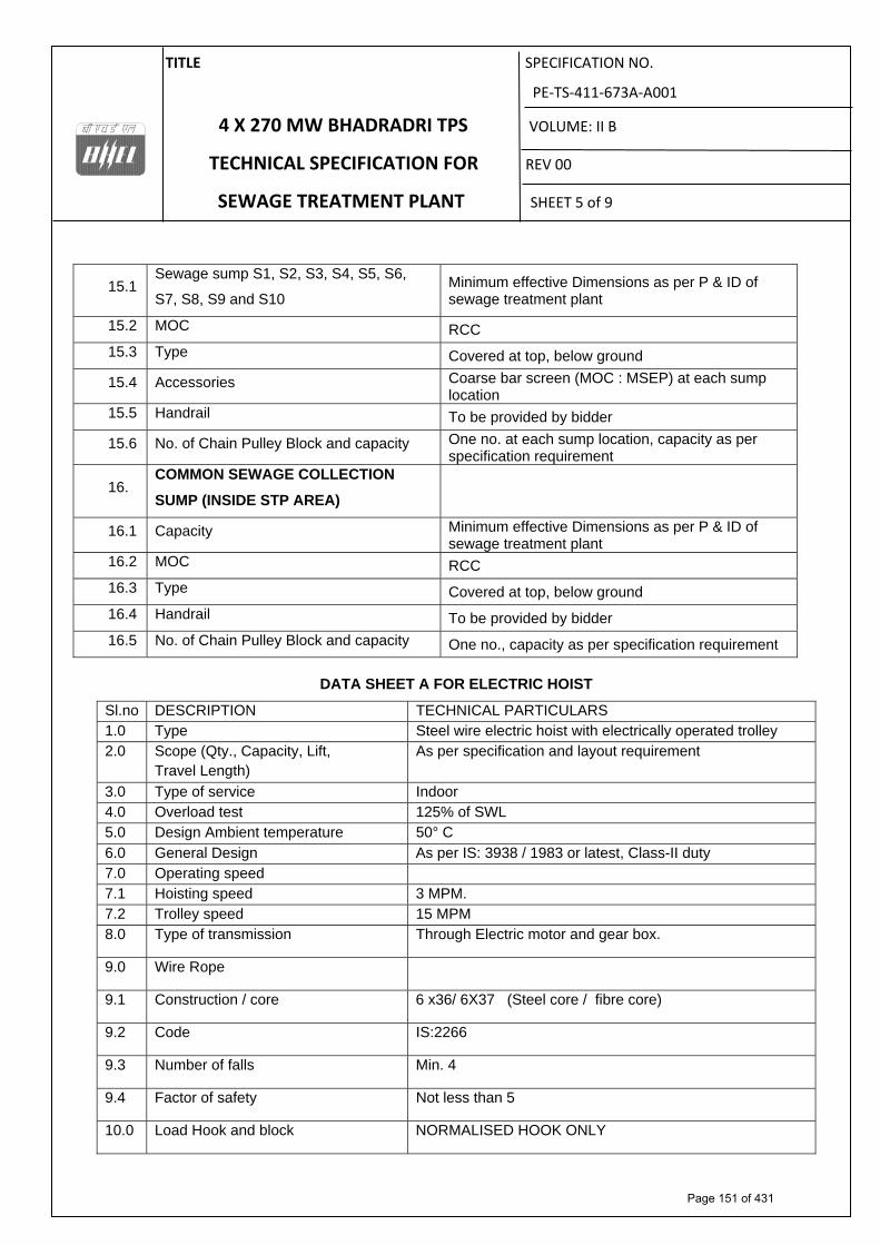
TITLE SPECIFICATION NO.
PE‐TS‐411‐673A‐A001
4 X 270 MW BHADRADRI TPS VOLUME: II B
TECHNICAL SPECIFICATION FOR REV 00
SEWAGE TREATMENT PLANT SHEET 5 of 9
15.1 Sewage sump S1, S2, S3, S4, S5, S6,
S7, S8, S9 and S10 Minimum effective Dimensions as per P & ID of sewage treatment plant
15.2 MOC RCC
15.3 Type Covered at top, below ground
15.4 Accessories Coarse bar screen (MOC : MSEP) at each sump location
15.5 Handrail To be provided by bidder
15.6 No. of Chain Pulley Block and capacity One no. at each sump location, capacity as per specification requirement
16. COMMON SEWAGE COLLECTION
SUMP (INSIDE STP AREA)
16.1 Capacity Minimum effective Dimensions as per P & ID of sewage treatment plant
16.2 MOC RCC
16.3 Type Covered at top, below ground
16.4 Handrail To be provided by bidder
16.5 No. of Chain Pulley Block and capacity One no., capacity as per specification requirement
DATA SHEET A FOR ELECTRIC HOIST
Sl.no DESCRIPTION TECHNICAL PARTICULARS 1.0 Type Steel wire electric hoist with electrically operated trolley 2.0 Scope (Qty., Capacity, Lift,
Travel Length) As per specification and layout requirement
3.0 Type of service Indoor 4.0 Overload test 125% of SWL 5.0 Design Ambient temperature 50° C 6.0 General Design As per IS: 3938 / 1983 or latest, Class-II duty 7.0 Operating speed 7.1 Hoisting speed 3 MPM. 7.2 Trolley speed 15 MPM 8.0 Type of transmission Through Electric motor and gear box.
9.0 Wire Rope
9.1 Construction / core 6 x36/ 6X37 (Steel core / fibre core)
9.2 Code IS:2266
9.3 Number of falls Min. 4
9.4 Factor of safety Not less than 5
10.0 Load Hook and block NORMALISED HOOK ONLY
Page 151 of 431

TITLE SPECIFICATION NO.
PE‐TS‐411‐673A‐A001
4 X 270 MW BHADRADRI TPS VOLUME: II B
TECHNICAL SPECIFICATION FOR REV 00
SEWAGE TREATMENT PLANT SHEET 6 of 9
10.1 Type of load hook Plain shank trapezoidal section with safety latch.
10.2 Load hook Code IS: 15560
10.3 Load hook Material As per IS:15560
10.4 Hook suspension Thrust bearing
10.5 Material of block suspension Fabricated from steel plate, Material: IS: 2062
11.0 Gearing
11.1 Type Spur / Helical
11.2 Gear/ pinion material as per IS 3938
11.3 Lubrication Oil splash/ grease lubricated
11.4 Bearing type Antifriction Ball / Roller
12.0 Trolley drive
12.1 Wheel Single flange taper thread
12.2 Wheel conform to (Std. / code) IS: 3938
12.3 Wheel material C55Mn75/ En-8/ En-9. (Max hardness 200 BHN)
12.4 Bearing type Antifriction Ball / Roller
12.5 Trolley type Rolled structural steel with side plates extended beyond wheel flanges to protect wheels.
12.6 Hardness Max hardness 200 BHN
13.0 SHEAVE
13.1 Material Fabricated from steel plate. IS: 2062 Gr. A or Gr. B / as per IS: 3938
13.2 Bearing type Antifriction Ball / Roller.
14.0 BRAKE (HOIST and TROLLEY)
14.1 Type DC EM brakes disc type (fail to safe).
14.2 Capacity As per IS 3938.
14.3 Number One number for each motor.
15.0 ROPE DRUM
15.1 Material Cast iron, cast steel or mild steel.
15.2 Flange / Flangeless Flanged
Page 152 of 431

TITLE SPECIFICATION NO.
PE‐TS‐411‐673A‐A001
4 X 270 MW BHADRADRI TPS VOLUME: II B
TECHNICAL SPECIFICATION FOR REV 00
SEWAGE TREATMENT PLANT SHEET 7 of 9
15.3 Type of groove As per manufacturers standard to suit the layout requirement.(Shall be decided during detail engineering)
17.0 TYPE OF DSL
17.1 CT travel PVC Shrouded bus bar conductor type DSL
18.0 MOTORS
18.1 Type Sq. Cage induction, TEFC, S4 duty, 40% CDF.
18.2 Number of start 150 starts / hr
18.3 Voltage , Phase and Frequency
415V ±10%, 3 phase, 4 wire, 50 Hz
18.4 Class of insulation Class “F” and temperature rise limited to class B.
18.5 Type of enclosure TEFC
18.6 Degree of protection provided for enclosure
IP-54/IP-55 depending upon Indoor / Outdoor application
18.7 Margin Motor rating will be calculated keeping margin of at least 10% over the maximum power requirement in the duty condition specified.
19.0 LIMIT SWITCHES Hoisting Trolley 19.1 Type Snap action, self
actuating type Lever type
20.0 Control panel * Fabricated from Cold rolled sheet steel not less than 2.5mm for front & rear & 2mm for side, top & bottom portion with gland plate of 3mm thick.
* Degree of protection shall be IP 54. * Power on indicating lamps shall be provided * Panel illumination lamps operated by door switch. * 2 nos earthing terminals on panel. * 20 % spares terminals ( clip on type) shall be provided. * Power and control terminals ( clip on type) shall be on separate channels. * Gland plate shall be double brass compression type.
20.1 Qty 1 No.
21.0 Pendent Push buttons Up /down / forward / Reverse push buttons. Indicative marking for easy operation shall be provided.
22.0 Power cables FRLS / EPR flexible Cu cable / Aluminum cable
23.0 Control cable FRLS / EPR flexible Cu cable / Aluminum cable
24.0 Control Voltage 110 V
Page 153 of 431

TITLE SPECIFICATION NO.
PE‐TS‐411‐673A‐A001
4 X 270 MW BHADRADRI TPS VOLUME: II B
TECHNICAL SPECIFICATION FOR REV 00
SEWAGE TREATMENT PLANT SHEET 8 of 9
DATA SHEET A FOR CHAIN PULLEY
1 Type Chain pulley block with/without travelling trolley
2 General Design IS: 3832
3 Duty Class as per IS:3832 Class –II
4 Hoisting Mechanism
a) Type Hand operated gear transmission
b) Type of gear Spur / Helical
c) Load Chain
i) Type Link type
ii) Material T (8) as per IS: 6216
iii) Conforms to (Std./Code) IS: 6216
d) Hand Chain
i) Type Link type
ii) Material Mild steel Grade 30
iii) Conform to Std. IS:2429 (Part I)
e) Load Hook & Hook Block
i) Type of load hook Plain shank- Trapezoidal section
ii) Load hooks conforms to IS: 15560
iii) Type of hook suspension Swivelling type with lock
iv) Type of make of bearing Thrust ball bearing of hook suspension
v) Type & Material of hook Carbon steel/forged steel As per IS 15560
f) Gears/ Pinion
i) Type Spur
ii) Material Alloy steel / carbon steel
iii) Type of Bearing Antifriction ball bearing / Roller
h) Sprockets:
Type of bearings used Antifriction ball bearing / Roller
i) Method of lubrication
Bearings Grease
Gearing & Pinions Grease
Sprockets Grease
j) Brakes
Type Screw and friction disc type
5 Trolley and Bridge drive
a) Trolley
i) Type Geared (Manually operated)
ii) Material of frame Mild steel (IS:2062 Grade A or B)
b) Drive Chain
i) Type Link type
ii) Material Steel Gr.30 as per IS 2429 (part 1)
Page 154 of 431

TITLE SPECIFICATION NO.
PE‐TS‐411‐673A‐A001
4 X 270 MW BHADRADRI TPS VOLUME: II B
TECHNICAL SPECIFICATION FOR REV 00
SEWAGE TREATMENT PLANT SHEET 9 of 9
c) Wheel
i) Number of pairs of wheel Two in each trolley/bridge
ii) Flange Single flanged
iii) Wheel material Cast Iron Gr. FG 200 as per IS:210
iv) Type of bearings need Antifriction
d) Gears
i) Type Spur / helical
ii) Material EN8
iii) Type of bearings used Antifriction
e) Method of lubrication for
i) Bearings Grease
ii) General Grease
iii) Sprockets Grease
6 Painting As per manufacturer standard
Page 155 of 431

TITLE SPECIFICATION NO.
PE‐TS‐411‐673A‐A001
4 X 270 MW BHADRADRI TPS VOLUME: II B
TECHNICAL SPECIFICATION FOR REV 00
SEWAGE TREATMENT PLANT SHEET 1 of 3
SECTION – C2
SPECIFIC TECHNICAL REQUIREMENTS FOR ELECTRICAL
Page 156 of 431

TITLE SPECIFICATION NO.
PE‐TS‐411‐673A‐A001
4 X 270 MW BHADRADRI TPS VOLUME: II B
TECHNICAL SPECIFICATION FOR REV 00
SEWAGE TREATMENT PLANT SHEET 2 of 3
1.0 EQUIPMENT & SERVICES TO BE PROVIDED BY BIDDER:
a) Services and equipment as per “Electrical Scope between BHEL and Vendor”.
b) Any item/work either supply of equipment or erection material which have not been specifically mentioned but are necessary to complete the work for trouble free and efficient operation of the plant shall be deemed to be included within the scope of this specification. The same shall be provided by the bidder without any extra charge.
c) Supply of mandatory spares as specified in the specifications of mechanical equipments.
d) Bidder shall furnish all AC as well as DC loads required for the system at different voltage levels (eg. 415V AC, 240 V AC, 220 V DC etc.) of all types, such as motor feeders, supply feeders in PEM format along with the offer.
e) All equipment shall be suitable for the power supply fault levels and other climatic conditions mentioned in the enclosed project information.
f) Bidder to furnish list of makes for each equipment at contract stage, which shall be subject to customer/BHEL approval without any commercial and delivery implications to BHEL
g) Various drawings, data sheets as per required format, Quality plans, calculations, test reports, test certificates, operation and maintenance manuals etc shall be furnished as specified at contract stage. All documents shall be subject to customer/BHEL approval without any commercial implication to BHEL.
h) Motor shall meet minimum requirement of motor specification. i) Vendor to clearly indicate equipment locations and local routing lengths in their
cable listing furnished to BHEL. j) Cable BOQ worked out based on routing of cable listing provided by the vendor
for “ both end equipment in vendor’s scope”shall be binding to the vendor with +10 % margin to take care of slight variation in routing length & wastages.
2.0 EQUIPMENT & SERVICES TO BE PROVIDED BY PURCHASER FOR ELECTRICAL & TERMINAL POINTS:
Refer “Electrical Scope between BHEL and Vendor”.
3.0 DOCUMENTS TO BE SUBMITTED ALONG WITH BID
3.1 The electrical specification without any deviation from the technical/quality assurance requirements stipulated shall be deemed to be complied by the bidder in case bidder furnishes the overall compliance of package technical specification in the form of compliance certificate/No deviation certificate.
3.2 No technical submittal such as copies of data sheets, drawings, write-up, quality plans, type test certificates, technical literature, etc, is required during tender stage. Any such submission even if made, shall not be considered as part of offer.
Page 157 of 431

TITLE SPECIFICATION NO.
PE‐TS‐411‐673A‐A001
4 X 270 MW BHADRADRI TPS VOLUME: II B
TECHNICAL SPECIFICATION FOR REV 00
SEWAGE TREATMENT PLANT SHEET 3 of 3
4.0 List of enclosures : a) Electrical scope between BHEL & vendor b) Standard BHEL speicification for motors (Volume D2). c) Quality plan for motors (Section C1-D) . d) Electrical Load data format e) BHEL cable listing format
Page 158 of 431

REV-0, DATE: 11.03.2015 ELECTRICAL SCOPE BETWEEN BHEL AND VENDOR
PACKAGES: SEWAGE TREATMENT PLANT (TECHNICAL SPECIFICATION NO. PE-TS-411-673A-A001) SCOPE OF VENDOR: SUPPLY, ERECTION & COMMISSIONING OF VENDOR’S EQUIPMENT PROJECT: 4X270MW BHADRADRI TPS
Page 1 of 3
S.NO DETAILS SCOPE SUPPLY
SCOPE E&C
REMARKS
1 415V MCC
BHEL
BHEL
240 V AC (supply feeder)/415 V AC (3 PHASE 4 WIRE) supply shall be provided by BHEL based on load data provided by vendor at contract stage for all equipment supplied by vendor as part of contract. Any other voltage level (AC/DC) required will be derived by the vendor.
2 Local Push Button Station (for motors) BHEL BHEL Located near the motor.
3 Power cables, control cables and screened control cables for a) both end equipment in BHEL’s scope b) both end equipment in vendor’s scope c) one end equipment in vendor’s scope
BHEL BHEL BHEL
BHEL Vendor BHEL
1. For 3.b) & c): Sizes of cables required shall be informed by vendor at contract stage (based on inputs provided by BHEL) in the form of cable listing. Finalisation of cable sizes shall be done by BHEL. Vendor shall provide lugs & glands accordingly. 2. Termination at BHEL equipment terminals by BHEL. 3. Termination at Vendor equipment terminals by Vendor.
4 Junction box for control & instrumentation cable Vendor Vendor Number of Junction Boxes shall be sufficient and positioned in the field to minimize local cabling (max 10-12 mtrs) and trunk cable.
5 Any special type of cable like compensating, co-axial, prefab, MICC, optical fibre etc.
Vendor Vendor Refer C&I portion of specification for scope of fibre Optical cables if used between PLC/ microprocessor & DCS.
6 Cable trays, accessories & cable trays supporting system 100/ 50 mm cable trays/ Conduits/ Galvanised steel cable troughs for local cabling
BHEL
Vendor
BHEL
Vendor
Local cabling from nearby main route cable tray (BHEL scope) to equipment terminal (vendor’s scope) shall be through 100/ 50 mm. cable trays/ conduits/ Galvanised steel cable troughs, as per approved layout drawing during contract stage.
7 Cable glands ,lugs and bimetallic strip for equipment supplied by Vendor
Vendor Vendor 1. Double compression Ni-Cr plated brass cable glands 2. Solder less crimping type heavy duty tinned copper lugs for power and control cables.
8 Conduit and conduit accessories for cabling between equipment supplied by vendor
Vendor Vendor Conduits shall be medium duty, hot dip galvanised cold rolled mild steel rigid conduit as per IS: 9537.
9 Lighting BHEL BHEL 10 Equipment grounding (including electronic earthing) & BHEL BHEL Refer note no. 4 for electronic earthing
Page 159 of 431

REV-0, DATE: 11.03.2015 ELECTRICAL SCOPE BETWEEN BHEL AND VENDOR
PACKAGES: SEWAGE TREATMENT PLANT (TECHNICAL SPECIFICATION NO. PE-TS-411-673A-A001) SCOPE OF VENDOR: SUPPLY, ERECTION & COMMISSIONING OF VENDOR’S EQUIPMENT PROJECT: 4X270MW BHADRADRI TPS
Page 2 of 3
S.NO DETAILS SCOPE SUPPLY
SCOPE E&C
REMARKS
lightning protection 11 Below grade grounding BHEL BHEL 12 LT Motors with base plate and foundation hardware Vendor Vendor Makes shall be subject to customer/ BHEL approval at contract stage. 13 Mandatory spares Vendor - Vendor to quote as per specification. 14 Recommended O & M spares Vendor - As specified elsewhere in specification 15 Any other equipment/ material/ service required for
completeness of system based on system offered by the vendor (to ensure trouble free and efficient operation of the system).
Vendor Vendor
16 a) Input cable schedules (Control & Screened Control Cables) b) Cable interconnection details for above c) Cable block diagram
Vendor
Vendor Vendor
- - -
Cable listing for Control and Instrumentation Cable and electronic earthing cable in enclosed excel format shall be submitted by vendor during detailed engineering stage.
17 Electrical Equipment & cable tray layout drawings Vendor -
For ensuring cabling requirements are met, vendor shall furnish Electrical equipment layout & cable tray layout drawings (both in print form as well as in AUTOCAD) of the complete plant (including electrical area) indicating location and identification of all equipment requiring cabling, and shall incorporate cable trays routing details marked on the drawing as per PEM interface comments. Cabling arrangement of the same (wherever overhead cable trays, trenches, cable ducts, conduits etc.) shall be decided during contract stage. Electrical equipment layout & cable tray layout drawing shall be subjected to BHEL/ customer approval without any commercial implications to BHEL.
18 Electrical Equipment GA drawing Vendor - For necessary interface review.
Page 160 of 431

REV-0, DATE: 11.03.2015 ELECTRICAL SCOPE BETWEEN BHEL AND VENDOR
PACKAGES: SEWAGE TREATMENT PLANT (TECHNICAL SPECIFICATION NO. PE-TS-411-673A-A001) SCOPE OF VENDOR: SUPPLY, ERECTION & COMMISSIONING OF VENDOR’S EQUIPMENT PROJECT: 4X270MW BHADRADRI TPS
Page 3 of 3
NOTES:
1. Make of all electrical equipment/ items supplied shall be reputed make & shall be subject to approval of BHEL/customer after award of contract. 2. All QPs shall be subject to approval of BHEL/customer after award of contract without any commercial implication. 3. In case the requirement of Junction Box arises on account of Power Cable size mis-match due to vendor engineering at later stage, vendor shall supply the Junction
Box for suitable termination. 4. Vendor shall indicate location of Electronic Earth pit in their Civil assignment drawing.
Page 161 of 431

REV:
00 D
ATE:
STAN
DARD
ELE
CTRI
CAL
SCOP
E BE
TWEE
N BH
EL A
ND V
ENDO
R (F
OR E
PC P
ROJE
CTS)
PA
CKAG
E: E
LECT
RIC
HOIS
T FO
R W
TP P
ACKA
GES
PROJ
ECT
: 4 X
270 M
W B
HADR
ADRI
TPS
SC
OPE
OF V
ENDO
R: S
UPPL
Y , E
RECT
ION
& CO
MMIS
SION
ING
OF V
ENDO
R’S
EQUI
PMEN
T
S. N
O DE
TAIL
SSC
OPE
SUPP
LYSC
OPE
E&C
REMA
RKS
1 Iso
lating
Swi
tch
Vend
or
Vend
orBH
EL w
ill pr
ovide
one n
umbe
r 415
V(3
ph, 4
W) s
upply
fee
der o
nly up
to is
olatin
g swi
tches
for c
rane
s. An
y othe
r vo
ltage
leve
l (AC/
DC) r
equir
ed w
ill be
deriv
ed by
the
vend
or. M
otor s
tarter
shall
be pa
rt of
crane
contr
ol pa
nel.
2 Po
wer c
ables
, con
trol c
ables
, scre
ened
contr
ol ca
bles a
nd an
y sp
ecial
cable
s (if r
equir
ed) b
etwee
n equ
ipmen
t sup
plied
by ve
ndor
. Ve
ndor
Ve
ndor
Ca
ble fr
om s
upply
feed
er t
o iso
lating
swi
tch s
hall
be in
BH
EL sc
ope.
3 Ca
bling
mate
rial (c
able
trays
, acc
esso
ries,
cable
tray
supp
ortin
g sy
stem,
cond
uits e
tc).
Vend
or
Vend
or
4 Eq
uipme
nt Ea
rthing
Ve
ndor
Ve
ndor
Al
l equ
ipmen
t meta
llic en
closu
res /
fram
es, m
etal
struc
ture e
tc. sh
all be
grou
nded
at tw
o poin
ts ea
ch to
the
near
est g
roun
ding p
oints
/ rise
rs pr
ovide
d by B
HEL.
5 Mo
tors
Vend
or
Vend
or
6 Ca
ble gl
ands
and l
ugs f
or eq
uipme
nt su
pplie
d by v
endo
r Ve
ndor
Ve
ndor
1.
Doub
le co
mpre
ssion
Ni-C
r plat
ed br
ass c
able
gland
s2.
Solde
r less
crim
ping t
ype h
eavy
duty
tinne
d co
pper
lugs
for p
ower
& co
ntrol
cable
s. 7
a)Inp
ut ca
ble sc
hedu
les (C
& I)
b)Ca
ble in
terco
nnec
tion d
etails
for a
bove
c)
Cab
le blo
ck di
agra
m
Vend
orVe
ndor
Vend
or
- - -
Cable
listin
g for
Con
trol a
nd In
strum
entat
ion C
able
in en
close
d exc
el for
mat s
hall b
e sub
mitte
d by v
endo
r du
ring d
etaile
d eng
ineer
ing st
age.
8 Eq
uipme
nt lay
out d
rawi
ngs
Vend
or
-
9 El
ectric
al Eq
uipme
nt GA
draw
ing
Vend
or
-
For
nece
ssar
y inte
rface
revie
w.
THIS
IS A
PA
RT
OF
TEC
HN
ICA
L SP
ECIF
ICA
TIO
N N
O, P
E-TS
-411
-673
A-A
001
Page 162 of 431

LOAD TITLE
RATING (KW / A)
UN
IT (
U)/
ST
N (
S) Nos.
VO
LT
AG
E C
OD
E*
FE
ED
ER
CO
DE
**
EM
ER
. L
OA
D (
Y)
CO
NT
.(C
)/ I
NT
T.(
I)
ST
AR
TIN
G T
IME
>
5 S
EC
(Y
)
LOCATION BOARD
NO.
CABLE
BL
OC
K C
AB
LE
D
RG
. No
. CONTROL CODE
REMARKS LOAD No. NAME PLATE
MAX. CONT.
DEMAND (MCR)
RU
NN
ING
ST
AN
DB
Y
SIZE CODE
NOs
1 2 3 4 5 6 7 8 9 10 11 12 13 14 15 16 17 18 19
NOTES: 1. COLUMN 1 TO 12 & 18 SHALL BE FILLED BY THE REQUISITIONER (ORIGINATING AGENCY); REMAINING COLUMNS ARE TO BE FILLED UP BY PEM (ELECTRICAL)
2. ABBREVIATIONS : * VOLTAGE CODE (7):- (ac) A=11 KV, B=6.6 KV, C=3.3 KV, D=415 V, E=240 V (1 PH), F=110 V (cc): G=220 V, H=110 V, J=48 V, K=+24V, L=-24 V
: ** FEEDER CODE (8):- U=UNIDIRECTIONAL STARTER, B=BI-DIRECTIONAL STARTER, S=SUPPLY FEEDER, D=SUPPLY FEEDER (CONTACTER CONTROLLED)
LOAD DATA (ELECTRICAL)
JOB NO. ORIGINATING AGENCY PEM (ELECTRICAL) PROJECT TITLE NAME DATA FILLED UP ON SYSTEM / S SIGN. DATA ENTERED ON DEPTT. / SECTION SHEET 1 OF 1 REV. 00 DE’S SIGN. & DATE
Page 163 of 431

UNITCABLENO FROM TO PURPOSE
CABLE SCOPE (BHEL PEM/ VENDOR) REMARKS CABLESIZE PATHCABLENO
TENTATIVE CABLE LENGTH
4X270 MW BHADRADRI TPSTECHNICAL SPECIFICATION FOR SEWAGE TREATMENT PLANT
CABLE SCHEDULE FORMAT
Page 164 of 431

TITLE SPECIFICATION NO.
PE‐TS‐411‐673A‐A001
4 X 270 MW BHADRADRI TPS VOLUME: II B
TECHNICAL SPECIFICATION FOR REV 00
SEWAGE TREATMENT PLANT SHEET 1 of 1
SECTION – C3
SPECIFIC TECHNICAL REQUIREMENTS FOR CONTROL AND
INSTRUMENTATION
Page 165 of 431

SPECIFICATION NO.
VOLUME II-BSECTION REV. NO. 00 DATE SHEET 1 OF 3
�
SPECIFIC TECHNICALREQUIREMENT�
1. Bidder to include Field instrumentation and Field Junction Box (JB’s), in his scope of supply. Field instrument specification and Data Sheet are given elsewhere in this spec.
2. All fields cabling for instruments/motor/pump/blower to JB is in bidder’s scope and details are given elsewhere in this spec. JB to PLC shall be provided by BHEL as free issue whereas cable schedule, cable interconnections and wiring diagram for the same shall be in bidders’ scope.
3. Instrument installation drawings are to be provided by bidder. All instrument fitting and erection hardware as per instrument installation diagram shall be in bidder’s scope.
4. All manual valves at pump discharge shall be provided with Open and Close Limit Switches.
5. PLC control system as defined in the enclosed specs and DATA Sheets shall be in bidder scope. The PLC system shall comprise of (i) PLC based local panel (ii) UPS Power supply (iii) Operator interface in the form of CRT, keyboard and OWS, along with required furniture.
6. PLC shall have the facility to synchronize its time with BHEL supplied GPS. Necessary Hardware (IRIG-B port) for same at PLC end to be provided by bidder. The cable connecting PLC and GPS shall be in BHEL scope.
7. PLC shall be connected to DCS through serial link with OPC Compliant for monitoring/Control. For detailed, please refer PLC Architecture Diagram.
8. One number RIO panels to be provided with Fiber Optic cable for connecting the RIO with the PLC. The network communication between RIO and PLC shall be redundant. All the necessary hardware and software is in STP vendor scope of supply. The fiber optic cable of 2.5 KM is required.
9. Back panel shall be provided with Colored MIMIC, Push Button, Lamps and Hardwire Annunciation.
10. All furniture (tables, chairs etc.) required for PLC operator HMI shall be in bidder's scope. Chairs shall be capable of being adjusted for height and position of backrest. The chairs shall be mounted on five castors, shall swivel and shall have arm rests'. One table and chair shall be provided for each operator station and separate table for each printer.
11. The requirements given below are to be read in conjunction with detailed Technical specification enclosed.
THIS IS A PART OF TECHNICAL SPECIFICATION NO. PE-TS-411-673A-A001
Page 166 of 431
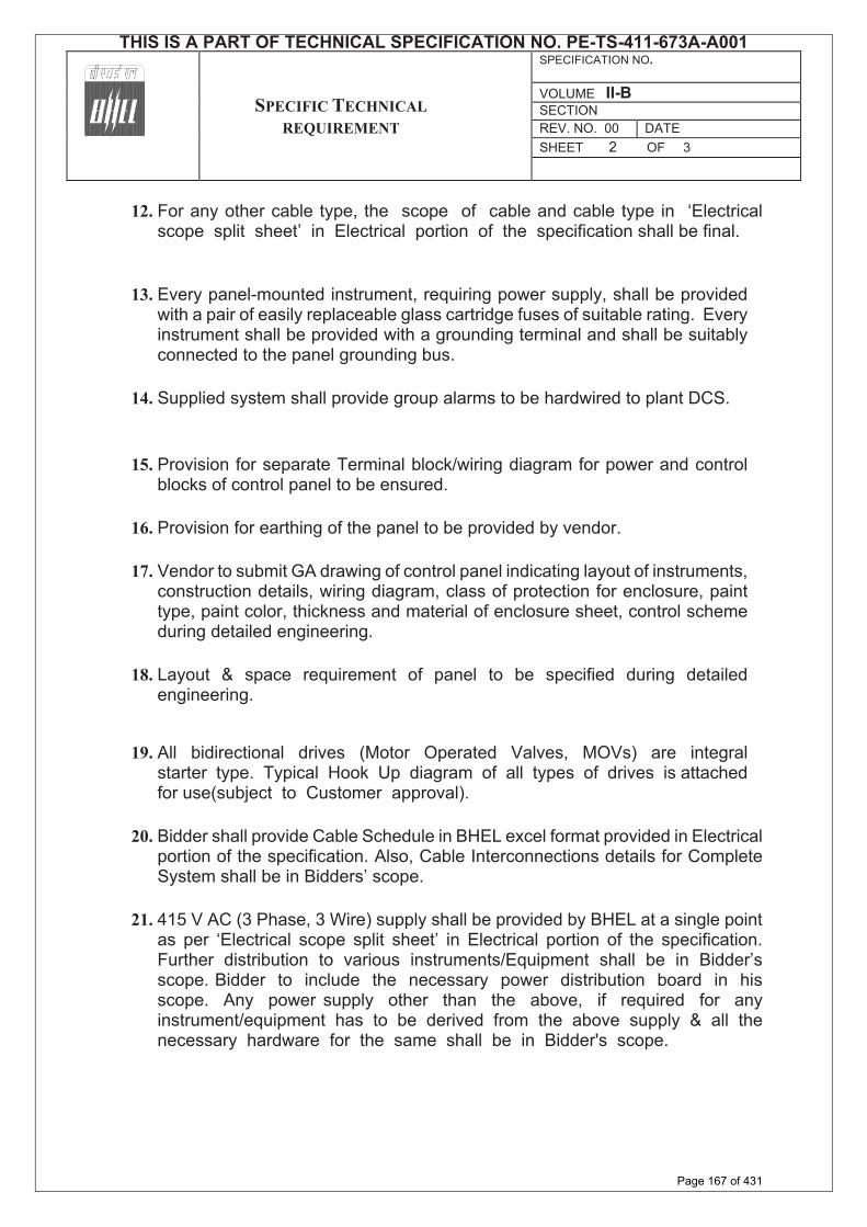
SPECIFICATION NO.
VOLUME II-BSECTION REV. NO. 00 DATE SHEET 2 OF 3
�
SPECIFIC TECHNICALREQUIREMENT�
12. For any other cable type, the scope of cable and cable type in ‘Electrical scope split sheet’ in Electrical portion of the specification shall be final.
13. Every panel-mounted instrument, requiring power supply, shall be provided with a pair of easily replaceable glass cartridge fuses of suitable rating. Every instrument shall be provided with a grounding terminal and shall be suitably connected to the panel grounding bus.
14. Supplied system shall provide group alarms to be hardwired to plant DCS.
15. Provision for separate Terminal block/wiring diagram for power and control blocks of control panel to be ensured.
16. Provision for earthing of the panel to be provided by vendor.
17. Vendor to submit GA drawing of control panel indicating layout of instruments, construction details, wiring diagram, class of protection for enclosure, paint type, paint color, thickness and material of enclosure sheet, control scheme during detailed engineering.
18. Layout & space requirement of panel to be specified during detailed engineering.
19. All bidirectional drives (Motor Operated Valves, MOVs) are integral starter type. Typical Hook Up diagram of all types of drives is attached for use(subject to Customer approval).
20. Bidder shall provide Cable Schedule in BHEL excel format provided in Electrical portion of the specification. Also, Cable Interconnections details for Complete System shall be in Bidders’ scope.
21. 415 V AC (3 Phase, 3 Wire) supply shall be provided by BHEL at a single point as per ‘Electrical scope split sheet’ in Electrical portion of the specification. Further distribution to various instruments/Equipment shall be in Bidder’s scope. Bidder to include the necessary power distribution board in his scope. Any power supply other than the above, if required for any instrument/equipment has to be derived from the above supply & all thenecessary hardware for the same shall be in Bidder's scope.
THIS IS A PART OF TECHNICAL SPECIFICATION NO. PE-TS-411-673A-A001
Page 167 of 431

SPECIFICATION NO.
VOLUME II-BSECTION REV. NO. 00 DATE SHEET 3 OF 3
�
SPECIFIC TECHNICALREQUIREMENT�
22. Bidder to provide all control panels, system cabinets, termination & relay cabinets complete with all accessories, wiring and all mounting and erection hardware including junction boxes, canopies, structural steel as required. All instruments/drives shall be terminated on Junction Boxes/Panel in Bidder scope of supply. 20% Spare terminals shall be provided on Junction Boxes.
23. Bidder to delegate/depute their person/experts as per owner/consultant requirements.
24. All the furniture for OWS/ Printer required for the system shall be in bidder's scope of supply.
25. The make of all the items shall be from approved sub-vendor list.
26. The design, manufacture, inspection, testing, site calibration and installation of all C&I equipment and systems covered under this specification shall conform to the latest editions of applicable codes and standards eg. ANSI, ASME, IEEE, ISO, IEC, IGCI, AWS, NFPA, AISC, IGS, SAMA, UBC, UL, NESC, NEMA, ISA, DIN, VDE, IS etc.
27. Bidder shall provide the signal exchange, to Plant DCS in BHEL prescribed format to be furnished during detailed engineering.
NOTES:
1. All equipment items shall be of latest design with proven on track record from reputed experienced manufacturers of specified type and range of equipment. The make/model of various instruments/items/systems and instrument sub-vendor shall be subject to approval of BHEL/Customer during detailed engineering stage.
2. The above given scope is indicative & minimum. Any item/ equipment not indicated above however required for the completeness of the system is to be supplied by bidder without any technical, commercial and delivery implication to BHEL.
3. Documents of C&I System shall be submitted to end user/owner for approval during detail engineering. Changes, if any, shall be accommodated by the bidder without any price/time implication.
THIS IS A PART OF TECHNICAL SPECIFICATION NO. PE-TS-411-673A-A001
Page 168 of 431

THIS
IS A
PA
RT
OF
TEC
HN
ICA
L SP
ECIF
ICA
TIO
N N
O. P
E-TS
-411
-673
A-A
001
Page 169 of 431

TITLE SPECIFICATION NO.
PE‐TS‐411‐673A‐A001
4 X 270 MW BHADRADRI TPS VOLUME: II B
TECHNICAL SPECIFICATION FOR REV 00
SEWAGE TREATMENT PLANT SHEET 1 of 13
ANNEXURES
Page 170 of 431

TITLE SPECIFICATION NO.
PE‐TS‐411‐673A‐A001
4 X 270 MW BHADRADRI TPS VOLUME: II B
TECHNICAL SPECIFICATION FOR REV 00
SEWAGE TREATMENT PLANT SHEET 2 of 13
ANNEXURE I
LIST OF MAKES
Page 171 of 431

TITLE SPECIFICATION NO.
PE‐TS‐411‐673A‐A001
4 X 270 MW BHADRADRI TPS VOLUME: II B
TECHNICAL SPECIFICATION FOR REV 00
SEWAGE TREATMENT PLANT SHEET 3 of 13
S.No.
ITEM SUPPLIERS PLACE QP /
INSPN CAT
REMARKS
1. PRESSURE VESSELS
GLOBAL STRUCTURES & COMPOSITE LTD
-
JASMINO POLYMERTECH TALOJA SYSCON ENGINEERS AMBERNATH
S.V. FABRICATORS NAVI MUMBAI SPARK FABRICATORS / STEELCON
-
ANUP ENGINEERING AHMEDABAD MURTHAL TANKS & VESSELS SONEPAT TITAN ENGG. DURGAPUR RISHI INDUSTRIES BAHALGARH UNIVERSAL HEAT EXCHANGERS - ATS CHEM SALEM/HOSUR CHEM PROCESS SYSTEM SANAND PROGEN CHENNAI CRYSTAL ENGINEERING HOSUR ISHAN EQUIPMENTS VADODARA
2. ATMOSPHERIC/ STORAGE TANKS
GLOBAL STRUCTURES & COMPOSITE LTD
-
JASMINO POLYMERTECH TALOJA SYSCON ENGINEERS AMBERNATH S.V. FABRICATORS NAVI MUMBAI SPARK FABRICATORS / STEELCON
-
ANUP ENGINEERING AHMEDABAD MURTHAL TANKS & VESSELS SONEPAT TITAN ENGG. DURGAPUR RISHI INDUSTRIES BAHALGARH UNIVERSAL HEAT EXCHANGERS - ATS CHEM SALEM/HOSUR CHEM PROCESS SYSTEM SANAND PROGEN CHENNAI CRYSTAL ENGINEERING HOSUR ISHAN EQUIPMENTS VADODARA
3. RUBBER LINING ( AT SHOP)
TEMSEC KOLKATA
RISHI INDUSTRIES SONEPAT
CORI ENGINEERS CHENNAI
POLY RUBBER MUMBAI
Page 172 of 431

TITLE SPECIFICATION NO.
PE‐TS‐411‐673A‐A001
4 X 270 MW BHADRADRI TPS VOLUME: II B
TECHNICAL SPECIFICATION FOR REV 00
SEWAGE TREATMENT PLANT SHEET 4 of 13
INDUSTRIAL LINING VADODARA
ARUL RUBBERS CHENNAI
JASMINO POLYMERTECH TALOJA
WESTERN RUBBER NAVI MUMBAI
ELASTOMER LINNING AMBERNATH
EMKAY RUBBER MUMBAI
4 ACTIVATED CARBON
INDUSTRIAL CARBON ANKLESHWAR
VVD & SONS TUTICORIN
GLOBAL ABSORBENT PVT LTD KOLKATA
ACTIVE CARBON -
WESTERN CHEMICALS -
5 AIR BLOWERS (TWIN LOBE TYPE)
SWAN PNEUMATIC NOIDA
EVEREST TRANSMISSION NEW DELHI
KAY INTERNATIONAL NEW DELHI / SONEPAT
EVEREST BLOWER BAHADURGARH
KULKARNI POWER TOOLS KOLHAPUR/ PUNE
6 METERING PUMPS
VK PUMPS NASIK
MILTON ROY INDIA CHENNAI
SWELLORE AHMEDABAD
POSITIVE METERING PUMPS NASIK
METACHEM MUMBAI
7 AGITATOR
REMI PEOCESS PLANT & M/C MUMBAI
FIBRE & FIBRE MUMBAI / SILVASA
CEECONS CHENNAI
STANDARD ENGINEERS MUMBAI
8 HORIZONTAL CENTRIFUGAL PUMPS
KIRLOSKAR BROTHERS LTD. WADI
MATHER & PLATT PUNE
KSB PUNE
SAM TURBO IND LTD COIMBATORE
KISHOR PUMPS PUNE
SULZER PUNE
WPIL GHAZIABAD
FLOWMORE UNIT-I &II SAHIBABAD
BEST & CROMPTON CHENNAI
9 HORIZONTAL CENTRIFUGAL PUMPS (RUBBER LINED)
KISHOR PUMPS PUNE
SU MOTORS MUMBAI
Page 173 of 431

TITLE SPECIFICATION NO.
PE‐TS‐411‐673A‐A001
4 X 270 MW BHADRADRI TPS VOLUME: II B
TECHNICAL SPECIFICATION FOR REV 00
SEWAGE TREATMENT PLANT SHEET 5 of 13
10 NON METALLIC (PP/FRP) HORIZONTAL CENTRIFUGAL PUMPS
ENGINEERS COMBINE THANE
ANTICORROSIVE VALSAD LEAK PROOF PUMPS PVT. LTD. (RAJEDIA)
-
11 MISC. PUMP VERTICAL TURBINE TYPE
KBL PUNE
M&P PUNE
WPIL GHAZIABAD
KISHORE PUMPS PUNE
FLOWMORE SAHIBABAD
10 RESIN TRAP ELEMENT JHONSONS SCREEN AUSTRALIA/ IRELAND
11 UNDER BED NOZZLE JONSONS SCREEN AUSTRALIA/ IRELAND
12 RESIN
ROHM & HASS FRANCE / USA
ION EXCHANGE INDIA
LANXESS GERMANY
PUROLITE ROMANIA/CHINA
THERMAX INDIA
13
HEATER ESCORTS FARIDABAD
RACOLDS FARIDABAD
14
MANUAL GATE / GLOBE / CHECK VALVES
HAWA ENGINEERS / MARCK & CARE
-
WEIR BDK -
A.V.VALVES -
LEADER -
OSWAL INDUSTRIES - CHEMTECH INDUSTRIAL VALVES PVT LTD
-
H SARKAR -
FOURESS - HAWA ENGINEERS / MARCK & CARE
-
BANKIM & COMPANY -
15 BALL VALVE ( MANUAL /PNEUMATIC/ ELECTRIC) CLASS 150
FLOWCHEM INDUSTRIES KALOL WEIR BDK HUBLI L&T (AUDCO) COIMBATORE
MICROFINISH VALVES HUBLI
AKAY VALVES HUBLI
Page 174 of 431

TITLE SPECIFICATION NO.
PE‐TS‐411‐673A‐A001
4 X 270 MW BHADRADRI TPS VOLUME: II B
TECHNICAL SPECIFICATION FOR REV 00
SEWAGE TREATMENT PLANT SHEET 6 of 13
16
ELECTRIC MOTOR
ABB -
SIEMENS -
CGL -
MARATHON/ ALSTOM -
BHARAT BIJLEE -
KEC -
ABB -
17 BALL VALVE (HIGH PRESSURE)
VELAN CANADA
BRAY CHINA
18
BUTTER-FLY VALVE (MANUAL / PNEUMATIC/ELECTRIC) CLASS 150
FLOW SERVE CHENNAI
WEIR BDK HUBLI
CRANE FLOW PROCESS SATARA
INTERVALVE (I) PVT LTD PUNE
BRAY CONTROL CHINA
FOURESS BANGALORE
KBL KOHNDHAPURI
PENTAIR VALVES HALOL
ADVANCE VALVES GREATER NOIDA
19
DUAL PLATE TYPE NON-RETURN VALVE (SS & CI /CIRL UPTO 200 NB, CLASS 150)
ADVANCE VALVES GREATER NOIDA
HAWA ENGINEERS AHMEDABAD
LEADER JALANDHAR
20 DIAPHRAGM VALVE (MANUAL / PNEUMATIC) CLASS 150
WEIR BDK HUBLI
CRANE FLOW PROCESS SATARA
PROCON MUMBAI
MAJESTIC VALVES ( LABLINE) -
HAWA ENGINEERS AHMEDABAD
21 CHECK VALVE / NRV (LINED / UNLINED), FLAP TYPE SIZE UPTO 50 NB
MAJESTIC VALVES ( LABLINE) -
WEIR BDK HUBLI
22
Y-TYPE STRAINER / STRAINER (WATER SERVICE)
OTOKLIN MUMBAI
GRAND PRIX NEW DELHI
JAYPEE NEW DELHI
GREAVES COTTON MUMBAI
MULTITEX NEW DELHI / NOIDA
FILTERATION ENGINEERING -
FLUIDNYE -
Page 175 of 431

TITLE SPECIFICATION NO.
PE‐TS‐411‐673A‐A001
4 X 270 MW BHADRADRI TPS VOLUME: II B
TECHNICAL SPECIFICATION FOR REV 00
SEWAGE TREATMENT PLANT SHEET 7 of 13
23 RUBBER FLAP TYPE CHECK VALVES
ASHVIK VALVES -
FLOW WAY VALVES -
BDK - MAJESTIC VALVES (LABLINE INST)
-
ADVANCE VALVES -
24 SOLENOID VALVES ROTEX -
AVCON -
25 PRESSURE GAUGE
GENERAL INSTRUMENTS WAAREE (BAUMER INSTRUMENTS)
H.GURU INSTRUMENTS
A.N.INSTRUMENTS
FORBES MARSHALL
26 DIFFERENETIAL PRESSURE GAUGE
GENERAL INSTRUMENTS WAAREE (BAUMER INSTRUMENTS)
H.GURU INSTRUMENTS
A.N.INSTRUMENTS
SWITZER
FORBES MARSHALL
27 TEMPERATURE GAUGE
GENERAL INSTRUMENTS WAAREE (BAUMER INSTRUMENTS)
H.GURU INSTRUMENTS
A.N.INSTRUMENTS
SWITZER
FORBES MARSHALL
28 LEVEL GUAGE (F&B, TUBULAR, REFLEX)
SBEM
CHEMTROL
PUNE TECHTROL
SIGMA
V AUTOMAT
GENERAL INSTRUMENTS
29 ROTAMETER
SWITZER
EUREKA
INSTRUMENT ENGINEERS
TRAC
Page 176 of 431

TITLE SPECIFICATION NO.
PE‐TS‐411‐673A‐A001
4 X 270 MW BHADRADRI TPS VOLUME: II B
TECHNICAL SPECIFICATION FOR REV 00
SEWAGE TREATMENT PLANT SHEET 8 of 13
30 LEVEL SWITCH ( ALL TYPES)
LEVCON CHEMTROLS SAMIL ( INDIA) PVT LTD.
SWITZER WAAREE (BAUMER INSTRUMENTS)
V AUTOMAT
PUNE TECHTROL
31 MAGNETIC FLOW METER
ABB - WAAREE (BAUMER INSTRUMENTS)
-
EUREKA -
EMERSON -
YOKOGAWA -
HACH (POTENSE) -
KROHNE MARSHALL -
32 FLOW TRANSMITTERS (ALL TYPES)
E & H -
KHRONE MARSHALL -
EMERSON -
ABB -
HONEYWELL -
YOKOGAWA -
33 LEVEL TRANSMITTERS (ALL TYPES)
EMERSON -
E & H -
ABB -
HONEYWELL -
V AUTOMAT -
YOKOGAWA -
SIEMENS -
KROHNE MARSHALL -
34 PRESSURE TRANSMITTERS (ALL TYPES)
EMERSON -
SIEMENS -
HONEYWELL -
YOKOGAWA -
ABB -
FORBES MARSHALL -
35 TEMPERATURE TRANSMITTERS
EMERSON -
E & H -
ABB -
Page 177 of 431

TITLE SPECIFICATION NO.
PE‐TS‐411‐673A‐A001
4 X 270 MW BHADRADRI TPS VOLUME: II B
TECHNICAL SPECIFICATION FOR REV 00
SEWAGE TREATMENT PLANT SHEET 9 of 13
HONEYWELL -
V AUTOMAT -
YOKOGAWA -
SIEMENS -
FORBES MARSHALL -
36 PH TRANSMITTERS
EMERSON -
YOKOGAWA -
HONEYWELL -
ABB -
HACH -
FORBES MARSHALL -
37. ANALYSERS (ALL TYPES)
ABB -
EMERSON -
YOKOGAWA -
HONEYWELL -
HACH POLYMETRON -
SIEMENS -
FORBES MARSHALL -
38 PLC WITH ENCLOSURE
GE FANUC -
HONEYWELL -
SIEMENS -
ROCKWELL AUTOMATION -
SCHNEIDER -
MITSHUBISHI -
YOKOGAWA -
ABB -
39 UPS HIREL HITACHI -
EMERSON -
DB POWER ELECTRONICS -
40 CABLE GLAND COMET -
DOWELL -
CHETNA -
41 CABLE LUGS
ELECTRO BILLETS -
COMET -
DOWELL -
CHETNA -
MS PLATES SAIL -
Page 178 of 431

TITLE SPECIFICATION NO.
PE‐TS‐411‐673A‐A001
4 X 270 MW BHADRADRI TPS VOLUME: II B
TECHNICAL SPECIFICATION FOR REV 00
SEWAGE TREATMENT PLANT SHEET 10 of 13
42 ESSAR -
TISCO -
ISPAT -
JINDAL -
43
CS PIPE (ASTM A 106 GR. B)
INDIAN SEAMLESS METAL TUBES
AHMEDABAD UPTO 150
NB
MAHARASHTRA SEAMLESS RAIGAD UPTO 350
NB
44
MS PIPES (IS: 1239 & 3589)
SAIL -
SURYA ROSHANI -
JINDAL -
MAHARASHTRA SEAMLESS -
LLOYDS STEEL -
SAW PIPES -
45 SS PIPES / TUBES
APEX TUBES BEHROR (ALWAR)
RATNAMANI CHATTRAL
REMI TARAPUR
PRAKASH STEELAGE -
46 POWER/CONTROL/INSTRUMENT CABLE
POLYCAB -
FINOLEX CABLE -
NICCO CABLE -
DELTON CABLE -
CORD CABLE -
PARAMOUNT -
UNIVERSAL CABLE -
RADIANT CABLES -
47 SAFETY SHOWER
UNICARE -
MOHAN INDUSTRIES -
SUPER SAFETY SERVICES -
48 FRP TANKS & FITTINGS
GLOBAL COMPOSITE -
EPP -
DEEPA COMPOSITE -
COROSEAL INDUSTRIES -
CHEMICAL PROCESS & EQUIPMENT PVT LTD
-
J.R FIBRE INDUSTRIES PVT LTD -
Page 179 of 431

TITLE SPECIFICATION NO.
PE‐TS‐411‐673A‐A001
4 X 270 MW BHADRADRI TPS VOLUME: II B
TECHNICAL SPECIFICATION FOR REV 00
SEWAGE TREATMENT PLANT SHEET 11 of 13
POLYPLAST -
49 EJECTOR
ESSEM TECHNOLOGIES -
RATNA PRASAD -
50 LOCAL CONTROL PANEL
INDUSTRIAL SWITCHGEAR & CONTROL
-
POSITRONICS -
DELTA CONTROL -
L & T -
GE POWER -
PYROTECH -
C& S -
51 TANK (FRP)
INDUSTRIAL SERVICE KOLKATA
SUNRISE BARODA
GANDHI & ASSOCIATES AHMEDABAD
MODERN EQUIPMENTS CHENNAI
EAGLE PLAST PUNE
OMEGA PLAST MUMBAI
52 STROKE CONTROLLER
V K PUMPS NASIK
METACHEM MUMBAI
SWELORE AHMEDABAD
MILTON ROY INDIA CHENNAI
53 SAFETY VALVES/RELIEF VALVES
METACHEM MUMBAI
KEYSTONE BARODA
V K PUMPS NASIK
MILTON ROY CHENNAI
54 STRAINER
OTOKLIN MUMBAI
GRAND PRIX NEW DELHI
AYPEE NEW DELHI
55 ORIFICE PLATE
MICRO PRECISION FARIDABAD
INSTRUMENTAION LTD PALGHAT
CARLO DYNAMICS HYDERABAD
56 SLUICE GATE
H SARKAR KOLKATA
JASH ENGINEERING -
YASHWANT INDUSTRIES -
57 3 WAY VALVE
HI TECH AHMEDABAD
ADVANCE VALVES PVT.LTD NOIDA
BDK HUBLI
FOURESS ENGG.INDIA LTD. MUMBAI
Page 180 of 431

TITLE SPECIFICATION NO.
PE‐TS‐411‐673A‐A001
4 X 270 MW BHADRADRI TPS VOLUME: II B
TECHNICAL SPECIFICATION FOR REV 00
SEWAGE TREATMENT PLANT SHEET 12 of 13
FLUIDLINEVALVES COMPANY PRIVATE LTD.,
MUMBAI
INSTRUMENTATION LTD. PALAKAD
KIRLOSKAR BROTHERS LTD. PUNE
VENUS PUMP & ENGG. WORKS KOLKATA
Surya Valves and Instruments Manufacturing Company
Chennai
STAFFORD CONTROLS LIMITED PUNE
MICON VALVES (INDIA) PVT.LTD MUMBAI
58
PLUG VALVE(MANUAL)
BDK HUBLI
HAWA ENGINEERS / MARCK & CARE
-
MICON VALVES -
MICON VALVES (INDIA) PVT.LTD MUMBAI
59 FITTINGS (CS/SS)
BHARAT FORGE PUNE
RELIANCE FORGE
EBY MUMBAI
SIDDARTH & GAUTAM FARIDABAD
MS FITTINGS KOLKATA
PRADEEP METALS LTD MUMBAI
TUBE PRODUCT INCOROPORATION
BARODA
60 FLANGES (SS/CS)
PRADEEP METALS LTD MUMBAI
TUBE PRODUCT INCOROPORATION
BARODA
MS FITTINGS KOLKATA
HAWA ENGINEERING -
ALIANCE PIPE & PLANGES KOLKATA
JAI AMBE MUMBAI
61 PIPE & FILLTING (PP,HDPE,PVC & CPVC)
GEROGE FISHCHER DELHI
ASTROL PLYTECHINC LTD AHMEDABAD
JAIN IRRIGATION -
ORIPLAST -
62
VALVES (GATE/GLOBE/NRV/BA LL)- (PP,HDPE,PVC & CPVC)
GEROGE FISHCHER IPING SYSTEMS PVT LTD
DELHI
ASTROL PLYTECHINC LTD AHMEDABAD
JAIN IRRIGATION -
ORIPLAST -
Page 181 of 431

TITLE SPECIFICATION NO.
PE‐TS‐411‐673A‐A001
4 X 270 MW BHADRADRI TPS VOLUME: II B
TECHNICAL SPECIFICATION FOR REV 00
SEWAGE TREATMENT PLANT SHEET 13 of 13
63 AIR FILTER REGULATOR SHAVO NORGEN -
PLACKA INSTRUMENTS -
64 FILTER MEDIA GLOBAL ABSORBENT KOLKATA
BHARAT MINERALS
65 BATTERIES AMCO (BATTERY NI-CD) -
HBL (BATTERY NI-CD) -
66 PAINT
BERGER -
ASIAN PAINTS -
SHALIMAR PAINTS -
KANSAI NEROLAC -
AKZO NOBEL -
67 PNEUMATIC ACTUATOR
PROCON ENGINEERS -
TYCO -
CRANE PROCESS -
BDK -
INTERVALVE -
BRAY CONTROL -
68 MOTORISED ACTUATOR
ROTARK -
AUMA -
LIMITORK -
69 CABLE TRAYS
RATAN ENGG -
INDIANA -
DOLPHIN -
INDUSTRIAL PERFORMATIONS -
MJ ENGG -
ANAND UDYOG -
VATCO -
STEELITE -
NOTE:
The sub vendor list enclosed ANNEXURE-I is indicative only and is subject to approval / acceptance by customer (TSGENCO). Bidder to propose his sub vendor list with back up documents (experience list, end user certificate as applicable) etc. The same shall subject to BHEL and Customer approval during detailed engineering stage without any technical, commercial & delivery implications to BHEL/TSGENCO.
Page 182 of 431

TITLE SPECIFICATION NO.
PE‐TS‐411‐673A‐A001
4 X 270 MW BHADRADRI TPS VOLUME: II B
TECHNICAL SPECIFICATION FOR REV 00
SEWAGE TREATMENT PLANT SHEET 1 of 7
ANNEXURE II
MANDATORY SPARE LIST
Page 183 of 431

TITLE SPECIFICATION NO.
PE‐TS‐411‐673A‐A001
4 X 270 MW BHADRADRI TPS VOLUME: II B
TECHNICAL SPECIFICATION FOR REV 00
SEWAGE TREATMENT PLANT SHEET 2 of 7
LIST OF MANDATORY SPARES FOR STP
1. Vertical Sump Pumps – (For each Type and Size)
Sl. No. Name of Items Unit QUANTIT
Y
i. Complete Casing including suction (if applicable) bell
Set 1
ii. Impeller Set 1
iii. Impeller key Number
1
iv. Wearing rings (Impeller & Casing ; as applicable)
Set 2
v. Impeller Shaft, line shaft and head shaft Set 1 vi. Shaft Sleeves Set 2 vii. Stuffing box Set 1 viii. Coupling between Pump & motor,
bushes, pins with all fasteners & coupling Guards.
Set 1
ix. Line Shaft Couplings (if applicable) Set 1
x. Impeller, Line and Head shaft bearings (as applicable)
Set 1
xi. Gland Packing & Gland Assembly Set 1
xii. Mechanical seal as applicable Set
1
2. Horizontal Centrifugal Pumps (For each Type and Size)
Sl. No. Name of Items Unit QUANTIT
Y i. Impeller for each type Set 1
ii. Wearing rings – Impeller for each type (if applicable)
Set 1
iii. Wearing rings – Casing for each type (if applicable)
Set 1
iv. Shaft for each type Set 1
v. Shaft Sleeves for each type Set 1
vi. Stuffing box for each type Set 1
vii. Coupling between Pump & motor, bushes, pins with all fasteners & coupling Guards
Set 1
viii. Pump bearings for each type Set 1
ix. Gland Packing & Gland Assembly for each type
Set 1
x. Mechanical seal as applicable Set
1
xi. Impeller key Number
1
Page 184 of 431

TITLE SPECIFICATION NO.
PE‐TS‐411‐673A‐A001
4 X 270 MW BHADRADRI TPS VOLUME: II B
TECHNICAL SPECIFICATION FOR REV 00
SEWAGE TREATMENT PLANT SHEET 3 of 7
3. AGITATORS (FOR EACH TANK AS APPLICABLE )
Sl. No. Name of Items Unit QUANTIT
Y i. Agitator Assembly with Gear Box Set 1
4. MOTOR
Sl. No. Name of Items Unit QUANTIT
Y i. Motor bearing for each type of pump Set 1
5. VALVES AND PIPING
Sl. No. Name of Items QUANTITY
i. Piping valves & traps - Complete assembly
5% or min. 1 no. (whichever is more) for each size, type & rating for total population
6. MANDATORY SPARES FOR CONTROL SYSTEM AND MEASURING INSTRUMENTS
Sl. No. Name of Items QUANTITY
6.1 Mandatory Spares for Temperature Elements and Thermowells
6.1.1
Thermocouple / RTD elements (10% of each type and length of elements, or a minimum of one number, whichever is more.)
2 Lot
6.1.2 Thermowells for each type of temperature sensors (10% or a minimum of one for each type, whichever is more.)
2 Lot
6.2 Mandatory Spares for Electronic Transmitters (for pressure, DP, Flow, level, Temperature) and Electrical Transducers.
6.2.1 Transmitters and Electrical Transducers (10% of total number of offered for each model and type for the project or a minimum of one number, whichever is more)
2 Lot
6.3 Mandatory spares for local gauges/switch (for Pressure, DP, Temperature, Flow, level, etc.)
6.3.1 Local gauges/ Switch (for Pressure, DP, Temperature, Flow, level, etc.) (10% of total number of instruments offered for each model and type for the project or a minimum of one number, whichever is more.)
2 Lot
6.4 Programmable Logical Control (PLC) 6.4.1 Function controller and control modules
(10% of number for each type or minimum of 4 number for each type whichever is high.)
2 Lot
6.4.2 Process I/O cards and drive modules 2 Lot
Page 185 of 431

TITLE SPECIFICATION NO.
PE‐TS‐411‐673A‐A001
4 X 270 MW BHADRADRI TPS VOLUME: II B
TECHNICAL SPECIFICATION FOR REV 00
SEWAGE TREATMENT PLANT SHEET 4 of 7
(10% of the number of cards offered for the project from each category.)
6.4.3 All other type of electronic modules like CPU of workstation, Power supply modules, communication modules, modules for Data highway / modules for LAN, controllers not covered above (10% of each type or minimum of 2 nos. of each type whichever is more).
2 Lot
6.4.4 All cards, controllers, lamp and other components used in LVS.
2 Lot (10%)
6.4.5 Control logic power supply fuses at each current rating (Three times the one hundred percent spare replacement).
2 Lot
6.4.6 Electric to pneumatic converters (10% of each type utilized with automatic control system using pneumatic drives or a minimum of one of each type, whichever is more.)
2 Lot
6.4.7 Plug-in type keyboard 2 No. of each type 6.4.8 Dot matrix Printer 2 No. 6.4.9 CRT 2 No. 6.4.10 DVDs 40 Nos. 6.4.11 Printer ribbons /inking mechanism for colour
printer. 20 Nos.
6.4.12 Ribbons for dot matrix printer. 60 Nos. 6.4.13 Data highway cable with adequate connectors. 500 meters 6.4.14 Hard disc drive unit as offered for system
complete with accessories. 2 No.
6.4.15 Interface cables for each type 4 Sets 6.4.16 Power supply modules of each type and rating 2 Lot (10%) 6.4.17
Interposing / coupling relays of each type. 2 Lot (5% of total quantity)
6.5 MANDATORY SPARES FOR UN-INTERRUPTIBLE POWER SUPPLY SYSTEM
6.5.1 Fuses (3 times, the one hundred percent spare replacement fuses shall be furnished with each panel board.)
2 Lot
6.5.2 Electronic modules for UPS , Charger, static switch & stabilzer and DC power supply system with each set consisting of at least one number of each type of electronic module for inverters, chargers, static switch, stabiliser etc.
2 Set
6.5.3 Battery cells 2 Lot (10%) 6.5.4 Thyrister without heat sink 2 Lot (10%) 6.5.5 Semiconductor fuse 2 Lot (10%) 6.6 Mandatory Spares for Control Panels / Desks6.6.1 Crimping Pins 2 Rolls 6.6.2 Bulbs for indicating lights
(Three times the one hundred percent spare replacement)
2 Lot
6.6.3 control circuit fuses of each current rating (Three times, the one hundred percent spare
2 Lot
Page 186 of 431

TITLE SPECIFICATION NO.
PE‐TS‐411‐673A‐A001
4 X 270 MW BHADRADRI TPS VOLUME: II B
TECHNICAL SPECIFICATION FOR REV 00
SEWAGE TREATMENT PLANT SHEET 5 of 7
replacement) 6.6.4 Push buttons, electrical control switches and
Illuminated push buttons etc
Lot (20%)
7. LIST OF MANDATORY SPARES FOR HOIST AND CHAIN PULLEY BLOCK
1 HOISTS (for each type and
rating, hoists)
1.1 Bearings for long travel wheels 2 sets 1.2 Bearings for gear boxes for each
type of hoist 2 sets
1.3 Break liners for all the brakes 100% of total population of each type & size
1.4 Oil seals 100% of total population of each type, size rating
1.5 Brake springs for all brakes -do- 1.6 Wire ropes for hooks 100% installed on each crane and
hoist 1.7 Solenoid coils for brakes 2 sets 1.8 Overload relay for motors 2 Nos. 1.9 Limit switches for hoists and travel
mechanisms 2 sets
1.10 Spare motors for hoists 2 Nos. 1.10.1 Long travel machinery i. Gear wheel 1 set ii. Internal clip 2 Nos. iii. Pinion 1 No. 2.0 Chain pulley block i. Load chain wheel 1 No. ii. Load chain stripping fork 5 Nos. iii. Hand chain wheel 2 Nos. iv. Ratchet pawl 1 No. v. Locking ratchet wheel 2 Nos. vi. Guide roller 2 Nos. vii. Brake disc 2 Nos. 3 Electrical Items 3.1 Trailing Cable One set of full length of each
size/type of cables as used for each type of Electrical Hoist
3.2 415 Volt Motor (Up to 30KW Rating
A Driving End & Non-Driving End Bearing
3Set for each type and rating of Motor
B Cooling Fan 2No. for each type and rating of Motor
C Motor Terminal Block 5Nos. for each type and rating of Motor
D Complete Set of Coupling 1Set for each Application 3.3 Control Panel a Back-up panel mounted devices
(Selector switches/ Push buttons/ 5% of installed capacity
Page 187 of 431

TITLE SPECIFICATION NO.
PE‐TS‐411‐673A‐A001
4 X 270 MW BHADRADRI TPS VOLUME: II B
TECHNICAL SPECIFICATION FOR REV 00
SEWAGE TREATMENT PLANT SHEET 6 of 7
Indicators etc. b Lamps/ LEDs 100% of the total quantity c Blank Tiles 10% of installed capacity d MCBs 10% of each type & rating e Fuses/ Fuse holder 100% of each type & rating
Notes: i) The Mandatory spares for the equipment under the contract provided by the vendor will strictly
conform to the specifications and documents and will be identical to the corresponding main equipment/components supplied under the contract.
ii) The quality plan and the inspection requirement finalized for the main equipment will also be applicable to the corresponding mandatory spares.
iii) In case, mandatory spares are not applicable as per equipment / item selected, bidder has to provide
equivalent mandatory spare as per for selected equipment / item in line with list of mandatory spares. The vendor warrants:
1. That all spares supplied will be new and in accordance with the contract document and will be free from defects in design, material and workmanship and shall further guarantee as under:
2. In case of any failure in the original component/equipments due to faulty designs, materials and
workmanship, the corresponding spare parts if any, supplied will be replaced without any extra cost to the BHEL and customer unless a joint examination and analysis by BHEL and/or customer of such spare parts prove that the defect found in the original part that failed can safely be assured not to be present in spare parts.
3. The long term availability of spares to the BHEL and the customer for the full life of the equipment
covered under the contract and that before going out of production of spare parts of the equipment covered under the contract, vendor and his sub-vendors shall give the BHEL and the customer at least 24 (Twenty Four) months advance notice so that the latter may order his bulk requirements of spares, if he so desires. The same provision will also be applicable to the sub-vendors. Further, in case of discontinuance of manufacture of any spares by the vendors or his sub-vendors the vendors and his sub-vendors, will provide the BHEL and the customer, 2 (two) years in advance, with full manufacturing drawings, material specifications and technical information required by the BHEL and the customer for the purpose of manufacture of such items and also the right to manufacture such spares for their own requirements.
4. Further in case of discontinuance of supply of spares by the vendors or his sub-vendors, the vendor
will provide the BHEL and the customer with full information for replacement of such spares with other equivalent makes, if so required by the BHEL and the customer.
5. Notwithstanding the above, the vendor shall be responsible for supply of spares for the lifetime of the
package at reasonable prices. The prices of all future requirements of spares shall be derived from the corresponding ex-works price at which the orders for such spares have been placed by the BHEL and the customer as a part of the mandatory or long term or any other kind of spares. The base indices for calculating ex-works price shall be commissioning of last equipment under main contract.
iv) The vendor will indicate the delivery period of the spares, which the BHEL and the customer may procure in accordance with this clause.
Page 188 of 431

TITLE SPECIFICATION NO.
PE‐TS‐411‐673A‐A001
4 X 270 MW BHADRADRI TPS VOLUME: II B
TECHNICAL SPECIFICATION FOR REV 00
SEWAGE TREATMENT PLANT SHEET 7 of 7
v) In case of emergency requirements of spares, the vendor would make every effort to expedite the manufacture and delivery of such spares on the basis of mutually agreed time schedule.
vi) In case the vendor fails to supply the mandatory or long term or any other kind of spares on the terms stipulated above, the BHEL and the customer shall be entitled to purchase the same from the alternate sources at the risk and the cost of the vendor and recover from the vendor, the excess amount paid by the BHEL and the customer over the rates as per the contract. In the event of such risk purchase by the BHEL or the customer, the purchases will be as per the works and procurement policy of the BHEL and the customer prevalent at the time of such purchases and BHEL & the customer at his option may include a representative from the vendor in finalizing the purchases.
vii) It is expressly understood that the final settlement between the parties in terms of relevant clauses of the tender document shall not relieve the vendor of any of his obligations under the provision of long term availability of spares and such provisions shall continue to be enforced till the expiry of 30 (thirty) years period reckoned from the scheduled date of completion of trial operation of the last equipment unless otherwise discharged expressly in writing by the BHEL or the customer.
Page 189 of 431
TITLE SPECIFICATION NO.
PE‐TS‐411‐673A‐A001
4 X 270 MW BHADRADRI TPS VOLUME: II B
TECHNICAL SPECIFICATION FOR REV 00
SEWAGE TREATMENT PLANT SHEET 1 of 2
ANNEXURE III
RAW WATER ANALYSIS AND CLARIFIED WATER ANALYSIS
Page 190 of 431

TITLE SPECIFICATION NO.
PE‐TS‐411‐673A‐A001
4 X 270 MW BHADRADRI TPS VOLUME: II B
TECHNICAL SPECIFICATION FOR REV 00
SEWAGE TREATMENT PLANT SHEET 2 of 2
RAW WATER ANALYSIS
SL. NO. Constituent Unit Value
1. pH - 7.73
2. Suspended solids mg/l 500
3. Turbidity NTU 16
4. Calcium as Ca mg/l 60
5. Magnesium as Mg mg/l 34
6. Total Hardness as CaCO3 mg/l 94
7. Chloride as Cl mg/l 30
8. Sulphate as SO4 mg/l 58
9. Sulphide mg/l -
10. Total Alkalinity as CaCO3 mg/l 140
11. Silica as SiO2 mg/l 5.2
12. Iron as Fe mg/l 0.007
13. Total dissolved solids mg/l 218
14. Conductivity at 25 degree C Micro Siemens /cm
328
CLARIFIED WATER ANALYSIS
TSS: 10 ppm
Page 191 of 431
TITLE SPECIFICATION NO.
PE‐TS‐411‐673A‐A001
4 X 270 MW BHADRADRI TPS VOLUME: II B
TECHNICAL SPECIFICATION FOR REV 00
SEWAGE TREATMENT PLANT SHEET 1 of 2
ANNEXURE IV
LIST OF TOOLS AND TACKLES
Page 192 of 431

TITLE SPECIFICATION NO.
PE‐TS‐411‐673A‐A001
4 X 270 MW BHADRADRI TPS VOLUME: II B
TECHNICAL SPECIFICATION FOR REV 00
SEWAGE TREATMENT PLANT SHEET 2 of 2
Bidder to consider necessary tools and tackles for mechanical, electrical and control & instrument as per their system requirement. In addition bidder to adhere relevant clauses of tender specification also. List of tools and tackles to be furnish by bidder during bid submission.
Page 193 of 431

TITLE SPECIFICATION NO.
PE‐TS‐411‐673A‐A001
4 X 270 MW BHADRADRI TPS VOLUME: II B
TECHNICAL SPECIFICATION FOR REV 00
SEWAGE TREATMENT PLANT SHEET 1 of 3
ANNEXURE V
DRAWING DOCUMENT / SUBMISSION SCHEDULE
Page 194 of 431

TITLE SPECIFICATION NO.
PE‐TS‐411‐673A‐A001
4 X 270 MW BHADRADRI TPS VOLUME: II B
TECHNICAL SPECIFICATION FOR REV 00
SEWAGE TREATMENT PLANT SHEET 2 of 3
Page 195 of 431

TITLE SPECIFICATION NO.
PE‐TS‐411‐673A‐A001
4 X 270 MW BHADRADRI TPS VOLUME: II B
TECHNICAL SPECIFICATION FOR REV 00
SEWAGE TREATMENT PLANT SHEET 3 of 3
Page 196 of 431

TITLE SPECIFICATION NO.
PE‐TS‐411‐673A‐A001
4 X 270 MW BHADRADRI TPS VOLUME: II B
TECHNICAL SPECIFICATION FOR REV 00
SEWAGE TREATMENT PLANT SHEET 1 of 4
ANNEXURE VI
MAIN DRAWING LIST WITH SCHEDULE OF SUBMISSION
Page 197 of 431

TITLE SPECIFICATION NO.
PE‐TS‐411‐673A‐A001
4 X 270 MW BHADRADRI TPS VOLUME: II B
TECHNICAL SPECIFICATION FOR REV 00
SEWAGE TREATMENT PLANT SHEET 2 of 4
Sl No DOCUMENT /
DRAWING NO. DRAWING / DOCUMENT TITLE
SCHEDULE OF SUBMISSION
FROM LOI SIZE
1 PE-V0-411-673A-A017 Instrument Schedule SEWAGE TREATMENT PLANT
12 A4
2 PE-V0-411-673A-A016 Data Sheet of Agitator FOR SEWAGE TREATMENT
PLANT 10 A4
3 PE-V0-411-673A-A005 MECH. GA DRAWINGS OF ALL SEWAGE SUMPS
AND TANKS FOR SEWAGE TREATMENT PLANT 10 A1
4 PE-V0-411-673A-A040 QAP for Control Cable & screened control cables 10 A4 5 PE-V0-411-673A-A021 Valve Schedule SEWAGE TREATMENT PLANT 12 A4
6 PE-V0-411-673A-A019 ELECTRICAL LOAD DATA SEWAGE TREATMENT
PLANT 8 A4
7 PE-V0-411-673A-A020 Operation & Control Philosophy SEWAGE
TREATMENT PLANT 6 A4
8 PE-V0-411-673A-A022 O & M Mannual FOR SEWAGE TREATMENT PLANT 24 A4
9 PE-V0-411-673A-A039 Data sheet Control Cable & screened control cables
10 A4
10 PE-V0-411-673A-A007 Design Calculation of Sewage Sump Pits 14 A4
11 PE-V0-411-673A-A015 TECHNICAL DATA SHEET FOR METERING PUMPS
FOR SEWAGE TREATMENT PLANT 10 A4
12 PE-V0-411-673A-A034 MECH. GA OF LAMELLA TUBE SETTLER CLARIFIER
FOR SEWAGE TREATMENT PLANT 10 A1
13 PE-V0-411-673A-A013 TECHNICAL DATA SHEET- INSTRUMENTS SEWAGE
TREATMENT PLANT 10 A4
14 PE-V0-411-673A-A004 YARD PIPING LAYOUT OF STP 16 A1 15 PE-V0-411-673A-A001 P&I Diagram for Sewage Treatment Plant 4 A1
16 PE-V0-411-673A-A010 DATA SHEET OF VALVES SEWAGE TREATMENT
PLANT 10 A4
17 PE-V0-411-673A-A027 QAP FOR METERING PUMPS WITH MOTOR FOR
SEWAGE TREATMENT PLANT 10 A4
18
PE-V0-411-673A-A038 PLC DOCUMENTS FOR STP -PLC CONFIGURATION DIAGRAM, DATA SHEET FOR PLC, GA & WIRING DETAILS FOR PLC PANEL, I/O LIST, BOM, MIMIC DIAGRAM, SCADA SCREEN , LIST FOR SIGNALS EXCHANGE WITH DDCMIS (BOTH HARDWIRED & SERIAL INTERFACE IN BHEL
12
A4
19 PE-V0-411-673A-A032 ENGINEERING BOQ FOR SEWAGE TREATMENT
PLANT 20 A4
20 PE-V0-411-673A-A030 ERECTION PROCEDURE SEWAGE TREATMENT
PLANT 16 A4
21 PE-V0-411-673A-A018 Cable Shedule FOR SEWAGE TREATMENT PLANT 16 A4
22 PE-V0-411-673A-A008 PROCESS DESIGN AND SIZING CALCULATION
INCLUDING PRESSURE DROP CALCULATIONS (STP)
4 A4
23 PE-V0-411-673A-A036 TECHNICAL DATA SHEET OF MOTOR for SEWAGE
TREATMENT PLANT 10 A4
24 PE-V0-411-673A-A023 Painting Schedule FOR SEWAGE TREATMENT
PLANT 10 A4
Page 198 of 431

TITLE SPECIFICATION NO.
PE‐TS‐411‐673A‐A001
4 X 270 MW BHADRADRI TPS VOLUME: II B
TECHNICAL SPECIFICATION FOR REV 00
SEWAGE TREATMENT PLANT SHEET 3 of 4
25 PE-V0-411-673A-A025 Sub Vendor List & inspection criteria for SEWAGE
TREATMENT PLANT 4 A4
26 PE-V0-411-673A-A026 QAP FOR SUBMERSIBLE WITH MOTOR SEWAGE
TREATMENT PLANT 10 A4
27 PE-V0-411-673A-A011 TECHNICAL DATA SHEET OF SUBMERSIBLE PUMPS
SEWAGE TREATMENT PLANT 10 A4
28 PE-V0-411-673A-A035 QAP FOR VALVES SEWAGE TREATMENT PLANT 10 A4
29 PE-V0-411-673A-A037 CABLE TRAY/ TRENCH & CONDUIT ROUTING
DIAGRAM OF STP 12 A1
30 PE-V0-411-673A-A003 PIPING LAYOUT OF STP (INSIDE AREA) 10 A1
31 PE-V0-411-673A-A012 TECHNICAL DATA SHEET OF SCREW AND
HORIZONTAL CENTRIFUGAL PUMPS FORSEWAGE TREATMENT PLANT
10 A4
32 PE-V0-411-673A-A028 QAP FOR BLOWERS WITH MOTOR FOR SEWAGE
TREATMENT PLANT 10 A4
33 PE-V0-411-673A-A002 Layout of SewageTreatment Plant 4 A1 34 PE-V0-411-673A-A029 QAP FOR PLC SEWAGE TREATMENT PLANT 12 A4
35 PE-V0-411-673A-A014 TECHNICAL DATA SHEET OF BLOWERS SEWAGE
TREATMENT PLANT 10 A4
36 PE-V0-411-673A-A031 PG TEST FOR SEWAGE TREATMENT PLANT 20 A4
37 PE-V0-411-673A-A033 QAP FOR LAMELLA CLARIFIER TUBE SETTLER FOR
SEWAGE TREATMENT PLANT 10 A4
Notes:
1. The above drawing list is tentative and shall be finalized with the successful bidder after placement of order. While some of the drawings indicated above may not be applicable, some additional drawings may also be required based on scope of work.
2. Drawings shall be prepared in Auto-Cad latest edition. Required no. of hard and soft copies (editable) of the drawings shall be furnished as per requirement specified elsewhere in the specification.
3. Only manual calculation with authentic supporting literature (e.g. extracts of hand Book/ standard/codes) shall be acceptable. All design calculations and drawings shall be in SI system only.
4. All the drawings and documents including general arrangement drawing, data sheet, calculation etc. to be furnished to the customer during detailed engineering stage shall include / indicate the following details for clarity w.r.t. Inspection, construction, erection and maintenance etc.:-
a) All drawings and documents shall indicate the list of all reference drawings including general arrangement.
b) All drawings shall include / show plan, elevation, side view, cross - section, skin section, blow - up view; all major self-manufactured and bought out items shall be labeled and included in BOQ / BOM in tabular form.
c) Painting schedule shall also be made as a part of general arrangement drawing of each equipment / items indicating at least 3 trade names.
d) All the drawings required to be furnished to customer during detailed engineering stage shall include technical parameters, details of paints and lubrication, hardness and BOQ / BOM in tabular form indicating all major components including bought out items and their quantity, material of construction indicating its applicable code / standard, weight, make etc.
Page 199 of 431

TITLE SPECIFICATION NO.
PE‐TS‐411‐673A‐A001
4 X 270 MW BHADRADRI TPS VOLUME: II B
TECHNICAL SPECIFICATION FOR REV 00
SEWAGE TREATMENT PLANT SHEET 4 of 4
e) Drawings/ documents to be submitted for purchasers review/ approval shall be under Revision A, B, C… etc. while drawings /documents to be submitted thereafter for customer’s approval after purchaser’s approval shall be under R-0, 1, 2, 3 ….etc.
f) Drawings and documents not covered above but required to check safety of machines/ system, shall be submitted during detailed engineering stage without any commercial implication.
g) All drawings shall include "B.O.M" and indicate quantity, material of construction, make along with IS/BS No., Technical parameters, dimensions, hardness, machining symbol and tolerance, requirement of radiography and hydraulic tests, painting details, elevation, side view, plan, skin section and blow-up view for clarity.
h) All drawings shall be prepared as per BHEL's title block and shall bear BHEL's drawing No.
i) Schedule of drawings submissions, comment incorporations & approval shall be as stipulated in the specifications. The successful bidder shall depute his design personnel to BHEL’s/ Customer’s/ Consultant’s office for across the table resolution of issues and to get documents approved in the stipulated time.
j) Bidder to follow the following the drawing submission schedule:
k) 1st submission of drawings from date of LOI as per the submission schedule.
l) Every revised submission incorporating comments – within 7 days.
m) Bidder to submit revised drawings complete in all respects incorporating all comments. Any incomplete drawing submitted shall be treated as non-submission with delays attributable to bidder’s account. For any clarification/ discussion required to complete the drawings, the bidder shall himself depute his personal to BHEL for across the table discussions/ finalizations/ submissions of drawings.
5. Bidder to note that the successful bidder, during detail engineering, will submit the drg/doc
through web based Document Management System in addition to hard copies to be submitted as per the Annexure III of this specification. Bidder would be provided access to the DMS for drg/doc approval and adequate training for the same. Detailed methodology would be finalized during the kick-off meeting. Bidder to ensure following at their end:
Internet explorer version – Minimum Internet Explorer 7
Internet speed – 2 mbps (Minimum preferred)
Pop ups from our external DMS IP (124.124.36.198) should not be blocked
Vendor’s Internal proxy setting should not block DMS application’s link (http://124.124.36.198/wrenchwebaccess/login.aspx)”
DMS user manuals to be used by BHEL PEM vendors for uploading, viewing, revising, commenting and tracking documents on PEM’s DMS have been uploaded on PEM internet website (www.bhelpem.com) under the Vendor session.
For quick access bidder may refer the link http://bhelpem.com/DMSManuals/DMSManuals.html
Page 200 of 431

TITLE SPECIFICATION NO.
PE‐TS‐411‐158‐11000‐A001
4 X 270 MW BHADRADRI TPS VOLUME: II B
TECHNICAL SPECIFICATION FOR REV 00
WATER TREATMENT PACKAGES SHEET 1 of 4
ANNEXURE VII
FORMAT FOR OPERATION AND MAINTENANCE MANUAL
Page 201 of 431

TITLE SPECIFICATION NO.
PE‐TS‐411‐158‐11000‐A001
4 X 270 MW BHADRADRI TPS VOLUME: II B
TECHNICAL SPECIFICATION FOR REV 00
WATER TREATMENT PACKAGES SHEET 2 of 4
Bidder to submit operation and Maintenance manual with minimum information as listed in below check list during contract stage.
Check List for Operation & Maintenance Manual
Project name :
Project number :
Package Name :
PO reference :
Document number :
Revision number :
Sl.no. & Sections
Description Tick ( √ )if included in Manual
Remarks
Yes No Not Applicable
1. Cover page
1.1 Project Name 1.2 Customer/consultant Name 1.3 Name of Package 1.4 Supplier details with phone, FAX ,email address
, Emergency Contact number
1.5 Name and sign of prepared by , checked by & approved by
1.6 Revision history with approval Details 2.0 Index
2.1 showing the sections & related page nos All the pages should be numbered section wise
3.0 Description of Plant/System
3.1 Description /write up of operating principle of system equipment/ associated sub-systems & accessories/controls system , operating conditions, performance parameters under normal , start up and special cases
3.2 Equipment list and basic parameter with Tag numbers
3.3 Data sheets approved by Customer/for information and catalogues provided by original manufacturer
3.4 Associated other packages and Interface /terminal points
3.5 P&ID & Process Diagrams 3.6 GA Layout drawings, As-built drawings , Actual
photograph of items/system (Drawings of A2 & bigger sizes are to be attached in the last)
3.7 Single line/wiring diagrams 3.8 Control philosophy /control write-ups
4.0 Commissioning Activities (if not covered in
Page 202 of 431

TITLE SPECIFICATION NO.
PE‐TS‐411‐158‐11000‐A001
4 X 270 MW BHADRADRI TPS VOLUME: II B
TECHNICAL SPECIFICATION FOR REV 00
WATER TREATMENT PACKAGES SHEET 3 of 4
separate document i.e. erection manual, commissioning manual)
4.1 Pre-Commissioning Checks 4.2 handling of items at site 4.3 Storage at site 4.4 Unpacking & Installation procedure
5.0 Operation Guidelines for plant personal/user/operator
5. 1 Interlock & Protection logic along with the limiting values of protection settings for the equipment along with brief philosophy behind the logic, drawings etc. to be provided.
5. 2 Start up, normal operation and shut down procedure for equipments along with the associated systems in step by step mode. Valve sequence chart, step list, interlocks etc. with Equipment isolating procedures to be mentioned.
5. 3 Do’s & Don’t of the equipments. 5. 4 Safety precautions to be taken during normal
operation. Safety symbols, Emergency instructions on total power failure condition/lubrication failure/any other condition
5. 5 Parameters to be monitored with normal values and limiting values
5. 6 Trouble shooting with causes and remedial measures
5. 7 Routine operational checks, recommended logs & records
5. 8 Changeover schedule if more than one auxiliary for the same purpose is given
5. 9 Painting requirement and schedule 5. 10 Inspection, repair , Testing and calibration
procedures
6.0 Maintenance guidelines for plant personal
6.1 List of Special Tools and Tackles required for Overhaul/Trouble shooting including special testing equipment required for calibration etc.
6.2
Stepwise dismantling and re-assembly procedure clearly specifying the tools to be used, checks to be made, records to be maintained, clearances etc. to be mentioned. Tolerances for fitment of various components to be given.
6.3 Preventive Maintenance & Overhauling schedules linked with running hours/calendar period along with checks to be given
6.4 Long term maintenance schedules especially for structural, foundations etc.
6.5 Consumable list along with the estimated
Page 203 of 431

TITLE SPECIFICATION NO.
PE‐TS‐411‐158‐11000‐A001
4 X 270 MW BHADRADRI TPS VOLUME: II B
TECHNICAL SPECIFICATION FOR REV 00
WATER TREATMENT PACKAGES SHEET 4 of 4
quantity required during commissioning, normal running and during maintenance like Preventive Maintenances and Overhaul. Storage/handling requirement of consumables/self-life.
6.6 List of lubricants with their Indian equivalent, Lubrication Schedule, Quantity required for each equipment for complete replacement is to be given
6.7 List of vendors & Sub-vendors with their latest addresses, service centres ,Telephone Nos., Fax Nos., Mobile Nos., e-mail IDs etc.
6.8 List of mandatory and recommended spare parts list
6.9 Tentative Lead time required for ordering of spares from the equipment supplier
6.10 Guarantee and warranty clauses 7.0 Statutory and other specific requirements
considerations.
8.0 List of reference documents 9.0 Binding as per requirement
Page 204 of 431


