Embed Size (px)
Citation preview
May 2020 2222--11991144--11CC--EENN
Single PackagedCooling/Electric Heat15 SEER Convertible, 2–5 Ton4TCY5024A1000A4TCY5030A1000A4TCY5036A1000A4TCY5042A1000A4TCY5048A1000A4TCY5060A1000A
NNoottee:: Graphics in this document are for representation only. Actual modelmay differ in appearance.
Product Data
©2020 Trane 22-1914-1C-EN
SAFETY SECTIONIImmppoorrttaanntt— This document contains a wiring diagram, a parts list, and service information.This is customer property and is to remain with this unit. Please return to service informationpack upon completion of work.
WWAARRNNIINNGGHHAAZZAARRDDOOUUSS VVOOLLTTAAGGEE!!FFaaiilluurree ttoo ffoollllooww tthhiiss WWaarrnniinngg ccoouulldd rreessuulltt iinn pprrooppeerrttyy ddaammaaggee,, sseevveerree ppeerrssoonnaall iinnjjuurryy,, oorrddeeaatthh..DDiissccoonnnneecctt aallll eelleeccttrriicc ppoowweerr,, iinncclluuddiinngg rreemmoottee ddiissccoonnnneeccttss bbeeffoorree sseerrvviicciinngg.. FFoolllloowwpprrooppeerr lloocckkoouutt//ttaaggoouutt pprroocceedduurreess ttoo eennssuurree tthhee ppoowweerr ccaannnnoott bbee iinnaaddvveerrtteennttllyy eenneerrggiizzeedd..
WWAARRNNIINNGGSSAAFFEETTYY AANNDD EELLEECCTTRRIICCAALL HHAAZZAARRDD!!FFaaiilluurree ttoo ffoollllooww tthhiiss WWaarrnniinngg ccoouulldd rreessuulltt iinn pprrooppeerrttyy ddaammaaggee,, sseevveerree ppeerrssoonnaall iinnjjuurryy,, oorrddeeaatthh..TThheessee sseerrvviicciinngg iinnssttrruuccttiioonnss aarree ffoorr uussee bbyy qquuaalliiffiieedd ppeerrssoonnnneell oonnllyy.. TToo rreedduuccee tthhee rriisskk ooffeelleeccttrriiccaall sshhoocckk,, ddoo nnoott ppeerrffoorrmm aannyy sseerrvviicciinngg ootthheerr tthhaann tthhaatt ccoonnttaaiinneedd iinn tthheesseeooppeerraattiinngg iinnssttrruuccttiioonnss uunnlleessss yyoouu aarree qquuaalliiffiieedd ttoo ddoo ssoo..
CCAAUUTTIIOONNGGRROOUUNNDDIINNGG RREEQQUUIIRREEDD!!FFaaiilluurree ttoo iinnssppeecctt oorr uussee pprrooppeerr sseerrvviiccee ttoooollss mmaayy rreessuulltt iinn eeqquuiippmmeenntt ddaammaaggee oorrppeerrssoonnaall iinnjjuurryy..RReeccoonnnneecctt aallll ggrroouunnddiinngg ddeevviicceess.. AAllll ppaarrttss ooff tthhiiss pprroodduucctt tthhaatt aarree ccaappaabbllee ooff ccoonndduuccttiinnggeelleeccttrriiccaall ccuurrrreenntt aarree ggrroouunnddeedd.. IIff ggrroouunnddiinngg wwiirreess,, ssccrreewwss,, ssttrraappss,, cclliippss,, nnuuttss,, oorr wwaasshheerrssuusseedd ttoo ccoommpplleettee aa ppaatthh ttoo ggrroouunndd aarree rreemmoovveedd ffoorr sseerrvviiccee,, tthheeyy mmuusstt bbee rreettuurrnneedd ttoo tthheeiirroorriiggiinnaall ppoossiittiioonn aanndd pprrooppeerrllyy ffaasstteenneedd..
WWAARRNNIINNGGUUNNIITT CCOONNTTAAIINNSS RR--441100AA RREEFFRRIIGGEERRAANNTT!!FFaaiilluurree ttoo uussee pprrooppeerr sseerrvviiccee ttoooollss mmaayy rreessuulltt iinn eeqquuiippmmeenntt ddaammaaggee oorr ppeerrssoonnaall iinnjjuurryy..RR--441100AA ooppeerraattiinngg pprreessssuurree eexxcceeeeddss tthhee lliimmiitt ooff RR--2222.. PPrrooppeerr sseerrvviiccee eeqquuiippmmeenntt iissrreeqquuiirreedd.. SSeerrvviiccee uussiinngg oonnllyy RR--441100AA RReeffrriiggeerraanntt aanndd aapppprroovveedd PPOOEE ccoommpprreessssoorr ooiill..
WWAARRNNIINNGGSSAAFFEETTYY HHAAZZAARRDD!!OOppeerraattiinngg tthhee uunniitt wwiitthhoouutt tthhee aacccceessss ppaanneellss pprrooppeerrllyy iinnssttaalllleedd mmaayy rreessuulltt iinn sseevveerreeppeerrssoonnaall iinnjjuurryy oorr ddeeaatthh..DDoo nnoott ooppeerraattee tthhee uunniitt wwiitthhoouutt tthhee eevvaappoorraattoorr ffaann aacccceessss ppaanneell oorr eevvaappoorraattoorr ccooiill aacccceessssppaanneell iinn ppllaaccee..
WWAARRNNIINNGGWWAARRNNIINNGG!!TThhiiss pprroodduucctt ccaann eexxppoossee yyoouu ttoo cchheemmiiccaallss iinncclluuddiinngg lleeaadd,, wwhhiicchh aarree kknnoowwnn ttoo tthhee SSttaattee ooffCCaalliiffoorrnniiaa ttoo ccaauussee ccaanncceerr aanndd bbiirrtthh ddeeffeeccttss oorr ootthheerr rreepprroodduuccttiivvee hhaarrmm.. FFoorr mmoorreeiinnffoorrmmaattiioonn ggoo ttoo wwwwww..PP6655WWaarrnniinnggss..ccaa..ggoovv..
IImmppoorrttaanntt:: Wear appropriate gloves, arm sleeve protectors and eye protection when servicing ormaintaining this equipment.
IImmppoorrttaanntt:: Air filters and media wheels or plates shall meet the test requirements in UL 900.
22-1914-1C-EN 3
Single Packaged Cooling/Electric Heat System. . . . . . . . . . . . . . . . . . . . . . . . . . . . . . . . . 4
Product Specifications . . . . . . . . . . . . . . . . . . . . . . . . . . . . . . . . . . . . . . . . . . . . . . . . . . . . . . . . . 5
Indoor Fan Performance (230v) . . . . . . . . . . . . . . . . . . . . . . . . . . . . . . . . . . . . . . . . . . . . . . . . 7
Supplementary Electric Heater. . . . . . . . . . . . . . . . . . . . . . . . . . . . . . . . . . . . . . . . . . . . . . . . 10
Wiring . . . . . . . . . . . . . . . . . . . . . . . . . . . . . . . . . . . . . . . . . . . . . . . . . . . . . . . . . . . . . . . . . . . . . . . . 12
Full Perimeter Roof Mounting Curb . . . . . . . . . . . . . . . . . . . . . . . . . . . . . . . . . . . . . . . . . . . 18
Optional Equipment — Filter Rack . . . . . . . . . . . . . . . . . . . . . . . . . . . . . . . . . . . . . . . . . . . . 20
Optional Equipment — Outside Air Damper . . . . . . . . . . . . . . . . . . . . . . . . . . . . . . . . . . 21
Outline Drawing . . . . . . . . . . . . . . . . . . . . . . . . . . . . . . . . . . . . . . . . . . . . . . . . . . . . . . . . . . . . . . 22
Mechanical Specifications . . . . . . . . . . . . . . . . . . . . . . . . . . . . . . . . . . . . . . . . . . . . . . . . . . . . 26
Table of Contents
4 22-1914-1C-EN
Single Packaged Cooling/Electric Heat System
IInnttrroodduucciinngg tthhee nneeww TTrraannee SSiinnggllee CCoooolliinngg//EElleeccttrriicc HHeeaatt SSyysstteemm
SSiinnggllee PPaacckkaaggeedd CCoooolliinngg SSyysstteemmss aarree eeaassyy aanndd vveerrssaattiillee ttoo iinnssttaallll..
Because cooling and air handling functions are all contained in a single cabinet, Trane packagedair conditioners are easy to install and service. It can be flush mounted beside your home atground level or placed on the roof for horizontal or downflow installation. When connected to anoptional Trane thermostat control, and air distribution ducts, you have a highly efficient, totalhome comfort system.
SSiinnggllee PPaacckkaaggeedd CCoooolliinngg SSyysstteemmss aarree uunnmmaattcchheedd iinn qquuaalliittyy aanndd rreelliiaabbiilliittyy..
All major components on these products, including the compressor, have been designed andmanufactured for maximum service. Every compressor is designed and manufactured toexacting specifications. Each design is life tested in extreme environments to ensure reliable andlong lasting operation in normal applications. Each compressor has internal motor protection foradded reliability.
22-1914-1C-EN 5
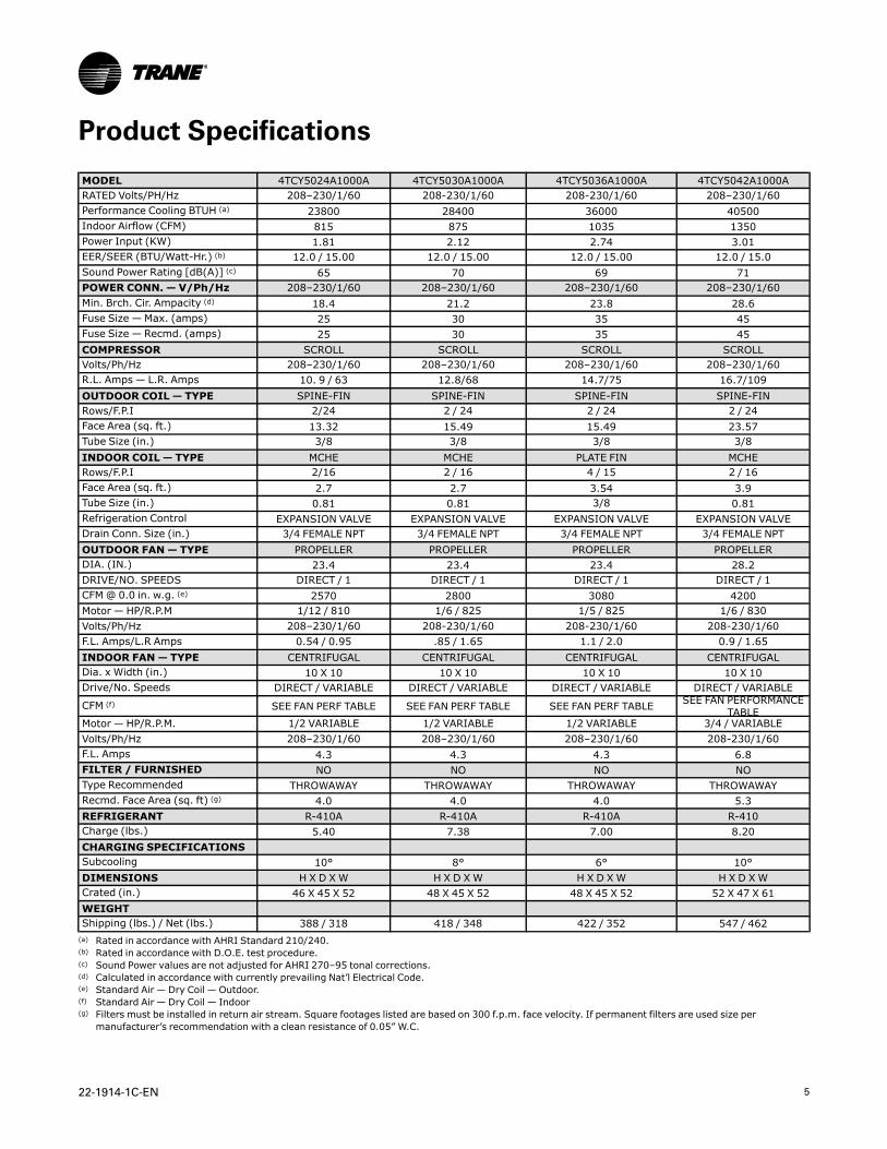
Product Specifications
MODEL 4TCY5024A1000A 4TCY5030A1000A 4TCY5036A1000A 4TCY5042A1000ARATED Volts/PH/Hz 208–230/1/60 208-230/1/60 208-230/1/60 208–230/1/60Performance Cooling BTUH (a) 23800 28400 36000 40500Indoor Airflow (CFM) 815 875 1035 1350Power Input (KW) 1.81 2.12 2.74 3.01EER/SEER (BTU/Watt-Hr.) (b) 12.0 / 15.00 12.0 / 15.00 12.0 / 15.00 12.0 / 15.0Sound Power Rating [dB(A)] (c) 65 70 69 71POWER CONN. — V/Ph/Hz 208–230/1/60 208–230/1/60 208–230/1/60 208–230/1/60Min. Brch. Cir. Ampacity (d) 18.4 21.2 23.8 28.6Fuse Size — Max. (amps) 25 30 35 45Fuse Size — Recmd. (amps) 25 30 35 45COMPRESSOR SCROLL SCROLL SCROLL SCROLLVolts/Ph/Hz 208–230/1/60 208–230/1/60 208–230/1/60 208–230/1/60R.L. Amps — L.R. Amps 10. 9 / 63 12.8/68 14.7/75 16.7/109OUTDOOR COIL — TYPE SPINE-FIN SPINE-FIN SPINE-FIN SPINE-FINRows/F.P.I 2/24 2 / 24 2 / 24 2 / 24Face Area (sq. ft.) 13.32 15.49 15.49 23.57Tube Size (in.) 3/8 3/8 3/8 3/8INDOOR COIL — TYPE MCHE MCHE PLATE FIN MCHERows/F.P.I 2/16 2 / 16 4 / 15 2 / 16Face Area (sq. ft.) 2.7 2.7 3.54 3.9Tube Size (in.) 0.81 0.81 3/8 0.81Refrigeration Control EXPANSION VALVE EXPANSION VALVE EXPANSION VALVE EXPANSION VALVEDrain Conn. Size (in.) 3/4 FEMALE NPT 3/4 FEMALE NPT 3/4 FEMALE NPT 3/4 FEMALE NPTOUTDOOR FAN— TYPE PROPELLER PROPELLER PROPELLER PROPELLERDIA. (IN.) 23.4 23.4 23.4 28.2DRIVE/NO. SPEEDS DIRECT / 1 DIRECT / 1 DIRECT / 1 DIRECT / 1CFM@ 0.0 in. w.g. (e) 2570 2800 3080 4200Motor — HP/R.P.M 1/12 / 810 1/6 / 825 1/5 / 825 1/6 / 830Volts/Ph/Hz 208–230/1/60 208-230/1/60 208-230/1/60 208-230/1/60F.L. Amps/L.R Amps 0.54 / 0.95 .85 / 1.65 1.1 / 2.0 0.9 / 1.65INDOOR FAN— TYPE CENTRIFUGAL CENTRIFUGAL CENTRIFUGAL CENTRIFUGALDia. x Width (in.) 10 X 10 10 X 10 10 X 10 10 X 10Drive/No. Speeds DIRECT / VARIABLE DIRECT / VARIABLE DIRECT / VARIABLE DIRECT / VARIABLE
CFM (f) SEE FAN PERF TABLE SEE FAN PERF TABLE SEE FAN PERF TABLE SEE FAN PERFORMANCETABLE
Motor — HP/R.P.M. 1/2 VARIABLE 1/2 VARIABLE 1/2 VARIABLE 3/4 / VARIABLEVolts/Ph/Hz 208–230/1/60 208–230/1/60 208–230/1/60 208-230/1/60F.L. Amps 4.3 4.3 4.3 6.8FILTER / FURNISHED NO NO NO NOType Recommended THROWAWAY THROWAWAY THROWAWAY THROWAWAYRecmd. Face Area (sq. ft) (g) 4.0 4.0 4.0 5.3REFRIGERANT R-410A R-410A R-410A R-410Charge (lbs.) 5.40 7.38 7.00 8.20CHARGING SPECIFICATIONSSubcooling 10° 8° 6° 10°DIMENSIONS H X D XW H X D XW H X D XW H X D XWCrated (in.) 46 X 45 X 52 48 X 45 X 52 48 X 45 X 52 52 X 47 X 61WEIGHTShipping (lbs.) / Net (lbs.) 388 / 318 418 / 348 422 / 352 547 / 462(a) Rated in accordance with AHRI Standard 210/240.(b) Rated in accordance with D.O.E. test procedure.(c) Sound Power values are not adjusted for AHRI 270–95 tonal corrections.(d) Calculated in accordance with currently prevailing Nat’l Electrical Code.(e) Standard Air — Dry Coil — Outdoor.(f) Standard Air — Dry Coil — Indoor(g) Filters must be installed in return air stream. Square footages listed are based on 300 f.p.m. face velocity. If permanent filters are used size per
manufacturer’s recommendation with a clean resistance of 0.05” W.C.
6 22-1914-1C-EN
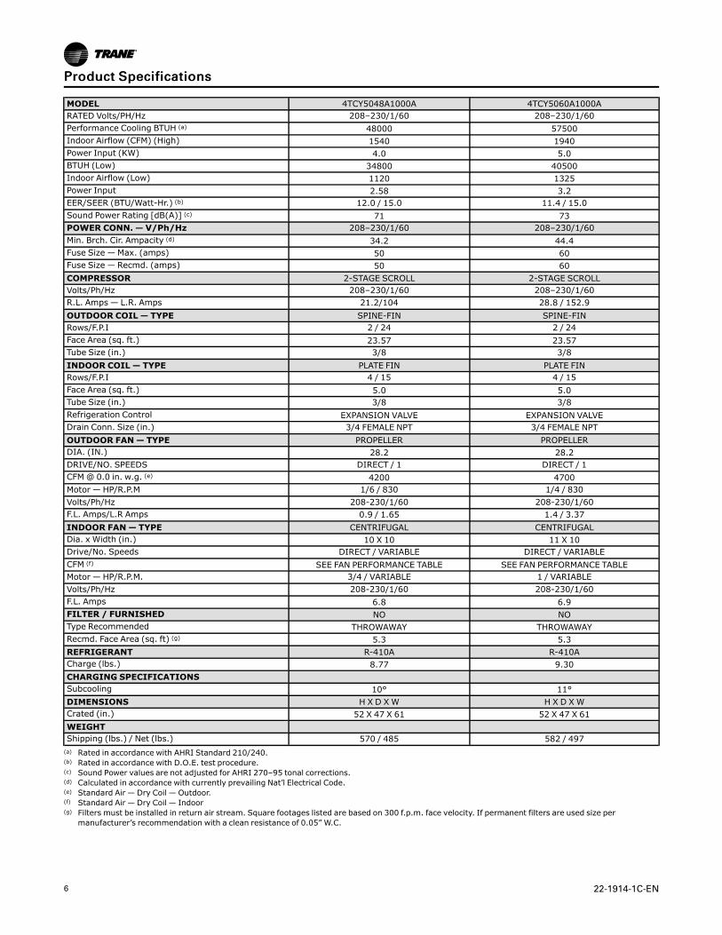
MODEL 4TCY5048A1000A 4TCY5060A1000ARATED Volts/PH/Hz 208–230/1/60 208–230/1/60Performance Cooling BTUH (a) 48000 57500Indoor Airflow (CFM) (High) 1540 1940Power Input (KW) 4.0 5.0BTUH (Low) 34800 40500Indoor Airflow (Low) 1120 1325Power Input 2.58 3.2EER/SEER (BTU/Watt-Hr.) (b) 12.0 / 15.0 11.4 / 15.0Sound Power Rating [dB(A)] (c) 71 73POWER CONN. — V/Ph/Hz 208–230/1/60 208–230/1/60Min. Brch. Cir. Ampacity (d) 34.2 44.4Fuse Size — Max. (amps) 50 60Fuse Size — Recmd. (amps) 50 60COMPRESSOR 2-STAGE SCROLL 2-STAGE SCROLLVolts/Ph/Hz 208–230/1/60 208–230/1/60R.L. Amps — L.R. Amps 21.2/104 28.8 / 152.9OUTDOOR COIL — TYPE SPINE-FIN SPINE-FINRows/F.P.I 2 / 24 2 / 24Face Area (sq. ft.) 23.57 23.57Tube Size (in.) 3/8 3/8INDOOR COIL — TYPE PLATE FIN PLATE FINRows/F.P.I 4 / 15 4 / 15Face Area (sq. ft.) 5.0 5.0Tube Size (in.) 3/8 3/8Refrigeration Control EXPANSION VALVE EXPANSION VALVEDrain Conn. Size (in.) 3/4 FEMALE NPT 3/4 FEMALE NPTOUTDOOR FAN— TYPE PROPELLER PROPELLERDIA. (IN.) 28.2 28.2DRIVE/NO. SPEEDS DIRECT / 1 DIRECT / 1CFM@ 0.0 in. w.g. (e) 4200 4700Motor — HP/R.P.M 1/6 / 830 1/4 / 830Volts/Ph/Hz 208-230/1/60 208-230/1/60F.L. Amps/L.R Amps 0.9 / 1.65 1.4 / 3.37INDOOR FAN— TYPE CENTRIFUGAL CENTRIFUGALDia. x Width (in.) 10 X 10 11 X 10Drive/No. Speeds DIRECT / VARIABLE DIRECT / VARIABLECFM (f) SEE FAN PERFORMANCE TABLE SEE FAN PERFORMANCE TABLEMotor — HP/R.P.M. 3/4 / VARIABLE 1 / VARIABLEVolts/Ph/Hz 208-230/1/60 208-230/1/60F.L. Amps 6.8 6.9FILTER / FURNISHED NO NOType Recommended THROWAWAY THROWAWAYRecmd. Face Area (sq. ft) (g) 5.3 5.3REFRIGERANT R-410A R-410ACharge (lbs.) 8.77 9.30CHARGING SPECIFICATIONSSubcooling 10° 11°DIMENSIONS H X D XW H X D XWCrated (in.) 52 X 47 X 61 52 X 47 X 61WEIGHTShipping (lbs.) / Net (lbs.) 570 / 485 582 / 497(a) Rated in accordance with AHRI Standard 210/240.(b) Rated in accordance with D.O.E. test procedure.(c) Sound Power values are not adjusted for AHRI 270–95 tonal corrections.(d) Calculated in accordance with currently prevailing Nat’l Electrical Code.(e) Standard Air — Dry Coil — Outdoor.(f) Standard Air — Dry Coil — Indoor(g) Filters must be installed in return air stream. Square footages listed are based on 300 f.p.m. face velocity. If permanent filters are used size per
manufacturer’s recommendation with a clean resistance of 0.05” W.C.
PPrroodduucctt SSppeecciiffiiccaattiioonnss
22-1914-1C-EN 7
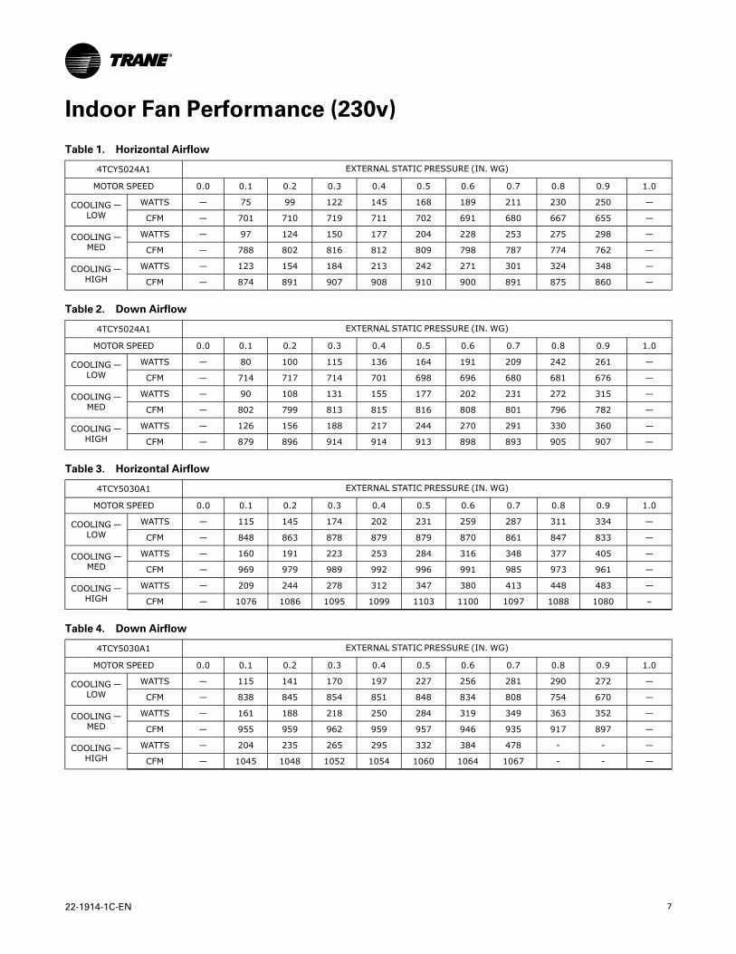
Indoor Fan Performance (230v)
Table 1. Horizontal Airflow
4TCY5024A1 EXTERNAL STATIC PRESSURE (IN. WG)
MOTOR SPEED 0.0 0.1 0.2 0.3 0.4 0.5 0.6 0.7 0.8 0.9 1.0
COOLING—LOW
WATTS — 75 99 122 145 168 189 211 230 250 —
CFM — 701 710 719 711 702 691 680 667 655 —
COOLING—MED
WATTS — 97 124 150 177 204 228 253 275 298 —
CFM — 788 802 816 812 809 798 787 774 762 —
COOLING—HIGH
WATTS — 123 154 184 213 242 271 301 324 348 —
CFM — 874 891 907 908 910 900 891 875 860 —
Table 2. Down Airflow
4TCY5024A1 EXTERNAL STATIC PRESSURE (IN. WG)
MOTOR SPEED 0.0 0.1 0.2 0.3 0.4 0.5 0.6 0.7 0.8 0.9 1.0
COOLING—LOW
WATTS — 80 100 115 136 164 191 209 242 261 —
CFM — 714 717 714 701 698 696 680 681 676 —
COOLING—MED
WATTS — 90 108 131 155 177 202 231 272 315 —
CFM — 802 799 813 815 816 808 801 796 782 —
COOLING—HIGH
WATTS — 126 156 188 217 244 270 291 330 360 —
CFM — 879 896 914 914 913 898 893 905 907 —
Table 3. Horizontal Airflow
4TCY5030A1 EXTERNAL STATIC PRESSURE (IN. WG)
MOTOR SPEED 0.0 0.1 0.2 0.3 0.4 0.5 0.6 0.7 0.8 0.9 1.0
COOLING—LOW
WATTS — 115 145 174 202 231 259 287 311 334 —
CFM — 848 863 878 879 879 870 861 847 833 —
COOLING—MED
WATTS — 160 191 223 253 284 316 348 377 405 —
CFM — 969 979 989 992 996 991 985 973 961 —
COOLING—HIGH
WATTS — 209 244 278 312 347 380 413 448 483 —
CFM — 1076 1086 1095 1099 1103 1100 1097 1088 1080 –
Table 4. Down Airflow
4TCY5030A1 EXTERNAL STATIC PRESSURE (IN. WG)
MOTOR SPEED 0.0 0.1 0.2 0.3 0.4 0.5 0.6 0.7 0.8 0.9 1.0
COOLING—LOW
WATTS — 115 141 170 197 227 256 281 290 272 —
CFM — 838 845 854 851 848 834 808 754 670 —
COOLING—MED
WATTS — 161 188 218 250 284 319 349 363 352 —
CFM — 955 959 962 959 957 946 935 917 897 —
COOLING—HIGH
WATTS — 204 235 265 295 332 384 478 - - —
CFM — 1045 1048 1052 1054 1060 1064 1067 - - —
8 22-1914-1C-EN
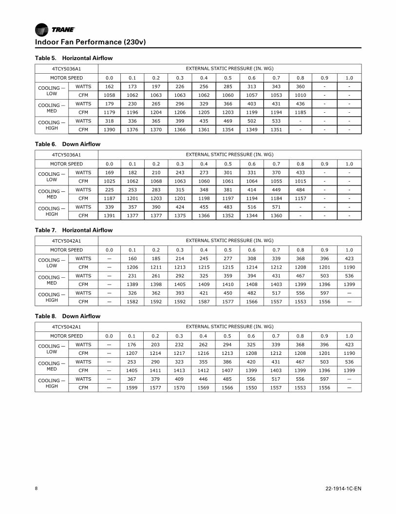
Table 5. Horizontal Airflow
4TCY5036A1 EXTERNAL STATIC PRESSURE (IN. WG)
MOTOR SPEED 0.0 0.1 0.2 0.3 0.4 0.5 0.6 0.7 0.8 0.9 1.0
COOLING—LOW
WATTS 162 173 197 226 256 285 313 343 360 - -
CFM 1058 1062 1063 1063 1062 1060 1057 1053 1010 - -
COOLING—MED
WATTS 179 230 265 296 329 366 403 431 436 - -
CFM 1179 1196 1204 1206 1205 1203 1199 1194 1185 - -
COOLING—HIGH
WATTS 318 336 365 399 435 469 502 533 - - -
CFM 1390 1376 1370 1366 1361 1354 1349 1351 - - -
Table 6. Down Airflow
4TCY5036A1 EXTERNAL STATIC PRESSURE (IN. WG)
MOTOR SPEED 0.0 0.1 0.2 0.3 0.4 0.5 0.6 0.7 0.8 0.9 1.0
COOLING—LOW
WATTS 169 182 210 243 273 301 331 370 433 - -
CFM 1025 1062 1068 1063 1060 1061 1064 1055 1015 - -
COOLING—MED
WATTS 225 253 283 315 348 381 414 449 484 - -
CFM 1187 1201 1203 1201 1198 1197 1194 1184 1157 - -
COOLING—HIGH
WATTS 339 357 390 424 455 483 516 571 - - -
CFM 1391 1377 1377 1375 1366 1352 1344 1360 - - -
Table 7. Horizontal Airflow
4TCY5042A1 EXTERNAL STATIC PRESSURE (IN. WG)
MOTOR SPEED 0.0 0.1 0.2 0.3 0.4 0.5 0.6 0.7 0.8 0.9 1.0
COOLING—LOW
WATTS — 160 185 214 245 277 308 339 368 396 423
CFM — 1206 1211 1213 1215 1215 1214 1212 1208 1201 1190
COOLING—MED
WATTS — 231 261 292 325 359 394 431 467 503 536
CFM — 1389 1398 1405 1409 1410 1408 1403 1399 1396 1399
COOLING—HIGH
WATTS — 326 362 393 421 450 482 517 556 597 —
CFM — 1582 1592 1592 1587 1577 1566 1557 1553 1556 —
Table 8. Down Airflow
4TCY5042A1 EXTERNAL STATIC PRESSURE (IN. WG)
MOTOR SPEED 0.0 0.1 0.2 0.3 0.4 0.5 0.6 0.7 0.8 0.9 1.0
COOLING—LOW
WATTS — 176 203 232 262 294 325 339 368 396 423
CFM — 1207 1214 1217 1216 1213 1208 1212 1208 1201 1190
COOLING—MED
WATTS — 253 290 323 355 386 420 431 467 503 536
CFM — 1405 1411 1413 1412 1407 1399 1403 1399 1396 1399
COOLING—HIGH
WATTS — 367 379 409 446 485 556 517 556 597 —
CFM — 1599 1577 1570 1569 1566 1550 1557 1553 1556 —
IInnddoooorr FFaann PPeerrffoorrmmaannccee ((223300vv))
22-1914-1C-EN 9
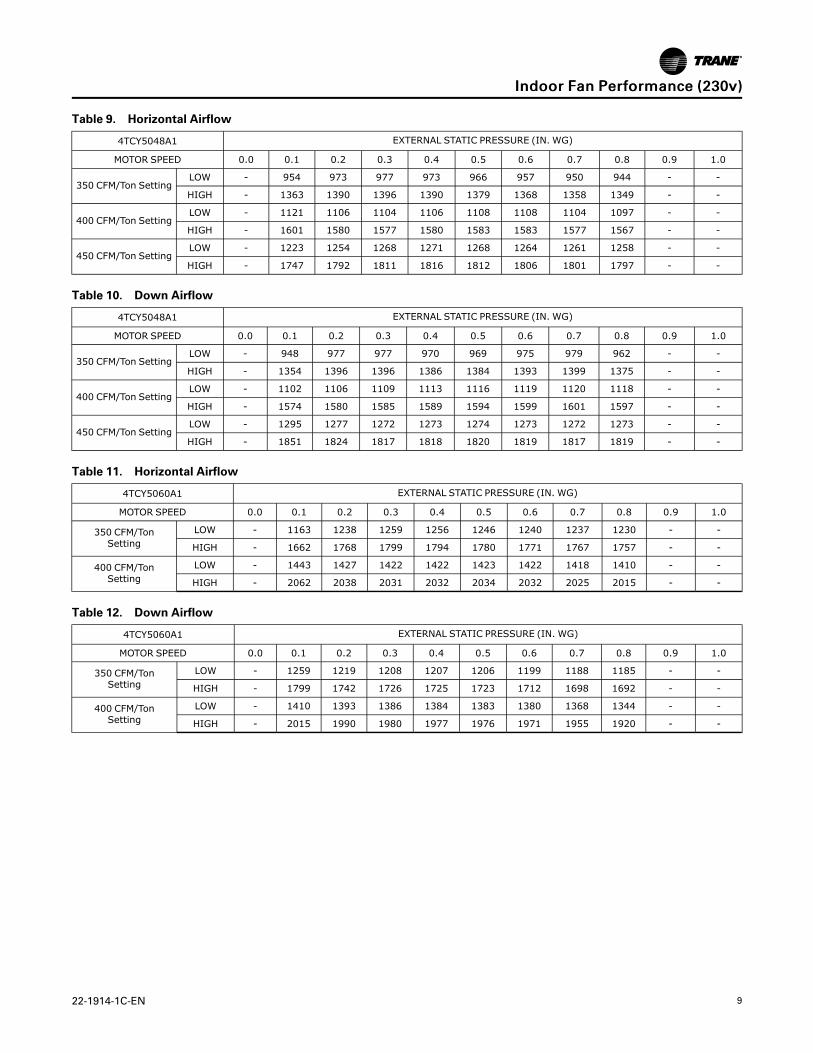
Table 9. Horizontal Airflow
4TCY5048A1 EXTERNAL STATIC PRESSURE (IN. WG)
MOTOR SPEED 0.0 0.1 0.2 0.3 0.4 0.5 0.6 0.7 0.8 0.9 1.0
350 CFM/Ton SettingLOW - 954 973 977 973 966 957 950 944 - -
HIGH - 1363 1390 1396 1390 1379 1368 1358 1349 - -
400 CFM/Ton SettingLOW - 1121 1106 1104 1106 1108 1108 1104 1097 - -
HIGH - 1601 1580 1577 1580 1583 1583 1577 1567 - -
450 CFM/Ton SettingLOW - 1223 1254 1268 1271 1268 1264 1261 1258 - -
HIGH - 1747 1792 1811 1816 1812 1806 1801 1797 - -
Table 10. Down Airflow
4TCY5048A1 EXTERNAL STATIC PRESSURE (IN. WG)
MOTOR SPEED 0.0 0.1 0.2 0.3 0.4 0.5 0.6 0.7 0.8 0.9 1.0
350 CFM/Ton SettingLOW - 948 977 977 970 969 975 979 962 - -
HIGH - 1354 1396 1396 1386 1384 1393 1399 1375 - -
400 CFM/Ton SettingLOW - 1102 1106 1109 1113 1116 1119 1120 1118 - -
HIGH - 1574 1580 1585 1589 1594 1599 1601 1597 - -
450 CFM/Ton SettingLOW - 1295 1277 1272 1273 1274 1273 1272 1273 - -
HIGH - 1851 1824 1817 1818 1820 1819 1817 1819 - -
Table 11. Horizontal Airflow
4TCY5060A1 EXTERNAL STATIC PRESSURE (IN. WG)
MOTOR SPEED 0.0 0.1 0.2 0.3 0.4 0.5 0.6 0.7 0.8 0.9 1.0
350 CFM/TonSetting
LOW - 1163 1238 1259 1256 1246 1240 1237 1230 - -
HIGH - 1662 1768 1799 1794 1780 1771 1767 1757 - -
400 CFM/TonSetting
LOW - 1443 1427 1422 1422 1423 1422 1418 1410 - -
HIGH - 2062 2038 2031 2032 2034 2032 2025 2015 - -
Table 12. Down Airflow
4TCY5060A1 EXTERNAL STATIC PRESSURE (IN. WG)
MOTOR SPEED 0.0 0.1 0.2 0.3 0.4 0.5 0.6 0.7 0.8 0.9 1.0
350 CFM/TonSetting
LOW - 1259 1219 1208 1207 1206 1199 1188 1185 - -
HIGH - 1799 1742 1726 1725 1723 1712 1698 1692 - -
400 CFM/TonSetting
LOW - 1410 1393 1386 1384 1383 1380 1368 1344 - -
HIGH - 2015 1990 1980 1977 1976 1971 1955 1920 - -
IInnddoooorr FFaann PPeerrffoorrmmaannccee ((223300vv))
10 22-1914-1C-EN
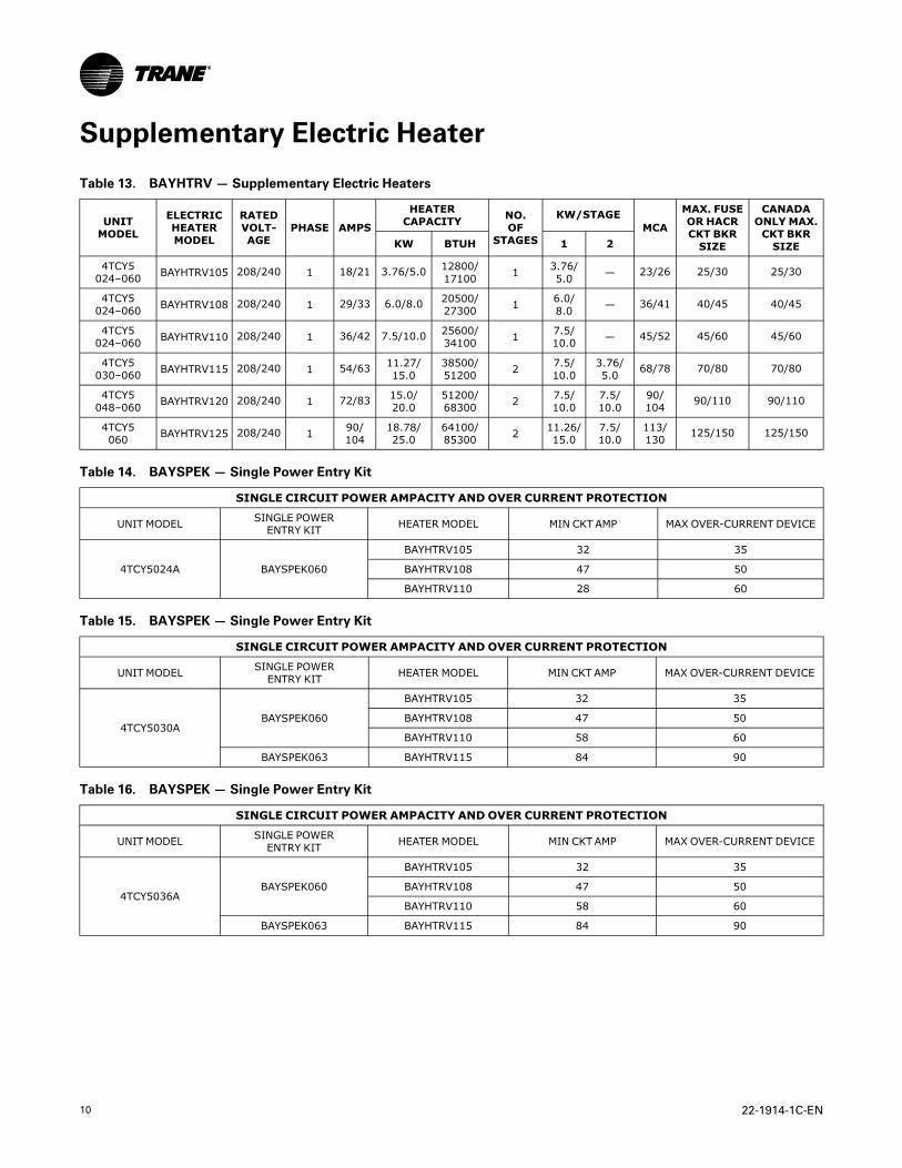
Supplementary Electric Heater
Table 13. BAYHTRV— Supplementary Electric Heaters
UNITMODEL
ELECTRICHEATERMODEL
RATEDVOLT-AGE
PHASE AMPS
HEATERCAPACITY NO.
OFSTAGES
KW/STAGEMCA
MAX. FUSEOR HACRCKT BKRSIZE
CANADAONLYMAX.CKT BKRSIZEKW BTUH 1 2
4TCY5024–060 BAYHTRV105 208/240 1 18/21 3.76/5.0 12800/
17100 1 3.76/5.0 — 23/26 25/30 25/30
4TCY5024–060 BAYHTRV108 208/240 1 29/33 6.0/8.0 20500/
27300 1 6.0/8.0 — 36/41 40/45 40/45
4TCY5024–060 BAYHTRV110 208/240 1 36/42 7.5/10.0 25600/
34100 1 7.5/10.0 — 45/52 45/60 45/60
4TCY5030–060 BAYHTRV115 208/240 1 54/63 11.27/
15.038500/51200 2 7.5/
10.03.76/5.0 68/78 70/80 70/80
4TCY5048–060 BAYHTRV120 208/240 1 72/83 15.0/
20.051200/68300 2 7.5/
10.07.5/10.0
90/104 90/110 90/110
4TCY5060 BAYHTRV125 208/240 1 90/
10418.78/25.0
64100/85300 2 11.26/
15.07.5/10.0
113/130 125/150 125/150
Table 14. BAYSPEK — Single Power Entry Kit
SINGLE CIRCUIT POWER AMPACITY ANDOVER CURRENT PROTECTION
UNIT MODEL SINGLE POWERENTRY KIT HEATER MODEL MIN CKTAMP MAX OVER-CURRENT DEVICE
4TCY5024A BAYSPEK060
BAYHTRV105 32 35
BAYHTRV108 47 50
BAYHTRV110 28 60
Table 15. BAYSPEK — Single Power Entry Kit
SINGLE CIRCUIT POWER AMPACITY ANDOVER CURRENT PROTECTION
UNIT MODEL SINGLE POWERENTRY KIT HEATER MODEL MIN CKT AMP MAX OVER-CURRENT DEVICE
4TCY5030ABAYSPEK060
BAYHTRV105 32 35
BAYHTRV108 47 50
BAYHTRV110 58 60
BAYSPEK063 BAYHTRV115 84 90
Table 16. BAYSPEK — Single Power Entry Kit
SINGLE CIRCUIT POWER AMPACITY ANDOVER CURRENT PROTECTION
UNIT MODEL SINGLE POWERENTRY KIT HEATER MODEL MIN CKTAMP MAX OVER-CURRENT DEVICE
4TCY5036ABAYSPEK060
BAYHTRV105 32 35
BAYHTRV108 47 50
BAYHTRV110 58 60
BAYSPEK063 BAYHTRV115 84 90
22-1914-1C-EN 11
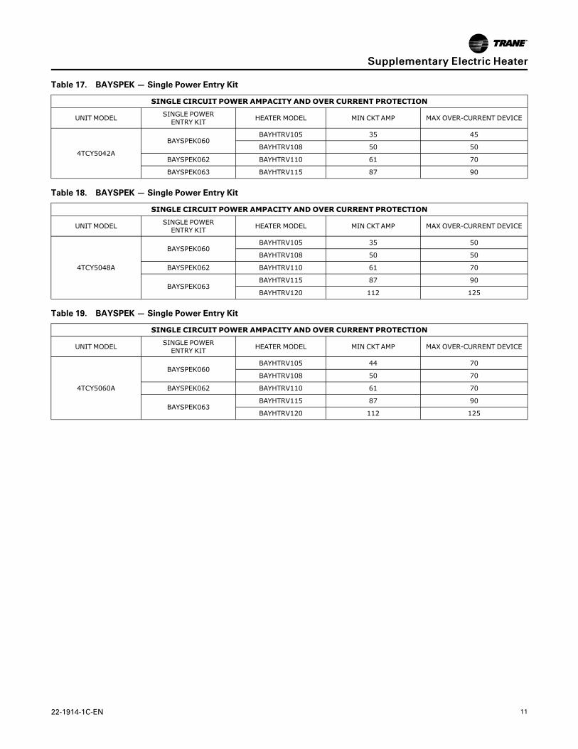
Table 17. BAYSPEK — Single Power Entry Kit
SINGLE CIRCUIT POWER AMPACITY ANDOVER CURRENT PROTECTION
UNIT MODEL SINGLE POWERENTRY KIT HEATER MODEL MIN CKTAMP MAX OVER-CURRENT DEVICE
4TCY5042A
BAYSPEK060BAYHTRV105 35 45
BAYHTRV108 50 50
BAYSPEK062 BAYHTRV110 61 70
BAYSPEK063 BAYHTRV115 87 90
Table 18. BAYSPEK — Single Power Entry Kit
SINGLE CIRCUIT POWER AMPACITY ANDOVER CURRENT PROTECTION
UNIT MODEL SINGLE POWERENTRY KIT HEATER MODEL MIN CKTAMP MAX OVER-CURRENT DEVICE
4TCY5048A
BAYSPEK060BAYHTRV105 35 50
BAYHTRV108 50 50
BAYSPEK062 BAYHTRV110 61 70
BAYSPEK063BAYHTRV115 87 90
BAYHTRV120 112 125
Table 19. BAYSPEK — Single Power Entry Kit
SINGLE CIRCUIT POWER AMPACITY ANDOVER CURRENT PROTECTION
UNIT MODEL SINGLE POWERENTRY KIT HEATER MODEL MIN CKTAMP MAX OVER-CURRENT DEVICE
4TCY5060A
BAYSPEK060BAYHTRV105 44 70
BAYHTRV108 50 70
BAYSPEK062 BAYHTRV110 61 70
BAYSPEK063BAYHTRV115 87 90
BAYHTRV120 112 125
SSuupppplleemmeennttaarryy EElleeccttrriicc HHeeaatteerr
12 22-1914-1C-EN
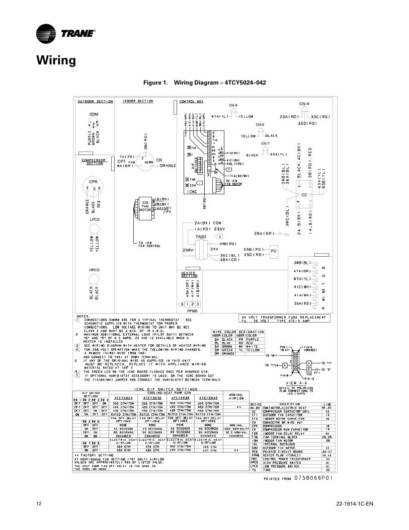
Wiring
Figure 1. Wiring Diagram – 4TCY5024–042
22-1914-1C-EN 13
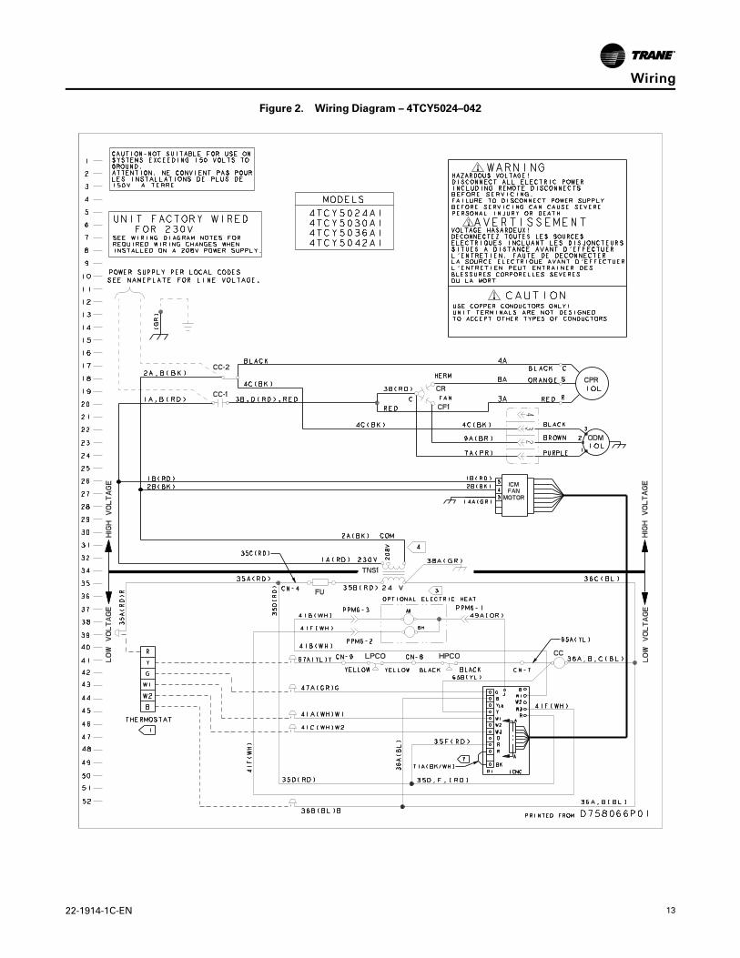
Figure 2. Wiring Diagram – 4TCY5024–042
WWiirriinngg
14 22-1914-1C-EN
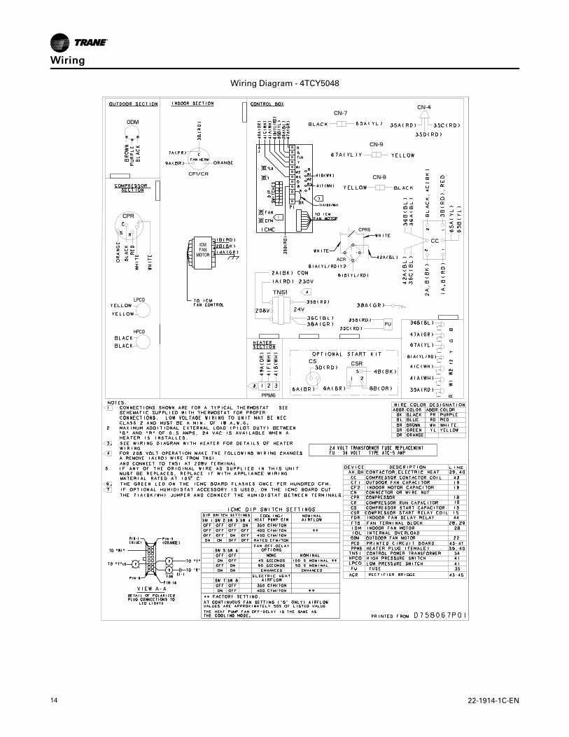
Wiring Diagram - 4TCY5048
WWiirriinngg
22-1914-1C-EN 15
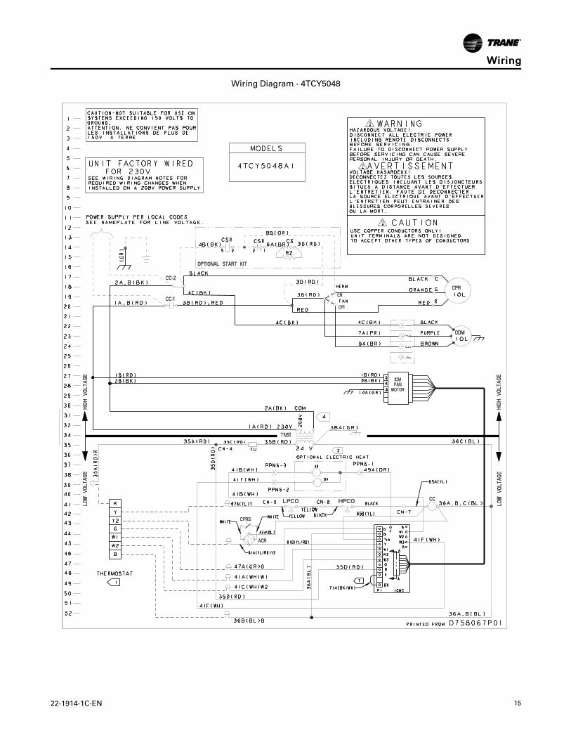
Wiring Diagram - 4TCY5048
WWiirriinngg
16 22-1914-1C-EN
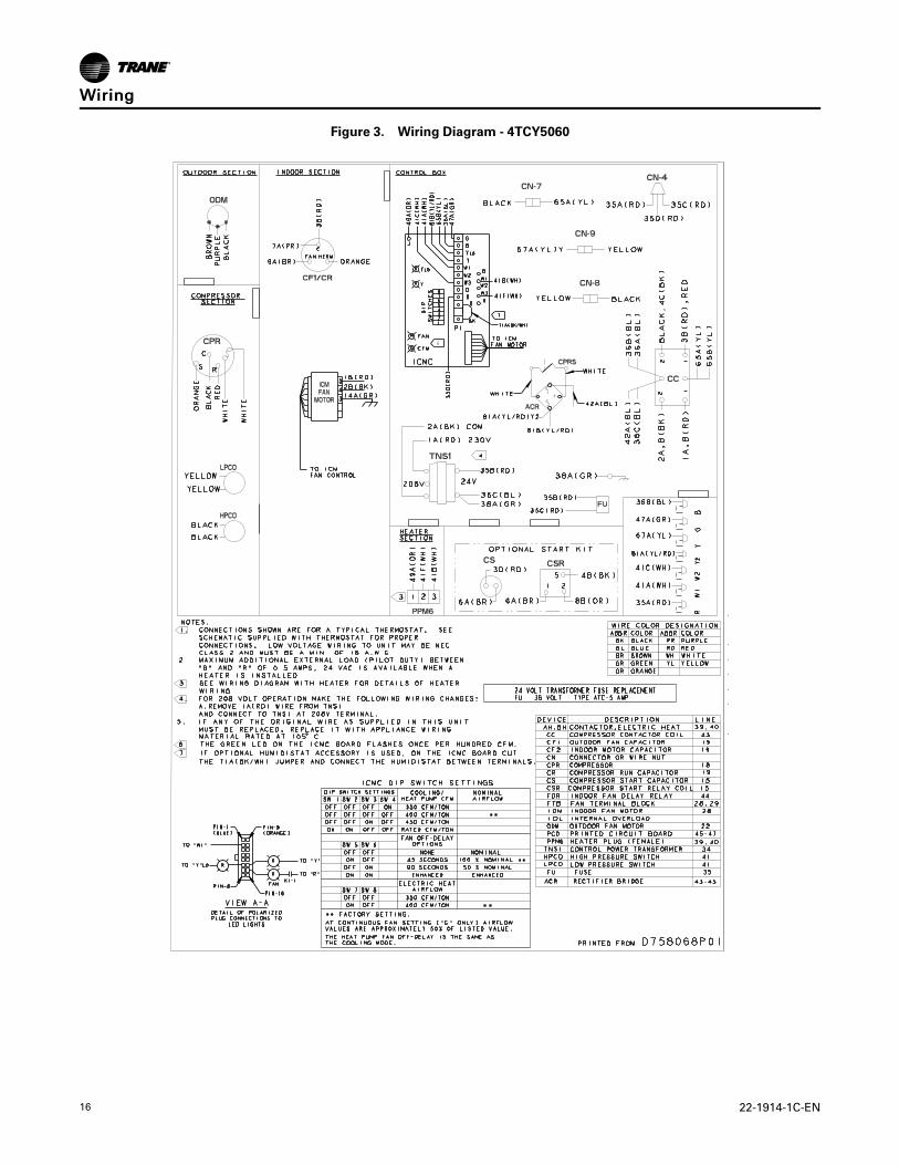
Figure 3. Wiring Diagram - 4TCY5060
WWiirriinngg
22-1914-1C-EN 17
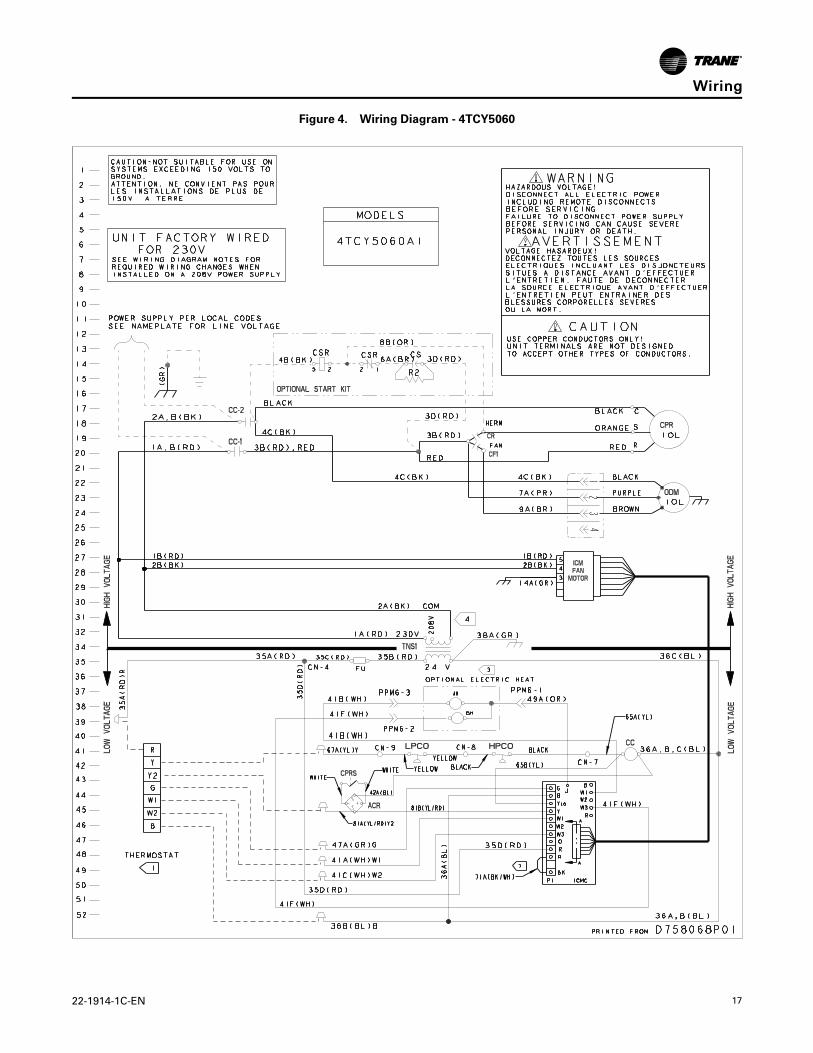
Figure 4. Wiring Diagram - 4TCY5060
WWiirriinngg
18 22-1914-1C-EN
Full Perimeter Roof Mounting Curb
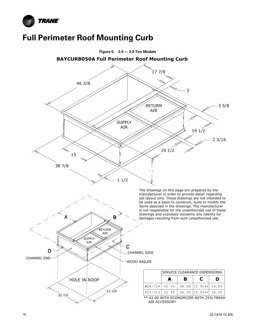
Figure 5. 2.0 — 3.0 Ton Models
A
SUPPLYAIR
RETURNAIR
SUPPLYAIR
RETURNAIR
CHANNEL SIDE
WOOD NAILER
HOLE IN ROOF
CHANNEL END
SERVICE CLEARANCE DIMENSIONS
A B C D
** 42.00 WITH ECONOMIZER WITH 25% FRESH AIR ACCESSORY
The drawings on this page are prepared by themanufacturer in order to provide detail regardingjob layout only. These drawings are not intended tobe used as a basis to construct, build or modify theitems depicted in the drawings. The manufactureris not responsible for the unauthorized use of thesedrawings and expressly disclaims any liability fordamages resulting from such unauthorized use.
BAYCURB050A Full Perimeter Roof Mounting Curb
46 3/8
17 7/8
3
15
38 7/8
3 5/8
19 1/2
2 3/16
19 1/2
1 1/2
35 7/843 3/8
22-1914-1C-EN 19
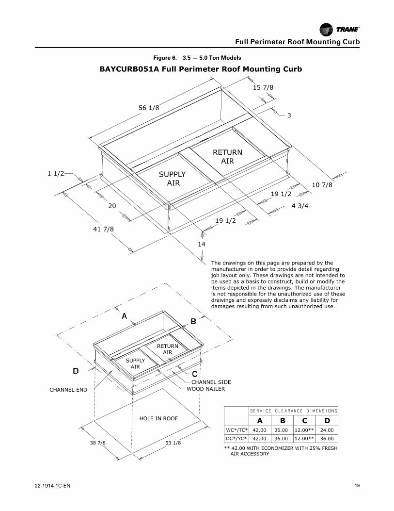
Figure 6. 3.5 — 5.0 Ton Models
The drawings on this page are prepared by themanufacturer in order to provide detail regardingjob layout only. These drawings are not intended tobe used as a basis to construct, build or modify theitems depicted in the drawings. The manufactureris not responsible for the unauthorized use of thesedrawings and expressly disclaims any liability fordamages resulting from such unauthorized use.
SUPPLYAIR
RETURNAIR
CHANNEL SIDEWOOD NAILER
HOLE IN ROOF
CHANNEL END
WC*/TC*
DC*/YC*
12.00**
12.00**42.00
42.00
36.00
36.00
36.00
24.00
** 42.00 WITH ECONOMIZER WITH 25% FRESH AIR ACCESSORY
A B DC
SUPPLY AIR
RETURNAIR
BAYCURB051A Full Perimeter Roof Mounting Curb
56 1/8
15 7/8
3
1 1/2
10 7/819 1/2
19 1/2
4 3/4
14
20
41 7/8
38 7/8 53 1/8
FFuullll PPeerriimmeetteerr RRooooff MMoouunnttiinngg CCuurrbb
20 22-1914-1C-EN
Optional Equipment — Filter Rack
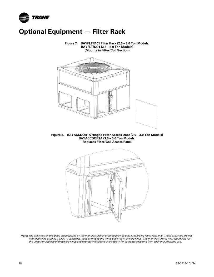
Figure 7. BAYFLTR101 Filter Rack (2.0 – 3.0 Ton Models)BAYFLTR201 (3.5 – 5.0 Ton Models)(Mounts in Filter/Coil Section)
Figure 8. BAYACCDOR1A Hinged Filter Access Door (2.0 – 3.0 Ton Models)BAYACCDOR2A (3.5 – 5.0 Ton Models)Replaces Filter/Coil Access Panel
Note: The drawings on this page are prepared by the manufacturer in order to provide detail regarding job layout only. These drawings are notintended to be used as a basis to construct, build or modify the items depicted in the drawings. The manufacturer is not responsible forthe unauthorized use of these drawings and expressly disclaims any liability for damages resulting from such unauthorized use.
22-1914-1C-EN 21
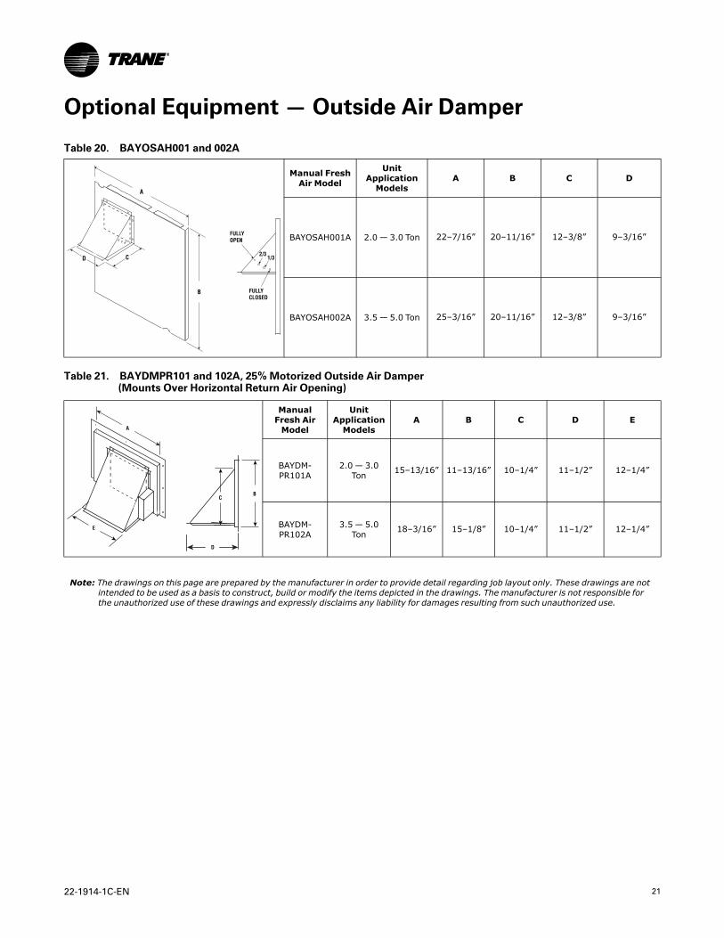
Optional Equipment — Outside Air Damper
Table 20. BAYOSAH001 and 002A
A
D C
B
FULLY OPEN
FULLY CLOSED
2/31/3
Manual FreshAir Model
UnitApplicationModels
A B C D
BAYOSAH001A 2.0 — 3.0 Ton 22–7/16” 20–11/16” 12–3/8” 9–3/16”
BAYOSAH002A 3.5 — 5.0 Ton 25–3/16” 20–11/16” 12–3/8” 9–3/16”
Table 21. BAYDMPR101 and 102A, 25% Motorized Outside Air Damper(Mounts Over Horizontal Return Air Opening)
A
E
BC
D
ManualFresh AirModel
UnitApplicationModels
A B C D E
BAYDM-PR101A
2.0 — 3.0Ton 15–13/16” 11–13/16” 10–1/4” 11–1/2” 12–1/4”
BAYDM-PR102A
3.5 — 5.0Ton 18–3/16” 15–1/8” 10–1/4” 11–1/2” 12–1/4”
Note: The drawings on this page are prepared by the manufacturer in order to provide detail regarding job layout only. These drawings are notintended to be used as a basis to construct, build or modify the items depicted in the drawings. The manufacturer is not responsible forthe unauthorized use of these drawings and expressly disclaims any liability for damages resulting from such unauthorized use.
22 22-1914-1C-EN
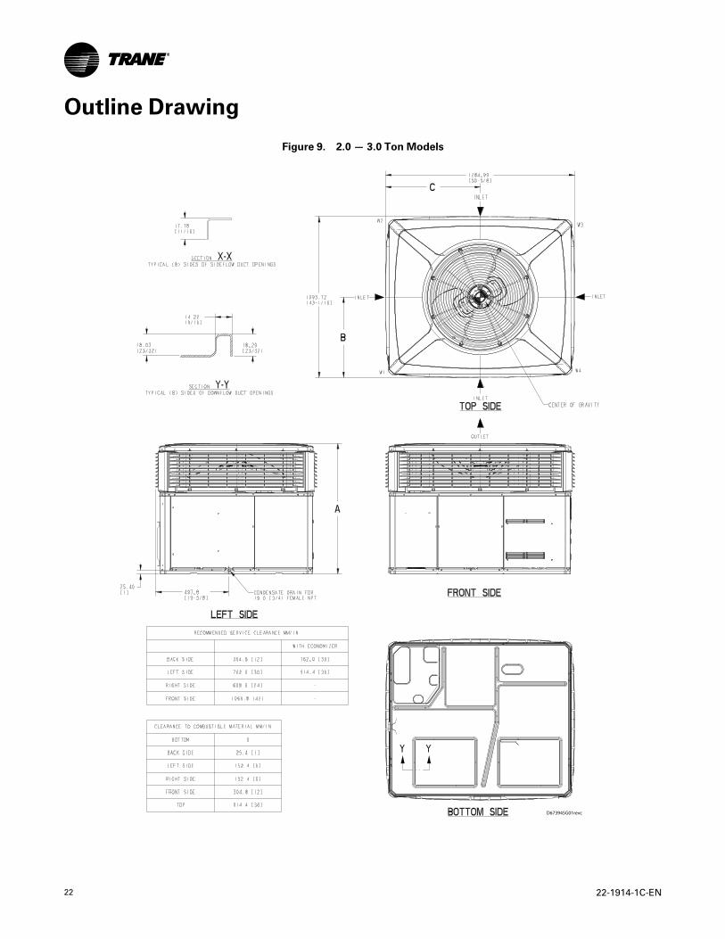
Outline Drawing
Figure 9. 2.0 — 3.0 Ton Models
D673945G01revc
22-1914-1C-EN 23
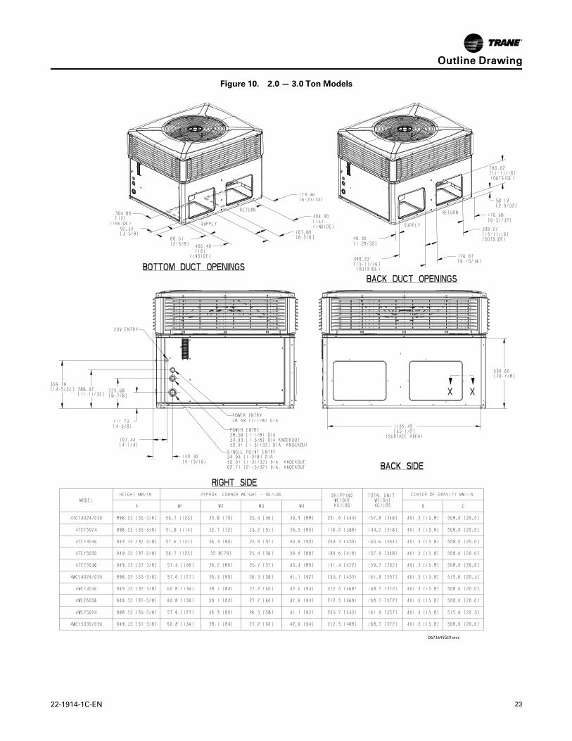
Figure 10. 2.0 — 3.0 Ton Models
D673645G01revc
OOuuttlliinnee DDrraawwiinngg
24 22-1914-1C-EN
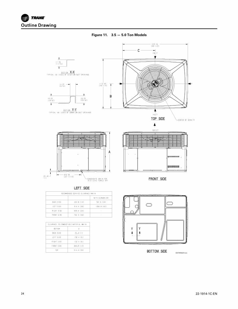
Figure 11. 3.5 — 5.0 Ton Models
D673946G01revc
OOuuttlliinnee DDrraawwiinngg
22-1914-1C-EN 25
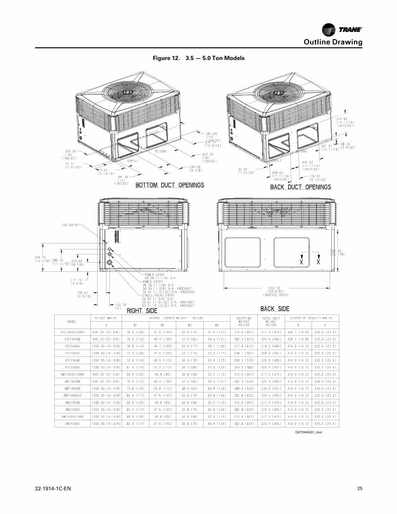
Figure 12. 3.5 — 5.0 Ton Models
D673946G01_revc
OOuuttlliinnee DDrraawwiinngg
26 22-1914-1C-EN
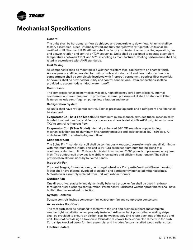
Mechanical Specifications
GGeenneerraall
The units shall be horizontal airflow as shipped and convertible to downflow. All units shall befactory assembled, piped, internally wired and fully charged with refrigerant. Units shall becertified to UL Standard 1995. All units shall be factory run tested to check cooling operation, fanand blower rotation and control or TXV sequence. Units shall be designed to operate at ambienttemperatures between 115°F and 55°F in cooling as manufactured. Cooling performance shall berated in accordance with AHRI standards.
UUnniitt CCaassiinngg
All components shall be mounted in a weather-resistant steel cabinet with an enamel finish.Access panels shall be provided for unit controls and indoor coil and fans. Indoor air sectioncompartment shall be completely insulated with fireproof, permanent, odorless fiber material.Knockouts shall be provided for utility and control connections. Drain connections shall beprovided to accommodate indoor water runoff.
CCoommpprreessssoorr
The compressor shall be hermetically sealed, high efficiency scroll compressors. Internalovercurrent and over temperature protection, internal pressure relief shall be standard. Otherfeatures include centrifugal oil pump, low vibration and noise.
RReeffrriiggeerraattiioonn SSyysstteemm
All units shall have refrigerant control. Service pressure tap ports and a refrigerant line filter shallbe standard.
EEvvaappoorraattoorr CCooiill ((22––44 TToonn MMooddeellss)) All aluminummicro channel, extruded tubes, mechanicallybonded to aluminum fins, and factory pressure and leak tested at 480 —650 psig. All units haveTXV to control refrigerant flow.
EEvvaappoorraattoorr CCooiill ((55 TToonn MMooddeell)) Internally enhanced 3/8” OD seamless copper tubingmechanically bonded to aluminum fins, factory pressure and leak tested at 480 – 650 psig. Allunits have TXV to control refrigerant flow.
CCoonnddeennsseerr CCooiill
The Spine Fin ™ condenser coil shall be continuously wrapped, corrosion resistant all aluminumwith minimum brazed joints. This coil is 3/8” OD seamless aluminum tubing glued to acontinuous aluminum fin. Coils are lab tested to withstand 2.000 pounds of pressure per squareinch. The outdoor coil provides low airflow resistance and efficient heat transfer. The coil isprotected on all four sides by louvered panels.
IInnddoooorr AAiirr FFaann
Constant Torgue, forward-curved, centrifugal wheel in a Composite Vortica ® Blower housing.Motor shall have thermal overload protection and permanently lubricated motor bearings.Motor/blower assembly isolated from unit with rubber mounts.
OOuuttddoooorr FFaann
One direct-drive, statically and dynamically balanced propeller fan shall be used in a draw-through vertical discharge configuration. Permanently lubricated weather proof motor shall havebuilt-in thermal overload protection.
SSyysstteemm CCoonnttrroollss
System controls include condenser fan, evaporator fan and compressor contactors.
AAcccceessssoorriieess RRooooff CCuurrbb
The roof curb shall be designed to mate with the unit and provide support and completeweathertight installation when properly installed. Adhesive back polyurethane sealing stripsshall be provided to ensure an airtight seal between supply and return openings of the curb andunit. The roof curb design allows field fabricated ductwork to be connected directly to the curb.Curb ships knocked down for field assembly, and includes factory installed wood nailer strips.
EElleeccttrriicc HHeeaatteerrss
22-1914-1C-EN 27
Each heater assembly shall include power supply fusing if over 48 amps, automatic resettinglimit switches and heat limiters for thermal protection. Heaters shall be provided with polarizedplugs for quick connection to unit low voltage wiring. Electric heat modules shall be UL listed.
SSiinnggllee SSoouurrccee PPoowweerr EEnnttrryy
This accessory when used with electric heat accessory shall allow single source powerconnection to unit and heater combination. Single source power entry kits shall have specificmatching heater(s). Kit shall include high voltage terminal blocks, fuse blocks and fuses, cut-to-length interconnecting wiring, and junction box (if required) to provide power sources with fuseprotection as required for both the unit and accessory heater. Kit components shall install withinthe heater cabinet in the heater access section. Single source branch power circuit shall beprotected and wired in accordance with local codes.
FFuullllyy MMoodduullaattiinngg EEccoonnoommiizzeerr
This accessory shall be field installed and be composed of the following items: 0–100% fresh airdamper, damper drive motor, fixed dry bulb enthalpy control, and low voltage pigtails forelectrical connections. Solid state enthalpy or differential enthalpy control is optional.Economizer operations shall be controlled by the preset position of the enthalpy control. Abarometric relief damper shall be standard with the economizer and provide a pressure operateddamper that shall be gravity closing and prohibit entrance of outside air on equipment "off"cycle. Economizer requires BAYRLAY004A relay kit to interface the economizer to the heat pump.
MMaannuuaall OOuuttssiiddee AAiirr DDaammppeerrss
Rain hood and screen shall be field installed. Suitable for up to 25% outside air.CCoonnttrrooll OOppttiioonnssSSttaannddaarrdd IInnddoooorr TThheerrmmoossttaattss
Two stage heating/cooling or one stage heating/cooling thermostats shall be available in eithermanual or automatic changeover.
PPrrooggrraammmmaabbllee EElleeccttrroonniicc NNiigghhtt SSeettttiinngg TThheerrmmoossttaatt
Programmable electronic thermostat shall provide heating setback and cooling setup with 7–dayprogramming capability. 1H/1C or 2H/2C models available.
MMeecchhaanniiccaall SSppeecciiffiiccaattiioonnss
Trane - by Trane Technologies (NYSE: TT), a global innovator - creates comfortable, energy efficient indoorenvironments for commercial and residential applications. For more information, please visit trane. com ortranetechnologies.com.
The AHRI Certified mark indicates Trane U.S. Inc. participation in the AHRI Certification program. For verification of individual certified products, go to ahridirectory.org.
Trane has a policy of continuous data improvement and it reserves the right to change design and specifications without notice. We are committed to usingenvironmentally conscious print practices.
22-1914-1C-EN 27 May 2020
Supersedes 22-1914-1B-EN (February 2017) ©2020 Trane


![[Didache ton Dodeka Apostolon] : the Didachè and kindred](https://img.dokumen.tips/doc/110x75/633c4d694fb67381ab001f85/didache-ton-dodeka-apostolon-the-didache-and-kindred.jpg)