Embed Size (px)
Citation preview

Tracer AdaptiView™ Display
Upgrade KitFor Tracer CH530/CH531 DynaView™ Display
Installation Instructions
May 2020 CDUA-SVN01G-EN
CDUA CVHE CDHFCVRD CDHF Tracer AdaptiViewCVGF CDHG
SAFETY WARNINGOnly qualified personnel should install and service the equipment. The installation, starting up, and servicing ofheating, ventilating, and air-conditioning equipment can be hazardous and requires specific knowledge and training.Improperly installed, adjusted or altered equipment by an unqualified person could result in death or serious injury.When working on the equipment, observe all precautions in the literature and on the tags, stickers, and labels that areattached to the equipment.
Distribution/use of this is limited to the Trane sales and service organization in support of Tracer AdaptiView and is notintended for independent third party use or for use apart from the Tracer AdaptiView display upgrade for Tracer CH530/CH531 DynaView display.

Introduction
Warnings, Cautions, and Notices
Safety advisories appear throughout this manual as required. Your personal safety and the properoperation of this machine depend upon the strict observance of these precautions.
Important Environmental Concerns
Scientific research has shown that certain man-made chemicals can affect the earth’s naturallyoccurring stratospheric ozone layer when released to the atmosphere. In particular, several of theidentified chemicals that may affect the ozone layer are refrigerants that contain Chlorine, Fluorineand Carbon (CFCs) and those containing Hydrogen, Chlorine, Fluorine and Carbon (HCFCs). Not allrefrigerants containing these compounds have the same potential impact to the environment.Trane advocates the responsible handling of all refrigerants-including industry replacements forCFCs and HCFCs such as saturated or unsaturated HFCs and HCFCs
Important Responsible Refrigerant Practices
Trane believes that responsible refrigerant practices are important to the environment, ourcustomers, and the air conditioning industry. All technicians who handle refrigerants must becertified according to local rules. For the USA, the Federal Clean Air Act (Section 608) sets forth therequirements for handling, reclaiming, recovering and recycling of certain refrigerants and theequipment that is used in these service procedures. In addition, some states or municipalities mayhave additional requirements that must also be adhered to for responsible management ofrefrigerants. Know the applicable laws and follow them.
The three types of advisories are defined as follows:
WARNING Indicates a potentially hazardous situation which, if not avoided, could result indeath or serious injury.
CAUTIONsIndicates a potentially hazardous situation which, if not avoided, could result inminor or moderate injury. It could also be used to alert against unsafe practices.
NOTICEIndicates a situation that could result in equipment or property-damage onlyaccidents.
WARNING
Proper Field Wiring and Grounding Required!
Failure to follow code could result in death or serious injury. All field wiring MUST beperformed by qualified personnel. Improperly installed and grounded field wiring poses FIREand ELECTROCUTION hazards. To avoid these hazards, you MUST follow requirements for fieldwiring installation and grounding as described in NEC and your local/state electrical codes.Failure to follow code could result in death or serious injury.
©2020 Trane CDUA-SVN01G-EN

Introduction
CDUA-SVN01G-EN 3
Copyright
This document and the information in it are the property of Trane, and may not be used orreproduced in whole or in part without written permission. Trane reserves the right to revise thispublication at any time, and to make changes to its content without obligation to notify any personof such revision or change.
Trademarks
Trane and the Trane logo, Foundation, and Frostat are trademarks of Trane in the United States andother countries. All trademarks referenced in this document are the trademarks of their respectiveowners.
Revision Summary
• Updated new graphic in the Installation chapter.
WARNING
Personal Protective Equipment (PPE) Required!
Failure to wear proper PPE for the job being undertaken could result in death or serious injury.Technicians, in order to protect themselves from potential electrical, mechanical, and chemicalhazards, MUST follow precautions in this manual and on the tags, stickers, and labels, as wellas the instructions below:
• Before installing/servicing this unit, technicians MUST put on all PPE required for the work
being undertaken (Examples; cut resistant gloves/sleeves, butyl gloves, safety glasses, hard
hat/bump cap, fall protection, electrical PPE and arc flash clothing). ALWAYS refer to
appropriate Safety Data Sheets (SDS) and OSHA guidelines for proper PPE.
• When working with or around hazardous chemicals, ALWAYS refer to the appropriate SDS
and OSHA/GHS (Global Harmonized System of Classification and Labeling of Chemicals)
guidelines for information on allowable personal exposure levels, proper respiratory
protection and handling instructions.
• If there is a risk of energized electrical contact, arc, or flash, technicians MUST put on all PPE
in accordance with OSHA, NFPA 70E, or other country-specific requirements for arc flash
protection, PRIOR to servicing the unit. NEVER PERFORM ANY SWITCHING,
DISCONNECTING, OR VOLTAGE TESTING WITHOUT PROPER ELECTRICAL PPE AND ARC
FLASH CLOTHING. ENSURE ELECTRICAL METERS AND EQUIPMENT ARE PROPERLY RATED
FOR INTENDED VOLTAGE.
WARNING
Follow EHS Policies!
Failure to follow instructions below could result in death or serious injury.
• All Trane personnel must follow the company’s Environmental, Health and Safety (EHS)
policies when performing work such as hot work, electrical, fall protection, lockout/tagout,
refrigerant handling, etc. Where local regulations are more stringent than these policies,
those regulations supersede these policies.
• Non-Trane personnel should always follow local regulations.

Table of Contents
4 CDUA-SVN01G-EN
Introduction . . . . . . . . . . . . . . . . . . . . . . . . . . . . . . . . . . . . . . . . . . . . . . . . . . . . . . 5
General Information . . . . . . . . . . . . . . . . . . . . . . . . . . . . . . . . . . . . . . . . . . . . . . . 6About This Manual . . . . . . . . . . . . . . . . . . . . . . . . . . . . . . . . . . . . . . . . . . . . 6Unit Model Number . . . . . . . . . . . . . . . . . . . . . . . . . . . . . . . . . . . . . . . . . . . 6Tracer AdaptiView Display Upgrade Kit Contents . . . . . . . . . . . . . . . . . . . 9Field-Provided Material . . . . . . . . . . . . . . . . . . . . . . . . . . . . . . . . . . . . . . . . 13
Installation . . . . . . . . . . . . . . . . . . . . . . . . . . . . . . . . . . . . . . . . . . . . . . . . . . . . . . 14Check the Configuration and Set-Points in the DynaView Display . . . . . 14Save the DynaView Configuration and Set-Points . . . . . . . . . . . . . . . . . . 14Shut Down Power . . . . . . . . . . . . . . . . . . . . . . . . . . . . . . . . . . . . . . . . . . . . 14
Remove the Existing Control Panel Door . . . . . . . . . . . . . . . . . . . . . . . . . . . 15
Install New Control Panel Door and Tracer UC800 Controller . . . . . . . . . . 16
Choosing Display Arm Mounting Location . . . . . . . . . . . . . . . . . . . . . . . . . . 18
Mount Display Arm and Display . . . . . . . . . . . . . . . . . . . . . . . . . . . . . . . . . . 20Adjusting the Tracer AdaptiView Display Arm . . . . . . . . . . . . . . . . . . . . . 22Install 1A2 Power Supply—CH531 Prebuilt Panels . . . . . . . . . . . . . . . . . . 25Install Communication Cable Between 1A1 and 1A2 Power Supplies . . 26Connect Input Power Wiring to 1A2 Power Supply . . . . . . . . . . . . . . . . . 27Routing New Wire Into and Out of the Control Panel Enclosure . . . . . . 27Before Restoring System Power . . . . . . . . . . . . . . . . . . . . . . . . . . . . . . . . 33Restoring System Power . . . . . . . . . . . . . . . . . . . . . . . . . . . . . . . . . . . . . . 34Programming the Tracer AdaptiView . . . . . . . . . . . . . . . . . . . . . . . . . . . . 34
Startup . . . . . . . . . . . . . . . . . . . . . . . . . . . . . . . . . . . . . . . . . . . . . . . . . . . . . . . 38

CDUA-SVN01G-EN 5
Introduction
Other Required Manuals
This manual must be used with the following publications (or their most recent versions):
• CVHE-SVX02B-EN1, Installation,Operation,andMaintenanceGuide:CVHE,CVHF,CVHGWater-Cooled CenTraVac Chillers with Tracer AdaptiView Control
• CTV-SVU01D-EN1, Operations Guide: Tracer AdaptiView Display for Water-Cooled CenTraVacChillers
• CTV-SVP02C-EN1, Programming Guide: Tracer TU Service Tool for Water-Cooled CenTraVacChillers with Tracer AdaptiView Control
• CTV-SVD03A-EN1, Diagnostics Manual: Diagnostic Descriptions, Troubleshooting Tables, andControl Component Overview for Water-Cooled CenTraVac Chillers with Tracer AdaptiViewControl
• TTU-SVN01J-EN1, Getting Started Guide: Tracer TU Service Tool
• ACC-SVN100A-EN2, Hardware and Software Installation Guide: LonTalk CommunicationInterface for Trane Chillers with Tracer AdaptiView Control
• CVRE-SVP01A-EN, Programming Guide: Tracer AdaptiView Panel Upgrade
1 A copy of this manual is shipped with the upgrade kit.2 This manual is only required if the upgrade kit is to be installed with a LonTalk® communication interface and if it is needed, the
installer must download a copy of this manual from the Trane e-Library.

General Information
About This Manual
The step-by-step instructions outlined in this manual describe the procedures required tosuccessfully upgrade an older Tracer™ CH530 DynaView equipped CVHE, CVGF, CVHF, CVHG,CDHF, or CDHG CenTraVac™ chiller to a Tracer AdaptiView display system. This manual alsoprovides instructions and describes the procedures required to upgrade a CH531 prebuilt panelretrofit-equipped chiller to a Tracer AdaptiView display system.
Notice that the installation instructions in this manual are divided into the following general topicareas:
1. Check the configuration and set-points in the DynaView display.
2. Save the DynaView display configuration and set-points.
3. Shut down power.
4. Remove the old control panel door.
5. Install new control panel door and Tracer UC800 controller.
6. Choosing display arm mounting location.
7. Mount display arm and new display.
8. Install 1A2 power supply (if not already present).
9. Install 1A2 power supply on CH531 prebuilt panels.
10. Install quad relay output LLID (required if using chiller control sequence 1).
11. Install communication cable between the 1A1 and 1A2 power supplies.
12. Connect input power wiring to the 1A2 power supply.
13. Routing new wire into and out of the control panel enclosure.
14. Wiring connections to the Tracer AdaptiView display and the Tracer UC800 controller.
15. Before restoring system power.
16. Restoring system power.
17. Programming the Tracer AdaptiView display.
18. Full page schematic wiring diagrams.
Unit Model Number
For service purposes, Trane Model CDUA Tracer AdaptiView display upgrade packages areassigned a multiple character alphanumeric model number that precisely identifies each unit.
An explanation of the identification code that appears on the unit nameplate is shown below. Useof the service model number will enable the owner/operator, installing contractors, and servicetechnicians to define the operation, components and options for any specific unit.
Refer to the model number printed on the nameplate when ordering replacement parts orrequesting service.
6 CDUA-SVN01G-EN

General Information
Model Number Breakdown
Example model number: C D U A 1 A 0 0 0 A 0
• Digits 1, 2, 3
– C D U = Color, Display, Upgrade
• Digit 4 = Development Sequence
– A
• Digit 5 = Controls Upgrade3
– 1 = Simplex
– 2 = Duplex
– 3 = Gear Drive
– 4 = CH531
• Digit 6 = Controls Sequence
– A = TVSQ 1 (Dual relays)
– B = TVSQ 2 (Quad relay)
• Digit 7 = Global Connector Kit
– 0 = Without Global Connector Kit
– A = With Global Connector Kit
• Digit 8 = Water Flow Transducer Kit
– 0 = No Water Flow Transducer Kit
– 1 = 0–30 Water Flow Transducer Kit
– 2 = 0–15 Water Flow Transducer Kit
• Digit 9 = Open
– 0 = Future use
• Digits 10, 11 = Design Sequence (DSEQ)
– A0 = Color Upgrade Release
3 Digit 5 does not affect the kit contents. It is strictly for record keeping.
CDUA-SVN01G-EN 7

General Information
Getting Started
To properly install an Tracer AdaptiView display upgrade kit, the technician must have goodknowledge of the Tracer AdaptiView control systems. Training in Tracer Adaptiview controls ishighly recommended before beginning this upgrade.
Nameplates
A Tracer AdaptiView nameplate is included in the kit to be installed near the original nameplate onthe control panel. Always provide the model number and serial number information from thenameplate when making inquiries, ordering parts, or literature for the Tracer AdaptiView displaysystem.
Figure 1. Tracer AdaptiView nameplate example
BC
8 CDUA-SVN01G-EN

General Information
Tracer AdaptiView Display Upgrade Kit Contents
Table 1. Basic bill of material for an Tracer AdaptiView upgrade kit
Description Qty. Part Number(a)Mnemonic Part Number(a)
Display arm 1 X45091462010 ARM00848
Tracer AdaptiView color display 1 X13760326020 MOD01629
Tracer UC800 controller 1 X13651144010 MOD01628
Four plug Phoenix type terminal connector 2 X19220085030 CON00431
DIN Rail end stop 2 X13491312010
Ethernet cable for Tracer UC800 to display connection, 3700 mm in length (Refer to Figure 2, p. 10) 1 X19070632020 CAB01206
Male to Female wire harness extension, 1 meter in length (Refer to Figure 3, p. 10) 1 X19051623010 CAB01149
Wire harness extension, Female connector to stripped end, 1 meter in length (Refer to Figure 3, p. 10) 1 X19051625020 CAB01155
2-conductor power supply communication cable, 8 inches in length (Refer to Figure 4, p. 10) 1 X19051243010 CAB00974
USB Type B service port cable (Refer to Figure 5, p. 10) 1 X19140818010
USB Type B service port cap 1 X19201118010
Bushing, 0.88 inch diameter 2 X1910001300 BUS00866
Power supply (for installation as 1A2 power supply) 1 X13650737060 BRD02102
Power supply mounting bracket 1 X19090702010 BRK03306
10-32 x 0.50-inch screw 4 X25330033410 SCR00889
5/16-18 x 1 inch hex head cap screw 4 X25012400000 SCR01839
5/16-inch lockwasher 4 X22020400000
5/16-inch hex nut 4 X28020700000
Serialized nameplate decal 1 X39001352010
Nameplate protector 1 X39001166030
Wiring diagram 1 506898440100
Literature package (install manuals in sealed plastic bag) 1 0506898670A00
10-32 x 1.00-inch screw 1 X25330033450 SCR01014
Quad Relay Output 1 X13650806040 BRD02948
CH531 sub panel 1 507104470100
Door assembly 1 506898140100
(Note: all of the components listed in the rows below are part of a hardware kit that is packaged within the door assembly container for shipment)
#4-40 x 0.25-inch machine screw 1 X25104021701
12-inch length of Spiral flex wire covering 2 X19210037
72-inch length of 4 conductor cable for Tracer UC800 to power supply connection 1 X19020324010
Hinge pins 2
6 mm Allen wrench 1
Half hinge(b) 2 50689828
M4-0.7 x 16 Phillips pan head screw(b) 6
M4 lockwasher(b) 6
M4-0.7 Hex nut(b) 6
(a) All part number information in this table is subject to change at any time.(b) Metric parts used for kit installation on China control boxes only.
CDUA-SVN01G-EN 9

General Information
Notes:
• Bk Black wire
• R Red wire
Figure 2. Ethernet cable for Tracer UC800 controller to display connection
Figure 3. Wire harness extensions: M to F connectors and F connector to stripped
Figure 4. Two-conductor power supply communication cable
Figure 5. USB Type B service port cable
10 CDUA-SVN01G-EN

General Information
Running the IPC Bus
There are several ways to string the IPC communication bus on the chiller. The Tracer AdaptiViewretrofit kit includes a general wire kit that has several different types of wires. An example of awiring layout can be seen in the below figure. Each application will vary depending on the options.You may have extra cables, or may be short needed cables. Extra cables can be ordered throughyour local Trane Parts Center. Use the latest version of PART-SVB16B-EN (Tracer CH530/CH531Pluggable Connector System) for identification of individual cables.
To connect the IPC bus to the control panel LLIDs, thread the bus into the control panel via aknockout or other entry. The CAB01155 connector has a female plug on one end and four strippedleads on the other end. Attach the four stripped leads to the power supply in the control panel.
WARNING
Hazardous Voltage! High Voltage Storage Capacitors!
Disconnect all electric power, including remote disconnects before servicing. Follow properlockout/tagout procedures to ensure the power cannot be inadvertently energized. For variablefrequency drives or other energy storing components provided by Trane or others, refer to theappropriate manufacturer’s literature for allowable waiting periods for discharge of capacitors.Verify with an appropriate voltmeter that all capacitors have discharged. Failure to disconnectpower and discharge capacitors before servicing could result in death or serious injury.
For additional information regarding the safe discharge of capacitors, see PROD-SVB06A-EN.
WARNING
PPE for Electric Contact and Arc/Flash Required!
Technicians must wear all necessary PPE equipment in accordance with NFPA 70E for electriccontact and arc/flash protection prior to disconnecting electric power including remotedisconnects. Failure to follow this requirement could result in an electrical shock and/or beingstruck by an arc/flash, which could result in death or serious injury.
Figure 6. Sample of IPC cable routing
Control Panel
CAB01155leads to female
CAB01149short, male to female
CAB01146short, male to 2 female
Transducer LLID
CDUA-SVN01G-EN 11

General Information
Notes:
• R. Red wire for 24 Volts direct current
• Bk. Black wire for ground
• Bl. Blue wire for IPC+ connection
• Gr. Gray wire for IPC- connection
Make sure all devices and LLIDs are connected together in some way. Use the correct cables so thatyou don’t have any open plugs when finished. Avoid placing wire ties directly over plug connectors.This may press on the locking mechanism and over time the plugs may release.
Figure 7. Connecting the stripped leads to the power supply
Table 2. Cables shipped for various options
CAB01146branch M(a) to 2 F500 mm
CAB01147branch M to 2F1000 mm
CAB01148branch M to 3F500 mm
CAB01149extension M to F1000 mm
CAB01150extension M to F2000 mm
CAB01152extension M to leads1000 mm
CAB01154extension M to receptacle1 M
CAB01155extension F to leads1000 mm
Standard panel cables 5 5 5 10 9 1 2 2
Actuator-stepper 1
Oil protection—full, low pressure or high pressure 1 1
Heat recovery / aux condenser 1 1 1
Hot gas bypass—electric actuator 1 1
Hot gas bypass—pulse actuator 1 1
Cold water reset 1 8
Enhanced protection 1 2 1 3
(a) The letters M and F represent male and female connectors.
12 CDUA-SVN01G-EN

General Information
Tools Required
Normal service tools are required to perform the majority of the work. A service technician with awell stocked tool chest should have the right tools to perform the job.
In addition to the normal service tools and hardware, the following is a partial list of specific fieldsupplied hardware/software components and special tools that are also required to perform thedisplay retrofit:
• An RS-232 male DB9 to female DB9 pin to pin serial cable to connect the DynaView to a PC orlaptop computer.
– Note: The cable must not be a “null-modem” cable.
– Note: The cable must be less than 50 feet in length.
– The RadioShack® part number for the proper cable is 26-117B.
• Type A to Type B USB cable to connect the Tracer UC800 controller to a PC or laptop computer.
• A PC or laptop computer equipped with the following:
– TechView™ service software, version 12.1 or newer.
– Tracer TU service software, version 2.02 or newer.
– Rover™ service software (only required if the chiller is equipped with a LonTalk® Comm5board)
• South pole magnet screwdriver (TOL01343).
• Electronics vacuum.
Field-Provided Material
Some field provided material will be required to perform the display retrofit. A list of material isprovided here to help the technician to plan ahead and to avoid material shortages at the job site.
• Wire, red and green #16 AWG control wire - required to make the connections between thepower supply and existing transformer.
• Wire connectors.
• Wire wrap or some other form of wire protection for areas that wiring runs may come intocontact with sharp edges.
• Cable ties to help “clean up” wiring runs.
If the unit is located outside, a cover is required for the display.
• The Trane® part number for this cover is COV03916.
CDUA-SVN01G-EN 13

Installation
Check the Configuration and Set-Points in the DynaView Display
1. Check the current configuration of the DynaView and confirm that all settings are correct. Makeany necessary changes.
2. Check all of the current chiller set-points programmed into the DynaView and confirm that theyare all correct for the unit. Make any necessary changes.
Save the DynaView Configuration and Set-Points
Using KestrelView™ on a PC or laptop computer:
1. Generate a Chiller Service report from the DynaView with Level 4 active.
2. Be sure to check all of the boxes to ensure that you get a complete report.
Shut Down Power
1. Using Lock out Tag out safety procedures, shut down the chiller’s main power.
2. Open all starter and control panel disconnect switches and secure them in the open position.
3. Confirm that the power is off to the control panel of the chiller.
Figure 8. KestrelView screenshot—accessing chiller service report
WARNING
Hazardous Voltage! High Voltage Storage Capacitors!
Disconnect all electric power, including remote disconnects before servicing. Follow properlockout/tagout procedures to ensure the power cannot be inadvertently energized. For variablefrequency drives or other energy storing components provided by Trane or others, refer to theappropriate manufacturer’s literature for allowable waiting periods for discharge of capacitors.Verify with an appropriate voltmeter that all capacitors have discharged. Failure to disconnectpower and discharge capacitors before servicing could result in death or serious injury.
For additional information regarding the safe discharge of capacitors, see PROD-SVB06A-EN.
14 CDUA-SVN01G-EN

Installation
Remove the Existing Control Panel Door
1. Unplug the wire feeding the DynaView on the existing control panel door. This may requirecutting some wire ties.
2. Disconnect the equipment ground wire from the door.
3. While supporting the door to prevent it from twisting or falling, remove the two hinge pinsusing a small punch and a set of pliers.
4. Set the door aside.
Figure 9. Existing door removal, steps 1 and 2
Figure 10. Existing door removal, steps 3 and 4
CDUA-SVN01G-EN 15

Installation
Install New Control Panel Door and Tracer UC800 Controller
1. Set the new control panel door in place and install the hinge pins.
2. Connect the equipment ground wire to the weld-stud on the door using the 10-32 hex lock nutwith star washer provided.
3. Clip the Tracer UC800 controller onto the DIN rail secured to the back side of the door.
Important: Note the correct orientation of the Tracer UC800 controller as shown in the belowfigure.
a. Install DIN rail end stops on each side of the Tracer UC800 controller.
b. Tighten the center screw on each stop to lock it in position to prevent the Tracer UC800controller from moving.
Figure 11. Mounting new control panel door
Figure 12. Equipment ground wire connected to new door
16 CDUA-SVN01G-EN

Installation
4. Install the round end of the USB Type B service port cable into the cut-out on the door and secureit with the plastic nut.
a. Remove the rubber protective plug from the inside of the weld nut.
b. Secure the dust cover to the outside of the door by inserting the #4-40 x 0.25-inch machinescrew provided through the shackle on the end of the cap chain, and then threading thescrew into the weld nut.
c. Plug the opposite end of the USB cable into the appropriate port in the Tracer UC800controller.
Figure 13. Mounting the Tracer UC800 controller onto new control panel door
CDUA-SVN01G-EN 17

Installation
Choosing Display Arm Mounting Location
Recommended mounting location:
The display arm assembly is designed to be secured to one of the two mounting bracketsunderneath the control panel enclosure.
Note: It is preferable to secure the arm to the right-hand mounting bracket, which is at the oppositeend of the control panel enclosure from the door hinges.
Figure 14. Installation of the USB service port cable
Figure 15. Recommended mounting location on right-hand control panel bracket
18 CDUA-SVN01G-EN

Installation
Alternative mounting location:
If the control panel mounting brackets are obstructed by thick layers of insulation, electricalconduits, etc., such that it is not possible to effectively install the display arm in the recommendedmounting location, it is permissible to mount the display arm onto the side of the control panelenclosure as shown in the below figures.
• It is preferable to secure the arm to the right-hand end of the control panel enclosure, which isat the opposite end of the cabinet from the door hinges. However, if a specific retrofit situationmakes it necessary to mount the display arm on the left-hand end of the enclosure, please notethat all of the cables provided within the display upgrade kit are long enough to allow thisinstallation location to be utilized.
• If an alternative mounting location is chosen, please be sure to take all of the precautionsnecessary to ensure that no electrical components inside the control panel enclosure aredamaged while drilling the display arm mounting holes.
Figure 16. Alternative mounting location chosen due to retrofitted insulation layers
CDUA-SVN01G-EN 19

Installation
Mount Display Arm and Display
Note: If utilizing the alternative mounting location, before drilling the display arm mounting holesthrough the side of the control enclosure, the following steps must be taken to preventdamaging any of the electrical components inside of the enclosure:
– Carefully position the template to ensure that all 4 mounting holes will be located such thatthe installed mounting bolts will not come into contact with any of the electricalcomponents.
– Before drilling, ensure that all electrical components are adequately protected from metalfilings. Temporarily remove components if necessary. Failure to prevent metal filings fromlodging against or inside of these electrical components can cause them to fail when theyare re-energized!
– Before and during drilling, ensure that all electrical cables and wires are not in line with thepath of the drill bit. Failure to prevent damage to these components can cause electricalshorts and/or sparks to occur when the system is re-energized!
– After all 4 mounting holes are drilled, use an electronics vacuum to remove any dirt, debris,or metal filings that may have accumulated inside of the control enclosure.
– Be sure to properly reinstall any components that were temporarily removed for theirprotection during the drilling process.
1. Using the template provided, mark the location of the 4 mounting holes required on the chosenmounting bracket.
2. Use a 3/8-inch bit to drill the holes.
Figure 17. Arm/display assembly mounted at alternative location
20 CDUA-SVN01G-EN

Installation
3. Secure the arm to the control panel bracket using the 5/16 - 18 x 1-inch hex bolts, 5/16 - inch lockwashers, and 5/16 - 18 hex nuts provided.
4. Securely fasten the Tracer AdaptiView display to the mounting plate on the end of the displayarm with the hardware provided.
Figure 18. Display arm mounting holes drilled through right-hand panel bracket
Figure 19. Bolting display arm to the panel bracket
CDUA-SVN01G-EN 21

Installation
5. After the display is attached, recheck the arm tension. The arm tension should be set so that thedisplay does not spring up or sag down out of the position it is moved to by the operator.
Adjusting the Tracer AdaptiView Display Arm
The Tracer AdaptiView display arm may be too loose or too tight and in need of adjustment. Toadjust the tension on the display arm:
1. There are three joints on the display arm that allow the Tracer AdaptiView display to bepositioned at a variety of heights and angles (refer to items labeled 1, 2, and 3 in the belowfigure). At each joint in the display arm there is either a hex bolt (1 and 2) or hex screw (3). Turnthe hex bolt or screw in the proper direction to increase or decrease tension.
Note: Each hex bolt or screw is labeled with ‘loosen’/‘tighten’, or '+'/'–' indicators.
Figure 20. Attaching Tracer AdaptiView display to arm
CAUTION
Display Arm Under Tension!
The display arm is spring-loaded! Do not unfasten the Tracer AdaptiView display from thedisplay arm for any reason without first decreasing the arm tension to its lowest setting!Failure to relieve the tension from the spring-loaded arm before unfastening the display couldresult in the arm forcefully snapping upwards unexpectedly, the moment the weight of thedisplay is removed from it! Failure to follow these instructions could result in minor tomoderate personal injury.
22 CDUA-SVN01G-EN

Installation
2. Joint 3 has a 6 mm hex screw controlling the tension on a gas spring, which allows the TracerAdaptiView display to tilt up and down.
3. Joints 1 and 2 are covered by a plastic cap. Remove the plastic cap to access the hex bolt. Adjustusing a 13 mm wrench as necessary.
4. To adjust the swivel of the Tracer AdaptiView display (the spin right and left similar to thesteering wheel on a car), you need to adjust the hex bolt located inside the display arm backplate. This adjustment needs to be done BEFORE attaching the display. Use a 9/16” or 14 mmwrench.
5. Use a 13 mm wrench to adjust the bolt (item labeled 4 in the above figure) that allows the entiredisplay arm to swivel to the left and right.
Figure 21. Joint locations on the display arm
4
32
1
CDUA-SVN01G-EN 23

Installation
Install 1A2 Power Supply—CH530 If Not Already Present
Notes: Proceed directly to the next stage of the installation process:
• for CH531 applications, or
• if there are already two power supplies (1A1 and 1A2) in place from the previous CH530 controlsystem.
1. Find the factory-drilled mounting holes on the inner back wall of the control panel enclosure tothe right of the existing power supply.
2. Attach the power supply to the mounting bracket with the hardware provided.
3. Attach the power supply assembly to the back wall of the enclosure using the 10-32 x 0.50-inchscrews provided.
Note: In all subsequent manual pages, this new power supply will be referred to as the 1A2power supply, while the preexisting power supply from the original control system willbe referred to as the 1A1 power supply.
Figure 22. Installation of second power supply
24 CDUA-SVN01G-EN

Installation
Install 1A2 Power Supply—CH531 Prebuilt Panels
1. Locate and remove the vent line solenoid time delay relay and base.
Note: Do not unwire the base. The wires should be long enough to reach the new location. Usecaution when removing the timer because the center alignment post is very fragile.
2. Locate and remove the 1A1 power supply LLID and bracket.
Note: Do not unwire the 1A1 power supply LLID. The wires should be long enough to reachthe new location.
3. Locate and remove the middle back panel securing screw on the right side.
4. Install the new sub back panel provided with the kit.
a. Secure the left side of the bracket using two #10-32 by 1/2-inch screws and the holes emptiedby the removal of the power supply bracket.
b. Secure the right side of the bracket using one 10-32 x 1.00-inch screw and the hole emptiedby the removal of the back panel securing screw.
5. Using the screws that were removed in Step 2, attach the existing power supply LLID onto thenew panel in the holes labeled 1A1.
6. Using the screws that were removed in Step 1, attach the vent line solenoid time delay relayand base in the holes labeled 1K20.
Important: The timer must be aligned correctly with the base.
7. With the hardware provided, attach the new power supply to the mounting bracket.
8. Using 10-32 x 0.50-inch screws provided, attach the power supply assembly to the new panelin the holes labeled 1A2.
Note: In all subsequent manual pages, this new power supply will be referred to as the 1A2 powersupply, while the preexisting power supply from the original control system will be referredto as the 1A1 power supply.
Figure 23. Installation of 1A2 power supply
CDUA-SVN01G-EN 25
Installation
Install Quad Relay Output LLID—CH530 If Using Chiller Control Sequence 1
Notes:
• If the DynaView had CTV software and was using control sequence 1, then installing the quadrelay output LLID is required. To determine this, examine the chiller service report that wassaved earlier. In the configuration section, look for "Connected to" and in the CH530 section,look for "Control Sequence". If these items are “CTV” and “1”, respectively, then adding thequad relay output LLID is required. If not, then skip this procedure.
• If the quad relay output LLID is added, it also needs to be bound in the programming phase ofthe UC800.
1. Remove LLIDs 1A3 dual relay, 1A5 dual relay, and 1A10 dual relay output from the control panel.Refer to Figure 39, p. 40.
2. Install the quad relay output LLID in an open space in the control panel, as close as possible towhere the 1A3 LLID was formerly located.
Note: This may also require moving some of the other LLIDs to different control panellocations.
3. Connect the wires from the previously removed LLIDs to the quad relay output LLID terminalsas shown in Figure 40, p. 41.
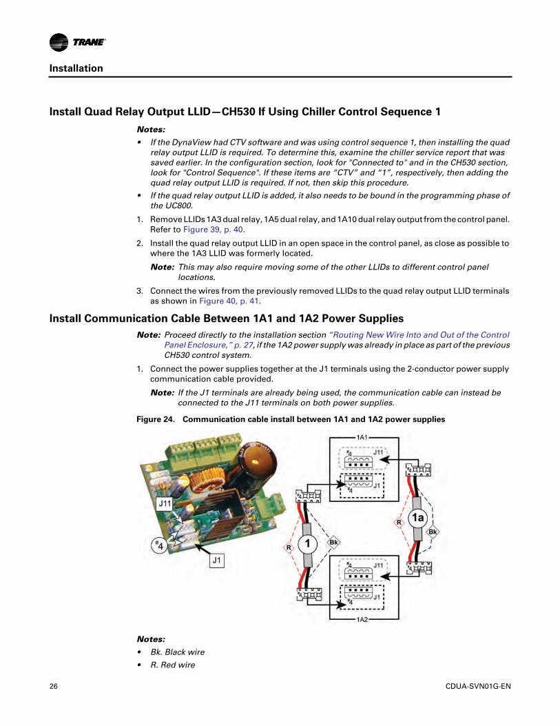
Install Communication Cable Between 1A1 and 1A2 Power Supplies
Note: Proceed directly to the installation section “Routing New Wire Into and Out of the ControlPanel Enclosure,” p. 27, if the 1A2 power supply was already in place as part of the previousCH530 control system.
1. Connect the power supplies together at the J1 terminals using the 2-conductor power supplycommunication cable provided.
Note: If the J1 terminals are already being used, the communication cable can instead beconnected to the J11 terminals on both power supplies.
Notes:
• Bk. Black wire
• R. Red wire
Figure 24. Communication cable install between 1A1 and 1A2 power supplies
26 CDUA-SVN01G-EN

Installation
Connect Input Power Wiring to 1A2 Power Supply
Notes:
• Proceed directly to the next stage of the installation process if the 1A2 power supply wasalready in place as part of the previous CH530 control system.
• The full schematic wiring diagram can be found in Figure 41, p. 42 of this manual.
1. Attach a Red 16 AWG wire between J2-1 on the 1A2 power supply and 1T1-X2.
2. Attach a Red 16 AWG wire between J2-2 on the 1A2 power supply and 1T1-X1.
3. Attach a Green 16 AWG wire between J2-3 on the 1A2 power supply and any available groundterminal on the 1X1 terminal block.
Notes:
• Gn. Green wire
• R. Red wire
Routing New Wire Into and Out of the Control Panel Enclosure
• Make use of the spare factory knock-outs that are available on the right-hand end of the controlenclosure, for routing all required wiring runs from the Tracer UC800 controller and the 1A2power supply out to the connection points on the display.
• Plastic grommets are provided in the upgrade kit to line the edges of the knock-outs used.
Note: If a specific retrofit situation has made it necessary to mount the display arm on the left-handpanel bracket or the left-hand end of the enclosure, please note that all of the cablesprovided within the display upgrade kit are long enough to allow utilizing the spare factoryknock-outs that already exist on the back of the control panel enclosure.
WARNING
Ground Wire!
All field-installed wiring must be completed by qualified personnel. All field-installed wiringmust comply with NEC and applicable local codes. Failure to follow this instruction couldresult in death or serious injuries.
Figure 25. Input power wiring to the 1A2 power supply
2
3
1
CDUA-SVN01G-EN 27

Installation
Figure 26. Example of pre-existing spare factory knock-outs on control enclosure
28 CDUA-SVN01G-EN

Installation
Wiring Connections to the Display and the Tracer UC800 Controller
Note: Also refer to the full schematic wiring diagram located in Figure 41, p. 42 of this manual.
1. Ethernet communication cable installation:
a. Attach the head of the Ethernet cable to the display.
b. Route the cable through the wire channel on the display arm.
Important: Leave enough slack in the cable to allow the display arm to be moved through its fullrange of motion without placing a strain on the cable or the terminal connections.
c. Take the cable around the back side of the control enclosure and feed it into the cabinetthrough one of the spare factory provided cable knock-outs.
d. Insert the cable end into the Ethernet port on the Tracer UC800 controller.
2. Install the Female connector to stripped end wire harness extension to the 1A2 power supply(the first half of the power supply run to the display):
a. Route the stripped end of this wire harness through the same cabinet knock-out used for theEthernet cable if possible, otherwise use one of the other spare factory made knock-outsprovided.
b. Connect each of the four individual wires to the correct terminal of the removable J4 terminalplug on the 1A2 power supply.
Figure 27. Ethernet cable installation between the display and the Tracer UC800 controller
CDUA-SVN01G-EN 29

Installation
Notes:
• R. Red wire for 24 Volts direct current
• Bk. Black wire for ground
• Bl. Blue wire for IPC+ connection (not actually used by Tracer AdaptiView but connect anyway)
• Gr. Gray wire for IPC- connection (not actually used by Tracer AdaptiView but connect anyway)
3. Complete the power supply connection to the display using the Male to Female wire harnessextension:
a. Connect the Male end of this cable to the Female connector on the cable installed in Step 2.
b. Route the cable harness through the wire channel on the display arm and connect theFemale end to the Male receptacle on the display unit.
Important: Leave enough slack in the cable to allow for the display arm to be moved throughits full range of motion without placing a strain on the cable or the terminalconnections.
Figure 28. Female to bare end wire harness install from outside cabinet in to 1A2
30 CDUA-SVN01G-EN

Installation
4. Connect the Tracer UC800 controller to the 1A2 power supply using the length of 4-conductorcable provided:
a. Connect each of the 4 individual wires on one end of the cable to the correct terminal of theremovable J5 terminal plug on the 1A2 power supply.
b. Route the other end of the cable inside of the cabinet over to the Tracer UC800 controller andconnect each of the 4 individual wires to the correct terminals on the controller.
Figure 29. Completion of power supply connection to the display
CDUA-SVN01G-EN 31

Installation
Notes:
• R. Red wire for 24 Volts direct current
• Bk. Black wire for ground
• Bl. Blue wire for IPC+ connection
• Gr. Gray wire for IPC-connection
5. Secure all cables in the wire channel on the display arm with cable ties:
a. There are 2 factory-drilled holes provided in the wire channel to aid in neatly securing thecables with cable ties as is recommended.
b. Important: Wire protection may be required at both ends of the wire channel and at thedoor hinge opening on the control panel enclosure due to the potential presence of sharpedges that could abrade or cut the wires.
Figure 30. Wire connections from 1A2 power supply J5 to Tracer UC800 controller
32 CDUA-SVN01G-EN

Installation
6. Use cable ties to clean up and secure wiring runs inside of the control panel enclosure.
Before Restoring System Power
1. To prevent an unexpected chiller start up when system power is first restored, implement theappropriate preventative measure from the list below:
a. If the chiller is equipped with an external Auto Stop button, disconnect the wire fromterminal J2-1 on the 1A13 LLID.
b. If the chiller is not equipped with an external Auto Stop button, disconnect the factoryinstalled jumper wire end from terminal J2-1 on the 1A13 LLID.
Figure 31. Neatly secure and protect cables in display arm wire channel
CAUTION
Unsafe Practices!
Do not restore system power without first having completed all of the tasks specified withinthis installation section. Failure to follow these instructions could result in minor or moderateinjury.
NOTICE
Unexpected Chiller Start Up!
Before the Tracer AdaptiView can be programmed, system power must be restored. To preventequipment damage from an unexpected chiller start up that cannot be stopped through the asyet unconfigured/unprogrammed display unit, first disable the control circuit that can allow anautomatic unit start before reenergizing the system.
CDUA-SVN01G-EN 33

Installation
Note: EAS. = External Auto Stop circuit
2. Perform a final inspection of the control panel enclosure before restoring system power.
a. Remove any tools and use a shop vacuum to remove any dirt or debris that may have beencreated during the installation process.
b. Confirm that all upgrade kit wiring has been correctly routed and that all terminalconnections have been properly made.
c. Inspect the rest of the electrical wiring and components within the enclosure to ensure thatno wiring connections were accidentally loosened or disconnected during the kit installationprocess.
d. Close and latch the control panel door.
Restoring System Power
1. Remove all lockout/tagout devices used at the power supply panels for the chiller equipment.
2. Warn all personnel in the area that system power is about to be restored.
3. Energize the system according to all applicable standard safety procedures.
Programming the Tracer AdaptiView
Note: For more information regarding the use of the Tracer TU service tool, installation, operationand programming of the Tracer UC800 controller, operation of the control system, and aguide to the diagnostics and troubleshooting of the control system, please refer to thefollowing manuals (or their most recent versions):
• TTU-SVN01J-EN, Getting Started Guide: Tracer TU Service Tool
• CTV-SVP02C-EN, Programming Guide: Tracer TU Service Tool for Water-Cooled CenTraVacChillers with Tracer AdaptiView Control
Figure 32. Preventing unexpected chiller start up before restoring system power
WARNING
Unsafe Practices!
Do not restore system power without first having completed the tasks specified in theprevious installation section, “Before restoring system power.” Failure to follow theseinstructions could result in minor or moderate injury or could result in equipment or propertydamage.
34 CDUA-SVN01G-EN

Installation
• CVHE-SVX02B-EN, Installation, Operation, and Maintenance Guide: CVHE, CVHF, CVHG Water-Cooled CenTraVac Chillers with Tracer AdaptiView Control
• CVRE-SVP01A-EN, Programming Guide: Tracer AdaptiView Panel Upgrade
• CTV-SVU01D-EN, Operations Guide: Tracer AdaptiView Display for Water-Cooled CenTraVacChillers
• CTV-SVD03A-EN, Diagnostics Manual: Diagnostic Descriptions, Troubleshooting Tables, andControl Component Overview for Water-Cooled CenTraVac Chillers with Tracer AdaptiViewControl
Note: If the chiller is equipped with a LonTalk® Comm5 board, the new software will require it tobe programmed to the LCI-C (COMM5) extension. This will also require the Rover servicetool and the manual ACC-SVN100A-EN (Hardware and Software Installation Guide: LonTalkCommunication Interface for Trane Chillers with Tracer AdaptiView Control).
1. Obtain a working AC power adaptor with which to power the technician’s laptop.
2. Connect the computer with the Tracer TU service tool software to the service port of the TracerUC800 controller with a USB type A/B cable.
3. Open Tracer TU.
Note: The UC800 ships with no software loaded. When first connecting to Tracer TU, a pop-up will direct you toward the software download page.
4. Choose the appropriate product type that matches the software type that was in the DynaView,and the latest version listed. Click the Upgrade Device button when complete.
NOTICE
Separate AC Power Required for Computers when Working on TracerAdaptiView!
When doing any service work on a Tracer AdaptiView control system that requires connectinga laptop computer running Tracer TU service tool software to the UC800 controller, the laptopmust be operated from a SEPARATE AC power source AT ALL TIMES. NEVER run the laptop oninternal battery power alone while connected to a UC800 controller! Should the computer’sinternal battery die or malfunction while connected to a UC800, fatal corruptions could occurto the electronic files within the controller that will render it completely inoperable and unableto accept new programming, requiring it to be replaced with new UC800. Damaging a UC800controller in this manner is not covered under any warranty!
Figure 33. Application software download
CDUA-SVN01G-EN 35

Installation
5. Follow the instructions below while also referring to Figure 34, p. 36 and Figure 35, p. 36:
a. Click the “Equipment Utility” tab (the wrench symbol on the right-hand side of the screen).
b. Click the “4. Configuration” tab.
c. Click the “Open File” button on the bottom of the “4. Configuration” screen.
d. Browse to the location of the Chiller Service Report file saved from the DynaView display atthe start of upgrade kit installation, highlight it, and then click “Open.”
6. After completing all of Step 5, Tracer TU’s “4. Configuration” tab screen should now bepopulated with the values from the Chiller Service Report.
7. Verify the configuration and then click “Save.”
a. Clicking “Save” sends the values from this Chiller Service Report directly to the TracerUC800 controller.
Figure 34. Navigating within the equipment utility configuration tab in Tracer TU
Figure 35. Location of the equipment utility tab in Tracer TU
5a
5c
5b
7a
36 CDUA-SVN01G-EN

Installation
8. After the configuration is saved, Tracer TU will automatically proceed to LLID Binding view.Check to see if any of the listed devices need to be bound, indicated by a red box. If the quadrelay LLID was installed, it will have to be bound now.
9. Once all LLIDs are bound, verify that the settings in the Service Setpoints, Field Startup, andPurge tabs are correct.
10. In Tracer TU, save a copy of the “Chiller Service Report”.
a. From the “Reports” drop-down menu, select and open “Chiller Service Report” (see thebelow figure).
b. Save a copy of “Chiller Service Report” as a Microsoft® Word document in the folder thatwas created in “My Documents”.
11. Save the current chiller configuration in the existing firmware version in the UC800.
Note: This step produces backup configuration data in the case the UC800 configurationbecomes corrupt.
a. Access the “Equipment Utilities” section of Tracer TU by clicking the wrench symbol onthe right-hand side of the screen.
b. Click the “Configuration” tab (see the below figure).
c. At the bottom of the screen, click the “Save File” button (not shown in below figure).
Figure 36. Binding view of quad relay LLID
Figure 37. Chiller service report (Tracer TU)
CDUA-SVN01G-EN 37

Installation
d. In the “Browse for Folder” window, click “Make New Folder”.
A folder will be created with the name “New Folder”; this can be renamed later. The pathto the folder will be:
C:\Programs\Trane\Tracer TU\Program\Plugins\UCDataBaseDAL\New Folder
e. Select the “New Folder” file.
f. Click the “OK” button.
The chiller configuration file will now be saved in the “New Folder”.
Startup
1. When the programming is completed and saved, shut down power to the control panel anddisconnect the USB cable from the door of the control panel.
2. Reconnect the wire removed from the J2-1 on the 1A13 LLID.
3. Restore power to the control panel.
The chiller is now ready for normal startup and checkout procedures.
If you have further questions, contact Trane Global Parts Technical Services. To contact them, senda message to [email protected].
Figure 38. Chiller configuration (Tracer TU, simplex chiller shown)
11a
11b
38 CDUA-SVN01G-EN

Installation
Full Page Schematic Wiring Diagrams
Notes:
• All of the schematic wiring diagrams displayed within this section of the installation manual areproprietary. These diagrams shall not be copied or their contents disclosed to outside partieswithout the written consent of Trane.
• The following hazard notifications apply to all of the electrical circuits depicted in each of theschematic wiring diagrams included within this section of the installation manual.
WARNING
Hazardous Voltage! High Voltage Storage Capacitors!
Disconnect all electric power, including remote disconnects before servicing. Follow properlockout/tagout procedures to ensure the power cannot be inadvertently energized. For variablefrequency drives or other energy storing components provided by Trane or others, refer to theappropriate manufacturer’s literature for allowable waiting periods for discharge of capacitors.Verify with an appropriate voltmeter that all capacitors have discharged. Failure to disconnectpower and discharge capacitors before servicing could result in death or serious injury.
For additional information regarding the safe discharge of capacitors, see PROD-SVB06A-EN.
WARNING
Ground Wire!
All field-installed wiring must be completed by qualified personnel. All field-installed wiringmust comply with NEC and applicable local codes. Failure to follow this instruction couldresult in death or serious injuries.
NOTICE
Use Copper Conductors Only!
Unit terminals are not designed to accept other types of conductors. Failure to use copperconductors could result in equipment damage.
CDUA-SVN01G-EN 39

Installation
Notes:
a. All notes and hazard notifications listed in “Full Page Schematic Wiring Diagrams,” p. 39 of thismanual apply to this drawing.
b. IPC BUS
c. Dual relay LLID to remove (its functions will be replaced by the Quad Relay)
d. Oil tank junction box
e. Customer provided
f. Oil tank heater
g. Evaporator water pump (optional)
h. Condenser water pump (required)
i. Ice building indicator (optional)
Figure 39. Existing LLIDs to remove before installing quad relay LLID
40 CDUA-SVN01G-EN

Installation
Notes:
a. All notes and hazard notifications listed in “Full Page Schematic Wiring Diagrams,” p. 39 of thismanual apply to this drawing.
b. IPC BUS
c. Quad relay output
d. Oil tank junction box
e. Customer provided
f. Oil tank heater
g. Evaporator water pump (optional)
h. Condenser water pump (required)
i. Ice building indicator (optional)
j. WB7 connects to 1A4-J11 (Line 101) when 1A4 is present
R. Red wire (proper orientation of connector for plugging into this terminal block is with theconnector end terminal holding the red wire being lined up with block terminal number 1)
S. Solid state oil heater relay
Figure 40. Quad relay LLID installation
CDUA-SVN01G-EN 41

Installation
Notes:
a. All notes and hazard notifications listed in “Full Page Schematic Wiring Diagrams,” p. 39 of thismanual apply to this drawing.
b. Power supply
c. Tracer UC800 controller
d. USB Type B service port cable from Tracer UC800 controller receptacle to control panel door
e. Ethernet cable connection between Tracer UC800 Ethernet port and Tracer AdaptiView display
f. 2-conductor communication cable (Note: could also be connected between J1 terminals)
g. 4-conductor cable
h. Female to bare end wire harness to Male to Female wire harness extension to display
i. Field provided 16 AWG control wire
Bl. Blue wire
Bk. Black wire
Gn.Green wire
Gr. Gray wire
Figure 41. Full schematic wiring diagram for a standard Tracer AdaptiView upgrade kit
42 CDUA-SVN01G-EN


©2020 Trane
Trane has a policy of continuous product and product data improvement and reserves the right to change design and specifications withoutnotice. We are committed to using environmentally conscious print practices.
Trane - by Trane Technologies (NYSE: TT), a global climate innovator - creates comfortable, energyefficient indoor environments for commercial and residential applications. For more information,please visit trane.com or tranetechnologies.com.
CDUA-SVN01G-EN 14 May 2020Supersedes CDUA-SVN01F-EN (Jul 2019)


