Embed Size (px)
Citation preview
316,318 and 420
Lawn and GardenTractors
For complete service information also see:
Onan Engines (16,18,20,24 HP) . . . . . . . . . CTM2
John Deere Horicon WorksTM1590 (17MAY95)
LITHO IN U.S.A.ENGLISH
SECTION 10—GENERAL INFORMATIONGroup 05—SafetyGroup 10—General SpecificationsGroup 15—Repair SpecificationsGroup 20—Test and Adjustment SpecificationsGroup 25—Fuels and LubricantsGroup 30—Serial Number Locations
SECTION 20—ENGINE REPAIRGroup 05—Engine
SECTION 40—ELECTRICAL REPAIRGroup 05—Front PTO Clutch
SECTION 50—POWER TRAIN REPAIRGroup 05—TransmissionGroup 10—Transmission Control LinkageGroup 15—DifferentialGroup 20—Rear AxlesGroup 25—Drive Shaft
SECTION 60—STEERING AND BRAKE REPAIRGroup 05—Steering—316Group 06—Steering—318 and 420Group 10—Brakes
SECTION 70—HYDRAULIC REPAIRGroup 05—Hydraulic Control Valve
SECTION 80—MISCELLANEOUS REPAIRGroup 05—Front AxleGroup 10—Mower Spindle and Jack Sheave
RepairGroup 15—Mower Gear Case Repair
SECTION 220—ENGINE, FUEL AND AIR SYSTEMCHECKOUT AND DIAGNOSIS
Group 05—Engine, Fuel and Air SystemCheckout
Group 10—Diagnosis, Tests and Adjustments
SECTION 240—ELECTRICAL CHECKOUT,OPERATION AND DIAGNOSIS
Group 05—Electrical System CheckoutGroup 10—Electrical SchematicsGroup 15—Component Location and OperationGroup 20—Electrical System DiagnosisGroup 25—Electrical System Component Tests
and Adjustments
SECTION 250—POWER TRAIN CHECKOUT,OPERATION AND DIAGNOSIS
Group 05—Power Train CheckoutGroup 10—Theory of OperationGroup 15—Diagnosis, Tests and Adjustments
SECTION 260—STEERING AND BRAKESCHECKOUT, OPERATION ANDDIAGNOSIS
Group 05—Steering And Brakes SystemCheckout
Group 10—Theory of OperationGroup 15—Diagnosis, Tests and Adjustments
SECTION 270—HYDRAULIC SYSTEMCHECKOUT, OPERATION ANDDIAGNOSIS
Group 05—Hydraulic System CheckoutGroup 10—Hydraulic SchematicsGroup 15—Theory of OperationGroup 20—Diagnosis, Tests and Adjustments
SECTION 299—DEALER FABRICATED TOOLSGroup 00—Dealer Fabricated Tools
Index
COPYRIGHT© 1995DEERE & COMPANY
Moline, IllinoisAll rights reserved
A John Deere ILLUSTRUCTION™ Manual
All information, illustrations and specifications in this manual are based onthe latest information available at the time of publication. The right isreserved to make changes at any time without notice.
TM1590-19-17MAY95
Contents
TM1590 (17MAY95) i 316, 318 & 420 Lawn and Garden Tractors020895
10
20
40
50
60
70
80
220
240
250
Contents
TM1590 (17MAY95) ii 316, 318 & 420 Lawn and Garden Tractors020895
10
20
40
50
60
70
80
220
240
250
Contents
TM1590 (17MAY95) iii 316, 318 & 420 Lawn and Garden Tractors020895
260
270
299
INDX
Contents
TM1590 (17MAY95) iv 316, 318 & 420 Lawn and Garden Tractors020895
260
270
299
INDX

FOREWORD
This manual is written for an experienced technician.Essential tools required in performing certain servicework are identified in this manual and arerecommended for use.
Live with safety: Read the safety messages in theintroduction of this manual and the cautionspresented throughout the text of the manual.
N This is the safety-alert symbol. When you seethis symbol on the machine or in this manual,be alert to the potential for personal injury.
Technical manuals are divided in two parts: repairand diagnostics. Repair sections tell how to repair thecomponents. Diagnostic sections help you identify themajority of routine failures quickly.
Information is organized in groups for the variouscomponents requiring service instruction. At thebeginning of each group are summary listings of allapplicable essential tools, other materials needed todo the job and service parts kits.
Section 10, Group 15—Repair Specifications, consistof all applicable specifications, near tolerances andspecific torque values for various components oneach individual machine.
Section 10, Group 20—Test and AdjustmentSpecifications, consist of all applicable test andadjustment specifications for various systems for eachindividual machine.
Binders, binder labels, and tab sets can be orderedby John Deere dealers direct from the John DeereDistribution Service Center.
This manual is part of a total product supportprogram.
FOS MANUALS—REFERENCE
TECHNICAL MANUALS—MACHINE SERVICE
COMPONENT MANUALS—COMPONENT SERVICE
Fundamentals of Service (FOS) Manuals cover basictheory of operation, fundamentals of troubleshooting,general maintenance, and basic type of failures andtheir causes. FOS Manuals are for training newpersonnel and for reference by experiencedtechnicians.
Technical Manuals are concise guides for specificmachines. Technical manuals are on-the-job guidescontaining only the vital information needed fordiagnosis, analysis, testing, and repair.
Component Technical Manuals are concise serviceguides for specific components. Component technicalmanuals are written as stand-alone manuals coveringmultiple machine applications.
MX,1590,IFC -19-09DEC94
Introduction
TM1590 (17MAY95) 316, 318 & 420 Lawn and Garden Tractors020895
JOHN DEERE DEALERS
IMPORTANT: Please remove this page and routethrough your service department.
This is a complete revision for models 316, 318 and 420found in TM1277 and TM1345. The complete revision ofremaining machines (322, 330, 332 and 430) can befound in TM1591. AFTER recieving both TM1590 andTM1591, please discard old TM1277 dated December1987, TM1345 dated June 1986 and TM1309 dated July1985.
NOTE: There are several “versions” of each modeltractor. All versions were not availble at time oflatest printing. Some versions may not becovered.
MX,1590,DLR -19-20MAR95
Dealer Presentation Sheet
TM1590 (17MAY95) 316, 318 & 420 Lawn and Garden Tractors020895
Dealer Presentation Sheet
TM1590 (17MAY95) 316, 318 & 420 Lawn and Garden Tractors020895
Section 10GENERAL INFORMATION
ContentsPage
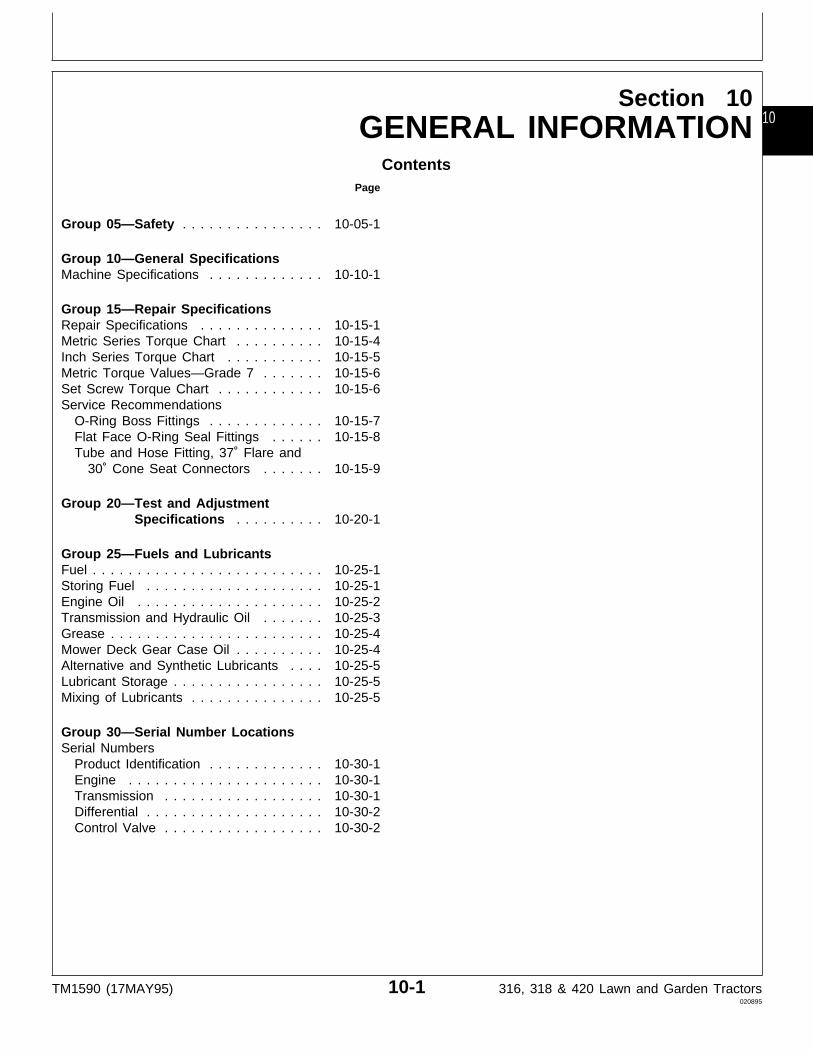
Group 05—Safety . . . . . . . . . . . . . . . . 10-05-1
Group 10—General SpecificationsMachine Specifications . . . . . . . . . . . . . 10-10-1
Group 15—Repair SpecificationsRepair Specifications . . . . . . . . . . . . . . 10-15-1Metric Series Torque Chart . . . . . . . . . . 10-15-4Inch Series Torque Chart . . . . . . . . . . . 10-15-5Metric Torque Values—Grade 7 . . . . . . . 10-15-6Set Screw Torque Chart . . . . . . . . . . . . 10-15-6Service Recommendations
O-Ring Boss Fittings . . . . . . . . . . . . . 10-15-7Flat Face O-Ring Seal Fittings . . . . . . 10-15-8Tube and Hose Fitting, 37˚ Flare and
30˚ Cone Seat Connectors . . . . . . . 10-15-9
Group 20—Test and AdjustmentSpecifications . . . . . . . . . . 10-20-1
Group 25—Fuels and LubricantsFuel . . . . . . . . . . . . . . . . . . . . . . . . . . 10-25-1Storing Fuel . . . . . . . . . . . . . . . . . . . . 10-25-1Engine Oil . . . . . . . . . . . . . . . . . . . . . 10-25-2Transmission and Hydraulic Oil . . . . . . . 10-25-3Grease . . . . . . . . . . . . . . . . . . . . . . . . 10-25-4Mower Deck Gear Case Oil . . . . . . . . . . 10-25-4Alternative and Synthetic Lubricants . . . . 10-25-5Lubricant Storage . . . . . . . . . . . . . . . . . 10-25-5Mixing of Lubricants . . . . . . . . . . . . . . . 10-25-5
Group 30—Serial Number LocationsSerial Numbers
Product Identification . . . . . . . . . . . . . 10-30-1Engine . . . . . . . . . . . . . . . . . . . . . . 10-30-1Transmission . . . . . . . . . . . . . . . . . . 10-30-1Differential . . . . . . . . . . . . . . . . . . . . 10-30-2Control Valve . . . . . . . . . . . . . . . . . . 10-30-2
TM1590 (17MAY95) 10-1 316, 318 & 420 Lawn and Garden Tractors020895
10

Contents
TM1590 (17MAY95) 10-2 316, 318 & 420 Lawn and Garden Tractors020895
10
RECOGNIZE SAFETY INFORMATION
This is the safety-alert symbol. When you see thissymbol on your machine or in this manual, be alert tothe potential for personal injury.
Follow recommended precautions and safe operatingpractices.
T81
389
-UN
-07D
EC
88
UNDERSTAND SIGNAL WORDS
A signal word—DANGER, WARNING, or CAUTION—isused with the safety-alert symbol. DANGER identifies themost serious hazards.
DANGER or WARNING safety signs are located nearspecific hazards. General precautions are listed onCAUTION safety signs. CAUTION also calls attention tosafety messages in this manual.
TS
187
-19
-30S
EP
88
FOLLOW SAFETY INSTRUCTIONS
Carefully read all safety messages in this manual and onyour machine safety signs. Keep safety signs in goodcondition. Replace missing or damaged safety signs. Besure new equipment components and repair parts includethe current safety signs. Replacement safety signs areavailable from your John Deere dealer.
Learn how to operate the machine and how to usecontrols properly. Do not let anyone operate withoutinstruction.
Keep your machine in proper working condition.Unauthorized modifications to the machine may impairthe function and/or safety and affect machine life.
If you do not understand any part of this manual andneed assistance, contact your John Deere dealer.
TS
201
-U
N-2
3AU
G88
DX,ALERT -19-03MAR93
DX,SIGNAL -19-03MAR93
DX,READ -19-03MAR93
Group 05Safety
TM1590 (17MAY95) 10-05-1 316, 318 & 420 Lawn and Garden Tractors020895
10051
HANDLE FLUIDS SAFELY—AVOID FIRES
When you work around fuel, do not smoke or work nearheaters or other fire hazards.
Store flammable fluids away from fire hazards. Do notincinerate or puncture pressurized containers.
Make sure machine is clean of trash, grease, and debris.
Do not store oily rags; they can ignite and burnspontaneously. T
S22
7
-
UN
-23A
UG
88
PREVENT BATTERY EXPLOSIONS
Keep sparks, lighted matches, and open flame awayfrom the top of battery. Battery gas can explode.
Never check battery charge by placing a metal objectacross the posts. Use a volt-meter or hydrometer.
Do not charge a frozen battery; it may explode. Warmbattery to 16˚C (60˚F).
TS
204
-U
N-2
3AU
G88
PREPARE FOR EMERGENCIES
Be prepared if a fire starts.
Keep a first aid kit and fire extinguisher handy.
Keep emergency numbers for doctors, ambulanceservice, hospital, and fire department near yourtelephone.
TS
291
-U
N-2
3AU
G88
DX,FLAME -19-04JUN90
DX,SPARKS -19-03MAR93
DX,FIRE2 -19-03MAR93
Safety
TM1590 (17MAY95) 10-05-2 316, 318 & 420 Lawn and Garden Tractors020895
1005
2
PREVENT ACID BURNS
Sulfuric acid in battery electrolyte is poisonous. It isstrong enough to burn skin, eat holes in clothing, andcause blindness if splashed into eyes.
Avoid the hazard by:1. Filling batteries in a well-ventilated area.2. Wearing eye protection and rubber gloves.3. Avoiding breathing fumes when electrolyte is added.4. Avoiding spilling or dripping electrolyte.5. Use proper jump start procedure.
If you spill acid on yourself:1. Flush your skin with water.2. Apply baking soda or lime to help neutralize the acid.3. Flush your eyes with water for 15—30 minutes. Getmedical attention immediately.
If acid is swallowed:1. Do not induce vomiting.2. Drink large amounts of water or milk, but do notexceed 2 L (2 quarts).3. Get medical attention immediately.
TS
203
-U
N-2
3AU
G88
DX,POISON -19-21APR93
Safety
TM1590 (17MAY95) 10-05-3 316, 318 & 420 Lawn and Garden Tractors020895
10053
HANDLE CHEMICAL PRODUCTS SAFELY
Direct exposure to hazardous chemicals can causeserious injury. Potentially hazardous chemicals used withJohn Deere equipment include such items as lubricants,coolants, paints, and adhesives.
A Material Safety Data Sheet (MSDS) provides specificdetails on chemical products: physical and healthhazards, safety procedures, and emergency responsetechniques.
Check the MSDS before you start any job using ahazardous chemical. That way you will know exactlywhat the risks are and how to do the job safely. Thenfollow procedures and recommended equipment.
(See your John Deere dealer for MSDS’s on chemicalproducts used with John Deere equipment.)
TS
1132
-U
N-2
6NO
V90
AVOID HIGH-PRESSURE FLUIDS
Escaping fluid under pressure can penetrate the skincausing serious injury.
Avoid the hazard by relieving pressure beforedisconnecting hydraulic or other lines. Tighten allconnections before applying pressure.
Search for leaks with a piece of cardboard. Protecthands and body from high pressure fluids.
If an accident occurs, see a doctor immediately. Anyfluid injected into the skin must be surgically removedwithin a few hours or gangrene may result. Doctorsunfamiliar with this type of injury should reference aknowledgeable medical source. Such information isavailable from Deere & Company Medical Department inMoline, Illinois, U.S.A.
X98
11
-UN
-23A
UG
88
DX,MSDS,NA -19-03MAR93
DX,FLUID -19-03MAR93
Safety
TM1590 (17MAY95) 10-05-4 316, 318 & 420 Lawn and Garden Tractors020895
1005
4
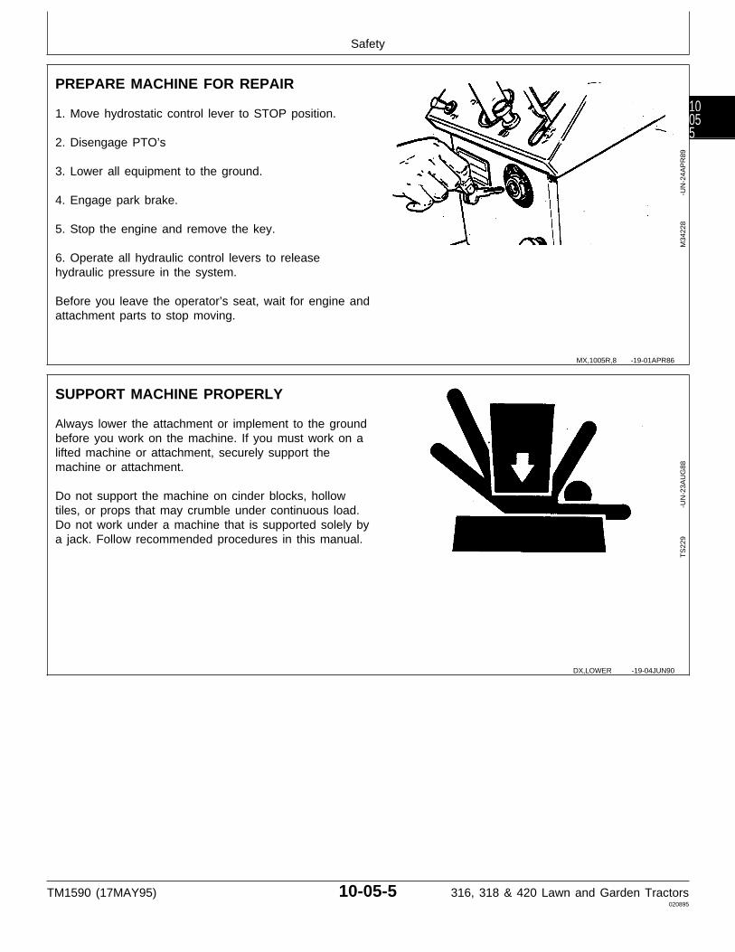
PREPARE MACHINE FOR REPAIR
1. Move hydrostatic control lever to STOP position.
2. Disengage PTO’s
3. Lower all equipment to the ground.
4. Engage park brake.
5. Stop the engine and remove the key.
6. Operate all hydraulic control levers to releasehydraulic pressure in the system.
Before you leave the operator’s seat, wait for engine andattachment parts to stop moving.
M34
228
-UN
-24A
PR
89
SUPPORT MACHINE PROPERLY
Always lower the attachment or implement to the groundbefore you work on the machine. If you must work on alifted machine or attachment, securely support themachine or attachment.
Do not support the machine on cinder blocks, hollowtiles, or props that may crumble under continuous load.Do not work under a machine that is supported solely bya jack. Follow recommended procedures in this manual.
TS
229
-U
N-2
3AU
G88
MX,1005R,8 -19-01APR86
DX,LOWER -19-04JUN90
Safety
TM1590 (17MAY95) 10-05-5 316, 318 & 420 Lawn and Garden Tractors020895
10055
WEAR PROTECTIVE CLOTHING
Wear close fitting clothing and safety equipmentappropriate to the job.
Prolonged exposure to loud noise can cause impairmentor loss of hearing.
Wear a suitable hearing protective device such asearmuffs or earplugs to protect against objectionable oruncomfortable loud noises.
Operating equipment safely requires the full attention ofthe operator. Do not wear radio or music headphoneswhile operating machine.
TS
206
-U
N-2
3AU
G88
WORK IN CLEAN AREA
Before starting a job:• Clean work area and machine.• Make sure you have all necessary tools to do your job.• Have the right parts on hand.• Read all instructions thoroughly; do not attemptshortcuts.
T66
42E
J
-U
N-1
8OC
T88
SERVICE MACHINES SAFELY
Tie long hair behind your head. Do not wear a necktie,scarf, loose clothing, or necklace when you work nearmachine tools or moving parts. If these items were to getcaught, severe injury could result.
Remove rings and other jewelry to prevent electricalshorts and entanglement in moving parts.
TS
228
-U
N-2
3AU
G88
DX,WEAR -19-10SEP90
DX,CLEAN -19-04JUN90
DX,LOOSE -19-04JUN90
Safety
TM1590 (17MAY95) 10-05-6 316, 318 & 420 Lawn and Garden Tractors020895
1005
6
WORK IN VENTILATED AREA
Engine exhaust fumes can cause sickness or death. If itis necessary to run an engine in an enclosed area,remove the exhaust fumes from the area with anexhaust pipe extension.
If you do not have an exhaust pipe extension, open thedoors and get outside air into the area.
TS
220
-U
N-2
3AU
G88
ILLUMINATE WORK AREA SAFELY
Illuminate your work area adequately but safely. Use aportable safety light for working inside or under themachine. Make sure the bulb is enclosed by a wirecage. The hot filament of an accidentally broken bulbcan ignite spilled fuel or oil.
TS
223
-U
N-2
3AU
G88
REPLACE SAFETY SIGNS
Replace missing or damaged safety signs. See themachine operator’s manual for correct safety signplacement.
TS
201
-U
N-2
3AU
G88
USE PROPER LIFTING EQUIPMENT
Lifting heavy components incorrectly can cause severeinjury or machine damage.
Follow recommended procedure for removal andinstallation of components in the manual.
TS
226
-U
N-2
3AU
G88
DX,AIR -19-04JUN90
DX,LIGHT -19-04JUN90
DX,SIGNS1 -19-04JUN90
DX,LIFT -19-04JUN90
Safety
TM1590 (17MAY95) 10-05-7 316, 318 & 420 Lawn and Garden Tractors020895
10057
REMOVE PAINT BEFORE WELDING ORHEATING
Avoid potentially toxic fumes and dust.
Hazardous fumes can be generated when paint isheated by welding, soldering, or using a torch.
Do all work outside or in a well ventilated area. Disposeof paint and solvent properly.
Remove paint before welding or heating:
• If you sand or grind paint, avoid breathing the dust.Wear an approved respirator.
• If you use solvent or paint stripper, remove stripperwith soap and water before welding. Remove solvent orpaint stripper containers and other flammable materialfrom area. Allow fumes to disperse at least 15 minutesbefore welding or heating.
TS
220
-U
N-2
3AU
G88
AVOID HEATING NEAR PRESSURIZEDFLUID LINES
Flammable spray can be generated by heating nearpressurized fluid lines, resulting in severe burns toyourself and bystanders. Do not heat by welding,soldering, or using a torch near pressurized fluid lines orother flammable materials. Pressurized lines can beaccidentally cut when heat goes beyond the immediateflame area.
TS
953
-U
N-1
5MA
Y90
DX,PAINT -19-03MAR93
DX,TORCH -19-03MAR93
Safety
TM1590 (17MAY95) 10-05-8 316, 318 & 420 Lawn and Garden Tractors020895
1005
8
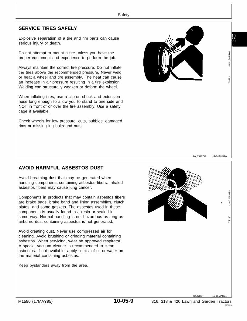
SERVICE TIRES SAFELY
Explosive separation of a tire and rim parts can causeserious injury or death.
Do not attempt to mount a tire unless you have theproper equipment and experience to perform the job.
Always maintain the correct tire pressure. Do not inflatethe tires above the recommended pressure. Never weldor heat a wheel and tire assembly. The heat can causean increase in air pressure resulting in a tire explosion.Welding can structurally weaken or deform the wheel.
When inflating tires, use a clip-on chuck and extensionhose long enough to allow you to stand to one side andNOT in front of or over the tire assembly. Use a safetycage if available.
Check wheels for low pressure, cuts, bubbles, damagedrims or missing lug bolts and nuts.
TS
952
-U
N-1
2AP
R90
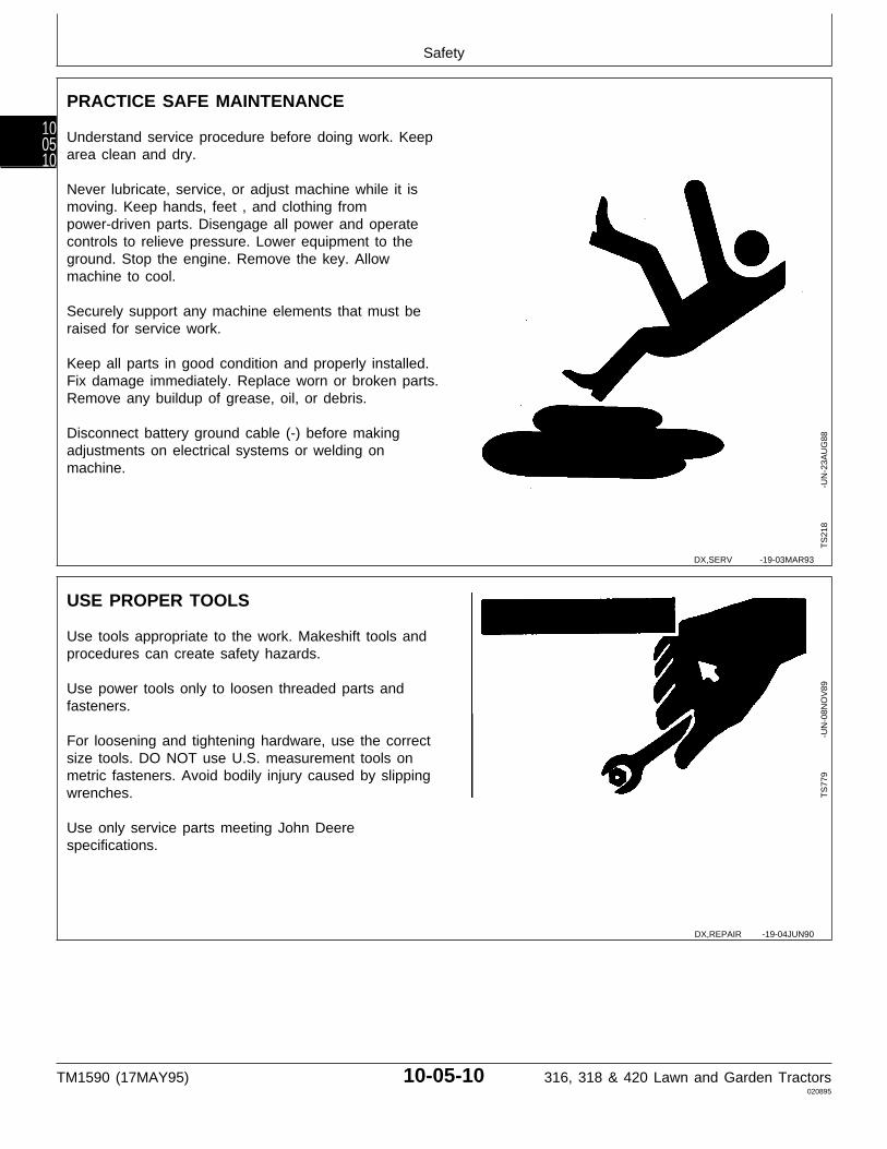
AVOID HARMFUL ASBESTOS DUST
Avoid breathing dust that may be generated whenhandling components containing asbestos fibers. Inhaledasbestos fibers may cause lung cancer.
Components in products that may contain asbestos fibersare brake pads, brake band and lining assemblies, clutchplates, and some gaskets. The asbestos used in thesecomponents is usually found in a resin or sealed insome way. Normal handling is not hazardous as long asairborne dust containing asbestos is not generated.
Avoid creating dust. Never use compressed air forcleaning. Avoid brushing or grinding material containingasbestos. When servicing, wear an approved respirator.A special vacuum cleaner is recommended to cleanasbestos. If not available, apply a mist of oil or water onthe material containing asbestos.
Keep bystanders away from the area.
TS
220
-U
N-2
3AU
G88
DX,TIRECP -19-24AUG90
DX,DUST -19-15MAR91
Safety
TM1590 (17MAY95) 10-05-9 316, 318 & 420 Lawn and Garden Tractors020895
10059
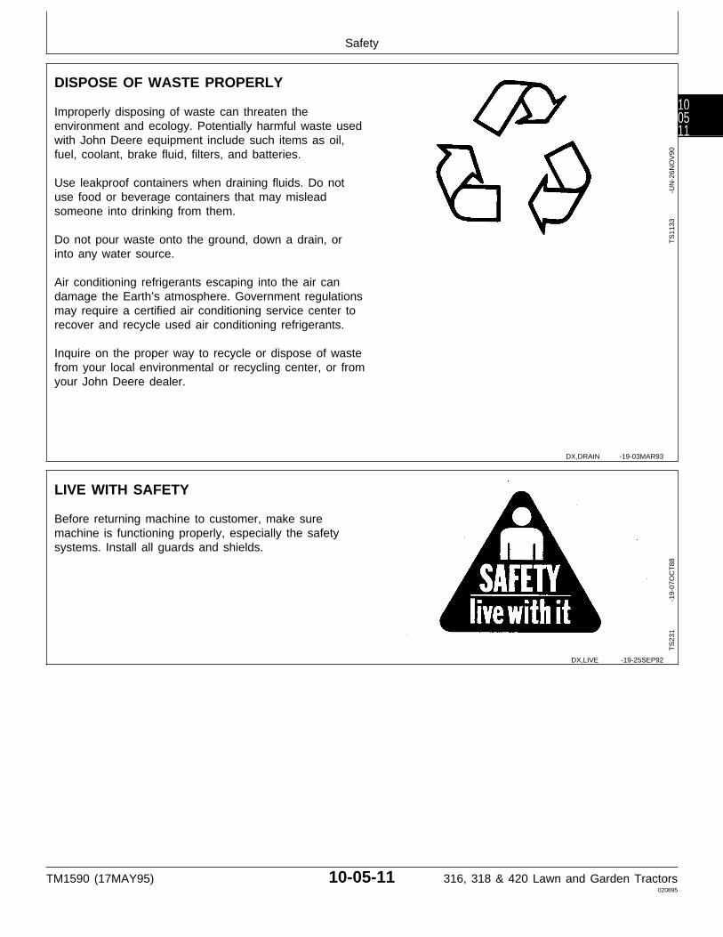
PRACTICE SAFE MAINTENANCE
Understand service procedure before doing work. Keeparea clean and dry.
Never lubricate, service, or adjust machine while it ismoving. Keep hands, feet , and clothing frompower-driven parts. Disengage all power and operatecontrols to relieve pressure. Lower equipment to theground. Stop the engine. Remove the key. Allowmachine to cool.
Securely support any machine elements that must beraised for service work.
Keep all parts in good condition and properly installed.Fix damage immediately. Replace worn or broken parts.Remove any buildup of grease, oil, or debris.
Disconnect battery ground cable (-) before makingadjustments on electrical systems or welding onmachine.
TS
218
-U
N-2
3AU
G88
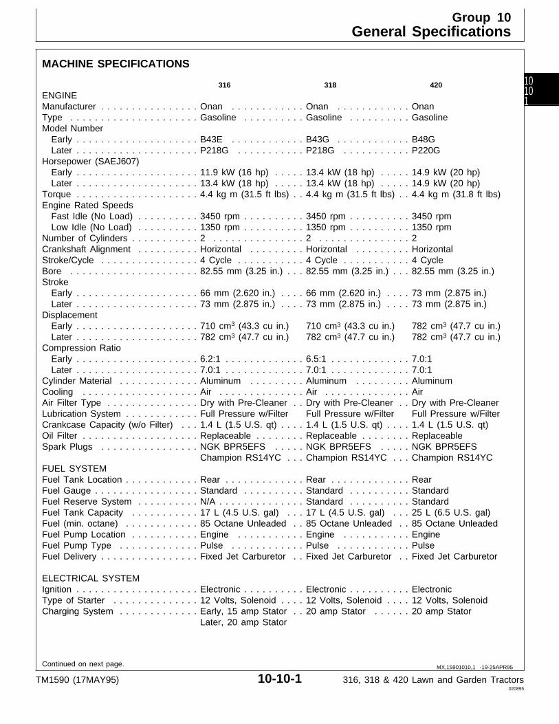
USE PROPER TOOLS
Use tools appropriate to the work. Makeshift tools andprocedures can create safety hazards.
Use power tools only to loosen threaded parts andfasteners.
For loosening and tightening hardware, use the correctsize tools. DO NOT use U.S. measurement tools onmetric fasteners. Avoid bodily injury caused by slippingwrenches.
Use only service parts meeting John Deerespecifications.
TS
779
-U
N-0
8NO
V89
DX,SERV -19-03MAR93
DX,REPAIR -19-04JUN90
Safety
TM1590 (17MAY95) 10-05-10 316, 318 & 420 Lawn and Garden Tractors020895
100510
DISPOSE OF WASTE PROPERLY
Improperly disposing of waste can threaten theenvironment and ecology. Potentially harmful waste usedwith John Deere equipment include such items as oil,fuel, coolant, brake fluid, filters, and batteries.
Use leakproof containers when draining fluids. Do notuse food or beverage containers that may misleadsomeone into drinking from them.
Do not pour waste onto the ground, down a drain, orinto any water source.
Air conditioning refrigerants escaping into the air candamage the Earth’s atmosphere. Government regulationsmay require a certified air conditioning service center torecover and recycle used air conditioning refrigerants.
Inquire on the proper way to recycle or dispose of wastefrom your local environmental or recycling center, or fromyour John Deere dealer.
TS
1133
-U
N-2
6NO
V90
LIVE WITH SAFETY
Before returning machine to customer, make suremachine is functioning properly, especially the safetysystems. Install all guards and shields.
TS
231
-19
-07O
CT
88
DX,DRAIN -19-03MAR93
DX,LIVE -19-25SEP92
Safety
TM1590 (17MAY95) 10-05-11 316, 318 & 420 Lawn and Garden Tractors020895
100511

Safety
TM1590 (17MAY95) 10-05-12 316, 318 & 420 Lawn and Garden Tractors020895
100512
MACHINE SPECIFICATIONS
316 318 420
ENGINEManufacturer . . . . . . . . . . . . . . . . Onan . . . . . . . . . . . . Onan . . . . . . . . . . . . OnanType . . . . . . . . . . . . . . . . . . . . . Gasoline . . . . . . . . . . Gasoline . . . . . . . . . . GasolineModel Number Early . . . . . . . . . . . . . . . . . . . . B43E . . . . . . . . . . . . B43G . . . . . . . . . . . . B48G Later . . . . . . . . . . . . . . . . . . . . P218G . . . . . . . . . . . P218G . . . . . . . . . . . P220GHorsepower (SAEJ607) Early . . . . . . . . . . . . . . . . . . . . 11.9 kW (16 hp) . . . . . 13.4 kW (18 hp) . . . . . 14.9 kW (20 hp) Later . . . . . . . . . . . . . . . . . . . . 13.4 kW (18 hp) . . . . . 13.4 kW (18 hp) . . . . . 14.9 kW (20 hp)Torque . . . . . . . . . . . . . . . . . . . . 4.4 kg m (31.5 ft lbs) . . 4.4 kg m (31.5 ft lbs) . . 4.4 kg m (31.8 ft lbs)Engine Rated Speeds Fast Idle (No Load) . . . . . . . . . . 3450 rpm . . . . . . . . . . 3450 rpm . . . . . . . . . . 3450 rpm Low Idle (No Load) . . . . . . . . . . 1350 rpm . . . . . . . . . . 1350 rpm . . . . . . . . . . 1350 rpmNumber of Cylinders . . . . . . . . . . . 2 . . . . . . . . . . . . . . . 2 . . . . . . . . . . . . . . . 2Crankshaft Alignment . . . . . . . . . . Horizontal . . . . . . . . . Horizontal . . . . . . . . . HorizontalStroke/Cycle . . . . . . . . . . . . . . . . 4 Cycle . . . . . . . . . . . 4 Cycle . . . . . . . . . . . 4 CycleBore . . . . . . . . . . . . . . . . . . . . . 82.55 mm (3.25 in.) . . . 82.55 mm (3.25 in.) . . . 82.55 mm (3.25 in.)Stroke Early . . . . . . . . . . . . . . . . . . . . 66 mm (2.620 in.) . . . . 66 mm (2.620 in.) . . . . 73 mm (2.875 in.) Later . . . . . . . . . . . . . . . . . . . . 73 mm (2.875 in.) . . . . 73 mm (2.875 in.) . . . . 73 mm (2.875 in.)Displacement Early . . . . . . . . . . . . . . . . . . . . 710 cm3 (43.3 cu in.) 710 cm3 (43.3 cu in.) 782 cm3 (47.7 cu in.) Later . . . . . . . . . . . . . . . . . . . . 782 cm3 (47.7 cu in.) 782 cm3 (47.7 cu in.) 782 cm3 (47.7 cu in.)Compression Ratio Early . . . . . . . . . . . . . . . . . . . . 6.2:1 . . . . . . . . . . . . . 6.5:1 . . . . . . . . . . . . . 7.0:1 Later . . . . . . . . . . . . . . . . . . . . 7.0:1 . . . . . . . . . . . . . 7.0:1 . . . . . . . . . . . . . 7.0:1Cylinder Material . . . . . . . . . . . . . Aluminum . . . . . . . . . Aluminum . . . . . . . . . AluminumCooling . . . . . . . . . . . . . . . . . . . Air . . . . . . . . . . . . . . Air . . . . . . . . . . . . . . AirAir Filter Type . . . . . . . . . . . . . . . Dry with Pre-Cleaner . . Dry with Pre-Cleaner . . Dry with Pre-CleanerLubrication System . . . . . . . . . . . . Full Pressure w/Filter Full Pressure w/Filter Full Pressure w/FilterCrankcase Capacity (w/o Filter) . . . 1.4 L (1.5 U.S. qt) . . . . 1.4 L (1.5 U.S. qt) . . . . 1.4 L (1.5 U.S. qt)Oil Filter . . . . . . . . . . . . . . . . . . . Replaceable . . . . . . . . Replaceable . . . . . . . . ReplaceableSpark Plugs . . . . . . . . . . . . . . . . NGK BPR5EFS . . . . . NGK BPR5EFS . . . . . NGK BPR5EFS
Champion RS14YC . . . Champion RS14YC . . . Champion RS14YCFUEL SYSTEMFuel Tank Location . . . . . . . . . . . . Rear . . . . . . . . . . . . . Rear . . . . . . . . . . . . . RearFuel Gauge . . . . . . . . . . . . . . . . . Standard . . . . . . . . . . Standard . . . . . . . . . . StandardFuel Reserve System . . . . . . . . . . N/A . . . . . . . . . . . . . . Standard . . . . . . . . . . StandardFuel Tank Capacity . . . . . . . . . . . 17 L (4.5 U.S. gal) . . . 17 L (4.5 U.S. gal) . . . 25 L (6.5 U.S. gal)Fuel (min. octane) . . . . . . . . . . . . 85 Octane Unleaded . . 85 Octane Unleaded . . 85 Octane UnleadedFuel Pump Location . . . . . . . . . . . Engine . . . . . . . . . . . Engine . . . . . . . . . . . EngineFuel Pump Type . . . . . . . . . . . . . Pulse . . . . . . . . . . . . Pulse . . . . . . . . . . . . PulseFuel Delivery . . . . . . . . . . . . . . . . Fixed Jet Carburetor . . Fixed Jet Carburetor . . Fixed Jet Carburetor
ELECTRICAL SYSTEMIgnition . . . . . . . . . . . . . . . . . . . . Electronic . . . . . . . . . . Electronic . . . . . . . . . . ElectronicType of Starter . . . . . . . . . . . . . . 12 Volts, Solenoid . . . . 12 Volts, Solenoid . . . . 12 Volts, SolenoidCharging System . . . . . . . . . . . . . Early, 15 amp Stator . . 20 amp Stator . . . . . . 20 amp Stator
Later, 20 amp Stator
Continued on next page. MX,15901010,1 -19-25APR95
Group 10General Specifications
TM1590 (17MAY95) 10-10-1 316, 318 & 420 Lawn and Garden Tractors020895
10101

316 318 420
ELECTRICAL SYSTEM, continuedBattery Type . . . . . . . . . . . . . . . . BCI Group 22F . . . . . . BCI Group 22F . . . . . . BCI Group 22FBattery Voltage . . . . . . . . . . . . . . . 12V . . . . . . . . . . . . . . 12V . . . . . . . . . . . . . . 12VBattery Reserve Capacity @ 25 amp . . . . . . . . . . . . . . . . . . 102 minutes . . . . . . . . 102 minutes . . . . . . . . 102 minutesBattery Cold Cranking amp @ 0˚F . . 491 amp . . . . . . . . . . 491 amp . . . . . . . . . . 491 ampHeadlights . . . . . . . . . . . . . . . . . . Standard . . . . . . . . . . Standard . . . . . . . . . . StandardRear Reflector/Tail Lights . . . . . . . . Standard . . . . . . . . . . Standard . . . . . . . . . . Standard Dash Indicator Lights . . . . . . . . . Standard . . . . . . . . . . Standard . . . . . . . . . . StandardOperator Presence System . . . . . . . Standard . . . . . . . . . . Standard . . . . . . . . . . StandardDash Instrumentation Hourmeter . . . . . . . . . . . . . . . . Standard . . . . . . . . . . Standard . . . . . . . . . . Standard
POWER TRAINTransmission Type . . . . . . . . . . . . Hydrostatic . . . . . . . . . Hydrostatic . . . . . . . . . Hydrostatic, 2 RangesNumber of Speeds . . . . . . . . . . . . Infinite . . . . . . . . . . . . Infinite . . . . . . . . . . . . InfiniteTravel Speeds Forward . . . . . . . . . . . . . . . . . . 0—12.38 km/h . . . . . . . 0—12.38 km/h . . . . . . . N/A
(0—7.69 mph) . . . . . . . (0—7.69 mph) . . . . . . . N/A Reverse . . . . . . . . . . . . . . . . . . 0—6.19 km/h . . . . . . . 0—6.19 km/h . . . . . . . N/A
(0—3.85 mph) . . . . . . . (0—3.85 mph) . . . . . . . N/A Forward, High . . . . . . . . . . . . . . N/A . . . . . . . . . . . . . . N/A . . . . . . . . . . . . . . 0—15.04 km/h
(0—9.35 mph) Forward, Low . . . . . . . . . . . . . . N/A . . . . . . . . . . . . . . N/A . . . . . . . . . . . . . . 0—9.35 km/h
(0—5.80 mph) Reverse, High . . . . . . . . . . . . . . N/A . . . . . . . . . . . . . . N/A . . . . . . . . . . . . . . 0—7.52 km/h
(0—4.67 mph) Reverse, Low . . . . . . . . . . . . . . N/A . . . . . . . . . . . . . . N/A . . . . . . . . . . . . . . 0—4.66 km/h
(0—2.90 mph)Transmission Capacity w/Filter . . . . 6.1 L (13 U.S. pt) . . . . 7.1 L (15 U.S. pt) . . . . 7.1 L (15 U.S. pt)Transmission Oil Cooler . . . . . . . . . N/A . . . . . . . . . . . . . . Standard . . . . . . . . . . StandardTransmission Oil Filter . . . . . . . . . . Standard . . . . . . . . . . Standard . . . . . . . . . . StandardDifferential Lock . . . . . . . . . . . . . . N/A . . . . . . . . . . . . . . N/A . . . . . . . . . . . . . . Standard
STEERINGType . . . . . . . . . . . . . . . . . . . . . . Manual . . . . . . . . . . . . Power, Hydrostatic . . . . Power, Hydrostatic
BRAKESLocation . . . . . . . . . . . . . . . . . . . Rear Wheels . . . . . . . . Rear Wheels . . . . . . . . Rear WheelsIndividually Controlled . . . . . . . . . . N/A . . . . . . . . . . . . . . Standard . . . . . . . . . . StandardType . . . . . . . . . . . . . . . . . . . . . . Shoe and Drum . . . . . . Shoe and Drum . . . . . . Shoe and DrumReturn-to-Neutral Braking . . . . . . . . Standard . . . . . . . . . . Standard . . . . . . . . . . StandardParking . . . . . . . . . . . . . . . . . . . . Yes . . . . . . . . . . . . . . Yes . . . . . . . . . . . . . . Yes
HYRAULIC SYSTEMType . . . . . . . . . . . . . . . . . . . . . . Single-Function . . . . . . Two-Function Three-Function
(One w/Float) . . . . . . . . (One w/Float)Hydraulic Couplers . . . . . . . . . . . . One Set . . . . . . . . . . . Two Sets . . . . . . . . . . Two Sets
Continued on next page. MX,15901010,2 -19-25APR95
General Specifications/Machine Specifications
TM1590 (17MAY95) 10-10-2 316, 318 & 420 Lawn and Garden Tractors020895
1010
2
316 318 420
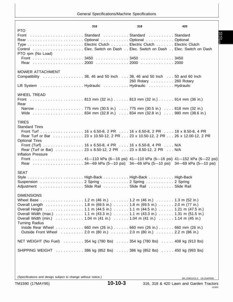
PTOFront . . . . . . . . . . . . . . . . . . . . . Standard . . . . . . . . . . Standard . . . . . . . . . . StandardRear . . . . . . . . . . . . . . . . . . . . . . Optional . . . . . . . . . . . Optional . . . . . . . . . . . OptionalType . . . . . . . . . . . . . . . . . . . . . . Electric Clutch . . . . . . . Electric Clutch . . . . . . . Electric ClutchControl . . . . . . . . . . . . . . . . . . . . Elec. Switch on Dash . . Elec. Switch on Dash . . Elec. Switch on DashPTO rpm (No Load) Front . . . . . . . . . . . . . . . . . . . . 3450 . . . . . . . . . . . . . 3450 . . . . . . . . . . . . . 3450 Rear . . . . . . . . . . . . . . . . . . . . 2000 . . . . . . . . . . . . . 2000 . . . . . . . . . . . . . 2000
MOWER ATTACHMENTCompatibility . . . . . . . . . . . . . . . . 38, 46 and 50 Inch . . . 38, 46 and 50 Inch . . . 50 and 60 Inch
260 Rotary . . . . . . . . . 260 RotaryLift System . . . . . . . . . . . . . . . . . Hydraulic . . . . . . . . . . Hydraulic . . . . . . . . . . Hydraulic
WHEEL TREADFront . . . . . . . . . . . . . . . . . . . . . 813 mm (32 in.) . . . . . . 813 mm (32 in.) . . . . . . 914 mm (36 in.)Rear Narrow . . . . . . . . . . . . . . . . . . . 775 mm (30.5 in.) . . . . 775 mm (30.5 in.) . . . . 818 mm (32 in.) Wide . . . . . . . . . . . . . . . . . . . . 834 mm (32.8 in.) . . . . 834 mm (32.8 in.) . . . . 980 mm (38.6 in.)
TIRESStandard Tires Front Turf . . . . . . . . . . . . . . . . . 16 x 6.50-8, 2 PR . . . . 16 x 6.50-8, 2 PR . . . . 18 x 8.50-8, 4 PR Rear Turf or Bar . . . . . . . . . . . . 23 x 10.50-12, 2 PR . . . 23 x 10.50-12, 2 PR . . . 26 x 12.00-12, 2 PROptional Tires Front (Turf) . . . . . . . . . . . . . . . . 16 x 6.50-8, 4 PR . . . . 16 x 6.50-8, 4 PR . . . . N/A Rear (Turf or Bar) . . . . . . . . . . . 23 x 8.50-12, 2 PR . . . 23 x 8.50-12, 2 PR . . . N/AInflation Pressure Front . . . . . . . . . . . . . . . . . . . . 41—110 kPa (6—16 psi) 41—110 kPa (6—16 psi) 41—152 kPa (6—22 psi) Rear . . . . . . . . . . . . . . . . . . . . 34—69 kPa (5—10 psi) 34—69 kPa (5—10 psi) 34—69 kPa (5—10 psi)
SEATStyle . . . . . . . . . . . . . . . . . . . . . . High-Back . . . . . . . . . . High-Back . . . . . . . . . . High-BackSuspension . . . . . . . . . . . . . . . . . 2 Spring . . . . . . . . . . . 2 Spring . . . . . . . . . . . 2 SpringAdjustment . . . . . . . . . . . . . . . . . Slide Rail . . . . . . . . . . Slide Rail . . . . . . . . . . Slide Rail
DIMENSIONSWheel Base . . . . . . . . . . . . . . . . . 1.2 m (46 in.) . . . . . . . 1.2 m (46 in.) . . . . . . . 1.3 m (52 in.)Overall Length . . . . . . . . . . . . . . . 1.8 m (69.5 in.) . . . . . . 1.8 m (69.5 in.) . . . . . . 2.0 m (77 in.)Overall Height . . . . . . . . . . . . . . . 1.1 m (44.5 in.) . . . . . . 1.1 m (44.5 in.) . . . . . . 1.21 m (47.5 in.)Overall Width (max.) . . . . . . . . . . . 1.1 m (43.3 in.) . . . . . . 1.1 m (43.3 in.) . . . . . . 1.31 m (51.5 in.)Overall Width (min.) . . . . . . . . . . . 1.04 m (41 in.) . . . . . . 1.04 m (41 in.) . . . . . . 1.14 m (45 in.)Turning Radius Inside Rear Wheel . . . . . . . . . . . 660 mm (26 in.) . . . . . . 660 mm (26 in.) . . . . . . 660 mm (26 in.) Outside Front Wheel . . . . . . . . . 2.0 m (80 in.) . . . . . . . 2.0 m (80 in.) . . . . . . . 2.2 m (86 in.)
NET WEIGHT (No Fuel) . . . . . . . . 354 kg (780 lbs) . . . . . 354 kg (780 lbs) . . . . . 408 kg (913 lbs)
SHIPPING WEIGHT . . . . . . . . . . . 386 kg (852 lbs) . . . . . 386 kg (852 lbs) . . . . . 450 kg (993 lbs)
(Specifications and design subject to change without notice.) MX,15901010,3 -19-25APR95
General Specifications/Machine Specifications
TM1590 (17MAY95) 10-10-3 316, 318 & 420 Lawn and Garden Tractors020895
10103

General Specifications/Machine Specifications
TM1590 (17MAY95) 10-10-4 316, 318 & 420 Lawn and Garden Tractors020895
1010
4
REPAIR SPECIFICATIONS
Item Specifications
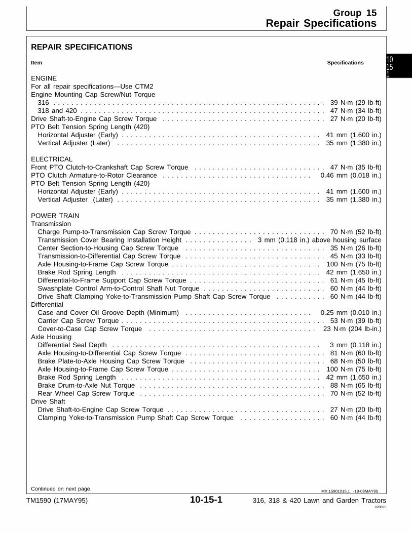
ENGINEFor all repair specifications—Use CTM2Engine Mounting Cap Screw/Nut Torque 316 . . . . . . . . . . . . . . . . . . . . . . . . . . . . . . . . . . . . . . . . . . . . . . . . . . . . . . . . . . . . 39 N·m (29 lb-ft) 318 and 420 . . . . . . . . . . . . . . . . . . . . . . . . . . . . . . . . . . . . . . . . . . . . . . . . . . . . . . 47 N·m (34 lb-ft)Drive Shaft-to-Engine Cap Screw Torque . . . . . . . . . . . . . . . . . . . . . . . . . . . . . . . . . . . . 27 N·m (20 lb-ft)PTO Belt Tension Spring Length (420) Horizontal Adjuster (Early) . . . . . . . . . . . . . . . . . . . . . . . . . . . . . . . . . . . . . . . . . . . . 41 mm (1.600 in.) Vertical Adjuster (Later) . . . . . . . . . . . . . . . . . . . . . . . . . . . . . . . . . . . . . . . . . . . . . 35 mm (1.380 in.)
ELECTRICALFront PTO Clutch-to-Crankshaft Cap Screw Torque . . . . . . . . . . . . . . . . . . . . . . . . . . . . . 47 N·m (35 lb-ft)PTO Clutch Armature-to-Rotor Clearance . . . . . . . . . . . . . . . . . . . . . . . . . . . . . . . . . 0.46 mm (0.018 in.)PTO Belt Tension Spring Length (420) Horizontal Adjuster (Early) . . . . . . . . . . . . . . . . . . . . . . . . . . . . . . . . . . . . . . . . . . . . 41 mm (1.600 in.) Vertical Adjuster (Later) . . . . . . . . . . . . . . . . . . . . . . . . . . . . . . . . . . . . . . . . . . . . . 35 mm (1.380 in.)
POWER TRAINTransmission Charge Pump-to-Transmission Cap Screw Torque . . . . . . . . . . . . . . . . . . . . . . . . . . . . . 70 N·m (52 lb-ft) Transmission Cover Bearing Installation Height . . . . . . . . . . . . . . . 3 mm (0.118 in.) above housing surface Center Section-to-Housing Cap Screw Torque . . . . . . . . . . . . . . . . . . . . . . . . . . . . . . . 35 N·m (26 lb-ft) Transmission-to-Differential Cap Screw Torque . . . . . . . . . . . . . . . . . . . . . . . . . . . . . . . 45 N·m (33 lb-ft) Axle Housing-to-Frame Cap Screw Torque . . . . . . . . . . . . . . . . . . . . . . . . . . . . . . . . . 100 N·m (75 lb-ft) Brake Rod Spring Length . . . . . . . . . . . . . . . . . . . . . . . . . . . . . . . . . . . . . . . . . . . . 42 mm (1.650 in.) Differential-to-Frame Support Cap Screw Torque . . . . . . . . . . . . . . . . . . . . . . . . . . . . . . 61 N·m (45 lb-ft) Swashplate Control Arm-to-Control Shaft Nut Torque . . . . . . . . . . . . . . . . . . . . . . . . . . . 60 N·m (44 lb-ft) Drive Shaft Clamping Yoke-to-Transmission Pump Shaft Cap Screw Torque . . . . . . . . . . . 60 N·m (44 lb-ft)Differential Case and Cover Oil Groove Depth (Minimum) . . . . . . . . . . . . . . . . . . . . . . . . . . . . 0.25 mm (0.010 in.) Carrier Cap Screw Torque . . . . . . . . . . . . . . . . . . . . . . . . . . . . . . . . . . . . . . . . . . . . . 53 N·m (39 lb-ft) Cover-to-Case Cap Screw Torque . . . . . . . . . . . . . . . . . . . . . . . . . . . . . . . . . . . . . 23 N·m (204 lb-in.)Axle Housing Differential Seal Depth . . . . . . . . . . . . . . . . . . . . . . . . . . . . . . . . . . . . . . . . . . . . . . 3 mm (0.118 in.) Axle Housing-to-Differential Cap Screw Torque . . . . . . . . . . . . . . . . . . . . . . . . . . . . . . . 81 N·m (60 lb-ft) Brake Plate-to-Axle Housing Cap Screw Torque . . . . . . . . . . . . . . . . . . . . . . . . . . . . . . 68 N·m (50 lb-ft) Axle Housing-to-Frame Cap Screw Torque . . . . . . . . . . . . . . . . . . . . . . . . . . . . . . . . . 100 N·m (75 lb-ft) Brake Rod Spring Length . . . . . . . . . . . . . . . . . . . . . . . . . . . . . . . . . . . . . . . . . . . . 42 mm (1.650 in.) Brake Drum-to-Axle Nut Torque . . . . . . . . . . . . . . . . . . . . . . . . . . . . . . . . . . . . . . . . . 88 N·m (65 lb-ft) Rear Wheel Cap Screw Torque . . . . . . . . . . . . . . . . . . . . . . . . . . . . . . . . . . . . . . . . . 70 N·m (52 lb-ft)Drive Shaft Drive Shaft-to-Engine Cap Screw Torque . . . . . . . . . . . . . . . . . . . . . . . . . . . . . . . . . . . 27 N·m (20 lb-ft) Clamping Yoke-to-Transmission Pump Shaft Cap Screw Torque . . . . . . . . . . . . . . . . . . . 60 N·m (44 lb-ft)
Continued on next page. MX,15901015,1 -19-08MAY95
Group 15Repair Specifications
TM1590 (17MAY95) 10-15-1 316, 318 & 420 Lawn and Garden Tractors020895
10151
Item Specifications
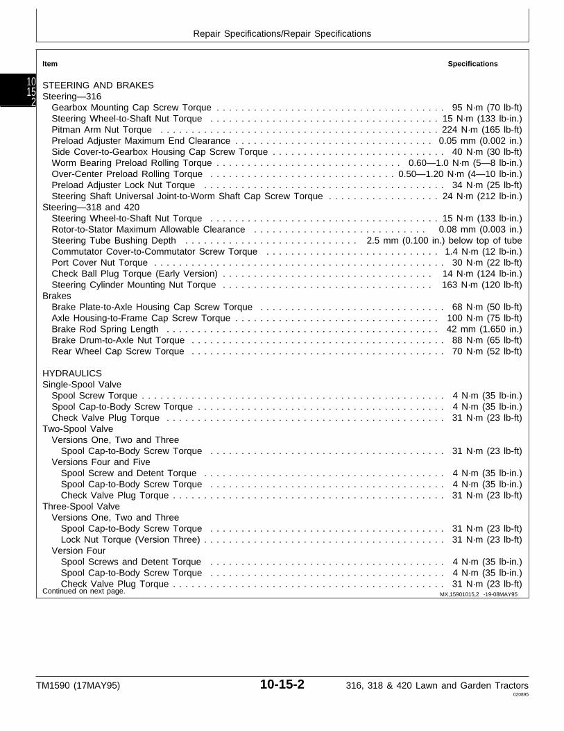
STEERING AND BRAKESSteering—316 Gearbox Mounting Cap Screw Torque . . . . . . . . . . . . . . . . . . . . . . . . . . . . . . . . . . . . . 95 N·m (70 lb-ft) Steering Wheel-to-Shaft Nut Torque . . . . . . . . . . . . . . . . . . . . . . . . . . . . . . . . . . . . . 15 N·m (133 lb-in.) Pitman Arm Nut Torque . . . . . . . . . . . . . . . . . . . . . . . . . . . . . . . . . . . . . . . . . . . . . 224 N·m (165 lb-ft) Preload Adjuster Maximum End Clearance . . . . . . . . . . . . . . . . . . . . . . . . . . . . . . . . 0.05 mm (0.002 in.) Side Cover-to-Gearbox Housing Cap Screw Torque . . . . . . . . . . . . . . . . . . . . . . . . . . . . 40 N·m (30 lb-ft) Worm Bearing Preload Rolling Torque . . . . . . . . . . . . . . . . . . . . . . . . . . . . . . 0.60—1.0 N·m (5—8 lb-in.) Over-Center Preload Rolling Torque . . . . . . . . . . . . . . . . . . . . . . . . . . . . . . 0.50—1.20 N·m (4—10 lb-in.) Preload Adjuster Lock Nut Torque . . . . . . . . . . . . . . . . . . . . . . . . . . . . . . . . . . . . . . . 34 N·m (25 lb-ft) Steering Shaft Universal Joint-to-Worm Shaft Cap Screw Torque . . . . . . . . . . . . . . . . . . 24 N·m (212 lb-in.)Steering—318 and 420 Steering Wheel-to-Shaft Nut Torque . . . . . . . . . . . . . . . . . . . . . . . . . . . . . . . . . . . . . 15 N·m (133 lb-in.) Rotor-to-Stator Maximum Allowable Clearance . . . . . . . . . . . . . . . . . . . . . . . . . . . . 0.08 mm (0.003 in.) Steering Tube Bushing Depth . . . . . . . . . . . . . . . . . . . . . . . . . . . . 2.5 mm (0.100 in.) below top of tube Commutator Cover-to-Commutator Screw Torque . . . . . . . . . . . . . . . . . . . . . . . . . . . . 1.4 N·m (12 lb-in.) Port Cover Nut Torque . . . . . . . . . . . . . . . . . . . . . . . . . . . . . . . . . . . . . . . . . . . . . . . 30 N·m (22 lb-ft) Check Ball Plug Torque (Early Version) . . . . . . . . . . . . . . . . . . . . . . . . . . . . . . . . . . 14 N·m (124 lb-in.) Steering Cylinder Mounting Nut Torque . . . . . . . . . . . . . . . . . . . . . . . . . . . . . . . . . . 163 N·m (120 lb-ft)Brakes Brake Plate-to-Axle Housing Cap Screw Torque . . . . . . . . . . . . . . . . . . . . . . . . . . . . . . 68 N·m (50 lb-ft) Axle Housing-to-Frame Cap Screw Torque . . . . . . . . . . . . . . . . . . . . . . . . . . . . . . . . . 100 N·m (75 lb-ft) Brake Rod Spring Length . . . . . . . . . . . . . . . . . . . . . . . . . . . . . . . . . . . . . . . . . . . . 42 mm (1.650 in.) Brake Drum-to-Axle Nut Torque . . . . . . . . . . . . . . . . . . . . . . . . . . . . . . . . . . . . . . . . . 88 N·m (65 lb-ft) Rear Wheel Cap Screw Torque . . . . . . . . . . . . . . . . . . . . . . . . . . . . . . . . . . . . . . . . . 70 N·m (52 lb-ft)
HYDRAULICSSingle-Spool Valve Spool Screw Torque . . . . . . . . . . . . . . . . . . . . . . . . . . . . . . . . . . . . . . . . . . . . . . . . . 4 N·m (35 lb-in.) Spool Cap-to-Body Screw Torque . . . . . . . . . . . . . . . . . . . . . . . . . . . . . . . . . . . . . . . . 4 N·m (35 lb-in.) Check Valve Plug Torque . . . . . . . . . . . . . . . . . . . . . . . . . . . . . . . . . . . . . . . . . . . . . 31 N·m (23 lb-ft)Two-Spool Valve Versions One, Two and Three Spool Cap-to-Body Screw Torque . . . . . . . . . . . . . . . . . . . . . . . . . . . . . . . . . . . . . . 31 N·m (23 lb-ft) Versions Four and Five Spool Screw and Detent Torque . . . . . . . . . . . . . . . . . . . . . . . . . . . . . . . . . . . . . . . 4 N·m (35 lb-in.) Spool Cap-to-Body Screw Torque . . . . . . . . . . . . . . . . . . . . . . . . . . . . . . . . . . . . . . 4 N·m (35 lb-in.) Check Valve Plug Torque . . . . . . . . . . . . . . . . . . . . . . . . . . . . . . . . . . . . . . . . . . . . 31 N·m (23 lb-ft)Three-Spool Valve Versions One, Two and Three Spool Cap-to-Body Screw Torque . . . . . . . . . . . . . . . . . . . . . . . . . . . . . . . . . . . . . . 31 N·m (23 lb-ft) Lock Nut Torque (Version Three) . . . . . . . . . . . . . . . . . . . . . . . . . . . . . . . . . . . . . . . 31 N·m (23 lb-ft) Version Four Spool Screws and Detent Torque . . . . . . . . . . . . . . . . . . . . . . . . . . . . . . . . . . . . . . 4 N·m (35 lb-in.) Spool Cap-to-Body Screw Torque . . . . . . . . . . . . . . . . . . . . . . . . . . . . . . . . . . . . . . 4 N·m (35 lb-in.) Check Valve Plug Torque . . . . . . . . . . . . . . . . . . . . . . . . . . . . . . . . . . . . . . . . . . . . 31 N·m (23 lb-ft)Continued on next page. MX,15901015,2 -19-08MAY95
Repair Specifications/Repair Specifications
TM1590 (17MAY95) 10-15-2 316, 318 & 420 Lawn and Garden Tractors020895
1015
2

Item Specifications
MISCELLANEOUSFront Axle PTO Belt Tension Spring Length (420) Horizontal Adjuster (Early) . . . . . . . . . . . . . . . . . . . . . . . . . . . . . . . . . . . . . . . . . . 41 mm (1.600 in.) Vertical Adjuster (Later) . . . . . . . . . . . . . . . . . . . . . . . . . . . . . . . . . . . . . . . . . . . 35 mm (1.380 in.) Toe-In . . . . . . . . . . . . . . . . . . . . . . . . . . . . . . . . . . . . . . . . . . . . . . . . . . . . . . . . . 4.8 mm (3/16 in.)Mower Blade Spindles Driven Sheave-to-Spindle Lock Nut Torque . . . . . . . . . . . . . . . . . . . . . . . . . . . . . . . . 140 N·m (103 lb-ft) Blade-to-Spindle Cap Screw Torque . . . . . . . . . . . . . . . . . . . . . . . . . . . . . . . . . . . . . . 73 N·m (54 lb-ft)Mower Blade Jack Sheave Jack Sheave-to-Spindle Lock Nut Torque . . . . . . . . . . . . . . . . . . . . . . . . . . . . . . . . . . 140 N·m (103 lb-ft) Blade-to-Spindle Cap Screw Torque . . . . . . . . . . . . . . . . . . . . . . . . . . . . . . . . . . . . . . 73 N·m (54 lb-ft)50-Inch Mower Gear Case Plug Installation Depth . . . . . . . . . . . . . . . . . . . . . . . . . . . . 1.59 mm (0.062 in.) below gear case surface Retainer Seal Installation Depth . . . . . . . . . . . . . . . . . . . . . . . . 2.54 mm (0.100 in.) below retainer surface Retainer-to-Gear Case Cap Screw Torque . . . . . . . . . . . . . . . . . . . . . . . . . . . . . . . . . . 30 N·m (22 lb-ft) Pillow Block Seal Installation Depth . . . . . . . . . . . . . . . . . . . . . . . 2.54 mm (0.100 in.) below block surface Pillow Block-to-Gear Case Cap Screw Torque . . . . . . . . . . . . . . . . . . . . . . . . . . . . . . . 30 N·m (22 lb-ft)Early 60-Inch Mower Gear Case Cap-to-Gear Case Cap Screw Torque . . . . . . . . . . . . . . . . . . . . . . . . . . . . . . . . . . . . . 30 N·m (22 lb-ft) Output Shaft Endplay . . . . . . . . . . . . . . . . . . . . . . . . . . . . . . . . . . . 0.025—0.076 mm (0.001—0.003 in.) Input Shaft Backlash . . . . . . . . . . . . . . . . . . . . . . . . . . . . . . . . . . . 0.076—0.130 mm (0.003—0.005 in.)Later 60-Inch Mower Gear Case Gear Case Seal Installation Depth . . . . . . . . . . . . . . . . . . . . 2.54 mm (0.100 in.) below gear case surface Retainer-to-Gear Case Cap Screw Torque . . . . . . . . . . . . . . . . . . . . . . . . . . . . . . . . . . 30 N·m (22 lb-ft) Pillow Block Seal Installation Depth . . . . . . . . . . . . . . . . . . . . . . . 2.54 mm (0.100 in.) below block surface Pillow Block-to-Gear Case Cap Screw Torque . . . . . . . . . . . . . . . . . . . . . . . . . . . . . . . 30 N·m (22 lb-ft)260 Rotary Mower Gear Case End Cap-to-Gear Case Cap Screw Torque . . . . . . . . . . . . . . . . . . . . . . . . . . . . . . . . . . 30 N·m (22 lb-ft) Input Shaft Endplay . . . . . . . . . . . . . . . . . . . . . . . . . . . . . . . . . . . . 0.025—0.076 mm (0.001—0.003 in.) Output Shaft Backlash . . . . . . . . . . . . . . . . . . . . . . . . . . . . . . . . . . 0.076—0.130 mm (0.003—0.005 in.) Housing-to-Gear Case Cap Screw Torque . . . . . . . . . . . . . . . . . . . . . . . . . . . . . . . . . . 30 N·m (22 lb-ft)
MX,15901015,6 -19-20MAR95
Repair Specifications/Repair Specifications
TM1590 (17MAY95) 10-15-3 316, 318 & 420 Lawn and Garden Tractors020895
10153
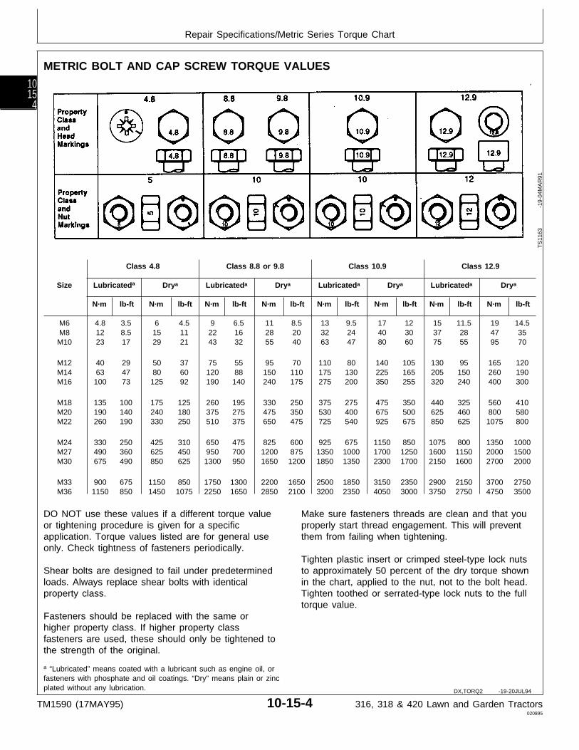
METRIC BOLT AND CAP SCREW TORQUE VALUES
Class 4.8 Class 8.8 or 9.8 Class 10.9 Class 12.9
Size Lubricateda Drya Lubricateda Drya Lubricateda Drya Lubricateda Drya
N·m lb-ft N·m lb-ft N·m lb-ft N·m lb-ft N·m lb-ft N·m lb-ft N·m lb-ft N·m lb-ft
M6 4.8 3.5 6 4.5 9 6.5 11 8.5 13 9.5 17 12 15 11.5 19 14.5M8 12 8.5 15 11 22 16 28 20 32 24 40 30 37 28 47 35M10 23 17 29 21 43 32 55 40 63 47 80 60 75 55 95 70
M12 40 29 50 37 75 55 95 70 110 80 140 105 130 95 165 120M14 63 47 80 60 120 88 150 110 175 130 225 165 205 150 260 190M16 100 73 125 92 190 140 240 175 275 200 350 255 320 240 400 300
M18 135 100 175 125 260 195 330 250 375 275 475 350 440 325 560 410M20 190 140 240 180 375 275 475 350 530 400 675 500 625 460 800 580M22 260 190 330 250 510 375 650 475 725 540 925 675 850 625 1075 800
M24 330 250 425 310 650 475 825 600 925 675 1150 850 1075 800 1350 1000M27 490 360 625 450 950 700 1200 875 1350 1000 1700 1250 1600 1150 2000 1500M30 675 490 850 625 1300 950 1650 1200 1850 1350 2300 1700 2150 1600 2700 2000
M33 900 675 1150 850 1750 1300 2200 1650 2500 1850 3150 2350 2900 2150 3700 2750M36 1150 850 1450 1075 2250 1650 2850 2100 3200 2350 4050 3000 3750 2750 4750 3500
DO NOT use these values if a different torque valueor tightening procedure is given for a specificapplication. Torque values listed are for general useonly. Check tightness of fasteners periodically.
Shear bolts are designed to fail under predeterminedloads. Always replace shear bolts with identicalproperty class.
Fasteners should be replaced with the same orhigher property class. If higher property classfasteners are used, these should only be tightened tothe strength of the original.
Make sure fasteners threads are clean and that youproperly start thread engagement. This will preventthem from failing when tightening.
Tighten plastic insert or crimped steel-type lock nutsto approximately 50 percent of the dry torque shownin the chart, applied to the nut, not to the bolt head.Tighten toothed or serrated-type lock nuts to the fulltorque value.
a “Lubricated” means coated with a lubricant such as engine oil, orfasteners with phosphate and oil coatings. “Dry” means plain or zincplated without any lubrication.
TS
1163
-19
-04M
AR
91
DX,TORQ2 -19-20JUL94
Repair Specifications/Metric Series Torque Chart
TM1590 (17MAY95) 10-15-4 316, 318 & 420 Lawn and Garden Tractors020895
1015
4

UNIFIED INCH BOLT AND CAP SCREW TORQUE VALUES
Grade 1 Grade 2b Grade 5, 5.1, or 5.2 Grade 8 or 8.2
Size Lubricateda Drya Lubricateda Drya Lubricateda Drya Lubricateda Drya
N·m lb-ft N·m lb-ft N·m lb-ft N·m lb-ft N·m lb-ft N·m lb-ft N·m lb-ft N·m lb-ft
1/4 3.7 2.8 4.7 3.5 6 4.5 7.5 5.5 9.5 7 12 9 13.5 10 17 12.55/16 7.7 5.5 10 7 12 9 15 11 20 15 25 18 28 21 35 263/8 14 10 17 13 22 16 27 20 35 26 44 33 50 36 63 46
7/16 22 16 28 20 35 26 44 32 55 41 70 52 80 58 100 751/2 33 25 42 31 53 39 67 50 85 63 110 80 120 90 150 1159/16 48 36 60 45 75 56 95 70 125 90 155 115 175 130 225 160
5/8 67 50 85 62 105 78 135 100 170 125 215 160 240 175 300 2253/4 120 87 150 110 190 140 240 175 300 225 375 280 425 310 550 4007/8 190 140 240 175 190 140 240 175 490 360 625 450 700 500 875 650
1 290 210 360 270 290 210 360 270 725 540 925 675 1050 750 1300 9751-1/8 400 300 510 375 400 300 510 375 900 675 1150 850 1450 1075 1850 13501-1/4 570 425 725 530 570 425 725 530 1300 950 1650 1200 2050 1500 2600 1950
1-3/8 750 550 950 700 750 550 950 700 1700 1250 2150 1550 2700 2000 3400 25501-1/2 1000 725 1250 925 990 725 1250 930 2250 1650 2850 2100 3600 2650 4550 3350
DO NOT use these values if a different torque valueor tightening procedure is given for a specificapplication. Torque values listed are for general useonly. Check tightness of fasteners periodically.
Shear bolts are designed to fail under predeterminedloads. Always replace shear bolts with identical grade.
Fasteners should be replaced with the same orhigher grade. If higher grade fasteners are used,these should only be tightened to the strength of theoriginal.
Make sure fasteners threads are clean and that youproperly start thread engagement. This will preventthem from failing when tightening.
Tighten plastic insert or crimped steel-type lock nutsto approximately 50 percent of the dry torque shownin the chart, applied to the nut, not to the bolt head.Tighten toothed or serrated-type lock nuts to the fulltorque value.
a “Lubricated” means coated with a lubricant such as engine oil, orfasteners with phosphate and oil coatings. “Dry” means plain or zincplated without any lubrication.
b Grade 2 applies for hex cap screws (not hex bolts) up to 152 mm(6-in.) long. Grade 1 applies for hex cap screws over 152 mm (6-in.)long, and for all other types of bolts and screws of any length.
TS
1162
-19
-04M
AR
91
DX,TORQ1 -19-20JUL94
Repair Specifications/Inch Series Torque Chart
TM1590 (17MAY95) 10-15-5 316, 318 & 420 Lawn and Garden Tractors020895
10155
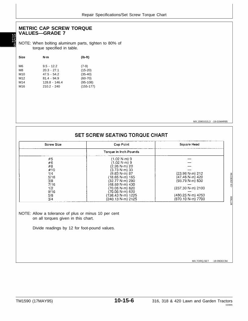
METRIC CAP SCREW TORQUEVALUES—GRADE 7
NOTE: When bolting aluminum parts, tighten to 80% oftorque specified in table.
Size N·m (lb-ft)
M6 9.5 - 12.2 (7-9)M8 20.3 - 27.1 (15-20)M10 47.5 - 54.2 (35-40)M12 81.4 - 94.9 (60-70)M14 128.8 - 146.4 (95-108)M16 210.2 - 240 (155-177)
NOTE: Allow a tolerance of plus or minus 10 per centon all torques given in this chart.
Divide readings by 12 for foot-pound values.M
7790
0
-1
9-15
DE
C94
MX,15901015,3 -19-01MAR95
MX,TORQ,SET -19-09DEC94
Repair Specifications/Set Screw Torque Chart
TM1590 (17MAY95) 10-15-6 316, 318 & 420 Lawn and Garden Tractors020895
1015
6
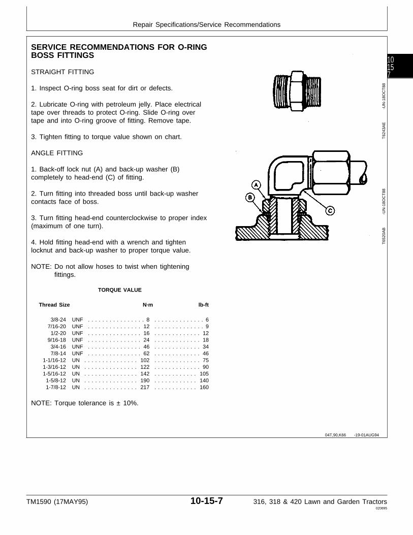
SERVICE RECOMMENDATIONS FOR O-RINGBOSS FITTINGS
STRAIGHT FITTING
1. Inspect O-ring boss seat for dirt or defects.
2. Lubricate O-ring with petroleum jelly. Place electricaltape over threads to protect O-ring. Slide O-ring overtape and into O-ring groove of fitting. Remove tape.
3. Tighten fitting to torque value shown on chart.
ANGLE FITTING
1. Back-off lock nut (A) and back-up washer (B)completely to head-end (C) of fitting.
2. Turn fitting into threaded boss until back-up washercontacts face of boss.
3. Turn fitting head-end counterclockwise to proper index(maximum of one turn).
4. Hold fitting head-end with a wrench and tightenlocknut and back-up washer to proper torque value.
NOTE: Do not allow hoses to twist when tighteningfittings.
TORQUE VALUE
Thread Size N·m lb-ft
3/8-24 UNF . . . . . . . . . . . . . . . . 8 . . . . . . . . . . . . . . 67/16-20 UNF . . . . . . . . . . . . . . . 12 . . . . . . . . . . . . . . 9
1/2-20 UNF . . . . . . . . . . . . . . . 16 . . . . . . . . . . . . . 129/16-18 UNF . . . . . . . . . . . . . . . 24 . . . . . . . . . . . . . 18
3/4-16 UNF . . . . . . . . . . . . . . . 46 . . . . . . . . . . . . . 347/8-14 UNF . . . . . . . . . . . . . . . 62 . . . . . . . . . . . . . 46
1-1/16-12 UN . . . . . . . . . . . . . . . 102 . . . . . . . . . . . . . 751-3/16-12 UN . . . . . . . . . . . . . . . 122 . . . . . . . . . . . . . 901-5/16-12 UN . . . . . . . . . . . . . . . 142 . . . . . . . . . . . . 105
1-5/8-12 UN . . . . . . . . . . . . . . . 190 . . . . . . . . . . . . 1401-7/8-12 UN . . . . . . . . . . . . . . . 217 . . . . . . . . . . . . 160
NOTE: Torque tolerance is ± 10%.
T62
43A
E
-U
N-1
8OC
T88
T65
20A
B
-U
N-1
8OC
T88
04T,90,K66 -19-01AUG94
Repair Specifications/Service Recommendations
TM1590 (17MAY95) 10-15-7 316, 318 & 420 Lawn and Garden Tractors020895
10157
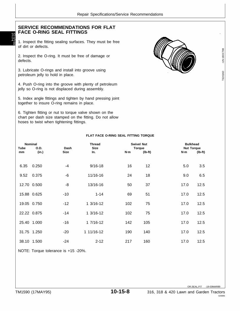
SERVICE RECOMMENDATIONS FOR FLATFACE O-RING SEAL FITTINGS
1. Inspect the fitting sealing surfaces. They must be freeof dirt or defects.
2. Inspect the O-ring. It must be free of damage ordefects.
3. Lubricate O-rings and install into groove usingpetroleum jelly to hold in place.
4. Push O-ring into the groove with plenty of petroleumjelly so O-ring is not displaced during assembly.
5. Index angle fittings and tighten by hand pressing jointtogether to insure O-ring remains in place.
6. Tighten fitting or nut to torque valve shown on thechart per dash size stamped on the fitting. Do not allowhoses to twist when tightening fittings.
FLAT FACE O-RING SEAL FITTING TORQUE
Nominal Thread Swivel Nut BulkheadTube O.D. Dash Size Torque Nut Torquemm (in.) Size In. N·m (lb-ft) N·m (lb-ft)
6.35 0.250 -4 9/16-18 16 12 5.0 3.5
9.52 0.375 -6 11/16-16 24 18 9.0 6.5
12.70 0.500 -8 13/16-16 50 37 17.0 12.5
15.88 0.625 -10 1-14 69 51 17.0 12.5
19.05 0.750 -12 1 3/16-12 102 75 17.0 12.5
22.22 0.875 -14 1 3/16-12 102 75 17.0 12.5
25.40 1.000 -16 1 7/16-12 142 105 17.0 12.5
31.75 1.250 -20 1 11/16-12 190 140 17.0 12.5
38.10 1.500 -24 2-12 217 160 17.0 12.5
NOTE: Torque tolerance is +15 -20%.
T62
43A
D
-U
N-1
8OC
T88
OR,SEAL,FIT -19-03MAR89
Repair Specifications/Service Recommendations
TM1590 (17MAY95) 10-15-8 316, 318 & 420 Lawn and Garden Tractors020895
1015
8
TUBE AND HOSE FITTING, 37˚ FLARE AND30˚ CONE SEAT CONNECTOR SERVICERECOMMENDATIONS
1. Inspect the flare and the flare seat. They must be freeof dirt and defects. If repeated leaks occur, inspect fordefects with a magnifying glass. If burrs and raised nickson the connector body cannot be removed with a slipstone, replace the connector.
2. Defects in the tube flare cannot be repaired. Replacethe tube. Overtightening a defective flared fitting will notstop leaks.
3. As a field repair, a ductile truncated cone shapedwasher can be used between the tube flare andconnector body. These washers are soft enough to filldefects in the seat and flare. They will also seal theconnection. Ductile washers are available from industrialsupply houses.
4. Align the tube with the fitting before attempting to startthe nut. Failure to do so can cause a deformed flare andsubsequent leaks. Install hoses without twists. A twistedhose attempts to straigten out when pressure is applied.This exerts a torque on the connection, eventuallycausing failure.
5. Lubricate the connection with hydraulic fluid, petroleumjelly or soap. Tighten the swivel nut by hand until it issnug.
6. Mark a line across the nut and connector body. Thisline will serve as a visual indicator as to whether the nuthas been tightened and by how much.
7. Using two wrenches, one on the connector body anda torque wrench on the nut, tighten the nut to the torquevalue as shown in the chart. In the case of a hose, itmay be necessary to use three wrenches to preventtwisting.
MX,15901015,4 -19-17JAN95
Repair Specifications/Service Recommendations
TM1590 (17MAY95) 10-15-9 316, 318 & 420 Lawn and Garden Tractors020895
10159
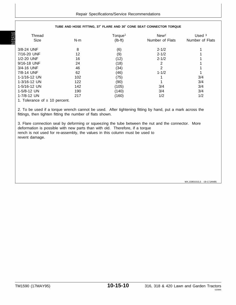
TUBE AND HOSE FITTING, 37˚ FLARE AND 30˚ CONE SEAT CONNECTOR TORQUE
Thread Torque1 New2 Used 3
Size N·m (lb-ft) Number of Flats Number of Flats
3/8-24 UNF 8 (6) 2-1/2 17/16-20 UNF 12 (9) 2-1/2 11/2-20 UNF 16 (12) 2-1/2 19/16-18 UNF 24 (18) 2 13/4-16 UNF 46 (34) 2 17/8-14 UNF 62 (46) 1-1/2 11-1/16-12 UN 102 (75) 1 3/41-3/16-12 UN 122 (90) 1 3/41-5/16-12 UN 142 (105) 3/4 3/41-5/8-12 UN 190 (140) 3/4 3/41-7/8-12 UN 217 (160) 1/2 1/21. Tolerance of ± 10 percent.
2. To be used if a torque wrench cannot be used. After tightening fitting by hand, put a mark across thefittings, then tighten fitting the number of flats shown.
3. Flare connection seal by deforming or squeezing the tube between the nut and the connector. Moredeformation is possible with new parts than with old. Therefore, if a torquerench is not used for re-assembly, the values in this column must be used torevent damage.
MX,15901015,5 -19-17JAN95
Repair Specifications/Service Recommendations
TM1590 (17MAY95) 10-15-10 316, 318 & 420 Lawn and Garden Tractors020895
101510
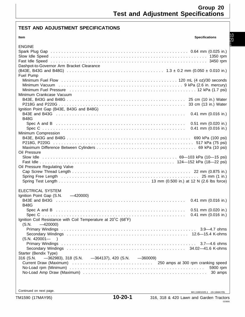
TEST AND ADJUSTMENT SPECIFICATIONS
Item Specifications
ENGINESpark Plug Gap . . . . . . . . . . . . . . . . . . . . . . . . . . . . . . . . . . . . . . . . . . . . . . . . . . . 0.64 mm (0.025 in.)Slow Idle Speed . . . . . . . . . . . . . . . . . . . . . . . . . . . . . . . . . . . . . . . . . . . . . . . . . . . . . . . . . . 1350 rpmFast Idle Speed . . . . . . . . . . . . . . . . . . . . . . . . . . . . . . . . . . . . . . . . . . . . . . . . . . . . . . . . . . 3450 rpmDashpot-to-Governor Arm Bracket Clearance(B43E, B43G and B48G) . . . . . . . . . . . . . . . . . . . . . . . . . . . . . . . . . . . . 1.3 ± 0.2 mm (0.050 ± 0.010 in.)Fuel Pump Minimum Fuel Flow . . . . . . . . . . . . . . . . . . . . . . . . . . . . . . . . . . . . . . . . . . . 120 mL (4 oz)/30 seconds Minimum Vacuum . . . . . . . . . . . . . . . . . . . . . . . . . . . . . . . . . . . . . . . . . . . . . . 9 kPa (2.6 in. mercury) Minimum Fuel Pressure . . . . . . . . . . . . . . . . . . . . . . . . . . . . . . . . . . . . . . . . . . . . . . . 12 kPa (1.7 psi)Minimum Crankcase Vacuum B43E, B43G and B48G . . . . . . . . . . . . . . . . . . . . . . . . . . . . . . . . . . . . . . . . . . . . 25 cm (10 in.) Water P218G and P220G . . . . . . . . . . . . . . . . . . . . . . . . . . . . . . . . . . . . . . . . . . . . . . . 33 cm (13 in.) WaterIgnition Point Gap (B43E, B43G and B48G) B43E and B43G . . . . . . . . . . . . . . . . . . . . . . . . . . . . . . . . . . . . . . . . . . . . . . . . 0.41 mm (0.016 in.) B48G Spec A and B . . . . . . . . . . . . . . . . . . . . . . . . . . . . . . . . . . . . . . . . . . . . . . . . 0.51 mm (0.020 in.) Spec C . . . . . . . . . . . . . . . . . . . . . . . . . . . . . . . . . . . . . . . . . . . . . . . . . . . . . 0.41 mm (0.016 in.)Minimum Compression B43E, B43G and B48G . . . . . . . . . . . . . . . . . . . . . . . . . . . . . . . . . . . . . . . . . . . . . . 690 kPa (100 psi) P218G, P220G . . . . . . . . . . . . . . . . . . . . . . . . . . . . . . . . . . . . . . . . . . . . . . . . . . . . 517 kPa (75 psi) Maximum Difference Between Cylinders . . . . . . . . . . . . . . . . . . . . . . . . . . . . . . . . . . . . . 69 kPa (10 psi)Oil Pressure Slow Idle . . . . . . . . . . . . . . . . . . . . . . . . . . . . . . . . . . . . . . . . . . . . . . . . . . 69—103 kPa (10—15 psi) Fast Idle . . . . . . . . . . . . . . . . . . . . . . . . . . . . . . . . . . . . . . . . . . . . . . . . . . 124—152 kPa (18—22 psi)Oil Pressure Regulating Valve Cap Screw Thread Length . . . . . . . . . . . . . . . . . . . . . . . . . . . . . . . . . . . . . . . . . . . . 22 mm (0.875 in.) Spring Free Length . . . . . . . . . . . . . . . . . . . . . . . . . . . . . . . . . . . . . . . . . . . . . . . . . . . 25 mm (1 in.) Spring Test Length . . . . . . . . . . . . . . . . . . . . . . . . . . . . . . . . . . 13 mm (0.500 in.) at 12 N (2.6 lbs force)
ELECTRICAL SYSTEMIgnition Point Gap (S.N. —420000) B43E and B43G . . . . . . . . . . . . . . . . . . . . . . . . . . . . . . . . . . . . . . . . . . . . . . . . 0.41 mm (0.016 in.) B48G Spec A and B . . . . . . . . . . . . . . . . . . . . . . . . . . . . . . . . . . . . . . . . . . . . . . . . 0.51 mm (0.020 in.) Spec C . . . . . . . . . . . . . . . . . . . . . . . . . . . . . . . . . . . . . . . . . . . . . . . . . . . . . 0.41 mm (0.016 in.)Ignition Coil Resistance with Coil Temperature at 20˚C (68˚F) (S.N. —420000) Primary Windings . . . . . . . . . . . . . . . . . . . . . . . . . . . . . . . . . . . . . . . . . . . . . . . . . . 3.9—4.7 ohms Secondary Windings . . . . . . . . . . . . . . . . . . . . . . . . . . . . . . . . . . . . . . . . . . . . . 12.6—15.4 K-ohms (S.N. 420001— ) Primary Windings . . . . . . . . . . . . . . . . . . . . . . . . . . . . . . . . . . . . . . . . . . . . . . . . . . 3.7—4.6 ohms Secondary Windings . . . . . . . . . . . . . . . . . . . . . . . . . . . . . . . . . . . . . . . . . . . . 34.02—41.6 K-ohmsStarter (Bendix Type)316 (S.N. —362983), 318 (S.N. —364137), 420 (S.N. —360009) Current Draw (Maximum) . . . . . . . . . . . . . . . . . . . . . . . . . . . . . . 250 amps at 300 rpm cranking speed No-Load rpm (Minimum) . . . . . . . . . . . . . . . . . . . . . . . . . . . . . . . . . . . . . . . . . . . . . . . . . . 5900 rpm No-Load Amp Draw (Maximum) . . . . . . . . . . . . . . . . . . . . . . . . . . . . . . . . . . . . . . . . . . . . . . 30 amps
Continued on next page. MX,15901020,1 -19-16MAY95
Group 20Test and Adjustment Specifications
TM1590 (17MAY95) 10-20-1 316, 318 & 420 Lawn and Garden Tractors020895
10201
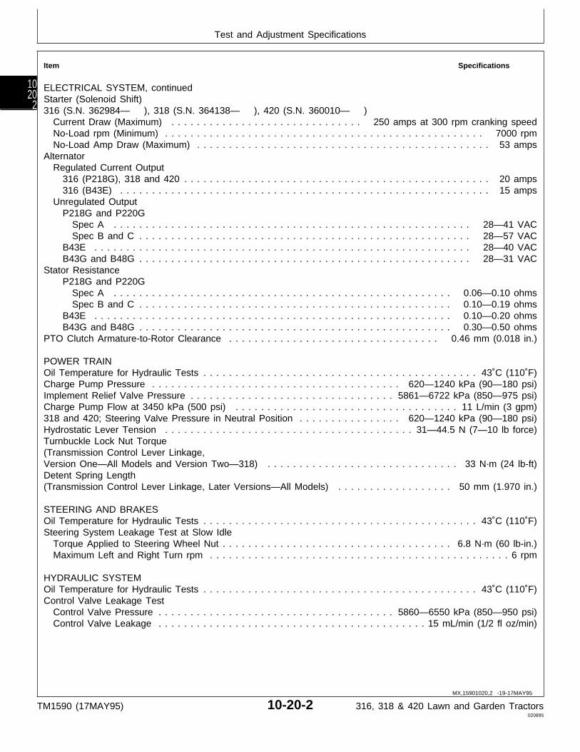
Item Specifications
ELECTRICAL SYSTEM, continuedStarter (Solenoid Shift)316 (S.N. 362984— ), 318 (S.N. 364138— ), 420 (S.N. 360010— ) Current Draw (Maximum) . . . . . . . . . . . . . . . . . . . . . . . . . . . . . . 250 amps at 300 rpm cranking speed No-Load rpm (Minimum) . . . . . . . . . . . . . . . . . . . . . . . . . . . . . . . . . . . . . . . . . . . . . . . . . . 7000 rpm No-Load Amp Draw (Maximum) . . . . . . . . . . . . . . . . . . . . . . . . . . . . . . . . . . . . . . . . . . . . . . 53 ampsAlternator Regulated Current Output 316 (P218G), 318 and 420 . . . . . . . . . . . . . . . . . . . . . . . . . . . . . . . . . . . . . . . . . . . . . . . . 20 amps 316 (B43E) . . . . . . . . . . . . . . . . . . . . . . . . . . . . . . . . . . . . . . . . . . . . . . . . . . . . . . . . . . 15 amps Unregulated Output P218G and P220G Spec A . . . . . . . . . . . . . . . . . . . . . . . . . . . . . . . . . . . . . . . . . . . . . . . . . . . . . . . . 28—41 VAC Spec B and C . . . . . . . . . . . . . . . . . . . . . . . . . . . . . . . . . . . . . . . . . . . . . . . . . . . . 28—57 VAC B43E . . . . . . . . . . . . . . . . . . . . . . . . . . . . . . . . . . . . . . . . . . . . . . . . . . . . . . . . . . . 28—40 VAC B43G and B48G . . . . . . . . . . . . . . . . . . . . . . . . . . . . . . . . . . . . . . . . . . . . . . . . . . . . 28—31 VACStator Resistance P218G and P220G Spec A . . . . . . . . . . . . . . . . . . . . . . . . . . . . . . . . . . . . . . . . . . . . . . . . . . . . . 0.06—0.10 ohms Spec B and C . . . . . . . . . . . . . . . . . . . . . . . . . . . . . . . . . . . . . . . . . . . . . . . . . 0.10—0.19 ohms B43E . . . . . . . . . . . . . . . . . . . . . . . . . . . . . . . . . . . . . . . . . . . . . . . . . . . . . . . . 0.10—0.20 ohms B43G and B48G . . . . . . . . . . . . . . . . . . . . . . . . . . . . . . . . . . . . . . . . . . . . . . . . . 0.30—0.50 ohmsPTO Clutch Armature-to-Rotor Clearance . . . . . . . . . . . . . . . . . . . . . . . . . . . . . . . . . 0.46 mm (0.018 in.)
POWER TRAINOil Temperature for Hydraulic Tests . . . . . . . . . . . . . . . . . . . . . . . . . . . . . . . . . . . . . . . . . . . 43˚C (110˚F)Charge Pump Pressure . . . . . . . . . . . . . . . . . . . . . . . . . . . . . . . . . . . . . . . 620—1240 kPa (90—180 psi)Implement Relief Valve Pressure . . . . . . . . . . . . . . . . . . . . . . . . . . . . . . . . 5861—6722 kPa (850—975 psi)Charge Pump Flow at 3450 kPa (500 psi) . . . . . . . . . . . . . . . . . . . . . . . . . . . . . . . . . . . 11 L/min (3 gpm)318 and 420; Steering Valve Pressure in Neutral Position . . . . . . . . . . . . . . . . 620—1240 kPa (90—180 psi)Hydrostatic Lever Tension . . . . . . . . . . . . . . . . . . . . . . . . . . . . . . . . . . . . . . . 31—44.5 N (7—10 lb force)Turnbuckle Lock Nut Torque(Transmission Control Lever Linkage,Version One—All Models and Version Two—318) . . . . . . . . . . . . . . . . . . . . . . . . . . . . . . 33 N·m (24 lb-ft)Detent Spring Length(Transmission Control Lever Linkage, Later Versions—All Models) . . . . . . . . . . . . . . . . . . 50 mm (1.970 in.)
STEERING AND BRAKESOil Temperature for Hydraulic Tests . . . . . . . . . . . . . . . . . . . . . . . . . . . . . . . . . . . . . . . . . . . 43˚C (110˚F)Steering System Leakage Test at Slow Idle Torque Applied to Steering Wheel Nut . . . . . . . . . . . . . . . . . . . . . . . . . . . . . . . . . . . . 6.8 N·m (60 lb-in.) Maximum Left and Right Turn rpm . . . . . . . . . . . . . . . . . . . . . . . . . . . . . . . . . . . . . . . . . . . . . . . 6 rpm
HYDRAULIC SYSTEMOil Temperature for Hydraulic Tests . . . . . . . . . . . . . . . . . . . . . . . . . . . . . . . . . . . . . . . . . . . 43˚C (110˚F)Control Valve Leakage Test Control Valve Pressure . . . . . . . . . . . . . . . . . . . . . . . . . . . . . . . . . . . . . 5860—6550 kPa (850—950 psi) Control Valve Leakage . . . . . . . . . . . . . . . . . . . . . . . . . . . . . . . . . . . . . . . . . . 15 mL/min (1/2 fl oz/min)
MX,15901020,2 -19-17MAY95
Test and Adjustment Specifications
TM1590 (17MAY95) 10-20-2 316, 318 & 420 Lawn and Garden Tractors020895
1020
2
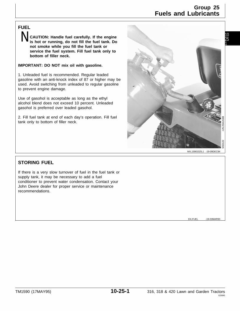
FUEL
N CAUTION: Handle fuel carefully. If the engineis hot or running, do not fill the fuel tank. Donot smoke while you fill the fuel tank orservice the fuel system. Fill fuel tank only tobottom of filler neck.
IMPORTANT: DO NOT mix oil with gasoline.
1. Unleaded fuel is recommended. Regular leadedgasoline with an anti-knock index of 87 or higher may beused. Avoid switching from unleaded to regular gasolineto prevent engine damage.
Use of gasohol is acceptable as long as the ethylalcohol blend does not exceed 10 percent. Unleadedgasohol is preferred over leaded gasohol.
2. Fill fuel tank at end of each day’s operation. Fill fueltank only to bottom of filler neck.
M33
122
-UN
-25A
UG
88
STORING FUEL
If there is a very slow turnover of fuel in the fuel tank orsupply tank, it may be necessary to add a fuelconditioner to prevent water condensation. Contact yourJohn Deere dealer for proper service or maintenancerecommendations.
MX,15901025,1 -19-09DEC94
DX,FUEL -19-03MAR93
Group 25Fuels and Lubricants
TM1590 (17MAY95) 10-25-1 316, 318 & 420 Lawn and Garden Tractors020895
10251
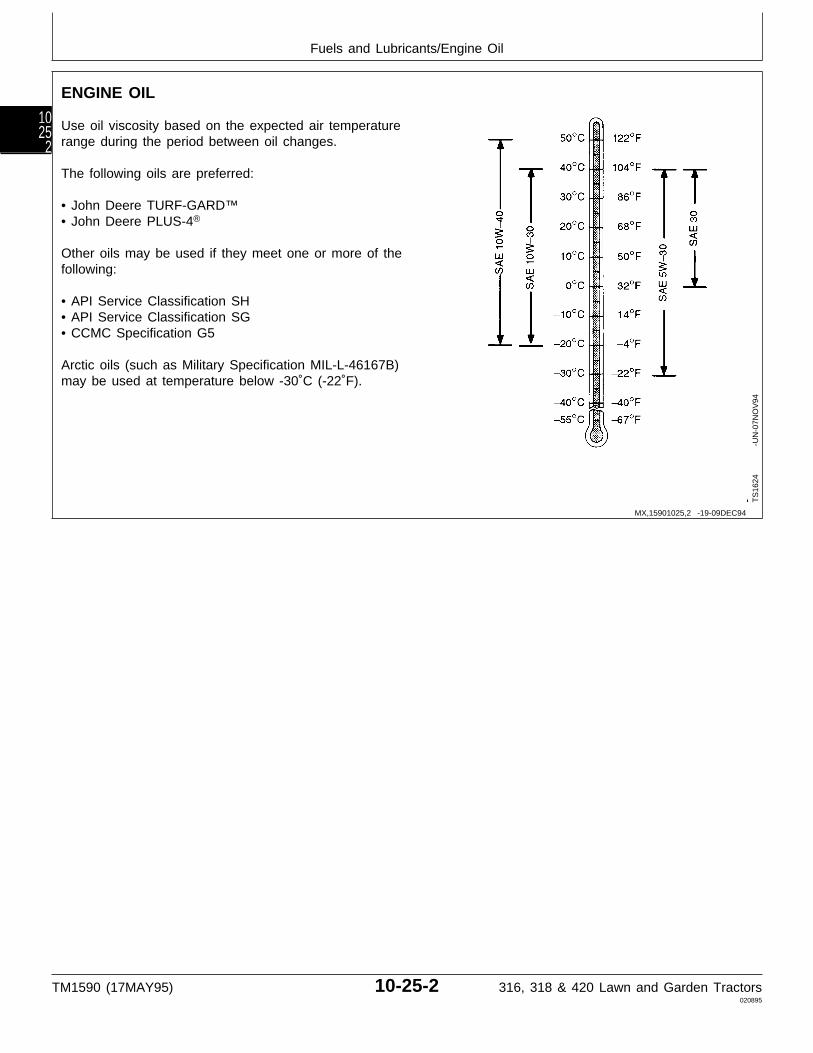
ENGINE OIL
Use oil viscosity based on the expected air temperaturerange during the period between oil changes.
The following oils are preferred:
• John Deere TURF-GARD™• John Deere PLUS-4®
Other oils may be used if they meet one or more of thefollowing:
• API Service Classification SH• API Service Classification SG• CCMC Specification G5
Arctic oils (such as Military Specification MIL-L-46167B)may be used at temperature below -30˚C (-22˚F).
TS
1624
-U
N-0
7NO
V94
MX,15901025,2 -19-09DEC94
Fuels and Lubricants/Engine Oil
TM1590 (17MAY95) 10-25-2 316, 318 & 420 Lawn and Garden Tractors020895
1025
2

TRANSMISSION AND HYDRAULIC OIL
Use oil viscosity based on the expected air temperaturerange during the period between oil changes.
The following oils are preferred:
• John Deere HY-GARD®
• John Deere Low Viscosity HY-GARD®
The following oils are also recommended:
• John Deere UNI-GARD™• John Deere BIO-HY-GARD™1
Other oils may be used if they meet one of the following:
• John Deere Standard JDM J20C• John Deere Standard JDM J20D• John Deere Standard JDM J27A
IMPORTANT: Do not use engine oil for thisapplication.
Arctic oils (such as Military Specification MIL-L-46167B)may be used at temperatures below -30˚C (-22˚F).
1BIO-HY-GARD meets or exceeds the minimum biodegradability of 80%within 21 days according to CEC-L-33-T-82 test method. BIO-HY-GARDshould not be mixed with mineral oils because this reduces thebiodegradability and makes proper oil recycling impossible.
TS
1413
-U
N-3
1JA
N94
DX,ANTI -19-01FEB94
Fuels and Lubricants/Transmission and Hydraulic Oil
TM1590 (17MAY95) 10-25-3 316, 318 & 420 Lawn and Garden Tractors020895
10253
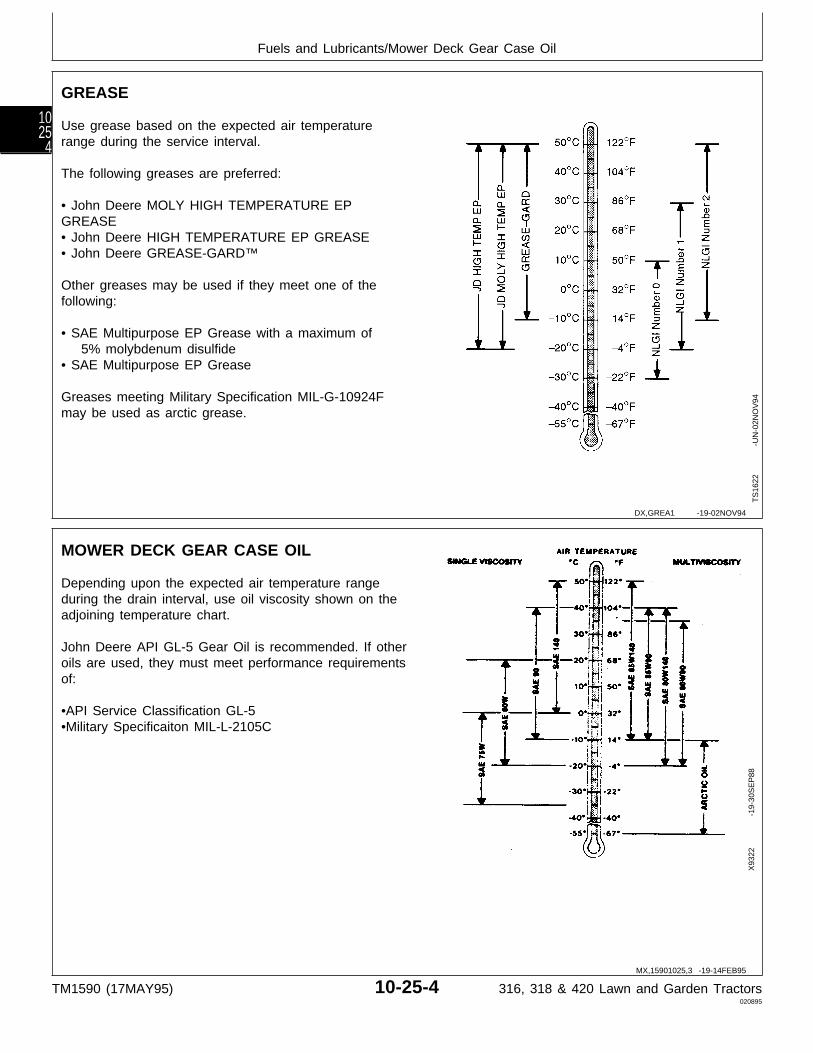
GREASE
Use grease based on the expected air temperaturerange during the service interval.
The following greases are preferred:
• John Deere MOLY HIGH TEMPERATURE EPGREASE• John Deere HIGH TEMPERATURE EP GREASE• John Deere GREASE-GARD™
Other greases may be used if they meet one of thefollowing:
• SAE Multipurpose EP Grease with a maximum of 5% molybdenum disulfide• SAE Multipurpose EP Grease
Greases meeting Military Specification MIL-G-10924Fmay be used as arctic grease.
TS
1622
-U
N-0
2NO
V94
MOWER DECK GEAR CASE OIL
Depending upon the expected air temperature rangeduring the drain interval, use oil viscosity shown on theadjoining temperature chart.
John Deere API GL-5 Gear Oil is recommended. If otheroils are used, they must meet performance requirementsof:
•API Service Classification GL-5•Military Specificaiton MIL-L-2105C
X93
22
-19-
30S
EP
88
DX,GREA1 -19-02NOV94
MX,15901025,3 -19-14FEB95
Fuels and Lubricants/Mower Deck Gear Case Oil
TM1590 (17MAY95) 10-25-4 316, 318 & 420 Lawn and Garden Tractors020895
1025
4

ALTERNATIVE AND SYNTHETIC LUBRICANTS
Conditions in certain geographical areas may requirelubricant recommendations different from thoseprinted in this manual. Some John Deere lubricantsmay not be available in your location. Consult yourJohn Deere dealer to obtain information andrecommendations.
Synthetic lubricants may be used if they meet theperformance requirements listed in this manual.
LUBRICANT STORAGE
Your equipment can operate at top efficiency only ifclean lubricants are used.
Use clean containers to handle all lubricants.
Whenever possible, store lubricants and containers inan area protected from dust, moisture, and othercontamination. Store containers on their side to avoidwater and dirt accumulation.
MIXING OF LUBRICANTS
In general, avoid mixing different brands or types of oil.Oil manufacturers blend additives in their oils to meetcertain specifications and performance requirements.Mixing different oils can interfere with the properfunctioning of these additives and degrade lubricantperformance.
DX,ALTER -19-01FEB94
DX,LUBST -19-01FEB94
DX,LUBMIX -19-01FEB94
Fuels and Lubricants/Mixing of Lubricants
TM1590 (17MAY95) 10-25-5 316, 318 & 420 Lawn and Garden Tractors020895
10255
Fuels and Lubricants/Mixing of Lubricants
TM1590 (17MAY95) 10-25-6 316, 318 & 420 Lawn and Garden Tractors020895
1025
6
SERIAL NUMBERS
When working on machines or components that arecovered by warranty, it is IMPORTANT that you includethe tractor Product Identification Number and thecomponent serial number on the warranty claim form.
The location of component serial number plates areshown below.
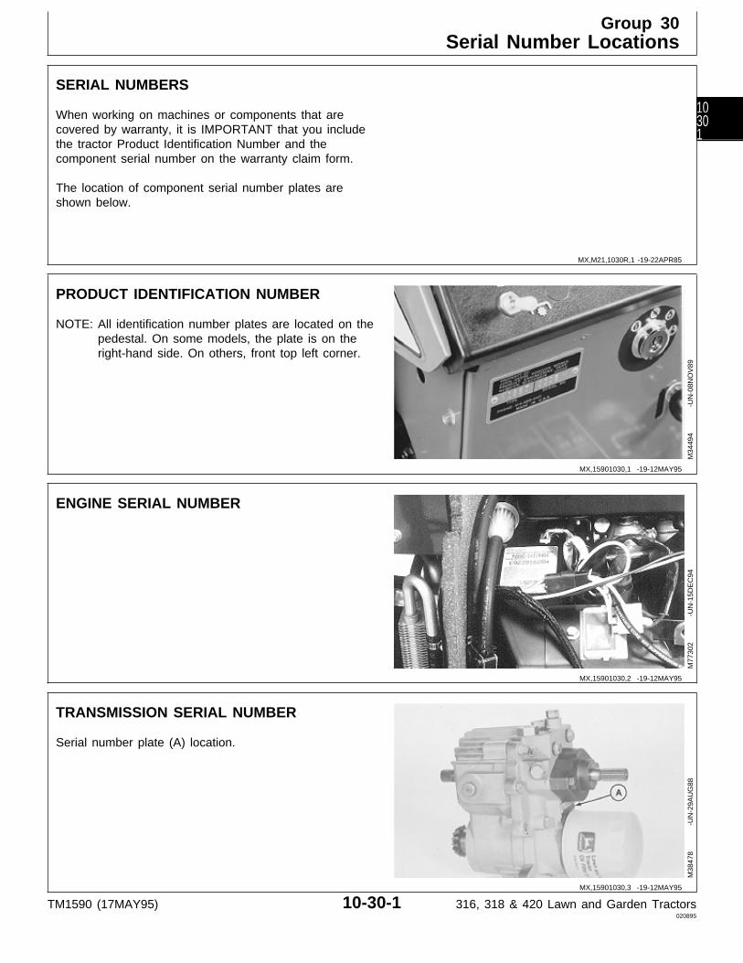
PRODUCT IDENTIFICATION NUMBER
NOTE: All identification number plates are located on thepedestal. On some models, the plate is on theright-hand side. On others, front top left corner.
M34
494
-UN
-08N
OV
89
ENGINE SERIAL NUMBER
M77
302
-UN
-15D
EC
94
TRANSMISSION SERIAL NUMBER
Serial number plate (A) location.
M38
478
-UN
-29A
UG
88
MX,M21,1030R,1 -19-22APR85
MX,15901030,1 -19-12MAY95
MX,15901030,2 -19-12MAY95
MX,15901030,3 -19-12MAY95
Group 30Serial Number Locations
TM1590 (17MAY95) 10-30-1 316, 318 & 420 Lawn and Garden Tractors020895
10301
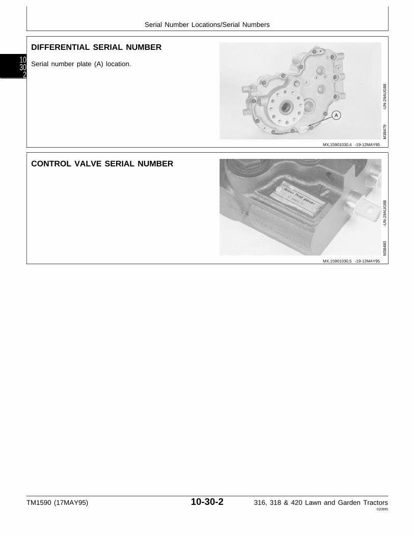
DIFFERENTIAL SERIAL NUMBER
Serial number plate (A) location.
M38
479
-UN
-29A
UG
88
CONTROL VALVE SERIAL NUMBER
M38
480
-UN
-29A
UG
88
MX,15901030,4 -19-12MAY95
MX,15901030,5 -19-12MAY95
Serial Number Locations/Serial Numbers
TM1590 (17MAY95) 10-30-2 316, 318 & 420 Lawn and Garden Tractors020895
1030
2
Section 20ENGINE REPAIR
ContentsPage
Group 05—EngineRepair—Use CTM2 . . . . . . . . . . . . . . . 20-05-1Remove and Install . . . . . . . . . . . . . . . 20-05-1
TM1590 (17MAY95) 20-1 316, 318 & 420 Lawn and Garden Tractors020895
20

Contents
TM1590 (17MAY95) 20-2 316, 318 & 420 Lawn and Garden Tractors020895
20
ONAN ENGINE REPAIR—USE CTM2
For complete repair information, the component technicalmanual (CTM) is also required. Use the componenttechnical manual in conjunction with this machinemanual.
TS
225
-U
N-1
7JA
N89
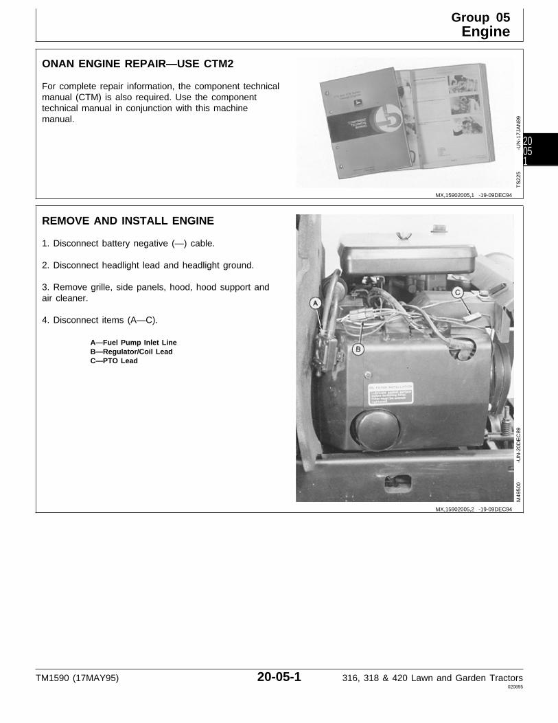
REMOVE AND INSTALL ENGINE
1. Disconnect battery negative (—) cable.
2. Disconnect headlight lead and headlight ground.
3. Remove grille, side panels, hood, hood support andair cleaner.
4. Disconnect items (A—C).
A—Fuel Pump Inlet LineB—Regulator/Coil LeadC—PTO Lead
M49
500
-UN
-20D
EC
89
MX,15902005,1 -19-09DEC94
MX,15902005,2 -19-09DEC94
Group 05Engine
TM1590 (17MAY95) 20-05-1 316, 318 & 420 Lawn and Garden Tractors020895
20051
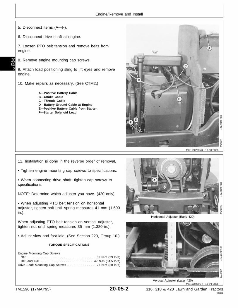
5. Disconnect items (A—F).
6. Disconnect drive shaft at engine.
7. Loosen PTO belt tension and remove belts fromengine.
8. Remove engine mounting cap screws.
9. Attach load positioning sling to lift eyes and removeengine.
10. Make repairs as necessary. (See CTM2.)
A—Positive Battery CableB—Choke CableC—Throttle CableD—Battery Ground Cable at EngineE—Positive Battery Cable from StarterF—Starter Solenoid Lead
M49
501
-UN
-20D
EC
89
11. Installation is done in the reverse order of removal.
• Tighten engine mounting cap screws to specifications.
• When connecting drive shaft, tighten cap screws tospecifications.
NOTE: Determine which adjuster you have. (420 only)
• When adjusting PTO belt tension on horizontaladjuster, tighten bolt until spring measures 41 mm (1.600in.).
Horizontal Adjuster (Early 420)
When adjusting PTO belt tension on vertical adjuster,tighten nut until spring measures 35 mm (1.380 in.).
• Adjust slow and fast idle. (See Section 220, Group 10.)
TORQUE SPECIFICATIONS
Engine Mounting Cap Screws 316 . . . . . . . . . . . . . . . . . . . . . . . . . . . . . . . . 39 N·m (29 lb-ft) 318 and 420 . . . . . . . . . . . . . . . . . . . . . . . . . 47 N·m (34.5 lb-ft)Drive Shaft Mounting Cap Screws . . . . . . . . . . . . . 27 N·m (20 lb-ft)
Vertical Adjuster (Later 420)
M49
503
-UN
-20D
EC
89M
4950
2
-U
N-2
0DE
C89
MX,15902005,3 -19-24FEB95
MX,15902005,4 -19-24FEB95
Engine/Remove and Install
TM1590 (17MAY95) 20-05-2 316, 318 & 420 Lawn and Garden Tractors020895
2005
2

Section 40ELECTRICAL REPAIR
ContentsPage
Group 05—Front PTO ClutchRemove . . . . . . . . . . . . . . . . . . . . . . . 40-05-1Disassemble, Inspect and Assemble . . . . 40-05-2Install . . . . . . . . . . . . . . . . . . . . . . . . . 40-05-4
TM1590 (17MAY95) 40-1 316, 318 & 420 Lawn and Garden Tractors020895
40

Contents
TM1590 (17MAY95) 40-2 316, 318 & 420 Lawn and Garden Tractors020895
40
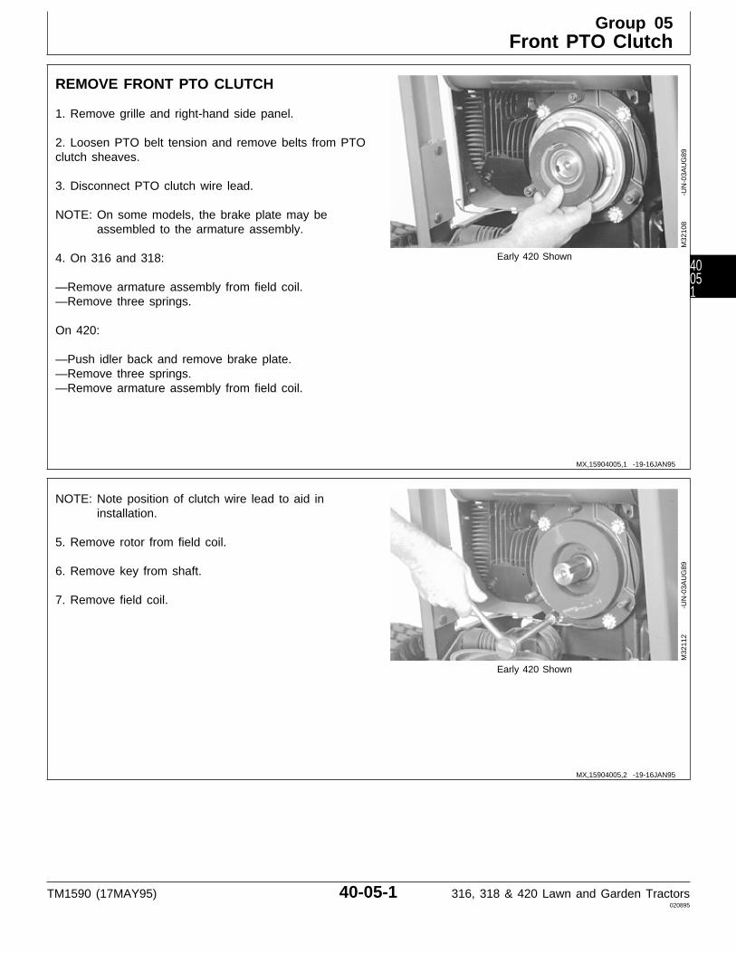
REMOVE FRONT PTO CLUTCH
1. Remove grille and right-hand side panel.
2. Loosen PTO belt tension and remove belts from PTOclutch sheaves.
3. Disconnect PTO clutch wire lead.
NOTE: On some models, the brake plate may beassembled to the armature assembly.
4. On 316 and 318: Early 420 Shown
—Remove armature assembly from field coil.—Remove three springs.
On 420:
—Push idler back and remove brake plate.—Remove three springs.—Remove armature assembly from field coil.
M32
108
-UN
-03A
UG
89
NOTE: Note position of clutch wire lead to aid ininstallation.
5. Remove rotor from field coil.
6. Remove key from shaft.
7. Remove field coil.
Early 420 ShownM
3211
2
-U
N-0
3AU
G89
MX,15904005,1 -19-16JAN95
MX,15904005,2 -19-16JAN95
Group 05Front PTO Clutch
TM1590 (17MAY95) 40-05-1 316, 318 & 420 Lawn and Garden Tractors020895
40051

DISASSEMBLE, INSPECT AND ASSEMBLEFRONT PTO CLUTCH
1. Inspect armature for bent, weak or broken contactsprings. Replace armature if damaged.
2. Inspect rotor and armature face contacts for wear.Replace if worn or grooved. Clean face contacts of dirtor foreign material.
M32
117
-UN
-03A
UG
89
NOTE: Bearing is press-fit in armature. Remove only ifreplacement is necessary.
3. Inspect armature bearing for wear or damage.Replace if necessary.
4. To replace armature bearing; remove snap ring.
M32
113
-UN
-03A
UG
89
5. Remove hub and bearing from armature using a pressand a 1-11/16 in. driver disk. Make sure assembly issupported on pulley, NOT on armature plate.
6. Remove shim washer from inside pulley hub.
7. Remove hub from bearing using a press and a 1-3/4in. driver disk.
8. Install hub into new bearing using a press and driverdisk.
9. Install shim washer in bottom of pulley hub.M
3211
4
-U
N-0
3AU
G89
MX,15904005,3 -19-12MAY95
MX,15904005,4 -19-14DEC94
MX,15904005,5 -19-14DEC94
Front PTO Clutch/Disassemble, Inspect and Assemble
TM1590 (17MAY95) 40-05-2 316, 318 & 420 Lawn and Garden Tractors020895
4005
2

IMPORTANT: Support the armature assembly on thespring rivets when installingbearing/hub assembly into armatureassembly, or damage to armature andsprings will occur.
10. Support armature on spring rivets and installbearing/hub assembly into pulley hub with a press and a2-15/16 in. driver disk.
11. Install snap ring.
M32
120
-UN
-03A
UG
89
12. Inspect field coil for wear or damage. Replace ifnecessary.
13. Test field coil for electrical continuity.
Early version:
—Attach field coil lead to positive (+) terminal of a charged storage battery.—Set coil base on negative (—) battery terminal.—Put a steel bolt across coil. Electromagnetic action will hold bolt to coil if coil is good. If bolt does not stick to coil, replace the coil.
Later version:
—Attach a jumper wire from one terminal of two-pin connector to negative (—) battery terminal.—Attach another jumper wire from the remaining terminal Early Version
of two-pin connector to positive (+) battery terminal.—Put a steel bolt across coil. Electromagnetic action will hold bolt to coil if coil is good. If bolt does not stick to coil, replace the coil.
Later Version
M32
118
-UN
-03A
UG
89M
7732
1
-U
N-2
5JA
N95
MX,15904005,6 -19-14DEC94
MX,15904005,7 -19-19JAN95
Front PTO Clutch/Disassemble, Inspect and Assemble
TM1590 (17MAY95) 40-05-3 316, 318 & 420 Lawn and Garden Tractors020895
40053

INSTALL FRONT PTO CLUTCH
IMPORTANT: Make sure clutch wire lead is in sameposition as when removed, to preventshorting of wires.
1. Install field coil and fasten with four cap screws andlock washers. Be sure coil assembly pilots, on backsideof coil, are seated in engine face. Tighten cap screws.
2. Install rotor and key.
Early 420 Shown
M32
112
-UN
-03A
UG
89
NOTE: Some models have a notch in the hub of thearmature assembly. This notch MUST slip overthe extended key in the crankshaft.
3. On 316 and 318:
—Install three springs on mounting studs.—Install armature assembly.
On 420:
—Install armature assembly.Early 420 Shown
—Install three springs on mounting studs.—Push idler back and install brake plate.
4. Install lock nuts. DO NOT tighten nuts.
5. Install washer and cap screw on end of crankshaft.Tighten cap screw to 47 N·m (35 lb-ft).
6. Connect PTO clutch wire lead.M
3210
7
-U
N-0
3AU
G89
MX,15904005,8 -19-01MAR95
MX,15904005,9 -19-08MAY95
Front PTO Clutch/Install
TM1590 (17MAY95) 40-05-4 316, 318 & 420 Lawn and Garden Tractors020895
4005
4

7. Put a 0.46 mm (0.018 in.) flat feeler gauge throughslots in brake plate between rotor and armature. Turnlock nuts until space between rotor and armature is 0.46mm (0.018 in.). Be sure all three nuts are adjusted sospace between armature and rotor is adjusted tospecification at each of three slots in brake plate.
8. After adjusting, turn ignition switch ON. Move PTOswitch ON and OFF several times to seat parts. Turnignition switch OFF. Recheck clearance and adjust asnecessary.
Early 420 Shown
M32
123
-UN
-03A
UG
89
9. Install PTO clutch belts.
10. On 420, lubricate idler shaft with multipurposegrease.
NOTE: Determine which adjuster you have. (420 only)
11. When adjusting PTO belt tension on horizontaladjuster, tighten bolt until spring measures 41 mm (1.600in.).
When adjusting PTO belt tension on vertical adjuster,tighten nut until spring measures 35 mm (1.380 in.). Horizontal Adjuster (Early 420)
12. Install right-hand side panel and grille.
Vertical Adjuster (Later 420)
M49
503
-UN
-20D
EC
89M
4950
2
-U
N-2
0DE
C89
MX,15904005,10 -19-20MAR95
MX,15904005,11 -19-16JAN95
Front PTO Clutch/Install
TM1590 (17MAY95) 40-05-5 316, 318 & 420 Lawn and Garden Tractors020895
40055

Front PTO Clutch/Install
TM1590 (17MAY95) 40-05-6 316, 318 & 420 Lawn and Garden Tractors020895
4005
6
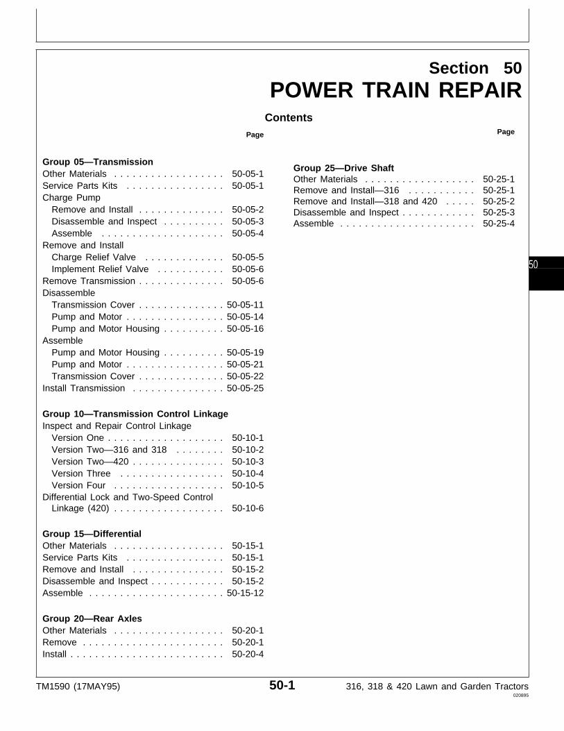
Section 50POWER TRAIN REPAIR
ContentsPage
Group 05—TransmissionOther Materials . . . . . . . . . . . . . . . . . . 50-05-1Service Parts Kits . . . . . . . . . . . . . . . . 50-05-1Charge Pump
Remove and Install . . . . . . . . . . . . . . 50-05-2Disassemble and Inspect . . . . . . . . . . 50-05-3Assemble . . . . . . . . . . . . . . . . . . . . 50-05-4
Remove and InstallCharge Relief Valve . . . . . . . . . . . . . 50-05-5Implement Relief Valve . . . . . . . . . . . 50-05-6
Remove Transmission . . . . . . . . . . . . . . 50-05-6Disassemble
Transmission Cover . . . . . . . . . . . . . . 50-05-11Pump and Motor . . . . . . . . . . . . . . . . 50-05-14Pump and Motor Housing . . . . . . . . . . 50-05-16
AssemblePump and Motor Housing . . . . . . . . . . 50-05-19Pump and Motor . . . . . . . . . . . . . . . . 50-05-21Transmission Cover . . . . . . . . . . . . . . 50-05-22
Install Transmission . . . . . . . . . . . . . . . 50-05-25
Group 10—Transmission Control LinkageInspect and Repair Control Linkage
Version One . . . . . . . . . . . . . . . . . . . 50-10-1Version Two—316 and 318 . . . . . . . . 50-10-2Version Two—420 . . . . . . . . . . . . . . . 50-10-3Version Three . . . . . . . . . . . . . . . . . 50-10-4Version Four . . . . . . . . . . . . . . . . . . 50-10-5
Differential Lock and Two-Speed ControlLinkage (420) . . . . . . . . . . . . . . . . . . 50-10-6
Group 15—DifferentialOther Materials . . . . . . . . . . . . . . . . . . 50-15-1Service Parts Kits . . . . . . . . . . . . . . . . 50-15-1Remove and Install . . . . . . . . . . . . . . . 50-15-2Disassemble and Inspect . . . . . . . . . . . . 50-15-2Assemble . . . . . . . . . . . . . . . . . . . . . . 50-15-12
Group 20—Rear AxlesOther Materials . . . . . . . . . . . . . . . . . . 50-20-1Remove . . . . . . . . . . . . . . . . . . . . . . . 50-20-1Install . . . . . . . . . . . . . . . . . . . . . . . . . 50-20-4
Page
Group 25—Drive ShaftOther Materials . . . . . . . . . . . . . . . . . . 50-25-1Remove and Install—316 . . . . . . . . . . . 50-25-1Remove and Install—318 and 420 . . . . . 50-25-2Disassemble and Inspect . . . . . . . . . . . . 50-25-3Assemble . . . . . . . . . . . . . . . . . . . . . . 50-25-4
TM1590 (17MAY95) 50-1 316, 318 & 420 Lawn and Garden Tractors020895
50

Contents
TM1590 (17MAY95) 50-2 316, 318 & 420 Lawn and Garden Tractors020895
50
OTHER MATERIAL
Number Name Use
M79292 MPG-2® Multi-Purpose Polymer Prevents parts from seizing. ApplyGrease to splines of transmission input
shaft.
®MPG-2 is a registered trademark of DuBois USA.
SERVICE PARTS KITS
The following kits are available through your partscatalog:
Charge Relief Valve Shim Pack Kit
Implement Relief Valve Shim Pack Kit
Differential Frame Support Bracket Replacement Kit forEarly Models
Motor Valve Plate Replacement Part for Early Models
MX,15905005,OTH-19-07MAR95
MX,15905005,KIT-19-23FEB95
Group 05Transmission
TM1590 (17MAY95) 50-05-1 316, 318 & 420 Lawn and Garden Tractors020895
50051

REMOVE AND INSTALL CHARGE PUMP
1. Remove fender deck and fuel tank.
2. Remove drive shaft. (See procedure in Group 25.)
N CAUTION: To avoid injury from escaping fluidunder pressure, stop engine and relieve thepressure in the system before disconnecting orconnecting hydraulic or other lines. Tighten allconnections before applying pressure.
3. Remove two cap screws and charge pump.
420 Shown
X98
11
-UN
-23A
UG
88M
3653
4
-U
N-2
5JA
N90
MX,15905005,2 -19-23FEB95
Transmission/Charge Pump
TM1590 (17MAY95) 50-05-2 316, 318 & 420 Lawn and Garden Tractors020895
5005
2
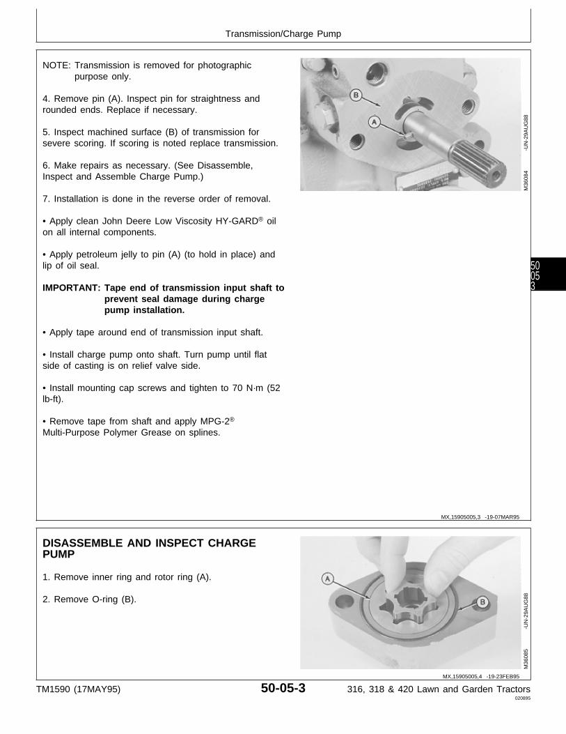
NOTE: Transmission is removed for photographicpurpose only.
4. Remove pin (A). Inspect pin for straightness androunded ends. Replace if necessary.
5. Inspect machined surface (B) of transmission forsevere scoring. If scoring is noted replace transmission.
6. Make repairs as necessary. (See Disassemble,Inspect and Assemble Charge Pump.)
7. Installation is done in the reverse order of removal.
• Apply clean John Deere Low Viscosity HY-GARD® oilon all internal components.
• Apply petroleum jelly to pin (A) (to hold in place) andlip of oil seal.
IMPORTANT: Tape end of transmission input shaft toprevent seal damage during chargepump installation.
• Apply tape around end of transmission input shaft.
• Install charge pump onto shaft. Turn pump until flatside of casting is on relief valve side.
• Install mounting cap screws and tighten to 70 N·m (52lb-ft).
• Remove tape from shaft and apply MPG-2®
Multi-Purpose Polymer Grease on splines.
M36
084
-UN
-29A
UG
88
DISASSEMBLE AND INSPECT CHARGEPUMP
1. Remove inner ring and rotor ring (A).
2. Remove O-ring (B).
M36
085
-UN
-29A
UG
88
MX,15905005,3 -19-07MAR95
MX,15905005,4 -19-23FEB95
Transmission/Charge Pump
TM1590 (17MAY95) 50-05-3 316, 318 & 420 Lawn and Garden Tractors020895
50053
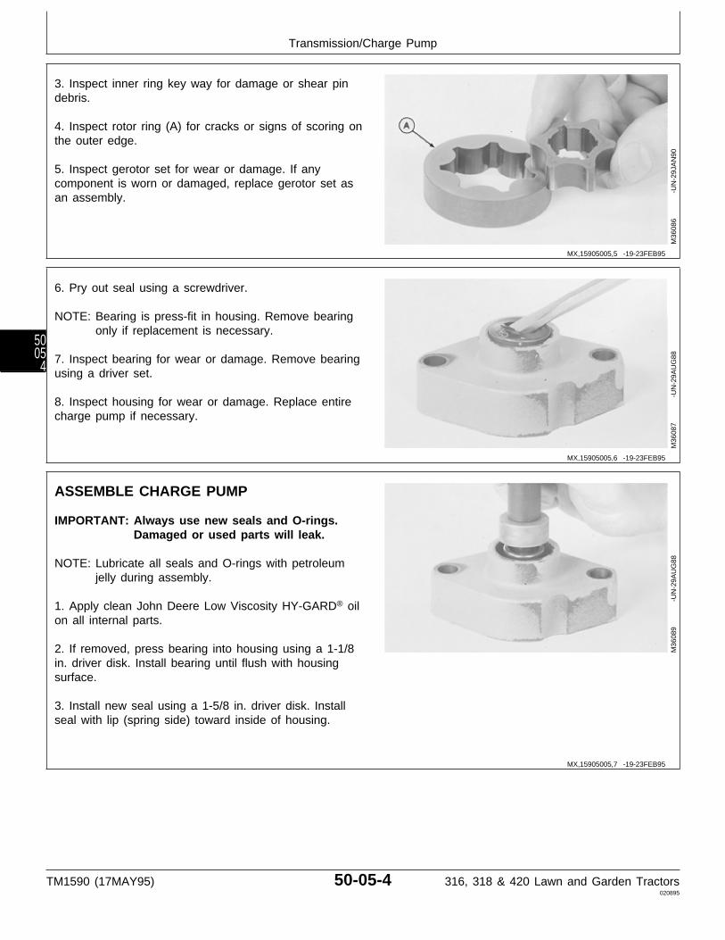
3. Inspect inner ring key way for damage or shear pindebris.
4. Inspect rotor ring (A) for cracks or signs of scoring onthe outer edge.
5. Inspect gerotor set for wear or damage. If anycomponent is worn or damaged, replace gerotor set asan assembly.
M36
086
-UN
-29J
AN
90
6. Pry out seal using a screwdriver.
NOTE: Bearing is press-fit in housing. Remove bearingonly if replacement is necessary.
7. Inspect bearing for wear or damage. Remove bearingusing a driver set.
8. Inspect housing for wear or damage. Replace entirecharge pump if necessary.
M36
087
-UN
-29A
UG
88
ASSEMBLE CHARGE PUMP
IMPORTANT: Always use new seals and O-rings.Damaged or used parts will leak.
NOTE: Lubricate all seals and O-rings with petroleumjelly during assembly.
1. Apply clean John Deere Low Viscosity HY-GARD® oilon all internal parts.
2. If removed, press bearing into housing using a 1-1/8in. driver disk. Install bearing until flush with housingsurface.
3. Install new seal using a 1-5/8 in. driver disk. Installseal with lip (spring side) toward inside of housing.
M36
089
-UN
-29A
UG
88
MX,15905005,5 -19-23FEB95
MX,15905005,6 -19-23FEB95
MX,15905005,7 -19-23FEB95
Transmission/Charge Pump
TM1590 (17MAY95) 50-05-4 316, 318 & 420 Lawn and Garden Tractors020895
5005
4
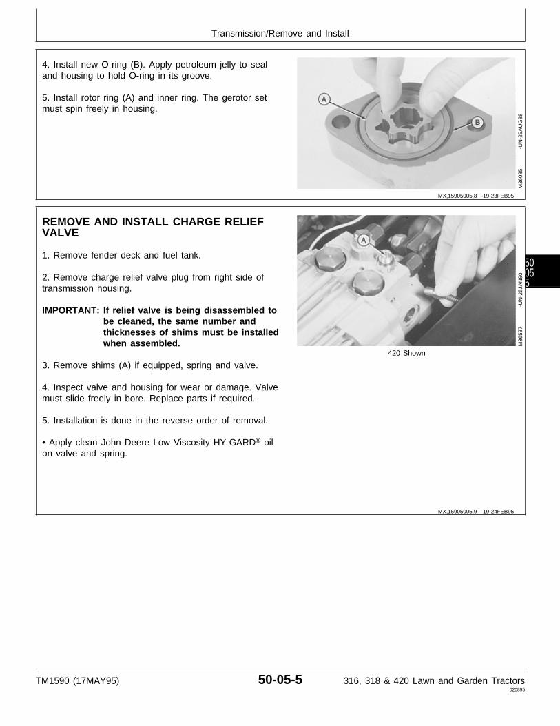
4. Install new O-ring (B). Apply petroleum jelly to sealand housing to hold O-ring in its groove.
5. Install rotor ring (A) and inner ring. The gerotor setmust spin freely in housing.
M36
085
-UN
-29A
UG
88
REMOVE AND INSTALL CHARGE RELIEFVALVE
1. Remove fender deck and fuel tank.
2. Remove charge relief valve plug from right side oftransmission housing.
IMPORTANT: If relief valve is being disassembled tobe cleaned, the same number andthicknesses of shims must be installedwhen assembled.
420 Shown
3. Remove shims (A) if equipped, spring and valve.
4. Inspect valve and housing for wear or damage. Valvemust slide freely in bore. Replace parts if required.
5. Installation is done in the reverse order of removal.
• Apply clean John Deere Low Viscosity HY-GARD® oilon valve and spring.
M36
537
-UN
-25J
AN
90
MX,15905005,8 -19-23FEB95
MX,15905005,9 -19-24FEB95
Transmission/Remove and Install
TM1590 (17MAY95) 50-05-5 316, 318 & 420 Lawn and Garden Tractors020895
50055
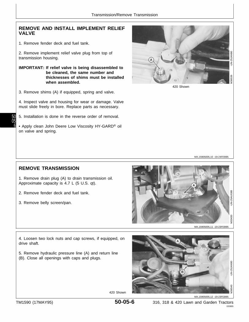
REMOVE AND INSTALL IMPLEMENT RELIEFVALVE
1. Remove fender deck and fuel tank.
2. Remove implement relief valve plug from top oftransmission housing.
IMPORTANT: If relief valve is being disassembled tobe cleaned, the same number andthicknesses of shims must be installedwhen assembled.
420 Shown
3. Remove shims (A) if equipped, spring and valve.
4. Inspect valve and housing for wear or damage. Valvemust slide freely in bore. Replace parts as necessary.
5. Installation is done in the reverse order of removal.
• Apply clean John Deere Low Viscosity HY-GARD® oilon valve and spring.
M36
539
-UN
-25J
AN
90
REMOVE TRANSMISSION
1. Remove drain plug (A) to drain transmission oil.Approximate capacity is 4.7 L (5 U.S. qt).
2. Remove fender deck and fuel tank.
3. Remove belly screen/pan.
M33
430
-UN
-25A
UG
88
4. Loosen two lock nuts and cap screws, if equipped, ondrive shaft.
5. Remove hydraulic pressure line (A) and return line(B). Close all openings with caps and plugs.
420 Shown M36
540
-UN
-25J
AN
90
MX,15905005,10 -19-24FEB95
MX,15905005,11 -19-23FEB95
MX,15905005,12 -19-23FEB95
Transmission/Remove Transmission
TM1590 (17MAY95) 50-05-6 316, 318 & 420 Lawn and Garden Tractors020895
5005
6
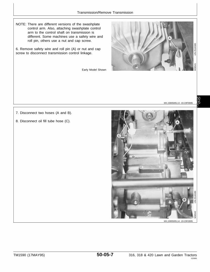
NOTE: There are different versions of the swashplatecontrol arm. Also, attaching swashplate controlarm to the control shaft on transmission isdifferent. Some machines use a safety wire androll pin, others use a nut and cap screw.
6. Remove safety wire and roll pin (A) or nut and capscrew to disconnect transmission control linkage.
Early Model Shown M36
541
-UN
-25J
AN
90
7. Disconnect two hoses (A and B).
8. Disconnect oil fill tube hose (C).
M36
542
-UN
-25J
AN
90
MX,15905005,13 -19-23FEB95
MX,15905005,14 -19-23FEB95
Transmission/Remove Transmission
TM1590 (17MAY95) 50-05-7 316, 318 & 420 Lawn and Garden Tractors020895
50057
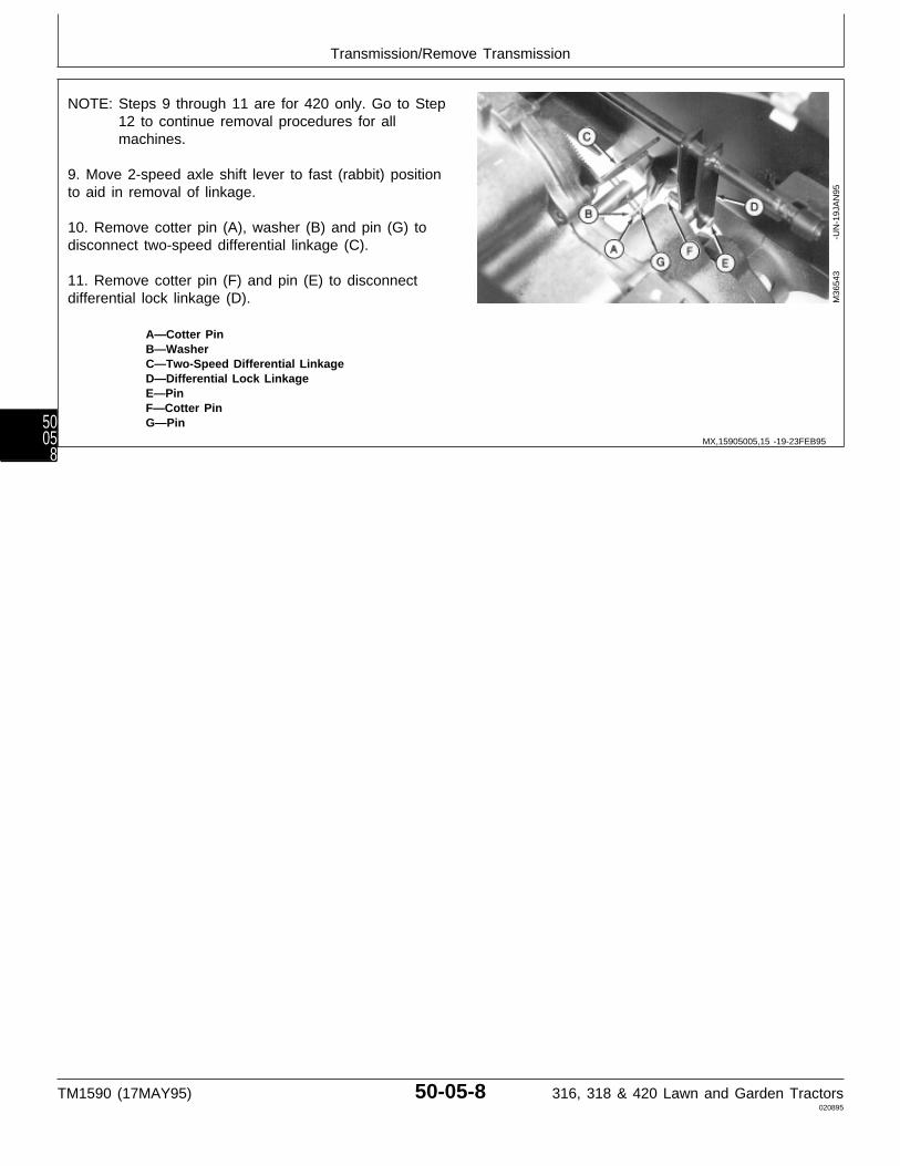
NOTE: Steps 9 through 11 are for 420 only. Go to Step12 to continue removal procedures for allmachines.
9. Move 2-speed axle shift lever to fast (rabbit) positionto aid in removal of linkage.
10. Remove cotter pin (A), washer (B) and pin (G) todisconnect two-speed differential linkage (C).
11. Remove cotter pin (F) and pin (E) to disconnectdifferential lock linkage (D).
A—Cotter PinB—WasherC—Two-Speed Differential LinkageD—Differential Lock LinkageE—PinF—Cotter PinG—Pin
M36
543
-UN
-19J
AN
95
MX,15905005,15 -19-23FEB95
Transmission/Remove Transmission
TM1590 (17MAY95) 50-05-8 316, 318 & 420 Lawn and Garden Tractors020895
5005
8
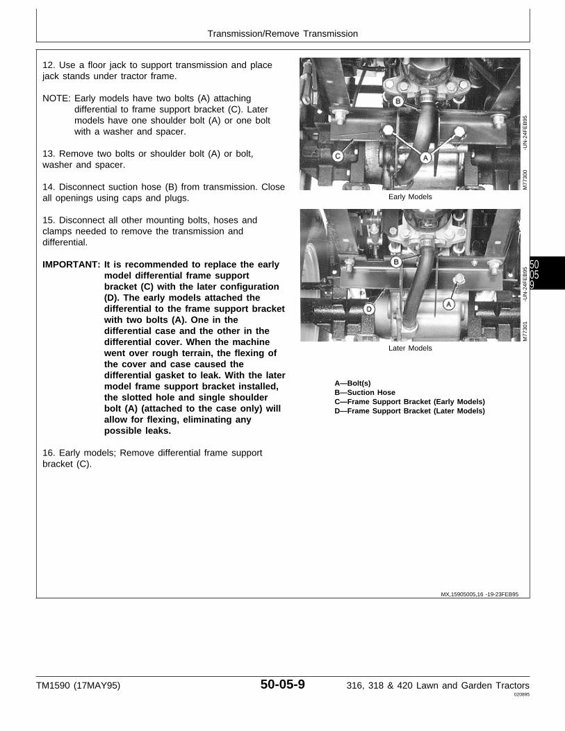
12. Use a floor jack to support transmission and placejack stands under tractor frame.
NOTE: Early models have two bolts (A) attachingdifferential to frame support bracket (C). Latermodels have one shoulder bolt (A) or one boltwith a washer and spacer.
13. Remove two bolts or shoulder bolt (A) or bolt,washer and spacer.
14. Disconnect suction hose (B) from transmission. Closeall openings using caps and plugs. Early Models
15. Disconnect all other mounting bolts, hoses andclamps needed to remove the transmission anddifferential.
IMPORTANT: It is recommended to replace the earlymodel differential frame supportbracket (C) with the later configuration(D). The early models attached thedifferential to the frame support bracketwith two bolts (A). One in thedifferential case and the other in thedifferential cover. When the machine
Later Modelswent over rough terrain, the flexing ofthe cover and case caused thedifferential gasket to leak. With the later
A—Bolt(s)model frame support bracket installed,B—Suction Hose
the slotted hole and single shoulder C—Frame Support Bracket (Early Models)bolt (A) (attached to the case only) will D—Frame Support Bracket (Later Models)allow for flexing, eliminating anypossible leaks.
16. Early models; Remove differential frame supportbracket (C).
M77
300
-UN
-24F
EB
95M
7730
1
-U
N-2
4FE
B95
MX,15905005,16 -19-23FEB95
Transmission/Remove Transmission
TM1590 (17MAY95) 50-05-9 316, 318 & 420 Lawn and Garden Tractors020895
50059

NOTE: Disconnect brakes on both sides of machine.
17. Disconnect spring (A).
18. Remove nut (B), plate or washer (D) and spring (C).
19. Bend tabs (F) flat. Remove two cap screws (E) fromeach side of machine.
20. Lower differential and transmission assembly and rollaway from frame.
Early ModelsA—Return SpringB—NutC—SpringD—Plate (Early Models) —Washer (Later Models)E—Mounting Cap Screw (2 used)F—Lock Plate Tab
Later Models
M77
903
-UN
-19J
AN
95M
7733
2
-U
N-1
3FE
B95
21. Thoroughly clean outside surface of differentialassembly with steam cleaner or cleaning solvent.
IMPORTANT: Mark spacers and cap screws beforedisassembly. Each spacer must beinstalled in its original location.
22. Remove four cap screws and spacers (A) to removetransmission.
23. Make repairs as necessary. (See procedures in thisgroup.)
M36
550
-UN
-25J
AN
90
MX,15905005,17 -19-23FEB95
MX,15905005,18 -19-23FEB95
Transmission/Remove Transmission
TM1590 (17MAY95) 50-05-10 316, 318 & 420 Lawn and Garden Tractors020895
500510
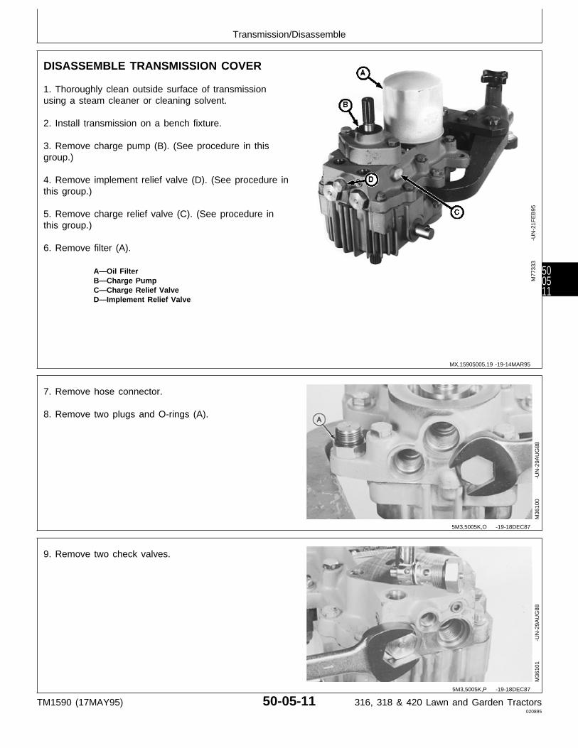
DISASSEMBLE TRANSMISSION COVER
1. Thoroughly clean outside surface of transmissionusing a steam cleaner or cleaning solvent.
2. Install transmission on a bench fixture.
3. Remove charge pump (B). (See procedure in thisgroup.)
4. Remove implement relief valve (D). (See procedure inthis group.)
5. Remove charge relief valve (C). (See procedure inthis group.)
6. Remove filter (A).
A—Oil FilterB—Charge PumpC—Charge Relief ValveD—Implement Relief Valve
M77
333
-UN
-21F
EB
95
7. Remove hose connector.
8. Remove two plugs and O-rings (A).
M36
100
-UN
-29A
UG
88
9. Remove two check valves.
M36
101
-UN
-29A
UG
88
MX,15905005,19 -19-14MAR95
5M3,5005K,O -19-18DEC87
5M3,5005K,P -19-18DEC87
Transmission/Disassemble
TM1590 (17MAY95) 50-05-11 316, 318 & 420 Lawn and Garden Tractors020895
500511

10. Remove O-ring, backup ring (B), and O-ring (A).
NOTE: Originally equipped 420 Lawn and GardenTractor transmissions do no have manuallyoperated check valves. If check valves havebeen replaced; service replacements will havemanually operated check valves.
11. Internal valve (C) must move freely inside checkvalve.
M36
102
-UN
-29A
UG
88
12. Remove four pipe plugs.
M77
334
-UN
-21F
EB
95
13. Remove snap ring to remove output shaft drive gear.
14. Remove O-ring.
M36
104
-UN
-29A
UG
88
IMPORTANT: Do not disassemble the transmissionany further while in the bench fixture.
15. LOOSEN eight cap screws (do not remove). Removetransmission from bench fixture.
M36
522
-UN
-25J
AN
90
5M3,5005K,Q -19-18DEC87
MX,15905005,41 -19-14MAR95
5M3,5005K,S -19-18DEC87
5M3,5005K,T -19-18DEC87
Transmission/Disassemble
TM1590 (17MAY95) 50-05-12 316, 318 & 420 Lawn and Garden Tractors020895
500512
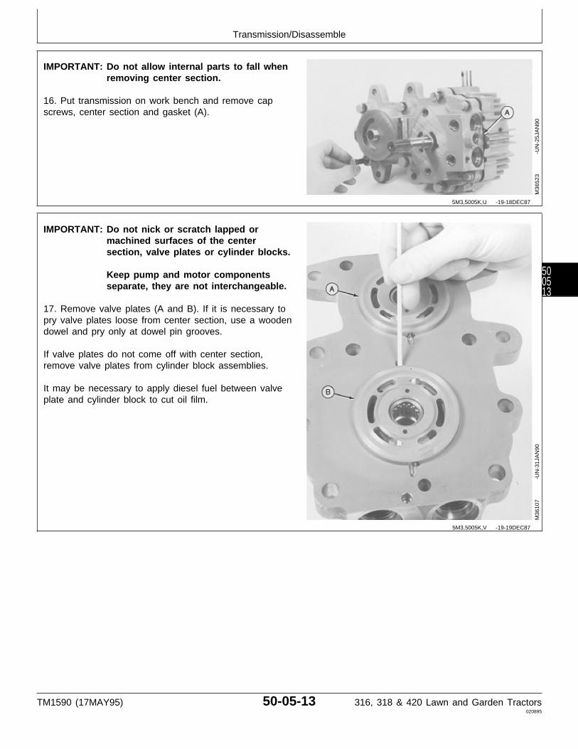
IMPORTANT: Do not allow internal parts to fall whenremoving center section.
16. Put transmission on work bench and remove capscrews, center section and gasket (A).
M36
523
-UN
-25J
AN
90
IMPORTANT: Do not nick or scratch lapped ormachined surfaces of the centersection, valve plates or cylinder blocks.
Keep pump and motor componentsseparate, they are not interchangeable.
17. Remove valve plates (A and B). If it is necessary topry valve plates loose from center section, use a woodendowel and pry only at dowel pin grooves.
If valve plates do not come off with center section,remove valve plates from cylinder block assemblies.
It may be necessary to apply diesel fuel between valveplate and cylinder block to cut oil film.
M36
107
-UN
-31J
AN
90
5M3,5005K,U -19-18DEC87
5M3,5005K,V -19-19DEC87
Transmission/Disassemble
TM1590 (17MAY95) 50-05-13 316, 318 & 420 Lawn and Garden Tractors020895
500513
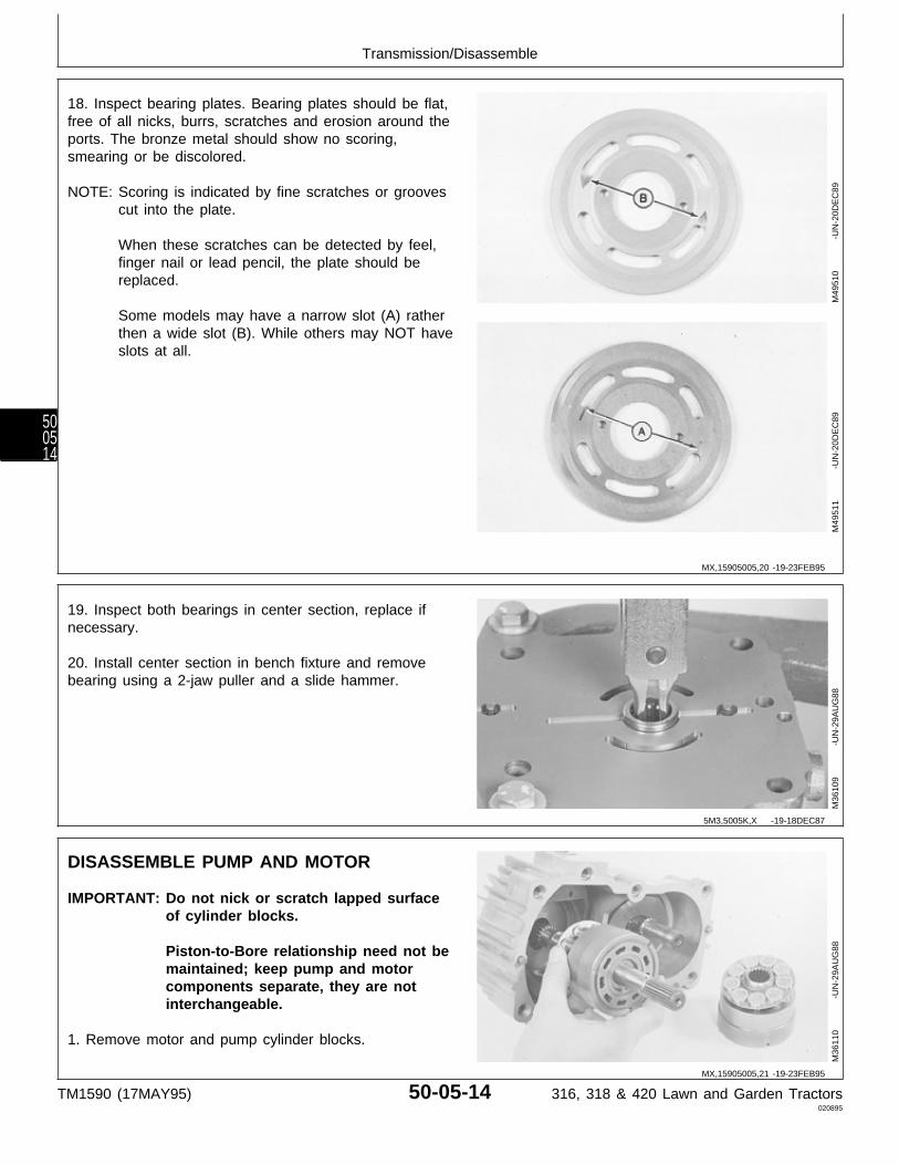
18. Inspect bearing plates. Bearing plates should be flat,free of all nicks, burrs, scratches and erosion around theports. The bronze metal should show no scoring,smearing or be discolored.
NOTE: Scoring is indicated by fine scratches or groovescut into the plate.
When these scratches can be detected by feel,finger nail or lead pencil, the plate should bereplaced.
Some models may have a narrow slot (A) ratherthen a wide slot (B). While others may NOT haveslots at all.
M49
510
-UN
-20D
EC
89M
4951
1
-U
N-2
0DE
C89
19. Inspect both bearings in center section, replace ifnecessary.
20. Install center section in bench fixture and removebearing using a 2-jaw puller and a slide hammer.
M36
109
-UN
-29A
UG
88
DISASSEMBLE PUMP AND MOTOR
IMPORTANT: Do not nick or scratch lapped surfaceof cylinder blocks.
Piston-to-Bore relationship need not bemaintained; keep pump and motorcomponents separate, they are notinterchangeable.
1. Remove motor and pump cylinder blocks.
M36
110
-UN
-29A
UG
88
MX,15905005,20 -19-23FEB95
5M3,5005K,X -19-18DEC87
MX,15905005,21 -19-23FEB95
Transmission/Disassemble
TM1590 (17MAY95) 50-05-14 316, 318 & 420 Lawn and Garden Tractors020895
500514
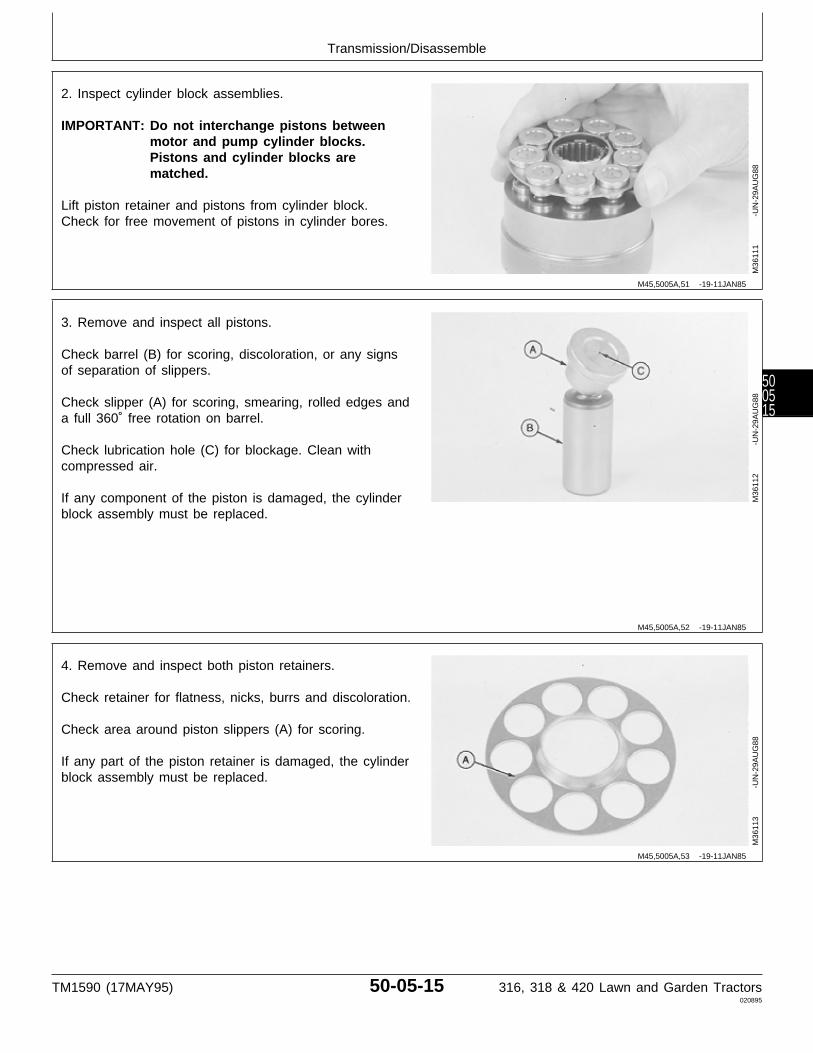
2. Inspect cylinder block assemblies.
IMPORTANT: Do not interchange pistons betweenmotor and pump cylinder blocks.Pistons and cylinder blocks arematched.
Lift piston retainer and pistons from cylinder block.Check for free movement of pistons in cylinder bores.
M36
111
-UN
-29A
UG
88
3. Remove and inspect all pistons.
Check barrel (B) for scoring, discoloration, or any signsof separation of slippers.
Check slipper (A) for scoring, smearing, rolled edges anda full 360˚ free rotation on barrel.
Check lubrication hole (C) for blockage. Clean withcompressed air.
If any component of the piston is damaged, the cylinderblock assembly must be replaced.
M36
112
-UN
-29A
UG
88
4. Remove and inspect both piston retainers.
Check retainer for flatness, nicks, burrs and discoloration.
Check area around piston slippers (A) for scoring.
If any part of the piston retainer is damaged, the cylinderblock assembly must be replaced.
M36
113
-UN
-29A
UG
88
M45,5005A,51 -19-11JAN85
M45,5005A,52 -19-11JAN85
M45,5005A,53 -19-11JAN85
Transmission/Disassemble
TM1590 (17MAY95) 50-05-15 316, 318 & 420 Lawn and Garden Tractors020895
500515
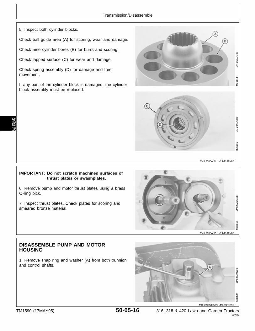
5. Inspect both cylinder blocks.
Check ball guide area (A) for scoring, wear and damage.
Check nine cylinder bores (B) for burrs and scoring.
Check lapped surface (C) for wear and damage.
Check spring assembly (D) for damage and freemovement.
If any part of the cylinder block is damaged, the cylinderblock assembly must be replaced.
M36
114
-UN
-29A
UG
88M
3611
5
-U
N-2
9AU
G88
IMPORTANT: Do not scratch machined surfaces ofthrust plates or swashplates.
6. Remove pump and motor thrust plates using a brassO-ring pick.
7. Inspect thrust plates. Check plates for scoring andsmeared bronze material.
M36
116
-UN
-29A
UG
88
DISASSEMBLE PUMP AND MOTORHOUSING
1. Remove snap ring and washer (A) from both trunnionand control shafts.
M36
524
-UN
-25J
AN
90
M45,5005A,54 -19-11JAN85
M45,5005A,55 -19-11JAN85
MX,15905005,22 -19-23FEB95
Transmission/Disassemble
TM1590 (17MAY95) 50-05-16 316, 318 & 420 Lawn and Garden Tractors020895
500516

IMPORTANT: Pump shaft and bearing assemblycould restrict movement of swashplate.Full swashplate movement isapproximately 25 mm (1 in.) in eachdirection. If necessary tap shaft with asoft faced hammer.
2. Push top of swashplate (C) down until it contacts thestops in the housing.
IMPORTANT: DO NOT drive pins after they bottom.Housing damage will result.
3. Drive pin (B) until it bottoms in housing.A—Trunnion ShaftB—Spring Pin4. Drive two pins (D) until the lower one bottoms inC—Pump Swashplatehousing.D—Spring Pin (2 used)E—Control Shaft
5. Turn swashplate to the neutral position. Pins should F—Motor Housingfall into housing.
6. Repeat the above steps to remove second pin (D).
7. Remove control shaft (E) and trunnion shaft (A) toremove swashplate.
8. Inspect swashplate and motor housing (F).
M36
525
-UN
-25J
AN
90
9. Remove pump shaft.
M36
119
-UN
-29A
UG
88
5M3,5005K,Z -19-18DEC87
M45,5005A,58 -19-11JAN85
Transmission/Disassemble
TM1590 (17MAY95) 50-05-17 316, 318 & 420 Lawn and Garden Tractors020895
500517

10. Inspect bearing, replace if necessary.
IMPORTANT: Be sure to hold shaft while removingbearing.
11. Remove bearing using a 1 in. driver disk (A), bearingpuller attachment and a press.
M36
120
-UN
-29A
UG
88
12. Remove three seals from housing.
M36
121
-UN
-29A
UG
88
NOTE: Some transmissions will have bearings, whileothers will have bushings.
13. Inspect trunnion bearing and control shaft bearing.Replace if necessary.
14. Drive bearings or bushings through housing using a13/16 in. driver disk (A) for bearings and a 7/8 in. driverdisk for bushings.
M36
122
-UN
-29A
UG
88
IMPORTANT: Be sure to hold shaft and bearing whenremoving from housing.
15. Remove motor shaft and bearing. Using a 1-in. driverdisk (A), and a press.
M36
123
-UN
-29A
UG
88
M45,5005A,59 -19-13MAR85
M45,5005A,60 -19-11JAN85
5M3,5005K,AA -19-18DEC87
M45,5005A,62 -19-13MAR85
Transmission/Disassemble
TM1590 (17MAY95) 50-05-18 316, 318 & 420 Lawn and Garden Tractors020895
500518
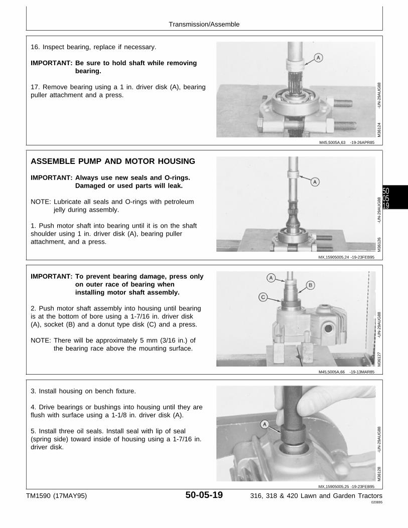
16. Inspect bearing, replace if necessary.
IMPORTANT: Be sure to hold shaft while removingbearing.
17. Remove bearing using a 1 in. driver disk (A), bearingpuller attachment and a press.
M36
124
-UN
-29A
UG
88
ASSEMBLE PUMP AND MOTOR HOUSING
IMPORTANT: Always use new seals and O-rings.Damaged or used parts will leak.
NOTE: Lubricate all seals and O-rings with petroleumjelly during assembly.
1. Push motor shaft into bearing until it is on the shaftshoulder using 1 in. driver disk (A), bearing pullerattachment, and a press.
M36
126
-UN
-29A
UG
88
IMPORTANT: To prevent bearing damage, press onlyon outer race of bearing wheninstalling motor shaft assembly.
2. Push motor shaft assembly into housing until bearingis at the bottom of bore using a 1-7/16 in. driver disk(A), socket (B) and a donut type disk (C) and a press.
NOTE: There will be approximately 5 mm (3/16 in.) ofthe bearing race above the mounting surface.
M36
127
-UN
-29A
UG
88
3. Install housing on bench fixture.
4. Drive bearings or bushings into housing until they areflush with surface using a 1-1/8 in. driver disk (A).
5. Install three oil seals. Install seal with lip of seal(spring side) toward inside of housing using a 1-7/16 in.driver disk.
M36
128
-UN
-29A
UG
88
M45,5005A,63 -19-26APR85
MX,15905005,24 -19-23FEB95
M45,5005A,66 -19-13MAR85
MX,15905005,25 -19-23FEB95
Transmission/Assemble
TM1590 (17MAY95) 50-05-19 316, 318 & 420 Lawn and Garden Tractors020895
500519
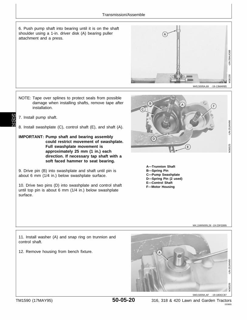
6. Push pump shaft into bearing until it is on the shaftshoulder using a 1-in. driver disk (A) bearing pullerattachment and a press.
M36
130
-UN
-29A
UG
88
NOTE: Tape over splines to protect seals from possibledamage when installing shafts, remove tape afterinstallation.
7. Install pump shaft.
8. Install swashplate (C), control shaft (E), and shaft (A).
IMPORTANT: Pump shaft and bearing assemblycould restrict movement of swashplate.Full swashplate movement isapproximately 25 mm (1 in.) eachdirection. If necessary tap shaft with asoft faced hammer to seat bearing.
A—Trunnion ShaftB—Spring Pin9. Drive pin (B) into swashplate and shaft until pin isC—Pump Swashplateabout 6 mm (1/4 in.) below swashplate surface.D—Spring Pin (2 used)E—Control Shaft
10. Drive two pins (D) into swashplate and control shaft F—Motor Housinguntil top pin is about 6 mm (1/4 in.) below swashplatesurface.
M36
525
-UN
-25J
AN
90
11. Install washer (A) and snap ring on trunnion andcontrol shaft.
12. Remove housing from bench fixture.
M36
526
-UN
-25J
AN
90
M45,5005A,69 -19-13MAR85
MX,15905005,26 -19-23FEB95
5M3,5005K,AF -19-18DEC87
Transmission/Assemble
TM1590 (17MAY95) 50-05-20 316, 318 & 420 Lawn and Garden Tractors020895
500520
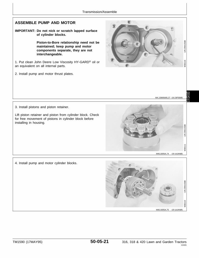
ASSEMBLE PUMP AND MOTOR
IMPORTANT: Do not nick or scratch lapped surfaceof cylinder blocks.
Piston-to-Bore relationship need not bemaintained; keep pump and motorcomponents separate, they are notinterchangeable.
1. Put clean John Deere Low Viscosity HY-GARD® oil oran equivalent on all internal parts.
2. Install pump and motor thrust plates.
M36
116
-UN
-29A
UG
88
3. Install pistons and piston retainer.
Lift piston retainer and piston from cylinder block. Checkfor free movement of pistons in cylinder block beforeinstalling in housing.
M36
111
-UN
-29A
UG
88
4. Install pump and motor cylinder blocks.
M36
110
-UN
-29A
UG
88
MX,15905005,27 -19-23FEB95
M45,5005A,74 -19-14JAN85
M45,5005A,75 -19-14JAN85
Transmission/Assemble
TM1590 (17MAY95) 50-05-21 316, 318 & 420 Lawn and Garden Tractors020895
500521

ASSEMBLE TRANSMISSION COVER
IMPORTANT: Do not nick or scratch lapped ormachined surfaces of the centersection, valve plates or cylinder block.
Keep pump and motor componentsseparate. They are not interchangeable.
Always use new seals and O-rings.Damaged or used parts will leak.
NOTE: Lubricate all seals and O-rings with petroleumjelly during assembly.
1. Install two needle bearings. Drive bearings intohousing until they are approximately 3 mm (0.118 in.)above the surface of the housing using a 5/8 in. driverdisk (A).
M36
132
-UN
-29A
UG
88
2. Put clean John Deere Low Viscosity HY-GARD® oil onvalve plates and housing surface.
IMPORTANT: Pump valve plate (B) has TWO slottedports (D).
Motor valve plate (A) may, or may nothave slotted ports. Early models haveFOUR slotted ports (C). Quiet hydro’s(later models) have no slotted ports. Allservice or replacement plates will nothave slotted ports.
NOTE: The motor valve plates are interchangeablebetween quiet hydros and early models.
3. Install pump valve plate (B) and motor valve plate (A)over the protruding bearings and align slots in plateswith pins in housing.
A—Motor Valve PlateB—Pump Valve PlateC—Slotted Ports (4) (Early Models)D—Slotted Ports (2)
M36
133
-UN
-22N
OV
89
MX,15905005,28 -19-23FEB95
MX,15905005,29 -19-23FEB95
Transmission/Assemble
TM1590 (17MAY95) 50-05-22 316, 318 & 420 Lawn and Garden Tractors020895
500522

IMPORTANT: Use extreme care when assembling thecenter section, valve plates andcylinder block to avoid dropping,nicking or scratching lapped surfaces.
4. Install center section and gasket (A) on housing andinstall eight cap screws. Tighten cap screws evenly.
NOTE: Center section will seem springy, this is becausethe springs inside the cylinder blocks are beingcompressed.
M36
523
-UN
-25J
AN
90
5. Install transmission in bench fixture.
IMPORTANT: Check for proper internal assembly byslowly rotating pump, motor andcontrol shaft while tightening capscrews.
6. Tighten cap screws to 35 N·m (26 lb-ft).
M77
335
-UN
-21F
EB
95
7. Install gear on motor shaft (output shaft). Install snapring.
M36
104
-UN
-29A
UG
88
5M3,5005K,AG -19-18DEC87
MX,15905005,30 -19-14MAR95
M45,5005A,80 -19-14JAN85
Transmission/Assemble
TM1590 (17MAY95) 50-05-23 316, 318 & 420 Lawn and Garden Tractors020895
500523

8. Install and tighten four pipe plugs.
M77
334
-UN
-21F
EB
95
9. Install O-ring (A), backup ring (B) and O-ring. Internalvalve (C) must move freely.
M36
102
-UN
-29A
UG
88
10. Install and tighten two check valves.
M36
101
-UN
-29A
UG
88
11. Install plugs and O-rings (A).
12. Install suction line fitting.
M36
100
-UN
-29A
UG
88
MX,15905005,42 -19-14MAR95
M45,5005A,82 -19-13MAR85
M45,5005A,83 -19-14JAN85
5M3,5005K,AI -19-18DEC87
Transmission/Assemble
TM1590 (17MAY95) 50-05-24 316, 318 & 420 Lawn and Garden Tractors020895
500524
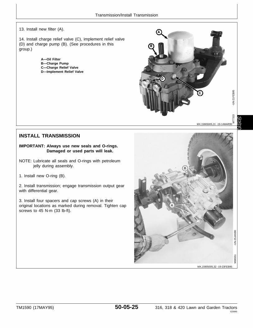
13. Install new filter (A).
14. Install charge relief valve (C), implement relief valve(D) and charge pump (B). (See procedures in thisgroup.)
A—Oil FilterB—Charge PumpC—Charge Relief ValveD—Implement Relief Valve
M77
333
-UN
-21F
EB
95
INSTALL TRANSMISSION
IMPORTANT: Always use new seals and O-rings.Damaged or used parts will leak.
NOTE: Lubricate all seals and O-rings with petroleumjelly during assembly.
1. Install new O-ring (B).
2. Install transmission; engage transmission output gearwith differential gear.
3. Install four spacers and cap screws (A) in theiroriginal locations as marked during removal. Tighten capscrews to 45 N·m (33 lb-ft).
M36
551
-UN
-25J
AN
90
MX,15905005,31 -19-14MAR95
MX,15905005,32 -19-23FEB95
Transmission/Install Transmission
TM1590 (17MAY95) 50-05-25 316, 318 & 420 Lawn and Garden Tractors020895
500525
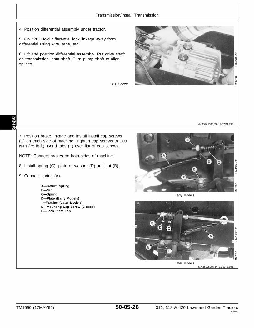
4. Position differential assembly under tractor.
5. On 420; Hold differential lock linkage away fromdifferential using wire, tape, etc.
6. Lift and position differential assembly. Put drive shafton transmission input shaft. Turn pump shaft to alignsplines.
420 Shown M36
578
-UN
-25J
AN
90
7. Position brake linkage and install install cap screws(E) on each side of machine. Tighten cap screws to 100N·m (75 lb-ft). Bend tabs (F) over flat of cap screws.
NOTE: Connect brakes on both sides of machine.
8. Install spring (C), plate or washer (D) and nut (B).
9. Connect spring (A).
A—Return SpringB—NutC—Spring Early ModelsD—Plate (Early Models) —Washer (Later Models)E—Mounting Cap Screw (2 used)F—Lock Plate Tab
Later Models
M77
903
-UN
-19J
AN
95M
7733
2
-U
N-1
3FE
B95
MX,15905005,33 -19-07MAR95
MX,15905005,34 -19-23FEB95
Transmission/Install Transmission
TM1590 (17MAY95) 50-05-26 316, 318 & 420 Lawn and Garden Tractors020895
500526

10. Lock brake pedals together (318 and 420) and applypark brake.
11. Loosen lock nut (A).
12. Turn nut until spring is 42 mm (1.650 in.) long.Tighten lock nut.
M36
554
-UN
-25J
AN
90
NOTE: Early models have two bolts (A) attachingdifferential to frame support bracket (C). Latermodels have one shoulder bolt (A) or one boltwith a washer and spacer.
IMPORTANT: It is recommended to replace the earlymodel differential frame supportbracket (C) with the later configuration(D). The early models attached thedifferential to the frame support bracketwith two bolts (A). One in thedifferential case and the other in thedifferential cover. When the machine Early Models
went over rough terrain, the flexing ofthe cover and case caused thedifferential gasket to leak. With the latermodel frame support bracket installed,the slotted hole and single shoulderbolt (A) (attached to the case only) willallow for flexing, eliminating anypossible leaks.
13. Early models; Install new differential frame supportbracket (D).
14. Install shoulder bolt (A) or bolt, washer and spacer.Later Models
Tighten to 61 N·m (45 lb-ft).
15. Attach all mounting bolts, hoses and clamps.A—Bolt(s)B—Suction Hose
16. Connect suction hose (B). C—Differential Frame Support Bracket (EarlyModels)
17. Remove jack stands and lower tractor. D—Differential Frame Support Bracket (LaterModels)
M77
300
-UN
-24F
EB
95M
7730
1
-U
N-2
4FE
B95
MX,15905005,35 -19-23FEB95
MX,15905005,36 -19-23FEB95
Transmission/Install Transmission
TM1590 (17MAY95) 50-05-27 316, 318 & 420 Lawn and Garden Tractors020895
500527
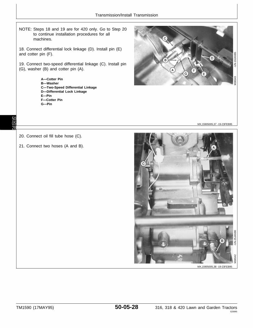
NOTE: Steps 18 and 19 are for 420 only. Go to Step 20to continue installation procedures for allmachines.
18. Connect differential lock linkage (D). Install pin (E)and cotter pin (F).
19. Connect two-speed differential linkage (C). Install pin(G), washer (B) and cotter pin (A).
A—Cotter PinB—WasherC—Two-Speed Differential LinkageD—Differential Lock LinkageE—PinF—Cotter PinG—Pin
M36
543
-UN
-19J
AN
95
20. Connect oil fill tube hose (C).
21. Connect two hoses (A and B).
M36
542
-UN
-25J
AN
90
MX,15905005,37 -19-23FEB95
MX,15905005,38 -19-23FEB95
Transmission/Install Transmission
TM1590 (17MAY95) 50-05-28 316, 318 & 420 Lawn and Garden Tractors020895
500528
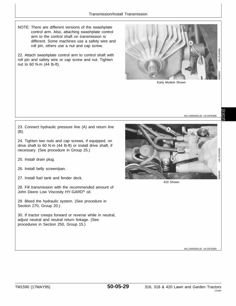
NOTE: There are different versions of the swashplatecontrol arm. Also, attaching swashplate controlarm to the control shaft on transmission isdifferent. Some machines use a safety wire androll pin, others use a nut and cap screw.
22. Attach swashplate control arm to control shaft withroll pin and safety wire or cap screw and nut. Tightennut to 60 N·m (44 lb-ft).
Early Models Shown
M36
541
-UN
-25J
AN
90
23. Connect hydraulic pressure line (A) and return line(B).
24. Tighten two nuts and cap screws, if equipped, ondrive shaft to 60 N·m (44 lb-ft) or install drive shaft, ifnecessary. (See procedure in Group 25.)
25. Install drain plug.
26. Install belly screen/pan.
27. Install fuel tank and fender deck.420 Shown
28. Fill transmission with the recommended amount ofJohn Deere Low Viscosity HY-GARD® oil.
29. Bleed the hydraulic system. (See procedure inSection 270, Group 20.)
30. If tractor creeps forward or reverse while in neutral,adjust neutral and neutral return linkage. (Seeprocedures in Section 250, Group 15.)
M36
540
-UN
-25J
AN
90
MX,15905005,39 -19-23FEB95
MX,15905005,40 -19-23FEB95
Transmission/Install Transmission
TM1590 (17MAY95) 50-05-29 316, 318 & 420 Lawn and Garden Tractors020895
500529

Transmission/Install Transmission
TM1590 (17MAY95) 50-05-30 316, 318 & 420 Lawn and Garden Tractors020895
500530
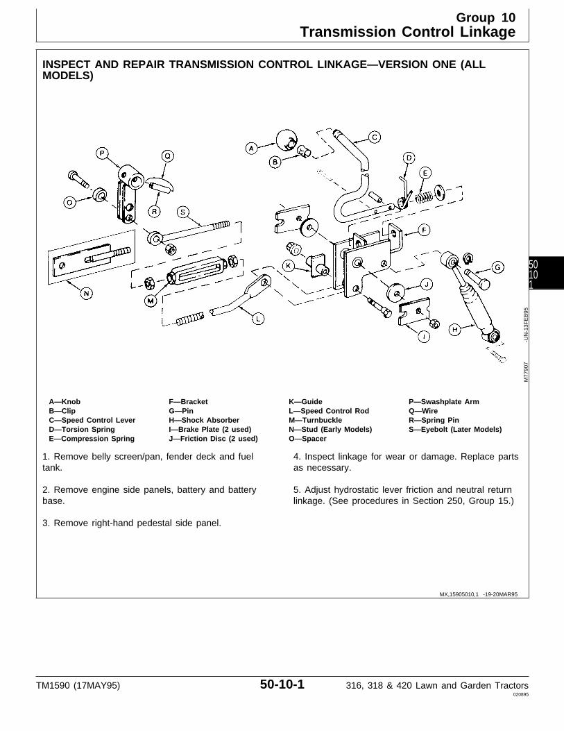
INSPECT AND REPAIR TRANSMISSION CONTROL LINKAGE—VERSION ONE (ALLMODELS)
A—Knob F—Bracket K—Guide P—Swashplate ArmB—Clip G—Pin L—Speed Control Rod Q—WireC—Speed Control Lever H—Shock Absorber M—Turnbuckle R—Spring PinD—Torsion Spring I—Brake Plate (2 used) N—Stud (Early Models) S—Eyebolt (Later Models)E—Compression Spring J—Friction Disc (2 used) O—Spacer
1. Remove belly screen/pan, fender deck and fueltank.
2. Remove engine side panels, battery and batterybase.
3. Remove right-hand pedestal side panel.
4. Inspect linkage for wear or damage. Replace partsas necessary.
5. Adjust hydrostatic lever friction and neutral returnlinkage. (See procedures in Section 250, Group 15.)
M77
907
-UN
-13F
EB
95
MX,15905010,1 -19-20MAR95
Group 10Transmission Control Linkage
TM1590 (17MAY95) 50-10-1 316, 318 & 420 Lawn and Garden Tractors020895
50101

INSPECT AND REPAIR TRANSMISSION CONTROL LINKAGE—VERSION TWO (316 AND318)
A—Knob F—Compression Spring K—Spacer P—Cap Screw (Later Models)B—Clip G—Friction Disc (2 used) L—Eyebolt Q—Swashplate Arm (LaterC—Speed Control Lever H—Speed Control Rod M—Guide Models)D—Shock Absorber I—Spacer N—Weld NutE—Spacer J—Turnbuckle O—Swashplate Arm
Assembly (Early Models)
1. Remove belly screen, fender deck and fuel tank.
2. Remove engine side panels, battery and batterybase.
3. Remove right-hand pedestal side panel.
4. Inspect linkage for wear or damage. Replace partsas necessary.
5. Adjust hydrostatic lever friction. (See procedure inSection 250, Group 15.)
6. Later Models; After connecting swashplate arm (Q)to transmission control shaft, tighten cap screw (P) to60 N·m (44 lb-ft).
7. Adjust neutral return linkage. (See procedure inSection 250, Group 15.)
M77
908
-UN
-13M
AR
95
MX,15905010,2 -19-08MAY95
Transmission Control Linkage/Inspect and Repair Control Linkage
TM1590 (17MAY95) 50-10-2 316, 318 & 420 Lawn and Garden Tractors020895
5010
2

INSPECT AND REPAIR TRANSMISSION CONTROL LINKAGE—VERSION TWO (420)
A—Knob F—Bracket K—Guide P—Cap Screw (Later Models)B—Clip G—Pin L—Speed Control Rod Q—Swashplate Arm (LaterC—Speed Control Lever H—Shock Absorber M—Turnbuckle Models)D—Torsion Spring I—Brake Plate (2 used) N—Eyebolt R—Swashplate ArmE—Compression Spring J—Friction Disc (2 used) O—Spacer Assembly (Early Models)
1. Remove belly pan, fender deck and fuel tank.
2. Remove engine side panels, battery and batterybase.
3. Remove right-hand pedestal side panel.
4. Inspect linkage for wear or damage. Replace partsas necessary.
5. Adjust hydrostatic lever friction. (See procedure inSection 250, Group 15.)
6. Later Models; After connecting swashplate arm (Q)to transmission control shaft, tighten cap screw (P) to60 N·m (44 lb-ft).
7. Adjust neutral return linkage. (See procedure inSection 250, Group 15.)
M77
909
-UN
-13F
EB
95
MX,15905010,3 -19-08MAY95
Transmission Control Linkage/Inspect and Repair Control Linkage
TM1590 (17MAY95) 50-10-3 316, 318 & 420 Lawn and Garden Tractors020895
50103
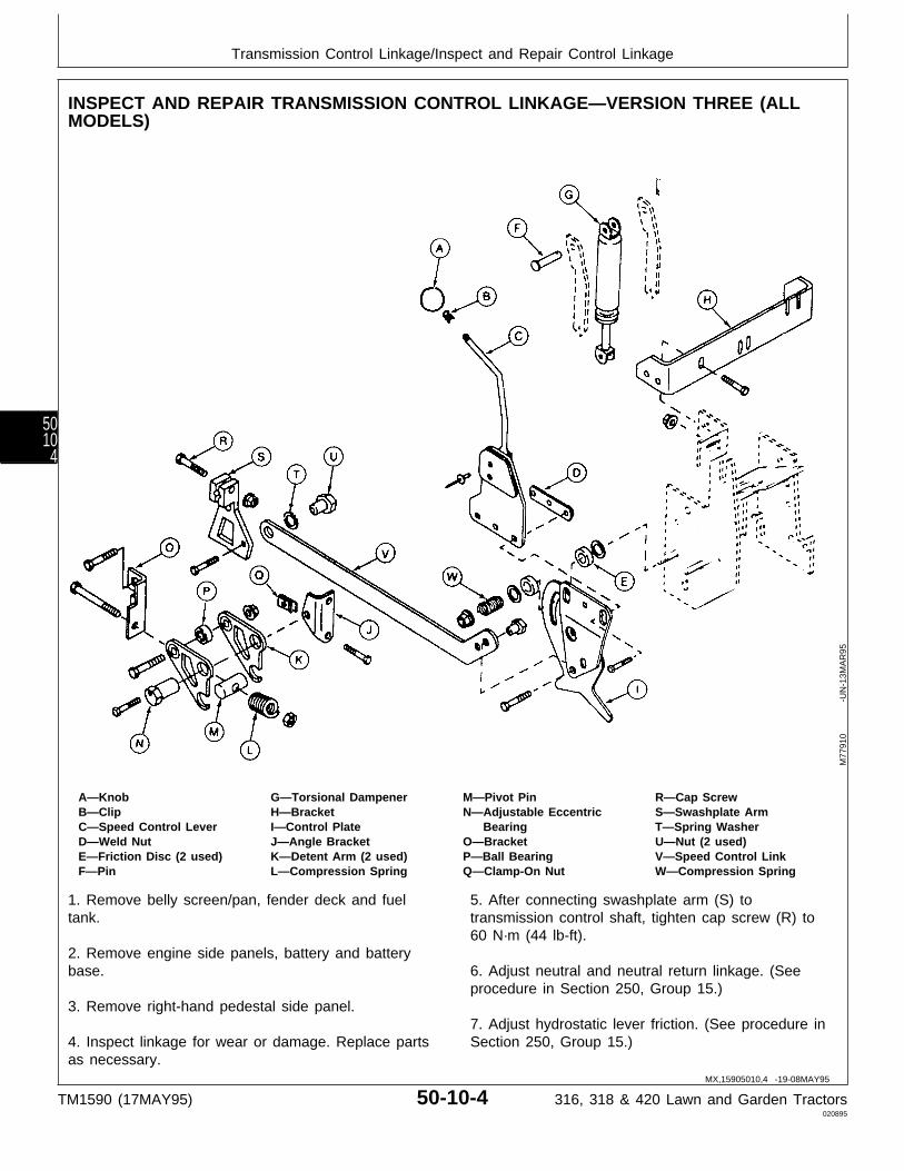
INSPECT AND REPAIR TRANSMISSION CONTROL LINKAGE—VERSION THREE (ALLMODELS)
A—Knob G—Torsional Dampener M—Pivot Pin R—Cap ScrewB—Clip H—Bracket N—Adjustable Eccentric S—Swashplate ArmC—Speed Control Lever I—Control Plate Bearing T—Spring WasherD—Weld Nut J—Angle Bracket O—Bracket U—Nut (2 used)E—Friction Disc (2 used) K—Detent Arm (2 used) P—Ball Bearing V—Speed Control LinkF—Pin L—Compression Spring Q—Clamp-On Nut W—Compression Spring
1. Remove belly screen/pan, fender deck and fueltank.
2. Remove engine side panels, battery and batterybase.
3. Remove right-hand pedestal side panel.
4. Inspect linkage for wear or damage. Replace partsas necessary.
5. After connecting swashplate arm (S) totransmission control shaft, tighten cap screw (R) to60 N·m (44 lb-ft).
6. Adjust neutral and neutral return linkage. (Seeprocedure in Section 250, Group 15.)
7. Adjust hydrostatic lever friction. (See procedure inSection 250, Group 15.)
M77
910
-UN
-13M
AR
95
MX,15905010,4 -19-08MAY95
Transmission Control Linkage/Inspect and Repair Control Linkage
TM1590 (17MAY95) 50-10-4 316, 318 & 420 Lawn and Garden Tractors020895
5010
4

INSPECT AND REPAIR TRANSMISSION CONTROL LINKAGE—VERSION FOUR (ALLMODELS)
A—Knob H—Speed Control Link N—Ball Bearing T—Cap ScrewB—Clip I—Angle Bracket O—Clamp-On Nut U—Spacer Nut (2 used)C—Speed Control Lever J—Detent Arm (2 used) P—Spring Washer V—BracketD—Weld Nut K—Compression Spring Q—Nut (2 used) W—Torsional DampenerE—Friction Disc (2 used) L—Pivot Pin R—Bracket X—Compression SpringF—Bracket M—Adjustable Eccentric S—Swashplate ArmG—Control Plate Bearing
1. Remove belly screen/pan, fender deck and fueltank.
2. Remove engine side panels, battery and batterybase.
3. Remove right-hand pedestal side panel.
4. Inspect linkage for wear or damage. Replace partsas necessary.
5. After connecting swashplate arm (S) totransmission control shaft, tighten cap screw (T) to 60N·m (44 lb-ft).
6. Adjust neutral and neutral return linkage. (Seeprocedure in Section 250, Group 15.)
7. Adjust hydrostatic lever friction. (See procedure inSection 250, Group 15.)
M77
911
-UN
-13F
EB
95
MX,15905010,5 -19-08MAY95
Transmission Control Linkage/Inspect and Repair Control Linkage
TM1590 (17MAY95) 50-10-5 316, 318 & 420 Lawn and Garden Tractors020895
50105

INSPECT AND REPAIR DIFFERENTIAL LOCK AND TWO-SPEED CONTROL LINKAGE(420)
A—Pin D—Knob G—Rear Angle Bracket J—KnobB—Spring E—Stud Extension H—Two-Speed Bracket K—Clip (2 used)C—Two-Speed Control Rod F—Front Angle Bracket I—Differential Lock Rod L—Pin
1. Remove belly pan.
2. Inspect linkage for wear or damage. Replace partsas necessary.
3. Adjust two-speed axle lever detent, if necessary.(See procedure in Section 250, Group 15.)
M77
912
-UN
-13F
EB
95
MX,15905010,6 -19-07MAR95
Transmission Control Linkage/Differential Lock and Two-Speed Control Linkage (420)
TM1590 (17MAY95) 50-10-6 316, 318 & 420 Lawn and Garden Tractors020895
5010
6
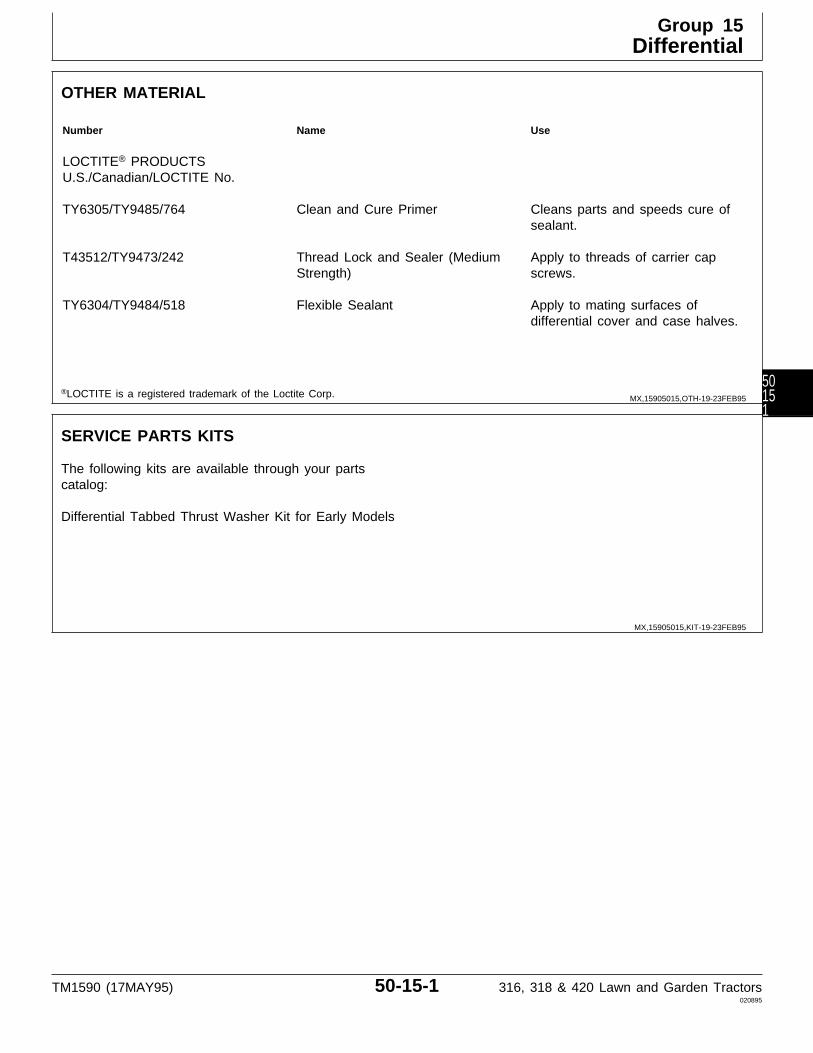
OTHER MATERIAL
Number Name Use
LOCTITE® PRODUCTSU.S./Canadian/LOCTITE No.
TY6305/TY9485/764 Clean and Cure Primer Cleans parts and speeds cure ofsealant.
T43512/TY9473/242 Thread Lock and Sealer (Medium Apply to threads of carrier capStrength) screws.
TY6304/TY9484/518 Flexible Sealant Apply to mating surfaces ofdifferential cover and case halves.
®LOCTITE is a registered trademark of the Loctite Corp.
SERVICE PARTS KITS
The following kits are available through your partscatalog:
Differential Tabbed Thrust Washer Kit for Early Models
MX,15905015,OTH-19-23FEB95
MX,15905015,KIT-19-23FEB95
Group 15Differential
TM1590 (17MAY95) 50-15-1 316, 318 & 420 Lawn and Garden Tractors020895
50151
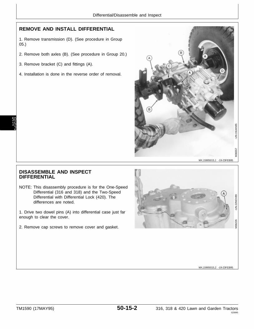
REMOVE AND INSTALL DIFFERENTIAL
1. Remove transmission (D). (See procedure in Group05.)
2. Remove both axles (B). (See procedure in Group 20.)
3. Remove bracket (C) and fittings (A).
4. Installation is done in the reverse order of removal.
M36
557
-UN
-19J
AN
95
DISASSEMBLE AND INSPECTDIFFERENTIAL
NOTE: This disassembly procedure is for the One-SpeedDifferential (316 and 318) and the Two-SpeedDifferential with Differential Lock (420). Thedifferences are noted.
1. Drive two dowel pins (A) into differential case just farenough to clear the cover.
2. Remove cap screws to remove cover and gasket. M36
226
-UN
-22N
OV
89
MX,15905015,1 -19-23FEB95
MX,15905015,2 -19-23FEB95
Differential/Disassemble and Inspect
TM1590 (17MAY95) 50-15-2 316, 318 & 420 Lawn and Garden Tractors020895
5015
2

NOTE: Early models have FLAT thrust washers. Latermodels have TABBED thrust washers. All serviceor replacement thrust washers will have the tabs.
IMPORTANT: It is recommended to replace the earlymodel (flat) thrust washers with thelater model (tabbed) thrust washers.The early model washers may spin withtheir respective shafts, causing wear tothe cover bearing surfaces.
3. Remove three thrust washers (A).One-Speed Differential
Two-Speed Differential
M36
168
-UN
-29A
UG
88M
3622
8
-U
N-2
2NO
V89
4. Remove differential; if equipped with differential lock,remove shift rod assembly with differential.
Without Differential Lock
With Differential Lock
M36
170
-UN
-22N
OV
89M
3616
9
-U
N-2
9AU
G88
MX,15905015,3 -19-23FEB95
MX,15905015,4 -19-23FEB95
Differential/Disassemble and Inspect
TM1590 (17MAY95) 50-15-3 316, 318 & 420 Lawn and Garden Tractors020895
50153
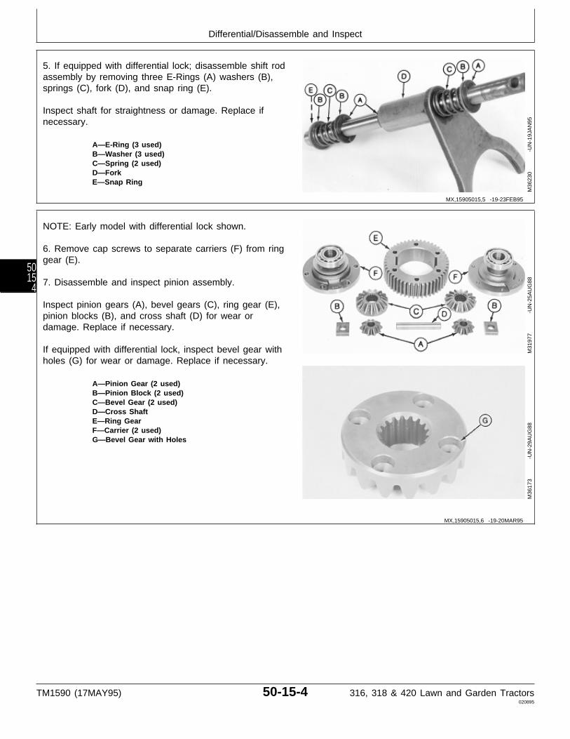
5. If equipped with differential lock; disassemble shift rodassembly by removing three E-Rings (A) washers (B),springs (C), fork (D), and snap ring (E).
Inspect shaft for straightness or damage. Replace ifnecessary.
A—E-Ring (3 used)B—Washer (3 used)C—Spring (2 used)D—ForkE—Snap Ring
M36
230
-UN
-19J
AN
95
NOTE: Early model with differential lock shown.
6. Remove cap screws to separate carriers (F) from ringgear (E).
7. Disassemble and inspect pinion assembly.
Inspect pinion gears (A), bevel gears (C), ring gear (E),pinion blocks (B), and cross shaft (D) for wear ordamage. Replace if necessary.
If equipped with differential lock, inspect bevel gear withholes (G) for wear or damage. Replace if necessary.
A—Pinion Gear (2 used)B—Pinion Block (2 used)C—Bevel Gear (2 used)D—Cross ShaftE—Ring GearF—Carrier (2 used)G—Bevel Gear with Holes
M31
977
-UN
-25A
UG
88M
3617
3
-U
N-2
9AU
G88
MX,15905015,5 -19-23FEB95
MX,15905015,6 -19-20MAR95
Differential/Disassemble and Inspect
TM1590 (17MAY95) 50-15-4 316, 318 & 420 Lawn and Garden Tractors020895
5015
4
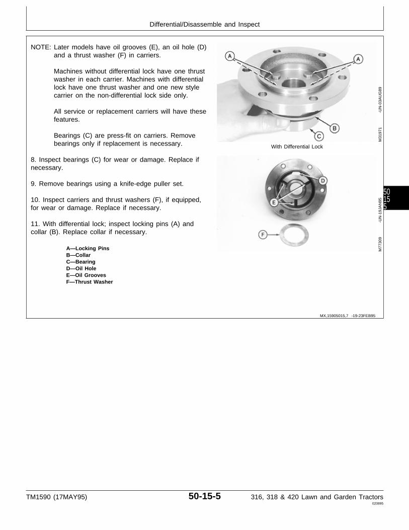
NOTE: Later models have oil grooves (E), an oil hole (D)and a thrust washer (F) in carriers.
Machines without differential lock have one thrustwasher in each carrier. Machines with differentiallock have one thrust washer and one new stylecarrier on the non-differential lock side only.
All service or replacement carriers will have thesefeatures.
Bearings (C) are press-fit on carriers. Removebearings only if replacement is necessary. With Differential Lock
8. Inspect bearings (C) for wear or damage. Replace ifnecessary.
9. Remove bearings using a knife-edge puller set.
10. Inspect carriers and thrust washers (F), if equipped,for wear or damage. Replace if necessary.
11. With differential lock; inspect locking pins (A) andcollar (B). Replace collar if necessary.
A—Locking PinsB—CollarC—BearingD—Oil HoleE—Oil GroovesF—Thrust Washer
M31
971
-UN
-03A
UG
89M
7730
9
-U
N-1
9JA
N95
MX,15905015,7 -19-23FEB95
Differential/Disassemble and Inspect
TM1590 (17MAY95) 50-15-5 316, 318 & 420 Lawn and Garden Tractors020895
50155

12. Remove and inspect countershaft assembly.
Inspect spur gear (A) and bevel gear (B) for worn ordamaged teeth.
Inspect countershaft (C) for worn or damaged splines orbearing surfaces.
13. Remove spacer (D), thrust washers (E) and thrustbearing (F).
Inspect parts for wear or damage. Replace if necessary.One-Speed Differential
A—Spur GearB—Bevel GearC—CountershaftD—SpacerE—Thrust Washer (2 used)F—Thrust Bearing
Two-Speed Differential
M36
175
-UN
-29A
UG
88M
3623
2
-U
N-2
2NO
V89
M77
905
-UN
-19J
AN
95
MX,15905015,8 -19-23FEB95
Differential/Disassemble and Inspect
TM1590 (17MAY95) 50-15-6 316, 318 & 420 Lawn and Garden Tractors020895
5015
6

14. Two-speed differential; remove set screw, spring, anddetent ball.
M36
233
-UN
-22N
OV
89M
3623
4
-U
N-2
2NO
V89
MX,15905015,9 -19-23FEB95
Differential/Disassemble and Inspect
TM1590 (17MAY95) 50-15-7 316, 318 & 420 Lawn and Garden Tractors020895
50157
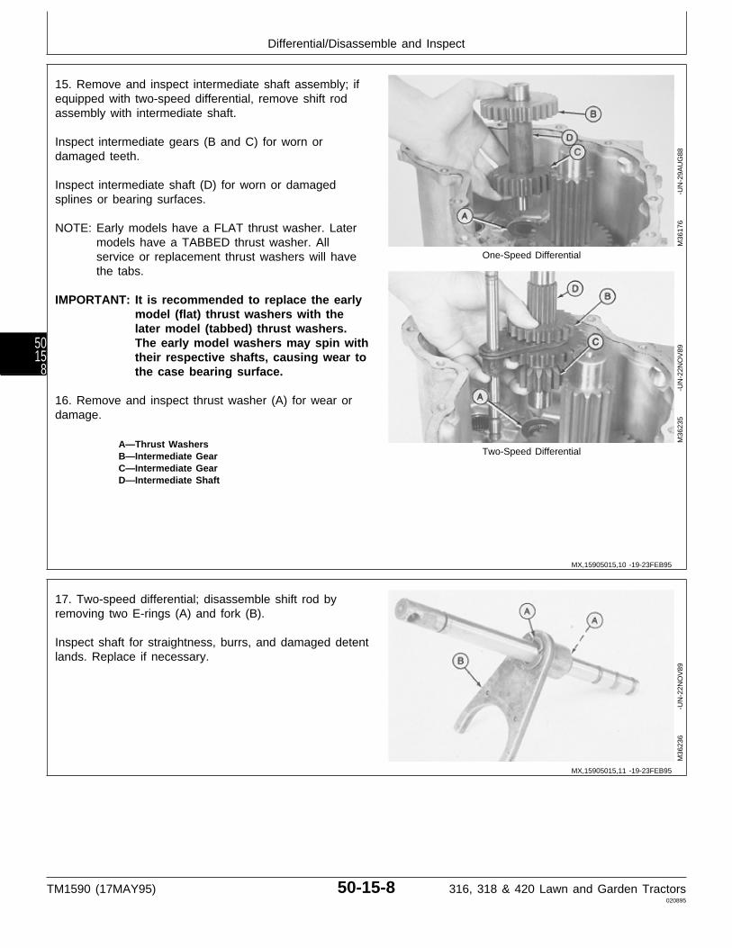
15. Remove and inspect intermediate shaft assembly; ifequipped with two-speed differential, remove shift rodassembly with intermediate shaft.
Inspect intermediate gears (B and C) for worn ordamaged teeth.
Inspect intermediate shaft (D) for worn or damagedsplines or bearing surfaces.
NOTE: Early models have a FLAT thrust washer. Latermodels have a TABBED thrust washer. Allservice or replacement thrust washers will have One-Speed Differential
the tabs.
IMPORTANT: It is recommended to replace the earlymodel (flat) thrust washers with thelater model (tabbed) thrust washers.The early model washers may spin withtheir respective shafts, causing wear tothe case bearing surface.
16. Remove and inspect thrust washer (A) for wear ordamage.
A—Thrust WashersTwo-Speed DifferentialB—Intermediate Gear
C—Intermediate GearD—Intermediate Shaft
M36
176
-UN
-29A
UG
88M
3623
5
-U
N-2
2NO
V89
17. Two-speed differential; disassemble shift rod byremoving two E-rings (A) and fork (B).
Inspect shaft for straightness, burrs, and damaged detentlands. Replace if necessary.
M36
236
-UN
-22N
OV
89
MX,15905015,10 -19-23FEB95
MX,15905015,11 -19-23FEB95
Differential/Disassemble and Inspect
TM1590 (17MAY95) 50-15-8 316, 318 & 420 Lawn and Garden Tractors020895
5015
8
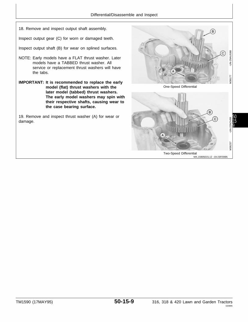
18. Remove and inspect output shaft assembly.
Inspect output gear (C) for worn or damaged teeth.
Inspect output shaft (B) for wear on splined surfaces.
NOTE: Early models have a FLAT thrust washer. Latermodels have a TABBED thrust washer. Allservice or replacement thrust washers will havethe tabs.
IMPORTANT: It is recommended to replace the earlymodel (flat) thrust washers with the One-Speed Differential
later model (tabbed) thrust washers.The early model washers may spin withtheir respective shafts, causing wear tothe case bearing surface.
19. Remove and inspect thrust washer (A) for wear ordamage.
Two-Speed Differential
M36
177
-UN
-29A
UG
88M
3623
7
-U
N-2
2NO
V89
MX,15905015,12 -19-23FEB95
Differential/Disassemble and Inspect
TM1590 (17MAY95) 50-15-9 316, 318 & 420 Lawn and Garden Tractors020895
50159
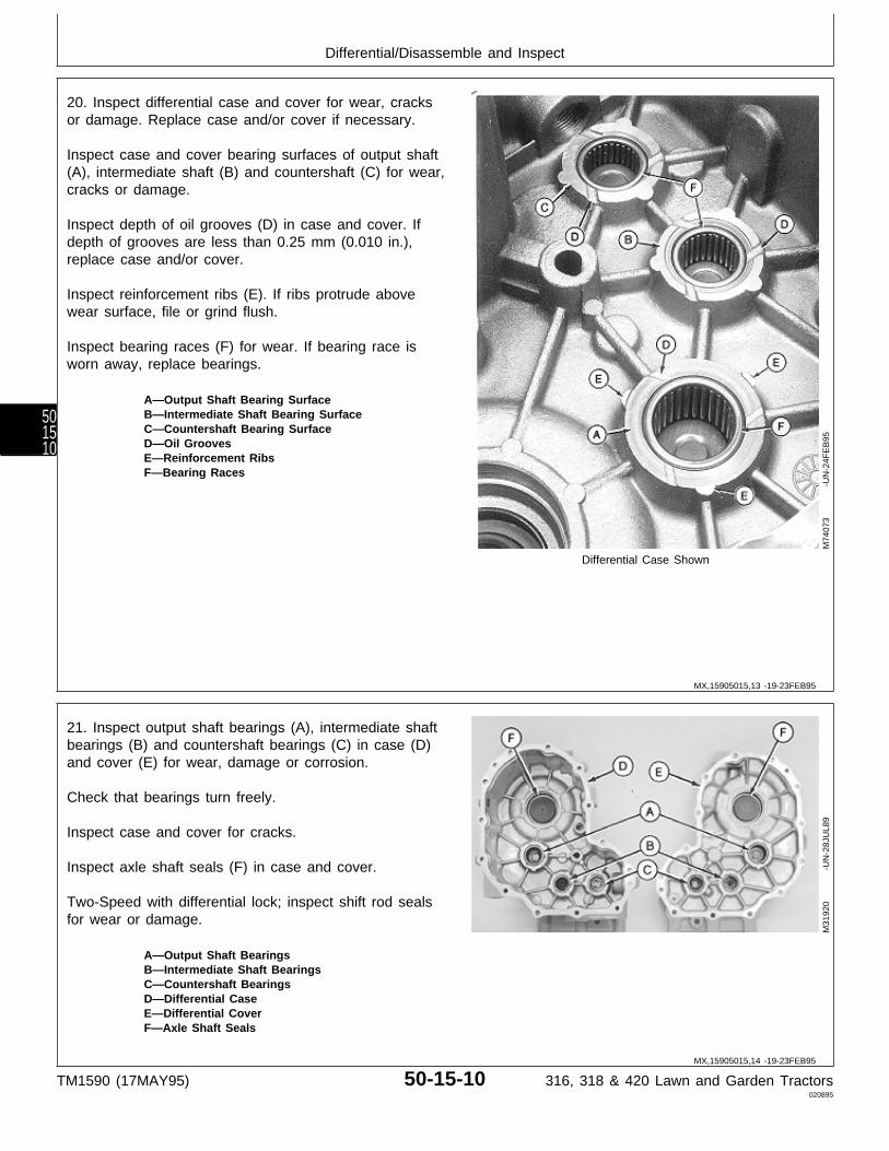
20. Inspect differential case and cover for wear, cracksor damage. Replace case and/or cover if necessary.
Inspect case and cover bearing surfaces of output shaft(A), intermediate shaft (B) and countershaft (C) for wear,cracks or damage.
Inspect depth of oil grooves (D) in case and cover. Ifdepth of grooves are less than 0.25 mm (0.010 in.),replace case and/or cover.
Inspect reinforcement ribs (E). If ribs protrude abovewear surface, file or grind flush.
Inspect bearing races (F) for wear. If bearing race isworn away, replace bearings.
A—Output Shaft Bearing SurfaceB—Intermediate Shaft Bearing SurfaceC—Countershaft Bearing SurfaceD—Oil GroovesE—Reinforcement RibsF—Bearing Races
Differential Case Shown
M74
073
-UN
-24F
EB
95
21. Inspect output shaft bearings (A), intermediate shaftbearings (B) and countershaft bearings (C) in case (D)and cover (E) for wear, damage or corrosion.
Check that bearings turn freely.
Inspect case and cover for cracks.
Inspect axle shaft seals (F) in case and cover.
Two-Speed with differential lock; inspect shift rod sealsfor wear or damage.
A—Output Shaft BearingsB—Intermediate Shaft BearingsC—Countershaft BearingsD—Differential CaseE—Differential CoverF—Axle Shaft Seals
M31
920
-UN
-28J
UL8
9
MX,15905015,13 -19-23FEB95
MX,15905015,14 -19-23FEB95
Differential/Disassemble and Inspect
TM1590 (17MAY95) 50-15-10 316, 318 & 420 Lawn and Garden Tractors020895
501510
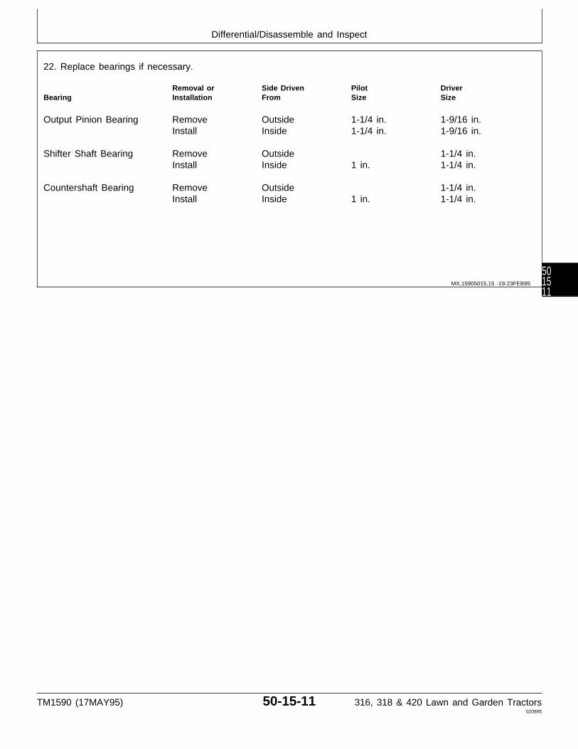
22. Replace bearings if necessary.
Removal or Side Driven Pilot DriverBearing Installation From Size Size
Output Pinion Bearing Remove Outside 1-1/4 in. 1-9/16 in.Install Inside 1-1/4 in. 1-9/16 in.
Shifter Shaft Bearing Remove Outside 1-1/4 in.Install Inside 1 in. 1-1/4 in.
Countershaft Bearing Remove Outside 1-1/4 in.Install Inside 1 in. 1-1/4 in.
MX,15905015,15 -19-23FEB95
Differential/Disassemble and Inspect
TM1590 (17MAY95) 50-15-11 316, 318 & 420 Lawn and Garden Tractors020895
501511
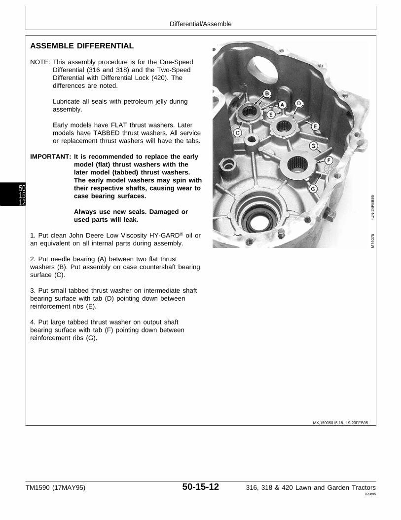
ASSEMBLE DIFFERENTIAL
NOTE: This assembly procedure is for the One-SpeedDifferential (316 and 318) and the Two-SpeedDifferential with Differential Lock (420). Thedifferences are noted.
Lubricate all seals with petroleum jelly duringassembly.
Early models have FLAT thrust washers. Latermodels have TABBED thrust washers. All serviceor replacement thrust washers will have the tabs.
IMPORTANT: It is recommended to replace the earlymodel (flat) thrust washers with thelater model (tabbed) thrust washers.The early model washers may spin withtheir respective shafts, causing wear tocase bearing surfaces.
Always use new seals. Damaged orused parts will leak.
1. Put clean John Deere Low Viscosity HY-GARD® oil oran equivalent on all internal parts during assembly.
2. Put needle bearing (A) between two flat thrustwashers (B). Put assembly on case countershaft bearingsurface (C).
3. Put small tabbed thrust washer on intermediate shaftbearing surface with tab (D) pointing down betweenreinforcement ribs (E).
4. Put large tabbed thrust washer on output shaftbearing surface with tab (F) pointing down betweenreinforcement ribs (G).
M74
075
-UN
-24F
EB
95
MX,15905015,18 -19-23FEB95
Differential/Assemble
TM1590 (17MAY95) 50-15-12 316, 318 & 420 Lawn and Garden Tractors020895
501512
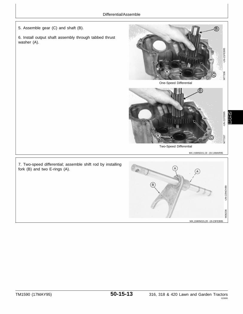
5. Assemble gear (C) and shaft (B).
6. Install output shaft assembly through tabbed thrustwasher (A).
One-Speed Differential
Two-Speed Differential
M77
336
-UN
-21F
EB
95M
7733
7
-U
N-2
1FE
B95
7. Two-speed differential; assemble shift rod by installingfork (B) and two E-rings (A).
M36
236
-UN
-22N
OV
89
MX,15905015,19 -19-14MAR95
MX,15905015,20 -19-23FEB95
Differential/Assemble
TM1590 (17MAY95) 50-15-13 316, 318 & 420 Lawn and Garden Tractors020895
501513

8. Assemble gears (B and C) and shaft (D).
9. Install intermediate shaft assembly through tabbedthrust washer (A); if equipped with two-speed, install shiftrod assembly with intermediate shaft assembly.
A—Thrust WasherB—Intermediate GearC—Intermediate GearD—Intermediate Shaft
One-Speed Differential
Two-Speed Differential
M36
176
-UN
-29A
UG
88M
3623
5
-U
N-2
2NO
V89
10. Two-speed differential; install detent ball, spring andset screw.
M36
234
-UN
-22N
OV
89M
3623
3
-U
N-2
2NO
V89
MX,15905015,21 -19-23FEB95
MX,15905015,22 -19-23FEB95
Differential/Assemble
TM1590 (17MAY95) 50-15-14 316, 318 & 420 Lawn and Garden Tractors020895
501514
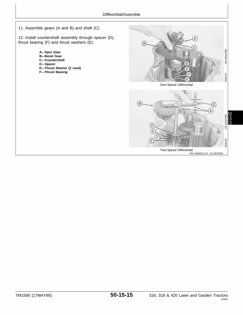
11. Assemble gears (A and B) and shaft (C).
12. Install countershaft assembly through spacer (D),thrust bearing (F) and thrust washers (E).
A—Spur GearB—Bevel GearC—CountershaftD—SpacerE—Thrust Washer (2 used)F—Thrust Bearing
One-Speed Differential
Two-Speed Differential
M36
175
-UN
-29A
UG
88M
3623
2
-U
N-2
2NO
V89
MX,15905015,23 -19-23FEB95
Differential/Assemble
TM1590 (17MAY95) 50-15-15 316, 318 & 420 Lawn and Garden Tractors020895
501515

NOTE: Early model with differential lock shown.
13. If removed, install collar (with differential lock) andbearings on carriers (F) using a driver set and a press.Install bearings flush with shaft surfaces.
NOTE: Carriers on later models have oil grooves, an oilhole and a thrust washer in carriers.
Machines without differential lock have one thrustwasher in each carrier. Machines with differentiallock have one thrust washer and one new stylecarrier on the non-differential lock side only.
All service or replacement carriers will have thesefeatures.
14. Install thrust washers, if equipped, in carriers (F).
15. Assemble carriers (F), ring gear (E), pinion gears(A), bevel gears (C), cross shaft (D), and pinion blocks(B).
If equipped with differential lock, install bevel gear withholes (G) toward carrier with lock pins and collar.
16. Clean the threads of all six cap screws and threadedcarrier, using Clean and Cure Primer. Apply thread lock
A—Pinion Gear (2 used)and sealer (medium strength) to the threads of cap B—Pinion Block (2 used)screws. C—Bevel Gear (2 used)
D—Cross ShaftE—Ring Gear17. Install cap screws and tighten to 53 N·m (39 lb-ft).F—Carrier (2 used)G—Bevel Gear with Holes
M31
977
-UN
-25A
UG
88M
3617
3
-U
N-2
9AU
G88
18. If equipped with differential lock, assemble shift rod,snap ring (E), washers (B), springs (C), fork (D), andE-rings (A).
A—E-Ring (3 used)B—Washer (3 used)C—Spring (2 used)D—ForkE—Snap Ring
M36
230
-UN
-19J
AN
95
MX,15905015,24 -19-20MAR95
MX,15905015,25 -19-23FEB95
Differential/Assemble
TM1590 (17MAY95) 50-15-16 316, 318 & 420 Lawn and Garden Tractors020895
501516

19. Install differential; if equipped with differential lock,install shift rod assembly with differential.
Without Differential Lock
With Differential Lock
M36
170
-UN
-22N
OV
89M
3616
9
-U
N-2
9AU
G88
MX,15905015,26 -19-23FEB95
Differential/Assemble
TM1590 (17MAY95) 50-15-17 316, 318 & 420 Lawn and Garden Tractors020895
501517
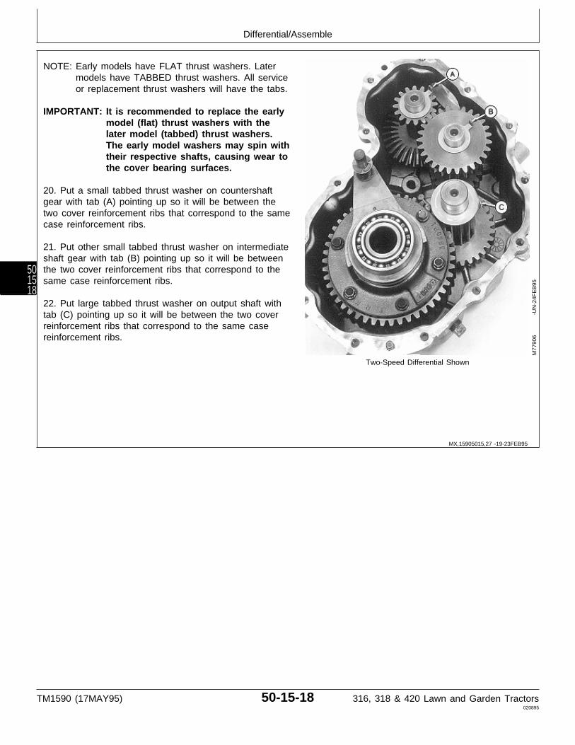
NOTE: Early models have FLAT thrust washers. Latermodels have TABBED thrust washers. All serviceor replacement thrust washers will have the tabs.
IMPORTANT: It is recommended to replace the earlymodel (flat) thrust washers with thelater model (tabbed) thrust washers.The early model washers may spin withtheir respective shafts, causing wear tothe cover bearing surfaces.
20. Put a small tabbed thrust washer on countershaftgear with tab (A) pointing up so it will be between thetwo cover reinforcement ribs that correspond to the samecase reinforcement ribs.
21. Put other small tabbed thrust washer on intermediateshaft gear with tab (B) pointing up so it will be betweenthe two cover reinforcement ribs that correspond to thesame case reinforcement ribs.
22. Put large tabbed thrust washer on output shaft withtab (C) pointing up so it will be between the two coverreinforcement ribs that correspond to the same casereinforcement ribs.
Two-Speed Differential Shown
M77
906
-UN
-24F
EB
95
MX,15905015,27 -19-23FEB95
Differential/Assemble
TM1590 (17MAY95) 50-15-18 316, 318 & 420 Lawn and Garden Tractors020895
501518
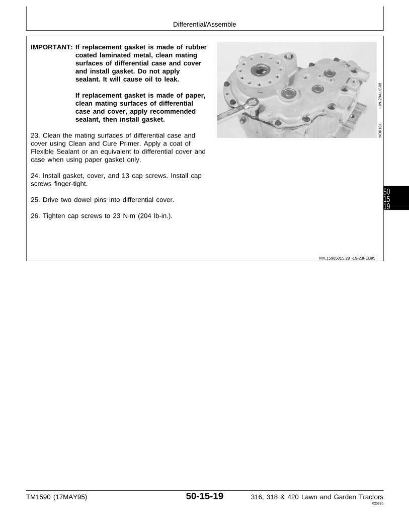
IMPORTANT: If replacement gasket is made of rubbercoated laminated metal, clean matingsurfaces of differential case and coverand install gasket. Do not applysealant. It will cause oil to leak.
If replacement gasket is made of paper,clean mating surfaces of differentialcase and cover, apply recommendedsealant, then install gasket.
23. Clean the mating surfaces of differential case andcover using Clean and Cure Primer. Apply a coat ofFlexible Sealant or an equivalent to differential cover andcase when using paper gasket only.
24. Install gasket, cover, and 13 cap screws. Install capscrews finger-tight.
25. Drive two dowel pins into differential cover.
26. Tighten cap screws to 23 N·m (204 lb-in.).
M36
181
-UN
-29A
UG
88
MX,15905015,28 -19-23FEB95
Differential/Assemble
TM1590 (17MAY95) 50-15-19 316, 318 & 420 Lawn and Garden Tractors020895
501519

Differential/Assemble
TM1590 (17MAY95) 50-15-20 316, 318 & 420 Lawn and Garden Tractors020895
501520
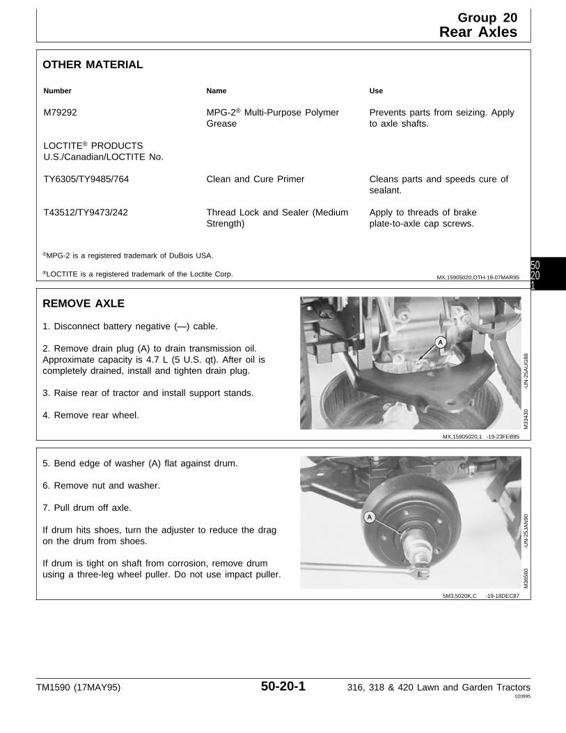
OTHER MATERIAL
Number Name Use
M79292 MPG-2® Multi-Purpose Polymer Prevents parts from seizing. ApplyGrease to axle shafts.
LOCTITE® PRODUCTSU.S./Canadian/LOCTITE No.
TY6305/TY9485/764 Clean and Cure Primer Cleans parts and speeds cure ofsealant.
T43512/TY9473/242 Thread Lock and Sealer (Medium Apply to threads of brakeStrength) plate-to-axle cap screws.
®MPG-2 is a registered trademark of DuBois USA.
®LOCTITE is a registered trademark of the Loctite Corp.
REMOVE AXLE
1. Disconnect battery negative (—) cable.
2. Remove drain plug (A) to drain transmission oil.Approximate capacity is 4.7 L (5 U.S. qt). After oil iscompletely drained, install and tighten drain plug.
3. Raise rear of tractor and install support stands.
4. Remove rear wheel.
M33
430
-UN
-25A
UG
88
5. Bend edge of washer (A) flat against drum.
6. Remove nut and washer.
7. Pull drum off axle.
If drum hits shoes, turn the adjuster to reduce the dragon the drum from shoes.
If drum is tight on shaft from corrosion, remove drumusing a three-leg wheel puller. Do not use impact puller.
M36
560
-UN
-25J
AN
90
MX,15905020,OTH-19-07MAR95
MX,15905020,1 -19-23FEB95
5M3,5020K,C -19-18DEC87
Group 20Rear Axles
TM1590 (17MAY95) 50-20-1 316, 318 & 420 Lawn and Garden Tractors020895
50201
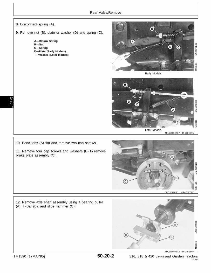
8. Disconnect spring (A).
9. Remove nut (B), plate or washer (D) and spring (C).
A—Return SpringB—NutC—SpringD—Plate (Early Models) —Washer (Later Models)
Early Models
Later Models
M78
048
-UN
-13F
EB
95M
7804
9
-U
N-1
3FE
B95
10. Bend tabs (A) flat and remove two cap screws.
11. Remove four cap screws and washers (B) to removebrake plate assembly (C).
M36
562
-UN
-25J
AN
90
12. Remove axle shaft assembly using a bearing puller(A), H-Bar (B), and slide hammer (C).
M36
563
-UN
-25J
AN
90
MX,15905020,7 -19-23FEB95
5M3,5020K,E -19-18DEC87
MX,15905020,2 -19-23FEB95
Rear Axles/Remove
TM1590 (17MAY95) 50-20-2 316, 318 & 420 Lawn and Garden Tractors020895
5020
2
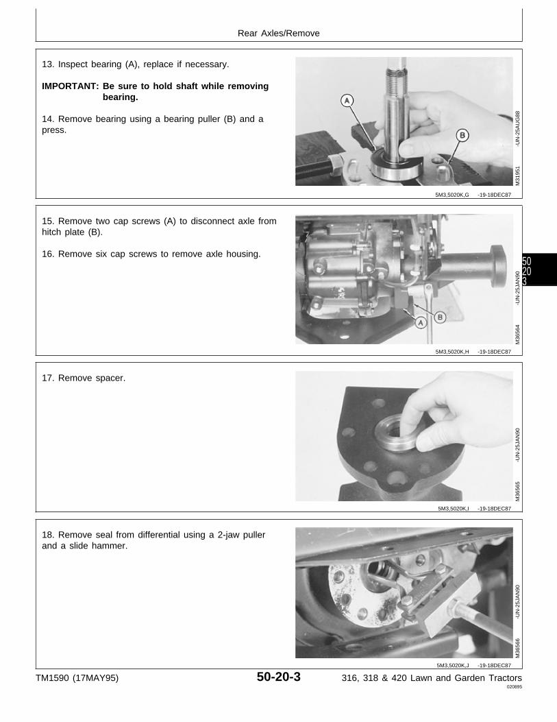
13. Inspect bearing (A), replace if necessary.
IMPORTANT: Be sure to hold shaft while removingbearing.
14. Remove bearing using a bearing puller (B) and apress.
M31
951
-UN
-25A
UG
88
15. Remove two cap screws (A) to disconnect axle fromhitch plate (B).
16. Remove six cap screws to remove axle housing.
M36
564
-UN
-25J
AN
90
17. Remove spacer.
M36
565
-UN
-25J
AN
90
18. Remove seal from differential using a 2-jaw pullerand a slide hammer.
M36
566
-UN
-25J
AN
90
5M3,5020K,G -19-18DEC87
5M3,5020K,H -19-18DEC87
5M3,5020K,I -19-18DEC87
5M3,5020K,J -19-18DEC87
Rear Axles/Remove
TM1590 (17MAY95) 50-20-3 316, 318 & 420 Lawn and Garden Tractors020895
50203
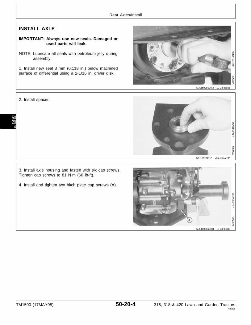
INSTALL AXLE
IMPORTANT: Always use new seals. Damaged orused parts will leak.
NOTE: Lubricate all seals with petroleum jelly duringassembly.
1. Install new seal 3 mm (0.118 in.) below machinedsurface of differential using a 2-1/16 in. driver disk.
M36
567
-UN
-25J
AN
90
2. Install spacer.
M36
565
-UN
-25J
AN
90
3. Install axle housing and fasten with six cap screws.Tighten cap screws to 81 N·m (60 lb-ft).
4. Install and tighten two hitch plate cap screws (A).
M36
568
-UN
-25J
AN
90
MX,15905020,3 -19-23FEB95
M21,5020R,15 -19-14MAY85
MX,15905020,8 -19-23FEB95
Rear Axles/Install
TM1590 (17MAY95) 50-20-4 316, 318 & 420 Lawn and Garden Tractors020895
5020
4

5. Install bearing (A) on axle shaft using a bearing puller(B) and a press. Push bearing tight against axle shaftshoulder.
M31
952
-UN
-25A
UG
88
6. Apply clean transmission fluid to the splined end ofthe axle shaft.
7. Carefully install axle shaft into housing and throughseal in differential. Align splines on shaft with splinedgear inside differential.
8. Tap shaft assembly into axle housing until bearing isflush with housing.
M36
569
-UN
-25J
AN
90
M21,5020R,17 -19-14MAY85
M21,5020R,18 -19-14MAY85
Rear Axles/Install
TM1590 (17MAY95) 50-20-5 316, 318 & 420 Lawn and Garden Tractors020895
50205
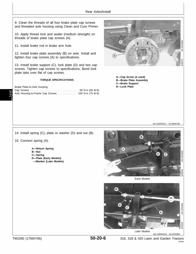
9. Clean the threads of all four brake plate cap screwsand threaded axle housing using Clean and Cure Primer.
10. Apply thread lock and sealer (medium strength) onthreads of brake plate cap screws (A).
11. Install brake rod in brake arm hole.
12. Install brake plate assembly (B) on axle. Install andtighten four cap screws (A) to specifications.
13. Install brake support (C), lock plate (D) and two capscrews. Tighten cap screws to specifications. Bend lockplate tabs over flat of cap screws.
A—Cap Screw (4 used)TORQUE SPECIFICATIONS B—Brake Plate Assembly
C—Brake SupportD—Lock PlateBrake Plate-to-Axle Housing
Cap Screws . . . . . . . . . . . . . . . . . . . . . . . . . . . . 68 N·m (50 lb-ft)Axle Housing-to-Frame Cap Screws . . . . . . . . . . . 100 N·m (75 lb-ft)
M36
570
-UN
-25J
AN
90
14. Install spring (C), plate or washer (D) and nut (B).
15. Connect spring (A).
A—Return SpringB—NutC—SpringD—Plate (Early Models) —Washer (Later Models)
Early Models
Later Models
M78
048
-UN
-13F
EB
95M
7804
9
-U
N-1
3FE
B95
MX,15905020,4 -19-08MAY95
MX,15905020,9 -19-23FEB95
Rear Axles/Install
TM1590 (17MAY95) 50-20-6 316, 318 & 420 Lawn and Garden Tractors020895
5020
6
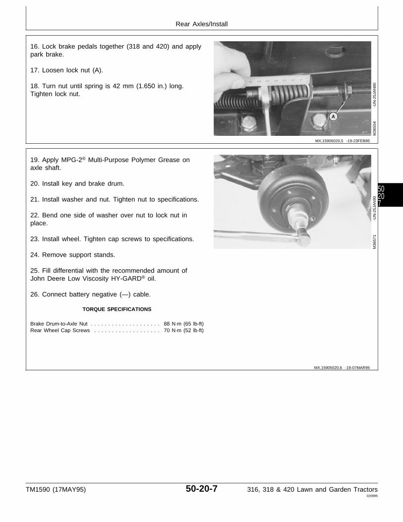
16. Lock brake pedals together (318 and 420) and applypark brake.
17. Loosen lock nut (A).
18. Turn nut until spring is 42 mm (1.650 in.) long.Tighten lock nut.
M36
554
-UN
-25J
AN
90
19. Apply MPG-2® Multi-Purpose Polymer Grease onaxle shaft.
20. Install key and brake drum.
21. Install washer and nut. Tighten nut to specifications.
22. Bend one side of washer over nut to lock nut inplace.
23. Install wheel. Tighten cap screws to specifications.
24. Remove support stands.
25. Fill differential with the recommended amount ofJohn Deere Low Viscosity HY-GARD® oil.
26. Connect battery negative (—) cable.
TORQUE SPECIFICATIONS
Brake Drum-to-Axle Nut . . . . . . . . . . . . . . . . . . . . 88 N·m (65 lb-ft)Rear Wheel Cap Screws . . . . . . . . . . . . . . . . . . . 70 N·m (52 lb-ft)
M36
571
-UN
-25J
AN
90
MX,15905020,5 -19-23FEB95
MX,15905020,6 -19-07MAR95
Rear Axles/Install
TM1590 (17MAY95) 50-20-7 316, 318 & 420 Lawn and Garden Tractors020895
50207

Rear Axles/Install
TM1590 (17MAY95) 50-20-8 316, 318 & 420 Lawn and Garden Tractors020895
5020
8
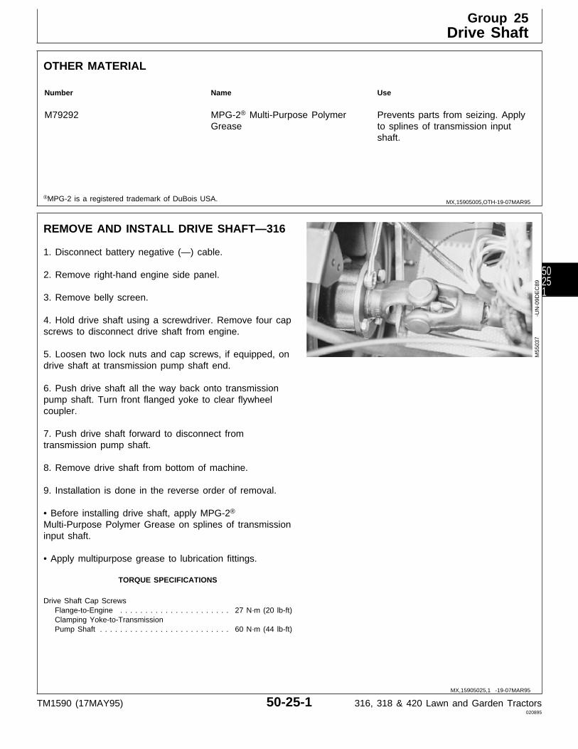
OTHER MATERIAL
Number Name Use
M79292 MPG-2® Multi-Purpose Polymer Prevents parts from seizing. ApplyGrease to splines of transmission input
shaft.
®MPG-2 is a registered trademark of DuBois USA.
REMOVE AND INSTALL DRIVE SHAFT—316
1. Disconnect battery negative (—) cable.
2. Remove right-hand engine side panel.
3. Remove belly screen.
4. Hold drive shaft using a screwdriver. Remove four capscrews to disconnect drive shaft from engine.
5. Loosen two lock nuts and cap screws, if equipped, ondrive shaft at transmission pump shaft end.
6. Push drive shaft all the way back onto transmissionpump shaft. Turn front flanged yoke to clear flywheelcoupler.
7. Push drive shaft forward to disconnect fromtransmission pump shaft.
8. Remove drive shaft from bottom of machine.
9. Installation is done in the reverse order of removal.
• Before installing drive shaft, apply MPG-2®
Multi-Purpose Polymer Grease on splines of transmissioninput shaft.
• Apply multipurpose grease to lubrication fittings.
TORQUE SPECIFICATIONS
Drive Shaft Cap Screws Flange-to-Engine . . . . . . . . . . . . . . . . . . . . . . 27 N·m (20 lb-ft) Clamping Yoke-to-Transmission Pump Shaft . . . . . . . . . . . . . . . . . . . . . . . . . . 60 N·m (44 lb-ft)
M55
037
-UN
-09D
EC
89
MX,15905005,OTH-19-07MAR95
MX,15905025,1 -19-07MAR95
Group 25Drive Shaft
TM1590 (17MAY95) 50-25-1 316, 318 & 420 Lawn and Garden Tractors020895
50251

REMOVE AND INSTALL DRIVE SHAFT—318AND 420
1. Disconnect battery negative (—) cable.
2. Remove right-hand engine side panel.
3. Remove belly screen/pan.
NOTE: Pedestal side removed for for photographicpurpose only.
4. Hold drive shaft with screwdriver and remove four capscrews (A) holding drive shaft to crankcase pulley.
5. Loosen two lock nuts and cap screws, if equipped, ondrive shaft at transmission pump shaft end.
6. Pull rearward on drive shaft and turn U-joint to clearcrankshaft pulley.
M43
706
-UN
-12J
AN
90
MX,15905025,2 -19-07MAR95
Drive Shaft/Remove and Install—318 and 420
TM1590 (17MAY95) 50-25-2 316, 318 & 420 Lawn and Garden Tractors020895
5025
2

N CAUTION: To avoid injury from escaping fluidunder pressure, stop engine and relieve thepressure in the system before disconnecting orconnecting hydraulic or other lines. Tighten allconnections before applying pressure.
NOTE: Fender deck and fuel tank removed forphotographic purpose only.
7. On 318; Remove hydraulic lines (A) from control valveas necessary to gain clearance for drive shaft to bepulled forward from the transmission input shaft.
8. Remove drive shaft from tractor.
9. Installation is done in the reverse order of removal.
• Before installing drive shaft, apply MPG-2®
Multi-Purpose Polymer Grease on splines of transmissioninput shaft.
• Apply multipurpose grease to lubrication fittings.
• Bleed hydraulic system. (See procedure in Section 270,Group 20.)
TORQUE SPECIFICATIONS
Drive Shaft Cap Screws Flange-to-Engine . . . . . . . . . . . . . . . . . . . . . . 27 N·m (20 lb-ft) Clamping Yoke-to-Transmission Pump Shaft . . . . . . . . . . . . . . . . . . . . . . . . . . 60 N·m (44 lb-ft)
X98
11
-UN
-23A
UG
88M
4370
7
-U
N-1
2JA
N90
DISASSEMBLE AND INSPECT DRIVE SHAFT
1. Inspect flanged yoke (A), splined yoke (B), shaft (C),end yokes (D) and cross and bearing assembly (E) forcracks, wear, and bending.
A—Flanged YokeB—Splined YokeC—ShaftD—End Yoke (2 used)E—Cross and Bearing Assembly (2 used)
M43
747
-UN
-12J
AN
90
MX,15905025,3 -19-07MAR95
MX,15905025,7 -19-20JAN95
Drive Shaft/Disassemble and Inspect
TM1590 (17MAY95) 50-25-3 316, 318 & 420 Lawn and Garden Tractors020895
50253
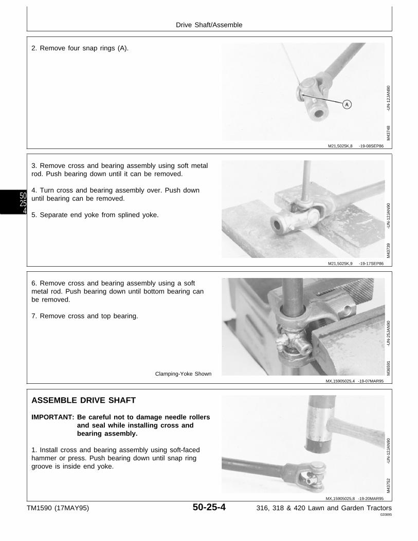
2. Remove four snap rings (A).
M43
748
-UN
-12J
AN
90
3. Remove cross and bearing assembly using soft metalrod. Push bearing down until it can be removed.
4. Turn cross and bearing assembly over. Push downuntil bearing can be removed.
5. Separate end yoke from splined yoke.
M43
739
-UN
-12J
AN
90
6. Remove cross and bearing assembly using a softmetal rod. Push bearing down until bottom bearing canbe removed.
7. Remove cross and top bearing.
Clamping-Yoke Shown M36
591
-UN
-25J
AN
90
ASSEMBLE DRIVE SHAFT
IMPORTANT: Be careful not to damage needle rollersand seal while installing cross andbearing assembly.
1. Install cross and bearing assembly using soft-facedhammer or press. Push bearing down until snap ringgroove is inside end yoke.
M43
752
-UN
-12J
AN
90
M21,5025K,8 -19-08SEP86
M21,5025K,9 -19-17SEP86
MX,15905025,4 -19-07MAR95
MX,15905025,8 -19-20MAR95
Drive Shaft/Assemble
TM1590 (17MAY95) 50-25-4 316, 318 & 420 Lawn and Garden Tractors020895
5025
4
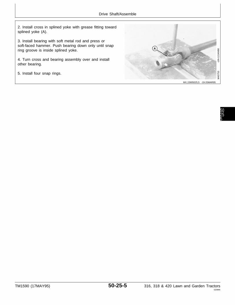
2. Install cross in splined yoke with grease fitting towardsplined yoke (A).
3. Install bearing with soft metal rod and press orsoft-faced hammer. Push bearing down only until snapring groove is inside splined yoke.
4. Turn cross and bearing assembly over and installother bearing.
5. Install four snap rings.
M43
753
-UN
-12J
AN
90
MX,15905025,5 -19-20MAR95
Drive Shaft/Assemble
TM1590 (17MAY95) 50-25-5 316, 318 & 420 Lawn and Garden Tractors020895
50255

Drive Shaft/Assemble
TM1590 (17MAY95) 50-25-6 316, 318 & 420 Lawn and Garden Tractors020895
5025
6
Section 60STEERING AND BRAKE REPAIR
ContentsPage
Group 05—Steering—316Special or Essential Tools . . . . . . . . . . . 60-05-1Service Parts Kits . . . . . . . . . . . . . . . . 60-05-1Gearbox
Remove and Install . . . . . . . . . . . . . . 60-05-2Disassemble and Inspect . . . . . . . . . . 60-05-6Assemble . . . . . . . . . . . . . . . . . . . . 60-05-12
Group 06—Steering—318 and 420Other Materials . . . . . . . . . . . . . . . . . . 60-06-1Service Parts Kits . . . . . . . . . . . . . . . . 60-06-1Steering Valve
Remove and Install . . . . . . . . . . . . . . 60-06-2Disassemble and Inspect . . . . . . . . . . 60-06-3Assemble . . . . . . . . . . . . . . . . . . . . 60-06-12
Steering CylinderRemove and Install . . . . . . . . . . . . . . 60-06-22
Group 10—BrakesOther Materials . . . . . . . . . . . . . . . . . . 60-10-1Brakes
Remove . . . . . . . . . . . . . . . . . . . . . 60-10-2Install . . . . . . . . . . . . . . . . . . . . . . . 60-10-5Adjust . . . . . . . . . . . . . . . . . . . . . . . 60-10-7
Brake Pedal(s) and Neutral ReturnLinkageInspect and Repair—316 . . . . . . . . . . 60-10-8Inspect and Repair—318 . . . . . . . . . . 60-10-13Inspect and Repair—420 . . . . . . . . . . 60-10-19
Inspect and Repair Park Brake Lever . . . 60-10-24
TM1590 (17MAY95) 60-1 316, 318 & 420 Lawn and Garden Tractors020895
60

Contents
TM1590 (17MAY95) 60-2 316, 318 & 420 Lawn and Garden Tractors020895
60
SPECIAL OR ESSENTIAL TOOLS
NOTE: Order tools according to information given in theU.S. SERVICE-GARD™ Catalog or in theEuropean Microfiche Tool Catalog (MTC).
Steering Gear Service Set....................JDG457
Used to service steering gearbox.
SERVICE PARTS KITS
The following kits are available through your partscatalog:
Return Guide Clamp Kit
Side Cover Kit
DX,TOOLS -19-05JUN91
MX,JDG457 -19-01MAR95
MX,15906005,KIT-19-01MAR95
Group 05Steering—316
TM1590 (17MAY95) 60-05-1 316, 318 & 420 Lawn and Garden Tractors020895
60051
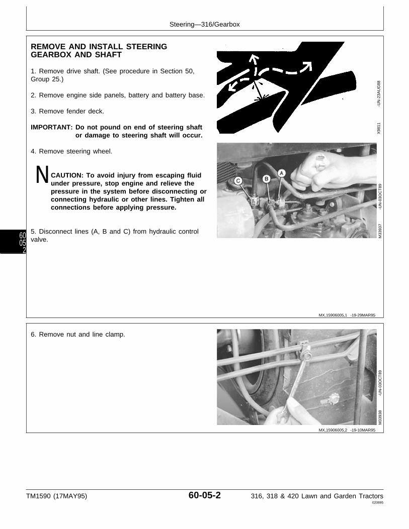
REMOVE AND INSTALL STEERINGGEARBOX AND SHAFT
1. Remove drive shaft. (See procedure in Section 50,Group 25.)
2. Remove engine side panels, battery and battery base.
3. Remove fender deck.
IMPORTANT: Do not pound on end of steering shaftor damage to steering shaft will occur.
4. Remove steering wheel.
N CAUTION: To avoid injury from escaping fluidunder pressure, stop engine and relieve thepressure in the system before disconnecting orconnecting hydraulic or other lines. Tighten allconnections before applying pressure.
5. Disconnect lines (A, B and C) from hydraulic controlvalve.
X98
11
-UN
-23A
UG
88M
3393
7
-U
N-0
3OC
T89
6. Remove nut and line clamp.
M33
938
-UN
-03O
CT
89
MX,15906005,1 -19-29MAR95
MX,15906005,2 -19-10MAR95
Steering—316/Gearbox
TM1590 (17MAY95) 60-05-2 316, 318 & 420 Lawn and Garden Tractors020895
6005
2

7. Remove bracket mounting cap screw.
M33
939
-UN
-03O
CT
89
8. Remove clip and disconnect brake neutral returnlinkage.
M33
940
-UN
-03O
CT
89
9. Remove pitman arm nut and washer. Remove pitmanarm using a two-jaw puller.
M33
942
-UN
-03O
CT
89
10. Remove cotter pin (A) and washer (B) to disconnectbrake llinkage on left side of machine frame.
M33
943
-UN
-03O
CT
89
MX,15906005,3 -19-10MAR95
MX,15906005,4 -19-10MAR95
MX,15906005,5 -19-10MAR95
MX,15906005,6 -19-10MAR95
Steering—316/Gearbox
TM1590 (17MAY95) 60-05-3 316, 318 & 420 Lawn and Garden Tractors020895
60053
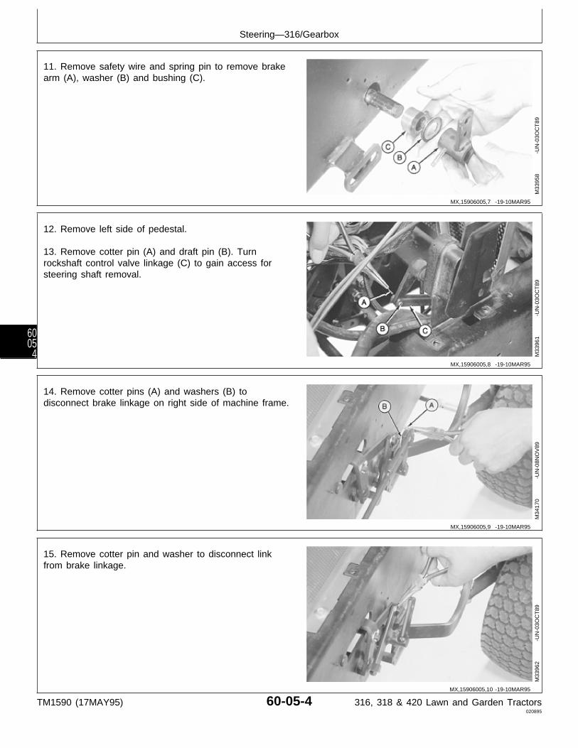
11. Remove safety wire and spring pin to remove brakearm (A), washer (B) and bushing (C).
M33
958
-UN
-03O
CT
89
12. Remove left side of pedestal.
13. Remove cotter pin (A) and draft pin (B). Turnrockshaft control valve linkage (C) to gain access forsteering shaft removal.
M33
961
-UN
-03O
CT
89
14. Remove cotter pins (A) and washers (B) todisconnect brake linkage on right side of machine frame.
M34
170
-UN
-08N
OV
89
15. Remove cotter pin and washer to disconnect linkfrom brake linkage.
M33
962
-UN
-03O
CT
89
MX,15906005,7 -19-10MAR95
MX,15906005,8 -19-10MAR95
MX,15906005,9 -19-10MAR95
MX,15906005,10 -19-10MAR95
Steering—316/Gearbox
TM1590 (17MAY95) 60-05-4 316, 318 & 420 Lawn and Garden Tractors020895
6005
4
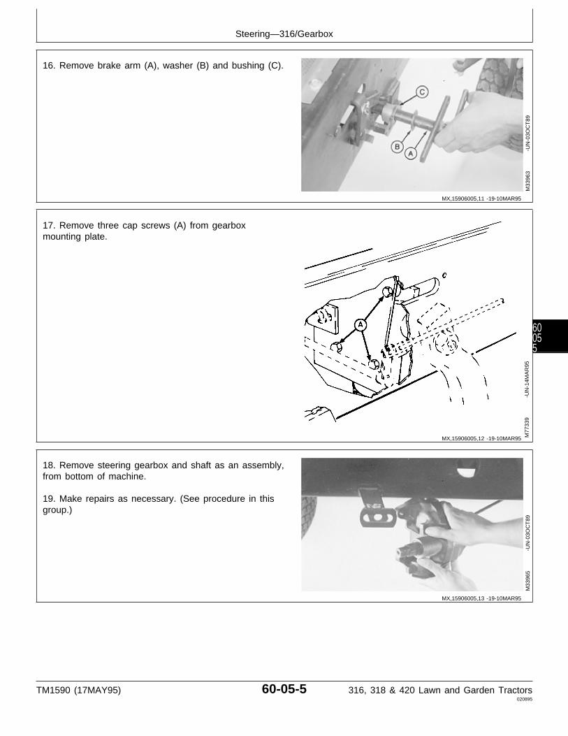
16. Remove brake arm (A), washer (B) and bushing (C).
M33
963
-UN
-03O
CT
89
17. Remove three cap screws (A) from gearboxmounting plate.
M77
339
-UN
-14M
AR
95
18. Remove steering gearbox and shaft as an assembly,from bottom of machine.
19. Make repairs as necessary. (See procedure in thisgroup.)
M33
965
-UN
-03O
CT
89
MX,15906005,11 -19-10MAR95
MX,15906005,12 -19-10MAR95
MX,15906005,13 -19-10MAR95
Steering—316/Gearbox
TM1590 (17MAY95) 60-05-5 316, 318 & 420 Lawn and Garden Tractors020895
60055
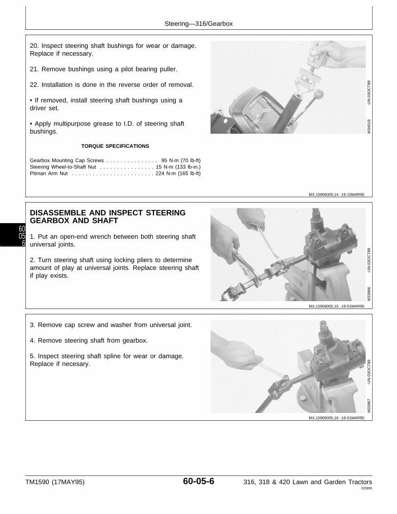
20. Inspect steering shaft bushings for wear or damage.Replace if necessary.
21. Remove bushings using a pilot bearing puller.
22. Installation is done in the reverse order of removal.
• If removed, install steering shaft bushings using adriver set.
• Apply multipurpose grease to I.D. of steering shaftbushings.
TORQUE SPECIFICATIONS
Gearbox Mounting Cap Screws . . . . . . . . . . . . . . . 95 N·m (70 lb-ft)Steering Wheel-to-Shaft Nut . . . . . . . . . . . . . . . . 15 N·m (133 lb-in.)Pitman Arm Nut . . . . . . . . . . . . . . . . . . . . . . . . 224 N·m (165 lb-ft)
M34
018
-UN
-03O
CT
89
DISASSEMBLE AND INSPECT STEERINGGEARBOX AND SHAFT
1. Put an open-end wrench between both steering shaftuniversal joints.
2. Turn steering shaft using locking pliers to determineamount of play at universal joints. Replace steering shaftif play exists.
M33
966
-UN
-03O
CT
89
3. Remove cap screw and washer from universal joint.
4. Remove steering shaft from gearbox.
5. Inspect steering shaft spline for wear or damage.Replace if necesary.
M33
967
-UN
-03O
CT
89
MX,15906005,14 -19-10MAR95
MX,15906005,15 -19-01MAR95
MX,15906005,16 -19-01MAR95
Steering—316/Gearbox
TM1590 (17MAY95) 60-05-6 316, 318 & 420 Lawn and Garden Tractors020895
6005
6
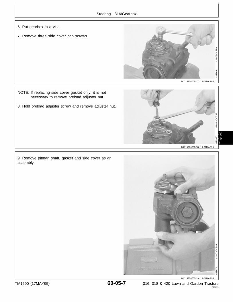
6. Put gearbox in a vise.
7. Remove three side cover cap screws.
M33
969
-UN
-03O
CT
89
NOTE: If replacing side cover gasket only, it is notnecessary to remove preload adjuster nut.
8. Hold preload adjuster screw and remove adjuster nut.
M33
970
-UN
-03O
CT
89
9. Remove pitman shaft, gasket and side cover as anassembly.
M33
971
-UN
-03O
CT
89
MX,15906005,17 -19-01MAR95
MX,15906005,18 -19-01MAR95
MX,15906005,19 -19-01MAR95
Steering—316/Gearbox
TM1590 (17MAY95) 60-05-7 316, 318 & 420 Lawn and Garden Tractors020895
60057
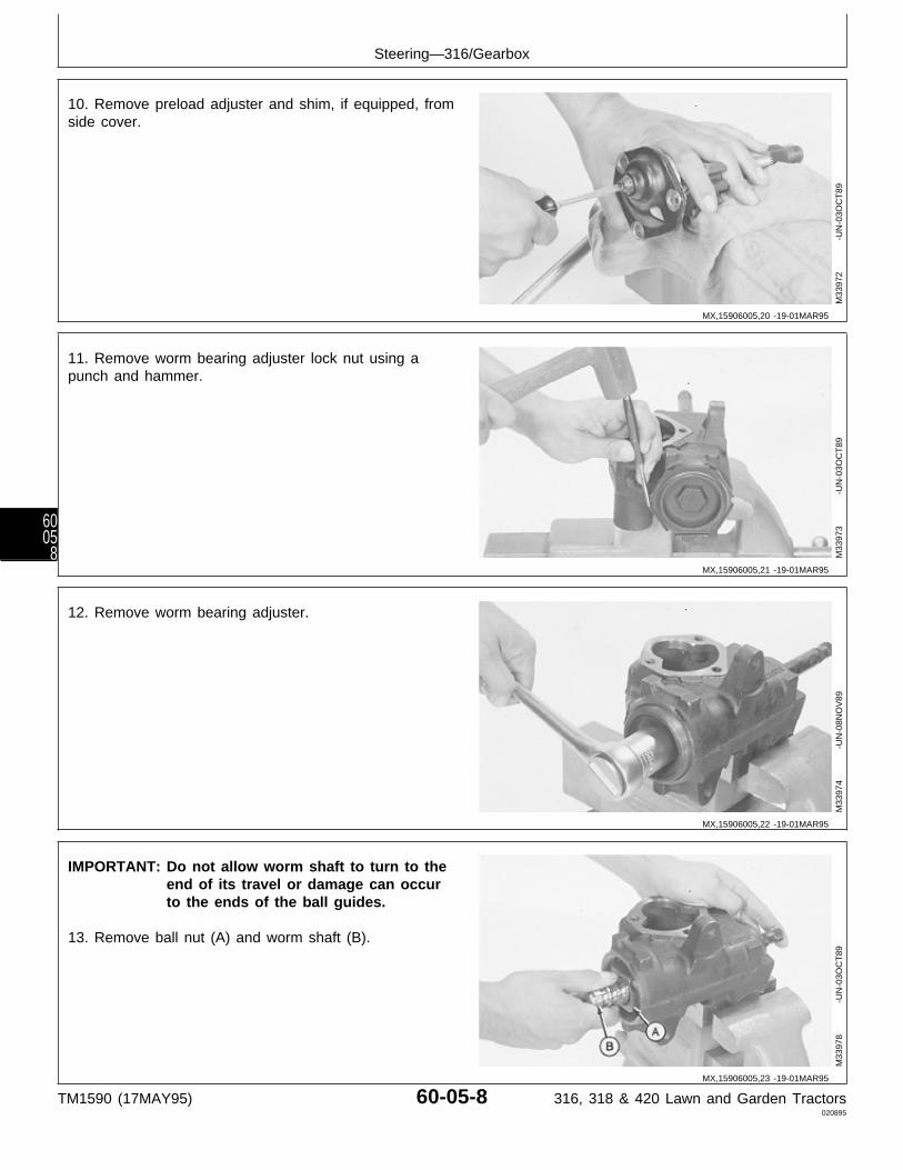
10. Remove preload adjuster and shim, if equipped, fromside cover.
M33
972
-UN
-03O
CT
89
11. Remove worm bearing adjuster lock nut using apunch and hammer.
M33
973
-UN
-03O
CT
89
12. Remove worm bearing adjuster.
M33
974
-UN
-08N
OV
89
IMPORTANT: Do not allow worm shaft to turn to theend of its travel or damage can occurto the ends of the ball guides.
13. Remove ball nut (A) and worm shaft (B).
M33
978
-UN
-03O
CT
89
MX,15906005,20 -19-01MAR95
MX,15906005,21 -19-01MAR95
MX,15906005,22 -19-01MAR95
MX,15906005,23 -19-01MAR95
Steering—316/Gearbox
TM1590 (17MAY95) 60-05-8 316, 318 & 420 Lawn and Garden Tractors020895
6005
8

14. Pry out lower bearing retainer using a screwdriver.
15. Remove lower worm bearing cone.
M33
976
-UN
-03O
CT
89
NOTE: Bearing cup is press-fit in bearing adjuster.Remove bearing cup only if replacement isnecessary.
Bearing cups and cones are matched and mustbe replaced as complete assemblies.
16. Inspect bearing cup in bearing adjuster for wear ordamage. Replace if necessary.
17. Screw bearing adjuster (A) into gearbox housing.Remove bearing cup using a slide hammer and pullerfrom JDG457 Steering Gear Service Set.
M33
977
-UN
-03O
CT
89
18. Remove upper worm bearing cone from shaft orgearbox housing.
M33
979
-UN
-03O
CT
89
MX,15906005,24 -19-01MAR95
MX,15906005,25 -19-01MAR95
MX,15906005,26 -19-01MAR95
Steering—316/Gearbox
TM1590 (17MAY95) 60-05-9 316, 318 & 420 Lawn and Garden Tractors020895
60059

19. Remove ball guide screw and clamp.
M33
980
-UN
-03O
CT
89
20. Remove ball guides (A), balls (B) and ball nut (D)from worm shaft (C).
NOTE: Ball nut and worm shaft are matched and mustbe replaced as a complete assembly.
If any ball becomes lost or damaged, install newballs as a complete set.
21. Inspect all parts for wear or damage. Replace asnecessary.
A—Ball GuidesB—Balls (50 used)C—Worm ShaftD—Ball Nut
M33
981
-UN
-03O
CT
89
MX,15906005,27 -19-01MAR95
MX,15906005,28 -19-01MAR95
Steering—316/Gearbox
TM1590 (17MAY95) 60-05-10 316, 318 & 420 Lawn and Garden Tractors020895
600510
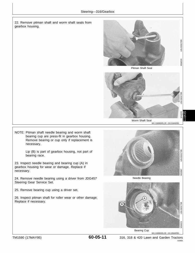
22. Remove pitman shaft and worm shaft seals fromgearbox housing.
Pitman Shaft Seal
Worm Shaft Seal
M34
019
-UN
-03O
CT
89M
3402
0
-U
N-0
3OC
T89
NOTE: Pitman shaft needle bearing and worm shaftbearing cup are press-fit in gearbox housing.Remove bearing or cup only if replacement isnecessary.
Lip (B) is part of gearbox housing, not part ofbearing race.
23. Inspect needle bearing and bearing cup (A) ingearbox housing for wear or damage. Replace ifnecessary.
24. Remove needle bearing using a driver from JDG457 Needle Bearing
Steering Gear Service Set.
25. Remove bearing cup using a driver set.
26. Inspect pitman shaft for roller wear or other damage.Replace if necessary.
Bearing Cup
M33
987
-UN
-03O
CT
89M
3402
1
-U
N-0
3OC
T89
MX,15906005,29 -19-01MAR95
MX,15906005,30 -19-10MAR95
Steering—316/Gearbox
TM1590 (17MAY95) 60-05-11 316, 318 & 420 Lawn and Garden Tractors020895
600511
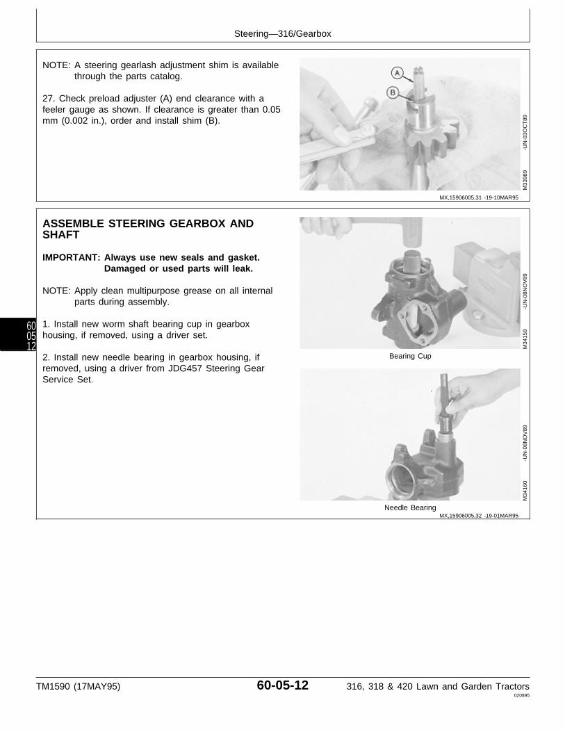
NOTE: A steering gearlash adjustment shim is availablethrough the parts catalog.
27. Check preload adjuster (A) end clearance with afeeler gauge as shown. If clearance is greater than 0.05mm (0.002 in.), order and install shim (B).
M33
989
-UN
-03O
CT
89
ASSEMBLE STEERING GEARBOX ANDSHAFT
IMPORTANT: Always use new seals and gasket.Damaged or used parts will leak.
NOTE: Apply clean multipurpose grease on all internalparts during assembly.
1. Install new worm shaft bearing cup in gearboxhousing, if removed, using a driver set.
2. Install new needle bearing in gearbox housing, if Bearing Cup
removed, using a driver from JDG457 Steering GearService Set.
Needle Bearing
M34
159
-UN
-08N
OV
89M
3416
0
-U
N-0
8NO
V89
MX,15906005,31 -19-10MAR95
MX,15906005,32 -19-01MAR95
Steering—316/Gearbox
TM1590 (17MAY95) 60-05-12 316, 318 & 420 Lawn and Garden Tractors020895
600512

3. Install new pitman shaft and worm shaft seals intogearbox housing using drivers from JDG457 SteeringGear Service Set.
4. Apply multipurpose grease to lip of seals.
Pitman Shaft Seal
Worm Shaft Seal
M34
161
-UN
-08N
OV
89M
3415
8
-U
N-0
8NO
V89
IMPORTANT: Install ball nut onto worm shaft asshown. An improperly installed ball nutcould cause gear damage or steeringlockup.
5. Assemble ball nut and worm shaft (B) with narrow endof ball nut teeth up (A) and worm shaft at the left.
M33
988
-UN
-03O
CT
89
MX,15906005,33 -19-01MAR95
MX,15906005,34 -19-01MAR95
Steering—316/Gearbox
TM1590 (17MAY95) 60-05-13 316, 318 & 420 Lawn and Garden Tractors020895
600513
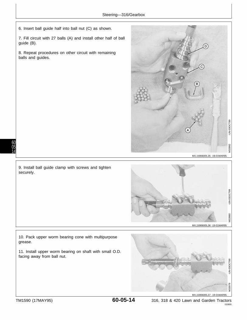
6. Insert ball guide half into ball nut (C) as shown.
7. Fill circuit with 27 balls (A) and install other half of ballguide (B).
8. Repeat procedures on other circuit with remainingballs and guides.
M33
992
-UN
-03O
CT
89
9. Install ball guide clamp with screws and tightensecurely.
M33
980
-UN
-03O
CT
89
10. Pack upper worm bearing cone with multipurposegrease.
11. Install upper worm bearing on shaft with small O.D.facing away from ball nut.
M33
979
-UN
-03O
CT
89
MX,15906005,35 -19-01MAR95
MX,15906005,36 -19-01MAR95
MX,15906005,37 -19-01MAR95
Steering—316/Gearbox
TM1590 (17MAY95) 60-05-14 316, 318 & 420 Lawn and Garden Tractors020895
600514
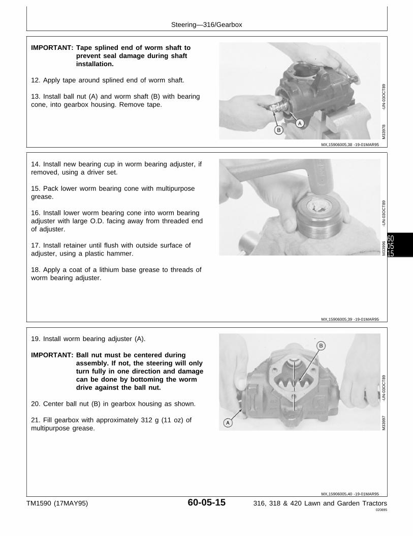
IMPORTANT: Tape splined end of worm shaft toprevent seal damage during shaftinstallation.
12. Apply tape around splined end of worm shaft.
13. Install ball nut (A) and worm shaft (B) with bearingcone, into gearbox housing. Remove tape.
M33
978
-UN
-03O
CT
89
14. Install new bearing cup in worm bearing adjuster, ifremoved, using a driver set.
15. Pack lower worm bearing cone with multipurposegrease.
16. Install lower worm bearing cone into worm bearingadjuster with large O.D. facing away from threaded endof adjuster.
17. Install retainer until flush with outside surface ofadjuster, using a plastic hammer.
18. Apply a coat of a lithium base grease to threads ofworm bearing adjuster.
M33
996
-UN
-03O
CT
89
19. Install worm bearing adjuster (A).
IMPORTANT: Ball nut must be centered duringassembly. If not, the steering will onlyturn fully in one direction and damagecan be done by bottoming the wormdrive against the ball nut.
20. Center ball nut (B) in gearbox housing as shown.
21. Fill gearbox with approximately 312 g (11 oz) ofmultipurpose grease. M
3399
7
-U
N-0
3OC
T89
MX,15906005,38 -19-01MAR95
MX,15906005,39 -19-01MAR95
MX,15906005,40 -19-01MAR95
Steering—316/Gearbox
TM1590 (17MAY95) 60-05-15 316, 318 & 420 Lawn and Garden Tractors020895
600515
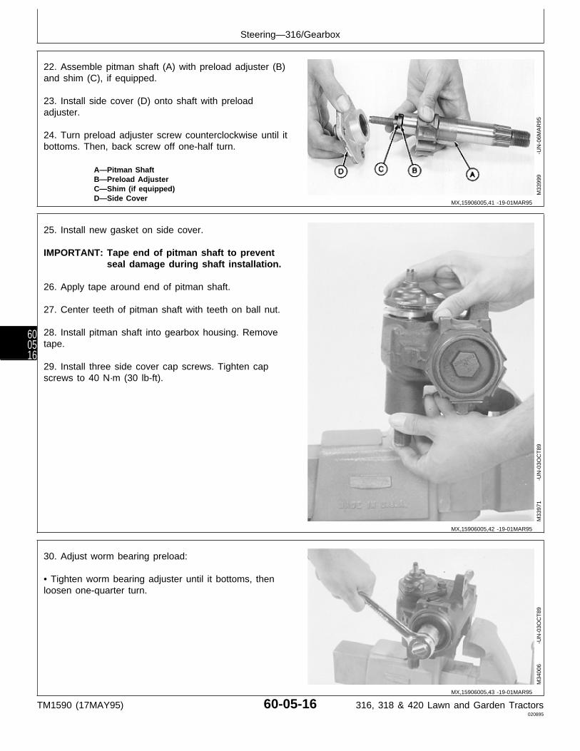
22. Assemble pitman shaft (A) with preload adjuster (B)and shim (C), if equipped.
23. Install side cover (D) onto shaft with preloadadjuster.
24. Turn preload adjuster screw counterclockwise until itbottoms. Then, back screw off one-half turn.
A—Pitman ShaftB—Preload AdjusterC—Shim (if equipped)D—Side Cover
M33
999
-UN
-06M
AR
95
25. Install new gasket on side cover.
IMPORTANT: Tape end of pitman shaft to preventseal damage during shaft installation.
26. Apply tape around end of pitman shaft.
27. Center teeth of pitman shaft with teeth on ball nut.
28. Install pitman shaft into gearbox housing. Removetape.
29. Install three side cover cap screws. Tighten capscrews to 40 N·m (30 lb-ft).
M33
971
-UN
-03O
CT
89
30. Adjust worm bearing preload:
• Tighten worm bearing adjuster until it bottoms, thenloosen one-quarter turn.
M34
006
-UN
-03O
CT
89
MX,15906005,41 -19-01MAR95
MX,15906005,42 -19-01MAR95
MX,15906005,43 -19-01MAR95
Steering—316/Gearbox
TM1590 (17MAY95) 60-05-16 316, 318 & 420 Lawn and Garden Tractors020895
600516
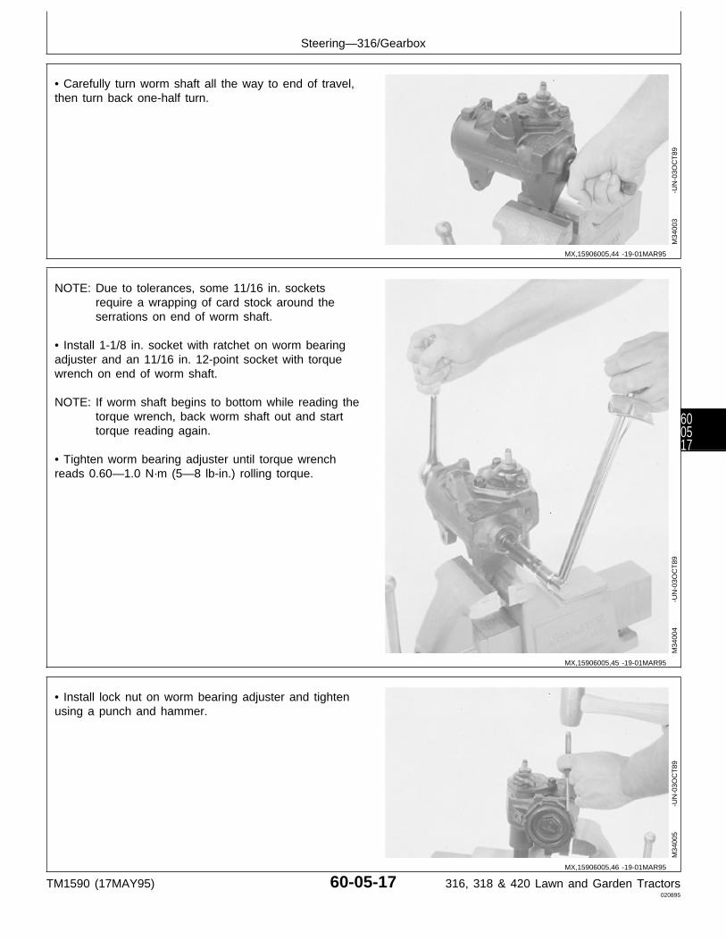
• Carefully turn worm shaft all the way to end of travel,then turn back one-half turn.
M34
003
-UN
-03O
CT
89
NOTE: Due to tolerances, some 11/16 in. socketsrequire a wrapping of card stock around theserrations on end of worm shaft.
• Install 1-1/8 in. socket with ratchet on worm bearingadjuster and an 11/16 in. 12-point socket with torquewrench on end of worm shaft.
NOTE: If worm shaft begins to bottom while reading thetorque wrench, back worm shaft out and starttorque reading again.
• Tighten worm bearing adjuster until torque wrenchreads 0.60—1.0 N·m (5—8 lb-in.) rolling torque.
M34
004
-UN
-03O
CT
89
• Install lock nut on worm bearing adjuster and tightenusing a punch and hammer.
M34
005
-UN
-03O
CT
89
MX,15906005,44 -19-01MAR95
MX,15906005,45 -19-01MAR95
MX,15906005,46 -19-01MAR95
Steering—316/Gearbox
TM1590 (17MAY95) 60-05-17 316, 318 & 420 Lawn and Garden Tractors020895
600517
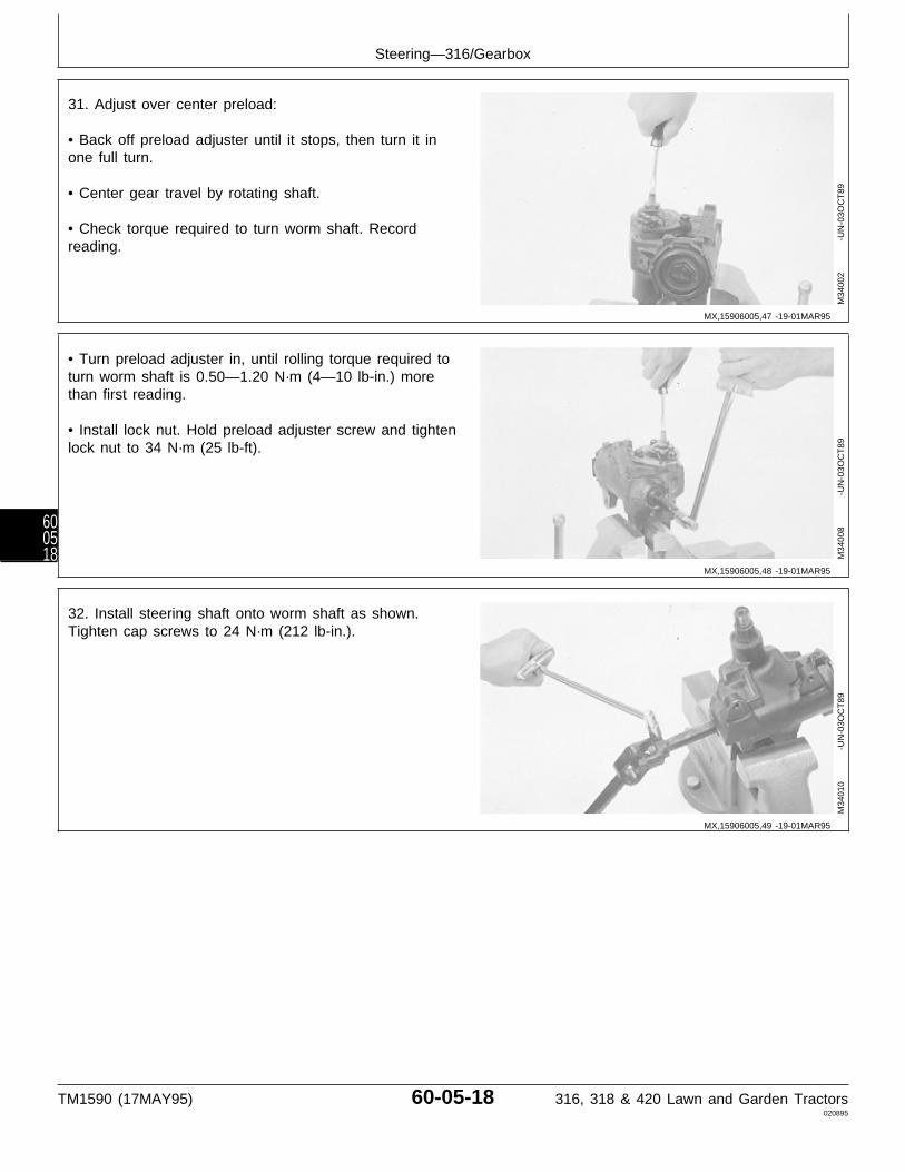
31. Adjust over center preload:
• Back off preload adjuster until it stops, then turn it inone full turn.
• Center gear travel by rotating shaft.
• Check torque required to turn worm shaft. Recordreading.
M34
002
-UN
-03O
CT
89
• Turn preload adjuster in, until rolling torque required toturn worm shaft is 0.50—1.20 N·m (4—10 lb-in.) morethan first reading.
• Install lock nut. Hold preload adjuster screw and tightenlock nut to 34 N·m (25 lb-ft).
M34
008
-UN
-03O
CT
89
32. Install steering shaft onto worm shaft as shown.Tighten cap screws to 24 N·m (212 lb-in.).
M34
010
-UN
-03O
CT
89
MX,15906005,47 -19-01MAR95
MX,15906005,48 -19-01MAR95
MX,15906005,49 -19-01MAR95
Steering—316/Gearbox
TM1590 (17MAY95) 60-05-18 316, 318 & 420 Lawn and Garden Tractors020895
600518
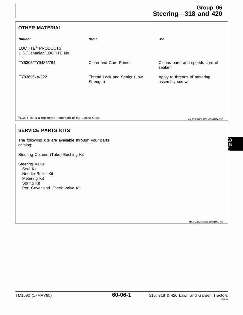
OTHER MATERIAL
Number Name Use
LOCTITE® PRODUCTSU.S./Canadian/LOCTITE No.
TY6305/TY9485/764 Clean and Cure Primer Cleans parts and speeds cure ofsealant.
TY9369/NA/222 Thread Lock and Sealer (Low Apply to threads of meteringStrength) assembly screws.
®LOCTITE is a registered trademark of the Loctite Corp.
SERVICE PARTS KITS
The following kits are available through your partscatalog:
Steering Column (Tube) Bushing Kit
Steering Valve Seal Kit Needle Roller Kit Metering Kit Spring Kit Port Cover and Check Valve Kit
MX,15906006,OTH-19-01MAR95
MX,15906006,KIT-19-01MAR95
Group 06Steering—318 and 420
TM1590 (17MAY95) 60-06-1 316, 318 & 420 Lawn and Garden Tractors020895
60061

REMOVE AND INSTALL STEERING VALVEAND COLUMN
NOTE: Removal and installation procedures for latermodels may vary slightly.
1. Remove fender deck.
2. Remove engine side panels.
3. Remove battery and battery base.
NOTE: On some machines, it may be necessary toremove hour meter, starter solenoid and circuitbreaker to remove right-hand pedestal side.
4. Remove right-hand pedestal side.
5. Remove drive shaft. (See procedure in Section 50,Group 25.)
IMPORTANT: Do not pound on end of steering shaftor damage to steering shaft will occur.
6. Remove steering wheel.
N CAUTION: To avoid injury from escaping fluidunder pressure, stop engine and relieve thepressure in the system before disconnecting orconnecting hydraulic or other lines. Tighten allconnections before applying pressure.
7. Disconnect hydraulic lines from bottom of steeringvalve.
X98
11
-UN
-23A
UG
88M
3183
8
-U
N-0
6MA
R95
8. Remove two nuts (A). Move electric module (B) awayfrom steering unit.
9. Mark forward face of steering unit to aid in installation.
10. Hold top of steering column and remove nuts (C).
M31
839
-UN
-28J
UL8
9
MX,15906006,1 -19-10MAR95
MX,15906006,2 -19-10MAR95
Steering—318 and 420/Steering Valve
TM1590 (17MAY95) 60-06-2 316, 318 & 420 Lawn and Garden Tractors020895
6006
2
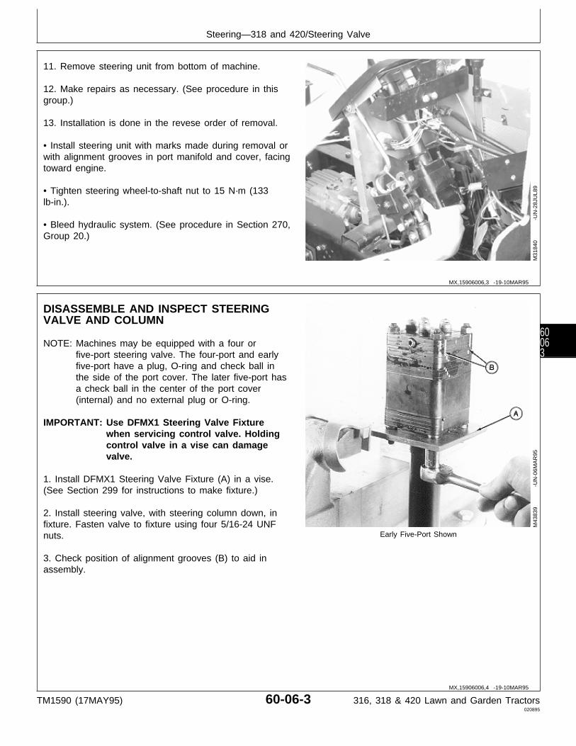
11. Remove steering unit from bottom of machine.
12. Make repairs as necessary. (See procedure in thisgroup.)
13. Installation is done in the revese order of removal.
• Install steering unit with marks made during removal orwith alignment grooves in port manifold and cover, facingtoward engine.
• Tighten steering wheel-to-shaft nut to 15 N·m (133lb-in.).
• Bleed hydraulic system. (See procedure in Section 270,Group 20.)
M31
840
-UN
-28J
UL8
9
DISASSEMBLE AND INSPECT STEERINGVALVE AND COLUMN
NOTE: Machines may be equipped with a four orfive-port steering valve. The four-port and earlyfive-port have a plug, O-ring and check ball inthe side of the port cover. The later five-port hasa check ball in the center of the port cover(internal) and no external plug or O-ring.
IMPORTANT: Use DFMX1 Steering Valve Fixturewhen servicing control valve. Holdingcontrol valve in a vise can damagevalve.
1. Install DFMX1 Steering Valve Fixture (A) in a vise.(See Section 299 for instructions to make fixture.)
2. Install steering valve, with steering column down, infixture. Fasten valve to fixture using four 5/16-24 UNFnuts. Early Five-Port Shown
3. Check position of alignment grooves (B) to aid inassembly.
M43
839
-UN
-06M
AR
95
MX,15906006,3 -19-10MAR95
MX,15906006,4 -19-10MAR95
Steering—318 and 420/Steering Valve
TM1590 (17MAY95) 60-06-3 316, 318 & 420 Lawn and Garden Tractors020895
60063

4. Four-port and early five-port; Loosen plug one turn.
M77
338
-UN
-21F
EB
95
IMPORTANT: Do not damage fittings during nutremoval. Do not nick or scratch themachined surfaces of the steeringvalve.
5. Remove nuts to remove port cover assembly (fourplates bonded together).
Early Five-Port Shown M43
841
-UN
-08J
AN
90
6. Later five-port; Remove port cover and check ball (A).
M77
303
-UN
-06M
AR
95
MX,15906006,5 -19-14MAR95
MX,15906006,6 -19-10MAR95
MX,15906006,7 -19-10MAR95
Steering—318 and 420/Steering Valve
TM1590 (17MAY95) 60-06-4 316, 318 & 420 Lawn and Garden Tractors020895
6006
4

NOTE: Four-port not shown. Unit is similar to earlyfive-port.
7. Remove seal ring and O-rings (A).
8. Inspect port cover for scratches on machined surfacesor damage to fittings. Replace cover if damaged.
Early Five-Port
Later Five-Port
M36
834
-UN
-29A
UG
88M
7805
6
-U
N-0
6MA
R95
9. Four-port and early five-port; Remove plug (A), O-ring(B) and check ball (C).
Five-Port Shown M43
832
-UN
-08J
AN
90
MX,15906006,8 -19-29MAR95
MX,15906006,9 -19-10MAR95
Steering—318 and 420/Steering Valve
TM1590 (17MAY95) 60-06-5 316, 318 & 420 Lawn and Garden Tractors020895
60065
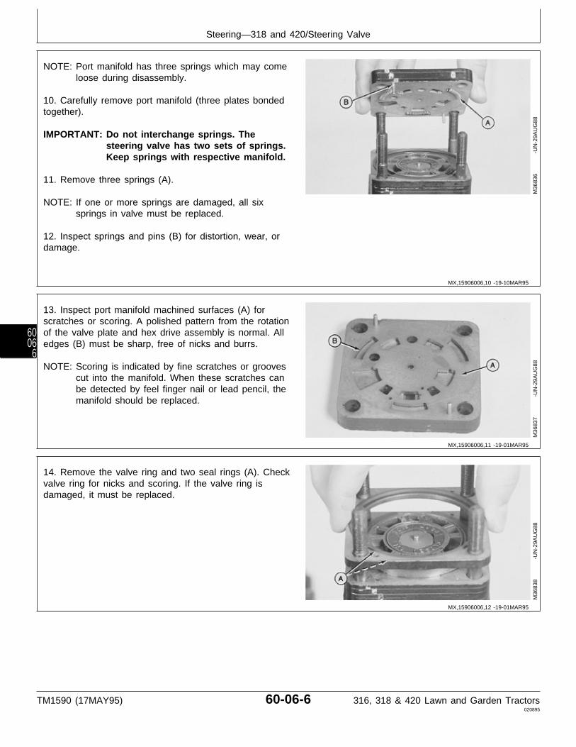
NOTE: Port manifold has three springs which may comeloose during disassembly.
10. Carefully remove port manifold (three plates bondedtogether).
IMPORTANT: Do not interchange springs. Thesteering valve has two sets of springs.Keep springs with respective manifold.
11. Remove three springs (A).
NOTE: If one or more springs are damaged, all sixsprings in valve must be replaced.
12. Inspect springs and pins (B) for distortion, wear, ordamage.
M36
836
-UN
-29A
UG
88
13. Inspect port manifold machined surfaces (A) forscratches or scoring. A polished pattern from the rotationof the valve plate and hex drive assembly is normal. Alledges (B) must be sharp, free of nicks and burrs.
NOTE: Scoring is indicated by fine scratches or groovescut into the manifold. When these scratches canbe detected by feel finger nail or lead pencil, themanifold should be replaced.
M36
837
-UN
-29A
UG
88
14. Remove the valve ring and two seal rings (A). Checkvalve ring for nicks and scoring. If the valve ring isdamaged, it must be replaced.
M36
838
-UN
-29A
UG
88
MX,15906006,10 -19-10MAR95
MX,15906006,11 -19-01MAR95
MX,15906006,12 -19-01MAR95
Steering—318 and 420/Steering Valve
TM1590 (17MAY95) 60-06-6 316, 318 & 420 Lawn and Garden Tractors020895
6006
6
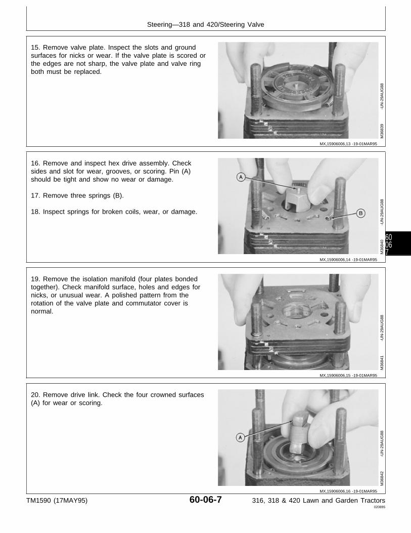
15. Remove valve plate. Inspect the slots and groundsurfaces for nicks or wear. If the valve plate is scored orthe edges are not sharp, the valve plate and valve ringboth must be replaced.
M36
839
-UN
-29A
UG
88
16. Remove and inspect hex drive assembly. Checksides and slot for wear, grooves, or scoring. Pin (A)should be tight and show no wear or damage.
17. Remove three springs (B).
18. Inspect springs for broken coils, wear, or damage.
M36
840
-UN
-29A
UG
88
19. Remove the isolation manifold (four plates bondedtogether). Check manifold surface, holes and edges fornicks, or unusual wear. A polished pattern from therotation of the valve plate and commutator cover isnormal.
M36
841
-UN
-29A
UG
88
20. Remove drive link. Check the four crowned surfaces(A) for wear or scoring.
M36
842
-UN
-29A
UG
88
MX,15906006,13 -19-01MAR95
MX,15906006,14 -19-01MAR95
MX,15906006,15 -19-01MAR95
MX,15906006,16 -19-01MAR95
Steering—318 and 420/Steering Valve
TM1590 (17MAY95) 60-06-7 316, 318 & 420 Lawn and Garden Tractors020895
60067
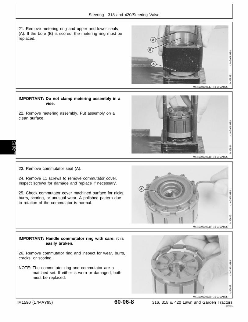
21. Remove metering ring and upper and lower seals(A). If the bore (B) is scored, the metering ring must bereplaced.
M36
843
-UN
-29A
UG
88
IMPORTANT: Do not clamp metering assembly in avise.
22. Remove metering assembly. Put assembly on aclean surface.
M36
844
-UN
-29A
UG
88
23. Remove commutator seal (A).
24. Remove 11 screws to remove commutator cover.Inspect screws for damage and replace if necessary.
25. Check commutator cover machined surface for nicks,burrs, scoring, or unusual wear. A polished pattern dueto rotation of the commutator is normal.
M36
845
-UN
-29A
UG
88
IMPORTANT: Handle commutator ring with care; it iseasily broken.
26. Remove commutator ring and inspect for wear, burrs,cracks, or scoring.
NOTE: The commutator ring and commutator are amatched set. If either is worn or damaged, bothmust be replaced.
M36
847
-UN
-29A
UG
88
MX,15906006,17 -19-01MAR95
MX,15906006,18 -19-01MAR95
MX,15906006,19 -19-01MAR95
MX,15906006,20 -19-01MAR95
Steering—318 and 420/Steering Valve
TM1590 (17MAY95) 60-06-8 316, 318 & 420 Lawn and Garden Tractors020895
6006
8

IMPORTANT: DO NOT use a screwdriver to removecommutator. Commutator can bedamaged.
27. Remove commutator and five pins (A) using a wooddowel or equivalent.
NOTE: The commutator is made up of two platesbonded together. It is a permanent assembly andcannot be disassembled.
28. Check commutator machined surface, holes andedges for nicks. Edges must be sharp.
M36
848
-UN
-29A
UG
88
29. Remove drive link spacer. Check spacer for grooves,wear, or damage.
30. The rotor should rotate and orbit freely within thestator. Check commutator side of stator face for groovesor scoring.
NOTE: Stator and rotor are a matched set. If either areworn or damaged, both must be replaced.
M36
849
-UN
-29A
UG
88
31. Measure rotor-to-stator clearance. Center rotor lobe(A) between stator lobes and check clearance directlyopposite lobe (A).
If rotor-to-stator clearance is more than 0.08 mm (0.003in.), replace rotor and stator.
M36
850
-UN
-29A
UG
88
MX,15906006,21 -19-01MAR95
MX,15906006,22 -19-01MAR95
MX,15906006,23 -19-01MAR95
Steering—318 and 420/Steering Valve
TM1590 (17MAY95) 60-06-9 316, 318 & 420 Lawn and Garden Tractors020895
60069

32. Lift the rotor and stator from the drive plate.
33. Check the drive plate side of the rotor assembly fornicks, grooves, or scoring. A spiral pattern due to rotormovement is normal.
The thrust bearing side of the plate should also show anormal wear pattern without grooves, flaking, or dents.
The flat sides of the input shaft hole should not begrooved or worn.
Drive Plate Side
Thrust Bearing Side
M36
851
-UN
-29A
UG
88M
3685
2
-U
N-2
9AU
G88
NOTE: Four-port and early five-port have a seal spacerand backup ring. Later five-port has a sealspacer only.
34. Remove parts (A—E).
35. Inspect parts for wear or damage. Replace ifnecessary.
A—Thrust Bearing SpacerB—Thrust BearingC—Face SealD—Backup-Ring (4-Port and Early 5-Port) Four-Port and Early Five-PortE—Seal Spacer
Later Five-Port
M36
853
-UN
-29A
UG
88M
7730
5
-U
N-0
6MA
R95
MX,15906006,24 -19-01MAR95
MX,15906006,25 -19-10MAR95
Steering—318 and 420/Steering Valve
TM1590 (17MAY95) 60-06-10 316, 318 & 420 Lawn and Garden Tractors020895
600610
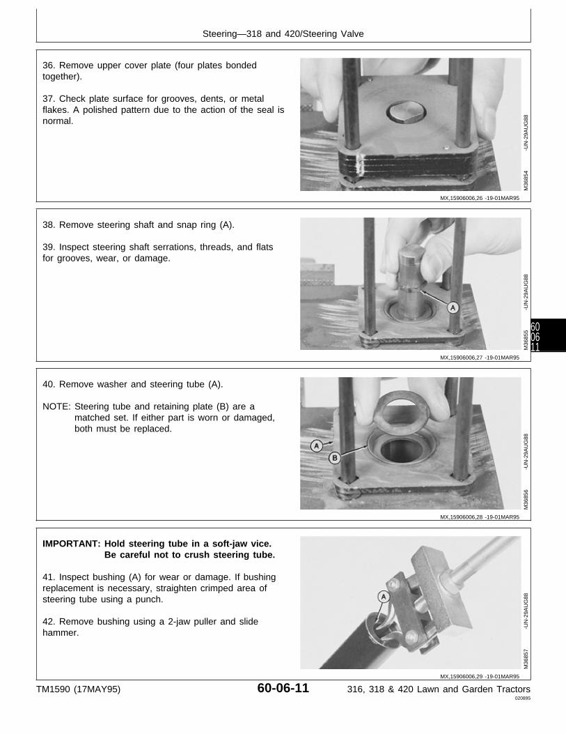
36. Remove upper cover plate (four plates bondedtogether).
37. Check plate surface for grooves, dents, or metalflakes. A polished pattern due to the action of the seal isnormal.
M36
854
-UN
-29A
UG
88
38. Remove steering shaft and snap ring (A).
39. Inspect steering shaft serrations, threads, and flatsfor grooves, wear, or damage.
M36
855
-UN
-29A
UG
88
40. Remove washer and steering tube (A).
NOTE: Steering tube and retaining plate (B) are amatched set. If either part is worn or damaged,both must be replaced.
M36
856
-UN
-29A
UG
88
IMPORTANT: Hold steering tube in a soft-jaw vice.Be careful not to crush steering tube.
41. Inspect bushing (A) for wear or damage. If bushingreplacement is necessary, straighten crimped area ofsteering tube using a punch.
42. Remove bushing using a 2-jaw puller and slidehammer.
M36
857
-UN
-29A
UG
88
MX,15906006,26 -19-01MAR95
MX,15906006,27 -19-01MAR95
MX,15906006,28 -19-01MAR95
MX,15906006,29 -19-01MAR95
Steering—318 and 420/Steering Valve
TM1590 (17MAY95) 60-06-11 316, 318 & 420 Lawn and Garden Tractors020895
600611

43. Remove nuts holding the four bolts to the fixture,and remove the bolts.
44. Inspect bolts for wear or damage. Replace ifnecessary.
M36
858
-UN
-29A
UG
88
ASSEMBLE STEERING VALVE ANDCOLUMN
IMPORTANT: Always use new seals and O-rings.Damaged or used parts will leak.
NOTE: Lubricate all seals and O-rings with petroleumjelly during assembly.
1. Apply clean John Deere Low Viscosity HY-GARD® oilon all internal parts.
2. Install four bolts, with short threaded end down, infixture. Install nuts and tighten finger tight.
M36
858
-UN
-29A
UG
88
3. Install bushing into steering tube with recess facinginto tube, using a driver set. Install bushing 2.5 mm(0.100 in.) below top of steering tube.
4. Slightly bend edges of steering tube over bushingusing a punch.
5. Apply multipurpose grease to inside of bushing.
M36
860
-UN
-29A
UG
88
MX,15906006,30 -19-01MAR95
MX,15906006,31 -19-10MAR95
MX,15906006,32 -19-01MAR95
Steering—318 and 420/Steering Valve
TM1590 (17MAY95) 60-06-12 316, 318 & 420 Lawn and Garden Tractors020895
600612

6. Install steering tube (A) on bolts. Be sure the squareholes in the steering tube are seated on the squareshoulders of the bolts.
7. Apply multipurpose grease on retainer plate (B) andwasher.
8. Install washer.
M36
856
-UN
-29A
UG
88
9. Install snap ring (A) on steering shaft.
10. Install steering shaft with threaded end down intosteering tube.
M36
855
-UN
-29A
UG
88
IMPORTANT: Alignment grooves must be on onlyone side of steering valve for propervalve operation.
11. Install upper cover plate over four bolts with thehighly polished surface up.
M36
854
-UN
-29A
UG
88
MX,15906006,33 -19-01MAR95
MX,15906006,34 -19-01MAR95
MX,15906006,35 -19-01MAR95
Steering—318 and 420/Steering Valve
TM1590 (17MAY95) 60-06-13 316, 318 & 420 Lawn and Garden Tractors020895
600613
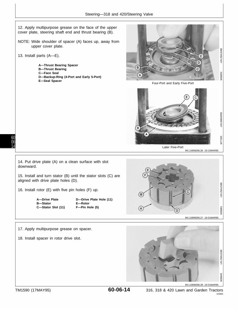
12. Apply multipurpose grease on the face of the uppercover plate, steering shaft end and thrust bearing (B).
NOTE: Wide shoulder of spacer (A) faces up, away fromupper cover plate.
13. Install parts (A—E).
A—Thrust Bearing SpacerB—Thrust BearingC—Face SealD—Backup-Ring (4-Port and Early 5-Port)E—Seal Spacer
Four-Port and Early Five-Port
Later Five-Port
M36
853
-UN
-29A
UG
88M
7730
5
-U
N-0
6MA
R95
14. Put drive plate (A) on a clean surface with slotdownward.
15. Install and turn stator (B) until the stator slots (C) arealigned with drive plate holes (D).
16. Install rotor (E) with five pin holes (F) up.
A—Drive Plate D—Drive Plate Hole (11)B—Stator E—RotorC—Stator Slot (11) F—Pin Hole (5)
M36
861
-UN
-29A
UG
88
17. Apply multipurpose grease on spacer.
18. Install spacer in rotor drive slot.
M36
849
-UN
-29A
UG
88
MX,15906006,36 -19-10MAR95
MX,15906006,37 -19-01MAR95
MX,15906006,38 -19-01MAR95
Steering—318 and 420/Steering Valve
TM1590 (17MAY95) 60-06-14 316, 318 & 420 Lawn and Garden Tractors020895
600614
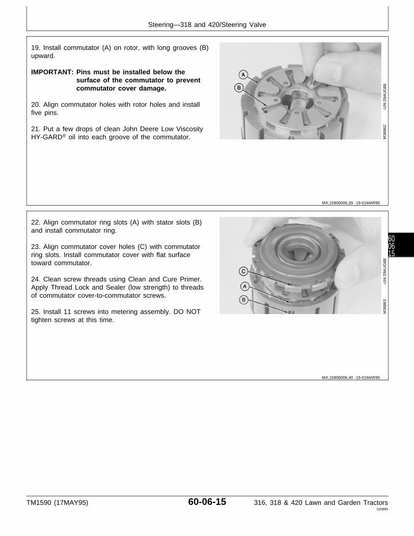
19. Install commutator (A) on rotor, with long grooves (B)upward.
IMPORTANT: Pins must be installed below thesurface of the commutator to preventcommutator cover damage.
20. Align commutator holes with rotor holes and installfive pins.
21. Put a few drops of clean John Deere Low ViscosityHY-GARD® oil into each groove of the commutator. M
3686
2
-U
N-2
9AU
G88
22. Align commutator ring slots (A) with stator slots (B)and install commutator ring.
23. Align commutator cover holes (C) with commutatorring slots. Install commutator cover with flat surfacetoward commutator.
24. Clean screw threads using Clean and Cure Primer.Apply Thread Lock and Sealer (low strength) to threadsof commutator cover-to-commutator screws.
25. Install 11 screws into metering assembly. DO NOTtighten screws at this time.
M36
863
-UN
-29A
UG
88
MX,15906006,39 -19-01MAR95
MX,15906006,40 -19-01MAR95
Steering—318 and 420/Steering Valve
TM1590 (17MAY95) 60-06-15 316, 318 & 420 Lawn and Garden Tractors020895
600615
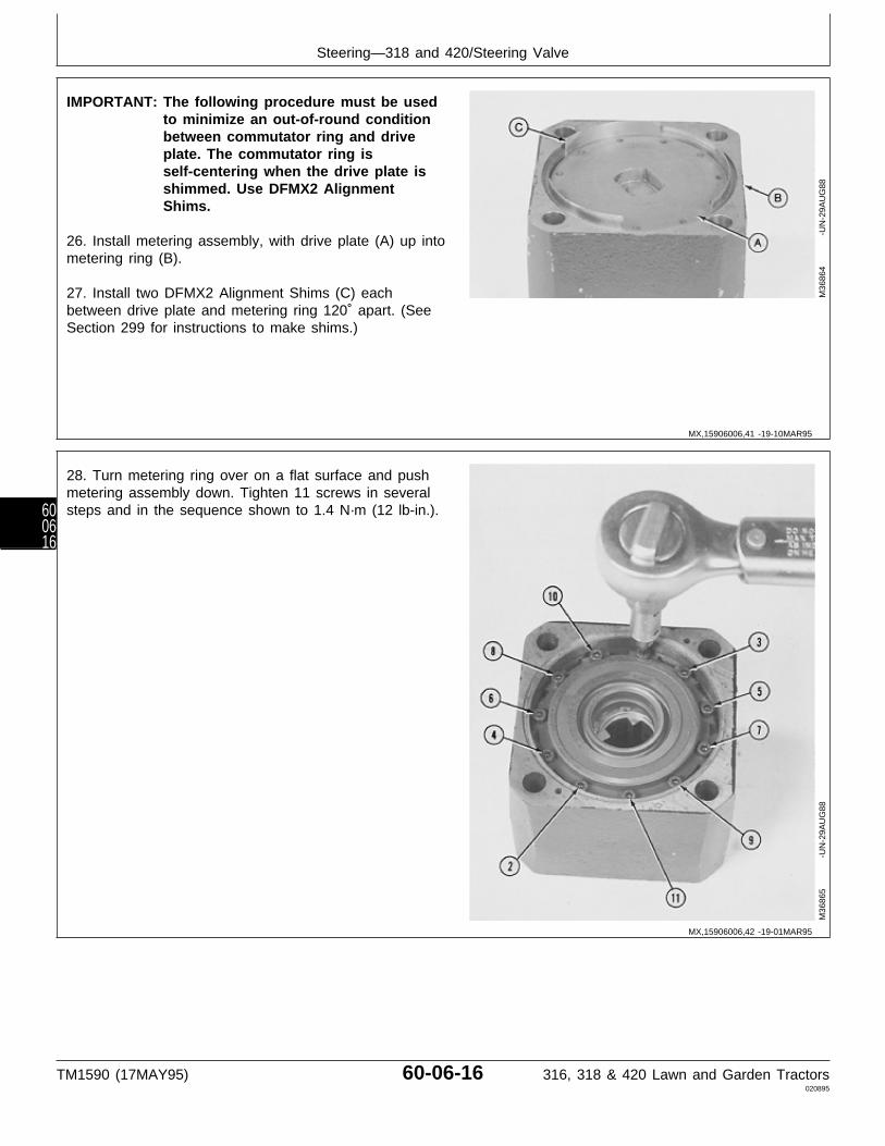
IMPORTANT: The following procedure must be usedto minimize an out-of-round conditionbetween commutator ring and driveplate. The commutator ring isself-centering when the drive plate isshimmed. Use DFMX2 AlignmentShims.
26. Install metering assembly, with drive plate (A) up intometering ring (B).
27. Install two DFMX2 Alignment Shims (C) eachbetween drive plate and metering ring 120˚ apart. (SeeSection 299 for instructions to make shims.)
M36
864
-UN
-29A
UG
88
28. Turn metering ring over on a flat surface and pushmetering assembly down. Tighten 11 screws in severalsteps and in the sequence shown to 1.4 N·m (12 lb-in.).
M36
865
-UN
-29A
UG
88
MX,15906006,41 -19-10MAR95
MX,15906006,42 -19-01MAR95
Steering—318 and 420/Steering Valve
TM1590 (17MAY95) 60-06-16 316, 318 & 420 Lawn and Garden Tractors020895
600616
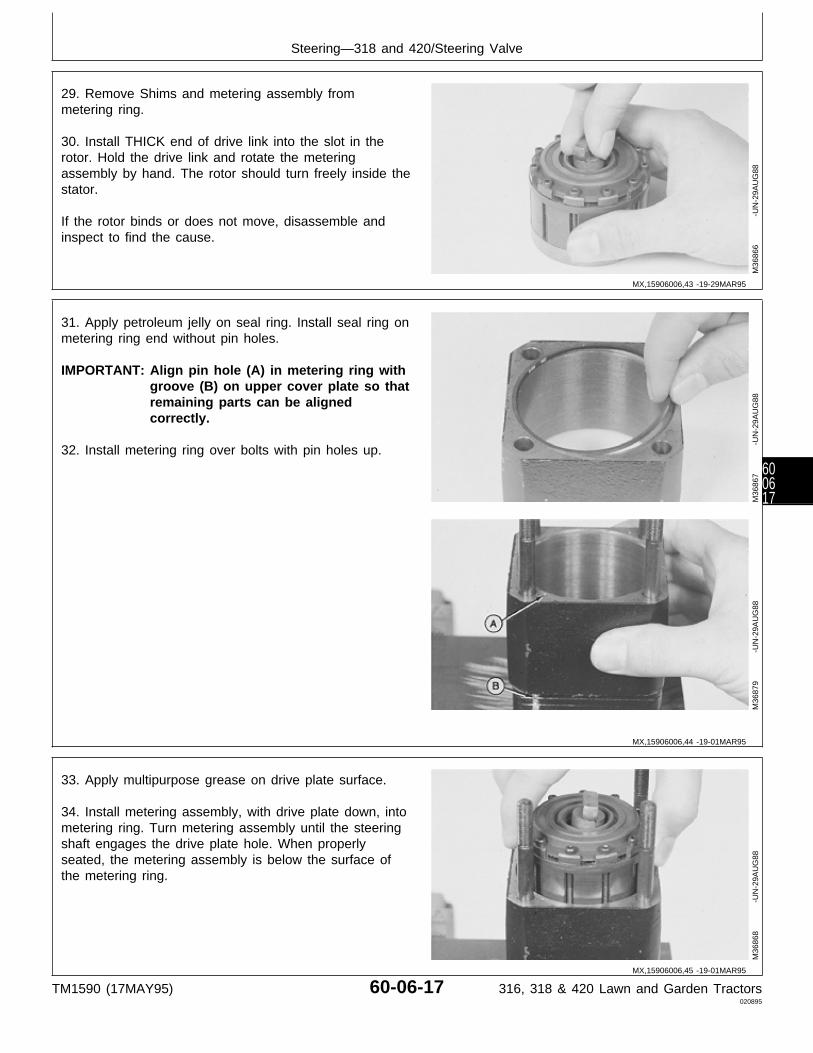
29. Remove Shims and metering assembly frommetering ring.
30. Install THICK end of drive link into the slot in therotor. Hold the drive link and rotate the meteringassembly by hand. The rotor should turn freely inside thestator.
If the rotor binds or does not move, disassemble andinspect to find the cause.
M36
866
-UN
-29A
UG
88
31. Apply petroleum jelly on seal ring. Install seal ring onmetering ring end without pin holes.
IMPORTANT: Align pin hole (A) in metering ring withgroove (B) on upper cover plate so thatremaining parts can be alignedcorrectly.
32. Install metering ring over bolts with pin holes up.
M36
867
-UN
-29A
UG
88M
3687
9
-U
N-2
9AU
G88
33. Apply multipurpose grease on drive plate surface.
34. Install metering assembly, with drive plate down, intometering ring. Turn metering assembly until the steeringshaft engages the drive plate hole. When properlyseated, the metering assembly is below the surface ofthe metering ring.
M36
868
-UN
-29A
UG
88
MX,15906006,43 -19-29MAR95
MX,15906006,44 -19-01MAR95
MX,15906006,45 -19-01MAR95
Steering—318 and 420/Steering Valve
TM1590 (17MAY95) 60-06-17 316, 318 & 420 Lawn and Garden Tractors020895
600617

35. Apply petroleum jelly on new commutator seal (A)and seal ring (B).
36. Install new commutator seal with yellow mark (C) ornarrow edge, down into commutator cover.
37. Install seal ring (B) and pins (D).
A—Commutator SealB—Seal RingC—Yellow Mark or Narrow EdgeD—Pin (2 used)
M36
869
-UN
-29A
UG
88
IMPORTANT: Align grooves (A) in isolation manifoldwith groove (B) in upper cover plate.
38. Install isolation manifold, with recessed slots up, onmetering ring.
39. Install pins (C).
M36
870
-UN
-29A
UG
88
40. Install three 13 mm (1/2 in.) springs (B) in recessedslots of the isolation manifold.
41. Install hex drive assembly, with pin (A) up, on drivelink.
M36
840
-UN
-29A
UG
88
42. Apply petroleum jelly on new seal rings (A). Installseal rings on valve ring.
43. Align valve ring holes (B) with pins (C) to installvalve ring.
M36
871
-UN
-29A
UG
88
MX,15906006,46 -19-01MAR95
MX,15906006,47 -19-01MAR95
MX,15906006,48 -19-01MAR95
MX,15906006,49 -19-01MAR95
Steering—318 and 420/Steering Valve
TM1590 (17MAY95) 60-06-18 316, 318 & 420 Lawn and Garden Tractors020895
600618
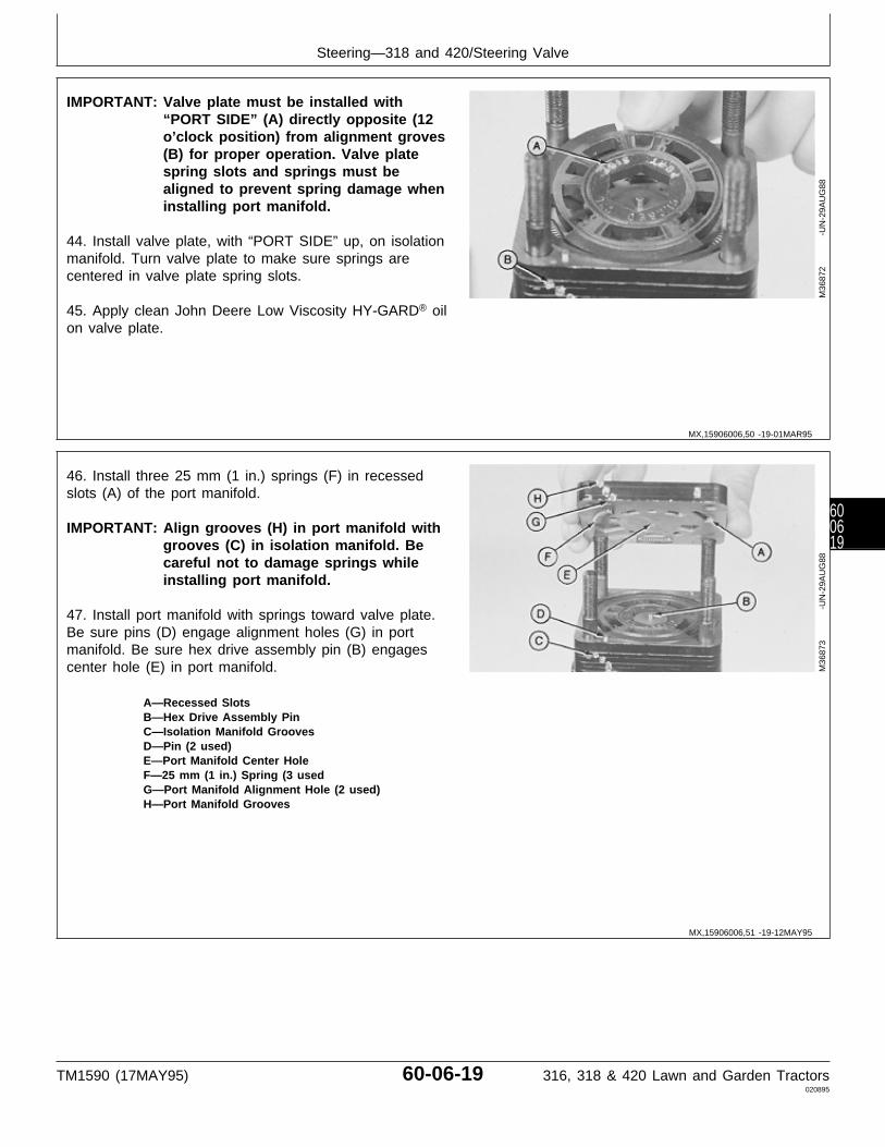
IMPORTANT: Valve plate must be installed with“PORT SIDE” (A) directly opposite (12o’clock position) from alignment groves(B) for proper operation. Valve platespring slots and springs must bealigned to prevent spring damage wheninstalling port manifold.
44. Install valve plate, with “PORT SIDE” up, on isolationmanifold. Turn valve plate to make sure springs arecentered in valve plate spring slots.
45. Apply clean John Deere Low Viscosity HY-GARD® oilon valve plate.
M36
872
-UN
-29A
UG
88
46. Install three 25 mm (1 in.) springs (F) in recessedslots (A) of the port manifold.
IMPORTANT: Align grooves (H) in port manifold withgrooves (C) in isolation manifold. Becareful not to damage springs whileinstalling port manifold.
47. Install port manifold with springs toward valve plate.Be sure pins (D) engage alignment holes (G) in portmanifold. Be sure hex drive assembly pin (B) engagescenter hole (E) in port manifold.
A—Recessed SlotsB—Hex Drive Assembly PinC—Isolation Manifold GroovesD—Pin (2 used)E—Port Manifold Center HoleF—25 mm (1 in.) Spring (3 usedG—Port Manifold Alignment Hole (2 used)H—Port Manifold Grooves
M36
873
-UN
-29A
UG
88
MX,15906006,50 -19-01MAR95
MX,15906006,51 -19-12MAY95
Steering—318 and 420/Steering Valve
TM1590 (17MAY95) 60-06-19 316, 318 & 420 Lawn and Garden Tractors020895
600619
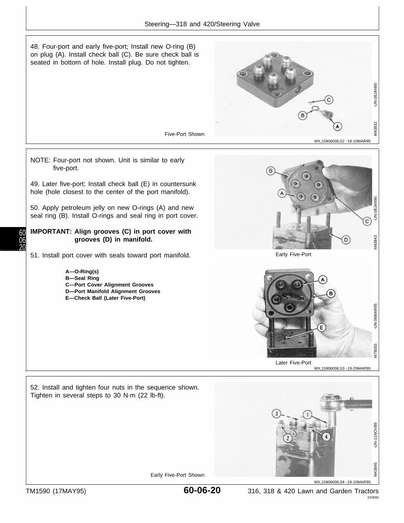
48. Four-port and early five-port; Install new O-ring (B)on plug (A). Install check ball (C). Be sure check ball isseated in bottom of hole. Install plug. Do not tighten.
Five-Port Shown M43
832
-UN
-08J
AN
90
NOTE: Four-port not shown. Unit is similar to earlyfive-port.
49. Later five-port; Install check ball (E) in countersunkhole (hole closest to the center of the port manifold).
50. Apply petroleum jelly on new O-rings (A) and newseal ring (B). Install O-rings and seal ring in port cover.
IMPORTANT: Align grooves (C) in port cover withgrooves (D) in manifold.
51. Install port cover with seals toward port manifold. Early Five-Port
A—O-Ring(s)B—Seal RingC—Port Cover Alignment GroovesD—Port Manifold Alignment GroovesE—Check Ball (Later Five-Port)
Later Five-Port
M43
843
-UN
-08J
AN
90M
7805
5
-U
N-0
6MA
R95
52. Install and tighten four nuts in the sequence shown.Tighten in several steps to 30 N·m (22 lb-ft).
Early Five-Port Shown M43
845
-UN
-11N
OV
89
MX,15906006,52 -19-10MAR95
MX,15906006,53 -19-29MAR95
MX,15906006,54 -19-10MAR95
Steering—318 and 420/Steering Valve
TM1590 (17MAY95) 60-06-20 316, 318 & 420 Lawn and Garden Tractors020895
600620
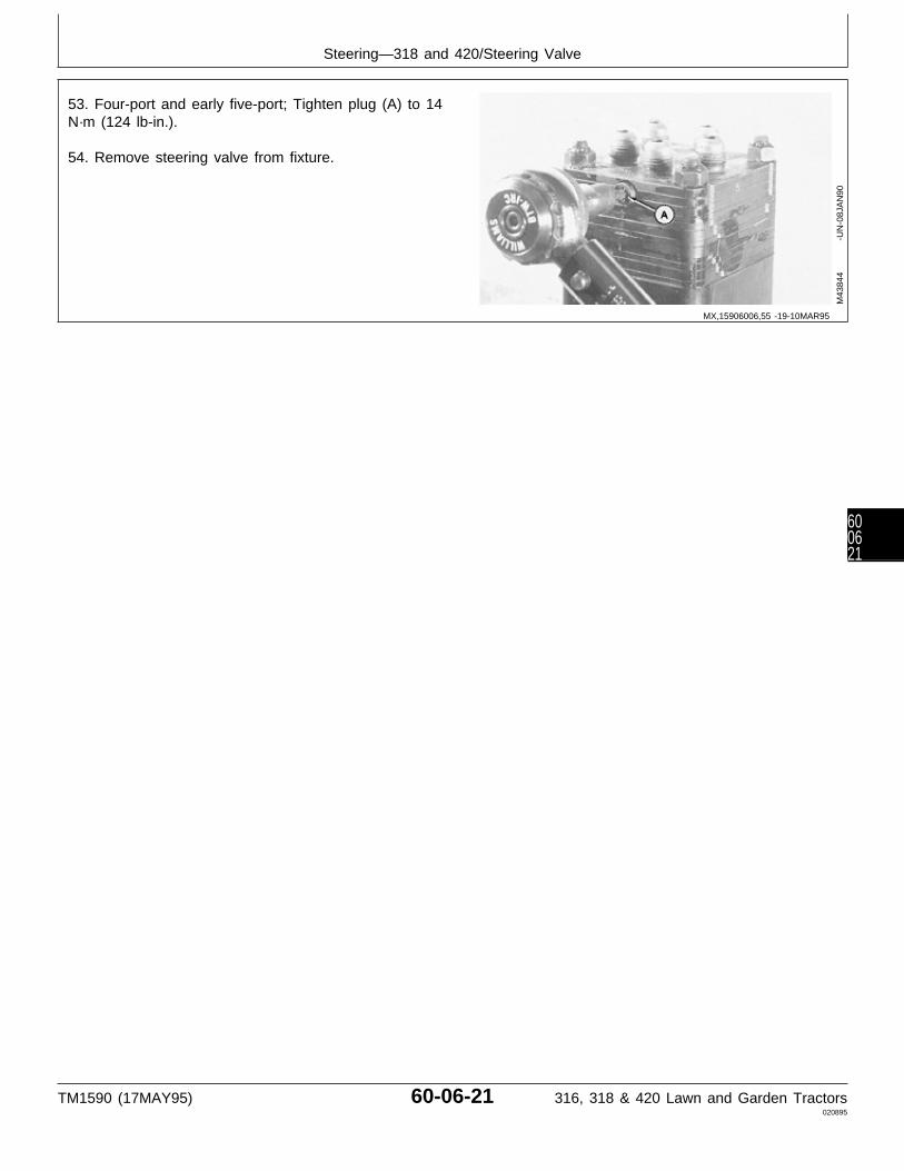
53. Four-port and early five-port; Tighten plug (A) to 14N·m (124 lb-in.).
54. Remove steering valve from fixture.
M43
844
-UN
-08J
AN
90
MX,15906006,55 -19-10MAR95
Steering—318 and 420/Steering Valve
TM1590 (17MAY95) 60-06-21 316, 318 & 420 Lawn and Garden Tractors020895
600621

REMOVE AND INSTALL STEERINGCYLINDER
N CAUTION: Escaping fluid under pressure canpenetrate the skin causing serious injury.Avoid the hazard by relieving pressure beforedisconnecting hydraulic or other lines. Tightenall connections before applying pressure.Search for leaks with a piece of cardboard.Protect hands and body from high pressurefluids.
If an accident occurs, see a doctorimmediately. Any fluid injected into the skinmust be surgically removed within a few hoursor gangrene may result. Doctors unfamiliarwith this type of injury should reference aknowledgeable medical source. Suchinformation is available from Deere & CompanyMedical Department in Moline, Illinois, U.S.A.
1. Disconnect hydraulic hoses at lines (A).
Early Model Shown2. Support cylinder and remove cotter pins (B), ifequipped, nuts (C) and bolts (D).
A—Hydraulic Lines3. Remove steering cylinder (E).B—Cotter Pins (if equipped)C—Nuts (Early Models)
NOTE: Cylinder is not repairable. If defective, replace —Lock Nuts (Later Models)complete assembly. D—Bolts
E—Steering Cylinder
4. Installation is done in the reverse order of removal.
• Tighten nuts (C) to 163 N·m (120 lb-ft).
• Bleed the hydraulic system. (See procedure in Section270, Group 20.)
X98
11
-UN
-23A
UG
88M
3182
2
-U
N-2
8JU
L89
MX,15906006,56 -19-10MAR95
Steering—318 and 420/Steering Cylinder
TM1590 (17MAY95) 60-06-22 316, 318 & 420 Lawn and Garden Tractors020895
600622
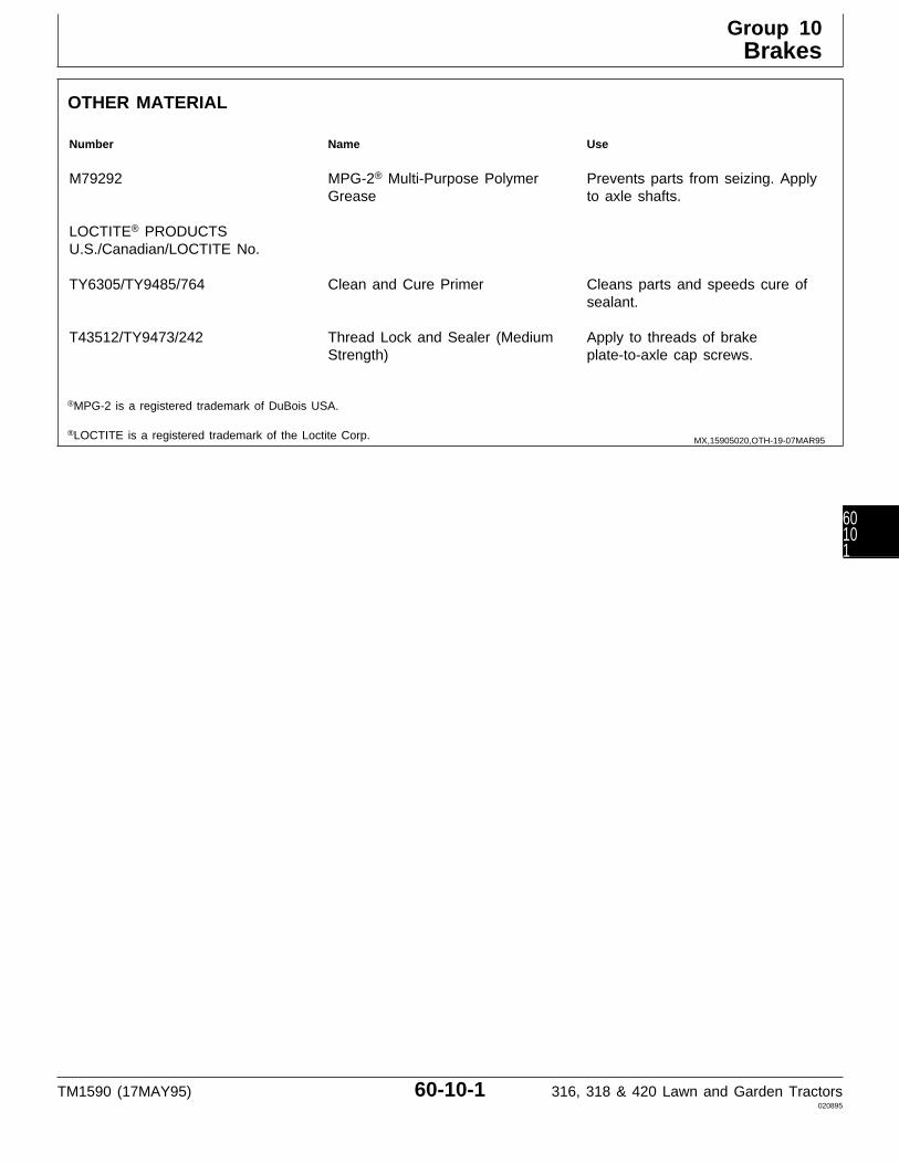
OTHER MATERIAL
Number Name Use
M79292 MPG-2® Multi-Purpose Polymer Prevents parts from seizing. ApplyGrease to axle shafts.
LOCTITE® PRODUCTSU.S./Canadian/LOCTITE No.
TY6305/TY9485/764 Clean and Cure Primer Cleans parts and speeds cure ofsealant.
T43512/TY9473/242 Thread Lock and Sealer (Medium Apply to threads of brakeStrength) plate-to-axle cap screws.
®MPG-2 is a registered trademark of DuBois USA.
®LOCTITE is a registered trademark of the Loctite Corp. MX,15905020,OTH-19-07MAR95
Group 10Brakes
TM1590 (17MAY95) 60-10-1 316, 318 & 420 Lawn and Garden Tractors020895
60101
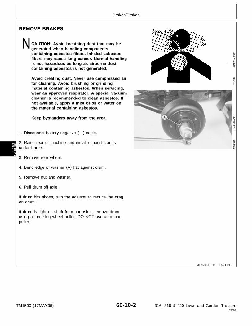
REMOVE BRAKES
N CAUTION: Avoid breathing dust that may begenerated when handling componentscontaining asbestos fibers. Inhaled asbestosfibers may cause lung cancer. Normal handlingis not hazardous as long as airborne dustcontaining asbestos is not generated.
Avoid creating dust. Never use compressed airfor cleaning. Avoid brushing or grindingmaterial containing asbestos. When servicing,wear an approved respirator. A special vacuumcleaner is recommended to clean asbestos. Ifnot available, apply a mist of oil or water onthe material containing asbestos.
Keep bystanders away from the area.
1. Disconnect battery negative (—) cable.
2. Raise rear of machine and install support standsunder frame.
3. Remove rear wheel.
4. Bend edge of washer (A) flat against drum.
5. Remove nut and washer.
6. Pull drum off axle.
If drum hits shoes, turn the adjuster to reduce the dragon drum.
If drum is tight on shaft from corrosion, remove drumusing a three-leg wheel puller. DO NOT use an impactpuller.
TS
220
-U
N-2
3AU
G88
M36
560
-UN
-25J
AN
90
MX,15905010,19 -19-14FEB95
Brakes/Brakes
TM1590 (17MAY95) 60-10-2 316, 318 & 420 Lawn and Garden Tractors020895
6010
2
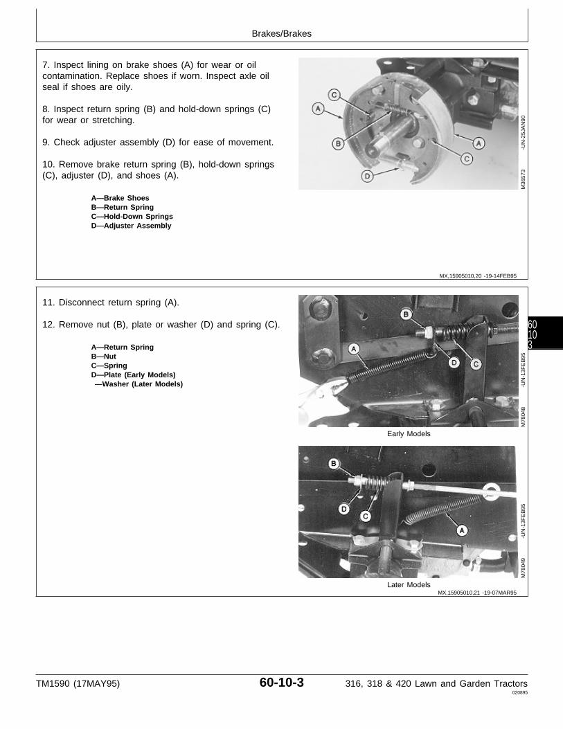
7. Inspect lining on brake shoes (A) for wear or oilcontamination. Replace shoes if worn. Inspect axle oilseal if shoes are oily.
8. Inspect return spring (B) and hold-down springs (C)for wear or stretching.
9. Check adjuster assembly (D) for ease of movement.
10. Remove brake return spring (B), hold-down springs(C), adjuster (D), and shoes (A).
A—Brake ShoesB—Return SpringC—Hold-Down SpringsD—Adjuster Assembly
M36
573
-UN
-25J
AN
90
11. Disconnect return spring (A).
12. Remove nut (B), plate or washer (D) and spring (C).
A—Return SpringB—NutC—SpringD—Plate (Early Models) —Washer (Later Models)
Early Models
Later Models
M78
048
-UN
-13F
EB
95M
7804
9
-U
N-1
3FE
B95
MX,15905010,20 -19-14FEB95
MX,15905010,21 -19-07MAR95
Brakes/Brakes
TM1590 (17MAY95) 60-10-3 316, 318 & 420 Lawn and Garden Tractors020895
60103
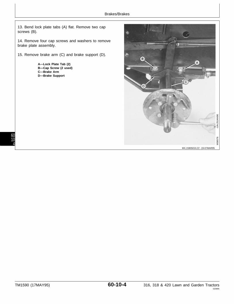
13. Bend lock plate tabs (A) flat. Remove two capscrews (B).
14. Remove four cap screws and washers to removebrake plate assembly.
15. Remove brake arm (C) and brake support (D).
A—Lock Plate Tab (2)B—Cap Screw (2 used)C—Brake ArmD—Brake Support
M36
576
-UN
-25J
AN
90
MX,15905010,22 -19-07MAR95
Brakes/Brakes
TM1590 (17MAY95) 60-10-4 316, 318 & 420 Lawn and Garden Tractors020895
6010
4
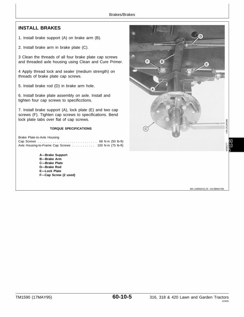
INSTALL BRAKES
1. Install brake support (A) on brake arm (B).
2. Install brake arm in brake plate (C).
3 Clean the threads of all four brake plate cap screwsand threaded axle housing using Clean and Cure Primer.
4 Apply thread lock and sealer (medium strength) onthreads of brake plate cap screws.
5. Install brake rod (D) in brake arm hole.
6. Install brake plate assembly on axle. Install andtighten four cap screws to specificctions.
7. Install brake support (A), lock plate (E) and two capscrews (F). Tighten cap screws to specifications. Bendlock plate tabs over flat of cap screws.
TORQUE SPECIFICATIONS
Brake Plate-to-Axle HousingCap Screws . . . . . . . . . . . . . . . . . . . . . . . . . . . . 68 N·m (50 lb-ft)Axle Housing-to-Frame Cap Screws . . . . . . . . . . . 100 N·m (75 lb-ft)
A—Brake SupportB—Brake ArmC—Brake PlateD—Brake RodE—Lock PlateF—Cap Screw (2 used)
M36
577
-UN
-25J
AN
90
MX,15905010,23 -19-08MAY95
Brakes/Brakes
TM1590 (17MAY95) 60-10-5 316, 318 & 420 Lawn and Garden Tractors020895
60105
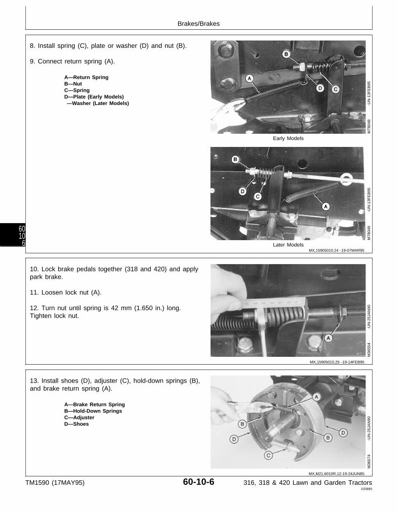
8. Install spring (C), plate or washer (D) and nut (B).
9. Connect return spring (A).
A—Return SpringB—NutC—SpringD—Plate (Early Models) —Washer (Later Models)
Early Models
Later Models
M78
048
-UN
-13F
EB
95M
7804
9
-U
N-1
3FE
B95
10. Lock brake pedals together (318 and 420) and applypark brake.
11. Loosen lock nut (A).
12. Turn nut until spring is 42 mm (1.650 in.) long.Tighten lock nut.
M36
554
-UN
-25J
AN
90
13. Install shoes (D), adjuster (C), hold-down springs (B),and brake return spring (A).
A—Brake Return SpringB—Hold-Down SpringsC—AdjusterD—Shoes
M36
574
-UN
-25J
AN
90
MX,15905010,24 -19-07MAR95
MX,15905010,25 -19-14FEB95
MX,M21,6010R,12-19-24JUN85
Brakes/Brakes
TM1590 (17MAY95) 60-10-6 316, 318 & 420 Lawn and Garden Tractors020895
6010
6
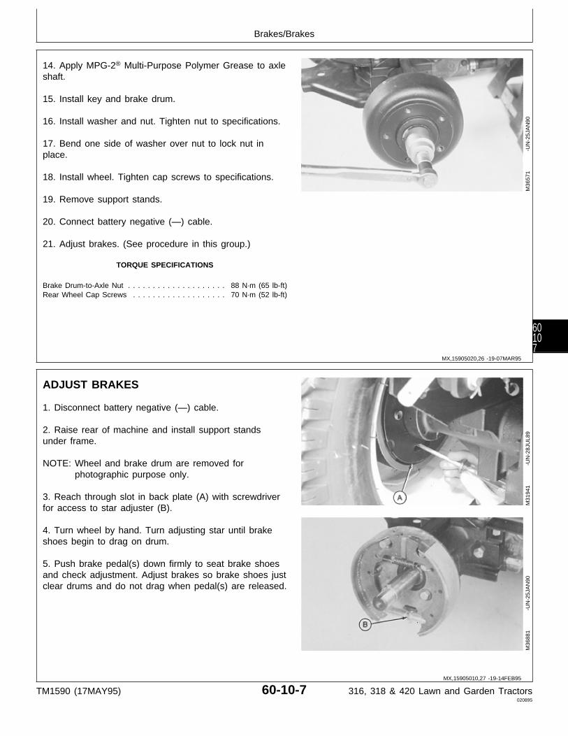
14. Apply MPG-2® Multi-Purpose Polymer Grease to axleshaft.
15. Install key and brake drum.
16. Install washer and nut. Tighten nut to specifications.
17. Bend one side of washer over nut to lock nut inplace.
18. Install wheel. Tighten cap screws to specifications.
19. Remove support stands.
20. Connect battery negative (—) cable.
21. Adjust brakes. (See procedure in this group.)
TORQUE SPECIFICATIONS
Brake Drum-to-Axle Nut . . . . . . . . . . . . . . . . . . . . 88 N·m (65 lb-ft)Rear Wheel Cap Screws . . . . . . . . . . . . . . . . . . . 70 N·m (52 lb-ft)
M36
571
-UN
-25J
AN
90
ADJUST BRAKES
1. Disconnect battery negative (—) cable.
2. Raise rear of machine and install support standsunder frame.
NOTE: Wheel and brake drum are removed forphotographic purpose only.
3. Reach through slot in back plate (A) with screwdriverfor access to star adjuster (B).
4. Turn wheel by hand. Turn adjusting star until brakeshoes begin to drag on drum.
5. Push brake pedal(s) down firmly to seat brake shoesand check adjustment. Adjust brakes so brake shoes justclear drums and do not drag when pedal(s) are released.
M31
941
-UN
-28J
UL8
9M
3688
1
-U
N-2
5JA
N90
MX,15905020,26 -19-07MAR95
MX,15905010,27 -19-14FEB95
Brakes/Brakes
TM1590 (17MAY95) 60-10-7 316, 318 & 420 Lawn and Garden Tractors020895
60107
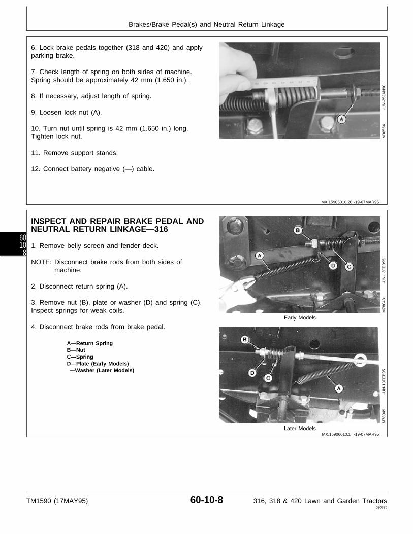
6. Lock brake pedals together (318 and 420) and applyparking brake.
7. Check length of spring on both sides of machine.Spring should be approximately 42 mm (1.650 in.).
8. If necessary, adjust length of spring.
9. Loosen lock nut (A).
10. Turn nut until spring is 42 mm (1.650 in.) long.Tighten lock nut.
11. Remove support stands.
12. Connect battery negative (—) cable.
M36
554
-UN
-25J
AN
90
INSPECT AND REPAIR BRAKE PEDAL ANDNEUTRAL RETURN LINKAGE—316
1. Remove belly screen and fender deck.
NOTE: Disconnect brake rods from both sides ofmachine.
2. Disconnect return spring (A).
3. Remove nut (B), plate or washer (D) and spring (C).Inspect springs for weak coils.
Early Models
4. Disconnect brake rods from brake pedal.
A—Return SpringB—NutC—SpringD—Plate (Early Models) —Washer (Later Models)
Later Models
M78
048
-UN
-13F
EB
95M
7804
9
-U
N-1
3FE
B95
MX,15905010,28 -19-07MAR95
MX,15906010,1 -19-07MAR95
Brakes/Brake Pedal(s) and Neutral Return Linkage
TM1590 (17MAY95) 60-10-8 316, 318 & 420 Lawn and Garden Tractors020895
6010
8
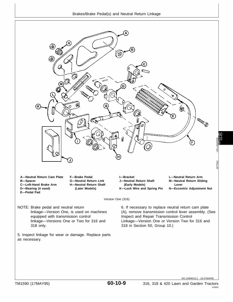
A—Neutral Return Cam Plate F—Brake Pedal I—Bracket L—Neutral Return ArmB—Spacer G—Neutral Return Link J—Neutral Return Shaft M—Neutral Return SlidingC—Left-Hand Brake Arm H—Neutral Return Shaft (Early Models) LeverD—Bearing (4 used) (Later Models) K—Lock Wire and Spring Pin N—Eccentric Adjustment NutE—Pedal Pad
Version One (316)
NOTE: Brake pedal and neutral returnlinkage—Version One, is used on machinesequipped with transmission controllinkage—Versions One or Two for 316 and318 only.
5. Inspect linkage for wear or damage. Replace partsas necessary.
6. If necessary to replace neutral return cam plate(A), remove transmission control lever assembly. (SeeInspect and Repair Transmission ControlLinkage—Version One or Version Two for 316 and318 in Section 50, Group 10.)
M77
914
-UN
-14M
AR
95
MX,15906010,2 -19-07MAR95
Brakes/Brake Pedal(s) and Neutral Return Linkage
TM1590 (17MAY95) 60-10-9 316, 318 & 420 Lawn and Garden Tractors020895
60109
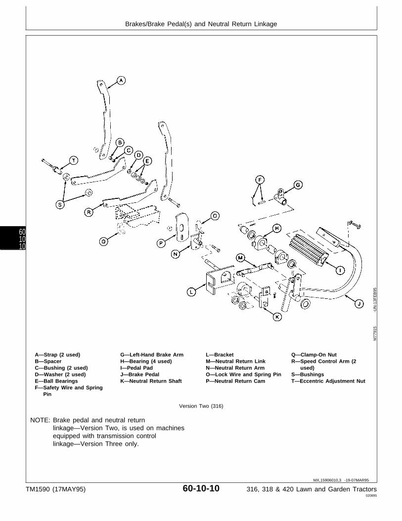
A—Strap (2 used) G—Left-Hand Brake Arm L—Bracket Q—Clamp-On NutB—Spacer H—Bearing (4 used) M—Neutral Return Link R—Speed Control Arm (2C—Bushing (2 used) I—Pedal Pad N—Neutral Return Arm used)D—Washer (2 used) J—Brake Pedal O—Lock Wire and Spring Pin S—BushingsE—Ball Bearings K—Neutral Return Shaft P—Neutral Return Cam T—Eccentric Adjustment NutF—Safety Wire and Spring
Pin
Version Two (316)
NOTE: Brake pedal and neutral returnlinkage—Version Two, is used on machinesequipped with transmission controllinkage—Version Three only.
M77
915
-UN
-13F
EB
95
MX,15906010,3 -19-07MAR95
Brakes/Brake Pedal(s) and Neutral Return Linkage
TM1590 (17MAY95) 60-10-10 316, 318 & 420 Lawn and Garden Tractors020895
601010
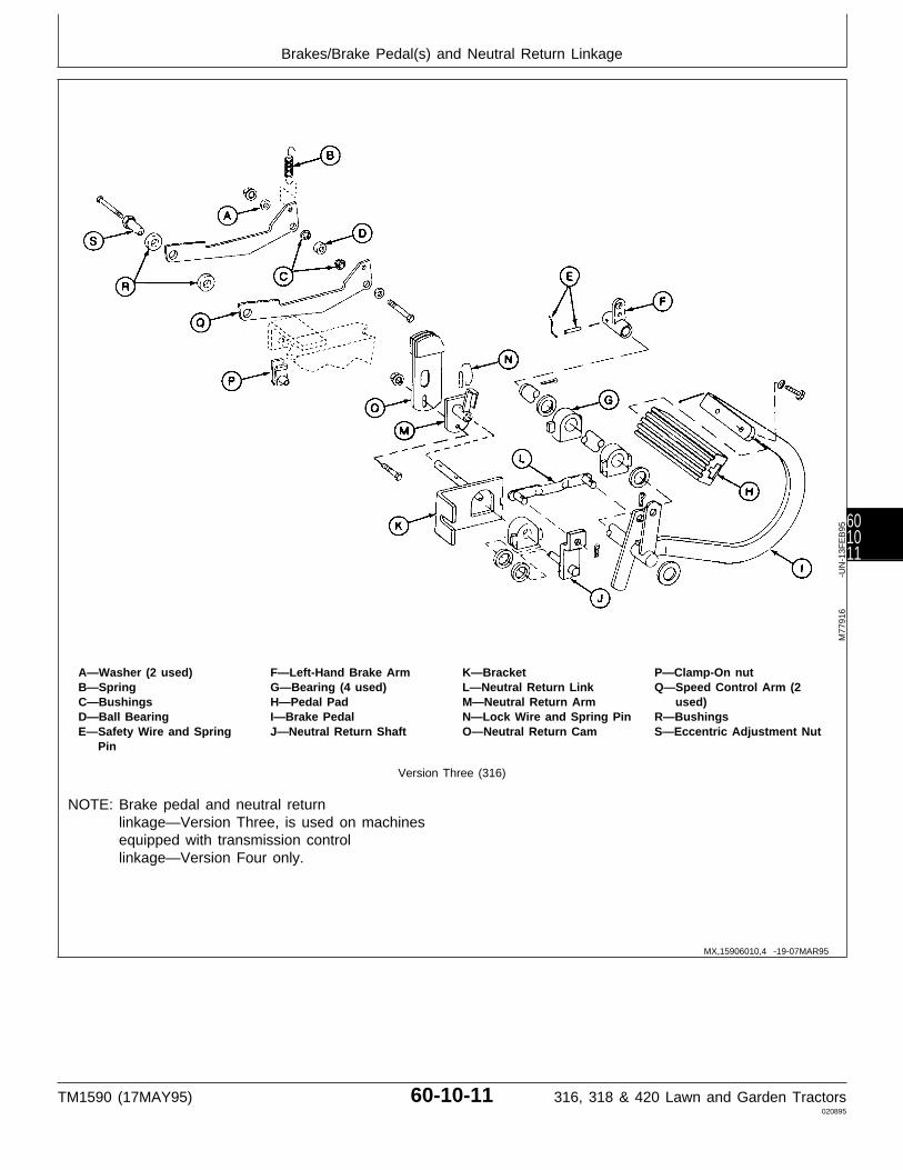
A—Washer (2 used) F—Left-Hand Brake Arm K—Bracket P—Clamp-On nutB—Spring G—Bearing (4 used) L—Neutral Return Link Q—Speed Control Arm (2C—Bushings H—Pedal Pad M—Neutral Return Arm used)D—Ball Bearing I—Brake Pedal N—Lock Wire and Spring Pin R—BushingsE—Safety Wire and Spring J—Neutral Return Shaft O—Neutral Return Cam S—Eccentric Adjustment Nut
Pin
Version Three (316)
NOTE: Brake pedal and neutral returnlinkage—Version Three, is used on machinesequipped with transmission controllinkage—Version Four only.
M77
916
-UN
-13F
EB
95
MX,15906010,4 -19-07MAR95
Brakes/Brake Pedal(s) and Neutral Return Linkage
TM1590 (17MAY95) 60-10-11 316, 318 & 420 Lawn and Garden Tractors020895
601011

7. Install all parts.
8. Connect brake rods to brake pedal.
9. Install spring (C), plate or washer (D) and nut (B).
10. Connect return spring (A).
A—Return SpringB—NutC—SpringD—Plate (Early Models) —Washer (Later Models)
Early Models
Later Models
M78
048
-UN
-13F
EB
95M
7804
9
-U
N-1
3FE
B95
11. Apply parking brake.
12. Loosen lock nut (A).
13. Turn nut until spring is 42 mm (1.650 in.) long.Tighten lock nut.
14. Install fender deck and belly screen.
M36
554
-UN
-25J
AN
90
MX,15906010,5 -19-07MAR95
MX,15906010,6 -19-14FEB95
Brakes/Brake Pedal(s) and Neutral Return Linkage
TM1590 (17MAY95) 60-10-12 316, 318 & 420 Lawn and Garden Tractors020895
601012
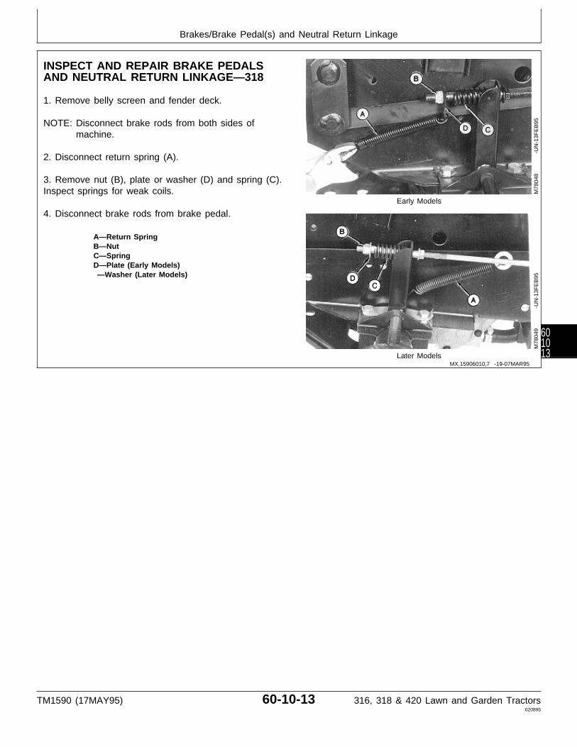
INSPECT AND REPAIR BRAKE PEDALSAND NEUTRAL RETURN LINKAGE—318
1. Remove belly screen and fender deck.
NOTE: Disconnect brake rods from both sides ofmachine.
2. Disconnect return spring (A).
3. Remove nut (B), plate or washer (D) and spring (C).Inspect springs for weak coils.
Early Models
4. Disconnect brake rods from brake pedal.
A—Return SpringB—NutC—SpringD—Plate (Early Models) —Washer (Later Models)
Later Models
M78
048
-UN
-13F
EB
95M
7804
9
-U
N-1
3FE
B95
MX,15906010,7 -19-07MAR95
Brakes/Brake Pedal(s) and Neutral Return Linkage
TM1590 (17MAY95) 60-10-13 316, 318 & 420 Lawn and Garden Tractors020895
601013
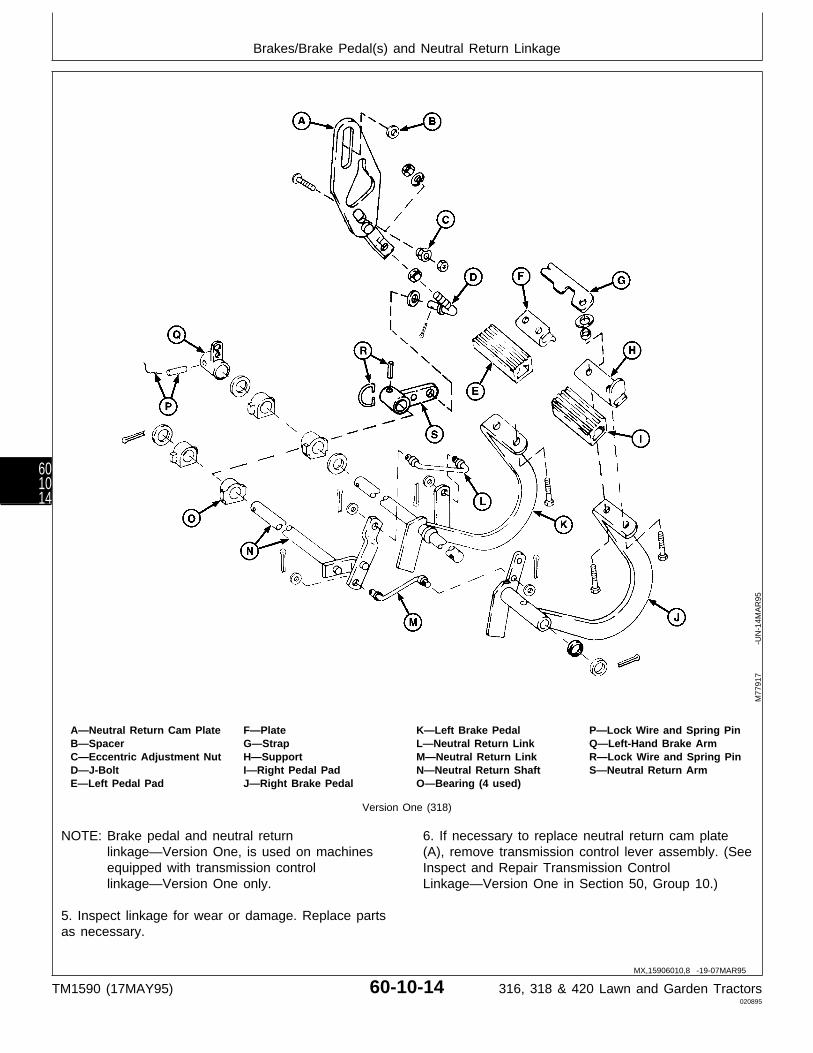
A—Neutral Return Cam Plate F—Plate K—Left Brake Pedal P—Lock Wire and Spring PinB—Spacer G—Strap L—Neutral Return Link Q—Left-Hand Brake ArmC—Eccentric Adjustment Nut H—Support M—Neutral Return Link R—Lock Wire and Spring PinD—J-Bolt I—Right Pedal Pad N—Neutral Return Shaft S—Neutral Return ArmE—Left Pedal Pad J—Right Brake Pedal O—Bearing (4 used)
Version One (318)
NOTE: Brake pedal and neutral returnlinkage—Version One, is used on machinesequipped with transmission controllinkage—Version One only.
5. Inspect linkage for wear or damage. Replace partsas necessary.
6. If necessary to replace neutral return cam plate(A), remove transmission control lever assembly. (SeeInspect and Repair Transmission ControlLinkage—Version One in Section 50, Group 10.)
M77
917
-UN
-14M
AR
95
MX,15906010,8 -19-07MAR95
Brakes/Brake Pedal(s) and Neutral Return Linkage
TM1590 (17MAY95) 60-10-14 316, 318 & 420 Lawn and Garden Tractors020895
601014
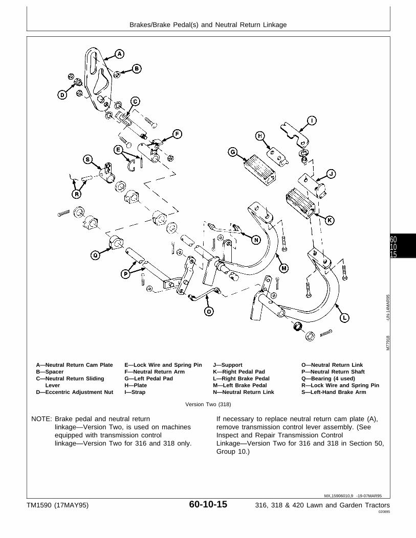
A—Neutral Return Cam Plate E—Lock Wire and Spring Pin J—Support O—Neutral Return LinkB—Spacer F—Neutral Return Arm K—Right Pedal Pad P—Neutral Return ShaftC—Neutral Return Sliding G—Left Pedal Pad L—Right Brake Pedal Q—Bearing (4 used)
Lever H—Plate M—Left Brake Pedal R—Lock Wire and Spring PinD—Eccentric Adjustment Nut I—Strap N—Neutral Return Link S—Left-Hand Brake Arm
Version Two (318)
NOTE: Brake pedal and neutral returnlinkage—Version Two, is used on machinesequipped with transmission controllinkage—Version Two for 316 and 318 only.
If necessary to replace neutral return cam plate (A),remove transmission control lever assembly. (SeeInspect and Repair Transmission ControlLinkage—Version Two for 316 and 318 in Section 50,Group 10.)
M77
918
-UN
-14M
AR
95
MX,15906010,9 -19-07MAR95
Brakes/Brake Pedal(s) and Neutral Return Linkage
TM1590 (17MAY95) 60-10-15 316, 318 & 420 Lawn and Garden Tractors020895
601015
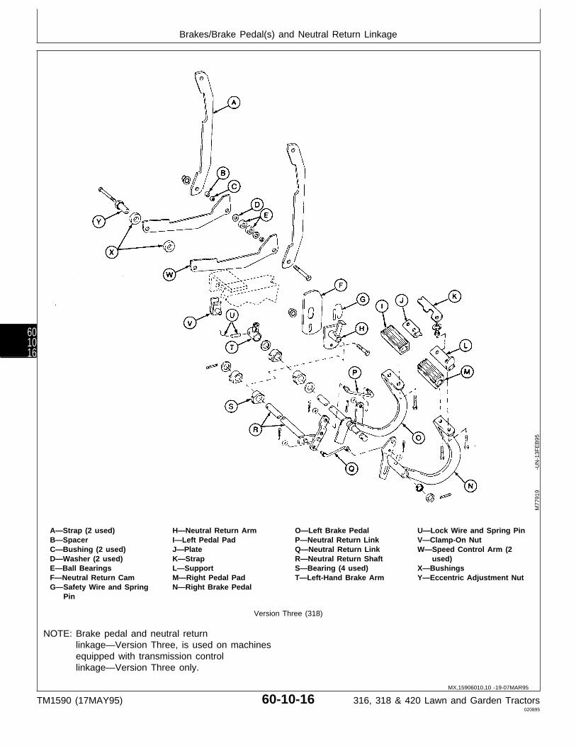
A—Strap (2 used) H—Neutral Return Arm O—Left Brake Pedal U—Lock Wire and Spring PinB—Spacer I—Left Pedal Pad P—Neutral Return Link V—Clamp-On NutC—Bushing (2 used) J—Plate Q—Neutral Return Link W—Speed Control Arm (2D—Washer (2 used) K—Strap R—Neutral Return Shaft used)E—Ball Bearings L—Support S—Bearing (4 used) X—BushingsF—Neutral Return Cam M—Right Pedal Pad T—Left-Hand Brake Arm Y—Eccentric Adjustment NutG—Safety Wire and Spring N—Right Brake Pedal
Pin
Version Three (318)
NOTE: Brake pedal and neutral returnlinkage—Version Three, is used on machinesequipped with transmission controllinkage—Version Three only.
M77
919
-UN
-13F
EB
95
MX,15906010,10 -19-07MAR95
Brakes/Brake Pedal(s) and Neutral Return Linkage
TM1590 (17MAY95) 60-10-16 316, 318 & 420 Lawn and Garden Tractors020895
601016
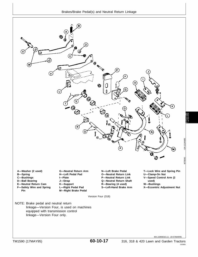
A—Washer (2 used) G—Neutral Return Arm N—Left Brake Pedal T—Lock Wire and Spring PinB—Spring H—Left Pedal Pad O—Neutral Return Link U—Clamp-On NutC—Bushings I—Plate P—Neutral Return Link V—Speed Control Arm (2D—Ball Bearing J—Strap Q—Neutral Return Shaft used)E—Neutral Return Cam K—Support R—Bearing (4 used) W—BushingsF—Safety Wire and Spring L—Right Pedal Pad S—Left-Hand Brake Arm X—Eccentric Adjustment Nut
Pin M—Right Brake Pedal
Version Four (318)
NOTE: Brake pedal and neutral returnlinkage—Version Four, is used on machinesequipped with transmission controllinkage—Version Four only.
M78
040
-UN
-13J
AN
95
MX,15906010,11 -19-07MAR95
Brakes/Brake Pedal(s) and Neutral Return Linkage
TM1590 (17MAY95) 60-10-17 316, 318 & 420 Lawn and Garden Tractors020895
601017
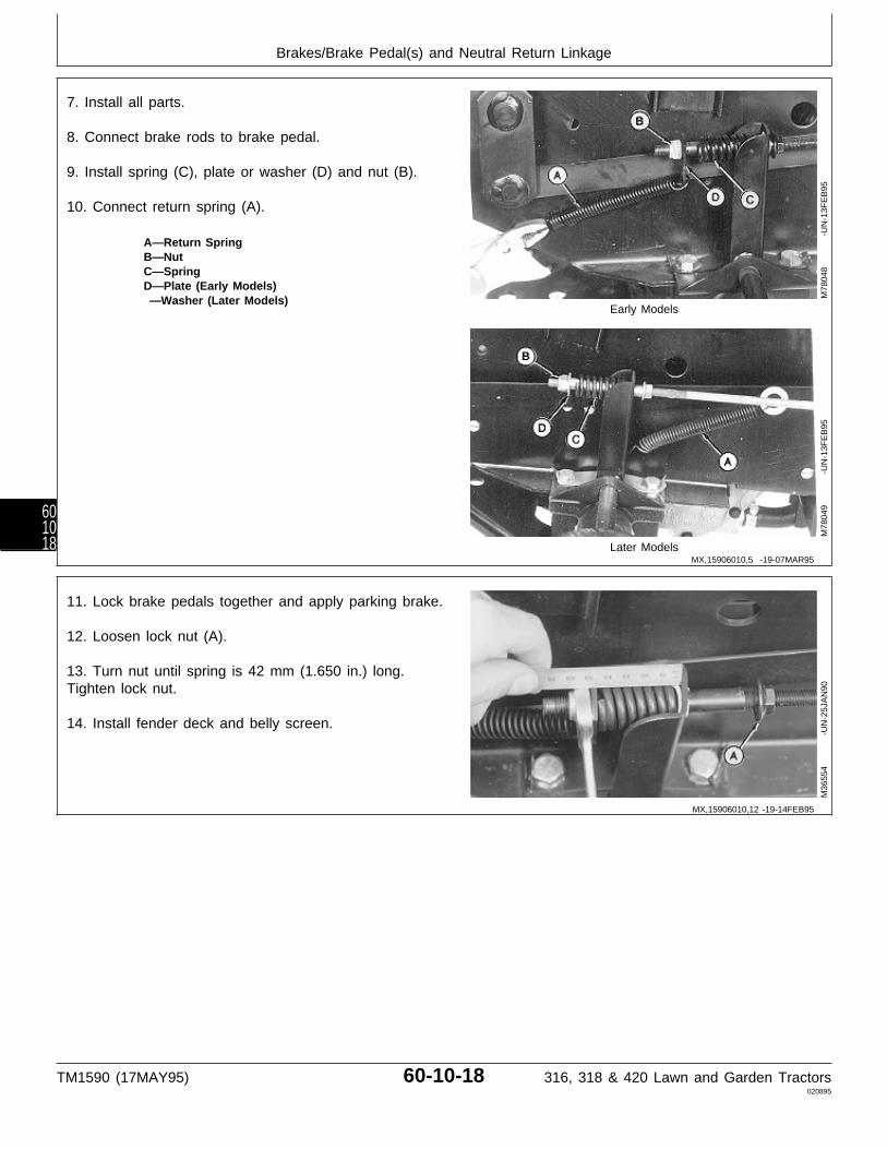
7. Install all parts.
8. Connect brake rods to brake pedal.
9. Install spring (C), plate or washer (D) and nut (B).
10. Connect return spring (A).
A—Return SpringB—NutC—SpringD—Plate (Early Models) —Washer (Later Models)
Early Models
Later Models
M78
048
-UN
-13F
EB
95M
7804
9
-U
N-1
3FE
B95
11. Lock brake pedals together and apply parking brake.
12. Loosen lock nut (A).
13. Turn nut until spring is 42 mm (1.650 in.) long.Tighten lock nut.
14. Install fender deck and belly screen.
M36
554
-UN
-25J
AN
90
MX,15906010,5 -19-07MAR95
MX,15906010,12 -19-14FEB95
Brakes/Brake Pedal(s) and Neutral Return Linkage
TM1590 (17MAY95) 60-10-18 316, 318 & 420 Lawn and Garden Tractors020895
601018

INSPECT AND REPAIR BRAKE PEDALSAND NEUTRAL RETURN LINKAGE—420
1. Remove belly pan and fender deck.
NOTE: Disconnect brake rods from both sides ofmachine.
2. Disconnect return spring (A).
3. Remove nut (B), plate or washer (D) and spring (C).Inspect springs for weak coils.
Early Models
4. Disconnect brake rods from brake pedal.
A—Return SpringB—NutC—SpringD—Plate (Early Models) —Washer (Later Models)
Later Models
M78
048
-UN
-13F
EB
95M
7804
9
-U
N-1
3FE
B95
MX,15906010,13 -19-07MAR95
Brakes/Brake Pedal(s) and Neutral Return Linkage
TM1590 (17MAY95) 60-10-19 316, 318 & 420 Lawn and Garden Tractors020895
601019

A—Neutral Return Cam Plate F—Strap K—Left Brake Pedal P—Lock Wire and Spring PinB—Spacer G—Support L—Neutral Return Link Q—Left-Hand Brake ArmC—J-Bolt H—Right Pedal Pad M—Neutral Return Shaft R—Eccentric Adjustment NutD—Left Pedal Pad I—Right Brake Pedal N—Bearing (4 used)E—Plate J—Neutral Return Link O—Neutral Return Welded
Shaft
Version One (420)
NOTE: Brake pedal and neutral returnlinkage—Version One, is used on machinesequipped with transmission controllinkage—Versions One or Two for 420 only.
5. Inspect linkage for wear or damage. Replace partsas necessary.
6. If necessary to replace neutral return cam plate(A), remove transmission control lever assembly. (SeeInspect and Repair Transmission ControlLinkage—Version One or Version Two for 420 only inSection 50, Group 10.)
M78
041
-UN
-14M
AR
95
MX,15906010,14 -19-20MAR95
Brakes/Brake Pedal(s) and Neutral Return Linkage
TM1590 (17MAY95) 60-10-20 316, 318 & 420 Lawn and Garden Tractors020895
601020
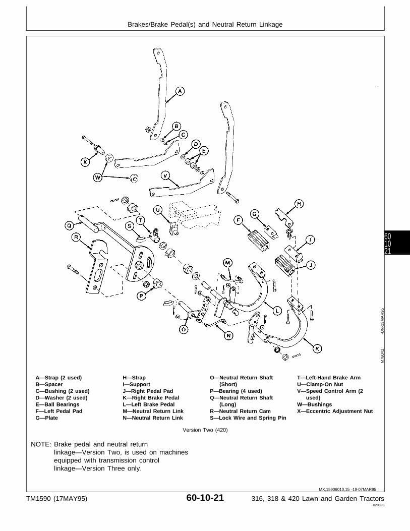
A—Strap (2 used) H—Strap O—Neutral Return Shaft T—Left-Hand Brake ArmB—Spacer I—Support (Short) U—Clamp-On NutC—Bushing (2 used) J—Right Pedal Pad P—Bearing (4 used) V—Speed Control Arm (2D—Washer (2 used) K—Right Brake Pedal Q—Neutral Return Shaft used)E—Ball Bearings L—Left Brake Pedal (Long) W—BushingsF—Left Pedal Pad M—Neutral Return Link R—Neutral Return Cam X—Eccentric Adjustment NutG—Plate N—Neutral Return Link S—Lock Wire and Spring Pin
Version Two (420)
NOTE: Brake pedal and neutral returnlinkage—Version Two, is used on machinesequipped with transmission controllinkage—Version Three only.
M78
042
-UN
-13M
AR
95
MX,15906010,15 -19-07MAR95
Brakes/Brake Pedal(s) and Neutral Return Linkage
TM1590 (17MAY95) 60-10-21 316, 318 & 420 Lawn and Garden Tractors020895
601021
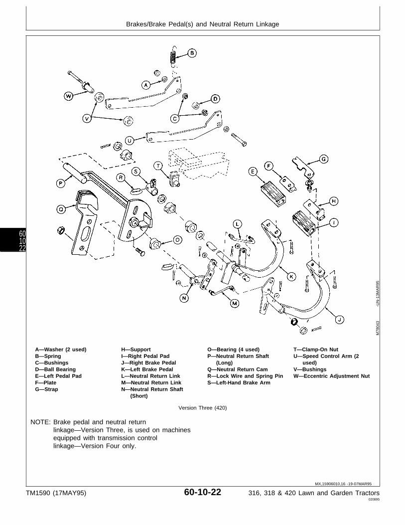
A—Washer (2 used) H—Support O—Bearing (4 used) T—Clamp-On NutB—Spring I—Right Pedal Pad P—Neutral Return Shaft U—Speed Control Arm (2C—Bushings J—Right Brake Pedal (Long) used)D—Ball Bearing K—Left Brake Pedal Q—Neutral Return Cam V—BushingsE—Left Pedal Pad L—Neutral Return Link R—Lock Wire and Spring Pin W—Eccentric Adjustment NutF—Plate M—Neutral Return Link S—Left-Hand Brake ArmG—Strap N—Neutral Return Shaft
(Short)
Version Three (420)
NOTE: Brake pedal and neutral returnlinkage—Version Three, is used on machinesequipped with transmission controllinkage—Version Four only.
M78
043
-UN
-13M
AR
95
MX,15906010,16 -19-07MAR95
Brakes/Brake Pedal(s) and Neutral Return Linkage
TM1590 (17MAY95) 60-10-22 316, 318 & 420 Lawn and Garden Tractors020895
601022
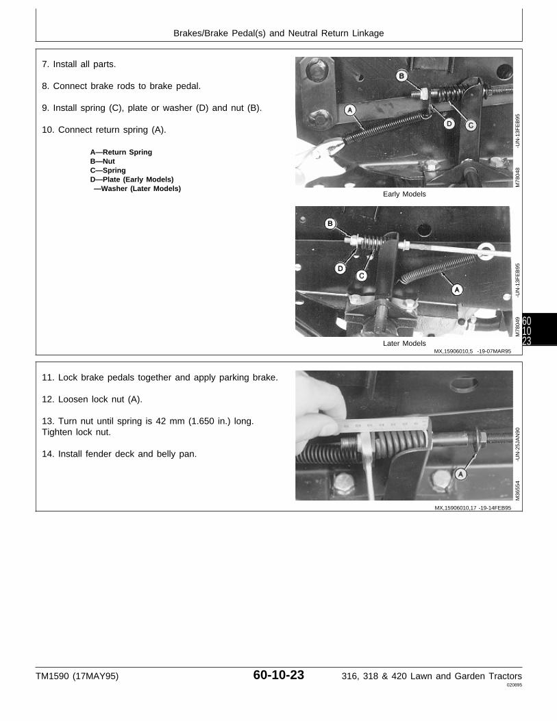
7. Install all parts.
8. Connect brake rods to brake pedal.
9. Install spring (C), plate or washer (D) and nut (B).
10. Connect return spring (A).
A—Return SpringB—NutC—SpringD—Plate (Early Models) —Washer (Later Models)
Early Models
Later Models
M78
048
-UN
-13F
EB
95M
7804
9
-U
N-1
3FE
B95
11. Lock brake pedals together and apply parking brake.
12. Loosen lock nut (A).
13. Turn nut until spring is 42 mm (1.650 in.) long.Tighten lock nut.
14. Install fender deck and belly pan.
M36
554
-UN
-25J
AN
90
MX,15906010,5 -19-07MAR95
MX,15906010,17 -19-14FEB95
Brakes/Brake Pedal(s) and Neutral Return Linkage
TM1590 (17MAY95) 60-10-23 316, 318 & 420 Lawn and Garden Tractors020895
601023

INSPECT AND REPAIR PARK BRAKELEVER
1. Remove belly screen/pan.
2. Inspect all parts for wear or damage. Replace asnecessary.
A—KnobB—Lock WasherC—WasherD—Weld NutE—Park Brake RodF—Lock PlateG—PinH—Torsion Spring
M77
913
-UN
-13F
EB
95
MX,15906010,18 -19-12MAY95
Brakes/Inspect and Repair Park Brake Lever
TM1590 (17MAY95) 60-10-24 316, 318 & 420 Lawn and Garden Tractors020895
601024
Section 70HYDRAULIC REPAIR
ContentsPage
Group 05—Hydraulic Control ValveOther Materials . . . . . . . . . . . . . . . . . . 70-05-1Service Parts Kits . . . . . . . . . . . . . . . . 70-05-1Remove and Install
316 and 318 . . . . . . . . . . . . . . . . . . 70-05-2420 . . . . . . . . . . . . . . . . . . . . . . . . 70-05-4
Disassemble, Inspect and AssembleSingle-Spool . . . . . . . . . . . . . . . . . . . 70-05-5Two-Spool . . . . . . . . . . . . . . . . . . . . 70-05-6Three-Spool . . . . . . . . . . . . . . . . . . . 70-05-9
TM1590 (17MAY95) 70-1 316, 318 & 420 Lawn and Garden Tractors020895
70
Contents
TM1590 (17MAY95) 70-2 316, 318 & 420 Lawn and Garden Tractors020895
70
OTHER MATERIAL
Number Name Use
M79292 MPG-2® Multi-Purpose Polymer Prevents parts from seizing. ApplyGrease to spool springs and end cap
cavities.
LOCTITE® PRODUCTSU.S./Canadian/LOCTITE No.
TY6305/TY9485/764 Clean and Cure Primer Cleans parts and speeds cure ofsealant.
T43512/TY9473/242 Thread Lock and Sealer (Medium Apply to threads spool screws.Strength)
®MPG-2 is a registered trademark of DuBois USA.
®LOCTITE is a registered trademark of the Loctite Corp.
SERVICE PARTS KITS
The following kits are available through your partscatalog:
Single-Spool Valve Spring Center Kit Load Check Kit Seal Kit
Two-Spool Valve Version One Seal Kit Versions Two and Three Seal Kit Detent Replacement Kit Versions Four and Five Seal Kit Load Check Kit Spring Center Kit Float Detent Kit Valve Detent Kit
Three-Spool Valve Version One, Two and Three Seal Kit Detent Replacement Kit Version Four Seal Kit Load Check Kit Spring Center Kit Float Detent Kit
MX,15907005,OTH-19-20APR95
MX,15907005,KIT-19-20APR95
Group 05Hydraulic Control Valve
TM1590 (17MAY95) 70-05-1 316, 318 & 420 Lawn and Garden Tractors020895
70051
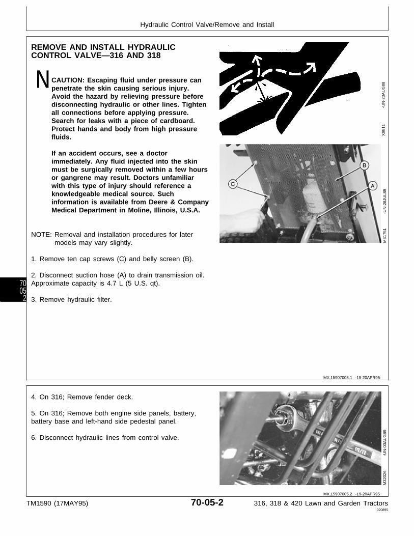
REMOVE AND INSTALL HYDRAULICCONTROL VALVE—316 AND 318
N CAUTION: Escaping fluid under pressure canpenetrate the skin causing serious injury.Avoid the hazard by relieving pressure beforedisconnecting hydraulic or other lines. Tightenall connections before applying pressure.Search for leaks with a piece of cardboard.Protect hands and body from high pressurefluids.
If an accident occurs, see a doctorimmediately. Any fluid injected into the skinmust be surgically removed within a few hoursor gangrene may result. Doctors unfamiliarwith this type of injury should reference aknowledgeable medical source. Suchinformation is available from Deere & CompanyMedical Department in Moline, Illinois, U.S.A.
NOTE: Removal and installation procedures for latermodels may vary slightly.
1. Remove ten cap screws (C) and belly screen (B).
2. Disconnect suction hose (A) to drain transmission oil.Approximate capacity is 4.7 L (5 U.S. qt).
3. Remove hydraulic filter.
X98
11
-UN
-23A
UG
88M
3175
1
-U
N-2
8JU
L89
4. On 316; Remove fender deck.
5. On 316; Remove both engine side panels, battery,battery base and left-hand side pedestal panel.
6. Disconnect hydraulic lines from control valve.
M32
026
-UN
-03A
UG
89
MX,15907005,1 -19-20APR95
MX,15907005,2 -19-20APR95
Hydraulic Control Valve/Remove and Install
TM1590 (17MAY95) 70-05-2 316, 318 & 420 Lawn and Garden Tractors020895
7005
2

7. Remove cotter pin(s) (A) from draft pin(s) (B).Disconnect control linkage.
316 Shown M55
071
-UN
-09D
EC
89
8. Remove two mounting bolts (B) and control valve (A).
9. Installation is done in the reverse order of removal.
• Fill transmission with the recommended amount ofJohn Deere Low Viscosity HY-GARD® oil.
• Bleed the hydraulic system. (See procedure in Section270, Group 20.)
M32
046
-UN
-03A
UG
89
MX,15907005,3 -19-20APR95
MX,15907005,4 -19-20APR95
Hydraulic Control Valve/Remove and Install
TM1590 (17MAY95) 70-05-3 316, 318 & 420 Lawn and Garden Tractors020895
70053
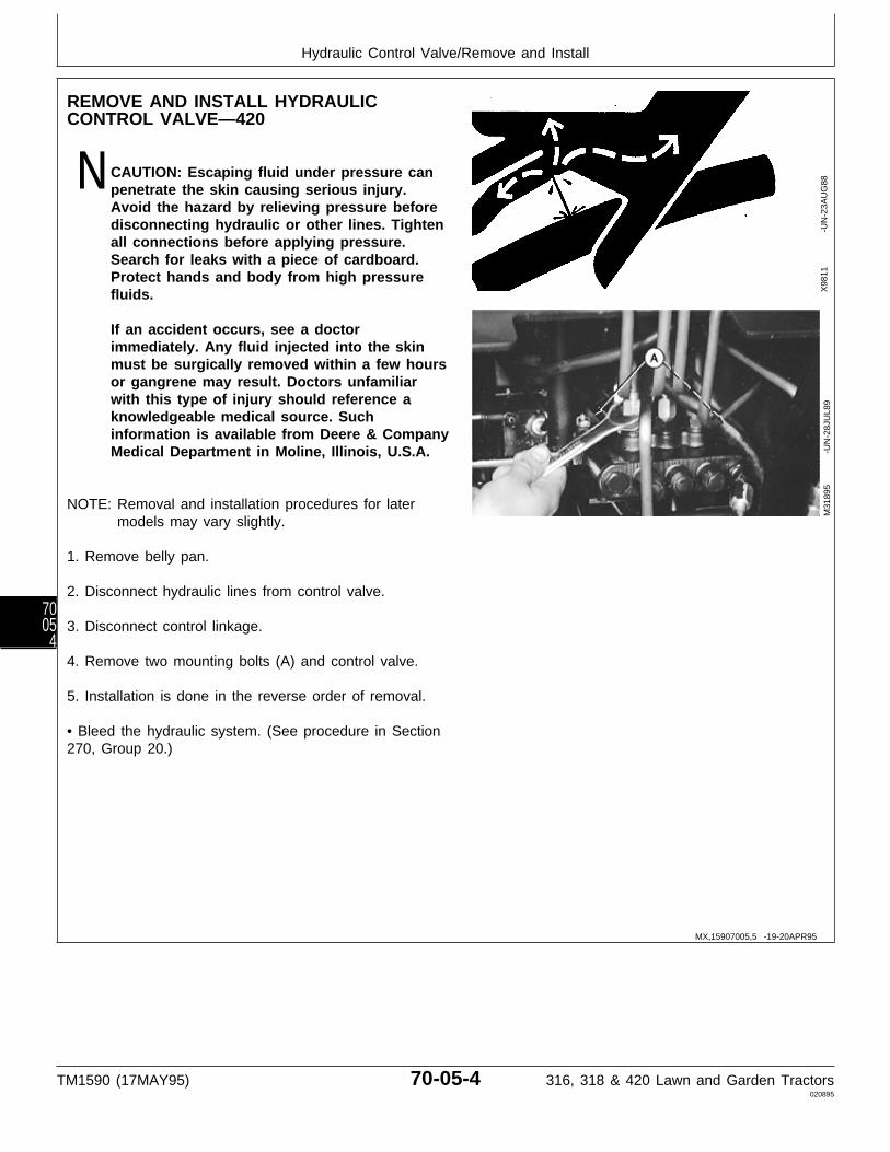
REMOVE AND INSTALL HYDRAULICCONTROL VALVE—420
N CAUTION: Escaping fluid under pressure canpenetrate the skin causing serious injury.Avoid the hazard by relieving pressure beforedisconnecting hydraulic or other lines. Tightenall connections before applying pressure.Search for leaks with a piece of cardboard.Protect hands and body from high pressurefluids.
If an accident occurs, see a doctorimmediately. Any fluid injected into the skinmust be surgically removed within a few hoursor gangrene may result. Doctors unfamiliarwith this type of injury should reference aknowledgeable medical source. Suchinformation is available from Deere & CompanyMedical Department in Moline, Illinois, U.S.A.
NOTE: Removal and installation procedures for latermodels may vary slightly.
1. Remove belly pan.
2. Disconnect hydraulic lines from control valve.
3. Disconnect control linkage.
4. Remove two mounting bolts (A) and control valve.
5. Installation is done in the reverse order of removal.
• Bleed the hydraulic system. (See procedure in Section270, Group 20.)
X98
11
-UN
-23A
UG
88M
3189
5
-U
N-2
8JU
L89
MX,15907005,5 -19-20APR95
Hydraulic Control Valve/Remove and Install
TM1590 (17MAY95) 70-05-4 316, 318 & 420 Lawn and Garden Tractors020895
7005
4

DISASSEMBLE, INSPECT AND ASSEMBLE HYDRAULIC CONTROLVALVE—SINGLE-SPOOL
A—Spool E—Spring H—Cap K—O-RingB—Body F—Spring Retainer I—Screw (2 used) L—SpringC—O-Ring G—Screw J—Plug M—PoppetD—Washer
IMPORTANT: Spool and body are matched andmust be replaced as a unit.
Always use new O-rings. Damagedor used parts will leak.
NOTE: Note location and position of fittings andlinkage to aid in assembly.
Lubricate all O-rings with petroleum jellyduring assembly.
Inspect all parts for wear or damage. Replace asnecessary.
• Apply clean John Deere Low Viscosity HY-GARD®
oil on all internal parts during assembly.
• Clean threads in end of spool (A) and on screw (G)using Clean and Cure Primer. Apply thread lock andsealer (medium strength) on threads of screw (G).
• Apply MPG-2® Multi-Purpose Polymer Grease onspring (E) and inside of cap (H).
• Tighten screws (G and I) and plug (J) tospecifications.
TORQUE SPECIFICATIONS
Screws (G and I) . . . . . . . . . . . . . . . . . . . . . . 4 N·m (35 lb-in.)Plug (J) . . . . . . . . . . . . . . . . . . . . . . . . . . . . 31 N·m (23 lb-ft)
M78
058
-UN
-24M
AR
95
MX,15907005,6 -19-25APR95
Hydraulic Control Valve/Disassemble, Inspect and Assemble
TM1590 (17MAY95) 70-05-5 316, 318 & 420 Lawn and Garden Tractors020895
70055

DISASSEMBLE, INSPECT AND ASSEMBLE HYDRAULIC CONTROL VALVE—TWO-SPOOL
A—Check Valve Plug (2 F—Float Detent Spool L—Detent R—Snap Ringused) G—Body M—Spring S—Washer
B—O-Ring (2 used) H—O-Ring (2 used) N—Ball (2 used) T—SpringC—Spring (2 used) I—Bushing (2 used) O—Cap U—Snap RingD—Poppet (2 used) J—Washer (2 used) P—Plug V—SleeveE—Spool K—Spring Q—Cap W—Washer (as required)
Version One
NOTE: There are five versions of this valve.Disassembly and assembly procedures mayvary slightly.
IMPORTANT: Spools and body are matched andmust be replaced as a unit. Spoolsmust be installed into the samebores from which they wereremoved for proper operation ofeach function.
Always use new O-rings. Damagedor used parts will leak.
NOTE: Note location and position of fittings andlinkages to aid in assembly.
Lubricate all O-rings with petroleum jellyduring assembly.
Inspect all parts for wear or damage. Replace asnecessary.
• Apply clean John Deere Low Viscosity HY-GARD®
oil on all internal parts during assembly.
• Apply MPG-2® Multi-Purpose Polymer Grease onsprings (K and T) and inside of caps (O and Q).
• Tighten caps (O and Q) to 31 N·m (23 lb-ft).M
7805
9
-U
N-1
4AP
R95
MX,15907005,7 -19-20APR95
Hydraulic Control Valve/Disassemble, Inspect and Assemble
TM1590 (17MAY95) 70-05-6 316, 318 & 420 Lawn and Garden Tractors020895
7005
6
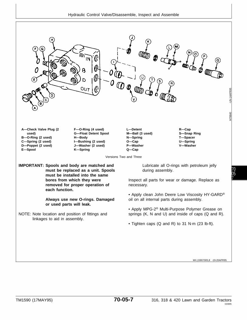
A—Check Valve Plug (2 F—O-Ring (4 used) L—Detent R—Capused) G—Float Detent Spool M—Ball (3 used) S—Snap Ring
B—O-Ring (2 used) H—Body N—Spring T—SpacerC—Spring (2 used) I—Bushing (2 used) O—Cap U—SpringD—Poppet (2 used) J—Washer (2 used) P—Washer V—WasherE—Spool K—Spring Q—Cap
Versions Two and Three
IMPORTANT: Spools and body are matched andmust be replaced as a unit. Spoolsmust be installed into the samebores from which they wereremoved for proper operation ofeach function.
Always use new O-rings. Damagedor used parts will leak.
NOTE: Note location and position of fittings andlinkages to aid in assembly.
Lubricate all O-rings with petroleum jellyduring assembly.
Inspect all parts for wear or damage. Replace asnecessary.
• Apply clean John Deere Low Viscosity HY-GARD®
oil on all internal parts during assembly.
• Apply MPG-2® Multi-Purpose Polymer Grease onsprings (K, N and U) and inside of caps (Q and R).
• Tighten caps (Q and R) to 31 N·m (23 lb-ft).
M78
840
-UN
-14A
PR
95
MX,15907005,8 -19-20APR95
Hydraulic Control Valve/Disassemble, Inspect and Assemble
TM1590 (17MAY95) 70-05-7 316, 318 & 420 Lawn and Garden Tractors020895
70057
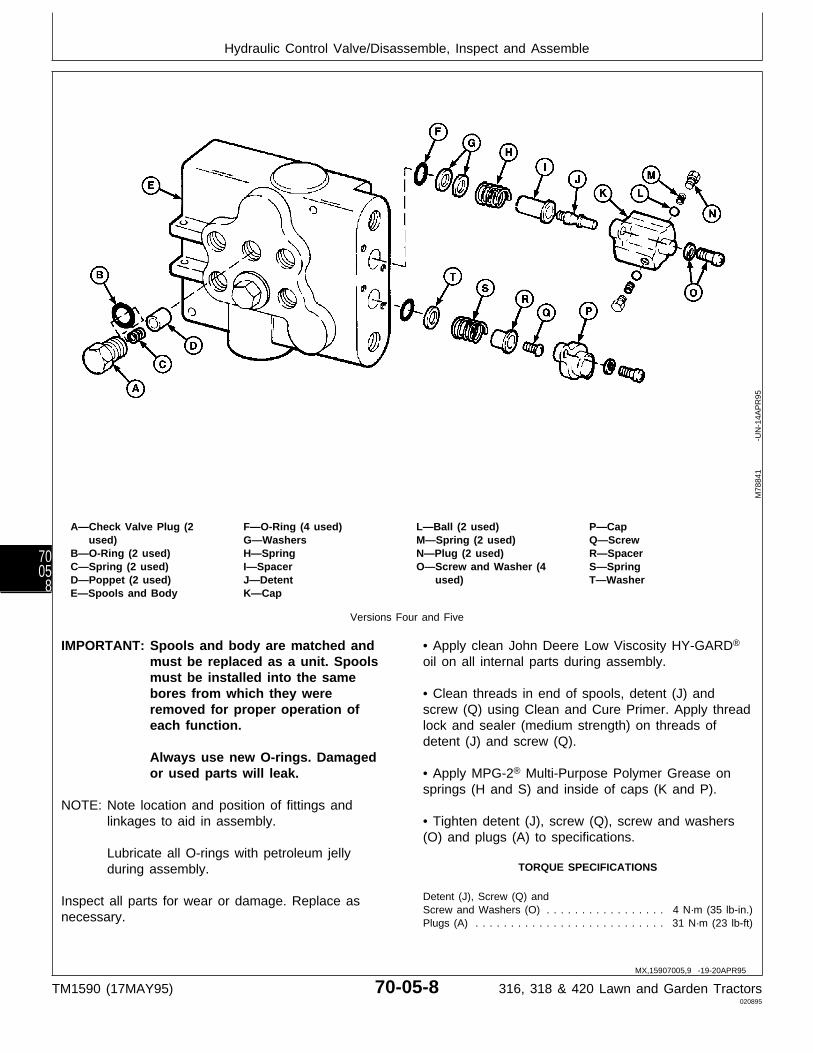
A—Check Valve Plug (2 F—O-Ring (4 used) L—Ball (2 used) P—Capused) G—Washers M—Spring (2 used) Q—Screw
B—O-Ring (2 used) H—Spring N—Plug (2 used) R—SpacerC—Spring (2 used) I—Spacer O—Screw and Washer (4 S—SpringD—Poppet (2 used) J—Detent used) T—WasherE—Spools and Body K—Cap
Versions Four and Five
IMPORTANT: Spools and body are matched andmust be replaced as a unit. Spoolsmust be installed into the samebores from which they wereremoved for proper operation ofeach function.
Always use new O-rings. Damagedor used parts will leak.
NOTE: Note location and position of fittings andlinkages to aid in assembly.
Lubricate all O-rings with petroleum jellyduring assembly.
Inspect all parts for wear or damage. Replace asnecessary.
• Apply clean John Deere Low Viscosity HY-GARD®
oil on all internal parts during assembly.
• Clean threads in end of spools, detent (J) andscrew (Q) using Clean and Cure Primer. Apply threadlock and sealer (medium strength) on threads ofdetent (J) and screw (Q).
• Apply MPG-2® Multi-Purpose Polymer Grease onsprings (H and S) and inside of caps (K and P).
• Tighten detent (J), screw (Q), screw and washers(O) and plugs (A) to specifications.
TORQUE SPECIFICATIONS
Detent (J), Screw (Q) andScrew and Washers (O) . . . . . . . . . . . . . . . . . 4 N·m (35 lb-in.)Plugs (A) . . . . . . . . . . . . . . . . . . . . . . . . . . . 31 N·m (23 lb-ft)
M78
841
-UN
-14A
PR
95
MX,15907005,9 -19-20APR95
Hydraulic Control Valve/Disassemble, Inspect and Assemble
TM1590 (17MAY95) 70-05-8 316, 318 & 420 Lawn and Garden Tractors020895
7005
8

DISASSEMBLE, INSPECT AND ASSEMBLE HYDRAULIC CONTROLVALVE—THREE-SPOOL
A—Check Valve Plug (3 F—Cap M—Bushing (3 used) T—Plug (2 used, Versionused) G—Shim (as required) N—Washer (2 used) Two only)
B—O-Ring (3 used) H—O-Ring O—Spacer (2 used) U—CapC—Spring (3 used) I—Spring P—Spring (2 used) V—Ball (2 used)D—Poppet (3 used) J—Poppet Q—Washer (2 used) W—SpringE—Lock Nut (Version Three K—Spools and Body R—Snap Ring (2 used) X—Detent
only) L—O-Ring (6 used) S—Cap (2 used) Y—Spring
Versions One, Two and Three
NOTE: There are four versions of this valve.Disassembly and assembly procedures mayvary slightly.
IMPORTANT: Spools and body are matched andmust be replaced as a unit. Spoolsmust be installed into the samebores from which they wereremoved for proper operation ofeach function.
Always use new O-rings. Damagedor used parts will leak.
NOTE: Note location and position of fittings andlinkages to aid in assembly.
Lubricate all O-rings with petroleum jellyduring assembly.
Inspect all parts for wear or damage. Replace asnecessary.
• Apply clean John Deere Low Viscosity HY-GARD®
oil on all internal parts during assembly.
• Apply MPG-2® Multi-Purpose Polymer Grease onsprings (P and Y) and inside of caps (S and U).
• Tighten lock nut (E), if equipped, and caps (S andU) to 31 N·m (23 lb-ft).
M78
842
-UN
-24A
PR
95
MX,15907005,10 -19-20APR95
Hydraulic Control Valve/Disassemble, Inspect and Assemble
TM1590 (17MAY95) 70-05-9 316, 318 & 420 Lawn and Garden Tractors020895
70059
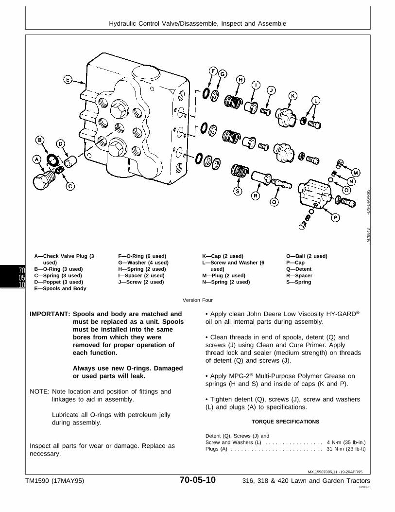
A—Check Valve Plug (3 F—O-Ring (6 used) K—Cap (2 used) O—Ball (2 used)used) G—Washer (4 used) L—Screw and Washer (6 P—Cap
B—O-Ring (3 used) H—Spring (2 used) used) Q—DetentC—Spring (3 used) I—Spacer (2 used) M—Plug (2 used) R—SpacerD—Poppet (3 used) J—Screw (2 used) N—Spring (2 used) S—SpringE—Spools and Body
Version Four
IMPORTANT: Spools and body are matched andmust be replaced as a unit. Spoolsmust be installed into the samebores from which they wereremoved for proper operation ofeach function.
Always use new O-rings. Damagedor used parts will leak.
NOTE: Note location and position of fittings andlinkages to aid in assembly.
Lubricate all O-rings with petroleum jellyduring assembly.
Inspect all parts for wear or damage. Replace asnecessary.
• Apply clean John Deere Low Viscosity HY-GARD®
oil on all internal parts during assembly.
• Clean threads in end of spools, detent (Q) andscrews (J) using Clean and Cure Primer. Applythread lock and sealer (medium strength) on threadsof detent (Q) and screws (J).
• Apply MPG-2® Multi-Purpose Polymer Grease onsprings (H and S) and inside of caps (K and P).
• Tighten detent (Q), screws (J), screw and washers(L) and plugs (A) to specifications.
TORQUE SPECIFICATIONS
Detent (Q), Screws (J) andScrew and Washers (L) . . . . . . . . . . . . . . . . . 4 N·m (35 lb-in.)Plugs (A) . . . . . . . . . . . . . . . . . . . . . . . . . . . 31 N·m (23 lb-ft)
M78
843
-UN
-14A
PR
95
MX,15907005,11 -19-20APR95
Hydraulic Control Valve/Disassemble, Inspect and Assemble
TM1590 (17MAY95) 70-05-10 316, 318 & 420 Lawn and Garden Tractors020895
700510
Section 80MISCELLANEOUS REPAIR
ContentsPage
Group 05—Front AxleSpecial or Essential Tools . . . . . . . . . . . 80-05-1Front Axle—316 and 318
Remove and Install . . . . . . . . . . . . . . 80-05-1Inspect and Replace Pivot Bushings . . . 80-05-2
Front Axle—420Remove . . . . . . . . . . . . . . . . . . . . . 80-05-2Disassemble and Inspect Pivot Pin . . . 80-05-4Assemble Pivot Pin . . . . . . . . . . . . . . 80-05-6Install . . . . . . . . . . . . . . . . . . . . . . . 80-05-7
SpindlesRemove and Install . . . . . . . . . . . . . . 80-05-9Inspect and Replace Bushings . . . . . . 80-05-11
Inspect and Replace Wheel Bearings . . . 80-05-12Adjust Toe-in . . . . . . . . . . . . . . . . . . . . 80-05-12
Group 10—Mower Spindle and Jack SheaveRepair
Mower Blade Spindles38 (Early), 46 and 50-Inch Mower . . . . 80-10-138-Inch Mower (Later) . . . . . . . . . . . . 80-10-1Early 60-Inch and 260 Rotary Mower . . 80-10-2Later 60-Inch and 260 Rotary Mower . . 80-10-3
Mower Blade Jack Sheaves46 and 50-Inch Mower . . . . . . . . . . . . 80-10-4
Group 15—Mower Gear Case RepairOther Materials . . . . . . . . . . . . . . . . . . 80-15-150-Inch Mower
Disassemble and Inspect . . . . . . . . . . 80-15-1Assemble . . . . . . . . . . . . . . . . . . . . 80-15-6
Early 60-Inch Mower (Curtis)Disassemble and Inspect . . . . . . . . . . 80-15-10Assemble . . . . . . . . . . . . . . . . . . . . 80-15-14
Later 60-Inch Mower (Peerless)Disassemble and Inspect . . . . . . . . . . 80-15-19Assemble . . . . . . . . . . . . . . . . . . . . 80-15-23
260 Rotary MowerDisassemble and Inspect . . . . . . . . . . 80-15-27Assemble . . . . . . . . . . . . . . . . . . . . 80-15-32
TM1590 (17MAY95) 80-1 316, 318 & 420 Lawn and Garden Tractors020895
80

Contents
TM1590 (17MAY95) 80-2 316, 318 & 420 Lawn and Garden Tractors020895
80
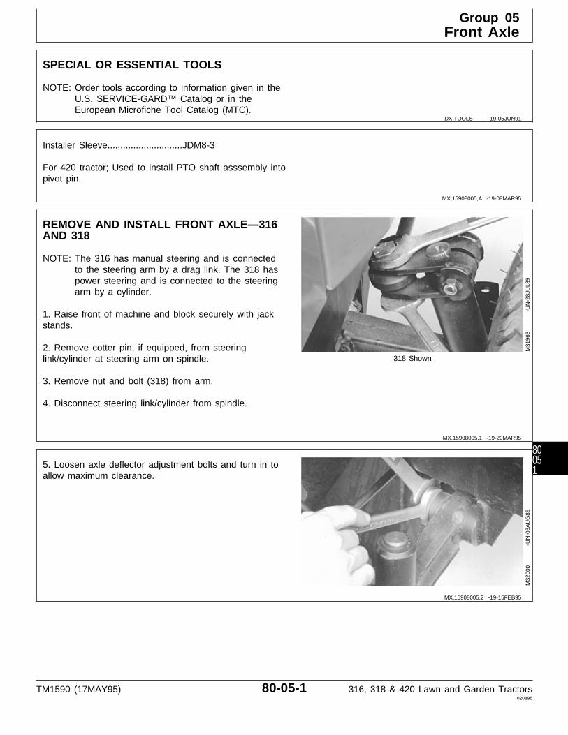
SPECIAL OR ESSENTIAL TOOLS
NOTE: Order tools according to information given in theU.S. SERVICE-GARD™ Catalog or in theEuropean Microfiche Tool Catalog (MTC).
Installer Sleeve.............................JDM8-3
For 420 tractor; Used to install PTO shaft asssembly intopivot pin.
REMOVE AND INSTALL FRONT AXLE—316AND 318
NOTE: The 316 has manual steering and is connectedto the steering arm by a drag link. The 318 haspower steering and is connected to the steeringarm by a cylinder.
1. Raise front of machine and block securely with jackstands.
2. Remove cotter pin, if equipped, from steeringlink/cylinder at steering arm on spindle. 318 Shown
3. Remove nut and bolt (318) from arm.
4. Disconnect steering link/cylinder from spindle.
M31
963
-UN
-28J
UL8
9
5. Loosen axle deflector adjustment bolts and turn in toallow maximum clearance.
M32
000
-UN
-03A
UG
89
DX,TOOLS -19-05JUN91
MX,15908005,A -19-08MAR95
MX,15908005,1 -19-20MAR95
MX,15908005,2 -19-15FEB95
Group 05Front Axle
TM1590 (17MAY95) 80-05-1 316, 318 & 420 Lawn and Garden Tractors020895
80051
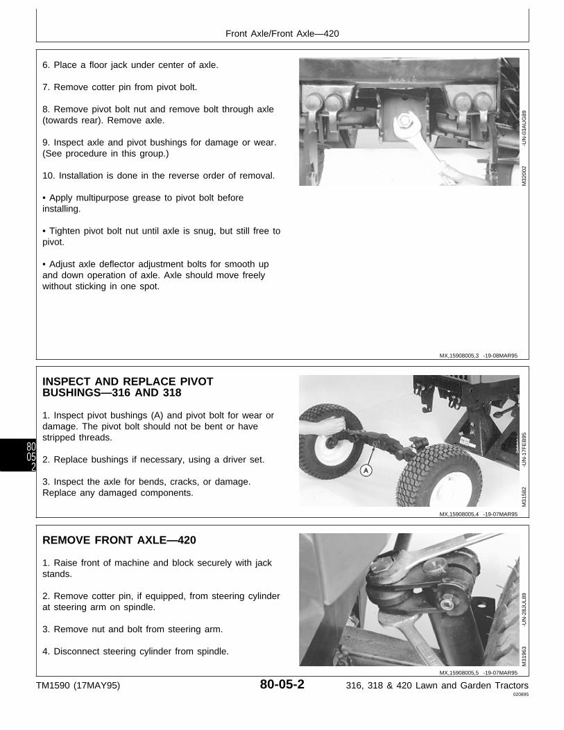
6. Place a floor jack under center of axle.
7. Remove cotter pin from pivot bolt.
8. Remove pivot bolt nut and remove bolt through axle(towards rear). Remove axle.
9. Inspect axle and pivot bushings for damage or wear.(See procedure in this group.)
10. Installation is done in the reverse order of removal.
• Apply multipurpose grease to pivot bolt beforeinstalling.
• Tighten pivot bolt nut until axle is snug, but still free topivot.
• Adjust axle deflector adjustment bolts for smooth upand down operation of axle. Axle should move freelywithout sticking in one spot.
M32
002
-UN
-03A
UG
89
INSPECT AND REPLACE PIVOTBUSHINGS—316 AND 318
1. Inspect pivot bushings (A) and pivot bolt for wear ordamage. The pivot bolt should not be bent or havestripped threads.
2. Replace bushings if necessary, using a driver set.
3. Inspect the axle for bends, cracks, or damage.Replace any damaged components.
M31
582
-UN
-17F
EB
95
REMOVE FRONT AXLE—420
1. Raise front of machine and block securely with jackstands.
2. Remove cotter pin, if equipped, from steering cylinderat steering arm on spindle.
3. Remove nut and bolt from steering arm.
4. Disconnect steering cylinder from spindle.
M31
963
-UN
-28J
UL8
9
MX,15908005,3 -19-08MAR95
MX,15908005,4 -19-07MAR95
MX,15908005,5 -19-07MAR95
Front Axle/Front Axle—420
TM1590 (17MAY95) 80-05-2 316, 318 & 420 Lawn and Garden Tractors020895
8005
2
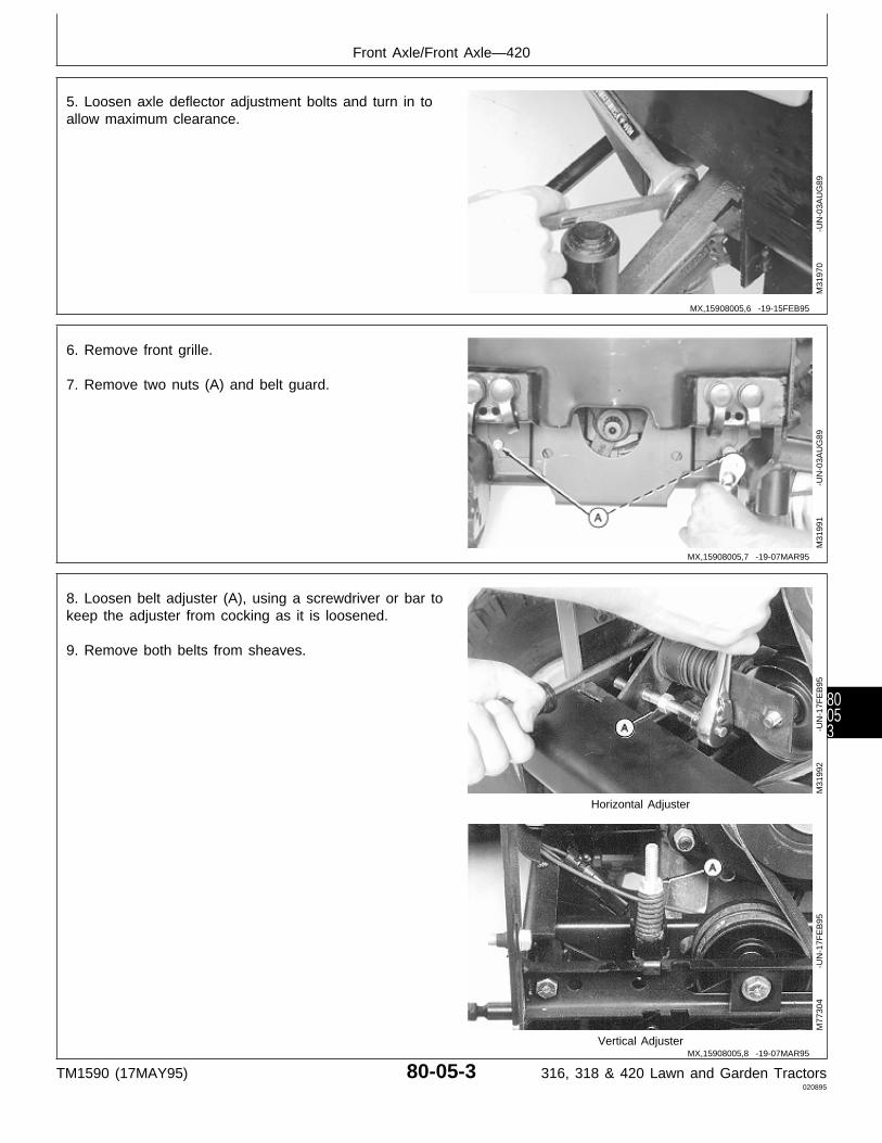
5. Loosen axle deflector adjustment bolts and turn in toallow maximum clearance.
M31
970
-UN
-03A
UG
89
6. Remove front grille.
7. Remove two nuts (A) and belt guard.
M31
991
-UN
-03A
UG
89
8. Loosen belt adjuster (A), using a screwdriver or bar tokeep the adjuster from cocking as it is loosened.
9. Remove both belts from sheaves.
Horizontal Adjuster
Vertical Adjuster
M31
992
-UN
-17F
EB
95M
7730
4
-U
N-1
7FE
B95
MX,15908005,6 -19-15FEB95
MX,15908005,7 -19-07MAR95
MX,15908005,8 -19-07MAR95
Front Axle/Front Axle—420
TM1590 (17MAY95) 80-05-3 316, 318 & 420 Lawn and Garden Tractors020895
80053

10. Remove snap ring from drive pulley.
11. Remove drive pulley from PTO shaft.
M31
994
-UN
-03A
UG
89
12. Remove two pivot pin retaining nuts (A).
M31
996
-UN
-03A
UG
89
13. Place a floor jack under center of axle.
14. Slide pivot pin (A) out towards front of tractor.Remove axle.
15. Inspect pivot pin bore (B) and axle (C) for damageor excessive wear. Replace axle if necessary.
16. Inspect pivot pin for damage or wear. (Seeprocedure in this group.)
M31
998
-UN
-03A
UG
89
DISASSEMBLE AND INSPECT PIVOTPIN—420
1. Remove snap ring (A).
M36
802
-UN
-29J
AN
90
MX,15908005,9 -19-15FEB95
MX,15908005,10 -19-15FEB95
MX,15908005,11 -19-15FEB95
MX,15908005,12 -19-15FEB95
Front Axle/Front Axle—420
TM1590 (17MAY95) 80-05-4 316, 318 & 420 Lawn and Garden Tractors020895
8005
4
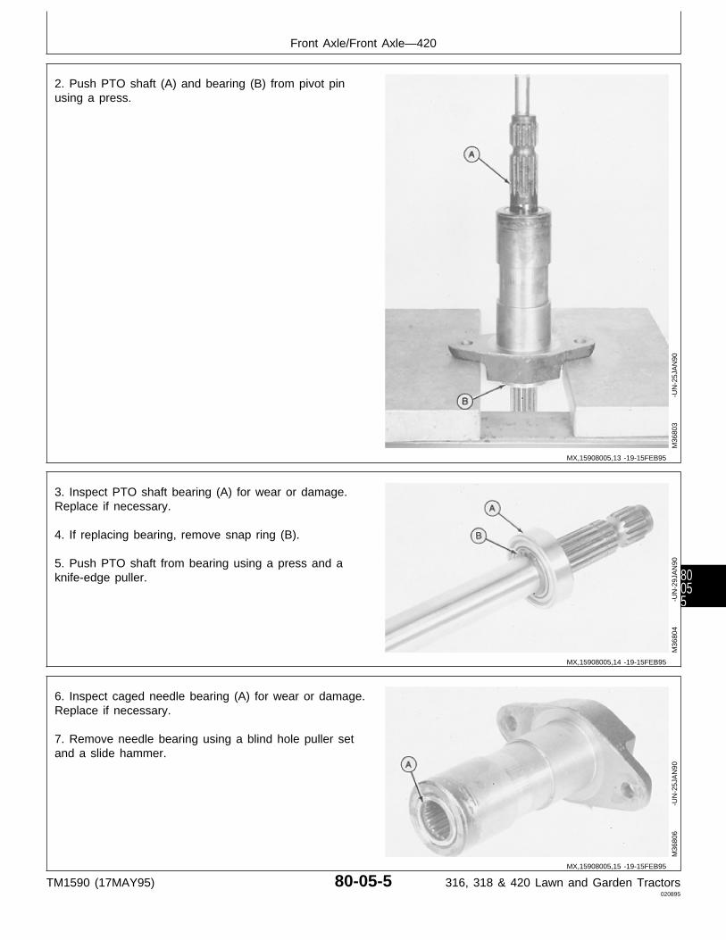
2. Push PTO shaft (A) and bearing (B) from pivot pinusing a press.
M36
803
-UN
-25J
AN
90
3. Inspect PTO shaft bearing (A) for wear or damage.Replace if necessary.
4. If replacing bearing, remove snap ring (B).
5. Push PTO shaft from bearing using a press and aknife-edge puller.
M36
804
-UN
-29J
AN
90
6. Inspect caged needle bearing (A) for wear or damage.Replace if necessary.
7. Remove needle bearing using a blind hole puller setand a slide hammer.
M36
806
-UN
-25J
AN
90
MX,15908005,13 -19-15FEB95
MX,15908005,14 -19-15FEB95
MX,15908005,15 -19-15FEB95
Front Axle/Front Axle—420
TM1590 (17MAY95) 80-05-5 316, 318 & 420 Lawn and Garden Tractors020895
80055

ASSEMBLE PIVOT PIN—420
1. Support pivot pin on a press. Put a driver disk (A) onbearing (B). Install bearing using a press until diskbottoms on pivot pin.
M36
808
-UN
-25J
AN
90
2. Install snap ring (A) on PTO shaft.
3. Support bearing on a knife-edge puller. Press PTOshaft (B) into bearing until it bottoms on snap ring.
M36
809
-UN
-25J
AN
90
MX,15908005,16 -19-15FEB95
MX,15908005,17 -19-07MAR95
Front Axle/Front Axle—420
TM1590 (17MAY95) 80-05-6 316, 318 & 420 Lawn and Garden Tractors020895
8005
6
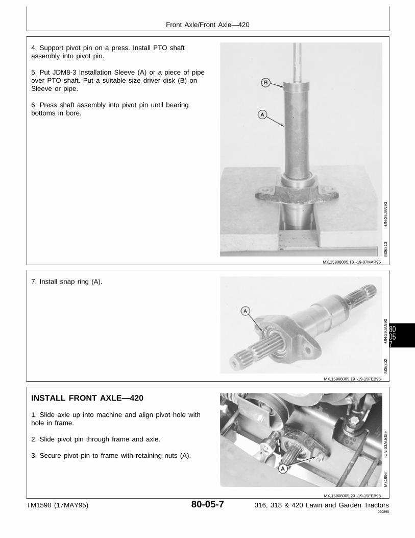
4. Support pivot pin on a press. Install PTO shaftassembly into pivot pin.
5. Put JDM8-3 Installation Sleeve (A) or a piece of pipeover PTO shaft. Put a suitable size driver disk (B) onSleeve or pipe.
6. Press shaft assembly into pivot pin until bearingbottoms in bore.
M36
810
-UN
-25J
AN
90
7. Install snap ring (A).
M36
802
-UN
-29J
AN
90
INSTALL FRONT AXLE—420
1. Slide axle up into machine and align pivot hole withhole in frame.
2. Slide pivot pin through frame and axle.
3. Secure pivot pin to frame with retaining nuts (A).
M31
996
-UN
-03A
UG
89
MX,15908005,18 -19-07MAR95
MX,15908005,19 -19-15FEB95
MX,15908005,20 -19-15FEB95
Front Axle/Front Axle—420
TM1590 (17MAY95) 80-05-7 316, 318 & 420 Lawn and Garden Tractors020895
80057

4. Slide drive pulley onto PTO shaft.
5. Install snap ring in PTO shaft groove.
6. Install belts on lower drive sheave and work ontoupper sheave.
M31
994
-UN
-03A
UG
89
7. Tighten belt adjuster:
When adjusting PTO belt tension on horizontal adjuster,tighten bolt until spring measures 41 mm (1.600 in.).
When adjusting PTO belt tension on vertical adjuster,tighten nut until spring measures 35 mm (1.380 in.).
Horizontal Adjuster
Vertical Adjuster
M49
503
-UN
-20D
EC
89M
4950
2
-U
N-2
0DE
C89
8. Install belt guard with two nuts (A).
9. Install front grille.
M31
991
-UN
-03A
UG
89
MX,15908005,21 -19-15FEB95
MX,15908005,22 -19-15FEB95
MX,15908005,23 -19-07MAR95
Front Axle/Front Axle—420
TM1590 (17MAY95) 80-05-8 316, 318 & 420 Lawn and Garden Tractors020895
8005
8

10. Connect steering cylinder to spindle.
11. Install bolt and nut through steering arm andcylinder.
12. Install cotter pin, if equipped, in steering arm bolt.
M31
963
-UN
-28J
UL8
9
13. Adjust axle deflector bolts for smooth up and downoperation of axle.
14. Test for proper axle deflector adjustment, by pushingdown on a wheel. The axle should move freely withoutsticking in one spot. Readjust if necessary.
15. Lower tractor from jack stands.
M31
970
-UN
-03A
UG
89
REMOVE AND INSTALL SPINDLES
NOTE: The 316 has manual steering and is connectedto the steering arm by a drag link. The 318 and420 have power steering and are connected tothe steering arm by a cylinder.
1. Raise front of machine and block securely with jackstands.
2. Remove front wheels.
3. Remove cotter pin, if equipped, from steeringlink/cylinder at steering arm on left spindle. 420 Shown
4. Remove nut and bolt (318 and 420) from arm.
5. Disconnect steering link/cylinder from steering arm.
M32
067
-UN
-03A
UG
89
MX,15908005,24 -19-07MAR95
MX,15908005,25 -19-15FEB95
MX,15908005,26 -19-20MAR95
Front Axle/Spindles
TM1590 (17MAY95) 80-05-9 316, 318 & 420 Lawn and Garden Tractors020895
80059
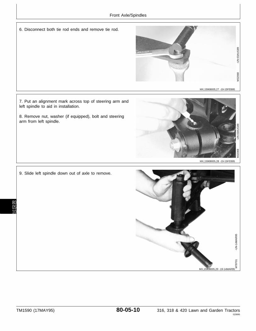
6. Disconnect both tie rod ends and remove tie rod.
M32
068
-UN
-03A
UG
89
7. Put an alignment mark across top of steering arm andleft spindle to aid in installation.
8. Remove nut, washer (if equipped), bolt and steeringarm from left spindle.
M32
069
-UN
-03A
UG
89
9. Slide left spindle down out of axle to remove.
M78
701
-UN
-14M
AR
95
MX,15908005,27 -19-15FEB95
MX,15908005,28 -19-15FEB95
MX,15908005,29 -19-14MAR95
Front Axle/Spindles
TM1590 (17MAY95) 80-05-10 316, 318 & 420 Lawn and Garden Tractors020895
800510

10. Remove snap ring from top of right spindle.
11. Slide right spindle down out of axle to remove.
12. Inspect spindles for wear or damage. Replace ifnecessary.
13. Inspect bushings for wear or damage. Replace ifnecessary. (See procedure in this group.)
14. Installation is done in the reverse order of removal.
• On left-hand side; align marks made on steering armand spindle shaft.
• Apply multipurpose grease to lubrication fittings.
• Adjust toe-in. (See procedure in this group.)
M32
072
-UN
-03A
UG
89
INSPECT AND REPLACE SPINDLEBUSHINGS
1. Remove spindles. (See procedure in this group.)
2. Remove bushings (A) from axle using a long brassdrift and a plastic headed hammer.
3. Install new bushings using a plastic headed hammer.Install bushings until they bottom against axle.
M36
815
-UN
-25J
AN
90
MX,15908005,30 -19-07MAR95
MX,15908005,31 -19-15FEB95
Front Axle/Spindles
TM1590 (17MAY95) 80-05-11 316, 318 & 420 Lawn and Garden Tractors020895
800511
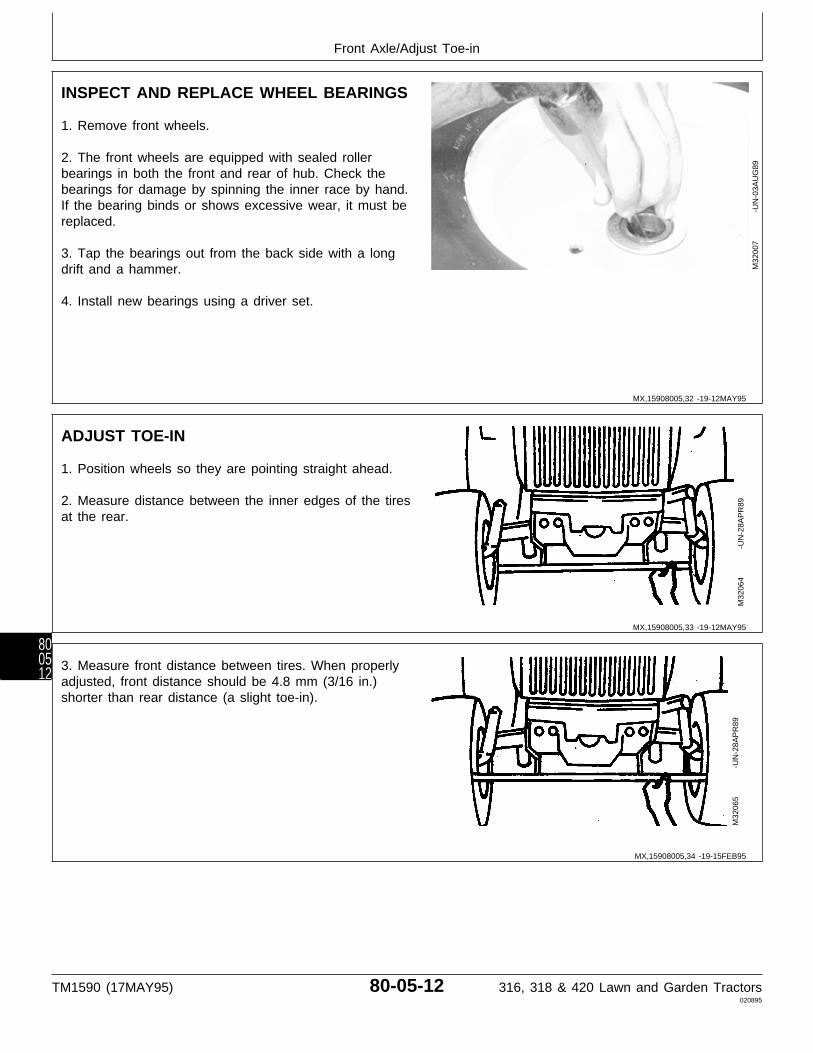
INSPECT AND REPLACE WHEEL BEARINGS
1. Remove front wheels.
2. The front wheels are equipped with sealed rollerbearings in both the front and rear of hub. Check thebearings for damage by spinning the inner race by hand.If the bearing binds or shows excessive wear, it must bereplaced.
3. Tap the bearings out from the back side with a longdrift and a hammer.
4. Install new bearings using a driver set.
M32
007
-UN
-03A
UG
89
ADJUST TOE-IN
1. Position wheels so they are pointing straight ahead.
2. Measure distance between the inner edges of the tiresat the rear.
M32
064
-UN
-28A
PR
89
3. Measure front distance between tires. When properlyadjusted, front distance should be 4.8 mm (3/16 in.)shorter than rear distance (a slight toe-in).
M32
065
-UN
-28A
PR
89
MX,15908005,32 -19-12MAY95
MX,15908005,33 -19-12MAY95
MX,15908005,34 -19-15FEB95
Front Axle/Adjust Toe-in
TM1590 (17MAY95) 80-05-12 316, 318 & 420 Lawn and Garden Tractors020895
800512

4. Loosen jam nuts and adjust tie rod to lengthen orshorten distance.
IMPORTANT: Make sure there is free movement ofball joints after tightening jam nuts.
5. Make certain to securely tighten jam nuts afteradjusting tie rod.
M32
066
-UN
-03A
UG
89
MX,M21,7005K,X -19-04NOV82
Front Axle/Adjust Toe-in
TM1590 (17MAY95) 80-05-13 316, 318 & 420 Lawn and Garden Tractors020895
800513
Front Axle/Adjust Toe-in
TM1590 (17MAY95) 80-05-14 316, 318 & 420 Lawn and Garden Tractors020895
800514
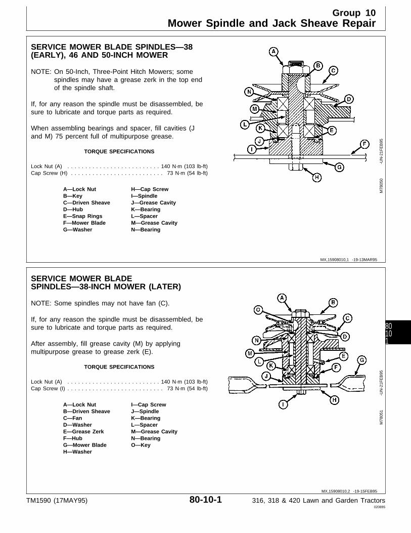
SERVICE MOWER BLADE SPINDLES—38(EARLY), 46 AND 50-INCH MOWER
NOTE: On 50-Inch, Three-Point Hitch Mowers; somespindles may have a grease zerk in the top endof the spindle shaft.
If, for any reason the spindle must be disassembled, besure to lubricate and torque parts as required.
When assembling bearings and spacer, fill cavities (Jand M) 75 percent full of multipurpose grease.
TORQUE SPECIFICATIONS
Lock Nut (A) . . . . . . . . . . . . . . . . . . . . . . . . . . 140 N·m (103 lb-ft)Cap Screw (H) . . . . . . . . . . . . . . . . . . . . . . . . . . 73 N·m (54 lb-ft)
A—Lock Nut H—Cap ScrewB—Key I—SpindleC—Driven Sheave J—Grease CavityD—Hub K—BearingE—Snap Rings L—SpacerF—Mower Blade M—Grease CavityG—Washer N—Bearing
M78
050
-UN
-21F
EB
95
SERVICE MOWER BLADESPINDLES—38-INCH MOWER (LATER)
NOTE: Some spindles may not have fan (C).
If, for any reason the spindle must be disassembled, besure to lubricate and torque parts as required.
After assembly, fill grease cavity (M) by applyingmultipurpose grease to grease zerk (E).
TORQUE SPECIFICATIONS
Lock Nut (A) . . . . . . . . . . . . . . . . . . . . . . . . . . 140 N·m (103 lb-ft)Cap Screw (I) . . . . . . . . . . . . . . . . . . . . . . . . . . . 73 N·m (54 lb-ft)
A—Lock Nut I—Cap ScrewB—Driven Sheave J—SpindleC—Fan K—BearingD—Washer L—SpacerE—Grease Zerk M—Grease CavityF—Hub N—BearingG—Mower Blade O—KeyH—Washer
M78
051
-UN
-21F
EB
95
MX,15908010,1 -19-13MAR95
MX,15908010,2 -19-15FEB95
Group 10Mower Spindle and Jack Sheave Repair
TM1590 (17MAY95) 80-10-1 316, 318 & 420 Lawn and Garden Tractors020895
80101
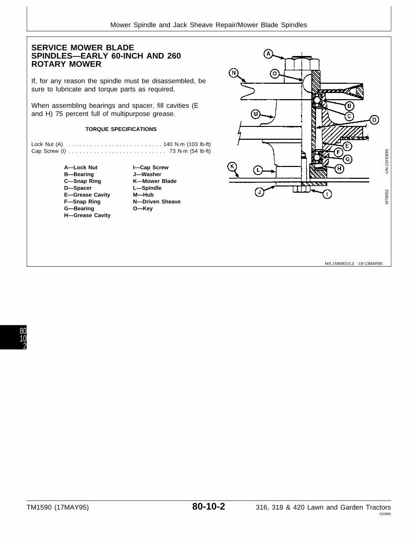
SERVICE MOWER BLADESPINDLES—EARLY 60-INCH AND 260ROTARY MOWER
If, for any reason the spindle must be disassembled, besure to lubricate and torque parts as required.
When assembling bearings and spacer, fill cavities (Eand H) 75 percent full of multipurpose grease.
TORQUE SPECIFICATIONS
Lock Nut (A) . . . . . . . . . . . . . . . . . . . . . . . . . . 140 N·m (103 lb-ft)Cap Screw (I) . . . . . . . . . . . . . . . . . . . . . . . . . . . 73 N·m (54 lb-ft)
A—Lock Nut I—Cap ScrewB—Bearing J—WasherC—Snap Ring K—Mower BladeD—Spacer L—SpindleE—Grease Cavity M—HubF—Snap Ring N—Driven SheaveG—Bearing O—KeyH—Grease Cavity
M78
052
-UN
-21F
EB
95
MX,15908010,3 -19-13MAR95
Mower Spindle and Jack Sheave Repair/Mower Blade Spindles
TM1590 (17MAY95) 80-10-2 316, 318 & 420 Lawn and Garden Tractors020895
8010
2
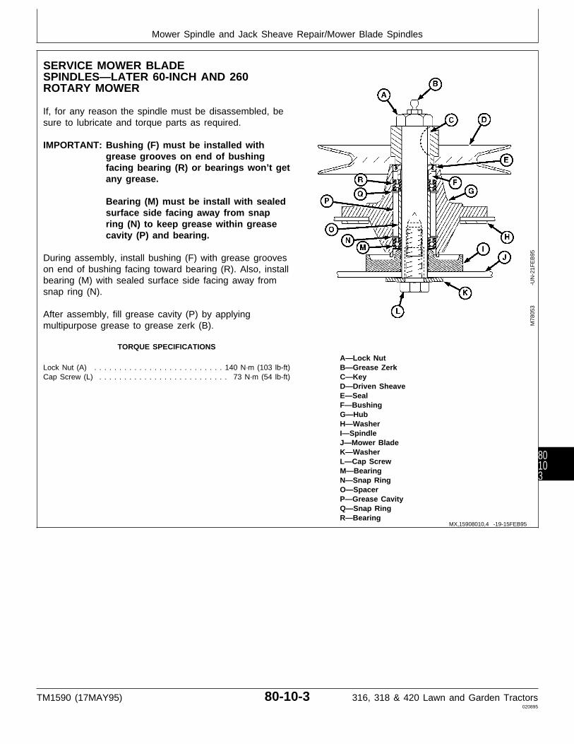
SERVICE MOWER BLADESPINDLES—LATER 60-INCH AND 260ROTARY MOWER
If, for any reason the spindle must be disassembled, besure to lubricate and torque parts as required.
IMPORTANT: Bushing (F) must be installed withgrease grooves on end of bushingfacing bearing (R) or bearings won’t getany grease.
Bearing (M) must be install with sealedsurface side facing away from snapring (N) to keep grease within greasecavity (P) and bearing.
During assembly, install bushing (F) with grease grooveson end of bushing facing toward bearing (R). Also, installbearing (M) with sealed surface side facing away fromsnap ring (N).
After assembly, fill grease cavity (P) by applyingmultipurpose grease to grease zerk (B).
TORQUE SPECIFICATIONS
A—Lock NutLock Nut (A) . . . . . . . . . . . . . . . . . . . . . . . . . . 140 N·m (103 lb-ft) B—Grease ZerkCap Screw (L) . . . . . . . . . . . . . . . . . . . . . . . . . . 73 N·m (54 lb-ft) C—Key
D—Driven SheaveE—SealF—BushingG—HubH—WasherI—SpindleJ—Mower BladeK—WasherL—Cap ScrewM—BearingN—Snap RingO—SpacerP—Grease CavityQ—Snap RingR—Bearing
M78
053
-UN
-21F
EB
95
MX,15908010,4 -19-15FEB95
Mower Spindle and Jack Sheave Repair/Mower Blade Spindles
TM1590 (17MAY95) 80-10-3 316, 318 & 420 Lawn and Garden Tractors020895
80103

SERVICE MOWER BLADE JACKSHEAVES—46 AND 50-INCH MOWER
Mower blade jack sheaves normally require no lubricationor service. If, for any reason the jack sheave must bedisassembled, be sure to lubricate and torque parts asrequired.
When assembling bearings and spacer, fill cavities (Kand N) 75 percent full of multipurpose grease.
TORQUE SPECIFICATIONS
Lock Nut (A) . . . . . . . . . . . . . . . . . . . . . . . . . . 140 N·m (103 lb-ft)Cap Screw (I) . . . . . . . . . . . . . . . . . . . . . . . . . . . 73 N·m (54 lb-ft)
A—Lock Nut I—Cap ScrewB—Key J—SpindleC—Jack Sheave K—Grease CavityD—Washer L—BearingE—Hub M—SpacerF—Snap Rings N—Grease CavityG—Mower Blade O—BearingH—Washer
M78
054
-UN
-21F
EB
95
MX,15908010,5 -19-15FEB95
Mower Spindle and Jack Sheave Repair/Mower Blade Jack Sheaves
TM1590 (17MAY95) 80-10-4 316, 318 & 420 Lawn and Garden Tractors020895
8010
4
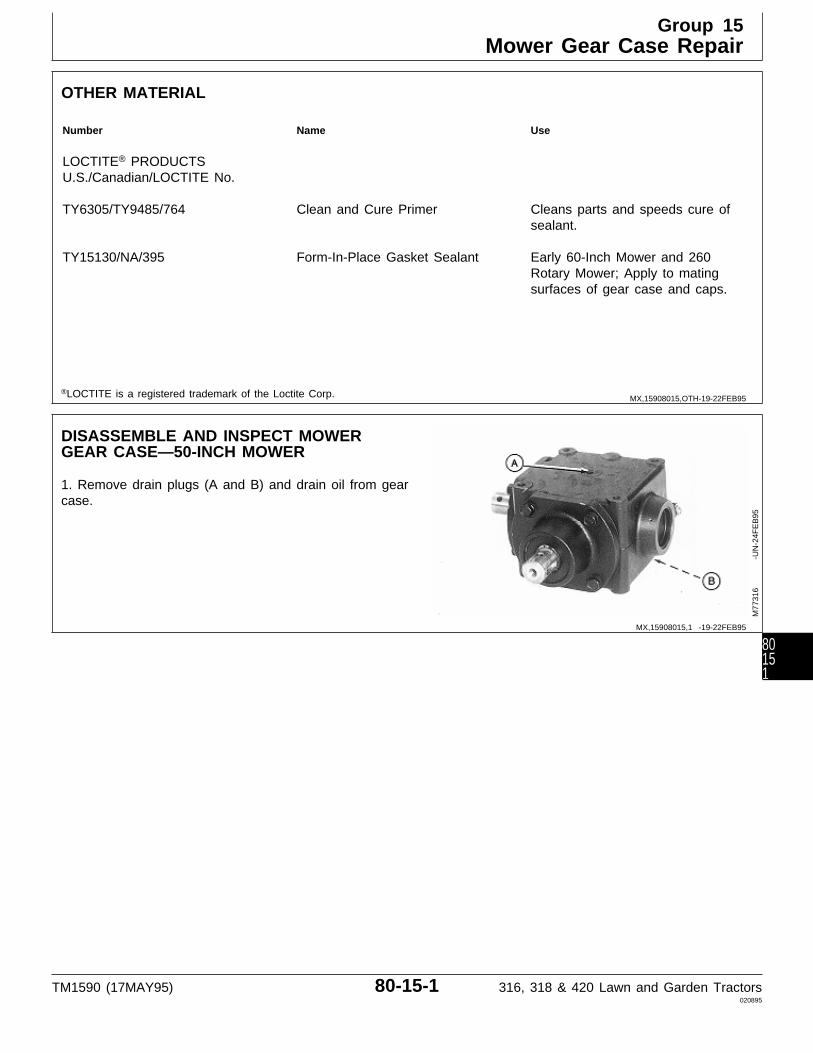
OTHER MATERIAL
Number Name Use
LOCTITE® PRODUCTSU.S./Canadian/LOCTITE No.
TY6305/TY9485/764 Clean and Cure Primer Cleans parts and speeds cure ofsealant.
TY15130/NA/395 Form-In-Place Gasket Sealant Early 60-Inch Mower and 260Rotary Mower; Apply to matingsurfaces of gear case and caps.
®LOCTITE is a registered trademark of the Loctite Corp.
DISASSEMBLE AND INSPECT MOWERGEAR CASE—50-INCH MOWER
1. Remove drain plugs (A and B) and drain oil from gearcase.
M77
316
-UN
-24F
EB
95
MX,15908015,OTH-19-22FEB95
MX,15908015,1 -19-22FEB95
Group 15Mower Gear Case Repair
TM1590 (17MAY95) 80-15-1 316, 318 & 420 Lawn and Garden Tractors020895
80151
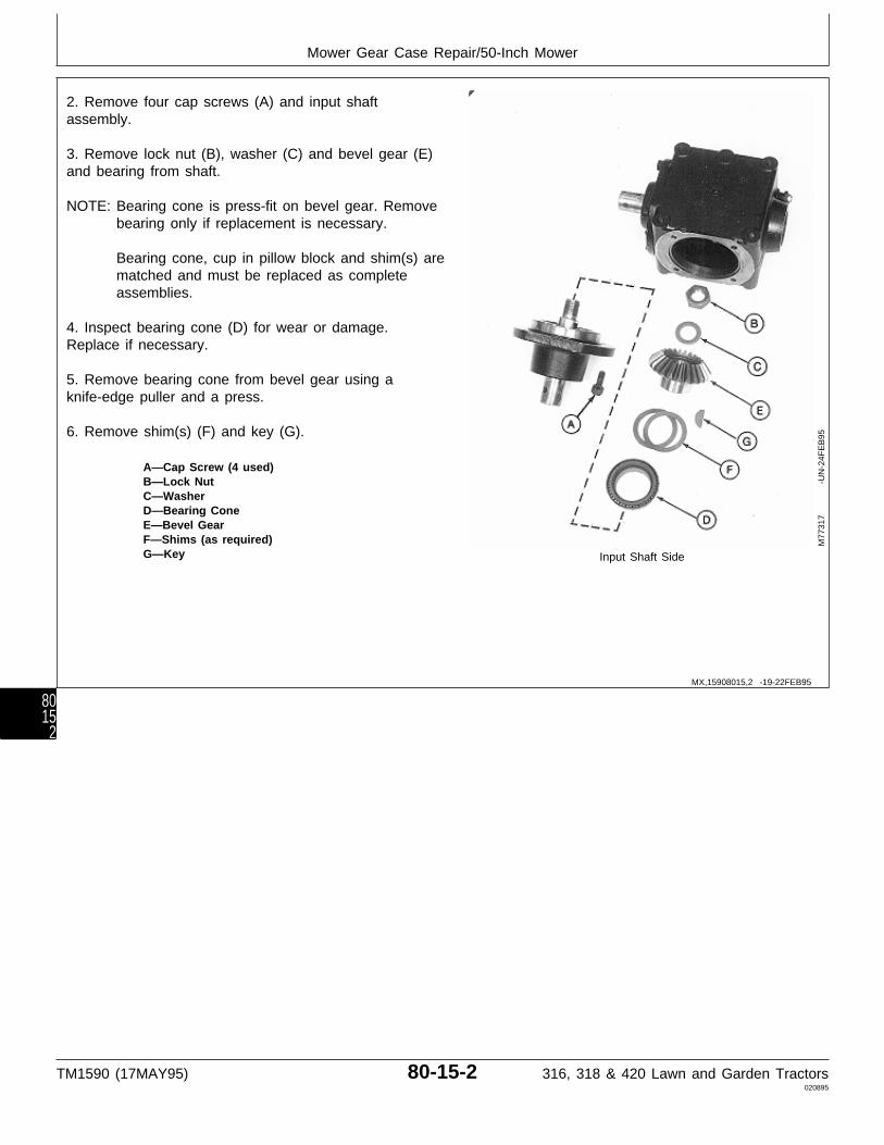
2. Remove four cap screws (A) and input shaftassembly.
3. Remove lock nut (B), washer (C) and bevel gear (E)and bearing from shaft.
NOTE: Bearing cone is press-fit on bevel gear. Removebearing only if replacement is necessary.
Bearing cone, cup in pillow block and shim(s) arematched and must be replaced as completeassemblies.
4. Inspect bearing cone (D) for wear or damage.Replace if necessary.
5. Remove bearing cone from bevel gear using aknife-edge puller and a press.
6. Remove shim(s) (F) and key (G).
A—Cap Screw (4 used)B—Lock NutC—WasherD—Bearing ConeE—Bevel GearF—Shims (as required)G—Key Input Shaft Side
M77
317
-UN
-24F
EB
95
MX,15908015,2 -19-22FEB95
Mower Gear Case Repair/50-Inch Mower
TM1590 (17MAY95) 80-15-2 316, 318 & 420 Lawn and Garden Tractors020895
8015
2

7. Press on threaded end of input shaft (C) to removeseal (A) and input shaft assembly from pillow block (I).
NOTE: Bearing cone is press-fit on input shaft. Removebearing only if replacement is necessary.
Bearing cups are press-fit in pillow block.Remove cups only if replacement is necessary.
Bearing cones and cups are matched and mustbe replaced as complete assemblies.
8. Inspect bearing cone (D) and cups (G and H) for wearor damage. Replace as necessary.
9. Remove snap ring (B) and press input shaft (C) frombearing (D).
10. Remove O-ring (E) and snap ring (F).
IMPORTANT: Remove bearing cups using a pressand driver disk, if possible. Using apunch and hammer can damage pillowblock. Use only if necessary.
11. Remove bearing cups (G and H) using a press anddriver set or punch and hammer. Input Shaft Assembly
A—SealB—Snap RingC—Input ShaftD—Bearing ConeE—O-RingF—Snap RingG—Bearing CupH—Bearing CupI—Pillow Block
M77
318
-UN
-24F
EB
95
MX,15908015,3 -19-13MAR95
Mower Gear Case Repair/50-Inch Mower
TM1590 (17MAY95) 80-15-3 316, 318 & 420 Lawn and Garden Tractors020895
80153
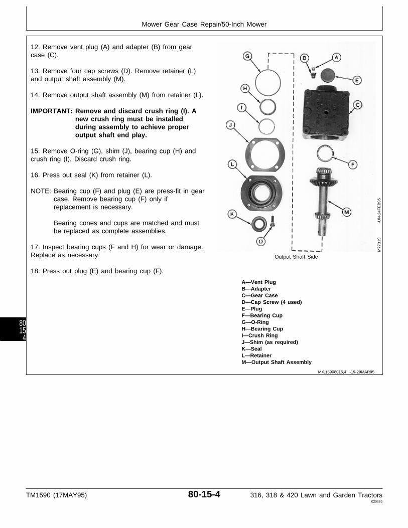
12. Remove vent plug (A) and adapter (B) from gearcase (C).
13. Remove four cap screws (D). Remove retainer (L)and output shaft assembly (M).
14. Remove output shaft assembly (M) from retainer (L).
IMPORTANT: Remove and discard crush ring (I). Anew crush ring must be installedduring assembly to achieve properoutput shaft end play.
15. Remove O-ring (G), shim (J), bearing cup (H) andcrush ring (I). Discard crush ring.
16. Press out seal (K) from retainer (L).
NOTE: Bearing cup (F) and plug (E) are press-fit in gearcase. Remove bearing cup (F) only ifreplacement is necessary.
Bearing cones and cups are matched and mustbe replaced as complete assemblies.
17. Inspect bearing cups (F and H) for wear or damage.Replace as necessary. Output Shaft Side
18. Press out plug (E) and bearing cup (F).
A—Vent PlugB—AdapterC—Gear CaseD—Cap Screw (4 used)E—PlugF—Bearing CupG—O-RingH—Bearing CupI—Crush RingJ—Shim (as required)K—SealL—RetainerM—Output Shaft Assembly
M77
319
-UN
-24F
EB
95
MX,15908015,4 -19-29MAR95
Mower Gear Case Repair/50-Inch Mower
TM1590 (17MAY95) 80-15-4 316, 318 & 420 Lawn and Garden Tractors020895
8015
4

NOTE: Bearing cones are press-fit on output shaft.Remove bearings only if replacement isnecessary.
Bearing cones and cups are matched and mustbe replaced as complete assemblies.
20. Inspect bearing cones (A and D) for wear ordamage. Replace if necessary.
21. Press output shaft (B) from bearing cone (A).Remove snap ring (C).
22. Remove bearing cone (D) from output shaft (B) usinga knife-edge puller and a press.
23. Remove bevel gear (E), snap ring (F) and key (G).
24. Inspect all parts for wear or damage. Replace asnecessary.
A—Bearing ConeB—Output ShaftC—Snap RingD—Bearing ConeE—Bevel GearF—Snap RingG—Key Output Shaft Assembly
M77
320
-UN
-24F
EB
95
MX,15908015,5 -19-29MAR95
Mower Gear Case Repair/50-Inch Mower
TM1590 (17MAY95) 80-15-5 316, 318 & 420 Lawn and Garden Tractors020895
80155

ASSEMBLE MOWER GEAR CASE—50-INCHMOWER
IMPORTANT: Always use new seals and O-rings.Damaged or used parts will leak.
NOTE: Lubricate all O-rings with petroleum jelly duringassembly.
Apply clean gear case oil on all internal partsduring assembly.
1. Install snap ring (F), key (G) and bevel gear (E).Install bevel gear on output shaft, small O.D. first.
2. Press bearing cone (D) on output shaft (B) with smallO.D. facing away from bevel gear (E). Install bearinguntil it bottoms against bevel gear.
3. Install snap ring (C).
4. Press bearing cone (A) on output shaft with smallO.D. facing away from bevel gear (E). Install bearinguntil it bottoms against snap ring.
A—Bearing ConeB—Output Shaft Output Shaft AssemblyC—Snap RingD—Bearing ConeE—Bevel GearF—Snap RingG—Key
M77
320
-UN
-24F
EB
95
MX,15908015,6 -19-13MAR95
Mower Gear Case Repair/50-Inch Mower
TM1590 (17MAY95) 80-15-6 316, 318 & 420 Lawn and Garden Tractors020895
8015
6
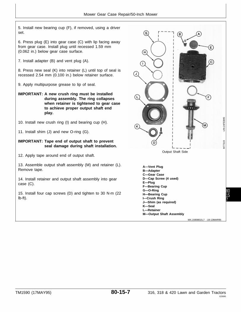
5. Install new bearing cup (F), if removed, using a driverset.
6. Press plug (E) into gear case (C) with lip facing awayfrom gear case. Install plug until recessed 1.59 mm(0.062 in.) below gear case surface.
7. Install adapter (B) and vent plug (A).
8. Press new seal (K) into retainer (L) until top of seal isrecessed 2.54 mm (0.100 in.) below retainer surface.
9. Apply multipurpose grease to lip of seal.
IMPORTANT: A new crush ring must be installedduring assembly. The ring collapseswhen retainer is tightened to gear caseto achieve proper output shaft endplay.
10. Install new crush ring (I) and bearing cup (H).
11. Install shim (J) and new O-ring (G).
IMPORTANT: Tape end of output shaft to preventseal damage during shaft installation.
Output Shaft Side12. Apply tape around end of output shaft.
13. Assemble output shaft assembly (M) and retainer (L). A—Vent PlugRemove tape. B—Adapter
C—Gear CaseD—Cap Screw (4 used)14. Install retainer and output shaft assembly into gearE—Plugcase (C).F—Bearing CupG—O-Ring
15. Install four cap screws (D) and tighten to 30 N·m (22 H—Bearing Cuplb-ft). I—Crush Ring
J—Shim (as required)K—SealL—RetainerM—Output Shaft Assembly
M77
319
-UN
-24F
EB
95
MX,15908015,7 -19-13MAR95
Mower Gear Case Repair/50-Inch Mower
TM1590 (17MAY95) 80-15-7 316, 318 & 420 Lawn and Garden Tractors020895
80157
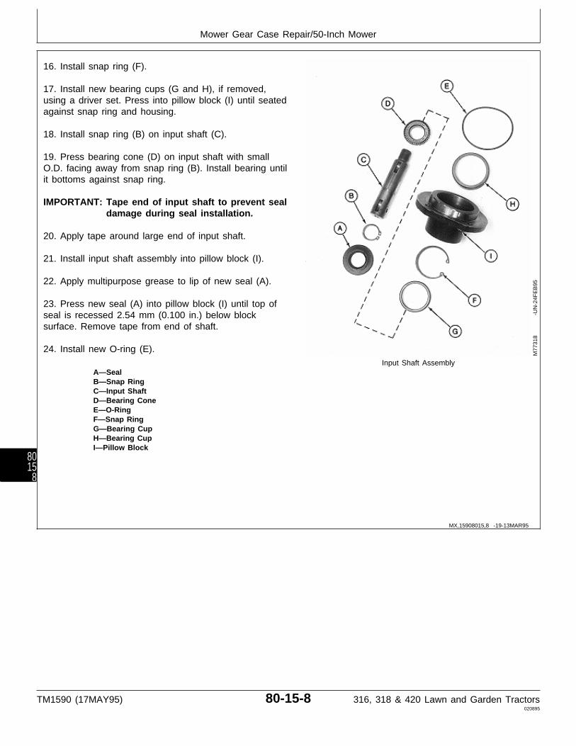
16. Install snap ring (F).
17. Install new bearing cups (G and H), if removed,using a driver set. Press into pillow block (I) until seatedagainst snap ring and housing.
18. Install snap ring (B) on input shaft (C).
19. Press bearing cone (D) on input shaft with smallO.D. facing away from snap ring (B). Install bearing untilit bottoms against snap ring.
IMPORTANT: Tape end of input shaft to prevent sealdamage during seal installation.
20. Apply tape around large end of input shaft.
21. Install input shaft assembly into pillow block (I).
22. Apply multipurpose grease to lip of new seal (A).
23. Press new seal (A) into pillow block (I) until top ofseal is recessed 2.54 mm (0.100 in.) below blocksurface. Remove tape from end of shaft.
24. Install new O-ring (E).Input Shaft Assembly
A—SealB—Snap RingC—Input ShaftD—Bearing ConeE—O-RingF—Snap RingG—Bearing CupH—Bearing CupI—Pillow Block
M77
318
-UN
-24F
EB
95
MX,15908015,8 -19-13MAR95
Mower Gear Case Repair/50-Inch Mower
TM1590 (17MAY95) 80-15-8 316, 318 & 420 Lawn and Garden Tractors020895
8015
8
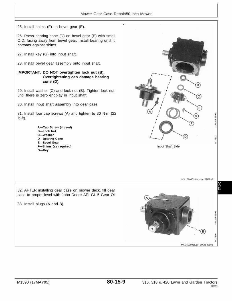
25. Install shims (F) on bevel gear (E).
26. Press bearing cone (D) on bevel gear (E) with smallO.D. facing away from bevel gear. Install bearing until itbottoms against shims.
27. Install key (G) into input shaft.
28. Install bevel gear assembly onto input shaft.
IMPORTANT: DO NOT overtighten lock nut (B).Overtightening can damage bearingcone (D).
29. Install washer (C) and lock nut (B). Tighten lock nutuntil there is zero endplay in input shaft.
30. Install input shaft assembly into gear case.
31. Install four cap screws (A) and tighten to 30 N·m (22lb-ft).
A—Cap Screw (4 used)B—Lock NutC—WasherD—Bearing ConeE—Bevel GearF—Shims (as required) Input Shaft SideG—Key
M77
317
-UN
-24F
EB
95
32. AFTER installing gear case on mower deck, fill gearcase to proper level with John Deere API GL-5 Gear Oil.
33. Install plugs (A and B).
M77
316
-UN
-24F
EB
95
MX,15908015,9 -19-22FEB95
MX,15908015,10 -19-22FEB95
Mower Gear Case Repair/50-Inch Mower
TM1590 (17MAY95) 80-15-9 316, 318 & 420 Lawn and Garden Tractors020895
80159

DISASSEMBLE AND INSPECT MOWERGEAR CASE—EARLY 60-INCH MOWER(CURTIS)
1. Remove drain plugs (A and B) and drain oil from gearcase.
2. Scribe an alignment mark across caps and gear case.Mark both caps in relation to the case side they areremoved from to aid in assembly.
M77
328
-UN
-24F
EB
95
MX,15908015,11 -19-13MAR95
Mower Gear Case Repair/Early 60-Inch Mower (Curtis)
TM1590 (17MAY95) 80-15-10 316, 318 & 420 Lawn and Garden Tractors020895
801510
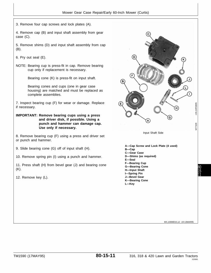
3. Remove four cap screws and lock plates (A).
4. Remove cap (B) and input shaft assembly from gearcase (C).
5. Remove shims (D) and input shaft assembly from cap(B).
6. Pry out seal (E).
NOTE: Bearing cup is press-fit in cap. Remove bearingcup only if replacement is necessary.
Bearing cone (K) is press-fit on input shaft.
Bearing cones and cups (one in gear casehousing) are matched and must be replaced ascomplete assemblies.
7. Inspect bearing cup (F) for wear or damage. Replaceif necessary.
IMPORTANT: Remove bearing cups using a pressand driver disk, if possible. Using apunch and hammer can damage cap.Use only if necessary.
Input Shaft Side8. Remove bearing cup (F) using a press and driver setor punch and hammer.
A—Cap Screw and Lock Plate (4 used)9. Slide bearing cone (G) off of input shaft (H). B—Cap
C—Gear CaseD—Shims (as required)10. Remove spring pin (I) using a punch and hammer.E—SealF—Bearing Cup
11. Press shaft (H) from bevel gear (J) and bearing cone G—Bearing Cone(K). H—Input Shaft
I—Spring PinJ—Bevel Gear12. Remove key (L).K—Bearing ConeL—Key
M77
329
-UN
-24F
EB
95
MX,15908015,12 -19-13MAR95
Mower Gear Case Repair/Early 60-Inch Mower (Curtis)
TM1590 (17MAY95) 80-15-11 316, 318 & 420 Lawn and Garden Tractors020895
801511
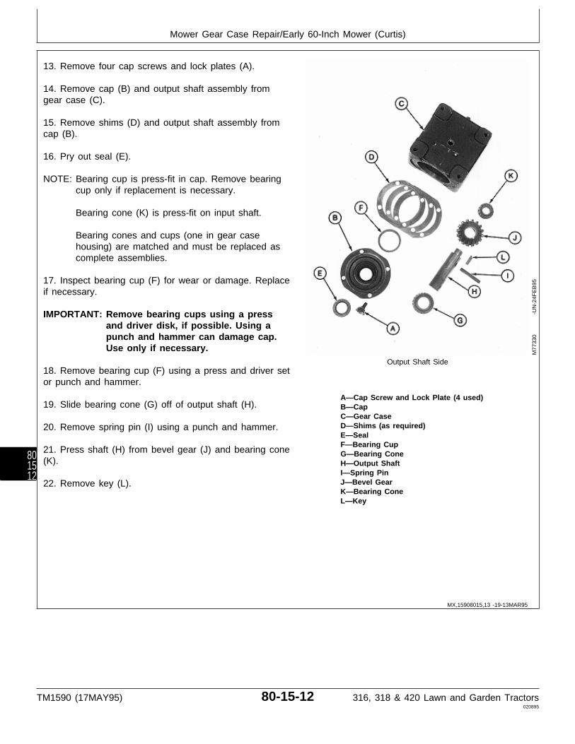
13. Remove four cap screws and lock plates (A).
14. Remove cap (B) and output shaft assembly fromgear case (C).
15. Remove shims (D) and output shaft assembly fromcap (B).
16. Pry out seal (E).
NOTE: Bearing cup is press-fit in cap. Remove bearingcup only if replacement is necessary.
Bearing cone (K) is press-fit on input shaft.
Bearing cones and cups (one in gear casehousing) are matched and must be replaced ascomplete assemblies.
17. Inspect bearing cup (F) for wear or damage. Replaceif necessary.
IMPORTANT: Remove bearing cups using a pressand driver disk, if possible. Using apunch and hammer can damage cap.Use only if necessary.
Output Shaft Side18. Remove bearing cup (F) using a press and driver setor punch and hammer.
A—Cap Screw and Lock Plate (4 used)19. Slide bearing cone (G) off of output shaft (H). B—Cap
C—Gear CaseD—Shims (as required)20. Remove spring pin (I) using a punch and hammer.E—SealF—Bearing Cup
21. Press shaft (H) from bevel gear (J) and bearing cone G—Bearing Cone(K). H—Output Shaft
I—Spring PinJ—Bevel Gear22. Remove key (L).K—Bearing ConeL—Key
M77
330
-UN
-24F
EB
95
MX,15908015,13 -19-13MAR95
Mower Gear Case Repair/Early 60-Inch Mower (Curtis)
TM1590 (17MAY95) 80-15-12 316, 318 & 420 Lawn and Garden Tractors020895
801512
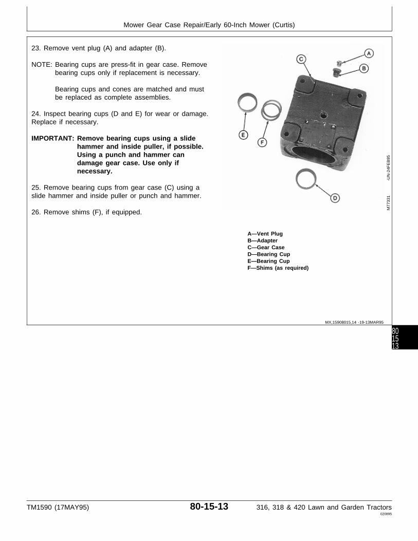
23. Remove vent plug (A) and adapter (B).
NOTE: Bearing cups are press-fit in gear case. Removebearing cups only if replacement is necessary.
Bearing cups and cones are matched and mustbe replaced as complete assemblies.
24. Inspect bearing cups (D and E) for wear or damage.Replace if necessary.
IMPORTANT: Remove bearing cups using a slidehammer and inside puller, if possible.Using a punch and hammer candamage gear case. Use only ifnecessary.
25. Remove bearing cups from gear case (C) using aslide hammer and inside puller or punch and hammer.
26. Remove shims (F), if equipped.
A—Vent PlugB—AdapterC—Gear CaseD—Bearing CupE—Bearing CupF—Shims (as required)
M77
331
-UN
-24F
EB
95
MX,15908015,14 -19-13MAR95
Mower Gear Case Repair/Early 60-Inch Mower (Curtis)
TM1590 (17MAY95) 80-15-13 316, 318 & 420 Lawn and Garden Tractors020895
801513
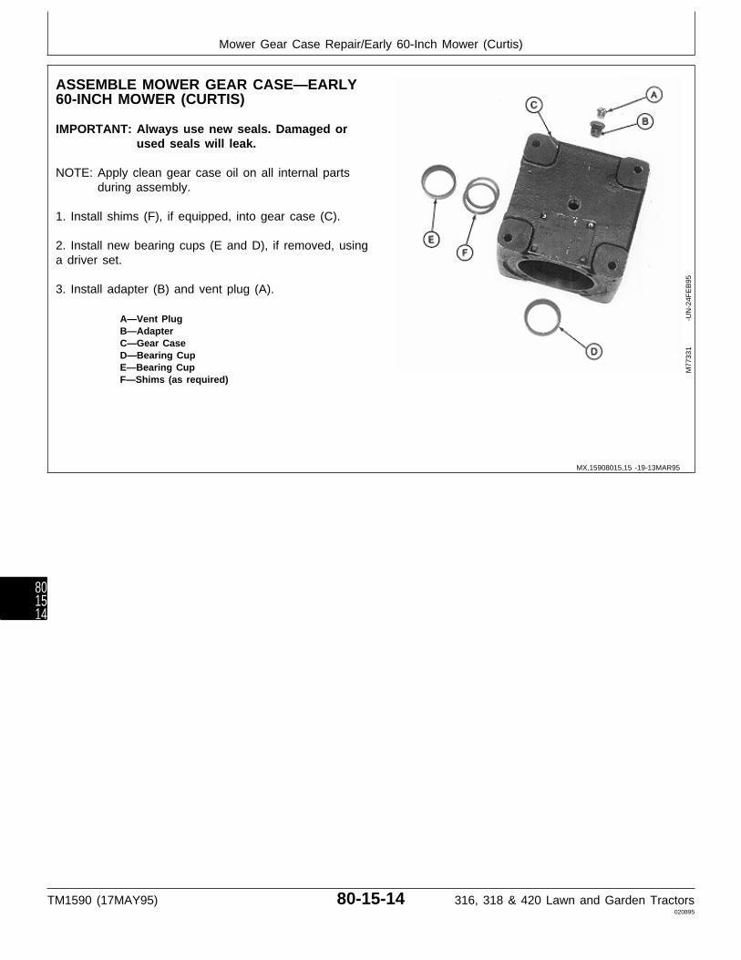
ASSEMBLE MOWER GEAR CASE—EARLY60-INCH MOWER (CURTIS)
IMPORTANT: Always use new seals. Damaged orused seals will leak.
NOTE: Apply clean gear case oil on all internal partsduring assembly.
1. Install shims (F), if equipped, into gear case (C).
2. Install new bearing cups (E and D), if removed, usinga driver set.
3. Install adapter (B) and vent plug (A).
A—Vent PlugB—AdapterC—Gear CaseD—Bearing CupE—Bearing CupF—Shims (as required)
M77
331
-UN
-24F
EB
95
MX,15908015,15 -19-13MAR95
Mower Gear Case Repair/Early 60-Inch Mower (Curtis)
TM1590 (17MAY95) 80-15-14 316, 318 & 420 Lawn and Garden Tractors020895
801514
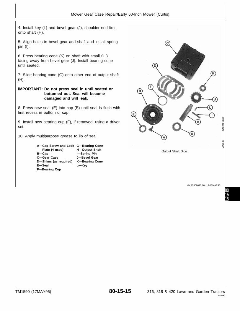
4. Install key (L) and bevel gear (J), shoulder end first,onto shaft (H).
5. Align holes in bevel gear and shaft and install springpin (I).
6. Press bearing cone (K) on shaft with small O.D.facing away from bevel gear (J). Install bearing coneuntil seated.
7. Slide bearing cone (G) onto other end of output shaft(H).
IMPORTANT: Do not press seal in until seated orbottomed out. Seal will becomedamaged and will leak.
8. Press new seal (E) into cap (B) until seal is flush withfirst recess in bottom of cap.
9. Install new bearing cup (F), if removed, using a driverset.
10. Apply multipurpose grease to lip of seal.
A—Cap Screw and Lock G—Bearing ConePlate (4 used) H—Output Shaft Output Shaft Side
B—Cap I—Spring PinC—Gear Case J—Bevel GearD—Shims (as required) K—Bearing ConeE—Seal L—KeyF—Bearing Cup
M77
330
-UN
-24F
EB
95
MX,15908015,16 -19-13MAR95
Mower Gear Case Repair/Early 60-Inch Mower (Curtis)
TM1590 (17MAY95) 80-15-15 316, 318 & 420 Lawn and Garden Tractors020895
801515
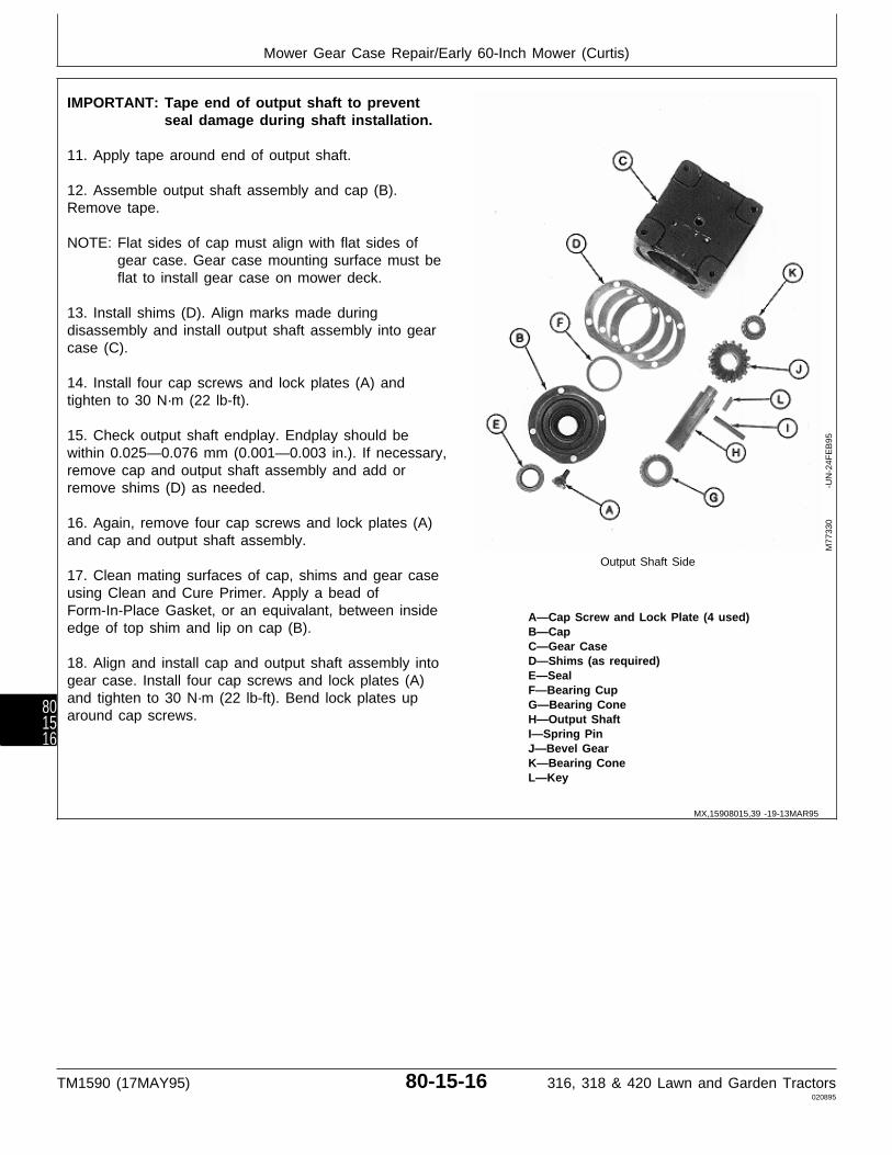
IMPORTANT: Tape end of output shaft to preventseal damage during shaft installation.
11. Apply tape around end of output shaft.
12. Assemble output shaft assembly and cap (B).Remove tape.
NOTE: Flat sides of cap must align with flat sides ofgear case. Gear case mounting surface must beflat to install gear case on mower deck.
13. Install shims (D). Align marks made duringdisassembly and install output shaft assembly into gearcase (C).
14. Install four cap screws and lock plates (A) andtighten to 30 N·m (22 lb-ft).
15. Check output shaft endplay. Endplay should bewithin 0.025—0.076 mm (0.001—0.003 in.). If necessary,remove cap and output shaft assembly and add orremove shims (D) as needed.
16. Again, remove four cap screws and lock plates (A)and cap and output shaft assembly.
Output Shaft Side17. Clean mating surfaces of cap, shims and gear caseusing Clean and Cure Primer. Apply a bead ofForm-In-Place Gasket, or an equivalant, between inside A—Cap Screw and Lock Plate (4 used)edge of top shim and lip on cap (B). B—Cap
C—Gear CaseD—Shims (as required)18. Align and install cap and output shaft assembly intoE—Sealgear case. Install four cap screws and lock plates (A)F—Bearing Cup
and tighten to 30 N·m (22 lb-ft). Bend lock plates up G—Bearing Conearound cap screws. H—Output Shaft
I—Spring PinJ—Bevel GearK—Bearing ConeL—Key
M77
330
-UN
-24F
EB
95
MX,15908015,39 -19-13MAR95
Mower Gear Case Repair/Early 60-Inch Mower (Curtis)
TM1590 (17MAY95) 80-15-16 316, 318 & 420 Lawn and Garden Tractors020895
801516

19. Install key (L) and bevel gear (J), shoulder end first,onto shaft (H).
20. Align holes in bevel gear and shaft and install springpin (I).
21. Press bearing cone (K) on shaft with small O.D.facing away from bevel gear (J). Install bearing untilseated.
22. Slide bearing cone (G) onto other end of input shaft(H).
IMPORTANT: Do not press seal in until seated orbottomed out. Seal will becomedamaged and will leak.
23. Press new seal (E) into cap (B) until seal is flushwith first recess in bottom of cap.
24. Install new bearing cup (F), if removed, using adriver set.
25. Apply multipurpose grease to lip of seal.
A—Cap Screw and Lock G—Bearing ConePlate (4 used) H—Input Shaft Input Shaft Side
B—Cap I—Spring PinC—Gear Case J—Bevel GearD—Shims (as required) K—Bearing ConeE—Seal L—KeyF—Bearing Cup
M77
329
-UN
-24F
EB
95
MX,15908015,17 -19-29MAR95
Mower Gear Case Repair/Early 60-Inch Mower (Curtis)
TM1590 (17MAY95) 80-15-17 316, 318 & 420 Lawn and Garden Tractors020895
801517
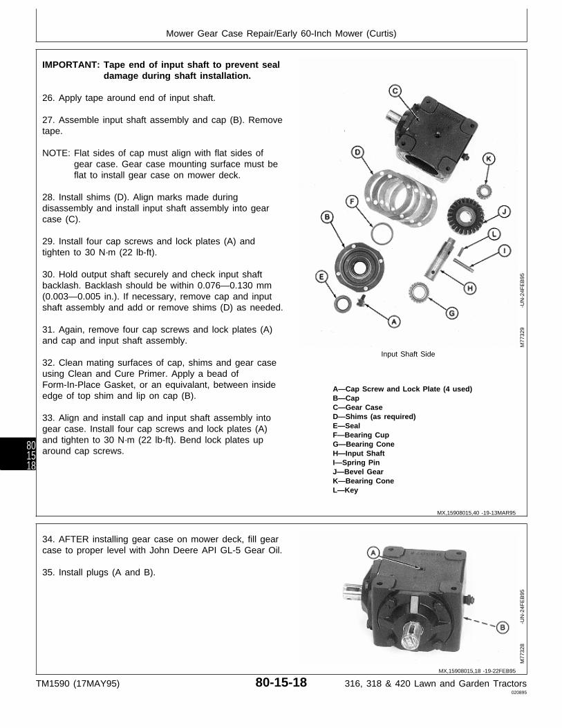
IMPORTANT: Tape end of input shaft to prevent sealdamage during shaft installation.
26. Apply tape around end of input shaft.
27. Assemble input shaft assembly and cap (B). Removetape.
NOTE: Flat sides of cap must align with flat sides ofgear case. Gear case mounting surface must beflat to install gear case on mower deck.
28. Install shims (D). Align marks made duringdisassembly and install input shaft assembly into gearcase (C).
29. Install four cap screws and lock plates (A) andtighten to 30 N·m (22 lb-ft).
30. Hold output shaft securely and check input shaftbacklash. Backlash should be within 0.076—0.130 mm(0.003—0.005 in.). If necessary, remove cap and inputshaft assembly and add or remove shims (D) as needed.
31. Again, remove four cap screws and lock plates (A)and cap and input shaft assembly.
Input Shaft Side32. Clean mating surfaces of cap, shims and gear caseusing Clean and Cure Primer. Apply a bead ofForm-In-Place Gasket, or an equivalant, between inside A—Cap Screw and Lock Plate (4 used)edge of top shim and lip on cap (B). B—Cap
C—Gear CaseD—Shims (as required)33. Align and install cap and input shaft assembly intoE—Sealgear case. Install four cap screws and lock plates (A)F—Bearing Cup
and tighten to 30 N·m (22 lb-ft). Bend lock plates up G—Bearing Conearound cap screws. H—Input Shaft
I—Spring PinJ—Bevel GearK—Bearing ConeL—Key
M77
329
-UN
-24F
EB
95
34. AFTER installing gear case on mower deck, fill gearcase to proper level with John Deere API GL-5 Gear Oil.
35. Install plugs (A and B).
M77
328
-UN
-24F
EB
95
MX,15908015,40 -19-13MAR95
MX,15908015,18 -19-22FEB95
Mower Gear Case Repair/Early 60-Inch Mower (Curtis)
TM1590 (17MAY95) 80-15-18 316, 318 & 420 Lawn and Garden Tractors020895
801518
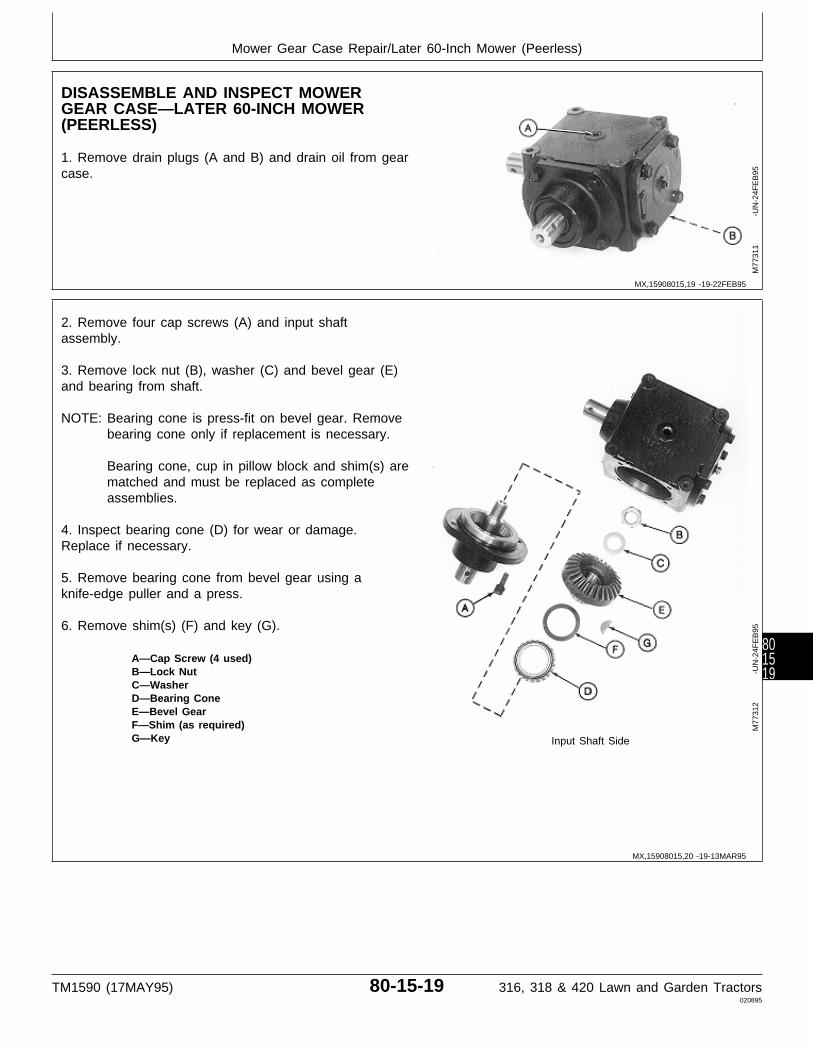
DISASSEMBLE AND INSPECT MOWERGEAR CASE—LATER 60-INCH MOWER(PEERLESS)
1. Remove drain plugs (A and B) and drain oil from gearcase.
M77
311
-UN
-24F
EB
95
2. Remove four cap screws (A) and input shaftassembly.
3. Remove lock nut (B), washer (C) and bevel gear (E)and bearing from shaft.
NOTE: Bearing cone is press-fit on bevel gear. Removebearing cone only if replacement is necessary.
Bearing cone, cup in pillow block and shim(s) arematched and must be replaced as completeassemblies.
4. Inspect bearing cone (D) for wear or damage.Replace if necessary.
5. Remove bearing cone from bevel gear using aknife-edge puller and a press.
6. Remove shim(s) (F) and key (G).
A—Cap Screw (4 used)B—Lock NutC—WasherD—Bearing ConeE—Bevel GearF—Shim (as required)G—Key Input Shaft Side
M77
312
-UN
-24F
EB
95
MX,15908015,19 -19-22FEB95
MX,15908015,20 -19-13MAR95
Mower Gear Case Repair/Later 60-Inch Mower (Peerless)
TM1590 (17MAY95) 80-15-19 316, 318 & 420 Lawn and Garden Tractors020895
801519
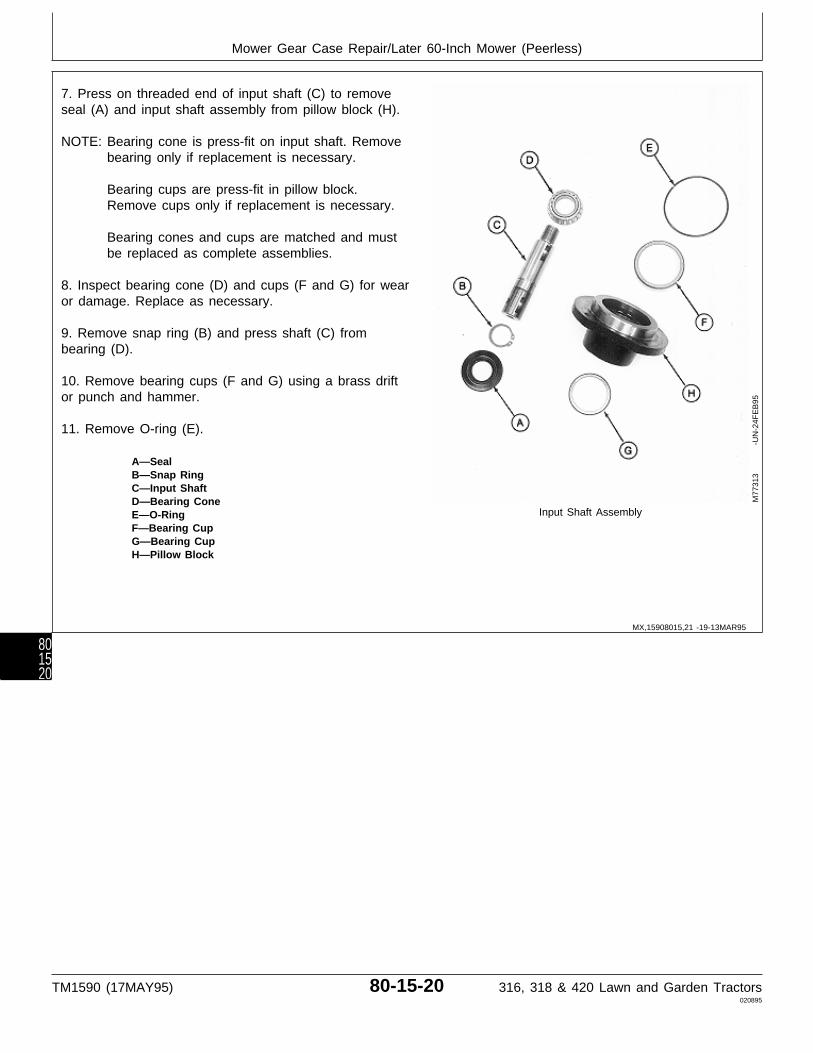
7. Press on threaded end of input shaft (C) to removeseal (A) and input shaft assembly from pillow block (H).
NOTE: Bearing cone is press-fit on input shaft. Removebearing only if replacement is necessary.
Bearing cups are press-fit in pillow block.Remove cups only if replacement is necessary.
Bearing cones and cups are matched and mustbe replaced as complete assemblies.
8. Inspect bearing cone (D) and cups (F and G) for wearor damage. Replace as necessary.
9. Remove snap ring (B) and press shaft (C) frombearing (D).
10. Remove bearing cups (F and G) using a brass driftor punch and hammer.
11. Remove O-ring (E).
A—SealB—Snap RingC—Input ShaftD—Bearing Cone
Input Shaft AssemblyE—O-RingF—Bearing CupG—Bearing CupH—Pillow Block
M77
313
-UN
-24F
EB
95
MX,15908015,21 -19-13MAR95
Mower Gear Case Repair/Later 60-Inch Mower (Peerless)
TM1590 (17MAY95) 80-15-20 316, 318 & 420 Lawn and Garden Tractors020895
801520

12. Remove vent plug (A) from retainer (G).
13. Remove four cap screws (B). Remove retainer (G)and output shaft assembly (K) by tapping on end of shaftwith a rubber mallet.
14. Remove output shaft assembly (K) from retainer (G).
15. Remove O-ring (F) and shim (C) from retainer (G).
IMPORTANT: Remove and discard crush ring (E). Anew crush ring must be installedduring assembly to achieve properoutput shaft end play.
16. Remove bearing cup (D) and crush ring (E). Discardcrush ring.
17. Pry out seal (H).
NOTE: Bearing cup is press-fit in gear case. Removebearing cup only if replacement is necessary.
Bearing cones and cups are matched and mustbe replaced as complete assemblies.
18. Inspect bearing cups (D and I) for wear or damage. Output Shaft SideReplace as necessary.
19. Remove bearing cup (I) using a brass drift or punch A—Vent Plugand hammer. B—Cap Screw (4 used)
C—Shim (as required)D—Bearing CupE—Crush RingF—O-RingG—RetainerH—SealI—Bearing CupJ—Gear CaseK—Output Shaft Assembly
M77
314
-UN
-24F
EB
95
MX,15908015,22 -19-13MAR95
Mower Gear Case Repair/Later 60-Inch Mower (Peerless)
TM1590 (17MAY95) 80-15-21 316, 318 & 420 Lawn and Garden Tractors020895
801521
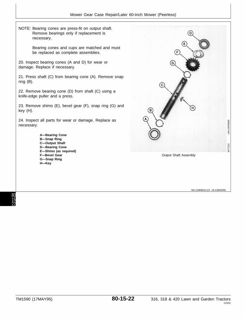
NOTE: Bearing cones are press-fit on output shaft.Remove bearings only if replacement isnecessary.
Bearing cones and cups are matched and mustbe replaced as complete assemblies.
20. Inspect bearing cones (A and D) for wear ordamage. Replace if necessary.
21. Press shaft (C) from bearing cone (A). Remove snapring (B).
22. Remove bearing cone (D) from shaft (C) using aknife-edge puller and a press.
23. Remove shims (E), bevel gear (F), snap ring (G) andkey (H).
24. Inspect all parts for wear or damage. Replace asnecessary.
A—Bearing ConeB—Snap RingC—Output ShaftD—Bearing ConeE—Shims (as required)F—Bevel Gear Output Shaft AssemblyG—Snap RingH—Key
M77
315
-UN
-24F
EB
95
MX,15908015,23 -19-13MAR95
Mower Gear Case Repair/Later 60-Inch Mower (Peerless)
TM1590 (17MAY95) 80-15-22 316, 318 & 420 Lawn and Garden Tractors020895
801522
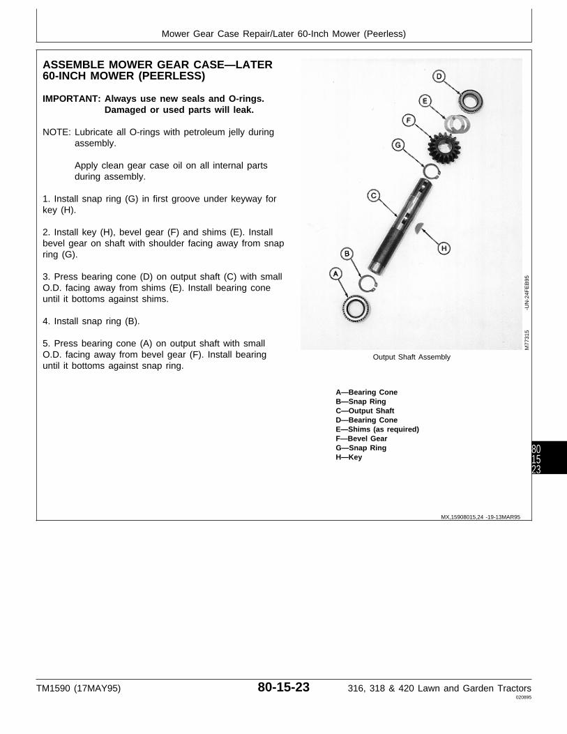
ASSEMBLE MOWER GEAR CASE—LATER60-INCH MOWER (PEERLESS)
IMPORTANT: Always use new seals and O-rings.Damaged or used parts will leak.
NOTE: Lubricate all O-rings with petroleum jelly duringassembly.
Apply clean gear case oil on all internal partsduring assembly.
1. Install snap ring (G) in first groove under keyway forkey (H).
2. Install key (H), bevel gear (F) and shims (E). Installbevel gear on shaft with shoulder facing away from snapring (G).
3. Press bearing cone (D) on output shaft (C) with smallO.D. facing away from shims (E). Install bearing coneuntil it bottoms against shims.
4. Install snap ring (B).
5. Press bearing cone (A) on output shaft with smallO.D. facing away from bevel gear (F). Install bearing Output Shaft Assemblyuntil it bottoms against snap ring.
A—Bearing ConeB—Snap RingC—Output ShaftD—Bearing ConeE—Shims (as required)F—Bevel GearG—Snap RingH—Key
M77
315
-UN
-24F
EB
95
MX,15908015,24 -19-13MAR95
Mower Gear Case Repair/Later 60-Inch Mower (Peerless)
TM1590 (17MAY95) 80-15-23 316, 318 & 420 Lawn and Garden Tractors020895
801523

6. Install new bearing cup (I), if removed, into gear case(J) using a driver set.
7. Press new seal (H) into gear case (J) until top of sealis recessed 2.54 mm (0.100 in.) below gear casesurface.
8. Apply multipurpose grease to lip of seal.
9. Install vent plug (A).
IMPORTANT: A new crush ring must be installedduring assembly. The ring collapseswhen retainer is tightened to gear caseto achieve proper output shaft endplay.
10. Install new crush ring (E) and bearing cup (D).
11. Install shim (C) and new O-ring (F).
IMPORTANT: Tape end of output shaft to preventseal damage during shaft installation.
12. Apply tape around end of output shaft.
13. Install output shaft assembly (K) into gear case (J). Output Shaft SideRemove tape.
14. Install retainer assembly and four cap screws (B). A—Vent PlugTighten cap screws to 30 N·m (22 lb-ft). B—Cap Screw (4 used)
C—Shim (as required)D—Bearing CupE—Crush RingF—O-RingG—RetainerH—SealI—Bearing CupJ—Gear CaseK—Output Shaft Assembly
M77
314
-UN
-24F
EB
95
MX,15908015,25 -19-13MAR95
Mower Gear Case Repair/Later 60-Inch Mower (Peerless)
TM1590 (17MAY95) 80-15-24 316, 318 & 420 Lawn and Garden Tractors020895
801524
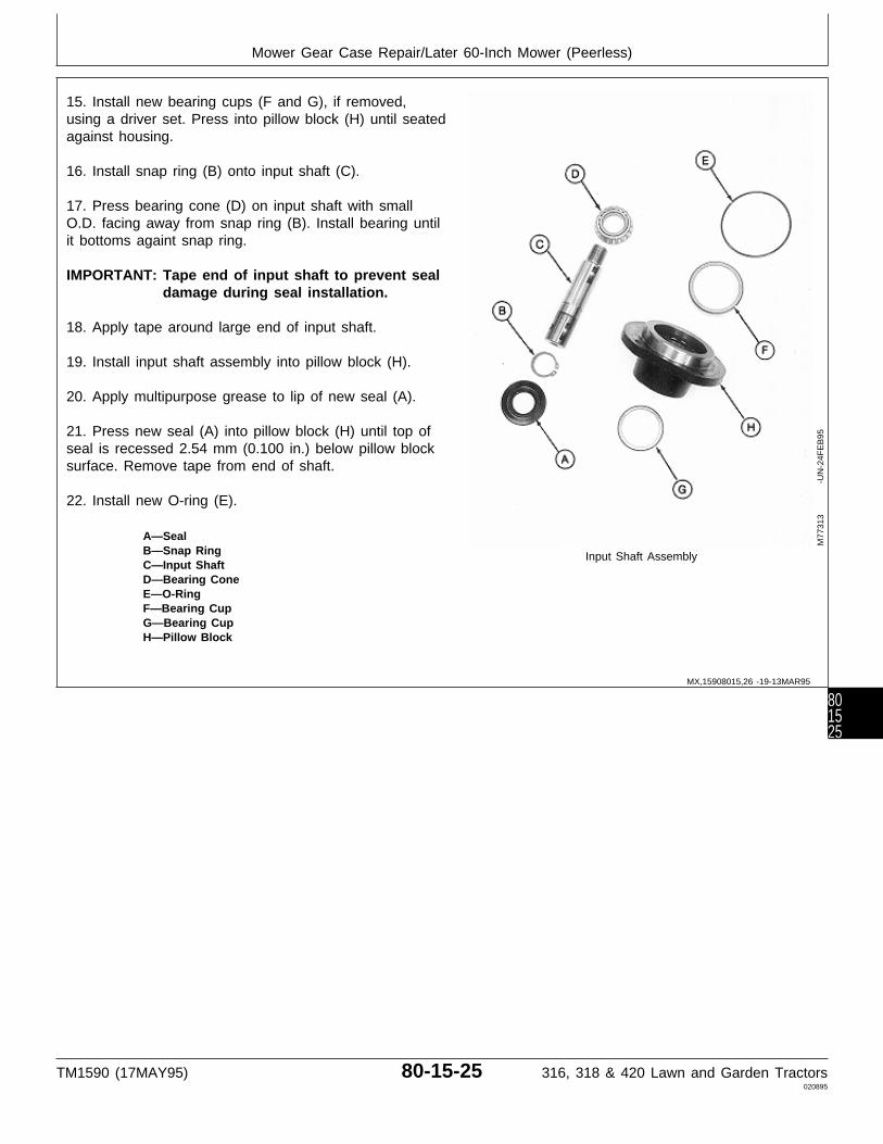
15. Install new bearing cups (F and G), if removed,using a driver set. Press into pillow block (H) until seatedagainst housing.
16. Install snap ring (B) onto input shaft (C).
17. Press bearing cone (D) on input shaft with smallO.D. facing away from snap ring (B). Install bearing untilit bottoms againt snap ring.
IMPORTANT: Tape end of input shaft to prevent sealdamage during seal installation.
18. Apply tape around large end of input shaft.
19. Install input shaft assembly into pillow block (H).
20. Apply multipurpose grease to lip of new seal (A).
21. Press new seal (A) into pillow block (H) until top ofseal is recessed 2.54 mm (0.100 in.) below pillow blocksurface. Remove tape from end of shaft.
22. Install new O-ring (E).
A—SealB—Snap Ring Input Shaft AssemblyC—Input ShaftD—Bearing ConeE—O-RingF—Bearing CupG—Bearing CupH—Pillow Block
M77
313
-UN
-24F
EB
95
MX,15908015,26 -19-13MAR95
Mower Gear Case Repair/Later 60-Inch Mower (Peerless)
TM1590 (17MAY95) 80-15-25 316, 318 & 420 Lawn and Garden Tractors020895
801525
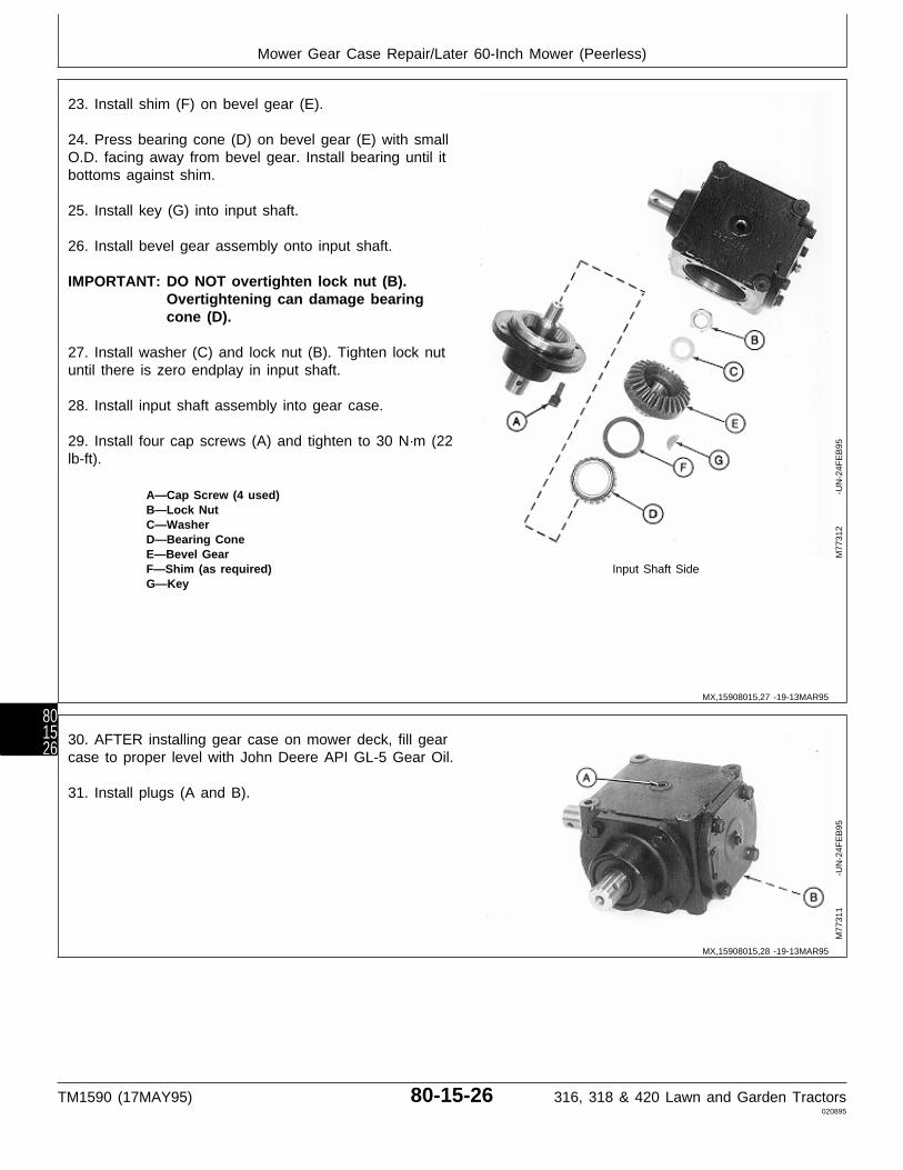
23. Install shim (F) on bevel gear (E).
24. Press bearing cone (D) on bevel gear (E) with smallO.D. facing away from bevel gear. Install bearing until itbottoms against shim.
25. Install key (G) into input shaft.
26. Install bevel gear assembly onto input shaft.
IMPORTANT: DO NOT overtighten lock nut (B).Overtightening can damage bearingcone (D).
27. Install washer (C) and lock nut (B). Tighten lock nutuntil there is zero endplay in input shaft.
28. Install input shaft assembly into gear case.
29. Install four cap screws (A) and tighten to 30 N·m (22lb-ft).
A—Cap Screw (4 used)B—Lock NutC—WasherD—Bearing ConeE—Bevel GearF—Shim (as required) Input Shaft SideG—Key
M77
312
-UN
-24F
EB
95
30. AFTER installing gear case on mower deck, fill gearcase to proper level with John Deere API GL-5 Gear Oil.
31. Install plugs (A and B).
M77
311
-UN
-24F
EB
95
MX,15908015,27 -19-13MAR95
MX,15908015,28 -19-13MAR95
Mower Gear Case Repair/Later 60-Inch Mower (Peerless)
TM1590 (17MAY95) 80-15-26 316, 318 & 420 Lawn and Garden Tractors020895
801526
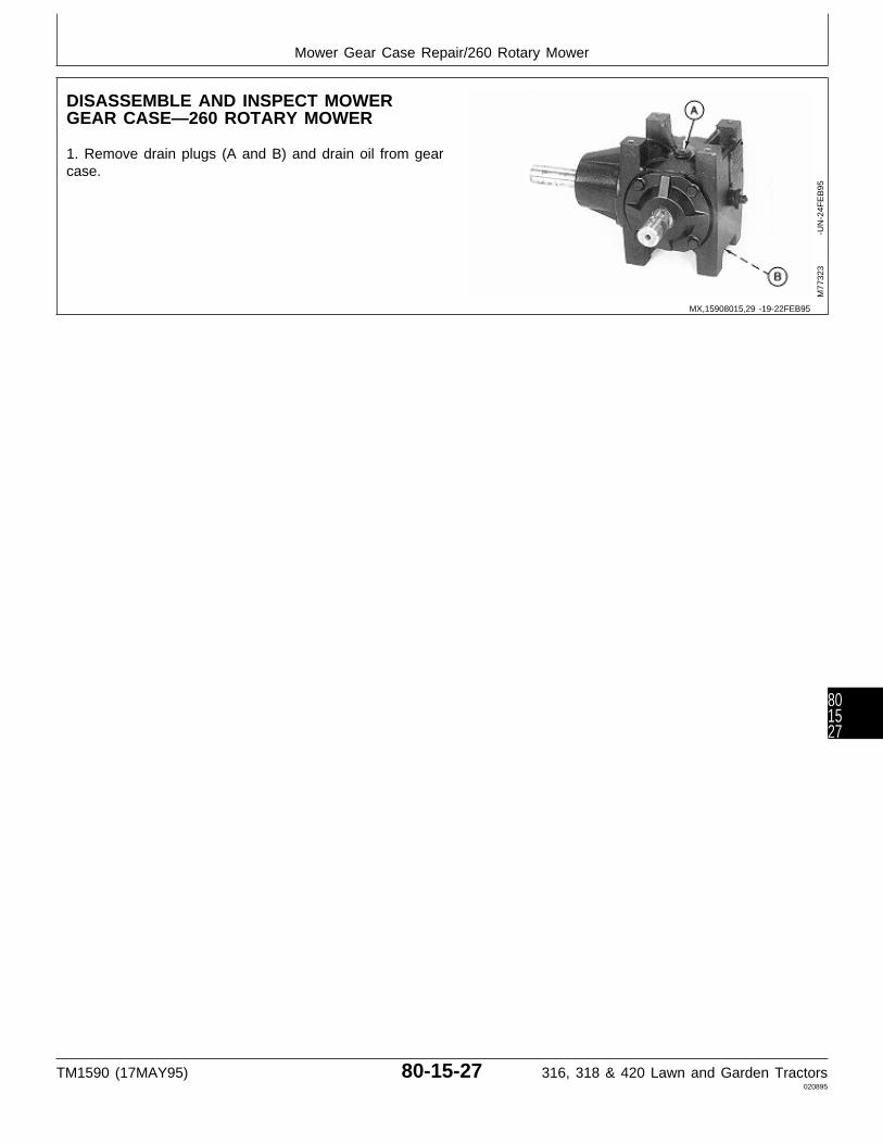
DISASSEMBLE AND INSPECT MOWERGEAR CASE—260 ROTARY MOWER
1. Remove drain plugs (A and B) and drain oil from gearcase.
M77
323
-UN
-24F
EB
95
MX,15908015,29 -19-22FEB95
Mower Gear Case Repair/260 Rotary Mower
TM1590 (17MAY95) 80-15-27 316, 318 & 420 Lawn and Garden Tractors020895
801527
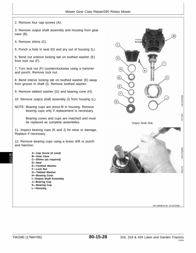
2. Remove four cap screws (A).
3. Remove output shaft assembly and housing from gearcase (B).
4. Remove shims (C).
5. Punch a hole in seal (D) and pry out of housing (L).
6. Bend out exterior locking tab on toothed washer (E)from lock nut (F).
7. Turn lock nut (F) counterclockwise using a hammerand punch. Remove lock nut.
8. Bend interior locking tab on toothed washer (E) awayfrom groove in shaft (I). Remove toothed washer.
9. Remove tabbed washer (G) and bearing cone (H).
10. Remove output shaft assembly (I) from housing (L).
NOTE: Bearing cups are press-fit in housing. Removebearing cups only if replacement is necessary.
Bearing cones and cups are matched and mustbe replaced as complete assemblies. Output Shaft Side
11. Inspect bearing cups (K and J) for wear or damage.Replace if necessary.
12. Remove bearing cups using a brass drift or punchand hammer.
A—Cap Screw (4 used)B—Gear CaseC—Shims (as required)D—SealE—Toothed WasherF—Lock NutG—Tabbed WasherH—Bearing ConeI—Output Shaft AssemblyJ—Bearing CupK—Bearing CupL—Housing
M77
324
-UN
-24F
EB
95M
3217
5
-U
N-2
7FE
B95
MX,15908015,30 -19-22FEB95
Mower Gear Case Repair/260 Rotary Mower
TM1590 (17MAY95) 80-15-28 316, 318 & 420 Lawn and Garden Tractors020895
801528
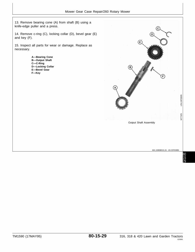
13. Remove bearing cone (A) from shaft (B) using aknife-edge puller and a press.
14. Remove c-ring (C), locking collar (D), bevel gear (E)and key (F).
15. Inspect all parts for wear or damage. Replace asnecessary.
A—Bearing ConeB—Output ShaftC—C-RingD—Locking CollarE—Bevel GearF—Key
Output Shaft Assembly
M77
325
-UN
-24F
EB
95
MX,15908015,31 -19-22FEB95
Mower Gear Case Repair/260 Rotary Mower
TM1590 (17MAY95) 80-15-29 316, 318 & 420 Lawn and Garden Tractors020895
801529

16. Remove four cap screws (A).
17. Remove input shaft assembly (B) from gear case(C).
18. Remove four cap screws (D), end cap (E) and shims(F).
19. Remove vent plug (H) and adapter (I).
NOTE: Bearing cup is press-fit in end cap. Removebearing cup only if replacement is necessary.
Bearing cones and cups are matched and mustbe replaced as complete assemblies.
20. Inspect bearing cup (G) for wear or damage.Replace if necessary.
21. Remove bearing cup (G) using a slide hammer anda three-jaw puller.
A—Cap Screw (4 used)B—Input Shaft AssemblyC—Gear CaseD—Cap Screw (4 used)E—End CapF—Shims (as required) Input Shaft SideG—Bearing CupH—Vent PlugI—Adapter
M77
326
-UN
-24F
EB
95
MX,15908015,32 -19-22FEB95
Mower Gear Case Repair/260 Rotary Mower
TM1590 (17MAY95) 80-15-30 316, 318 & 420 Lawn and Garden Tractors020895
801530
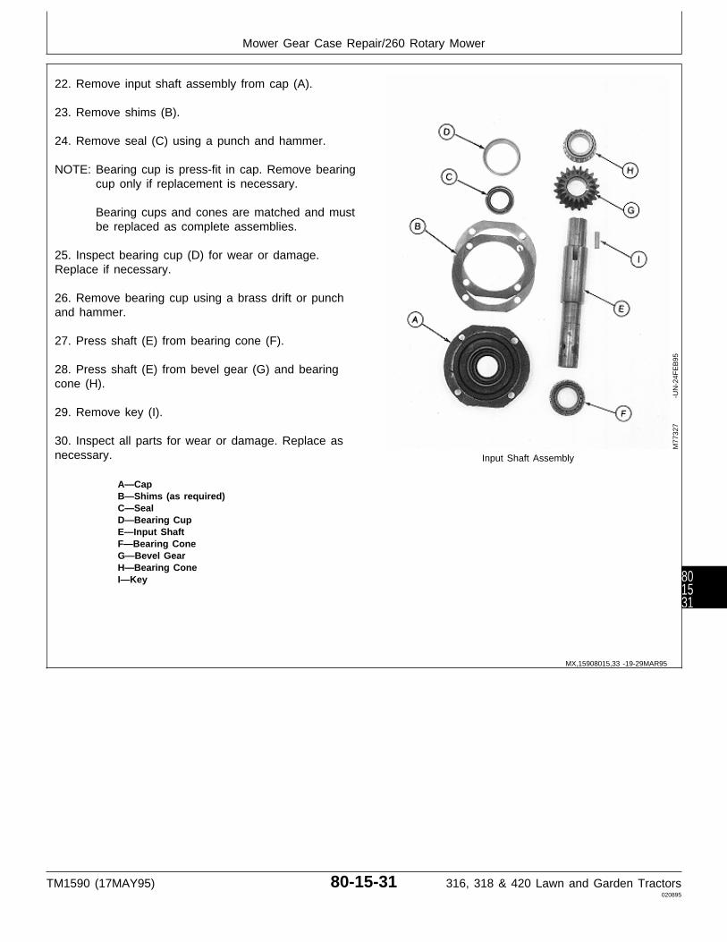
22. Remove input shaft assembly from cap (A).
23. Remove shims (B).
24. Remove seal (C) using a punch and hammer.
NOTE: Bearing cup is press-fit in cap. Remove bearingcup only if replacement is necessary.
Bearing cups and cones are matched and mustbe replaced as complete assemblies.
25. Inspect bearing cup (D) for wear or damage.Replace if necessary.
26. Remove bearing cup using a brass drift or punchand hammer.
27. Press shaft (E) from bearing cone (F).
28. Press shaft (E) from bevel gear (G) and bearingcone (H).
29. Remove key (I).
30. Inspect all parts for wear or damage. Replace asnecessary. Input Shaft Assembly
A—CapB—Shims (as required)C—SealD—Bearing CupE—Input ShaftF—Bearing ConeG—Bevel GearH—Bearing ConeI—Key
M77
327
-UN
-24F
EB
95
MX,15908015,33 -19-29MAR95
Mower Gear Case Repair/260 Rotary Mower
TM1590 (17MAY95) 80-15-31 316, 318 & 420 Lawn and Garden Tractors020895
801531

ASSEMBLE MOWER GEAR CASE—260ROTARY MOWER
IMPORTANT: Always use new seals. Damaged orused seals will leak.
NOTE: Apply clean gear case oil on all internal partsduring assembly.
1. Install key (I) into input shaft (E).
2. Press bevel gear (G), tapered end first, onto shaft (E)until started.
3. Press bearing cone (H) on shaft with small O.D.facing away from bevel gear (G). Install both bearingcone and bevel gear until bearing bottoms against shaft.
4. Press bearing cone (F) onto other end of input shaft(E) with small O.D. facing away from bevel gear.
IMPORTANT: Do not press seal in until seated orbottomed out. Seal will becomedamaged and will leak.
5. Press new seal (C) into cap (A) until top of seal isflush with first recess inside cap. Input Shaft Assembly
6. Apply multipurpose grease to lip of seal.
A—Cap7. Install new bearing cup (D), if removed, using a driver B—Shims (as required)set. C—Seal
D—Bearing CupE—Input ShaftIMPORTANT: Tape end of input shaft to prevent sealF—Bearing Cone
damage during shaft installation. G—Bevel GearH—Bearing Cone
8. Apply tape around end of input shaft. I—Key
9. Assemble input shaft assembly and cap (A). Removetape.
10. Install shims (B) on cap (A).M
7732
7
-U
N-2
4FE
B95
MX,15908015,34 -19-29MAR95
Mower Gear Case Repair/260 Rotary Mower
TM1590 (17MAY95) 80-15-32 316, 318 & 420 Lawn and Garden Tractors020895
801532
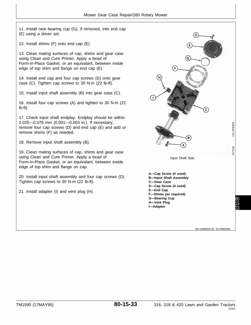
11. Install new bearing cup (G), if removed, into end cap(E) using a driver set.
12. Install shims (F) onto end cap (E).
13. Clean mating surfaces of cap, shims and gear caseusing Clean and Cure Primer. Apply a bead ofForm-In-Place Gasket, or an equivalant, between insideedge of top shim and flange on end cap (E).
14. Install end cap and four cap screws (D) onto gearcase (C). Tighten cap screws to 30 N·m (22 lb-ft).
15. Install input shaft assembly (B) into gear case (C).
16. Install four cap screws (A) and tighten to 30 N·m (22lb-ft).
17. Check input shaft endplay. Endplay should be within0.025—0.076 mm (0.001—0.003 in.). If necessary,remove four cap screws (D) and end cap (E) and add orremove shims (F) as needed.
18. Remove input shaft assembly (B).
19. Clean mating surfaces of cap, shims and gear caseusing Clean and Cure Primer. Apply a bead of Input Shaft SideForm-In-Place Gasket, or an equivalant, between insideedge of top shim and flange on cap.
A—Cap Screw (4 used)20. Install input shaft assembly and four cap screws (D). B—Input Shaft AssemblyTighten cap screws to 30 N·m (22 lb-ft). C—Gear Case
D—Cap Screw (4 used)E—End Cap21. Install adapter (I) and vent plug (H).F—Shims (as required)G—Bearing CupH—Vent PlugI—Adapter
M77
326
-UN
-24F
EB
95
MX,15908015,35 -19-29MAR95
Mower Gear Case Repair/260 Rotary Mower
TM1590 (17MAY95) 80-15-33 316, 318 & 420 Lawn and Garden Tractors020895
801533

22. Install key (F) and bevel gear (E) on shaft (B). Installbevel gear with shoulder end toward threaded end ofshaft.
23. Install locking collar (D) with groove facing awayfrom bevel gear. Install c-ring (C).
24. Press bearing cone (A) on shaft with small O.D.facing away from bevel gear (E). Install bearing until itbottoms locking collar (D) against c-ring (C).
A—Bearing ConeB—Output ShaftC—C-RingD—Locking CollarE—Bevel GearF—Key
Output Shaft Assembly
M77
325
-UN
-24F
EB
95
MX,15908015,36 -19-13MAR95
Mower Gear Case Repair/260 Rotary Mower
TM1590 (17MAY95) 80-15-34 316, 318 & 420 Lawn and Garden Tractors020895
801534

25. Install new bearing cups (K and J), if removed, intohousing (L) using a driver set.
26. Install output shaft assembly (I) into housing (L).
27. Slide bearing cone (H) on shaft with small O.D.facing toward housing (L).
28. Install tabbed washer (G) and toothed washer (E).Press internal tab on toothed washer (E) into slot onshaft using a screwdriver.
29. Install lock nut (F). Tighten lock nut, using a punchand hammer, until there is zero endplay in output shaft.Bend up one tab from toothed washer (E), that is inalignment with a slot in lock nut (F), to secure nut inplace.
IMPORTANT: Tape end of output shaft to preventseal damage during shaft installation.
30. Apply tape around end of output shaft.
31. Apply multipurpose grease to lip of seal.
32. Press new seal (D) into housing (L) until seal is flushwith top of housing. Remove tape. Output Shaft Side
33. Install shims (C) on housing (L).
A—Cap Screw (4 used)34. Install output shaft assembly and housing into gear B—Gear Casecase (B). C—Shims (as required)
D—SealE—Toothed Washer35. Install four cap screws (A) and tighten to 30 N·m (22F—Lock Nut
lb-ft). G—Tabbed WasherH—Bearing Cone
36. Hold input shaft securely and check output shaft I—Output Shaft AssemblyJ—Bearing Cupbacklash. Backlash should be within 0.076—0.130 mmK—Bearing Cup(0.003—0.005 in.). If necessary, remove four cap screwsL—Housing
(A) and housing and output shaft assembly and add orremove shims (C) as needed.
37. Again, remove four cap screws (A) and housing andoutput shaft assembly.
38. Clean mating surfaces of housing, shims and gearcase using Clean and Cure Primer. Apply a bead ofForm-In-Place Gasket, or an equivalant, between insideedge of top shim and flange on housing (L).
39. Install housing and output shaft assembly into gearcase. Install four cap screws (A) and tighten to 30 N·m(22 lb-ft).
M77
324
-UN
-24F
EB
95
MX,15908015,37 -19-13MAR95
Mower Gear Case Repair/260 Rotary Mower
TM1590 (17MAY95) 80-15-35 316, 318 & 420 Lawn and Garden Tractors020895
801535

40. AFTER installing gear case on mower deck, fill gearcase to proper level with John Deere API GL-5 Gear Oil.
41. Install plugs (A and B).
M77
323
-UN
-24F
EB
95
MX,15908015,38 -19-13MAR95
Mower Gear Case Repair/260 Rotary Mower
TM1590 (17MAY95) 80-15-36 316, 318 & 420 Lawn and Garden Tractors020895
801536
Section 220ENGINE, FUEL AND AIR SYSTEM
CHECKOUT AND DIAGNOSISContents
Page
Group 05—Engine, Fuel and Air SystemCheckout
Before You Start . . . . . . . . . . . . . . . . . 220-05-1Engine Oil and Leak Check . . . . . . . . . . 220-05-1Fuel Leak Check . . . . . . . . . . . . . . . . . 220-05-1Throttle Lever Check . . . . . . . . . . . . . . 220-05-1Engine Start Check . . . . . . . . . . . . . . . 220-05-2Choke Lever Check . . . . . . . . . . . . . . . 220-05-2Engine Oil Pressure Check . . . . . . . . . . 220-05-2Engine Performance Check . . . . . . . . . . 220-05-2Operator Complaint Not Identified . . . . . . 220-05-3
Group 10—Diagnosis, Tests and AdjustmentsAbout This Group . . . . . . . . . . . . . . . . 220-10-1Troubleshooting Guide . . . . . . . . . . . . . 220-10-1Ignition Spark Test . . . . . . . . . . . . . . . . 220-10-6Throttle Cable Adjustment . . . . . . . . . . . 220-10-6Choke Cable Adjustment . . . . . . . . . . . . 220-10-7Idle Mixture and Speed Adjustment . . . . . 220-10-7Governor Linkage Adjustment . . . . . . . . . 220-10-9Dashpot Adjustment (B43E, B43G and
B48G) . . . . . . . . . . . . . . . . . . . . . . . 220-10-9Fuel Filter Test . . . . . . . . . . . . . . . . . 220-10-10Fuel Transfer Pump Test . . . . . . . . . . . 220-10-10Crankcase Vacuum Test . . . . . . . . . . . 220-10-11Timing Adjustment (B43E, B43G and
B48G) . . . . . . . . . . . . . . . . . . . . . . 220-10-11Compression Pressure Test . . . . . . . . . 220-10-12Engine Oil Pressure Test . . . . . . . . . . 220-10-12Oil Pressure Regulating Valve Check . . 220-10-13Throttle Lever Adjustment . . . . . . . . . . 220-10-13
TM1590 (17MAY95) 220-1 316, 318 & 420 Lawn and Garden Tractors020895
220

Contents
TM1590 (17MAY95) 220-2 316, 318 & 420 Lawn and Garden Tractors020895
220
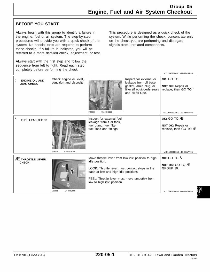
BEFORE YOU START
Always begin with this group to identify a failure inthe engine, fuel or air system. The step-by-stepprocedures will provide you with a quick check of thesystem. No special tools are required to performthese checks. If a failure is indicated, you will bereferred to a more detailed check, adjustment, or test.
Always start with the first step and follow thesequence from left to right. Read each stepcompletely before performing the check.
This procedure is designed as a quick check of thesystem. While performing the check, concentrate onlyon the check you are performing and disregardsignals from unrelated components.
; ENGINE OIL ANDLEAK CHECK
Check engine oil level,condition and viscosity.
M49220 -UN-20DEC89
Inspect for external oilleakage from oil basegasket, drain plug, oilfilter (if equipped), sealsand oil fill tube.
OK: GO TO ‘
NOT OK: Repair orreplace, then GO TO ‘
‘ FUEL LEAK CHECK
M49219 -UN-20DEC89
Inspect for external fuelleakage from fuel tank,fuel pump, fuel filter,fuel lines and fittings.
OK: GO TO Æ
NOT OK: Repair orreplace, then GO TO Æ
Æ THROTTLE LEVERCHECK
M55061 -UN-09DEC89
Move throttle lever from low idle position to highidle position.
LOOK: Throttle lever must contact stops in thedash at low and high idle positions.
FEEL: Throttle lever must move smoothly fromlow to high idle position.
OK: GO TO Å
NOT OK: GO TO Æ,GROUP 10.
MX,159022005,1 -19-27APR95
MX,159022005,2 -19-05MAY95
MX,159022005,3 -19-27APR95
MX,159022005,4 -19-27APR95
Group 05Engine, Fuel and Air System Checkout
TM1590 (17MAY95) 220-05-1 316, 318 & 420 Lawn and Garden Tractors020895
220051

Å ENGINE STARTCHECK
Operator on seat.
Put hydrostatic controllever in N/STOPposition.
Put PTO lever in OFFposition.
Pull choke knob all theway out.
Depress brake pedal(s).
M55029 -UN-09DEC89
Turn key switch toSTART position.
Starter must crankengine. Engine muststart.
OK: GO TO Ö
NOT OK: GO TO ;,GROUP 10.
Ö CHOKE LEVERCHECK
M55031 -UN-09DEC89
Run engine at half throttle.
Quickly pull choke knob all the way out, thenpush in.
LISTEN: Engine must falter, then resume speed.
OK: GO TO Ò
NOT OK: GO TO Å,GROUP 10.
Ò ENGINE OILPRESSURE CHECK
M55030 -UN-09DEC89
Run engine at full throttle.
LOOK: Oil pressure lamp must go OFF.
Remove air cleaner cover.
LOOK: Air filter must not be oil soaked.
OK: GO TO Õ
OIL PRESSURE LAMPSTAYS ON: Test oilpressure sender inSection 240. If senderis OK and lamp is stillon, then GO TO 1#,GROUP 10.
Õ ENGINEPERFORMANCECHECK
N CAUTION: Engine exhaust fumes cancause sickness or death. If running an enginein an enclosed area, remove the exhaustfumes from the area with an exhaust pipeextension.
If you do not have an exhaust pipe extension,open the doors and get outside air into the area.
MX,159022005,5 -19-16MAY95
MX,159022005,6 -19-05MAY95
MX,159022005,7 -19-27APR95
MX,159022005,8 -19-05MAY95
Engine, Fuel and Air System Checkout/Engine Performance Check
TM1590 (17MAY95) 220-05-2 316, 318 & 420 Lawn and Garden Tractors020895
22005
2
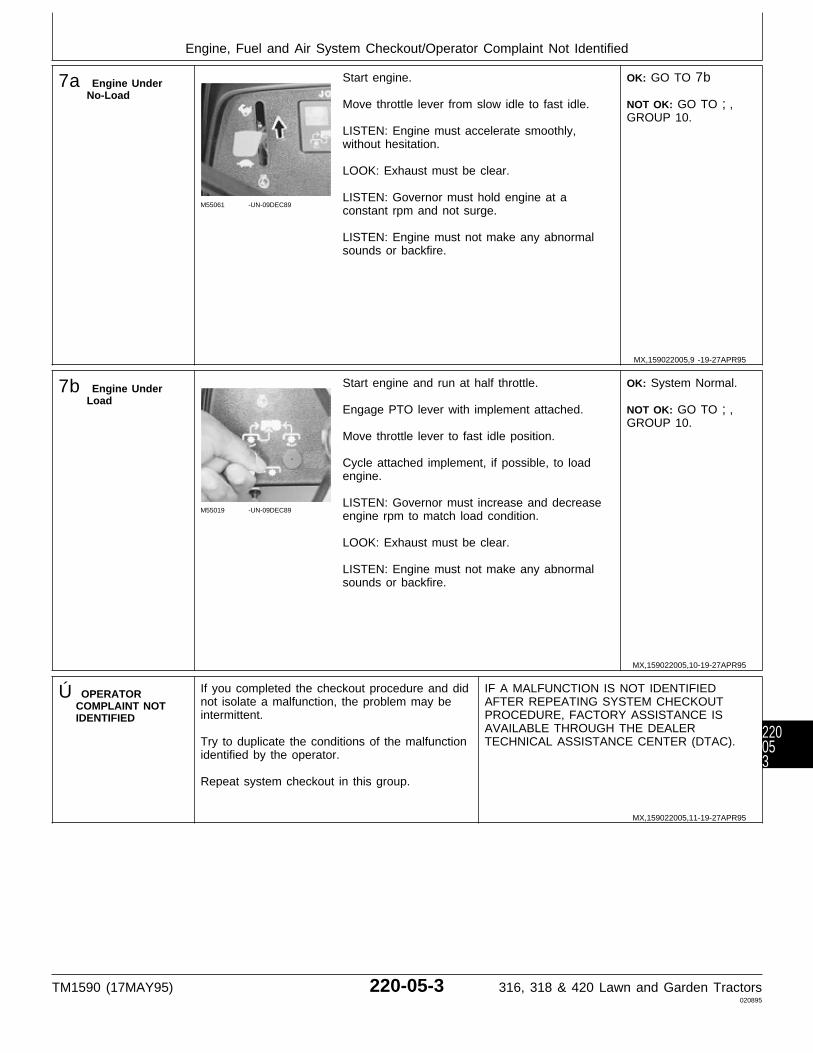
7a Engine UnderNo-Load
M55061 -UN-09DEC89
Start engine.
Move throttle lever from slow idle to fast idle.
LISTEN: Engine must accelerate smoothly,without hesitation.
LOOK: Exhaust must be clear.
LISTEN: Governor must hold engine at aconstant rpm and not surge.
LISTEN: Engine must not make any abnormalsounds or backfire.
OK: GO TO 7b
NOT OK: GO TO ;,GROUP 10.
7b Engine UnderLoad
M55019 -UN-09DEC89
Start engine and run at half throttle.
Engage PTO lever with implement attached.
Move throttle lever to fast idle position.
Cycle attached implement, if possible, to loadengine.
LISTEN: Governor must increase and decreaseengine rpm to match load condition.
LOOK: Exhaust must be clear.
LISTEN: Engine must not make any abnormalsounds or backfire.
OK: System Normal.
NOT OK: GO TO ;,GROUP 10.
Ú OPERATORCOMPLAINT NOTIDENTIFIED
If you completed the checkout procedure and didnot isolate a malfunction, the problem may beintermittent.
Try to duplicate the conditions of the malfunctionidentified by the operator.
Repeat system checkout in this group.
IF A MALFUNCTION IS NOT IDENTIFIEDAFTER REPEATING SYSTEM CHECKOUTPROCEDURE, FACTORY ASSISTANCE ISAVAILABLE THROUGH THE DEALERTECHNICAL ASSISTANCE CENTER (DTAC).
MX,159022005,9 -19-27APR95
MX,159022005,10-19-27APR95
MX,159022005,11-19-27APR95
Engine, Fuel and Air System Checkout/Operator Complaint Not Identified
TM1590 (17MAY95) 220-05-3 316, 318 & 420 Lawn and Garden Tractors020895
220053

Engine, Fuel and Air System Checkout/Operator Complaint Not Identified
TM1590 (17MAY95) 220-05-4 316, 318 & 420 Lawn and Garden Tractors020895
22005
4
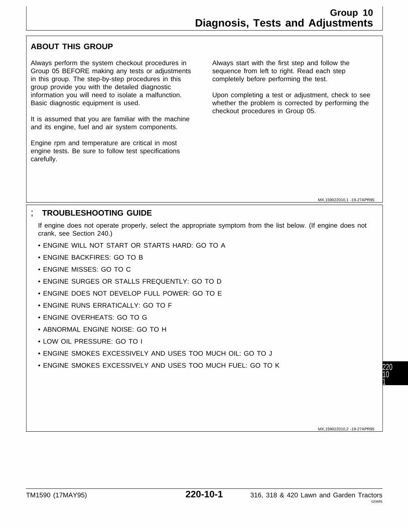
ABOUT THIS GROUP
Always perform the system checkout procedures inGroup 05 BEFORE making any tests or adjustmentsin this group. The step-by-step procedures in thisgroup provide you with the detailed diagnosticinformation you will need to isolate a malfunction.Basic diagnostic equipment is used.
It is assumed that you are familiar with the machineand its engine, fuel and air system components.
Engine rpm and temperature are critical in mostengine tests. Be sure to follow test specificationscarefully.
Always start with the first step and follow thesequence from left to right. Read each stepcompletely before performing the test.
Upon completing a test or adjustment, check to seewhether the problem is corrected by performing thecheckout procedures in Group 05.
; TROUBLESHOOTING GUIDE
If engine does not operate properly, select the appropriate symptom from the list below. (If engine does notcrank, see Section 240.)
• ENGINE WILL NOT START OR STARTS HARD: GO TO A
• ENGINE BACKFIRES: GO TO B
• ENGINE MISSES: GO TO C
• ENGINE SURGES OR STALLS FREQUENTLY: GO TO D
• ENGINE DOES NOT DEVELOP FULL POWER: GO TO E
• ENGINE RUNS ERRATICALLY: GO TO F
• ENGINE OVERHEATS: GO TO G
• ABNORMAL ENGINE NOISE: GO TO H
• LOW OIL PRESSURE: GO TO I
• ENGINE SMOKES EXCESSIVELY AND USES TOO MUCH OIL: GO TO J
• ENGINE SMOKES EXCESSIVELY AND USES TOO MUCH FUEL: GO TO K
MX,159022010,1 -19-27APR95
MX,159022010,2 -19-27APR95
Group 10Diagnosis, Tests and Adjustments
TM1590 (17MAY95) 220-10-1 316, 318 & 420 Lawn and Garden Tractors020895
220101
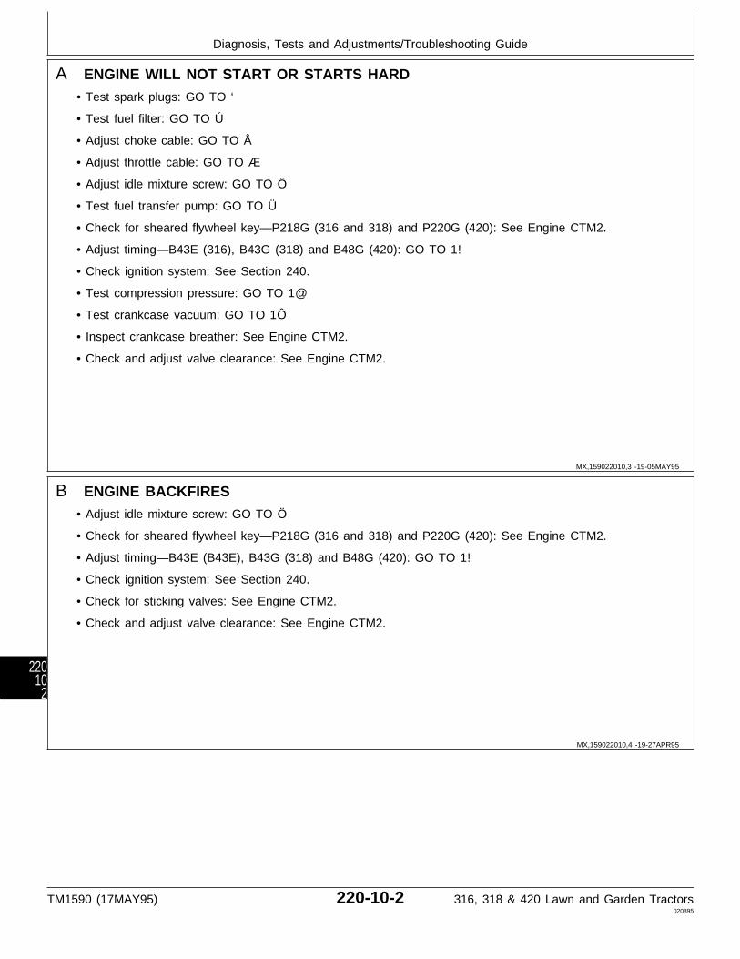
A ENGINE WILL NOT START OR STARTS HARD
• Test spark plugs: GO TO ‘
• Test fuel filter: GO TO Ú
• Adjust choke cable: GO TO Å
• Adjust throttle cable: GO TO Æ
• Adjust idle mixture screw: GO TO Ö
• Test fuel transfer pump: GO TO Ü
• Check for sheared flywheel key—P218G (316 and 318) and P220G (420): See Engine CTM2.
• Adjust timing—B43E (316), B43G (318) and B48G (420): GO TO 1!
• Check ignition system: See Section 240.
• Test compression pressure: GO TO 1@
• Test crankcase vacuum: GO TO 1Ô
• Inspect crankcase breather: See Engine CTM2.
• Check and adjust valve clearance: See Engine CTM2.
B ENGINE BACKFIRES
• Adjust idle mixture screw: GO TO Ö
• Check for sheared flywheel key—P218G (316 and 318) and P220G (420): See Engine CTM2.
• Adjust timing—B43E (B43E), B43G (318) and B48G (420): GO TO 1!
• Check ignition system: See Section 240.
• Check for sticking valves: See Engine CTM2.
• Check and adjust valve clearance: See Engine CTM2.
MX,159022010,3 -19-05MAY95
MX,159022010,4 -19-27APR95
Diagnosis, Tests and Adjustments/Troubleshooting Guide
TM1590 (17MAY95) 220-10-2 316, 318 & 420 Lawn and Garden Tractors020895
22010
2
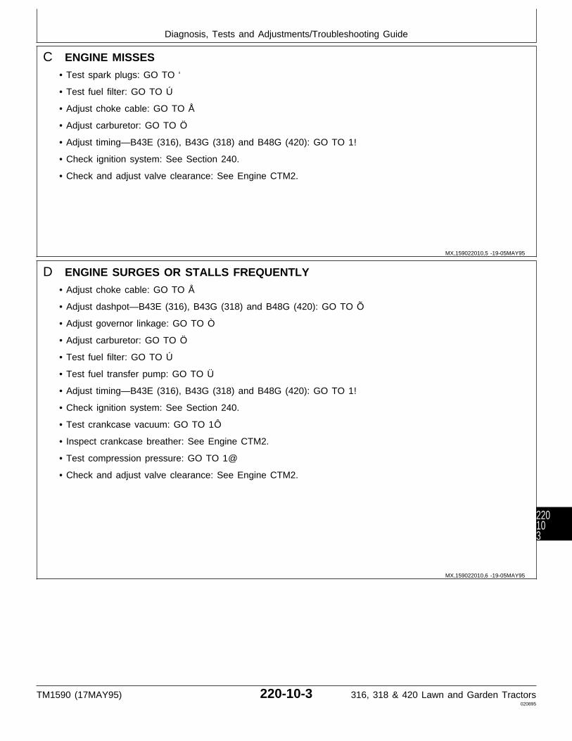
C ENGINE MISSES
• Test spark plugs: GO TO ‘
• Test fuel filter: GO TO Ú
• Adjust choke cable: GO TO Å
• Adjust carburetor: GO TO Ö
• Adjust timing—B43E (316), B43G (318) and B48G (420): GO TO 1!
• Check ignition system: See Section 240.
• Check and adjust valve clearance: See Engine CTM2.
D ENGINE SURGES OR STALLS FREQUENTLY
• Adjust choke cable: GO TO Å
• Adjust dashpot—B43E (316), B43G (318) and B48G (420): GO TO Õ
• Adjust governor linkage: GO TO Ò
• Adjust carburetor: GO TO Ö
• Test fuel filter: GO TO Ú
• Test fuel transfer pump: GO TO Ü
• Adjust timing—B43E (316), B43G (318) and B48G (420): GO TO 1!
• Check ignition system: See Section 240.
• Test crankcase vacuum: GO TO 1Ô
• Inspect crankcase breather: See Engine CTM2.
• Test compression pressure: GO TO 1@
• Check and adjust valve clearance: See Engine CTM2.
MX,159022010,5 -19-05MAY95
MX,159022010,6 -19-05MAY95
Diagnosis, Tests and Adjustments/Troubleshooting Guide
TM1590 (17MAY95) 220-10-3 316, 318 & 420 Lawn and Garden Tractors020895
220103
E ENGINE DOES NOT DEVELOP FULL POWER
• Adjust throttle cable: GO TO Æ
• Adjust choke cable: GO TO Å
• Adjust governor linkage: GO TO Ò
• Adjust carburetor: GO TO Ö
• Test spark plugs: GO TO ‘
• Check muffler for restriction or plugged condition.
• Test fuel filter: GO TO Ú
• Test fuel transfer pump: GO TO Ü
• Adjust timing—B43E (316), B43G (318) and B48G (420): GO TO 1!
• Check ignition system: See Section 240.
• Test compression pressure: GO TO 1@
• Test crankcase vacuum: GO TO 1Ô
• Inspect crankcase breather: See Engine CTM2.
• Check and adjust valve clearance: See Engine CTM2.
F ENGINE RUNS ERRATICALLY
• Check for loose electrical connections: See Section 240.
• Test spark plugs: GO TO ‘
• Adjust carburetor: GO TO Ö
• Adjust dashpot—B43E (316), B43G (318) and B48G (420): GO TO Õ
• Adjust governor linkage: GO TO Ò
• Adjust timing—B43E (316), B43G (318) and B48G (420): GO TO 1!
• Test fuel filter: GO TO Ú
• Test fuel transfer pump: GO TO Ü
• Check ignition system: See Section 240.
• Test crankcase vacuum: GO TO 1Ô
• Inspect crankcase breather: See engine CTM2.
• Check and adjust valve clearance: See Engine CTM2.
• Check carburetor for plugged passages: See Engine CTM2.
MX,159022010,7 -19-05MAY95
MX,159022010,8 -19-08MAY95
Diagnosis, Tests and Adjustments/Troubleshooting Guide
TM1590 (17MAY95) 220-10-4 316, 318 & 420 Lawn and Garden Tractors020895
22010
4

G ENGINE OVERHEATS
• Check muffler for restriction or plugged condition.
• Adjust carburetor: GO TO Ö
• Adjust governor linkage: TO TO Ò
• Check engine oil pressure: GO TO 1#
• Check oil pump suction screen for plugged condition: See Engine CTM2.
• Check oil pump for wear or damage: See Engine CTM2.
• Check oil passages: See Engine CTM2.
• Check internal bearing clearance: See Engine CTM2.
• Check for carbon build-up in combustion chamber: See Engine CTM2.
H ABNORMAL ENGINE NOISE
• Check for loose flywheel: See Engine CTM2.
• Check and adjust valve clearance: See Engine CTM2.
• Check for carbon build-up in combustion chamber: See Engine CTM2.
• Inspect engine for worn cylinder walls, loose or worn connecting rods, excessive main bearing endplay,and excessive crankshaft or camshaft endplay: See Engine CTM2.
I LOW OIL PRESSURE
• Test oil indicator light and sender: See Section 240.
• Check engine oil pressure: GO TO 1#
• Check oil pump suction screen for plugged condition: See Engine CTM2.
• Check oil pump for wear of damage: See Engine CTM2.
• Check oil passages: See Engine CTM2.
• Check for excessive main bearing clearance and connecting rod bearing clearance: See Engine CTM2.
MX,159022010,9 -19-03MAY95
MX,159022010,10-19-27APR95
MX,159022010,11-19-03MAY95
Diagnosis, Tests and Adjustments/Troubleshooting Guide
TM1590 (17MAY95) 220-10-5 316, 318 & 420 Lawn and Garden Tractors020895
220105

J ENGINE SMOKES EXCESSIVELY AND USES TOO MUCH OIL
• Test crankcase vacuum: GO TO 1Ô
• Inspect crankcase breather: See Engine CTM2.
• Test compression pressure: GO TO 1@
• Check valve stem seals (if equipped): See Engine CTM2.
• Check for correct engine oil dipstick being used.
• Check for proper installation of oil passage plug: See Engine CTM2.
K ENGINE SMOKES EXCESSIVELY AND USES TOO MUCH FUEL
• Adjust choke cable: GO TO Å
• Adjust carburetor: GO TO Ö
• Check carburetor float adjustment: See Engine CTM2.
‘ IGNITION SPARKTEST
M37088 -UN-29AUG88
Connect spark plug wire to JDM-74-5 IgnitionTest Plug or D-05351ST Spark Tester.
Crank engine and watch for spark.
LOOK: Ignition Test Plug or Tester must spark.
SPARK “BLUE” HOT:OK, Continue with test.
NO SPARK OR“YELLOW” WEAKSPARK: GO TOSECTION 240.
M37430 -UN-25JAN90
Remove spark plug.
Inspect spark plug for wet or fouled condition ordamage.
Check spark plug gap. Spark plug gap should be0.64 mm (0.025 in.)
Repeat spark test with original plug.
NO SPARK: Replaceplug.
Æ THROTTLE CABLEADJUSTMENT
M55061 -UN-09DEC89
Move throttle lever tofast idle position.
M37408 -UN-25JAN90
Loosen clamp.
Hold throttle controllever against fast idlestop (A). Tighten clamp.
MX,159022010,12-19-05MAY95
MX,159022010,13-19-05MAY95
MX,159022010,14-19-05MAY95
MX,159022010,15-19-03MAY95
Diagnosis, Tests and Adjustments/Throttle Cable Adjustment
TM1590 (17MAY95) 220-10-6 316, 318 & 420 Lawn and Garden Tractors020895
22010
6

Å CHOKE CABLEADJUSTMENT
Remove air filter.
4a Early Models Pull choke knob outand then push knob in.
LOOK: Choke platemust be completelyclosed, then completelyopen.
M37084 -UN-28APR95
If necessary, loosen screw (A) and push chokeknob all the way in.
Pull on choke lever to completely open chokeplate. Tighten screw (A).
Check for completely open and completelyclosed positions.
4b Later Models Pull choke knob outand then push knob in.
LOOK: Choke platemust be completelyclosed, then completelyopen.
M77308 -UN-28APR95
If necessary, loosen screw (B) and push chokeknob all the way in.
Push choke cable to completely open chokeplate. Tighten screw (B).
Check for completely open and completelyclosed positions.
Ö IDLE MIXTURE AND SPEED ADJUSTMENT
IMPORTANT: Forcing the idle mixture screwtight will damage the needle and seat.
NOTE: On later P218G (316 and 318) andP220G (420) engines; A “limiter cap” is installedover the idle mixture screw. The screw shouldonly need to be adjusted within these limits. Ifscrew is being replaced, pry off “cap” andremove screw. Turn the new idle mixture screwclockwise until lightly seated, thencounterclockwise 1-1/4 turns. Install “cap” withtab up and centered between stops oncarburetor.
M37083 -UN-29AUG88
Turn idle mixture screwclockwise until lightlyseated, thencounterclockwise 1-1/4turns.
Start and run engine tobring it to NORMALOPERATINGTEMPERATURE. Movethrottle lever to slowidle position.
Continued on next page
MX,159022010,16-19-03MAY95
MX,159022010,17-19-08MAY95
MX,159022010,18-19-08MAY95
Diagnosis, Tests and Adjustments/Idle Mixture and Speed Adjustment
TM1590 (17MAY95) 220-10-7 316, 318 & 420 Lawn and Garden Tractors020895
220107
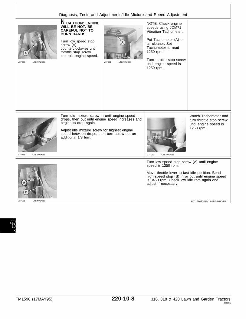
M37098 -UN-29AUG88
N CAUTION: ENGINEWILL BE HOT. BECAREFUL NOT TOBURN HANDS.
Turn low speed stopscrew (A)counterclockwise untilthrottle stop screwcontrols engine speed.
M37099 -UN-29AUG88
NOTE: Check enginespeeds using JDM71Vibration Tachometer.
Put Tachometer (A) onair cleaner. SetTachometer to read1250 rpm.
Turn throttle stop screwuntil engine speed is1250 rpm.
M37083 -UN-29AUG88
Turn idle mixture screw in until engine speeddrops, then out until engine speed increases andbegins to drop again.
Adjust idle mixture screw for highest enginespeed between drops, then turn screw out anadditional 1/8 turn.
M37100 -UN-29AUG88
Watch Tachometer andturn throttle stop screwuntil engine speed is1250 rpm.
M37101 -UN-29AUG88
Turn low speed stop screw (A) until enginespeed is 1350 rpm.
Move throttle lever to fast idle position. Bendhigh speed stop (B) in or out until engine speedis 3450 rpm. Check low idle rpm again andadjust if necessary.
MX,159022010,19-19-03MAY95
Diagnosis, Tests and Adjustments/Idle Mixture and Speed Adjustment
TM1590 (17MAY95) 220-10-8 316, 318 & 420 Lawn and Garden Tractors020895
22010
8
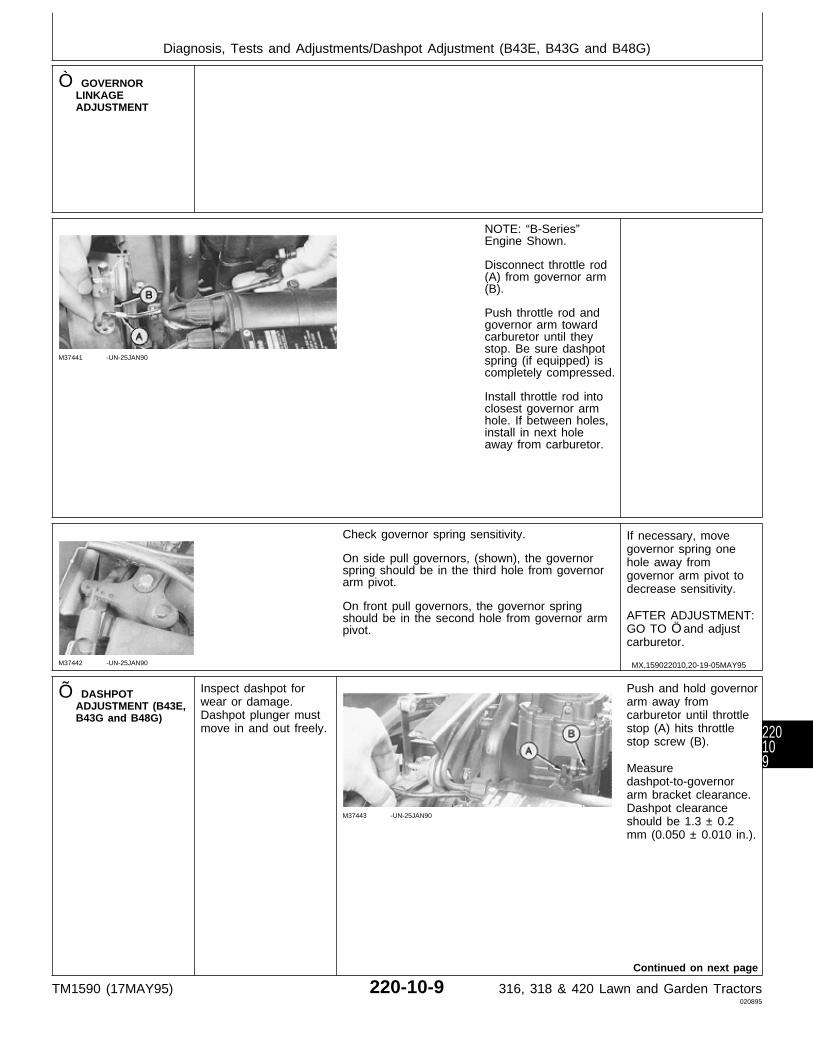
Ò GOVERNORLINKAGEADJUSTMENT
M37441 -UN-25JAN90
NOTE: “B-Series”Engine Shown.
Disconnect throttle rod(A) from governor arm(B).
Push throttle rod andgovernor arm towardcarburetor until theystop. Be sure dashpotspring (if equipped) iscompletely compressed.
Install throttle rod intoclosest governor armhole. If between holes,install in next holeaway from carburetor.
M37442 -UN-25JAN90
Check governor spring sensitivity.
On side pull governors, (shown), the governorspring should be in the third hole from governorarm pivot.
On front pull governors, the governor springshould be in the second hole from governor armpivot.
If necessary, movegovernor spring onehole away fromgovernor arm pivot todecrease sensitivity.
AFTER ADJUSTMENT:GO TO Ö and adjustcarburetor.
Õ DASHPOTADJUSTMENT (B43E,B43G and B48G)
Inspect dashpot forwear or damage.Dashpot plunger mustmove in and out freely.
M37443 -UN-25JAN90
Push and hold governorarm away fromcarburetor until throttlestop (A) hits throttlestop screw (B).
Measuredashpot-to-governorarm bracket clearance.Dashpot clearanceshould be 1.3 ± 0.2mm (0.050 ± 0.010 in.).
Continued on next page
MX,159022010,20-19-05MAY95
Diagnosis, Tests and Adjustments/Dashpot Adjustment (B43E, B43G and B48G)
TM1590 (17MAY95) 220-10-9 316, 318 & 420 Lawn and Garden Tractors020895
220109
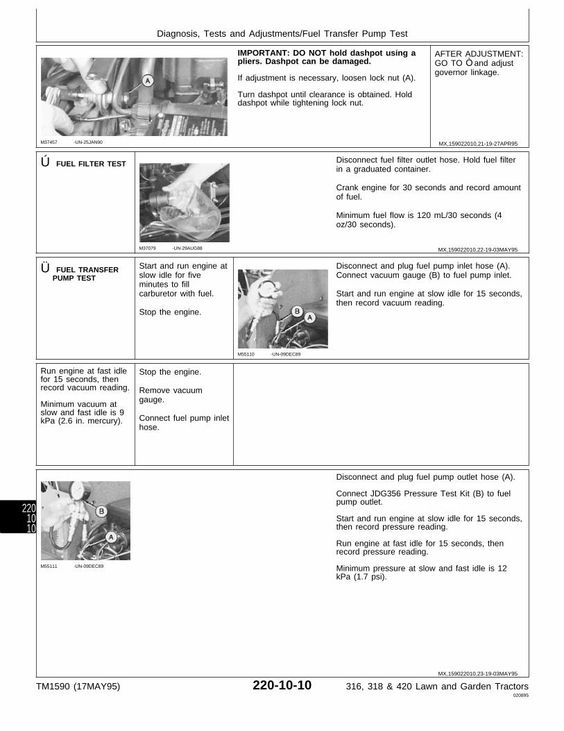
M37457 -UN-25JAN90
IMPORTANT: DO NOT hold dashpot using apliers. Dashpot can be damaged.
If adjustment is necessary, loosen lock nut (A).
Turn dashpot until clearance is obtained. Holddashpot while tightening lock nut.
AFTER ADJUSTMENT:GO TO Ò and adjustgovernor linkage.
Ú FUEL FILTER TEST
M37079 -UN-29AUG88
Disconnect fuel filter outlet hose. Hold fuel filterin a graduated container.
Crank engine for 30 seconds and record amountof fuel.
Minimum fuel flow is 120 mL/30 seconds (4oz/30 seconds).
Ü FUEL TRANSFERPUMP TEST
Start and run engine atslow idle for fiveminutes to fillcarburetor with fuel.
Stop the engine.
M55110 -UN-09DEC89
Disconnect and plug fuel pump inlet hose (A).Connect vacuum gauge (B) to fuel pump inlet.
Start and run engine at slow idle for 15 seconds,then record vacuum reading.
Run engine at fast idlefor 15 seconds, thenrecord vacuum reading.
Minimum vacuum atslow and fast idle is 9kPa (2.6 in. mercury).
Stop the engine.
Remove vacuumgauge.
Connect fuel pump inlethose.
M55111 -UN-09DEC89
Disconnect and plug fuel pump outlet hose (A).
Connect JDG356 Pressure Test Kit (B) to fuelpump outlet.
Start and run engine at slow idle for 15 seconds,then record pressure reading.
Run engine at fast idle for 15 seconds, thenrecord pressure reading.
Minimum pressure at slow and fast idle is 12kPa (1.7 psi).
MX,159022010,21-19-27APR95
MX,159022010,22-19-03MAY95
MX,159022010,23-19-03MAY95
Diagnosis, Tests and Adjustments/Fuel Transfer Pump Test
TM1590 (17MAY95) 220-10-10 316, 318 & 420 Lawn and Garden Tractors020895
2201010

1Ô CRANKCASEVACUUM TEST
Remove dipstick.
Put plug (A) in dipstick hole.
IMPORTANT: Do not hook up restof Test Kit until engine is runningor fluid in Manometer will besucked into crankcase duringcranking mode.
Start engine and run at fast idle.
Make test connections from JT05697 U-TubeManometer Kit.
Record crankcase vacuum reading.
SPECIFICATIONS
Minimum Crankcase Vacuum:B43E (Early 316),B43G (Early 318) andB48G (Early 420) . . . . . . . . . . . 25 cm (10 in.) waterP218G (Later 316 and 318) andP220G (Later 420) . . . . . . . . . . 33 cm (13 in.) water
Remove Manometer line from plug beforeshutting off engine.
M49221 -UN-20DEC89
A—AHT8741-F66 PlugB—JT05703 Double BarbFittingC—JT05699 Clear LineD—JT05698 U-TubeManometer
1! TIMINGADJUSTMENT(B43E, B43G andB48G)
M37092 -UN-29AUG88
M37095 -UN-28APR95
Remove air cleaner base (A) and ignition pointcover (B).
Rotate crankshaft clockwise (facing flywheel) untilpoints are completely open.
Turn adjusting screw (C) until ignition points areat widest gap.
Inspect ignition points for oxidation; stuck, burnt,or pitted condition.
Check point gap using a feeler gauge. Gap mustaccording to specifications. If necessary, turnadjusting screw (C) until gap is correct.
SPECIFICATIONS
B43E and B43G . . . . . . . . . . . . 0.41 mm (0.016 in.)B48G Spec A and B . . . . . . . . . . . . 0.51 mm (0.020 in.) Spec C . . . . . . . . . . . . . . . . 0.41 mm (0.016 in.)
MX,159022010,24-19-28APR95
MX,159022010,25-19-16MAY95
Diagnosis, Tests and Adjustments/Timing Adjustment (B43E, B43G and B48G)
TM1590 (17MAY95) 220-10-11 316, 318 & 420 Lawn and Garden Tractors020895
2201011
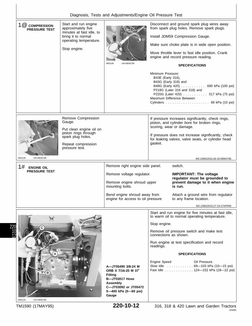
1@ COMPRESSIONPRESSURE TEST
Start and run engineapproximately fiveminutes at fast idle, tobring it to normaloperating temperature.
Stop engine.
M55108 -UN-09DEC89
Disconnect and ground spark plug wires awayfrom spark plug holes. Remove spark plugs.
Install JDM59 Compression Gauge.
Make sure choke plate is in wide open position.
Move throttle lever to fast idle position. Crankengine and record pressure reading.
SPECIFICATIONS
Minimum Pressure: B43E (Early 316), B43G (Early 318) and B48G (Early 420) . . . . . . . . . . . 690 kPa (100 psi) P218G (Later 316 and 318) and P220G (Later 420) . . . . . . . . . . . 517 kPa (75 psi)Maximum Difference BetweenCylinders . . . . . . . . . . . . . . . . . . . . 69 kPa (10 psi)
M55109 -UN-09DEC89
Remove CompressionGauge.
Put clean engine oil onpiston rings throughspark plug holes.
Repeat compressionpressure test.
If pressure increases significantly, check rings,piston, and cylinder bore for broken rings,scoring, wear or damage.
If pressure does not increase significantly, checkfor leaking valves, valve seats, or cylinder headgasket.
1# ENGINE OILPRESSURE TEST
Remove right engine side panel.
Remove voltage regulator.
Remove engine shroud uppermounting bolts.
Bend engine shroud away fromengine for access to oil pressure
switch.
IMPORTANT: The voltageregulator must be grounded toprevent damage to it when engineis run.
Attach a ground wire from regulatorto any frame location.
M55134 -UN-20DEC89
A—JT05490 3/8-24 MORB X 7/16-20 M 37˚FittingB—JT03017 HoseAssemblyC—JT03092 or JT054720—400 kPa (0—60 psi)Gauge
Start and run engine for five minutes at fast idle,to warm oil to normal operating temperature.
Stop engine.
Remove oil pressure switch and make testconnections as shown.
Run engine at test specification and recordreadings.
SPECIFICATIONS
Engine Speed Oil PressureSlow Idle . . . . . . . . . . . . 69—103 kPa (10—15 psi)Fast Idle . . . . . . . . . . . . . 124—152 kPa (18—22 psi)
MX,159022010,26-19-05MAY95
MX,159022010,27-19-27APR95
Diagnosis, Tests and Adjustments/Engine Oil Pressure Test
TM1590 (17MAY95) 220-10-12 316, 318 & 420 Lawn and Garden Tractors020895
2201012
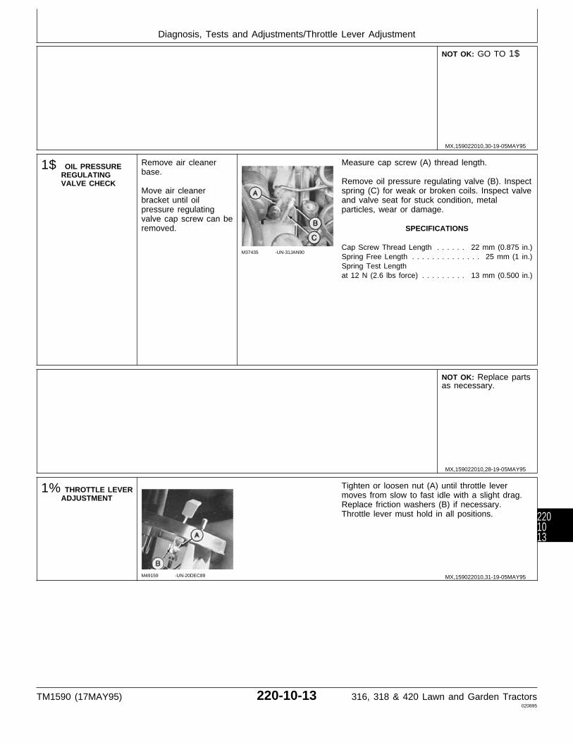
NOT OK: GO TO 1$
1$ OIL PRESSUREREGULATINGVALVE CHECK
Remove air cleanerbase.
Move air cleanerbracket until oilpressure regulatingvalve cap screw can beremoved.
M37435 -UN-31JAN90
Measure cap screw (A) thread length.
Remove oil pressure regulating valve (B). Inspectspring (C) for weak or broken coils. Inspect valveand valve seat for stuck condition, metalparticles, wear or damage.
SPECIFICATIONS
Cap Screw Thread Length . . . . . . 22 mm (0.875 in.)Spring Free Length . . . . . . . . . . . . . . 25 mm (1 in.)Spring Test Lengthat 12 N (2.6 lbs force) . . . . . . . . . 13 mm (0.500 in.)
NOT OK: Replace partsas necessary.
1% THROTTLE LEVERADJUSTMENT
M49159 -UN-20DEC89
Tighten or loosen nut (A) until throttle levermoves from slow to fast idle with a slight drag.Replace friction washers (B) if necessary.Throttle lever must hold in all positions.
MX,159022010,30-19-05MAY95
MX,159022010,28-19-05MAY95
MX,159022010,31-19-05MAY95
Diagnosis, Tests and Adjustments/Throttle Lever Adjustment
TM1590 (17MAY95) 220-10-13 316, 318 & 420 Lawn and Garden Tractors020895
2201013
Diagnosis, Tests and Adjustments/Throttle Lever Adjustment
TM1590 (17MAY95) 220-10-14 316, 318 & 420 Lawn and Garden Tractors020895
2201014

Section 240ELECTRICAL CHECKOUT, OPERATION
AND DIAGNOSISContents
Page
Group 05—Electrical System CheckoutBefore You Start . . . . . . . . . . . . . . . . . 240-05-1Dash Lamp Circuit Check . . . . . . . . . . . 240-05-1Starting Circuit Check . . . . . . . . . . . . . . 240-05-2Ignition Circuit (Spark) Check . . . . . . . . . 240-05-2PTO Clutch and Lamp Check . . . . . . . . 240-05-3Brake Neutral Start Check . . . . . . . . . . . 240-05-3Transmission Neutral Start Check . . . . . . 240-05-4PTO Neutral Start Check . . . . . . . . . . . . 240-05-4Seat Switch Check for PTO . . . . . . . . . . 240-05-4Seat Switch Check for Ignition . . . . . . . . 240-05-5Hour Meter Check . . . . . . . . . . . . . . . . 240-05-5Lighting Check . . . . . . . . . . . . . . . . . . 240-05-5Operator Complaint Not Identified . . . . . . 240-05-6
Group 10—Electrical SchematicsSingle PTO . . . . . . . . . . . . . . . . . . . . . 240-10-3Dual PTO . . . . . . . . . . . . . . . . . . . . . . 240-10-4
Group 15—Component Location and OperationElectrical Component Location . . . . . . . . 240-15-1Theory of Operation
Starting Circuit . . . . . . . . . . . . . . . . . 240-15-2Ignition Circuit . . . . . . . . . . . . . . . . . 240-15-4PTO Circuit . . . . . . . . . . . . . . . . . . . 240-15-6Charging Circuit . . . . . . . . . . . . . . . . 240-15-8Engine Oil Pressure Lamp Circuit . . . 240-15-10
Group 20—Electrical System DiagnosisAbout This Group . . . . . . . . . . . . . . . . 240-20-1Verify System Grounds . . . . . . . . . . . . . 240-20-1Battery Tests . . . . . . . . . . . . . . . . . . . . 240-20-1Dash Lamp Circuit Tests . . . . . . . . . . . . 240-20-4Starting Circuit Tests . . . . . . . . . . . . . 240-20-10Ignition Circuit Tests . . . . . . . . . . . . . . 240-20-14PTO Clutch and Lamp Tests . . . . . . . . 240-20-21Brake Neutral Start Safety Switch Test . 240-20-25Transmission Neutral Start Safety Switch
Test . . . . . . . . . . . . . . . . . . . . . . . 240-20-26PTO Neutral Start Safety Switch Test . . 240-20-26Seat Switch Test For PTO Time Delay . 240-20-26
Page
Seat Switch Test For Ignition TimeDelay . . . . . . . . . . . . . . . . . . . . . . 240-20-27
Hour Meter Circuit Test . . . . . . . . . . . . 240-20-27Lighting Test . . . . . . . . . . . . . . . . . . . 240-20-28
Group 25—Electrical System Component Testsand Adjustments
Before You Start . . . . . . . . . . . . . . . . . 240-25-1Key Switch Test . . . . . . . . . . . . . . . . . 240-25-1Circuit Breaker Test . . . . . . . . . . . . . . . 240-25-1Starter Tests . . . . . . . . . . . . . . . . . . . . 240-25-2Alternator and Regulator/Rectifier Tests . . 240-25-5PTO Clutch Adjustment Check . . . . . . . . 240-25-7System Short Circuit Tests
20-Amp Fuse . . . . . . . . . . . . . . . . . . 240-25-82 or 3-Amp Fuses . . . . . . . . . . . . . . . 240-25-9
TM1590 (17MAY95) 240-1 316, 318 & 420 Lawn and Garden Tractors020895
240

Contents
TM1590 (17MAY95) 240-2 316, 318 & 420 Lawn and Garden Tractors020895
240
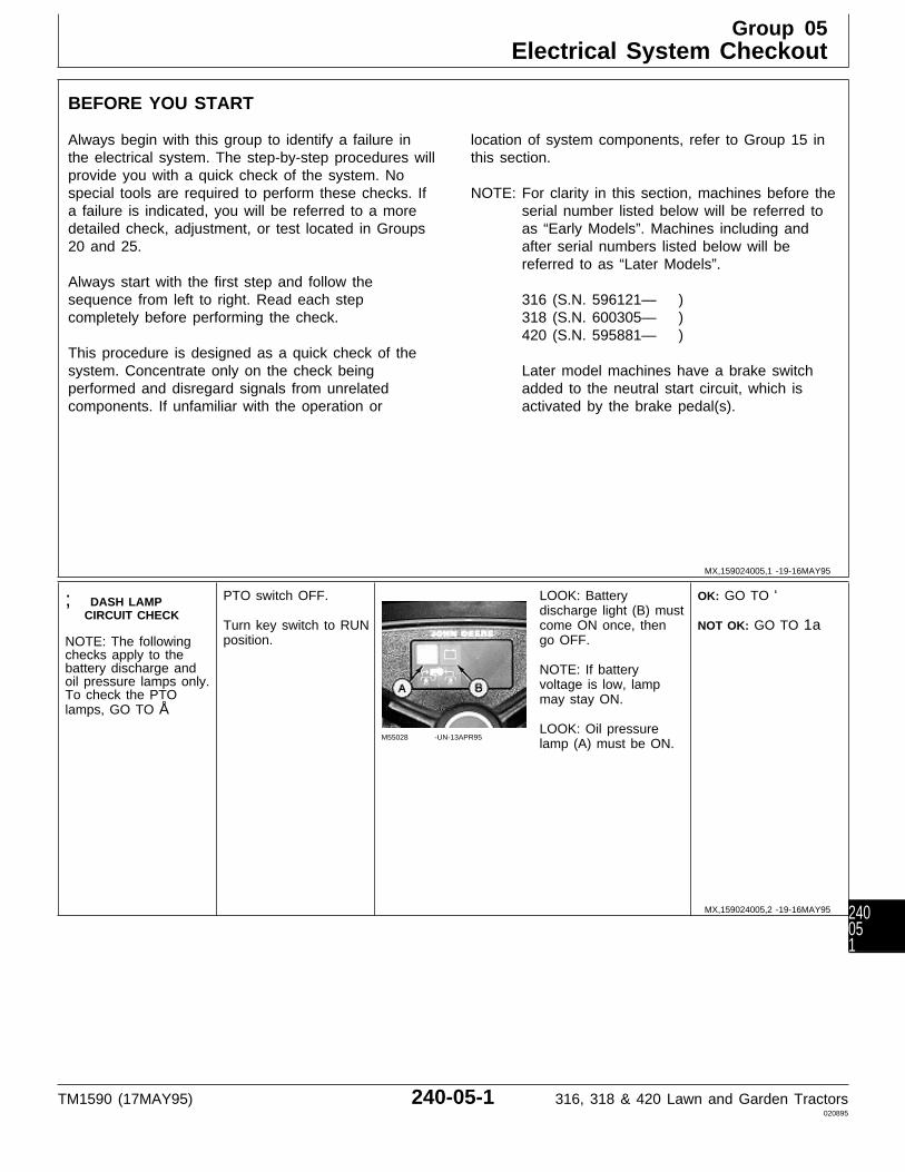
BEFORE YOU START
Always begin with this group to identify a failure inthe electrical system. The step-by-step procedures willprovide you with a quick check of the system. Nospecial tools are required to perform these checks. Ifa failure is indicated, you will be referred to a moredetailed check, adjustment, or test located in Groups20 and 25.
Always start with the first step and follow thesequence from left to right. Read each stepcompletely before performing the check.
This procedure is designed as a quick check of thesystem. Concentrate only on the check beingperformed and disregard signals from unrelatedcomponents. If unfamiliar with the operation or
location of system components, refer to Group 15 inthis section.
NOTE: For clarity in this section, machines before theserial number listed below will be referred toas “Early Models”. Machines including andafter serial numbers listed below will bereferred to as “Later Models”.
316 (S.N. 596121— )318 (S.N. 600305— )420 (S.N. 595881— )
Later model machines have a brake switchadded to the neutral start circuit, which isactivated by the brake pedal(s).
; DASH LAMPCIRCUIT CHECK
NOTE: The followingchecks apply to thebattery discharge andoil pressure lamps only.To check the PTOlamps, GO TO Å
PTO switch OFF.
Turn key switch to RUNposition.
M55028 -UN-13APR95
LOOK: Batterydischarge light (B) mustcome ON once, thengo OFF.
NOTE: If batteryvoltage is low, lampmay stay ON.
LOOK: Oil pressurelamp (A) must be ON.
OK: GO TO ‘
NOT OK: GO TO 1a
MX,159024005,1 -19-16MAY95
MX,159024005,2 -19-16MAY95
Group 05Electrical System Checkout
TM1590 (17MAY95) 240-05-1 316, 318 & 420 Lawn and Garden Tractors020895
240051

1a DASH LAMPS DONOT OPERATE
Key switch OFF.
NOTE:A—20-Amp FuseB—2-Amp FuseC—20-Amp FuseD—3-Amp Fuse
M55140 -UN-13APR95
M77926 -UN-12APR95
For machines:316 (S.N. —475000)318 (S.N. —475000)420 (S.N. —595880),disconnect fuse holdersand check 20-amp fuse(A) and 2-amp fuse (B).
For machines:316 (S.N. 475001— )318 (S.N. 475001— )420 (S.N. 595881— ),remove and check20-amp fuse (C) and3-amp fuse (D).
FUSE OK: GO TO ;,Group 20.
FUSES BLOWN:Replace fuse, thenrepeat ;
FUSES BLOW AFTERREPLACING: GO TO;, Group 20.
‘ STARTING CIRCUITCHECK
PTO switch OFF.
Hydrostatic lever inN/STOP position.
M55029 -UN-09DEC89
Later Models; Depressbrake pedal(s).
Turn key switch toSTART position.
LISTEN: Starter mustcrank engine. Enginemust start and run (usechoke as needed).
OK: GO TO Å
ENGINE CRANKS BUTDOESN’T START: GOTO Æ
ENGINE DOESN’TCRANK: Check fuses,then GO TO ‘, Group20.
ENGINE STARTS, BUTMISFIRES: For Machines (S.N. —420000); GO TO 3j For Machines (S.N.420001— ); GO TO 3k
Æ IGNITION CIRCUIT(SPARK) CHECK
PTO switch OFF.
Hydrostatic lever inN/STOP position.
Later Models; Engagepark brake.
Remove both engineside panels.
M37088 -UN-29AUG88
Disconnect spark plugwires from spark plugsand connect one to aspark tester. Other plugwire must be groundedto the engine.
Crank engine.
LOOK: Tester mustindicate a strong, bluespark.
Repeat test on otherspark plug.
SPARK: GO TOSection 220, Group 10to check spark pluggap.
NO SPARK: GO TO Æ,Group 20.
MX,159024005,3 -19-16MAY95
MX,159024005,4 -19-17MAY95
MX,159024005,5 -19-17MAY95
Electrical System Checkout/Ignition Circuit (Spark) Check
TM1590 (17MAY95) 240-05-2 316, 318 & 420 Lawn and Garden Tractors020895
24005
2

Å PTO CLUTCH ANDLAMP CHECK
Sit on seat.
PTO switch OFF.
Turn key switch to RUNposition.
M55019 -UN-09DEC89
M36492 -UN-29JAN90
Move PTO switch toON position.
LISTEN: Clutch must“click” ON.
LOOK: PTO lamp mustcome ON.
OK: GO TO Ö
NOT OK: GO TO 4a
4a PTO DOES NOTOPERATEPROPERLY
Key switch OFF.
NOTE:A—20-Amp FuseB—2-Amp FuseC—20-Amp FuseD—3-Amp Fuse
M55140 -UN-13APR95
M77926 -UN-12APR95
For machines:316 (S.N. —475000)318 (S.N. —475000)420 (S.N. —595880),disconnect fuseholders to check20-amp fuse (A) and2-amp fuse (B).
For machines:316 (S.N. 475001— )318 (S.N. 475001— )420 (S.N. 595881— ),remove and check20-amp fuse (C) and3-amp fuse (D).
FUSES OK: GO TO Å,Group 20.
FUSES BLOWN:Replace fuse, thenrepeat Å
FUSES BLOW AFTERREPLACING: GO TO;, Group 20.
Ö BRAKE NEUTRALSTART CHECK—FOR MACHINES:316 (SN 596121— )318 (SN 600305— )420 (SN 595881— )
PTO switch OFF.
Hydrostatic lever inN/STOP position.
M77933 -UN-17JAN95
Brake pedal(s)completely released.
Turn key switch toSTART position.
LISTEN: Engine mustNOT crank.
OK: GO TO Ò
NOT OK: GO TO Ö,Group 20.
MX,159024005,6 -19-16MAY95
MX,159024005,7 -19-16MAY95
MX,159024005,8 -19-16MAY95
Electrical System Checkout/Brake Neutral Start Check
TM1590 (17MAY95) 240-05-3 316, 318 & 420 Lawn and Garden Tractors020895
240053

Ò TRANSMISSIONNEUTRAL STARTCHECK
M55018 -UN-09DEC89
PTO switch OFF.
Later Models; Depressbrake pedal(s).
Pull hydrostatic leveraway from N/STOPswitch slot.
Turn key switch toSTART position.
LISTEN: Engine mustNOT crank.
OK: GO TO Õ
NOT OK: GO TO Ò,Group 20.
Õ PTO NEUTRALSTART CHECK
PTO switch OFF.
Hydrostatic lever inN/STOP position.
Later Models; Depressbrake pedal(s).
M55019 -UN-09DEC89
Move PTO switch toON position.
Turn key switch toSTART position.
LISTEN: Engine mustNOT crank.
OK: GO TO Ú
NOT OK: GO TO Õ,Group 20.
Ú SEAT SWITCHCHECK FOR PTO
M55019 -UN-09DEC89
Sit on seat.
PTO switch OFF.
Hydrostatic lever inN/STOP position.
Later Models; Depressbrake pedal(s).
Start engine andoperate at half throttle.
Move PTO switch toON position.
Raise off seat for 2—3seconds.
LOOK/LISTEN: PTOlamp must go OFF.PTO clutch mustdisengage.
Turn PTO switch OFF,then ON to engagePTO.
Raise off seat andquickly sit back downbefore one secondelapses.
LOOK/LISTEN: PTOlamp and PTO clutchmust stay ON.
OK: GO TO Ü
NOT OK: GO TO Ú,Group 20.
MX,159024005,9 -19-16MAY95
MX,159024005,10-19-16MAY95
MX,159024005,11-19-16MAY95
Electrical System Checkout/Seat Switch Check for PTO
TM1590 (17MAY95) 240-05-4 316, 318 & 420 Lawn and Garden Tractors020895
24005
4
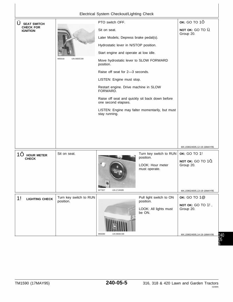
Ü SEAT SWITCHCHECK FORIGNITION
M55018 -UN-09DEC89
PTO switch OFF.
Sit on seat.
Later Models; Depress brake pedal(s).
Hydrostatic lever in N/STOP position.
Start engine and operate at low idle.
Move hydrostatic lever to SLOW FORWARDposition.
Raise off seat for 2—3 seconds.
LISTEN: Engine must stop.
Restart engine. Drive machine in SLOWFORWARD.
Raise off seat and quickly sit back down beforeone second elapses.
LISTEN: Engine may falter momentarily, but muststay running.
OK: GO TO 1Ô
NOT OK: GO TO Ü,Group 20.
1Ô HOUR METERCHECK
Sit on seat.
M77927 -UN-17JAN95
Turn key switch to RUNposition.
LOOK: Hour metermust operate.
OK: GO TO 1!
NOT OK: GO TO 1Ô,Group 20.
1! LIGHTING CHECK Turn key switch to RUNposition.
M55080 -UN-09DEC89
Pull light switch to ONposition.
LOOK: All lights mustbe ON.
OK: GO TO 1@
NOT OK: GO TO 1!,Group 20.
MX,159024005,12-19-16MAY95
MX,159024005,13-19-16MAY95
MX,159024005,14-19-16MAY95
Electrical System Checkout/Lighting Check
TM1590 (17MAY95) 240-05-5 316, 318 & 420 Lawn and Garden Tractors020895
240055
1@ OPERATORCOMPLAINT NOTIDENTIFIED
If you completed thecheckout procedure anddid not isolate amalfunction, theproblem may beintermittent.
Try to duplicate theconditions of themalfunction identified bythe operator.
Verify system groundsand battery condition.(See steps A and Bin Group 20.)
PERFORM BATTERY TESTS AND GROUNDTESTS AS INSTRUCTED IN GROUP 20 ANDREPEAT THE CHECKOUT PROCEDURE INTHIS GROUP.
IF A MALFUNCTION IS NOT IDENTIFIEDAFTER REPEATING SYSTEM CHECKOUTPROCEDURE, FACTORY ASSISTANCE ISAVAILABLE THROUGH THE DEALERTECHNICAL ASSISTANCE CENTER (DTAC).
MX,159024005,15-19-16MAY95
Electrical System Checkout/Operator Complaint Not Identified
TM1590 (17MAY95) 240-05-6 316, 318 & 420 Lawn and Garden Tractors020895
24005
6

Group 10Electrical Schematics
TM1590 (17MAY95) 240-10-1 316, 318 & 420 Lawn and Garden Tractors020895
240101

316, 318 AND 420 ELECTRICAL SCHEMATIC—SINGLE PTO
A1—TDC Module M2—Starter Motor: X5—Rear PTO Harness 3-Pin X17—Headlight HarnessA2—Ignition Module 316 (S.N. —362983) Connector Connector
(S.N. 420001— ) 318 (S.N. —364137) X6—Rear PTO Switch 2-Pin 1-Pin (S.N. —475000)B1—Engine Oil Pressure 420 (S.N. —360009) Connector 2-Pin (S.N. 475001— )
Switch N1—Voltage X7—Rear PTO Switch 3-Pin X18—Tail Light HarnessC1—Condenser Regulator/Rectifier Connector Connector
(S.N. 420001— ) P1—Front PTO Indicator X8—Brake Switch 2-Pin 1-Pin (S.N. —475000)E1—Spark Plug P3—Hour Meter Connector: 2-Pin (S.N. 475001— )E2—Spark Plug P4—Battery Discharge 316 (S.N. 596121— ) X19—Engine Oil PressureE3—Ignition (Breaker) Points Indicator 318 (S.N. 600305— ) Switch 1-Pin Connector
(S.N. —420000) P5—Engine Oil Pressure 420 (S.N. 595881— ) X20—Hour Meter 1-PinE4—Left Headlight Indicator X9—Transmission Neutral ConnectorE5—Middle Headlight S1—Key Switch Switch 1-Pin Connector X21—Hour Meter 1-PinE6—Right Headlight S2—Front PTO Switch X10—Transmission Neutral Connector (Ground)E7—Left Tail Light S4—Brake Switch: Switch 1-Pin Connector X22—TDC Module 2-PinE8—Right Tail Light 316 (S.N. 596121— ) X11—Seat Switch 2-Pin ConnectorF1—20-Amp Fuse 318 (S.N. 600305— ) Connector X23—TDC Module 8-PinF2—2-Amp Fuse: 420 (S.N. 595881— ) X12—Engine Harness 3-Pin Connector
316 (S.N. —475000) S5—Transmission Neutral Connector X24—Rear PTO Clutch 1-Pin 318 (S.N. —475000) Switch X13—Voltage Connector (Ground) 420 (S.N. —595880) S6—Seat Switch Regulator/Rectifier X25—Rear PTO Lamp 1-Pin3-Amp Fuse: S7—Headlight Switch 1-Pin Connector (VDC Connector (Ground) 316 (S.N. 475001— ) T1—Ignition Coil Output) X26—Front PTO Clutch 2-Pin 318 (S.N. 475001— ) W1—Engine Ground X14—Voltage Connector 420 (S.N. 595881— ) (S.N. 475001— ) Regulator/Rectifier X27—Single Point Ground
F3—25-Amp Circuit Breaker X1—Key Switch 5-Pin 1-Pin Connector 1-Pin Connector:G1—Battery Connector (Stator) 316 (S.N. 596121— )G2—Stator Alternator X2—Key Switch 1-Pin X15—Voltage 318 (S.N. 600305— )K1—Starter Solenoid: Connector Regulator/Rectifier 420 (S.N. 595881— )
316 (S.N. —362983) X3—Front PTO Switch 2-Pin 1-Pin Connector Y1—Front PTO Clutch 318 (S.N. —364137) Connector (Stator) 420 (S.N. —360009) X4—Front PTO Switch 3-Pin X16—Headlight Switch 2-Pin
M1—Starter Motor: Connector Connector 316 (S.N. 362984— ) 318 (S.N. 364138— ) 420 (S.N. 360010— )
Legend For Electrical Schematic
NOTE: Wire colors are the same for all machines.Wire numbers indicated on schematic are formachines (S.N. 475001— ).
1. For 316 (S.N. —596120), 318 (S.N. —600304) and 420 (S.N. —595880)machines, brake switch (S4) is not used.Purple wire “710” connects transmissionneutral switch directly to terminal “S2” of keyswitch.
2. For machines (S.N. —475000), a lightgreen wire is used instead of the red “210”wire used on later machines. The green wireconnects to terminal “B” of key switch (S1),not to circuit breaker (F3) as does the red“210” wire.
NOTE: 3. The electrical schematic shows groundcircuits for machines (S.N. 475001— ). Forthese machines, all component groundsterminate (spliced) inside the main harnesswith one wire connecting to a single groundpoint at the engine.
For machines (S.N. —475000), the (blk)ground wires for the PTO lamps, hour meter,and TDC module (2-pin connector) terminateat the right pedestal panel. Exteriorcomponents, such as the PTO clutches andhead and tail lights use the tractor frame forground.
MX,159024015,1 -19-16MAY95
Electrical Schematics
TM1590 (17MAY95) 240-10-2 316, 318 & 420 Lawn and Garden Tractors020895
24010
2
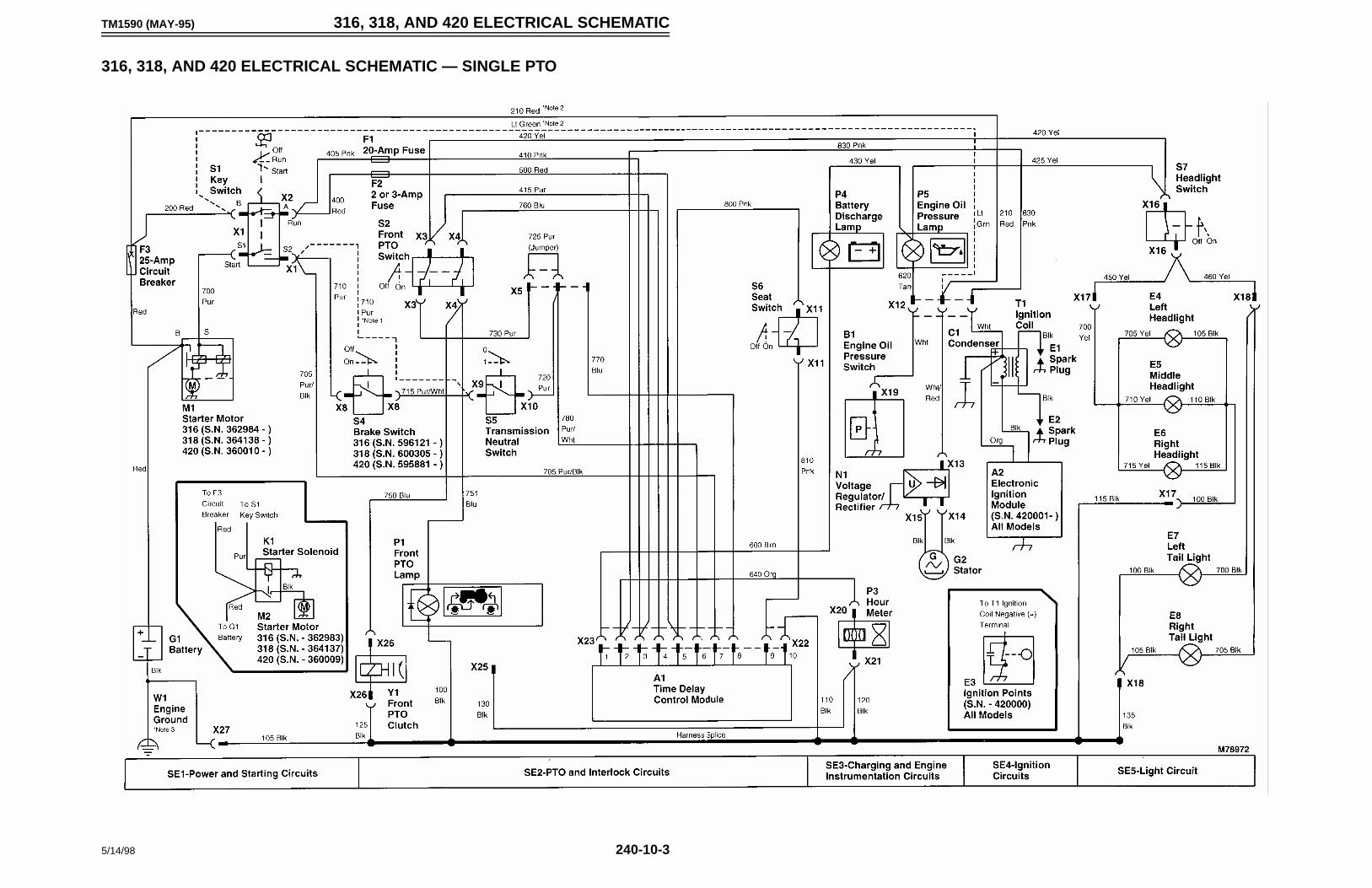
TM1590 (MAY-95) 316, 318, AND 420 ELECTRICAL SCHEMATIC
5/14/98 240-10-3
316, 318, AND 420 ELECTRICAL SCHEMATIC — SINGLE PTO
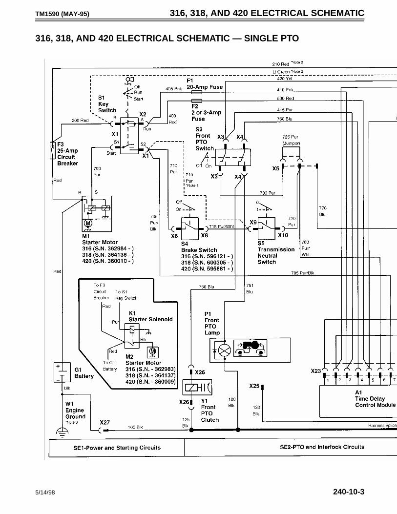
TM1590 (MAY-95) 316, 318, AND 420 ELECTRICAL SCHEMATIC
5/14/98 240-10-3
316, 318, AND 420 ELECTRICAL SCHEMATIC — SINGLE PTO
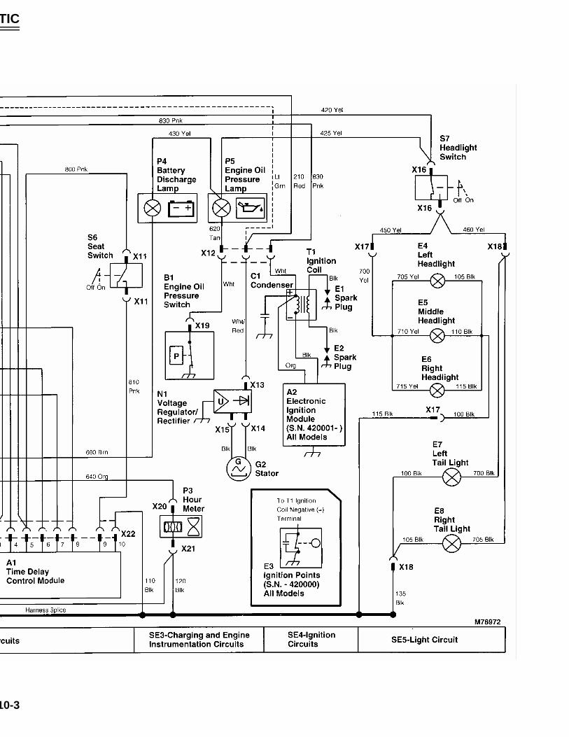
TM1590 (MAY-95) 316, 318, AND 420 ELECTRICAL SCHEMATIC
5/14/98 240-10-3
316, 318, AND 420 ELECTRICAL SCHEMATIC — SINGLE PTO
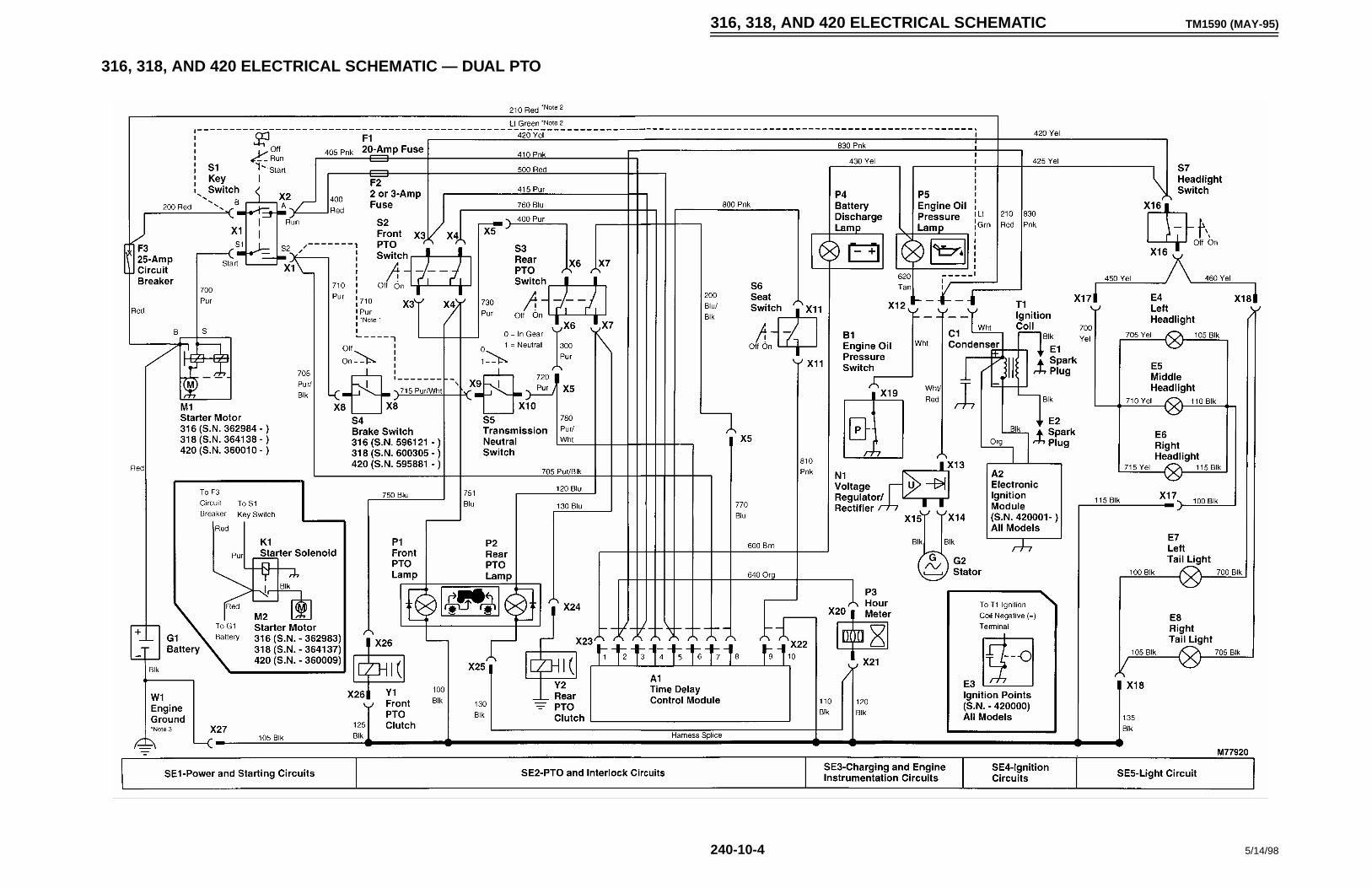
316, 318, AND 420 ELECTRICAL SCHEMATIC TM1590 (MAY-95)
240-10-4 5/14/98
316, 318, AND 420 ELECTRICAL SCHEMATIC — DUAL PTO
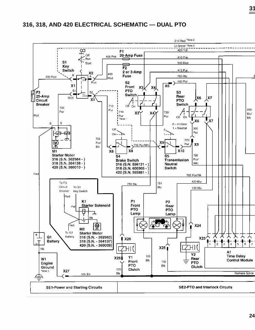
316, 318, AND 420 ELECTRICAL SCHEMATIC TM1590 (MAY-95)
240-10-4 5/14/98
316, 318, AND 420 ELECTRICAL SCHEMATIC — DUAL PTO
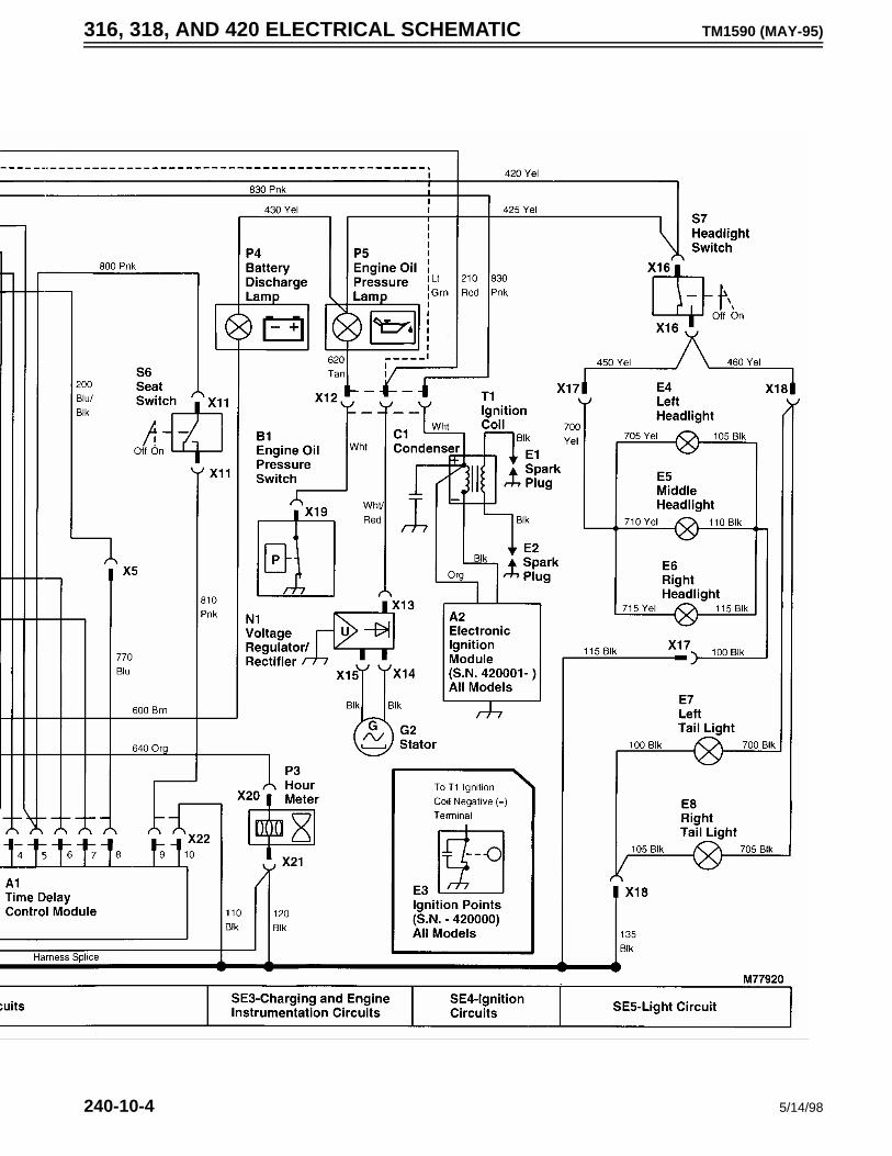
316, 318, AND 420 ELECTRICAL SCHEMATIC TM1590 (MAY-95)
240-10-4 5/14/98
316, 318, AND 420 ELECTRICAL SCHEMATIC — DUAL PTO
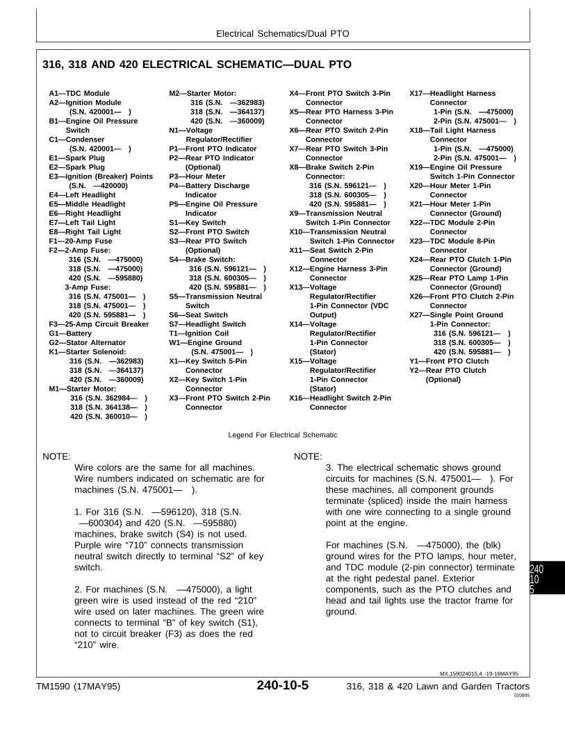
316, 318 AND 420 ELECTRICAL SCHEMATIC—DUAL PTO
A1—TDC Module M2—Starter Motor: X4—Front PTO Switch 3-Pin X17—Headlight HarnessA2—Ignition Module 316 (S.N. —362983) Connector Connector
(S.N. 420001— ) 318 (S.N. —364137) X5—Rear PTO Harness 3-Pin 1-Pin (S.N. —475000)B1—Engine Oil Pressure 420 (S.N. —360009) Connector 2-Pin (S.N. 475001— )
Switch N1—Voltage X6—Rear PTO Switch 2-Pin X18—Tail Light HarnessC1—Condenser Regulator/Rectifier Connector Connector
(S.N. 420001— ) P1—Front PTO Indicator X7—Rear PTO Switch 3-Pin 1-Pin (S.N. —475000)E1—Spark Plug P2—Rear PTO Indicator Connector 2-Pin (S.N. 475001— )E2—Spark Plug (Optional) X8—Brake Switch 2-Pin X19—Engine Oil PressureE3—Ignition (Breaker) Points P3—Hour Meter Connector: Switch 1-Pin Connector
(S.N. —420000) P4—Battery Discharge 316 (S.N. 596121— ) X20—Hour Meter 1-PinE4—Left Headlight Indicator 318 (S.N. 600305— ) ConnectorE5—Middle Headlight P5—Engine Oil Pressure 420 (S.N. 595881— ) X21—Hour Meter 1-PinE6—Right Headlight Indicator X9—Transmission Neutral Connector (Ground)E7—Left Tail Light S1—Key Switch Switch 1-Pin Connector X22—TDC Module 2-PinE8—Right Tail Light S2—Front PTO Switch X10—Transmission Neutral ConnectorF1—20-Amp Fuse S3—Rear PTO Switch Switch 1-Pin Connector X23—TDC Module 8-PinF2—2-Amp Fuse: (Optional) X11—Seat Switch 2-Pin Connector
316 (S.N. —475000) S4—Brake Switch: Connector X24—Rear PTO Clutch 1-Pin 318 (S.N. —475000) 316 (S.N. 596121— ) X12—Engine Harness 3-Pin Connector (Ground) 420 (S.N. —595880) 318 (S.N. 600305— ) Connector X25—Rear PTO Lamp 1-Pin3-Amp Fuse: 420 (S.N. 595881— ) X13—Voltage Connector (Ground) 316 (S.N. 475001— ) S5—Transmission Neutral Regulator/Rectifier X26—Front PTO Clutch 2-Pin 318 (S.N. 475001— ) Switch 1-Pin Connector (VDC Connector 420 (S.N. 595881— ) S6—Seat Switch Output) X27—Single Point Ground
F3—25-Amp Circuit Breaker S7—Headlight Switch X14—Voltage 1-Pin Connector:G1—Battery T1—Ignition Coil Regulator/Rectifier 316 (S.N. 596121— )G2—Stator Alternator W1—Engine Ground 1-Pin Connector 318 (S.N. 600305— )K1—Starter Solenoid: (S.N. 475001— ) (Stator) 420 (S.N. 595881— )
316 (S.N. —362983) X1—Key Switch 5-Pin X15—Voltage Y1—Front PTO Clutch 318 (S.N. —364137) Connector Regulator/Rectifier Y2—Rear PTO Clutch 420 (S.N. —360009) X2—Key Switch 1-Pin 1-Pin Connector (Optional)
M1—Starter Motor: Connector (Stator) 316 (S.N. 362984— ) X3—Front PTO Switch 2-Pin X16—Headlight Switch 2-Pin 318 (S.N. 364138— ) Connector Connector 420 (S.N. 360010— )
Legend For Electrical Schematic
NOTE: Wire colors are the same for all machines.Wire numbers indicated on schematic are formachines (S.N. 475001— ).
1. For 316 (S.N. —596120), 318 (S.N. —600304) and 420 (S.N. —595880)machines, brake switch (S4) is not used.Purple wire “710” connects transmissionneutral switch directly to terminal “S2” of keyswitch.
2. For machines (S.N. —475000), a lightgreen wire is used instead of the red “210”wire used on later machines. The green wireconnects to terminal “B” of key switch (S1),not to circuit breaker (F3) as does the red“210” wire.
NOTE: 3. The electrical schematic shows groundcircuits for machines (S.N. 475001— ). Forthese machines, all component groundsterminate (spliced) inside the main harnesswith one wire connecting to a single groundpoint at the engine.
For machines (S.N. —475000), the (blk)ground wires for the PTO lamps, hour meter,and TDC module (2-pin connector) terminateat the right pedestal panel. Exteriorcomponents, such as the PTO clutches andhead and tail lights use the tractor frame forground.
MX,159024015,4 -19-16MAY95
Electrical Schematics/Dual PTO
TM1590 (17MAY95) 240-10-5 316, 318 & 420 Lawn and Garden Tractors020895
240105

Electrical Schematics/Dual PTO
TM1590 (17MAY95) 240-10-6 316, 318 & 420 Lawn and Garden Tractors020895
24010
6
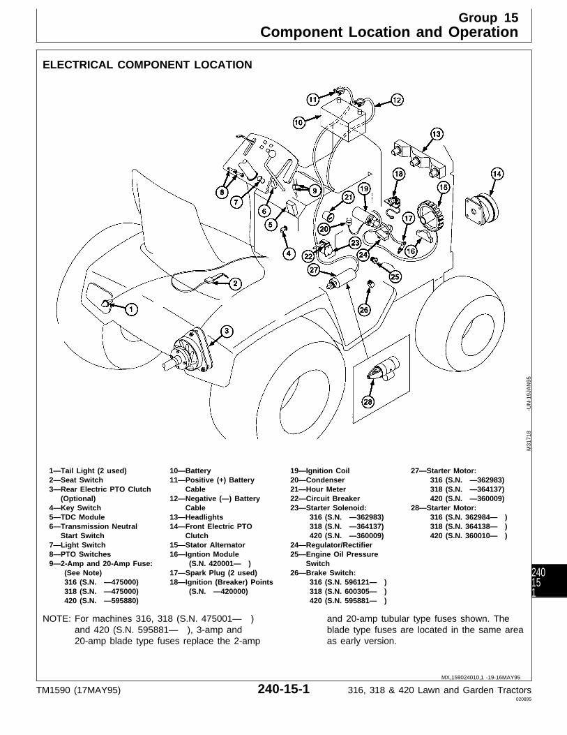
ELECTRICAL COMPONENT LOCATION
1—Tail Light (2 used) 10—Battery 19—Ignition Coil 27—Starter Motor:2—Seat Switch 11—Positive (+) Battery 20—Condenser 316 (S.N. —362983)3—Rear Electric PTO Clutch Cable 21—Hour Meter 318 (S.N. —364137)
(Optional) 12—Negative (—) Battery 22—Circuit Breaker 420 (S.N. —360009)4—Key Switch Cable 23—Starter Solenoid: 28—Starter Motor:5—TDC Module 13—Headlights 316 (S.N. —362983) 316 (S.N. 362984— )6—Transmission Neutral 14—Front Electric PTO 318 (S.N. —364137) 318 (S.N. 364138— )
Start Switch Clutch 420 (S.N. —360009) 420 (S.N. 360010— )7—Light Switch 15—Stator Alternator 24—Regulator/Rectifier8—PTO Switches 16—Igntion Module 25—Engine Oil Pressure9—2-Amp and 20-Amp Fuse: (S.N. 420001— ) Switch
(See Note) 17—Spark Plug (2 used) 26—Brake Switch: 316 (S.N. —475000) 18—Ignition (Breaker) Points 316 (S.N. 596121— ) 318 (S.N. —475000) (S.N. —420000) 318 (S.N. 600305— ) 420 (S.N. —595880) 420 (S.N. 595881— )
NOTE: For machines 316, 318 (S.N. 475001— )and 420 (S.N. 595881— ), 3-amp and20-amp blade type fuses replace the 2-amp
and 20-amp tubular type fuses shown. Theblade type fuses are located in the same areaas early version.
M31
718
-UN
-19J
AN
95
MX,159024010,1 -19-16MAY95
Group 15Component Location and Operation
TM1590 (17MAY95) 240-15-1 316, 318 & 420 Lawn and Garden Tractors020895
240151

STARTING CIRCUIT OPERATION
The function of the starting circuit is to crank theengine by energizing starter motor (M1). PTOswitches (S2 and S3), transmission neutral switch(S5), and brake switch (S4) are used as interlocksafety switches within the starter circuit. For thestarter motor to energize, the following conditionsmust be met:
• Front and rear PTO switches in OFF position. • Hydrostatic Control Lever in N/STOP position. • Brake pedal depressed. • Key Switch in “START” position.
NOTE: Depressing the brake pedal required only onlater models:316 (S.N. 596121— )318 (S.N. 600305— )420 (S.N. 595881— )
For all other machines, depressing the brakepedal is not necessary for starter operation.
PTO switches (S2 and S3) are used in the startingcircuit to prevent the engine from cranking while thePTO is engaged. Each PTO switch contains two setsof contacts; one for the PTO circuit (lower contact)and the other (upper contact) as a safety interlock forthe starting circuit. When the PTO switch is in the ONposition (PTO engaged), the PTO switch interlockcontacts are open. When the PTO switch is in theOFF position (PTO disengaged), the PTO interlockcontacts are closed, allowing current to flow totransmission neutral switch (S5).
The transmission neutral switch is used in the startingcircuit to prevent the engine from cranking when thetransmission is in gear. When the hydrostatic controllever is in the forward or reverse position, thetransmission neutral switch contacts are open. Movingthe hydrostatic control lever to the N/STOP positioncloses the contacts, allowing current to flow to brakeswitch (S4).
NOTE: Brake switch equipped on machines: 316(S.N. 596121— ), 318 (S.N. 600305— ),and 420 (S.N. 595881— ) only. For allother machines, current flows from thetransmission switch, directly to terminal “S2”on key switch (S1).
The brake switch will prevent the engine fromcranking unless the brake pedal is depressed or park
brake is engaged. Depressing the brake pedal closesthe brake switch contacts, allowing current to flow toterminal “S2” on key switch (S1).
The key switch initiates current flow through thestarting circuit with the use of two sets of contacts.Both contacts are open when the switch is in theOFF position. When the key switch is turned to theSTART position, both contacts close. If all theinterlock switch contacts in the start circuit are closed,current from the battery positive terminal flowsthrough the 25 amp circuit breaker (F3) to terminal“B” on the key switch. Current flows across theclosed contacts, out terminal “A” to the 20 amp fuse(F1). From fuse (F1), current flows through the PTO,transmission, and brake (if equipped) switches andflows back to terminal “S2” of the key switch. Thecurrent flows across the key switch contacts, then outterminal “S1” to starter solenoid (K2), energizing thesolenoid.
NOTE: For machines 316 (S.N. —362983), 318(S.N. —364137) and 420 (S.N. —360009), a bendix drive starter motor isused. These starter motors use a remotemounted starter solenoid relay.
Starter solenoid (K2) contains two coil windings calledthe pull-in and hold-in windings. Current flowingthrough these coils produce a strong magnetic fieldwhich pulls a plunger inward and closes solenoidmain contacts (A). Because the starter is a shift type(solenoid mounted on starter), the plunger also movesthe starter drive gear outward to mesh with theflywheel ring gear.
When the solenoid contacts close, high current fromthe battery flows across the solenoid contacts tostarter motor (M1), causing it to turn. Because thepull-in windings are grounded through the starter,current will flow through the pull-in windings only aslong as the solenoid main contacts are open. Whenthe solenoid contacts close, both ends of the pull-inwindings have the same voltage. This causes thecurrent to stop flowing through the pull-in windings.Because the hold-in windings are grounded directly tothe chassis, current continues to flow through thehold-in windings. This keeps the solenoid energized(main contacts closed; starter drive engaged) until thekey switch is turned to the RUN or OFF position.
MX,159024020,1 -19-16MAY95
Component Location and Operation/Theory of Operation
TM1590 (17MAY95) 240-15-2 316, 318 & 420 Lawn and Garden Tractors020895
24015
2
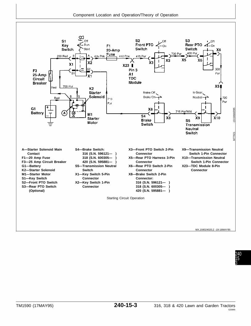
A—Starter Solenoid Main S4—Brake Switch: X3—Front PTO Switch 2-Pin X9—Transmission NeutralContact 316 (S.N. 596121— ) Connector Switch 1-Pin Connector
F1—20 Amp Fuse 318 (S.N. 600305— ) X5—Rear PTO Harness 3-Pin X10—Transmission NeutralF3—25 Amp Circuit Breaker 420 (S.N. 595881— ) Connector Switch 1-Pin ConnectorG1—Battery S5—Transmission Neutral X6—Rear PTO Switch 2-Pin X23—TDC Module 8-PinK2—Starter Solenoid Switch Connector ConnectorM1—Starter Motor X1—Key Switch 5-Pin X8—Brake Switch 2-PinS1—Key Switch Connector Connector:S2—Front PTO Switch X2—Key Switch 1-Pin 316 (S.N. 596121— )S3—Rear PTO Switch Connector 318 (S.N. 600305— )
(Optional) 420 (S.N. 595881— )
Starting Circuit Operation
M77
921
-19-
04M
AR
95
MX,159024020,2 -19-16MAY95
Component Location and Operation/Theory of Operation
TM1590 (17MAY95) 240-15-3 316, 318 & 420 Lawn and Garden Tractors020895
240153
IGNITION CIRCUIT OPERATION
The function of the ignition circuit is to produce sparkacross the gap of spark plugs (E1 and E2). Thecircuit is a battery ignition type that fires both sparkplugs simultaniously, thus eliminating the need for adistributor. The ignition circuit automatically stops theengine anytime the operator rises off the seat formore than one second when tractor is in gear or ifPTO is engaged.
OPERATOR ON SEAT—MACHINE IN GEARAND/OR PTO ENGAGED:When the key switch (S1) is turned to the RUN orSTART position, current flows from the positiveterminal of battery (G1), through circuit breaker (F3),across key switch contacts at terminals “B” and “A”,to fuses (F1 and F2). From fuse (F2), current flowsacross the contacts of seat switch (S6), through timedelay IC (E), to switch transistor (D) located insidethe TDC module. As long as current from the ICflows to the transistor, the transistor is “switched on”.In this state, the transistor completes the path toground for TDC ignition relay coil (B). The groundpath allows current to flow from fuse (F1), throughthe relay coil to ground. This energizes the relay coilwhich closes relay contacts (A).
Current from fuse (F1) then flows across ignition relaycontacts (A), out the TDC module to ignition coil (T1).The current flows through the coil primary windings,then through ignition module (A2) to ground.
Current flowing through the primary windingsproduces a magnetic field around the primary andsecondary windings.
NOTE: For machines (S.N. —420000), ignition points(E3) are used. The ignition points areactuated by a pushrod that rides on acamshaft lobe.
The ignition module receives a signal from a triggerring containing permanent magnets (the ring rotateswith the engine crankshaft). This signal causes theignition module to “break” the circuit, momentarilystopping current flow through the primary windings,and cause the magnetic field to collapse across thesecondary windings. The collapsing magnetic fieldinduces high voltage in the secondary windings of theignition coil. The induced voltage flows from one endof the secondary windings, through the two sparkplugs (jumping the plug gaps), then back to theopposite end of the secondary windings. The engine
block completes the circuit between the two sparkplugs.
When the operator rises from the seat, the seatswitch contacts open, causing current to stop flowingto the time delay IC. If the operator does not returnto the seat within approximately one second, the timedelay IC stops current flow to transistor (D). Thetransistor will “switch off”, causing current throughrelay coil (B) to stop flowing and de-energize the coil.With the coil no longer energized, relay contacts (A)will open. Current stops flowing to the ignition coil,thus stopping the engine.
NOTE: Driving the machine over rough terrain cancause the seat switch contacts to momentarilyopen and close. When this happens, the timedelay IC allows the engine to operate withoutinterruption.
If the operator returns to the seat withinapproximately one second, current flow isre-established to the time delay IC before it has achance to “time out” and stop current flow to thetransistor. Current flow is NOT interrupted to theignition coil and the engine is allowed to continueoperating.
OPERATOR OFF SEAT—MACHINE IN NEUTRALAND PTO DISENGAGED:When operator is off the seat, current to the ignitioncoil can still be maintained through the neutral start(interlock) circuit. For current to flow through theinterlock circuit, the key switch must be turned to theRUN or START position, the hydrostatic control leverin the STOP position, the PTO switch(es) in the OFFposition (PTO disengaged), and park brake engaged(later models only).
With these conditions met, current flows from terminal“A” of the key switch to fuse (F1). From fuse (F1),current flows through the interlock contacts of thePTO switch(es), transmission neutral switch, andbrake switch to terminal “S1” on the key switch. Fromterminal “S1”, current flows to transistor (C) located inthe TDC module. As long as current from theinterlock circuit flows to transistor (C), the transistor is“switched on”. In this state, the transistor provides analternate path to ground for relay coil (B). Theenergized relay closes the relay contacts, allowingcurrent to flow to the igniton coil.
MX,159024020,3 -19-16MAY95
Component Location and Operation/Theory of Operation
TM1590 (17MAY95) 240-15-4 316, 318 & 420 Lawn and Garden Tractors020895
24015
4

A—TDC Ignition Relay C1—Condenser G1—Battery X12—Engine Harness 3-PinContacts (S.N. 420001— ) M1—Starter Motor Connector
B—TDC Ignition Relay Coil E1—Spark Plug S1—Key Switch X22—TDC Module 2-PinC—Switch Transistor E2—Spark Plug S6—Seat Switch ConnectorD—Time Delay Switch E3—Ignition Points T1—Ignition Coil X23—TDC Module 8-Pin
Transistor (S.N. —420000) W1—Engine Ground ConnectorE—Time Delay IC (Internal F1—20 Amp Fuse X1—Key Switch 5-Pin X27—Single Point Ground
Circuit) F2—2 Amp Fuse Connector 1-Pin Connector:A1—Time Delay Control (Early Machines) X2—Key Switch 1-Pin 316 (S.N. 596121— )
(TDC) Module 3 Amp Fuse Connector 318 (S.N. 600305— )A2—Ignition Module (Later Machines) X11—Seat Switch 2-Pin 420 (S.N. 595881— )
(S.N. 420001— ) F3—25 Amp Circuit Breaker Connector
NOTE: 1. For machines 316 (S.N. —596120), 318(S.N. —600304) and 420 (S.N. —595880),brake switch (S4) is not used. Interlockcurrent flow to transistor (C) comes fromtransmission neutral start switch (S5).
NOTE: 2. The illustration shows ground circuit formachines (S.N. 475001— ). For machines(S.N. —475000), the blk wire from the TDCmodule 2-pin connector terminates (grounds)at the right pedestal panel.
M77
922
-19-
04M
AR
95
MX,159024020,4 -19-16MAY95
Component Location and Operation/Theory of Operation
TM1590 (17MAY95) 240-15-5 316, 318 & 420 Lawn and Garden Tractors020895
240155
PTO CIRCUIT OPERATION
The function of the PTO circuit is to energize thePTO clutch(es) and turn on the PTO lamp(s). Also,the PTO circuit automatically disengages the PTOclutch(es) anytime the operator rises off the seat formore than one second.
To engage the PTO clutch(es), the followingconditions must be met: • Operator on seat. • Key Switch at RUN position. • PTO switches initially at OFF position, then moved to ON position.
When the operator is on the seat and key switch (S1)is turned to the RUN or START position, currentflows from the positive terminal of battery (G1),through circuit breaker (F3), to key switch terminal“B”. The current flows across the switch contacts tokey switch terminal “A”. From terminal “A”, currentflows to fuses (F1 and F2). From fuse (F2), currentflows across the closed contacts of seat switch (S6)to pin “9” of TDC module connector (X22).
Inside the TDC module, current flows to time delay IC(A), then to switch transistor (B). As long as currentfrom the IC flows to the transistor, the transistor is“switched on”. In this state, the transistor completesthe path to ground for PTO relay coil (G).
NOTE: Front PTO switch (S2) and optional rear PTOswitch (S3) have two sets of contacts each.One set is used to actuate the clutches andthe other set is used in the interlock circuit(see Starting Circuit Theory of Operation inthis group).
If machine is not equipped with rear PTO, ajumper wire at 3-pin connector (X5) is used inplace of the rear PTO switch.
With the PTO switch(es) in the OFF position, currentwill flow from fuse (F1) to connector (X3) on the frontPTO switch. Current flows across the switch contacts,then to 3-pin connector (X5). If equipped with optionalrear PTO, current will flow from connector (X5) toconnector (X6) on the rear PTO switch. Current flowsacross the switch contacts and back out to connector(X5). From connector (X5), current flows to the TDCmodule, through pin “6” of connector (X23). Inside theTDC module, current flows through diodes (E and F),then through the PTO relay coil and transistor (B) toground. The interlock circuit current energizes the
PTO relay coil, which closes relay contacts (D). Oncethe contacts are closed, current flows directly fromfuse (F1), across the relay contacts to the relay coil.This current keeps the relay energized (latched) aslong as transistor (B) provides a path to ground.Once the coil is latched, current from the interlockcircuit is no longer needed to keep the relayenergized.
When the front PTO switch is moved to the ONposition, current flowing across the relay contacts willalso flow to connector (X4) on the front PTO switch,through pin “4” of connector (X23). Current flowsacross the switch contacts to front PTO clutch (Y1),engaging the clutch. Current also flows to front PTOlamp (P1), turning the lamp on.
NOTE: Operation of optional rear PTO is same asfront PTO, except power for rear PTO comesfrom TDC module through pin “8” of connector(X23).
When the operator rises from the seat, the seatswitch contacts open, causing current to stop flowingto the time delay IC. If the operator does not returnto the seat within approximately one second, the timedelay IC stops current flow to transistor (B). Thetransistor will “switch off”, causing current through thePTO relay coil to stop flowing and de-energize thecoil. At this point the PTO relay contacts will open,stopping current flow to the PTO clutch(es) andlamp(s), thus disengaging the PTO clutch(es) andturning the lamp(s) off.
NOTE: Driving the machine over rough terrain cancause the seat switch contacts to momentarilyopen and close. If this happens, the timedelay IC allows the PTO(s) to operate withoutinterruption.
If the operator returns to the seat withinapproximately one second, current flow isre-established to the time delay IC before it has achance to “time out” and stop current flow to thetransistor. Current flow is NOT interrupted, allowingthe PTO(s) to continue operating.
NOTE: Illustration shows component ground formachines (S.N. 475001— ). For machines(S.N. —475000), the component groundpoint is located at right side of pedestal panel.
MX,159024020,5 -19-16MAY95
Component Location and Operation/Theory of Operation
TM1590 (17MAY95) 240-15-6 316, 318 & 420 Lawn and Garden Tractors020895
24015
6
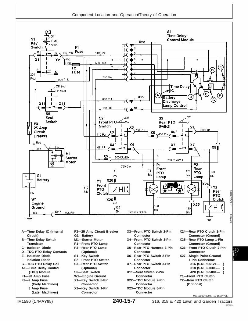
A—Time Delay IC (Internal F3—25 Amp Circuit Breaker X3—Front PTO Switch 2-Pin X24—Rear PTO Clutch 1-PinCircuit) G1—Battery Connector Connector (Ground)
B—Time Delay Switch M1—Starter Motor X4—Front PTO Switch 3-Pin X25—Rear PTO Lamp 1-PinTransistor P1—Front PTO Lamp Connector Connector (Ground)
C—Isolation Diode P2—Rear PTO Lamp X5—Rear PTO Harness 3-Pin X26—Front PTO Clutch 2-PinD—TDC PTO Relay Contacts (Optional) Connector ConnectorE—Isolation Diode S1—Key Switch X6—Rear PTO Switch 2-Pin X27—Single Point GroundF—Isolation Diode S2—Front PTO Switch Connector 1-Pin Connector:G—TDC PTO Relay Coil S3—Rear PTO Switch X7—Rear PTO Switch 3-Pin 316 (S.N. 596121— )A1—Time Delay Control (Optional) Connector 318 (S.N. 600305— )
(TDC) Module S6—Seat Switch X11—Seat Switch 2-Pin 420 (S.N. 595881— )F1—20 Amp Fuse W1—Engine Ground Connector Y1—Front PTO ClutchF2—2 Amp Fuse X1—Key Switch 5-Pin X22—TDC Module 2-Pin Y2—Rear PTO Clutch
(Early Machines) Connector Connector (Optional)3 Amp Fuse X2—Key Switch 1-Pin X23—TDC Module 8-Pin (Later Machines) Connector Connector
M77
923
-19-
04M
AR
95
MX,159024020,6 -19-16MAY95
Component Location and Operation/Theory of Operation
TM1590 (17MAY95) 240-15-7 316, 318 & 420 Lawn and Garden Tractors020895
240157
CHARGING CIRUIT OPERATION
The function of the charging circuit is to keep thebattery properly charged by supplying approximately13.6—14.7 VDC to the battery while the engine isoperating.
The charging system is a permanent magnet andstator type. The magnets are located in the flywheel,which rotates around the stationary stator (G2)windings. Current output is controlled by voltageregulator/rectifier (N1), mounted separately from thestator. Battery discharge lamp (P4) warns theoperator when battery discharge lamp control (A)senses low battery voltage. The battery dischargelamp and lamp control DO NOT monitor currentoutput from the stator.
As the flywheel turns, the permanent magnets inducealternating current (AC) in the stator windings. Thealternating current flows to the voltageregulator/rectifier. The rectifier portion of the voltageregulator/rectifier converts the alternating current todirect current (DC). The regulator portion stabilizesthe direct current and increases or decreases currentflow as required by the battery.
Battery discharge lamp control (A) senses batteryvoltage present at fuse (F2). If the lamp controlsenses low voltage (less than 12.3 volts), it willprovide a path to ground for battery discharge lamp(P4). Since battery voltage is always available at thedischarge lamp when the key switch is in the RUN orSTART position, the ground path provided by thelamp control will allow battery current from fuse (F1)to flow through the battery discharge lamp to ground,lighting the discharge lamp. The lamp will stay onuntil battery voltage increases to 12.7 volts. At thispoint, the battery discharge lamp control will breakthe path to ground, turning the battery discharge lampoff.
Fuses (F1 and F2) protect the battery discharge lampand lamp control circuit from excessive current.
NOTE: (*) For machines (S.N. —475000), a lightgreen wire is used instead of the 210 red wireused on later machines. The green wireconnects to terminal “B” of key switch (S1),instead of connecting to circuit breaker (F3).
NOTE: 1. The illustration shows ground circuit formachines (S.N. 475001— ).
For machines (S.N. —475000), the blk wirefrom the TDC module 2-pin connectorterminates (grounds) at the right side of thepedestal panel.
MX,159024020,7 -19-16MAY95
Component Location and Operation/Theory of Operation
TM1590 (17MAY95) 240-15-8 316, 318 & 420 Lawn and Garden Tractors020895
24015
8

A—Battery Discharge Lamp F3—25 Amp Circuit Breaker S1—Key Switch X16—Headlight SwitchControl G1—Battery W1—Engine Ground (See Connector
A1—Time Delay Control G2—Stator Note) X22—TDC Module 2-Pin(TDC) Module M1—Starter Motor X1—Key Switch 5-Pin Connector
F1—20 Amp Fuse N1—Voltage Connector X23—TDC Module 8-PinF2—2 Amp Fuse Regulator/Rectifier X2— Key Switch 1-Pin Connector
(Early Machines) P4—Battery Discharge Lamp Connector3 Amp Fuse P5—Engine Oil Pressure X3—Front PTO Switch 2-Pin (Later Machines) Lamp Connector
Charging Circuit Operation
M77
924
-19-
04M
AR
95
MX,159024020,8 -19-16MAY95
Component Location and Operation/Theory of Operation
TM1590 (17MAY95) 240-15-9 316, 318 & 420 Lawn and Garden Tractors020895
240159

OIL PRESSURE LAMP CIRCUIT OPERATION
B1—Engine Oil Pressure M1—Starter Motor X2—Key Switch 1-Pin X16—Headlight Switch 2-PinSwitch P5—Engine Oil Pressure Connector Connector
F1—20 Amp Fuse Lamp X3—Front PTO Switch 2-Pin X23—TDC Module 8-PinF3—25 Amp Circuit Breaker S1—Key Switch Connector ConnectorG1—Battery X1—Key Switch 5-Pin
Connector
The purpose of the oil pressure lamp circuit is towarn the operator when engine oil pressure is too lowfor safe operation of the engine.
Oil pressure switch (B1) is a normally-closed switch.When there is no oil pressure, such as when theengine is not operating, the switch contacts areclosed. The closed contacts of the oil pressure switchprovide a path to ground for oil pressure lamp (P5).
When the key switch is turned to the RUN or STARTposition, current from the battery flows through circuitbreaker (F3), key switch (S1), and 20 amp fuse (F1).From the fuse, current flows through oil pressurelamp (P5), oil pressure switch (B1), then to ground,lighting the oil pressure lamp. The lamp will stay lituntil either the key switch is turned to the OFFposition or engine oil pressure increases to the pointwhere the pressure switch contacts open, such asduring normal engine operation.
Fuse (F1) protects the oil pressure lamp circuit fromexcessive current.
M77
925
-19-
04M
AR
95
MX,159024020,9 -19-16MAY95
Component Location and Operation/Theory of Operation
TM1590 (17MAY95) 240-15-10 316, 318 & 420 Lawn and Garden Tractors020895
2401510
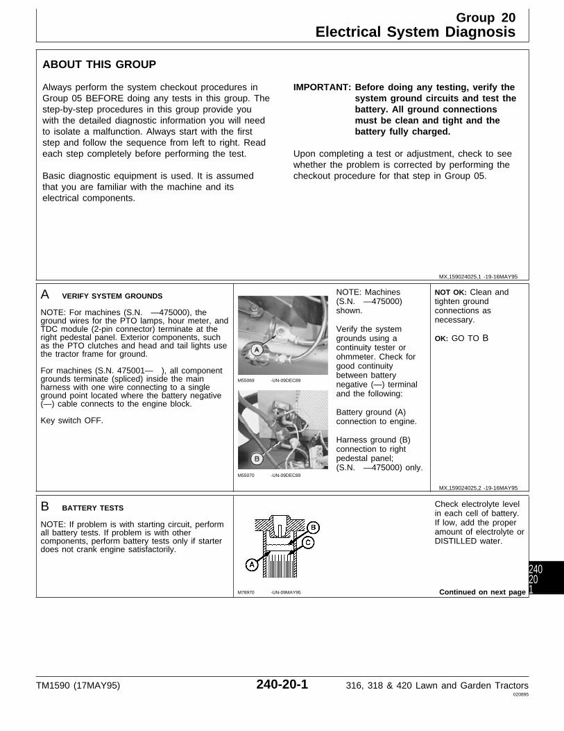
ABOUT THIS GROUP
Always perform the system checkout procedures inGroup 05 BEFORE doing any tests in this group. Thestep-by-step procedures in this group provide youwith the detailed diagnostic information you will needto isolate a malfunction. Always start with the firststep and follow the sequence from left to right. Readeach step completely before performing the test.
Basic diagnostic equipment is used. It is assumedthat you are familiar with the machine and itselectrical components.
IMPORTANT: Before doing any testing, verify thesystem ground circuits and test thebattery. All ground connectionsmust be clean and tight and thebattery fully charged.
Upon completing a test or adjustment, check to seewhether the problem is corrected by performing thecheckout procedure for that step in Group 05.
A VERIFY SYSTEM GROUNDS
NOTE: For machines (S.N. —475000), theground wires for the PTO lamps, hour meter, andTDC module (2-pin connector) terminate at theright pedestal panel. Exterior components, suchas the PTO clutches and head and tail lights usethe tractor frame for ground.
For machines (S.N. 475001— ), all componentgrounds terminate (spliced) inside the mainharness with one wire connecting to a singleground point located where the battery negative(—) cable connects to the engine block.
Key switch OFF.
M55069 -UN-09DEC89
M55070 -UN-09DEC89
NOTE: Machines(S.N. —475000)shown.
Verify the systemgrounds using acontinuity tester orohmmeter. Check forgood continuitybetween batterynegative (—) terminaland the following:
Battery ground (A)connection to engine.
Harness ground (B)connection to rightpedestal panel;(S.N. —475000) only.
NOT OK: Clean andtighten groundconnections asnecessary.
OK: GO TO B
B BATTERY TESTS
NOTE: If problem is with starting circuit, performall battery tests. If problem is with othercomponents, perform battery tests only if starterdoes not crank engine satisfactorily.
M78970 -UN-09MAY95
Check electrolyte levelin each cell of battery.If low, add the properamount of electrolyte orDISTILLED water.
Continued on next page
MX,159024025,1 -19-16MAY95
MX,159024025,2 -19-16MAY95
Group 20Electrical System Diagnosis
TM1590 (17MAY95) 240-20-1 316, 318 & 420 Lawn and Garden Tractors020895
240201
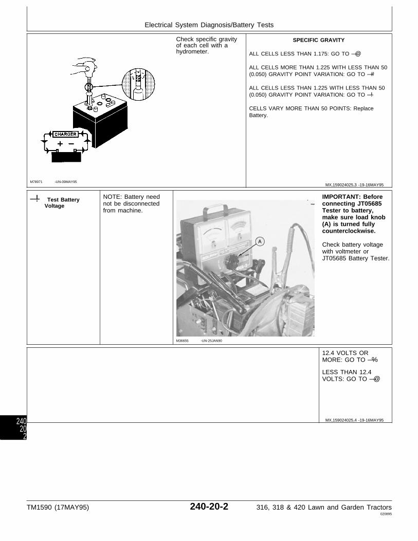
M78971 -UN-09MAY95
Check specific gravityof each cell with ahydrometer.
SPECIFIC GRAVITY
ALL CELLS LESS THAN 1.175: GO TO —@
ALL CELLS MORE THAN 1.225 WITH LESS THAN 50(0.050) GRAVITY POINT VARIATION: GO TO —#
ALL CELLS LESS THAN 1.225 WITH LESS THAN 50(0.050) GRAVITY POINT VARIATION: GO TO —!
CELLS VARY MORE THAN 50 POINTS: ReplaceBattery.
—! Test BatteryVoltage
NOTE: Battery neednot be disconnectedfrom machine.
M36655 -UN-25JAN90
IMPORTANT: Beforeconnecting JT05685Tester to battery,make sure load knob(A) is turned fullycounterclockwise.
Check battery voltagewith voltmeter orJT05685 Battery Tester.
12.4 VOLTS ORMORE: GO TO —%
LESS THAN 12.4VOLTS: GO TO —@
MX,159024025,3 -19-16MAY95
MX,159024025,4 -19-16MAY95
Electrical System Diagnosis/Battery Tests
TM1590 (17MAY95) 240-20-2 316, 318 & 420 Lawn and Garden Tractors020895
24020
2
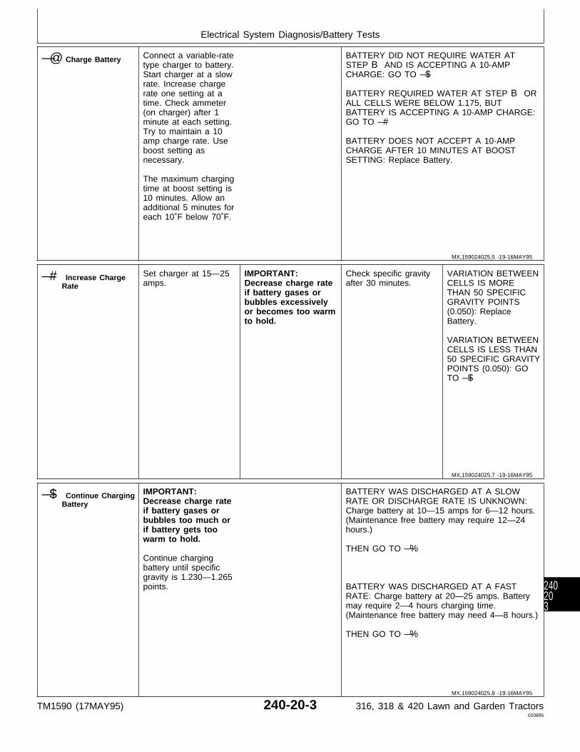
—@ Charge Battery Connect a variable-ratetype charger to battery.Start charger at a slowrate. Increase chargerate one setting at atime. Check ammeter(on charger) after 1minute at each setting.Try to maintain a 10amp charge rate. Useboost setting asnecessary.
The maximum chargingtime at boost setting is10 minutes. Allow anadditional 5 minutes foreach 10˚F below 70˚F.
BATTERY DID NOT REQUIRE WATER ATSTEP B AND IS ACCEPTING A 10-AMPCHARGE: GO TO —$
BATTERY REQUIRED WATER AT STEP B ORALL CELLS WERE BELOW 1.175, BUTBATTERY IS ACCEPTING A 10-AMP CHARGE:GO TO —#
BATTERY DOES NOT ACCEPT A 10-AMPCHARGE AFTER 10 MINUTES AT BOOSTSETTING: Replace Battery.
—# Increase ChargeRate
Set charger at 15—25amps.
IMPORTANT:Decrease charge rateif battery gases orbubbles excessivelyor becomes too warmto hold.
Check specific gravityafter 30 minutes.
VARIATION BETWEENCELLS IS MORETHAN 50 SPECIFICGRAVITY POINTS(0.050): ReplaceBattery.
VARIATION BETWEENCELLS IS LESS THAN50 SPECIFIC GRAVITYPOINTS (0.050): GOTO —$
—$ Continue ChargingBattery
IMPORTANT:Decrease charge rateif battery gases orbubbles too much orif battery gets toowarm to hold.
Continue chargingbattery until specificgravity is 1.230—1.265points.
BATTERY WAS DISCHARGED AT A SLOWRATE OR DISCHARGE RATE IS UNKNOWN:Charge battery at 10—15 amps for 6—12 hours.(Maintenance free battery may require 12—24hours.)
THEN GO TO —%
BATTERY WAS DISCHARGED AT A FASTRATE: Charge battery at 20—25 amps. Batterymay require 2—4 hours charging time.(Maintenance free battery may need 4—8 hours.)
THEN GO TO —%
MX,159024025,5 -19-16MAY95
MX,159024025,7 -19-16MAY95
MX,159024025,8 -19-16MAY95
Electrical System Diagnosis/Battery Tests
TM1590 (17MAY95) 240-20-3 316, 318 & 420 Lawn and Garden Tractors020895
240203
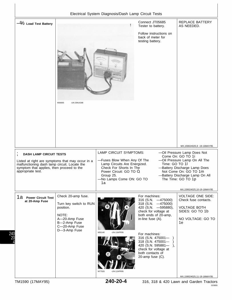
—% Load Test Battery
M36665 -UN-29AUG88
Connect JT05685Tester to battery.
Follow instructions onback of meter fortesting battery.
REPLACE BATTERYAS NEEDED.
; DASH LAMP CIRCUIT TESTS
Listed at right are symptoms that may occur in amalfunctioning dash lamp circuit. Locate thesymptom that applies, then proceed to theappropriate test.
LAMP CIRCUIT SYMPTOMS:
—Fuses Blow When Any Of The Lamp Circuits Are Energized. Check For Shorts In The Power Circuit: GO TO Ò, Group 25.—No Lamps Come ON: GO TO 1a
—Oil Pressure Lamp Does Not Come On: GO TO 1i—Oil Pressure Lamp On All The Time: GO TO 1l—Battery Discharge Lamp Does Not Come On: GO TO 1m—Battery Discharge Lamp On All The Time: GO TO 1p
1a Power Circuit Testat 20-Amp Fuse
Check 20-amp fuse.
Turn key switch to RUNposition.
NOTE:A—20-Amp FuseB—2-Amp FuseC—20-Amp FuseD—3-Amp Fuse
M55140 -UN-13APR95
M77926 -UN-12APR95
For machines:316 (S.N. —475000)318 (S.N. —475000)420 (S.N. —595880),check for voltage atboth ends of 20-amp,in-line fuse (A).
For machines:316 (S.N. 475001— )318 (S.N. 475001— )420 (S.N. 595881— ),check for voltage atboth contacts of20-amp fuse (C).
VOLTAGE ONE SIDE:Check fuse contacts.
VOLTAGE BOTHSIDES: GO TO 1b
NO VOLTAGE: GO TO1e
MX,159024025,9 -19-16MAY95
MX,159024025,10-19-16MAY95
MX,159024025,11-19-16MAY95
Electrical System Diagnosis/Dash Lamp Circuit Tests
TM1590 (17MAY95) 240-20-4 316, 318 & 420 Lawn and Garden Tractors020895
24020
4
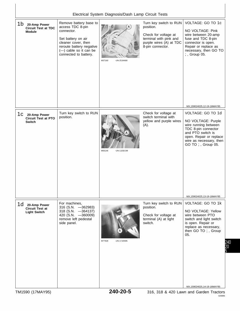
1b 20-Amp PowerCircuit Test at TDCModule
Remove battery base toaccess TDC 8-pinconnector.
Set battery on aircleaner cover, thenreroute battery negative(—) cable so it can beconnected to battery.
M37160 -UN-25JAN90
Turn key switch to RUNposition.
Check for voltage atterminal with pink andpurple wires (A) at TDC8-pin connector.
VOLTAGE: GO TO 1c
NO VOLTAGE: Pinkwire between 20-ampfuse and TDC 8-pinconnector is open.Repair or replace asnecessary, then GO TO;, Group 05.
1c 20-Amp PowerCircuit Test at PTOSwitch
Turn key switch to RUNposition.
M55146 -UN-11DEC89
Check for voltage atswitch terminal withyellow and purple wires(A).
VOLTAGE: GO TO 1d
NO VOLTAGE: Purplewire running betweenTDC 8-pin connectorand PTO switch isopen. Repair or replacewire as necessary, thenGO TO ;, Group 05.
1d 20-Amp PowerCircuit Test atLight Switch
For machines,316 (S.N. —362983)318 (S.N. —364137)420 (S.N. —360009)remove left pedestalside panel.
M77928 -UN-17JAN95
Turn key switch to RUNposition.
Check for voltage atterminal (A) at lightswitch.
VOLTAGE: GO TO 1k
NO VOLTAGE: Yellowwire between PTOswitch and light switchis open. Repair orreplace as necessary,then GO TO ;, Group05.
MX,159024025,12-19-16MAY95
MX,159024025,13-19-16MAY95
MX,159024025,14-19-16MAY95
Electrical System Diagnosis/Dash Lamp Circuit Tests
TM1590 (17MAY95) 240-20-5 316, 318 & 420 Lawn and Garden Tractors020895
240205
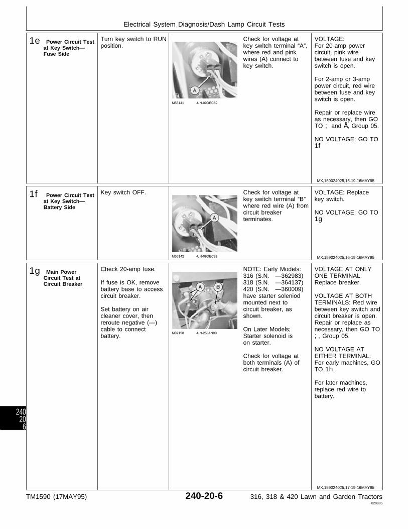
1e Power Circuit Testat Key Switch—Fuse Side
Turn key switch to RUNposition.
M55141 -UN-09DEC89
Check for voltage atkey switch terminal “A”,where red and pinkwires (A) connect tokey switch.
VOLTAGE:For 20-amp powercircuit, pink wirebetween fuse and keyswitch is open.
For 2-amp or 3-amppower circuit, red wirebetween fuse and keyswitch is open.
Repair or replace wireas necessary, then GOTO ; and Å, Group 05.
NO VOLTAGE: GO TO1f
1f Power Circuit Testat Key Switch—Battery Side
Key switch OFF.
M55142 -UN-09DEC89
Check for voltage atkey switch terminal “B”where red wire (A) fromcircuit breakerterminates.
VOLTAGE: Replacekey switch.
NO VOLTAGE: GO TO1g
1g Main PowerCircuit Test atCircuit Breaker
Check 20-amp fuse.
If fuse is OK, removebattery base to accesscircuit breaker.
Set battery on aircleaner cover, thenreroute negative (—)cable to connectbattery.
M37158 -UN-25JAN90
NOTE: Early Models:316 (S.N. —362983)318 (S.N. —364137)420 (S.N. —360009)have starter soleniodmounted next tocircuit breaker, asshown.
On Later Models;Starter solenoid ison starter.
Check for voltage atboth terminals (A) ofcircuit breaker.
VOLTAGE AT ONLYONE TERMINAL:Replace breaker.
VOLTAGE AT BOTHTERMINALS: Red wirebetween key switch andcircuit breaker is open.Repair or replace asnecessary, then GO TO;, Group 05.
NO VOLTAGE ATEITHER TERMINAL:For early machines, GOTO 1h.
For later machines,replace red wire tobattery.
MX,159024025,15-19-16MAY95
MX,159024025,16-19-16MAY95
MX,159024025,17-19-16MAY95
Electrical System Diagnosis/Dash Lamp Circuit Tests
TM1590 (17MAY95) 240-20-6 316, 318 & 420 Lawn and Garden Tractors020895
24020
6
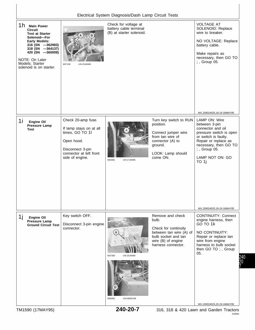
1h Main PowerCircuitTest at StarterSolenoid—ForEarly Models:316 (SN —362983)318 (SN —364137)420 (SN —360009)
NOTE: On LaterModels; Startersolenoid is on starter.
M37158 -UN-25JAN90
Check for voltage atbattery cable terminal(B) at starter solenoid.
VOLTAGE ATSOLENOID: Replacewire to breaker.
NO VOLTAGE: Replacebattery cable.
Make repairs asnecessary, then GO TO;, Group 05.
1i Engine OilPressure LampTest
Check 20-amp fuse.
If lamp stays on at alltimes, GO TO 1l
Open hood.
Disconnect 3-pinconnector at left frontside of engine.
M55081 -UN-17JAN95
Turn key switch to RUNposition.
Connect jumper wirefrom tan wire ofconnector (A) toground.
LOOK: Lamp shouldcome ON.
LAMP ON: Wirebetween 3-pinconnector and oilpressure switch is openor switch is faulty.Repair or replace asnecessary, then GO TO;, Group 05.
LAMP NOT ON: GOTO 1j
1j Engine OilPressure LampGround Circuit Test
Key switch OFF.
Disconnect 3-pin engineconnector.
M37300 -UN-25JAN90
M55082 -UN-09DEC89
Remove and checkbulb.
Check for continuitybetween tan wire (A) ofbulb socket and tanwire (B) of engineharness connector.
CONTINUITY: Connectengine harness, thenGO TO 1k
NO CONTINUITY:Repair or replace tanwire from engineharness to bulb socketthen GO TO ;, Group05.
MX,159024025,18-19-16MAY95
MX,159024025,19-19-16MAY95
MX,159024025,20-19-16MAY95
Electrical System Diagnosis/Dash Lamp Circuit Tests
TM1590 (17MAY95) 240-20-7 316, 318 & 420 Lawn and Garden Tractors020895
240207
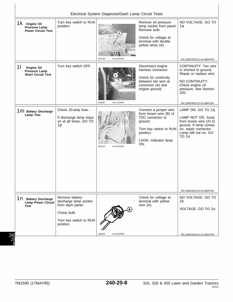
1k Engine OilPressure LampPower Circuit Test.
Turn key switch to RUNposition.
M37299 -UN-25JAN90
Remove oil pressurelamp socket from panel.Remove bulb.
Check for voltage atterminal with doubleyellow wires (A).
NO VOLTAGE: GO TO1a
1l Engine OilPressure LampShort Circuit Test
Turn key switch OFF.
M55081 -UN-17JAN95
Disconnect engineharness connector.
Check for continuitybetween tan wire atconnector (A) andengine ground.
CONTINUITY: Tan wireis shorted to ground.Repair or replace wire.
NO CONTINUITY:Check engine oilpressure. See Section220.
1m Battery DischargeLamp Test
Check 20-amp fuse.
If discharge lamp stayson at all times, GO TO1p
M37163 -UN-25JAN90
Connect a jumper wirefrom brown wire (B) ofTDC connector toground.
Turn key switch to RUNposition.
LOOK: Indicator lampON.
LAMP ON: GO TO 1q
LAMP NOT ON: Jumpfrom brown wire (A) toground. If lamp comeson, repair connector.Lamp still not on, GOTO 1n
1n Battery DischargeLamp Power CircuitTest
Remove batterydischarge lamp socketfrom dash panel.
Check bulb.
Turn key switch to RUNposition.
M36635 -UN-24APR89
Check for voltage atterminal with yellowwire (A).
NO VOLTAGE: GO TO1k
VOLTAGE: GO TO 1o
MX,159024025,21-19-16MAY95
MX,159024025,22-19-16MAY95
MX,159024025,23-19-16MAY95
MX,159024025,24-19-16MAY95
Electrical System Diagnosis/Dash Lamp Circuit Tests
TM1590 (17MAY95) 240-20-8 316, 318 & 420 Lawn and Garden Tractors020895
24020
8
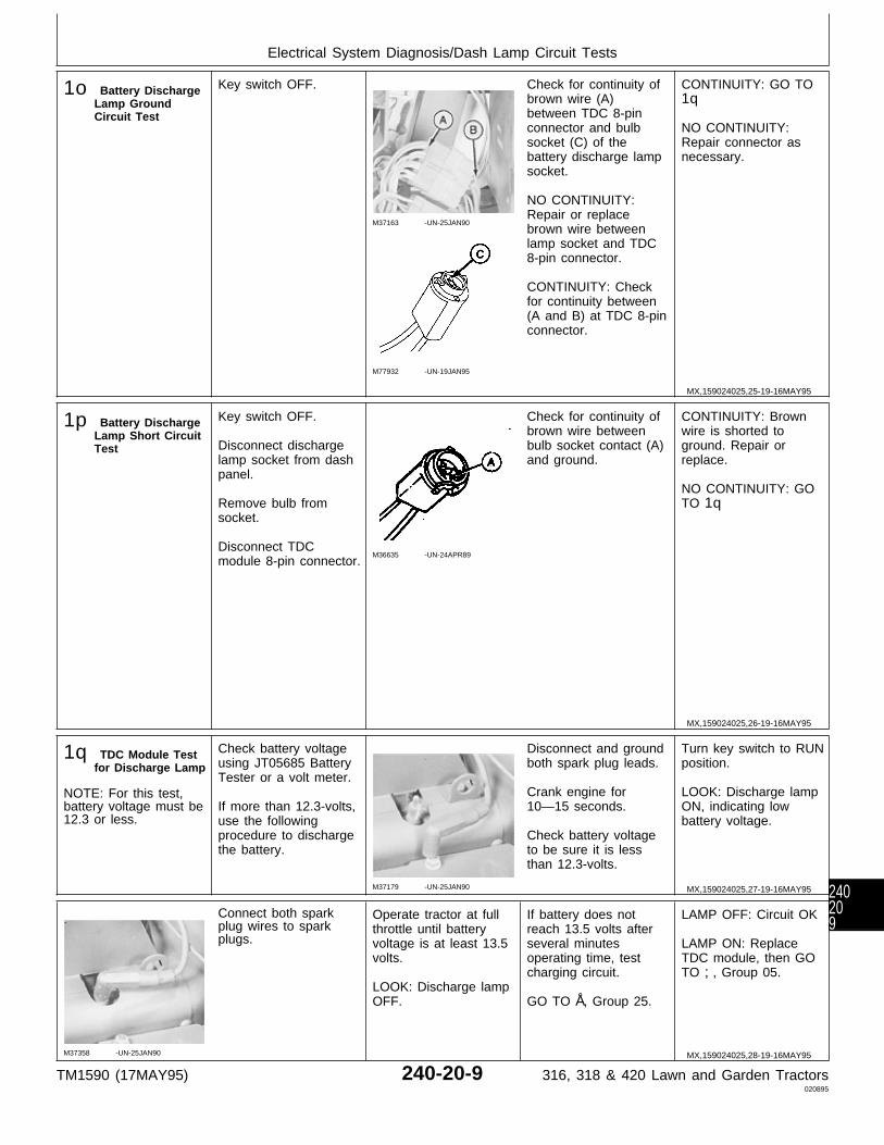
1o Battery DischargeLamp GroundCircuit Test
Key switch OFF.
M37163 -UN-25JAN90
M77932 -UN-19JAN95
Check for continuity ofbrown wire (A)between TDC 8-pinconnector and bulbsocket (C) of thebattery discharge lampsocket.
NO CONTINUITY:Repair or replacebrown wire betweenlamp socket and TDC8-pin connector.
CONTINUITY: Checkfor continuity between(A and B) at TDC 8-pinconnector.
CONTINUITY: GO TO1q
NO CONTINUITY:Repair connector asnecessary.
1p Battery DischargeLamp Short CircuitTest
Key switch OFF.
Disconnect dischargelamp socket from dashpanel.
Remove bulb fromsocket.
Disconnect TDCmodule 8-pin connector.
M36635 -UN-24APR89
Check for continuity ofbrown wire betweenbulb socket contact (A)and ground.
CONTINUITY: Brownwire is shorted toground. Repair orreplace.
NO CONTINUITY: GOTO 1q
1q TDC Module Testfor Discharge Lamp
NOTE: For this test,battery voltage must be12.3 or less.
Check battery voltageusing JT05685 BatteryTester or a volt meter.
If more than 12.3-volts,use the followingprocedure to dischargethe battery.
M37179 -UN-25JAN90
Disconnect and groundboth spark plug leads.
Crank engine for10—15 seconds.
Check battery voltageto be sure it is lessthan 12.3-volts.
Turn key switch to RUNposition.
LOOK: Discharge lampON, indicating lowbattery voltage.
M37358 -UN-25JAN90
Connect both sparkplug wires to sparkplugs.
Operate tractor at fullthrottle until batteryvoltage is at least 13.5volts.
LOOK: Discharge lampOFF.
If battery does notreach 13.5 volts afterseveral minutesoperating time, testcharging circuit.
GO TO Å, Group 25.
LAMP OFF: Circuit OK
LAMP ON: ReplaceTDC module, then GOTO ;, Group 05.
MX,159024025,25-19-16MAY95
MX,159024025,26-19-16MAY95
MX,159024025,27-19-16MAY95
MX,159024025,28-19-16MAY95
Electrical System Diagnosis/Dash Lamp Circuit Tests
TM1590 (17MAY95) 240-20-9 316, 318 & 420 Lawn and Garden Tractors020895
240209

‘ STARTING CIRCUITTESTS
Listed at right aresymptoms that mayoccur in amalfunctioning startingcircuit. Locate thesymptom that applies,then proceed to theappropriate test.
IMPORTANT: Testbattery and verifygrounds beforetesting startingcircuit. (See steps Aand B at thebeginning of thisgroup.)
STARTING CIRCUIT SYMPTOMS:
—Starter Operates, But Doesn’t Crank Engine: REPAIR STARTER (See CTM2.)
—Solenoid Doesn’t Click, Starter Doesn’t Operate: For Machines: 316 (S.N. —362983) 318 (S.N. —364137) 420 (S.N. —360009) GO TO 2a For Machines: 316 (S.N. 362984— ) 318 (S.N. 364138— ) 420 (S.N. 360010— ) GO TO 2c
—Solenoid Clicks, Starter Doesn’t Operate:
For Machines: 316 (S.N. —362983) 318 (S.N. —364137) 420 (S.N. —360009) GO TO 2b For Machines: 316 (S.N. 362984— ) 318 (S.N. 364138— ) 420 (S.N. 360010— ) GO TO 2d
—Starter Cranks Engine Slowly Or Erratically: GO TO Æ, Group 25.
2a Starter Test—For Machines:316 (SN —362983)318 (SN —364137)420 (SN —360009)
Remove battery base toaccess solenoid.
Set battery on aircleaner base, thenreroute negative (—)battery cable toconnect.
PTO switch OFF.
Key switch OFF.
Hydrostatic lever inN/STOP position.
Park brake engaged.
M37179 -UN-25JAN90
Disconnect spark plugwires from spark plugsand ground to engineblock.
M37165 -UN-25JAN90
Disconnect small purple wire (A) from solenoid.Connect one end of a jumper wire to theexposed terminal, then briefly touch other end ofjumper to battery cable terminal (B).
LISTEN: Starter must operate.
STARTER OPERATES:GO TO 2e
STARTER DOESN’TOPERATE: GO TO2b
2b Starter SolenoidTest—ForMachines:316 (SN —362983)318 (SN —364137)420 (SN —360009)
PTO switch OFF.
Key switch OFF.
Hydrostatic lever inN/STOP position.
Park brake engaged.
Spark plug wiresdisconnected andgrounded.
M37166 -UN-25JAN90
Briefly jump betweenthe two large terminals(A), located on thestarter solenoid.
LISTEN: Starter mustoperate.
STARTER OPERATES:Replace solenoid, thenGO TO ‘ group 05.
STARTER DOESN’TOPERATE: Checkbattery and starterwiring connections, thenGO TO Æ, Group 25.
MX,159024025,29-19-16MAY95
MX,159024025,30-19-16MAY95
MX,159024025,31-19-16MAY95
Electrical System Diagnosis/Starting Circuit Tests
TM1590 (17MAY95) 240-20-10 316, 318 & 420 Lawn and Garden Tractors020895
2402010
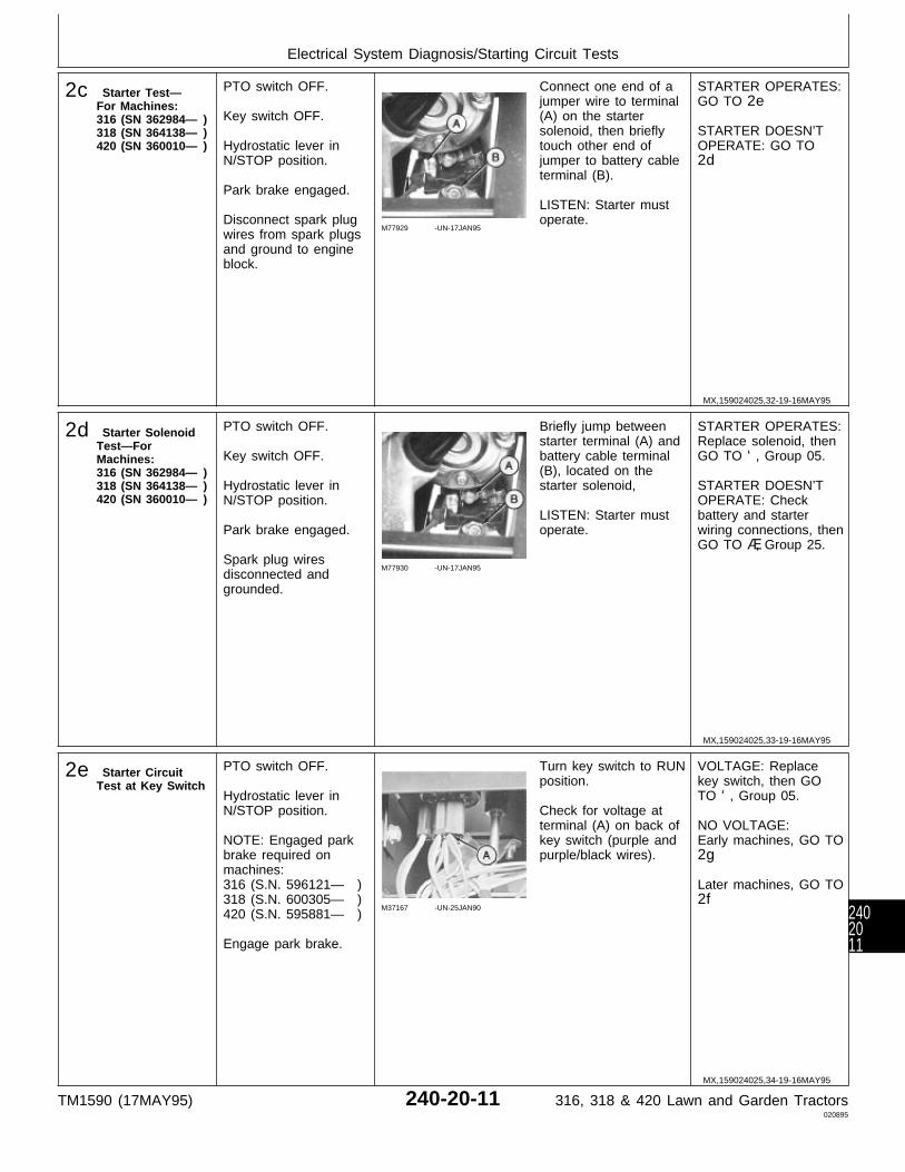
2c Starter Test—For Machines:316 (SN 362984— )318 (SN 364138— )420 (SN 360010— )
PTO switch OFF.
Key switch OFF.
Hydrostatic lever inN/STOP position.
Park brake engaged.
Disconnect spark plugwires from spark plugsand ground to engineblock.
M77929 -UN-17JAN95
Connect one end of ajumper wire to terminal(A) on the startersolenoid, then brieflytouch other end ofjumper to battery cableterminal (B).
LISTEN: Starter mustoperate.
STARTER OPERATES:GO TO 2e
STARTER DOESN’TOPERATE: GO TO2d
2d Starter SolenoidTest—ForMachines:316 (SN 362984— )318 (SN 364138— )420 (SN 360010— )
PTO switch OFF.
Key switch OFF.
Hydrostatic lever inN/STOP position.
Park brake engaged.
Spark plug wiresdisconnected andgrounded.
M77930 -UN-17JAN95
Briefly jump betweenstarter terminal (A) andbattery cable terminal(B), located on thestarter solenoid,
LISTEN: Starter mustoperate.
STARTER OPERATES:Replace solenoid, thenGO TO ‘, Group 05.
STARTER DOESN’TOPERATE: Checkbattery and starterwiring connections, thenGO TO Æ, Group 25.
2e Starter CircuitTest at Key Switch
PTO switch OFF.
Hydrostatic lever inN/STOP position.
NOTE: Engaged parkbrake required onmachines:316 (S.N. 596121— )318 (S.N. 600305— )420 (S.N. 595881— )
Engage park brake.
M37167 -UN-25JAN90
Turn key switch to RUNposition.
Check for voltage atterminal (A) on back ofkey switch (purple andpurple/black wires).
VOLTAGE: Replacekey switch, then GOTO ‘, Group 05.
NO VOLTAGE:Early machines, GO TO2g
Later machines, GO TO2f
MX,159024025,32-19-16MAY95
MX,159024025,33-19-16MAY95
MX,159024025,34-19-16MAY95
Electrical System Diagnosis/Starting Circuit Tests
TM1590 (17MAY95) 240-20-11 316, 318 & 420 Lawn and Garden Tractors020895
2402011
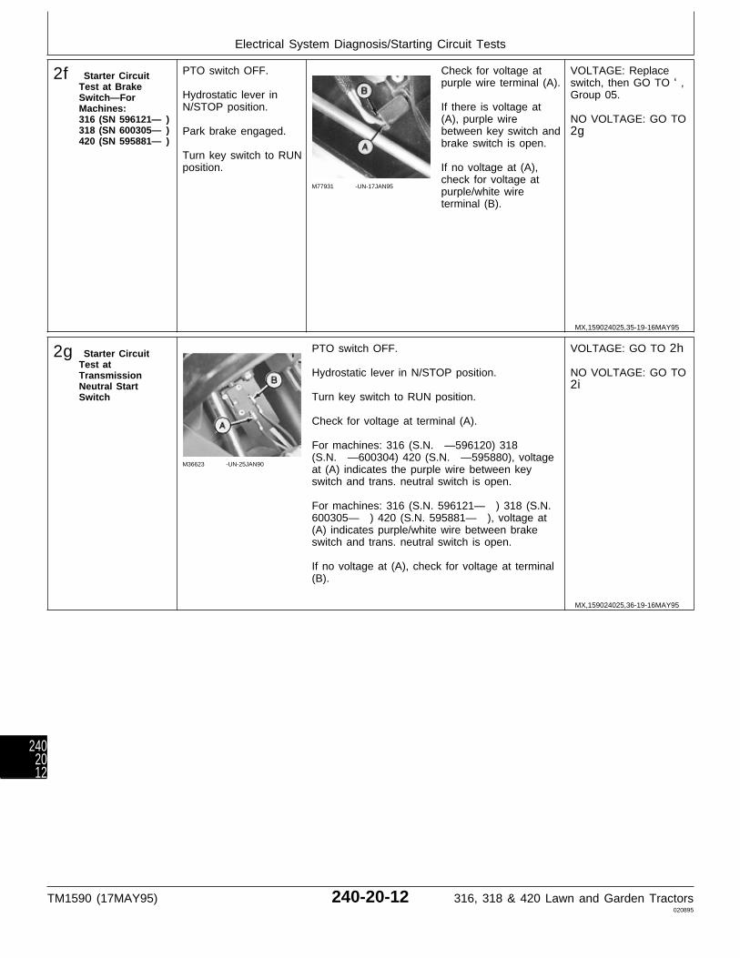
2f Starter CircuitTest at BrakeSwitch—ForMachines:316 (SN 596121— )318 (SN 600305— )420 (SN 595881— )
PTO switch OFF.
Hydrostatic lever inN/STOP position.
Park brake engaged.
Turn key switch to RUNposition.
M77931 -UN-17JAN95
Check for voltage atpurple wire terminal (A).
If there is voltage at(A), purple wirebetween key switch andbrake switch is open.
If no voltage at (A),check for voltage atpurple/white wireterminal (B).
VOLTAGE: Replaceswitch, then GO TO ‘,Group 05.
NO VOLTAGE: GO TO2g
2g Starter CircuitTest atTransmissionNeutral StartSwitch
M36623 -UN-25JAN90
PTO switch OFF.
Hydrostatic lever in N/STOP position.
Turn key switch to RUN position.
Check for voltage at terminal (A).
For machines: 316 (S.N. —596120) 318(S.N. —600304) 420 (S.N. —595880), voltageat (A) indicates the purple wire between keyswitch and trans. neutral switch is open.
For machines: 316 (S.N. 596121— ) 318 (S.N.600305— ) 420 (S.N. 595881— ), voltage at(A) indicates purple/white wire between brakeswitch and trans. neutral switch is open.
If no voltage at (A), check for voltage at terminal(B).
VOLTAGE: GO TO 2h
NO VOLTAGE: GO TO2i
MX,159024025,35-19-16MAY95
MX,159024025,36-19-16MAY95
Electrical System Diagnosis/Starting Circuit Tests
TM1590 (17MAY95) 240-20-12 316, 318 & 420 Lawn and Garden Tractors020895
2402012
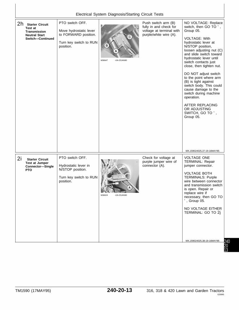
2h Starter CircuitTest atTransmissionNeutral StartSwitch—Continued
PTO switch OFF.
Move hydrostatic leverto FORWARD position.
Turn key switch to RUNposition.
M36647 -UN-25JAN90
Push switch arm (B)fully in and check forvoltage at terminal withpurple/white wire (A).
NO VOLTAGE: Replaceswitch, then GO TO ‘,Group 05.
VOLTAGE: Withhydrostatic lever atN/STOP position,loosen adjusting nut (C)and slide switch towardhydrostatic lever untilswitch contacts justclose, then tighten nut.
DO NOT adjust switchto the point where arm(B) is tight againstswitch body. This couldcause damage to theswitch during machineoperation.
AFTER REPLACINGOR ADJUSTINGSWITCH, GO TO ‘,Group 05.
2i Starter CircuitTest at JumperConnector—SinglePTO
PTO switch OFF.
Hydrostatic lever inN/STOP position.
Turn key switch to RUNposition.
M36624 -UN-25JAN90
Check for voltage atpurple jumper wire ofconnector (A).
VOLTAGE ONETERMINAL: Repairjumper connector.
VOLTAGE BOTHTERMINALS: Purplewire between connectorand transmission switchis open. Repair orreplace wire ifnecessary, then GO TO‘, Group 05.
NO VOLTAGE EITHERTERMINAL: GO TO 2j
MX,159024025,37-19-16MAY95
MX,159024025,38-19-16MAY95
Electrical System Diagnosis/Starting Circuit Tests
TM1590 (17MAY95) 240-20-13 316, 318 & 420 Lawn and Garden Tractors020895
2402013
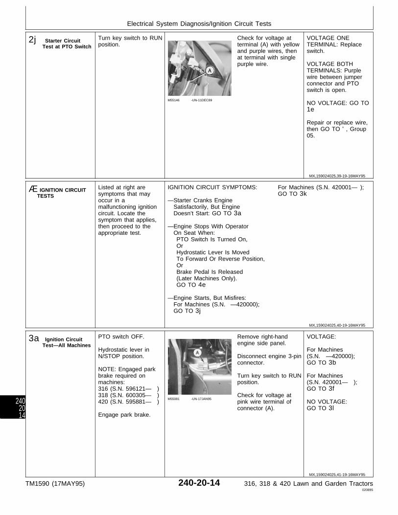
2j Starter CircuitTest at PTO Switch
Turn key switch to RUNposition.
M55146 -UN-11DEC89
Check for voltage atterminal (A) with yellowand purple wires, thenat terminal with singlepurple wire.
VOLTAGE ONETERMINAL: Replaceswitch.
VOLTAGE BOTHTERMINALS: Purplewire between jumperconnector and PTOswitch is open.
NO VOLTAGE: GO TO1e
Repair or replace wire,then GO TO ‘, Group05.
Æ IGNITION CIRCUITTESTS
Listed at right aresymptoms that mayoccur in amalfunctioning ignitioncircuit. Locate thesymptom that applies,then proceed to theappropriate test.
IGNITION CIRCUIT SYMPTOMS:
—Starter Cranks Engine Satisfactorily, But Engine Doesn’t Start: GO TO 3a
—Engine Stops With Operator On Seat When: PTO Switch Is Turned On, Or Hydrostatic Lever Is Moved To Forward Or Reverse Position, Or Brake Pedal Is Released (Later Machines Only). GO TO 4e
—Engine Starts, But Misfires: For Machines (S.N. —420000); GO TO 3j
For Machines (S.N. 420001— ); GO TO 3k
3a Ignition CircuitTest—All Machines
PTO switch OFF.
Hydrostatic lever inN/STOP position.
NOTE: Engaged parkbrake required onmachines:316 (S.N. 596121— )318 (S.N. 600305— )420 (S.N. 595881— )
Engage park brake.
M55081 -UN-17JAN95
Remove right-handengine side panel.
Disconnect engine 3-pinconnector.
Turn key switch to RUNposition.
Check for voltage atpink wire terminal ofconnector (A).
VOLTAGE:
For Machines(S.N. —420000);GO TO 3b
For Machines(S.N. 420001— );GO TO 3f
NO VOLTAGE:GO TO 3l
MX,159024025,39-19-16MAY95
MX,159024025,40-19-16MAY95
MX,159024025,41-19-16MAY95
Electrical System Diagnosis/Ignition Circuit Tests
TM1590 (17MAY95) 240-20-14 316, 318 & 420 Lawn and Garden Tractors020895
2402014
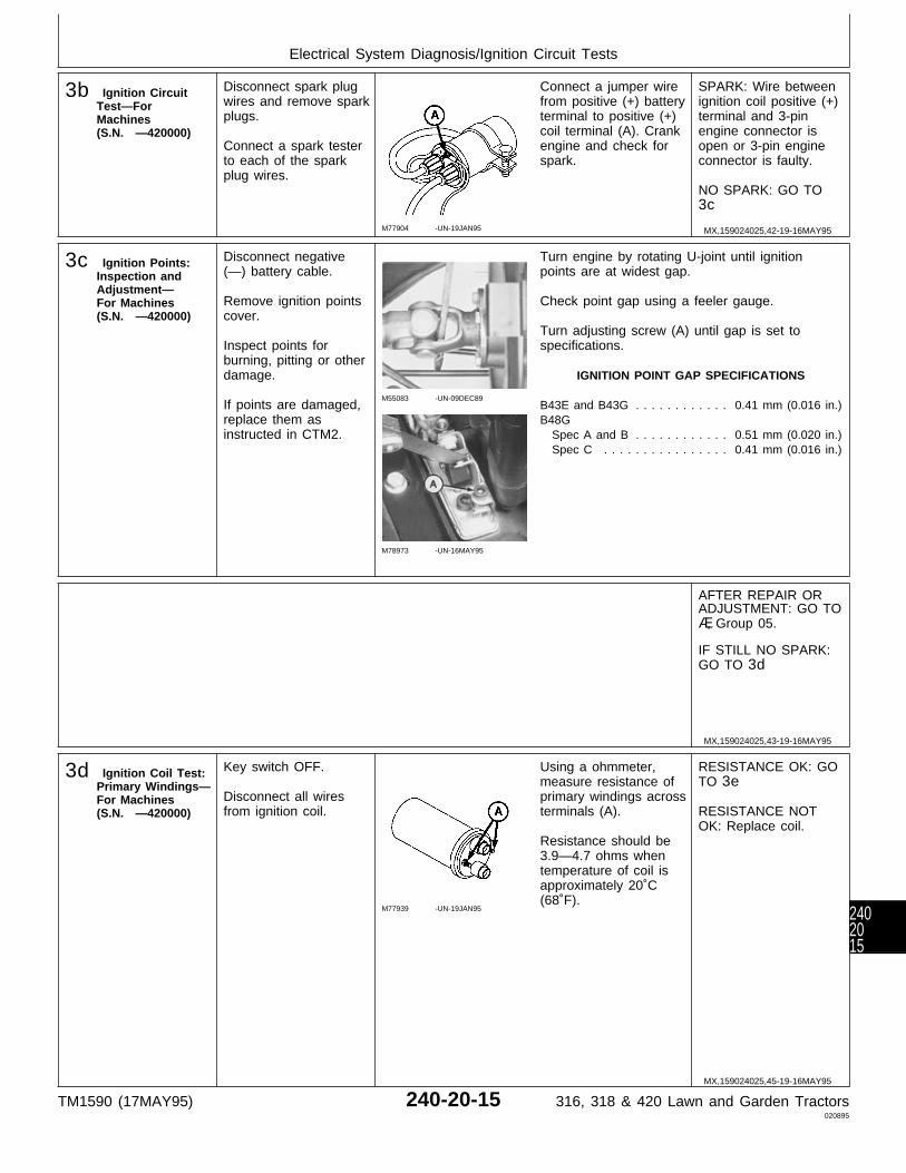
3b Ignition CircuitTest—ForMachines(S.N. —420000)
Disconnect spark plugwires and remove sparkplugs.
Connect a spark testerto each of the sparkplug wires.
M77904 -UN-19JAN95
Connect a jumper wirefrom positive (+) batteryterminal to positive (+)coil terminal (A). Crankengine and check forspark.
SPARK: Wire betweenignition coil positive (+)terminal and 3-pinengine connector isopen or 3-pin engineconnector is faulty.
NO SPARK: GO TO3c
3c Ignition Points:Inspection andAdjustment—For Machines(S.N. —420000)
Disconnect negative(—) battery cable.
Remove ignition pointscover.
Inspect points forburning, pitting or otherdamage.
If points are damaged,replace them asinstructed in CTM2.
M55083 -UN-09DEC89
M78973 -UN-16MAY95
Turn engine by rotating U-joint until ignitionpoints are at widest gap.
Check point gap using a feeler gauge.
Turn adjusting screw (A) until gap is set tospecifications.
IGNITION POINT GAP SPECIFICATIONS
B43E and B43G . . . . . . . . . . . . 0.41 mm (0.016 in.)B48G Spec A and B . . . . . . . . . . . . 0.51 mm (0.020 in.) Spec C . . . . . . . . . . . . . . . . 0.41 mm (0.016 in.)
AFTER REPAIR ORADJUSTMENT: GO TOÆ, Group 05.
IF STILL NO SPARK:GO TO 3d
3d Ignition Coil Test:Primary Windings—For Machines(S.N. —420000)
Key switch OFF.
Disconnect all wiresfrom ignition coil.
M77939 -UN-19JAN95
Using a ohmmeter,measure resistance ofprimary windings acrossterminals (A).
Resistance should be3.9—4.7 ohms whentemperature of coil isapproximately 20˚C(68˚F).
RESISTANCE OK: GOTO 3e
RESISTANCE NOTOK: Replace coil.
MX,159024025,42-19-16MAY95
MX,159024025,43-19-16MAY95
MX,159024025,45-19-16MAY95
Electrical System Diagnosis/Ignition Circuit Tests
TM1590 (17MAY95) 240-20-15 316, 318 & 420 Lawn and Garden Tractors020895
2402015

3e Ignition Coil Test:SecondaryWindings—For Machines(S.N. —420000)
Key switch OFF.
Disconnect all wiresfrom ignition coil.
M77938 -UN-19JAN95
Using a ohmmeter,measure resistance ofsecondary windings atspark plug wireterminals (A).
Resistance should be12.6—15.4 K-ohmswhen temperature ofcoil is approximately20˚C (68˚F).
RESISTANCE NOTOK: Replace coil, thenGO TO Æ, Group 05.
3f Ignition CircuitTest—ForMachines(S.N. 420001— )
Disconnect spark plugwires and remove sparkplugs.
Connect a spark testerto each of the sparkplug wires.
M45243 -UN-12JAN90
IMPORTANT: Do nottouch the negativecoil terminal with thejumper wire. Batteryvoltage applied to thenegative coil terminalwill damage theignition controlmodule.
NOTE: Terminal (A) issmaller in diameter ofthe two posts.
Connect a jumper wirefrom positive (+) batteryterminal to positive (+)coil terminal (A).
Crank engine andcheck for spark.
SPARK: White wire to3-pin engine connectoris open or 3-pin engineconnector is faulty.Repair or replace asnecessary, then GO TOÆ, Group 05.
NO SPARK: GO TO3g
MX,159024025,46-19-16MAY95
MX,159024025,47-19-16MAY95
Electrical System Diagnosis/Ignition Circuit Tests
TM1590 (17MAY95) 240-20-16 316, 318 & 420 Lawn and Garden Tractors020895
2402016
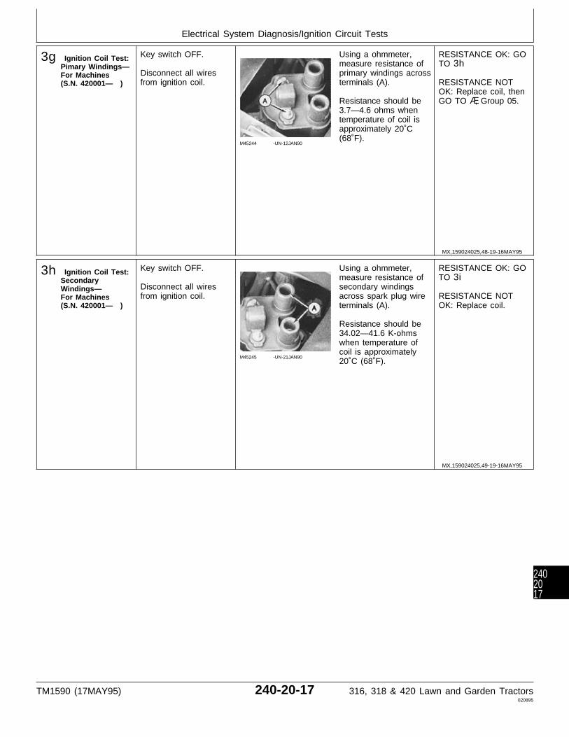
3g Ignition Coil Test:Pimary Windings—For Machines(S.N. 420001— )
Key switch OFF.
Disconnect all wiresfrom ignition coil.
M45244 -UN-12JAN90
Using a ohmmeter,measure resistance ofprimary windings acrossterminals (A).
Resistance should be3.7—4.6 ohms whentemperature of coil isapproximately 20˚C(68˚F).
RESISTANCE OK: GOTO 3h
RESISTANCE NOTOK: Replace coil, thenGO TO Æ, Group 05.
3h Ignition Coil Test:SecondaryWindings—For Machines(S.N. 420001— )
Key switch OFF.
Disconnect all wiresfrom ignition coil.
M45245 -UN-21JAN90
Using a ohmmeter,measure resistance ofsecondary windingsacross spark plug wireterminals (A).
Resistance should be34.02—41.6 K-ohmswhen temperature ofcoil is approximately20˚C (68˚F).
RESISTANCE OK: GOTO 3i
RESISTANCE NOTOK: Replace coil.
MX,159024025,48-19-16MAY95
MX,159024025,49-19-16MAY95
Electrical System Diagnosis/Ignition Circuit Tests
TM1590 (17MAY95) 240-20-17 316, 318 & 420 Lawn and Garden Tractors020895
2402017
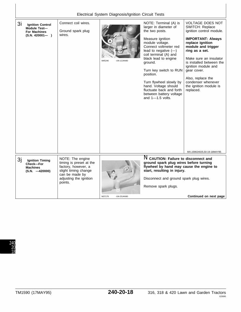
3i Ignition ControlModule Test—For Machines(S.N. 420001— )
Connect coil wires.
Ground spark plugwires.
M45246 -UN-12JAN90
NOTE: Terminal (A) islarger in diameter ofthe two posts.
Measure ignitionmodule voltage.Connect voltmeter redlead to negative (—)coil terminal (A) andblack lead to engineground.
Turn key switch to RUNposition.
Turn flywheel slowly byhand. Voltage shouldfluctuate back and forthbetween battery voltageand 1—1.5 volts.
VOLTAGE DOES NOTSWITCH: Replaceignition control module.
IMPORTANT: Alwaysreplace ignitionmodule and triggerring as a set.
Make sure an insulatoris installed between theignition module andgear cover.
Also, replace thecondenser wheneverthe ignition module isreplaced.
3j Ignition TimingCheck—ForMachines(S.N. —420000)
NOTE: The enginetiming is preset at thefactory, however, aslight timing changecan be made byadjusting the ignitionpoints.
M37179 -UN-25JAN90
N CAUTION: Failure to disconnect andground spark plug wires before turningflywheel by hand may cause the engine tostart, resulting in injury.
Disconnect and ground spark plug wires.
Remove spark plugs.
Continued on next page
MX,159024025,50-19-16MAY95
Electrical System Diagnosis/Ignition Circuit Tests
TM1590 (17MAY95) 240-20-18 316, 318 & 420 Lawn and Garden Tractors020895
2402018

M78974 -UN-16MAY95
Remove blower housing to access gearcasecover timing marks (A) and flywheel timing mark(B).
Connect one lead of an ohmmeter or continuitytester to the primary windings negative (—)terminal of the ignition coil.
Connect the other tester lead to engine groundor negative (—) terminal of battery.
Slowly turn flywheel clockwise until meter ortester shows no continuity.
Turn flywheel 360 degrees until meter or testeragain shows no continuity. At this point theignition points just open, which is when ignitionoccurs.
Check which of the gear case timing marks (A)is directly across from flywheel timing mark (B).See chart for timing specification of particularengine used.
If timing is early (advanced), the igniton pointgap is too wide. If the timing is late (retarded),the point gap is too narrow. Adjust ignition pointsas necessary, GO TO 3c.
NOTE: The ignition point gap of: 0.41 mm (0.016in.) equals 16˚ BTC 0.51 mm (0.020 in.) equals20˚ BTC
The “Spec” letter is the last letter of the enginemodel number.
TIMING SPECIFICATION
Engine Model Timing In Degrees
B43E and B43G . . . . . . . . . . . . . . . . . . . . 16˚ BTC
B48GSpec A and B . . . . . . . . . . . . . . . . . . . . . 20˚ BTCSpec C . . . . . . . . . . . . . . . . . . . . . . . . . . 16˚ BTC
MX,15902402551A-19-16MAY95
Electrical System Diagnosis/Ignition Circuit Tests
TM1590 (17MAY95) 240-20-19 316, 318 & 420 Lawn and Garden Tractors020895
2402019
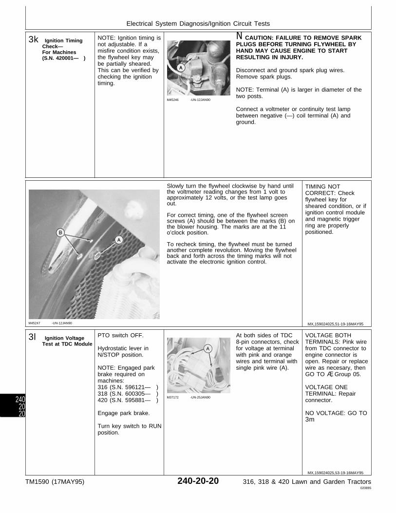
3k Ignition TimingCheck—For Machines(S.N. 420001— )
NOTE: Ignition timing isnot adjustable. If amisfire condition exists,the flywheel key maybe partially sheared.This can be verified bychecking the ignitiontiming.
M45246 -UN-12JAN90
N CAUTION: FAILURE TO REMOVE SPARKPLUGS BEFORE TURNING FLYWHEEL BYHAND MAY CAUSE ENGINE TO STARTRESULTING IN INJURY.
Disconnect and ground spark plug wires.Remove spark plugs.
NOTE: Terminal (A) is larger in diameter of thetwo posts.
Connect a voltmeter or continuity test lampbetween negative (—) coil terminal (A) andground.
M45247 -UN-12JAN90
Slowly turn the flywheel clockwise by hand untilthe voltmeter reading changes from 1 volt toapproximately 12 volts, or the test lamp goesout.
For correct timing, one of the flywheel screenscrews (A) should be between the marks (B) onthe blower housing. The marks are at the 11o’clock position.
To recheck timing, the flywheel must be turnedanother complete revolution. Moving the flywheelback and forth across the timing marks will notactivate the electronic ignition control.
TIMING NOTCORRECT: Checkflywheel key forsheared condition, or ifignition control moduleand magnetic triggerring are properlypositioned.
3l Ignition VoltageTest at TDC Module
PTO switch OFF.
Hydrostatic lever inN/STOP position.
NOTE: Engaged parkbrake required onmachines:316 (S.N. 596121— )318 (S.N. 600305— )420 (S.N. 595881— )
Engage park brake.
Turn key switch to RUNposition.
M37172 -UN-25JAN90
At both sides of TDC8-pin connectors, checkfor voltage at terminalwith pink and orangewires and terminal withsingle pink wire (A).
VOLTAGE BOTHTERMINALS: Pink wirefrom TDC connector toengine connector isopen. Repair or replacewire as necesary, thenGO TO Æ, Group 05.
VOLTAGE ONETERMINAL: Repairconnector.
NO VOLTAGE: GO TO3m
MX,159024025,51-19-16MAY95
MX,159024025,53-19-16MAY95
Electrical System Diagnosis/Ignition Circuit Tests
TM1590 (17MAY95) 240-20-20 316, 318 & 420 Lawn and Garden Tractors020895
2402020
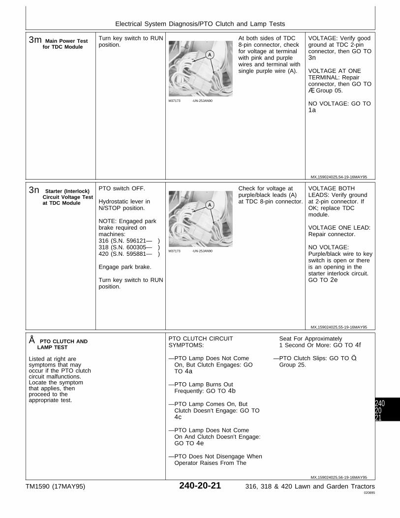
3m Main Power Testfor TDC Module
Turn key switch to RUNposition.
M37173 -UN-25JAN90
At both sides of TDC8-pin connector, checkfor voltage at terminalwith pink and purplewires and terminal withsingle purple wire (A).
VOLTAGE: Verify goodground at TDC 2-pinconnector, then GO TO3n
VOLTAGE AT ONETERMINAL: Repairconnector, then GO TOÆ, Group 05.
NO VOLTAGE: GO TO1a
3n Starter (Interlock)Circuit Voltage Testat TDC Module
PTO switch OFF.
Hydrostatic lever inN/STOP position.
NOTE: Engaged parkbrake required onmachines:316 (S.N. 596121— )318 (S.N. 600305— )420 (S.N. 595881— )
Engage park brake.
Turn key switch to RUNposition.
M37173 -UN-25JAN90
Check for voltage atpurple/black leads (A)at TDC 8-pin connector.
VOLTAGE BOTHLEADS: Verify groundat 2-pin connector. IfOK; replace TDCmodule.
VOLTAGE ONE LEAD:Repair connector.
NO VOLTAGE:Purple/black wire to keyswitch is open or thereis an opening in thestarter interlock circuit.GO TO 2e
Å PTO CLUTCH ANDLAMP TEST
Listed at right aresymptoms that mayoccur if the PTO clutchcircuit malfunctions.Locate the symptomthat applies, thenproceed to theappropriate test.
PTO CLUTCH CIRCUITSYMPTOMS:
—PTO Lamp Does Not Come On, But Clutch Engages: GO TO 4a
—PTO Lamp Burns Out Frequently: GO TO 4b
—PTO Lamp Comes On, But Clutch Doesn’t Engage: GO TO 4c
—PTO Lamp Does Not Come On And Clutch Doesn’t Engage: GO TO 4e
—PTO Does Not Disengage When Operator Raises From The
Seat For Approximately 1 Second Or More: GO TO 4f
—PTO Clutch Slips: GO TO Ö, Group 25.
MX,159024025,54-19-16MAY95
MX,159024025,55-19-16MAY95
MX,159024025,56-19-16MAY95
Electrical System Diagnosis/PTO Clutch and Lamp Tests
TM1590 (17MAY95) 240-20-21 316, 318 & 420 Lawn and Garden Tractors020895
2402021

4a PTO Lamp Test Remove battery base toaccess instrumentpanel.
Disconnect PTO lampsocket.
Remove and checkbulb.
M36643 -UN-29AUG88
If bulb is good, checkfor continuity betweenblack wire at contact(A) and ground.
CONTINUITY: Replaceblue wire between PTOswitch and bulb socket.Repair or replace wireas necessary, then GOTO Å, Group 05.
NO CONTINUITY:Repair or replaceground wire asnecessary, then GO TOÅ, Group 05.
4b PTO Lamp DiodeTest
NOTE: Diodes aredesigned to allowcurrent flow in onedirection only.
Remove battery base toaccess instrumentpanel.
Remove PTO lampsocket.
Remove bulb.
Check diode withohmmeter or continuitytester. If using a digitalmeter, use diode checkposition on meter.
Check for continuityacross terminals of bulbsocket. Reverse leadsand check again.
LOOK: There should becontinuity in onedirection only.
CONTINUITY ONEDIRECTION ONLY:Circuit probably has anintermittent short.Check all connectionsand grounds, then GOTO Ò, Group 25.
CONTINUITY BOTHDIRECTIONS OR NOCONTINUITY: Replacediode.
4c PTO Voltage Testat ClutchConnector
Remove right-handengine side panel.
Install jumper wireacross seat switchconnector or havesomeone sit on seat.
Turn key switch to RUNposition.
Move PTO switch toON position.
M55084 -UN-09DEC89
NOTE: Machines(S.N. —475000)shown. Later machinesuse a 2-pin connector.
Check for voltage atblue lead of PTO clutchconnector.
VOLTAGE: GO TO 4d
NO VOLTAGE: GO TO4e
MX,159024025,57-19-16MAY95
MX,159024025,58-19-16MAY95
MX,159024025,59-19-16MAY95
Electrical System Diagnosis/PTO Clutch and Lamp Tests
TM1590 (17MAY95) 240-20-22 316, 318 & 420 Lawn and Garden Tractors020895
2402022
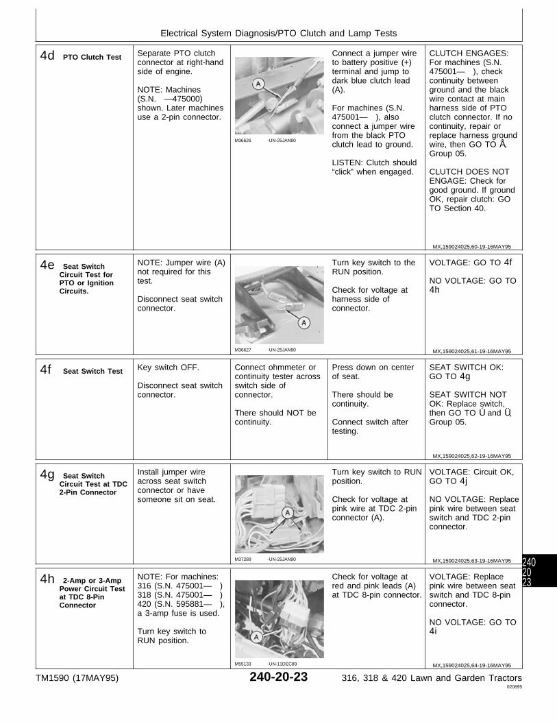
4d PTO Clutch Test Separate PTO clutchconnector at right-handside of engine.
NOTE: Machines(S.N. —475000)shown. Later machinesuse a 2-pin connector.
M36626 -UN-25JAN90
Connect a jumper wireto battery positive (+)terminal and jump todark blue clutch lead(A).
For machines (S.N.475001— ), alsoconnect a jumper wirefrom the black PTOclutch lead to ground.
LISTEN: Clutch should“click” when engaged.
CLUTCH ENGAGES:For machines (S.N.475001— ), checkcontinuity betweenground and the blackwire contact at mainharness side of PTOclutch connector. If nocontinuity, repair orreplace harness groundwire, then GO TO Å,Group 05.
CLUTCH DOES NOTENGAGE: Check forgood ground. If groundOK, repair clutch: GOTO Section 40.
4e Seat SwitchCircuit Test forPTO or IgnitionCircuits.
NOTE: Jumper wire (A)not required for thistest.
Disconnect seat switchconnector.
M36627 -UN-25JAN90
Turn key switch to theRUN position.
Check for voltage atharness side ofconnector.
VOLTAGE: GO TO 4f
NO VOLTAGE: GO TO4h
4f Seat Switch Test Key switch OFF.
Disconnect seat switchconnector.
Connect ohmmeter orcontinuity tester acrossswitch side ofconnector.
There should NOT becontinuity.
Press down on centerof seat.
There should becontinuity.
Connect switch aftertesting.
SEAT SWITCH OK:GO TO 4g
SEAT SWITCH NOTOK: Replace switch,then GO TO Ú and Ü,Group 05.
4g Seat SwitchCircuit Test at TDC2-Pin Connector
Install jumper wireacross seat switchconnector or havesomeone sit on seat.
M37289 -UN-25JAN90
Turn key switch to RUNposition.
Check for voltage atpink wire at TDC 2-pinconnector (A).
VOLTAGE: Circuit OK,GO TO 4j
NO VOLTAGE: Replacepink wire between seatswitch and TDC 2-pinconnector.
4h 2-Amp or 3-AmpPower Circuit Testat TDC 8-PinConnector
NOTE: For machines:316 (S.N. 475001— )318 (S.N. 475001— )420 (S.N. 595881— ),a 3-amp fuse is used.
Turn key switch toRUN position.
M55133 -UN-11DEC89
Check for voltage atred and pink leads (A)at TDC 8-pin connector.
VOLTAGE: Replacepink wire between seatswitch and TDC 8-pinconnector.
NO VOLTAGE: GO TO4i
MX,159024025,60-19-16MAY95
MX,159024025,61-19-16MAY95
MX,159024025,62-19-16MAY95
MX,159024025,63-19-16MAY95
MX,159024025,64-19-16MAY95
Electrical System Diagnosis/PTO Clutch and Lamp Tests
TM1590 (17MAY95) 240-20-23 316, 318 & 420 Lawn and Garden Tractors020895
2402023

4i Power CircuitVoltage Test at2-Amp or 3-AmpFuse
Turn key switch toRUN position.
M55140 -UN-13APR95
M77926 -UN-12APR95
For machines:316 (S.N. —475000)318 (S.N. —475000)420 (S.N. —595880),check for voltage atboth ends of 2-amp,in-line fuse (B).
For machines:316 (S.N. 475001— )318 (S.N. 475001— )420 (S.N. 595881— ),check for voltage atboth contacts of 3-ampfuse (D).
VOLTAGE BOTHSIDES: Replace redwire to TDC 8-pinconnector.
VOLTAGE ONE SIDE:Check fuse contacts.
NO VOLTAGE: GO TO1e
4j PTO circuit Test atPTO Switch
Key switch OFF.
PTO switch OFF.
Install jumper wireacross seat switchconnector.
M55144 -UN-09DEC89
Turn key switch to RUNposition.
Move PTO switch toON position.
Check for voltage atdouble blue leads (A)at PTO switch.
VOLTAGE: Replaceblue wire to PTO clutchconnector.
NO VOLTAGE: GO TO4k
4k PTO Circuit Testat PTO Switch—Continued
Jumper wire acrossseat switch connector.
Key switch at RUNposition.
PTO switch ON.
M55145 -UN-09DEC89
Check for voltage atsingle blue lead (A) onPTO switch.
VOLTAGE: ReplacePTO switch.
NO VOLTAGE: GO TO4l
4l PTO Circuit Testat TDC Module
Jumper wire acrossseat switch connector.
Key switch at RUNposition.
PTO switch ON.
M37181 -UN-25JAN90
Check for voltage atsingle blue wires (A) atTDC 8-pin connector.
VOLTAGE ONE LEAD:Repair connector.
VOLTAGE BOTHLEADS: Replace bluewire from 8-pinconnector to PTOswitch.
NO VOLTAGE: GO TO4m
MX,159024025,65-19-16MAY95
MX,159024025,66-19-16MAY95
MX,159024025,67-19-16MAY95
MX,159024025,68-19-16MAY95
Electrical System Diagnosis/PTO Clutch and Lamp Tests
TM1590 (17MAY95) 240-20-24 316, 318 & 420 Lawn and Garden Tractors020895
2402024

4m 20-Amp PowerCircuit Test at TDCModule
Turn key switch to RUNposition.
M37290 -UN-25JAN90
Check for voltage atpink and purple leadsand single purple lead(A) at TDC 8-pinconnector.
VOLTAGE ONE LEAD:Repair connector.
VOLTAGE BOTHLEADS: GO TO 4n
NO VOLTAGE: GO TO1f
4n TDC GroundCheck at 2-PinConnector
M36649 -UN-28APR95
Turn key switch to OFFposition.
Verify good ground atTDC 2-pin connector(A).
GOOD GROUND:Replace TDC Module.
NO OR POORGROUND: Cleanconnections and restoregood ground, then GOTO Å, Group 05.
Ö BRAKE NEUTRALSTART SAFETYSWITCH TEST—For Machines:316 (SN 596121— )318 (SN 600305— )420 (SN 595881— )
PTO switch OFF.
Hydrostatic lever inSTOP position.
M77933 -UN-17JAN95
M77931 -UN-17JAN95
Release brake pedalcompletely.
Turn key switch to RUNposition.
Check for voltage atpurple lead (A).
VOLTAGE: Check forproper switchengagement. IF OK;replace switch, thenGO TO Ö, Group 05.
NOTE: Brake switchengagement can beadjusted by slightlybending theengagement pad that’swelded on the brakelinkage shaft. Check forproper brakeadjustment beforebending the tab. (SeeSection 60, Group 10.)
MX,159024025,69-19-16MAY95
MX,159024025,70-19-16MAY95
MX,159024025,71-19-16MAY95
Electrical System Diagnosis/Brake Neutral Start Safety Switch Test
TM1590 (17MAY95) 240-20-25 316, 318 & 420 Lawn and Garden Tractors020895
2402025

Ò TRANSMISSIONNEUTRAL STARTSAFETY SWITCHTEST
Key switch OFF.
Put hydrostatic lever inREVERSE position.
M45195 -UN-08JAN90
With switch arm (A)fully released, check forcontinuity acrossterminals (B).
CONTINUITY: Replaceand adjust switch.
NO CONTINUITY: Pushswitch arm (A) fully in.
Check for continuityacross terminals (B)again.
NO CONTINUITY:Replace and adjustswitch.
CONTINUITY: Adjustswitch if necessary.
IMPORTANT: Aftertightening nut (C),make sure hydro leverdoes not push switcharm (A) againstswitch body,otherwise, damage toswitch could occur.
Put hydrostatic lever inN/STOP position,loosen adjusting nut (C)and slide switch towardhydrostatic lever untilswitch “clicks” (contactsjust close), then tightennut.
AFTER REPLACINGAND/OR ADJUSTINGSWITCH: GO TO ‘and Ò, Group 05.
Õ PTO NEUTRALSTART SAFETYSWITCH TEST
Turn key switch to RUNposition.
Move PTO switch toON position.
M36648 -UN-17JAN95
Check for voltage atboth purple leads (A) atPTO switch.
VOLTAGE AT BOTHLEADS: Replaceswitch, then GO TO Õ,Group 05.
Ú SEAT SWITCH TESTFOR PTO TIMEDELAY
Key switch OFF.
M37289 -UN-25JAN90
Check the black leads(A) of the TDC 2-pinconnector for goodground.
GOOD GROUND:Replace TDC module,then GO TO ;, Group05.
POOR GROUND:Clean and tighten allground connections asneeded, then GO TOÚ, Group 05.
MX,159024025,72-19-16MAY95
MX,159024025,73-19-16MAY95
MX,159024025,74-19-16MAY95
Electrical System Diagnosis/Seat Switch Test For PTO Time Delay
TM1590 (17MAY95) 240-20-26 316, 318 & 420 Lawn and Garden Tractors020895
2402026

Ü SEAT SWITCH TESTFOR IGNITION TIMEDELAY
Key switch OFF.
M37289 -UN-25JAN90
Check the black leads(A) of the TDC 2-pinconnector for goodground.
GOOD GROUND:Replace TDC module,then GO TO ;, Group05.
POOR GROUND:Clean and tighten allground connectionsthen GO TO Ü, Group05.
1Ô HOUR METERCIRCUIT TEST
Check fuses.
Put jumper wire acrossseat switch terminals.
Key switch OFF.
M77934 -UN-19JAN95
Check for continuitybetween terminal withtwo black wires (A) andground.
Turn key switch to RUNposition.
Check for voltage atterminal with orangewire (B).
CONTINUITY ANDVOLTAGE OK: Replacehour meter.
NO CONTINUITY:Black wire from hourmeter to ground isopen.
NO VOLTAGE: Checkif orange wire to TDC8-pin connector isopen. If ok, GO TO3k
MX,159024025,75-19-16MAY95
MX,159024025,76-19-16MAY95
Electrical System Diagnosis/Hour Meter Circuit Test
TM1590 (17MAY95) 240-20-27 316, 318 & 420 Lawn and Garden Tractors020895
2402027
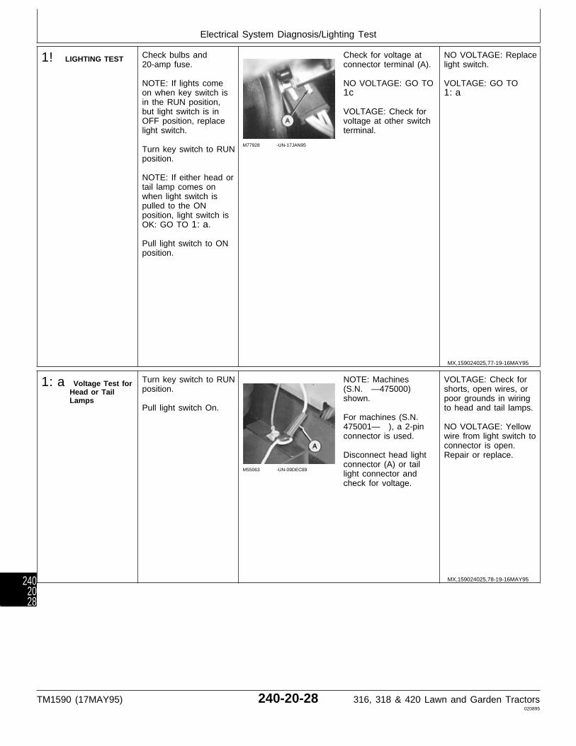
1! LIGHTING TEST Check bulbs and20-amp fuse.
NOTE: If lights comeon when key switch isin the RUN position,but light switch is inOFF position, replacelight switch.
Turn key switch to RUNposition.
NOTE: If either head ortail lamp comes onwhen light switch ispulled to the ONposition, light switch isOK: GO TO 1:a.
Pull light switch to ONposition.
M77928 -UN-17JAN95
Check for voltage atconnector terminal (A).
NO VOLTAGE: GO TO1c
VOLTAGE: Check forvoltage at other switchterminal.
NO VOLTAGE: Replacelight switch.
VOLTAGE: GO TO1:a
1:a Voltage Test forHead or TailLamps
Turn key switch to RUNposition.
Pull light switch On.
M55063 -UN-09DEC89
NOTE: Machines(S.N. —475000)shown.
For machines (S.N.475001— ), a 2-pinconnector is used.
Disconnect head lightconnector (A) or taillight connector andcheck for voltage.
VOLTAGE: Check forshorts, open wires, orpoor grounds in wiringto head and tail lamps.
NO VOLTAGE: Yellowwire from light switch toconnector is open.Repair or replace.
MX,159024025,77-19-16MAY95
MX,159024025,78-19-16MAY95
Electrical System Diagnosis/Lighting Test
TM1590 (17MAY95) 240-20-28 316, 318 & 420 Lawn and Garden Tractors020895
2402028
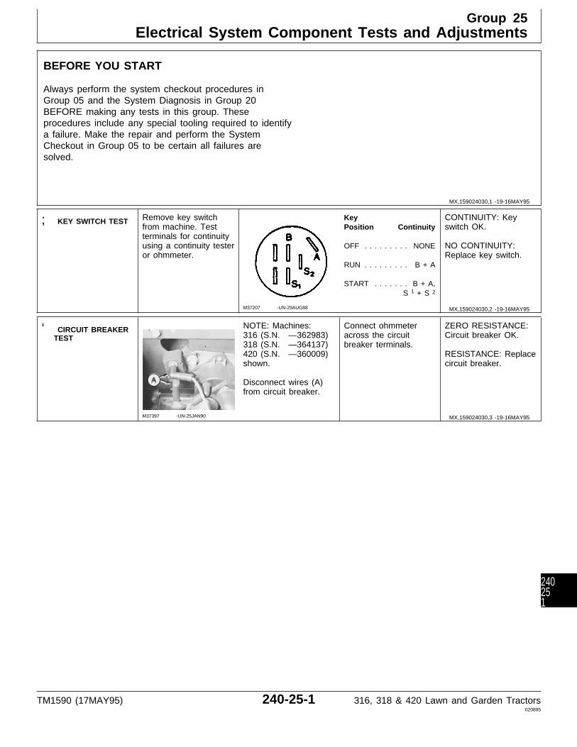
BEFORE YOU START
Always perform the system checkout procedures inGroup 05 and the System Diagnosis in Group 20BEFORE making any tests in this group. Theseprocedures include any special tooling required to identifya failure. Make the repair and perform the SystemCheckout in Group 05 to be certain all failures aresolved.
; KEY SWITCH TEST Remove key switchfrom machine. Testterminals for continuityusing a continuity testeror ohmmeter.
M37207 -UN-29AUG88
KeyPosition Continuity
OFF . . . . . . . . . NONE
RUN . . . . . . . . . B + A
START . . . . . . . B + A,S 1 + S 2
CONTINUITY: Keyswitch OK.
NO CONTINUITY:Replace key switch.
‘ CIRCUIT BREAKERTEST
M37397 -UN-25JAN90
NOTE: Machines:316 (S.N. —362983)318 (S.N. —364137)420 (S.N. —360009)shown.
Disconnect wires (A)from circuit breaker.
Connect ohmmeteracross the circuitbreaker terminals.
ZERO RESISTANCE:Circuit breaker OK.
RESISTANCE: Replacecircuit breaker.
MX,159024030,1 -19-16MAY95
MX,159024030,2 -19-16MAY95
MX,159024030,3 -19-16MAY95
Group 25Electrical System Component Tests and Adjustments
TM1590 (17MAY95) 240-25-1 316, 318 & 420 Lawn and Garden Tractors020895
240251
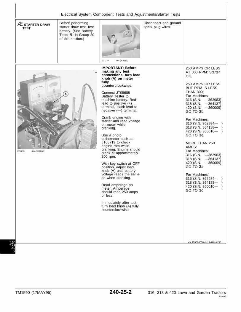
Æ STARTER DRAWTEST
Before performingstarter draw test, testbattery. (See BatteryTests B in Group 20of this section.)
M37179 -UN-25JAN90
Disconnect and groundspark plug wires.
M36655 -UN-25JAN90
IMPORTANT: Beforemaking any testconnections, turn loadknob (A) on meterfullycounterclockwise.
Connect JT05685Battery Tester tomachine battery. Redlead to positive (+)terminal, black lead tonegative (—) terminal.
Crank engine withstarter and read voltageon meter whilecranking.
Use a phototachometer such asJT05719 to checkengine rpm whilecranking. Engine shouldcrank at approximately300 rpm.
With key switch at OFFposition, adjust loadknob (A) until batteryvoltage reads the sameas when cranking.
Read amperage onmeter. Amperageshould read 250 ampsor less.
Immediately after test,turn load knob (A) fullycounterclockwise.
250 AMPS OR LESSAT 300 RPM: StarterOK.
250 AMPS OR LESSBUT RPM IS LESSTHAN 300:For Machines:316 (S.N. —362983)318 (S.N. —364137)420 (S.N. —360009)GO TO 3b
For Machines:316 (S.N. 362984— )318 (S.N. 364138— )420 (S.N. 360010— )GO TO 3e
MORE THAN 250AMPS:For Machines:316 (S.N. —362983)318 (S.N. —364137)420 (S.N. —360009)GO TO 3a
For Machines:316 (S.N. 362984— )318 (S.N. 364138— )420 (S.N. 360010— )GO TO 3d
MX,159024030,4 -19-16MAY95
Electrical System Component Tests and Adjustments/Starter Tests
TM1590 (17MAY95) 240-25-2 316, 318 & 420 Lawn and Garden Tractors020895
24025
2
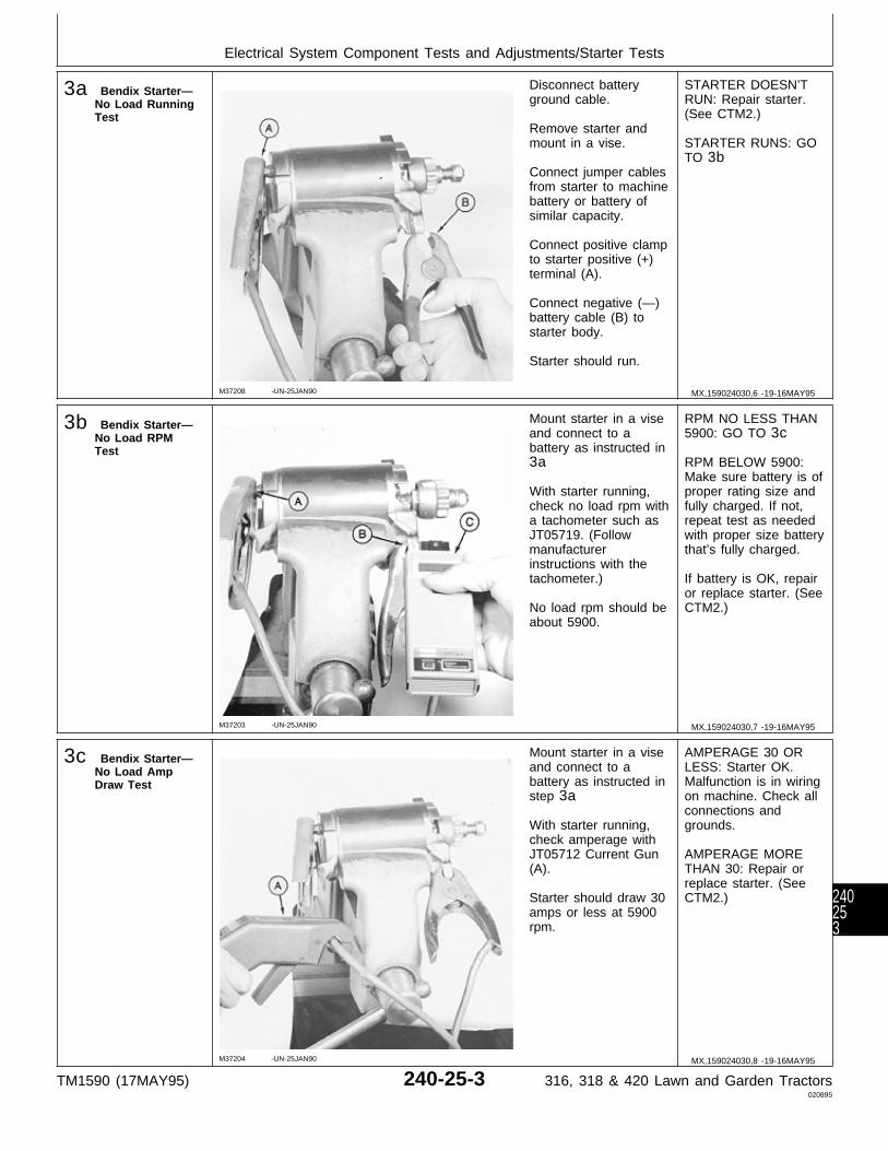
3a Bendix Starter—No Load RunningTest
M37208 -UN-25JAN90
Disconnect batteryground cable.
Remove starter andmount in a vise.
Connect jumper cablesfrom starter to machinebattery or battery ofsimilar capacity.
Connect positive clampto starter positive (+)terminal (A).
Connect negative (—)battery cable (B) tostarter body.
Starter should run.
STARTER DOESN’TRUN: Repair starter.(See CTM2.)
STARTER RUNS: GOTO 3b
3b Bendix Starter—No Load RPMTest
M37203 -UN-25JAN90
Mount starter in a viseand connect to abattery as instructed in3a
With starter running,check no load rpm witha tachometer such asJT05719. (Followmanufacturerinstructions with thetachometer.)
No load rpm should beabout 5900.
RPM NO LESS THAN5900: GO TO 3c
RPM BELOW 5900:Make sure battery is ofproper rating size andfully charged. If not,repeat test as neededwith proper size batterythat’s fully charged.
If battery is OK, repairor replace starter. (SeeCTM2.)
3c Bendix Starter—No Load AmpDraw Test
M37204 -UN-25JAN90
Mount starter in a viseand connect to abattery as instructed instep 3a
With starter running,check amperage withJT05712 Current Gun(A).
Starter should draw 30amps or less at 5900rpm.
AMPERAGE 30 ORLESS: Starter OK.Malfunction is in wiringon machine. Check allconnections andgrounds.
AMPERAGE MORETHAN 30: Repair orreplace starter. (SeeCTM2.)
MX,159024030,6 -19-16MAY95
MX,159024030,7 -19-16MAY95
MX,159024030,8 -19-16MAY95
Electrical System Component Tests and Adjustments/Starter Tests
TM1590 (17MAY95) 240-25-3 316, 318 & 420 Lawn and Garden Tractors020895
240253

3d Solenoid ShiftStarter—No LoadRunning Test
M77935 -UN-17JAN95
Disconnect batteryground cable.
Remove starter andmount in a vise.
Use jumper cables toconnect starter tomachine battery orbattery of similarcapacity.
Connect positive clamp(A) to positive (+)battery cable terminalon starter solenoid.
Connect negative (—)battery cable (B) tostarter body.
Connect jumper wire(C) to the solenoid coilterminal and to positivecable clamp as shown.
Starter should engageand run.
STARTER DOESN’TRUN: Repair starter.(See CTM2.)
STARTER ENGAGESAND RUNS: GO TO3e
3e Solenoid ShiftStarter—No LoadRPM Test
M77936 -UN-18JAN95
Mount starter in a viseand connect to abattery as instructed in3d
With starter running,check no load rpm witha tachometer such asJT05719. (Followmanufacturerinstructions with thetachometer.)
No load rpm should beabout 7000.
RPM NO LESS THAN7000: GO TO 3f
RPM BELOW 7000:Make sure battery is ofproper rating size andfully charged. If not,repeat test as neededwith proper size batterythat’s fully charged.
If battery is OK, repairor replace starter. (SeeCTM2.)
MX,159024030,9 -19-16MAY95
MX,159024030,10-19-16MAY95
Electrical System Component Tests and Adjustments/Starter Tests
TM1590 (17MAY95) 240-25-4 316, 318 & 420 Lawn and Garden Tractors020895
24025
4
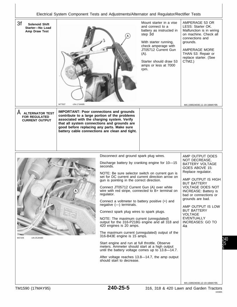
3f Solenoid ShiftStarter—No LoadAmp Draw Test
M77937 -UN-17JAN95
Mount starter in a viseand connect to abattery as instructed instep 3d
With starter running,check amperage withJT05712 Current Gun(A).
Starter should draw 53amps or less at 7000rpm.
AMPERAGE 53 ORLESS: Starter OK.Malfunction is in wiringon machine. Check allconnections andgrounds.
AMPERAGE MORETHAN 53: Repair orreplace starter. (SeeCTM2.)
Å ALTERNATOR TESTFOR REGULATEDCURRENT OUTPUT
IMPORTANT: Poor connections and groundscontribute to a large portion of the problemsassociated with the charging system. Verifythat all system connections and grounds aregood before replacing any parts. Make surebattery cable connections are clean and tight.
M37205 -UN-25JAN90
Disconnect and ground spark plug wires.
Discharge battery by cranking engine for 10—15seconds.
NOTE: Be sure selector switch on current gun isset for DC current and current direction arrow ongun is pointing in the correct direction.
Connect JT05712 Current Gun (A) over whitewire with red stripe, connected to B+ terminal onregulator.
Connect a voltmeter to battery positive (+) andnegative (—) terminals.
Connect spark plug wires to spark plugs.
NOTE: The maximum current (unregulated)output for the 316-P218G engine and all 318 and420 engines is 20 amps.
The maximum current (unregulated) output of the316-B43E engine is 15 amps.
Start engine and run at full throttle. Observemeters. Ammeter should start at a high outputuntil the battery voltage comes up to 13.8—14.7.
After voltage reaches 13.8—14.7, the amp outputshould start to decrease.
AMP OUTPUT DOESNOT DECREASE,BATTERY VOLTAGEGOES ABOVE 15:Replace regulator.
AMP OUTPUT IS HIGHBUT BATTERYVOLTAGE DOES NOTINCREASE: Battery isbad or connections orgrounds are bad.
AMP OUTPUT IS LOWBUT BATTERYVOLTAGEEVENTUALLYINCREASES: GO TO4a
MX,159024030,11-19-16MAY95
MX,159024030,12-19-16MAY95
Electrical System Component Tests and Adjustments/Alternator and Regulator/Rectifier Tests
TM1590 (17MAY95) 240-25-5 316, 318 & 420 Lawn and Garden Tractors020895
240255
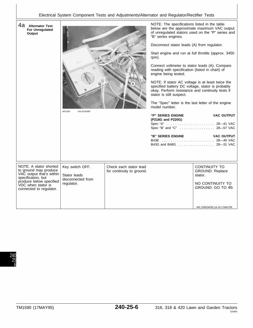
4a Alternator TestFor UnregulatedOutput
M37209 -UN-25JAN90
NOTE: The specifications listed in the tablebelow are the approximate maximum VAC outputof unregulated stators used on the “P” series and“B” series engines.
Disconnect stator leads (A) from regulator.
Start engine and run at full throttle (approx. 3450rpm).
Connect voltmeter to stator leads (A). Comparereading with specification (listed in chart) ofengine being tested.
NOTE: If stator AC voltage is at least twice thespecified battery DC voltage, stator is probablyokay. Perform resistance and continuity tests ifstator is still suspect.
The “Spec” letter is the last letter of the enginemodel number.
“P” SERIES ENGINE VAC OUTPUT(P218G and P220G)Spec “A” . . . . . . . . . . . . . . . . . . . . . . 28—41 VACSpec “B” and “C” . . . . . . . . . . . . . . . . 28—57 VAC
“B” SERIES ENGINE VAC OUTPUTB43E . . . . . . . . . . . . . . . . . . . . . . . . 28—40 VACB43G and B48G . . . . . . . . . . . . . . . . . 28—31 VAC
NOTE: A stator shortedto ground may produceVAC output that’s withinspecification, butproduce below specifiedVDC when stator isconnected to regulator.
Key switch OFF.
Stator leadsdisconnected fromregulator.
Check each stator leadfor continuity to ground.
CONTINUITY TOGROUND: Replacestator.
NO CONTINUITY TOGROUND: GO TO 4b
MX,159024030,14-19-17MAY95
Electrical System Component Tests and Adjustments/Alternator and Regulator/Rectifier Tests
TM1590 (17MAY95) 240-25-6 316, 318 & 420 Lawn and Garden Tractors020895
24025
6
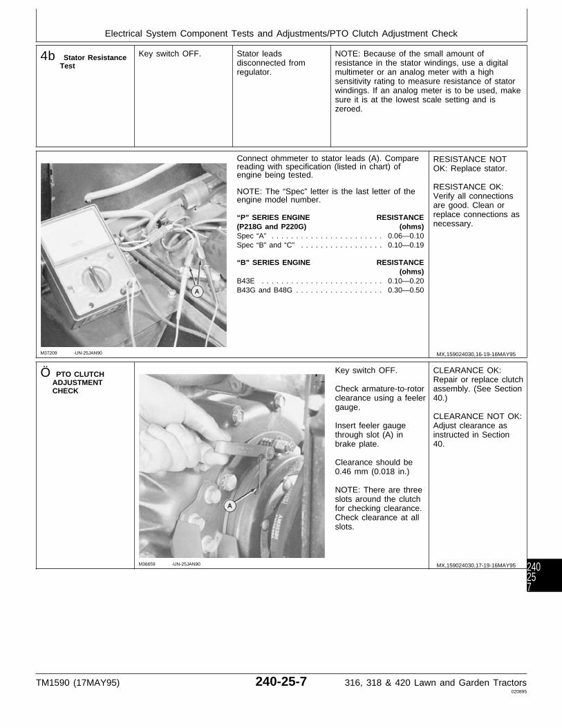
4b Stator ResistanceTest
Key switch OFF. Stator leadsdisconnected fromregulator.
NOTE: Because of the small amount ofresistance in the stator windings, use a digitalmultimeter or an analog meter with a highsensitivity rating to measure resistance of statorwindings. If an analog meter is to be used, makesure it is at the lowest scale setting and iszeroed.
M37209 -UN-25JAN90
Connect ohmmeter to stator leads (A). Comparereading with specification (listed in chart) ofengine being tested.
NOTE: The “Spec” letter is the last letter of theengine model number.
“P” SERIES ENGINE RESISTANCE(P218G and P220G) (ohms)Spec “A” . . . . . . . . . . . . . . . . . . . . . . . 0.06—0.10Spec “B” and “C” . . . . . . . . . . . . . . . . . 0.10—0.19
“B” SERIES ENGINE RESISTANCE(ohms)
B43E . . . . . . . . . . . . . . . . . . . . . . . . . 0.10—0.20B43G and B48G . . . . . . . . . . . . . . . . . . 0.30—0.50
RESISTANCE NOTOK: Replace stator.
RESISTANCE OK:Verify all connectionsare good. Clean orreplace connections asnecessary.
Ö PTO CLUTCHADJUSTMENTCHECK
M36659 -UN-25JAN90
Key switch OFF.
Check armature-to-rotorclearance using a feelergauge.
Insert feeler gaugethrough slot (A) inbrake plate.
Clearance should be0.46 mm (0.018 in.)
NOTE: There are threeslots around the clutchfor checking clearance.Check clearance at allslots.
CLEARANCE OK:Repair or replace clutchassembly. (See Section40.)
CLEARANCE NOT OK:Adjust clearance asinstructed in Section40.
MX,159024030,16-19-16MAY95
MX,159024030,17-19-16MAY95
Electrical System Component Tests and Adjustments/PTO Clutch Adjustment Check
TM1590 (17MAY95) 240-25-7 316, 318 & 420 Lawn and Garden Tractors020895
240257
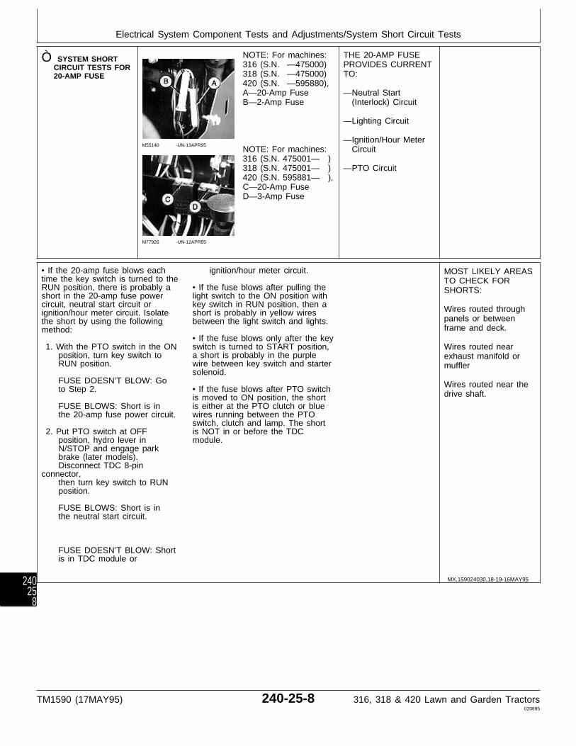
Ò SYSTEM SHORTCIRCUIT TESTS FOR20-AMP FUSE
M55140 -UN-13APR95
M77926 -UN-12APR95
NOTE: For machines:316 (S.N. —475000)318 (S.N. —475000)420 (S.N. —595880),A—20-Amp FuseB—2-Amp Fuse
NOTE: For machines:316 (S.N. 475001— )318 (S.N. 475001— )420 (S.N. 595881— ),C—20-Amp FuseD—3-Amp Fuse
THE 20-AMP FUSEPROVIDES CURRENTTO:
—Neutral Start (Interlock) Circuit
—Lighting Circuit
—Ignition/Hour Meter Circuit
—PTO Circuit
• If the 20-amp fuse blows eachtime the key switch is turned to theRUN position, there is probably ashort in the 20-amp fuse powercircuit, neutral start circuit orignition/hour meter circuit. Isolatethe short by using the followingmethod:
1. With the PTO switch in the ON position, turn key switch to RUN position.
FUSE DOESN’T BLOW: Go to Step 2.
FUSE BLOWS: Short is in the 20-amp fuse power circuit.
2. Put PTO switch at OFF position, hydro lever in N/STOP and engage park brake (later models). Disconnect TDC 8-pinconnector, then turn key switch to RUN position.
FUSE BLOWS: Short is in the neutral start circuit.
FUSE DOESN’T BLOW: Short is in TDC module or
ignition/hour meter circuit.
• If the fuse blows after pulling thelight switch to the ON position withkey switch in RUN position, then ashort is probably in yellow wiresbetween the light switch and lights.
• If the fuse blows only after the keyswitch is turned to START position,a short is probably in the purplewire between key switch and startersolenoid.
• If the fuse blows after PTO switchis moved to ON position, the shortis either at the PTO clutch or bluewires running between the PTOswitch, clutch and lamp. The shortis NOT in or before the TDCmodule.
MOST LIKELY AREASTO CHECK FORSHORTS:
Wires routed throughpanels or betweenframe and deck.
Wires routed nearexhaust manifold ormuffler
Wires routed near thedrive shaft.
MX,159024030,18-19-16MAY95
Electrical System Component Tests and Adjustments/System Short Circuit Tests
TM1590 (17MAY95) 240-25-8 316, 318 & 420 Lawn and Garden Tractors020895
24025
8
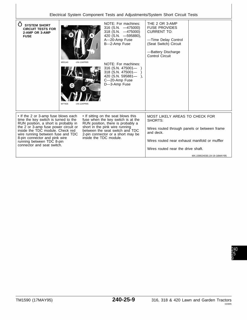
Õ SYSTEM SHORTCIRCUIT TESTS FOR2-AMP OR 3-AMPFUSE
M55140 -UN-13APR95
M77926 -UN-12APR95
NOTE: For machines:316 (S.N. —475000)318 (S.N. —475000)420 (S.N. —595880),A—20-Amp FuseB—2-Amp Fuse
NOTE: For machines:316 (S.N. 475001— )318 (S.N. 475001— )420 (S.N. 595881— ),C—20-Amp FuseD—3-Amp Fuse
THE 2 OR 3-AMPFUSE PROVIDESCURRENT TO:
—Time Delay Control(Seat Switch) Circuit
—Battery DischargeControl Circuit
• If the 2 or 3-amp fuse blows eachtime the key switch is turned to theRUN position, a short is probably inthe 2 or 3-amp fuse power circuit orinside the TDC module. Check redwire running between fuse and TDC8-pin connector and pink wirerunning between TDC 8-pinconnector and seat switch.
• If sitting on the seat blows thisfuse when the key switch is at theRUN position, there is probably ashort in the pink wire runningbetween the seat switch and TDC2-pin connector or a short may beinside the TDC module.
MOST LIKELY AREAS TO CHECK FORSHORTS:
Wires routed through panels or between frameand deck.
Wires routed near exhaust manifold or muffler
Wires routed near the drive shaft.
MX,159024030,19-19-16MAY95
Electrical System Component Tests and Adjustments/System Short Circuit Tests
TM1590 (17MAY95) 240-25-9 316, 318 & 420 Lawn and Garden Tractors020895
240259

Electrical System Component Tests and Adjustments/System Short Circuit Tests
TM1590 (17MAY95) 240-25-10 316, 318 & 420 Lawn and Garden Tractors020895
2402510
Section 250POWER TRAIN CHECKOUT, OPERATION
AND DIAGNOSISContents
Page
Group 05—Power Train CheckoutBefore You Start . . . . . . . . . . . . . . . . . 250-05-1Transmission Oil Leak Check . . . . . . . . . 250-05-1Hydrostatic Lever Friction Check . . . . . . . 250-05-1Transmission Neutral Check . . . . . . . . . 250-05-1Neutral Return Check . . . . . . . . . . . . . . 250-05-2Transmission Drive Check . . . . . . . . . . . 250-05-2Speed Reduction Check . . . . . . . . . . . . 250-05-2Two-Speed Axle Lever Check (420) . . . . 250-05-3Differential Lock Check (420) . . . . . . . . . 250-05-3Operator Complaint Not Identified . . . . . . 250-05-3
Group 10—Theory of OperationHydrostatic Transmission Operation . . . . . 250-10-2
Group 15—Diagnosis, Tests and AdjustmentsAbout This Group . . . . . . . . . . . . . . . . 250-15-1Troubleshooting Guide . . . . . . . . . . . . . 250-15-1Check Valve Debris Check . . . . . . . . . . 250-15-5Charge Pump
Pressure Test . . . . . . . . . . . . . . . . . . 250-15-5Suction Line Check . . . . . . . . . . . . . . 250-15-6
Charge Relief ValveCheck . . . . . . . . . . . . . . . . . . . . . . . 250-15-6Adjustment . . . . . . . . . . . . . . . . . . . . 250-15-6
Implement Relief ValvePressure Test . . . . . . . . . . . . . . . . . . 250-15-7Check . . . . . . . . . . . . . . . . . . . . . . . 250-15-7Adjustment . . . . . . . . . . . . . . . . . . . . 250-15-7
Charge Pump Flow Test . . . . . . . . . . . . 250-15-8Welch Plug Location Check . . . . . . . . . . 250-15-8Hydraulic Oil Warm-Up Procedure . . . . . . 250-15-9Steering Valve Neutral Check (318 and
420) . . . . . . . . . . . . . . . . . . . . . . . . 250-15-9Hydrostatic Lever Friction Adjustment . . 250-15-10Neutral Return Linkage Adjustment (Early
Models) . . . . . . . . . . . . . . . . . . . . . 250-15-10Neutral Adjustment (Early Models) . . . . 250-15-13Neutral and Neutral Return Linkage
Adjustment (Later Models) . . . . . . . . 250-15-14
Page
Two-Speed Axle Lever Linkage Check(420) . . . . . . . . . . . . . . . . . . . . . . 250-15-17
Differential Lock Linkage Check (420) . . 250-15-17
TM1590 (17MAY95) 250-1 316, 318 & 420 Lawn and Garden Tractors020895
250

Contents
TM1590 (17MAY95) 250-2 316, 318 & 420 Lawn and Garden Tractors020895
250
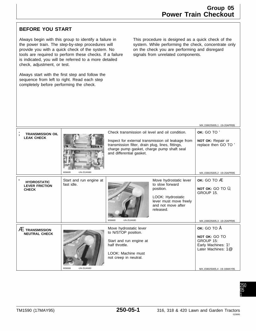
BEFORE YOU START
Always begin with this group to identify a failure inthe power train. The step-by-step procedures willprovide you with a quick check of the system. Notools are required to perform these checks. If a failureis indicated, you will be referred to a more detailedcheck, adjustment, or test.
Always start with the first step and follow thesequence from left to right. Read each stepcompletely before performing the check.
This procedure is designed as a quick check of thesystem. While performing the check, concentrate onlyon the check you are performing and disregardsignals from unrelated components.
; TRANSMISSION OILLEAK CHECK
M36695 -UN-25JAN90
Check transmission oil level and oil condition.
Inspect for external transmission oil leakage fromtransmission filter, drain plug, lines, fittings,charge pump gasket, charge pump shaft sealand differential gasket.
OK: GO TO ‘
NOT OK: Repair orreplace then GO TO ‘
‘ HYDROSTATICLEVER FRICTIONCHECK
Start and run engine atfast idle.
M36669 -UN-25JAN90
Move hydrostatic leverto slow forwardposition.
LOOK: Hydrostaticlever must move freelyand not move afterreleased.
OK: GO TO Æ
NOT OK: GO TO Ü,GROUP 15.
Æ TRANSMISSIONNEUTRAL CHECK
M36668 -UN-25JAN90
Move hydrostatic leverto N/STOP position.
Start and run engine athalf throttle.
LOOK: Machine mustnot creep in neutral.
OK: GO TO Å
NOT OK: GO TOGROUP 15:Early Machines: 1!Later Machines: 1@
MX,159025005,1 -19-20APR95
MX,159025005,2 -19-20APR95
MX,159025005,3 -19-20APR95
MX,159025005,4 -19-16MAY95
Group 05Power Train Checkout
TM1590 (17MAY95) 250-05-1 316, 318 & 420 Lawn and Garden Tractors020895
250051
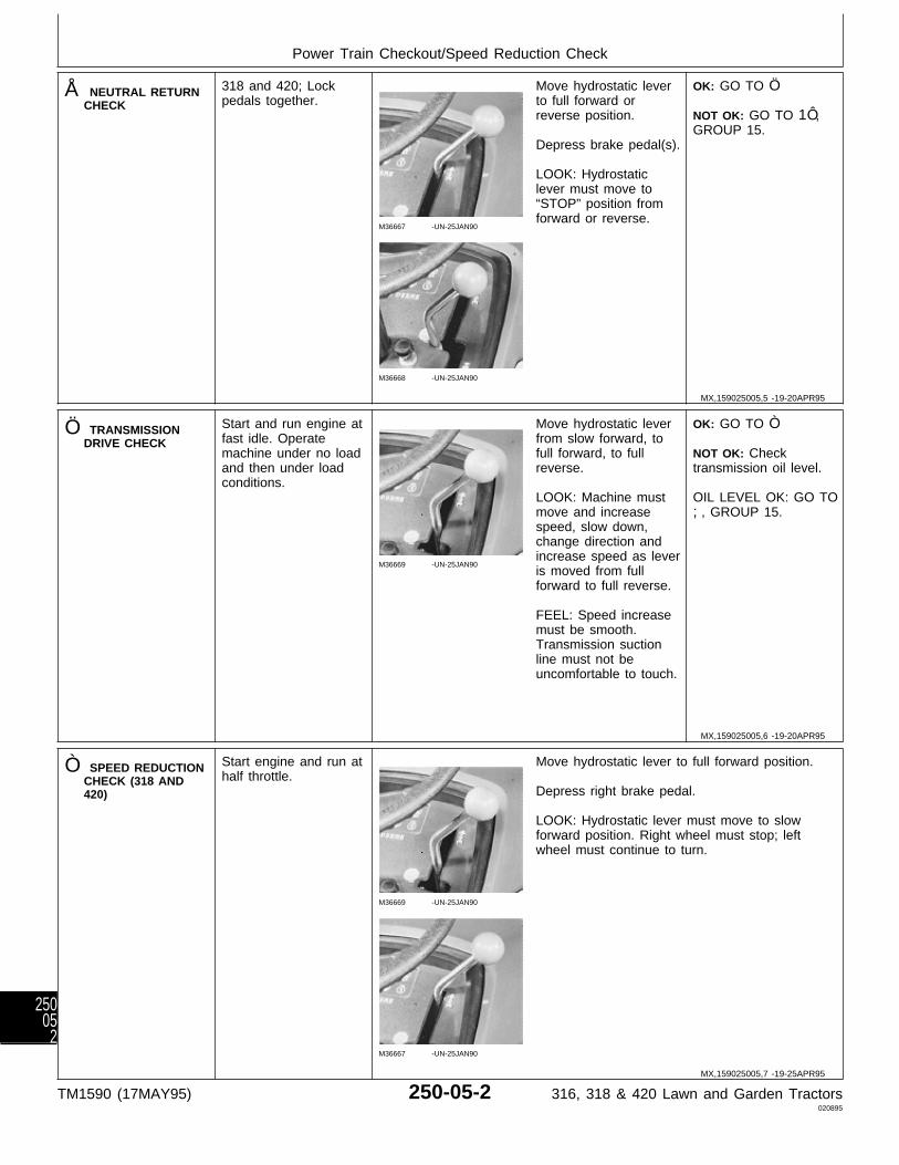
Å NEUTRAL RETURNCHECK
318 and 420; Lockpedals together.
M36667 -UN-25JAN90
M36668 -UN-25JAN90
Move hydrostatic leverto full forward orreverse position.
Depress brake pedal(s).
LOOK: Hydrostaticlever must move to“STOP” position fromforward or reverse.
OK: GO TO Ö
NOT OK: GO TO 1Ô,GROUP 15.
Ö TRANSMISSIONDRIVE CHECK
Start and run engine atfast idle. Operatemachine under no loadand then under loadconditions.
M36669 -UN-25JAN90
Move hydrostatic leverfrom slow forward, tofull forward, to fullreverse.
LOOK: Machine mustmove and increasespeed, slow down,change direction andincrease speed as leveris moved from fullforward to full reverse.
FEEL: Speed increasemust be smooth.Transmission suctionline must not beuncomfortable to touch.
OK: GO TO Ò
NOT OK: Checktransmission oil level.
OIL LEVEL OK: GO TO;, GROUP 15.
Ò SPEED REDUCTIONCHECK (318 AND420)
Start engine and run athalf throttle.
M36669 -UN-25JAN90
M36667 -UN-25JAN90
Move hydrostatic lever to full forward position.
Depress right brake pedal.
LOOK: Hydrostatic lever must move to slowforward position. Right wheel must stop; leftwheel must continue to turn.
MX,159025005,5 -19-20APR95
MX,159025005,6 -19-20APR95
MX,159025005,7 -19-25APR95
Power Train Checkout/Speed Reduction Check
TM1590 (17MAY95) 250-05-2 316, 318 & 420 Lawn and Garden Tractors020895
25005
2

Move hydrostatic leverto full forward position.
M36671 -UN-25JAN90
Depress left brakepedal.
LOOK: Hydrostaticlever must move toslow forward position.Left wheel must stop;right wheel mustcontinue to turn.
OK: GO TO Õ
NOT OK: GO TO Ü,GROUP 15.
Õ TWO-SPEED AXLELEVER CHECK (420)
Start and run engine athalf throttle.
M36672 -UN-25JAN90
Move two-speed axlelever to slow speedposition. Movehydrostatic lever to fullforward position.
LOOK: Observe groundspeed.
Move two-speed axlelever to fast speedposition. Movehydrostatic lever to fullforward position.
LOOK: Ground speedmust be approximatelytwice as fast.
OK: GO TO Ú
NOT OK: GO TO 1#,GROUP 15.
Ú DIFFERENTIALLOCK CHECK (420)
Start and run engine atfast idle.
Move hydrostatic leverto slow forwardposition.
M36673 -UN-25JAN90
Turn steering wheel leftor right.
Depress differential lockand turn left or right.
LOOK: With differentiallock depressed,machine must try to gostraight forward whensteering wheel is turnedor rear tire must showscuffing on the ground.
OK: System Normal.
NOT OK: GO TO 1$,GROUP 15.
Ü OPERATORCOMPLAINT NOTIDENTIFIED
If you completed the checkout procedure and didnot isolate a malfunction, the problem may beintermittent.
Try to duplicate the conditions of the malfunctionidentified by the operator.
IF A MALFUNCTION IS NOT IDENTIFIEDAFTER SYSTEM CHECKOUT PROCEDURE;FACTORY ASSISTANCE IS AVAILABLETHROUGH DEALER TECHNICAL ASSISTANCECENTER (DTAC).
MX,159025005,8 -19-25APR95
MX,159025005,9 -19-20APR95
MX,159025005,10-19-20APR95
MX,159025005,11-19-20APR95
Power Train Checkout/Operator Complaint Not Identified
TM1590 (17MAY95) 250-05-3 316, 318 & 420 Lawn and Garden Tractors020895
250053

Power Train Checkout/Operator Complaint Not Identified
TM1590 (17MAY95) 250-05-4 316, 318 & 420 Lawn and Garden Tractors020895
25005
4
Group 10Theory of Operation
TM1590 (17MAY95) 250-10-1 316, 318 & 420 Lawn and Garden Tractors020895
250101

HYDROSTATIC TRANSMISSION OPERATION
Function:Transfers power from the input (pump) shaft to thegear drive components of the transmission. It alsoprovides infinitely variable speed and torque within arange in forward and reverse directions.
Also supplies pressurized oil to the hydraulic lift andsteering systems.
Theory of Operation:The transmission consists of a variable displacement,axial piston pump (B) connected in a closed loop to afixed displacement, axial piston motor (I). A chargepump (C) and valve system is used to charge andlubricate the transmission.
The charge pump is a gerotor-type, fixeddisplacement pump. It continually pumps oilthroughout the entire hydrostatic/hydraulic systemwhenever the engine is running.
As the input (pump) shaft (A) is turned by the enginedrive shaft, the pump rotating group consisting of thevariable hydrostatic pump and charge pump also turn.The charge pump draws pressure-free oil from thereservoir (F) through the filter (D) and pressurizes itto approximately 620—1240 kPa (90—180 psi). Thecharge oil pressure is enough to unseat the forwardand/or reverse check valve (E and M), supplyingcharge pressure oil to pump (B).
The transmission also supplies pressurized oil to thelift and hydraulic steering systems. If pressure in thisline becomes excessive, the implement relief valve(N) will open allowing the oil to flow into the reservoir.
NEUTRAL:With the transmission in the neutral position, springsin the pump cylinder bores force the pump pistonsagainst the variable position swashplate, which isparallel to the pump body. With the swashplateparallel to the pump body, the pistons do notreciprocate in the cylinder block, they merely rotate,no oil is being drawn in or discharged from the pump.The pump is in a zero displacement position and themachine remains stationary.
FORWARD:As the swashplate control arm is moved to theforward position, the variable position swashplate ismoved from the neutral position to a forward angleposition. Springs inside the cylinder bores force thepistons against the swashplate. As the pump rotates
the pistons follow the contour of the swashplate theymove outward, drawing oil into their bores. As thepistons continue to rotate, the swashplate angleforces the pistons back into the bores, forcing oil outof the bores through the valve plate.
High pressure oil from the pump forces the forwardcheck valve (E) closed and supplies pressurized oil tothe drive motor (I). The motor works in conjunctionwith a fixed position swashplate. Oil enters the pistonbore through a port in the valve plate at a pointwhere the piston is compressed in its bore.
As the oil fills the piston bore, the piston is forced outand follows the contour of the swashplate. Thiscauses the motor to rotate. Oil pressure within thesecomponents is directly proportional to the loadencountered. This is known as the high pressure sideof the system.
As the motor continues to rotate, the piston is nowcompressed by the angle of the swashplate and oil isforced from the piston bore into the other port in thevalve plate. This oil is directed back to the suctionside of the pump. There is minimal oil pressure fromthe back to the motor and this is referred as the lowpressure side of the system.
The reverse check (freewheel) valve (M) remainsopen to allow charge pressure oil to flow to the lowpressure side of the system to make up for any oillost due to internal lubrication/leakage.
REVERSE:The operation of the transmission in reverse is similarto forward operation, except that the reverseswashplate position causes the pressurized oil flow tobe reversed. When oil flow is reversed, the reversecheck (freewheel) valve (M) is forced closed supplingpressurized oil to the drive motor. The forward checkvalve (E) remains open to allow charge pressure oilto flow to the low pressure side of the system tomake up for any oil lost due to internallubrication/leakage.
FREEWHEEL:When the forward/reverse check (freewheel) valvesare manually engaged, the valves are forced off theirseats and allows oil to flow from both sides of themotor to the reservoir. Normally the motor wouldhave excessive resistance to movement due todynamic braking of the hydrostatic closed loop.
MX,159025010,1 -19-20APR95
Theory of Operation/Hydrostatic Transmission Operation
TM1590 (17MAY95) 250-10-2 316, 318 & 420 Lawn and Garden Tractors020895
25010
2

A—Input (Pump) Shaft E—Forward Check H—Hydrostatic Transmission K—Transmission Case DrainB—Variable Hydrostatic (Freewheel) Valve Housing L—Implement Relief Valve
Pump F—Reservoir I—Hydrostatic Drive Motor M—Reverse CheckC—Charge Pump G—Charge Relief Valve J—Output (Motor) Shaft (Freewheel) ValveD—Filter
M78
856
-UN
-03A
PR
95MX,159025010,2 -19-20APR95
Theory of Operation/Hydrostatic Transmission Operation
TM1590 (17MAY95) 250-10-3 316, 318 & 420 Lawn and Garden Tractors020895
250103

Theory of Operation/Hydrostatic Transmission Operation
TM1590 (17MAY95) 250-10-4 316, 318 & 420 Lawn and Garden Tractors020895
25010
4
ABOUT THIS GROUP
Always perform the system checkout procedures inGroup 05 BEFORE making any tests or adjustmentsin this group. The step-by-step procedures in thisgroup provide you with the detailed diagnosticinformation you will need to isolate a malfunction.Basic diagnostic equipment is used.
It is assumed that you are familiar with the machineand its power train components. If you needadditional information, read the theory of operation inGroup 10 or refer to the overall hydraulic schematicsin Section 270, Group 10.
Engine rpm and temperature are critical in mosthydraulic tests. Be sure to follow test specificationscarefully.
Always start with the first step and follow thesequence from left to right. Read each stepcompletely before performing the test.
Upon completing a test or adjustment, check to seewhether the problem is corrected by performing thecheckout procedures in Group 05.
; TROUBLESHOOTING GUIDE
If machine does not operate properly, select the appropriate symptom from the list below.
• MACHINE MOVES IN ONE DIRECTION ONLY: GO TO A
• MACHINE WILL NOT MOVE IN EITHER DIRECTION: GO TO B
• MACHINE CREEPS IN ONE DIRECTION CONSISTENTLY: GO TO 1! OR 1@
• HYDRO CONTROL LEVER DOES NOT RETURN TO NEUTRAL WHEN BOTH BRAKES ARE APPLIED:GO TO 1Ô
• TRANSMISSION OPERATION HAS ERRATIC OR LOW POWER OR SPEED WILL NOT INCREASE: GOTO C
• MACHINE WILL NOT REACH FULL SPEED: GO TO D
• TRANSMISSION OPERATES HOT: GO TO E
• MACHINE FREEWHEELS: GO TO F
• HYDRAULIC SYSTEM IS NOISY: GO TO G
• NO HYDRAULICS AFTER BEING SERVICED: GO TO H
• CHARGE PUMP SEAL REPEATEDLY FAILS: GO TO I
MX,159025015,1 -19-20APR95
MX,159025015,2 -19-20APR95
Group 15Diagnosis, Tests and Adjustments
TM1590 (17MAY95) 250-15-1 316, 318 & 420 Lawn and Garden Tractors020895
250151
A MACHINE MOVES IN ONE DIRECTION ONLY
• Inspect transmission control linkage for wear or damage. See Section 50.
• 316 and 318; Test for debris in check valves: GO TO ‘
• Inspect check valves for damaged valve seat, seals or stuck check ball. See Section 50.
• Inspect internal transmission components for wear or damage. See Section 50.
B MACHINE WILL NOT MOVE IN EITHER DIRECTION
• Inspect transmission control linkage for wear or damage. See Section 50.
• Inspect transmission drive shaft and crankshaft pulley for loose cap screws or damage.
• Check for improper charge pump installation (180 degrees off). See Section 50.
• Test charge pump pressure: GO TO Æ
• Inspect check valves for damaged valve seat, seals or stuck check ball. See Section 50.
• Inspect internal rotating group for scoring and wear (slippers, pistons and cylinder block, valve plate andcylinder block). If internal damage is found, check for missing welch plug: GO TO Ò
C TRANSMISSION OPERATION HAS ERRATIC OR LOW POWER OR SPEED WILLNOT INCREASE
• Inspect brakes and brake linkage for wear or damage. See Section 60.
• Inspect transmission control linkage for wear or damage. See Section 50.
• Check for improper charge pump installation (180 degrees off). See Section 50.
• Test charge pump pressure: GO TO Æ
• Inspect check valves for damaged valve seat, seals or stuck check ball. See Section 50.
• Inspect internal rotating group for scoring and wear (slippers, pistons and cylinder block, valve plate andcylinder block). If internal damage is found, check for missing welch plug: GO TO Ò
• Check for dirt accumulation on transmission causing transmission oil to overheat: GO TO Õ
• Check for high draft loads causing transmission oil to overheat: GO TO Õ
MX,159025015,3 -19-20APR95
MX,159025015,4 -19-20APR95
MX,159025015,5 -19-20APR95
Diagnosis, Tests and Adjustments/Troubleshooting Guide
TM1590 (17MAY95) 250-15-2 316, 318 & 420 Lawn and Garden Tractors020895
25015
2
D MACHINE WILL NOT REACH FULL SPEED
• Inspect transmission control linkage for wear or damage. See Section 50.
• Inspect transmission and differential mounting cap screws for loose condition.
• Check engine fast idle speed: See Section 220.
• Inspect check valves for damaged seat, seals or stuck check ball. See Section 50.
• Inspect internal rotating group for scoring and wear (slippers, pistons and cylinder block, valve plate andcylinder block). If internal damage is found check for missing welch plug: GO TO Ò
E TRANSMISSION OPERATES HOT
• Check transmission temperature. GO TO Õ
• Check all cooling components for plugged or restricted condition.
• 318 and 420; Test steering valve for neutral return: GO TO Ú
• Test charge pump pressure: GO TO Æ
• Inspect internal transmission components for wear or damage. See Section 50.
• Check for dirt accumulation on transmission causing transmission oil to overheat: GO TO Õ
• Check for high draft loads causing transmission oil to overheat: GO TO Õ
F MACHINE FREEWHEELS
• Inspect transmission control linkage for loose connections allowing swashplate movement under load. SeeSection 50.
• 316 and 318; Test for debris in check valves: GO TO ‘
• Inspect check valves for damaged valve seat, seals or stuck check ball. See Section 50.
• Test charge pump pressure: GO TO Æ
• Inspect internal rotating group for scoring and wear (slippers, pistons and cylinder block, valve plate andcylinder block). If internal damage is found check for missing welch plug: GO TO Ò
MX,159025015,6 -19-20APR95
MX,159025015,7 -19-20APR95
MX,159025015,8 -19-20APR95
Diagnosis, Tests and Adjustments/Troubleshooting Guide
TM1590 (17MAY95) 250-15-3 316, 318 & 420 Lawn and Garden Tractors020895
250153
G HYDRAULIC SYSTEM IS NOISY
• Check power steering valve, if equipped, or hydraulic control valve for overheating. If either valve is toohot to touch after 1/2 hour of operation, disassemble valve and repair internal leak. See Section 60 or 70.
• Adjust hydrostatic transmission linkage for positive neutral position: GO TO 1Ô
• Check steel hydraulic lines for vibration. Especially the line that runs from the charge pump to the steeringvalve on later 318 and 420 models, or the line that runs from the charge pump to the SCV on early 318and 420 models. Secure with clamps or replace with a rubber pressure hose rated at 8274 kPa (1200 psi).
• Adjust charge relief valve so that charge pressure is above 1379 kPa (200 psi). The increased chargepressure will not cause any problems and it may eliminate the noise, if it is caused by charge relief valvechattering: GO TO 3c
• Increase implement relief pressure to upper limit of specification: GO TO 4b
H NO HYDRAULICS AFTER BEING SERVICED
• Check for improper charge pump installation (180 degrees off). See Section 50.
• Check for proper installation of transmission output shaft bearing into aluminum case. If installed tooshallow, the motor rotating group will not contact the valve plate. See Section 50.
I CHARGE PUMP SEAL REPEATEDLY FAILS
• Inspect the seal surface on the shaft.
• Inspect seal for cuts which may be caused by installing seal over shaft without covering sharp splines.
• Check for a loose or worn U-Joint on the drive shaft.
• Inspect charge pump for wear or damage. Charge pressure may be getting into the seal area because ofinternal pump leakage. See Section 50.
MX,159025015,9 -19-20APR95
MX,159025015,10-19-20APR95
MX,159025015,11-19-20APR95
Diagnosis, Tests and Adjustments/Troubleshooting Guide
TM1590 (17MAY95) 250-15-4 316, 318 & 420 Lawn and Garden Tractors020895
25015
4
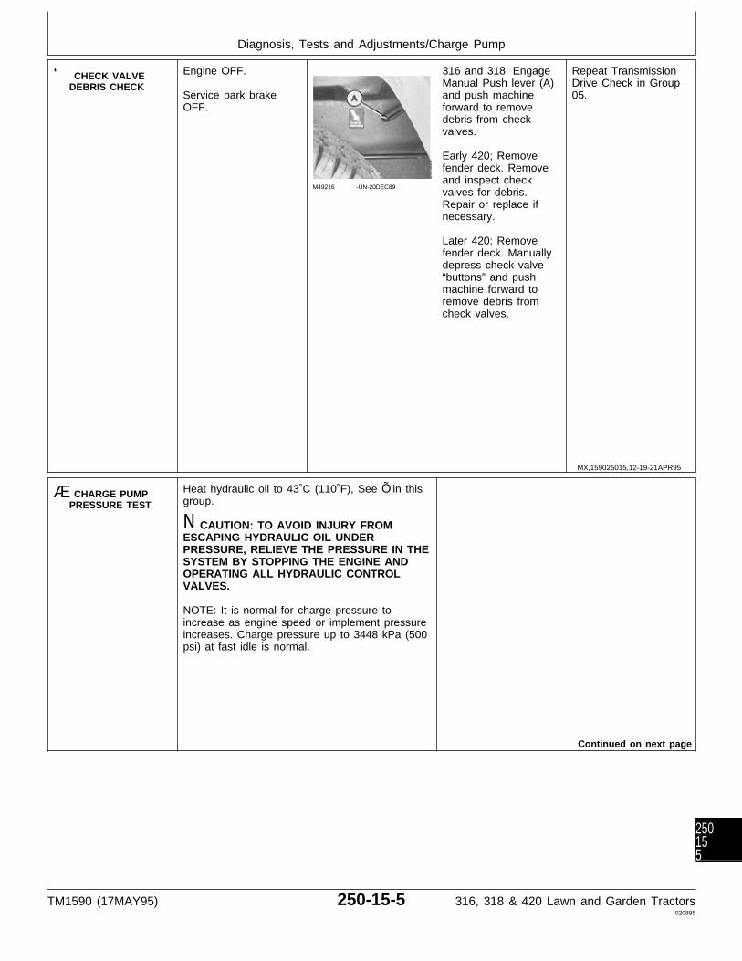
‘ CHECK VALVEDEBRIS CHECK
Engine OFF.
Service park brakeOFF.
M49216 -UN-20DEC89
316 and 318; EngageManual Push lever (A)and push machineforward to removedebris from checkvalves.
Early 420; Removefender deck. Removeand inspect checkvalves for debris.Repair or replace ifnecessary.
Later 420; Removefender deck. Manuallydepress check valve“buttons” and pushmachine forward toremove debris fromcheck valves.
Repeat TransmissionDrive Check in Group05.
Æ CHARGE PUMPPRESSURE TEST
Heat hydraulic oil to 43˚C (110˚F), See Õ in thisgroup.
N CAUTION: TO AVOID INJURY FROMESCAPING HYDRAULIC OIL UNDERPRESSURE, RELIEVE THE PRESSURE IN THESYSTEM BY STOPPING THE ENGINE ANDOPERATING ALL HYDRAULIC CONTROLVALVES.
NOTE: It is normal for charge pressure toincrease as engine speed or implement pressureincreases. Charge pressure up to 3448 kPa (500psi) at fast idle is normal.
Continued on next page
MX,159025015,12-19-21APR95
Diagnosis, Tests and Adjustments/Charge Pump
TM1590 (17MAY95) 250-15-5 316, 318 & 420 Lawn and Garden Tractors020895
250155

M36682 -UN-25JAN90
A—JT03339 ConnectorB—JT03107 AdapterC—JT03017 HoseD—JT03344 Gauge, 2000kPa (300 psi)
IMPORTANT:Hydraulic controllevers must remain inneutral position andengine must be run atslow idle.
Pressure gauge willbe damaged if ahydraulic function isactuated or test is runat fast idle.
Make test connectionsfrom JT01765 Lawnand Grounds CareProducts HydraulicFitting Kit.
Run engine at slowidle.
LOOK: Record pressurereading.
Charge pressure mustbe 620—1240 kPa(90—180 psi).
CHARGE PRESSUREOK: Inspect checkvalves for wear ordamage. See Section50. Then repeat Æ
CHARGE PRESSURELOW: REPLACEFILTER,THEN...REPEAT Æ
CHARGE PRESSURESTILL LOW: GO TO3a
3a Charge PumpSuction Line Check
M49217 -UN-20DEC89
Inspect suction line (A)for restriction, loosehose clamp, holes ordamage that wouldcause air leakage.
SUCTION LINE OK:GO TO 3b
SUCTION LINEDAMAGED: Repair orreplace then bleedhydraulic system. SeeSection 270, Group 20.
3b Charge ReliefValve Check
M36683 -UN-25JAN90
Remove charge reliefvalve and check for abroken spring or astuck or damagedvalve. Replace brokenparts.
CHARGE RELIEFVALVE OR SPRINGWORN: GO TO 3c
CHARGE RELIEFVALVE NOTDAMAGED: GO TO Å
3c Charge ReliefValve Adjustment
M36684 -UN-25JAN90
NOTE: Only use shims to increase pressurewhen valve or spring are worn. Charge pressurewill not increase by adding shims if anothercomponent is leaking.
Add shims (A) in spring retainer to increasecharge pressure to specification.
Check charge pressure.
IF CHARGEPRESSURE IS STILLLOW: GO TO Å
MX,159025015,13-19-20APR95
MX,159025015,14-19-20APR95
MX,159025015,15-19-20APR95
MX,159025015,16-19-20APR95
Diagnosis, Tests and Adjustments/Charge Relief Valve
TM1590 (17MAY95) 250-15-6 316, 318 & 420 Lawn and Garden Tractors020895
25015
6
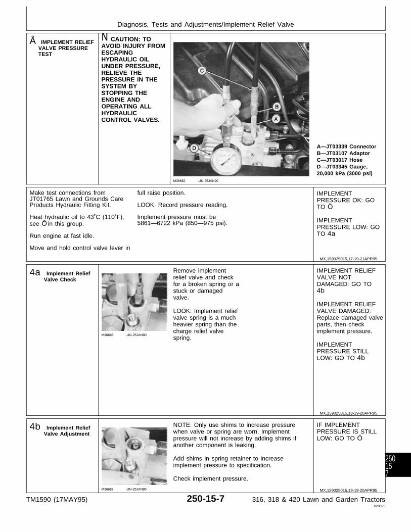
Å IMPLEMENT RELIEFVALVE PRESSURETEST
N CAUTION: TOAVOID INJURY FROMESCAPINGHYDRAULIC OILUNDER PRESSURE,RELIEVE THEPRESSURE IN THESYSTEM BYSTOPPING THEENGINE ANDOPERATING ALLHYDRAULICCONTROL VALVES.
M36682 -UN-25JAN90
A—JT03339 ConnectorB—JT03107 AdaptorC—JT03017 HoseD—JT03345 Gauge,20,000 kPa (3000 psi)
Make test connections fromJT01765 Lawn and Grounds CareProducts Hydraulic Fitting Kit.
Heat hydraulic oil to 43˚C (110˚F),see Õ in this group.
Run engine at fast idle.
Move and hold control valve lever in
full raise position.
LOOK: Record pressure reading.
Implement pressure must be5861—6722 kPa (850—975 psi).
IMPLEMENTPRESSURE OK: GOTO Ö
IMPLEMENTPRESSURE LOW: GOTO 4a
4a Implement ReliefValve Check
M36686 -UN-25JAN90
Remove implementrelief valve and checkfor a broken spring or astuck or damagedvalve.
LOOK: Implement reliefvalve spring is a muchheavier spring than thecharge relief valvespring.
IMPLEMENT RELIEFVALVE NOTDAMAGED: GO TO4b
IMPLEMENT RELIEFVALVE DAMAGED:Replace damaged valveparts, then checkimplement pressure.
IMPLEMENTPRESSURE STILLLOW: GO TO 4b
4b Implement ReliefValve Adjustment
M36687 -UN-25JAN90
NOTE: Only use shims to increase pressurewhen valve or spring are worn. Implementpressure will not increase by adding shims ifanother component is leaking.
Add shims in spring retainer to increaseimplement pressure to specification.
Check implement pressure.
IF IMPLEMENTPRESSURE IS STILLLOW: GO TO Ö
MX,159025015,17-19-21APR95
MX,159025015,18-19-20APR95
MX,159025015,19-19-20APR95
Diagnosis, Tests and Adjustments/Implement Relief Valve
TM1590 (17MAY95) 250-15-7 316, 318 & 420 Lawn and Garden Tractors020895
250157
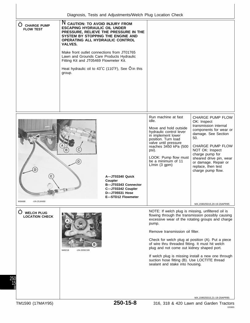
Ö CHARGE PUMPFLOW TEST
N CAUTION: TO AVOID INJURY FROMESCAPING HYDRAULIC OIL UNDERPRESSURE, RELIEVE THE PRESSURE IN THESYSTEM BY STOPPING THE ENGINE ANDOPERATING ALL HYDRAULIC CONTROLVALVES.
Make front outlet connections from JT01765Lawn and Grounds Care Products HydraulicFitting Kit and JT05469 Flowmeter Kit.
Heat hydraulic oil to 43˚C (110˚F), See Õ in thisgroup.
M36688 -UN-25JAN90
A—JT03340 QuickCouplerB—JT03343 ConnectorC—JT03342 CouplerD—JT05531 HoseE—STD12 Flowmeter
Run machine at fastidle.
Move and hold outsidehydraulic control leverin implement lowerposition. Turn loadvalve until pressurereaches 3450 kPa (500psi).
LOOK: Pump flow mustbe a minimum of 11L/min (3 gpm)
CHARGE PUMP FLOWOK: Inspecttransmission internalcomponents for wear ordamage. See Section50.
CHARGE PUMP FLOWNOT OK: Inspectcharge pump forsheared drive pin, wearor damage. Repair orreplace, then testcharge pump flow.
Ò WELCH PLUGLOCATION CHECK
M49218 -UN-20DEC89
NOTE: If welch plug is missing, unfiltered oil isflowing through the transmission possibly causingexcessive wear of the rotating groups and chargepump.
Remove transmission oil filter.
Check for welch plug at position (A). Put a pieceof wire thru threaded fitting. It must hit welchplug and not come out kidney shaped port.
If welch plug is missing install a new one throughsuction hose fitting (B). Use LOCTITE threadsealant and stake into housing.
MX,159025015,20-19-20APR95
MX,159025015,21-19-20APR95
Diagnosis, Tests and Adjustments/Welch Plug Location Check
TM1590 (17MAY95) 250-15-8 316, 318 & 420 Lawn and Garden Tractors020895
25015
8
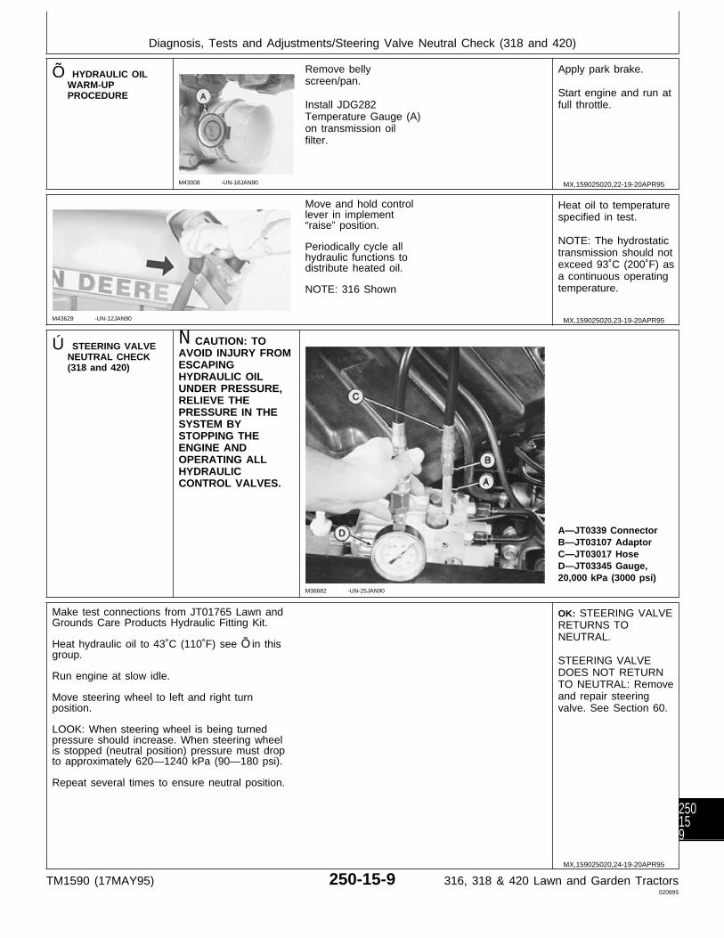
Õ HYDRAULIC OILWARM-UPPROCEDURE
M43008 -UN-18JAN90
Remove bellyscreen/pan.
Install JDG282Temperature Gauge (A)on transmission oilfilter.
Apply park brake.
Start engine and run atfull throttle.
M43629 -UN-12JAN90
Move and hold controllever in implement“raise” position.
Periodically cycle allhydraulic functions todistribute heated oil.
NOTE: 316 Shown
Heat oil to temperaturespecified in test.
NOTE: The hydrostatictransmission should notexceed 93˚C (200˚F) asa continuous operatingtemperature.
Ú STEERING VALVENEUTRAL CHECK(318 and 420)
N CAUTION: TOAVOID INJURY FROMESCAPINGHYDRAULIC OILUNDER PRESSURE,RELIEVE THEPRESSURE IN THESYSTEM BYSTOPPING THEENGINE ANDOPERATING ALLHYDRAULICCONTROL VALVES.
M36682 -UN-25JAN90
A—JT0339 ConnectorB—JT03107 AdaptorC—JT03017 HoseD—JT03345 Gauge,20,000 kPa (3000 psi)
Make test connections from JT01765 Lawn andGrounds Care Products Hydraulic Fitting Kit.
Heat hydraulic oil to 43˚C (110˚F) see Õ in thisgroup.
Run engine at slow idle.
Move steering wheel to left and right turnposition.
LOOK: When steering wheel is being turnedpressure should increase. When steering wheelis stopped (neutral position) pressure must dropto approximately 620—1240 kPa (90—180 psi).
Repeat several times to ensure neutral position.
OK: STEERING VALVERETURNS TONEUTRAL.
STEERING VALVEDOES NOT RETURNTO NEUTRAL: Removeand repair steeringvalve. See Section 60.
MX,159025020,22-19-20APR95
MX,159025020,23-19-20APR95
MX,159025020,24-19-20APR95
Diagnosis, Tests and Adjustments/Steering Valve Neutral Check (318 and 420)
TM1590 (17MAY95) 250-15-9 316, 318 & 420 Lawn and Garden Tractors020895
250159
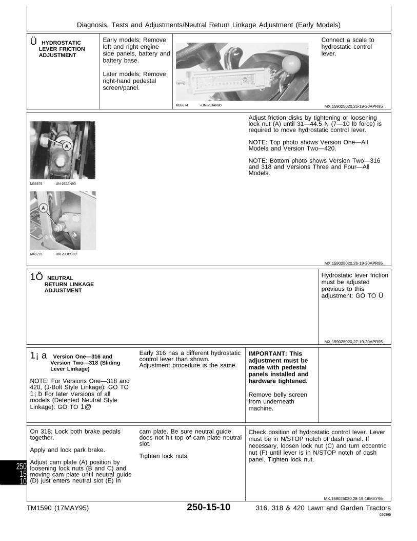
Ü HYDROSTATICLEVER FRICTIONADJUSTMENT
Early models; Removeleft and right engineside panels, battery andbattery base.
Later models; Removeright-hand pedestalscreen/panel.
M36674 -UN-25JAN90
Connect a scale tohydrostatic controllever.
M36675 -UN-25JAN90
M49215 -UN-20DEC89
Adjust friction disks by tightening or looseninglock nut (A) until 31—44.5 N (7—10 lb force) isrequired to move hydrostatic control lever.
NOTE: Top photo shows Version One—AllModels and Version Two—420.
NOTE: Bottom photo shows Version Two—316and 318 and Versions Three and Four—AllModels.
1Ô NEUTRALRETURN LINKAGEADJUSTMENT
Hydrostatic lever frictionmust be adjustedprevious to thisadjustment: GO TO Ü
1¡a Version One—316 andVersion Two—318 (SlidingLever Linkage)
NOTE: For Versions One—318 and420, (J-Bolt Style Linkage): GO TO1¡b For later Versions of allmodels (Detented Neutral StyleLinkage): GO TO 1@
Early 316 has a different hydrostaticcontrol lever than shown.Adjustment procedure is the same.
IMPORTANT: Thisadjustment must bemade with pedestalpanels installed andhardware tightened.
Remove belly screenfrom underneathmachine.
On 318; Lock both brake pedalstogether.
Apply and lock park brake.
Adjust cam plate (A) position byloosening lock nuts (B and C) andmoving cam plate until neutral guide(D) just enters neutral slot (E) in
cam plate. Be sure neutral guidedoes not hit top of cam plate neutralslot.
Tighten lock nuts.
Check position of hydrostatic control lever. Levermust be in N/STOP notch of dash panel. Ifnecessary, loosen lock nut (C) and turn eccentricnut (F) until lever is in N/STOP notch of dashpanel. Tighten lock nut.
MX,159025020,25-19-20APR95
MX,159025020,26-19-20APR95
MX,159025020,27-19-20APR95
MX,159025020,28-19-16MAY95
Diagnosis, Tests and Adjustments/Neutral Return Linkage Adjustment (Early Models)
TM1590 (17MAY95) 250-15-10 316, 318 & 420 Lawn and Garden Tractors020895
2501510
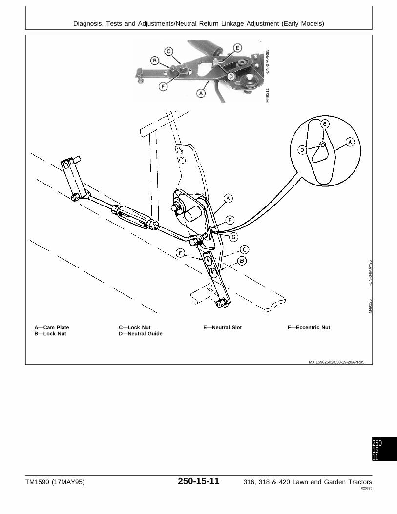
A—Cam Plate C—Lock Nut E—Neutral Slot F—Eccentric NutB—Lock Nut D—Neutral Guide
M49
211
-UN
-07A
PR
95
M49
225
-UN
-04M
AY
95
MX,159025020,30-19-20APR95
Diagnosis, Tests and Adjustments/Neutral Return Linkage Adjustment (Early Models)
TM1590 (17MAY95) 250-15-11 316, 318 & 420 Lawn and Garden Tractors020895
2501511

1¡b Versions One—318 and 420(J-Bolt Style Linkage)
NOTE: For Version One—316 andVersion Two—318 (Sliding LeverLinkage): GO TO 1¡a For laterVersions of all models (DetentedNeutral Style Linkage): GO TO1@
On 318, the J-bolt attached to camplate (A) with lock nuts (B), facesopposite direction shown.Adjustment procedure is the same.
IMPORTANT: Thisadjustment must bemade with pedestalpanels installed andhardware tightened.
Remove bellyscreen/pan fromunderneath machine.
Lock both brake pedals together.
Apply and lock park brake.
Adjust cam plate (A) position bytightening or loosening J-Bolt locknuts (B) until neutral guide (C) justenters neutral slot (D) in cam plate.Be sure neutral guide does not hit
top of cam plate neutral slot.
Tighten lock nuts.
Check position of hydrostatic control lever. Levermust be in N/STOP notch of dash panel. Ifnecessary, loosen lock nut (E) and turn eccentricnut (F) until lever is in N/STOP notch of dashpanel. Tighten lock nut.
MX,159025020,31-19-16MAY95
Diagnosis, Tests and Adjustments/Neutral Return Linkage Adjustment (Early Models)
TM1590 (17MAY95) 250-15-12 316, 318 & 420 Lawn and Garden Tractors020895
2501512
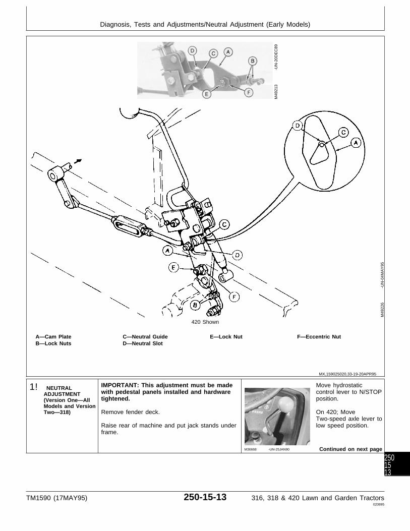
420 Shown
A—Cam Plate C—Neutral Guide E—Lock Nut F—Eccentric NutB—Lock Nuts D—Neutral Slot
M49
213
-UN
-20D
EC
89
M49
226
-UN
-04M
AY
95
1! NEUTRALADJUSTMENT(Version One—AllModels and VersionTwo—318)
IMPORTANT: This adjustment must be madewith pedestal panels installed and hardwaretightened.
Remove fender deck.
Raise rear of machine and put jack stands underframe.
M36668 -UN-25JAN90
Move hydrostaticcontrol lever to N/STOPposition.
On 420; MoveTwo-speed axle lever tolow speed position.
Continued on next page
MX,159025020,33-19-20APR95
Diagnosis, Tests and Adjustments/Neutral Adjustment (Early Models)
TM1590 (17MAY95) 250-15-13 316, 318 & 420 Lawn and Garden Tractors020895
2501513
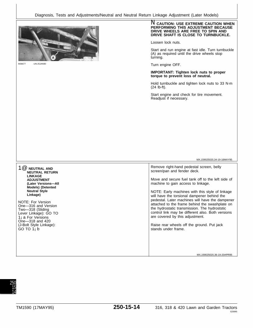
M36677 -UN-25JAN90
N CAUTION: USE EXTREME CAUTION WHENPERFORMING THIS ADJUSTMENT BECAUSEDRIVE WHEELS ARE FREE TO SPIN ANDDRIVE SHAFT IS CLOSE TO TURNBUCKLE.
Loosen lock nuts.
Start and run engine at fast idle. Turn turnbuckle(A) as required until the drive wheels stopturning.
Turn engine OFF.
IMPORTANT: Tighten lock nuts to propertorque to prevent loss of neutral.
Hold turnbuckle and tighten lock nuts to 33 N·m(24 lb-ft).
Start engine and check for tire movement.Readjust if necessary.
1@ NEUTRAL ANDNEUTRAL RETURNLINKAGEADJUSTMENT(Later Versions—AllModels) (DetentedNeutral StyleLinkage)
NOTE: For VersionOne—316 and VersionTwo—318 (SlidingLever Linkage): GO TO1¡a For VersionsOne—318 and 420(J-Bolt Style Linkage):GO TO 1¡b
Remove right-hand pedestal screen, bellyscreen/pan and fender deck.
Move and secure fuel tank off to the left side ofmachine to gain access to linkage.
NOTE: Early machines with this style of linkagewill have the torsional dampener behind thepedestal. Later machines will have the dampenerattached to the frame behind the swashplate onthe hydrostatic transmission. The hydroststiccontrol link may be different also. Both versionsare covered by this adjustment.
Raise rear wheels off the ground. Put jackstands under frame.
MX,159025020,34-19-16MAY95
MX,159025020,36-19-20APR95
Diagnosis, Tests and Adjustments/Neutral and Neutral Return Linkage Adjustment (Later Models)
TM1590 (17MAY95) 250-15-14 316, 318 & 420 Lawn and Garden Tractors020895
2501514
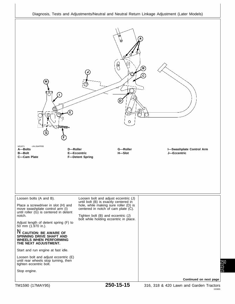
M51871 -UN-26APR95
A—Bolts D—Roller G—Roller I—Swashplate Control ArmB—Bolt E—Eccentric H—Slot J—EccentricC—Cam Plate F—Detent Spring
Loosen bolts (A and B).
Place a screwdriver in slot (H) andmove swashplate control arm (I)until roller (G) is centered in detentnotch.
Adjust length of detent spring (F) to50 mm (1.970 in.).
N CAUTION: BE AWARE OFSPINNING DRIVE SHAFT ANDWHEELS WHEN PERFORMINGTHE NEXT ADJUSTMENT.
Start and run engine at fast idle.
Loosen bolt and adjust eccentric (E)until rear wheels stop turning, thentighten eccentric bolt.
Stop engine.
Continued on next page
Loosen bolt and adjust eccentric (J)until bolt (B) is exactly centered inhole, while making sure roller (D) iscentered in notch of cam plate (C).
Tighten bolt (B) and eccentric (J)bolt while holding eccentric in place.
Diagnosis, Tests and Adjustments/Neutral and Neutral Return Linkage Adjustment (Later Models)
TM1590 (17MAY95) 250-15-15 316, 318 & 420 Lawn and Garden Tractors020895
2501515
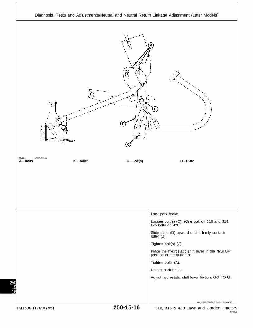
M51872 -UN-26APR95
A—Bolts B—Roller C—Bolt(s) D—Plate
Lock park brake.
Loosen bolt(s) (C). (One bolt on 316 and 318,two bolts on 420).
Slide plate (D) upward until it firmly contactsroller (B).
Tighten bolt(s) (C).
Place the hydrostatic shift lever in the N/STOPposition in the quadrant.
Tighten bolts (A).
Unlock park brake.
Adjust hydrostatic shift lever friction: GO TO Ü
MX,159025020,32-19-16MAY95
Diagnosis, Tests and Adjustments/Neutral and Neutral Return Linkage Adjustment (Later Models)
TM1590 (17MAY95) 250-15-16 316, 318 & 420 Lawn and Garden Tractors020895
2501516

1# TWO-SPEED AXLELEVER LINKAGECHECK (420)
M36693 -UN-25JAN90
Remove belly pan.
Inspect two-speed axlelever linkage formissing pin, brokenspring, wear ordamage. Plate notchmust engage slotseasily.
LINKAGE OK: GO TO1ƒa
LINKAGE DAMAGED:Repair or replace asnecessary.
1ƒa Two-speed AxleLever DetentAdjustment
M36694 -UN-25JAN90
Remove fender deckand fuel tank.
Remove detent screw(A), spring (B) and ball(C). Inspect parts fordamage; replace asnecessary. Install balland spring.
Apply thread lock andsealer (low strength) ondetent screw threads.Install and tightendetent screw. Iftwo-speed lever is hardto move, turn detentscrew counterclockwiseone turn.
DETENT OK: GO TO1ƒb
1ƒb DifferentialInspection
M36695 -UN-25JAN90
Remove and disassemble differential. (Seeprocedures in Section 50.)
Inspect shifter fork and two-speed gears forimproper assembly, wear or damage.
1$ DIFFERENTIALLOCK LINKAGECHECK (420)
M36696 -UN-25JAN90
Remove belly pan.
Inspect differential locklinkage for missing pin,bent rod, wear ordamage. Differentiallock shift rod must slidein and out easily.
LINKAGE OK: GO TO1´a
1´a DifferentialInspection
M36695 -UN-25JAN90
Remove and disassemble differential. (Seeprocedures in Section 50.)
Inspect shifter fork, shift collar, pins, shift rod,and springs for improper assembly, wear ordamage.
MX,159025020,39-19-20APR95
MX,159025020,40-19-20APR95
MX,159025020,41-19-20APR95
MX,159025020,42-19-20APR95
MX,159025020,43-19-20APR95
Diagnosis, Tests and Adjustments/Differential Lock Linkage Check (420)
TM1590 (17MAY95) 250-15-17 316, 318 & 420 Lawn and Garden Tractors020895
2501517
Diagnosis, Tests and Adjustments/Differential Lock Linkage Check (420)
TM1590 (17MAY95) 250-15-18 316, 318 & 420 Lawn and Garden Tractors020895
2501518

Section 260STEERING AND BRAKES CHECKOUT,
OPERATION AND DIAGNOSISContents
Page
Group 05—Steering And Brakes SystemCheckout
Before You Start . . . . . . . . . . . . . . . . . 260-05-1Steering System Oil Leak Check (318
and 420) . . . . . . . . . . . . . . . . . . . . . 260-05-1Hydrostatic Steering System Check (318
and 420) . . . . . . . . . . . . . . . . . . . . . 260-05-2Service Park Brake Check . . . . . . . . . . . 260-05-3Turn Brake Check (318 and 420) . . . . . . 260-05-3Operator Complaint Not Identified . . . . . . 260-05-4
Group 10—Theory of OperationSteering Valve/System Operation
Four-Port Valve . . . . . . . . . . . . . . . . 260-10-1Five-Port Valve . . . . . . . . . . . . . . . . . 260-10-2
Group 15—Diagnosis, Tests and AdjustmentsAbout This Group . . . . . . . . . . . . . . . . 260-15-1Troubleshooting Guide . . . . . . . . . . . . . 260-15-1Hydraulic Oil Warm-up Procedure . . . . . . 260-15-4Steering System Leakage Test . . . . . . . . 260-15-5Steering Valve Leakage Test . . . . . . . . . 260-15-5
TM1590 (17MAY95) 260-1 316, 318 & 420 Lawn and Garden Tractors020895
260

Contents
TM1590 (17MAY95) 260-2 316, 318 & 420 Lawn and Garden Tractors020895
260
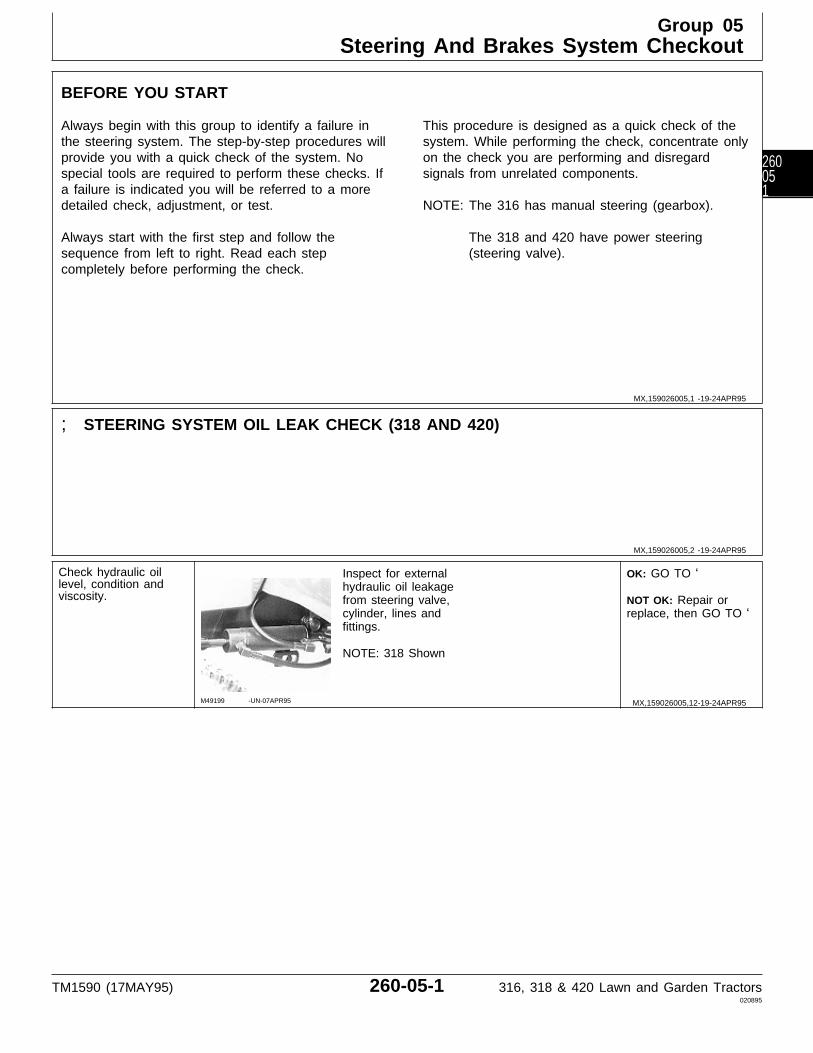
BEFORE YOU START
Always begin with this group to identify a failure inthe steering system. The step-by-step procedures willprovide you with a quick check of the system. Nospecial tools are required to perform these checks. Ifa failure is indicated you will be referred to a moredetailed check, adjustment, or test.
Always start with the first step and follow thesequence from left to right. Read each stepcompletely before performing the check.
This procedure is designed as a quick check of thesystem. While performing the check, concentrate onlyon the check you are performing and disregardsignals from unrelated components.
NOTE: The 316 has manual steering (gearbox).
The 318 and 420 have power steering(steering valve).
; STEERING SYSTEM OIL LEAK CHECK (318 AND 420)
Check hydraulic oillevel, condition andviscosity.
M49199 -UN-07APR95
Inspect for externalhydraulic oil leakagefrom steering valve,cylinder, lines andfittings.
NOTE: 318 Shown
OK: GO TO ‘
NOT OK: Repair orreplace, then GO TO ‘
MX,159026005,1 -19-24APR95
MX,159026005,2 -19-24APR95
MX,159026005,12-19-24APR95
Group 05Steering And Brakes System Checkout
TM1590 (17MAY95) 260-05-1 316, 318 & 420 Lawn and Garden Tractors020895
260051
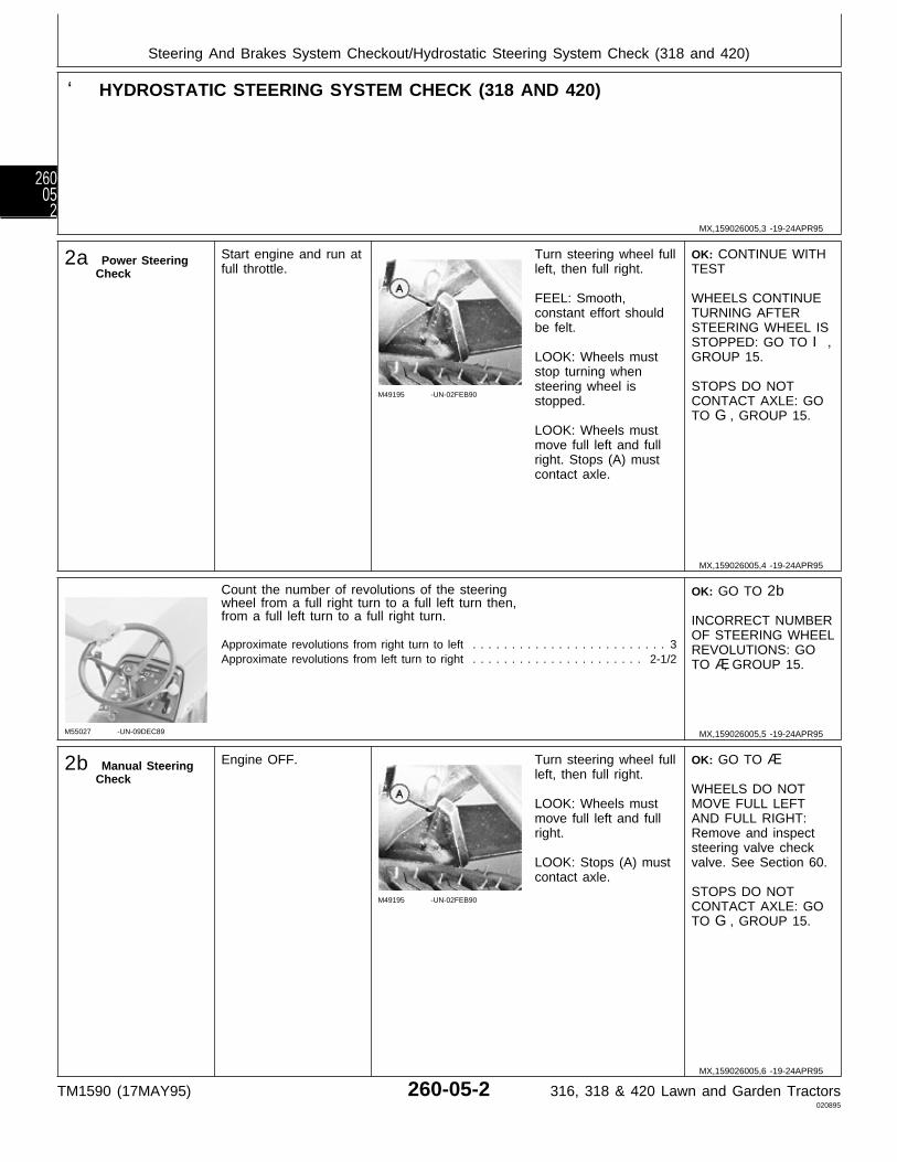
‘ HYDROSTATIC STEERING SYSTEM CHECK (318 AND 420)
2a Power SteeringCheck
Start engine and run atfull throttle.
M49195 -UN-02FEB90
Turn steering wheel fullleft, then full right.
FEEL: Smooth,constant effort shouldbe felt.
LOOK: Wheels muststop turning whensteering wheel isstopped.
LOOK: Wheels mustmove full left and fullright. Stops (A) mustcontact axle.
OK: CONTINUE WITHTEST
WHEELS CONTINUETURNING AFTERSTEERING WHEEL ISSTOPPED: GO TO I,GROUP 15.
STOPS DO NOTCONTACT AXLE: GOTO G, GROUP 15.
M55027 -UN-09DEC89
Count the number of revolutions of the steeringwheel from a full right turn to a full left turn then,from a full left turn to a full right turn.
Approximate revolutions from right turn to left . . . . . . . . . . . . . . . . . . . . . . . . . 3Approximate revolutions from left turn to right . . . . . . . . . . . . . . . . . . . . . . 2-1/2
OK: GO TO 2b
INCORRECT NUMBEROF STEERING WHEELREVOLUTIONS: GOTO Æ, GROUP 15.
2b Manual SteeringCheck
Engine OFF.
M49195 -UN-02FEB90
Turn steering wheel fullleft, then full right.
LOOK: Wheels mustmove full left and fullright.
LOOK: Stops (A) mustcontact axle.
OK: GO TO Æ
WHEELS DO NOTMOVE FULL LEFTAND FULL RIGHT:Remove and inspectsteering valve checkvalve. See Section 60.
STOPS DO NOTCONTACT AXLE: GOTO G, GROUP 15.
MX,159026005,3 -19-24APR95
MX,159026005,4 -19-24APR95
MX,159026005,5 -19-24APR95
MX,159026005,6 -19-24APR95
Steering And Brakes System Checkout/Hydrostatic Steering System Check (318 and 420)
TM1590 (17MAY95) 260-05-2 316, 318 & 420 Lawn and Garden Tractors020895
26005
2

Æ SERVICE PARK BRAKE CHECK
3a Park Brake LockLever Check
M49000 -UN-08JAN90
Depress brake pedal(s)and engage servicepark brake lock.
LOOK: Service parkbrake must remain inpark position.
Disengage service parkbrake.
Move park brake knobup and down.
FEEL: Slight springpressure should be felt.
OK: GO TO 3b
NOT OK: Adjust parkbrake linkage. SeeSection 60.
3b Brake Pedal(s)Check
M49001 -UN-08JAN90
Latch brake pedalstogether, if equipped.Depress brake pedal(s)and engage servicepark brake lock.
NOTE: 318 Shown
Try to move hydrostatlever forward orreverse.
FEEL: Lever must NOTmove from N/STOPposition.
OK: GO TO Å
NOT OK: Adjust parkbrake linkage andshoes. See Section 60.
Å TURN BRAKE CHECK (318 AND 420)
Drive machine forwardat medium speed.
M49002 -UN-08JAN90
Depress left, then rightturn brake.
LOOK: Left, then rightwheel must stop andother must continuedriving.
OK: System normal.
NOT OK: Inspect andadjust brake shoes.See Section 60.
MX,159026005,7 -19-24APR95
MX,159026005,8 -19-24APR95
MX,159026005,9 -19-16MAY95
MX,159026005,10-19-05MAY95
MX,159026005,13-19-24APR95
Steering And Brakes System Checkout/Turn Brake Check (318 and 420)
TM1590 (17MAY95) 260-05-3 316, 318 & 420 Lawn and Garden Tractors020895
260053

Ö OPERATOR COMPLAINT NOT IDENTIFIED
If you completed the checkout procedure and didnot isolate a malfunction, the problem may beintermittent.
Try to duplicate the condition of the malfunctionidentified by the operator.
Repeat systemcheckout in this group.
IF A MALFUNCTION IS NOT IDENTIFIEDAFTER REPEATING SYSTEM CHECKOUTPROCEDURE, FACTORY ASSISTANCE ISAVAILABLE THROUGH THE DEALERTECHNICAL ASSISTANCE CENTER (DTAC).
MX,159026005,11-19-24APR95
MX,159026005,14-19-24APR95
Steering And Brakes System Checkout/Operator Complaint Not Identified
TM1590 (17MAY95) 260-05-4 316, 318 & 420 Lawn and Garden Tractors020895
26005
4
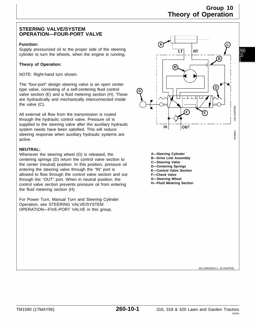
STEERING VALVE/SYSTEMOPERATION—FOUR-PORT VALVE
Function:Supply pressurized oil to the proper side of the steeringcylinder to turn the wheels, when the engine is running.
Theory of Operation:
NOTE: Right-hand turn shown.
The “four-port” design steering valve is an open centertype valve, consisting of a self-centering fluid controlvalve section (E) and a fluid metering section (H). Theseare hydraulically and mechanically interconnected insidethe valve (C).
All external oil flow from the transmission is routedthrough the hydraulic control valve. Pressure oil issupplied to the steering valve after the auxiliary hydraulicsystem needs have been satisfied. This will reducesteering response when auxiliary hydraulic systems areactive.
NEUTRAL:A—Steering CylinderWhenever the steering wheel (G) is released, theB—Drive Link Assemblycentering springs (D) return the control valve section toC—Steering Valve
the center (neutral) position. In this position, pressure oil D—Centering Springsentering the steering valve through the “IN” port is E—Control Valve Sectionallowed to flow through the control valve section and out F—Check Valve
G—Steering Wheelthrough the “OUT” port. When in neutral position, theH—Fluid Metering Sectioncontrol valve section prevents pressure oil from entering
the fluid metering section (H).
For Power Turn, Manual Turn and Steering CylinderOperation, see STEERING VALVE/SYSTEMOPERATION—FIVE-PORT VALVE in this group.
M78
854
-UN
-03A
PR
95
MX,159026010,1 -19-24APR95
Group 10Theory of Operation
TM1590 (17MAY95) 260-10-1 316, 318 & 420 Lawn and Garden Tractors020895
260101
STEERING VALVE/SYSTEM OPERATION—FIVE-PORT VALVE
Function:Supply pressurized oil to the proper side of thesteering cylinder to turn the wheels, when the engineis running.
Theory of Operation:
NOTE: Right-hand turn shown.
All external oil flow from the transmission is routedthrough the steering valve. The steering valve is anopen center type valve. The “five-port” designprovides “power beyond” to the auxiliary hydraulicsystems only after satisfying steering valve needs.
The steering valve consists of a self-centering fluidcontrol valve section (E) and a fluid metering section(H). These are hydraulically and mechanicallyinterconnected inside the valve (C).
NEUTRAL:Whenever the steering wheel (G) is released, thecentering springs (D) return the control valve sectionto the center (neutral) position. In this position,charge pressure oil entering the steering valvethrough port “IN” is allowed to flow through thecontrol valve section and out through port “AUX”.When in neutral position, the control valve preventscharge pressure oil from entering the fluid meteringsection.
POWER TURN:As the steering wheel is turned to the right, thecontrol valve section is shifted by the drive linkassembly (B). This shifting opens the steering cylinderports “RT” and “LT”. Oil flow to auxiliary hydraulicsystems through port “AUX” is reduced giving thesteering valve priority over the auxiliary systemcomponents.
Oil flows from port “IN” directly to the inlet of thecontrol valve section. As the steering wheel is turned,
charge pressure oil is routed through the controlvalve section to the fluid metering section. Metered oilis routed to port “RT” on the steering cylinder. Returnoil from the other end of the steering cylinder isrouted back to port “LT”, through the control valveand “OUT” port, returning to the transmission.
When the rotation of the steering wheel stops, thecentering springs (D) move the control valve sectionback to the center (neutral) position, and will remainthere until the steering wheel is moved again.
MANUAL TURN:If hydraulic pressure is lost, the machine can still besteered without hydraulic assistance. All componentsstill function the same with the exception of the fluidmetering section (H). The fluid metering section nowacts as a pump, moving oil from one side of themetering section to the other as the steering wheel isturned.
When the rotation of the steering wheel stops, thecentering springs move the valve back to the center(neutral) position, and will remain there until thesteering wheel is moved again.
STEERING CYLINDER OPERATION:The steering cylinder is a double-acting design.
One end of the cylinder is attached to the framewhich prevents the cylinder from moving. The rod endis attached to the steering arm/spindle.
As pressurized oil enters the cylinder, the piston androd move, moving the steering arm, causing themachine to turn.
To turn in the other direction, pressurized oil isapplied to the other port, moving the cylinder in theopposite direction.
MX,159026010,2 -19-24APR95
Theory of Operation/Steering Valve/System Operation
TM1590 (17MAY95) 260-10-2 316, 318 & 420 Lawn and Garden Tractors020895
26010
2
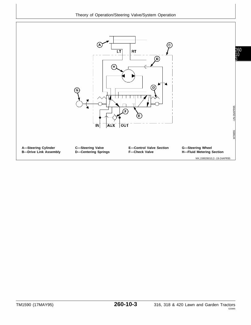
A—Steering Cylinder C—Steering Valve E—Control Valve Section G—Steering WheelB—Drive Link Assembly D—Centering Springs F—Check Valve H—Fluid Metering Section
M78
855
-UN
-26A
PR
95
MX,159026010,3 -19-24APR95
Theory of Operation/Steering Valve/System Operation
TM1590 (17MAY95) 260-10-3 316, 318 & 420 Lawn and Garden Tractors020895
260103

Theory of Operation/Steering Valve/System Operation
TM1590 (17MAY95) 260-10-4 316, 318 & 420 Lawn and Garden Tractors020895
26010
4
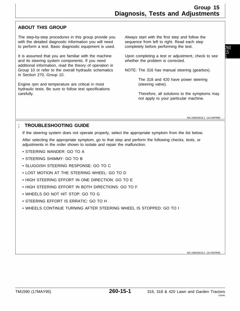
ABOUT THIS GROUP
The step-by-step procedures in this group provide youwith the detailed diagnostic information you will needto perform a test. Basic diagnostic equipment is used.
It is assumed that you are familiar with the machineand its steering system components. If you needadditional information, read the theory of operation inGroup 10 or refer to the overall hydraulic schematicsin Section 270, Group 10.
Engine rpm and temperature are critical in mosthydraulic tests. Be sure to follow test specificationscarefully.
Always start with the first step and follow thesequence from left to right. Read each stepcompletely before performing the test.
Upon completing a test or adjustment, check to seewhether the problem is corrected.
NOTE: The 316 has manual steering (gearbox).
The 318 and 420 have power steering(steering valve).
Therefore, all solutions to the symptoms maynot apply to your particular machine.
; TROUBLESHOOTING GUIDE
If the steering system does not operate properly, select the appropriate symptom from the list below.
After selecting the appropriate symptom, go to that step and perform the following checks, tests, oradjustments in the order shown to isolate and repair the malfunction.
• STEERING WANDER: GO TO A
• STEERING SHIMMY: GO TO B
• SLUGGISH STEERING RESPONSE: GO TO C
• LOST MOTION AT THE STEERING WHEEL: GO TO D
• HIGH STEERING EFFORT IN ONE DIRECTION: GO TO E
• HIGH STEERING EFFORT IN BOTH DIRECTIONS: GO TO F
• WHEELS DO NOT HIT STOP: GO TO G
• STEERING EFFORT IS ERRATIC: GO TO H
• WHEELS CONTINUE TURNING AFTER STEERING WHEEL IS STOPPED: GO TO I
MX,159026015,1 -19-24APR95
MX,159026015,2 -19-24APR95
Group 15Diagnosis, Tests and Adjustments
TM1590 (17MAY95) 260-15-1 316, 318 & 420 Lawn and Garden Tractors020895
260151
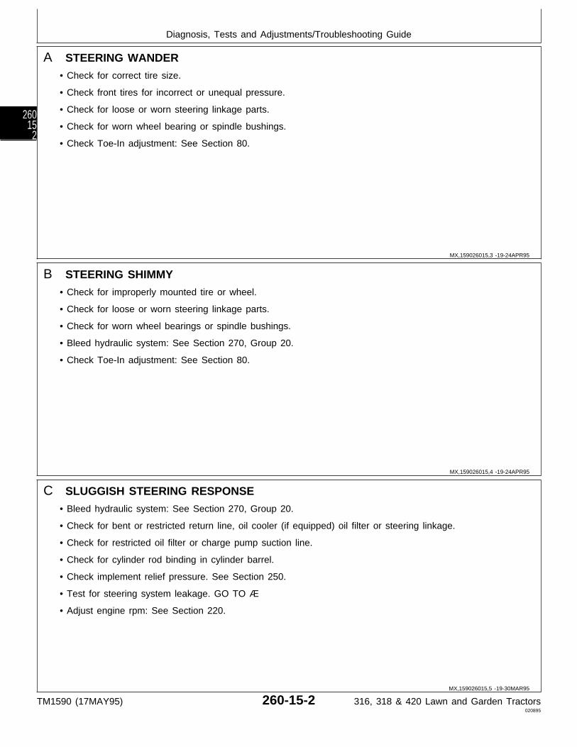
A STEERING WANDER
• Check for correct tire size.
• Check front tires for incorrect or unequal pressure.
• Check for loose or worn steering linkage parts.
• Check for worn wheel bearing or spindle bushings.
• Check Toe-In adjustment: See Section 80.
B STEERING SHIMMY
• Check for improperly mounted tire or wheel.
• Check for loose or worn steering linkage parts.
• Check for worn wheel bearings or spindle bushings.
• Bleed hydraulic system: See Section 270, Group 20.
• Check Toe-In adjustment: See Section 80.
C SLUGGISH STEERING RESPONSE
• Bleed hydraulic system: See Section 270, Group 20.
• Check for bent or restricted return line, oil cooler (if equipped) oil filter or steering linkage.
• Check for restricted oil filter or charge pump suction line.
• Check for cylinder rod binding in cylinder barrel.
• Check implement relief pressure. See Section 250.
• Test for steering system leakage. GO TO Æ
• Adjust engine rpm: See Section 220.
MX,159026015,3 -19-24APR95
MX,159026015,4 -19-24APR95
MX,159026015,5 -19-30MAR95
Diagnosis, Tests and Adjustments/Troubleshooting Guide
TM1590 (17MAY95) 260-15-2 316, 318 & 420 Lawn and Garden Tractors020895
26015
2

D LOST MOTION AT STEERING WHEEL
• Check for loose or worn steering linkage.
• Check for steering valve loose at mounting.
• Bleed hydraulic system: See Section 270, Group 20.
E HIGH STEERING EFFORT IN ONE DIRECTION
• Check for binding of linkage or cylinder rod binding in cylinder barrel.
• Check for bent or restricted return line.
• Test for steering system leakage: GO TO Æ
• Inspect plate valve for sticking: See Section 60.
F HIGH STEERING EFFORT IN BOTH DIRECTIONS
• Check for improperly mounted tires or wheels.
• Check for binding of steering linkage and cylinder.
• Check for bent or restricted return line, oil cooler (if equipped) or oil filter.
• Check implement relief pressure. See Section 250.
• Check for steering valve check ball missing, damaged, or in “IN” port: See Section 60.
• Adjust engine rpm: See Section 220.
• Check for dirt accumulation on transmission causing transmission to overheat: GO TO ‘
• Check for high draft load causing transmission to overheat: GO TO ‘
MX,159026015,6 -19-30MAR95
MX,159026015,7 -19-30MAR95
MX,159026015,8 -19-30MAR95
Diagnosis, Tests and Adjustments/Troubleshooting Guide
TM1590 (17MAY95) 260-15-3 316, 318 & 420 Lawn and Garden Tractors020895
260153
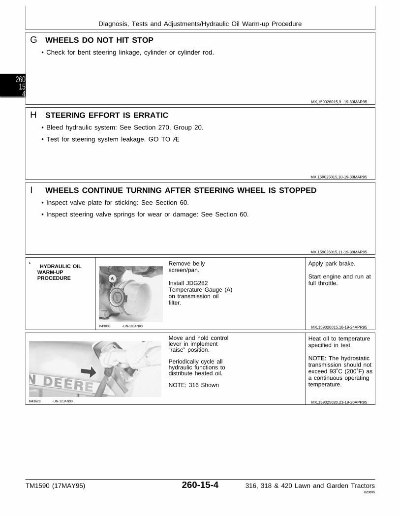
G WHEELS DO NOT HIT STOP
• Check for bent steering linkage, cylinder or cylinder rod.
H STEERING EFFORT IS ERRATIC
• Bleed hydraulic system: See Section 270, Group 20.
• Test for steering system leakage. GO TO Æ
I WHEELS CONTINUE TURNING AFTER STEERING WHEEL IS STOPPED
• Inspect valve plate for sticking: See Section 60.
• Inspect steering valve springs for wear or damage: See Section 60.
‘ HYDRAULIC OILWARM-UPPROCEDURE
M43008 -UN-18JAN90
Remove bellyscreen/pan.
Install JDG282Temperature Gauge (A)on transmission oilfilter.
Apply park brake.
Start engine and run atfull throttle.
M43629 -UN-12JAN90
Move and hold controllever in implement“raise” position.
Periodically cycle allhydraulic functions todistribute heated oil.
NOTE: 316 Shown
Heat oil to temperaturespecified in test.
NOTE: The hydrostatictransmission should notexceed 93˚C (200˚F) asa continuous operatingtemperature.
MX,159026015,9 -19-30MAR95
MX,159026015,10-19-30MAR95
MX,159026015,11-19-30MAR95
MX,159026015,16-19-24APR95
MX,159025020,23-19-20APR95
Diagnosis, Tests and Adjustments/Hydraulic Oil Warm-up Procedure
TM1590 (17MAY95) 260-15-4 316, 318 & 420 Lawn and Garden Tractors020895
26015
4
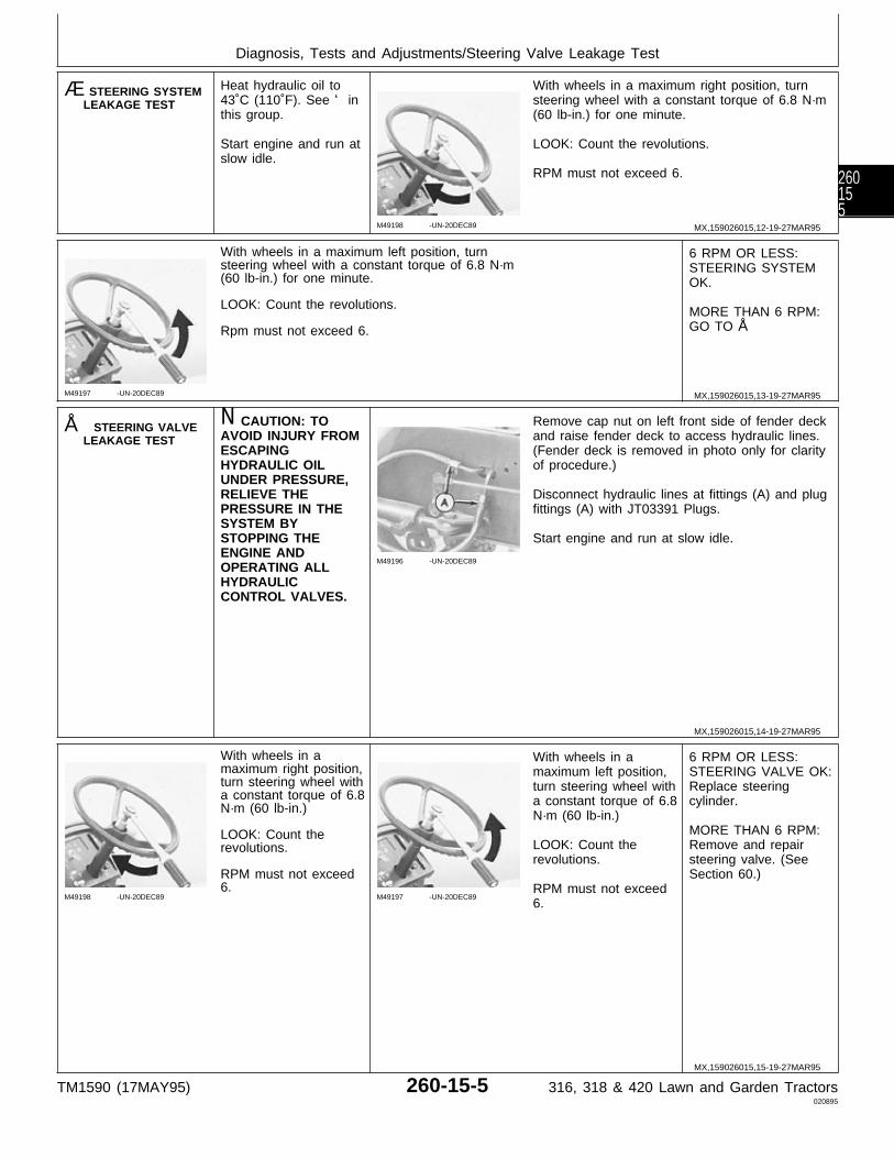
Æ STEERING SYSTEMLEAKAGE TEST
Heat hydraulic oil to43˚C (110˚F). See ‘ inthis group.
Start engine and run atslow idle.
M49198 -UN-20DEC89
With wheels in a maximum right position, turnsteering wheel with a constant torque of 6.8 N·m(60 lb-in.) for one minute.
LOOK: Count the revolutions.
RPM must not exceed 6.
M49197 -UN-20DEC89
With wheels in a maximum left position, turnsteering wheel with a constant torque of 6.8 N·m(60 lb-in.) for one minute.
LOOK: Count the revolutions.
Rpm must not exceed 6.
6 RPM OR LESS:STEERING SYSTEMOK.
MORE THAN 6 RPM:GO TO Å
Å STEERING VALVELEAKAGE TEST
N CAUTION: TOAVOID INJURY FROMESCAPINGHYDRAULIC OILUNDER PRESSURE,RELIEVE THEPRESSURE IN THESYSTEM BYSTOPPING THEENGINE ANDOPERATING ALLHYDRAULICCONTROL VALVES.
M49196 -UN-20DEC89
Remove cap nut on left front side of fender deckand raise fender deck to access hydraulic lines.(Fender deck is removed in photo only for clarityof procedure.)
Disconnect hydraulic lines at fittings (A) and plugfittings (A) with JT03391 Plugs.
Start engine and run at slow idle.
M49198 -UN-20DEC89
With wheels in amaximum right position,turn steering wheel witha constant torque of 6.8N·m (60 lb-in.)
LOOK: Count therevolutions.
RPM must not exceed6.
M49197 -UN-20DEC89
With wheels in amaximum left position,turn steering wheel witha constant torque of 6.8N·m (60 lb-in.)
LOOK: Count therevolutions.
RPM must not exceed6.
6 RPM OR LESS:STEERING VALVE OK:Replace steeringcylinder.
MORE THAN 6 RPM:Remove and repairsteering valve. (SeeSection 60.)
MX,159026015,12-19-27MAR95
MX,159026015,13-19-27MAR95
MX,159026015,14-19-27MAR95
MX,159026015,15-19-27MAR95
Diagnosis, Tests and Adjustments/Steering Valve Leakage Test
TM1590 (17MAY95) 260-15-5 316, 318 & 420 Lawn and Garden Tractors020895
260155

Diagnosis, Tests and Adjustments/Steering Valve Leakage Test
TM1590 (17MAY95) 260-15-6 316, 318 & 420 Lawn and Garden Tractors020895
26015
6
Section 270HYDRAULIC SYSTEM CHECKOUT,
OPERATION AND DIAGNOSISContents
Page
Group 05—Hydraulic System CheckoutBefore You Start . . . . . . . . . . . . . . . . . 270-05-1Hydraulic System Oil Leak Check . . . . . . 270-05-1Hydraulic Control Valve Check . . . . . . . . 270-05-2Operator Complaint Not Identified . . . . . . 270-05-2
Group 10—Hydraulic SchematicsHydraulic Circuit Symbols . . . . . . . . . . . 270-10-2Hydraulic System Schematics
316 . . . . . . . . . . . . . . . . . . . . . . . . 270-10-5Early 318 . . . . . . . . . . . . . . . . . . . . . 270-10-6Later 318 . . . . . . . . . . . . . . . . . . . . . 270-10-9Early 420 . . . . . . . . . . . . . . . . . . . . 270-10-10Later 420 . . . . . . . . . . . . . . . . . . . . 270-10-13
Group 15—Theory of OperationHydraulic Lift System Operation
Three-Position Spool . . . . . . . . . . . . . 270-15-1Four-Position Spool . . . . . . . . . . . . . . 270-15-2
Group 20—Diagnosis, Tests and AdjustmentsAbout This Group . . . . . . . . . . . . . . . . 270-20-1Troubleshooting Guide . . . . . . . . . . . . . 270-20-2Hydraulic Oil Warm-Up Procedure . . . . . . 270-20-5Rockshaft Cylinder Leakage Test . . . . . . 270-20-5Control Valve Leakage Test . . . . . . . . . . 270-20-6Bleed Hydraulic System . . . . . . . . . . . . 270-20-8
TM1590 (17MAY95) 270-1 316, 318 & 420 Lawn and Garden Tractors020895
270

Contents
TM1590 (17MAY95) 270-2 316, 318 & 420 Lawn and Garden Tractors020895
270

BEFORE YOU START
Always begin with this group to identify a failure inthe hydraulic system. The step-by-step procedureswill provide you with a quick check of the system. Nospecial tools are required to perform these checks. Ifa failure is indicated, you will be referred to a moredetailed check, adjustment, or test.
Always start with the first step and follow thesequence from left to right. Read each stepcompletely before performing the check.
This procedure is designed as a quick check of thesystem. While performing the check, concentrate onlyon the check you are performing and disregardsignals from unrelated components.
NOTE: The 316 has manual steering (gearbox),single-spool control valve and rockshaftcylinder.
The 318 has power steering, steering cylinder,two-spool control valve, rockshaft cylinder andoil cooler.
The 420 has power steering, steering cylinder,three-spool control valve, rockshaft cylinderand oil cooler.
For further information, refer to the overallhydraulic schematics in Group 10.
; HYDRAULICSYSTEM OIL LEAKCHECK
Check hydraulic oillevel, condition andviscosity.
M49199 -UN-07APR95
Inspect control valve,cylinders, lines, hosesand fittings for externalhydraulic oil leakage.
NOTE: 318 Shown
OK: GO TO ‘
NOT OK: Repair orreplace, then GO TO ‘
MX,159027005,1 -19-24APR95
MX,159027005,2 -19-24APR95
Group 05Hydraulic System Checkout
TM1590 (17MAY95) 270-05-1 316, 318 & 420 Lawn and Garden Tractors020895
270051
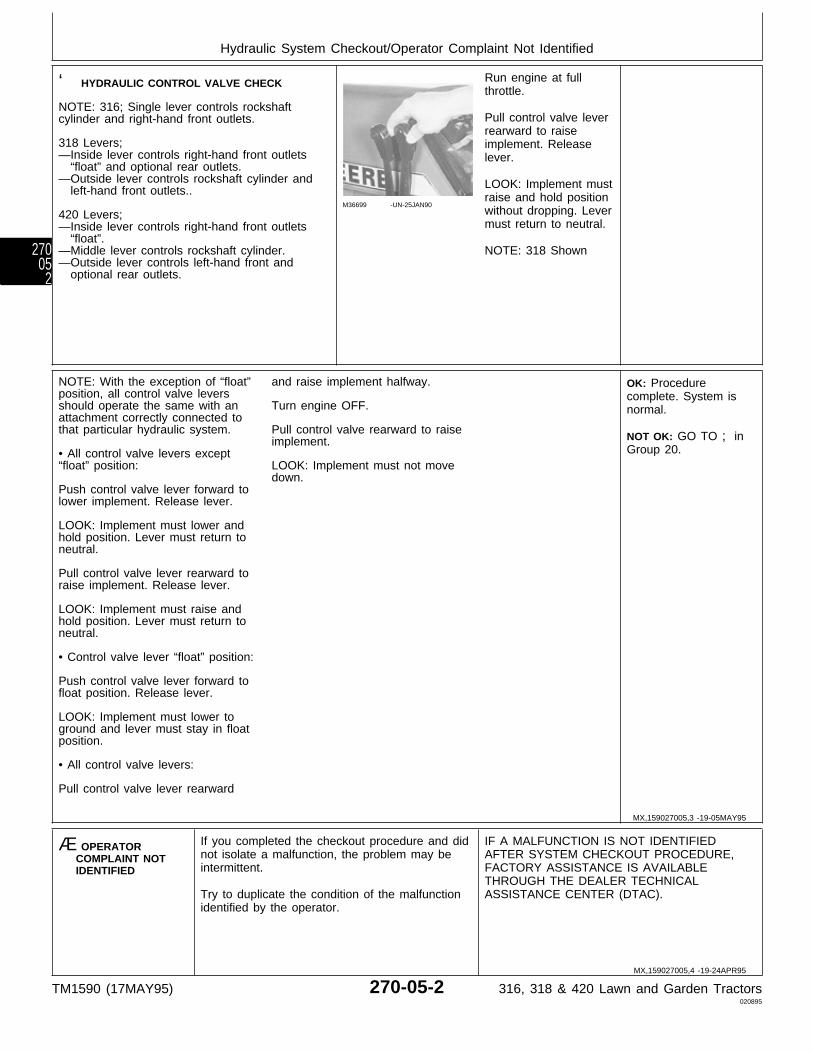
‘ HYDRAULIC CONTROL VALVE CHECK
NOTE: 316; Single lever controls rockshaftcylinder and right-hand front outlets.
318 Levers;—Inside lever controls right-hand front outlets “float” and optional rear outlets.—Outside lever controls rockshaft cylinder and left-hand front outlets..
420 Levers;—Inside lever controls right-hand front outlets “float”.—Middle lever controls rockshaft cylinder.—Outside lever controls left-hand front and optional rear outlets.
M36699 -UN-25JAN90
Run engine at fullthrottle.
Pull control valve leverrearward to raiseimplement. Releaselever.
LOOK: Implement mustraise and hold positionwithout dropping. Levermust return to neutral.
NOTE: 318 Shown
NOTE: With the exception of “float”position, all control valve leversshould operate the same with anattachment correctly connected tothat particular hydraulic system.
• All control valve levers except“float” position:
Push control valve lever forward tolower implement. Release lever.
LOOK: Implement must lower andhold position. Lever must return toneutral.
Pull control valve lever rearward toraise implement. Release lever.
LOOK: Implement must raise andhold position. Lever must return toneutral.
• Control valve lever “float” position:
Push control valve lever forward tofloat position. Release lever.
LOOK: Implement must lower toground and lever must stay in floatposition.
• All control valve levers:
Pull control valve lever rearward
and raise implement halfway.
Turn engine OFF.
Pull control valve rearward to raiseimplement.
LOOK: Implement must not movedown.
OK: Procedurecomplete. System isnormal.
NOT OK: GO TO ; inGroup 20.
Æ OPERATORCOMPLAINT NOTIDENTIFIED
If you completed the checkout procedure and didnot isolate a malfunction, the problem may beintermittent.
Try to duplicate the condition of the malfunctionidentified by the operator.
IF A MALFUNCTION IS NOT IDENTIFIEDAFTER SYSTEM CHECKOUT PROCEDURE,FACTORY ASSISTANCE IS AVAILABLETHROUGH THE DEALER TECHNICALASSISTANCE CENTER (DTAC).
MX,159027005,3 -19-05MAY95
MX,159027005,4 -19-24APR95
Hydraulic System Checkout/Operator Complaint Not Identified
TM1590 (17MAY95) 270-05-2 316, 318 & 420 Lawn and Garden Tractors020895
27005
2
HYDRAULIC SYSTEM SCHEMATICS
The hydraulic system schematics on the following pagescan be folded out for use while diagnosing malfunctionsor while repairing hydraulic components.
MX,159027010,1 -19-24APR95
Group 10Hydraulic Schematics
TM1590 (17MAY95) 270-10-1 316, 318 & 420 Lawn and Garden Tractors020895
270101
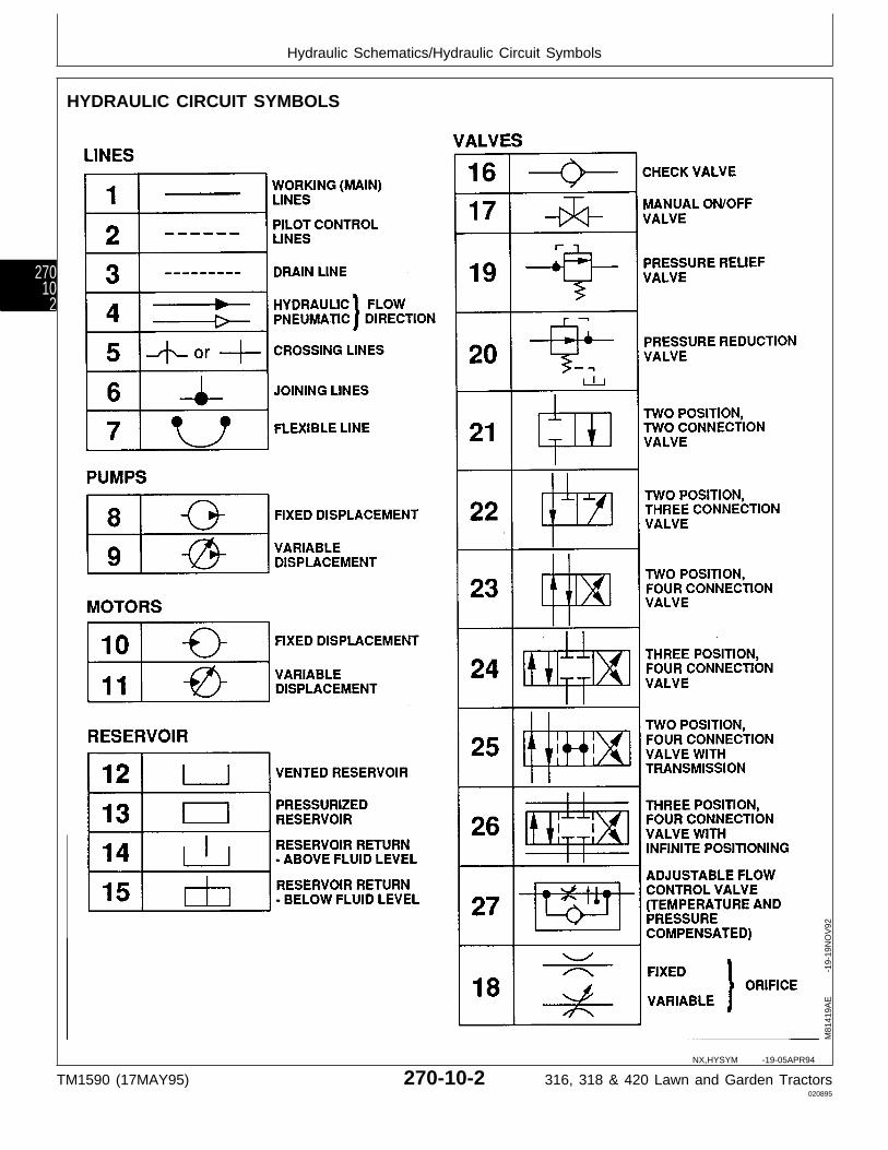
HYDRAULIC CIRCUIT SYMBOLS
M81
419A
E
-19
-19N
OV
92
NX,HYSYM -19-05APR94
Hydraulic Schematics/Hydraulic Circuit Symbols
TM1590 (17MAY95) 270-10-2 316, 318 & 420 Lawn and Garden Tractors020895
27010
2

M81
440A
E
-19
-19N
OV
92
NX,HYSYM1 -19-05APR94
Hydraulic Schematics/Hydraulic Circuit Symbols
TM1590 (17MAY95) 270-10-3 316, 318 & 420 Lawn and Garden Tractors020895
270103
LEGEND FOR HYDRAULIC SYSTEM SCHEMATIC—316
1—Hydrostatic Transmission 6—Implement Relief Valve 11—Input (Pump) Shaft 14—Hydraulic Control Valve2—Output (Motor) Shaft 7—Check (Freewheel) Valves 12—Control Valve Spool 15—Rockshaft Cylinder3—Hydrostatic Drive Motor 8—Charge Pump (Three-Position) 16—Right Front Hydraulic4—Transmission Case Drain 9—Filter 13—Check Valve Outlets5—Charge Relief Valve 10—Variable Hydrostatic
Pump
MX,159027010,2 -19-03MAY95
Hydraulic Schematics/Hydraulic Circuit Symbols
TM1590 (17MAY95) 270-10-4 316, 318 & 420 Lawn and Garden Tractors020895
27010
4

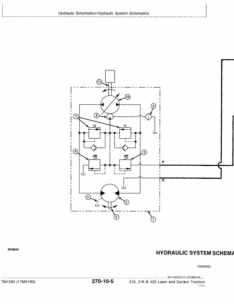
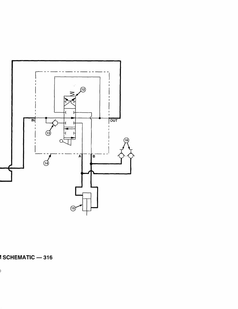
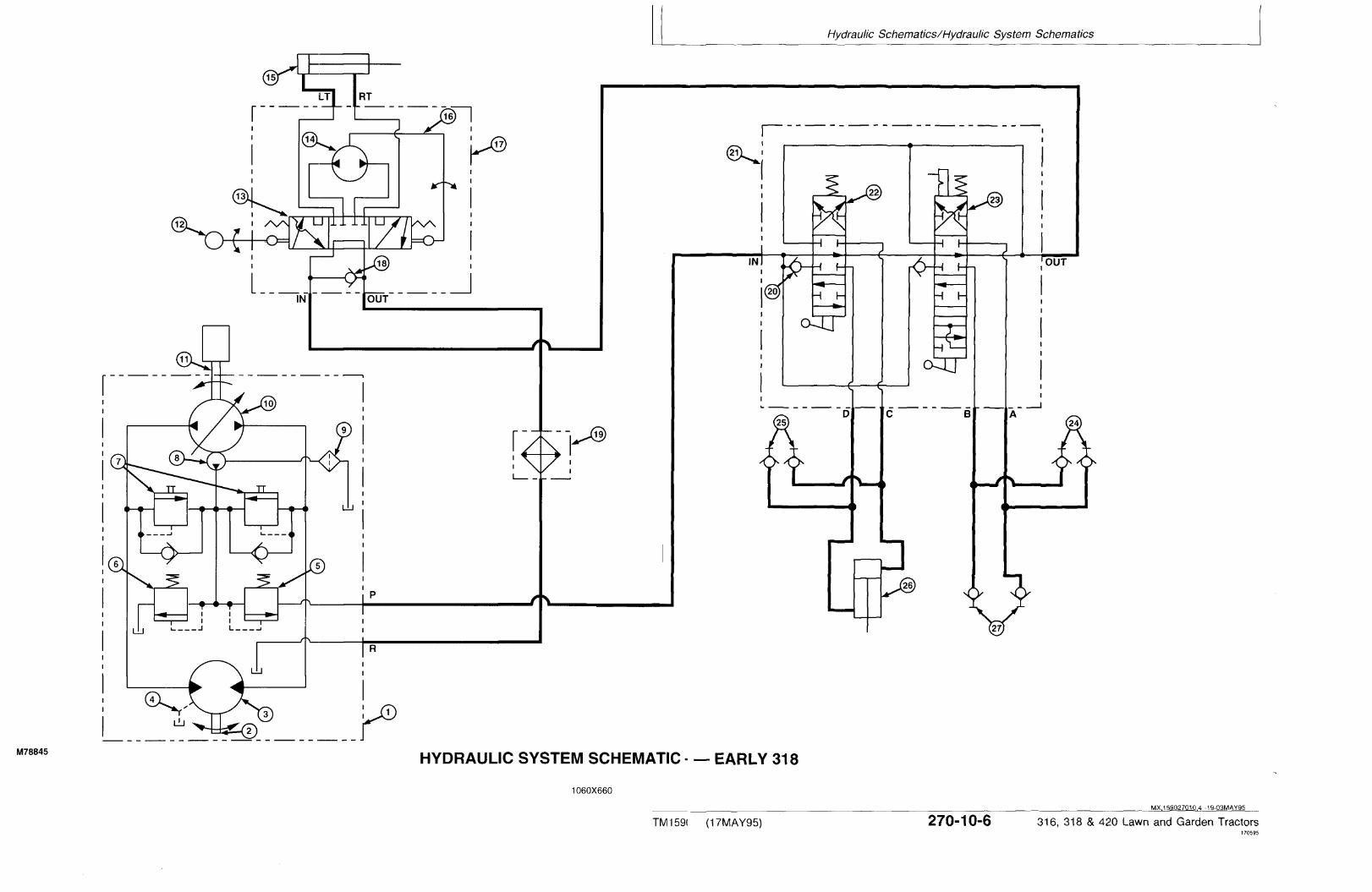
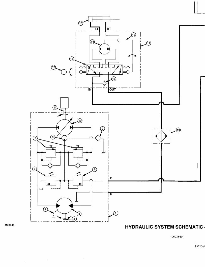
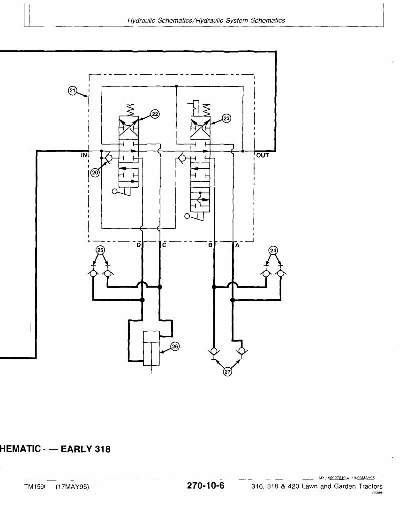

LEGEND FOR HYDRAULIC SYSTEM SCHEMATIC—EARLY 318
1—Hydrostatic Transmission 10—Variable Hydrostatic 17—Steering Valve (4-Port) 24—Front Hydraulic2—Output (Motor) Shaft Pump 18—Check Valve Outlets—Right Side3—Hydrostatic Drive Motor 11—Input (Pump) Shaft 19—Oil Cooler 25—Front Hydraulic4—Transmission Case Drain 12—Steering Wheel 20—Check Valve (2 used) Outlets—Left Side5—Charge Relief Valve 13—Control Valve Section 21—Hydraulic Control Valve 26—Rockshaft Cylinder6—Implement Relief Valve 14—Fluid Metering Section 22—Control Valve Spool 27—Rear Hydraulic Outlets7—Check (Freewheel) Valves 15—Steering Cylinder (Three-Position) (Optional)8—Charge Pump 16—Drive Link Assembly 23—Control Valve Spool with9—Filter “Float” (Four-Position)
MX,159027010,5 -19-03MAY95
Hydraulic Schematics/Hydraulic System Schematics
TM1590 (17MAY95) 270-10-7 316, 318 & 420 Lawn and Garden Tractors020895
270107
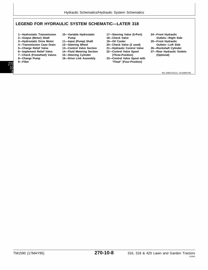
LEGEND FOR HYDRAULIC SYSTEM SCHEMATIC—LATER 318
1—Hydrostatic Transmission 10—Variable Hydrostatic 17—Steering Valve (5-Port) 24—Front Hydraulic2—Output (Motor) Shaft Pump 18—Check Valve Outlets—Right Side3—Hydrostatic Drive Motor 11—Input (Pump) Shaft 19—Oil Cooler 25—Front Hydraulic4—Transmission Case Drain 12—Steering Wheel 20—Check Valve (2 used) Outlets—Left Side5—Charge Relief Valve 13—Control Valve Section 21—Hydraulic Control Valve 26—Rockshaft Cylinder6—Implement Relief Valve 14—Fluid Metering Section 22—Control Valve Spool 27—Rear Hydraulic Outlets7—Check (Freewheel) Valves 15—Steering Cylinder (Three-Position) (Optional)8—Charge Pump 16—Drive Link Assembly 23—Control Valve Spool with9—Filter “Float” (Four-Position)
MX,159027010,6 -19-03MAY95
Hydraulic Schematics/Hydraulic System Schematics
TM1590 (17MAY95) 270-10-8 316, 318 & 420 Lawn and Garden Tractors020895
27010
8
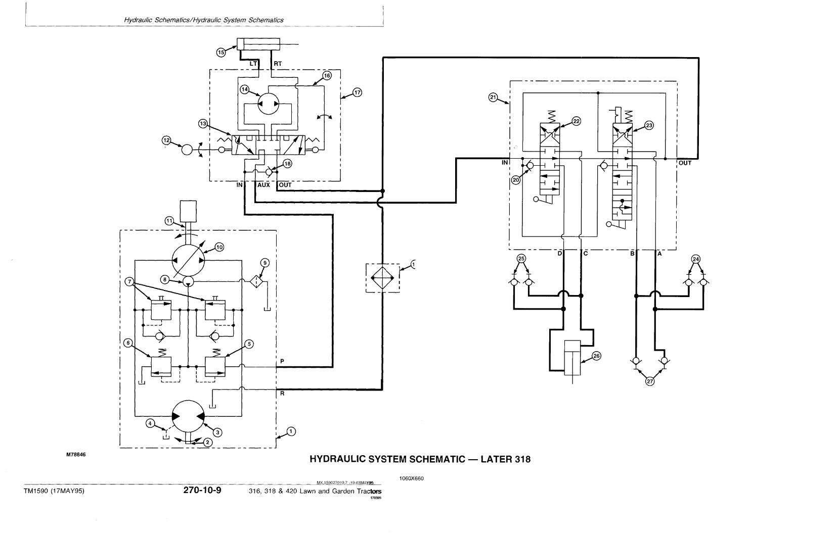
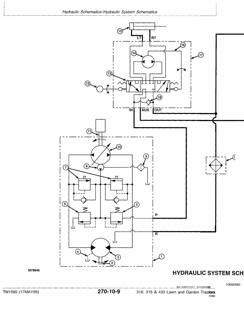
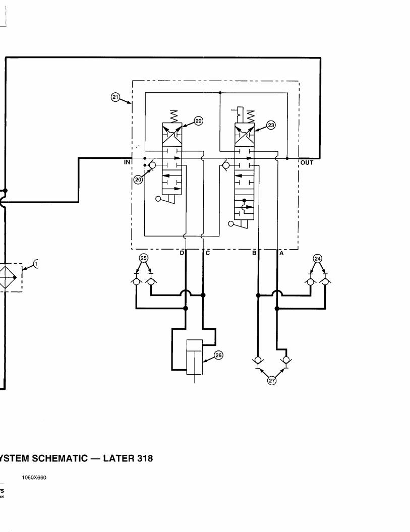


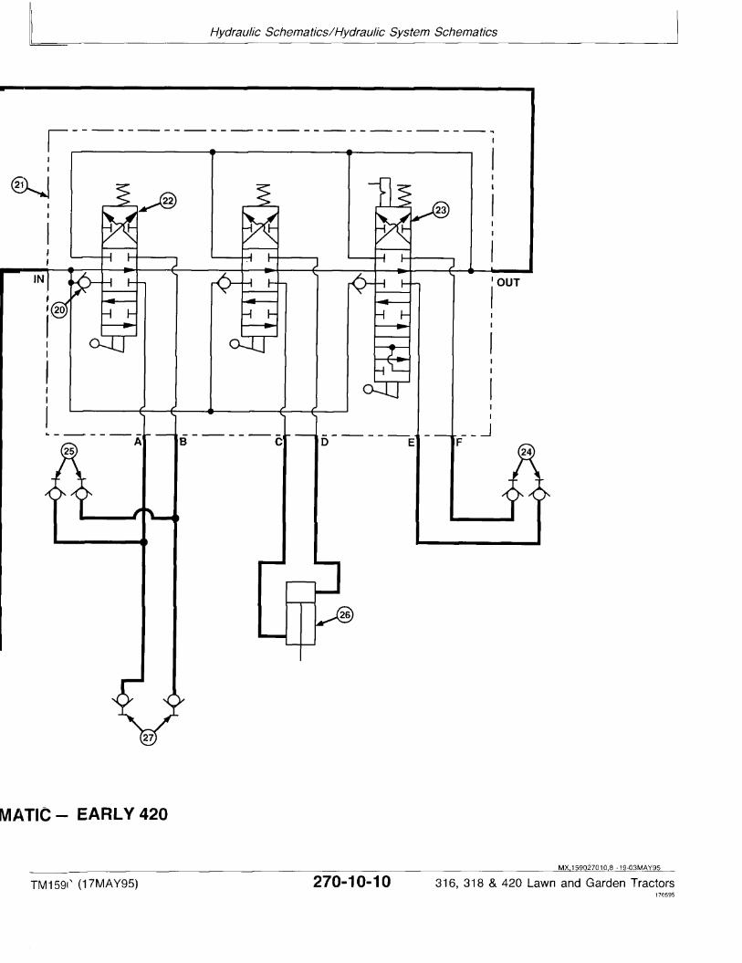

LEGEND FOR HYDRAULIC SYSTEM SCHEMATIC—EARLY 420
1—Hydrostatic Transmission 10—Variable Hydrostatic 17—Steering Valve (4-Port) 24—Front Hydraulic2—Output (Motor) Shaft Pump 18—Check Valve Outlets—Right Side3—Hydrostatic Drive Motor 11—Input (Pump) Shaft 19—Oil Cooler 25—Front Hydraulic4—Transmission Case Drain 12—Steering Wheel 20—Check Valve (3 used) Outlets—Left Side5—Charge Relief Valve 13—Control Valve Section 21—Hydraulic Control Valve 26—Rockshaft Cylinder6—Implement Relief Valve 14—Fluid Metering Section 22—Control Valve Spool 27—Rear Hydraulic Outlets7—Check (Freewheel) Valves 15—Steering Cylinder (Three-Position) (2 used) (Optional)8—Charge Pump 16—Drive Link Assembly 23—Control Valve Spool with9—Filter “Float” (Four-Position)
MX,159027010,9 -19-03MAY95
Hydraulic Schematics/Hydraulic System Schematics
TM1590 (17MAY95) 270-10-11 316, 318 & 420 Lawn and Garden Tractors020895
2701011

LEGEND FOR HYDRAULIC SYSTEM SCHEMATIC—LATER 420
1—Hydrostatic Transmission 10—Variable Hydrostatic 17—Steering Valve (5-Port) 24—Front Hydraulic2—Output (Motor) Shaft Pump 18—Check Valve Outlets—Right Side3—Hydrostatic Drive Motor 11—Input (Pump) Shaft 19—Oil Cooler 25—Front Hydraulic4—Transmission Case Drain 12—Steering Wheel 20—Check Valve (3 used) Outlets—Left Side5—Charge Relief Valve 13—Control Valve Section 21—Hydraulic Control Valve 26—Rockshaft Cylinder6—Implement Relief Valve 14—Fluid Metering Section 22—Control Valve Spool 27—Rear Hydraulic Outlets7—Check (Freewheel) Valves 15—Steering Cylinder (Three-Position) (2 used) (Optional)8—Charge Pump 16—Drive Link Assembly 23—Control Valve Spool with9—Filter “Float” (Four-Position)
MX,159027010,10-19-03MAY95
Hydraulic Schematics/Hydraulic System Schematics
TM1590 (17MAY95) 270-10-12 316, 318 & 420 Lawn and Garden Tractors020895
2701012
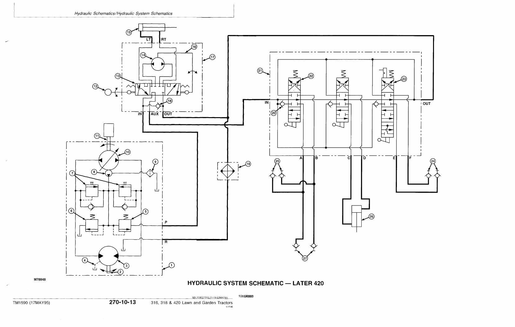
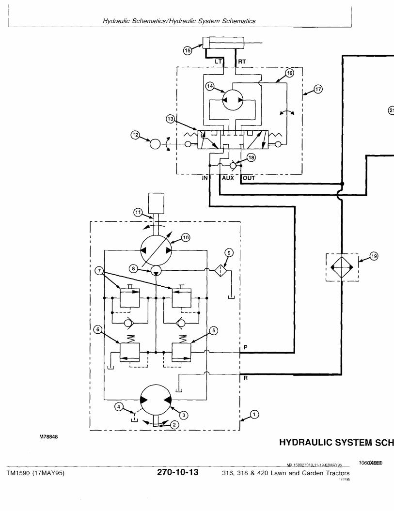
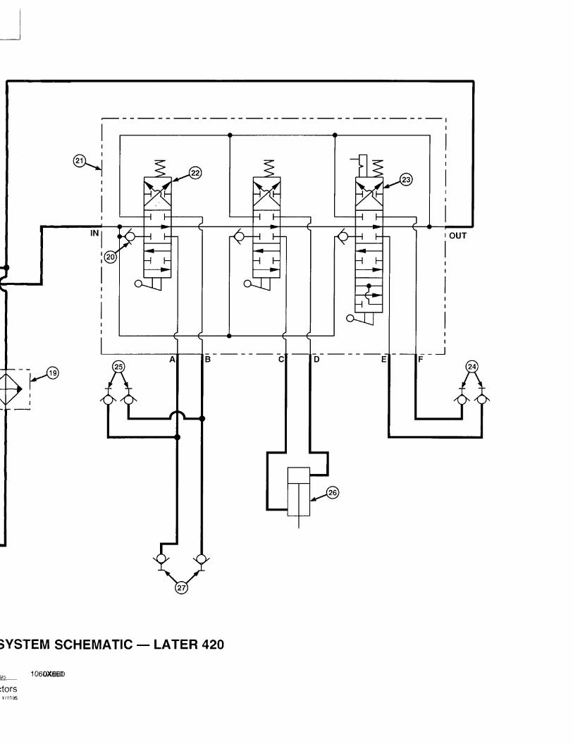

Hydraulic Schematics/Hydraulic System Schematics
TM1590 (17MAY95) 270-10-14 316, 318 & 420 Lawn and Garden Tractors020895
2701014
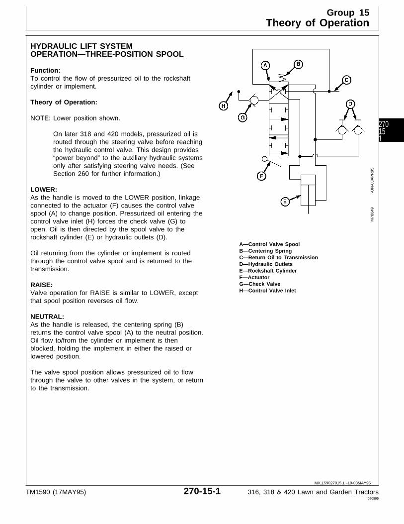
HYDRAULIC LIFT SYSTEMOPERATION—THREE-POSITION SPOOL
Function:To control the flow of pressurized oil to the rockshaftcylinder or implement.
Theory of Operation:
NOTE: Lower position shown.
On later 318 and 420 models, pressurized oil isrouted through the steering valve before reachingthe hydraulic control valve. This design provides“power beyond” to the auxiliary hydraulic systemsonly after satisfying steering valve needs. (SeeSection 260 for further information.)
LOWER:As the handle is moved to the LOWER position, linkageconnected to the actuator (F) causes the control valvespool (A) to change position. Pressurized oil entering thecontrol valve inlet (H) forces the check valve (G) toopen. Oil is then directed by the spool valve to therockshaft cylinder (E) or hydraulic outlets (D).
A—Control Valve SpoolB—Centering SpringOil returning from the cylinder or implement is routedC—Return Oil to Transmission
through the control valve spool and is returned to the D—Hydraulic Outletstransmission. E—Rockshaft Cylinder
F—ActuatorG—Check ValveRAISE:H—Control Valve InletValve operation for RAISE is similar to LOWER, except
that spool position reverses oil flow.
NEUTRAL:As the handle is released, the centering spring (B)returns the control valve spool (A) to the neutral position.Oil flow to/from the cylinder or implement is thenblocked, holding the implement in either the raised orlowered position.
The valve spool position allows pressurized oil to flowthrough the valve to other valves in the system, or returnto the transmission.
M78
849
-UN
-03A
PR
95
MX,159027015,1 -19-03MAY95
Group 15Theory of Operation
TM1590 (17MAY95) 270-15-1 316, 318 & 420 Lawn and Garden Tractors020895
270151

HYDRAULIC LIFT SYSTEMOPERATION—FOUR-POSITION SPOOL
Function:To control the flow of pressurized oil to the implement.
Theory of Operation:
NOTE: Float position shown.
On later 318 and 420 models, pressurized oil isrouted through the steering valve before reachingthe hydraulic control valve. This design provides“power beyond” to the auxiliary hydraulic systemsonly after satisfying steering valve needs. (SeeSection 260 for further information.)
RAISE:As the handle is moved to the RAISE position, linkageconnected to the actuator causes the control valve spoolto change position. Pressurized oil entering the controlvalve inlet forces the check valve to open. Oil is thendirected by the spool valve to the hydraulic outlets.
Oil returning from the implement is routed through theA—Detentcontrol valve spool and is returned to the transmission.B—Centering SpringC—Control Valve Spool
LOWER: D—Return Oil to TransmissionValve operation for LOWER is similar to RAISE, except E—Hydraulic Outletsthat spool position reverses oil flow. F—Actuator
G—Check ValveH—Control Valve InletNEUTRAL:I—Inlet from Valve Stack
As the handle is released, the centering spring (B)returns the control valve spool (C) to the neutral position.Oil flow to/from the implement is then blocked, holdingthe implement in either the raised or lowered position.
The valve spool position allows pressurized oil to flowthrough the valve to other valves in the system, or returnto the transmission.
FLOAT:As the handle is moved to the FLOAT position, linkageconnected to the actuator (F) causes the control valvespool (C) to change position and engage the detent (A),locking the valve in position. In this position, both sidesof the hydraulic outlets (E) are connected to the returnline (D) to the transmission. This allows pressure to bereleased as the implement moves or “floats”.
Valve spool position also allows pressurized oil enteringfrom the valve stack inlet (I) to flow though the valve andreturn to the transmission.
M78
850
-UN
-03A
PR
95
MX,159027015,2 -19-03MAY95
Theory of Operation/Hydraulic Lift System Operation
TM1590 (17MAY95) 270-15-2 316, 318 & 420 Lawn and Garden Tractors020895
27015
2

ABOUT THIS GROUP
The step-by-step procedures in this group provide youwith the detailed diagnostic information you will needto perform a test. Basic diagnostic equipment is used.
It is assumed that you are familiar with the machineand its hydraulic system components. If you needadditional information, read the theory of operation inGroup 15 or refer to the overall hydraulic schematicsin Group 10.
Engine rpm and temperature are critical in mosthydraulic tests. Be sure to follow test specificationscarefully.
Always start with the first step and follow thesequence from left to right. Read each stepcompletely before performing the test.
Upon completing a test or adjustment, check to seewhether the problem is corrected.
NOTE: The 316 has manual steering (gearbox),single-spool control valve and rockshaftcylinder.
The 318 has power steering, steering cylinder,two-spool control valve, rockshaft cylinder andoil cooler.
The 420 has power steering, steering cylinder,three-spool control valve, rockshaft cylinderand oil cooler.
MX,159027020,1 -19-24APR95
Group 20Diagnosis, Tests and Adjustments
TM1590 (17MAY95) 270-20-1 316, 318 & 420 Lawn and Garden Tractors020895
270201
; TROUBLESHOOTING GUIDE
If hydraulic system does not operate properly, select the appropriate symptom from the list below.
After selecting the appropriate symptom, go to that step and perform the following checks, tests, oradjustments in the order shown to isolate and repair malfunction.
• HYDRAULIC SYSTEM INOPERATIVE: GO TO A
• LOW OR SLOW HYDRAULIC POWER: GO TO B
• HYDRAULIC SYSTEM OPERATES ERRATICALLY: GO TO C
• LOAD DROPS WITH CONTROL VALVE IN NEUTRAL POSITION: GO TO D
• LOAD DROPS SLIGHTLY WHEN CONTROL VALVE IS SHIFTED TO RAISE POSITION: Check fordamaged lift check in control valve. See Section 70.
• EXCESSIVE HYDRAULIC PUMP NOISE: GO TO E
• CONTROL VALVE STICKS OR HARD TO OPERATE: GO TO F
• FREQUENT FAILURE OF HYDRAULIC LINES AND O-RINGS: GO TO G
• HYDRAULIC OIL FOAMS: GO TO H
• HYDRAULIC OIL OVERHEATS: GO TO I
• 318 AND 420; ATTACHMENT OR HYDRAULIC LEVER DOES NOT STAY IN FLOAT POSITION: Inspectcontrol valve detent assembly for wear or damage. See Section 70.
A HYDRAULIC SYSTEM INOPERATIVE
• Check for slipping or broken transmission drive shaft. See Section 50.
• Check for proper charge pump housing installation. See Section 50.
• Check hoses for proper attaching location.
• Check for dented or restricted lines.
• Test charge pump pressure. See Section 250.
• Check suction line for air leaks. See Section 250.
• Check for plugged oil filter.
• Test implement relief valve pressure. See Section 250.
• 318 and 420; Check for steering valve check ball missing, damaged, or in “IN” port. See Section 60.
MX,159027020,2 -19-24APR95
MX,159027020,3 -19-24APR95
Diagnosis, Tests and Adjustments/Troubleshooting Guide
TM1590 (17MAY95) 270-20-2 316, 318 & 420 Lawn and Garden Tractors020895
27020
2

B LOW OR SLOW HYDRAULIC POWER
• Check for dented or restricted lines.
• Check for proper engine speed. See Section 220.
• Test charge pump pressure. See Section 250.
• Check for plugged oil filter.
• Check suction line for air leaks. See Section 250.
• Test implement relief valve pressure. See Section 250.
• Test control valve for leakage. GO TO Å
• Inspect cylinder packings for excessive wear. GO TO Æ
C HYDRAULIC SYSTEM OPERATES ERRATICALLY
• Bleed hydraulic system. GO TO Ö
• Check for restricted lines.
• Test charge pump pressure. See Section 250.
• Check for plugged oil filter.
• Check suction line for air leaks. See Section 250.
• Check for dirt in implement relief valve. See Section 50.
D LOAD DROPS WITH CONTROL VALVE IN NEUTRAL POSITION
• Check lines from control valve to rockshaft cylinder for leakage.
• Check control valve for centering when released.
• Check implement relief valve for leakage. See Section 250.
• Test control valve for leakage. GO TO Å
• Check cylinder packings and O-rings for leakage. GO TO Æ
MX,159027020,4 -19-24APR95
MX,159027020,5 -19-24APR95
MX,159027020,6 -19-24APR95
Diagnosis, Tests and Adjustments/Troubleshooting Guide
TM1590 (17MAY95) 270-20-3 316, 318 & 420 Lawn and Garden Tractors020895
270203

E EXCESSIVE HYDRAULIC PUMP NOISE
• Bleed hydraulic system. GO TO Ö
• Check suction line for air leaks. See Section 250.
• Check for worn or damaged charge pump. See Section 50.
F CONTROL VALVE STICKS OR HARD TO OPERATE
• Check for binding control valve linkage.
• Inspect control valve for broken return spring, contaminated or scored valve bore, or bent valve spool.See Section 70.
G FREQUENT FAILURE OF HYDRAULIC LINES AND O-RINGS
• Check hydraulic oil for contamination.
• Check hydraulic connections for proper torque.
• Test implement relief valve pressure. See Section 250.
H HYDRAULIC OIL FOAMS
• Check hydraulic lines for kinks or dents.
• Check suction line for air leaks. See Section 250.
I HYDRAULIC OIL OVERHEATS
• Operator holding control valve open too long causing implement relief valve to open.
• Check oil cooler fins (if equipped) and transmission fins for plugged condition.
• Check for restricted lines or plugged oil filter.
• Test implement relief valve pressure. See Section 250.
• Check for high air temperatures and high draft loads. GO TO ‘
MX,159027020,7 -19-24APR95
MX,159027020,8 -19-24APR95
MX,159027020,9 -19-24APR95
MX,159027020,10-19-24APR95
MX,159027020,11-19-24APR95
Diagnosis, Tests and Adjustments/Troubleshooting Guide
TM1590 (17MAY95) 270-20-4 316, 318 & 420 Lawn and Garden Tractors020895
27020
4
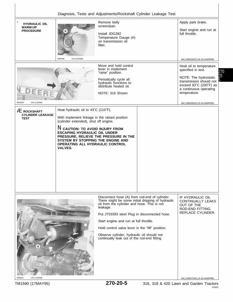
‘ HYDRAULIC OILWARM-UPPROCEDURE
M43008 -UN-18JAN90
Remove bellyscreen/pan.
Install JDG282Temperature Gauge (A)on transmission oilfilter.
Apply park brake.
Start engine and run atfull throttle.
M43629 -UN-12JAN90
Move and hold controllever in implement“raise” position.
Periodically cycle allhydraulic functions todistribute heated oil.
NOTE: 316 Shown
Heat oil to temperaturespecified in test.
NOTE: The hydrostatictransmission should notexceed 93˚C (200˚F) asa continuous operatingtemperature.
Æ ROCKSHAFTCYLINDER LEAKAGETEST
Heat hydraulic oil to 43˚C (110˚F).
With implement linkage in the raised position(cylinder extended), shut off engine.
N CAUTION: TO AVOID INJURY FROMESCAPING HYDRAULIC OIL UNDERPRESSURE, RELIEVE THE PRESSURE IN THESYSTEM BY STOPPING THE ENGINE ANDOPERATING ALL HYDRAULIC CONTROLVALVES.
M43631 -UN-12JAN90
Disconnect hose (A) from rod-end of cylinder.There might be some initial dripping of hydraulicoil from the cylinder and hose. This is notleakage.
Put JT03393 steel Plug in disconnected hose.
Start engine and run at full throttle.
Hold control valve lever in the “lift” position.
Observe cylinder, hydraulic oil should notcontinually leak out of the rod-end fitting.
IF HYDRAULIC OILCONTINUALLY LEAKSOUT OF THEROD-END FITTING,REPLACE CYLINDER.
MX,159026015,16-19-24APR95
MX,159025020,23-19-20APR95
MX,159027020,14-19-24APR95
Diagnosis, Tests and Adjustments/Rockshaft Cylinder Leakage Test
TM1590 (17MAY95) 270-20-5 316, 318 & 420 Lawn and Garden Tractors020895
270205
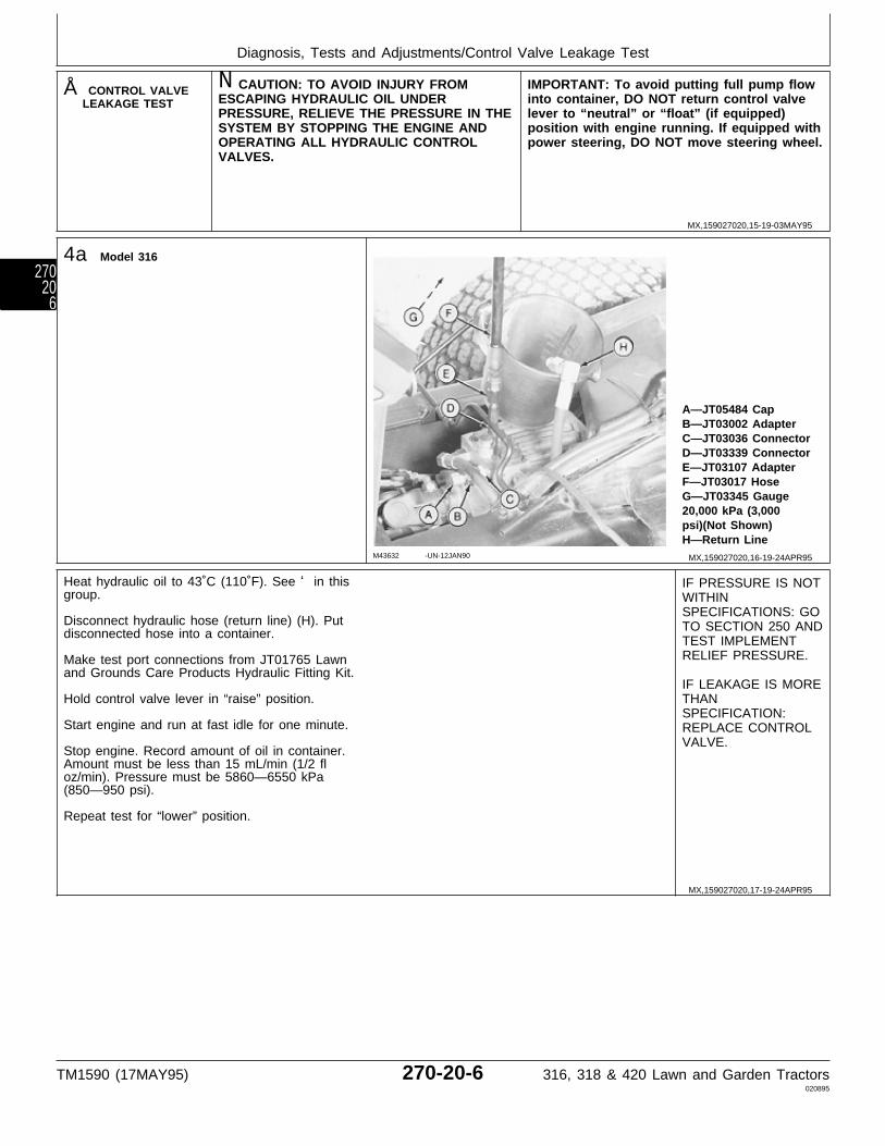
Å CONTROL VALVELEAKAGE TEST
N CAUTION: TO AVOID INJURY FROMESCAPING HYDRAULIC OIL UNDERPRESSURE, RELIEVE THE PRESSURE IN THESYSTEM BY STOPPING THE ENGINE ANDOPERATING ALL HYDRAULIC CONTROLVALVES.
IMPORTANT: To avoid putting full pump flowinto container, DO NOT return control valvelever to “neutral” or “float” (if equipped)position with engine running. If equipped withpower steering, DO NOT move steering wheel.
4a Model 316
M43632 -UN-12JAN90
A—JT05484 CapB—JT03002 AdapterC—JT03036 ConnectorD—JT03339 ConnectorE—JT03107 AdapterF—JT03017 HoseG—JT03345 Gauge20,000 kPa (3,000psi)(Not Shown)H—Return Line
Heat hydraulic oil to 43˚C (110˚F). See ‘ in thisgroup.
Disconnect hydraulic hose (return line) (H). Putdisconnected hose into a container.
Make test port connections from JT01765 Lawnand Grounds Care Products Hydraulic Fitting Kit.
Hold control valve lever in “raise” position.
Start engine and run at fast idle for one minute.
Stop engine. Record amount of oil in container.Amount must be less than 15 mL/min (1/2 floz/min). Pressure must be 5860—6550 kPa(850—950 psi).
Repeat test for “lower” position.
IF PRESSURE IS NOTWITHINSPECIFICATIONS: GOTO SECTION 250 ANDTEST IMPLEMENTRELIEF PRESSURE.
IF LEAKAGE IS MORETHANSPECIFICATION:REPLACE CONTROLVALVE.
MX,159027020,15-19-03MAY95
MX,159027020,16-19-24APR95
MX,159027020,17-19-24APR95
Diagnosis, Tests and Adjustments/Control Valve Leakage Test
TM1590 (17MAY95) 270-20-6 316, 318 & 420 Lawn and Garden Tractors020895
27020
6
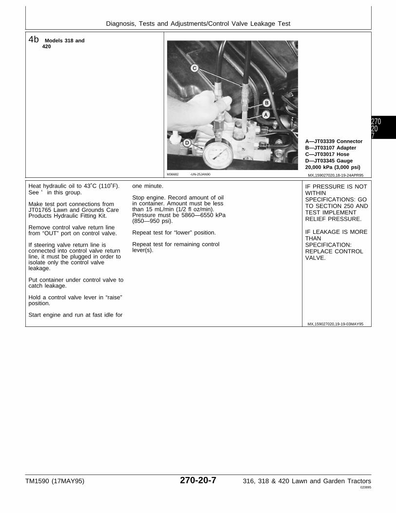
4b Models 318 and420
M36682 -UN-25JAN90
A—JT03339 ConnectorB—JT03107 AdapterC—JT03017 HoseD—JT03345 Gauge20,000 kPa (3,000 psi)
Heat hydraulic oil to 43˚C (110˚F).See ‘ in this group.
Make test port connections fromJT01765 Lawn and Grounds CareProducts Hydraulic Fitting Kit.
Remove control valve return linefrom “OUT” port on control valve.
If steering valve return line isconnected into control valve returnline, it must be plugged in order toisolate only the control valveleakage.
Put container under control valve tocatch leakage.
Hold a control valve lever in “raise”position.
Start engine and run at fast idle for
one minute.
Stop engine. Record amount of oilin container. Amount must be lessthan 15 mL/min (1/2 fl oz/min).Pressure must be 5860—6550 kPa(850—950 psi).
Repeat test for “lower” position.
Repeat test for remaining controllever(s).
IF PRESSURE IS NOTWITHINSPECIFICATIONS: GOTO SECTION 250 ANDTEST IMPLEMENTRELIEF PRESSURE.
IF LEAKAGE IS MORETHANSPECIFICATION:REPLACE CONTROLVALVE.
MX,159027020,18-19-24APR95
MX,159027020,19-19-03MAY95
Diagnosis, Tests and Adjustments/Control Valve Leakage Test
TM1590 (17MAY95) 270-20-7 316, 318 & 420 Lawn and Garden Tractors020895
270207
Ö BLEED HYDRAULIC SYSTEM
After installing a repaired or replacement part, follow this run-in procedure to assure that air is purged fromthe hydraulic system.
1. Start engine and idle for 10 minutes.
2. Run engine at high idle for one minute.
3. Turn steering wheel full left and hold for five seconds.
4. Turn steering wheel to straight forward for 10 seconds.
5. Turn steering wheel full right and hold for five seconds.
6. Return steering wheel to straight forward. Travel vehicle forward about 20 feet and then make two hardleft turns.
7. Then make two hard right turns.
8. Travel vehicle in reverse for 10 feet.
9. Cycle mower deck up and down three times.
10. Shut engine off and inspect hydraulic components for leaks.
11. Fill reservoir as required with John Deere Low Viscosity HY-GARD® oil.
MX,159027020,20-19-29MAR95
Diagnosis, Tests and Adjustments/Bleed Hydraulic System
TM1590 (17MAY95) 270-20-8 316, 318 & 420 Lawn and Garden Tractors020895
27020
8

Section 299DEALER FABRICATED TOOLS
ContentsPage
Group 00—Dealer Fabricated ToolsDFMX1 Steering Valve Fixture . . . . . . . . 299-00-1DFMX2 Alignment Shims . . . . . . . . . . . . 299-00-1
TM1590 (17MAY95) 299-1 316, 318 & 420 Lawn and Garden Tractors020895
299
Contents
TM1590 (17MAY95) 299-2 316, 318 & 420 Lawn and Garden Tractors020895
299
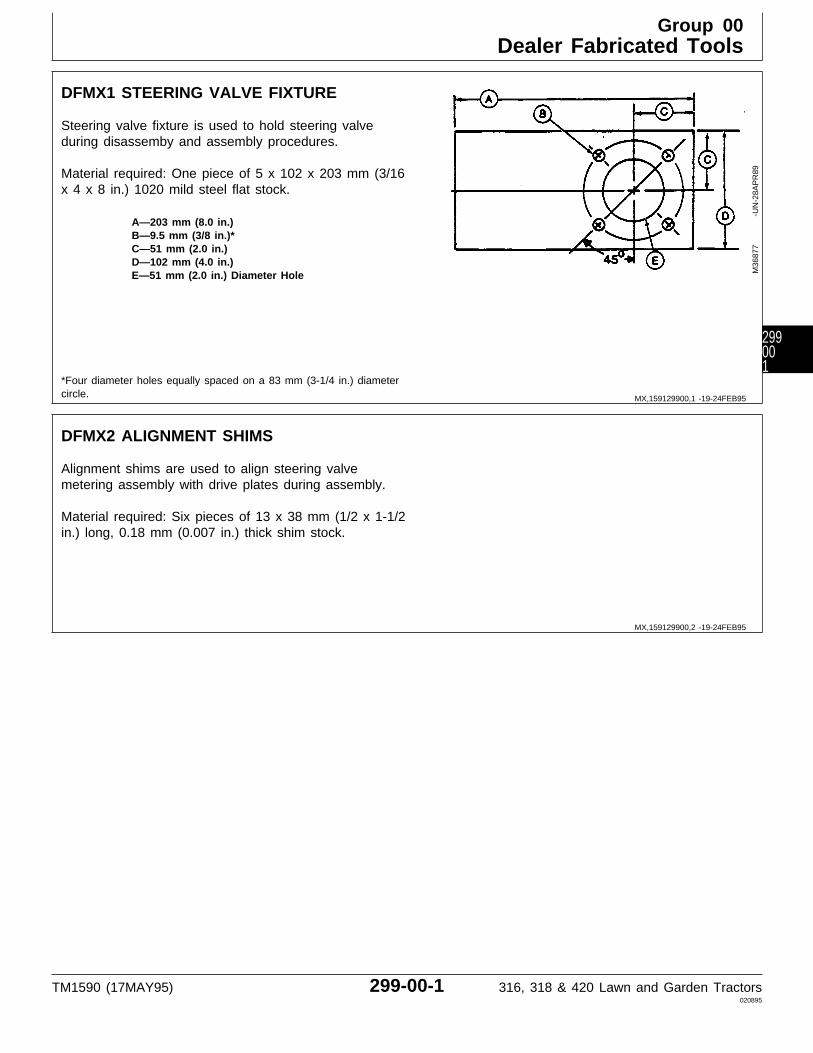
DFMX1 STEERING VALVE FIXTURE
Steering valve fixture is used to hold steering valveduring disassemby and assembly procedures.
Material required: One piece of 5 x 102 x 203 mm (3/16x 4 x 8 in.) 1020 mild steel flat stock.
A—203 mm (8.0 in.)B—9.5 mm (3/8 in.)*C—51 mm (2.0 in.)D—102 mm (4.0 in.)E—51 mm (2.0 in.) Diameter Hole
*Four diameter holes equally spaced on a 83 mm (3-1/4 in.) diametercircle.
M36
877
-UN
-28A
PR
89
DFMX2 ALIGNMENT SHIMS
Alignment shims are used to align steering valvemetering assembly with drive plates during assembly.
Material required: Six pieces of 13 x 38 mm (1/2 x 1-1/2in.) long, 0.18 mm (0.007 in.) thick shim stock.
MX,159129900,1 -19-24FEB95
MX,159129900,2 -19-24FEB95
Group 00Dealer Fabricated Tools
TM1590 (17MAY95) 299-00-1 316, 318 & 420 Lawn and Garden Tractors020895
299001

Dealer Fabricated Tools/DFMX2 Alignment Shims
TM1590 (17MAY95) 299-00-2 316, 318 & 420 Lawn and Garden Tractors020895
29900
2
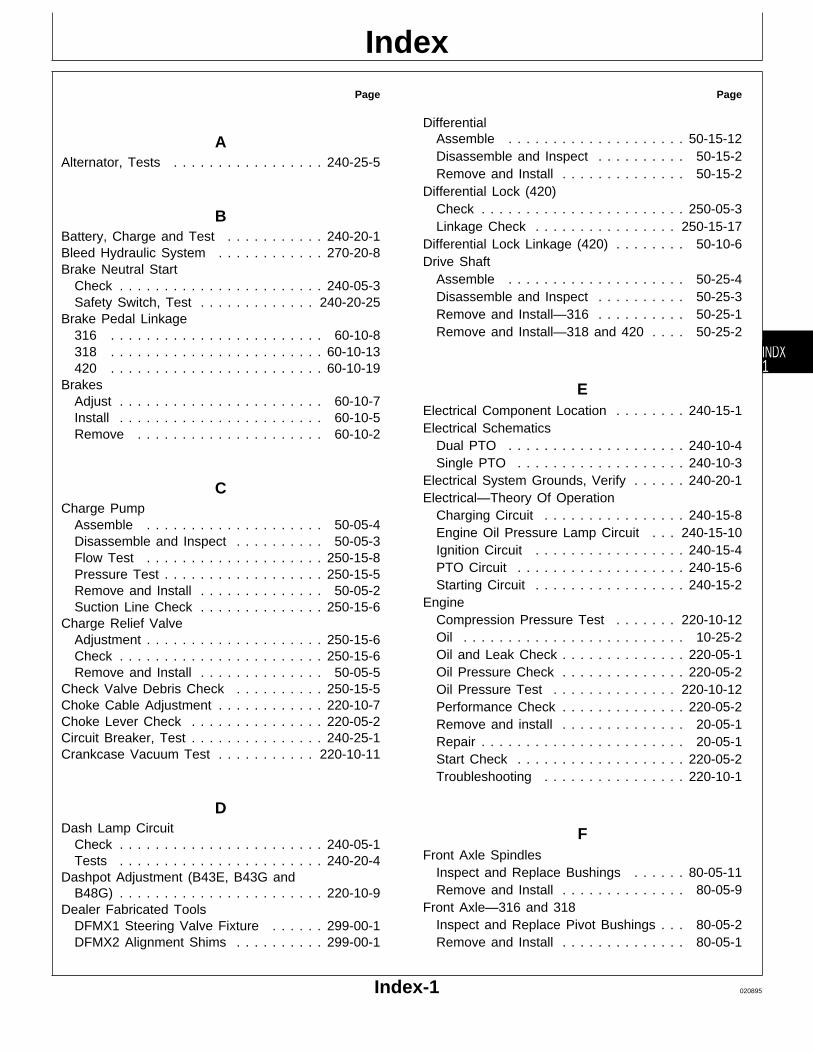
Page
AAlternator, Tests . . . . . . . . . . . . . . . . . 240-25-5
BBattery, Charge and Test . . . . . . . . . . . 240-20-1Bleed Hydraulic System . . . . . . . . . . . . 270-20-8Brake Neutral Start
Check . . . . . . . . . . . . . . . . . . . . . . . 240-05-3Safety Switch, Test . . . . . . . . . . . . . 240-20-25
Brake Pedal Linkage316 . . . . . . . . . . . . . . . . . . . . . . . . 60-10-8318 . . . . . . . . . . . . . . . . . . . . . . . . 60-10-13420 . . . . . . . . . . . . . . . . . . . . . . . . 60-10-19
BrakesAdjust . . . . . . . . . . . . . . . . . . . . . . . 60-10-7Install . . . . . . . . . . . . . . . . . . . . . . . 60-10-5Remove . . . . . . . . . . . . . . . . . . . . . 60-10-2
CCharge Pump
Assemble . . . . . . . . . . . . . . . . . . . . 50-05-4Disassemble and Inspect . . . . . . . . . . 50-05-3Flow Test . . . . . . . . . . . . . . . . . . . . 250-15-8Pressure Test . . . . . . . . . . . . . . . . . . 250-15-5Remove and Install . . . . . . . . . . . . . . 50-05-2Suction Line Check . . . . . . . . . . . . . . 250-15-6
Charge Relief ValveAdjustment . . . . . . . . . . . . . . . . . . . . 250-15-6Check . . . . . . . . . . . . . . . . . . . . . . . 250-15-6Remove and Install . . . . . . . . . . . . . . 50-05-5
Check Valve Debris Check . . . . . . . . . . 250-15-5Choke Cable Adjustment . . . . . . . . . . . . 220-10-7Choke Lever Check . . . . . . . . . . . . . . . 220-05-2Circuit Breaker, Test . . . . . . . . . . . . . . . 240-25-1Crankcase Vacuum Test . . . . . . . . . . . 220-10-11
DDash Lamp Circuit
Check . . . . . . . . . . . . . . . . . . . . . . . 240-05-1Tests . . . . . . . . . . . . . . . . . . . . . . . 240-20-4
Dashpot Adjustment (B43E, B43G andB48G) . . . . . . . . . . . . . . . . . . . . . . . 220-10-9
Dealer Fabricated ToolsDFMX1 Steering Valve Fixture . . . . . . 299-00-1DFMX2 Alignment Shims . . . . . . . . . . 299-00-1
Page
DifferentialAssemble . . . . . . . . . . . . . . . . . . . . 50-15-12Disassemble and Inspect . . . . . . . . . . 50-15-2Remove and Install . . . . . . . . . . . . . . 50-15-2
Differential Lock (420)Check . . . . . . . . . . . . . . . . . . . . . . . 250-05-3Linkage Check . . . . . . . . . . . . . . . . 250-15-17
Differential Lock Linkage (420) . . . . . . . . 50-10-6Drive Shaft
Assemble . . . . . . . . . . . . . . . . . . . . 50-25-4Disassemble and Inspect . . . . . . . . . . 50-25-3Remove and Install—316 . . . . . . . . . . 50-25-1Remove and Install—318 and 420 . . . . 50-25-2
EElectrical Component Location . . . . . . . . 240-15-1Electrical Schematics
Dual PTO . . . . . . . . . . . . . . . . . . . . 240-10-4Single PTO . . . . . . . . . . . . . . . . . . . 240-10-3
Electrical System Grounds, Verify . . . . . . 240-20-1Electrical—Theory Of Operation
Charging Circuit . . . . . . . . . . . . . . . . 240-15-8Engine Oil Pressure Lamp Circuit . . . 240-15-10Ignition Circuit . . . . . . . . . . . . . . . . . 240-15-4PTO Circuit . . . . . . . . . . . . . . . . . . . 240-15-6Starting Circuit . . . . . . . . . . . . . . . . . 240-15-2
EngineCompression Pressure Test . . . . . . . 220-10-12Oil . . . . . . . . . . . . . . . . . . . . . . . . . 10-25-2Oil and Leak Check . . . . . . . . . . . . . . 220-05-1Oil Pressure Check . . . . . . . . . . . . . . 220-05-2Oil Pressure Test . . . . . . . . . . . . . . 220-10-12Performance Check . . . . . . . . . . . . . . 220-05-2Remove and install . . . . . . . . . . . . . . 20-05-1Repair . . . . . . . . . . . . . . . . . . . . . . . 20-05-1Start Check . . . . . . . . . . . . . . . . . . . 220-05-2Troubleshooting . . . . . . . . . . . . . . . . 220-10-1
FFront Axle Spindles
Inspect and Replace Bushings . . . . . . 80-05-11Remove and Install . . . . . . . . . . . . . . 80-05-9
Front Axle—316 and 318Inspect and Replace Pivot Bushings . . . 80-05-2Remove and Install . . . . . . . . . . . . . . 80-05-1
Index
Index-1 020895
INDX1
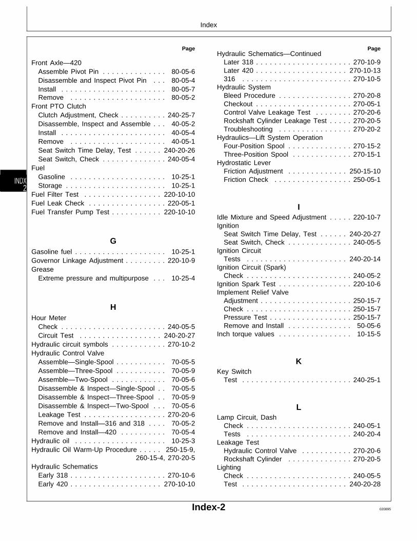
Page
Front Axle—420Assemble Pivot Pin . . . . . . . . . . . . . . 80-05-6Disassemble and Inspect Pivot Pin . . . 80-05-4Install . . . . . . . . . . . . . . . . . . . . . . . 80-05-7Remove . . . . . . . . . . . . . . . . . . . . . 80-05-2
Front PTO ClutchClutch Adjustment, Check . . . . . . . . . . 240-25-7Disassemble, Inspect and Assemble . . . 40-05-2Install . . . . . . . . . . . . . . . . . . . . . . . 40-05-4Remove . . . . . . . . . . . . . . . . . . . . . 40-05-1Seat Switch Time Delay, Test . . . . . . 240-20-26Seat Switch, Check . . . . . . . . . . . . . . 240-05-4
FuelGasoline . . . . . . . . . . . . . . . . . . . . . 10-25-1Storage . . . . . . . . . . . . . . . . . . . . . . 10-25-1
Fuel Filter Test . . . . . . . . . . . . . . . . . 220-10-10Fuel Leak Check . . . . . . . . . . . . . . . . . 220-05-1Fuel Transfer Pump Test . . . . . . . . . . . 220-10-10
GGasoline fuel . . . . . . . . . . . . . . . . . . . . 10-25-1Governor Linkage Adjustment . . . . . . . . . 220-10-9Grease
Extreme pressure and multipurpose . . . 10-25-4
HHour Meter
Check . . . . . . . . . . . . . . . . . . . . . . . 240-05-5Circuit Test . . . . . . . . . . . . . . . . . . 240-20-27
Hydraulic circuit symbols . . . . . . . . . . . . 270-10-2Hydraulic Control Valve
Assemble—Single-Spool . . . . . . . . . . . 70-05-5Assemble—Three-Spool . . . . . . . . . . . 70-05-9Assemble—Two-Spool . . . . . . . . . . . . 70-05-6Disassemble & Inspect—Single-Spool . . 70-05-5Disassemble & Inspect—Three-Spool . . 70-05-9Disassemble & Inspect—Two-Spool . . . 70-05-6Leakage Test . . . . . . . . . . . . . . . . . . 270-20-6Remove and Install—316 and 318 . . . . 70-05-2Remove and Install—420 . . . . . . . . . . 70-05-4
Hydraulic oil . . . . . . . . . . . . . . . . . . . . 10-25-3Hydraulic Oil Warm-Up Procedure . . . . . 250-15-9,
260-15-4, 270-20-5Hydraulic Schematics
Early 318 . . . . . . . . . . . . . . . . . . . . . 270-10-6Early 420 . . . . . . . . . . . . . . . . . . . . 270-10-10
PageHydraulic Schematics—Continued
Later 318 . . . . . . . . . . . . . . . . . . . . . 270-10-9Later 420 . . . . . . . . . . . . . . . . . . . . 270-10-13316 . . . . . . . . . . . . . . . . . . . . . . . . 270-10-5
Hydraulic SystemBleed Procedure . . . . . . . . . . . . . . . . 270-20-8Checkout . . . . . . . . . . . . . . . . . . . . . 270-05-1Control Valve Leakage Test . . . . . . . . 270-20-6Rockshaft Cylinder Leakage Test . . . . . 270-20-5Troubleshooting . . . . . . . . . . . . . . . . 270-20-2
Hydraulics—Lift System OperationFour-Position Spool . . . . . . . . . . . . . . 270-15-2Three-Position Spool . . . . . . . . . . . . . 270-15-1
Hydrostatic LeverFriction Adjustment . . . . . . . . . . . . . 250-15-10Friction Check . . . . . . . . . . . . . . . . . 250-05-1
IIdle Mixture and Speed Adjustment . . . . . 220-10-7Ignition
Seat Switch Time Delay, Test . . . . . . 240-20-27Seat Switch, Check . . . . . . . . . . . . . . 240-05-5
Ignition CircuitTests . . . . . . . . . . . . . . . . . . . . . . 240-20-14
Ignition Circuit (Spark)Check . . . . . . . . . . . . . . . . . . . . . . . 240-05-2
Ignition Spark Test . . . . . . . . . . . . . . . . 220-10-6Implement Relief Valve
Adjustment . . . . . . . . . . . . . . . . . . . . 250-15-7Check . . . . . . . . . . . . . . . . . . . . . . . 250-15-7Pressure Test . . . . . . . . . . . . . . . . . . 250-15-7Remove and Install . . . . . . . . . . . . . . 50-05-6
Inch torque values . . . . . . . . . . . . . . . . 10-15-5
KKey Switch
Test . . . . . . . . . . . . . . . . . . . . . . . . 240-25-1
LLamp Circuit, Dash
Check . . . . . . . . . . . . . . . . . . . . . . . 240-05-1Tests . . . . . . . . . . . . . . . . . . . . . . . 240-20-4
Leakage TestHydraulic Control Valve . . . . . . . . . . . 270-20-6Rockshaft Cylinder . . . . . . . . . . . . . . 270-20-5
LightingCheck . . . . . . . . . . . . . . . . . . . . . . . 240-05-5Test . . . . . . . . . . . . . . . . . . . . . . . 240-20-28
Index
Index-2 020895
INDX
2
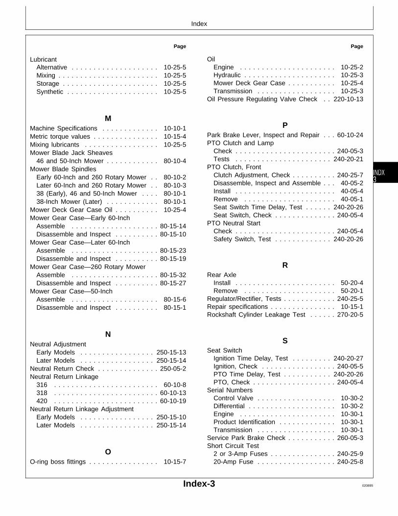
Page
LubricantAlternative . . . . . . . . . . . . . . . . . . . . 10-25-5Mixing . . . . . . . . . . . . . . . . . . . . . . . 10-25-5Storage . . . . . . . . . . . . . . . . . . . . . . 10-25-5Synthetic . . . . . . . . . . . . . . . . . . . . . 10-25-5
MMachine Specifications . . . . . . . . . . . . . 10-10-1Metric torque values . . . . . . . . . . . . . . . 10-15-4Mixing lubricants . . . . . . . . . . . . . . . . . 10-25-5Mower Blade Jack Sheaves
46 and 50-Inch Mower . . . . . . . . . . . . 80-10-4Mower Blade Spindles
Early 60-Inch and 260 Rotary Mower . . 80-10-2Later 60-Inch and 260 Rotary Mower . . 80-10-338 (Early), 46 and 50-Inch Mower . . . . 80-10-138-Inch Mower (Later) . . . . . . . . . . . . 80-10-1
Mower Deck Gear Case Oil . . . . . . . . . . 10-25-4Mower Gear Case—Early 60-Inch
Assemble . . . . . . . . . . . . . . . . . . . . 80-15-14Disassemble and Inspect . . . . . . . . . . 80-15-10
Mower Gear Case—Later 60-InchAssemble . . . . . . . . . . . . . . . . . . . . 80-15-23Disassemble and Inspect . . . . . . . . . . 80-15-19
Mower Gear Case—260 Rotary MowerAssemble . . . . . . . . . . . . . . . . . . . . 80-15-32Disassemble and Inspect . . . . . . . . . . 80-15-27
Mower Gear Case—50-InchAssemble . . . . . . . . . . . . . . . . . . . . 80-15-6Disassemble and Inspect . . . . . . . . . . 80-15-1
NNeutral Adjustment
Early Models . . . . . . . . . . . . . . . . . 250-15-13Later Models . . . . . . . . . . . . . . . . . 250-15-14
Neutral Return Check . . . . . . . . . . . . . . 250-05-2Neutral Return Linkage
316 . . . . . . . . . . . . . . . . . . . . . . . . 60-10-8318 . . . . . . . . . . . . . . . . . . . . . . . . 60-10-13420 . . . . . . . . . . . . . . . . . . . . . . . . 60-10-19
Neutral Return Linkage AdjustmentEarly Models . . . . . . . . . . . . . . . . . 250-15-10Later Models . . . . . . . . . . . . . . . . . 250-15-14
OO-ring boss fittings . . . . . . . . . . . . . . . . 10-15-7
Page
OilEngine . . . . . . . . . . . . . . . . . . . . . . 10-25-2Hydraulic . . . . . . . . . . . . . . . . . . . . . 10-25-3Mower Deck Gear Case . . . . . . . . . . . 10-25-4Transmission . . . . . . . . . . . . . . . . . . 10-25-3
Oil Pressure Regulating Valve Check . . 220-10-13
PPark Brake Lever, Inspect and Repair . . . 60-10-24PTO Clutch and Lamp
Check . . . . . . . . . . . . . . . . . . . . . . . 240-05-3Tests . . . . . . . . . . . . . . . . . . . . . . 240-20-21
PTO Clutch, FrontClutch Adjustment, Check . . . . . . . . . . 240-25-7Disassemble, Inspect and Assemble . . . 40-05-2Install . . . . . . . . . . . . . . . . . . . . . . . 40-05-4Remove . . . . . . . . . . . . . . . . . . . . . 40-05-1Seat Switch Time Delay, Test . . . . . . 240-20-26Seat Switch, Check . . . . . . . . . . . . . . 240-05-4
PTO Neutral StartCheck . . . . . . . . . . . . . . . . . . . . . . . 240-05-4Safety Switch, Test . . . . . . . . . . . . . 240-20-26
RRear Axle
Install . . . . . . . . . . . . . . . . . . . . . . . 50-20-4Remove . . . . . . . . . . . . . . . . . . . . . 50-20-1
Regulator/Rectifier, Tests . . . . . . . . . . . . 240-25-5Repair specifications . . . . . . . . . . . . . . . 10-15-1Rockshaft Cylinder Leakage Test . . . . . . 270-20-5
SSeat Switch
Ignition Time Delay, Test . . . . . . . . . 240-20-27Ignition, Check . . . . . . . . . . . . . . . . . 240-05-5PTO Time Delay, Test . . . . . . . . . . . 240-20-26PTO, Check . . . . . . . . . . . . . . . . . . . 240-05-4
Serial NumbersControl Valve . . . . . . . . . . . . . . . . . . 10-30-2Differential . . . . . . . . . . . . . . . . . . . . 10-30-2Engine . . . . . . . . . . . . . . . . . . . . . . 10-30-1Product Identification . . . . . . . . . . . . . 10-30-1Transmission . . . . . . . . . . . . . . . . . . 10-30-1
Service Park Brake Check . . . . . . . . . . . 260-05-3Short Circuit Test
2 or 3-Amp Fuses . . . . . . . . . . . . . . . 240-25-920-Amp Fuse . . . . . . . . . . . . . . . . . . 240-25-8
Index
Index-3 020895
INDX3

Page
SpecificationsMachine . . . . . . . . . . . . . . . . . . . . . 10-10-1Repair . . . . . . . . . . . . . . . . . . . . . . . 10-15-1Test and Adjustment . . . . . . . . . . . . . 10-20-1
Speed Reduction Check (318 and 420) . . 250-05-2Starter, Tests . . . . . . . . . . . . . . . . . . . 240-25-2Starting Circuit
Check . . . . . . . . . . . . . . . . . . . . . . . 240-05-2Tests . . . . . . . . . . . . . . . . . . . . . . 240-20-10
Steering Column—318 and 420Assemble . . . . . . . . . . . . . . . . . . . . 60-06-12Disassemble and Inspect . . . . . . . . . . 60-06-3Remove and Install . . . . . . . . . . . . . . 60-06-2
Steering Cylinder (318 and 420)Remove and Install . . . . . . . . . . . . . . 60-06-22
Steering Gearbox—316Assemble . . . . . . . . . . . . . . . . . . . . 60-05-12Disassemble and Inspect . . . . . . . . . . 60-05-6Remove and Install . . . . . . . . . . . . . . 60-05-2
Steering Shaft—316Assemble . . . . . . . . . . . . . . . . . . . . 60-05-12Disassemble and Inspect . . . . . . . . . . 60-05-6Remove and Install . . . . . . . . . . . . . . 60-05-2
Steering SystemCheck (318 and 420) . . . . . . . . . . . . . 260-05-2Leakage Test . . . . . . . . . . . . . . . . . . 260-15-5Oil Leak Check (318 and 420) . . . . . . 260-05-1Troubleshooting . . . . . . . . . . . . . . . . 260-15-1
Steering Valve/System OperationFive-Port Valve . . . . . . . . . . . . . . . . . 260-10-2Four-Port Valve . . . . . . . . . . . . . . . . 260-10-1
Steering Valve—318 and 420Assemble . . . . . . . . . . . . . . . . . . . . 60-06-12Disassemble and Inspect . . . . . . . . . . 60-06-3Leakage Test . . . . . . . . . . . . . . . . . . 260-15-5Neutral Check . . . . . . . . . . . . . . . . . 250-15-9Remove and Install . . . . . . . . . . . . . . 60-06-2
Storing lubricants . . . . . . . . . . . . . . . . . 10-25-5Synthetic Lubricants . . . . . . . . . . . . . . . 10-25-5
TTest and Adjustment Specifications . . . . . 10-20-1Throttle Cable Adjustment . . . . . . . . . . . 220-10-6Throttle Lever Adjustment . . . . . . . . . . 220-10-13Throttle Lever Check . . . . . . . . . . . . . . 220-05-1Timing Adjustment (B43E, B43G and
B48G) . . . . . . . . . . . . . . . . . . . . . . 220-10-11Toe-In, Adjust . . . . . . . . . . . . . . . . . . . 80-05-12Torque value
O-Ring boss fitting . . . . . . . . . . . . . . 10-15-7
Page
Torque valuesInch . . . . . . . . . . . . . . . . . . . . . . . . 10-15-5Metric . . . . . . . . . . . . . . . . . . . . . . . 10-15-4Metric—Grade 7 . . . . . . . . . . . . . . . . 10-15-6
TransmissionAssemble Cover . . . . . . . . . . . . . . . . 50-05-22Assemble Pump and Motor . . . . . . . . . 50-05-21Assemble Pump and Motor Housing . . . 50-05-19Disassemble Cover . . . . . . . . . . . . . . 50-05-11Disassemble Pump and Motor . . . . . . . 50-05-14Disassemble Pump and Motor Housing . 50-05-16Drive Check . . . . . . . . . . . . . . . . . . . 250-05-2Install . . . . . . . . . . . . . . . . . . . . . . . 50-05-25Neutral Check . . . . . . . . . . . . . . . . . 250-05-1Oil Leak Check . . . . . . . . . . . . . . . . . 250-05-1Remove . . . . . . . . . . . . . . . . . . . . . 50-05-6Theory of Operation . . . . . . . . . . . . . 250-10-2Troubleshooting . . . . . . . . . . . . . . . . 250-15-1
Transmission Control LinkageVersion Four . . . . . . . . . . . . . . . . . . 50-10-5Version One . . . . . . . . . . . . . . . . . . . 50-10-1Version Three . . . . . . . . . . . . . . . . . 50-10-4Version Two—316 and 318 . . . . . . . . 50-10-2Version Two—420 . . . . . . . . . . . . . . . 50-10-3
Transmission Neutral StartCheck . . . . . . . . . . . . . . . . . . . . . . . 240-05-4Safety Switch, Test . . . . . . . . . . . . . 240-20-26
Transmission oil . . . . . . . . . . . . . . . . . . 10-25-3Turn Brake Check (318 and 420) . . . . . . 260-05-3Two-Speed Axle (420)
Lever Check . . . . . . . . . . . . . . . . . . 250-05-3Lever Linkage Check . . . . . . . . . . . . 250-15-17
Two-Speed Control Linkage (420) . . . . . . 50-10-6
WWelch Plug Location Check . . . . . . . . . . 250-15-8Wheel Bearings, Inspect and Replace . . . 80-05-12
Index
Index-4 020895
INDX
4


