Embed Size (px)
Citation preview
Title Section
GENERAL INFORMATION 00
ENGINE 01
SUSPENSION 02
DRIVELINE/AXLE 03
BRAKES 04
TRANSMISSION/TRANSAXLE 05
STEERING 06
HEATER, VENTILATION &AIR CONDITIONING (HVAC) 07
RESTRAINTS 08
BODY & ACCESSORIES 09
CONTENTS2007MazdaCX-9ServiceHighlights
FOREWORDThis manual contains on-vehicle service and/or diagnosis procedures for the Mazda CX-9.
For proper repair and maintenance, a thorough familiarization with this manual is important, and it should always be kept in a handy place for quick and easy reference.
All the contents of this manual, including drawings and specifications, are the latest available at the time of printing. As modifications affecting repair or maintenance occur, relevant information supplementary to this volume will be made available at Mazda dealers. This manual should be kept up-to-date.
Mazda Motor Corporation reserves the right to alter the specifications and contents of this manual without obligation or advance notice.
All rights reserved. No part of this book may be reproduced or used in any form or by any means, electronic or mechanical—including photocopying and recording and the use of any kind of information storage and retrieval system—without permission in writing.
Mazda Motor CorporationHIROSHIMA, JAPAN
APPLICATION:This manual is applicable to vehicles beginning with the Vehicle Identification Numbers (VIN), and related materials shown on the following page.
© 2006 Mazda Motor CorporationPRINTED IN U.S.A., DECEMBER 2006Form No. 3423–1U–06LPart No. 9999–95–001F–07
3423-1U-06L(INDEX).fm 1 ページ 2006年11月24日 金曜日 午後2時47分
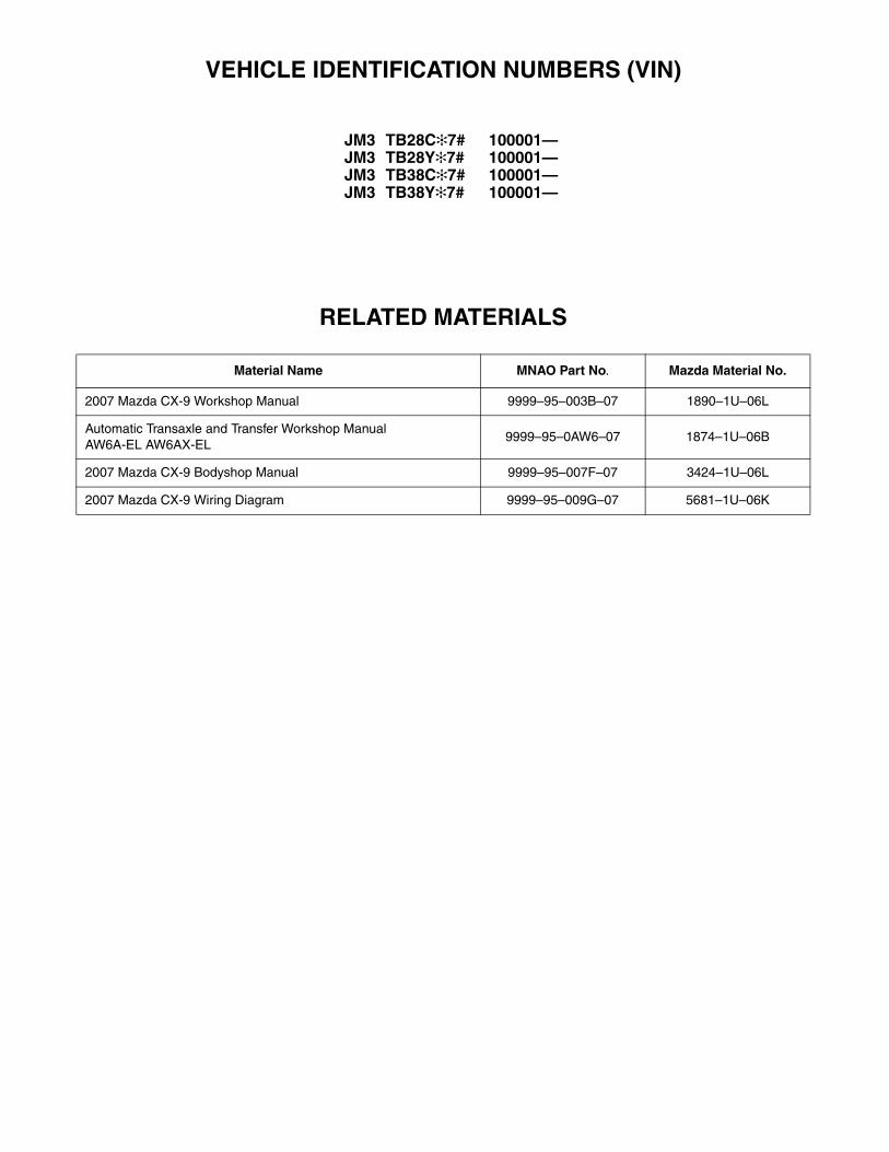
VEHICLE IDENTIFICATION NUMBERS (VIN)
JM3 TB28C✻7# 100001—JM3 TB28Y✻7# 100001—JM3 TB38C✻7# 100001—JM3 TB38Y✻7# 100001—
RELATED MATERIALS
Material Name MNAO Part No. Mazda Material No.
2007 Mazda CX-9 Workshop Manual 9999–95–003B–07 1890–1U–06L
Automatic Transaxle and Transfer Workshop Manual AW6A-EL AW6AX-EL
9999–95–0AW6–07 1874–1U–06B
2007 Mazda CX-9 Bodyshop Manual 9999–95–007F–07 3424–1U–06L
2007 Mazda CX-9 Wiring Diagram 9999–95–009G–07 5681–1U–06K
3423-1U-06L(INDEX).fm 2 ページ 2006年11月24日 金曜日 午後2時47分
00GENERAL INFORMATION
00-00–1
SECTION00-00
Toc of SCTGENERAL INFORMATION . . . .00-00
Toc of SCT
00-00 GENERAL INFORMATIONAIM OF DEVELOPMENT . . . . . . . . . . . . . 00-00–1
Product Concept . . . . . . . . . . . . . . . . . . 00-00–1Vehicle Outline . . . . . . . . . . . . . . . . . . . 00-00–2
VEHICLE IDENTIFICATION NUMBER (VIN) CODE . . . . . . . . . . . . . . 00-00–9
VEHICLE IDENTIFICATION NUMBER (VIN) . . . . . . . . . . . . . . . . . . . . 00-00–9
UNITS. . . . . . . . . . . . . . . . . . . . . . . . . . . . 00-00–10Conversion to SI Units
(Système International d'Unités) . . . . 00-00–10Rounding Off . . . . . . . . . . . . . . . . . . . . 00-00–10Upper and Lower Limits . . . . . . . . . . . . 00-00–10
SAE STANDARDS. . . . . . . . . . . . . . . . . . 00-00–11
End of TocNG: GENERAL INFORMATIONAIM OF DEVELOPMENT
id000000100100
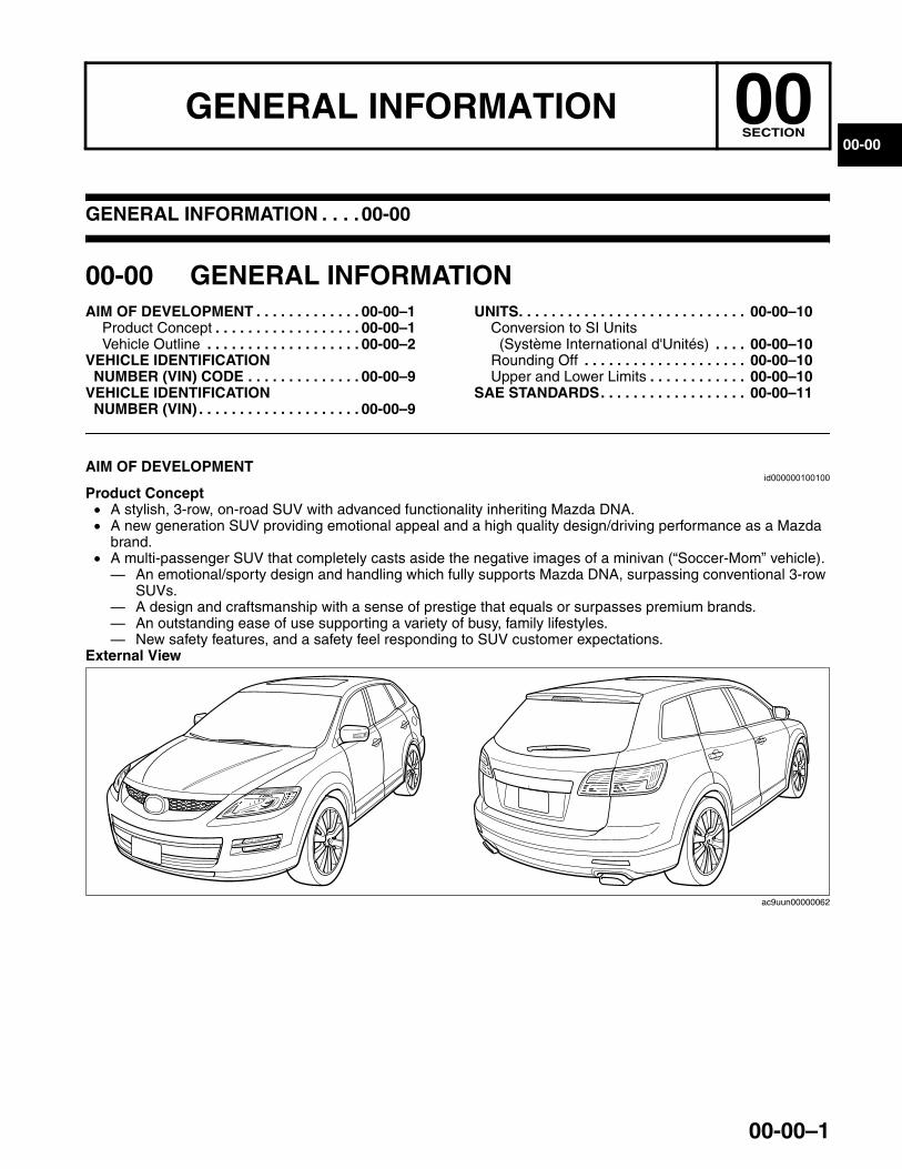
Product Concept• A stylish, 3-row, on-road SUV with advanced functionality inheriting Mazda DNA.• A new generation SUV providing emotional appeal and a high quality design/driving performance as a Mazda
brand.• A multi-passenger SUV that completely casts aside the negative images of a minivan (“Soccer-Mom” vehicle).— An emotional/sporty design and handling which fully supports Mazda DNA, surpassing conventional 3-row
SUVs.— A design and craftsmanship with a sense of prestige that equals or surpasses premium brands.— An outstanding ease of use supporting a variety of busy, family lifestyles.— New safety features, and a safety feel responding to SUV customer expectations.
External View
ac9uun00000062
3423-1U-06H(00-00).fm 1 ページ 2006年11月22日 水曜日 午前9時19分
GENERAL INFORMATION
00-00–2
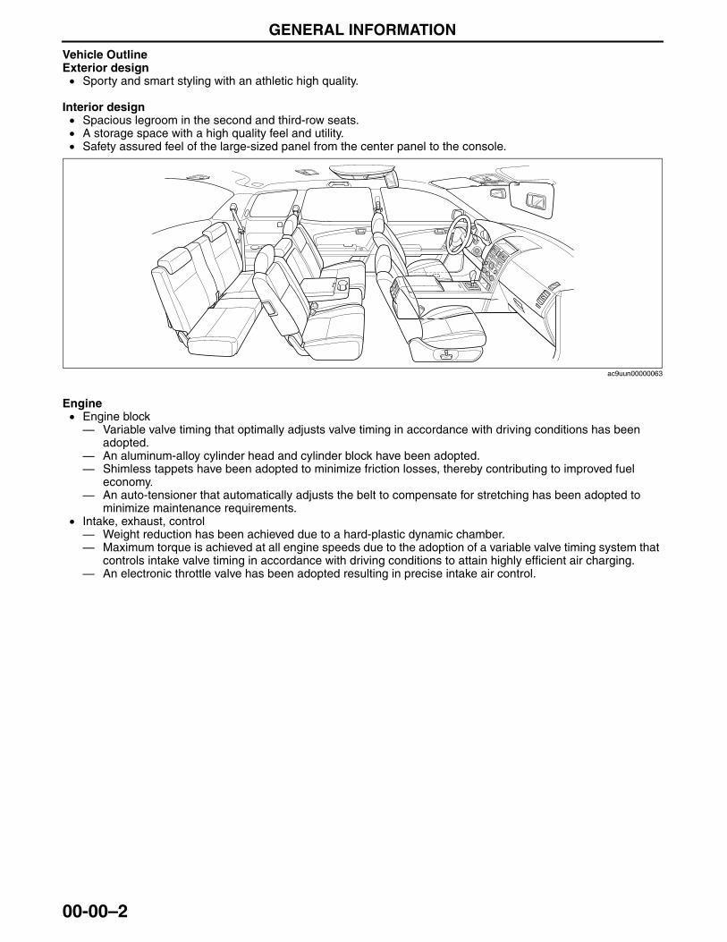
Vehicle OutlineExterior design• Sporty and smart styling with an athletic high quality.
Interior design• Spacious legroom in the second and third-row seats.• A storage space with a high quality feel and utility.• Safety assured feel of the large-sized panel from the center panel to the console.
Engine• Engine block— Variable valve timing that optimally adjusts valve timing in accordance with driving conditions has been
adopted.— An aluminum-alloy cylinder head and cylinder block have been adopted.— Shimless tappets have been adopted to minimize friction losses, thereby contributing to improved fuel
economy.— An auto-tensioner that automatically adjusts the belt to compensate for stretching has been adopted to
minimize maintenance requirements.• Intake, exhaust, control— Weight reduction has been achieved due to a hard-plastic dynamic chamber.— Maximum torque is achieved at all engine speeds due to the adoption of a variable valve timing system that
controls intake valve timing in accordance with driving conditions to attain highly efficient air charging.— An electronic throttle valve has been adopted resulting in precise intake air control.
ac9uun00000063
3423-1U-06H(00-00).fm 2 ページ 2006年11月22日 水曜日 午前9時19分
GENERAL INFORMATION
00-00–3
00-00
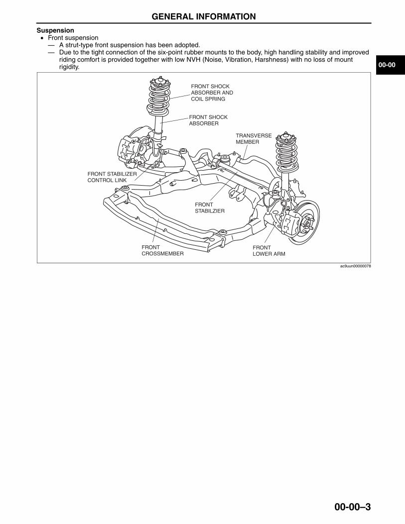
Suspension• Front suspension— A strut-type front suspension has been adopted.— Due to the tight connection of the six-point rubber mounts to the body, high handling stability and improved
riding comfort is provided together with low NVH (Noise, Vibration, Harshness) with no loss of mount rigidity.
FRONT SHOCK ABSORBER AND COIL SPRING
FRONT SHOCK ABSORBER
FRONT STABILIZER CONTROL LINK
FRONT STABILZIER
TRANSVERSE MEMBER
FRONT LOWER ARM
FRONT CROSSMEMBER
ac9uun00000078
3423-1U-06H(00-00).fm 3 ページ 2006年11月22日 水曜日 午前9時19分
GENERAL INFORMATION
00-00–4
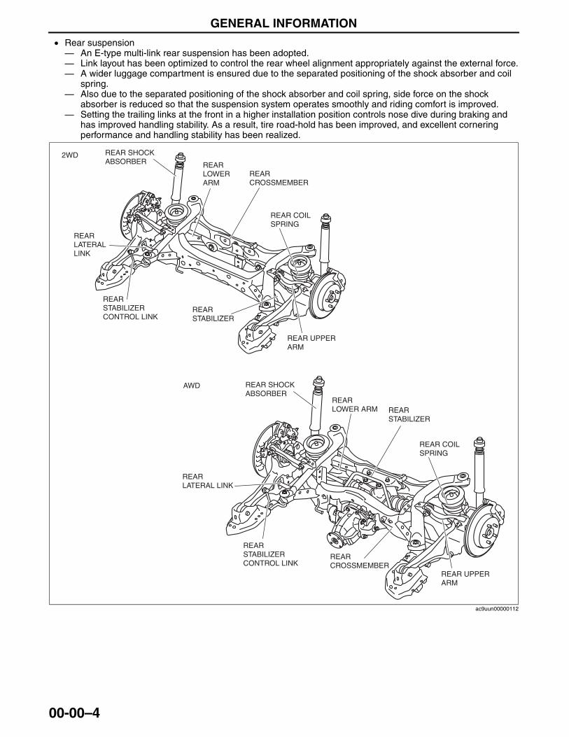
• Rear suspension— An E-type multi-link rear suspension has been adopted.— Link layout has been optimized to control the rear wheel alignment appropriately against the external force.— A wider luggage compartment is ensured due to the separated positioning of the shock absorber and coil
spring.— Also due to the separated positioning of the shock absorber and coil spring, side force on the shock
absorber is reduced so that the suspension system operates smoothly and riding comfort is improved.— Setting the trailing links at the front in a higher installation position controls nose dive during braking and
has improved handling stability. As a result, tire road-hold has been improved, and excellent cornering performance and handling stability has been realized.
2WD
AWD
REAR UPPER ARM
REAR LATERAL LINK
REAR CROSSMEMBER
REAR SHOCK ABSORBER
REAR STABILIZER
REAR LOWER ARM
REAR COIL SPRING
REAR STABILIZER CONTROL LINK
REAR UPPER ARM
REAR LATERAL LINK
REAR CROSSMEMBER
REAR SHOCK ABSORBER
REAR STABILIZER
REAR LOWER ARM
REAR COIL SPRING
REAR STABILIZER CONTROL LINK
ac9uun00000112
3423-1U-06H(00-00).fm 4 ページ 2006年11月22日 水曜日 午前9時19分
GENERAL INFORMATION
00-00–5
00-00
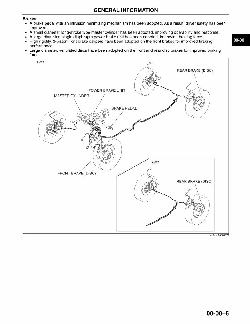
Brakes• A brake pedal with an intrusion minimizing mechanism has been adopted. As a result, driver safety has been
improved.• A small diameter long-stroke type master cylinder has been adopted, improving operability and response.• A large diameter, single diaphragm power brake unit has been adopted, improving braking force.• High rigidity, 2-piston front brake calipers have been adopted on the front brakes for improved braking
performance.• Large diameter, ventilated discs have been adopted on the front and rear disc brakes for improved braking
force.
2WD
BRAKE PEDAL
POWER BRAKE UNIT
FRONT BRAKE (DISC)
REAR BRAKE (DISC)
REAR BRAKE (DISC)
MASTER CYLINDER
AWD
ac9uun00000570
3423-1U-06H(00-00).fm 5 ページ 2006年11月22日 水曜日 午前9時19分
GENERAL INFORMATION
00-00–6
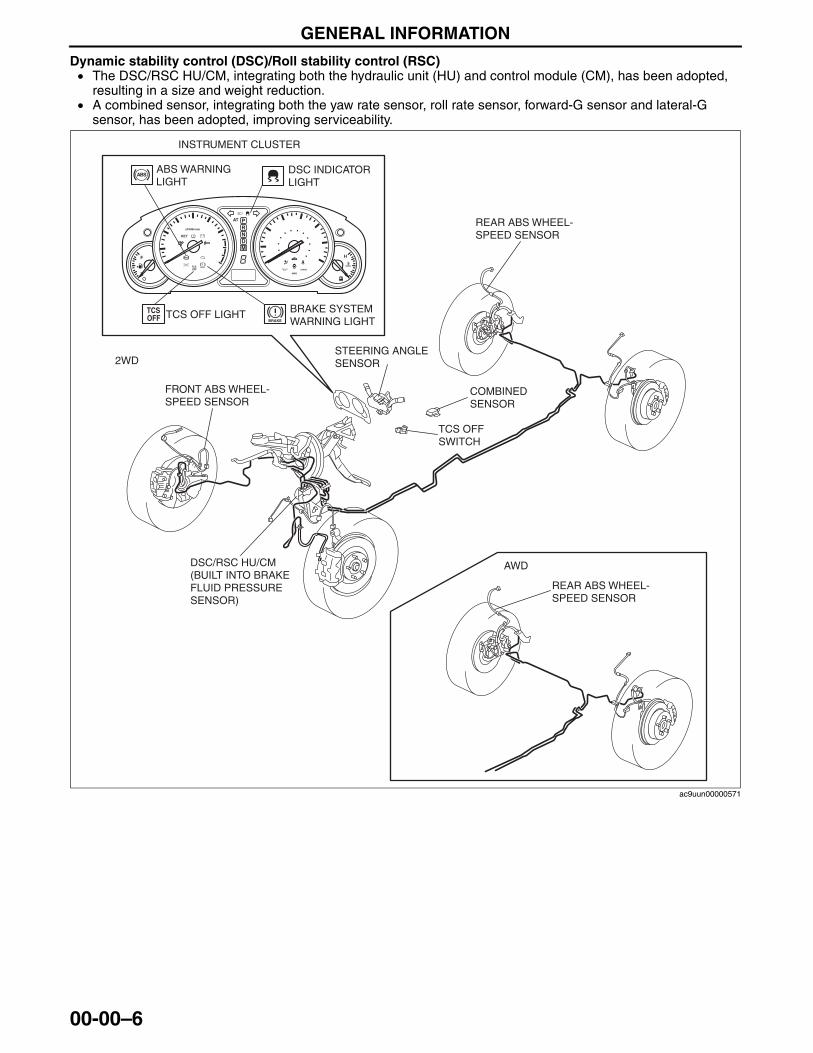
Dynamic stability control (DSC)/Roll stability control (RSC)• The DSC/RSC HU/CM, integrating both the hydraulic unit (HU) and control module (CM), has been adopted,
resulting in a size and weight reduction.• A combined sensor, integrating both the yaw rate sensor, roll rate sensor, forward-G sensor and lateral-G
sensor, has been adopted, improving serviceability.
BRAKE
BRAKE
2WD
AWD
BRAKE SYSTEM WARNING LIGHT
ABS WARNING LIGHT
TCS OFF LIGHT
FRONT ABS WHEEL- SPEED SENSOR
REAR ABS WHEEL-SPEED SENSOR
REAR ABS WHEEL-SPEED SENSOR
STEERING ANGLE SENSOR
TCS OFF SWITCH
COMBINED SENSOR
DSC/RSC HU/CM (BUILT INTO BRAKE FLUID PRESSURE SENSOR)
DSC INDICATOR LIGHT
INSTRUMENT CLUSTER
ac9uun00000571
3423-1U-06H(00-00).fm 6 ページ 2006年11月22日 水曜日 午前9時19分
GENERAL INFORMATION
00-00–7
00-00
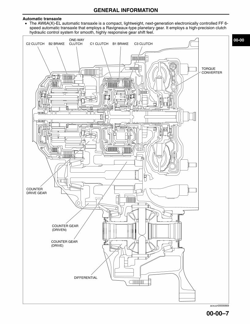
Automatic transaxle• The AW6A(X)-EL automatic transaxle is a compact, lightweight, next-generation electronically controlled FF 6-
speed automatic transaxle that employs a Ravigneaux-type planetary gear. It employs a high-precision clutch hydraulic control system for smooth, highly responsive gear shift feel.
C2 CLUTCH C1 CLUTCH C3 CLUTCHB2 BRAKE B1 BRAKEONE-WAYCLUTCH
COUNTERDRIVE GEAR
COUNTER GEAR (DRIVEN)
DIFFERENTIAL
TORQUECONVERTER
COUNTER GEAR (DRIVE)
acxuun00000669
3423-1U-06H(00-00).fm 7 ページ 2006年11月22日 水曜日 午前9時19分
GENERAL INFORMATION
00-00–8
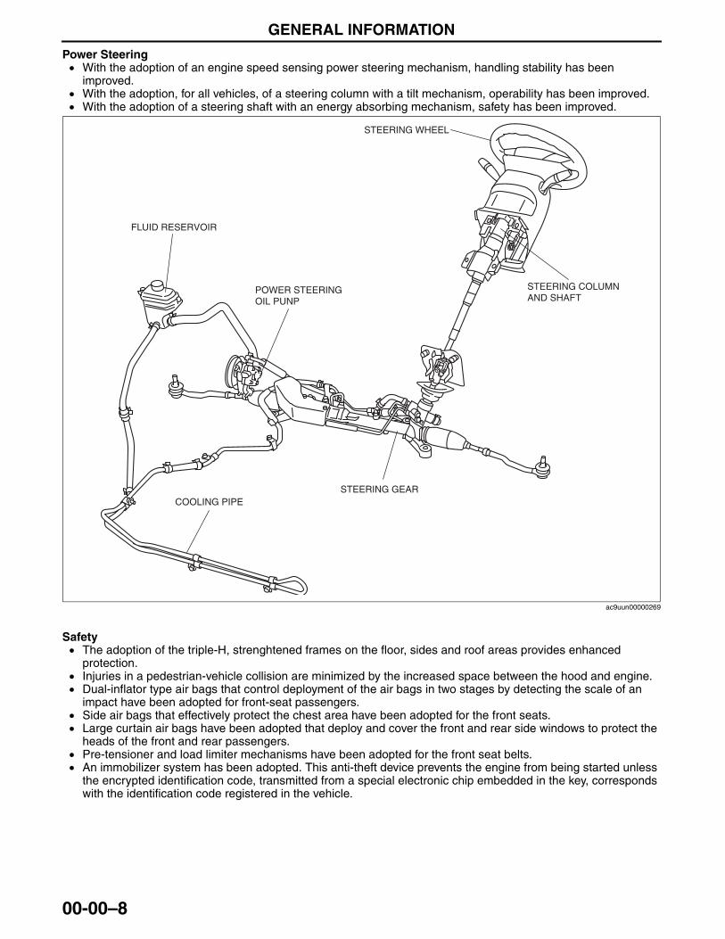
Power Steering• With the adoption of an engine speed sensing power steering mechanism, handling stability has been
improved.• With the adoption, for all vehicles, of a steering column with a tilt mechanism, operability has been improved.• With the adoption of a steering shaft with an energy absorbing mechanism, safety has been improved.
Safety• The adoption of the triple-H, strenghtened frames on the floor, sides and roof areas provides enhanced
protection.• Injuries in a pedestrian-vehicle collision are minimized by the increased space between the hood and engine. • Dual-inflator type air bags that control deployment of the air bags in two stages by detecting the scale of an
impact have been adopted for front-seat passengers.• Side air bags that effectively protect the chest area have been adopted for the front seats.• Large curtain air bags have been adopted that deploy and cover the front and rear side windows to protect the
heads of the front and rear passengers.• Pre-tensioner and load limiter mechanisms have been adopted for the front seat belts.• An immobilizer system has been adopted. This anti-theft device prevents the engine from being started unless
the encrypted identification code, transmitted from a special electronic chip embedded in the key, corresponds with the identification code registered in the vehicle.
End Of Sie
FLUID RESERVOIR
POWER STEERING OIL PUNP
STEERING COLUMN AND SHAFT
STEERING WHEEL
STEERING GEARCOOLING PIPE
ac9uun00000269
3423-1U-06H(00-00).fm 8 ページ 2006年11月22日 水曜日 午前9時19分
GENERAL INFORMATION
00-00–9
00-00
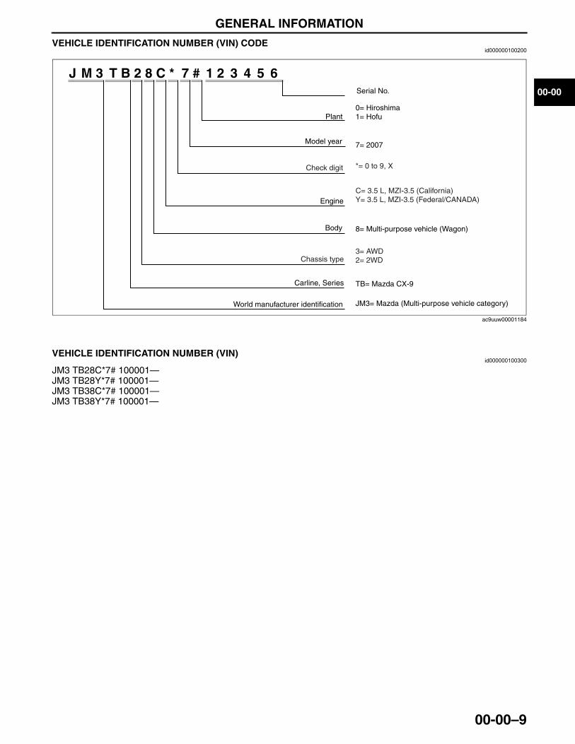
VEHICLE IDENTIFICATION NUMBER (VIN) CODEid000000100200
End Of Sie
VEHICLE IDENTIFICATION NUMBER (VIN)id000000100300
JM3 TB28C*7# 100001—JM3 TB28Y*7# 100001—JM3 TB38C*7# 100001—JM3 TB38Y*7# 100001—End Of Sie
J M 3 T B 2 8 C * 7 # 1 2 3 4 5 6
Model year
Plant
Serial No.
0= Hiroshima1= Hofu
7= 2007
Engine
Body 8= Multi-purpose vehicle (Wagon)
Carline, Series TB= Mazda CX-9
JM3= Mazda (Multi-purpose vehicle category)World manufacturer identification
Check digit *= 0 to 9, X
C= 3.5 L, MZI-3.5 (California)Y= 3.5 L, MZI-3.5 (Federal/CANADA)
Chassis type3= AWD2= 2WD
ac9uuw00001184
3423-1U-06H(00-00).fm 9 ページ 2006年11月22日 水曜日 午前9時19分
GENERAL INFORMATION
00-00–10
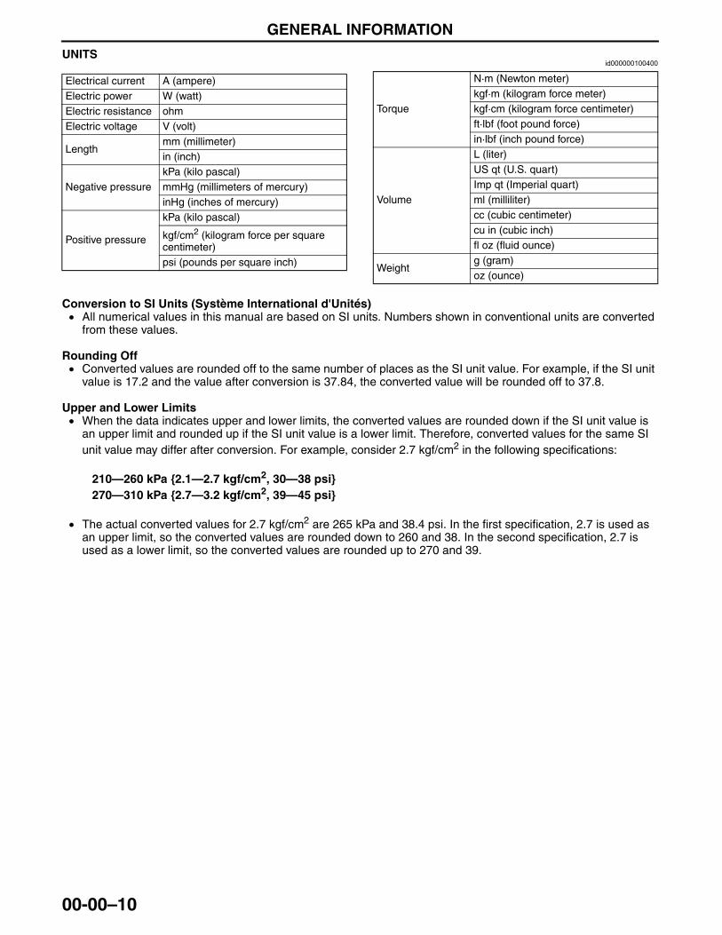
UNITSid000000100400
Conversion to SI Units (Système International d'Unités)• All numerical values in this manual are based on SI units. Numbers shown in conventional units are converted
from these values.
Rounding Off• Converted values are rounded off to the same number of places as the SI unit value. For example, if the SI unit
value is 17.2 and the value after conversion is 37.84, the converted value will be rounded off to 37.8.
Upper and Lower Limits• When the data indicates upper and lower limits, the converted values are rounded down if the SI unit value is
an upper limit and rounded up if the SI unit value is a lower limit. Therefore, converted values for the same SI unit value may differ after conversion. For example, consider 2.7 kgf/cm2 in the following specifications:
210—260 kPa {2.1—2.7 kgf/cm2, 30—38 psi}270—310 kPa {2.7—3.2 kgf/cm2, 39—45 psi}
• The actual converted values for 2.7 kgf/cm2 are 265 kPa and 38.4 psi. In the first specification, 2.7 is used as an upper limit, so the converted values are rounded down to 260 and 38. In the second specification, 2.7 is used as a lower limit, so the converted values are rounded up to 270 and 39.
End Of Sie
Electrical current A (ampere)Electric power W (watt)Electric resistance ohmElectric voltage V (volt)
Lengthmm (millimeter)in (inch)
Negative pressurekPa (kilo pascal)mmHg (millimeters of mercury)inHg (inches of mercury)
Positive pressure
kPa (kilo pascal)
kgf/cm2 (kilogram force per square centimeter)psi (pounds per square inch)
Torque
N·m (Newton meter)kgf·m (kilogram force meter)kgf·cm (kilogram force centimeter)ft·lbf (foot pound force)in·lbf (inch pound force)
Volume
L (liter)US qt (U.S. quart)Imp qt (Imperial quart)ml (milliliter)cc (cubic centimeter)cu in (cubic inch)fl oz (fluid ounce)
Weightg (gram)oz (ounce)
3423-1U-06H(00-00).fm 10 ページ 2006年11月22日 水曜日 午前9時19分
GENERAL INFORMATION
00-00–11
00-00
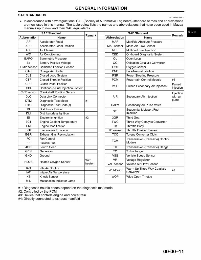
SAE STANDARDSid000000100600
• In accordance with new regulations, SAE (Society of Automotive Engineers) standard names and abbreviations are now used in this manual. The table below lists the names and abbreviations that have been used in Mazda manuals up to now and their SAE equivalents.
#1: Diagnostic trouble codes depend on the diagnostic test mode.#2: Controlled by the PCM#3: Device that controls engine and powertrain#4: Directly connected to exhaust manifoldEnd Of Sie
SAE StandardRemark
SAE StandardRemark
Abbreviation Name Abbreviation NameAP Accelerator Pedal MAP Manifold Absolute Pressure
APP Accelerator Pedal Position MAF sensor Mass Air Flow SensorACL Air Cleaner MFL Multiport Fuel InjectionA/C Air Conditioning OBD On-board Diagnostic System
BARO Barometric Pressure OL Open LoopB+ Battery Positive Voltage OC Oxidation Catalytic Converter
CMP sensor Camshaft Position Sensor O2S Oxygen sensorCAC Charge Air Cooler PNP Park/Neutral PositionCLS Closed Loop System PSP Power Steering PressureCTP Closed Throttle Position PCM Powertrain Control Module #3CPP Clutch Pedal Position
PAIR Pulsed Secondary Air Injection Pulsed injectionCIS Continuous Fuel Injection System
CKP sensor Crankshaft Position SensorAIR Secondary Air Injection
Injection with air pump
DLC Data Link ConnectorDTM Diagnostic Test Mode #1DTC Diagnostic Test Code(s) SAPV Secondary Air Pulse ValveDI Distributor Ignition
SFI Sequential Multiport Fuel InjectionDLI Distributorless Ignition
EI Electronic Ignition #2 3GR Third GearECT Engine Coolant Temperature TWC Three Way Catalytic ConverterEM Engine Modification TB Throttle Body
EVAP Evaporative Emission TP sensor Throttle Position SensorEGR Exhaust Gas Recirculation TCC Torque Converter ClutchFC Fan Control
TCM Transmission (Transaxle) Control ModuleFF Flexible Fuel
4GR Fourth Gear TR Transmission (Transaxle) RangeGEN Generator TC TurbochargerGND Ground VSS Vehicle Speed Sensor
HO2S Heated Oxygen Sensor With heater
VR Voltage RegulatorVAF sensor Volume Air Flow Sensor
IAC Idle Air ControlWU-TWC Warm Up Three Way Catalytic
Converter #4IAT Intake Air TemperatureKS Knock Sensor WOP Wide Open ThrottleMIL Malfunction Indicator Lamp
3423-1U-06H(00-00).fm 11 ページ 2006年11月22日 水曜日 午前9時19分

01-00–1
01ENGINESECTION
01-00
Toc of SCTOUTLINE[MZI-3.5] . . . . . . . . . .01-00ON-BOARD DIAGNOSTIC
[MZI-3.5] . . . . . . . . . . . . . . . . .01-02MECHANICAL[MZI-3.5] . . . . . .01-10LUBRICATION[MZI-3.5] . . . . . .01-11COOLING SYSTEM
[MZI-3.5] . . . . . . . . . . . . . . . . .01-12INTAKE-AIR SYSTEM
[MZI-3.5] . . . . . . . . . . . . . . . . .01-13FUEL SYSTEM[MZI-3.5] . . . . . .01-14EXHAUST SYSTEM
[MZI-3.5] . . . . . . . . . . . . . . . . .01-15
EMISSION SYSTEM[MZI-3.5]. . . . . . . . . . . . . . . . . 01-16
CHARGING SYSTEM[MZI-3.5]. . . . . . . . . . . . . . . . . 01-17
IGNITION SYSTEM[MZI-3.5]. . . . . . . . . . . . . . . . . 01-18
STARTING SYSTEM[MZI-3.5]. . . . . . . . . . . . . . . . . 01-19
CRUISE CONTROL SYSTEM[MZI-3.5]. . . . . . . . . . . . . . . . . 01-20
CONTROL SYSTEM[MZI-3.5]. . . . . . . . . . . . . . . . . 01-40
Toc of SCT
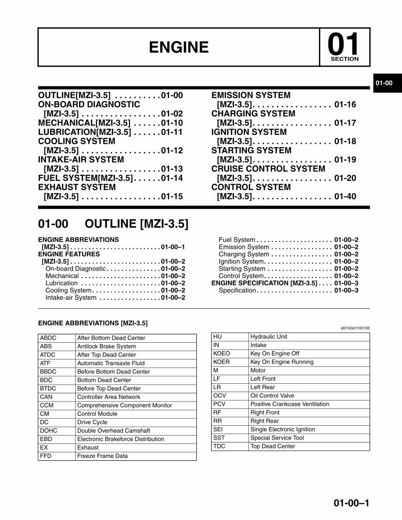
01-00 OUTLINE [MZI-3.5]ENGINE ABBREVIATIONS
[MZI-3.5] . . . . . . . . . . . . . . . . . . . . . . . . . 01-00–1ENGINE FEATURES
[MZI-3.5] . . . . . . . . . . . . . . . . . . . . . . . . . 01-00–2On-board Diagnostic . . . . . . . . . . . . . . . 01-00–2Mechanical . . . . . . . . . . . . . . . . . . . . . . 01-00–2Lubrication . . . . . . . . . . . . . . . . . . . . . . 01-00–2Cooling System . . . . . . . . . . . . . . . . . . . 01-00–2Intake-air System . . . . . . . . . . . . . . . . . 01-00–2
Fuel System . . . . . . . . . . . . . . . . . . . . . 01-00–2Emission System . . . . . . . . . . . . . . . . . 01-00–2Charging System . . . . . . . . . . . . . . . . . 01-00–2Ignition System. . . . . . . . . . . . . . . . . . . 01-00–2Starting System . . . . . . . . . . . . . . . . . . 01-00–2Control System. . . . . . . . . . . . . . . . . . . 01-00–2
ENGINE SPECIFICATION [MZI-3.5] . . . . 01-00–3Specification . . . . . . . . . . . . . . . . . . . . . 01-00–3
End of TocNG: ENGINE COMPLETEENGINE ABBREVIATIONS [MZI-3.5]
id0100d1100100
End Of Sie
ABDC After Bottom Dead CenterABS Antilock Brake SystemATDC After Top Dead CenterATF Automatic Transaxle FluidBBDC Before Bottom Dead CenterBDC Bottom Dead Center BTDC Before Top Dead CenterCAN Controller Area NetworkCCM Comprehensive Component MonitorCM Control ModuleDC Drive CycleDOHC Double Overhead CamshaftEBD Electronic Brakeforce DistributionEX ExhaustFFD Freeze Frame Data
HU Hydraulic UnitIN IntakeKOEO Key On Engine OffKOER Key On Engine RunningM MotorLF Left FrontLR Left RearOCV Oil Control ValvePCV Positive Crankcase VentilationRF Right FrontRR Right RearSEI Single Electronic IgnitionSST Special Service ToolTDC Top Dead Center
3423-1U-06H(01-00).fm 1 ページ 2006年11月21日 火曜日 午後4時45分
OUTLINE [MZI-3.5]
01-00–2
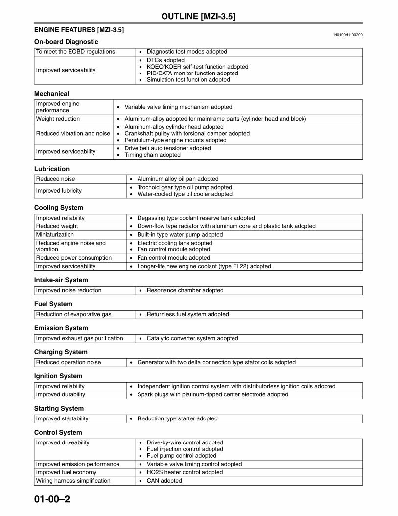
ENGINE FEATURES [MZI-3.5]id0100d1100200
On-board Diagnostic
Mechanical
Lubrication
Cooling System
Intake-air System
Fuel System
Emission System
Charging System
Ignition System
Starting System
Control System
To meet the EOBD regulations • Diagnostic test modes adopted
Improved serviceability
• DTCs adopted• KOEO/KOER self-test function adopted• PID/DATA monitor function adopted• Simulation test function adopted
Improved engine performance • Variable valve timing mechanism adopted
Weight reduction • Aluminum-alloy adopted for mainframe parts (cylinder head and block)
Reduced vibration and noise• Aluminum-alloy cylinder head adopted• Crankshaft pulley with torsional damper adopted • Pendulum-type engine mounts adopted
Improved serviceability • Drive belt auto tensioner adopted • Timing chain adopted
Reduced noise • Aluminum alloy oil pan adopted
Improved lubricity • Trochoid gear type oil pump adopted• Water-cooled type oil cooler adopted
Improved reliability • Degassing type coolant reserve tank adoptedReduced weight • Down-flow type radiator with aluminum core and plastic tank adoptedMiniaturization • Built-in type water pump adoptedReduced engine noise and vibration
• Electric cooling fans adopted• Fan control module adopted
Reduced power consumption • Fan control module adoptedImproved serviceability • Longer-life new engine coolant (type FL22) adopted
Improved noise reduction • Resonance chamber adopted
Reduction of evaporative gas • Returnless fuel system adopted
Improved exhaust gas purification • Catalytic converter system adopted
Reduced operation noise • Generator with two delta connection type stator coils adopted
Improved reliability • Independent ignition control system with distributorless ignition coils adoptedImproved durability • Spark plugs with platinum-tipped center electrode adopted
Improved startability • Reduction type starter adopted
Improved driveability • Drive-by-wire control adopted• Fuel injection control adopted• Fuel pump control adopted
Improved emission performance • Variable valve timing control adoptedImproved fuel economy • HO2S heater control adoptedWiring harness simplification • CAN adopted
3423-1U-06H(01-00).fm 2 ページ 2006年11月21日 火曜日 午後4時45分
OUTLINE [MZI-3.5]
01-00–3
01-00
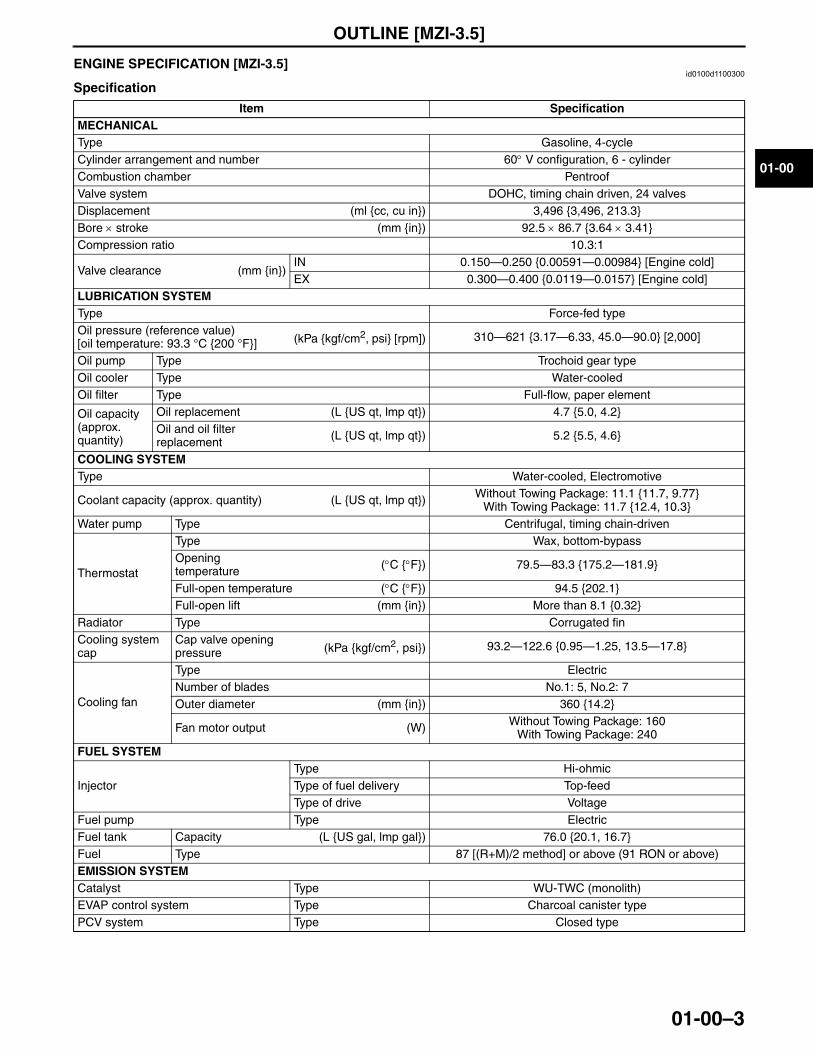
End Of SieENGINE SPECIFICATION [MZI-3.5]id0100d1100300
Specification
Item SpecificationMECHANICALType Gasoline, 4-cycleCylinder arrangement and number 60° V configuration, 6 - cylinderCombustion chamber PentroofValve system DOHC, timing chain driven, 24 valvesDisplacement (ml {cc, cu in}) 3,496 {3,496, 213.3}Bore × stroke (mm {in}) 92.5 × 86.7 {3.64 × 3.41}Compression ratio 10.3:1
Valve clearance (mm {in})IN 0.150—0.250 {0.00591—0.00984} [Engine cold]EX 0.300—0.400 {0.0119—0.0157} [Engine cold]
LUBRICATION SYSTEMType Force-fed typeOil pressure (reference value)[oil temperature: 93.3 °C {200 °F}] (kPa {kgf/cm2, psi} [rpm]) 310—621 {3.17—6.33, 45.0—90.0} [2,000]
Oil pump Type Trochoid gear typeOil cooler Type Water-cooledOil filter Type Full-flow, paper element
Oil capacity (approx. quantity)
Oil replacement (L {US qt, lmp qt}) 4.7 {5.0, 4.2}Oil and oil filter replacement (L {US qt, lmp qt}) 5.2 {5.5, 4.6}
COOLING SYSTEMType Water-cooled, Electromotive
Coolant capacity (approx. quantity) (L {US qt, lmp qt}) Without Towing Package: 11.1 {11.7, 9.77}With Towing Package: 11.7 {12.4, 10.3}
Water pump Type Centrifugal, timing chain-driven
Thermostat
Type Wax, bottom-bypassOpening temperature (°C {°F}) 79.5—83.3 {175.2—181.9}
Full-open temperature (°C {°F}) 94.5 {202.1}Full-open lift (mm {in}) More than 8.1 {0.32}
Radiator Type Corrugated finCooling system cap
Cap valve opening pressure (kPa {kgf/cm2, psi}) 93.2—122.6 {0.95—1.25, 13.5—17.8}
Cooling fan
Type ElectricNumber of blades No.1: 5, No.2: 7Outer diameter (mm {in}) 360 {14.2}
Fan motor output (W) Without Towing Package: 160With Towing Package: 240
FUEL SYSTEM
InjectorType Hi-ohmicType of fuel delivery Top-feedType of drive Voltage
Fuel pump Type ElectricFuel tank Capacity (L {US gal, lmp gal}) 76.0 {20.1, 16.7}Fuel Type 87 [(R+M)/2 method] or above (91 RON or above)EMISSION SYSTEMCatalyst Type WU-TWC (monolith)EVAP control system Type Charcoal canister typePCV system Type Closed type
3423-1U-06H(01-00).fm 3 ページ 2006年11月28日 火曜日 午後1時10分
OUTLINE [MZI-3.5]
01-00–4
Engine oil specification
End Of Sie
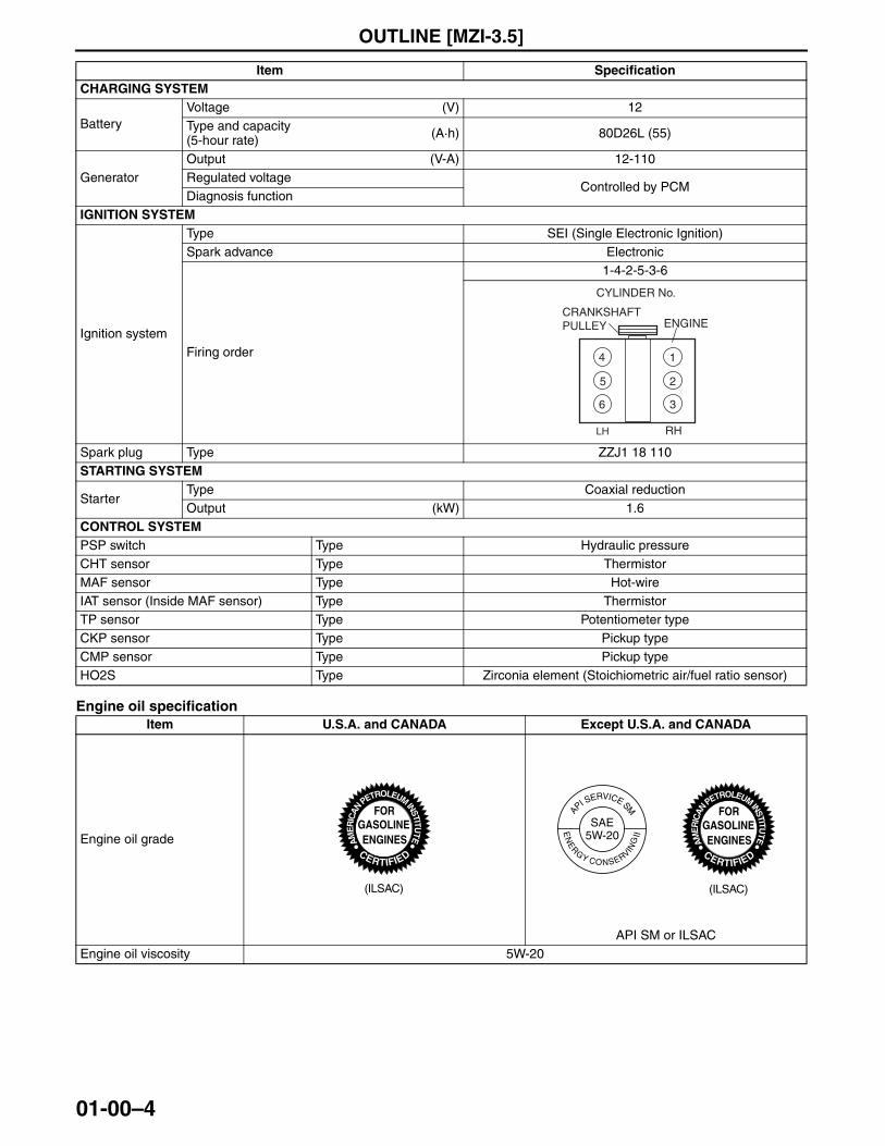
CHARGING SYSTEM
BatteryVoltage (V) 12Type and capacity(5-hour rate) (A·h) 80D26L (55)
GeneratorOutput (V-A) 12-110Regulated voltage
Controlled by PCMDiagnosis function
IGNITION SYSTEM
Ignition system
Type SEI (Single Electronic Ignition)Spark advance Electronic
Firing order
1-4-2-5-3-6
Spark plug Type ZZJ1 18 110STARTING SYSTEM
StarterType Coaxial reductionOutput (kW) 1.6
CONTROL SYSTEMPSP switch Type Hydraulic pressureCHT sensor Type ThermistorMAF sensor Type Hot-wireIAT sensor (Inside MAF sensor) Type ThermistorTP sensor Type Potentiometer typeCKP sensor Type Pickup typeCMP sensor Type Pickup typeHO2S Type Zirconia element (Stoichiometric air/fuel ratio sensor)
Item U.S.A. and CANADA Except U.S.A. and CANADA
Engine oil grade
API SM or ILSACEngine oil viscosity 5W-20
Item Specification
RHLH
1
2
3
4
5
6
ENGINE
CYLINDER No.
CRANKSHAFTPULLEY
(ILSAC)
SMSM
(ILSAC)
3423-1U-06H(01-00).fm 4 ページ 2006年12月5日 火曜日 午前10時41分
ON-BOARD DIAGNOSTIC [MZI-3.5]
01-02–1
01-02
01-02 ON-BOARD DIAGNOSTIC [MZI-3.5]ON-BOARD DIAGNOSTIC OUTLINE
[MZI-3.5] . . . . . . . . . . . . . . . . . . . . . . . . 01-02–2Features . . . . . . . . . . . . . . . . . . . . . . . . 01-02–2
ON-BOARD DIAGNOSTIC SYSTEM TEST MODE[MZI-3.5] . . . . . . . . . . . . . . 01-02–3
OBD-II Diagnostic Data Monitor (Mode 01). . . . . . . . . . . . . . . . . . . . . . 01-02–3
OBD-II Freeze Frame Data (Mode 02). . . . . . . . . . . . . . . . . . . . . . 01-02–5
OBD-II Diagnostic Trouble Code (Mode 03). . . . . . . . . . . . . . . . . . . . . . 01-02–5
OBD-II Diagnostic Monitoring System Test Results (Mode 06) . . . . . . . . . . . 01-02–9
ON-BOARD DIAGNOSTIC SYSTEM MALFUNCTION DETECTION FUNCTION[MZI-3.5] . . . . . . . . . . . . . . . 01-02–10
Features . . . . . . . . . . . . . . . . . . . . . . . . 01-02–10Malfunction Diagnosis Function . . . . . . 01-02–10Self-test Function . . . . . . . . . . . . . . . . . 01-02–13
ON-BOARD DIAGNOSTIC SYSTEM PID/DATA MONITOR FUNCTION[MZI-3.5] . . . . . . . . . . . . . . . . . . . . . . . . 01-02–14
Features . . . . . . . . . . . . . . . . . . . . . . . . 01-02–14
Function . . . . . . . . . . . . . . . . . . . . . . . . 01-02–14ON-BOARD DIAGNOSTIC SYSTEM
SIMULATION FUNCTION[MZI-3.5] . . . . . . . . . . . . . . . . . . . . . . . . . 01-02–16
Features . . . . . . . . . . . . . . . . . . . . . . . . 01-02–16Function . . . . . . . . . . . . . . . . . . . . . . . . 01-02–16
ON-BOARD DIAGNOSTIC SYSTEM EXTERNAL DIAGNOSTIC UNIT COMMUNICATION FUNCTION[MZI-3.5] . . . . . . . . . . . . . . . . . . . . . . . . . 01-02–16
Features . . . . . . . . . . . . . . . . . . . . . . . . 01-02–16ON-BOARD DIAGNOSTIC SYSTEM
MALFUNCTION DISPLAY FUNCTION[MZI-3.5] . . . . . . . . . . . . . . . . . . . . . . . . . 01-02–17
Features . . . . . . . . . . . . . . . . . . . . . . . . 01-02–17Function . . . . . . . . . . . . . . . . . . . . . . . . 01-02–17
ON-BOARD DIAGNOSTIC SYSTEM DIAGNOSTIC DATA MEMORY FUNCTION[MZI-3.5] . . . . . . . . . . . . . . . . 01-02–17
Features . . . . . . . . . . . . . . . . . . . . . . . . 01-02–17Memory Function . . . . . . . . . . . . . . . . . 01-02–17Initialization Function. . . . . . . . . . . . . . . 01-02–17
End of TocNG: ON-BOARD DIAGNOSTIC (ENGINE CONTROL SYSTEM)
3423-1U-06H(01-02).fm 1 ページ 2006年11月29日 水曜日 午前9時15分
ON-BOARD DIAGNOSTIC [MZI-3.5]
01-02–2
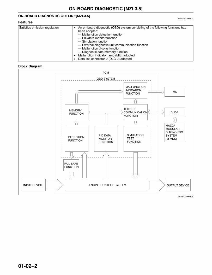
ON-BOARD DIAGNOSTIC OUTLINE[MZI-3.5]id0102d1100100
Features
Block Diagram
End Of Sie
Satisfies emission regulation • An on-board diagnostic (OBD) system consisting of the following functions has been adopted:— Malfunction detection function— PID/data monitor function— Simulation function— External diagnostic unit communication function— Malfunction display function— Diagnostic data memory function
• Malfunction indicator lamp (MIL) adopted• Data link connector-2 (DLC-2) adopted
PCM
OBD SYSTEM
MALFUNCTION INDICATION FUNCTION
MIL
MEMORY FUNCTION
TESTER COMMUNICATION FUNCTION
DLC-2
MAZDA MODULAR DIAGNOSTIC SYSTEM(M-MDS)
DETECTION FUNCTION
PID DATA MONITOR FUNCTION
SIMULATION TEST FUNCTION
FAIL-SAFE FUNCTION
INPUT DEVICE ENGINE CONTROL SYSTEM OUTPUT DEVICE
atraan00000306
3423-1U-06H(01-02).fm 2 ページ 2006年11月29日 水曜日 午前9時15分
ON-BOARD DIAGNOSTIC [MZI-3.5]
01-02–3
01-02
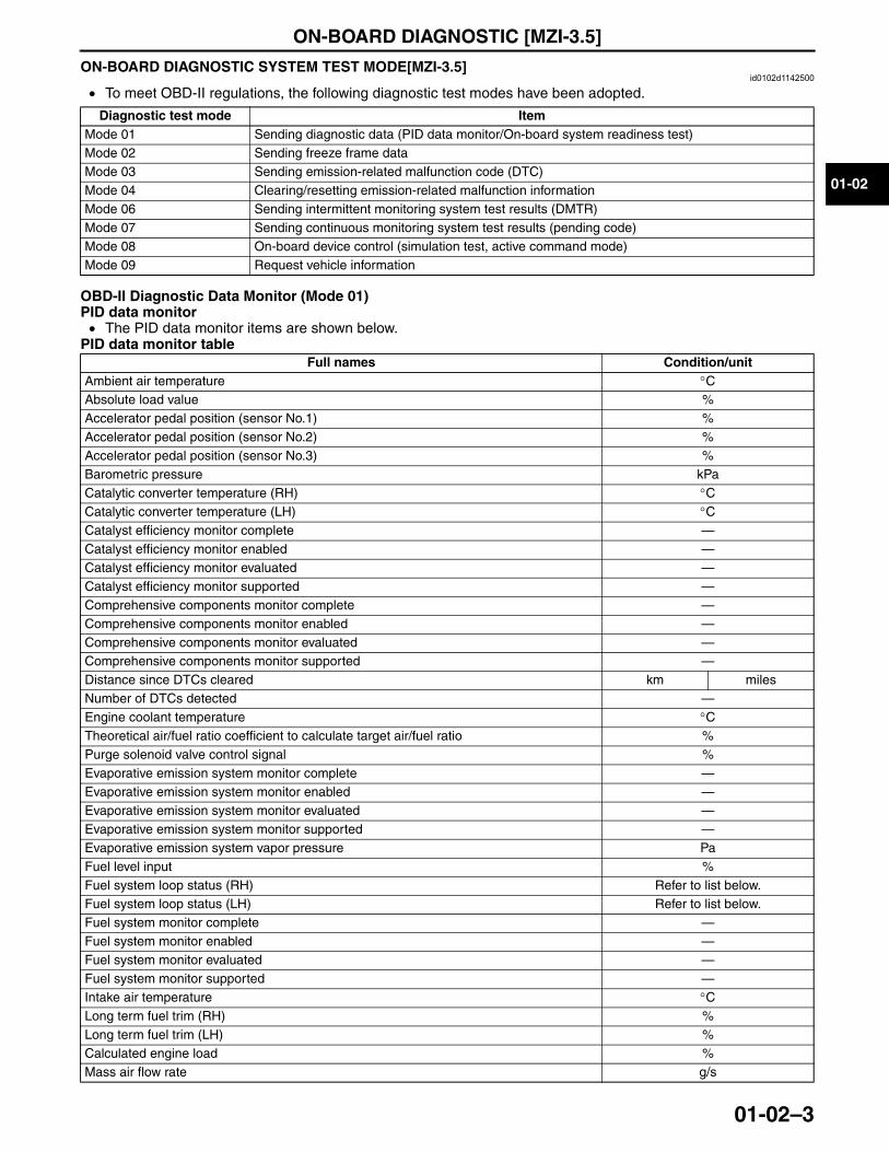
ON-BOARD DIAGNOSTIC SYSTEM TEST MODE[MZI-3.5]id0102d1142500
• To meet OBD-II regulations, the following diagnostic test modes have been adopted.
OBD-II Diagnostic Data Monitor (Mode 01)PID data monitor• The PID data monitor items are shown below.
PID data monitor table
Diagnostic test mode ItemMode 01 Sending diagnostic data (PID data monitor/On-board system readiness test)Mode 02 Sending freeze frame dataMode 03 Sending emission-related malfunction code (DTC)Mode 04 Clearing/resetting emission-related malfunction informationMode 06 Sending intermittent monitoring system test results (DMTR)Mode 07 Sending continuous monitoring system test results (pending code)Mode 08 On-board device control (simulation test, active command mode)Mode 09 Request vehicle information
Full names Condition/unitAmbient air temperature °CAbsolute load value %Accelerator pedal position (sensor No.1) %Accelerator pedal position (sensor No.2) %Accelerator pedal position (sensor No.3) %Barometric pressure kPaCatalytic converter temperature (RH) °CCatalytic converter temperature (LH) °CCatalyst efficiency monitor complete —Catalyst efficiency monitor enabled —Catalyst efficiency monitor evaluated —Catalyst efficiency monitor supported —Comprehensive components monitor complete —Comprehensive components monitor enabled —Comprehensive components monitor evaluated —Comprehensive components monitor supported —Distance since DTCs cleared km milesNumber of DTCs detected —Engine coolant temperature °CTheoretical air/fuel ratio coefficient to calculate target air/fuel ratio %Purge solenoid valve control signal %Evaporative emission system monitor complete —Evaporative emission system monitor enabled —Evaporative emission system monitor evaluated —Evaporative emission system monitor supported —Evaporative emission system vapor pressure PaFuel level input %Fuel system loop status (RH) Refer to list below.Fuel system loop status (LH) Refer to list below.Fuel system monitor complete —Fuel system monitor enabled —Fuel system monitor evaluated —Fuel system monitor supported —Intake air temperature °CLong term fuel trim (RH) %Long term fuel trim (LH) %Calculated engine load %Mass air flow rate g/s
3423-1U-06H(01-02).fm 3 ページ 2006年11月29日 水曜日 午前9時15分
ON-BOARD DIAGNOSTIC [MZI-3.5]
01-02–4
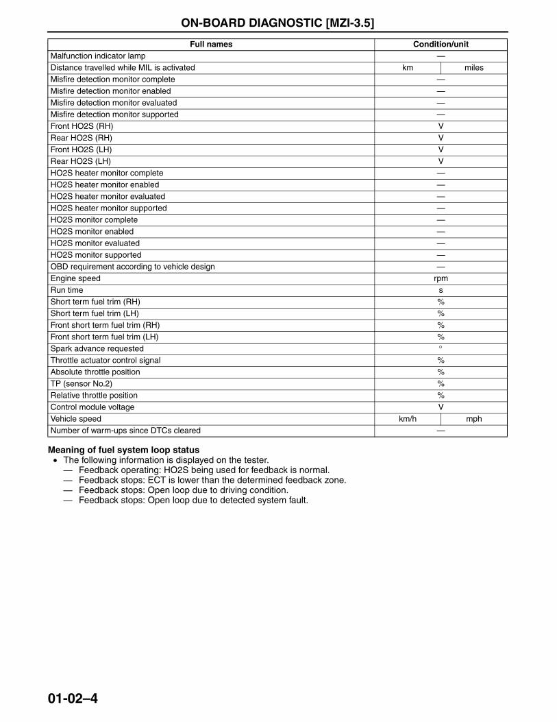
Meaning of fuel system loop status• The following information is displayed on the tester.— Feedback operating: HO2S being used for feedback is normal.— Feedback stops: ECT is lower than the determined feedback zone.— Feedback stops: Open loop due to driving condition.— Feedback stops: Open loop due to detected system fault.
Malfunction indicator lamp —Distance travelled while MIL is activated km milesMisfire detection monitor complete —Misfire detection monitor enabled —Misfire detection monitor evaluated —Misfire detection monitor supported —Front HO2S (RH) VRear HO2S (RH) VFront HO2S (LH) VRear HO2S (LH) VHO2S heater monitor complete —HO2S heater monitor enabled —HO2S heater monitor evaluated —HO2S heater monitor supported —HO2S monitor complete —HO2S monitor enabled —HO2S monitor evaluated —HO2S monitor supported —OBD requirement according to vehicle design —Engine speed rpmRun time sShort term fuel trim (RH) %Short term fuel trim (LH) %Front short term fuel trim (RH) %Front short term fuel trim (LH) %Spark advance requested °Throttle actuator control signal %Absolute throttle position %TP (sensor No.2) %Relative throttle position %Control module voltage VVehicle speed km/h mphNumber of warm-ups since DTCs cleared —
Full names Condition/unit
3423-1U-06H(01-02).fm 4 ページ 2006年11月29日 水曜日 午前9時15分
ON-BOARD DIAGNOSTIC [MZI-3.5]
01-02–5
01-02
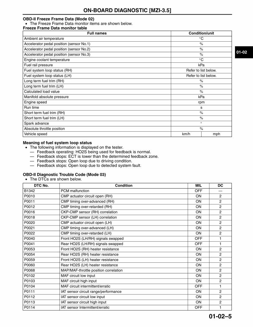
OBD-II Freeze Frame Data (Mode 02)• The Freeze Frame Data monitor items are shown below.
Freeze Frame Data monitor table
Meaning of fuel system loop status• The following information is displayed on the tester.— Feedback operating: HO2S being used for feedback is normal.— Feedback stops: ECT is lower than the determined feedback zone.— Feedback stops: Open loop due to driving condition.— Feedback stops: Open loop due to detected system fault.
OBD-II Diagnostic Trouble Code (Mode 03)• The DTCs are shown below.
Full names Condition/unitAmbient air temperature °CAccelerator pedal position (sensor No.1) %Accelerator pedal position (sensor No.2) %Accelerator pedal position (sensor No.3) %Engine coolant temperature °CFuel rail pressure kPaFuel system loop status (RH) Refer to list below.Fuel system loop status (LH) Refer to list below.Long term fuel trim (RH) %Long term fuel trim (LH) %Calculated load value %Manifold absolute pressure kPaEngine speed rpmRun time sShort term fuel trim (RH) %Short term fuel trim (LH) %Spark advance °Absolute throttle position %Vehicle speed km/h mph
DTC No. Condition MIL DCB1342 PCM malfunction OFF —P0010 CMP actuator circuit open (RH) ON 2P0011 CMP timing over-advanced (RH) ON 2P0012 CMP timing over-retarded (RH) ON 2P0016 CKP-CMP sensor (RH) correlation ON 2P0018 CKP-CMP sensor (LH) correlation ON 2P0020 CMP actuator circuit open (LH) ON 2P0021 CMP timing over-advanced (LH) ON 2P0022 CMP timing over-retarded (LH) ON 2P0040 Front HO2S (LH/RH) signals swapped OFF 1P0041 Rear HO2S (LH/RH) signals swapped OFF 1P0053 Front HO2S (RH) heater resistance ON 2P0054 Rear HO2S (RH) heater resistance ON 2P0059 Front HO2S (LH) heater resistance ON 2P0060 Rear HO2S (LH) heater resistance ON 2P0068 MAP/MAF-throttle position correlation ON 2P0102 MAF circuit low input ON 2P0103 MAF circuit high input ON 2P0104 MAF circuit intermittent/erratic OFF 1P0111 IAT sensor circuit range/performance ON 2P0112 IAT sensor circuit low input ON 2P0113 IAT sensor circuit high input ON 2P0114 IAT sensor Intermittent/erratic OFF 1
3423-1U-06H(01-02).fm 5 ページ 2006年11月29日 水曜日 午前9時15分
ON-BOARD DIAGNOSTIC [MZI-3.5]
01-02–6
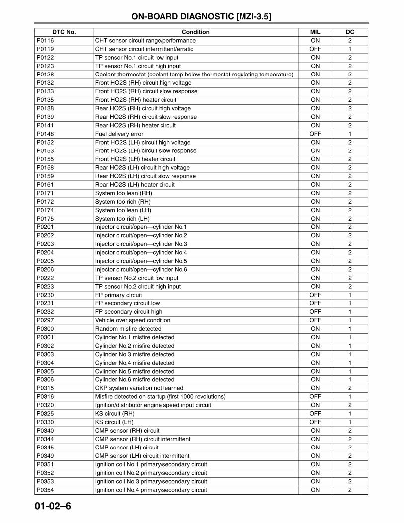
P0116 CHT sensor circuit range/performance ON 2P0119 CHT sensor circuit intermittent/erratic OFF 1P0122 TP sensor No.1 circuit low input ON 2P0123 TP sensor No.1 circuit high input ON 2P0128 Coolant thermostat (coolant temp below thermostat regulating temperature) ON 2P0132 Front HO2S (RH) circuit high voltage ON 2P0133 Front HO2S (RH) circuit slow response ON 2P0135 Front HO2S (RH) heater circuit ON 2P0138 Rear HO2S (RH) circuit high voltage ON 2P0139 Rear HO2S (RH) circuit slow response ON 2P0141 Rear HO2S (RH) heater circuit ON 2P0148 Fuel delivery error OFF 1P0152 Front HO2S (LH) circuit high voltage ON 2P0153 Front HO2S (LH) circuit slow response ON 2P0155 Front HO2S (LH) heater circuit ON 2P0158 Rear HO2S (LH) circuit high voltage ON 2P0159 Rear HO2S (LH) circuit slow response ON 2P0161 Rear HO2S (LH) heater circuit ON 2P0171 System too lean (RH) ON 2P0172 System too rich (RH) ON 2P0174 System too lean (LH) ON 2P0175 System too rich (LH) ON 2P0201 Injector circuit/open—cylinder No.1 ON 2P0202 Injector circuit/open—cylinder No.2 ON 2P0203 Injector circuit/open—cylinder No.3 ON 2P0204 Injector circuit/open—cylinder No.4 ON 2P0205 Injector circuit/open—cylinder No.5 ON 2P0206 Injector circuit/open—cylinder No.6 ON 2P0222 TP sensor No.2 circuit low input ON 2P0223 TP sensor No.2 circuit high input ON 2P0230 FP primary circuit OFF 1P0231 FP secondary circuit low OFF 1P0232 FP secondary circuit high OFF 1P0297 Vehicle over speed condition OFF 1P0300 Random misfire detected ON 1P0301 Cylinder No.1 misfire detected ON 1P0302 Cylinder No.2 misfire detected ON 1P0303 Cylinder No.3 misfire detected ON 1P0304 Cylinder No.4 misfire detected ON 1P0305 Cylinder No.5 misfire detected ON 1P0306 Cylinder No.6 misfire detected ON 1P0315 CKP system variation not learned ON 2P0316 Misfire detected on startup (first 1000 revolutions) OFF 1P0320 Ignition/distributor engine speed input circuit ON 2P0325 KS circuit (RH) OFF 1P0330 KS circuit (LH) OFF 1P0340 CMP sensor (RH) circuit ON 2P0344 CMP sensor (RH) circuit intermittent ON 2P0345 CMP sensor (LH) circuit ON 2P0349 CMP sensor (LH) circuit intermittent ON 2P0351 Ignition coil No.1 primary/secondary circuit ON 2P0352 Ignition coil No.2 primary/secondary circuit ON 2P0353 Ignition coil No.3 primary/secondary circuit ON 2P0354 Ignition coil No.4 primary/secondary circuit ON 2
DTC No. Condition MIL DC
3423-1U-06H(01-02).fm 6 ページ 2006年11月29日 水曜日 午前9時15分
ON-BOARD DIAGNOSTIC [MZI-3.5]
01-02–7
01-02
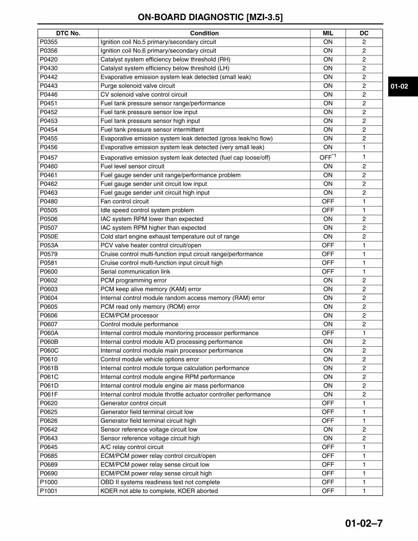
P0355 Ignition coil No.5 primary/secondary circuit ON 2P0356 Ignition coil No.6 primary/secondary circuit ON 2P0420 Catalyst system efficiency below threshold (RH) ON 2P0430 Catalyst system efficiency below threshold (LH) ON 2P0442 Evaporative emission system leak detected (small leak) ON 2P0443 Purge solenoid valve circuit ON 2P0446 CV solenoid valve control circuit ON 2P0451 Fuel tank pressure sensor range/performance ON 2P0452 Fuel tank pressure sensor low input ON 2P0453 Fuel tank pressure sensor high input ON 2P0454 Fuel tank pressure sensor intermittent ON 2P0455 Evaporative emission system leak detected (gross leak/no flow) ON 2P0456 Evaporative emission system leak detected (very small leak) ON 1
P0457 Evaporative emission system leak detected (fuel cap loose/off) OFF*1 1
P0460 Fuel level sensor circuit ON 2P0461 Fuel gauge sender unit range/performance problem ON 2P0462 Fuel gauge sender unit circuit low input ON 2P0463 Fuel gauge sender unit circuit high input ON 2P0480 Fan control circuit OFF 1P0505 Idle speed control system problem OFF 1P0506 IAC system RPM lower than expected ON 2P0507 IAC system RPM higher than expected ON 2P050E Cold start engine exhaust temperature out of range ON 2P053A PCV valve heater control circuit/open OFF 1P0579 Cruise control multi-function input circuit range/performance OFF 1P0581 Cruise control multi-function input circuit high OFF 1P0600 Serial communication link OFF 1P0602 PCM programming error ON 2P0603 PCM keep alive memory (KAM) error ON 2P0604 Internal control module random access memory (RAM) error ON 2P0605 PCM read only memory (ROM) error ON 2P0606 ECM/PCM processor ON 2P0607 Control module performance ON 2P060A Internal control module monitoring processor performance OFF 1P060B Internal control module A/D processing performance ON 2P060C Internal control module main processor performance ON 2P0610 Control module vehicle options error ON 2P061B Internal control module torque calculation performance ON 2P061C Internal control module engine RPM performance ON 2P061D Internal control module engine air mass performance ON 2P061F Internal control module throttle actuator controller performance ON 2P0620 Generator control circuit OFF 1P0625 Generator field terminal circuit low OFF 1P0626 Generator field terminal circuit high OFF 1P0642 Sensor reference voltage circuit low ON 2P0643 Sensor reference voltage circuit high ON 2P0645 A/C relay control circuit OFF 1P0685 ECM/PCM power relay control circuit/open OFF 1P0689 ECM/PCM power relay sense circuit low OFF 1P0690 ECM/PCM power relay sense circuit high OFF 1P1000 OBD II systems readiness test not complete OFF 1P1001 KOER not able to complete, KOER aborted OFF 1
DTC No. Condition MIL DC
3423-1U-06H(01-02).fm 7 ページ 2006年12月7日 木曜日 午前9時57分
ON-BOARD DIAGNOSTIC [MZI-3.5]
01-02–8
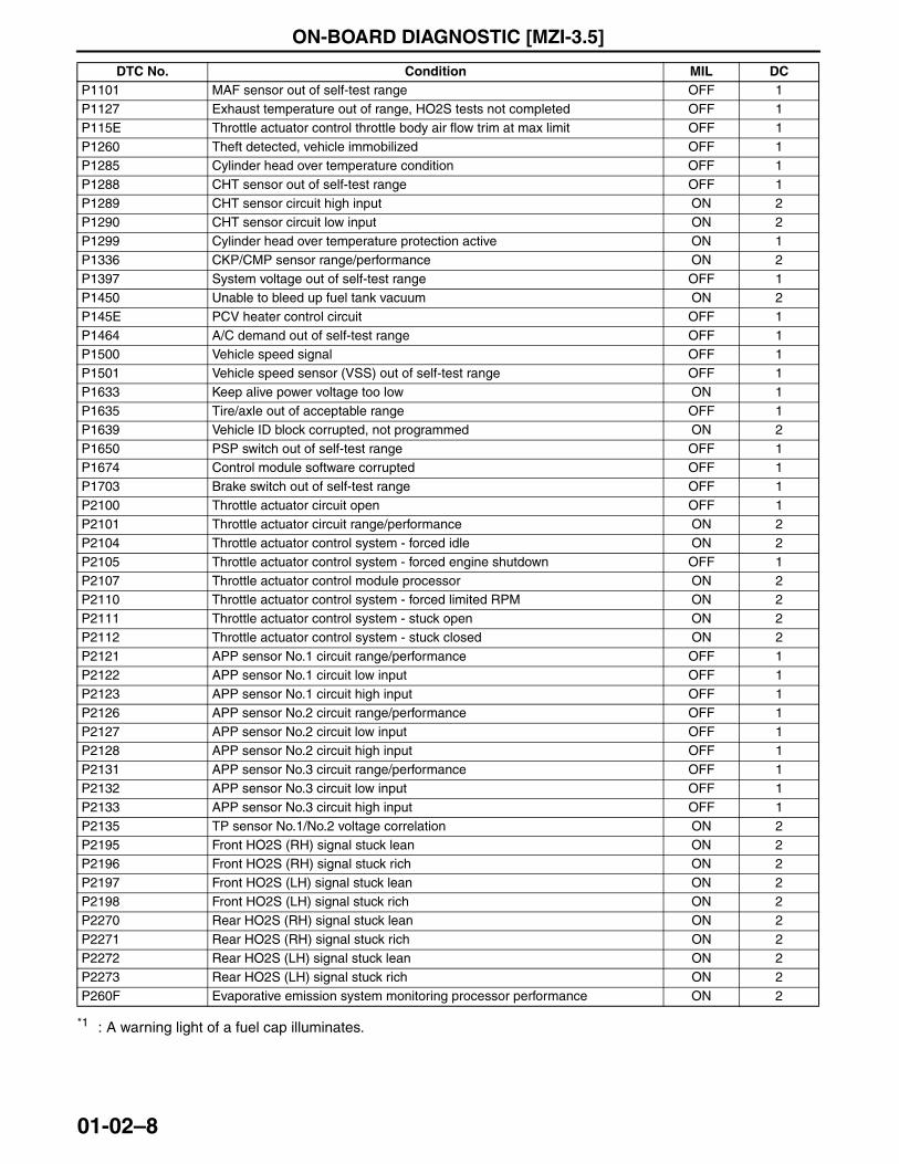
*1 : A warning light of a fuel cap illuminates.
P1101 MAF sensor out of self-test range OFF 1P1127 Exhaust temperature out of range, HO2S tests not completed OFF 1P115E Throttle actuator control throttle body air flow trim at max limit OFF 1P1260 Theft detected, vehicle immobilized OFF 1P1285 Cylinder head over temperature condition OFF 1P1288 CHT sensor out of self-test range OFF 1P1289 CHT sensor circuit high input ON 2P1290 CHT sensor circuit low input ON 2P1299 Cylinder head over temperature protection active ON 1P1336 CKP/CMP sensor range/performance ON 2P1397 System voltage out of self-test range OFF 1P1450 Unable to bleed up fuel tank vacuum ON 2P145E PCV heater control circuit OFF 1P1464 A/C demand out of self-test range OFF 1P1500 Vehicle speed signal OFF 1P1501 Vehicle speed sensor (VSS) out of self-test range OFF 1P1633 Keep alive power voltage too low ON 1P1635 Tire/axle out of acceptable range OFF 1P1639 Vehicle ID block corrupted, not programmed ON 2P1650 PSP switch out of self-test range OFF 1P1674 Control module software corrupted OFF 1P1703 Brake switch out of self-test range OFF 1P2100 Throttle actuator circuit open OFF 1P2101 Throttle actuator circuit range/performance ON 2P2104 Throttle actuator control system - forced idle ON 2P2105 Throttle actuator control system - forced engine shutdown OFF 1P2107 Throttle actuator control module processor ON 2P2110 Throttle actuator control system - forced limited RPM ON 2P2111 Throttle actuator control system - stuck open ON 2P2112 Throttle actuator control system - stuck closed ON 2P2121 APP sensor No.1 circuit range/performance OFF 1P2122 APP sensor No.1 circuit low input OFF 1P2123 APP sensor No.1 circuit high input OFF 1P2126 APP sensor No.2 circuit range/performance OFF 1P2127 APP sensor No.2 circuit low input OFF 1P2128 APP sensor No.2 circuit high input OFF 1P2131 APP sensor No.3 circuit range/performance OFF 1P2132 APP sensor No.3 circuit low input OFF 1P2133 APP sensor No.3 circuit high input OFF 1P2135 TP sensor No.1/No.2 voltage correlation ON 2P2195 Front HO2S (RH) signal stuck lean ON 2P2196 Front HO2S (RH) signal stuck rich ON 2P2197 Front HO2S (LH) signal stuck lean ON 2P2198 Front HO2S (LH) signal stuck rich ON 2P2270 Rear HO2S (RH) signal stuck lean ON 2P2271 Rear HO2S (RH) signal stuck rich ON 2P2272 Rear HO2S (LH) signal stuck lean ON 2P2273 Rear HO2S (LH) signal stuck rich ON 2P260F Evaporative emission system monitoring processor performance ON 2
DTC No. Condition MIL DC
3423-1U-06H(01-02).fm 8 ページ 2006年11月29日 水曜日 午前9時15分
ON-BOARD DIAGNOSTIC [MZI-3.5]
01-02–9
01-02
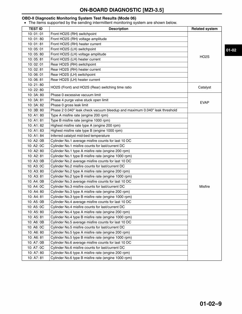
OBD-II Diagnostic Monitoring System Test Results (Mode 06)• The items supported by the sending intermittent monitoring system are shown below.
End Of Sie
TEST ID Description Related system10: 01: 01 Front HO2S (RH) switchpoint
HO2S
10: 01: 80 Front HO2S (RH) voltage amplitude10: 01: 81 Front HO2S (RH) heater current10: 05: 01 Front HO2S (LH) switchpoint10: 05: 80 Front HO2S (LH) voltage amplitude10: 05: 81 Front HO2S (LH) heater current10: 02: 01 Rear HO2S (RH) switchpoint10: 02: 81 Rear HO2S (RH) heater current10: 06: 01 Rear HO2S (LH) switchpoint10: 06: 81 Rear HO2S (LH) heater current10: 21: 80
HO2S (Front) and HO2S (Rear) switching time ratio Catalyst10: 22: 8010: 3A: 80 Phase 0 excessive vacuum limit
EVAP10: 3A: 81 Phase 4 purge valve stuck open limit10: 3A: 82 Phase 0 gross leak limit10: 3B: 80 Phase 2 0.040" leak check vacuum bleedup and maximum 0.040" leak threshold10: A1: 80 Type A misfire rate (engine 200 rpm)
Misfire
10: A1: 81 Type B misfire rate (engine 1000 rpm)10: A1: 82 Highest misfire rate type A (engine 200 rpm)10: A1: 83 Highest misfire rate type B (engine 1000 rpm)10: A1: 84 Inferred catalyst mid-bed temperature10: A2: 0B Cylinder No.1 average misfire counts for last 10 DC10: A2: 0C Cylinder No.1 misfire counts for last/current DC10: A2: 80 Cylinder No.1 type A misfire rate (engine 200 rpm)10: A2: 81 Cylinder No.1 type B misfire rate (engine 1000 rpm)10: A3: 0B Cylinder No.2 average misfire counts for last 10 DC10: A3: 0C Cylinder No.2 misfire counts for last/current DC10: A3: 80 Cylinder No.2 type A misfire rate (engine 200 rpm)10: A3: 81 Cylinder No.2 type B misfire rate (engine 1000 rpm)10: A4: 0B Cylinder No.3 average misfire counts for last 10 DC10: A4: 0C Cylinder No.3 misfire counts for last/current DC10: A4: 80 Cylinder No.3 type A misfire rate (engine 200 rpm)10: A4: 81 Cylinder No.3 type B misfire rate (engine 1000 rpm)10: A5: 0B Cylinder No.4 average misfire counts for last 10 DC10: A5: 0C Cylinder No.4 misfire counts for last/current DC10: A5: 80 Cylinder No.4 type A misfire rate (engine 200 rpm)10: A5: 81 Cylinder No.4 type B misfire rate (engine 1000 rpm)10: A6: 0B Cylinder No.5 average misfire counts for last 10 DC10: A6: 0C Cylinder No.5 misfire counts for last/current DC10: A6: 80 Cylinder No.5 type A misfire rate (engine 200 rpm)10: A6: 81 Cylinder No.5 type B misfire rate (engine 1000 rpm)10: A7: 0B Cylinder No.6 average misfire counts for last 10 DC10: A7: 0C Cylinder No.6 misfire counts for last/current DC10: A7: 80 Cylinder No.6 type A misfire rate (engine 200 rpm)10: A7: 81 Cylinder No.6 type B misfire rate (engine 1000 rpm)
3423-1U-06H(01-02).fm 9 ページ 2006年11月29日 水曜日 午前9時15分
ON-BOARD DIAGNOSTIC [MZI-3.5]
01-02–10
ON-BOARD DIAGNOSTIC SYSTEM MALFUNCTION DETECTION FUNCTION[MZI-3.5]id0102d1141900
Features• If any malfunction develops in the engine control system, the PCM stores that malfunction as a DTC. Stored
DTCs can be read-out using the Mazda Modular Diagnostic System (M-MDS).• The malfunction detection function includes malfunction diagnosis and self-test functions.
Malfunction Diagnosis Function• This function detects malfunctions that develop in the engine control system.• When the malfunction conditions are consistent with the malfunction determination conditions preset in the
PCM, the PCM determines that an engine control system malfunction has occurred and stores the corresponding DTC (s).
Comprehensive Component Monitor• The Comprehensive Component Monitor (CCM) monitors for malfunctions in any powertrain electronic
component or circuit that provides input or output signals to the PCM that can effect emissions and is not monitored by another system monitor. Inputs and outputs are, at a minimum, monitored for circuit continuity or specified range of values. Where feasible, inputs are also inspected for rationality, and outputs are inspected for proper functionality.
• CCM covers many components and circuits, and tests them in various ways depending on the hardware, function, and type of signal. For example, analog inputs such as throttle position or engine coolant temperature are typically inspected continuously for opens, shorts, and unspecified values. Some digital inputs such as brake switch on rationality inspection; inspecting if the input value makes sense at the current engine operating conditions. These types of tests require monitoring several components and can only be performed under appropriate test conditions.
• Outputs such as coil drivers are checked for open and short circuits by monitoring a feedback circuit or “dedicated IC chip” associated with the output. Other outputs such as relays, require additional feedback circuits to monitor the secondary side of the relay. Some outputs are also monitored for correct function by observing the reaction of the control system to a given change in the output command. Some tests can only be carried out under appropriate test conditions.
• The following is an example of some of the input and output components monitored by the CCM for OBD. The monitored components belong to a PCM supported subsystem.Inputs— Includes: CHT sensor, IAT sensor, MAF sensor, TP sensor, CKP sensor, CMP sensor, Fuel tank pressure
sensor, refrigerant pressure switch (medium pressure)Outputs— Includes: Fuel pump, A/C relay, purge solenoid valve, CV solenoid valve, OCV
• The CCM is activated after the engine is started and is operating. A DTC is stored in the PCM memory and the MIL is illuminated if a malfunction is detected for two consecutive drive cycles. Many of the CCM monitor items are also performed during self-test.
Fuel System Monitor• The fuel system monitor is an on-board function designed to monitor correction values for fuel injection control.
The fuel control system uses fuel injection learning correction values stored in the PCM to compensate for deviations in fuel system components due to normal wear and aging. During fuel system feedback control, fuel injection control learns the corrections required to correct a “biased” rich or lean fuel system. These corrections are stored as fuel feedback correction coefficients. Fuel injection control has two correction methods: Long term and short term fuel corrections. Long term fuel correction uses the learning correction coefficient and short term fuel correction uses the fuel feedback correction coefficient. Inputs from the CHT, IAT, and MAF sensors are required to activate fuel injection control and perform fuel system monitor. Once activated, the fuel system monitor inspects if the fuel feedback and fuel learning correction coefficients exceed a specified limit. When a malfunction is detected as described below, the fuel system monitor stores a corresponding DTC.— The HO2S detects the presence of oxygen in the exhaust gas and provides the PCM with feedback
indicating the air/fuel ratio.— A correction factor is added to the fuel injector pulse width calculation according to the long and short term
fuel corrections as needed to compensate for deviations in the fuel system.— As the deviation from the stoichiometric air/fuel ratio becomes larger, air/fuel ratio control suffers and
uncombusted gas in the exhaust increase. If the stoichiometric air/fuel ratio exceeds the specified limit and the fuel correction coefficient approaches the specified limit, the fuel system monitor stores DTCs as follows:• DTCs P0171 and P0174: Detection of a lean shift in fuel system operation• DTCs P0172 and P0175: Detection of a rich shift in fuel system operation
• The MIL is illuminated if a malfunction is detected during two consecutive drive cycles.
3423-1U-06H(01-02).fm 10 ページ 2006年11月29日 水曜日 午前9時15分
ON-BOARD DIAGNOSTIC [MZI-3.5]
01-02–11
01-02
HO2S Monitor• The HO2S monitor is an on-board diagnostic function designed to monitor the HO2S for malfunctions or
deterioration that can affect emissions. The HO2S used for fuel injector control is monitored for proper output voltage. Inputs from the CHT, IAT, MAF and CKP sensors are required for HO2S monitor operation. The fuel system and misfire detection monitors must also have been performed successfully before the HO2S monitor is activated.— The HO2S detects the oxygen content in the exhaust gas and outputs voltage between 0—1.0 V. If the air
fuel ratio is leaner than the stoichiometric air/fuel ratio (14.7: 1), the HO2S generates 0—0.45 V. If the air fuel ratio is richer than the stoichiometric air/fuel ratio (14.7: 1), the HO2S generates 0.45—1.0 V. The HO2S monitor evaluates the HO2S for proper operation.
— The time between HO2S switches is monitored after the engine is started and during fuel system feedback conditions. Excessive time between switches or no switches since engine startup indicates a concern. Since a lack of switching can be caused by HO2S concerns or by shifts in the fuel system, DTCs are stored that provide additional information for this concern. Different DTCs indicate whether the sensor always indicates lean/disconnected (P2195 or P2197), or always indicates rich (P2196 or P2198). The HO2S signal is also monitored for high voltage, in excess of 1.1 V and stores a unique DTC (P0132 or P0152). An excess voltage condition is caused by a HO2S heater or battery power short to the HO2S signal line.
— A functional test of the rear HO2S is done during normal vehicle operation. The peak rich and lean voltages are continuously monitored. Voltages that exceed the calibrated rich and lean thresholds indicate a functional sensor. If the voltages have not exceeded the thresholds after a long period of vehicle operation, the air/fuel ratio may be forced rich or lean in an attempt to get the rear sensor to switch. If the sensor does not exceed the rich and lean peak thresholds, a concern is indicated. The HO2S signal is also monitored for high voltage, in excess of 1.1 V and stores a unique DTC (P0138 or P0158). An excess voltage condition is caused by a HO2S heater or battery power short to the HO2S signal line.
— The HO2S monitor DTCs can be categorized as follows:• P0040, P0041: Property failure• P0133, P0139, P0153, P0159: Slow response rate• P0053, P0054, P059, P0060: Heater circuit malfunction• P1127: Rear HO2S not running in on-demand self-test• P2195, P2196, P2197, P2198: HO2S lack of switching• P2270, P2272: HO2S lack of switching (sensor indicates lean)• P2271, P2273: HO2S lack of switching (sensor indicates rich)
• The MIL is illuminated if a malfunction is detected during two consecutive drive cycles.
Misfire Detection Monitor• The misfire detection monitor is an on-board diagnostic function designed to detect engine misfire and identify
in which cylinder the misfire has occurred. Misfire is defined as lack of combustion in a cylinder due to absence of spark, poor fuel metering, poor compression, or any other cause. The misfire detection monitor will only be enable when certain base engine conditions are first satisfied. Inputs from the CHT, IAT, MAF and CKP sensors are required for the monitor to be performed. The misfire detection monitor is also activated during the self-test.— The PCM synchronizes the ignition timing with crankshaft rotation signal from the CKP sensor. The
crankshaft rotation signal is also the main signal used for determining which cylinder misfires.— The crankshaft rotation signal generated by the CKP sensor is derived from by sensing the passage of
teeth on the crankshaft position wheel mounted on the end of the crankshaft.— This signal is input to the PCM and then used to calculate the time between crankshaft rotation signals, and
also crankshaft rotation speed and acceleration. The power loss of each cylinder is determined by comparing the accelerations of each cylinder. When the power loss of a particular cylinder exceeds a specified value and other conditions are met, then that cylinder is determined to have misfired.Misfire type A• Upon detection of a serious misfire that could cause catalyst damage, the MIL flashes once per second
during the misfire and a DTC is stored.Misfire type B• Upon detection of a misfire that could exceed the emission limits or cause the vehicle to fail an
inspection and maintenance tailpipe emissions test, the MIL illuminates and a DTC is stored. DTC P0300 is stored in the case of a multiple cylinder misfire.
— DTCs P0301, P0302, P0303, P0304, P0305, and P0306 are stored in case of an individual type A or type B single cylinder misfire.
— DTC P0316 is stored if a type B threshold is exceeded during the first 1,000 revolutions after engine startup. This DTC is stored in addition to the normal P03xx DTC that indicates the misfiring cylinder.
3423-1U-06H(01-02).fm 11 ページ 2006年11月29日 水曜日 午前9時15分
ON-BOARD DIAGNOSTIC [MZI-3.5]
01-02–12
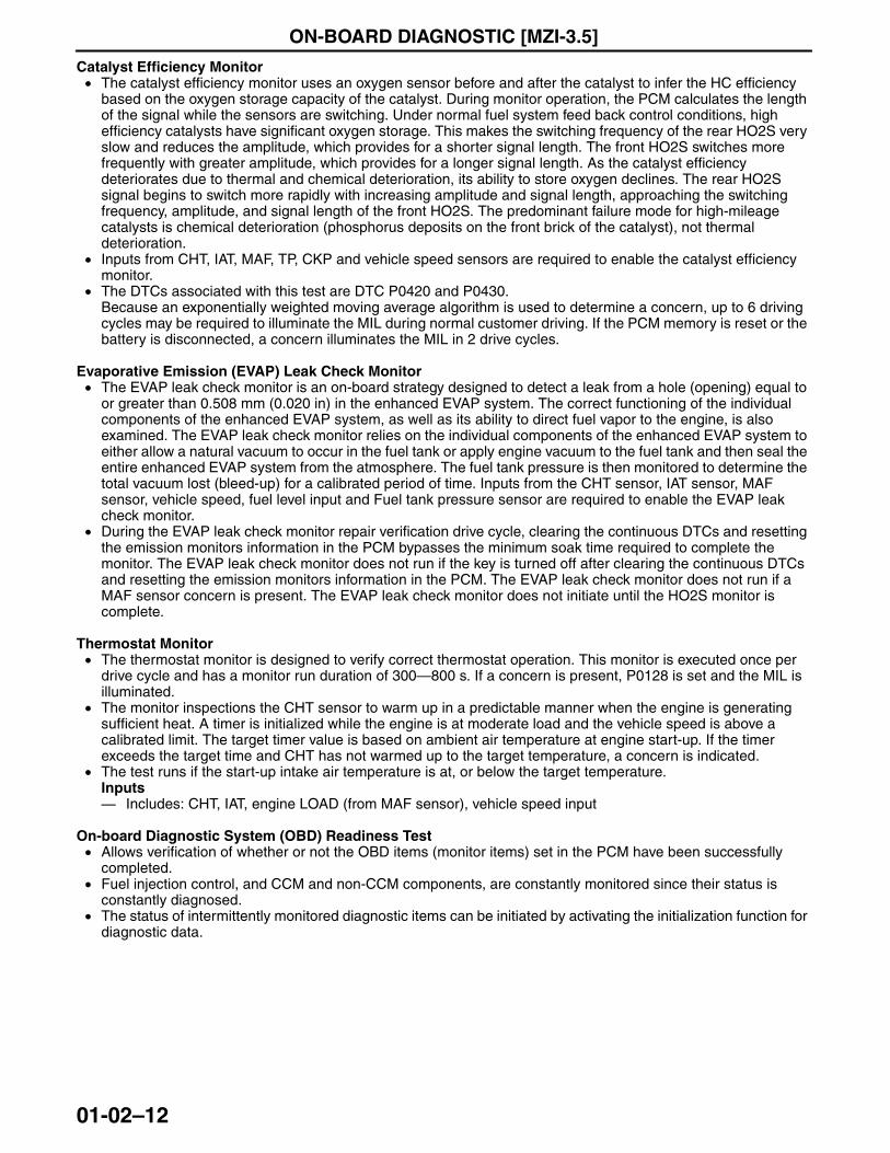
Catalyst Efficiency Monitor• The catalyst efficiency monitor uses an oxygen sensor before and after the catalyst to infer the HC efficiency
based on the oxygen storage capacity of the catalyst. During monitor operation, the PCM calculates the length of the signal while the sensors are switching. Under normal fuel system feed back control conditions, high efficiency catalysts have significant oxygen storage. This makes the switching frequency of the rear HO2S very slow and reduces the amplitude, which provides for a shorter signal length. The front HO2S switches more frequently with greater amplitude, which provides for a longer signal length. As the catalyst efficiency deteriorates due to thermal and chemical deterioration, its ability to store oxygen declines. The rear HO2S signal begins to switch more rapidly with increasing amplitude and signal length, approaching the switching frequency, amplitude, and signal length of the front HO2S. The predominant failure mode for high-mileage catalysts is chemical deterioration (phosphorus deposits on the front brick of the catalyst), not thermal deterioration.
• Inputs from CHT, IAT, MAF, TP, CKP and vehicle speed sensors are required to enable the catalyst efficiency monitor.
• The DTCs associated with this test are DTC P0420 and P0430.Because an exponentially weighted moving average algorithm is used to determine a concern, up to 6 driving cycles may be required to illuminate the MIL during normal customer driving. If the PCM memory is reset or the battery is disconnected, a concern illuminates the MIL in 2 drive cycles.
Evaporative Emission (EVAP) Leak Check Monitor• The EVAP leak check monitor is an on-board strategy designed to detect a leak from a hole (opening) equal to
or greater than 0.508 mm (0.020 in) in the enhanced EVAP system. The correct functioning of the individual components of the enhanced EVAP system, as well as its ability to direct fuel vapor to the engine, is also examined. The EVAP leak check monitor relies on the individual components of the enhanced EVAP system to either allow a natural vacuum to occur in the fuel tank or apply engine vacuum to the fuel tank and then seal the entire enhanced EVAP system from the atmosphere. The fuel tank pressure is then monitored to determine the total vacuum lost (bleed-up) for a calibrated period of time. Inputs from the CHT sensor, IAT sensor, MAF sensor, vehicle speed, fuel level input and Fuel tank pressure sensor are required to enable the EVAP leak check monitor.
• During the EVAP leak check monitor repair verification drive cycle, clearing the continuous DTCs and resetting the emission monitors information in the PCM bypasses the minimum soak time required to complete the monitor. The EVAP leak check monitor does not run if the key is turned off after clearing the continuous DTCs and resetting the emission monitors information in the PCM. The EVAP leak check monitor does not run if a MAF sensor concern is present. The EVAP leak check monitor does not initiate until the HO2S monitor is complete.
Thermostat Monitor• The thermostat monitor is designed to verify correct thermostat operation. This monitor is executed once per
drive cycle and has a monitor run duration of 300—800 s. If a concern is present, P0128 is set and the MIL is illuminated.
• The monitor inspections the CHT sensor to warm up in a predictable manner when the engine is generating sufficient heat. A timer is initialized while the engine is at moderate load and the vehicle speed is above a calibrated limit. The target timer value is based on ambient air temperature at engine start-up. If the timer exceeds the target time and CHT has not warmed up to the target temperature, a concern is indicated.
• The test runs if the start-up intake air temperature is at, or below the target temperature.Inputs— Includes: CHT, IAT, engine LOAD (from MAF sensor), vehicle speed input
On-board Diagnostic System (OBD) Readiness Test• Allows verification of whether or not the OBD items (monitor items) set in the PCM have been successfully
completed.• Fuel injection control, and CCM and non-CCM components, are constantly monitored since their status is
constantly diagnosed.• The status of intermittently monitored diagnostic items can be initiated by activating the initialization function for
diagnostic data.
3423-1U-06H(01-02).fm 12 ページ 2006年11月29日 水曜日 午前9時15分
ON-BOARD DIAGNOSTIC [MZI-3.5]
01-02–13
01-02
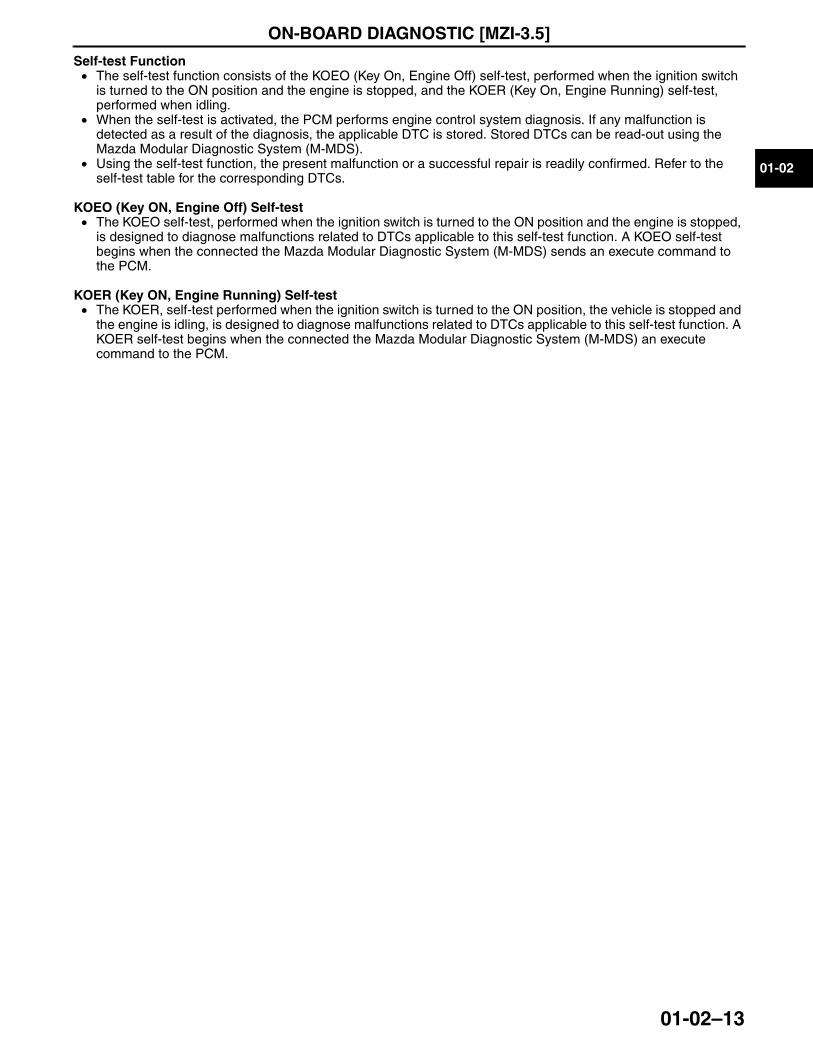
Self-test Function• The self-test function consists of the KOEO (Key On, Engine Off) self-test, performed when the ignition switch
is turned to the ON position and the engine is stopped, and the KOER (Key On, Engine Running) self-test, performed when idling.
• When the self-test is activated, the PCM performs engine control system diagnosis. If any malfunction is detected as a result of the diagnosis, the applicable DTC is stored. Stored DTCs can be read-out using the Mazda Modular Diagnostic System (M-MDS).
• Using the self-test function, the present malfunction or a successful repair is readily confirmed. Refer to the self-test table for the corresponding DTCs.
KOEO (Key ON, Engine Off) Self-test• The KOEO self-test, performed when the ignition switch is turned to the ON position and the engine is stopped,
is designed to diagnose malfunctions related to DTCs applicable to this self-test function. A KOEO self-test begins when the connected the Mazda Modular Diagnostic System (M-MDS) sends an execute command to the PCM.
KOER (Key ON, Engine Running) Self-test• The KOER, self-test performed when the ignition switch is turned to the ON position, the vehicle is stopped and
the engine is idling, is designed to diagnose malfunctions related to DTCs applicable to this self-test function. A KOER self-test begins when the connected the Mazda Modular Diagnostic System (M-MDS) an execute command to the PCM.
End Of Sie
3423-1U-06H(01-02).fm 13 ページ 2006年11月29日 水曜日 午前9時15分
ON-BOARD DIAGNOSTIC [MZI-3.5]
01-02–14
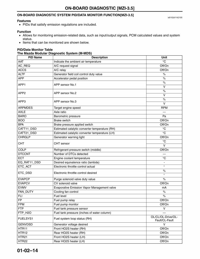
ON-BOARD DIAGNOSTIC SYSTEM PID/DATA MONITOR FUNCTION[MZI-3.5]id0102d1142100
Features• PIDs that satisfy emission regulations are included.
Function• Allows for monitoring emission-related data, such as input/output signals, PCM calculated values and system
status.• Items that can be monitored are shown below.
PID/Data Monitor TableThe Mazda Modular Diagnostic System (M-MDS)
PID Name Description UnitAAT Indicate the ambient air temperature °CAC_REQ A/C request signal Off/OnACCS A/C relay Off/OnALTF Generator field coil control duty value %APP Accelerator pedal position %
APP1 APP sensor No.1%V
APP2 APP sensor No.2%V
APP3 APP sensor No.3%V
ARPMDES Target engine speed RPMAXLE Axle ratio —BARO Barometric pressure PaBOO Brake switch Off/OnBPA Brake pressure applied switch Off/OnCATT11_DSD Estimated catalytic converter temperature (RH) °CCATT21_DSD Estimated catalytic converter temperature (LH) °CCHRGLP Generator warning light Off/On
CHT CHT sensor°CV
COLP Refrigerant pressure switch (middle) Off/OnDTCCNT Number of DTCs detected —ECT Engine coolant temperature °CEQ_RAT11_DSD Desired equivalence ratio (lambda) -ETC_ACT Electronic throttle control actual °
ETC_DSD Electronic throttle control desired%°
EVAPCP Purge solenoid valve duty value %EVAPCV CV solenoid valve Off/OnEVMV Evaporative Emission Vapor Management valve mAFAN_DUTY Cooling fan control %FLI Fuel level %FP Fuel pump relay Off/OnFPM Fuel pump monitor Off/OnFTP Fuel tank pressure sensor VFTP_H2O Fuel tank pressure (inches of water column) —
FUELSYS1 Fuel system loop status (RH) OL/CL/OL-Drive/OL-Fault/CL-Fault
GENVDSD Generator voltage desired VHTR11 Front HO2S heater (RH) Off/OnHTR12 Rear HO2S heater (RH) Off/OnHTR21 Front HO2S heater (LH) Off/OnHTR22 Rear HO2S heater (LH) Off/On
3423-1U-06H(01-02).fm 14 ページ 2006年11月29日 水曜日 午前9時15分
ON-BOARD DIAGNOSTIC [MZI-3.5]
01-02–15
01-02
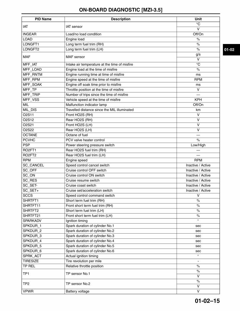
IAT IAT sensor°CV
INGEAR Load/no load condition Off/OnLOAD Engine load %LONGFT1 Long term fuel trim (RH) %LONGFT2 Long term fuel trim (LH) %
MAF MAF sensorg/sV
MFF_IAT Intake air temperature at the time of misfire °CMFF_LOAD Engine load at the time of misfire %MFF_RNTM Engine running time at time of misfire msMFF_RPM Engine speed at the time of misfire RPMMFF_SOAK Engine off soak time prior to misfire msMFF_TP Throttle position at the time of misfire VMFF_TRIP Number of trips since the time of misfire —MFF_VSS Vehicle speed at the time of misfire KPHMIL Malfunction indicator lamp Off/OnMIL_DIS Travelled distance since the MIL illuminated kmO2S11 Front HO2S (RH) VO2S12 Rear HO2S (RH) VO2S21 Front HO2S (LH) VO2S22 Rear HO2S (LH) VOCTANE Octane of fuel —PCVHC PCV valve heater control %PSP Power steering pressure switch Low/HighRO2FT1 Rear HO2S fuel trim (RH) —RO2FT2 Rear HO2S fuel trim (LH) —RPM Engine speed RPMSC_CANCEL Speed control cancel switch Inactive / ActiveSC_OFF Cruise control OFF switch Inactive / ActiveSC_ON Cruise control ON switch Inactive / ActiveSC_RES Cruise resume switch Inactive / ActiveSC_SET- Cruise coast switch Inactive / ActiveSC_SET+ Cruise set/acceleration switch Inactive / ActiveSCCS Speed control command switch VSHRTFT1 Short term fuel trim (RH) %SHRTFT11 Front short term fuel trim (RH) %SHRTFT2 Short term fuel trim (LH) %SHRTFT21 Front short term fuel trim (LH) %SPARKADV Ignition timing °SPKDUR_1 Spark duration of cylinder No.1 secSPKDUR_2 Spark duration of cylinder No.2 secSPKDUR_3 Spark duration of cylinder No.3 secSPKDUR_4 Spark duration of cylinder No.4 secSPKDUR_5 Spark duration of cylinder No.5 secSPKDUR_6 Spark duration of cylinder No.6 secSPRK_ACT Actual ignition timing °TIRESIZE Tire revolution per mile -TP REL Relative throttle position %
TP1 TP sensor No.1%V
TP2 TP sensor No.2%V
VPWR Battery voltage V
PID Name Description Unit
3423-1U-06H(01-02).fm 15 ページ 2006年11月29日 水曜日 午前9時15分
ON-BOARD DIAGNOSTIC [MZI-3.5]
01-02–16
End Of SieON-BOARD DIAGNOSTIC SYSTEM SIMULATION FUNCTION[MZI-3.5]
id0102d1142200
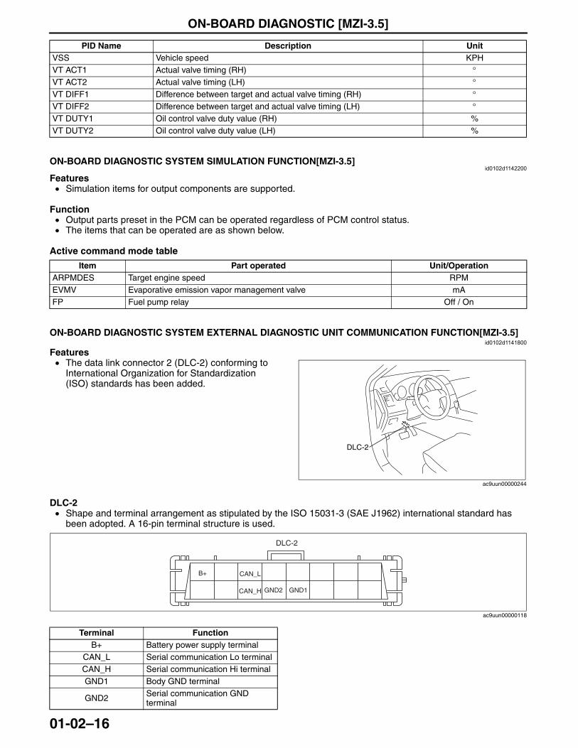
Features• Simulation items for output components are supported.
Function• Output parts preset in the PCM can be operated regardless of PCM control status.• The items that can be operated are as shown below.
Active command mode table
End Of SieON-BOARD DIAGNOSTIC SYSTEM EXTERNAL DIAGNOSTIC UNIT COMMUNICATION FUNCTION[MZI-3.5]
id0102d1141800
Features• The data link connector 2 (DLC-2) conforming to
International Organization for Standardization (ISO) standards has been added.
DLC-2• Shape and terminal arrangement as stipulated by the ISO 15031-3 (SAE J1962) international standard has
been adopted. A 16-pin terminal structure is used.
VSS Vehicle speed KPHVT ACT1 Actual valve timing (RH) °VT ACT2 Actual valve timing (LH) °VT DIFF1 Difference between target and actual valve timing (RH) °VT DIFF2 Difference between target and actual valve timing (LH) °VT DUTY1 Oil control valve duty value (RH) %VT DUTY2 Oil control valve duty value (LH) %
PID Name Description Unit
Item Part operated Unit/OperationARPMDES Target engine speed RPMEVMV Evaporative emission vapor management valve mAFP Fuel pump relay Off / On
DLC-2
ac9uun00000244
Terminal FunctionB+ Battery power supply terminal
CAN_L Serial communication Lo terminalCAN_H Serial communication Hi terminalGND1 Body GND terminal
GND2 Serial communication GND terminal
B+ CAN_L
GND1CAN_H GND2
DLC-2
ac9uun00000118
3423-1U-06H(01-02).fm 16 ページ 2006年11月29日 水曜日 午前9時15分
ON-BOARD DIAGNOSTIC [MZI-3.5]
01-02–17
01-02
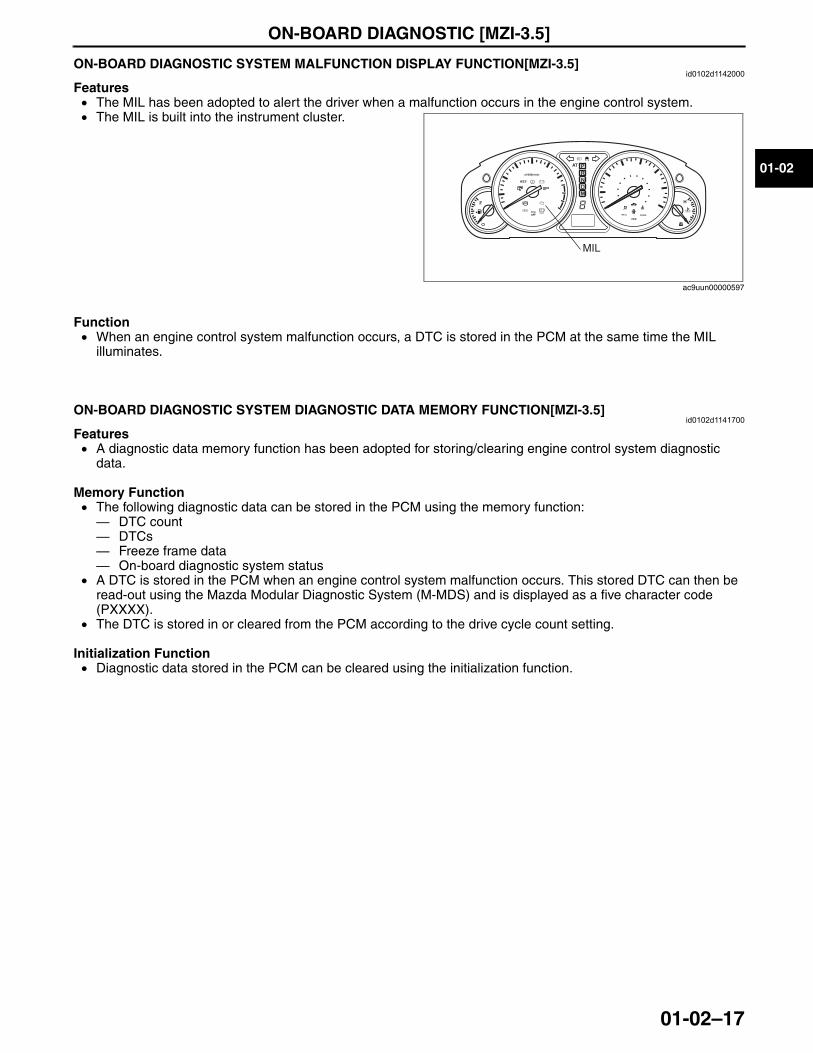
End Of SieON-BOARD DIAGNOSTIC SYSTEM MALFUNCTION DISPLAY FUNCTION[MZI-3.5]id0102d1142000
Features• The MIL has been adopted to alert the driver when a malfunction occurs in the engine control system.• The MIL is built into the instrument cluster.
Function• When an engine control system malfunction occurs, a DTC is stored in the PCM at the same time the MIL
illuminates.End Of Sie
ON-BOARD DIAGNOSTIC SYSTEM DIAGNOSTIC DATA MEMORY FUNCTION[MZI-3.5]id0102d1141700
Features• A diagnostic data memory function has been adopted for storing/clearing engine control system diagnostic
data.
Memory Function• The following diagnostic data can be stored in the PCM using the memory function:— DTC count— DTCs— Freeze frame data— On-board diagnostic system status
• A DTC is stored in the PCM when an engine control system malfunction occurs. This stored DTC can then be read-out using the Mazda Modular Diagnostic System (M-MDS) and is displayed as a five character code (PXXXX).
• The DTC is stored in or cleared from the PCM according to the drive cycle count setting.
Initialization Function• Diagnostic data stored in the PCM can be cleared using the initialization function.
End Of Sie
BRAKE
MIL
ac9uun00000597
3423-1U-06H(01-02).fm 17 ページ 2006年11月29日 水曜日 午前9時15分

MECHANICAL [MZI-3.5]
01-10–1
01-10
01-10 MECHANICAL [MZI-3.5]ENGINE STRUCTURAL VIEW
[MZI-3.5] . . . . . . . . . . . . . . . . . . . . . . . . 01-10–1CYLINDER HEAD COVER
CONSTRUCTION [MZI-3.5] . . . . . . . . . 01-10–2CYLINDER HEAD
CONSTRUCTION [MZI-3.5] . . . . . . . . . 01-10–2CYLINDER BLOCK
CONSTRUCTION [MZI-3.5] . . . . . . . . . 01-10–3CRANKSHAFT, MAIN BEARING
CONSTRUCTION [MZI-3.5] . . . . . . . . . 01-10–4CRANKSHAFT PULLEY
CONSTRUCTION [MZI-3.5] . . . . . . . . . 01-10–4PISTON CONSTRUCTION [MZI-3.5] . . . 01-10–5
Construction. . . . . . . . . . . . . . . . . . . . . 01-10–5CONNECTING ROD
CONSTRUCTION [MZI-3.5] . . . . . . . . . 01-10–5ENGINE FRONT COVER
CONSTRUCTION [MZI-3.5] . . . . . . . . . 01-10–6DRIVE BELT
CONSTRUCTION [MZI-3.5] . . . . . . . . . 01-10–7Generator and A/C Drive Belt . . . . . . . 01-10–7Power Steering Oil Pump
Drive Belt . . . . . . . . . . . . . . . . . . . . . . 01-10–7CAMSHAFT
CONSTRUCTION [MZI-3.5] . . . . . . . . . 01-10–8VALVE MECHANISM
OUTLINE [MZI-3.5] . . . . . . . . . . . . . . . . 01-10–8VALVE MECHANISM
STRUCTURAL VIEW [MZI-3.5]. . . . . . . 01-10–8
VALVE, VALVE SPRING, VALVE SEAL GUIDE CONSTRUCTION [MZI-3.5] . . . . . . . . . . 01-10–9
TAPPET CONSTRUCTION [MZI-3.5] . . . . . . . . . . . . . . . . . . . . . . . . . 01-10–9
VARIABLE VALVE TIMING MECHANISM OUTLINE [MZI-3.5]. . . . . . . . . . . . . . . . . 01-10–10
VARIABLE VALVE TIMING MECHANISM CONSTRUCTION/OPERATION [MZI-3.5] . . . . . . . . . . . . . . . . . . . . . . . . . 01-10–10
Construction . . . . . . . . . . . . . . . . . . . . . 01-10–10Hydraulic Pressure Flow Diagram. . . . . 01-10–11Component and Function . . . . . . . . . . . 01-10–11Operation . . . . . . . . . . . . . . . . . . . . . . . 01-10–11
VARIABLE VALVE TIMING ACTUATOR CONSTRUCTION [MZI-3.5] . . . . . . . . . . 01-10–12
OIL CONTROL VALVE (OCV) OPERATION [MZI-3.5] . . . . . . . . . . . . . . 01-10–12
TIMING CHAIN, CHAIN TENSIONER CONSTRUCTION [MZI-3.5] . . . . . . . . . . 01-10–13
Timing Chain . . . . . . . . . . . . . . . . . . . . . 01-10–13Camshaft Timing Chain. . . . . . . . . . . . . 01-10–14
ENGINE MOUNT OUTLINE [MZI-3.5]. . . . . . . . . . . . . . . . . 01-10–15
ENGINE MOUNT CONSTRUCTION [MZI-3.5] . . . . . . . . . . 01-10–16
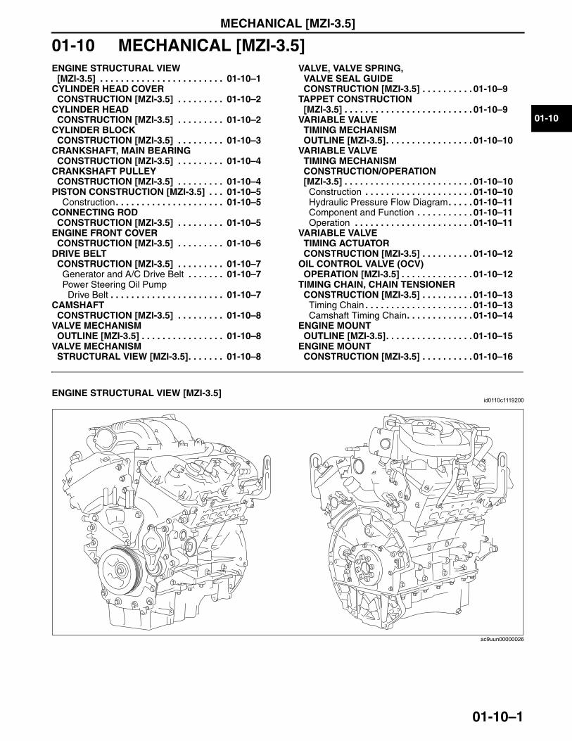
End of TocNG: ENGINE COMPLETEENGINE STRUCTURAL VIEW [MZI-3.5]
id0110c1119200
End Of SieNG: CYLINDER HEAD
ac9uun00000026
3423-1U-06H(01-10).fm 1 ページ 2006年11月22日 水曜日 午前9時23分
MECHANICAL [MZI-3.5]
01-10–2
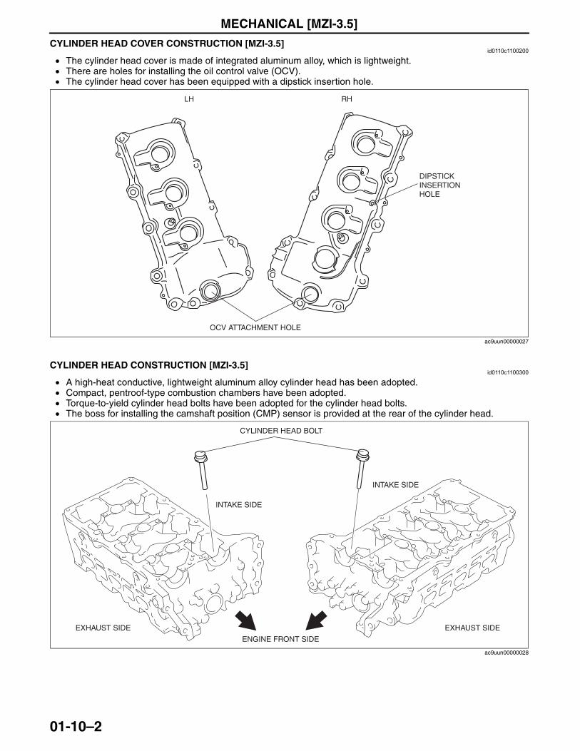
CYLINDER HEAD COVER CONSTRUCTION [MZI-3.5]id0110c1100200
• The cylinder head cover is made of integrated aluminum alloy, which is lightweight.• There are holes for installing the oil control valve (OCV).• The cylinder head cover has been equipped with a dipstick insertion hole.
End Of SieCYLINDER HEAD CONSTRUCTION [MZI-3.5]
id0110c1100300
• A high-heat conductive, lightweight aluminum alloy cylinder head has been adopted.• Compact, pentroof-type combustion chambers have been adopted.• Torque-to-yield cylinder head bolts have been adopted for the cylinder head bolts.• The boss for installing the camshaft position (CMP) sensor is provided at the rear of the cylinder head.
End Of SieNG: CYLINDER BLOCK
LH RH
DIPSTICK INSERTION HOLE
OCV ATTACHMENT HOLE
ac9uun00000027
CYLINDER HEAD BOLT
ENGINE FRONT SIDE
EXHAUST SIDE
INTAKE SIDE
EXHAUST SIDE
INTAKE SIDE
ac9uun00000028
3423-1U-06H(01-10).fm 2 ページ 2006年11月22日 水曜日 午前9時23分
MECHANICAL [MZI-3.5]
01-10–3
01-10
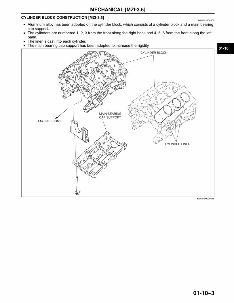
CYLINDER BLOCK CONSTRUCTION [MZI-3.5]id0110c1100500
• Aluminum alloy has been adopted on the cylinder block, which consists of a cylinder block and a main bearing cap support.
• The cylinders are numbered 1, 2, 3 from the front along the right bank and 4, 5, 6 from the front along the left bank.
• The liner is cast into each cylinder.• The main bearing cap support has been adopted to increase the rigidity.
End Of SieNG: CRANKSHAFT
1
2
3
4
5
6
CYLINDER BLOCK
CYLINDER LINER
MAIN BEARING CAP SUPPORT
ENGINE FRONT
ac9uun00000056
3423-1U-06H(01-10).fm 3 ページ 2006年11月22日 水曜日 午前9時23分
MECHANICAL [MZI-3.5]
01-10–4
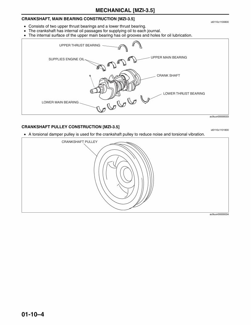
CRANKSHAFT, MAIN BEARING CONSTRUCTION [MZI-3.5]id0110c1100800
• Consists of two upper thrust bearings and a lower thrust bearing.• The crankshaft has internal oil passages for supplying oil to each journal.• The internal surface of the upper main bearing has oil grooves and holes for oil lubrication.
End Of SieNG: CRANKSHAFT PULLEYCRANKSHAFT PULLEY CONSTRUCTION [MZI-3.5]
id0110c1101800
• A torsional damper pulley is used for the crankshaft pulley to reduce noise and torsional vibration.
End Of SieNG: PISTON
SUPPLIES ENGINE OIL
UPPER THRUST BEARING
UPPER MAIN BEARING
LOWER MAIN BEARING
LOWER THRUST BEARING
CRANK SHAFT
ac9uun00000033
CRANKSHAFT PULLEY
ac9uun00000034
3423-1U-06H(01-10).fm 4 ページ 2006年11月22日 水曜日 午前9時23分
MECHANICAL [MZI-3.5]
01-10–5
01-10
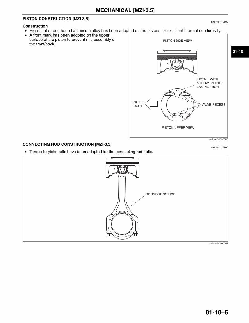
PISTON CONSTRUCTION [MZI-3.5]id0110c1119600
Construction• High-heat strengthened aluminum alloy has been adopted on the pistons for excellent thermal conductivity.• A front mark has been adopted on the upper
surface of the piston to prevent mis-assembly of the front/back.
End Of SieNG: CONNECTING ROD
CONNECTING ROD CONSTRUCTION [MZI-3.5]id0110c1119700
• Torque-to-yield bolts have been adopted for the connecting rod bolts.
End Of SieNG: ENGINE
PISTON SIDE VIEW
PISTON UPPER VIEW
ENGINEFRONT VALVE RECESS
INSTALL WITH ARROW FACING ENGINE FRONT
ac9uun00000050
CONNECTING ROD
ac9uun00000051
3423-1U-06H(01-10).fm 5 ページ 2006年11月22日 水曜日 午前9時23分
MECHANICAL [MZI-3.5]
01-10–6
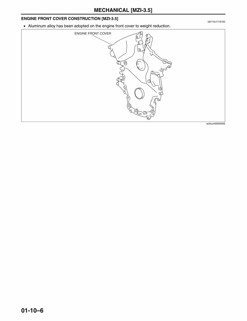
ENGINE FRONT COVER CONSTRUCTION [MZI-3.5]id0110c1119100
• Aluminum alloy has been adopted on the engine front cover to weight reduction.
End Of SieNG: DRIVE BELT
ENGINE FRONT COVER
ac9uun00000035
3423-1U-06H(01-10).fm 6 ページ 2006年11月22日 水曜日 午前9時23分
MECHANICAL [MZI-3.5]
01-10–7
01-10
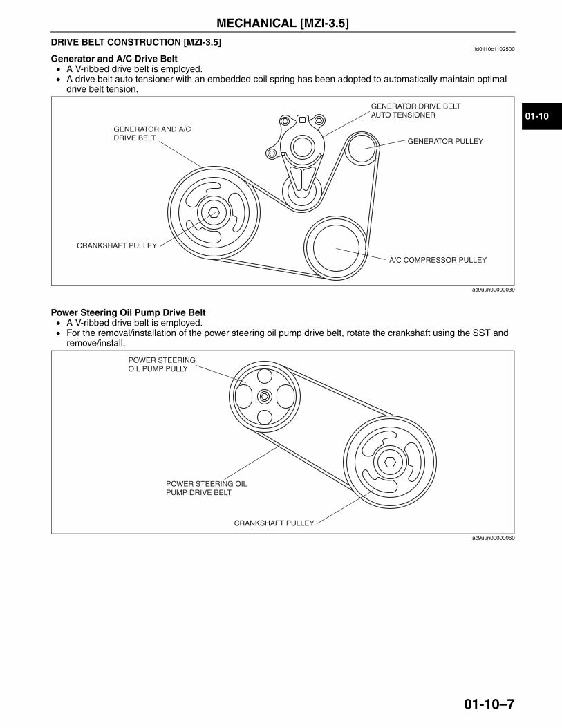
DRIVE BELT CONSTRUCTION [MZI-3.5]id0110c1102500
Generator and A/C Drive Belt• A V-ribbed drive belt is employed.• A drive belt auto tensioner with an embedded coil spring has been adopted to automatically maintain optimal
drive belt tension.
Power Steering Oil Pump Drive Belt• A V-ribbed drive belt is employed.• For the removal/installation of the power steering oil pump drive belt, rotate the crankshaft using the SST and
remove/install.
End Of SieNG: CAMSHAFT
GENERATOR AND A/C DRIVE BELT
CRANKSHAFT PULLEY
GENERATOR DRIVE BELT AUTO TENSIONER
GENERATOR PULLEY
A/C COMPRESSOR PULLEY
ac9uun00000039
POWER STEERING OIL PUMP PULLY
POWER STEERING OIL PUMP DRIVE BELT
CRANKSHAFT PULLEY
ac9uun00000060
3423-1U-06H(01-10).fm 7 ページ 2006年11月22日 水曜日 午前9時23分
MECHANICAL [MZI-3.5]
01-10–8
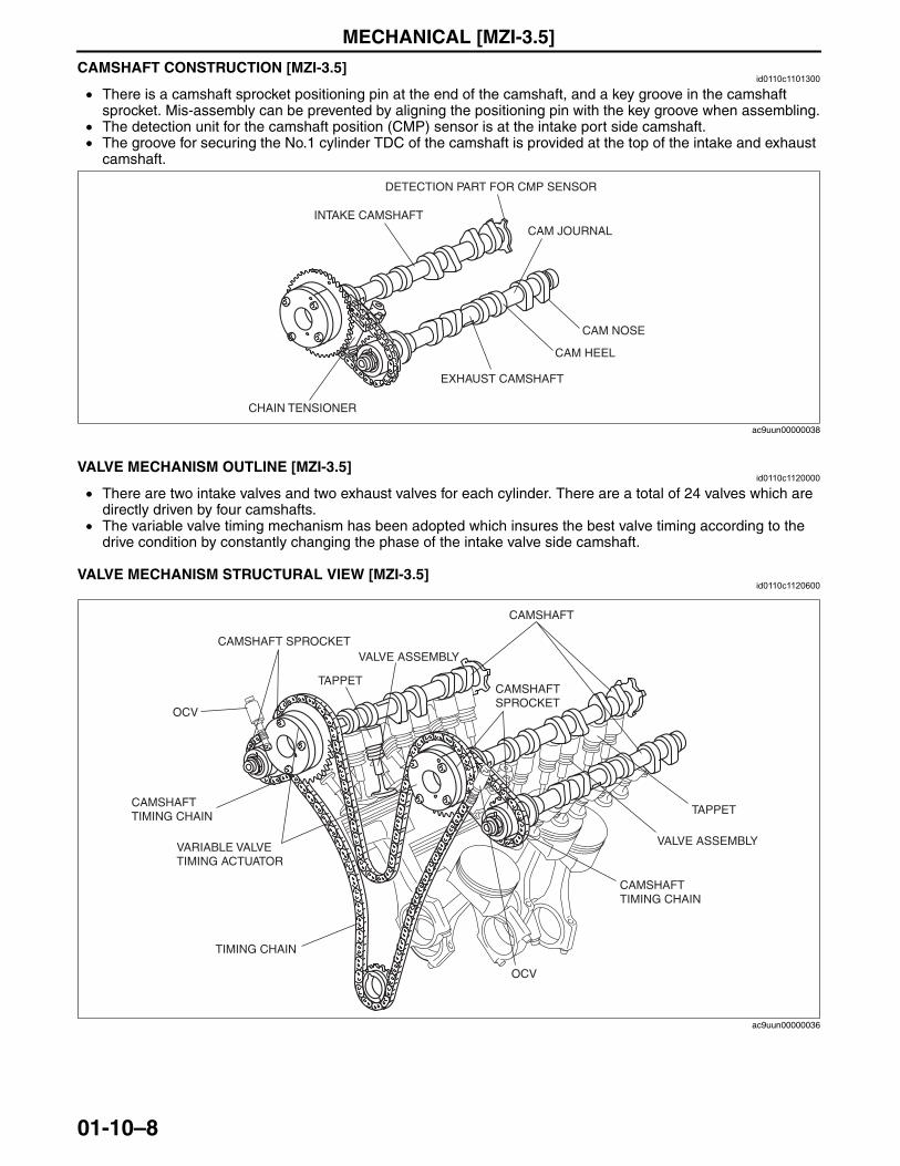
CAMSHAFT CONSTRUCTION [MZI-3.5]id0110c1101300
• There is a camshaft sprocket positioning pin at the end of the camshaft, and a key groove in the camshaft sprocket. Mis-assembly can be prevented by aligning the positioning pin with the key groove when assembling.
• The detection unit for the camshaft position (CMP) sensor is at the intake port side camshaft. • The groove for securing the No.1 cylinder TDC of the camshaft is provided at the top of the intake and exhaust
camshaft.
End Of SieNG: VALVEVALVE MECHANISM OUTLINE [MZI-3.5]
id0110c1120000
• There are two intake valves and two exhaust valves for each cylinder. There are a total of 24 valves which are directly driven by four camshafts.
• The variable valve timing mechanism has been adopted which insures the best valve timing according to the drive condition by constantly changing the phase of the intake valve side camshaft.
End Of SieVALVE MECHANISM STRUCTURAL VIEW [MZI-3.5]
id0110c1120600
End Of Sie
INTAKE CAMSHAFT
CHAIN TENSIONER
EXHAUST CAMSHAFT
DETECTION PART FOR CMP SENSOR
CAM HEEL
CAM NOSE
CAM JOURNAL
ac9uun00000038
CAMSHAFT
TIMING CHAIN
CAMSHAFT SPROCKET
CAMSHAFT SPROCKET
CAMSHAFT TIMING CHAIN
CAMSHAFT TIMING CHAIN
VALVE ASSEMBLY
TAPPET
OCV
VARIABLE VALVE TIMING ACTUATOR
VALVE ASSEMBLY
TAPPET
OCV
ac9uun00000036
3423-1U-06H(01-10).fm 8 ページ 2006年11月22日 水曜日 午前9時23分
MECHANICAL [MZI-3.5]
01-10–9
01-10
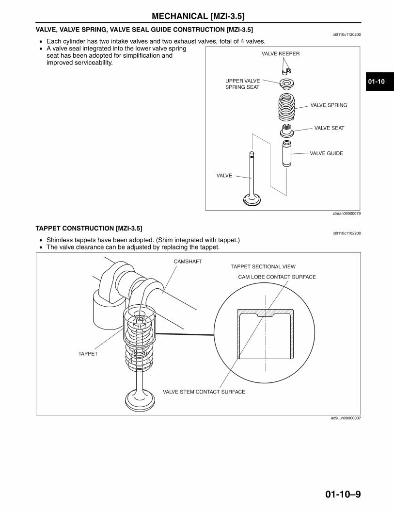
VALVE, VALVE SPRING, VALVE SEAL GUIDE CONSTRUCTION [MZI-3.5]id0110c1120200
• Each cylinder has two intake valves and two exhaust valves, total of 4 valves.• A valve seal integrated into the lower valve spring
seat has been adopted for simplification and improved serviceability.
End Of SieNG: TAPPET
TAPPET CONSTRUCTION [MZI-3.5]id0110c1102200
• Shimless tappets have been adopted. (Shim integrated with tappet.)• The valve clearance can be adjusted by replacing the tappet.
End Of SieNG: VALVE
VALVE KEEPER
UPPER VALVE SPRING SEAT
VALVE SPRING
VALVE SEAT
VALVE GUIDE
VALVE
atraan00000079
VALVE STEM CONTACT SURFACE
CAM LOBE CONTACT SURFACE
TAPPET SECTIONAL VIEWCAMSHAFT
TAPPET
ac9uun00000037
3423-1U-06H(01-10).fm 9 ページ 2006年11月22日 水曜日 午前9時23分
MECHANICAL [MZI-3.5]
01-10–10
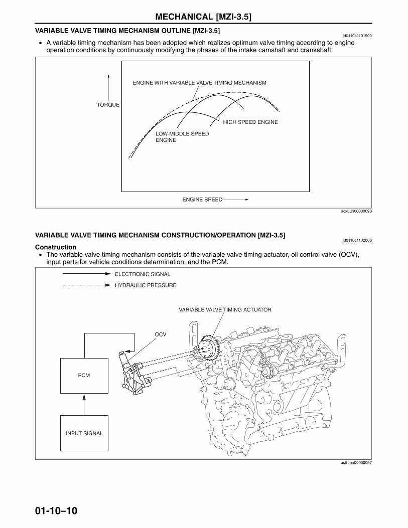
VARIABLE VALVE TIMING MECHANISM OUTLINE [MZI-3.5]id0110c1101900
• A variable timing mechanism has been adopted which realizes optimum valve timing according to engine operation conditions by continuously modifying the phases of the intake camshaft and crankshaft.
End Of Sie
VARIABLE VALVE TIMING MECHANISM CONSTRUCTION/OPERATION [MZI-3.5]id0110c1102000
Construction• The variable valve timing mechanism consists of the variable valve timing actuator, oil control valve (OCV),
input parts for vehicle conditions determination, and the PCM.
ENGINE SPEED
TORQUE
ENGINE WITH VARIABLE VALVE TIMING MECHANISM
HIGH SPEED ENGINE
LOW-MIDDLE SPEED ENGINE
acxuun00000093
OCV
VARIABLE VALVE TIMING ACTUATOR
HYDRAULIC PRESSURE
ELECTRONIC SIGNAL
INPUT SIGNAL
PCM
ac9uun00000057
3423-1U-06H(01-10).fm 10 ページ 2006年11月22日 水曜日 午前9時23分
MECHANICAL [MZI-3.5]
01-10–11
01-10
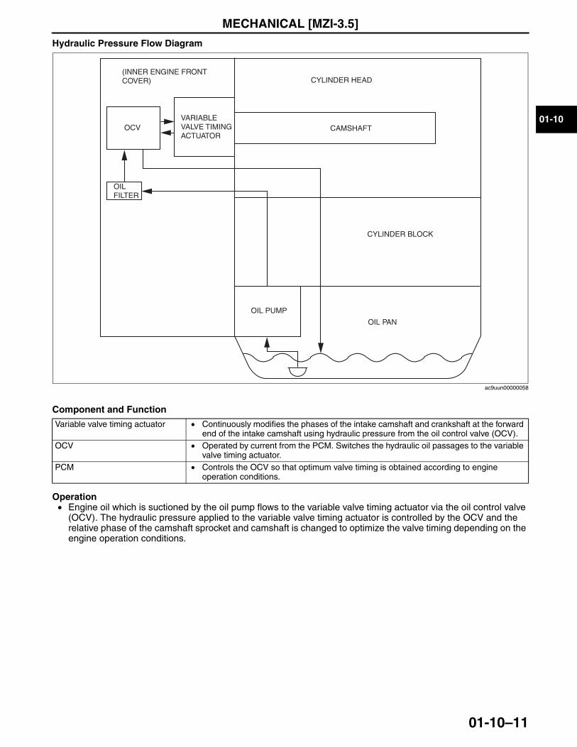
Hydraulic Pressure Flow Diagram
Component and Function
Operation• Engine oil which is suctioned by the oil pump flows to the variable valve timing actuator via the oil control valve
(OCV). The hydraulic pressure applied to the variable valve timing actuator is controlled by the OCV and the relative phase of the camshaft sprocket and camshaft is changed to optimize the valve timing depending on the engine operation conditions.
End Of SieNG: VARIABLE VALVE TIMING ACTUATOR
Variable valve timing actuator • Continuously modifies the phases of the intake camshaft and crankshaft at the forward end of the intake camshaft using hydraulic pressure from the oil control valve (OCV).
OCV • Operated by current from the PCM. Switches the hydraulic oil passages to the variable valve timing actuator.
PCM • Controls the OCV so that optimum valve timing is obtained according to engine operation conditions.
CYLINDER HEAD
CYLINDER BLOCK
OIL PUMP
OIL FILTER
OCVVARIABLE VALVE TIMING ACTUATOR
(INNER ENGINE FRONT COVER)
OIL PAN
CAMSHAFT
ac9uun00000058
3423-1U-06H(01-10).fm 11 ページ 2006年11月22日 水曜日 午前9時23分
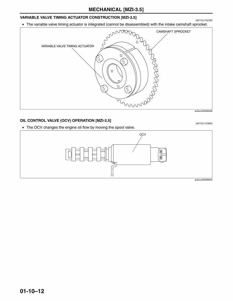
MECHANICAL [MZI-3.5]
01-10–12
VARIABLE VALVE TIMING ACTUATOR CONSTRUCTION [MZI-3.5]id0110c1102300
• The variable valve timing actuator is integrated (cannot be disassembled) with the intake camshaft sprocket.
End Of SieNG: OIL CONTROL VALVE (OCV)OIL CONTROL VALVE (OCV) OPERATION [MZI-3.5]
id0110c1103600
• The OCV changes the engine oil flow by moving the spool valve.
End Of SieNG: TIMING CHAIN
VARIABLE VALVE TIMING ACTUATOR
CAMSHAFT SPROCKET
ac9uun00000046
OCV
ac9uun00000045
3423-1U-06H(01-10).fm 12 ページ 2006年11月22日 水曜日 午前9時23分
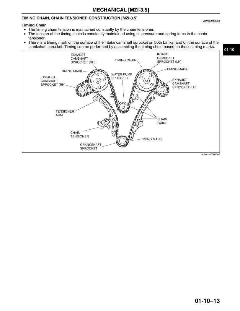
MECHANICAL [MZI-3.5]
01-10–13
01-10
TIMING CHAIN, CHAIN TENSIONER CONSTRUCTION [MZI-3.5]id0110c1101200
Timing Chain• The timing chain tension is maintained constantly by the chain tensioner.• The tension of the timing chain is constantly maintained using oil pressure and spring force in the chain
tensioner.• There is a timing mark on the surface of the intake camshaft sprocket on both banks, and on the surface of the
crankshaft sprocket. Timing can be performed by assembling the timing chain based on these timing marks.
EXHAUST CAMSHAFT SPROCKET (LH)
CHAIN GUIDE
CRANKSHAFT SPROCKET
CHAIN TENSIONER
TENSIONER ARM
WATER PUMP SPROCKET
TIMING CHAIN
EXHAUST CAMSHAFT SPROCKET (RH)
INTAKE CAMSHAFT SPROCKET (LH)
EXHAUST CAMSHAFT SPROCKET (RH)
TIMING MARK TIMING MARK
TIMING MARK
ac9uun00000040
3423-1U-06H(01-10).fm 13 ページ 2006年11月22日 水曜日 午前9時23分
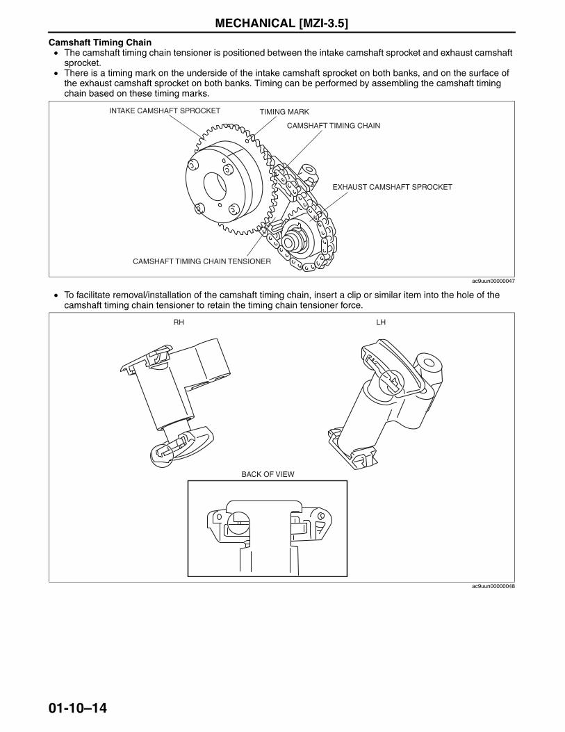
MECHANICAL [MZI-3.5]
01-10–14
Camshaft Timing Chain• The camshaft timing chain tensioner is positioned between the intake camshaft sprocket and exhaust camshaft
sprocket.• There is a timing mark on the underside of the intake camshaft sprocket on both banks, and on the surface of
the exhaust camshaft sprocket on both banks. Timing can be performed by assembling the camshaft timing chain based on these timing marks.
• To facilitate removal/installation of the camshaft timing chain, insert a clip or similar item into the hole of the camshaft timing chain tensioner to retain the timing chain tensioner force.
End Of SieNG: ENGINE MOUNT
INTAKE CAMSHAFT SPROCKET
CAMSHAFT TIMING CHAIN TENSIONER
EXHAUST CAMSHAFT SPROCKET
CAMSHAFT TIMING CHAIN
TIMING MARK
ac9uun00000047
RH LH
BACK OF VIEW
ac9uun00000048
3423-1U-06H(01-10).fm 14 ページ 2006年11月22日 水曜日 午前9時23分
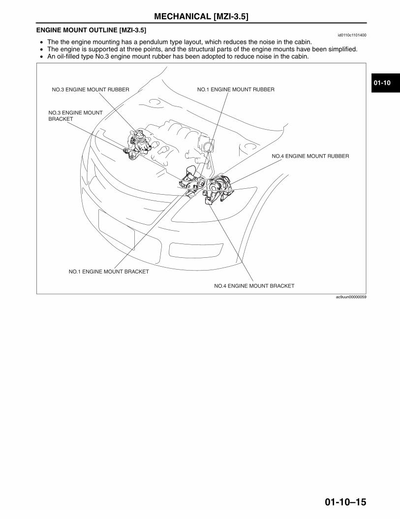
MECHANICAL [MZI-3.5]
01-10–15
01-10
ENGINE MOUNT OUTLINE [MZI-3.5]id0110c1101400
• The the engine mounting has a pendulum type layout, which reduces the noise in the cabin.• The engine is supported at three points, and the structural parts of the engine mounts have been simplified.• An oil-filled type No.3 engine mount rubber has been adopted to reduce noise in the cabin.
End Of Sie
NO.3 ENGINE MOUNT RUBBER
NO.3 ENGINE MOUNT BRACKET
NO.1 ENGINE MOUNT RUBBER
NO.1 ENGINE MOUNT BRACKET
NO.4 ENGINE MOUNT BRACKET
NO.4 ENGINE MOUNT RUBBER
ac9uun00000059
3423-1U-06H(01-10).fm 15 ページ 2006年11月22日 水曜日 午前9時23分
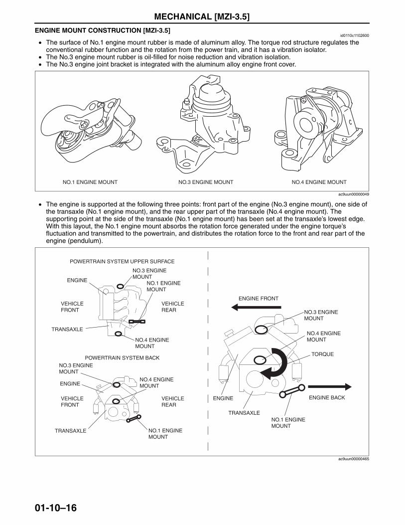
MECHANICAL [MZI-3.5]
01-10–16
ENGINE MOUNT CONSTRUCTION [MZI-3.5]id0110c1102600
• The surface of No.1 engine mount rubber is made of aluminum alloy. The torque rod structure regulates the conventional rubber function and the rotation from the power train, and it has a vibration isolator.
• The No.3 engine mount rubber is oil-filled for noise reduction and vibration isolation.• The No.3 engine joint bracket is integrated with the aluminum alloy engine front cover.
• The engine is supported at the following three points: front part of the engine (No.3 engine mount), one side of the transaxle (No.1 engine mount), and the rear upper part of the transaxle (No.4 engine mount). The supporting point at the side of the transaxle (No.1 engine mount) has been set at the transaxle’s lowest edge. With this layout, the No.1 engine mount absorbs the rotation force generated under the engine torque’s fluctuation and transmitted to the powertrain, and distributes the rotation force to the front and rear part of the engine (pendulum).
End Of Sie
NO.1 ENGINE MOUNT NO.3 ENGINE MOUNT NO.4 ENGINE MOUNT
ac9uun00000049
VEHICLEREAR
VEHICLEFRONT
POWERTRAIN SYSTEM UPPER SURFACE
POWERTRAIN SYSTEM BACK
ENGINE
ENGINE
ENGINE
NO.3 ENGINEMOUNT
NO.3 ENGINEMOUNT
NO.3 ENGINEMOUNT
NO.1 ENGINEMOUNT
NO.1 ENGINEMOUNT
NO.1 ENGINEMOUNT
NO.4 ENGINEMOUNT
NO.4 ENGINEMOUNT
TORQUE
NO.4 ENGINEMOUNT
VEHICLEREAR
TRANSAXLE
TRANSAXLE
TRANSAXLE
VEHICLEFRONT
ENGINE FRONT
ENGINE BACK
ac9uun00000465
3423-1U-06H(01-10).fm 16 ページ 2006年11月22日 水曜日 午前9時23分
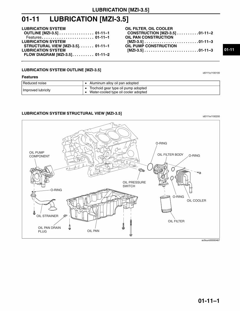
LUBRICATION [MZI-3.5]
01-11–1
01-11
01-11 LUBRICATION [MZI-3.5]LUBRICATION SYSTEM
OUTLINE [MZI-3.5] . . . . . . . . . . . . . . . . 01-11–1Features . . . . . . . . . . . . . . . . . . . . . . . . 01-11–1
LUBRICATION SYSTEM STRUCTURAL VIEW [MZI-3.5]. . . . . . . 01-11–1
LUBRICATION SYSTEM FLOW DIAGRAM [MZI-3.5] . . . . . . . . . . 01-11–2
OIL FILTER, OIL COOLER CONSTRUCTION [MZI-3.5] . . . . . . . . . . 01-11–2
OIL PAN CONSTRUCTION [MZI-3.5] . . . . . . . . . . . . . . . . . . . . . . . . . 01-11–3
OIL PUMP CONSTRUCTION [MZI-3.5] . . . . . . . . . . . . . . . . . . . . . . . . . 01-11–3
End of TocNG: LUBRICATION SYSTEMLUBRICATION SYSTEM OUTLINE [MZI-3.5]
id0111e1100100
Features
End Of Sie
LUBRICATION SYSTEM STRUCTURAL VIEW [MZI-3.5]id0111e1100200
End Of Sie
Reduced noise • Aluminum alloy oil pan adopted
Improved lubricity • Trochoid gear type oil pump adopted• Water-cooled type oil cooler adopted
OIL PAN DRAIN PLUG OIL PAN
OIL PRESSURE SWITCH
OIL FILTER
OIL COOLER
OIL FILTER BODY
O-RING
O-RING
O-RINGOIL PUMP COMPONENT
OIL STRAINER
O-RING
ac9uun00000467
3423-1U-06H(01-11).fm 1 ページ 2006年11月22日 水曜日 午前9時21分
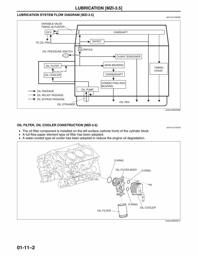
LUBRICATION [MZI-3.5]
01-11–2
LUBRICATION SYSTEM FLOW DIAGRAM [MZI-3.5]id0111e1100300
End Of SieNG: OIL FILTER
OIL FILTER, OIL COOLER CONSTRUCTION [MZI-3.5]id0111e1118100
• The oil filter component is installed on the left surface (vehicle front) of the cylinder block.• A full-flow paper element type oil filter has been adopted.• A water-cooled type oil cooler has been adopted to reduce the engine oil degradation.
End Of SieNG: OIL PAN
OIL PANOIL STRAINER
OIL PUMP
OIL COOLER
OIL FILTER
OIL PRESSURE SWITCH
MAIN BEARING
CRANKSHAFT
CONNECTING ROD BEARING
TAPPET
CAMSHAFT
OIL BYPASS PASSAGE
TIMINGCHAIN
CHAIN TENSIONER
ORIFICE
OIL PASSAGE
OIL RELIEF PASSAGE
OCV
VARIABLE VALVE TIMING ACTUATOR
TO OIL PAN
ac9uun00000468
OIL FILTEROIL COOLER
OIL FILTER BODY
O-RING
O-RING
O-RING
ac9uun00000471
3423-1U-06H(01-11).fm 2 ページ 2006年11月22日 水曜日 午前9時21分
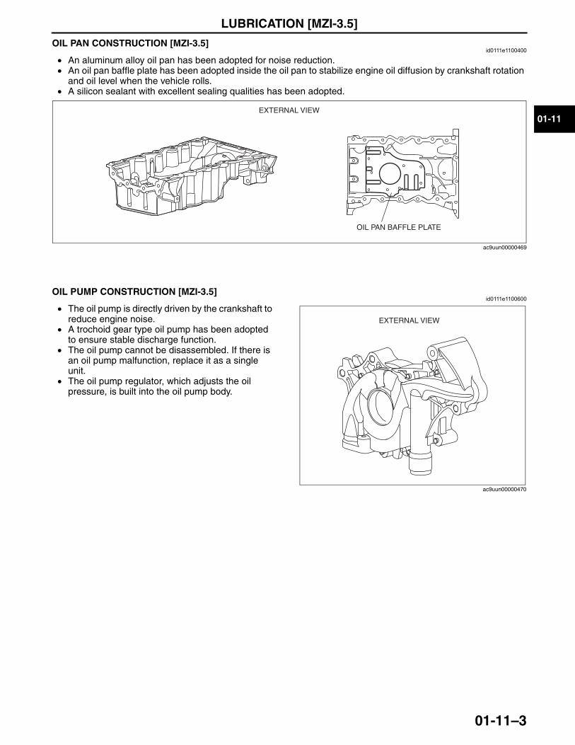
LUBRICATION [MZI-3.5]
01-11–3
01-11
OIL PAN CONSTRUCTION [MZI-3.5]id0111e1100400
• An aluminum alloy oil pan has been adopted for noise reduction. • An oil pan baffle plate has been adopted inside the oil pan to stabilize engine oil diffusion by crankshaft rotation
and oil level when the vehicle rolls.• A silicon sealant with excellent sealing qualities has been adopted.
End Of SieNG: OIL PUMP
OIL PUMP CONSTRUCTION [MZI-3.5]id0111e1100600
• The oil pump is directly driven by the crankshaft to reduce engine noise.
• A trochoid gear type oil pump has been adopted to ensure stable discharge function.
• The oil pump cannot be disassembled. If there is an oil pump malfunction, replace it as a single unit.
• The oil pump regulator, which adjusts the oil pressure, is built into the oil pump body.
End Of Sie
EXTERNAL VIEW
OIL PAN BAFFLE PLATE
ac9uun00000469
EXTERNAL VIEW
ac9uun00000470
3423-1U-06H(01-11).fm 3 ページ 2006年11月22日 水曜日 午前9時21分

COOLING SYSTEM [MZI-3.5]
01-12–1
01-12
01-12 COOLING SYSTEM [MZI-3.5]COOLING SYSTEM
OUTLINE [MZI-3.5] . . . . . . . . . . . . . . . . 01-12–1Features . . . . . . . . . . . . . . . . . . . . . . . . 01-12–1
COOLING SYSTEM STRUCTURAL VIEW [MZI-3.5]. . . . . . . 01-12–2
COOLING SYSTEM FLOW DIAGRAM [MZI-3.5] . . . . . . . . . . 01-12–3
COOLING SYSTEM CAP, COOLANT RESERVE TANK CONSTRUCTION [MZI-3.5] . . . . . . . . . 01-12–3
RADIATOR CONSTRUCTION [MZI-3.5] . . . . . . . . . . . . . . . . . . . . . . . . 01-12–4
THERMOSTAT CONSTRUCTION/OPERATION [MZI-3.5] . . . . . . . . . . . . . . . . . . . . . . . . 01-12–4
Construction . . . . . . . . . . . . . . . . . . . . . 01-12–4Operation . . . . . . . . . . . . . . . . . . . . . . . 01-12–4
WATER PUMP CONSTRUCTION/OPERATION [MZI-3.5] . . . . . . . . . . . . . . . . . . . . . . . . . 01-12–5
Construction . . . . . . . . . . . . . . . . . . . . . 01-12–5Operation . . . . . . . . . . . . . . . . . . . . . . . 01-12–5
COOLING FAN COMPONENT CONSTRUCTION [MZI-3.5] . . . . . . . . . . 01-12–6
FAN CONTROL MODULE CONSTRUCTION/OPERATION [MZI-3.5] . . . . . . . . . . . . . . . . . . . . . . . . . 01-12–8
Construction . . . . . . . . . . . . . . . . . . . . . 01-12–8Operation . . . . . . . . . . . . . . . . . . . . . . . 01-12–8Fail-safe function . . . . . . . . . . . . . . . . . . 01-12–9
End of TocNG: COOLING SYSTEMCOOLING SYSTEM OUTLINE [MZI-3.5]
id0112d1100100
Features
End Of Sie
Improved reliability • Degassing type coolant reserve tank adoptedReduced weight • Down-flow type radiator with aluminum core and plastic tank adoptedMiniaturization • Built-in type water pump adoptedReduced engine noise and vibration
• Electric cooling fans adopted• Fan control module adopted
Reduced power consumption • Fan control module adoptedImproved serviceability • Longer-life new engine coolant (type FL22) adopted
3423-1U-06H(01-12).fm 1 ページ 2006年11月22日 水曜日 午前9時25分
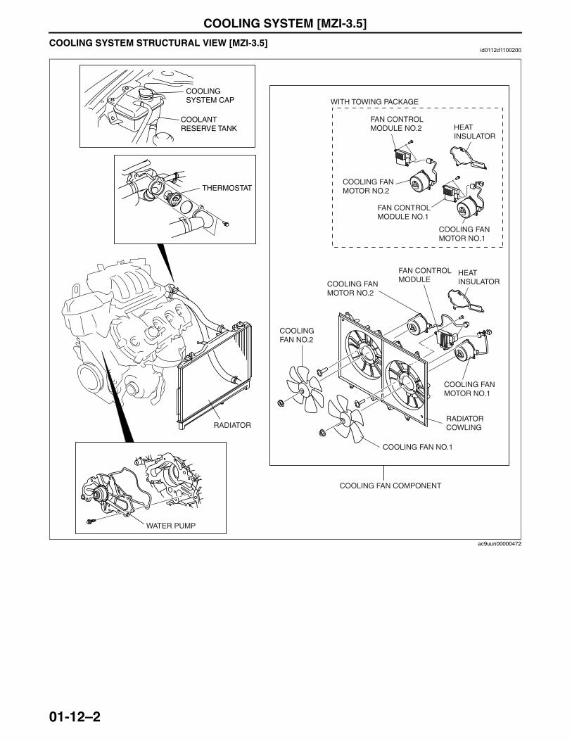
COOLING SYSTEM [MZI-3.5]
01-12–2
COOLING SYSTEM STRUCTURAL VIEW [MZI-3.5]id0112d1100200
End Of Sie
COOLING SYSTEM CAP
COOLANT RESERVE TANK
THERMOSTAT
RADIATOR
WATER PUMP
COOLING FAN MOTOR NO.2
COOLING FAN NO.1
COOLING FAN NO.2
COOLING FAN MOTOR NO.1
FAN CONTROL MODULE
HEAT INSULATOR
RADIATOR COWLING
HEAT INSULATOR
COOLING FAN MOTOR NO.1
COOLING FAN MOTOR NO.2
FAN CONTROL MODULE NO.1
FAN CONTROL MODULE NO.2
COOLING FAN COMPONENT
WITH TOWING PACKAGE
ac9uun00000472
3423-1U-06H(01-12).fm 2 ページ 2006年11月22日 水曜日 午前9時25分
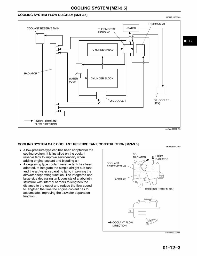
COOLING SYSTEM [MZI-3.5]
01-12–3
01-12
COOLING SYSTEM FLOW DIAGRAM [MZI-3.5]id0112d1100300
End Of SieNG: COOLING SYSTEM CAP
COOLING SYSTEM CAP, COOLANT RESERVE TANK CONSTRUCTION [MZI-3.5]id0112d1142100
• A low-pressure type cap has been adopted for the cooling system. It is installed on the coolant reserve tank to improve serviceability when adding engine coolant and bleeding air.
• A degassing type coolant reserve tank has been adopted, to integrate the simple airtight sub-tank and the air/water separating tank, improving the air/water separating function. The integrated and large-size degassing tank consists of a labyrinth structure with internal barriers to lengthen the distance to the outlet and reduce the flow speed to lengthen the time the engine coolant has to accumulate, improving the air/water separation function.
End Of SieNG: RADIATOR
COOLANT RESERVE TANK
CYLINDER HEAD
THERMOSTAT HOUSING
HEATER
OIL COOLER OIL COOLER(ATX)
THERMOSTAT
CYLINDER BLOCK
RADIATOR
ENGINE COOLANTFLOW DIRECTION
WATER PUMP
ac9uun00000473
COOLING SYSTEM CAP
FROM RADIATOR
TO RADIATOR
BARRIER
COOLANT RESERVE TANK
COOLANT FLOW DIRECTION
ac9uun00000466
3423-1U-06H(01-12).fm 3 ページ 2006年11月22日 水曜日 午前9時25分
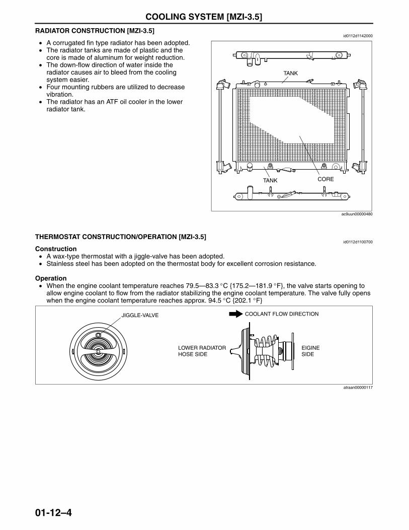
COOLING SYSTEM [MZI-3.5]
01-12–4
RADIATOR CONSTRUCTION [MZI-3.5]id0112d1142000
• A corrugated fin type radiator has been adopted.• The radiator tanks are made of plastic and the
core is made of aluminum for weight reduction.• The down-flow direction of water inside the
radiator causes air to bleed from the cooling system easier.
• Four mounting rubbers are utilized to decrease vibration.
• The radiator has an ATF oil cooler in the lower radiator tank.
End Of SieNG: THERMOSTAT
THERMOSTAT CONSTRUCTION/OPERATION [MZI-3.5]id0112d1100700
Construction• A wax-type thermostat with a jiggle-valve has been adopted.• Stainless steel has been adopted on the thermostat body for excellent corrosion resistance.
Operation• When the engine coolant temperature reaches 79.5—83.3 °C {175.2—181.9 °F}, the valve starts opening to
allow engine coolant to flow from the radiator stabilizing the engine coolant temperature. The valve fully opens when the engine coolant temperature reaches approx. 94.5 °C {202.1 °F}
End Of SieNG: WATER PUMP
TANK
TANK CORE
ac9uun00000480
LOWER RADIATOR HOSE SIDE
EIGINE SIDE
JIGGLE-VALVE COOLANT FLOW DIRECTION
atraan00000117
3423-1U-06H(01-12).fm 4 ページ 2006年11月22日 水曜日 午前9時25分
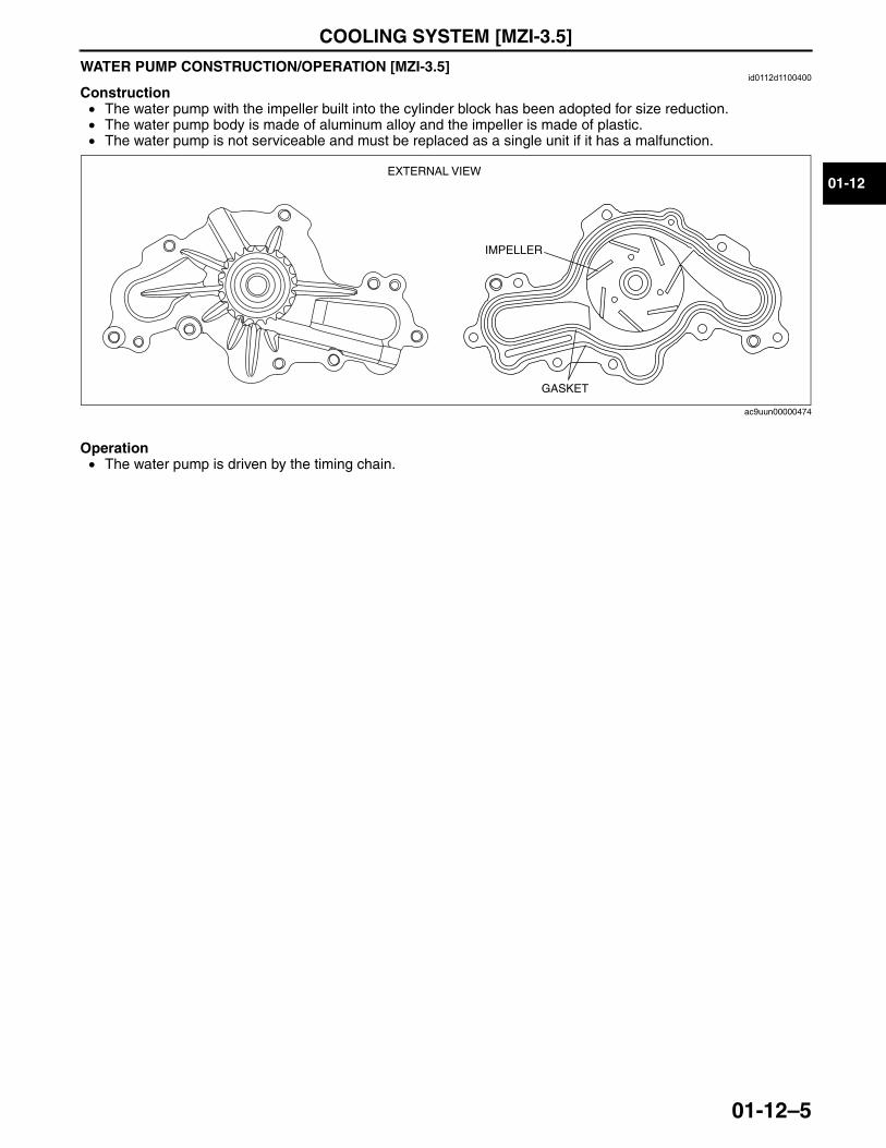
COOLING SYSTEM [MZI-3.5]
01-12–5
01-12
WATER PUMP CONSTRUCTION/OPERATION [MZI-3.5]id0112d1100400
Construction• The water pump with the impeller built into the cylinder block has been adopted for size reduction.• The water pump body is made of aluminum alloy and the impeller is made of plastic.• The water pump is not serviceable and must be replaced as a single unit if it has a malfunction.
Operation• The water pump is driven by the timing chain.
End Of SieNG: COOLING FAN
EXTERNAL VIEW
IMPELLER
GASKET
ac9uun00000474
3423-1U-06H(01-12).fm 5 ページ 2006年11月22日 水曜日 午前9時25分
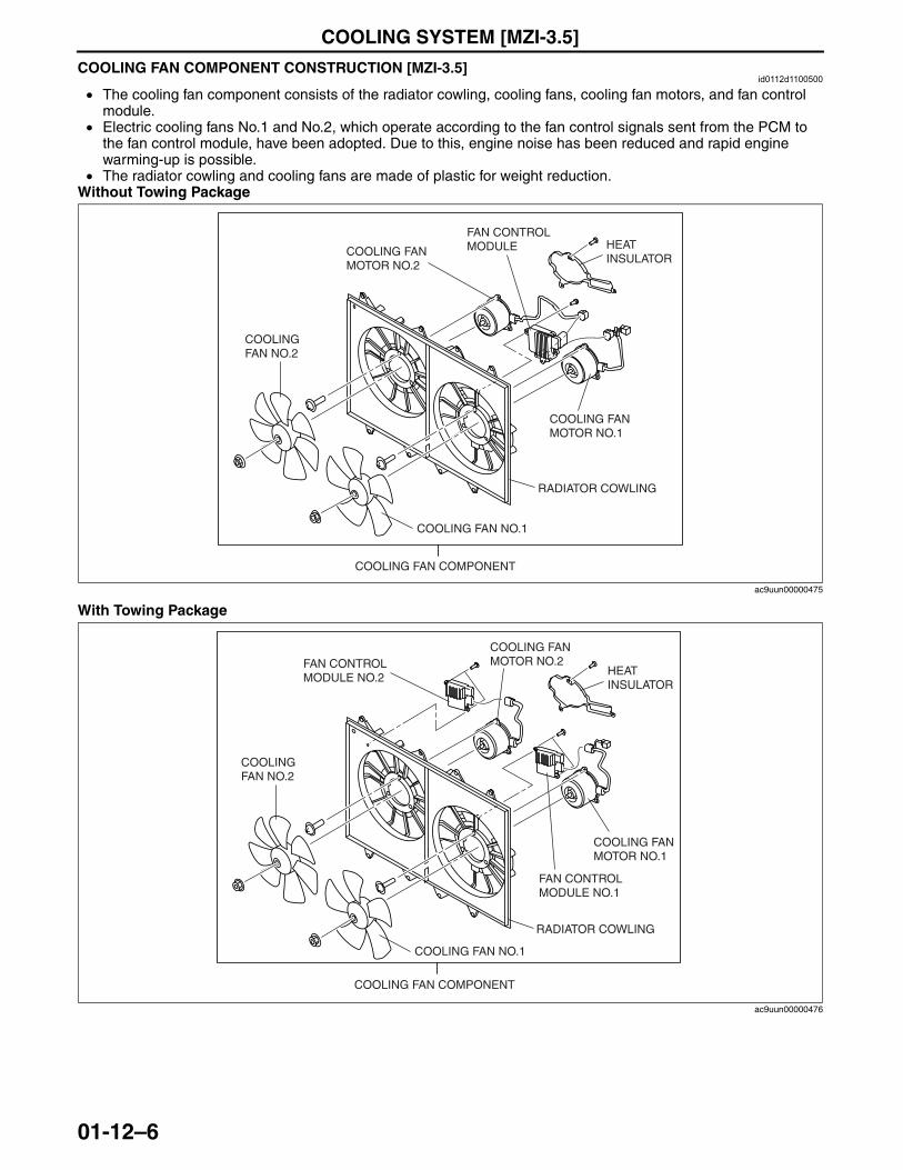
COOLING SYSTEM [MZI-3.5]
01-12–6
COOLING FAN COMPONENT CONSTRUCTION [MZI-3.5]id0112d1100500
• The cooling fan component consists of the radiator cowling, cooling fans, cooling fan motors, and fan control module.
• Electric cooling fans No.1 and No.2, which operate according to the fan control signals sent from the PCM to the fan control module, have been adopted. Due to this, engine noise has been reduced and rapid engine warming-up is possible.
• The radiator cowling and cooling fans are made of plastic for weight reduction.Without Towing Package
With Towing Package
RADIATOR COWLING
COOLING FAN MOTOR NO.2
COOLING FAN NO.1
COOLING FAN COMPONENT
COOLING FAN NO.2
COOLING FAN MOTOR NO.1
FAN CONTROL MODULE HEAT
INSULATOR
ac9uun00000475
RADIATOR COWLING
COOLING FAN MOTOR NO.2
COOLING FAN NO.1
COOLING FAN COMPONENT
COOLING FAN NO.2
COOLING FAN MOTOR NO.1
HEAT INSULATOR
FAN CONTROL MODULE NO.1
FAN CONTROL MODULE NO.2
ac9uun00000476
3423-1U-06H(01-12).fm 6 ページ 2006年11月22日 水曜日 午前9時25分
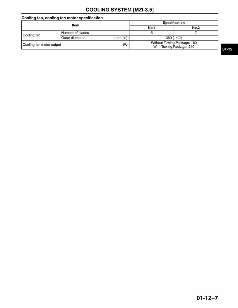
COOLING SYSTEM [MZI-3.5]
01-12–7
01-12
Cooling fan, cooling fan motor specification
End Of SieNG: FAN CONTROL MODULE
ItemSpecification
No.1 No.2
Cooling fanNumber of blades 5 7Outer diameter (mm {in}) 360 {14.2}
Cooling fan motor output (W) Without Towing Package: 160With Towing Package: 240
3423-1U-06H(01-12).fm 7 ページ 2006年11月22日 水曜日 午前9時25分
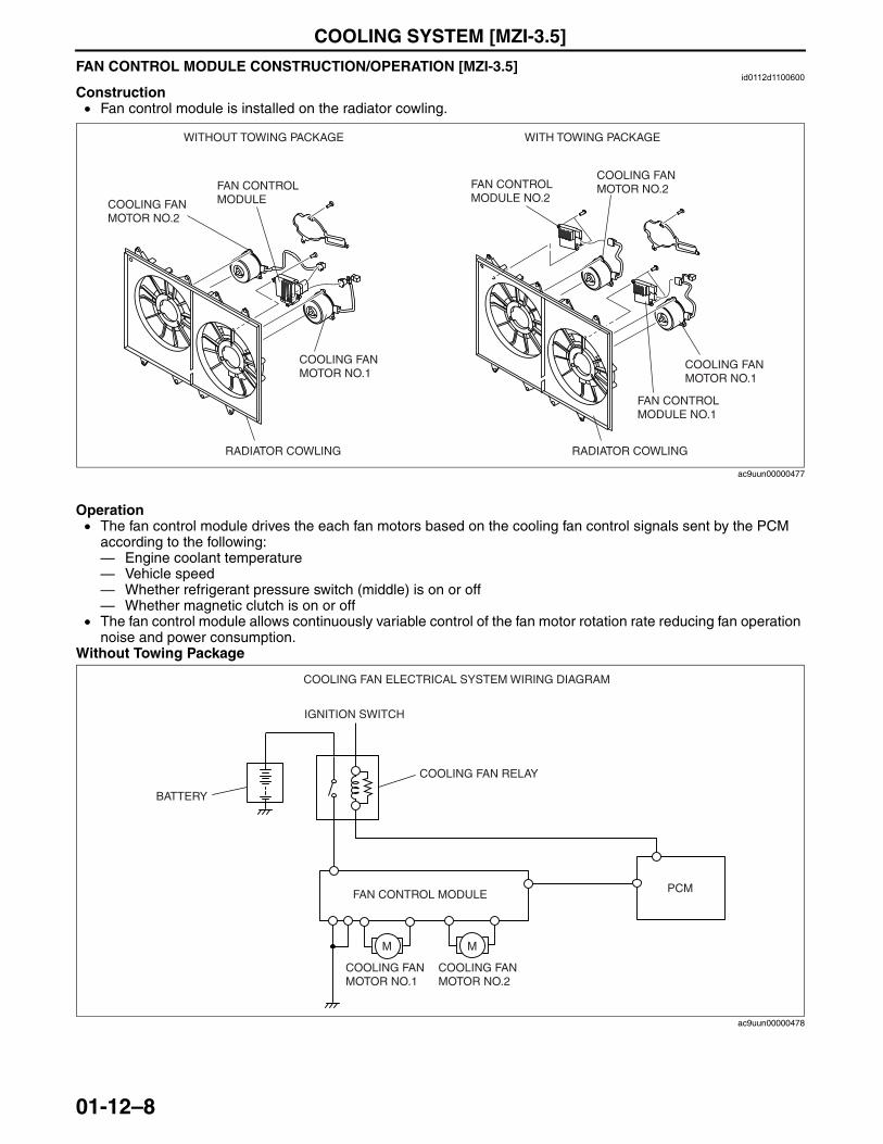
COOLING SYSTEM [MZI-3.5]
01-12–8
FAN CONTROL MODULE CONSTRUCTION/OPERATION [MZI-3.5]id0112d1100600
Construction• Fan control module is installed on the radiator cowling.
Operation• The fan control module drives the each fan motors based on the cooling fan control signals sent by the PCM
according to the following: — Engine coolant temperature— Vehicle speed— Whether refrigerant pressure switch (middle) is on or off— Whether magnetic clutch is on or off
• The fan control module allows continuously variable control of the fan motor rotation rate reducing fan operation noise and power consumption.
Without Towing Package
COOLING FAN MOTOR NO.2
COOLING FAN MOTOR NO.1
FAN CONTROL MODULE
FAN CONTROL MODULE NO.2
COOLING FAN MOTOR NO.2
RADIATOR COWLING
COOLING FAN MOTOR NO.1
FAN CONTROL MODULE NO.1
WITHOUT TOWING PACKAGE WITH TOWING PACKAGE
RADIATOR COWLING
ac9uun00000477
PCM
COOLING FAN MOTOR NO.1
FAN CONTROL MODULE
COOLING FAN MOTOR NO.2
COOLING FAN RELAY
IGNITION SWITCH
BATTERY
COOLING FAN ELECTRICAL SYSTEM WIRING DIAGRAM
M M
ac9uun00000478
3423-1U-06H(01-12).fm 8 ページ 2006年11月22日 水曜日 午前9時25分
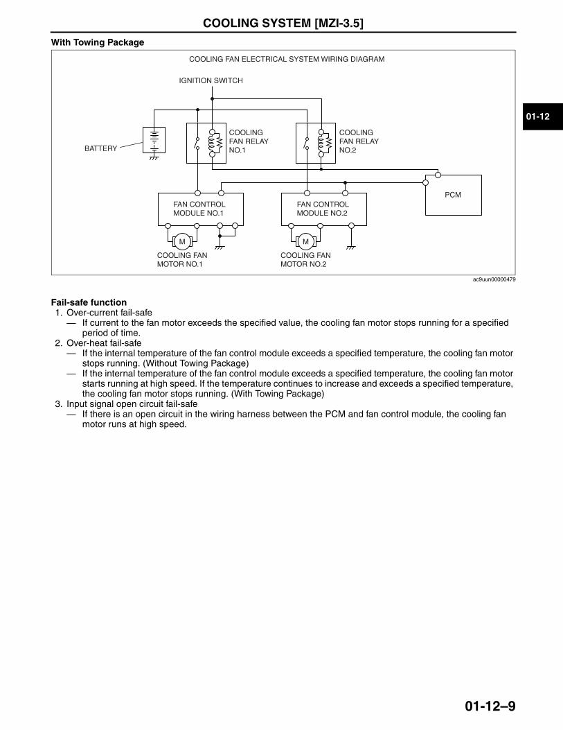
COOLING SYSTEM [MZI-3.5]
01-12–9
01-12
With Towing Package
Fail-safe function1. Over-current fail-safe— If current to the fan motor exceeds the specified value, the cooling fan motor stops running for a specified
period of time.2. Over-heat fail-safe— If the internal temperature of the fan control module exceeds a specified temperature, the cooling fan motor
stops running. (Without Towing Package)— If the internal temperature of the fan control module exceeds a specified temperature, the cooling fan motor
starts running at high speed. If the temperature continues to increase and exceeds a specified temperature, the cooling fan motor stops running. (With Towing Package)
3. Input signal open circuit fail-safe— If there is an open circuit in the wiring harness between the PCM and fan control module, the cooling fan
motor runs at high speed.End Of Sie
PCM
COOLING FAN RELAY NO.1
COOLING FAN RELAY NO.2
IGNITION SWITCH
BATTERY
COOLING FAN ELECTRICAL SYSTEM WIRING DIAGRAM
COOLING FAN MOTOR NO.1
FAN CONTROL MODULE NO.1
M
COOLING FAN MOTOR NO.2
FAN CONTROL MODULE NO.2
M
ac9uun00000479
3423-1U-06H(01-12).fm 9 ページ 2006年11月22日 水曜日 午前9時25分

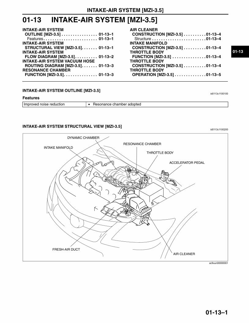
INTAKE-AIR SYSTEM [MZI-3.5]
01-13–1
01-13
01-13 INTAKE-AIR SYSTEM [MZI-3.5]INTAKE-AIR SYSTEM
OUTLINE [MZI-3.5] . . . . . . . . . . . . . . . . 01-13–1Features . . . . . . . . . . . . . . . . . . . . . . . . 01-13–1
INTAKE-AIR SYSTEM STRUCTURAL VIEW [MZI-3.5]. . . . . . . 01-13–1
INTAKE-AIR SYSTEM FLOW DIAGRAM [MZI-3.5] . . . . . . . . . . 01-13–2
INTAKE-AIR SYSTEM VACUUM HOSE ROUTING DIAGRAM [MZI-3.5]. . . . . . . 01-13–3
RESONANCE CHAMBER FUNCTION [MZI-3.5]. . . . . . . . . . . . . . . 01-13–3
AIR CLEANER CONSTRUCTION [MZI-3.5] . . . . . . . . . . 01-13–4
Structure . . . . . . . . . . . . . . . . . . . . . . . . 01-13–4INTAKE MANIFOLD
CONSTRUCTION [MZI-3.5] . . . . . . . . . . 01-13–4THROTTLE BODY
FUNCTION [MZI-3.5] . . . . . . . . . . . . . . . 01-13–4THROTTLE BODY
CONSTRUCTION [MZI-3.5] . . . . . . . . . . 01-13–4THROTTLE BODY
OPERATION [MZI-3.5] . . . . . . . . . . . . . . 01-13–5
End of TocNG: INTAKE-AIR SYSTEMINTAKE-AIR SYSTEM OUTLINE [MZI-3.5]
id0113c1100100
Features
End Of Sie
INTAKE-AIR SYSTEM STRUCTURAL VIEW [MZI-3.5]id0113c1100200
End Of Sie
Improved noise reduction • Resonance chamber adopted
ACCELERATOR PEDAL
AIR CLEANERFRESH-AIR DUCT
THROTTLE BODY
RESONANCE CHAMBER
DYNAMIC CHAMBER
INTAKE MANIFOLD
ac9uun00000001
3423-1U-06H(01-13).fm 1 ページ 2006年11月21日 火曜日 午後4時55分
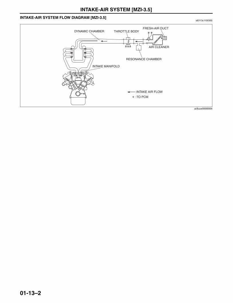
INTAKE-AIR SYSTEM [MZI-3.5]
01-13–2
INTAKE-AIR SYSTEM FLOW DIAGRAM [MZI-3.5]id0113c1100300
End Of Sie
AIR CLEANER
FRESH-AIR DUCTTHROTTLE BODY
RESONANCE CHAMBER
DYNAMIC CHAMBER
INTAKE MANIFOLD
:INTAKE AIR FLOW
:TO PCM
ac9uuw00000004
3423-1U-06H(01-13).fm 2 ページ 2006年11月21日 火曜日 午後4時55分
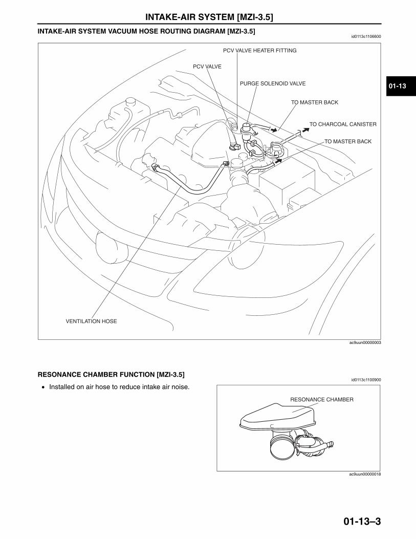
INTAKE-AIR SYSTEM [MZI-3.5]
01-13–3
01-13
INTAKE-AIR SYSTEM VACUUM HOSE ROUTING DIAGRAM [MZI-3.5]id0113c1106600
End Of SieNG: RESONANCE CHAMBER
RESONANCE CHAMBER FUNCTION [MZI-3.5]id0113c1100900
• Installed on air hose to reduce intake air noise.End Of SieNG: AIR CLEANER
VENTILATION HOSE
PCV VALVE
TO CHARCOAL CANISTER
TO MASTER BACK
TO MASTER BACK
PURGE SOLENOID VALVE
PCV VALVE HEATER FITTING
ac9uun00000003
RESONANCE CHAMBER
ac9uun00000018
3423-1U-06H(01-13).fm 3 ページ 2006年11月21日 火曜日 午後4時55分
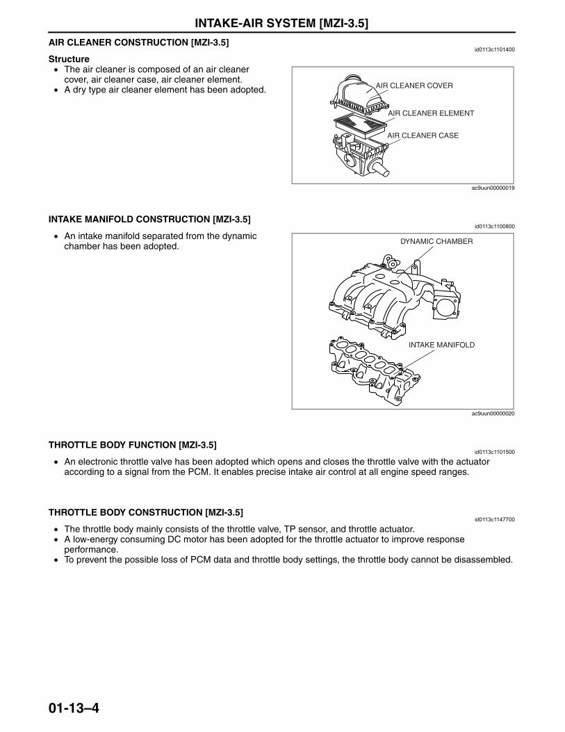
INTAKE-AIR SYSTEM [MZI-3.5]
01-13–4
AIR CLEANER CONSTRUCTION [MZI-3.5]id0113c1101400
Structure• The air cleaner is composed of an air cleaner
cover, air cleaner case, air cleaner element.• A dry type air cleaner element has been adopted.
End Of SieNG: INTAKE MANIFOLD
INTAKE MANIFOLD CONSTRUCTION [MZI-3.5]id0113c1100800
• An intake manifold separated from the dynamic chamber has been adopted.
End Of SieNG: THROTTLE BODY
THROTTLE BODY FUNCTION [MZI-3.5]id0113c1101500
• An electronic throttle valve has been adopted which opens and closes the throttle valve with the actuator according to a signal from the PCM. It enables precise intake air control at all engine speed ranges.
End Of Sie
THROTTLE BODY CONSTRUCTION [MZI-3.5]id0113c1147700
• The throttle body mainly consists of the throttle valve, TP sensor, and throttle actuator.• A low-energy consuming DC motor has been adopted for the throttle actuator to improve response
performance.• To prevent the possible loss of PCM data and throttle body settings, the throttle body cannot be disassembled.
End Of Sie
AIR CLEANER COVER
AIR CLEANER CASE
AIR CLEANER ELEMENT
ac9uun00000019
DYNAMIC CHAMBER
INTAKE MANIFOLD
ac9uun00000020
3423-1U-06H(01-13).fm 4 ページ 2006年11月21日 火曜日 午後4時55分
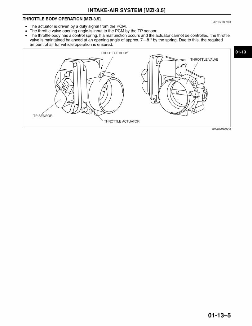
INTAKE-AIR SYSTEM [MZI-3.5]
01-13–5
01-13
THROTTLE BODY OPERATION [MZI-3.5]id0113c1147800
• The actuator is driven by a duty signal from the PCM.• The throttle valve opening angle is input to the PCM by the TP sensor.• The throttle body has a control spring. If a malfunction occurs and the actuator cannot be controlled, the throttle
valve is maintained balanced at an opening angle of approx. 7—8 ° by the spring. Due to this, the required amount of air for vehicle operation is ensured.
End Of Sie
THROTTLE BODY
THROTTLE ACTUATOR
THROTTLE VALVE
TP SENSOR
ac9uun00000012
3423-1U-06H(01-13).fm 5 ページ 2006年11月21日 火曜日 午後4時55分

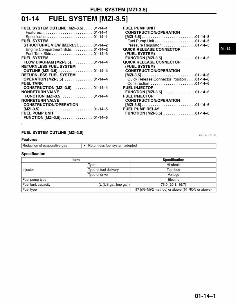
FUEL SYSTEM [MZI-3.5]
01-14–1
01-14
01-14 FUEL SYSTEM [MZI-3.5]FUEL SYSTEM OUTLINE [MZI-3.5] . . . . 01-14–1
Features . . . . . . . . . . . . . . . . . . . . . . . . 01-14–1Specification. . . . . . . . . . . . . . . . . . . . . 01-14–1
FUEL SYSTEM STRUCTURAL VIEW [MZI-3.5]. . . . . . . 01-14–2
Engine Compartment Side. . . . . . . . . . 01-14–2Fuel Tank Side . . . . . . . . . . . . . . . . . . . 01-14–3
FUEL SYSTEM FLOW DIAGRAM [MZI-3.5] . . . . . . . . . . 01-14–4
RETURNLESS FUEL SYSTEM OUTLINE [MZI-3.5] . . . . . . . . . . . . . . . . 01-14–4
RETURNLESS FUEL SYSTEM OPERATION [MZI-3.5] . . . . . . . . . . . . . 01-14–4
FUEL TANK CONSTRUCTION [MZI-3.5] . . . . . . . . . 01-14–4
NONRETURN VALVE FUNCTION [MZI-3.5] . . . . . . . . . . . . . . 01-14–4
NONRETURN VALVE CONSTRUCTION/OPERATION [MZI-3.5] . . . . . . . . . . . . . . . . . . . . . . . . 01-14–5
FUEL PUMP UNIT FUNCTION [MZI-3.5]. . . . . . . . . . . . . . . 01-14–5
FUEL PUMP UNIT CONSTRUCTION/OPERATION [MZI-3.5] . . . . . . . . . . . . . . . . . . . . . . . . . 01-14–5
Fuel Pump Unit . . . . . . . . . . . . . . . . . . . 01-14–5Pressure Regulator . . . . . . . . . . . . . . . . 01-14–5
QUICK RELEASE CONNECTOR (FUEL SYSTEM) FUNCTION [MZI-3.5] . . . . . . . . . . . . . . . 01-14–5
QUICK RELEASE CONNECTOR (FUEL SYSTEM) CONSTRUCTION/OPERATION [MZI-3.5] . . . . . . . . . . . . . . . . . . . . . . . . . 01-14–6
Quick Release Connector Position . . . . 01-14–6Construction . . . . . . . . . . . . . . . . . . . . . 01-14–6
FUEL INJECTOR FUNCTION [MZI-3.5] . . . . . . . . . . . . . . . 01-14–6
FUEL INJECTOR CONSTRUCTION/OPERATION [MZI-3.5] . . . . . . . . . . . . . . . . . . . . . . . . . 01-14–6
FUEL PUMP RELAY FUNCTION [MZI-3.5] . . . . . . . . . . . . . . . 01-14–6
End of TocNG: FUEL SYSTEMFUEL SYSTEM OUTLINE [MZI-3.5]
id0114d1100100
Features
Specification
End Of Sie
Reduction of evaporative gas • Returnless fuel system adopted
Item Specification
InjectorType Hi-ohmicType of fuel delivery Top-feedType of drive Voltage
Fuel pump type ElectricFuel tank capacity (L {US gal, lmp gal}) 76.0 {20.1, 16.7}Fuel type 87 [(R+M)/2 method] or above (91 RON or above)
3423-1U-06H(01-14).fm 1 ページ 2006年11月21日 火曜日 午後4時56分
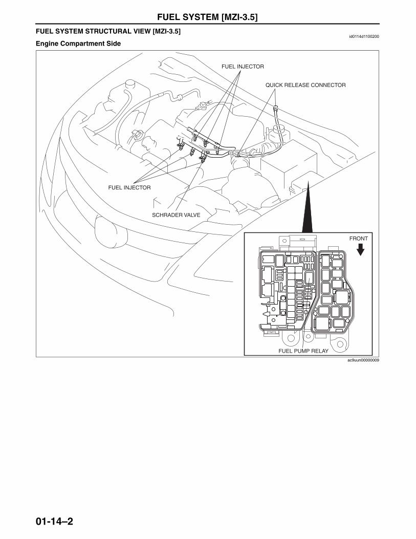
FUEL SYSTEM [MZI-3.5]
01-14–2
FUEL SYSTEM STRUCTURAL VIEW [MZI-3.5]id0114d1100200
Engine Compartment Side
QUICK RELEASE CONNECTOR
FUEL INJECTOR
FRONT
FUEL INJECTOR
FUEL PUMP RELAY
SCHRADER VALVE
ac9uun00000009
3423-1U-06H(01-14).fm 2 ページ 2006年11月21日 火曜日 午後4時56分
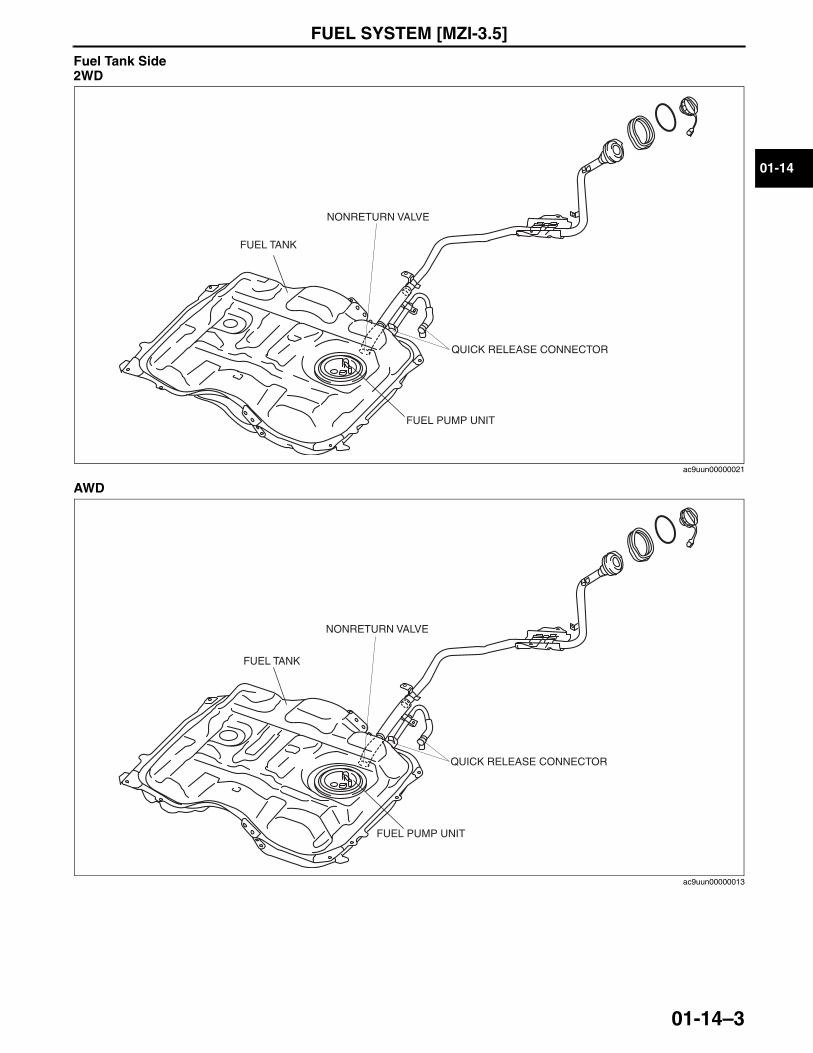
FUEL SYSTEM [MZI-3.5]
01-14–3
01-14
Fuel Tank Side2WD
AWD
End Of Sie
FUEL TANK
FUEL PUMP UNIT
QUICK RELEASE CONNECTOR
NONRETURN VALVE
ac9uun00000021
FUEL PUMP UNIT
FUEL TANK
QUICK RELEASE CONNECTOR
NONRETURN VALVE
ac9uun00000013
3423-1U-06H(01-14).fm 3 ページ 2006年11月21日 火曜日 午後4時56分
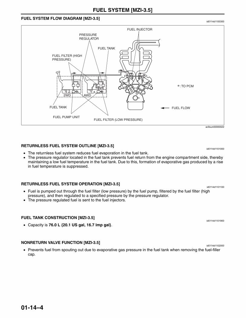
FUEL SYSTEM [MZI-3.5]
01-14–4
FUEL SYSTEM FLOW DIAGRAM [MZI-3.5]id0114d1100300
End Of Sie
RETURNLESS FUEL SYSTEM OUTLINE [MZI-3.5]id0114d1101000
• The returnless fuel system reduces fuel evaporation in the fuel tank.• The pressure regulator located in the fuel tank prevents fuel return from the engine compartment side, thereby
maintaining a low fuel temperature in the fuel tank. Due to this, formation of evaporative gas produced by a rise in fuel temperature is suppressed.
End Of Sie
RETURNLESS FUEL SYSTEM OPERATION [MZI-3.5]id0114d1101100
• Fuel is pumped out through the fuel filter (low pressure) by the fuel pump, filtered by the fuel filter (high pressure), and then regulated to a specified pressure by the pressure regulator.
• The pressure regulated fuel is sent to the fuel injectors.End Of SieNG: FUEL TANK
FUEL TANK CONSTRUCTION [MZI-3.5]id0114d1101900
• Capacity is 76.0 L {20.1 US gal, 16.7 lmp gal}.End Of SieNG: NONRETURN VALVE
NONRETURN VALVE FUNCTION [MZI-3.5]id0114d1102000
• Prevents fuel from spouting out due to evaporative gas pressure in the fuel tank when removing the fuel-filler cap.
End Of Sie
: TO PCM
FUEL FILTER (HIGH PRESSURE)
FUEL FILTER (LOW PRESSURE)
PRESSURE REGULATOR
FUEL TANK
FUEL TANK
FUEL PUMP UNIT
2WD AWD
FUEL INJECTOR
FUEL FLOW
ac9uun00000022
3423-1U-06H(01-14).fm 4 ページ 2006年11月21日 火曜日 午後4時56分
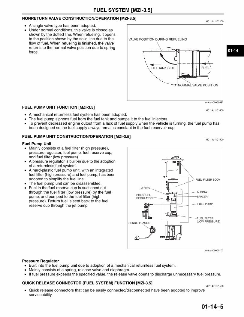
FUEL SYSTEM [MZI-3.5]
01-14–5
01-14
NONRETURN VALVE CONSTRUCTION/OPERATION [MZI-3.5]id0114d1102100
• A single valve type has been adopted.• Under normal conditions, this valve is closed as
shown by the dotted line. When refueling, it opens to the position shown by the solid line due to the flow of fuel. When refueling is finished, the valve returns to the normal valve position due to spring force.
End Of SieNG: FUEL PUMP
FUEL PUMP UNIT FUNCTION [MZI-3.5]id0114d1101400
• A mechanical returnless fuel system has been adopted.• The fuel pump siphons fuel from the fuel tank and pumps it to the fuel injectors.• To prevent decreased engine output from a lack of fuel supply when the vehicle is turning, the fuel pump has
been designed so the fuel supply always remains constant in the fuel reservoir cup.End Of SieFUEL PUMP UNIT CONSTRUCTION/OPERATION [MZI-3.5]
id0114d1101500
Fuel Pump Unit• Mainly consists of a fuel filter (high pressure),
pressure regulator, fuel pump, fuel reserve cup, and fuel filter (low pressure).
• A pressure regulator is built-in due to the adoption of a returnless fuel system.
• A hard-plastic fuel pump unit, with an integrated fuel filter (high pressure) and fuel pump, has been adopted to simplify the fuel line.
• The fuel pump unit can be disassembled.• Fuel in the fuel reserve cup is suctioned out
through the fuel filter (low pressure) by the fuel pump, and pumped to the fuel filter (high pressure). Return fuel is sent back to the fuel reserve cup through the jet pump.
Pressure Regulator• Built into the fuel pump unit due to adoption of a mechanical returnless fuel system.• Mainly consists of a spring, release valve and diaphragm.• If fuel pressure exceeds the specified value, the release valve opens to discharge unnecessary fuel pressure.
End Of SieNG: QUICK RELEASE CONNECTORQUICK RELEASE CONNECTOR (FUEL SYSTEM) FUNCTION [MZI-3.5]
id0114d1151500
• Quick release connectors that can be easily connected/disconnected have been adopted to improve serviceability.
End Of Sie
VALVE POSITION DURING REFUELING
FUELFUEL TANK SIDE
NORMAL VALVE POSITION
ac9uun00000587
FUEL FILTER BODY
PRESSURE REGULATOR
FUEL PUMP
SPACER
FUEL FILTER (LOW PRESSURE)
O-RING
SENDER GAUGE
O-RING
ac9uun00000107
3423-1U-06H(01-14).fm 5 ページ 2006年11月21日 火曜日 午後4時56分
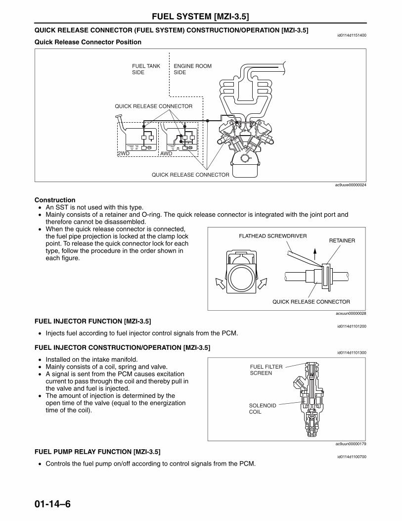
FUEL SYSTEM [MZI-3.5]
01-14–6
QUICK RELEASE CONNECTOR (FUEL SYSTEM) CONSTRUCTION/OPERATION [MZI-3.5]id0114d1151400
Quick Release Connector Position
Construction• An SST is not used with this type. • Mainly consists of a retainer and O-ring. The quick release connector is integrated with the joint port and
therefore cannot be disassembled.• When the quick release connector is connected,
the fuel pipe projection is locked at the clamp lock point. To release the quick connector lock for each type, follow the procedure in the order shown in each figure.
End Of SieNG: FUEL INJECTOR
FUEL INJECTOR FUNCTION [MZI-3.5]id0114d1101200
• Injects fuel according to fuel injector control signals from the PCM.End Of SieFUEL INJECTOR CONSTRUCTION/OPERATION [MZI-3.5]
id0114d1101300
• Installed on the intake manifold. • Mainly consists of a coil, spring and valve.• A signal is sent from the PCM causes excitation
current to pass through the coil and thereby pull in the valve and fuel is injected.
• The amount of injection is determined by the open time of the valve (equal to the energization time of the coil).
End Of SieNG: FUEL SYSTEM
FUEL PUMP RELAY FUNCTION [MZI-3.5]id0114d1100700
• Controls the fuel pump on/off according to control signals from the PCM.End Of Sie
FUEL TANK SIDE
ENGINE ROOM SIDE
QUICK RELEASE CONNECTOR
QUICK RELEASE CONNECTOR
AWD2WD
ac9uuw00000024
FLATHEAD SCREWDRIVER
QUICK RELEASE CONNECTOR
RETAINER
acxuun00000028
FUEL FILTER SCREEN
SOLENOID COIL
ac9uun00000179
3423-1U-06H(01-14).fm 6 ページ 2006年11月21日 火曜日 午後4時56分
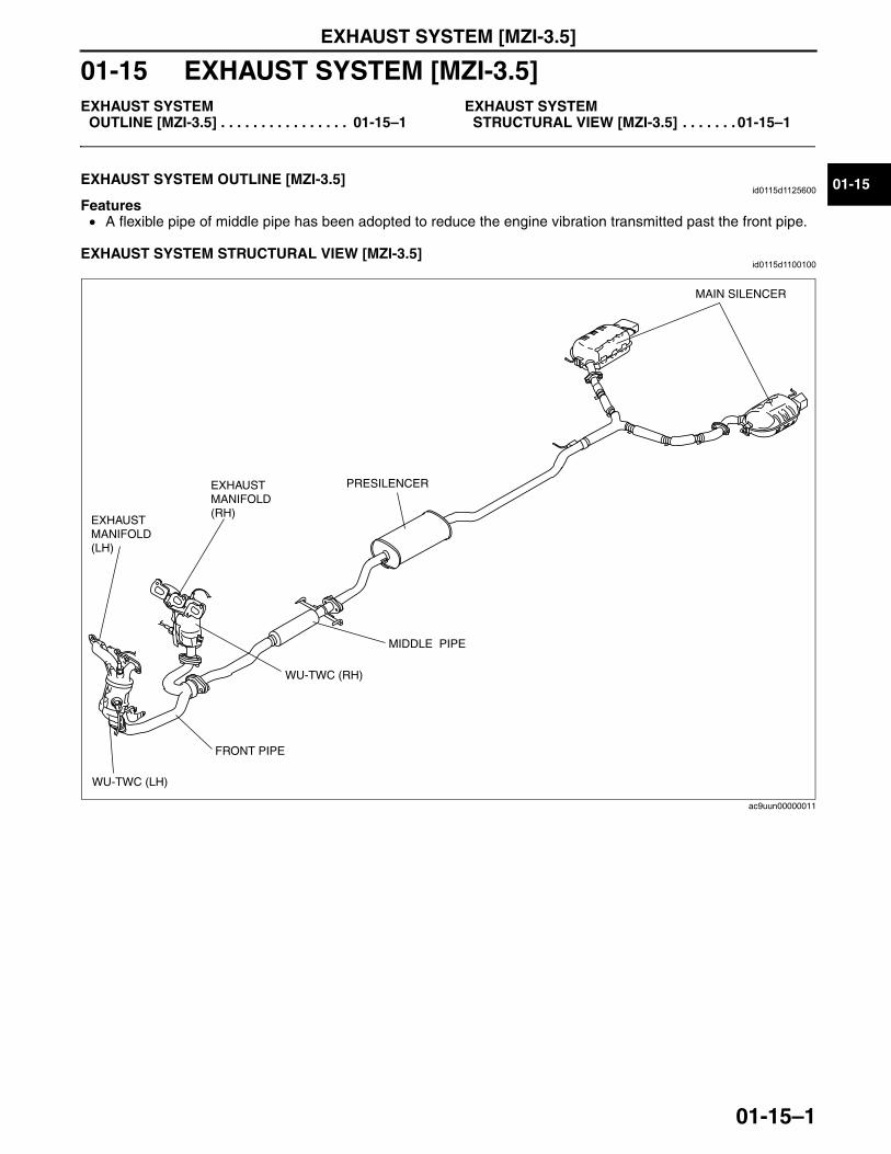
EXHAUST SYSTEM [MZI-3.5]
01-15–1
01-15
01-15 EXHAUST SYSTEM [MZI-3.5]EXHAUST SYSTEM
OUTLINE [MZI-3.5] . . . . . . . . . . . . . . . . 01-15–1EXHAUST SYSTEM
STRUCTURAL VIEW [MZI-3.5] . . . . . . . 01-15–1
End of TocNG: EXHAUST SYSTEMEXHAUST SYSTEM OUTLINE [MZI-3.5]
id0115d1125600
Features• A flexible pipe of middle pipe has been adopted to reduce the engine vibration transmitted past the front pipe.
End Of SieEXHAUST SYSTEM STRUCTURAL VIEW [MZI-3.5]
id0115d1100100
End Of Sie
WU-TWC (RH)
FRONT PIPE
MIDDLE PIPE
WU-TWC (LH)
EXHAUST MANIFOLD (LH)
EXHAUST MANIFOLD (RH)
PRESILENCER
MAIN SILENCER
ac9uun00000011
3423-1U-06H(01-15).fm 1 ページ 2006年11月21日 火曜日 午後4時57分

EMISSION SYSTEM [MZI-3.5]
01-16–1
01-16
01-16 EMISSION SYSTEM [MZI-3.5]EMISSION SYSTEM
OUTLINE [MZI-3.5] . . . . . . . . . . . . . . . . 01-16–2Feature. . . . . . . . . . . . . . . . . . . . . . . . . 01-16–2Specification. . . . . . . . . . . . . . . . . . . . . 01-16–2
EMISSION SYSTEM STRUCTURAL VIEW [MZI-3.5]. . . . . . . 01-16–2
Engine Compartment Side. . . . . . . . . . 01-16–2Exhaust System Side . . . . . . . . . . . . . . 01-16–3Fuel Tank Side . . . . . . . . . . . . . . . . . . . 01-16–3
EXHAUST PURIFICATION SYSTEM OUTLINE [MZI-3.5] . . . . . . . . . . . . . . . . 01-16–4
Feature. . . . . . . . . . . . . . . . . . . . . . . . . 01-16–4CATALYTIC CONVERTER SYSTEM
OUTLINE [MZI-3.5] . . . . . . . . . . . . . . . . 01-16–4Feature. . . . . . . . . . . . . . . . . . . . . . . . . 01-16–4
CATALYTIC CONVERTER SYSTEM STRUCTURE [MZI-3.5] . . . . . . . . . . . . . 01-16–5
CATALYTIC CONVERTER SYSTEM OPERATION [MZI-3.5] . . . . . . . . . . . . . 01-16–5
EVAPORATIVE EMISSION (EVAP) CONTROL SYSTEM OUTLINE [MZI-3.5] . . . . . . . . . . . . . . . . . . . . . . . . 01-16–5
Features . . . . . . . . . . . . . . . . . . . . . . . . 01-16–5EVAPORATIVE EMISSION (EVAP)
CONTROL SYSTEM STRUCTURE [MZI-3.5] . . . . . . . . . . . . . . . . . . . . . . . . 01-16–6
EVAPORATIVE EMISSION (EVAP) CONTROL SYSTEM OPERATION [MZI-3.5] . . . . . . . . . . . . . . . . . . . . . . . . 01-16–6
PURGE SOLENOID VALVE FUNCTION [MZI-3.5]. . . . . . . . . . . . . . . 01-16–6
PURGE SOLENOID VALVE CONSTRUCTION/OPERATION [MZI-3.5] . . . . . . . . . . . . . . . . . . . . . . . . 01-16–6
POSITIVE CRANKCASE VENTILATION (PCV) SYSTEM OUTLINE [MZI-3.5] . . . . . . . . . . . . . . . . . . . . . . . . 01-16–6
Feature. . . . . . . . . . . . . . . . . . . . . . . . . 01-16–6POSITIVE CRANKCASE VENTILATION
(PCV) SYSTEM STRUCTURE [MZI-3.5] . . . . . . . . . . . . . . . . . . . . . . . . 01-16–7
POSITIVE CRANKCASE VENTILATION (PCV) SYSTEM OPERATION [MZI-3.5] . . . . . . . . . . . . . . . . . . . . . . . . 01-16–7
POSITIVE CRANKCASE VENTILATION (PCV) VALVE FUNCTION [MZI-3.5] . . . 01-16–7
POSITIVE CRANKCASE VENTILATION (PCV) VALVE CONSTRUCTION/OPERATION [MZI-3.5] . . . . . . . . . . . . . . . . . . . . . . . . 01-16–7
POSITIVE CRANKCASE VENTILATION (PCV) VALVE HEATER FITTING FUNCTION [MZI-3.5] . . . . . . . . 01-16–7
POSITIVE CRANKCASE VENTILATION (PCV) VALVE HEATER FITTING CONSTRUCTION/OPERATION [MZI-3.5] . . . . . . . . . . . . . . . . . . . . . . . . . 01-16–8
CHARCOAL CANISTER FUNCTION [MZI-3.5] . . . . . . . . . . . . . . . 01-16–8
CHARCOAL CANISTER CONSTRUCTION/OPERATION [MZI-3.5] . . . . . . . . . . . . . . . . . . . . . . . . . 01-16–8
CANISTER VENT (CV) SOLENOID VALVE FUNCTION [MZI-3.5] . . . . . . . . . . . . . . . 01-16–8
CANISTER VENT (CV) SOLENOID VALVE CONSTRUCTION/OPERATION [MZI-3.5] . . . . . . . . . . . . . . . . . . . . . . . . . 01-16–8
AIR FILTER FUNCTION [MZI-3.5] . . . . . . 01-16–8AIR FILTER
CONSTRUCTION/OPERATION [MZI-3.5] . . . . . . . . . . . . . . . . . . . . . . . . . 01-16–9
FUEL SHUT-OFF VALVE FUNCTION [MZI-3.5] . . . . . . . . . . . . . . . 01-16–9
FUEL SHUT-OFF VALVE CONSTRUCTION/OPERATION [MZI-3.5] . . . . . . . . . . . . . . . . . . . . . . . . . 01-16–9
ROLLOVER VALVE FUNCTION [MZI-3.5] . . . . . . . . . . . . . . . 01-16–9
ROLLOVER VALVE CONSTRUCTION/OPERATION [MZI-3.5] . . . . . . . . . . . . . . . . . . . . . . . . . 01-16–9
QUICK RELEASE CONNECTOR (EMISSION SYSTEM) FUNCTION [MZI-3.5] . . . . . . . . . . . . . . . 01-16–10
QUICK RELEASE CONNECTOR (EMISSION SYSTEM) CONSTRUCTION/OPERATION [MZI-3.5] . . . . . . . . . . . . . . . . . . . . . . . . . 01-16–10
Quick Release Connector Type. . . . . . . 01-16–10Type A Construction . . . . . . . . . . . . . . . 01-16–10Type B Construction . . . . . . . . . . . . . . . 01-16–11Type C Construction . . . . . . . . . . . . . . . 01-16–11Type D Construction . . . . . . . . . . . . . . . 01-16–12Type E Construction . . . . . . . . . . . . . . . 01-16–12
End of TocNG: EMISSION SYSTEM
3423-1U-06H(01-16).fm 1 ページ 2006年11月22日 水曜日 午後2時4分
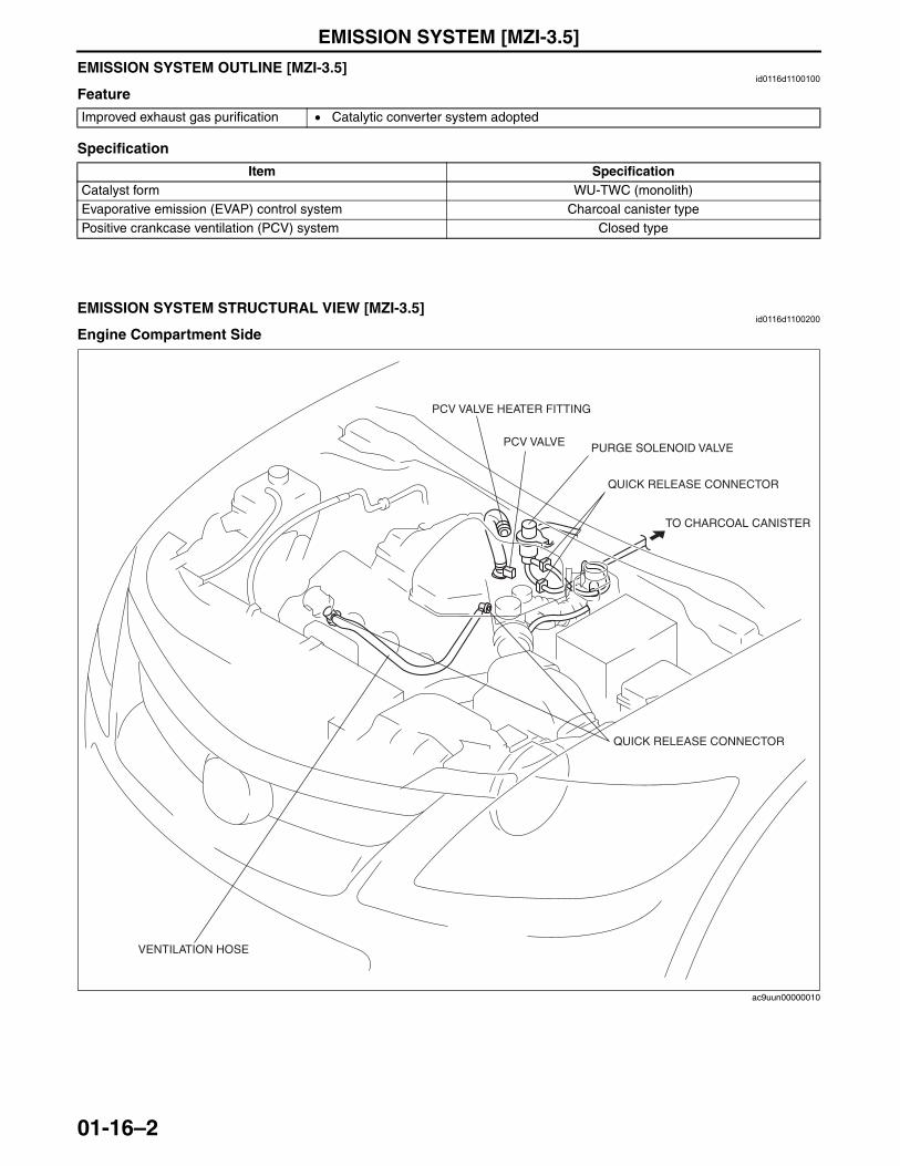
EMISSION SYSTEM [MZI-3.5]
01-16–2
EMISSION SYSTEM OUTLINE [MZI-3.5]id0116d1100100
Feature
Specification
End Of Sie
EMISSION SYSTEM STRUCTURAL VIEW [MZI-3.5]id0116d1100200
Engine Compartment Side
Improved exhaust gas purification • Catalytic converter system adopted
Item SpecificationCatalyst form WU-TWC (monolith)Evaporative emission (EVAP) control system Charcoal canister typePositive crankcase ventilation (PCV) system Closed type
VENTILATION HOSE
PCV VALVE
TO CHARCOAL CANISTER
PURGE SOLENOID VALVE
PCV VALVE HEATER FITTING
QUICK RELEASE CONNECTOR
QUICK RELEASE CONNECTOR
ac9uun00000010
3423-1U-06H(01-16).fm 2 ページ 2006年11月22日 水曜日 午後2時4分
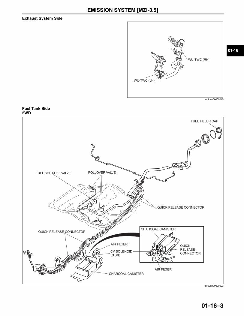
EMISSION SYSTEM [MZI-3.5]
01-16–3
01-16
Exhaust System Side
Fuel Tank Side2WD
WU-TWC (RH)
WU-TWC (LH)
ac9uun00000015
FUEL FILLER CAP
QUICK RELEASE CONNECTOR
QUICK RELEASE CONNECTOR
CV SOLENOID VALVE
FUEL SHUT-OFF VALVE ROLLOVER VALVE
AIR FILTER
AIR FILTERCHARCOAL CANISTER
CHARCOAL CANISTERQUICK RELEASE CONNECTOR
ac9uun00000023
3423-1U-06H(01-16).fm 3 ページ 2006年11月22日 水曜日 午後2時4分
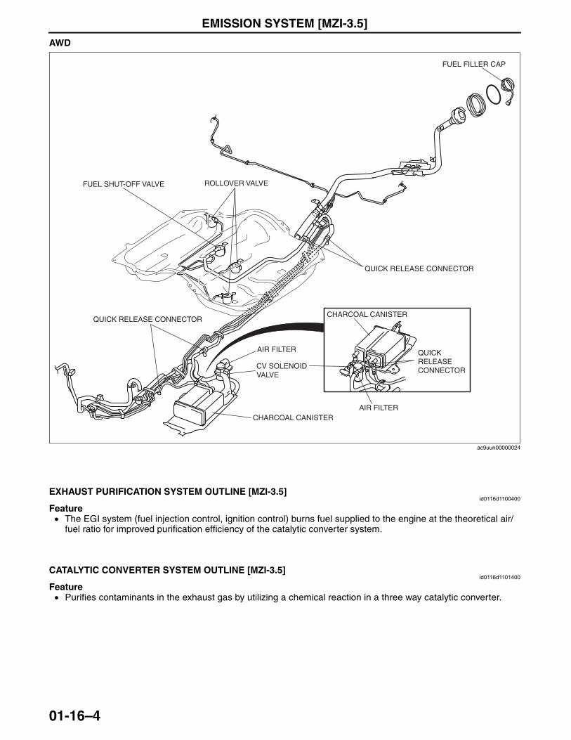
EMISSION SYSTEM [MZI-3.5]
01-16–4
AWD
End Of SieNG: EXHAUST PURIFICATION SYSTEM
EXHAUST PURIFICATION SYSTEM OUTLINE [MZI-3.5]id0116d1100400
Feature• The EGI system (fuel injection control, ignition control) burns fuel supplied to the engine at the theoretical air/
fuel ratio for improved purification efficiency of the catalytic converter system.End Of SieNG: CATALYTIC CONVERTER SYSTEM
CATALYTIC CONVERTER SYSTEM OUTLINE [MZI-3.5]id0116d1101400
Feature• Purifies contaminants in the exhaust gas by utilizing a chemical reaction in a three way catalytic converter.
End Of Sie
FUEL FILLER CAP
QUICK RELEASE CONNECTOR
FUEL SHUT-OFF VALVE ROLLOVER VALVE
QUICK RELEASE CONNECTOR
QUICK RELEASE CONNECTOR
CV SOLENOID VALVE
AIR FILTER
AIR FILTERCHARCOAL CANISTER
CHARCOAL CANISTER
ac9uun00000024
3423-1U-06H(01-16).fm 4 ページ 2006年11月22日 水曜日 午後2時4分
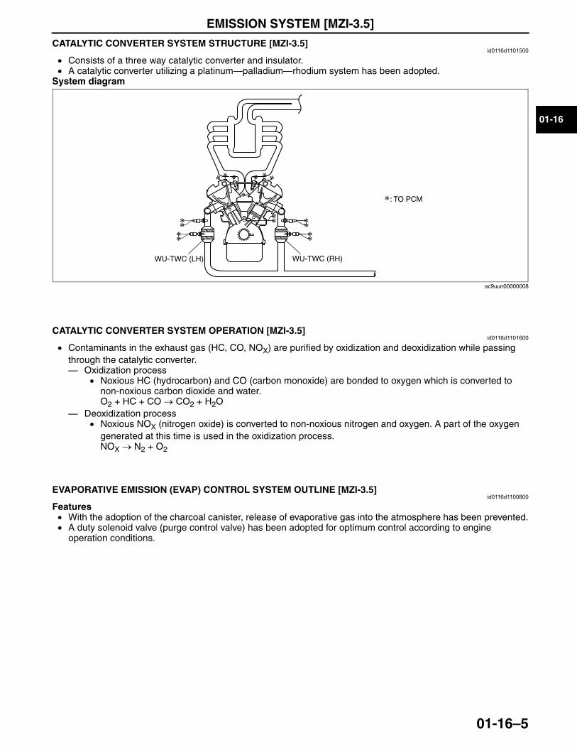
EMISSION SYSTEM [MZI-3.5]
01-16–5
01-16
CATALYTIC CONVERTER SYSTEM STRUCTURE [MZI-3.5]id0116d1101500
• Consists of a three way catalytic converter and insulator.• A catalytic converter utilizing a platinum—palladium—rhodium system has been adopted.
System diagram
End Of Sie
CATALYTIC CONVERTER SYSTEM OPERATION [MZI-3.5]id0116d1101600
• Contaminants in the exhaust gas (HC, CO, NOX) are purified by oxidization and deoxidization while passing through the catalytic converter.— Oxidization process
• Noxious HC (hydrocarbon) and CO (carbon monoxide) are bonded to oxygen which is converted to non-noxious carbon dioxide and water.O2 + HC + CO → CO2 + H2O
— Deoxidization process• Noxious NOX (nitrogen oxide) is converted to non-noxious nitrogen and oxygen. A part of the oxygen
generated at this time is used in the oxidization process.NOX → N2 + O2
End Of SieNG: EVAP CONTROL SYSTEM
EVAPORATIVE EMISSION (EVAP) CONTROL SYSTEM OUTLINE [MZI-3.5]id0116d1100800
Features• With the adoption of the charcoal canister, release of evaporative gas into the atmosphere has been prevented.• A duty solenoid valve (purge control valve) has been adopted for optimum control according to engine
operation conditions.End Of Sie
: TO PCM
WU-TWC (RH)WU-TWC (LH)
ac9uun00000008
3423-1U-06H(01-16).fm 5 ページ 2006年11月22日 水曜日 午後2時4分
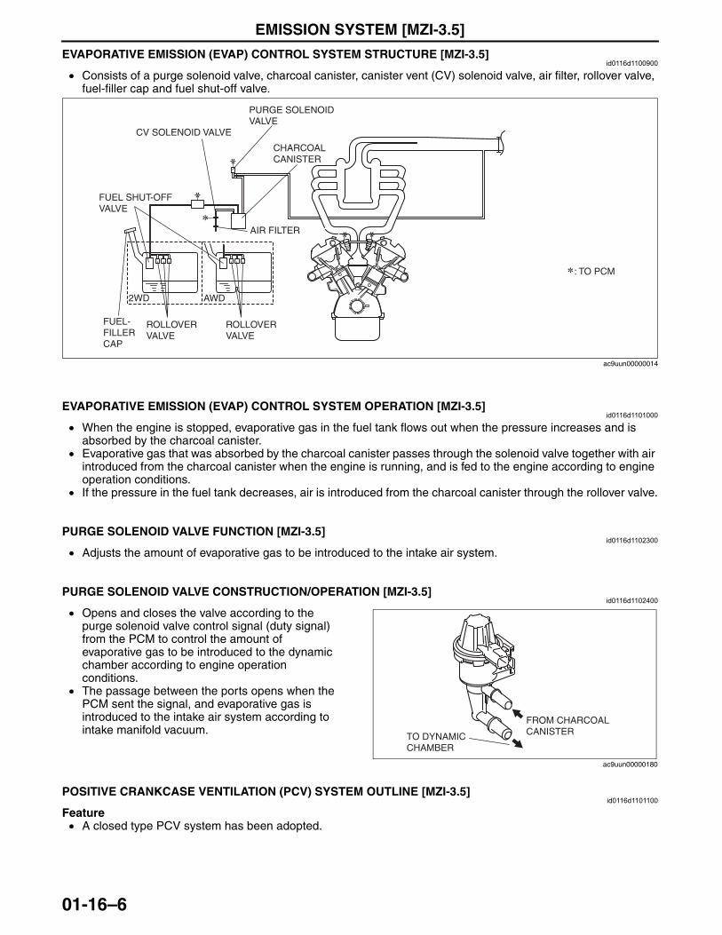
EMISSION SYSTEM [MZI-3.5]
01-16–6
EVAPORATIVE EMISSION (EVAP) CONTROL SYSTEM STRUCTURE [MZI-3.5]id0116d1100900
• Consists of a purge solenoid valve, charcoal canister, canister vent (CV) solenoid valve, air filter, rollover valve, fuel-filler cap and fuel shut-off valve.
End Of Sie
EVAPORATIVE EMISSION (EVAP) CONTROL SYSTEM OPERATION [MZI-3.5]id0116d1101000
• When the engine is stopped, evaporative gas in the fuel tank flows out when the pressure increases and is absorbed by the charcoal canister.
• Evaporative gas that was absorbed by the charcoal canister passes through the solenoid valve together with air introduced from the charcoal canister when the engine is running, and is fed to the engine according to engine operation conditions.
• If the pressure in the fuel tank decreases, air is introduced from the charcoal canister through the rollover valve.End Of SieNG: PURGE SOLENOID VALVE
PURGE SOLENOID VALVE FUNCTION [MZI-3.5]id0116d1102300
• Adjusts the amount of evaporative gas to be introduced to the intake air system.End Of Sie
PURGE SOLENOID VALVE CONSTRUCTION/OPERATION [MZI-3.5]id0116d1102400
• Opens and closes the valve according to the purge solenoid valve control signal (duty signal) from the PCM to control the amount of evaporative gas to be introduced to the dynamic chamber according to engine operation conditions.
• The passage between the ports opens when the PCM sent the signal, and evaporative gas is introduced to the intake air system according to intake manifold vacuum.
End Of SieNG: PCV SYSTEM
POSITIVE CRANKCASE VENTILATION (PCV) SYSTEM OUTLINE [MZI-3.5]id0116d1101100
Feature• A closed type PCV system has been adopted.
End Of Sie
: TO PCM
FUEL SHUT-OFF VALVE
PURGE SOLENOID VALVE
CHARCOAL CANISTER
FUEL- FILLER CAP
ROLLOVER VALVE
ROLLOVER VALVE
AIR FILTER
CV SOLENOID VALVE
AWD2WD
ac9uun00000014
FROM CHARCOAL CANISTERTO DYNAMIC
CHAMBER
ac9uun00000180
3423-1U-06H(01-16).fm 6 ページ 2006年11月22日 水曜日 午後2時4分

EMISSION SYSTEM [MZI-3.5]
01-16–7
01-16
POSITIVE CRANKCASE VENTILATION (PCV) SYSTEM STRUCTURE [MZI-3.5]id0116d1101200
• Consists of a PCV valve, ventilation hose and PCV valve heater fitting.
End Of SiePOSITIVE CRANKCASE VENTILATION (PCV) SYSTEM OPERATION [MZI-3.5]
id0116d1101300
• Blowby gas (unburnt gas), including CO and HC exhausted from the crankcase, is forced into the intake air system and burned in the combustion chamber to prevent its atmospheric release.
End Of SieNG: PCV VALVE
POSITIVE CRANKCASE VENTILATION (PCV) VALVE FUNCTION [MZI-3.5]id0116d1101700
• Adjusts the amount of blowby gas conducted to the intake air system according to the intake manifold vacuum.• Regulates the air (including blowby gas) passing from the cylinder head cover to the dynamic chamber during
low load (when vacuum in the intake manifold is high) to ensure an optimum air/fuel ratio.• Heater operates by the signal from PCM when IAT is low, and anti-icing is done.
End Of Sie
POSITIVE CRANKCASE VENTILATION (PCV) VALVE CONSTRUCTION/OPERATION [MZI-3.5]id0116d1101800
• The PCV valve is installed on the cylinder head.• Consists of a O-ring, spring and valves.• The PCV valve ensures the passage of blowby
gas by opening the valve according to the intake manifold vacuum, and adjusts the amount of gas by spring force.
End Of Sie
POSITIVE CRANKCASE VENTILATION (PCV) VALVE HEATER FITTING FUNCTION [MZI-3.5]id0116d1105900
• Heater operates by the signal from PCM when IAT is low, and anti-icing is done.End Of Sie
: TO PCMPCV VALVE
VENTILATION HOSE
PCV VALVE HEATER FITTING
ac9uun00000007
PCV VALVE
O-RINGTAB
TO DYNAMIC CHAMBER
FROM CYLINDER HEAD
PCV VALVE HEATER CONTROL
ac9uun00000025
3423-1U-06H(01-16).fm 7 ページ 2006年11月22日 水曜日 午後2時4分
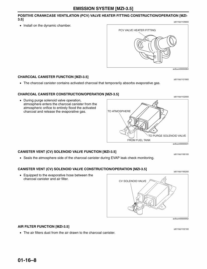
EMISSION SYSTEM [MZI-3.5]
01-16–8
POSITIVE CRANKCASE VENTILATION (PCV) VALVE HEATER FITTING CONSTRUCTION/OPERATION [MZI-3.5]
id0116d1105800
• Install on the dynamic chamber.End Of SieNG: CHARCOAL CANISTER
CHARCOAL CANISTER FUNCTION [MZI-3.5]id0116d1101900
• The charcoal canister contains activated charcoal that temporarily absorbs evaporative gas.End Of Sie
CHARCOAL CANISTER CONSTRUCTION/OPERATION [MZI-3.5]id0116d1102000
• During purge solenoid valve operation, atmosphere enters the charcoal canister from the atmospheric orifice to entirely flood the activated charcoal and release the evaporative gas.
End Of SieNG: CANISTER VENT (CV) SOLENOID VALVE
CANISTER VENT (CV) SOLENOID VALVE FUNCTION [MZI-3.5]id0116d1190100
• Seals the atmosphere side of the charcoal canister during EVAP leak check monitoring.End Of Sie
CANISTER VENT (CV) SOLENOID VALVE CONSTRUCTION/OPERATION [MZI-3.5]id0116d1190200
• Equipped to the evaporative hose between the charcoal canister and air filter.
End Of SieNG: AIR FILTER (EMISSION SYSTEM)
AIR FILTER FUNCTION [MZI-3.5]id0116d1102100
• The air filters dust from the air drawn to the charcoal canister.End Of Sie
PCV VALVE HEATER FITTING
ac9uun00000064
FROM FUEL TANK
TO PURGE SOLENOID VALVE
TO ATMOSPHERE
ac9uun00000031
CV SOLENOID VALVE
ac9uun00000052
3423-1U-06H(01-16).fm 8 ページ 2006年11月22日 水曜日 午後2時4分
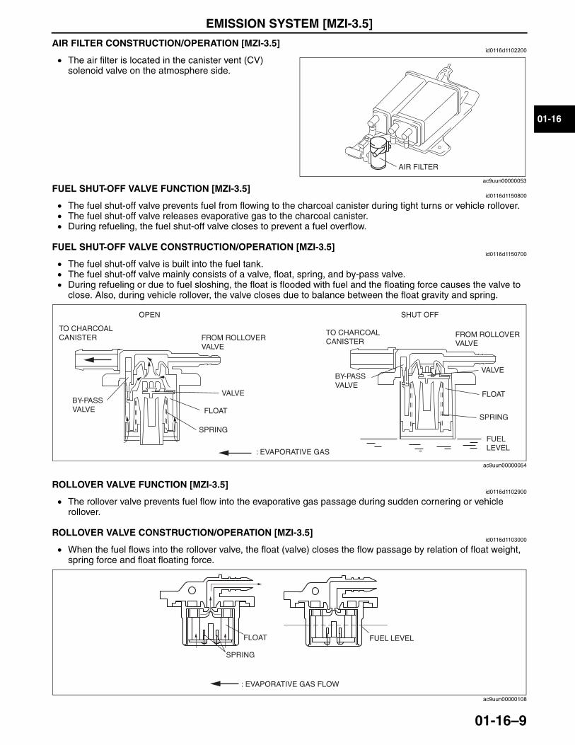
EMISSION SYSTEM [MZI-3.5]
01-16–9
01-16
AIR FILTER CONSTRUCTION/OPERATION [MZI-3.5]id0116d1102200
• The air filter is located in the canister vent (CV) solenoid valve on the atmosphere side.
End Of SieNG: FUEL SHUT-OFF VALVE
FUEL SHUT-OFF VALVE FUNCTION [MZI-3.5]id0116d1150800
• The fuel shut-off valve prevents fuel from flowing to the charcoal canister during tight turns or vehicle rollover.• The fuel shut-off valve releases evaporative gas to the charcoal canister.• During refueling, the fuel shut-off valve closes to prevent a fuel overflow.
End Of SieFUEL SHUT-OFF VALVE CONSTRUCTION/OPERATION [MZI-3.5]
id0116d1150700
• The fuel shut-off valve is built into the fuel tank.• The fuel shut-off valve mainly consists of a valve, float, spring, and by-pass valve.• During refueling or due to fuel sloshing, the float is flooded with fuel and the floating force causes the valve to
close. Also, during vehicle rollover, the valve closes due to balance between the float gravity and spring.
End Of SieNG: ROLLOVER VALVEROLLOVER VALVE FUNCTION [MZI-3.5]
id0116d1102900
• The rollover valve prevents fuel flow into the evaporative gas passage during sudden cornering or vehicle rollover.
End Of SieROLLOVER VALVE CONSTRUCTION/OPERATION [MZI-3.5]
id0116d1103000
• When the fuel flows into the rollover valve, the float (valve) closes the flow passage by relation of float weight, spring force and float floating force.
AIR FILTER
ac9uun00000053
SHUT OFFOPEN
TO CHARCOAL CANISTER FROM ROLLOVER
VALVE
FROM ROLLOVERVALVE
TO CHARCOAL CANISTER
FLOAT
SPRING
SPRING
FLOAT
VALVEBY-PASS VALVE
BY-PASS VALVE
VALVE
: EVAPORATIVE GAS
FUELLEVEL
ac9uun00000054
SPRING
FLOAT FUEL LEVEL
: EVAPORATIVE GAS FLOW
ac9uun00000108
3423-1U-06H(01-16).fm 9 ページ 2006年11月22日 水曜日 午後2時4分
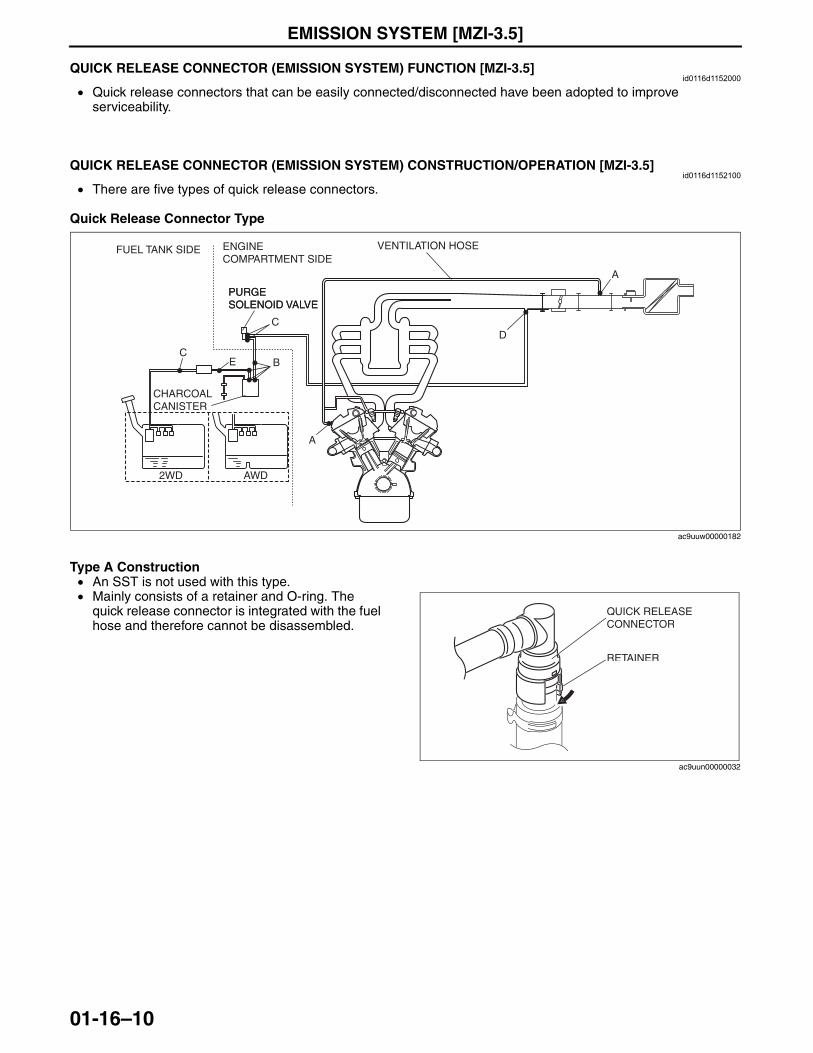
EMISSION SYSTEM [MZI-3.5]
01-16–10
End Of SieQUICK RELEASE CONNECTOR (EMISSION SYSTEM) FUNCTION [MZI-3.5]id0116d1152000
• Quick release connectors that can be easily connected/disconnected have been adopted to improve serviceability.
End Of Sie
QUICK RELEASE CONNECTOR (EMISSION SYSTEM) CONSTRUCTION/OPERATION [MZI-3.5]id0116d1152100
• There are five types of quick release connectors.
Quick Release Connector Type
Type A Construction• An SST is not used with this type.• Mainly consists of a retainer and O-ring. The
quick release connector is integrated with the fuel hose and therefore cannot be disassembled.
PURGE SOLENOID VALVE
A
D
A
BEC
C
VENTILATION HOSE
CHARCOAL CANISTER
PURGE SOLENOID VALVE
ENGINE COMPARTMENT SIDE
FUEL TANK SIDE
2WD AWD
ac9uuw00000182
QUICK RELEASECONNECTOR
RETAINER
ac9uun00000032
3423-1U-06H(01-16).fm 10 ページ 2006年11月22日 水曜日 午後2時4分
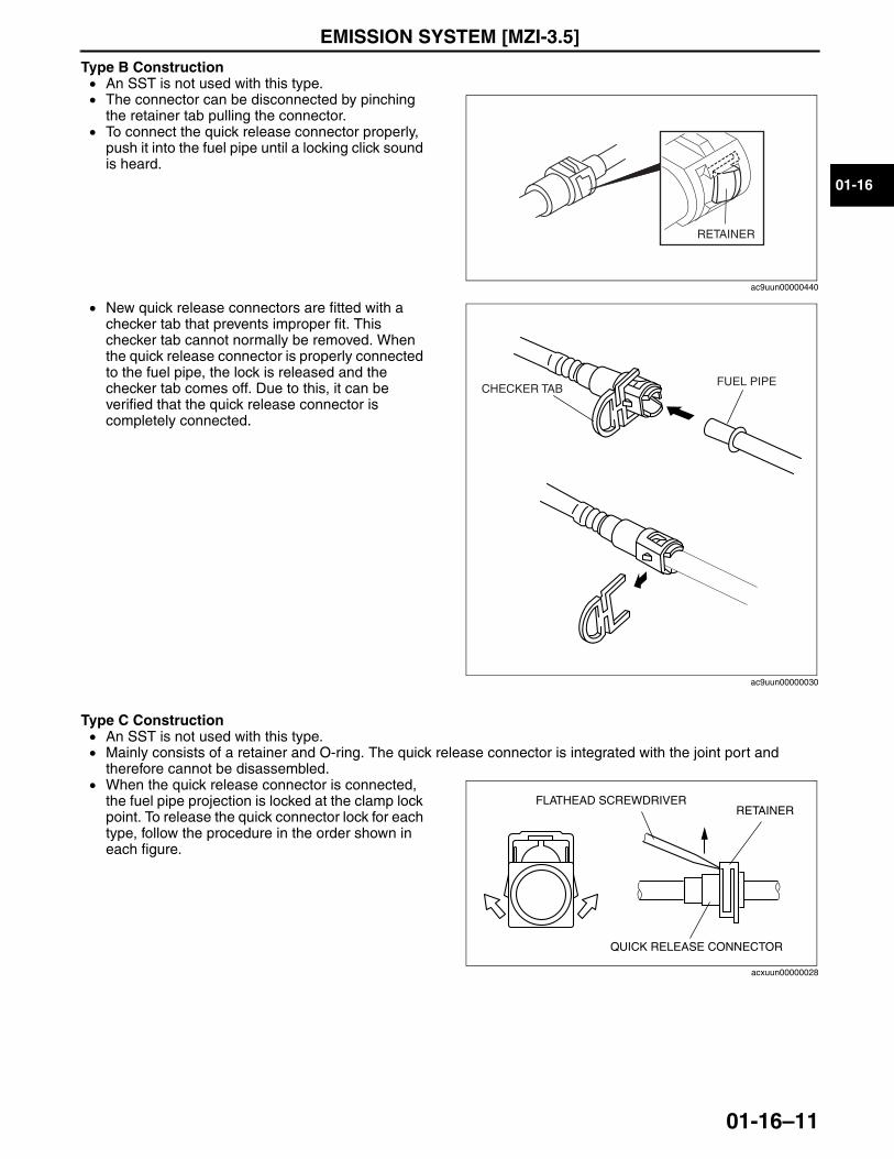
EMISSION SYSTEM [MZI-3.5]
01-16–11
01-16
Type B Construction• An SST is not used with this type.• The connector can be disconnected by pinching
the retainer tab pulling the connector. • To connect the quick release connector properly,
push it into the fuel pipe until a locking click sound is heard.
• New quick release connectors are fitted with a checker tab that prevents improper fit. This checker tab cannot normally be removed. When the quick release connector is properly connected to the fuel pipe, the lock is released and the checker tab comes off. Due to this, it can be verified that the quick release connector is completely connected.
Type C Construction• An SST is not used with this type.• Mainly consists of a retainer and O-ring. The quick release connector is integrated with the joint port and
therefore cannot be disassembled.• When the quick release connector is connected,
the fuel pipe projection is locked at the clamp lock point. To release the quick connector lock for each type, follow the procedure in the order shown in each figure.
RETAINER
ac9uun00000440
CHECKER TABFUEL PIPE
ac9uun00000030
FLATHEAD SCREWDRIVER
QUICK RELEASE CONNECTOR
RETAINER
acxuun00000028
3423-1U-06H(01-16).fm 11 ページ 2006年11月22日 水曜日 午後2時4分
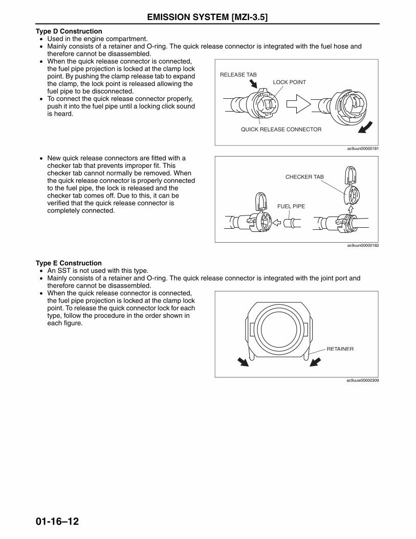
EMISSION SYSTEM [MZI-3.5]
01-16–12
Type D Construction• Used in the engine compartment.• Mainly consists of a retainer and O-ring. The quick release connector is integrated with the fuel hose and
therefore cannot be disassembled.• When the quick release connector is connected,
the fuel pipe projection is locked at the clamp lock point. By pushing the clamp release tab to expand the clamp, the lock point is released allowing the fuel pipe to be disconnected.
• To connect the quick release connector properly, push it into the fuel pipe until a locking click sound is heard.
• New quick release connectors are fitted with a checker tab that prevents improper fit. This checker tab cannot normally be removed. When the quick release connector is properly connected to the fuel pipe, the lock is released and the checker tab comes off. Due to this, it can be verified that the quick release connector is completely connected.
Type E Construction• An SST is not used with this type.• Mainly consists of a retainer and O-ring. The quick release connector is integrated with the joint port and
therefore cannot be disassembled.• When the quick release connector is connected,
the fuel pipe projection is locked at the clamp lock point. To release the quick connector lock for each type, follow the procedure in the order shown in each figure.
End Of Sie
RELEASE TABLOCK POINT
QUICK RELEASE CONNECTOR
ac9uun00000181
CHECKER TAB
FUEL PIPE
ac9uun00000182
RETAINER
ac9uuw00000309
3423-1U-06H(01-16).fm 12 ページ 2006年11月22日 水曜日 午後2時4分
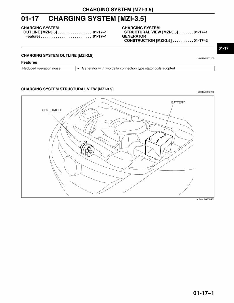
CHARGING SYSTEM [MZI-3.5]
01-17–1
01-17
01-17 CHARGING SYSTEM [MZI-3.5]CHARGING SYSTEM
OUTLINE [MZI-3.5] . . . . . . . . . . . . . . . . 01-17–1Features . . . . . . . . . . . . . . . . . . . . . . . . 01-17–1
CHARGING SYSTEM STRUCTURAL VIEW [MZI-3.5] . . . . . . . 01-17–1
GENERATOR CONSTRUCTION [MZI-3.5] . . . . . . . . . . 01-17–2
End of TocNG: CHARGING SYSTEMCHARGING SYSTEM OUTLINE [MZI-3.5]
id0117d1102100
Features
End Of Sie
CHARGING SYSTEM STRUCTURAL VIEW [MZI-3.5]id0117d1102200
End Of SieNG: GENERATOR
Reduced operation noise • Generator with two delta connection type stator coils adopted
BATTERY
GENERATOR
ac9uun00000481
3423-1U-06H(01-17).fm 1 ページ 2006年11月22日 水曜日 午後1時47分
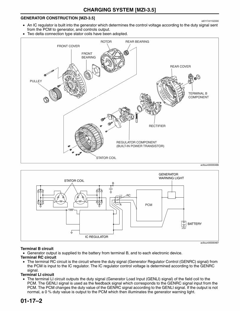
CHARGING SYSTEM [MZI-3.5]
01-17–2
GENERATOR CONSTRUCTION [MZI-3.5]id0117d1102300
• An IC regulator is built into the generator which determines the control voltage according to the duty signal sent from the PCM to generator, and controls output.
• Two delta connection type stator coils have been adopted.
Terminal B circuit• Generator output is supplied to the battery from terminal B, and to each electronic device.
Terminal RC circuit• The terminal RC circuit is the circuit where the duty signal (Generator Regulator Control (GENRC) signal) from
the PCM is input to the IC regulator. The IC regulator control voltage is determined according to the GENRC signal.
Terminal LI circuit• The terminal LI circuit outputs the duty signal (Generator Load Input (GENLI) signal) of the field coil to the
PCM. The GENLI signal is used as the feedback signal which corresponds to the GENRC signal input from the PCM. The PCM changes the duty value of the GENRC signal according to the GENLI signal. If the output is not normal, a 0 % duty value is output to the PCM which then illuminates the generator warning light.
PULLEY
FRONT COVER
FRONT BEARING
ROTOR REAR BEARING
STATOR COIL
REAR COVER
TERMINAL B COMPONENT
RECTIFIER
REGULATOR COMPONENT (BUILT-IN POWER TRANSISTOR)
ac9uun00000486
PCM
BATTERY
IC REGULATOR
B
GENERATORWARNING LIGHT
STATOR COIL
LI
A
RC
ac9uun00000487
3423-1U-06H(01-17).fm 2 ページ 2006年11月22日 水曜日 午後1時47分

CHARGING SYSTEM [MZI-3.5]
01-17–3
01-17
Terminal A circuit• Terminal A circuit is used to detect battery voltage. This voltage is used to determine generator output voltage.
This circuit is used to supply current to the field coil (rotor). The amount of current supplied to the field coil (rotor) determines the generator output current.
• The phase difference in the circuit of the two stator coils causes the electromagnetic pull between the rotor and the stator to be eliminated logically. Due to this, electromagnetic vibration and generator operation noise (electromagnetic noise) have been reduced.
• The pulsation occurring through voltage rectifying is minimized, as a result, stable voltage output is supplied due to the adoption of two stator coils with the phase difference.
End Of Sie
STATOR COIL
PHASE DIFFERENCE
acxuun00000548
0
0 30 60 90 120 150 180 210 240 270 300 330 3600 30 60 90 120 150 180 210 240 270 300 330 360
0
RECTIFIED VOLTAGESTATOR COIL (INCLUDES 1 TYPE) STATOR COIL (INCLUDES 2 TYPE)
ANGLE (°)ANGLE (°)
VO
LTA
GE
(V
)
VO
LTA
GE
(V
)
acxuun00000549
3423-1U-06H(01-17).fm 3 ページ 2006年11月22日 水曜日 午後1時47分

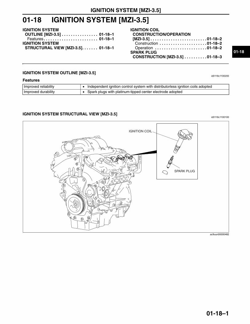
IGNITION SYSTEM [MZI-3.5]
01-18–1
01-18
01-18 IGNITION SYSTEM [MZI-3.5]IGNITION SYSTEM
OUTLINE [MZI-3.5] . . . . . . . . . . . . . . . . 01-18–1Features . . . . . . . . . . . . . . . . . . . . . . . . 01-18–1
IGNITION SYSTEM STRUCTURAL VIEW [MZI-3.5]. . . . . . . 01-18–1
IGNITION COIL CONSTRUCTION/OPERATION [MZI-3.5] . . . . . . . . . . . . . . . . . . . . . . . . . 01-18–2
Construction . . . . . . . . . . . . . . . . . . . . . 01-18–2Operation . . . . . . . . . . . . . . . . . . . . . . . 01-18–2
SPARK PLUG CONSTRUCTION [MZI-3.5] . . . . . . . . . . 01-18–3
End of TocNG: IGNITION SYSTEMIGNITION SYSTEM OUTLINE [MZI-3.5]
id0118c1100200
Features
End Of Sie
IGNITION SYSTEM STRUCTURAL VIEW [MZI-3.5]id0118c1100100
End Of SieNG: IGNITION COIL
Improved reliability • Independent ignition control system with distributorless ignition coils adoptedImproved durability • Spark plugs with platinum-tipped center electrode adopted
SPARK PLUG
IGNITION COIL
ac9uun00000482
3423-1U-06H(01-18).fm 1 ページ 2006年11月21日 火曜日 午後5時1分
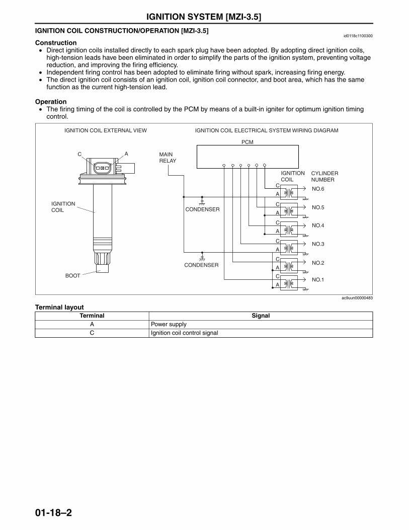
IGNITION SYSTEM [MZI-3.5]
01-18–2
IGNITION COIL CONSTRUCTION/OPERATION [MZI-3.5]id0118c1100300
Construction• Direct ignition coils installed directly to each spark plug have been adopted. By adopting direct ignition coils,
high-tension leads have been eliminated in order to simplify the parts of the ignition system, preventing voltage reduction, and improving the firing efficiency.
• Independent firing control has been adopted to eliminate firing without spark, increasing firing energy.• The direct ignition coil consists of an ignition coil, ignition coil connector, and boot area, which has the same
function as the current high-tension lead.
Operation• The firing timing of the coil is controlled by the PCM by means of a built-in igniter for optimum ignition timing
control.
Terminal layout
End Of SieNG: SPARK PLUG
Terminal SignalA Power supplyC Ignition coil control signal
C
A
C
A
C
A
C
A
C
A
C
A
IGNITION COIL ELECTRICAL SYSTEM WIRING DIAGRAMIGNITION COIL EXTERNAL VIEW
IGNITIONCOIL
BOOT
IGNITION COIL
CYLINDER NUMBER
NO.6
NO.5
NO.4
NO.3
NO.2
NO.1
PCM
MAINRELAY
CONDENSER
CONDENSER
AC
ac9uun00000483
3423-1U-06H(01-18).fm 2 ページ 2006年11月21日 火曜日 午後5時1分
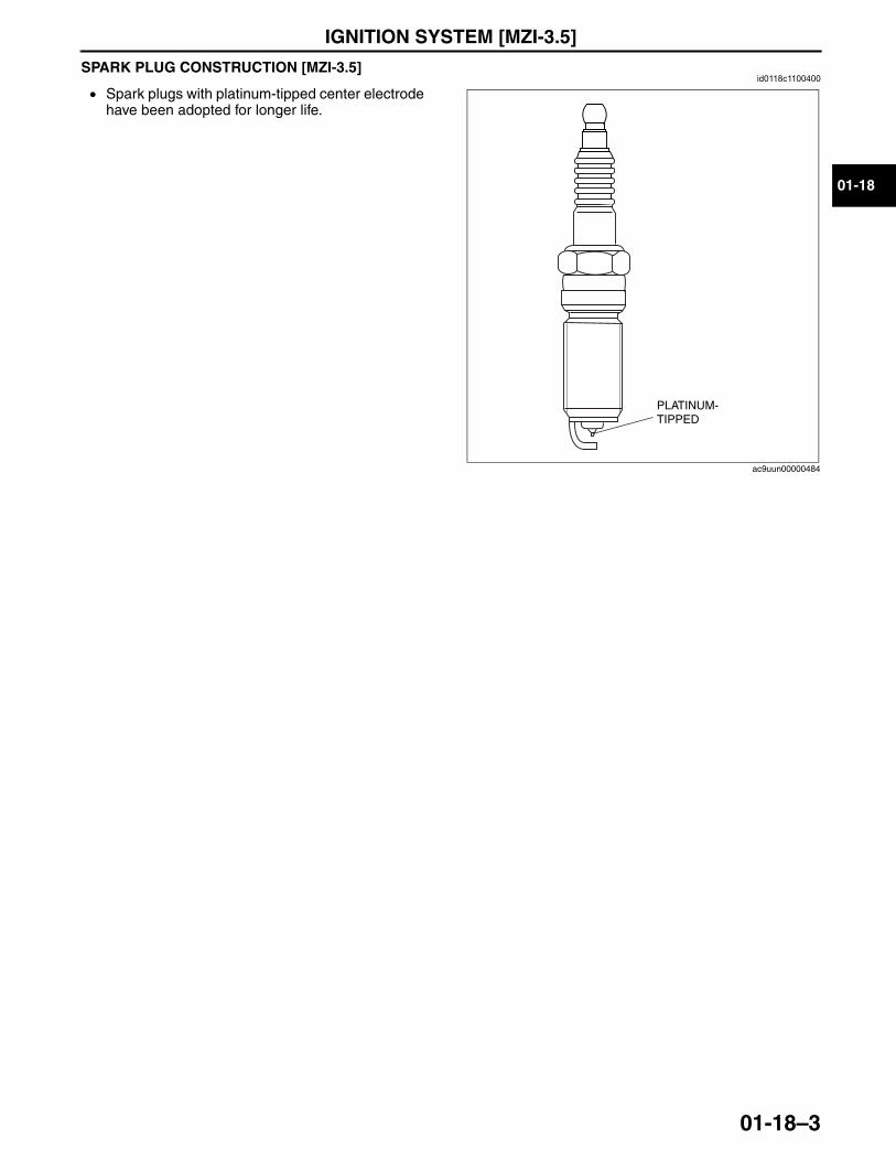
IGNITION SYSTEM [MZI-3.5]
01-18–3
01-18
SPARK PLUG CONSTRUCTION [MZI-3.5]id0118c1100400
• Spark plugs with platinum-tipped center electrode have been adopted for longer life.
End Of Sie
PLATINUM-TIPPED
ac9uun00000484
3423-1U-06H(01-18).fm 3 ページ 2006年11月21日 火曜日 午後5時1分

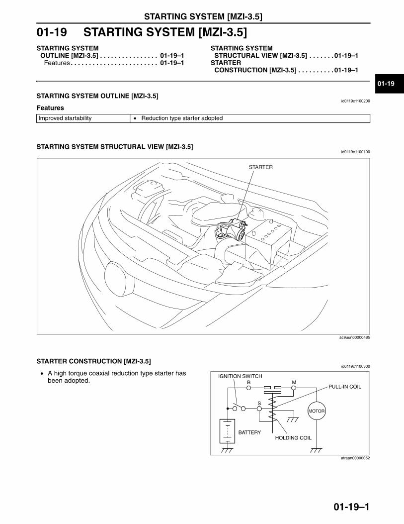
STARTING SYSTEM [MZI-3.5]
01-19–1
01-19
01-19 STARTING SYSTEM [MZI-3.5]STARTING SYSTEM
OUTLINE [MZI-3.5] . . . . . . . . . . . . . . . . 01-19–1Features . . . . . . . . . . . . . . . . . . . . . . . . 01-19–1
STARTING SYSTEM STRUCTURAL VIEW [MZI-3.5] . . . . . . . 01-19–1
STARTER CONSTRUCTION [MZI-3.5] . . . . . . . . . . 01-19–1
End of TocNG: STARTING SYSTEMSTARTING SYSTEM OUTLINE [MZI-3.5]
id0119c1100200
Features
End Of Sie
STARTING SYSTEM STRUCTURAL VIEW [MZI-3.5]id0119c1100100
End Of SieNG: STARTER
STARTER CONSTRUCTION [MZI-3.5]id0119c1100300
• A high torque coaxial reduction type starter has been adopted.
End Of Sie
Improved startability • Reduction type starter adopted
STARTER
ac9uun00000485
B
S
MIGNITION SWITCH
BATTERYHOLDING COIL
MOTOR
PULL-IN COIL
atraan00000052
3423-1U-06H(01-19).fm 1 ページ 2006年11月28日 火曜日 午後4時6分

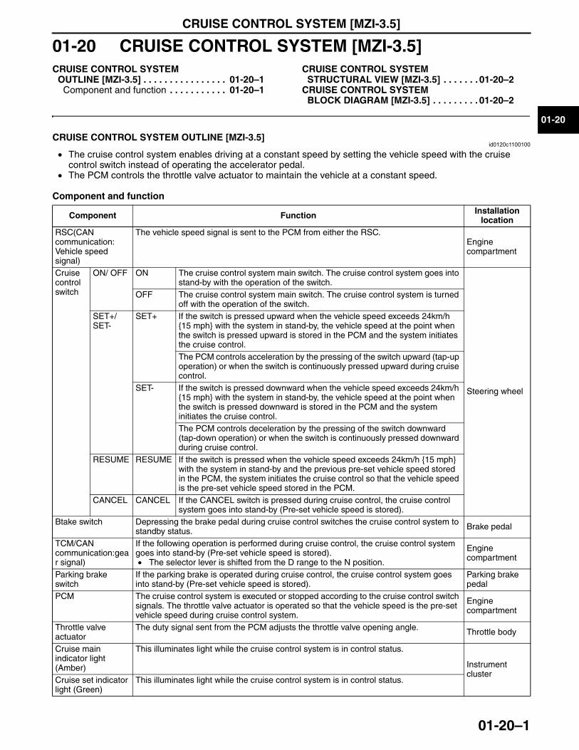
CRUISE CONTROL SYSTEM [MZI-3.5]
01-20–1
01-20
01-20 CRUISE CONTROL SYSTEM [MZI-3.5]CRUISE CONTROL SYSTEM
OUTLINE [MZI-3.5] . . . . . . . . . . . . . . . . 01-20–1Component and function . . . . . . . . . . . 01-20–1
CRUISE CONTROL SYSTEM STRUCTURAL VIEW [MZI-3.5] . . . . . . . 01-20–2
CRUISE CONTROL SYSTEM BLOCK DIAGRAM [MZI-3.5] . . . . . . . . . 01-20–2
End of TocNG: CRUISE CONTROL SYSTEMCRUISE CONTROL SYSTEM OUTLINE [MZI-3.5]
id0120c1100100
• The cruise control system enables driving at a constant speed by setting the vehicle speed with the cruise control switch instead of operating the accelerator pedal.
• The PCM controls the throttle valve actuator to maintain the vehicle at a constant speed.
Component and function
Component Function Installation location
RSC(CAN communication: Vehicle speed signal)
The vehicle speed signal is sent to the PCM from either the RSC.Engine compartment
Cruise control switch
ON/ OFF ON The cruise control system main switch. The cruise control system goes into stand-by with the operation of the switch.
Steering wheel
OFF The cruise control system main switch. The cruise control system is turned off with the operation of the switch.
SET+/ SET-
SET+ If the switch is pressed upward when the vehicle speed exceeds 24km/h {15 mph} with the system in stand-by, the vehicle speed at the point when the switch is pressed upward is stored in the PCM and the system initiates the cruise control.The PCM controls acceleration by the pressing of the switch upward (tap-up operation) or when the switch is continuously pressed upward during cruise control.
SET- If the switch is pressed downward when the vehicle speed exceeds 24km/h {15 mph} with the system in stand-by, the vehicle speed at the point when the switch is pressed downward is stored in the PCM and the system initiates the cruise control.The PCM controls deceleration by the pressing of the switch downward (tap-down operation) or when the switch is continuously pressed downward during cruise control.
RESUME RESUME If the switch is pressed when the vehicle speed exceeds 24km/h {15 mph} with the system in stand-by and the previous pre-set vehicle speed stored in the PCM, the system initiates the cruise control so that the vehicle speed is the pre-set vehicle speed stored in the PCM.
CANCEL CANCEL If the CANCEL switch is pressed during cruise control, the cruise control system goes into stand-by (Pre-set vehicle speed is stored).
Btake switch Depressing the brake pedal during cruise control switches the cruise control system to standby status. Brake pedal
TCM/CAN communication:gear signal)
If the following operation is performed during cruise control, the cruise control system goes into stand-by (Pre-set vehicle speed is stored). • The selector lever is shifted from the D range to the N position.
Engine compartment
Parking brake switch
If the parking brake is operated during cruise control, the cruise control system goes into stand-by (Pre-set vehicle speed is stored).
Parking brake pedal
PCM The cruise control system is executed or stopped according to the cruise control switch signals. The throttle valve actuator is operated so that the vehicle speed is the pre-set vehicle speed during cruise control system.
Engine compartment
Throttle valve actuator
The duty signal sent from the PCM adjusts the throttle valve opening angle. Throttle body
Cruise main indicator light (Amber)
This illuminates light while the cruise control system is in control status.
Instrument cluster
Cruise set indicator light (Green)
This illuminates light while the cruise control system is in control status.
3423-1U-06H(01-20).fm 1 ページ 2006年11月21日 火曜日 午後5時3分
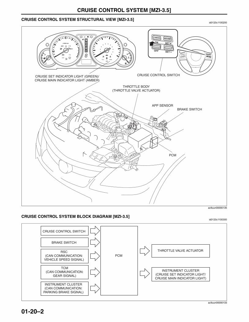
CRUISE CONTROL SYSTEM [MZI-3.5]
01-20–2
End Of SieCRUISE CONTROL SYSTEM STRUCTURAL VIEW [MZI-3.5]id0120c1100200
End Of SieCRUISE CONTROL SYSTEM BLOCK DIAGRAM [MZI-3.5]
id0120c1100300
BRAKE
APP SENSORBRAKE SWITCH
PCM
THROTTLE BODY(THROTTLE VALVE ACTUATOR)
CRUISE SET INDICATOR LIGHT (GREEN)/ CRUISE MAIN INDICATOR LIGHT (AMBER)
CRUISE CONTROL SWITCH
ac9uun00000135
PCM
CRUISE CONTROL SWITCH
BRAKE SWITCH
RSC(CAN COMMUNICATION:
VEHICLE SPEED SIGNAL)
THROTTLE VALVE ACTUATOR
INSTRUMENT CLUSTER(CRUISE SET INDICATOR LIGHT/CRUISE MAIN INDICATOR LIGHT)
INSTRUMENT CLUSTER(CAN COMMUNICATION:
PARKING BRAKE SIGNAL)
TCM(CAN COMMUNICATION:
GEAR SIGNAL)
ac9uun00000133
3423-1U-06H(01-20).fm 2 ページ 2006年11月21日 火曜日 午後5時3分
CONTROL SYSTEM [MZI-3.5]
01-40–1
01-40
01-40 CONTROL SYSTEM [MZI-3.5]ENGINE CONTROL SYSTEM
OUTLINE [MZI-3.5] . . . . . . . . . . . . . . . . 01-40–2Features . . . . . . . . . . . . . . . . . . . . . . . . 01-40–2Specification. . . . . . . . . . . . . . . . . . . . . 01-40–2
ENGINE CONTROL SYSTEM STRUCTURAL VIEW [MZI-3.5]. . . . . . . 01-40–3
ENGINE CONTROL SYSTEM DIAGRAM [MZI-3.5] . . . . . . . . . . . . . . . 01-40–4
ELECTRICAL FAN CONTROL OUTLINE [MZI-3.5] . . . . . . . . . . . . . . . . 01-40–4
ELECTRICAL FAN CONTROL BLOCK DIAGRAM [MZI-3.5] . . . . . . . . 01-40–4
ELECTRICAL FAN CONTROL OPERATION [MZI-3.5] . . . . . . . . . . . . . 01-40–5
Without Towing Package . . . . . . . . . . . 01-40–5With Towing Package . . . . . . . . . . . . . . 01-40–5
PCM FUNCTION [MZI-3.5] . . . . . . . . . . . 01-40–6Function List. . . . . . . . . . . . . . . . . . . . . 01-40–6
PCM CONSTRUCTION/OPERATION [MZI-3.5] . . . . . . . . . . . . . . . . . . . . . . . . 01-40–6
Structure . . . . . . . . . . . . . . . . . . . . . . . 01-40–6POWER STEERING PRESSURE
(PSP) SWITCH FUNCTION [MZI-3.5] . . . . . . . . . . . . . . . . . . . . . . . . 01-40–7
POWER STEERING PRESSURE (PSP) SWITCH CONSTRUCTION/OPERATION [MZI-3.5] . . . . . . . . . . . . . . . . . . . . . . . . 01-40–7
INTAKE AIR TEMPERATURE (IAT) SENSOR FUNCTION [MZI-3.5] . . . . . . . . . . . . . . . . . . . . . . . . 01-40–7
INTAKE AIR TEMPERATURE (IAT) SENSOR CONSTRUCTION/OPERATION [MZI-3.5] . . . . . . . . . . . . . . . . . . . . . . . . 01-40–7
ACCELERATOR PEDAL POSITION (APP) SENSOR FUNCTION [MZI-3.5] . . . . . . . . . . . . . . . . . . . . . . . . 01-40–7
ACCELERATOR PEDAL POSITION (APP) SENSOR CONSTRUCTION/OPERATION [MZI-3.5] . . . . . . . . . . . . . . . . . . . . . . . . 01-40–7
KNOCK SENSOR (KS) FUNCTION [MZI-3.5] . . . . . . . . . . . . . . . 01-40–8
KNOCK SENSOR (KS) CONSTRUCTION/OPERATION [MZI-3.5] . . . . . . . . . . . . . . . . . . . . . . . . . 01-40–8
MASS AIR FLOW (MAF) SENSOR FUNCTION [MZI-3.5] . . . . . . . . . . . . . . . 01-40–8
MASS AIR FLOW (MAF) SENSOR CONSTRUCTION/OPERATION [MZI-3.5] . . . . . . . . . . . . . . . . . . . . . . . . . 01-40–8
CRANKSHAFT POSITION (CKP) SENSOR FUNCTION [MZI-3.5] . . . . . . . 01-40–8
CRANKSHAFT POSITION (CKP) SENSOR CONSTRUCTION/OPERATION [MZI-3.5] . . . . . . . . . . . . . . . . . . . . . . . . . 01-40–9
CAMSHAFT POSITION (CMP) SENSOR FUNCTION [MZI-3.5] . . . . . . . 01-40–9
CAMSHAFT POSITION (CMP) SENSOR CONSTRUCTION/OPERATION [MZI-3.5] . . . . . . . . . . . . . . . . . . . . . . . . . 01-40–9
HEATED OXYGEN SENSOR (HO2S) FUNCTION [MZI-3.5] . . . . . . . . . . . . . . . 01-40–10
HEATED OXYGEN SENSOR (HO2S) CONSTRUCTION/OPERATION [MZI-3.5] . . . . . . . . . . . . . . . . . . . . . . . . . 01-40–10
THROTTLE POSITION (TP) SENSOR FUNCTION [MZI-3.5] . . . . . . . . . . . . . . . 01-40–10
THROTTLE POSITION (TP) SENSOR CONSTRUCTION/OPERATION [MZI-3.5] . . . . . . . . . . . . . . . . . . . . . . . . . 01-40–10
CYLINDER HEAD TEMPERATURE (CHT) SENSOR FUNCTION [MZI-3.5] . . . . . . . . . . . . . . . . . . . . . . . . . 01-40–10
CYLINDER HEAD TEMPERATURE (CHT) SENSOR CONSTRUCTION/OPERATION [MZI-3.5] . . . . . . . . . . . . . . . . . . . . . . . . . 01-40–11
FUEL TANK PRESSURE SENSOR FUNCTION [MZI-3.5] . . . . . . . . . . . . . . . 01-40–11
FUEL TANK PRESSURE SENSOR CONSTRUCTION/OPERATION [MZI-3.5] . . . . . . . . . . . . . . . . . . . . . . . . . 01-40–11
End of TocNG: ENGINE CONTROL SYSTEM
3423-1U-06H(01-40).fm 1 ページ 2006年11月22日 水曜日 午後2時18分
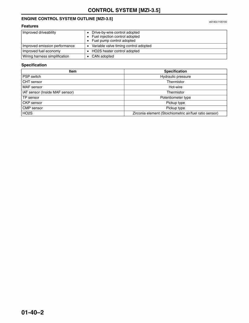
CONTROL SYSTEM [MZI-3.5]
01-40–2
ENGINE CONTROL SYSTEM OUTLINE [MZI-3.5]id0140c1100100
Features
Specification
End Of Sie
Improved driveability • Drive-by-wire control adopted• Fuel injection control adopted• Fuel pump control adopted
Improved emission performance • Variable valve timing control adoptedImproved fuel economy • HO2S heater control adoptedWiring harness simplification • CAN adopted
Item SpecificationPSP switch Hydraulic pressureCHT sensor ThermistorMAF sensor Hot-wireIAT sensor (Inside MAF sensor) ThermistorTP sensor Potentiometer typeCKP sensor Pickup typeCMP sensor Pickup typeHO2S Zirconia element (Stoichiometric air/fuel ratio sensor)
3423-1U-06H(01-40).fm 2 ページ 2006年11月22日 水曜日 午後2時18分
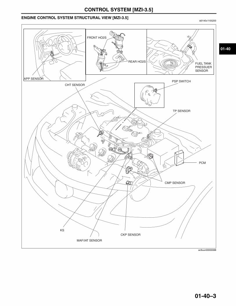
CONTROL SYSTEM [MZI-3.5]
01-40–3
01-40
ENGINE CONTROL SYSTEM STRUCTURAL VIEW [MZI-3.5]id0140c1100200
End Of Sie
FUEL TANK PRESSUER SENSOR
PCM
MAF/IAT SENSOR
TP SENSOR
CHT SENSOR
CKP SENSOR
CMP SENSOR
KS
FRONT HO2S
REAR HO2S
PSP SWITCHAPP SENSOR
ac9uun00000088
3423-1U-06H(01-40).fm 3 ページ 2006年11月22日 水曜日 午後2時18分
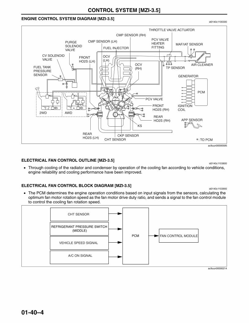
CONTROL SYSTEM [MZI-3.5]
01-40–4
ENGINE CONTROL SYSTEM DIAGRAM [MZI-3.5]id0140c1100300
End Of Sie
ELECTRICAL FAN CONTROL OUTLINE [MZI-3.5]id0140c1103800
• Through cooling of the radiator and condenser by operation of the cooling fan according to vehicle conditions, engine reliability and cooling performance have been improved.
End Of Sie
ELECTRICAL FAN CONTROL BLOCK DIAGRAM [MZI-3.5]id0140c1103900
• The PCM determines the engine operation conditions based on input signals from the sensors, calculating the optimum fan motor rotation speed as the fan motor drive duty ratio, and sends a signal to the fan control module to control the cooling fan rotation speed.
End Of Sie
TP SENSOR
FUEL INJECTOR
CMP SENSOR (RH)
CMP SENSOR (LH)
CKP SENSOR
IGNITION COIL
GENERATOR
CHT SENSOR
OCV (LH)
PCV VALVE HEATER FITTING
PCV VALVE
AIR CLEANER
MAF/IAT SENSOR
FRONT HO2S (LH)
REAR HO2S (LH)
KS
PCM
: TO PCM
PURGE SOLENOID VALVE
APP SENSOR
THROTTLE VALVE ACTUATOR
OCV (RH)
FRONT HO2S (RH)
REAR HO2S (RH)
FUEL TANK PRESSURE SENSOR
CV SOLENOID VALVE
2WD AWD
ac9uun00000595
CHT SENSOR
VEHICLE SPEED SIGNAL
A/C ON SIGNAL
FAN CONTROL MODULEPCM
REFRIGERANT PRESSURE SWITCH (MIDDLE)
ac9uun00000214
3423-1U-06H(01-40).fm 4 ページ 2006年11月22日 水曜日 午後2時18分
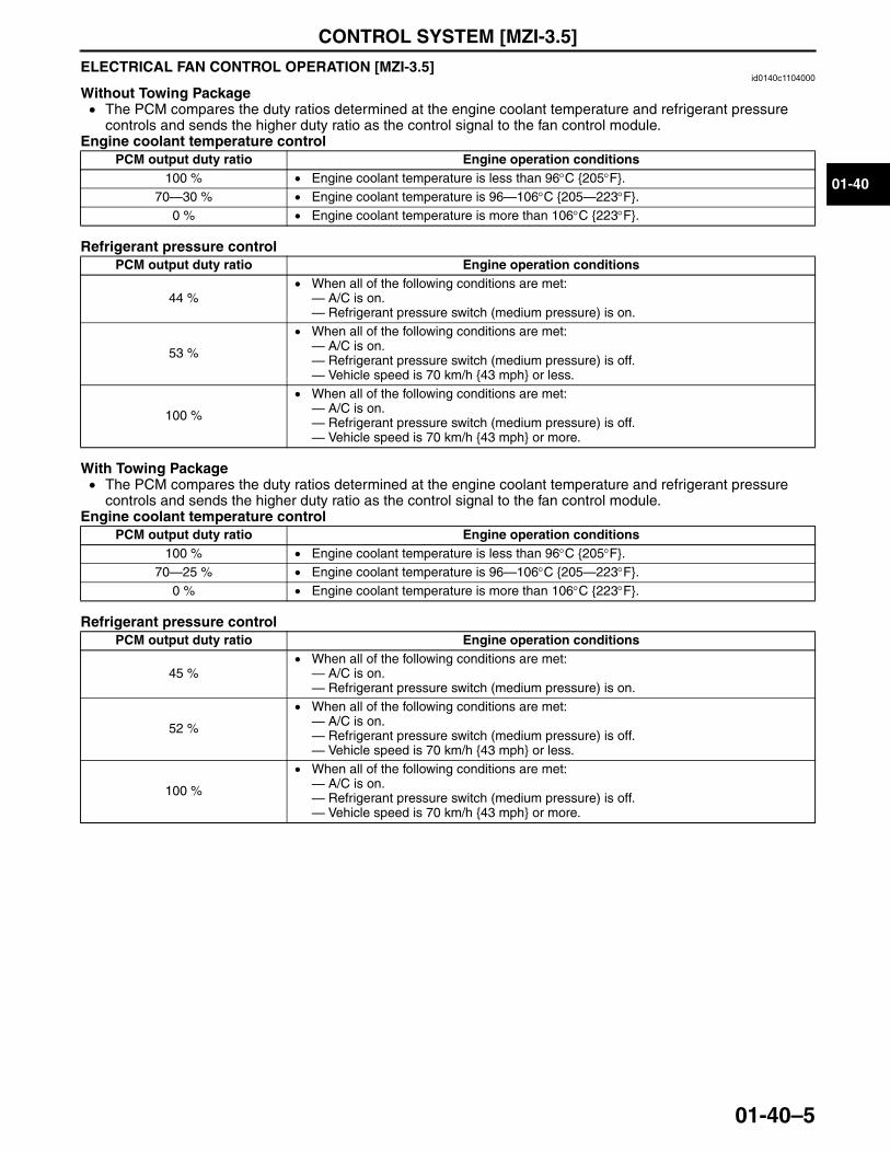
CONTROL SYSTEM [MZI-3.5]
01-40–5
01-40
ELECTRICAL FAN CONTROL OPERATION [MZI-3.5]id0140c1104000
Without Towing Package• The PCM compares the duty ratios determined at the engine coolant temperature and refrigerant pressure
controls and sends the higher duty ratio as the control signal to the fan control module.Engine coolant temperature control
Refrigerant pressure control
With Towing Package• The PCM compares the duty ratios determined at the engine coolant temperature and refrigerant pressure
controls and sends the higher duty ratio as the control signal to the fan control module.Engine coolant temperature control
Refrigerant pressure control
End Of SieNG: PCM
PCM output duty ratio Engine operation conditions100 % • Engine coolant temperature is less than 96°C {205°F}.
70—30 % • Engine coolant temperature is 96—106°C {205—223°F}.0 % • Engine coolant temperature is more than 106°C {223°F}.
PCM output duty ratio Engine operation conditions
44 %• When all of the following conditions are met:— A/C is on.— Refrigerant pressure switch (medium pressure) is on.
53 %
• When all of the following conditions are met:— A/C is on.— Refrigerant pressure switch (medium pressure) is off.— Vehicle speed is 70 km/h {43 mph} or less.
100 %
• When all of the following conditions are met:— A/C is on.— Refrigerant pressure switch (medium pressure) is off.— Vehicle speed is 70 km/h {43 mph} or more.
PCM output duty ratio Engine operation conditions100 % • Engine coolant temperature is less than 96°C {205°F}.
70—25 % • Engine coolant temperature is 96—106°C {205—223°F}.0 % • Engine coolant temperature is more than 106°C {223°F}.
PCM output duty ratio Engine operation conditions
45 %• When all of the following conditions are met:— A/C is on.— Refrigerant pressure switch (medium pressure) is on.
52 %
• When all of the following conditions are met:— A/C is on.— Refrigerant pressure switch (medium pressure) is off.— Vehicle speed is 70 km/h {43 mph} or less.
100 %
• When all of the following conditions are met:— A/C is on.— Refrigerant pressure switch (medium pressure) is off.— Vehicle speed is 70 km/h {43 mph} or more.
3423-1U-06H(01-40).fm 5 ページ 2006年11月22日 水曜日 午後2時18分
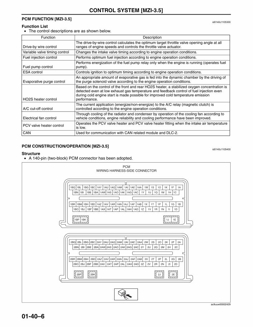
CONTROL SYSTEM [MZI-3.5]
01-40–6
PCM FUNCTION [MZI-3.5]id0140c1105300
Function List• The control descriptions are as shown below.
End Of SiePCM CONSTRUCTION/OPERATION [MZI-3.5]
id0140c1105400
Structure• A 140-pin (two-block) PCM connector has been adopted.
Function Description
Drive-by wire controlThe drive-by-wire control calculates the optimum target throttle valve opening angle at all ranges of engine speeds and controls the throttle valve actuator.
Variable valve timing control Changes the intake valve timing according to engine operation conditions.Fuel injection control Performs optimum fuel injection according to engine operation conditions.
Fuel pump controlPerforms energization of the fuel pump relay only when the engine is running (operates fuel pump).
ESA control Controls ignition to optimum timing according to engine operation conditions.
Evaporative purge controlAn appropriate amount of evaporative gas is fed into the dynamic chamber by the driving of the purge solenoid valve according to the engine operation conditions.
HO2S heater control
Based on the control of the front and rear HO2S heater, a stabilized oxygen concentration is detected even at low exhaust gas temperature and feedback control of fuel injection even during cold engine start is made possible for improved cold temperature emission performance.
A/C cut-off controlThe current application (energize/non-energize) to the A/C relay (magnetic clutch) is controlled according to the engine operation conditions.
Electrical fan controlThrough cooling of the radiator and condenser by operation of the cooling fan according to vehicle conditions, engine reliability and cooling performance have been improved.
PCV valve heater control Operates the PCV valve heater and PCV valve heater fitting when the intake air temperature is low.
CAN Used for communication with CAN related module and DLC-2.
1BQ 1BL
1BI
1BG
1BE
1AI
1AG1AK
1AM
1AC
1AQ
1AO
1BC 1AE
1BP 1BK
1AY
1AW 1AS 1H1M 1C1Q1Y 1U
1AU
1BA1BN
1F1K1O1AA 1A1W 1S
1BJ 1BF 1AH1AL 1AD1AP1AX 1AT 1I1N 1D1R1Z 1V1BB1BO
1J 1E
1BR 1BM 1BH 1AJ1AN1AR1BD 1AF1AZ 1AV 1G1L1P1AB 1B1X 1T
2BQ 2BL
2BI
2BG
2BE
2AI
2AG2AK
2AM
2AC
2AQ
2AO
2BC 2AE
2BP
2AY
2AW 2AS 2H2M 2C2Q2Y 2U
2AU
2BA2BN
2F2K2O2AA 2A2W 2S
2BR 2BM
2BJ
2BH
2BF
2AJ
2AH2AL
2AN
2AD
2AR
2AP
2BD 2AF2AZ
2AX 2AT 2I2N 2D2R2Z 2V
2AV
2BB2BO
2G2L2P2AB 2B2X 2T
2BK 2J 2E
PCMWIRING HARNESS-SIDE CONNECTOR
ac9uuw00002429
3423-1U-06H(01-40).fm 6 ページ 2006年11月22日 水曜日 午後2時18分
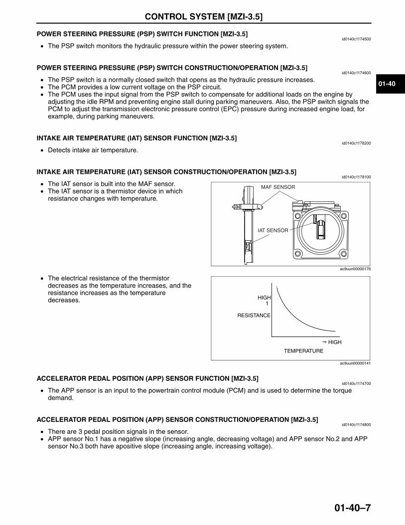
CONTROL SYSTEM [MZI-3.5]
01-40–7
01-40
End Of SiePOWER STEERING PRESSURE (PSP) SWITCH FUNCTION [MZI-3.5]id0140c1174500
• The PSP switch monitors the hydraulic pressure within the power steering system. End Of Sie
POWER STEERING PRESSURE (PSP) SWITCH CONSTRUCTION/OPERATION [MZI-3.5]id0140c1174600
• The PSP switch is a normally closed switch that opens as the hydraulic pressure increases. • The PCM provides a low current voltage on the PSP circuit. • The PCM uses the input signal from the PSP switch to compensate for additional loads on the engine by
adjusting the idle RPM and preventing engine stall during parking maneuvers. Also, the PSP switch signals the PCM to adjust the transmission electronic pressure control (EPC) pressure during increased engine load, for example, during parking maneuvers.
End Of SieNG: INTAKE AIR TEMPERATURE SENSOR
INTAKE AIR TEMPERATURE (IAT) SENSOR FUNCTION [MZI-3.5]id0140c1178200
• Detects intake air temperature.End Of Sie
INTAKE AIR TEMPERATURE (IAT) SENSOR CONSTRUCTION/OPERATION [MZI-3.5]id0140c1178100
• The IAT sensor is built into the MAF sensor.• The IAT sensor is a thermistor device in which
resistance changes with temperature.
• The electrical resistance of the thermistor decreases as the temperature increases, and the resistance increases as the temperature decreases.
End Of SieNG: ACCELERATOR PEDAL POSITION SENSOR
ACCELERATOR PEDAL POSITION (APP) SENSOR FUNCTION [MZI-3.5]id0140c1174700
• The APP sensor is an input to the powertrain control module (PCM) and is used to determine the torque demand.
End Of Sie
ACCELERATOR PEDAL POSITION (APP) SENSOR CONSTRUCTION/OPERATION [MZI-3.5]id0140c1174800
• There are 3 pedal position signals in the sensor. • APP sensor No.1 has a negative slope (increasing angle, decreasing voltage) and APP sensor No.2 and APP
sensor No.3 both have apositive slope (increasing angle, increasing voltage). End Of SieNG: KNOCK SENSOR
MAF SENSOR
IAT SENSOR
ac9uun00000176
RESISTANCE
TEMPERATURE
HIGH
HIGH
ac9uun00000141
3423-1U-06H(01-40).fm 7 ページ 2006年11月22日 水曜日 午後2時18分
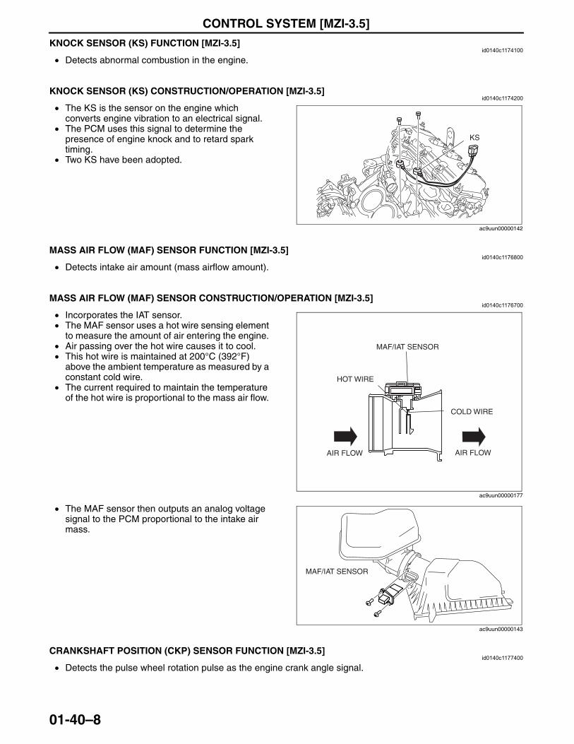
CONTROL SYSTEM [MZI-3.5]
01-40–8
KNOCK SENSOR (KS) FUNCTION [MZI-3.5]id0140c1174100
• Detects abnormal combustion in the engine. End Of Sie
KNOCK SENSOR (KS) CONSTRUCTION/OPERATION [MZI-3.5]id0140c1174200
• The KS is the sensor on the engine which converts engine vibration to an electrical signal.
• The PCM uses this signal to determine the presence of engine knock and to retard spark timing.
• Two KS have been adopted.End Of SieNG: MASS AIR FLOW SENSOR
MASS AIR FLOW (MAF) SENSOR FUNCTION [MZI-3.5]id0140c1176800
• Detects intake air amount (mass airflow amount).End Of Sie
MASS AIR FLOW (MAF) SENSOR CONSTRUCTION/OPERATION [MZI-3.5]id0140c1176700
• Incorporates the IAT sensor.• The MAF sensor uses a hot wire sensing element
to measure the amount of air entering the engine. • Air passing over the hot wire causes it to cool. • This hot wire is maintained at 200°C (392°F)
above the ambient temperature as measured by a constant cold wire.
• The current required to maintain the temperature of the hot wire is proportional to the mass air flow.
• The MAF sensor then outputs an analog voltage signal to the PCM proportional to the intake air mass.
End Of SieNG: CRANKSHAFT POSITION SENSOR
CRANKSHAFT POSITION (CKP) SENSOR FUNCTION [MZI-3.5]id0140c1177400
• Detects the pulse wheel rotation pulse as the engine crank angle signal.End Of Sie
KS
ac9uun00000142
AIR FLOW AIR FLOW
COLD WIRE
HOT WIRE
MAF/IAT SENSOR
ac9uun00000177
MAF/IAT SENSOR
ac9uun00000143
3423-1U-06H(01-40).fm 8 ページ 2006年11月22日 水曜日 午後2時18分
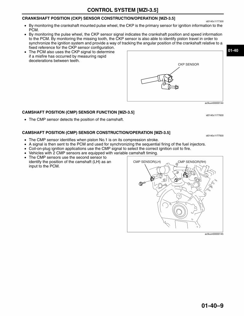
CONTROL SYSTEM [MZI-3.5]
01-40–9
01-40
CRANKSHAFT POSITION (CKP) SENSOR CONSTRUCTION/OPERATION [MZI-3.5]id0140c1177300
• By monitoring the crankshaft mounted pulse wheel, the CKP is the primary sensor for ignition information to the PCM.
• By monitoring the pulse wheel, the CKP sensor signal indicates the crankshaft position and speed information to the PCM. By monitoring the missing tooth, the CKP sensor is also able to identify piston travel in order to synchronize the ignition system and provide a way of tracking the angular position of the crankshaft relative to a fixed reference for the CKP sensor configuration.
• The PCM also uses the CKP signal to determine if a misfire has occurred by measuring rapid decelerations between teeth.
End Of SieNG: CAMSHAFT POSITION SENSOR
CAMSHAFT POSITION (CMP) SENSOR FUNCTION [MZI-3.5]id0140c1177600
• The CMP sensor detects the position of the camshaft.End Of Sie
CAMSHAFT POSITION (CMP) SENSOR CONSTRUCTION/OPERATION [MZI-3.5]id0140c1177500
• The CMP sensor identifies when piston No.1 is on its compression stroke. • A signal is then sent to the PCM and used for synchronizing the sequential firing of the fuel injectors. • Coil-on-plug ignition applications use the CMP signal to select the correct ignition coil to fire.• Vehicles with 2 CMP sensors are equipped with variable camshaft timing. • The CMP sensors use the second sensor to
identify the position of the camshaft (LH) as an input to the PCM.
End Of SieNG: HEATED OXYGEN SENSOR
CKP SENSOR
ac9uun00000144
CMP SENSOR(LH) CMP SENSOR(RH)
ac9uun00000145
3423-1U-06H(01-40).fm 9 ページ 2006年11月22日 水曜日 午後2時18分
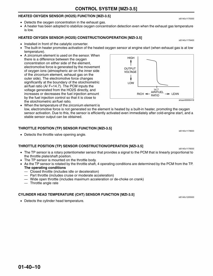
CONTROL SYSTEM [MZI-3.5]
01-40–10
HEATED OXYGEN SENSOR (HO2S) FUNCTION [MZI-3.5]id0140c1178300
• Detects the oxygen concentration in the exhaust gas.• A heater has been adopted to stabilize oxygen concentration detection even when the exhaust gas temperature
is low.End Of SieHEATED OXYGEN SENSOR (HO2S) CONSTRUCTION/OPERATION [MZI-3.5]
id0140c1178400
• Installed in front of the catalytic converter.• The built-in heater promotes activation of the heated oxygen sensor at engine start (when exhaust gas is at low
temperature). • A zirconium element is used on the sensor. When
there is a difference between the oxygen concentration on either side of the element, electromotive force is generated by the movement of oxygen ions (atmospheric air on the inner side of the zirconium element, exhaust gas on the outer side). The electromotive force changes significantly at the boundary of the stoichiometric air/fuel ratio (A/ F=14.7). The PCM inputs the voltage generated from the HO2S directly, and increases or decreases the fuel injection amount by the fuel injection control so that it is close to the stoichiometric air/fuel ratio.
• When the temperature of the zirconium element is low, electromotive force is not generated so the element is heated by a built-in heater, promoting the oxygen sensor activation. Due to this, the sensor is efficiently activated even immediately after cold-engine start, and a stable sensor output can be obtained.
End Of SieNG: THROTTLE POSITION SENSOR
THROTTLE POSITION (TP) SENSOR FUNCTION [MZI-3.5]id0140c1178600
• Detects the throttle valve opening angle.End Of Sie
THROTTLE POSITION (TP) SENSOR CONSTRUCTION/OPERATION [MZI-3.5]id0140c1178500
• The TP sensor is a rotary potentiometer sensor that provides a signal to the PCM that is linearly proportional to the throttle plate/shaft position.
• The TP sensor is mounted on the throttle body. • As the TP sensor is rotated by the throttle shaft, 4 operating conditions are determined by the PCM from the TP.
The operating conditions— Closed throttle (includes idle or deceleration)— Part throttle (includes cruise or moderate acceleration)— Wide open throttle (includes maximum acceleration or de-choke on crank)— Throttle angle rate
End Of SieNG: CYLINDER HEAD TEMPERATURE (CHT) SENSOR
CYLINDER HEAD TEMPERATURE (CHT) SENSOR FUNCTION [MZI-3.5]id0140c1205500
• Detects the cylinder head temperature.End Of Sie
14.7
HIGH
OUTPUT VOLTAGE
LOW
RICHAIR/FUEL RATIO LEAN
atraan00000418
3423-1U-06H(01-40).fm 10 ページ 2006年11月22日 水曜日 午後2時18分
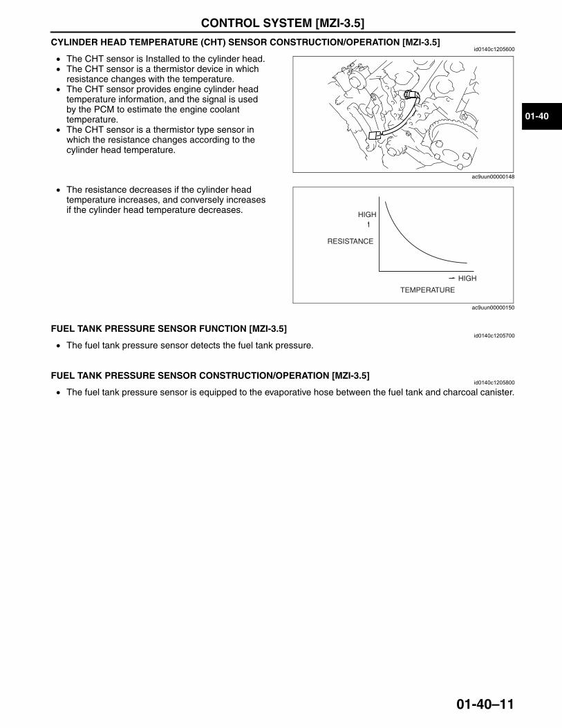
CONTROL SYSTEM [MZI-3.5]
01-40–11
01-40
CYLINDER HEAD TEMPERATURE (CHT) SENSOR CONSTRUCTION/OPERATION [MZI-3.5]id0140c1205600
• The CHT sensor is Installed to the cylinder head.• The CHT sensor is a thermistor device in which
resistance changes with the temperature. • The CHT sensor provides engine cylinder head
temperature information, and the signal is used by the PCM to estimate the engine coolant temperature.
• The CHT sensor is a thermistor type sensor in which the resistance changes according to the cylinder head temperature.
• The resistance decreases if the cylinder head temperature increases, and conversely increases if the cylinder head temperature decreases.
End Of SieNG: FUEL TANK PRESSURE SENSOR
FUEL TANK PRESSURE SENSOR FUNCTION [MZI-3.5]id0140c1205700
• The fuel tank pressure sensor detects the fuel tank pressure.End Of Sie
FUEL TANK PRESSURE SENSOR CONSTRUCTION/OPERATION [MZI-3.5]id0140c1205800
• The fuel tank pressure sensor is equipped to the evaporative hose between the fuel tank and charcoal canister.End Of Sie
ac9uun00000148
RESISTANCE
HIGH
HIGH
TEMPERATURE
ac9uun00000150
3423-1U-06H(01-40).fm 11 ページ 2006年11月22日 水曜日 午後2時18分

02-00–1
02SUSPENSIONSECTION
02-00Toc of SCTOUTLINE . . . . . . . . . . . . . . . . . .02-00ON-BOARD DIAGNOSTIC . . . .02-02WHEEL AND TIRES . . . . . . . . .02-12
FRONT SUSPENSION. . . . . . . 02-13REAR SUSPENSION . . . . . . . . 02-14
Toc of SCT
02-00 OUTLINESUSPENSION ABBREVIATIONS . . . . . . 02-00–1SUSPENSION FEATURES. . . . . . . . . . . . 02-00–1SUSPENSION SPECIFICATIONS . . . . . . 02-00–2
Suspension . . . . . . . . . . . . . . . . . . . . . 02-00–2Wheel and Tire . . . . . . . . . . . . . . . . . . . 02-00–2
End of TocNG: SUSPENSIONSUSPENSION ABBREVIATIONS
id020000100100
End Of Sie
SUSPENSION FEATURESid020000100200
End Of Sie
AWD All Wheel DriveCAN Controller Area NetworkCM Control ModuleRF signal(s) Radio Frequency signal(s)OFF Switch OffON Switch OnPID Parameter IdentificationTPMS Tire Pressure Monitoring System2WD 2-wheel Drive
Improved rigidity and handling stability • Strut type front suspension and E-type multi-link rear suspension adopted
Improved handling and riding comfort
• Six-point rubber mount system front crossmember adopted• Front shock absorber with large bore piston adopted• Front spring layout optimized• Separated input type front shock absorber mount adopted• Ball-type strut bearings adopted on the front strut upper mount
Enlarged trunk compartment • Separated positioning of rear shock absorber and coil spring adopted
Improved marketability • 20 inch wheel and tire adopted• Adhesive-type balance weights adopted
Environmental consideration • Steel balance weights adopted to reduce the use of leadTire condition maintenance assistance • Tire pressure monitoring system (TPMS) adopted
3423-1U-06H(02-00).fm 1 ページ 2006年11月21日 火曜日 午後5時5分
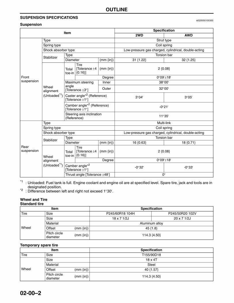
OUTLINE
02-00–2
SUSPENSION SPECIFICATIONSid020000100300
Suspension
*1 : Unloaded: Fuel tank is full. Engine coolant and engine oil are at specified level. Spare tire, jack and tools are in designated position.
*2 : Difference between left and right not exceed 1°30′.
Wheel and TireStandard tire
Temporary spare tire
ItemSpecification
2WD AWD
Front suspension
Type Strut typeSpring type Coil springShock absorber type Low-pressure gas charged, cylindrical, double-acting
StabilizerType Torsion barDiameter (mm {in}) 31 {1.22} 32 {1.25}
Wheel alignment (Unloaded*1)
Total toe-in
Tire [Tolerance ±4 {0.16}]
(mm {in}) 2 {0.08}
Degree 0°09′±18′Maximum steering angle [Tolerance ±3°]
Inner 38°00′
Outer 32°00′
Caster angle*2 (Reference)[Tolerance ±1°]
3°04′ 3°05′
Camber angle*2 (Reference)[Tolerance ±1°]
-0°21′
Steering axis inclination (Reference) 11°35′
Rear suspension
Type Multi-linkSpring type Coil springShock absorber type Low-pressure gas charged, cylindrical, double-acting
StabilizerType Torsion barDiameter (mm {in}) 16 {0.63} 18 {0.71}
Wheel alignment (Unloaded*1)
Total toe-in
Tire [Tolerance ±4 {0.16}]
(mm {in}) 2 {0.08}
Degree 0°09′±18′
Camber angle*2 [Tolerance ±1°]
-0°32′ -0°33′
Thrust angle [Tolerance ±48′] 0°
Item SpecificationTire Size P245/60R18 104H P245/50R20 102V
Wheel
Size 18 x 7 1/2J 20 x 7 1/2JMaterial Aluminum alloyOffset (mm {in}) 45 {1.8}Pitch circle diameter (mm {in}) 114.3 {4.50}
Item SpecificationTire Size T155/90D18
Wheel
Size 18 x 4TMaterial SteelOffset (mm {in}) 40 {1.57}Pitch circle diameter (mm {in}) 114.3 {4.50}
3423-1U-06H(02-00).fm 2 ページ 2006年11月21日 火曜日 午後5時5分
ON-BOARD DIAGNOSTIC
02-02–1
02-02
02-02 ON-BOARD DIAGNOSTICON-BOARD DIAGNOSTIC
SYSTEM OUTLINE (TIRE PRESSURE MONITORING SYSTEM). . . . . . . . . . . . 02-02–1
Block Diagram . . . . . . . . . . . . . . . . . . . 02-02–2ON-BOARD DIAGNOSTIC
SYSTEM FUNCTION (TIRE PRESSURE MONITORING SYSTEM). . . . . . . . . . . . 02-02–3
Malfunction Detection Function . . . . . . 02-02–3Malfunction Indication Function . . . . . . 02-02–3Memory Function . . . . . . . . . . . . . . . . . 02-02–3DTC Table . . . . . . . . . . . . . . . . . . . . . . 02-02–3
ON-BOARD DIAGNOSTIC SYSTEM PID/DATA MONITOR FUNCTION (TIRE PRESSURE MONITORING SYSTEM). . . . . . . . . . . . 02-02–4
ON-BOARD DIAGNOSTIC SYSTEM ACTIVE COMMAND MODES FUNCTION (TIRE PRESSURE MONITORING SYSTEM) . . . . . . . . . . . . 02-02–5
ON-BOARD DIAGNOSTIC SYSTEM FREEZE FRAME DATA MONITOR FUNCTION (TIRE PRESSURE MONITORING SYSTEM) . . . . . . . . . . . . 02-02–6
ON-BOARD DIAGNOSTIC SYSTEM EXTERNAL TESTER COMMUNICATION FUNCTION (TIRE PRESSURE MONITORING SYSTEM) . . . . . . . . . . . . 02-02–7
External Tester Communication Function . . . . . . . . . . 02-02–7
Serial Communication . . . . . . . . . . . . . . 02-02–7DLC-2 CONSTRUCTION . . . . . . . . . . . . . 02-02–7
End of TocNG: TIRE PRESSURE MONITORING SYSTEMON-BOARD DIAGNOSTIC SYSTEM OUTLINE (TIRE PRESSURE MONITORING SYSTEM)
id020200100100
• The on-board diagnostic system consists of a malfunction detection system that detects abnormalities in input/output signals when the ignition switch is at the ON position, a data monitor function that reads out specified input/output signals, and an active command modes function that execuse the wheel unit ID registration.
• The Data Link Connector 2 (DLC-2), which groups together all the connectors used for malfunction diagnosis into a single location, has been adopted, thereby improving serviceability. Diagnosis is performed by connecting the Mazda Modular Diagnostic System (M-MDS) to the DLC-2.
• In addition to DTC read-out, the Mazda Modular Diagnostic System (M-MDS) is used to clear DTCs using the display screen of the diagnostic tester, and to access the data monitor, providing enhanced malfunction diagnosis and improved serviceability.
3423-1U-06H(02-02).fm 1 ページ 2006年11月21日 火曜日 午後5時5分
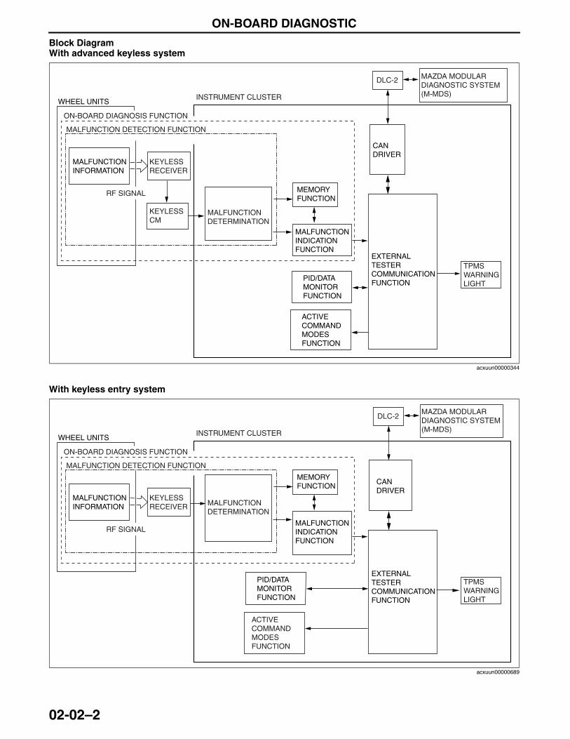
ON-BOARD DIAGNOSTIC
02-02–2
Block DiagramWith advanced keyless system
With keyless entry system
End Of Sie
WHEEL UNITS
MALFUNCTIONINFORMATION
PID/DATAMONITORFUNCTION
EXTERNALTESTERCOMMUNICATIONFUNCTION
MEMORYFUNCTION
DLC-2
CANDRIVER
TPMSWARNINGLIGHT
MALFUNCTIONINDICATIONFUNCTION
ON-BOARD DIAGNOSIS FUNCTION
INSTRUMENT CLUSTER
MALFUNCTIONDETERMINATION
MALFUNCTION DETECTION FUNCTION
KEYLESS RECEIVER
KEYLESS CM
RF SIGNAL
ACTIVE COMMAND MODES FUNCTION
MAZDA MODULAR DIAGNOSTIC SYSTEM (M-MDS)
acxuun00000344
WHEEL UNITS
MALFUNCTIONINFORMATION
PID/DATAMONITORFUNCTION
EXTERNALTESTERCOMMUNICATIONFUNCTION
MEMORYFUNCTION
DLC-2
CANDRIVER
TPMSWARNINGLIGHT
MALFUNCTIONINDICATIONFUNCTION
ON-BOARD DIAGNOSIS FUNCTION
INSTRUMENT CLUSTER
MALFUNCTIONDETERMINATION
MALFUNCTION DETECTION FUNCTION
KEYLESS RECEIVER
RF SIGNAL
ACTIVE COMMAND MODES FUNCTION
MAZDA MODULAR DIAGNOSTIC SYSTEM (M-MDS)
acxuun00000689
3423-1U-06H(02-02).fm 2 ページ 2006年11月21日 火曜日 午後5時5分
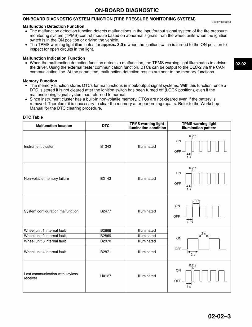
ON-BOARD DIAGNOSTIC
02-02–3
02-02
ON-BOARD DIAGNOSTIC SYSTEM FUNCTION (TIRE PRESSURE MONITORING SYSTEM)id020200100200
Malfunction Detection Function• The malfunction detection function detects malfunctions in the input/output signal system of the tire pressure
monitoring system (TPMS) control module based on abnormal signals from the wheel units when the ignition switch is in the ON position or driving the vehicle.
• The TPMS warning light illuminates for approx. 3.0 s when the ignition switch is turned to the ON position to inspect for open circuits in the light.
Malfunction Indication Function• When the malfunction detection function detects a malfunction, the TPMS warning light illuminates to advise
the driver. Using the external tester communication function, DTCs can be output to the DLC-2 via the CAN communication line. At the same time, malfunction detection results are sent to the memory functions.
Memory Function• The memory function stores DTCs for malfunctions in input/output signal systems. With this function, once a
DTC is stored it is not cleared after the ignition switch has been turned off (LOCK position), even if the malfunctioning signal system has returned to normal.
• Since instrument cluster has a built-in non-volatile memory, DTCs are not cleared even if the battery is removed. Therefore, it is necessary to clear the memory after performing repairs. Refer to the Workshop Manual for the DTC clearing procedure.
DTC Table
Malfunction location DTC TPMS warning lightillumination condition
TPMS warning lightillumination pattern
Instrument cluster B1342 Illuminated
Non-volatile memory failure B2143 Illuminated
System configuration malfunction B2477 Illuminated
Wheel unit 1 internal fault B2868 IlluminatedWheel unit 2 internal fault B2869 IlluminatedWheel unit 3 internal fault B2870 Illuminated
Wheel unit 4 internal fault B2871 Illuminated
Lost communication with keyless receiver U0127 Illuminated
ON
OFF
1 s
0.2 s
ON
OFF
1 s
0.2 s
ON
OFF
0.5 s
0.5 s
ON
OFF
2 s
2 s
ON
OFF
1 s
0.2 s
3423-1U-06H(02-02).fm 3 ページ 2006年11月21日 火曜日 午後5時5分
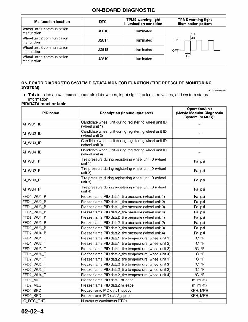
ON-BOARD DIAGNOSTIC
02-02–4
End Of Sie
ON-BOARD DIAGNOSTIC SYSTEM PID/DATA MONITOR FUNCTION (TIRE PRESSURE MONITORING SYSTEM)
id020200100300
• This function allows access to certain data values, input signal, calculated values, and system status information.
PID/DATA monitor table
Wheel unit 1 communication malfunction U2616 Illuminated
Wheel unit 2 communication malfunction U2617 Illuminated
Wheel unit 3 communication malfunction U2618 Illuminated
Wheel unit 4 communication malfunction U2619 Illuminated
Malfunction location DTC TPMS warning lightillumination condition
TPMS warning lightillumination pattern
ON
OFF
1 s
1 s
PID name Description (Input/output part)Operation/unit
(Mazda Modular Diagnostic System (M-MDS))
AI_WU1_ID Candidate wheel unit during registering wheel unit ID (wheel unit 1) –
AI_WU2_ID Candidate wheel unit during registering wheel unit ID (wheel unit 2) –
AI_WU3_ID Candidate wheel unit during registering wheel unit ID (wheel unit 3) –
AI_WU4_ID Candidate wheel unit during registering wheel unit ID (wheel unit 4) –
AI_WU1_P Tire pressure during registering wheel unit ID (wheel unit 1) Pa, psi
AI_WU2_P Tire pressure during registering wheel unit ID (wheel unit 2) Pa, psi
AI_WU3_P Tire pressure during registering wheel unit ID (wheel unit 3) Pa, psi
AI_WU4_P Tire pressure during registering wheel unit ID (wheel unit 4) Pa, psi
FFD1_WU1_P Freeze frame PID data1_tire pressure (wheel unit 1) Pa, psiFFD1_WU2_P Freeze frame PID data1_tire pressure (wheel unit 2) Pa, psiFFD1_WU3_P Freeze frame PID data1_tire pressure (wheel unit 3) Pa, psiFFD1_WU4_P Freeze frame PID data2_tire pressure (wheel unit 4) Pa, psiFFD2_WU1_P Freeze frame PID data2_tire pressure (wheel unit 1) Pa, psiFFD2_WU2_P Freeze frame PID data2_tire pressure (wheel unit 2) Pa, psiFFD2_WU3_P Freeze frame PID data2_tire pressure (wheel unit 3) Pa, psiFFD2_WU4_P Freeze frame PID data2_tire pressure (wheel unit 4) Pa, psiFFD1_WU1_T Freeze frame PID data1_tire temperature (wheel unit 1) °C, °FFFD1_WU2_T Freeze frame PID data1_tire temperature (wheel unit 2) °C, °FFFD1_WU3_T Freeze frame PID data1_tire temperature (wheel unit 3) °C, °FFFD1_WU4_T Freeze frame PID data2_tire temperature (wheel unit 4) °C, °FFFD2_WU1_T Freeze frame PID data2_tire temperature (wheel unit 1) °C, °FFFD2_WU2_T Freeze frame PID data2_tire temperature (wheel unit 2) °C, °FFFD2_WU3_T Freeze frame PID data2_tire temperature (wheel unit 3) °C, °FFFD2_WU4_T Freeze frame PID data2_tire temperature (wheel unit 4) °C, °FFFD1_MLG Freeze frame PID data1 mileage m, mi (ft)FFD2_MLG Freeze frame PID data2 mileage m, mi (ft)FFD1_SPD Freeze flame PID data1_speed KPH, MPHFFD2_SPD Freeze flame PID data2_speed KPH, MPHIC_DTC_CNT Number of continuous DTCs –
3423-1U-06H(02-02).fm 4 ページ 2006年11月21日 火曜日 午後5時5分
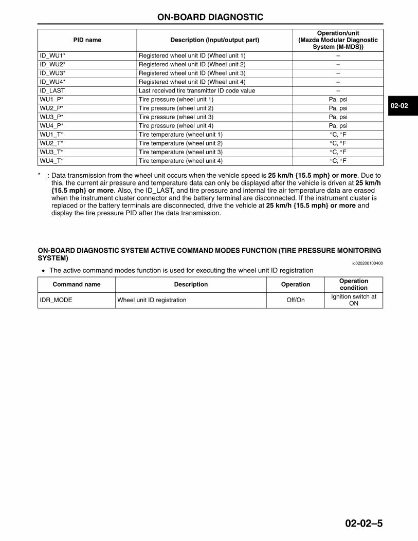
ON-BOARD DIAGNOSTIC
02-02–5
02-02
* : Data transmission from the wheel unit occurs when the vehicle speed is 25 km/h {15.5 mph} or more. Due to this, the current air pressure and temperature data can only be displayed after the vehicle is driven at 25 km/h {15.5 mph} or more. Also, the ID_LAST, and tire pressure and internal tire air temperature data are erased when the instrument cluster connector and the battery terminal are disconnected. If the instrument cluster is replaced or the battery terminals are disconnected, drive the vehicle at 25 km/h {15.5 mph} or more and display the tire pressure PID after the data transmission.
End Of Sie
ON-BOARD DIAGNOSTIC SYSTEM ACTIVE COMMAND MODES FUNCTION (TIRE PRESSURE MONITORING SYSTEM)
id020200100400
• The active command modes function is used for executing the wheel unit ID registration
End Of Sie
ID_WU1* Registered wheel unit ID (Wheel unit 1) –ID_WU2* Registered wheel unit ID (Wheel unit 2) –ID_WU3* Registered wheel unit ID (Wheel unit 3) –ID_WU4* Registered wheel unit ID (Wheel unit 4) –ID_LAST Last received tire transmitter ID code value –WU1_P* Tire pressure (wheel unit 1) Pa, psiWU2_P* Tire pressure (wheel unit 2) Pa, psiWU3_P* Tire pressure (wheel unit 3) Pa, psiWU4_P* Tire pressure (wheel unit 4) Pa, psiWU1_T* Tire temperature (wheel unit 1) °C, °FWU2_T* Tire temperature (wheel unit 2) °C, °FWU3_T* Tire temperature (wheel unit 3) °C, °FWU4_T* Tire temperature (wheel unit 4) °C, °F
PID name Description (Input/output part)Operation/unit
(Mazda Modular Diagnostic System (M-MDS))
Command name Description Operation Operation condition
IDR_MODE Wheel unit ID registration Off/On Ignition switch at ON
3423-1U-06H(02-02).fm 5 ページ 2006年11月21日 火曜日 午後5時5分
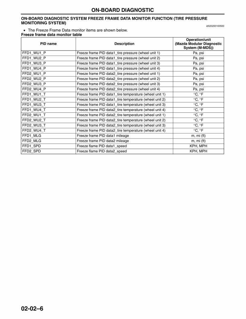
ON-BOARD DIAGNOSTIC
02-02–6
ON-BOARD DIAGNOSTIC SYSTEM FREEZE FRAME DATA MONITOR FUNCTION (TIRE PRESSURE MONITORING SYSTEM)
id020200100500
• The Freeze Frame Data monitor items are shown below.Freeze frame data monitor table
End Of Sie
PID name DescriptionOperation/unit
(Mazda Modular Diagnostic System (M-MDS))
FFD1_WU1_P Freeze frame PID data1_tire pressure (wheel unit 1) Pa, psiFFD1_WU2_P Freeze frame PID data1_tire pressure (wheel unit 2) Pa, psiFFD1_WU3_P Freeze frame PID data1_tire pressure (wheel unit 3) Pa, psiFFD1_WU4_P Freeze frame PID data1_tire pressure (wheel unit 4) Pa, psiFFD2_WU1_P Freeze frame PID data2_tire pressure (wheel unit 1) Pa, psiFFD2_WU2_P Freeze frame PID data2_tire pressure (wheel unit 2) Pa, psiFFD2_WU3_P Freeze frame PID data2_tire pressure (wheel unit 3) Pa, psiFFD2_WU4_P Freeze frame PID data2_tire pressure (wheel unit 4) Pa, psiFFD1_WU1_T Freeze frame PID data1_tire temperature (wheel unit 1) °C, °FFFD1_WU2_T Freeze frame PID data1_tire temperature (wheel unit 2) °C, °FFFD1_WU3_T Freeze frame PID data1_tire temperature (wheel unit 3) °C, °FFFD1_WU4_T Freeze frame PID data2_tire temperature (wheel unit 4) °C, °FFFD2_WU1_T Freeze frame PID data2_tire temperature (wheel unit 1) °C, °FFFD2_WU2_T Freeze frame PID data2_tire temperature (wheel unit 2) °C, °FFFD2_WU3_T Freeze frame PID data2_tire temperature (wheel unit 3) °C, °FFFD2_WU4_T Freeze frame PID data2_tire temperature (wheel unit 4) °C, °FFFD1_MLG Freeze frame PID data1 mileage m, mi (ft)FFD2_MLG Freeze frame PID data2 mileage m, mi (ft)FFD1_SPD Freeze flame PID data1_speed KPH, MPHFFD2_SPD Freeze flame PID data2_speed KPH, MPH
3423-1U-06H(02-02).fm 6 ページ 2006年11月21日 火曜日 午後5時5分
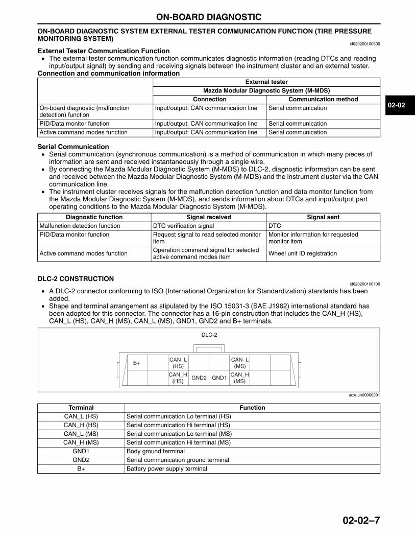
ON-BOARD DIAGNOSTIC
02-02–7
02-02
ON-BOARD DIAGNOSTIC SYSTEM EXTERNAL TESTER COMMUNICATION FUNCTION (TIRE PRESSURE MONITORING SYSTEM)
id020200100600
External Tester Communication Function• The external tester communication function communicates diagnostic information (reading DTCs and reading
input/output signal) by sending and receiving signals between the instrument cluster and an external tester.Connection and communication information
Serial Communication• Serial communication (synchronous communication) is a method of communication in which many pieces of
information are sent and received instantaneously through a single wire.• By connecting the Mazda Modular Diagnostic System (M-MDS) to DLC-2, diagnostic information can be sent
and received between the Mazda Modular Diagnostic System (M-MDS) and the instrument cluster via the CAN communication line.
• The instrument cluster receives signals for the malfunction detection function and data monitor function from the Mazda Modular Diagnostic System (M-MDS), and sends information about DTCs and input/output part operating conditions to the Mazda Modular Diagnostic System (M-MDS).
End Of SieDLC-2 CONSTRUCTION
id020200100700
• A DLC-2 connector conforming to ISO (International Organization for Standardization) standards has been added.
• Shape and terminal arrangement as stipulated by the ISO 15031-3 (SAE J1962) international standard has been adopted for this connector. The connector has a 16-pin construction that includes the CAN_H (HS), CAN_L (HS), CAN_H (MS), CAN_L (MS), GND1, GND2 and B+ terminals.
End Of Sie
External testerMazda Modular Diagnostic System (M-MDS)
Connection Communication methodOn-board diagnostic (malfunction detection) function
Input/output: CAN communication line Serial communication
PID/Data monitor function Input/output: CAN communication line Serial communicationActive command modes function Input/output: CAN communication line Serial communication
Diagnostic function Signal received Signal sentMalfunction detection function DTC verification signal DTCPID/Data monitor function Request signal to read selected monitor
itemMonitor information for requested monitor item
Active command modes function Operation command signal for selected active command modes item Wheel unit ID registration
Terminal FunctionCAN_L (HS) Serial communication Lo terminal (HS)CAN_H (HS) Serial communication Hi terminal (HS)CAN_L (MS) Serial communication Lo terminal (MS)CAN_H (MS) Serial communication Hi terminal (MS)
GND1 Body ground terminalGND2 Serial communication ground terminal
B+ Battery power supply terminal
DLC-2
B+CAN_L
(HS)
CAN_H(HS)
GND2 GND1
CAN_L (MS)
CAN_H(MS)
acxuun00000291
3423-1U-06H(02-02).fm 7 ページ 2006年11月21日 火曜日 午後5時5分

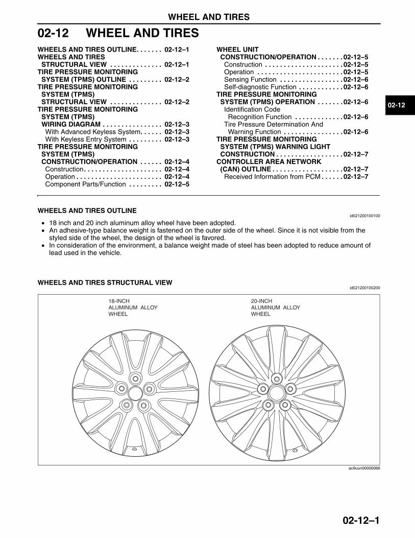
WHEEL AND TIRES
02-12–1
02-12
02-12 WHEEL AND TIRESWHEELS AND TIRES OUTLINE. . . . . . . 02-12–1WHEELS AND TIRES
STRUCTURAL VIEW . . . . . . . . . . . . . . 02-12–1TIRE PRESSURE MONITORING
SYSTEM (TPMS) OUTLINE . . . . . . . . . 02-12–2TIRE PRESSURE MONITORING
SYSTEM (TPMS) STRUCTURAL VIEW . . . . . . . . . . . . . . 02-12–2
TIRE PRESSURE MONITORING SYSTEM (TPMS) WIRING DIAGRAM . . . . . . . . . . . . . . . . 02-12–3
With Advanced Keyless System. . . . . . 02-12–3With Keyless Entry System . . . . . . . . . 02-12–3
TIRE PRESSURE MONITORING SYSTEM (TPMS) CONSTRUCTION/OPERATION . . . . . . 02-12–4
Construction. . . . . . . . . . . . . . . . . . . . . 02-12–4Operation . . . . . . . . . . . . . . . . . . . . . . . 02-12–4Component Parts/Function . . . . . . . . . 02-12–5
WHEEL UNIT CONSTRUCTION/OPERATION . . . . . . . 02-12–5
Construction . . . . . . . . . . . . . . . . . . . . . 02-12–5Operation . . . . . . . . . . . . . . . . . . . . . . . 02-12–5Sensing Function . . . . . . . . . . . . . . . . . 02-12–6Self-diagnostic Function . . . . . . . . . . . . 02-12–6
TIRE PRESSURE MONITORING SYSTEM (TPMS) OPERATION . . . . . . . 02-12–6
Identification Code Recognition Function . . . . . . . . . . . . . 02-12–6
Tire Pressure Determination And Warning Function . . . . . . . . . . . . . . . . 02-12–6
TIRE PRESSURE MONITORING SYSTEM (TPMS) WARNING LIGHT CONSTRUCTION . . . . . . . . . . . . . . . . . . 02-12–7
CONTROLLER AREA NETWORK (CAN) OUTLINE . . . . . . . . . . . . . . . . . . . 02-12–7
Received Information from PCM . . . . . . 02-12–7
End of TocNG: WHEELS AND TIRESWHEELS AND TIRES OUTLINE
id021200100100
• 18 inch and 20 inch aluminum alloy wheel have been adopted.• An adhesive-type balance weight is fastened on the outer side of the wheel. Since it is not visible from the
styled side of the wheel, the design of the wheel is favored.• In consideration of the environment, a balance weight made of steel has been adopted to reduce amount of
lead used in the vehicle.End Of Sie
WHEELS AND TIRES STRUCTURAL VIEWid021200100200
End Of SieNG: TIRE PRESSURE MONITORING SYSTEM
18-INCH ALUMINUM ALLOY WHEEL
20-INCHALUMINUM ALLOYWHEEL
ac9uun00000066
3423-1U-06H(02-12).fm 1 ページ 2006年11月22日 水曜日 午前11時14分
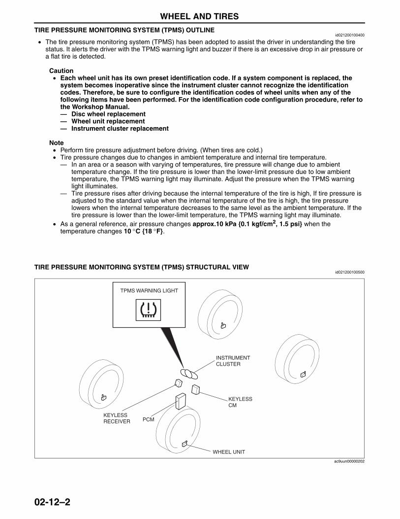
WHEEL AND TIRES
02-12–2
TIRE PRESSURE MONITORING SYSTEM (TPMS) OUTLINEid021200100400
• The tire pressure monitoring system (TPMS) has been adopted to assist the driver in understanding the tire status. It alerts the driver with the TPMS warning light and buzzer if there is an excessive drop in air pressure or a flat tire is detected.
Caution• Each wheel unit has its own preset identification code. If a system component is replaced, the
system becomes inoperative since the instrument cluster cannot recognize the identification codes. Therefore, be sure to configure the identification codes of wheel units when any of the following items have been performed. For the identification code configuration procedure, refer to the Workshop Manual.— Disc wheel replacement— Wheel unit replacement— Instrument cluster replacement
Note• Perform tire pressure adjustment before driving. (When tires are cold.)• Tire pressure changes due to changes in ambient temperature and internal tire temperature.— In an area or a season with varying of temperatures, tire pressure will change due to ambient
temperature change. If the tire pressure is lower than the lower-limit pressure due to low ambient temperature, the TPMS warning light may illuminate. Adjust the pressure when the TPMS warning light illuminates.
— Tire pressure rises after driving because the internal temperature of the tire is high, If tire pressure is adjusted to the standard value when the internal temperature of the tire is high, the tire pressure lowers when the internal temperature decreases to the same level as the ambient temperature. If the tire pressure is lower than the lower-limit temperature, the TPMS warning light may illuminate.
• As a general reference, air pressure changes approx.10 kPa {0.1 kgf/cm2, 1.5 psi} when the temperature changes 10 °C {18 °F}.
End Of Sie
TIRE PRESSURE MONITORING SYSTEM (TPMS) STRUCTURAL VIEWid021200100500
End Of Sie
WHEEL UNIT
PCMKEYLESS RECEIVER
KEYLESS CM
INSTRUMENT CLUSTER
TPMS WARNING LIGHT
ac9uun00000202
3423-1U-06H(02-12).fm 2 ページ 2006年11月22日 水曜日 午前11時14分
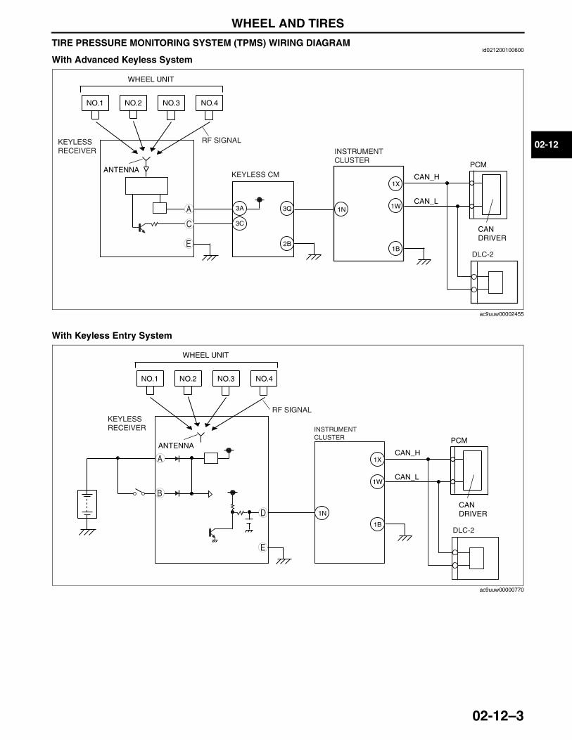
WHEEL AND TIRES
02-12–3
02-12
TIRE PRESSURE MONITORING SYSTEM (TPMS) WIRING DIAGRAMid021200100600
With Advanced Keyless System
With Keyless Entry System
End Of Sie
NO.1
ANTENNA
NO.2 NO.3 NO.4
RF SIGNAL
CANDRIVER
CAN_H
CAN_L
PCM
WHEEL UNIT
E
C
A
KEYLESS RECEIVER
KEYLESS CM
INSTRUMENT CLUSTER
3Q 1N
1X
1W
1B2B
DLC-2
3A
3C
ac9uuw00002455
NO.1
ANTENNA
NO.2 NO.3 NO.4
RF SIGNAL
CANDRIVER
CAN_H
CAN_L
PCM
WHEEL UNIT
E
D
B
A
INSTRUMENT CLUSTER
1N
1X
1W
1BDLC-2
KEYLESS RECEIVER
ac9uuw00000770
3423-1U-06H(02-12).fm 3 ページ 2006年11月22日 水曜日 午前11時14分
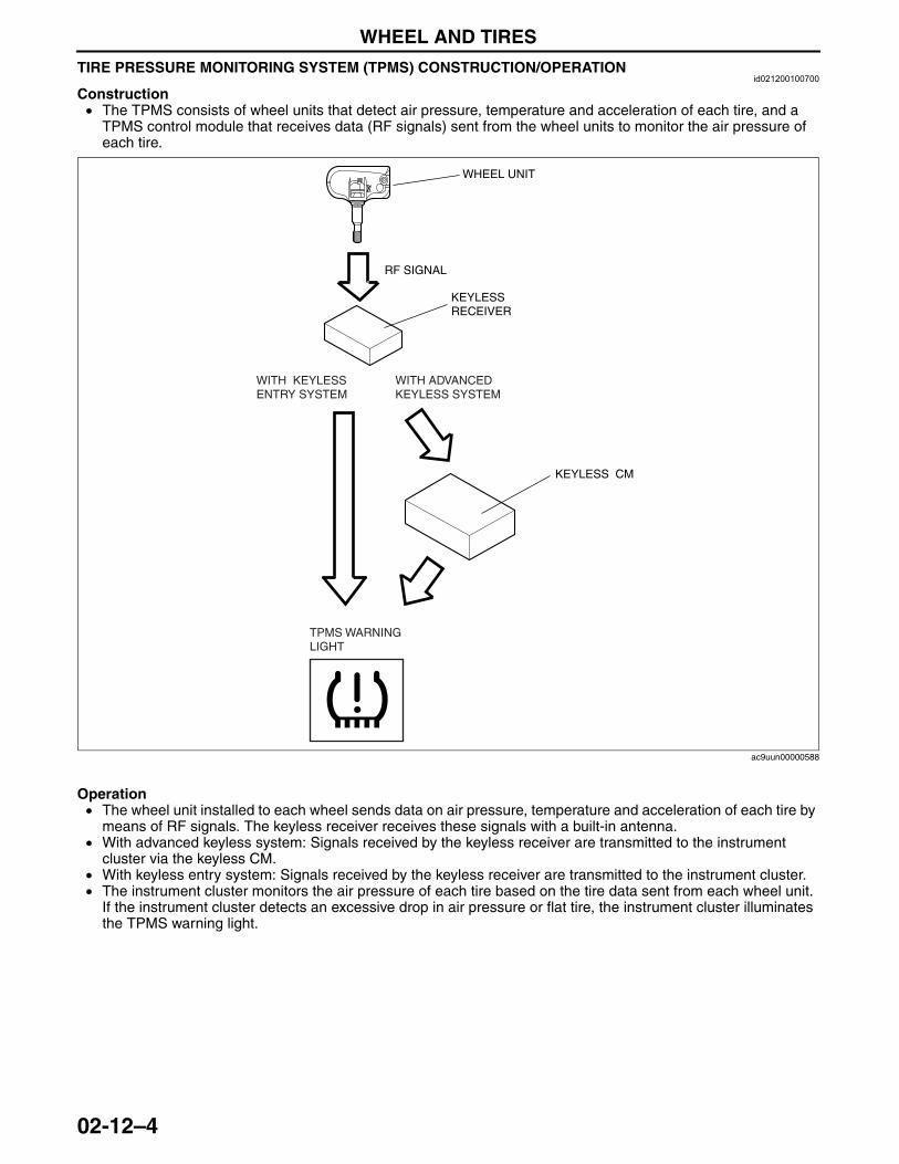
WHEEL AND TIRES
02-12–4
TIRE PRESSURE MONITORING SYSTEM (TPMS) CONSTRUCTION/OPERATIONid021200100700
Construction• The TPMS consists of wheel units that detect air pressure, temperature and acceleration of each tire, and a
TPMS control module that receives data (RF signals) sent from the wheel units to monitor the air pressure of each tire.
Operation• The wheel unit installed to each wheel sends data on air pressure, temperature and acceleration of each tire by
means of RF signals. The keyless receiver receives these signals with a built-in antenna.• With advanced keyless system: Signals received by the keyless receiver are transmitted to the instrument
cluster via the keyless CM.• With keyless entry system: Signals received by the keyless receiver are transmitted to the instrument cluster.• The instrument cluster monitors the air pressure of each tire based on the tire data sent from each wheel unit.
If the instrument cluster detects an excessive drop in air pressure or flat tire, the instrument cluster illuminates the TPMS warning light.
RF SIGNAL
KEYLESS RECEIVER
WHEEL UNIT
TPMS WARNING LIGHT
KEYLESS CM
WITH ADVANCED KEYLESS SYSTEM
WITH KEYLESS ENTRY SYSTEM
ac9uun00000588
3423-1U-06H(02-12).fm 4 ページ 2006年11月22日 水曜日 午前11時14分
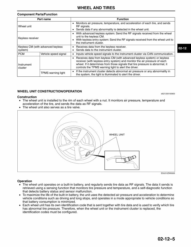
WHEEL AND TIRES
02-12–5
02-12
Component Parts/Function
End Of SieNG: WHEEL SENSOR
WHEEL UNIT CONSTRUCTION/OPERATIONid021200100900
Construction• The wheel unit is installed to the rim of each wheel with a nut. It monitors air pressure, temperature and
acceleration of the tire, and sends the data as RF signals.• The wheel unit also serves as a tire valve.
Operation• The wheel unit operates on a built-in battery, and regularly sends tire data as RF signals. The data it sends is
retrieved using a sensing function that monitors tire pressure and temperature, and a self-diagnostic function that detects battery status and sensor malfunction.
• To maximize the life of the built-in battery, the unit uses the detected air pressure and acceleration to determine vehicle conditions such as driving and long stops, and operates in a mode appropriate to vehicle conditions so that battery consumption is minimized.
• Each wheel unit has its own identification code that is sent together with tire data and is used to verify which tire has abnormal tire pressure. Therefore, when the wheel unit or the instrument cluster is replaced, the identification codes must be configured.
Part name Function
Wheel unit• Monitors air pressure, temperature, and acceleration of each tire, and sends
RF signals.• Sends data if any abnormality is detected in the wheel unit.
Keyless receiver
• With advanced keyless system: Send the RF signals received from the wheel unit to the keyless CM.
• With keyless entry system: Send the RF signals received from the wheel unit to the instrument cluster.
Keyless CM (with advanced keyless system)
• Receives data from the keyless receiver.• Sends data to the instrument cluster.
PCM Vehicle speed signal • Inputs vehicle speed signals to the instrument cluster via CAN communication.
Instrument cluster
• Receives data from keyless CM (with advanced keyless system) or keyless receiver (with keyless entry system) and monitor the air pressure of each wheel. If it determines from those signals that tire pressure is abnormal, it controls the TPMS warning light to alert the driver.
TPMS warning light • If the instrument cluster detects abnormal air pressure or any abnormality in the system, the light is illuminated to alert the driver.
WHEEL UNIT
E5U212ZW5005
3423-1U-06H(02-12).fm 5 ページ 2006年11月22日 水曜日 午前11時14分
WHEEL AND TIRES
02-12–6
Sensing Function• The sensing function periodically monitors the following data and sends it to the keyless receiver.— Tire pressure— Tire temperature— Tire acceleration— Voltage of the built-in battery
• Intervals of tire data monitoring and data transmission to the keyless receiver differ depending on the operational mode (varies according to vehicle conditions).
Self-diagnostic Function• The self-diagnostic function continuously performs malfunction diagnosis for each sensing function item. If any
abnormality is found by the malfunction diagnosis, the data is sent to the keyless receiver.End Of SieNG: TIRE PRESSURE MONITORING SYSTEM CONTROL MODULE
TIRE PRESSURE MONITORING SYSTEM (TPMS) OPERATIONid021200101000
• The instrument cluster monitors the tire pressure of each tire and the wheel units for abnormalities using the received data. If any abnormality is found, it controls TPMS warning light to alert and notify the driver.
• The instrument cluster controls the following functions based on the received data:Function list
Identification Code Recognition Function• Since the identification codes of wheel units mounted on the vehicle have been configured in the instrument
cluster, the instrument cluster can verify the identification codes sent from the wheel units against the configured identification codes.
• When the received identification code agrees with the configured identification code, data such as tire pressure is updated according to the received signal. When the identification code does not agree, that signal data is ignored.
Tire Pressure Determination And Warning Function• The instrument cluster determines the tire pressure status of each wheel by comparing tire pressure data
received from the wheel units with the preset values in the instrument cluster.• If a malfunction is detected in the received signals, the instrument cluster flashes the TPMS warning light to
notify the driver of a tire malfunction.• The informing/warning of an abnormal tire pressure determination takes precedence over the informing/
warning of a missing signal or malfunction determination.
Identification code recognition function • Recognizes whether received signals are from own wheel units.
Tire pressure determination/warning function
• Compares received tire pressure data with preset values. If the pressure is determined to be too low, the instrument cluster alerts the driver via the TPMS warning light.
3423-1U-06H(02-12).fm 6 ページ 2006年11月22日 水曜日 午前11時14分
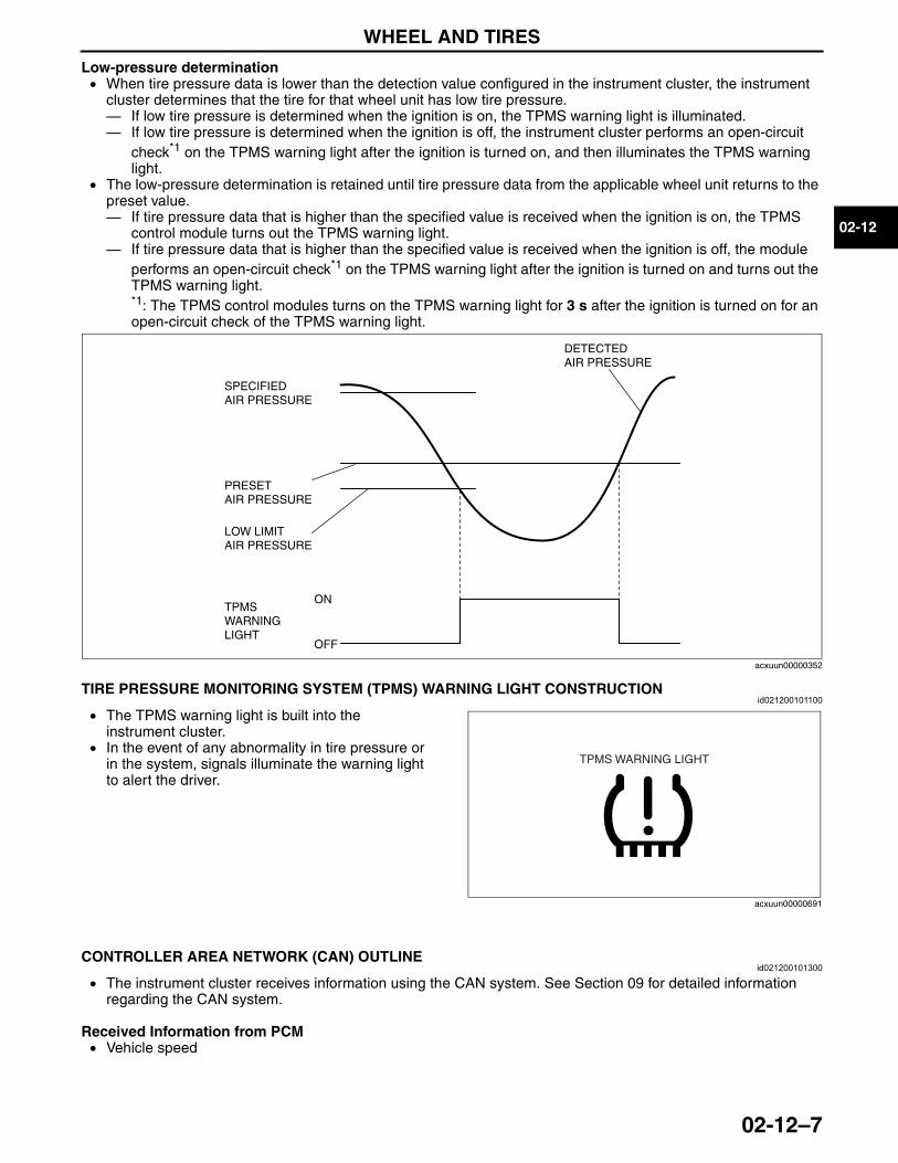
WHEEL AND TIRES
02-12–7
02-12
Low-pressure determination• When tire pressure data is lower than the detection value configured in the instrument cluster, the instrument
cluster determines that the tire for that wheel unit has low tire pressure.— If low tire pressure is determined when the ignition is on, the TPMS warning light is illuminated.— If low tire pressure is determined when the ignition is off, the instrument cluster performs an open-circuit
check*1 on the TPMS warning light after the ignition is turned on, and then illuminates the TPMS warning light.
• The low-pressure determination is retained until tire pressure data from the applicable wheel unit returns to the preset value.— If tire pressure data that is higher than the specified value is received when the ignition is on, the TPMS
control module turns out the TPMS warning light.— If tire pressure data that is higher than the specified value is received when the ignition is off, the module
performs an open-circuit check*1 on the TPMS warning light after the ignition is turned on and turns out the TPMS warning light.*1: The TPMS control modules turns on the TPMS warning light for 3 s after the ignition is turned on for an open-circuit check of the TPMS warning light.
End Of SieTIRE PRESSURE MONITORING SYSTEM (TPMS) WARNING LIGHT CONSTRUCTIONid021200101100
• The TPMS warning light is built into the instrument cluster.
• In the event of any abnormality in tire pressure or in the system, signals illuminate the warning light to alert the driver.
End Of Sie
CONTROLLER AREA NETWORK (CAN) OUTLINEid021200101300
• The instrument cluster receives information using the CAN system. See Section 09 for detailed information regarding the CAN system.
Received Information from PCM• Vehicle speed
End Of Sie
TPMS WARNING LIGHT
PRESET AIR PRESSURE
SPECIFIED AIR PRESSURE
LOW LIMITAIR PRESSURE
DETECTEDAIR PRESSURE
ON
OFF
acxuun00000352
TPMS WARNING LIGHT
acxuun00000691
3423-1U-06H(02-12).fm 7 ページ 2006年11月22日 水曜日 午前11時14分

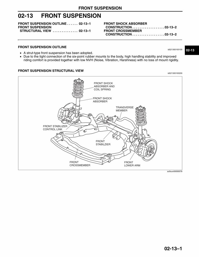
FRONT SUSPENSION
02-13–1
02-13
02-13 FRONT SUSPENSIONFRONT SUSPENSION OUTLINE . . . . . . 02-13–1FRONT SUSPENSION
STRUCTURAL VIEW . . . . . . . . . . . . . . 02-13–1
FRONT SHOCK ABSORBER CONSTRUCTION . . . . . . . . . . . . . . . . . . 02-13–2
FRONT CROSSMEMBER CONSTRUCTION . . . . . . . . . . . . . . . . . . 02-13–2
End of TocNG: FRONT SUSPENSIONFRONT SUSPENSION OUTLINE
id021300100100
• A strut-type front suspension has been adopted.• Due to the tight connection of the six-point rubber mounts to the body, high handling stability and improved
riding comfort is provided together with low NVH (Noise, Vibration, Harshness) with no loss of mount rigidity.End Of Sie
FRONT SUSPENSION STRUCTURAL VIEWid021300100200
End Of SieNG: FRONT SHOCK ABSORBER
FRONT SHOCK ABSORBER AND COIL SPRING
FRONT SHOCK ABSORBER
FRONT STABILIZER CONTROL LINK
FRONT STABILZIER
TRANSVERSE MEMBER
FRONT LOWER ARM
FRONT CROSSMEMBER
ac9uun00000078
3423-1U-06H(02-13).fm 1 ページ 2006年11月21日 火曜日 午後5時7分
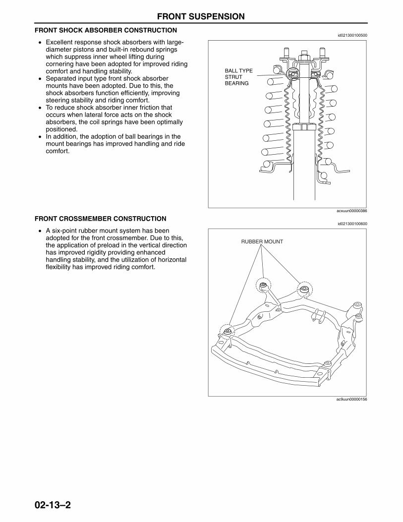
FRONT SUSPENSION
02-13–2
FRONT SHOCK ABSORBER CONSTRUCTIONid021300100500
• Excellent response shock absorbers with large-diameter pistons and built-in rebound springs which suppress inner wheel lifting during cornering have been adopted for improved riding comfort and handling stability.
• Separated input type front shock absorber mounts have been adopted. Due to this, the shock absorbers function efficiently, improving steering stability and riding comfort.
• To reduce shock absorber inner friction that occurs when lateral force acts on the shock absorbers, the coil springs have been optimally positioned.
• In addition, the adoption of ball bearings in the mount bearings has improved handling and ride comfort.
End Of SieNG: FRONT CROSSMEMBER
FRONT CROSSMEMBER CONSTRUCTIONid021300100600
• A six-point rubber mount system has been adopted for the front crossmember. Due to this, the application of preload in the vertical direction has improved rigidity providing enhanced handling stability, and the utilization of horizontal flexibility has improved riding comfort.
End Of Sie
BALL TYPE STRUT BEARING
acxuun00000386
RUBBER MOUNT
ac9uun00000156
3423-1U-06H(02-13).fm 2 ページ 2006年11月21日 火曜日 午後5時7分
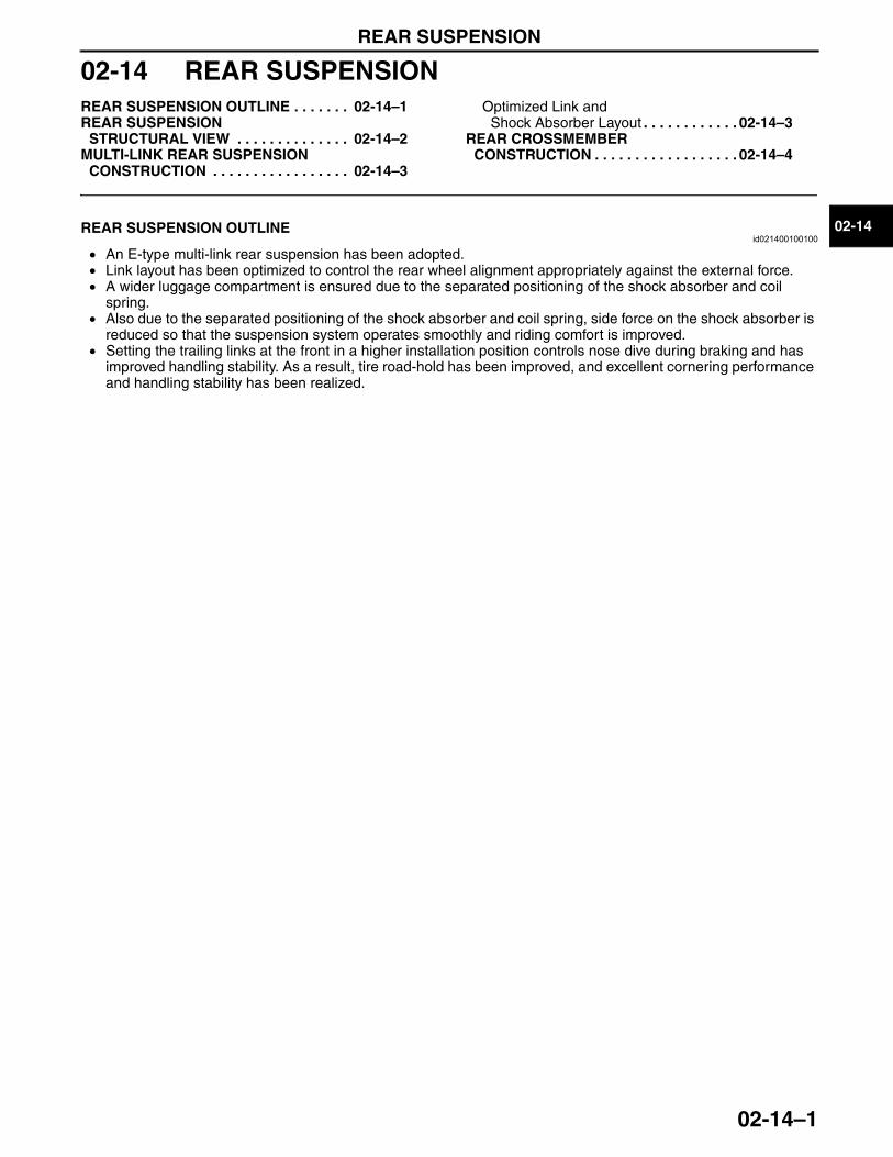
REAR SUSPENSION
02-14–1
02-14
02-14 REAR SUSPENSIONREAR SUSPENSION OUTLINE . . . . . . . 02-14–1REAR SUSPENSION
STRUCTURAL VIEW . . . . . . . . . . . . . . 02-14–2MULTI-LINK REAR SUSPENSION
CONSTRUCTION . . . . . . . . . . . . . . . . . 02-14–3
Optimized Link and Shock Absorber Layout . . . . . . . . . . . . 02-14–3
REAR CROSSMEMBER CONSTRUCTION . . . . . . . . . . . . . . . . . . 02-14–4
End of TocNG: REAR SUSPENSIONREAR SUSPENSION OUTLINE
id021400100100
• An E-type multi-link rear suspension has been adopted.• Link layout has been optimized to control the rear wheel alignment appropriately against the external force.• A wider luggage compartment is ensured due to the separated positioning of the shock absorber and coil
spring.• Also due to the separated positioning of the shock absorber and coil spring, side force on the shock absorber is
reduced so that the suspension system operates smoothly and riding comfort is improved.• Setting the trailing links at the front in a higher installation position controls nose dive during braking and has
improved handling stability. As a result, tire road-hold has been improved, and excellent cornering performance and handling stability has been realized.
End Of Sie
3423-1U-06H(02-14).fm 1 ページ 2006年11月21日 火曜日 午後5時7分
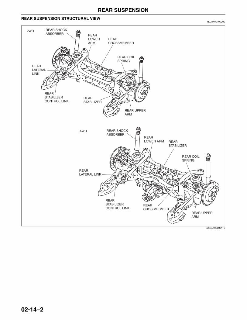
REAR SUSPENSION
02-14–2
REAR SUSPENSION STRUCTURAL VIEWid021400100200
End Of Sie
2WD
AWD
REAR UPPER ARM
REAR LATERAL LINK
REAR CROSSMEMBER
REAR SHOCK ABSORBER
REAR STABILIZER
REAR LOWER ARM
REAR COIL SPRING
REAR STABILIZER CONTROL LINK
REAR UPPER ARM
REAR LATERAL LINK
REAR CROSSMEMBER
REAR SHOCK ABSORBER
REAR STABILIZER
REAR LOWER ARM
REAR COIL SPRING
REAR STABILIZER CONTROL LINK
ac9uun00000112
3423-1U-06H(02-14).fm 2 ページ 2006年11月21日 火曜日 午後5時7分
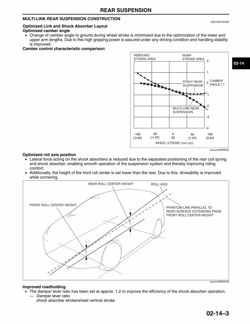
REAR SUSPENSION
02-14–3
02-14
MULTI-LINK REAR SUSPENSION CONSTRUCTIONid021400100300
Optimized Link and Shock Absorber LayoutOptimized camber angle• Change of camber angle to ground during wheel stroke is minimized due to the optimization of the lower and
upper arm lengths. Due to this high gripping power is assured under any driving condition and handling stability is improved.
Camber control characteristic comparison
Optimized roll axis position• Lateral force acting on the shock absorbers is reduced due to the separated positioning of the rear coil spring
and shock absorber, enabling smooth operation of the suspension system and thereby improving riding comfort.
• Additionally, the height of the front roll center is set lower than the rear. Due to this, driveability is improved while cornering.
Improved roadholding• The damper lever ratio has been set at approx. 1.2 to improve the efficiency of the shock absorber operation.— Damper lever ratio
shock absorber stroke/wheel vertical strokeEnd Of SieNG: REAR CROSSMEMBER
100 {3.94}
50 {1.97}
0{0}
0
-50 {-1.97}
-100 {-3.94}
2
1
-1
-2
-3
-4
REBOUND STROKE AREA
WHEEL STROKE (mm {in})
BUMP STROKE AREA
CAMBER ANGLE (°)
STRUT REAR SUSPENSION
MULTI-LINK REAR SUSPENSION
acxuun00000432
FRONT ROLL CENTER HEIGHT
REAR ROLL CENTER HEIGHT
PHANTOM LINE PARALLEL TO ROAD SURFACE EXTENDING FROM FRONT ROLL CENTER HEIGHT
ROLL AXIS
acxuun00000433
3423-1U-06H(02-14).fm 3 ページ 2006年11月21日 火曜日 午後5時7分
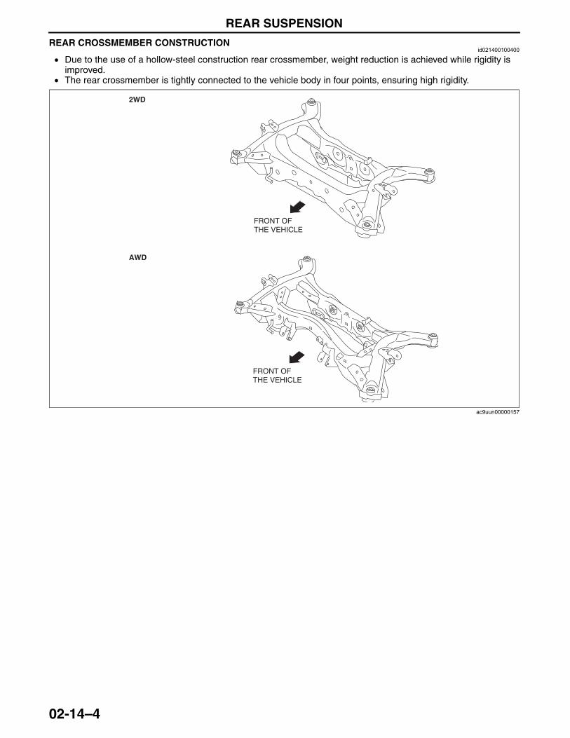
REAR SUSPENSION
02-14–4
REAR CROSSMEMBER CONSTRUCTIONid021400100400
• Due to the use of a hollow-steel construction rear crossmember, weight reduction is achieved while rigidity is improved.
• The rear crossmember is tightly connected to the vehicle body in four points, ensuring high rigidity.
End Of Sie
FRONT OF THE VEHICLE
FRONT OF THE VEHICLE
2WD
AWD
ac9uun00000157
3423-1U-06H(02-14).fm 4 ページ 2006年11月21日 火曜日 午後5時7分
03-00–1
03DRIVELINE/AXLESECTION
03-00
Toc of SCTOUTLINE . . . . . . . . . . . . . . . . . .03-00ON-BOARD DIAGNOSTIC . . . .03-02FRONT AXLE . . . . . . . . . . . . . .03-11REAR AXLE . . . . . . . . . . . . . . .03-12
DRIVE SHAFT . . . . . . . . . . . . . 03-13DIFFERENTIAL . . . . . . . . . . . . 03-14TRANSFER . . . . . . . . . . . . . . . 03-16ALL WHEEL DRIVE (AWD) . . . 03-19
Toc of SCT
03-00 OUTLINEDRIVELINE/AXLE ABBREVIATIONS . . . 03-00–1DRIVELINE/AXLE FEATURES . . . . . . . . 03-00–1
DRIVELINE/AXLE SPECIFICATIONS. . . 03-00–2
End of TocNG: DRIVELINE/AXLEDRIVELINE/AXLE ABBREVIATIONS
id030000150300
End Of Sie
DRIVELINE/AXLE FEATURESid030000100100
End Of Sie
ABS Antilock Brake SystemAWD All Wheel DriveCAN Controller Area NetworkCM Control ModuleDSC Dynamic Stability Control HU Hydraulic UnitRSC Roll Stability Control2WD 2-wheel Drive
Improved driveability • Bell-shaped constant velocity joint adopted for wheel-side joint of front and rear drive shaft
• Tripod-shaped constant velocity joint adopted for differential-side joint of front drive shaft• Double offset-shaped constant velocity joint adopted for differential-side joint of rear
drive shaft Improved rigidity, reduced noise and vibration
• Characteristics of front drive shaft optimized• Constant velocity joint type rear drive shaft adopted (AWD)• 3-part, 4-joint type propeller shaft with middle shaft bearing has been adopted
Improved off-road mobility, handling stability and marketability
• Electronic AWD control system adopted
Size and weight reduction • Rear differential with an integrated coupling component adopted• Aluminum differential carrier adopted
Improved serviceability • Self diagnostic function adopted for electronic AWD control system• A maintenance-free transfer has been adopted
3423-1U-06H(03-00).fm 1 ページ 2006年11月21日 火曜日 午後5時7分
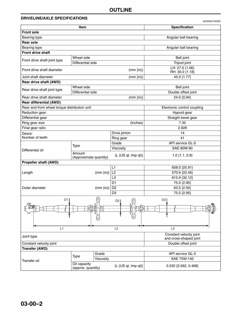
OUTLINE
03-00–2
DRIVELINE/AXLE SPECIFICATIONSid030000100200
End Of Sie
Item SpecificationFront axleBearing type Angular ball bearingRear axleBearing type Angular ball bearingFront drive shaft
Front drive shaft joint typeWheel side Bell jointDifferential side Tripod joint
Front drive shaft diameter (mm {in}) LH: 27.0 {1.06}RH: 30.0 {1.18}
Joint shaft diameter (mm {in}) 45.0 {1.77}Rear drive shaft (AWD)
Rear drive shaft joint typeWheel side Bell jointDifferential side Double offset joint
Rear drive shaft diameter (mm {in}) 24.0 {0.94}Rear differential (AWD)Rear and front wheel torque distribution unit Electronic control couplingReduction gear Hypoid gearDifferential gear Straight bevel gearRing gear size (Inches) 7.35Final gear ratio 2.928
Gears:Number of teeth
Drive pinion 14Ring gear 41
Differential oilType
Grade API service GL-5Viscosity SAE 80W-90
Amount(Approximate quantity) (L {US qt, lmp qt}) 1.0 {1.1, 0.9}
Propeller shaft (AWD)
Length (mm {in})L1 658.0 {25.91}L2 570.6 {22.46}L3 815.9 {32.12}
Outer diameter (mm {in})D1 75.0 {2.95}D2 63.5 {2.50}D3 75.0 {2.95}
Joint type Constant velocity jointand cross-shaped joint
Constant velocity joint Double offset jointTransfer (AWD)
Transfer oilType
Grade API service GL-5Viscosity SAE 75W-140
Oil capacity(approx. quantity) (L {US qt, Imp qt}) 0.532 {0.562, 0.468}
L1 L2 L3
D1 D2 D3
3423-1U-06H(03-00).fm 2 ページ 2006年11月21日 火曜日 午後5時7分
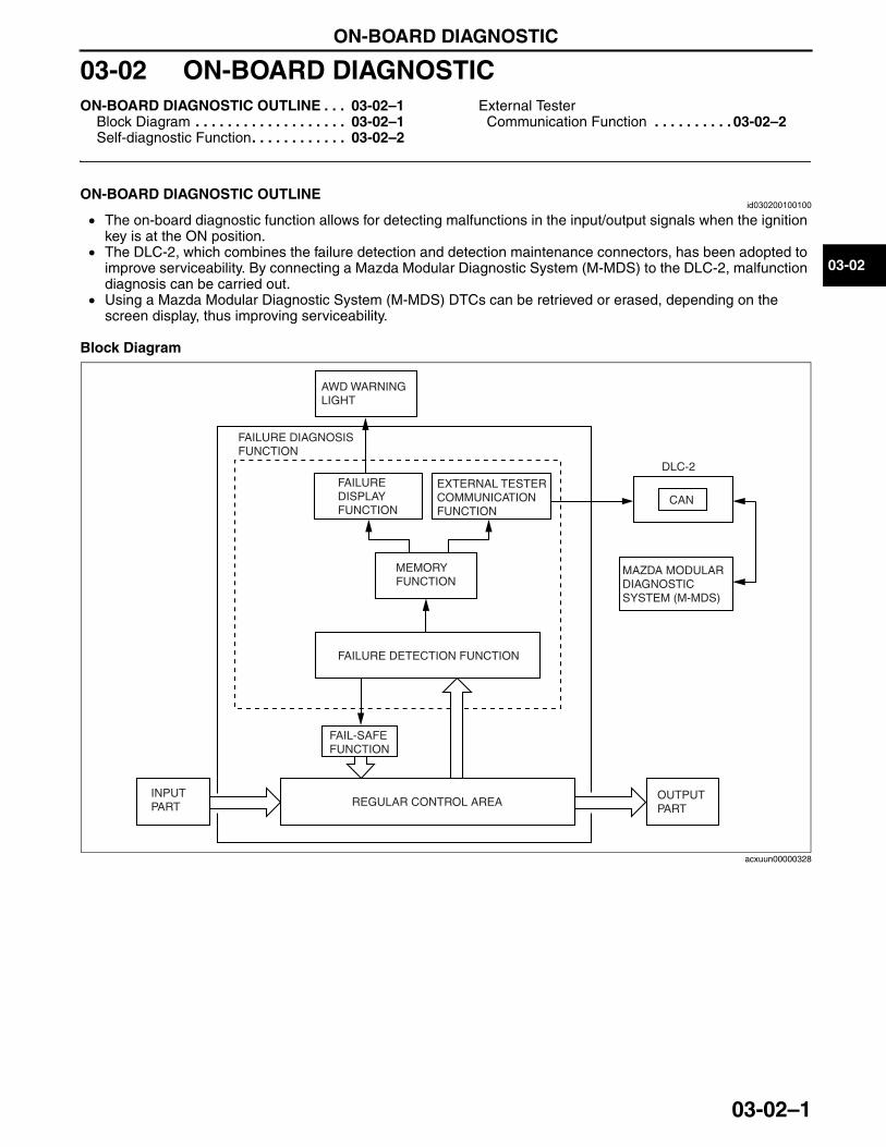
ON-BOARD DIAGNOSTIC
03-02–1
03-02
03-02 ON-BOARD DIAGNOSTICON-BOARD DIAGNOSTIC OUTLINE . . . 03-02–1
Block Diagram . . . . . . . . . . . . . . . . . . . 03-02–1Self-diagnostic Function. . . . . . . . . . . . 03-02–2
External Tester Communication Function . . . . . . . . . . 03-02–2
End of TocNG: ELECTRONIC 4WD CONTROL SYSTEMON-BOARD DIAGNOSTIC OUTLINE
id030200100100
• The on-board diagnostic function allows for detecting malfunctions in the input/output signals when the ignition key is at the ON position.
• The DLC-2, which combines the failure detection and detection maintenance connectors, has been adopted to improve serviceability. By connecting a Mazda Modular Diagnostic System (M-MDS) to the DLC-2, malfunction diagnosis can be carried out.
• Using a Mazda Modular Diagnostic System (M-MDS) DTCs can be retrieved or erased, depending on the screen display, thus improving serviceability.
Block Diagram
INPUT PART
OUTPUT PART
REGULAR CONTROL AREA
FAIL-SAFE FUNCTION
FAILURE DETECTION FUNCTION
MEMORY FUNCTION
FAILURE DISPLAY FUNCTION
EXTERNAL TESTER COMMUNICATION FUNCTION
FAILURE DIAGNOSIS FUNCTION
AWD WARNING LIGHT
DLC-2
CAN
MAZDA MODULAR DIAGNOSTIC SYSTEM (M-MDS)
acxuun00000328
3423-1U-06H(03-02).fm 1 ページ 2006年11月21日 火曜日 午後5時8分
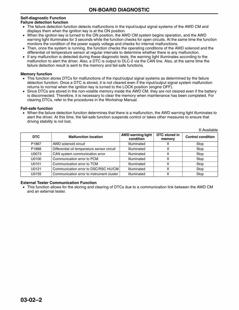
ON-BOARD DIAGNOSTIC
03-02–2
Self-diagnostic FunctionFailure detection function• The failure detection function detects malfunctions in the input/output signal systems of the AWD CM and
displays them when the ignition key is at the ON position.• When the ignition key is turned to the ON position, the AWD CM system begins operation, and the AWD
warning light illuminates for 3 seconds while the function checks for open circuits. At the same time the function monitors the condition of the power supply voltage and checks for internal malfunctions.
• Then, once the system is running, the function checks the operating conditions of the AWD solenoid and the differential oil temperature sensor at regular intervals to determine whether there is any malfunction.
• If any malfunction is detected during these diagnostic tests, the warning light illuminates according to the malfunction to alert the driver. Also, a DTC is output to DLC-2 via the CAN line. Also, at the same time the failure detection result is sent to the memory and fail-safe functions.
Memory function• This function stores DTCs for malfunctions of the input/output signal systems as determined by the failure
detection function. Once a DTC is stored, it is not cleared even if the input/output signal system malfunction returns to normal when the ignition key is turned to the LOCK position (engine OFF).
• Since DTCs are stored in the non-volatile memory inside the AWD CM, they are not cleared even if the battery is disconnected. Therefore, it is necessary to clear the memory when maintenance has been completed. For clearing DTCs, refer to the procedures in the Workshop Manual.
Fail-safe function• When the failure detection function determines that there is a malfunction, the AWD warning light illuminates to
alert the driver. At this time, the fail-safe function suspends control or takes other measures to ensure that driving stability is not lost.
X:Available
External Tester Communication Function• This function allows for the storing and clearing of DTCs due to a communication link between the AWD CM
and an external tester.End Of Sie
DTC Malfunction location AWD warning light condition
DTC stored in memory Control condition
P1887 AWD solenoid circuit Illuminated X StopP1888 Differential oil temperature sensor circuit Illuminated X StopU0073 CAN system communication error Illuminated X StopU0100 Communication error to PCM Illuminated X StopU0101 Communication error to TCM Illuminated X StopU0121 Communication error to DSC/RSC HU/CM Illuminated X StopU0155 Communication error to instrument cluster Illuminated X Stop
3423-1U-06H(03-02).fm 2 ページ 2006年11月21日 火曜日 午後5時8分
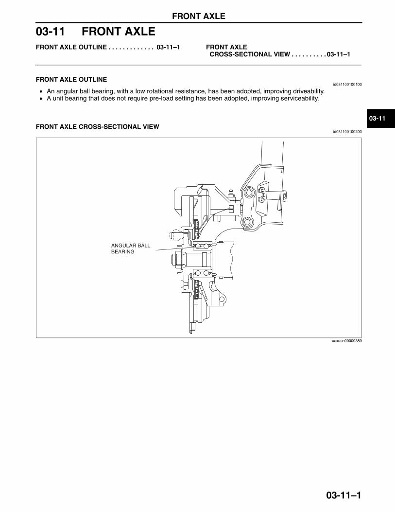
FRONT AXLE
03-11–1
03-11
03-11 FRONT AXLEFRONT AXLE OUTLINE . . . . . . . . . . . . . 03-11–1 FRONT AXLE
CROSS-SECTIONAL VIEW . . . . . . . . . . 03-11–1
End of TocNG: FRONT AXLEFRONT AXLE OUTLINE
id031100100100
• An angular ball bearing, with a low rotational resistance, has been adopted, improving driveability.• A unit bearing that does not require pre-load setting has been adopted, improving serviceability.
End Of Sie
FRONT AXLE CROSS-SECTIONAL VIEWid031100100200
End Of Sie
ANGULAR BALL BEARING
acxuun00000389
3423-1U-06H(03-11).fm 1 ページ 2006年11月21日 火曜日 午後5時8分

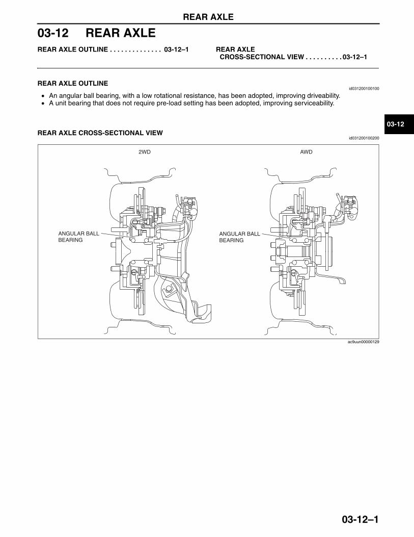
REAR AXLE
03-12–1
03-12
03-12 REAR AXLEREAR AXLE OUTLINE . . . . . . . . . . . . . . 03-12–1 REAR AXLE
CROSS-SECTIONAL VIEW . . . . . . . . . . 03-12–1
End of TocNG: REAR AXLEREAR AXLE OUTLINE
id031200100100
• An angular ball bearing, with a low rotational resistance, has been adopted, improving driveability.• A unit bearing that does not require pre-load setting has been adopted, improving serviceability.
End Of Sie
REAR AXLE CROSS-SECTIONAL VIEWid031200100200
End Of Sie
2WD AWD
ANGULAR BALL BEARING
ANGULAR BALL BEARING
ac9uun00000129
3423-1U-06H(03-12).fm 1 ページ 2006年11月21日 火曜日 午後5時9分

DRIVE SHAFT
03-13–1
03-13
03-13 DRIVE SHAFTDRIVE SHAFT OUTLINE . . . . . . . . . . . . 03-13–1DRIVE SHAFT STRUCTURAL VIEW . . . 03-13–2FRONT DRIVE SHAFT STRUCTURE. . . 03-13–3
JOINT SHAFT OUTLINE . . . . . . . . . . . . . 03-13–3Construction . . . . . . . . . . . . . . . . . . . . . 03-13–3
REAR DRIVE SHAFT STRUCTURE . . . . 03-13–4
End of TocNG: DRIVE SHAFTDRIVE SHAFT OUTLINE
id031300151600
• A large size front drive shaft and joint shaft has been adopted, improving driveability and reducing noise/vibration.
• A constant velocity joint system has been adopted for the rear drive shaft, improving driveability and reducing noise/vibration.
End Of Sie
3423-1U-06H(03-13).fm 1 ページ 2006年11月21日 火曜日 午後5時9分
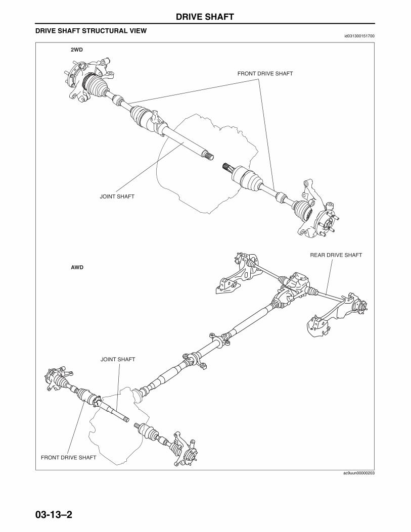
DRIVE SHAFT
03-13–2
DRIVE SHAFT STRUCTURAL VIEWid031300151700
End Of SieNG: FRONT DRIVE SHAFT
JOINT SHAFT
FRONT DRIVE SHAFT
2WD
AWD
JOINT SHAFT
FRONT DRIVE SHAFT
REAR DRIVE SHAFT
ac9uun00000203
3423-1U-06H(03-13).fm 2 ページ 2006年11月21日 火曜日 午後5時9分
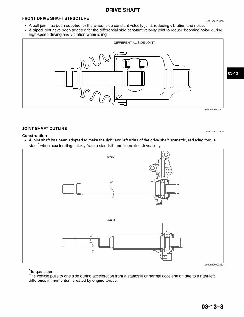
DRIVE SHAFT
03-13–3
03-13
FRONT DRIVE SHAFT STRUCTUREid031300101000
• A bell joint has been adopted for the wheel-side constant velocity joint, reducing vibration and noise.• A tripod joint have been adopted for the differential side constant velocity joint to reduce booming noise during
high-speed driving and vibration when idling.
End Of SieNG: JOINT SHAFT
JOINT SHAFT OUTLINEid031300100500
Construction• A joint shaft has been adopted to make the right and left sides of the drive shaft isometric, reducing torque
steer* when accelerating quickly from a standstill and improving driveability.
*Torque steerThe vehicle pulls to one side during acceleration from a standstill or normal acceleration due to a right-left difference in momentum created by engine torque.
End Of SieNG: REAR DRIVE SHAFT
DIFFERENTIAL SIDE JOINT
acxuun00000391
2WD
AWD
ac9uun00000153
3423-1U-06H(03-13).fm 3 ページ 2006年11月21日 火曜日 午後5時9分
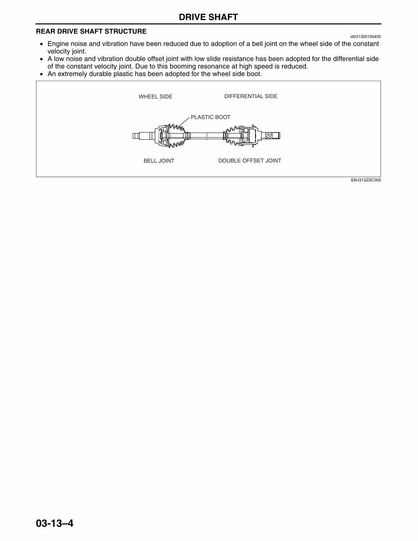
DRIVE SHAFT
03-13–4
REAR DRIVE SHAFT STRUCTUREid031300100400
• Engine noise and vibration have been reduced due to adoption of a bell joint on the wheel side of the constant velocity joint.
• A low noise and vibration double offset joint with low slide resistance has been adopted for the differential side of the constant velocity joint. Due to this booming resonance at high speed is reduced.
• An extremely durable plastic has been adopted for the wheel side boot.
End Of Sie
WHEEL SIDE DIFFERENTIAL SIDE
PLASTIC BOOT
BELL JOINT DOUBLE OFFSET JOINT
E6U313ZSC002
3423-1U-06H(03-13).fm 4 ページ 2006年11月21日 火曜日 午後5時9分
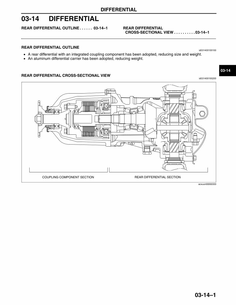
DIFFERENTIAL
03-14–1
03-14
03-14 DIFFERENTIALREAR DIFFERENTIAL OUTLINE . . . . . . 03-14–1 REAR DIFFERENTIAL
CROSS-SECTIONAL VIEW . . . . . . . . . . 03-14–1
End of TocNG: DIFFERENTIAL (FF/FR)REAR DIFFERENTIAL OUTLINE
id031400100100
• A rear differential with an integrated coupling component has been adopted, reducing size and weight.• An aluminum differential carrier has been adopted, reducing weight.
End Of Sie
REAR DIFFERENTIAL CROSS-SECTIONAL VIEWid031400100200
End Of Sie
COUPLING COMPONENT SECTION REAR DIFFERENTIAL SECTION
acxuun00000333
3423-1U-06H(03-14).fm 1 ページ 2006年11月21日 火曜日 午後5時10分

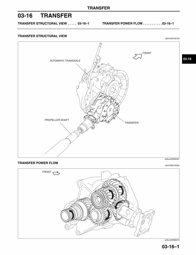
TRANSFER
03-16–1
03-16
03-16 TRANSFERTRANSFER STRUCTURAL VIEW . . . . . 03-16–1 TRANSFER POWER FLOW. . . . . . . . . . . 03-16–1
End of TocNG: TRANSFERTRANSFER STRUCTURAL VIEW
id031600100100
End Of SieTRANSFER POWER FLOWid031600100300
AUTOMATIC TRANSAXLE
TRANSFERPROPELLER SHAFT
FRONT
ac9uun00000427
FRONT
ac9uun00000410
3423-1U-06H(03-16).fm 1 ページ 2006年11月21日 火曜日 午後5時10分

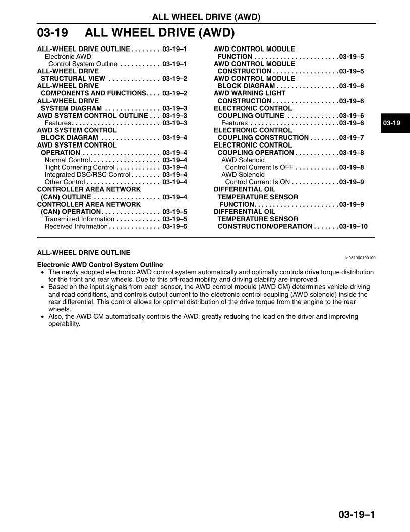
ALL WHEEL DRIVE (AWD)
03-19–1
03-19
03-19 ALL WHEEL DRIVE (AWD)ALL-WHEEL DRIVE OUTLINE . . . . . . . . 03-19–1
Electronic AWD Control System Outline . . . . . . . . . . . 03-19–1
ALL-WHEEL DRIVE STRUCTURAL VIEW . . . . . . . . . . . . . . 03-19–2
ALL-WHEEL DRIVE COMPONENTS AND FUNCTIONS. . . . 03-19–2
ALL-WHEEL DRIVE SYSTEM DIAGRAM . . . . . . . . . . . . . . . 03-19–3
AWD SYSTEM CONTROL OUTLINE . . . 03-19–3Features . . . . . . . . . . . . . . . . . . . . . . . . 03-19–3
AWD SYSTEM CONTROL BLOCK DIAGRAM . . . . . . . . . . . . . . . . 03-19–4
AWD SYSTEM CONTROL OPERATION . . . . . . . . . . . . . . . . . . . . . 03-19–4
Normal Control. . . . . . . . . . . . . . . . . . . 03-19–4Tight Cornering Control . . . . . . . . . . . . 03-19–4Integrated DSC/RSC Control . . . . . . . . 03-19–4Other Control . . . . . . . . . . . . . . . . . . . . 03-19–4
CONTROLLER AREA NETWORK (CAN) OUTLINE . . . . . . . . . . . . . . . . . . 03-19–4
CONTROLLER AREA NETWORK (CAN) OPERATION. . . . . . . . . . . . . . . . 03-19–5
Transmitted Information . . . . . . . . . . . . 03-19–5Received Information . . . . . . . . . . . . . . 03-19–5
AWD CONTROL MODULE FUNCTION . . . . . . . . . . . . . . . . . . . . . . . 03-19–5
AWD CONTROL MODULE CONSTRUCTION . . . . . . . . . . . . . . . . . . 03-19–5
AWD CONTROL MODULE BLOCK DIAGRAM . . . . . . . . . . . . . . . . . 03-19–6
AWD WARNING LIGHT CONSTRUCTION . . . . . . . . . . . . . . . . . . 03-19–6
ELECTRONIC CONTROL COUPLING OUTLINE . . . . . . . . . . . . . . 03-19–6
Features . . . . . . . . . . . . . . . . . . . . . . . . 03-19–6ELECTRONIC CONTROL
COUPLING CONSTRUCTION . . . . . . . . 03-19–7ELECTRONIC CONTROL
COUPLING OPERATION . . . . . . . . . . . . 03-19–8AWD Solenoid
Control Current Is OFF . . . . . . . . . . . . 03-19–8AWD Solenoid
Control Current Is ON . . . . . . . . . . . . . 03-19–9DIFFERENTIAL OIL
TEMPERATURE SENSOR FUNCTION. . . . . . . . . . . . . . . . . . . . . . . 03-19–9
DIFFERENTIAL OIL TEMPERATURE SENSOR CONSTRUCTION/OPERATION . . . . . . . 03-19–10
End of TocNG: ELECTRONIC 4WD CONTROL SYSTEMALL-WHEEL DRIVE OUTLINE
id031900100100
Electronic AWD Control System Outline• The newly adopted electronic AWD control system automatically and optimally controls drive torque distribution
for the front and rear wheels. Due to this off-road mobility and driving stability are improved.• Based on the input signals from each sensor, the AWD control module (AWD CM) determines vehicle driving
and road conditions, and controls output current to the electronic control coupling (AWD solenoid) inside the rear differential. This control allows for optimal distribution of the drive torque from the engine to the rear wheels.
• Also, the AWD CM automatically controls the AWD, greatly reducing the load on the driver and improving operability.
End Of Sie
3423-1U-06H(03-19).fm 1 ページ 2006年11月21日 火曜日 午後5時11分
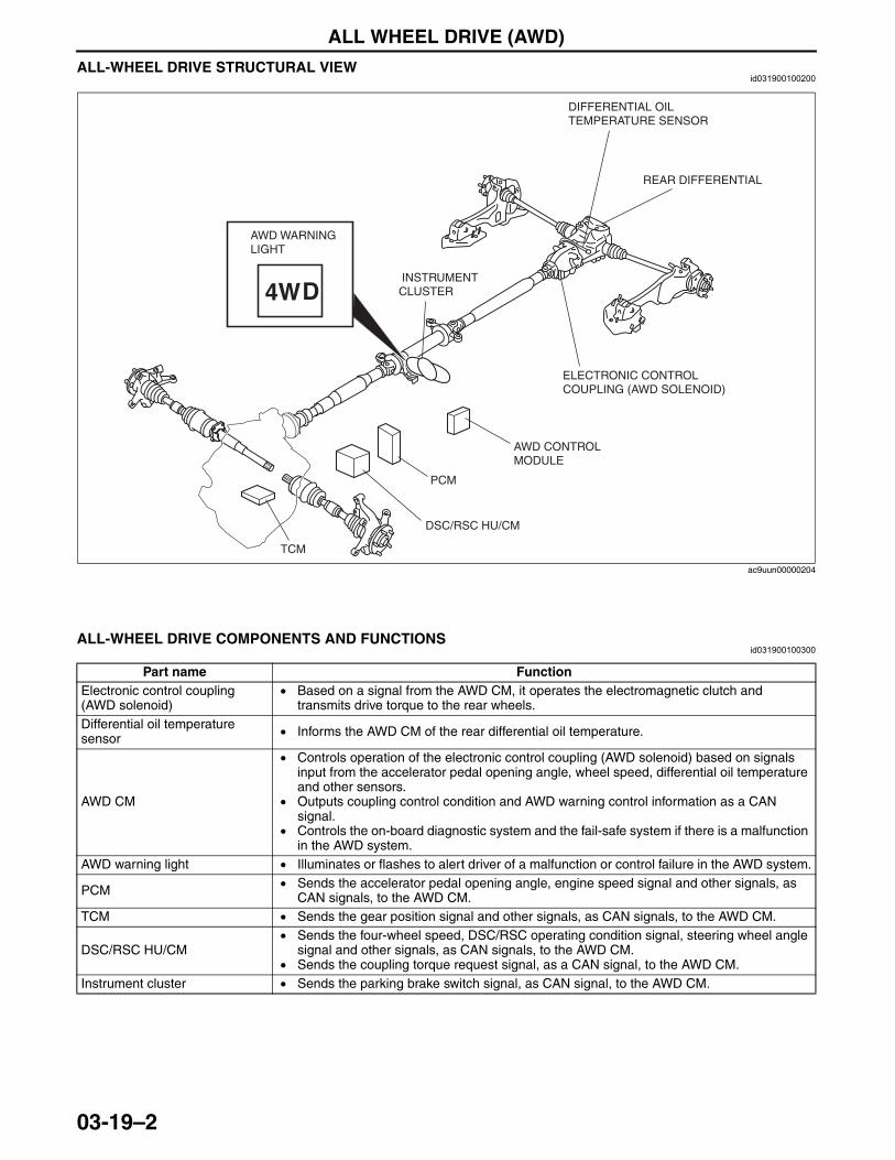
ALL WHEEL DRIVE (AWD)
03-19–2
ALL-WHEEL DRIVE STRUCTURAL VIEWid031900100200
End Of Sie
ALL-WHEEL DRIVE COMPONENTS AND FUNCTIONSid031900100300
End Of Sie
AWD WARNINGLIGHT
AWD CONTROL MODULE
DSC/RSC HU/CM
PCM
TCM
ELECTRONIC CONTROL COUPLING (AWD SOLENOID)
DIFFERENTIAL OIL TEMPERATURE SENSOR
REAR DIFFERENTIAL
INSTRUMENT CLUSTER
ac9uun00000204
Part name FunctionElectronic control coupling (AWD solenoid)
• Based on a signal from the AWD CM, it operates the electromagnetic clutch and transmits drive torque to the rear wheels.
Differential oil temperature sensor • Informs the AWD CM of the rear differential oil temperature.
AWD CM
• Controls operation of the electronic control coupling (AWD solenoid) based on signals input from the accelerator pedal opening angle, wheel speed, differential oil temperature and other sensors.
• Outputs coupling control condition and AWD warning control information as a CAN signal.
• Controls the on-board diagnostic system and the fail-safe system if there is a malfunction in the AWD system.
AWD warning light • Illuminates or flashes to alert driver of a malfunction or control failure in the AWD system.
PCM • Sends the accelerator pedal opening angle, engine speed signal and other signals, as CAN signals, to the AWD CM.
TCM • Sends the gear position signal and other signals, as CAN signals, to the AWD CM.
DSC/RSC HU/CM• Sends the four-wheel speed, DSC/RSC operating condition signal, steering wheel angle
signal and other signals, as CAN signals, to the AWD CM.• Sends the coupling torque request signal, as a CAN signal, to the AWD CM.
Instrument cluster • Sends the parking brake switch signal, as CAN signal, to the AWD CM.
3423-1U-06H(03-19).fm 2 ページ 2006年11月21日 火曜日 午後5時11分
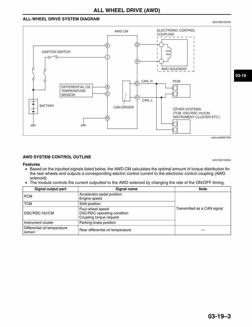
ALL WHEEL DRIVE (AWD)
03-19–3
03-19
ALL-WHEEL DRIVE SYSTEM DIAGRAMid031900100400
End Of Sie
AWD SYSTEM CONTROL OUTLINEid031900100500
Features• Based on the inputted signals listed below, the AWD CM calculates the optimal amount of torque distribution for
the rear wheels and outputs a corresponding electric control current to the electronic control coupling (AWD solenoid).
• The module controls the current outputted to the AWD solenoid by changing the rate of the ON/OFF timing.
End Of Sie
K
BATTERY
IGNITION SWITCH
DIFFERENTIAL OIL TEMPERATURE SENSOR
AWD CM ELECTRONIC CONTROL COUPLING
AWD SOLENOID
OTHER SYSTEMS(TCM, DSC/RSC HU/CM, INSTRUMENT CLUSTER ETC.)
PCMCAN_H
CAN_L
CAN DRIVER
I
A
C
N
O
P
G
H
ac9uuw00001453
Signal output part Signal name Note
PCM Accelerator pedal positionEngine speed
Transmitted as a CAN signalTCM Shift position
DSC/RSC HU/CMFour-wheel speedDSC/RSC operating conditionCoupling torque request
Instrument cluster Parking brake positionDifferential oil temperature sensor Rear differential oil temperature —
3423-1U-06H(03-19).fm 3 ページ 2006年11月21日 火曜日 午後5時11分
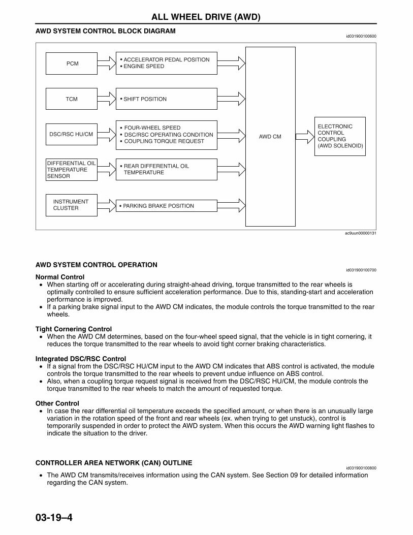
ALL WHEEL DRIVE (AWD)
03-19–4
AWD SYSTEM CONTROL BLOCK DIAGRAMid031900100600
End Of Sie
AWD SYSTEM CONTROL OPERATIONid031900100700
Normal Control• When starting off or accelerating during straight-ahead driving, torque transmitted to the rear wheels is
optimally controlled to ensure sufficient acceleration performance. Due to this, standing-start and acceleration performance is improved.
• If a parking brake signal input to the AWD CM indicates, the module controls the torque transmitted to the rear wheels.
Tight Cornering Control• When the AWD CM determines, based on the four-wheel speed signal, that the vehicle is in tight cornering, it
reduces the torque transmitted to the rear wheels to avoid tight corner braking characteristics.
Integrated DSC/RSC Control• If a signal from the DSC/RSC HU/CM input to the AWD CM indicates that ABS control is activated, the module
controls the torque transmitted to the rear wheels to prevent undue influence on ABS control.• Also, when a coupling torque request signal is received from the DSC/RSC HU/CM, the module controls the
torque transmitted to the rear wheels to match the amount of requested torque.
Other Control• In case the rear differential oil temperature exceeds the specified amount, or when there is an unusually large
variation in the rotation speed of the front and rear wheels (ex. when trying to get unstuck), control is temporarily suspended in order to protect the AWD system. When this occurs the AWD warning light flashes to indicate the situation to the driver.
End Of Sie
CONTROLLER AREA NETWORK (CAN) OUTLINEid031900100800
• The AWD CM transmits/receives information using the CAN system. See Section 09 for detailed information regarding the CAN system.
End Of Sie
SHIFT POSITIONTCM
DSC/RSC HU/CMFOUR-WHEEL SPEEDDSC/RSC OPERATING CONDITIONCOUPLING TORQUE REQUEST
ACCELERATOR PEDAL POSITIONENGINE SPEEDPCM
AWD CM
ELECTRONIC CONTROL COUPLING(AWD SOLENOID)
DIFFERENTIAL OIL TEMPERATURE SENSOR
INSTRUMENT CLUSTER
REAR DIFFERENTIAL OIL TEMPERATURE
PARKING BRAKE POSITION
ac9uun00000131
3423-1U-06H(03-19).fm 4 ページ 2006年11月21日 火曜日 午後5時11分
ALL WHEEL DRIVE (AWD)
03-19–5
03-19
CONTROLLER AREA NETWORK (CAN) OPERATIONid031900100900
Transmitted Information• Coupling torque• AWD system condition (warning light information)
Received Information• Four-wheel speed• Accelerator pedal opening angle• Engine speed• DSC/RSC operating condition• Shift position• Coupling torque request
End Of SieNG: 4WD CONTROL MODULEAWD CONTROL MODULE FUNCTION
id031900101000
• The AWD CM calculates the optimal amount of torque distribution for the rear wheels and outputs a corresponding electric current to the electronic control coupling (AWD solenoid). This calculation is based on the accelerator pedal angle, four-wheel speed, engine speed, and other related input signals, matched with the vehicle driving and road surface conditions.
Function table
End Of Sie
AWD CONTROL MODULE CONSTRUCTIONid031900101100
• The AWD CM is installed to the left of the dashboard. (Driver side)End Of Sie
Function name ContentsAWD system control function
• Based on each input signal, the electronic control current sent to the electronic control coupling (AWD solenoid) is optimally controlled.
Diagnostic system
• If the self-diagnostic system detects a malfunction, the AWD warning light illuminates to alert the driver, and at the same time the system suspends control or performs other measures to prevent a loss of driving stability and protect the system.
• The detected malfunction is stored as a DTC in the AWD CM.
3423-1U-06H(03-19).fm 5 ページ 2006年11月21日 火曜日 午後5時11分
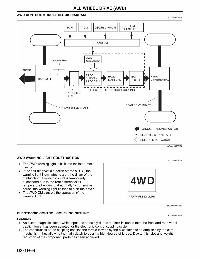
ALL WHEEL DRIVE (AWD)
03-19–6
AWD CONTROL MODULE BLOCK DIAGRAMid031900101200
End Of SieNG: 4X4 INDICATOR SWITCH
AWD WARNING LIGHT CONSTRUCTIONid031900101300
• The AWD warning light is built into the instrument cluster.
• If the self-diagnostic function stores a DTC, the warning light illuminates to alert the driver of the malfunction. If system control is temporarily suspended due to the rear differential oil temperature becoming abnormally hot or similar cause, the warning light flashes to alert the driver.
• The AWD CM controls the operation of the warning light.
End Of SieNG: COUPLING COMPONENT
ELECTRONIC CONTROL COUPLING OUTLINEid031900101400
Features• An electromagnetic clutch, which operates smoothly due to the lack influence from the front and rear wheel
traction force, has been adopted for the electronic control coupling system.• The construction of the coupling enables the torque formed by the pilot clutch to be amplified by the cam
mechanism, thus allowing the main clutch to obtain a high degree of torque. Due to this, size and weight reduction of the component parts has been achieved.
End Of Sie
FRONT
PCM TCM DSC/RSC HU/CMINSTRUMENT CLUSTER
AWD CM
TRANSAXLE
TRANSFER
PROPELLER SHAFT
FRONT DRIVE SHAFT
AWD SOLENOID
PILOT CLUTCH/PILOT CAM
BALL/MAIN CAM
MAIN CLUTCH
ELECTRONIC CONTROL COUPLING
REAR DIFFERENTIAL
REAR DRIVE SHAFT
TORQUE TRANSMISSION PATH
ELECTRIC SIGNAL PATH
SOLENOID ACTIVATION
ac9uun00000130
AWD WARNING LIGHT
ac9uun00000450
3423-1U-06H(03-19).fm 6 ページ 2006年11月21日 火曜日 午後5時11分
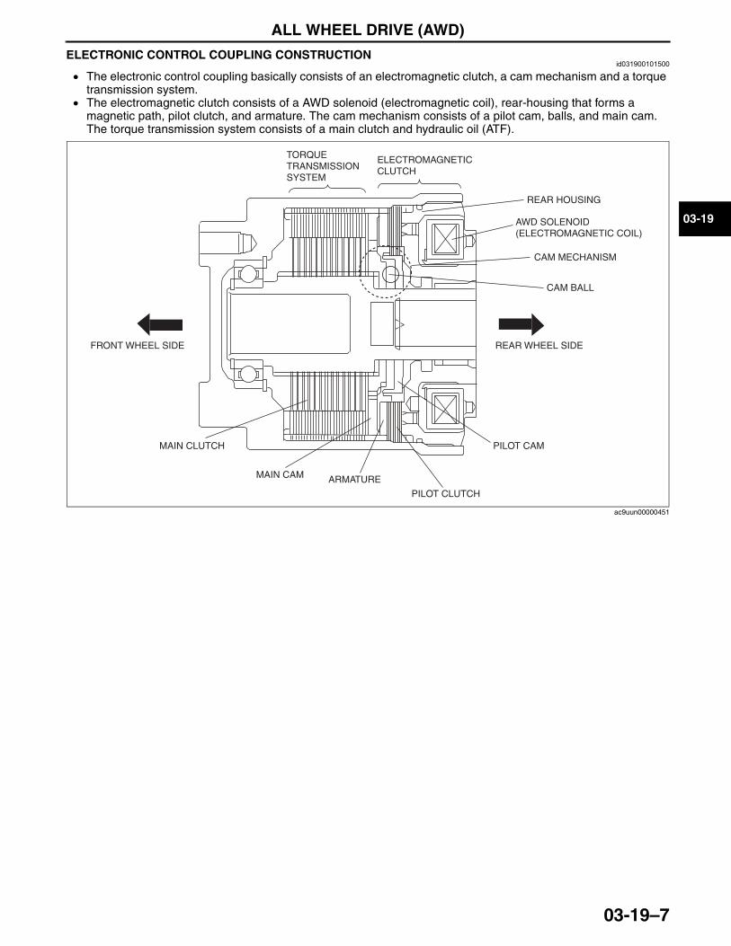
ALL WHEEL DRIVE (AWD)
03-19–7
03-19
ELECTRONIC CONTROL COUPLING CONSTRUCTIONid031900101500
• The electronic control coupling basically consists of an electromagnetic clutch, a cam mechanism and a torque transmission system.
• The electromagnetic clutch consists of a AWD solenoid (electromagnetic coil), rear-housing that forms a magnetic path, pilot clutch, and armature. The cam mechanism consists of a pilot cam, balls, and main cam. The torque transmission system consists of a main clutch and hydraulic oil (ATF).
End Of Sie
FRONT WHEEL SIDE REAR WHEEL SIDE
TORQUE TRANSMISSION SYSTEM
ELECTROMAGNETIC CLUTCH
REAR HOUSING
AWD SOLENOID (ELECTROMAGNETIC COIL)
CAM MECHANISM
CAM BALL
MAIN CLUTCH
MAIN CAM ARMATURE
PILOT CLUTCH
PILOT CAM
ac9uun00000451
3423-1U-06H(03-19).fm 7 ページ 2006年11月21日 火曜日 午後5時11分
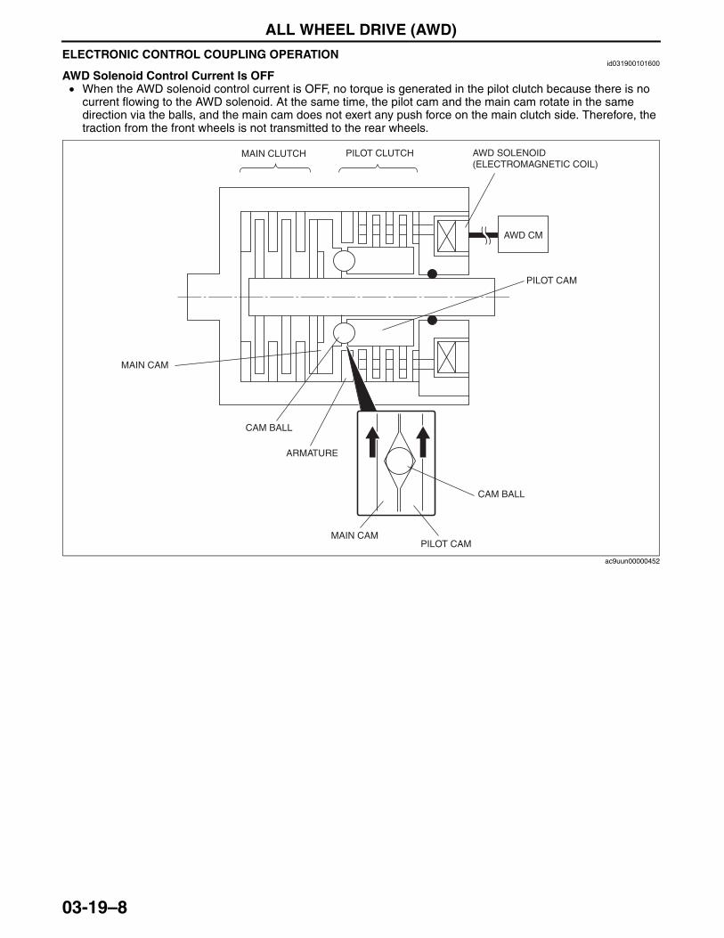
ALL WHEEL DRIVE (AWD)
03-19–8
ELECTRONIC CONTROL COUPLING OPERATIONid031900101600
AWD Solenoid Control Current Is OFF• When the AWD solenoid control current is OFF, no torque is generated in the pilot clutch because there is no
current flowing to the AWD solenoid. At the same time, the pilot cam and the main cam rotate in the same direction via the balls, and the main cam does not exert any push force on the main clutch side. Therefore, the traction from the front wheels is not transmitted to the rear wheels.
AWD SOLENOID (ELECTROMAGNETIC COIL)
CAM BALL
MAIN CLUTCH
MAIN CAM
ARMATURE
PILOT CLUTCH
PILOT CAM
CAM BALL
MAIN CAMPILOT CAM
AWD CM
ac9uun00000452
3423-1U-06H(03-19).fm 8 ページ 2006年11月21日 火曜日 午後5時11分
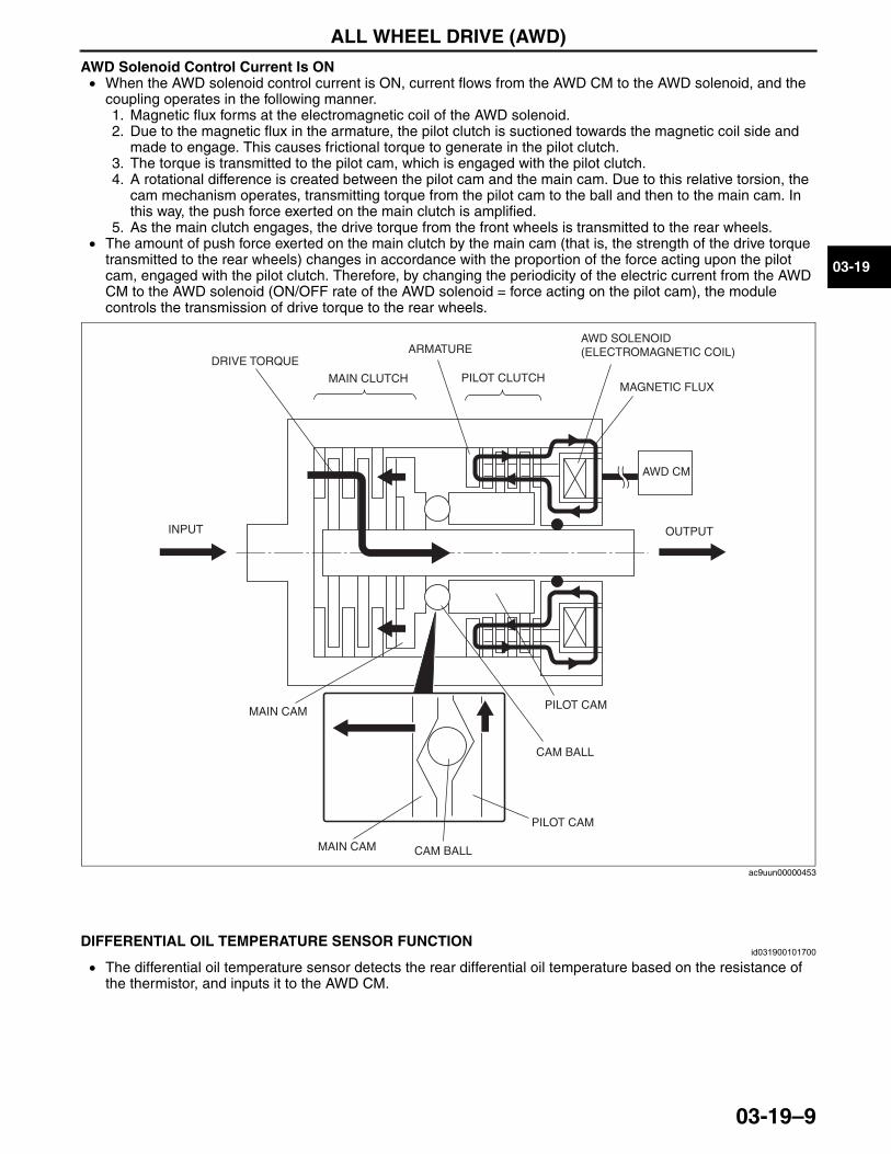
ALL WHEEL DRIVE (AWD)
03-19–9
03-19
AWD Solenoid Control Current Is ON• When the AWD solenoid control current is ON, current flows from the AWD CM to the AWD solenoid, and the
coupling operates in the following manner.1. Magnetic flux forms at the electromagnetic coil of the AWD solenoid.2. Due to the magnetic flux in the armature, the pilot clutch is suctioned towards the magnetic coil side and
made to engage. This causes frictional torque to generate in the pilot clutch.3. The torque is transmitted to the pilot cam, which is engaged with the pilot clutch.4. A rotational difference is created between the pilot cam and the main cam. Due to this relative torsion, the
cam mechanism operates, transmitting torque from the pilot cam to the ball and then to the main cam. In this way, the push force exerted on the main clutch is amplified.
5. As the main clutch engages, the drive torque from the front wheels is transmitted to the rear wheels.• The amount of push force exerted on the main clutch by the main cam (that is, the strength of the drive torque
transmitted to the rear wheels) changes in accordance with the proportion of the force acting upon the pilot cam, engaged with the pilot clutch. Therefore, by changing the periodicity of the electric current from the AWD CM to the AWD solenoid (ON/OFF rate of the AWD solenoid = force acting on the pilot cam), the module controls the transmission of drive torque to the rear wheels.
End Of SieNG: DIFFERENTIAL OIL TEMPERATURE SENSOR
DIFFERENTIAL OIL TEMPERATURE SENSOR FUNCTIONid031900101700
• The differential oil temperature sensor detects the rear differential oil temperature based on the resistance of the thermistor, and inputs it to the AWD CM.
End Of Sie
AWD SOLENOID (ELECTROMAGNETIC COIL)
CAM BALL
MAIN CLUTCH
MAIN CAM
ARMATURE
PILOT CLUTCH
PILOT CAM
AWD CM
CAM BALLMAIN CAM
PILOT CAM
INPUT OUTPUT
DRIVE TORQUE
MAGNETIC FLUX
ac9uun00000453
3423-1U-06H(03-19).fm 9 ページ 2006年11月21日 火曜日 午後5時11分
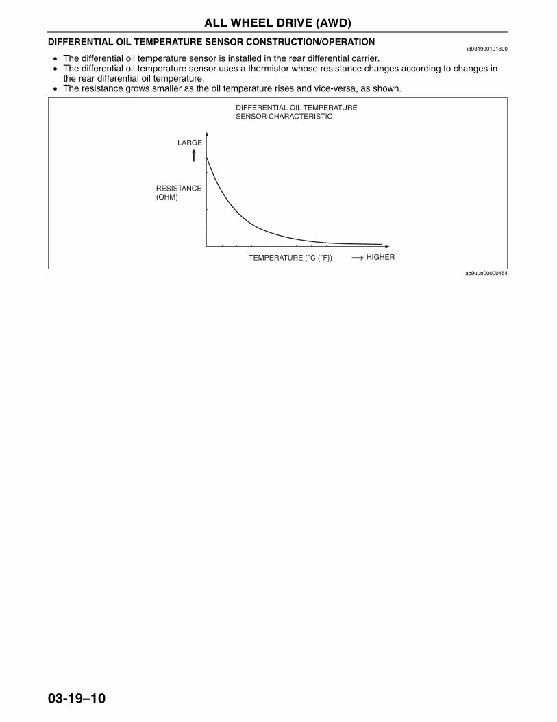
ALL WHEEL DRIVE (AWD)
03-19–10
DIFFERENTIAL OIL TEMPERATURE SENSOR CONSTRUCTION/OPERATIONid031900101800
• The differential oil temperature sensor is installed in the rear differential carrier.• The differential oil temperature sensor uses a thermistor whose resistance changes according to changes in
the rear differential oil temperature.• The resistance grows smaller as the oil temperature rises and vice-versa, as shown.
End Of Sie
DIFFERENTIAL OIL TEMPERATURE SENSOR CHARACTERISTIC
RESISTANCE (OHM)
TEMPERATURE (˚C {˚F})
LARGE
HIGHER
ac9uun00000454
3423-1U-06H(03-19).fm 10 ページ 2006年11月21日 火曜日 午後5時11分
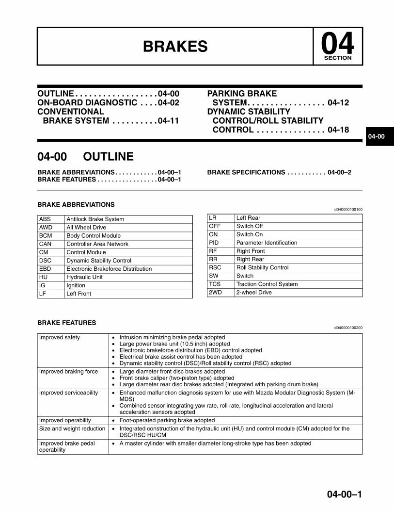
04-00–1
04BRAKESSECTION
04-00
Toc of SCTOUTLINE . . . . . . . . . . . . . . . . . .04-00ON-BOARD DIAGNOSTIC . . . .04-02CONVENTIONAL
BRAKE SYSTEM . . . . . . . . . .04-11
PARKING BRAKE SYSTEM. . . . . . . . . . . . . . . . . 04-12
DYNAMIC STABILITY CONTROL/ROLL STABILITY CONTROL . . . . . . . . . . . . . . . 04-18
Toc of SCT
04-00 OUTLINEBRAKE ABBREVIATIONS. . . . . . . . . . . . 04-00–1BRAKE FEATURES . . . . . . . . . . . . . . . . . 04-00–1
BRAKE SPECIFICATIONS . . . . . . . . . . . 04-00–2
End of TocNG: BRAKESBRAKE ABBREVIATIONS
id040000100100
End Of SieBRAKE FEATURES
id040000100200
End Of Sie
ABS Antilock Brake SystemAWD All Wheel DriveBCM Body Control ModuleCAN Controller Area NetworkCM Control ModuleDSC Dynamic Stability Control EBD Electronic Brakeforce DistributionHU Hydraulic UnitIG IgnitionLF Left Front
LR Left RearOFF Switch OffON Switch OnPID Parameter IdentificationRF Right FrontRR Right RearRSC Roll Stability ControlSW SwitchTCS Traction Control System2WD 2-wheel Drive
Improved safety • Intrusion minimizing brake pedal adopted• Large power brake unit (10.5 inch) adopted • Electronic brakeforce distribution (EBD) control adopted• Electrical brake assist control has been adopted • Dynamic stability control (DSC)/Roll stability control (RSC) adopted
Improved braking force • Large diameter front disc brakes adopted• Front brake caliper (two-piston type) adopted • Large diameter rear disc brakes adopted (Integrated with parking drum brake)
Improved serviceability • Enhanced malfunction diagnosis system for use with Mazda Modular Diagnostic System (M-MDS)
• Combined sensor integrating yaw rate, roll rate, longitudinal acceleration and lateral acceleration sensors adopted
Improved operability • Foot-operated parking brake adoptedSize and weight reduction • Integrated construction of the hydraulic unit (HU) and control module (CM) adopted for the
DSC/RSC HU/CMImproved brake pedal operability
• A master cylinder with smaller diameter long-stroke type has been adopted
3423-1U-06H(04-00).fm 1 ページ 2006年11月22日 水曜日 午後2時26分
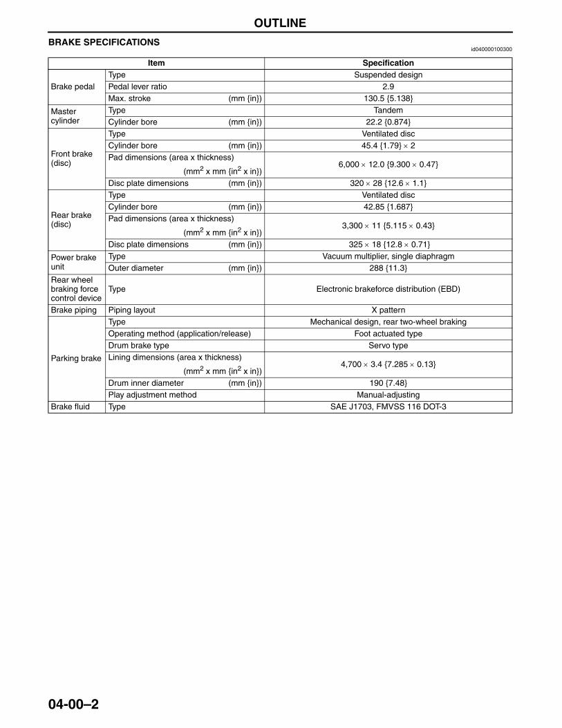
OUTLINE
04-00–2
BRAKE SPECIFICATIONSid040000100300
End Of Sie
Item Specification
Brake pedalType Suspended designPedal lever ratio 2.9Max. stroke (mm {in}) 130.5 {5.138}
Master cylinder
Type TandemCylinder bore (mm {in}) 22.2 {0.874}
Front brake (disc)
Type Ventilated discCylinder bore (mm {in}) 45.4 {1.79} × 2Pad dimensions (area x thickness)
6,000 × 12.0 {9.300 × 0.47}(mm2 x mm {in2 x in})
Disc plate dimensions (mm {in}) 320 × 28 {12.6 × 1.1}
Rear brake (disc)
Type Ventilated discCylinder bore (mm {in}) 42.85 {1.687}Pad dimensions (area x thickness)
3,300 × 11 {5.115 × 0.43}(mm2 x mm {in2 x in})
Disc plate dimensions (mm {in}) 325 × 18 {12.8 × 0.71}
Power brake unit
Type Vacuum multiplier, single diaphragmOuter diameter (mm {in}) 288 {11.3}
Rear wheel braking force control device
Type Electronic brakeforce distribution (EBD)
Brake piping Piping layout X pattern
Parking brake
Type Mechanical design, rear two-wheel brakingOperating method (application/release) Foot actuated typeDrum brake type Servo type Lining dimensions (area x thickness)
4,700 × 3.4 {7.285 × 0.13}(mm2 x mm {in2 x in})
Drum inner diameter (mm {in}) 190 {7.48}Play adjustment method Manual-adjusting
Brake fluid Type SAE J1703, FMVSS 116 DOT-3
3423-1U-06H(04-00).fm 2 ページ 2006年11月22日 水曜日 午後2時26分
ON-BOARD DIAGNOSTIC
04-02–1
04-02
04-02 ON-BOARD DIAGNOSTICON-BOARD DIAGNOSTIC
SYSTEM OUTLINE . . . . . . . . . . . . . . . . 04-02–2Block Diagram . . . . . . . . . . . . . . . . . . . 04-02–2
ON-BOARD DIAGNOSTIC SYSTEM FUNCTION. . . . . . . . . . . . . . . 04-02–3
Malfunction Detection Function . . . . . . 04-02–3Memory Function . . . . . . . . . . . . . . . . . 04-02–3Fail-safe Function. . . . . . . . . . . . . . . . . 04-02–3
ON-BOARD DIAGNOSTIC SYSTEM PID/DATA MONITOR FUNCTION. . . . . . . . . . . . . . 04-02–8
PID/DATA Monitor Table . . . . . . . . . . . . 04-02–8
ON-BOARD DIAGNOSTIC SYSTEM ACTIVE COMMAND MODES FUNCTION . . . . . . . . . . . . . . . . 04-02–9
Active Command Modes Table . . . . . . . 04-02–9ON-BOARD DIAGNOSTIC
SYSTEM EXTERNAL TESTER COMMUNICATION FUNCTION . . . . . . . 04-02–10
Connections and Communication Contents . . . . . . . . . . 04-02–10
Serial communication . . . . . . . . . . . . . . 04-02–10DLC-2 CONSTRUCTION . . . . . . . . . . . . . 04-02–11
End of TocNG: ROLL STABILITY CONTROL
3423-1U-06H(04-02).fm 1 ページ 2006年11月21日 火曜日 午後5時12分
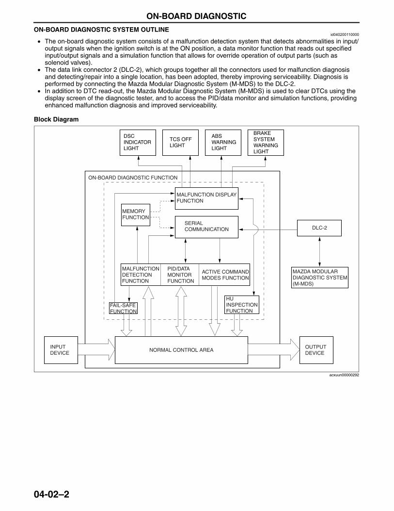
ON-BOARD DIAGNOSTIC
04-02–2
ON-BOARD DIAGNOSTIC SYSTEM OUTLINEid040200110000
• The on-board diagnostic system consists of a malfunction detection system that detects abnormalities in input/output signals when the ignition switch is at the ON position, a data monitor function that reads out specified input/output signals and a simulation function that allows for override operation of output parts (such as solenoid valves).
• The data link connector 2 (DLC-2), which groups together all the connectors used for malfunction diagnosis and detecting/repair into a single location, has been adopted, thereby improving serviceability. Diagnosis is performed by connecting the Mazda Modular Diagnostic System (M-MDS) to the DLC-2.
• In addition to DTC read-out, the Mazda Modular Diagnostic System (M-MDS) is used to clear DTCs using the display screen of the diagnostic tester, and to access the PID/data monitor and simulation functions, providing enhanced malfunction diagnosis and improved serviceability.
Block Diagram
End Of Sie
DLC-2
ON-BOARD DIAGNOSTIC FUNCTION
MEMORY FUNCTION
MALFUNCTION DISPLAY FUNCTION
SERIAL COMMUNICATION
MALFUNCTION DETECTION FUNCTION
PID/DATA MONITOR FUNCTION
ACTIVE COMMAND MODES FUNCTION
FAIL-SAFE FUNCTION
HU INSPECTION FUNCTION
INPUT DEVICE
NORMAL CONTROL AREAOUTPUT DEVICE
DSC INDICATOR LIGHT
TCS OFF LIGHT
ABS WARNING LIGHT
BRAKE SYSTEM WARNING LIGHT
MAZDA MODULAR DIAGNOSTIC SYSTEM (M-MDS)
acxuun00000292
3423-1U-06H(04-02).fm 2 ページ 2006年11月21日 火曜日 午後5時12分
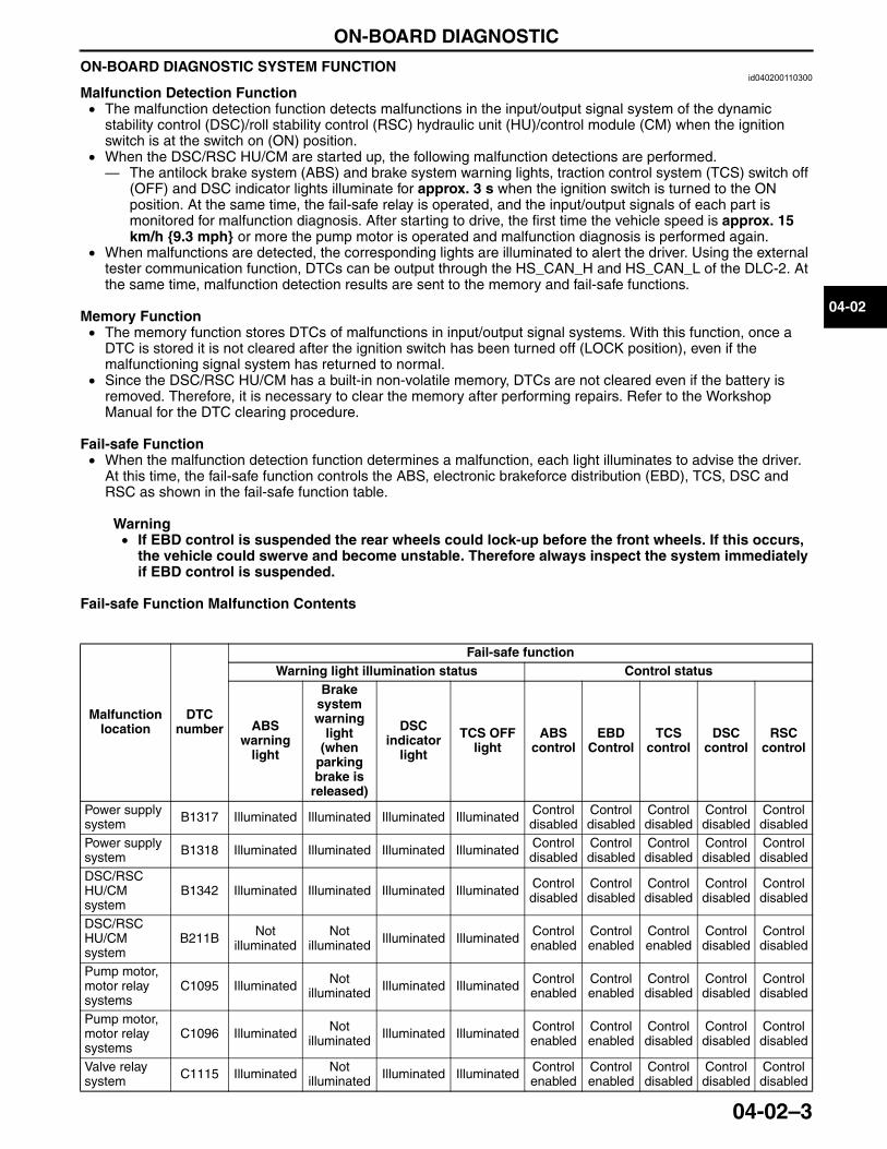
ON-BOARD DIAGNOSTIC
04-02–3
04-02
ON-BOARD DIAGNOSTIC SYSTEM FUNCTIONid040200110300
Malfunction Detection Function• The malfunction detection function detects malfunctions in the input/output signal system of the dynamic
stability control (DSC)/roll stability control (RSC) hydraulic unit (HU)/control module (CM) when the ignition switch is at the switch on (ON) position.
• When the DSC/RSC HU/CM are started up, the following malfunction detections are performed.— The antilock brake system (ABS) and brake system warning lights, traction control system (TCS) switch off
(OFF) and DSC indicator lights illuminate for approx. 3 s when the ignition switch is turned to the ON position. At the same time, the fail-safe relay is operated, and the input/output signals of each part is monitored for malfunction diagnosis. After starting to drive, the first time the vehicle speed is approx. 15 km/h {9.3 mph} or more the pump motor is operated and malfunction diagnosis is performed again.
• When malfunctions are detected, the corresponding lights are illuminated to alert the driver. Using the external tester communication function, DTCs can be output through the HS_CAN_H and HS_CAN_L of the DLC-2. At the same time, malfunction detection results are sent to the memory and fail-safe functions.
Memory Function• The memory function stores DTCs of malfunctions in input/output signal systems. With this function, once a
DTC is stored it is not cleared after the ignition switch has been turned off (LOCK position), even if the malfunctioning signal system has returned to normal.
• Since the DSC/RSC HU/CM has a built-in non-volatile memory, DTCs are not cleared even if the battery is removed. Therefore, it is necessary to clear the memory after performing repairs. Refer to the Workshop Manual for the DTC clearing procedure.
Fail-safe Function• When the malfunction detection function determines a malfunction, each light illuminates to advise the driver.
At this time, the fail-safe function controls the ABS, electronic brakeforce distribution (EBD), TCS, DSC and RSC as shown in the fail-safe function table.
Warning• If EBD control is suspended the rear wheels could lock-up before the front wheels. If this occurs,
the vehicle could swerve and become unstable. Therefore always inspect the system immediately if EBD control is suspended.
Fail-safe Function Malfunction Contents
Malfunction location
DTC number
Fail-safe functionWarning light illumination status Control status
ABS warning
light
Brake system warning
light (when
parking brake is
released)
DSC indicator
light
TCS OFF light
ABS control
EBD Control
TCS control
DSC control
RSC control
Power supply system B1317 Illuminated Illuminated Illuminated Illuminated Control
disabledControl disabled
Control disabled
Control disabled
Control disabled
Power supply system B1318 Illuminated Illuminated Illuminated Illuminated Control
disabledControl disabled
Control disabled
Control disabled
Control disabled
DSC/RSC HU/CM system
B1342 Illuminated Illuminated Illuminated Illuminated Control disabled
Control disabled
Control disabled
Control disabled
Control disabled
DSC/RSC HU/CM system
B211B Not illuminated
Not illuminated Illuminated Illuminated Control
enabledControl enabled
Control enabled
Control disabled
Control disabled
Pump motor, motor relay systems
C1095 Illuminated Not illuminated Illuminated Illuminated Control
enabledControl enabled
Control disabled
Control disabled
Control disabled
Pump motor, motor relay systems
C1096 Illuminated Not illuminated Illuminated Illuminated Control
enabledControl enabled
Control disabled
Control disabled
Control disabled
Valve relay system C1115 Illuminated Not
illuminated Illuminated Illuminated Control enabled
Control enabled
Control disabled
Control disabled
Control disabled
3423-1U-06H(04-02).fm 3 ページ 2006年11月21日 火曜日 午後5時12分
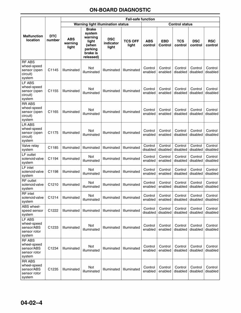
ON-BOARD DIAGNOSTIC
04-02–4
RF ABS wheel-speed sensor (open circuit) system
C1145 Illuminated Not illuminated Illuminated Illuminated Control
enabledControl enabled
Control disabled
Control disabled
Control disabled
LF ABS wheel-speed sensor (open circuit) system
C1155 Illuminated Not illuminated Illuminated Illuminated Control
enabledControl enabled
Control disabled
Control disabled
Control disabled
RR ABS wheel-speed sensor (open circuit) system
C1165 Illuminated Not illuminated Illuminated Illuminated Control
enabledControl enabled
Control disabled
Control disabled
Control disabled
LR ABS wheel-speed sensor (open circuit) system
C1175 Illuminated Not illuminated Illuminated Illuminated Control
enabledControl enabled
Control disabled
Control disabled
Control disabled
Valve relay system C1185 Illuminated Illuminated Illuminated Illuminated Control
disabledControl disabled
Control disabled
Control disabled
Control disabled
LF outlet solenoid valve system
C1194 Illuminated Not illuminated Illuminated Illuminated Control
enabledControl enabled
Control disabled
Control disabled
Control disabled
LF inlet solenoid valve system
C1198 Illuminated Not illuminated Illuminated Illuminated Control
enabledControl enabled
Control disabled
Control disabled
Control disabled
RF outlet solenoid valve system
C1210 Illuminated Not illuminated Illuminated Illuminated Control
enabledControl enabled
Control disabled
Control disabled
Control disabled
RF inlet solenoid valve system
C1214 Illuminated Not illuminated Illuminated Illuminated Control
enabledControl enabled
Control disabled
Control disabled
Control disabled
ABS wheel-speed sensor system
C1222 Illuminated Illuminated Illuminated Illuminated Control disabled
Control disabled
Control disabled
Control disabled
Control disabled
LF ABS wheel-speed sensor/ABS sensor rotor system
C1233 Illuminated Not illuminated Illuminated Illuminated Control
enabledControl enabled
Control disabled
Control disabled
Control disabled
RF ABS wheel-speed sensor/ABS sensor rotor system
C1234 Illuminated Not illuminated Illuminated Illuminated Control
enabledControl enabled
Control disabled
Control disabled
Control disabled
RR ABS wheel-speed sensor/ABS sensor rotor system
C1235 Illuminated Not illuminated Illuminated Illuminated Control
enabledControl enabled
Control disabled
Control disabled
Control disabled
Malfunction location
DTC number
Fail-safe functionWarning light illumination status Control status
ABS warning
light
Brake system warning
light (when
parking brake is
released)
DSC indicator
light
TCS OFF light
ABS control
EBD Control
TCS control
DSC control
RSC control
3423-1U-06H(04-02).fm 4 ページ 2006年11月21日 火曜日 午後5時12分
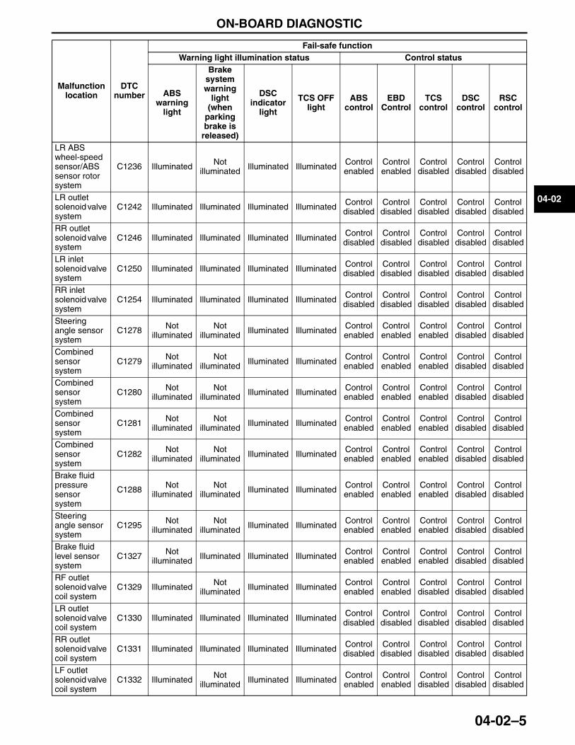
ON-BOARD DIAGNOSTIC
04-02–5
04-02
LR ABS wheel-speed sensor/ABS sensor rotor system
C1236 Illuminated Not illuminated Illuminated Illuminated Control
enabledControl enabled
Control disabled
Control disabled
Control disabled
LR outlet solenoid valve system
C1242 Illuminated Illuminated Illuminated Illuminated Control disabled
Control disabled
Control disabled
Control disabled
Control disabled
RR outlet solenoid valve system
C1246 Illuminated Illuminated Illuminated Illuminated Control disabled
Control disabled
Control disabled
Control disabled
Control disabled
LR inlet solenoid valve system
C1250 Illuminated Illuminated Illuminated Illuminated Control disabled
Control disabled
Control disabled
Control disabled
Control disabled
RR inlet solenoid valve system
C1254 Illuminated Illuminated Illuminated Illuminated Control disabled
Control disabled
Control disabled
Control disabled
Control disabled
Steering angle sensor system
C1278 Not illuminated
Not illuminated Illuminated Illuminated Control
enabledControl enabled
Control enabled
Control disabled
Control disabled
Combined sensor system
C1279 Not illuminated
Not illuminated Illuminated Illuminated Control
enabledControl enabled
Control enabled
Control disabled
Control disabled
Combined sensor system
C1280 Not illuminated
Not illuminated Illuminated Illuminated Control
enabledControl enabled
Control enabled
Control disabled
Control disabled
Combined sensor system
C1281 Not illuminated
Not illuminated Illuminated Illuminated Control
enabledControl enabled
Control enabled
Control disabled
Control disabled
Combined sensor system
C1282 Not illuminated
Not illuminated Illuminated Illuminated Control
enabledControl enabled
Control enabled
Control disabled
Control disabled
Brake fluid pressure sensor system
C1288 Not illuminated
Not illuminated Illuminated Illuminated Control
enabledControl enabled
Control enabled
Control disabled
Control disabled
Steering angle sensor system
C1295 Not illuminated
Not illuminated Illuminated Illuminated Control
enabledControl enabled
Control enabled
Control disabled
Control disabled
Brake fluid level sensor system
C1327 Not illuminated Illuminated Illuminated Illuminated Control
enabledControl enabled
Control enabled
Control disabled
Control disabled
RF outlet solenoid valve coil system
C1329 Illuminated Not illuminated Illuminated Illuminated Control
enabledControl enabled
Control disabled
Control disabled
Control disabled
LR outlet solenoid valve coil system
C1330 Illuminated Illuminated Illuminated Illuminated Control disabled
Control disabled
Control disabled
Control disabled
Control disabled
RR outlet solenoid valve coil system
C1331 Illuminated Illuminated Illuminated Illuminated Control disabled
Control disabled
Control disabled
Control disabled
Control disabled
LF outlet solenoid valve coil system
C1332 Illuminated Not illuminated Illuminated Illuminated Control
enabledControl enabled
Control disabled
Control disabled
Control disabled
Malfunction location
DTC number
Fail-safe functionWarning light illumination status Control status
ABS warning
light
Brake system warning
light (when
parking brake is
released)
DSC indicator
light
TCS OFF light
ABS control
EBD Control
TCS control
DSC control
RSC control
3423-1U-06H(04-02).fm 5 ページ 2006年11月21日 火曜日 午後5時12分
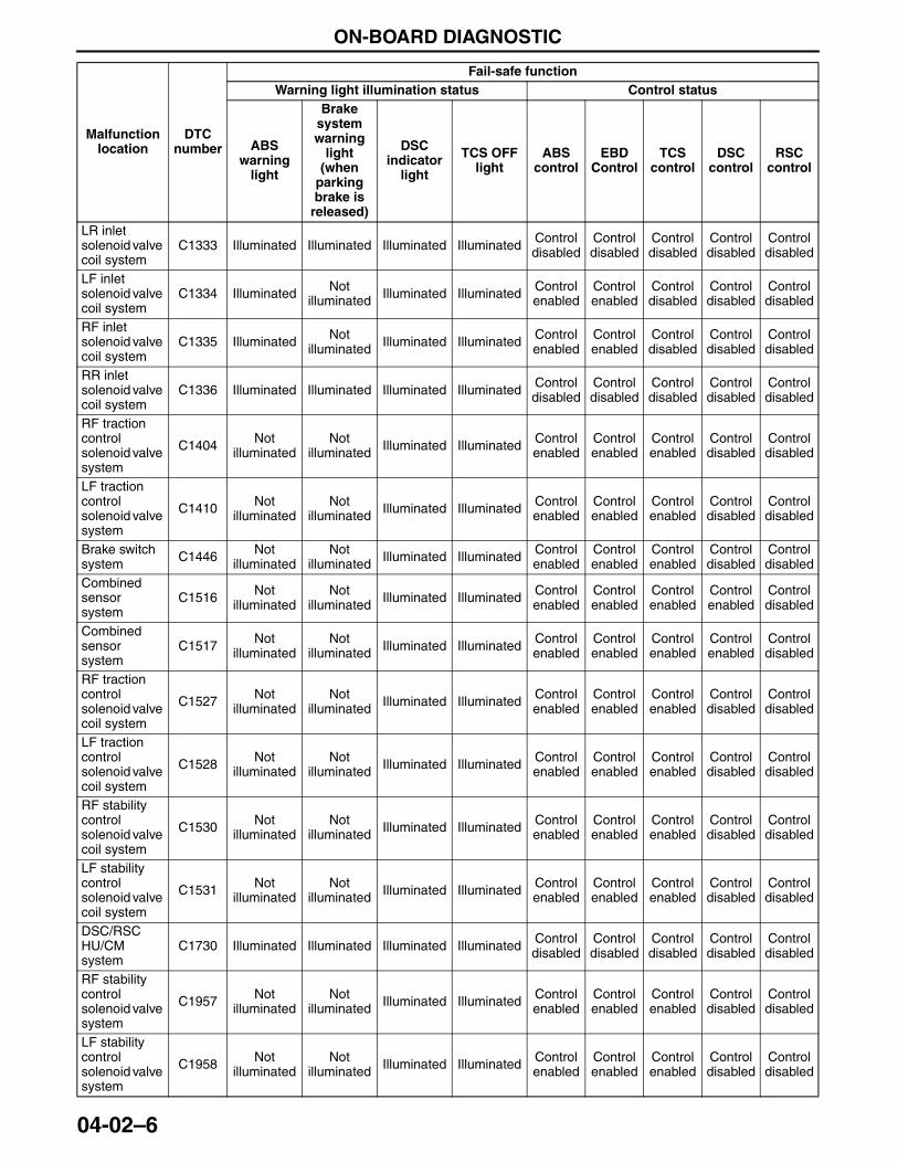
ON-BOARD DIAGNOSTIC
04-02–6
LR inlet solenoid valve coil system
C1333 Illuminated Illuminated Illuminated Illuminated Control disabled
Control disabled
Control disabled
Control disabled
Control disabled
LF inlet solenoid valve coil system
C1334 Illuminated Not illuminated Illuminated Illuminated Control
enabledControl enabled
Control disabled
Control disabled
Control disabled
RF inlet solenoid valve coil system
C1335 Illuminated Not illuminated Illuminated Illuminated Control
enabledControl enabled
Control disabled
Control disabled
Control disabled
RR inlet solenoid valve coil system
C1336 Illuminated Illuminated Illuminated Illuminated Control disabled
Control disabled
Control disabled
Control disabled
Control disabled
RF traction control solenoid valve system
C1404 Not illuminated
Not illuminated Illuminated Illuminated Control
enabledControl enabled
Control enabled
Control disabled
Control disabled
LF traction control solenoid valve system
C1410 Not illuminated
Not illuminated Illuminated Illuminated Control
enabledControl enabled
Control enabled
Control disabled
Control disabled
Brake switch system C1446 Not
illuminatedNot
illuminated Illuminated Illuminated Control enabled
Control enabled
Control enabled
Control disabled
Control disabled
Combined sensor system
C1516 Not illuminated
Not illuminated Illuminated Illuminated Control
enabledControl enabled
Control enabled
Control enabled
Control disabled
Combined sensor system
C1517 Not illuminated
Not illuminated Illuminated Illuminated Control
enabledControl enabled
Control enabled
Control enabled
Control disabled
RF traction control solenoid valve coil system
C1527 Not illuminated
Not illuminated Illuminated Illuminated Control
enabledControl enabled
Control enabled
Control disabled
Control disabled
LF traction control solenoid valve coil system
C1528 Not illuminated
Not illuminated Illuminated Illuminated Control
enabledControl enabled
Control enabled
Control disabled
Control disabled
RF stability control solenoid valve coil system
C1530 Not illuminated
Not illuminated Illuminated Illuminated Control
enabledControl enabled
Control enabled
Control disabled
Control disabled
LF stability control solenoid valve coil system
C1531 Not illuminated
Not illuminated Illuminated Illuminated Control
enabledControl enabled
Control enabled
Control disabled
Control disabled
DSC/RSC HU/CM system
C1730 Illuminated Illuminated Illuminated Illuminated Control disabled
Control disabled
Control disabled
Control disabled
Control disabled
RF stability control solenoid valve system
C1957 Not illuminated
Not illuminated Illuminated Illuminated Control
enabledControl enabled
Control enabled
Control disabled
Control disabled
LF stability control solenoid valve system
C1958 Not illuminated
Not illuminated Illuminated Illuminated Control
enabledControl enabled
Control enabled
Control disabled
Control disabled
Malfunction location
DTC number
Fail-safe functionWarning light illumination status Control status
ABS warning
light
Brake system warning
light (when
parking brake is
released)
DSC indicator
light
TCS OFF light
ABS control
EBD Control
TCS control
DSC control
RSC control
3423-1U-06H(04-02).fm 6 ページ 2006年11月21日 火曜日 午後5時12分
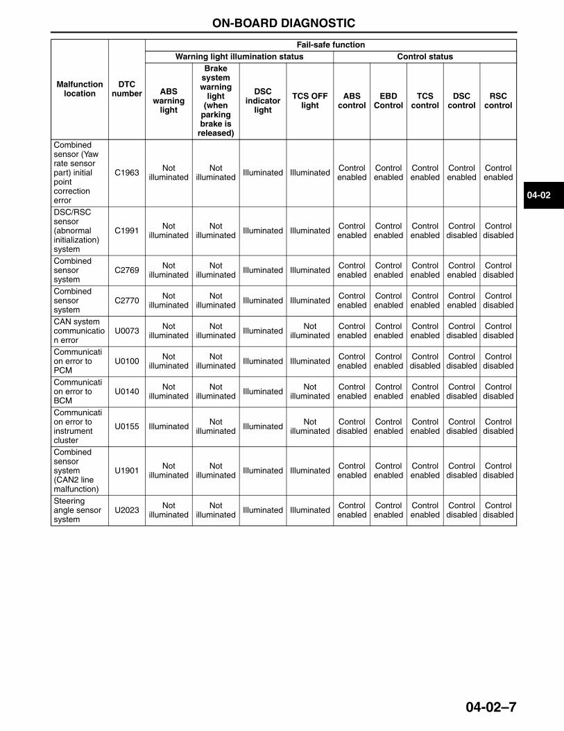
ON-BOARD DIAGNOSTIC
04-02–7
04-02
End Of Sie
Combined sensor (Yaw rate sensor part) initial point correction error
C1963 Not illuminated
Not illuminated Illuminated Illuminated Control
enabledControl enabled
Control enabled
Control enabled
Control enabled
DSC/RSC sensor (abnormal initialization) system
C1991 Not illuminated
Not illuminated Illuminated Illuminated Control
enabledControl enabled
Control enabled
Control disabled
Control disabled
Combined sensor system
C2769 Not illuminated
Not illuminated Illuminated Illuminated Control
enabledControl enabled
Control enabled
Control enabled
Control disabled
Combined sensor system
C2770 Not illuminated
Not illuminated Illuminated Illuminated Control
enabledControl enabled
Control enabled
Control enabled
Control disabled
CAN system communication error
U0073 Not illuminated
Not illuminated Illuminated Not
illuminatedControl enabled
Control enabled
Control enabled
Control disabled
Control disabled
Communication error to PCM
U0100 Not illuminated
Not illuminated Illuminated Illuminated Control
enabledControl enabled
Control disabled
Control disabled
Control disabled
Communication error to BCM
U0140 Not illuminated
Not illuminated Illuminated Not
illuminatedControl enabled
Control enabled
Control enabled
Control disabled
Control disabled
Communication error to instrument cluster
U0155 Illuminated Not illuminated Illuminated Not
illuminatedControl disabled
Control enabled
Control enabled
Control disabled
Control disabled
Combined sensor system (CAN2 line malfunction)
U1901 Not illuminated
Not illuminated Illuminated Illuminated Control
enabledControl enabled
Control enabled
Control disabled
Control disabled
Steering angle sensor system
U2023 Not illuminated
Not illuminated Illuminated Illuminated Control
enabledControl enabled
Control enabled
Control disabled
Control disabled
Malfunction location
DTC number
Fail-safe functionWarning light illumination status Control status
ABS warning
light
Brake system warning
light (when
parking brake is
released)
DSC indicator
light
TCS OFF light
ABS control
EBD Control
TCS control
DSC control
RSC control
3423-1U-06H(04-02).fm 7 ページ 2006年11月21日 火曜日 午後5時12分
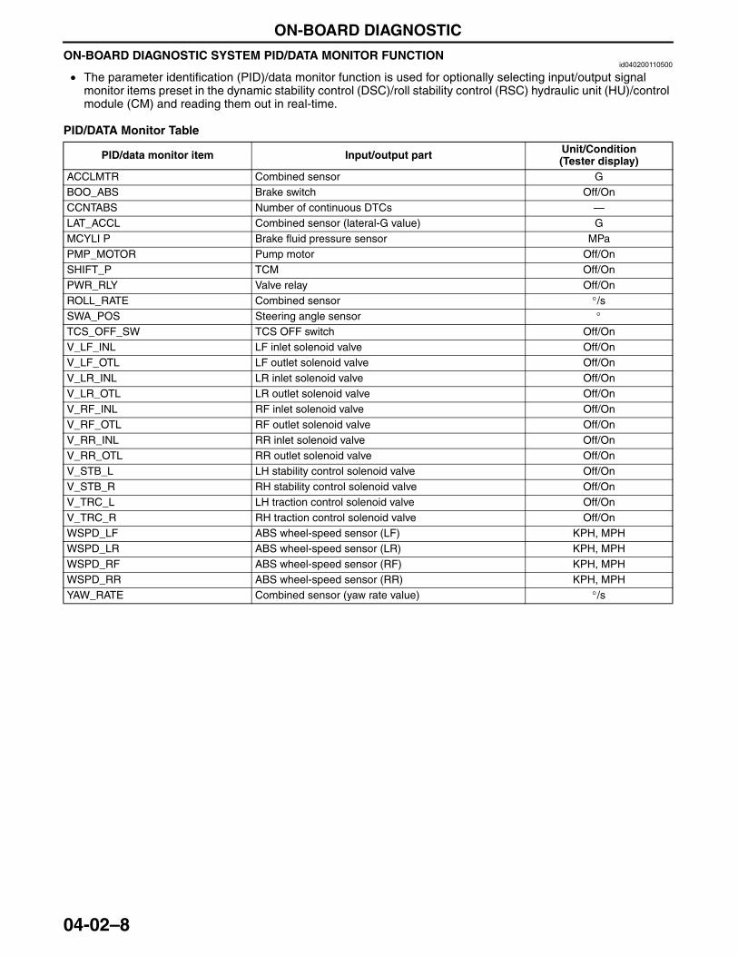
ON-BOARD DIAGNOSTIC
04-02–8
ON-BOARD DIAGNOSTIC SYSTEM PID/DATA MONITOR FUNCTIONid040200110500
• The parameter identification (PID)/data monitor function is used for optionally selecting input/output signal monitor items preset in the dynamic stability control (DSC)/roll stability control (RSC) hydraulic unit (HU)/control module (CM) and reading them out in real-time.
PID/DATA Monitor Table
End Of Sie
PID/data monitor item Input/output part Unit/Condition(Tester display)
ACCLMTR Combined sensor GBOO_ABS Brake switch Off/OnCCNTABS Number of continuous DTCs —LAT_ACCL Combined sensor (lateral-G value) GMCYLI P Brake fluid pressure sensor MPaPMP_MOTOR Pump motor Off/OnSHIFT_P TCM Off/OnPWR_RLY Valve relay Off/OnROLL_RATE Combined sensor °/sSWA_POS Steering angle sensor °TCS_OFF_SW TCS OFF switch Off/OnV_LF_INL LF inlet solenoid valve Off/OnV_LF_OTL LF outlet solenoid valve Off/OnV_LR_INL LR inlet solenoid valve Off/OnV_LR_OTL LR outlet solenoid valve Off/OnV_RF_INL RF inlet solenoid valve Off/OnV_RF_OTL RF outlet solenoid valve Off/OnV_RR_INL RR inlet solenoid valve Off/OnV_RR_OTL RR outlet solenoid valve Off/OnV_STB_L LH stability control solenoid valve Off/OnV_STB_R RH stability control solenoid valve Off/OnV_TRC_L LH traction control solenoid valve Off/OnV_TRC_R RH traction control solenoid valve Off/OnWSPD_LF ABS wheel-speed sensor (LF) KPH, MPHWSPD_LR ABS wheel-speed sensor (LR) KPH, MPHWSPD_RF ABS wheel-speed sensor (RF) KPH, MPHWSPD_RR ABS wheel-speed sensor (RR) KPH, MPHYAW_RATE Combined sensor (yaw rate value) °/s
3423-1U-06H(04-02).fm 8 ページ 2006年11月21日 火曜日 午後5時12分
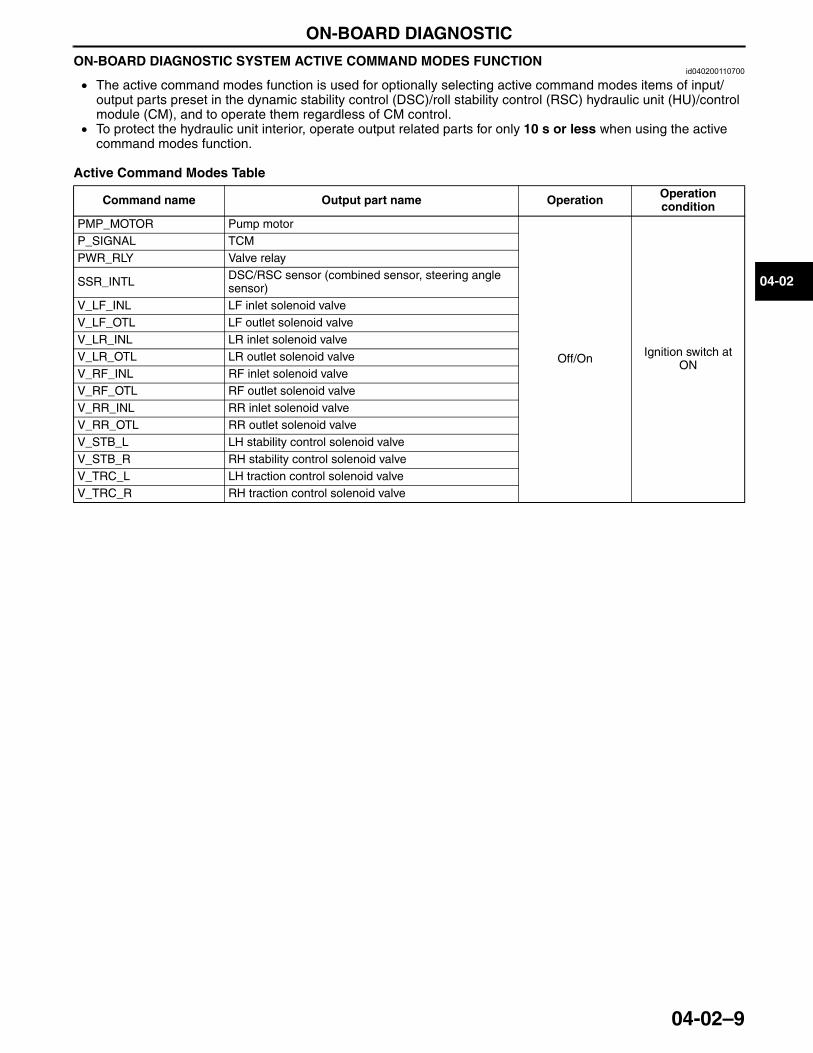
ON-BOARD DIAGNOSTIC
04-02–9
04-02
ON-BOARD DIAGNOSTIC SYSTEM ACTIVE COMMAND MODES FUNCTIONid040200110700
• The active command modes function is used for optionally selecting active command modes items of input/output parts preset in the dynamic stability control (DSC)/roll stability control (RSC) hydraulic unit (HU)/control module (CM), and to operate them regardless of CM control.
• To protect the hydraulic unit interior, operate output related parts for only 10 s or less when using the active command modes function.
Active Command Modes Table
End Of Sie
Command name Output part name Operation Operation condition
PMP_MOTOR Pump motor
Off/On Ignition switch at ON
P_SIGNAL TCMPWR_RLY Valve relay
SSR_INTL DSC/RSC sensor (combined sensor, steering angle sensor)
V_LF_INL LF inlet solenoid valveV_LF_OTL LF outlet solenoid valveV_LR_INL LR inlet solenoid valveV_LR_OTL LR outlet solenoid valveV_RF_INL RF inlet solenoid valveV_RF_OTL RF outlet solenoid valveV_RR_INL RR inlet solenoid valveV_RR_OTL RR outlet solenoid valveV_STB_L LH stability control solenoid valveV_STB_R RH stability control solenoid valveV_TRC_L LH traction control solenoid valveV_TRC_R RH traction control solenoid valve
3423-1U-06H(04-02).fm 9 ページ 2006年11月21日 火曜日 午後5時12分
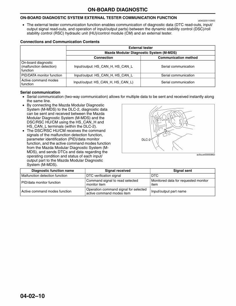
ON-BOARD DIAGNOSTIC
04-02–10
ON-BOARD DIAGNOSTIC SYSTEM EXTERNAL TESTER COMMUNICATION FUNCTIONid040200110900
• The external tester communication function enables communication of diagnostic data (DTC read-outs, input/output signal read-outs, and operation of input/output parts) between the dynamic stability control (DSC)/roll stability control (RSC) hydraulic unit (HU)/control module (CM) and an external tester.
Connections and Communication Contents
Serial communication• Serial communication (two-way communication) allows for multiple data to be sent and received instantly along
the same line.• By connecting the Mazda Modular Diagnostic
System (M-MDS) to the DLC-2, diagnostic data can be sent and received between the Mazda Modular Diagnostic System (M-MDS) and the DSC/RSC HU/CM using the HS_CAN_H and HS_CAN_L terminals (within the DLC-2).
• The DSC/RSC HU/CM receives the command signals of the malfunction detection function, parameter identification (PID)/data monitor function, and the active command modes function from the Mazda Modular Diagnostic System (M-MDS), and sends DTCs and data regarding the operating condition and status of each input/output part to the Mazda Modular Diagnostic System (M-MDS).
End Of Sie
External testerMazda Modular Diagnostic System (M-MDS)
Connection Communication methodOn-board diagnostic (malfunction detection) function
Input/output: HS_CAN_H, HS_CAN_L Serial communication
PID/DATA monitor function Input/output: HS_CAN_H, HS_CAN_L Serial communicationActive command modes function Input/output: HS_CAN_H, HS_CAN_L) Serial communication
DLC-2
ac9uuw00000862
Diagnostic function name Signal received Signal sentMalfunction detection function DTC verification signal DTC
PID/data monitor function Command signal to read selected monitor item
Monitored data for requested monitor item
Active command modes function Operation command signal for selected active command modes item Input/output part name
3423-1U-06H(04-02).fm 10 ページ 2006年11月21日 火曜日 午後5時12分
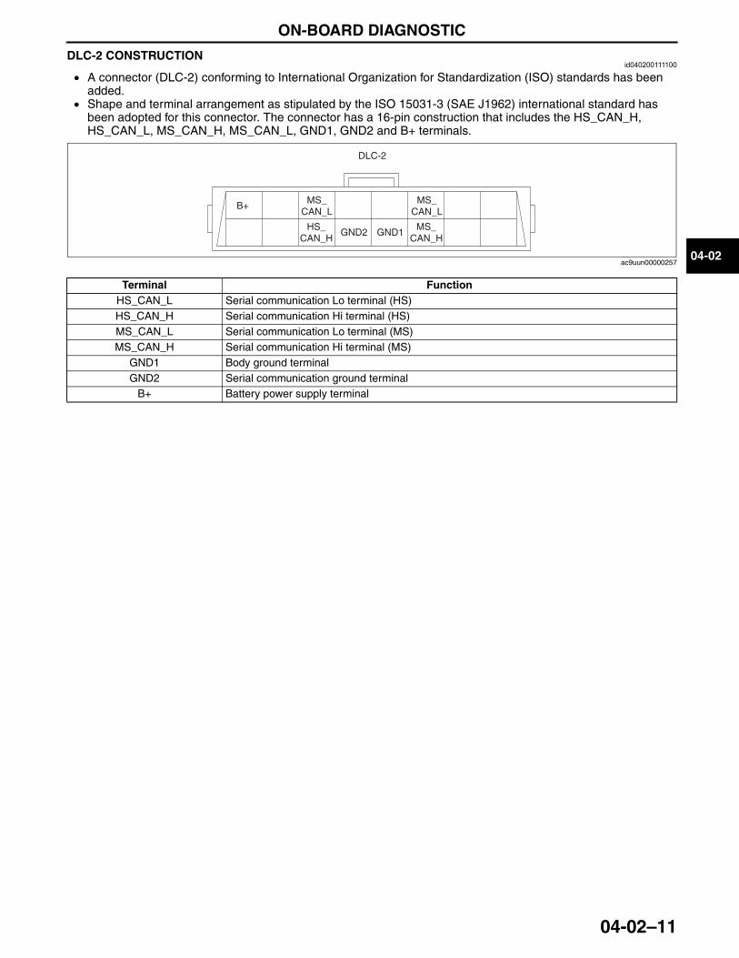
ON-BOARD DIAGNOSTIC
04-02–11
04-02
DLC-2 CONSTRUCTIONid040200111100
• A connector (DLC-2) conforming to International Organization for Standardization (ISO) standards has been added.
• Shape and terminal arrangement as stipulated by the ISO 15031-3 (SAE J1962) international standard has been adopted for this connector. The connector has a 16-pin construction that includes the HS_CAN_H, HS_CAN_L, MS_CAN_H, MS_CAN_L, GND1, GND2 and B+ terminals.
End Of Sie
Terminal FunctionHS_CAN_L Serial communication Lo terminal (HS)HS_CAN_H Serial communication Hi terminal (HS)MS_CAN_L Serial communication Lo terminal (MS)MS_CAN_H Serial communication Hi terminal (MS)
GND1 Body ground terminalGND2 Serial communication ground terminal
B+ Battery power supply terminal
DLC-2
B+MS_
CAN_L
HS_CAN_H
GND2 GND1
MS_CAN_L
MS_CAN_H
ac9uun00000257
3423-1U-06H(04-02).fm 11 ページ 2006年11月21日 火曜日 午後5時12分

CONVENTIONAL BRAKE SYSTEM
04-11–1
04-11
04-11 CONVENTIONAL BRAKE SYSTEMCONVENTIONAL BRAKE
SYSTEM OUTLINE . . . . . . . . . . . . . . . . 04-11–1CONVENTIONAL BRAKE
SYSTEM STRUCTURAL VIEW. . . . . . . 04-11–2INTRUSION-MINIMIZING
BRAKE PEDAL FUNCTION . . . . . . . . . 04-11–2INTRUSION-MINIMIZING
BRAKE PEDAL CONSTRUCTION/OPERATION . . . . . . 04-11–3
Construction. . . . . . . . . . . . . . . . . . . . . 04-11–3
Operation . . . . . . . . . . . . . . . . . . . . . . . 04-11–4MASTER CYLINDER
CONSTRUCTION . . . . . . . . . . . . . . . . . . 04-11–5POWER BRAKE UNIT
CONSTRUCTION . . . . . . . . . . . . . . . . . . 04-11–5FRONT BRAKE (DISC)
CONSTRUCTION . . . . . . . . . . . . . . . . . . 04-11–6REAR BRAKE (DISC)
CONSTRUCTION . . . . . . . . . . . . . . . . . . 04-11–6
End of TocNG: CONVENTIONAL BRAKE SYSTEMCONVENTIONAL BRAKE SYSTEM OUTLINE
id041100100100
• A brake pedal with an intrusion minimizing mechanism has been adopted. As a result, driver safety has been improved.
• A small diameter long-stroke type master cylinder has been adopted, improving operability and response.• A large diameter, single diaphragm power brake unit has been adopted, improving braking force.• High rigidity, 2-piston front brake calipers have been adopted on the front brakes for improved braking
performance.• Large diameter, ventilated discs have been adopted on the front and rear disc brakes for improved braking
force.End Of Sie
3423-1U-06H(04-11).fm 1 ページ 2006年11月21日 火曜日 午後5時14分
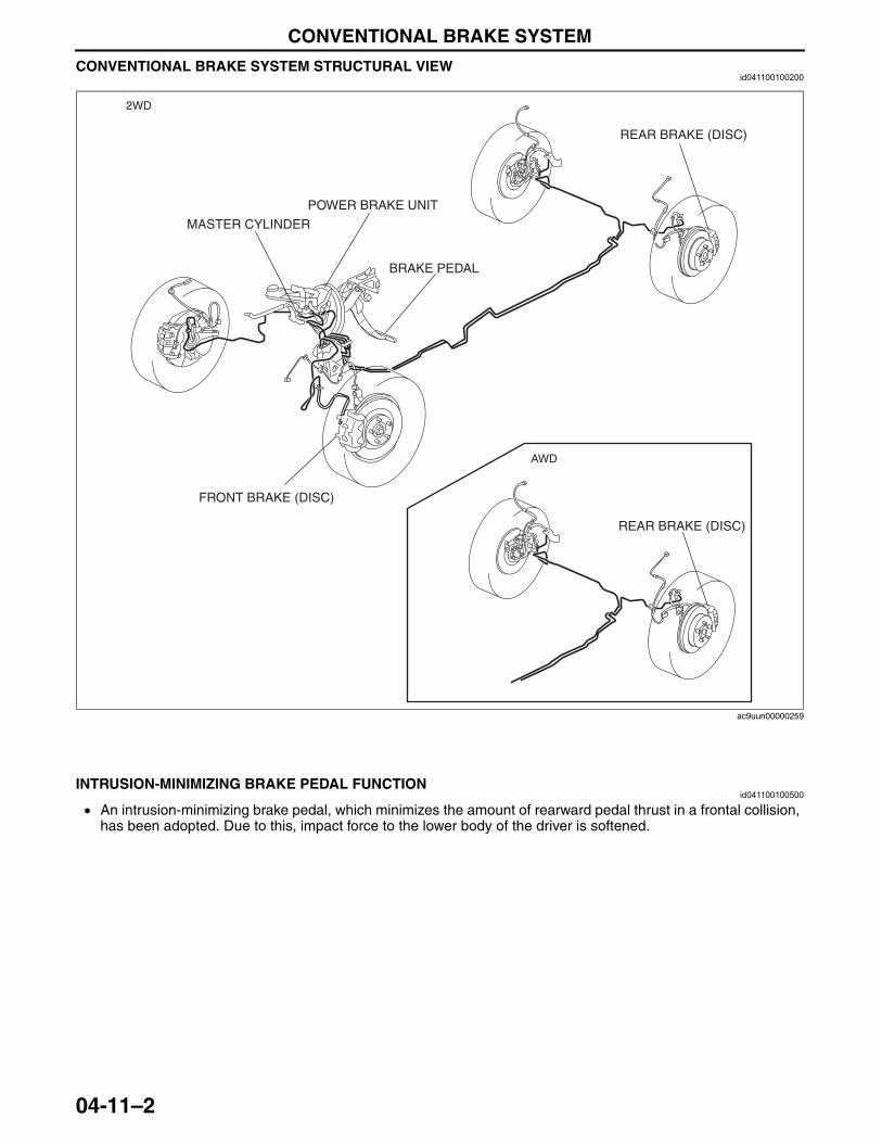
CONVENTIONAL BRAKE SYSTEM
04-11–2
CONVENTIONAL BRAKE SYSTEM STRUCTURAL VIEWid041100100200
End Of SieNG: BRAKE PEDAL
INTRUSION-MINIMIZING BRAKE PEDAL FUNCTIONid041100100500
• An intrusion-minimizing brake pedal, which minimizes the amount of rearward pedal thrust in a frontal collision, has been adopted. Due to this, impact force to the lower body of the driver is softened.
End Of Sie
2WD
BRAKE PEDAL
POWER BRAKE UNIT
FRONT BRAKE (DISC)
REAR BRAKE (DISC)
REAR BRAKE (DISC)
MASTER CYLINDER
AWD
ac9uun00000259
3423-1U-06H(04-11).fm 2 ページ 2006年11月21日 火曜日 午後5時14分
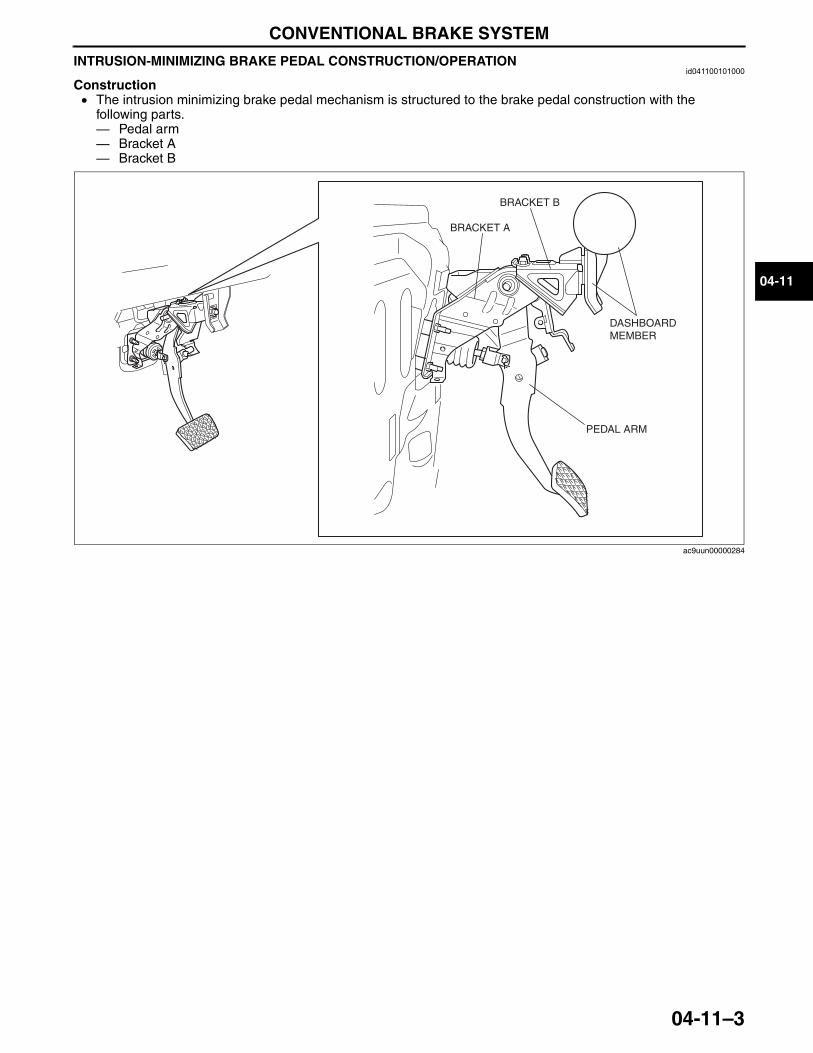
CONVENTIONAL BRAKE SYSTEM
04-11–3
04-11
INTRUSION-MINIMIZING BRAKE PEDAL CONSTRUCTION/OPERATIONid041100101000
Construction• The intrusion minimizing brake pedal mechanism is structured to the brake pedal construction with the
following parts.— Pedal arm— Bracket A— Bracket B
BRACKET A
DASHBOARD MEMBER
BRACKET B
PEDAL ARM
ac9uun00000284
3423-1U-06H(04-11).fm 3 ページ 2006年11月21日 火曜日 午後5時14分
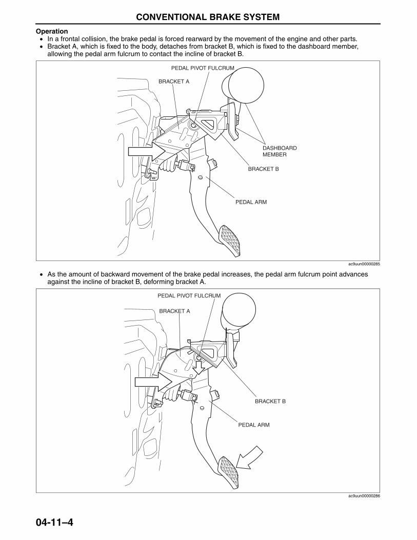
CONVENTIONAL BRAKE SYSTEM
04-11–4
Operation• In a frontal collision, the brake pedal is forced rearward by the movement of the engine and other parts.• Bracket A, which is fixed to the body, detaches from bracket B, which is fixed to the dashboard member,
allowing the pedal arm fulcrum to contact the incline of bracket B.
• As the amount of backward movement of the brake pedal increases, the pedal arm fulcrum point advances against the incline of bracket B, deforming bracket A.
PEDAL PIVOT FULCRUM
BRACKET A
DASHBOARD MEMBER
BRACKET B
PEDAL ARM
ac9uun00000285
PEDAL PIVOT FULCRUM
BRACKET A
BRACKET B
PEDAL ARM
ac9uun00000286
3423-1U-06H(04-11).fm 4 ページ 2006年11月21日 火曜日 午後5時14分
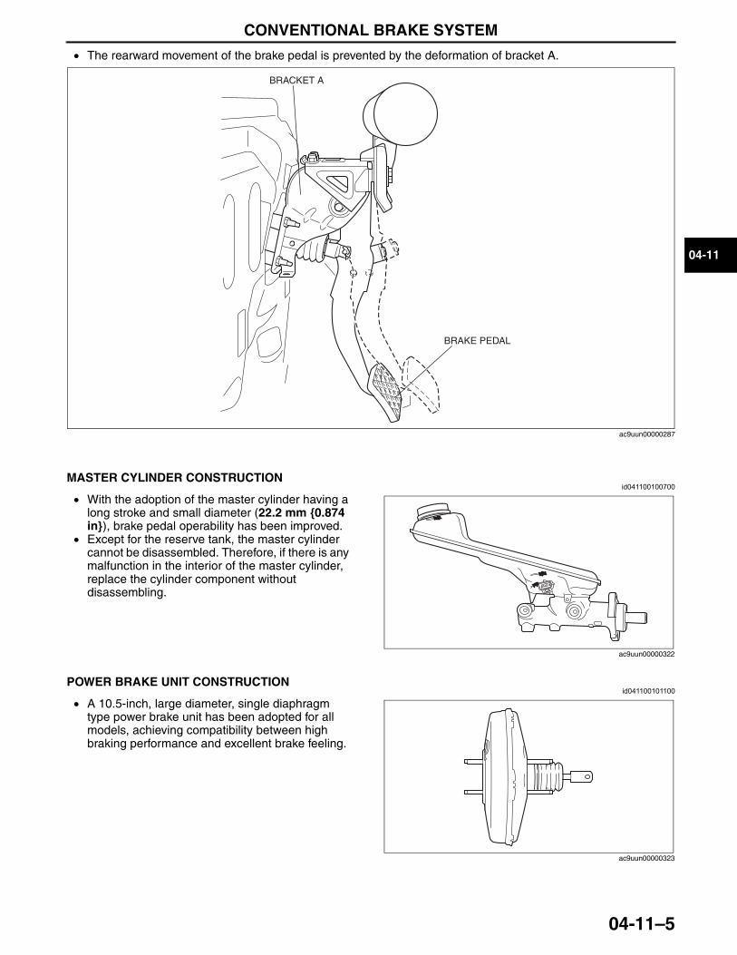
CONVENTIONAL BRAKE SYSTEM
04-11–5
04-11
• The rearward movement of the brake pedal is prevented by the deformation of bracket A.
End Of SieNG: MASTER CYLINDER
MASTER CYLINDER CONSTRUCTIONid041100100700
• With the adoption of the master cylinder having a long stroke and small diameter (22.2 mm {0.874 in}), brake pedal operability has been improved.
• Except for the reserve tank, the master cylinder cannot be disassembled. Therefore, if there is any malfunction in the interior of the master cylinder, replace the cylinder component without disassembling.
End Of SieNG: POWER BRAKE UNIT
POWER BRAKE UNIT CONSTRUCTIONid041100101100
• A 10.5-inch, large diameter, single diaphragm type power brake unit has been adopted for all models, achieving compatibility between high braking performance and excellent brake feeling.
End Of SieNG: FRONT BRAKE (DISC)
BRACKET A
BRAKE PEDAL
ac9uun00000287
ac9uun00000322
ac9uun00000323
3423-1U-06H(04-11).fm 5 ページ 2006年11月21日 火曜日 午後5時14分
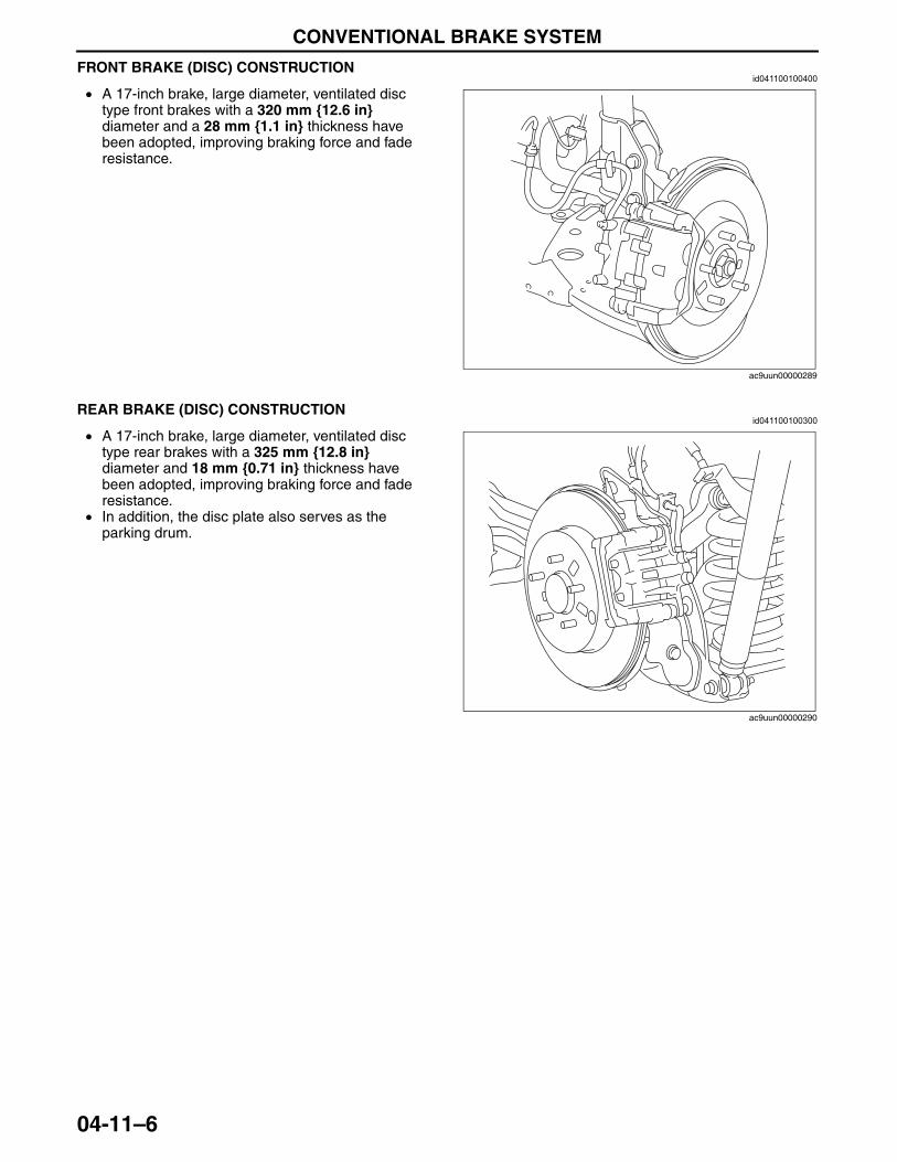
CONVENTIONAL BRAKE SYSTEM
04-11–6
FRONT BRAKE (DISC) CONSTRUCTIONid041100100400
• A 17-inch brake, large diameter, ventilated disc type front brakes with a 320 mm {12.6 in} diameter and a 28 mm {1.1 in} thickness have been adopted, improving braking force and fade resistance.
End Of SieNG: REAR BRAKE (DISC)
REAR BRAKE (DISC) CONSTRUCTIONid041100100300
• A 17-inch brake, large diameter, ventilated disc type rear brakes with a 325 mm {12.8 in} diameter and 18 mm {0.71 in} thickness have been adopted, improving braking force and fade resistance.
• In addition, the disc plate also serves as the parking drum.
End Of Sie
ac9uun00000289
ac9uun00000290
3423-1U-06H(04-11).fm 6 ページ 2006年11月21日 火曜日 午後5時14分
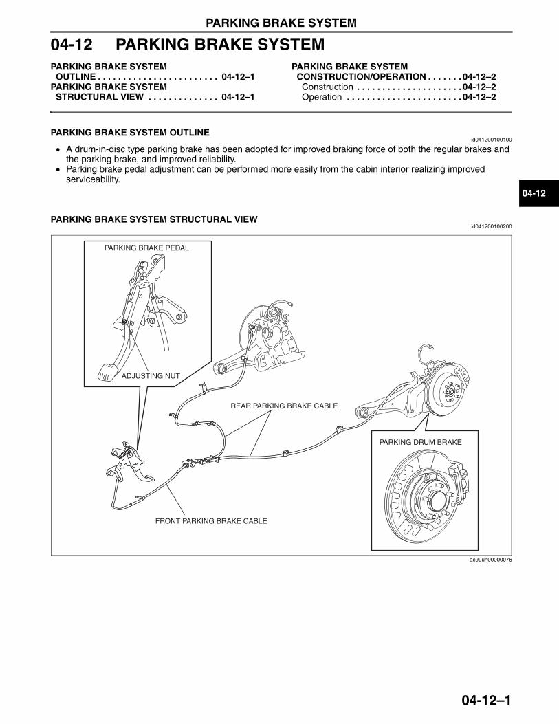
PARKING BRAKE SYSTEM
04-12–1
04-12
04-12 PARKING BRAKE SYSTEMPARKING BRAKE SYSTEM
OUTLINE . . . . . . . . . . . . . . . . . . . . . . . . 04-12–1PARKING BRAKE SYSTEM
STRUCTURAL VIEW . . . . . . . . . . . . . . 04-12–1
PARKING BRAKE SYSTEM CONSTRUCTION/OPERATION . . . . . . . 04-12–2
Construction . . . . . . . . . . . . . . . . . . . . . 04-12–2Operation . . . . . . . . . . . . . . . . . . . . . . . 04-12–2
End of TocNG: PARKING BRAKE SYSTEMPARKING BRAKE SYSTEM OUTLINE
id041200100100
• A drum-in-disc type parking brake has been adopted for improved braking force of both the regular brakes and the parking brake, and improved reliability.
• Parking brake pedal adjustment can be performed more easily from the cabin interior realizing improved serviceability.
End Of Sie
PARKING BRAKE SYSTEM STRUCTURAL VIEWid041200100200
End Of Sie
PARKING BRAKE PEDAL
ADJUSTING NUT
FRONT PARKING BRAKE CABLE
REAR PARKING BRAKE CABLE
PARKING DRUM BRAKE
ac9uun00000076
3423-1U-06H(04-12).fm 1 ページ 2006年11月21日 火曜日 午後5時14分
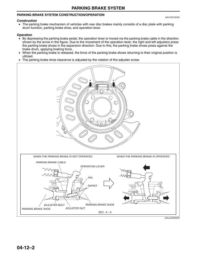
PARKING BRAKE SYSTEM
04-12–2
PARKING BRAKE SYSTEM CONSTRUCTION/OPERATIONid041200100300
Construction• The parking brake mechanism of vehicles with rear disc brakes mainly consists of a disc plate with parking
drum function, parking brake shoe, and operation lever.
Operation• By depressing the parking brake pedal, the operation lever is moved via the parking brake cable in the direction
shown by the arrow in the figure. Due to the movement of the operation lever, the right and left adjusters press the parking brake shoes in the expansion direction. Due to this, the parking brake shoes press against the brake drum, applying braking force.
• When the parking brake is released, the force of the parking brake shoes returning to their original position is utilized.
• The parking brake shoe clearance is adjusted by the rotation of the adjuster screw.
End Of Sie
AA
SEC. A - A
WHEN THE PARKING BRAKE IS OPERATEDWHEN THE PARKING BRAKE IS NOT OPERATED
PARKING BRAKE SHOE
PARKING BRAKE SHOEADJUSTER NUT
ADJUSTER BOLT
TAPPET
PIN
PARKING BRAKE CABLE
OPERATION LEVER
ac9uun00000293
3423-1U-06H(04-12).fm 2 ページ 2006年11月21日 火曜日 午後5時14分
DYNAMIC STABILITY CONTROL/ROLL STABILITY CONTROL
04-18–1
04-18
04-18 DYNAMIC STABILITY CONTROL/ROLL STABILITY CONTROLDSC/RSC OUTLINE . . . . . . . . . . . . . . . . 04-18–1
RSC Operation Outline . . . . . . . . . . . . 04-18–1DSC Operation Outline . . . . . . . . . . . . 04-18–2
DSC/RSC STRUCTURAL VIEW . . . . . . . 04-18–3DSC/RSC CONSTRUCTION . . . . . . . . . . 04-18–4DSC/RSC SYSTEM
WIRING DIAGRAM . . . . . . . . . . . . . . . . 04-18–5DSC/RSC HU/CM CONSTRUCTION . . . 04-18–6DSC/RSC HU PART FUNCTION. . . . . . . 04-18–6DSC/RSC HU PART
CONSTRUCTION/OPERATION . . . . . . 04-18–6Construction. . . . . . . . . . . . . . . . . . . . . 04-18–6Operation . . . . . . . . . . . . . . . . . . . . . . . 04-18–8
DSC/RSC CM PART FUNCTION . . . . . . 04-18–16Function Table . . . . . . . . . . . . . . . . . . . 04-18–16Block Diagram . . . . . . . . . . . . . . . . . . . 04-18–17
ABS CONTROL OUTLINE . . . . . . . . . . . 04-18–18Block Diagram . . . . . . . . . . . . . . . . . . . 04-18–18
ABS CONTROL OPERATION. . . . . . . . . 04-18–19Operating Condition
Transition Diagram . . . . . . . . . . . . . . . 04-18–19EBD CONTROL OUTLINE . . . . . . . . . . . 04-18–20
Features . . . . . . . . . . . . . . . . . . . . . . . . 04-18–20Block Diagram . . . . . . . . . . . . . . . . . . . 04-18–20
EBD CONTROL OPERATION. . . . . . . . . 04-18–21Operating Condition
Transition Diagram . . . . . . . . . . . . . . . 04-18–21TCS CONTROL OUTLINE . . . . . . . . . . . 04-18–22
Features . . . . . . . . . . . . . . . . . . . . . . . . 04-18–22Block Diagram . . . . . . . . . . . . . . . . . . . 04-18–22
TCS CONTROL OPERATION . . . . . . . . . 04-18–22DSC CONTROL OUTLINE . . . . . . . . . . . 04-18–23
Vehicle Condition Determination . . . . . . 04-18–23Oversteer Tendency Determination. . . . 04-18–23Understeer Tendency Determination. . . 04-18–23
DSC CONTROL OPERATION . . . . . . . . . 04-18–24Oversteer Tendency Suppression . . . . . 04-18–24Understeer Tendency Suppression . . . . 04-18–24
RSC CONTROL OUTLINE . . . . . . . . . . . . 04-18–25CONTROLLER AREA NETWORK
(CAN) OUTLINE . . . . . . . . . . . . . . . . . . . 04-18–25Data sent . . . . . . . . . . . . . . . . . . . . . . . . 04-18–25Data received . . . . . . . . . . . . . . . . . . . . 04-18–25
ABS WHEEL-SPEED SENSOR FUNCTION . . . . . . . . . . . . . . . . . . . . . . . 04-18–25
ABS WHEEL-SPEED SENSOR CONSTRUCTION/OPERATION . . . . . . . 04-18–26
Construction . . . . . . . . . . . . . . . . . . . . . 04-18–26Operation . . . . . . . . . . . . . . . . . . . . . . . 04-18–28
COMBINED SENSOR FUNCTION. . . . . . 04-18–29COMBINED SENSOR
CONSTRUCTION/OPERATION . . . . . . . 04-18–29BRAKE FLUID PRESSURE SENSOR
FUNCTION . . . . . . . . . . . . . . . . . . . . . . . 04-18–29BRAKE FLUID PRESSURE SENSOR
CONSTRUCTION . . . . . . . . . . . . . . . . . . 04-18–29DSC INDICATOR LIGHT FUNCTION. . . . 04-18–30DSC INDICATOR LIGHT
OPERATION . . . . . . . . . . . . . . . . . . . . . . 04-18–30DSC Indicator Light Operation . . . . . . . 04-18–30
TCS OFF SWITCH, TCS OFF LIGHT FUNCTION . . . . . . . . . . . . . . . . . . . . . . . 04-18–31
TCS OFF SWITCH, TCS OFF LIGHT OPERATION . . . . . . . . . . . . . . . . . . . . . . 04-18–31
End of TocNG: ROLL STABILITY CONTROLDSC/RSC OUTLINE
id041800817600
• The dynamic stability control (DSC)/roll stability control (RSC) HU/CM, integrating both the hydraulic unit (HU) and control module (CM), has been adopted, resulting in a size and weight reduction.
• A combined sensor, integrating both the yaw rate sensor, roll rate sensor, forward-G sensor and lateral-G sensor, has been adopted, improving serviceability.
• An enhanced malfunction diagnosis system, used with the Mazda Modular Diagnostic System (M-MDS), has been adopted, improving serviceability.
RSC Operation Outline• The dynamic stability control (DSC)/roll stability control (RSC) system monitors the signal from the roll rate
sensor and each sensor, and calculates if the vehicle may be approaching a situation where rollover is probable. When this occurs, the DSC/RSC system applies preemptive action.
3423-1U-06H(04-18).fm 1 ページ 2006年11月22日 水曜日 午後2時38分

DYNAMIC STABILITY CONTROL/ROLL STABILITY CONTROL
04-18–2
DSC Operation Outline• The antilock brake system (ABS) prevents wheel lock-up during braking. The traction control system (TCS)
detects drive wheel spin due to the accelerator pedal being pressed too hard or similar causes and controls engine speed to suppress wheel spin. With these systems, safety is assured when driving or stopping.
• Additionally, sudden changes in vehicle attitude, due to evasive steering or road conditions, are controlled by the DSC. The DSC suppresses vehicle sideslip when driving due to vehicle spin (oversteer) or drift-out (understeer) by controlling braking and engine speed. At this time, the DSC indicator light illuminates to alert the driver that the DSC is operating due to a dangerous situation. As a result, the driver can calmly react and is provided leeway for the next maneuver, resulting in safe driving conditions.
• In this way the combination of DSC + ABS + TCS ensures driving, stopping and turning safety in all aspects.
Results Of DSC Operation
Caution• While the DSC is a steering safety system, it does not improve normal steering function.
Therefore, always drive carefully, even if the vehicle has DSC, and do not overestimate the DSC capability.
• The DSC and ABS will not operate normally under the following conditions: — With tires that are not of the specified size, manufacturer or tread pattern, or not inflated
according to specification— With tires that have significant comparative wear variation— With tire chains
End Of Sie
WITHOUT DSC WITH DSC
DRIFT OUT (UNDERSTEER)
DRIFT OUT (UNDERSTEER) SUPPRESSION
VEHICLE SPIN (OVERSTEER)
VEHICLE SPIN (OVERSTEER) SUPPRESSION
WITHOUT DSC WITH DSC
ac9uun00000381
3423-1U-06H(04-18).fm 2 ページ 2006年11月22日 水曜日 午後2時38分
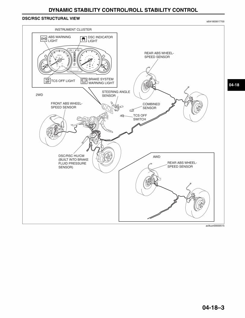
DYNAMIC STABILITY CONTROL/ROLL STABILITY CONTROL
04-18–3
04-18
DSC/RSC STRUCTURAL VIEWid041800817700
End Of Sie
BRAKE
BRAKE
2WD
AWD
BRAKE SYSTEM WARNING LIGHT
ABS WARNING LIGHT
TCS OFF LIGHT
FRONT ABS WHEEL- SPEED SENSOR
REAR ABS WHEEL-SPEED SENSOR
REAR ABS WHEEL-SPEED SENSOR
STEERING ANGLE SENSOR
TCS OFF SWITCH
COMBINED SENSOR
DSC/RSC HU/CM (BUILT INTO BRAKE FLUID PRESSURE SENSOR)
DSC INDICATOR LIGHT
INSTRUMENT CLUSTER
ac9uun00000515
3423-1U-06H(04-18).fm 3 ページ 2006年11月27日 月曜日 午前9時44分
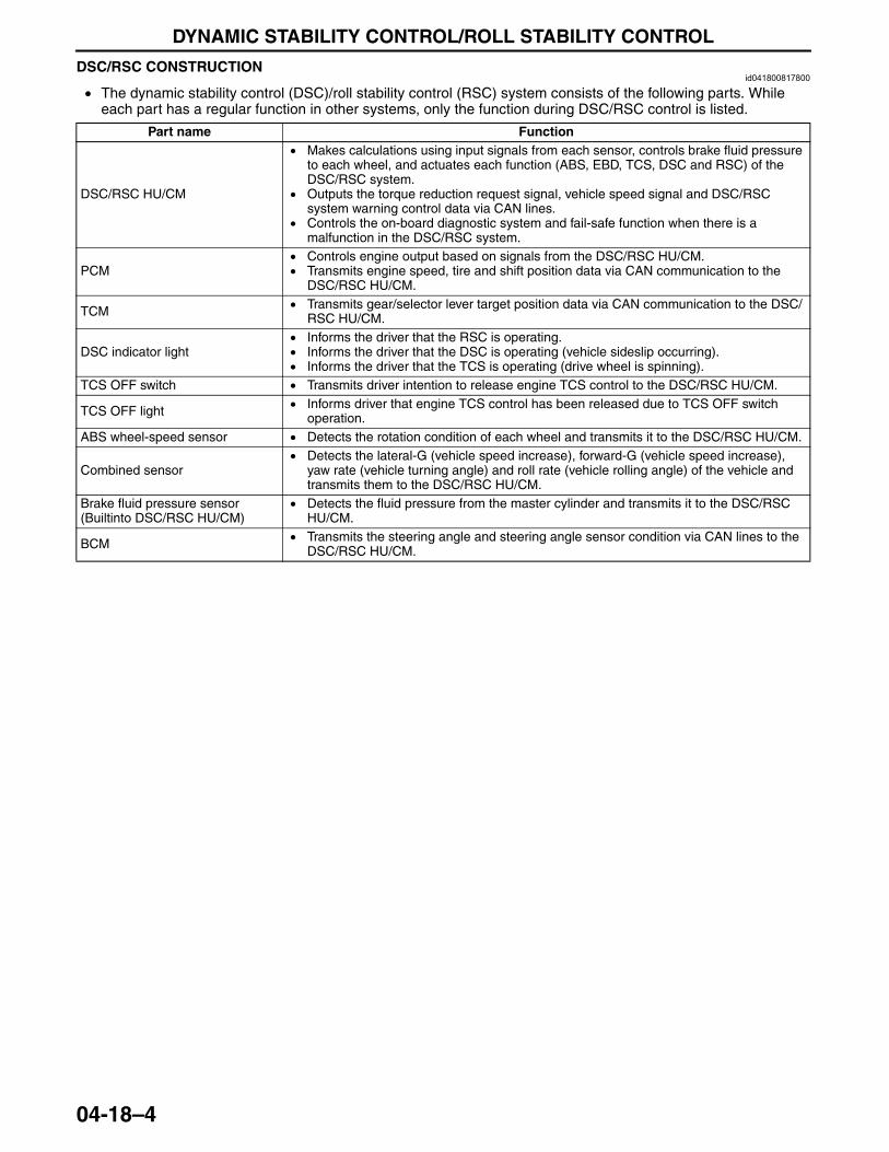
DYNAMIC STABILITY CONTROL/ROLL STABILITY CONTROL
04-18–4
DSC/RSC CONSTRUCTIONid041800817800
• The dynamic stability control (DSC)/roll stability control (RSC) system consists of the following parts. While each part has a regular function in other systems, only the function during DSC/RSC control is listed.
End Of Sie
Part name Function
DSC/RSC HU/CM
• Makes calculations using input signals from each sensor, controls brake fluid pressure to each wheel, and actuates each function (ABS, EBD, TCS, DSC and RSC) of the DSC/RSC system.
• Outputs the torque reduction request signal, vehicle speed signal and DSC/RSC system warning control data via CAN lines.
• Controls the on-board diagnostic system and fail-safe function when there is a malfunction in the DSC/RSC system.
PCM• Controls engine output based on signals from the DSC/RSC HU/CM.• Transmits engine speed, tire and shift position data via CAN communication to the
DSC/RSC HU/CM.
TCM • Transmits gear/selector lever target position data via CAN communication to the DSC/RSC HU/CM.
DSC indicator light• Informs the driver that the RSC is operating.• Informs the driver that the DSC is operating (vehicle sideslip occurring).• Informs the driver that the TCS is operating (drive wheel is spinning).
TCS OFF switch • Transmits driver intention to release engine TCS control to the DSC/RSC HU/CM.
TCS OFF light • Informs driver that engine TCS control has been released due to TCS OFF switch operation.
ABS wheel-speed sensor • Detects the rotation condition of each wheel and transmits it to the DSC/RSC HU/CM.
Combined sensor• Detects the lateral-G (vehicle speed increase), forward-G (vehicle speed increase),
yaw rate (vehicle turning angle) and roll rate (vehicle rolling angle) of the vehicle and transmits them to the DSC/RSC HU/CM.
Brake fluid pressure sensor (Builtinto DSC/RSC HU/CM)
• Detects the fluid pressure from the master cylinder and transmits it to the DSC/RSC HU/CM.
BCM • Transmits the steering angle and steering angle sensor condition via CAN lines to the DSC/RSC HU/CM.
3423-1U-06H(04-18).fm 4 ページ 2006年11月22日 水曜日 午後2時38分
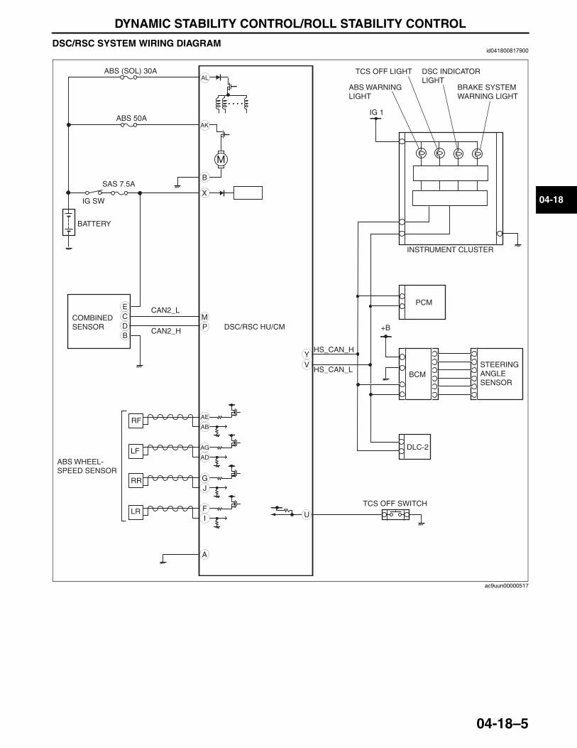
DYNAMIC STABILITY CONTROL/ROLL STABILITY CONTROL
04-18–5
04-18
DSC/RSC SYSTEM WIRING DIAGRAMid041800817900
End Of Sie
M
A
AK
G
AB
U
AE
AG
AD
J
FI
B
YV
X
AL
E
PB
TCS OFF SWITCH
COMBINED SENSOR
STEERING ANGLE SENSOR
ABS 50A
ABS (SOL) 30A
IG 1
BCM
ABS WHEEL-SPEED SENSOR
RF
LF
RR
LR
PCM
HS_CAN_H
HS_CAN_L
DLC-2
BRAKE SYSTEM WARNING LIGHT
ABS WARNING LIGHT
TCS OFF LIGHT DSC INDICATOR LIGHT
DSC/RSC HU/CM
INSTRUMENT CLUSTER
IG SW
BATTERY
+B
SAS 7.5A
CAN2_H
CAN2_LCD
ac9uun00000517
3423-1U-06H(04-18).fm 5 ページ 2006年11月22日 水曜日 午後2時38分
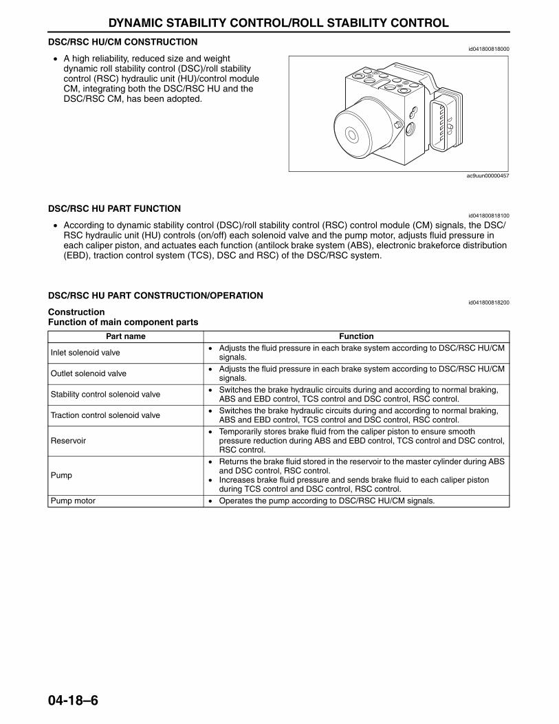
DYNAMIC STABILITY CONTROL/ROLL STABILITY CONTROL
04-18–6
DSC/RSC HU/CM CONSTRUCTIONid041800818000
• A high reliability, reduced size and weight dynamic roll stability control (DSC)/roll stability control (RSC) hydraulic unit (HU)/control module CM, integrating both the DSC/RSC HU and the DSC/RSC CM, has been adopted.
End Of Sie
DSC/RSC HU PART FUNCTIONid041800818100
• According to dynamic stability control (DSC)/roll stability control (RSC) control module (CM) signals, the DSC/RSC hydraulic unit (HU) controls (on/off) each solenoid valve and the pump motor, adjusts fluid pressure in each caliper piston, and actuates each function (antilock brake system (ABS), electronic brakeforce distribution (EBD), traction control system (TCS), DSC and RSC) of the DSC/RSC system.
End Of Sie
DSC/RSC HU PART CONSTRUCTION/OPERATIONid041800818200
ConstructionFunction of main component parts
ac9uun00000457
Part name Function
Inlet solenoid valve • Adjusts the fluid pressure in each brake system according to DSC/RSC HU/CM signals.
Outlet solenoid valve • Adjusts the fluid pressure in each brake system according to DSC/RSC HU/CM signals.
Stability control solenoid valve • Switches the brake hydraulic circuits during and according to normal braking, ABS and EBD control, TCS control and DSC control, RSC control.
Traction control solenoid valve • Switches the brake hydraulic circuits during and according to normal braking, ABS and EBD control, TCS control and DSC control, RSC control.
Reservoir• Temporarily stores brake fluid from the caliper piston to ensure smooth
pressure reduction during ABS and EBD control, TCS control and DSC control, RSC control.
Pump
• Returns the brake fluid stored in the reservoir to the master cylinder during ABS and DSC control, RSC control.
• Increases brake fluid pressure and sends brake fluid to each caliper piston during TCS control and DSC control, RSC control.
Pump motor • Operates the pump according to DSC/RSC HU/CM signals.
3423-1U-06H(04-18).fm 6 ページ 2006年11月22日 水曜日 午後2時38分
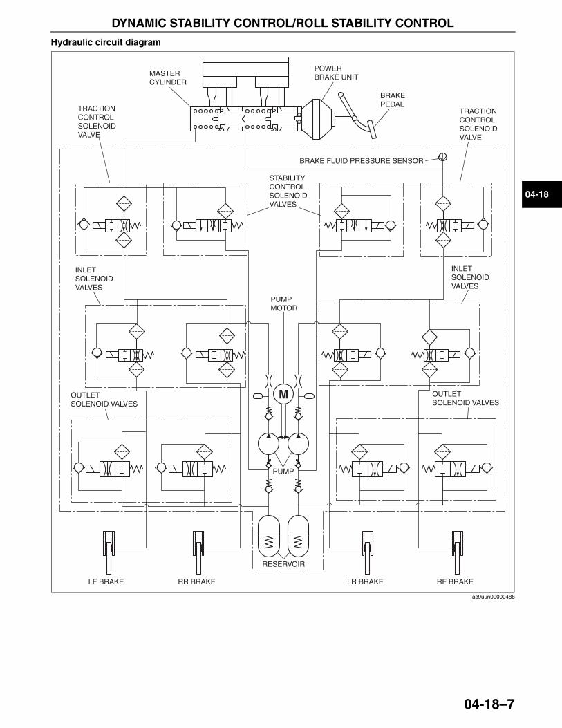
DYNAMIC STABILITY CONTROL/ROLL STABILITY CONTROL
04-18–7
04-18
Hydraulic circuit diagram
POWER BRAKE UNITMASTER
CYLINDER
TRACTION CONTROL SOLENOID VALVE
INLET SOLENOID VALVES
OUTLET SOLENOID VALVES
LF BRAKE RR BRAKE LR BRAKE RF BRAKE
RESERVOIR
PUMP
BRAKE PEDAL
INLET SOLENOID VALVES
OUTLET SOLENOID VALVES
BRAKE FLUID PRESSURE SENSOR
PUMP MOTOR
STABILITY CONTROL SOLENOID VALVES
TRACTION CONTROL SOLENOID VALVE
ac9uun00000488
3423-1U-06H(04-18).fm 7 ページ 2006年11月22日 水曜日 午後2時38分
DYNAMIC STABILITY CONTROL/ROLL STABILITY CONTROL
04-18–8
OperationDuring normal braking• During normal braking, the solenoid valves are not energized and all of them are off. When the brake pedal is
depressed, brake fluid pressure is transmitted from the master cylinder, through the traction switch and inlet solenoid valves, and then to the caliper piston.
Solenoid valve operation tableTraction control solenoid
valveStability control solenoid
valve Inlet solenoid valve Outlet solenoid valve Pump motor, pumpLF—RR RF—LR LF—RR RF—LR LF RF LR RR LF RF LR RR
OFF (open) OFF (closed) OFF (open) OFF (closed) Stopped
3423-1U-06H(04-18).fm 8 ページ 2006年11月22日 水曜日 午後2時38分
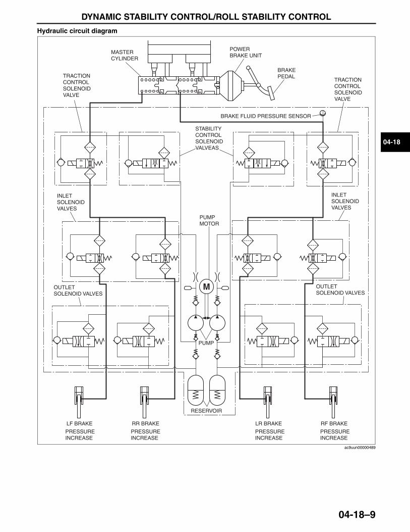
DYNAMIC STABILITY CONTROL/ROLL STABILITY CONTROL
04-18–9
04-18
Hydraulic circuit diagram
POWER BRAKE UNIT
MASTER CYLINDER
TRACTION CONTROL SOLENOID VALVE
INLET SOLENOID VALVES
OUTLET SOLENOID VALVES
LF BRAKE RR BRAKE LR BRAKE RF BRAKE
RESERVOIR
PUMP
BRAKE PEDAL
INLET SOLENOID VALVES
OUTLET SOLENOID VALVES
BRAKE FLUID PRESSURE SENSOR
PUMP MOTOR
STABILITY CONTROL SOLENOID VALVEAS
TRACTION CONTROL SOLENOID VALVE
PRESSURE INCREASE
PRESSURE INCREASE
PRESSURE INCREASE
PRESSURE INCREASE
ac9uun00000489
3423-1U-06H(04-18).fm 9 ページ 2006年11月22日 水曜日 午後2時38分
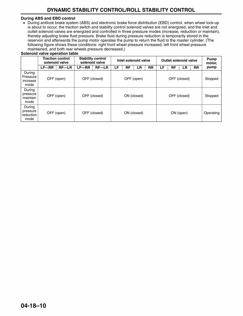
DYNAMIC STABILITY CONTROL/ROLL STABILITY CONTROL
04-18–10
During ABS and EBD control• During antilock brake system (ABS) and electronic brake force distribution (EBD) control, when wheel lock-up
is about to occur, the traction switch and stability control solenoid valves are not energized, and the inlet and outlet solenoid valves are energized and controlled in three pressure modes (increase, reduction or maintain), thereby adjusting brake fluid pressure. Brake fluid during pressure reduction is temporarily stored in the reservoir and afterwards the pump motor operates the pump to return the fluid to the master cylinder. (The following figure shows these conditions: right front wheel pressure increased, left front wheel pressure maintained, and both rear wheels pressure decreased.)
Solenoid valve operation tableTraction control solenoid valve
Stability control solenoid valve Inlet solenoid valve Outlet solenoid valve Pump
motor, pumpLF—RR RF—LR LF—RR RF—LR LF RF LR RR LF RF LR RR
During Pressure increase
mode
OFF (open) OFF (closed) OFF (open) OFF (closed) Stopped
During pressure maintain
mode
OFF (open) OFF (closed) ON (closed) OFF (closed) Stopped
During pressure reduction
mode
OFF (open) OFF (closed) ON (closed) ON (open) Operating
3423-1U-06H(04-18).fm 10 ページ 2006年11月22日 水曜日 午後2時38分
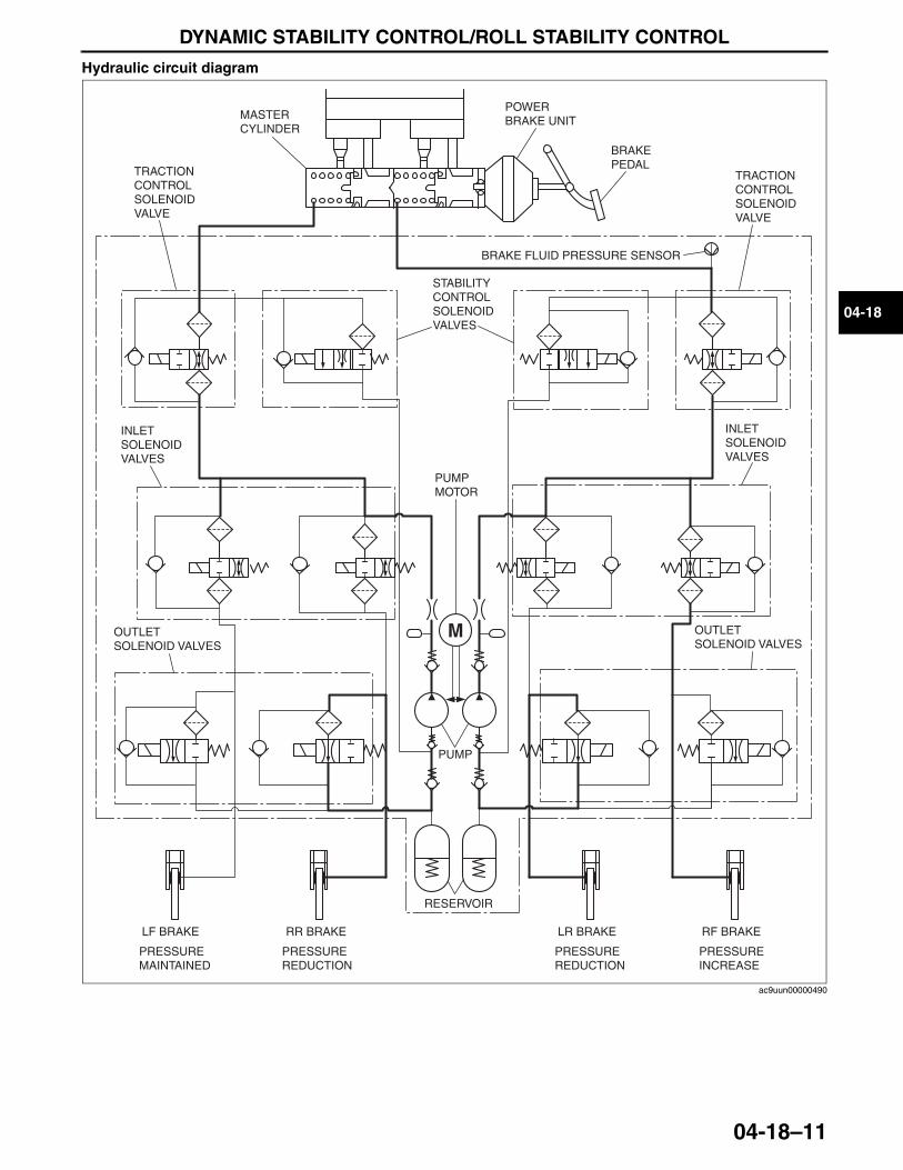
DYNAMIC STABILITY CONTROL/ROLL STABILITY CONTROL
04-18–11
04-18
Hydraulic circuit diagram
POWER BRAKE UNITMASTER
CYLINDER
TRACTION CONTROL SOLENOID VALVE
INLET SOLENOID VALVES
OUTLET SOLENOID VALVES
LF BRAKE RR BRAKE LR BRAKE RF BRAKE
RESERVOIR
PUMP
BRAKE PEDAL
INLET SOLENOID VALVES
OUTLET SOLENOID VALVES
BRAKE FLUID PRESSURE SENSOR
PUMP MOTOR
STABILITY CONTROL SOLENOID VALVES
TRACTION CONTROL SOLENOID VALVE
PRESSURE MAINTAINED
PRESSURE INCREASE
PRESSURE REDUCTION
PRESSURE REDUCTION
ac9uun00000490
3423-1U-06H(04-18).fm 11 ページ 2006年11月22日 水曜日 午後2時38分
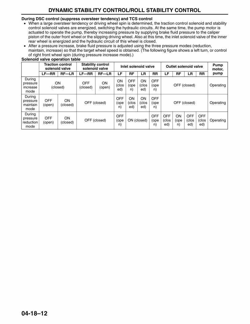
DYNAMIC STABILITY CONTROL/ROLL STABILITY CONTROL
04-18–12
During DSC control (suppress oversteer tendency) and TCS control • When a large oversteer tendency or driving wheel spin is determined, the traction control solenoid and stability
control solenoid valves are energized, switching the hydraulic circuits. At the same time, the pump motor is actuated to operate the pump, thereby increasing pressure by supplying brake fluid pressure to the caliper piston of the outer front wheel or the slipping driving wheel. Also at this time, the inlet solenoid valve of the inner rear wheel is energized and the hydraulic circuit of this wheel is closed.
• After a pressure increase, brake fluid pressure is adjusted using the three pressure modes (reduction, maintain, increase) so that the target wheel speed is obtained. (The following figure shows a left turn, or control of right front wheel spin (during pressure increase mode).)
Solenoid valve operation tableTraction control solenoid valve
Stability control solenoid valve Inlet solenoid valve Outlet solenoid valve Pump
motor, pumpLF—RR RF—LR LF—RR RF—LR LF RF LR RR LF RF LR RR
During pressure increase
mode
ON(closed)
OFF(closed)
ON(open)
ON(closed)
OFF(open)
ON(closed)
OFF(open)
OFF (closed) Operating
During pressure maintain
mode
OFF(open)
ON(closed) OFF (closed)
OFF(ope
n)
ON (closed)
ON (closed)
OFF(open)
OFF (closed) Operating
During pressure reduction
mode
OFF(open)
ON(closed) OFF (closed)
OFF(ope
n)ON (closed)
OFF(open)
OFF(closed)
ON(ope
n)
OFF(closed)
OFF(closed)
Operating
3423-1U-06H(04-18).fm 12 ページ 2006年11月22日 水曜日 午後2時38分
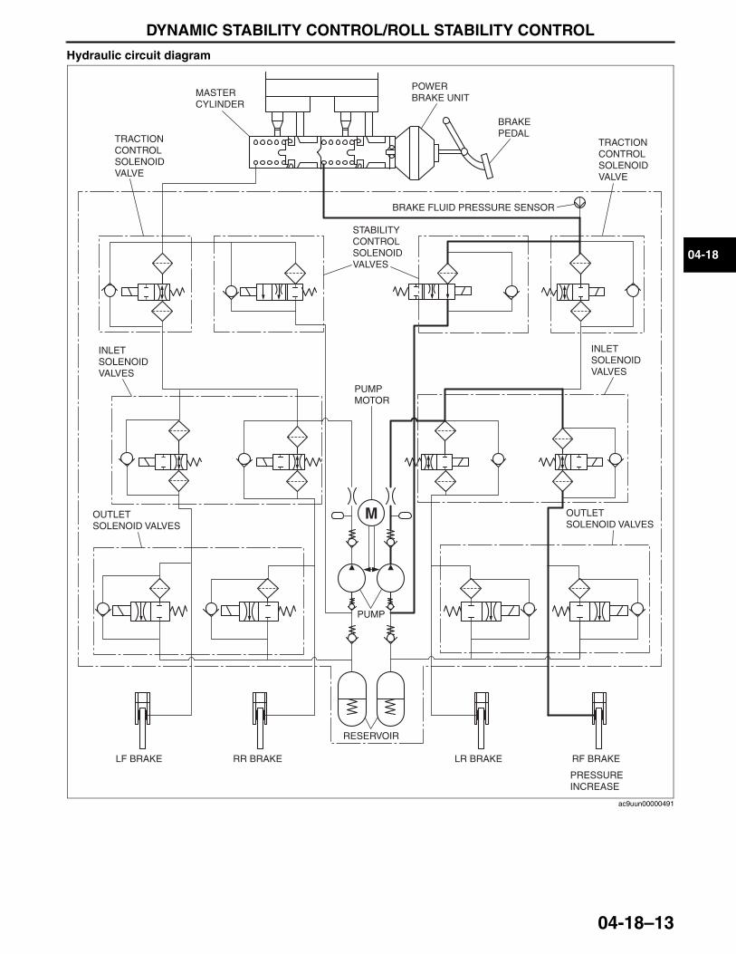
DYNAMIC STABILITY CONTROL/ROLL STABILITY CONTROL
04-18–13
04-18
Hydraulic circuit diagram
POWER BRAKE UNITMASTER
CYLINDER
TRACTION CONTROL SOLENOID VALVE
INLET SOLENOID VALVES
OUTLET SOLENOID VALVES
LF BRAKE RR BRAKE LR BRAKE RF BRAKE
RESERVOIR
PUMP
BRAKE PEDAL
INLET SOLENOID VALVES
OUTLET SOLENOID VALVES
BRAKE FLUID PRESSURE SENSOR
PUMP MOTOR
STABILITY CONTROL SOLENOID VALVES
TRACTION CONTROL SOLENOID VALVE
PRESSURE INCREASE
ac9uun00000491
3423-1U-06H(04-18).fm 13 ページ 2006年11月22日 水曜日 午後2時38分
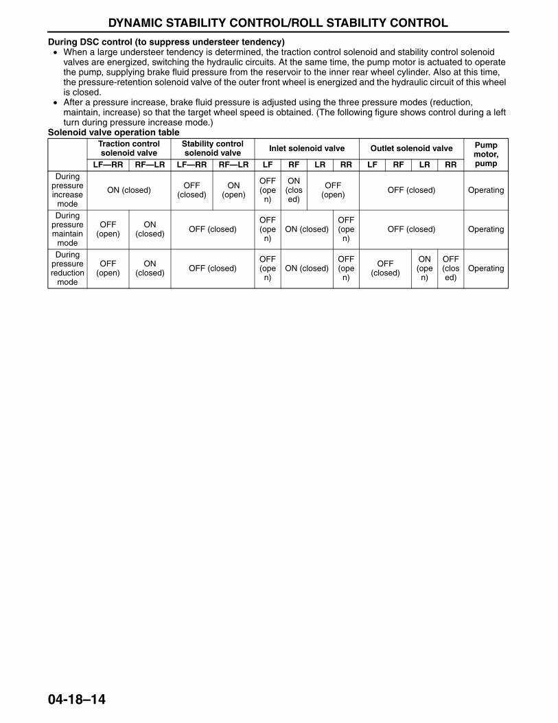
DYNAMIC STABILITY CONTROL/ROLL STABILITY CONTROL
04-18–14
During DSC control (to suppress understeer tendency)• When a large understeer tendency is determined, the traction control solenoid and stability control solenoid
valves are energized, switching the hydraulic circuits. At the same time, the pump motor is actuated to operate the pump, supplying brake fluid pressure from the reservoir to the inner rear wheel cylinder. Also at this time, the pressure-retention solenoid valve of the outer front wheel is energized and the hydraulic circuit of this wheel is closed.
• After a pressure increase, brake fluid pressure is adjusted using the three pressure modes (reduction, maintain, increase) so that the target wheel speed is obtained. (The following figure shows control during a left turn during pressure increase mode.)
Solenoid valve operation tableTraction control solenoid valve
Stability control solenoid valve Inlet solenoid valve Outlet solenoid valve Pump
motor, pumpLF—RR RF—LR LF—RR RF—LR LF RF LR RR LF RF LR RR
During pressure increase
mode
ON (closed) OFF(closed)
ON(open)
OFF(ope
n)
ON(closed)
OFF(open) OFF (closed) Operating
During pressure maintain
mode
OFF(open)
ON(closed) OFF (closed)
OFF(ope
n)ON (closed)
OFF(open)
OFF (closed) Operating
During pressure reduction
mode
OFF(open)
ON(closed) OFF (closed)
OFF(ope
n)ON (closed)
OFF(open)
OFF(closed)
ON(open)
OFF(closed)
Operating
3423-1U-06H(04-18).fm 14 ページ 2006年11月22日 水曜日 午後2時38分
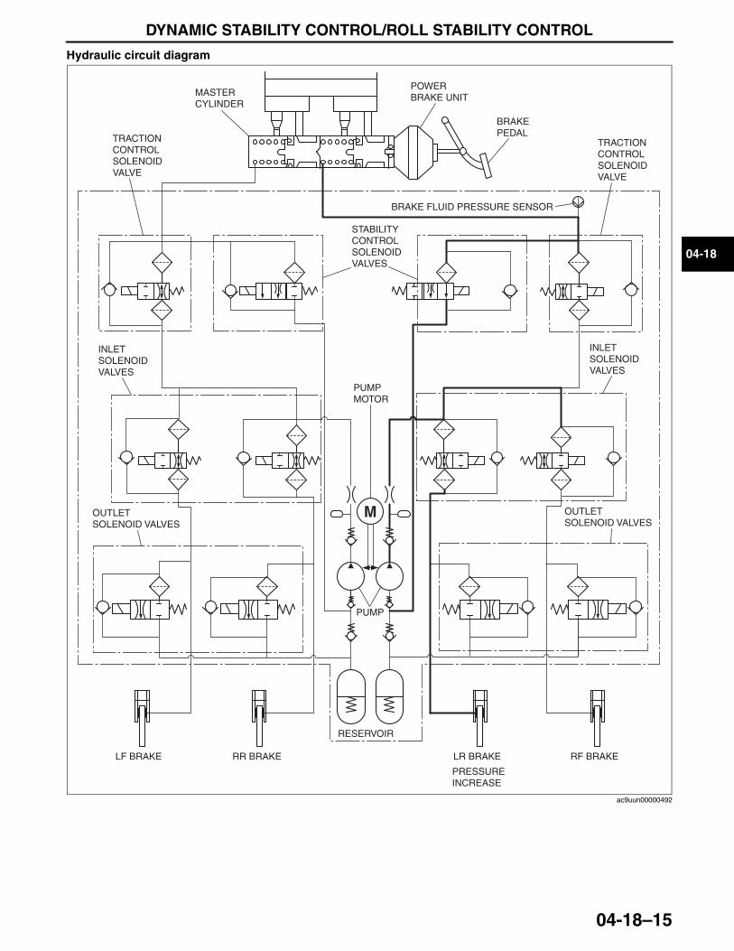
DYNAMIC STABILITY CONTROL/ROLL STABILITY CONTROL
04-18–15
04-18
Hydraulic circuit diagram
End Of Sie
POWER BRAKE UNITMASTER
CYLINDER
TRACTIONCONTROL SOLENOID VALVE
INLET SOLENOID VALVES
OUTLET SOLENOID VALVES
LF BRAKE RR BRAKE LR BRAKE RF BRAKE
RESERVOIR
PUMP
BRAKE PEDAL
INLETSOLENOIDVALVES
OUTLETSOLENOID VALVES
BRAKE FLUID PRESSURE SENSOR
PUMPMOTOR
STABILITYCONTROLSOLENOIDVALVES
TRACTIONCONTROL SOLENOID VALVE
PRESSURE INCREASE
ac9uun00000492
3423-1U-06H(04-18).fm 15 ページ 2006年11月22日 水曜日 午後2時38分
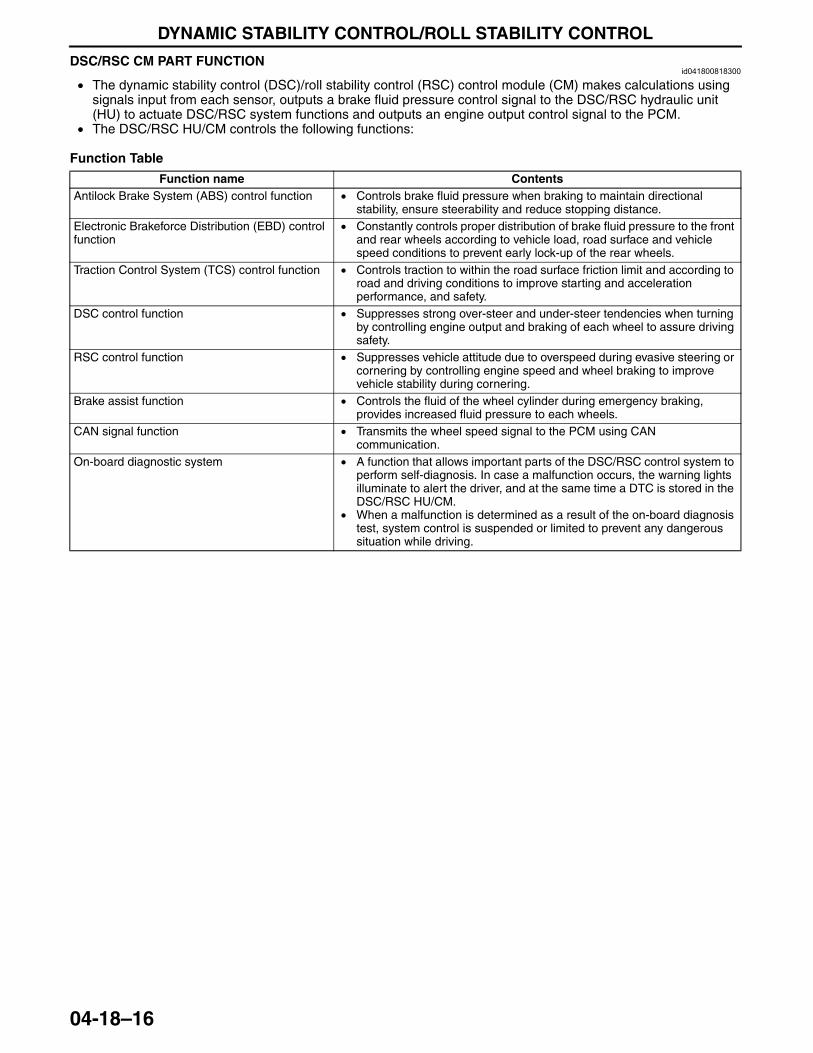
DYNAMIC STABILITY CONTROL/ROLL STABILITY CONTROL
04-18–16
DSC/RSC CM PART FUNCTIONid041800818300
• The dynamic stability control (DSC)/roll stability control (RSC) control module (CM) makes calculations using signals input from each sensor, outputs a brake fluid pressure control signal to the DSC/RSC hydraulic unit (HU) to actuate DSC/RSC system functions and outputs an engine output control signal to the PCM.
• The DSC/RSC HU/CM controls the following functions:
Function Table
Function name ContentsAntilock Brake System (ABS) control function • Controls brake fluid pressure when braking to maintain directional
stability, ensure steerability and reduce stopping distance.Electronic Brakeforce Distribution (EBD) control function
• Constantly controls proper distribution of brake fluid pressure to the front and rear wheels according to vehicle load, road surface and vehicle speed conditions to prevent early lock-up of the rear wheels.
Traction Control System (TCS) control function • Controls traction to within the road surface friction limit and according to road and driving conditions to improve starting and acceleration performance, and safety.
DSC control function • Suppresses strong over-steer and under-steer tendencies when turning by controlling engine output and braking of each wheel to assure driving safety.
RSC control function • Suppresses vehicle attitude due to overspeed during evasive steering or cornering by controlling engine speed and wheel braking to improve vehicle stability during cornering.
Brake assist function • Controls the fluid of the wheel cylinder during emergency braking, provides increased fluid pressure to each wheels.
CAN signal function • Transmits the wheel speed signal to the PCM using CAN communication.
On-board diagnostic system • A function that allows important parts of the DSC/RSC control system to perform self-diagnosis. In case a malfunction occurs, the warning lights illuminate to alert the driver, and at the same time a DTC is stored in the DSC/RSC HU/CM.
• When a malfunction is determined as a result of the on-board diagnosis test, system control is suspended or limited to prevent any dangerous situation while driving.
3423-1U-06H(04-18).fm 16 ページ 2006年11月22日 水曜日 午後2時38分
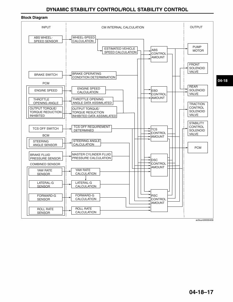
DYNAMIC STABILITY CONTROL/ROLL STABILITY CONTROL
04-18–17
04-18
Block Diagram
End Of Sie
INPUT
ABS WHEEL-SPEED SENSOR
BRAKE SWITCH
PCM
ENGINE SPEED
THROTTLE OPENING ANGLE
OUTPUT TORQUE/ TORQUE REDUCTION INHIBITED
TCS OFF SWITCH
STEERING ANGLE SENSOR
CM INTERNAL CALCULATION
WHEEL-SPEED CALCULATION
ESTIMATED VEHICLE SPEED CALCULATION
BRAKE OPERATING CONDITION DETERMINATION
ENGINE SPEED CALCULATION
THROTTLE OPENING ANGLE DATA ASSIMILATED
OUTPUT TORQUE/TORQUE RESUCTION INHIBITED DATA ASSIMILATED
TCS OFF REQUIREMENT DETERMINED
BRAKE FLUID PRESSURE SENSOR
MASTER CYLINDER FLUID PRESSURE CALCULATION
DSC CONTROL AMOUNT
TCS CONTROL AMOUNT
EBD CONTROL AMOUNT
ABS CONTROL AMOUNT
OUTPUT
PUMP MOTOR
FRONT SOLENOID VALVE
REAR SOLENOID VALVE
PCM
TRACTION CONTROL SOLENOID VALVE
STABILITY CONTROL SOLENOID VALVEBCM
STEERING ANGLE CALCULATION
RSC CONTROL AMOUNT
COMBINED SENSOR
YAW RATE SENSOR
YAW RATE CALCULATION
LATERAL-G SENSOR
LATERAL-G CALCULATION
ROLL RATE CALCULATION
ROLL RATE SENSOR
FORWARD-G SENSOR
FORWARD-G CALCULATION
ac9uun00000456
3423-1U-06H(04-18).fm 17 ページ 2006年11月22日 水曜日 午後2時38分
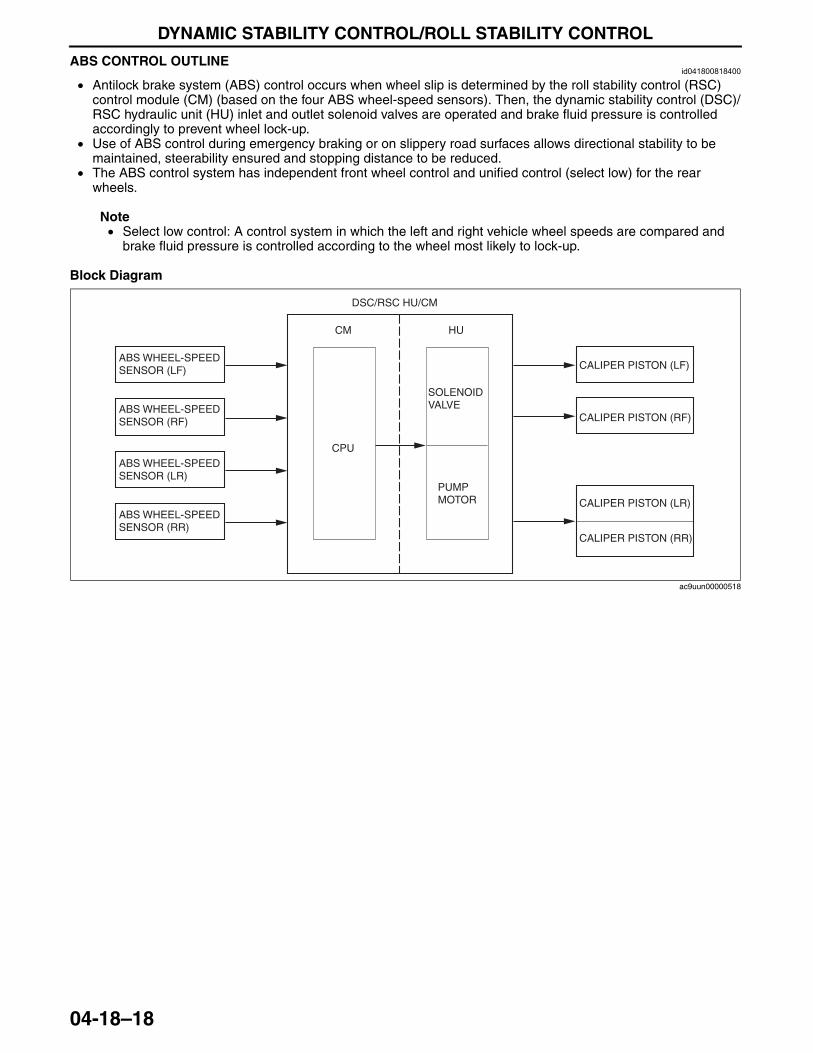
DYNAMIC STABILITY CONTROL/ROLL STABILITY CONTROL
04-18–18
ABS CONTROL OUTLINEid041800818400
• Antilock brake system (ABS) control occurs when wheel slip is determined by the roll stability control (RSC) control module (CM) (based on the four ABS wheel-speed sensors). Then, the dynamic stability control (DSC)/RSC hydraulic unit (HU) inlet and outlet solenoid valves are operated and brake fluid pressure is controlled accordingly to prevent wheel lock-up.
• Use of ABS control during emergency braking or on slippery road surfaces allows directional stability to be maintained, steerability ensured and stopping distance to be reduced.
• The ABS control system has independent front wheel control and unified control (select low) for the rear wheels.
Note• Select low control: A control system in which the left and right vehicle wheel speeds are compared and
brake fluid pressure is controlled according to the wheel most likely to lock-up.
Block Diagram
End Of Sie
ABS WHEEL-SPEED SENSOR (LF)
ABS WHEEL-SPEED SENSOR (RF)
ABS WHEEL-SPEED SENSOR (LR)
ABS WHEEL-SPEED SENSOR (RR)
DSC/RSC HU/CM
CM
CPU
HU
SOLENOID VALVE
PUMP MOTOR
CALIPER PISTON (LF)
CALIPER PISTON (RF)
CALIPER PISTON (LR)
CALIPER PISTON (RR)
ac9uun00000518
3423-1U-06H(04-18).fm 18 ページ 2006年11月22日 水曜日 午後2時38分
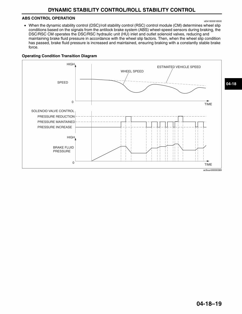
DYNAMIC STABILITY CONTROL/ROLL STABILITY CONTROL
04-18–19
04-18
ABS CONTROL OPERATIONid041800818500
• When the dynamic stability control (DSC)/roll stability control (RSC) control module (CM) determines wheel slip conditions based on the signals from the antilock brake system (ABS) wheel-speed sensors during braking, the DSC/RSC CM operates the DSC/RSC hydraulic unit (HU) inlet and outlet solenoid valves, reducing and maintaining brake fluid pressure in accordance with the wheel slip factors. Then, when the wheel slip condition has passed, brake fluid pressure is increased and maintained, ensuring braking with a constantly stable brake force.
Operating Condition Transition Diagram
End Of Sie
0
0
ESTIMATED VEHICLE SPEEDWHEEL SPEED
SPEED
SOLENOID VALVE CONTROL
BRAKE FLUID PRESSURE
PRESSURE REDUCTION
TIME
PRESSURE MAINTAINED
PRESSURE INCREASE
HIGH
HIGH
TIME
ac9uun00000389
3423-1U-06H(04-18).fm 19 ページ 2006年11月22日 水曜日 午後2時38分
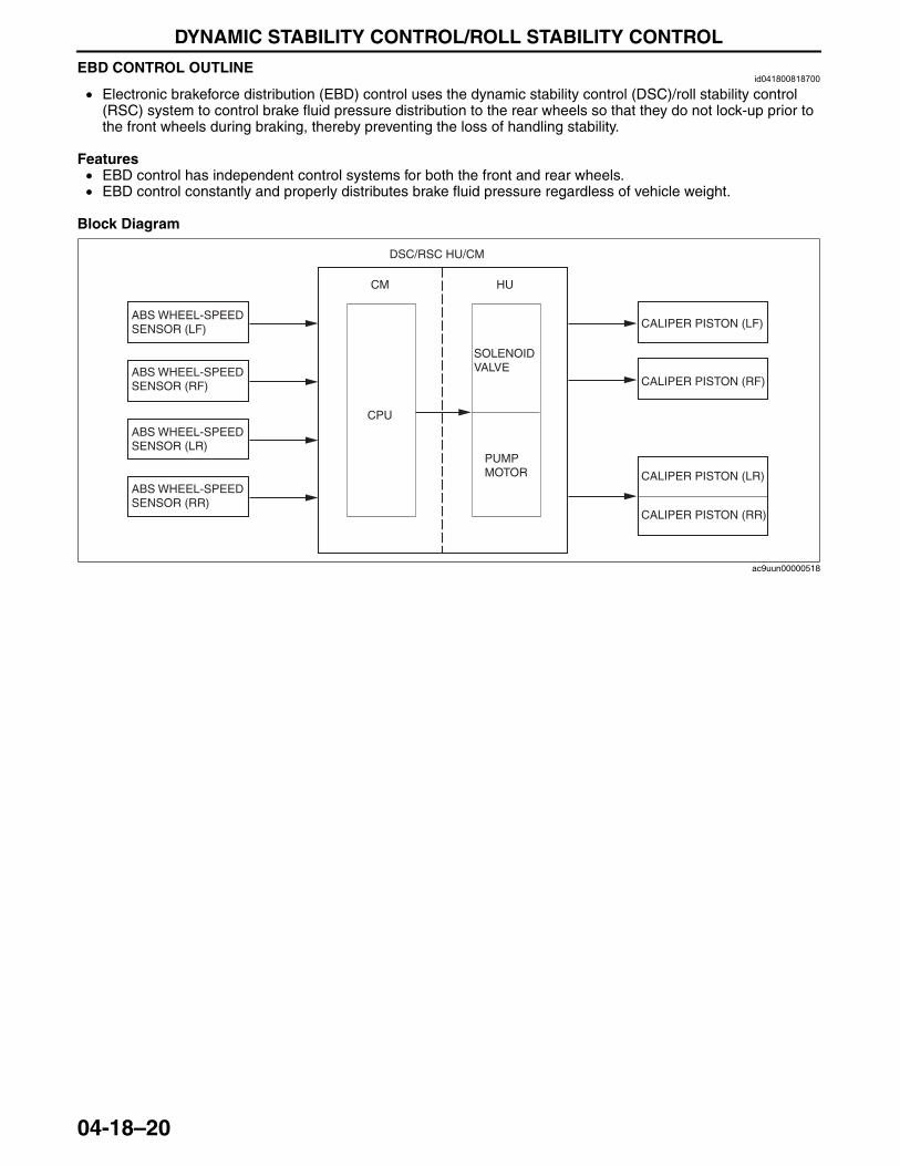
DYNAMIC STABILITY CONTROL/ROLL STABILITY CONTROL
04-18–20
EBD CONTROL OUTLINEid041800818700
• Electronic brakeforce distribution (EBD) control uses the dynamic stability control (DSC)/roll stability control (RSC) system to control brake fluid pressure distribution to the rear wheels so that they do not lock-up prior to the front wheels during braking, thereby preventing the loss of handling stability.
Features• EBD control has independent control systems for both the front and rear wheels.• EBD control constantly and properly distributes brake fluid pressure regardless of vehicle weight.
Block Diagram
End Of Sie
ABS WHEEL-SPEED SENSOR (LF)
ABS WHEEL-SPEED SENSOR (RF)
ABS WHEEL-SPEED SENSOR (LR)
ABS WHEEL-SPEED SENSOR (RR)
DSC/RSC HU/CM
CM
CPU
HU
SOLENOID VALVE
PUMP MOTOR
CALIPER PISTON (LF)
CALIPER PISTON (RF)
CALIPER PISTON (LR)
CALIPER PISTON (RR)
ac9uun00000518
3423-1U-06H(04-18).fm 20 ページ 2006年11月22日 水曜日 午後2時38分
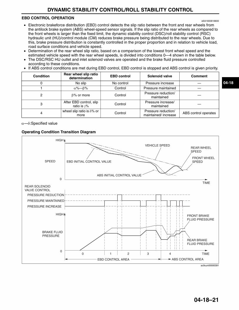
DYNAMIC STABILITY CONTROL/ROLL STABILITY CONTROL
04-18–21
04-18
EBD CONTROL OPERATIONid041800818800
• Electronic brakeforce distribution (EBD) control detects the slip ratio between the front and rear wheels from the antilock brake system (ABS) wheel-speed sensor signals. If the slip ratio of the rear wheels as compared to the front wheels is larger than the fixed limit, the dynamic stability control (DSC)/roll stability control (RSC) hydraulic unit (HU)/control module (CM) reduces brake pressure being distributed to the rear wheels. Due to this, brake pressure distribution is constantly controlled in the proper proportion and in relation to vehicle load, road surface conditions and vehicle speed.
• Determination of the rear wheel slip ratio, based on a comparison of the lowest front wheel speed and the estimated vehicle speed with the rear wheel speeds, is divided into conditions 0—4 shown in the table below.
• The DSC/RSC HU outlet and inlet solenoid valves are operated and the brake fluid pressure controlled according to these conditions.
• If ABS control conditions are met during EBD control, EBD control is stopped and ABS control is given priority.
α—δ:Specified value
Operating Condition Transition Diagram
End Of Sie
Condition Rear wheel slip ratio determination EBD control Solenoid valve Comment
0 No slip No control Pressure increase —1 α%—β% Control Pressure maintained —
2 β% or more Control Pressure reduction/maintained —
3 After EBD control, slip ratio is γ% Control Pressure increase/
maintained —
4 wheel slip ratio is δ% or more Control Pressure reduction/
maintained/ increase ABS control operates
43210
0
0
REAR SOLENOID VALVE CONTROL
PRESSURE REDUCTION
PRESSURE MAINTAINED
PRESSURE INCREASE
HIGH
BRAKE FLUID PRESSURE
EBD CONTROL AREA ABS CONTROL AREA
FRONT BRAKE FLUID PRESSURE
REAR BRAKE FLUID PRESSURE
TIME
HIGH
SPEED EBD INITIAL CONTROL VALUE
ABS INITIAL CONTROL VALUE
VEHICLE SPEEDREAR WHEEL SPEED
FRONT WHEEL SPEED
TIME
ac9uun00000391
3423-1U-06H(04-18).fm 21 ページ 2006年11月22日 水曜日 午後2時38分
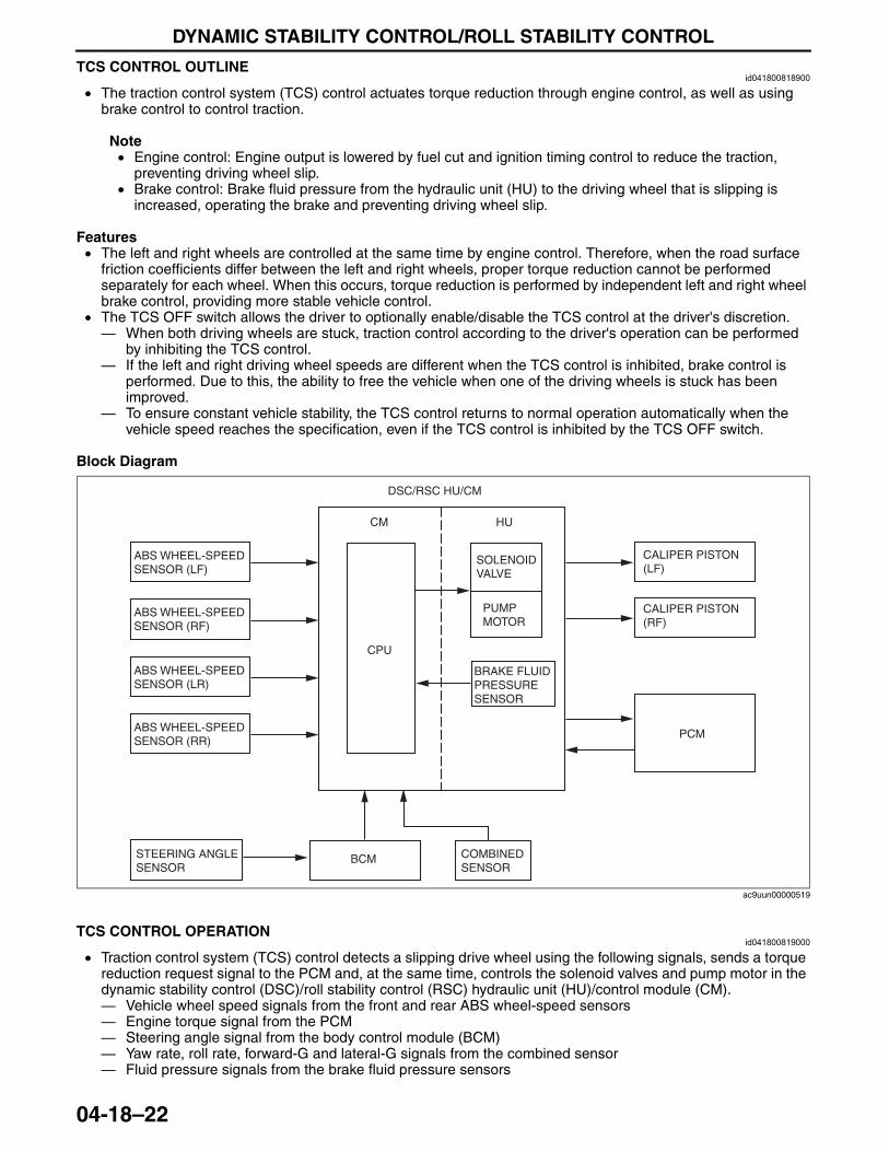
DYNAMIC STABILITY CONTROL/ROLL STABILITY CONTROL
04-18–22
TCS CONTROL OUTLINEid041800818900
• The traction control system (TCS) control actuates torque reduction through engine control, as well as using brake control to control traction.
Note• Engine control: Engine output is lowered by fuel cut and ignition timing control to reduce the traction,
preventing driving wheel slip.• Brake control: Brake fluid pressure from the hydraulic unit (HU) to the driving wheel that is slipping is
increased, operating the brake and preventing driving wheel slip.
Features• The left and right wheels are controlled at the same time by engine control. Therefore, when the road surface
friction coefficients differ between the left and right wheels, proper torque reduction cannot be performed separately for each wheel. When this occurs, torque reduction is performed by independent left and right wheel brake control, providing more stable vehicle control.
• The TCS OFF switch allows the driver to optionally enable/disable the TCS control at the driver's discretion.— When both driving wheels are stuck, traction control according to the driver's operation can be performed
by inhibiting the TCS control.— If the left and right driving wheel speeds are different when the TCS control is inhibited, brake control is
performed. Due to this, the ability to free the vehicle when one of the driving wheels is stuck has been improved.
— To ensure constant vehicle stability, the TCS control returns to normal operation automatically when the vehicle speed reaches the specification, even if the TCS control is inhibited by the TCS OFF switch.
Block Diagram
End Of SieTCS CONTROL OPERATION
id041800819000
• Traction control system (TCS) control detects a slipping drive wheel using the following signals, sends a torque reduction request signal to the PCM and, at the same time, controls the solenoid valves and pump motor in the dynamic stability control (DSC)/roll stability control (RSC) hydraulic unit (HU)/control module (CM).— Vehicle wheel speed signals from the front and rear ABS wheel-speed sensors— Engine torque signal from the PCM— Steering angle signal from the body control module (BCM)— Yaw rate, roll rate, forward-G and lateral-G signals from the combined sensor— Fluid pressure signals from the brake fluid pressure sensors
End Of Sie
BRAKE FLUID PRESSURE SENSOR
DSC/RSC HU/CM
ABS WHEEL-SPEED SENSOR (LF)
ABS WHEEL-SPEED SENSOR (RF)
ABS WHEEL-SPEED SENSOR (LR)
ABS WHEEL-SPEED SENSOR (RR)
STEERING ANGLE SENSOR
COMBINED SENSOR
CPU
CM HU
SOLENOID VALVE
PUMP MOTOR
PCM
CALIPER PISTON (RF)
CALIPER PISTON (LF)
BCM
ac9uun00000519
3423-1U-06H(04-18).fm 22 ページ 2006年11月22日 水曜日 午後2時38分
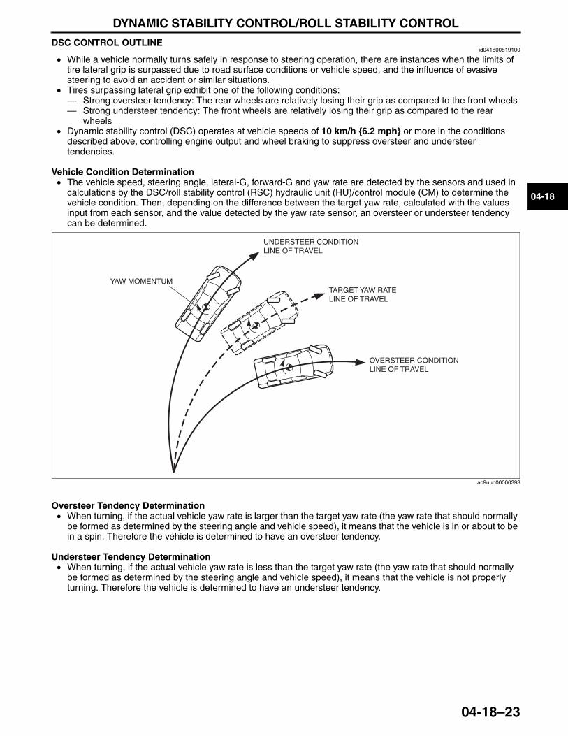
DYNAMIC STABILITY CONTROL/ROLL STABILITY CONTROL
04-18–23
04-18
DSC CONTROL OUTLINEid041800819100
• While a vehicle normally turns safely in response to steering operation, there are instances when the limits of tire lateral grip is surpassed due to road surface conditions or vehicle speed, and the influence of evasive steering to avoid an accident or similar situations.
• Tires surpassing lateral grip exhibit one of the following conditions:— Strong oversteer tendency: The rear wheels are relatively losing their grip as compared to the front wheels — Strong understeer tendency: The front wheels are relatively losing their grip as compared to the rear
wheels • Dynamic stability control (DSC) operates at vehicle speeds of 10 km/h {6.2 mph} or more in the conditions
described above, controlling engine output and wheel braking to suppress oversteer and understeer tendencies.
Vehicle Condition Determination• The vehicle speed, steering angle, lateral-G, forward-G and yaw rate are detected by the sensors and used in
calculations by the DSC/roll stability control (RSC) hydraulic unit (HU)/control module (CM) to determine the vehicle condition. Then, depending on the difference between the target yaw rate, calculated with the values input from each sensor, and the value detected by the yaw rate sensor, an oversteer or understeer tendency can be determined.
Oversteer Tendency Determination• When turning, if the actual vehicle yaw rate is larger than the target yaw rate (the yaw rate that should normally
be formed as determined by the steering angle and vehicle speed), it means that the vehicle is in or about to be in a spin. Therefore the vehicle is determined to have an oversteer tendency.
Understeer Tendency Determination• When turning, if the actual vehicle yaw rate is less than the target yaw rate (the yaw rate that should normally
be formed as determined by the steering angle and vehicle speed), it means that the vehicle is not properly turning. Therefore the vehicle is determined to have an understeer tendency.
End Of Sie
YAW MOMENTUM
UNDERSTEER CONDITION LINE OF TRAVEL
TARGET YAW RATE LINE OF TRAVEL
OVERSTEER CONDITION LINE OF TRAVEL
ac9uun00000393
3423-1U-06H(04-18).fm 23 ページ 2006年11月22日 水曜日 午後2時38分
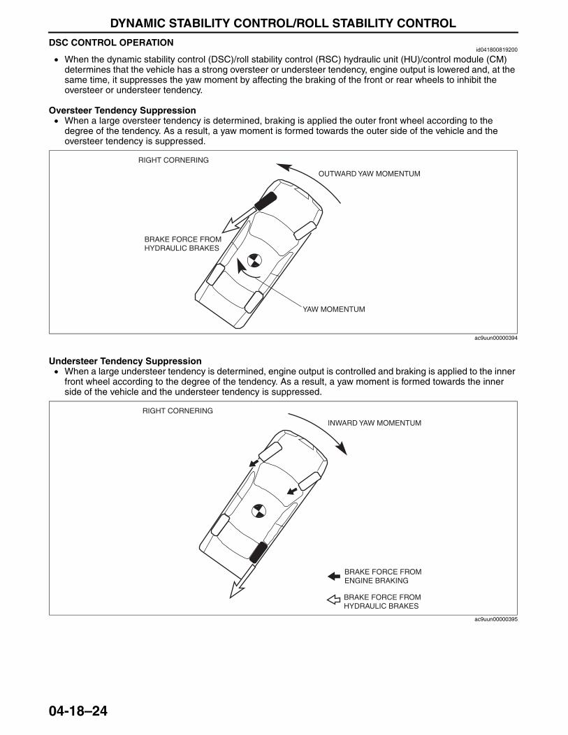
DYNAMIC STABILITY CONTROL/ROLL STABILITY CONTROL
04-18–24
DSC CONTROL OPERATIONid041800819200
• When the dynamic stability control (DSC)/roll stability control (RSC) hydraulic unit (HU)/control module (CM) determines that the vehicle has a strong oversteer or understeer tendency, engine output is lowered and, at the same time, it suppresses the yaw moment by affecting the braking of the front or rear wheels to inhibit the oversteer or understeer tendency.
Oversteer Tendency Suppression• When a large oversteer tendency is determined, braking is applied the outer front wheel according to the
degree of the tendency. As a result, a yaw moment is formed towards the outer side of the vehicle and the oversteer tendency is suppressed.
Understeer Tendency Suppression• When a large understeer tendency is determined, engine output is controlled and braking is applied to the inner
front wheel according to the degree of the tendency. As a result, a yaw moment is formed towards the inner side of the vehicle and the understeer tendency is suppressed.
End Of Sie
RIGHT CORNERING
BRAKE FORCE FROM HYDRAULIC BRAKES
YAW MOMENTUM
OUTWARD YAW MOMENTUM
ac9uun00000394
RIGHT CORNERING
INWARD YAW MOMENTUM
BRAKE FORCE FROM ENGINE BRAKING
BRAKE FORCE FROM HYDRAULIC BRAKES
ac9uun00000395
3423-1U-06H(04-18).fm 24 ページ 2006年11月22日 水曜日 午後2時38分
DYNAMIC STABILITY CONTROL/ROLL STABILITY CONTROL
04-18–25
04-18
RSC CONTROL OUTLINEid041800819300
• The dynamic stability control (DSC)/roll stability control (RSC) system monitors the signal from the roll rate sensor and each sensor, and calculates if the vehicle may be approaching a situation where rollover is probable. When this occurs, the DSC/RSC system applies preemptive action. When the DSC/RSC system is activated, it adjusts the braking force of specific wheels in response to the direct measurement of the vehicle roll motion. By adjusting the brake force, the DSC/RSC system can reduce cornering forces, reducing the total roll moment acting on the vehicle. The DSC/RSC system has the roll rate sensor located within the combined sensor and an additional program within the DSC/RSC control module (CM) to support the vehicle control during sudden steering operation. Information from the roll rate sensor is input into the DSC/RSC CM. The computer uses information from the antilock brake system (ABS) wheel-speed sensor (wheel speed), throttle position sensor (throttle valve opening angle), steering angle sensor (steering wheel angle, steering wheel rate of change), and combined sensor (longitudinal-G, lateral-G, yaw rate, roll rate). If the DSC/RSC CM determines from all these inputs that conditions exist for a potential rollover, the CM applies one or more brakes and reduces the engine torque to make the vehicle more stable.
End Of Sie
CONTROLLER AREA NETWORK (CAN) OUTLINEid041800819500
• The dynamic stability control (DSC)/roll stability control (RSC) hydraulic unit (HU)/control module (CM) sends and receives data to and from other modules via the CAN system. Refer to Section 09 for a detailed explanation of the controller area network (CAN) system.
Data sent• Brake system status• Wheel speeds of all four wheels• Torque reduction request• Desired coupling torque
Data received• Engine speed• Accelerator pedal position• Engine torque• Torque reduction disabled• Target gear position/selector lever position• Steering angle• Steering angle sensor status• Brake switch• Brake fluid level• Parking brake position• AWD system status• Coupling torque inhibit
End Of SieNG: FRONT ABS WHEEL-SPEED SENSOR
ABS WHEEL-SPEED SENSOR FUNCTIONid041800819600
• The Antilock brake system (ABS) wheel-speed sensor detects and transmits the rotation condition of each wheel to the dynamic stability control (DSC)/roll stability control (RSC) hydraulic unit (HU)/control module (CM).
• The signal from the ABS wheel-speed sensors is the primary signal for DSC/RSC HU/CM control.End Of Sie
3423-1U-06H(04-18).fm 25 ページ 2006年11月22日 水曜日 午後2時38分
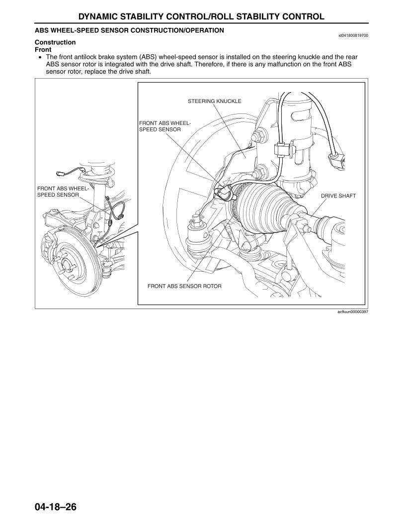
DYNAMIC STABILITY CONTROL/ROLL STABILITY CONTROL
04-18–26
ABS WHEEL-SPEED SENSOR CONSTRUCTION/OPERATIONid041800819700
ConstructionFront• The front antilock brake system (ABS) wheel-speed sensor is installed on the steering knuckle and the rear
ABS sensor rotor is integrated with the drive shaft. Therefore, if there is any malfunction on the front ABS sensor rotor, replace the drive shaft.
FRONT ABS WHEEL-SPEED SENSOR
FRONT ABS WHEEL-SPEED SENSOR
FRONT ABS SENSOR ROTOR
STEERING KNUCKLE
DRIVE SHAFT
ac9uun00000397
3423-1U-06H(04-18).fm 26 ページ 2006年11月22日 水曜日 午後2時38分
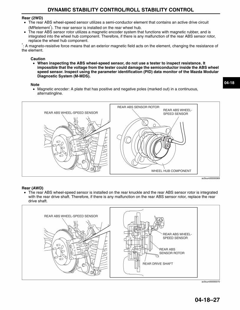
DYNAMIC STABILITY CONTROL/ROLL STABILITY CONTROL
04-18–27
04-18
Rear (2WD)• The rear ABS wheel-speed sensor utilizes a semi-conductor element that contains an active drive circuit
(MRelement*). The rear sensor is installed on the rear wheel hub.• The rear ABS sensor rotor utilizes a magnetic encoder system that functions with magnetic rubber, and is
integrated into the wheel hub component. Therefore, if there is any malfunction of the rear ABS sensor rotor, replace the wheel hub component.
*: A magneto-resistive force means that an exterior magnetic field acts on the element, changing the resistance of the element.
Caution• When inspecting the ABS wheel-speed sensor, do not use a tester to inspect resistance. It
impossible that the voltage from the tester could damage the semiconductor inside the ABS wheel speed sensor. Inspect using the parameter identification (PID) data monitor of the Mazda Modular Diagnostic System (M-MDS).
Note• Magnetic encoder: A plate that has positive and negative poles (marked out) in a continuous,
alternatingline.
Rear (AWD)• The rear ABS wheel-speed sensor is installed on the rear knuckle and the rear ABS sensor rotor is integrated
with the rear drive shaft. Therefore, if there is any malfunction on the rear ABS sensor rotor, replace the rear drive shaft.
REAR ABS SENSOR ROTORREAR ABS WHEEL-SPEED SENSORREAR ABS WHEEL-SPEED SENSOR
WHEEL HUB COMPONENT
ac9uun00000069
REAR ABS SENSOR ROTOR
REAR ABS WHEEL-SPEED SENSOR
REAR ABS WHEEL-SPEED SENSOR
REAR DRIVE SHAFT
ac9uun00000070
3423-1U-06H(04-18).fm 27 ページ 2006年11月22日 水曜日 午後2時38分
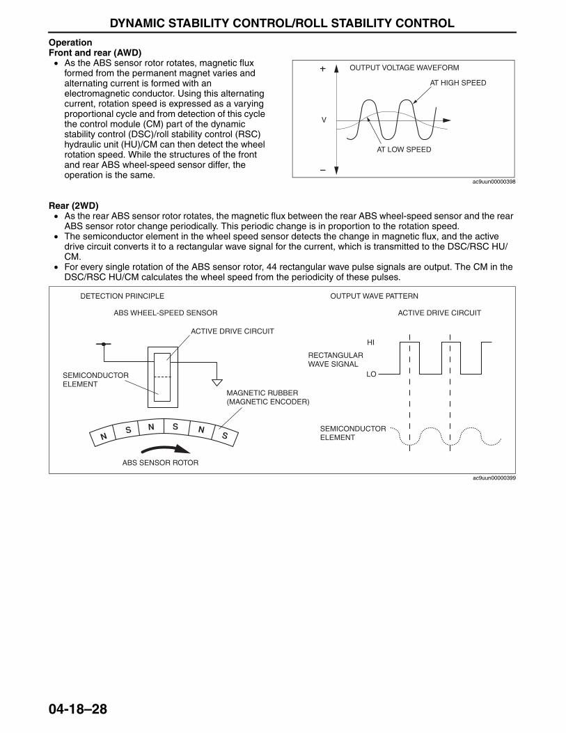
DYNAMIC STABILITY CONTROL/ROLL STABILITY CONTROL
04-18–28
OperationFront and rear (AWD)• As the ABS sensor rotor rotates, magnetic flux
formed from the permanent magnet varies and alternating current is formed with an electromagnetic conductor. Using this alternating current, rotation speed is expressed as a varying proportional cycle and from detection of this cycle the control module (CM) part of the dynamic stability control (DSC)/roll stability control (RSC) hydraulic unit (HU)/CM can then detect the wheel rotation speed. While the structures of the front and rear ABS wheel-speed sensor differ, the operation is the same.
Rear (2WD)• As the rear ABS sensor rotor rotates, the magnetic flux between the rear ABS wheel-speed sensor and the rear
ABS sensor rotor change periodically. This periodic change is in proportion to the rotation speed.• The semiconductor element in the wheel speed sensor detects the change in magnetic flux, and the active
drive circuit converts it to a rectangular wave signal for the current, which is transmitted to the DSC/RSC HU/CM.
• For every single rotation of the ABS sensor rotor, 44 rectangular wave pulse signals are output. The CM in the DSC/RSC HU/CM calculates the wheel speed from the periodicity of these pulses.
End Of SieNG: COMBINED SENSOR
V
OUTPUT VOLTAGE WAVEFORM
AT LOW SPEED
AT HIGH SPEED
ac9uun00000398
DETECTION PRINCIPLE
ABS WHEEL-SPEED SENSOR
ACTIVE DRIVE CIRCUIT
SEMICONDUCTOR ELEMENT
MAGNETIC RUBBER (MAGNETIC ENCODER)
ABS SENSOR ROTOR
OUTPUT WAVE PATTERN
ACTIVE DRIVE CIRCUIT
HI
LO
RECTANGULAR WAVE SIGNAL
SEMICONDUCTOR ELEMENT
ac9uun00000399
3423-1U-06H(04-18).fm 28 ページ 2006年11月22日 水曜日 午後2時38分
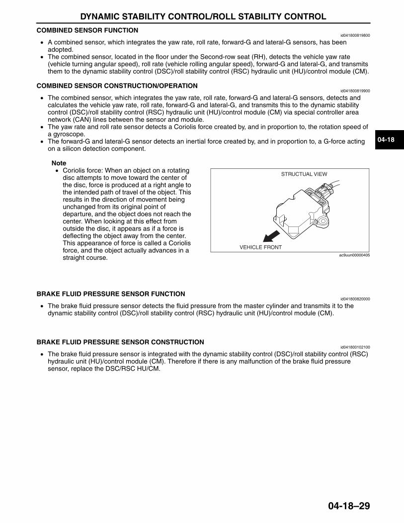
DYNAMIC STABILITY CONTROL/ROLL STABILITY CONTROL
04-18–29
04-18
COMBINED SENSOR FUNCTIONid041800819800
• A combined sensor, which integrates the yaw rate, roll rate, forward-G and lateral-G sensors, has been adopted.
• The combined sensor, located in the floor under the Second-row seat (RH), detects the vehicle yaw rate (vehicle turning angular speed), roll rate (vehicle rolling angular speed), forward-G and lateral-G, and transmits them to the dynamic stability control (DSC)/roll stability control (RSC) hydraulic unit (HU)/control module (CM).
End Of SieCOMBINED SENSOR CONSTRUCTION/OPERATION
id041800819900
• The combined sensor, which integrates the yaw rate, roll rate, forward-G and lateral-G sensors, detects and calculates the vehicle yaw rate, roll rate, forward-G and lateral-G, and transmits this to the dynamic stability control (DSC)/roll stability control (RSC) hydraulic unit (HU)/control module (CM) via special controller area network (CAN) lines between the sensor and module.
• The yaw rate and roll rate sensor detects a Coriolis force created by, and in proportion to, the rotation speed of a gyroscope.
• The forward-G and lateral-G sensor detects an inertial force created by, and in proportion to, a G-force acting on a silicon detection component.
Note• Coriolis force: When an object on a rotating
disc attempts to move toward the center of the disc, force is produced at a right angle to the intended path of travel of the object. This results in the direction of movement being unchanged from its original point of departure, and the object does not reach the center. When looking at this effect from outside the disc, it appears as if a force is deflecting the object away from the center. This appearance of force is called a Coriolis force, and the object actually advances in a straight course.
End Of SieNG: BRAKE FLUID PRESSURE SENSOR
BRAKE FLUID PRESSURE SENSOR FUNCTIONid041800820000
• The brake fluid pressure sensor detects the fluid pressure from the master cylinder and transmits it to the dynamic stability control (DSC)/roll stability control (RSC) hydraulic unit (HU)/control module (CM).
End Of Sie
BRAKE FLUID PRESSURE SENSOR CONSTRUCTIONid041800102100
• The brake fluid pressure sensor is integrated with the dynamic stability control (DSC)/roll stability control (RSC) hydraulic unit (HU)/control module (CM). Therefore if there is any malfunction of the brake fluid pressure sensor, replace the DSC/RSC HU/CM.
End Of SieNG: DSC INDICATOR LIGHT
VEHICLE FRONT
STRUCTUAL VIEW
ac9uun00000405
3423-1U-06H(04-18).fm 29 ページ 2006年11月22日 水曜日 午後2時38分
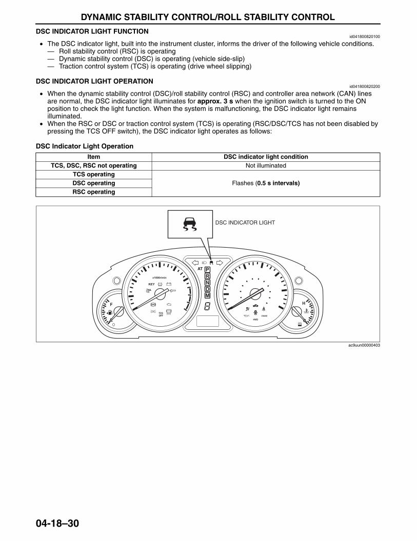
DYNAMIC STABILITY CONTROL/ROLL STABILITY CONTROL
04-18–30
DSC INDICATOR LIGHT FUNCTIONid041800820100
• The DSC indicator light, built into the instrument cluster, informs the driver of the following vehicle conditions.— Roll stability control (RSC) is operating— Dynamic stability control (DSC) is operating (vehicle side-slip)— Traction control system (TCS) is operating (drive wheel slipping)
End Of SieDSC INDICATOR LIGHT OPERATION
id041800820200
• When the dynamic stability control (DSC)/roll stability control (RSC) and controller area network (CAN) lines are normal, the DSC indicator light illuminates for approx. 3 s when the ignition switch is turned to the ON position to check the light function. When the system is malfunctioning, the DSC indicator light remains illuminated.
• When the RSC or DSC or traction control system (TCS) is operating (RSC/DSC/TCS has not been disabled by pressing the TCS OFF switch), the DSC indicator light operates as follows:
DSC Indicator Light Operation
End Of SieNG: TCS OFF SWITCH
Item DSC indicator light conditionTCS, DSC, RSC not operating Not illuminated
TCS operatingFlashes (0.5 s intervals)DSC operating
RSC operating
BRAKE
DSC INDICATOR LIGHT
ac9uun00000403
3423-1U-06H(04-18).fm 30 ページ 2006年11月22日 水曜日 午後2時38分
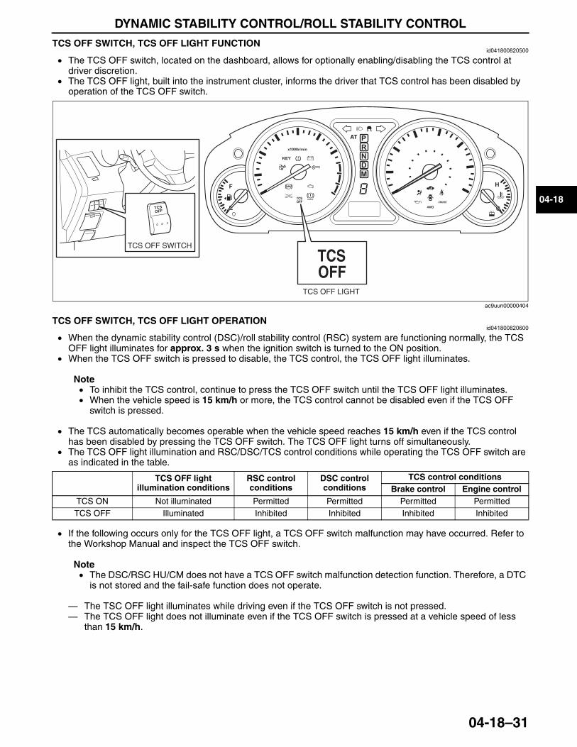
DYNAMIC STABILITY CONTROL/ROLL STABILITY CONTROL
04-18–31
04-18
TCS OFF SWITCH, TCS OFF LIGHT FUNCTIONid041800820500
• The TCS OFF switch, located on the dashboard, allows for optionally enabling/disabling the TCS control at driver discretion.
• The TCS OFF light, built into the instrument cluster, informs the driver that TCS control has been disabled by operation of the TCS OFF switch.
End Of SieTCS OFF SWITCH, TCS OFF LIGHT OPERATIONid041800820600
• When the dynamic stability control (DSC)/roll stability control (RSC) system are functioning normally, the TCS OFF light illuminates for approx. 3 s when the ignition switch is turned to the ON position.
• When the TCS OFF switch is pressed to disable, the TCS control, the TCS OFF light illuminates.
Note• To inhibit the TCS control, continue to press the TCS OFF switch until the TCS OFF light illuminates.• When the vehicle speed is 15 km/h or more, the TCS control cannot be disabled even if the TCS OFF
switch is pressed.
• The TCS automatically becomes operable when the vehicle speed reaches 15 km/h even if the TCS control has been disabled by pressing the TCS OFF switch. The TCS OFF light turns off simultaneously.
• The TCS OFF light illumination and RSC/DSC/TCS control conditions while operating the TCS OFF switch are as indicated in the table.
• If the following occurs only for the TCS OFF light, a TCS OFF switch malfunction may have occurred. Refer to the Workshop Manual and inspect the TCS OFF switch.
Note• The DSC/RSC HU/CM does not have a TCS OFF switch malfunction detection function. Therefore, a DTC
is not stored and the fail-safe function does not operate.
— The TSC OFF light illuminates while driving even if the TCS OFF switch is not pressed.— The TCS OFF light does not illuminate even if the TCS OFF switch is pressed at a vehicle speed of less
than 15 km/h.End Of Sie
BRAKE
TCS OFF LIGHT
TCS OFF SWITCH
ac9uun00000404
TCS OFF light illumination conditions
RSC control conditions
DSC control conditions
TCS control conditionsBrake control Engine control
TCS ON Not illuminated Permitted Permitted Permitted PermittedTCS OFF Illuminated Inhibited Inhibited Inhibited Inhibited
3423-1U-06H(04-18).fm 31 ページ 2006年11月28日 火曜日 午後4時33分

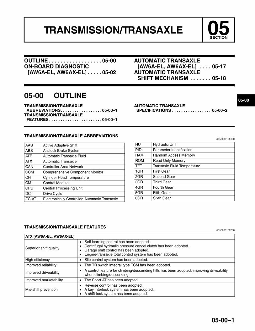
05-00–1
05TRANSMISSION/TRANSAXLESECTION
05-00
Toc of SCTOUTLINE . . . . . . . . . . . . . . . . . .05-00ON-BOARD DIAGNOSTIC
[AW6A-EL, AW6AX-EL] . . . . .05-02
AUTOMATIC TRANSAXLE[AW6A-EL, AW6AX-EL] . . . . 05-17
AUTOMATIC TRANSAXLE SHIFT MECHANISM . . . . . . . 05-18
Toc of SCT
05-00 OUTLINETRANSMISSION/TRANSAXLE
ABBREVIATIONS. . . . . . . . . . . . . . . . . . 05-00–1TRANSMISSION/TRANSAXLE
FEATURES . . . . . . . . . . . . . . . . . . . . . . . 05-00–1
AUTOMATIC TRANSAXLE SPECIFICATIONS . . . . . . . . . . . . . . . . . 05-00–2
End of TocNG: TRANSMISSION/TRANSAXLETRANSMISSION/TRANSAXLE ABBREVIATIONS
id050000100100
End Of Sie
TRANSMISSION/TRANSAXLE FEATURESid050000100200
End Of Sie
AAS Active Adaptive ShiftABS Antilock Brake SystemATF Automatic Transaxle FluidATX Automatic TransaxleCAN Controller Area NetworkCCM Comprehensive Component MonitorCHT Cylinder Head TemperatureCM Control ModuleCPU Central Processing UnitDC Drive CycleEC-AT Electronically Controlled Automatic Transaxle
HU Hydraulic UnitPID Parameter IdentificationRAM Random Access MemoryROM Read Only MemoryTFT Transaxle Fluid Temperature1GR First Gear2GR Second Gear3GR Third Gear4GR Fourth Gear5GR Fifth Gear6GR Sixth Gear
ATX [AW6A-EL, AW6AX-EL]
Superior shift quality
• Self learning control has been adopted.• Centrifugal hydraulic pressure cancel clutch has been adopted.• Garage shift control has been adopted.• Engine-transaxle total control system has been adopted.
High efficiency • Slip control system has been adopted.Improved reliability • The TR switch integral type TCM has been adopted.
Improved driveability • A control feature for climbing/descending hills has been adopted, improving driveability when climbing/descending.
Improved marketability • The Sport AT has been adopted.
Mis-shift prevention• Reverse control has been adopted.• A key interlock system has been adopted.• A shift-lock system has been adopted.
3423-1U-06H(05-00).fm 1 ページ 2006年11月21日 火曜日 午後5時16分
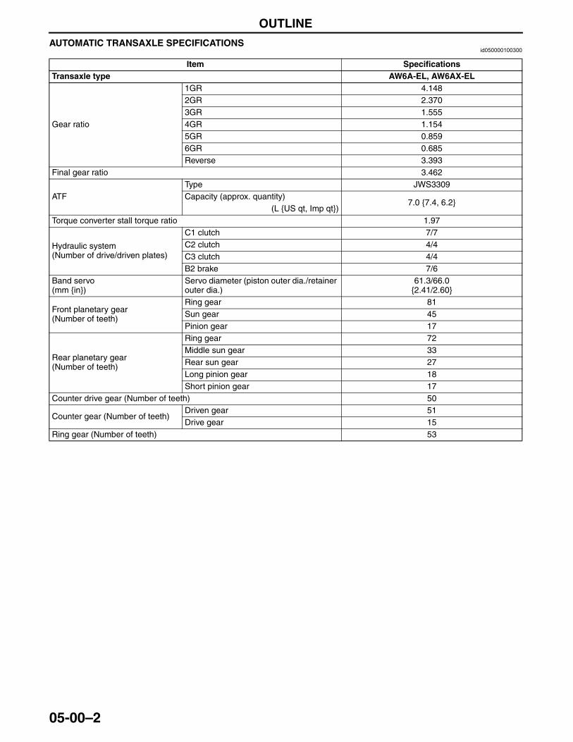
OUTLINE
05-00–2
AUTOMATIC TRANSAXLE SPECIFICATIONSid050000100300
End Of Sie
Item SpecificationsTransaxle type AW6A-EL, AW6AX-EL
Gear ratio
1GR 4.1482GR 2.3703GR 1.5554GR 1.1545GR 0.8596GR 0.685Reverse 3.393
Final gear ratio 3.462
ATFType JWS3309Capacity (approx. quantity)
7.0 {7.4, 6.2}(L {US qt, Imp qt})
Torque converter stall torque ratio 1.97
Hydraulic system(Number of drive/driven plates)
C1 clutch 7/7C2 clutch 4/4C3 clutch 4/4B2 brake 7/6
Band servo(mm {in})
Servo diameter (piston outer dia./retainer outer dia.)
61.3/66.0{2.41/2.60}
Front planetary gear(Number of teeth)
Ring gear 81Sun gear 45Pinion gear 17
Rear planetary gear(Number of teeth)
Ring gear 72Middle sun gear 33Rear sun gear 27Long pinion gear 18Short pinion gear 17
Counter drive gear (Number of teeth) 50
Counter gear (Number of teeth)Driven gear 51Drive gear 15
Ring gear (Number of teeth) 53
3423-1U-06H(05-00).fm 2 ページ 2006年11月21日 火曜日 午後5時16分
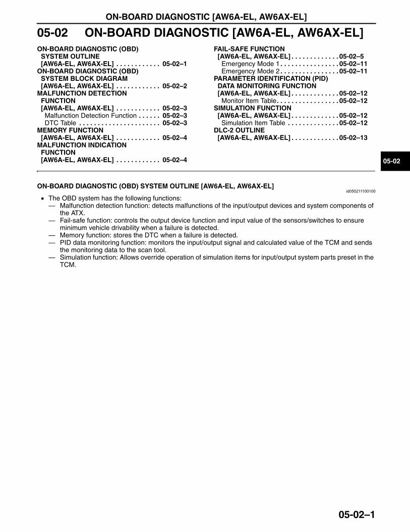
ON-BOARD DIAGNOSTIC [AW6A-EL, AW6AX-EL]
05-02–1
05-02
05-02 ON-BOARD DIAGNOSTIC [AW6A-EL, AW6AX-EL]ON-BOARD DIAGNOSTIC (OBD)
SYSTEM OUTLINE [AW6A-EL, AW6AX-EL] . . . . . . . . . . . . 05-02–1
ON-BOARD DIAGNOSTIC (OBD) SYSTEM BLOCK DIAGRAM [AW6A-EL, AW6AX-EL] . . . . . . . . . . . . 05-02–2
MALFUNCTION DETECTION FUNCTION [AW6A-EL, AW6AX-EL] . . . . . . . . . . . . 05-02–3
Malfunction Detection Function . . . . . . 05-02–3DTC Table . . . . . . . . . . . . . . . . . . . . . . 05-02–3
MEMORY FUNCTION [AW6A-EL, AW6AX-EL] . . . . . . . . . . . . 05-02–4
MALFUNCTION INDICATION FUNCTION [AW6A-EL, AW6AX-EL] . . . . . . . . . . . . 05-02–4
FAIL-SAFE FUNCTION [AW6A-EL, AW6AX-EL] . . . . . . . . . . . . . 05-02–5
Emergency Mode 1 . . . . . . . . . . . . . . . . 05-02–11Emergency Mode 2 . . . . . . . . . . . . . . . . 05-02–11
PARAMETER IDENTIFICATION (PID) DATA MONITORING FUNCTION [AW6A-EL, AW6AX-EL] . . . . . . . . . . . . . 05-02–12
Monitor Item Table. . . . . . . . . . . . . . . . . 05-02–12SIMULATION FUNCTION
[AW6A-EL, AW6AX-EL] . . . . . . . . . . . . . 05-02–12Simulation Item Table . . . . . . . . . . . . . . 05-02–12
DLC-2 OUTLINE [AW6A-EL, AW6AX-EL] . . . . . . . . . . . . . 05-02–13
End of TocNG: AUTOMATIC TRANSAXLEON-BOARD DIAGNOSTIC (OBD) SYSTEM OUTLINE [AW6A-EL, AW6AX-EL]
id050211100100
• The OBD system has the following functions: — Malfunction detection function: detects malfunctions of the input/output devices and system components of
the ATX.— Fail-safe function: controls the output device function and input value of the sensors/switches to ensure
minimum vehicle drivability when a failure is detected.— Memory function: stores the DTC when a failure is detected.— PID data monitoring function: monitors the input/output signal and calculated value of the TCM and sends
the monitoring data to the scan tool.— Simulation function: Allows override operation of simulation items for input/output system parts preset in the
TCM.End Of Sie
3423-1U-06H(05-02).fm 1 ページ 2006年11月22日 水曜日 午後5時30分
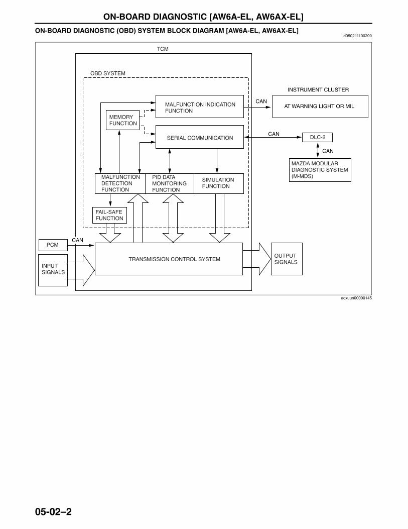
ON-BOARD DIAGNOSTIC [AW6A-EL, AW6AX-EL]
05-02–2
ON-BOARD DIAGNOSTIC (OBD) SYSTEM BLOCK DIAGRAM [AW6A-EL, AW6AX-EL]id050211100200
End Of Sie
TCM
OBD SYSTEM
MEMORYFUNCTION
MALFUNCTION INDICATION FUNCTION
SERIAL COMMUNICATION
MALFUNCTIONDETECTIONFUNCTION
PID DATAMONITORINGFUNCTION
SIMULATIONFUNCTION
FAIL-SAFEFUNCTION
TRANSMISSION CONTROL SYSTEMOUTPUTSIGNALS
DLC-2
INSTRUMENT CLUSTER
CAN
AT WARNING LIGHT OR MILCAN
INPUTSIGNALS
CANPCM
MAZDA MODULAR DIAGNOSTIC SYSTEM (M-MDS)
CAN
acxuun00000145
3423-1U-06H(05-02).fm 2 ページ 2006年11月21日 火曜日 午後5時16分
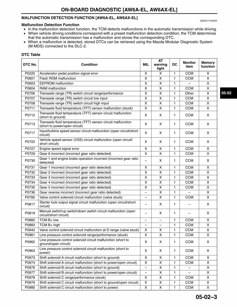
ON-BOARD DIAGNOSTIC [AW6A-EL, AW6AX-EL]
05-02–3
05-02
MALFUNCTION DETECTION FUNCTION [AW6A-EL, AW6AX-EL]id050211100300
Malfunction Detection Function• In the malfunction detection function, the TCM detects malfunctions in the automatic transmission while driving.• When vehicle driving conditions correspond with a preset malfunction detection condition, the TCM determines
that the automatic transmission has a malfunction and stores the corresponding DTC.• When a malfunction is detected, stored DTCs can be retrieved using the Mazda Modular Diagnostic System
(M-MDS) connected to the DLC-2.
DTC Table
DTC No. Condition MILAT
warning light
DC Monitor item
Memory function
P0220 Accelerator pedal position signal error X X 1 CCM XP0601 Flash ROM malfunction X X 1 CCM XP0603 EEPROM malfunction X X 1 – XP0604 RAM malfunction X X 1 CCM XP0706 Transaxle range (TR) switch circuit range/performance X X 1 Other XP0707 Transaxle range (TR) switch circuit low input X X 1 CCM XP0708 Transaxle range (TR) switch circuit high input X X 1 CCM XP0711 Transaxle fluid temperature (TFT) sensor malfunction (stuck) X X 1 CCM X
P0712 Transaxle fluid temperature (TFT) sensor circuit malfunction (short to ground) X X 1 CCM X
P0713 Transaxle fluid temperature (TFT) sensor circuit malfunction (short to power/open circuit) X X 1 CCM X
P0717 Input/turbine speed sensor circuit malfunction (open circuit/short circuit) X X 1 CCM X
P0722 Vehicle speed sensor (VSS) circuit malfunction (open circuit/short circuit) X X 1 CCM X
P0727 Engine speed signal error X X 1 CCM XP0729 Gear 6 incorrect (incorrect gear ratio detected) X X 1 CCM X
P0730 Gear 1 and engine brake operation incorrect (incorrect gear ratio detected) – X 1 CCM X
P0731 Gear 1 incorrect (incorrect gear ratio detected) X X 1 CCM XP0732 Gear 2 incorrect (incorrect gear ratio detected) X X 1 CCM XP0733 Gear 3 incorrect (incorrect gear ratio detected) X X 1 CCM XP0734 Gear 4 incorrect (incorrect gear ratio detected) X X 1 CCM XP0735 Gear 5 incorrect (incorrect gear ratio detected) X X 1 CCM XP0736 Gear reverse incorrect (incorrect gear ratio detected) – X 1 – XP0780 Valve control solenoid circuit malfunction (valve stuck) – X 1 CCM X
P0817 Starter lock output signal circuit malfunction (open circuit/short circuit) – X 1 – X
P0819 Manual switch/up switch/down switch circuit malfunction (open circuit/short circuit) – X 1 – X
P0882 TCM B+ low – – 1 CCM XP0883 TCM B+ high – – 1 CCM XP0942 Valve control solenoid circuit malfunction at D range (valve stuck) X X 1 CCM XP0961 Line pressure control solenoid range/performance (stuck) X X 1 CCM X
P0962 Line pressure control solenoid circuit malfunction (short to ground/open circuit) X X 1 CCM X
P0963 Line pressure control solenoid circuit malfunction (short to power) X X 1 CCM X
P0973 Shift solenoid A circuit malfunction (short to ground) X X 1 CCM XP0974 Shift solenoid A circuit malfunction (short to power/open circuit) X X 1 CCM XP0976 Shift solenoid B circuit malfunction (short to ground) – X 1 – XP0977 Shift solenoid B circuit malfunction (short to power/open circuit) – X 1 – XP0978 Shift solenoid C range/performance (stuck) X X 1 CCM XP0979 Shift solenoid C circuit malfunction (short to ground/open circuit) X X 1 CCM XP0980 Shift solenoid C circuit malfunction (short to power) X X 1 CCM X
3423-1U-06H(05-02).fm 3 ページ 2006年11月21日 火曜日 午後5時16分
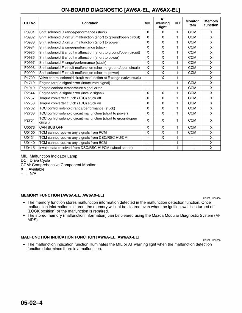
ON-BOARD DIAGNOSTIC [AW6A-EL, AW6AX-EL]
05-02–4
MIL: Malfunction Indicator LampDC: Drive CycleCCM: Comprehensive Component MonitorX : Available– : N/A
End Of Sie
MEMORY FUNCTION [AW6A-EL, AW6AX-EL]id050211100400
• The memory function stores malfunction information detected in the malfunction detection function. Once malfunction information is stored, the memory will not be cleared even when the ignition switch is turned off (LOCK position) or the malfunction is repaired.
• The stored memory (malfunction information) can be cleared using the Mazda Modular Diagnostic System (M-MDS).
End Of Sie
MALFUNCTION INDICATION FUNCTION [AW6A-EL, AW6AX-EL]id050211100500
• The malfunction indication function illuminates the MIL or AT warning light when the malfunction detection function determines there is a malfunction.
End Of Sie
P0981 Shift solenoid D range/performance (stuck) X X 1 CCM XP0982 Shift solenoid D circuit malfunction (short to ground/open circuit) X X 1 CCM XP0983 Shift solenoid D circuit malfunction (short to power) X X 1 CCM XP0984 Shift solenoid E range/performance (stuck) X X 1 CCM XP0985 Shift solenoid E circuit malfunction (short to ground/open circuit) X X 1 CCM XP0986 Shift solenoid E circuit malfunction (short to power) X X 1 CCM XP0997 Shift solenoid F range/performance (stuck) X X 1 CCM XP0998 Shift solenoid F circuit malfunction (short to ground/open circuit) X X 1 CCM XP0999 Shift solenoid F circuit malfunction (short to power) X X 1 CCM XP1700 Valve control solenoid circuit malfunction at R range (valve stuck) – X 1 – XP1719 Engine torque signal error (inaccurate signal) – – 1 CCM XP1919 Engine coolant temperature signal error – – 1 CCM XP2544 Engine torque signal error (invalid signal) X X 1 CCM XP2757 Torque converter clutch (TCC) stuck off X X 1 CCM XP2758 Torque converter clutch (TCC) stuck on X X 1 CCM XP2762 TCC control solenoid range/performance (stuck) X X 1 CCM XP2763 TCC control solenoid circuit malfunction (short to power) X X 1 CCM X
P2764 TCC control solenoid circuit malfunction (short to ground/open circuit) X X 1 CCM X
U0073 CAN BUS OFF X X 1 CCM XU0100 TCM cannot receive any signals from PCM X X 1 CCM XU0121 TCM cannot receive any signals from DSC/RSC HU/CM – X 1 – XU0140 TCM cannot receive any signals from BCM – – 1 – XU0415 Invalid data received from DSC/RSC HU/CM (wheel speed) – – 1 – X
DTC No. Condition MILAT
warning light
DC Monitor item
Memory function
3423-1U-06H(05-02).fm 4 ページ 2006年11月21日 火曜日 午後5時16分
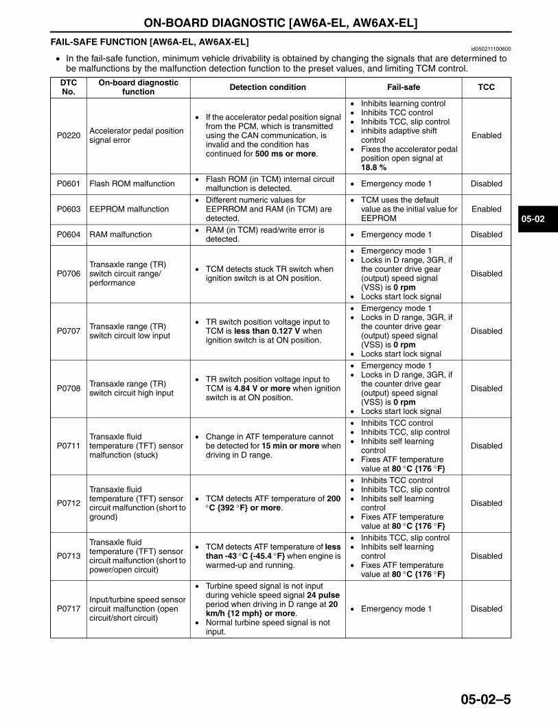
ON-BOARD DIAGNOSTIC [AW6A-EL, AW6AX-EL]
05-02–5
05-02
FAIL-SAFE FUNCTION [AW6A-EL, AW6AX-EL]id050211100600
• In the fail-safe function, minimum vehicle drivability is obtained by changing the signals that are determined to be malfunctions by the malfunction detection function to the preset values, and limiting TCM control.
DTC No.
On-board diagnostic function Detection condition Fail-safe TCC
P0220 Accelerator pedal position signal error
• If the accelerator pedal position signal from the PCM, which is transmitted using the CAN communication, is invalid and the condition has continued for 500 ms or more.
• Inhibits learning control• Inhibits TCC control• Inhibits TCC, slip control• inhibits adaptive shift
control• Fixes the accelerator pedal
position open signal at 18.8 %
Enabled
P0601 Flash ROM malfunction • Flash ROM (in TCM) internal circuit malfunction is detected. • Emergency mode 1 Disabled
P0603 EEPROM malfunction• Different numeric values for
EEPRROM and RAM (in TCM) are detected.
• TCM uses the default value as the initial value for EEPROM
Enabled
P0604 RAM malfunction • RAM (in TCM) read/write error is detected. • Emergency mode 1 Disabled
P0706Transaxle range (TR) switch circuit range/performance
• TCM detects stuck TR switch when ignition switch is at ON position.
• Emergency mode 1• Locks in D range, 3GR, if
the counter drive gear (output) speed signal (VSS) is 0 rpm
• Locks start lock signal
Disabled
P0707 Transaxle range (TR) switch circuit low input
• TR switch position voltage input to TCM is less than 0.127 V when ignition switch is at ON position.
• Emergency mode 1• Locks in D range, 3GR, if
the counter drive gear (output) speed signal (VSS) is 0 rpm
• Locks start lock signal
Disabled
P0708 Transaxle range (TR) switch circuit high input
• TR switch position voltage input to TCM is 4.84 V or more when ignition switch is at ON position.
• Emergency mode 1• Locks in D range, 3GR, if
the counter drive gear (output) speed signal (VSS) is 0 rpm
• Locks start lock signal
Disabled
P0711Transaxle fluid temperature (TFT) sensor malfunction (stuck)
• Change in ATF temperature cannot be detected for 15 min or more when driving in D range.
• Inhibits TCC control• Inhibits TCC, slip control• Inhibits self learning
control• Fixes ATF temperature
value at 80 °C {176 °F}
Disabled
P0712
Transaxle fluid temperature (TFT) sensor circuit malfunction (short to ground)
• TCM detects ATF temperature of 200 °C {392 °F} or more.
• Inhibits TCC control• Inhibits TCC, slip control• Inhibits self learning
control• Fixes ATF temperature
value at 80 °C {176 °F}
Disabled
P0713
Transaxle fluid temperature (TFT) sensor circuit malfunction (short to power/open circuit)
• TCM detects ATF temperature of less than -43 °C {-45.4 °F} when engine is warmed-up and running.
• Inhibits TCC, slip control• Inhibits self learning
control• Fixes ATF temperature
value at 80 °C {176 °F}
Disabled
P0717Input/turbine speed sensor circuit malfunction (open circuit/short circuit)
• Turbine speed signal is not input during vehicle speed signal 24 pulse period when driving in D range at 20 km/h {12 mph} or more.
• Normal turbine speed signal is not input.
• Emergency mode 1 Disabled
3423-1U-06H(05-02).fm 5 ページ 2006年11月21日 火曜日 午後5時16分
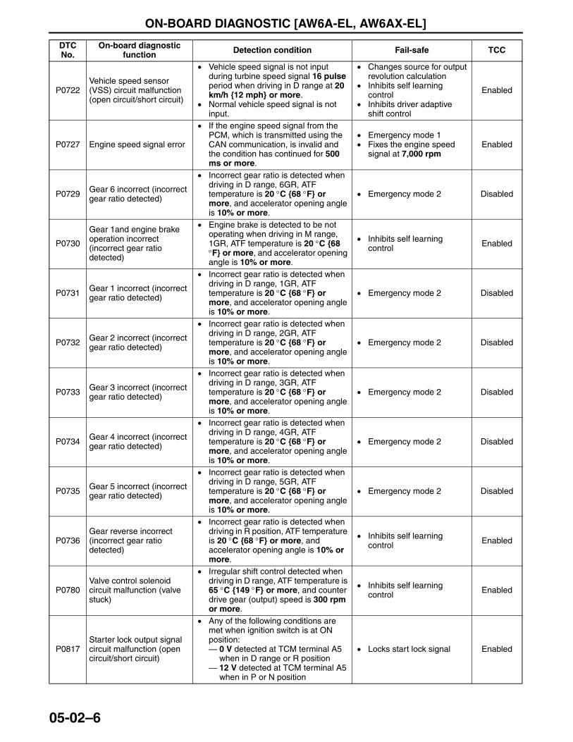
ON-BOARD DIAGNOSTIC [AW6A-EL, AW6AX-EL]
05-02–6
P0722Vehicle speed sensor (VSS) circuit malfunction (open circuit/short circuit)
• Vehicle speed signal is not input during turbine speed signal 16 pulse period when driving in D range at 20 km/h {12 mph} or more.
• Normal vehicle speed signal is not input.
• Changes source for output revolution calculation
• Inhibits self learning control
• Inhibits driver adaptive shift control
Enabled
P0727 Engine speed signal error
• If the engine speed signal from the PCM, which is transmitted using the CAN communication, is invalid and the condition has continued for 500 ms or more.
• Emergency mode 1• Fixes the engine speed
signal at 7,000 rpmEnabled
P0729 Gear 6 incorrect (incorrect gear ratio detected)
• Incorrect gear ratio is detected when driving in D range, 6GR, ATF temperature is 20 °C {68 °F} or more, and accelerator opening angle is 10% or more.
• Emergency mode 2 Disabled
P0730
Gear 1and engine brake operation incorrect (incorrect gear ratio detected)
• Engine brake is detected to be not operating when driving in M range, 1GR, ATF temperature is 20 °C {68 °F} or more, and accelerator opening angle is 10% or more.
• Inhibits self learning control Enabled
P0731 Gear 1 incorrect (incorrect gear ratio detected)
• Incorrect gear ratio is detected when driving in D range, 1GR, ATF temperature is 20 °C {68 °F} or more, and accelerator opening angle is 10% or more.
• Emergency mode 2 Disabled
P0732 Gear 2 incorrect (incorrect gear ratio detected)
• Incorrect gear ratio is detected when driving in D range, 2GR, ATF temperature is 20 °C {68 °F} or more, and accelerator opening angle is 10% or more.
• Emergency mode 2 Disabled
P0733 Gear 3 incorrect (incorrect gear ratio detected)
• Incorrect gear ratio is detected when driving in D range, 3GR, ATF temperature is 20 °C {68 °F} or more, and accelerator opening angle is 10% or more.
• Emergency mode 2 Disabled
P0734 Gear 4 incorrect (incorrect gear ratio detected)
• Incorrect gear ratio is detected when driving in D range, 4GR, ATF temperature is 20 °C {68 °F} or more, and accelerator opening angle is 10% or more.
• Emergency mode 2 Disabled
P0735 Gear 5 incorrect (incorrect gear ratio detected)
• Incorrect gear ratio is detected when driving in D range, 5GR, ATF temperature is 20 °C {68 °F} or more, and accelerator opening angle is 10% or more.
• Emergency mode 2 Disabled
P0736Gear reverse incorrect (incorrect gear ratio detected)
• Incorrect gear ratio is detected when driving in R position, ATF temperature is 20 °C {68 °F} or more, and accelerator opening angle is 10% or more.
• Inhibits self learning control Enabled
P0780Valve control solenoid circuit malfunction (valve stuck)
• Irregular shift control detected when driving in D range, ATF temperature is 65 °C {149 °F} or more, and counter drive gear (output) speed is 300 rpm or more.
• Inhibits self learning control Enabled
P0817Starter lock output signal circuit malfunction (open circuit/short circuit)
• Any of the following conditions are met when ignition switch is at ON position:— 0 V detected at TCM terminal A5
when in D range or R position— 12 V detected at TCM terminal A5
when in P or N position
• Locks start lock signal Enabled
DTC No.
On-board diagnostic function Detection condition Fail-safe TCC
3423-1U-06H(05-02).fm 6 ページ 2006年11月21日 火曜日 午後5時16分
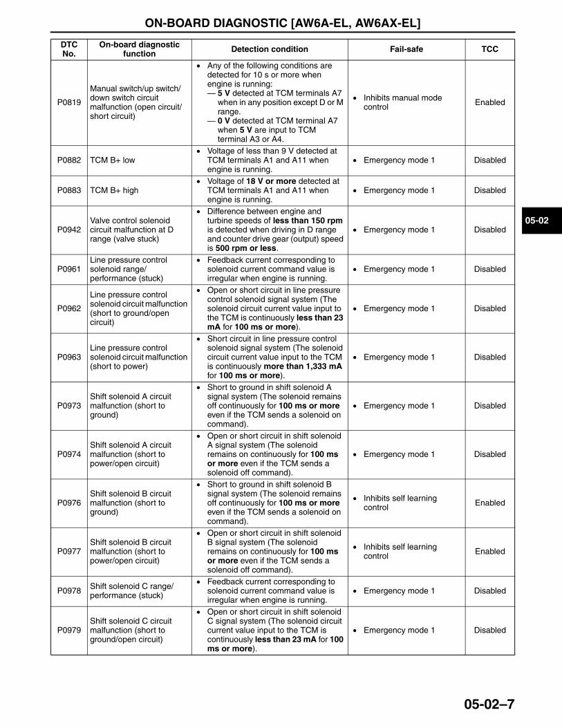
ON-BOARD DIAGNOSTIC [AW6A-EL, AW6AX-EL]
05-02–7
05-02
P0819
Manual switch/up switch/down switch circuit malfunction (open circuit/short circuit)
• Any of the following conditions are detected for 10 s or more when engine is running:— 5 V detected at TCM terminals A7
when in any position except D or M range.
— 0 V detected at TCM terminal A7 when 5 V are input to TCM terminal A3 or A4.
• Inhibits manual mode control Enabled
P0882 TCM B+ low• Voltage of less than 9 V detected at
TCM terminals A1 and A11 when engine is running.
• Emergency mode 1 Disabled
P0883 TCM B+ high• Voltage of 18 V or more detected at
TCM terminals A1 and A11 when engine is running.
• Emergency mode 1 Disabled
P0942Valve control solenoid circuit malfunction at D range (valve stuck)
• Difference between engine and turbine speeds of less than 150 rpm is detected when driving in D range and counter drive gear (output) speed is 500 rpm or less.
• Emergency mode 1 Disabled
P0961Line pressure control solenoid range/performance (stuck)
• Feedback current corresponding to solenoid current command value is irregular when engine is running.
• Emergency mode 1 Disabled
P0962
Line pressure control solenoid circuit malfunction (short to ground/open circuit)
• Open or short circuit in line pressure control solenoid signal system (The solenoid circuit current value input to the TCM is continuously less than 23 mA for 100 ms or more).
• Emergency mode 1 Disabled
P0963Line pressure control solenoid circuit malfunction (short to power)
• Short circuit in line pressure control solenoid signal system (The solenoid circuit current value input to the TCM is continuously more than 1,333 mA for 100 ms or more).
• Emergency mode 1 Disabled
P0973Shift solenoid A circuit malfunction (short to ground)
• Short to ground in shift solenoid A signal system (The solenoid remains off continuously for 100 ms or more even if the TCM sends a solenoid on command).
• Emergency mode 1 Disabled
P0974Shift solenoid A circuit malfunction (short to power/open circuit)
• Open or short circuit in shift solenoid A signal system (The solenoid remains on continuously for 100 ms or more even if the TCM sends a solenoid off command).
• Emergency mode 1 Disabled
P0976Shift solenoid B circuit malfunction (short to ground)
• Short to ground in shift solenoid B signal system (The solenoid remains off continuously for 100 ms or more even if the TCM sends a solenoid on command).
• Inhibits self learning control Enabled
P0977Shift solenoid B circuit malfunction (short to power/open circuit)
• Open or short circuit in shift solenoid B signal system (The solenoid remains on continuously for 100 ms or more even if the TCM sends a solenoid off command).
• Inhibits self learning control Enabled
P0978 Shift solenoid C range/performance (stuck)
• Feedback current corresponding to solenoid current command value is irregular when engine is running.
• Emergency mode 1 Disabled
P0979Shift solenoid C circuit malfunction (short to ground/open circuit)
• Open or short circuit in shift solenoid C signal system (The solenoid circuit current value input to the TCM is continuously less than 23 mA for 100 ms or more).
• Emergency mode 1 Disabled
DTC No.
On-board diagnostic function Detection condition Fail-safe TCC
3423-1U-06H(05-02).fm 7 ページ 2006年11月21日 火曜日 午後5時16分
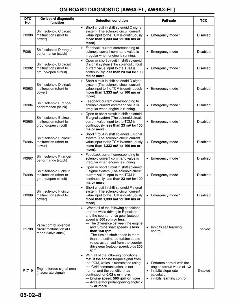
ON-BOARD DIAGNOSTIC [AW6A-EL, AW6AX-EL]
05-02–8
P0980Shift solenoid C circuit malfunction (short to power)
• Short circuit in shift solenoid C signal system (The solenoid circuit current value input to the TCM is continuously more than 1,333 mA for 100 ms or more).
• Emergency mode 1 Disabled
P0981 Shift solenoid D range/performance (stuck)
• Feedback current corresponding to solenoid current command value is irregular when engine is running.
• Emergency mode 1 Disabled
P0982Shift solenoid D circuit malfunction (short to ground/open circuit)
• Open or short circuit in shift solenoid D signal system (The solenoid circuit current value input to the TCM is continuously less than 23 mA for 100 ms or more).
• Emergency mode 1 Disabled
P0983Shift solenoid D circuit malfunction (short to power)
• Short circuit in shift solenoid D signal system (The solenoid circuit current value input to the TCM is continuously more than 1,333 mA for 100 ms or more).
• Emergency mode 1 Disabled
P0984 Shift solenoid E range/performance (stuck)
• Feedback current corresponding to solenoid current command value is irregular when engine is running.
• Emergency mode 1 Disabled
P0985Shift solenoid E circuit malfunction (short to ground/open circuit)
• Open or short circuit in shift solenoid E signal system (The solenoid circuit current value input to the TCM is continuously less than 23 mA for 100 ms or more).
• Emergency mode 1 Disabled
P0986Shift solenoid E circuit malfunction (short to power)
• Short circuit in shift solenoid E signal system (The solenoid circuit current value input to the TCM is continuously more than 1,333 mA for 100 ms or more).
• Emergency mode 1 Disabled
P0997 Shift solenoid F range/performance (stuck)
• Feedback current corresponding to solenoid current command value is irregular when engine is running.
• Emergency mode 1 Disabled
P0998Shift solenoid F circuit malfunction (short to ground/open circuit)
• Open or short circuit in shift solenoid F signal system (The solenoid circuit current value input to the TCM is continuously less than 23 mA for 100 ms or more).
• Emergency mode 1 Disabled
P0999Shift solenoid F circuit malfunction (short to power)
• Short circuit in shift solenoid F signal system (The solenoid circuit current value input to the TCM is continuously more than 1,333 mA for 100 ms or more).
• Emergency mode 1 Disabled
P1700Valve control solenoid circuit malfunction at R range (valve stuck)
• When all of the following conditions are met while driving in R position and the counter drive gear (output} speed is 500 rpm or less:— The difference between the engine
and turbine shaft speeds is less than 150 rpm
— The turbine shaft speed is more than the estimated turbine speed value, as derived from the counter drive gear (output) speed, plus 200 rpm.
• Inhibits self learning control Enabled
P1719 Engine torque signal error (inaccurate signal)
• With all of the following conditions met, if the engine torque signal from the PCM, which is transmitted using the CAN communication, is not normal and the condition has continued for 0.02 s or more.— Engine speed: 500 rpm or more— Accelerator pedal opening angle: 2
% or more
• Performs control with the engine torque value of 1.2
• inhibits slope rate calculation
• inhibits learning control
Enabled
DTC No.
On-board diagnostic function Detection condition Fail-safe TCC
3423-1U-06H(05-02).fm 8 ページ 2006年11月21日 火曜日 午後5時16分
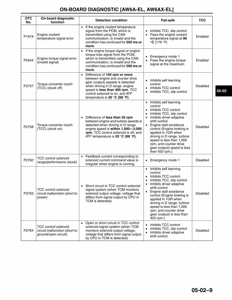
ON-BOARD DIAGNOSTIC [AW6A-EL, AW6AX-EL]
05-02–9
05-02
P1919 Engine coolant temperature signal error
• If the engine coolant temperature signal from the PCM, which is transmitted using the CAN communication, is invalid and the condition has continued for 500 ms or more.
• inhibits TCC, slip control• Fixes the engine coolant
temperature signal at 80 °C {176 °F}
Enabled
P2544 Engine torque signal error (invalid signal)
• If the engine torque signal or engine torque-loss signal from the PCM, which is transmitted using the CAN communication, is invalid and the condition has continued for 500 ms or more.
• Emergency mode 1• Fixes the engine torque
signal at the maximumEnabled
P2757 Torque converter clutch (TCC) (stuck off)
• Difference of 100 rpm or more between engine and counter drive gear (output) speeds is detected when driving in D range, engine speed is less than 400 rpm, TCC control solenoid is on, and ATF temperature is 20 °C {68 °F}.
• Inhibits self learning control
• Inhibits TCC control• Inhibits TCC, slip control
Disabled
P2758 Torque converter clutch (TCC) (stuck on)
• Difference of less than 30 rpm between engine and turbine speeds is detected when driving in D range, engine speed is within 1,000—3,000 rpm, TCC control solenoid is off, and ATF temperature is 20 °C {68 °F}.
• Inhibits self learning control
• Inhibits TCC control• Inhibits TCC, slip control• Inhibits driver adaptive
shift control• Engine stall avoidance
control (Engine braking is applied in 1GR when driving in D range, turbine speed is less than 1,000 rpm, and counter drive gear (output) speed is less than 420 rpm.)
Disabled
P2762 TCC control solenoid range/performance (stuck)
• Feedback current corresponding to solenoid current command value is irregular when engine is running.
• Emergency mode 1 Disabled
P2763TCC control solenoid circuit malfunction (short to power)
• Short circuit in TCC control solenoid signal system (when TCM monitors solenoid output voltage, voltage that differs from signal output by CPU in TCM is detected).
• Inhibits self learning control
• Inhibits TCC control• Inhibits TCC, slip control• Inhibits driver adaptive
shift control• Engine stall avoidance
control (Engine braking is applied in 1GR when driving in D range, turbine speed is less than 1,000 rpm, and counter drive gear (output) is less than 420 rpm.)
Disabled
P2764TCC control solenoid circuit malfunction (short to ground/open circuit)
• Open or short circuit in TCC control solenoid signal system (when TCM monitors solenoid output voltage, voltage that differs from signal output by CPU in TCM is detected).
• Inhibits TCC control• Inhibits TCC, slip control• Inhibits driver adaptive
shift control
Disabled
DTC No.
On-board diagnostic function Detection condition Fail-safe TCC
3423-1U-06H(05-02).fm 9 ページ 2006年11月21日 火曜日 午後5時16分
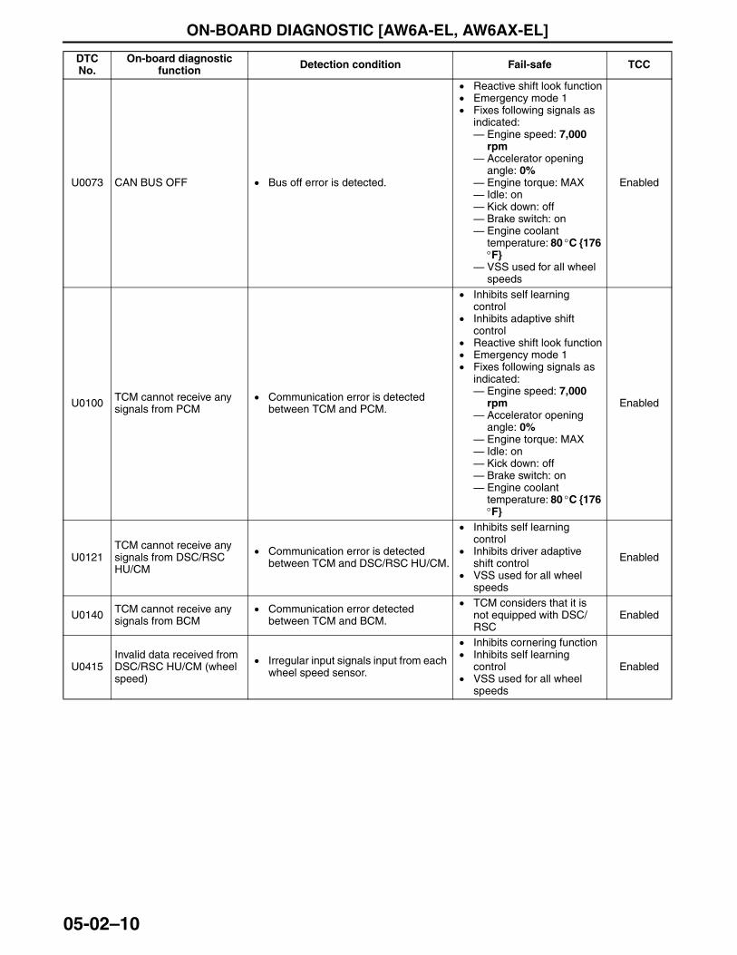
ON-BOARD DIAGNOSTIC [AW6A-EL, AW6AX-EL]
05-02–10
U0073 CAN BUS OFF • Bus off error is detected.
• Reactive shift look function• Emergency mode 1• Fixes following signals as
indicated:— Engine speed: 7,000
rpm— Accelerator opening
angle: 0%— Engine torque: MAX— Idle: on— Kick down: off— Brake switch: on— Engine coolant
temperature: 80 °C {176 °F}
— VSS used for all wheel speeds
Enabled
U0100 TCM cannot receive any signals from PCM
• Communication error is detected between TCM and PCM.
• Inhibits self learning control
• Inhibits adaptive shift control
• Reactive shift look function• Emergency mode 1• Fixes following signals as
indicated:— Engine speed: 7,000
rpm— Accelerator opening
angle: 0%— Engine torque: MAX— Idle: on— Kick down: off— Brake switch: on— Engine coolant
temperature: 80 °C {176 °F}
Enabled
U0121TCM cannot receive any signals from DSC/RSC HU/CM
• Communication error is detected between TCM and DSC/RSC HU/CM.
• Inhibits self learning control
• Inhibits driver adaptive shift control
• VSS used for all wheel speeds
Enabled
U0140 TCM cannot receive any signals from BCM
• Communication error detected between TCM and BCM.
• TCM considers that it is not equipped with DSC/RSC
Enabled
U0415Invalid data received from DSC/RSC HU/CM (wheel speed)
• Irregular input signals input from each wheel speed sensor.
• Inhibits cornering function• Inhibits self learning
control• VSS used for all wheel
speeds
Enabled
DTC No.
On-board diagnostic function Detection condition Fail-safe TCC
3423-1U-06H(05-02).fm 10 ページ 2006年11月21日 火曜日 午後5時16分
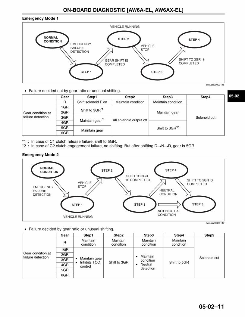
ON-BOARD DIAGNOSTIC [AW6A-EL, AW6AX-EL]
05-02–11
05-02
Emergency Mode 1
• Failure decided not by gear ratio or unusual shifting.
*1 : In case of C1 clutch release failure, shift to 5GR.*2 : In case of C2 clutch engagement failure, no shifting. But after shifting D→N→D, gear is 5GR.
Emergency Mode 2
• Failure decided by gear ratio or unusual shifting.
End Of Sie
NORMAL CONDITION
STEP 1
STEP 2
STEP 3
STEP 4EMERGENCY FAILURE DETECTION
GEAR SHIFT IS COMPLETED
VEHICLE RUNNING
VEHICLE STOP
SHIFT TO 3GR IS COMPLETED
acxuun00000146
Gear condition at failure detection
Gear Step1 Step2 Step3 Step4R Shift solenoid F on Maintain condition Maintain condition
Solenoid cut
1GRShift to 3GR*1
All solenoid output off
Maintain gear2GR3GR
Maintain gear*14GR
Shift to 3GR*25GRMaintain gear
6GR
NORMAL CONDITION
STEP 1
STEP 2
STEP 3
STEP 4
EMERGENCY FAILURE DETECTION
VEHICLE RUNNING
VEHICLE STOP
SHIFT TO 5GR IS COMPLETED
STEP 5
NOT NEUTRAL CONDITION
SHIFT TO 3GR IS COMPLETED
NEUTRAL CONDITION
acxuun00000147
Gear condition at failure detection
Gear Step1 Step2 Step3 Step4 Step5
R Maintain condition
Maintain condition
Maintain condition
Maintain condition
Solenoid cut
1GR
• Maintain gear• Inhibits TCC
controlShift to 3GR
• Maintain condition
• Neutral detection
Shift to 5GR
2GR3GR4GR5GR6GR
3423-1U-06H(05-02).fm 11 ページ 2006年11月21日 火曜日 午後5時16分
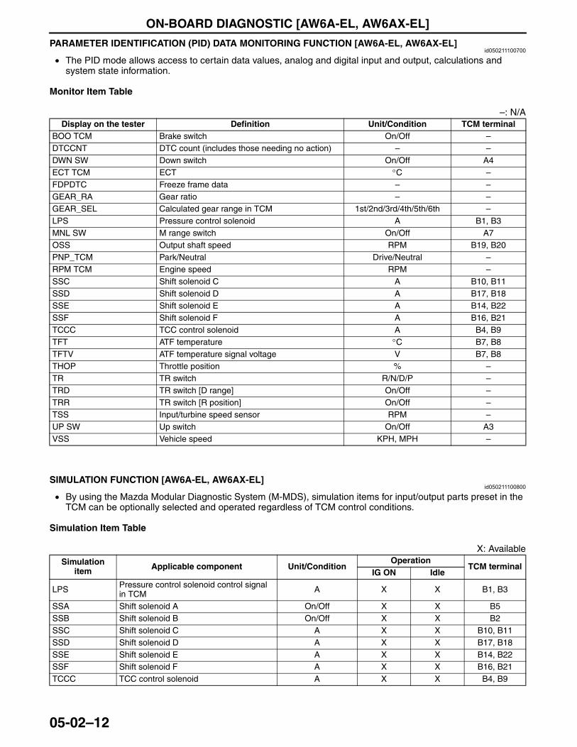
ON-BOARD DIAGNOSTIC [AW6A-EL, AW6AX-EL]
05-02–12
PARAMETER IDENTIFICATION (PID) DATA MONITORING FUNCTION [AW6A-EL, AW6AX-EL]id050211100700
• The PID mode allows access to certain data values, analog and digital input and output, calculations and system state information.
Monitor Item Table
–: N/A
End Of Sie
SIMULATION FUNCTION [AW6A-EL, AW6AX-EL]id050211100800
• By using the Mazda Modular Diagnostic System (M-MDS), simulation items for input/output parts preset in the TCM can be optionally selected and operated regardless of TCM control conditions.
Simulation Item Table
X: Available
End Of Sie
Display on the tester Definition Unit/Condition TCM terminalBOO TCM Brake switch On/Off –DTCCNT DTC count (includes those needing no action) – –DWN SW Down switch On/Off A4ECT TCM ECT °C –FDPDTC Freeze frame data – –GEAR_RA Gear ratio – –GEAR_SEL Calculated gear range in TCM 1st/2nd/3rd/4th/5th/6th –LPS Pressure control solenoid A B1, B3MNL SW M range switch On/Off A7OSS Output shaft speed RPM B19, B20PNP_TCM Park/Neutral Drive/Neutral –RPM TCM Engine speed RPM –SSC Shift solenoid C A B10, B11SSD Shift solenoid D A B17, B18SSE Shift solenoid E A B14, B22SSF Shift solenoid F A B16, B21TCCC TCC control solenoid A B4, B9TFT ATF temperature °C B7, B8TFTV ATF temperature signal voltage V B7, B8THOP Throttle position % –TR TR switch R/N/D/P –TRD TR switch [D range] On/Off –TRR TR switch [R position] On/Off –TSS Input/turbine speed sensor RPM –UP SW Up switch On/Off A3VSS Vehicle speed KPH, MPH –
Simulation item Applicable component Unit/Condition
OperationTCM terminal
IG ON Idle
LPS Pressure control solenoid control signal in TCM A X X B1, B3
SSA Shift solenoid A On/Off X X B5SSB Shift solenoid B On/Off X X B2SSC Shift solenoid C A X X B10, B11SSD Shift solenoid D A X X B17, B18SSE Shift solenoid E A X X B14, B22SSF Shift solenoid F A X X B16, B21TCCC TCC control solenoid A X X B4, B9
3423-1U-06H(05-02).fm 12 ページ 2006年11月21日 火曜日 午後5時16分
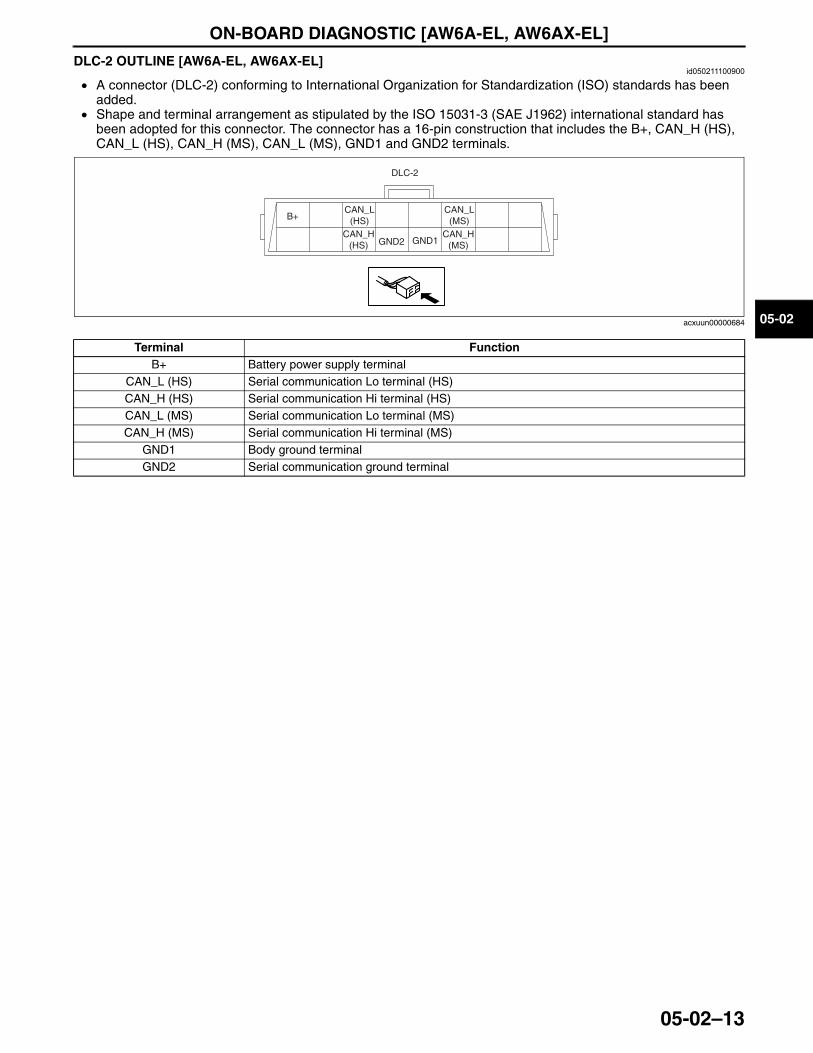
ON-BOARD DIAGNOSTIC [AW6A-EL, AW6AX-EL]
05-02–13
05-02
DLC-2 OUTLINE [AW6A-EL, AW6AX-EL]id050211100900
• A connector (DLC-2) conforming to International Organization for Standardization (ISO) standards has been added.
• Shape and terminal arrangement as stipulated by the ISO 15031-3 (SAE J1962) international standard has been adopted for this connector. The connector has a 16-pin construction that includes the B+, CAN_H (HS), CAN_L (HS), CAN_H (MS), CAN_L (MS), GND1 and GND2 terminals.
End Of Sie
Terminal FunctionB+ Battery power supply terminal
CAN_L (HS) Serial communication Lo terminal (HS)CAN_H (HS) Serial communication Hi terminal (HS)CAN_L (MS) Serial communication Lo terminal (MS)CAN_H (MS) Serial communication Hi terminal (MS)
GND1 Body ground terminalGND2 Serial communication ground terminal
CAN_L (HS)
CAN_H (HS)
CAN_L (MS)
CAN_H (MS)GND2 GND1
B+
DLC-2
acxuun00000684
3423-1U-06H(05-02).fm 13 ページ 2006年11月21日 火曜日 午後5時16分

AUTOMATIC TRANSAXLE [AW6A-EL, AW6AX-EL]
05-17–1
05-17
05-17 AUTOMATIC TRANSAXLE [AW6A-EL, AW6AX-EL]AUTOMATIC TRANSAXLE
OUTLINE [AW6A-EL, AW6AX-EL] . . . . 05-17–2AUTOMATIC TRANSAXLE
FEATURES [AW6A-EL, AW6AX-EL] . . . . . . . . . . . . 05-17–2
Torque Converter Clutch (TCC) Control and Slip Control . . . . . . . . . . . 05-17–2
Self Learning Control . . . . . . . . . . . . . . 05-17–2Manual Mode Shift Control . . . . . . . . . 05-17–2
AUTOMATIC TRANSAXLE CROSS-SECTIONAL VIEW [AW6A-EL, AW6AX-EL] . . . . . . . . . . . . 05-17–3
AUTOMATIC TRANSAXLE CONTROL SYSTEM WIRING DIAGRAM [AW6A-EL, AW6AX-EL] . . . . . . . . . . . . 05-17–4
EC-AT OPERATION CHART [AW6A-EL, AW6AX-EL] . . . . . . . . . . . . 05-17–5
POWERFLOW STRUCTURE [AW6A-EL, AW6AX-EL] . . . . . . . . . . . . 05-17–6
Description of Components . . . . . . . . . 05-17–6POWERFLOW OPERATION
[AW6A-EL, AW6AX-EL] . . . . . . . . . . . . 05-17–81GR (D range) . . . . . . . . . . . . . . . . . . . 05-17–81GR (M range) . . . . . . . . . . . . . . . . . . . 05-17–102GR . . . . . . . . . . . . . . . . . . . . . . . . . . . 05-17–113GR . . . . . . . . . . . . . . . . . . . . . . . . . . . 05-17–124GR . . . . . . . . . . . . . . . . . . . . . . . . . . . 05-17–135GR . . . . . . . . . . . . . . . . . . . . . . . . . . . 05-17–146GR . . . . . . . . . . . . . . . . . . . . . . . . . . . 05-17–15R position . . . . . . . . . . . . . . . . . . . . . . . 05-17–16
CENTRIFUGAL HYDRAULIC PRESSURE CANCEL CLUTCH OUTLINE [AW6A-EL, AW6AX-EL] . . . . 05-17–18
TORQUE CONVERTER OUTLINE [AW6A-EL, AW6AX-EL] . . . . 05-17–20
CONTROL VALVE BODY COMPONENT OUTLINE [AW6A-EL, AW6AX-EL] . . . . . . . . . . . . 05-17–21
ELECTRONIC CONTROL SYSTEM CONSTRUCTION [AW6A-EL, AW6AX-EL] . . . . . . . . . . . . 05-17–22
ELECTRONIC CONTROL SYSTEM BLOCK DIAGRAM [AW6A-EL, AW6AX-EL] . . . . . . . . . . . . 05-17–23
ELECTRONIC CONTROL ITEMS AND CONTENTS [AW6A-EL, AW6AX-EL] . . . . . . . . . . . . 05-17–23
COMPONENT DESCRIPTIONS (ELECTRONIC CONTROL) [AW6A-EL, AW6AX-EL] . . . . . . . . . . . . 05-17–24
INPUT/OUTPUT SIGNAL AND RELATED CONTROLS [AW6A-EL, AW6AX-EL] . . . . . . . . . . . . 05-17–25
TRANSAXLE RANGE (TR) SWITCH OUTLINE [AW6A-EL, AW6AX-EL] . . . . . . . . . . . . 05-17–25
TRANSAXLE RANGE (TR) SWITCH OPERATION [AW6A-EL, AW6AX-EL] . . . . . . . . . . . . 05-17–26
TCM OUTLINE [AW6A-EL, AW6AX-EL] . . . . . . . . . . . . . 05-17–27
TCM Terminals . . . . . . . . . . . . . . . . . . . 05-17–27COUPLER COMPONENT
(TRANSAXLE FLUID TEMPERATURE (TFT) SENSOR) OUTLINE [AW6A-EL, AW6AX-EL] . . . . . . . . . . . . . 05-17–28
SHIFT SOLENOID A, B OUTLINE [AW6A-EL, AW6AX-EL] . . . . . . . . . . . . . 05-17–29
SHIFT CONTROL SOLENOID COMPONENT OUTLINE [AW6A-EL, AW6AX-EL] . . . . . . . . . . . . . 05-17–30
LINE PRESSURE CONTROL SOLENOID OUTLINE [AW6A-EL, AW6AX-EL] . . . . . . . . . . . . . 05-17–31
TORQUE CONVERTER CLUTCH (TCC) CONTROL SOLENOID OUTLINE [AW6A-EL, AW6AX-EL] . . . . . . . . . . . . . 05-17–32
INPUT/TURBINE SPEED SENSOR, VEHICLE SPEED SENSOR (VSS) OUTLINE [AW6A-EL, AW6AX-EL] . . . . 05-17–33
AUTOMATIC GEAR SHIFT CONTROL OUTLINE [AW6A-EL, AW6AX-EL] . . . . 05-17–33
DRIVER ADAPTIVE SHIFT CONTROL OUTLINE [AW6A-EL, AW6AX-EL] . . . . . . . . . . . . . 05-17–34
Active Adaptive Shift (AAS) Mode . . . . . 05-17–34MANUAL MODE SHIFT
CONTROL OUTLINE [AW6A-EL, AW6AX-EL] . . . . . . . . . . . . . 05-17–35
MANUAL MODE SHIFT CONTROL OPERATION [AW6A-EL, AW6AX-EL] . . . . . . . . . . . . . 05-17–36
Manual Mode Shift . . . . . . . . . . . . . . . . 05-17–36Shift Diagram . . . . . . . . . . . . . . . . . . . . 05-17–37
AT WARNING LIGHT FUNCTION [AW6A-EL, AW6AX-EL] . . . . . . . . . . . . . 05-17–37
AT WARNING LIGHT CONSTRUCTION/OPERATION [AW6A-EL, AW6AX-EL] . . . . . . . . . . . . . 05-17–38
SELECTOR INDICATOR LIGHT FUNCTION [AW6A-EL, AW6AX-EL] . . . . . . . . . . . . . 05-17–38
SELECTOR INDICATOR LIGHT CONSTRUCTION/OPERATION [AW6A-EL, AW6AX-EL] . . . . . . . . . . . . . 05-17–39
Construction . . . . . . . . . . . . . . . . . . . . . 05-17–39Operation . . . . . . . . . . . . . . . . . . . . . . . 05-17–39
TCC, SLIP CONTROL OUTLINE [AW6A-EL, AW6AX-EL] . . . . . . . . . . . . . 05-17–40
ENGINE-TRANSAXLE TOTAL CONTROL OPERATION [AW6A-EL, AW6AX-EL] . . . . . . . . . . . . . 05-17–41
GARAGE SHIFT CONTROL OUTLINE [AW6A-EL, AW6AX-EL] . . . . 05-17–42
REVERSE CONTROL OUTLINE [AW6A-EL, AW6AX-EL] . . . . . . . . . . . . . 05-17–42
SELF-DIAGNOSIS FUNCTION OUTLINE [AW6A-EL, AW6AX-EL] . . . . 05-17–42
FAIL-SAFE OUTLINE [AW6A-EL, AW6AX-EL] . . . . . . . . . . . . . 05-17–42
3423-1U-06H(05-17).fm 1 ページ 2006年11月21日 火曜日 午後5時17分
AUTOMATIC TRANSAXLE [AW6A-EL, AW6AX-EL]
05-17–2
N POSITION LEARNING FUNCTION [AW6A-EL, AW6AX-EL] . . . . . . . . . . . . . 05-17–42
COOLING SYSTEM OUTLINE [AW6A-EL, AW6AX-EL] . . . . . . . . . . . . 05-17–43
End of TocNG: AUTOMATIC TRANSAXLEAUTOMATIC TRANSAXLE OUTLINE [AW6A-EL, AW6AX-EL]
id051723101700
• The AW6A (X) -EL automatic transaxle is a compact, lightweight, next-generation electronically controlled FF 6-speed automatic transaxle that employs a Ravigneaux-type planetary gear. It employs a high-precision clutch hydraulic control system for smooth, highly responsive gear shift feel.
End Of Sie
AUTOMATIC TRANSAXLE FEATURES [AW6A-EL, AW6AX-EL]id051723101800
Torque Converter Clutch (TCC) Control and Slip Control• Based on output speed signals, signals from the PCM (engine speed and throttle opening) and vehicle speed,
smooth TCC control is performed. Also, the slip rate is detected by adding input speed signals, and slip control is performed.
Self Learning Control• Since TCM performs shift control learning and garage shift control learning, it provides smooth clutch
engagement at gear shifting and smooth and delicate shifting while driving.
Manual Mode Shift Control• By moving the selector lever from the “D range” into the manual shift position and shifting into + (up-shift) or –
(down-shift), the driver can select the desired gear, enabling sporty driving that feels like a manual transaxle.End Of Sie
3423-1U-06H(05-17).fm 2 ページ 2006年11月21日 火曜日 午後5時17分
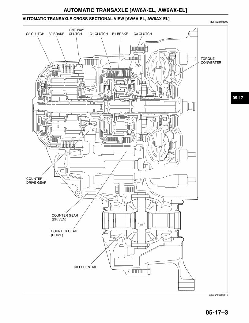
AUTOMATIC TRANSAXLE [AW6A-EL, AW6AX-EL]
05-17–3
05-17
AUTOMATIC TRANSAXLE CROSS-SECTIONAL VIEW [AW6A-EL, AW6AX-EL]id051723101900
End Of Sie
C2 CLUTCH C1 CLUTCH C3 CLUTCHB2 BRAKE B1 BRAKEONE-WAYCLUTCH
COUNTERDRIVE GEAR
COUNTER GEAR (DRIVEN)
DIFFERENTIAL
TORQUECONVERTER
COUNTER GEAR (DRIVE)
acxuun00000612
3423-1U-06H(05-17).fm 3 ページ 2006年11月21日 火曜日 午後5時17分
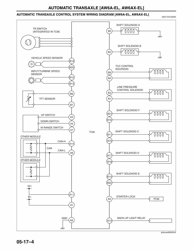
AUTOMATIC TRANSAXLE [AW6A-EL, AW6AX-EL]
05-17–4
AUTOMATIC TRANSAXLE CONTROL SYSTEM WIRING DIAGRAM [AW6A-EL, AW6AX-EL]id051723102000
TR SWITCH (INTEGRATED IN TCM)
VEHICLE SPEED SENSOR
SHIFT SOLENOID A
TCC CONTROL SOLENOID
LINE PRESSURE CONTROL SOLENOID
PCM
BACK-UP LIGHT RELAY
INPUT/TURBINE SPEED SENSOR
CAN
TFT SENSOR
M RANGE SWITCH
B20
B12
B13
B8
B2
B9
B4
B3
B1
B21
B16
B11
B10
B17
B18
B14
B22
B5
B7
A3
A4
A7
A6
A14
A1
A5
A13A9
A11
TCM
CAN-H
CAN-L
GND
B19
UP SWITCH
DOWN SWITCH
OTHER MODULE
OTHER MODULE
IG1
B+
SHIFT SOLENOID C
SHIFT SOLENOID E
STARTER LOCK
SHIFT SOLENOID B
SHIFT SOLENOID D
SHIFT SOLENOID F
ac9uuw00002243
3423-1U-06H(05-17).fm 4 ページ 2006年11月21日 火曜日 午後5時17分
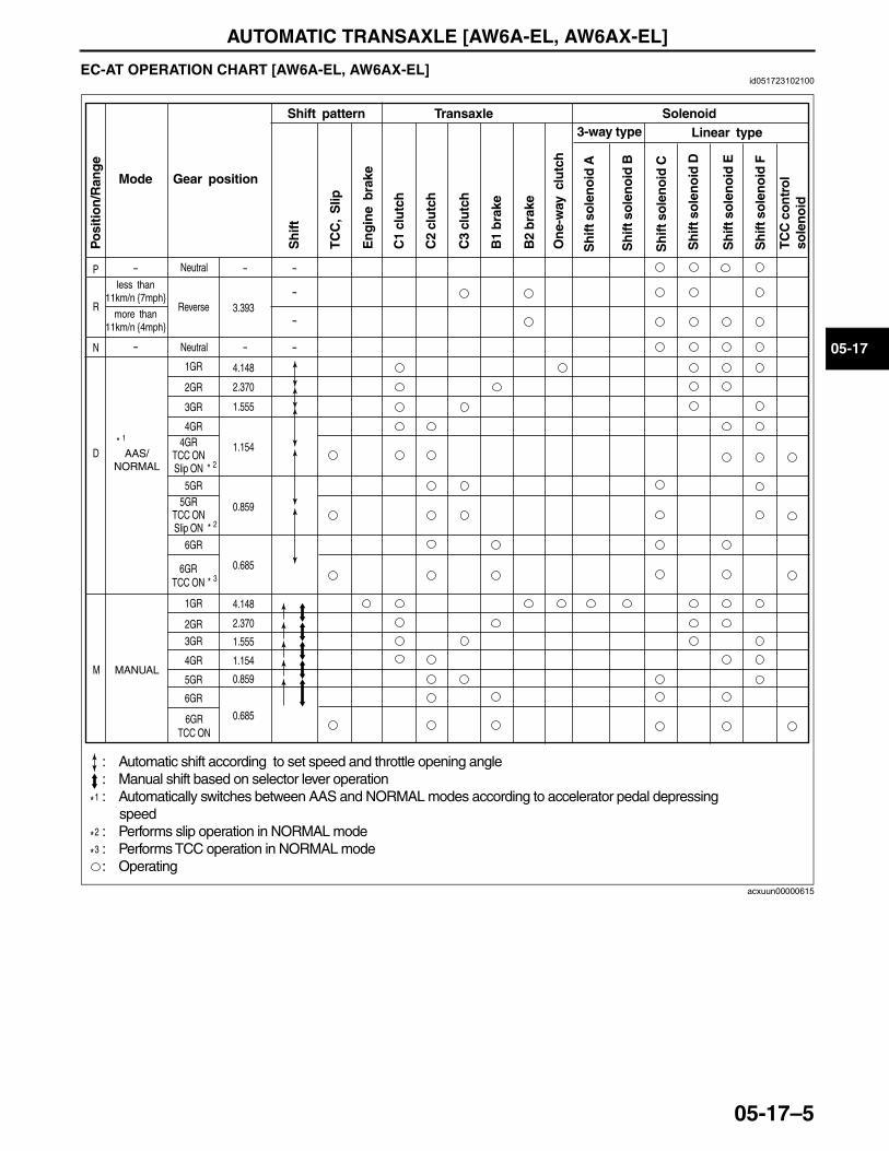
AUTOMATIC TRANSAXLE [AW6A-EL, AW6AX-EL]
05-17–5
05-17
End Of SieEC-AT OPERATION CHART [AW6A-EL, AW6AX-EL]id051723102100
End Of Sie
Mode
Neutral
Neutral
3.393
4.148
2.370
1.555
1.154
4.148
2.370
1.555
1.154
0.859
0.685
0.859
0.685
1GR
2GR
3GR
4GR
1GR
2GR
3GR
4GR
5GR
Reverse
Gear position
Shift pattern Transaxle Solenoid3-way type
Po
sitio
n/R
ang
e
Sh
ift
TC
C,
Slip
En
gin
e b
rake
On
e-w
ay c
lutc
h
C1
clu
tch
C2
clu
tch
C3
clu
tch
Sh
ift s
ole
no
id A
B1
bra
ke
B2
bra
ke
P
R
N
-
-
-
-
-
-
-
-
D1*AAS/
NORMAL
4GR TCC ON Slip ON
5GR TCC ON Slip ON
less than 11km/n {7mph}
more than 11km/n {4mph}
6GR
6GR TCC ON
5GR
6GR
6GR TCC ON
Linear type
1*
2*3*
: Automatic shift according to set speed and throttle opening angle: Manual shift based on selector lever operation: Automatically switches between AAS and NORMAL modes according to accelerator pedal depressing speed: Performs slip operation in NORMAL mode: Performs TCC operation in NORMAL mode: Operating
TC
C c
on
tro
l so
len
oid
M MANUAL
Sh
ift s
ole
no
id F
Sh
ift s
ole
no
id E
Sh
ift s
ole
no
id D
Sh
ift s
ole
no
id C
Sh
ift s
ole
no
id B
2*
2*
3*
acxuun00000615
3423-1U-06H(05-17).fm 5 ページ 2006年11月21日 火曜日 午後5時17分
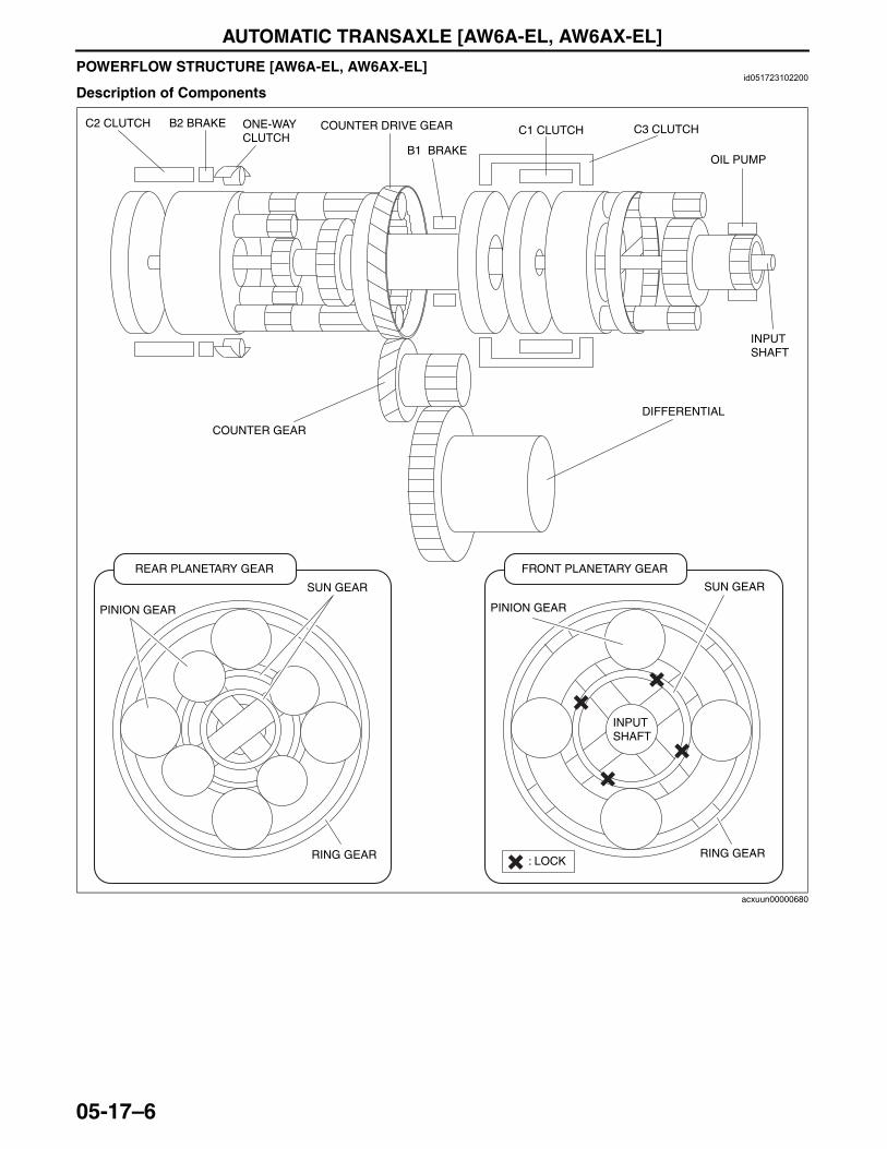
AUTOMATIC TRANSAXLE [AW6A-EL, AW6AX-EL]
05-17–6
POWERFLOW STRUCTURE [AW6A-EL, AW6AX-EL]id051723102200
Description of Components
PINION GEAR
REAR PLANETARY GEAR
SUN GEAR
RING GEAR
PINION GEAR
FRONT PLANETARY GEAR
SUN GEAR
RING GEAR: LOCK
COUNTER GEAR
DIFFERENTIAL
INPUTSHAFT
OIL PUMP
C3 CLUTCHC1 CLUTCH
B1 BRAKE
COUNTER DRIVE GEARC2 CLUTCH B2 BRAKE ONE-WAY CLUTCH
INPUTSHAFT
acxuun00000680
3423-1U-06H(05-17).fm 6 ページ 2006年11月21日 火曜日 午後5時17分
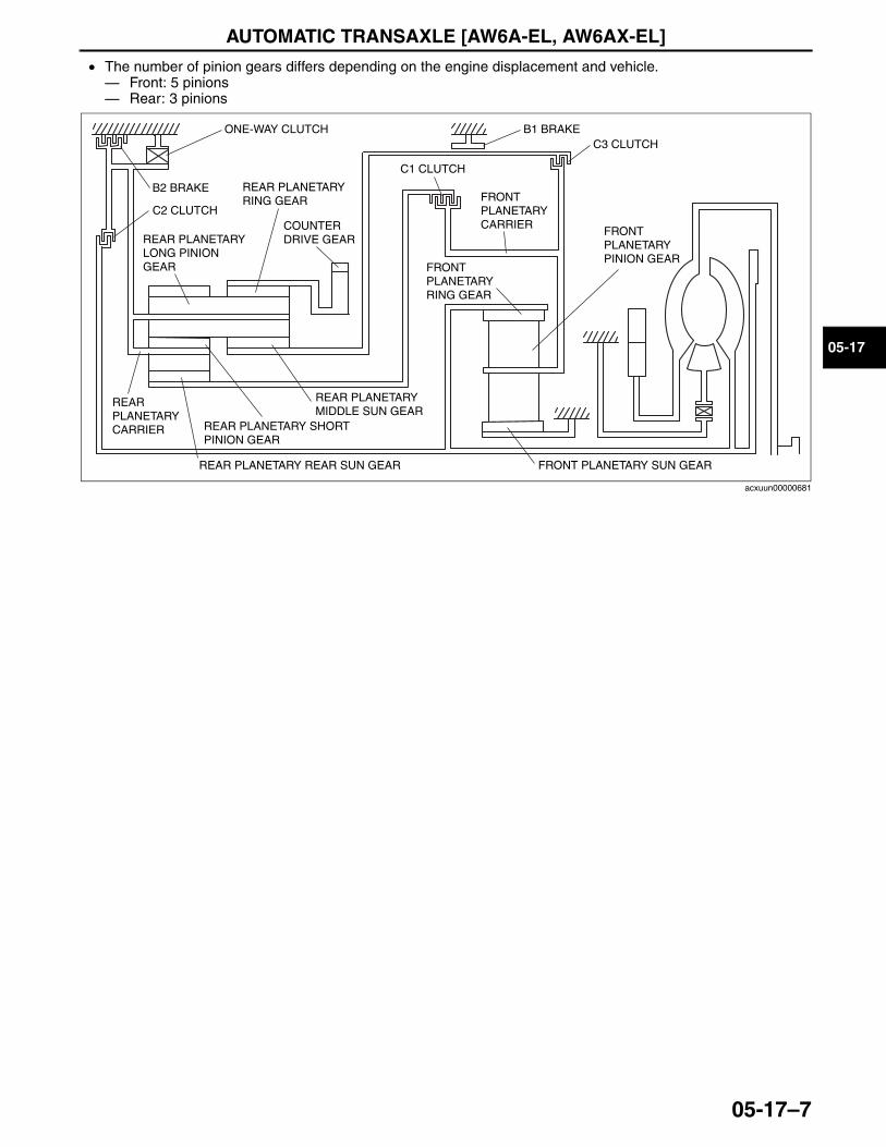
AUTOMATIC TRANSAXLE [AW6A-EL, AW6AX-EL]
05-17–7
05-17
• The number of pinion gears differs depending on the engine displacement and vehicle.— Front: 5 pinions— Rear: 3 pinions
End Of Sie
C1 CLUTCH
ONE-WAY CLUTCH
FRONT PLANETARY PINION GEAR
REAR PLANETARY RING GEAR
FRONT PLANETARY RING GEAR
FRONT PLANETARY CARRIER
C3 CLUTCHB1 BRAKE
FRONT PLANETARY SUN GEAR
B2 BRAKE
REAR PLANETARY LONG PINION GEAR
C2 CLUTCH
REAR PLANETARY MIDDLE SUN GEAR
REAR PLANETARY CARRIER REAR PLANETARY SHORT
PINION GEAR
REAR PLANETARY REAR SUN GEAR
COUNTER DRIVE GEAR
acxuun00000681
3423-1U-06H(05-17).fm 7 ページ 2006年11月21日 火曜日 午後5時17分
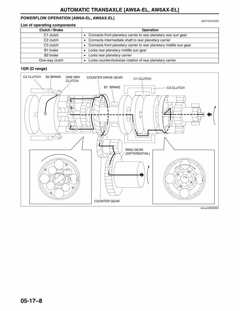
AUTOMATIC TRANSAXLE [AW6A-EL, AW6AX-EL]
05-17–8
POWERFLOW OPERATION [AW6A-EL, AW6AX-EL]id051723102300
List of operating components
1GR (D range)
Clutch / Brake OperationC1 clutch • Connects front planetary carrier to rear planetary rear sun gearC2 clutch • Connects intermediate shaft to rear planetary carrierC3 clutch • Connects front planetary carrier to rear planetary middle sun gearB1 brake • Locks rear planetary middle sun gearB2 brake • Locks rear planetary carrier
One-way clutch • Locks counterclockwise rotation of rear planetary carrier
C3 CLUTCH
C1 CLUTCH
B1 BRAKE
C2 CLUTCH B2 BRAKE ONE-WAY CLUTCH
COUNTER GEAR
RING GEAR (DIFFERENTIAL)
COUNTER DRIVE GEAR
acxuun00000620
3423-1U-06H(05-17).fm 8 ページ 2006年11月21日 火曜日 午後5時17分
AUTOMATIC TRANSAXLE [AW6A-EL, AW6AX-EL]
05-17–9
05-17
Power transmission pathway
[Operating components: C1 clutch, One-way clutch]• Operating components:
C1 clutch, One-way clutch (counterclockwise rotation is locked), B2 brake (ON when engine brake is operating)
1. Input shaft (rotates clockwise) [same revolutions as the torque converter’s turbine runner]2. Front planetary ring gear (rotates clockwise) [same revolutions as the input shaft]3. Front planetary pinion gear (rotates clockwise on its axis, orbits clockwise)
[because the front planetary sun gear is locked by the oil pump, it is pressed against the front planetary ring gear and orbits the sun gear while rotating on its axis (because the front planetary ring gear has internal gears, the rotational direction does not change)]
4. Front planetary carrier (rotates clockwise)[reduction: same revolution as the front planetary pinion gear orbit revolution]
5. C1 clutch (rotates clockwise) [connects the front planetary carrier and the rear planetary rear sun gear]6. Rear planetary rear sun gear (rotates clockwise) [same revolution as the front planetary carrier]7. Rear planetary short pinion gear (rotates counterclockwise on its axis)
[the rear planetary carrier tries to rotate counterclockwise, but the counterclockwise rotation is locked by one-way clutch.]
8. Rear planetary long pinion gear (rotates clockwise on its axis)[the rear planetary middle sun gear rotates counterclockwise (idling)]
9. Rear planetary ring gear (rotates clockwise)[the rear planetary ring gear is rotated by the rear planetary long pinion gear (because the rear planetary ring gear has internal gears, the rotational direction does not change)]
10. Counter drive gear (rotates clockwise)[because the rear planetary ring gear is installed on the counter drive gear, the rotational direction and the revolution are the same as the rear planetary ring gear]
11. Counter gear (rotates counterclockwise)12. Differential ring gear (rotates clockwise)
Planetary gear unit Input, Locked, Output
FrontInput: Ring gear
Locked: Sun gearOutput: Carrier
RearInput: Rear sun gear
Locked: CarrierOutput: Ring gear
3423-1U-06H(05-17).fm 9 ページ 2006年11月21日 火曜日 午後5時17分
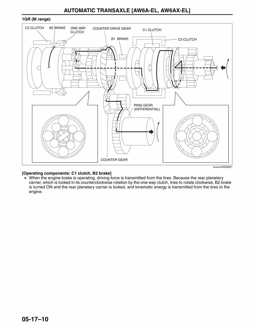
AUTOMATIC TRANSAXLE [AW6A-EL, AW6AX-EL]
05-17–10
1GR (M range)
[Operating components: C1 clutch, B2 brake]• When the engine brake is operating, driving force is transmitted from the tires. Because the rear planetary
carrier, which is locked in its counterclockwise rotation by the one-way clutch, tries to rotate clockwise, B2 brake is turned ON and the rear planetary carrier is locked, and kinematic energy is transmitted from the tires to the engine.
C3 CLUTCH
C1 CLUTCH
B1 BRAKE
C2 CLUTCH B2 BRAKE ONE-WAY CLUTCH
COUNTER GEAR
RING GEAR (DIFFERENTIAL)
COUNTER DRIVE GEAR
acxuun00000621
3423-1U-06H(05-17).fm 10 ページ 2006年11月21日 火曜日 午後5時17分
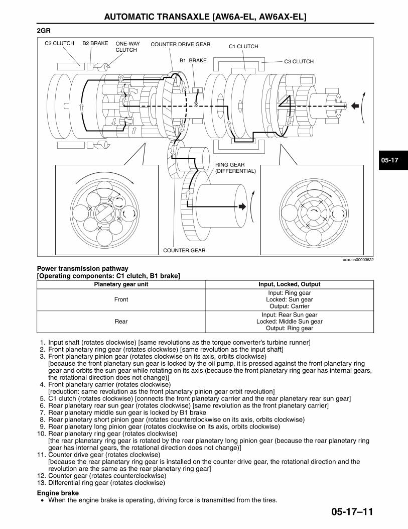
AUTOMATIC TRANSAXLE [AW6A-EL, AW6AX-EL]
05-17–11
05-17
2GR
Power transmission pathway[Operating components: C1 clutch, B1 brake]
1. Input shaft (rotates clockwise) [same revolutions as the torque converter’s turbine runner]2. Front planetary ring gear (rotates clockwise) [same revolution as the input shaft]3. Front planetary pinion gear (rotates clockwise on its axis, orbits clockwise)
[because the front planetary sun gear is locked by the oil pump, it is pressed against the front planetary ring gear and orbits the sun gear while rotating on its axis (because the front planetary ring gear has internal gears, the rotational direction does not change)]
4. Front planetary carrier (rotates clockwise)[reduction: same revolution as the front planetary pinion gear orbit revolution]
5. C1 clutch (rotates clockwise) [connects the front planetary carrier and the rear planetary rear sun gear]6. Rear planetary rear sun gear (rotates clockwise) [same revolution as the front planetary carrier]7. Rear planetary middle sun gear is locked by B1 brake8. Rear planetary short pinion gear (rotates counterclockwise on its axis, orbits clockwise)9. Rear planetary long pinion gear (rotates clockwise on its axis, orbits clockwise)
10. Rear planetary ring gear (rotates clockwise)[the rear planetary ring gear is rotated by the rear planetary long pinion gear (because the rear planetary ring gear has internal gears, the rotational direction does not change)]
11. Counter drive gear (rotates clockwise)[because the rear planetary ring gear is installed on the counter drive gear, the rotational direction and the revolution are the same as the rear planetary ring gear]
12. Counter gear (rotates counterclockwise)13. Differential ring gear (rotates clockwise)
Engine brake• When the engine brake is operating, driving force is transmitted from the tires.
Planetary gear unit Input, Locked, Output
FrontInput: Ring gear
Locked: Sun gearOutput: Carrier
RearInput: Rear Sun gear
Locked: Middle Sun gearOutput: Ring gear
C3 CLUTCH
C1 CLUTCH
B1 BRAKE
C2 CLUTCH B2 BRAKE ONE-WAY CLUTCH
COUNTER GEAR
RING GEAR (DIFFERENTIAL)
COUNTER DRIVE GEAR
acxuun00000622
3423-1U-06H(05-17).fm 11 ページ 2006年11月21日 火曜日 午後5時17分
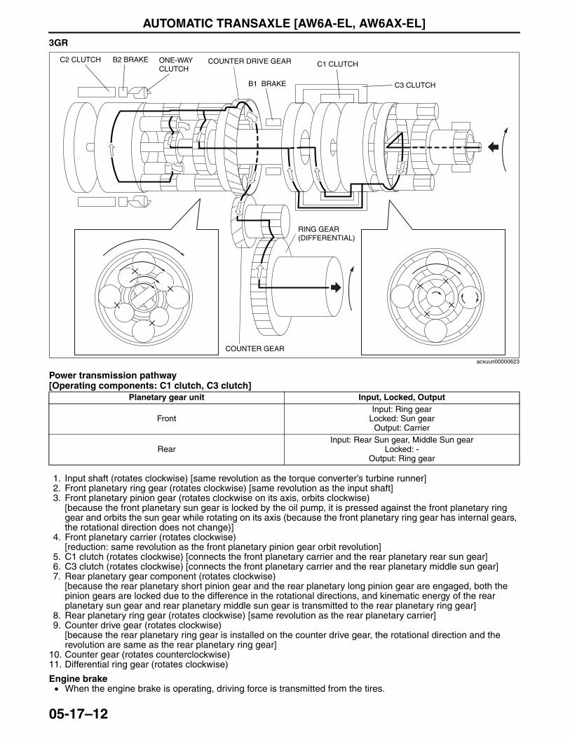
AUTOMATIC TRANSAXLE [AW6A-EL, AW6AX-EL]
05-17–12
3GR
Power transmission pathway[Operating components: C1 clutch, C3 clutch]
1. Input shaft (rotates clockwise) [same revolution as the torque converter’s turbine runner]2. Front planetary ring gear (rotates clockwise) [same revolution as the input shaft]3. Front planetary pinion gear (rotates clockwise on its axis, orbits clockwise)
[because the front planetary sun gear is locked by the oil pump, it is pressed against the front planetary ring gear and orbits the sun gear while rotating on its axis (because the front planetary ring gear has internal gears, the rotational direction does not change)]
4. Front planetary carrier (rotates clockwise)[reduction: same revolution as the front planetary pinion gear orbit revolution]
5. C1 clutch (rotates clockwise) [connects the front planetary carrier and the rear planetary rear sun gear]6. C3 clutch (rotates clockwise) [connects the front planetary carrier and the rear planetary middle sun gear]7. Rear planetary gear component (rotates clockwise)
[because the rear planetary short pinion gear and the rear planetary long pinion gear are engaged, both the pinion gears are locked due to the difference in the rotational directions, and kinematic energy of the rear planetary sun gear and rear planetary middle sun gear is transmitted to the rear planetary ring gear]
8. Rear planetary ring gear (rotates clockwise) [same revolution as the rear planetary carrier]9. Counter drive gear (rotates clockwise)
[because the rear planetary ring gear is installed on the counter drive gear, the rotational direction and the revolution are same as the rear planetary ring gear]
10. Counter gear (rotates counterclockwise)11. Differential ring gear (rotates clockwise)
Engine brake• When the engine brake is operating, driving force is transmitted from the tires.
Planetary gear unit Input, Locked, Output
FrontInput: Ring gear
Locked: Sun gearOutput: Carrier
RearInput: Rear Sun gear, Middle Sun gear
Locked: -Output: Ring gear
C3 CLUTCH
C1 CLUTCH
B1 BRAKE
C2 CLUTCH B2 BRAKE ONE-WAY CLUTCH
COUNTER GEAR
RING GEAR (DIFFERENTIAL)
COUNTER DRIVE GEAR
acxuun00000623
3423-1U-06H(05-17).fm 12 ページ 2006年11月21日 火曜日 午後5時17分
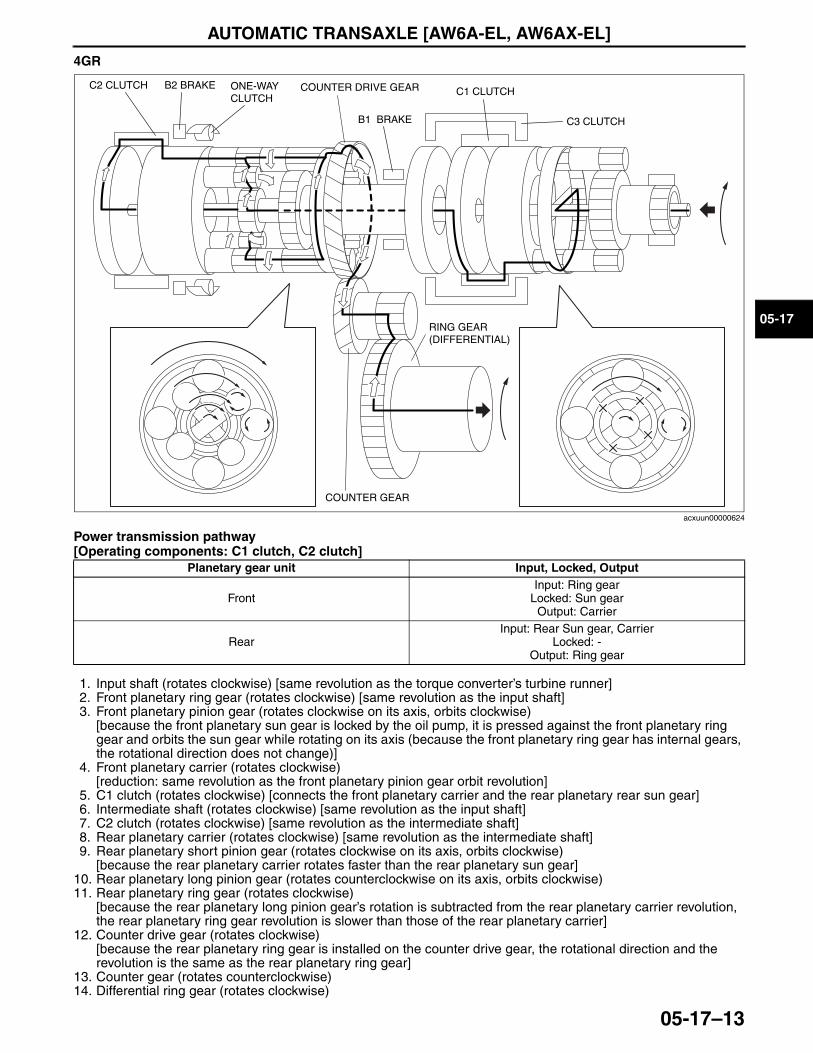
AUTOMATIC TRANSAXLE [AW6A-EL, AW6AX-EL]
05-17–13
05-17
4GR
Power transmission pathway[Operating components: C1 clutch, C2 clutch]
1. Input shaft (rotates clockwise) [same revolution as the torque converter’s turbine runner]2. Front planetary ring gear (rotates clockwise) [same revolution as the input shaft]3. Front planetary pinion gear (rotates clockwise on its axis, orbits clockwise)
[because the front planetary sun gear is locked by the oil pump, it is pressed against the front planetary ring gear and orbits the sun gear while rotating on its axis (because the front planetary ring gear has internal gears, the rotational direction does not change)]
4. Front planetary carrier (rotates clockwise)[reduction: same revolution as the front planetary pinion gear orbit revolution]
5. C1 clutch (rotates clockwise) [connects the front planetary carrier and the rear planetary rear sun gear]6. Intermediate shaft (rotates clockwise) [same revolution as the input shaft]7. C2 clutch (rotates clockwise) [same revolution as the intermediate shaft]8. Rear planetary carrier (rotates clockwise) [same revolution as the intermediate shaft]9. Rear planetary short pinion gear (rotates clockwise on its axis, orbits clockwise)
[because the rear planetary carrier rotates faster than the rear planetary sun gear]10. Rear planetary long pinion gear (rotates counterclockwise on its axis, orbits clockwise)11. Rear planetary ring gear (rotates clockwise)
[because the rear planetary long pinion gear’s rotation is subtracted from the rear planetary carrier revolution, the rear planetary ring gear revolution is slower than those of the rear planetary carrier]
12. Counter drive gear (rotates clockwise)[because the rear planetary ring gear is installed on the counter drive gear, the rotational direction and the revolution is the same as the rear planetary ring gear]
13. Counter gear (rotates counterclockwise)14. Differential ring gear (rotates clockwise)
Planetary gear unit Input, Locked, Output
FrontInput: Ring gear
Locked: Sun gearOutput: Carrier
RearInput: Rear Sun gear, Carrier
Locked: -Output: Ring gear
C3 CLUTCH
C1 CLUTCH
B1 BRAKE
C2 CLUTCH B2 BRAKE ONE-WAY CLUTCH
COUNTER GEAR
RING GEAR (DIFFERENTIAL)
COUNTER DRIVE GEAR
acxuun00000624
3423-1U-06H(05-17).fm 13 ページ 2006年11月21日 火曜日 午後5時17分
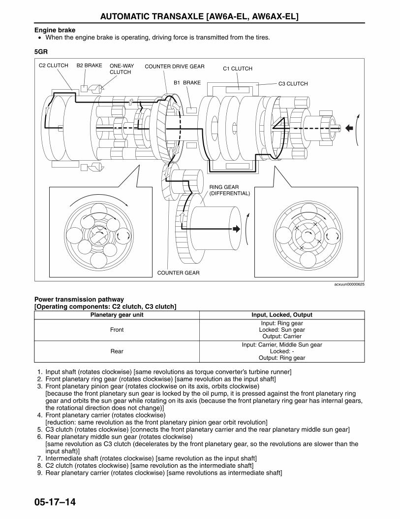
AUTOMATIC TRANSAXLE [AW6A-EL, AW6AX-EL]
05-17–14
Engine brake• When the engine brake is operating, driving force is transmitted from the tires.
5GR
Power transmission pathway[Operating components: C2 clutch, C3 clutch]
1. Input shaft (rotates clockwise) [same revolutions as torque converter’s turbine runner]2. Front planetary ring gear (rotates clockwise) [same revolution as the input shaft]3. Front planetary pinion gear (rotates clockwise on its axis, orbits clockwise)
[because the front planetary sun gear is locked by the oil pump, it is pressed against the front planetary ring gear and orbits the sun gear while rotating on its axis (because the front planetary ring gear has internal gears, the rotational direction does not change)]
4. Front planetary carrier (rotates clockwise)[reduction: same revolution as the front planetary pinion gear orbit revolution]
5. C3 clutch (rotates clockwise) [connects the front planetary carrier and the rear planetary middle sun gear]6. Rear planetary middle sun gear (rotates clockwise)
[same revolution as C3 clutch (decelerates by the front planetary gear, so the revolutions are slower than the input shaft)]
7. Intermediate shaft (rotates clockwise) [same revolution as the input shaft]8. C2 clutch (rotates clockwise) [same revolution as the intermediate shaft]9. Rear planetary carrier (rotates clockwise) [same revolutions as intermediate shaft]
Planetary gear unit Input, Locked, Output
FrontInput: Ring gear
Locked: Sun gearOutput: Carrier
RearInput: Carrier, Middle Sun gear
Locked: -Output: Ring gear
C3 CLUTCH
C1 CLUTCH
B1 BRAKE
C2 CLUTCH B2 BRAKE ONE-WAY CLUTCH
COUNTER GEAR
RING GEAR (DIFFERENTIAL)
COUNTER DRIVE GEAR
acxuun00000625
3423-1U-06H(05-17).fm 14 ページ 2006年11月21日 火曜日 午後5時17分
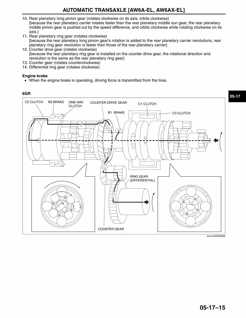
AUTOMATIC TRANSAXLE [AW6A-EL, AW6AX-EL]
05-17–15
05-17
10. Rear planetary long pinion gear (rotates clockwise on its axis, orbits clockwise)[because the rear planetary carrier rotates faster than the rear planetary middle sun gear, the rear planetary middle pinion gear is pushed out by the speed difference, and orbits clockwise while rotating clockwise on its axis.]
11. Rear planetary ring gear (rotates clockwise)[because the rear planetary long pinion gear’s rotation is added to the rear planetary carrier revolutions, rear planetary ring gear revolution is faster than those of the rear planetary carrier]
12. Counter drive gear (rotates clockwise)[because the rear planetary ring gear is installed on the counter drive gear, the rotational direction and revolution is the same as the rear planetary ring gear]
13. Counter gear (rotates counterclockwise)14. Differential ring gear (rotates clockwise)
Engine brake• When the engine brake is operating, driving force is transmitted from the tires.
6GR
C3 CLUTCH
C1 CLUTCH
B1 BRAKE
C2 CLUTCH B2 BRAKE ONE-WAY CLUTCH
COUNTER GEAR
RING GEAR (DIFFERENTIAL)
COUNTER DRIVE GEAR
acxuun00000626
3423-1U-06H(05-17).fm 15 ページ 2006年11月21日 火曜日 午後5時17分
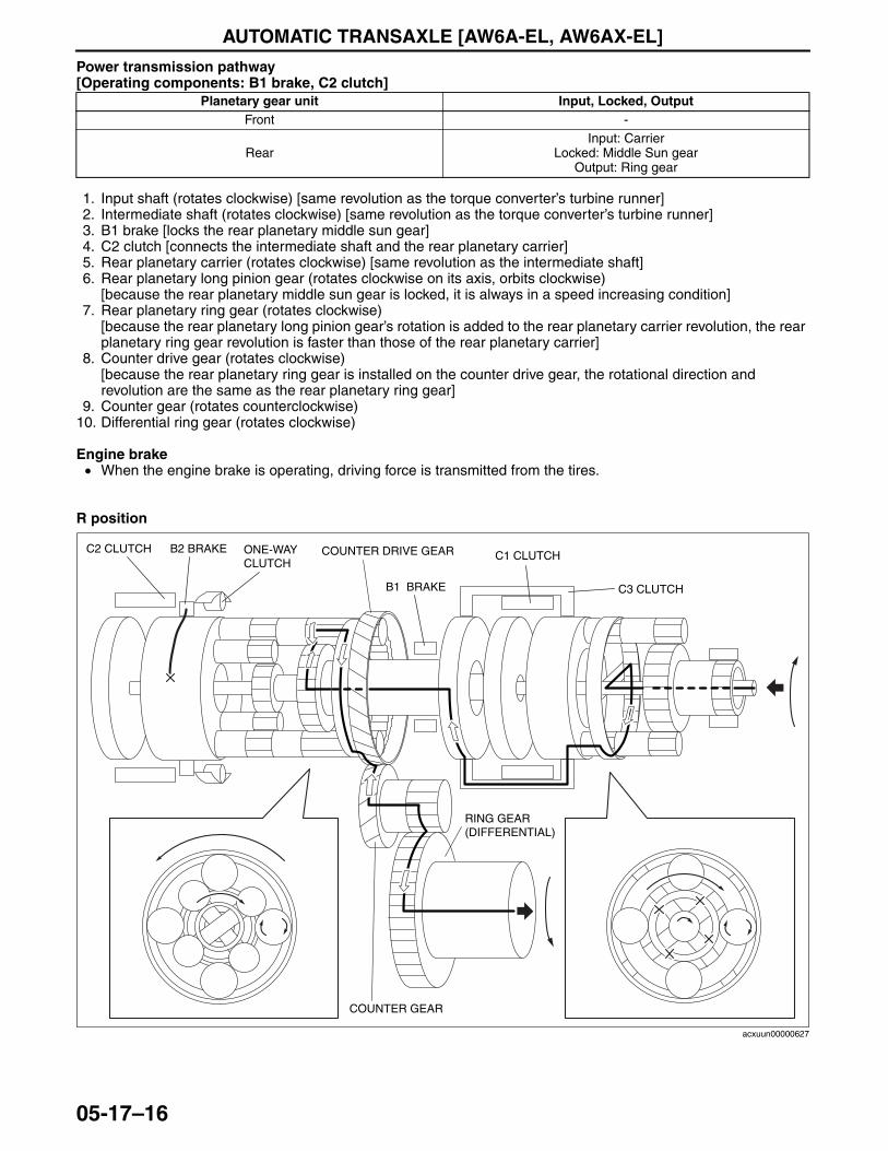
AUTOMATIC TRANSAXLE [AW6A-EL, AW6AX-EL]
05-17–16
Power transmission pathway[Operating components: B1 brake, C2 clutch]
1. Input shaft (rotates clockwise) [same revolution as the torque converter’s turbine runner]2. Intermediate shaft (rotates clockwise) [same revolution as the torque converter’s turbine runner]3. B1 brake [locks the rear planetary middle sun gear]4. C2 clutch [connects the intermediate shaft and the rear planetary carrier]5. Rear planetary carrier (rotates clockwise) [same revolution as the intermediate shaft]6. Rear planetary long pinion gear (rotates clockwise on its axis, orbits clockwise)
[because the rear planetary middle sun gear is locked, it is always in a speed increasing condition]7. Rear planetary ring gear (rotates clockwise)
[because the rear planetary long pinion gear’s rotation is added to the rear planetary carrier revolution, the rear planetary ring gear revolution is faster than those of the rear planetary carrier]
8. Counter drive gear (rotates clockwise)[because the rear planetary ring gear is installed on the counter drive gear, the rotational direction and revolution are the same as the rear planetary ring gear]
9. Counter gear (rotates counterclockwise)10. Differential ring gear (rotates clockwise)
Engine brake• When the engine brake is operating, driving force is transmitted from the tires.
R position
Planetary gear unit Input, Locked, OutputFront -
RearInput: Carrier
Locked: Middle Sun gearOutput: Ring gear
C3 CLUTCH
C1 CLUTCH
B1 BRAKE
C2 CLUTCH B2 BRAKE ONE-WAY CLUTCH
COUNTER GEAR
RING GEAR (DIFFERENTIAL)
COUNTER DRIVE GEAR
acxuun00000627
3423-1U-06H(05-17).fm 16 ページ 2006年11月21日 火曜日 午後5時17分
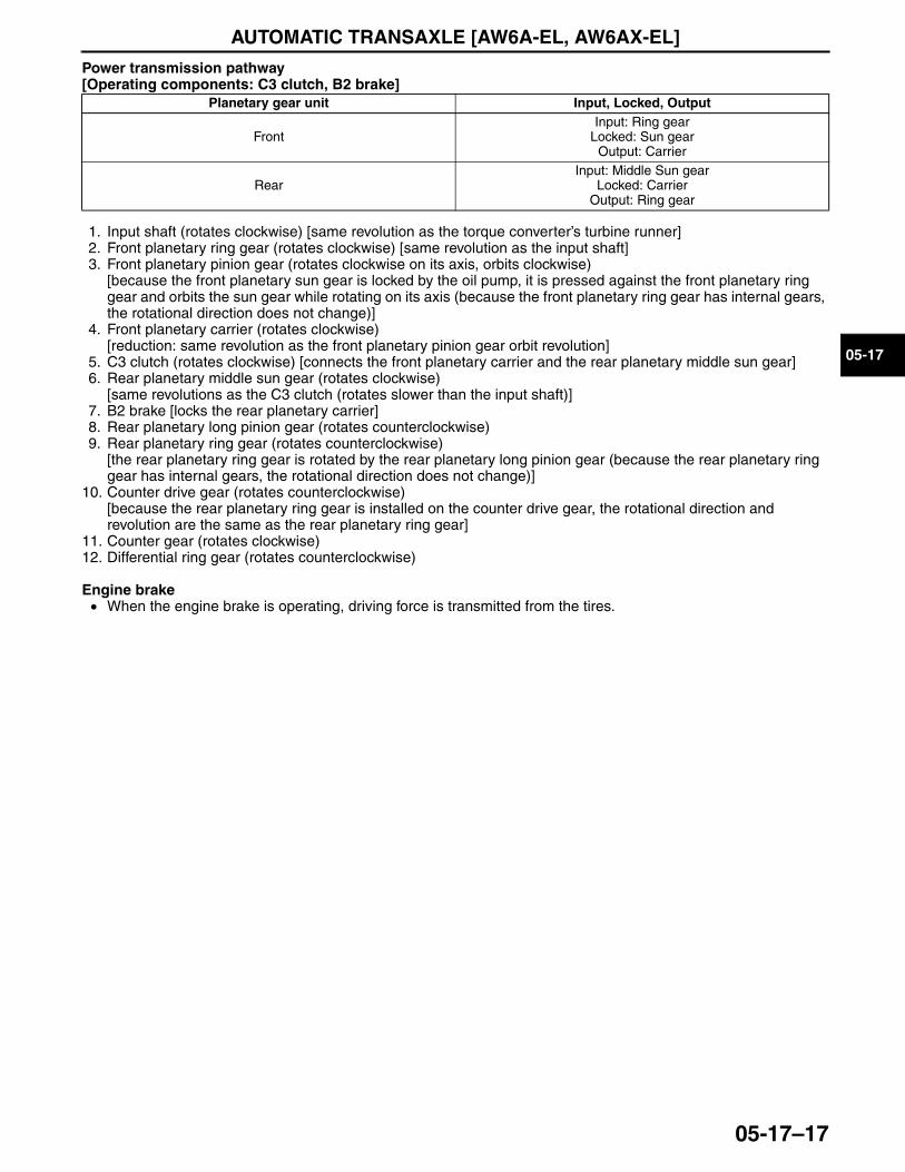
AUTOMATIC TRANSAXLE [AW6A-EL, AW6AX-EL]
05-17–17
05-17
Power transmission pathway[Operating components: C3 clutch, B2 brake]
1. Input shaft (rotates clockwise) [same revolution as the torque converter’s turbine runner]2. Front planetary ring gear (rotates clockwise) [same revolution as the input shaft]3. Front planetary pinion gear (rotates clockwise on its axis, orbits clockwise)
[because the front planetary sun gear is locked by the oil pump, it is pressed against the front planetary ring gear and orbits the sun gear while rotating on its axis (because the front planetary ring gear has internal gears, the rotational direction does not change)]
4. Front planetary carrier (rotates clockwise)[reduction: same revolution as the front planetary pinion gear orbit revolution]
5. C3 clutch (rotates clockwise) [connects the front planetary carrier and the rear planetary middle sun gear]6. Rear planetary middle sun gear (rotates clockwise)
[same revolutions as the C3 clutch (rotates slower than the input shaft)]7. B2 brake [locks the rear planetary carrier]8. Rear planetary long pinion gear (rotates counterclockwise)9. Rear planetary ring gear (rotates counterclockwise)
[the rear planetary ring gear is rotated by the rear planetary long pinion gear (because the rear planetary ring gear has internal gears, the rotational direction does not change)]
10. Counter drive gear (rotates counterclockwise)[because the rear planetary ring gear is installed on the counter drive gear, the rotational direction and revolution are the same as the rear planetary ring gear]
11. Counter gear (rotates clockwise)12. Differential ring gear (rotates counterclockwise)
Engine brake• When the engine brake is operating, driving force is transmitted from the tires.
End Of Sie
Planetary gear unit Input, Locked, Output
FrontInput: Ring gear
Locked: Sun gearOutput: Carrier
RearInput: Middle Sun gear
Locked: CarrierOutput: Ring gear
3423-1U-06H(05-17).fm 17 ページ 2006年11月21日 火曜日 午後5時17分
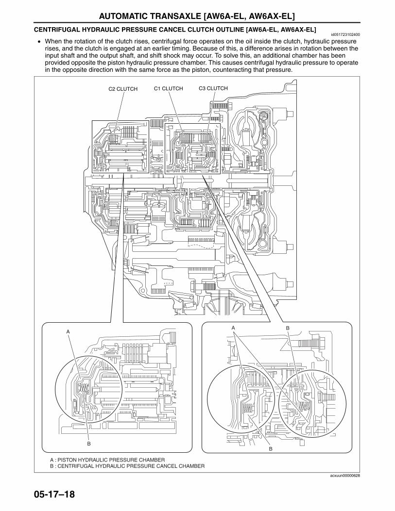
AUTOMATIC TRANSAXLE [AW6A-EL, AW6AX-EL]
05-17–18
CENTRIFUGAL HYDRAULIC PRESSURE CANCEL CLUTCH OUTLINE [AW6A-EL, AW6AX-EL]id051723102400
• When the rotation of the clutch rises, centrifugal force operates on the oil inside the clutch, hydraulic pressure rises, and the clutch is engaged at an earlier timing. Because of this, a difference arises in rotation between the input shaft and the output shaft, and shift shock may occur. To solve this, an additional chamber has been provided opposite the piston hydraulic pressure chamber. This causes centrifugal hydraulic pressure to operate in the opposite direction with the same force as the piston, counteracting that pressure.
A : PISTON HYDRAULIC PRESSURE CHAMBERB : CENTRIFUGAL HYDRAULIC PRESSURE CANCEL CHAMBER
B
A
B
A B
C2 CLUTCH C1 CLUTCH C3 CLUTCH
acxuun00000628
3423-1U-06H(05-17).fm 18 ページ 2006年11月21日 火曜日 午後5時17分
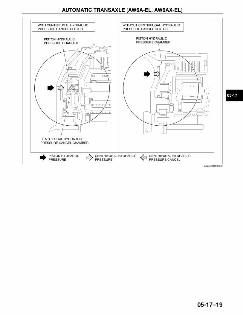
AUTOMATIC TRANSAXLE [AW6A-EL, AW6AX-EL]
05-17–19
05-17
End Of SieNG: TORQUE CONVERTER
WITHOUT CENTRIFUGAL HYDRAULICPRESSURE CANCEL CLUTCH
WITH CENTRIFUGAL HYDRAULICPRESSURE CANCEL CLUTCH
PISTON HYDRAULICPRESSURE CHAMBER
CENTRIFUGAL HYDRAULICPRESSURE CANCEL CHAMBER
PISTON HYDRAULICPRESSURE CHAMBER
CENTRIFUGAL HYDRAULICPRESSURE CANCEL
CENTRIFUGAL HYDRAULICPRESSURE
PISTON HYDRAULICPRESSURE
acxuun00000629
3423-1U-06H(05-17).fm 19 ページ 2006年11月21日 火曜日 午後5時17分
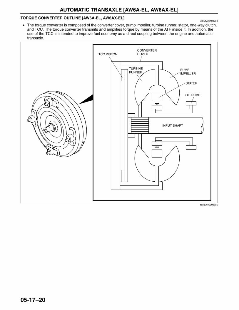
AUTOMATIC TRANSAXLE [AW6A-EL, AW6AX-EL]
05-17–20
TORQUE CONVERTER OUTLINE [AW6A-EL, AW6AX-EL]id051723100700
• The torque converter is composed of the converter cover, pump impeller, turbine runner, stator, one-way clutch, and TCC. The torque converter transmits and amplifies torque by means of the ATF inside it. In addition, the use of the TCC is intended to improve fuel economy as a direct coupling between the engine and automatic transaxle.
End Of SieNG: CONTROL VALVE BODY
CONVERTER COVER
PUMP IMPELLER
STATER
OIL PUMP
INPUT SHAFT
TCC PISTON
TURBINE RUNNER
acxuun00000605
3423-1U-06H(05-17).fm 20 ページ 2006年11月21日 火曜日 午後5時17分
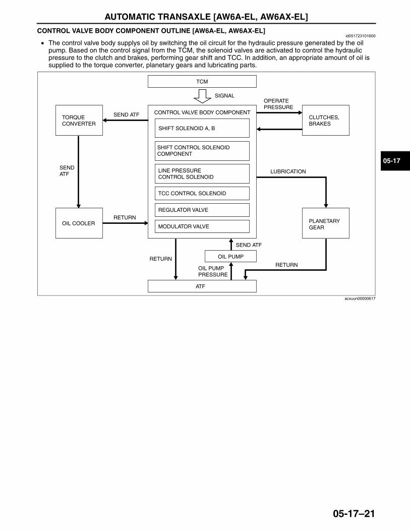
AUTOMATIC TRANSAXLE [AW6A-EL, AW6AX-EL]
05-17–21
05-17
CONTROL VALVE BODY COMPONENT OUTLINE [AW6A-EL, AW6AX-EL]id051723101600
• The control valve body supplys oil by switching the oil circuit for the hydraulic pressure generated by the oil pump. Based on the control signal from the TCM, the solenoid valves are activated to control the hydraulic pressure to the clutch and brakes, performing gear shift and TCC. In addition, an appropriate amount of oil is supplied to the torque converter, planetary gears and lubricating parts.
End Of SieNG: TCM
TCM
CONTROL VALVE BODY COMPONENT
ATF
SIGNAL
OIL PUMPRETURN
SEND ATF
SEND ATF
OIL PUMP PRESSURE
SHIFT SOLENOID A, B
CLUTCHES, BRAKES
OPERATE PRESSURE
TORQUE CONVERTER
SEND ATF
OIL COOLERRETURN
LUBRICATION
RETURN
PLANETARY GEAR
LINE PRESSURE CONTROL SOLENOID
TCC CONTROL SOLENOID
REGULATOR VALVE
MODULATOR VALVE
SHIFT CONTROL SOLENOID COMPONENT
acxuun00000617
3423-1U-06H(05-17).fm 21 ページ 2006年11月21日 火曜日 午後5時17分
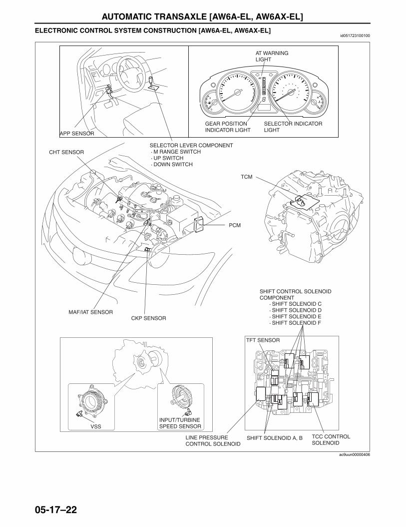
AUTOMATIC TRANSAXLE [AW6A-EL, AW6AX-EL]
05-17–22
ELECTRONIC CONTROL SYSTEM CONSTRUCTION [AW6A-EL, AW6AX-EL]id051723100100
End Of Sie
PCM
MAF/IAT SENSORCKP SENSOR
APP SENSOR
TFT SENSOR
TCC CONTROL SOLENOID
SHIFT SOLENOID A, BLINE PRESSURE CONTROL SOLENOID
SHIFT CONTROL SOLENOID COMPONENT
INPUT/TURBINE SPEED SENSORVSS
· SHIFT SOLENOID C· SHIFT SOLENOID D · SHIFT SOLENOID E · SHIFT SOLENOID F
TCM
SELECTOR LEVER COMPONENT · M RANGE SWITCH · UP SWITCH · DOWN SWITCH
GEAR POSITION INDICATOR LIGHT
AT WARNING LIGHT
SELECTOR INDICATOR LIGHT
CHT SENSOR
ac9uun00000406
3423-1U-06H(05-17).fm 22 ページ 2006年11月21日 火曜日 午後5時17分
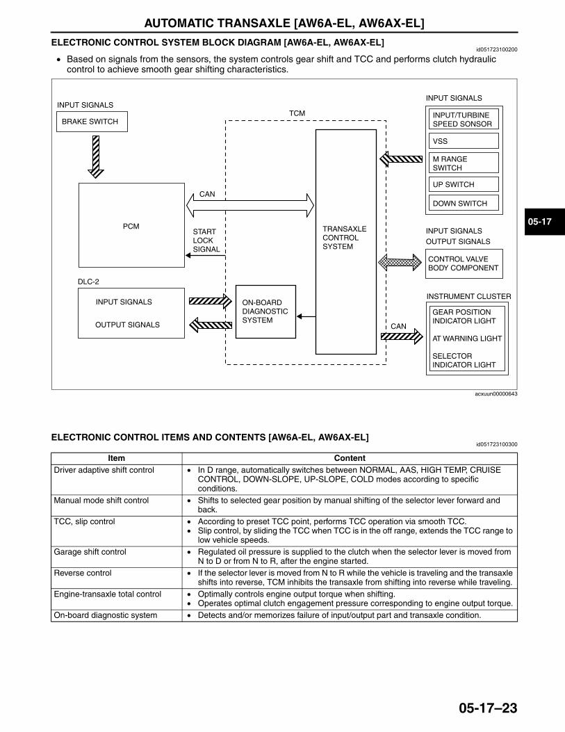
AUTOMATIC TRANSAXLE [AW6A-EL, AW6AX-EL]
05-17–23
05-17
ELECTRONIC CONTROL SYSTEM BLOCK DIAGRAM [AW6A-EL, AW6AX-EL]id051723100200
• Based on signals from the sensors, the system controls gear shift and TCC and performs clutch hydraulic control to achieve smooth gear shifting characteristics.
End Of Sie
ELECTRONIC CONTROL ITEMS AND CONTENTS [AW6A-EL, AW6AX-EL]id051723100300
End Of Sie
TCM
PCM
CAN
TRANSAXLE CONTROL SYSTEM
INPUT/TURBINE SPEED SONSOR
VSS
INPUT SIGNALS
CONTROL VALVE BODY COMPONENT
INPUT SIGNALSOUTPUT SIGNALS
GEAR POSITION INDICATOR LIGHT
AT WARNING LIGHT
SELECTOR INDICATOR LIGHT
INSTRUMENT CLUSTER
BRAKE SWITCH
INPUT SIGNALS
UP SWITCH
DOWN SWITCH
M RANGE SWITCH
ON-BOARD DIAGNOSTIC SYSTEM
START LOCK SIGNAL
INPUT SIGNALS
DLC-2
OUTPUT SIGNALS CAN
acxuun00000643
Item ContentDriver adaptive shift control • In D range, automatically switches between NORMAL, AAS, HIGH TEMP, CRUISE
CONTROL, DOWN-SLOPE, UP-SLOPE, COLD modes according to specific conditions.
Manual mode shift control • Shifts to selected gear position by manual shifting of the selector lever forward and back.
TCC, slip control • According to preset TCC point, performs TCC operation via smooth TCC.• Slip control, by sliding the TCC when TCC is in the off range, extends the TCC range to
low vehicle speeds.Garage shift control • Regulated oil pressure is supplied to the clutch when the selector lever is moved from
N to D or from N to R, after the engine started.Reverse control • If the selector lever is moved from N to R while the vehicle is traveling and the transaxle
shifts into reverse, TCM inhibits the transaxle from shifting into reverse while traveling.Engine-transaxle total control • Optimally controls engine output torque when shifting.
• Operates optimal clutch engagement pressure corresponding to engine output torque.On-board diagnostic system • Detects and/or memorizes failure of input/output part and transaxle condition.
3423-1U-06H(05-17).fm 23 ページ 2006年11月21日 火曜日 午後5時17分
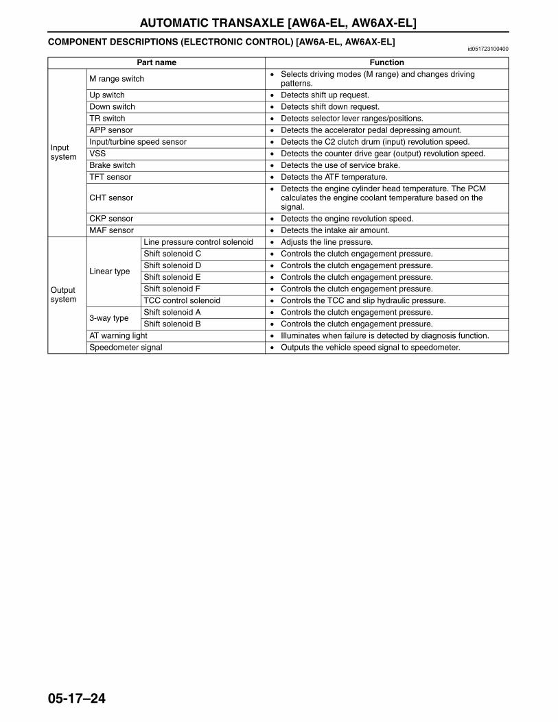
AUTOMATIC TRANSAXLE [AW6A-EL, AW6AX-EL]
05-17–24
COMPONENT DESCRIPTIONS (ELECTRONIC CONTROL) [AW6A-EL, AW6AX-EL]id051723100400
End Of Sie
Part name Function
Input system
M range switch • Selects driving modes (M range) and changes driving patterns.
Up switch • Detects shift up request.Down switch • Detects shift down request.TR switch • Detects selector lever ranges/positions.APP sensor • Detects the accelerator pedal depressing amount.Input/turbine speed sensor • Detects the C2 clutch drum (input) revolution speed.VSS • Detects the counter drive gear (output) revolution speed.Brake switch • Detects the use of service brake.TFT sensor • Detects the ATF temperature.
CHT sensor• Detects the engine cylinder head temperature. The PCM
calculates the engine coolant temperature based on the signal.
CKP sensor • Detects the engine revolution speed.MAF sensor • Detects the intake air amount.
Output system
Linear type
Line pressure control solenoid • Adjusts the line pressure.Shift solenoid C • Controls the clutch engagement pressure.Shift solenoid D • Controls the clutch engagement pressure.Shift solenoid E • Controls the clutch engagement pressure.Shift solenoid F • Controls the clutch engagement pressure.TCC control solenoid • Controls the TCC and slip hydraulic pressure.
3-way typeShift solenoid A • Controls the clutch engagement pressure.Shift solenoid B • Controls the clutch engagement pressure.
AT warning light • Illuminates when failure is detected by diagnosis function.Speedometer signal • Outputs the vehicle speed signal to speedometer.
3423-1U-06H(05-17).fm 24 ページ 2006年11月21日 火曜日 午後5時17分
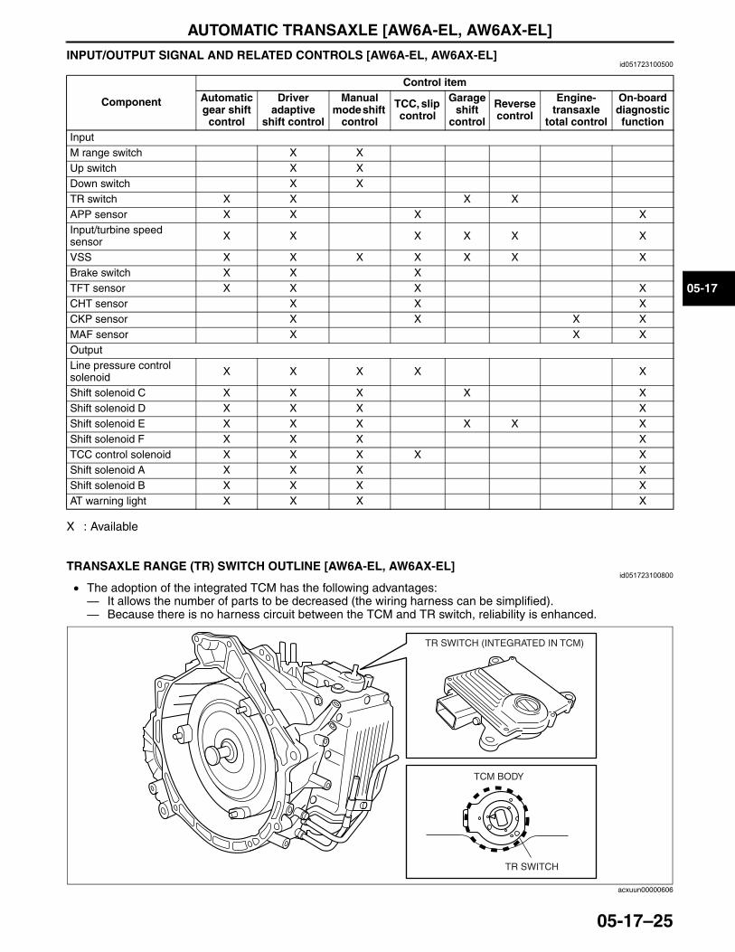
AUTOMATIC TRANSAXLE [AW6A-EL, AW6AX-EL]
05-17–25
05-17
INPUT/OUTPUT SIGNAL AND RELATED CONTROLS [AW6A-EL, AW6AX-EL]id051723100500
X : Available
End Of SieNG: AUTOMATIC TRANSMISSION/TRANSAXLE INPUT (SENSOR/SWITCH)TRANSAXLE RANGE (TR) SWITCH OUTLINE [AW6A-EL, AW6AX-EL]
id051723100800
• The adoption of the integrated TCM has the following advantages:— It allows the number of parts to be decreased (the wiring harness can be simplified).— Because there is no harness circuit between the TCM and TR switch, reliability is enhanced.
Component
Control itemAutomatic gear shift
control
Driver adaptive
shift control
Manual mode shift
control
TCC, slip control
Garage shift
control
Reverse control
Engine-transaxle
total control
On-board diagnostic function
InputM range switch X XUp switch X XDown switch X XTR switch X X X XAPP sensor X X X XInput/turbine speed sensor X X X X X X
VSS X X X X X X XBrake switch X X XTFT sensor X X X XCHT sensor X X XCKP sensor X X X XMAF sensor X X XOutputLine pressure control solenoid X X X X X
Shift solenoid C X X X X XShift solenoid D X X X XShift solenoid E X X X X X XShift solenoid F X X X XTCC control solenoid X X X X XShift solenoid A X X X XShift solenoid B X X X XAT warning light X X X X
TCM BODY
TR SWITCH
TR SWITCH (INTEGRATED IN TCM)
acxuun00000606
3423-1U-06H(05-17).fm 25 ページ 2006年11月21日 火曜日 午後5時17分
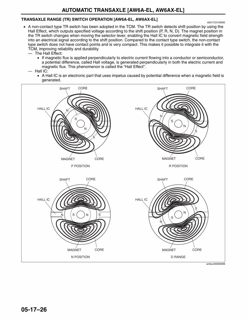
AUTOMATIC TRANSAXLE [AW6A-EL, AW6AX-EL]
05-17–26
End Of SieTRANSAXLE RANGE (TR) SWITCH OPERATION [AW6A-EL, AW6AX-EL]id051723100900
• A non-contact type TR switch has been adopted in the TCM. The TR switch detects shift position by using the Hall Effect, which outputs specified voltage according to the shift position (P, R, N, D). The magnet position in the TR switch changes when moving the selector lever, enabling the Hall IC to convert magnetic field strength into an electrical signal according to the shift position. Compared to the contact type switch, the non-contact type switch does not have contact points and is very compact. This makes it possible to integrate it with the TCM, improving reliability and durability.— The Hall Effect:
• If magnetic flux is applied perpendicularly to electric current flowing into a conductor or semiconductor, a potential difference, called Hall voltage, is generated perpendicularly in both the electric current and magnetic flux. This phenomenon is called the “Hall Effect”.
— Hall IC:• A Hall IC is an electronic part that uses impetus caused by potential difference when a magnetic field is
generated.
CORE
CORE
MAGNET
P POSITION
HALL IC
SHAFT
N
N
S
S
CORE
CORE
MAGNET
N POSITION
HALL IC
SHAFT
N N SS
CORE
CORE
MAGNET
D RANGE
HALL IC
SHAFT
N
NS
S
CORE
CORE
MAGNET
R POSITION
HALL IC
SHAFT
N
N
S
S
ac9uun00000596
3423-1U-06H(05-17).fm 26 ページ 2006年11月22日 水曜日 午後5時35分
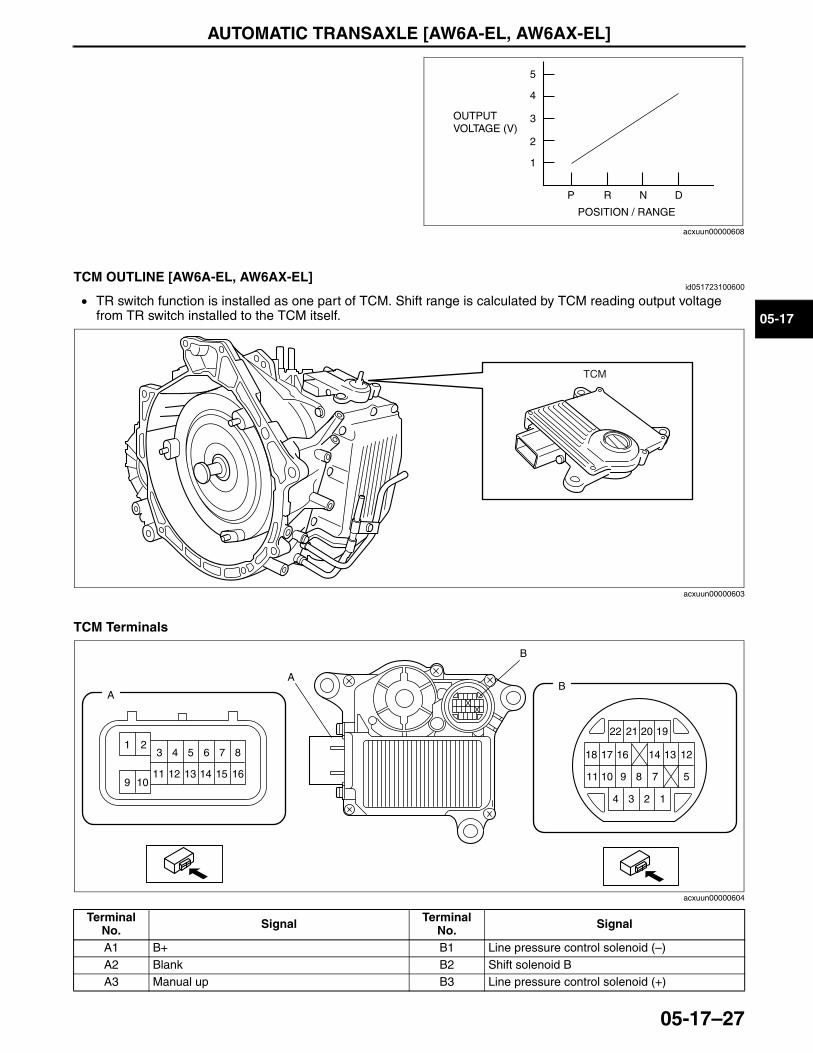
AUTOMATIC TRANSAXLE [AW6A-EL, AW6AX-EL]
05-17–27
05-17
End Of SieNG: TCM
TCM OUTLINE [AW6A-EL, AW6AX-EL]id051723100600
• TR switch function is installed as one part of TCM. Shift range is calculated by TCM reading output voltage from TR switch installed to the TCM itself.
TCM Terminals
.
OUTPUT VOLTAGE (V)
POSITION / RANGE
P
1
2
3
4
5
R N D
acxuun00000608
TCM
acxuun00000603
BA
A
B
22
18 17 16 14 13 12
11 10 9 8 7 5
1234
21 20 19
161514131211109
87651 2
3 4
acxuun00000604
Terminal No. Signal Terminal
No. Signal
A1 B+ B1 Line pressure control solenoid (–)A2 Blank B2 Shift solenoid BA3 Manual up B3 Line pressure control solenoid (+)
3423-1U-06H(05-17).fm 27 ページ 2006年11月21日 火曜日 午後5時17分
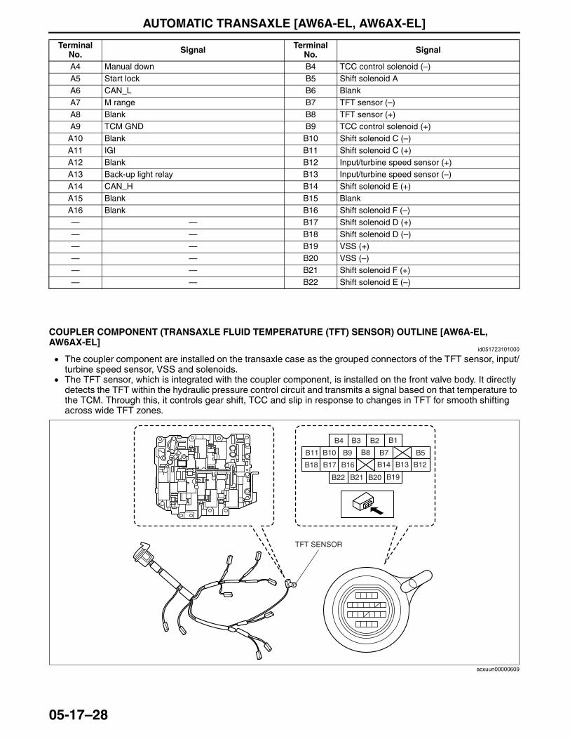
AUTOMATIC TRANSAXLE [AW6A-EL, AW6AX-EL]
05-17–28
End Of SieNG: AUTOMATIC TRANSMISSION/TRANSAXLE INPUT (SENSOR/SWITCH)
COUPLER COMPONENT (TRANSAXLE FLUID TEMPERATURE (TFT) SENSOR) OUTLINE [AW6A-EL, AW6AX-EL]
id051723101000
• The coupler component are installed on the transaxle case as the grouped connectors of the TFT sensor, input/turbine speed sensor, VSS and solenoids.
• The TFT sensor, which is integrated with the coupler component, is installed on the front valve body. It directly detects the TFT within the hydraulic pressure control circuit and transmits a signal based on that temperature to the TCM. Through this, it controls gear shift, TCC and slip in response to changes in TFT for smooth shifting across wide TFT zones.
.
A4 Manual down B4 TCC control solenoid (–)A5 Start lock B5 Shift solenoid AA6 CAN_L B6 BlankA7 M range B7 TFT sensor (–)A8 Blank B8 TFT sensor (+)A9 TCM GND B9 TCC control solenoid (+)
A10 Blank B10 Shift solenoid C (–)A11 IGI B11 Shift solenoid C (+)A12 Blank B12 Input/turbine speed sensor (+)A13 Back-up light relay B13 Input/turbine speed sensor (–)A14 CAN_H B14 Shift solenoid E (+)A15 Blank B15 BlankA16 Blank B16 Shift solenoid F (–)— — B17 Shift solenoid D (+)— — B18 Shift solenoid D (–)— — B19 VSS (+)— — B20 VSS (–)— — B21 Shift solenoid F (+)— — B22 Shift solenoid E (–)
Terminal No. Signal Terminal
No. Signal
TFT SENSOR
B4 B3 B2 B1
B22 B21 B20 B19
B11 B10 B9 B8
B18 B17 B16
B7 B5
B14 B13 B12
acxuun00000609
3423-1U-06H(05-17).fm 28 ページ 2006年11月21日 火曜日 午後5時17分
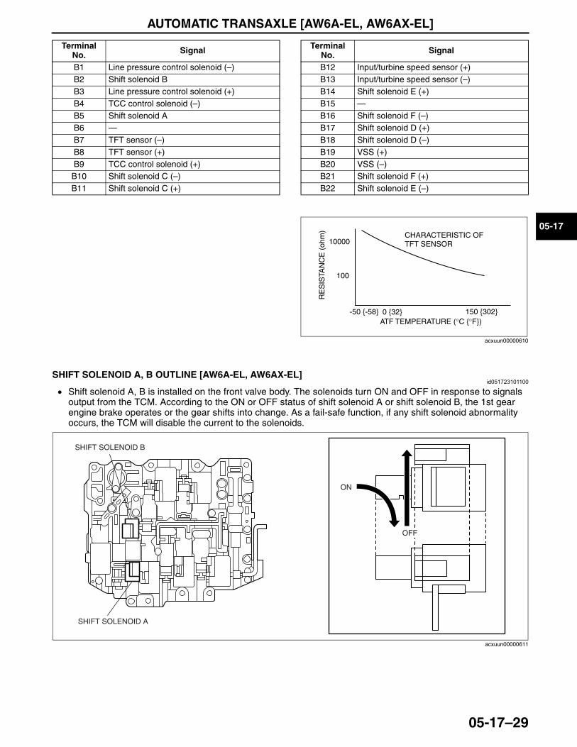
AUTOMATIC TRANSAXLE [AW6A-EL, AW6AX-EL]
05-17–29
05-17End Of Sie
SHIFT SOLENOID A, B OUTLINE [AW6A-EL, AW6AX-EL]id051723101100
• Shift solenoid A, B is installed on the front valve body. The solenoids turn ON and OFF in response to signals output from the TCM. According to the ON or OFF status of shift solenoid A or shift solenoid B, the 1st gear engine brake operates or the gear shifts into change. As a fail-safe function, if any shift solenoid abnormality occurs, the TCM will disable the current to the solenoids.
End Of Sie
Terminal No. Signal
B1 Line pressure control solenoid (–)B2 Shift solenoid BB3 Line pressure control solenoid (+)B4 TCC control solenoid (–)B5 Shift solenoid AB6 —B7 TFT sensor (–)B8 TFT sensor (+)B9 TCC control solenoid (+)
B10 Shift solenoid C (–)B11 Shift solenoid C (+)
B12 Input/turbine speed sensor (+)B13 Input/turbine speed sensor (–)B14 Shift solenoid E (+)B15 —B16 Shift solenoid F (–)B17 Shift solenoid D (+)B18 Shift solenoid D (–)B19 VSS (+)B20 VSS (–)B21 Shift solenoid F (+)B22 Shift solenoid E (–)
Terminal No. Signal
10000
100
RE
SIS
TAN
CE
(oh
m)
-50 {-58} 0 {32} 150 {302}ATF TEMPERATURE (°C {°F})
CHARACTERISTIC OF TFT SENSOR
acxuun00000610
OFF
ON
SHIFT SOLENOID B
SHIFT SOLENOID A
acxuun00000611
3423-1U-06H(05-17).fm 29 ページ 2006年11月21日 火曜日 午後5時17分
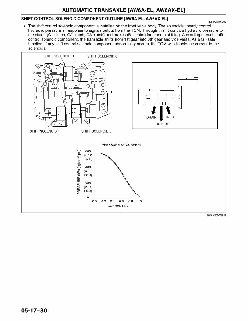
AUTOMATIC TRANSAXLE [AW6A-EL, AW6AX-EL]
05-17–30
SHIFT CONTROL SOLENOID COMPONENT OUTLINE [AW6A-EL, AW6AX-EL]id051723101200
• The shift control solenoid component is installed on the front valve body. The solenoids linearly control hydraulic pressure in response to signals output from the TCM. Through this, it controls hydraulic pressure to the clutch (C1 clutch, C2 clutch, C3 clutch) and brakes (B1 brake) for smooth shifting. According to each shift control solenoid component, the transaxle shifts from 1st gear into 6th gear and vice versa. As a fail-safe function, if any shift control solenoid component abnormality occurs, the TCM will disable the current to the solenoids.
End Of Sie
INPUTDRAIN
OUTPUT
SHIFT SOLENOID D SHIFT SOLENOID C
SHIFT SOLENOID F SHIFT SOLENOID E
400 {4.08, 58.0}
600 {6.12, 87.0}
200 {2.04, 29.0}
00.0 0.2 0.4 0.6 0.8 1.0
CURRENT (A)
PRESSURE BY CURRENT
PR
ES
SU
RE
(kP
a {k
gf/c
m2
,psi
}
acxuun00000644
3423-1U-06H(05-17).fm 30 ページ 2006年11月21日 火曜日 午後5時17分
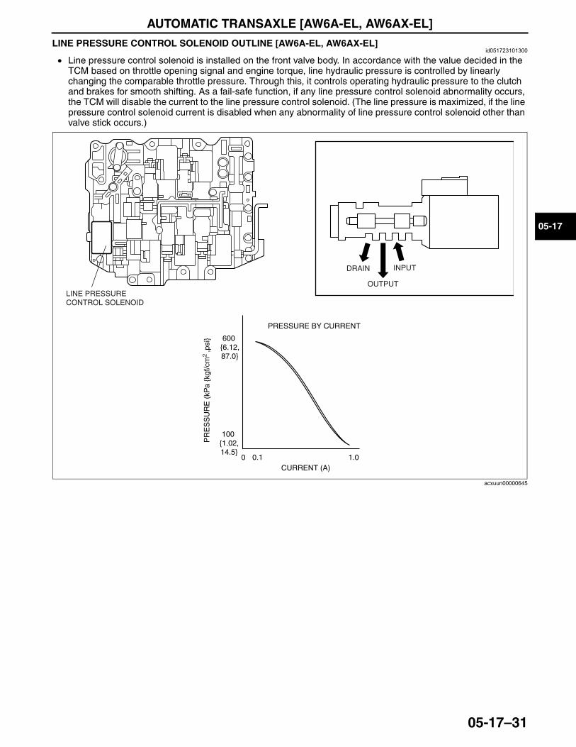
AUTOMATIC TRANSAXLE [AW6A-EL, AW6AX-EL]
05-17–31
05-17
LINE PRESSURE CONTROL SOLENOID OUTLINE [AW6A-EL, AW6AX-EL]id051723101300
• Line pressure control solenoid is installed on the front valve body. In accordance with the value decided in the TCM based on throttle opening signal and engine torque, line hydraulic pressure is controlled by linearly changing the comparable throttle pressure. Through this, it controls operating hydraulic pressure to the clutch and brakes for smooth shifting. As a fail-safe function, if any line pressure control solenoid abnormality occurs, the TCM will disable the current to the line pressure control solenoid. (The line pressure is maximized, if the line pressure control solenoid current is disabled when any abnormality of line pressure control solenoid other than valve stick occurs.)
End Of Sie
INPUTDRAIN
OUTPUTLINE PRESSURE CONTROL SOLENOID
600 {6.12, 87.0}
100 {1.02, 14.5}
0 0.1 1.0CURRENT (A)
PRESSURE BY CURRENT
PR
ES
SU
RE
(kP
a {k
gf/c
m2
,psi
}
acxuun00000645
3423-1U-06H(05-17).fm 31 ページ 2006年11月21日 火曜日 午後5時17分
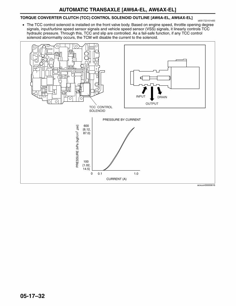
AUTOMATIC TRANSAXLE [AW6A-EL, AW6AX-EL]
05-17–32
TORQUE CONVERTER CLUTCH (TCC) CONTROL SOLENOID OUTLINE [AW6A-EL, AW6AX-EL]id051723101400
• The TCC control solenoid is installed on the front valve body. Based on engine speed, throttle opening degree signals, input/turbine speed sensor signals and vehicle speed sensor (VSS) signals, it linearly controls TCC hydraulic pressure. Through this, TCC and slip are controlled. As a fail-safe function, if any TCC control solenoid abnormality occurs, the TCM will disable the current to the solenoid.
End Of Sie
INPUT
OUTPUTTCC CONTROL SOLENOID
DRAIN
0 0.1 1.0
CURRENT (A)
PRESSURE BY CURRENT
600 {6.12, 87.0}
100 {1.02, 14.5}
PR
ES
SU
RE
(kP
a {k
gf/c
m2
,psi
}
acxuun00000616
3423-1U-06H(05-17).fm 32 ページ 2006年11月21日 火曜日 午後5時17分
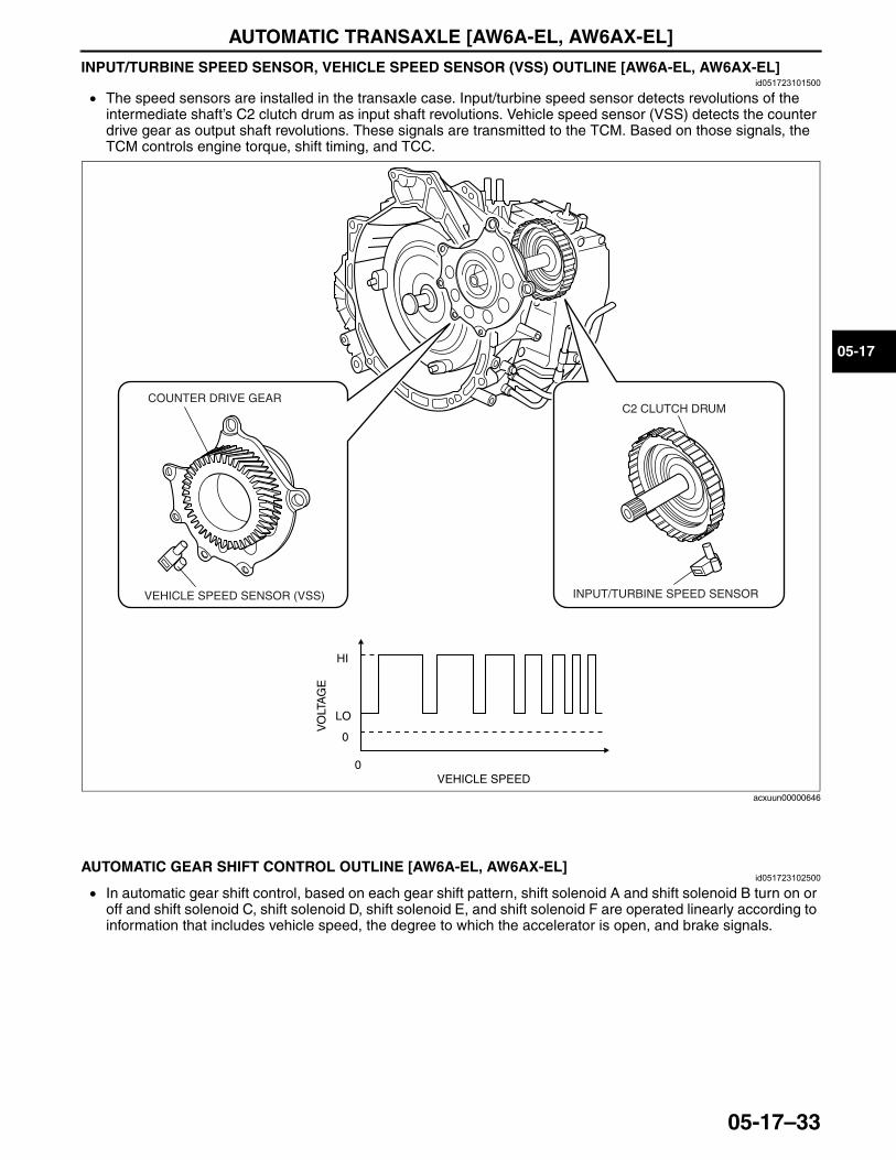
AUTOMATIC TRANSAXLE [AW6A-EL, AW6AX-EL]
05-17–33
05-17
INPUT/TURBINE SPEED SENSOR, VEHICLE SPEED SENSOR (VSS) OUTLINE [AW6A-EL, AW6AX-EL]id051723101500
• The speed sensors are installed in the transaxle case. Input/turbine speed sensor detects revolutions of the intermediate shaft’s C2 clutch drum as input shaft revolutions. Vehicle speed sensor (VSS) detects the counter drive gear as output shaft revolutions. These signals are transmitted to the TCM. Based on those signals, the TCM controls engine torque, shift timing, and TCC.
End Of SieNG: AUTOMATIC TRANSAXLE
AUTOMATIC GEAR SHIFT CONTROL OUTLINE [AW6A-EL, AW6AX-EL]id051723102500
• In automatic gear shift control, based on each gear shift pattern, shift solenoid A and shift solenoid B turn on or off and shift solenoid C, shift solenoid D, shift solenoid E, and shift solenoid F are operated linearly according to information that includes vehicle speed, the degree to which the accelerator is open, and brake signals.
End Of Sie
C2 CLUTCH DRUM
INPUT/TURBINE SPEED SENSOR
COUNTER DRIVE GEAR
VEHICLE SPEED SENSOR (VSS)
VEHICLE SPEED
VO
LTA
GE
HI
LO
0
0
acxuun00000646
3423-1U-06H(05-17).fm 33 ページ 2006年11月21日 火曜日 午後5時17分
AUTOMATIC TRANSAXLE [AW6A-EL, AW6AX-EL]
05-17–34
DRIVER ADAPTIVE SHIFT CONTROL OUTLINE [AW6A-EL, AW6AX-EL]id051723102600
• The AW6A (X) -EL automatic transaxle does not have a driving mode selection switch that allows drivers to select a mode themselves. The vehicle is ordinarily in NORMAL mode. However, when specific conditions are met, the TCM selects a shifting pattern appropriate to driving conditions from all of the shifting patterns and switches automatically.
Active Adaptive Shift (AAS) Mode• When certain conditions are met, AAS mode is automatically selected from normal mode. In AAS mode, the
shift point is set higher than the normal shift point so that high-engine speed, high-output conditions are available.
• AAS mode is canceled when the vehicle speed remains constant (stable vehicle behavior).
Conditions for switching to active adaptive shift (AAS) mode• The accelerator pedal is depressed fully to accelerate rapidly while driving in D range.• Rapid acceleration or deceleration continues for a certain period of time while driving in D range.
Mode DescriptionNORMAL • Used during normal driving.
AAS • In this mode, shift point and TCC point settings are higher than in the normal driving condition for generating high engine speed and output.
MANUAL (See 05-17-35 MANUAL MODE SHIFT CONTROL OUTLINE [AW6A-EL, AW6AX-EL].)
HIGH TEMP • When ATF temperature becomes too high, this mode activates TCC at an earlier timing to stop the temperature rise and lower the temperature.
CRUISE CONTROL • When cruise control is ON, gears are fixed to perform smooth driving.
DOWN-SLOPE• When the vehicle is driven down a slope, the TCM detects the gradient based on the signal from
the PCM and the engine speed, and switches the drive mode to DOWN-SLOPE mode. Due to this, load on the brakes is reduced.
UP-SLOPE • When driving up a slope, TCM detects an up-slope based on the engine control unit signal and output speed. TCM switches to UP-SLOPE mode to prevent driving force drop.
COLD • TCM detects that the engine is cold based on the signal (ECT signal) from the PCM when the ignition switch is on. TCM switches to cold mode to improve warm-up performance.
3423-1U-06H(05-17).fm 34 ページ 2006年11月21日 火曜日 午後5時17分
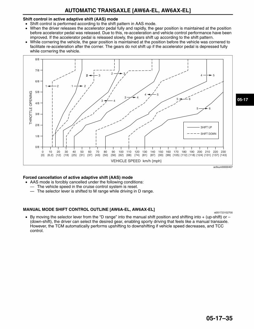
AUTOMATIC TRANSAXLE [AW6A-EL, AW6AX-EL]
05-17–35
05-17
Shift control in active adaptive shift (AAS) mode• Shift control is performed according to the shift pattern in AAS mode.• When the driver releases the accelerator pedal fully and rapidly, the gear position is maintained at the position
before accelerator pedal was released. Due to this, re-acceleration and vehicle control performance have been improved. If the accelerator pedal is released slowly, the gears shift up according to the shift pattern.
• While cornering the vehicle, the gear position is maintained at the position before the vehicle was cornered to facilitate re-acceleration after the corner. The gears do not shift up if the accelerator pedal is depressed fully while cornering the vehicle.
Forced cancellation of active adaptive shift (AAS) mode• AAS mode is forcibly cancelled under the following conditions:— The vehicle speed in the cruise control system is reset.— The selector lever is shifted to M range while driving in D range.
End Of Sie
MANUAL MODE SHIFT CONTROL OUTLINE [AW6A-EL, AW6AX-EL]id051723102700
• By moving the selector lever from the “D range” into the manual shift position and shifting into + (up-shift) or – (down-shift), the driver can select the desired gear, enabling sporty driving that feels like a manual transaxle. However, the TCM automatically performs upshifting to downshifting if vehicle speed decreases, and TCC control.
End Of Sie
0/8
1/8
2/8
3/8
4/8
5/8
6/8
7/8
8/8
VEHICLE SPEED km/h {mph}
0{0}
10{6.2}
20{12}
30{19}
40{25}
50{31}
60{37}
70{43}
80{50}
90{56}
100{62}
110{68}
120{74}
130{81}
140{87}
150{93}
160{99}
170{105}
180{112}
190{118}
200{124}
210{131}
220{137}
230{143}
1 1 22
22 32 3
4 5
4 5
3 43 4
5 6
5 6
TH
RO
TT
LE O
PE
NIN
G
SHIFT UP
SHIFT DOWN
ac9uun00000407
3423-1U-06H(05-17).fm 35 ページ 2006年11月21日 火曜日 午後5時17分
AUTOMATIC TRANSAXLE [AW6A-EL, AW6AX-EL]
05-17–36
MANUAL MODE SHIFT CONTROL OPERATION [AW6A-EL, AW6AX-EL]id051723102800
Manual Mode Shift• When the selector lever is shifted over from the D to M range position, the M range switch in the selector lever
component turns on, sending a manual mode command signal to the TCM which activates the manual mode shift control.
• When in manual mode and the selector lever is operated in the back (+) direction, the up switch in the selector lever component is turned on and an up-shift command signal is input to the TCM. — The TCM, triggered by the up-shift command signal, carries out shifting by outputting an operation signal to
the shift control solenoid. • Conversely, when the selector lever is operated in the forward (–) direction, the down switch in the selector lever
component turns on, and a down-shift command signal is input to the TCM. — The TCM, triggered by the down-shift command signal, carries out shifting by outputting an operation signal
to the shift control solenoid if the vehicle speed is less than the set speed and the gear position is 2GR or above.
• The TCM utilizes a specialized M range automatic shift diagram. Due to this, restriction of manual shift demand and automatic control of downshifting or upshifting is carried out, reducing load on the ATX, preventing engine over-rev and ensuring drive stability.
• If the engine speed reaches the excessive speed fuel cut zone while the shift lever is in the M range, the fuel cut and supply occur repeatedly. Moreover, if the engine speed is not lowered, the engine speed is lowered by a forced shift up of the gear to protect the engine.
Condition Shift control Note2GR→3GR up-shift command at low speed • To reduce load on the ATX, upshifting is
inhibited until vehicle reaches speed possible for upshifting
• Selector indicator “M” light and gear position indicator light flash to alert driver
3GR→4GR up-shift command at low speed4GR→5GR up-shift command at low speed5GR→6GR up-shift command at low speed6GR→5GR down-shift command, above set speed
• To prevent engine over-rev, downshifting is inhibited until vehicle reaches speed possible for downshifting
• Gear position indicator light flash to alert driver5GR→4GR down-shift command, above set
speed4GR→3GR down-shift command, above set speed3GR→2GR down-shift command, above set speed2GR→1GR down-shift command, above set speedIn 6GR deceleration, speed goes below coast-down set speed (deceleration down-shift)
• To assure drive stability, automatically downshifts from 6GR to 5GR
–
In 5GR deceleration, speed goes below coast-down set speed (deceleration down-shift)
• To assure drive stability, automatically downshifts from 5GR to 4GR
In 4GR deceleration, speed goes below coast-down set speed (deceleration down-shift)
• To assure drive stability, automatically downshifts from 4GR to 3GR
In 3GR deceleration, speed goes below coast-down set speed (deceleration down-shift)
• To assure drive stability, automatically downshifts from 3GR to 1GR
In 2GR deceleration, speed goes below coast-down set speed (deceleration down-shift)
• To assure drive stability, automatically downshifts from 2GR to 1GR
Wide open throttle at 85—95 km/h {53—58 mph} in 5GR
• To improve acceleration performance, 5GR to 4GR kickdown occurs
–Wide open throttle at 60—70 km/h {38—43 mph} in 4GR
• To improve acceleration performance, 4GR to 3GR kickdown occurs
Wide open throttle at 36—44 km/h {23—27 mph} in 3GR
• To improve acceleration performance, 3GR to 2GR kickdown occurs
3423-1U-06H(05-17).fm 36 ページ 2006年11月21日 火曜日 午後5時17分
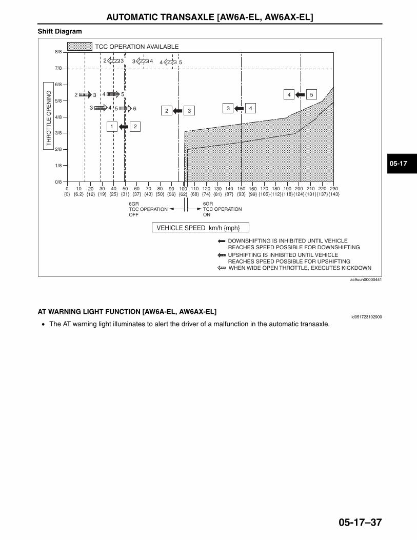
AUTOMATIC TRANSAXLE [AW6A-EL, AW6AX-EL]
05-17–37
05-17
Shift Diagram
End Of Sie
AT WARNING LIGHT FUNCTION [AW6A-EL, AW6AX-EL]id051723102900
• The AT warning light illuminates to alert the driver of a malfunction in the automatic transaxle.End Of Sie
VEHICLE SPEED km/h {mph}
DOWNSHIFTING IS INHIBITED UNTIL VEHICLE REACHES SPEED POSSIBLE FOR DOWNSHIFTINGUPSHIFTING IS INHIBITED UNTIL VEHICLE REACHES SPEED POSSIBLE FOR UPSHIFTING
TCC OPERATION AVAILABLET
HR
OT
TLE
OP
EN
ING
6GR TCC OPERATION ON
6GR TCC OPERATION OFF
230{143}
220{137}
210{131}
200{124}
190{118}
180{112}
170{105}
160{99}
150{93}
140 {87}
130{81}
120{74}
110{68}
90{56}
100{62}
80{50}
70{43}
50{31}
60{37}
30{19}
40{25}
10{6.2}
20{12}
0{0}
8/8
7/8
6/8
5/8
4/8
3/8
2/8
1/8
0/8
65
4
21
43
32
2 3 3 4
4 55
WHEN WIDE OPEN THROTTLE, EXECUTES KICKDOWN
3 3 4 4 52
ac9uun00000441
3423-1U-06H(05-17).fm 37 ページ 2006年11月21日 火曜日 午後5時17分
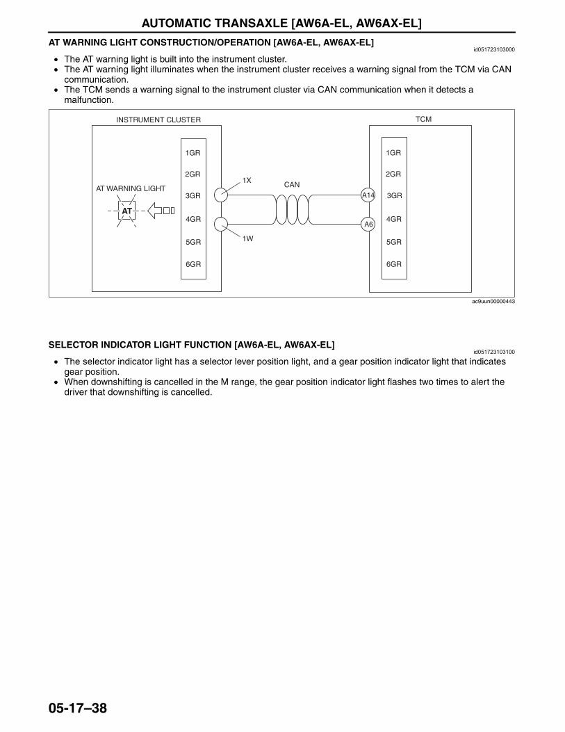
AUTOMATIC TRANSAXLE [AW6A-EL, AW6AX-EL]
05-17–38
AT WARNING LIGHT CONSTRUCTION/OPERATION [AW6A-EL, AW6AX-EL]id051723103000
• The AT warning light is built into the instrument cluster.• The AT warning light illuminates when the instrument cluster receives a warning signal from the TCM via CAN
communication.• The TCM sends a warning signal to the instrument cluster via CAN communication when it detects a
malfunction.
End Of Sie
SELECTOR INDICATOR LIGHT FUNCTION [AW6A-EL, AW6AX-EL]id051723103100
• The selector indicator light has a selector lever position light, and a gear position indicator light that indicates gear position.
• When downshifting is cancelled in the M range, the gear position indicator light flashes two times to alert the driver that downshifting is cancelled.
End Of Sie
AT
2GR
3GR
4GR
5GR
2GR
3GR
4GR
5GR
CAN
TCMINSTRUMENT CLUSTER
AT WARNING LIGHT
1GR1GR
6GR6GR
1W
1X
A14
A6
ac9uun00000443
3423-1U-06H(05-17).fm 38 ページ 2006年11月21日 火曜日 午後5時17分
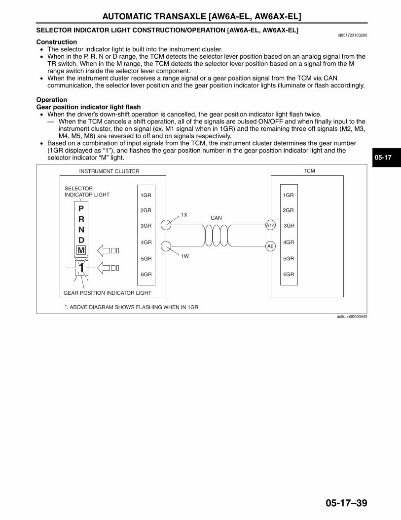
AUTOMATIC TRANSAXLE [AW6A-EL, AW6AX-EL]
05-17–39
05-17
SELECTOR INDICATOR LIGHT CONSTRUCTION/OPERATION [AW6A-EL, AW6AX-EL]id051723103200
Construction• The selector indicator light is built into the instrument cluster.• When in the P, R, N or D range, the TCM detects the selector lever position based on an analog signal from the
TR switch. When in the M range, the TCM detects the selector lever position based on a signal from the M range switch inside the selector lever component.
• When the instrument cluster receives a range signal or a gear position signal from the TCM via CAN communication, the selector lever position and the gear position indicator lights illuminate or flash accordingly.
OperationGear position indicator light flash• When the driver’s down-shift operation is cancelled, the gear position indicator light flash twice.— When the TCM cancels a shift operation, all of the signals are pulsed ON/OFF and when finally input to the
instrument cluster, the on signal (ex. M1 signal when in 1GR) and the remaining three off signals (M2, M3, M4, M5, M6) are reversed to off and on signals respectively.
• Based on a combination of input signals from the TCM, the instrument cluster determines the gear number (1GR displayed as “1”), and flashes the gear position number in the gear position indicator light and the selector indicator “M” light.
End Of Sie
M
*:
PRND
1
TCMINSTRUMENT CLUSTER
SELECTOR INDICATOR LIGHT
GEAR POSITION INDICATOR LIGHT
ABOVE DIAGRAM SHOWS FLASHING WHEN IN 1GR
CAN
1W
1X2GR
3GR
4GR
5GR
2GR
3GR
4GR
5GR
1GR1GR
6GR6GR
A14
A6
ac9uun00000442
3423-1U-06H(05-17).fm 39 ページ 2006年11月21日 火曜日 午後5時17分
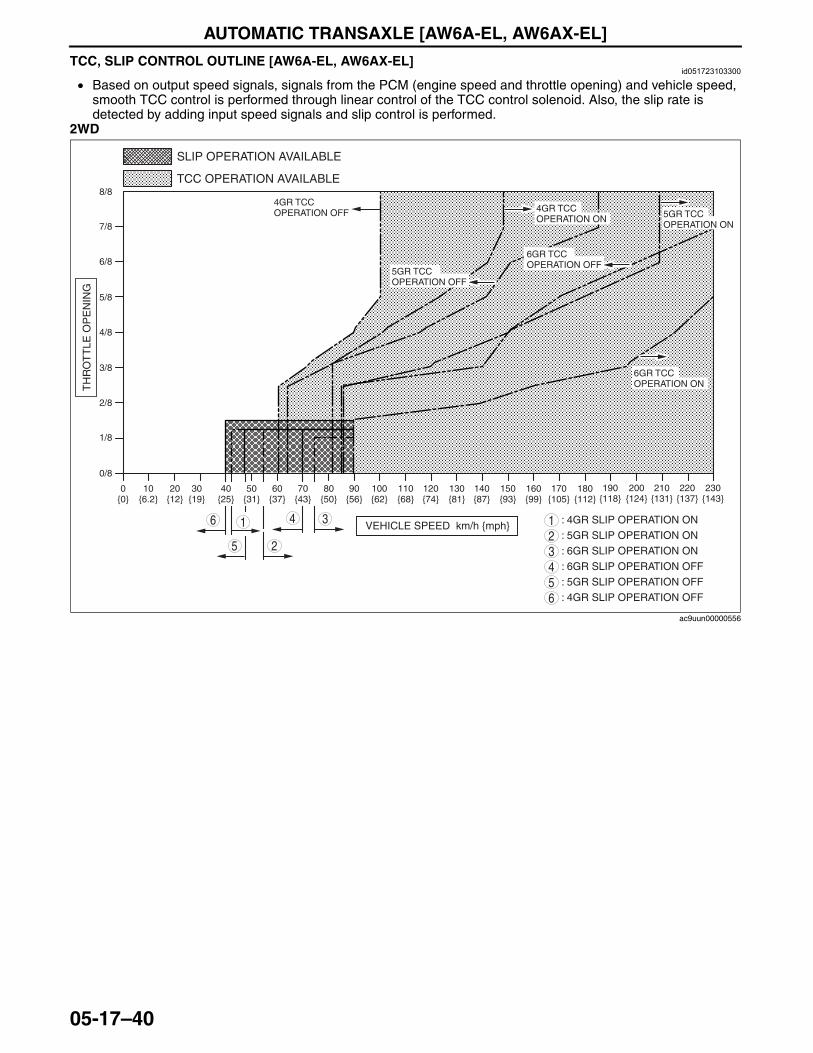
AUTOMATIC TRANSAXLE [AW6A-EL, AW6AX-EL]
05-17–40
TCC, SLIP CONTROL OUTLINE [AW6A-EL, AW6AX-EL]id051723103300
• Based on output speed signals, signals from the PCM (engine speed and throttle opening) and vehicle speed, smooth TCC control is performed through linear control of the TCC control solenoid. Also, the slip rate is detected by adding input speed signals and slip control is performed.
2WD
4
2
3
5
6 1
0/8
1/8
2/8
3/8
4/8
5/8
6/8
7/8
8/8
0{0}
10{6.2}
20{12}
30{19}
40{25}
50{31}
60{37}
70{43}
80{50}
90{56}
100{62}
110{68}
120{74}
130{81}
140{87}
150{93}
160{99}
170{105}
190{118}
200{124}
210{131}
220{137}
230{143}
180{112}
VEHICLE SPEED km/h {mph}
TH
RO
TT
LE O
PE
NIN
G
4GR TCC OPERATION OFF 4GR TCC
OPERATION ON
5GR TCC OPERATION OFF
5GR TCC OPERATION ON
6GR TCC OPERATION OFF
6GR TCC OPERATION ON
TCC OPERATION AVAILABLE
SLIP OPERATION AVAILABLE
: 4GR SLIP OPERATION ON1: 5GR SLIP OPERATION ON2: 6GR SLIP OPERATION ON3: 6GR SLIP OPERATION OFF4: 5GR SLIP OPERATION OFF5: 4GR SLIP OPERATION OFF6
ac9uun00000556
3423-1U-06H(05-17).fm 40 ページ 2006年11月21日 火曜日 午後5時17分
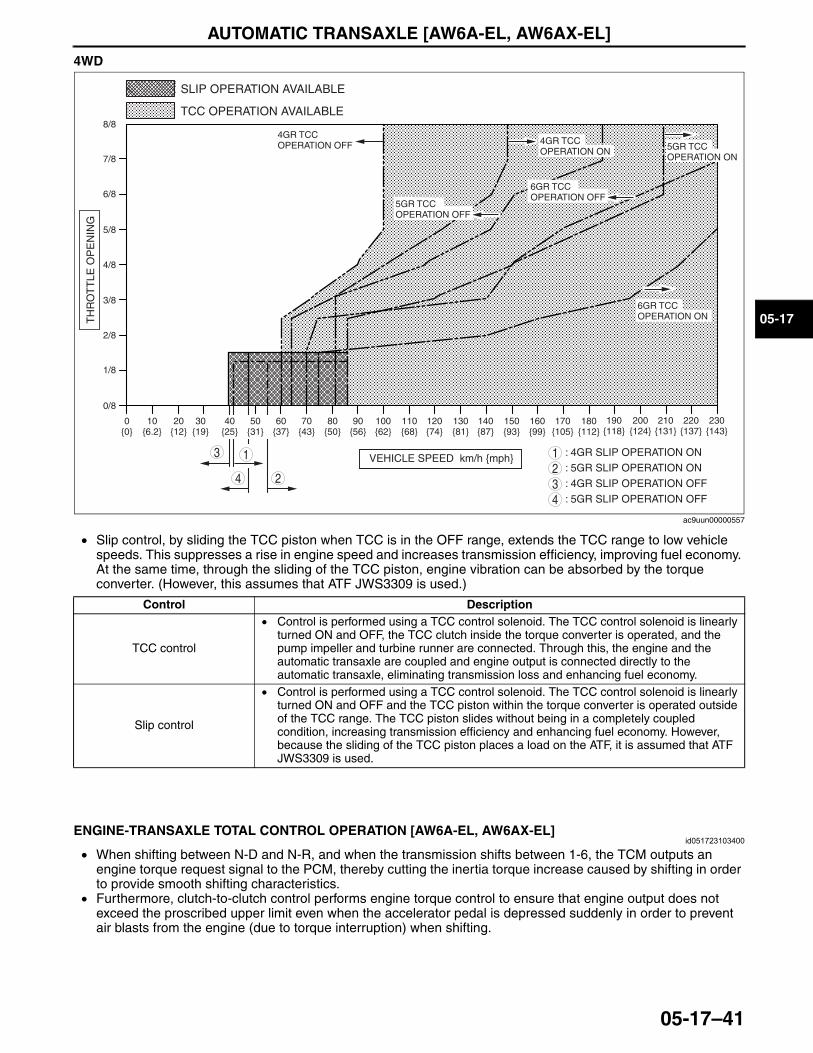
AUTOMATIC TRANSAXLE [AW6A-EL, AW6AX-EL]
05-17–41
05-17
4WD
• Slip control, by sliding the TCC piston when TCC is in the OFF range, extends the TCC range to low vehicle speeds. This suppresses a rise in engine speed and increases transmission efficiency, improving fuel economy. At the same time, through the sliding of the TCC piston, engine vibration can be absorbed by the torque converter. (However, this assumes that ATF JWS3309 is used.)
End Of Sie
ENGINE-TRANSAXLE TOTAL CONTROL OPERATION [AW6A-EL, AW6AX-EL]id051723103400
• When shifting between N-D and N-R, and when the transmission shifts between 1-6, the TCM outputs an engine torque request signal to the PCM, thereby cutting the inertia torque increase caused by shifting in order to provide smooth shifting characteristics.
• Furthermore, clutch-to-clutch control performs engine torque control to ensure that engine output does not exceed the proscribed upper limit even when the accelerator pedal is depressed suddenly in order to prevent air blasts from the engine (due to torque interruption) when shifting.
End Of Sie
24
3 1
0/8
1/8
2/8
3/8
4/8
5/8
6/8
7/8
8/8
0{0}
10{6.2}
20{12}
30{19}
40{25}
50{31}
60{37}
70{43}
80{50}
90{56}
100{62}
110{68}
120{74}
130{81}
140{87}
150{93}
160{99}
170{105}
190{118}
200{124}
210{131}
220{137}
230{143}
180{112}
VEHICLE SPEED km/h {mph}
TH
RO
TT
LE O
PE
NIN
G
4GR TCC OPERATION OFF 4GR TCC
OPERATION ON
5GR TCC OPERATION OFF
5GR TCC OPERATION ON
6GR TCC OPERATION OFF
6GR TCC OPERATION ON
TCC OPERATION AVAILABLE
SLIP OPERATION AVAILABLE
: 4GR SLIP OPERATION ON1: 5GR SLIP OPERATION ON2: 4GR SLIP OPERATION OFF3: 5GR SLIP OPERATION OFF4
ac9uun00000557
Control Description
TCC control
• Control is performed using a TCC control solenoid. The TCC control solenoid is linearly turned ON and OFF, the TCC clutch inside the torque converter is operated, and the pump impeller and turbine runner are connected. Through this, the engine and the automatic transaxle are coupled and engine output is connected directly to the automatic transaxle, eliminating transmission loss and enhancing fuel economy.
Slip control
• Control is performed using a TCC control solenoid. The TCC control solenoid is linearly turned ON and OFF and the TCC piston within the torque converter is operated outside of the TCC range. The TCC piston slides without being in a completely coupled condition, increasing transmission efficiency and enhancing fuel economy. However, because the sliding of the TCC piston places a load on the ATF, it is assumed that ATF JWS3309 is used.
3423-1U-06H(05-17).fm 41 ページ 2006年11月21日 火曜日 午後5時17分
AUTOMATIC TRANSAXLE [AW6A-EL, AW6AX-EL]
05-17–42
GARAGE SHIFT CONTROL OUTLINE [AW6A-EL, AW6AX-EL]id051723103500
• When the selector lever is moved from N to D or from N to R, after the engine is started, shift solenoid C and shift solenoid E are used for the oil pressure required by C1 clutch or C3 clutch and appropriately regulated oil pressure is supplied to the clutch, engaging smoothly without shock.
Note• When the engine is cold, the first piston stroke resistance becomes large, creating a time lag for shift
operation. In order to reduce the time lag, control is not performed.• By controlling the oil pressure according to the piston stroke, smooth engagement without shock becomes
possible.
End Of SieREVERSE CONTROL OUTLINE [AW6A-EL, AW6AX-EL]
id051723103600
• If the selector lever is moved from N to R while the vehicle is traveling and the transaxle shifts into reverse, the wheels may be locked, which is extremely dangerous. In order to avoid this, TCM inhibits the transaxle from shifting into reverse while traveling.
Note• Even when the selector lever is moved from N to R, the transaxle does not shift into reverse if the vehicle
speed is 10 km/h {6 mph} or more.• When this control is activated, the C3 clutch is released without operating the shift solenoid E so that the
transaxle does not shift into reverse.• Reverse control takes precedence over N-R shift control.
End Of SieSELF-DIAGNOSIS FUNCTION OUTLINE [AW6A-EL, AW6AX-EL]
id051723103700
• The TCM monitors the communication status of each sensor, electronic component and PCM including the PCM. If any malfunction should occur, the TCM functions to warn the driver and stores the malfunction as a diagnosis code.— If any malfunction should occur in the automatic transaxle, the TCM will cause warning light to light up in
order to inform the driver of the malfunction.— The TCM stores the malfunction as a diagnosis code. — The diagnosis code and TCM data can be inspected by connecting the Mazda Modular Diagnostic System
(M-MDS).• Deleting the diagnosis codes and initializing the learned values can be performed only with the Mazda Modular
Diagnostic System (M-MDS).End Of Sie
FAIL-SAFE OUTLINE [AW6A-EL, AW6AX-EL]id051723103800
• With the fail-safe function, if any malfunction should occur in the automatic transaxle system, the TCM will output a control signal, and control will be performed to make travelling a minimum distance possible. If shift solenoid malfunction, the TCM will cancel the output of control signals to the solenoid. If this happens, automatic transaxle gear shifting will be controlled by oil pressure circuits only and the gears will shift as shown in the chart below.
End Of Sie
N POSITION LEARNING FUNCTION [AW6A-EL, AW6AX-EL]id051723103900
• The AW6A (X) -EL automatic transaxle has the “neutral position learning” function. For the neutral position learning procedure, refer to the CX-7 Workshop Manual.
End Of Sie
Shift position Gear positionR Reverse
D, M 3rd gear (5th gear in case of shift solenoid C malfunction)
3423-1U-06H(05-17).fm 42 ページ 2006年11月21日 火曜日 午後5時17分
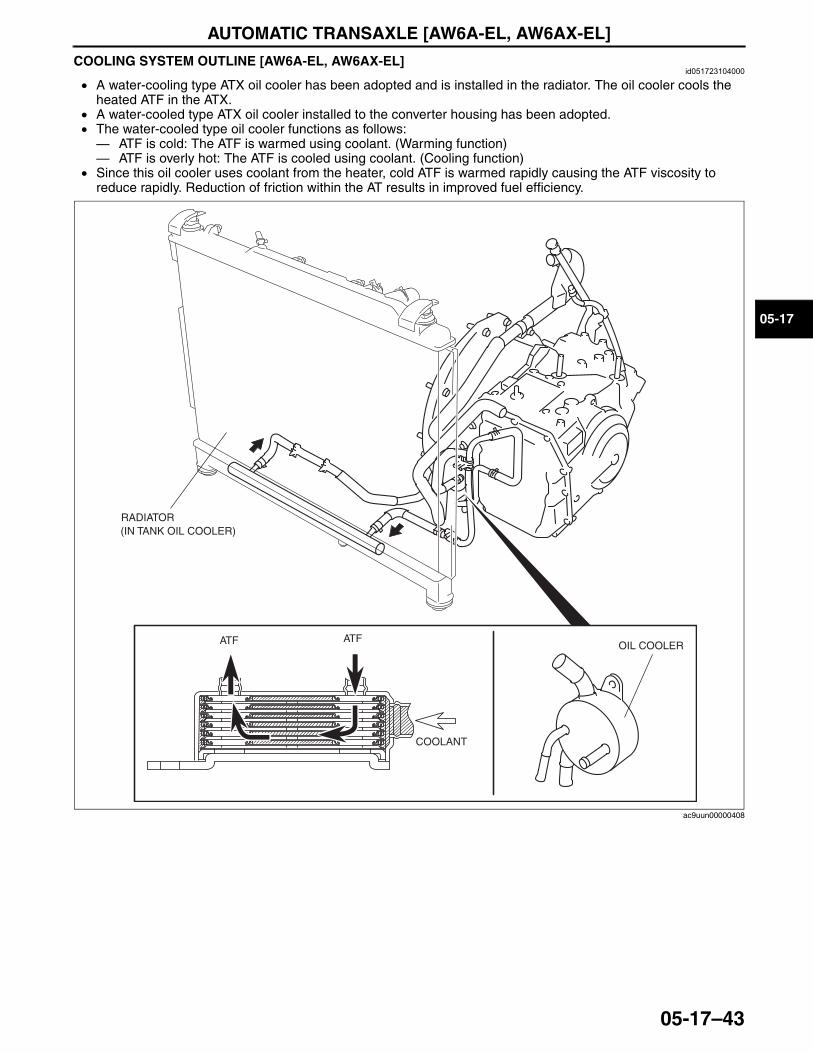
AUTOMATIC TRANSAXLE [AW6A-EL, AW6AX-EL]
05-17–43
05-17
COOLING SYSTEM OUTLINE [AW6A-EL, AW6AX-EL]id051723104000
• A water-cooling type ATX oil cooler has been adopted and is installed in the radiator. The oil cooler cools the heated ATF in the ATX.
• A water-cooled type ATX oil cooler installed to the converter housing has been adopted.• The water-cooled type oil cooler functions as follows:— ATF is cold: The ATF is warmed using coolant. (Warming function)— ATF is overly hot: The ATF is cooled using coolant. (Cooling function)
• Since this oil cooler uses coolant from the heater, cold ATF is warmed rapidly causing the ATF viscosity to reduce rapidly. Reduction of friction within the AT results in improved fuel efficiency.
End Of Sie
RADIATOR (IN TANK OIL COOLER)
OIL COOLERATF ATF
COOLANT
ac9uun00000408
3423-1U-06H(05-17).fm 43 ページ 2006年11月21日 火曜日 午後5時17分

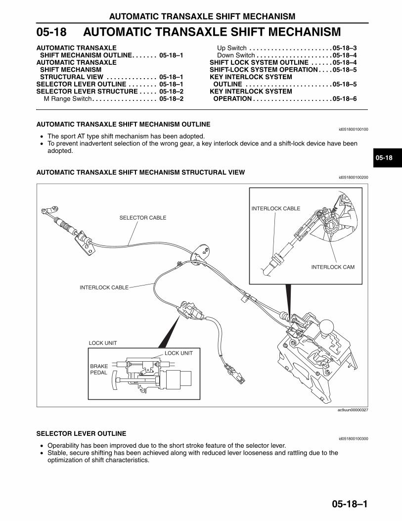
AUTOMATIC TRANSAXLE SHIFT MECHANISM
05-18–1
05-18
05-18 AUTOMATIC TRANSAXLE SHIFT MECHANISMAUTOMATIC TRANSAXLE
SHIFT MECHANISM OUTLINE. . . . . . . 05-18–1AUTOMATIC TRANSAXLE
SHIFT MECHANISM STRUCTURAL VIEW . . . . . . . . . . . . . . 05-18–1
SELECTOR LEVER OUTLINE . . . . . . . . 05-18–1SELECTOR LEVER STRUCTURE . . . . . 05-18–2
M Range Switch . . . . . . . . . . . . . . . . . . 05-18–2
Up Switch . . . . . . . . . . . . . . . . . . . . . . . 05-18–3Down Switch . . . . . . . . . . . . . . . . . . . . . 05-18–4
SHIFT LOCK SYSTEM OUTLINE . . . . . . 05-18–4SHIFT-LOCK SYSTEM OPERATION . . . . 05-18–5KEY INTERLOCK SYSTEM
OUTLINE . . . . . . . . . . . . . . . . . . . . . . . . 05-18–5KEY INTERLOCK SYSTEM
OPERATION . . . . . . . . . . . . . . . . . . . . . . 05-18–6
End of TocNG: SHIFT MECHANISMAUTOMATIC TRANSAXLE SHIFT MECHANISM OUTLINE
id051800100100
• The sport AT type shift mechanism has been adopted.• To prevent inadvertent selection of the wrong gear, a key interlock device and a shift-lock device have been
adopted.End Of Sie
AUTOMATIC TRANSAXLE SHIFT MECHANISM STRUCTURAL VIEWid051800100200
End Of Sie
SELECTOR LEVER OUTLINEid051800100300
• Operability has been improved due to the short stroke feature of the selector lever.• Stable, secure shifting has been achieved along with reduced lever looseness and rattling due to the
optimization of shift characteristics.End Of Sie
INTERLOCK CAM
INTERLOCK CABLE
SELECTOR CABLE
LOCK UNIT
LOCK UNIT
BRAKE PEDAL
INTERLOCK CABLE
ac9uun00000327
3423-1U-06H(05-18).fm 1 ページ 2006年11月21日 火曜日 午後5時20分
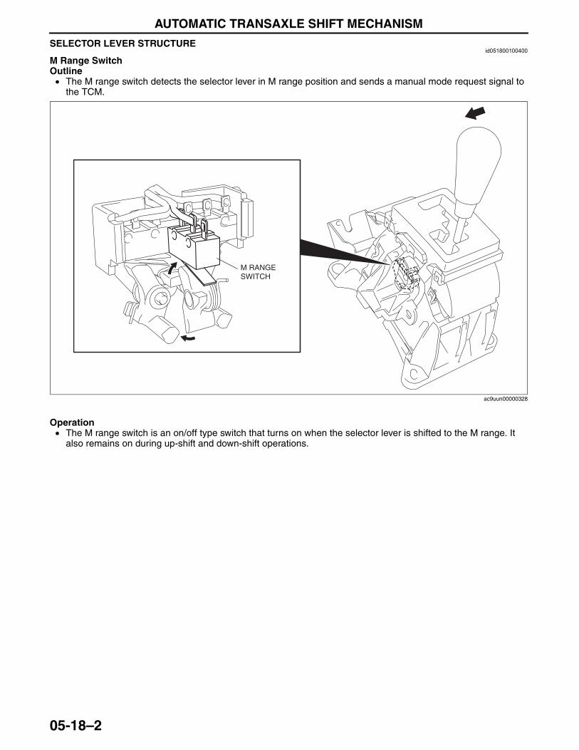
AUTOMATIC TRANSAXLE SHIFT MECHANISM
05-18–2
SELECTOR LEVER STRUCTUREid051800100400
M Range SwitchOutline• The M range switch detects the selector lever in M range position and sends a manual mode request signal to
the TCM.
Operation• The M range switch is an on/off type switch that turns on when the selector lever is shifted to the M range. It
also remains on during up-shift and down-shift operations.
M RANGE SWITCH
ac9uun00000328
3423-1U-06H(05-18).fm 2 ページ 2006年11月21日 火曜日 午後5時20分
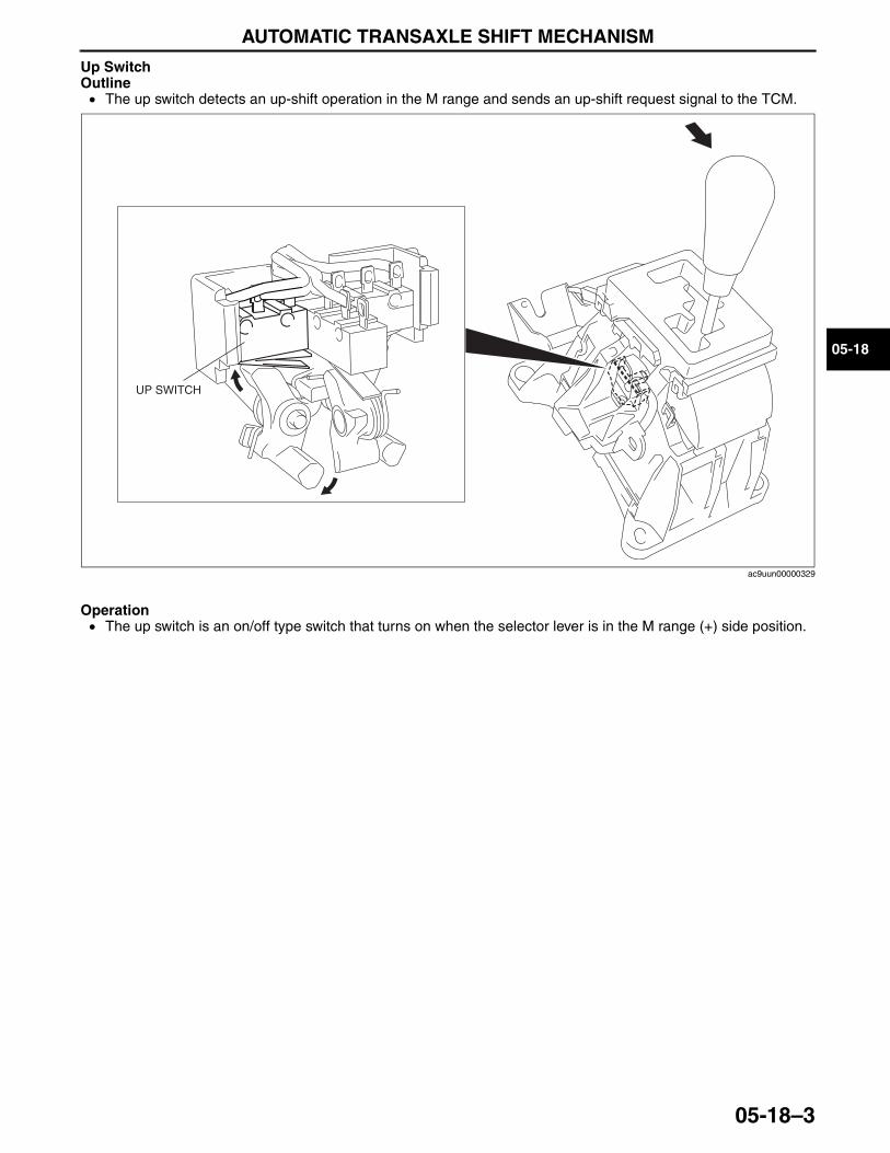
AUTOMATIC TRANSAXLE SHIFT MECHANISM
05-18–3
05-18
Up SwitchOutline• The up switch detects an up-shift operation in the M range and sends an up-shift request signal to the TCM.
Operation• The up switch is an on/off type switch that turns on when the selector lever is in the M range (+) side position.
UP SWITCH
ac9uun00000329
3423-1U-06H(05-18).fm 3 ページ 2006年11月21日 火曜日 午後5時20分
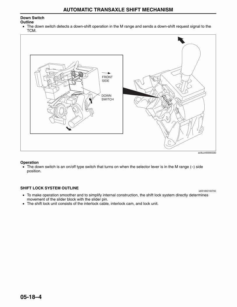
AUTOMATIC TRANSAXLE SHIFT MECHANISM
05-18–4
Down SwitchOutline• The down switch detects a down-shift operation in the M range and sends a down-shift request signal to the
TCM.
Operation• The down switch is an on/off type switch that turns on when the selector lever is in the M range (–) side
position.End Of SieNG: SHIFT LOCK SYSTEM
SHIFT LOCK SYSTEM OUTLINEid051800100700
• To make operation smoother and to simplify internal construction, the shift lock system directly determines movement of the slider block with the slider pin.
• The shift lock unit consists of the interlock cable, interlock cam, and lock unit.End Of Sie
DOWN SWITCH
FRONT SIDE
ac9uun00000330
3423-1U-06H(05-18).fm 4 ページ 2006年11月21日 火曜日 午後5時20分
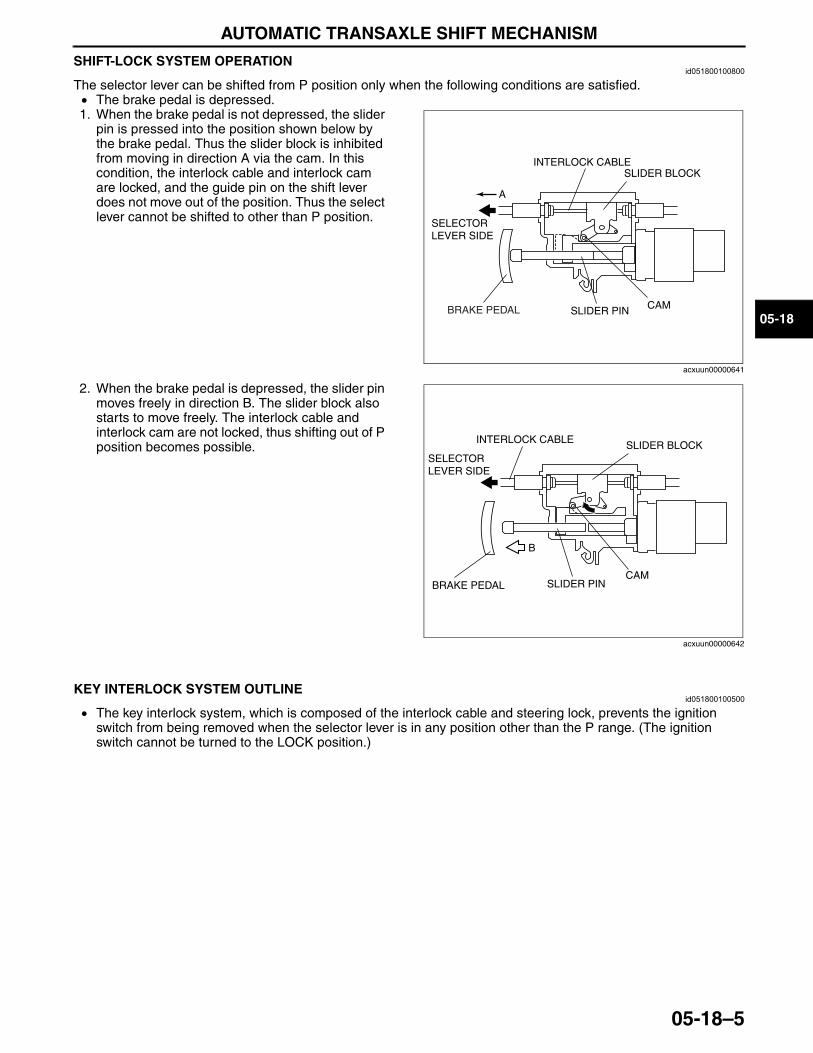
AUTOMATIC TRANSAXLE SHIFT MECHANISM
05-18–5
05-18
SHIFT-LOCK SYSTEM OPERATIONid051800100800
The selector lever can be shifted from P position only when the following conditions are satisfied.• The brake pedal is depressed.1. When the brake pedal is not depressed, the slider
pin is pressed into the position shown below by the brake pedal. Thus the slider block is inhibited from moving in direction A via the cam. In this condition, the interlock cable and interlock cam are locked, and the guide pin on the shift lever does not move out of the position. Thus the select lever cannot be shifted to other than P position.
2. When the brake pedal is depressed, the slider pin moves freely in direction B. The slider block also starts to move freely. The interlock cable and interlock cam are not locked, thus shifting out of P position becomes possible.
End Of SieNG: KEY INTERLOCK SYSTEM
KEY INTERLOCK SYSTEM OUTLINEid051800100500
• The key interlock system, which is composed of the interlock cable and steering lock, prevents the ignition switch from being removed when the selector lever is in any position other than the P range. (The ignition switch cannot be turned to the LOCK position.)
End Of Sie
SLIDER PIN CAM
INTERLOCK CABLESLIDER BLOCK
A
SELECTORLEVER SIDE
BRAKE PEDAL
acxuun00000641
SLIDER PINCAM
INTERLOCK CABLE SLIDER BLOCK
B
SELECTORLEVER SIDE
BRAKE PEDAL
acxuun00000642
3423-1U-06H(05-18).fm 5 ページ 2006年11月21日 火曜日 午後5時20分
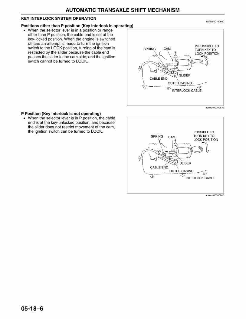
AUTOMATIC TRANSAXLE SHIFT MECHANISM
05-18–6
KEY INTERLOCK SYSTEM OPERATIONid051800100600
Positions other than P position (Key interlock is operating)• When the selector lever is in a position or range
other than P position, the cable end is set at the key-locked position. When the engine is switched off and an attempt is made to turn the ignition switch to the LOCK position, turning of the cam is restricted by the slider because the cable end pushes the slider to the cam side, and the ignition switch cannot be turned to LOCK.
P Position (Key interlock is not operating)• When the selector lever is in P position, the cable
end is at the key-unlocked position, and because the slider does not restrict movement of the cam, the ignition switch can be turned to LOCK.
End Of Sie
SPRING CAM
CABLE ENDSLIDER
OUTER CASING
INTERLOCK CABLE
IMPOSSIBLE TO TURN KEY TO LOCK POSITION
acxuun00000639
SPRING CAM
CABLE ENDSLIDER
OUTER CASING
INTERLOCK CABLE
POSSIBLE TO TURN KEY TO LOCK POSITION
acxuun00000640
3423-1U-06H(05-18).fm 6 ページ 2006年11月21日 火曜日 午後5時20分
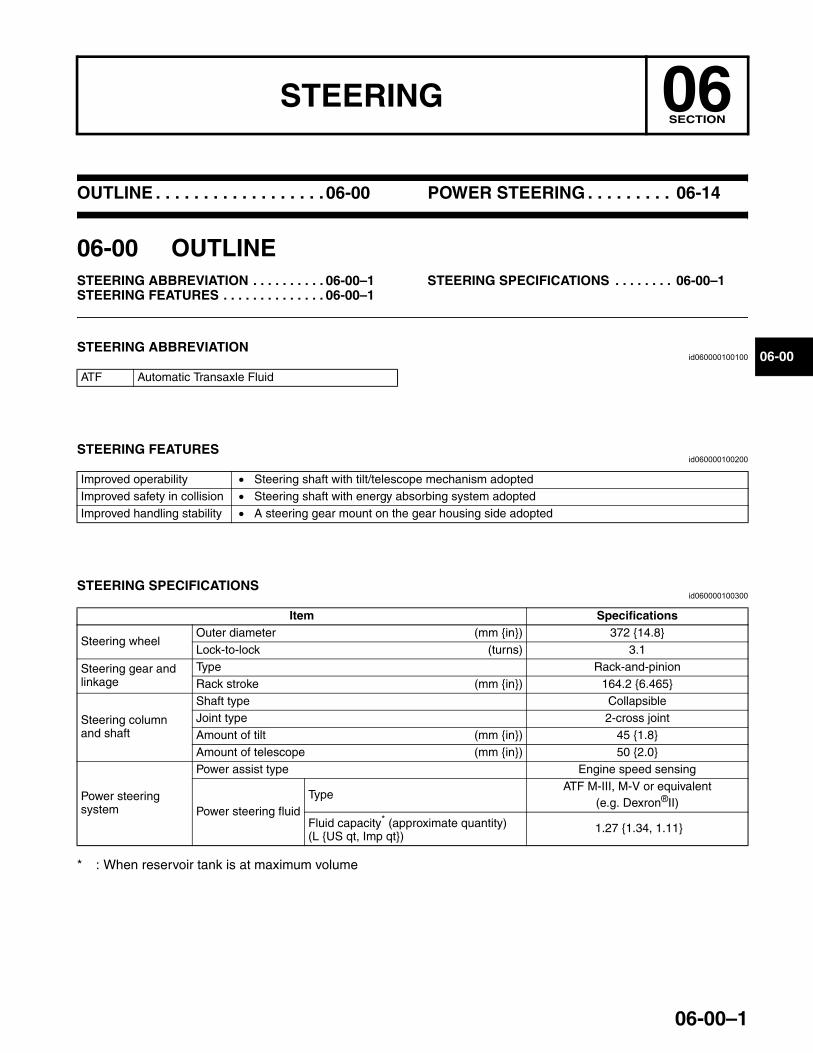
06-00–1
06STEERINGSECTION
06-00
Toc of SCTOUTLINE . . . . . . . . . . . . . . . . . .06-00 POWER STEERING . . . . . . . . . 06-14
Toc of SCT
06-00 OUTLINESTEERING ABBREVIATION . . . . . . . . . . 06-00–1STEERING FEATURES . . . . . . . . . . . . . . 06-00–1
STEERING SPECIFICATIONS . . . . . . . . 06-00–1
End of TocNG: STEERINGSTEERING ABBREVIATION
id060000100100
End Of Sie
STEERING FEATURESid060000100200
End Of Sie
STEERING SPECIFICATIONSid060000100300
* : When reservoir tank is at maximum volume
End Of Sie
ATF Automatic Transaxle Fluid
Improved operability • Steering shaft with tilt/telescope mechanism adoptedImproved safety in collision • Steering shaft with energy absorbing system adoptedImproved handling stability • A steering gear mount on the gear housing side adopted
Item Specifications
Steering wheelOuter diameter (mm {in}) 372 {14.8}Lock-to-lock (turns) 3.1
Steering gear and linkage
Type Rack-and-pinionRack stroke (mm {in}) 164.2 {6.465}
Steering column and shaft
Shaft type CollapsibleJoint type 2-cross jointAmount of tilt (mm {in}) 45 {1.8}Amount of telescope (mm {in}) 50 {2.0}
Power steering system
Power assist type Engine speed sensing
Power steering fluidType
ATF M-III, M-V or equivalent (e.g. Dexron®II)
Fluid capacity* (approximate quantity)(L {US qt, Imp qt})
1.27 {1.34, 1.11}
3423-1U-06H(06-00).fm 1 ページ 2006年11月21日 火曜日 午後5時20分

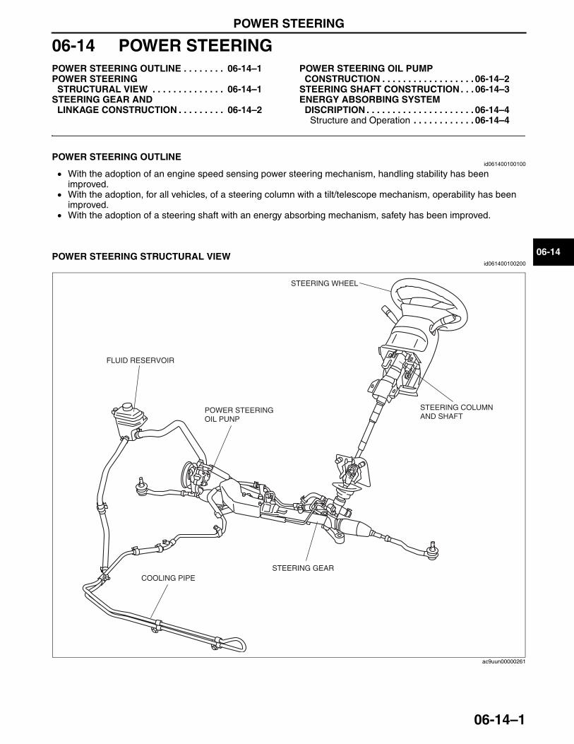
POWER STEERING
06-14–1
06-14
06-14 POWER STEERINGPOWER STEERING OUTLINE . . . . . . . . 06-14–1POWER STEERING
STRUCTURAL VIEW . . . . . . . . . . . . . . 06-14–1STEERING GEAR AND
LINKAGE CONSTRUCTION . . . . . . . . . 06-14–2
POWER STEERING OIL PUMP CONSTRUCTION . . . . . . . . . . . . . . . . . . 06-14–2
STEERING SHAFT CONSTRUCTION . . . 06-14–3ENERGY ABSORBING SYSTEM
DISCRIPTION . . . . . . . . . . . . . . . . . . . . . 06-14–4Structure and Operation . . . . . . . . . . . . 06-14–4
End of TocNG: STEERINGPOWER STEERING OUTLINE
id061400100100
• With the adoption of an engine speed sensing power steering mechanism, handling stability has been improved.
• With the adoption, for all vehicles, of a steering column with a tilt/telescope mechanism, operability has been improved.
• With the adoption of a steering shaft with an energy absorbing mechanism, safety has been improved.End Of Sie
POWER STEERING STRUCTURAL VIEWid061400100200
End Of SieNG: STEERING GEAR AND LINKAGE
FLUID RESERVOIR
POWER STEERING OIL PUNP
STEERING COLUMN AND SHAFT
STEERING WHEEL
STEERING GEARCOOLING PIPE
ac9uun00000261
3423-1U-06H(06-14).fm 1 ページ 2006年11月21日 火曜日 午後5時21分
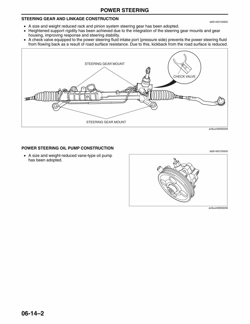
POWER STEERING
06-14–2
STEERING GEAR AND LINKAGE CONSTRUCTIONid061400100600
• A size and weight reduced rack and pinion system steering gear has been adopted.• Heightened support rigidity has been achieved due to the integration of the steering gear mounts and gear
housing, improving response and steering stability.• A check valve equipped to the power steering fluid intake port (pressure side) prevents the power steering fluid
from flowing back as a result of road surface resistance. Due to this, kickback from the road surface is reduced.
End Of SieNG: POWER STEERING OIL PUMP
POWER STEERING OIL PUMP CONSTRUCTIONid061400100500
• A size and weight-reduced vane-type oil pump has been adopted.
End Of SieNG: STEERING WHEEL AND COLUMN
CHECK VALVE
STEERING GEAR MOUNT
STEERING GEAR MOUNT
ac9uun00000249
ac9uun00000248
3423-1U-06H(06-14).fm 2 ページ 2006年11月21日 火曜日 午後5時21分
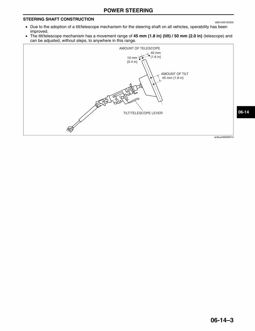
POWER STEERING
06-14–3
06-14
STEERING SHAFT CONSTRUCTIONid061400100300
• Due to the adoption of a tilt/telescope mechanism for the steering shaft on all vehicles, operability has been improved.
• The tilt/telescope mechanism has a movement range of 45 mm {1.8 in} (tilt) / 50 mm {2.0 in} (telescope) and can be adjusted, without steps, to anywhere in this range.
End Of Sie
AMOUNT OF TILT 45 mm {1.8 in}
TILT/TELESCOPE LEVER
AMOUNT OF TELESCOPE40 mm {1.6 in}10 mm
{0.4 in}
ac9uun00000514
3423-1U-06H(06-14).fm 3 ページ 2006年11月21日 火曜日 午後5時21分
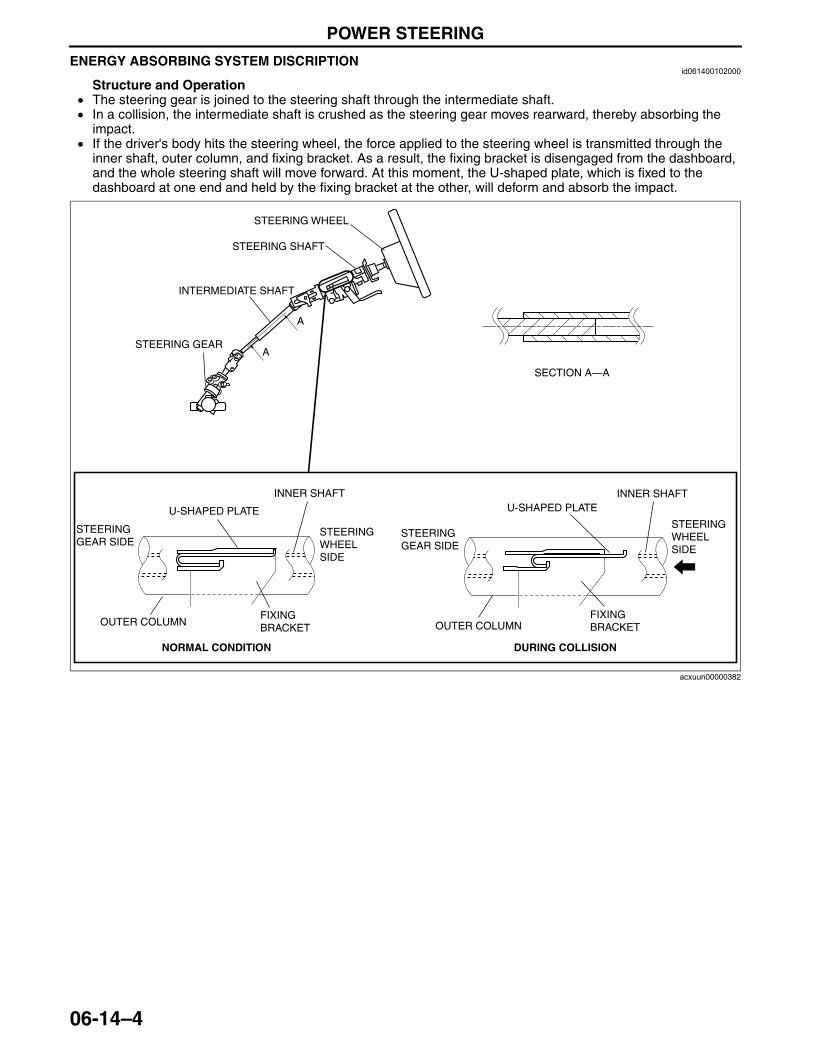
POWER STEERING
06-14–4
ENERGY ABSORBING SYSTEM DISCRIPTIONid061400102000
Structure and Operation• The steering gear is joined to the steering shaft through the intermediate shaft.• In a collision, the intermediate shaft is crushed as the steering gear moves rearward, thereby absorbing the
impact.• If the driver's body hits the steering wheel, the force applied to the steering wheel is transmitted through the
inner shaft, outer column, and fixing bracket. As a result, the fixing bracket is disengaged from the dashboard, and the whole steering shaft will move forward. At this moment, the U-shaped plate, which is fixed to the dashboard at one end and held by the fixing bracket at the other, will deform and absorb the impact.
End Of Sie
A
A
STEERING WHEEL
STEERING SHAFT
INTERMEDIATE SHAFT
SECTION A—A
STEERING GEAR
STEERING GEAR SIDE
OUTER COLUMN OUTER COLUMNFIXINGBRACKET
FIXINGBRACKET
NORMAL CONDITION DURING COLLISION
U-SHAPED PLATE U-SHAPED PLATEINNER SHAFT INNER SHAFT
STEERING GEAR SIDE
STEERING WHEEL SIDE
STEERING WHEEL SIDE
acxuun00000382
3423-1U-06H(06-14).fm 4 ページ 2006年11月21日 火曜日 午後5時21分
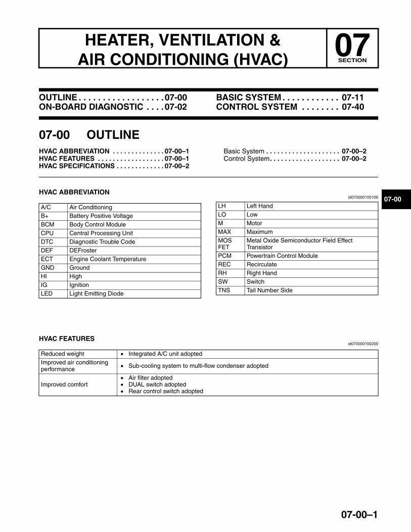
07-00–1
07HEATER, VENTILATION & AIR CONDITIONING (HVAC) SECTION
07-00
Toc of SCTOUTLINE . . . . . . . . . . . . . . . . . .07-00ON-BOARD DIAGNOSTIC . . . .07-02
BASIC SYSTEM . . . . . . . . . . . . 07-11CONTROL SYSTEM . . . . . . . . 07-40
Toc of SCT
07-00 OUTLINEHVAC ABBREVIATION . . . . . . . . . . . . . . 07-00–1HVAC FEATURES . . . . . . . . . . . . . . . . . . 07-00–1HVAC SPECIFICATIONS . . . . . . . . . . . . . 07-00–2
Basic System . . . . . . . . . . . . . . . . . . . . 07-00–2Control System. . . . . . . . . . . . . . . . . . . 07-00–2
End of TocNG: HEATER, VENTILATION AND AIR CONDITIONING (HVAC)HVAC ABBREVIATION
id070000100100
End Of Sie
HVAC FEATURESid070000100200
End Of Sie
A/C Air ConditioningB+ Battery Positive VoltageBCM Body Control ModuleCPU Central Processing UnitDTC Diagnostic Trouble CodeDEF DEFrosterECT Engine Coolant TemperatureGND GroundHI HighIG IgnitionLED Light Emitting Diode
LH Left HandLO LowM MotorMAX MaximumMOS FET
Metal Oxide Semiconductor Field Effect Transistor
PCM Powertrain Control ModuleREC RecirculateRH Right HandSW SwitchTNS Tail Number Side
Reduced weight • Integrated A/C unit adoptedImproved air conditioning performance • Sub-cooling system to multi-flow condenser adopted
Improved comfort• Air filter adopted• DUAL switch adopted• Rear control switch adopted
3423-1U-06H(07-00).fm 1 ページ 2006年11月21日 火曜日 午後5時21分
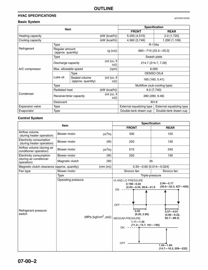
OUTLINE
07-00–2
HVAC SPECIFICATIONSid070000100300
Basic System
Control System
ItemSpecification
FRONT REARHeating capacity (kW {kcal/h}) 5.250 {4,515} 2.0 {1,720}Cooling capacity (kW {kcal/h}) 4.360 {3,749} 1.290 {1,109}
RefrigerantType R-134aRegular amount (approx. quantity) (g {oz}) 660—710 {23.3—25.0}
A/C compressor
Type Swash plate
Discharge capacity (ml {cc, floz}) 214.7 {214.7, 7.26}
Max. allowable speed (rpm) 6,000
Lube oilType DENSO OIL8Sealed volume (approx. quantity)
(ml {cc, floz}) 160 {160, 5.41}
Condenser
Type Multiflow (sub-cooling type)Radiated heat (kW {kcal/h}) 9.0 {7,740}
Receiver/drier capacity (ml {cc, floz}) 280 {280, 9.46}
Desiccant XH-9Expansion valve Type External equalizing type External equalizing typeEvaporator Type Double-tank drawn cup Double-tank drawn cup
ItemSpecification
FRONT REARAirflow volume (during heater operation) Blower motor (m3/h) 330 120
Electricity consumption (during heater operation) Blower motor (W) 220 130
Airflow volume (during air conditioner operation) Blower motor (m3/h) 515 240
Electricity consumption (during air conditioner operation)
Blower motor (W) 250 130
Magnetic clutch (W) 35
Magnetic clutch clearance (approx. quantity) (mm {in}) 0.35—0.60 {0.014—0.024}Fan type Blower motor Sirocco fan Sirocco fan
Refrigerant pressure switch
Type Triple-pressureOperating pressure
(MPa {kgf/cm2, psi})
ON
OFF
ON
OFF
0.198—0.22{2.02—2.24, 28.8—31.9
0.57—0.61{5.82—6.22,82.7—88.4}
1.11—1.35{11.4—13.7, 161—195}
1.44—1.60{14.7—16.3, 209—232}
0.02{0.20, 2.90}
HI AND LO PRESSURE
MEDIUM-PRESSURE
2.94—3.17{30.0—32.3, 427—459}
3423-1U-06H(07-00).fm 2 ページ 2006年11月21日 火曜日 午後5時21分
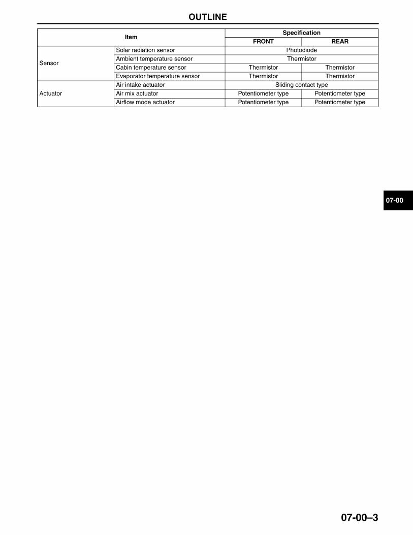
OUTLINE
07-00–3
07-00
End Of Sie
Sensor
Solar radiation sensor PhotodiodeAmbient temperature sensor ThermistorCabin temperature sensor Thermistor ThermistorEvaporator temperature sensor Thermistor Thermistor
ActuatorAir intake actuator Sliding contact typeAir mix actuator Potentiometer type Potentiometer typeAirflow mode actuator Potentiometer type Potentiometer type
ItemSpecification
FRONT REAR
3423-1U-06H(07-00).fm 3 ページ 2006年11月21日 火曜日 午後5時21分

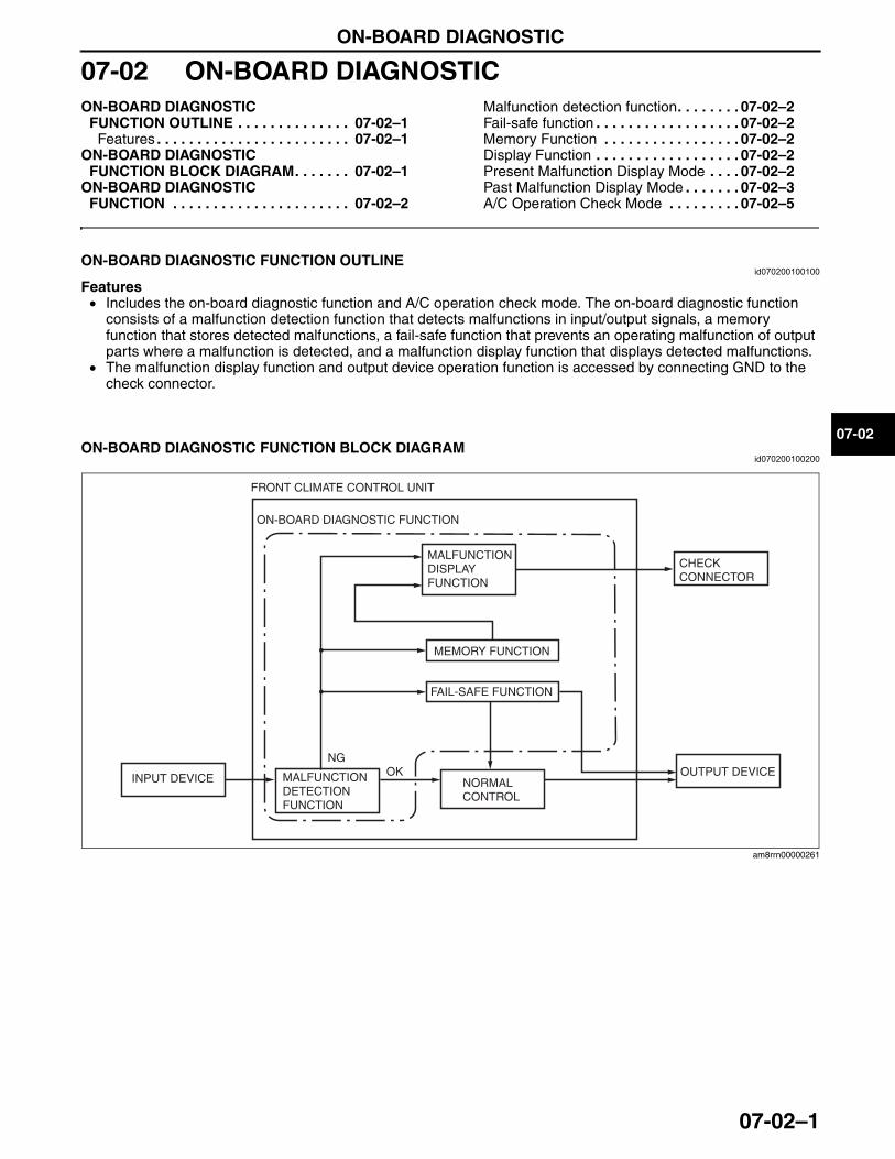
ON-BOARD DIAGNOSTIC
07-02–1
07-02
07-02 ON-BOARD DIAGNOSTICON-BOARD DIAGNOSTIC
FUNCTION OUTLINE . . . . . . . . . . . . . . 07-02–1Features . . . . . . . . . . . . . . . . . . . . . . . . 07-02–1
ON-BOARD DIAGNOSTIC FUNCTION BLOCK DIAGRAM. . . . . . . 07-02–1
ON-BOARD DIAGNOSTIC FUNCTION . . . . . . . . . . . . . . . . . . . . . . 07-02–2
Malfunction detection function. . . . . . . . 07-02–2Fail-safe function . . . . . . . . . . . . . . . . . . 07-02–2Memory Function . . . . . . . . . . . . . . . . . 07-02–2Display Function . . . . . . . . . . . . . . . . . . 07-02–2Present Malfunction Display Mode . . . . 07-02–2Past Malfunction Display Mode . . . . . . . 07-02–3A/C Operation Check Mode . . . . . . . . . 07-02–5
End of TocNG: ON-BOARD DIAGNOSTIC FUNCTIONON-BOARD DIAGNOSTIC FUNCTION OUTLINE
id070200100100
Features• Includes the on-board diagnostic function and A/C operation check mode. The on-board diagnostic function
consists of a malfunction detection function that detects malfunctions in input/output signals, a memory function that stores detected malfunctions, a fail-safe function that prevents an operating malfunction of output parts where a malfunction is detected, and a malfunction display function that displays detected malfunctions.
• The malfunction display function and output device operation function is accessed by connecting GND to the check connector.
End Of Sie
ON-BOARD DIAGNOSTIC FUNCTION BLOCK DIAGRAMid070200100200
End Of Sie
NGOK
FRONT CLIMATE CONTROL UNIT
ON-BOARD DIAGNOSTIC FUNCTION
INPUT DEVICE MALFUNCTION DETECTION FUNCTION
NORMAL CONTROL
OUTPUT DEVICE
MALFUNCTION DISPLAYFUNCTION
MEMORY FUNCTION
FAIL-SAFE FUNCTION
CHECKCONNECTOR
am8rrn00000261
3423-1U-06H(07-02).fm 1 ページ 2006年11月21日 火曜日 午後5時22分
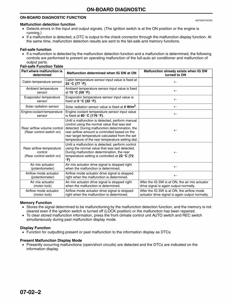
ON-BOARD DIAGNOSTIC
07-02–2
ON-BOARD DIAGNOSTIC FUNCTIONid070200100300
Malfunction detection function• Detects errors in the input and output signals. (The ignition switch is at the ON position or the engine is
running.)• If a malfunction is detected, a DTC is output to the check connector through the malfunction display function. At
the same time, malfunction detection results are sent to the fail-safe and memory functions.
Fail-safe function• If a malfunction is detected by the malfunction detection function and a malfunction is determined, the following
controls are performed to prevent an operating malfunction of the full-auto air conditioner and malfunction of output parts.
Fail-safe Function Table
Memory Function• Stores the signal determined to be malfunctioning by the malfunction detection function, and the memory is not
cleared even if the ignition switch is turned off (LOCK position) or the malfunction has been repaired.• To clear stored malfunction information, press the front climate control unit AUTO switch and REC switch
simultaneously during past malfunction display mode.
Display Function• Function for outputting present or past malfunction to the information display as DTCs.
Present Malfunction Display Mode• Presently occurring malfunctions (open/short circuits) are detected and the DTCs are indicated on the
information display.
Part where malfunction is determined Malfunction determined when IG SW at ON Malfunction already exists when IG SW
turned to ON
Cabin temperature sensor Cabin temperature sensor input value is fixed at 25 °C {77 °F}. ←
Ambient temperature sensor
Ambient temperature sensor input value is fixed at 15 °C {59 °F}. ←
Evaporator temperature sensor
Evaporator temperature sensor input value is fixed at 0 °C {32 °F}. ←
Solar radiation sensor Solar radiation sensor value is fixed at 0 W/m2. ←
Engine coolant temperature sensor
Engine coolant temperature sensor input value is fixed at 80 °C {176 °F}. ←
Rear airflow volume control (Rear control switch on)
Until a malfunction is detected, perform manual control using the normal value that was last detected. During malfunction determination, the rear airflow amount is controlled based on the rear target temperature calculated from the set temperature of the rear temperature setting dial.
←
Rear airflow temperature control
(Rear control switch on)
Until a malfunction is detected, perform control using the normal value that was last detected. During malfunction determination, the rear temperature setting is controlled at 22 °C {72 °F}
←
Air mix actuator (potentiometer)
Air mix actuator drive signal is stopped right when the malfunction is determined. ←
Airflow mode actuator (potentiometer)
Airflow mode actuator drive signal is stopped right when the malfunction is determined. ←
Air mix actuator (motor lock)
Air mix actuator drive signal is stopped right when the malfunction is determined.
After the IG SW is at ON, the air mix actuator drive signal is again output normally.
Airflow mode actuator (motor lock)
Airflow mode actuator drive signal is stopped right when the malfunction is determined.
After the IG SW is at ON, the airflow mode actuator drive signal is again output normally.
3423-1U-06H(07-02).fm 2 ページ 2006年11月21日 火曜日 午後5時22分
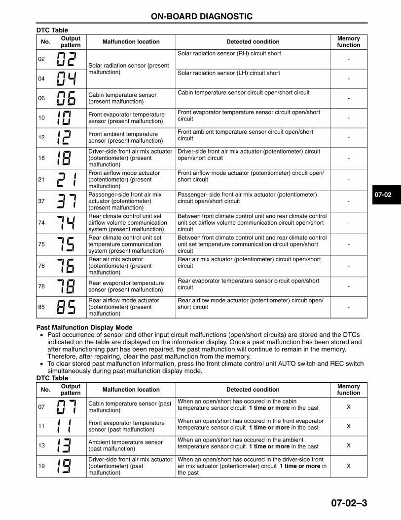
ON-BOARD DIAGNOSTIC
07-02–3
07-02
DTC Table
Past Malfunction Display Mode• Past occurrence of sensor and other input circuit malfunctions (open/short circuits) are stored and the DTCs
indicated on the table are displayed on the information display. Once a past malfunction has been stored and after malfunctioning part has been repaired, the past malfunction will continue to remain in the memory. Therefore, after repairing, clear the past malfunction from the memory.
• To clear stored past malfunction information, press the front climate control unit AUTO switch and REC switch simultaneously during past malfunction display mode.
DTC Table
No. Output pattern Malfunction location Detected condition Memory
function
02Solar radiation sensor (present malfunction)
Solar radiation sensor (RH) circuit short-
04Solar radiation sensor (LH) circuit short
-
06 Cabin temperature sensor (present malfunction)
Cabin temperature sensor circuit open/short circuit-
10 Front evaporator temperature sensor (present malfunction)
Front evaporator temperature sensor circuit open/short circuit -
12 Front ambient temperature sensor (present malfunction)
Front ambient temperature sensor circuit open/short circuit -
18Driver-side front air mix actuator (potentiometer) (present malfunction)
Driver-side front air mix actuator (potentiometer) circuit open/short circuit -
21Front airflow mode actuator (potentiometer) (present malfunction)
Front airflow mode actuator (potentiometer) circuit open/short circuit -
37Passenger-side front air mix actuator (potentiometer) (present malfunction)
Passenger- side front air mix actuator (potentiometer) circuit open/short circuit -
74Rear climate control unit set airflow volume communication system (present malfunction)
Between front climate control unit and rear climate control unit set airflow volume communication circuit open/short circuit
-
75Rear climate control unit set temperature communication system (present malfunction)
Between front climate control unit and rear climate control unit set temperature communication circuit open/short circuit
-
76Rear air mix actuator (potentiometer) (present malfunction)
Rear air mix actuator (potentiometer) circuit open/short circuit -
78 Rear evaporator temperature sensor (present malfunction)
Rear evaporator temperature sensor circuit open/short circuit -
85Rear airflow mode actuator (potentiometer) (present malfunction)
Rear airflow mode actuator (potentiometer) circuit open/short circuit -
No. Output pattern Malfunction location Detected condition Memory
function
07 Cabin temperature sensor (past malfunction)
When an open/short has occured in the cabin temperature sensor circuit 1 time or more in the past X
11 Front evaporator temperature sensor (past malfunction)
When an open/short has occured in the front evaporator temperature sensor circuit 1 time or more in the past X
13 Ambient temperature sensor (past malfunction)
When an open/short has occured in the ambient temperature sensor circuit 1 time or more in the past X
19Driver-side front air mix actuator (potentiometer) (past malfunction)
When an open/short has occured in the driver-side front air mix actuator (potentiometer) circuit 1 time or more in the past
X
3423-1U-06H(07-02).fm 3 ページ 2006年11月21日 火曜日 午後5時22分
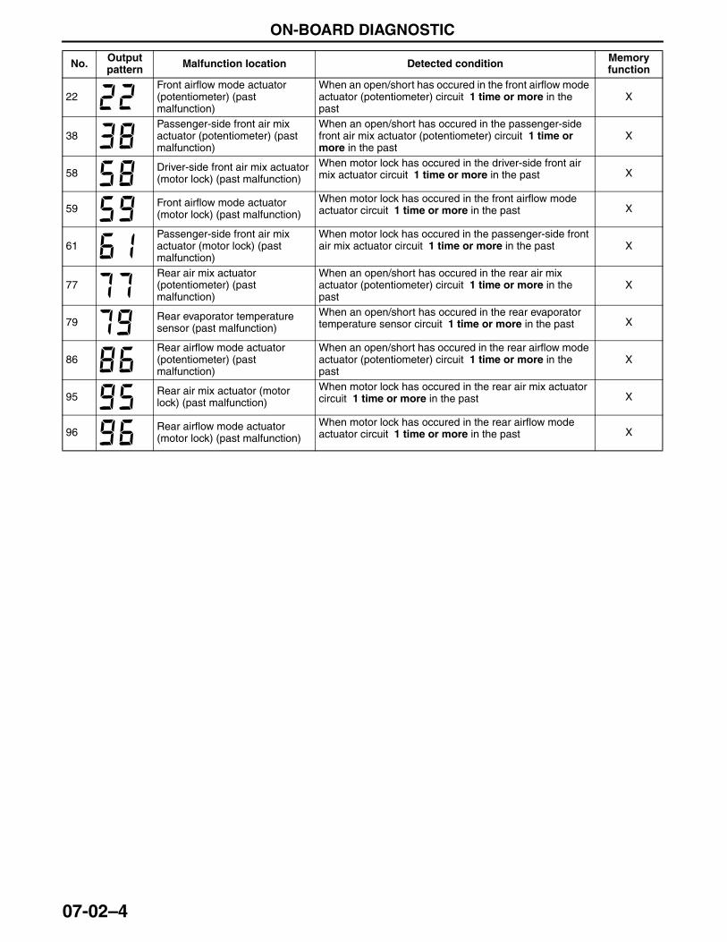
ON-BOARD DIAGNOSTIC
07-02–4
22Front airflow mode actuator (potentiometer) (past malfunction)
When an open/short has occured in the front airflow mode actuator (potentiometer) circuit 1 time or more in the past
X
38Passenger-side front air mix actuator (potentiometer) (past malfunction)
When an open/short has occured in the passenger-side front air mix actuator (potentiometer) circuit 1 time or more in the past
X
58 Driver-side front air mix actuator (motor lock) (past malfunction)
When motor lock has occured in the driver-side front air mix actuator circuit 1 time or more in the past X
59 Front airflow mode actuator (motor lock) (past malfunction)
When motor lock has occured in the front airflow mode actuator circuit 1 time or more in the past X
61Passenger-side front air mix actuator (motor lock) (past malfunction)
When motor lock has occured in the passenger-side front air mix actuator circuit 1 time or more in the past X
77Rear air mix actuator (potentiometer) (past malfunction)
When an open/short has occured in the rear air mix actuator (potentiometer) circuit 1 time or more in the past
X
79 Rear evaporator temperature sensor (past malfunction)
When an open/short has occured in the rear evaporator temperature sensor circuit 1 time or more in the past X
86Rear airflow mode actuator (potentiometer) (past malfunction)
When an open/short has occured in the rear airflow mode actuator (potentiometer) circuit 1 time or more in the past
X
95 Rear air mix actuator (motor lock) (past malfunction)
When motor lock has occured in the rear air mix actuator circuit 1 time or more in the past X
96 Rear airflow mode actuator (motor lock) (past malfunction)
When motor lock has occured in the rear airflow mode actuator circuit 1 time or more in the past X
No. Output pattern Malfunction location Detected condition Memory
function
3423-1U-06H(07-02).fm 4 ページ 2006年11月21日 火曜日 午後5時22分
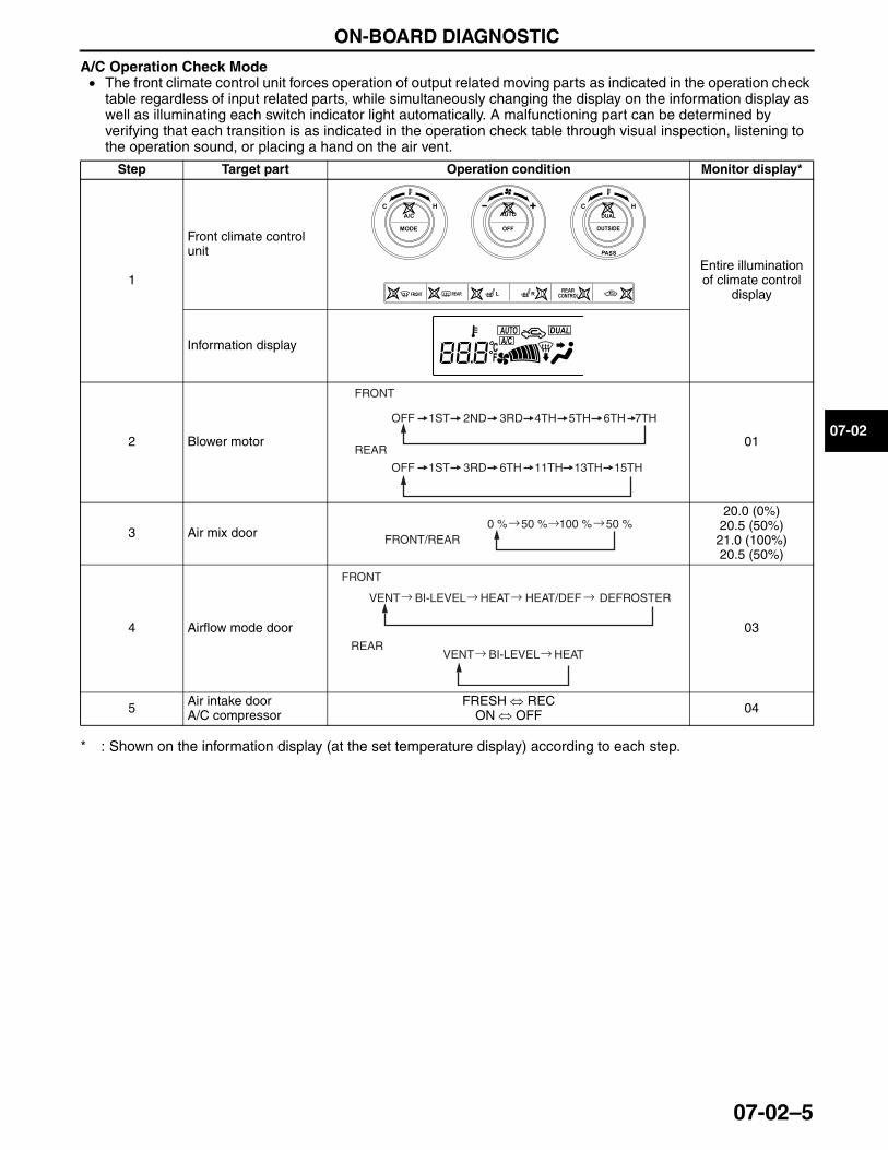
ON-BOARD DIAGNOSTIC
07-02–5
07-02
A/C Operation Check Mode• The front climate control unit forces operation of output related moving parts as indicated in the operation check
table regardless of input related parts, while simultaneously changing the display on the information display as well as illuminating each switch indicator light automatically. A malfunctioning part can be determined by verifying that each transition is as indicated in the operation check table through visual inspection, listening to the operation sound, or placing a hand on the air vent.
* : Shown on the information display (at the set temperature display) according to each step.
End Of Sie
Step Target part Operation condition Monitor display*
1
Front climate control unit
Entire illumination of climate control
display
Information display
2 Blower motor 01
3 Air mix door
20.0 (0%)20.5 (50%)21.0 (100%)20.5 (50%)
4 Airflow mode door 03
5 Air intake doorA/C compressor
FRESH ⇔ RECON ⇔ OFF 04
FRONT
REAR
1STOFF 2ND 3RD 4TH 5TH 6TH 7TH
1STOFF 3RD 6TH 11TH 13TH 15TH
→ →0 % 50 % →50 %100 %FRONT/REAR
→ → → →
→ →
FRONT
REAR
VENT BI-LEVEL DEFROSTERHEAT/DEFHEAT
VENT BI-LEVEL HEAT
3423-1U-06H(07-02).fm 5 ページ 2006年11月21日 火曜日 午後5時22分

BASIC SYSTEM
07-11–1
07-11
07-11 BASIC SYSTEMBASIC SYSTEM OUTLINE . . . . . . . . . . . 07-11–1BASIC SYSTEM
STRUCTURAL VIEW . . . . . . . . . . . . . . 07-11–2Structural View . . . . . . . . . . . . . . . . . . . 07-11–2Flow Diagram . . . . . . . . . . . . . . . . . . . . 07-11–3
FRONT A/C UNIT CONSTRUCTION/OPERATION . . . . . . 07-11–4
Construction. . . . . . . . . . . . . . . . . . . . . 07-11–4Operation . . . . . . . . . . . . . . . . . . . . . . . 07-11–5
AIR FILTER FUNCTION . . . . . . . . . . . . . 07-11–7
REAR A/C UNIT CONSTRUCTION/OPERATION . . . . . . . 07-11–7
Air Mix Door Operation . . . . . . . . . . . . . 07-11–8Airflow Mode Door Operation . . . . . . . . 07-11–8
A/C COMPRESSOR CONSTRUCTION . . . . . . . . . . . . . . . . . . 07-11–9
Construction . . . . . . . . . . . . . . . . . . . . . 07-11–9CONDENSER CONSTRUCTION . . . . . . . 07-11–9REFRIGERANT LINE
CONSTRUCTION . . . . . . . . . . . . . . . . . . 07-11–10
End of TocNG: HVAC BASIC SYSTEMBASIC SYSTEM OUTLINE
id071100100100
End Of Sie
Reduced weight • Integrated A/C unit adoptedImproved air conditioning performance • Sub-cooling system to multi-flow condenser adopted
Improved comfort • Air filter adopted
3423-1U-06H(07-11).fm 1 ページ 2006年11月21日 火曜日 午後5時23分
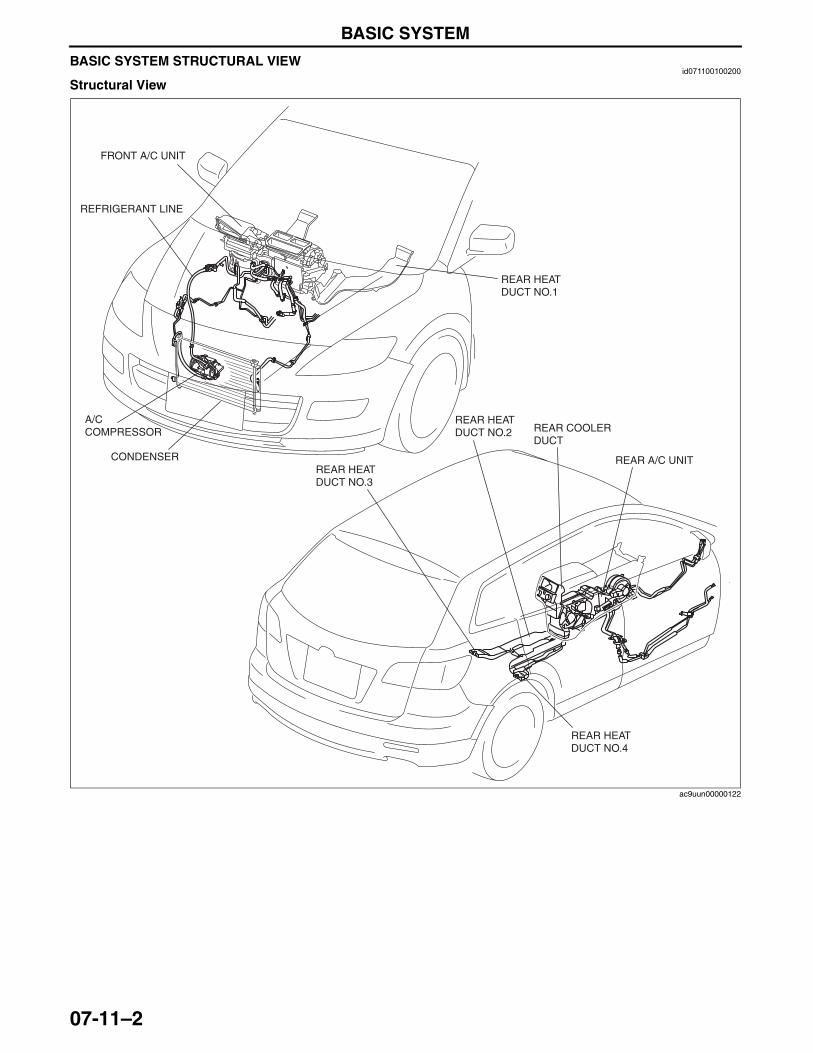
BASIC SYSTEM
07-11–2
BASIC SYSTEM STRUCTURAL VIEWid071100100200
Structural View
FRONT A/C UNIT
REFRIGERANT LINE
A/C COMPRESSOR
CONDENSER
REAR HEAT DUCT NO.1
REAR HEAT DUCT NO.2
REAR HEAT DUCT NO.3
REAR HEAT DUCT NO.4
REAR COOLER DUCT
REAR A/C UNIT
ac9uun00000122
3423-1U-06H(07-11).fm 2 ページ 2006年11月21日 火曜日 午後5時23分
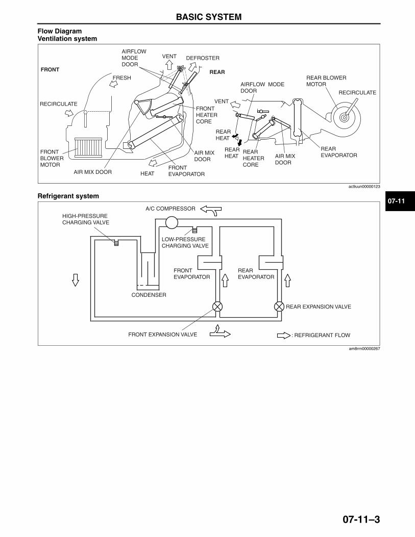
BASIC SYSTEM
07-11–3
07-11
Flow DiagramVentilation system
Refrigerant system
End Of SieNG: FRONT A/C UNIT
FRONT REAR
VENT
HEAT
DEFROSTERAIRFLOW MODE DOOR
RECIRCULATE
FRESH
FRONT BLOWER MOTOR
AIR MIX DOORFRONT EVAPORATOR
AIR MIX DOOR
FRONT HEATER CORE
RECIRCULATE
REAR HEAT
VENT
AIRFLOW MODE DOOR
REAR EVAPORATOR
REAR BLOWER MOTOR
REARHEATER CORE
AIR MIX DOOR
REAR HEAT
ac9uun00000123
A/C COMPRESSOR
CONDENSER
FRONTEVAPORATOR
REAREVAPORATOR
LOW-PRESSURE CHARGING VALVE
HIGH-PRESSURE CHARGING VALVE
REAR EXPANSION VALVE
FRONT EXPANSION VALVE : REFRIGERANT FLOW
am8rrn00000267
3423-1U-06H(07-11).fm 3 ページ 2006年11月21日 火曜日 午後5時23分
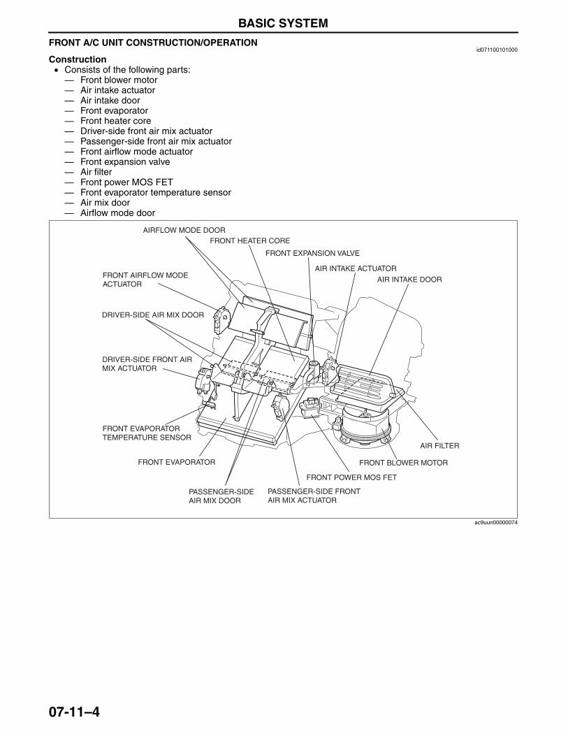
BASIC SYSTEM
07-11–4
FRONT A/C UNIT CONSTRUCTION/OPERATIONid071100101000
Construction• Consists of the following parts:— Front blower motor— Air intake actuator— Air intake door— Front evaporator— Front heater core— Driver-side front air mix actuator— Passenger-side front air mix actuator— Front airflow mode actuator— Front expansion valve— Air filter— Front power MOS FET— Front evaporator temperature sensor— Air mix door— Airflow mode door
AIR INTAKE DOOR
AIRFLOW MODE DOOR
AIR INTAKE ACTUATOR
FRONT POWER MOS FET
FRONT BLOWER MOTOR
FRONT HEATER CORE
FRONT EXPANSION VALVE
DRIVER-SIDE FRONT AIR MIX ACTUATOR
PASSENGER-SIDE FRONT AIR MIX ACTUATOR
AIR FILTER
FRONT AIRFLOW MODE ACTUATOR
DRIVER-SIDE AIR MIX DOOR
PASSENGER-SIDE AIR MIX DOOR
FRONT EVAPORATOR TEMPERATURE SENSOR
FRONT EVAPORATOR
ac9uun00000074
3423-1U-06H(07-11).fm 4 ページ 2006年11月21日 火曜日 午後5時23分
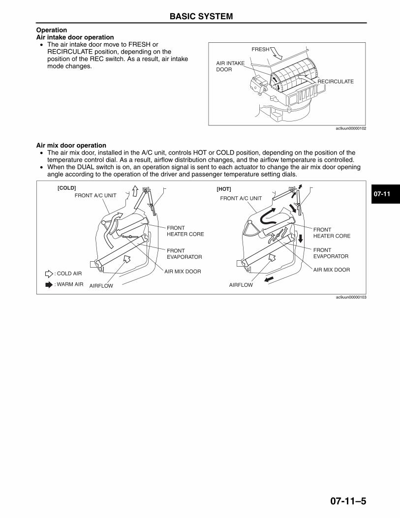
BASIC SYSTEM
07-11–5
07-11
OperationAir intake door operation• The air intake door move to FRESH or
RECIRCULATE position, depending on the position of the REC switch. As a result, air intake mode changes.
Air mix door operation• The air mix door, installed in the A/C unit, controls HOT or COLD position, depending on the position of the
temperature control dial. As a result, airflow distribution changes, and the airflow temperature is controlled.• When the DUAL switch is on, an operation signal is sent to each actuator to change the air mix door opening
angle according to the operation of the driver and passenger temperature setting dials.
AIR INTAKE DOOR
FRESH
RECIRCULATE
ac9uun00000102
FRONT HEATER CORE
FRONT EVAPORATOR
FRONT A/C UNIT
[COLD]
AIR MIX DOOR
FRONT HEATER CORE
FRONT EVAPORATOR
[HOT]
: COLD AIR
: WARM AIR
AIR MIX DOOR
AIRFLOW AIRFLOW
FRONT A/C UNIT
ac9uun00000103
3423-1U-06H(07-11).fm 5 ページ 2006年11月21日 火曜日 午後5時23分
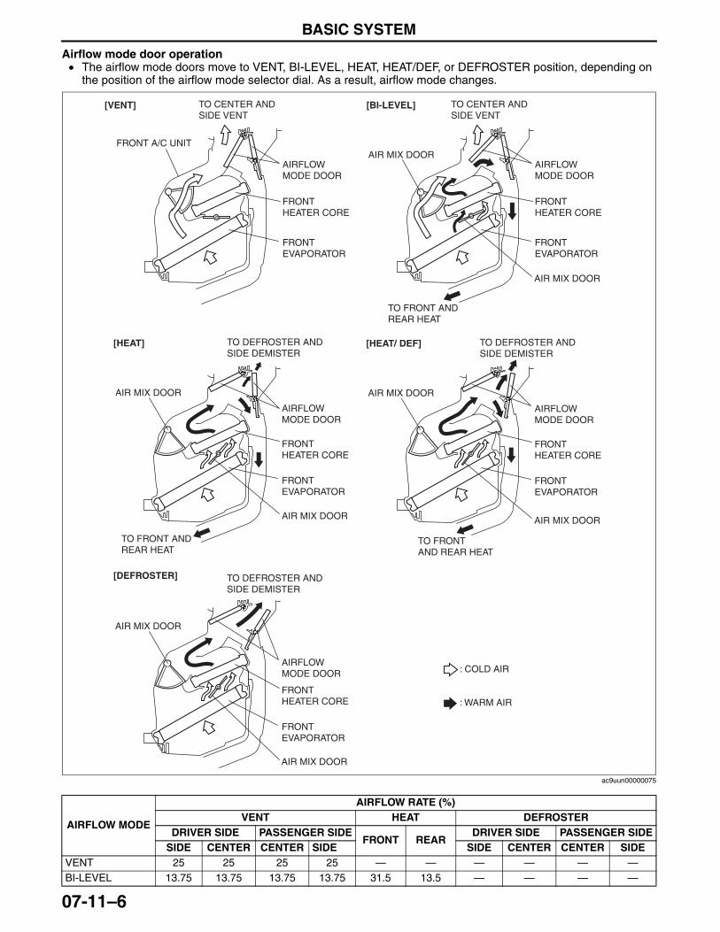
BASIC SYSTEM
07-11–6
Airflow mode door operation• The airflow mode doors move to VENT, BI-LEVEL, HEAT, HEAT/DEF, or DEFROSTER position, depending on
the position of the airflow mode selector dial. As a result, airflow mode changes.
AIRFLOW MODE
AIRFLOW RATE (%)VENT HEAT DEFROSTER
DRIVER SIDE PASSENGER SIDEFRONT REAR
DRIVER SIDE PASSENGER SIDESIDE CENTER CENTER SIDE SIDE CENTER CENTER SIDE
VENT 25 25 25 25 — — — — — —BI-LEVEL 13.75 13.75 13.75 13.75 31.5 13.5 — — — —
TO CENTER AND SIDE VENT
AIRFLOW MODE DOOR
FRONT HEATER CORE
FRONT EVAPORATOR
FRONT A/C UNIT
[VENT] TO CENTER AND SIDE VENT
AIRFLOW MODE DOOR
AIR MIX DOOR
FRONT HEATER CORE
FRONT EVAPORATOR
[BI-LEVEL]
TO DEFROSTER AND SIDE DEMISTER
TO FRONT AND REAR HEAT
TO FRONT AND REAR HEAT
AIRFLOW MODE DOOR
AIR MIX DOOR
FRONT HEATER CORE
FRONT EVAPORATOR
[HEAT/ DEF]TO DEFROSTER AND SIDE DEMISTER
TO FRONT AND REAR HEAT
AIRFLOW MODE DOOR
AIR MIX DOOR
AIR MIX DOOR
FRONT HEATER CORE
FRONT EVAPORATOR
[HEAT]
[DEFROSTER]
AIR MIX DOOR
AIR MIX DOOR
TO DEFROSTER AND SIDE DEMISTER
AIRFLOW MODE DOOR
AIR MIX DOOR
FRONT HEATER CORE
FRONT EVAPORATOR
AIR MIX DOOR
: COLD AIR
: WARM AIR
ac9uun00000075
3423-1U-06H(07-11).fm 6 ページ 2006年11月21日 火曜日 午後5時23分
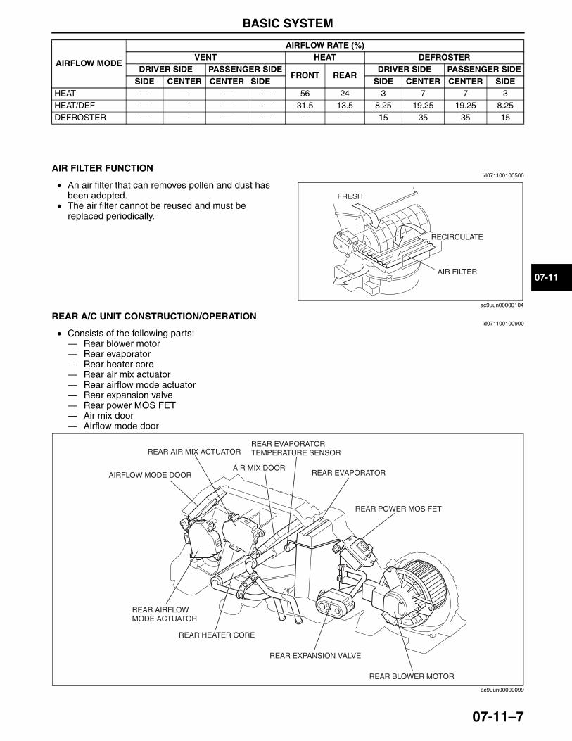
BASIC SYSTEM
07-11–7
07-11
End Of SieNG: AIR FILTER
AIR FILTER FUNCTIONid071100100500
• An air filter that can removes pollen and dust has been adopted.
• The air filter cannot be reused and must be replaced periodically.
End Of SieNG: REAR A/C UNIT
REAR A/C UNIT CONSTRUCTION/OPERATIONid071100100900
• Consists of the following parts:— Rear blower motor— Rear evaporator— Rear heater core— Rear air mix actuator— Rear airflow mode actuator— Rear expansion valve— Rear power MOS FET— Air mix door— Airflow mode door
HEAT — — — — 56 24 3 7 7 3HEAT/DEF — — — — 31.5 13.5 8.25 19.25 19.25 8.25DEFROSTER — — — — — — 15 35 35 15
AIRFLOW MODE
AIRFLOW RATE (%)VENT HEAT DEFROSTER
DRIVER SIDE PASSENGER SIDEFRONT REAR
DRIVER SIDE PASSENGER SIDESIDE CENTER CENTER SIDE SIDE CENTER CENTER SIDE
AIR FILTER
FRESH
RECIRCULATE
ac9uun00000104
REAR EVAPORATORAIR MIX DOOR
REAR AIR MIX ACTUATOR
AIRFLOW MODE DOOR
REAR EVAPORATOR TEMPERATURE SENSOR
REAR POWER MOS FET
REAR BLOWER MOTOR
REAR EXPANSION VALVE
REAR HEATER CORE
REAR AIRFLOW MODE ACTUATOR
ac9uun00000099
3423-1U-06H(07-11).fm 7 ページ 2006年11月21日 火曜日 午後5時23分
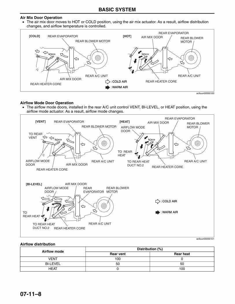
BASIC SYSTEM
07-11–8
Air Mix Door Operation• The air mix door moves to HOT or COLD position, using the air mix actuator. As a result, airflow distribution
changes, and airflow temperature is controlled.
Airflow Mode Door Operation• The airflow mode doors, installed in the rear A/C unit control VENT, BI-LEVEL, or HEAT position, using the
airflow mode actuator. As a result, airflow mode changes.
Airflow distribution
End Of SieNG: A/C COMPRESSOR
: COLD AIR
: WARM AIR
: COLD AIR
REAR EVAPORATOR
REAR BLOWER MOTOR
REAR A/C UNIT
REAR HEATER CORE
AIR MIX DOOR
: WARM AIR
[COLD] [HOT]REAR EVAPORATOR
REAR BLOWER MOTOR
REAR A/C UNIT
REAR HEATER CORE
AIR MIX DOOR
ac9uun00000100
Airflow mode Distribution (%)
Rear vent Rear heatVENT 100 0
BI-LEVEL 50 50HEAT 0 100
: COLD AIR
: WARM AIR
: COLD AIR
REAR EVAPORATOR
REAR BLOWER MOTOR
REAR A/C UNIT
REAR HEATER CORE
TO REAR VENT
AIRFLOW MODE DOOR
AIRFLOW MODE DOOR
AIR MIX DOOR
: WARM AIR
[VENT]
[BI-LEVEL]
[HEAT]REAR EVAPORATOR
REAR BLOWER MOTOR
REAR A/C UNIT
REAR HEATER CORE
TO REAR HEAT DUCT NO.2
AIR MIX DOOR
AIRFLOW MODE DOOR
REAR EVAPORATOR
REAR BLOWER MOTOR
REAR A/C UNIT
REAR HEATER CORETO REAR HEAT DUCT NO.2
TO REAR HEAT
TO REAR HEAT
AIR MIX DOOR
ac9uun00000101
3423-1U-06H(07-11).fm 8 ページ 2006年11月21日 火曜日 午後5時23分
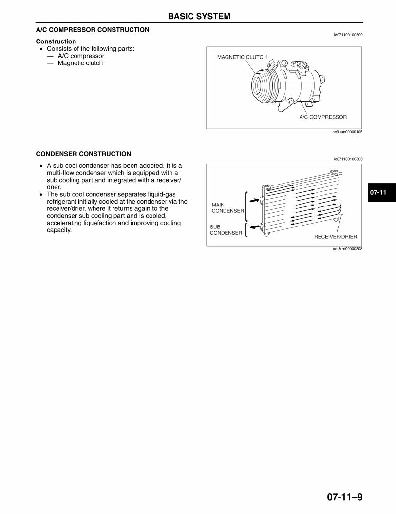
BASIC SYSTEM
07-11–9
07-11
A/C COMPRESSOR CONSTRUCTIONid071100100600
Construction• Consists of the following parts: — A/C compressor— Magnetic clutch
End Of SieNG: CONDENSER
CONDENSER CONSTRUCTIONid071100100800
• A sub cool condenser has been adopted. It is a multi-flow condenser which is equipped with a sub cooling part and integrated with a receiver/drier.
• The sub cool condenser separates liquid-gas refrigerant initially cooled at the condenser via the receiver/drier, where it returns again to the condenser sub cooling part and is cooled, accelerating liquefaction and improving cooling capacity.
End Of SieNG: REFRIGERANT LINES
MAGNETIC CLUTCH
A/C COMPRESSOR
ac9uun00000105
MAIN CONDENSER
SUB CONDENSER
RECEIVER/DRIER
am8rrn00000308
3423-1U-06H(07-11).fm 9 ページ 2006年11月21日 火曜日 午後5時23分
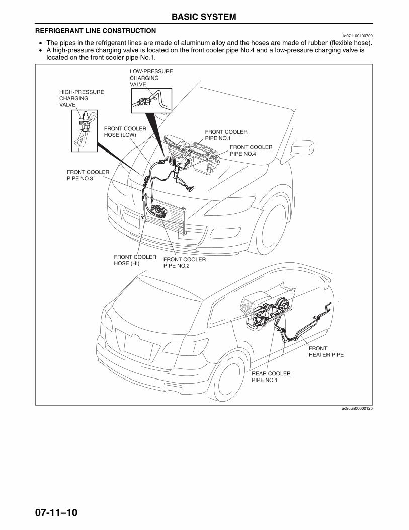
BASIC SYSTEM
07-11–10
REFRIGERANT LINE CONSTRUCTIONid071100100700
• The pipes in the refrigerant lines are made of aluminum alloy and the hoses are made of rubber (flexible hose).• A high-pressure charging valve is located on the front cooler pipe No.4 and a low-pressure charging valve is
located on the front cooler pipe No.1.
End Of Sie
FRONT COOLER PIPE NO.3
FRONT COOLER HOSE (LOW)
FRONT COOLER HOSE (HI)
FRONT COOLER PIPE NO.2
FRONT COOLER PIPE NO.1
FRONT COOLER PIPE NO.4
HIGH-PRESSURE CHARGING VALVE
LOW-PRESSURE CHARGING VALVE
REAR COOLER PIPE NO.1
FRONT HEATER PIPE
ac9uun00000125
3423-1U-06H(07-11).fm 10 ページ 2006年11月21日 火曜日 午後5時23分
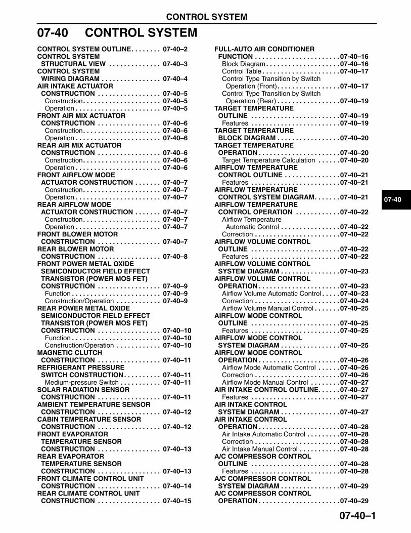
CONTROL SYSTEM
07-40–1
07-40
07-40 CONTROL SYSTEMCONTROL SYSTEM OUTLINE. . . . . . . . 07-40–2CONTROL SYSTEM
STRUCTURAL VIEW . . . . . . . . . . . . . . 07-40–3CONTROL SYSTEM
WIRING DIAGRAM . . . . . . . . . . . . . . . . 07-40–4AIR INTAKE ACTUATOR
CONSTRUCTION . . . . . . . . . . . . . . . . . 07-40–5Construction. . . . . . . . . . . . . . . . . . . . . 07-40–5Operation . . . . . . . . . . . . . . . . . . . . . . . 07-40–5
FRONT AIR MIX ACTUATOR CONSTRUCTION . . . . . . . . . . . . . . . . . 07-40–6
Construction. . . . . . . . . . . . . . . . . . . . . 07-40–6Operation . . . . . . . . . . . . . . . . . . . . . . . 07-40–6
REAR AIR MIX ACTUATOR CONSTRUCTION . . . . . . . . . . . . . . . . . 07-40–6
Construction. . . . . . . . . . . . . . . . . . . . . 07-40–6Operation . . . . . . . . . . . . . . . . . . . . . . . 07-40–6
FRONT AIRFLOW MODE ACTUATOR CONSTRUCTION . . . . . . . 07-40–7
Construction. . . . . . . . . . . . . . . . . . . . . 07-40–7Operation . . . . . . . . . . . . . . . . . . . . . . . 07-40–7
REAR AIRFLOW MODE ACTUATOR CONSTRUCTION . . . . . . . 07-40–7
Construction. . . . . . . . . . . . . . . . . . . . . 07-40–7Operation . . . . . . . . . . . . . . . . . . . . . . . 07-40–7
FRONT BLOWER MOTOR CONSTRUCTION . . . . . . . . . . . . . . . . . 07-40–7
REAR BLOWER MOTOR CONSTRUCTION . . . . . . . . . . . . . . . . . 07-40–8
FRONT POWER METAL OXIDE SEMICONDUCTOR FIELD EFFECT TRANSISTOR (POWER MOS FET) CONSTRUCTION . . . . . . . . . . . . . . . . . 07-40–9
Function . . . . . . . . . . . . . . . . . . . . . . . . 07-40–9Construction/Operation . . . . . . . . . . . . 07-40–9
REAR POWER METAL OXIDE SEMICONDUCTOR FIELD EFFECT TRANSISTOR (POWER MOS FET) CONSTRUCTION . . . . . . . . . . . . . . . . . 07-40–10
Function . . . . . . . . . . . . . . . . . . . . . . . . 07-40–10Construction/Operation . . . . . . . . . . . . 07-40–10
MAGNETIC CLUTCH CONSTRUCTION . . . . . . . . . . . . . . . . . 07-40–11
REFRIGERANT PRESSURE SWITCH CONSTRUCTION . . . . . . . . . . 07-40–11
Medium-pressure Switch . . . . . . . . . . . 07-40–11SOLAR RADIATION SENSOR
CONSTRUCTION . . . . . . . . . . . . . . . . . 07-40–11AMBIENT TEMPERATURE SENSOR
CONSTRUCTION . . . . . . . . . . . . . . . . . 07-40–12CABIN TEMPERATURE SENSOR
CONSTRUCTION . . . . . . . . . . . . . . . . . 07-40–12FRONT EVAPORATOR
TEMPERATURE SENSOR CONSTRUCTION . . . . . . . . . . . . . . . . . 07-40–13
REAR EVAPORATOR TEMPERATURE SENSOR CONSTRUCTION . . . . . . . . . . . . . . . . . 07-40–13
FRONT CLIMATE CONTROL UNIT CONSTRUCTION . . . . . . . . . . . . . . . . . 07-40–14
REAR CLIMATE CONTROL UNIT CONSTRUCTION . . . . . . . . . . . . . . . . . 07-40–15
FULL-AUTO AIR CONDITIONER FUNCTION . . . . . . . . . . . . . . . . . . . . . . . 07-40–16
Block Diagram . . . . . . . . . . . . . . . . . . . . 07-40–16Control Table . . . . . . . . . . . . . . . . . . . . . 07-40–17Control Type Transition by Switch
Operation (Front). . . . . . . . . . . . . . . . . 07-40–17Control Type Transition by Switch
Operation (Rear) . . . . . . . . . . . . . . . . . 07-40–19TARGET TEMPERATURE
OUTLINE . . . . . . . . . . . . . . . . . . . . . . . . 07-40–19Features . . . . . . . . . . . . . . . . . . . . . . . . 07-40–19
TARGET TEMPERATURE BLOCK DIAGRAM . . . . . . . . . . . . . . . . . 07-40–20
TARGET TEMPERATURE OPERATION . . . . . . . . . . . . . . . . . . . . . . 07-40–20
Target Temperature Calculation . . . . . . 07-40–20AIRFLOW TEMPERATURE
CONTROL OUTLINE . . . . . . . . . . . . . . . 07-40–21Features . . . . . . . . . . . . . . . . . . . . . . . . 07-40–21
AIRFLOW TEMPERATURE CONTROL SYSTEM DIAGRAM. . . . . . . 07-40–21
AIRFLOW TEMPERATURE CONTROL OPERATION . . . . . . . . . . . . 07-40–22
Airflow Temperature Automatic Control . . . . . . . . . . . . . . . . 07-40–22
Correction . . . . . . . . . . . . . . . . . . . . . . . 07-40–22AIRFLOW VOLUME CONTROL
OUTLINE . . . . . . . . . . . . . . . . . . . . . . . . 07-40–22Features . . . . . . . . . . . . . . . . . . . . . . . . 07-40–22
AIRFLOW VOLUME CONTROL SYSTEM DIAGRAM . . . . . . . . . . . . . . . . 07-40–23
AIRFLOW VOLUME CONTROL OPERATION . . . . . . . . . . . . . . . . . . . . . . 07-40–23
Airflow Volume Automatic Control . . . . . 07-40–23Correction . . . . . . . . . . . . . . . . . . . . . . . 07-40–24Airflow Volume Manual Control . . . . . . . 07-40–25
AIRFLOW MODE CONTROL OUTLINE . . . . . . . . . . . . . . . . . . . . . . . . 07-40–25
Features . . . . . . . . . . . . . . . . . . . . . . . . 07-40–25AIRFLOW MODE CONTROL
SYSTEM DIAGRAM . . . . . . . . . . . . . . . . 07-40–25AIRFLOW MODE CONTROL
OPERATION . . . . . . . . . . . . . . . . . . . . . . 07-40–26Airflow Mode Automatic Control . . . . . . 07-40–26Correction . . . . . . . . . . . . . . . . . . . . . . . 07-40–26Airflow Mode Manual Control . . . . . . . . 07-40–27
AIR INTAKE CONTROL OUTLINE. . . . . . 07-40–27Features . . . . . . . . . . . . . . . . . . . . . . . . 07-40–27
AIR INTAKE CONTROL SYSTEM DIAGRAM . . . . . . . . . . . . . . . . 07-40–27
AIR INTAKE CONTROL OPERATION . . . . . . . . . . . . . . . . . . . . . . 07-40–28
Air Intake Automatic Control . . . . . . . . . 07-40–28Correction . . . . . . . . . . . . . . . . . . . . . . . 07-40–28Air Intake Manual Control . . . . . . . . . . . 07-40–28
A/C COMPRESSOR CONTROL OUTLINE . . . . . . . . . . . . . . . . . . . . . . . . 07-40–28
Features . . . . . . . . . . . . . . . . . . . . . . . . 07-40–28A/C COMPRESSOR CONTROL
SYSTEM DIAGRAM . . . . . . . . . . . . . . . . 07-40–29A/C COMPRESSOR CONTROL
OPERATION . . . . . . . . . . . . . . . . . . . . . . 07-40–29
3423-1U-06H(07-40).fm 1 ページ 2006年11月22日 水曜日 午後2時48分
CONTROL SYSTEM
07-40–2
A/C Compressor Automatic Control . . . . . . . . . . . . . . . . 07-40–29
Correction. . . . . . . . . . . . . . . . . . . . . . . 07-40–30A/C Compressor Manual Control . . . . . 07-40–30
End of TocNG: HVAC CONTROL SYSTEMCONTROL SYSTEM OUTLINE
id074000100100
End Of Sie
Improved comfort
• A DUAL switch has been adopted with which different temperature settings are possible for the driver and passenger sides
• A rear fully-automatic air conditioner for rear seat passengers has been adopted in the console
• A rear control switch has been adopted which enables rear A/C operation and the verification of operation conditions using the rear climate control unit.
3423-1U-06H(07-40).fm 2 ページ 2006年11月22日 水曜日 午後2時48分
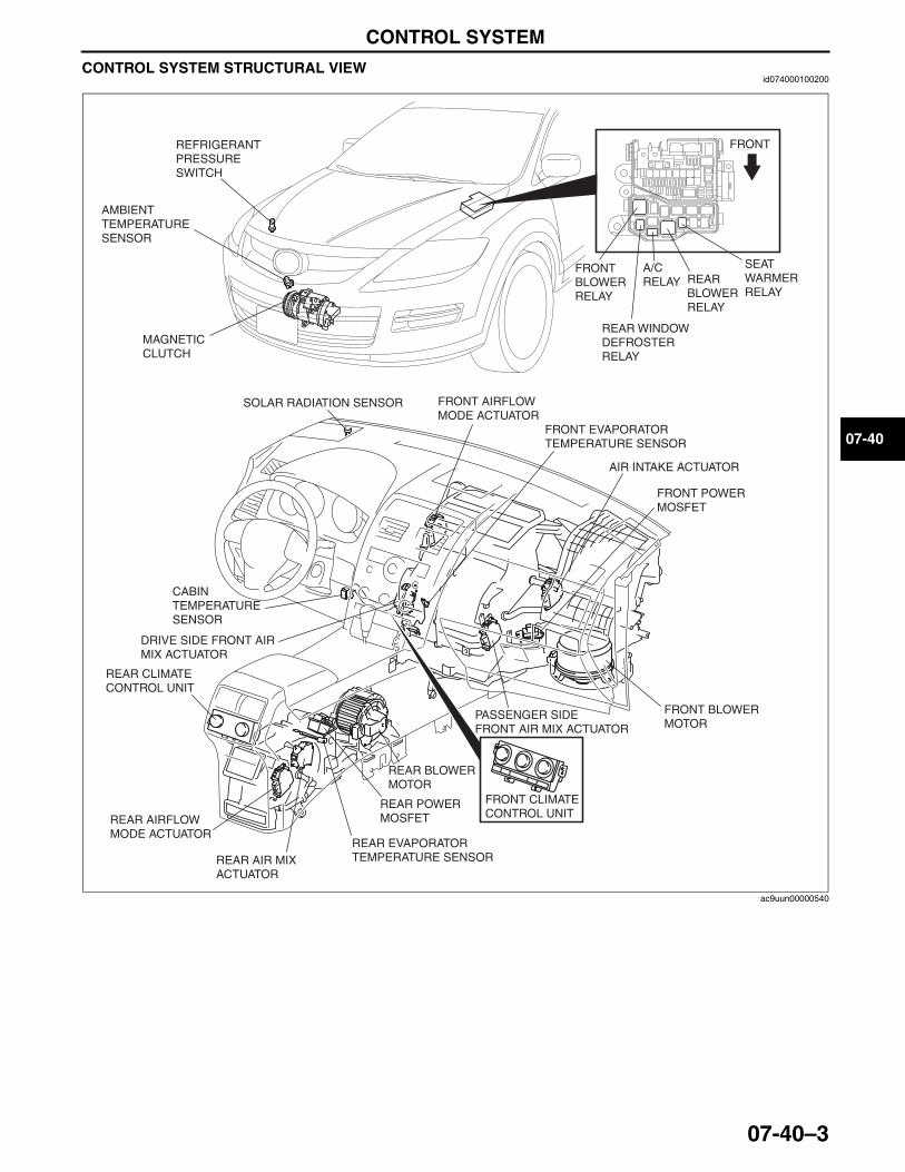
CONTROL SYSTEM
07-40–3
07-40
CONTROL SYSTEM STRUCTURAL VIEWid074000100200
End Of Sie
FRONT
FRONT BLOWER RELAY
AMBIENT TEMPERATURE SENSOR
REFRIGERANT PRESSURE SWITCH
MAGNETIC CLUTCH
REAR WINDOW DEFROSTER RELAY
A/C RELAY REAR
BLOWER RELAY
SEAT WARMER RELAY
SOLAR RADIATION SENSOR FRONT AIRFLOW MODE ACTUATOR
CABIN TEMPERATURESENSOR
DRIVE SIDE FRONT AIR MIX ACTUATOR
FRONT EVAPORATOR TEMPERATURE SENSOR
FRONT POWER MOSFET
FRONT BLOWER MOTOR
REAR BLOWER MOTOR
REAR POWER MOSFET
REAR EVAPORATOR TEMPERATURE SENSORREAR AIR MIX
ACTUATOR
REAR AIRFLOW MODE ACTUATOR
REAR CLIMATE CONTROL UNIT
FRONT CLIMATE CONTROL UNIT
AIR INTAKE ACTUATOR
PASSENGER SIDE FRONT AIR MIX ACTUATOR
ac9uun00000540
3423-1U-06H(07-40).fm 3 ページ 2006年11月22日 水曜日 午後2時48分
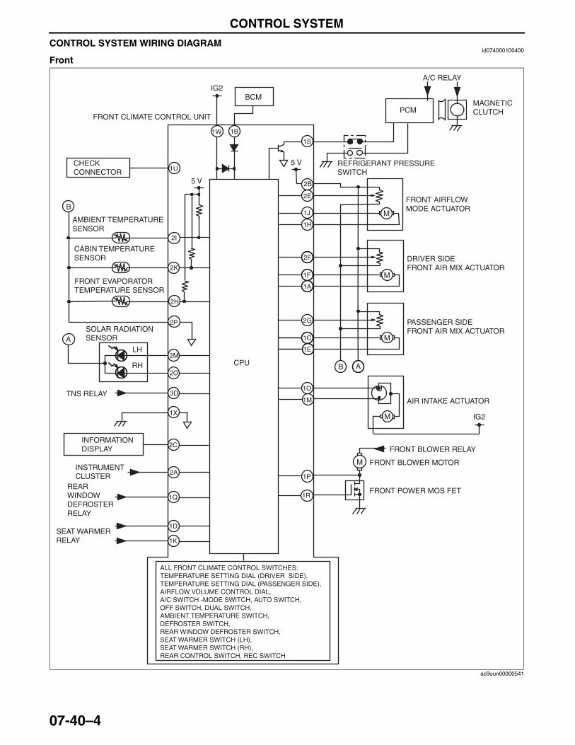
CONTROL SYSTEM
07-40–4
CONTROL SYSTEM WIRING DIAGRAMid074000100400
Front
1S
1A
1F
M
M
M
M
M
ALL FRONT CLIMATE CONTROL SWITCHES:TEMPERATURE SETTING DIAL (DRIVER SIDE), TEMPERATURE SETTING DIAL (PASSENGER SIDE), AIRFLOW VOLUME CONTROL DIAL, A/C SWITCH -MODE SWITCH, AUTO SWITCH, OFF SWITCH, DUAL SWITCH, AMBIENT TEMPERATURE SWITCH, DEFROSTER SWITCH, REAR WINDOW DEFROSTER SWITCH, SEAT WARMER SWITCH (LH), SEAT WARMER SWITCH (RH), REAR CONTROL SWITCH, REC SWITCH
LH
RH
A
B
2I
1U
2H
2K
2P
2M
2O
2C
3D
1X
2A
5 V
IG2
1B1W
PCM
5 V
1E
1C
2G
2F
1H
2B
2E
1J
B A
1M
1O
1P
1R
IG2
FRONT CLIMATE CONTROL UNIT
MAGNETIC CLUTCH
A/C RELAY
REFRIGERANT PRESSURESWITCH
FRONT AIRFLOW MODE ACTUATOR
DRIVER SIDEFRONT AIR MIX ACTUATOR
PASSENGER SIDEFRONT AIR MIX ACTUATOR
AIR INTAKE ACTUATOR
FRONT BLOWER RELAY
FRONT BLOWER MOTOR
FRONT POWER MOS FET
CPU
AMBIENT TEMPERATURE SENSOR
CABIN TEMPERATURE SENSOR
FRONT EVAPORATOR TEMPERATURE SENSOR
SOLAR RADIATION SENSOR
TNS RELAY
CHECKCONNECTOR
INFORMATION DISPLAY
INSTRUMENT CLUSTER
BCM
REAR WINDOW DEFROSTER RELAY
1Q
SEAT WARMER RELAY
1D
1K
ac9uun00000541
3423-1U-06H(07-40).fm 4 ページ 2006年11月27日 月曜日 午前10時51分
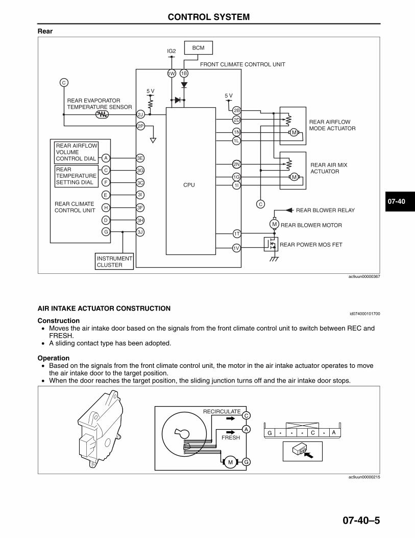
CONTROL SYSTEM
07-40–5
07-40
Rear
End Of SieNG: AIR INTAKE ACTUATOR
AIR INTAKE ACTUATOR CONSTRUCTIONid074000101700
Construction• Moves the air intake door based on the signals from the front climate control unit to switch between REC and
FRESH.• A sliding contact type has been adopted.
Operation• Based on the signals from the front climate control unit, the motor in the air intake actuator operates to move
the air intake door to the target position.• When the door reaches the target position, the sliding junction turns off and the air intake door stops.
End Of SieNG: FRONT AIR MIX ACTUATOR
2J
3C
3I
3G
3E
M
2P
3F
3HM
M
5 V
IG2
5 V
1B1W
1I
2N
C
C
1L
1G
1T
1V
2B
2D
1N
A
C
F
E
H
D
FRONT CLIMATE CONTROL UNIT
REAR EVAPORATOR TEMPERATURE SENSOR
REAR CLIMATE CONTROL UNIT
REAR AIRFLOW MODE ACTUATOR
REAR AIR MIX ACTUATOR
CPU
REAR BLOWER RELAY
REAR BLOWER MOTOR
REAR POWER MOS FET
3JG
BCM
INSTRUMENT CLUSTER
REAR AIRFLOW VOLUME CONTROL DIAL
REAR TEMPERATURE SETTING DIAL
ac9uun00000367
M
C A****
C
A
G
G
RECIRCULATE
FRESH
ac9uun00000215
3423-1U-06H(07-40).fm 5 ページ 2006年11月22日 水曜日 午後2時48分
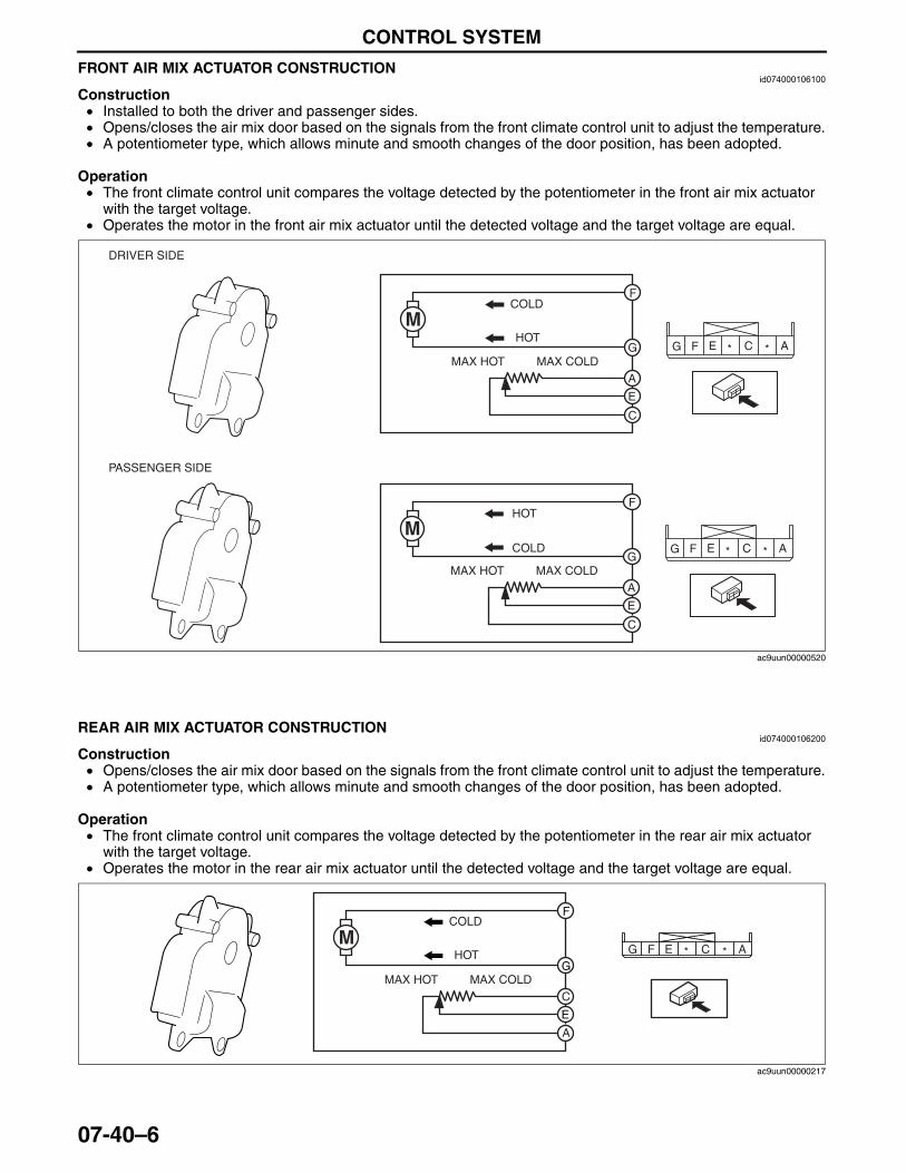
CONTROL SYSTEM
07-40–6
FRONT AIR MIX ACTUATOR CONSTRUCTIONid074000106100
Construction• Installed to both the driver and passenger sides.• Opens/closes the air mix door based on the signals from the front climate control unit to adjust the temperature.• A potentiometer type, which allows minute and smooth changes of the door position, has been adopted.
Operation• The front climate control unit compares the voltage detected by the potentiometer in the front air mix actuator
with the target voltage.• Operates the motor in the front air mix actuator until the detected voltage and the target voltage are equal.
End Of SieNG: REAR AIR MIX ACTUATOR
REAR AIR MIX ACTUATOR CONSTRUCTIONid074000106200
Construction• Opens/closes the air mix door based on the signals from the front climate control unit to adjust the temperature.• A potentiometer type, which allows minute and smooth changes of the door position, has been adopted.
Operation• The front climate control unit compares the voltage detected by the potentiometer in the rear air mix actuator
with the target voltage.• Operates the motor in the rear air mix actuator until the detected voltage and the target voltage are equal.
End Of SieNG: FRONT AIRFLOW MODE ACTUATOR
M
M
F
G
E
MAX HOT MAX COLDA
C
HOT
COLD
A*C*EFG
A*C*EFG
F
G
E
MAX HOT MAX COLDA
C
HOT
COLD
DRIVER SIDE
PASSENGER SIDE
ac9uun00000520
A*C*EFGM
F
G
E
MAX HOT MAX COLDC
A
HOT
COLD
ac9uun00000217
3423-1U-06H(07-40).fm 6 ページ 2006年11月27日 月曜日 午前10時56分
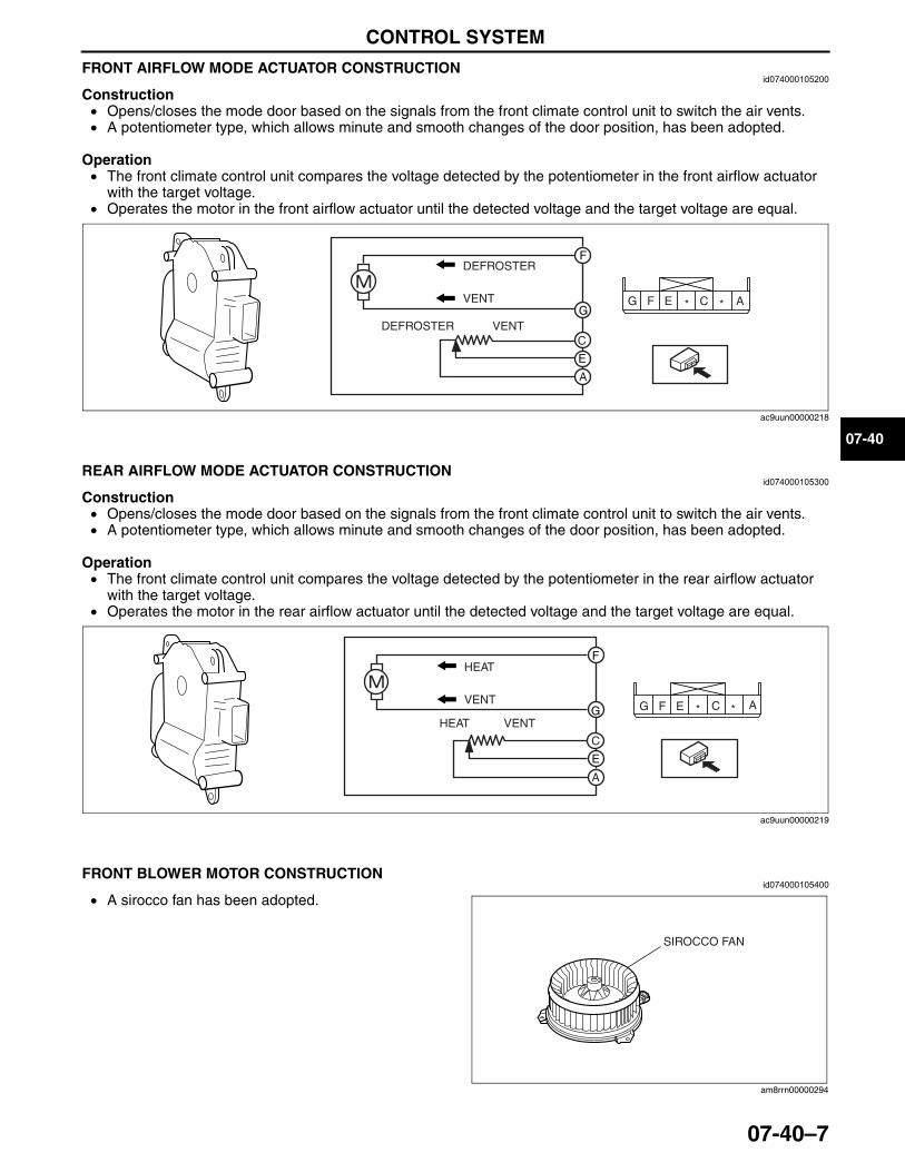
CONTROL SYSTEM
07-40–7
07-40
FRONT AIRFLOW MODE ACTUATOR CONSTRUCTIONid074000105200
Construction• Opens/closes the mode door based on the signals from the front climate control unit to switch the air vents.• A potentiometer type, which allows minute and smooth changes of the door position, has been adopted.
Operation• The front climate control unit compares the voltage detected by the potentiometer in the front airflow actuator
with the target voltage.• Operates the motor in the front airflow actuator until the detected voltage and the target voltage are equal.
End Of SieNG: REAR AIRFLOW MODE ACTUATOR
REAR AIRFLOW MODE ACTUATOR CONSTRUCTIONid074000105300
Construction• Opens/closes the mode door based on the signals from the front climate control unit to switch the air vents.• A potentiometer type, which allows minute and smooth changes of the door position, has been adopted.
Operation• The front climate control unit compares the voltage detected by the potentiometer in the rear airflow actuator
with the target voltage.• Operates the motor in the rear airflow actuator until the detected voltage and the target voltage are equal.
End Of SieNG: FRONT BLOWER MOTOR
FRONT BLOWER MOTOR CONSTRUCTIONid074000105400
• A sirocco fan has been adopted.End Of SieNG: REAR BLOWER MOTOR
A*C*EFG
F
G
E
C
A
DEFROSTER VENT
DEFROSTER
VENT
ac9uun00000218
A*C*EFG
F
G
E
A
C
HEAT VENT
HEAT
VENT
ac9uun00000219
SIROCCO FAN
am8rrn00000294
3423-1U-06H(07-40).fm 7 ページ 2006年11月22日 水曜日 午後2時48分
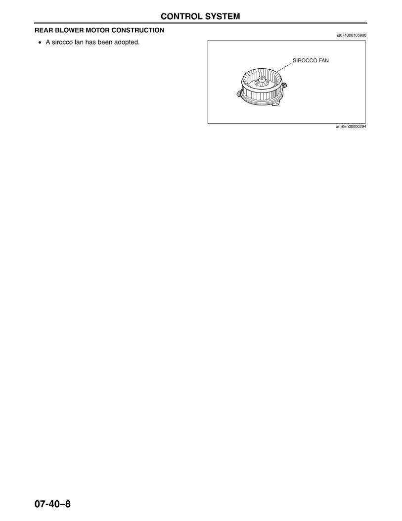
CONTROL SYSTEM
07-40–8
REAR BLOWER MOTOR CONSTRUCTIONid074000105900
• A sirocco fan has been adopted.End Of SieNG: FRONT POWER MOS FET
SIROCCO FAN
am8rrn00000294
3423-1U-06H(07-40).fm 8 ページ 2006年11月22日 水曜日 午後2時48分
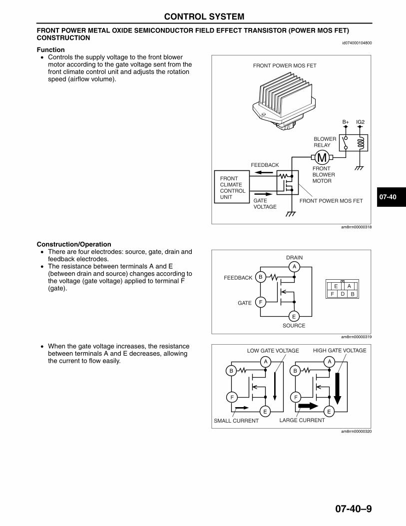
CONTROL SYSTEM
07-40–9
07-40
FRONT POWER METAL OXIDE SEMICONDUCTOR FIELD EFFECT TRANSISTOR (POWER MOS FET) CONSTRUCTION
id074000104800
Function• Controls the supply voltage to the front blower
motor according to the gate voltage sent from the front climate control unit and adjusts the rotation speed (airflow volume).
Construction/Operation• There are four electrodes: source, gate, drain and
feedback electrodes.• The resistance between terminals A and E
(between drain and source) changes according to the voltage (gate voltage) applied to terminal F (gate).
• When the gate voltage increases, the resistance between terminals A and E decreases, allowing the current to flow easily.
End Of SieNG: REAR POWER MOS FET
B+ IG2
M
FRONT POWER MOS FET
FRONT CLIMATE CONTROL UNIT
BLOWER RELAY
FRONT BLOWER MOTOR
FRONT POWER MOS FET
FEEDBACK
GATE VOLTAGE
am8rrn00000318
F
E
A
B
E
F
A
BD
DRAIN
FEEDBACK
GATE
SOURCE
am8rrn00000319
B
E
A
B
E
A
F F
LOW GATE VOLTAGE HIGH GATE VOLTAGE
SMALL CURRENT LARGE CURRENT
am8rrn00000320
3423-1U-06H(07-40).fm 9 ページ 2006年11月22日 水曜日 午後2時48分
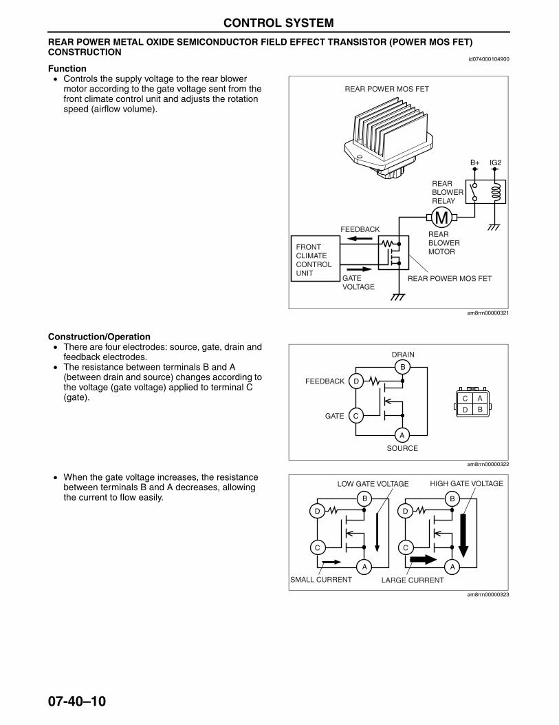
CONTROL SYSTEM
07-40–10
REAR POWER METAL OXIDE SEMICONDUCTOR FIELD EFFECT TRANSISTOR (POWER MOS FET) CONSTRUCTION
id074000104900
Function• Controls the supply voltage to the rear blower
motor according to the gate voltage sent from the front climate control unit and adjusts the rotation speed (airflow volume).
Construction/Operation• There are four electrodes: source, gate, drain and
feedback electrodes.• The resistance between terminals B and A
(between drain and source) changes according to the voltage (gate voltage) applied to terminal C (gate).
• When the gate voltage increases, the resistance between terminals B and A decreases, allowing the current to flow easily.
End Of SieNG: MAGNETIC CLUTCH
B+ IG2
M
REAR POWER MOS FET
FRONT CLIMATE CONTROL UNIT
REARBLOWER RELAY
REAR BLOWER MOTOR
REAR POWER MOS FET
FEEDBACK
GATE VOLTAGE
am8rrn00000321
C
D
A
B
A
BD
C
DRAIN
FEEDBACK
GATE
SOURCE
am8rrn00000322
B
D
A
B
D
A
C C
LOW GATE VOLTAGE HIGH GATE VOLTAGE
SMALL CURRENT LARGE CURRENT
am8rrn00000323
3423-1U-06H(07-40).fm 10 ページ 2006年11月22日 水曜日 午後2時48分
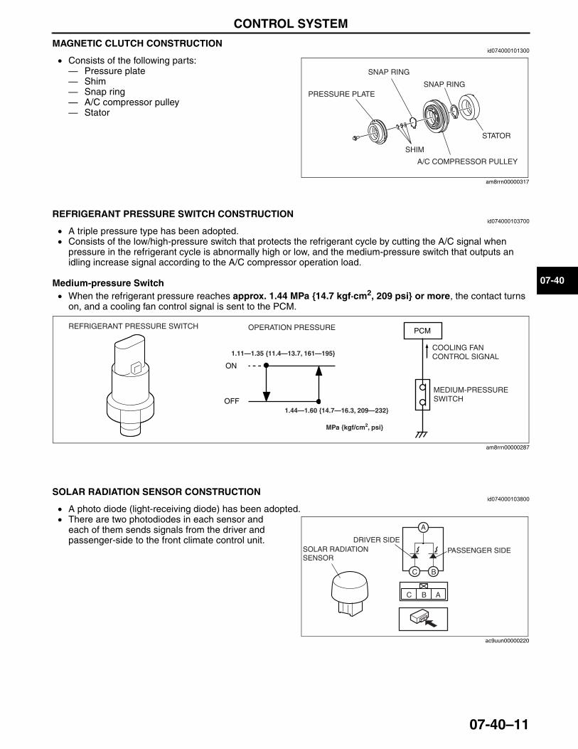
CONTROL SYSTEM
07-40–11
07-40
MAGNETIC CLUTCH CONSTRUCTIONid074000101300
• Consists of the following parts: — Pressure plate— Shim— Snap ring— A/C compressor pulley— Stator
End Of SieNG: REFRIGERANT PRESSURE SWITCH
REFRIGERANT PRESSURE SWITCH CONSTRUCTIONid074000103700
• A triple pressure type has been adopted.• Consists of the low/high-pressure switch that protects the refrigerant cycle by cutting the A/C signal when
pressure in the refrigerant cycle is abnormally high or low, and the medium-pressure switch that outputs an idling increase signal according to the A/C compressor operation load.
Medium-pressure Switch• When the refrigerant pressure reaches approx. 1.44 MPa {14.7 kgf·cm2, 209 psi} or more, the contact turns
on, and a cooling fan control signal is sent to the PCM.
End Of SieNG: SOLAR RADIATION SENSOR
SOLAR RADIATION SENSOR CONSTRUCTIONid074000103800
• A photo diode (light-receiving diode) has been adopted.• There are two photodiodes in each sensor and
each of them sends signals from the driver and passenger-side to the front climate control unit.
End Of SieNG: AMBIENT TEMPERATURE SENSOR
PRESSURE PLATE
SNAP RING
SNAP RING
STATOR
A/C COMPRESSOR PULLEY
SHIM
am8rrn00000317
ON
OFF
PCMREFRIGERANT PRESSURE SWITCH OPERATION PRESSURE
MEDIUM-PRESSURE SWITCH
COOLING FAN CONTROL SIGNAL
MPa {kgf/cm2, psi}
1.11—1.35 {11.4—13.7, 161—195}
1.44—1.60 {14.7—16.3, 209—232}
am8rrn00000287
SOLAR RADIATION SENSOR
A
BC
ABC
DRIVER SIDEPASSENGER SIDE
ac9uun00000220
3423-1U-06H(07-40).fm 11 ページ 2006年11月22日 水曜日 午後2時48分
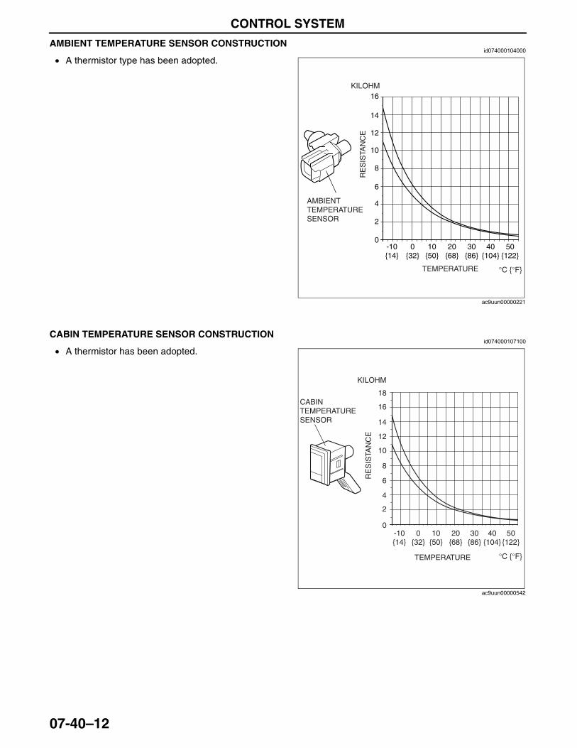
CONTROL SYSTEM
07-40–12
AMBIENT TEMPERATURE SENSOR CONSTRUCTIONid074000104000
• A thermistor type has been adopted.End Of SieNG: CABIN TEMPERATURE SENSOR
CABIN TEMPERATURE SENSOR CONSTRUCTIONid074000107100
• A thermistor has been adopted.End Of SieNG: FRONT EVAPORATOR TEMPERATURE SENSOR
AMBIENT TEMPERATURE SENSOR
16
14
12
10
8
6
4
2
0-10{14}
0{32}
10{50}
20{68}
30{86}
40{104}
50{122}
TEMPERATURE
RE
SIS
TAN
CE
KILOHM
°C {°F}
ac9uun00000221
CABIN TEMPERATURE SENSOR
16
18
14
12
10
8
6
4
2
0-10{14}
0{32}
10{50}
20{68}
30{86}
40{104}
50{122}
TEMPERATURE
RE
SIS
TAN
CE
KILOHM
°C {°F}
ac9uun00000542
3423-1U-06H(07-40).fm 12 ページ 2006年11月22日 水曜日 午後2時48分
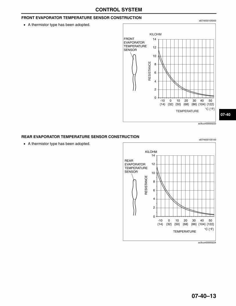
CONTROL SYSTEM
07-40–13
07-40
FRONT EVAPORATOR TEMPERATURE SENSOR CONSTRUCTIONid074000105000
• A thermistor type has been adopted.End Of SieNG: REAR EVAPORATOR TEMPERATURE SENSOR
REAR EVAPORATOR TEMPERATURE SENSOR CONSTRUCTIONid074000105100
• A thermistor type has been adopted.End Of SieNG: FRONT CLIMATE CONTROL UNIT
FRONT EVAPORATOR TEMPERATURE SENSOR
14
12
10
8
6
4
2
0-10{14}
0{32}
10{50}
20{68}
30{86}
40{104}
50{122}
TEMPERATURE°C {°F}
RE
SIS
TAN
CE
KILOHM
ac9uun00000223
REAR EVAPORATOR TEMPERATURE SENSOR
14
12
10
8
6
4
2
0-10{14}
0{32}
10{50}
20{68}
30{86}
40{104}
50{122}
TEMPERATURE°C {°F}
RE
SIS
TAN
CE
KILOHM
ac9uun00000224
3423-1U-06H(07-40).fm 13 ページ 2006年11月22日 水曜日 午後2時48分
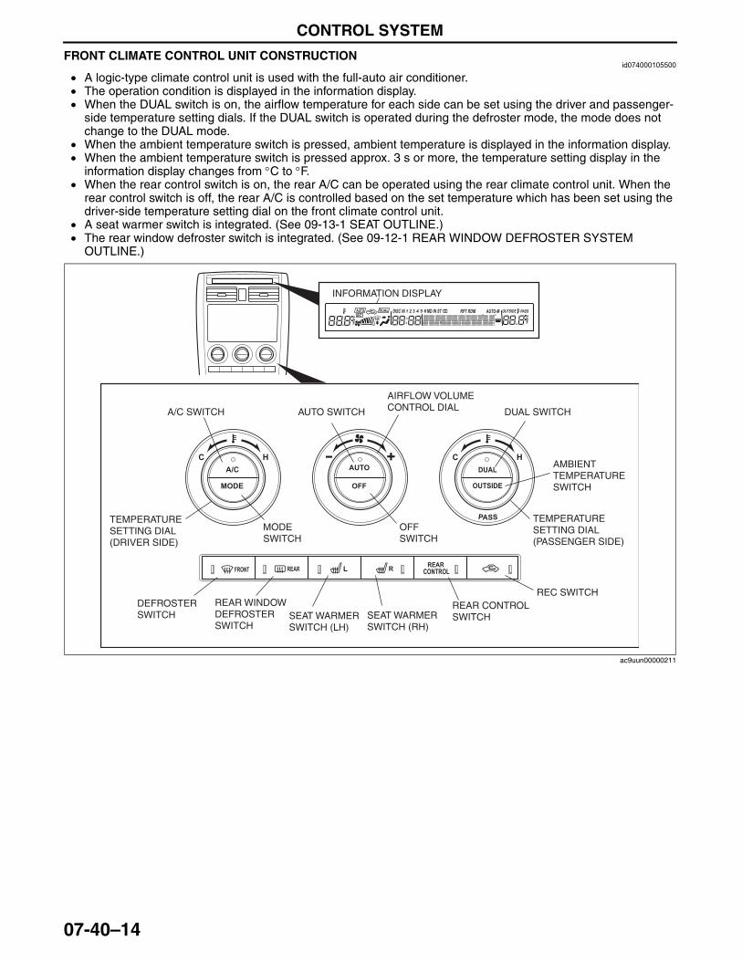
CONTROL SYSTEM
07-40–14
FRONT CLIMATE CONTROL UNIT CONSTRUCTIONid074000105500
• A logic-type climate control unit is used with the full-auto air conditioner.• The operation condition is displayed in the information display.• When the DUAL switch is on, the airflow temperature for each side can be set using the driver and passenger-
side temperature setting dials. If the DUAL switch is operated during the defroster mode, the mode does not change to the DUAL mode.
• When the ambient temperature switch is pressed, ambient temperature is displayed in the information display.• When the ambient temperature switch is pressed approx. 3 s or more, the temperature setting display in the
information display changes from °C to °F.• When the rear control switch is on, the rear A/C can be operated using the rear climate control unit. When the
rear control switch is off, the rear A/C is controlled based on the set temperature which has been set using the driver-side temperature setting dial on the front climate control unit.
• A seat warmer switch is integrated. (See 09-13-1 SEAT OUTLINE.)• The rear window defroster switch is integrated. (See 09-12-1 REAR WINDOW DEFROSTER SYSTEM
OUTLINE.)
End Of SieNG: REAR CLIMATE CONTROL UNIT
A/C SWITCH
DEFROSTER SWITCH
AUTO SWITCH DUAL SWITCH
REC SWITCH
MODE SWITCH
OFF SWITCH
TEMPERATURE SETTING DIAL (DRIVER SIDE)
TEMPERATURE SETTING DIAL (PASSENGER SIDE)
AIRFLOW VOLUME CONTROL DIAL
REAR CONTROL SWITCH
REAR WINDOW DEFROSTER SWITCH
SEAT WARMER SWITCH (LH)
SEAT WARMER SWITCH (RH)
INFORMATION DISPLAY
AMBIENT TEMPERATURE SWITCH
ac9uun00000211
3423-1U-06H(07-40).fm 14 ページ 2006年11月22日 水曜日 午後2時48分
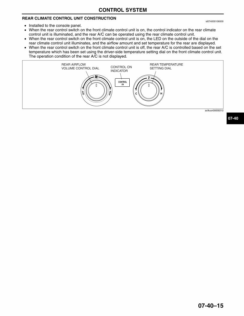
CONTROL SYSTEM
07-40–15
07-40
REAR CLIMATE CONTROL UNIT CONSTRUCTIONid074000106000
• Installed to the console panel.• When the rear control switch on the front climate control unit is on, the control indicator on the rear climate
control unit is illuminated, and the rear A/C can be operated using the rear climate control unit.• When the rear control switch on the front climate control unit is on, the LED on the outside of the dial on the
rear climate control unit illuminates, and the airflow amount and set temperature for the rear are displayed.• When the rear control switch on the front climate control unit is off, the rear A/C is controlled based on the set
temperature which has been set using the driver-side temperature setting dial on the front climate control unit. The operation condition of the rear A/C is not displayed.
End Of SieNG: FULL-AUTO AIR CONDITIONER SYSTEM
REAR TEMPERATURE SETTING DIAL
REAR AIRFLOW VOLUME CONTROL DIAL CONTROL ON
INDICATOR
ac9uun00000212
3423-1U-06H(07-40).fm 15 ページ 2006年11月22日 水曜日 午後2時48分
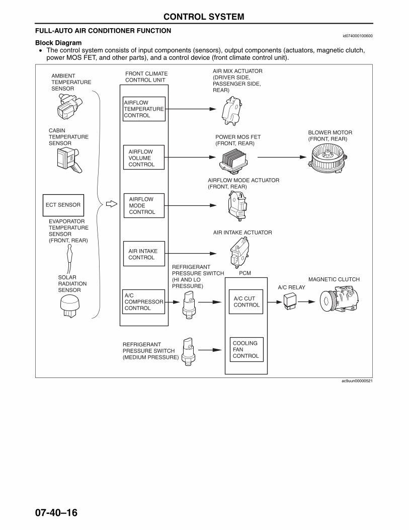
CONTROL SYSTEM
07-40–16
FULL-AUTO AIR CONDITIONER FUNCTIONid074000100600
Block Diagram• The control system consists of input components (sensors), output components (actuators, magnetic clutch,
power MOS FET, and other parts), and a control device (front climate control unit).
PCM
AIR MIX ACTUATOR (DRIVER SIDE, PASSENGER SIDE, REAR)
FRONT CLIMATE CONTROL UNIT
AMBIENT TEMPERATURE SENSOR
CABIN TEMPERATURE SENSOR
ECT SENSOR
EVAPORATOR TEMPERATURE SENSOR(FRONT, REAR)
SOLAR RADIATION SENSOR
REFRIGERANT PRESSURE SWITCH(MEDIUM PRESSURE)
REFRIGERANT PRESSURE SWITCH(HI AND LO PRESSURE)
BLOWER MOTOR(FRONT, REAR)POWER MOS FET
(FRONT, REAR)
AIRFLOW MODE ACTUATOR (FRONT, REAR)
AIR INTAKE ACTUATOR
A/C RELAY
MAGNETIC CLUTCH
AIRFLOWTEMPERATURECONTROL
AIRFLOWVOLUMECONTROL
AIRFLOW MODECONTROL
AIR INTAKECONTROL
A/C COMPRESSORCONTROL
A/C CUTCONTROL
COOLING FAN CONTROL
ac9uun00000521
3423-1U-06H(07-40).fm 16 ページ 2006年11月22日 水曜日 午後2時48分
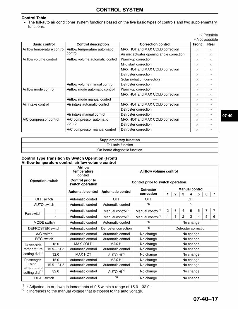
CONTROL SYSTEM
07-40–17
07-40
Control Table• The full-auto air conditioner system functions based on the five basic types of controls and two supplementary
functions.
×:Possible-:Not possible
Control Type Transition by Switch Operation (Front)Airflow temperature control, airflow volume control
*1 : Adjusted up or down in increments of 0.5 within a range of 15.0—32.0.*2 : Increases to the manual voltage that is closest to the auto voltage.
Basic control Control description Correction control Front RearAirflow temperature control Airflow temperature automatic
controlMAX HOT and MAX COLD correction × ×Air mix actuator opening angle correction × ×
Airflow volume control Airflow volume automatic control Warm-up correction × ×Mild start correction × ×MAX HOT and MAX COLD correction × ×Defroster correction × -Solar radiation correction × -
Airflow volume manual control Defroster correction × -Airflow mode control Airflow mode automatic control Warm-up correction × -
MAX HOT and MAX COLD correction × ×Airflow mode manual control ⎯ × -
Air intake control Air intake automatic control MAX HOT and MAX COLD correction × -Defroster correction × -
Air intake manual control Defroster correction × -A/C compressor control A/C compressor automatic
controlMAX HOT and MAX COLD correction × -Defroster correction × -
A/C compressor manual control Defroster correction × -
Supplementary functionFail-safe function
On-board diagnostic function
Operation switch
Airflow temperature
controlAirflow volume control
Control prior to switch operation Control prior to switch operation
Automatic control Automatic control Defroster correction
Manual control1 2 3 4 5 6 7
OFF switch Automatic control OFF OFF OFF
AUTO switch Automatic control Automatic control *6 *6
Fan switch+ Automatic control Manual control*2 Manual control*7 2 3 4 5 6 7 7
- Automatic control Manual control*3 Manual control*8 1 1 2 3 4 5 6
MODE switch Automatic control Automatic control *5 No change
DEFROSTER switch Automatic control Defroster correction *5 Defroster correction
A/C switch Automatic control Automatic control No change No changeREC switch Automatic control Automatic control No change No change
Driver-side temperature setting dial*1
15.0 MAX COLD MAX HI No change No change15.5—31.5 Automatic control Automatic control No change No change
32.0 MAX HOT AUTO HI*4 No change No change
Passenger-side
temperature setting dial*1
15.0 Automatic control MAX HI No change No change15.5—31.5 Automatic control Automatic control No change No change
32.0 Automatic control AUTO HI*4 No change No change
DUAL switch Automatic control *6 No change No change
3423-1U-06H(07-40).fm 17 ページ 2006年11月22日 水曜日 午後2時48分
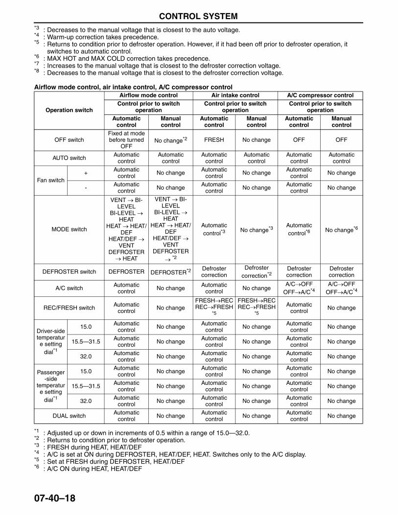
CONTROL SYSTEM
07-40–18
*3 : Decreases to the manual voltage that is closest to the auto voltage.*4 : Warm-up correction takes precedence.*5 : Returns to condition prior to defroster operation. However, if it had been off prior to defroster operation, it
switches to automatic control.*6 : MAX HOT and MAX COLD correction takes precedence.*7 : Increases to the manual voltage that is closest to the defroster correction voltage.*8 : Decreases to the manual voltage that is closest to the defroster correction voltage.
Airflow mode control, air intake control, A/C compressor control
*1 : Adjusted up or down in increments of 0.5 within a range of 15.0—32.0.*2 : Returns to condition prior to defroster operation.*3 : FRESH during HEAT, HEAT/DEF*4 : A/C is set at ON during DEFROSTER, HEAT/DEF, HEAT. Switches only to the A/C display.*5 : Set at FRESH during DEFROSTER, HEAT/DEF*6 : A/C ON during HEAT, HEAT/DEF
Operation switch
Airflow mode control Air intake control A/C compressor controlControl prior to switch
operationControl prior to switch
operationControl prior to switch
operationAutomatic
controlManual control
Automatic control
Manual control
Automatic control
Manual control
OFF switchFixed at mode before turned
OFFNo change*2 FRESH No change OFF OFF
AUTO switch Automatic control
Automatic control
Automatic control
Automatic control
Automatic control
Automatic control
Fan switch+ Automatic
control No change Automatic control No change Automatic
control No change
- Automatic control No change Automatic
control No change Automatic control No change
MODE switch
VENT → BI-LEVEL
BI-LEVEL → HEAT
HEAT → HEAT/DEF
HEAT/DEF → VENT
DEFROSTER → HEAT
VENT → BI-LEVEL
BI-LEVEL → HEAT
HEAT → HEAT/DEF
HEAT/DEF → VENT
DEFROSTER → *2
Automatic control*3 No change*3 Automatic
control*6 No change*6
DEFROSTER switch DEFROSTER DEFROSTER*2 Defroster correction
Defroster correction*2
Defroster correction
Defroster correction
A/C switch Automatic control No change Automatic
control No changeA/C→OFF
OFF→A/C*4A/C→OFF
OFF→A/C*4
REC/FRESH switch Automatic control No change
FRESH→RECREC→FRESH
*5
FRESH→RECREC→FRESH
*5
Automatic control No change
Driver-side temperature setting
dial*1
15.0 Automatic control No change Automatic
control No change Automatic control No change
15.5—31.5 Automatic control No change Automatic
control No change Automatic control No change
32.0 Automatic control No change Automatic
control No change Automatic control No change
Passenger-side
temperature setting
dial*1
15.0 Automatic control No change Automatic
control No change Automatic control No change
15.5—31.5 Automatic control No change Automatic
control No change Automatic control No change
32.0 Automatic control No change Automatic
control No change Automatic control No change
DUAL switch Automatic control No change Automatic
control No change Automatic control No change
3423-1U-06H(07-40).fm 18 ページ 2006年11月22日 水曜日 午後2時48分
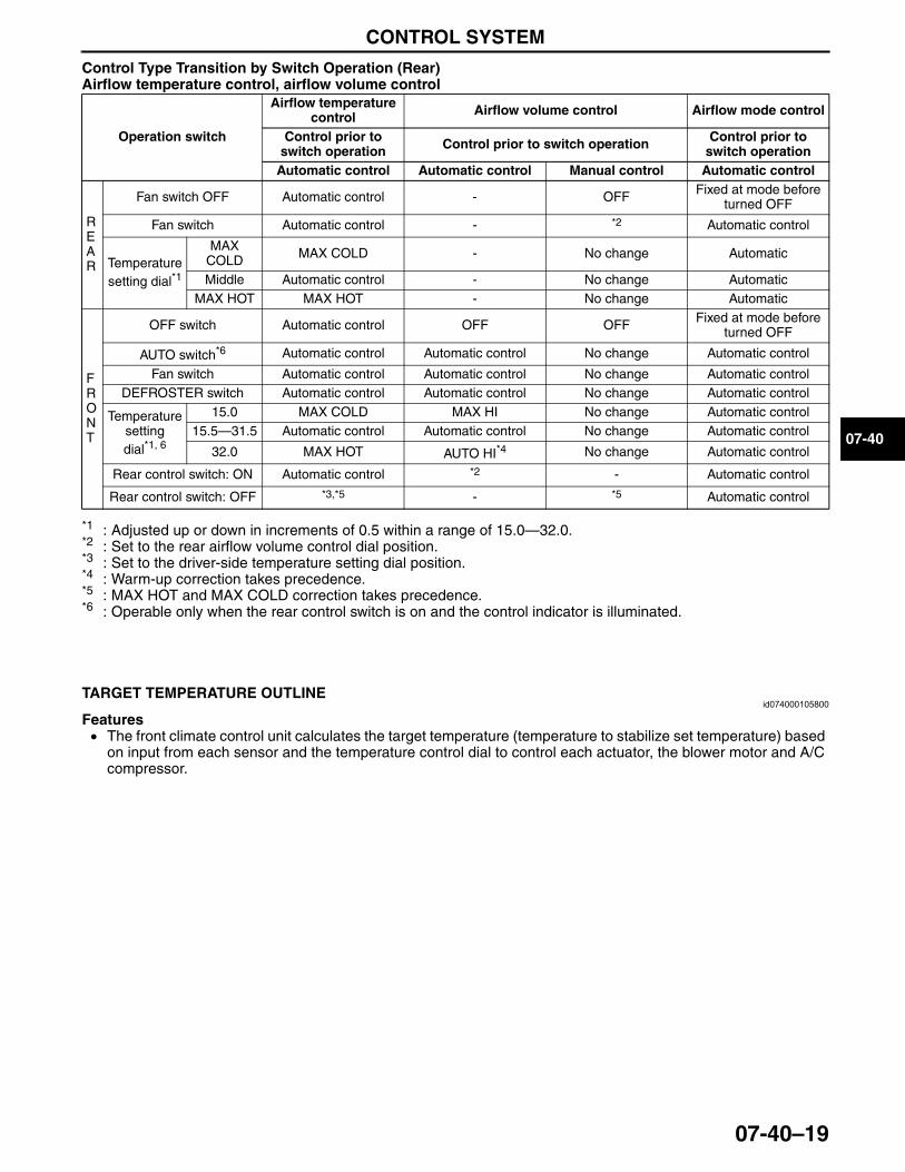
CONTROL SYSTEM
07-40–19
07-40
Control Type Transition by Switch Operation (Rear)Airflow temperature control, airflow volume control
*1 : Adjusted up or down in increments of 0.5 within a range of 15.0—32.0.*2 : Set to the rear airflow volume control dial position.*3 : Set to the driver-side temperature setting dial position.*4 : Warm-up correction takes precedence.*5 : MAX HOT and MAX COLD correction takes precedence.*6 : Operable only when the rear control switch is on and the control indicator is illuminated.
End Of SieNG: TARGET TEMPERATURE
TARGET TEMPERATURE OUTLINEid074000105800
Features• The front climate control unit calculates the target temperature (temperature to stabilize set temperature) based
on input from each sensor and the temperature control dial to control each actuator, the blower motor and A/C compressor.
End Of Sie
Operation switch
Airflow temperature control Airflow volume control Airflow mode control
Control prior to switch operation Control prior to switch operation Control prior to
switch operationAutomatic control Automatic control Manual control Automatic control
REAR
Fan switch OFF Automatic control - OFF Fixed at mode before turned OFF
Fan switch Automatic control - *2 Automatic control
Temperature setting dial*1
MAX COLD MAX COLD - No change Automatic
Middle Automatic control - No change AutomaticMAX HOT MAX HOT - No change Automatic
FRONT
OFF switch Automatic control OFF OFF Fixed at mode before turned OFF
AUTO switch*6 Automatic control Automatic control No change Automatic control
Fan switch Automatic control Automatic control No change Automatic controlDEFROSTER switch Automatic control Automatic control No change Automatic control
Temperature setting dial*1, 6
15.0 MAX COLD MAX HI No change Automatic control15.5—31.5 Automatic control Automatic control No change Automatic control
32.0 MAX HOT AUTO HI*4 No change Automatic control
Rear control switch: ON Automatic control *2 - Automatic control
Rear control switch: OFF *3,*5 - *5 Automatic control
3423-1U-06H(07-40).fm 19 ページ 2006年11月22日 水曜日 午後2時48分
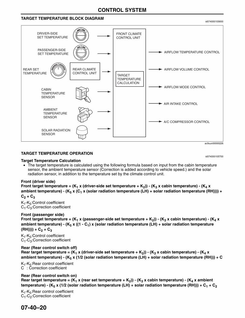
CONTROL SYSTEM
07-40–20
TARGET TEMPERATURE BLOCK DIAGRAMid074000105600
End Of SieTARGET TEMPERATURE OPERATION
id074000105700
Target Temperature Calculation• The target temperature is calculated using the following formula based on input from the cabin temperature
sensor, the ambient temperature sensor (Correction is added according to vehicle speed.) and the solar radiation sensor, in addition to the temperature set by the climate control unit.
Front (driver side)Front target temperature = (K1 x (driver-side set temperature + K2)) - (K3 x cabin temperature) - (K4 x ambient temperature) - (K5 x (C1 x (solar radiation temperature (LH) + solar radiation temperature (RH)))) + C2 + C3
K1-K5:Control coefficientC1-C3:Correction coefficient
Front (passenger side)Front target temperature = (K1 x (passenger-side set temperature + K2)) - (K3 x cabin temperature) - (K4 x ambient temperature) - (K5 x ((1 - C1) x (solar radiation temperature (LH) + solar radiation temperature (RH)))) + C2 + C3
K1-K5:Control coefficientC1-C3:Correction coefficient
Rear (Rear control switch off)Rear target temperature = (K1 x (driver-side set temperature + K2)) - (K3 x cabin temperature) - (K4 x ambient temperature) - (K5 x (1/2 (solar radiation temperature (LH) + solar radiation temperature (RH))) + C
K1-K5:Rear control coefficientC : Correction coefficient
Rear (Rear control switch on)Rear target temperature = (K1 x (rear set temperature + K2)) - (K3 x cabin temperature) - (K4 x ambient temperature) - (K5 x (1/2 (solar radiation temperature (LH) + solar radiation temperature (RH))) + C1 + C2
K1-K5:Rear control coefficientC1-C2:Correction coefficient
REAR CLIMATE CONTROL UNIT
FRONT CLIMATE CONTROL UNIT
SOLAR RADIATION SENSOR
CABIN TEMPERATURE SENSOR
AMBIENT TEMPERATURE SENSOR
DRIVER-SIDE SET TEMPERATURE
AIRFLOW TEMPERATURE CONTROL
AIRFLOW VOLUME CONTROL
AIRFLOW MODE CONTROL
AIR INTAKE CONTROL
A/C COMPRESSOR CONTROL
TARGETTEMPERATURE CALCULATION
REAR SETTEMPERATURE
PASSENGER-SIDE SET TEMPERATURE
ac9uun00000226
3423-1U-06H(07-40).fm 20 ページ 2006年11月22日 水曜日 午後2時48分
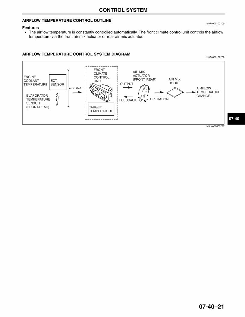
CONTROL SYSTEM
07-40–21
07-40
End Of SieAIRFLOW TEMPERATURE CONTROL OUTLINEid074000102100
Features• The airflow temperature is constantly controlled automatically. The front climate control unit controls the airflow
temperature via the front air mix actuator or rear air mix actuator.End Of Sie
AIRFLOW TEMPERATURE CONTROL SYSTEM DIAGRAMid074000102200
End Of Sie
TARGETTEMPERATURE
ECT SENSOR
EVAPORATOR TEMPERATURE SENSOR (FRONT/REAR)
ENGINECOOLANTTEMPERATURE
SIGNAL
FRONTCLIMATE CONTROL UNIT AIR MIX
DOOR
AIR MIXACTUATOR(FRONT, REAR)
AIRFLOWTEMPERATURECHANGE
OPERATION
OUTPUT
FEEDBACK
ac9uun00000227
3423-1U-06H(07-40).fm 21 ページ 2006年11月22日 水曜日 午後2時48分
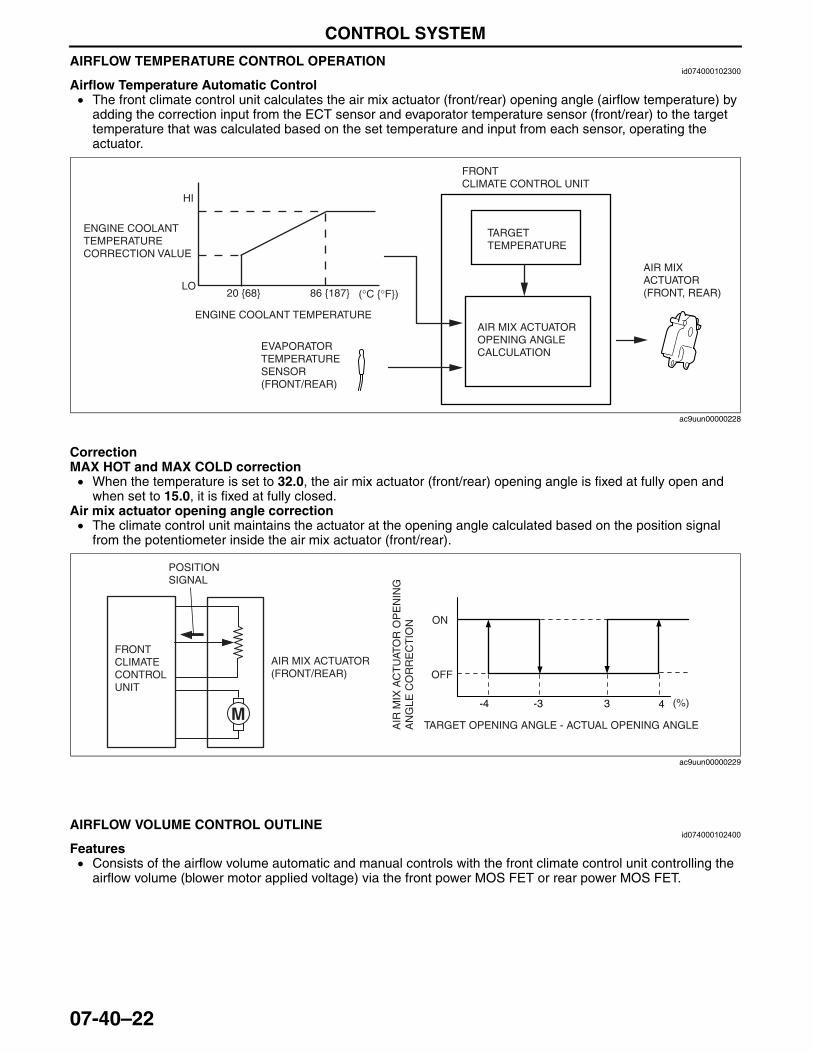
CONTROL SYSTEM
07-40–22
AIRFLOW TEMPERATURE CONTROL OPERATIONid074000102300
Airflow Temperature Automatic Control• The front climate control unit calculates the air mix actuator (front/rear) opening angle (airflow temperature) by
adding the correction input from the ECT sensor and evaporator temperature sensor (front/rear) to the target temperature that was calculated based on the set temperature and input from each sensor, operating the actuator.
CorrectionMAX HOT and MAX COLD correction• When the temperature is set to 32.0, the air mix actuator (front/rear) opening angle is fixed at fully open and
when set to 15.0, it is fixed at fully closed.Air mix actuator opening angle correction• The climate control unit maintains the actuator at the opening angle calculated based on the position signal
from the potentiometer inside the air mix actuator (front/rear).
End Of SieNG: AIRFLOW VOLUME CONTROL
AIRFLOW VOLUME CONTROL OUTLINEid074000102400
Features• Consists of the airflow volume automatic and manual controls with the front climate control unit controlling the
airflow volume (blower motor applied voltage) via the front power MOS FET or rear power MOS FET.End Of Sie
20 {68} 86 {187}
HI
LO
ENGINE COOLANT TEMPERATURE
(°C {°F})
ENGINE COOLANT TEMPERATURE CORRECTION VALUE
TARGETTEMPERATURE
EVAPORATOR TEMPERATURE SENSOR (FRONT/REAR)
FRONTCLIMATE CONTROL UNIT
AIR MIX ACTUATOR OPENING ANGLE CALCULATION
AIR MIXACTUATOR(FRONT, REAR)
ac9uun00000228
-4 -3 43
OFF
ON
(%)
AIR
MIX
AC
TU
ATO
R O
PE
NIN
G
AN
GLE
CO
RR
EC
TIO
N
TARGET OPENING ANGLE - ACTUAL OPENING ANGLE
POSITION SIGNAL
AIR MIX ACTUATOR (FRONT/REAR)
FRONT CLIMATE CONTROL UNIT
M
ac9uun00000229
3423-1U-06H(07-40).fm 22 ページ 2006年11月22日 水曜日 午後2時48分
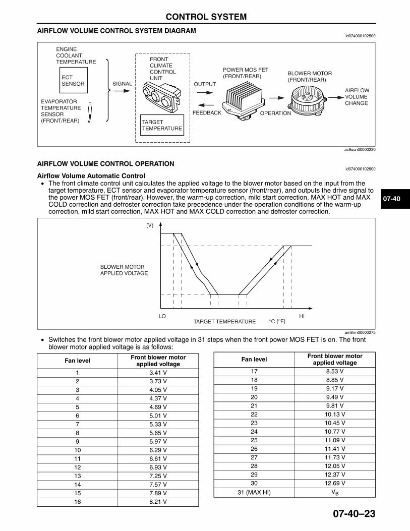
CONTROL SYSTEM
07-40–23
07-40
AIRFLOW VOLUME CONTROL SYSTEM DIAGRAMid074000102500
End Of SieAIRFLOW VOLUME CONTROL OPERATION
id074000102600
Airflow Volume Automatic Control• The front climate control unit calculates the applied voltage to the blower motor based on the input from the
target temperature, ECT sensor and evaporator temperature sensor (front/rear), and outputs the drive signal to the power MOS FET (front/rear). However, the warm-up correction, mild start correction, MAX HOT and MAX COLD correction and defroster correction take precedence under the operation conditions of the warm-up correction, mild start correction, MAX HOT and MAX COLD correction and defroster correction.
• Switches the front blower motor applied voltage in 31 steps when the front power MOS FET is on. The front blower motor applied voltage is as follows:
OUTPUT
FEEDBACK
POWER MOS FET(FRONT/REAR)
OPERATION
BLOWER MOTOR(FRONT/REAR)
AIRFLOW VOLUMECHANGE
TARGETTEMPERATURE
ECT SENSOR
EVAPORATOR TEMPERATURE SENSOR (FRONT/REAR)
ENGINECOOLANTTEMPERATURE
SIGNAL
FRONTCLIMATE CONTROL UNIT
ac9uun00000230
(V)
TARGET TEMPERATURE °C {°F}LO HI
BLOWER MOTOR APPLIED VOLTAGE
am8rrn00000275
Fan level Front blower motor applied voltage
1 3.41 V2 3.73 V3 4.05 V4 4.37 V5 4.69 V6 5.01 V7 5.33 V8 5.65 V9 5.97 V10 6.29 V11 6.61 V12 6.93 V13 7.25 V14 7.57 V15 7.89 V16 8.21 V
17 8.53 V18 8.85 V19 9.17 V20 9.49 V21 9.81 V22 10.13 V23 10.45 V24 10.77 V25 11.09 V26 11.41 V27 11.73 V28 12.05 V29 12.37 V30 12.69 V
31 (MAX HI) VB
Fan level Front blower motor applied voltage
3423-1U-06H(07-40).fm 23 ページ 2006年11月22日 水曜日 午後2時48分
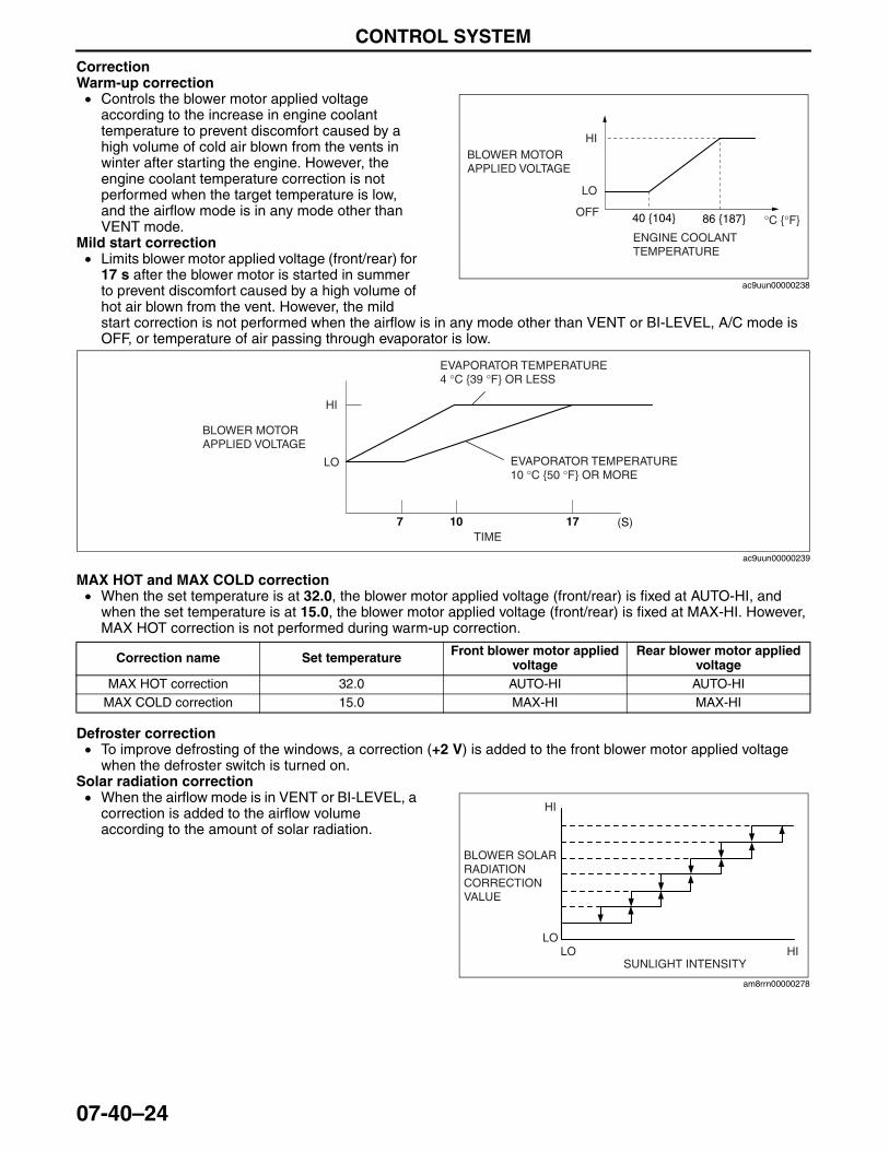
CONTROL SYSTEM
07-40–24
CorrectionWarm-up correction• Controls the blower motor applied voltage
according to the increase in engine coolant temperature to prevent discomfort caused by a high volume of cold air blown from the vents in winter after starting the engine. However, the engine coolant temperature correction is not performed when the target temperature is low, and the airflow mode is in any mode other than VENT mode.
Mild start correction• Limits blower motor applied voltage (front/rear) for
17 s after the blower motor is started in summer to prevent discomfort caused by a high volume of hot air blown from the vent. However, the mild start correction is not performed when the airflow is in any mode other than VENT or BI-LEVEL, A/C mode is OFF, or temperature of air passing through evaporator is low.
MAX HOT and MAX COLD correction• When the set temperature is at 32.0, the blower motor applied voltage (front/rear) is fixed at AUTO-HI, and
when the set temperature is at 15.0, the blower motor applied voltage (front/rear) is fixed at MAX-HI. However, MAX HOT correction is not performed during warm-up correction.
Defroster correction• To improve defrosting of the windows, a correction (+2 V) is added to the front blower motor applied voltage
when the defroster switch is turned on.Solar radiation correction• When the airflow mode is in VENT or BI-LEVEL, a
correction is added to the airflow volume according to the amount of solar radiation.
40 {104} 86 {187} °C {°F}OFF
LO
HIBLOWER MOTOR APPLIED VOLTAGE
ENGINE COOLANT TEMPERATURE
ac9uun00000238
(S)7 10 17
HI
LO
BLOWER MOTOR APPLIED VOLTAGE
EVAPORATOR TEMPERATURE 4 °C {39 °F} OR LESS
EVAPORATOR TEMPERATURE 10 °C {50 °F} OR MORE
TIME
ac9uun00000239
Correction name Set temperature Front blower motor applied voltage
Rear blower motor applied voltage
MAX HOT correction 32.0 AUTO-HI AUTO-HIMAX COLD correction 15.0 MAX-HI MAX-HI
BLOWER SOLAR RADIATION CORRECTION VALUE
HI
LOHILO
SUNLIGHT INTENSITY
am8rrn00000278
3423-1U-06H(07-40).fm 24 ページ 2006年11月27日 月曜日 午前10時49分
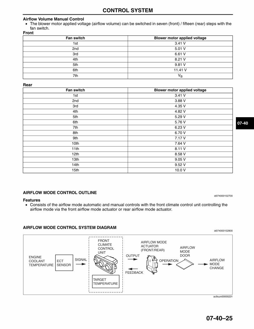
CONTROL SYSTEM
07-40–25
07-40
Airflow Volume Manual Control• The blower motor applied voltage (airflow volume) can be switched in seven (front) / fifteen (rear) steps with the
fan switch.Front
Rear
End Of SieNG: AIRFLOW MODE CONTROL
AIRFLOW MODE CONTROL OUTLINEid074000102700
Features• Consists of the airflow mode automatic and manual controls with the front climate control unit controlling the
airflow mode via the front airflow mode actuator or rear airflow mode actuator.End Of Sie
AIRFLOW MODE CONTROL SYSTEM DIAGRAMid074000102800
End Of Sie
Fan switch Blower motor applied voltage1st 3.41 V2nd 5.01 V3rd 6.61 V4th 8.21 V5th 9.81 V6th 11.41 V
7th VB
Fan switch Blower motor applied voltage1st 3.41 V2nd 3.88 V3rd 4.35 V4th 4.82 V5th 5.29 V6th 5.76 V7th 6.23 V8th 6.70 V9th 7.17 V
10th 7.64 V11th 8.11 V12th 8.58 V13th 9.05 V14th 9.52 V15th 10.0 V
TARGETTEMPERATURE
ECT SENSOR
ENGINECOOLANTTEMPERATURE
SIGNAL
FRONTCLIMATE CONTROL UNIT
OUTPUT
FEEDBACK
AIRFLOW MODEACTUATOR(FRONT/REAR)
OPERATION
AIRFLOW MODE DOOR
AIRFLOWMODECHANGE
ac9uun00000231
3423-1U-06H(07-40).fm 25 ページ 2006年11月22日 水曜日 午後2時48分
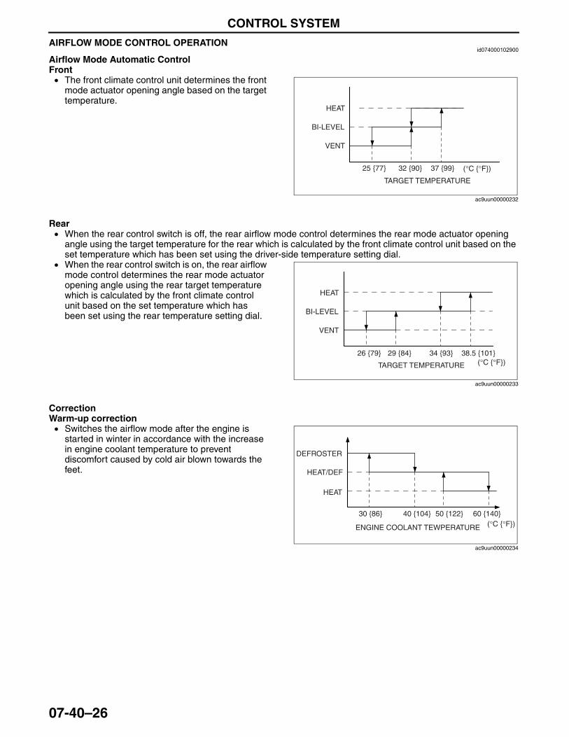
CONTROL SYSTEM
07-40–26
AIRFLOW MODE CONTROL OPERATIONid074000102900
Airflow Mode Automatic ControlFront• The front climate control unit determines the front
mode actuator opening angle based on the target temperature.
Rear• When the rear control switch is off, the rear airflow mode control determines the rear mode actuator opening
angle using the target temperature for the rear which is calculated by the front climate control unit based on the set temperature which has been set using the driver-side temperature setting dial.
• When the rear control switch is on, the rear airflow mode control determines the rear mode actuator opening angle using the rear target temperature which is calculated by the front climate control unit based on the set temperature which has been set using the rear temperature setting dial.
CorrectionWarm-up correction• Switches the airflow mode after the engine is
started in winter in accordance with the increase in engine coolant temperature to prevent discomfort caused by cold air blown towards the feet.
25 {77} 32 {90} (°C {°F})37 {99}
TARGET TEMPERATURE
HEAT
BI-LEVEL
VENT
ac9uun00000232
TARGET TEMPERATURE
HEAT
BI-LEVEL
VENT
26 {79} 29 {84}(°C {°F})
34 {93} 38.5 {101}
ac9uun00000233
ENGINE COOLANT TEWPERATURE
DEFROSTER
HEAT/DEF
HEAT
30 {86} 40 {104} 50 {122} 60 {140}(°C {°F})
ac9uun00000234
3423-1U-06H(07-40).fm 26 ページ 2006年11月22日 水曜日 午後2時48分
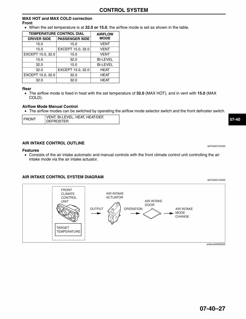
CONTROL SYSTEM
07-40–27
07-40
MAX HOT and MAX COLD correctionFront• When the set temperature is at 32.0 or 15.0, the airflow mode is set as shown in the table.
Rear• The airflow mode is fixed in heat with the set temperature of 32.0 (MAX HOT), and in vent with 15.0 (MAX
COLD).
Airflow Mode Manual Control• The airflow modes can be switched by operating the airflow mode selector switch and the front defroster switch.
End Of SieNG: AIR INTAKE CONTROL
AIR INTAKE CONTROL OUTLINEid074000103300
Features• Consists of the air intake automatic and manual controls with the front climate control unit controlling the air
intake mode via the air intake actuator.End Of Sie
AIR INTAKE CONTROL SYSTEM DIAGRAMid074000103400
End Of Sie
TEMPERATURE CONTROL DIAL AIRFLOW MODEDRIVER SIDE PASSENGER SIDE
15.0 15.0 VENT15.0 EXCEPT 15.0, 32.0 VENT
EXCEPT 15.0, 32.0 15.0 VENT15.0 32.0 BI-LEVEL32.0 15.0 BI-LEVEL32.0 EXCEPT 15.0, 32.0 HEAT
EXCEPT 15.0, 32.0 32.0 HEAT32.0 32.0 HEAT
FRONT VENT, BI-LEVEL, HEAT, HEAT/DEF, DEFROSTER
OUTPUT
AIR INTAKEACTUATOR
OPERATION
AIR INTAKEDOOR
AIR INTAKEMODECHANGE
TARGETTEMPERATURE
FRONTCLIMATE CONTROL UNIT
ac9uun00000235
3423-1U-06H(07-40).fm 27 ページ 2006年11月22日 水曜日 午後2時48分
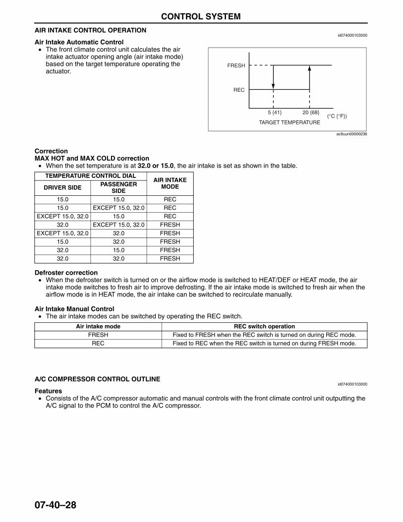
CONTROL SYSTEM
07-40–28
AIR INTAKE CONTROL OPERATIONid074000103500
Air Intake Automatic Control• The front climate control unit calculates the air
intake actuator opening angle (air intake mode) based on the target temperature operating the actuator.
CorrectionMAX HOT and MAX COLD correction• When the set temperature is at 32.0 or 15.0, the air intake is set as shown in the table.
Defroster correction• When the defroster switch is turned on or the airflow mode is switched to HEAT/DEF or HEAT mode, the air
intake mode switches to fresh air to improve defrosting. If the air intake mode is switched to fresh air when the airflow mode is in HEAT mode, the air intake can be switched to recirculate manually.
Air Intake Manual Control• The air intake modes can be switched by operating the REC switch.
End Of SieNG: A/C COMPRESSOR CONTROL
A/C COMPRESSOR CONTROL OUTLINEid074000103000
Features• Consists of the A/C compressor automatic and manual controls with the front climate control unit outputting the
A/C signal to the PCM to control the A/C compressor.End Of Sie
TARGET TEMPERATURE
FRESH
REC
5 {41} 20 {68}(°C {°F})
ac9uun00000236
TEMPERATURE CONTROL DIALAIR INTAKE
MODEDRIVER SIDE PASSENGER SIDE
15.0 15.0 REC15.0 EXCEPT 15.0, 32.0 REC
EXCEPT 15.0, 32.0 15.0 REC32.0 EXCEPT 15.0, 32.0 FRESH
EXCEPT 15.0, 32.0 32.0 FRESH15.0 32.0 FRESH32.0 15.0 FRESH32.0 32.0 FRESH
Air intake mode REC switch operationFRESH Fixed to FRESH when the REC switch is turned on during REC mode.
REC Fixed to REC when the REC switch is turned on during FRESH mode.
3423-1U-06H(07-40).fm 28 ページ 2006年11月22日 水曜日 午後2時48分
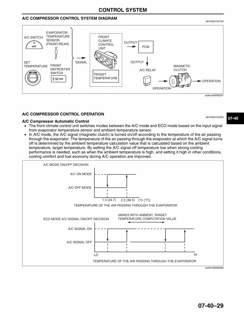
CONTROL SYSTEM
07-40–29
07-40
A/C COMPRESSOR CONTROL SYSTEM DIAGRAMid074000103100
End Of Sie
A/C COMPRESSOR CONTROL OPERATIONid074000103200
A/C Compressor Automatic Control• The front climate control unit switches modes between the A/C mode and ECO mode based on the input signal
from evaporator temperature sensor and ambient temperature sensor.• In A/C mode, the A/C signal (magnetic clutch) is turned on/off according to the temperature of the air passing
through the evaporator. The temperature of the air passing through the evaporator at which the A/C signal turns off is determined by the ambient temperature calculation value that is calculated based on the ambient temperature, target temperature. By setting the A/C signal off temperature low when strong cooling performance is needed, such as when the ambient temperature is high, and setting it high in other conditions, cooling comfort and fuel economy during A/C operation are improved.
TARGETTEMPERATURE
FRONTCLIMATE CONTROL UNIT PCM
A/C SWITCH
EVAPORATOR TEMPERATURE SENSOR(FRONT/REAR)
FRONT DEFROSTER SWITCH
A/C RELAYMAGNETICCLUTCH
OUTPUT
OUTPUT
OPERATION
SIGNALSET TEMPERATURE
OPERATION
ac9uun00000237
1.5 {34.7}
TEMPERATURE OF THE AIR PASSING THROUGH THE EVAPORATOR
TEMPERATURE OF THE AIR PASSING THROUGH THE EVAPORATOR
VARIES WITH ANBIENT, TARGET TEMPERATURE COMPUTATION VALUE
A/C MODE ON/OFF DECISION
ECO MODE A/C SIGNAL ON/OFF DECISION
A/C ON MODE
A/C OFF MODE
A/C SIGNAL ON
A/C SIGNAL OFF
LO HI
(°C {°F})2.5 {36.5}
am8rrn00000283
3423-1U-06H(07-40).fm 29 ページ 2006年11月22日 水曜日 午後2時48分
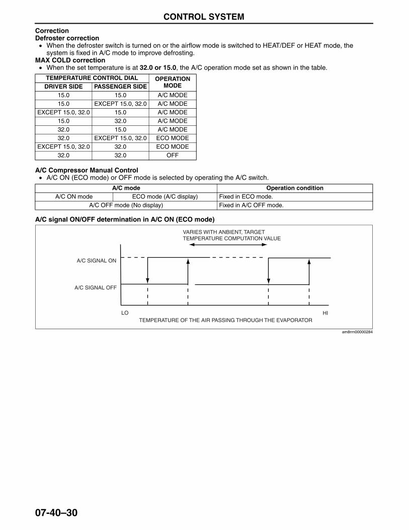
CONTROL SYSTEM
07-40–30
CorrectionDefroster correction• When the defroster switch is turned on or the airflow mode is switched to HEAT/DEF or HEAT mode, the
system is fixed in A/C mode to improve defrosting.MAX COLD correction• When the set temperature is at 32.0 or 15.0, the A/C operation mode set as shown in the table.
A/C Compressor Manual Control• A/C ON (ECO mode) or OFF mode is selected by operating the A/C switch.
A/C signal ON/OFF determination in A/C ON (ECO mode)
End Of Sie
TEMPERATURE CONTROL DIAL OPERATION MODEDRIVER SIDE PASSENGER SIDE
15.0 15.0 A/C MODE15.0 EXCEPT 15.0, 32.0 A/C MODE
EXCEPT 15.0, 32.0 15.0 A/C MODE15.0 32.0 A/C MODE32.0 15.0 A/C MODE32.0 EXCEPT 15.0, 32.0 ECO MODE
EXCEPT 15.0, 32.0 32.0 ECO MODE32.0 32.0 OFF
A/C mode Operation conditionA/C ON mode ECO mode (A/C display) Fixed in ECO mode.
A/C OFF mode (No display) Fixed in A/C OFF mode.
TEMPERATURE OF THE AIR PASSING THROUGH THE EVAPORATOR
VARIES WITH ANBIENT, TARGET TEMPERATURE COMPUTATION VALUE
A/C SIGNAL ON
A/C SIGNAL OFF
LO HI
am8rrn00000284
3423-1U-06H(07-40).fm 30 ページ 2006年11月22日 水曜日 午後2時48分
08-00–1
08RESTRAINTSSECTION
08-00
Toc of SCTOUTLINE . . . . . . . . . . . . . . . . . .08-00ON-BOARD DIAGNOSTIC . . . .08-02
AIR BAG SYSTEM . . . . . . . . . . 08-10SEAT BELT. . . . . . . . . . . . . . . . 08-11
Toc of SCT
08-00 OUTLINERESTRAINTS ABBREVIATIONS. . . . . . . 08-00–1 RESTRAINTS FEATURES . . . . . . . . . . . 08-00–1
End of TocNG: RESTRAINTSRESTRAINTS ABBREVIATIONS
id080000100100
End Of Sie
RESTRAINTS FEATURESid080000100200
End Of Sie
ALR Automatic Locking RetractorCAN Controller Area NetworkDLC Data Link ConnectorDTC Diagnostic Trouble CodeELR Emergency Locking RetractorGND Ground IG Ignition
LED Light Emitting DiodeLH Left HandPAD Passenger Air Bag DeactivationPID Parameter IdentificationRH Right HandSAS Sophisticated Air Bag SensorSST Special Service Tool
Improved safety
• A two-step deployment control has been adopted to the front air bag system (driver and passenger side) deployment control.
• A curtain air bag module has been adopted.• A side air bag module has been adopted.• A pre-tensioner seat belt has been adopted.• A rollover control has been adopted.• Three-point seat belt with the following functions for front seat passengers adopted— ELR (Emergency Locking Retractor: emergency locking mechanism)— ALR (Automatic Locking Retractor: child-restraint seat locking mechanism) (passenger
side only)— Pre-tensioner seat belt (See 08-10-18 PRE-TENSIONER SEAT BELT CONSTRUCTION/
OPERATION.)— Load limiter, which adjusts restraint force of the seat belt to reduce the possibility of injury
to passengers caused by excess seat belt pressure after pre-tensioner operation• Three-point seat belt with the following functions for second-row seat passengers adopted— ELR— ALR (left and right side only)
• Three-point seat belt with the following functions for third-row seat passengers adopted— ELR
3423-1U-06H(08-00).fm 1 ページ 2006年11月21日 火曜日 午後5時26分

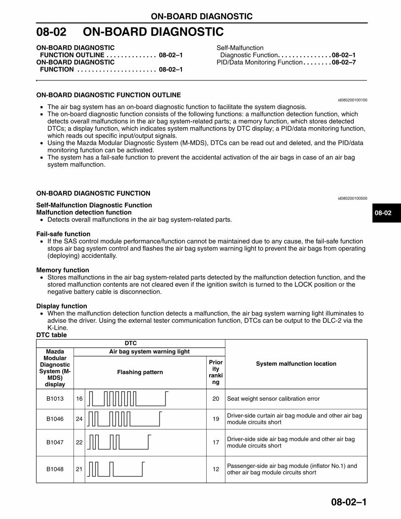
ON-BOARD DIAGNOSTIC
08-02–1
08-02
08-02 ON-BOARD DIAGNOSTICON-BOARD DIAGNOSTIC
FUNCTION OUTLINE . . . . . . . . . . . . . . 08-02–1ON-BOARD DIAGNOSTIC
FUNCTION . . . . . . . . . . . . . . . . . . . . . . 08-02–1
Self-Malfunction Diagnostic Function. . . . . . . . . . . . . . . 08-02–1
PID/Data Monitoring Function . . . . . . . . 08-02–7
End of TocNG: AIR BAG SYSTEMON-BOARD DIAGNOSTIC FUNCTION OUTLINE
id080200100100
• The air bag system has an on-board diagnostic function to facilitate the system diagnosis.• The on-board diagnostic function consists of the following functions: a malfunction detection function, which
detects overall malfunctions in the air bag system-related parts; a memory function, which stores detected DTCs; a display function, which indicates system malfunctions by DTC display; a PID/data monitoring function, which reads out specific input/output signals.
• Using the Mazda Modular Diagnostic System (M-MDS), DTCs can be read out and deleted, and the PID/data monitoring function can be activated.
• The system has a fail-safe function to prevent the accidental activation of the air bags in case of an air bag system malfunction.
End Of Sie
ON-BOARD DIAGNOSTIC FUNCTIONid080200100500
Self-Malfunction Diagnostic FunctionMalfunction detection function• Detects overall malfunctions in the air bag system-related parts.
Fail-safe function• If the SAS control module performance/function cannot be maintained due to any cause, the fail-safe function
stops air bag system control and flashes the air bag system warning light to prevent the air bags from operating (deploying) accidentally.
Memory function• Stores malfunctions in the air bag system-related parts detected by the malfunction detection function, and the
stored malfunction contents are not cleared even if the ignition switch is turned to the LOCK position or the negative battery cable is disconnection.
Display function• When the malfunction detection function detects a malfunction, the air bag system warning light illuminates to
advise the driver. Using the external tester communication function, DTCs can be output to the DLC-2 via the K-Line.
DTC tableDTC
System malfunction location
Mazda Modular
Diagnostic System (M-
MDS) display
Air bag system warning light
Flashing pattern
Priority
ranking
B1013 16 20 Seat weight sensor calibration error
B1046 24 19 Driver-side curtain air bag module and other air bag module circuits short
B1047 22 17 Driver-side side air bag module and other air bag module circuits short
B1048 21 12 Passenger-side air bag module (inflator No.1) and other air bag module circuits short
3423-1U-06H(08-02).fm 1 ページ 2006年11月21日 火曜日 午後5時29分
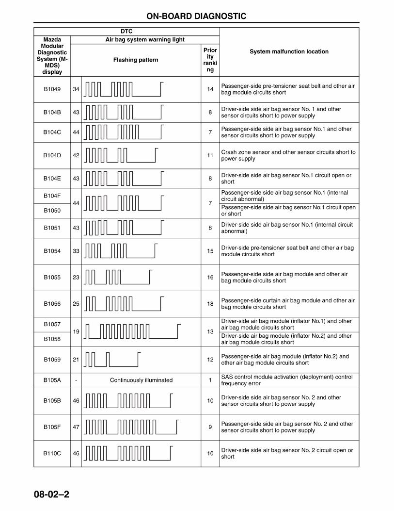
ON-BOARD DIAGNOSTIC
08-02–2
B1049 34 14 Passenger-side pre-tensioner seat belt and other air bag module circuits short
B104B 43 8 Driver-side side air bag sensor No. 1 and other sensor circuits short to power supply
B104C 44 7 Passenger-side side air bag sensor No.1 and other sensor circuits short to power supply
B104D 42 11 Crash zone sensor and other sensor circuits short to power supply
B104E 43 8 Driver-side side air bag sensor No.1 circuit open or short
B104F44 7
Passenger-side side air bag sensor No.1 (internal circuit abnormal)
B1050 Passenger-side side air bag sensor No.1 circuit open or short
B1051 43 8 Driver-side side air bag sensor No.1 (internal circuit abnormal)
B1054 33 15 Driver-side pre-tensioner seat belt and other air bag module circuits short
B1055 23 16 Passenger-side side air bag module and other air bag module circuits short
B1056 25 18 Passenger-side curtain air bag module and other air bag module circuits short
B105719 13
Driver-side air bag module (inflator No.1) and other air bag module circuits short
B1058 Driver-side air bag module (inflator No.2) and other air bag module circuits short
B1059 21 12 Passenger-side air bag module (inflator No.2) and other air bag module circuits short
B105A - Continuously illuminated 1 SAS control module activation (deployment) control frequency error
B105B 46 10 Driver-side side air bag sensor No. 2 and other sensor circuits short to power supply
B105F 47 9 Passenger-side side air bag sensor No. 2 and other sensor circuits short to power supply
B110C 46 10 Driver-side side air bag sensor No. 2 circuit open or short
DTC
System malfunction location
Mazda Modular
Diagnostic System (M-
MDS) display
Air bag system warning light
Flashing pattern
Priority
ranking
3423-1U-06H(08-02).fm 2 ページ 2006年11月21日 火曜日 午後5時29分
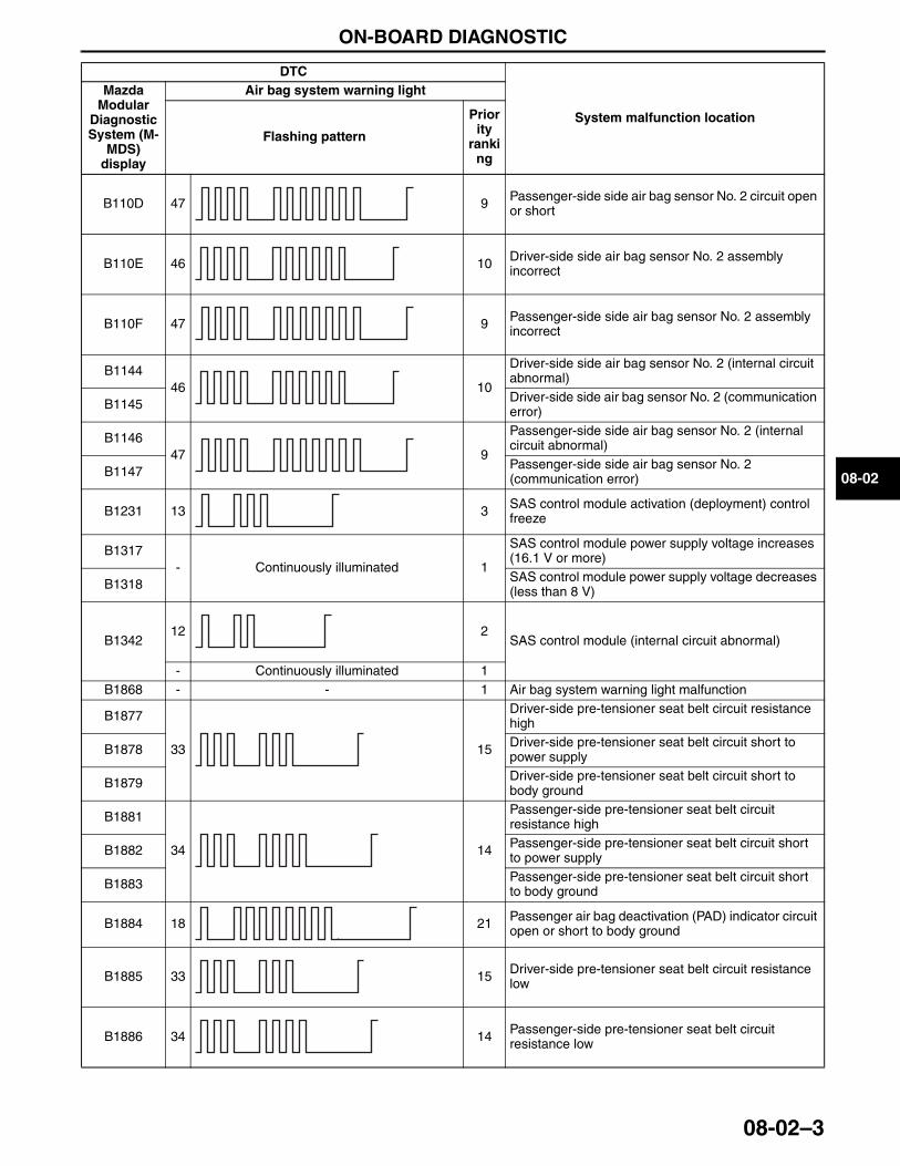
ON-BOARD DIAGNOSTIC
08-02–3
08-02
B110D 47 9 Passenger-side side air bag sensor No. 2 circuit open or short
B110E 46 10 Driver-side side air bag sensor No. 2 assembly incorrect
B110F 47 9 Passenger-side side air bag sensor No. 2 assembly incorrect
B114446 10
Driver-side side air bag sensor No. 2 (internal circuit abnormal)
B1145 Driver-side side air bag sensor No. 2 (communication error)
B114647 9
Passenger-side side air bag sensor No. 2 (internal circuit abnormal)
B1147 Passenger-side side air bag sensor No. 2 (communication error)
B1231 13 3 SAS control module activation (deployment) control freeze
B1317- Continuously illuminated 1
SAS control module power supply voltage increases (16.1 V or more)
B1318 SAS control module power supply voltage decreases (less than 8 V)
B134212 2
SAS control module (internal circuit abnormal)
- Continuously illuminated 1B1868 - - 1 Air bag system warning light malfunction
B1877
33 15
Driver-side pre-tensioner seat belt circuit resistance high
B1878 Driver-side pre-tensioner seat belt circuit short to power supply
B1879 Driver-side pre-tensioner seat belt circuit short to body ground
B1881
34 14
Passenger-side pre-tensioner seat belt circuit resistance high
B1882 Passenger-side pre-tensioner seat belt circuit short to power supply
B1883 Passenger-side pre-tensioner seat belt circuit short to body ground
B1884 18 21 Passenger air bag deactivation (PAD) indicator circuit open or short to body ground
B1885 33 15 Driver-side pre-tensioner seat belt circuit resistance low
B1886 34 14 Passenger-side pre-tensioner seat belt circuit resistance low
DTC
System malfunction location
Mazda Modular
Diagnostic System (M-
MDS) display
Air bag system warning light
Flashing pattern
Priority
ranking
3423-1U-06H(08-02).fm 3 ページ 2006年11月21日 火曜日 午後5時29分
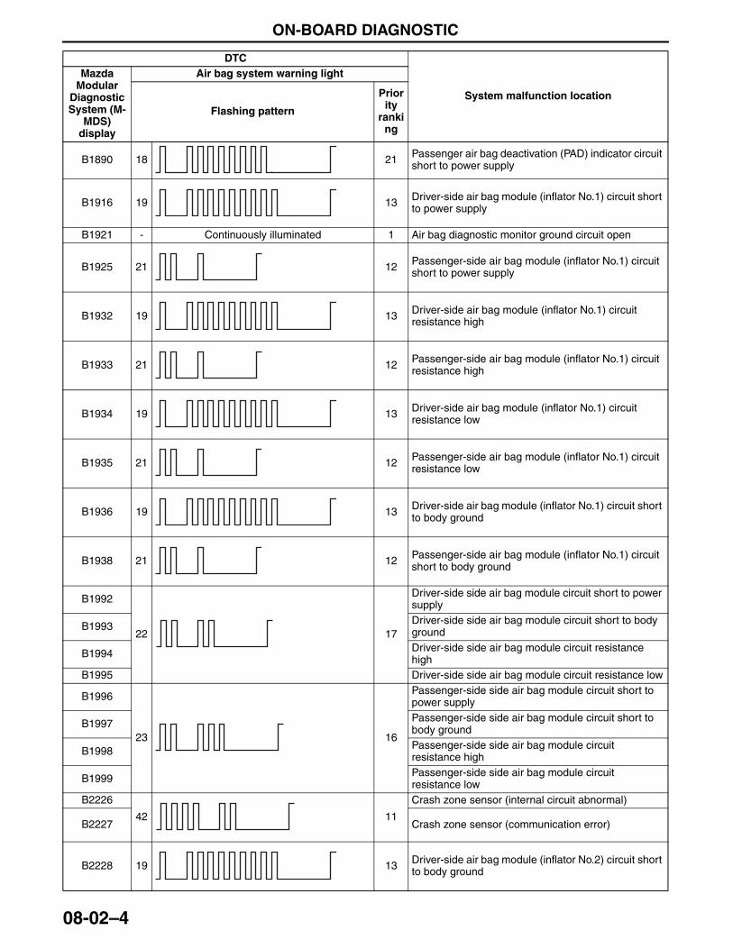
ON-BOARD DIAGNOSTIC
08-02–4
B1890 18 21 Passenger air bag deactivation (PAD) indicator circuit short to power supply
B1916 19 13 Driver-side air bag module (inflator No.1) circuit short to power supply
B1921 - Continuously illuminated 1 Air bag diagnostic monitor ground circuit open
B1925 21 12 Passenger-side air bag module (inflator No.1) circuit short to power supply
B1932 19 13 Driver-side air bag module (inflator No.1) circuit resistance high
B1933 21 12 Passenger-side air bag module (inflator No.1) circuit resistance high
B1934 19 13 Driver-side air bag module (inflator No.1) circuit resistance low
B1935 21 12 Passenger-side air bag module (inflator No.1) circuit resistance low
B1936 19 13 Driver-side air bag module (inflator No.1) circuit short to body ground
B1938 21 12 Passenger-side air bag module (inflator No.1) circuit short to body ground
B1992
22 17
Driver-side side air bag module circuit short to power supply
B1993 Driver-side side air bag module circuit short to body ground
B1994 Driver-side side air bag module circuit resistance high
B1995 Driver-side side air bag module circuit resistance low
B1996
23 16
Passenger-side side air bag module circuit short to power supply
B1997 Passenger-side side air bag module circuit short to body ground
B1998 Passenger-side side air bag module circuit resistance high
B1999 Passenger-side side air bag module circuit resistance low
B2226
42 11
Crash zone sensor (internal circuit abnormal)
B2227 Crash zone sensor (communication error)
B2228 19 13 Driver-side air bag module (inflator No.2) circuit short to body ground
DTC
System malfunction location
Mazda Modular
Diagnostic System (M-
MDS) display
Air bag system warning light
Flashing pattern
Priority
ranking
3423-1U-06H(08-02).fm 4 ページ 2006年11月21日 火曜日 午後5時29分
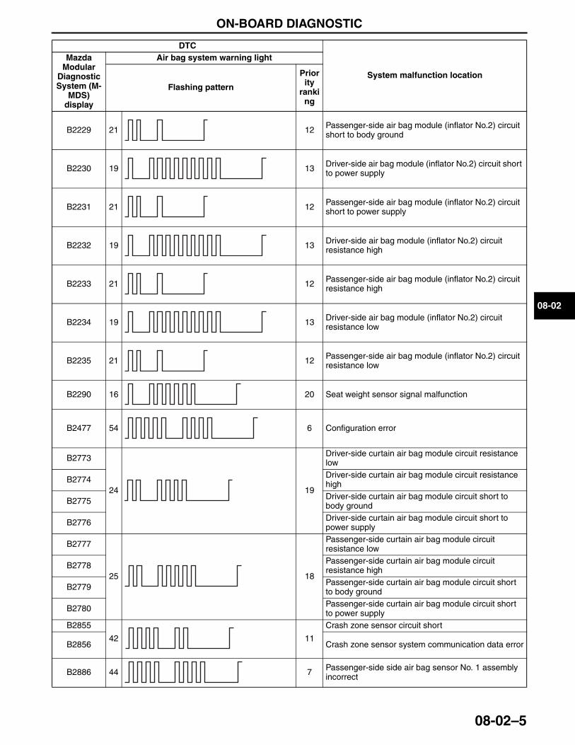
ON-BOARD DIAGNOSTIC
08-02–5
08-02
B2229 21 12 Passenger-side air bag module (inflator No.2) circuit short to body ground
B2230 19 13 Driver-side air bag module (inflator No.2) circuit short to power supply
B2231 21 12 Passenger-side air bag module (inflator No.2) circuit short to power supply
B2232 19 13 Driver-side air bag module (inflator No.2) circuit resistance high
B2233 21 12 Passenger-side air bag module (inflator No.2) circuit resistance high
B2234 19 13 Driver-side air bag module (inflator No.2) circuit resistance low
B2235 21 12 Passenger-side air bag module (inflator No.2) circuit resistance low
B2290 16 20 Seat weight sensor signal malfunction
B2477 54 6 Configuration error
B2773
24 19
Driver-side curtain air bag module circuit resistance low
B2774 Driver-side curtain air bag module circuit resistance high
B2775 Driver-side curtain air bag module circuit short to body ground
B2776 Driver-side curtain air bag module circuit short to power supply
B2777
25 18
Passenger-side curtain air bag module circuit resistance low
B2778 Passenger-side curtain air bag module circuit resistance high
B2779 Passenger-side curtain air bag module circuit short to body ground
B2780 Passenger-side curtain air bag module circuit short to power supply
B2855
42 11
Crash zone sensor circuit short
B2856 Crash zone sensor system communication data error
B2886 44 7 Passenger-side side air bag sensor No. 1 assembly incorrect
DTC
System malfunction location
Mazda Modular
Diagnostic System (M-
MDS) display
Air bag system warning light
Flashing pattern
Priority
ranking
3423-1U-06H(08-02).fm 5 ページ 2006年11月21日 火曜日 午後5時29分
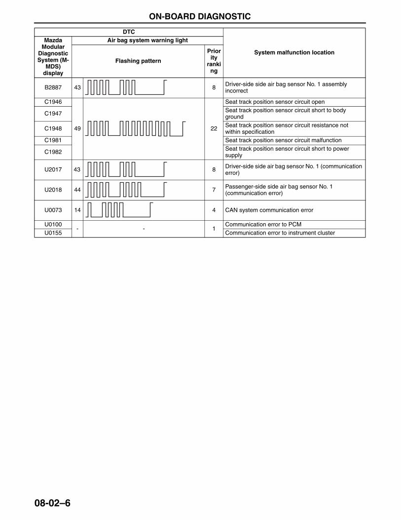
ON-BOARD DIAGNOSTIC
08-02–6
B2887 43 8 Driver-side side air bag sensor No. 1 assembly incorrect
C1946
49 22
Seat track position sensor circuit open
C1947 Seat track position sensor circuit short to body ground
C1948 Seat track position sensor circuit resistance not within specification
C1981 Seat track position sensor circuit malfunction
C1982 Seat track position sensor circuit short to power supply
U2017 43 8 Driver-side side air bag sensor No. 1 (communication error)
U2018 44 7 Passenger-side side air bag sensor No. 1 (communication error)
U0073 14 4 CAN system communication error
U0100- - 1
Communication error to PCMU0155 Communication error to instrument cluster
DTC
System malfunction location
Mazda Modular
Diagnostic System (M-
MDS) display
Air bag system warning light
Flashing pattern
Priority
ranking
3423-1U-06H(08-02).fm 6 ページ 2006年11月21日 火曜日 午後5時29分
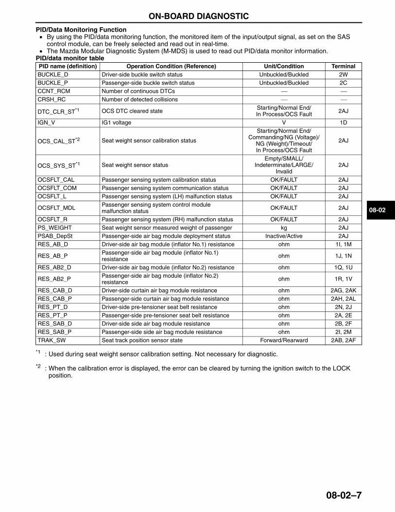
ON-BOARD DIAGNOSTIC
08-02–7
08-02
PID/Data Monitoring Function• By using the PID/data monitoring function, the monitored item of the input/output signal, as set on the SAS
control module, can be freely selected and read out in real-time. • The Mazda Modular Diagnostic System (M-MDS) is used to read out PID/data monitor information.
PID/data monitor table
*1 : Used during seat weight sensor calibration setting. Not necessary for diagnostic.
*2 : When the calibration error is displayed, the error can be cleared by turning the ignition switch to the LOCK position.
End Of Sie
PID name (definition) Operation Condition (Reference) Unit/Condition TerminalBUCKLE_D Driver-side buckle switch status Unbuckled/Buckled 2WBUCKLE_P Passenger-side buckle switch status Unbuckled/Buckled 2CCCNT_RCM Number of continuous DTCs ⎯ ⎯CRSH_RC Number of detected collisions ⎯ ⎯
DTC_CLR_ST*1 OCS DTC cleared state Starting/Normal End/In Process/OCS Fault 2AJ
IGN_V IG1 voltage V 1D
OCS_CAL_ST*2 Seat weight sensor calibration status
Starting/Normal End/Commanding/NG (Voltage)/
NG (Weight)/Timeout/In Process/OCS Fault
2AJ
OCS_SYS_ST*1 Seat weight sensor statusEmpty/SMALL/
Indeterminate/LARGE/Invalid
2AJ
OCSFLT_CAL Passenger sensing system calibration status OK/FAULT 2AJOCSFLT_COM Passenger sensing system communication status OK/FAULT 2AJOCSFLT_L Passenger sensing system (LH) malfunction status OK/FAULT 2AJ
OCSFLT_MDL Passenger sensing system control module malfunction status OK/FAULT 2AJ
OCSFLT_R Passenger sensing system (RH) malfunction status OK/FAULT 2AJPS_WEIGHT Seat weight sensor measured weight of passenger kg 2AJPSAB_DepSt Passenger-side air bag module deployment status Inactive/Active 2AJRES_AB_D Driver-side air bag module (inflator No.1) resistance ohm 1I, 1M
RES_AB_P Passenger-side air bag module (inflator No.1) resistance ohm 1J, 1N
RES_AB2_D Driver-side air bag module (inflator No.2) resistance ohm 1Q, 1U
RES_AB2_P Passenger-side air bag module (inflator No.2) resistance ohm 1R, 1V
RES_CAB_D Driver-side curtain air bag module resistance ohm 2AG, 2AKRES_CAB_P Passenger-side curtain air bag module resistance ohm 2AH, 2ALRES_PT_D Driver-side pre-tensioner seat belt resistance ohm 2N, 2JRES_PT_P Passenger-side pre-tensioner seat belt resistance ohm 2A, 2ERES_SAB_D Driver-side side air bag module resistance ohm 2B, 2FRES_SAB_P Passenger-side side air bag module resistance ohm 2I, 2MTRAK_SW Seat track position sensor state Forward/Rearward 2AB, 2AF
3423-1U-06H(08-02).fm 7 ページ 2006年11月21日 火曜日 午後5時29分

AIR BAG SYSTEM
08-10–1
08-10
08-10 AIR BAG SYSTEMAIR BAG SYSTEM OUTLINE . . . . . . . . . 08-10–2AIR BAG SYSTEM
STRUCTURAL VIEW . . . . . . . . . . . . . . 08-10–3AIR BAG SYSTEM
WIRING DIAGRAM . . . . . . . . . . . . . . . . 08-10–4SAS CONTROL MODULE
FUNCTION . . . . . . . . . . . . . . . . . . . . . . 08-10–5Sensing Function . . . . . . . . . . . . . . . . . 08-10–5Backup Power Supply Function . . . . . . 08-10–5Configuration Function . . . . . . . . . . . . . 08-10–5
SAS CONTROL MODULE CONSTRUCTION/OPERATION . . . . . . 08-10–6
Front Air Bag System (Two-Step Deployment Control) . . . . . 08-10–6
Side Air Bag Sensor System . . . . . . . . 08-10–7Rollover Control . . . . . . . . . . . . . . . . . . 08-10–8Seat Position Matching
Deployment Control . . . . . . . . . . . . . . 08-10–9Seat Belt Buckled/Unbuckled
Condition Matching (Deployment) Control . . . . . . . . . . . . . 08-10–9
Passenger Detection System Operation (Deployment) Control . . . . . . . . . . . . . 08-10–10
SEAT TRACK POSITION SENSOR FUNCTION . . . . . . . . . . . . . . . . . . . . . . 08-10–10
SEAT TRACK POSITION SENSOR CONSTRUCTION/OPERATION . . . . . . 08-10–10
PASSENGER SENSING SYSTEM OUTLINE . . . . . . . . . . . . . . . . . . . . . . . . 08-10–10
PASSENGER SENSING SYSTEM CONSTRUCTION . . . . . . . . . . . . . . . . . . 08-10–11
PASSENGER SENSING SYSTEM OPERATION . . . . . . . . . . . . . . . . . . . . . . 08-10–12
DRIVER-SIDE AIR BAG MODULE FUNCTION . . . . . . . . . . . . . . . . . . . . . . . 08-10–14
DRIVER-SIDE AIR BAG MODULE CONSTRUCTION/OPERATION . . . . . . . 08-10–14
Inflator Operation . . . . . . . . . . . . . . . . . 08-10–14PASSENGER-SIDE AIR BAG MODULE
FUNCTION . . . . . . . . . . . . . . . . . . . . . . . 08-10–15Outline . . . . . . . . . . . . . . . . . . . . . . . . . . 08-10–15
PASSENGER-SIDE AIR BAG MODULE CONSTRUCTION/OPERATION . . . . . . . 08-10–15
Inflator Operation . . . . . . . . . . . . . . . . . 08-10–15SIDE AIR BAG MODULE FUNCTION . . . 08-10–16SIDE AIR BAG MODULE
CONSTRUCTION/OPERATION . . . . . . . 08-10–16Construction . . . . . . . . . . . . . . . . . . . . . 08-10–16
CURTAIN AIR BAG MODULE FUNCTION . . . . . . . . . . . . . . . . . . . . . . . 08-10–17
CURTAIN AIR BAG MODULE CONSTRUCTION/OPERATION . . . . . . . 08-10–17
Construction . . . . . . . . . . . . . . . . . . . . . 08-10–17Operation . . . . . . . . . . . . . . . . . . . . . . . 08-10–17
PRE-TENSIONER SEAT BELT FUNCTION . . . . . . . . . . . . . . . . . . . . . . . 08-10–18
PRE-TENSIONER SEAT BELT CONSTRUCTION/OPERATION . . . . . . . 08-10–18
Construction . . . . . . . . . . . . . . . . . . . . . 08-10–18Operation . . . . . . . . . . . . . . . . . . . . . . . 08-10–19
End of TocNG: AIR BAG SYSTEM
3423-1U-06H(08-10).fm 1 ページ 2006年11月22日 水曜日 午後2時54分
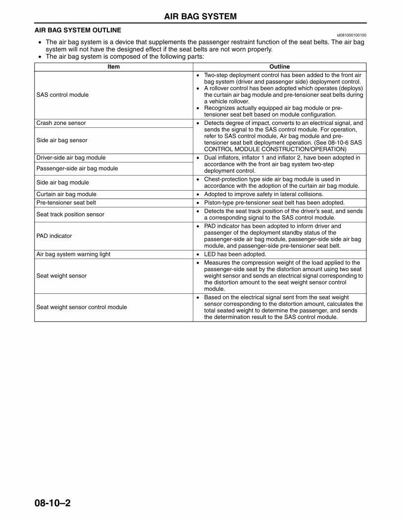
AIR BAG SYSTEM
08-10–2
AIR BAG SYSTEM OUTLINEid081000100100
• The air bag system is a device that supplements the passenger restraint function of the seat belts. The air bag system will not have the designed effect if the seat belts are not worn properly.
• The air bag system is composed of the following parts:
End Of Sie
Item Outline
SAS control module
• Two-step deployment control has been added to the front air bag system (driver and passenger side) deployment control.
• A rollover control has been adopted which operates (deploys) the curtain air bag module and pre-tensioner seat belts during a vehicle rollover.
• Recognizes actually equipped air bag module or pre-tensioner seat belt based on module configuration.
Crash zone sensor • Detects degree of impact, converts to an electrical signal, and sends the signal to the SAS control module. For operation, refer to SAS control module, Air bag module and pre-tensioner seat belt deployment operation. (See 08-10-6 SAS CONTROL MODULE CONSTRUCTION/OPERATION)
Side air bag sensor
Driver-side air bag module • Dual inflators, inflator 1 and inflator 2, have been adopted in accordance with the front air bag system two-step deployment control.Passenger-side air bag module
Side air bag module • Chest-protection type side air bag module is used in accordance with the adoption of the curtain air bag module.
Curtain air bag module • Adopted to improve safety in lateral collisions.Pre-tensioner seat belt • Piston-type pre-tensioner seat belt has been adopted.
Seat track position sensor • Detects the seat track position of the driver’s seat, and sends a corresponding signal to the SAS control module.
PAD indicator
• PAD indicator has been adopted to inform driver and passenger of the deployment standby status of the passenger-side air bag module, passenger-side side air bag module, and passenger-side pre-tensioner seat belt.
Air bag system warning light • LED has been adopted.
Seat weight sensor
• Measures the compression weight of the load applied to the passenger-side seat by the distortion amount using two seat weight sensor and sends an electrical signal corresponding to the distortion amount to the seat weight sensor control module.
Seat weight sensor control module
• Based on the electrical signal sent from the seat weight sensor corresponding to the distortion amount, calculates the total seated weight to determine the passenger, and sends the determination result to the SAS control module.
3423-1U-06H(08-10).fm 2 ページ 2006年11月22日 水曜日 午後2時54分
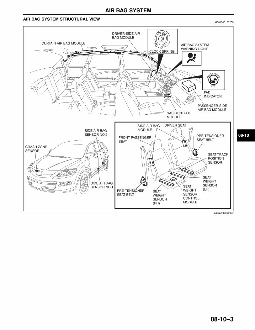
AIR BAG SYSTEM
08-10–3
08-10
AIR BAG SYSTEM STRUCTURAL VIEWid081000100200
End Of Sie
CLOCK SPRING
PAD INDICATOR
AIR BAG SYSTEM WARNING LIGHT
DRIVER-SIDE AIR BAG MODULE
PASSENGER-SIDE AIR BAG MODULE
CURTAIN AIR BAG MODULE
SAS CONTROL MODULE
SEAT TRACK POSITION SENSOR
SIDE AIR BAG MODULE
CRASH ZONE SENSOR
SIDE AIR BAG SENSOR NO.1 SEAT
WEIGHT SENSOR CONTROL MODULE
SEAT WEIGHT SENSOR (LH)
SEAT WEIGHT SENSOR (RH)
SIDE AIR BAG SENSOR NO.2
PRE-TENSIONER SEAT BELT
FRONT PASSENGER SEAT
DRIVER SEAT
PRE-TENSIONER SEAT BELT
ac9uun00000097
3423-1U-06H(08-10).fm 3 ページ 2006年11月22日 水曜日 午後2時54分
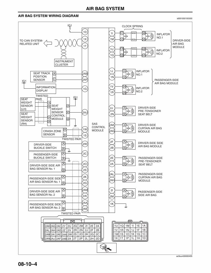
AIR BAG SYSTEM
08-10–4
AIR BAG SYSTEM WIRING DIAGRAMid081000100300
1I
1M
1J
1N
CRASH ZONE SENSOR
IG1
1D
1K
1W
1S
2S
2O
2G
2N
2J
2AG
2AK
2F
2B
2A
2E
2AL
2AH
2I
2M2AI
2AM
2AE
2AA
A
B
A
B
A
B
A
B
A
B
A
B
1D
1C 3B
3A
A
A
A
B
B
B
A
A
B
B
CLOCK SPRING
2K
SAS CONTROL MODULE
1A
1E
1X
1T
2A
2B
2C
2D
2E
2F
2G
2H
2I
2J
2K
2L
2M
2N
2O
2P
2Q
2R
2S
2T
2U
2V
2W
2X
2Y
2Z
2AA
2AB
2AC
2AD
2AE
2AF
2AG
2AH
2AI
2AJ
2AK
2AL
2AM
2AN
1A
1B
1C
1D
1E
1F
1G
1H
1I
1J
1K
1L
1M
1N
1O
1P
1Q
1R
1S
1T
1U
1V
1W
1X
DRIVER-SIDE PRE-TENSIONER SEAT BELT
DRIVER-SIDE CURTAIN AIR BAG MODULE
PASSENGER-SIDE PRE-TENSIONER SEAT BELT
PASSENGER-SIDE CURTAIN AIR BAG MODULE
DRIVER-SIDE SIDE AIR BAG MODULE
PASSENGER-SIDE SIDE AIR BAG
DRIVER-SIDE SIDE AIR BAG SENSOR No. 1
PASSENGER-SIDE SIDE AIR BAG SENSOR No. 1
DRIVER-SIDE SIDE AIR BAG SENSOR No. 2
PASSENGER-SIDE SIDE AIR BAG SENSOR No. 2
TO CAN SYSTEM-RELATED UNIT
1A
1B
4B
4A
1U
1Q
INFLATOR NO.1
DRIVER-SIDEAIR BAGMODULE
INFLATOR NO.2
INSTRUMENT CLUSTER
2A
2B
INFLATOR NO.1
PASSENGER-SIDEAIR BAG MODULE
INFLATOR NO.2
1V
1R
2AB
2AF
SEAT TRACK POSITIONSENSOR
A
C
IG1
3D 2AJ
3A
3B
1A
1B
2A
2B
SEAT WEIGHT SENSOR (LH)
SEAT WEIGHT SENSOR (RH)
SEAT WEIGHT SENSOR CONTROL MODULE
TWISTED PAIR
1G
IG1
INFORMATION DISPLAY
DRIVER-SIDE BUCKLE SWITCH
PASSENGER-SIDEBUCKLE SWITCH
A
B
A
B
2W
2C
TWISTED PAIR
TWISTED PAIR
ac9uun00000455
3423-1U-06H(08-10).fm 4 ページ 2006年11月22日 水曜日 午後2時54分
AIR BAG SYSTEM
08-10–5
08-10
End Of SieSAS CONTROL MODULE FUNCTIONid081000101000
Sensing Function• crash, angular rate, and low-G sensors are built into the SAS control module.• If the degree of impact detected by the crash zone sensor and the crash sensor built into the SAS control
module exceeds the set value during a frontal collision to the vehicle, the SAS control module sends an operation (deployment) signal to the air bag module and the pre-tensioner seat belts.
• If the degree of impact detected by side air bag sensor No. 1 or No. 2 and the crash sensor built into the SAS control module exceeds the set value during a side collision to the vehicle, the SAS control module sends an operation (deployment) signal to the side air bag module and curtain air bag module.
• During vehicle rollover, the rollover determination is performed based on the results detected by the angular rate and low-G sensors built into the SAS control module.
Backup Power Supply Function• The backup power supply function enables the condenser to discharge and supply power to assure air bag
system operation/deployment properly for a specified time even if the power supply to the SAS control module is cut due to a collision.
Configuration Function• Identifies the variation of the air bag module installed to the vehicle when replacing the SAS control module
with a new one.• If the air bag module installed to the vehicle and the module identified by the SAS control module differ, a DTC
is displayed.• Refer to the Workshop Manual for the configuration setting procedure.
End Of Sie
3423-1U-06H(08-10).fm 5 ページ 2006年11月22日 水曜日 午後2時54分
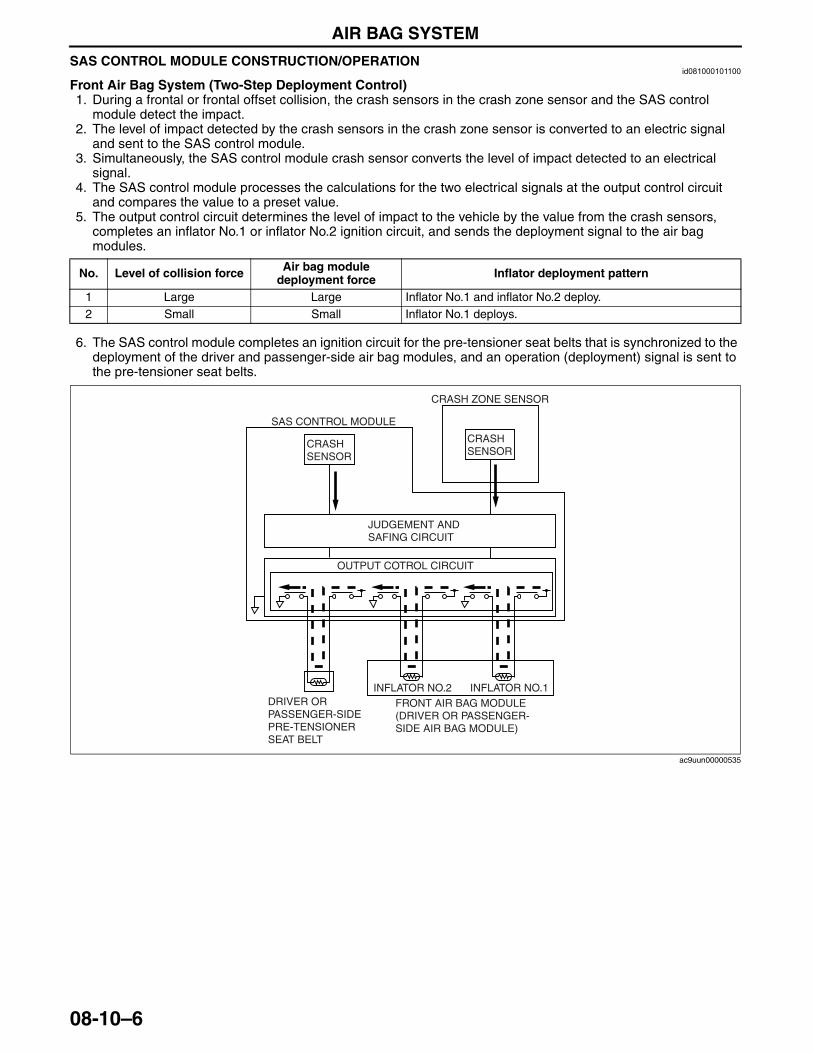
AIR BAG SYSTEM
08-10–6
SAS CONTROL MODULE CONSTRUCTION/OPERATIONid081000101100
Front Air Bag System (Two-Step Deployment Control)1. During a frontal or frontal offset collision, the crash sensors in the crash zone sensor and the SAS control
module detect the impact.2. The level of impact detected by the crash sensors in the crash zone sensor is converted to an electric signal
and sent to the SAS control module.3. Simultaneously, the SAS control module crash sensor converts the level of impact detected to an electrical
signal.4. The SAS control module processes the calculations for the two electrical signals at the output control circuit
and compares the value to a preset value.5. The output control circuit determines the level of impact to the vehicle by the value from the crash sensors,
completes an inflator No.1 or inflator No.2 ignition circuit, and sends the deployment signal to the air bag modules.
6. The SAS control module completes an ignition circuit for the pre-tensioner seat belts that is synchronized to the deployment of the driver and passenger-side air bag modules, and an operation (deployment) signal is sent to the pre-tensioner seat belts.
No. Level of collision force Air bag module deployment force Inflator deployment pattern
1 Large Large Inflator No.1 and inflator No.2 deploy.2 Small Small Inflator No.1 deploys.
SAS CONTROL MODULE
CRASH ZONE SENSOR
CRASHSENSOR
CRASHSENSOR
OUTPUT COTROL CIRCUIT
FRONT AIR BAG MODULE(DRIVER OR PASSENGER-SIDE AIR BAG MODULE)
INFLATOR NO.1INFLATOR NO.2DRIVER OR PASSENGER-SIDE PRE-TENSIONER SEAT BELT
JUDGEMENT AND SAFING CIRCUIT
ac9uun00000535
3423-1U-06H(08-10).fm 6 ページ 2006年11月22日 水曜日 午後2時54分
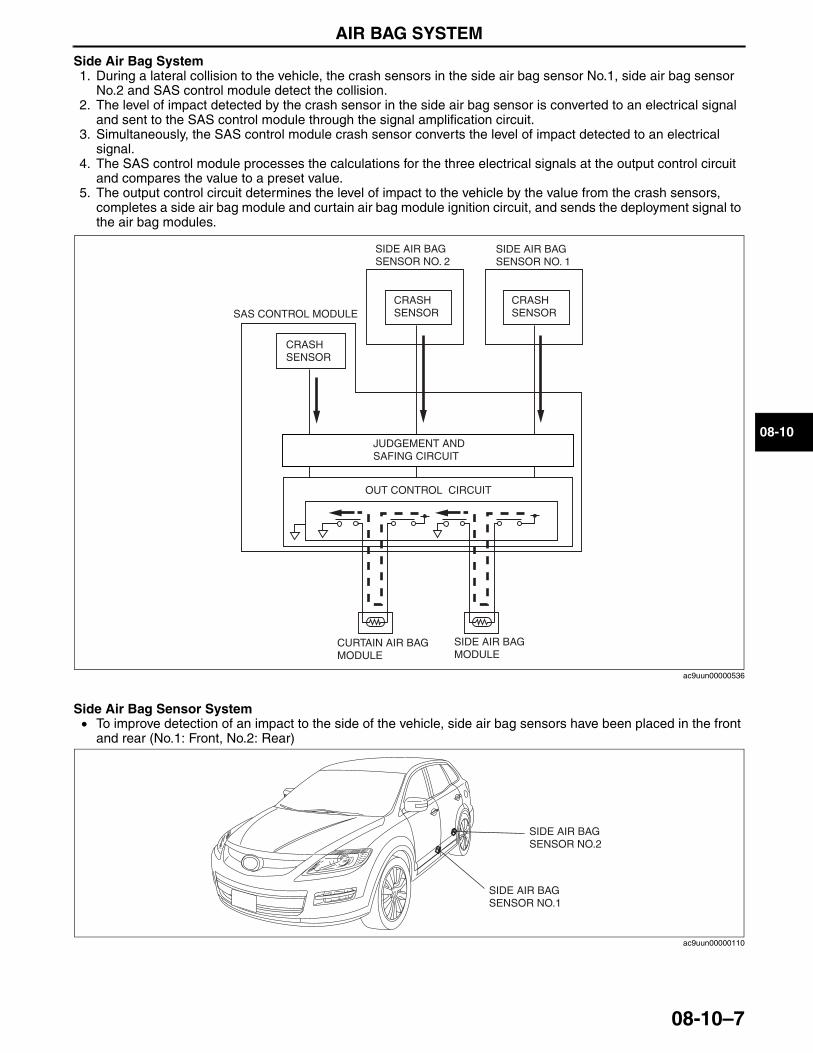
AIR BAG SYSTEM
08-10–7
08-10
Side Air Bag System1. During a lateral collision to the vehicle, the crash sensors in the side air bag sensor No.1, side air bag sensor
No.2 and SAS control module detect the collision.2. The level of impact detected by the crash sensor in the side air bag sensor is converted to an electrical signal
and sent to the SAS control module through the signal amplification circuit.3. Simultaneously, the SAS control module crash sensor converts the level of impact detected to an electrical
signal.4. The SAS control module processes the calculations for the three electrical signals at the output control circuit
and compares the value to a preset value.5. The output control circuit determines the level of impact to the vehicle by the value from the crash sensors,
completes a side air bag module and curtain air bag module ignition circuit, and sends the deployment signal to the air bag modules.
Side Air Bag Sensor System• To improve detection of an impact to the side of the vehicle, side air bag sensors have been placed in the front
and rear (No.1: Front, No.2: Rear)
SIDE AIR BAG SENSOR NO. 2
SIDE AIR BAG SENSOR NO. 1
CRASHSENSOR
CRASHSENSORSAS CONTROL MODULE
CURTAIN AIR BAG MODULE
SIDE AIR BAG MODULE
CRASHSENSOR
OUT CONTROL CIRCUIT
JUDGEMENT AND SAFING CIRCUIT
ac9uun00000536
SIDE AIR BAG SENSOR NO.1
SIDE AIR BAG SENSOR NO.2
ac9uun00000110
3423-1U-06H(08-10).fm 7 ページ 2006年11月22日 水曜日 午後2時54分
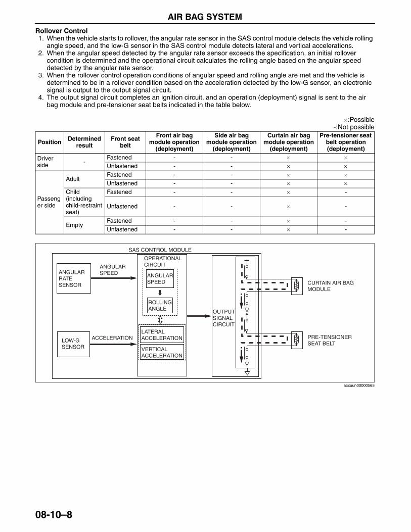
AIR BAG SYSTEM
08-10–8
Rollover Control1. When the vehicle starts to rollover, the angular rate sensor in the SAS control module detects the vehicle rolling
angle speed, and the low-G sensor in the SAS control module detects lateral and vertical accelerations.2. When the angular speed detected by the angular rate sensor exceeds the specification, an initial rollover
condition is determined and the operational circuit calculates the rolling angle based on the angular speed detected by the angular rate sensor.
3. When the rollover control operation conditions of angular speed and rolling angle are met and the vehicle is determined to be in a rollover condition based on the acceleration detected by the low-G sensor, an electronic signal is output to the output signal circuit.
4. The output signal circuit completes an ignition circuit, and an operation (deployment) signal is sent to the air bag module and pre-tensioner seat belts indicated in the table below.
×:Possible-:Not possible
Position Determined result
Front seat belt
Front air bag module operation
(deployment)
Side air bag module operation
(deployment)
Curtain air bag module operation
(deployment)
Pre-tensioner seat belt operation (deployment)
Driver side -
Fastened - - × ×Unfastened - - × ×
Passenger side
AdultFastened - - × ×Unfastened - - × ×
Child (including child-restraint seat)
Fastened - - × -
Unfastened - - × -
EmptyFastened - - × -Unfastened - - × -
SAS CONTROL MODULE
LOW-G SENSOR
CURTAIN AIR BAG MODULE
PRE-TENSIONER SEAT BELT
OUTPUT SIGNAL CIRCUIT
ANGULAR RATE SENSOR
ANGULAR SPEED
ACCELERATION
OPERATIONAL CIRCUIT
ANGULAR SPEED
ROLLING ANGLE
LATERAL ACCELERATION
VERTICAL ACCELERATION
acxuun00000565
3423-1U-06H(08-10).fm 8 ページ 2006年11月22日 水曜日 午後2時54分
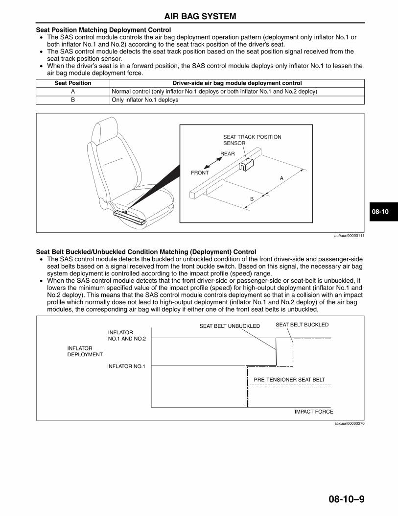
AIR BAG SYSTEM
08-10–9
08-10
Seat Position Matching Deployment Control• The SAS control module controls the air bag deployment operation pattern (deployment only inflator No.1 or
both inflator No.1 and No.2) according to the seat track position of the driver’s seat.• The SAS control module detects the seat track position based on the seat position signal received from the
seat track position sensor.• When the driver’s seat is in a forward position, the SAS control module deploys only inflator No.1 to lessen the
air bag module deployment force.
Seat Belt Buckled/Unbuckled Condition Matching (Deployment) Control• The SAS control module detects the buckled or unbuckled condition of the front driver-side and passenger-side
seat belts based on a signal received from the front buckle switch. Based on this signal, the necessary air bag system deployment is controlled according to the impact profile (speed) range.
• When the SAS control module detects that the front driver-side or passenger-side or seat-belt is unbuckled, it lowers the minimum specified value of the impact profile (speed) for high-output deployment (inflator No.1 and No.2 deploy). This means that the SAS control module controls deployment so that in a collision with an impact profile which normally dose not lead to high-output deployment (inflator No.1 and No.2 deploy) of the air bag modules, the corresponding air bag will deploy if either one of the front seat belts is unbuckled.
Seat Position Driver-side air bag module deployment controlA Normal control (only inflator No.1 deploys or both inflator No.1 and No.2 deploy)B Only inflator No.1 deploys
REAR
SEAT TRACK POSITIONSENSOR
FRONT
B
A
ac9uun00000111
SEAT BELT BUCKLED
PRE-TENSIONER SEAT BELT
IMPACT FORCE
INFLATORDEPLOYMENT
INFLATOR NO.1 AND NO.2
INFLATOR NO.1
SEAT BELT UNBUCKLED
acxuun00000270
3423-1U-06H(08-10).fm 9 ページ 2006年11月22日 水曜日 午後2時54分
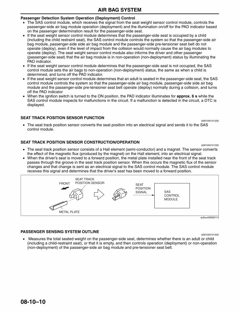
AIR BAG SYSTEM
08-10–10
Passenger Detection System Operation (Deployment) Control• The SAS control module, which receives the signal from the seat weight sensor control module, controls the
passenger-side air bag module operation (deployment) and the illumination on/off for the PAD indicator based on the passenger determination result for the passenger-side seat.
• If the seat weight sensor control module determines that the passenger-side seat is occupied by a child (including the child restraint seat), the SAS control module controls the system so that the passenger-side air bag module, passenger-side side air bag module and the passenger-side pre-tensioner seat belt do not operate (deploy), even if the level of impact from the collision would normally cause the air bag modules to operate (deploy). The seat weight sensor control module also informs the driver and other passenger (passenger-side seat) that the air bag module is in non-operation (non-deployment) status by illuminating the PAD indicator.
• If the seat weight sensor control module determines that the passenger-side seat is not occupied, the SAS control module sets the air bags to non-operation (non-deployment) status, the same as when a child is determined, and turns off the PAD indicator.
• If the seat weight sensor control module determines that an adult is seated in the passenger-side seat, the SAS control module controls the system so that the passenger-side air bag module, passenger-side side air bag module and the passenger-side pre-tensioner seat belt operate (deploy) normally during a collision, and turns off the PAD indicator
• When the ignition switch is turned to the ON position, the PAD indicator illuminates for approx. 6 s while the SAS control module inspects for malfunctions in the circuit. If a malfunction is detected in the circuit, a DTC is displayed.
End Of Sie
SEAT TRACK POSITION SENSOR FUNCTIONid081000101200
• The seat track position sensor converts the seat position into an electrical signal and sends it to the SAS control module.
End Of Sie
SEAT TRACK POSITION SENSOR CONSTRUCTION/OPERATIONid081000101300
• The seat track position sensor consists of a Hall element (semi-conductor) and a magnet. The sensor converts the effect of the magnetic flux (produced by the magnet) on the Hall element, into an electrical signal.
• When the driver’s seat is moved to a forward position, the metal plate installed near the front of the seat track passes through the groove in the seat track position sensor. When this occurs the magnetic flux of the sensor changes and that change is sent as an electrical signal to the SAS control module. The SAS control module receives this signal and determines that the driver’s seat has been moved to a forward position.
End Of Sie
PASSENGER SENSING SYSTEM OUTLINEid081000101400
• Measures the total seated weight on the passenger-side seat, determines whether there is an adult or child (including a child-restraint seat), or that it is empty, and then controls operation (deployment) or non-operation (non-deployment) of the passenger-side air bag module and pre-tensioner seat belt.
End Of Sie
SEAT TRACKPOSITION SENSOR SEAT
POSITION SIGNAL SAS
CONTROLMODULE
FRONT
METAL PLATE
ac9uun00000113
3423-1U-06H(08-10).fm 10 ページ 2006年11月22日 水曜日 午後2時54分
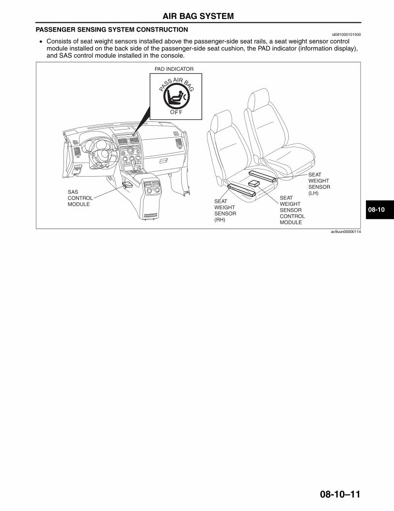
AIR BAG SYSTEM
08-10–11
08-10
PASSENGER SENSING SYSTEM CONSTRUCTIONid081000101500
• Consists of seat weight sensors installed above the passenger-side seat rails, a seat weight sensor control module installed on the back side of the passenger-side seat cushion, the PAD indicator (information display), and SAS control module installed in the console.
End Of Sie
SEAT WEIGHT SENSOR CONTROL MODULE
SEAT WEIGHT SENSOR (LH)
SEAT WEIGHT SENSOR (RH)
PAD INDICATOR
SAS CONTROL MODULE
ac9uun00000114
3423-1U-06H(08-10).fm 11 ページ 2006年11月22日 水曜日 午後2時54分
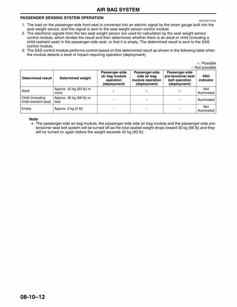
AIR BAG SYSTEM
08-10–12
PASSENGER SENSING SYSTEM OPERATIONid081000101600
1. The load on the passenger-side front seat is converted into an electric signal by the strain gauge built into the seat weight sensor, and this signal is sent to the seat weight sensor control module.
2. The electronic signals from the two seat weight sensor are used for calculation by the seat weight sensor control module, which divides the result and then determines whether there is an adult or child (including a child-restraint seat) in the passenger-side seat, or that it is empty. The determined result is sent to the SAS control module.
3. The SAS control module performs control based on this determined result as shown in the following table when the module detects a level of impact requiring operation (deployment).
×: Possible-: Not possible
Note• The passenger-side air bag module, the passenger-side side air bag module and the passenger-side pre-
tensioner seat belt system will be turned off as the total seated weight drops toward 30 kg {66 lb} and they will be turned on again before the weight exceeds 42 kg {93 lb}.
Determined result Determined weight
Passenger-side air bag module
operation (deployment)
Passenger-side side air bag
module operation (deployment)
Passenger-side pre-tensioner seat
belt operation (deployment)
PAD indicator
Adult Approx. 42 kg {93 lb} or more × × × Not
illuminatedChild (including child-restraint seat)
Approx. 30 kg {66 lb} or less - - - Illuminated
Empty Approx. 0 kg {0 lb} - - - Not illuminated
3423-1U-06H(08-10).fm 12 ページ 2006年11月22日 水曜日 午後2時54分
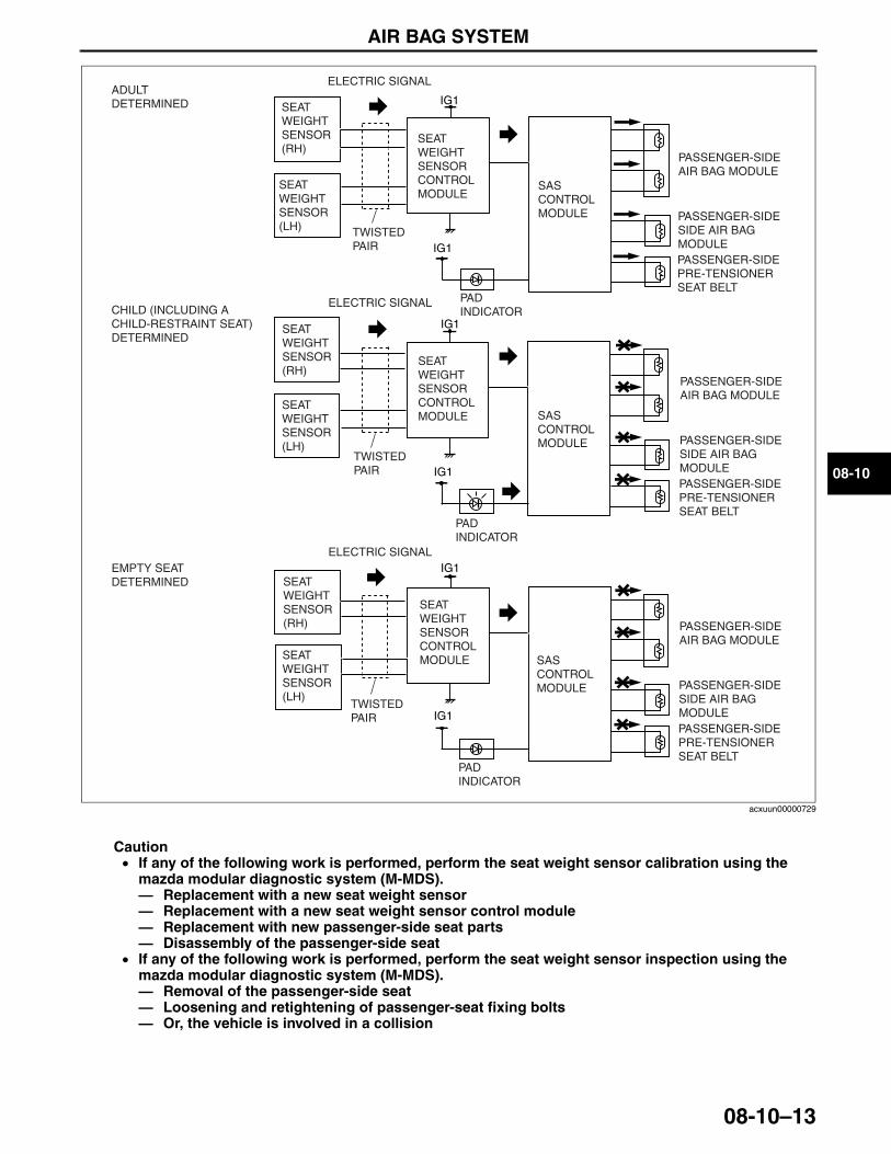
AIR BAG SYSTEM
08-10–13
08-10
Caution• If any of the following work is performed, perform the seat weight sensor calibration using the
mazda modular diagnostic system (M-MDS).— Replacement with a new seat weight sensor— Replacement with a new seat weight sensor control module— Replacement with new passenger-side seat parts— Disassembly of the passenger-side seat
• If any of the following work is performed, perform the seat weight sensor inspection using the mazda modular diagnostic system (M-MDS).— Removal of the passenger-side seat— Loosening and retightening of passenger-seat fixing bolts— Or, the vehicle is involved in a collision
End Of SieNG: DRIVER-SIDE AIR BAG MODULE
IG1
IG1
PASSENGER-SIDE AIR BAG MODULE
PASSENGER-SIDESIDE AIR BAG MODULEPASSENGER-SIDEPRE-TENSIONER SEAT BELT
IG1
IG1
IG1
IG1
PAD INDICATOR
PAD INDICATOR
PAD INDICATOR
SAS CONTROL MODULE
SAS CONTROL MODULE
SAS CONTROL MODULE
SEAT WEIGHT SENSOR (RH)
SEAT WEIGHT SENSOR CONTROL MODULE
ADULT DETERMINED
EMPTY SEAT DETERMINED
SEAT WEIGHT SENSOR CONTROL MODULE
SEAT WEIGHT SENSOR (LH)
SEAT WEIGHT SENSOR CONTROL MODULE
SEAT WEIGHT SENSOR (RH)
SEAT WEIGHT SENSOR (RH)
SEAT WEIGHT SENSOR (LH)
SEAT WEIGHT SENSOR (LH)
TWISTED PAIR
TWISTED PAIR
TWISTED PAIR
ELECTRIC SIGNAL
ELECTRIC SIGNAL
ELECTRIC SIGNAL
CHILD (INCLUDING A CHILD-RESTRAINT SEAT) DETERMINED
PASSENGER-SIDE AIR BAG MODULE
PASSENGER-SIDESIDE AIR BAG MODULEPASSENGER-SIDEPRE-TENSIONER SEAT BELT
PASSENGER-SIDE AIR BAG MODULE
PASSENGER-SIDESIDE AIR BAG MODULEPASSENGER-SIDEPRE-TENSIONER SEAT BELT
acxuun00000729
3423-1U-06H(08-10).fm 13 ページ 2006年11月22日 水曜日 午後2時54分
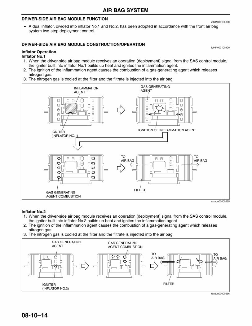
AIR BAG SYSTEM
08-10–14
DRIVER-SIDE AIR BAG MODULE FUNCTIONid081000100800
• A dual inflator, divided into inflator No.1 and No.2, has been adopted in accordance with the front air bag system two-step deployment control.
End Of Sie
DRIVER-SIDE AIR BAG MODULE CONSTRUCTION/OPERATIONid081000100900
Inflator OperationInflator No.11. When the driver-side air bag module receives an operation (deployment) signal from the SAS control module,
the igniter built into inflator No.1 builds up heat and ignites the inflammation agent.2. The ignition of the inflammation agent causes the combustion of a gas-generating agent which releases
nitrogen gas.3. The nitrogen gas is cooled at the filter and the filtrate is injected into the air bag.
Inflator No.21. When the driver-side air bag module receives an operation (deployment) signal from the SAS control module,
the igniter built into inflator No.2 builds up heat and ignites the inflammation agent.2. The ignition of the inflammation agent causes the combustion of a gas-generating agent which releases
nitrogen gas.3. The nitrogen gas is cooled at the filter and the filtrate is injected into the air bag.
End Of SieNG: PASSENGER-SIDE AIR BAG MODULE
INFLAMMATIONAGENT
IGNITION OF INFLAMMATION AGENTIGNITER(INFLATOR NO.1)
GAS GENERATINGAGENT
GAS GENERATINGAGENT COMBUSTION
TOAIR BAG
TOAIR BAG
FILTER
acxuun00000265
IGNITER(INFLATOR NO.2)
GAS GENERATINGAGENT
GAS GENERATINGAGENT COMBUSTION
TOAIR BAG
TOAIR BAG
FILTER
acxuun00000266
3423-1U-06H(08-10).fm 14 ページ 2006年11月22日 水曜日 午後2時54分
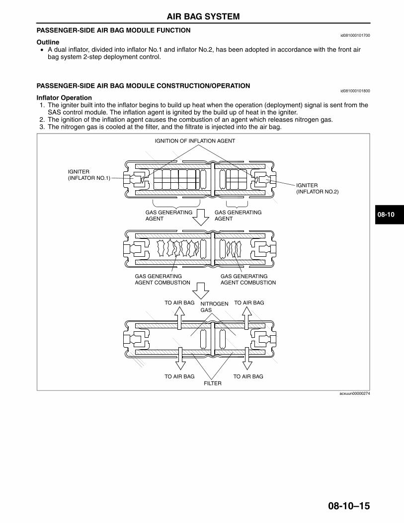
AIR BAG SYSTEM
08-10–15
08-10
PASSENGER-SIDE AIR BAG MODULE FUNCTIONid081000101700
Outline• A dual inflator, divided into inflator No.1 and inflator No.2, has been adopted in accordance with the front air
bag system 2-step deployment control.End Of Sie
PASSENGER-SIDE AIR BAG MODULE CONSTRUCTION/OPERATIONid081000101800
Inflator Operation1. The igniter built into the inflator begins to build up heat when the operation (deployment) signal is sent from the
SAS control module. The inflation agent is ignited by the build up of heat in the igniter.2. The ignition of the inflation agent causes the combustion of an agent which releases nitrogen gas.3. The nitrogen gas is cooled at the filter, and the filtrate is injected into the air bag.
End Of SieNG: SIDE AIR BAG MODULE
IGNITION OF INFLATION AGENT
IGNITER(INFLATOR NO.2)
IGNITER(INFLATOR NO.1)
GAS GENERATING AGENT
GAS GENERATING AGENT COMBUSTION
TO AIR BAG
TO AIR BAG TO AIR BAGFILTER
TO AIR BAGNITROGEN GAS
GAS GENERATING AGENT COMBUSTION
GAS GENERATING AGENT
acxuun00000274
3423-1U-06H(08-10).fm 15 ページ 2006年11月22日 水曜日 午後2時54分
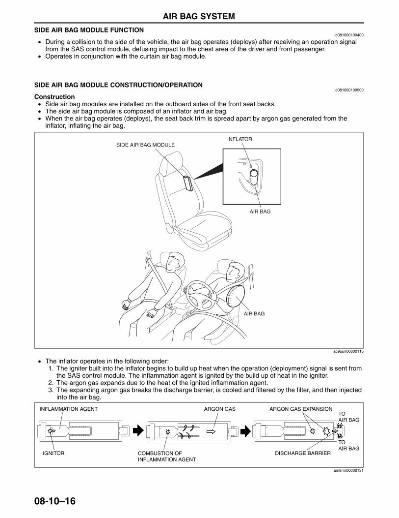
AIR BAG SYSTEM
08-10–16
SIDE AIR BAG MODULE FUNCTIONid081000100400
• During a collision to the side of the vehicle, the air bag operates (deploys) after receiving an operation signal from the SAS control module, defusing impact to the chest area of the driver and front passenger.
• Operates in conjunction with the curtain air bag module.End Of Sie
SIDE AIR BAG MODULE CONSTRUCTION/OPERATIONid081000100500
Construction• Side air bag modules are installed on the outboard sides of the front seat backs.• The side air bag module is composed of an inflator and air bag.• When the air bag operates (deploys), the seat back trim is spread apart by argon gas generated from the
inflator, inflating the air bag.
• The inflator operates in the following order:1. The igniter built into the inflator begins to build up heat when the operation (deployment) signal is sent from
the SAS control module. The inflammation agent is ignited by the build up of heat in the igniter.2. The argon gas expands due to the heat of the ignited inflammation agent.3. The expanding argon gas breaks the discharge barrier, is cooled and filtered by the filter, and then injected
into the air bag.
End Of SieNG: CURTAIN AIR BAG MODULE
SIDE AIR BAG MODULEINFLATOR
AIR BAG
AIR BAG
ac9uun00000115
INFLAMMATION AGENT ARGON GAS EXPANSION
DISCHARGE BARRIER
TOAIR BAG
ARGON GAS
COMBUSTION OF INFLAMMATION AGENT
IGNITOR
TOAIR BAG
am8rrn00000131
3423-1U-06H(08-10).fm 16 ページ 2006年11月22日 水曜日 午後2時54分
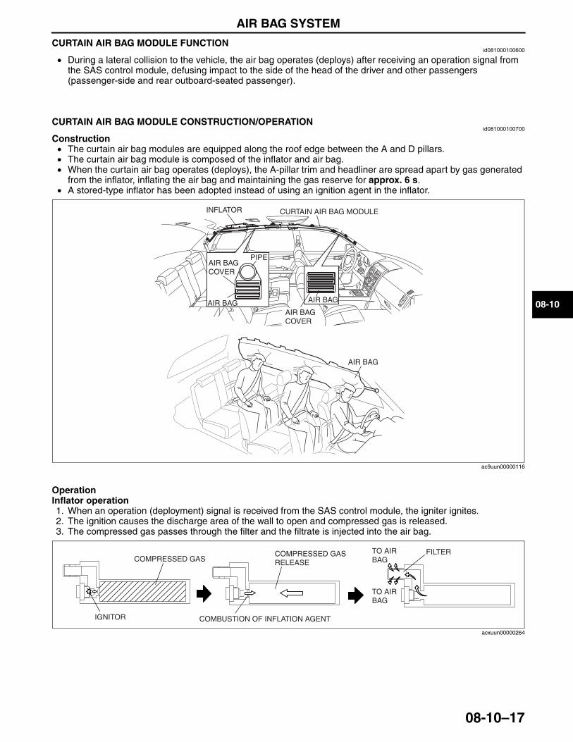
AIR BAG SYSTEM
08-10–17
08-10
CURTAIN AIR BAG MODULE FUNCTIONid081000100600
• During a lateral collision to the vehicle, the air bag operates (deploys) after receiving an operation signal from the SAS control module, defusing impact to the side of the head of the driver and other passengers (passenger-side and rear outboard-seated passenger).
End Of Sie
CURTAIN AIR BAG MODULE CONSTRUCTION/OPERATIONid081000100700
Construction• The curtain air bag modules are equipped along the roof edge between the A and D pillars.• The curtain air bag module is composed of the inflator and air bag.• When the curtain air bag operates (deploys), the A-pillar trim and headliner are spread apart by gas generated
from the inflator, inflating the air bag and maintaining the gas reserve for approx. 6 s.• A stored-type inflator has been adopted instead of using an ignition agent in the inflator.
OperationInflator operation1. When an operation (deployment) signal is received from the SAS control module, the igniter ignites.2. The ignition causes the discharge area of the wall to open and compressed gas is released.3. The compressed gas passes through the filter and the filtrate is injected into the air bag.
End Of SieNG: PRE-TENSIONER SEAT BELT
CURTAIN AIR BAG MODULE
AIR BAG
AIR BAG COVER
PIPE
AIR BAG
AIR BAG
INFLATOR
AIR BAG COVER
ac9uun00000116
IGNITOR
COMPRESSED GAS
COMBUSTION OF INFLATION AGENT
COMPRESSED GAS RELEASE
FILTERTO AIR BAG
TO AIR BAG
acxuun00000264
3423-1U-06H(08-10).fm 17 ページ 2006年11月22日 水曜日 午後2時54分
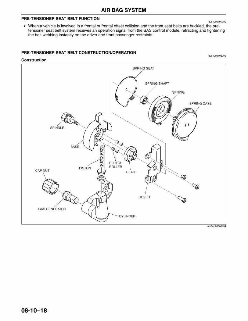
AIR BAG SYSTEM
08-10–18
PRE-TENSIONER SEAT BELT FUNCTIONid081000101900
• When a vehicle is involved in a frontal or frontal offset collision and the front seat belts are buckled, the pre-tensioner seat belt system receives an operation signal from the SAS control module, retracting and tightening the belt webbing instantly on the driver and front passenger restraints.
End Of Sie
PRE-TENSIONER SEAT BELT CONSTRUCTION/OPERATIONid081000102000
Construction
SPRING
BASE
SPINDLE
GEARPISTON
CLUTCH ROLLER
GAS GENERATOR
CYLINDER
COVER
SPRING SEAT
SPRING SHAFT
CAP NUT
SPRING CASE
am8rrn00000134
3423-1U-06H(08-10).fm 18 ページ 2006年11月22日 水曜日 午後2時54分
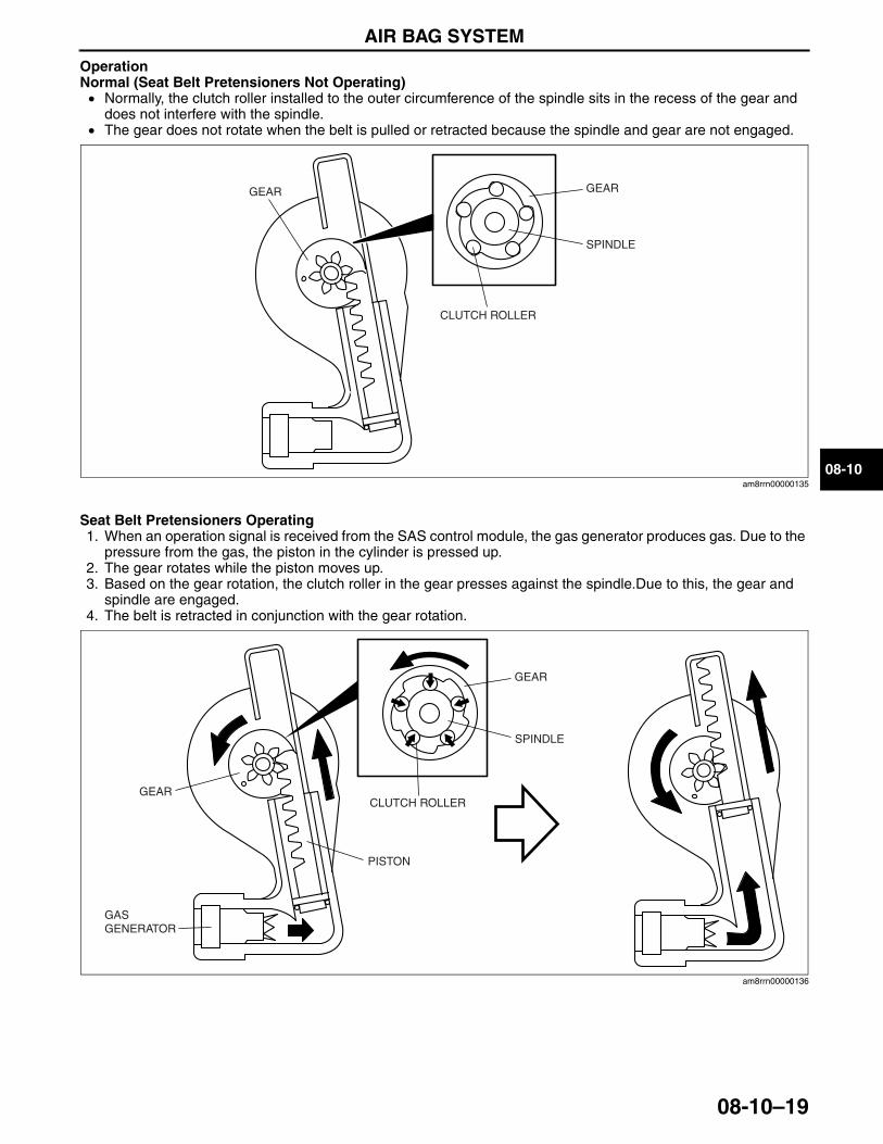
AIR BAG SYSTEM
08-10–19
08-10
OperationNormal (Seat Belt Pretensioners Not Operating)• Normally, the clutch roller installed to the outer circumference of the spindle sits in the recess of the gear and
does not interfere with the spindle.• The gear does not rotate when the belt is pulled or retracted because the spindle and gear are not engaged.
Seat Belt Pretensioners Operating1. When an operation signal is received from the SAS control module, the gas generator produces gas. Due to the
pressure from the gas, the piston in the cylinder is pressed up.2. The gear rotates while the piston moves up.3. Based on the gear rotation, the clutch roller in the gear presses against the spindle.Due to this, the gear and
spindle are engaged.4. The belt is retracted in conjunction with the gear rotation.
End Of Sie
GEAR GEAR
SPINDLE
CLUTCH ROLLER
am8rrn00000135
GAS GENERATOR
GEAR
PISTON
SPINDLE
CLUTCH ROLLERGEAR
am8rrn00000136
3423-1U-06H(08-10).fm 19 ページ 2006年11月22日 水曜日 午後2時54分

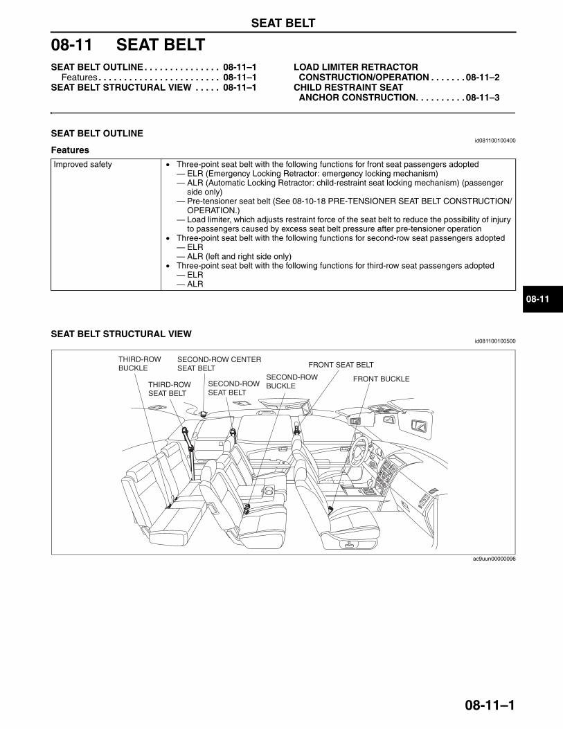
SEAT BELT
08-11–1
08-11
08-11 SEAT BELTSEAT BELT OUTLINE . . . . . . . . . . . . . . . 08-11–1
Features . . . . . . . . . . . . . . . . . . . . . . . . 08-11–1SEAT BELT STRUCTURAL VIEW . . . . . 08-11–1
LOAD LIMITER RETRACTOR CONSTRUCTION/OPERATION . . . . . . . 08-11–2
CHILD RESTRAINT SEAT ANCHOR CONSTRUCTION. . . . . . . . . . 08-11–3
End of TocNG: SEAT BELTSEAT BELT OUTLINE
id081100100400
Features
End Of Sie
SEAT BELT STRUCTURAL VIEWid081100100500
End Of Sie
Improved safety • Three-point seat belt with the following functions for front seat passengers adopted— ELR (Emergency Locking Retractor: emergency locking mechanism)— ALR (Automatic Locking Retractor: child-restraint seat locking mechanism) (passenger
side only)— Pre-tensioner seat belt (See 08-10-18 PRE-TENSIONER SEAT BELT CONSTRUCTION/
OPERATION.)— Load limiter, which adjusts restraint force of the seat belt to reduce the possibility of injury
to passengers caused by excess seat belt pressure after pre-tensioner operation• Three-point seat belt with the following functions for second-row seat passengers adopted— ELR— ALR (left and right side only)
• Three-point seat belt with the following functions for third-row seat passengers adopted— ELR— ALR
FRONT BUCKLESECOND-ROW BUCKLE
SECOND-ROW CENTER SEAT BELT
THIRD-ROW BUCKLE FRONT SEAT BELT
SECOND-ROW SEAT BELT
THIRD-ROW SEAT BELT
ac9uun00000096
3423-1U-06H(08-11).fm 1 ページ 2006年11月21日 火曜日 午後5時34分
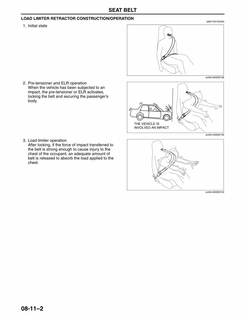
SEAT BELT
08-11–2
LOAD LIMITER RETRACTOR CONSTRUCTION/OPERATIONid081100100300
1. Initial state
2. Pre-tensioner and ELR operationWhen the vehicle has been subjected to an impact, the pre-tensioner or ELR activates, locking the belt and securing the passenger’s body.
3. Load limiter operationAfter locking, if the force of impact transferred to the belt is strong enough to cause injury to the chest of the occupant, an adequate amount of belt is released to absorb the load applied to the chest.
End Of SieNG: CHILD-RESTRANT SEAT ANCHOR
am8rrn00000138
THE VEHICLE IS INVOLVED AN IMPACT
am8rrn00000139
am8rrn00000140
3423-1U-06H(08-11).fm 2 ページ 2006年11月21日 火曜日 午後5時34分
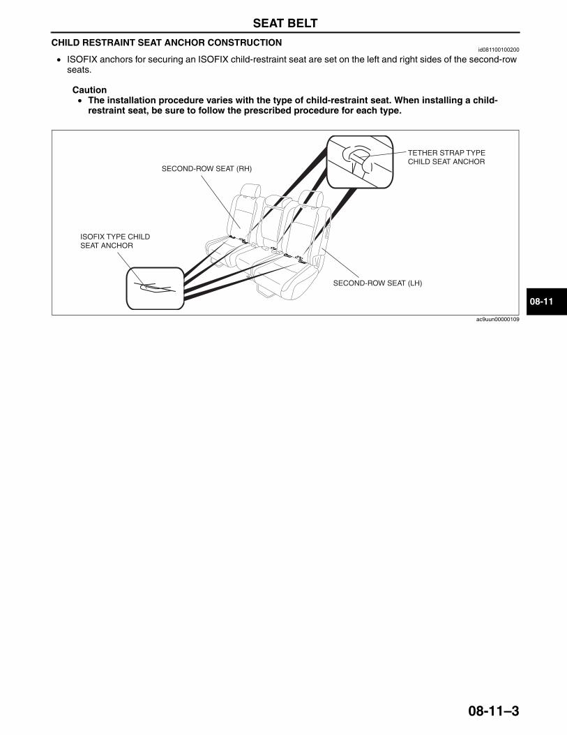
SEAT BELT
08-11–3
08-11
CHILD RESTRAINT SEAT ANCHOR CONSTRUCTIONid081100100200
• ISOFIX anchors for securing an ISOFIX child-restraint seat are set on the left and right sides of the second-row seats.
Caution• The installation procedure varies with the type of child-restraint seat. When installing a child-
restraint seat, be sure to follow the prescribed procedure for each type.
End Of Sie
ISOFIX TYPE CHILD SEAT ANCHOR
SECOND-ROW SEAT (LH)
SECOND-ROW SEAT (RH)
TETHER STRAP TYPE CHILD SEAT ANCHOR
ac9uun00000109
3423-1U-06H(08-11).fm 3 ページ 2006年11月21日 火曜日 午後5時34分

09-00–1
09BODY & ACCESSORIESSECTION
09-00
Toc of SCTOUTLINE . . . . . . . . . . . . . . . . . .09-00BODY PANELS . . . . . . . . . . . . .09-10DOORS AND LIFTGATE. . . . . .09-11GLASS/WINDOWS/
MIRRORS . . . . . . . . . . . . . . . .09-12SEATS . . . . . . . . . . . . . . . . . . . .09-13SECURITY AND LOCKS
[ADVANCED KEYLESS SYSTEM]. . . . . . . . . . . . . . . . .09-14A
SECURITY AND LOCKS[KEYLESS ENTRY SYSTEM]. . . . . . . . . . . . . . . . .09-14B
SUNROOF . . . . . . . . . . . . . . . . 09-15EXTERIOR TRIM . . . . . . . . . . . 09-16INTERIOR TRIM. . . . . . . . . . . . 09-17LIGHTING SYSTEMS. . . . . . . . 09-18WIPER/WASHER SYSTEM . . . 09-19ENTERTAINMENT . . . . . . . . . . 09-20POWER SYSTEMS . . . . . . . . . 09-21INSTRUMENTATION/
DRIVER INFO. . . . . . . . . . . . . 09-22CONTROL SYSTEM . . . . . . . . 09-40
Toc of SCT
09-00 OUTLINEBODY AND ACCESSORIES
ABBREVIATIONS. . . . . . . . . . . . . . . . . . 09-00–1BODY AND ACCESSORIES
FEATURES . . . . . . . . . . . . . . . . . . . . . . 09-00–2
End of TocNG: BODY AND ACCESSORIESBODY AND ACCESSORIES ABBREVIATIONS
id090000100100
End Of Sie
ACC AccessoriesALC Auto Level ControlATX Automatic TransaxleAWD All Wheel DriveBCM Body Control ModuleCAN Controller Area NetworkCM Control ModuleCPU Central Processing UnitDLC Data Link ConnectorDSC Dynamic Stability ControlDTC Diagnostic Trouble CodeDRL Daytime running lightECT Engine Coolant TemperatureGND GroundGPS Global Positioning SystemHF/TEL Hands-Free TelephoneHI HighIC Integrated CircuitsIG IgnitionINT IntermittentLCD Liquid Crystal DisplayLED Light Emitting Diode
LF Left FrontLH Left HandLO LowLR Left RearM MotorOFF Switch OffON Switch OnPCM Powertrain Control ModulePID Parameter IdentificationPLG Power LiftgatePTC Positive Temperature CoefficientP/W CM Power Window Control ModuleRES Rear Entertainment SystemRF Right FrontRH Right HandRR Right RearRSC Roll Stability ControlSAS Sophisticated Air Bag SensorSW SwitchTCM Transaxle Control ModuleTNS Tail Number Side LightsTPMS Tire Pressure Monitoring System
3423-1U-06H(09-00).fm 1 ページ 2006年11月21日 火曜日 午後5時34分
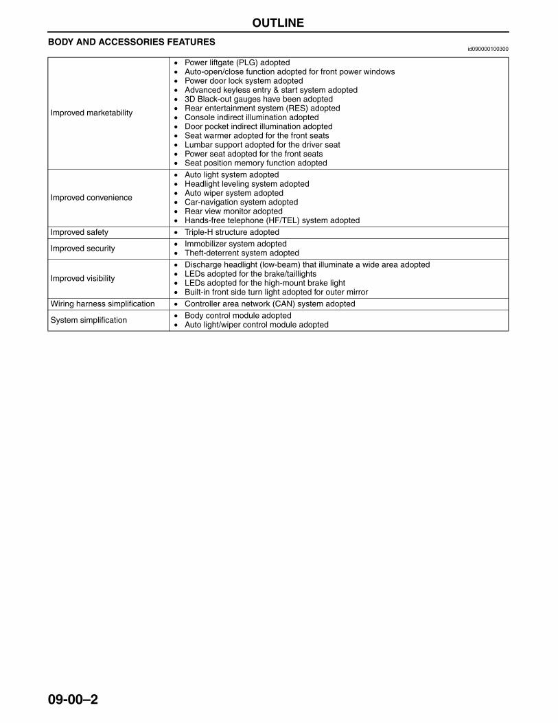
OUTLINE
09-00–2
BODY AND ACCESSORIES FEATURESid090000100300
End Of Sie
Improved marketability
• Power liftgate (PLG) adopted• Auto-open/close function adopted for front power windows• Power door lock system adopted• Advanced keyless entry & start system adopted• 3D Black-out gauges have been adopted• Rear entertainment system (RES) adopted• Console indirect illumination adopted• Door pocket indirect illumination adopted• Seat warmer adopted for the front seats• Lumbar support adopted for the driver seat• Power seat adopted for the front seats• Seat position memory function adopted
Improved convenience
• Auto light system adopted• Headlight leveling system adopted• Auto wiper system adopted• Car-navigation system adopted• Rear view monitor adopted• Hands-free telephone (HF/TEL) system adopted
Improved safety • Triple-H structure adopted
Improved security • Immobilizer system adopted• Theft-deterrent system adopted
Improved visibility
• Discharge headlight (low-beam) that illuminate a wide area adopted• LEDs adopted for the brake/taillights• LEDs adopted for the high-mount brake light• Built-in front side turn light adopted for outer mirror
Wiring harness simplification • Controller area network (CAN) system adopted
System simplification • Body control module adopted• Auto light/wiper control module adopted
3423-1U-06H(09-00).fm 2 ページ 2006年11月21日 火曜日 午後5時34分
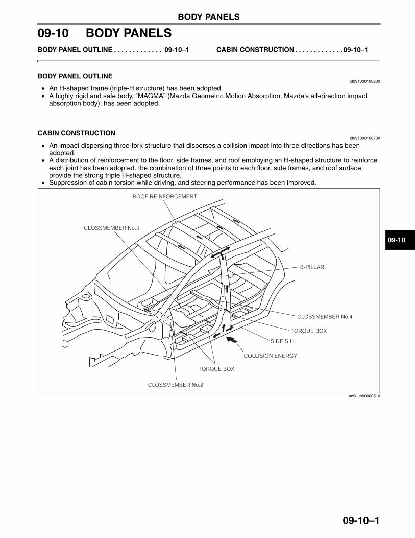
BODY PANELS
09-10–1
09-10
09-10 BODY PANELSBODY PANEL OUTLINE . . . . . . . . . . . . . 09-10–1 CABIN CONSTRUCTION . . . . . . . . . . . . . 09-10–1
End of TocNG: BODY PANELBODY PANEL OUTLINE
id091000100200
• An H-shaped frame (triple-H structure) has been adopted.• A highly rigid and safe body, "MAGMA” (Mazda Geometric Motion Absorption; Mazda’s all-direction impact
absorption body), has been adopted.End Of Sie
CABIN CONSTRUCTIONid091000100700
• An impact dispersing three-fork structure that disperses a collision impact into three directions has been adopted.
• A distribution of reinforcement to the floor, side frames, and roof employing an H-shaped structure to reinforce each joint has been adopted. the combination of three points to each floor, side frames, and roof surface provide the strong triple H-shaped structure.
• Suppression of cabin torsion while driving, and steering performance has been improved.
End Of Sie
SIDE SILL
B-PILLAR
ROOF REINFORCEMENT
COLLISION ENERGY
CLOSSMEMBER No.2
CLOSSMEMBER No.4
CLOSSMEMBER No.3
TORQUE BOX
TORQUE BOX
ac9uun00000510
3423-1U-06H(09-10).fm 1 ページ 2006年11月21日 火曜日 午後5時35分

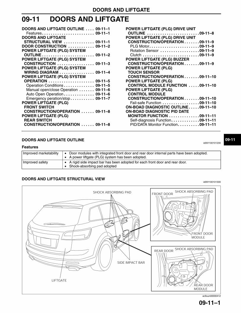
DOORS AND LIFTGATE
09-11–1
09-11
09-11 DOORS AND LIFTGATEDOORS AND LIFTGATE OUTLINE . . . . 09-11–1
Features . . . . . . . . . . . . . . . . . . . . . . . . 09-11–1DOORS AND LIFTGATE
STRUCTURAL VIEW . . . . . . . . . . . . . . 09-11–1DOOR CONSTRUCTION . . . . . . . . . . . . 09-11–2POWER LIFTGATE (PLG) SYSTEM
OUTLINE . . . . . . . . . . . . . . . . . . . . . . . . 09-11–2POWER LIFTGATE (PLG) SYSTEM
CONSTRUCTION . . . . . . . . . . . . . . . . . 09-11–3POWER LIFTGATE (PLG) SYSTEM
WIRING DIAGRAM . . . . . . . . . . . . . . . . 09-11–4POWER LIFTGATE (PLG) SYSTEM
OPERATION . . . . . . . . . . . . . . . . . . . . . 09-11–5Operation Conditions . . . . . . . . . . . . . . 09-11–5Manual open/close Operation . . . . . . . 09-11–6Auto Open Operation . . . . . . . . . . . . . . 09-11–6Emergency peration/stop . . . . . . . . . . . 09-11–7
POWER LIFTGATE (PLG) FRONT SWITCH CONSTRUCTION/OPERATION . . . . . . 09-11–8
POWER LIFTGATE (PLG) REAR SWITCH CONSTRUCTION/OPERATION . . . . . . 09-11–8
POWER LIFTGATE (PLG) DRIVE UNIT OUTLINE . . . . . . . . . . . . . . . . . . . . . . . . 09-11–8
POWER LIFTGATE (PLG) DRIVE UNIT CONSTRUCTION/OPERATION . . . . . . . 09-11–9
PLG Motor . . . . . . . . . . . . . . . . . . . . . . . 09-11–9Rotation Sensor . . . . . . . . . . . . . . . . . . 09-11–9Clutch . . . . . . . . . . . . . . . . . . . . . . . . . . 09-11–9
POWER LIFTGATE (PLG) BUZZER CONSTRUCTION/OPERATION . . . . . . . 09-11–9
POWER LIFTGATE (PLG) TOUCH SENSOR CONSTRUCTION/OPERATION . . . . . . . 09-11–10
POWER LIFTGATE (PLG) CONTROL MODULE FUNCTION . . . . . 09-11–10
POWER LIFTGATE (PLG) CONTROL MODULE CONSTRUCTION/OPERATION . . . . . . . 09-11–10
Fail-safe Function . . . . . . . . . . . . . . . . . 09-11–10ON-BOAD DIAGNOSTIC OUTLINE . . . . . 09-11–10ON-BOAD DIAGNOSTIC PID DATE
MONITOR FUNCTION . . . . . . . . . . . . . . 09-11–11Self-diagnosis Function . . . . . . . . . . . . . 09-11–11PID/DATA Monitor Function . . . . . . . . . . 09-11–11
End of TocNG: DOORDOORS AND LIFTGATE OUTLINE
id091100101200
Features
End Of SieDOORS AND LIFTGATE STRUCTURAL VIEW
id091100101300
Improved marketability • Door modules with integrated front door and rear door internal parts have been adopted.• A power liftgate (PLG) system has been adopted.
Improved safety • A rigid side impact bar has been adopted for each front door and rear door.• Shock-absorbing pad adopted
SHOCK ABSORBING PAD SHOCK ABSORBING PAD
LIFTGATE
SIDE IMPACT BAR
FRONT DOORMODULE
REAR DOORMODULE
REAR DOOR
FRONT DOOR
SHOCK ABSORBING PAD
ac9uun00000412
3423-1U-06H(09-11).fm 1 ページ 2006年11月21日 火曜日 午後5時36分
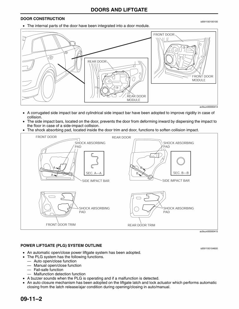
DOORS AND LIFTGATE
09-11–2
End Of SieDOOR CONSTRUCTIONid091100100100
• The internal parts of the door have been integrated into a door module.
• A corrugated side impact bar and cylindrical side impact bar have been adopted to improve rigidity in case of collision.
• The side impact bars, located on the door, prevents the door from deforming inward by dispersing the impact to the floor in case of a side-impact collision.
• The shock absorbing pad, located inside the door trim and door, functions to soften collision impact.
End Of Sie
POWER LIFTGATE (PLG) SYSTEM OUTLINEid091100104600
• An automatic open/close power liftgate system has been adopted.• The PLG system has the following functions.— Auto open/close function— Manual open/close function— Fail-safe function— Malfunction detection function
• A buzzer sounds when the PLG is operating and if a malfunction is detected.• An auto closure mechanism has been adopted on the liftgate latch and lock actuator which performs automatic
closing from the latch release/ajar condition during opening/closing in auto/manual.End Of Sie
FRONT DOOR
FRONT DOORMODULE
REAR DOORMODULE
REAR DOOR
ac9uun00000414
A B
SEC. A—A SEC. B—B
FRONT DOOR REAR DOOR
FRONT DOOR TRIM REAR DOOR TRIM
SIDE IMPACT BAR SIDE IMPACT BAR
A B
SHOCK ABSORBING PAD
SHOCK ABSORBING PAD
SHOCK ABSORBING PAD
SHOCK ABSORBING PAD
ac9uun00000415
3423-1U-06H(09-11).fm 2 ページ 2006年11月21日 火曜日 午後5時36分
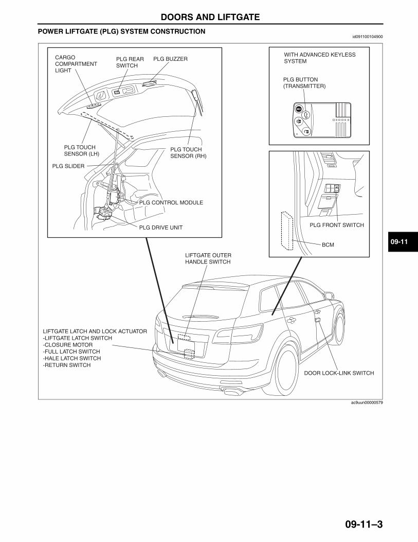
DOORS AND LIFTGATE
09-11–3
09-11
POWER LIFTGATE (PLG) SYSTEM CONSTRUCTIONid091100104900
End Of Sie
CARGO COMPARTMENT LIGHT
PLG TOUCH SENSOR (LH)
PLG TOUCH SENSOR (RH)
PLG DRIVE UNIT PLG FRONT SWITCH
LIFTGATE LATCH AND LOCK ACTUATOR
DOOR LOCK-LINK SWITCH
LIFTGATE OUTER HANDLE SWITCH
-LIFTGATE LATCH SWITCH-CLOSURE MOTOR-FULL LATCH SWITCH-HALE LATCH SWITCH-RETURN SWITCH
BCM
PLG REAR SWITCH
PLG BUZZER
PLG BUTTON (TRANSMITTER)
WITH ADVANCED KEYLESS SYSTEM
PLG CONTROL MODULE
PLG SLIDER
ac9uun00000579
3423-1U-06H(09-11).fm 3 ページ 2006年11月21日 火曜日 午後5時36分
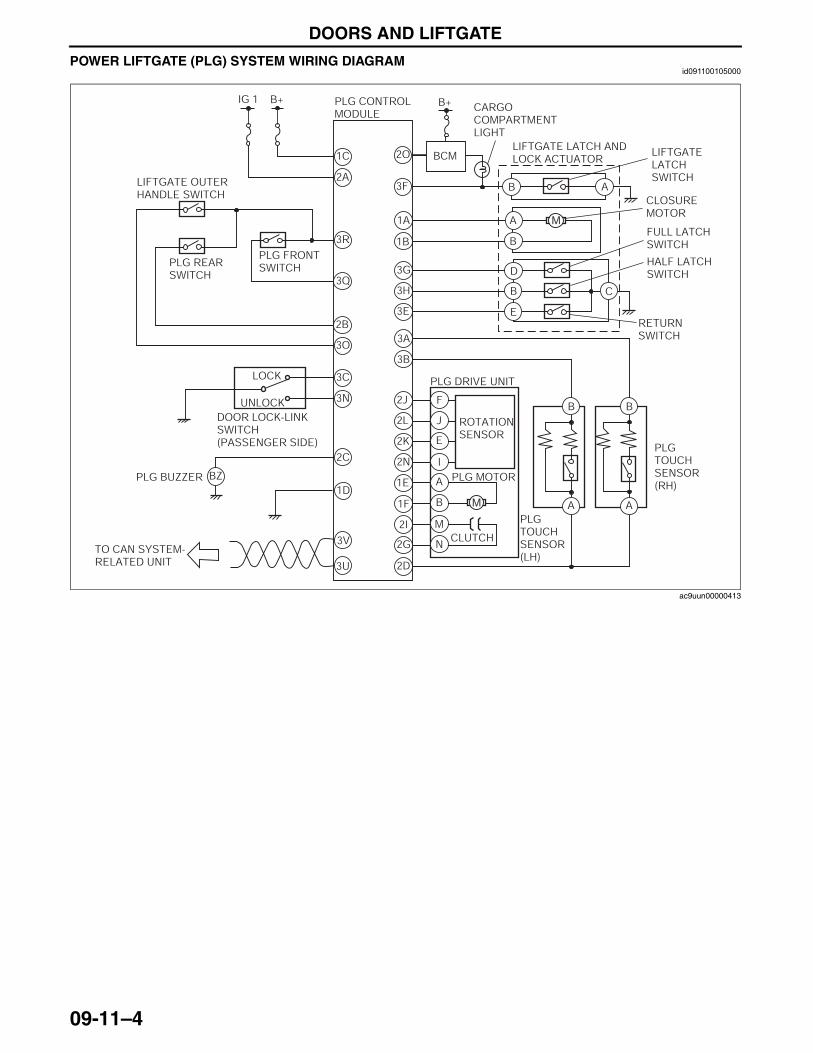
DOORS AND LIFTGATE
09-11–4
POWER LIFTGATE (PLG) SYSTEM WIRING DIAGRAMid091100105000
End Of Sie
M
M
LIFTGATE OUTER HANDLE SWITCH
PLG CONTROL MODULE
CARGO COMPARTMENT LIGHT
LIFTGATE LATCH SWITCH
FULL LATCH SWITCH
HALF LATCH SWITCH
RETURN SWITCH
B+ B+IG 1
1C
1B
1A
3F
3G
3H
3E
3B
3A
2J
2L
2K
2N
2D
1E
1F
2I
2G
2C
BZ
2A
2O
3R
2B
3Q
3O
3C
3N
3V
3U
1D
PLG REAR SWITCH
DOOR LOCK-LINK SWITCH (PASSENGER SIDE)
PLG FRONT SWITCH
PLG BUZZER
PLG DRIVE UNIT
PLG TOUCH SENSOR (RH)
PLG TOUCH SENSOR (LH)
ROTATION SENSOR
F
J
E
I
A
B
M
N
B
A
B
A
E
D
B C
B
A
CLOSURE MOTOR
BCMLIFTGATE LATCH AND LOCK ACTUATOR
B A
LOCK
UNLOCK
TO CAN SYSTEM-RELATED UNIT
CLUTCH
PLG MOTOR
ac9uun00000413
3423-1U-06H(09-11).fm 4 ページ 2006年11月21日 火曜日 午後5時36分
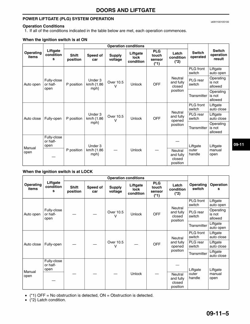
DOORS AND LIFTGATE
09-11–5
09-11
POWER LIFTGATE (PLG) SYSTEM OPERATIONid091100105100
Operation Conditions1. If all of the conditions indicated in the table below are met, each operation commences.
When the ignition switch is at ON
When the ignition switch is at LOCK
• (*1) OFF = No obstruction is detected, ON = Obstruction is detected.• (*2) Latch condition.
Operating items
Liftgate condition
s
Operation conditions
Switch operated
Switch operation
resultShift
positionSpeed of
carSupply voltage
Liftgate lock
condition
PLG touch
sensor (*1)
Latch condition
(*2)
Auto openFully-close or half-open
P positionUnder 3
km/h {1.86 mph}
Over 10.5 V Unlock OFF
Neutral and fully closed position
PLG front switch
Liftgate auto open
PLG rear switch
Operating is not allowed
TransmitterOperating is not allowed
Auto close Fully-open P positionUnder 3
km/h {1.86 mph}
Over 10.5 V Unlock OFF
Neutral and fully opened position
PLG front switch
Liftgate auto close
PLG rear switch
Liftgate auto close
TransmitterOperating is not allowed
Manual open
Fully-close or half-open
P positionUnder 3
km/h {1.86 mph}
— Unlock —
—Liftgate outer handle
Liftgate manual open
—
Neutral and fully closed position
Operating items
Liftgate condition
s
Operation conditions
Operating switch
OperationsShift
positionSpeed of
carSupply voltage
Liftgate lock
condition
PLG touch
sensor (*1)
Latch condition
(*2)
Auto openFully-close or half-open
— — Over 10.5 V Unlock OFF
Neutral and fully closed position
PLG front switch
Liftgate auto open
PLG rear switch
Operating is not allowed
Transmitter Liftgate auto open
Auto close Fully-open — — Over 10.5 V — OFF
Neutral and fully opened position
PLG front switch
Liftgate auto close
PLG rear switch
Liftgate auto close
Transmitter Liftgate auto close
Manual open
Fully-close or half-open
— — — Unlock —
—Liftgate outer handle
Liftgate manual open
—
Neutral and fully closed position
3423-1U-06H(09-11).fm 5 ページ 2006年11月21日 火曜日 午後5時36分
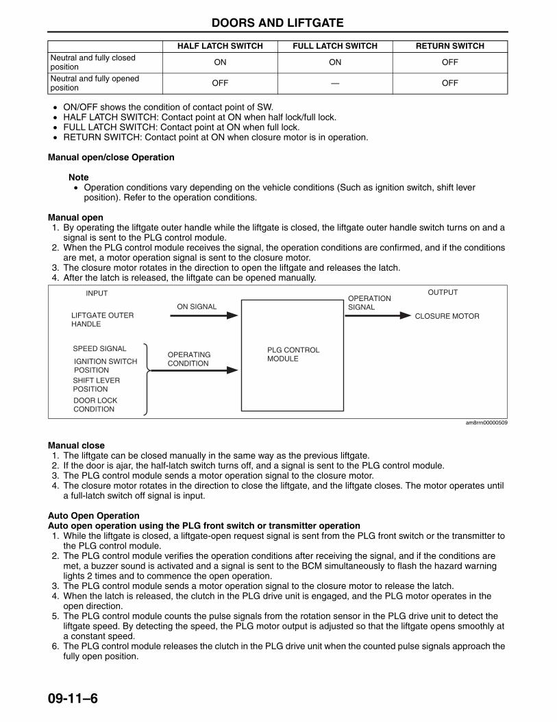
DOORS AND LIFTGATE
09-11–6
• ON/OFF shows the condition of contact point of SW.• HALF LATCH SWITCH: Contact point at ON when half lock/full lock.• FULL LATCH SWITCH: Contact point at ON when full lock.• RETURN SWITCH: Contact point at ON when closure motor is in operation.
Manual open/close Operation
Note• Operation conditions vary depending on the vehicle conditions (Such as ignition switch, shift lever
position). Refer to the operation conditions.
Manual open1. By operating the liftgate outer handle while the liftgate is closed, the liftgate outer handle switch turns on and a
signal is sent to the PLG control module.2. When the PLG control module receives the signal, the operation conditions are confirmed, and if the conditions
are met, a motor operation signal is sent to the closure motor.3. The closure motor rotates in the direction to open the liftgate and releases the latch.4. After the latch is released, the liftgate can be opened manually.
Manual close1. The liftgate can be closed manually in the same way as the previous liftgate.2. If the door is ajar, the half-latch switch turns off, and a signal is sent to the PLG control module.3. The PLG control module sends a motor operation signal to the closure motor.4. The closure motor rotates in the direction to close the liftgate, and the liftgate closes. The motor operates until
a full-latch switch off signal is input.
Auto Open OperationAuto open operation using the PLG front switch or transmitter operation1. While the liftgate is closed, a liftgate-open request signal is sent from the PLG front switch or the transmitter to
the PLG control module.2. The PLG control module verifies the operation conditions after receiving the signal, and if the conditions are
met, a buzzer sound is activated and a signal is sent to the BCM simultaneously to flash the hazard warning lights 2 times and to commence the open operation.
3. The PLG control module sends a motor operation signal to the closure motor to release the latch.4. When the latch is released, the clutch in the PLG drive unit is engaged, and the PLG motor operates in the
open direction.5. The PLG control module counts the pulse signals from the rotation sensor in the PLG drive unit to detect the
liftgate speed. By detecting the speed, the PLG motor output is adjusted so that the liftgate opens smoothly at a constant speed.
6. The PLG control module releases the clutch in the PLG drive unit when the counted pulse signals approach the fully open position.
HALF LATCH SWITCH FULL LATCH SWITCH RETURN SWITCHNeutral and fully closed position ON ON OFF
Neutral and fully opened position OFF — OFF
LIFTGATE OUTER HANDLE
CLOSURE MOTOR
OUTPUT
PLG CONTROL MODULE
INPUT
ON SIGNALOPERATION SIGNAL
SPEED SIGNAL
IGNITION SWITCH POSITIONSHIFT LEVER POSITION
OPERATING CONDITION
DOOR LOCK CONDITION
am8rrn00000509
3423-1U-06H(09-11).fm 6 ページ 2006年11月21日 火曜日 午後5時36分
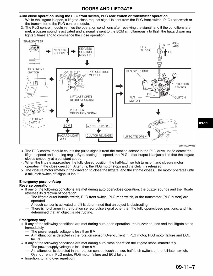
DOORS AND LIFTGATE
09-11–7
09-11
Auto close operation using the PLG front switch, PLG rear switch or transmitter operation1. While the liftgate is open, a liftgate-close request signal is sent from the PLG front switch, PLG rear switch or
the transmitter to the PLG control module.2. The PLG control module verifies the operation conditions after receiving the signal, and if the conditions are
met, a buzzer sound is activated and a signal is sent to the BCM simultaneously to flash the hazard warning lights 2 times and to commence the close operation.
3. The PLG control module counts the pulse signals from the rotation sensor in the PLG drive unit to detect the liftgate speed and opening angle. By detecting the speed, the PLG motor output is adjusted so that the liftgate closes smoothly at a constant speed.
4. When the liftgate approaches the fully closed position, the half-latch switch turns off, and closure motor operates in the close direction. After this, the PLG motor stops and the clutch is released.
5. The closure motor rotates in the direction to close the liftgate, and the liftgate closes. The motor operates until a full-latch switch off signal is input.
Emergency peration/stopReverse operation• If any of the following conditions are met during auto open/close operation, the buzzer sounds and the liftgate
reverses its direction of operation.— The liftgate outer handle switch, PLG front switch, PLG rear switch, or the transmitter (PLG button) are
operated— A touch sensor is activated and it is determined that an object is obstructing— There is no change in the rotation sensor pulse signal other than the fully open/closed positions, and it is
determined that an object is obstructing.
Emergency stop• If any of the following conditions are met during auto open operation, the buzzer sounds and the liftgate stops
immediately.— The power supply voltage is less than 8 V— A malfunction is detected in the rotation sensor, Over-current in PLG motor, PLG motor failure and ECU
failure.• If any of the following conditions are met during auto close operation the liftgate stops immediately.— The power supply voltage is less than 8 V— A malfunction is detected in the rotation sensor, touch sensor, half-latch switch, or the full-latch switch,
Over-current in PLG motor, PLG motor failure and ECU failure.• Insertion, turning over repetition.
CLUTCHPLG MOTOR
PLG SLIDER
PLG ARM
UP
ROTATION SENSOR
PLG DRIVE UNITPLG FRONT SWITCH
PLG REAR SWITCH
TRANSMITTER
KEYLESS RECEIVER
KEYLESS CONTROL MODULE
PLG CONTROL MODULE
LIFTGATE OPEN REQUEST SIGNAL
PLG OPEN OPERATION SIGNAL
BCM
HAZARD LIGHT TWICE
CLOSURE MOTOR
CLUTCH RELEASE LIFTGATE OPEN
ac9uun00000436
3423-1U-06H(09-11).fm 7 ページ 2006年11月21日 火曜日 午後5時36分
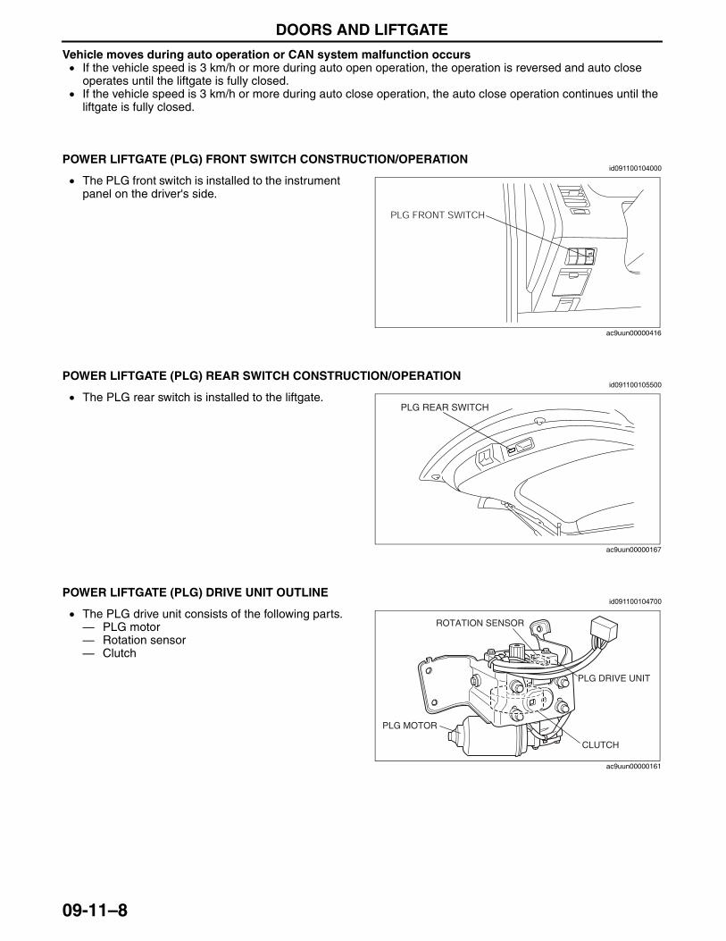
DOORS AND LIFTGATE
09-11–8
Vehicle moves during auto operation or CAN system malfunction occurs• If the vehicle speed is 3 km/h or more during auto open operation, the operation is reversed and auto close
operates until the liftgate is fully closed.• If the vehicle speed is 3 km/h or more during auto close operation, the auto close operation continues until the
liftgate is fully closed.End Of Sie
POWER LIFTGATE (PLG) FRONT SWITCH CONSTRUCTION/OPERATIONid091100104000
• The PLG front switch is installed to the instrument panel on the driver's side.
End Of Sie
POWER LIFTGATE (PLG) REAR SWITCH CONSTRUCTION/OPERATIONid091100105500
• The PLG rear switch is installed to the liftgate.End Of Sie
POWER LIFTGATE (PLG) DRIVE UNIT OUTLINEid091100104700
• The PLG drive unit consists of the following parts.— PLG motor— Rotation sensor— Clutch
End Of Sie
PLG FRONT SWITCH
ac9uun00000416
PLG REAR SWITCH
ac9uun00000167
PLG DRIVE UNIT
CLUTCH
PLG MOTOR
ROTATION SENSOR
ac9uun00000161
3423-1U-06H(09-11).fm 8 ページ 2006年11月21日 火曜日 午後5時36分
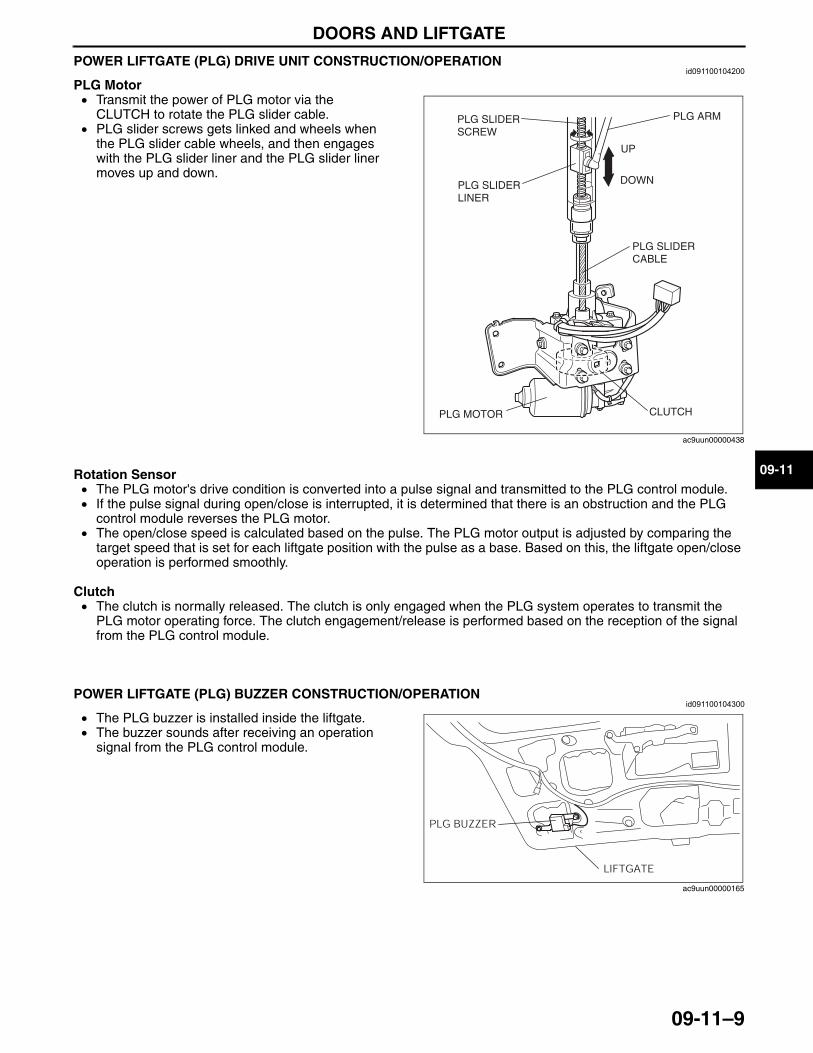
DOORS AND LIFTGATE
09-11–9
09-11
POWER LIFTGATE (PLG) DRIVE UNIT CONSTRUCTION/OPERATIONid091100104200
PLG Motor• Transmit the power of PLG motor via the
CLUTCH to rotate the PLG slider cable.• PLG slider screws gets linked and wheels when
the PLG slider cable wheels, and then engages with the PLG slider liner and the PLG slider liner moves up and down.
Rotation Sensor• The PLG motor's drive condition is converted into a pulse signal and transmitted to the PLG control module.• If the pulse signal during open/close is interrupted, it is determined that there is an obstruction and the PLG
control module reverses the PLG motor.• The open/close speed is calculated based on the pulse. The PLG motor output is adjusted by comparing the
target speed that is set for each liftgate position with the pulse as a base. Based on this, the liftgate open/close operation is performed smoothly.
Clutch• The clutch is normally released. The clutch is only engaged when the PLG system operates to transmit the
PLG motor operating force. The clutch engagement/release is performed based on the reception of the signal from the PLG control module.
End Of Sie
POWER LIFTGATE (PLG) BUZZER CONSTRUCTION/OPERATIONid091100104300
• The PLG buzzer is installed inside the liftgate.• The buzzer sounds after receiving an operation
signal from the PLG control module.End Of Sie
CLUTCHPLG MOTOR
PLG SLIDER CABLE
PLG SLIDER LINER
PLG ARM
UP
DOWN
PLG SLIDER SCREW
ac9uun00000438
PLG BUZZER
LIFTGATE
ac9uun00000165
3423-1U-06H(09-11).fm 9 ページ 2006年11月21日 火曜日 午後5時36分
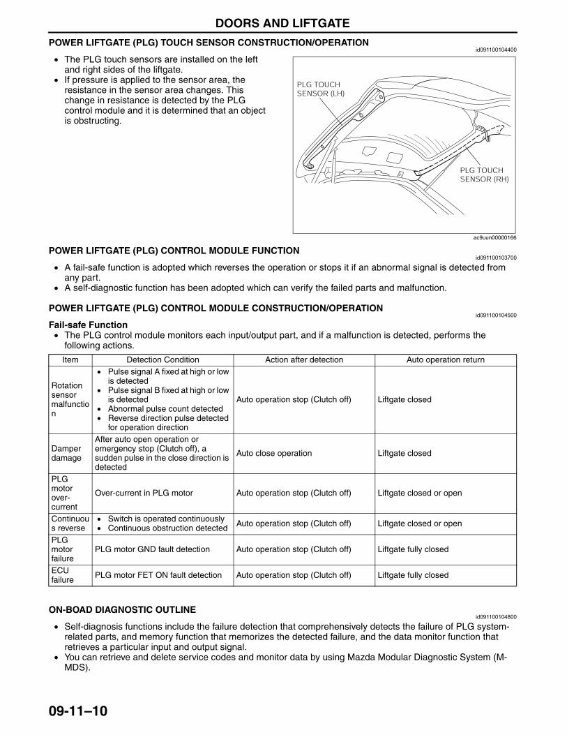
DOORS AND LIFTGATE
09-11–10
POWER LIFTGATE (PLG) TOUCH SENSOR CONSTRUCTION/OPERATIONid091100104400
• The PLG touch sensors are installed on the left and right sides of the liftgate.
• If pressure is applied to the sensor area, the resistance in the sensor area changes. This change in resistance is detected by the PLG control module and it is determined that an object is obstructing.
End Of Sie
POWER LIFTGATE (PLG) CONTROL MODULE FUNCTIONid091100103700
• A fail-safe function is adopted which reverses the operation or stops it if an abnormal signal is detected from any part.
• A self-diagnostic function has been adopted which can verify the failed parts and malfunction.End Of SiePOWER LIFTGATE (PLG) CONTROL MODULE CONSTRUCTION/OPERATION
id091100104500
Fail-safe Function• The PLG control module monitors each input/output part, and if a malfunction is detected, performs the
following actions.
End Of SieON-BOAD DIAGNOSTIC OUTLINE
id091100104800
• Self-diagnosis functions include the failure detection that comprehensively detects the failure of PLG system-related parts, and memory function that memorizes the detected failure, and the data monitor function that retrieves a particular input and output signal.
• You can retrieve and delete service codes and monitor data by using Mazda Modular Diagnostic System (M-MDS).
End Of Sie
PLG TOUCH SENSOR (LH)
PLG TOUCH SENSOR (RH)
ac9uun00000166
Item Detection Condition Action after detection Auto operation return
Rotation sensor malfunction
• Pulse signal A fixed at high or low is detected
• Pulse signal B fixed at high or low is detected
• Abnormal pulse count detected• Reverse direction pulse detected
for operation direction
Auto operation stop (Clutch off) Liftgate closed
Damper damage
After auto open operation or emergency stop (Clutch off), a sudden pulse in the close direction is detected
Auto close operation Liftgate closed
PLG motor over-current
Over-current in PLG motor Auto operation stop (Clutch off) Liftgate closed or open
Continuous reverse
• Switch is operated continuously• Continuous obstruction detected Auto operation stop (Clutch off) Liftgate closed or open
PLG motor failure
PLG motor GND fault detection Auto operation stop (Clutch off) Liftgate fully closed
ECU failure PLG motor FET ON fault detection Auto operation stop (Clutch off) Liftgate fully closed
3423-1U-06H(09-11).fm 10 ページ 2006年11月21日 火曜日 午後5時36分
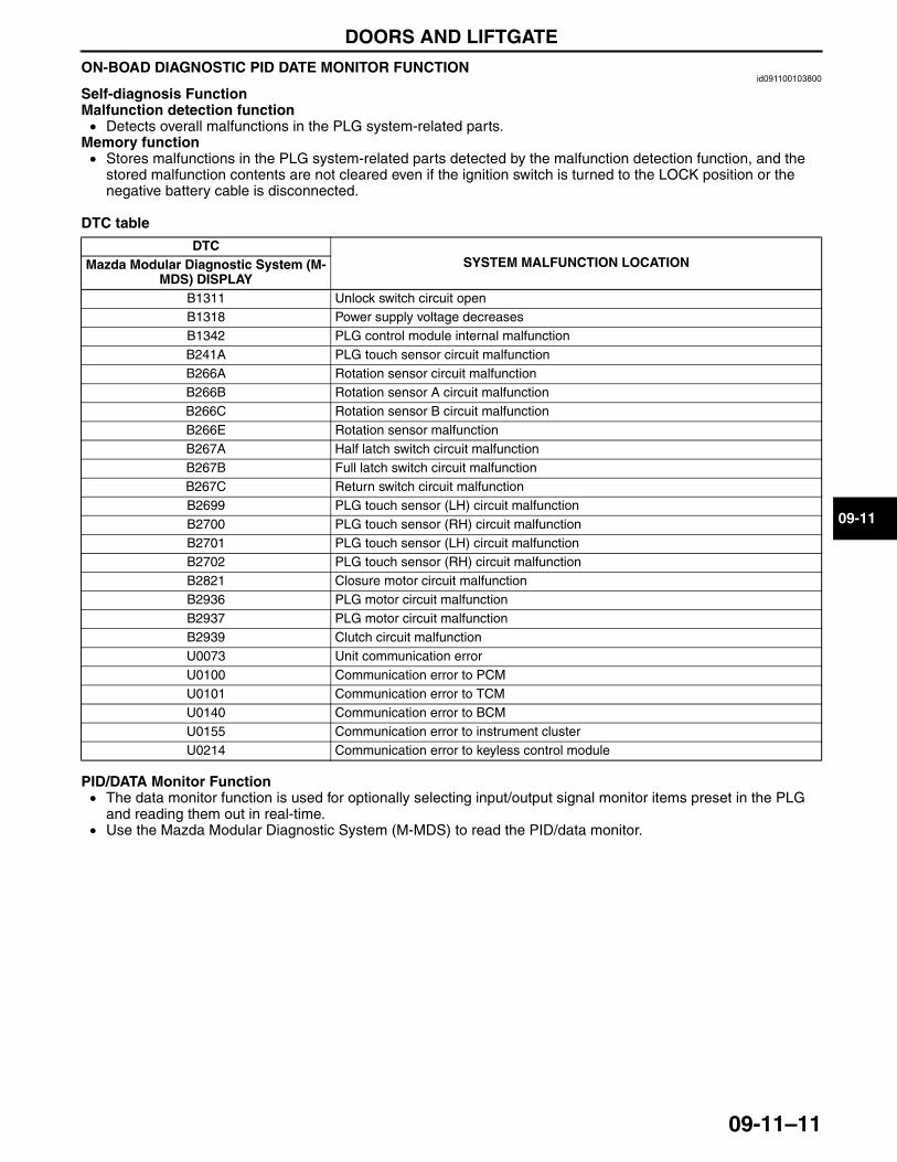
DOORS AND LIFTGATE
09-11–11
09-11
ON-BOAD DIAGNOSTIC PID DATE MONITOR FUNCTIONid091100103800
Self-diagnosis FunctionMalfunction detection function• Detects overall malfunctions in the PLG system-related parts.
Memory function• Stores malfunctions in the PLG system-related parts detected by the malfunction detection function, and the
stored malfunction contents are not cleared even if the ignition switch is turned to the LOCK position or the negative battery cable is disconnected.
DTC table
PID/DATA Monitor Function• The data monitor function is used for optionally selecting input/output signal monitor items preset in the PLG
and reading them out in real-time.• Use the Mazda Modular Diagnostic System (M-MDS) to read the PID/data monitor.
DTCSYSTEM MALFUNCTION LOCATIONMazda Modular Diagnostic System (M-
MDS) DISPLAYB1311 Unlock switch circuit openB1318 Power supply voltage decreasesB1342 PLG control module internal malfunctionB241A PLG touch sensor circuit malfunctionB266A Rotation sensor circuit malfunctionB266B Rotation sensor A circuit malfunctionB266C Rotation sensor B circuit malfunctionB266E Rotation sensor malfunctionB267A Half latch switch circuit malfunctionB267B Full latch switch circuit malfunctionB267C Return switch circuit malfunctionB2699 PLG touch sensor (LH) circuit malfunctionB2700 PLG touch sensor (RH) circuit malfunctionB2701 PLG touch sensor (LH) circuit malfunctionB2702 PLG touch sensor (RH) circuit malfunctionB2821 Closure motor circuit malfunctionB2936 PLG motor circuit malfunctionB2937 PLG motor circuit malfunctionB2939 Clutch circuit malfunctionU0073 Unit communication errorU0100 Communication error to PCMU0101 Communication error to TCMU0140 Communication error to BCMU0155 Communication error to instrument clusterU0214 Communication error to keyless control module
3423-1U-06H(09-11).fm 11 ページ 2006年11月21日 火曜日 午後5時36分
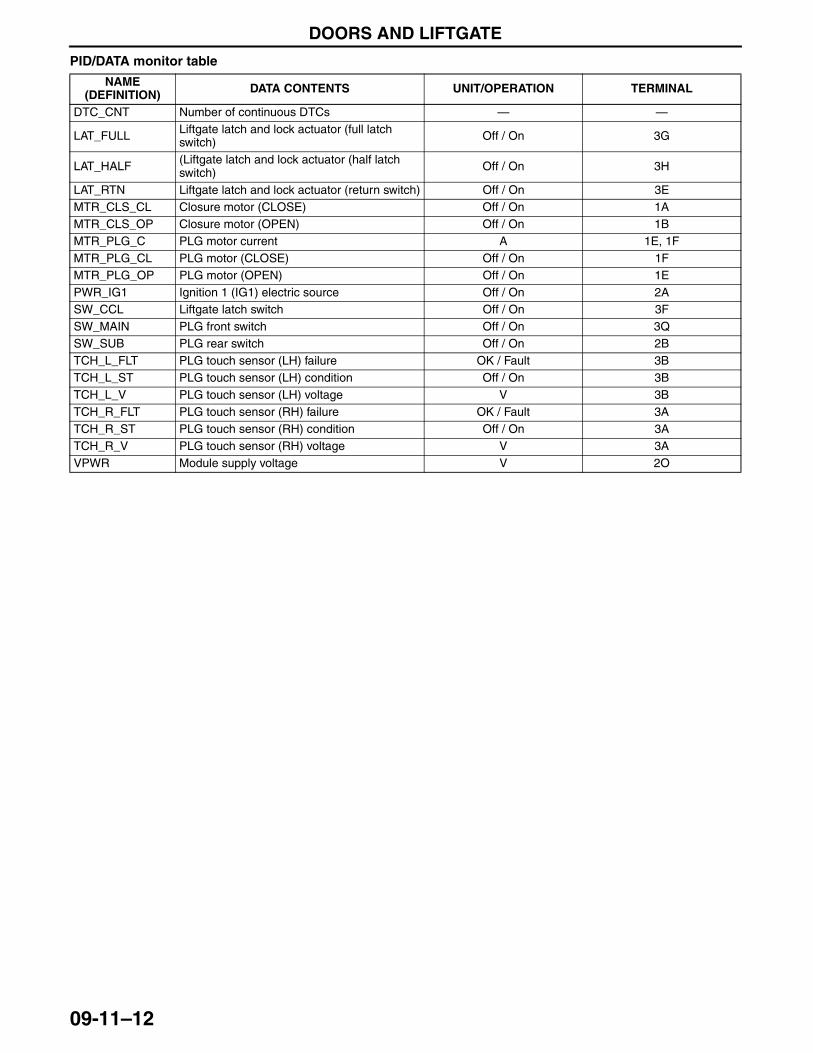
DOORS AND LIFTGATE
09-11–12
PID/DATA monitor table
End Of Sie
NAME (DEFINITION) DATA CONTENTS UNIT/OPERATION TERMINAL
DTC_CNT Number of continuous DTCs — —
LAT_FULL Liftgate latch and lock actuator (full latch switch) Off / On 3G
LAT_HALF (Liftgate latch and lock actuator (half latch switch) Off / On 3H
LAT_RTN Liftgate latch and lock actuator (return switch) Off / On 3EMTR_CLS_CL Closure motor (CLOSE) Off / On 1AMTR_CLS_OP Closure motor (OPEN) Off / On 1BMTR_PLG_C PLG motor current A 1E, 1FMTR_PLG_CL PLG motor (CLOSE) Off / On 1FMTR_PLG_OP PLG motor (OPEN) Off / On 1EPWR_IG1 Ignition 1 (IG1) electric source Off / On 2ASW_CCL Liftgate latch switch Off / On 3FSW_MAIN PLG front switch Off / On 3QSW_SUB PLG rear switch Off / On 2BTCH_L_FLT PLG touch sensor (LH) failure OK / Fault 3BTCH_L_ST PLG touch sensor (LH) condition Off / On 3BTCH_L_V PLG touch sensor (LH) voltage V 3BTCH_R_FLT PLG touch sensor (RH) failure OK / Fault 3ATCH_R_ST PLG touch sensor (RH) condition Off / On 3ATCH_R_V PLG touch sensor (RH) voltage V 3AVPWR Module supply voltage V 2O
3423-1U-06H(09-11).fm 12 ページ 2006年11月21日 火曜日 午後5時36分
GLASS/WINDOWS/MIRRORS
09-12–1
09-12
09-12 GLASS/WINDOWS/MIRRORSREAR WINDOW DEFROSTER
SYSTEM OUTLINE . . . . . . . . . . . . . . . . 09-12–2REAR WINDOW DEFROSTER
SYSTEM STRUCTURAL VIEW. . . . . . . 09-12–2REAR WINDOW DEFROSTER
SYSTEM WIRING DIAGRAM . . . . . . . . 09-12–3POWER WINDOW SYSTEM
OUTLINE . . . . . . . . . . . . . . . . . . . . . . . . 09-12–3POWER WINDOW SYSTEM
STRUCTURAL VIEW . . . . . . . . . . . . . . 09-12–4POWER WINDOW SYSTEM
WIRING DIAGRAM . . . . . . . . . . . . . . . . 09-12–5POWER WINDOW SYSTEM
OPERATION . . . . . . . . . . . . . . . . . . . . . 09-12–6Manual Open/Close Function . . . . . . . 09-12–6Auto-Open/Close Function
(Front windows) . . . . . . . . . . . . . . . . . 09-12–6Auto Reverse Pinch
Protection Function (Front windows) . . . . . . . . . . . . . . . . . 09-12–6
Two-step Down Function . . . . . . . . . . . 09-12–7Ignition Off Timer Function. . . . . . . . . . 09-12–7Fail-safe Function. . . . . . . . . . . . . . . . . 09-12–7
EXTERIOR OPEN/CLOSE FUNCTION OUTLINE . . . . . . . . . . . . . . . . . . . . . . . . 09-12–8
EXTERIOR OPEN/CLOSE FUNCTION STRUCTURAL VIEW . . . . . . . . . . . . . . . 09-12–8
EXTERIOR OPEN/CLOSE FUNCTION BLOCK DIAGRAM . . . . . . . . . . . . . . . . . 09-12–9
EXTERIOR OPEN/CLOSE FUNCTION OPERATION . . . . . . . . . . . . . . . . . . . . . . 09-12–10
Open/Close Function/Operation in Conjunction with Key Operation . . . . . 09-12–10
Open Function/Operation in Conjunction with Transmitter . . . . . . . . 09-12–11
Close Function/Operation in Conjunction with Request Switch . . . . 09-12–11
Operation Prohibition/Stop Condition . . 09-12–12POWER WINDOW SWITCH
CONSTRUCTION . . . . . . . . . . . . . . . . . . 09-12–12Block Diagram . . . . . . . . . . . . . . . . . . . . 09-12–12
POWER WINDOW MOTOR CONSTRUCTION . . . . . . . . . . . . . . . . . . 09-12–13
POWER OUTER MIRROR OUTLINE . . . . 09-12–13POWER OUTER MIRROR
STRUCTURAL VIEW . . . . . . . . . . . . . . . 09-12–14POWER OUTER MIRROR SYSTEM
WIRING DIAGRAM. . . . . . . . . . . . . . . . . 09-12–14POWER OUTER MIRROR
OPERATION . . . . . . . . . . . . . . . . . . . . . . 09-12–15Mirror Glass Adjustment . . . . . . . . . . . . 09-12–15
End of TocNG: REAR WINDOW DEFROSTER
3423-1U-06H(09-12).fm 1 ページ 2006年11月22日 水曜日 午後3時3分
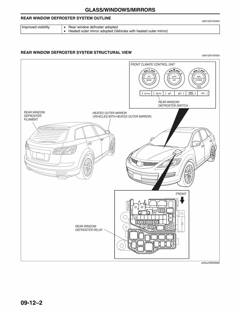
GLASS/WINDOWS/MIRRORS
09-12–2
REAR WINDOW DEFROSTER SYSTEM OUTLINEid091200100400
End Of Sie
REAR WINDOW DEFROSTER SYSTEM STRUCTURAL VIEWid091200100500
End Of Sie
Improved visibility • Rear window defroster adopted• Heated outer mirror adopted (Vehicles with heated outer mirror)
REAR WINDOW DEFROSTER RELAY
FRONT CLIMATE CONTROL UNIT
FRONT
REAR WINDOW DEFROSTER SWITCH
REAR WINDOW DEFROSTER FILAMENT
HEATED OUTER MIRROR (VEHICLES WITH HEATED OUTER MIRROR)
ac9uun00000085
3423-1U-06H(09-12).fm 2 ページ 2006年11月22日 水曜日 午後3時3分
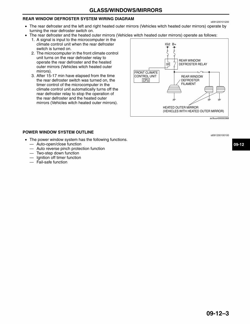
GLASS/WINDOWS/MIRRORS
09-12–3
09-12
REAR WINDOW DEFROSTER SYSTEM WIRING DIAGRAMid091200101200
• The rear defroster and the left and right heated outer mirrors (Vehicles witch heated outer mirrors) operate by turning the rear defroster switch on.
• The rear defroster and the heated outer mirrors (Vehicles witch heated outer mirrors) operate as follows:1. A signal is input to the microcomputer in the
climate control unit when the rear defroster switch is turned on.
2. The microcomputer in the front climate control unit turns on the rear defroster relay to operate the rear defroster and the heated outer mirrors (Vehicles witch heated outer mirrors).
3. After 15-17 min have elapsed from the time the rear defroster switch was turned on, the timer control of the microcomputer in the climate control unit automatically turns off the rear defroster relay to stop the operation of the rear defroster and the heated outer mirrors (Vehicles witch heated outer mirrors).
End Of SieNG: POWER WINDOW SYSTEM
POWER WINDOW SYSTEM OUTLINEid091200100100
• The power window system has the following functions.— Auto-open/close function— Auto reverse pinch protection function— Two-step down function— Ignition off timer function— Fail-safe function
End Of Sie
IG2 B+
REAR WINDOW DEFROSTER RELAY
REAR WINDOW DEFROSTER FILAMENT
FRONT CLIMATE CONTROL UNIT
CPU
HEATED OUTER MIRROR(VEHICLES WITH HEATED OUTER MIRROR)
ac9uun00000368
3423-1U-06H(09-12).fm 3 ページ 2006年11月21日 火曜日 午後5時37分
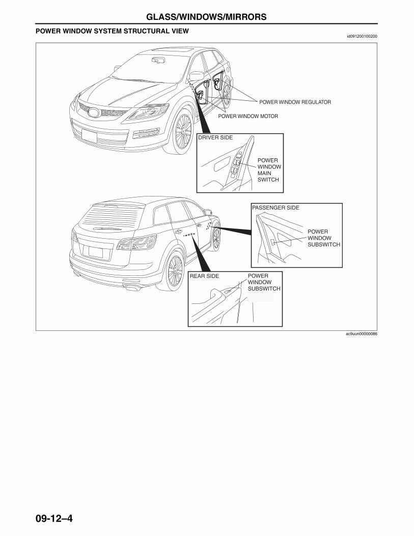
GLASS/WINDOWS/MIRRORS
09-12–4
POWER WINDOW SYSTEM STRUCTURAL VIEWid091200100200
End Of Sie
POWER WINDOW SUBSWITCH
POWER WINDOW MAIN SWITCH
POWER WINDOW REGULATOR
POWER WINDOW MOTOR
DRIVER SIDE
PASSENGER SIDE
REAR SIDE POWER WINDOW SUBSWITCH
ac9uun00000086
3423-1U-06H(09-12).fm 4 ページ 2006年11月21日 火曜日 午後5時37分
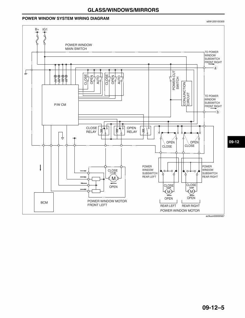
GLASS/WINDOWS/MIRRORS
09-12–5
09-12
POWER WINDOW SYSTEM WIRING DIAGRAMid091200100300
BCM
b
a
TO POWER WINDOW SUBSWITCH FRONT RIGHT
TO POWER WINDOW SUBSWITCH FRONT RIGHT
CLOSE
OPEN
POWER WINDOW MOTOR FRONT LEFT
B+ IG1
CLOSE
OPEN
CLOSE
OPEN
POWER WINDOWMAIN SWITCH
POWER WINDOW MOTOR
POWER WINDOW SUBSWITCH REAR RIGHT
POWER WINDOW SUBSWITCH REAR LEFT
REAR RIGHTREAR LEFT
P/W CM
CLO
SE
OP
EN
AU
TO
CLO
SE
OP
EN
AU
TO
PO
WE
R-C
UT
SW
ITC
H
CO
NJU
NC
TIO
NC
IRC
UIT
CLOSE RELAY
OPEN RELAY
CLOSEOPEN
CLOSEOPEN
ac9uun00000567
3423-1U-06H(09-12).fm 5 ページ 2006年11月21日 火曜日 午後5時37分
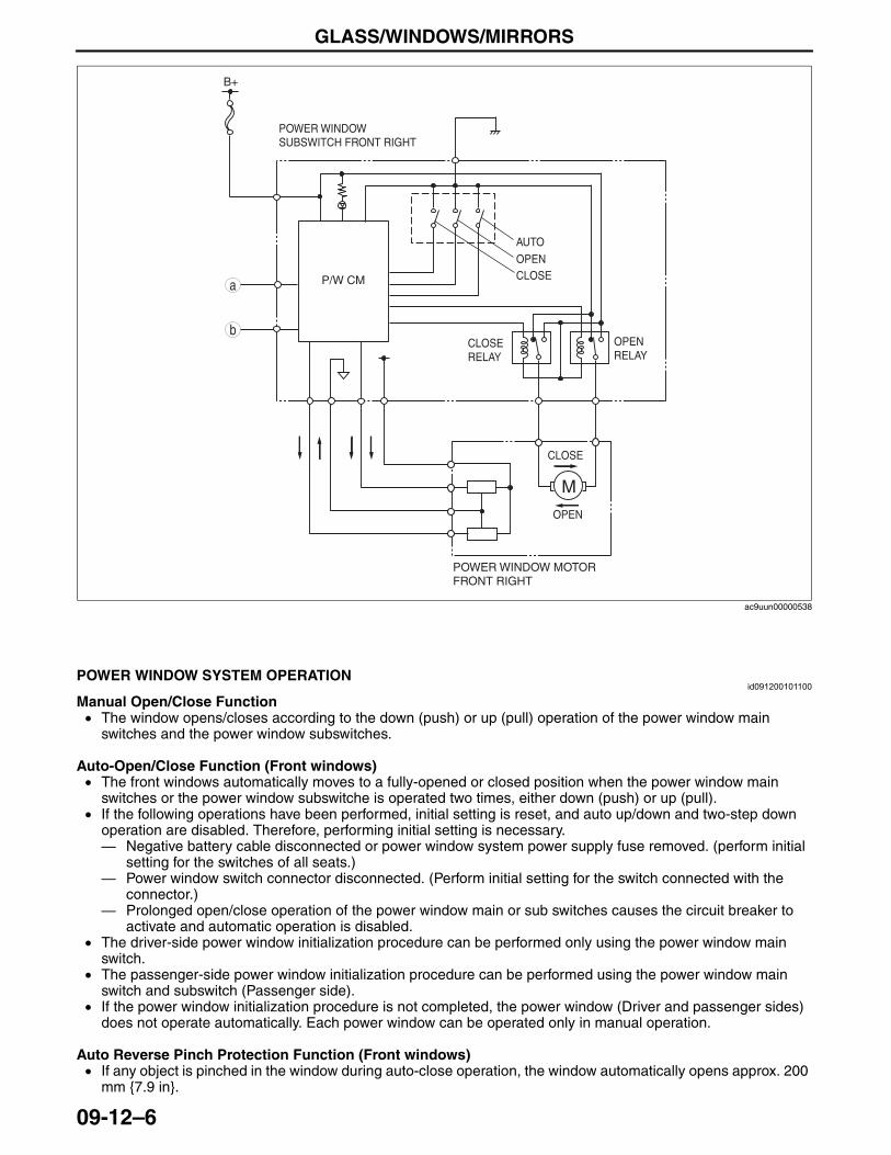
GLASS/WINDOWS/MIRRORS
09-12–6
End Of Sie
POWER WINDOW SYSTEM OPERATIONid091200101100
Manual Open/Close Function• The window opens/closes according to the down (push) or up (pull) operation of the power window main
switches and the power window subswitches.
Auto-Open/Close Function (Front windows)• The front windows automatically moves to a fully-opened or closed position when the power window main
switches or the power window subswitche is operated two times, either down (push) or up (pull).• If the following operations have been performed, initial setting is reset, and auto up/down and two-step down
operation are disabled. Therefore, performing initial setting is necessary.— Negative battery cable disconnected or power window system power supply fuse removed. (perform initial
setting for the switches of all seats.)— Power window switch connector disconnected. (Perform initial setting for the switch connected with the
connector.)— Prolonged open/close operation of the power window main or sub switches causes the circuit breaker to
activate and automatic operation is disabled.• The driver-side power window initialization procedure can be performed only using the power window main
switch.• The passenger-side power window initialization procedure can be performed using the power window main
switch and subswitch (Passenger side).• If the power window initialization procedure is not completed, the power window (Driver and passenger sides)
does not operate automatically. Each power window can be operated only in manual operation.
Auto Reverse Pinch Protection Function (Front windows)• If any object is pinched in the window during auto-close operation, the window automatically opens approx. 200
mm {7.9 in}.
P/W CM
B+
b
a
I
POWER WINDOW MOTOR FRONT RIGHT
CLOSEOPEN
AUTO
CLOSE
OPEN
CLOSE RELAY
OPEN RELAY
POWER WINDOW SUBSWITCH FRONT RIGHT
ac9uun00000538
3423-1U-06H(09-12).fm 6 ページ 2006年11月21日 火曜日 午後5時37分
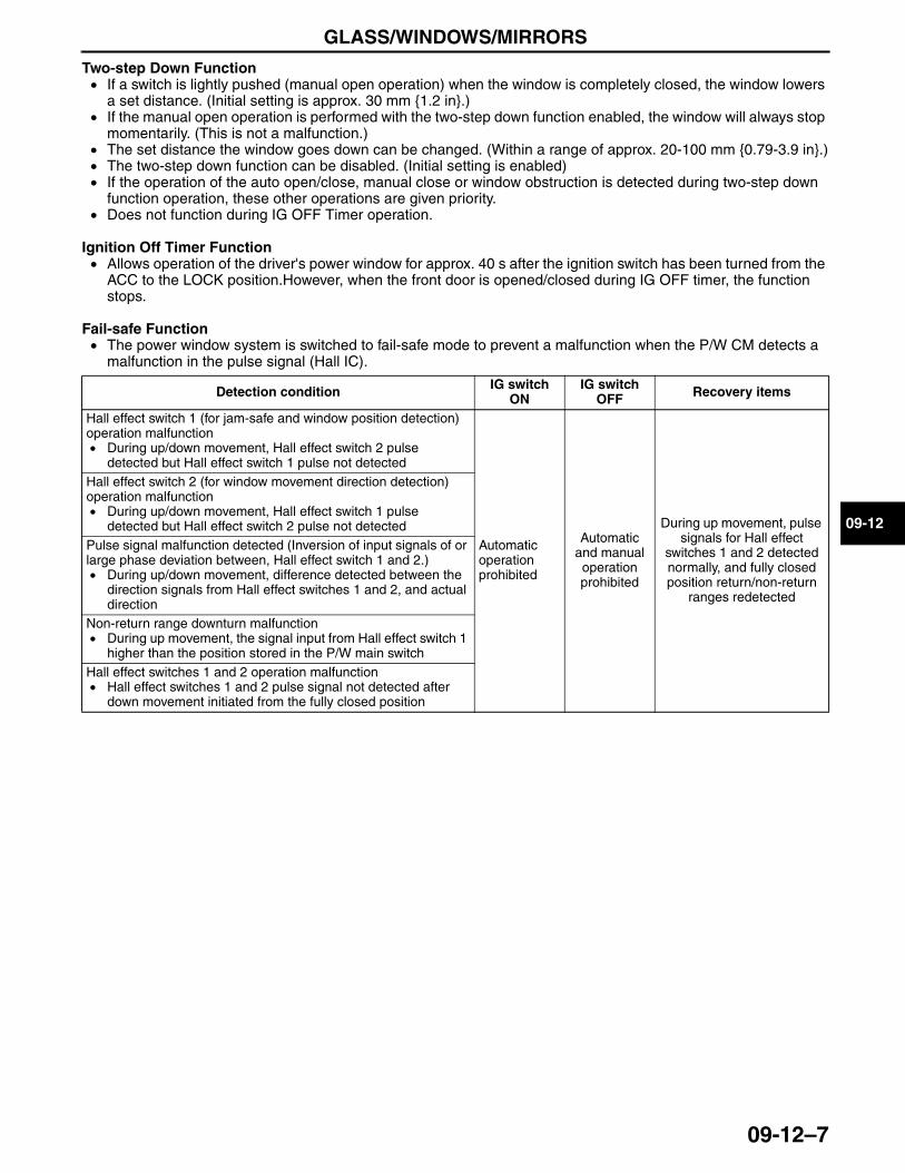
GLASS/WINDOWS/MIRRORS
09-12–7
09-12
Two-step Down Function• If a switch is lightly pushed (manual open operation) when the window is completely closed, the window lowers
a set distance. (Initial setting is approx. 30 mm {1.2 in}.)• If the manual open operation is performed with the two-step down function enabled, the window will always stop
momentarily. (This is not a malfunction.)• The set distance the window goes down can be changed. (Within a range of approx. 20-100 mm {0.79-3.9 in}.)• The two-step down function can be disabled. (Initial setting is enabled)• If the operation of the auto open/close, manual close or window obstruction is detected during two-step down
function operation, these other operations are given priority.• Does not function during IG OFF Timer operation.
Ignition Off Timer Function• Allows operation of the driver's power window for approx. 40 s after the ignition switch has been turned from the
ACC to the LOCK position.However, when the front door is opened/closed during IG OFF timer, the function stops.
Fail-safe Function• The power window system is switched to fail-safe mode to prevent a malfunction when the P/W CM detects a
malfunction in the pulse signal (Hall IC).
End Of Sie
Detection condition IG switch ON
IG switch OFF Recovery items
Hall effect switch 1 (for jam-safe and window position detection) operation malfunction• During up/down movement, Hall effect switch 2 pulse
detected but Hall effect switch 1 pulse not detected
Automatic operation prohibited
Automatic and manual operation prohibited
During up movement, pulse signals for Hall effect
switches 1 and 2 detected normally, and fully closed position return/non-return
ranges redetected
Hall effect switch 2 (for window movement direction detection) operation malfunction• During up/down movement, Hall effect switch 1 pulse
detected but Hall effect switch 2 pulse not detectedPulse signal malfunction detected (Inversion of input signals of or large phase deviation between, Hall effect switch 1 and 2.)• During up/down movement, difference detected between the
direction signals from Hall effect switches 1 and 2, and actual direction
Non-return range downturn malfunction• During up movement, the signal input from Hall effect switch 1
higher than the position stored in the P/W main switchHall effect switches 1 and 2 operation malfunction• Hall effect switches 1 and 2 pulse signal not detected after
down movement initiated from the fully closed position
3423-1U-06H(09-12).fm 7 ページ 2006年11月22日 水曜日 午後3時4分
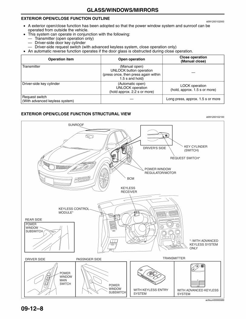
GLASS/WINDOWS/MIRRORS
09-12–8
EXTERIOR OPEN/CLOSE FUNCTION OUTLINEid091200102000
• A exterior open/close function has been adopted so that the power window system and sunroof can be operated from outside the vehicle.
• This system can operate in conjunction with the following:— Transmitter (open operation only)— Driver-side door key cylinder— Driver-side request switch (with advanced keyless system, close operation only)
• An automatic reverse function operates if the door glass is obstructed during close operation.
End Of SieEXTERIOR OPEN/CLOSE FUNCTION STRUCTURAL VIEW
id091200102100
Operation item Open operation Close operation(Manual close)
Transmitter (Manual open)UNLOCK button operation
(press once, then press again within 1.5 s and hold)
—
Driver-side key cylinder (Automatic open)UNLOCK operation
(hold approx. 2.2 s or more)
LOCK operation(hold, approx. 1.5 s or more)
Request switch(With advanced keyless system) — Long press, approx. 1.5 s or more
WITH ADVANCED KEYLESSSYSTEM
TRANSMITTER
WITH KEYLESS ENTRYSYSTEM
DRIVER'S SIDE KEY CYLINDER(SWITCH)
REQUEST SWITCH*
PASSNGER SIDE
BCM
DRIVER SIDE
POWER WINDOWREGULATOR/MOTOR
KEYLESS CONTROLMODULE*
KEYLESSRECEIVER
*: WITH ADVANCED KEYLESS SYSTEM ONLY
POWER WINDOW MAIN SWITCH
POWER WINDOW SUBSWITCH
POWER WINDOW SUBSWITCH
REAR SIDE
SUNROOF
ac9uun00000089
3423-1U-06H(09-12).fm 8 ページ 2006年11月22日 水曜日 午後3時4分
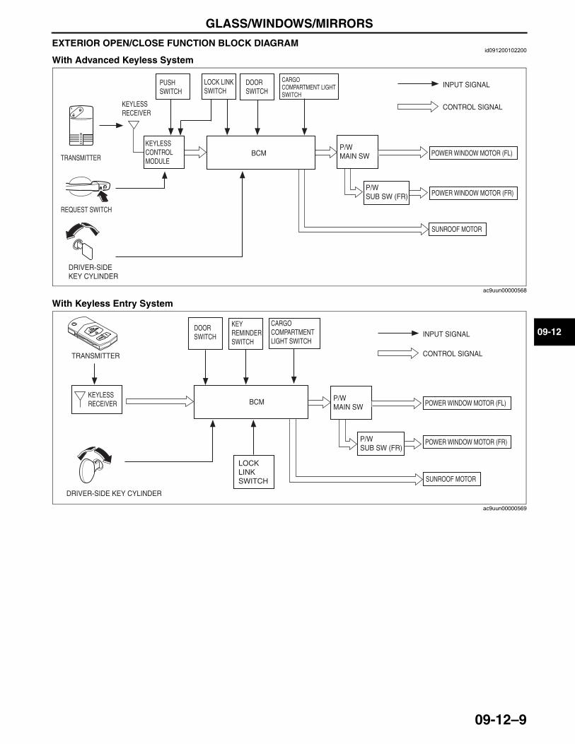
GLASS/WINDOWS/MIRRORS
09-12–9
09-12
EXTERIOR OPEN/CLOSE FUNCTION BLOCK DIAGRAMid091200102200
With Advanced Keyless System
With Keyless Entry System
End Of Sie
POWER WINDOW MOTOR (FL)
DOOR SWITCH
PUSH SWITCH
CARGO COMPARTMENT LIGHT SWITCH
BCMP/WMAIN SW
KEYLESS RECEIVER
INPUT SIGNAL
CONTROL SIGNAL
TRANSMITTER
DRIVER-SIDE KEY CYLINDER
KEYLESS CONTROL MODULE
REQUEST SWITCH
POWER WINDOW MOTOR (FR)
SUNROOF MOTOR
P/WSUB SW (FR)
LOCK LINK SWITCH
ac9uun00000568
DOOR SWITCH
KEY REMINDER SWITCH
CARGO COMPARTMENT LIGHT SWITCH
BCMKEYLESS RECEIVER
INPUT SIGNAL
CONTROL SIGNALTRANSMITTER
DRIVER-SIDE KEY CYLINDER
POWER WINDOW MOTOR (FL) P/WMAIN SW
POWER WINDOW MOTOR (FR)P/WSUB SW (FR)
LOCKLINKSWITCH SUNROOF MOTOR
ac9uun00000569
3423-1U-06H(09-12).fm 9 ページ 2006年11月21日 火曜日 午後5時37分
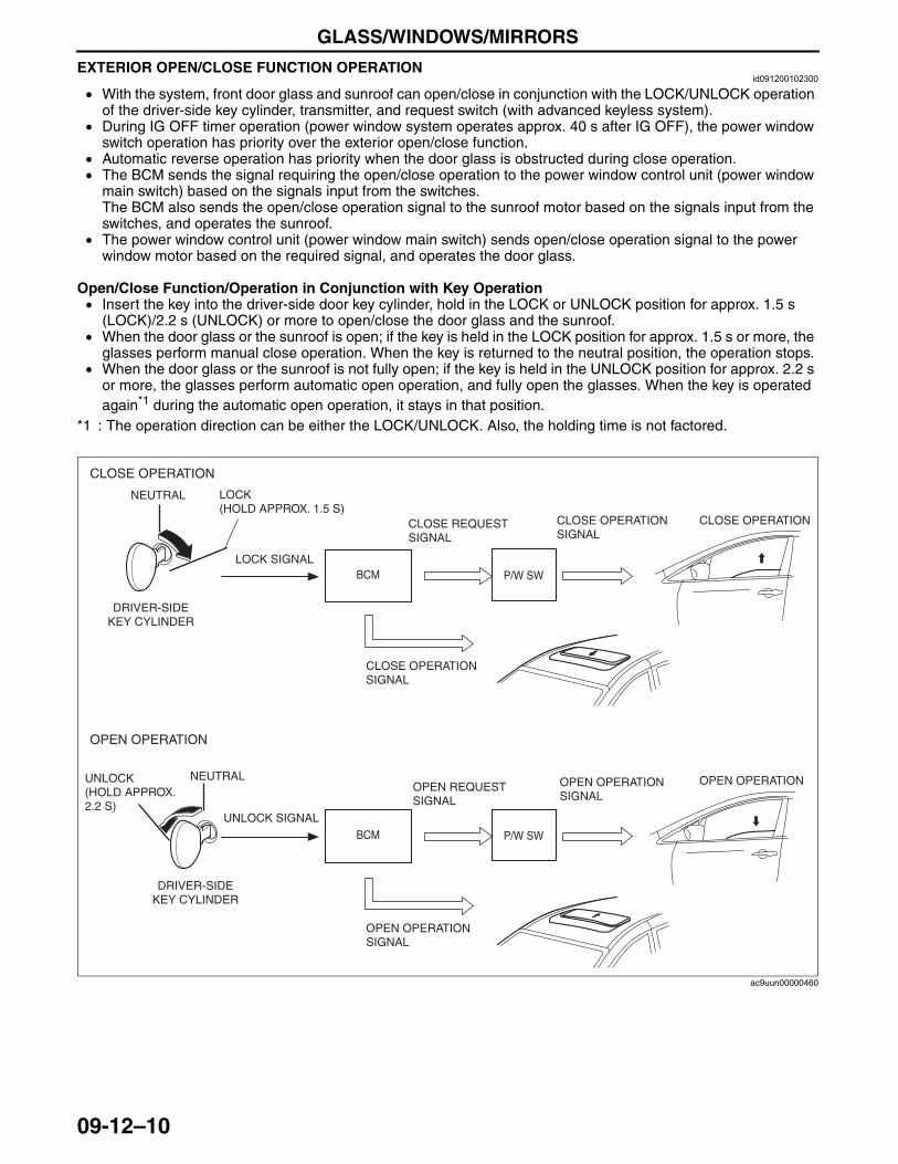
GLASS/WINDOWS/MIRRORS
09-12–10
EXTERIOR OPEN/CLOSE FUNCTION OPERATIONid091200102300
• With the system, front door glass and sunroof can open/close in conjunction with the LOCK/UNLOCK operation of the driver-side key cylinder, transmitter, and request switch (with advanced keyless system).
• During IG OFF timer operation (power window system operates approx. 40 s after IG OFF), the power window switch operation has priority over the exterior open/close function.
• Automatic reverse operation has priority when the door glass is obstructed during close operation.• The BCM sends the signal requiring the open/close operation to the power window control unit (power window
main switch) based on the signals input from the switches.The BCM also sends the open/close operation signal to the sunroof motor based on the signals input from the switches, and operates the sunroof.
• The power window control unit (power window main switch) sends open/close operation signal to the power window motor based on the required signal, and operates the door glass.
Open/Close Function/Operation in Conjunction with Key Operation• Insert the key into the driver-side door key cylinder, hold in the LOCK or UNLOCK position for approx. 1.5 s
(LOCK)/2.2 s (UNLOCK) or more to open/close the door glass and the sunroof. • When the door glass or the sunroof is open; if the key is held in the LOCK position for approx. 1.5 s or more, the
glasses perform manual close operation. When the key is returned to the neutral position, the operation stops.• When the door glass or the sunroof is not fully open; if the key is held in the UNLOCK position for approx. 2.2 s
or more, the glasses perform automatic open operation, and fully open the glasses. When the key is operated again*1 during the automatic open operation, it stays in that position.
*1 : The operation direction can be either the LOCK/UNLOCK. Also, the holding time is not factored.
LOCK (HOLD APPROX. 1.5 S)
NEUTRAL
DRIVER-SIDEKEY CYLINDER
BCM P/W SWLOCK SIGNAL
CLOSE OPERATIONSIGNAL
CLOSE REQUESTSIGNAL
CLOSE OPERATION
CLOSE OPERATION
UNLOCK (HOLD APPROX. 2.2 S)
NEUTRAL
DRIVER-SIDEKEY CYLINDER
BCM P/W SW
UNLOCK SIGNAL
OPEN OPERATIONSIGNAL
OPEN REQUESTSIGNAL
OPEN OPERATION
OPEN OPERATION
CLOSE OPERATIONSIGNAL
OPEN OPERATIONSIGNAL
ac9uun00000460
3423-1U-06H(09-12).fm 10 ページ 2006年11月21日 火曜日 午後5時37分
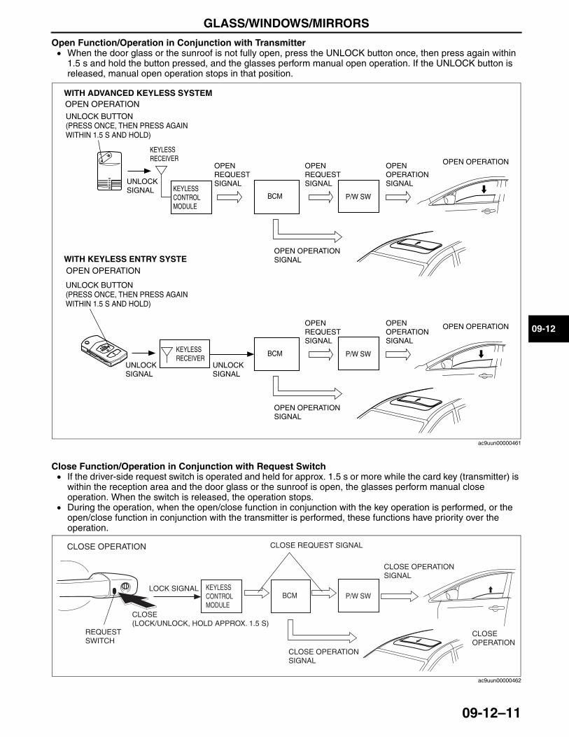
GLASS/WINDOWS/MIRRORS
09-12–11
09-12
Open Function/Operation in Conjunction with Transmitter• When the door glass or the sunroof is not fully open, press the UNLOCK button once, then press again within
1.5 s and hold the button pressed, and the glasses perform manual open operation. If the UNLOCK button is released, manual open operation stops in that position.
Close Function/Operation in Conjunction with Request Switch • If the driver-side request switch is operated and held for approx. 1.5 s or more while the card key (transmitter) is
within the reception area and the door glass or the sunroof is open, the glasses perform manual close operation. When the switch is released, the operation stops.
• During the operation, when the open/close function in conjunction with the key operation is performed, or the open/close function in conjunction with the transmitter is performed, these functions have priority over the operation.
BCM
UNLOCK SIGNAL
OPEN OPERATIONSIGNAL
OPEN REQUESTSIGNAL
OPEN OPERATION
OPEN OPERATION
P/W SW
OPEN REQUESTSIGNAL
KEYLESS RECEIVER
KEYLESS CONTROL MODULE
OPEN OPERATION
KEYLESS RECEIVER
OPEN OPERATION
BCM
OPEN OPERATIONSIGNAL
OPEN REQUESTSIGNAL
P/W SW
UNLOCK SIGNAL
UNLOCK SIGNAL
WITH ADVANCED KEYLESS SYSTEM
WITH KEYLESS ENTRY SYSTE
UNLOCK BUTTON (PRESS ONCE, THEN PRESS AGAIN WITHIN 1.5 S AND HOLD)
UNLOCK BUTTON (PRESS ONCE, THEN PRESS AGAIN WITHIN 1.5 S AND HOLD)
OPEN OPERATIONSIGNAL
OPEN OPERATIONSIGNAL
ac9uun00000461
BCM P/W SWLOCK SIGNAL
CLOSE OPERATIONSIGNAL
CLOSE OPERATION
CLOSE OPERATION CLOSE REQUEST SIGNAL
KEYLESS CONTROL MODULE
REQUESTSWITCH
CLOSE(LOCK/UNLOCK, HOLD APPROX. 1.5 S)
CLOSE OPERATIONSIGNAL
ac9uun00000462
3423-1U-06H(09-12).fm 11 ページ 2006年11月21日 火曜日 午後5時37分
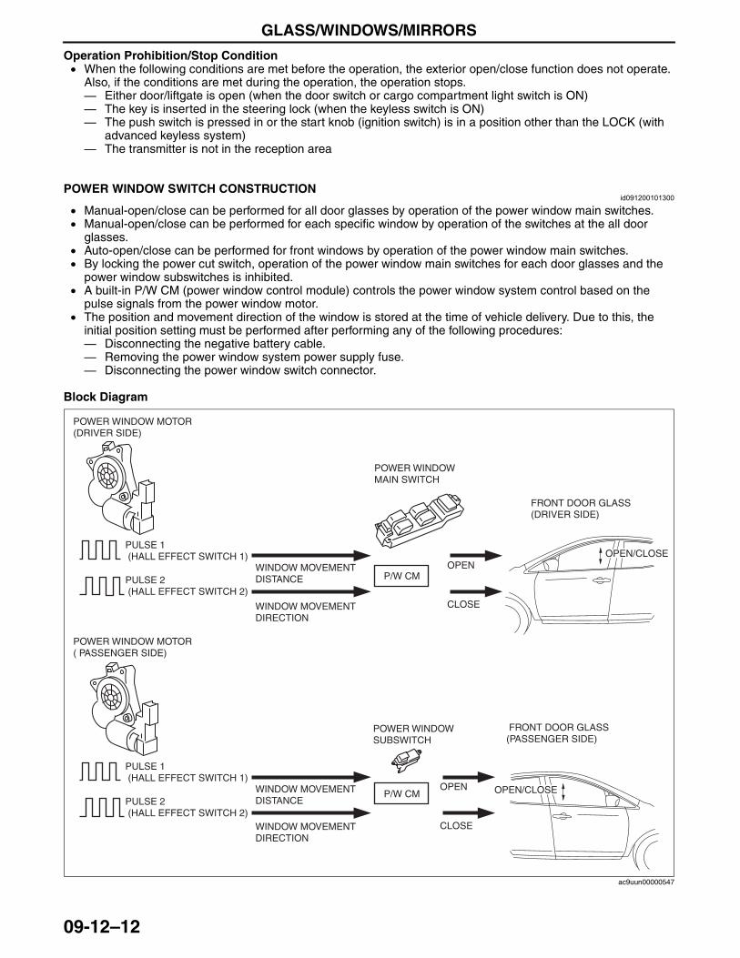
GLASS/WINDOWS/MIRRORS
09-12–12
Operation Prohibition/Stop Condition• When the following conditions are met before the operation, the exterior open/close function does not operate.
Also, if the conditions are met during the operation, the operation stops.— Either door/liftgate is open (when the door switch or cargo compartment light switch is ON)— The key is inserted in the steering lock (when the keyless switch is ON)— The push switch is pressed in or the start knob (ignition switch) is in a position other than the LOCK (with
advanced keyless system)— The transmitter is not in the reception area
End Of SieNG: WINDOW SWITCH
POWER WINDOW SWITCH CONSTRUCTIONid091200101300
• Manual-open/close can be performed for all door glasses by operation of the power window main switches.• Manual-open/close can be performed for each specific window by operation of the switches at the all door
glasses.• Auto-open/close can be performed for front windows by operation of the power window main switches.• By locking the power cut switch, operation of the power window main switches for each door glasses and the
power window subswitches is inhibited.• A built-in P/W CM (power window control module) controls the power window system control based on the
pulse signals from the power window motor.• The position and movement direction of the window is stored at the time of vehicle delivery. Due to this, the
initial position setting must be performed after performing any of the following procedures:— Disconnecting the negative battery cable.— Removing the power window system power supply fuse.— Disconnecting the power window switch connector.
Block Diagram
End Of SieNG: WINDOW MOTOR
P/W CM
OPEN/CLOSE
OPEN/CLOSE
OPEN
CLOSE
POWER WINDOW MOTOR (DRIVER SIDE)
POWER WINDOW MOTOR ( PASSENGER SIDE)
FRONT DOOR GLASS(DRIVER SIDE)
FRONT DOOR GLASS (PASSENGER SIDE)
PULSE 1 (HALL EFFECT SWITCH 1)
PULSE 2 (HALL EFFECT SWITCH 2)
WINDOW MOVEMENT DISTANCE
WINDOW MOVEMENT DIRECTION
POWER WINDOW MAIN SWITCH
POWER WINDOW SUBSWITCH
WINDOW MOVEMENT DISTANCE
WINDOW MOVEMENT DIRECTION
P/W CMOPEN
CLOSE
PULSE 1 (HALL EFFECT SWITCH 1)
PULSE 2 (HALL EFFECT SWITCH 2)
ac9uun00000547
3423-1U-06H(09-12).fm 12 ページ 2006年11月21日 火曜日 午後5時37分
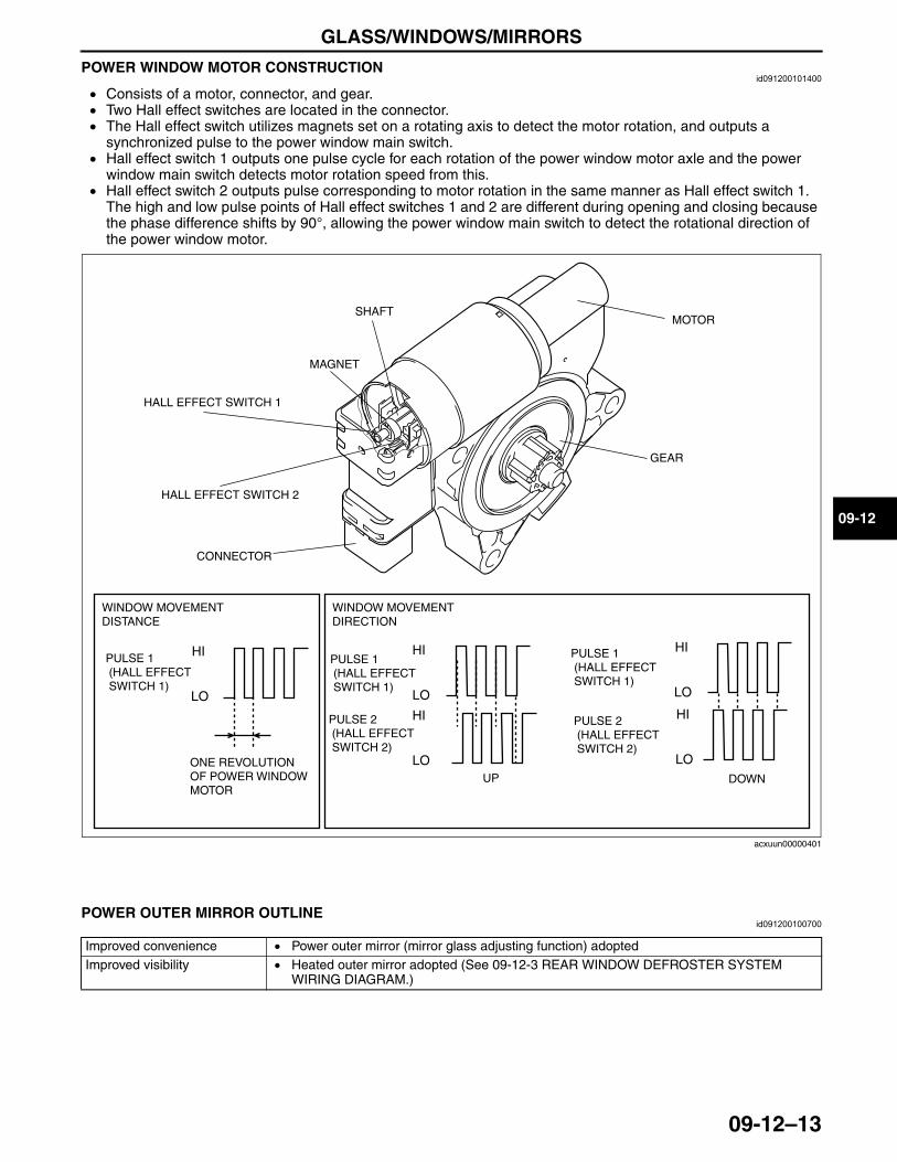
GLASS/WINDOWS/MIRRORS
09-12–13
09-12
POWER WINDOW MOTOR CONSTRUCTIONid091200101400
• Consists of a motor, connector, and gear.• Two Hall effect switches are located in the connector.• The Hall effect switch utilizes magnets set on a rotating axis to detect the motor rotation, and outputs a
synchronized pulse to the power window main switch.• Hall effect switch 1 outputs one pulse cycle for each rotation of the power window motor axle and the power
window main switch detects motor rotation speed from this.• Hall effect switch 2 outputs pulse corresponding to motor rotation in the same manner as Hall effect switch 1.
The high and low pulse points of Hall effect switches 1 and 2 are different during opening and closing because the phase difference shifts by 90°, allowing the power window main switch to detect the rotational direction of the power window motor.
End Of SieNG: OUTER MIRROR
POWER OUTER MIRROR OUTLINEid091200100700
End Of Sie
LO
HI
LO
HI
LO
HI
LO
HI
LO
HI
MOTOR
CONNECTOR
GEAR
HALL EFFECT SWITCH 1
HALL EFFECT SWITCH 2
SHAFT
MAGNET
PULSE 1 (HALL EFFECT SWITCH 1)
PULSE 2 (HALL EFFECT SWITCH 2)
PULSE 1 (HALL EFFECT SWITCH 1)
PULSE 1 (HALL EFFECT SWITCH 1)
PULSE 2 (HALL EFFECT SWITCH 2)
ONE REVOLUTION OF POWER WINDOW MOTOR
UP DOWN
WINDOW MOVEMENT DISTANCE
WINDOW MOVEMENT DIRECTION
acxuun00000401
Improved convenience • Power outer mirror (mirror glass adjusting function) adoptedImproved visibility • Heated outer mirror adopted (See 09-12-3 REAR WINDOW DEFROSTER SYSTEM
WIRING DIAGRAM.)
3423-1U-06H(09-12).fm 13 ページ 2006年11月21日 火曜日 午後5時37分
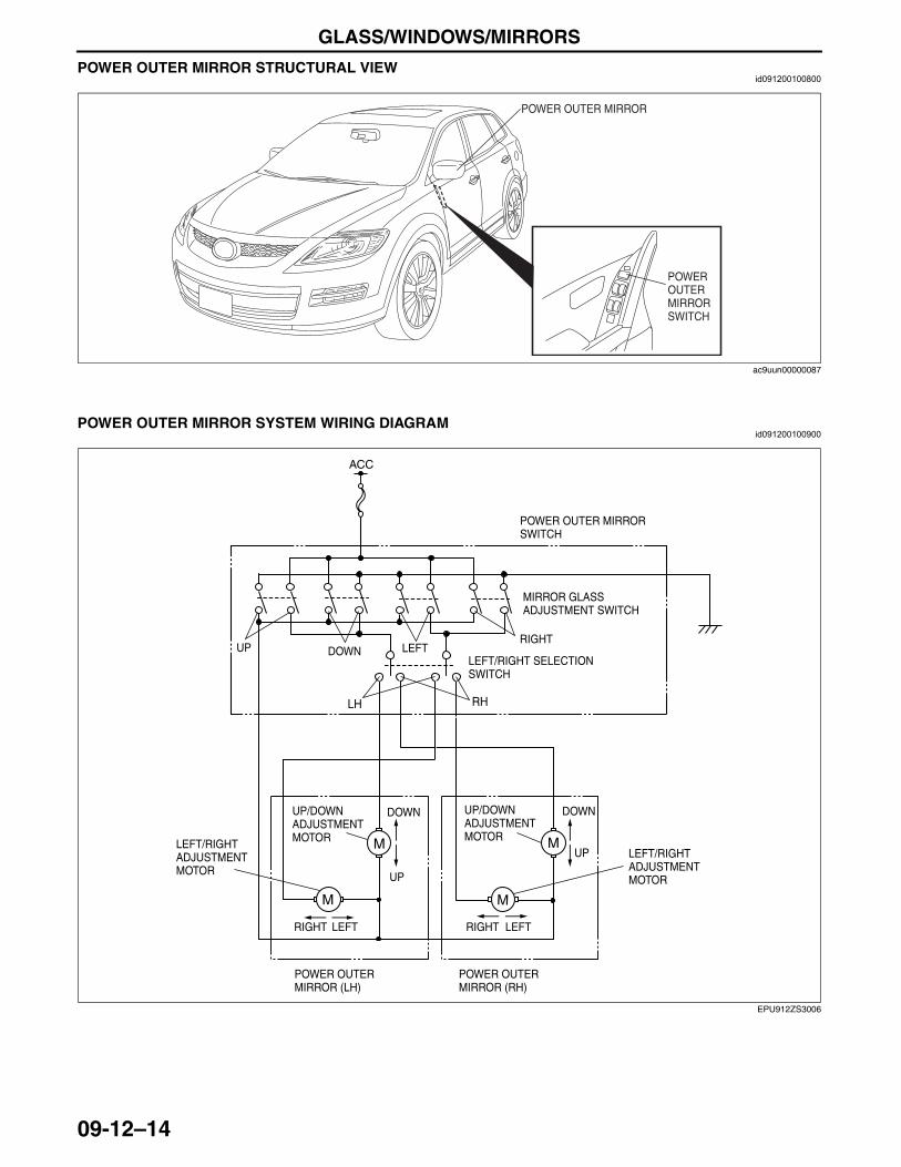
GLASS/WINDOWS/MIRRORS
09-12–14
POWER OUTER MIRROR STRUCTURAL VIEWid091200100800
End Of Sie
POWER OUTER MIRROR SYSTEM WIRING DIAGRAMid091200100900
End Of Sie
POWER OUTER MIRROR
POWER OUTER MIRROR SWITCH
ac9uun00000087
LH RH
ACC
POWER OUTER MIRROR SWITCH
UP DOWN LEFTRIGHT
MIRROR GLASS ADJUSTMENT SWITCH
LEFT/RIGHT SELECTION SWITCH
UP
DOWNUP/DOWN ADJUSTMENT MOTOR
UP
DOWN
LEFTRIGHT LEFTRIGHT
POWER OUTER MIRROR (LH)
POWER OUTER MIRROR (RH)
UP/DOWN ADJUSTMENT MOTOR
LEFT/RIGHT ADJUSTMENT MOTOR
LEFT/RIGHT ADJUSTMENT MOTOR
EPU912ZS3006
3423-1U-06H(09-12).fm 14 ページ 2006年11月21日 火曜日 午後5時37分
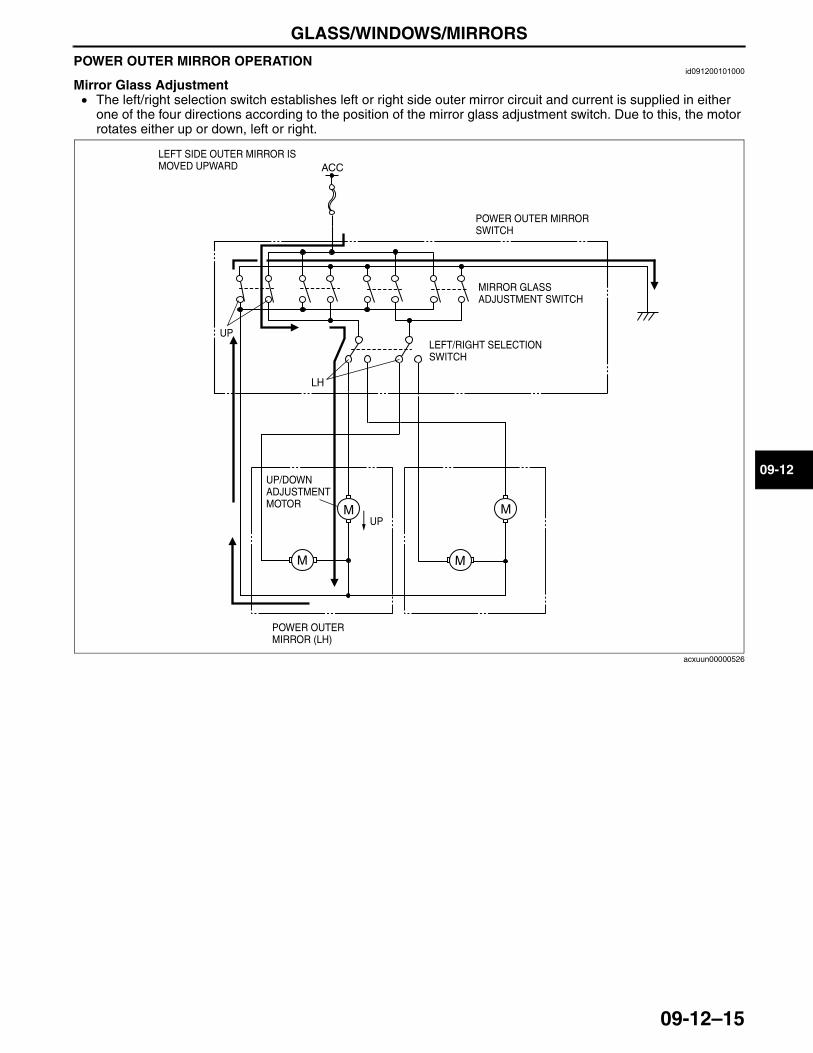
GLASS/WINDOWS/MIRRORS
09-12–15
09-12
POWER OUTER MIRROR OPERATIONid091200101000
Mirror Glass Adjustment• The left/right selection switch establishes left or right side outer mirror circuit and current is supplied in either
one of the four directions according to the position of the mirror glass adjustment switch. Due to this, the motor rotates either up or down, left or right.
End Of Sie
LH
ACC
POWER OUTER MIRROR SWITCH
UP
MIRROR GLASS ADJUSTMENT SWITCH
LEFT/RIGHT SELECTION SWITCH
UP
UP/DOWN ADJUSTMENT MOTOR
POWER OUTER MIRROR (LH)
LEFT SIDE OUTER MIRROR IS MOVED UPWARD
acxuun00000526
3423-1U-06H(09-12).fm 15 ページ 2006年11月21日 火曜日 午後5時37分

SEATS
09-13–1
09-13
09-13 SEATSSEAT OUTLINE . . . . . . . . . . . . . . . . . . . . 09-13–1SEATS STRUCTURAL VIEW . . . . . . . . . 09-13–2SEAT SPECIFICATION . . . . . . . . . . . . . . 09-13–3POWER SEAT SYSTEM
WIRING DIAGRAM . . . . . . . . . . . . . . . . 09-13–4Driver Seat . . . . . . . . . . . . . . . . . . . . . . 09-13–4Passenger Seat . . . . . . . . . . . . . . . . . . 09-13–4
POWER SEAT CONSTRUCTION/OPERATION . . . . . . 09-13–5
SEAT POSITION MEMORY FUNCTION OUTLINE . . . . . . . . . . . . . . 09-13–5
SEAT POSITION MEMORY STRUCTURAL VIEW . . . . . . . . . . . . . . 09-13–6
SEAT POSITION MEMORY WIRING DIAGRAM . . . . . . . . . . . . . . . . 09-13–7
SEAT POSITION MEMORY OPERATION . . . . . . . . . . . . . . . . . . . . . . 09-13–8
Seat Position Memory Operation . . . . . 09-13–8Seat Position Auto Call Up
Operation . . . . . . . . . . . . . . . . . . . . . . 09-13–8SEAT POSITION MEMORY
CONTROL MODULE FUNCTION . . . . . 09-13–9Seat Position Detection Function . . . . . 09-13–9Seat Position Memory Function . . . . . . 09-13–9Memory Call Up Function
(Memory Switch) . . . . . . . . . . . . . . . . . 09-13–9Memory Call Up Function
(Transmitter) . . . . . . . . . . . . . . . . . . . . 09-13–10
End of TocNG: SEATSSEAT OUTLINE
id091300100100
End Of Sie
Improved marketability
• Power seat has been adopted for the front seats.• Lumbar support has been adopted for the driver’s seat.• Seat warmer has been adopted for the front seats.(Leather seat only)• Seat automatically slides to the seat position programmed in the position memory control
module by operating the memory switch or unlocking the door using the transmitter. Improved safety • Built-in side air bag has been adopted for the front seats.
3423-1U-06H(09-13).fm 1 ページ 2006年11月21日 火曜日 午後5時39分
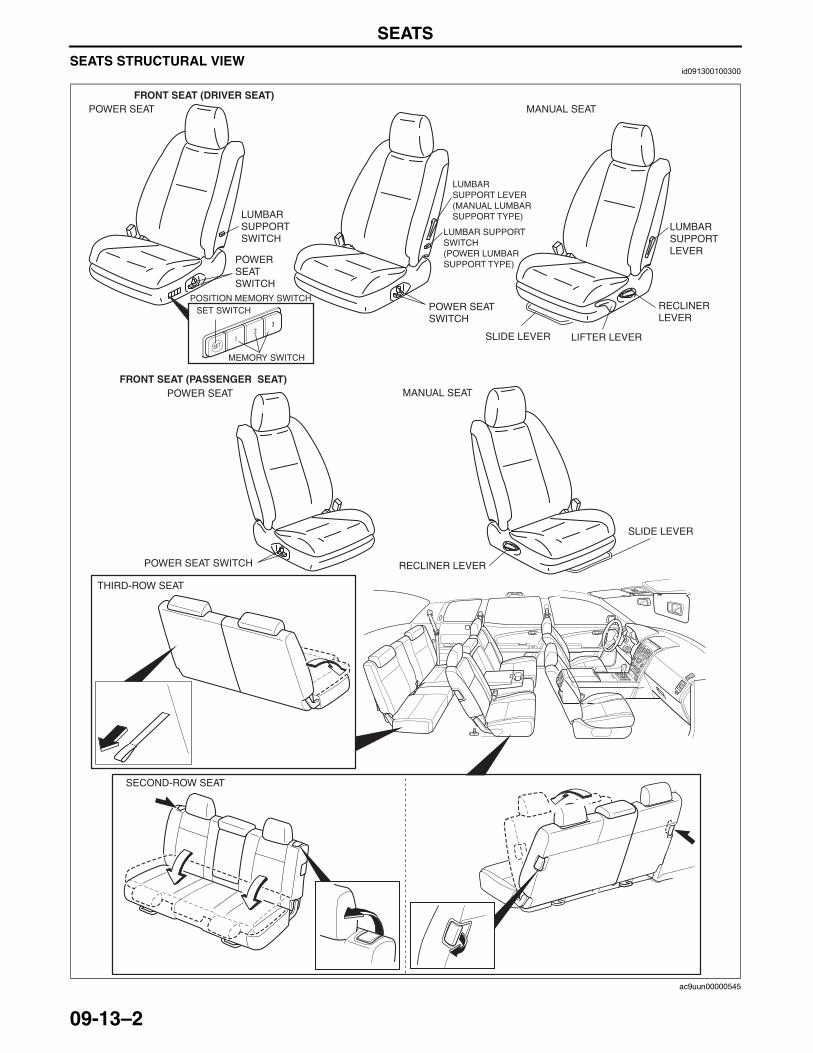
SEATS
09-13–2
SEATS STRUCTURAL VIEWid091300100300
FRONT SEAT (DRIVER SEAT)
FRONT SEAT (PASSENGER SEAT)
POWER SEAT SWITCH
POSITION MEMORY SWITCH
LUMBAR SUPPORT SWITCH
LUMBAR SUPPORT LEVER
LIFTER LEVER
RECLINER LEVER
MANUAL SEAT
MANUAL SEAT
POWER SEAT
POWER SEAT
RECLINER LEVER
SET SWITCH POWER SEAT SWITCH
LUMBAR SUPPORT LEVER(MANUAL LUMBAR SUPPORT TYPE)
LUMBAR SUPPORT SWITCH(POWER LUMBAR SUPPORT TYPE)
POWER SEAT SWITCH
MEMORY SWITCH
SLIDE LEVER
SLIDE LEVER
SECOND-ROW SEAT
THIRD-ROW SEAT
ac9uun00000545
3423-1U-06H(09-13).fm 2 ページ 2006年11月21日 火曜日 午後5時39分
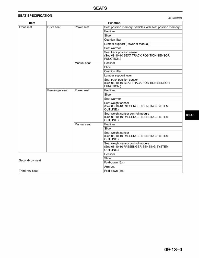
SEATS
09-13–3
09-13
End Of SieSEAT SPECIFICATIONid091300100200
End Of SieNG: POWER SEAT
Item FunctionFront seat Drive seat Power seat Seat position memory (vehicles with seat position memory)
ReclinerSlideCushion lifterLumbar support (Power or manual)Seat warmerSeat track position sensor(See 08-10-10 SEAT TRACK POSITION SENSOR FUNCTION.)
Manual seat ReclinerSlideCushion lifterLumbar support leverSeat track position sensor(See 08-10-10 SEAT TRACK POSITION SENSOR FUNCTION.)
Passenger seat Power seat ReclinerSlideSeat warmerSeat weight sensor(See 08-10-10 PASSENGER SENSING SYSTEM OUTLINE.)Seat weight sensor control module(See 08-10-10 PASSENGER SENSING SYSTEM OUTLINE.)
Manual seat ReclinerSlideSeat weight sensor(See 08-10-10 PASSENGER SENSING SYSTEM OUTLINE.)Seat weight sensor control module(See 08-10-10 PASSENGER SENSING SYSTEM OUTLINE.)
Second-row seat
ReclinerSlideFold-down (6:4)Armrest
Third-row seat Fold-down (5:5)
3423-1U-06H(09-13).fm 3 ページ 2006年11月21日 火曜日 午後5時39分
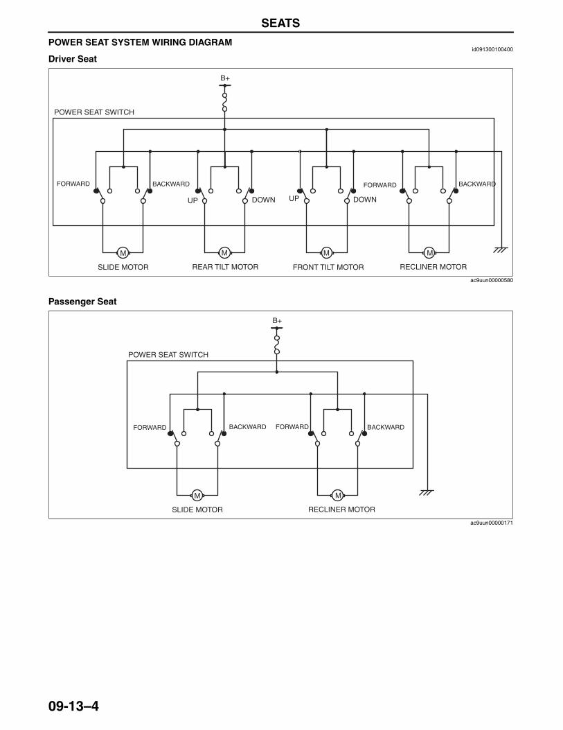
SEATS
09-13–4
POWER SEAT SYSTEM WIRING DIAGRAMid091300100400
Driver Seat
Passenger Seat
End Of Sie
M M M M
POWER SEAT SWITCH
B+
UP DOWN
BACKWARDFORWARD FORWARD BACKWARD
UP DOWN
REAR TILT MOTORSLIDE MOTOR FRONT TILT MOTOR RECLINER MOTOR
ac9uun00000580
M M
POWER SEAT SWITCH
B+
FORWARD BACKWARDBACKWARD FORWARD
SLIDE MOTOR RECLINER MOTOR
ac9uun00000171
3423-1U-06H(09-13).fm 4 ページ 2006年11月21日 火曜日 午後5時39分
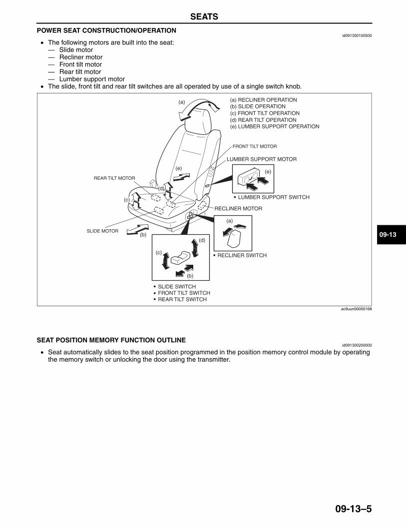
SEATS
09-13–5
09-13
POWER SEAT CONSTRUCTION/OPERATIONid091300100500
• The following motors are built into the seat:— Slide motor— Recliner motor— Front tilt motor— Rear tilt motor— Lumber support motor
• The slide, front tilt and rear tilt switches are all operated by use of a single switch knob.
End Of Sie
SEAT POSITION MEMORY FUNCTION OUTLINEid091300200000
• Seat automatically slides to the seat position programmed in the position memory control module by operating the memory switch or unlocking the door using the transmitter.
End Of Sie
RECLINER MOTOR
LUMBER SUPPORT MOTOR
(a)
(e)(e)
(a)
(b)
(b)
(c)
(c)
(d)
(d)
(a) RECLINER OPERATION(b) SLIDE OPERATION (c) FRONT TILT OPERATION(d) REAR TILT OPERATION
SLIDE SWITCHFRONT TILT SWITCHREAR TILT SWITCH
RECLINER SWITCH
LUMBER SUPPORT SWITCH
(e) LUMBER SUPPORT OPERATION
SLIDE MOTOR
FRONT TILT MOTOR
REAR TILT MOTOR
ac9uun00000168
3423-1U-06H(09-13).fm 5 ページ 2006年11月21日 火曜日 午後5時39分
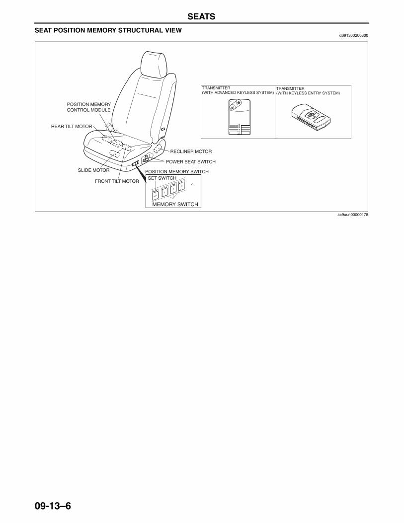
SEATS
09-13–6
SEAT POSITION MEMORY STRUCTURAL VIEWid091300200300
End Of Sie
POSITION MEMORY SWITCH
POWER SEAT SWITCH
RECLINER MOTOR
SLIDE MOTOR
FRONT TILT MOTOR
REAR TILT MOTOR
POSITION MEMORY CONTROL MODULE
SET SWITCH
MEMORY SWITCH
TRANSMITTER (WITH ADVANCED KEYLESS SYSTEM)
TRANSMITTER (WITH KEYLESS ENTRY SYSTEM)
ac9uun00000178
3423-1U-06H(09-13).fm 6 ページ 2006年11月21日 火曜日 午後5時39分
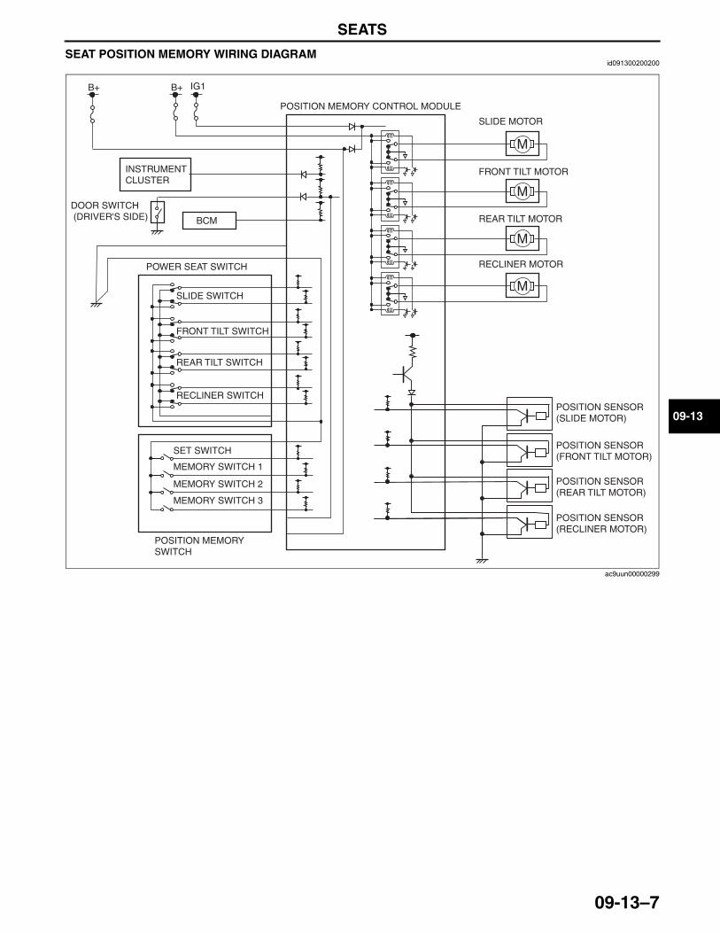
SEATS
09-13–7
09-13
SEAT POSITION MEMORY WIRING DIAGRAMid091300200200
End Of Sie
BCM
B+ B+
POSITION MEMORY SWITCH
POSITION MEMORY CONTROL MODULE
INSTRUMENT CLUSTER
SLIDE MOTOR
FRONT TILT MOTOR
REAR TILT MOTOR
RECLINER MOTOR
POSITION SENSOR (SLIDE MOTOR)
POSITION SENSOR (RECLINER MOTOR)
POSITION SENSOR (REAR TILT MOTOR)
POSITION SENSOR (FRONT TILT MOTOR)
MEMORY SWITCH 1
MEMORY SWITCH 3
MEMORY SWITCH 2
SET SWITCH
SLIDE SWITCH
RECLINER SWITCH
REAR TILT SWITCH
FRONT TILT SWITCH
POWER SEAT SWITCH
DOOR SWITCH (DRIVER'S SIDE)
IG1
ac9uun00000299
3423-1U-06H(09-13).fm 7 ページ 2006年11月21日 火曜日 午後5時39分
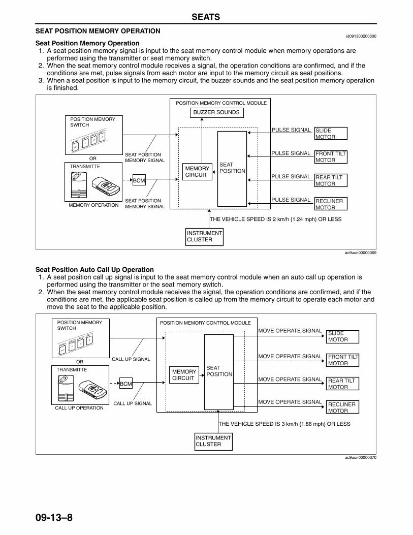
SEATS
09-13–8
SEAT POSITION MEMORY OPERATIONid091300200600
Seat Position Memory Operation1. A seat position memory signal is input to the seat memory control module when memory operations are
performed using the transmitter or seat memory switch.2. When the seat memory control module receives a signal, the operation conditions are confirmed, and if the
conditions are met, pulse signals from each motor are input to the memory circuit as seat positions.3. When a seat position is input to the memory circuit, the buzzer sounds and the seat position memory operation
is finished.
Seat Position Auto Call Up Operation1. A seat position call up signal is input to the seat memory control module when an auto call up operation is
performed using the transmitter or the seat memory switch.2. When the seat memory control module receives the signal, the operation conditions are confirmed, and if the
conditions are met, the applicable seat position is called up from the memory circuit to operate each motor and move the seat to the applicable position.
End Of Sie
POSITION MEMORY SWITCH
TRANSMITTE
OR
BCM
MEMORY CIRCUIT
BUZZER SOUNDS
RECLINER MOTOR
REAR TILT MOTOR
SLIDE MOTOR
FRONT TILT MOTOR
PULSE SIGNAL
PULSE SIGNAL
PULSE SIGNAL
PULSE SIGNAL
SEAT POSITION
SEAT POSITION MEMORY SIGNAL
POSITION MEMORY CONTROL MODULE
MEMORY OPERATIONSEAT POSITION MEMORY SIGNAL
INSTRUMENT CLUSTER
THE VEHICLE SPEED IS 2 km/h {1.24 mph} OR LESS
ac9uun00000369
POSITION MEMORY SWITCH
TRANSMITTE
OR
BCM
MEMORY CIRCUIT
RECLINER MOTOR
REAR TILT MOTOR
SLIDE MOTOR
FRONT TILT MOTOR
MOVE OPERATE SIGNAL
SEAT POSITION
CALL UP SIGNAL CALL UP OPERATION
CALL UP SIGNAL
MOVE OPERATE SIGNAL
MOVE OPERATE SIGNAL
MOVE OPERATE SIGNAL
INSTRUMENT CLUSTER
THE VEHICLE SPEED IS 3 km/h {1.86 mph} OR LESS
POSITION MEMORY CONTROL MODULE
ac9uun00000370
3423-1U-06H(09-13).fm 8 ページ 2006年11月21日 火曜日 午後5時39分
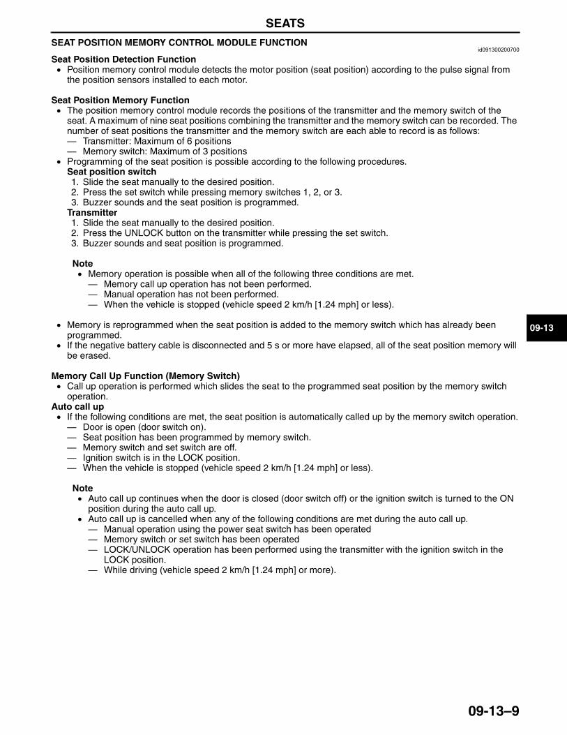
SEATS
09-13–9
09-13
SEAT POSITION MEMORY CONTROL MODULE FUNCTIONid091300200700
Seat Position Detection Function• Position memory control module detects the motor position (seat position) according to the pulse signal from
the position sensors installed to each motor.
Seat Position Memory Function• The position memory control module records the positions of the transmitter and the memory switch of the
seat. A maximum of nine seat positions combining the transmitter and the memory switch can be recorded. The number of seat positions the transmitter and the memory switch are each able to record is as follows: — Transmitter: Maximum of 6 positions— Memory switch: Maximum of 3 positions
• Programming of the seat position is possible according to the following procedures.Seat position switch1. Slide the seat manually to the desired position.2. Press the set switch while pressing memory switches 1, 2, or 3.3. Buzzer sounds and the seat position is programmed.
Transmitter1. Slide the seat manually to the desired position.2. Press the UNLOCK button on the transmitter while pressing the set switch.3. Buzzer sounds and seat position is programmed.
Note• Memory operation is possible when all of the following three conditions are met.— Memory call up operation has not been performed.— Manual operation has not been performed.— When the vehicle is stopped (vehicle speed 2 km/h [1.24 mph] or less).
• Memory is reprogrammed when the seat position is added to the memory switch which has already been programmed.
• If the negative battery cable is disconnected and 5 s or more have elapsed, all of the seat position memory will be erased.
Memory Call Up Function (Memory Switch)• Call up operation is performed which slides the seat to the programmed seat position by the memory switch
operation.Auto call up• If the following conditions are met, the seat position is automatically called up by the memory switch operation.— Door is open (door switch on).— Seat position has been programmed by memory switch.— Memory switch and set switch are off.— Ignition switch is in the LOCK position.— When the vehicle is stopped (vehicle speed 2 km/h [1.24 mph] or less).
Note• Auto call up continues when the door is closed (door switch off) or the ignition switch is turned to the ON
position during the auto call up.• Auto call up is cancelled when any of the following conditions are met during the auto call up.— Manual operation using the power seat switch has been operated— Memory switch or set switch has been operated— LOCK/UNLOCK operation has been performed using the transmitter with the ignition switch in the
LOCK position.— While driving (vehicle speed 2 km/h [1.24 mph] or more).
3423-1U-06H(09-13).fm 9 ページ 2006年11月21日 火曜日 午後5時39分
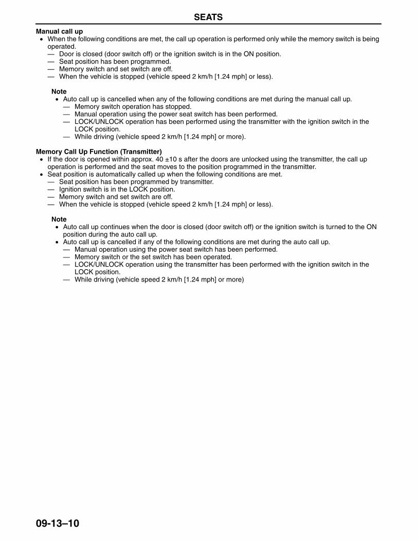
SEATS
09-13–10
Manual call up• When the following conditions are met, the call up operation is performed only while the memory switch is being
operated.— Door is closed (door switch off) or the ignition switch is in the ON position.— Seat position has been programmed.— Memory switch and set switch are off.— When the vehicle is stopped (vehicle speed 2 km/h [1.24 mph] or less).
Note• Auto call up is cancelled when any of the following conditions are met during the manual call up.— Memory switch operation has stopped.— Manual operation using the power seat switch has been performed.— LOCK/UNLOCK operation has been performed using the transmitter with the ignition switch in the
LOCK position.— While driving (vehicle speed 2 km/h [1.24 mph] or more).
Memory Call Up Function (Transmitter)• If the door is opened within approx. 40 ±10 s after the doors are unlocked using the transmitter, the call up
operation is performed and the seat moves to the position programmed in the transmitter.• Seat position is automatically called up when the following conditions are met.— Seat position has been programmed by transmitter.— Ignition switch is in the LOCK position.— Memory switch and set switch are off.— When the vehicle is stopped (vehicle speed 2 km/h [1.24 mph] or less).
Note• Auto call up continues when the door is closed (door switch off) or the ignition switch is turned to the ON
position during the auto call up.• Auto call up is cancelled if any of the following conditions are met during the auto call up.— Manual operation using the power seat switch has been performed.— Memory switch or the set switch has been operated.— LOCK/UNLOCK operation using the transmitter has been performed with the ignition switch in the
LOCK position.— While driving (vehicle speed 2 km/h [1.24 mph] or more)
End Of Sie
3423-1U-06H(09-13).fm 10 ページ 2006年11月21日 火曜日 午後5時39分
SECURITY AND LOCKS [ADVANCED KEYLESS SYSTEM]
09-14A–1
09-14A
09-14A SECURITY AND LOCKS [ADVANCED KEYLESS SYSTEM]SECURITY AND LOCKS OUTLINE
[ADVANCED KEYLESS SYSTEM] . . . . 09-14A–2Features . . . . . . . . . . . . . . . . . . . . . . . . 09-14A–2
SECURITY AND LOCKS STRUCTURAL VIEW [ADVANCED KEYLESS SYSTEM] . . . . 09-14A–2
SECURITY AND LOCKS SYSTEMWIRING DIAGRAM [ADVANCED KEYLESS SYSTEM] . . . . 09-14A–3
THEFT-DETERRENT SYSTEM OUTLINE [ADVANCED KEYLESS SYSTEM] . . . 09-14A–4
THEFT-DETERRENT SYSTEM STRUCTURAL VIEW [ADVANCED KEYLESS SYSTEM] . . . . 09-14A–4
THEFT-DETERRENT SYSTEM WIRING DIAGRAM [ADVANCED KEYLESS SYSTEM] . . . . 09-14A–5
THEFT-DETERRENT SYSTEM OPERATION [ADVANCED KEYLESS SYSTEM] . . . . 09-14A–6
POWER DOOR LOCK SYSTEM OUTLINE [ADVANCED KEYLESS SYSTEM] . . . . 09-14A–7
POWER DOOR LOCK SYSTEM OPERATION [ADVANCED KEYLESS SYSTEM] . . . . 09-14A–7
POWER DOOR LOCK SYSTEM WIRING DIAGRAM [ADVANCED KEYLESS SYSTEM] . . . . 09-14A–8
KEYLESS ENTRY SYSTEM OUTLINE [ADVANCED KEYLESS SYSTEM] . . . . 09-14A–8
IMMOBILIZER SYSTEM OUTLINE [ADVANCED KEYLESS SYSTEM] . . . . 09-14A–9
IMMOBILIZER SYSTEM STRUCTURAL VIEW [ADVANCED KEYLESS SYSTEM] . . . . 09-14A–10
IMMOBILIZER SYSTEM WIRING DIAGRAM [ADVANCED KEYLESS SYSTEM] . . . . 09-14A–10
IMMOBILIZER SYSTEM OPERATION [ADVANCED KEYLESS SYSTEM] . . . . 09-14A–11
ON-BOARD DIAGNOSTIC SYSTEM (IMMOBILIZER SYSTEM) MALFUNCTION DIAGNOSIS FUNCTION [ADVANCED KEYLESS SYSTEM] . . . . 09-14A–12
DTC TABLE . . . . . . . . . . . . . . . . . . . . . 09-14A–12ON-BOARD DIAGNOSTIC SYSTEM
(IMMOBILIZER SYSTEM) PID/DATA MONITOR FUNCTION [ADVANCED KEYLESS SYSTEM] . . . . 09-14A–13
PID/Data Monitor Table . . . . . . . . . . . . . 09-14A–13IMMOBILIZER SYSTEM COMPONENT
REPLACEMENT/KEY ADDITION AND CLEARING OUTLINE [ADVANCED KEYLESS SYSTEM] . . . . 09-14A–14
KEYLESS ENTRY SYSTEM OPERATION [ADVANCED KEYLESS SYSTEM] . . . . 09-14A–16
Normal Keyless Entry Function . . . . . . . 09-14A–16Advanced Keyless Entry Function. . . . . 09-14A–17
ADVANCED KEYLESS START FUNCTION OPERATION [ADVANCED KEYLESS SYSTEM] . . . . 09-14A–18
WARNING/GUIDANCE FUNCTION OPERATION [ADVANCED KEYLESS SYSTEM] . . . . 09-14A–19
CUSTOMIZE FUNCTION OUTLINE [ADVANCED KEYLESS SYSTEM] . . . . 09-14A–20
CARD KEY (TRANSMITTER) CONSTRUCTION/OPERATION [ADVANCED KEYLESS SYSTEM] . . . . 09-14A–20
KEYLESS ANTENNA CONSTRUCTION/OPERATION [ADVANCED KEYLESS SYSTEM] . . . . 09-14A–21
REQUEST SWITCH CONSTRUCTION [ADVANCED KEYLESS SYSTEM] . . . . 09-14A–21
ON-BOARD DIAGNOSYS SYSTEM OUTLINE (KEYLESS ENTRY SYSTEM) [ADVANCED KEYLESS SYSTEM] . . . . 09-14A–22
Special Features . . . . . . . . . . . . . . . . . . 09-14A–22ON-BOARD DIAGNOSYS SYSTEM
PID DATA/MONITOR FUNCTION OPERATION (KEYLESS ENTRY SYSTEM) [ADVANCED KEYLESS SYSTEM] . . . . 09-14A–22
On-board Diagnostic Function . . . . . . . 09-14A–22PID/data monitor function . . . . . . . . . . . 09-14A–23Simulation Function. . . . . . . . . . . . . . . . 09-14A–23
AUXILIARY KEY CONSTRUCTION [ADVANCED KEYLESS SYSTEM] . . . . 09-14A–24
COIL ANTENNA CONSTRUCTION [ADVANCED KEYLESS SYSTEM] . . . . 09-14A–24
SECURITY LIGHT CONSTRUCTION/OPERATION [ADVANCED KEYLESS SYSTEM] . . . . 09-14A–25
Construction . . . . . . . . . . . . . . . . . . . . . 09-14A–25Operation . . . . . . . . . . . . . . . . . . . . . . . 09-14A–25
KEYLESS BEEPER CONSTRUCTION [ADVANCED KEYLESS SYSTEM] . . . . 09-14A–26
End of TocNG: SECURITY AND LOCKS
3423-1U-06H(09-14A).fm 1 ページ 2006年11月22日 水曜日 午後3時12分
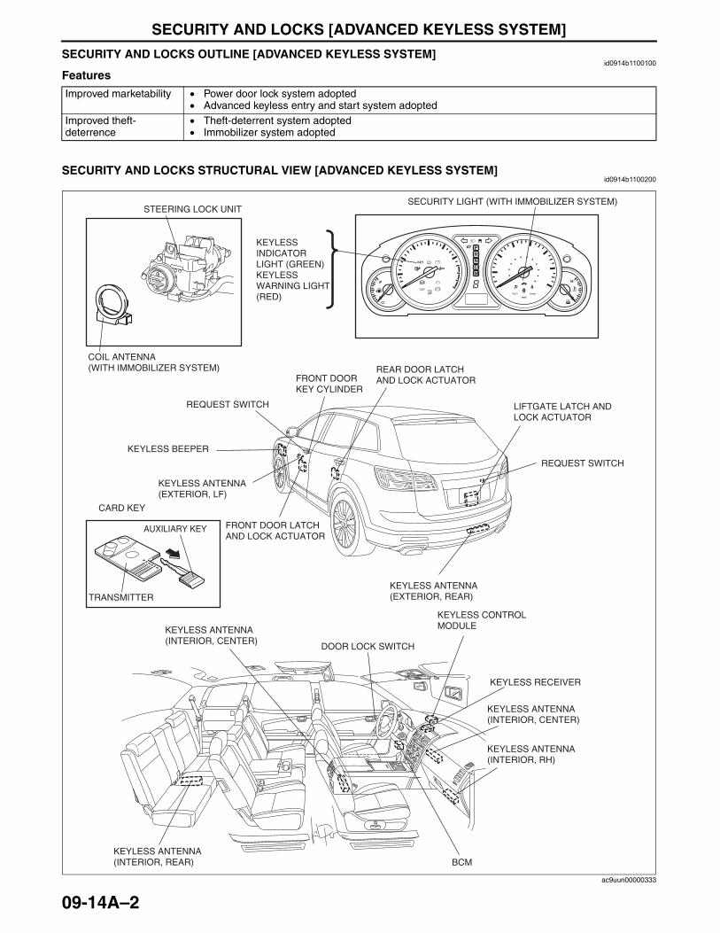
SECURITY AND LOCKS [ADVANCED KEYLESS SYSTEM]
09-14A–2
SECURITY AND LOCKS OUTLINE [ADVANCED KEYLESS SYSTEM]id0914b1100100
Features
End Of SieSECURITY AND LOCKS STRUCTURAL VIEW [ADVANCED KEYLESS SYSTEM]
id0914b1100200
Improved marketability • Power door lock system adopted• Advanced keyless entry and start system adopted
Improved theft-deterrence
• Theft-deterrent system adopted• Immobilizer system adopted
SECURITY LIGHT (WITH IMMOBILIZER SYSTEM)
COIL ANTENNA (WITH IMMOBILIZER SYSTEM)
KEYLESS INDICATOR LIGHT (GREEN)KEYLESS WARNING LIGHT (RED)
STEERING LOCK UNIT
KEYLESS ANTENNA(EXTERIOR, LF)
KEYLESS ANTENNA(EXTERIOR, REAR)
KEYLESS ANTENNA(INTERIOR, CENTER)
KEYLESS ANTENNA(INTERIOR, RH)
KEYLESS ANTENNA(INTERIOR, REAR)
FRONT DOOR KEY CYLINDER
REQUEST SWITCH
REQUEST SWITCH
FRONT DOOR LATCH AND LOCK ACTUATOR
LIFTGATE LATCH AND LOCK ACTUATOR
CARD KEY
KEYLESS CONTROL MODULE
KEYLESS RECEIVER
BCM
AUXILIARY KEY
TRANSMITTER
REAR DOOR LATCH AND LOCK ACTUATOR
KEYLESS BEEPER
KEYLESS ANTENNA(INTERIOR, CENTER)
DOOR LOCK SWITCH
ac9uun00000333
3423-1U-06H(09-14A).fm 2 ページ 2006年11月21日 火曜日 午後5時39分
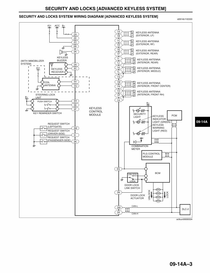
SECURITY AND LOCKS [ADVANCED KEYLESS SYSTEM]
09-14A–3
09-14A
End Of SieSECURITY AND LOCKS SYSTEM WIRING DIAGRAM [ADVANCED KEYLESS SYSTEM]id0914b1100300
End Of SieNG: THEFT-DETERRENT SYSTEM
KEYLESS INDICATOR LIGHT (GREEN)KEYLESS WARNING LIGHT (RED)
B+ACCIG1
IG1
2A
2E
2C
3A
2B
3C
B+
M
M
M
M
3V
3U
3H
3E
1A
1B
1C
1D
1E
1F
1I
1J
1K
1L
1G
2K
3W
3X
3Q
3N
3F
3I
3M
3K
LOC
K
UN
LOC
K
1M
1N
1O
1P
1H
DLC-2
B+
CAN-L
CAN-H
PCM
UNLOCK
LOCK
BCM
KEYLESS ANTENNA(EXTERIOR, LF)
KEYLESS ANTENNA(EXTERIOR, RF)
KEYLESS ANTENNA(EXTERIOR, REAR)
KEYLESS ANTENNA(INTERIOR, REAR)
KEYLESS ANTENNA(INTERIOR, MIDDLE)
KEYLESS ANTENNA(INTERIOR, FRONT CENTER)
KEYLESS ANTENNA(INTERIOR, FRONT RH)
KEYLESS CONTROL MODULE
(WITH IMMOBILIZER SYSTEM)
KEYLESS RECEIVER
COIL ANTENNA
STEERING LOCK UNIT
PUSH SWITCH
KEY REMINDER SWITCH
PLG CONTROL MODULE
REQUEST SWITCH(LEFTGATE)
REQUEST SWITCH(DRIVER-SIDE)
REQUEST SWITCH(PASSENGER-SIDE)
DOOR LOCK ACTUATOR
DOOR LOCK LINK SWITCH
SECURITY LIGHT
COMBINATION METER
KEYLESS BUZZER
ac9uun00000334
3423-1U-06H(09-14A).fm 3 ページ 2006年11月22日 水曜日 午後3時11分
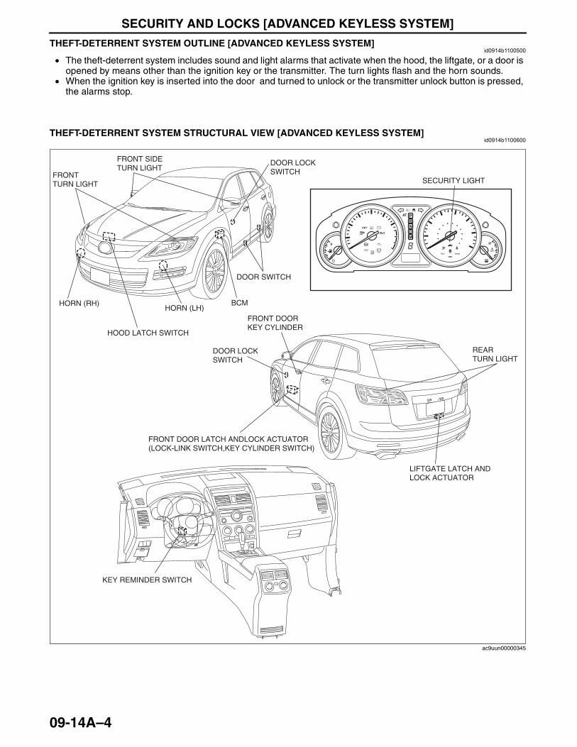
SECURITY AND LOCKS [ADVANCED KEYLESS SYSTEM]
09-14A–4
THEFT-DETERRENT SYSTEM OUTLINE [ADVANCED KEYLESS SYSTEM]id0914b1100500
• The theft-deterrent system includes sound and light alarms that activate when the hood, the liftgate, or a door is opened by means other than the ignition key or the transmitter. The turn lights flash and the horn sounds.
• When the ignition key is inserted into the door and turned to unlock or the transmitter unlock button is pressed, the alarms stop.
End Of Sie
THEFT-DETERRENT SYSTEM STRUCTURAL VIEW [ADVANCED KEYLESS SYSTEM]id0914b1100600
End Of Sie
BRAKE
SECURITY LIGHT
FRONT DOOR LATCH ANDLOCK ACTUATOR(LOCK-LINK SWITCH,KEY CYLINDER SWITCH)
KEY REMINDER SWITCH
HOOD LATCH SWITCH
DOOR SWITCH
HORN (RH)HORN (LH)
FRONT TURN LIGHT
FRONT SIDE TURN LIGHT
LIFTGATE LATCH AND LOCK ACTUATOR
FRONT DOOR KEY CYLINDER
REAR TURN LIGHT
BCM
DOOR LOCK SWITCH
DOOR LOCK SWITCH
ac9uun00000345
3423-1U-06H(09-14A).fm 4 ページ 2006年11月22日 水曜日 午後3時11分

SECURITY AND LOCKS [ADVANCED KEYLESS SYSTEM]
09-14A–5
09-14A
THEFT-DETERRENT SYSTEM WIRING DIAGRAM [ADVANCED KEYLESS SYSTEM]id0914b1100700
End Of Sie
B+
B+IG1B+
LOCK
UNLOCK
KEYLESS CONTROL MODULE
BCM
DOOR LOCK-LINK SWITCH(DRIVER SIDE)
LIFTGATE LATCH SWITCH
HOOD LATCHSWITCH
DOOR LOCK SWITCH(DRIVER SIDE)
DOOR LOCK SWITCH(PASSENGER SIDE)
DOOR LOCK-LINK SWITCH(PASSENGER SIDE)
B+
HORNRELAY
HORN
DOOR KEY CYLINDER SWITCH
CARGO COMPARTMENT LIGHT
DOOR SWITCH
ac9uun00000548
3423-1U-06H(09-14A).fm 5 ページ 2006年11月21日 火曜日 午後5時39分

SECURITY AND LOCKS [ADVANCED KEYLESS SYSTEM]
09-14A–6
THEFT-DETERRENT SYSTEM OPERATION [ADVANCED KEYLESS SYSTEM]id0914b1100800
Item Action Confirmation Note
Arming
The theft-deterrent system can be armed by performing the following operations:1. Turn the ignition switch to ON, then
to LOCK position.2. Remove the key from the steering
lock.3. Perform the following:
• Close all doors.• Close the liftgate.• Close the hood.
4. Lock all doors.*1
• Hazard warning lights flash once.
• With any door open, the doors will not lock with the transmitter and the theft-deterrent system will not arm
• The liftgate can be opened with the key or the transmitter even when the system is armed. The alarm will not come on and the system will remain armed.
*1: If the hood or the liftgate is open, the doors will lock but the alarm will not arm until the hood or liftgate is closed.
Arming cancel
Arming can be canceled by either of the following operations:• Unlock any doors using the
transmitter or key.• Insert the key into the steering lock
and turn the ignition switch to ON position.
• Hazard warning lights flash two times.
-
Alarm
The alarm triggers with each of the following operations:• Forcing open a door, the hood, or
the liftgate.• Unlock any doors without using the
transmitter or key. • Open a door, the hood or the
liftgate by operating an door lock switch, the hood release lever or the liftgate opener switch.
• Ignition switch turned to ON position using incorrect key.
• Hazard warning lights flash.
• Horn sounds.
• The alarm continues for approx. 27.5 min, then stops.
Alarm cancel
Alarm can be canceled by either of the following operations:• Door unlock with transmitter or key.• liftgate open with transmitter or key.
- -
3423-1U-06H(09-14A).fm 6 ページ 2006年11月21日 火曜日 午後5時39分
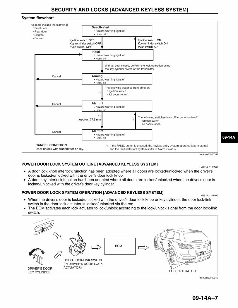
SECURITY AND LOCKS [ADVANCED KEYLESS SYSTEM]
09-14A–7
09-14A
System flowchart
End Of SieNG: POWER DOOR LOCK SYSTEMPOWER DOOR LOCK SYSTEM OUTLINE [ADVANCED KEYLESS SYSTEM]
id0914b1100900
• A door lock knob interlock function has been adopted where all doors are locked/unlocked when the driver’s door is locked/unlocked with the driver’s door lock knob.
• A door key interlock function has been adopted where all doors are locked/unlocked when the driver’s door is locked/unlocked with the driver’s door key cylinder.
End Of SiePOWER DOOR LOCK SYSTEM OPERATION [ADVANCED KEYLESS SYSTEM]
id0914b1101000
• When the driver’s door is locked/unlocked with the driver’s door lock knob or key cylinder, the door lock-link switch in the door lock actuator is locked/unlocked via the rod.
• The BCM activates each lock actuator to lock/unlock according to the lock/unlock signal from the door lock-link switch.
End Of Sie
All doors include the following: Front door Rear door Liftgate Bonnet
Deactivated Hazard warning light: off Horn: off
Initial Hazard warning light: off Horn: off
Key reminder switch ONIgnition switch ON
Push switch ONKey reminder switch OFFIgnition switch OFF
Push switch OFF
With all door closed, perform the lock operation using the key cylinder switch or the transmitter
The following switchse from off to on Ignition switch All doors (open)
Alarm 1 Hazard warning light: on Horn: on
Approx. 27.5 min
Alarm 2 Hazard warning light: off Horn: off
The following switchse from off to on, or on to off Ignition switch All doors (open)
CANCEL CONDITIONDoor unlock with transmitter or key.
*1: If the PANIC button is pressed, the keyless entry system operates (alarm status) and the theft-deterrent system shifts to Alarm 2 status.
*1 *1
*1
Cancel
Cancel
Cancel
Arming Hazard warning light: off Horn: off
ac9uun00000358
DRIVER'S DOOR KEY CYLINDER
DOOR LOCK-LINK SWITCH (IN DRIVER'S DOOR LOCK ACTUATOR)
BCM
LOCK ACTUATOR
ac9uun00000340
3423-1U-06H(09-14A).fm 7 ページ 2006年11月21日 火曜日 午後5時39分
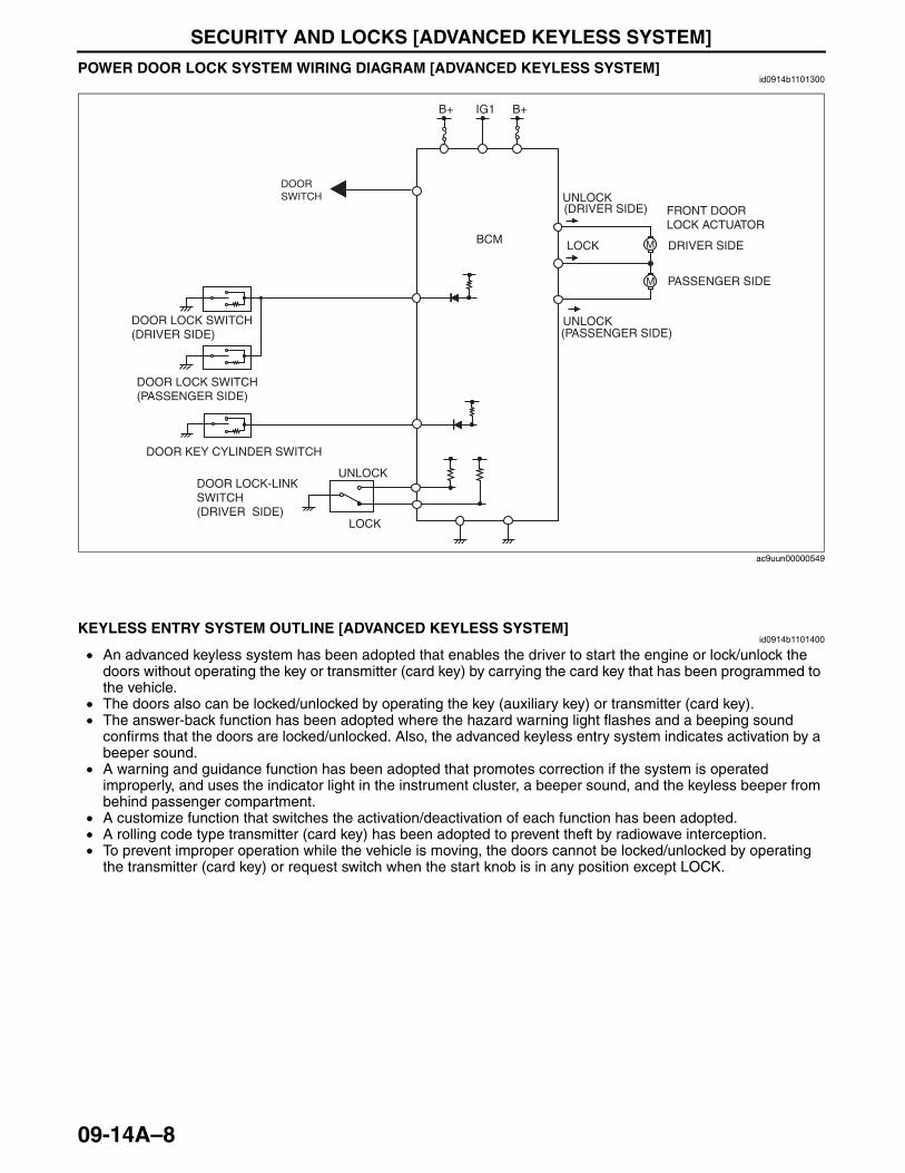
SECURITY AND LOCKS [ADVANCED KEYLESS SYSTEM]
09-14A–8
POWER DOOR LOCK SYSTEM WIRING DIAGRAM [ADVANCED KEYLESS SYSTEM]id0914b1101300
End Of Sie
KEYLESS ENTRY SYSTEM OUTLINE [ADVANCED KEYLESS SYSTEM]id0914b1101400
• An advanced keyless system has been adopted that enables the driver to start the engine or lock/unlock the doors without operating the key or transmitter (card key) by carrying the card key that has been programmed to the vehicle.
• The doors also can be locked/unlocked by operating the key (auxiliary key) or transmitter (card key).• The answer-back function has been adopted where the hazard warning light flashes and a beeping sound
confirms that the doors are locked/unlocked. Also, the advanced keyless entry system indicates activation by a beeper sound.
• A warning and guidance function has been adopted that promotes correction if the system is operated improperly, and uses the indicator light in the instrument cluster, a beeper sound, and the keyless beeper from behind passenger compartment.
• A customize function that switches the activation/deactivation of each function has been adopted.• A rolling code type transmitter (card key) has been adopted to prevent theft by radiowave interception.• To prevent improper operation while the vehicle is moving, the doors cannot be locked/unlocked by operating
the transmitter (card key) or request switch when the start knob is in any position except LOCK.End Of SieNG: IMMOBILIZER SYSTEM
M
M
B+IG1B+
LOCK
UNLOCK
BCM
DOOR LOCK-LINK SWITCH(DRIVER SIDE)
FRONT DOOR LOCK ACTUATOR
PASSENGER SIDE
DRIVER SIDE
DOOR LOCK SWITCH(DRIVER SIDE)
DOOR LOCK SWITCH(PASSENGER SIDE)
UNLOCK
UNLOCK
LOCK
(PASSENGER SIDE)
(DRIVER SIDE)
DOOR KEY CYLINDER SWITCH
DOOR SWITCH
ac9uun00000549
3423-1U-06H(09-14A).fm 8 ページ 2006年11月21日 火曜日 午後5時39分

SECURITY AND LOCKS [ADVANCED KEYLESS SYSTEM]
09-14A–9
09-14A
IMMOBILIZER SYSTEM OUTLINE [ADVANCED KEYLESS SYSTEM]id0914b1101700
• The immobilizer system is a vehicle theft prevention device that only allows keys that have previously been registered to the vehicle to start the engine and prevents it from being started in any other manner (such as with an unregistered key or by starter relay short).
• The immobilizer system consists of the key (built-in transponder), coil antenna, keyless control module, PCM, and security light (in the instrument cluster).
• Ignition keys for use with the immobilizer system have an electronic communication device (transponder) built into the key head that retains specific electronic codes (key ID number).
• The immobilizer system operates automatically when the ignition switch is turned to the LOCK or ACC position. When this occurs, the security light flashes repeatedly 0.1 s every 2 s.
• In order to start the engine, the immobilizer system must be made inoperable using a key previously registered with the vehicle. No special operation is required to release the immobilizer system but rather the vehicle is started similar to vehicles without the system: the ignition switch is turned from the LOCK or ACC position to the ON or START position and the release operation begins automatically. The engine can only be started after the key, keyless control module and PCM successfully perform their parts of the verification procedure. For details, refer to “09-14A-11 IMMOBILIZER SYSTEM OPERATION [ADVANCED KEYLESS SYSTEM]”.
• If the immobilizer system is not released due to a malfunction or verification failure, the security light in the instrument cluster displays a DTC. At the same time, DTCs are stored respectively in the PCM and keyless control module. The stored DTCs can be verified using the Mazda Modular Diagnostic System (M-MDS). Repair the malfunctioning part using the verified DTCs. For details, refer to “09-14A-13 ON-BOARD DIAGNOSTIC SYSTEM (IMMOBILIZER SYSTEM) PID/DATA MONITOR FUNCTION [ADVANCED KEYLESS SYSTEM]”.
• The immobilizer system cannot be deactivated.
Caution• The immobilizer system must be reset using the Mazda Modular Diagnostic System (M-MDS) after
performing any of the following: “Replacement of all the keys (steering lock replacement or similar procedure)”, “Keyless control module replacement”, “PCM replacement” and “Keyless control module and PCM replacement”. Moreover, when performing “Replacement of all the keys” or “Keyless control module replacement”, two or more keys usable with the immobilizer system must be readied. For details, refer to Workshop Manual.
• Two or more key ID numbers must be registered for the engine to start. For key ID number registration, refer the Workshop ManualSection 09-14, “IMMOBILIZER SYSTEM COMPONENT REPLACEMENT/KEY ADDITION AND CLEARING”.
• A maximum of eight key ID numbers can be registered for one vehicle. The PID/data monitor function can be used to verify the number of key ID numbers registered for a single vehicle. For details refer to Workshop Manual.
• The following conditions may cause poor signal communication between the key and vehicle, resulting in the engine not starting or a key registration error. Do not perform key registration under the following conditions: — If any of the following items are touching or near the key head.
• Spare keys• Keys for other vehicles equipped with an immobilizer system• Any metallic object• Any electronic device, or any credit or other cards with magnetic strips
End Of Sie
METAL RING LYINGON KEY HEAD
METAL PART OF ANOTHER KEY TOUCHING KEY HEAD
KEY IS CLOSE TO OR TOUCHING ANOTHER IMMOBILIZER SYSTEM KEY
METAL OBJECT TOUCHING KEY HEAD
EXAMPLES:
acxuun00000705
3423-1U-06H(09-14A).fm 9 ページ 2006年11月21日 火曜日 午後5時39分
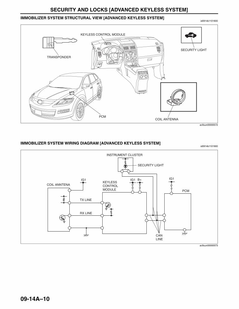
SECURITY AND LOCKS [ADVANCED KEYLESS SYSTEM]
09-14A–10
IMMOBILIZER SYSTEM STRUCTURAL VIEW [ADVANCED KEYLESS SYSTEM]id0914b1101800
End Of Sie
IMMOBILIZER SYSTEM WIRING DIAGRAM [ADVANCED KEYLESS SYSTEM]id0914b1101900
End Of Sie
PCM
TRANSPONDER
SECURITY LIGHT
KEYLESS CONTROL MODULE
COIL ANTENNA
ac9uun00000572
COIL ANNTENA
INSTRUMENT CLUSTER
SECURITY LIGHT
KEYLESSCONTROLMODULE PCM
IG1IG1IG1 B+
TX LINE
RX LINE
CANLINE
ac9uun00000573
3423-1U-06H(09-14A).fm 10 ページ 2006年11月21日 火曜日 午後5時39分
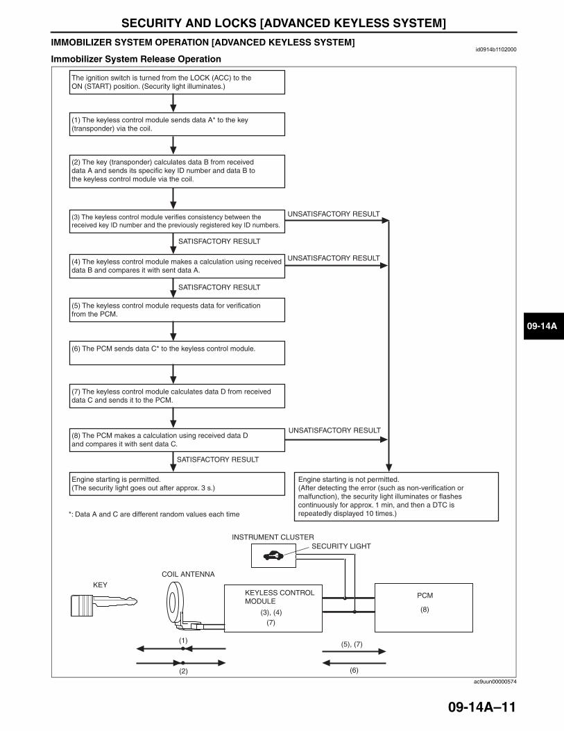
SECURITY AND LOCKS [ADVANCED KEYLESS SYSTEM]
09-14A–11
09-14A
IMMOBILIZER SYSTEM OPERATION [ADVANCED KEYLESS SYSTEM]id0914b1102000
Immobilizer System Release Operation
The ignition switch is turned from the LOCK (ACC) to the ON (START) position. (Security light illuminates.)
(1) The keyless control module sends data A* to the key (transponder) via the coil.
(3) The keyless control module verifies consistency between the received key ID number and the previously registered key ID numbers.
(4) The keyless control module makes a calculation using received data B and compares it with sent data A.
(5) The keyless control module requests data for verification from the PCM.
(6) The PCM sends data C* to the keyless control module.
(7) The keyless control module calculates data D from received data C and sends it to the PCM.
(8) The PCM makes a calculation using received data D and compares it with sent data C.
Engine starting is permitted. (The security light goes out after approx. 3 s.)
Engine starting is not permitted. (After detecting the error (such as non-verification or malfunction), the security light illuminates or flashes continuously for approx. 1 min, and then a DTC is repeatedly displayed 10 times.)
(2) The key (transponder) calculates data B from received data A and sends its specific key ID number and data B to the keyless control module via the coil.
*: Data A and C are different random values each time
UNSATISFACTORY RESULT
UNSATISFACTORY RESULT
UNSATISFACTORY RESULT
SATISFACTORY RESULT
SATISFACTORY RESULT
SATISFACTORY RESULT
(5), (7)
(6)(2)
(1)
(3), (4) (8)
(7)
KEY
COIL ANTENNA
PCMKEYLESS CONTROL MODULE
INSTRUMENT CLUSTERSECURITY LIGHT
ac9uun00000574
3423-1U-06H(09-14A).fm 11 ページ 2006年11月21日 火曜日 午後5時39分
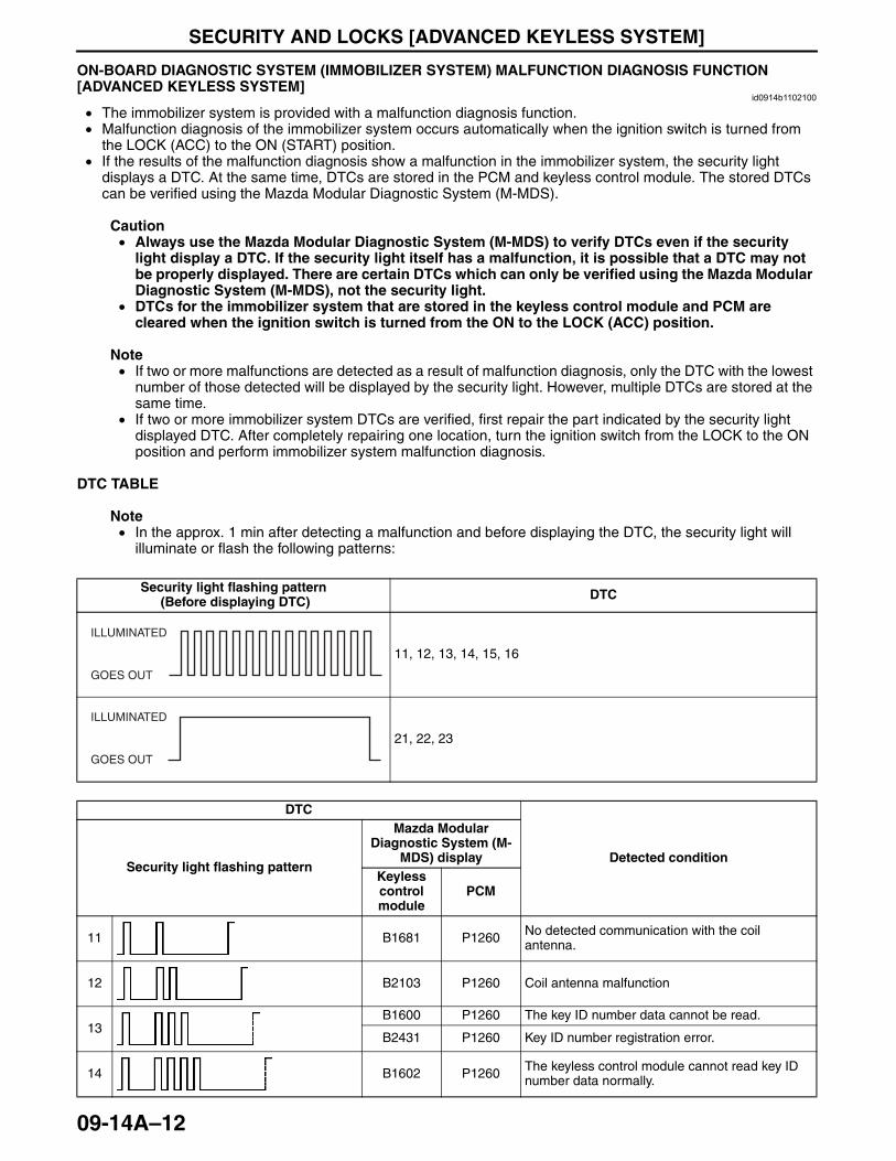
SECURITY AND LOCKS [ADVANCED KEYLESS SYSTEM]
09-14A–12
End Of SieON-BOARD DIAGNOSTIC SYSTEM (IMMOBILIZER SYSTEM) MALFUNCTION DIAGNOSIS FUNCTION [ADVANCED KEYLESS SYSTEM]
id0914b1102100
• The immobilizer system is provided with a malfunction diagnosis function.• Malfunction diagnosis of the immobilizer system occurs automatically when the ignition switch is turned from
the LOCK (ACC) to the ON (START) position.• If the results of the malfunction diagnosis show a malfunction in the immobilizer system, the security light
displays a DTC. At the same time, DTCs are stored in the PCM and keyless control module. The stored DTCs can be verified using the Mazda Modular Diagnostic System (M-MDS).
Caution• Always use the Mazda Modular Diagnostic System (M-MDS) to verify DTCs even if the security
light display a DTC. If the security light itself has a malfunction, it is possible that a DTC may not be properly displayed. There are certain DTCs which can only be verified using the Mazda Modular Diagnostic System (M-MDS), not the security light.
• DTCs for the immobilizer system that are stored in the keyless control module and PCM are cleared when the ignition switch is turned from the ON to the LOCK (ACC) position.
Note• If two or more malfunctions are detected as a result of malfunction diagnosis, only the DTC with the lowest
number of those detected will be displayed by the security light. However, multiple DTCs are stored at the same time.
• If two or more immobilizer system DTCs are verified, first repair the part indicated by the security light displayed DTC. After completely repairing one location, turn the ignition switch from the LOCK to the ON position and perform immobilizer system malfunction diagnosis.
DTC TABLE
Note• In the approx. 1 min after detecting a malfunction and before displaying the DTC, the security light will
illuminate or flash the following patterns:
Security light flashing pattern (Before displaying DTC) DTC
11, 12, 13, 14, 15, 16
21, 22, 23
DTC
Detected conditionSecurity light flashing pattern
Mazda Modular Diagnostic System (M-
MDS) displayKeyless control module
PCM
11 B1681 P1260 No detected communication with the coil antenna.
12 B2103 P1260 Coil antenna malfunction
13B1600 P1260 The key ID number data cannot be read.
B2431 P1260 Key ID number registration error.
14 B1602 P1260 The keyless control module cannot read key ID number data normally.
ILLUMINATED
GOES OUT
ILLUMINATED
GOES OUT
3423-1U-06H(09-14A).fm 12 ページ 2006年11月21日 火曜日 午後5時39分
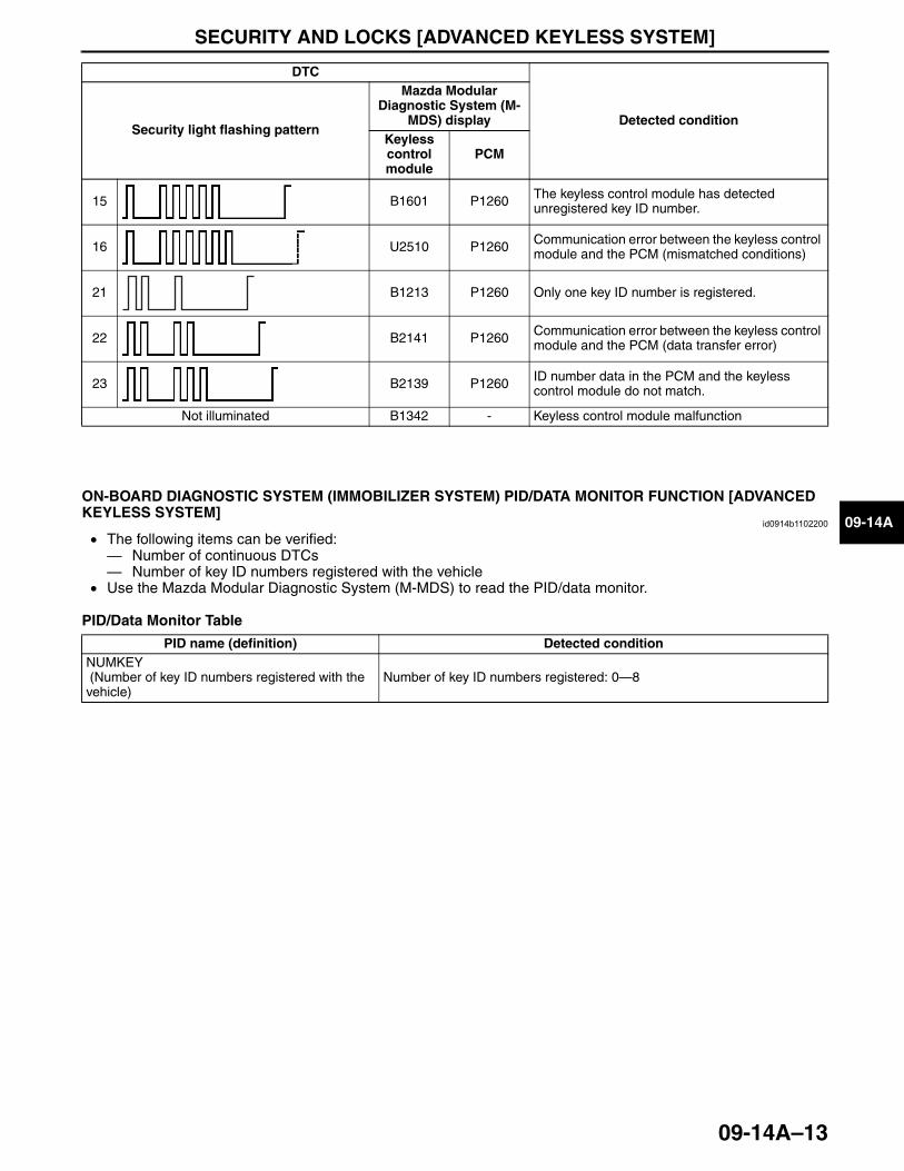
SECURITY AND LOCKS [ADVANCED KEYLESS SYSTEM]
09-14A–13
09-14A
End Of Sie
ON-BOARD DIAGNOSTIC SYSTEM (IMMOBILIZER SYSTEM) PID/DATA MONITOR FUNCTION [ADVANCED KEYLESS SYSTEM]
id0914b1102200
• The following items can be verified: — Number of continuous DTCs— Number of key ID numbers registered with the vehicle
• Use the Mazda Modular Diagnostic System (M-MDS) to read the PID/data monitor.
PID/Data Monitor Table
End Of Sie
15 B1601 P1260 The keyless control module has detected unregistered key ID number.
16 U2510 P1260 Communication error between the keyless control module and the PCM (mismatched conditions)
21 B1213 P1260 Only one key ID number is registered.
22 B2141 P1260 Communication error between the keyless control module and the PCM (data transfer error)
23 B2139 P1260 ID number data in the PCM and the keyless control module do not match.
Not illuminated B1342 - Keyless control module malfunction
DTC
Detected conditionSecurity light flashing pattern
Mazda Modular Diagnostic System (M-
MDS) displayKeyless control module
PCM
PID name (definition) Detected conditionNUMKEY (Number of key ID numbers registered with the vehicle)
Number of key ID numbers registered: 0—8
3423-1U-06H(09-14A).fm 13 ページ 2006年11月21日 火曜日 午後5時39分
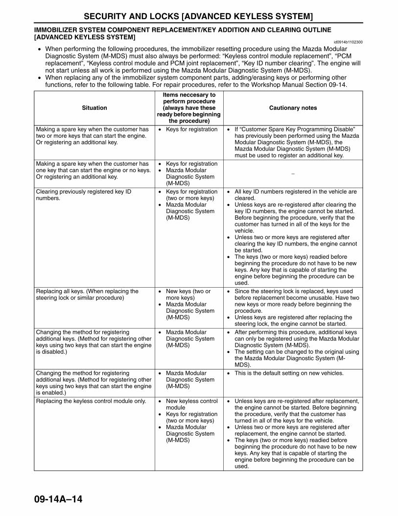
SECURITY AND LOCKS [ADVANCED KEYLESS SYSTEM]
09-14A–14
IMMOBILIZER SYSTEM COMPONENT REPLACEMENT/KEY ADDITION AND CLEARING OUTLINE [ADVANCED KEYLESS SYSTEM]
id0914b1102300
• When performing the following procedures, the immobilizer resetting procedure using the Mazda Modular Diagnostic System (M-MDS) must also always be performed: “Keyless control module replacement”, “PCM replacement”, “Keyless control module and PCM joint replacement”, “Key ID number clearing”. The engine will not start unless all work is performed using the Mazda Modular Diagnostic System (M-MDS).
• When replacing any of the immobilizer system component parts, adding/erasing keys or performing other functions, refer to the following table. For repair procedures, refer to the Workshop Manual Section 09-14.
Situation
Items neccesary to perform procedure (always have these
ready before beginning the procedure)
Cautionary notes
Making a spare key when the customer has two or more keys that can start the engine. Or registering an additional key.
• Keys for registration • If “Customer Spare Key Programming Disable” has previously been performed using the Mazda Modular Diagnostic System (M-MDS), the Mazda Modular Diagnostic System (M-MDS) must be used to register an additional key.
Making a spare key when the customer has one key that can start the engine or no keys. Or registering an additional key.
• Keys for registration• Mazda Modular
Diagnostic System (M-MDS)
−
Clearing previously registered key ID numbers.
• Keys for registration (two or more keys)
• Mazda Modular Diagnostic System (M-MDS)
• All key ID numbers registered in the vehicle are cleared.
• Unless keys are re-registered after clearing the key ID numbers, the engine cannot be started. Before beginning the procedure, verify that the customer has turned in all of the keys for the vehicle.
• Unless two or more keys are registered after clearing the key ID numbers, the engine cannot be started.
• The keys (two or more keys) readied before beginning the procedure do not have to be new keys. Any key that is capable of starting the engine before beginning the procedure can be used.
Replacing all keys. (When replacing the steering lock or similar procedure)
• New keys (two or more keys)
• Mazda Modular Diagnostic System (M-MDS)
• Since the steering lock is replaced, keys used before replacement become unusable. Have two new keys or more ready before beginning the procedure.
• Unless keys are registered after replacing the steering lock, the engine cannot be started.
Changing the method for registering additional keys. (Method for registering other keys using two keys that can start the engine is disabled.)
• Mazda Modular Diagnostic System (M-MDS)
• After performing this procedure, additional keys can only be registered using the Mazda Modular Diagnostic System (M-MDS).
• The setting can be changed to the original using the Mazda Modular Diagnostic System (M-MDS).
Changing the method for registering additional keys. (Method for registering other keys using two keys that can start the engine is enabled.)
• Mazda Modular Diagnostic System (M-MDS)
• This is the default setting on new vehicles.
Replacing the keyless control module only. • New keyless control module
• Keys for registration (two or more keys)
• Mazda Modular Diagnostic System (M-MDS)
• Unless keys are re-registered after replacement, the engine cannot be started. Before beginning the procedure, verify that the customer has turned in all of the keys for the vehicle.
• Unless two or more keys are registered after replacement, the engine cannot be started.
• The keys (two or more keys) readied before beginning the procedure do not have to be new keys. Any key that is capable of starting the engine before beginning the procedure can be used.
3423-1U-06H(09-14A).fm 14 ページ 2006年11月21日 火曜日 午後5時39分
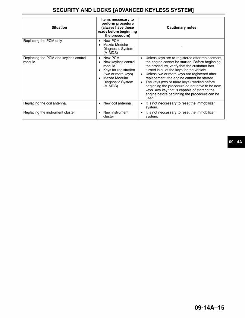
SECURITY AND LOCKS [ADVANCED KEYLESS SYSTEM]
09-14A–15
09-14A
End Of SieNG: KEYLESS ENTRY SYSTEM
Replacing the PCM only. • New PCM• Mazda Modular
Diagnostic System (M-MDS)
-
Replacing the PCM and keyless control module.
• New PCM• New keyless control
module• Keys for registration
(two or more keys)• Mazda Modular
Diagnostic System (M-MDS)
• Unless keys are re-registered after replacement, the engine cannot be started. Before beginning the procedure, verify that the customer has turned in all of the keys for the vehicle.
• Unless two or more keys are registered after replacement, the engine cannot be started.
• The keys (two or more keys) readied before beginning the procedure do not have to be new keys. Any key that is capable of starting the engine before beginning the procedure can be used.
Replacing the coil antenna. • New coil antenna • It is not neccessary to reset the immobilizer system.
Replacing the instrument cluster. • New instrument cluster
• It is not neccessary to reset the immobilizer system.
Situation
Items neccesary to perform procedure (always have these
ready before beginning the procedure)
Cautionary notes
3423-1U-06H(09-14A).fm 15 ページ 2006年11月21日 火曜日 午後5時39分
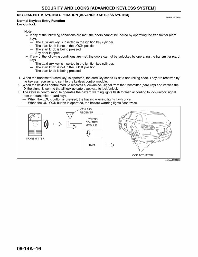
SECURITY AND LOCKS [ADVANCED KEYLESS SYSTEM]
09-14A–16
KEYLESS ENTRY SYSTEM OPERATION [ADVANCED KEYLESS SYSTEM]id0914b1102600
Normal Keyless Entry FunctionLock/unlock
Note• If any of the following conditions are met, the doors cannot be locked by operating the transmitter (card
key).— The auxiliary key is inserted in the ignition key cylinder.— The start knob is not in the LOCK position.— The start knob is being pressed.— Any door is open.
• If any of the following conditions are met, the doors cannot be unlocked by operating the transmitter (card key).— The auxiliary key is inserted in the ignition key cylinder.— The start knob is not in the LOCK position.— The start knob is being pressed.
1. When the transmitter (card key) is operated, the card key sends ID data and rolling code. They are received by the keyless receiver and sent to the keyless control module.
2. When the keyless control module receives a lock/unlock signal from the transmitter (card key) and verifies the ID, the signal is sent to the all lock actuators activate to lock/unlock.
3. The keyless control module operates the hazard warning lights flash to flash according to lock/unlock signal from the transmitter (card key).— When the LOCK button is pressed, the hazard warning lights flash once.— When the UNLOCK button is operated, the hazard warning lights flash twice.
KEYLESS RECEIVER
KEYLESS CONTROL MODULE
BCM
TRANSMITTER
LOCK ACTUATOR
ac9uun00000335
3423-1U-06H(09-14A).fm 16 ページ 2006年11月21日 火曜日 午後5時39分
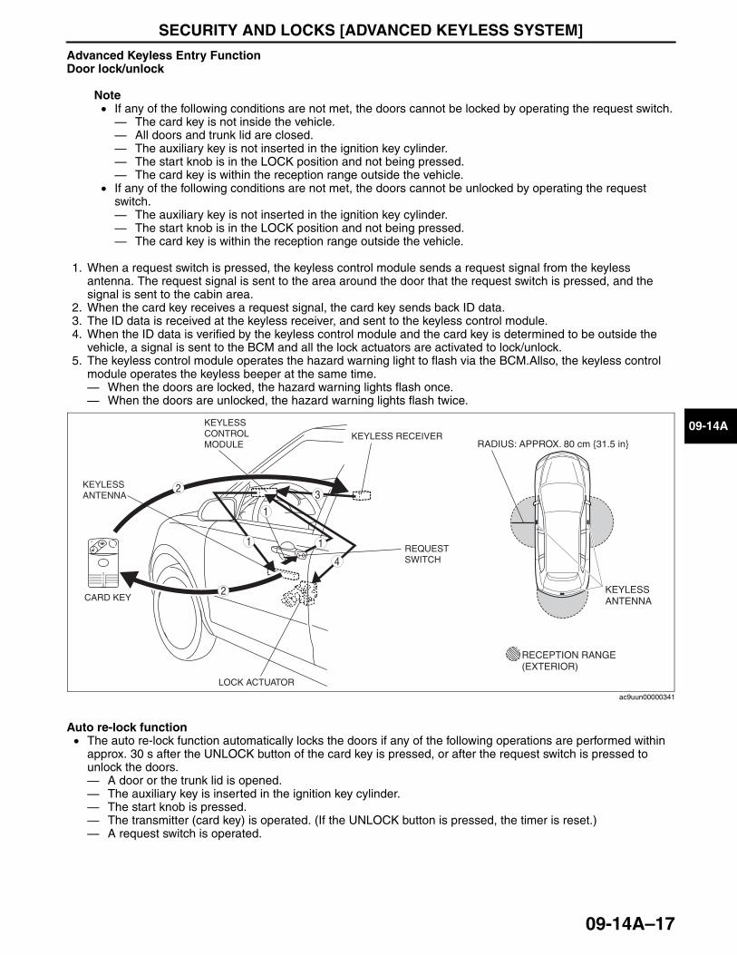
SECURITY AND LOCKS [ADVANCED KEYLESS SYSTEM]
09-14A–17
09-14A
Advanced Keyless Entry FunctionDoor lock/unlock
Note• If any of the following conditions are not met, the doors cannot be locked by operating the request switch.— The card key is not inside the vehicle.— All doors and trunk lid are closed.— The auxiliary key is not inserted in the ignition key cylinder.— The start knob is in the LOCK position and not being pressed.— The card key is within the reception range outside the vehicle.
• If any of the following conditions are not met, the doors cannot be unlocked by operating the request switch.— The auxiliary key is not inserted in the ignition key cylinder.— The start knob is in the LOCK position and not being pressed.— The card key is within the reception range outside the vehicle.
1. When a request switch is pressed, the keyless control module sends a request signal from the keyless antenna. The request signal is sent to the area around the door that the request switch is pressed, and the signal is sent to the cabin area.
2. When the card key receives a request signal, the card key sends back ID data.3. The ID data is received at the keyless receiver, and sent to the keyless control module.4. When the ID data is verified by the keyless control module and the card key is determined to be outside the
vehicle, a signal is sent to the BCM and all the lock actuators are activated to lock/unlock.5. The keyless control module operates the hazard warning light to flash via the BCM.Allso, the keyless control
module operates the keyless beeper at the same time.— When the doors are locked, the hazard warning lights flash once.— When the doors are unlocked, the hazard warning lights flash twice.
Auto re-lock function• The auto re-lock function automatically locks the doors if any of the following operations are performed within
approx. 30 s after the UNLOCK button of the card key is pressed, or after the request switch is pressed to unlock the doors.— A door or the trunk lid is opened.— The auxiliary key is inserted in the ignition key cylinder.— The start knob is pressed.— The transmitter (card key) is operated. (If the UNLOCK button is pressed, the timer is reset.)— A request switch is operated.
RECEPTION RANGE (EXTERIOR)
KEYLESS CONTROL MODULE
KEYLESS RECEIVER
KEYLESS ANTENNA
2
REQUEST SWITCH
CARD KEY
1
2
3
4
LOCK ACTUATOR
RADIUS: APPROX. 80 cm {31.5 in}
KEYLESS ANTENNA
11
ac9uun00000341
3423-1U-06H(09-14A).fm 17 ページ 2006年11月21日 火曜日 午後5時39分
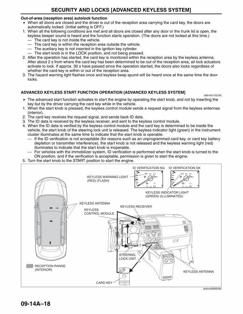
SECURITY AND LOCKS [ADVANCED KEYLESS SYSTEM]
09-14A–18
Out-of-area (reception area) autolock function• When all doors are closed and the driver is out of the reception area carrying the card key, the doors are
automatically locked. (Initial setting is OFF.)1. When all the following conditions are met and all doors are closed after any door or the trunk lid is open, the
keyless beeper sound is heard and the function starts operation. (The doors are not locked at this time.)— The card key is not inside the vehicle.— The card key is within the reception area outside the vehicle.— The auxiliary key is not inserted in the ignition key cylinder.— The start knob is in the LOCK position, and not being pressed.
2. After the operation has started, the card key is monitored within the reception area by the keyless antenna. After about 2 s from where the card key has been determined to be out of the reception area, all lock actuators activate to lock. If approx. 30 s have passed since the operation started, the doors also locks regardless of whether the card key is within or out of the reception area.
3. The hazard warning light flashes once and keyless beep spund will be heard once at the same time the door locks.
End Of Sie
ADVANCED KEYLESS START FUNCTION OPERATION [ADVANCED KEYLESS SYSTEM]id0914b1102700
• The advanced start function activates to start the engine by operating the start knob, and not by inserting the key but by the driver carrying the card key while in the vehicle.
1. When the start knob is pressed, the keyless control module sends a request signal from the keyless antennas (interior).
2. The card key receives the request signal, and sends back ID data.3. The ID data is received by the keyless receiver, and sent to the keyless control module.4. When the ID data is verified by the keyless control module and the card key is determined to be inside the
vehicle, the start knob of the steering lock unit is released. The keyless indicator light (green) in the instrument cluster illuminates at the same time to indicate that the start knob is operable.— If the ID verification is not acceptable (for reasons such as an unprogrammed card key, or card key battery
depletion or transmitter interference), the start knob is not released and the keyless warning light (red) illuminates to indicate that the start knob is inoperable.
— For vehicles with the immobilizer system, ID verification is performed when the start knob is turned to the ON position, and if the verification is acceptable, permission is given to start the engine.
5. Turn the start knob to the START position to start the engine.
End Of Sie
KEYLESS CONTROL MODULE
CARD KEY
RECEPTION RANGE(INTERIOR)
KEYLESS ANTENNA
KEYLESS ANTENNA
KEYLESS RECEIVER
ID VERIFICATION NG ID VERIFICATION OK
KEYLESS INDICATOR LIGHT(GREEN) (ILLUMINATED)
KEYLESS WARNING LIGHT(RED) (FLASH)
BRAKE BRAKE
1
1
2
2
3
4
STEERING LOCK UNIT
ac9uun00000342
3423-1U-06H(09-14A).fm 18 ページ 2006年11月21日 火曜日 午後5時39分
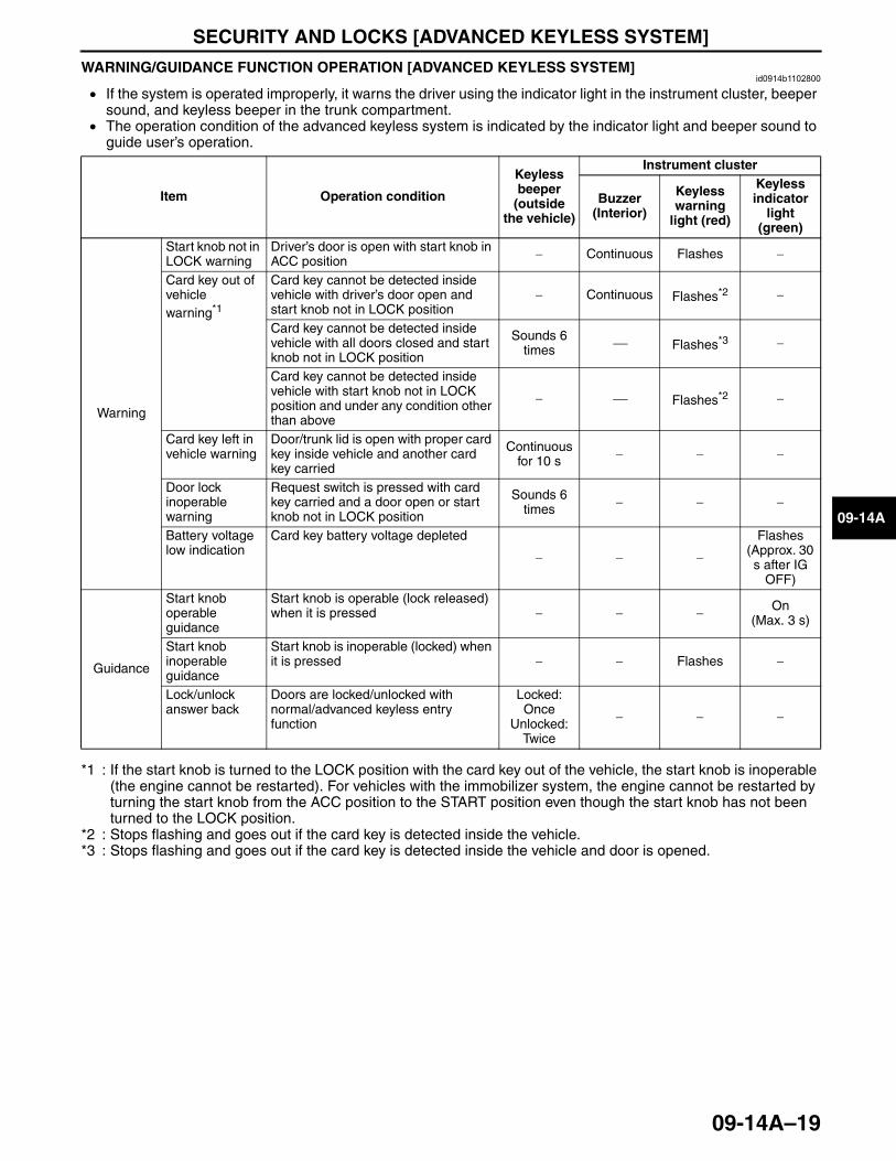
SECURITY AND LOCKS [ADVANCED KEYLESS SYSTEM]
09-14A–19
09-14A
WARNING/GUIDANCE FUNCTION OPERATION [ADVANCED KEYLESS SYSTEM]id0914b1102800
• If the system is operated improperly, it warns the driver using the indicator light in the instrument cluster, beeper sound, and keyless beeper in the trunk compartment.
• The operation condition of the advanced keyless system is indicated by the indicator light and beeper sound to guide user’s operation.
*1 : If the start knob is turned to the LOCK position with the card key out of the vehicle, the start knob is inoperable (the engine cannot be restarted). For vehicles with the immobilizer system, the engine cannot be restarted by turning the start knob from the ACC position to the START position even though the start knob has not been turned to the LOCK position.
*2 : Stops flashing and goes out if the card key is detected inside the vehicle.*3 : Stops flashing and goes out if the card key is detected inside the vehicle and door is opened.
End Of Sie
Item Operation condition
Keyless beeper
(outside the vehicle)
Instrument cluster
Buzzer (Interior)
Keyless warning
light (red)
Keyless indicator
light (green)
Warning
Start knob not in LOCK warning
Driver’s door is open with start knob in ACC position − Continuous Flashes −
Card key out of vehicle warning*1
Card key cannot be detected inside vehicle with driver’s door open and start knob not in LOCK position
− Continuous Flashes*2 −
Card key cannot be detected inside vehicle with all doors closed and start knob not in LOCK position
Sounds 6 times ⎯ Flashes*3 −
Card key cannot be detected inside vehicle with start knob not in LOCK position and under any condition other than above
− ⎯ Flashes*2 −
Card key left in vehicle warning
Door/trunk lid is open with proper card key inside vehicle and another card key carried
Continuous for 10 s − − −
Door lock inoperable warning
Request switch is pressed with card key carried and a door open or start knob not in LOCK position
Sounds 6 times − − −
Battery voltage low indication
Card key battery voltage depleted
− − −
Flashes(Approx. 30 s after IG
OFF)
Guidance
Start knob operable guidance
Start knob is operable (lock released) when it is pressed − − − On
(Max. 3 s)
Start knob inoperable guidance
Start knob is inoperable (locked) when it is pressed − − Flashes −
Lock/unlock answer back
Doors are locked/unlocked with normal/advanced keyless entry function
Locked: Once
Unlocked: Twice
− − −
3423-1U-06H(09-14A).fm 19 ページ 2006年11月21日 火曜日 午後5時39分
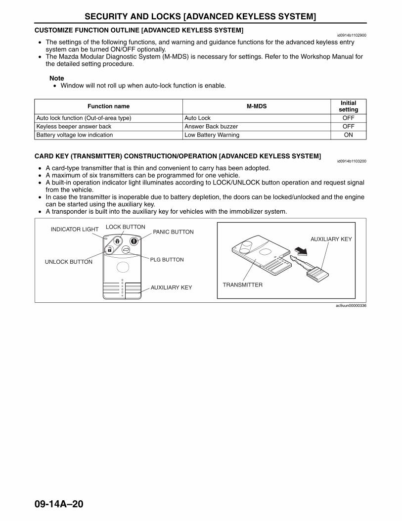
SECURITY AND LOCKS [ADVANCED KEYLESS SYSTEM]
09-14A–20
CUSTOMIZE FUNCTION OUTLINE [ADVANCED KEYLESS SYSTEM]id0914b1102900
• The settings of the following functions, and warning and guidance functions for the advanced keyless entry system can be turned ON/OFF optionally.
• The Mazda Modular Diagnostic System (M-MDS) is necessary for settings. Refer to the Workshop Manual for the detailed setting procedure.
Note• Window will not roll up when auto-lock function is enable.
End Of SieCARD KEY (TRANSMITTER) CONSTRUCTION/OPERATION [ADVANCED KEYLESS SYSTEM]
id0914b1103200
• A card-type transmitter that is thin and convenient to carry has been adopted.• A maximum of six transmitters can be programmed for one vehicle.• A built-in operation indicator light illuminates according to LOCK/UNLOCK button operation and request signal
from the vehicle.• In case the transmitter is inoperable due to battery depletion, the doors can be locked/unlocked and the engine
can be started using the auxiliary key.• A transponder is built into the auxiliary key for vehicles with the immobilizer system.
End Of Sie
Function name M-MDS Initial setting
Auto lock function (Out-of-area type) Auto Lock OFFKeyless beeper answer back Answer Back buzzer OFFBattery voltage low indication Low Battery Warning ON
INDICATOR LIGHT
AUXILIARY KEY
UNLOCK BUTTON
LOCK BUTTON
TRANSMITTERAUXILIARY KEY
PANIC BUTTON
PLG BUTTON
ac9uun00000336
3423-1U-06H(09-14A).fm 20 ページ 2006年11月21日 火曜日 午後5時39分
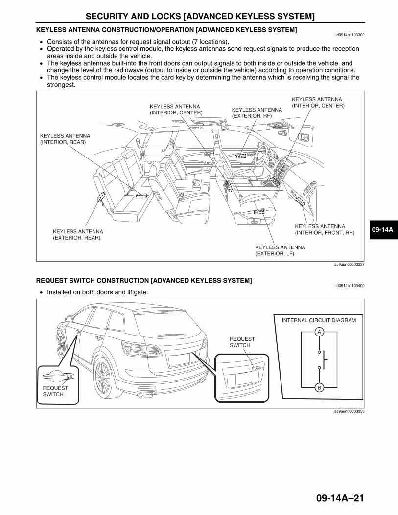
SECURITY AND LOCKS [ADVANCED KEYLESS SYSTEM]
09-14A–21
09-14A
KEYLESS ANTENNA CONSTRUCTION/OPERATION [ADVANCED KEYLESS SYSTEM]id0914b1103300
• Consists of the antennas for request signal output (7 locations).• Operated by the keyless control module, the keyless antennas send request signals to produce the reception
areas inside and outside the vehicle.• The keyless antennas built-into the front doors can output signals to both inside or outside the vehicle, and
change the level of the radiowave (output to inside or outside the vehicle) according to operation conditions.• The keyless control module locates the card key by determining the antenna which is receiving the signal the
strongest.
End Of SieREQUEST SWITCH CONSTRUCTION [ADVANCED KEYLESS SYSTEM]
id0914b1103400
• Installed on both doors and liftgate.
End Of Sie
KEYLESS ANTENNA(EXTERIOR, REAR)
KEYLESS ANTENNA(INTERIOR, REAR)
KEYLESS ANTENNA(INTERIOR, CENTER)
KEYLESS ANTENNA(INTERIOR, FRONT, RH)
KEYLESS ANTENNA(INTERIOR, CENTER)
KEYLESS ANTENNA (EXTERIOR, RF)
KEYLESS ANTENNA (EXTERIOR, LF)
ac9uun00000337
B
A
INTERNAL CIRCUIT DIAGRAM
REQUEST SWITCH
REQUEST SWITCH
ac9uun00000338
3423-1U-06H(09-14A).fm 21 ページ 2006年11月21日 火曜日 午後5時39分
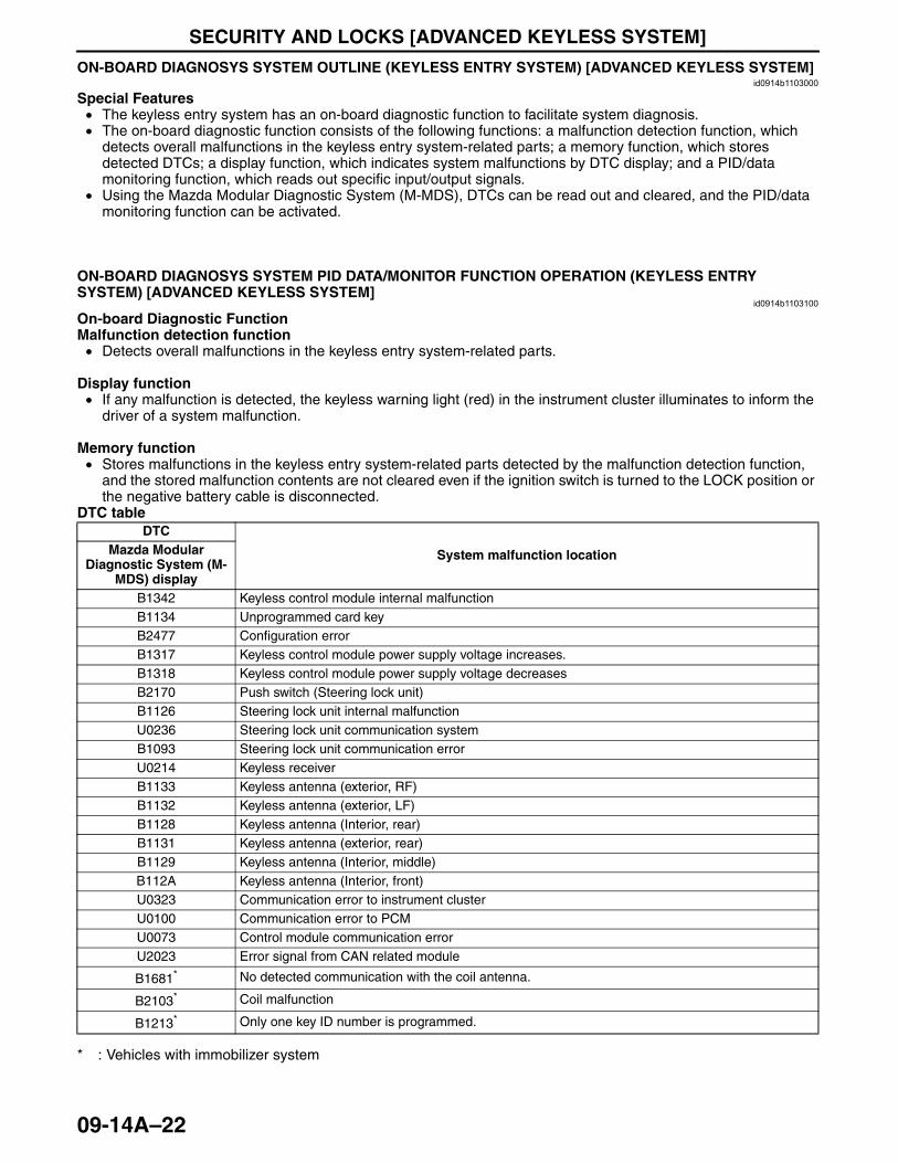
SECURITY AND LOCKS [ADVANCED KEYLESS SYSTEM]
09-14A–22
ON-BOARD DIAGNOSYS SYSTEM OUTLINE (KEYLESS ENTRY SYSTEM) [ADVANCED KEYLESS SYSTEM]id0914b1103000
Special Features• The keyless entry system has an on-board diagnostic function to facilitate system diagnosis.• The on-board diagnostic function consists of the following functions: a malfunction detection function, which
detects overall malfunctions in the keyless entry system-related parts; a memory function, which stores detected DTCs; a display function, which indicates system malfunctions by DTC display; and a PID/data monitoring function, which reads out specific input/output signals.
• Using the Mazda Modular Diagnostic System (M-MDS), DTCs can be read out and cleared, and the PID/data monitoring function can be activated.
End Of Sie
ON-BOARD DIAGNOSYS SYSTEM PID DATA/MONITOR FUNCTION OPERATION (KEYLESS ENTRY SYSTEM) [ADVANCED KEYLESS SYSTEM]
id0914b1103100
On-board Diagnostic FunctionMalfunction detection function• Detects overall malfunctions in the keyless entry system-related parts.
Display function• If any malfunction is detected, the keyless warning light (red) in the instrument cluster illuminates to inform the
driver of a system malfunction.
Memory function• Stores malfunctions in the keyless entry system-related parts detected by the malfunction detection function,
and the stored malfunction contents are not cleared even if the ignition switch is turned to the LOCK position or the negative battery cable is disconnected.
DTC table
* : Vehicles with immobilizer system
DTC
System malfunction locationMazda Modular Diagnostic System (M-
MDS) displayB1342 Keyless control module internal malfunctionB1134 Unprogrammed card keyB2477 Configuration errorB1317 Keyless control module power supply voltage increases.B1318 Keyless control module power supply voltage decreasesB2170 Push switch (Steering lock unit)B1126 Steering lock unit internal malfunctionU0236 Steering lock unit communication systemB1093 Steering lock unit communication errorU0214 Keyless receiverB1133 Keyless antenna (exterior, RF)B1132 Keyless antenna (exterior, LF)B1128 Keyless antenna (Interior, rear)B1131 Keyless antenna (exterior, rear)B1129 Keyless antenna (Interior, middle)B112A Keyless antenna (Interior, front)U0323 Communication error to instrument clusterU0100 Communication error to PCMU0073 Control module communication errorU2023 Error signal from CAN related module
B1681* No detected communication with the coil antenna.
B2103* Coil malfunction
B1213* Only one key ID number is programmed.
3423-1U-06H(09-14A).fm 22 ページ 2006年11月21日 火曜日 午後5時39分
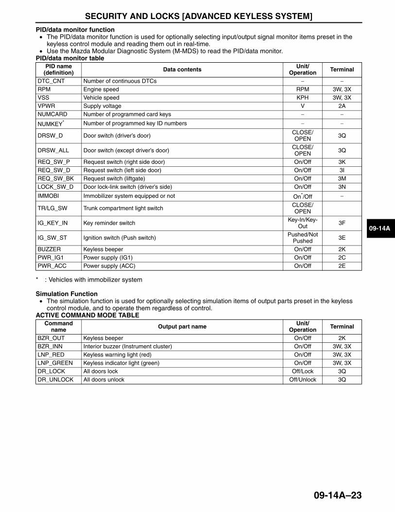
SECURITY AND LOCKS [ADVANCED KEYLESS SYSTEM]
09-14A–23
09-14A
PID/data monitor function• The PID/data monitor function is used for optionally selecting input/output signal monitor items preset in the
keyless control module and reading them out in real-time.• Use the Mazda Modular Diagnostic System (M-MDS) to read the PID/data monitor.
PID/data monitor table
* : Vehicles with immobilizer system
Simulation Function• The simulation function is used for optionally selecting simulation items of output parts preset in the keyless
control module, and to operate them regardless of control.ACTIVE COMMAND MODE TABLE
End Of SieNG: IMMOBILIZER SYSTEM
PID name (definition) Data contents Unit/
Operation Terminal
DTC_CNT Number of continuous DTCs − −RPM Engine speed RPM 3W, 3XVSS Vehicle speed KPH 3W, 3XVPWR Supply voltage V 2ANUMCARD Number of programmed card keys − −
NUMKEY* Number of programmed key ID numbers − −
DRSW_D Door switch (driver’s door) CLOSE/OPEN 3Q
DRSW_ALL Door switch (except driver’s door) CLOSE/OPEN 3Q
REQ_SW_P Request switch (right side door) On/Off 3KREQ_SW_D Request switch (left side door) On/Off 3IREQ_SW_BK Request switch (liftgate) On/Off 3MLOCK_SW_D Door lock-link switch (driver’s side) On/Off 3N
IMMOBI Immobilizer system equipped or not On*/Off −
TR/LG_SW Trunk compartment light switch CLOSE/OPEN
IG_KEY_IN Key reminder switch Key-In/Key-Out 3F
IG_SW_ST Ignition switch (Push switch) Pushed/Not Pushed 3E
BUZZER Keyless beeper On/Off 2KPWR_IG1 Power supply (IG1) On/Off 2CPWR_ACC Power supply (ACC) On/Off 2E
Command name Output part name Unit/
Operation Terminal
BZR_OUT Keyless beeper On/Off 2KBZR_INN Interior buzzer (Instrument cluster) On/Off 3W, 3XLNP_RED Keyless warning light (red) On/Off 3W, 3XLNP_GREEN Keyless indicator light (green) On/Off 3W, 3XDR_LOCK All doors lock Off/Lock 3QDR_UNLOCK All doors unlock Off/Unlock 3Q
3423-1U-06H(09-14A).fm 23 ページ 2006年11月21日 火曜日 午後5時39分
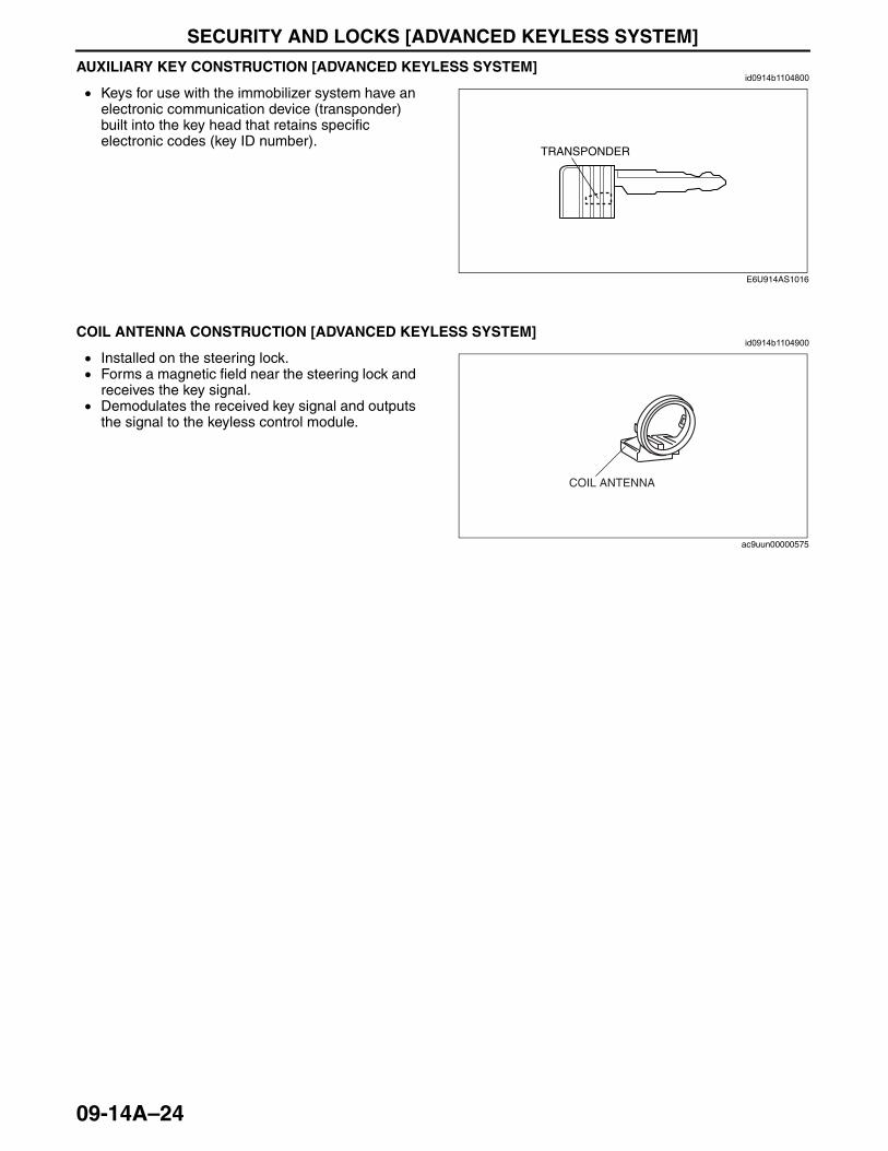
SECURITY AND LOCKS [ADVANCED KEYLESS SYSTEM]
09-14A–24
AUXILIARY KEY CONSTRUCTION [ADVANCED KEYLESS SYSTEM]id0914b1104800
• Keys for use with the immobilizer system have an electronic communication device (transponder) built into the key head that retains specific electronic codes (key ID number).
End Of Sie
COIL ANTENNA CONSTRUCTION [ADVANCED KEYLESS SYSTEM]id0914b1104900
• Installed on the steering lock.• Forms a magnetic field near the steering lock and
receives the key signal.• Demodulates the received key signal and outputs
the signal to the keyless control module.End Of Sie
TRANSPONDER
E6U914AS1016
COIL ANTENNA
ac9uun00000575
3423-1U-06H(09-14A).fm 24 ページ 2006年11月27日 月曜日 午前11時0分
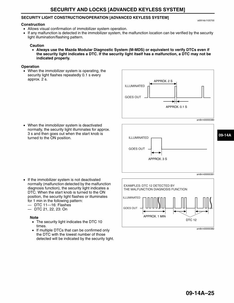
SECURITY AND LOCKS [ADVANCED KEYLESS SYSTEM]
09-14A–25
09-14A
SECURITY LIGHT CONSTRUCTION/OPERATION [ADVANCED KEYLESS SYSTEM]id0914b1105700
Construction• Allows visual confirmation of immobilizer system operation.• If any malfunction is detected in the immobilizer system, the malfunction location can be verified by the security
light illumination/flashing pattern.
Caution• Always use the Mazda Modular Diagnostic System (M-MDS) or equivalent to verify DTCs even if
the security light indicates a DTC. If the security light itself has a malfunction, a DTC may not be indicated properly.
Operation• When the immobilizer system is operating, the
security light flashes repeatedly 0.1 s every approx. 2 s.
• When the immobilizer system is deactivated normally, the security light illuminates for approx. 3 s and then goes out when the start knob is turned to the ON position.
• If the immobilizer system is not deactivated normally (malfunction detected by the malfunction diagnosis function), the security light indicates a DTC. When the start knob is turned to the ON position, the security light flashes or illuminates for 1 min in the following pattern:— DTC 11—16: Flashes— DTC 21, 22, 23: On
Note• The security light indicates the DTC 10
times.• If multiple DTCs that can be confirmed only
the DTC with the lowest number of those detected will be indicated by the security light.
End Of SieNG: KEYLESS ENTRY SYSTEM
ILLUMINATED
GOES OUT
APPROX. 2 S
APPROX. 0.1 S
am8rrn00000380
ILLUMINATED
GOES OUT
APPROX. 3 S
am8rrn00000381
EXAMPLES: DTC 12 DETECTED BY THE MALFUNCTION DIAGNOSIS FUNCTION
ILLUMINATED
GOES OUT
APPROX. 1 MINDTC 12
am8rrn00000382
3423-1U-06H(09-14A).fm 25 ページ 2006年11月21日 火曜日 午後5時39分
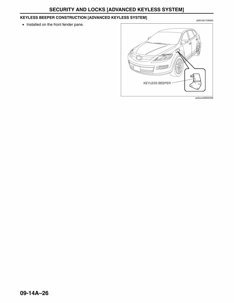
SECURITY AND LOCKS [ADVANCED KEYLESS SYSTEM]
09-14A–26
KEYLESS BEEPER CONSTRUCTION [ADVANCED KEYLESS SYSTEM]id0914b1109000
• Installed on the front fender pane.End Of Sie
KEYLESS BEEPER
ac9uun00000339
3423-1U-06H(09-14A).fm 26 ページ 2006年11月21日 火曜日 午後5時39分
SECURITY AND LOCKS [KEYLESS ENTRY SYSTEM]
09-14B–1
09-14B
09-14B SECURITY AND LOCKS [KEYLESS ENTRY SYSTEM]SECURITY AND LOCKS OUTLINE
[KEYLESS ENTRY SYSTEM] . . . . . . . . 09-14B–1Features . . . . . . . . . . . . . . . . . . . . . . . . 09-14B–1
SECURITY AND LOCKS STRUCTURAL VIEW [KEYLESS ENTRY SYSTEM] . . . . . . . . 09-14B–2
SECURITY AND LOCKS SYSTEM WIRING DIAGRAM [KEYLESS ENTRY SYSTEM] . . . . . . . . 09-14B–3
THEFT-DETERRENT SYSTEM OUTLINE [KEYLESS ENTRY SYSTEM] . . . . . . . . 09-14B–4
THEFT-DETERRENT SYSTEM STRUCTURAL VIEW [KEYLESS ENTRY SYSTEM] . . . . . . . . 09-14B–4
THEFT-DETERRENT SYSTEM WIRING DIAGRAM [KEYLESS ENTRY SYSTEM] . . . . . . . . 09-14B–5
THEFT-DETERRENT SYSTEM OPERATION [KEYLESS ENTRY SYSTEM] . . . . . . . . 09-14B–6
POWER DOOR LOCK SYSTEM OUTLINE [KEYLESS ENTRY SYSTEM] . . . . . . . . 09-14B–7
POWER DOOR LOCK SYSTEM OPERATION [KEYLESS ENTRY SYSTEM] . . . . . . . . 09-14B–7
POWER DOOR LOCK SYSTEM WIRING DIAGRAM [KEYLESS ENTRY SYSTEM] . . . . . . . . 09-14B–8
KEYLESS ENTRY SYSTEM OUTLINE [KEYLESS ENTRY SYSTEM] . . . . . . . . 09-14B–8
IMMOBILIZER SYSTEM OUTLINE [KEYLESS ENTRY SYSTEM] . . . . . . . . 09-14B–9
IMMOBILIZER SYSTEM STRUCTURAL VIEW [KEYLESS ENTRY SYSTEM] . . . . . . . . 09-14B–10
IMMOBILIZER SYSTEM WIRING DIAGRAM [KEYLESS ENTRY SYSTEM] . . . . . . . . 09-14B–10
ON-BOARD DIAGNOSTIC SYSTEM (IMMOBILIZER SYSTEM) PID/DATA MONITOR FUNCTION [KEYLESS ENTRY SYSTEM] . . . . . . . . 09-14B–11
PID/Data Monitor Table . . . . . . . . . . . . . 09-14B–11KEYLESS ENTRY SYSTEM
OPERATION [KEYLESS ENTRY SYSTEM] . . . . . . . . 09-14B–11
Lock/unlock . . . . . . . . . . . . . . . . . . . . . . 09-14B–11TRANSMITTER
(RETRACTABLE KEY TYPE) STRUCTURAL VIEW [KEYLESS ENTRY SYSTEM] . . . . . . . . 09-14B–12
IMMOBILIZER SYSTEM CONSTRUCTION/OPERATION [KEYLESS ENTRY SYSTEM] . . . . . . . . 09-14B–12
Immobilizer System Release Operation . . . . . . . . . . . . . . . 09-14B–13
Immobilizer System Setting. . . . . . . . . . 09-14B–14
End of TocNG: SECURITY AND LOCKSSECURITY AND LOCKS OUTLINE [KEYLESS ENTRY SYSTEM]
id0914b3100100
Features
End Of Sie
Improved marketability • Power door lock system adopted• Keyless entry system adopted
Improved theft-deterrence
• Theft-deterrent system adopted• Immobilizer system adopted
3423-1U-06H(09-14B).fm 1 ページ 2006年11月22日 水曜日 午後3時19分
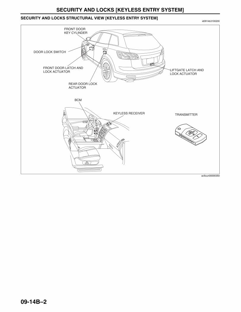
SECURITY AND LOCKS [KEYLESS ENTRY SYSTEM]
09-14B–2
SECURITY AND LOCKS STRUCTURAL VIEW [KEYLESS ENTRY SYSTEM]id0914b3100200
End Of Sie
LIFTGATE LATCH AND LOCK ACTUATOR
TRANSMITTER
REAR DOOR LOCK ACTUATOR
FRONT DOOR LATCH AND LOCK ACTUATOR
FRONT DOOR KEY CYLINDER
KEYLESS RECEIVER
BCM
DOOR LOCK SWITCH
ac9uun00000350
3423-1U-06H(09-14B).fm 2 ページ 2006年11月21日 火曜日 午後5時41分
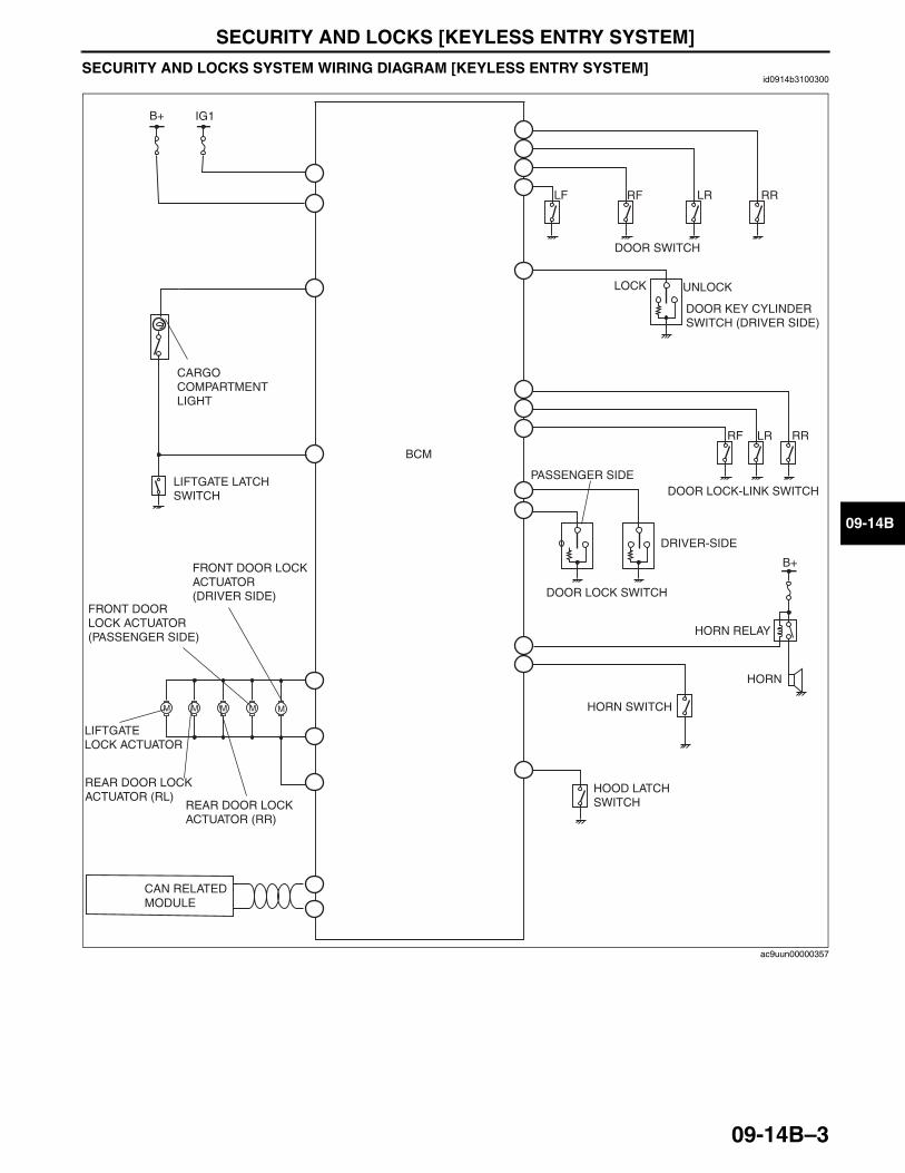
SECURITY AND LOCKS [KEYLESS ENTRY SYSTEM]
09-14B–3
09-14B
SECURITY AND LOCKS SYSTEM WIRING DIAGRAM [KEYLESS ENTRY SYSTEM]id0914b3100300
End Of SieNG: THEFT-DETERRENT SYSTEM
MM MM
LR RRLF RF
RRRF LR
DRIVER-SIDE
DOOR LOCK SWITCH
PASSENGER SIDE
DOOR SWITCH
DOOR LOCK-LINK SWITCH
HORN RELAY
HORN SWITCH
HORN
HOOD LATCH SWITCH
LOCK UNLOCK
DOOR KEY CYLINDER SWITCH (DRIVER SIDE)
B+
CAN RELATED MODULE
IG1B+
CARGO COMPARTMENT LIGHT
LIFTGATE LATCH SWITCH
LIFTGATELOCK ACTUATOR
REAR DOOR LOCK ACTUATOR (RL)
REAR DOOR LOCK ACTUATOR (RR)
FRONT DOORLOCK ACTUATOR (PASSENGER SIDE)
M
FRONT DOOR LOCK ACTUATOR(DRIVER SIDE)
BCM
ac9uun00000357
3423-1U-06H(09-14B).fm 3 ページ 2006年11月22日 水曜日 午後3時20分
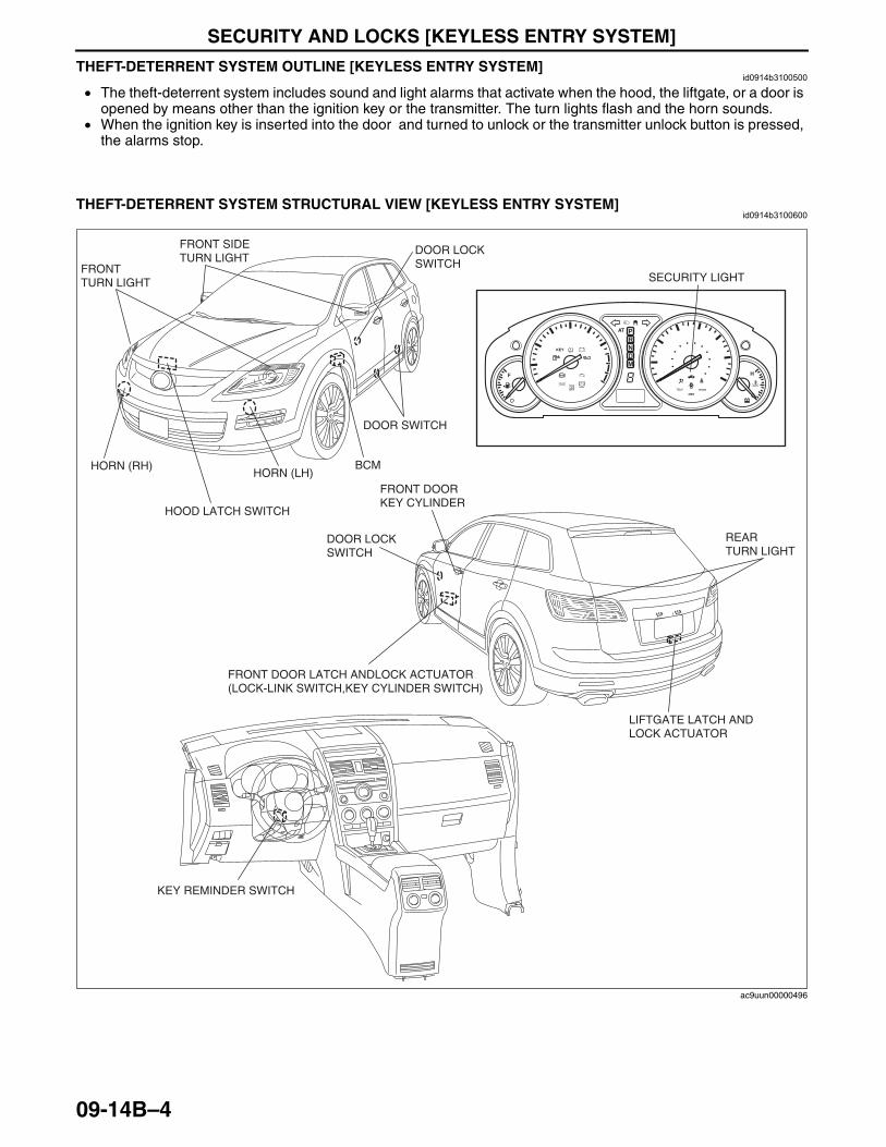
SECURITY AND LOCKS [KEYLESS ENTRY SYSTEM]
09-14B–4
THEFT-DETERRENT SYSTEM OUTLINE [KEYLESS ENTRY SYSTEM]id0914b3100500
• The theft-deterrent system includes sound and light alarms that activate when the hood, the liftgate, or a door is opened by means other than the ignition key or the transmitter. The turn lights flash and the horn sounds.
• When the ignition key is inserted into the door and turned to unlock or the transmitter unlock button is pressed, the alarms stop.
End Of Sie
THEFT-DETERRENT SYSTEM STRUCTURAL VIEW [KEYLESS ENTRY SYSTEM]id0914b3100600
End Of Sie
BRAKE
SECURITY LIGHT
FRONT DOOR LATCH ANDLOCK ACTUATOR(LOCK-LINK SWITCH,KEY CYLINDER SWITCH)
KEY REMINDER SWITCH
HOOD LATCH SWITCH
DOOR SWITCH
HORN (RH)HORN (LH)
FRONT TURN LIGHT
FRONT SIDE TURN LIGHT
LIFTGATE LATCH AND LOCK ACTUATOR
FRONT DOOR KEY CYLINDER
REAR TURN LIGHT
BCM
DOOR LOCK SWITCH
DOOR LOCK SWITCH
ac9uun00000496
3423-1U-06H(09-14B).fm 4 ページ 2006年11月22日 水曜日 午後3時20分
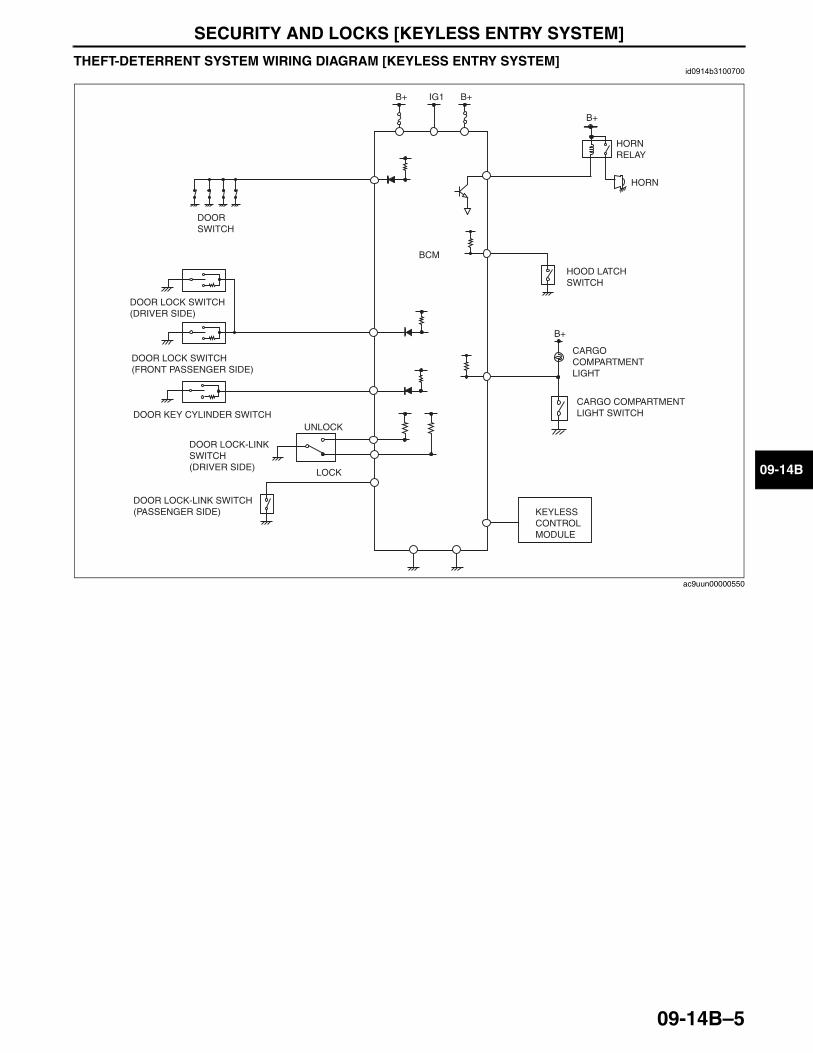
SECURITY AND LOCKS [KEYLESS ENTRY SYSTEM]
09-14B–5
09-14B
THEFT-DETERRENT SYSTEM WIRING DIAGRAM [KEYLESS ENTRY SYSTEM]id0914b3100700
End Of Sie
B+
B+IG1B+
LOCK
UNLOCK
KEYLESS CONTROL MODULE
BCM
DOOR LOCK-LINK SWITCH(DRIVER SIDE)
CARGO COMPARTMENT LIGHT SWITCH
HOOD LATCHSWITCH
DOOR LOCK SWITCH(DRIVER SIDE)
DOOR LOCK SWITCH(FRONT PASSENGER SIDE)
DOOR LOCK-LINK SWITCH(PASSENGER SIDE)
B+
HORNRELAY
HORN
DOOR KEY CYLINDER SWITCH
CARGO COMPARTMENT LIGHT
DOOR SWITCH
ac9uun00000550
3423-1U-06H(09-14B).fm 5 ページ 2006年11月21日 火曜日 午後5時41分
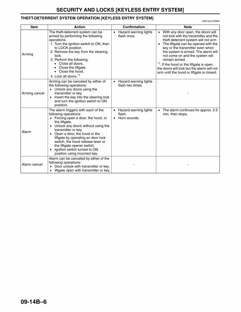
SECURITY AND LOCKS [KEYLESS ENTRY SYSTEM]
09-14B–6
THEFT-DETERRENT SYSTEM OPERATION [KEYLESS ENTRY SYSTEM]id0914b3100800
Item Action Confirmation Note
Arming
The theft-deterrent system can be armed by performing the following operations:1. Turn the ignition switch to ON, then
to LOCK position.2. Remove the key from the steering
lock.3. Perform the following:
• Close all doors.• Close the liftgate.• Close the hood.
4. Lock all doors.*1
• Hazard warning lights flash once.
• With any door open, the doors will not lock with the transmitter and the theft-deterrent system will not arm
• The liftgate can be opened with the key or the transmitter even when the system is armed. The alarm will not come on and the system will remain armed.
*1: If the hood or the liftgate is open, the doors will lock but the alarm will not arm until the hood or liftgate is closed.
Arming cancel
Arming can be canceled by either of the following operations:• Unlock any doors using the
transmitter or key.• Insert the key into the steering lock
and turn the ignition switch to ON position.
• Hazard warning lights flash two times.
-
Alarm
The alarm triggers with each of the following operations:• Forcing open a door, the hood, or
the liftgate.• Unlock any doors without using the
transmitter or key. • Open a door, the hood or the
liftgate by operating an door lock switch, the hood release lever or the liftgate opener switch.
• Ignition switch turned to ON position using incorrect key.
• Hazard warning lights flash.
• Horn sounds.
• The alarm continues for approx. 2.5 min, then stops.
Alarm cancel
Alarm can be canceled by either of the following operations:• Door unlock with transmitter or key.• liftgate open with transmitter or key.
- -
3423-1U-06H(09-14B).fm 6 ページ 2006年11月21日 火曜日 午後5時41分
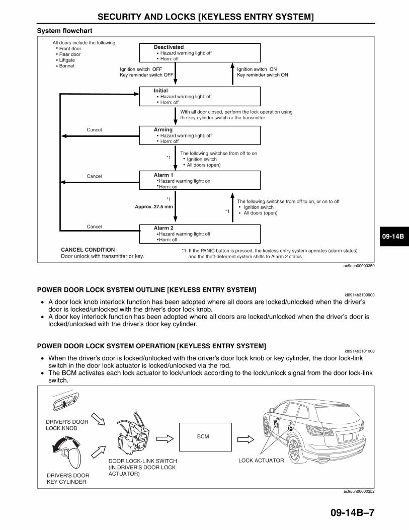
SECURITY AND LOCKS [KEYLESS ENTRY SYSTEM]
09-14B–7
09-14B
System flowchart
End Of SieNG: POWER DOOR LOCK SYSTEM
POWER DOOR LOCK SYSTEM OUTLINE [KEYLESS ENTRY SYSTEM]id0914b3100900
• A door lock knob interlock function has been adopted where all doors are locked/unlocked when the driver’s door is locked/unlocked with the driver’s door lock knob.
• A door key interlock function has been adopted where all doors are locked/unlocked when the driver’s door is locked/unlocked with the driver’s door key cylinder.
End Of Sie
POWER DOOR LOCK SYSTEM OPERATION [KEYLESS ENTRY SYSTEM]id0914b3101000
• When the driver’s door is locked/unlocked with the driver’s door lock knob or key cylinder, the door lock-link switch in the door lock actuator is locked/unlocked via the rod.
• The BCM activates each lock actuator to lock/unlock according to the lock/unlock signal from the door lock-link switch.
All doors include the following: Front door Rear door Liftgate Bonnet
Deactivated Hazard warning light: off Horn: off
Initial Hazard warning light: off Horn: off
Key reminder switch ONIgnition switch ON
Key reminder switch OFFIgnition switch OFF
With all door closed, perform the lock operation using the key cylinder switch or the transmitter
Arming Hazard warning light: off Horn: off
The following switchse from off to on Ignition switch All doors (open)
Alarm 1 Hazard warning light: on Horn: on
Approx. 27.5 min
Alarm 2 Hazard warning light: off Horn: off
The following switchse from off to on, or on to off Ignition switch All doors (open)
CANCEL CONDITIONDoor unlock with transmitter or key.
*1: If the PANIC button is pressed, the keyless entry system operates (alarm status) and the theft-deterrent system shifts to Alarm 2 status.
*1
*1
*1
Cancel
Cancel
Cancel
ac9uun00000359
DRIVER'S DOOR LOCK KNOB
DRIVER'S DOOR KEY CYLINDER
DOOR LOCK-LINK SWITCH (IN DRIVER'S DOOR LOCK ACTUATOR)
BCM
LOCK ACTUATOR
ac9uun00000352
3423-1U-06H(09-14B).fm 7 ページ 2006年11月21日 火曜日 午後5時41分
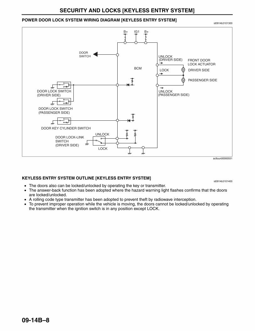
SECURITY AND LOCKS [KEYLESS ENTRY SYSTEM]
09-14B–8
End Of SiePOWER DOOR LOCK SYSTEM WIRING DIAGRAM [KEYLESS ENTRY SYSTEM]id0914b3101300
End Of Sie
KEYLESS ENTRY SYSTEM OUTLINE [KEYLESS ENTRY SYSTEM]id0914b3101400
• The doors also can be locked/unlocked by operating the key or transmitter.• The answer-back function has been adopted where the hazard warning light flashes confirms that the doors
are locked/unlocked.• A rolling code type transmitter has been adopted to prevent theft by radiowave interception.• To prevent improper operation while the vehicle is moving, the doors cannot be locked/unlocked by operating
the transmitter when the ignition switch is in any position except LOCK.End Of SieNG: IMMOBILIZER SYSTEM
M
M
B+IG1B+
LOCK
UNLOCK
BCM
DOOR LOCK-LINK SWITCH(DRIVER SIDE)
FRONT DOOR LOCK ACTUATOR
PASSENGER SIDE
DRIVER SIDE
DOOR LOCK SWITCH(DRIVER SIDE)
DOOR LOCK SWITCH(PASSENGER SIDE)
UNLOCK
UNLOCK
LOCK
(PASSENGER SIDE)
(DRIVER SIDE)
DOOR KEY CYLINDER SWITCH
DOOR SWITCH
ac9uun00000551
3423-1U-06H(09-14B).fm 8 ページ 2006年11月21日 火曜日 午後5時41分
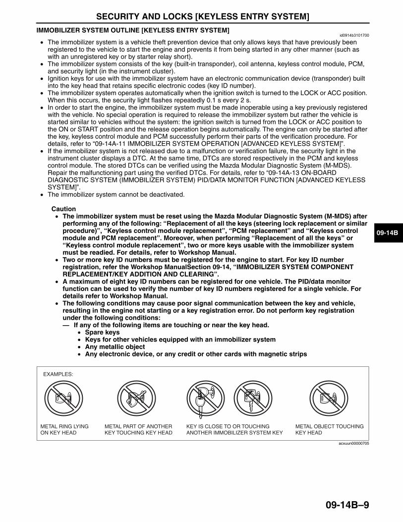
SECURITY AND LOCKS [KEYLESS ENTRY SYSTEM]
09-14B–9
09-14B
IMMOBILIZER SYSTEM OUTLINE [KEYLESS ENTRY SYSTEM]id0914b3101700
• The immobilizer system is a vehicle theft prevention device that only allows keys that have previously been registered to the vehicle to start the engine and prevents it from being started in any other manner (such as with an unregistered key or by starter relay short).
• The immobilizer system consists of the key (built-in transponder), coil antenna, keyless control module, PCM, and security light (in the instrument cluster).
• Ignition keys for use with the immobilizer system have an electronic communication device (transponder) built into the key head that retains specific electronic codes (key ID number).
• The immobilizer system operates automatically when the ignition switch is turned to the LOCK or ACC position. When this occurs, the security light flashes repeatedly 0.1 s every 2 s.
• In order to start the engine, the immobilizer system must be made inoperable using a key previously registered with the vehicle. No special operation is required to release the immobilizer system but rather the vehicle is started similar to vehicles without the system: the ignition switch is turned from the LOCK or ACC position to the ON or START position and the release operation begins automatically. The engine can only be started after the key, keyless control module and PCM successfully perform their parts of the verification procedure. For details, refer to “09-14A-11 IMMOBILIZER SYSTEM OPERATION [ADVANCED KEYLESS SYSTEM]”.
• If the immobilizer system is not released due to a malfunction or verification failure, the security light in the instrument cluster displays a DTC. At the same time, DTCs are stored respectively in the PCM and keyless control module. The stored DTCs can be verified using the Mazda Modular Diagnostic System (M-MDS). Repair the malfunctioning part using the verified DTCs. For details, refer to “09-14A-13 ON-BOARD DIAGNOSTIC SYSTEM (IMMOBILIZER SYSTEM) PID/DATA MONITOR FUNCTION [ADVANCED KEYLESS SYSTEM]”.
• The immobilizer system cannot be deactivated.
Caution• The immobilizer system must be reset using the Mazda Modular Diagnostic System (M-MDS) after
performing any of the following: “Replacement of all the keys (steering lock replacement or similar procedure)”, “Keyless control module replacement”, “PCM replacement” and “Keyless control module and PCM replacement”. Moreover, when performing “Replacement of all the keys” or “Keyless control module replacement”, two or more keys usable with the immobilizer system must be readied. For details, refer to Workshop Manual.
• Two or more key ID numbers must be registered for the engine to start. For key ID number registration, refer the Workshop ManualSection 09-14, “IMMOBILIZER SYSTEM COMPONENT REPLACEMENT/KEY ADDITION AND CLEARING”.
• A maximum of eight key ID numbers can be registered for one vehicle. The PID/data monitor function can be used to verify the number of key ID numbers registered for a single vehicle. For details refer to Workshop Manual.
• The following conditions may cause poor signal communication between the key and vehicle, resulting in the engine not starting or a key registration error. Do not perform key registration under the following conditions: — If any of the following items are touching or near the key head.
• Spare keys• Keys for other vehicles equipped with an immobilizer system• Any metallic object• Any electronic device, or any credit or other cards with magnetic strips
End Of Sie
METAL RING LYINGON KEY HEAD
METAL PART OF ANOTHER KEY TOUCHING KEY HEAD
KEY IS CLOSE TO OR TOUCHING ANOTHER IMMOBILIZER SYSTEM KEY
METAL OBJECT TOUCHING KEY HEAD
EXAMPLES:
acxuun00000705
3423-1U-06H(09-14B).fm 9 ページ 2006年11月21日 火曜日 午後5時41分
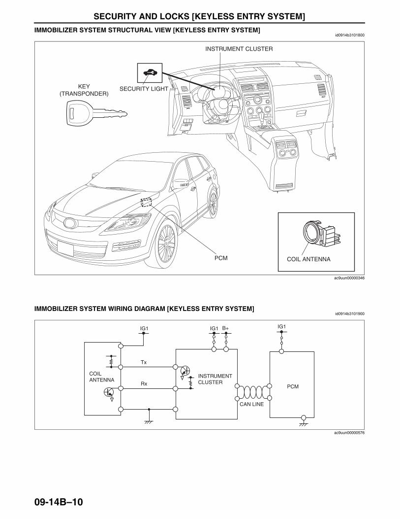
SECURITY AND LOCKS [KEYLESS ENTRY SYSTEM]
09-14B–10
IMMOBILIZER SYSTEM STRUCTURAL VIEW [KEYLESS ENTRY SYSTEM]id0914b3101800
End Of Sie
IMMOBILIZER SYSTEM WIRING DIAGRAM [KEYLESS ENTRY SYSTEM]id0914b3101900
End Of Sie
INSTRUMENT CLUSTER
SECURITY LIGHTKEY(TRANSPONDER)
COIL ANTENNAPCM
ac9uun00000346
PCM
IG1IG1IG1 B+
COIL ANTENNA
Tx
Rx
INSTRUMENT CLUSTER
CAN LINE
ac9uun00000576
3423-1U-06H(09-14B).fm 10 ページ 2006年11月21日 火曜日 午後5時41分
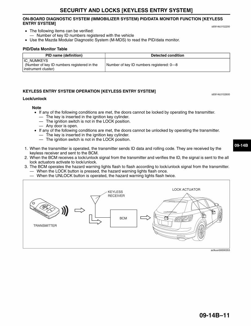
SECURITY AND LOCKS [KEYLESS ENTRY SYSTEM]
09-14B–11
09-14B
ON-BOARD DIAGNOSTIC SYSTEM (IMMOBILIZER SYSTEM) PID/DATA MONITOR FUNCTION [KEYLESS ENTRY SYSTEM]
id0914b3102200
• The following items can be verified: — Number of key ID numbers registered with the vehicle
• Use the Mazda Modular Diagnostic System (M-MDS) to read the PID/data monitor.
PID/Data Monitor Table
End Of SieNG: KEYLESS ENTRY SYSTEM
KEYLESS ENTRY SYSTEM OPERATION [KEYLESS ENTRY SYSTEM]id0914b3102600
Lock/unlock
Note• If any of the following conditions are met, the doors cannot be locked by operating the transmitter.— The key is inserted in the ignition key cylinder.— The ignition switch is not in the LOCK position.— Any door is open.
• If any of the following conditions are met, the doors cannot be unlocked by operating the transmitter.— The key is inserted in the ignition key cylinder.— The ignition switch is not in the LOCK position.
1. When the transmitter is operated, the transmitter sends ID data and rolling code. They are received by the keyless receiver and sent to the BCM.
2. When the BCM receives a lock/unlock signal from the transmitter and verifies the ID, the signal is sent to the all lock actuators activate to lock/unlock.
3. The BCM operates the hazard warning lights flash to flash according to lock/unlock signal from the transmitter.— When the LOCK button is pressed, the hazard warning lights flash once.— When the UNLOCK button is operated, the hazard warning lights flash twice.
End Of SieNG: POWER DOOR LOCK SYSTEM
PID name (definition) Detected conditionIC_NUMKEYS (Number of key ID numbers registered in the instrument cluster)
Number of key ID numbers registered: 0—8
KEYLESS RECEIVER
BCM
TRANSMITTER
LOCK ACTUATOR
ac9uun00000353
3423-1U-06H(09-14B).fm 11 ページ 2006年11月21日 火曜日 午後5時41分
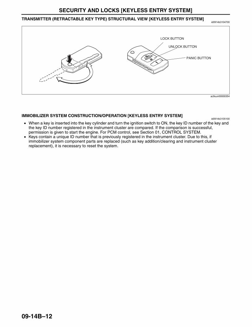
SECURITY AND LOCKS [KEYLESS ENTRY SYSTEM]
09-14B–12
TRANSMITTER (RETRACTABLE KEY TYPE) STRUCTURAL VIEW [KEYLESS ENTRY SYSTEM]id0914b3104700
End Of SieNG: IMMOBILIZER SYSTEM
IMMOBILIZER SYSTEM CONSTRUCTION/OPERATION [KEYLESS ENTRY SYSTEM]id0914b3105100
• When a key is inserted into the key cylinder and turn the ignition switch to ON, the key ID number of the key and the key ID number registered in the instrument cluster are compared. If the comparison is successful, permission is given to start the engine. For PCM control, see Section 01, CONTROL SYSTEM.
• Keys contain a unique ID number that is previously registered in the instrument cluster. Due to this, if immobilizer system component parts are replaced (such as key addition/clearing and instrument cluster replacement), it is necessary to reset the system.
LOCK BUTTON
UNLOCK BUTTON
PANIC BUTTON
ac9uun00000354
3423-1U-06H(09-14B).fm 12 ページ 2006年11月21日 火曜日 午後5時41分
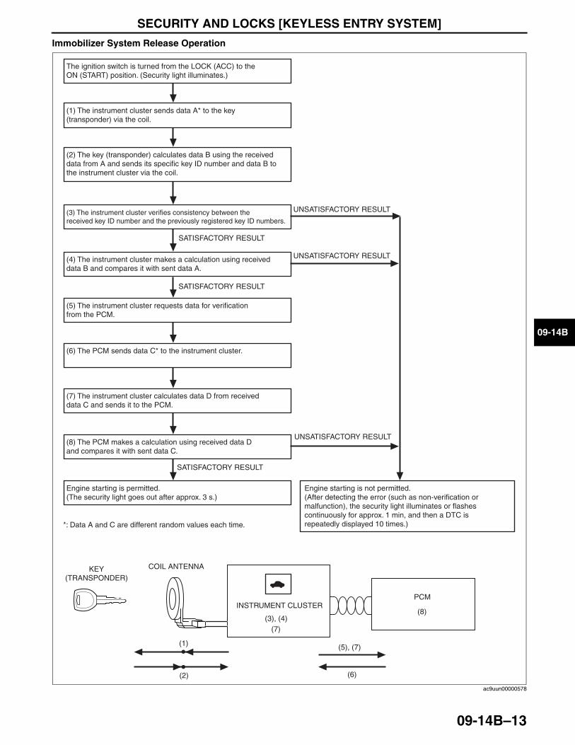
SECURITY AND LOCKS [KEYLESS ENTRY SYSTEM]
09-14B–13
09-14B
Immobilizer System Release Operation
The ignition switch is turned from the LOCK (ACC) to the ON (START) position. (Security light illuminates.)
(1) The instrument cluster sends data A* to the key (transponder) via the coil.
(3) The instrument cluster verifies consistency between the received key ID number and the previously registered key ID numbers.
(4) The instrument cluster makes a calculation using received data B and compares it with sent data A.
(5) The instrument cluster requests data for verification from the PCM.
(6) The PCM sends data C* to the instrument cluster.
(7) The instrument cluster calculates data D from received data C and sends it to the PCM.
(8) The PCM makes a calculation using received data D and compares it with sent data C.
Engine starting is permitted. (The security light goes out after approx. 3 s.)
Engine starting is not permitted. (After detecting the error (such as non-verification or malfunction), the security light illuminates or flashes continuously for approx. 1 min, and then a DTC is repeatedly displayed 10 times.)
(2) The key (transponder) calculates data B using the received data from A and sends its specific key ID number and data B to the instrument cluster via the coil.
*: Data A and C are different random values each time.
UNSATISFACTORY RESULT
UNSATISFACTORY RESULT
UNSATISFACTORY RESULT
SATISFACTORY RESULT
SATISFACTORY RESULT
SATISFACTORY RESULT
(5), (7)
(6)(2)
(1)
(3), (4)(8)
(7)
KEY(TRANSPONDER)
COIL ANTENNA
PCMINSTRUMENT CLUSTER
ac9uun00000578
3423-1U-06H(09-14B).fm 13 ページ 2006年11月21日 火曜日 午後5時41分
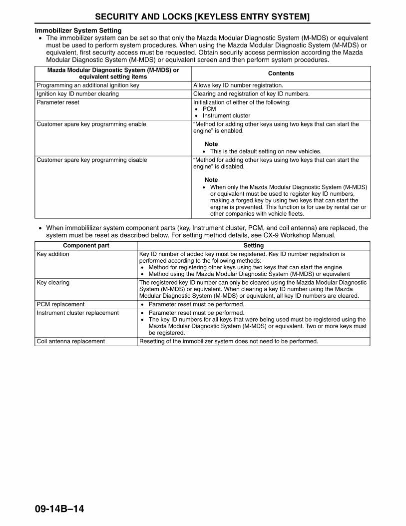
SECURITY AND LOCKS [KEYLESS ENTRY SYSTEM]
09-14B–14
Immobilizer System Setting• The immobilizer system can be set so that only the Mazda Modular Diagnostic System (M-MDS) or equivalent
must be used to perform system procedures. When using the Mazda Modular Diagnostic System (M-MDS) or equivalent, first security access must be requested. Obtain security access permission according the Mazda Modular Diagnostic System (M-MDS) or equivalent screen and then perform system procedures.
• When immobililizer system component parts (key, Instrument cluster, PCM, and coil antenna) are replaced, the system must be reset as described below. For setting method details, see CX-9 Workshop Manual.
End Of Sie
Mazda Modular Diagnostic System (M-MDS) or equivalent setting items Contents
Programming an additional ignition key Allows key ID number registration.Ignition key ID number clearing Clearing and registration of key ID numbers.Parameter reset Initialization of either of the following:
• PCM• Instrument cluster
Customer spare key programming enable “Method for adding other keys using two keys that can start the engine” is enabled.
Note• This is the default setting on new vehicles.
Customer spare key programming disable “Method for adding other keys using two keys that can start the engine” is disabled.
Note• When only the Mazda Modular Diagnostic System (M-MDS)
or equivalent must be used to register key ID numbers, making a forged key by using two keys that can start the engine is prevented. This function is for use by rental car or other companies with vehicle fleets.
Component part SettingKey addition Key ID number of added key must be registered. Key ID number registration is
performed according to the following methods:• Method for registering other keys using two keys that can start the engine• Method using the Mazda Modular Diagnostic System (M-MDS) or equivalent
Key clearing The registered key ID number can only be cleared using the Mazda Modular Diagnostic System (M-MDS) or equivalent. When clearing a key ID number using the Mazda Modular Diagnostic System (M-MDS) or equivalent, all key ID numbers are cleared.
PCM replacement • Parameter reset must be performed.Instrument cluster replacement • Parameter reset must be performed.
• The key ID numbers for all keys that were being used must be registered using the Mazda Modular Diagnostic System (M-MDS) or equivalent. Two or more keys must be registered.
Coil antenna replacement Resetting of the immobilizer system does not need to be performed.
3423-1U-06H(09-14B).fm 14 ページ 2006年11月21日 火曜日 午後5時41分
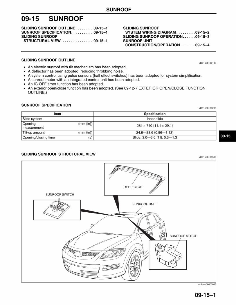
SUNROOF
09-15–1
09-15
09-15 SUNROOFSLIDING SUNROOF OUTLINE. . . . . . . . 09-15–1SUNROOF SPECIFICATION. . . . . . . . . . 09-15–1SLIDING SUNROOF
STRUCTURAL VIEW . . . . . . . . . . . . . . 09-15–1
SLIDING SUNROOF SYSTEM WIRING DIAGRAM . . . . . . . . . 09-15–2
SLIDING SUNROOF OPERATION. . . . . . 09-15–3SUNROOF UNIT
CONSTRUCTION/OPERATION . . . . . . . 09-15–4
End of TocNG: SUNROOFSLIDING SUNROOF OUTLINE
id091500100100
• An electric sunroof with tilt mechanism has been adopted.• A deflector has been adopted, reducing throbbing noise.• A system control using pulse sensors (hall effect switches) has been adopted for system simplification.• A sunroof motor with an integrated control unit has been adopted.• An IG OFF timer function has been adopted.• An exterior open/close function has been adopted. (See 09-12-7 EXTERIOR OPEN/CLOSE FUNCTION
OUTLINE.)End Of Sie
SUNROOF SPECIFICATIONid091500100200
End Of Sie
SLIDING SUNROOF STRUCTURAL VIEWid091500100300
Item SpecificationSlide system Inner slideOpening measurement
(mm {in}) 281 × 740 {11.1 × 29.1}
Tilt-up amount (mm {in}) 24.6—28.6 {0.96—1.12}Opening/closing time (s) Slide: 3.0—6.0, Tilt: 0.3—1.3
SUNROOF MOTOR
DEFLECTOR
SUNROOF SWITCH
SUNROOF UNIT
ac9uun00000065
3423-1U-06H(09-15).fm 1 ページ 2006年11月21日 火曜日 午後5時42分
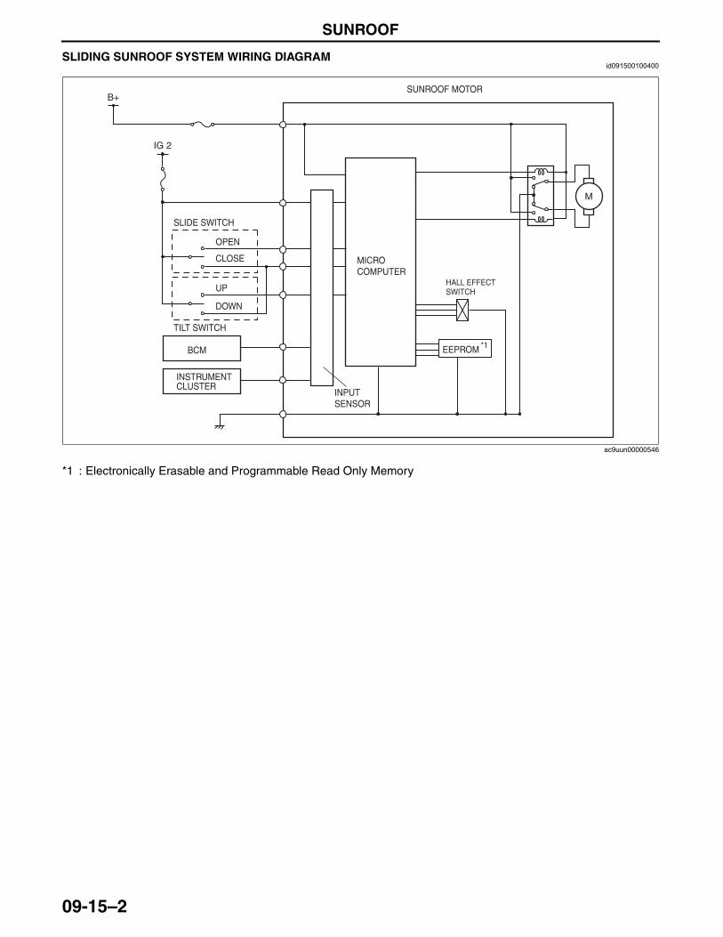
SUNROOF
09-15–2
End Of SieSLIDING SUNROOF SYSTEM WIRING DIAGRAMid091500100400
*1 : Electronically Erasable and Programmable Read Only Memory
End Of Sie
M
IG 2
B+SUNROOF MOTOR
SLIDE SWITCH
OPEN
CLOSE
UP
DOWN
INPUT SENSOR
MICRO COMPUTER
HALL EFFECT SWITCH
TILT SWITCH
BCM
INSTRUMENT CLUSTER
EEPROM *1
ac9uun00000546
3423-1U-06H(09-15).fm 2 ページ 2006年11月21日 火曜日 午後5時42分
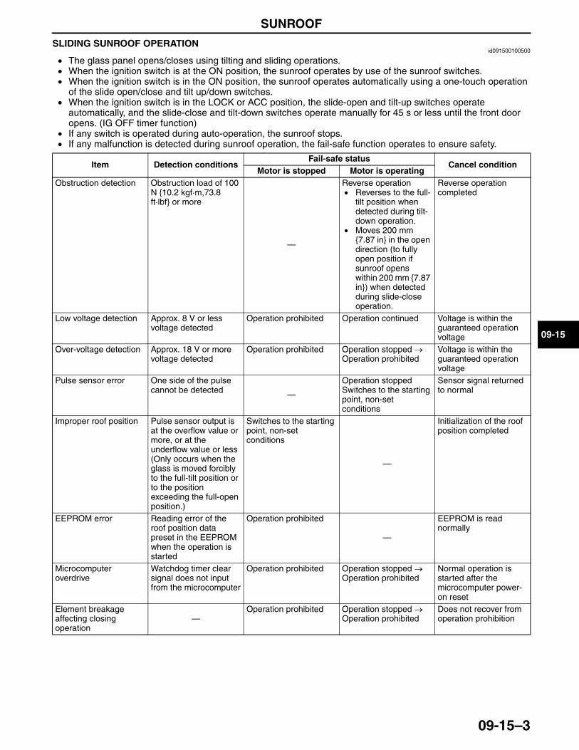
SUNROOF
09-15–3
09-15
SLIDING SUNROOF OPERATIONid091500100500
• The glass panel opens/closes using tilting and sliding operations.• When the ignition switch is at the ON position, the sunroof operates by use of the sunroof switches.• When the ignition switch is in the ON position, the sunroof operates automatically using a one-touch operation
of the slide open/close and tilt up/down switches.• When the ignition switch is in the LOCK or ACC position, the slide-open and tilt-up switches operate
automatically, and the slide-close and tilt-down switches operate manually for 45 s or less until the front door opens. (IG OFF timer function)
• If any switch is operated during auto-operation, the sunroof stops.• If any malfunction is detected during sunroof operation, the fail-safe function operates to ensure safety.
End Of SieNG: SUNROOF UNIT
Item Detection conditionsFail-safe status
Cancel conditionMotor is stopped Motor is operating
Obstruction detection Obstruction load of 100 N {10.2 kgf·m,73.8 ft·lbf} or more
—
Reverse operation• Reverses to the full-
tilt position when detected during tilt-down operation.
• Moves 200 mm {7.87 in} in the open direction (to fully open position if sunroof opens within 200 mm {7.87 in}) when detected during slide-close operation.
Reverse operation completed
Low voltage detection Approx. 8 V or less voltage detected
Operation prohibited Operation continued Voltage is within the guaranteed operation voltage
Over-voltage detection Approx. 18 V or more voltage detected
Operation prohibited Operation stopped → Operation prohibited
Voltage is within the guaranteed operation voltage
Pulse sensor error One side of the pulse cannot be detected —
Operation stopped Switches to the starting point, non-set conditions
Sensor signal returned to normal
Improper roof position Pulse sensor output is at the overflow value or more, or at the underflow value or less (Only occurs when the glass is moved forcibly to the full-tilt position or to the position exceeding the full-open position.)
Switches to the starting point, non-set conditions
—
Initialization of the roof position completed
EEPROM error Reading error of the roof position data preset in the EEPROM when the operation is started
Operation prohibited
—
EEPROM is read normally
Microcomputer overdrive
Watchdog timer clear signal does not input from the microcomputer
Operation prohibited Operation stopped → Operation prohibited
Normal operation is started after the microcomputer power-on reset
Element breakage affecting closing operation
—Operation prohibited Operation stopped →
Operation prohibitedDoes not recover from operation prohibition
3423-1U-06H(09-15).fm 3 ページ 2006年11月21日 火曜日 午後5時42分
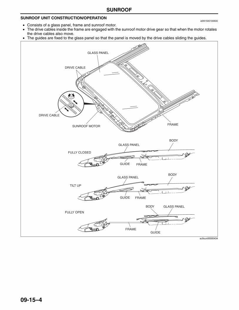
SUNROOF
09-15–4
SUNROOF UNIT CONSTRUCTION/OPERATIONid091500100600
• Consists of a glass panel, frame and sunroof motor.• The drive cables inside the frame are engaged with the sunroof motor drive gear so that when the motor rotates
the drive cables also move.• The guides are fixed to the glass panel so that the panel is moved by the drive cables sliding the guides.
End Of Sie
GLASS PANEL
DRIVE CABLE
SUNROOF MOTOR FRAME
DRIVE CABLE
GLASS PANELBODY
BODY
BODY
GLASS PANEL
GLASS PANEL
FULLY OPEN
TILT UP
FULLY CLOSED
GUIDE
GUIDE
GUIDE FRAME
FRAME
FRAME
ac9uun00000434
3423-1U-06H(09-15).fm 4 ページ 2006年11月21日 火曜日 午後5時42分
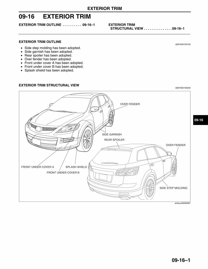
EXTERIOR TRIM
09-16–1
09-16
09-16 EXTERIOR TRIMEXTERIOR TRIM OUTLINE . . . . . . . . . . 09-16–1 EXTERIOR TRIM
STRUCTURAL VIEW . . . . . . . . . . . . . . . 09-16–1
End of TocNG: EXTERIOR TRIMEXTERIOR TRIM OUTLINE
id091600100100
• Side step molding has been adopted.• Side garnish has been adopted.• Rear spoiler has been adopted.• Over fender has been adopted.• Front under cover A has been adopted.• Front under cover B has been adopted.• Splash shield has been adopted.
End Of Sie
EXTERIOR TRIM STRUCTURAL VIEWid091600100200
End Of Sie
SIDE GARNISH
SIDE STEP MOLDING
REAR SPOILER
OVER FENDER
OVER FENDER
FRONT UNDER COVER A SPLASH SHIELD
FRONT UNDER COVER B
ac9uun00000067
3423-1U-06H(09-16).fm 1 ページ 2006年11月21日 火曜日 午後5時43分

INTERIOR TRIM
09-17–1
09-17
09-17 INTERIOR TRIMINTERIOR TRIM OUTLINE . . . . . . . . . . . 09-17–1 INTERIOR TRIM
STRUCTURAL VIEW . . . . . . . . . . . . . . . 09-17–2
End of TocNG: INTERIOR TRIMINTERIOR TRIM OUTLINE
id091700100100
• The center panel with front climate control units, is located at the center of the dashboard. This improves functionality and gives a unified appearance.
• A console cover integrated with rear climate control units and ventilator grilles has been adopted.• Various storage spaces have been added.
End Of Sie
3423-1U-06H(09-17).fm 1 ページ 2006年11月21日 火曜日 午後5時43分
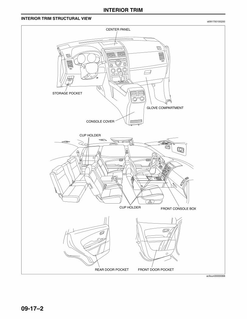
INTERIOR TRIM
09-17–2
INTERIOR TRIM STRUCTURAL VIEWid091700100200
End Of Sie
CENTER PANEL
GLOVE COMPARTMENT
CUP HOLDER
CUP HOLDER
STORAGE POCKET
FRONT CONSOLE BOX
CONSOLE COVER
FRONT DOOR POCKETREAR DOOR POCKET
ac9uun00000068
3423-1U-06H(09-17).fm 2 ページ 2006年11月21日 火曜日 午後5時43分
LIGHTING SYSTEMS
09-18–1
09-18
09-18 LIGHTING SYSTEMSLIGHTING SYSTEMS OUTLINE. . . . . . . 09-18–2LIGHTING SYSTEMS
SPECIFICATION . . . . . . . . . . . . . . . . . . 09-18–2LIGHTING SYSTEMS
STRUCTURAL VIEW . . . . . . . . . . . . . . 09-18–3FRONT COMBINATION LIGHT
CONSTRUCTION . . . . . . . . . . . . . . . . . 09-18–4Projector-type Headlight . . . . . . . . . . . 09-18–4
DISCHARGE HEADLIGHT OUTLINE . . . . . . . . . . . . . . . . . . . . . . . . 09-18–4
DISCHARGE HEADLIGHT STRUCTURAL VIEW . . . . . . . . . . . . . . 09-18–5
DISCHARGE HEADLIGHT OPERATION . . . . . . . . . . . . . . . . . . . . . 09-18–5
DISCHARGE HEADLIGHT CONTROL MODULE FUNCTION . . . . . 09-18–5
Abnormal Input Detection Function . . . . . . . . . . . . . . . 09-18–5
Abnormal Output Detection Function . . . . . . . . . . . . . . . 09-18–5
DISCHARGE HEADLIGHT CONTROL MODULE CONSTRUCTION/OPERATION . . . . . . 09-18–6
FRONT FOG LIGHT CONSTRUCTION . . . . . . . . . . . . . . . . . 09-18–6
AUTO LIGHT SYSTEM OUTLINE. . . . . . 09-18–7AUTO LIGHT SYSTEM
STRUCTURAL VIEW . . . . . . . . . . . . . . 09-18–7AUTO LIGHT SYSTEM
WIRING DIAGRAM . . . . . . . . . . . . . . . . 09-18–8AUTO LIGHT SYSTEM
OPERATION . . . . . . . . . . . . . . . . . . . . . 09-18–10Operation . . . . . . . . . . . . . . . . . . . . . . . 09-18–10Illumination operation . . . . . . . . . . . . . . 09-18–11Lights off operation . . . . . . . . . . . . . . . 09-18–12Fail-Safe Function . . . . . . . . . . . . . . . . 09-18–12
AUTO LIGHT SENSOR FUNCTION . . . . . . . . . . . . . . . . . . . . . . 09-18–13
AUTO LIGHT SENSOR OPERATION . . . . . . . . . . . . . . . . . . . . . 09-18–13
Function Description . . . . . . . . . . . . . . 09-18–13AUTO LIGHT-OFF SYSTEM
OUTLINE . . . . . . . . . . . . . . . . . . . . . . . . 09-18–14AUTO LIGHT-OFF SYSTEM
OPERATION . . . . . . . . . . . . . . . . . . . . . 09-18–14Operation . . . . . . . . . . . . . . . . . . . . . . . 09-18–14
Timing Chart . . . . . . . . . . . . . . . . . . . . . 09-18–14AUTO LIGHT-OFF SYSTEM
WIRING DIAGRAM. . . . . . . . . . . . . . . . . 09-18–15Auto Light/wiper Control Module . . . . . . 09-18–15Auto Light-off Control Module . . . . . . . . 09-18–17
HEADLIGHT LEVELING SYSTEM OUTLINE . . . . . . . . . . . . . . . . . . . . . . . . 09-18–18
HEADLIGHT LEVELING SYSTEM STRUCTURAL VIEW . . . . . . . . . . . . . . . 09-18–18
HEADLIGHT LEVELING SYSTEM DIAGRAM . . . . . . . . . . . . . . . . . . . . . . . . 09-18–18
HEADLIGHT LEVELING SYSTEM OPERATION . . . . . . . . . . . . . . . . . . . . . . 09-18–19
DRL (DAYTIME RUNNING LIGHT) SYSTEM OUTLINE. . . . . . . . . . . . . . . . . 09-18–19
DRL (DAYTIME RUNNING LIGHT) SYSTEM WIRING DIAGRAM . . . . . . . . . 09-18–20
DRL (DAYTIME RUNNING LIGHT) SYSTEM OPERATION . . . . . . . . . . . . . . 09-18–21
Operation Condition . . . . . . . . . . . . . . . 09-18–21Illumination Operation . . . . . . . . . . . . . . 09-18–21
FRONT SIDE TURN LIGHT CONSTRUCTION . . . . . . . . . . . . . . . . . . 09-18–22
REAR COMBINATION LIGHT CONSTRUCTION . . . . . . . . . . . . . . . . . . 09-18–22
INBOARD LIGHT CONSTRUCTION . . . . 09-18–23HIGH-MOUNT BRAKE LIGHT
CONSTRUCTION . . . . . . . . . . . . . . . . . . 09-18–23LICENSE PLATE LIGHT
CONSTRUCTION . . . . . . . . . . . . . . . . . . 09-18–23INTERIOR LIGHTING SYSTEM
CONSTRUCTION . . . . . . . . . . . . . . . . . . 09-18–24ROOM LIGHT CONTROL SYSTEM
FUNCTION . . . . . . . . . . . . . . . . . . . . . . . 09-18–25ROOM LIGHT CONTROL SYSTEM
OPERATION . . . . . . . . . . . . . . . . . . . . . . 09-18–26IGNITION KEY ILLUMINATION
FUNCTION . . . . . . . . . . . . . . . . . . . . . . . 09-18–27IGNITION KEY ILLUMINATION
OPERATION . . . . . . . . . . . . . . . . . . . . . . 09-18–28Illumination Condition . . . . . . . . . . . . . . 09-18–28Cancel Condition . . . . . . . . . . . . . . . . . . 09-18–28
INDIRECT ILLUMINATION OUTLINE . . . . . . . . . . . . . . . . . . . . . . . . 09-18–28
INDIRECT ILLUMINATION STRUCTURAL VIEW . . . . . . . . . . . . . . . 09-18–28
End of TocNG: LIGHTING SYSTEMS
3423-1U-06H(09-18).fm 1 ページ 2006年11月22日 水曜日 午後3時28分
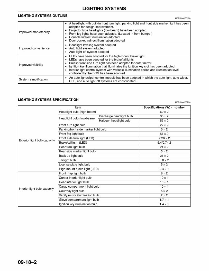
LIGHTING SYSTEMS
09-18–2
LIGHTING SYSTEMS OUTLINEid091800100100
End Of Sie
LIGHTING SYSTEMS SPECIFICATIONid091800100200
End Of Sie
Improved marketability
• A headlight with built-in front turn light, parking light and front side marker light has been adopted for design improvement.
• Projector type headlights (low-beam) have been adopted.• Front fog lights have been adopted. (Located in front bumper)• Console Indirect illumination adopted• Door pocket Indirect illumination adopted
Improved convenience• Headlight leveling system adopted• Auto light system adopted• Auto light-off system adopted
Improved visibility
• LEDs have been adopted for the high-mount brake light.• LEDs have been adopted for the brake/taillights.• Built-in front side turn light has been adopted for outer mirror.• Ignition key illumination that illuminates the ignition key slot has been adopted.• Interior light control system with variable illumination period and illumination level
controlled by the BCM has been adopted.
System simplification • An auto light/wiper control module has been adopted in which the auto light, auto wiper, DRL, and auto light-off systems are consolidated.
Item Specifications (W) × number
Exterior light bulb capacity
Headlight bulb (high-beam) 60 × 2
Headlight bulb (low-beam)Discharge headlight bulb 35 × 2Halogen headlight bulb 55 × 2
Front turn light bulb 27 × 2Parking/front side marker light bulb 5 × 2Front fog light bulb 51 × 2Front side turn light (LED) 2.26 × 2Brake/taillight (LED) 5.4/0.7× 2Rear turn light bulb 21 × 2Rear side marker light bulb 5 × 2Back-up light bulb 21 × 2Taillight bulb 3.8 × 2License plate light bulb 5 × 2High-mount brake light (LED) 2.4 × 1
Interior light bulb capacity
Front map light bulb 8 × 2Center interior light bulb 10 × 1Rear interior light bulb 10 × 1Cargo compartment light bulb 10 × 1Courtesy light bulb 5 × 2Vanity mirror illumination bulb 2 × 2Glove compartment light bulb 1.7 × 1Ignition key illumination bulb 1.4 × 1
3423-1U-06H(09-18).fm 2 ページ 2006年11月29日 水曜日 午前11時1分
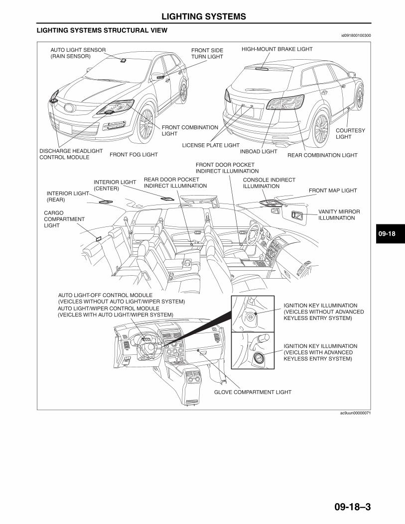
LIGHTING SYSTEMS
09-18–3
09-18
LIGHTING SYSTEMS STRUCTURAL VIEWid091800100300
End Of SieNG: FRONT COMBINATION LIGHT
DISCHARGE HEADLIGHT CONTROL MODULE FRONT FOG LIGHT
FRONT COMBINATION LIGHT
FRONT SIDE TURN LIGHT
HIGH-MOUNT BRAKE LIGHT
LICENSE PLATE LIGHTINBOAD LIGHT
REAR COMBINATION LIGHT
COURTESY LIGHT
VANITY MIRROR ILLUMINATION
FRONT MAP LIGHT
CONSOLE INDIRECT ILLUMINATION
FRONT DOOR POCKET INDIRECT ILLUMINATION
REAR DOOR POCKET INDIRECT ILLUMINATION
INTERIOR LIGHT (CENTER)
INTERIOR LIGHT (REAR)
CARGO COMPARTMENT LIGHT
AUTO LIGHT/WIPER CONTROL MODULE (VEICLES WITH AUTO LIGHT/WIPER SYSTEM)
AUTO LIGHT-OFF CONTROL MODULE (VEICLES WITHOUT AUTO LIGHT/WIPER SYSTEM)
GLOVE COMPARTMENT LIGHT
IGNITION KEY ILLUMINATION (VEICLES WITH ADVANCED KEYLESS ENTRY SYSTEM)
IGNITION KEY ILLUMINATION (VEICLES WITHOUT ADVANCED KEYLESS ENTRY SYSTEM)
AUTO LIGHT SENSOR (RAIN SENSOR)
ac9uun00000071
3423-1U-06H(09-18).fm 3 ページ 2006年11月21日 火曜日 午後5時44分
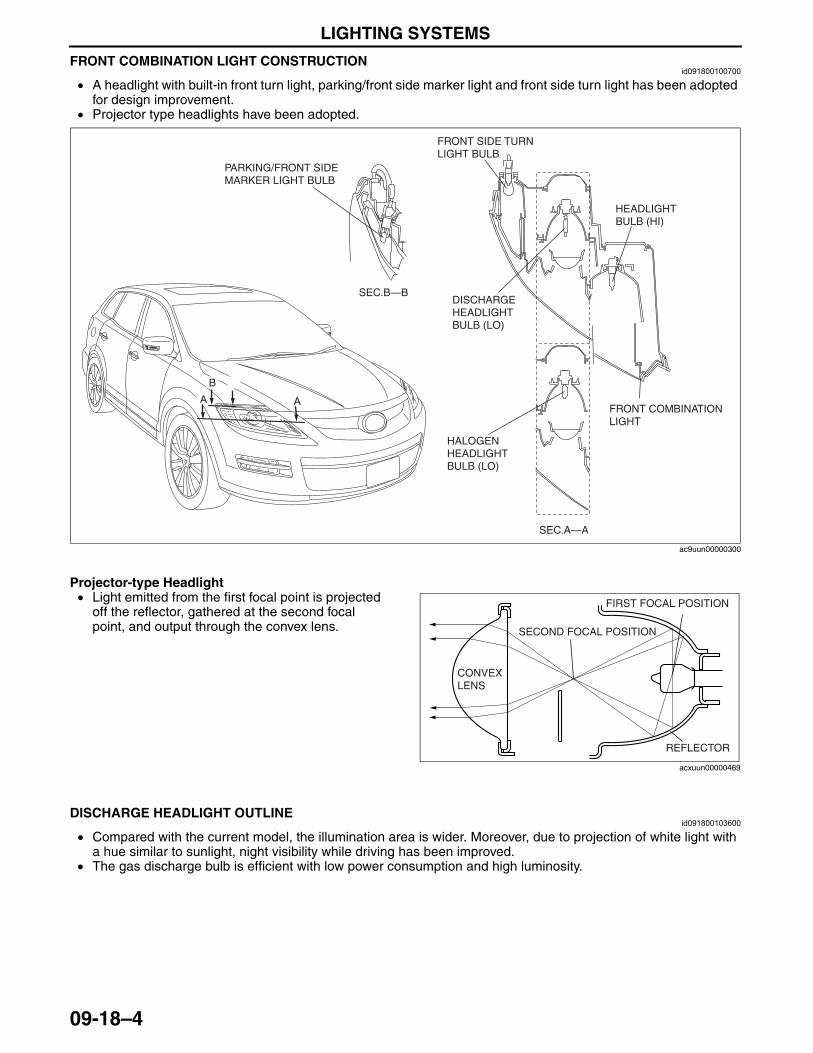
LIGHTING SYSTEMS
09-18–4
FRONT COMBINATION LIGHT CONSTRUCTIONid091800100700
• A headlight with built-in front turn light, parking/front side marker light and front side turn light has been adopted for design improvement.
• Projector type headlights have been adopted.
Projector-type Headlight• Light emitted from the first focal point is projected
off the reflector, gathered at the second focal point, and output through the convex lens.
End Of SieNG: DISCHARGE HEADLIGHT
DISCHARGE HEADLIGHT OUTLINEid091800103600
• Compared with the current model, the illumination area is wider. Moreover, due to projection of white light with a hue similar to sunlight, night visibility while driving has been improved.
• The gas discharge bulb is efficient with low power consumption and high luminosity.End Of Sie
SEC.A—A
SEC.B—B
FRONT SIDE TURN LIGHT BULB
HALOGEN HEADLIGHT BULB (LO)
HEADLIGHT BULB (HI)
FRONT COMBINATION LIGHT
PARKING/FRONT SIDE MARKER LIGHT BULB
DISCHARGE HEADLIGHT BULB (LO)
AA
B
ac9uun00000300
CONVEX LENS
SECOND FOCAL POSITION
FIRST FOCAL POSITION
REFLECTOR
acxuun00000469
3423-1U-06H(09-18).fm 4 ページ 2006年11月22日 水曜日 午後3時37分
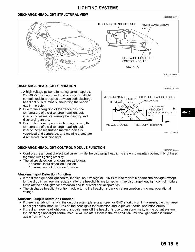
LIGHTING SYSTEMS
09-18–5
09-18
DISCHARGE HEADLIGHT STRUCTURAL VIEWid091800103700
End Of Sie
DISCHARGE HEADLIGHT OPERATIONid091800103500
1. A high voltage pulse (alternating current approx. 25,000 V) traveling from the discharge headlight control module is applied between both discharge headlight bulb terminals, energizing the xenon gas in the bulb.
2. Due to the energizing of the xenon gas, the temperature of the discharge headlight bulb interior increases, vaporizing the mercury and discharging an arc.
3. Due to the mercury and discharging the arc, the temperature of the discharge headlight bulb interior increases further, metallic iodide is vaporized and separated, and metallic atoms are discharged, producing light.
End Of Sie
DISCHARGE HEADLIGHT CONTROL MODULE FUNCTIONid091800103400
• Controls the amount of electrical current while the discharge headlights are on to maintain optimum brightness together with lighting stability.
• The failure detection functions are as follows:— Abnormal input detection function— Abnormal output detection function
Abnormal Input Detection Function• If the discharge headlight control module input voltage (9—16 V) fails to maintain operational voltage (except
for the drop in voltage immediately after the headlights are turned on), the discharge headlight control module turns off the headlights for protection and to prevent partial operation.
• The discharge headlight control module turns the headlights back on at resumption of normal operational voltage.
Abnormal Output Detection Function• If there is an abnormality in the output system (detects an open or GND short circuit in harness), the discharge
headlight control module turns off the headlights for protection and to prevent partial operation errors.• If the discharge headlight control module turns off the headlights due to an abnormality in the output system,
the discharge headlight control module will maintain them in the off condition until the light switch is turned again from off to on.
End Of Sie
SEC. A—A
A
A
DISCHARGE HEADLIGHT BULB
DISCHARGE HEADLIGHT CONTROL MODULE
FRONT COMBINATION LIGHT
ac9uun00000092
B+
METALLIC ATOMS
TERMINALLIGHT
DISCHARGE HEADLIGHT BULBXENON GAS
DISCHARGE HEADLIGHT CONTROL MODULE
LIGHT
MERCURY TERMINALMETALLIC IODIDE
acxuun00000559
3423-1U-06H(09-18).fm 5 ページ 2006年11月29日 水曜日 午前11時3分
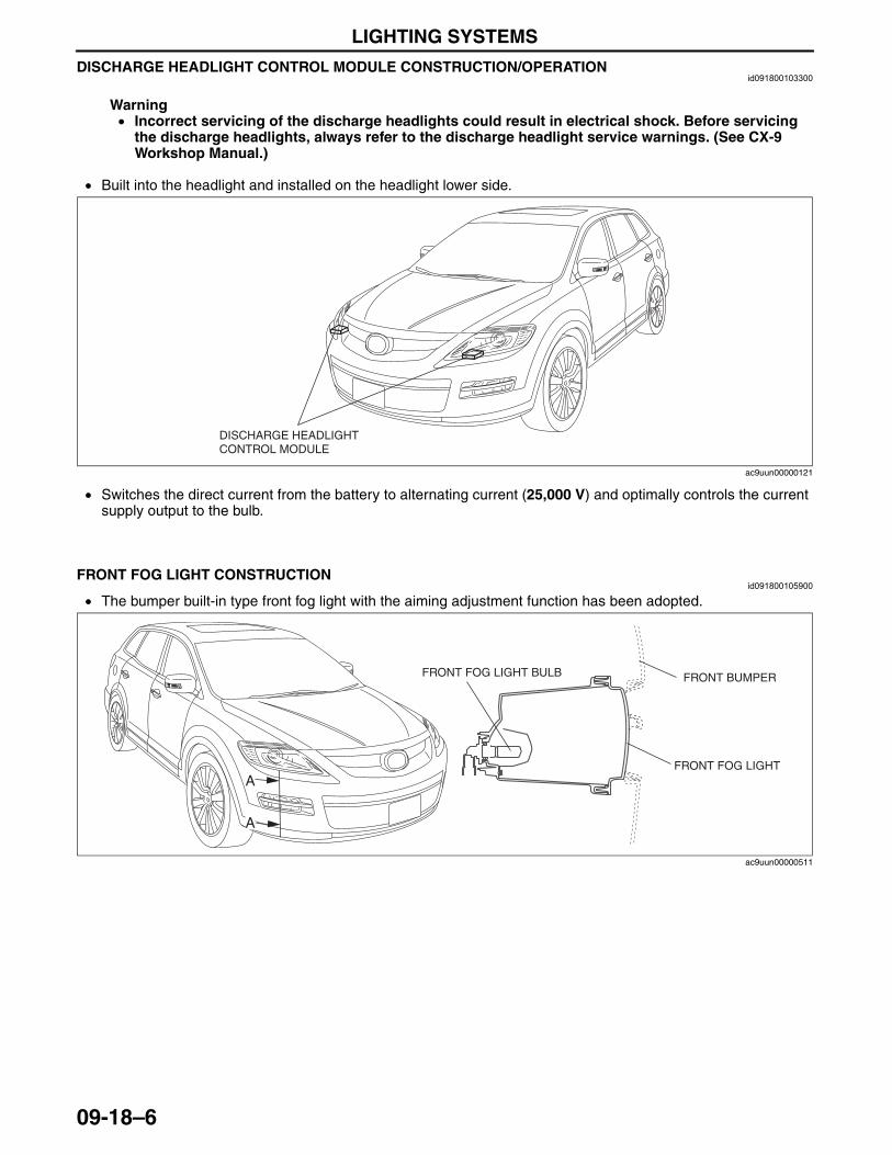
LIGHTING SYSTEMS
09-18–6
DISCHARGE HEADLIGHT CONTROL MODULE CONSTRUCTION/OPERATIONid091800103300
Warning• Incorrect servicing of the discharge headlights could result in electrical shock. Before servicing
the discharge headlights, always refer to the discharge headlight service warnings. (See CX-9 Workshop Manual.)
• Built into the headlight and installed on the headlight lower side.
• Switches the direct current from the battery to alternating current (25,000 V) and optimally controls the current supply output to the bulb.
End Of Sie
FRONT FOG LIGHT CONSTRUCTIONid091800105900
• The bumper built-in type front fog light with the aiming adjustment function has been adopted.
End Of SieNG: AUTO LIGHT SYSTEM
DISCHARGE HEADLIGHT CONTROL MODULE
ac9uun00000121
A
A
FRONT FOG LIGHT BULB
FRONT FOG LIGHT
FRONT BUMPER
ac9uun00000511
3423-1U-06H(09-18).fm 6 ページ 2006年11月22日 水曜日 午後3時28分
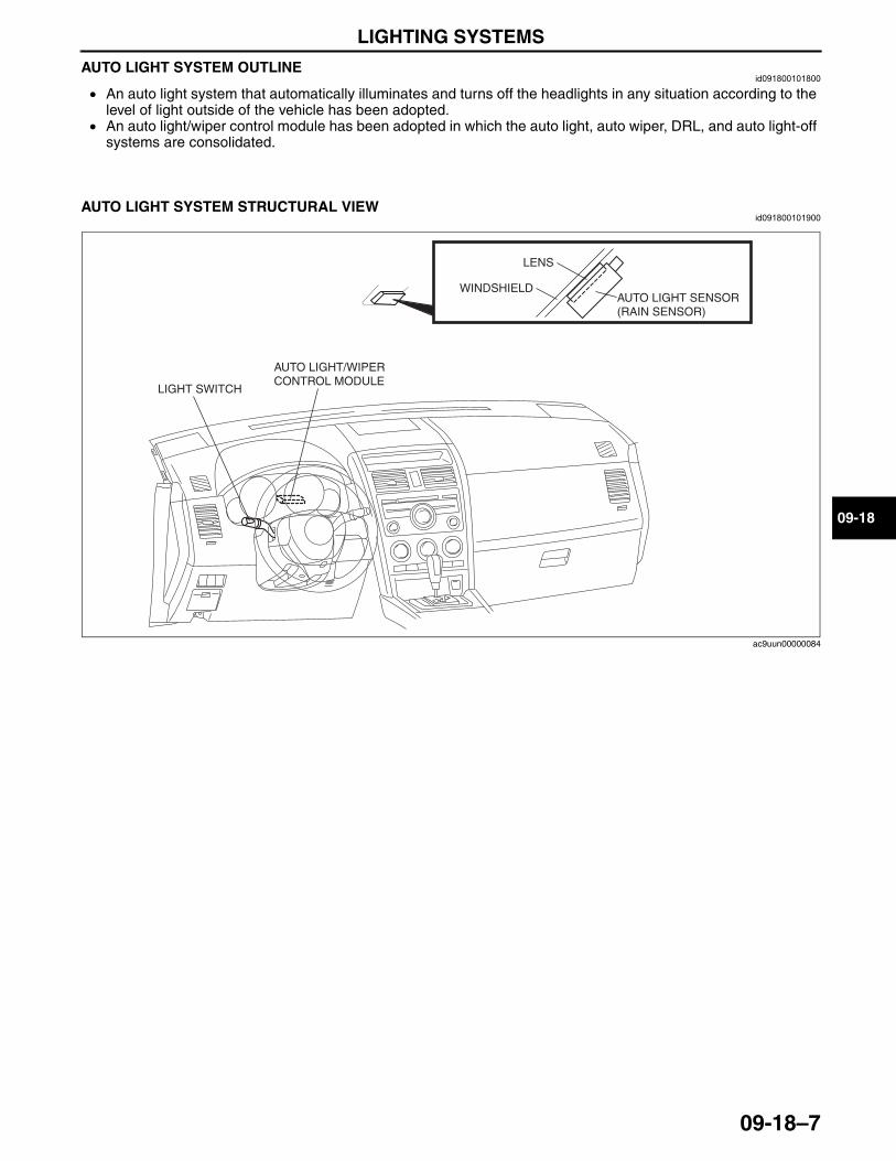
LIGHTING SYSTEMS
09-18–7
09-18
AUTO LIGHT SYSTEM OUTLINEid091800101800
• An auto light system that automatically illuminates and turns off the headlights in any situation according to the level of light outside of the vehicle has been adopted.
• An auto light/wiper control module has been adopted in which the auto light, auto wiper, DRL, and auto light-off systems are consolidated.
End Of Sie
AUTO LIGHT SYSTEM STRUCTURAL VIEWid091800101900
End Of Sie
LIGHT SWITCH
AUTO LIGHT/WIPER CONTROL MODULE
LENS
WINDSHIELDAUTO LIGHT SENSOR (RAIN SENSOR)
ac9uun00000084
3423-1U-06H(09-18).fm 7 ページ 2006年11月22日 水曜日 午後3時28分
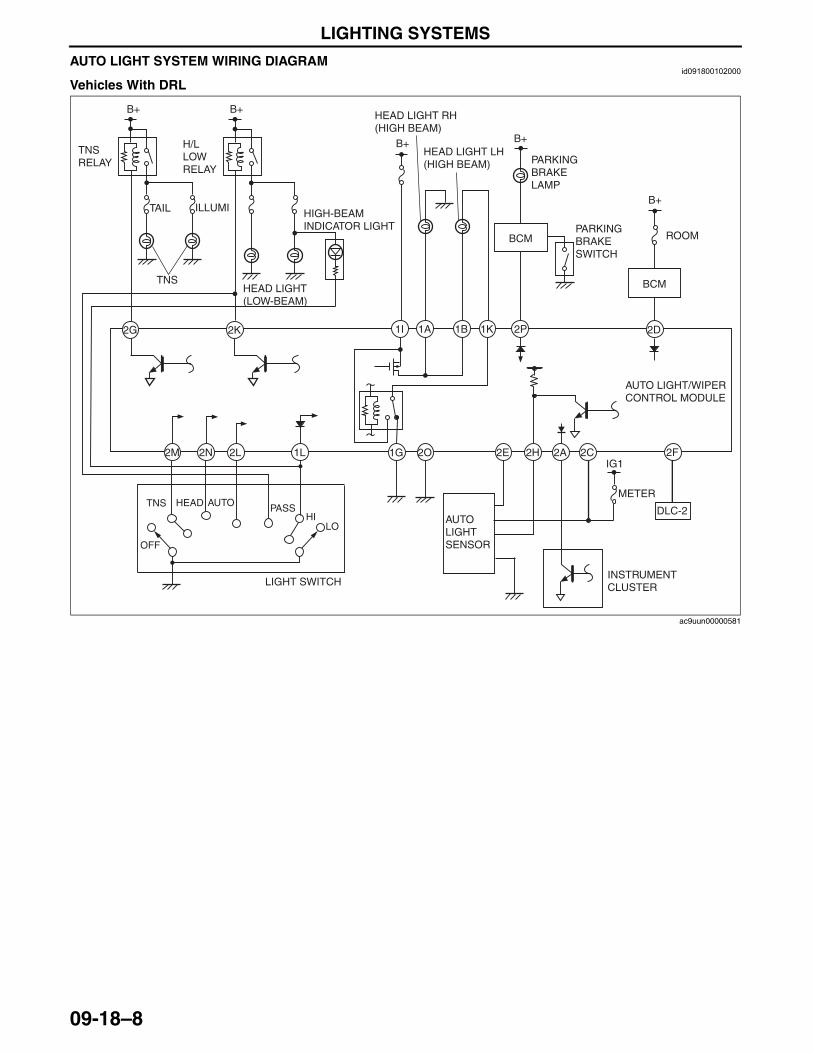
LIGHTING SYSTEMS
09-18–8
AUTO LIGHT SYSTEM WIRING DIAGRAMid091800102000
Vehicles With DRL
1L2L2N2M
2K2G
B+ B+
TNS RELAY
H/L LOW RELAY
HEAD LIGHT (LOW-BEAM)
AUTO LIGHT/WIPER CONTROL MODULE
HIGH-BEAM INDICATOR LIGHT
ILLUMITAIL
LIGHT SWITCH
HIPASSHEAD AUTO
OFF
TNS
LO
2O 2E 2H 2A 2C
AUTO LIGHTSENSOR
1G
1K1B1A1I 2P
B+
HEAD LIGHT RH (HIGH BEAM)
HEAD LIGHT LH (HIGH BEAM)
PARKING BRAKE SWITCH
PARKING BRAKE LAMP
B+
INSTRUMENT CLUSTER
2F
DLC-2
2D
B+
ROOMBCM
BCM
METER
IG1
TNS
ac9uun00000581
3423-1U-06H(09-18).fm 8 ページ 2006年11月21日 火曜日 午後5時44分
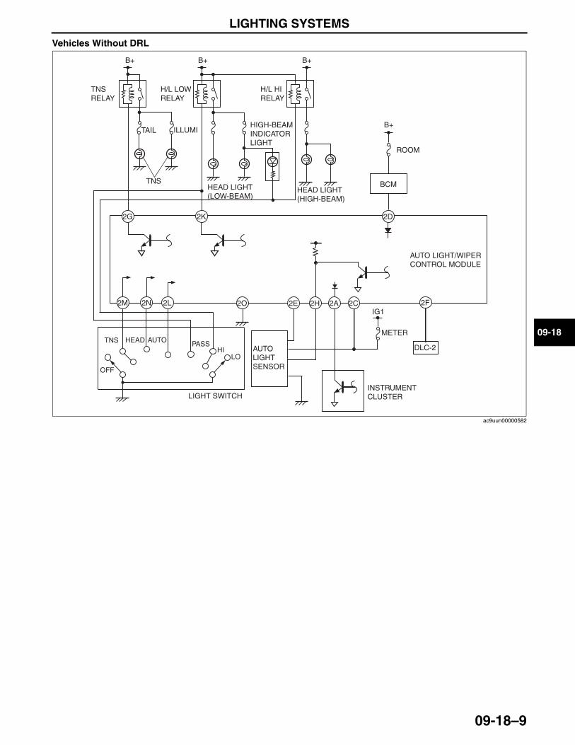
LIGHTING SYSTEMS
09-18–9
09-18
Vehicles Without DRL
End Of Sie
2D
2O 2E 2H 2A 2C
2K2G
B+
B+ B+
TNS RELAY
H/L LOW RELAY
B+
H/L HI RELAY
HEAD LIGHT (LOW-BEAM)
HEAD LIGHT (HIGH-BEAM)
ILLUMI
ROOM
TAILHIGH-BEAM INDICATOR LIGHT
TNS
INSTRUMENT CLUSTER
AUTO LIGHTSENSOR
2F
DLC-2
BCM
METER
2L2N2M
LIGHT SWITCH
HIPASSHEAD AUTO
OFF
TNS
LO
AUTO LIGHT/WIPER CONTROL MODULE
IG1
ac9uun00000582
3423-1U-06H(09-18).fm 9 ページ 2006年11月21日 火曜日 午後5時44分
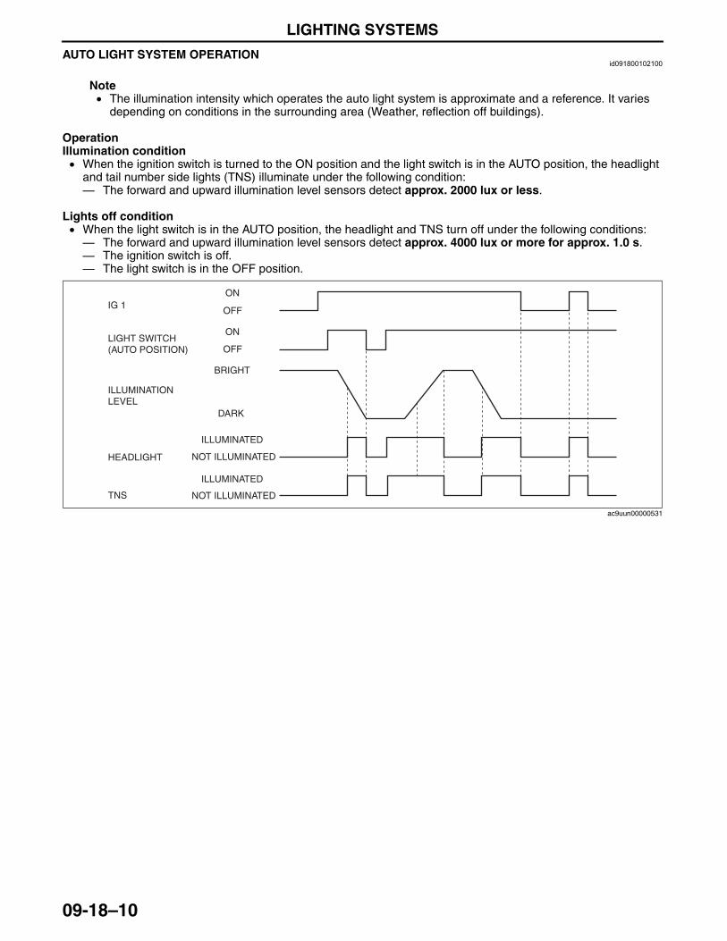
LIGHTING SYSTEMS
09-18–10
AUTO LIGHT SYSTEM OPERATIONid091800102100
Note• The illumination intensity which operates the auto light system is approximate and a reference. It varies
depending on conditions in the surrounding area (Weather, reflection off buildings).
OperationIllumination condition• When the ignition switch is turned to the ON position and the light switch is in the AUTO position, the headlight
and tail number side lights (TNS) illuminate under the following condition:— The forward and upward illumination level sensors detect approx. 2000 lux or less.
Lights off condition• When the light switch is in the AUTO position, the headlight and TNS turn off under the following conditions:— The forward and upward illumination level sensors detect approx. 4000 lux or more for approx. 1.0 s.— The ignition switch is off.— The light switch is in the OFF position.
LIGHT SWITCH(AUTO POSITION)
ILLUMINATIONLEVEL
OFF
OFF
IG 1
TNS
HEADLIGHT
BRIGHT
NOT ILLUMINATED
NOT ILLUMINATED
DARK
ILLUMINATED
ILLUMINATED
ON
ON
ac9uun00000531
3423-1U-06H(09-18).fm 10 ページ 2006年11月21日 火曜日 午後5時44分
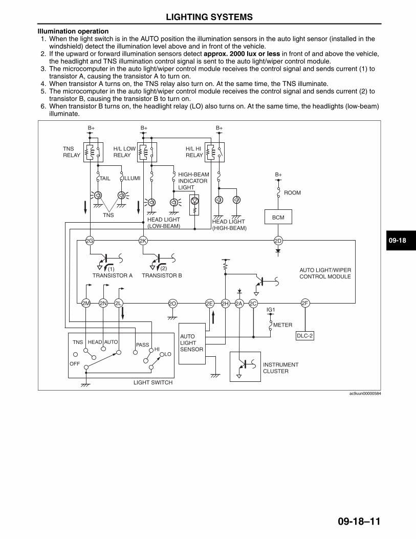
LIGHTING SYSTEMS
09-18–11
09-18
Illumination operation1. When the light switch is in the AUTO position the illumination sensors in the auto light sensor (installed in the
windshield) detect the illumination level above and in front of the vehicle.2. If the upward or forward illumination sensors detect approx. 2000 lux or less in front of and above the vehicle,
the headlight and TNS illumination control signal is sent to the auto light/wiper control module.3. The microcomputer in the auto light/wiper control module receives the control signal and sends current (1) to
transistor A, causing the transistor A to turn on.4. When transistor A turns on, the TNS relay also turn on. At the same time, the TNS illuminate.5. The microcomputer in the auto light/wiper control module receives the control signal and sends current (2) to
transistor B, causing the transistor B to turn on.6. When transistor B turns on, the headlight relay (LO) also turns on. At the same time, the headlights (low-beam)
illuminate.
(1) (2)
2K2G
B+ B+
TNS RELAY
H/L LOW RELAY
B+
H/L HI RELAY
HEAD LIGHT (LOW-BEAM)
HEAD LIGHT (HIGH-BEAM)
ILLUMITAILHIGH-BEAM INDICATOR LIGHT
TNS
AUTO LIGHT/WIPER CONTROL MODULETRANSISTOR A TRANSISTOR B
2D
2O 2E 2H 2A 2C
B+
ROOM
INSTRUMENT CLUSTER
AUTO LIGHTSENSOR
2F
DLC-2
BCM
METER
2L2N2M
LIGHT SWITCH
HIPASSHEAD AUTO
OFF
TNS
LO
IG1
ac9uun00000584
3423-1U-06H(09-18).fm 11 ページ 2006年11月21日 火曜日 午後5時44分
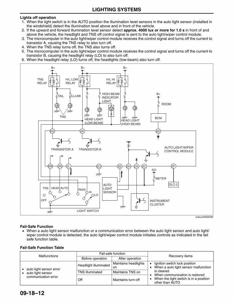
LIGHTING SYSTEMS
09-18–12
Lights off operation1. When the light switch is in the AUTO position the illumination level sensors in the auto light sensor (installed in
the windshield) detect the illumination level above and in front of the vehicle.2. If the upward and forward illumination level sensor detect approx. 4000 lux or more for 1.0 s in front of and
above the vehicle, the headlight and TNS off control signal is sent to the auto light/wiper control module.3. The microcomputer in the auto light/wiper control module receives the control signal and turns off the current to
transistor A, causing the TNS relay to also turn off.4. When the TNS relay turns off, the TNS also turns off.5. The microcomputer in the auto light/wiper control module receives the control signal and turns off the current to
transistor B, causing the headlight relay (LO) to also turn off.6. When the headlight relay (LO) turns off, the headlights (low-beam) also turn off.
Fail-Safe Function• When a auto light sensor malfunction or a communication error between the auto light sensor and auto light/
wiper control module is detected, the auto light/wiper control module initiates controls as indicated in the fail safe function table.
Fail-Safe Function Table
2K2G
B+ B+
TNS RELAY
H/L LOW RELAY
B+
H/L HI RELAY
HEAD LIGHT (LOW-BEAM)
HEAD LIGHT (HIGH-BEAM)
ILLUMITAILHIGH-BEAM INDICATOR LIGHT
TNS
AUTO LIGHT/WIPER CONTROL MODULE
2D
2O 2E 2H 2A 2C
B+
ROOM
INSTRUMENT CLUSTER
AUTO LIGHTSENSOR
DLC-2
BCM
METER
2L2N2M
LIGHT SWITCH
HIPASSHEAD AUTO
OFF
TNS
LO
IG12F
TRANSISTOR A TRANSISTOR B
ac9uun00000585
MalfunctionsFail-safe function
Recovery itemsBefore operation After operation
• auto light sensor error• auto light sensor
communication error
Headlight illuminated Maintains headlights on
• Ignition switch lock position• When a auto light sensor malfunction
is cleared• When communication is restored• When the light switch is in a position
other than AUTO
TNS illuminated Maintains TNS on
Off Maintains turn-off
3423-1U-06H(09-18).fm 12 ページ 2006年11月21日 火曜日 午後5時44分
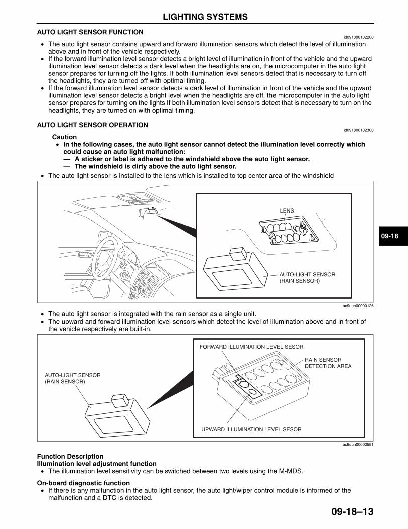
LIGHTING SYSTEMS
09-18–13
09-18
End Of SieAUTO LIGHT SENSOR FUNCTIONid091800102200
• The auto light sensor contains upward and forward illumination sensors which detect the level of illumination above and in front of the vehicle respectively.
• If the forward illumination level sensor detects a bright level of illumination in front of the vehicle and the upward illumination level sensor detects a dark level when the headlights are on, the microcomputer in the auto light sensor prepares for turning off the lights. If both illumination level sensors detect that is necessary to turn off the headlights, they are turned off with optimal timing.
• If the forward illumination level sensor detects a dark level of illumination in front of the vehicle and the upward illumination level sensor detects a bright level when the headlights are off, the microcomputer in the auto light sensor prepares for turning on the lights If both illumination level sensors detect that is necessary to turn on the headlights, they are turned on with optimal timing.
End Of SieAUTO LIGHT SENSOR OPERATION
id091800102300
Caution• In the following cases, the auto light sensor cannot detect the illumination level correctly which
could cause an auto light malfunction:— A sticker or label is adhered to the windshield above the auto light sensor.— The windshield is dirty above the auto light sensor.
• The auto light sensor is installed to the lens which is installed to top center area of the windshield
• The auto light sensor is integrated with the rain sensor as a single unit.• The upward and forward illumination level sensors which detect the level of illumination above and in front of
the vehicle respectively are built-in.
Function DescriptionIllumination level adjustment function• The illumination level sensitivity can be switched between two levels using the M-MDS.
On-board diagnostic function• If there is any malfunction in the auto light sensor, the auto light/wiper control module is informed of the
malfunction and a DTC is detected.
LENS
AUTO-LIGHT SENSOR (RAIN SENSOR)
ac9uun00000126
AUTO-LIGHT SENSOR (RAIN SENSOR)
UPWARD ILLUMINATION LEVEL SESOR
FORWARD ILLUMINATION LEVEL SESOR
RAIN SENSOR DETECTION AREA
ac9uun00000591
3423-1U-06H(09-18).fm 13 ページ 2006年11月22日 水曜日 午後3時29分
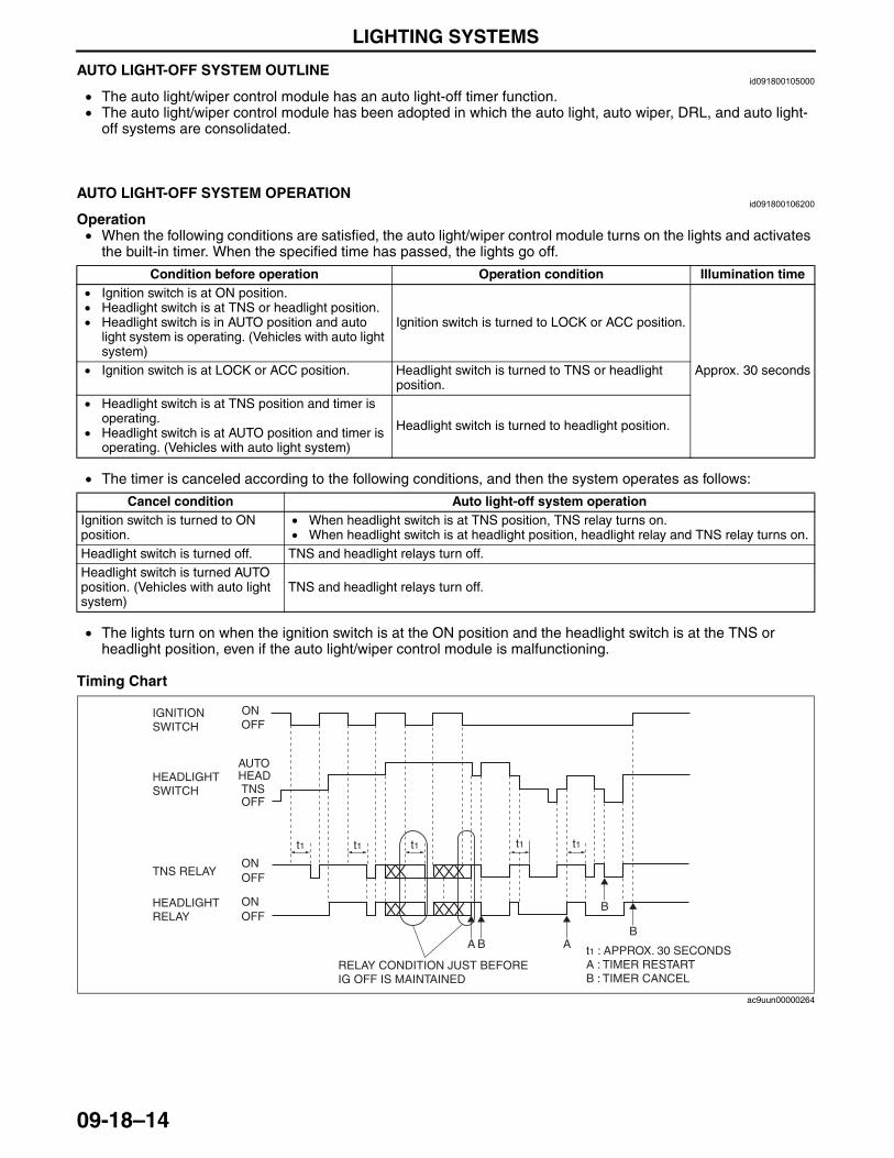
LIGHTING SYSTEMS
09-18–14
End Of SieAUTO LIGHT-OFF SYSTEM OUTLINEid091800105000
• The auto light/wiper control module has an auto light-off timer function.• The auto light/wiper control module has been adopted in which the auto light, auto wiper, DRL, and auto light-
off systems are consolidated.End Of Sie
AUTO LIGHT-OFF SYSTEM OPERATIONid091800106200
Operation• When the following conditions are satisfied, the auto light/wiper control module turns on the lights and activates
the built-in timer. When the specified time has passed, the lights go off.
• The timer is canceled according to the following conditions, and then the system operates as follows:
• The lights turn on when the ignition switch is at the ON position and the headlight switch is at the TNS or headlight position, even if the auto light/wiper control module is malfunctioning.
Timing Chart
End Of Sie
Condition before operation Operation condition Illumination time• Ignition switch is at ON position.• Headlight switch is at TNS or headlight position.• Headlight switch is in AUTO position and auto
light system is operating. (Vehicles with auto light system)
Ignition switch is turned to LOCK or ACC position.
Approx. 30 seconds• Ignition switch is at LOCK or ACC position. Headlight switch is turned to TNS or headlight position.
• Headlight switch is at TNS position and timer is operating.
• Headlight switch is at AUTO position and timer is operating. (Vehicles with auto light system)
Headlight switch is turned to headlight position.
Cancel condition Auto light-off system operationIgnition switch is turned to ON position.
• When headlight switch is at TNS position, TNS relay turns on.• When headlight switch is at headlight position, headlight relay and TNS relay turns on.
Headlight switch is turned off. TNS and headlight relays turn off.Headlight switch is turned AUTO position. (Vehicles with auto light system)
TNS and headlight relays turn off.
t1t1 t1 t1 t1
ONOFF
ONOFF
OFFTNS
ONOFF
AUTOHEAD
IGNITION SWITCH
HEADLIGHT SWITCH
HEADLIGHT RELAY
TNS RELAY
t1 : APPROX. 30 SECONDS A : TIMER RESTART B : TIMER CANCEL
B
B
ABA
RELAY CONDITION JUST BEFORE IG OFF IS MAINTAINED
ac9uun00000264
3423-1U-06H(09-18).fm 14 ページ 2006年11月21日 火曜日 午後5時44分
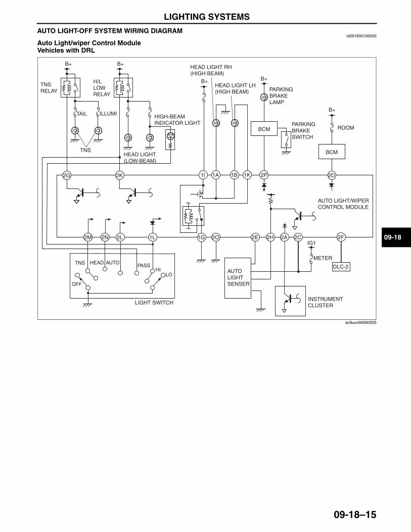
LIGHTING SYSTEMS
09-18–15
09-18
AUTO LIGHT-OFF SYSTEM WIRING DIAGRAMid091800106000
Auto Light/wiper Control ModuleVehicles with DRL
2O 2E 2H 2A 2C1L2L2N2M
2K2G
B+ B+
TNS RELAY
H/L LOW RELAY
HEAD LIGHT (LOW-BEAM)
AUTO LIGHT/WIPER CONTROL MODULE
HIGH-BEAM INDICATOR LIGHT
AUTO LIGHTSENSER
ILLUMITAIL
1G
1K1B1A1I 2P
B+
HEAD LIGHT RH (HIGH BEAM)
HEAD LIGHT LH (HIGH BEAM)
PARKING BRAKE SWITCH
PARKING BRAKE LAMP
B+
INSTRUMENT CLUSTER
TNS
2F
DLC-2
2D
B+
ROOMBCM
BCM
METER
IG1
LIGHT SWITCH
HIPASSHEAD AUTO
OFF
TNS
LO
ac9uun00000555
3423-1U-06H(09-18).fm 15 ページ 2006年11月21日 火曜日 午後5時44分
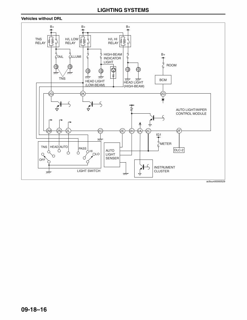
LIGHTING SYSTEMS
09-18–16
Vehicles without DRL
2D
2O 2E 2H 2A 2C
2K2G
B+
B+ B+
TNS RELAY
H/L LOW RELAY
B+
H/L HI RELAY
HEAD LIGHT (LOW-BEAM)
HEAD LIGHT (HIGH-BEAM)
ILLUMI
ROOM
TAILHIGH-BEAM INDICATOR LIGHT
TNS
INSTRUMENT CLUSTER
AUTO LIGHTSENSER
2F
DLC-2
BCM
METER
2L2N2M
LIGHT SWITCH
HIPASSHEAD AUTO
OFF
TNS
LO
AUTO LIGHT/WIPER CONTROL MODULE
IG1
ac9uun00000529
3423-1U-06H(09-18).fm 16 ページ 2006年11月21日 火曜日 午後5時44分
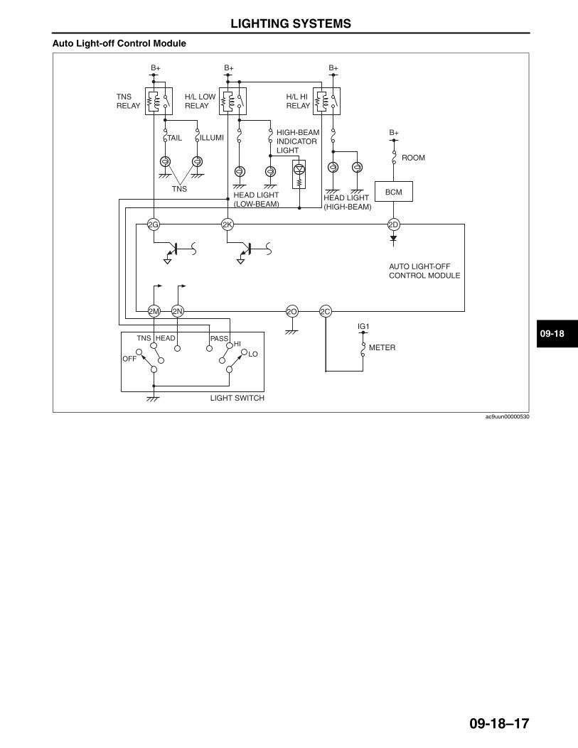
LIGHTING SYSTEMS
09-18–17
09-18
Auto Light-off Control Module
End Of SieNG: HEADLIGHT LEVELING SYSTEM
2D
2O 2C
2K2G
B+
B+ B+
TNS RELAY
H/L LOW RELAY
B+
H/L HI RELAY
HEAD LIGHT (LOW-BEAM)
HEAD LIGHT (HIGH-BEAM)
AUTO LIGHT-OFF CONTROL MODULE
ILLUMI
ROOM
METER
TAILHIGH-BEAM INDICATOR LIGHT
TNS
IG1
2N2M
BCM
LIGHT SWITCH
HIPASSHEAD
OFF
TNS
LO
ac9uun00000530
3423-1U-06H(09-18).fm 17 ページ 2006年11月22日 水曜日 午後3時29分
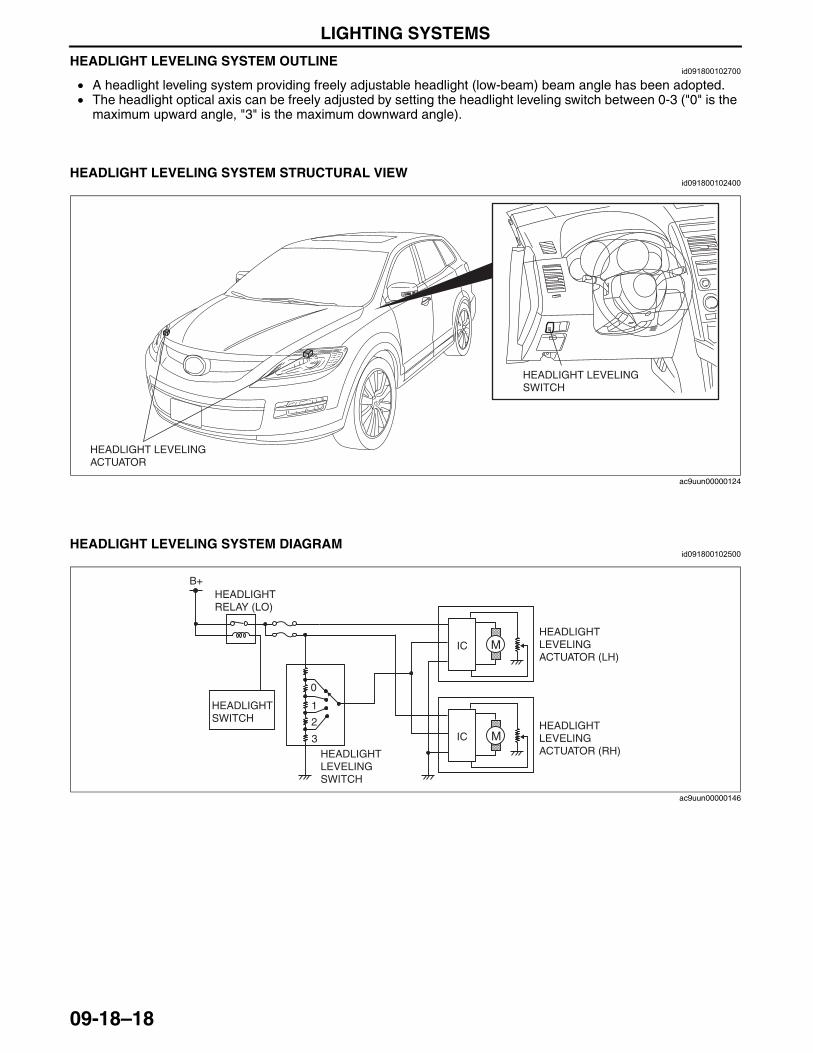
LIGHTING SYSTEMS
09-18–18
HEADLIGHT LEVELING SYSTEM OUTLINEid091800102700
• A headlight leveling system providing freely adjustable headlight (low-beam) beam angle has been adopted.• The headlight optical axis can be freely adjusted by setting the headlight leveling switch between 0-3 ("0" is the
maximum upward angle, "3" is the maximum downward angle).End Of Sie
HEADLIGHT LEVELING SYSTEM STRUCTURAL VIEWid091800102400
End Of Sie
HEADLIGHT LEVELING SYSTEM DIAGRAMid091800102500
End Of Sie
HEADLIGHT LEVELING SWITCH
HEADLIGHT LEVELING ACTUATOR
ac9uun00000124
B+
M
M
IC
IC
HEADLIGHT RELAY (LO)
3
2
1
0
HEADLIGHT SWITCH
HEADLIGHT LEVELING SWITCH
HEADLIGHT LEVELING ACTUATOR (RH)
HEADLIGHT LEVELING ACTUATOR (LH)
ac9uun00000146
3423-1U-06H(09-18).fm 18 ページ 2006年11月22日 水曜日 午後3時29分
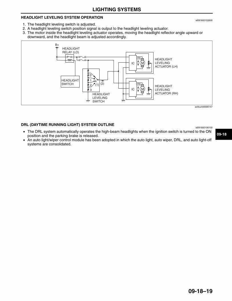
LIGHTING SYSTEMS
09-18–19
09-18
HEADLIGHT LEVELING SYSTEM OPERATIONid091800102600
1. The headlight leveling switch is adjusted.2. A headlight leveling switch position signal is output to the headlight leveling actuator. 3. The motor inside the headlight leveling actuator operates, moving the headlight reflector angle upward or
downward, and the headlight beam is adjusted accordingly.
End Of SieNG: DAYTIME RUNNING LIGHT SYSTEM
DRL (DAYTIME RUNNING LIGHT) SYSTEM OUTLINEid091800106100
• The DRL system automatically operates the high-beam headlights when the ignition switch is turned to the ON position and the parking brake is released.
• An auto light/wiper control module has been adopted in which the auto light, auto wiper, DRL, and auto light-off systems are consolidated.
End Of Sie
B+
M
M
IC
IC
HEADLIGHT RELAY (LO)
3
2
1
0
HEADLIGHT SWITCH
HEADLIGHT LEVELING SWITCH
HEADLIGHT LEVELING ACTUATOR (RH)
HEADLIGHT LEVELING ACTUATOR (LH)
(1) (2)
(3)
(3)
ac9uun00000147
3423-1U-06H(09-18).fm 19 ページ 2006年11月21日 火曜日 午後5時44分
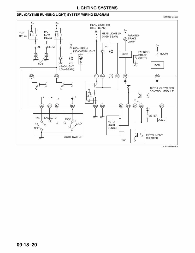
LIGHTING SYSTEMS
09-18–20
DRL (DAYTIME RUNNING LIGHT) SYSTEM WIRING DIAGRAMid091800109500
End Of Sie
2O 2E 2H 2A 2C1L2L2N2M
2K2G
B+ B+
TNS RELAY
H/L LOW RELAY
HEAD LIGHT (LOW-BEAM)
AUTO LIGHT/WIPER CONTROL MODULE
HIGH-BEAM INDICATOR LIGHT
AUTO LIGHTSENSER
ILLUMITAIL
1G
1K1B1A1I 2P
B+
HEAD LIGHT RH (HIGH BEAM)
HEAD LIGHT LH (HIGH BEAM)
PARKING BRAKE SWITCH
PARKING BRAKE LAMP
B+
INSTRUMENT CLUSTER
TNS
2F
DLC-2
2D
B+
ROOMBCM
BCM
METER
IG1
LIGHT SWITCH
HIPASSHEAD AUTO
OFF
TNS
LO
ac9uun00000528
3423-1U-06H(09-18).fm 20 ページ 2006年11月21日 火曜日 午後5時44分
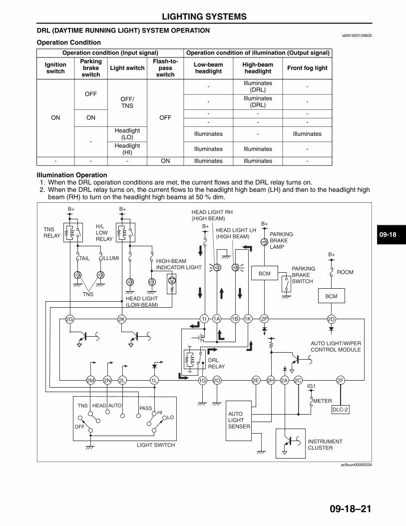
LIGHTING SYSTEMS
09-18–21
09-18
DRL (DAYTIME RUNNING LIGHT) SYSTEM OPERATIONid091800109600
Operation Condition
Illumination Operation1. When the DRL operation conditions are met, the current flows and the DRL relay turns on.2. When the DRL relay turns on, the current flows to the headlight high beam (LH) and then to the headlight high
beam (RH) to turn on the headlight high beams at 50 % dim.
End Of SieNG: FRONT SIDE TURN LIGHT
Operation condition (Input signal) Operation condition of illumination (Output signal)
Ignition switch
Parking brake switch
Light switchFlash-to-
pass switch
Low-beam headlight
High-beam headlight Front fog light
ON
OFFOFF/TNS
OFF
- Illuminates (DRL) -
- Illuminates (DRL) -
ON- - -- - -
-
Headlight (LO) Illuminates - Illuminates
Headlight (HI) Illuminates Illuminates -
- - - ON Illuminates Illuminates -
DRL RELAY
2O 2E 2H 2A 2C1L2L2N2M
2K2G
B+ B+
TNS RELAY
H/L LOW RELAY
HEAD LIGHT (LOW-BEAM)
HIGH-BEAM INDICATOR LIGHT
AUTO LIGHTSENSER
ILLUMITAIL
1G
1K1B1A1I 2P
B+
HEAD LIGHT RH (HIGH BEAM)
HEAD LIGHT LH (HIGH BEAM)
PARKING BRAKE SWITCH
PARKING BRAKE LAMP
B+
INSTRUMENT CLUSTER
TNS
2F
DLC-2
2D
B+
ROOMBCM
BCM
METER
IG1
LIGHT SWITCH
HIPASSHEAD AUTO
OFF
TNS
LO
AUTO LIGHT/WIPER CONTROL MODULE
ac9uun00000534
3423-1U-06H(09-18).fm 21 ページ 2006年11月21日 火曜日 午後5時44分
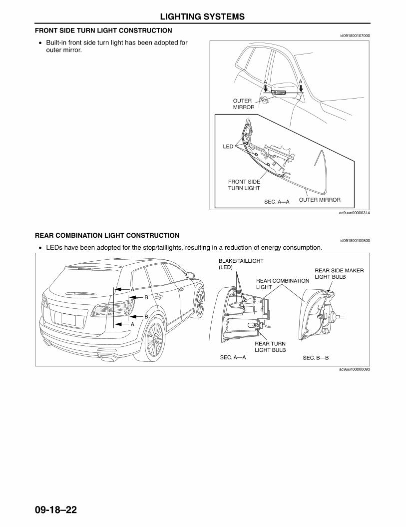
LIGHTING SYSTEMS
09-18–22
FRONT SIDE TURN LIGHT CONSTRUCTIONid091800107000
• Built-in front side turn light has been adopted for outer mirror.
End Of SieNG: REAR COMBINATION LIGHT
REAR COMBINATION LIGHT CONSTRUCTIONid091800100800
• LEDs have been adopted for the stop/taillights, resulting in a reduction of energy consumption.
End Of SieNG: INBOARD COMBINATION LIGHT
LED
FRONT SIDE TURN LIGHT
A A
SEC. A—A
OUTER MIRROR
OUTER MIRROR
ac9uun00000314
SEC. A—A SEC. B—B
B
B
REAR TURN LIGHT BULB
BLAKE/TAILLIGHT (LED)
A
A
REAR SIDE MAKER LIGHT BULB
REAR COMBINATION LIGHT
ac9uun00000093
3423-1U-06H(09-18).fm 22 ページ 2006年11月21日 火曜日 午後5時44分
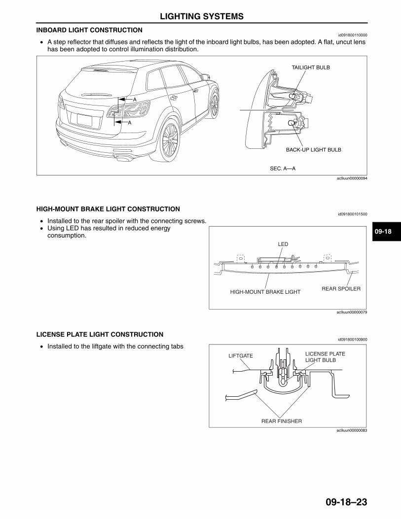
LIGHTING SYSTEMS
09-18–23
09-18
INBOARD LIGHT CONSTRUCTIONid091800110000
• A step reflector that diffuses and reflects the light of the inboard light bulbs, has been adopted. A flat, uncut lens has been adopted to control illumination distribution.
End Of SieNG: HIGH-MOUNT BRAKE LIGHT
HIGH-MOUNT BRAKE LIGHT CONSTRUCTIONid091800101500
• Installed to the rear spoiler with the connecting screws.• Using LED has resulted in reduced energy
consumption.End Of SieNG: LICENSE PLATE LIGHT
LICENSE PLATE LIGHT CONSTRUCTIONid091800100900
• Installed to the liftgate with the connecting tabsEnd Of SieNG: INTERIOR LIGHT
SEC. A—A
TAILIGHT BULB
BACK-UP LIGHT BULB
A
A
ac9uun00000094
LED
HIGH-MOUNT BRAKE LIGHT REAR SPOILER
ac9uun00000079
LIFTGATE
REAR FINISHER
LICENSE PLATE LIGHT BULB
ac9uun00000083
3423-1U-06H(09-18).fm 23 ページ 2006年11月21日 火曜日 午後5時44分
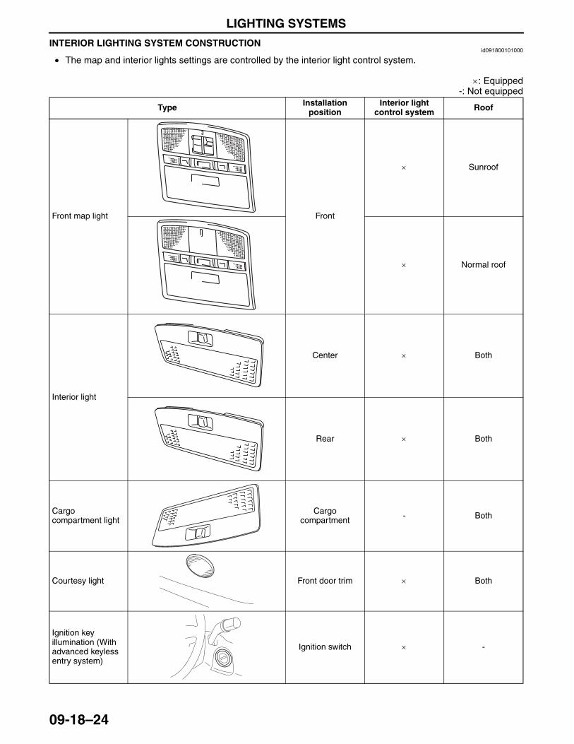
LIGHTING SYSTEMS
09-18–24
INTERIOR LIGHTING SYSTEM CONSTRUCTIONid091800101000
• The map and interior lights settings are controlled by the interior light control system.
×: Equipped-: Not equipped
Type Installation position
Interior light control system Roof
Front map light Front
× Sunroof
× Normal roof
Interior light
Center × Both
Rear × Both
Cargo compartment light
Cargo compartment - Both
Courtesy light Front door trim × Both
Ignition key illumination (With advanced keyless entry system)
Ignition switch × -
3423-1U-06H(09-18).fm 24 ページ 2006年11月21日 火曜日 午後5時44分
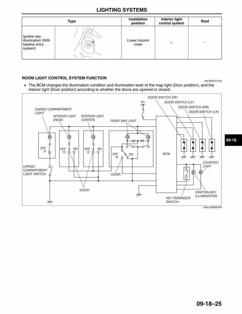
LIGHTING SYSTEMS
09-18–25
09-18
End Of Sie
ROOM LIGHT CONTROL SYSTEM FUNCTIONid091800101100
• The BCM changes the illumination condition and illumination level of the map light (Door position), and the interior light (Door position) according to whether the doors are opened or closed.
End Of Sie
Ignition key illumination (With keyless entry system)
Lower column cover × -
Type Installation position
Interior light control system Roof
B+
BCM
OFF
DOOR
OFF ON
DOOR SWITCH (RF)
FRONT MAP LIGHT
INTERIOR LIGHT (REAR)
INTERIOR LIGHT (CENTER)
CARGO COMPARTMENT LIGHT
CARGO COMPARTMENT LIGHT SWITCH
DOOR SWITCH (LF)
DOOR SWITCH (RR)
DOOR SWITCH (LR)
OFF ON
DOOR
OFF ON
COURTESY LIGHT
IGNITION KEY ILLUMINATION
KEY REMINDER SWITCH
ac9uun00000169
3423-1U-06H(09-18).fm 25 ページ 2006年11月21日 火曜日 午後5時44分
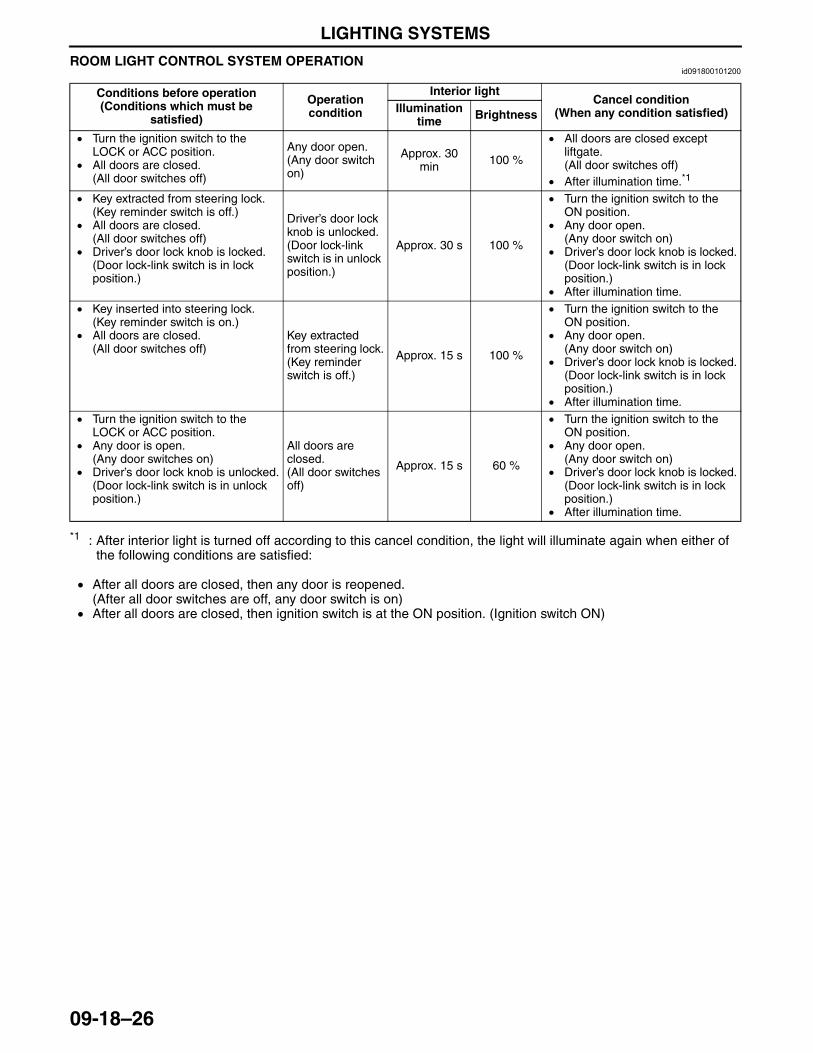
LIGHTING SYSTEMS
09-18–26
ROOM LIGHT CONTROL SYSTEM OPERATIONid091800101200
*1 : After interior light is turned off according to this cancel condition, the light will illuminate again when either of the following conditions are satisfied:
• After all doors are closed, then any door is reopened.(After all door switches are off, any door switch is on)
• After all doors are closed, then ignition switch is at the ON position. (Ignition switch ON)
Conditions before operation(Conditions which must be
satisfied)
Operation condition
Interior lightCancel condition
(When any condition satisfied)Illumination time Brightness
• Turn the ignition switch to the LOCK or ACC position.
• All doors are closed.(All door switches off)
Any door open. (Any door switch on)
Approx. 30 min 100 %
• All doors are closed except liftgate.(All door switches off)
• After illumination time.*1
• Key extracted from steering lock.(Key reminder switch is off.)
• All doors are closed.(All door switches off)
• Driver’s door lock knob is locked.(Door lock-link switch is in lock position.)
Driver’s door lock knob is unlocked.(Door lock-link switch is in unlock position.)
Approx. 30 s 100 %
• Turn the ignition switch to the ON position.
• Any door open. (Any door switch on)
• Driver’s door lock knob is locked.(Door lock-link switch is in lock position.)
• After illumination time.• Key inserted into steering lock.
(Key reminder switch is on.)• All doors are closed.
(All door switches off)Key extracted from steering lock.(Key reminder switch is off.)
Approx. 15 s 100 %
• Turn the ignition switch to the ON position.
• Any door open. (Any door switch on)
• Driver’s door lock knob is locked.(Door lock-link switch is in lock position.)
• After illumination time.• Turn the ignition switch to the
LOCK or ACC position.• Any door is open.
(Any door switches on)• Driver’s door lock knob is unlocked.
(Door lock-link switch is in unlock position.)
All doors are closed.(All door switches off)
Approx. 15 s 60 %
• Turn the ignition switch to the ON position.
• Any door open. (Any door switch on)
• Driver’s door lock knob is locked.(Door lock-link switch is in lock position.)
• After illumination time.
3423-1U-06H(09-18).fm 26 ページ 2006年11月21日 火曜日 午後5時44分
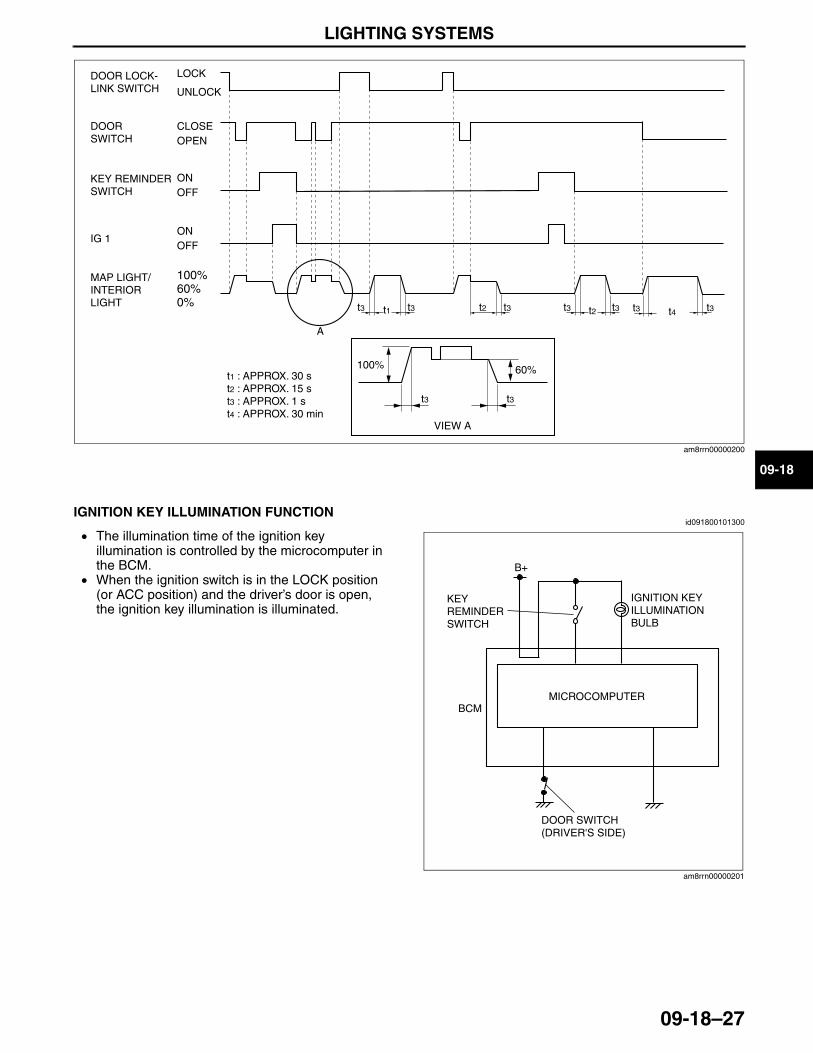
LIGHTING SYSTEMS
09-18–27
09-18End Of Sie
IGNITION KEY ILLUMINATION FUNCTIONid091800101300
• The illumination time of the ignition key illumination is controlled by the microcomputer in the BCM.
• When the ignition switch is in the LOCK position (or ACC position) and the driver’s door is open, the ignition key illumination is illuminated.
End Of Sie
LOCK
UNLOCK
CLOSEOPEN
ONOFF
ONOFF
A
t3 t3 t3
t3t3
t3 t3t2
100% 60%
t2t1 t4t3 t30%60%100%
DOOR LOCK-LINK SWITCH
DOOR SWITCH
KEY REMINDERSWITCH
IG 1
MAP LIGHT/INTERIOR LIGHT
VIEW A
t1 : APPROX. 30 st2 : APPROX. 15 st3 : APPROX. 1 st4 : APPROX. 30 min
am8rrn00000200
B+
BCM
IGNITION KEY ILLUMINATION BULB
MICROCOMPUTER
KEY REMINDER SWITCH
DOOR SWITCH(DRIVER'S SIDE)
am8rrn00000201
3423-1U-06H(09-18).fm 27 ページ 2006年11月22日 水曜日 午後3時42分
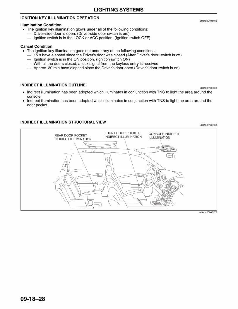
LIGHTING SYSTEMS
09-18–28
IGNITION KEY ILLUMINATION OPERATIONid091800101400
Illumination Condition• The ignition key illumination glows under all of the following conditions:— Driver-side door is open. (Driver-side door switch is on.)— Ignition switch is in the LOCK or ACC position. (Ignition switch OFF)
Cancel Condition• The ignition key illumination goes out under any of the following conditions:— 15 s have elapsed since the Driver’s door was closed (After Driver’s door lswitch is off).— Ignition switch is in the ON position. (Ignition switch ON)— With all the doors closed, a lock signal from the keyless entry is received.— Approx. 30 min have elapsed since the Driver’s door open (Driver’s door switch is on)
End Of SieNG: ENTERTAINMENT ILLUMINATION
INDIRECT ILLUMINATION OUTLINEid091800105400
• Indirect illumination has been adopted which illuminates in conjunction with TNS to light the area around the console.
• Indirect illumination has been adopted which illuminates in conjunction with TNS to light the area around the door pocket.
End Of Sie
INDIRECT ILLUMINATION STRUCTURAL VIEWid091800105500
End Of Sie
CONSOLE INDIRECT ILLUMINATION
FRONT DOOR POCKET INDIRECT ILLUMINATIONREAR DOOR POCKET
INDIRECT ILLUMINATION
ac9uun00000175
3423-1U-06H(09-18).fm 28 ページ 2006年11月21日 火曜日 午後5時44分
WIPER/WASHER SYSTEM
09-19–1
09-19
09-19 WIPER/WASHER SYSTEMWIPER/WASHER OUTLINE . . . . . . . . . . 09-19–1WASHER TANK SPECIFICATION . . . . . 09-19–1WIPER/WASHER SYSTEM
STRUCTURAL VIEW . . . . . . . . . . . . . . 09-19–2WINDSHIELD WIPER SYSTEM
OUTLINE . . . . . . . . . . . . . . . . . . . . . . . . 09-19–3WINDSHIELD WIPER SYSTEM
WIRING DIAGRAM . . . . . . . . . . . . . . . . 09-19–3WINDSHIELD WIPER SYSTEM
OPERATION . . . . . . . . . . . . . . . . . . . . . 09-19–4Continuous Operation . . . . . . . . . . . . . 09-19–4Autostop Operation . . . . . . . . . . . . . . . 09-19–4One-touch Wiper Operation . . . . . . . . . 09-19–5Intermittent Wiper Operation . . . . . . . . 09-19–5Synchronized Washer And
Wiper Operation . . . . . . . . . . . . . . . . . 09-19–6REAR WIPER SYSTEM OUTLINE . . . . . 09-19–6REAR WIPER SYSTEM
WIRING DIAGRAM . . . . . . . . . . . . . . . . 09-19–6REAR WIPER SYSTEM
OPERATION . . . . . . . . . . . . . . . . . . . . . 09-19–7Continuous Operation . . . . . . . . . . . . . 09-19–7Autostop Operation . . . . . . . . . . . . . . . 09-19–8Intermittent Wiper Operation . . . . . . . . 09-19–9Synchronized Washer And
Wiper Operation . . . . . . . . . . . . . . . . . 09-19–9
AUTO WIPER SYSTEM OUTLINE . . . . . . 09-19–10AUTO WIPER SYSTEM
STRUCTURAL VIEW . . . . . . . . . . . . . . . 09-19–11AUTO WIPER SYSTEM
WIRING DIAGRAM. . . . . . . . . . . . . . . . . 09-19–11AUTO WIPER SYSTEM
OPERATION . . . . . . . . . . . . . . . . . . . . . . 09-19–12Intermittent Operation . . . . . . . . . . . . . . 09-19–12Low Speed Operation . . . . . . . . . . . . . . 09-19–12High Speed Operation. . . . . . . . . . . . . . 09-19–12Fail-Safe Function . . . . . . . . . . . . . . . . . 09-19–13
RAIN SENSOR FUNCTION . . . . . . . . . . . 09-19–13Rainfall detection function . . . . . . . . . . . 09-19–13Sensitivity Adjustment Function . . . . . . 09-19–13Initial Setting Function . . . . . . . . . . . . . . 09-19–13On-board Diagnostic Function . . . . . . . 09-19–13
RAIN SENSOR CONSTRUCTION/OPERATION . . . . . . . 09-19–14
Operation With No Rainfall Contacting Windshield . . . . . . . . . . . . 09-19–15
Operation With Rainfall Contacting Windshield . . . . . . . . . . . . 09-19–15
WASHER FLUID-LEVEL SENSOR FUNCTION . . . . . . . . . . . . . . . . . . . . . . . 09-19–16
End of TocNG: WIPER/WASHER SYSTEMSWIPER/WASHER OUTLINE
id091900100100
End Of Sie
WASHER TANK SPECIFICATIONid091900100200
End Of Sie
Improved convenience • Auto wiper system adopted which enables fully automatic windshield wiper operation
System simplification • An auto light/wiper control module has been adopted in which the auto light, auto wiper, DRL, and auto light-off systems are consolidated.
Washer tank capacity 4.5 L {4.8 US qt, 4.0 Imp qt}
3423-1U-06H(09-19).fm 1 ページ 2006年11月22日 水曜日 午後3時48分
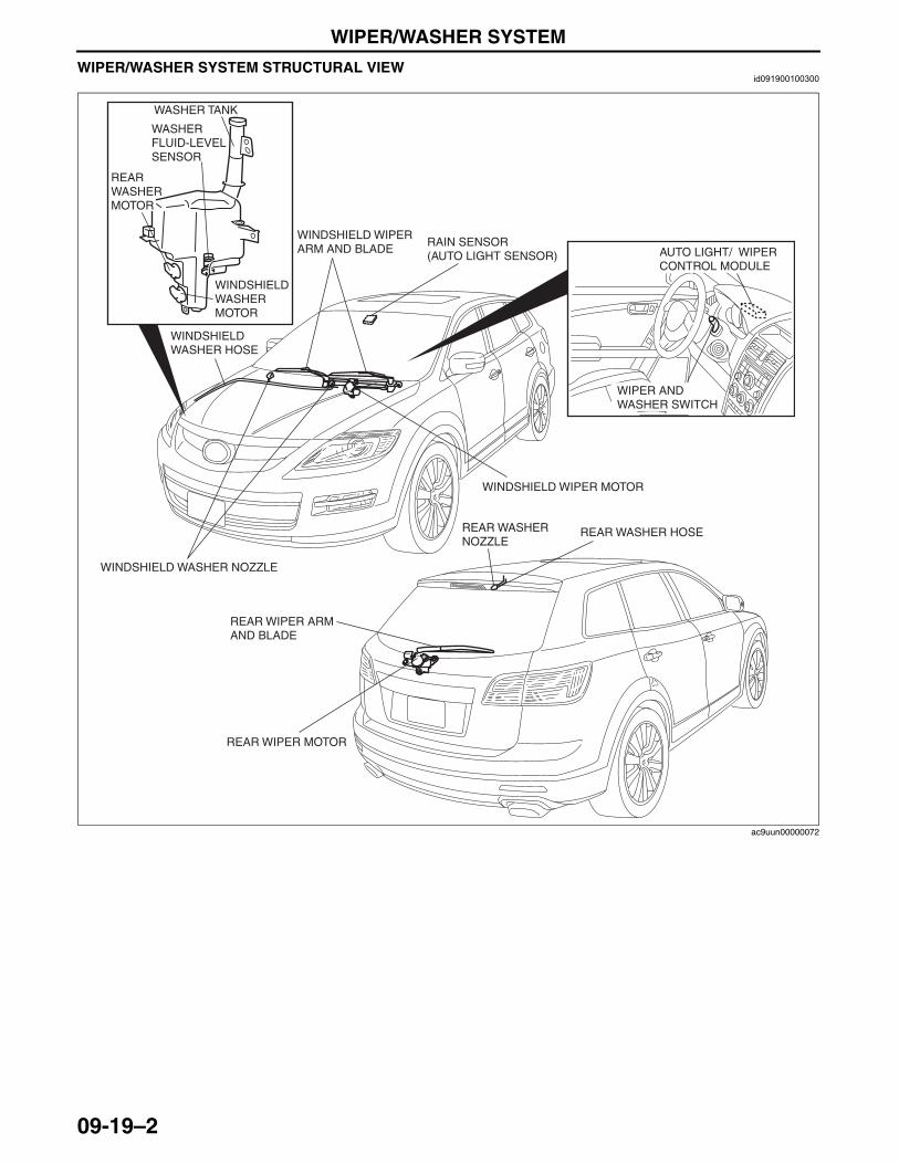
WIPER/WASHER SYSTEM
09-19–2
WIPER/WASHER SYSTEM STRUCTURAL VIEWid091900100300
End Of Sie
WASHER TANK
WASHER FLUID-LEVEL SENSOR
REAR WASHER MOTOR
WINDSHIELD WASHER MOTOR
WINDSHIELD WASHER HOSE
WINDSHIELD WIPER ARM AND BLADE
WINDSHIELD WASHER NOZZLE
WINDSHIELD WIPER MOTOR
AUTO LIGHT/ WIPER CONTROL MODULE
WIPER AND WASHER SWITCH
REAR WASHER HOSEREAR WASHER NOZZLE
REAR WIPER ARM AND BLADE
REAR WIPER MOTOR
RAIN SENSOR (AUTO LIGHT SENSOR)
ac9uun00000072
3423-1U-06H(09-19).fm 2 ページ 2006年11月22日 水曜日 午後3時48分
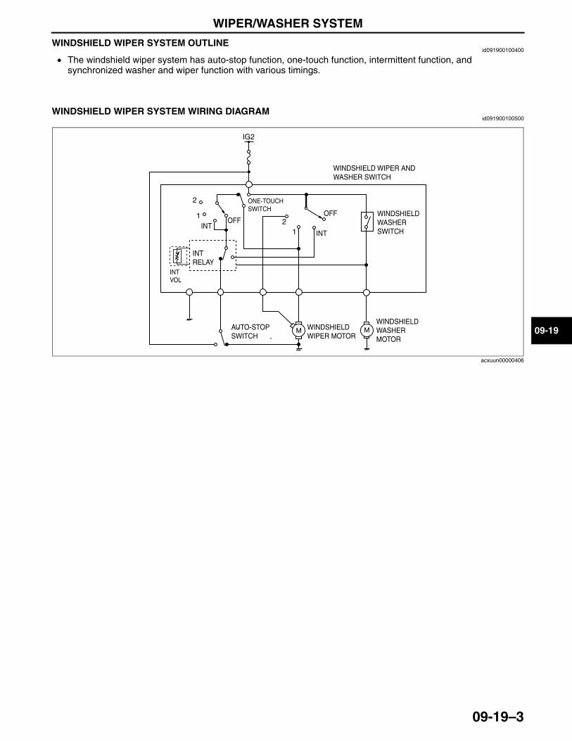
WIPER/WASHER SYSTEM
09-19–3
09-19
WINDSHIELD WIPER SYSTEM OUTLINEid091900100400
• The windshield wiper system has auto-stop function, one-touch function, intermittent function, and synchronized washer and wiper function with various timings.
End Of Sie
WINDSHIELD WIPER SYSTEM WIRING DIAGRAMid091900100500
End Of Sie
IG2
INTINT
OFFOFF
1
12
2
INT RELAY
ONE-TOUCH SWITCH
INTVOL
WINDSHIELD WIPER AND WASHER SWITCH
WINDSHIELD WASHER SWITCH
WINDSHIELD WASHER MOTOR
AUTO-STOP SWITCH
WINDSHIELD WIPER MOTOR
acxuun00000406
3423-1U-06H(09-19).fm 3 ページ 2006年11月22日 水曜日 午後3時48分
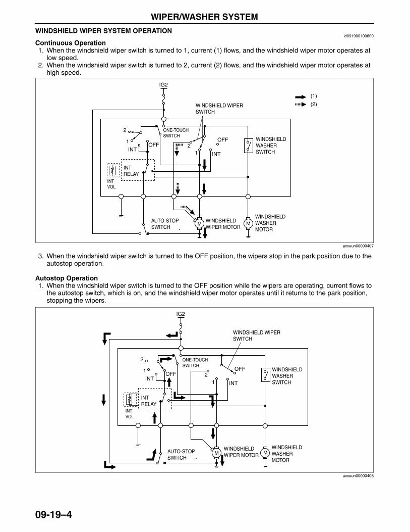
WIPER/WASHER SYSTEM
09-19–4
WINDSHIELD WIPER SYSTEM OPERATIONid091900100600
Continuous Operation1. When the windshield wiper switch is turned to 1, current (1) flows, and the windshield wiper motor operates at
low speed.2. When the windshield wiper switch is turned to 2, current (2) flows, and the windshield wiper motor operates at
high speed.
3. When the windshield wiper switch is turned to the OFF position, the wipers stop in the park position due to the autostop operation.
Autostop Operation1. When the windshield wiper switch is turned to the OFF position while the wipers are operating, current flows to
the autostop switch, which is on, and the windshield wiper motor operates until it returns to the park position, stopping the wipers.
IG2
INTINT
OFFOFF
1
12
2
(2)
(1)
INT RELAY
ONE-TOUCH SWITCH
INTVOL
WINDSHIELD WIPER SWITCH
WINDSHIELD WASHER SWITCH
WINDSHIELD WASHER MOTOR
AUTO-STOP SWITCH
WINDSHIELD WIPER MOTOR
acxuun00000407
IG2
INTINT
OFFOFF
1
12
2
INT RELAY
ONE-TOUCH SWITCH
INTVOL
WINDSHIELD WIPER SWITCH
WINDSHIELD WASHER SWITCH
WINDSHIELD WASHER MOTOR
AUTO-STOP SWITCH
WINDSHIELD WIPER MOTOR
acxuun00000408
3423-1U-06H(09-19).fm 4 ページ 2006年11月21日 火曜日 午後5時45分
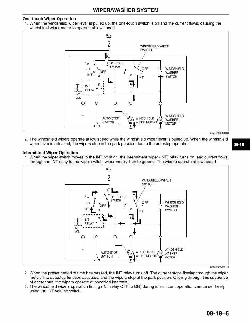
WIPER/WASHER SYSTEM
09-19–5
09-19
One-touch Wiper Operation1. When the windshield wiper lever is pulled up, the one-touch switch is on and the current flows, causing the
windshield wiper motor to operate at low speed.
2. The windshield wipers operate at low speed while the windshield wiper lever is pulled up. When the windshield wiper lever is released, the wipers stop in the park position due to the autostop operation.
Intermittent Wiper Operation1. When the wiper switch moves to the INT position, the intermittent wiper (INT) relay turns on, and current flows
through the INT relay to the wiper switch, wiper motor, then to ground. The wipers operate at low speed.
2. When the preset period of time has passed, the INT relay turns off. The current stops flowing through the wiper motor. The autostop function activates, and the wipers stop at the park position. Cycling through this sequence of operations, the wipers operate at specified intervals.
3. The windshield wipers operation timing (INT relay OFF to ON) during intermittent operation can be set freely using the INT volume switch.
IG2
INTINT
OFFOFF
1
12
2
INT RELAY
ONE-TOUCH SWITCH
INTVOL
WINDSHIELD WIPER SWITCH
WINDSHIELD WASHER SWITCH
WINDSHIELD WASHER MOTOR
AUTO-STOP SWITCH
WINDSHIELD WIPER MOTOR
acxuun00000409
IG2
INTINT
OFFOFF
1
12
2
INT RELAY
ONE-TOUCH SWITCH
INTVOL
WINDSHIELD WIPER SWITCH
WINDSHIELD WASHER SWITCH
WINDSHIELD WASHER MOTOR
AUTO-STOP SWITCH
WINDSHIELD WIPER MOTOR
acxuun00000410
3423-1U-06H(09-19).fm 5 ページ 2006年11月21日 火曜日 午後5時45分
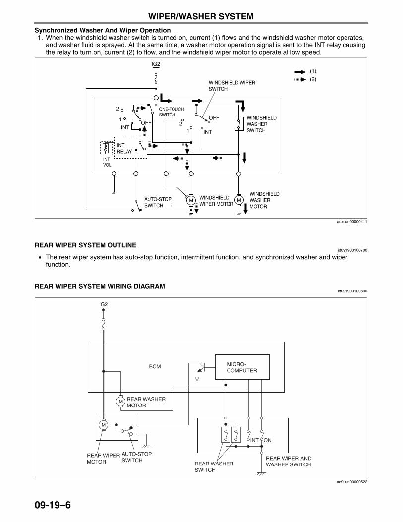
WIPER/WASHER SYSTEM
09-19–6
Synchronized Washer And Wiper Operation1. When the windshield washer switch is turned on, current (1) flows and the windshield washer motor operates,
and washer fluid is sprayed. At the same time, a washer motor operation signal is sent to the INT relay causing the relay to turn on, current (2) to flow, and the windshield wiper motor to operate at low speed.
End Of Sie
REAR WIPER SYSTEM OUTLINEid091900100700
• The rear wiper system has auto-stop function, intermittent function, and synchronized washer and wiper function.
End Of Sie
REAR WIPER SYSTEM WIRING DIAGRAMid091900100800
End Of Sie
IG2
INTINT
OFFOFF
1
12
2
(2)
(1)
INT RELAY
ONE-TOUCH SWITCH
INTVOL
WINDSHIELD WIPER SWITCH
WINDSHIELD WASHER SWITCH
WINDSHIELD WASHER MOTOR
AUTO-STOP SWITCH
WINDSHIELD WIPER MOTOR
acxuun00000411
REAR WIPER AND WASHER SWITCH
BCM
REAR WASHER SWITCH
REAR WASHER MOTOR
ONINT
IG2
AUTO-STOPSWITCH
REAR WIPERMOTOR
MICRO-COMPUTER
ac9uun00000522
3423-1U-06H(09-19).fm 6 ページ 2006年11月21日 火曜日 午後5時45分
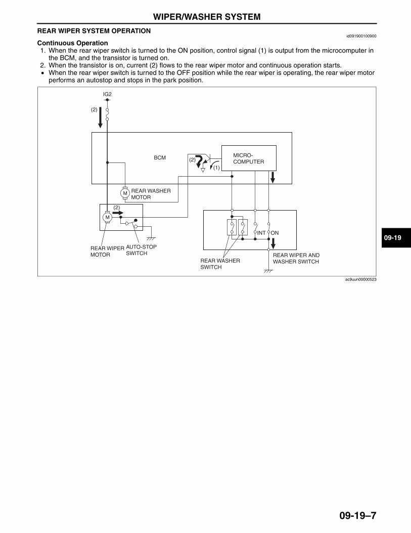
WIPER/WASHER SYSTEM
09-19–7
09-19
REAR WIPER SYSTEM OPERATIONid091900100900
Continuous Operation1. When the rear wiper switch is turned to the ON position, control signal (1) is output from the microcomputer in
the BCM, and the transistor is turned on.2. When the transistor is on, current (2) flows to the rear wiper motor and continuous operation starts.• When the rear wiper switch is turned to the OFF position while the rear wiper is operating, the rear wiper motor
performs an autostop and stops in the park position.
REAR WIPER AND WASHER SWITCH
BCM
REAR WASHER SWITCH
REAR WASHER MOTOR
ONINT
IG2
AUTO-STOPSWITCH
REAR WIPERMOTOR
MICRO-COMPUTER
(2)
(2)
(1)
(2)
ac9uun00000523
3423-1U-06H(09-19).fm 7 ページ 2006年11月21日 火曜日 午後5時45分
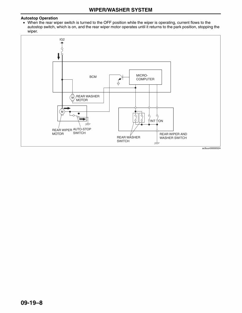
WIPER/WASHER SYSTEM
09-19–8
Autostop Operation• When the rear wiper switch is turned to the OFF position while the wiper is operating, current flows to the
autostop switch, which is on, and the rear wiper motor operates until it returns to the park position, stopping the wiper.
REAR WIPER AND WASHER SWITCH
BCM
REAR WASHER SWITCH
REAR WASHER MOTOR
ONINT
IG2
AUTO-STOPSWITCH
REAR WIPERMOTOR
MICRO-COMPUTER
ac9uun00000524
3423-1U-06H(09-19).fm 8 ページ 2006年11月21日 火曜日 午後5時45分
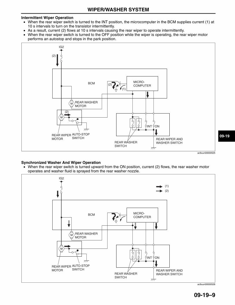
WIPER/WASHER SYSTEM
09-19–9
09-19
Intermittent Wiper Operation• When the rear wiper switch is turned to the INT position, the microcomputer in the BCM supplies current (1) at
10 s intervals to turn on the transistor intermittently.• As a result, current (2) flows at 10 s intervals causing the rear wiper to operate intermittently.• When the rear wiper switch is turned to the OFF position while the wiper is operating, the rear wiper motor
performs an autostop and stops in the park position.
Synchronized Washer And Wiper Operation• When the rear wiper switch is turned upward from the ON position, current (2) flows, the rear washer motor
operates and washer fluid is sprayed from the rear washer nozzle.
REAR WIPER AND WASHER SWITCH
BCM
REAR WASHER SWITCH
REAR WASHER MOTOR
ONINT
IG2
AUTO-STOPSWITCH
REAR WIPERMOTOR
MICRO-COMPUTER
(2)
(2)
(1)
(2)
ac9uun00000525
REAR WIPER AND WASHER SWITCH
BCM
REAR WASHER SWITCH
REAR WASHER MOTOR
ONINT
IG2
AUTO-STOPSWITCH
REAR WIPERMOTOR
MICRO-COMPUTER
(2)
(1)
ac9uun00000526
3423-1U-06H(09-19).fm 9 ページ 2006年11月21日 火曜日 午後5時45分
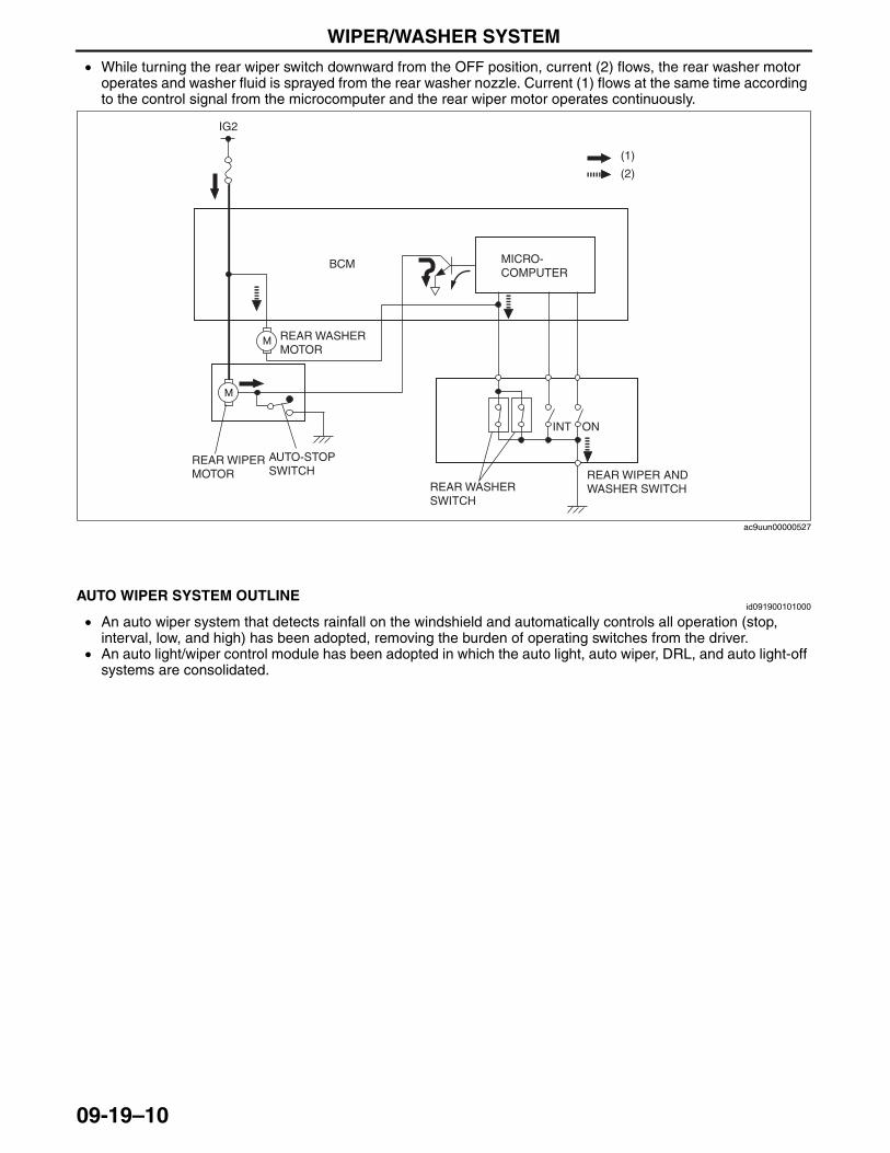
WIPER/WASHER SYSTEM
09-19–10
• While turning the rear wiper switch downward from the OFF position, current (2) flows, the rear washer motor operates and washer fluid is sprayed from the rear washer nozzle. Current (1) flows at the same time according to the control signal from the microcomputer and the rear wiper motor operates continuously.
End Of SieNG: AUTO WIPER SYSTEM
AUTO WIPER SYSTEM OUTLINEid091900101000
• An auto wiper system that detects rainfall on the windshield and automatically controls all operation (stop, interval, low, and high) has been adopted, removing the burden of operating switches from the driver.
• An auto light/wiper control module has been adopted in which the auto light, auto wiper, DRL, and auto light-off systems are consolidated.
End Of Sie
REAR WIPER AND WASHER SWITCH
BCM
REAR WASHER SWITCH
REAR WASHER MOTOR
ONINT
IG2
AUTO-STOPSWITCH
REAR WIPERMOTOR
MICRO-COMPUTER
(2)
(1)
ac9uun00000527
3423-1U-06H(09-19).fm 10 ページ 2006年11月21日 火曜日 午後5時45分
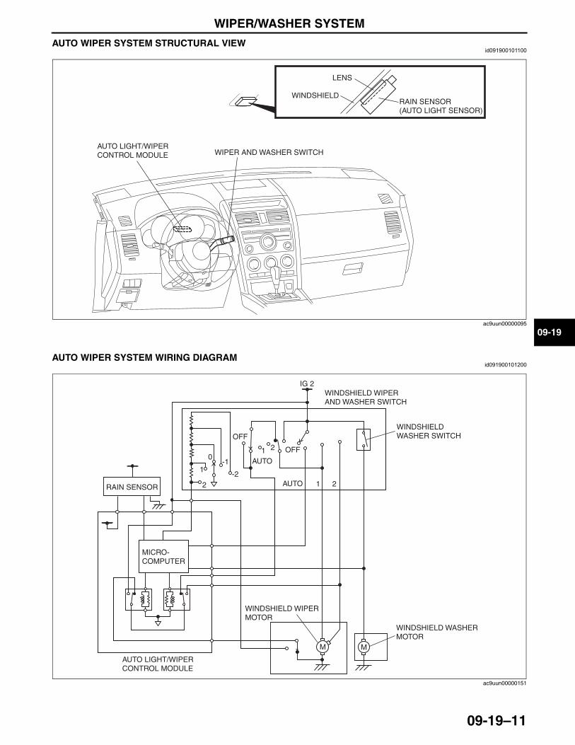
WIPER/WASHER SYSTEM
09-19–11
09-19
AUTO WIPER SYSTEM STRUCTURAL VIEWid091900101100
End Of Sie
AUTO WIPER SYSTEM WIRING DIAGRAMid091900101200
End Of Sie
WIPER AND WASHER SWITCHAUTO LIGHT/WIPER CONTROL MODULE
LENS
WINDSHIELDRAIN SENSOR (AUTO LIGHT SENSOR)
ac9uun00000095
M M
IG 2
OFF
OFF
AUTO
AUTO
1
1
2
2
-2
-10
1
2
WINDSHIELD WIPER AND WASHER SWITCH
WINDSHIELD WASHER SWITCH
WINDSHIELD WASHER MOTOR
WINDSHIELD WIPER MOTOR
MICRO-COMPUTER
RAIN SENSOR
AUTO LIGHT/WIPER CONTROL MODULE
ac9uun00000151
3423-1U-06H(09-19).fm 11 ページ 2006年11月21日 火曜日 午後5時45分
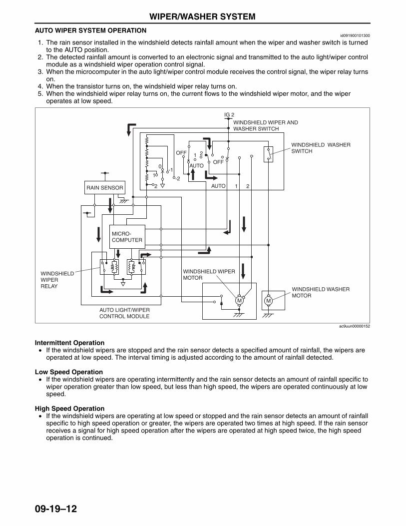
WIPER/WASHER SYSTEM
09-19–12
AUTO WIPER SYSTEM OPERATIONid091900101300
1. The rain sensor installed in the windshield detects rainfall amount when the wiper and washer switch is turned to the AUTO position.
2. The detected rainfall amount is converted to an electronic signal and transmitted to the auto light/wiper control module as a windshield wiper operation control signal.
3. When the microcomputer in the auto light/wiper control module receives the control signal, the wiper relay turns on.
4. When the transistor turns on, the windshield wiper relay turns on.5. When the windshield wiper relay turns on, the current flows to the windshield wiper motor, and the wiper
operates at low speed.
Intermittent Operation• If the windshield wipers are stopped and the rain sensor detects a specified amount of rainfall, the wipers are
operated at low speed. The interval timing is adjusted according to the amount of rainfall detected.
Low Speed Operation• If the windshield wipers are operating intermittently and the rain sensor detects an amount of rainfall specific to
wiper operation greater than low speed, but less than high speed, the wipers are operated continuously at low speed.
High Speed Operation• If the windshield wipers are operating at low speed or stopped and the rain sensor detects an amount of rainfall
specific to high speed operation or greater, the wipers are operated two times at high speed. If the rain sensor receives a signal for high speed operation after the wipers are operated at high speed twice, the high speed operation is continued.
M M
-2
-10
1
2
IG 2
RAIN SENSOR
MICRO-COMPUTER
WINDSHIELD WASHER MOTOR
WINDSHIELD WIPER MOTOR
WINDSHIELD WIPER RELAY
WINDSHIELD WASHER SWITCH
WINDSHIELD WIPER AND WASHER SWITCH
AUTO LIGHT/WIPER CONTROL MODULE
OFF
OFF
AUTO
AUTO
1
1
2
2
ac9uun00000152
3423-1U-06H(09-19).fm 12 ページ 2006年11月22日 水曜日 午後3時48分
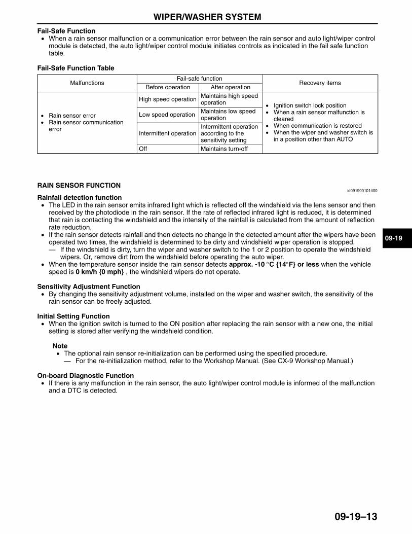
WIPER/WASHER SYSTEM
09-19–13
09-19
Fail-Safe Function• When a rain sensor malfunction or a communication error between the rain sensor and auto light/wiper control
module is detected, the auto light/wiper control module initiates controls as indicated in the fail safe function table.
Fail-Safe Function Table
End Of Sie
RAIN SENSOR FUNCTIONid091900101400
Rainfall detection function• The LED in the rain sensor emits infrared light which is reflected off the windshield via the lens sensor and then
received by the photodiode in the rain sensor. If the rate of reflected infrared light is reduced, it is determined that rain is contacting the windshield and the intensity of the rainfall is calculated from the amount of reflection rate reduction.
• If the rain sensor detects rainfall and then detects no change in the detected amount after the wipers have been operated two times, the windshield is determined to be dirty and windshield wiper operation is stopped.— If the windshield is dirty, turn the wiper and washer switch to the 1 or 2 position to operate the windshield
wipers. Or, remove dirt from the windshield before operating the auto wiper.• When the temperature sensor inside the rain sensor detects approx. -10 °C {14°F} or less when the vehicle
speed is 0 km/h {0 mph} , the windshield wipers do not operate.
Sensitivity Adjustment Function• By changing the sensitivity adjustment volume, installed on the wiper and washer switch, the sensitivity of the
rain sensor can be freely adjusted.
Initial Setting Function• When the ignition switch is turned to the ON position after replacing the rain sensor with a new one, the initial
setting is stored after verifying the windshield condition.
Note• The optional rain sensor re-initialization can be performed using the specified procedure.— For the re-initialization method, refer to the Workshop Manual. (See CX-9 Workshop Manual.)
On-board Diagnostic Function• If there is any malfunction in the rain sensor, the auto light/wiper control module is informed of the malfunction
and a DTC is detected.End Of Sie
MalfunctionsFail-safe function
Recovery itemsBefore operation After operation
• Rain sensor error• Rain sensor communication
error
High speed operation Maintains high speed operation • Ignition switch lock position
• When a rain sensor malfunction is cleared
• When communication is restored• When the wiper and washer switch is
in a position other than AUTO
Low speed operation Maintains low speed operation
Intermittent operationIntermittent operation according to the sensitivity setting
Off Maintains turn-off
3423-1U-06H(09-19).fm 13 ページ 2006年11月22日 水曜日 午後3時48分
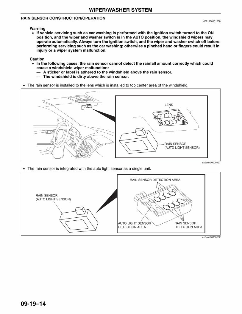
WIPER/WASHER SYSTEM
09-19–14
RAIN SENSOR CONSTRUCTION/OPERATIONid091900101500
Warning• If vehicle servicing such as car washing is performed with the ignition switch turned to the ON
position, and the wiper and washer switch is in the AUTO position, the windshield wipers may operate automatically. Always turn the ignition switch, and the wiper and washer switch off before performing servicing such as the car washing; otherwise a pinched hand or fingers could result in injury or a wiper system malfunction.
Caution• In the following cases, the rain sensor cannot detect the rainfall amount correctly which could
cause a windshield wiper malfunction:— A sticker or label is adhered to the windshield above the rain sensor.— The windshield is dirty above the rain sensor.
• The rain sensor is installed to the lens which is installed to top center area of the windshield.
• The rain sensor is integrated with the auto light sensor as a single unit.
RAIN SENSOR(AUTO LIGHT SENSOR)
LENS
ac9uun00000127
RAIN SENSOR (AUTO LIGHT SENSOR)
RAIN SENSOR DETECTION AREA
RAIN SENSOR DETECTION AREA
AUTO LIGHT SENSOR DETECTION AREA
ac9uun00000592
3423-1U-06H(09-19).fm 14 ページ 2006年11月21日 火曜日 午後5時45分
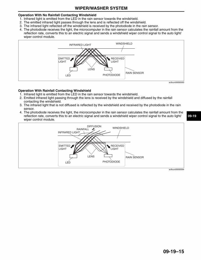
WIPER/WASHER SYSTEM
09-19–15
09-19
Operation With No Rainfall Contacting Windshield1. Infrared light is emitted from the LED in the rain sensor towards the windshield.2. The emitted infrared light passes through the lens and is reflected off the windshield.3. The infrared light reflected off the windshield is received by the photodiode in the rain sensor.4. The photodiode receives the light, the microcomputer in the rain sensor calculates the rainfall amount from the
reflection rate, converts this to an electric signal and sends a windshield wiper control signal to the auto light/wiper control module.
Operation With Rainfall Contacting Windshield1. Infrared light is emitted from the LED in the rain sensor towards the windshield.2. Emitted infrared light passing through the lens is received by the windshield and diffused by the rainfall
contacting the windshield.3. The infrared light that is not diffused is reflected by the windshield and received by the photodiode in the rain
sensor.4. The photodiode receives the light, the microcomputer in the rain sensor calculates the rainfall amount from the
reflection rate, converts this to an electric signal and sends a windshield wiper control signal to the auto light/wiper control module.
End Of SieNG: WASHER FLUID-LEVEL SENSOR
INFRARED LIGHT
LENSRAIN SENSOR
PHOTODIODE
WINDSHIELD
EMITTED LIGHT
RECEIVED LIGHT
LED
ac9uun00000593
LED
RAINFALLDIFFUSION
INFRARED LIGHT
LENS RAIN SENSOR
PHOTODIODE
WINDSHIELD
EMITTED LIGHT
RECEIVED LIGHT
ac9uun00000594
3423-1U-06H(09-19).fm 15 ページ 2006年11月23日 木曜日 午前11時12分
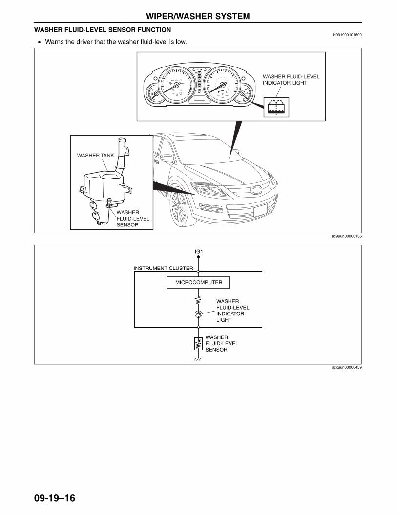
WIPER/WASHER SYSTEM
09-19–16
WASHER FLUID-LEVEL SENSOR FUNCTIONid091900101600
• Warns the driver that the washer fluid-level is low.
End Of Sie
BRAKE
WASHER FLUID-LEVEL INDICATOR LIGHT
WASHER TANK
WASHER FLUID-LEVEL SENSOR
ac9uun00000136
IG1
MICROCOMPUTER
INSTRUMENT CLUSTER
WASHER FLUID-LEVEL INDICATOR LIGHT
WASHER FLUID-LEVEL SENSOR
acxuun00000459
3423-1U-06H(09-19).fm 16 ページ 2006年11月21日 火曜日 午後5時45分
ENTERTAINMENT
09-20–1
09-20
09-20 ENTERTAINMENTENTERTAINMENT OUTLINE . . . . . . . . . 09-20–3AUDIO SYSTEM
STRUCTURAL VIEW . . . . . . . . . . . . . . 09-20–4AUDIO SYSTEM
BLOCK DIAGRAM . . . . . . . . . . . . . . . . 09-20–6AUDIO SYSTEM
SPECIFICATIONS . . . . . . . . . . . . . . . . . 09-20–6Audio Unit. . . . . . . . . . . . . . . . . . . . . . . 09-20–6Speaker . . . . . . . . . . . . . . . . . . . . . . . . 09-20–6
AUDIO UNIT CONSTRUCTION/OPERATION . . . . . . 09-20–7
Standard Audio . . . . . . . . . . . . . . . . . . 09-20–7Touch Panel Type Audio. . . . . . . . . . . . 09-20–8Button Location . . . . . . . . . . . . . . . . . . 09-20–10
AUTO LEVEL CONTROL (ALC) FUNCTION . . . . . . . . . . . . . . . . . . . . . . 09-20–11
AUTO LEVEL CONTROL (ALC) OPERATION . . . . . . . . . . . . . . . . . . . . . 09-20–12
AUDIOPILOT OUTLINE . . . . . . . . . . . . . 09-20–12AUDIOPILOT
CONSTRUCTION/OPERATION . . . . . . 09-20–13ON-BOARD DIAGNOSTIC
SYSTEM FUNCTION [AUDIO AMPLIFIER]. . . . . . . . . . . . . . . 09-20–13
Self-diagnostic Function. . . . . . . . . . . . 09-20–13ON-BOARD DIAGNOSTIC
SYSTEM FUNCTION [AUDIO (STANDARD AUDIO)] . . . . . . . 09-20–14
Self-diagnostic Function. . . . . . . . . . . . 09-20–14Diagnostic Assist Function . . . . . . . . . . 09-20–15
ON-BOARD DIAGNOSTIC SYSTEM FUNCTION [AUDIO (TOUCH PANEL TYPE AUDIO)] . . . . . . 09-20–17
Self-diagnostic Function. . . . . . . . . . . . 09-20–17Diagnostic Assist Function . . . . . . . . . . 09-20–18
ON-BOARD DIAGNOSTIC SYSTEM FUNCTION [HANDS-FREE TELEPHONE (HF/TEL) SYSTEM] . . . . . . . . . . . . . . . . 09-20–20
Self-diagnostic Function. . . . . . . . . . . . 09-20–20Diagnostic Assist Function . . . . . . . . . . 09-20–21
CONTROLLER AREA NETWOR (CAN) OUTLINE . . . . . . . . . . . . . . . . . . 09-20–22
Data sent . . . . . . . . . . . . . . . . . . . . . . . 09-20–22Data received . . . . . . . . . . . . . . . . . . . . 09-20–22
ACTION ILLUMINATION OUTLINE . . . . 09-20–22ACTION ILLUMINATION
STRUCTURAL VIEW . . . . . . . . . . . . . . 09-20–23SPEAKER CONSTRUCTION . . . . . . . . . 09-20–23
Front Door Speaker . . . . . . . . . . . . . . . 09-20–23Rear Door Speaker . . . . . . . . . . . . . . . 09-20–23Tweeter (without Bose®) . . . . . . . . . . . 09-20–23Front Speaker (with Bose®) . . . . . . . . . 09-20–23Rear Speaker (with Bose®) . . . . . . . . . 09-20–23Center Speaker (with Bose®) . . . . . . . 09-20–23Roof Speaker (with RES) . . . . . . . . . . . 09-20–23Bass-box (with Bose®). . . . . . . . . . . . . 09-20–23
AUDIO AMPLIFIER CONSTRUCTION . . . . . . . . . . . . . . . . . 09-20–24
Terminal Layout and Signal . . . . . . . . . 09-20–24AUDIO AMPLIFIER FUNCTION . . . . . . . 09-20–25
Centerpoint Function. . . . . . . . . . . . . . . 09-20–255.1ch Discrete Surround Sound
(Front Seat-optimized And Rear Seat-optimized Modes) . . . . . . . 09-20–25
ANTENNA CONSTRUCTION. . . . . . . . . . 09-20–26Glass Antenna. . . . . . . . . . . . . . . . . . . . 09-20–26
AUDIO CONTROL SWITCH OUTLINE . . . . . . . . . . . . . . . . . . . . . . . . 09-20–26
AUDIO CONTROL SWITCH CONSTRUCTION/OPERATION . . . . . . . 09-20–26
Construction . . . . . . . . . . . . . . . . . . . . . 09-20–26Operation . . . . . . . . . . . . . . . . . . . . . . . 09-20–26
CAR-NAVIGATION SYSTEM OUTLINE . . . . . . . . . . . . . . . . . . . . . . . . 09-20–27
CAR-NAVIGATION SYSTEM STRUCTURAL VIEW . . . . . . . . . . . . . . . 09-20–27
CAR-NAVIGATION SYSTEM BLOCK DIAGRAM . . . . . . . . . . . . . . . . . 09-20–29
CAR-NAVIGATION SYSTEM SPECIFICATIONS . . . . . . . . . . . . . . . . . 09-20–29
Car-navigation Unit . . . . . . . . . . . . . . . . 09-20–29Audio Unit . . . . . . . . . . . . . . . . . . . . . . . 09-20–29Speaker . . . . . . . . . . . . . . . . . . . . . . . . . 09-20–29
COMPONENT PART AND FUNCTION . . . . . . . . . . . . . . . . . . . . . . . 09-20–30
NAVIGATION FUNCTION. . . . . . . . . . . . . 09-20–31Outline . . . . . . . . . . . . . . . . . . . . . . . . . . 09-20–31Map Screen Selection . . . . . . . . . . . . . . 09-20–31Destination Setting Function . . . . . . . . . 09-20–33Voice Recognition Function. . . . . . . . . . 09-20–34
CAR-NAVIGATION UNIT OUTLINE . . . . . . . . . . . . . . . . . . . . . . . . 09-20–34
CAR-NAVIGATION UNIT CONSTRUCTION . . . . . . . . . . . . . . . . . . 09-20–35
Structure . . . . . . . . . . . . . . . . . . . . . . . . 09-20–35Terminal Layout and Signals . . . . . . . . . 09-20–35
AUTONOMOUS NAVIGATION OPERATION . . . . . . . . . . . . . . . . . . . . . . 09-20–36
GYRO SENSOR FUNCTION . . . . . . . . . . 09-20–36GPS (GLOBAL POSITIONING
SYSTEM) NAVIGATION OUTLINE . . . . 09-20–36GPS (GLOBAL POSITIONING
SYSTEM) NAVIGATION OPERATION . . . . . . . . . . . . . . . . . . . . . . 09-20–37
MAP MATCHING OUTLINE . . . . . . . . . . . 09-20–37MAP MATCHING OPERATION . . . . . . . . 09-20–38
Map Matching Remarks . . . . . . . . . . . . 09-20–38MICROPHONE
CONSTRUCTION/OPERATION . . . . . . . 09-20–41Terminal Layout and Signals . . . . . . . . . 09-20–41
REAR VIEW MONITOR OUTLINE . . . . . . 09-20–42REAR VIEW MONITOR
STRUCTURAL VIEW . . . . . . . . . . . . . . . 09-20–42REAR MOUNT CAMERA
FUNCTION . . . . . . . . . . . . . . . . . . . . . . . 09-20–42REAR MOUNT CAMERA
CONSTRUCTION/OPERATION . . . . . . . 09-20–43Displayable Range . . . . . . . . . . . . . . . . 09-20–43
REAR ENTERTAINMENT SYSTEM (RES) OUTLINE . . . . . . . . . . . 09-20–44
Outline . . . . . . . . . . . . . . . . . . . . . . . . . . 09-20–44Specifications . . . . . . . . . . . . . . . . . . . . 09-20–44
3423-1U-06H(09-20).fm 1 ページ 2006年11月21日 火曜日 午後5時46分
ENTERTAINMENT
09-20–2
REAR ENTERTAINMENT SYSTEM (RES) STRUCTURAL VIEW. . . . . . . . . . 09-20–45
REAR ENTERTAINMENT SYSTEM (RES) BLOCK DIAGRAM. . . . . . . . . . . . 09-20–46
Terminal Layout and Signal . . . . . . . . . 09-20–47REAR ENTERTAINMENT SYSTEM
(RES) FUNCTION. . . . . . . . . . . . . . . . . . 09-20–48DVD/CD Play Function . . . . . . . . . . . . . 09-20–48Auxiliary Input Function. . . . . . . . . . . . . 09-20–48Initial Setting Function . . . . . . . . . . . . . 09-20–49Picture Adjustment Function . . . . . . . . . 09-20–49Screen Size Setting Function . . . . . . . . 09-20–49Display Open/Close
Detection Function . . . . . . . . . . . . . . . 09-20–49Wireless Sound Output Function . . . . . 09-20–50Abnormal Temperature
Detection and Protection Function . . . . . . . . . . . . . . . 09-20–50
Fun Control Function . . . . . . . . . . . . . . 09-20–50Low Voltage Detection and
Protection Function . . . . . . . . . . . . . . . 09-20–50REMOTE CONTROLLER
CONSTRUCTION . . . . . . . . . . . . . . . . . . 09-20–51Buttons Function . . . . . . . . . . . . . . . . . . 09-20–51
AUXILIARY TERMINAL UNIT CONSTRUCTION . . . . . . . . . . . . . . . . . . 09-20–52
Outline . . . . . . . . . . . . . . . . . . . . . . . . . 09-20–52Construction . . . . . . . . . . . . . . . . . . . . . 09-20–52
AUXILIARY JACK CONSTRUCTION/OPERATION . . . . . . 09-20–52
Outline . . . . . . . . . . . . . . . . . . . . . . . . . 09-20–52Structural View . . . . . . . . . . . . . . . . . . . 09-20–52
POWER SUPPLY SOCKET (AC 115 V) CONSTRUCTION . . . . . . . . 09-20–53
INVERTER FUNCTION . . . . . . . . . . . . . . 09-20–54Fail-safe function . . . . . . . . . . . . . . . . . 09-20–54
INVERTER CONSTRUCTION/OPERATION . . . . . . 09-20–55
Outline . . . . . . . . . . . . . . . . . . . . . . . . . 09-20–55Operation . . . . . . . . . . . . . . . . . . . . . . . 09-20–55
HANDS-FREE TELEPHONE (HF/TEL) SYSTEM OUTLINE . . . . . . . . 09-20–55
HANDS-FREE TELEPHONE (HF/TEL) SYSTEM STRUCTURAL VIEW. . . . . . . . . . . . . . . 09-20–56
Component part and Function . . . . . . . 09-20–57HANDS-FREE TELEPHONE
(HF/TEL) SYSTEM BLOCK DIAGRAM . . . . . . . . . . . . . . . . 09-20–58
Terminal Layout and Signal . . . . . . . . . 09-20–59HANDS-FREE TELEPHONE
(HF/TEL) SYSTEM FUNCTION. . . . . . . 09-20–60
End of TocNG: AUDIO
3423-1U-06H(09-20).fm 2 ページ 2006年11月21日 火曜日 午後5時46分
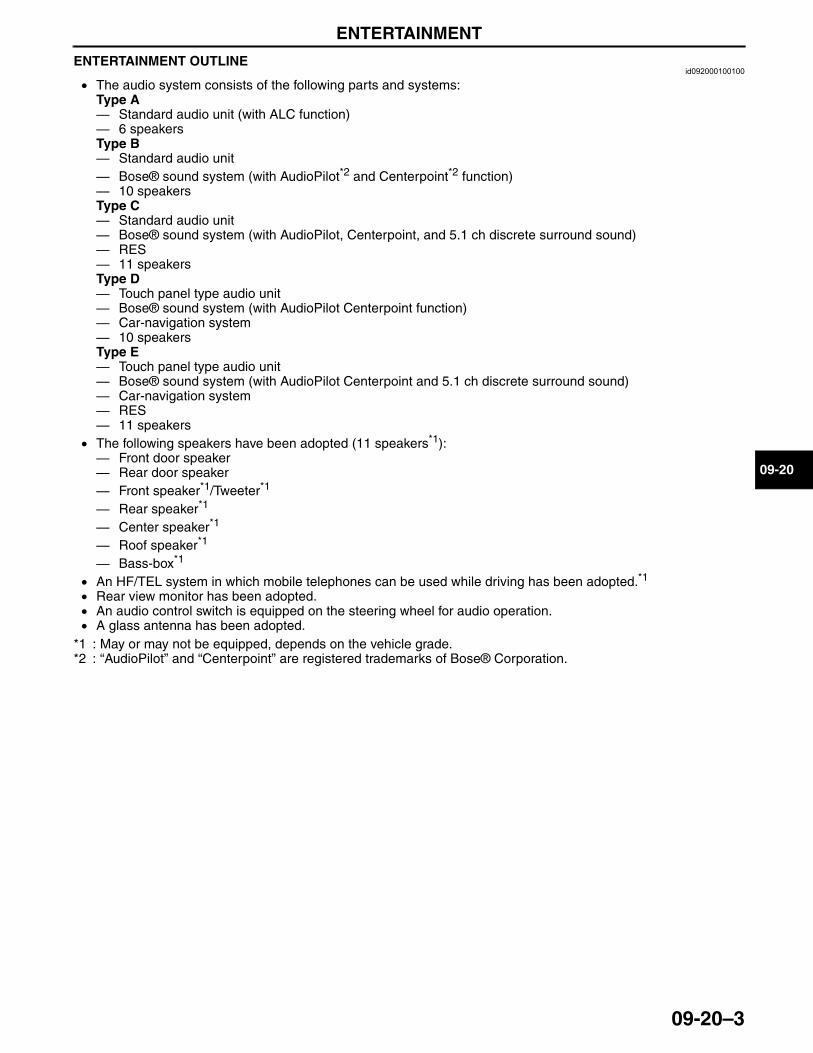
ENTERTAINMENT
09-20–3
09-20
ENTERTAINMENT OUTLINEid092000100100
• The audio system consists of the following parts and systems:Type A— Standard audio unit (with ALC function)— 6 speakersType B— Standard audio unit— Bose® sound system (with AudioPilot*2 and Centerpoint*2 function)— 10 speakersType C— Standard audio unit— Bose® sound system (with AudioPilot, Centerpoint, and 5.1 ch discrete surround sound)— RES— 11 speakersType D— Touch panel type audio unit— Bose® sound system (with AudioPilot Centerpoint function)— Car-navigation system— 10 speakersType E— Touch panel type audio unit— Bose® sound system (with AudioPilot Centerpoint and 5.1 ch discrete surround sound)— Car-navigation system— RES— 11 speakers
• The following speakers have been adopted (11 speakers*1):— Front door speaker— Rear door speaker— Front speaker*1/Tweeter*1
— Rear speaker*1
— Center speaker*1
— Roof speaker*1
— Bass-box*1
• An HF/TEL system in which mobile telephones can be used while driving has been adopted.*1
• Rear view monitor has been adopted.• An audio control switch is equipped on the steering wheel for audio operation.• A glass antenna has been adopted.
*1 : May or may not be equipped, depends on the vehicle grade.*2 : “AudioPilot” and “Centerpoint” are registered trademarks of Bose® Corporation.
End Of Sie
3423-1U-06H(09-20).fm 3 ページ 2006年11月21日 火曜日 午後5時46分
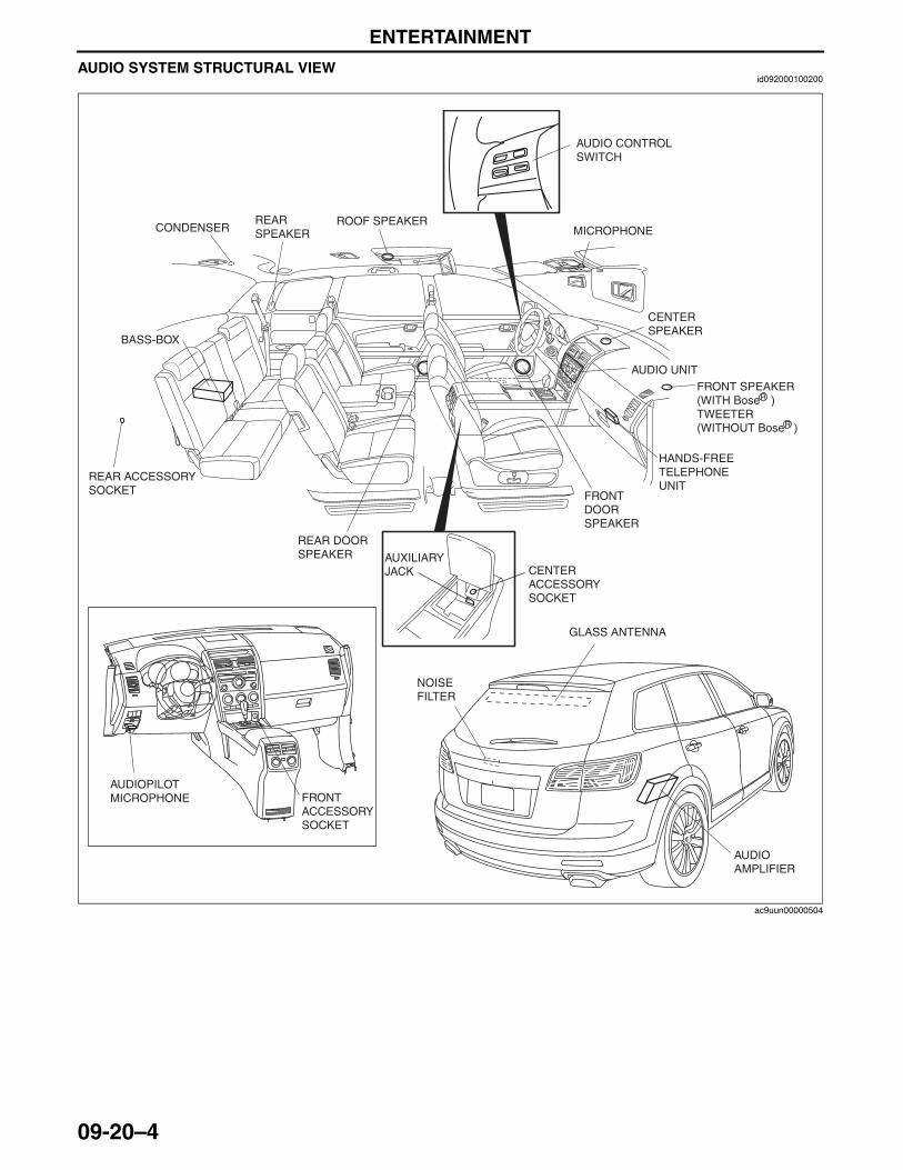
ENTERTAINMENT
09-20–4
AUDIO SYSTEM STRUCTURAL VIEWid092000100200
AUDIO CONTROL SWITCH
MICROPHONE
CENTER SPEAKER
AUDIO UNITFRONT SPEAKER (WITH BoseR )TWEETER (WITHOUT BoseR )
HANDS-FREE TELEPHONE UNIT
FRONT DOOR SPEAKER
CENTER ACCESSORY SOCKET
AUXILIARY JACK
REAR DOOR SPEAKER
ROOF SPEAKERCONDENSER
REAR ACCESSORY SOCKET
BASS-BOX
FRONT ACCESSORY SOCKET
AUDIOPILOT MICROPHONE
GLASS ANTENNA
NOISE FILTER
AUDIO AMPLIFIER
REAR SPEAKER
ac9uun00000504
3423-1U-06H(09-20).fm 4 ページ 2006年11月21日 火曜日 午後5時46分
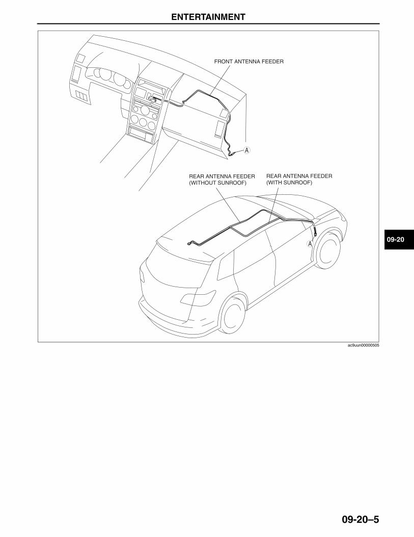
ENTERTAINMENT
09-20–5
09-20
End Of Sie
A
FRONT ANTENNA FEEDER
REAR ANTENNA FEEDER (WITHOUT SUNROOF)
REAR ANTENNA FEEDER (WITH SUNROOF)
A
ac9uun00000505
3423-1U-06H(09-20).fm 5 ページ 2006年11月21日 火曜日 午後5時46分
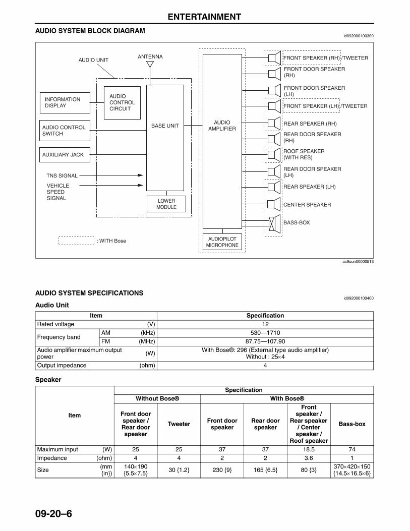
ENTERTAINMENT
09-20–6
AUDIO SYSTEM BLOCK DIAGRAMid092000100300
End Of Sie
AUDIO SYSTEM SPECIFICATIONSid092000100400
Audio Unit
Speaker
End Of SieNG: AUDIO UNIT
ANTENNA
INFORMATION DISPLAY
AUDIO UNIT
AUDIO CONTROL SWITCH
AUXILIARY JACK
BASE UNIT
TNS SIGNAL
FRONT SPEAKER (RH) /TWEETER
FRONT DOOR SPEAKER (RH)
FRONT SPEAKER (LH) /TWEETER
FRONT DOOR SPEAKER (LH)
REAR SPEAKER (RH)
REAR SPEAKER (LH)
AUDIO CONTROL CIRCUIT
AUDIO AMPLIFIER
AUDIOPILOT MICROPHONE
REAR DOOR SPEAKER (RH)
ROOF SPEAKER (WITH RES)
REAR DOOR SPEAKER (LH)
CENTER SPEAKER
VEHICLE SPEED SIGNAL
: WITH Bose
LOWER MODULE
BASS-BOX
ac9uun00000513
Item SpecificationRated voltage (V) 12
Frequency bandAM (kHz) 530—1710FM (MHz) 87.75—107.90
Audio amplifier maximum output power (W) With Bose®: 296 (External type audio amplifier)
Without : 25×4Output impedance (ohm) 4
Item
SpecificationWithout Bose® With Bose®
Front door speaker / Rear door speaker
Tweeter Front door speaker
Rear door speaker
Front speaker /
Rear speaker / Center
speaker / Roof speaker
Bass-box
Maximum input (W) 25 25 37 37 18.5 74Impedance (ohm) 4 4 2 2 3.6 1
Size (mm{in})
140×190 {5.5×7.5} 30 {1.2} 230 {9} 165 {6.5} 80 {3} 370×420×150
{14.5×16.5×6}
3423-1U-06H(09-20).fm 6 ページ 2006年11月21日 火曜日 午後5時46分
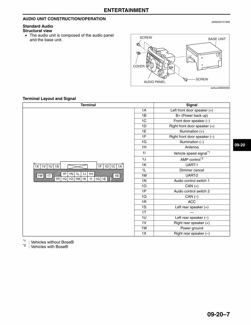
ENTERTAINMENT
09-20–7
09-20
AUDIO UNIT CONSTRUCTION/OPERATIONid092000101600
Standard AudioStructural view• The audio unit is composed of the audio panel
and the base unit.
Terminal Layout and Signal
*1 : Vehicles without Bose®*2 : Vehicles with Bose®
SCREW
SCREWAUDIO PANEL
COVER
BASE UNIT
ac9uun00000303
Terminal Signal1A Left front door speaker (+)1B B+ (Power back up)1C Front door speaker (–)1D Right front door speaker (+)1E Illumination (+)1F Right front door speaker (–)1G Illumination (–)1H Antenna
1I Vehicle speed signal*1
1J AMP control*2
1K UART-11L Dimmer cancel1M UART-21N Audio control switch 11O CAN (+)1P Audio control switch 21Q CAN (–)1R ACC1S Left rear speaker (+)1T —1U Left rear speaker (–)1V Right rear speaker (+)1W Power ground1X Right rear speaker (–)
1A
1B
1C1D1F
1E1G
1H
1I
1J
1K
1L
1M
1N
1O
1P
1Q1R
1S1U
1T1W
1V1X
3423-1U-06H(09-20).fm 7 ページ 2006年11月22日 水曜日 午後4時12分
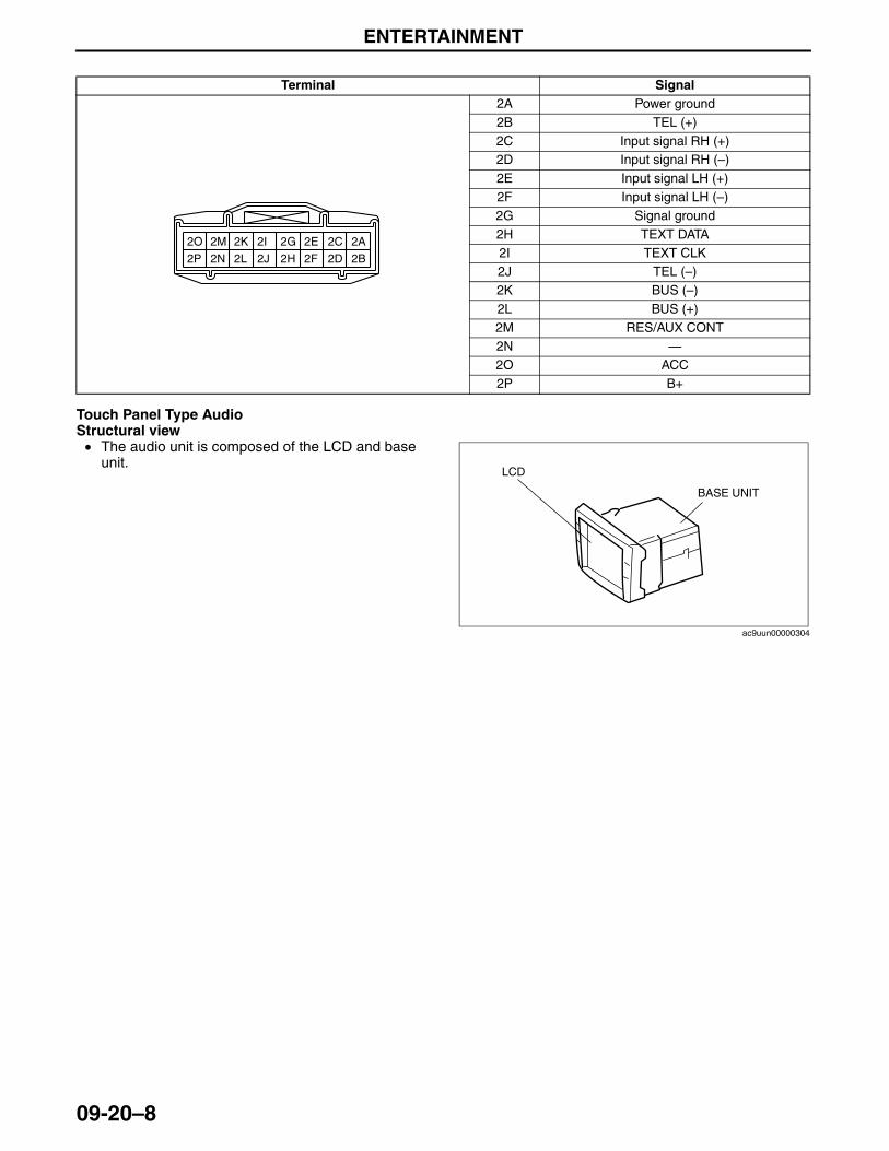
ENTERTAINMENT
09-20–8
Touch Panel Type AudioStructural view• The audio unit is composed of the LCD and base
unit.
Terminal Signal2A Power ground2B TEL (+)2C Input signal RH (+)2D Input signal RH (–)2E Input signal LH (+)2F Input signal LH (–)2G Signal ground2H TEXT DATA2I TEXT CLK2J TEL (–)2K BUS (–)2L BUS (+)2M RES/AUX CONT2N —2O ACC2P B+
2A2C2E2G2I2K2M2O
2B2D2F2H2J2L2N2P
LCD
BASE UNIT
ac9uun00000304
3423-1U-06H(09-20).fm 8 ページ 2006年11月22日 水曜日 午後4時12分
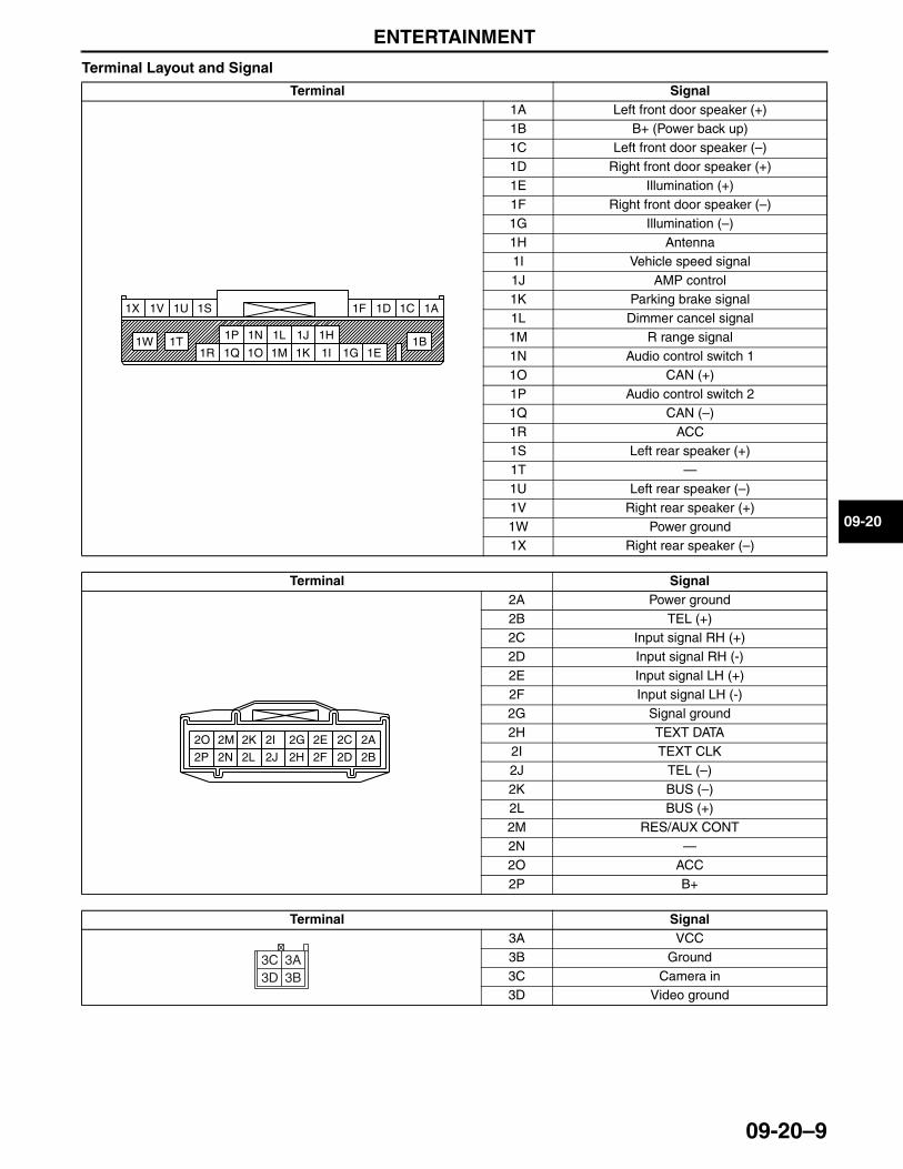
ENTERTAINMENT
09-20–9
09-20
Terminal Layout and Signal
Terminal Signal1A Left front door speaker (+)1B B+ (Power back up)1C Left front door speaker (–)1D Right front door speaker (+)1E Illumination (+)1F Right front door speaker (–)1G Illumination (–)1H Antenna1I Vehicle speed signal1J AMP control1K Parking brake signal1L Dimmer cancel signal1M R range signal1N Audio control switch 11O CAN (+)1P Audio control switch 21Q CAN (–)1R ACC1S Left rear speaker (+)1T —1U Left rear speaker (–)1V Right rear speaker (+)1W Power ground1X Right rear speaker (–)
Terminal Signal2A Power ground2B TEL (+)2C Input signal RH (+)2D Input signal RH (-)2E Input signal LH (+)2F Input signal LH (-)2G Signal ground2H TEXT DATA2I TEXT CLK2J TEL (–)2K BUS (–)2L BUS (+)2M RES/AUX CONT2N —2O ACC2P B+
Terminal Signal3A VCC3B Ground3C Camera in3D Video ground
1A
1B
1C1D1F
1E1G
1H
1I
1J
1K
1L
1M
1N
1O
1P
1Q1R
1S1U
1T1W
1V1X
2A2C2E2G2I2K2M2O
2B2D2F2H2J2L2N2P
3C3D 3B
3A
3423-1U-06H(09-20).fm 9 ページ 2006年11月21日 火曜日 午後5時46分
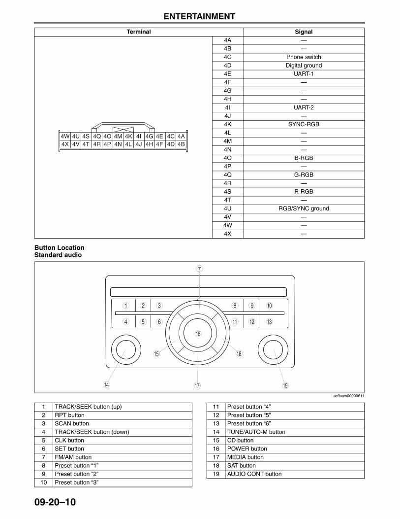
ENTERTAINMENT
09-20–10
Button LocationStandard audio
.
Terminal Signal4A —4B —4C Phone switch4D Digital ground4E UART-14F —4G —4H —4I UART-24J —4K SYNC-RGB4L —4M —4N —4O B-RGB4P —4Q G-RGB4R —4S R-RGB4T —4U RGB/SYNC ground4V —4W —4X —
4W 4U 4S 4Q 4O 4M 4K 4I 4G 4A4C4E4D4F4H4J4L4N4P4R4T4V4X 4B
98
54
3 10
19
18
17
15
16
14
1311 126
1 2
7
ac9uuw00000611
1 TRACK/SEEK button (up)2 RPT button3 SCAN button4 TRACK/SEEK button (down)5 CLK button6 SET button7 FM/AM button8 Preset button “1”9 Preset button “2”
10 Preset button “3”
11 Preset button “4”12 Preset button “5”13 Preset button “6”14 TUNE/AUTO-M button15 CD button16 POWER button17 MEDIA button18 SAT button19 AUDIO CONT button
3423-1U-06H(09-20).fm 10 ページ 2006年11月21日 火曜日 午後5時46分
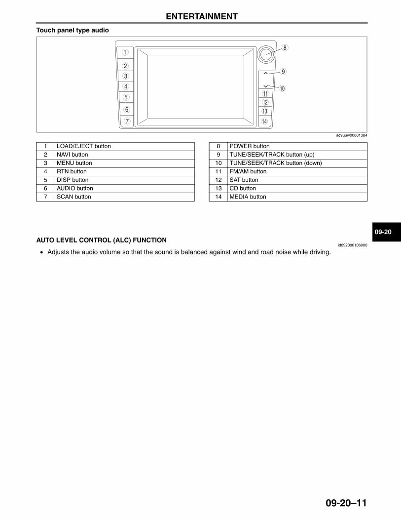
ENTERTAINMENT
09-20–11
09-20
Touch panel type audio
.
End Of Sie
AUTO LEVEL CONTROL (ALC) FUNCTIONid092000106900
• Adjusts the audio volume so that the sound is balanced against wind and road noise while driving.End Of Sie
9
8
7
5
4
3
10
14
13
1112
6
1
2
ac9uuw00001384
1 LOAD/EJECT button2 NAVI button3 MENU button4 RTN button5 DISP button6 AUDIO button7 SCAN button
8 POWER button9 TUNE/SEEK/TRACK button (up)
10 TUNE/SEEK/TRACK button (down)11 FM/AM button12 SAT button13 CD button14 MEDIA button
3423-1U-06H(09-20).fm 11 ページ 2006年11月21日 火曜日 午後5時46分
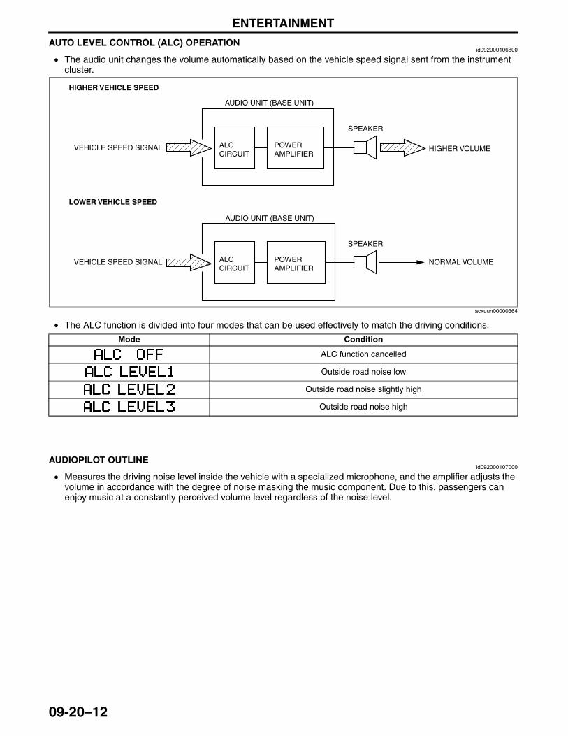
ENTERTAINMENT
09-20–12
AUTO LEVEL CONTROL (ALC) OPERATIONid092000106800
• The audio unit changes the volume automatically based on the vehicle speed signal sent from the instrument cluster.
• The ALC function is divided into four modes that can be used effectively to match the driving conditions.
End Of Sie
AUDIOPILOT OUTLINEid092000107000
• Measures the driving noise level inside the vehicle with a specialized microphone, and the amplifier adjusts the volume in accordance with the degree of noise masking the music component. Due to this, passengers can enjoy music at a constantly perceived volume level regardless of the noise level.
End Of Sie
HIGHER VEHICLE SPEED
VEHICLE SPEED SIGNAL
LOWER VEHICLE SPEED
VEHICLE SPEED SIGNAL
AUDIO UNIT (BASE UNIT)
ALC CIRCUIT
ALC CIRCUIT
AUDIO UNIT (BASE UNIT)
POWER AMPLIFIER
POWER AMPLIFIER
SPEAKER
SPEAKER
HIGHER VOLUME
NORMAL VOLUME
acxuun00000364
Mode Condition
ALC function cancelled
Outside road noise low
Outside road noise slightly high
Outside road noise high
3423-1U-06H(09-20).fm 12 ページ 2006年11月21日 火曜日 午後5時46分
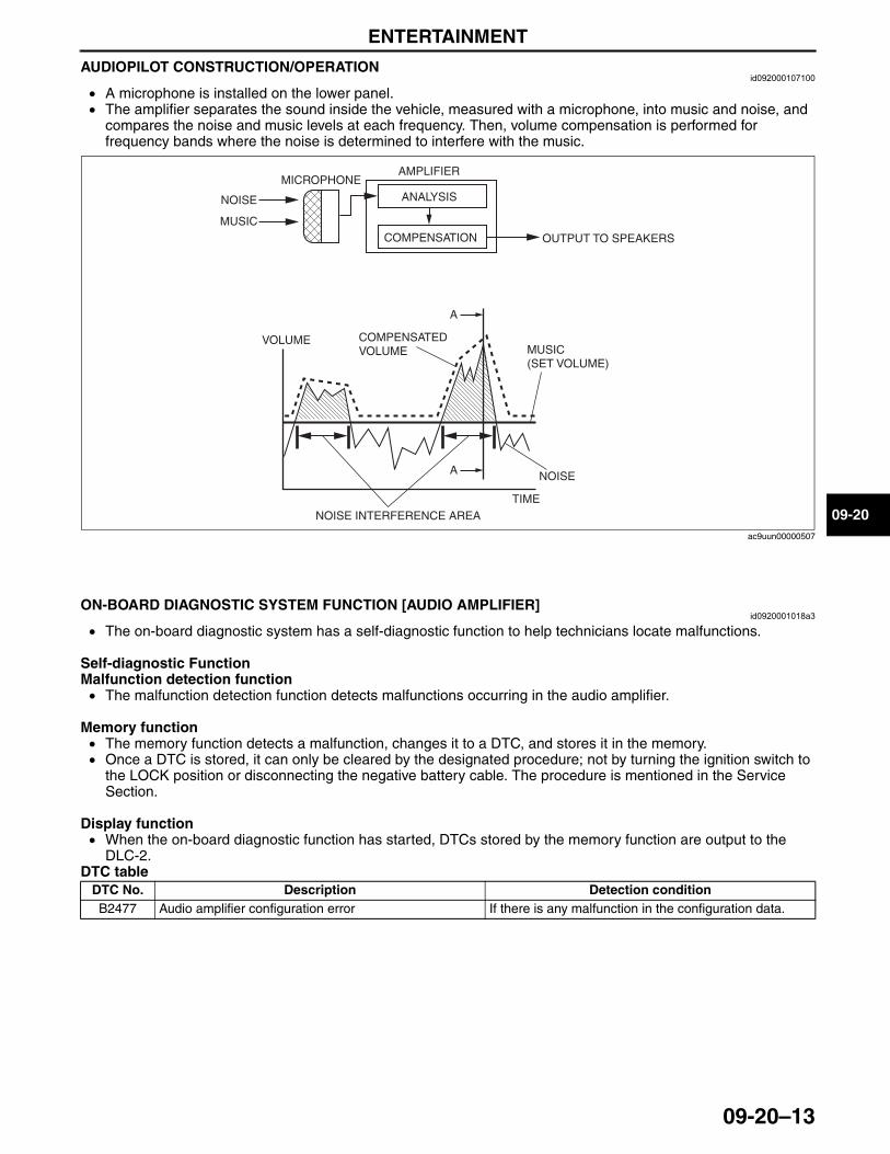
ENTERTAINMENT
09-20–13
09-20
AUDIOPILOT CONSTRUCTION/OPERATIONid092000107100
• A microphone is installed on the lower panel.• The amplifier separates the sound inside the vehicle, measured with a microphone, into music and noise, and
compares the noise and music levels at each frequency. Then, volume compensation is performed for frequency bands where the noise is determined to interfere with the music.
End Of Sie
ON-BOARD DIAGNOSTIC SYSTEM FUNCTION [AUDIO AMPLIFIER]id0920001018a3
• The on-board diagnostic system has a self-diagnostic function to help technicians locate malfunctions.
Self-diagnostic FunctionMalfunction detection function• The malfunction detection function detects malfunctions occurring in the audio amplifier.
Memory function• The memory function detects a malfunction, changes it to a DTC, and stores it in the memory.• Once a DTC is stored, it can only be cleared by the designated procedure; not by turning the ignition switch to
the LOCK position or disconnecting the negative battery cable. The procedure is mentioned in the Service Section.
Display function• When the on-board diagnostic function has started, DTCs stored by the memory function are output to the
DLC-2.DTC table
End Of Sie
NOISE
MUSIC
MICROPHONEAMPLIFIER
OUTPUT TO SPEAKERS
TIME
MUSIC(SET VOLUME)
NOISE INTERFERENCE AREA
A
A
ANALYSIS
COMPENSATION
VOLUME
NOISE
COMPENSATEDVOLUME
ac9uun00000507
DTC No. Description Detection conditionB2477 Audio amplifier configuration error If there is any malfunction in the configuration data.
3423-1U-06H(09-20).fm 13 ページ 2006年11月21日 火曜日 午後5時46分
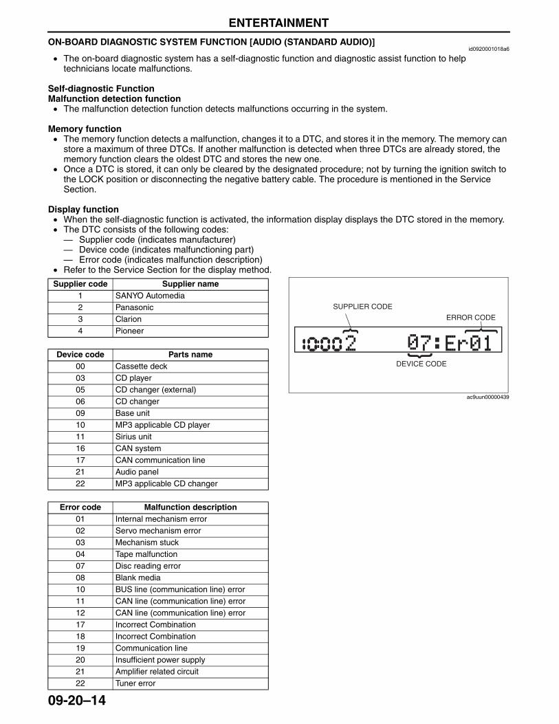
ENTERTAINMENT
09-20–14
ON-BOARD DIAGNOSTIC SYSTEM FUNCTION [AUDIO (STANDARD AUDIO)]id0920001018a6
• The on-board diagnostic system has a self-diagnostic function and diagnostic assist function to help technicians locate malfunctions.
Self-diagnostic FunctionMalfunction detection function• The malfunction detection function detects malfunctions occurring in the system.
Memory function• The memory function detects a malfunction, changes it to a DTC, and stores it in the memory. The memory can
store a maximum of three DTCs. If another malfunction is detected when three DTCs are already stored, the memory function clears the oldest DTC and stores the new one.
• Once a DTC is stored, it can only be cleared by the designated procedure; not by turning the ignition switch to the LOCK position or disconnecting the negative battery cable. The procedure is mentioned in the Service Section.
Display function• When the self-diagnostic function is activated, the information display displays the DTC stored in the memory.• The DTC consists of the following codes:— Supplier code (indicates manufacturer)— Device code (indicates malfunctioning part)— Error code (indicates malfunction description)
• Refer to the Service Section for the display method.
Supplier code Supplier name1 SANYO Automedia2 Panasonic3 Clarion4 Pioneer
Device code Parts name00 Cassette deck03 CD player05 CD changer (external)06 CD changer09 Base unit10 MP3 applicable CD player11 Sirius unit16 CAN system17 CAN communication line21 Audio panel22 MP3 applicable CD changer
Error code Malfunction description01 Internal mechanism error02 Servo mechanism error03 Mechanism stuck04 Tape malfunction07 Disc reading error08 Blank media10 BUS line (communication line) error11 CAN line (communication line) error12 CAN line (communication line) error17 Incorrect Combination18 Incorrect Combination19 Communication line20 Insufficient power supply21 Amplifier related circuit22 Tuner error
SUPPLIER CODE
ERROR CODE
DEVICE CODE
ac9uun00000439
3423-1U-06H(09-20).fm 14 ページ 2006年11月21日 火曜日 午後5時46分
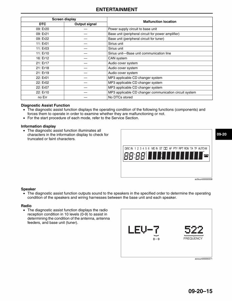
ENTERTAINMENT
09-20–15
09-20
Diagnostic Assist Function• The diagnostic assist function displays the operating condition of the following functions (components) and
forces them to operate in order to examine whether they are malfunctioning or not.• For the start procedure of each mode, refer to the Service Section.
Information display• The diagnostic assist function illuminates all
characters in the information display to check for truncated or faint characters.
Speaker• The diagnostic assist function outputs sound to the speakers in the specified order to determine the operating
condition of the speakers and wiring harnesses between the base unit and each speaker.
Radio• The diagnostic assist function displays the radio
reception condition in 10 levels (0-9) to assist in determining the condition of the antenna, antenna feeders, and base unit (tuner).
Screen displayMalfunction location
DTC Output signal09: Er20 — Power supply circuit to base unit09: Er21 — Base unit (peripheral circuit for power amplifier)09: Er22 — Base unit (peripheral circuit for tuner)11: Er01 — Sirius unit11: Er03 — Sirius unit11: Er10 — Sirius unit—Base unit communication line16: Er12 — CAN system21: Er17 — Audio cover system21: Er18 — Audio cover system21: Er19 — Audio cover system22: Er01 — MP3 applicable CD changer system22: Er02 — MP3 applicable CD changer system22: Er07 — MP3 applicable CD changer system22: Er10 — MP3 applicable CD changer communication circuit systemno Err — No DTCs stored
DISC IN 1 2 3 4 5 6 MD IN AF PTY RPT RDM TA TP AUTO-M
ac9uun00000508
FREQUENCY
acxuun00000371
3423-1U-06H(09-20).fm 15 ページ 2006年11月21日 火曜日 午後5時46分
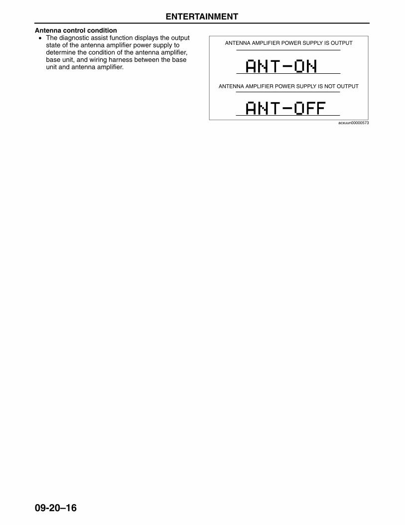
ENTERTAINMENT
09-20–16
Antenna control condition• The diagnostic assist function displays the output
state of the antenna amplifier power supply to determine the condition of the antenna amplifier, base unit, and wiring harness between the base unit and antenna amplifier.
End Of Sie
ANTENNA AMPLIFIER POWER SUPPLY IS OUTPUT
ANTENNA AMPLIFIER POWER SUPPLY IS NOT OUTPUT
acxuun00000573
3423-1U-06H(09-20).fm 16 ページ 2006年11月21日 火曜日 午後5時46分
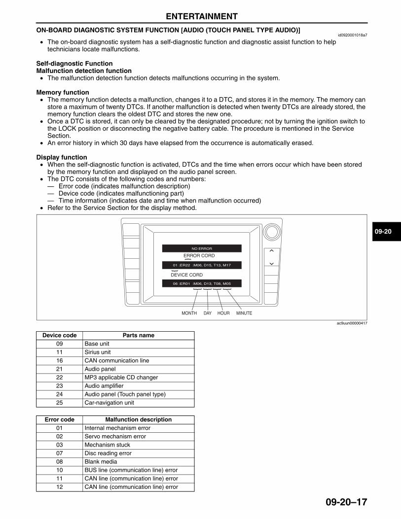
ENTERTAINMENT
09-20–17
09-20
ON-BOARD DIAGNOSTIC SYSTEM FUNCTION [AUDIO (TOUCH PANEL TYPE AUDIO)]id0920001018a7
• The on-board diagnostic system has a self-diagnostic function and diagnostic assist function to help technicians locate malfunctions.
Self-diagnostic FunctionMalfunction detection function• The malfunction detection function detects malfunctions occurring in the system.
Memory function• The memory function detects a malfunction, changes it to a DTC, and stores it in the memory. The memory can
store a maximum of twenty DTCs. If another malfunction is detected when twenty DTCs are already stored, the memory function clears the oldest DTC and stores the new one.
• Once a DTC is stored, it can only be cleared by the designated procedure; not by turning the ignition switch to the LOCK position or disconnecting the negative battery cable. The procedure is mentioned in the Service Section.
• An error history in which 30 days have elapsed from the occurrence is automatically erased.
Display function• When the self-diagnostic function is activated, DTCs and the time when errors occur which have been stored
by the memory function and displayed on the audio panel screen.• The DTC consists of the following codes and numbers:— Error code (indicates malfunction description)— Device code (indicates malfunctioning part)— Time information (indicates date and time when malfunction occurred)
• Refer to the Service Section for the display method.
ERROR CORD
DEVICE CORD
MONTH DAY HOUR MINUTE
ac9uun00000417
Device code Parts name09 Base unit11 Sirius unit16 CAN communication line21 Audio panel22 MP3 applicable CD changer23 Audio amplifier24 Audio panel (Touch panel type)25 Car-navigation unit
Error code Malfunction description01 Internal mechanism error02 Servo mechanism error03 Mechanism stuck07 Disc reading error08 Blank media10 BUS line (communication line) error11 CAN line (communication line) error12 CAN line (communication line) error
3423-1U-06H(09-20).fm 17 ページ 2006年11月21日 火曜日 午後5時46分
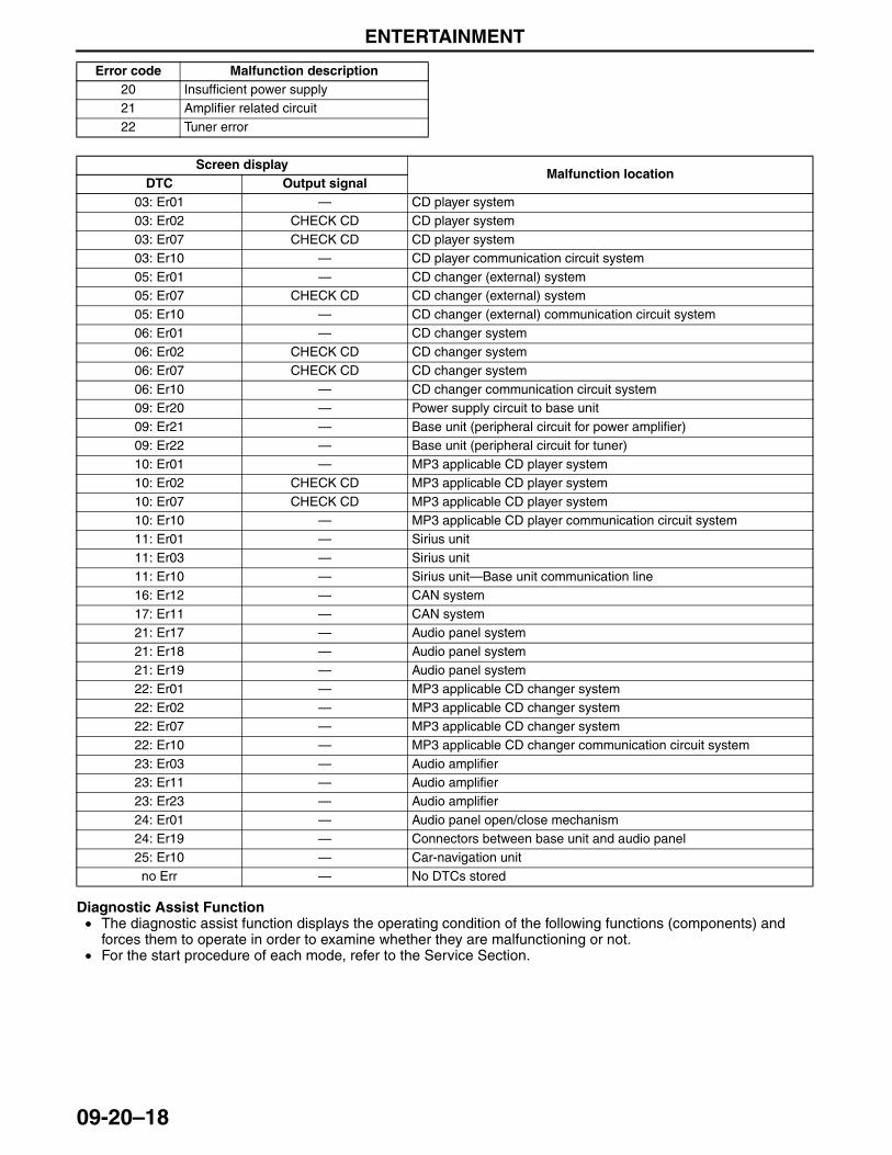
ENTERTAINMENT
09-20–18
Diagnostic Assist Function• The diagnostic assist function displays the operating condition of the following functions (components) and
forces them to operate in order to examine whether they are malfunctioning or not.• For the start procedure of each mode, refer to the Service Section.
20 Insufficient power supply21 Amplifier related circuit22 Tuner error
Error code Malfunction description
Screen displayMalfunction location
DTC Output signal03: Er01 — CD player system03: Er02 CHECK CD CD player system03: Er07 CHECK CD CD player system03: Er10 — CD player communication circuit system05: Er01 — CD changer (external) system05: Er07 CHECK CD CD changer (external) system05: Er10 — CD changer (external) communication circuit system06: Er01 — CD changer system06: Er02 CHECK CD CD changer system06: Er07 CHECK CD CD changer system06: Er10 — CD changer communication circuit system09: Er20 — Power supply circuit to base unit09: Er21 — Base unit (peripheral circuit for power amplifier)09: Er22 — Base unit (peripheral circuit for tuner)10: Er01 — MP3 applicable CD player system10: Er02 CHECK CD MP3 applicable CD player system10: Er07 CHECK CD MP3 applicable CD player system10: Er10 — MP3 applicable CD player communication circuit system11: Er01 — Sirius unit11: Er03 — Sirius unit11: Er10 — Sirius unit—Base unit communication line16: Er12 — CAN system17: Er11 — CAN system21: Er17 — Audio panel system21: Er18 — Audio panel system21: Er19 — Audio panel system22: Er01 — MP3 applicable CD changer system22: Er02 — MP3 applicable CD changer system22: Er07 — MP3 applicable CD changer system22: Er10 — MP3 applicable CD changer communication circuit system23: Er03 — Audio amplifier23: Er11 — Audio amplifier23: Er23 — Audio amplifier24: Er01 — Audio panel open/close mechanism24: Er19 — Connectors between base unit and audio panel25: Er10 — Car-navigation unitno Err — No DTCs stored
3423-1U-06H(09-20).fm 18 ページ 2006年11月21日 火曜日 午後5時46分
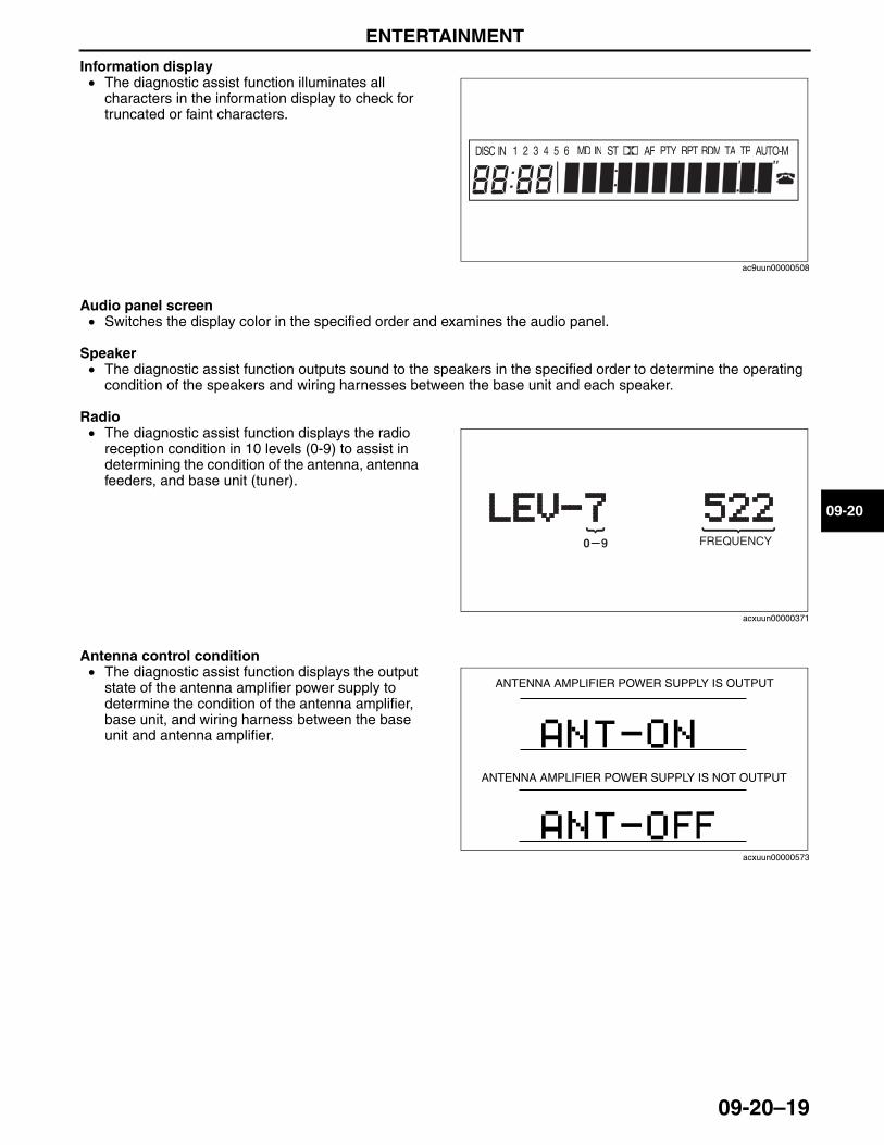
ENTERTAINMENT
09-20–19
09-20
Information display• The diagnostic assist function illuminates all
characters in the information display to check for truncated or faint characters.
Audio panel screen• Switches the display color in the specified order and examines the audio panel.
Speaker• The diagnostic assist function outputs sound to the speakers in the specified order to determine the operating
condition of the speakers and wiring harnesses between the base unit and each speaker.
Radio• The diagnostic assist function displays the radio
reception condition in 10 levels (0-9) to assist in determining the condition of the antenna, antenna feeders, and base unit (tuner).
Antenna control condition• The diagnostic assist function displays the output
state of the antenna amplifier power supply to determine the condition of the antenna amplifier, base unit, and wiring harness between the base unit and antenna amplifier.
End Of Sie
DISC IN 1 2 3 4 5 6 MD IN AF PTY RPT RDM TA TP AUTO-M
ac9uun00000508
FREQUENCY
acxuun00000371
ANTENNA AMPLIFIER POWER SUPPLY IS OUTPUT
ANTENNA AMPLIFIER POWER SUPPLY IS NOT OUTPUT
acxuun00000573
3423-1U-06H(09-20).fm 19 ページ 2006年11月21日 火曜日 午後5時46分
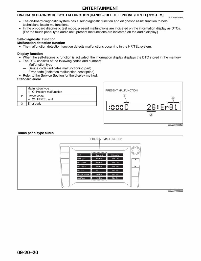
ENTERTAINMENT
09-20–20
ON-BOARD DIAGNOSTIC SYSTEM FUNCTION [HANDS-FREE TELEPHONE (HF/TEL) SYSTEM]id0920001018a8
• The on-board diagnostic system has a self-diagnostic function and diagnostic assist function to help technicians locate malfunctions.
• In the on-board diagnostic test mode, present malfunctions are indicated on the information display as DTCs. (For the touch panel type audio unit, present malfunctions are indicated on the audio display.)
Self-diagnostic FunctionMalfunction detection function• The malfunction detection function detects malfunctions occurring in the HF/TEL system.
Display function• When the self-diagnostic function is activated, the information display displays the DTC stored in the memory.• The DTC consists of the following codes and numbers:— Malfunction type— Device code (indicates malfunctioning part)— Error code (indicates malfunction description)
• Refer to the Service Section for the display method.Standard audio.
Touch panel type audio
1 Malfunction type• C: Present malfunction
2 Device code• 26: HF/TEL unit
3 Error code
31
2
PRESENT MALFUNCTION
ac9uun00000497
PRESENT MALFUNCTION
ac9uun00000509
3423-1U-06H(09-20).fm 20 ページ 2006年11月21日 火曜日 午後5時46分
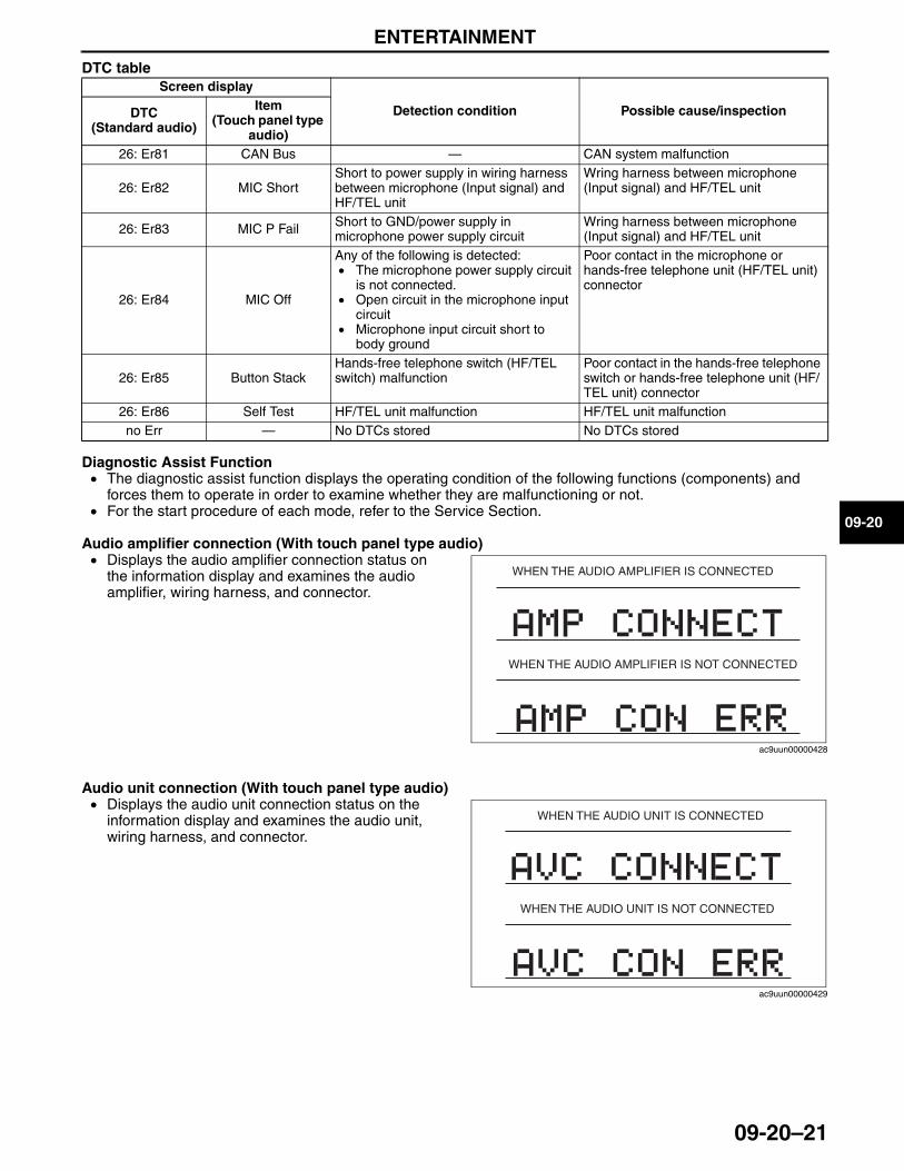
ENTERTAINMENT
09-20–21
09-20
DTC table
Diagnostic Assist Function• The diagnostic assist function displays the operating condition of the following functions (components) and
forces them to operate in order to examine whether they are malfunctioning or not.• For the start procedure of each mode, refer to the Service Section.
Audio amplifier connection (With touch panel type audio)• Displays the audio amplifier connection status on
the information display and examines the audio amplifier, wiring harness, and connector.
Audio unit connection (With touch panel type audio)• Displays the audio unit connection status on the
information display and examines the audio unit, wiring harness, and connector.
Screen display
Detection condition Possible cause/inspectionDTC(Standard audio)
Item(Touch panel type
audio)26: Er81 CAN Bus — CAN system malfunction
26: Er82 MIC ShortShort to power supply in wiring harness between microphone (Input signal) and HF/TEL unit
Wring harness between microphone (Input signal) and HF/TEL unit
26: Er83 MIC P Fail Short to GND/power supply in microphone power supply circuit
Wring harness between microphone (Input signal) and HF/TEL unit
26: Er84 MIC Off
Any of the following is detected:• The microphone power supply circuit
is not connected.• Open circuit in the microphone input
circuit• Microphone input circuit short to
body ground
Poor contact in the microphone or hands-free telephone unit (HF/TEL unit) connector
26: Er85 Button StackHands-free telephone switch (HF/TEL switch) malfunction
Poor contact in the hands-free telephone switch or hands-free telephone unit (HF/TEL unit) connector
26: Er86 Self Test HF/TEL unit malfunction HF/TEL unit malfunctionno Err — No DTCs stored No DTCs stored
WHEN THE AUDIO AMPLIFIER IS CONNECTED
WHEN THE AUDIO AMPLIFIER IS NOT CONNECTED
ac9uun00000428
WHEN THE AUDIO UNIT IS CONNECTED
WHEN THE AUDIO UNIT IS NOT CONNECTED
ac9uun00000429
3423-1U-06H(09-20).fm 21 ページ 2006年11月21日 火曜日 午後5時46分
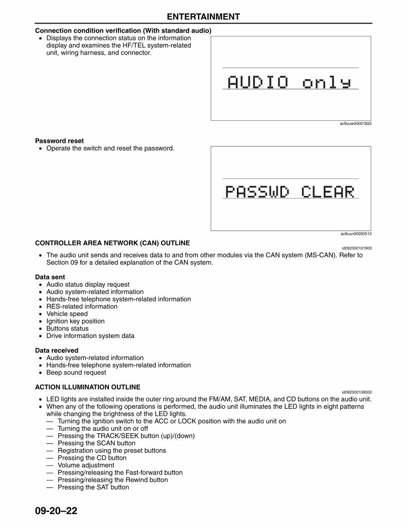
ENTERTAINMENT
09-20–22
Connection condition verification (With standard audio)• Displays the connection status on the information
display and examines the HF/TEL system-related unit, wiring harness, and connector.
Password reset• Operate the switch and reset the password.
End Of Sie
CONTROLLER AREA NETWORK (CAN) OUTLINEid092000101900
• The audio unit sends and receives data to and from other modules via the CAN system (MS-CAN). Refer to Section 09 for a detailed explanation of the CAN system.
Data sent• Audio status display request• Audio system-related information• Hands-free telephone system-related information• RES-related information• Vehicle speed• Ignition key position• Buttons status• Drive information system data
Data received• Audio system-related information• Hands-free telephone system-related information• Beep sound request
End Of SieACTION ILLUMINATION OUTLINE
id092000108000
• LED lights are installed inside the outer ring around the FM/AM, SAT, MEDIA, and CD buttons on the audio unit.• When any of the following operations is performed, the audio unit illuminates the LED lights in eight patterns
while changing the brightness of the LED lights.— Turning the ignition switch to the ACC or LOCK position with the audio unit on— Turning the audio unit on or off— Pressing the TRACK/SEEK button (up)/(down)— Pressing the SCAN button— Registration using the preset buttons— Pressing the CD button— Volume adjustment— Pressing/releasing the Fast-forward button— Pressing/releasing the Rewind button— Pressing the SAT button
End Of Sie
ac9uuw00001825
ac9uun00000512
3423-1U-06H(09-20).fm 22 ページ 2006年11月21日 火曜日 午後5時46分
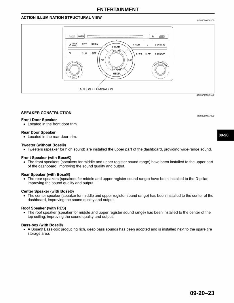
ENTERTAINMENT
09-20–23
09-20
ACTION ILLUMINATION STRUCTURAL VIEWid092000108100
End Of SieNG: SPEAKER
SPEAKER CONSTRUCTIONid092000107900
Front Door Speaker• Located in the front door trim.
Rear Door Speaker• Located in the rear door trim.
Tweeter (without Bose®)• Tweeters (speaker for high sound) are installed the upper part of the dashboard, providing wide-range sound.
Front Speaker (with Bose®)• The front speakers (speakers for middle and upper register sound range) have been installed to the upper part
of the dashboard, improving the sound quality and output.
Rear Speaker (with Bose®)• The rear speakers (speakers for middle and upper register sound range) have been installed to the D-pillar,
improving the sound quality and output.
Center Speaker (with Bose®)• The center speaker (speaker for middle and upper register sound range) has been installed to the center of the
dashboard, improving the sound quality and output.
Roof Speaker (with RES)• The roof speaker (speaker for middle and upper register sound range) has been installed to the center of the
top ceiling, improving the sound quality and output.
Bass-box (with Bose®)• A Bose® Bass-box producing rich, deep bass sounds has been adopted and is installed next to the spare tire
storage area.End Of SieNG: AUDIO AMPLIFIER
ACTION ILLUMINATION
ac9uun00000590
3423-1U-06H(09-20).fm 23 ページ 2006年11月21日 火曜日 午後5時46分
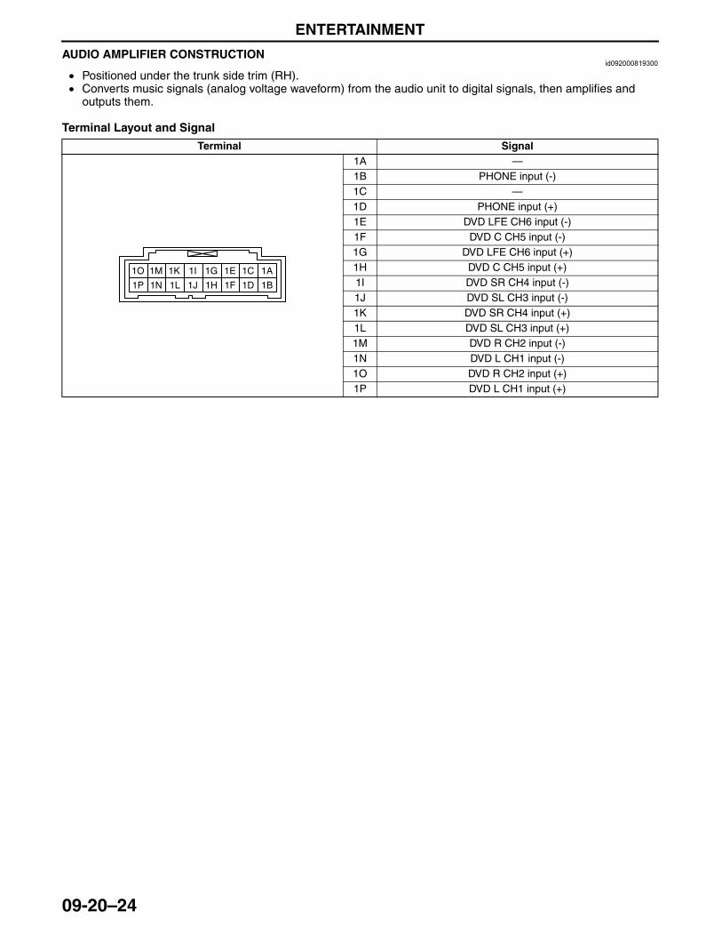
ENTERTAINMENT
09-20–24
AUDIO AMPLIFIER CONSTRUCTIONid092000819300
• Positioned under the trunk side trim (RH).• Converts music signals (analog voltage waveform) from the audio unit to digital signals, then amplifies and
outputs them.
Terminal Layout and Signal
Terminal Signal1A —1B PHONE input (-)1C —1D PHONE input (+)1E DVD LFE CH6 input (-)1F DVD C CH5 input (-) 1G DVD LFE CH6 input (+)1H DVD C CH5 input (+)1I DVD SR CH4 input (-)1J DVD SL CH3 input (-)1K DVD SR CH4 input (+)1L DVD SL CH3 input (+)1M DVD R CH2 input (-)1N DVD L CH1 input (-)1O DVD R CH2 input (+)1P DVD L CH1 input (+)
1A1C1E1G
1B1D1F1H
1I1K1M1O
1J1L1N1P
3423-1U-06H(09-20).fm 24 ページ 2006年11月21日 火曜日 午後5時46分
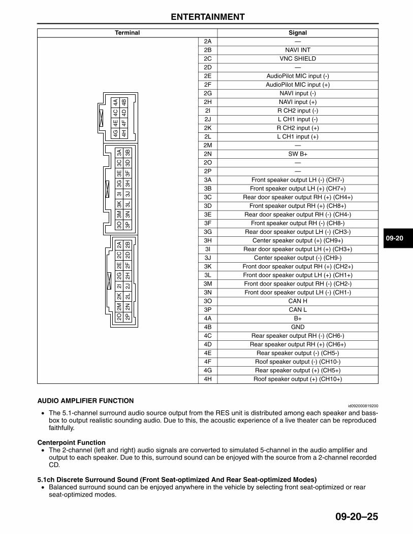
ENTERTAINMENT
09-20–25
09-20
End Of SieAUDIO AMPLIFIER FUNCTION
id092000819200
• The 5.1-channel surround audio source output from the RES unit is distributed among each speaker and bass-box to output realistic sounding audio. Due to this, the acoustic experience of a live theater can be reproduced faithfully.
Centerpoint Function• The 2-channel (left and right) audio signals are converted to simulated 5-channel in the audio amplifier and
output to each speaker. Due to this, surround sound can be enjoyed with the source from a 2-channel recorded CD.
5.1ch Discrete Surround Sound (Front Seat-optimized And Rear Seat-optimized Modes)• Balanced surround sound can be enjoyed anywhere in the vehicle by selecting front seat-optimized or rear
seat-optimized modes.End Of SieNG: ANTENNA
2A —2B NAVI INT2C VNC SHIELD2D —2E AudioPilot MIC input (-)2F AudioPilot MIC input (+)2G NAVI input (-)2H NAVI input (+)2I R CH2 input (-)2J L CH1 input (-)2K R CH2 input (+)2L L CH1 input (+)2M —2N SW B+2O —2P —3A Front speaker output LH (-) (CH7-)3B Front speaker output LH (+) (CH7+)3C Rear door speaker output RH (+) (CH4+)3D Front speaker output RH (+) (CH8+)3E Rear door speaker output RH (-) (CH4-)3F Front speaker output RH (-) (CH8-)3G Rear door speaker output LH (-) (CH3-)3H Center speaker output (+) (CH9+)3I Rear door speaker output LH (+) (CH3+)3J Center speaker output (-) (CH9-)3K Front door speaker output RH (+) (CH2+)3L Front door speaker output LH (+) (CH1+)3M Front door speaker output RH (-) (CH2-)3N Front door speaker output LH (-) (CH1-)3O CAN H3P CAN L4A B+4B GND4C Rear speaker output RH (-) (CH6-)4D Rear speaker output RH (+) (CH6+)4E Rear speaker output (-) (CH5-)4F Roof speaker output (-) (CH10-)4G Rear speaker output (+) (CH5+)4H Roof speaker output (+) (CH10+)
Terminal Signal
2A2C
2E2G
2B2D
2F2H
2I2K
2M2O
2J2L
2N2P
3A3C
3E3G
3B3D
3F3H
4A4C
4E4G
4B4D
4F4H
3I3K
3M3O
3J3L
3N3P
3423-1U-06H(09-20).fm 25 ページ 2006年11月21日 火曜日 午後5時46分
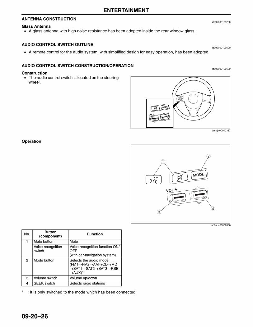
ENTERTAINMENT
09-20–26
ANTENNA CONSTRUCTIONid092000103200
Glass Antenna• A glass antenna with high noise resistance has been adopted inside the rear window glass.
End Of SieNG: AUDIO CONTROL SWITCH
AUDIO CONTROL SWITCH OUTLINEid092000100500
• A remote control for the audio system, with simplified design for easy operation, has been adopted.End Of Sie
AUDIO CONTROL SWITCH CONSTRUCTION/OPERATIONid092000100600
Construction• The audio control switch is located on the steering
wheel.
Operation
* : It is only switched to the mode which has been connected.
End Of SieNG: CAR-NAVIGATION SYSTEM
ampjjn00000337
43
12
ac9uun00000380
No. Button (component) Function
1 Mute button MuteVoice recognition switch
Voice recognition function ON/OFF(with car-navigation system)
2 Mode button Selects the audio mode(FM1→FM2→AM→CD→MD→SAT1→SAT2→SAT3→RSE→AUX)*
3 Volume switch Volume up/down4 SEEK switch Selects radio stations
3423-1U-06H(09-20).fm 26 ページ 2006年11月21日 火曜日 午後5時46分
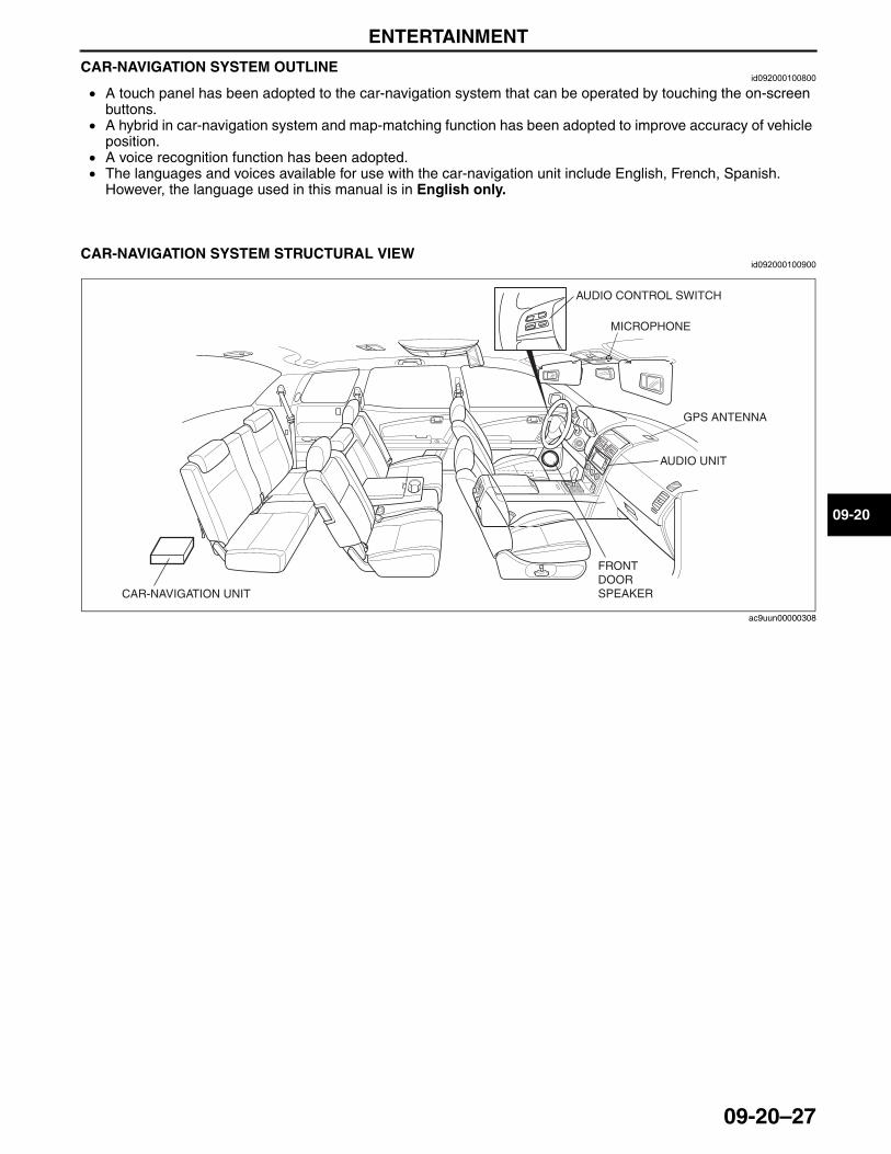
ENTERTAINMENT
09-20–27
09-20
CAR-NAVIGATION SYSTEM OUTLINEid092000100800
• A touch panel has been adopted to the car-navigation system that can be operated by touching the on-screen buttons.
• A hybrid in car-navigation system and map-matching function has been adopted to improve accuracy of vehicle position.
• A voice recognition function has been adopted.• The languages and voices available for use with the car-navigation unit include English, French, Spanish.
However, the language used in this manual is in English only.End Of Sie
CAR-NAVIGATION SYSTEM STRUCTURAL VIEWid092000100900
AUDIO CONTROL SWITCH
MICROPHONE
GPS ANTENNA
AUDIO UNIT
FRONT DOOR SPEAKERCAR-NAVIGATION UNIT
ac9uun00000308
3423-1U-06H(09-20).fm 27 ページ 2006年11月21日 火曜日 午後5時46分
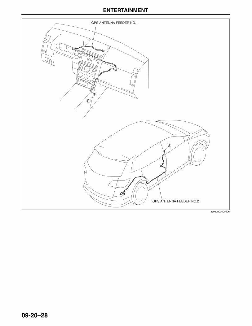
ENTERTAINMENT
09-20–28
End Of Sie
B
GPS ANTENNA FEEDER NO.1
GPS ANTENNA FEEDER NO.2
B
ac9uun00000506
3423-1U-06H(09-20).fm 28 ページ 2006年11月21日 火曜日 午後5時46分
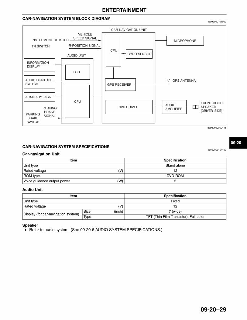
ENTERTAINMENT
09-20–29
09-20
CAR-NAVIGATION SYSTEM BLOCK DIAGRAMid092000101000
End Of Sie
CAR-NAVIGATION SYSTEM SPECIFICATIONSid092000101100
Car-navigation Unit
Audio Unit
Speaker• Refer to audio system. (See 09-20-6 AUDIO SYSTEM SPECIFICATIONS.)
End Of Sie
VEHICLE SPEED SIGNALINSTRUMENT CLUSTER
TR SWITCH R-POSITION SIGNAL
CAR-NAVIGATION UNIT
CPU
GPS RECEIVER
GYRO SENSOR
DVD DRIVER
GPS ANTENNA
LCD
PARKING BRAKE SWITCH
PARKING BRAKE SIGNAL
FRONT DOOR SPEAKER (DRIVER SIDE)
AUDIO UNIT
CPU
MICROPHONE
AUDIO AMPLIFIER
INFORMATION DISPLAY
AUDIO CONTROL SWITCH
AUXILIARY JACK
ac9uun00000446
Item SpecificationUnit type Stand aloneRated voltage (V) 12ROM type DVD-ROMVoice guidance output power (W) 5
Item SpecificationUnit type FixedRated voltage (V) 12
Display (for car-navigation system)Size (inch) 7 (wide)Type TFT (Thin Film Transistor); Full-color
3423-1U-06H(09-20).fm 29 ページ 2006年11月21日 火曜日 午後5時46分
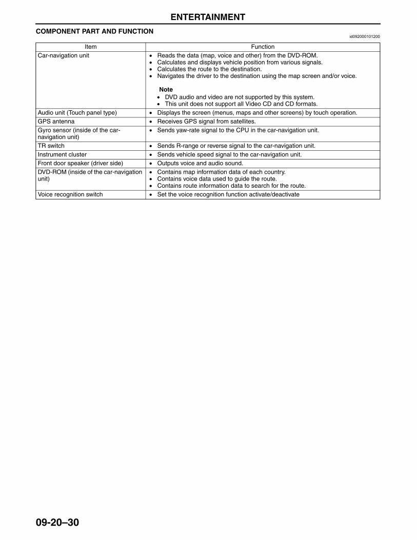
ENTERTAINMENT
09-20–30
COMPONENT PART AND FUNCTIONid092000101200
End Of Sie
Item FunctionCar-navigation unit • Reads the data (map, voice and other) from the DVD-ROM.
• Calculates and displays vehicle position from various signals.• Calculates the route to the destination.• Navigates the driver to the destination using the map screen and/or voice.
Note• DVD audio and video are not supported by this system.• This unit does not support all Video CD and CD formats.
Audio unit (Touch panel type) • Displays the screen (menus, maps and other screens) by touch operation.GPS antenna • Receives GPS signal from satellites.Gyro sensor (inside of the car-navigation unit)
• Sends yaw-rate signal to the CPU in the car-navigation unit.
TR switch • Sends R-range or reverse signal to the car-navigation unit.Instrument cluster • Sends vehicle speed signal to the car-navigation unit. Front door speaker (driver side) • Outputs voice and audio sound.DVD-ROM (inside of the car-navigation unit)
• Contains map information data of each country.• Contains voice data used to guide the route.• Contains route information data to search for the route.
Voice recognition switch • Set the voice recognition function activate/deactivate
3423-1U-06H(09-20).fm 30 ページ 2006年11月21日 火曜日 午後5時46分
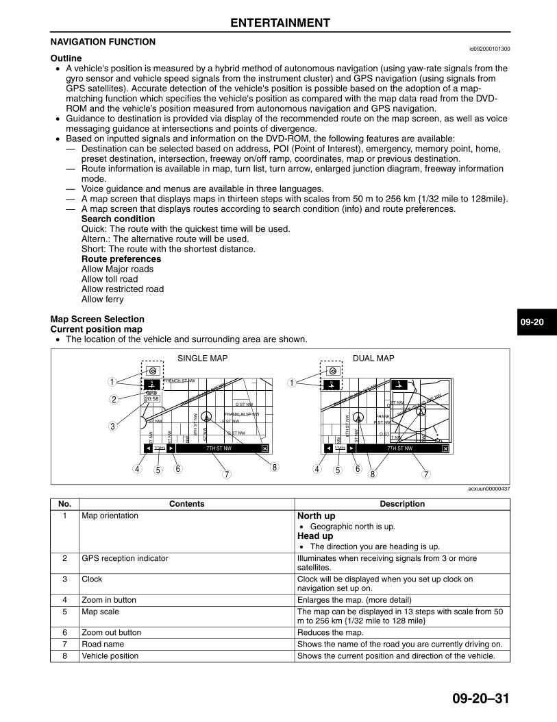
ENTERTAINMENT
09-20–31
09-20
NAVIGATION FUNCTIONid092000101300
Outline• A vehicle's position is measured by a hybrid method of autonomous navigation (using yaw-rate signals from the
gyro sensor and vehicle speed signals from the instrument cluster) and GPS navigation (using signals from GPS satellites). Accurate detection of the vehicle's position is possible based on the adoption of a map-matching function which specifies the vehicle's position as compared with the map data read from the DVD-ROM and the vehicle’s position measured from autonomous navigation and GPS navigation.
• Guidance to destination is provided via display of the recommended route on the map screen, as well as voice messaging guidance at intersections and points of divergence.
• Based on inputted signals and information on the DVD-ROM, the following features are available:— Destination can be selected based on address, POI (Point of Interest), emergency, memory point, home,
preset destination, intersection, freeway on/off ramp, coordinates, map or previous destination.— Route information is available in map, turn list, turn arrow, enlarged junction diagram, freeway information
mode.— Voice guidance and menus are available in three languages.— A map screen that displays maps in thirteen steps with scales from 50 m to 256 km {1/32 mile to 128mile}.— A map screen that displays routes according to search condition (info) and route preferences.
Search conditionQuick: The route with the quickest time will be used.Altern.: The alternative route will be used.Short: The route with the shortest distance.Route preferencesAllow Major roadsAllow toll roadAllow restricted roadAllow ferry
Map Screen SelectionCurrent position map• The location of the vehicle and surrounding area are shown.
.
1/16mi 1/16mi7TH ST NW
20:58
FRENCH ST NW
FRANKLIN ST NW FRANKL
O ST NW ST NW
O ST NW O ST8TH
ST
NW
8TH
ST
NW
ST
NW
ST
NW
ST
NW
ST
NW
ST NW
NW
NW NW
P ST NW P ST NW
RHODE ISLAND AVE NW
RHODE ISLAND AVE NW
RHODE ISLAND AVE NW
O
T NW
7TH ST NW
SINGLE MAP DUAL MAP
87 754
3
6 54 6
1
2
1
8
acxuun00000437
No. Contents Description1 Map orientation North up
• Geographic north is up.Head up• The direction you are heading is up.
2 GPS reception indicator Illuminates when receiving signals from 3 or more satellites.
3 Clock Clock will be displayed when you set up clock on navigation set up on.
4 Zoom in button Enlarges the map. (more detail)5 Map scale The map can be displayed in 13 steps with scale from 50
m to 256 km {1/32 mile to 128 mile}6 Zoom out button Reduces the map.7 Road name Shows the name of the road you are currently driving on.8 Vehicle position Shows the current position and direction of the vehicle.
3423-1U-06H(09-20).fm 31 ページ 2006年11月21日 火曜日 午後5時46分
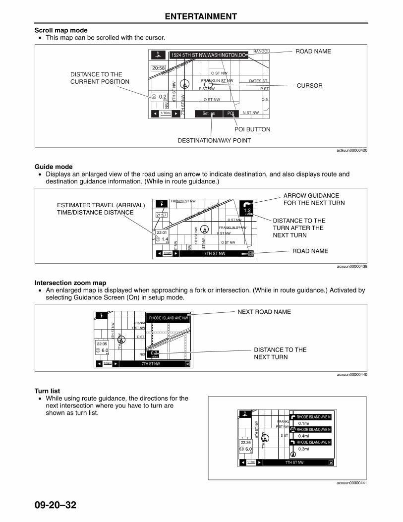
ENTERTAINMENT
09-20–32
Scroll map mode• This map can be scrolled with the cursor.
Guide mode• Displays an enlarged view of the road using an arrow to indicate destination, and also displays route and
destination guidance information. (While in route guidance.)
Intersection zoom map• An enlarged map is displayed when approaching a fork or intersection. (While in route guidance.) Activated by
selecting Guidance Screen (On) in setup mode.
Turn list• While using route guidance, the directions for the
next intersection where you have to turn are shown as turn list.
RHODE ISLAND AVE NW
1/16mi
mi
Set as POI
1524 5TH ST NW,WASHINGTON,DO
20:58
FRANKLIN ST NW
O ST NW
O ST NW
N ST NW
O 58TH
ST
NW
7TH
ST
NW
NW
P ST NW
0.2
P ST
RATES ST
RANOOL ROAD NAME
CURSOR
DISTANCE TO THE CURRENT POSITION
DESTINATION/WAY POINT
POI BUTTON
ac9uun00000420
1/16mi
mi
miles
7TH ST NW
21:57
22:01
1.4
1.2
FRENCH ST NW
FRANKLIN ST NW
O ST NW
O ST NW8TH
ST
NW
ST
NW
ST
NW
NW
P ST NW
RHODE ISLAND AVE NW
ROAD NAME
ARROW GUIDANCE FOR THE NEXT TURNESTIMATED TRAVEL (ARRIVAL)
TIME/DISTANCE DISTANCEDISTANCE TO THE TURN AFTER THE NEXT TURN
acxuun00000439
1/16mi
FRANKL
D ST
RID
8TH
ST
NW
7T
H S
T N
W
P ST NW
7TH ST NW
RHODE ISLAND AVE NW
mimiles
22:35
6.00.3
NEXT ROAD NAME
DISTANCE TO THE NEXT TURN
acxuun00000440
1/16mi
FRANKL
D ST8TH
ST
NW
7T
H S
T N
W
P ST NW
7TH ST NW
RHODE ISLAND AVE N
RHODE ISLAND AVE N
RHODE ISLAND AVE N
mi
22:36
6.0 0.3mi
0.4mi
0.1mi
acxuun00000441
3423-1U-06H(09-20).fm 32 ページ 2006年11月21日 火曜日 午後5時46分
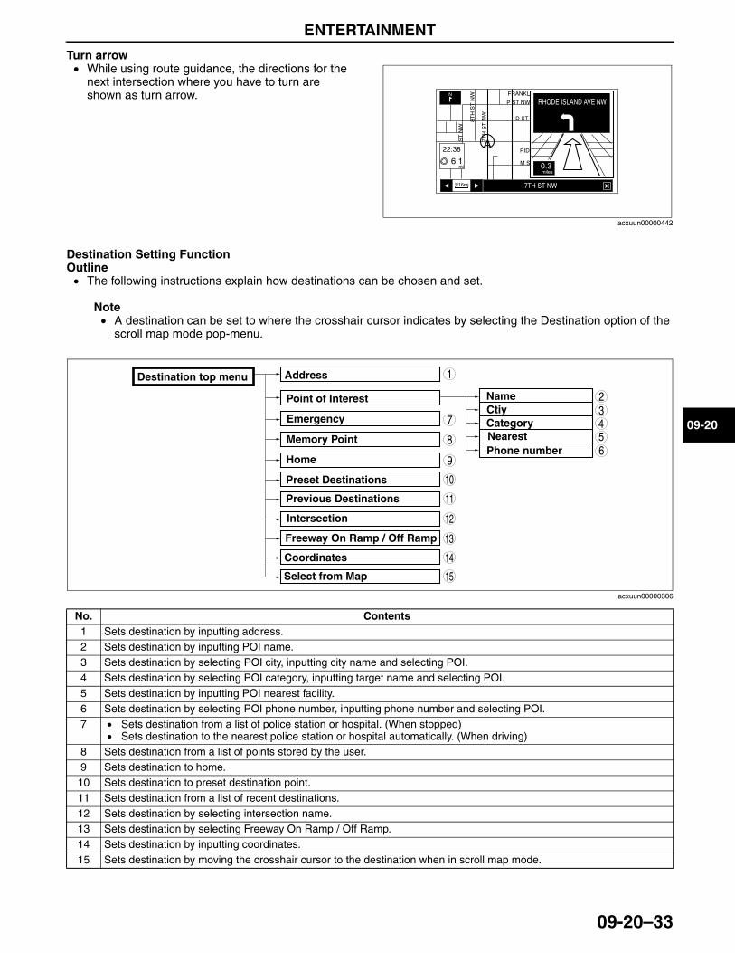
ENTERTAINMENT
09-20–33
09-20
Turn arrow• While using route guidance, the directions for the
next intersection where you have to turn are shown as turn arrow.
Destination Setting FunctionOutline• The following instructions explain how destinations can be chosen and set.
Note• A destination can be set to where the crosshair cursor indicates by selecting the Destination option of the
scroll map mode pop-menu.
.
1/16mi
FRANKL
D ST
RID
M S
8TH
ST
NW
ST
NW
7T
H S
T N
W
P ST NW
7TH ST NW
RHODE ISLAND AVE NW
mi
22:38
6.10.3miles
acxuun00000442
Destination top menu Address
Point of Interest
Emergency
Name
CategoryNearest
Home
Intersection
Coordinates
Previous Destinations
Memory Point
Preset Destinations
Freeway On Ramp / Off Ramp
Select from Map
Ctiy
Phone number
1
9
8
7543
10
13
11
12
6
2
15
14
acxuun00000306
No. Contents1 Sets destination by inputting address.2 Sets destination by inputting POI name.3 Sets destination by selecting POI city, inputting city name and selecting POI.4 Sets destination by selecting POI category, inputting target name and selecting POI.5 Sets destination by inputting POI nearest facility.6 Sets destination by selecting POI phone number, inputting phone number and selecting POI.7 • Sets destination from a list of police station or hospital. (When stopped)
• Sets destination to the nearest police station or hospital automatically. (When driving)8 Sets destination from a list of points stored by the user.9 Sets destination to home.10 Sets destination to preset destination point.11 Sets destination from a list of recent destinations.12 Sets destination by selecting intersection name.13 Sets destination by selecting Freeway On Ramp / Off Ramp.14 Sets destination by inputting coordinates.15 Sets destination by moving the crosshair cursor to the destination when in scroll map mode.
3423-1U-06H(09-20).fm 33 ページ 2006年11月21日 火曜日 午後5時46分

ENTERTAINMENT
09-20–34
Voice Recognition Function• Voice control can be carried out by simply
pressing voice recognition switch and speaking voice command into the microphone.
End Of SieNG: CAR-NAVIGATION UNIT
CAR-NAVIGATION UNIT OUTLINEid092000102200
• Using exterior signal input and DVD-ROM information, this unit detects vehicle position, provides destination route guidance, and displays color maps.
End Of Sie
VOICE RECOGNITION SWITCH
ac9uun00000426
3423-1U-06H(09-20).fm 34 ページ 2006年11月21日 火曜日 午後5時46分
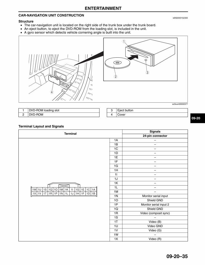
ENTERTAINMENT
09-20–35
09-20
CAR-NAVIGATION UNIT CONSTRUCTIONid092000102300
Structure• The car-navigation unit is located on the right side of the trunk box under the trunk board.• An eject button, to eject the DVD-ROM from the loading slot, is included in the unit.• A gyro sensor which detects vehicle cornering angle is built into the unit.
.
Terminal Layout and Signals
3
1
2
4
ac9uun00000377
1 DVD-ROM loading slot2 DVD-ROM
3 Eject button4 Cover
TerminalSignals
24-pin connector1A –1B –1C –1D –1E –1F –1G –1H –1I –1J –1K –1L –1M –1N Monitor serial input1O Shield GND1P Monitor serial input 21Q Shield GND1R Video (composit sync)1S –1T Video (B)1U Video GND1V Video (G)1W –1X Video (R)
1A1C1E1G1I1K1M1O
1B1D1F1H1J1L1N1P
1Q1S1U1W
1R1T1V1X
3423-1U-06H(09-20).fm 35 ページ 2006年11月21日 火曜日 午後5時46分
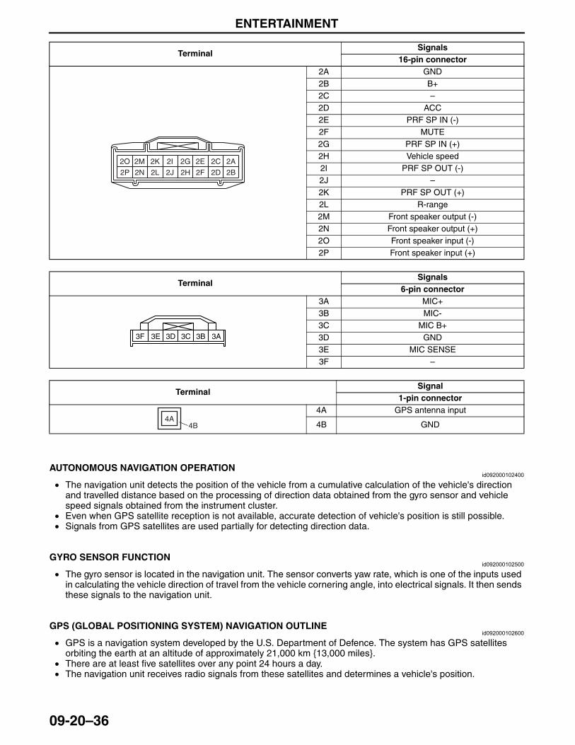
ENTERTAINMENT
09-20–36
End Of Sie
AUTONOMOUS NAVIGATION OPERATIONid092000102400
• The navigation unit detects the position of the vehicle from a cumulative calculation of the vehicle's direction and travelled distance based on the processing of direction data obtained from the gyro sensor and vehicle speed signals obtained from the instrument cluster.
• Even when GPS satellite reception is not available, accurate detection of vehicle's position is still possible.• Signals from GPS satellites are used partially for detecting direction data.
End Of Sie
GYRO SENSOR FUNCTIONid092000102500
• The gyro sensor is located in the navigation unit. The sensor converts yaw rate, which is one of the inputs used in calculating the vehicle direction of travel from the vehicle cornering angle, into electrical signals. It then sends these signals to the navigation unit.
End Of Sie
GPS (GLOBAL POSITIONING SYSTEM) NAVIGATION OUTLINEid092000102600
• GPS is a navigation system developed by the U.S. Department of Defence. The system has GPS satellites orbiting the earth at an altitude of approximately 21,000 km {13,000 miles}.
• There are at least five satellites over any point 24 hours a day. • The navigation unit receives radio signals from these satellites and determines a vehicle's position.
End Of Sie
TerminalSignals
16-pin connector2A GND2B B+2C –2D ACC2E PRF SP IN (-)2F MUTE2G PRF SP IN (+)2H Vehicle speed2I PRF SP OUT (-)2J –2K PRF SP OUT (+)2L R-range2M Front speaker output (-)2N Front speaker output (+)2O Front speaker input (-)2P Front speaker input (+)
TerminalSignals
6-pin connector3A MIC+3B MIC-3C MIC B+3D GND3E MIC SENSE3F –
TerminalSignal
1-pin connector4A GPS antenna input
4B GND
2A2C2E2G2I2K2M2O
2B2D2F2H2J2L2N2P
3A3C3E 3B3D3F
4A4B
3423-1U-06H(09-20).fm 36 ページ 2006年11月21日 火曜日 午後5時46分
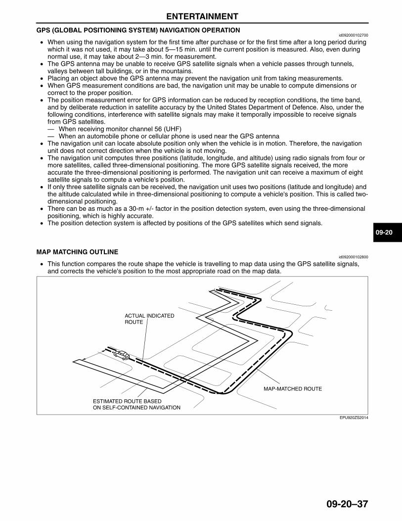
ENTERTAINMENT
09-20–37
09-20
GPS (GLOBAL POSITIONING SYSTEM) NAVIGATION OPERATIONid092000102700
• When using the navigation system for the first time after purchase or for the first time after a long period during which it was not used, it may take about 5—15 min. until the current position is measured. Also, even during normal use, it may take about 2—3 min. for measurement.
• The GPS antenna may be unable to receive GPS satellite signals when a vehicle passes through tunnels, valleys between tall buildings, or in the mountains.
• Placing an object above the GPS antenna may prevent the navigation unit from taking measurements.• When GPS measurement conditions are bad, the navigation unit may be unable to compute dimensions or
correct to the proper position.• The position measurement error for GPS information can be reduced by reception conditions, the time band,
and by deliberate reduction in satellite accuracy by the United States Department of Defence. Also, under the following conditions, interference with satellite signals may make it temporally impossible to receive signals from GPS satellites.— When receiving monitor channel 56 (UHF)— When an automobile phone or cellular phone is used near the GPS antenna
• The navigation unit can locate absolute position only when the vehicle is in motion. Therefore, the navigation unit does not correct direction when the vehicle is not moving.
• The navigation unit computes three positions (latitude, longitude, and altitude) using radio signals from four or more satellites, called three-dimensional positioning. The more GPS satellite signals received, the more accurate the three-dimensional positioning is performed. The navigation unit can receive a maximum of eight satellite signals to compute a vehicle's position.
• If only three satellite signals can be received, the navigation unit uses two positions (latitude and longitude) and the altitude calculated while in three-dimensional positioning to compute a vehicle's position. This is called two-dimensional positioning.
• There can be as much as a 30-m +/- factor in the position detection system, even using the three-dimensional positioning, which is highly accurate.
• The position detection system is affected by positions of the GPS satellites which send signals.End Of Sie
MAP MATCHING OUTLINEid092000102800
• This function compares the route shape the vehicle is travelling to map data using the GPS satellite signals, and corrects the vehicle's position to the most appropriate road on the map data.
End Of Sie
MAP-MATCHED ROUTE
ACTUAL INDICATED ROUTE
ESTIMATED ROUTE BASED ON SELF-CONTAINED NAVIGATION
EPU920ZS2014
3423-1U-06H(09-20).fm 37 ページ 2006年11月21日 火曜日 午後5時46分
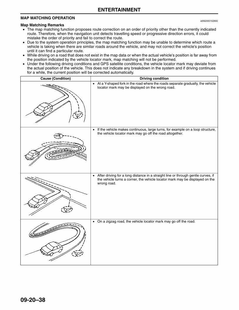
ENTERTAINMENT
09-20–38
MAP MATCHING OPERATIONid092000102900
Map Matching Remarks• The map matching function proposes route correction on an order of priority other than the currently indicated
route. Therefore, when the navigation unit detects travelling speed or progressive direction errors, it could mistake the order of priority and fail to correct the route.
• Due to the system operation principles, the map matching function may be unable to determine which route a vehicle is taking when there are similar roads around the vehicle, and may not correct the vehicle's position until it can find a particular route.
• While driving on a road that does not exist in the map data or when the actual vehicle's position is far away from the position indicated by the vehicle locator mark, map matching will not be performed.
• Under the following driving conditions and GPS satellite conditions, the vehicle locator mark may deviate from the actual position of the vehicle. This does not indicate any breakdown in the system and if driving continues for a while, the current position will be corrected automatically.
Cause (Condition) Driving condition• At a Y-shaped fork in the road where the roads separate gradually, the vehicle
locator mark may be displayed on the wrong road.
• If the vehicle makes continuous, large turns, for example on a loop structure, the vehicle locator mark may go off the road altogether.
• After driving for a long distance in a straight line or through gentle curves, if the vehicle turns a corner, the vehicle locator mark may be displayed on the wrong road.
• On a zigzag road, the vehicle locator mark may go off the road.
3423-1U-06H(09-20).fm 38 ページ 2006年11月21日 火曜日 午後5時46分
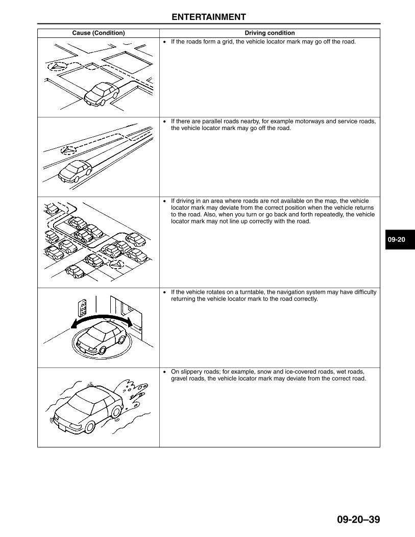
ENTERTAINMENT
09-20–39
09-20
• If the roads form a grid, the vehicle locator mark may go off the road.
• If there are parallel roads nearby, for example motorways and service roads, the vehicle locator mark may go off the road.
• If driving in an area where roads are not available on the map, the vehicle locator mark may deviate from the correct position when the vehicle returns to the road. Also, when you turn or go back and forth repeatedly, the vehicle locator mark may not line up correctly with the road.
• If the vehicle rotates on a turntable, the navigation system may have difficulty returning the vehicle locator mark to the road correctly.
• On slippery roads; for example, snow and ice-covered roads, wet roads, gravel roads, the vehicle locator mark may deviate from the correct road.
Cause (Condition) Driving condition
3423-1U-06H(09-20).fm 39 ページ 2006年11月21日 火曜日 午後5時46分
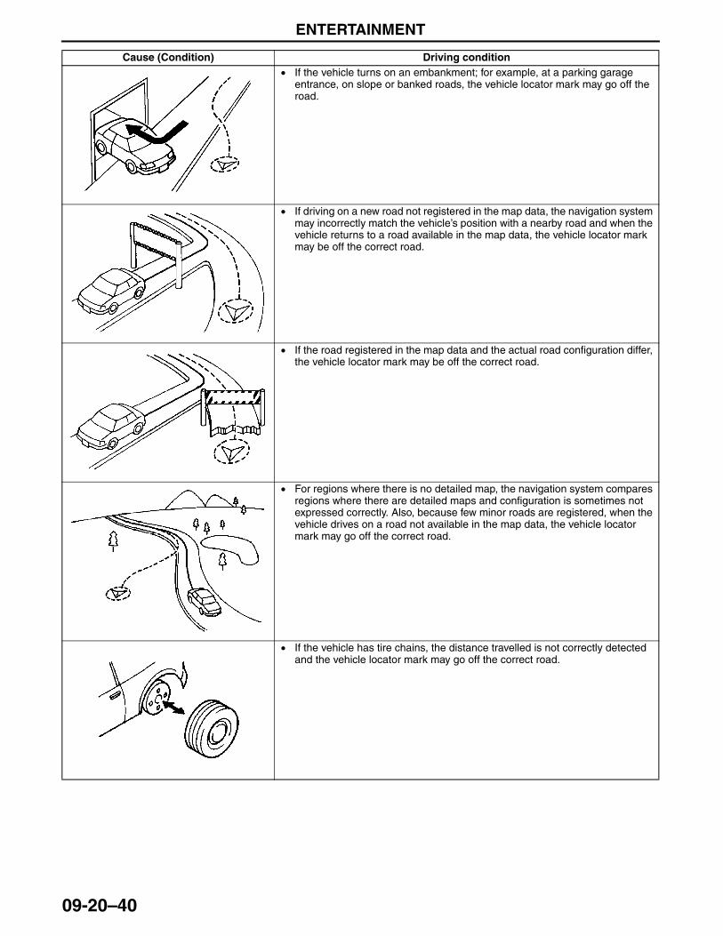
ENTERTAINMENT
09-20–40
• If the vehicle turns on an embankment; for example, at a parking garage entrance, on slope or banked roads, the vehicle locator mark may go off the road.
• If driving on a new road not registered in the map data, the navigation system may incorrectly match the vehicle’s position with a nearby road and when the vehicle returns to a road available in the map data, the vehicle locator mark may be off the correct road.
• If the road registered in the map data and the actual road configuration differ, the vehicle locator mark may be off the correct road.
• For regions where there is no detailed map, the navigation system compares regions where there are detailed maps and configuration is sometimes not expressed correctly. Also, because few minor roads are registered, when the vehicle drives on a road not available in the map data, the vehicle locator mark may go off the correct road.
• If the vehicle has tire chains, the distance travelled is not correctly detected and the vehicle locator mark may go off the correct road.
Cause (Condition) Driving condition
3423-1U-06H(09-20).fm 40 ページ 2006年11月21日 火曜日 午後5時46分
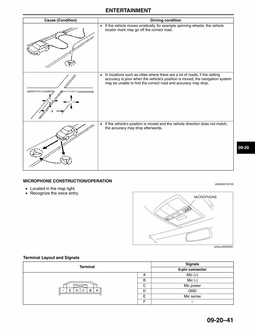
ENTERTAINMENT
09-20–41
09-20
End Of SieNG: MICROPHONEMICROPHONE CONSTRUCTION/OPERATION
id092000100700
• Located in the map light.• Recognize the voice entry.
Terminal Layout and Signals
End Of SieNG: BACK MONITOR CONTROL UNIT
• If the vehicle moves erratically, for example spinning wheels, the vehicle locator mark may go off the correct road.
• In locations such as cities where there are a lot of roads, if the setting accuracy is poor when the vehicle’s position is moved, the navigation system may be unable to find the correct road and accuracy may drop.
• If the vehicle’s position is moved and the vehicle direction does not match, the accuracy may drop afterwards.
Cause (Condition) Driving condition
MICROPHONE
ac9uun00000351
TerminalSignals
6-pin connectorA Mic (+)B Mic (-)C Mic powerD GNDE Mic senseF –
ABCDE*
3423-1U-06H(09-20).fm 41 ページ 2006年11月21日 火曜日 午後5時46分
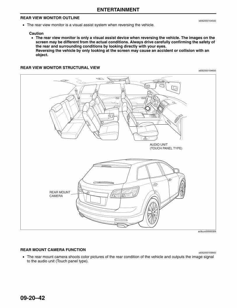
ENTERTAINMENT
09-20–42
REAR VIEW MONITOR OUTLINEid092000104500
• The rear view monitor is a visual assist system when reversing the vehicle.
Caution• The rear view monitor is only a visual assist device when reversing the vehicle. The images on the
screen may be different from the actual conditions. Always drive carefully confirming the safety of the rear and surrounding conditions by looking directly with your eyes.Reversing the vehicle by only looking at the screen may cause an accident or collision with an object.
End Of SieREAR VIEW MONITOR STRUCTURAL VIEW
id092000104600
End Of SieNG: BACK MONITOR CAMERA
REAR MOUNT CAMERA FUNCTIONid092000109900
• The rear mount camera shoots color pictures of the rear condition of the vehicle and outputs the image signal to the audio unit (Touch panel type).
End Of Sie
AUDIO UNIT(TOUCH PANEL TYPE)
REAR MOUNT CAMERA
ac9uun00000309
3423-1U-06H(09-20).fm 42 ページ 2006年11月21日 火曜日 午後5時46分
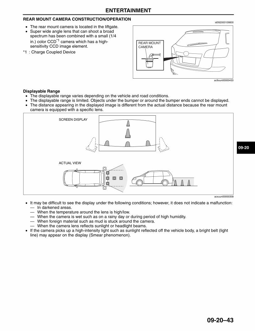
ENTERTAINMENT
09-20–43
09-20
REAR MOUNT CAMERA CONSTRUCTION/OPERATIONid092000109800
• The rear mount camera is located in the liftgate.• Super wide angle lens that can shoot a broad
spectrum has been combined with a small (1/4 in.) color CCD*1 camera which has a high-sensitivity CCD image element.
*1 : Charge Coupled Device
Displayable Range• The displayable range varies depending on the vehicle and road conditions.• The displayable range is limited. Objects under the bumper or around the bumper ends cannot be displayed.• The distance appearing in the displayed image is different from the actual distance because the rear mount
camera is equipped with a specific lens.
• It may be difficult to see the display under the following conditions; however, it does not indicate a malfunction:— In darkened areas.— When the temperature around the lens is high/low.— When the camera is wet such as on a rainy day or during period of high humidity.— When foreign material such as mud is stuck around the camera.— When the camera lens reflects sunlight or headlight beams.
• If the camera picks up a high-intensity light such as sunlight reflected off the vehicle body, a bright belt (light line) may appear on the display (Smear phenomenon).
End Of SieNG: REAR ENTERTAINMENT SYSTEM (RES)
REAR MOUNT CAMERA
ac9uun00000433
SCREEN DISPLAY
ACTUAL VIEW
acxuun00000358
3423-1U-06H(09-20).fm 43 ページ 2006年11月21日 火曜日 午後5時46分
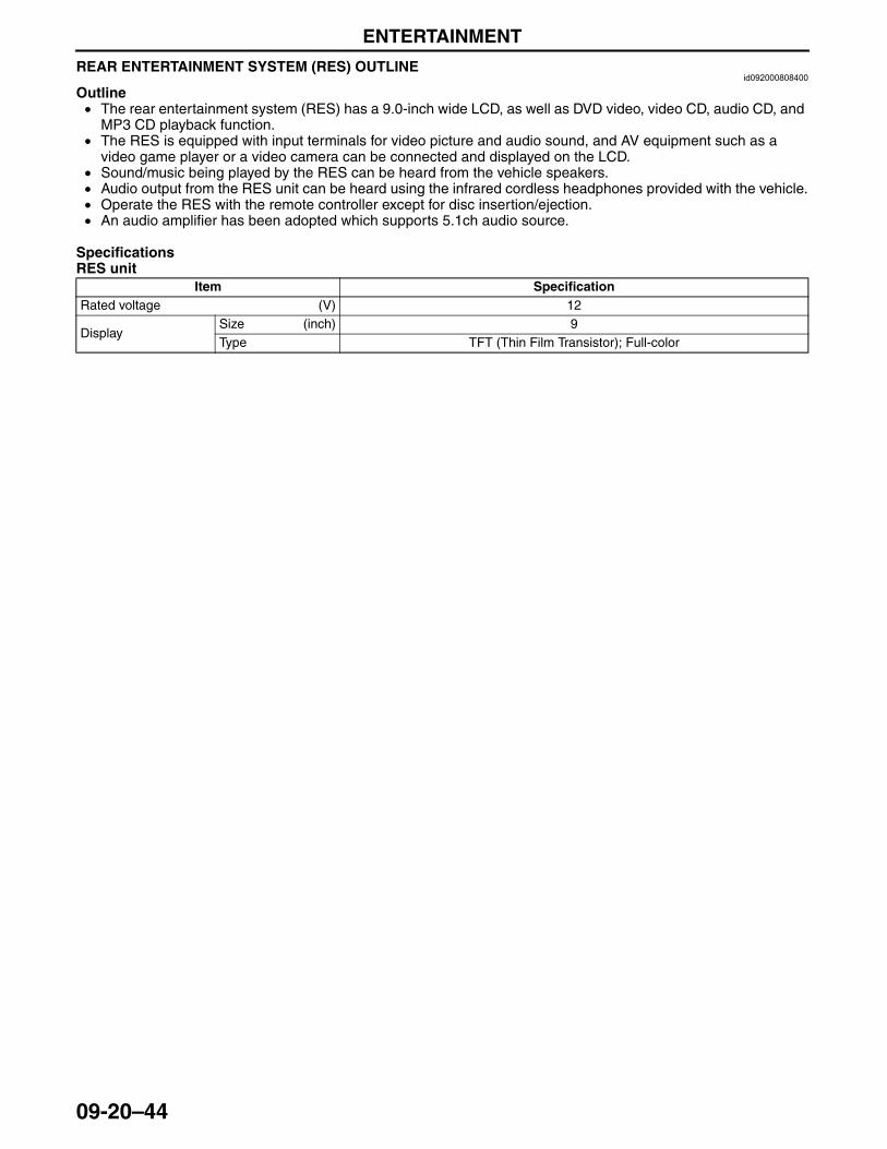
ENTERTAINMENT
09-20–44
REAR ENTERTAINMENT SYSTEM (RES) OUTLINEid092000808400
Outline• The rear entertainment system (RES) has a 9.0-inch wide LCD, as well as DVD video, video CD, audio CD, and
MP3 CD playback function.• The RES is equipped with input terminals for video picture and audio sound, and AV equipment such as a
video game player or a video camera can be connected and displayed on the LCD.• Sound/music being played by the RES can be heard from the vehicle speakers.• Audio output from the RES unit can be heard using the infrared cordless headphones provided with the vehicle.• Operate the RES with the remote controller except for disc insertion/ejection.• An audio amplifier has been adopted which supports 5.1ch audio source.
SpecificationsRES unit
End Of Sie
Item SpecificationRated voltage (V) 12
Display Size (inch) 9Type TFT (Thin Film Transistor); Full-color
3423-1U-06H(09-20).fm 44 ページ 2006年11月22日 水曜日 午後4時20分
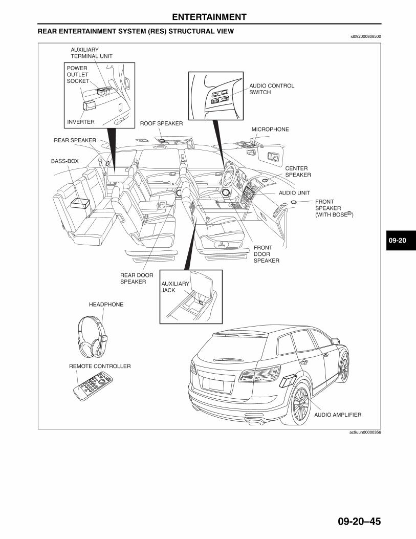
ENTERTAINMENT
09-20–45
09-20
REAR ENTERTAINMENT SYSTEM (RES) STRUCTURAL VIEWid092000808500
End Of Sie
AUDIO CONTROL SWITCH
MICROPHONE
CENTER SPEAKER
AUDIO UNIT
FRONT SPEAKER(WITH BOSER )
FRONT DOOR SPEAKER
AUXILIARY JACK
REAR DOOR SPEAKER
ROOF SPEAKER
BASS-BOX
REAR SPEAKER
AUDIO AMPLIFIER
HEADPHONE
REMOTE CONTROLLER
INVERTER
POWER OUTLET SOCKET
AUXILIARY TERMINAL UNIT
ac9uun00000356
3423-1U-06H(09-20).fm 45 ページ 2006年11月21日 火曜日 午後5時46分
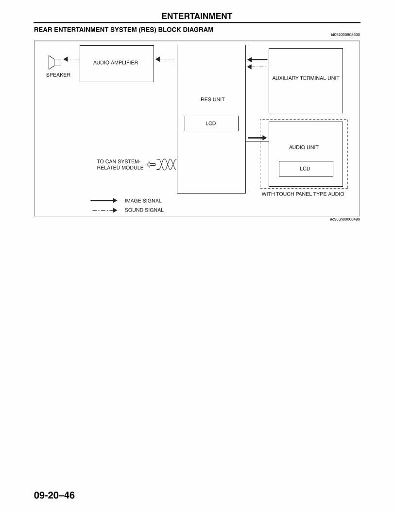
ENTERTAINMENT
09-20–46
REAR ENTERTAINMENT SYSTEM (RES) BLOCK DIAGRAMid092000808600
LCD
LCD
SPEAKER
AUDIO AMPLIFIER
RES UNIT
AUXILIARY TERMINAL UNIT
AUDIO UNIT
IMAGE SIGNAL
SOUND SIGNAL
WITH TOUCH PANEL TYPE AUDIO
TO CAN SYSTEM-RELATED MODULE
ac9uun00000499
3423-1U-06H(09-20).fm 46 ページ 2006年11月21日 火曜日 午後5時46分
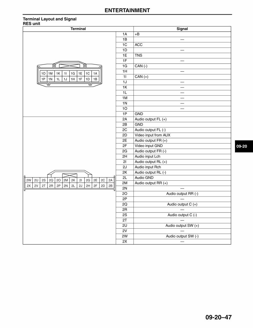
ENTERTAINMENT
09-20–47
09-20
Terminal Layout and Signal RES unit
End Of Sie
Terminal Signal1A +B1B —1C ACC1D —1E TNS1F —1G CAN (-)1H —1I CAN (+)1J —1K —1L —1M —1N —1O —1P GND2A Audio output FL (+)2B GND2C Audio output FL (-)2D Video input from AUX2E Audio output FR (+)2F Video input GND2G Audio output FR (-)2H Audio input Lch2I Audio output RL (+)2J Audio input Rch2K Audio output RL (-)2L Audio GND2M Audio output RR (+)2N —2O Audio output RR (-)2P —2Q Audio output C (+)2R —2S Audio output C (-)2T —2U Audio output SW (+)2V —2W Audio output SW (-)2X —
1A
1B
1C
1D
1E
1F
1G
1H1J
1K
1L
1M
1N
1O
1P
1I
2B2D2F2H2J
2K
2L2N2P
2Q
2R
2S
2T
2U
2V
2W
2X
2A2C2E2G2I2M2O
3423-1U-06H(09-20).fm 47 ページ 2006年11月21日 火曜日 午後5時46分
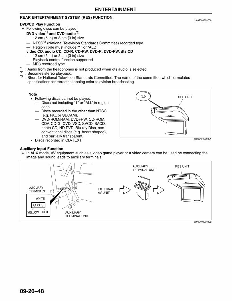
ENTERTAINMENT
09-20–48
REAR ENTERTAINMENT SYSTEM (RES) FUNCTIONid092000808700
DVD/CD Play Function • Following discs can be played.
DVD video*1 and DVD audio*2
— 12 cm {5 in} or 8 cm {3 in} size— NTSC*3 (National Television Standards Committee) recorded type— Region code must include “1” or “ALL”video CD, audio CD, CD-R, CD-RW, DVD-R, DVD-RW, dts CD— 12 cm {5 in} or 8 cm {3 in} size— Playback control function supported— MP3 recorded type
*1 : Audio from the headphones is not produced when dts audio is selected.*2 : Becomes stereo playback.*3 : Short for National Television Standards Committee. The name of the committee which formulates
specifications for terrestrial analog color television broadcasting.
Note• Following discs cannot be played.— Discs not including “1” or “ALL” in region
code.— Discs recorded in the other than NTSC
(e.g. PAL or SECAM).— DVD-ROM/RAM, DVD+RW, CD-ROM,
CDV, CD-G, CVD, VSD, SVCD, SACD, photo CD, HD DVD, Blu-ray Disc, non-conventional discs (e.g. heart-shaped), and partially transparent.
• Discs recorded in CD-TEXT.
Auxiliary Input Function• In AUX mode, AV equipment such as a video game player or a video camera can be used be connecting the
image and sound leads to auxiliary terminals.
RES UNIT
ac9uun00000401
RES UNIT
AUXILIARY TERMINAL UNIT
AUXILIARY TERMINAL UNIT
EXTERNAL AV UNIT
AUXILIARY TERMINALS
YELLOW RED
WHITE
ac9uun00000402
3423-1U-06H(09-20).fm 48 ページ 2006年11月22日 水曜日 午後4時25分
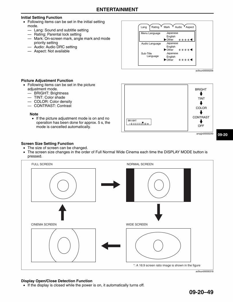
ENTERTAINMENT
09-20–49
09-20
Initial Setting Function • Following items can be set in the initial setting
mode.— Lang: Sound and subtitle setting— Rating: Parental lock setting— Mark: On-screen mark, angle mark and mode
priority setting— Audio: Audio DRC setting— Aspect: Not available
Picture Adjustment Function• Following items can be set in the picture
adjustment mode.— BRIGHT: Brightness— TINT: Color shade— COLOR: Color density— CONTRAST: Contrast
Note• If the picture adjustment mode is on and no
operation has been done for approx. 5 s, the mode is cancelled automatically.
Screen Size Setting Function• The size of screen can be changed.• The screen size changes in the order of Full Normal Wide Cinema each time the DISPLAY MODE button is
pressed.
Display Open/Close Detection Function• If the display is closed while the power is on, it automatically turns off.
ac9uun00000256
+-
BRIGHT
TINT
COLOR
CONTRAST
OFF
ampjjn00000249
*: A 16:9 screen ratio image is shown in the figure
FULL SCREEN NORMAL SCREEN
WIDE SCREENCINEMA SCREEN
ac9uun00000318
3423-1U-06H(09-20).fm 49 ページ 2006年11月21日 火曜日 午後5時46分
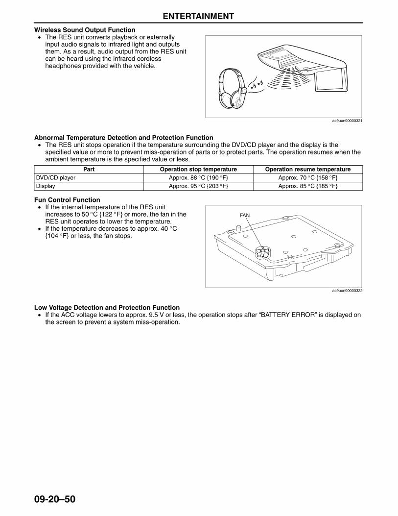
ENTERTAINMENT
09-20–50
Wireless Sound Output Function• The RES unit converts playback or externally
input audio signals to infrared light and outputs them. As a result, audio output from the RES unit can be heard using the infrared cordless headphones provided with the vehicle.
Abnormal Temperature Detection and Protection Function• The RES unit stops operation if the temperature surrounding the DVD/CD player and the display is the
specified value or more to prevent miss-operation of parts or to protect parts. The operation resumes when the ambient temperature is the specified value or less.
Fun Control Function• If the internal temperature of the RES unit
increases to 50 °C {122 °F} or more, the fan in the RES unit operates to lower the temperature.
• If the temperature decreases to approx. 40 °C {104 °F} or less, the fan stops.
Low Voltage Detection and Protection Function• If the ACC voltage lowers to approx. 9.5 V or less, the operation stops after “BATTERY ERROR” is displayed on
the screen to prevent a system miss-operation.End Of Sie
ac9uun00000331
Part Operation stop temperature Operation resume temperatureDVD/CD player Approx. 88 °C {190 °F} Approx. 70 °C {158 °F}Display Approx. 95 °C {203 °F} Approx. 85 °C {185 °F}
FAN
ac9uun00000332
3423-1U-06H(09-20).fm 50 ページ 2006年11月21日 火曜日 午後5時46分
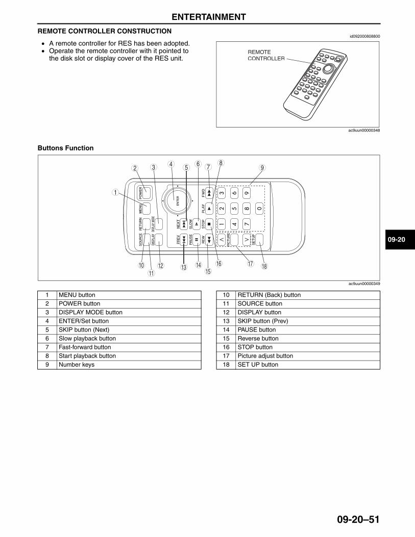
ENTERTAINMENT
09-20–51
09-20
REMOTE CONTROLLER CONSTRUCTIONid092000808800
• A remote controller for RES has been adopted.• Operate the remote controller with it pointed to
the disk slot or display cover of the RES unit.
Buttons Function
.
End Of Sie
REMOTE CONTROLLER
ac9uun00000348
98
7543
10 181715
16141311
12
6
1
2
ac9uun00000349
1 MENU button2 POWER button3 DISPLAY MODE button4 ENTER/Set button5 SKIP button (Next)6 Slow playback button7 Fast-forward button8 Start playback button9 Number keys
10 RETURN (Back) button11 SOURCE button12 DISPLAY button13 SKIP button (Prev)14 PAUSE button15 Reverse button16 STOP button17 Picture adjust button18 SET UP button
3423-1U-06H(09-20).fm 51 ページ 2006年11月21日 火曜日 午後5時46分
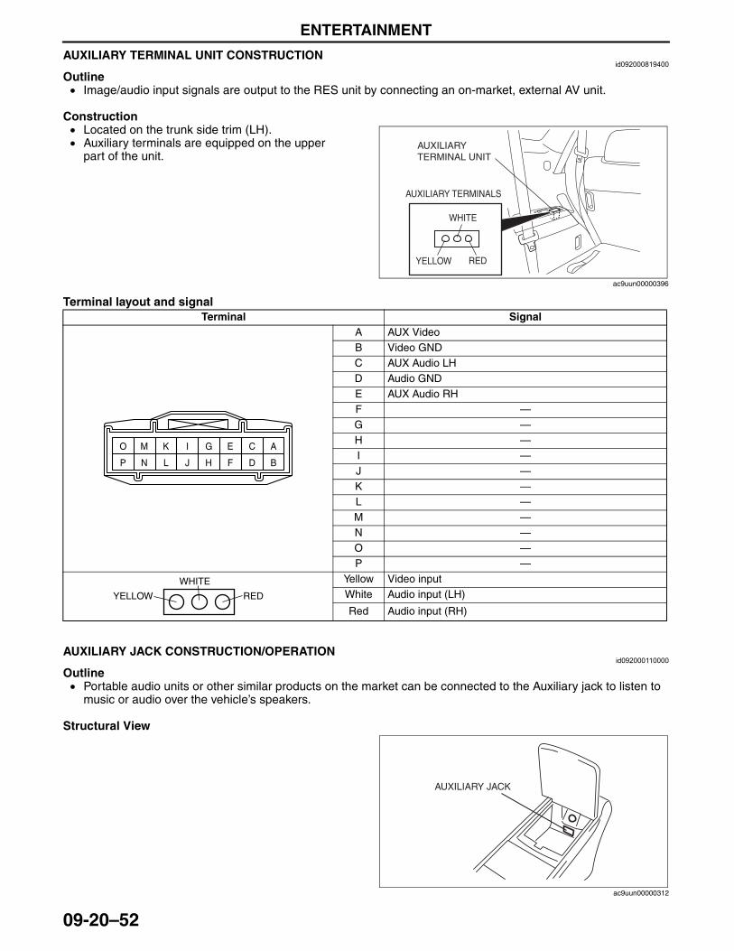
ENTERTAINMENT
09-20–52
AUXILIARY TERMINAL UNIT CONSTRUCTIONid092000819400
Outline• Image/audio input signals are output to the RES unit by connecting an on-market, external AV unit.
Construction• Located on the trunk side trim (LH).• Auxiliary terminals are equipped on the upper
part of the unit.
Terminal layout and signal
End Of SieNG: AUDIO UNITAUXILIARY JACK CONSTRUCTION/OPERATION
id092000110000
Outline• Portable audio units or other similar products on the market can be connected to the Auxiliary jack to listen to
music or audio over the vehicle’s speakers.
Structural View
YELLOW RED
WHITE
AUXILIARY TERMINAL UNIT
AUXILIARY TERMINALS
ac9uun00000396
Terminal SignalA AUX VideoB Video GNDC AUX Audio LHD Audio GNDE AUX Audio RHF —G —H —I —J —K —L —M —N —O —P —
Yellow Video inputWhite Audio input (LH)
Red Audio input (RH)
A
B
C
D
E
F
G
HJ
K
L
M
N
O
P
I
YELLOW RED
WHITE
AUXILIARY JACK
ac9uun00000312
3423-1U-06H(09-20).fm 52 ページ 2006年11月21日 火曜日 午後5時46分
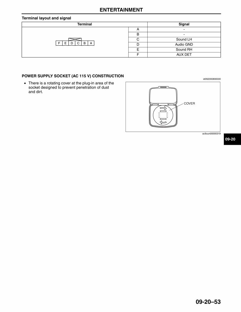
ENTERTAINMENT
09-20–53
09-20
Terminal layout and signal
End Of SieNG: POWER SUPPLY SOCKET
POWER SUPPLY SOCKET (AC 115 V) CONSTRUCTIONid092000808300
• There is a rotating cover at the plug-in area of the socket designed to prevent penetration of dust and dirt.
End Of Sie
Terminal SignalA -B -C Sound LHD Audio GNDE Sound RHF AUX DET
ABCDEF
COVER
ac9uun00000319
3423-1U-06H(09-20).fm 53 ページ 2006年11月21日 火曜日 午後5時46分
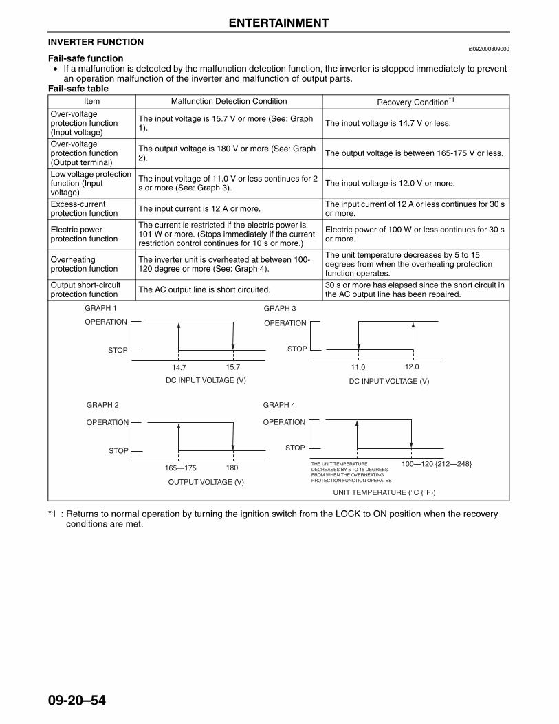
ENTERTAINMENT
09-20–54
INVERTER FUNCTIONid092000809000
Fail-safe function• If a malfunction is detected by the malfunction detection function, the inverter is stopped immediately to prevent
an operation malfunction of the inverter and malfunction of output parts.Fail-safe table
*1 : Returns to normal operation by turning the ignition switch from the LOCK to ON position when the recovery conditions are met.
End Of Sie
Item Malfunction Detection Condition Recovery Condition*1
Over-voltage protection function (Input voltage)
The input voltage is 15.7 V or more (See: Graph 1). The input voltage is 14.7 V or less.
Over-voltage protection function (Output terminal)
The output voltage is 180 V or more (See: Graph 2). The output voltage is between 165-175 V or less.
Low voltage protection function (Input voltage)
The input voltage of 11.0 V or less continues for 2 s or more (See: Graph 3). The input voltage is 12.0 V or more.
Excess-current protection function The input current is 12 A or more. The input current of 12 A or less continues for 30 s
or more.
Electric power protection function
The current is restricted if the electric power is 101 W or more. (Stops immediately if the current restriction control continues for 10 s or more.)
Electric power of 100 W or less continues for 30 s or more.
Overheating protection function
The inverter unit is overheated at between 100-120 degree or more (See: Graph 4).
The unit temperature decreases by 5 to 15 degrees from when the overheating protection function operates.
Output short-circuit protection function The AC output line is short circuited. 30 s or more has elapsed since the short circuit in
the AC output line has been repaired.
DC INPUT VOLTAGE (V) DC INPUT VOLTAGE (V)
OPERATION
15.7
STOP
OPERATION
STOP
OPERATION
STOP
OPERATION
STOP
14.7 12.011.0
OUTPUT VOLTAGE (V)
180165—175
UNIT TEMPERATURE (°C {°F})
100—120 {212—248}
GRAPH 1
GRAPH 2
GRAPH 3
GRAPH 4
THE UNIT TEMPERATURE DECREASES BY 5 TO 15 DEGREES FROM WHEN THE OVERHEATING PROTECTION FUNCTION OPERATES
3423-1U-06H(09-20).fm 54 ページ 2006年11月22日 水曜日 午後4時5分
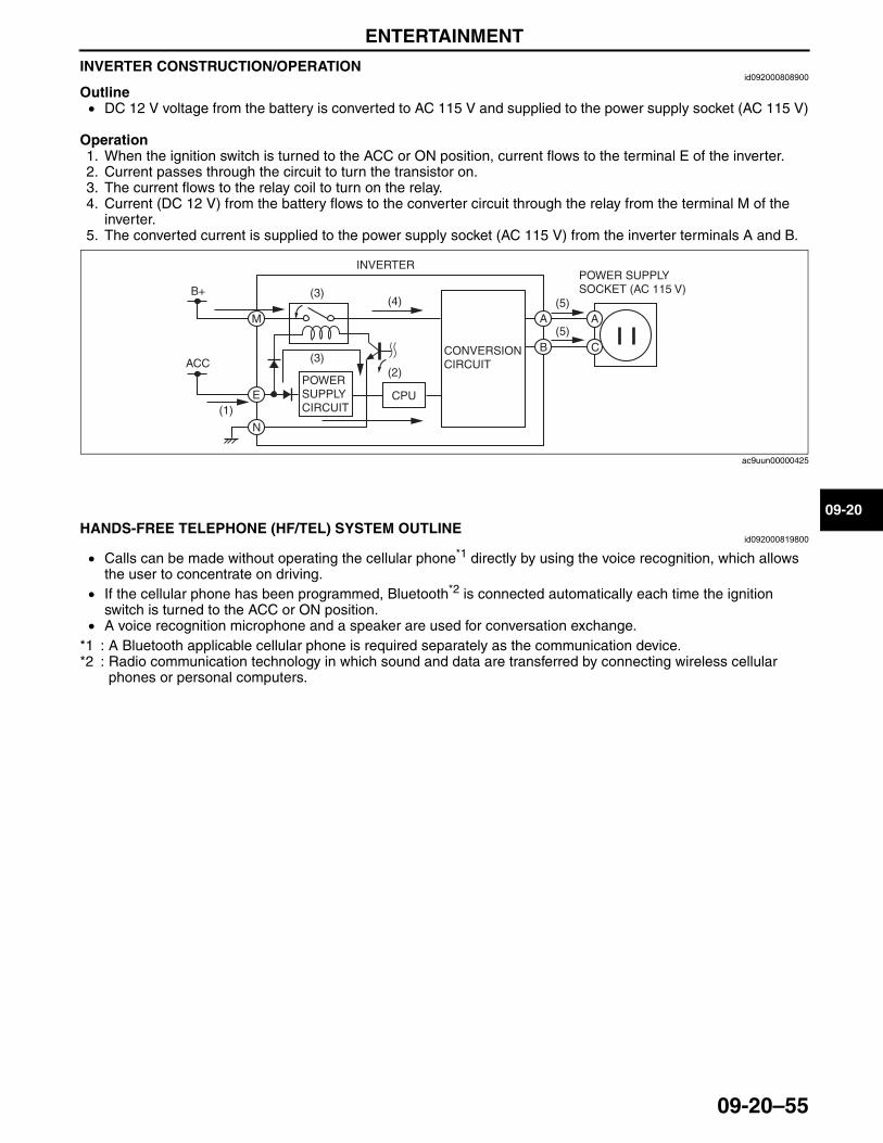
ENTERTAINMENT
09-20–55
09-20
INVERTER CONSTRUCTION/OPERATIONid092000808900
Outline• DC 12 V voltage from the battery is converted to AC 115 V and supplied to the power supply socket (AC 115 V)
Operation1. When the ignition switch is turned to the ACC or ON position, current flows to the terminal E of the inverter.2. Current passes through the circuit to turn the transistor on.3. The current flows to the relay coil to turn on the relay.4. Current (DC 12 V) from the battery flows to the converter circuit through the relay from the terminal M of the
inverter.5. The converted current is supplied to the power supply socket (AC 115 V) from the inverter terminals A and B.
End Of SieNG: HF/TEL SYSTEM
HANDS-FREE TELEPHONE (HF/TEL) SYSTEM OUTLINEid092000819800
• Calls can be made without operating the cellular phone*1 directly by using the voice recognition, which allows the user to concentrate on driving.
• If the cellular phone has been programmed, Bluetooth*2 is connected automatically each time the ignition switch is turned to the ACC or ON position.
• A voice recognition microphone and a speaker are used for conversation exchange.*1 : A Bluetooth applicable cellular phone is required separately as the communication device.*2 : Radio communication technology in which sound and data are transferred by connecting wireless cellular
phones or personal computers.
End Of Sie
B+
ACC
(1)
(3)(5)
(5)
(3)(2)
(4)
INVERTER
CPU
POWER SUPPLY SOCKET (AC 115 V)
M
E
N
A A
CB
POWER SUPPLY CIRCUIT
CONVERSION CIRCUIT
ac9uun00000425
3423-1U-06H(09-20).fm 55 ページ 2006年11月29日 水曜日 午前10時46分
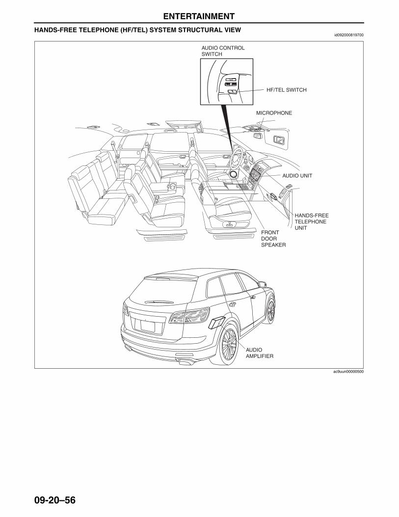
ENTERTAINMENT
09-20–56
HANDS-FREE TELEPHONE (HF/TEL) SYSTEM STRUCTURAL VIEWid092000819700
AUDIO CONTROL SWITCH
MICROPHONE
AUDIO UNIT
HANDS-FREE TELEPHONE UNIT
FRONT DOOR SPEAKER
AUDIO AMPLIFIER
HF/TEL SWITCH
ac9uun00000500
3423-1U-06H(09-20).fm 56 ページ 2006年11月21日 火曜日 午後5時46分
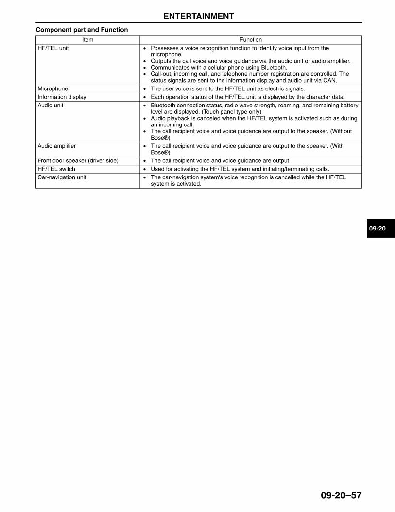
ENTERTAINMENT
09-20–57
09-20
Component part and Function
End Of Sie
Item FunctionHF/TEL unit • Possesses a voice recognition function to identify voice input from the
microphone.• Outputs the call voice and voice guidance via the audio unit or audio amplifier.• Communicates with a cellular phone using Bluetooth.• Call-out, incoming call, and telephone number registration are controlled. The
status signals are sent to the information display and audio unit via CAN.Microphone • The user voice is sent to the HF/TEL unit as electric signals.Information display • Each operation status of the HF/TEL unit is displayed by the character data.Audio unit • Bluetooth connection status, radio wave strength, roaming, and remaining battery
level are displayed. (Touch panel type only)• Audio playback is canceled when the HF/TEL system is activated such as during
an incoming call.• The call recipient voice and voice guidance are output to the speaker. (Without
Bose®)Audio amplifier • The call recipient voice and voice guidance are output to the speaker. (With
Bose®)Front door speaker (driver side) • The call recipient voice and voice guidance are output.HF/TEL switch • Used for activating the HF/TEL system and initiating/terminating calls.Car-navigation unit • The car-navigation system's voice recognition is cancelled while the HF/TEL
system is activated.
3423-1U-06H(09-20).fm 57 ページ 2006年11月21日 火曜日 午後5時46分
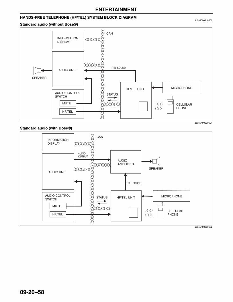
ENTERTAINMENT
09-20–58
HANDS-FREE TELEPHONE (HF/TEL) SYSTEM BLOCK DIAGRAMid092000819500
Standard audio (without Bose®)
Standard audio (with Bose®)
MUTE
HF/TEL
HF/TEL UNIT MICROPHONE
SPEAKER
AUDIO CONTROL SWITCH
CAN
INFORMATION DISPLAY
AUDIO UNITTEL SOUND
CELLULAR PHONE
STATUS
ac9uun00000501
INFORMATION DISPLAY
AUDIO UNIT
MUTE
HF/TEL
HF/TEL UNIT MICROPHONE
SPEAKER
AUDIO CONTROL SWITCH
CAN
TEL SOUND
AUDIO AMPLIFIER
AUDIO OUTPUT
CELLULAR PHONE
STATUS
ac9uun00000502
3423-1U-06H(09-20).fm 58 ページ 2006年11月21日 火曜日 午後5時46分
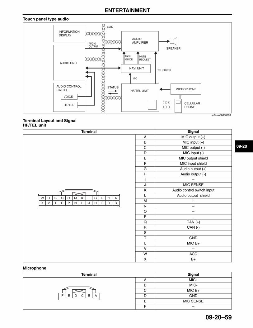
ENTERTAINMENT
09-20–59
09-20
Touch panel type audio
Terminal Layout and SignalHF/TEL unit
MIcrophone
Terminal SignalA MIC output (+)B MIC input (+)C MIC output (-)D MIC input (-)E MIC output shieldF MIC input shieldG Audio output (+)H Audio output (-)I –J MIC SENSEK Audio control switch inputL Audio output shieldM –N –O –P –Q CAN (+)R CAN (-)S –T GNDU MIC B+V –W ACCX B+
Terminal SignalA MIC+B MIC-C MIC B+D GNDE MIC SENSEF –
INFORMATION DISPLAY
AUDIO UNIT
VOICE
HF/TEL
HF/TEL UNIT MICROPHONE
SPEAKER
AUDIO CONTROL SWITCH
CAN
TEL SOUND
AUDIO AMPLIFIERAUDIO
OUTPUT
NAVI UNIT
MIC
NAVI GUIDE
MUTE REQUEST
CELLULAR PHONE
STATUS
ac9uun00000503
ACEGIKMO
BDFHJLNP
QSUW
RTVX
ACE BDF
3423-1U-06H(09-20).fm 59 ページ 2006年11月21日 火曜日 午後5時46分
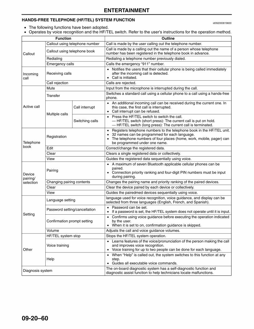
ENTERTAINMENT
09-20–60
End Of SieHANDS-FREE TELEPHONE (HF/TEL) SYSTEM FUNCTIONid092000819600
• The following functions have been adopted.• Operates by voice recognition and the HF/TEL switch. Refer to the user's instructions for the operation method.
End Of Sie
Function Outline
Callout
Callout using telephone number Call is made by the user calling out the telephone number.
Callout using telephone book Call is made by a calling out the name of a person whose telephone number has been registered in the telephone book in advance.
Redialing Redialing a telephone number previously dialed.Emergency calls Calls the emergency “911” number.
Incoming call
Receiving calls• Notifies the users that their cellular phone is being called immediately
after the incoming call is detected.• Call is initiated.
Call rejection Calls are rejected.
Active call
Mute Input from the microphone is interrupted during the call.
Transfer Switches a standard call using a cellular phone to a call using a hands-free phone.
Multiple calls
Call interrupt• An additional incoming call can be received during the current one. In
this case, the first call is interrupted.• Call interrupt can be refused.
Switching calls• Press the HF/TEL switch to switch the call.— HF/TEL switch (short press): The current call is put on hold.— HF/TEL switch (long press): The current call is terminated.
Telephone book
Registration
• Registers telephone numbers to the telephone book in the HF/TEL unit.• 32 names can be programmed for each language.• The telephone numbers of four places (home, work, mobile, pager) can
be programmed under one name.Edit Correct/change the registered data.Clear Clears a single registered data or collectively.View Guides the registered data sequentially using voice.
Device pairing/selection
Pairing
• A maximum of seven Bluetooth applicable cellular phones can be paired.
• Connection priority ranking and four-digit PIN numbers must be input during pairing.
Changing pairing contents Changes the pairing name and priority ranking of the paired devices.Clear Clear the device paired by each device or collectively.View Guides the pairedmed devices sequentially using voice.
Setting
Language setting language used for voice recognition, voice guidance, and display can be selected from three languages (English, French, and Spanish).
Password setting/cancellation • Password can be set.• If a password is set, the HF/TEL system does not operate until it is input.
Confirmation prompt setting• Confirms using voice guidance before executing the operation indicated
by the user.• When it is set to on, confirmation guidance is skipped.
Volume Adjusts the call and voice guidance volumes.
Other
HF/TEL system stop Stops the HF/TEL system operation.
Voice training• Learns features of the voice/pronunciation of the person making the call
and improves voice recognition. • Voice training for up to two people can be done for each language.
Help• When “Help” is called out, the system switches to this function at any
step.• Guides all executable voice commands.
Diagnosis system The on-board diagnostic system has a self-diagnostic function and diagnostic assist function to help technicians locate malfunctions.
3423-1U-06H(09-20).fm 60 ページ 2006年11月21日 火曜日 午後5時46分
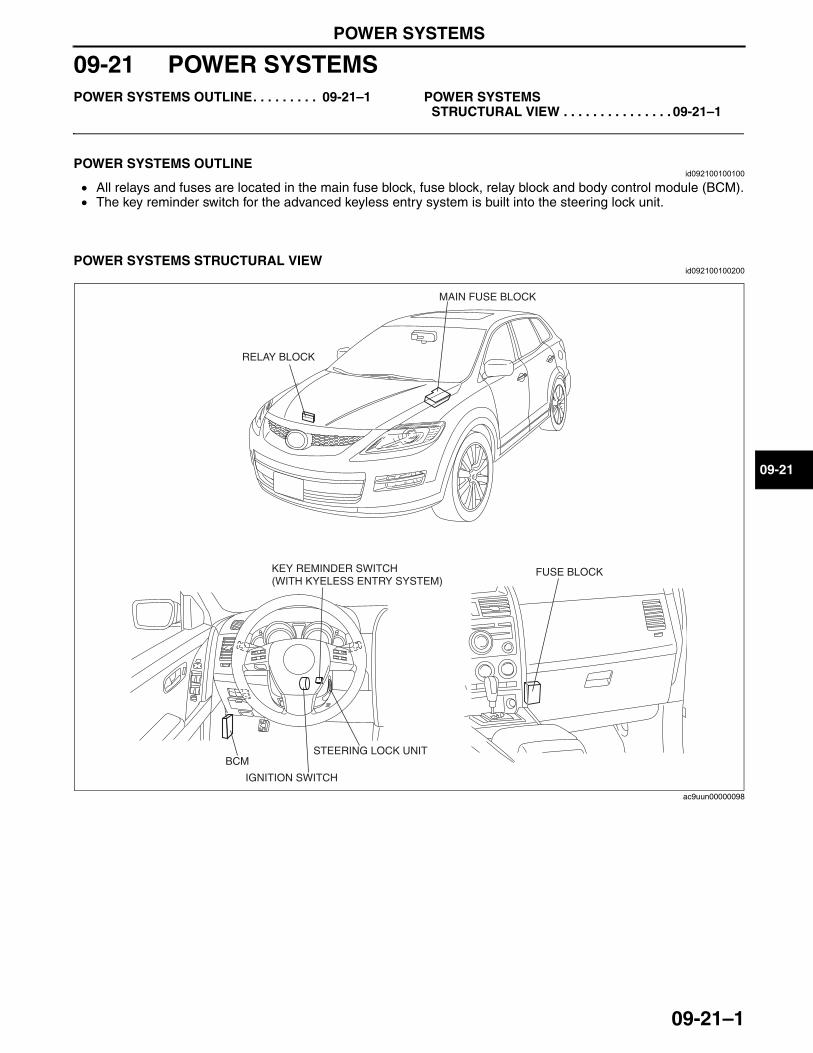
POWER SYSTEMS
09-21–1
09-21
09-21 POWER SYSTEMSPOWER SYSTEMS OUTLINE. . . . . . . . . 09-21–1 POWER SYSTEMS
STRUCTURAL VIEW . . . . . . . . . . . . . . . 09-21–1
End of TocNG: POWER SUPPLY SYSTEMPOWER SYSTEMS OUTLINE
id092100100100
• All relays and fuses are located in the main fuse block, fuse block, relay block and body control module (BCM).• The key reminder switch for the advanced keyless entry system is built into the steering lock unit.
End Of Sie
POWER SYSTEMS STRUCTURAL VIEWid092100100200
End Of Sie
MAIN FUSE BLOCK
RELAY BLOCK
KEY REMINDER SWITCH(WITH KYELESS ENTRY SYSTEM)
BCM
IGNITION SWITCH
STEERING LOCK UNIT
FUSE BLOCK
ac9uun00000098
3423-1U-06H(09-21).fm 1 ページ 2006年11月21日 火曜日 午後5時49分

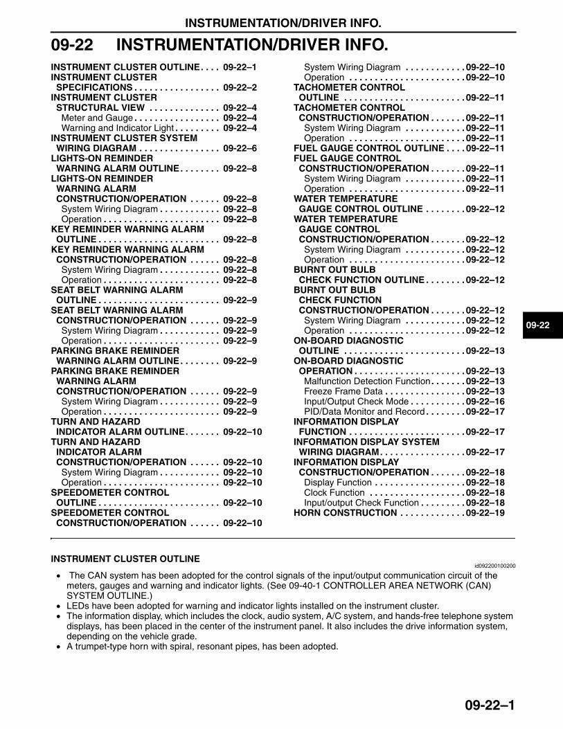
INSTRUMENTATION/DRIVER INFO.
09-22–1
09-22
09-22 INSTRUMENTATION/DRIVER INFO.INSTRUMENT CLUSTER OUTLINE. . . . 09-22–1INSTRUMENT CLUSTER
SPECIFICATIONS . . . . . . . . . . . . . . . . . 09-22–2INSTRUMENT CLUSTER
STRUCTURAL VIEW . . . . . . . . . . . . . . 09-22–4Meter and Gauge . . . . . . . . . . . . . . . . . 09-22–4Warning and Indicator Light . . . . . . . . . 09-22–4
INSTRUMENT CLUSTER SYSTEM WIRING DIAGRAM . . . . . . . . . . . . . . . . 09-22–6
LIGHTS-ON REMINDER WARNING ALARM OUTLINE. . . . . . . . 09-22–8
LIGHTS-ON REMINDER WARNING ALARM CONSTRUCTION/OPERATION . . . . . . 09-22–8
System Wiring Diagram . . . . . . . . . . . . 09-22–8Operation . . . . . . . . . . . . . . . . . . . . . . . 09-22–8
KEY REMINDER WARNING ALARM OUTLINE . . . . . . . . . . . . . . . . . . . . . . . . 09-22–8
KEY REMINDER WARNING ALARM CONSTRUCTION/OPERATION . . . . . . 09-22–8
System Wiring Diagram . . . . . . . . . . . . 09-22–8Operation . . . . . . . . . . . . . . . . . . . . . . . 09-22–8
SEAT BELT WARNING ALARM OUTLINE . . . . . . . . . . . . . . . . . . . . . . . . 09-22–9
SEAT BELT WARNING ALARM CONSTRUCTION/OPERATION . . . . . . 09-22–9
System Wiring Diagram . . . . . . . . . . . . 09-22–9Operation . . . . . . . . . . . . . . . . . . . . . . . 09-22–9
PARKING BRAKE REMINDER WARNING ALARM OUTLINE. . . . . . . . 09-22–9
PARKING BRAKE REMINDER WARNING ALARM CONSTRUCTION/OPERATION . . . . . . 09-22–9
System Wiring Diagram . . . . . . . . . . . . 09-22–9Operation . . . . . . . . . . . . . . . . . . . . . . . 09-22–9
TURN AND HAZARD INDICATOR ALARM OUTLINE. . . . . . . 09-22–10
TURN AND HAZARD INDICATOR ALARM CONSTRUCTION/OPERATION . . . . . . 09-22–10
System Wiring Diagram . . . . . . . . . . . . 09-22–10Operation . . . . . . . . . . . . . . . . . . . . . . . 09-22–10
SPEEDOMETER CONTROL OUTLINE . . . . . . . . . . . . . . . . . . . . . . . . 09-22–10
SPEEDOMETER CONTROL CONSTRUCTION/OPERATION . . . . . . 09-22–10
System Wiring Diagram . . . . . . . . . . . . 09-22–10Operation . . . . . . . . . . . . . . . . . . . . . . . 09-22–10
TACHOMETER CONTROL OUTLINE . . . . . . . . . . . . . . . . . . . . . . . . 09-22–11
TACHOMETER CONTROL CONSTRUCTION/OPERATION . . . . . . . 09-22–11
System Wiring Diagram . . . . . . . . . . . . 09-22–11Operation . . . . . . . . . . . . . . . . . . . . . . . 09-22–11
FUEL GAUGE CONTROL OUTLINE . . . . 09-22–11FUEL GAUGE CONTROL
CONSTRUCTION/OPERATION . . . . . . . 09-22–11System Wiring Diagram . . . . . . . . . . . . 09-22–11Operation . . . . . . . . . . . . . . . . . . . . . . . 09-22–11
WATER TEMPERATURE GAUGE CONTROL OUTLINE . . . . . . . . 09-22–12
WATER TEMPERATURE GAUGE CONTROL CONSTRUCTION/OPERATION . . . . . . . 09-22–12
System Wiring Diagram . . . . . . . . . . . . 09-22–12Operation . . . . . . . . . . . . . . . . . . . . . . . 09-22–12
BURNT OUT BULB CHECK FUNCTION OUTLINE . . . . . . . . 09-22–12
BURNT OUT BULB CHECK FUNCTION CONSTRUCTION/OPERATION . . . . . . . 09-22–12
System Wiring Diagram . . . . . . . . . . . . 09-22–12Operation . . . . . . . . . . . . . . . . . . . . . . . 09-22–12
ON-BOARD DIAGNOSTIC OUTLINE . . . . . . . . . . . . . . . . . . . . . . . . 09-22–13
ON-BOARD DIAGNOSTIC OPERATION . . . . . . . . . . . . . . . . . . . . . . 09-22–13
Malfunction Detection Function . . . . . . . 09-22–13Freeze Frame Data . . . . . . . . . . . . . . . . 09-22–13Input/Output Check Mode . . . . . . . . . . . 09-22–16PID/Data Monitor and Record . . . . . . . . 09-22–17
INFORMATION DISPLAY FUNCTION . . . . . . . . . . . . . . . . . . . . . . . 09-22–17
INFORMATION DISPLAY SYSTEM WIRING DIAGRAM. . . . . . . . . . . . . . . . . 09-22–17
INFORMATION DISPLAY CONSTRUCTION/OPERATION . . . . . . . 09-22–18
Display Function . . . . . . . . . . . . . . . . . . 09-22–18Clock Function . . . . . . . . . . . . . . . . . . . 09-22–18Input/output Check Function . . . . . . . . . 09-22–18
HORN CONSTRUCTION . . . . . . . . . . . . . 09-22–19
End of TocNG: INSTRUMENT CLUSTERINSTRUMENT CLUSTER OUTLINE
id092200100200
• The CAN system has been adopted for the control signals of the input/output communication circuit of the meters, gauges and warning and indicator lights. (See 09-40-1 CONTROLLER AREA NETWORK (CAN) SYSTEM OUTLINE.)
• LEDs have been adopted for warning and indicator lights installed on the instrument cluster.• The information display, which includes the clock, audio system, A/C system, and hands-free telephone system
displays, has been placed in the center of the instrument panel. It also includes the drive information system, depending on the vehicle grade.
• A trumpet-type horn with spiral, resonant pipes, has been adopted.End Of Sie
3423-1U-06H(09-22).fm 1 ページ 2006年11月21日 火曜日 午後5時49分
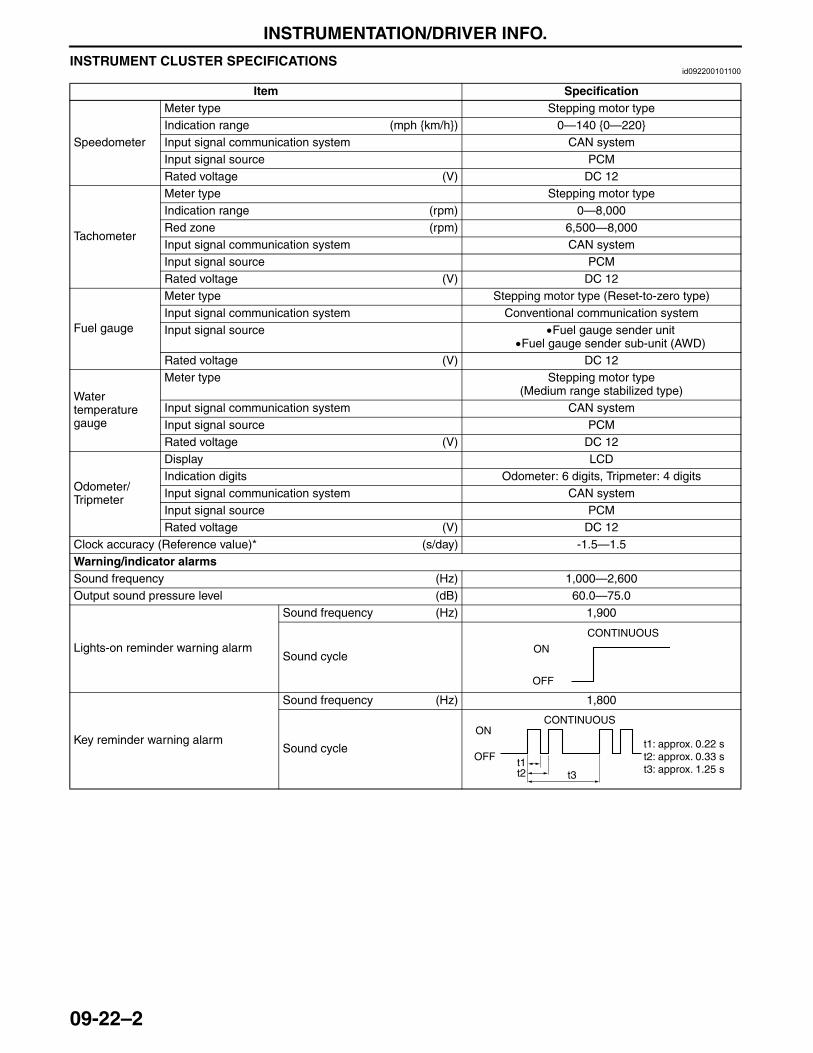
INSTRUMENTATION/DRIVER INFO.
09-22–2
INSTRUMENT CLUSTER SPECIFICATIONSid092200101100
Item Specification
Speedometer
Meter type Stepping motor typeIndication range (mph {km/h}) 0—140 {0—220}Input signal communication system CAN systemInput signal source PCMRated voltage (V) DC 12
Tachometer
Meter type Stepping motor typeIndication range (rpm) 0—8,000Red zone (rpm) 6,500—8,000Input signal communication system CAN systemInput signal source PCMRated voltage (V) DC 12
Fuel gauge
Meter type Stepping motor type (Reset-to-zero type)Input signal communication system Conventional communication systemInput signal source •Fuel gauge sender unit
•Fuel gauge sender sub-unit (AWD)Rated voltage (V) DC 12
Water temperature gauge
Meter type Stepping motor type(Medium range stabilized type)
Input signal communication system CAN systemInput signal source PCMRated voltage (V) DC 12
Odometer/Tripmeter
Display LCDIndication digits Odometer: 6 digits, Tripmeter: 4 digitsInput signal communication system CAN systemInput signal source PCMRated voltage (V) DC 12
Clock accuracy (Reference value)* (s/day) -1.5—1.5Warning/indicator alarmsSound frequency (Hz) 1,000—2,600Output sound pressure level (dB) 60.0—75.0
Lights-on reminder warning alarm
Sound frequency (Hz) 1,900
Sound cycle
Key reminder warning alarm
Sound frequency (Hz) 1,800
Sound cycle
CONTINUOUS
ON
OFF
ON
OFF
CONTINUOUS
t1t2
t1: approx. 0.22 st2: approx. 0.33 s
t3 t3: approx. 1.25 s
3423-1U-06H(09-22).fm 2 ページ 2006年11月21日 火曜日 午後5時49分

INSTRUMENTATION/DRIVER INFO.
09-22–3
09-22
* : If the clock accuracy varies largely from the reference value, battery deterioration or an information display malfunction may have occurred.
End Of Sie
Seat belt warning alarm
Sound frequency (Hz) 1,000
Sound cycle
Tire pressure warning alarm
Sound frequency (Hz) 2,600
Sound cycle
Advanced keyless entry system warning alarm
Sound frequency (Hz) 1,800
Sound cycle
Air bag system warning alarm
Sound frequency (Hz) 2,200
Sound cycle
Parking brake reminder warning alarm
Sound frequency (Hz) 2,000
Sound cycle
Turn and hazard indicator alarm
Sound frequency (Hz) 1,700—1,800
Sound cycle
Panel light control indicator alarm
Sound frequency (Hz) 1,900
Sound cycle
Item Specification
ON
OFF
t1: approx. 0.05 st2: approx. 1 st3: approx. 31 s
WHILE VEHICLE DRIVING(VEHICLE SPEED 20 km/h {12.4 mph} OR MORE)
WHEN IGNITION SWITCH TURNED ON
ON
OFF
t1t2
t3
t1t2
t3
t1: approx. 0.05 st2: approx. 1 st3: approx. 6 s
CONTINUOUSON
OFFt1t2
t1: approx. 0.3 st2: approx. 0.6 s
ON
OFF
CONTINUOUS
t1t2
t1: approx. 0.22 st2: approx. 0.33 s
t3 t3: approx. 1.25 s
ON
OFFt1 t2
t3
t1: approx. 5 st2: approx. 55 st3: approx. 2,100 s
CONTINUOUS
ON
OFF
ON
OFF
DEPEND ON MESSAGE FROM BCM
ON
OFF approx. 0.06 s
3423-1U-06H(09-22).fm 3 ページ 2006年11月21日 火曜日 午後5時49分
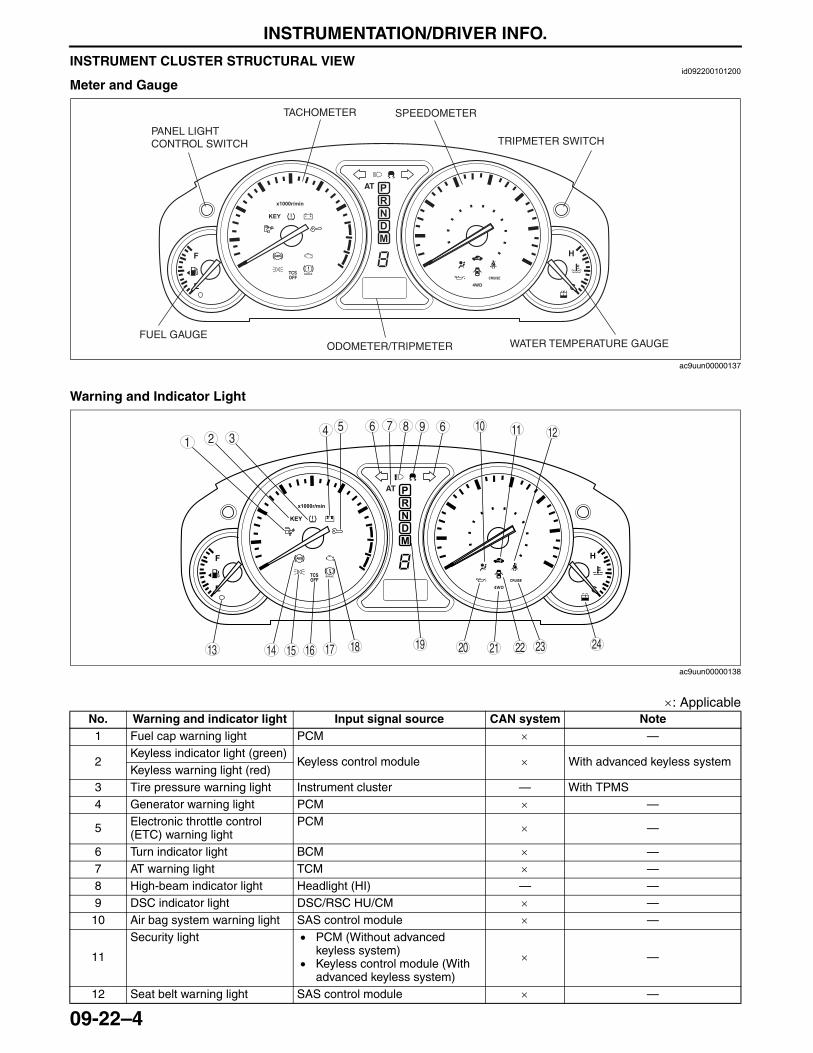
INSTRUMENTATION/DRIVER INFO.
09-22–4
INSTRUMENT CLUSTER STRUCTURAL VIEWid092200101200
Meter and Gauge
Warning and Indicator Light
×: ApplicableNo. Warning and indicator light Input signal source CAN system Note1 Fuel cap warning light PCM × —
2Keyless indicator light (green)
Keyless control module × With advanced keyless systemKeyless warning light (red)
3 Tire pressure warning light Instrument cluster — With TPMS4 Generator warning light PCM × —
5 Electronic throttle control (ETC) warning light
PCM × —
6 Turn indicator light BCM × —7 AT warning light TCM × —8 High-beam indicator light Headlight (HI) — —9 DSC indicator light DSC/RSC HU/CM × —10 Air bag system warning light SAS control module × —
11
Security light • PCM (Without advanced keyless system)
• Keyless control module (With advanced keyless system)
× —
12 Seat belt warning light SAS control module × —
BRAKE
TACHOMETER SPEEDOMETER
WATER TEMPERATURE GAUGEFUEL GAUGE
TRIPMETER SWITCH
ODOMETER/TRIPMETER
PANEL LIGHT CONTROL SWITCH
ac9uun00000137
BRAKE
987543
10
19181715 1614 20 242321 22
61 2
13
11 126
ac9uun00000138
3423-1U-06H(09-22).fm 4 ページ 2006年11月21日 火曜日 午後5時49分
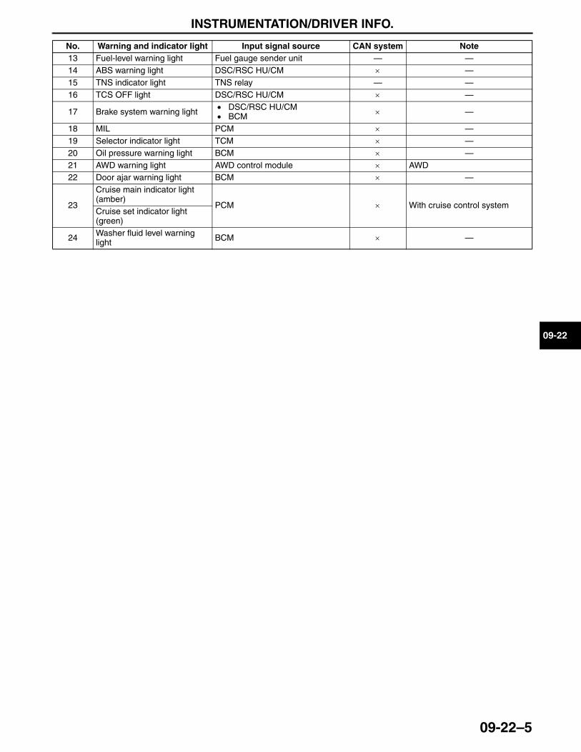
INSTRUMENTATION/DRIVER INFO.
09-22–5
09-22
End Of Sie
13 Fuel-level warning light Fuel gauge sender unit — —14 ABS warning light DSC/RSC HU/CM × —15 TNS indicator light TNS relay — —16 TCS OFF light DSC/RSC HU/CM × —
17 Brake system warning light • DSC/RSC HU/CM• BCM × —
18 MIL PCM × —19 Selector indicator light TCM × —20 Oil pressure warning light BCM × —21 AWD warning light AWD control module × AWD22 Door ajar warning light BCM × —
23
Cruise main indicator light (amber)
PCM × With cruise control systemCruise set indicator light (green)
24 Washer fluid level warning light BCM × —
No. Warning and indicator light Input signal source CAN system Note
3423-1U-06H(09-22).fm 5 ページ 2006年11月21日 火曜日 午後5時49分
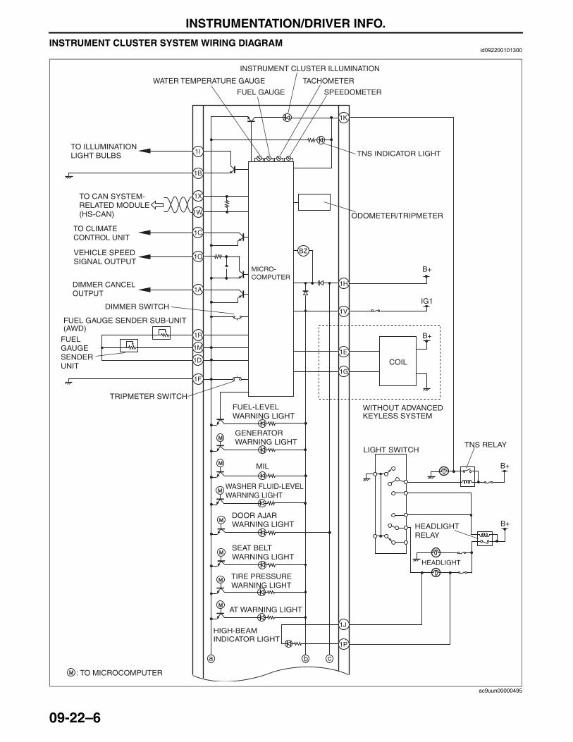
INSTRUMENTATION/DRIVER INFO.
09-22–6
INSTRUMENT CLUSTER SYSTEM WIRING DIAGRAMid092200101300
IG1
1X
1W
1I
1B
1O
1R
1M
1F
1K
BZ
1H
1V
1E
1G
1J
1P
b ca
B+
B+
B+
B+
INSTRUMENT CLUSTER ILLUMINATION
WATER TEMPERATURE GAUGE
FUEL GAUGE
TACHOMETER
SPEEDOMETER
ODOMETER/TRIPMETER
MICRO-COMPUTER
TRIPMETER SWITCH
MIL
AT WARNING LIGHT
COIL
LIGHT SWITCHTNS RELAY
HEADLIGHT
: TO MICROCOMPUTER
TO CAN SYSTEM-RELATED MODULE (HS-CAN)
VEHICLE SPEED SIGNAL OUTPUT
TO ILLUMINATION LIGHT BULBS
WASHER FLUID-LEVEL WARNING LIGHT
SEAT BELT WARNING LIGHT
DOOR AJAR WARNING LIGHT
FUEL-LEVEL WARNING LIGHT
GENERATOR WARNING LIGHT
TNS INDICATOR LIGHT
HEADLIGHT RELAY
HIGH-BEAM INDICATOR LIGHT
TIRE PRESSURE WARNING LIGHT
1ADIMMER CANCEL OUTPUT
DIMMER SWITCH
1D
FUEL GAUGE SENDER UNIT
FUEL GAUGE SENDER SUB-UNIT (AWD)
WITHOUT ADVANCED KEYLESS SYSTEM
1CTO CLIMATE CONTROL UNIT
ac9uun00000495
3423-1U-06H(09-22).fm 6 ページ 2006年11月21日 火曜日 午後5時49分
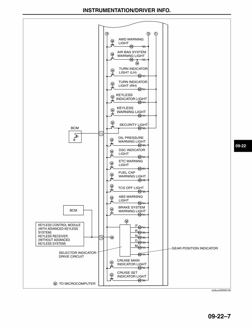
INSTRUMENTATION/DRIVER INFO.
09-22–7
09-22
End Of Sie
b ca
P
R
N
D
M
1U
BCM
1N
SECURITY LIGHT
GEAR POSITION INDICATOR
: TO MICROCOMPUTER
CRUISE SET INDICATOR LIGHT
CRUISE MAIN INDICATOR LIGHT
BRAKE SYSTEM WARNING LIGHT
ABS WARNING LIGHT
DSC INDICATOR LIGHT
TCS OFF LIGHT
OIL PRESSURE WARNING LIGHT
SELECTOR INDICATOR DRIVE CIRCUIT
AIR BAG SYSTEM WARNING LIGHT
AWD WARNING LIGHT
TURN INDICATOR LIGHT (LH)
TURN INDICATOR LIGHT (RH)
KEYLESS INDICATOR LIGHT
KEYLESS WARNING LIGHT
ETC WARNING LIGHT
FUEL CAP WARNING LIGHT
KEYLESS CONTROL MODULE (WITH ADVANCED KEYLESS SYSTEM)KEYLESS RECEIVER (WITHOUT ADVANCED KEYLESS SYSTEM)
BCM
ac9uun00000140
3423-1U-06H(09-22).fm 7 ページ 2006年11月21日 火曜日 午後5時49分
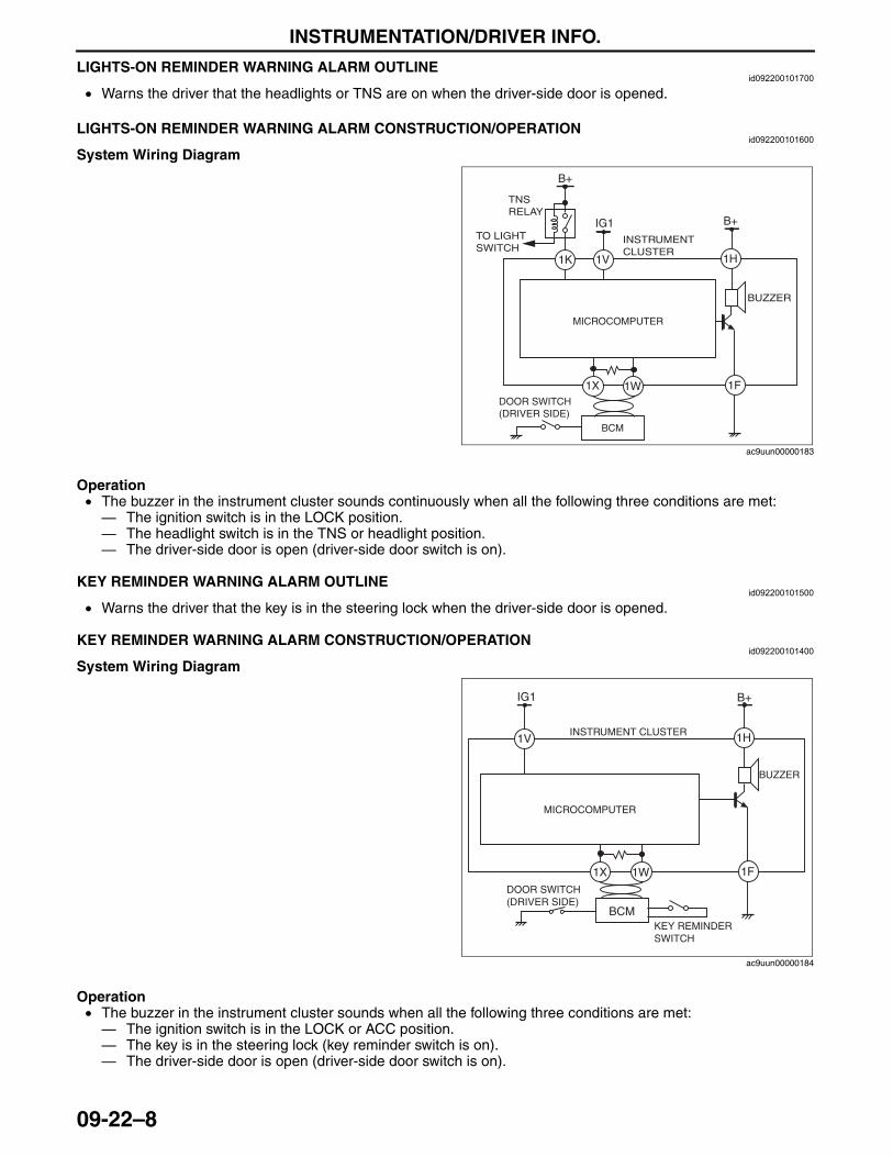
INSTRUMENTATION/DRIVER INFO.
09-22–8
LIGHTS-ON REMINDER WARNING ALARM OUTLINEid092200101700
• Warns the driver that the headlights or TNS are on when the driver-side door is opened.End Of SieLIGHTS-ON REMINDER WARNING ALARM CONSTRUCTION/OPERATION
id092200101600
System Wiring Diagram
Operation• The buzzer in the instrument cluster sounds continuously when all the following three conditions are met: — The ignition switch is in the LOCK position.— The headlight switch is in the TNS or headlight position.— The driver-side door is open (driver-side door switch is on).
End Of SieKEY REMINDER WARNING ALARM OUTLINE
id092200101500
• Warns the driver that the key is in the steering lock when the driver-side door is opened.End Of SieKEY REMINDER WARNING ALARM CONSTRUCTION/OPERATION
id092200101400
System Wiring Diagram
Operation• The buzzer in the instrument cluster sounds when all the following three conditions are met: — The ignition switch is in the LOCK or ACC position.— The key is in the steering lock (key reminder switch is on).— The driver-side door is open (driver-side door switch is on).
End Of Sie
IG1 B+
1V
1F1W1X
1H
B+
1K
BCM
INSTRUMENT CLUSTER
TNS RELAY
TO LIGHT SWITCH
BUZZER
MICROCOMPUTER
DOOR SWITCH (DRIVER SIDE)
ac9uun00000183
1V
1F1W1X
1H
BCM
IG1 B+
DOOR SWITCH (DRIVER SIDE)
KEY REMINDER SWITCH
INSTRUMENT CLUSTER
BUZZER
MICROCOMPUTER
ac9uun00000184
3423-1U-06H(09-22).fm 8 ページ 2006年11月21日 火曜日 午後5時49分
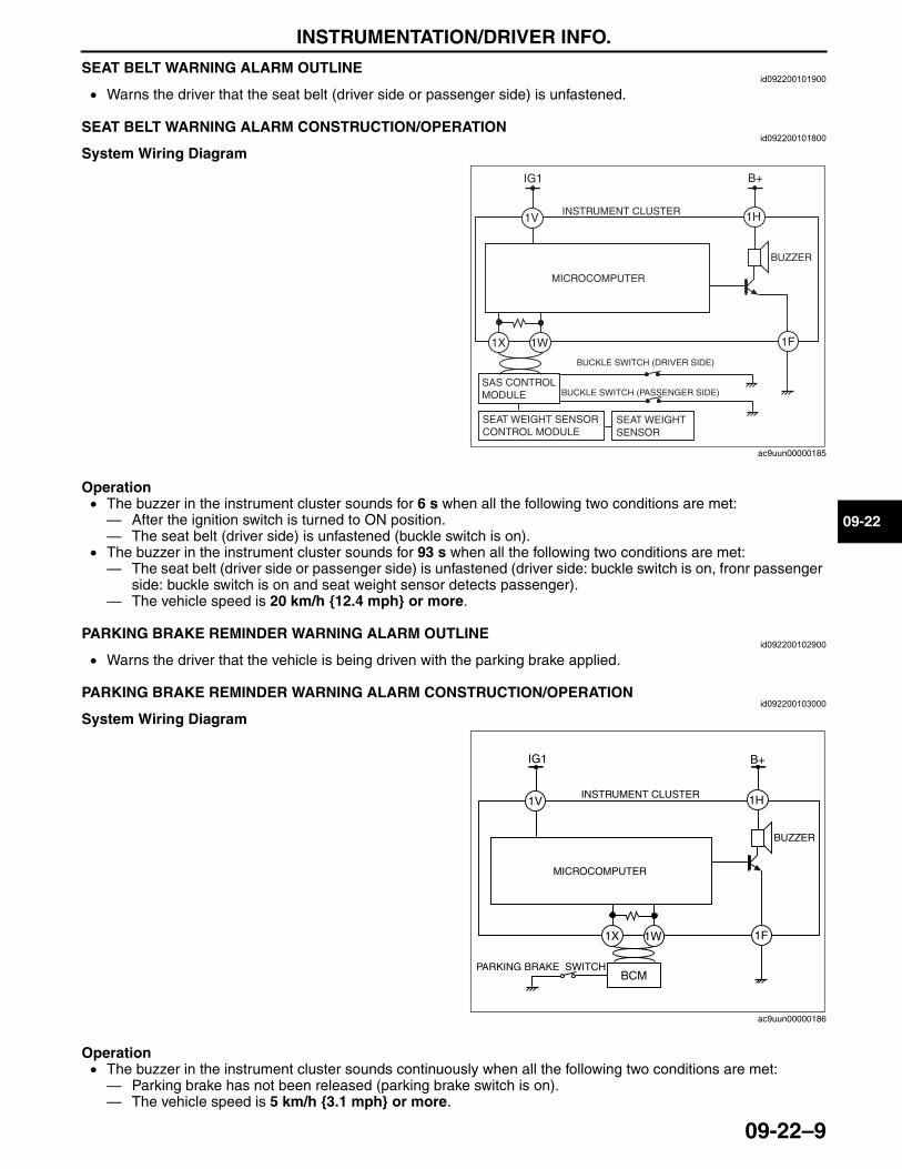
INSTRUMENTATION/DRIVER INFO.
09-22–9
09-22
SEAT BELT WARNING ALARM OUTLINEid092200101900
• Warns the driver that the seat belt (driver side or passenger side) is unfastened.End Of SieSEAT BELT WARNING ALARM CONSTRUCTION/OPERATION
id092200101800
System Wiring Diagram
Operation• The buzzer in the instrument cluster sounds for 6 s when all the following two conditions are met:— After the ignition switch is turned to ON position.— The seat belt (driver side) is unfastened (buckle switch is on).
• The buzzer in the instrument cluster sounds for 93 s when all the following two conditions are met:— The seat belt (driver side or passenger side) is unfastened (driver side: buckle switch is on, fronr passenger
side: buckle switch is on and seat weight sensor detects passenger).— The vehicle speed is 20 km/h {12.4 mph} or more.
End Of SiePARKING BRAKE REMINDER WARNING ALARM OUTLINE
id092200102900
• Warns the driver that the vehicle is being driven with the parking brake applied.End Of SiePARKING BRAKE REMINDER WARNING ALARM CONSTRUCTION/OPERATION
id092200103000
System Wiring Diagram
Operation• The buzzer in the instrument cluster sounds continuously when all the following two conditions are met: — Parking brake has not been released (parking brake switch is on).— The vehicle speed is 5 km/h {3.1 mph} or more.
1V
1F
1H
IG1 B+
INSTRUMENT CLUSTER
MICROCOMPUTER
BUZZER
SAS CONTROL MODULE
BUCKLE SWITCH (DRIVER SIDE)
BUCKLE SWITCH (PASSENGER SIDE)
SEAT WEIGHT SENSOR CONTROL MODULE
SEAT WEIGHT SENSOR
1W1X
ac9uun00000185
1V
1F1W1X
1H
BCM
IG1 B+
PARKING BRAKE SWITCH
INSTRUMENT CLUSTER
BUZZER
MICROCOMPUTER
ac9uun00000186
3423-1U-06H(09-22).fm 9 ページ 2006年11月21日 火曜日 午後5時49分
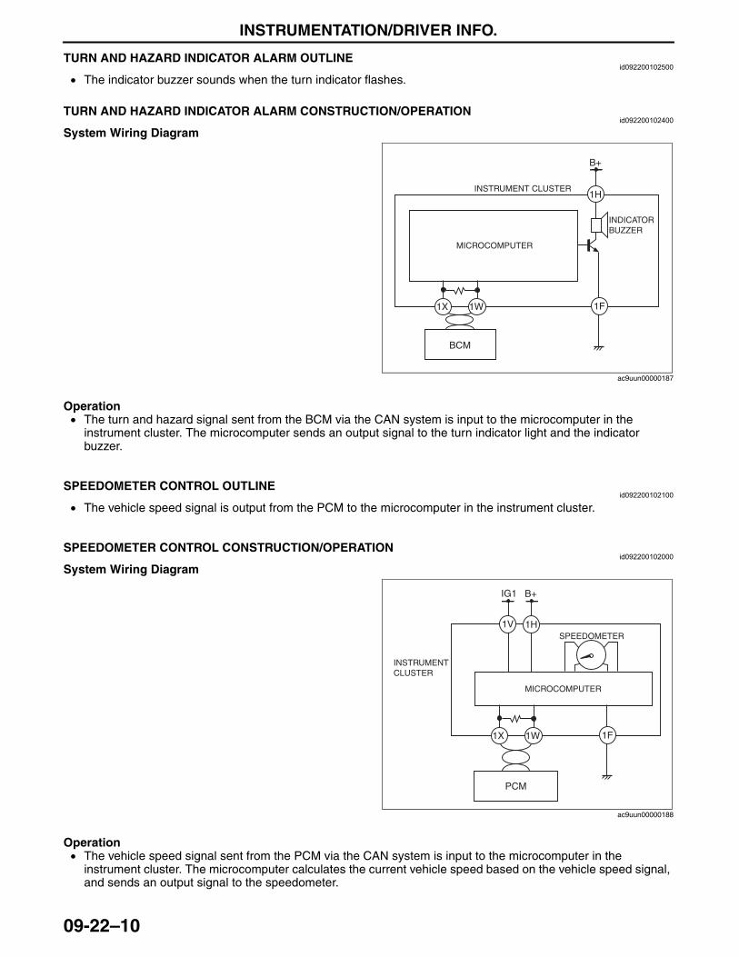
INSTRUMENTATION/DRIVER INFO.
09-22–10
End Of SieTURN AND HAZARD INDICATOR ALARM OUTLINEid092200102500
• The indicator buzzer sounds when the turn indicator flashes.End Of SieTURN AND HAZARD INDICATOR ALARM CONSTRUCTION/OPERATION
id092200102400
System Wiring Diagram
Operation• The turn and hazard signal sent from the BCM via the CAN system is input to the microcomputer in the
instrument cluster. The microcomputer sends an output signal to the turn indicator light and the indicator buzzer.
End Of Sie
SPEEDOMETER CONTROL OUTLINEid092200102100
• The vehicle speed signal is output from the PCM to the microcomputer in the instrument cluster.End Of Sie
SPEEDOMETER CONTROL CONSTRUCTION/OPERATIONid092200102000
System Wiring Diagram
Operation• The vehicle speed signal sent from the PCM via the CAN system is input to the microcomputer in the
instrument cluster. The microcomputer calculates the current vehicle speed based on the vehicle speed signal, and sends an output signal to the speedometer.
End Of Sie
B+
1F1W1X
1H
BCM
INSTRUMENT CLUSTER
MICROCOMPUTER
INDICATOR BUZZER
ac9uun00000187
IG1 B+
1V
1F1W1X
1H
PCM
INSTRUMENT CLUSTER
MICROCOMPUTER
SPEEDOMETER
ac9uun00000188
3423-1U-06H(09-22).fm 10 ページ 2006年11月21日 火曜日 午後5時49分
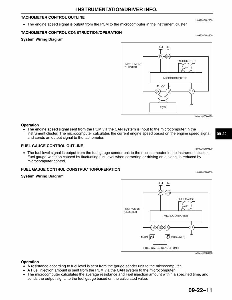
INSTRUMENTATION/DRIVER INFO.
09-22–11
09-22
TACHOMETER CONTROL OUTLINEid092200102300
• The engine speed signal is output from the PCM to the microcomputer in the instrument cluster.End Of SieTACHOMETER CONTROL CONSTRUCTION/OPERATION
id092200102200
System Wiring Diagram
Operation• The engine speed signal sent from the PCM via the CAN system is input to the microcomputer in the
instrument cluster. The microcomputer calculates the current engine speed based on the engine speed signal, and sends an output signal to the tachometer.
End Of SieFUEL GAUGE CONTROL OUTLINE
id092200100800
• The fuel level signal is output from the fuel gauge sender unit to the microcomputer in the instrument cluster. Fuel gauge variation caused by fluctuating fuel level when cornering or driving on a slope, is reduced by microcomputer control.
End Of SieFUEL GAUGE CONTROL CONSTRUCTION/OPERATION
id092200100700
System Wiring Diagram
Operation• A resistance according to fuel level is sent from the gauge sender unit to the microcomputer. • A Fuel injection amount is sent from the PCM via the CAN system to the microcomputer. • The microcomputer calculates the average resistance and Fuel injection amount within a specified time, and
sends the output signal to the fuel gauge based on the calculated value. End Of Sie
IG1 B+
1V
1F 1W1X
1H
INSTRUMENT CLUSTER
MICROCOMPUTER
TACHOMETER
PCM
ac9uun00000189
IG1 B+
1V
1F1R1M
1H
INSTRUMENT CLUSTER
MICROCOMPUTER
FUEL GAUGE
MAIN SUB (AWD)
1D
FUEL GAUGE SENDER UNIT
ac9uun00000190
3423-1U-06H(09-22).fm 11 ページ 2006年11月21日 火曜日 午後5時49分
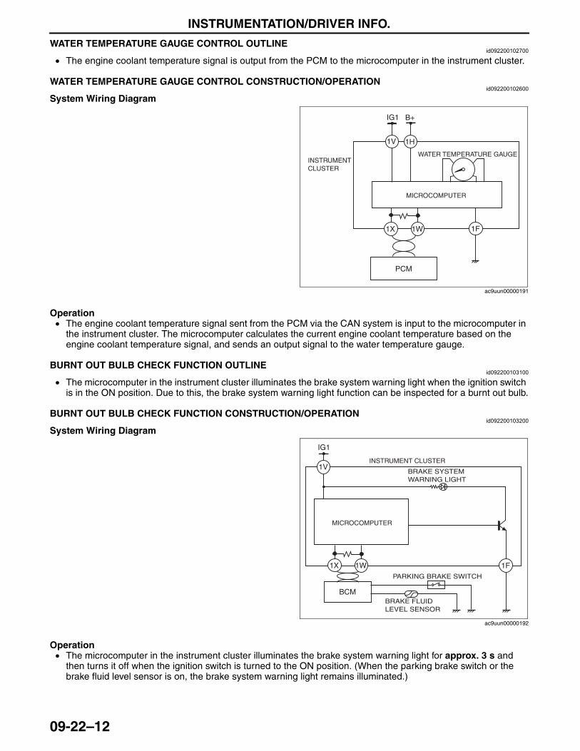
INSTRUMENTATION/DRIVER INFO.
09-22–12
WATER TEMPERATURE GAUGE CONTROL OUTLINEid092200102700
• The engine coolant temperature signal is output from the PCM to the microcomputer in the instrument cluster.End Of SieWATER TEMPERATURE GAUGE CONTROL CONSTRUCTION/OPERATION
id092200102600
System Wiring Diagram
Operation• The engine coolant temperature signal sent from the PCM via the CAN system is input to the microcomputer in
the instrument cluster. The microcomputer calculates the current engine coolant temperature based on the engine coolant temperature signal, and sends an output signal to the water temperature gauge.
End Of SieBURNT OUT BULB CHECK FUNCTION OUTLINE
id092200103100
• The microcomputer in the instrument cluster illuminates the brake system warning light when the ignition switch is in the ON position. Due to this, the brake system warning light function can be inspected for a burnt out bulb.
End Of SieBURNT OUT BULB CHECK FUNCTION CONSTRUCTION/OPERATION
id092200103200
System Wiring Diagram
Operation• The microcomputer in the instrument cluster illuminates the brake system warning light for approx. 3 s and
then turns it off when the ignition switch is turned to the ON position. (When the parking brake switch or the brake fluid level sensor is on, the brake system warning light remains illuminated.)
End Of Sie
IG1 B+
1V
1F1W1X
1H
INSTRUMENT CLUSTER
MICROCOMPUTER
PCM
WATER TEMPERATURE GAUGE
ac9uun00000191
1V
IG1
INSTRUMENT CLUSTER
MICROCOMPUTER
BRAKE SYSTEM WARNING LIGHT
BRAKE FLUID LEVEL SENSOR
PARKING BRAKE SWITCH
1F1W1X
BCM
ac9uun00000192
3423-1U-06H(09-22).fm 12 ページ 2006年11月21日 火曜日 午後5時49分
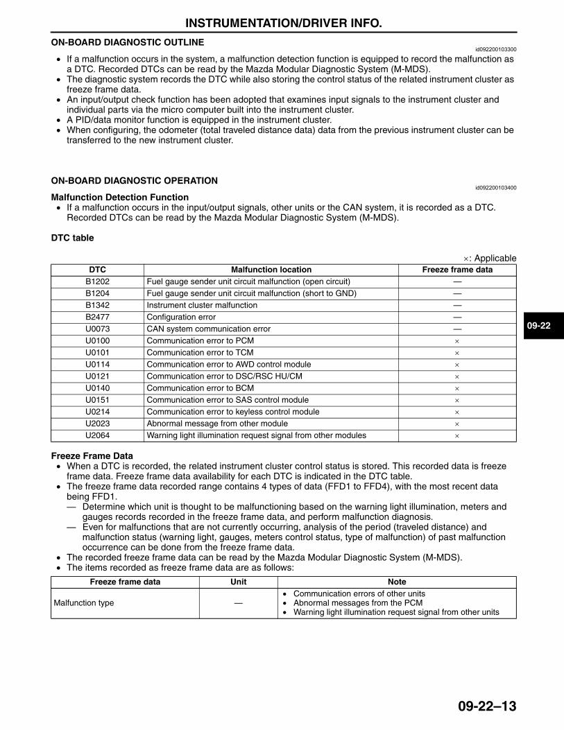
INSTRUMENTATION/DRIVER INFO.
09-22–13
09-22
ON-BOARD DIAGNOSTIC OUTLINEid092200103300
• If a malfunction occurs in the system, a malfunction detection function is equipped to record the malfunction as a DTC. Recorded DTCs can be read by the Mazda Modular Diagnostic System (M-MDS).
• The diagnostic system records the DTC while also storing the control status of the related instrument cluster as freeze frame data.
• An input/output check function has been adopted that examines input signals to the instrument cluster and individual parts via the micro computer built into the instrument cluster.
• A PID/data monitor function is equipped in the instrument cluster.• When configuring, the odometer (total traveled distance data) data from the previous instrument cluster can be
transferred to the new instrument cluster.End Of Sie
ON-BOARD DIAGNOSTIC OPERATIONid092200103400
Malfunction Detection Function• If a malfunction occurs in the input/output signals, other units or the CAN system, it is recorded as a DTC.
Recorded DTCs can be read by the Mazda Modular Diagnostic System (M-MDS).
DTC table
×: Applicable
Freeze Frame Data• When a DTC is recorded, the related instrument cluster control status is stored. This recorded data is freeze
frame data. Freeze frame data availability for each DTC is indicated in the DTC table.• The freeze frame data recorded range contains 4 types of data (FFD1 to FFD4), with the most recent data
being FFD1.— Determine which unit is thought to be malfunctioning based on the warning light illumination, meters and
gauges records recorded in the freeze frame data, and perform malfunction diagnosis.— Even for malfunctions that are not currently occurring, analysis of the period (traveled distance) and
malfunction status (warning light, gauges, meters control status, type of malfunction) of past malfunction occurrence can be done from the freeze frame data.
• The recorded freeze frame data can be read by the Mazda Modular Diagnostic System (M-MDS).• The items recorded as freeze frame data are as follows:
DTC Malfunction location Freeze frame dataB1202 Fuel gauge sender unit circuit malfunction (open circuit) —B1204 Fuel gauge sender unit circuit malfunction (short to GND) —B1342 Instrument cluster malfunction —B2477 Configuration error —U0073 CAN system communication error —U0100 Communication error to PCM ×U0101 Communication error to TCM ×U0114 Communication error to AWD control module ×U0121 Communication error to DSC/RSC HU/CM ×U0140 Communication error to BCM ×U0151 Communication error to SAS control module ×U0214 Communication error to keyless control module ×U2023 Abnormal message from other module ×U2064 Warning light illumination request signal from other modules ×
Freeze frame data Unit Note
Malfunction type —• Communication errors of other units• Abnormal messages from the PCM• Warning light illumination request signal from other units
3423-1U-06H(09-22).fm 13 ページ 2006年11月21日 火曜日 午後5時49分
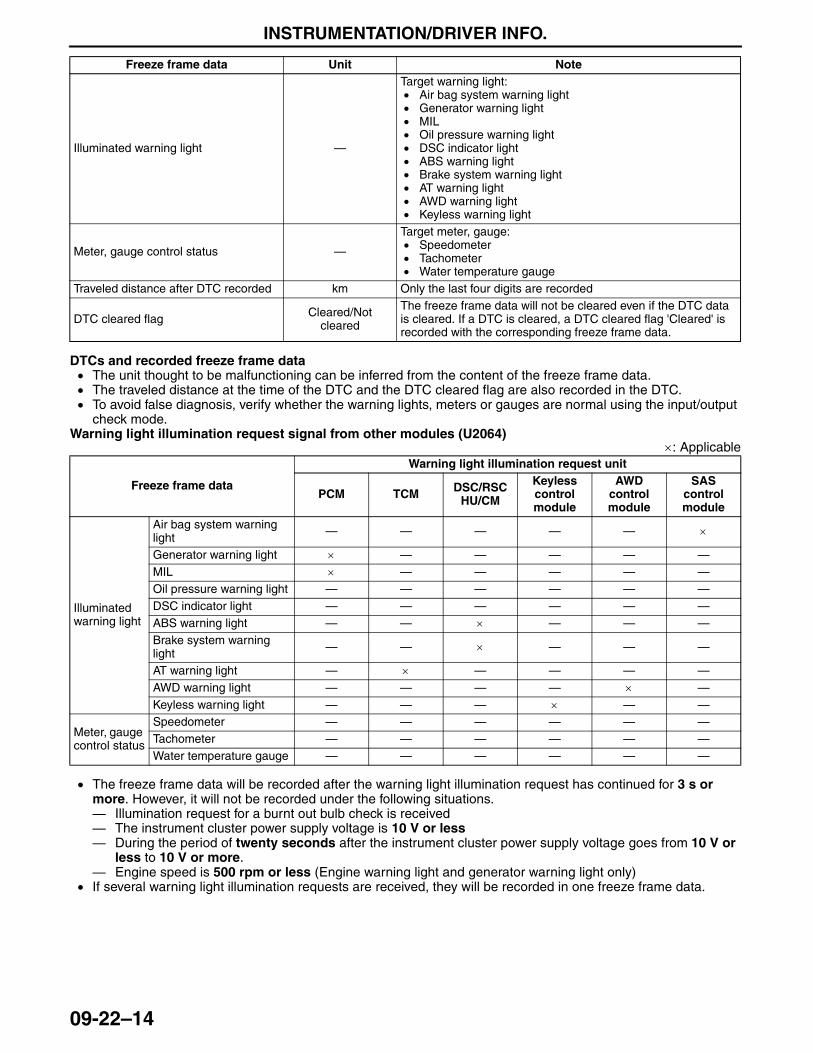
INSTRUMENTATION/DRIVER INFO.
09-22–14
DTCs and recorded freeze frame data• The unit thought to be malfunctioning can be inferred from the content of the freeze frame data.• The traveled distance at the time of the DTC and the DTC cleared flag are also recorded in the DTC.• To avoid false diagnosis, verify whether the warning lights, meters or gauges are normal using the input/output
check mode.Warning light illumination request signal from other modules (U2064)
×: Applicable
• The freeze frame data will be recorded after the warning light illumination request has continued for 3 s or more. However, it will not be recorded under the following situations.— Illumination request for a burnt out bulb check is received— The instrument cluster power supply voltage is 10 V or less— During the period of twenty seconds after the instrument cluster power supply voltage goes from 10 V or
less to 10 V or more.— Engine speed is 500 rpm or less (Engine warning light and generator warning light only)
• If several warning light illumination requests are received, they will be recorded in one freeze frame data.
Illuminated warning light —
Target warning light:• Air bag system warning light• Generator warning light• MIL• Oil pressure warning light• DSC indicator light• ABS warning light• Brake system warning light• AT warning light• AWD warning light• Keyless warning light
Meter, gauge control status —
Target meter, gauge:• Speedometer• Tachometer• Water temperature gauge
Traveled distance after DTC recorded km Only the last four digits are recorded
DTC cleared flag Cleared/Not cleared
The freeze frame data will not be cleared even if the DTC data is cleared. If a DTC is cleared, a DTC cleared flag 'Cleared' is recorded with the corresponding freeze frame data.
Freeze frame data Unit Note
Freeze frame data
Warning light illumination request unit
PCM TCM DSC/RSC HU/CM
Keyless control module
AWD control module
SAS control module
Illuminated warning light
Air bag system warning light — — — — — ×
Generator warning light × — — — — —MIL × — — — — —Oil pressure warning light — — — — — —DSC indicator light — — — — — —ABS warning light — — × — — —Brake system warning light — — × — — —
AT warning light — × — — — —AWD warning light — — — — × —Keyless warning light — — — × — —
Meter, gauge control status
Speedometer — — — — — —Tachometer — — — — — —Water temperature gauge — — — — — —
3423-1U-06H(09-22).fm 14 ページ 2006年11月21日 火曜日 午後5時49分
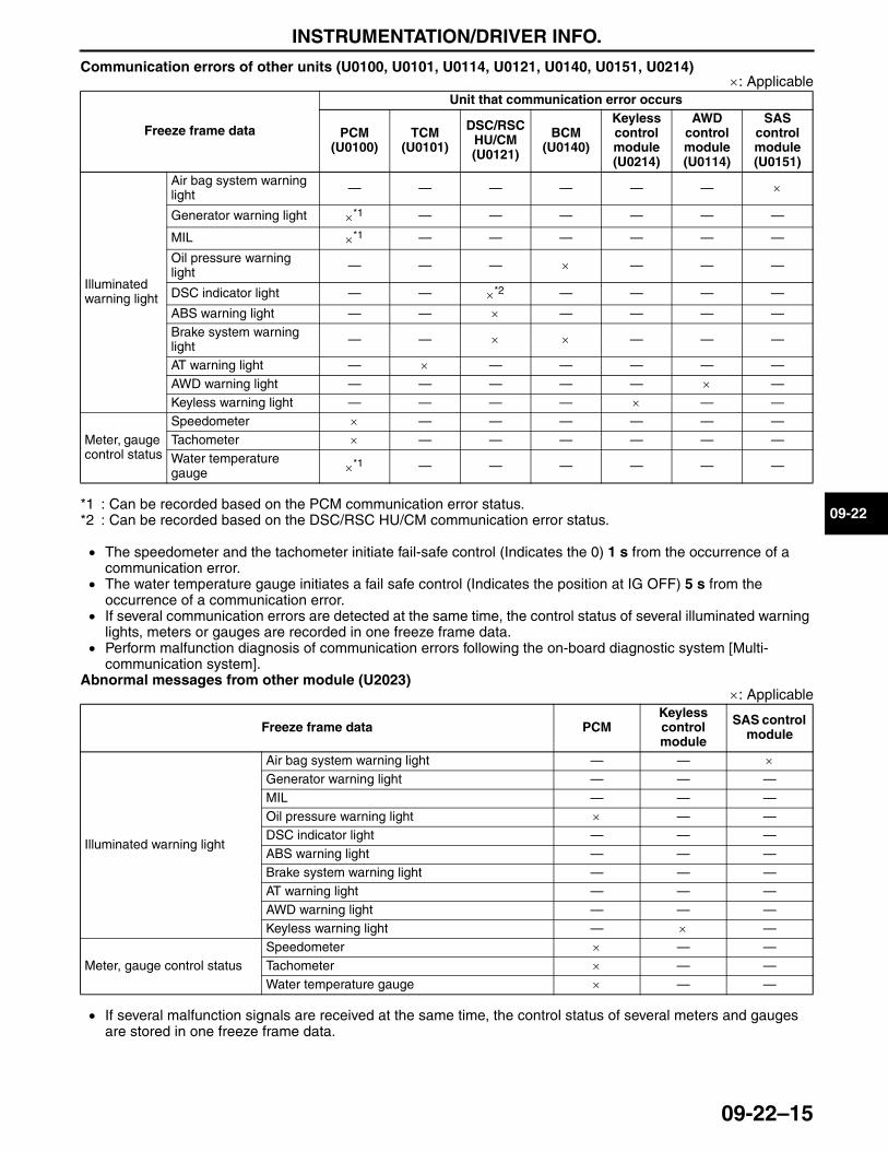
INSTRUMENTATION/DRIVER INFO.
09-22–15
09-22
Communication errors of other units (U0100, U0101, U0114, U0121, U0140, U0151, U0214)×: Applicable
*1 : Can be recorded based on the PCM communication error status.*2 : Can be recorded based on the DSC/RSC HU/CM communication error status.
• The speedometer and the tachometer initiate fail-safe control (Indicates the 0) 1 s from the occurrence of a communication error.
• The water temperature gauge initiates a fail safe control (Indicates the position at IG OFF) 5 s from the occurrence of a communication error.
• If several communication errors are detected at the same time, the control status of several illuminated warning lights, meters or gauges are recorded in one freeze frame data.
• Perform malfunction diagnosis of communication errors following the on-board diagnostic system [Multi-communication system].
Abnormal messages from other module (U2023)×: Applicable
• If several malfunction signals are received at the same time, the control status of several meters and gauges are stored in one freeze frame data.
Freeze frame data
Unit that communication error occurs
PCM (U0100)
TCM (U0101)
DSC/RSC HU/CM (U0121)
BCM (U0140)
Keyless control module (U0214)
AWD control module (U0114)
SAS control module (U0151)
Illuminated warning light
Air bag system warning light — — — — — — ×
Generator warning light ×*1 — — — — — —
MIL ×*1 — — — — — —
Oil pressure warning light — — — × — — —
DSC indicator light — — ×*2 — — — —
ABS warning light — — × — — — —Brake system warning light — — × × — — —
AT warning light — × — — — — —AWD warning light — — — — — × —Keyless warning light — — — — × — —
Meter, gauge control status
Speedometer × — — — — — —Tachometer × — — — — — —Water temperature gauge ×*1 — — — — — —
Freeze frame data PCMKeyless control module
SAS control module
Illuminated warning light
Air bag system warning light — — ×Generator warning light — — —MIL — — —Oil pressure warning light × — —DSC indicator light — — —ABS warning light — — —Brake system warning light — — —AT warning light — — —AWD warning light — — —Keyless warning light — × —
Meter, gauge control statusSpeedometer × — —Tachometer × — —Water temperature gauge × — —
3423-1U-06H(09-22).fm 15 ページ 2006年11月21日 火曜日 午後5時49分
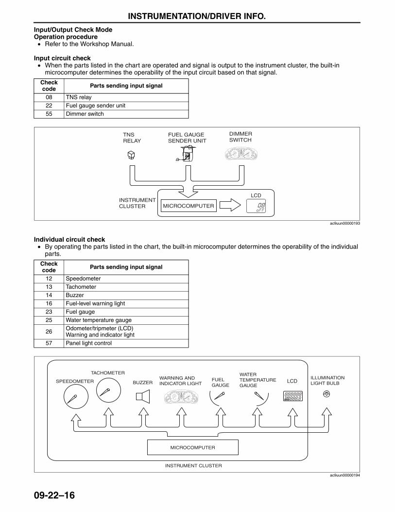
INSTRUMENTATION/DRIVER INFO.
09-22–16
Input/Output Check ModeOperation procedure• Refer to the Workshop Manual.
Input circuit check• When the parts listed in the chart are operated and signal is output to the instrument cluster, the built-in
microcomputer determines the operability of the input circuit based on that signal.
Individual circuit check• By operating the parts listed in the chart, the built-in microcomputer determines the operability of the individual
parts.
Check code Parts sending input signal
08 TNS relay22 Fuel gauge sender unit55 Dimmer switch
BRAKE
LCD
TNS RELAY
FUEL GAUGE SENDER UNIT
DIMMER SWITCH
INSTRUMENT CLUSTER MICROCOMPUTER
ac9uun00000193
Check code Parts sending input signal
12 Speedometer13 Tachometer14 Buzzer16 Fuel-level warning light23 Fuel gauge25 Water temperature gauge
26 Odometer/tripmeter (LCD)Warning and indicator light
57 Panel light control
BRAKE
LCDSPEEDOMETER
TACHOMETER
BUZZERWARNING AND INDICATOR LIGHT
FUEL GAUGE
WATER TEMPERATURE GAUGE
ILLUMINATION LIGHT BULB
INSTRUMENT CLUSTER
MICROCOMPUTER
ac9uun00000194
3423-1U-06H(09-22).fm 16 ページ 2006年11月21日 火曜日 午後5時49分
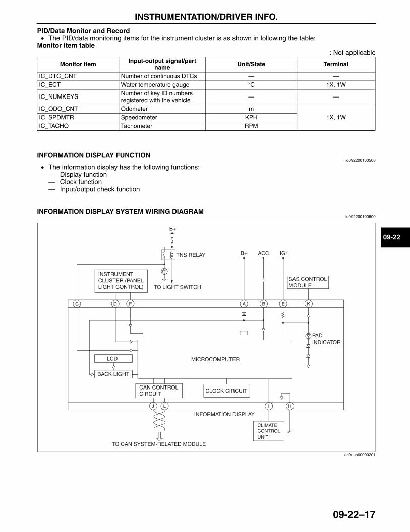
INSTRUMENTATION/DRIVER INFO.
09-22–17
09-22
PID/Data Monitor and Record• The PID/data monitoring items for the instrument cluster is as shown in following the table:
Monitor item table—: Not applicable
End Of SieNG: INFORMATION DISPLAY
INFORMATION DISPLAY FUNCTIONid092200100500
• The information display has the following functions: — Display function— Clock function— Input/output check function
End Of Sie
INFORMATION DISPLAY SYSTEM WIRING DIAGRAMid092200100600
End Of Sie
Monitor item Input-output signal/part name Unit/State Terminal
IC_DTC_CNT Number of continuous DTCs — —IC_ECT Water temperature gauge °C 1X, 1W
IC_NUMKEYS Number of key ID numbers registered with the vehicle — —
IC_ODO_CNT Odometer m1X, 1WIC_SPDMTR Speedometer KPH
IC_TACHO Tachometer RPM
C A BD
B+
E K
IG1
B+
ACC
LJ H
TO CAN SYSTEM-RELATED MODULE
TNS RELAY
TO LIGHT SWITCH
INSTRUMENT CLUSTER (PANEL LIGHT CONTROL)
PAD INDICATOR
SAS CONTROL MODULE
INFORMATION DISPLAY
LCD
CAN CONTROL CIRCUIT CLOCK CIRCUIT
MICROCOMPUTER
F
I
CLIMATE CONTROL UNIT
BACK LIGHT
ac9uun00000201
3423-1U-06H(09-22).fm 17 ページ 2006年11月22日 水曜日 午後4時31分
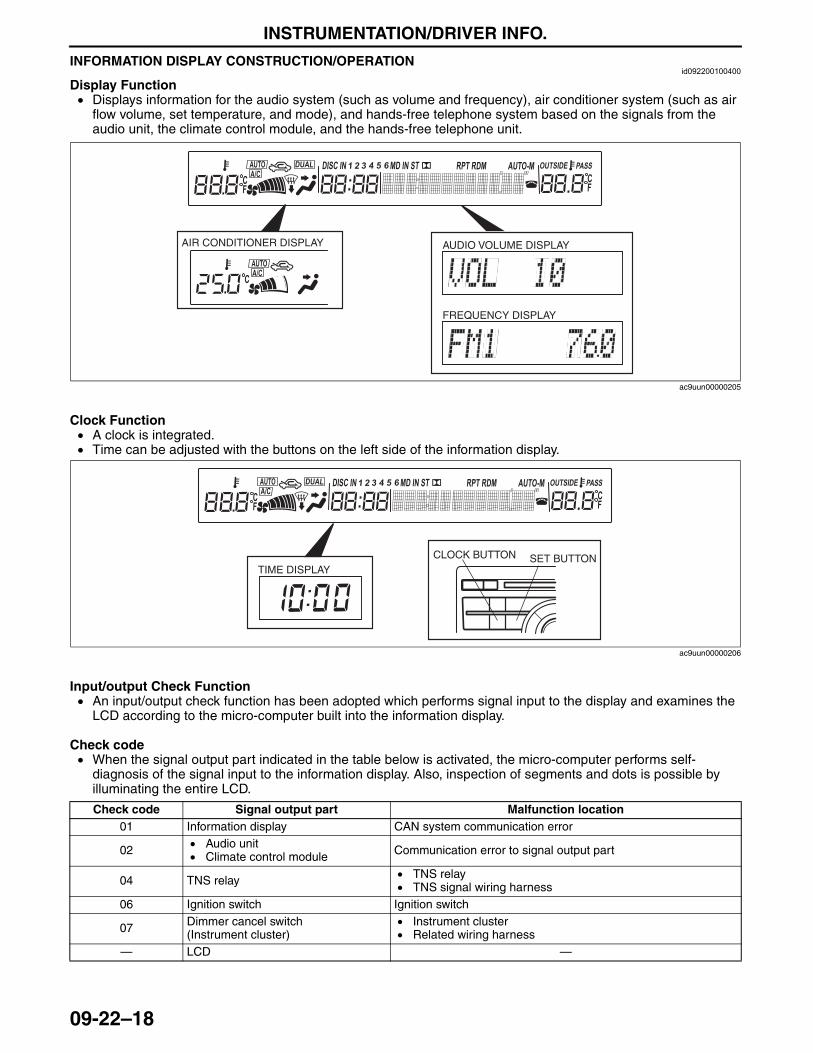
INSTRUMENTATION/DRIVER INFO.
09-22–18
INFORMATION DISPLAY CONSTRUCTION/OPERATIONid092200100400
Display Function• Displays information for the audio system (such as volume and frequency), air conditioner system (such as air
flow volume, set temperature, and mode), and hands-free telephone system based on the signals from the audio unit, the climate control module, and the hands-free telephone unit.
Clock Function• A clock is integrated.• Time can be adjusted with the buttons on the left side of the information display.
Input/output Check Function• An input/output check function has been adopted which performs signal input to the display and examines the
LCD according to the micro-computer built into the information display.
Check code• When the signal output part indicated in the table below is activated, the micro-computer performs self-
diagnosis of the signal input to the information display. Also, inspection of segments and dots is possible by illuminating the entire LCD.
AIR CONDITIONER DISPLAY AUDIO VOLUME DISPLAY
FREQUENCY DISPLAY
ac9uun00000205
SET BUTTONTIME DISPLAY
CLOCK BUTTON
ac9uun00000206
Check code Signal output part Malfunction location01 Information display CAN system communication error
02 • Audio unit• Climate control module Communication error to signal output part
04 TNS relay • TNS relay• TNS signal wiring harness
06 Ignition switch Ignition switch
07 Dimmer cancel switch(Instrument cluster)
• Instrument cluster• Related wiring harness
— LCD —
3423-1U-06H(09-22).fm 18 ページ 2006年11月21日 火曜日 午後5時49分
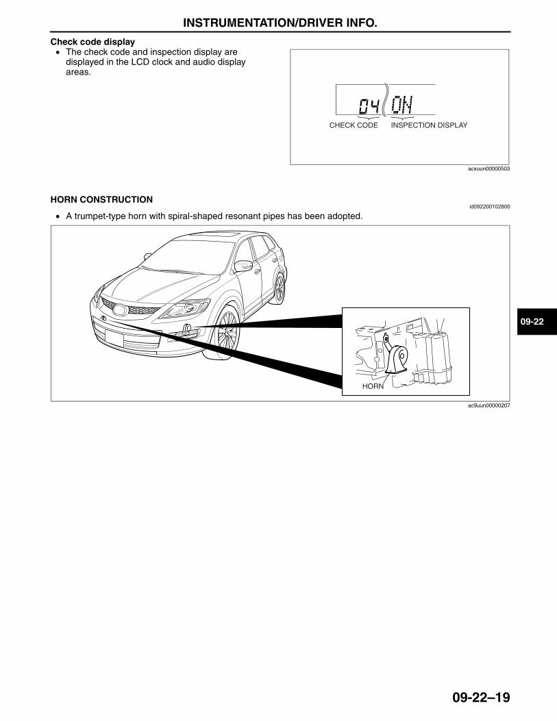
INSTRUMENTATION/DRIVER INFO.
09-22–19
09-22
Check code display• The check code and inspection display are
displayed in the LCD clock and audio display areas.
End Of SieNG: HORN
HORN CONSTRUCTIONid092200102800
• A trumpet-type horn with spiral-shaped resonant pipes has been adopted.
End Of Sie
INSPECTION DISPLAYCHECK CODE
acxuun00000503
HORN
ac9uun00000207
3423-1U-06H(09-22).fm 19 ページ 2006年11月21日 火曜日 午後5時49分

CONTROL SYSTEM
09-40–1
09-40
09-40 CONTROL SYSTEMCONTROLLER AREA NETWORK
(CAN) SYSTEM OUTLINE . . . . . . . . . . 09-40–1CAN SYSTEM STRUCTURAL VIEW . . . 09-40–2CAN SYSTEM WIRING DIAGRAM . . . . . 09-40–3
HS-CAN . . . . . . . . . . . . . . . . . . . . . . . . 09-40–3MS-CAN . . . . . . . . . . . . . . . . . . . . . . . . 09-40–4
CAN SYSTEM DESCRIPTION . . . . . . . . 09-40–5Mechanism of CAN
System-Related Module. . . . . . . . . . . 09-40–5Twisted Pair . . . . . . . . . . . . . . . . . . . . . 09-40–5Time Division Multiplex . . . . . . . . . . . . 09-40–6Vehicle CAN System . . . . . . . . . . . . . . 09-40–6CAN Signal-Chart (HS-CAN) . . . . . . . . 09-40–7CAN Signal-Chart (MS-CAN). . . . . . . . 09-40–9
On-Board Diagnostic Function . . . . . . . 09-40–9BODY CONTROL MODULE (BCM)
OUTLINE . . . . . . . . . . . . . . . . . . . . . . . . 09-40–13BODY CONTROL MODULE (BCM)
STRUCTURAL VIEW . . . . . . . . . . . . . . . 09-40–14BODY CONTROL MODULE (BCM)
WIRING DIAGRAM. . . . . . . . . . . . . . . . . 09-40–15STEERING ANGLE DETECTION
FUNCTION . . . . . . . . . . . . . . . . . . . . . . . 09-40–18Steering Angle Sensor . . . . . . . . . . . . . 09-40–18Sleep Control . . . . . . . . . . . . . . . . . . . . 09-40–19
ON-BOARD DIAGNOSTIC FUNCTION . . 09-40–20Malfunction Detection Function . . . . . . . 09-40–20PID/Data Monitor Function . . . . . . . . . . 09-40–21
End of TocNG: CAN SYSTEMCONTROLLER AREA NETWORK (CAN) SYSTEM OUTLINE
id094000101300
• Due to the simplification of the wiring harness, a CAN system for transmission of multiplex input/output signals among electrical modules has been adopted.
• Twisted-pair wiring is used for connections between the following modules. (Each electrical module hereafter referred to as a CAN system-related module): — PCM— TCM— DSC/RSC HU/CM— BCM— AWD control module— PLG control module— SAS control module— Keyless control module— Instrument cluster— Audio unit (base module)— Audio amplifier— RES unit— Hands-free telephone unit— Information display— Engine off natural vacuum (Engine-off-natural-vacuum is integrated in the PCM)
• With an on-board diagnostic function included for each multiplex module, display of DTCs using the Mazda Modular Diagnostic System (M-MDS) has improved serviceability.
End Of Sie
3423-1U-06H(09-40).fm 1 ページ 2006年11月21日 火曜日 午後5時51分
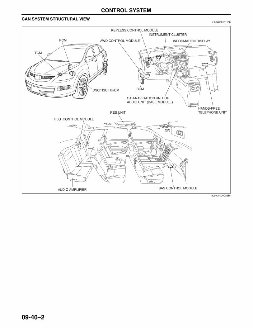
CONTROL SYSTEM
09-40–2
CAN SYSTEM STRUCTURAL VIEWid094000101100
End Of Sie
INSTRUMENT CLUSTER
BCM
CAR-NAVIGATION UNIT OR AUDIO UNIT (BASE MODULE)
KEYLESS CONTROL MODULE
SAS CONTROL MODULE
PLG CONTROL MODULE
RES UNIT
INFORMATION DISPLAYAWD CONTROL MODULE
AUDIO AMPLIFIER
DSC/RSC HU/CM
PCM
TCM
HANDS-FREE TELEPHONE UNIT
ac9uun00000288
3423-1U-06H(09-40).fm 2 ページ 2006年11月21日 火曜日 午後5時51分
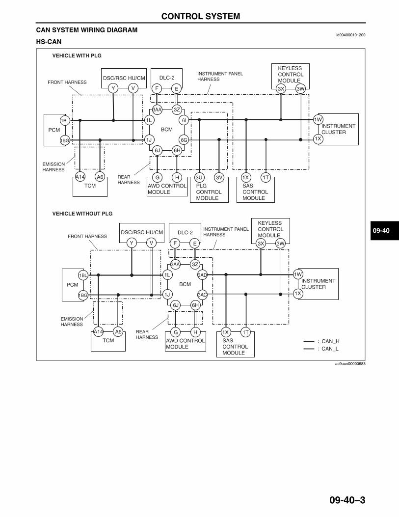
CONTROL SYSTEM
09-40–3
09-40
CAN SYSTEM WIRING DIAGRAMid094000101200
HS-CAN
:
: CAN_HCAN_L
DLC-2FRONT HARNESS
INSTRUMENT PANEL HARNESS
REAR HARNESS
1BG
1BL
Y V F E
A14 A6
1W
1X
3AD
3AC
1L
1J
3W3X
HG
3Z3AA
6H6J
PCM BCM
DSC/RSC HU/CM
TCM AWD CONTROL MODULE
1T1X
SAS CONTROL MODULE
KEYLESS CONTROL MODULE
INSTRUMENT CLUSTER
EMISSION HARNESS
DLC-2FRONT HARNESS
INSTRUMENT PANEL HARNESS
REAR HARNESS
1BG
1BL
Y V F E
A14 A6
1W
1X
6I
6G
1L
1J
3W3X
HG
3Z3AA
6H6J
PCM BCM
DSC/RSC HU/CM
TCM AWD CONTROL MODULE
1T1X
SAS CONTROL MODULE
3V3U
PLG CONTROL MODULE
KEYLESS CONTROL MODULE
INSTRUMENT CLUSTER
EMISSION HARNESS
VEHICLE WITHOUT PLG
VEHICLE WITH PLG
ac9uun00000583
3423-1U-06H(09-40).fm 3 ページ 2006年11月21日 火曜日 午後5時51分
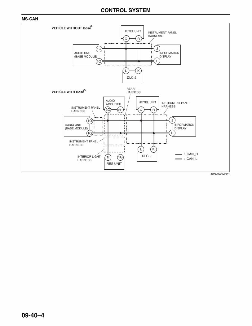
CONTROL SYSTEM
09-40–4
MS-CAN
End Of Sie
:
:
1Q
1O
Q R
L K
3O 3P
CAN_HCAN_L
DLC-2
J
L
AUDIO UNIT (BASE MODULE)
HF/TEL UNITAUDIO AMPLIFIER
INFORMATION DISPLAY
INSTRUMENT PANEL HARNESS
REAR HARNESS
INSTRUMENT PANEL HARNESS
INSTRUMENT PANEL HARNESS
INTERIOR LIGHT HARNESS
1I 1G
RES UNIT
1Q
1O
Q R
L K
DLC-2
J
L
AUDIO UNIT (BASE MODULE)
HF/TEL UNIT
INFORMATION DISPLAY
INSTRUMENT PANEL HARNESS
VEHICLE WITHOUT Bose
VEHICLE WITH Bose
R
R
ac9uun00000544
3423-1U-06H(09-40).fm 4 ページ 2006年11月21日 火曜日 午後5時51分
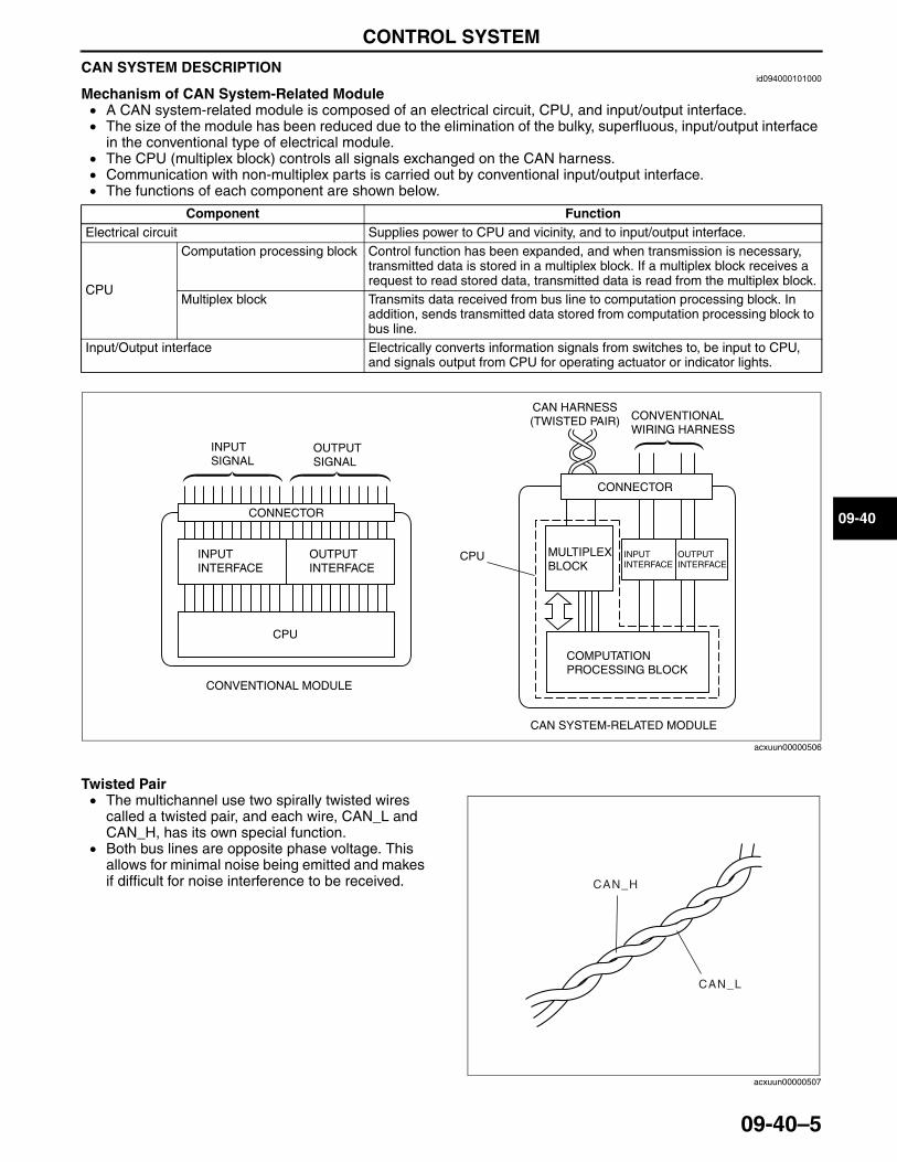
CONTROL SYSTEM
09-40–5
09-40
CAN SYSTEM DESCRIPTIONid094000101000
Mechanism of CAN System-Related Module• A CAN system-related module is composed of an electrical circuit, CPU, and input/output interface.• The size of the module has been reduced due to the elimination of the bulky, superfluous, input/output interface
in the conventional type of electrical module.• The CPU (multiplex block) controls all signals exchanged on the CAN harness.• Communication with non-multiplex parts is carried out by conventional input/output interface.• The functions of each component are shown below.
Twisted Pair• The multichannel use two spirally twisted wires
called a twisted pair, and each wire, CAN_L and CAN_H, has its own special function.
• Both bus lines are opposite phase voltage. This allows for minimal noise being emitted and makes if difficult for noise interference to be received.
Component FunctionElectrical circuit Supplies power to CPU and vicinity, and to input/output interface.
CPU
Computation processing block Control function has been expanded, and when transmission is necessary, transmitted data is stored in a multiplex block. If a multiplex block receives a request to read stored data, transmitted data is read from the multiplex block.
Multiplex block Transmits data received from bus line to computation processing block. In addition, sends transmitted data stored from computation processing block to bus line.
Input/Output interface Electrically converts information signals from switches to, be input to CPU, and signals output from CPU for operating actuator or indicator lights.
INPUT SIGNAL
OUTPUT SIGNAL
CONNECTOR
INPUT INTERFACE
OUTPUT INTERFACE
CPU
CONVENTIONAL MODULE
CPU
CAN HARNESS (TWISTED PAIR) CONVENTIONAL
WIRING HARNESS
CONNECTOR
MULTIPLEX BLOCK
INPUT INTERFACE
OUTPUT INTERFACE
COMPUTATION PROCESSING BLOCK
CAN SYSTEM-RELATED MODULE
acxuun00000506
CAN_H
CAN_L
acxuun00000507
3423-1U-06H(09-40).fm 5 ページ 2006年11月21日 火曜日 午後5時51分
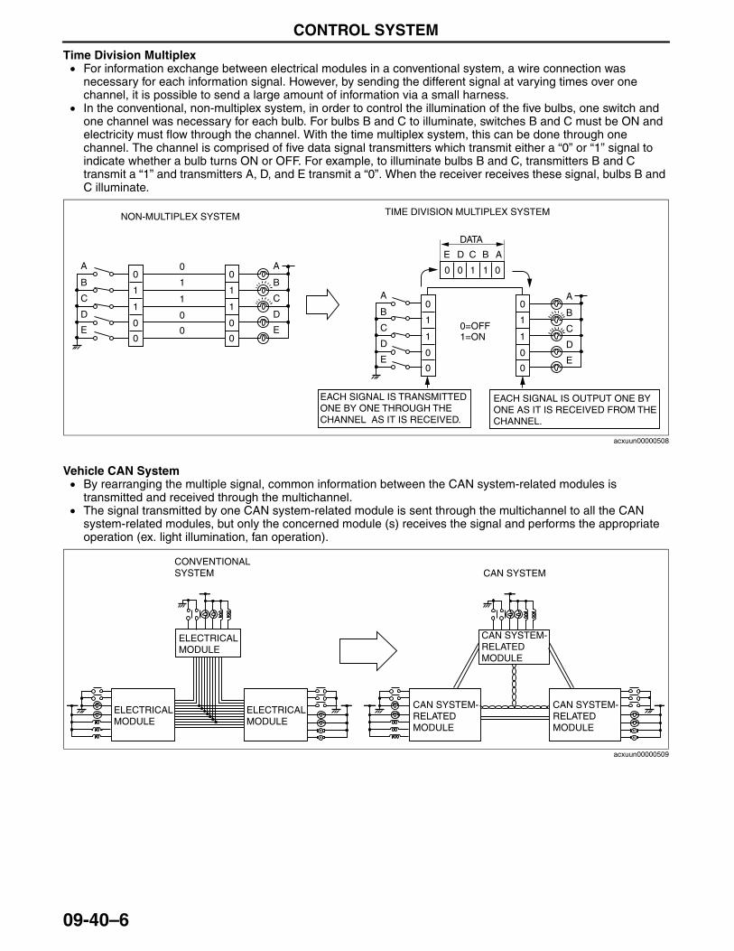
CONTROL SYSTEM
09-40–6
Time Division Multiplex• For information exchange between electrical modules in a conventional system, a wire connection was
necessary for each information signal. However, by sending the different signal at varying times over one channel, it is possible to send a large amount of information via a small harness.
• In the conventional, non-multiplex system, in order to control the illumination of the five bulbs, one switch and one channel was necessary for each bulb. For bulbs B and C to illuminate, switches B and C must be ON and electricity must flow through the channel. With the time multiplex system, this can be done through one channel. The channel is comprised of five data signal transmitters which transmit either a “0” or “1” signal to indicate whether a bulb turns ON or OFF. For example, to illuminate bulbs B and C, transmitters B and C transmit a “1” and transmitters A, D, and E transmit a “0”. When the receiver receives these signal, bulbs B and C illuminate.
Vehicle CAN System• By rearranging the multiple signal, common information between the CAN system-related modules is
transmitted and received through the multichannel.• The signal transmitted by one CAN system-related module is sent through the multichannel to all the CAN
system-related modules, but only the concerned module (s) receives the signal and performs the appropriate operation (ex. light illumination, fan operation).
A0
0
0
1
1
0
0
0
1
1
0
0
0
1
1 0
0 0 1 1 0
0
0
1
1
0
0
0
1
1
B
C
D
E
A
B
C
D
E
A
ABCD
0=OFF1=ON
E
B
C
D
E
A
B
C
D
E
NON-MULTIPLEX SYSTEM TIME DIVISION MULTIPLEX SYSTEM
EACH SIGNAL IS TRANSMITTED ONE BY ONE THROUGH THE CHANNEL AS IT IS RECEIVED.
EACH SIGNAL IS OUTPUT ONE BY ONE AS IT IS RECEIVED FROM THE CHANNEL.
DATA
acxuun00000508
CONVENTIONALSYSTEM
ELECTRICALMODULE
ELECTRICALMODULE
ELECTRICALMODULE
CAN SYSTEM-RELATED MODULE
CAN SYSTEM-RELATED MODULE
CAN SYSTEM-RELATED MODULE
CAN SYSTEM
acxuun00000509
3423-1U-06H(09-40).fm 6 ページ 2006年11月21日 火曜日 午後5時51分
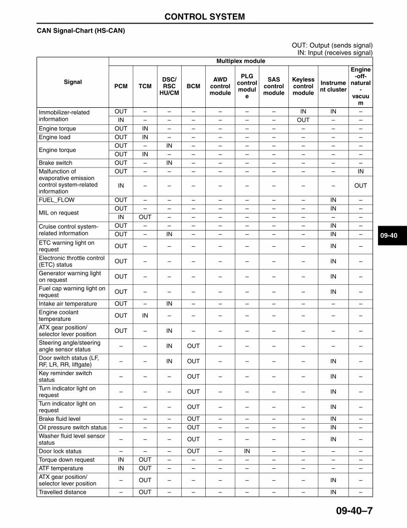
CONTROL SYSTEM
09-40–7
09-40
CAN Signal-Chart (HS-CAN)
OUT: Output (sends signal)IN: Input (receives signal)
Signal
Multiplex module
PCM TCMDSC/RSC
HU/CMBCM
AWD control module
PLG control modul
e
SAS control module
Keyless control module
Instrument cluster
Engine-off-
natural-
vacuum
Immobilizer-related information
OUT – – – – – – IN IN –IN – – – – – – OUT – –
Engine torque OUT IN – – – – – – – –Engine load OUT IN – – – – – – – –
Engine torqueOUT – IN – – – – – – –OUT IN – – – – – – – –
Brake switch OUT – IN – – – – – – –Malfunction of evaporative emission control system-related information
OUT – – – – – – – – IN
IN – – – – – – – – OUT
FUEL_FLOW OUT – – – – – – – IN –
MIL on requestOUT – – – – – – – IN –
IN OUT – – – – – – – –
Cruise control system-related information
OUT – – – – – – – IN –OUT – IN – – – – – IN –
ETC warning light on request OUT – – – – – – – IN –
Electronic throttle control (ETC) status OUT – – – – – – – IN –
Generator warning light on request OUT – – – – – – – IN –
Fuel cap warning light on request OUT – – – – – – – IN –
Intake air temperature OUT – IN – – – – – – –Engine coolant temperature OUT IN – – – – – – – –
ATX gear position/selector lever position OUT – IN – – – – – – –
Steering angle/steering angle sensor status – – IN OUT – – – – – –
Door switch status (LF, RF, LR, RR, liftgate) – – IN OUT – – – – IN –
Key reminder switch status – – – OUT – – – – IN –
Turn indicator light on request – – – OUT – – – – IN –
Turn indicator light on request – – – OUT – – – – IN –
Brake fluid level – – – OUT – – – – IN –Oil pressure switch status – – – OUT – – – – IN –Washer fluid level sensor status – – – OUT – – – – IN –
Door lock status – – – OUT – IN – – – –Torque down request IN OUT – – – – – – – –ATF temperature IN OUT – – – – – – – –ATX gear position/selector lever position – OUT – – – – – – IN –
Travelled distance – OUT – – – – – – IN –
3423-1U-06H(09-40).fm 7 ページ 2006年11月21日 火曜日 午後5時51分
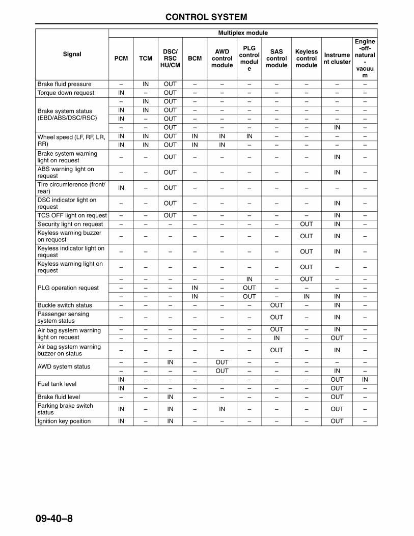
CONTROL SYSTEM
09-40–8
Brake fluid pressure – IN OUT – – – – – – –Torque down request IN – OUT – – – – – – –
Brake system status (EBD/ABS/DSC/RSC)
– IN OUT – – – – – – –IN IN OUT – – – – – – –IN – OUT – – – – – – –– – OUT – – – – – IN –
Wheel speed (LF, RF, LR, RR)
IN IN OUT IN IN IN – – – –IN IN OUT IN IN – – – – –
Brake system warning light on request – – OUT – – – – – IN –
ABS warning light on request – – OUT – – – – – IN –
Tire circumference (front/rear) IN – OUT – – – – – – –
DSC indicator light on request – – OUT – – – – – IN –
TCS OFF light on request – – OUT – – – – – IN –Security light on request – – – – – – – OUT IN –Keyless warning buzzer on request – – – – – – – OUT IN –
Keyless indicator light on request – – – – – – – OUT IN –
Keyless warning light on request – – – – – – – OUT – –
PLG operation request– – – – – IN – OUT – –– – – IN – OUT – – – –– – – IN – OUT – IN IN –
Buckle switch status – – – – – – OUT – IN –Passenger sensing system status – – – – – – OUT – IN –
Air bag system warning light on request
– – – – – – OUT – IN –– – – – – – IN – OUT –
Air bag system warning buzzer on status – – – – – – OUT – IN –
AWD system status– – IN – OUT – – – – –– – – – OUT – – – IN –
Fuel tank levelIN – – – – – – – OUT ININ – – – – – – – OUT –
Brake fluid level – – IN – – – – – OUT –Parking brake switch status IN – IN – IN – – – OUT –
Ignition key position IN – IN – – – – – OUT –
Signal
Multiplex module
PCM TCMDSC/RSC
HU/CMBCM
AWD control module
PLG control modul
e
SAS control module
Keyless control module
Instrument cluster
Engine-off-
natural-
vacuum
3423-1U-06H(09-40).fm 8 ページ 2006年11月21日 火曜日 午後5時51分
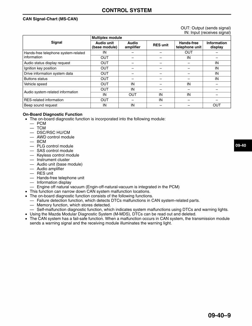
CONTROL SYSTEM
09-40–9
09-40
CAN Signal-Chart (MS-CAN)
OUT: Output (sends signal)IN: Input (receives signal)
On-Board Diagnostic Function• The on-board diagnostic function is incorporated into the following module:— PCM— TCM— DSC/RSC HU/CM— AWD control module— BCM— PLG control module— SAS control module— Keyless control module— Instrument cluster— Audio unit (base module)— Audio amplifier— RES unit— Hands-free telephone unit— Information display— Engine off natural vacuum (Engin-off-natural-vacuum is integrated in the PCM)
• This function can narrow down CAN system malfunction locations.• The on-board diagnostic function consists of the following functions.— Failure detection function, which detects DTCs malfunctions in CAN system-related parts.— Memory function, which stores detected.— Self-malfunction diagnostic function, which indicates system malfunctions using DTCs and warning lights.
• Using the Mazda Modular Diagnostic System (M-MDS), DTCs can be read out and deleted.• The CAN system has a fail-safe function. When a malfunction occurs in CAN system, the transmission module
sends a warning signal and the receiving module illuminates the warning light.
SignalMultiplex module
Audio unit (base module)
Audio amplifier RES unit Hands-free
telephone unitInformation
display
Hands-free telephone system-related information
IN – – OUT –OUT – – IN –
Audio status display request OUT – – – INIgnition key position OUT – – – INDrive information system data OUT – – – INButtons status OUT – – – INVehicle speed OUT IN – IN –
Audio system-related informationOUT IN – – –IN OUT IN IN –
RES-related information OUT – IN – –Beep sound request IN IN – – OUT
3423-1U-06H(09-40).fm 9 ページ 2006年11月21日 火曜日 午後5時51分
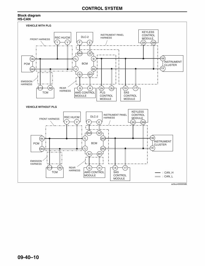
CONTROL SYSTEM
09-40–10
Block diagramHS-CAN
:
: CAN_HCAN_L
DLC-2FRONT HARNESS
INSTRUMENT PANEL HARNESS
REAR HARNESS
1BG
1BL
Y V F E
A14 A6
1W
1X
3AD
3AC
1L
1J
3W3X
HG
3Z3AA
6H6J
PCM BCM
RSC HU/CM
TCM AWD CONTROL MODULE
1T1X
SAS CONTROL MODULE
KEYLESS CONTROL MODULE
INSTRUMENT CLUSTER
EMISSION HARNESS
DLC-2FRONT HARNESS
INSTRUMENT PANEL HARNESS
REAR HARNESS
1BG
1BL
Y V F E
A14 A6
1W
1X
6I
6G
1L
1J
3W3X
HG
3Z3AA
6H6J
PCM BCM
RSC HU/CM
TCM AWD CONTROL MODULE
1T1X
SAS CONTROL MODULE
3V 3U
PLG CONTROL MODULE
KEYLESS CONTROL MODULE
INSTRUMENT CLUSTER
EMISSION HARNESS
VEHICLE WITHOUT PLG
VEHICLE WITH PLG
ac9uun00000586
3423-1U-06H(09-40).fm 10 ページ 2006年11月21日 火曜日 午後5時51分
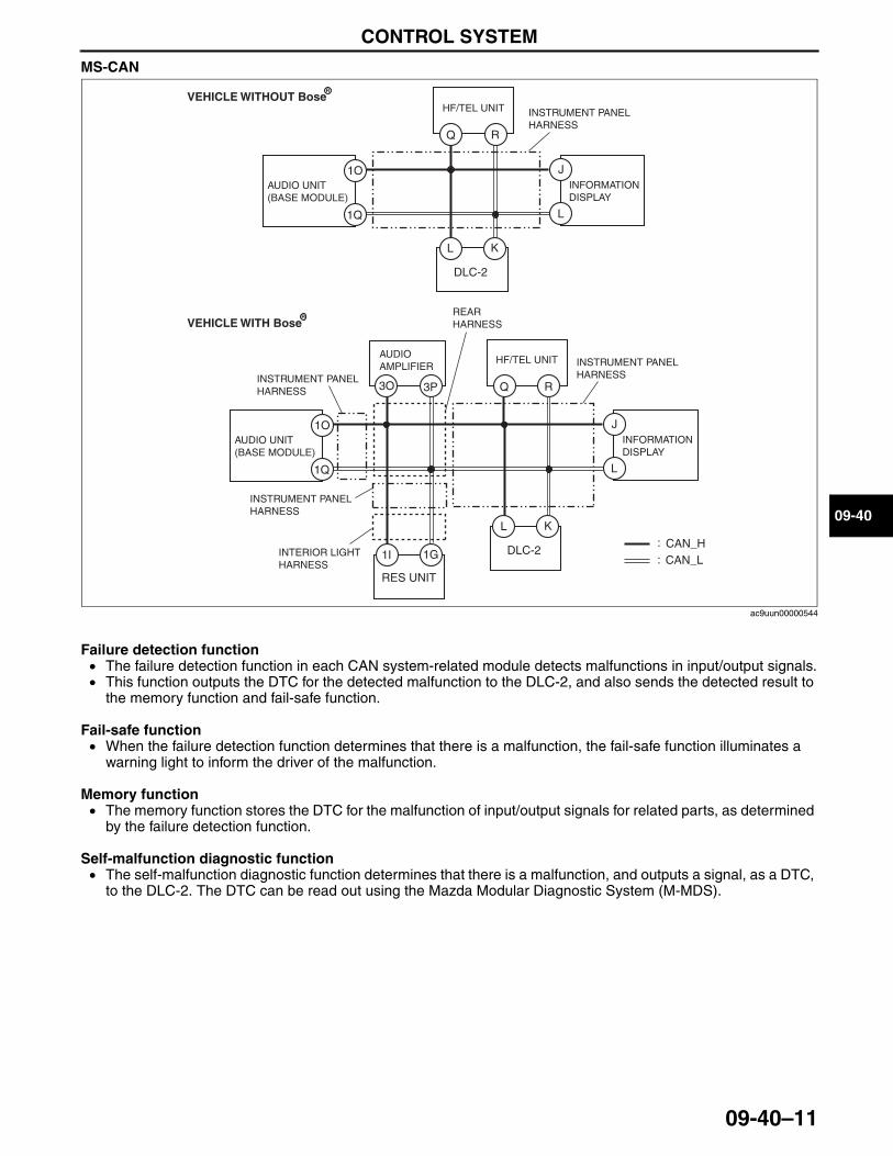
CONTROL SYSTEM
09-40–11
09-40
MS-CAN
Failure detection function• The failure detection function in each CAN system-related module detects malfunctions in input/output signals.• This function outputs the DTC for the detected malfunction to the DLC-2, and also sends the detected result to
the memory function and fail-safe function.
Fail-safe function• When the failure detection function determines that there is a malfunction, the fail-safe function illuminates a
warning light to inform the driver of the malfunction.
Memory function• The memory function stores the DTC for the malfunction of input/output signals for related parts, as determined
by the failure detection function.
Self-malfunction diagnostic function• The self-malfunction diagnostic function determines that there is a malfunction, and outputs a signal, as a DTC,
to the DLC-2. The DTC can be read out using the Mazda Modular Diagnostic System (M-MDS).
:
:
1Q
1O
Q R
L K
3O 3P
CAN_HCAN_L
DLC-2
J
L
AUDIO UNIT (BASE MODULE)
HF/TEL UNITAUDIO AMPLIFIER
INFORMATION DISPLAY
INSTRUMENT PANEL HARNESS
REAR HARNESS
INSTRUMENT PANEL HARNESS
INSTRUMENT PANEL HARNESS
INTERIOR LIGHT HARNESS
1I 1G
RES UNIT
1Q
1O
Q R
L K
DLC-2
J
L
AUDIO UNIT (BASE MODULE)
HF/TEL UNIT
INFORMATION DISPLAY
INSTRUMENT PANEL HARNESS
VEHICLE WITHOUT Bose
VEHICLE WITH Bose
R
R
ac9uun00000544
3423-1U-06H(09-40).fm 11 ページ 2006年11月21日 火曜日 午後5時51分
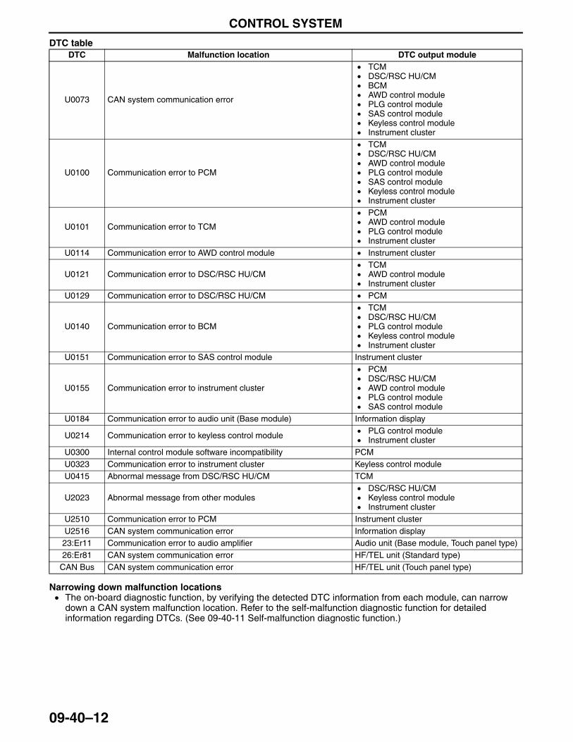
CONTROL SYSTEM
09-40–12
DTC table
Narrowing down malfunction locations• The on-board diagnostic function, by verifying the detected DTC information from each module, can narrow
down a CAN system malfunction location. Refer to the self-malfunction diagnostic function for detailed information regarding DTCs. (See 09-40-11 Self-malfunction diagnostic function.)
DTC Malfunction location DTC output module
U0073 CAN system communication error
• TCM• DSC/RSC HU/CM• BCM• AWD control module• PLG control module• SAS control module• Keyless control module• Instrument cluster
U0100 Communication error to PCM
• TCM• DSC/RSC HU/CM• AWD control module• PLG control module• SAS control module• Keyless control module• Instrument cluster
U0101 Communication error to TCM
• PCM• AWD control module• PLG control module• Instrument cluster
U0114 Communication error to AWD control module • Instrument cluster
U0121 Communication error to DSC/RSC HU/CM• TCM• AWD control module• Instrument cluster
U0129 Communication error to DSC/RSC HU/CM • PCM
U0140 Communication error to BCM
• TCM• DSC/RSC HU/CM• PLG control module• Keyless control module• Instrument cluster
U0151 Communication error to SAS control module Instrument cluster
U0155 Communication error to instrument cluster
• PCM• DSC/RSC HU/CM• AWD control module• PLG control module• SAS control module
U0184 Communication error to audio unit (Base module) Information display
U0214 Communication error to keyless control module • PLG control module• Instrument cluster
U0300 Internal control module software incompatibility PCMU0323 Communication error to instrument cluster Keyless control moduleU0415 Abnormal message from DSC/RSC HU/CM TCM
U2023 Abnormal message from other modules• DSC/RSC HU/CM• Keyless control module• Instrument cluster
U2510 Communication error to PCM Instrument clusterU2516 CAN system communication error Information display23:Er11 Communication error to audio amplifier Audio unit (Base module, Touch panel type)26:Er81 CAN system communication error HF/TEL unit (Standard type)
CAN Bus CAN system communication error HF/TEL unit (Touch panel type)
3423-1U-06H(09-40).fm 12 ページ 2006年11月21日 火曜日 午後5時51分
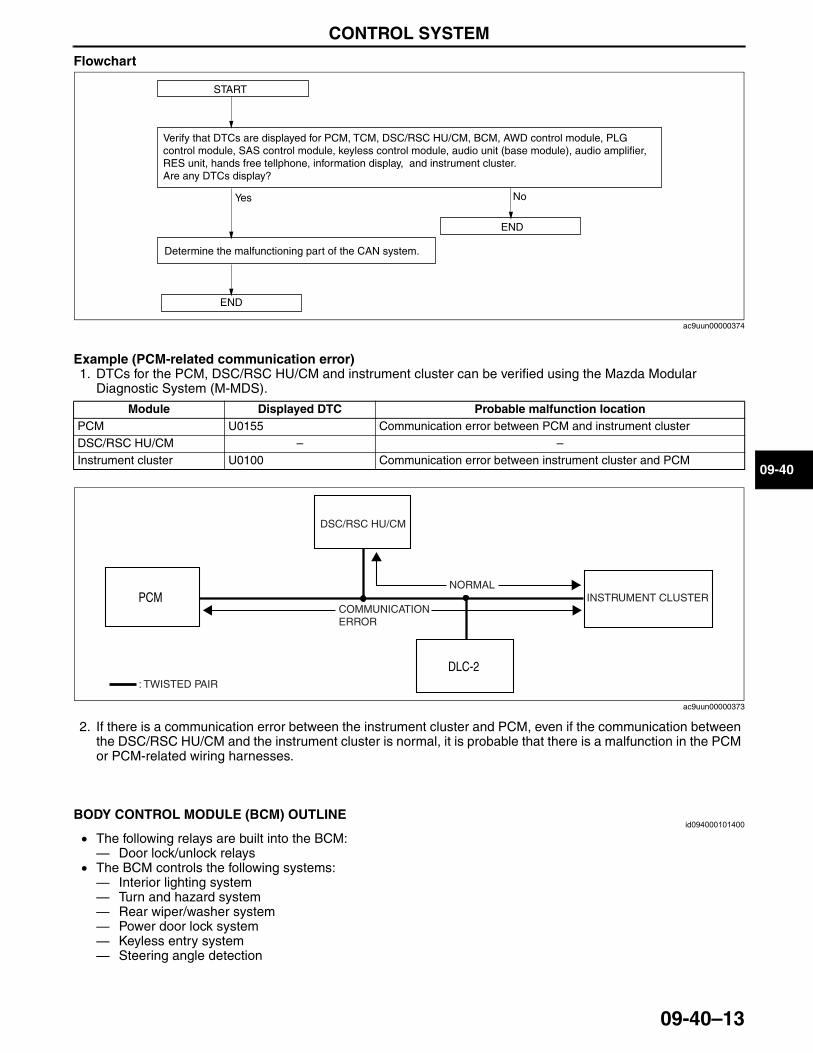
CONTROL SYSTEM
09-40–13
09-40
Flowchart
Example (PCM-related communication error)1. DTCs for the PCM, DSC/RSC HU/CM and instrument cluster can be verified using the Mazda Modular
Diagnostic System (M-MDS).
2. If there is a communication error between the instrument cluster and PCM, even if the communication between the DSC/RSC HU/CM and the instrument cluster is normal, it is probable that there is a malfunction in the PCM or PCM-related wiring harnesses.
End Of SieNG: POWER SUPPLY SYSTEM
BODY CONTROL MODULE (BCM) OUTLINEid094000101400
• The following relays are built into the BCM: — Door lock/unlock relays
• The BCM controls the following systems: — Interior lighting system— Turn and hazard system— Rear wiper/washer system— Power door lock system— Keyless entry system— Steering angle detection
End Of Sie
START
Verify that DTCs are displayed for PCM, TCM, DSC/RSC HU/CM, BCM, AWD control module, PLG control module, SAS control module, keyless control module, audio unit (base module), audio amplifier, RES unit, hands free tellphone, information display, and instrument cluster.Are any DTCs display?
Yes No
END
Determine the malfunctioning part of the CAN system.
END
ac9uun00000374
Module Displayed DTC Probable malfunction locationPCM U0155 Communication error between PCM and instrument clusterDSC/RSC HU/CM – –Instrument cluster U0100 Communication error between instrument cluster and PCM
DLC-2
PCM
: TWISTED PAIR
INSTRUMENT CLUSTER
DSC/RSC HU/CM
NORMAL
COMMUNICATION ERROR
ac9uun00000373
3423-1U-06H(09-40).fm 13 ページ 2006年11月21日 火曜日 午後5時51分
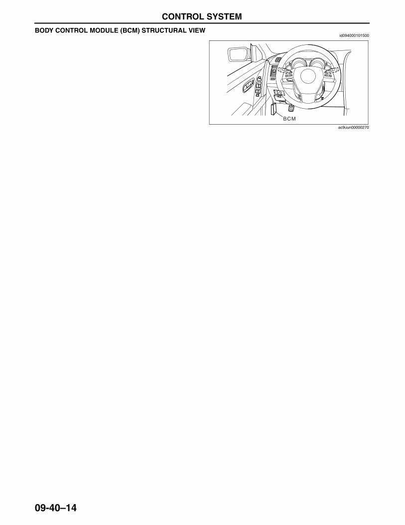
CONTROL SYSTEM
09-40–14
BODY CONTROL MODULE (BCM) STRUCTURAL VIEWid094000101500
End Of Sie
BCM
ac9uun00000270
3423-1U-06H(09-40).fm 14 ページ 2006年11月21日 火曜日 午後5時51分
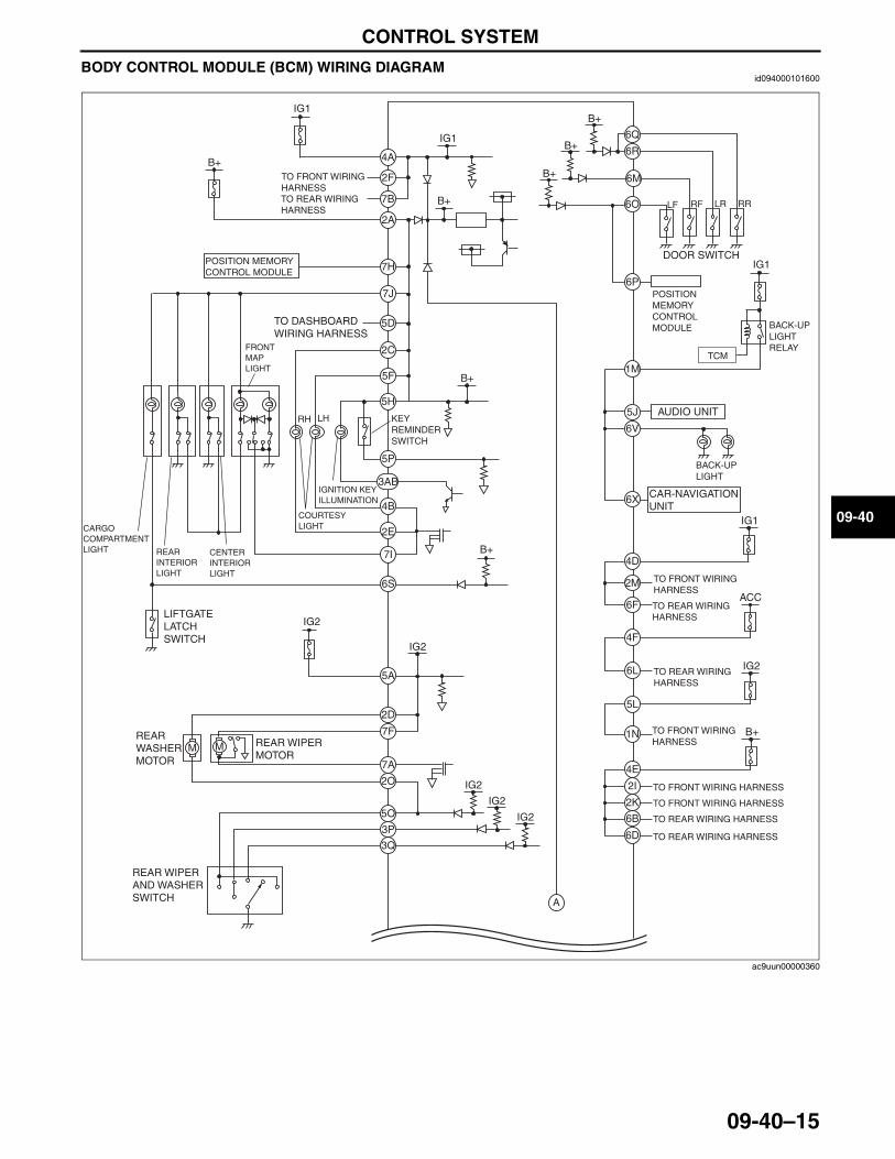
CONTROL SYSTEM
09-40–15
09-40
BODY CONTROL MODULE (BCM) WIRING DIAGRAMid094000101600
TCM
A
POSITION MEMORY CONTROL MODULE
2A
7H
7J
5D
2C
5F
5H
5P
3AB
6Q
6R
6M
6O
6P
1M
5J
6V
6X
4D
2M
6F
4F
6L
5L
1N
4E
2I
2K
6B
6D
4B
2E
7I
6S
5A
2D
7F
7A
2O
5O
3P
3Q
POSITION MEMORY CONTROL MODULE
MM
IG1
ACC
IG2
B+
IG2
IG2
IG1
IG2
IG2
IG2
B+
4A
2F
7B
IG1
IG1
B+
B+
B+
B+
B+
B+
LF RF RR
KEY REMINDER SWITCH
DOOR SWITCH
TO REAR WIRING HARNESS
TO FRONT WIRING HARNESS
TO REAR WIRING HARNESS
TO REAR WIRING HARNESS
TO REAR WIRING HARNESS
TO FRONT WIRING HARNESS
TO FRONT WIRING HARNESS
TO FRONT WIRING HARNESS
LIFTGATE LATCH SWITCH
REAR WIPER MOTOR
REAR WASHER MOTOR
BACK-UP LIGHT
BACK-UP LIGHT RELAY
AUDIO UNIT
CAR-NAVIGATION UNIT
FRONT MAP LIGHT
CENTER INTERIOR LIGHT
TO FRONT WIRING HARNESSTO REAR WIRING HARNESS
TO DASHBOARD WIRING HARNESS
REAR WIPER AND WASHER SWITCH
REAR INTERIOR LIGHT
CARGO COMPARTMENT LIGHT
IGNITION KEY ILLUMINATION
COURTESY LIGHT
LHRH
LR
ac9uun00000360
3423-1U-06H(09-40).fm 15 ページ 2006年11月21日 火曜日 午後5時51分
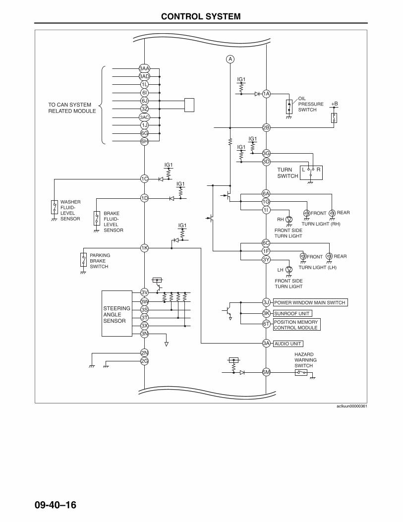
CONTROL SYSTEM
09-40–16
1A
2B
3G
3D
6A
1G
6C
1F
3J
3K
6T
3A
5M
3AD
3AA
6H
1C
1D
3V
3S
3T
3X
3N
2N
2G
3W
6G
1J
3AC
3Z
6J
6I
1L
+B
IG1
IG1
IG1
IG1
IG1
OIL PRESSURE SWITCH
TURN SWITCH
AUDIO UNIT
POSITION MEMORY CONTROL MODULE
POWER WINDOW MAIN SWITCH
HAZARD WARNING SWITCH
SUNROOF UNIT
TURN LIGHT (RH)
TURN LIGHT (LH)
REAR
REAR
FRONT
FRONT
WASHER FLUID-LEVEL SENSOR
1K
IG1
PARKING BRAKE SWITCH
BRAKE FLUID-LEVEL SENSOR
STEERING ANGLE SENSOR
TO CAN SYSTEM RELATED MODULE
L R
1I
FRONT SIDE TURN LIGHT
RH
3Y
FRONT SIDE TURN LIGHT
LH
A
ac9uun00000361
3423-1U-06H(09-40).fm 16 ページ 2006年11月21日 火曜日 午後5時51分
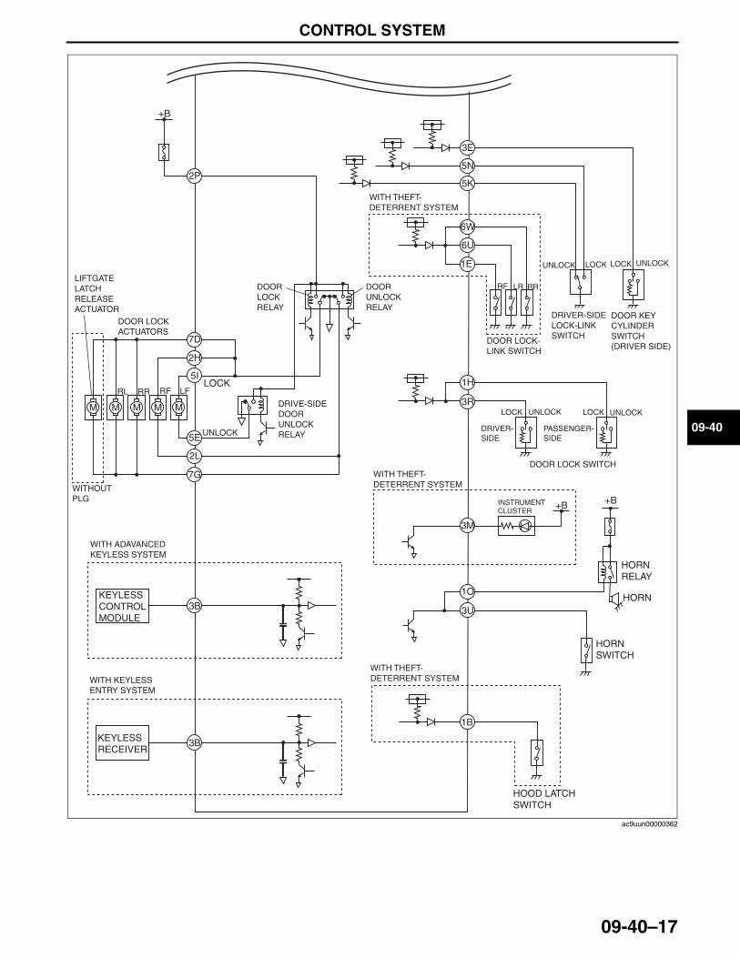
CONTROL SYSTEM
09-40–17
09-40
End Of Sie
2P
7D
3E
5N
5K
6W
6U
1E
1H
3R
3M
1O
3U
1B
2H
5I
5E
2L
7G
3B
+B+B
+B
DOOR KEY CYLINDER SWITCH(DRIVER SIDE)
HOOD LATCH SWITCH
DRIVER-SIDE LOCK-LINK SWITCH
DOOR LOCK-LINK SWITCH
LIFTGATE LATCH RELEASE ACTUATOR
DOOR LOCK ACTUATORS
M M M M M
WITHOUT PLG
KEYLESS CONTROL MODULE
3BKEYLESS RECEIVER
UNLOCK
LOCK
DRIVE-SIDE DOOR UNLOCK RELAY
DOOR LOCK RELAY
DOOR UNLOCK RELAY
HORN RELAY
HORN SWITCH
HORN
WITH THEFT-DETERRENT SYSTEM
DOOR LOCK SWITCH
LOCK LOCKUNLOCK
LOCKUNLOCK LOCK UNLOCK
UNLOCK
WITH THEFT-DETERRENT SYSTEM
WITH THEFT-DETERRENT SYSTEM
RL RR RF LF
RF LR RR
INSTRUMENT CLUSTER
PASSENGER-SIDE
DRIVER-SIDE
WITH KEYLESS ENTRY SYSTEM
WITH ADAVANCED KEYLESS SYSTEM
ac9uun00000362
3423-1U-06H(09-40).fm 17 ページ 2006年11月21日 火曜日 午後5時51分
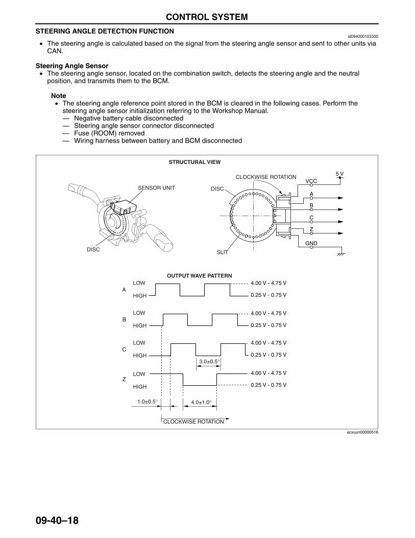
CONTROL SYSTEM
09-40–18
STEERING ANGLE DETECTION FUNCTIONid094000103300
• The steering angle is calculated based on the signal from the steering angle sensor and sent to other units via CAN.
Steering Angle Sensor• The steering angle sensor, located on the combination switch, detects the steering angle and the neutral
position, and transmits them to the BCM.
Note• The steering angle reference point stored in the BCM is cleared in the following cases. Perform the
steering angle sensor initialization referring to the Workshop Manual.— Negative battery cable disconnected— Steering angle sensor connector disconnected— Fuse (ROOM) removed— Wiring harness between battery and BCM disconnected
1.0±0.5° 4.0±1.0°
3.0±0.5°
VCC
A
Z
B
GND
5 V
4.00 V - 4.75 V
4.00 V - 4.75 V
0.25 V - 0.75 V
0.25 V - 0.75 V
C
Z
4.00 V - 4.75 V
4.00 V - 4.75 V
0.25 V - 0.75 V
0.25 V - 0.75 V
C
B
A
STRUCTURAL VIEW
LOW
HIGH
LOW
HIGH
LOW
HIGH
LOW
HIGH
SENSOR UNIT
OUTPUT WAVE PATTERN
CLOCKWISE ROTATION
CLOCKWISE ROTATION
SLITDISC
DISC
acxuun00000516
3423-1U-06H(09-40).fm 18 ページ 2006年11月21日 火曜日 午後5時51分
CONTROL SYSTEM
09-40–19
09-40
Sleep Control• When determination is made with all of the following conditions met and no occupants in the vehicle, the BCM
initiates sleep control and controls power consumption.— Ignition switch is in the LOCK position— Fifteen hours have elapsed since the ignition switch was in the LOCK position
• If any one of the following operations is performed, the BCM returns to normal control.— Ignition switch is turned to the ON position.— The key is inserted in the steering lock.— A door or the liftgate is opened— The steering wheel is operated
• During sleep control, the power supply voltage to the steering angle sensor becomes intermittent to control power consumption.
Note• If sudden maneuvering is performed during slip control, the steering angle reference point stored in the
BCM could be cleared. Perform the steering angle sensor initialization referring to the Workshop Manual.
End Of Sie
3423-1U-06H(09-40).fm 19 ページ 2006年11月21日 火曜日 午後5時51分
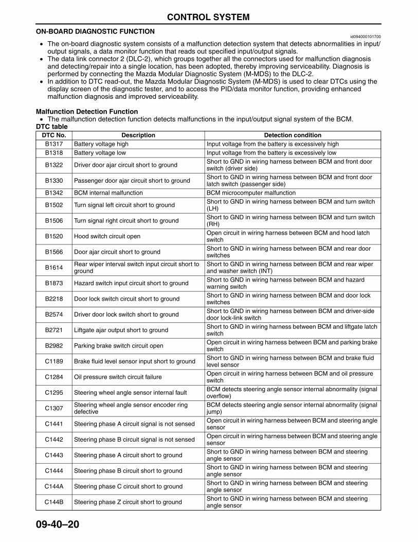
CONTROL SYSTEM
09-40–20
ON-BOARD DIAGNOSTIC FUNCTIONid094000101700
• The on-board diagnostic system consists of a malfunction detection system that detects abnormalities in input/output signals, a data monitor function that reads out specified input/output signals.
• The data link connector 2 (DLC-2), which groups together all the connectors used for malfunction diagnosis and detecting/repair into a single location, has been adopted, thereby improving serviceability. Diagnosis is performed by connecting the Mazda Modular Diagnostic System (M-MDS) to the DLC-2.
• In addition to DTC read-out, the Mazda Modular Diagnostic System (M-MDS) is used to clear DTCs using the display screen of the diagnostic tester, and to access the PID/data monitor function, providing enhanced malfunction diagnosis and improved serviceability.
Malfunction Detection Function• The malfunction detection function detects malfunctions in the input/output signal system of the BCM.
DTC tableDTC No. Description Detection conditionB1317 Battery voltage high Input voltage from the battery is excessively highB1318 Battery voltage low Input voltage from the battery is excessively low
B1322 Driver door ajar circuit short to ground Short to GND in wiring harness between BCM and front door switch (driver side)
B1330 Passenger door ajar circuit short to ground Short to GND in wiring harness between BCM and front door latch switch (passenger side)
B1342 BCM internal malfunction BCM microcomputer malfunction
B1502 Turn signal left circuit short to ground Short to GND in wiring harness between BCM and turn switch (LH)
B1506 Turn signal right circuit short to ground Short to GND in wiring harness between BCM and turn switch (RH)
B1520 Hood switch circuit open Open circuit in wiring harness between BCM and hood latch switch
B1566 Door ajar circuit short to ground Short to GND in wiring harness between BCM and rear door switches
B1614 Rear wiper interval switch input circuit short to ground
Short to GND in wiring harness between BCM and rear wiper and washer switch (INT)
B1873 Hazard switch input circuit short to ground Short to GND in wiring harness between BCM and hazard warning switch
B2218 Door lock switch circuit short to ground Short to GND in wiring harness between BCM and door lock switches
B2574 Driver door lock switch short to ground Short to GND in wiring harness between BCM and driver-side door lock-link switch
B2721 Liftgate ajar output short to ground Short to GND in wiring harness between BCM and liftgate latch switch
B2982 Parking brake switch circuit open Open circuit in wiring harness between BCM and parking brake switch
C1189 Brake fluid level sensor input short to ground Short to GND in wiring harness between BCM and brake fluid level sensor
C1284 Oil pressure switch circuit failure Open circuit in wiring harness between BCM and oil pressure switch
C1295 Steering wheel angle sensor internal fault BCM detects steering angle sensor internal abnormality (signal overflow)
C1307 Steering wheel angle sensor encoder ring defective
BCM detects steering angle sensor internal abnormality (signal jump)
C1441 Steering phase A circuit signal is not sensed Open circuit in wiring harness between BCM and steering angle sensor
C1442 Steering phase B circuit signal is not sensed Open circuit in wiring harness between BCM and steering angle sensor
C1443 Steering phase A circuit short to ground Short to GND in wiring harness between BCM and steering angle sensor
C1444 Steering phase B circuit short to ground Short to GND in wiring harness between BCM and steering angle sensor
C144A Steering phase C circuit short to ground Short to GND in wiring harness between BCM and steering angle sensor
C144B Steering phase Z circuit short to ground Short to GND in wiring harness between BCM and steering angle sensor
3423-1U-06H(09-40).fm 20 ページ 2006年11月21日 火曜日 午後5時51分
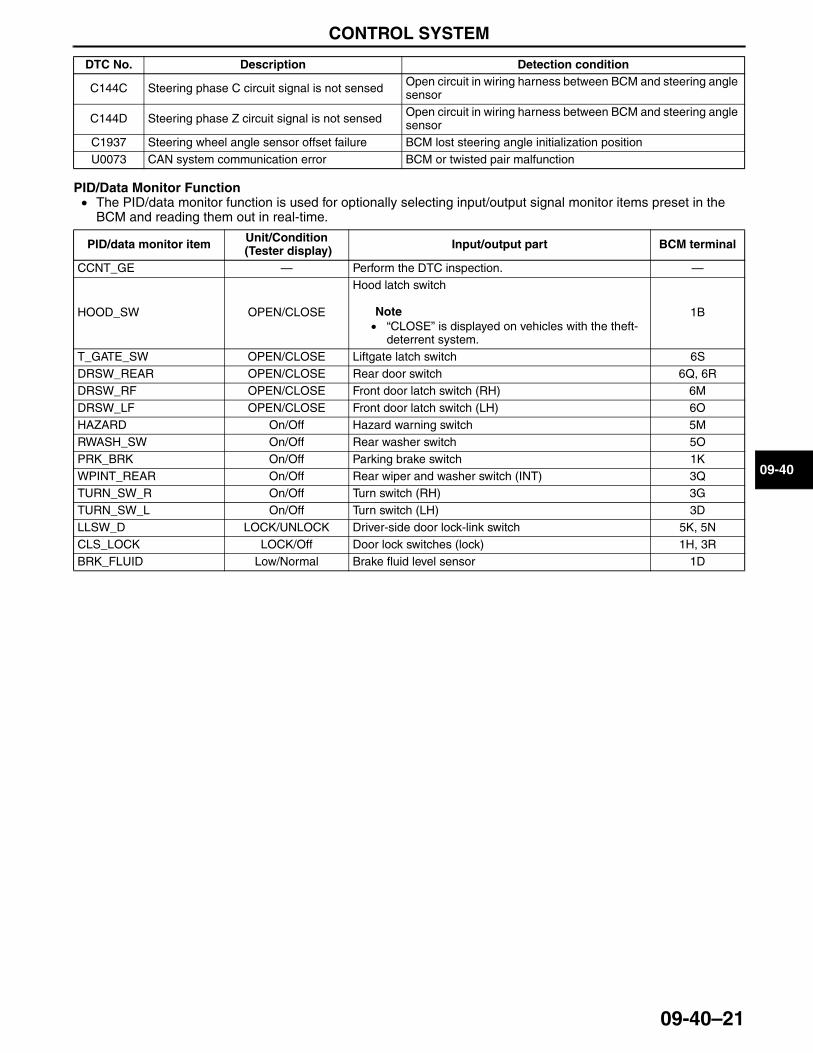
CONTROL SYSTEM
09-40–21
09-40
PID/Data Monitor Function• The PID/data monitor function is used for optionally selecting input/output signal monitor items preset in the
BCM and reading them out in real-time.
End Of Sie
C144C Steering phase C circuit signal is not sensed Open circuit in wiring harness between BCM and steering angle sensor
C144D Steering phase Z circuit signal is not sensed Open circuit in wiring harness between BCM and steering angle sensor
C1937 Steering wheel angle sensor offset failure BCM lost steering angle initialization positionU0073 CAN system communication error BCM or twisted pair malfunction
DTC No. Description Detection condition
PID/data monitor item Unit/Condition (Tester display) Input/output part BCM terminal
CCNT_GE — Perform the DTC inspection. —
HOOD_SW OPEN/CLOSE
Hood latch switch
Note• “CLOSE” is displayed on vehicles with the theft-
deterrent system.
1B
T_GATE_SW OPEN/CLOSE Liftgate latch switch 6SDRSW_REAR OPEN/CLOSE Rear door switch 6Q, 6RDRSW_RF OPEN/CLOSE Front door latch switch (RH) 6MDRSW_LF OPEN/CLOSE Front door latch switch (LH) 6OHAZARD On/Off Hazard warning switch 5MRWASH_SW On/Off Rear washer switch 5OPRK_BRK On/Off Parking brake switch 1KWPINT_REAR On/Off Rear wiper and washer switch (INT) 3QTURN_SW_R On/Off Turn switch (RH) 3GTURN_SW_L On/Off Turn switch (LH) 3DLLSW_D LOCK/UNLOCK Driver-side door lock-link switch 5K, 5NCLS_LOCK LOCK/Off Door lock switches (lock) 1H, 3RBRK_FLUID Low/Normal Brake fluid level sensor 1D
3423-1U-06H(09-40).fm 21 ページ 2006年11月21日 火曜日 午後5時51分


