Embed Size (px)
Citation preview
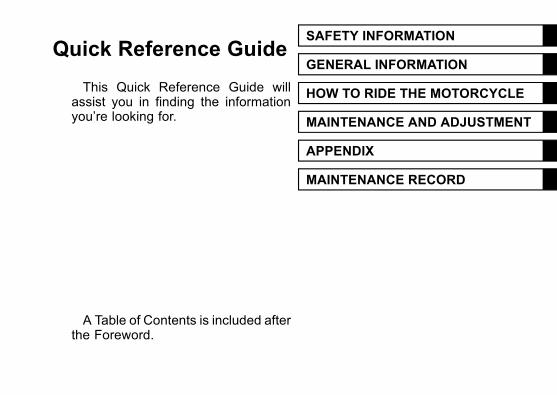
Quick Reference GuideSAFETY INFORMATION j
GENERAL INFORMATION j
HOW TO RIDE THE MOTORCYCLE j
MAINTENANCE AND ADJUSTMENT j
APPENDIX j
MAINTENANCE RECORD j
This Quick Reference Guide willassist you in finding the informationyou’re looking for.
A Table of Contents is included afterthe Foreword.
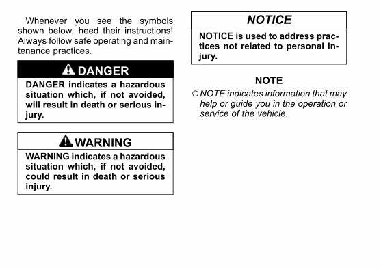
Whenever you see the symbolsshown below, heed their instructions!Always follow safe operating and main-tenance practices.
DANGERDANGER indicates a hazardoussituation which, if not avoided,will result in death or serious in-jury.
WARNINGWARNING indicates a hazardoussituation which, if not avoided,could result in death or seriousinjury.
NOTICE
NOTICE is used to address prac-tices not related to personal in-jury.
NOTE
○NOTE indicates information that mayhelp or guide you in the operation orservice of the vehicle.
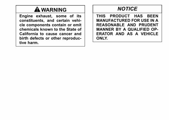
WARNINGEngine exhaust, some of itsconstituents, and certain vehi-cle components contain or emitchemicals known to the State ofCalifornia to cause cancer andbirth defects or other reproduc-tive harm.
NOTICE
THIS PRODUCT HAS BEENMANUFACTURED FOR USE IN AREASONABLE AND PRUDENTMANNER BY A QUALIFIED OP-ERATOR AND AS A VEHICLEONLY.
Foreword
Congratulations on your purchase of a new Kawasaki motorcycle. Your new mo-torcycle is the product of Kawasaki’s advanced engineering, exhaustive testing,and continuous striving for superior reliability, safety and performance.
Please read this Owner’s Manual carefully before riding so that you will bethoroughly familiar with the proper operation of your motorcycle’s controls, its fea-tures, capabilities, and limitations. This manual offers many safe riding tips, but itspurpose is not to provide instruction in all the techniques and skills required to ridea motorcycle safely. Kawasaki strongly recommends that all operators of this vehi-cle enroll in a motorcycle rider training program to attain awareness of the mentaland physical requirements necessary for safe motorcycle operation.
To ensure a long, trouble-free life for your motorcycle, give it the proper care andmaintenance described in this manual. For those who would like more detailed in-formation on their Kawasaki Motorcycle, a Service Manual is available for purchasefrom any authorized Kawasaki motorcycle dealer. The Service Manual contains de-tailed disassembly and maintenance information. Those who plan to do their ownwork should, of course, be competent mechanics and possess the special toolsdescribed in the Service Manual.
Keep this Owner’s Manual aboard your motorcycle at all times so that you canrefer to it whenever you need information.
This manual should be considered a permanent part of the motorcycle and shouldremain with the motorcycle when it is sold.
All rights reserved. No part of this publication may be reproduced without ourprior written permission.
This publication includes the latest information available at the time of printing.However, there may be minor differences between the actual product and illustra-tions and text in this manual.All products are subject to change without prior notice or obligation.
KAWASAKI HEAVY INDUSTRIES, LTD.Motorcycle & Engine Company
© 2015 Kawasaki Heavy Industries, Ltd. Apr. 14, 2015. (1)
Emission Control Information
To protect the environment in which we all live, Kawasaki has incorporatedcrankcase emission (1) and exhaust emission (2) control systems in compliancewith applicable regulations of the United States Environmental Protection Agencyand California Air Resources Board. Additionally, Kawasaki has incorporatedan evaporative emission control system (3) in compliance with applicable regu-lations of the United States Environmental Protection Agency and California AirResources Board.
1. Crankcase Emission Control SystemThis system eliminates the release of crankcase vapors into the atmosphere.
Instead, the vapors are routed through an oil separator to the intake side of theengine. While the engine is operating, the vapors are drawn into the combustionchamber, where they are burned along with the fuel and air supplied by the fuelinjection system.
2. Exhaust Emission Control SystemThis system reduces the amount of pollutants discharged into the atmosphere
by the exhaust of this motorcycle. The fuel, ignition and exhaust systems of thismotorcycle have been carefully designed and constructed to ensure an efficientengine with low exhaust pollutant levels. The exhaust system of this model motor-cycle includes a catalytic converter system.
3. Evaporative Emission Control SystemThe evaporative emission control system for this vehicle consists of low perme-
ation fuel hoses and fuel tank.
3. Evaporative Emission Control System (California)Vapors caused by fuel evaporation in the fuel system are not vented into the
atmosphere. Instead, fuel vapors are routed into the running engine to be burned,or stored in a canister when the engine is stopped.
High Altitude Performance Adjustment InformationHigh Altitude adjustment is not required.
Maintenance and Warranty
Proper maintenance is necessary to ensure that your motorcycle will continue tohave low emission levels. This Owner’s Manual contains those maintenance rec-ommendations for your motorcycle. Those items identified by the Periodic Mainte-nance Chart are necessary to ensure compliance with the applicable standards.As the owner of this motorcycle, you have the responsibility to make sure that
the recommended maintenance is carried out according to the instructions in thisOwner’s Manual at your own expense.The Kawasaki Limited Emission Control System Warranty requires that you re-
turn your motorcycle to an authorized Kawasaki dealer for remedy under warranty.Please read the warranty carefully, and keep it valid by complying with the owner’sobligations it contains.You should keep a maintenance record for your motorcycle. To assist you in
keeping this record, we have provided space on pages 170 through 175 of thismanual where an authorized Kawasaki dealer, or someone equally competent, canrecord themaintenance. You should also retain copies of maintenance work orders,bills, etc., as verification of this maintenance.
Tampering With Noise Control System Prohibited
Federal law prohibits the following acts or the causing thereof: (1) the removal orrendering inoperative by any person other than for purposes of maintenance, re-pair, or replacement, of any device or element of design incorporated into any newvehicle for the purpose of noise control prior to its sale or delivery to the ultimatepurchaser or while it is in use, or (2) the use of the vehicle after such device orelement of design has been removed or rendered inoperative by any person.
Among those acts presumed to constitute tampering are the acts listed below:* Replacement of the original exhaust system or muffler with a component not incompliance with Federal regulations.
* Removal of the muffler(s) or any internal portion of the muffler(s).* Removal of the air box or air box cover.* Modifications to the muffler(s) or air intake system by cutting, drilling, or othermeans if such modifications result in increased noise levels.
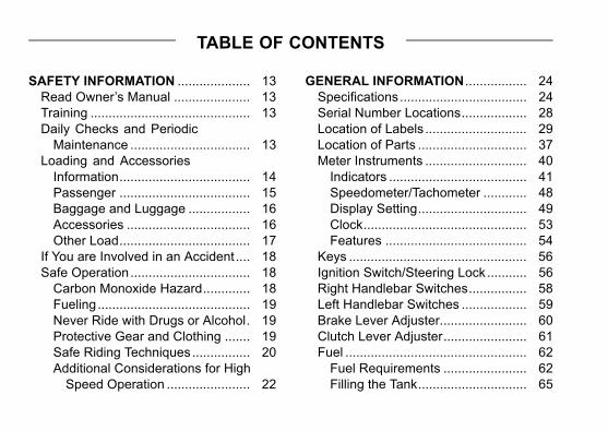
TABLE OF CONTENTS
SAFETY INFORMATION .................... 13
Read Owner’s Manual ..................... 13
Training ............................................ 13
Daily Checks and Periodic
Maintenance ................................. 13
Loading and Accessories
Information.................................... 14
Passenger .................................... 15
Baggage and Luggage ................. 16
Accessories .................................. 16
Other Load.................................... 17
If You are Involved in an Accident.... 18
Safe Operation................................. 18
Carbon Monoxide Hazard............. 18
Fueling.......................................... 19
Never Ride with Drugs or Alcohol. 19
Protective Gear and Clothing ....... 19
Safe Riding Techniques................ 20
Additional Considerations for High
Speed Operation ....................... 22
GENERAL INFORMATION ................. 24
Specifications................................... 24
Serial Number Locations.................. 28
Location of Labels ............................ 29
Location of Parts .............................. 37
Meter Instruments ............................ 40
Indicators ...................................... 41
Speedometer/Tachometer ............ 48
Display Setting.............................. 49
Clock............................................. 53
Features ....................................... 54
Keys ................................................. 56
Ignition Switch/Steering Lock........... 56
Right Handlebar Switches................ 58
Left Handlebar Switches .................. 59
Brake Lever Adjuster........................ 60
Clutch Lever Adjuster....................... 61
Fuel .................................................. 62
Fuel Requirements ....................... 62
Filling the Tank.............................. 65
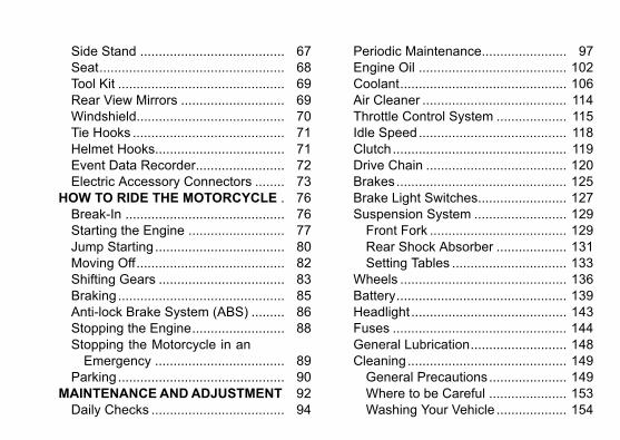
Side Stand ....................................... 67
Seat.................................................. 68
Tool Kit ............................................. 69
Rear View Mirrors ............................ 69
Windshield........................................ 70
Tie Hooks ......................................... 71
Helmet Hooks................................... 71
Event Data Recorder........................ 72
Electric Accessory Connectors ........ 73
HOW TO RIDE THE MOTORCYCLE . 76
Break-In ........................................... 76
Starting the Engine .......................... 77
Jump Starting ................................... 80
Moving Off........................................ 82
Shifting Gears .................................. 83
Braking............................................. 85
Anti-lock Brake System (ABS) ......... 86
Stopping the Engine......................... 88
Stopping the Motorcycle in an
Emergency ................................... 89
Parking............................................. 90
MAINTENANCEANDADJUSTMENT 92
Daily Checks .................................... 94
Periodic Maintenance....................... 97
Engine Oil ........................................ 102
Coolant............................................. 106
Air Cleaner ....................................... 114
Throttle Control System ................... 115
Idle Speed........................................ 118
Clutch............................................... 119
Drive Chain ...................................... 120
Brakes.............................................. 125
Brake Light Switches........................ 127
Suspension System ......................... 129
Front Fork ..................................... 129
Rear Shock Absorber ................... 131
Setting Tables ............................... 133
Wheels ............................................. 136
Battery.............................................. 139
Headlight .......................................... 143
Fuses ............................................... 144
General Lubrication.......................... 148
Cleaning........................................... 149
General Precautions..................... 149
Where to be Careful ..................... 153
Washing Your Vehicle ................... 154
APPENDIX .......................................... 156
Storage ............................................ 156
Troubleshooting Guide..................... 159
Your Warranty/Owner Satisfaction ... 164
Reporting Safety Defects ................. 169
Environmental Protection................. 170
MAINTENANCE RECORD ................. 171
SAFETY INFORMATION 13
SAFETY INFORMATION
Read Owner’s Manual
Read this Owner’s Manual care-fully before riding so that you will bethoroughly familiar with the proper op-eration of your motorcycle’s controls,its features, capabilities, and limita-tions. This manual offers many saferiding tips, but its purpose is not to pro-vide instruction in all of the techniquesand skills required to ride a motorcyclesafely.
Training
Kawasaki strongly recommends thatall operators of this vehicle complete asuitable motorcycle rider training pro-gram to learn the proper skills and tech-niques necessary for safe motorcycleoperation.
Daily Checks and PeriodicMaintenance
It is important to keep your motorcy-cle properly maintained and in safe rid-ing condition. Inspect your motorcy-cle before every ride and carry out allperiodic maintenance. See the DailyChecks section and the Periodic Main-tenance section in the MAINTENANCEAND ADJUSTMENT chapter for moreinformation.
WARNINGFailure to perform these checksor to correct a problem beforeoperation may result in seriousdamage or an accident. Alwaysperform daily checks before op-eration.
14 SAFETY INFORMATION
jTo ensure your motorcycle is ser-
viced using the latest servicing infor-mation, it is recommended that anauthorized Kawasaki Dealer performsthe periodic maintenance as directedin the Owner’s Manual.If you notice any irregular operat-
ing condition, have your motorcyclethoroughly checked at an authorizedKawasaki dealer as soon as possible.
Loading and AccessoriesInformation
WARNINGIncorrect loading, improper in-stallation or use of accessories,or modification of your motorcy-cle may result in an unsafe ridingcondition. Before you ride themotorcycle, make sure it is notoverloaded and that you havefollowed these instructions.
Maximum Load
Weight of rider, passenger, baggage,and accessories must not exceed 210 kg(463 lb).
With the exception of genuineKawasaki Parts and Accessories,Kawasaki has no control over thedesign or application of accessories.In some cases, improper installation
SAFETY INFORMATION 15
or use of accessories, or motorcyclemodification, will void the motorcyclewarranty; can negatively affect perfor-mance, stability and safety; and caneven be illegal.In selecting and using accessories,
and in loading the motorcycle, you arepersonally responsible for your ownsafety and the safety of other personsinvolved.
NOTE
○Kawasaki Parts and Accessorieshave been specially designed foruse on Kawasaki motorcycles. Westrongly recommend that all partsand accessories you add to yourmotorcycle be genuine Kawasakicomponents.
Because a motorcycle is sensitive tochanges in weight and aerodynamicforces, you must take extreme care incarrying cargo, passengers and/or in
fitting additional accessories. The fol-lowing general guidelines have beenprepared to assist you in making yourdeterminations.
Passenger
1. Never carry more than one passen-ger.
2. The passenger should only sit on thepillion.
3. Any passenger should be thor-oughly familiar with motorcycle op-eration. The passenger can affectcontrol of the motorcycle by im-proper positioning during corneringand sudden movements. It is im-portant that the passenger sits stillwhile the motorcycle is in motionand not interfere with the operationof the motorcycle. Do not carry ani-mals on your motorcycle.
16 SAFETY INFORMATION
j4. Do not carry passengers unlesspassenger footpegs are installed.Instruct any passenger before ridingto keep his or her feet on the pas-senger footpegs and hold on to theoperator or grab rail. Do not carrya passenger unless he or she is tallenough to reach the footpegs withtheir feet.
Baggage and Luggage
1. All baggage should be carried aslow as possible to reduce the effecton the motorcycle’s center of grav-ity. Baggage weight should also bedistributed equally on both sides ofthe motorcycle. Avoid carrying bag-gage that extends beyond the rearof the motorcycle.
2. Baggage should be securely at-tached. Make sure that the baggage
will not move around while you areriding. Recheck baggage securityas often as possible (not while themotorcycle is in motion) and adjustas necessary.
3. Do not carry heavy or bulky itemson a luggage rack. It is designedfor light items, and overloading canaffect handling due to changes inweight distribution and aerodynamicforces.
Accessories
1. Do not install accessories or carrybaggage that impairs the perfor-mance of the motorcycle. Makesure that you have not adverselyaffected any lighting components,road clearance, banking capability(i.e., lean angle), control operation,wheel travel, front fork movement,
SAFETY INFORMATION 17
or any other aspects of the motor-cycle’s operation.
2. Weight attached to the handlebarsor front fork will increase the massof the steering assembly and canresult in an unsafe riding condition.
3. Fairings, windshields, backrests,and other large items have the ca-pability of adversely affecting stabil-ity and handling of the motorcycle,not only due to their weight, butalso due to the aerodynamic forceacting on these surfaces while themotorcycle is in operation. Poorlydesigned or installed items can re-sult in an unsafe riding condition.Lugs are provided on the swingarmto attach accessory rear stand adap-tors. Always remove the rear standadapters before riding or sitting onthe machine to prevent possibledamage to the muffler or swingarm.
Other Load
1. This motorcycle is not intended tobe equipped with a sidecar or to beused to tow any trailers or other ve-hicles. Kawasaki does not manu-facture sidecars or trailers for mo-torcycles and cannot predict the ef-fects of such accessories on han-dling or stability, but can only warnthat the effects can be adverse andthat Kawasaki cannot assume re-sponsibility for the results of suchunintended use of the motorcycle.
2. Furthermore, any adverse effects onmotorcycle components caused bythe use of such accessories will notbe remedied under warranty.
18 SAFETY INFORMATION
jIf You are Involved in anAccident
Make sure of your own safety first.Determine the severity of any injuriesand call for emergency assistance ifneeded. Always follow applicable lawsand regulations if any other person, ve-hicle or property is involved.Do not attempt to continue riding
without first evaluating your motorcy-cle’s condition. Inspect for fluid leaks,check critical nuts and bolts, and checkthe handlebars, control levers, brakes,and wheels for damage and properfunction. Ride slowly and cautiously- your motorcycle may have suffereddamage that is not immediately appar-ent. Have your motorcycle thoroughlychecked at a Kawasaki dealer as soonas possible.
Safe Operation
The following should be carefully ob-served for safe and effective vehicleoperation.
Carbon Monoxide Hazard
DANGERExhaust gas contains carbonmonoxide, a colorless, odor-less poisonous gas. Inhalingcarbon monoxide can causeserious brain injury or death.DO NOT run the engine in en-closed areas. Operate only in awell-ventilated area.
SAFETY INFORMATION 19
Fueling
WARNINGGasoline is extremely flammableand can be explosive undercertain conditions. To avoid apossible fire or explosion, turnthe ignition switch off. Do notsmoke. Make sure the area iswell ventilated and free from anysource of flame or sparks; thisincludes any appliance with apilot light.
Never Ride with Drugs or Alcohol
Alcohol and drugs impair your judg-ment and reaction time. Never con-sume alcohol or drugs before or whileriding motorcycles.
Protective Gear and Clothing
HelmetKawasaki strongly recommends both
the operator and passenger wear aDOT-approved helmet even if this isnot a legal requirement.- Make sure that your helmet fits cor-rectly and is properly fastened.
- Choose a motorcycle helmet thatmeets DOT safety standards. Askyour motorcycle dealer to adviseyou if necessary.
20 SAFETY INFORMATION
jEye ProtectionAlways use eye protection. If your
helmet does not have a visor installed,wear goggles.
GlovesWear gloves which have suitable
protection for your hands, especiallyagainst abrasion.
ClothingWear protective clothing.- Wear bright, highly visible clothingthat allows freedom of movementto suit your riding style.
- Always wear a long- sleeved jacketand long trousers which are abra-sion resistant and keep you warm.
- Avoid wearing clothes which haveloose cuffs or other fasteningswhich could interfere with the con-trols of your motorcycle.
BootsWear proper protective boots that fit
properly and do not interfere with gearshifting or braking.
Safe Riding Techniques
Keep Hands on HandlebarsWhen riding always keep both hands
on the handlebars and both feet on thefootpegs. Removing your hands fromthe handlebars or feet from the foot-pegs while riding can be hazardous. Ifyou remove even one hand or foot, youreduce your ability to control the motor-cycle.
Look Over Your ShoulderBefore changing lanes, look over
your shoulder to make sure the wayis clear. Do not rely solely on the rear
SAFETY INFORMATION 21
view mirror; you may misjudge a vehi-cle’s distance and speed, or you maynot see it at all.
Accelerate and Brake SmoothlyIn general your actions should be
smooth as sudden acceleration, brak-ing or turning may cause loss of control,especially when riding in wet conditionsor on loose road surfaces, when theability to maneuver will be reduced.
Select Correct Gear SpeedsWhen going up steep slopes, shift to
a lower gear so that there is power tospare rather than overloading the en-gine.
Use Both Front and Rear BrakesWhen applying the brakes, use both
the front and rear brakes. Applyingonly one brake for sudden braking maycause the motorcycle to skid and losecontrol.
Use Engine BrakeWhen going down long slopes, help
control vehicle speed by closing thethrottle so that the engine can act as anauxiliary brake. Use the front and rearbrakes for primary braking.
Riding in Wet ConditionsRely more on the throttle to control
vehicle speed and less on the front andrear brakes. The throttle should also beused judiciously to avoid skidding therear wheel from too rapid accelerationor deceleration.Braking performance is also reduced
in wet conditions. Carefully ride at aslow speed and apply the brakes sev-eral times to help dry and restores themto normal operating performance.Lubricate the drive chain after wet
-weather riding to prevent rust and cor-rosion.
22 SAFETY INFORMATION
jRide PrudentlyRiding at the proper speed and avoid-
ing unnecessarily fast acceleration areimportant not only for safety and lowfuel consumption but also for long ve-hicle life and quieter operation.
Riding on Rough RoadsExercise caution, slow down, and
grip the fuel tank with the knees forbetter stability.
AccelerationWhen quick acceleration is neces-
sary to pass another vehicle, shift toa lower gear to obtain the necessarypower.
DownshiftingTo avoid engine damage and rear
wheel lock-up do not downshift at highrpm.
Avoid Unnecessary WeavingUnnecessary weaving jeopardizes
the safety of both the rider and othermotorists.
Additional Considerations forHigh Speed Operation
WARNINGHandling characteristics of amotorcycle at high speeds mayvary from those you are familiarwith at legal highway speeds.Do not attempt high speed oper-ation unless you have receivedsufficient training and have therequired skills.Do not operate at high speeds onpublic roads.
SAFETY INFORMATION 23
BrakesThe importance of the brakes, es-
pecially during high speed operation,cannot be overemphasized. Check tosee that they are correctly adjusted andfunctioning properly.
SteeringLooseness in the steering can cause
loss of control. Check to see that thehandlebars turns freely but has no play.
TiresHigh speed operation is hard on tires,
and good tires are crucial for safe rid-ing. Examine their overall condition, in-flate them to the proper pressure, andcheck the wheel balance.
FuelHave sufficient fuel for the high fuel
consumption during high speed opera-tion.
Engine OilTo avoid engine seizure and resulting
loss of control, make sure that the oillevel is at the upper level line.
CoolantTo avoid overheating, check that the
coolant level is at the upper level line.
Electrical EquipmentMake sure that the headlight,
tail/brake light, turn signals, horn, etc.,all work properly.
MiscellaneousMake sure that all nuts and bolts are
tight and that all safety related parts arein good condition.
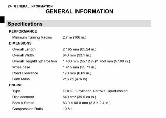
24 GENERAL INFORMATION
j
GENERAL INFORMATION
Specifications
PERFORMANCE
Minimum Turning Radius 2.7 m (106 in.)
DIMENSIONS
Overall Length 2 165 mm (85.24 in.)
Overall Width 840 mm (33.1 in.)
Overall Height/High Position 1 400 mm (55.12 in.)/1 450 mm (57.09 in.)
Wheelbase 1 415 mm (55.71 in.)
Road Clearance 170 mm (6.69 in.)
Curb Mass 216 kg (476 lb)
ENGINE
Type DOHC, 2-cylinder, 4-stroke, liquid-cooled
Displacement 649 cm³ (39.6 cu in.)
Bore × Stroke 83.0 × 60.0 mm (3.3 × 2.4 in.)
Compression Ratio 10.8:1
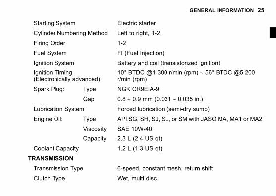
GENERAL INFORMATION 25
Starting System Electric starter
Cylinder Numbering Method Left to right, 1-2
Firing Order 1-2
Fuel System FI (Fuel Injection)
Ignition System Battery and coil (transistorized ignition)
Ignition Timing(Electronically advanced)
10° BTDC @1 300 r/min (rpm) ∼ 56° BTDC @5 200r/min (rpm)
Spark Plug: Type NGK CR9EIA-9
Gap 0.8 ∼ 0.9 mm (0.031 ∼ 0.035 in.)
Lubrication System Forced lubrication (semi-dry sump)
Engine Oil: Type API SG, SH, SJ, SL, or SM with JASO MA, MA1 or MA2
Viscosity SAE 10W-40
Capacity 2.3 L (2.4 US qt)
Coolant Capacity 1.2 L (1.3 US qt)
TRANSMISSION
Transmission Type 6-speed, constant mesh, return shift
Clutch Type Wet, multi disc
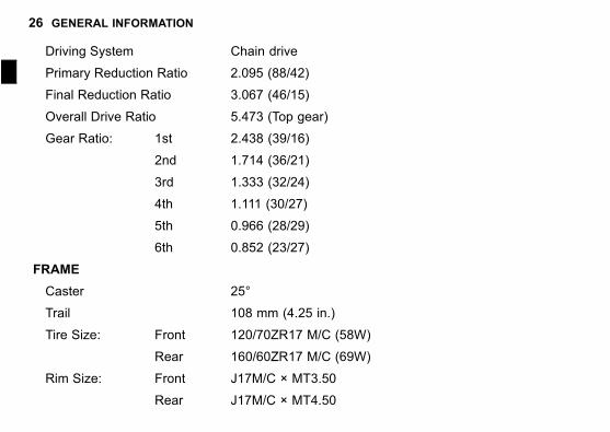
26 GENERAL INFORMATION
j
Driving System Chain drive
Primary Reduction Ratio 2.095 (88/42)
Final Reduction Ratio 3.067 (46/15)
Overall Drive Ratio 5.473 (Top gear)
Gear Ratio: 1st 2.438 (39/16)
2nd 1.714 (36/21)
3rd 1.333 (32/24)
4th 1.111 (30/27)
5th 0.966 (28/29)
6th 0.852 (23/27)
FRAME
Caster 25°
Trail 108 mm (4.25 in.)
Tire Size: Front 120/70ZR17 M/C (58W)
Rear 160/60ZR17 M/C (69W)
Rim Size: Front J17M/C × MT3.50
Rear J17M/C × MT4.50
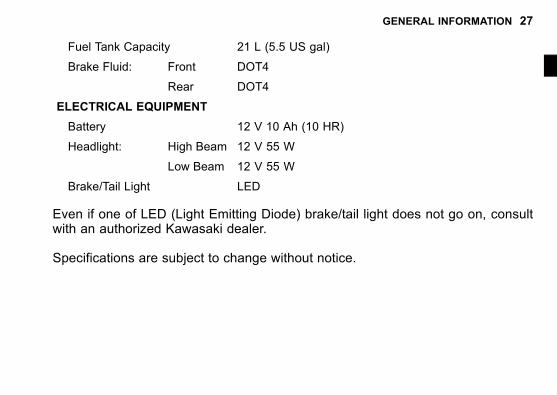
GENERAL INFORMATION 27
Fuel Tank Capacity 21 L (5.5 US gal)
Brake Fluid: Front DOT4
Rear DOT4
ELECTRICAL EQUIPMENT
Battery 12 V 10 Ah (10 HR)
Headlight: High Beam 12 V 55 W
Low Beam 12 V 55 W
Brake/Tail Light LED
Even if one of LED (Light Emitting Diode) brake/tail light does not go on, consultwith an authorized Kawasaki dealer.
Specifications are subject to change without notice.
28 GENERAL INFORMATION
j
Serial Number Locations
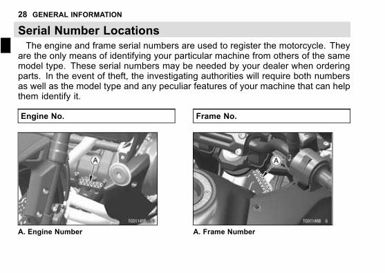
The engine and frame serial numbers are used to register the motorcycle. Theyare the only means of identifying your particular machine from others of the samemodel type. These serial numbers may be needed by your dealer when orderingparts. In the event of theft, the investigating authorities will require both numbersas well as the model type and any peculiar features of your machine that can helpthem identify it.
Engine No.
A. Engine Number
Frame No.
A. Frame Number
GENERAL INFORMATION 29
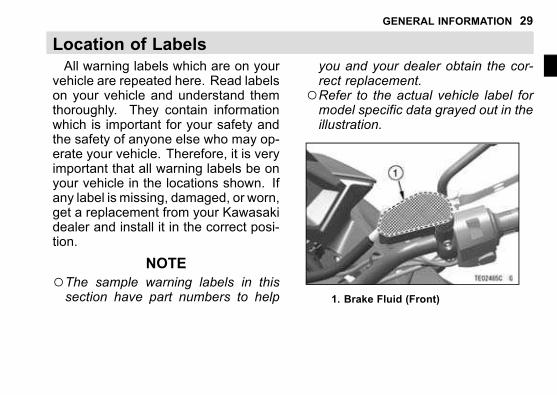
Location of Labels
All warning labels which are on yourvehicle are repeated here. Read labelson your vehicle and understand themthoroughly. They contain informationwhich is important for your safety andthe safety of anyone else who may op-erate your vehicle. Therefore, it is veryimportant that all warning labels be onyour vehicle in the locations shown. Ifany label is missing, damaged, or worn,get a replacement from your Kawasakidealer and install it in the correct posi-tion.
NOTE
○The sample warning labels in thissection have part numbers to help
you and your dealer obtain the cor-rect replacement.
○Refer to the actual vehicle label formodel specific data grayed out in theillustration.
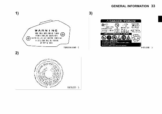
1. Brake Fluid (Front)
30 GENERAL INFORMATION
j
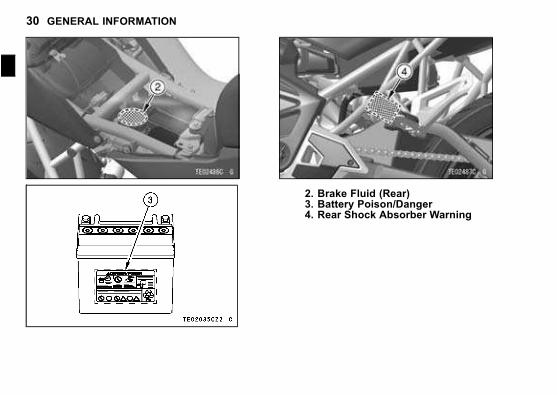
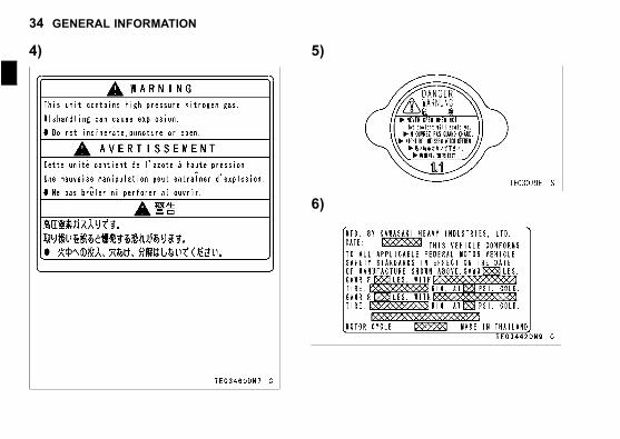
2. Brake Fluid (Rear)3. Battery Poison/Danger4. Rear Shock Absorber Warning
GENERAL INFORMATION 31
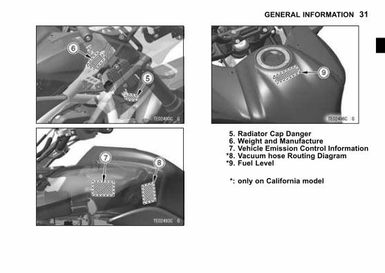
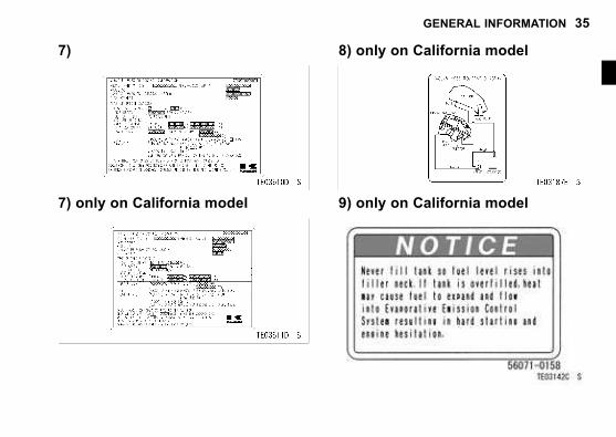
5. Radiator Cap Danger6. Weight and Manufacture7. Vehicle Emission Control Information*8. Vacuum hose Routing Diagram*9. Fuel Level
*: only on California model
32 GENERAL INFORMATION
j
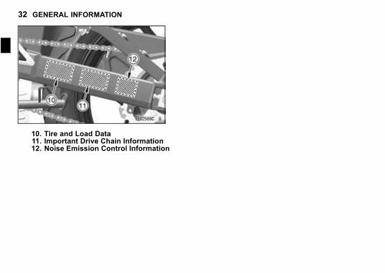
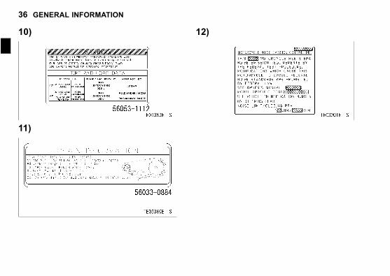
10. Tire and Load Data11. Important Drive Chain Information12. Noise Emission Control Information
GENERAL INFORMATION 33
1)
2)
3)
34 GENERAL INFORMATION
j
4) 5)
6)
GENERAL INFORMATION 35
7)
7) only on California model
8) only on California model
9) only on California model
36 GENERAL INFORMATION
j
10)
11)
12)
GENERAL INFORMATION 37
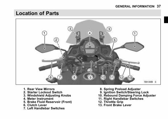
Location of Parts
1. Rear View Mirrors2. Starter Lockout Switch3. Windshield Adjusting Knobs4. Meter Instrument5. Brake Fluid Reservoir (Front)6. Clutch Lever7. Left Handlebar Switches
8. Spring Preload Adjuster9. Ignition Switch/Steering Lock10. Rebound Damping Force Adjuster11. Right Handlebar Switches12. Throttle Grip13. Front Brake Lever
38 GENERAL INFORMATION
j
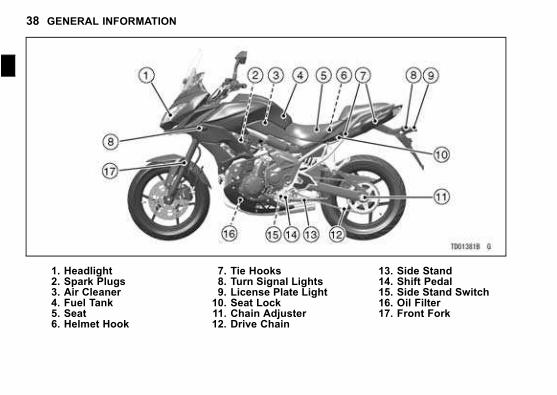
1. Headlight2. Spark Plugs3. Air Cleaner4. Fuel Tank5. Seat6. Helmet Hook
7. Tie Hooks8. Turn Signal Lights9. License Plate Light10. Seat Lock11. Chain Adjuster12. Drive Chain
13. Side Stand14. Shift Pedal15. Side Stand Switch16. Oil Filter17. Front Fork
GENERAL INFORMATION 39
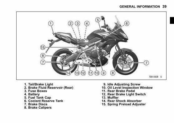
1. Tail/Brake Light2. Brake Fluid Reservoir (Rear)3. Fuse Boxes4. Battery5. Fuel Tank Cap6. Coolant Reserve Tank7. Brake Discs8. Brake Calipers
9. Idle Adjusting Screw10. Oil Level Inspection Window11. Rear Brake Pedal12. Rear Brake Light Switch13. Muffler14. Rear Shock Absorber15. Spring Preload Adjuster
40 GENERAL INFORMATION
j
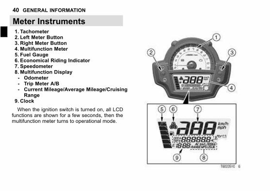
Meter Instruments1. Tachometer2. Left Meter Button3. Right Meter Button4. Multifunction Meter5. Fuel Gauge6. Economical Riding Indicator7. Speedometer8. Multifunction Display- Odometer- Trip Meter A/B- Current Mileage/Average Mileage/CruisingRange
9. Clock
When the ignition switch is turned on, all LCDfunctions are shown for a few seconds, then themultifunction meter turns to operational mode.
GENERAL INFORMATION 41
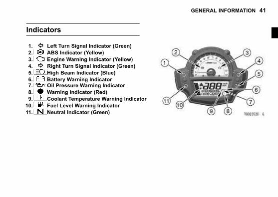
Indicators
1. Left Turn Signal Indicator (Green)
2. ABS Indicator (Yellow)
3. Engine Warning Indicator (Yellow)
4. Right Turn Signal Indicator (Green)
5. High Beam Indicator (Blue)
6. Battery Warning Indicator7. Oil Pressure Warning Indicator
8. Warning Indicator (Red)
9. Coolant Temperature Warning Indicator
10. Fuel Level Warning Indicator
11. Neutral Indicator (Green)
42 GENERAL INFORMATION
j
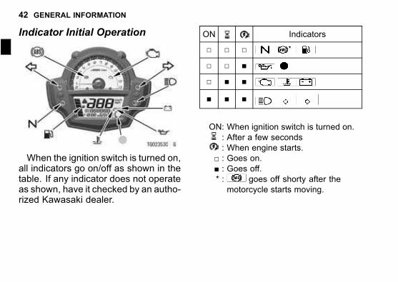
Indicator Initial Operation
When the ignition switch is turned on,all indicators go on/off as shown in thetable. If any indicator does not operateas shown, have it checked by an autho-rized Kawasaki dealer.
ON Indicators
□ □ □
□ □ ■
□ ■ ■
■ ■ ■
ON: When ignition switch is turned on.
: After a few seconds
: When engine starts.
□ : Goes on.■ : Goes off.* : goes off shorty after the
motorcycle starts moving.
GENERAL INFORMATION 43
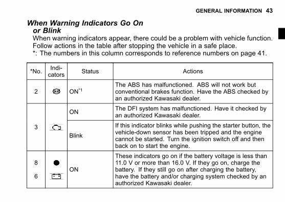
When Warning Indicators Go Onor BlinkWhen warning indicators appear, there could be a problem with vehicle function.Follow actions in the table after stopping the vehicle in a safe place.*: The numbers in this column corresponds to reference numbers on page 41.
*No.Indi-cators
Status Actions
2 ON*1The ABS has malfunctioned. ABS will not work butconventional brakes function. Have the ABS checked byan authorized Kawasaki dealer.
ONThe DFI system has malfunctioned. Have it checked byan authorized Kawasaki dealer.
3
Blink
If this indicator blinks while pushing the starter button, thevehicle-down sensor has been tripped and the enginecannot be started. Turn the ignition switch off and thenback on to start the engine.
8
6ON
These indicators go on if the battery voltage is less than11.0 V or more than 16.0 V. If they go on, charge thebattery. If they still go on after charging the battery,have the battery and/or charging system checked by anauthorized Kawasaki dealer.
44 GENERAL INFORMATION
j*No.
Indi-cators
Status Actions
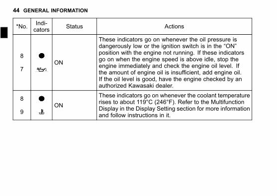
8
7ON
These indicators go on whenever the oil pressure isdangerously low or the ignition switch is in the “ON”position with the engine not running. If these indicatorsgo on when the engine speed is above idle, stop theengine immediately and check the engine oil level. Ifthe amount of engine oil is insufficient, add engine oil.If the oil level is good, have the engine checked by anauthorized Kawasaki dealer.
8
9ON
These indicators go on whenever the coolant temperaturerises to about 119°C (246°F). Refer to the MultifunctionDisplay in the Display Setting section for more informationand follow instructions in it.
GENERAL INFORMATION 45
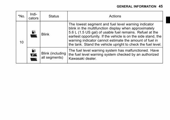
*No.Indi-cators
Status Actions
Blink
The lowest segment and fuel level warning indicatorblink in the multifunction display when approximately5.6 L (1.5 US gal) of usable fuel remains. Refuel at theearliest opportunity. If the vehicle is on the side stand, thewarning indicator cannot estimate the amount of fuel inthe tank. Stand the vehicle upright to check the fuel level.
10
Blink (includingall segments)
The fuel level warning system has malfunctioned. Havethe fuel level warning system checked by an authorizedKawasaki dealer.
46 GENERAL INFORMATION
j
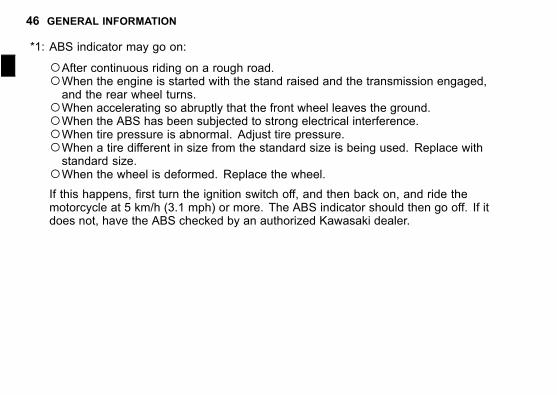
*1: ABS indicator may go on:
○After continuous riding on a rough road.○When the engine is started with the stand raised and the transmission engaged,and the rear wheel turns.
○When accelerating so abruptly that the front wheel leaves the ground.○When the ABS has been subjected to strong electrical interference.○When tire pressure is abnormal. Adjust tire pressure.○When a tire different in size from the standard size is being used. Replace withstandard size.
○When the wheel is deformed. Replace the wheel.If this happens, first turn the ignition switch off, and then back on, and ride themotorcycle at 5 km/h (3.1 mph) or more. The ABS indicator should then go off. If itdoes not, have the ABS checked by an authorized Kawasaki dealer.
GENERAL INFORMATION 47
Other Indicators
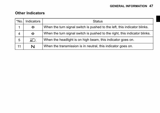
*No. Indicators Status
1 When the turn signal switch is pushed to the left, this indicator blinks.
4 When the turn signal switch is pushed to the right, this indicator blinks.
5 When the headlight is on high beam, this indicator goes on.
11 When the transmission is in neutral, this indicator goes on.
48 GENERAL INFORMATION
j Speedometer/Tachometer
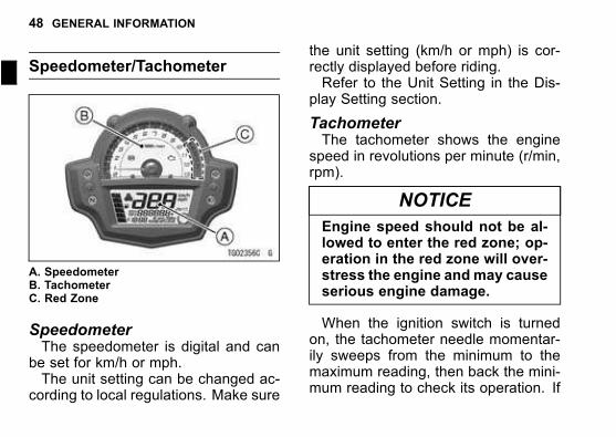
A. SpeedometerB. TachometerC. Red Zone
SpeedometerThe speedometer is digital and can
be set for km/h or mph.The unit setting can be changed ac-
cording to local regulations. Make sure
the unit setting (km/h or mph) is cor-rectly displayed before riding.Refer to the Unit Setting in the Dis-
play Setting section.
TachometerThe tachometer shows the engine
speed in revolutions per minute (r/min,rpm).
NOTICE
Engine speed should not be al-lowed to enter the red zone; op-eration in the red zone will over-stress the engine and may causeserious engine damage.
When the ignition switch is turnedon, the tachometer needle momentar-ily sweeps from the minimum to themaximum reading, then back the mini-mum reading to check its operation. If
GENERAL INFORMATION 49
the tachometer does not operate cor-rectly, have it checked by an authorizedKawasaki dealer.
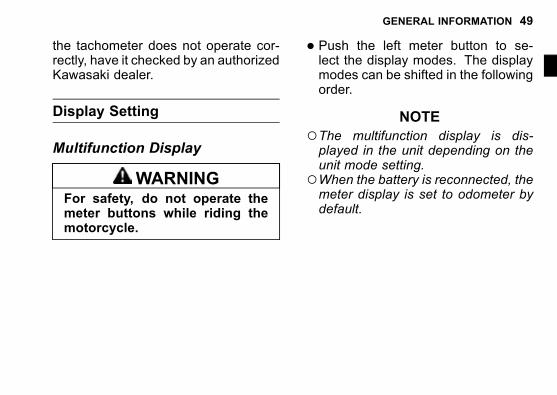
Display Setting
Multifunction Display
WARNINGFor safety, do not operate themeter buttons while riding themotorcycle.
� Push the left meter button to se-lect the display modes. The displaymodes can be shifted in the followingorder.
NOTE
○The multifunction display is dis-played in the unit depending on theunit mode setting.
○When the battery is reconnected, themeter display is set to odometer bydefault.
50 GENERAL INFORMATION
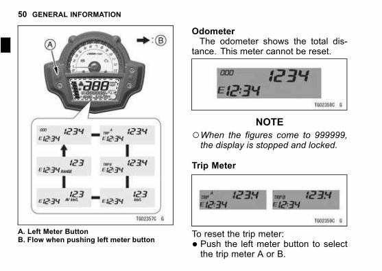
j
A. Left Meter ButtonB. Flow when pushing left meter button
OdometerThe odometer shows the total dis-
tance. This meter cannot be reset.
NOTE
○When the figures come to 999999,the display is stopped and locked.
Trip Meter
To reset the trip meter:
� Push the left meter button to selectthe trip meter A or B.
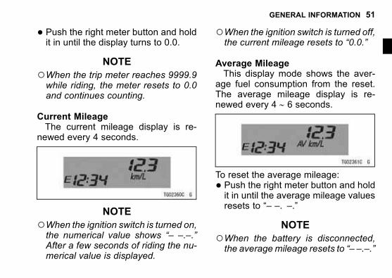
GENERAL INFORMATION 51
� Push the right meter button and holdit in until the display turns to 0.0.
NOTE
○When the trip meter reaches 9999.9while riding, the meter resets to 0.0and continues counting.
Current MileageThe current mileage display is re-
newed every 4 seconds.
NOTE
○When the ignition switch is turned on,the numerical value shows “– –.–.”After a few seconds of riding the nu-merical value is displayed.
○When the ignition switch is turned off,the current mileage resets to “0.0.”
Average MileageThis display mode shows the aver-
age fuel consumption from the reset.The average mileage display is re-newed every 4 ∼ 6 seconds.
To reset the average mileage:
� Push the right meter button and holdit in until the average mileage valuesresets to “– –. –.”
NOTE
○When the battery is disconnected,the average mileage resets to “– –.–.”
52 GENERAL INFORMATION
j
○After resetting the average mileage,the numerical value is not displayeduntil the vehicle has travelled 100 m(328 ft).
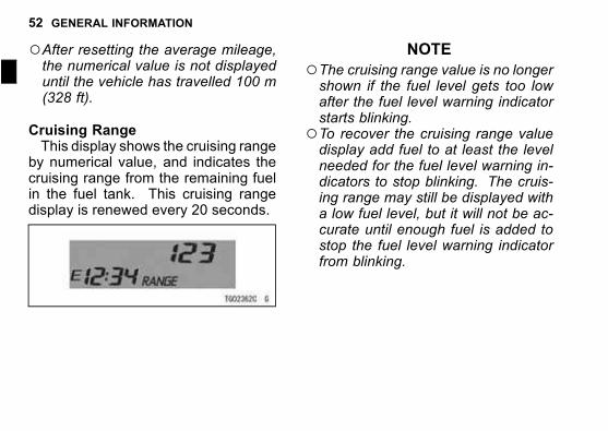
Cruising RangeThis display shows the cruising range
by numerical value, and indicates thecruising range from the remaining fuelin the fuel tank. This cruising rangedisplay is renewed every 20 seconds.
NOTE
○The cruising range value is no longershown if the fuel level gets too lowafter the fuel level warning indicatorstarts blinking.
○To recover the cruising range valuedisplay add fuel to at least the levelneeded for the fuel level warning in-dicators to stop blinking. The cruis-ing range may still be displayed witha low fuel level, but it will not be ac-curate until enough fuel is added tostop the fuel level warning indicatorfrom blinking.
GENERAL INFORMATION 53
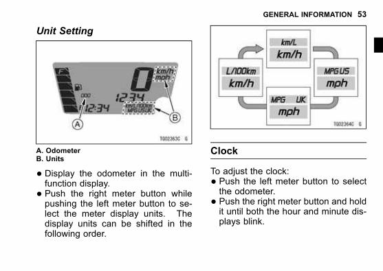
Unit Setting
A. OdometerB. Units
� Display the odometer in the multi-function display.
� Push the right meter button whilepushing the left meter button to se-lect the meter display units. Thedisplay units can be shifted in thefollowing order.
Clock
To adjust the clock:
� Push the left meter button to selectthe odometer.
� Push the right meter button and holdit until both the hour and minute dis-plays blink.
54 GENERAL INFORMATION
j
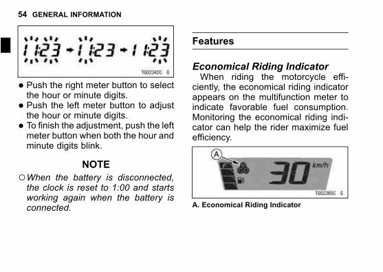
� Push the right meter button to selectthe hour or minute digits.
� Push the left meter button to adjustthe hour or minute digits.
� To finish the adjustment, push the leftmeter button when both the hour andminute digits blink.
NOTE
○When the battery is disconnected,the clock is reset to 1:00 and startsworking again when the battery isconnected.
Features
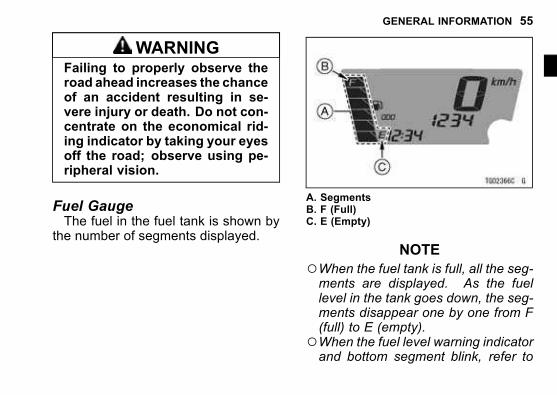
Economical Riding IndicatorWhen riding the motorcycle effi-
ciently, the economical riding indicatorappears on the multifunction meter toindicate favorable fuel consumption.Monitoring the economical riding indi-cator can help the rider maximize fuelefficiency.
A. Economical Riding Indicator
GENERAL INFORMATION 55
WARNINGFailing to properly observe theroad ahead increases the chanceof an accident resulting in se-vere injury or death. Do not con-centrate on the economical rid-ing indicator by taking your eyesoff the road; observe using pe-ripheral vision.
Fuel GaugeThe fuel in the fuel tank is shown by
the number of segments displayed.
A. SegmentsB. F (Full)C. E (Empty)
NOTE
○When the fuel tank is full, all the seg-ments are displayed. As the fuellevel in the tank goes down, the seg-ments disappear one by one from F(full) to E (empty).
○When the fuel level warning indicatorand bottom segment blink, refer to
56 GENERAL INFORMATION
j
the “WhenWarning Indicators Go Onor Blink” of Indicators in this chapter.
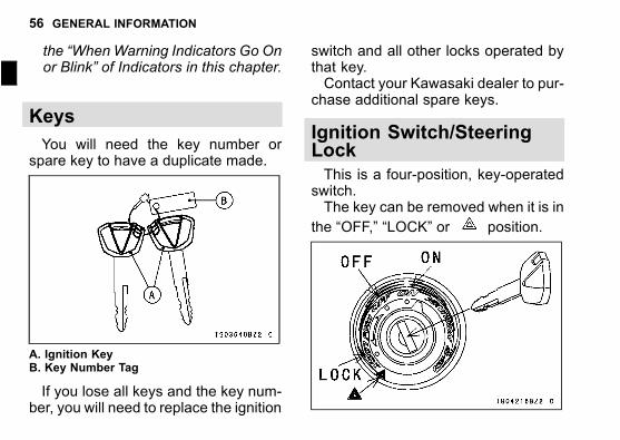
Keys
You will need the key number orspare key to have a duplicate made.
A. Ignition KeyB. Key Number Tag
If you lose all keys and the key num-ber, you will need to replace the ignition
switch and all other locks operated bythat key.Contact your Kawasaki dealer to pur-
chase additional spare keys.
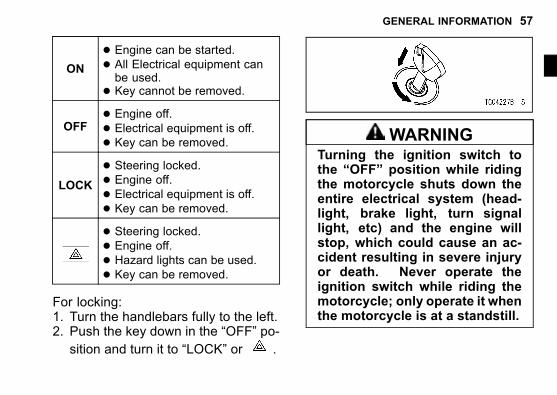
Ignition Switch/SteeringLock
This is a four-position, key-operatedswitch.The key can be removed when it is in
the “OFF,” “LOCK” or position.
GENERAL INFORMATION 57
ON
� Engine can be started.� All Electrical equipment canbe used.
� Key cannot be removed.
OFF� Engine off.� Electrical equipment is off.� Key can be removed.
LOCK
� Steering locked.� Engine off.� Electrical equipment is off.� Key can be removed.� Steering locked.� Engine off.� Hazard lights can be used.� Key can be removed.
For locking:1. Turn the handlebars fully to the left.2. Push the key down in the “OFF” po-
sition and turn it to “LOCK” or .
WARNINGTurning the ignition switch tothe “OFF” position while ridingthe motorcycle shuts down theentire electrical system (head-light, brake light, turn signallight, etc) and the engine willstop, which could cause an ac-cident resulting in severe injuryor death. Never operate theignition switch while riding themotorcycle; only operate it whenthe motorcycle is at a standstill.
58 GENERAL INFORMATION
j
NOTE
○The tail, city and license plate lightsare on whenever the ignition key isin the “ON” position. The headlightgoes on when the starter button isreleased after starting the engine.
○Do not leave the ignition switch at the“ON” position for an extended timewith the engine stopped, or the bat-tery may become totally discharged.
○Do not leave the hazard lightsswitched on for a long time with-out the engine running or the batterywill become discharged.
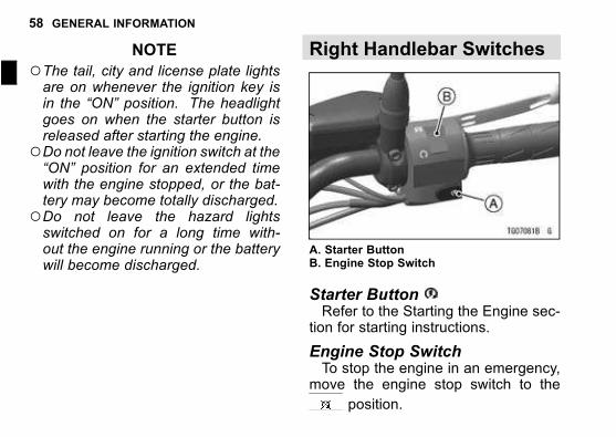
Right Handlebar Switches
A. Starter ButtonB. Engine Stop Switch
Starter ButtonRefer to the Starting the Engine sec-
tion for starting instructions.
Engine Stop SwitchTo stop the engine in an emergency,
move the engine stop switch to the
position.
GENERAL INFORMATION 59
Ordinarily, the engine stop switch
must be in the position for themotorcycle to operate.
NOTE
○Ordinarily, the ignition switch shouldbe used to stop the engine.
○Although the engine stop switchstops the engine, it does not turn offall the electrical circuits and eventu-ally the battery will be discharged.
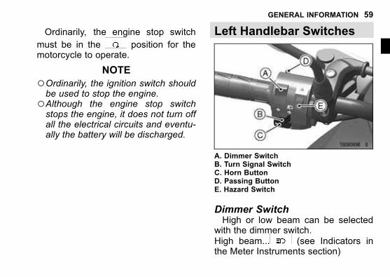
Left Handlebar Switches
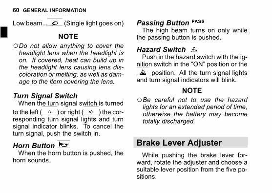
A. Dimmer SwitchB. Turn Signal SwitchC. Horn ButtonD. Passing ButtonE. Hazard Switch
Dimmer SwitchHigh or low beam can be selected
with the dimmer switch.High beam... (see Indicators inthe Meter Instruments section)
60 GENERAL INFORMATION
j
Low beam... (Single light goes on)
NOTE
○Do not allow anything to cover theheadlight lens when the headlight ison. If covered, heat can build up inthe headlight lens causing lens dis-coloration or melting, as well as dam-age to the item covering the lens.
Turn Signal SwitchWhen the turn signal switch is turned
to the left ( ) or right ( ) the cor-responding turn signal lights and turnsignal indicator blinks. To cancel theturn signal, push the switch in.
Horn ButtonWhen the horn button is pushed, the
horn sounds.
Passing ButtonThe high beam turns on only while
the passing button is pushed.
Hazard SwitchPush in the hazard switch with the ig-
nition switch in the “ON” position or the
position. All the turn signal lightsand turn signal indicators will blink.
NOTE
○Be careful not to use the hazardlights for an extended period of time,otherwise the battery may becometotally discharged.
Brake Lever Adjuster
While pushing the brake lever for-ward, rotate the adjuster and choose asuitable lever position from the five po-sitions.
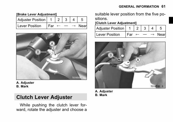
GENERAL INFORMATION 61
[Brake Lever Adjustment]
Adjuster Position 1 2 3 4 5
Lever Position Far ← — → Near
A. AdjusterB. Mark
Clutch Lever Adjuster
While pushing the clutch lever for-ward, rotate the adjuster and choose a
suitable lever position from the five po-sitions.[Clutch Lever Adjustment]
Adjuster Position 1 2 3 4 5
Lever Position Far ← — → Near
A. AdjusterB. Mark
62 GENERAL INFORMATION
j
Fuel
WARNINGGasoline is extremely flammableand can be explosive under cer-tain conditions, creating the po-tential for serious burns. Turnthe ignition switch off.Do not smoke.Make sure the area is well ven-tilated and free from any sourceof flame or sparks; this includesany appliance with a pilot light.
Fuel Requirements
Use clean, flesh unleaded gasolinewith the following conditions.
� Antiknock Index of 87 or more� Up to 10% of ethanol contained
NOTICE
Use only unleaded gasoline.Never use leaded gasoline.Leaded gasoline significantlyreduces the capability of the cat-alytic converter in the exhaustsystem.
NOTICE
Use minimum of 87 octane gaso-line only to prevent severe en-gine damage.
GENERAL INFORMATION 63
NOTICE
If engine “knocking” or “ping-ing”occurs, use a differentbrand of gasoline of a higheroctane rating. If this condition isallowed to continue it can leadto severe engine damage. Gaso-line quality is important. Fuelsof low quality or not meetingstandard industry specificationsmay result in unsatisfactory per-formance. Operating problemsthat result from the use of poorquality or nonrecommended fuelmay not be covered under yourwarranty.
NOTICE
Avoid using blends of unleadedgasoline and methanol (wood al-cohol) whenever possible, andnever use “gasohol” containingmore than 5% methanol.Fuel system damage and perfor-mance problems may result.
NOTE
○Other oxygenates approved for usein unleaded gasoline include TAME(up to 16.7%) and ETBE (up to17.2%). Fuel containing these oxy-genates can also be used in yourKawasaki.
64 GENERAL INFORMATION
j
NOTICE
Never use gasoline with an oc-tane rating lower than the min-imum specified by Kawasaki.Never use “gasohol” with morethan 10% ethanol, or more than5% methanol.Gasoline containing methanolmust also be blended with cosol-vents and corrosion inhibitors.Certain ingredients of gasolinemay cause paint fading or dam-age. Be extra careful not to spillgasoline or gasoline oxygenateblends during refueling.When not operating yourKawasaki for 30 to 60 days, mix afuel stabilizer (such as STA-BIL)with the gasoline in the fuel tank.Fuel stabilizer additives inhibitoxidation of the fuel which mini-mizes gummy deposits.
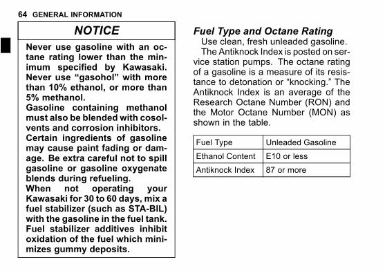
Fuel Type and Octane RatingUse clean, fresh unleaded gasoline.The Antiknock Index is posted on ser-
vice station pumps. The octane ratingof a gasoline is a measure of its resis-tance to detonation or “knocking.” TheAntiknock Index is an average of theResearch Octane Number (RON) andthe Motor Octane Number (MON) asshown in the table.
Fuel Type Unleaded Gasoline
Ethanol Content E10 or less
Antiknock Index 87 or more
GENERAL INFORMATION 65
NOTICE
Do not use any fuel that con-tains more ethanol or other oxy-genates than specified for E10fuel* in this vehicle. Damageto the engine and fuel system,or engine starting and/or per-formance problems may resultfrom the use of improper fuel.
*E10 means fuel containing up to 10%ethanol.
Filling the Tank
Avoid filling the tank in the rain orwhere heavy dust is blowing so that thefuel does not get contaminated.
WARNINGGasoline is extremely flammableand can be explosive under cer-tain conditions, creating the po-tential for serious burns. Turnthe ignition switch off. Do notsmoke.Make sure the area is well ven-tilated and free from any sourceof flame or sparks; this includesany appliance with a pilot light.Never fill the tank completely tothe top.If the tank is filled completely tothe top, heat may cause the fuelto expand and overflow throughthe vents in the tank cap.After refueling, make sure thetank cap is closed securely.If gasoline is spilled on the fueltank, wipe it off immediately.
66 GENERAL INFORMATION
j
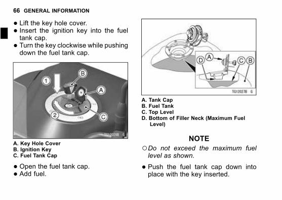
� Lift the key hole cover.� Insert the ignition key into the fueltank cap.
� Turn the key clockwise while pushingdown the fuel tank cap.
A. Key Hole CoverB. Ignition KeyC. Fuel Tank Cap
� Open the fuel tank cap.� Add fuel.
A. Tank CapB. Fuel TankC. Top LevelD. Bottom of Filler Neck (Maximum Fuel
Level)
NOTE
○Do not exceed the maximum fuellevel as shown.
� Push the fuel tank cap down intoplace with the key inserted.
GENERAL INFORMATION 67
� The key can be removed by turningcounterclockwise to the original po-sition.
� Close the key hole cover.
NOTICE
Never fill the tank completely tothe top.If the tank is filled completely tothe top, heat may cause the fuelto expand and overflow throughthe vents in the tank cap.After refueling, make sure thetank cap is closed securely.If gasoline is spilled on the fueltank, wipe it off immediately.
NOTE
○The fuel tank cap cannot be closedwithout the key inserted, and the key
cannot be removed unless the cap islocked properly.
○Do not push on the key to close thecap, or the cap cannot be locked.
Side Stand
Always kick the stand fully up beforemoving the motorcycle. The engine willstop automatically if themotorcycle is ingear and the clutch is released with theside stand down.
NOTE
○When using the side stand, turn thehandlebars to the left.
○Make sure the side stand is down se-curely before leaving the motorcycle.
○Do not sit on the motorcycle while itis on its side stand.
68 GENERAL INFORMATION
j
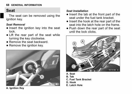
Seat
The seat can be removed using theignition key.
Seat Removal
� Insert the ignition key into the seatlock.
� Lift the rear part of the seat whileturning the key clockwise.
� Remove the seat backward.� Remove the ignition key.
A. Ignition Key
Seat Installation
� Insert the tab at the front part of theseat under the fuel tank bracket.
� Insert the hook at the rear part of theseat into the latch hole on the frame.
� Push down the rear part of the seatuntil the lock clicks.
A. SeatB. TabC. Fuel Tank BracketD. HookE. Latch Hole
GENERAL INFORMATION 69
� Lift the front and rear ends of theseat to make sure they are securelylocked.
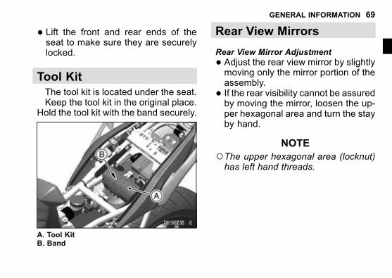
Tool Kit
The tool kit is located under the seat.Keep the tool kit in the original place.
Hold the tool kit with the band securely.
A. Tool KitB. Band
Rear View Mirrors
Rear View Mirror Adjustment
� Adjust the rear view mirror by slightlymoving only the mirror portion of theassembly.
� If the rear visibility cannot be assuredby moving the mirror, loosen the up-per hexagonal area and turn the stayby hand.
NOTE
○The upper hexagonal area (locknut)has left hand threads.
70 GENERAL INFORMATION
j
A. Rear View MirrorB. StayC. Rubber BootD. Upper Hexagonal AreaE. Lower Hexagonal Area
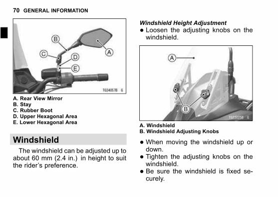
Windshield
The windshield can be adjusted up toabout 60 mm (2.4 in.) in height to suitthe rider’s preference.
Windshield Height Adjustment
� Loosen the adjusting knobs on thewindshield.
A. WindshieldB. Windshield Adjusting Knobs
�When moving the windshield up ordown.
� Tighten the adjusting knobs on thewindshield.
� Be sure the windshield is fixed se-curely.
GENERAL INFORMATION 71
Tie Hooks
When securing light loads to the seat,use the tie hooks located at the left andright grab rails.
A. Tie Hooks
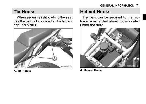
Helmet Hooks
Helmets can be secured to the mo-torcycle using the helmet hooks locatedunder the seat.
A. Helmet Hooks
72 GENERAL INFORMATION
j
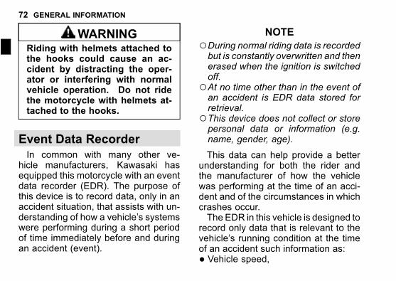
WARNINGRiding with helmets attached tothe hooks could cause an ac-cident by distracting the oper-ator or interfering with normalvehicle operation. Do not ridethe motorcycle with helmets at-tached to the hooks.
Event Data Recorder
In common with many other ve-hicle manufacturers, Kawasaki hasequipped this motorcycle with an eventdata recorder (EDR). The purpose ofthis device is to record data, only in anaccident situation, that assists with un-derstanding of how a vehicle’s systemswere performing during a short periodof time immediately before and duringan accident (event).
NOTE
○During normal riding data is recordedbut is constantly overwritten and thenerased when the ignition is switchedoff.
○At no time other than in the event ofan accident is EDR data stored forretrieval.
○This device does not collect or storepersonal data or information (e.g.name, gender, age).
This data can help provide a betterunderstanding for both the rider andthe manufacturer of how the vehiclewas performing at the time of an acci-dent and of the circumstances in whichcrashes occur.The EDR in this vehicle is designed to
record only data that is relevant to thevehicle’s running condition at the timeof an accident such information as:
� Vehicle speed,
GENERAL INFORMATION 73
� Engine crankshaft rotational speed,and
� Throttle opening.To access information on an EDR,
special equipment and access to theEDR is required. Kawasaki will notshare EDR information without obtain-ing your consent, unless required bygovernment authorities, or acting pur-suant to lawful authority.
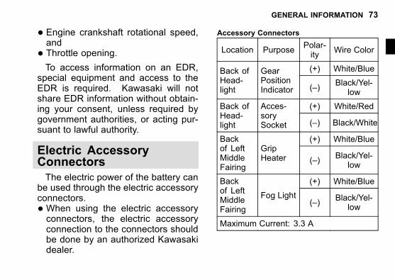
Electric AccessoryConnectors
The electric power of the battery canbe used through the electric accessoryconnectors.
�When using the electric accessoryconnectors, the electric accessoryconnection to the connectors shouldbe done by an authorized Kawasakidealer.
Accessory Connectors
Location PurposePolar-ity
Wire Color
(+) White/BlueBack ofHead-light
GearPositionIndicator (–)
Black/Yel-low
(+) White/RedBack ofHead-light
Acces-sorySocket (–) Black/White
(+) White/BlueBackof LeftMiddleFairing
GripHeater (–)
Black/Yel-low
(+) White/BlueBackof LeftMiddleFairing
Fog Light(–)
Black/Yel-low
Maximum Current: 3.3 A

74 GENERAL INFORMATION
j
A. For Gear Position IndicatorB. For Accessory Socket
A. For Grip HeaterB. For Fog Light
GENERAL INFORMATION 75
NOTICE
The vehicle has electrical acces-sory circuit (5 A fuse) for thesocket and connectors. Alwaysinstall a fuse 5 A or less for thecircuit. Do not connect morethan 40 W of total load to the ve-hicle’s electrical system or thebattery may become discharge,even with the engine running.
76 HOW TO RIDE THE MOTORCYCLE
j
HOW TO RIDE THE MOTORCYCLE
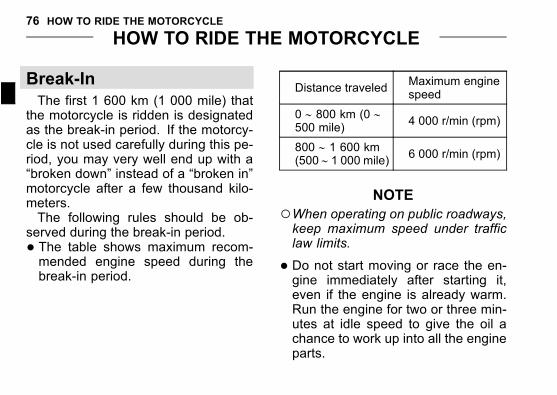
Break-In
The first 1 600 km (1 000 mile) thatthe motorcycle is ridden is designatedas the break-in period. If the motorcy-cle is not used carefully during this pe-riod, you may very well end up with a“broken down” instead of a “broken in”motorcycle after a few thousand kilo-meters.The following rules should be ob-
served during the break-in period.
� The table shows maximum recom-mended engine speed during thebreak-in period.
Distance traveledMaximum enginespeed
0 ∼ 800 km (0 ∼500 mile)
4 000 r/min (rpm)
800 ∼ 1 600 km(500 ∼ 1 000 mile) 6 000 r/min (rpm)
NOTE
○When operating on public roadways,keep maximum speed under trafficlaw limits.
� Do not start moving or race the en-gine immediately after starting it,even if the engine is already warm.Run the engine for two or three min-utes at idle speed to give the oil achance to work up into all the engineparts.
HOW TO RIDE THE MOTORCYCLE 77
� Do not race the engine while thetransmission is in neutral.
WARNINGNew tires are slippery and maycause loss of control and injury.A break-in period of 160 km (100miles) is necessary to estab-lish normal tire traction. Duringbreak-in, avoid sudden and max-imum braking and acceleration,and hard cornering.
In addition to the above, at 1 000km (600 mile) it is extremely importantthat the owner has the initial mainte-nance service performed by an autho-rized Kawasaki dealer.
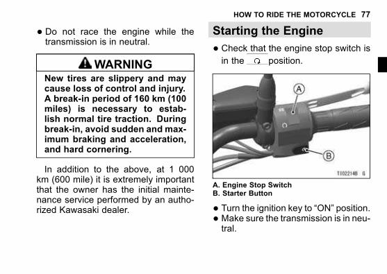
Starting the Engine
� Check that the engine stop switch isin the position.
A. Engine Stop SwitchB. Starter Button
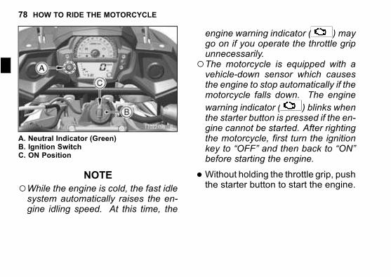
� Turn the ignition key to “ON” position.� Make sure the transmission is in neu-tral.
78 HOW TO RIDE THE MOTORCYCLE
j
A. Neutral Indicator (Green)B. Ignition SwitchC. ON Position
NOTE
○While the engine is cold, the fast idlesystem automatically raises the en-gine idling speed. At this time, the
engine warning indicator ( ) maygo on if you operate the throttle gripunnecessarily.
○The motorcycle is equipped with avehicle-down sensor which causesthe engine to stop automatically if themotorcycle falls down. The engine
warning indicator ( ) blinks whenthe starter button is pressed if the en-gine cannot be started. After rightingthe motorcycle, first turn the ignitionkey to “OFF” and then back to “ON”before starting the engine.
�Without holding the throttle grip, pushthe starter button to start the engine.
HOW TO RIDE THE MOTORCYCLE 79
NOTICE
Do not operate the starter con-tinuously for more than 5 sec-onds, or the starter will overheatand the battery power will droptemporarily. Wait 15 secondsbetween each operation of thestarter to let it cool and the bat-tery power recover.
NOTE
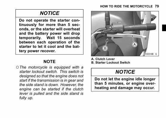
○The motorcycle is equipped with astarter lockout switch. This switch isdesigned so that the engine does notstart if the transmission is in gear andthe side stand is down. However, theengine can be started if the clutchlever is pulled and the side stand isfully up.
A. Clutch LeverB. Starter Lockout Switch
NOTICE
Do not let the engine idle longerthan 5 minutes, or engine over-heating and damage may occur.
80 HOW TO RIDE THE MOTORCYCLE
j
Jump Starting
If your motorcycle battery is “rundown,” it should be removed andcharged. If this is not practical, a 12volt booster battery and jumper cablesmay be used to start the engine.
DANGER
� Battery acid generates hydro-gen gas which is flammableand explosive under certainconditions. It is present withina battery at all times, even in adischarged condition. Keep allflames and sparks (cigarettes)away from the battery.
�Wear eye protection whenworking with a battery. In theevent of battery acid contactwith skin, eyes, or clothing,wash the affected areas imme-diately with water for at leastfive minutes. Seek medical at-tention.
Connecting Jumper Cables
� Make sure the ignition switch isturned off.
HOW TO RIDE THE MOTORCYCLE 81
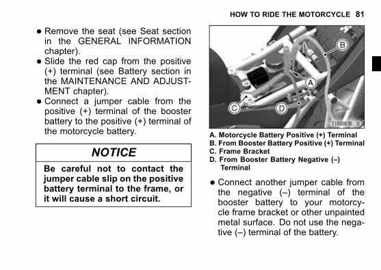
� Remove the seat (see Seat sectionin the GENERAL INFORMATIONchapter).
� Slide the red cap from the positive(+) terminal (see Battery section inthe MAINTENANCE AND ADJUST-MENT chapter).
� Connect a jumper cable from thepositive (+) terminal of the boosterbattery to the positive (+) terminal ofthe motorcycle battery.
NOTICE
Be careful not to contact thejumper cable slip on the positivebattery terminal to the frame, orit will cause a short circuit.
A. Motorcycle Battery Positive (+) TerminalB. From Booster Battery Positive (+) TerminalC. Frame BracketD. From Booster Battery Negative (–)
Terminal
� Connect another jumper cable fromthe negative (–) terminal of thebooster battery to your motorcy-cle frame bracket or other unpaintedmetal surface. Do not use the nega-tive (–) terminal of the battery.
82 HOW TO RIDE THE MOTORCYCLE
j
DANGERBatteries contain sulfuric acidthat can cause burns and pro-duce hydrogen gas which ishighly explosive.
� Do not make this last connec-tion at the fuel system or bat-tery.
� Take care not to touch the pos-itive and negative cables to-gether, and do not lean overthe battery when making thislast connection.
� Do not connect to a frozen bat-tery. It could explode.
� Do not reverse polarity by con-necting positive (+) to negative(–), or a battery explosion andserious damage to the electri-cal system may occur.
� Follow the standard engine startingprocedure.
NOTICE
Do not operate the starter con-tinuously for more than 5 sec-onds or the starter will overheatand the battery power will droptemporarily. Wait 15 secondsbetween each operation of thestarter to let it cool and the bat-tery power recover.
� After the engine has started, discon-nect the jumper cables. Disconnectthe negative (–) cable from the mo-torcycle first.
� Install the removed parts.
Moving Off
� Check that the side stand is up.
HOW TO RIDE THE MOTORCYCLE 83
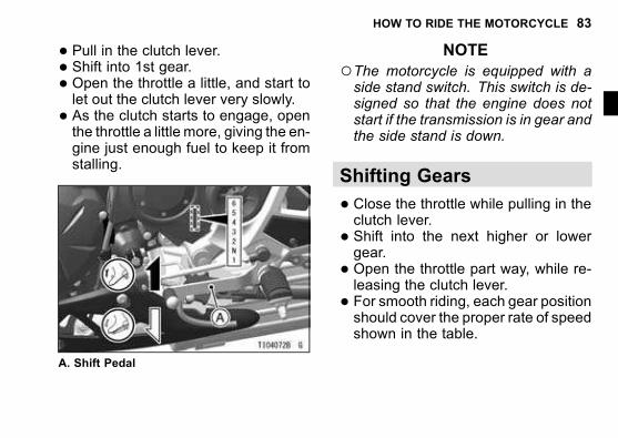
� Pull in the clutch lever.� Shift into 1st gear.� Open the throttle a little, and start tolet out the clutch lever very slowly.
� As the clutch starts to engage, openthe throttle a little more, giving the en-gine just enough fuel to keep it fromstalling.
A. Shift Pedal
NOTE
○The motorcycle is equipped with aside stand switch. This switch is de-signed so that the engine does notstart if the transmission is in gear andthe side stand is down.
Shifting Gears
� Close the throttle while pulling in theclutch lever.
� Shift into the next higher or lowergear.
� Open the throttle part way, while re-leasing the clutch lever.
� For smooth riding, each gear positionshould cover the proper rate of speedshown in the table.
84 HOW TO RIDE THE MOTORCYCLE
j
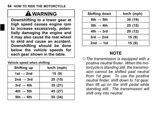
WARNINGDownshifting to a lower gear athigh speed causes engine rpmto increase excessively, poten-tially damaging the engine andit may also cause the rear wheelto skid and cause an accident.Downshifting should be donebelow the vehicle speeds foreach gear shown in the table.
Vehicle speed when shifting
Shifting up km/h (mph)
1st → 2nd 15 (9)
2nd → 3rd 25 (15)
3rd → 4th 35 (21)
4th → 5th 45 (27)
5th → 6th 55 (34)
Shifting down km/h (mph)
6th → 5th 30 (19)
5th → 4th 25 (15)
4th → 3rd 20 (12)
3rd → 2nd 15 (9)
2nd → 1st 15 (9)
NOTE
○The transmission is equipped with apositive neutral finder. When the mo-torcycle is standing still, the transmis-sion cannot be shifted past neutralfrom 1st gear. To use the positiveneutral finder, shift down to 1st gear,then lift up on the shift pedal whilestanding still. The transmission willshift only into neutral.
HOW TO RIDE THE MOTORCYCLE 85
Braking
� Close the throttle completely, leav-ing the clutch engaged (except whenshifting gears) so that the engine willhelp slow down the motorcycle.
� Shift down one gear at a time so thatyou are in 1st gear when you cometo a complete stop.
�When stopping, always apply bothbrakes at the same time. Normallythe front brake should be applied a lit-tle more than the rear. Shift down orfully disengage the clutch as neces-sary to keep the engine from stalling.
� Never lock the brakes, or it will causethe tires to skid. When turning a cor-ner, it is better not to brake at all. Re-duce your speed before you get intothe corner.
� For emergency braking, disregarddownshifting, and concentrate on
applying the brakes as hard as pos-sible without skidding.
� Even in motorcycles equipped withABS, braking during cornering maycause wheel slip. When turning acorner, it is better to limit braking tothe light application of both brakesor not to brake at all. Reduce yourspeed before you get into the corner.
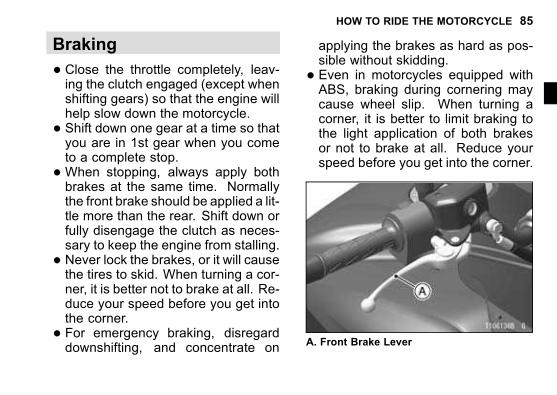
A. Front Brake Lever
86 HOW TO RIDE THE MOTORCYCLE
j
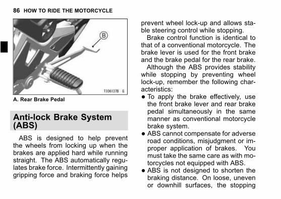
A. Rear Brake Pedal
Anti-lock Brake System(ABS)
ABS is designed to help preventthe wheels from locking up when thebrakes are applied hard while runningstraight. The ABS automatically regu-lates brake force. Intermittently gaininggripping force and braking force helps
prevent wheel lock-up and allows sta-ble steering control while stopping.Brake control function is identical to
that of a conventional motorcycle. Thebrake lever is used for the front brakeand the brake pedal for the rear brake.Although the ABS provides stability
while stopping by preventing wheellock-up, remember the following char-acteristics:
� To apply the brake effectively, usethe front brake lever and rear brakepedal simultaneously in the samemanner as conventional motorcyclebrake system.
� ABS cannot compensate for adverseroad conditions, misjudgment or im-proper application of brakes. Youmust take the same care as with mo-torcycles not equipped with ABS.
� ABS is not designed to shorten thebraking distance. On loose, unevenor downhill surfaces, the stopping
HOW TO RIDE THE MOTORCYCLE 87
distance of a motorcycle with ABSmay be longer than that of an equiv-alent motorcycle without ABS. Usespecial caution in such areas.
� ABS will help prevent wheel lock-upwhen braking in a straight line, but itcannot control wheel slip which maybe caused by braking during corner-ing. When turning a corner, it is bet-ter to limit braking to the light appli-cation of both brakes or not to brakeat all. Reduce your speed before youget into the corner.
� Same as conventional brake system,an excessive sudden braking maycause wheel lock up that makes itharder to control a motorcycle.
� During braking, ABS will not preventthe rear wheel lifting.
WARNINGABS cannot protect the riderfrom all possible hazards andis not a substitute for safe rid-ing practices. Be aware of howthe ABS system operates andits limitations. It is the rider’sresponsibility to ride at appro-priate speeds and manner forweather, road surface and trafficconditions.
� The computers integrated in the ABScompare vehicle speed with wheelspeed. Since non-recommendedtires can affect wheel speed, theymay confuse the computers, whichcan extend braking distance.
88 HOW TO RIDE THE MOTORCYCLE
j
WARNINGUse of non-recommended tiresmay cause malfunctioning ofABS and can lead to extendedbraking distance. The ridercould have an accident as a re-sult. Always use recommendedstandard tires for this motorcy-cle.
NOTE
○When the ABS is functioning, youmay feel a pulsing in the brake leveror pedal. This is normal. You neednot suspend applying brakes.
○ABS does not function at speeds ofapprox. 5 km/h (3.1 mph) or below.
○ABS does not function if the batteryis discharged. When riding with aninsufficiently charged battery, ABSmay not function. Keep the battery
in good condition according to the“Battery Maintenance” section.
Stopping the Engine
� Close the throttle completely.� Shift the transmission into neutral.� Turn the ignition key to “OFF.”� Support the motorcycle on a firm,level surface with the side stand.
� Lock the steering.NOTE
○The motorcycle is equipped with avehicle-down sensor which causesthe engine to stop automatically if themotorcycle falls down. The engine
warning indicator ( ) blinks whenthe starter button is pressed if the en-gine cannot be started. After rightingthe motorcycle, first turn the ignition
HOW TO RIDE THE MOTORCYCLE 89
key to “OFF” and then back to “ON”before starting the engine.
Stopping the Motorcycle inan Emergency
Your Kawasaki Motorcycle has beendesigned and manufactured to pro-vide you optimum safety and conve-nience. However, in order to fully ben-efit from Kawasaki’s safety engineeringand craftsmanship, it is essential thatyou, the owner and operator, properlymaintain your motorcycle and becomethoroughly familiar with its operation.Improper maintenance can create adangerous situation known as throt-tle failure. Two of the most commoncauses of throttle failure are:
1. An improperly serviced or cloggedair cleaner may allow dirt and dustto enter the throttle body and stickthe throttle open.
2. During removal of the air cleaner,dirt is allowed to enter and jam thefuel injection system.
In an emergency situation such asthrottle failure, your vehicle may bestopped by applying the brakes anddisengaging the clutch. Once thisstopping procedure is initiated, the en-gine stop switch may be used to stopthe engine. If the engine stop switch isused, turn off the ignition switch afterstopping the motorcycle.
90 HOW TO RIDE THE MOTORCYCLE
j
Parking
WARNINGOperating or parking the vehi-cle near flammablematerials cancause a fire, and can result inproperty damage or severe per-sonal injury.Do not idle or park your vehiclein an area where tall or dry veg-etation, or other flammable ma-terials could come into contactwith the muffler or exhaust pipe.
WARNINGThe engine and exhaust systemget extremely hot during normaloperation and can cause seriousburns.Never touch a hot engine, ex-haust pipe, or muffler during op-eration or after stopping the en-gine.
� Shift the transmission into neutraland turn the ignition key to “OFF.”
� Support the motorcycle on a firm,level surface with the side stand.
NOTICE
Do not park on a soft or steeplyinclined surface, or the motorcy-cle may fall over.
� If parking inside a garage or otherstructure, be sure it is well ventilated
HOW TO RIDE THE MOTORCYCLE 91
and the motorcycle is not close toany source of flame or sparks; thisincludes any appliance with a pilotlight.
WARNINGGasoline is extremely flammableand can be explosive under cer-tain conditions, creating the po-tential for serious burns. Turnthe ignition switch off. Do notsmoke. Make sure the area iswell ventilated and free from anysource of flame or sparks; thisincludes any appliance with a pi-lot light.
� Lock the steering to help preventtheft.
NOTE
○When stopping near traffic at night,you can leave the turn signal lightsblinking for greater visibility by turn-
ing the ignition key to the posi-tion and push in the hazard switch.
92 MAINTENANCE AND ADJUSTMENT
j
MAINTENANCE AND ADJUSTMENT
The maintenance and adjustments outlined in this chapter must be carried out inaccordance with the Daily Checks and Periodic Maintenance to keep the motorcy-cle in good running condition and to reduce air pollution. The initial maintenanceis vitally important and must not be neglected.
WARNINGFailure to perform these checks or to correct a problem before opera-tion may result in serious damage or an accident. Always perform dailychecks before operation.
With a basic knowledge of mechanics and the proper use of tools, you should beable to carry out many of the maintenance items described in this chapter. If youlack proper experience or doubt your ability, all adjustments, maintenance, andrepair work should be completed by a qualified technician.Please note that Kawasaki cannot assume any responsibility for damage result-
ing from incorrect or improper adjustment made by the owner.
MAINTENANCE AND ADJUSTMENT 93
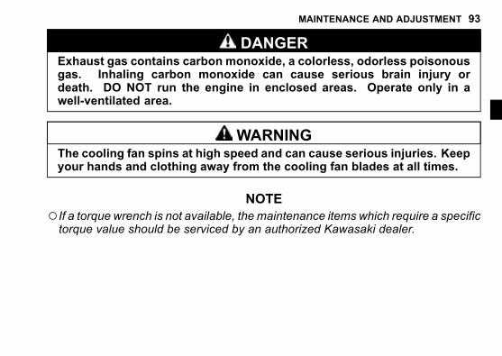
DANGERExhaust gas contains carbon monoxide, a colorless, odorless poisonousgas. Inhaling carbon monoxide can cause serious brain injury ordeath. DO NOT run the engine in enclosed areas. Operate only in awell-ventilated area.
WARNINGThe cooling fan spins at high speed and can cause serious injuries. Keepyour hands and clothing away from the cooling fan blades at all times.
NOTE
○If a torque wrench is not available, the maintenance items which require a specifictorque value should be serviced by an authorized Kawasaki dealer.
94 MAINTENANCE AND ADJUSTMENT
j
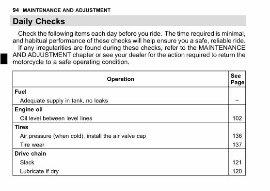
Daily Checks
Check the following items each day before you ride. The time required is minimal,and habitual performance of these checks will help ensure you a safe, reliable ride.If any irregularities are found during these checks, refer to the MAINTENANCE
AND ADJUSTMENT chapter or see your dealer for the action required to return themotorcycle to a safe operating condition.
OperationSeePage
Fuel
Adequate supply in tank, no leaks –
Engine oil
Oil level between level lines 102
Tires
Air pressure (when cold), install the air valve cap 136
Tire wear 137
Drive chain
Slack 121
Lubricate if dry 120
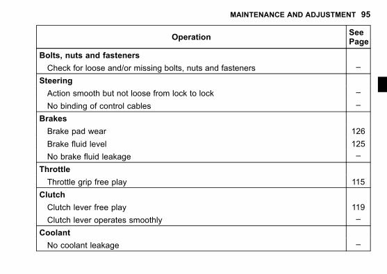
MAINTENANCE AND ADJUSTMENT 95
OperationSeePage
Bolts, nuts and fasteners
Check for loose and/or missing bolts, nuts and fasteners –
Steering
Action smooth but not loose from lock to lock –
No binding of control cables –
Brakes
Brake pad wear 126
Brake fluid level 125
No brake fluid leakage –
Throttle
Throttle grip free play 115
Clutch
Clutch lever free play 119
Clutch lever operates smoothly –
Coolant
No coolant leakage –
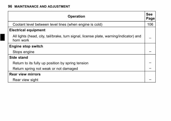
96 MAINTENANCE AND ADJUSTMENT
j
OperationSeePage
Coolant level between level lines (when engine is cold) 106
Electrical equipment
All lights (head, city, tail/brake, turn signal, license plate, warning/indicator) andhorn work
–
Engine stop switch
Stops engine –
Side stand
Return to its fully up position by spring tension –
Return spring not weak or not damaged –
Rear view mirrors
Rear view sight –
MAINTENANCE AND ADJUSTMENT 97
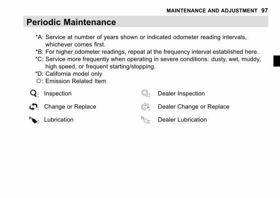
Periodic Maintenance
*A: Service at number of years shown or indicated odometer reading intervals,
whichever comes first.
*B: For higher odometer readings, repeat at the frequency interval established here.
*C: Service more frequently when operating in severe conditions: dusty, wet, muddy,
high speed, or frequent starting/stopping.
*D: California model only
○: Emission Related Item: Inspection : Dealer Inspection
: Change or Replace : Dealer Change or Replace
: Lubrication : Dealer Lubrication
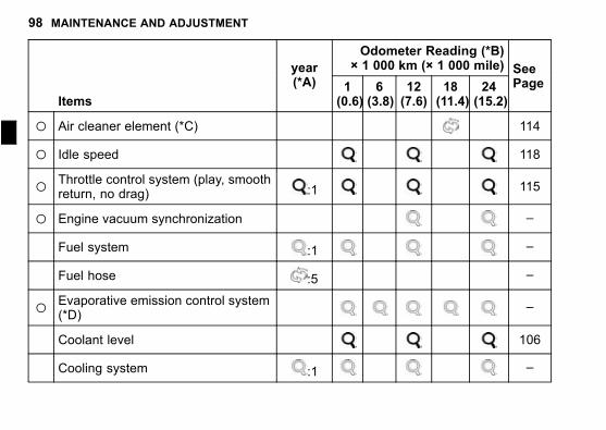
98 MAINTENANCE AND ADJUSTMENT
j
Odometer Reading (*B)× 1 000 km (× 1 000 mile)
Items
year(*A) 1
(0.6)6(3.8)
12(7.6)
18(11.4)
24(15.2)
SeePage
○ Air cleaner element (*C) 114
○ Idle speed 118
○ Throttle control system (play, smoothreturn, no drag) :1 115
○ Engine vacuum synchronization –
Fuel system :1 –
Fuel hose :5 –
○ Evaporative emission control system(*D)
–
Coolant level 106
Cooling system :1 –
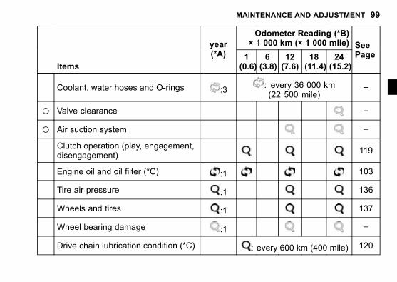
MAINTENANCE AND ADJUSTMENT 99
Odometer Reading (*B)× 1 000 km (× 1 000 mile)
Items
year(*A) 1
(0.6)6(3.8)
12(7.6)
18(11.4)
24(15.2)
SeePage
Coolant, water hoses and O-rings :3: every 36 000 km(22 500 mile)
–
○ Valve clearance –
○ Air suction system –
Clutch operation (play, engagement,disengagement)
119
Engine oil and oil filter (*C) :1 103
Tire air pressure :1 136
Wheels and tires :1 137
Wheel bearing damage :1 –
Drive chain lubrication condition (*C) : every 600 km (400 mile) 120
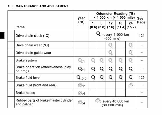
100 MAINTENANCE AND ADJUSTMENT
j
Odometer Reading (*B)× 1 000 km (× 1 000 mile)
Items
year(*A) 1
(0.6)6(3.8)
12(7.6)
18(11.4)
24(15.2)
SeePage
Drive chain slack (*C) : every 1 000 km(600 mile)
121
Drive chain wear (*C) –
Drive chain guide wear –
Brake system :1 –
Brake operation (effectiveness, play,no drag) :1 –
Brake fluid level :0.5 125
Brake fluid (front and rear) :2 –
Brake hoses :4 –
Rubber parts of brake master cylinderand caliper :4
: every 48 000 km(30 000 mile)
–
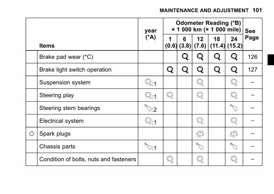
MAINTENANCE AND ADJUSTMENT 101
Odometer Reading (*B)× 1 000 km (× 1 000 mile)
Items
year(*A) 1
(0.6)6(3.8)
12(7.6)
18(11.4)
24(15.2)
SeePage
Brake pad wear (*C) 126
Brake light switch operation 127
Suspension system :1 –
Steering play :1 –
Steering stem bearings :2 –
Electrical system :1 –
○ Spark plugs –
Chassis parts :1 –
Condition of bolts, nuts and fasteners –
102 MAINTENANCE AND ADJUSTMENT
j
Engine Oil
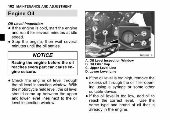
Oil Level Inspection
� If the engine is cold, start the engineand run it for several minutes at idlespeed.
� Stop the engine, then wait severalminutes until the oil settles.
NOTICE
Racing the engine before the oilreaches every part can cause en-gine seizure.
� Check the engine oil level throughthe oil level inspection window. Withthe motorcycle held level, the oil levelshould come up between the upperand lower level lines next to the oillevel inspection window.
A. Oil Level Inspection WindowB. Oil Filler CapC. Upper Level LineD. Lower Level Line
� If the oil level is too high, remove theexcess oil through the oil filler open-ing using a syringe or some othersuitable device.
� If the oil level is too low, add oil toreach the correct level. Use thesame type and brand of oil that isalready in the engine.
MAINTENANCE AND ADJUSTMENT 103
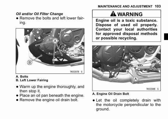
Oil and/or Oil Filter Change
� Remove the bolts and left lower fair-ing.
A. BoltsB. Left Lower Fairing
�Warm up the engine thoroughly, andthen stop it.
� Place an oil pan beneath the engine.� Remove the engine oil drain bolt.
WARNINGEngine oil is a toxic substance.Dispose of used oil properly.Contact your local authoritiesfor approved disposal methodsor possible recycling.
A. Engine Oil Drain Bolt
� Let the oil completely drain withthe motorcycle perpendicular to theground.
104 MAINTENANCE AND ADJUSTMENT
j
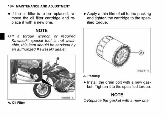
� If the oil filter is to be replaced, re-move the oil filter cartridge and re-place it with a new one.
NOTE
○If a torque wrench or requiredKawasaki special tool is not avail-able, this item should be serviced byan authorized Kawasaki dealer.
A. Oil Filter
� Apply a thin film of oil to the packingand tighten the cartridge to the spec-ified torque.
A. Packing
� Install the drain bolt with a new gas-ket. Tighten it to the specified torque.
NOTE
○Replace the gasket with a new one.
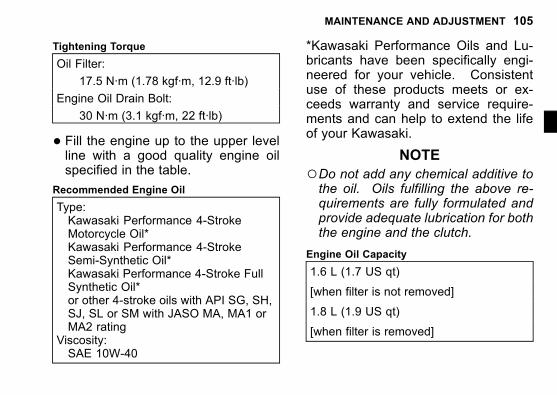
MAINTENANCE AND ADJUSTMENT 105
Tightening Torque
Oil Filter:
17.5 N·m (1.78 kgf·m, 12.9 ft·lb)
Engine Oil Drain Bolt:
30 N·m (3.1 kgf·m, 22 ft·lb)
� Fill the engine up to the upper levelline with a good quality engine oilspecified in the table.
Recommended Engine Oil
Type:Kawasaki Performance 4-StrokeMotorcycle Oil*Kawasaki Performance 4-StrokeSemi-Synthetic Oil*Kawasaki Performance 4-Stroke FullSynthetic Oil*or other 4-stroke oils with API SG, SH,SJ, SL or SM with JASO MA, MA1 orMA2 rating
Viscosity:SAE 10W-40
*Kawasaki Performance Oils and Lu-bricants have been specifically engi-neered for your vehicle. Consistentuse of these products meets or ex-ceeds warranty and service require-ments and can help to extend the lifeof your Kawasaki.
NOTE
○Do not add any chemical additive tothe oil. Oils fulfilling the above re-quirements are fully formulated andprovide adequate lubrication for boththe engine and the clutch.
Engine Oil Capacity
1.6 L (1.7 US qt)
[when filter is not removed]
1.8 L (1.9 US qt)
[when filter is removed]
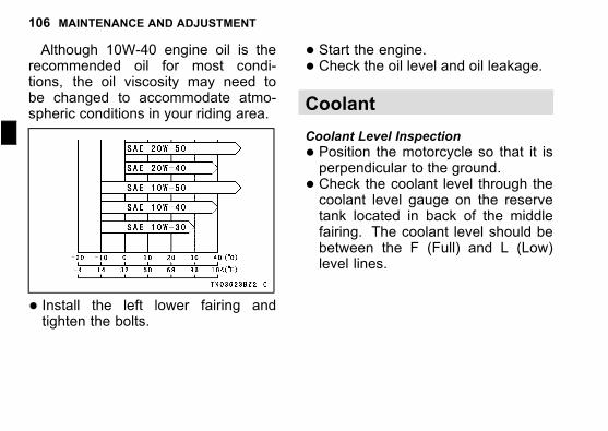
106 MAINTENANCE AND ADJUSTMENT
j
Although 10W-40 engine oil is therecommended oil for most condi-tions, the oil viscosity may need tobe changed to accommodate atmo-spheric conditions in your riding area.
� Install the left lower fairing andtighten the bolts.
� Start the engine.� Check the oil level and oil leakage.
Coolant
Coolant Level Inspection
� Position the motorcycle so that it isperpendicular to the ground.
� Check the coolant level through thecoolant level gauge on the reservetank located in back of the middlefairing. The coolant level should bebetween the F (Full) and L (Low)level lines.
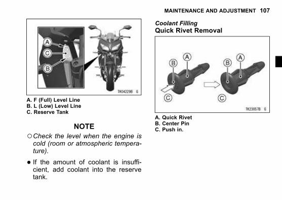
MAINTENANCE AND ADJUSTMENT 107
A. F (Full) Level LineB. L (Low) Level LineC. Reserve Tank
NOTE
○Check the level when the engine iscold (room or atmospheric tempera-ture).
� If the amount of coolant is insuffi-cient, add coolant into the reservetank.
Coolant Filling
Quick Rivet Removal
A. Quick RivetB. Center PinC. Push in.
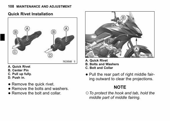
108 MAINTENANCE AND ADJUSTMENT
j
Quick Rivet Installation
A. Quick RivetB. Center PinC. Pull up fully.D. Push in.
� Remove the quick rivet.� Remove the bolts and washers.� Remove the bolt and collar.
A. Quick RivetB. Bolts and WashersC. Bolt and Collar
� Pull the rear part of right middle fair-ing outward to clear the projections.
NOTE
○To protect the hook and tab, hold themiddle part of middle fairing.
MAINTENANCE AND ADJUSTMENT 109
A. Projections
� Clear the hook and tab of the middlefairing from the inner cover.
A. HookB. TabC. Inner Cover
� Pull the front part of middle fairingoutward to clear the projections.
110 MAINTENANCE AND ADJUSTMENT
j
A. Projections
� Disconnect the right turn signal lightlead connector, and remove the rightmiddle fairing.
A. Right Turn Signal Light Lead Connector
� Remove the cap from the reservetank and add coolant through thefiller opening to the F (Full) level line.
MAINTENANCE AND ADJUSTMENT 111
A. Reserve Tank Cap
NOTE
○In an emergency you can add wa-ter alone to the coolant reserve tank,however it must be returned to thecorrect mixture ratio by the additionof antifreeze concentrate as soon aspossible.
NOTICE
If coolant must be added of-ten, or the reserve tank com-pletely runs dry, there is proba-bly leakage in the system. Havethe cooling system inspectedby your authorized Kawasakidealer.
� Install the reserve tank cap.� Connect the right turn signal lightlead connector.
� Insert the projections at the front partof middle fairing into the grommetson the upper fairing.
112 MAINTENANCE AND ADJUSTMENT
j
A. ProjectionsB. Grommets
� Insert the hook and tab on the mid-dle fairing into the slots on the innercover.
A. HookB. TabC. Slots
� Insert the projections at the rear partof middle fairing into the grommetson the fuel tank and frame.
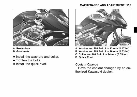
MAINTENANCE AND ADJUSTMENT 113
A. ProjectionsB. Grommets
� Install the washers and collar.� Tighten the bolts.� Install the quick rivet.
A. Washer and M5 Bolt, L = 12 mm (0.47 in.)B. Washer and M5 Bolt, L = 16 mm (0.63 in.)C. Collar and M6 Bolt, L = 14 mm (0.55 in.)D. Quick Rivet
Coolant Change
Have the coolant changed by an au-thorized Kawasaki dealer.
114 MAINTENANCE AND ADJUSTMENT
j
Coolant Requirement
WARNINGCoolant containing corrosion in-hibitors for aluminum enginesand radiators include harm-ful chemicals for human body.Drinking coolant can result inserious injury or death. Usecoolant in accordance with theinstructions of themanufacturer.
Use a permanent type of antifreeze(soft water and ethylene glycol plus cor-rosion and rust inhibitor chemicals foraluminum engines and radiators) in thecooling system. On the mixture ratioof coolant, choose the suitable one re-ferring to the relation between freezingpoint and strength directed on the con-tainer.
NOTICE
If hard water is used in the sys-tem, it causes scale accumula-tion in the water passages, andconsiderably reduces the effi-ciency of the cooling system.
NOTE
○A permanent type of antifreeze is in-stalled in the cooling system whenshipped. It is mixed at 50% and hasthe freezing point of –35°C (–31°F).
Air Cleaner
This motorcycle’s air cleaner elementconsists of a wet paper filter. Cleaningand replacement of the air cleaner ele-ment should be done by an authorizedKawasaki dealer.
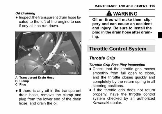
MAINTENANCE AND ADJUSTMENT 115
Oil Draining
� Inspect the transparent drain hose lo-cated to the left of the engine to seeif any oil has run down.
A. Transparent Drain HoseB. ClampC. Plug
� If there is any oil in the transparentdrain hose, remove the clamp andplug from the lower end of the drainhose, and drain the oil.
WARNINGOil on tires will make them slip-pery and can cause an accidentand injury. Be sure to install theplug in the drain hose after drain-ing.
Throttle Control System
Throttle Grip
Throttle Grip Free Play Inspection
� Check that the throttle grip movessmoothly from full open to close,and the throttle closes quickly andcompletely by the return spring in allsteering positions.
� If the throttle grip does not returnproperly, have the throttle controlsystem checked by an authorizedKawasaki dealer.
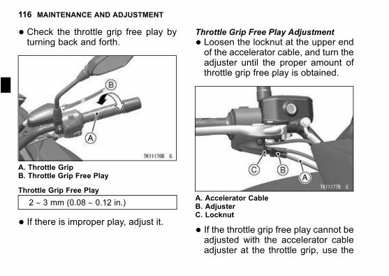
116 MAINTENANCE AND ADJUSTMENT
j
� Check the throttle grip free play byturning back and forth.
A. Throttle GripB. Throttle Grip Free Play
Throttle Grip Free Play
2 ∼ 3 mm (0.08 ∼ 0.12 in.)
� If there is improper play, adjust it.
Throttle Grip Free Play Adjustment
� Loosen the locknut at the upper endof the accelerator cable, and turn theadjuster until the proper amount ofthrottle grip free play is obtained.
A. Accelerator CableB. AdjusterC. Locknut
� If the throttle grip free play cannot beadjusted with the accelerator cableadjuster at the throttle grip, use the
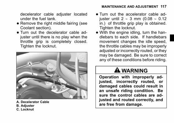
MAINTENANCE AND ADJUSTMENT 117
decelerator cable adjuster locatedunder the fuel tank.
� Remove the right middle fairing (seeCoolant section).
� Turn out the decelerator cable ad-juster until there is no play when thethrottle grip is completely closed.Tighten the locknut.
A. Decelerator CableB. AdjusterC. Locknut
� Turn out the accelerator cable ad-juster until 2 ∼ 3 mm (0.08 ∼ 0.12in.) of throttle grip play is obtained.Tighten the locknut.
�With the engine idling, turn the han-dlebars to each side. If handlebarsmovement changes the idle speed,the throttle cables may be improperlyadjusted or incorrectly routed, or theymay be damaged. Be sure to correctany of these conditions before riding.
WARNINGOperation with improperly ad-justed, incorrectly routed, ordamaged cables could result inan unsafe riding condition. Besure the control cables are ad-justed and routed correctly, andare free from damage.
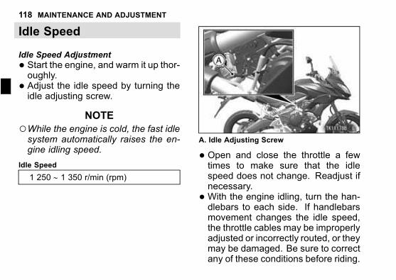
118 MAINTENANCE AND ADJUSTMENT
j
Idle Speed
Idle Speed Adjustment
� Start the engine, and warm it up thor-oughly.
� Adjust the idle speed by turning theidle adjusting screw.
NOTE
○While the engine is cold, the fast idlesystem automatically raises the en-gine idling speed.
Idle Speed
1 250 ∼ 1 350 r/min (rpm)
A. Idle Adjusting Screw
� Open and close the throttle a fewtimes to make sure that the idlespeed does not change. Readjust ifnecessary.
�With the engine idling, turn the han-dlebars to each side. If handlebarsmovement changes the idle speed,the throttle cables may be improperlyadjusted or incorrectly routed, or theymay be damaged. Be sure to correctany of these conditions before riding.
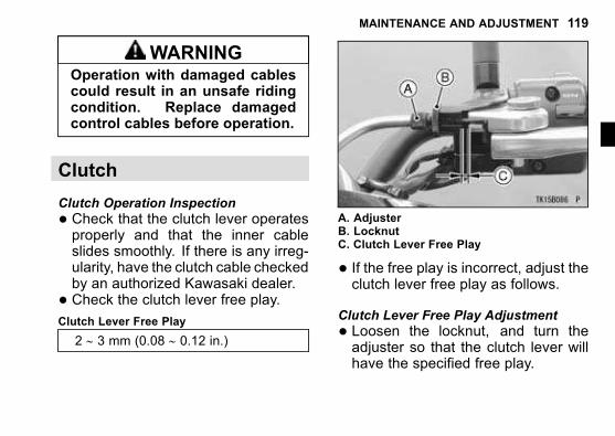
MAINTENANCE AND ADJUSTMENT 119
WARNINGOperation with damaged cablescould result in an unsafe ridingcondition. Replace damagedcontrol cables before operation.
Clutch
Clutch Operation Inspection
� Check that the clutch lever operatesproperly and that the inner cableslides smoothly. If there is any irreg-ularity, have the clutch cable checkedby an authorized Kawasaki dealer.
� Check the clutch lever free play.Clutch Lever Free Play
2 ∼ 3 mm (0.08 ∼ 0.12 in.)
A. AdjusterB. LocknutC. Clutch Lever Free Play
� If the free play is incorrect, adjust theclutch lever free play as follows.
Clutch Lever Free Play Adjustment
� Loosen the locknut, and turn theadjuster so that the clutch lever willhave the specified free play.
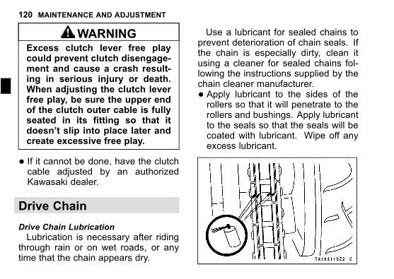
120 MAINTENANCE AND ADJUSTMENT
j
WARNINGExcess clutch lever free playcould prevent clutch disengage-ment and cause a crash result-ing in serious injury or death.When adjusting the clutch leverfree play, be sure the upper endof the clutch outer cable is fullyseated in its fitting so that itdoesn’t slip into place later andcreate excessive free play.
� If it cannot be done, have the clutchcable adjusted by an authorizedKawasaki dealer.
Drive Chain
Drive Chain Lubrication
Lubrication is necessary after ridingthrough rain or on wet roads, or anytime that the chain appears dry.
Use a lubricant for sealed chains toprevent deterioration of chain seals. Ifthe chain is especially dirty, clean itusing a cleaner for sealed chains fol-lowing the instructions supplied by thechain cleaner manufacturer.
� Apply lubricant to the sides of therollers so that it will penetrate to therollers and bushings. Apply lubricantto the seals so that the seals will becoated with lubricant. Wipe off anyexcess lubricant.

MAINTENANCE AND ADJUSTMENT 121
�Wipe off any lubricant that gets on thetire surface.
Drive Chain Slack Inspection
� Set the motorcycle up on its sidestand.
� Clean the chain if it is dirty, and lubri-cate it if it appears dry.
� Rotate the rear wheel to find the po-sition where the chain is tightest, andmeasure the maximum chain slackby pulling up and pushing down thechain midway between the enginesprocket and rear wheel sprocket.
A. Chain Slack
� If the drive chain is too tight or tooloose, adjust it so that the chain slackis within the standard value.
Drive Chain Slack
Standard: 25 ∼ 35 mm (1.0 ∼ 1.4 in.)
Drive Chain Slack Adjustment
� Loosen the left and right chain ad-juster locknuts.
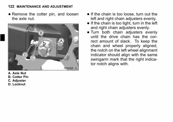
122 MAINTENANCE AND ADJUSTMENT
j
� Remove the cotter pin, and loosenthe axle nut.
A. Axle NutB. Cotter PinC. AdjusterD. Locknut
� If the chain is too loose, turn out theleft and right chain adjusters evenly.
� If the chain is too tight, turn in the leftand right chain adjusters evenly.
� Turn both chain adjusters evenlyuntil the drive chain has the cor-rect amount of slack. To keep thechain and wheel properly aligned,the notch on the left wheel alignmentindicator should align with the sameswingarm mark that the right indica-tor notch aligns with.
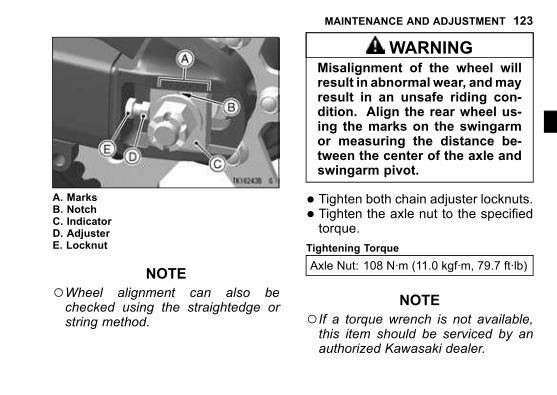
MAINTENANCE AND ADJUSTMENT 123
A. MarksB. NotchC. IndicatorD. AdjusterE. Locknut
NOTE
○Wheel alignment can also bechecked using the straightedge orstring method.
WARNINGMisalignment of the wheel willresult in abnormal wear, andmayresult in an unsafe riding con-dition. Align the rear wheel us-ing the marks on the swingarmor measuring the distance be-tween the center of the axle andswingarm pivot.
� Tighten both chain adjuster locknuts.� Tighten the axle nut to the specifiedtorque.
Tightening Torque
Axle Nut: 108 N·m (11.0 kgf·m, 79.7 ft·lb)
NOTE
○If a torque wrench is not available,this item should be serviced by anauthorized Kawasaki dealer.
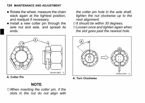
124 MAINTENANCE AND ADJUSTMENT
j
� Rotate the wheel, measure the chainslack again at the tightest position,and readjust if necessary.
� Install a new cotter pin through theaxle nut and axle, and spread itsends.
A. Cotter Pin
NOTE
○When inserting the cotter pin, if theslots in the nut do not align with
the cotter pin hole in the axle shaft,tighten the nut clockwise up to thenext alignment.
○It should be within 30 degrees.○Loosen once and tighten again whenthe slot goes past the nearest hole.
A. Turn Clockwise
MAINTENANCE AND ADJUSTMENT 125
WARNINGA loose axle nut can lead to anaccident resulting in serious in-jury or death. Tighten the axlenut to the proper torque and in-stall a new cotter pin.
� Check the rear brake (see Brakessection).
Brakes
If you feel there is something wrongwhen applying the brakes, have thebrake system checked by an autho-rized Kawasaki dealer immediately.
WARNINGAir in the brake lines diminishbraking performance and cancause an accident resulting ininjury or death. If the brake leveror pedal feels mushy when itis applied, there might be air inthe brake lines or the brake maybe defective. Have the brakechecked immediately by an au-thorized Kawasaki dealer.
Brake Fluid Level Inspection
�With the front brake fluid reservoirheld horizontal, the brake fluid levelmust be above the lower level line.
126 MAINTENANCE AND ADJUSTMENT
j
A. Front Brake Fluid ReservoirB. Lower Level Line
�With the rear brake fluid reservoirheld horizontal, the brake fluid levelmust be kept between the upper andlower level lines.
A. Rear Brake Fluid ReservoirB. Upper Level LineC. Lower Level Line
� If the fluid level is lower than thelower level line it may indicate thatthe fluid is leaking. In this case, havethe brake system inspected by an au-thorized Kawasaki dealer.
Brake Pad Wear Inspection
Inspect the brakes for wear. For eachfront and rear disc brake caliper, if the
MAINTENANCE AND ADJUSTMENT 127
thickness of either pad lining is lessthan 1 mm (0.04 in.), replace both padsin the caliper as a set. Pad replace-ment should be done by an authorizedKawasaki dealer.
A. Front Brake PadsB. Lining ThicknessC. 1 mm (0.04 in.)
A. Rear Brake PadsB. Lining ThicknessC. 1 mm (0.04 in.)
Brake Light Switches
Brake Light Switch Inspection
� Turn the ignition switch on.� The brake light should go on whenthe front brake is applied.
128 MAINTENANCE AND ADJUSTMENT
j
� If it does not, ask your authorizedKawasaki dealer to inspect the frontbrake light switch.
� Check the operation of the rear brakelight switch by depressing the brakepedal. The brake light should go onafter the proper pedal travel.
A. Brake PedalB. 12 mm (0.47 in.)
� If the light does not come on, adjustthe rear brake light switch.
Brake Pedal Travel
12 mm (0.47 in.)
Brake Light Switch Adjustment
� To adjust the rear brake light switch,move the switch up or down by turn-ing the adjusting nut.
A. Rear Brake Light SwitchB. Adjusting NutC. Lights soonerD. Lights later
MAINTENANCE AND ADJUSTMENT 129
NOTICE
To avoid damaging the electricalconnections inside the switch,be sure that the switch bodydoes not turn during adjustment.
Suspension System
Front Fork
Spring Preload Adjustment
The adjuster is located at the top ofleft front fork leg.Standard
6 1/2 turns in
In from the fully seated position (turnedfully counterclockwise).
� Turn the adjuster clockwise to in-crease spring preload and stiffen thesuspension.
� Turn the adjuster counterclockwiseto decrease spring preload andsoften the suspension.
NOTICE
Do not turn the adjuster beyondthe fully seated position or theadjusting mechanism may bedamaged.
NOTE
○The spring preload adjuster can beturned with the allen wrench or suit-able tool.
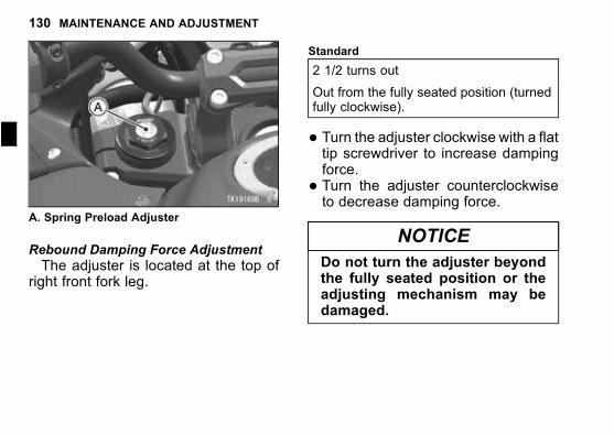
130 MAINTENANCE AND ADJUSTMENT
j
A. Spring Preload Adjuster
Rebound Damping Force Adjustment
The adjuster is located at the top ofright front fork leg.
Standard
2 1/2 turns out
Out from the fully seated position (turnedfully clockwise).
� Turn the adjuster clockwise with a flattip screwdriver to increase dampingforce.
� Turn the adjuster counterclockwiseto decrease damping force.
NOTICE
Do not turn the adjuster beyondthe fully seated position or theadjusting mechanism may bedamaged.
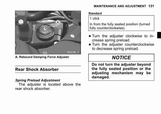
MAINTENANCE AND ADJUSTMENT 131
A. Rebound Damping Force Adjuster
Rear Shock Absorber
Spring Preload Adjustment
The adjuster is located above therear shock absorber.
Standard
1 click
In from the fully seated position (turnedfully counterclockwise).
� Turn the adjuster clockwise to in-crease spring preload.
� Turn the adjuster counterclockwiseto decrease spring preload.
NOTICE
Do not turn the adjuster beyondthe fully seated position or theadjusting mechanism may bedamaged.
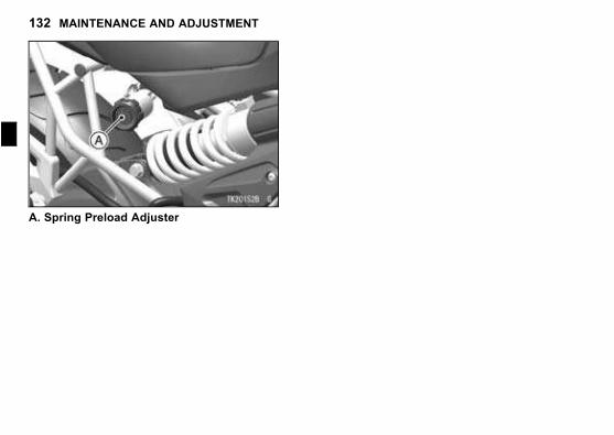
132 MAINTENANCE AND ADJUSTMENT
j
A. Spring Preload Adjuster
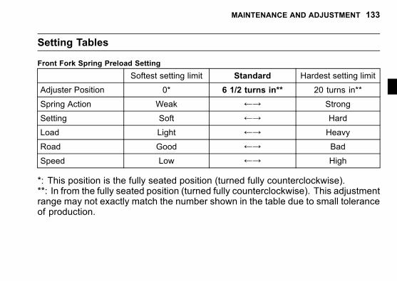
MAINTENANCE AND ADJUSTMENT 133
Setting Tables
Front Fork Spring Preload Setting
Softest setting limit Standard Hardest setting limit
Adjuster Position 0* 6 1/2 turns in** 20 turns in**
Spring Action Weak ←→ Strong
Setting Soft ←→ Hard
Load Light ←→ Heavy
Road Good ←→ Bad
Speed Low ←→ High
*: This position is the fully seated position (turned fully counterclockwise).**: In from the fully seated position (turned fully counterclockwise). This adjustmentrange may not exactly match the number shown in the table due to small toleranceof production.
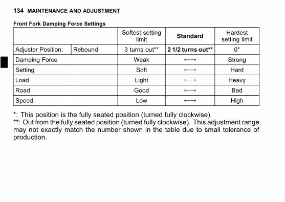
134 MAINTENANCE AND ADJUSTMENT
j
Front Fork Damping Force Settings
Softest settinglimit
StandardHardest
setting limit
Adjuster Position: Rebound 3 turns out** 2 1/2 turns out** 0*
Damping Force Weak ←→ Strong
Setting Soft ←→ Hard
Load Light ←→ Heavy
Road Good ←→ Bad
Speed Low ←→ High
*: This position is the fully seated position (turned fully clockwise).**: Out from the fully seated position (turned fully clockwise). This adjustment rangemay not exactly match the number shown in the table due to small tolerance ofproduction.
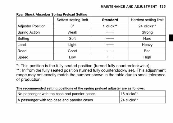
MAINTENANCE AND ADJUSTMENT 135
Rear Shock Absorber Spring Preload Setting
Softest setting limit Standard Hardest setting limit
Adjuster Position 0* 1 click** 24 clicks**
Spring Action Weak ←→ Strong
Setting Soft ←→ Hard
Load Light ←→ Heavy
Road Good ←→ Bad
Speed Low ←→ High
*: This position is the fully seated position (turned fully counterclockwise).**: In from the fully seated position (turned fully counterclockwise). This adjustmentrange may not exactly match the number shown in the table due to small toleranceof production.
The recommended setting positions of the spring preload adjuster are as follows:
No passenger with top case and pannier cases 16 clicks**
A passenger with top case and pannier cases 24 clicks**
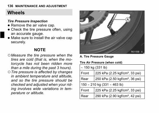
136 MAINTENANCE AND ADJUSTMENT
j
Wheels
Tire Pressure Inspection
� Remove the air valve cap.� Check the tire pressure often, usingan accurate gauge.
� Make sure to install the air valve capsecurely.
NOTE
○Measure the tire pressure when thetires are cold (that is, when the mo-torcycle has not been ridden morethan a mile during the past 3 hours).
○Tire pressure is affected by changesin ambient temperature and altitude,and so the tire pressure should bechecked and adjusted when your rid-ing involves wide variations in tem-perature or altitude.
A. Tire Pressure Gauge
Tire Air Pressure (when cold)
∼ 150 kg (331 lb)
Front 225 kPa (2.25 kgf/cm², 33 psi)
Rear 250 kPa (2.50 kgf/cm², 36 psi)
150 ∼ 210 kg (331 ∼ 463 lb)
Front 225 kPa (2.25 kgf/cm², 33 psi)
Rear 290 kPa (2.90 kgf/cm², 42 psi)
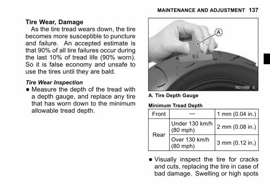
MAINTENANCE AND ADJUSTMENT 137
Tire Wear, DamageAs the tire tread wears down, the tire
becomes more susceptible to punctureand failure. An accepted estimate isthat 90% of all tire failures occur duringthe last 10% of tread life (90% worn).So it is false economy and unsafe touse the tires until they are bald.
Tire Wear Inspection
� Measure the depth of the tread witha depth gauge, and replace any tirethat has worn down to the minimumallowable tread depth.
A. Tire Depth Gauge
Minimum Tread Depth
Front — 1 mm (0.04 in.)
Under 130 km/h(80 mph)
2 mm (0.08 in.)
RearOver 130 km/h(80 mph)
3 mm (0.12 in.)
� Visually inspect the tire for cracksand cuts, replacing the tire in case ofbad damage. Swelling or high spots
138 MAINTENANCE AND ADJUSTMENT
j
indicate internal damage, requiringtire replacement.
A. Crack or CutB. NailC. Swelling or High SpotD. Stone
� Remove any imbedded stones orother foreign particles from the tread.
NOTE
○Have the wheel balance inspectedwhenever a new tire is installed.
WARNINGTires that have been puncturedand repaired do not have thesame capabilities as undam-aged tires and can suddenly fail,causing an accident resultingin serious injury or death. Re-place damaged tires as soon aspossible. To ensure safe han-dling and stability, use only therecommended standard tires forreplacement, inflated to the stan-dard pressure. If it is necessaryto ride on a repaired tire, do notexceed 100 km/h (60 mph) untilthe tire is replaced.
NOTE
○When operating on public roadways,keep maximum speed under trafficlaw limits.
MAINTENANCE AND ADJUSTMENT 139
Standard Tire (Tubeless)
Front
Make, Type:DUNLOP, D222F J
Size:120/70ZR17 M/C (58W)
Rear
Make, Type:DUNLOP, D222 J
Size:160/60ZR17 M/C (69W)
WARNINGMixing tire brands and types canadversely affect handling andcause an accident resulting ininjury or death. Always use thesame manufacturer’s tires onboth front and rear wheels.
WARNINGNew tires are slippery and maycause loss of control and injury.A break-in period of 160 km (100miles) is necessary to estab-lish normal tire traction. Duringbreak-in, avoid sudden and max-imum braking and acceleration,and hard cornering.
Battery
The battery installed in this motorcy-cle is a sealed type, so it is not nec-essary to check the battery electrolytelevel or add distilled water.
140 MAINTENANCE AND ADJUSTMENT
j
NOTICE
Never remove the sealing strip,or the battery can be damaged.Do not install a conventionalbattery in this motorcycle, or theelectrical system cannot workproperly.
Make Siam Furukawa
Type FTX12-BS
Battery MaintenanceIt is the owner’s responsibility to keep
the battery fully charged. Failure to doso can lead to battery failure and leaveyou stranded.If you are riding your vehicle infre-
quently, inspect the battery voltageweekly using a voltmeter. If it dropsbelow 12.6 volts, the battery should becharged using an appropriate charger(check with your Kawasaki dealer).
If you will not be using the motorcy-cle for longer than two weeks, thebattery should be charged using anappropriate charger. Do not use an au-tomotive-type quick charger that mayovercharge the battery and damage it.
NOTE
○Leaving the battery connectedcauses the electrical components(clock etc) to make the battery dis-charged, resulting the over dischargeof the battery. In this case, the repairor replacement of the battery is notincluded in the warranty. If you donot drive for four weeks or more, dis-connect the battery from the vehicle.
Kawasaki-recommended chargers are:
Battery Mate 150-9OptiMate 4Yuasa MB-2040/2060Christie C10122S
MAINTENANCE AND ADJUSTMENT 141
If the above chargers are not avail-able, use equivalent one.For more details, ask your Kawasaki
dealer.
Battery Charging
� Charge the battery following the in-structions of your battery charger.
� The charger will keep the battery fullycharged until you are ready to re-install the battery in the motorcycle(see Battery Installation).
DANGER
� Battery acid generates hydro-gen gas which is flammableand explosive under certainconditions. It is present withina battery at all times, even in adischarged condition. Keep allflames and sparks (cigarettes)away from the battery.
�Wear eye protection whenworking with a battery. In theevent of battery acid contactwith skin, eyes, or clothing,wash the affected areas imme-diately with water for at leastfive minutes. Seek medical at-tention.
142 MAINTENANCE AND ADJUSTMENT
j
WARNINGBattery posts, terminals and re-lated accessories contain leadand lead compounds, chemicalsknown to the State of Californiato cause cancer and reproduc-tive harm. Wash hands afterhandling.
Battery Removal
� Make sure the ignition switch isturned off.
� Remove the seat. Refer to the Seatsection in the GENERAL INFORMA-TION chapter.
� Disconnect the negative (–) cablefrom the (–) terminal.
� Slide the red cap from the positive (+)terminal.
� Disconnect the positive (+) cablefrom the (+) terminal.
A. Red CapB. (–) TerminalC. (+) Terminal
� Take the battery out of the batterycase.
� Clean the battery using a solution ofbaking soda and water. Be sure thatthe cable connections are clean.
Battery Installation
� Place the battery on the battery case.
MAINTENANCE AND ADJUSTMENT 143
� Connect the (+) cable to the (+) ter-minal, and then connect the (–) cableto the (–) terminal.
NOTICE
Installing the (–) cable to the (+)terminal of the battery or the (+)cable to the (–) terminal of thebattery can seriously damagethe electrical system.
� Put a light coat of grease on the ter-minals to prevent corrosion.
� Cover the (+) terminal with the redcap.
� Install the removed parts.
Headlight
Headlight aiming should be done byan authorized Kawasaki dealer.
Horizontal Adjustment
The headlight beam is adjustablehorizontally. If not properly adjustedhorizontally, the beam will point to oneside rather than straight ahead.
� Turn the horizontal adjuster in or outuntil the beam points straight ahead.
A. Horizontal AdjustersB. Vertical Adjusters
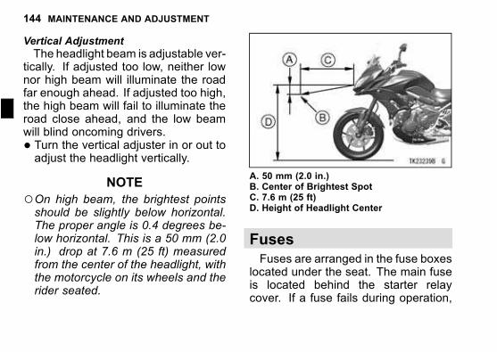
144 MAINTENANCE AND ADJUSTMENT
j
Vertical Adjustment
The headlight beam is adjustable ver-tically. If adjusted too low, neither lownor high beam will illuminate the roadfar enough ahead. If adjusted too high,the high beam will fail to illuminate theroad close ahead, and the low beamwill blind oncoming drivers.
� Turn the vertical adjuster in or out toadjust the headlight vertically.
NOTE
○On high beam, the brightest pointsshould be slightly below horizontal.The proper angle is 0.4 degrees be-low horizontal. This is a 50 mm (2.0in.) drop at 7.6 m (25 ft) measuredfrom the center of the headlight, withthe motorcycle on its wheels and therider seated.
A. 50 mm (2.0 in.)B. Center of Brightest SpotC. 7.6 m (25 ft)D. Height of Headlight Center
Fuses
Fuses are arranged in the fuse boxeslocated under the seat. The main fuseis located behind the starter relaycover. If a fuse fails during operation,
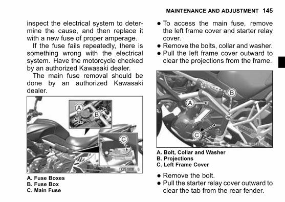
MAINTENANCE AND ADJUSTMENT 145
inspect the electrical system to deter-mine the cause, and then replace itwith a new fuse of proper amperage.If the fuse fails repeatedly, there is
something wrong with the electricalsystem. Have the motorcycle checkedby an authorized Kawasaki dealer.The main fuse removal should be
done by an authorized Kawasakidealer.
A. Fuse BoxesB. Fuse BoxC. Main Fuse
� To access the main fuse, removethe left frame cover and starter relaycover.
� Remove the bolts, collar and washer.� Pull the left frame cover outward toclear the projections from the frame.
A. Bolt, Collar and WasherB. ProjectionsC. Left Frame Cover
� Remove the bolt.� Pull the starter relay cover outward toclear the tab from the rear fender.
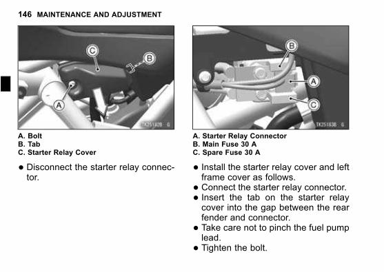
146 MAINTENANCE AND ADJUSTMENT
j
A. BoltB. TabC. Starter Relay Cover
� Disconnect the starter relay connec-tor.
A. Starter Relay ConnectorB. Main Fuse 30 AC. Spare Fuse 30 A
� Install the starter relay cover and leftframe cover as follows.
� Connect the starter relay connector.� Insert the tab on the starter relaycover into the gap between the rearfender and connector.
� Take care not to pinch the fuel pumplead.
� Tighten the bolt.
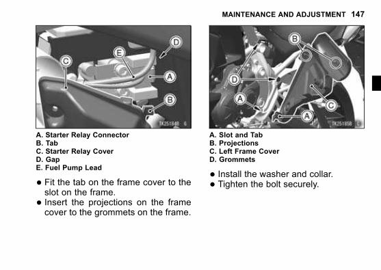
MAINTENANCE AND ADJUSTMENT 147
A. Starter Relay ConnectorB. TabC. Starter Relay CoverD. GapE. Fuel Pump Lead
� Fit the tab on the frame cover to theslot on the frame.
� Insert the projections on the framecover to the grommets on the frame.
A. Slot and TabB. ProjectionsC. Left Frame CoverD. Grommets
� Install the washer and collar.� Tighten the bolt securely.
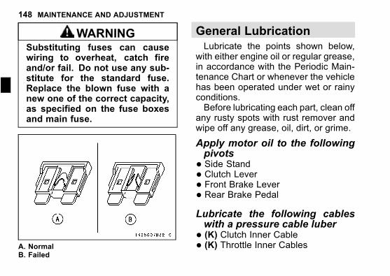
148 MAINTENANCE AND ADJUSTMENT
j
WARNINGSubstituting fuses can causewiring to overheat, catch fireand/or fail. Do not use any sub-stitute for the standard fuse.Replace the blown fuse with anew one of the correct capacity,as specified on the fuse boxesand main fuse.
A. NormalB. Failed
General Lubrication
Lubricate the points shown below,with either engine oil or regular grease,in accordance with the Periodic Main-tenance Chart or whenever the vehiclehas been operated under wet or rainyconditions.Before lubricating each part, clean off
any rusty spots with rust remover andwipe off any grease, oil, dirt, or grime.
Apply motor oil to the followingpivots
� Side Stand� Clutch Lever� Front Brake Lever� Rear Brake PedalLubricate the following cableswith a pressure cable luber
� (K) Clutch Inner Cable� (K) Throttle Inner Cables
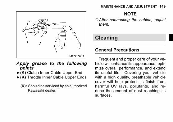
MAINTENANCE AND ADJUSTMENT 149
Apply grease to the followingpoints
� (K) Clutch Inner Cable Upper End� (K) Throttle Inner Cable Upper Ends(K): Should be serviced by an authorized
Kawasaki dealer.
NOTE
○After connecting the cables, adjustthem.
Cleaning
General Precautions
Frequent and proper care of your ve-hicle will enhance its appearance, opti-mize overall performance, and extendits useful life. Covering your vehiclewith a high quality, breathable vehiclecover will help protect its finish fromharmful UV rays, pollutants, and re-duce the amount of dust reaching itssurfaces.
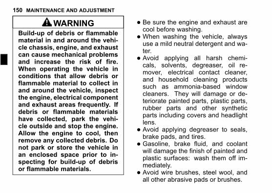
150 MAINTENANCE AND ADJUSTMENT
j
WARNINGBuild-up of debris or flammablematerial in and around the vehi-cle chassis, engine, and exhaustcan cause mechanical problemsand increase the risk of fire.When operating the vehicle inconditions that allow debris orflammable material to collect inand around the vehicle, inspectthe engine, electrical componentand exhaust areas frequently. Ifdebris or flammable materialshave collected, park the vehi-cle outside and stop the engine.Allow the engine to cool, thenremove any collected debris. Donot park or store the vehicle inan enclosed space prior to in-specting for build-up of debrisor flammable materials.
� Be sure the engine and exhaust arecool before washing.
�When washing the vehicle, alwaysuse a mild neutral detergent and wa-ter.
� Avoid applying all harsh chemi-cals, solvents, degreaser, oil re-mover, electrical contact cleaner,and household cleaning productssuch as ammonia-based windowcleaners. They will damage or de-teriorate painted parts, plastic parts,rubber parts and other syntheticparts including covers and headlightlens.
� Avoid applying degreaser to seals,brake pads, and tires.
� Gasoline, brake fluid, and coolantwill damage the finish of painted andplastic surfaces: wash them off im-mediately.
� Avoid wire brushes, steel wool, andall other abrasive pads or brushes.
MAINTENANCE AND ADJUSTMENT 151
� Take care when washing the head-light lens and other plastic parts asthey can easily be scratched.
NOTE
○After riding in an area where theroads are salted or near the ocean,immediately wash your vehicle withcold water. Do not use warm wateras it accelerates the chemical reac-tion of the salt. After drying, applya corrosion protection spray on allmetal and chrome surfaces to pre-vent corrosion.
○Condensationmay form on the insideof the headlight lens after riding in therain, washing the vehicle or in humidweather. To remove the moisture,start the engine and turn on the head-light. Gradually the condensation onthe inside of the lens will clear off.
RadiatorClean off any obstructions with a
stream of low-pressure water.
NOTICE
Using high-pressure water, asfrom a car wash facility, coulddamage the radiator fins andimpair the radiator’s effective-ness. Do not obstruct or deflectairflow through the radiator byinstalling unauthorized acces-sories in front of the radiator orbehind the cooling fan. Inter-ference with the radiator airflowcan lead to overheating and con-sequent engine damage.
Matte Paint Parts
�When washing the vehicle, alwaysuse a mild neutral detergent and wa-ter, or cleaners for matte paint.
152 MAINTENANCE AND ADJUSTMENT
j
� The matte paint effect may be lostwhen the paint is excessively rubbed.
� If any doubt, consult an authorizedKawasaki dealer.
Plastic PartsAfter washing, use a soft cloth to gen-
tly dry plastic parts. When dry, treat theheadlight lens and other non paintedplastic parts with an approved plasticcleaner/polisher product.
NOTICE
Plastic parts may deteriorateand break if they come in con-tact with chemical substancesor household cleaning productssuch as gasoline, brake fluid,window cleaners, thread-lockingagents, or other harsh chemi-cals. If a plastic part comes incontact with any harsh chemicalsubstance, wash it off immedi-ately with water and a mild neu-tral detergent, and then inspectfor damage. Avoid using abra-sive pads or brushes to cleanplastic parts, as they will dam-age the part’s finish.
Chrome and AluminumChrome and uncoated aluminum
parts can be treated with a chrome/alu-minum polish. Coated aluminum
MAINTENANCE AND ADJUSTMENT 153
should be washed with a mild neu-tral detergent and finished with a spraypolish. Aluminum wheels, both paintedand unpainted can be cleaned withspecial non-acid based wheel spraycleaners.
Leather, Vinyl, and RubberIf your vehicle has leather acces-
sories, special care must be taken.Use a leather cleaner/treatment toclean and care for leather accessories.Washing leather parts with detergentand water will damage them, shorten-ing their life.Vinyl parts should be washed with the
rest of the vehicle, then treated with avinyl treatment.
The sidewalls of tires and other rub-ber components should be treated witha rubber protectant to help prolong theiruseful life.
Where to be Careful
Avoid spraying water with any greatforce near the following places.
� Disc brake master cylinder andcaliper.
� Under the seat - if water gets into thefuse box or battery, it can ground outthe spark. When this happens thevehicle will not operate properly andthe affected parts must be wiped dry.
154 MAINTENANCE AND ADJUSTMENT
j
NOTICE
Coin operated, high pressurespray washers are not recom-mended. Water may be forcedinto bearings and other compo-nents causing eventual failurefrom rust and corrosion. Somesoaps are highly alkaline andmay leave a residue or causespotting.
NOTE
○Abrasive cleanser or high pressurewasher will damage the surface fin-ish on the bodywork.
Washing Your Vehicle
� Before washing, precautionsmust betaken to keep water off the followingparts.
Muffler rear opening - cover with aplastic bag.Ignition switch - cover the keyhole
with tape.
� Rinse your vehicle with cold waterfrom a garden hose to remove anyloose dirt.
� Mix a mild neutral detergent (de-signed for motorcycles or automo-biles) and water in a bucket. Usea soft cloth or sponge to wash yourvehicle.
� After washing, rinse your vehiclethoroughly with clean water to re-move any residue (residue from thedetergent can damage parts of yourvehicle).
� Remove the plastic bag and tape.� Use a soft cloth to dry your vehicle.As you dry, inspect your vehicle forchips and scratches. Do not let thewater air dry as this can damage thepainted surfaces.
MAINTENANCE AND ADJUSTMENT 155
� Carefully ride your vehicle at a slowspeed and apply the brakes severaltimes. This helps dry the brakesand restores them to normal operat-ing performance.
156 APPENDIX
j
APPENDIX
Storage
Whenever your motorcycle will not be in use for a long period, proper storage isessential.It consists of checking and replacing missing or worn parts; lubricating parts to
ensure that they do not corrode and, in general, preparing the motorcycle so thatwhen the time comes to use it again, it will be in top condition.See your authorized Kawasaki dealer for this service or do the following.
Preparation for StorageMake sure the area is well ventilated and free from any source of flame.
DANGERExhaust gas contains carbon monoxide, a colorless, odorless poisonousgas. Inhaling carbon monoxide can cause serious brain injury ordeath. DO NOT run the engine in enclosed areas. Operate only in awell-ventilated area.
APPENDIX 157
WARNINGGasoline is extremely flammable and can be explosive under certain con-ditions, creating the potential for serious burns.
� Turn the ignition key off.� Do not smoke.� Make sure the area is well ventilated and free from any source of flame or sparks;this includes any appliance with a pilot light.
WARNINGGasoline is a toxic substance. Dispose of gasoline properly. Contact yourlocal authorities for approved disposal methods.
� Clean the entire vehicle thoroughly.� Run the engine for about five minutes to warm the oil, shut it off, and drain theengine oil. (see Engine Oil section in the MAINTENANCE AND ADJUSTMENTchapter)
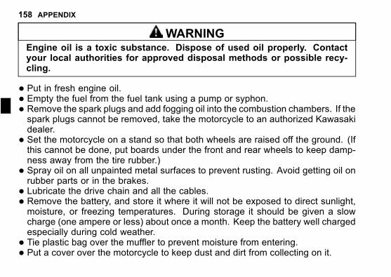
158 APPENDIX
j
WARNINGEngine oil is a toxic substance. Dispose of used oil properly. Contactyour local authorities for approved disposal methods or possible recy-cling.
� Put in fresh engine oil.� Empty the fuel from the fuel tank using a pump or syphon.
� Remove the spark plugs and add fogging oil into the combustion chambers. If thespark plugs cannot be removed, take the motorcycle to an authorized Kawasakidealer.
� Set the motorcycle on a stand so that both wheels are raised off the ground. (Ifthis cannot be done, put boards under the front and rear wheels to keep damp-ness away from the tire rubber.)
� Spray oil on all unpainted metal surfaces to prevent rusting. Avoid getting oil onrubber parts or in the brakes.
� Lubricate the drive chain and all the cables.� Remove the battery, and store it where it will not be exposed to direct sunlight,moisture, or freezing temperatures. During storage it should be given a slowcharge (one ampere or less) about once a month. Keep the battery well chargedespecially during cold weather.
� Tie plastic bag over the muffler to prevent moisture from entering.
� Put a cover over the motorcycle to keep dust and dirt from collecting on it.
APPENDIX 159
Preparation after Storage
� Remove the plastic bag from the muffler.
� Charge the battery if necessary and install the battery in the motorcycle.� Fill the fuel tank with fresh fuel.� Check all the points listed in the Daily Checks section.� Lubricate the pivots, bolts, and nuts.
Troubleshooting Guide
If a Problem Occurs
Performing daily checks and periodic maintenance prevents unexpected troublesfrom occurring. In case of a breakdown, take emergency measures and contactyour Kawasaki dealer to request repair. For safety, inspection and maintenanceshould be done within your knowledge and ability. If you are not confident in com-pleting an inspection or maintenance, ask an authorized Kawasaki dealer to do thework.
160 APPENDIX
j
WARNING
�When carrying out an inspection, follow the precautions below.� Secure a place where you can work in safety without obstructing trafficaround you. Do not carry out any inspection unless it is safe.
� Support the motorcycle on a firm, level surface with the stand.� The engine and muffler will become hot during operation. To avoidburns etc., do not touch the hot engine or muffler just after the enginehas stopped.
� Exhaust gas contains harmful substances such as carbon monoxide.Do not run the engine in an enclosed garage or poorly ventilated area.
�Wait until the engine cools down before carrying out inspection andmaintenance or replenishing fuel. Make sure the area is well ventilatedand free from any source of flame or sparks. Do not place any appliancewith a pilot light nearby.
� If a test ride is needed, ride in a safe area and pay close attention totraffic around you.
When any warning indicators go on or blink, have the motorcycle inspected byan authorized Kawasaki dealer immediately.
If the Engine Does Not Start
When the engine turns over but the engine does not start, inspect as follows.
APPENDIX 161
� Check the fuel level in the fuel tank. If only a small quantity of fuel remains inthe bottom, replenish the fuel tank. (Fuel in the tank cannot be completely con-sumed.)
� Leaving the motorcycle unused for a long time may cause fuel in the tank todeteriorate. In that case, ask an authorized Kawasaki dealer for inspection.
�When the engine warning indicator on the meter goes on and stays on, there maybe a problem with the fuel injection system. Ask an authorized Kawasaki dealerfor inspection and maintenance.
� The motorcycle is equipped with a vehicle-down sensor which stops the engineautomatically when the motorcycle falls down. When the starter button is pressedafter the motorcycle has fallen down, the engine warning indicator blinks and theengine does not start. To start the engine, switch the ignition key to the “OFF”position and then back to the “ON” position.
If the engine will not start after completing the above inspection and maintenance,there may be something wrong with another system such as the ignition system.Ask an authorized Kawasaki dealer for inspection and maintenance.
When the starter motor does not rotate, inspect as follows.
� Check the position of the engine stop switch. Push the engine stop switch in theposition if it is in the position.
� Make sure that the gear position is in the neutral position. If not, shift the trans-mission into neutral.
162 APPENDIX
j
� Inspect the fuse condition. If any fuse has blown, replace it with a new one of thesame amperage.
WARNINGSubstituting fuses can causewiring to overheat, catch fire and/or fail. Useonly standard fuses of the correct capacity and specifications.
� Check the battery cable connections etc. (see page 142). If necessary, tightenthe connecting bolts to securely connect them.
� In case of slow blinking of the turn signal lights, low volume of the horn sound,or when you press the starter button and hear a click but the starter motor doesnot rotate, battery charging status is not good. Refresh the battery’s charge (seepage 141) and check if the starter motor rotates.
� Even after a refresh charge, if the starter motor stops rotating the engine properly,the battery may have deteriorated. Have the battery inspected by an authorizedKawasaki dealer.
If the starter motor will not start after completing the above inspection and mainte-nance, there may be something wrong with another part such as the starter motor.Ask an authorized Kawasaki dealer for inspection and maintenance.
APPENDIX 163
If the Engine Stalls or Runs Poorly
� Check the fuel level in the fuel tank. If only a small quantity of fuel remains,replenish the fuel tank. (Fuel in the tank cannot be completely consumed.)
� Raise the side stand fully up before starting the engine. (If you try to move offwith the side stand is still down, the engine will stop.)
� Make sure that correct fuel is used. If not, replace the fuel the correct type (seepage 62).
� Due to too much play in the clutch lever, the clutch may not disengage. If thereis any problem, adjust the clutch lever free play correctly.
� In case of slow blinking of the turn signal lights, low volume of the horn sound,or when you press the starter button and hear a click but the starter motor doesnot rotate, the battery is discharged. Check the connections of the battery termi-nals for looseness (see page 142). If necessary, tighten the bolts to remove thelooseness. If the above methods cannot solve the problems, ask an authorizedKawasaki dealer for inspection and maintenance.
� If the warning indicator goes on and coolant temperature warning indicator is dis-played, the engine may have overheated. Check the coolant level in the reservetank after the engine cools down. If the coolant quantity is less than the lowerlevel, replenish the coolant or soft water up to the upper level (see page 106).Ask an authorized Kawasaki dealer to identify the cause of the overheat imme-diately.
164 APPENDIX
j
�When the engine warning indicator on the meter goes on and stays on, thereis something wrong with the fuel injection system. Ask an authorized Kawasakidealer for inspection and maintenance.
If the engine stalls after completing the above inspection and maintenance, theremay be something wrong with other system. Ask an authorized Kawasaki dealerfor inspection and maintenance.
Your Warranty/Owner Satisfaction
Welcome to the Kawasaki family!
Congratulations on buying your Kawasaki vehicle. You’ve chosen a great, high-quality product with state-of-the-art features and built to Kawasaki’s high standards.Your satisfaction is important to your authorized Kawasaki dealer and to KawasakiMotors Corp., U.S.A. Here is some important information regarding your vehicle’slimited warranty.
Frequently Asked Questions
What is a Limited Warranty?The most important thing to know about your warranty is that it protects you
from manufacturing defects in material or workmanship during the warranty pe-riod. You can find the warranty period in the Kawasaki Limited Warranty Certificateyour Kawasaki dealer provided to you at the time of sale. The warranty does not
APPENDIX 165
cover the cost of regularly-scheduled maintenance. The warranty also does not ap-ply to the normal wear of items such as tires, brake pads, transmission drive belts,chains, sprockets, etc.
What is the Good Times Protection Plan?Much of the warranty coverage offered by the limited warranty can be extended by
purchasing Kawasaki’s Good Time™ Protection Plan (GTPP). See your Kawasakidealer or go to Kawasaki.com for more information if you don’t already have theGTPP.
What Am I Responsible For?You are responsible for maintaining your vehicle according to the maintenance
schedule shown in this owner’s manual.
You are responsible for notifying your dealer immediately if there is a problem,and you, as the owner, will need to authorize the dealer to inspect the unit.
You will be responsible for paying for routine maintenance, including the firstscheduled service. You can have the required servicing done by your Kawasakidealer (recommended) or an equally-qualified service facility. You can also do yourown maintenance work if you have the proper tools, service references, and me-chanical skills. However, if a failure is found to be caused by improper servicing, itwould not be covered by the limited warranty.
166 APPENDIX
j
You may purchase a Kawasaki Service Manual and any necessary special toolsdirectly from your Kawasaki dealer.
You will be responsible for paying for repairs needed because of an accident, toreplace worn parts such as tires, chains, brakes, and for repairs needed becauseof a lack of maintenance, misuse or racing.
Whether you do it yourself or take your vehicle to a Kawasaki dealer, be sureto record your service in the Maintenance Record section of this Owner’s Manual.Keep all receipts for the service and/or items necessary to perform the maintenanceso that in the event of a failure you can document the service history.
What Are The Dealership’s Responsibilities?
Your Kawasaki dealer offers a wide range of services, parts, accessories, andinformation on your product and on Kawasaki.
Each dealer is independently owned and operated and is responsible for the deal-ership’s operations, its repair, warranty, and service work, and its personnel.
APPENDIX 167
Your dealer is responsible for completing the set up and pre-delivery service ofyour new Kawasaki vehicle. The dealership should also explain its operation, main-tenance, and warranty provisions so you understand them at the time of purchaseor at any other time you have questions.
The dealership is responsible for inspecting your Kawasaki vehicle if there is afailure, investigating the cause of the problem, and getting any needed authoriza-tion from Kawasaki if the repair is one that will be covered by the limited warranty.The dealership will also file all necessary paperwork. The dealership is responsi-ble for correctly completing any necessary repairs, whether they are covered bythe limited warranty or not.
How Do I Get Warranty Service?
If there is a problem with your vehicle within the limited warranty period, you willneed to schedule a service appointment and provide any maintenance records toan authorized Kawasaki dealer for inspection and diagnosis. You can go to anyKawasaki dealer for warranty repairs. Your Kawasaki dealer will inspect your vehi-cle and give you the results of the inspection. The dealer will perform the repairsat no cost to you if it is determined that the problem is covered by the warranty.
168 APPENDIX
j
Kawasaki will work with your dealer to resolve any warranty issues. No autho-rization for warranty work can be given until your vehicle has been inspected by aKawasaki dealer.
What if I am not Satisfied With My Warranty Service?
If you aren’t satisfied with your dealership’s repair work or operations, it is best todiscuss the situation with the appropriate dealership manager. If you have alreadydone this, then contact the dealership’s owner or general manager to request areview of the issue.
If you are unable to resolve a problem after consulting with the dealership man-agement and need further assistance, contact Kawasaki Motors Corp., U.S.A. atthe address below. Please be certain to provide the model, vehicle identificationnumber (VIN), mileage or hours of use, accessories, dates that events occurredand what action has been taken by both you and your dealer. Include the nameand address of the dealership. To assist us in resolving your inquiry, please includecopies of related receipts and any other pertinent information including the nameof the dealership personnel with whom you have been working. Upon receipt ofyour correspondence, Kawasaki Motors Corp., U.S.A. will contact the dealershipand work with it in resolving your problem.
APPENDIX 169
Want to Contact Kawasaki?
This owner’s manual should answer most of your questions about your Kawasaki.Your Kawasaki dealer should either be able to answer any other questions youmight have immediately or be able to find the answer for you.
Please send your correspondence to:Consumer ServicesKawasaki Motors Corp., U.S.A.P.O. Box 25252Santa Ana, CA 92799-5252(949) 460-5688
Reporting Safety Defects
(For Products Sold in the United States of America, District of Columbia, andU.S. Territories Only)
If you believe that your vehicle has a defect which could cause a crash or couldcause injury or death, you should immediately inform the National Highway TrafficSafety Administration (NHTSA) in addition to notifying Kawasaki Motors Corpora-tion, U.S.A.
170 APPENDIX
j
If NHTSA receives similar complaints, it may open an investigation, and if it findsthat a safety defect exists in a group of vehicles, it may order a recall and remedycampaign. However, NHTSA cannot become involved in individual problems be-tween you, your dealer, or Kawasaki Motors Corporation, U.S.A.
To contact NHTSA, you may either call the Auto Safety Hotline toll-free at 1-800-424-9393 (or 366-0123 in Washington, D.C. area) or write to: NHTSA, U.S. De-partment of Transportation, Washington, D.C. 20590. You can also obtain otherinformation about motor vehicle safety from the Hotline.
Environmental Protection
To help preserve the environment, properly discard used batteries, tires, oils andfluids, or other vehicle components that you might dispose of in the future. Con-sult your authorized Kawasaki dealer or local environmental waste agency for theirproper disposal procedure. This also applies to disposal of the entire vehicle at theend of its life.
MAINTENANCE RECORD 171
MAINTENANCE RECORD
Owner Name.......................................................................................
Address ..............................................................................................
Phone Number ...................................................................................
Engine Number ..................................................................................
Vehicle Number..................................................................................
Key Code............................................................................................
Selling Dealer Name..........................................................................
Phone Number ...................................................................................
Warranty Start Date ...........................................................................Note: Keep this information and a spare key in a secure location.
DateOdometerReading
Maintenance Performed Dealer Name Dealer Address
172 MAINTENANCE RECORD
j
DateOdometerReading
Maintenance Performed Dealer Name Dealer Address

MAINTENANCE RECORD 173
DateOdometerReading
Maintenance Performed Dealer Name Dealer Address

174 MAINTENANCE RECORD
j
DateOdometerReading
Maintenance Performed Dealer Name Dealer Address
MAINTENANCE RECORD 175
DateOdometerReading
Maintenance Performed Dealer Name Dealer Address

176 MAINTENANCE RECORD
j
DateOdometerReading
Maintenance Performed Dealer Name Dealer Address