Embed Size (px)
Citation preview
17-073 www.powercommander.com 1999-2008 Kawasaki VN1500 - PCV - 1
PARTS LIST
1 PowerCommander1 USBCable1 InstallationGuide2 PowerCommanderDecals2 DynojetDecals2 Velcrostrips1 Alcoholswab1 Posi-tap1 Groundwire
THE LATEST POWER COMMANDER SOFTWARE AND MAP FILES CAN BE
DOWNLOADED FROM OUR WEB SITE AT:www.powercommander.com
Kawasaki Vulcan Models
I ns ta l l a t i on I ns t ruc t i ons
PLEASE READ ALL DIRECTIONS BEFORE STARTING INSTALLATION
THE IGNITION MUST BE TURNED OFF BEFORE INSTALLATION!
2191 Mendenhall Drive North Las Vegas, NV 89081 (800) 992-4993 www.powercommander.com
1999-2005 VN1500 Drifter2000-2004 VN1500 Nomad2000-2008 VN1500 Classic
2002-2008 Mean Streak (1500 & 1600)
17-073 www.powercommander.com 1999-2008 Kawasaki VN1500 - PCV - 2
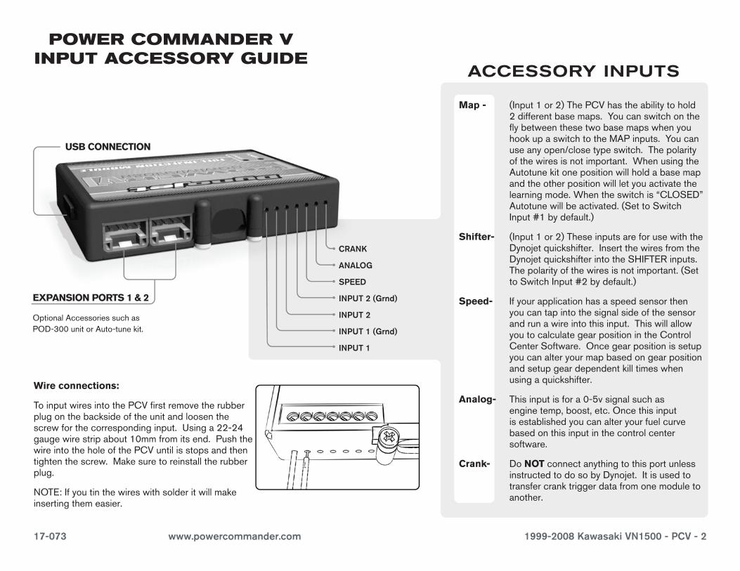
EXPANSION PORTS 1 & 2
OptionalAccessoriessuchasPOD-300unitorAuto-tunekit.
POWER COMMANDER V INPUT ACCESSORY GUIDE
Map - (Input1or2)ThePCVhastheabilitytohold2differentbasemaps.YoucanswitchontheflybetweenthesetwobasemapswhenyouhookupaswitchtotheMAPinputs.Youcanuseanyopen/closetypeswitch.Thepolarityofthewiresisnotimportant.WhenusingtheAutotunekitonepositionwillholdabasemapandtheotherpositionwillletyouactivatethelearningmode.Whentheswitchis“CLOSED”Autotunewillbeactivated.(SettoSwitchInput#1bydefault.)
Shifter- (Input1or2)TheseinputsareforusewiththeDynojetquickshifter.InsertthewiresfromtheDynojetquickshifterintotheSHIFTERinputs.Thepolarityofthewiresisnotimportant.(SettoSwitchInput#2bydefault.)
Speed- Ifyourapplicationhasaspeedsensorthenyoucantapintothesignalsideofthesensorandrunawireintothisinput.ThiswillallowyoutocalculategearpositionintheControlCenterSoftware.Oncegearpositionissetupyoucanalteryourmapbasedongearpositionandsetupgeardependentkilltimeswhenusingaquickshifter.
Analog- Thisinputisfora0-5vsignalsuchasenginetemp,boost,etc.Oncethisinputisestablishedyoucanalteryourfuelcurvebasedonthisinputinthecontrolcentersoftware.
Crank- DoNOTconnectanythingtothisportunlessinstructedtodosobyDynojet.Itisusedtotransfercranktriggerdatafromonemoduletoanother.
ACCESSORY INPUTS
Wire connections:
ToinputwiresintothePCVfirstremovetherubberplugonthebacksideoftheunitandloosenthescrewforthecorrespondinginput.Usinga22-24gaugewirestripabout10mmfromitsend.PushthewireintotheholeofthePCVuntilisstopsandthentightenthescrew.Makesuretoreinstalltherubberplug.
NOTE:Ifyoutinthewireswithsolderitwillmakeinsertingthemeasier.
CRANK
ANALOG
SPEED
INPUT 1 (Grnd)
INPUT 1
INPUT 2 (Grnd)
INPUT 2
USB CONNECTION
17-073 www.powercommander.com 1999-2008 Kawasaki VN1500 - PCV - 3
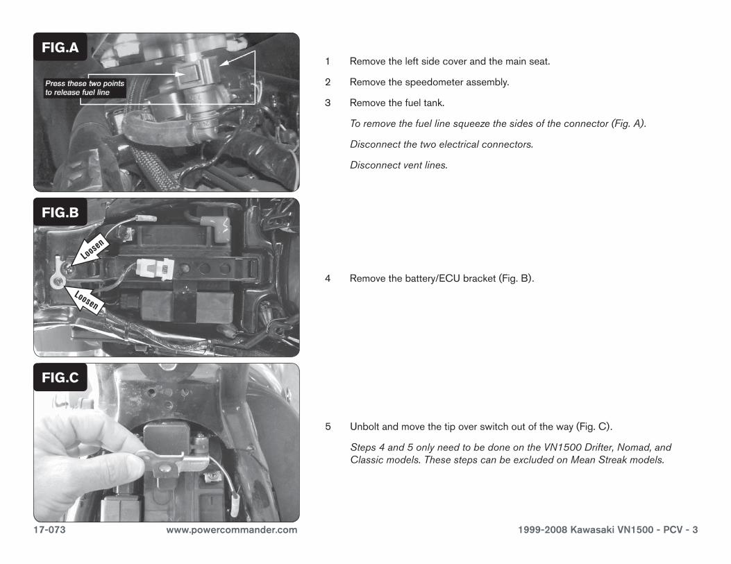
1 Removetheleftsidecoverandthemainseat.
2 Removethespeedometerassembly.
3 Removethefueltank.
Toremovethefuellinesqueezethesidesoftheconnector(Fig.A).
Disconnectthetwoelectricalconnectors.
Disconnectventlines.
4 Removethebattery/ECUbracket(Fig.B).
FIG.C
FIG.B
FIG.A
5 Unboltandmovethetipoverswitchoutoftheway(Fig.C).
Steps4and5onlyneedtobedoneontheVN1500Drifter,Nomad,andClassicmodels.ThesestepscanbeexcludedonMeanStreakmodels.
Loosen
Loosen
17-073 www.powercommander.com 1999-2008 Kawasaki VN1500 - PCV - 4
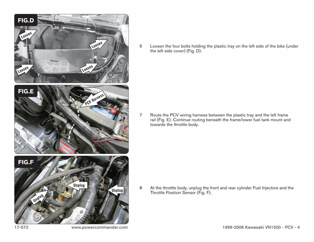
7 RoutethePCVwiringharnessbetweentheplastictrayandtheleftframerail(Fig.E).Continueroutingbeneaththeframe/lowerfueltankmountandtowardsthethrottlebody.
8 Atthethrottlebody,unplugthefrontandrearcylinderFuelInjectorsandtheThrottlePositionSensor(Fig.F).
FIG.E
FIG.F
6 Loosenthefourboltsholdingtheplastictrayontheleftsideofthebike(undertheleftsidecover)(Fig.D).
FIG.D
Unplug
Loosen
Loosen
Loosen
Loosen
PCV Harness
UnplugUnplug
17-073 www.powercommander.com 1999-2008 Kawasaki VN1500 - PCV - 5
9 UsethesuppliedPosi-taptoattachtheGREYwireofthePCVwiringharnesstothestockYELLOW/WHITEwireoftheTPSconnector.PlugtheTPSconnectorbackontotheTPS(FigG).
FIG.G
10 PlugthepairofPCVleadswithORANGEcoloredwiresin-lineoftheFrontCylinderFuelInjectorandthestockwiringharness.
11 PlugthepairofPCVleadswithYELLOWcoloredwiresin-lineoftheRearCylinderFuelInjectorandthestockwiringharness(Fig.H).
12 Reinstallthefueltank,speedometerassembly,andthetipoverswitch.
FIG.H
13 OnMeanStreakmodelsonly,plugthePCVgroundwirewiththemalebulletconnectorintothestockauxiliarygroundconnector.Thestockauxiliarygroundconnectorisfoundnexttothebattery.IthasadoublefemalebulletconnectorandaBLACK/YELLOWwire.
YoucanomitthesuppliedGroundWireonMeanStreakmodels.ItisonlyusedonVN1500Drifter,Nomad,andClassicmodels.
FIG.J
17-073 www.powercommander.com 1999-2008 Kawasaki VN1500 - PCV - 6
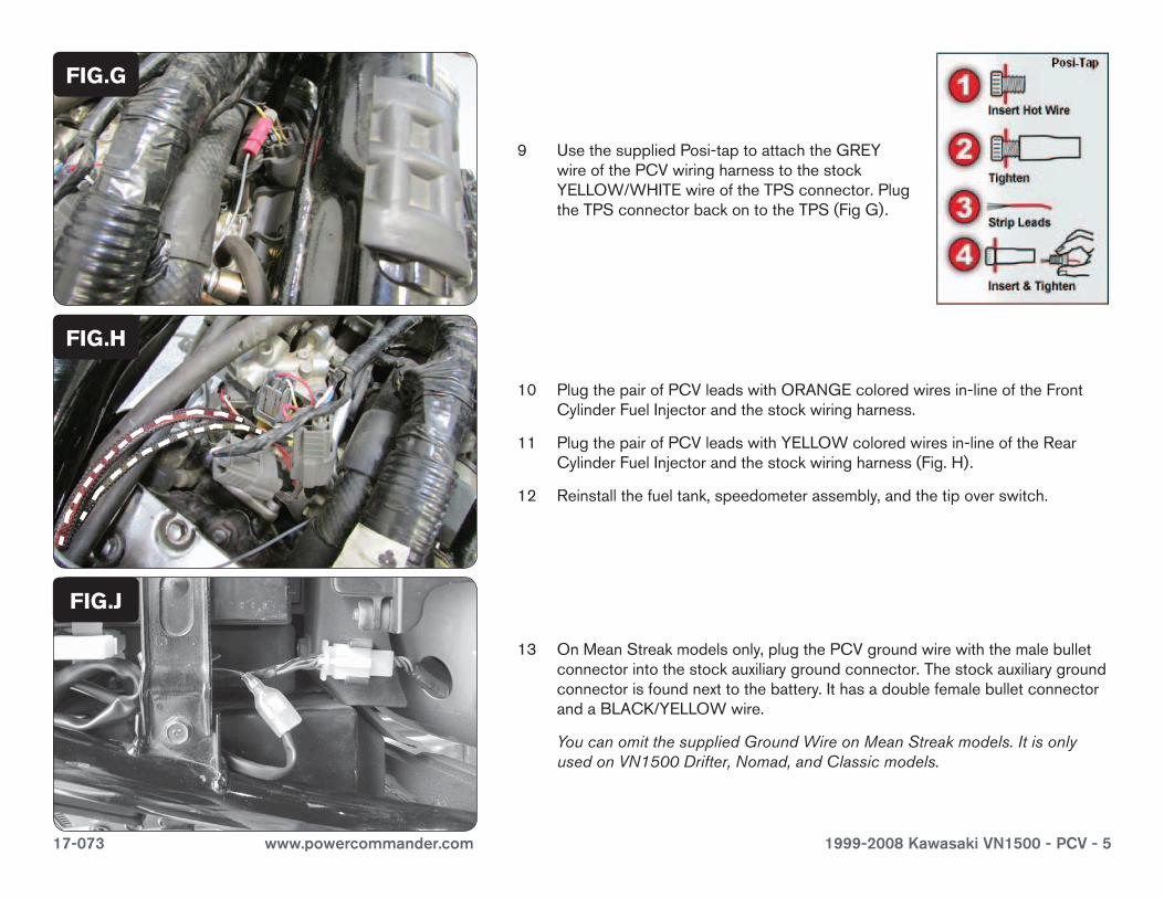
14 OnVN1500Drifter,Nomad,andClassicmodels,securethesuppliedGroundWiretothenegative(-)terminalofthebike’sbattery.PlugthePCVwiringharnessintotheGroundWire(Fig.K).
FIG.K
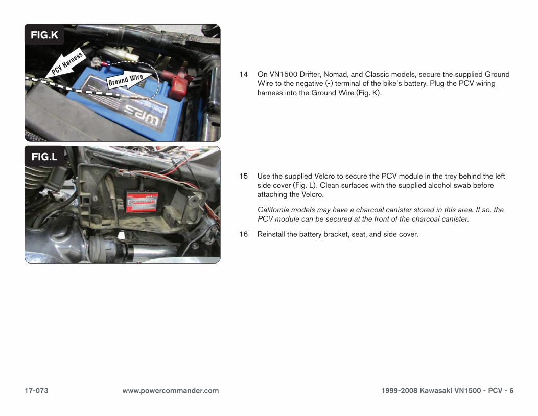
15 UsethesuppliedVelcrotosecurethePCVmoduleinthetreybehindtheleftsidecover(Fig.L).CleansurfaceswiththesuppliedalcoholswabbeforeattachingtheVelcro.
Californiamodelsmayhaveacharcoalcanisterstoredinthisarea.Ifso,thePCVmodulecanbesecuredatthefrontofthecharcoalcanister.
16 Reinstallthebatterybracket,seat,andsidecover.
FIG.L
PCV Harness
Ground Wire


