Embed Size (px)
Citation preview

TM
WAR DEPABTMENT
TECHNICAL MANUAL
jt
155-MM GUN MATERIEL, M1917, M1918
AND MODIFICATIONS
Noyember 1,1941

*TM 9-345
TECHNICAL MANUAL 1 ' . , i :. •WaA-Ek' frfel.'AR'JMENT,No. 9-345 j . .^ASHJIJOTON,. Noyembec-J., 1941.
" ". --o* -';*; ^-° ','.' / ° •-'155-MM GUN MATfiRIEL; M1917, :M191g, AND
MODIFICAT'I0SJ^ J ;* ' .' ; \l
Prepared under direction of the Chief of Ordnance
ParagraphsCHAPTER 1. GENEHAL_______._._-___.. _..........-_.._. 1-3CHAPTER 2. GUN AND CARRIAGE.
Section I. General information and data. ._ ________ 4-6II. Description and operation _____ ___________ 7-14
III. Description of groups______ _______________ 1.5-27IV. Disassembly and assembly _ _ _____________ 28—44V. Inspection and adj ustment ________________ 45
VI. Functioning-. _________________________ . 46-48VII . Care and preservation ___________________ 49-57
CHAPTER 3. SIGHTING AND FIRE-CONTROL EQUIPMENT.Section I. Sighting equipment _-_______--_--__--__-_ 58-66
II. Fire-control equipment. -___-_-__-________ 67-73III. Plotting room fire-control equipment- ______ 74-84
CHAPTER 4. AMMUNITION_________-_____-______________ 85-123CHAPTER 5. SPARE PARTS AND ACCESSORIES-. _____ ______ 124-125CHAPTER 6. SUBCALIBER EQUIPMENT_________-__-____-__ 126-132CHAPTER 7. MATERIEL AFFECTED BY GAS________--_---_ 133—134
Page
APPENDIX. LIST OF REFERENCES.- _____________________ 210INDEX. _________-___-___-__-___--_---__---_--__-_---- 213
CHAPTER 1 -_J -
GENEEAL /<s"/ ~.. ' . - - _ P..rngwtph
Purpose____ _ _ __ _ __ _ _ _ ________ __ ___________ __ -,^ • _ _= _ .--—c _ __ *-^\Scone ________________________ _iir-- __ -; _ ;._ **%"^ c_/ — * References _ ________ ___________________ _5.^ _ - ____ i>.-_ _ "3"
1. Purpose. — This manual is published for the^iifprxnation guidance of the using arms and services. "^ •'••'- -~-TI." -
2. Scope. — a. This manual contains all the essentia'E-iiifo,ririation of a technical character required by the using arms and services for
"This manual supersedes TR 1305-155C. March 10, 1931. including C 1, January 2, 1933;C 2, January 2, 1934; and C 3, January 2, 1936. _ _ __ _
416703°—41———1 1 ^ " " ' "

TM9-3« f03061.32-3 ... . (,«HD3$ANCpE DEPARTMENT
'..•:.; ." &-*s£,-SfS! *--% & ill ill", ' - , . . *, *BtrfMac?fe^^^:J^^^P •- 4^J CS.S ^"*
the identification,\ise, aid'care •oFTSfie'TTarticuhir equipment described, as well tift ijss 'and ciW'tJiojft^ittitntinition, spare parts, and accessories and sighting "and-fire-tohtrol'-equipment.
&. Disassembly-and assam-bly-and repairs by battery personnel will be undertaKeil.'p'nlj^undei" tlie supervision of an officer or the chief mechanic.
c. In cases where the nature of repair, modification, or adjustmentis beyond the scope and/or facilities of the battery personnel, the
'local or otherwise designated ordnance service should be informedin order that trained personnel with suitable tools and equipmentmay be provided.
3. References.—All Technical Manuals, Field Manuals, Firing Tables, Standard Nomenclature Lists, and other publications per taining to the materiel described herein are listed in the appendix.

TM 9-345
CHAPTER 2 GUN AND CARRIAGE
ParagraphsSECTION I. General information and data ________ _ _ 4-6
II. Description and operation ____ _ ________ 7-14III. Description of groups ________________ 15-27IV. Disassembly and assembly _ __ _ _______ _ 28-44 V. Inspection and adjustment_-______ ___ ____ 45
VI. Functioning ______________________ 46-48VII. Care and preservation ______ — _ — ___ _ _ 49-57
SECTION I
GENERAL INFORMATION AND DATAParagraph
General information — ____________________ _ _ _______ . ___ 4 Weights, dimensions, and ballistics (155-mm gun, M1917, M1917A1, and
M1918MI) _________________________________________ 5 General data pertaining to 155-mm gun carriage, M1917, M1917A1, M1918,
and M1918A1 ; and 155-mm gun carriage limber, M1917, M1917A1, M1918, and M1&18A1 ______________________________________ 6
4. General information. — The weights, measurements, and bal listic data given in paragraphs 5 and 6 are approximately the same for each of the models mentioned.
5. Weights, dimensions, and ballistics (155-mm gun, M1917, M1917A1, and M1918MI).Weight of 155-mm gun M1918MI, complete _____ pounds _ 8,715 Caliber, 155-mm or _______________ —— __ inches _ 6. 102
" Length (muzzle to rear face of breech ring) __ _ ___ do __ 232. 87 '^Chamber:^ ' Diameter _________________________ do __ 6.693
Length, breech closed to base of projectile — ___ do __ 37. 087Capacity ________________ _ _ —— cubic inches _ 1,329
Rifling:^ Number of grooves _________ — _ ——— __- — _ — — 48
Twist, right hand, uniform, 1 turn in 29.89 calibers "7." (inclination 6°). vj Travel of projectile in bore _______ _____ __ inches— 185
Weight of projectile ___________ — ___ pounds _ 95-.^'. Weight of full powder charge ____ — _ — _____do _ — 251/4— Maximum powder pressure per square inch__ —— do —— 31, 500
Range with full charge ___________ — — _ -yards — 18,000 „ Rate of fire (with supercharge) :
^ 4 rounds per minute for not to exceed 40 rounds.

TM 9-3455-6 ORDNANCE DEPARTMENT
6. General data pertaining to 155-mm gun carriage, M1917, M1917A1, M1918, and M1918A1; and 155-nim gun carriage limber, M1917, M1917A1, M1918, and M1918A1.Weight of recoil mechanism with elevation sector
and piston rod nuts—________________pounds_ 3,114Weight of sights and bracket, panoramic sight,
5 pounds, quadrant sight and bracket, 41 pounds__do__ 46 Weight of 2 large spades_________—_——__—do_— 1, 220 Weight of accessories carried on carriage and
limber (including axle pivot pin 27y2 pounds) ___do__ 35 Weight of limber chassis_____________-___--do__ 3. 600 Weight of limber seat and trail clamping transom__do__ 245 Weight of remainder of carriage____—_—__—do_— 10.970 Total weight, gun (8,715 pounds), carriage and
limber, road position, without caterpillar band___do__ 27, 800 Keaction at each carriage wheel (road position)____do__ 8,300 Reaction at each limber wheel (road position)——__do_... 5,600 Weight of caterpillar band for one wheel—_—————do—— 534 Weight of one 1,160-mm dual rubber-tired wheel
(average without 35-pound brake drum)_______do__— 985Dimensions:
Width of track, center to center of wheels___inches-- 88. 58(2,250 mm)
Greatest width (over hub caps)________inches__ 105.28(2,674 mm)
Height of center line of bore from ground (at 0°elevation with caterpillar bands) _______-inches— 54.17
(1,376 mm)Caterpillar bands raise the gun approximately._inches-- 2
(51 mm) Height of line of sight above ground-_____do___ 69. 81Height of cradle trunnions above ground__-___do.__ 52 Wheel base, carriage, and limber___________feet_Width of space required for half-turn________do__Length over-all, traveling position, gun.
carriage, and limber-_______ — _________do_— 28%With 10-ton artillery tractor (approximately)_do__ 42% Road clearance (without caterpillar bands) —
At middle of gun axle spring-.---__..._inches_ 11 At ends of gun axle spring.______---____do__
TM 9-345155-MM GUN MATERIEL 6-7
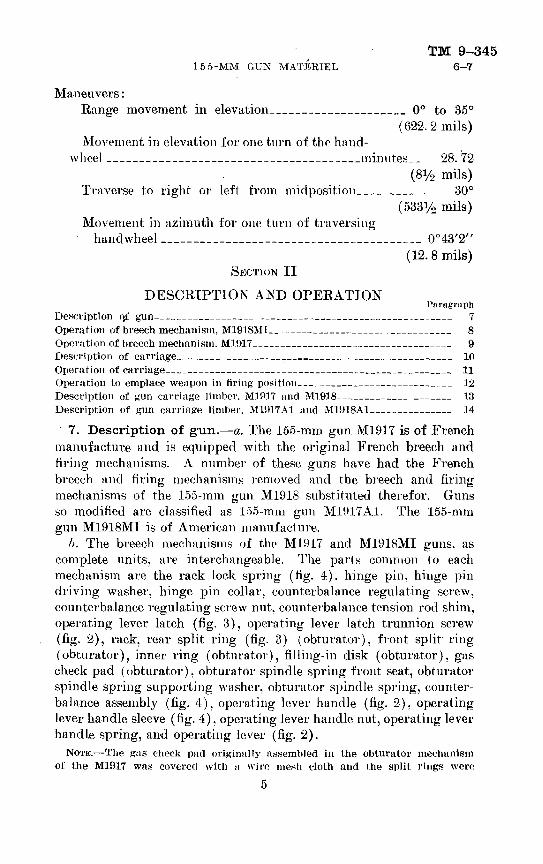
Maneuvers:Range movement in elevation______________ 0° to 35°
(622. 2 mils)Movement in elevation for one turn of the hand-
wheel _____________________minutes.- 28. 72(81/2 mils)
Traverse to right or left from midposition_______ 30°(5331/0 mils)
Movement in azimuth for one turn of traversing handwheel ______________________ '_ _______ 0°43'2"
(12. 8 mils) SECTION II
DESCRIPTION AND OPERATIONParagraph
Description Q£ gun_-__________—____________________ 7Operation of breech mechanism. M1918MI______________________ 8Operation of breech mechanism. M1017________________________ 9Description of carriage——______———__———__————________-__ 10Operation of carriage__—_———___—__—__________. _____ 11Opemtiou to emplace weapon in firing position_-_________________ 12Description of gun carriage limber, M1917 and M1918______________ 13Description of gun carriage limber, M1917A1 and M1918A1__________ 14
7. Description of gun.—a. The 155-mm gun M1917 is of French manufacture and is equipped with the original French breech and firing mechanisms. A number of these guns have had the French breech and firing mechanisms removed and the breech and firing mechanisms of the 155-mm gun M1918 substituted therefor. Guns so modified are classified as 155-mm gun M1917A1. The 155-mm gun M1918MI is of American manufacture.
b. The breech mechanisms of the M1917 and M1918MI guns, as complete units, are interchangeable. The parts common (o each mechanism are the rack lock spring (fig. 4). hinge pin. hinge pin driving washer, hinge pin collar, counterbalance regulating screw, counterbalance regulating screw nut. counterbalance tension rod shim, operating lever latch (fig. 3), operating lever latch trunnion screw (fig. 2), rack, rear split ring (fig. 3) (obturator), front split ring (obturator), inner ring (obturator), filling-in disk (obturator), gas check pad (obturator), obturator spindle spring front seat, obturator spindle spring supporting washer, obturator spindle spring, counter balance assembly (fig. 4). operating lever handle (fig. 2), operating lever handle sleeve (fig. 4), operating lever handle nut, operating lever handle spring, and operating lever (fig. 2).
NOTE.—Tlie gas check pad originally assembled in the obturator mechanism of the M1917 was covered with a wire mesh cloth and the split rings were
5

TM 9-3457-8 ORDNANCE DEPARTMENT
made of bronze. These differences in materials (Jo not affect their interchange- ability.
c. There are in service both M1917 and M1918MI guns with their respective breech mechanisms. M1917 breech mechanisms are being modified to make the parts interchangeable with the M1918MI. The
" M1917 breech mechanisms will he modified accordingly before being reissued when the gun is returned to arsenal for repairs. The modi fication consists of inserting a ring at the rear end of the breechblock and modifying the carrier to permit use of the M1918 firing mecha nism housing. The only change necessary to the obturator spindle is the retapping of the vent plug hole.
8. Operation of breech mechanism, M1918MI.—a. To open the breech mechanism M1918MI, raise the firing mechanism block latch (fig. 5) and remove the firing mechanism by unscrewing it to the left. Grasp the operating lever handle (fig. 2) and press it down in order to disengage it from the breechblock carrier lever catch. At the same time pull on the operating lever handle. In the first part of this move ment, the operating lever turns freely on the hingle pin (fig. 4), and its lug operates the rack (fig. 2), which turns the breechblock (fig. 3), dis engaging its threads from those in the breech ring. When the breech block is completely unlocked, further rotation of it to the right is prevented by a lug on the rack coming in contact with the rack lock (fig. 4) and preventing further movement of the operating lever independent of the breechblock carrier. Further pull on the operating lever handle (fig. 2) draws the breechblock carrier away from the gun and permits the rack lock (fig. 4) to be forced into its seat in the rack by the action of the rack lock spring, thus locking the breech block in the open position. The hinge pin is locked to the breechblock carrier by the hinge pin driving washer and so is forced to turn the breechblock carrier. The rotary motion thus developed in the hinge pin creates a pull on the counterbalance tension rod through the lever arm on the hinge pin and compresses the counterbalance spring to a greater or lesser degree, according to the position of the counterbalance regulating nut which must be adjusted so as properly to counterbalance the mechanism at the given elevation. When the breechblock carrier strikes the operating lever catch bracket, the operating lever latch on the operating lever catches on the operating lever catch and locks the breech mechanism in its open position.
b. To close the breech mechanism, as when opening the breech mechanism, grasp the operating lever handle (fig. 2) and press it down to disengage the operating lever latch from the operating lever catch (fig. 4). At the same time pull on the operating lever handle.
6

TM 9-345155-MM GUN MATERIEL 8-9
This movement will cause the breechblock carrier to come against the rear face of the gun, the counterbalance facilitating the closing if the counterbalance regulating nut is set in the proper position. The rack lock, the forward end of which projects from the front face of the breechblock carrier, strikes the breech ring and is pushed back into its seat, freeing the rack. The operating lever continues to ro tate about the axis of the hinge pin and moves the rack to the left, screwing the breechblock home. The operating lever comes to rest when the operating lever latch engages the operating lever catch on the breechblock carrier.
c. The firing mechanism is held in the hand and loaded by inserting a primer into the primer holder (fig. 5). This locates the cap in the primer directly in front of the firing pin. The firing mechanism is then screwed into the firing mechanism housing, and when the firing mechanism has passed the firing mechanism block latch it has seated the primer in the obturator spindle plug.
d. Firing of the M191TA1 and M1918MI gun is accomplished by giving a quick pull on the lanyard which is hooked to the arm on the left end of the percussion hammer operating shaft. The operator stands to the right rear of the gun when firing.
e. The breechblock of the M1917A1 and M1918MI gun cannot be opened after the insertion of the firing mechanism until the firing mechanism is removed, due to the fact that the firing mechanism safety plunger (fig. 5) cannot move while the firing mechanism is assembled in the firing mechanism housing.
/. The breechblock will not accidentally open or close, because of the operation of the operating lever latch.
9. Operation of breech mechanism, M1917.—a. To open the breech, turn the percussion hammer to a perpendicular position. Pull out on the firing mechanism handle until it clears the slot in the face of the breechblock carrier. Unscrew the firing mechanism to the left about three-quarters of a turn.
b. Grasp the operating lever handle and press down in order to disengage it from the breechblock carrier lever catch. At the same time pull on the operating lever handle until the breech is completely opened and latched by the rack lock.
c. The firing mechanism is held in the hand and loaded by insert ing a primer into the primer holder. With the breechblock in the closed position, screw the firing mechanism into its housing by means of the firing mechanism handle until the heel of the handle enters the slot in the face of the breechblock carrier.

TM 9-3459-10 ORDNANCE DEPARTMENT
d. To fire, turn the percussion hammer to a horizontal position in line with the firing pin. IPull the lanyard handle to the rear as far as it will go and then release the handle.
e. If the breech mechanism is provided with a safety bolt the breech cannot be opened Mrith the firing mechanism in place. When the breech is opened the bolt prevents the firing mechanism from being inserted.
10. Description of carriage.—a. The gun carriage M1918 is pat terned after the French design "Grande Puissance Filloux" (G. P. F.), which means a gun and carriage of great power, and the name of the inventor. The carriage is of the split-trail type and possesses great ruggedness and ease of operation in supporting and controlling the movement of the gun.
(1) The M1917 and M1918 gun carriages are being modified for high speed transport and application of electric brakes.
(2) The model designation of the M1917 and M1918 gun carriages are changed to M1917A1 and M1918A1, respectively.
(3) As the differences between the 155-mm gun carriages, M1917 and M1918, and the 155-mm gun carriages. M1917A1 and M1918A1, exist only in minor mechanical designs and in the type of brakes, this manual will cover mainly the 155-mm gun carriages, M1917 and M1918. Carriages modified for "high speed transport" and "electric brakes" will be covered under their respective headings.
l>. The recoil mechanism (fig. 8) to which the gun is secured is the hydropneumatic variable recoil type and is housed in a cradle. The cradle is suspended by its trunnions resting in the trunnion bear ings of the top carriage.
c. The top carriage (fig. 10 and 11) pivots about a vertical axis on the chassis, a part of the bottom carriage assembly. The bottom carriage (fig. 12) is provided with a 3-point suspension, 'the front being suspended from the gun axle, while each of the rear carriers has a trail hinged thereto by a trail hinge pin. Thus, for firing, the two trails are spread and locked in position by the trail locking bolts.
d. The firing stresses are transmitted through the trunnions, top carriage, bottom carriage, and trails to the spades which are attached to the rear end of the trails. The spades being buried in the ground transmit the reaction back to the trails and prevent movement of the carriage.
e. The principal parts of the carriage are the cradle (fig. 9) which houses the recoil mechanism; top carriage with elevating and trav ersing mechanisms (fig. 11) ; bottom carriage (fig. 12) ; gun axle

TM 9-345155-MM GUN MATERIEL 10-12
(fig. 13); gun axle springs; wheels; trails (fig. 16); spades; and road brake (fig. 15). These groups are described in section III.
11. Operation of carriage.—a. The elevating handwheel (fig. 11) is located on the left side of the carriage. One complete turn of the handwheel elevates the gun 28.72 minutes. The maximum range movement is 0° to 35°'.
b. The traversing handwheel (fig. 11) is located on the left side front of the carriage. One complete turn of the handwheel traverses the carriage 43.2 minutes. Maximum traversing movement right and left is 60°.
12. Operation to emplace weapon in firing position.—When the carriage is limbered (fig. 17), the gun retracted and secured by the traveling lock and the axle pivot pin withdrawn, the weight of (he carriage is borne by the gun axle springs. Assembly of the cater pillar band to the wheels will depend upon ground conditions, such as soft ground.
a. Remove the breech, muzzle, and piston rod covers. Thoroughly clean the piston rod ends and the piston rod nuts (fig. 8). Lubricate the threads of each piston rod nut with SAE 10 engine oil for tempera tures below 32° F. and SAE 20 engine oil for temperatures above 32° F. Clean and lubricate the translating racks, cradle, and gun slides.
b. Unscrew the traveling bar clip locking screw releasing the travel ing lock beam.
G. Assemble the ratchet wrenches to the traveling lock pinions lo cated at each end of the traveling lock beam. It is essential that the mechanic in charge station himself in such position that he can watch the progress of the traveling lock beam and control the movement of either pinion so as to keep the traveling lock beam square across the trail and avoid jamming and breaking the teeth in the pinions and translating racks when moving the gun to or from battery position.
d. Assemble the recoil and counterrecoil piston rod nuts (fig. 8), which are housed in the breech ring of the gun, to the recoil and coun terrecoil piston rods.
e. Release the traveling lock locking screw located near the mid point of the traveling lock beam, until the traveling lock locking screw nut moves freely in the T-shaped slot of the breech ring. Move the traveling lock beam to the rear to clear the gun and lift it off the trails.
/. Unlash the spades and remove them.g. Place the jack beam across and under the trails and place the
jacks beneath its ends. Pin the jack beam fulcrum to the rear lug of the bottom carriage. The jacks require blocking underneath to secure sufficient lift as well as to provide a perfectly solid foundation. The
9

TM 9-34512 ORDNANCE DEPARTMENT
4- by 42-inch blocks issued as maneuvering material are generally satis factory. For heavy lifting, the jacks must rest squarely on a good foundation.
h. Disconnect the brake cables at the ball connections.i. Loosen the trail clamping bolt nuts seven or eight turns or until
the clamping bolt eye may be disengaged from the trail clamping bolt pins, then remove the limber seat and clamping trail transom. Place blocking beneath the trails back of the limber to support the trails in case of failure of the jacks.
j. Lift with the jacks until the limber can be pulled out from under the trails.
k. Lower with the jacks, removing the blocking as the trails descend until they are just clear of the ground. Remove the pin which holds the two trails together.
I. Clean the openings of the trail which encircle the trail locking bolts. Unscrew the trail locking bolt nuts to give plenty of clearance when the trails are moved into position.
in. Man the ends of the trails and spread them until the trail locking- bolts prevent further movement. Mark the ground at the rear end of each trail, also lines about 4 feet long on each side of the trails, then swing the trails back toward the center of the carriage sufficiently to allow plenty of working space to dig a trench for the spade. Measure 26 inches forward from the marks placed at the rear end of the trails. Lay out a rectangle, measuring 8 inches wide, 50 inches long, at right angles to the 4-foot lines placed on each side of the trails. Dig a trench within the rectangle 2 feet deep; cut necessary space to clear spade braces. Sink the spades in the trench, giving plenty of clearance in rear of the points of the spades.
n. Lay the spade clamp bolts down pointing away from the center of the spade. Clean all dirt from the top of the spade and underside of the trails. Swing the trails into position and tighten the trail locking bolt nuts (fig. 12). Lower the trails onto the spades; swing the spade clamp bolts into engagement with the spade clamping tran som. ManeuVer the spades with crowbars, if necessary, to get proper relation between trail and spade, and tighten the spade clamp bolts.
o. Remove the jacks and jack beam.p. Unshackle the gun axle spring. Place the jacks on large blocks
beneath the two jack lugs on the front of the bottom carriage and raise the bottom carriage until there is clearance between the bottom carriage and the gun axle spring. Release the shackle adjusting bolt safety clips (fig. 14) by pressing in on the shackle adjusting bolt safety clip lock and pulling down on the shackle adjusting bolt safety
10

TM 9-345155-MM GUN MATERIEL 12-13
clip. Pull the shackle adjusting bolt pin out, releasing the shackle adjusting bolt. Swing the shackle adjusting bolts down and replace (the shackle adjusting bolt pins in the brake brackets. Release the spring eye pin safety clips by pressing in on the safety clip lock. Pull the spring eye pin safety clip down and draw the assembly as Sar out as it will come.
<q. Open the axle pivot pin cap (fig. 12). Lower the jacks until the ;gun centering pins rest on the gun axle. Wipe and lubricate the axle ipivot pin housing, clean and lubricate the axle pivot pin and shove it into place. Close the axle pivot pin cap.
r. Pit for gun clearance. Set the gun at 20° elevation. Place a straight-edged board on top of the gun, one end bearing on the ground. Traverse the gun through its arc allowing the board to scribe a line. Elevate the gun to its maximum elevation, place the board under the recoil mechanism, traverse and mark the ground in the same manner as above. Dig a pit within the scribed lines 32 inches deep and shaped as shown in figure 16.
s. Equipment required for firing:Telescope, panoramic. M8, and mount, telescope, M6A1.Quadrant sight M1918.Quadrant sight bracket M1918.Sighting platform.Loading tray.Sponge, and rammer, with staff.
(1) The panoramic sight is attached to an upright arm of the quadrant sight which has a T-shaped slot milled at its upper end to receive the T-shaped lug of the panoramic sight. The panoramic sight is held rigid in the slot by a clamp.
(2) The quadrant sight M1918 is mounted on the quadrant sight bracket which is bolted to the left trunnion of the cradle. Figure 6 shows the bolt and dowel pinholes used in securing the brackets to the trunnion.
(3) The sighting platform is bolted to the ledge projecting from the bottom of the bottom carriage just inside the left trail. The sighting platform can be attached only when the trails are in the fir ing position and must be dismounted before the trails are closed for traveling.
13. Description of gun carriage limber, M1917 and M1918.— a. The gun carriage limber, M1917 and M1918 (figs. 17 and 18), is a two-wheeled vehicle composed of two sections: a chassis designed to support and secure the trails and to provide a coupling for the trac tor; and a seat for the operator of the road brake. The principal
11

TM 9-34513-14 ORDNANCE DEPARTMENT
parts of the chassis are the wheels, axle, steering mechanism, frame, and springs.
b. The wheels and wheel fastenings are interchangeable with those of the carriage, but no brake drums are assembled to the wheels.
c. When the trails coupled together are raised for limbering, the limber is backed under until the rear spring hangers contact with the limber stops attached to the under side of the trails. The trails are then lowered until they rest upon the limber forward transom. The clamping trail transom (fig. 17) is laid across the trails behind the trail clamping transom stops and drawn down and forward by the in clined trail clamping bolts, one on either side of the trail. The result is a very rigid connection between the trail and the limber. The trail clamping bolts have eye heads easily detached from the fixed trail clamping bolt pins, when the clamping bolt nuts are loose.
14. Description of gun carriage limber, M1917A1 and M1918A1.-—a. The gun carriage limbers, M1917A1 and M1918A1, are gun carriage limbers, M1917 and M1918, modified for high speed. The modification consists of the removal of the brake operator's seat, the installation of electric brakes, and equipping the wheels with antifriction bearings.
6. (1) The electric brakes consist mainly of an electromagnet, backing plate, brake band assembly, and a brake drum.
(2) The electromagnet is circular in shape and is attached to a backing plate bolted to a support of the axle. The magnet can re volve in either direction within a limited arc. When current is applied it energizes the magnet and causes the magnet, to cling to the armature which is bolted inside the brake drum. The armature revolves with the brake drum and is kept in contact with the magnet by means of flat springs. The more current applied to the magnet the tighter it clings to the armature. This attraction of the magnet to the armature causes the magnet to start turning with the armature. Fastened to the armature is a lug which, as the magnet moves, engages the cam lever which in turn expands the brake band which presses evenly against the brake drum in the conventional way, thus causing the wheel to stop. "Grabbing'' and "locking" are eliminated because there is always a slight slipping action between armature and magnet.
o. (1) To avoid injury to personnel and insure safe road transporta tion, it is directed that the driver of the prime mover be instructed to hold the speed to not over 15 miles per hour. On down grades, curves, rough or slippery roads, this speed must be reduced.
(2) The driver must always have the load under control, having the drawbar of the carriage in tension, thereby allowing no slack between
12

TM 9-345155-MM GUN MATERIEL 14-15
the prime mover and carriage. Unless this is done, there will be a tendency for the load to overrun the prime mover and push its rear end sideways or off the road: that is, cause the load to jacknif e.
(3) When applying the hrakes for a slow-down or a stop, always apply/ the brakes on t'he carriage before applying the brakes on the prime mover.
(4) Should an 8-ton prime mover be used, a pay load or ballast load of at least 3 tons should be carried. This will improve traction and tend to equalize the weight of the prime mover with the drawn load.
SECTION III
DESCRIPTION OF GEOUPSParagraph
Barrel assembly_______. _____________________________ 15Breech mechanism____________________________________ 16Counterbalance mechanism______________________________ 17Cradle _____________ _________________ __________ 18Top carriage_______________________________________ 19Bottom carriage and axle_____________________________ 20Wheels_________________________. __________________ 21Wheels modified for increased speed-—____-_____—_„___—————— 22Trails_____________________________________________ 23Limber_____________________________________________ 24Electric and hand controlled brakes,_ _—__————————_—————— 25Electric brake wiving-_____—_- __--——————————————————— 26155-mm gun sencoast emplacement._—__————— — -.————————————— 27
15. Barrel assembly.—a. The M191T and M1918MI gun is of the built-up type consisting of a tube strengthened by necessary rings, jacket, and hoops. A4 recoil lug on the under side of the breech ring provides means of attaching the recoil and recuperator rods. Bronze clips to serve as guides in the cradle are secured to the sides of the jackets.
~b. The interior diameter of the breech ring abutting the breech face of the tube is threaded and sectored to receive the breechblock. An extension on the under side forms a recoil lug by means of which the gun is connected to the recoil mechanism. Two lugs on the right side form a hinge for the breechblock carrier. Slightly in front of the hinge the operating lever catch bracket is fastened. This forms a stop and also serves to hold the breech mechanism in the open position as its operating lever catch engages the operating lever latch on the operating lever. Two leveling plates of german silver are inlaid in the top of the breech ring. They parallel the axis of the bore of the gun and are used as seats for the gunner's quadrant when laying the gun.
13

TM 9-34516 ORDNANCE DEPARTMENT
16. Breech mechanism.—a. The breechblock (fig. 3) is of the cylindrical interrupted screw type with a 12-ram (0.47244 inch) left- hand buttress thread flattened at the top and bottom on nearly its entire length. The outer diameter is divided into eight sectors, the threads being removed from alternate sectors. This permits the threads of the breechblock to engage with those in the breech ring by a one-eighth revolution of the breechblock in the breech recess in closing. At the rear end and just in rear of the breech threads, the periphery of the breechblock is threaded to screw into the breechblock carrier. A portion of these threads is cut away and gear teeth are cut in this space for the purpose of rotating the breechblock when it is brought into engagement with a horizontally disposed rack mounted in the breechblock carrier and moved by operation of the operating lever. The breechblock is bored to receive the obturator spindle and hub of the breechblock carrier.
6. The breechblock carrier (fig. 3) is hinged to the lugs on the breech ring by the hinge pin and is secured to the latter by the hinge pin driving washer. It is threaded internally to receive the breechblock and has a hub on which the breechblock circles when rotated. The rack lock and rack lock spring are in its front side. The hollow hub of the breechblock carrier incloses the firing mech anism housing (fig. 5), obturator spindle, and its allied parts. Tha breechblock carrier lever catch (fig. 2) locks the operating lever in the closed position. The rack slides in the breechblock carrier and its teeth mesh with those on the breechblock. The lug which operates the rack is on the under side of the operating lever. Sockets for the rack lock (fig. 4) and the lug of the operating, lever are cut in the rack (fig. 2).
c. The operating lever (fig. 2) performs the function of first rotating the breechblock (fig. 3) in the breechblock carrier until the threads are disengaged and then swinging the mechanism as a whole about the hinge pin (fig. 4) until it is locked in an open position. For approximately the first 30° of movement of the operating lever (fig. 2) in opening, and the last 30° in closing, the breechblock car rier is seated. Within the operating lever handle is an operating lever handle spring (fig. 4) which keeps the operating lever handle in a raised position and prevents unlocking of the mechanism until pres sure is brought to bear on the handle. An operating lever latch (fig. 3) running through the operating lever locks the breech mechanism in the open position.
d. The obturator mechanism consists of the obturator spindle (fig-, 3), front, and the obturator rear split rings, obturator inner ring,
14

TM 9-345155-MM GUN MATERIEL 16
obturator gas check pad. obturator filling-in disk, obturator spindle spring, and obturator spindle spring supporting washer. The gas check pad is made of one part nonfluid oil and three parts asbestos in a canvas or copper wire screen. An obturator spindle vent bushing is screwed into the head of the obturator spindle. The obturator spindle plug (fig. 5) is screwed into the rear end of the obturator spindle and forms the seat for the primer. A copper washer is inserted in front of the obturator spindle plug to make a gastight joint. The obturator spindle passes through the breechblock (fig. 5) and the breechblock carrier. The firing mechanism housing is inserted into the breechblock carrier (fig. 3) and over the rear end of the obturator spindle, which compresses the obturator spindle spring, thereby draw ing the gas check pad and its allied parts to a firm bearing on the muzzle face of the breechblock.
e. The firing mechanism M1918 is screwed into the firing mechanism housing. It is also common to—
155-mm howitzer M1918'.8-inch howitzers, M1917. Mks. VI and VIII1/2.240-mm howitzers, M1918 and M1918MI.
/. The firing mechanism is composed of a firing mechanism block (fig. 5) which contains the firing pin, compression spring, firing pin guide, firing pin housing, primer holder, and two safety set screws. The primer holder has a slot to receive the head of the primer and is screwed into the forward end of the firing mechanism block holding the firing pin guide in place. The firing pin housing is screwed into the rear end of the firing mechanism block and, as its name implies, houses the firing pin and (firing pin) compression spring. Safety set screws prevent the unscrewing of the primer holder and the firing pin housing.
g. The firing mechanism block (fig. 5) is provided with a handle for screwing the firing mechanism into the firing mechanism housing. It can be completely screwed into the housing only when the breech mechanism is closed, as the firing mechanism safety plunger prevents complete assembly at any other time. The firing mechanism block has a rim 071 which the lug on the percussion hammer strikes and thus pre vents firing unless the firing mechanism is screwed fully home, at which time the lug on the percussion hammer drops into a recess in the rim. Each battery is provided with a gage to determine when the lug on the percussion hammer is worn beyond the safety limit. When this gage will pass over the lug, the percussion hammer should be replaced.
15

TM 9-34516-17 ORDNANCE DEPARTMENT
h. The firing mechanism safety plunger (fig. 5) and firing mech anism safety plunger spring are located in the lug in the upper element of the firing mechanism housing. The plunger has a cam surface which bears against an arc cam surface on the inside of a circular boss on the breechblock when the breech mechanism is not fully closed. This forces the firing mechanism safety plunger to protrude through and into the space occupied by the firing mechanism, thereby prevent ing the seating of the firing mechanism. It is possible, however, par tially to insert the firing mechanism before closing the breechblock. This practice is strictly prohibited.
i. The firing mechanism block latch (figs. 2 and 5) is attached to the breechblock carrier' at the right and a little above the firing mechanism housing. Its function is to prevent the firing mechanism from unscrewing during firing.
j. The percussion mechanism is attached to the rear face of the breechblock carrier below the firing mechanism housing. The per cussion hammer is attached to the percussion hammer operating shaft which is held in place by the percussion hammer operating shaft collar and percussion hammer operating shaft collar detent. A percussion hammer lock bolt with a knurled finger grip is encased in the percussion hammer operating shaft housing, its function being to hold the percussion hammer stationary when the gun is in travel ing position. In firing, as a safety precaution, the percussion ham mer lock bolt will be locked immediately the breech is opened, and this bolt will not be unlocked until after the breechblock has been fully rotated and locked in the closed position and the gun is ready to be fired.
17. Counterbalance mechanism.—The counterbalance mecha nism overcomes the effect of gravity on the operation of the breech mechanism, making it easier to open and close. It consists of a counterbalance cylinder (fig. 4) attached to the gun by the counter balance bracket in which a counterbalance tension rod slides. At tached to one end of the counterbalance tension rod is a counterbalance piston acting upon the counterbalance spring, and on the other end is a socket which fits around the counterbalance regu lating nut. This nut is fitted to a counterbalance regulating screw seated in a slotted arm which is a projection of the hinge pin. By rotating the counterbalance regulating screw the counterbalance reg ulating nut is moved in such a manner that the tension of the counter balance spring will either be increased or decreased as desired, according to the angle of fire.
16

TM 9-345155-MM GUN MATERIEL 18
18. Cradle.—a. The cradle (fig. 9) is a steel forging which rocks on its trunnions in the bearings of the top carriage. The gun slides in recoil and counterrecoil in guiding slots formed on top-of the cradle. The largest of the three bores of the cradle contains the recoil mechanism, while the other two house the parts of the counter- recoil system. Bolted firmly to the under side of the cradle is a seg ment of a worm gear having 94 teeth to the complete circle which forms the elevating sector. The replenisher cylinder (fig. 7) or automatic filler is bolted to the left front side of the cradle.
b. The recoil system (fig. 8) is for the purpose of controlling the force created by firing and to check the movement of the recoiling mass in a gradual manner so as not to cause displacement of the carriage. The counterrecoil mechanism is for the purpose of return ing the recoiling mass into battery in order that the gun may be fired again.
c. The recoil pointer is attached to the right side of the gun. It is for the purpose of indicating the length of recoil. Previous to firing, by placing grease, chalk, or other substance on the cradle the pointer will trace a record of the length of recoil.
d. The piston rods (fig. 8) of the recoil and counterrecoil mecha nisms are connected to the lug of the breech ring of the gun. All space in the recoil cylinder not otherwise occupied is filled with oil, and the oil in rear of the recoil piston must, in recoil, pass through the ports and control rod grooves. These grooves are so arranged that rotation of the control rod varies the area of the orifices through which the oil must pass. The rotation of the control rod is accomplished by geared segments linked to the top carriage in such a manner that the position of the rod is automatically con trolled by the elevation of the cradle. As the angle of elevation increases, the length of recoil is shortened.
e. The replenisher cylinder (fig. 7) or automatic filler is a device which communicates with the recoil cylinder and assures a sufficient supply of oil at all times. It also serves as a reservoir to permit the escape from the recoil cylinder of excess oil which is due to expansion on account of heat developed during firing or hot weather. (See par. 50.9(2).)
/. The replenisher cylinder (fig. 7) contains a piston which is driven forward by the replenisher piston spring. Should there be no oil in the replenisher, the spring will force the piston until it stops against the front end of the chamber.
ff. The replenisher piston (fig. 7) is prolonged to the rear, the ex tension serving as a guide to hold the piston in line, as well as acting
416763°— 41———2 17

TM 9-34518 ORDNANCE DEPARTMENT
as a gage which makes it possible to ascertain at any time the quantity of recoil oil contained in the replenisher. A graduated scale is used for measuring the distance from the rear face of the replenisher to the rear end of the piston extension. The normal working position, indicative of the correct amount of recoil oil, is 150 mm (5.9 inches) in from the rear face of the replenisher. (See par. 50g(l).)
h. When it is necessary to add oil to the recoil system to compensate for leakage, it is done through the recoil filling valve in the front of the replenisher housing. A drain plug is set in the front of the cradle for the removal of oil and air from the recoil system.
*. The recuperator cylinder houses the floating piston (fig. 8), which separates the compressed nitrogen in the forward end of the cylinder from the oil in rear of the floating piston. A smaller cylin der which has direct communication with the recuperator cylinder houses the counterrecoil rod. the rear end of which is attached to the breech ring of the gun. In recoil the oil in rear of the counter- recoil piston is forced through a communicating orifice into the re cuperator cylinder, where it forces the floating piston forward and builds up a sufficient pressure in the nitrogen to return the gun to battery. The expansion of the compressed nitrogen forces the float ing piston to the rear. It in turn drives the oil against the regulator valve which closes, leaving two small holes for the passage of the escap- iiig oil into the counterrecoil cylinder. In the latter cylinder the oil decrees the 'countercoil rod forward, forcing the gun into battery.
\%he purpose of the small holes in the regulator valve (fig. 8) is to throttle the oil and reduce the speed of counterrecoil. The effect of such throttling, at the regular valve and at the rear end of the counterrecoil rod, is to ease the gun into battery without shock.
k. The small amount of oil which separates the floating piston from the regulator is known as the counterrecoil reserve oil (fig. 8), and should this oil be reduced through leakage the floating piston would bear against the regulator valve and damage to the mechanism would occur if fired in this position. There is an oil index in the re cuperator cylinder rear head which indicates by its position whether or not such reserve oil is present. If there is a full reserve the oil index will project 5 mm (0.19 inch). If there is no reserve the oil index will disappear into the cylinder head and the system must be filled before firing. Such filling is accomplished with the battery pump or the oil screw filler through the filling valve set in the right side of the cradle about 160 mm (6.3 inches) from the rear end. A filling and drain plug is provided in the recuperator rear cylinder head.
18

TM 9-34515 5-MM GUN MATERIEL 19-20
19. Top carriage.—a. The top carriage is a heavy steel casting having two upright arms which form a yoke. The upper ends of these arms are machined to receive the trunnions of the cradle. In order completely to encircle the trunnions, trunnion bearing caps (fig. 11) are provided and are assembled into recesses machined in the upright arms. The bottom part of the carriage has a machined surface, elliptical in shape, which bears on a corresponding surface of the bottom carriage when the gun is fired. The top carriage is secured to the bottom carriage by a wide embracing lug on the latter. In order to facilitate traversing, however, the weight of the top carriage, tipping parts, and gun is borne on a small steel pivot (fig. 12) and not on the elliptical bearing surface of the top and bottom carriages. The pivot supports the weight through a column of eight Belleville springs assembled in the elastic suspension housing bolted beneath the bottom carriage. The force of recoil compresses these springs, permitting contact of the elliptical bearing surfaces as stated above. By changing the position of the spring suspension adjusting nut the space between these bearing surfaces may be varied within limits. The maximum clearance allowable is 0.012 inch. The clear ance between these elliptical surfaces should be only sufficient to make traversing possible with a minimum effort at the traversing handwheel.
b. The hand wheels (fig. 10), driving gears, and shafting of the elevating and traversing mechanisms are mounted on the top car riage and are operated from the left side. The gearing is inclosed in the sighting gear casing which sets in a depression in the top carriage casting and is provided with a sighting gear casing cover.
20. Bottom carriage and axle.—a. The bottom carriage sup ports the top carriage and provides hinge connection for the trails. The forward portion of the bottom carriage (fig. 13) forms a traverse chamber through which the gun axle passes and in which the axle moves vertically according to the deflection and return of the gun axle spring under road shocks. The front and rear walls of the axle chamber form guiding and bearing surfaces for the axle to control its movement and resist horizontal thrust.
&. The connections with the gun axle differ in traveling arrange ment from that in the firing position. In the traveling arrangement the bottom carriage rests directly on the gun axle spring (fig. 13), to which it is rigidly connected by four spring plate bolts. The gun axle spring is suspended from the axle by means of lower spring shackles. When the gun is placed in firing position the lower spring shackles are disconnected and the weight of the
19
THE ARMY LIBRARYWASHINGTON, B.C.

TM 9-34520-23 ORDNANCE DEPARTMENT1
carriage is borne on the gun axle. The two lugs that project from the front of the bottom carriage are provided for applying the lifting jacks, by means of which the carriage is lowered until the two gun centering pins rest on the gun axle, or for raising the carriage to place it in traveling position. The contact of the <nm centering pins with the rounded surface of the axle brings a hole in the axle in line with mating holes in the bottom carriage. The axle pivot pin is inserted in these openings to lock the axle and bottom carriage together. The bottom carriage is permitted a rocking move ment on the axle pivot pin, which thus forms an equalizing device compensating for differences in level between the top surfaces of the spades and the plane on which the wheels rest.
c. The sides of the bottom carriage are extended as wings to the right and left rear, and each wing is bored to receive the trail hinge pin (fig. 12), which acts as a pivot about which the trail swings in passing from the closed to the spread position.
21. Wheels.—a. The wheel (fig. 13) used on 155-nim gun car riage M1917 and M1918. consists of a cast steel body equipped with two solid rubber tires between which is a tire separator ring of forged steel. The hub of the wheel center is fitted with a hub liner of bronze.
6. The complete wheel, when fitted and secured in place on the axle arm. has assembled on the arm between the hub and shoulder of the axle a fiber gasket and a steel washer which prevent the entrance of- dirt and the loss of the lubricant within the hub. Dirt and other foreign matter are kept from the fastenings and the outer end of the hub by a hub cap which screws to the wheel center over the end of the arm and fastenings.
22. Wheels modified for increased speed.—The wheels de scribed in paragraph 21 have been modified to receive antifriction bearings, roller bearing retainer, and roller bearing retaining ring, which houses an oil seal. This modification also applies to limber wheels modified for high speed. The 155-mm gun carriage and limber, M1917A1 and M1918A1, are equipped with these modified wheels.
23. Trails.—a. The two trails (fig. 16) are composed of steel plates and trail ends, riveted together forming a box beam which is hinged to the wings of the bottom carriage by the trail hinge pins. When spread, each trail forms an angle of 30° with the center of the carriage. The outward swing of the trails is limited by the trail ends which come in contact with and encircle the trail locking bolts (fig. 12). The trail locking bolt nuts are screwed down into counterbored seats and lock the trails in the spread position.
20

TM 9-345155-MM GUN MATERIEL 23-24
&. At the rear end of the trails, spade seat plates are riveted which form bearing surfaces for the spades (fig. 16). On the inner side of the trails at the rear end are trail connecting pieces. A trail connect ing pin inserted through the trail connecting pieces holds the trails in the closed position. Other pieces riveted to the top and bottom near the rear ends are for alining, supporting, and retaining the trails on the spades or the limber. Translating racks screwed to the top of the trails are for use in moving the gun to and from traveling position. Attached to each trail about midway are traveling bar clips. These clips lock the traveling lock to the trails when it is fastened to the gun in traveling position.
o. There are two pairs of spades provided: one for use in ordinary or soft ground and the other in hard ground. Both types are built of plates and function both as spades and floats. Each spade is equipped with swing bolts for securing it to the spade clamping transoms. In traveling, the spades for soft ground are lashed to the tops of the trails in front of the limber seat. The spades for hard ground are carried on an accompanying vehicle.
24. Limber.—a. The axle (fig. 17) is a steel forging, I-section in form, similar to the ordinary automobile front axle. The ends are forked and vertically bored to seat the steering knuckle spindles. The steering knuckles are hinged by the steering knuckle spindle and are designed to swing in unison by an arrangement of steering arms, steer ing tie rods, and drawbar tie.
b. Two pads on the axle form seats for the springs and are drilled to receiA'e the ends of the large limber spring clips (fig. 17).
c. The frame is an assembly of two channel-shaped side rails with front and rear spring hangers (fig. 17) riveted to them, joined by the main steel casting known as the forward transom and by the flange steel rear transom. It is attached to the axle by two seinielliptic, multiple leaf springs which extend beneath the side rails.
d. The forward transom (fig. 17) is bored in the center of the frame for the vertical pintle bolt of the drawbar tie and is so shaped that it limits the swing of the drawbar tie and consequently the turning angle of the vehicle. The drawbar is hinged on a horizontal pin in the front end of the drawbar tie.
e. The rear end of the drawbar tie (fig. 17) is connected by steering rods and their universal joint couplings to steering arms rigidly fixed in the steering knuckles. As the drawbar is swung to either side, the steering knuckles are swung in the same direction so that the wheels follow the movement of the drawbar.
21

TM 9-34524^25 ORDNANCE DEPARTMENT
/. When the limber is detached from the carriage and drawn as a single vehicle, it is necessary to lock the drawbar tie to the forward transom, and this is accomplished by inserting the drawbar key (fig. 17) downward through the transom and drawbar tie. It is also neces sary to fix the drawbar to the drawbar tie, and a second drawbar key is inserted through the rear' ends of the yoke of the drawbar and a hole in the drawbar tie. The drawbar keys are chained to the drawbar tie to prevent their loss.
g. The leaves of the limber springs (fig. 17) are maintained in proper relation by a flattened limber spring centering bolt having a circular head which passes through a hole in the bronze lower spring plate and fits a counterbore in the axle. An upper spring plate is assembled over the spring centering bolt washer above the spring, and holds the spring clips which clamp the spring to the axle in correct position.
h. The springs are bushed at each end and are attached to the for ward spring hanger of the frame by the spring eye pins, and to the rear spring hangers through the limber spring shackles.
i. The limber seat support is of box form, built up of plates and angles and bolted to the trail clamping transom (fig. 17). Upon this is secured a support for the cushioned seat back, which support also forms seat arms. The opening at the top of the seat support is closed by a cover plate surmounted by a padded spring seat which is retained in a flange formed by the top angle of the seat support.
j. The left brake lever shaft bearing and brake lever yoke bearing are two brackets bolted to the clamping trail transom (fig. 17), to the left and right, respectively, of the seat support. In these is supported a tubular shaft with a cable rocker on each end. The cable passes from one detachable ball connection with the br'ake.cable of one trail, over the cable rocker on that side, then through the bore of the brake lever shaft and out over the other brake rocker to the other brake rope ball connection. When the brake lever is unlatched and pulled to the rear, the cable winds up on the brake rockers and puts tension on the car riage brake cables. If this tension is unequal the cable slips through the shaft and equalizes the stress. The brake lever latch pawl auto matically engages the brake quadrant bolted to the yoke of the brake lever yoke bearing to hold the brake in the tightened position.
25. Electric and hand controlled brakes.—a. The construction of the brakes for the carriage, M1917A1 and M1918A1, and the lim ber, M1917A1 and M1918A1, is identical with the exception that the carriage wheel brake is equipped for operation by an auxiliary hand brake mechanism.
22

TM 9-845155-MM GUN MATERIEL 25-26
(1) The electric brake is controlled by the operator of the prime mover who manipulates .a controller which acts like a rheostat switch, allowing current to flow from the battery of the prime mover, energizing the magnet and thereby causing it to cling to and rotate with the armature until the lug of the magnet forces the cam lever (in the direction of rotation) against the open ends of the brake band, thereby expanding the brake band against the brake drum and stopping the wheel.
(2) As the brakes are released at the controller, the current is shut off. the magnet releases the armature and -is returned to its original position by the magnet return springs, and the brake band is contracted by the brake band return spring and is pulled away from the brake drum.
b. Hand brake control.— (1) The end of the hand brake shaft is eccentric with the shaft and mounts a roller which is in contact with the thrust lever.
(2) As the hand brake lever is moved to "set" the brake, the crank end of the hand brake shaft is forced against the rolls of the brake band and causes the brake band to expand against the brake drum of the wheel and stops the wheel. As the hand brake is released, the tension of the brake band return spring forces the thrust lever and brake band to their original positions.
(3) With the hand brake lever set, the teeth of the rack are en gaged by the spring actuated plunger of the hand brake lever. To release the brake, push down on the plunger knob on the top of the hand brake lever.
26. Electric brake wiring.—a. General.—The wiring of the elec trical brake on the carriage and limber, M1917A1 and M1918A1, is illustrated in figure 20.
(1) The electric wires are led from the terminals on the carriage wheel brakes through flexible conduits and the rigid conduit (secured to each end of the trail) to the jumper cables which are inserted in the coupling sockets on the limber.
(2) Coupling sockets are wired to the limber wheel brakes, the safety switch, the dry cell batteries for the safety switch in case, a,nd the coupling socket which forms the limber connection for the jumper cable socket of the prime mover. All wire connections are made by soldered joints.
b. Safety switch.—The safety switch (fig. 20) is provided to set the brakes on the carriage in the event of a break-away between the prime mover and carriage. The switch is connected with the prime mover by the safety switch chain (fig. 20). As a break-in-two occurs
23

TM 9-34526-28 ORDNANCE DEPARTMENT
and the electric current from the battery of the prime mover to the carriage is broken, the lever on the safety switch is pulled by the safety chain. The movement of the safety switch lever causes a con nection to be made with the auxiliary dry cell batteries on the limber located in the battery box case. The current from these batteries energizes the electromagnets in the brakes and sets the brake in the same manner as described in paragraph 25a(l).
NOTE.—To disengage the safety switch and release the brakes, the safety switch lever must be returned to the off position.
c. 12-volt resistor.—The electric brakes are designed to operate from a 6-volt system. A 12-volt resistor is incorporated in the hook up which reduces the system to the required 6 volts in the event that the prime mover is equipped with a 12-volt system.
27. 155-mm gun seacoast emplacement.—When the 155-mm gun is used by the coast artillery on the 180° emplacement, the spade seats are removed and those of different design applied. If these guns are later required for use in the field no change will be neces- ary as the spades may be used with the new spade seat plates.
SECTION IV DISASSEMBLY AND ASSEMBLY
ParagraphGeneral (subassemblies of M1918MI gun)____________________ 28Disassembly of operating lever__________________________ 29Assembly of operating lever______________________——————— 30Disassembly of percussion mechanism___:____________—___- 31Assembly of percussion mechanism_________________———_——— 32Disassembly of firing mechanism_____________-_____——_——— 33Assembly of firing mechanism_———____—__—______——_——— 34Disassembly of counterbalance regulating screw____________—_——— 35Assembly of counterbalance regulating screw____—__—_————_——— 36Disassembly of counterbalance_____________________——_--— 37Assembly of counterbalance________________________—_—_ 38Disassembly of operating lever catch bracket__—______———_——— 39Assembly of operating lever catch bracket————————————————————— 40Disassembly of breech mechanism————————_——————————————— 41Assembly of breech mechanism_____________—______-___—— 42Disassembly and assembly of carriage—_———__—_—____——_——— 43 Disassembly and assembly of wheels of M1918A1 carriage and M1918A1
limber.————————————_————————————_————————————————— 44
• 28. General (subassemblies of M1918MI gun).—It is de sirable to complete the subassembling before attempting the assembly of mechanisms to the gun. In all assembling, the bearings, sliding surfaces, threads, etc., should be clean and lubricated with SAE 10
24

TM 9-345155-MM GUN MATERIEL 28-32
engine oil for temperatures below 32° F. and SAE 20 engine oil for temperatures above 32° F.
29. Disassembly of operating lever.—Remove the operating lever latch guide screws (fig. 4), the operating lever latch guide, and the operating lever latch trunnion screw (fig. 2). Withdraw the operating lever latch. Remove the operating lever handle nut (fig. 4.) Lift off the operating lever handle sleeve, the operating lever handle, and remove the operating lever handle spring.
30. Assembly of operating lever.—Pass the operating lever handle over the spindle on the operating lever. Slip the operating lever handle sleeve (fig. 4) over the operating lever handle. Drop the operating lever handle spring into its seat in the top of the spindle on the operating lever and screw the operating lever handle nut into the operating lever handle as far as it will go. Insert the operating lever latch into the operating level1 (the end with the knob which functions in a round hole in the operating lever handle should enter first with the recessed side of the other end toward the bottom) and depress the latch to permit assembly. Pass the operating lever latch trunnion screw (fig. 2) through the operating lever and latch and screw home. The last piece to be assembled is the operating lever latch guide (fig. 4) which is held in place by two screws.
31. Disassembly of percussion mechanism.—The percussion hammer operating shaft housing is permanently assembled to the breechblock carrier (fig. 2) by four percussion hammer operating shaft housing securing screws which cannot be removed without special equipment. Remove the percussion hammer operating shaft collar detent, slide the percussion hammer operating shaft collar from the percussion hammer operating shaft. Grasp the percussion ham mer in the right hand, then withdraw the percussion hammer oper ating shaft from the percussion hammer operating shaft housing. Remove the percussion hammer lock bolt spring screw and withdraw the percussion hammer lock bolt and percussion hammer lock bolt spring.
32. Assembly of percussion mechanism.—To assemble the per cussion hammer, set its hub in the pocket of the percussion hammer operating shaft housing and pass the percussion hammer operating shaft through the housing and the hammer (fig. 2). Assemble the percussion hammer operating shaft collar and its detent. Set the percussion hammer lock bolt spring in the percussion hammer lock bolt and secure by the percussion hammer lock bolt spring screw. Pass the percussion hummer lock bolt, into the rectangular-shaped
2ft
TM 9-34532-38 ORDNANCE DEPARTMENT
hole in the percussion hammer operating shaft housing, taking care to keep the percussion hammer lock bolt spring facing downward. The last piece to be assembled is the percussion hammer lock bolt screw which should be screwed into its seat on the top of the per cussion hammer operating shaft housing.
33. Disassembly of firing mechanism.—The firing mechanism block handle (fig. 5) and collar are permanently riveted to the firing mechanism block. Eemove the safety set screw from the primer holder and unscrew the primer holder. Remove the firing pin guide, the (firing pin) compression spring, and the firing pin. Remove the safety set screw and unscrew the firing pin housing with the wrench provided.
34. Assembly of firing mechanism.—Place the firing pin guide (fig. 5) in its seat in the block and screw the primer holder in its seat, which will hold the guide in position. Lock the primer holder with the safety set screw. Place the firing pin spring into the firing pin guide and the firing pin into the spring. Screw the firing pin hous ing into the rear end of the firing mechanism block and assemble the safety set screw.
35. Disassembly of counterbalance regulating screw.—With draw the cotter pin from the end of the counterbalance regulating screw (fig. 4). Remove the counterbalance regulating screw nut and unscrew the counterbalance regulating screw from the counterbalance regulating nut.
36. Assembly of counterbalance regulating screw.—Set the counterbalance regulating nut (fig. 4) in the top of the hinge pin. Pass the counterbalance regulating screw through its bushing and into the counterbalance regulating nut until the flange on the screw abuts the one on the bushing. Assemble successively to the other end of the screw the counterbalance regulating screw washer, nut and cotter pin.
37. Disassembly of counterbalance.—Remove the counter balance cylinder head screws (fig. 4) and unscrew the counterbalance cylinder head. Withdraw the counterbalance tension rod, counter balance spring, counterbalance piston, and the counterbalance cylinder head from the counterbalance cylinder. Unscrew the counterbalance cylinder head (pivoted) from the counterbalance cylinder.
38. Assembly of counterbalance.—Screw the counterbalance cylinder head (pivoted) (fig. 4) to the counterbalance cylinder. As semble in the order named the following parts over the counterbal ance tension rod: counterbalance cylinder head, counterbalance spring, counterbalance piston, and the counterbalance tension rod nut. Place
26

TM 9-345155-MM GUN MATERIEL 38-41
this assembly within the counterbalance cylinder and assemble the counterbalance cylinder head to the counterbalance cylinder.
39. Disassembly of operating lever catch bracket.—Take out the two screws which hold the operating lever catch (fig. 4) to the operating lever catch bracket and remove the operating lever catch and the operating lever catch bracket screws from the operating lever catch bracket and breechblock carrier. Eemove the four block carrier stop screws which hold the block carrier stop to the operating lever catch bracket.
40. Assembly of operating lever catch bracket.—Place the block carrier stop on the operating lever catch bracket (fig. 4) and secure with the four block carrier stop screws. The operating lever catch bracket assembly is secured to the gun by four operating lever catch bracket screws. The two upper screw holes in the gun and in the bracket (bottom side) are counterbored to receive the operating lever catch bracket shims which locate the bracket and keep it from shifting.
41. Disassembly of breech mechanism.—a. Eemove the firing mechanism block latch assembly (fig. 5) from the breechblock car rier by the removal of its four firing mechanism block latch holder screws. Remove the firing mechanism by rotating it to the left. Drive the hinge pin collar detent (fig. 4) from the hinge pin and take off the hinge pin collar. Drive out the detent which holds the counterbalance bracket collar to the counterbalance bracket pivot. Remove the counterbalance bracket collar. Open the breech mech anism and insert the counterbalance tension rod spacer between the shoulders of the counterbalance tension rod and the rear end of the counterbalance cylinder. Then slowly close the breech mechanism and lift off the counterbalance assembly when the counterbalance regulating nut is at the large opening of the tension rod eye.
l>. Raise the hinge pin (fig. 4) about 2% inches and hold it while opening the breech (the weight of the breech mechanism, when open, will hold the hinge pin up), depress the rack lock, and move the operating handle to the closed position while holding the breechblock open.
G. Depress the firing mechanism housing key spring (fig. 5) and draw the firing mechanism key to the rear as far as possible. It will not come out entirely. Using (obturator spindle) face spanner wrench, unscrew and remove the obturator spindle by turning to the left. Take care not to injure the gas check pad (obturator) (fig. 3), rear split rings (obturator), and filling-in disk (obturator) which are assembled on the obturator spindle.
27

TM 9-34541-42 ORDNANCE DEPARTMENT
d. Draw the firing mechanism housing (fig. 5) from the breech block carrier with which will come the firing mechanism housing key, and the firing mechanism safety plunger, the latter part being assembled to the housing.
e. Raise the operating lever (fig. 2) on the hinge pin, disengaging the rack, and swing forward as far as possible. With the left hand press the rack down as far as possible and with the right hand turn the breechblock to the left, and withdraw the rack from the breech block carrier. Lift out the rack lock (fig. 4) and rack lock spring.
/. Turn the breechblock to the right approximately four revolu tions and slip it from the hub of the breechblock carrier. Remove the obturator spindle spring front seat (fig. 3) and the obturator spindle spring supporting washer from the bore of the breechblock. Remove the obturator spindle spring rear seat and the obturator spindle spring from the breechblock carrier. Lift out the hinge pin (fig. 4), raising the breechblock carrier slightly to overcome sag, remove the operating lever, and draw the breechblock carrier and the hinge pin driving washer from the lugs of the breech ring.
42. Assembly of breech mechanism.—a. To assemble the breech mechanism to the barrel, place the hinge pin driving washer (fig. 4) on the bottom face of the breechblock carrier lug and. while holding it in position, set the breechblock carrier lug between the hinge lugs on the breech ring. Set the operating lever on the upper lug on the breech ring and on the breechblock carrier which should be about 45° from the breech face of the gun. Pass the hinge pin assembly through the operating lever and the hinge lugs of the gun and breech block carrier. Leave the hinge pin projecting about 2y2 inches and swing the operating lever as far forward as possible.
b. Assemble the rack lock (fig. 4) and rack lock spring to the breechblock carrier. Set the breechblock on its muzzle face and place in it, in the order named, the obturator spindle spring front seat (fig. 3) (with flange down) and obturator spindle spring sup porting washer. In the breechblock carrier hub place the obturator spindle spring rear seat (with flange facing muzzle) and the obtu rator spindle spring. Place the breechblock on the breechblock car rier hub. Pass a stick through the bore of the breechblock, holding it against the upper side so as to keep the obturator spindle spring, etc., in position. Turn the breechblock to the left, screwing it into the breechblock carrier as far as possible, and then back it off slightly until the assembly line on one of the slotted sectors is in line with the line of the breechblock.
28

Tiff 9-345155-MM GUN MATERIEL 42
G. Depress the rack lock (fig. 4) and push the rack, with the teeth down, into the recess in the breechblock carrier until the line on the rack is about one-fourth inch in advance of the line on the breech block carrier. With the breechblock and rack set in this position, depress the rack lock and rotate the breechblock to the right as far as possible. This causes the gear teeth on the breechblock to engage in the teeth on the rack, drawing it into the breechblock carrier. Eel ease the rack lock and turn the breechblock to the left until the rack lock engages the rack. Swing the operating lever to the rear until the lug on its bottom side is over the slot in the rack, then lower the operating lever and allow the lug on it to engage the slot in the rack. At this time it will be possible to swing the breechblock into the gun, which should be done slowly the first time so as not to damage the breechblock if not properly assembled.
d. With the mechanism in the open position, depress the rack lock (fig. 4) and rotate the operating lever to the locked position to facili tate assembly of the firing mechanism housing and obturating mechanism.
e. Assemble the front split ring (fig. 3), gas check pad, rear split ring, inner ring and filling-in disk to the obturator spindle in the order named.
/. The obturator spindle (fig. 3) should then be passed through the bore of the breechblock. Insert the firing mechanism housing key (fig. 5) into the notch in the firing mechanism housing so that the lug on the firing mechanism housing key spring abuts against the breech face of the firing mechanism housing. Hold the key in this position and insert the firing mechanism housing into the breechblock carrier. Rotate the obturator spindle to the right so that the threads on it will engage those in the firing mechanism housing and draw the housing into position. When the housing is almost in, depress the firing mechanism housing key spring and at the same time press in on the key until it enters the slot in the end of the obturator spindle as the spindle reaches its final position. This locks the obturator spindle arid prevents it from rotating. Close the mechanism to take the weight oif the hinge pin.
g. Screw the counterbalance regulating nut (fig. 4) to a position about % inch from its neutral position over the center of the hinge pin to allow the counterbalance cylinder to be placed in position without putting tension on the counterbalance spring. Place the counterbalance tension rod shim on the counterbalance regulating nut. Point the lever arm of the hinge pin toward the
29

TM 9-34542-43 ORDNANCE DEPARTMENT
muzzle a-nd to the left so that it will just clear the counterbalance cylinder when the cylinder is held in line between the counterbalance regulating nut and the pivot on the counterbalance bracket. Take the counterbalance cylinder, with its allied parts assembled, and pass the elongated hole in the counterbalance tension rod (flat side down) over the counterbalance regulating nut, and at the same time assemble the other end to its pivot on the counterbalance bracket. Screw the counterbalance regulating nut to its neutral position. Turn the lever arm of the hinge pin so that it points toward the handle of the operating lever (still closed). Tap the hinge pin into position. Assemble the hinge pin collar and detent to the hinge pin, and the counterbalance bracket collar and detent to the pivot on the counter balance bracket. Note that when the hinge pin is properly assembled the counterbalance holds the breech mechanism open as well as tending to assist in closing.
h. Assemble the firing mechanism block safety latch assembly (fig. 5) to the face of the breechblock carrier by means of the four screws.
i. Screw the firing mechanism into the firing mechanism housing as far as it will go. This completes the assembly.
43. Disassembly and assembly of carriage.—a. (1) Incidents of wear, breakage, cleaning, and inspecting make necessary the occa sional disassembly and assembly of various parts of the carriage. This work comes under two headings—that which can be performed by the battery personnel with the equipment furnished and that which must be performed by ordnance maintenance personnel.
(2) The battery personnel may, in general, do such dismounting as is required for the assembling of the spare parts carried by the batter}7 , and such work should be done in the manner prescribed. Any difficulty which cannot be remedied by the prescribed methods will be brought to the attention of the ordnance maintenance com pany. Battery personnel will not attempt to dismount the gun from the cradle or the cradle from the carriage due to the impracticability of furnishing the organization with necessary equipment for the performance of this work.
(3) No filing on the sight or gun parts will be done by the battery personnel except as outlined herein. Filing is to be done only by order of the battery commander.
(4) The use of wrenches which do not fit snugly on the parts should be avoided, as they will not only fail to tighten the parts properly but will damage the corners of nuts and there is danger of spreading the wrenches and rendering them useless.
30

TM 9-345155 :MM GUN MATERIEL 43
l>. (1) To remove a carriage wheel (fig. 15), release the brake and take out one of the type A pins of the brake link and the brake band adjusting bolt spindle, nut. and brake band adjusting bolt spindle washer, thus disconnecting the brake band assembly so that it may come off with the wheel.
(2) Place a jack under the forward lug of the bottom carriage and lift the wheel clear of the ground.
(3) Kemove the hub cap (fig. 15), cotter pin, and wheel fastening nut lock collar and slide the wheel off. Weight of wheel and brake parts is about 1,020 pounds. Take off the fiber journal gasket for examination. Preserve all of the nuts and cotter pins for assembling.
(4) Clean all of the parts of the hub and axle spindle and examine for scoring. Smooth off all roughness. Pay particular attention to cleaning the passage for lubricant in the lock collar and lock nut. Special attention should be given to the under side of the axle spindle.
(5) To assemble a carriage wheel to the carriage, the hub liner (fig. 13) and axle spindle being clean and smooth and the carriage on the jack, as for disassembling, put on the journal gasket, grease the axle spindle, and slip the wheel in place. Follow with the lock collar, wheel fastening nut, cotter pin and hub cap, in the order named, and connect the brake band.
c. (1) The elevating oblique spindle (fig. 11) and traversing oblique spindle at their upper ends fit elongated sockets which permit their being raised longitudinally to disengage their lower ends, after which the lower end is swung to one side and the oblique spindle lowered until free at the upper end. A bronze plunger in each upper squared socket is forced downward by a coiled spring and bears against the top of each oblique spindle to hold it down on the con nection below. The ends of the socket springs are expanded so that the pressure of the end coils will support the spring sockets when the oblique spindles are removed. The oblique spindle spring sockets can be pulled out without difficulty with a pair of pliers. These parts must not be omitted in assembling as the oblique spindle may be come lost on the road. Clean 'and lightly oil the bearing surfaces before assembling. Eemoval of the oblique spindles exposes oil holes in the heads of the parts below.
(2) To remove a handwheel (fig. 11), elevating or traversing, take out the cotter pin and pull the handwheel off the spindle. Do not lose the small semicircular key. Handwheel handles are easily dis mounted for replacement by unscrewing the spindle nut about half its length, holding some solid block against the face of the hand-
31

TM 9-34543 ORDNANCE DEPARTMENT
wheel and giving the spindle nut a sharp tap with a hammer to loosen the spindle from its tapered seat.
(3) No further dismounting of the elevating and traversing mech anism should be performed by the battery personnel.
d. (1) To dismount the elastic suspension housing (fig. 12) raise the rear end of the trail oh to the limber, or higher if necessary, to obtain sufficient room to work under the bottom carriage. Remove the adjusting nut locking strap and with 77-mm box wrench (hexa gonal spring suspension adjusting nut) unscrew the spring suspen sion adjusting nut until the top carriage rests on the bottom carriage. Support the elastic suspension housing by blocking underneath, re move the three elastic suspension housing bolt nuts, and lower the elastic suspension housing, with its contained parts, out of the elastic suspension housing cover. The weight of the housing and contents is about 40 pounds. With the housing dismounted, all contained parts are easily disassembled and replaced without specific instruc tions. It should be noted, however, that the eight Belleville springs are assembled in pairs with the concaved surfaces facing each other. When assembled, each pair will rest on the convexed surface of the other pair as shown in figure 12.
(2) The upper pivot (fig. 12) may remain suspended in the pivot bolt by suction. It will not need to be replaced unless badly worn, in which case the ordnance maintenance company will be notified, and will drill a small hole though the center of the upper pivot to relieve the partial vacuum behind it.
(3) Before assembling a new upper pivot, scribe a deep scratch from top to bottom to relieve the air pressure, and clean and lightly oil the seat in the pivot bolt.
(4) To assemble the elastic suspension housing (fig. 12) to the bottom- carriage, place the upper pivot in the pivot bolt using a light, clean grease, if necessary, to secure sufficient suction to hold it up. Spring the upper end of the elastic suspension housing cover into the grooves of the pivot bolt.
(5) Having cleaned and lubricated all parts, put the lower pivot assembly with the Belleville spring, nut down, in the housing and place the step on the lower pivot. Pack the housing full of clean lubricating graphite grease. Raise the housing into place, guiding it onto the elastic suspension housing bolts, and screw on the three elastic suspension housing bolt nuts and assemble the cotter pins.
(6) Screw in the spring suspension adjusting nut (fig. 12) and raise the top carriage just enough to traverse the carriage with very little effort applied to the traversing handwheel. Check the clearance be-
32

TM 9-345155-MM GUN MATERIEL 43-45
t\veen the bottom and top carriages. This clearance must not exceed 0.012 inch. Secure the adjusting nut locking strap.
(7) Spring the elastic suspension housing cover down over the head of the elastic suspension housing.
44. Disassembly and assembly of wheels of M1918A1 car riage and M1918A1 limber.—The procedure for disassembling and assembling the 155-mm gun carriage and limber wheels is as follows:
a. Wheels must be raised clear of the ground. Remove the hub cap and hub cap gasket. Remove the outer bearing jam nut, outer bearing adjusting jam nut lock washer, bearing adjusting nut washer, and the bearing adjusting nut assembly. Slide the wheel from the axle, taking care that the outer axle roller bearing does not fall to the ground. Remove the cap screws from the roller bear ing retaining ring and remove the oil seal. Remove the axle inner roller bearing.
b. In the reassembling of the wheel, pack the axle inner roller bearing with wheel bearing grease and assemble it within its housing. Cover both sides of the roller bearing retaining ring gasket with gasket cement and place it against the face of the roller bearing re taining ring. Assemble the roller bearing retaining ring and tighten each cap screw alternately until the roller bearing retaining ring has an even bearing. Cover the metal of the oil seal' with gasket cement and place it within the recess of the roller bearing retaining ring. Assemble the wheel over the axle, taking care not to damage the oil seal as it passes over the axle spacing collar. Hand pack the outer axle roller bearing and place it within its housing. Assemble the bearing adjusting nut with just enough tension to allow the wheel to revolve freely without end play. Assemble the bearing adjusting nut washer, jam nut lock washer, and the outer bearing jam nut. Place the hub cap gasket in position and assemble the hub cap.
c. When packing the wheel bearings with grease, great care must be taken not to allow any grease, however slight, to touch any part of the brake. Grease will cause grabbing, locking, or loss of braking effort.
SECTION V
INSPECTION AND ADJUSTMENTParagraph
Inspection—————______——______———_____————___———— 45
45. Inspection.—The following instructions with reference to the inspection of guns, carriages, and limbers should be scrupulously observed by all concerned:
416763°—41——-3 38
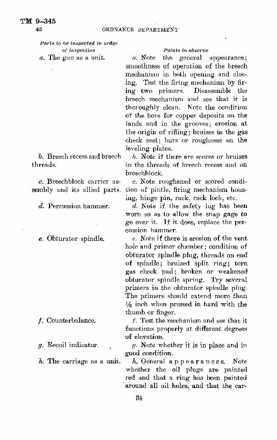
TM 9-34545 ORDNANCE DEPARTMENT
Parts to be inspected in orderof inspection
a. The gun as a unit.
&. Breech recess and breech threads.
c. Breechblock carrier as sembly and its allied parts.
d. Percussion hammer.
e. Obturator spindle.
/. Counterbalance.
ff. Recoil indicator.
h. The carriage as a unit.
Points to observea. Note the general appearance;
smoothness of operation of the breech mechanism in both opening and clos ing. Test the firing mechanism by fir ing two primers. Disassemble the breech mechanism and see that it is thoroughly clean. Note the condition of the bore for copper deposits on the lands and in the grooves; erosion at the origin of rifling; bruises in the gas check seat; burs or roughness on the leveling plates.
b. Note if there are scores or bruises in the threads of breech recess and on breechblock.
G. Note roughened or scored condi tion of pintle, firing mechanism hous ing, hinge pin, rack, rack lock, etc.
d. Note if the safety lug has been worn so as to allow the snap gage to go over it. If it does, replace the per cussion hammer.
e. Note if there is erosion of the vent hole and primer chamber; condition of obturator spindle plug, threads on end of spindle; bruised split ring; torn gas check pad; broken or weakened obturator spindle spring. Try several primers in the obturator spindle plug. The primers should extend more than ys inch when pressed in hard with the thumb or finger.
f. Test the mechanism and see that it functions properly at different degrees of elevation.
g. Note whether it is in place and in good condition.
A. General appearances. Note whether the oil plugs are painted red and that a ring has been painted around all oil holes., and that the car-
34

155-MM GUN MATERIELTM 9-345
45
Parts to lie inspected in order of inspection
i. Recoil mechanism.
j. Elevating mechanism.
. Traversing mechanism.
I Trails.
m. Spade.
Points to observeriage is painted in accordance with regulations.
i. See that the proper amount of oil is in both recoil and recuperator cylin ders. Note whether the oil index and the replenisher piston function cor rectly. See that the recoil and recuper ator piston rod nuts are screwed tight. When the gun is tired, see that the re lief valve in the counterrecoil front head is functioning properly and al lowing the air trapped in the cylinder to escape. See that air is escaping from the replenisher piston guide as sembled in the rear end of the replen isher. (See par. 47a(2).)
;/. Note whether operation is smooth and whether properly lubricated. Ele vate and depress. Note the movement of the connecting rod and that it func tions properly. Note whether the nut which retains the handwheel is in place.
k. Note whether operation is smooth. Note whether there is excessive back lash, and that parts are properly lubri cated. Test clearance between the top and bottom carriages using a piece of tin or heavy paper measuring 0.012 inch; this clearance not to exceed 0.012 inch.
I. Note the condition of the translat ing racks; that the teeth are not burred or broken. Move the trail hinge pin up and down and see that it is properly lubricated. Test the trail locking bolt nuts for ease of operation, also the traveling bar clip clamping screw.
m. Note condition of swing bolt nuts and that they move freely on the bolts. Genera] condition of the spades.
35

TM 9-34545 ORDNANCE DEPARTMENT
Parts to be inspected in orderof inspection
n. Bottom carriage.
•o. Axle.
p. Brakes.
q. Wheel.
r. The limber as a unit.
s. Electric brakes.
Points to observen. Note condition of spring shackles
and spring shackle pins and that they are not scored or stuck tight. Open and close the axle pivot pin cap; see that it latches properly.
o. Note condition of axle where it bears in the axle housing.
p. Note condition of brake lining, that all parts of the brake mechanism function properly, and that all nuts and pins are in place.
q. Note condition of the rubber; that all torn strips and embedded stones have been removed. Remove the hub cap and see that the gun axle is properly lubricated. Note that all nuts of the brake drum bolts are in place and held by cotter pins.
r. Note general appearance. Note condition of limber springs; that steer ing mechanism moves freely; that the seat is in good condition; that trail clamping bolts and nuts are in good condition; that all oil cups are in place and moving parts receiving lubrication.
s. Note condition of dry cell batter ies. Check battery terminals. Check current at brakes. Check ground con nections. Check plug and socket for dirty or corroded blades or broken socket. Check controller by connecting both wires to one terminal and see if brakes are effective. Check safety switch by pulling the safety switch lever and listen for the click caused by armature contacting the magnet.
36

155-MM GUN MATERIEL
SECTION VI FUNCTIONING
Malfunction of gun___________Malfunction of carriage_____ . Malfunction of electric equipment-
TM 9-345 46
Paragraph4647
—— 48
46. Malfunction of gun.Malfunction
a. Fails to fire.Cause
a. (1) Firing mechanism not screwed home.
(2) Fouled firing pin.
(3) Deformed point on firing pin.
(4) Weak pull on the lanyard.
b. Fails to fire &. Defective prim- when proper per- er. cussion on primer is obtained.
G. Fails to fire c. (1) Damp or after the primer has fouled vent hole discharged. through obturator
spindle.(2) Damp charge.
d. Breech mech- d. (1) Lack of lu- anisin does not op- brication between erate freely. rack and breechblock
carrier.(2) Lack of lubri
cation and the for mation of scores in
Correctiona. (1) Screw the firing
mechanism as far beyond the latch as it will go.
(2) Remove firing mechanism and disassem ble. Wash all parts free of dirt or gummed oil with dry-cleaning solvent. Dry thoroughly and lubri cate with recommended lubricating oil.
(3) Remove firing mechanism, disassemble and replace firing pin.
(4) Pull lanyard with considerable snap.
1). After three percus sions, wait at least 2 min utes and then replace primer.
c. (1) Wait at least 10 minutes, remove primer, and clean vent hole.
(2) Wait at least 10 minutes and replace the charge.
d. (1) Remove the rack. Clean and lubricate.
(2) Disassemble the breechblock and thorough ly clean. If the threads

TM 9-34546-47 ORDNANCE DEPARTMENT
Cause Correctionthe threads of the are scored, repair must bebreechblock carrier made by the personnel ofor in the breech re- an ordnance maintenancecess.
e. Lack of lubrica tion and roughness on shaft and shaft bearings.
Malfunction of carriage.
e. Percussion hammer not work ing freely.
47.Malfunction
a. R e p 1 e n isher piston less than 50 mm (1.97 inches) from rear face of replenisher. (See par. 500(2).)
b. Replenisher piston 200 mm (7.87 inches) from rear face.
c. Oil leaks from rear of replenisher.
Causea. (1) Expansion
of oil due to warm weather or continued firing.
(2) Accumulation of air in the recoil system. When the accumulation, of air occurs to any great extent after the sys tem ,has been drained and filled it is an in dication that the replenisher piston packing is defective or that the cylinder wall is leaking.
&. Insufficient, oil in replenisher.
c. Whether or not a serious leak exists must be determined by the position of the replenisher piston and the frequency of
company.e. Disassemble, clean,
and remove roughness.
Correctiona. (1) Drain the recoil
cylinder until the piston of the replenisher is 150 mm (5.9 inches) from the rear face of the replen isher. (See par. 50^(1).)
(2) Refer to ordnance maintenance personnel.
b. Fill the mechanism until the piston is 150 mm (5.9 inches) from the rear face of the replenisher. (See par. 50^(2).)
c. There is no cause for alarm should the oil drip rapidly or even run in a stream from the rear of the replenisher when the gun is elevated, provided
38

155-MM GUN MATERIELTM 9-345
47
Malfunction Causerefilling required in the recoil system.
d. Position of d. Replenisher pis- replenish er piston ton stuck, does not change during firing.
Correctionthe cradle has been at zero elevation for some time previously. This condition might exist on a normal replenisher. A leak at any packing that does not exceed 3 drops per minute is not considered serious.
d. Insert a block of hardwood in the rear of the replenisher against the piston end and tap with a hammer. It has been found that where the replenisher has not been exercised from time to time the piston rod may become rusted in the replenisher piston guide. The replenisher may be exercised by draining as much of the oil as possible (through the filling and drain valve release) and then pumping in oil until the rear end of the piston rod projects to the rear of the replenisher and any visible rust polished off. Enough oil should then be withdrawn to
1 bring the piston back to normal position. The replenishers of all .155- inm gun carriages in the Iuinds of troops which are not being used for firing should be exer cised in. the manner pre scribed above at least
39

TM 9-34547 ORDNANCE DEPARTMENT
Malfunction Cause
e. Oil index projects less than 5 mm (0.19 inch).
«. oil.
(1) Loss of reserve
(2) Loss of gas pres sure either through the recuperator cylinder front head or past the floating piston.
Correctiononce a month. There are two 2-mm holes in the replenisher piston guide (fig. 7), and one 3-mm hole in the re plenisher cylinder, which are produced for the purpose of draining the cylinder of accumu lated water and oil that has passed the replen isher piston, and to pro vide for the circulation of air through the re plenisher. The 2-mm holes are in the center of the teat wrench holes. The 3-mm hole is in the under side of the replen isher about \% inches from the rear end. It is very important that these holes be kept open. The walls of a replen isher should never be struck with a hammer or any other article. If the replenisher cylinder becomes dented in any way, report the fact to the ordnance mainte nance company.
e. (1) Drain the re mainder of the reserve and refill.
(2) Gas escaping by the floating piston is indicated by an emulsi fied condition of reserve oil drained off. If, when proceeding to fill the
40
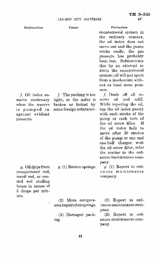
155-MM GTJN MATERIELTM 9-345
47
Malfunction
j. Oil index re mains stationary when the reserve is pumped in against evident pressure.
g. Oil drips from counterrecoil rod, recoil rod, or con trol rod stuffing boxes in excess of 3 drops per min ute.
Cause
/. The packing is too tight, or the index is broken or locked by some foreign substance.
g. (1) Broken springs.
Correctioncounterrecoil system in the ordinary manner, the oil index does not move out and the pump works easily, the gas pressure has probably been lost. Substantiate this by an attempt to drain the counterrecoil system; oil will not spurt from a mechanism with out at least some pres sure.
/. Drain off all re serve oil and refill. While injecting the oil, tap the oil index gently with each stroke of the pump or each turn of the oil screw filler. If the oil index fails to move after 30 strokes of the pump or one and one-half charges with the oil screw filler, refer the matter to the ord nance maintenance com pany.
g. (1) Report to ord nance maintenance company.
(2) More compres- (2) Report to ord- sionrequired on springs, nancemaintenancecom-
pany.(3) Damaged pack- (3) Report to ord-
ing. nance maintenance com pany.
41

TM 9-34547
Malfunction h. Oil leaks from
forward end of counterrecoil cyl inder.
OKDNANCE DEPARTMENT
i. Excessive leaks from recu perator and recoil filling and drain plugs.
j. Gun will not return to battery.
k. Gun returns to battery with too great a shock.
Causeh. Black oil appear
ing in front of the counterrecoil piston is a normal condition due to lubrication. Clear oil is an indication of a leak due to broken packing springs or lack of compression on the springs.
i. Sticking of valve or defective packing.
Correctionh. Report a leak of
clear oil to ordnance maintenance company.
j. (1) Too much oil in the recoil system.
(2) Insufficient oil in the counterrecoil sys tem.
(3) Insufficient air pressure.
k. (1) Insufficient oil in recoil system.
(2) Excess oil in counterrecoil system.
(3) Change of vis cosity of oil (due to rapid firing).
(4) Frictions of vari ous packings too low.
i. Remove the plug and insert a piece of %- inch drill rod into the hole against the end of the valve stem and tap it lightly with a ham mer. If this does not- stop the leak, report it to the ordnance main tenance company.
j. (1) Drain the recoil reserve oil, purge and refill.
(2) Drain off the re serve oil and refill.
(3) Report to ord nance maintenance com pany for investigation.
k. (1) Refill recoil system to normal.
(2) Drain counterre coil reserve and refill to normal.
(3) Allow mechanism • to cool.
(4) Report to ord nance maintenance com pany.
42

155-MM GUN MATERIELTM 9-345
47
Malfunction I. Gun slow to
return to battery (when oil gage is normal).
m. Uneven and jerky counterre- coil.
7i. Gun in coun- terrecoil does not cause a hissing sound like air es caping.
CauseI. (1) Insufficient air
pressure.
(2) Too much friction on packing.
m. (1) Too close lit of bearing surfaces such as the recoil rod piston liner and anti friction ring bearings.
(2) Scoring of vari ous bearings.
(3) Foreign sub stances in the oil.
n. Air vents are stopped up.
o. Gun recoils more than the maximum distance allowable.
o. (1) Insufficient oil in recoil mechanism.
(2) Insufficient -gas pressure in recoil mech anism.
(3) Insufficient fric tions.
CorrectionI. (1) Report to ord
nance maintenance com pany.
(2) Report to ord nance maintenance com pany.
m. (1) Report to ord nance maintenance com pany.
(2) Report to ord nance maintenance com pany.
(3) Report to ord nance maintenance com pany.
n. Clean the vents in the replenisher piston guide, using a small wire. If air is not es caping from the coun- terrecoil cylinder front head notify the ordnance maintenance company which will remove coun- terrecoil cylinder head and try the relief valve. Disassemble and clean if necessary.
o. (1) Refill recoil sys tem to normal.
(2) Report to ord nance maintenance com pany.
(3) Report to ord nance maintenance com pany.

TM 9-34547-48
Malfunction
p. Gun does not recoil full distance.
</. Gun will not elevate to fuU 35° (when carriage is set on level ground).
ORDNANCE DEPARTMENT
Cause(4) Malfunction
control rod.of
p. (1) Low viscosity of oil due to low tem perature.
(2) Scoring of vari ous bearing surfaces.
(3) Increased fric tion on all packings.
(4) Malfunction control rod.
of
([. (1) Valve turning mechanism jammed.
(2) Interference be tween the elevating sector and elevating worm or top carriage.
(3) Interference be tween cradle and top carriage.
(4) Malfunction of the elevating mecha nism.
48. Malfunction of electric equipment.
Correction(4) Report to ord
nance maintenance com pany.
p. (1) Warm the re coil mechanism by fir ing warming rounds or otherwise.
(2) Report to ord nance maintenance com pany.
(3) Report to ord nance maintenance com pany.
(4) Report to ord nance maintenance com pany.
g. (1) Report trouble to ordnance mainte nance company.
(2) Report trouble to the ordnance mainte nance company.
(3) Report trouble to ordnance main tenan ce company.
(4) Report trouble to ordnance maintenance company.
Malfuncton a. No brakes or
intermittent brakes.
Causea. (1) Broken
in circuit.wire
(2)Controller defec tive.
Correctiona. (1) Check entire
wiring for broken wires.
(2) Short out the con - troller by connecting both wires to one ter minal and. see if brakes are effective.

155-MM GUN MATERIELTM 9-345
48
Malfunction Cause(3) Poor conneC'
tions.
(4) Broken wire on magnet.
(5) Poor ground con dition in circuit.
(6) Defective plug or socket.
b. Weak brakes. 6. (1) Glazed mag net facing.
(2) Grabbing brakes.
(3) Wire broken in insulation. Loose con nection. Poor contact at load control. (See a(2) above.)
(4) Insufficient cur rent.
Correction(3) Check, clean, and
tighten all connections at brake, controller, load control, and socket.
(4) If broken wire is on outside of magnet, re pair if possible. If no current flows through magnet, notify ordnance maintenance company.
(5) Clean up and tighten connections.
(6) Check plug and socket for loose connec tions, dirty or corroded blades, or a broken socket. Repair or re place with new socket.
6. (1) Roughen the facing of the magnet with coarse emery cloth.
(2) Check and see if stop lights have been connected into the brake circuit by mistake.
(3) Check wiring for defective parts. Short out load control.
(4) Insufficient cur rent may be due to poor connections at the brake, controller and load control, ground, or plug and socket. Clean up and tighten all con nections, check plug and socket for corroded or dirty blades. Repair or replace with new socket.
45
TM 9-34548-49 ORDNANCE DEPARTMENT
Malfu-H rition Cause Correction c. Brakes grab- c. (1) Loose or worn c. (1) Tighten or re-
bing. wheel bearings. place bearings.(2) Only one brake (2) Check current at
working. the brakes by using am meter. (See par. 54.)
(3) Contactor arm (3) Smooth out con- in controller pitted. tactor arm with fine
emery cloth:
SECTION VII
CARE AND PRESERVATIONParagraph
Gun_________________________________________________ 49Carnage and limber_______________________________.. __ 50Lubrication instructions__________________________ _, __ __ 51Care of electric brakes____________________________.______ 52Cleaners and abrasives_______________________________-__ 53Preservatives_______________________________________ 54Paint and related materials______________________________ 55Lubricants__________________________________________ 56Miscellaneous materials and tools__________________—__—_ 57
49. Gun.—a. General.— (1) Cannon become less copper fouled when properly cared for, and it is known that the wear of cannon does not depend entirely upon the number of rounds fired but very much upon the care given the bore in cleaning, oiling, and cooling between rounds.
(2) The accuracy life of cannon usually depends on the amount of erosion of the bore at the front of the forcing cone or beginning of the rifling. This condition is produced by a fast rate of h're and its at tendant excessive heating, therefore it is essential that after 10 minutes of firing the piece is washed and oiled and allowed to cool. Each projectile will be cleaned before it is inserted into the bore of the gun.
(3) In cleaning after firing, wash the bore with a solution made by dissolving ^ pound of soda ash or 1 pound of sal soda in 1 gallon of water, using the sponge for swabbing purposes. Wipe perfectly dry, using the sponge covered with burlap, and then oil the bore with a light coating of SAE 10 engine oil for temperatures below 32° F. and SAE 30 engine oil for temperatures above 32° F., applying it with the bore slush brush.
(4) The breech should be kept covered to prevent dust and grit get ting into the recesses of the mechanism and impeding their easy operation.
46

TM 9-345155-MM GUN MATERIEL 49
(5) When materiel is not in use, extreme care must be taken to prevent injury to the gas check seat. Bruises in the gas check seat affect the seating of the split ring (fig. 3) and are likely to cause leak age of gas and burning of the gas check pad. If such a leak should occur, serious erosion may result. Rusting of the gas check seat is likely to occur, due to the gas check pad being susceptible to moisture. The seat and rings therefore should be well protected by rust-preven tive compound when the gun is not in use.
(6) The surface of the leveling plates should be protected from injury. In case of accidental injury, repair should be made by the personnel of the ordnance maintenance company.
(7) The breech mechanism should be kept clean and well lubricated. It should be disassembled periodically when not in use and lubricated to prevent rusting.
(8) When in use the mechanism should be disassembled at intervals and after each firing period cleaned and oiled. This is extremely important as no provision is made to oil by means of the oiler or oil channels.
(9) It is important that any cutting or abrasion on the threads of the breechblock (fig. 3) or in the breech recess be reported to the ord nance maintenance company for correction.
(10) If the breechblock (fig. 3) does not rotate smoothly or the mechanism requires a greater effort than usual to operate, it should be considered sufficient warning to warrant disassembly and determina tion of the cause.
(11) In assembly or disassembly do not use a steel hammer directly on any part. A copper drift should be interposed or a copper hammer used to prevent deforming the part.
1). Firing mechanism.—(I) The firing mechanism parts (fig. 5) require careful attention and should be disassembled frequently for the purpose of cleaning and oiling. The parts should be washed with dry-cleaning solvent to remove any gummy oil, after which they should be wiped dry and lubricated with SAE 10 engine oil for temperatures below 32° F. and SAE 30 engine oil for temperatures above 32°.
(2) Fouling of the firing pin or the use of heavier oil than specified may result in misfire. This is especially true in cold weather as the oil may congeal and become gummy.
(3) The primer seat and the vent hole in the obturator spindle should be kept clean by frequent use of the vent cleaning tool. The slightest accumulation of fouling in the primer seat will cause the primer to enter with difficulty and cause trouble in extraction.

TM 9-34549 ORDNANCE DEPARTMENT
o. Misfires.—A misfire occurs if the piece faiJs to fire when desired. Failure of the piece to fire is due to one of two causes: failure of the prime)' to fire or failure of the propelling charge to ignite.
(1) General precautions.—The following general precautions will be taken in all cases:
(a) The piece will be kept trained on the target or on a safe place in the field of fire.
(b) All persons will be kept clear of the path of recoil until after the breechblock is opened.
(<?) When removing the firing mechanism, opening the breech, or reaming the vent, the operator will stand clear of the path of recoil and all other persons will be kepi from the rear of the breech.
(d) In no case will the breechblock be opened before the primer is removed.
(e) Whenever a new primer is inserted and another attempt to fire results in failure, all precautions and procedure will be as prescribed for the first failure. The firing of more than two primers in an attempt to ignite the propelling charge usually is not justified.
(2), Primer failures.—In case the discharge of the primer is not heard, the following procedure will be observed :
(a) At least three attempts will be made to fire the primer, the lanyard being pulled with considerable snap.
(b) If a special device is available which permits the lifting of the latch and removal of the firing mechanism by a person entirely clear of the path of recoil, the primer may be removed after 2 minutes have elapsed since the last attempt to fire. If no special device is available, proceed as in d below.
((?) When removing the firing mechanism, the operator will note whether or not the firing, mechanism was fully screwed home. (The primer will not be hit properly unless the firing mechanism is screwed as far beyond the latch as possible.)
(d) The primer, after removal, will be examined to determine whether or not it has fired.
(e) If the primer has fired, proceed as in d below. (/) If the primer has not fired, the percussion head will be examined
and—1. If the head has been properly indented, the primer will be
handled carefully and disposed of quickly due to the pos sibility of a primer hangfire. A new primer should then be inserted and an attempt made to fire.
'8. If the head has not been properly struck, and if the firing mechanism was found to have been properly seated, the
48

TM 9-345155-MM GUN MATERIEL 49-50
firing mechanism should be inspected for the following faults: dirty or gummy parts, firing pin or firing pin spring broken, firing pin housing or primer holder loosened. A. new primer should then be inserted and an. attempt made to fire.
d. Propelling charge failure.—In case the discharge of the primer is heard but the propelling charge has failed to explode, no attempt will be made to remove the primer or to open the breecli until 10 minutes have elapsed after the firing of the primer. After 10 minutes the primer will be removed, a cleaning bit will be run through the vent, another primer will be inserted, and another attempt will be made to fire. Failure of the propelling charge to ignite indicates an abnormal condition of the charge such as a missing igniter, igniter end of charge against the projectile, wet igniter, or igniter charge folded over and not accessible to the flash of the primer.
50. Carriage and limber.—a. General.— (1) Maintenance of the carriage and limber in service requires proper cleaning, strict observ ance of the lubrication program, and proper attention to the adjust ments of the traveling lock, axle pivot pin, canvas covers, trail clamp ing bolts, and wheel brakes when traveling, as well as in correction of loose or broken parts.
(2) All bearing surfaces, screw threads, and exterior parts must be clean and as free from dirt as possible. Special attention should be given those bearing surfaces which are exposed. When disassembly and assembly operations are being carried on, extra precautions must be taken to prevent the entrance of foreign matter into the working parts.
b. Care of wheels.— (1) Remove, by means of a screw driver or small bar, any small stones or other foreign substance which may have become lodged in the rubber of the tires.
(2) If a strip of rubber is cut or torn on the edges of the tires, cut off the loose portion to prevent the strip from tearing further.
(3) Keep tires free from oil and grease as much as possible as these have a deteriorating effect upon the rubber.
(4) Caterpillar band segments should be kept clean and the segment pins well lubricated. Examine the fastening pins frequently and renew those showing evidence of wear or breakage before the segment pin is bent by coming partially out of its seat.
(5) Before traveling, remove the wheels, clean the hub liners and bearings on the axle arms, smooth' off any roughness, and thoroughly lubricate before replacement. Pack the hubs and bushings with grease, O. D.. No. 0.
4in7(i8°— 41———4 49

TM 9-34550 ORDNANCE DEPARTMENT
G. To adjust road brake.— (1) As the brake band linings wear, it becomes necessary to tighten them. The carriage being limbered, place lifting jacks under the lugs of the bottom carriage and raise both wheels from the ground. Set the limber hand brake lever at two- thirds of its full travel on the brake quadrant and have a man stand on one of the horizontal spokes of each wheel. (The men should be of equal weight.) Tighten the brake bands equally by screwing down the lower nuts of the brake band adjusting bolts until neither wheel revolves under the weight of the man on the spoke. Release the brake and see if each wheel is free. Set the brake again and repeat the test. The remaining one-third travel of the brake quadrant will allow for some wear of the brake band linings before it becomes necessary to again adjust the brake. When satisfactory action is secured, set the upper nuts of the brake band adjusting bolts down hard against the lower nuts to secure them from turning.
(2) All adjustments of the brake band for wear should be made through the brake band adjusting bolt (fig. 15) and not by taking up slack in the longitudinal or traverse cables. Stretching of the cables or slipping of the clamps may be taken care of by readjusting and tightening the clamps.
(3) Keep oil and grease from the brake linings. If they become glazed or greasy, clean them with dry-cleaning solvent.
d. Maintenance of trail and spades.— (1) Clean the notches for the locking bolts in the upper and lower trail ends.
(2) Clean the teeth and upper portion of the translating racks.(3) Clean and oil the threads and points of the traveling car clip
screws.(4) Clean that portion of the spade clamping transoms upon which
the spade bolt lock nuts bear.(5) Clean the spades, especially those surfaces which come in con
tact with the trails; oil the spade clamp bolt threads and the spade clamp bolt lock nuts.
(6) Before fastening the trail to the limber, clean the top and rear spring hangers of the limber, as well as the limber stops of the trails.
e. Drain holes.— (1) The top carriage should be provided with a drain hole in each pocket. See that these holes are not closed with dirt.
(2) Keep the drain hole in the bottom carriage which leads into the axle housing clean of all obstructions.
/. Recoil mechanism.— (1) Before firing, the recoil and counter- recoil mechanisms should be examined for leakage of oil to see that a proper amount of reserve oil is in the counterrecoil system and in
50

TM 9-345155-MM GUN MATERIEL 50
the replenisher, that the gun slides are well lubricated, and thai; piston rod nuts are properly tightened.
(2) During firing, the action of the mechanism, should be watched to see that the gun returns to battery smoothly and without shock, and that there is no leakage of oil.
(3) When replenishing the reserve oil it should be carefully filtered through a piece of clean cloth, as well as though the wire strainer of the filling funnel. Every precaution must be taken to prevent the introduction of grit into the mechanism, either in the oil or through failure to clean the filling pipe or connections thoroughly.
(4) To remove and replace a filling or drain plug remove the filling or drain plug with the screw driver. Be careful that the gasket beneath the plug is not lost. Examine the threads of the plug and if in good condition place and screw the plug upon the gasket tightly but do not force it excessively.
g. Fitting of recoil cylinder.— (1) The position of the replenisher piston (fig. 7) governs the filling of the recoil cylinder. The normal position of the replenisher piston is 150 mm (5.9 inches) measured from the rear face of the replenisher cylinder. This position indi cates a full cylinder and sufficient reserve in the replenisher.
NOTE.—When it is known that rapid fire is to take place, the replenisher should be drained until the reading of the replenishing piston is 200 mm (7.87 inches) measured from the rear face of the replenisher cylinder.
(2) When the replenisher piston (fig. 7) is at a point 100 mm (3.93 inches) or less from the rear face of the replenisher, oil should be removed from the recoil cylinder before firing is continued.
NOTE.—When in an emergency it is necessary to continue firing without Interruption, firing may be permitted until the rending is down to 60 mm.
(3) When the replenisher piston (fig. 7) has moved in to a point 200 mm (7.87 inches) or more from the rear face of the replenisher, oil should be added.
(4) Before filling the recoil cylinder with oil, test the operation of the replenisher piston by inserting a scale through the opening of the replenisher piston guide and against the replenisher piston, then releasing oil from the recoil cylinder by means of the filling and drain valve release screwed into the recoil cylinder drain hole (fig. 7). If movement of the replenisher piston takes place, proceed with the filling of the recoil cylinder as follows: Unscrew the filling and drain plug of the recoil cylinder filling hole (fig. 7) (on left side of the replenisher), and screw the union of the pump coil into the filling hole loosely and pump a little oil through until all air is ex-
51

TM 9-34550 ORDNANCE DEPARTMENT
eluded. The union should be set up without the use of a wrench, except for the final tightening. Extreme care must be taken to pre vent any injury to the threads of the filling hole, as any damage may put the entire cradle out of commission. As the filling and drain valve release is already in place, work the pump and force oil through until it flows from the filling and drain valve release free from air bubbles; then remove the filling and drain valve release and continue to work the pump until the rear end of the replenisher piston is 150 mm (5.9 inches) from the rear face of the replenisher. Remove the filling pipe union and replace the filling and drain plugs.
(5) The oil screw filler may also be used in filling the recoil cylin der with oil. The oil screw filler requii'es careful handling in order to avoid breaking it off in the filling hole by the operator failing prop erly to balance the effort required to turn the handle. Only an ex perienced man should be allowed to use the oil screw filler and it should only be used when no pump is available.
(6) In filling the recoil cylinder with the oil screw filler remove the filling plug from the replenisher. Before screwing the oil screw filler into the filling hole (fig. 7) it must be filled with oil as follows: Unscrew the screw assembly of the filler as far as the threads permit. Unscrew the screw nut from the body and remove the nut and screw. Hold the filler vertically, close the opening at the nozzle with a finger, and pour the filler three-fourths full of perfectly clean recoil oil. Replace the filler screw and screw on the screw nut, invert the filler and give the screw a turn or more to remove all air contained in the filler.
(7) Screw the filler into the recoil cylinder filling hole (fig. 7) of the replenisher with great care to avoid damage to the threads. While still loose, give a few turns to the screw to force out any air which may be in the filling hole; then tighten against the gasket. Turn the screw with both hands on the handle, balancing the effort so that there will be no tendency to push the filler to one side. Screw the piston in as far as it will go. Continue the above operation until the replenisher piston is 150 mm (5.9 inches) from the rear face of the replenisher. Unscrew the oil filler and replace the filling plug.
h. Fitting counterrecoil or recuperator cylinder.— (1) The position of the oil index which is directly below the filling and drain plug (fig. 9) governs all filling and draining of the system. The normal position of the oil index is 5 mm out from the rear face of the cradle.
(2) When the counterrecoil of the gun or the position of the oil index indicates that there is too small a quantity of oil in the recuperator, it will be necessary to drain off the reserve oil before
52
TM 9-345155-MM GUN MATERIEL 50
refilling. This is accomplished by inserting the filling and drain valve release in the recuperator rear cylinder head. The reserve oil will spurt out in a stream and suddenly drop to a trickle. At this point the flow of oil should be stopped by unscrewing the filling and drain valve release. It will be noted that the oil index has moved out of sight before all of the reserve oil has been released. If the oil index has not moved tap it gently with a small piece of wood as it may be frozen. The amount of reserve oil which will escape will be close to a quart.
(3) To fill the recuperator system remove the plug from the filling hole located on the right side of the cradle (fig. 7). Clamp the pump chest to the right trail, purge the pump, clean the union, and screw the union into the filling hole loosely. Work the pump a few strokes to clear the pipe and connection of air, and screw the union firmly against the gasket in the filling hole. Give the pump a few more strokes and screw in the filling and drain valve release. Note whether air bubbles appear- in the escaping oil. If free from air bubbles remove the filling and drain valve release. Give the pump exactly 100 strokes which will fill the cylinder with the required amount of oil. It will be noted that 30 full strokes of the pump will cause the oil index to move out to its maximum projection from 5 mm to 6 mm beyond the rear face of the cradle, but 70 more strokes of the lever are required to introduce the necessary reserve oil. Detach the pump and replace both plugs.
(4) Filling the recuperator cylinder can also be accomplished by the use of the oil screw filler. The same procedure will be fol lowed in the release of the reserve oil as outlined for filling the system by means of the pump. After the oil screw filler has been filled with recoil oil as outlined above it will be screwed into the filling hole located on the right side of the cradle. The oil screw filler will be filled five times and the contents forced into the recuperator cylinder. Remove the oil screw filler and replace the filling plug.
i. Replacing, adjusting, and assembling carnage brake rocker spring.— (1) To replace and adjust a carriage brake rocker spring, right, release the brake, take off the brake shaft nut, unhook the ends of the spring, and remove the brake rocker and the spring. Clean and oil the clutch face.
(2) To assemble, put on the new spring and the brake rocker (fig. 15), hook the ends of the spring, and screw the brake shaft nut on one or two turns. Draw the brake band tightly about the drum with any convenient clamp over the brake band ends. Set the limber brake lever at two-thirds of its full movement on the brake
53
TM 9-34550 ORDNANCE DEPARTMENT
quadrant and draw the brake cable tight. The rear end of the brake cable will indicate the position of the upper end of the brake rocker, which may then be set in correct relation to the brake shaft and the brake shaft nut tightened. The length of the brake cables should be such that in the position of brake set as described above, the brake rocker is inclined about 10° forward of the vertical.
j. To change limber spring (carnage limbered] (fig. 17).— (1) When the limber spring is free, the upper leaf may arc so much as to bring the eyes too close together to assemble readily the spring eye pins. For this reason a hardwood block about 4 inches thick should be wedged between the upper leaf and the limber side rail just forward of the limber spring shackle to relieve the pressure on the pin before dismounting. The upper part of the limber and trails are then raised by jacks, and the limber spring clips, large, taken off to free the spring. The same wedges and blocks may then be placed on the replacement spring and the weight on the trails allowed to compress the spring until the lower spring eye pin can be assembled. The spring eye pins should be cleaned of all rust and well slushed with SAE 10 engine oil for temperatures below 32° F. or SAE 30 engine oil. for temperatures above 32° F.
(2) The limber spring leaves are maintained in correct relation by a, flat center bolt and side clips. The height of the limber spring, •when free, is at least 160 mm (G.3 inches) from top of the axle to center of the eye. deflecting to a height of 110 mm (4.33 inches) under a load of 4,400 pounds.
k. To replace Umber yteering knuckle.— (1) Loosen the steering knuckle spindle lock nuts so that the nuts are together and the bottom of the lower nut flush with or a little below the lower end of the steering knuckle spindle. Set a jack under the spindle with a piece of sheet copper, lead, or other soft metal between the lock nut and jack, and lift that end of the axle. Strike a light blow or two on the top of the yoke of the axle with a piece of timber, if necessary, to start the steering knuckle spindle from its tapered seat in the axle. After starting the spindle, transfer the jack to the axle inside the spindle and raise and remove the limber wheel, disconnect the steering tie rod, take off the lock nuts, and raise the spindle out. The steering knuckle is then free. If it is necessary to change the steering arm, back its nut off a thread or two and turn the steering knuckle down on some solid support which does not interefere with movement of the steering arm. Put a hardwood block on the steer ing arm nut and strike it with a sledge to start the steering arm out of its tapered seat. Striking on the nut in this manner is less
54

TM 9-345155-MM. GUN MATERIEL 50-51
apt to mar the parts than to take the nuts off and strike against the threaded end of the arm or spindle. If the joint, between the steering arm and knuckle, which has been solidly set, proves stub born, soak it with penetrating oil for an hour or so and try again.
(2) The steering knuckle spindle should fit well in the steering knuckle bushings. If the bushings become worn and permit appre ciable side play, they should be replaced. Turning the steering knuckle spindle around one-quarter of a revolution may tighten the joint so as to make immediate replacement unnecessary. Clean the oil passage in the spindle before assembling and make sure that there is not the slightest particle of grit in or on the tapered portions of the spindle or steering arm to spoil the fit, which must be set up solid.
51. Lubrication instructions.—a. General instructions.— (1) Excessive wear can be prevented by keeping the materiel clean and well lubricated. The life of the gun and carriage depends on proper lubrication. Particular attention should be given to sliding and bearing surfaces of the cradle and breech mechanism.
(2) Lubricating oils and greases as shown in the lubrication chart should be used as prescribed.
(3) Lubricating fittings are painted red for ease in locating. Oil holes are encircled by a red ring.
(4) The hand oiler should be worked slowly and the parts oiled should be maneuvered to insure proper distribution of the lubricant.
(5) Should an oiler valve stick and prevent the passage of the oil, it may be loosened with a piece of wire pushed through the hole. Care should be taken not to damage the valve.
(6) Care must be taken when cleaning oil and grease compart ments to insure the complete removal of all residue or sediment. Dirt or other foreign matter should not be allowed to drop into any of the lubricating compartments.
(7) Battery personnel when cleaning the gun are cautioned not to play water from the high-pressure hose directly against the trun nion bearings or trail pin housings, since this will result in water entering into the bearings and cause nonfunction of the operating parts.
(8) Lubrication frequencies are based on continual use of the materiel with frequent firing.
(9) No lubricants will be used other than those prescribed, with out, the authority of the Ordnance Department.
&. Special instructions.— (1) Traversing sector.— (a) The top car riage should be traversed to the left until the worm leaves the
55
TM 9-34551 ORDNANCE DEPARTMENT
traversing sector. It may be necessary to withdraw the axle pivot pin and jack up the carriage to obtain clearance between the cradle and wheel. Wipe the traversing sector clean and apply a film of oil.
(£>) While the gun is at extreme traverse, clean and wipe the top carriage retaining lug and wipe clean the clip on the bottom carriage beneath which the lug moves.
(c) Bring the traversing worm back into mesh very carefully to prevent injury to the teeth of the worm or sector.
(2) Elevating sector.—The elevating sector should be wiped clean and a film of oil applied with the cradle depressed and elevated through the whole range of elevation. Make sure the elevating worm is covered with a film of oil.
(3) Cradle.— (a) Clean and oil all accessible parts of the gun slides while moving the gun from battery to traveling position or vice versa.
(b) Clean and oil the ends of the recoil and counterrecoil piston rods and piston rod nuts with the gun in traveling position.
(c) Clean and oil the valve-turning rod and connecting rod of the recoil mechanism while elevating and depressing the cradle. Put a few drops of oil in the oil cup at the front end of the replenisher.
(4) Top carriage.— (a) In the sighting gear casing cover, four oil cups are provided, two serving the handwheel shafts and two the elevating and traversing gear spindles which drive the oblique spindles. About 1 teaspoonful of oil should be placed in each of the oil cups of the cover at each oiling.
(b) The handwheel handles should be given an occasional drop of oil at each end while the handles are turning on their spindles.
(5) Brake (Ml917 and M1918).—The brake cables should be lubricated with grease, O. D., No. 0, where they pass through the cable rocker bushings and rear cable guides on the trail. The ball connections should be oiled occasionally while stretched to maximum length and exercised to work the lubricant into the spring chambers. Drops of oil should be placed at the joints of the links and in the oil cups of the carriage brake brackets and limber shaft bearings. Oil the sides of the slot in the brake lever for the brake quadrant and the joints of the brake lever latch and handle.
(6) Wrenches a,nd pinions.—The ratchet wrenches and the travel ing lock pinions should be oiled each time before using.
(7) Detailed repairs.—When repairs are beyond the scope pre scribed for the using arms, the materiel should be taken to the ordnance maintenance company which will issue a 7'eceipt therefor. When notification of the completion of such repairs has been received
56
TM 9-345155-MM GUN MATERIEL 51
from the ordnance maintenance company, the organization will send for the materiel, returning the receipt previously received.
(8) Oil.—Moving parts not specifically mentioned herein should be lubricated daily with oil. Wherever oil is specified in these in structions. SAE 10 engine oil for temperatures below 32° F. and SAE 30 engine oil for temperatures above 32° F. should be used.
(9) Lubrication chart.—The lubrication chart gives the location, lubricant, amount, frequency, and method of application for the vari ous lubricating points of the 155-mm gun materiel, M1917, M1918, and modifications. The following points requiring lubrication are more or less obscure and apt to be overlooked in oiling the materiel:
(a) Oil cups in the left end of the traversing bevel pinion housing. Oil introduced here lubricates the bevel pinion teeth and works through a channel in the center of the traversing worm pinion to the bearings on either side of the traversing worm. It cannot be seen except when in firing position and when the top carriage is traversed to the left.
(b) The open oil holes in tops of the traversing spindle pinion arbor and the elevating spindle bevel pinion which serve the sup porting bearings of those parts are exposed when the piece is fully elevated and the oblique spindles are removed.
(c) The oil cup near the front end of the elevating worm shaft in the elevating bevel pinion housing cover may be reached with the cradle fully elevated. This oil cup serves the bearings of the ele vating worm shaft bevel pinion only. The main bearings of the elevating worm shaft are served by the oil cup in the rear stop through an oil passage in the center of the worm shaft.
(d) The oil cups in the floor of the top carriage, one on either side and outside of the elevating worm compartment, lead oil to the surface between the top carriage and bottom carriage. They are accessible when the cradle is elevated.
(e) The great weight carried by the gun axle spring bushings forces out the lubricant and therefore the spring eye pins should be frequently withdrawn, oiled, and reinserted. Oil the spring plungers in the forward end of .the spring eye pins and shackle adjusting bolt pins, at the same time working the plungers in and out to be sure of proper action. Take this opportunity to work a little oil into the upper bearings of the lower spring shackle. The limber spring eye pins, especially the rear pins, should also be frequently lubricated.
(/) The front and rear surfaces of the axle in the axle chamber of the bottom carriage, as well as the guides for the limber drawbar, should be covered with oil frequently while on the march.
57

TM 9-345 51 ORDNANCE DEPARTMENT
LUBRICATION
155-mm gun, carriage, and Umber
Parts Lubricated
Name
Traversing mechanism:
Elevating mechanism:
Elevating handwheel handles.-------,. ———————
Axle and attachments:
equipped). Qun:
Operating lever handle - - __ _______ .Firing mechanism blockFiring mechanism block latch -.— ..........Firing mechanism safetv plunger _._ — __ ._ _. ._ .
Percussion hammer operating shaft - -__ - — _ _. — -
Obturator spindle spring ._ . _. — ____ _ -
Counterbalance spring _ .. _
Bore ._ _ — — _ _ . — _ . _Cradle:
Cradle clips (R and L) .. ...
Recoil rod and counterrecoil rod. _ ------- _ _ _ ._Limber:
Limber steering knuckle spindle. ....................Limber spring eye pin __ _ __________ ._ ...
No.
1
2
1
2
Frequencytime
Daily. —— —....-do-—--....... do... ... .__
-.._ do— ......
... --do— — -
--.do— ..--- .--.do.—....—— do—— ....
_ do-.— -..—— do... .......—— do......—-.-do— -— .
..... do— ———
.....do—— ...
.....do— -------..do— .....
Daily.. — ...... ..do.....—...... do—— ........ . do... ......—— do—— ....
.....do..— ...
..... do—— ...
Method and/orapplication
Oil hole..-.. ..........
Hand oiler..,- — .....
..-.do--—— .—— ———— do..———— —— ..
__ .do-— ............. -do——.. .........
....do——— .......... .
....do——— -. --------—— do—— ... ..... ... .—— do—— ... ... .....——do........,. — ........do..— ..., ........—— do— ....... ... ...—do— .............
——do—... ...... --....do——— ...........
_— do— ———— —— ....do.... ............
--..do——— ...........-do— .. ..-.-....
—— do—— ——— ——-.do ...do...... . ..........
..-.do. — —— ........
. .-do ,. --..___ ——
—— do—— — ————- do.
Oil cups —— ._ —— .... Hand oiler..., .. ._..
58

155-MM GUN MATERIEL
INSTRUCTION CHART
Ml 017, M1918, and modifications
TM 9-345 51
Required lubricants
Below 32° F j Above32° F
SAE 10... ............_. ..do. ...- —— --_....-do, .............
..... do............ .....
..... do,.- —— .... ....
--.-do— ._ ...........
..-.do. ..............
— ..do... ... ...... .........do. ..-.--.....-.. .do- ------- -Grease, 0. D., No. 0__
SAE 10. — .--- __ .---.... . do— ........ ......
doGrease, wheel bear
ing, No. 2.
—.do. .... ..————— do—— .... ...... ....... do—— ..... ... ....-..--do, .............——do—— .............. ..do. . —— ......
—— do— .... .... .... .do
----do-.--.-.......-...—do- ..................do........ — ...........do. ..-.-.. . ......do....... ............ ..do. ....... ......do- ...............—— .do— ... ..... ..........do- _ ---_.....---_
.....do...—— ......... ——do— ..................do-.---...—— ..... .....do......................do
——.do.... —— ............-do——— ....... ....
---do.. — -.... do.———
— do———
... do———
— do———— do———___do———
-do... —--.do——....do.. —— do———
...do. .....-do.. .
— do—— ._—do.......
SAE 30..
.-do——.. do..
.-do— ....
...do- . ..—do———...do...-.do-.- -_--.do..—...-.do.. . -.---do—.-.-. do..-.do . .....do.......—do. . -— do—— .....do.
— do....... ...do.......—do——— --do.......—do.......
--do..,—— do——— _
Amount
Fill- ....... ..--,.-.. --.Film..... .... — .....—Fill.... ........ .........
Film —— ............. —
Fill.... ——— ...... — ..
Film.—— — — — ———Fill. ..................Film. — -..-- —— .......
-— do—— - — — ......——do——————..—
Pack hubs and bushings.
Fill. ——_ ————— .—Film-... ——— .———
—— do— .-.—.-..—-——do———-———
Film......... ..........--— do... ... — ... ... ——--— do— .... -—— — ...——do—————.———---..do... ... — ..........— ..do———— ————_ — _do .__.——————.....do- ..............
.....do......— .........— ..do——— — ———— ..do——— — ———.....do ....-.-----....-..
...-.do .....----....-.-.„
.—.do————— ———
.-...do.— —— ...... ...—- do—— _.__.--——___.... do— ...............
Fill-.........-...-..-. ..-..do................ .Film.......—— .........
——do— ................---.do— ........... ...
Fill.------- — -. .... .Film.- ..................
Remarks
Clean and lubricate. Remove traversing oblique spindle to
uncover oil hole. Lubricate at contact surfaces.
Remove elevating oblique spindle to un cover oil hole.
Clean and lubricate.
Lubricate at contact surfaces. Do.
Also lubricate at contact surfaces. Lubricate at start of march and every 60
miles of travel.
Do not pack hubs.
Follow prescribed instructions in manual. Clean and lubricate daily and during lulls between firing. (If time permits.) These instructions are for continuous or intermittent use of the materiel or for expectant use of the materiel. For storage or shipment follow prescribed instructions in manual. For those parts that cannot be lubricated with out major tear-down of the mecha nisms, disassembly of the materiel within a period of every three days is prescribed. Care must be taken that no sand, dust or dirt comes into con tact with the operating parts of the mechanism.
Also lubricate before firing, retracting or returning gun from traveling position.
Lubricate on contact surfaces.
59

TM 9-345 51 ORDNANCE DEPARTMENT
165-mm gun, carriage, and limber
Parts Lubricated
Name
Trail:
Trail clampine bolts -------- - - .
Miscellaneous: Replenisher cylinder measuring rod
Pintle bolt. ..........................................
No.
12
16
1
Frequencytime
Daily....- —
.. .do._._.____
do .......
do —— ..
.... do. .--..
.....do ... -.-.
.... .do....——
... do. ......-. do .....__...do . ..........do. .. ...
Method and/orapplication
Hand oiler , ...--.
.. do ........ .......
Oil cup. -_. -.- . -... do.................
.. . do.... - ——— ____
.- . do
. ..do ._............
NOTE.—Avoid excess of lubricants on exposed parts to prevent accumulation of dust and grit.
60

155-MM GTJN MATERIEL
M1917, M1918, and modifications
TM 9-34551
Required lubricants
Below 32° F
.....do........—— .
.....do... —______._.__
.... do... .............
do....._.do... ..............
.....do.................
.....do.................do ..
.... do...
....-do.. ...............
Above 32° T
SAE so
...do ..
...do . ...
do . .
...do......
...do.......
.. do.....
...do... - .
.--do..
...do.. .. -
...do.. ...
Amount
Film.. .................
Fill..————. ——— ——
.. .do. . .. ..... ..._,-
Fill..... ———— ———— .. .do . .. —— . ——— ...
do . —— ——— . .. .do..... --------
. —do..——— —— —— ..Fill-.... ...... .... .... .
Remarks
Lubricate at top of bearings and before spreading trails.
Lubricate at oil hole in top around the head and at top of lower bearing. (Also lubricate before spreading trails.)
Work the oil into the threads under the nuts.
Lubricate until handles slide freely.
Oil cups are located on each side of top carriage floor.
Lubricate on contact surfaces.
61

TM 9-34551-52 ORDNANCE DEPARTMENT
(g) The trail locking bolts should be given a few drops of oil at the top of each bearing in the bottom carriage before the trails are spread and each bolt raised and lowered in the bearings several times to distribute the oil thoroughly. Use oil on the threads and in the openings in the trail ends. Oil the trail locking bolt nut, handle where it slides through the nut. The spade clamping bolt and trail clamping bolt of the limber should receive the same lubrica tion as the trail locking bolts. t
52. Care of electric brakes.—a. Wiring and controller.—Check the wiring and the controller before examining the brakes. When the brakes are new, several applications must be made before maximum efficiency is obtained.
b. Facing of magnet.—The facing of the magnet may become glazed. This is not characteristic of the facing but is from some foreign substance imbedding itself into the material resulting in a polished surface. If the facing cannot be roughened with coarse emery cloth notify the ordnance officer.
c. Current.—Check current at the brakes using the ammeter fur nished as an accessory. Disconnect one brake wire only. Connect one side of the ammeter to the brake, the other side to the terminal of the live wire that was removed from the brake. Leave the other brake in the circuit. Take reading, which should not be less than 2.6 amperes. If this amount of current is not available, the brakes will not operate properly. Check for poor connections and partly broken or worn wires. Check current consumption of the brake on opposite side, connect the other brake in the circuit. The reading of both magnets should not vary more than 0.1 of an ampere. In case there is a greater variation, check all connections for good contact or a broken wire at the magnet. Test battery of prime mover to see if sufficiently charged to turn over the starting motor. When test is completed, remove ammeter from circuit and connect live wire to brake terminal.
d. Stop lights.—Stop lights must not be connected into the brake circuit. This changes the graduation of the current as it passes through the controller, resulting in weak or "grabbing" brakes.
e. Bearings and wheels.—Worn bearings or loose wheels will cause erratic action of the brakes and can be evidenced by the wide track the pole faces of the magnets make on the armatures. The roller bearing must be adjusted by tightening on the bearing adjusting nut, or replacing bearing, if broken or badly worn.
/. Brake lining.—Notify the ordnance officer when brake lining is worn out or has become greasy.
62
TM 9-345155-MM GUN MATERIEL 52
g. Brake d>*u<ms out of round.—Notify ordnance officer.h. Brake band distorted.—Notify ordna-nce officer.i. Broken or weak brake band spring.—Remove the wheel and re
place spring.j. Controller burned out.—Replace with new controller.k. Broken magnet spring.—Remove the wheel and replace spring.1. Bushing in magnet worn, out.—Notify ordnance officer.m. Bent contactor blades in controller.—Straighten blade with flat
nose pliers to correct spacing.n. Broken spring in hand control.—Replace with new spring.o. Warped backing plate.—Notify ordnance officer.p. Insufficient spacing between armature and magnet.— (1) Re
move the wheel and place it in the position as indicated in figure 21. Place inner bearing in hub, block armature out against stop at (3).
(2) Place short end of outer post against magnet face at (1), slide center post against bearing set at (A), tighten thumbscrew (5) on frame, slide collar (8) against frame and tighten the thumbscrew.
(3) Place long ends of outer posts against armature face (4), loosen thumbscrew (5) on frame, slide center pin until it touches at bearing shoulder (7), tighten thumbscrew (5).
(4) The distance (D) from the collar to the frame is depressed; if this distance is greater than % 2 , shim bearing at location (A), if under %, shim out armature ring at (B). If the above instructions have been carefully followed the armature will depress approximately % inch against the magnet when the wheel is mounted on the axle in running position.
(5) When spindle has a grease retainer that slips on the spindle back of the bearing, be sure that the retainer is in place before checking the armature depression.
(6) When reassembling the wheel, do not allow grease, however slight in amount, to touch any part of the brake mechanism housed in the brake drum.
q. Electrical check-up.— (1) Begin check-up at the brake and work forward to the controller. Use the ammeter furnished.
(2) When taking the reading of the brake, disconnect the live wire and place the ammeter in series with that wire and the brake. The other brake must be left in contact. When connection has been made apply the controller full on.
(3) The reading should indicate 0.4 of an ampere, less than the amperage rating stamped on the side of the magnet.
(4) Failing to get this reading, follow the electrical system to the coupling on the limber for bare wires. Examine coupling socket
63

TM 9-34552-53 ORDNANCE DEPARTMENT
connections for corrosion, etc. If these connections are faulty re place with new socket.
(5) Test coupler cable for current. Check the prime mover cou pling socket connection for corrosion.
(6) When testing the controller, disconnect the battery lead-in wire at the controller and place the ammeter between the lead-in wire and the controller. Note the reading with the controller full on. Next disconnect the ammeter at the controller and connect ammeter to opposite controller post. Change controllers if the difference in reading is greater than 0.2 of an ampere.
53. Cleaners and abrasives.—See TM 9-850* for those pre scribed, their use. and application. The following are prescribed:
Burlap, jute.Cloth, crocus.Cloth, emery.Cloths, wiping, cotton, mixed, sterilized (for machinery).Compound, cleaning, triaodium phosphate.Compound, rust-preventive, light.Lime, hydrated (lime slaked and powdered).Paper, lens, tissue.Paper, flint.Polish, metal, paste.Kemover, paint and varnish.Soap, saddle.Soda, caustic (lye), for cleaning purposes.Solvent, dry-cleaning.Sponges.Waste, cotton (two grades, colored and white).
a. Soap, saddle.— (1) Used for cleaning leather equipment.(2) The action of soap depends upon a chemical combination of
alkalies in the soap and the grease which is to be softened and re moved. The resulting soapy compound is readily washed off, leaving nothing to hold the dirt. The soap will thus remove some of the oil in the leather, and repeated washings will probably require replacement of oil to prevent the leather from becoming harsh and brittle.
(3) Nearly all ordnance leather equipment is russet leather. When it becomes soiled it should be cleaned by carefully removing all hard ened grease with a sliver of wood (not glass or knife) and washing with a sponge saturated with a heavy lather of saddle soap and clean, tepid water. Rinse thoroughly and rub vigorously with a dry cloth until the leather is dry. Straps and other articles of un-
*See Appendix.64

TM 9-345155-MM GUN MATERIEL 53-54
varnished leather which become dry and brittle should be cleaned as described and, while the leather is still slightly moist, given an exceedingly light coat of neat's-foot oil by rubbing with a soft cloth moistened (not saturated) with the oil. Wipe off any oil that the leather does not absorb. In cold weather the oil may be heated luke warm (never hot) and the article, after being oiled, hung in a warm place. Shellacked sole leather cases do not require oiling.
(4) Russet leather, as manufactured, is stuffed with a dubbing of cod liver oil and tallow, which is absorbed to the extent that the quality of the leather is improved and its life prolonged, but not enough oil remains on the surface to soil the clothing if the equip ment is properly cared for. It should be noted that in the washing and oiling described above, if more than a light coat of oil be given, the leather will be greatly darkened and will quickly soil the cloth ing. No method of cleaning will then restore the original light color of the leather or remove stains from it.
(5) Articles of black leather may be cleaned with saddle soap, rinsed, and when nearly dry, lightly sponged with a mixture of 1 teaspoonful of lampblack in 1 pint of neat's-foot oil, the mixture having been first stirred until it has a glossy black appearance. The mixture should then be well rubbed into the leather. Leather equip ment which has become wet should be dried in the shade. Wet leather exposed to the sun or to too high a heat from a stove or radiator becomes hard and brittle.
Z>. Sponges.—Used for washing and cleaning materiel. Natural sponges may be substituted for by cellulose sponges in sizes Nos. 4, 6. 8. and 10 (approximate dimensions in inches: 1% by 3% by 4%; 1% by 31/4 by 5%; 2 by 3% by 6y4 ; 2% by 45/8 by 6%). These latter sponges must not be wrung. Squeezing only is the proper method.
c. Waste, cotton (two grades, colored and white).— (1) The col ored cotton waste is used for general cleaning purposes on the exte rior of ordnance materiel such as gun carriages and automotive vehicles. It is also used as calking for cracks from which it is desired to exclude dust and dirt.
(2) White waste is used for general cleaning purposes on finished surfaces of ordnance materiel. In lieu of white cotton waste an ' equivalent amount of clean wiping cloths may be used.
54. Preservatives.—See TM 9-850* for information on rust, cor rosion, inspection for corrosion, rust preventives, preparation of metal surfaces for slushing, method of slushing, inspection of grease films, and storage conditions.
*See Appendix.416763°—41———5 65

TM 9-34554-55 ORDNANCE DEPARTMENT
a. Naphthalene, flake.— (1) A flaked form of moth ball. (2) Used as a moth repellent to preserve the linings of helmets,
felt wads, felt packings of instrument chests, carpet, gun sponges, and paint and varnish brushes. It is sprinkled thickly on the arti cles, which should, if possible, be then wrapped in paper covers and tightly boxed. The material should be thoroughly brushed and aired before packing and should be periodically inspected. If there are any signs of devastation by the moth larvae the articles must be unpacked, cleaned, and recharged with naphthalene.
b. Naphthalene should be used in air-tight receptacles in order to obtain a concentrated naphthalene vapor.
55. Paint and related materials.—See TM 9-850.* Lacquer. Lead. red.Mixture, liquid (for red lead paint). Oil, linseed, raw. Enamel, red, water-resistant. Enamel, white.Enamel, synthetic, olive drab, lusterless, QM E-S-474b. Stencil, black. Stencil, white. Shellac, orange.Thinner, QM E—S-370a (for use with enamel, synthetic, olive
drab, lusterless. QM E-S-474b).a. Oil paints arnd their application.— (1) Paint is used for preser
vation against rust, deterioration, and decay of metals and woods. Some paints adhere to metal surfaces better than others, the liquids of the first or base coat seeming to penetrate very minute depressions or pits in the metal or to etch themselves into the surface and thus form a good bond for following coats. The paints are issued mixed and ready to apply, except in a few instances. Paint stored in large containers should be well stirred before transfer to smaller con tainers. Ordnance materiel is well painted before issue and one maintenance coat per year should be ample for protection.
(2) Red lead paint is a good base coat on iron or steel. Bed lead possesses no particular advantages as a base coat on nonferrous metals. Red lead paint does not keep well and must be mixed as needed; the formula for 1 gallon is—
20 pounds of dry red lead.3 quarts of liquid mixture.
•See Appendix.
66
TM 9-345155-MM GUK MATERIEL 55
The usual process of mixture is to place a small amount of dry red lead in a suitable container, work a little of the mixture into it to form a paste, and then stir the rest of the liquid mixture into it.
(3) All ordnance materiel should be painted with lusterless flat enamel. Enamel, synthetic, olive drab, lusterless. QM E-S-474b, 5;hould be used on the materiel described herein.
(4) This enamel may be applied over the present long oil enamel and oil paint issued by the Ordnance Department. Method of ap plication may be by brush or spray. It may be brushed on satisfac torily when used unthinned in the original package consistency; or when thinned no more than 5 percent by volume with thinner, QM Spec. E-S-370a. The enamel will spray satisfactorily when thinned with 15 percent by volume of this thinner. If sprayed, it dries hard enough for repainting within i/2 hour. It dries hard in 16 hours. A few exceptions have been made to the requirement for painting all ordnance materiel with paint that will produce a dull, lusterless finish; fire-control instruments which require the crystalline finish and materiel which has already been finished with a lusterless finish are examples.
(5) Care must be used in preparing the surface for painting. It should be made thoroughly clean, dry, and smooth.
(6) All paint should be well stirred before using. If too thick, it may be thinned, but not to such an extent that the paint does not cover. The exact and proper thickness of each coat can be learned only by experience. If too thin, it often cracks in drying, and if too thick it becomes blistered, wrinkled, and unequal. The first coat may, however, be much thinner than any of the succeeding coats.
(7) Parts to be painted may be washed in a liquid solution of 1 pound of soda ash in 8 quarts of warm water, then rinsed in clean water and wiped thoroughly dry.
(8) When artillery is in fair condition and only marred in spots, the marred places should be touched up with lusterless enamel and permitted to dry. The whole surface should then be sandpapered with No. 1 flint paper and repainted with a finished coat and allowed to dry thoroughly before use.
(9) When materiel is in bad condition, all parts should be thor oughly sandpapered with No. 2 flint paper, given a coat of lusterless enamel or olive-drab second-coat paint, and permitted to dry. It should then be sandpapered with No. 00 flint paper. Finally apply a finishing coat of enamel, synthetic, olive drab, lusterless, QM E-S- 474b, and permit the parts to dry thoroughly before using.
67

TM 9-34555 ORDNANCE DEPARTMENT
(10) After repeated paintings the paint may become so thick as to scale off in places or present an unsightly appearance. It may then be removed by the use of a lime-and-lye solution, the paint and varnish remover, or cleaning compound. It is important that every trace of lye, remover, or cleaning compound be rinsed off. Special attention to this requirement is necessary,in preparing wooden parts because of the porosity of the wood. In addition to the cleaning, woodwork should be properly putty-stopped after the priming coat and before the second coat is applied.
(11) Oil cups, grease-gun fittings, spring oil-hole covers and simi lar lubricating devices, as well as a spot % inch in diameter around each oil hole, are painted red so that they may be readily located.
(12) At the conclusion of a job of painting, the brushes must be carefully washed clean with dry-cleaning solvent and kept in water, except that camel's-hair brushes, after thorough cleaning, should be laid Hat on a shelf or other convenient clean surface in order that the hair may not be disturbed. Worn paint brushes should be retained for use in spreading rust-preventive compounds. Any usable paint remaining in the paint pot should be kept tightly covered.
b. Lacquer.—A rapidly drying and very transparent liquid. Sets to touch in 3 minutes. Used on sandblasted metal surfaces of five- control and sighting equipment because of its transparency and to prevent tarnishing and deterioration. The lacquer, which must be thin enough to flow easily, is applied with a camel's-hair brush. Alcohol may be used as a thinner but only when absolutely necessary.
c. Lead.— (1) General.—Used as an extra heavy rust-preventive coating on exposed metallic surfaces. Various materials have been used to reduce the stiff lead paste to a more plastic and workable material. Since freedom from corrosive elements is desired, rust- preventive compound is preferable to lubricating oil for this purpose. Melted tallow is sometimes used. The white lead coating may be used for the preservation of material in stand-by condition, the idea being that it is more adhesive under extremes of temperature than rust-preventive compound. It should not be used on intricate work ing surfaces where it cannot be readily removed without damaging those surfaces.
(2) fied, dry.— (a) Separate requisition is required for the neces sary liquid mixture for making red lead paint.
(&) Red lead paint is used as a base coat on iron and steel non- bearing parts of ordnance materiel. It has the effect of slightly etching the surface and so secures a good bond for succeeding coats.
d. Mixture, liquid, for red lead paint.—Used for mixing red lead paint.
68
TM 9-345155-MM GUN MATERIEL 55-56
6. Oil. linseed, raaw.—Used as an auxiliary thinner for ready-mixed paint. As a thinner add small quantities of raw oil at a time, stir ring constantly until the paint flows freely under the brush. Linseed oil must not be used as thinner for the enamel, synthetic, olive drab, lusterless, QM E-S-474b.
/. Enamel, red, water-resisting.—Used around oil holes and fittings for lubricants to attract attention and furnish ready identification. Also for target marking disks and aiming posts.
g. Enamel, white.—Used on aiming posts.h. Enamel, synthetic, olive drab, lusterless^ QM E-S-Jfilib.—Used
for painting all types of ordnance materiel, unless specifically excepted.
i. Stencil, black.—Used for stenciling equipment, material, and emplacements, except on black background.
j. Stencil, white.—Used for stenciling equipment and material, except on white background.
k. /Shellac, orange.—Used for finishing the inside of wooden chests.56. Lubricants.—a. Lubricants and their uses are as follows:
Oil, engine, SAE 10. Oil, engine, SAE 30. Grease, O. D., No. 0. Grease, wheel bearing, No. 2.Oil, lubricating, for aircraft instrument and machine guns,
U. S. A. Spec. No. 2-2T.(1) Oil, engine, SAE 10.—Used when temperature is below 32° F.
according to lubrication chart.(2) Oil, engine, SAE 30.—Used when temperature is 32° F. or
above according to lubrication chart.(3) Grease, 0. D., No. 0.—Used according to lubrication chart for
bushing equipped wheels.(4) Grease, wheel bearing, No. 2.—Used in the wheels of all artil
lery carriages incorporating in their design antifriction bearings.(5) Oil, lubricating, for aircraft instrument and machine gwis,
U. S. A. Spec. No. %-%7.—Used to lubricate delicate bearings of fire- control and sighting instruments unless otherwise prescribed. To be applied by dropping from end of the dropper attached to the stopper of the bottle or from the end of a piece of clean wire.
b. In the oiling of fire-control instruments, only a few drops are needed. If more than is necessary is used, it may creep into the optical elements of the instrument and so affect the serviceability of the instrument as to require complete disassembly to remove the oil.
69

TM 9-34557 ORDNANCE DEPARTMENT
57. Miscellaneous materials and tools.—a. List.—For the pur poses for which used, see TM 9-850.*
Brushes:Mottling, No. 2 (% inch).Artist's, camel's-hair, round. No. 1 (y8 inch).Artist's, camel's-hair, round, No. 5 (^ inch).Duster, painter's, round (21/2 inches).Sash tool, oval, No. 1 (2% 2 by 1% inches).Sash tool, oval, No. 3 (1%2 by 2% inches).Scratch, painter's, handled (14 by % inches).Varnish, oval (1% inches).
Burlap, jute, 8 ounces (40 inches wide). Knife, putty. Needle, sacking. Palm, sailmaker's. Twine, jute.
b. Care of brushes.— (1) The bristles of brushes are subject to attack by moths. Brushes in storage should be protected by naphthalene flakes.
(2) Camel's-hair brushes after being thoroughly cleaned with turpentine should be laid flat on a horizontal surface (not in water). Other paint brushes should be cleaned after using and kept with bristles submerged in fresh water.
-BARREL, ASSEMBLY
(•CLIP, INTERMEDIATE, R H
-SCREW, CLIP -CLIP, REAR, R H,
"Seo Appendix.
l.o FRONT, RH. «——CUP, HOOP, R H.
RA FSD 2397
•'II.II;IIE J.—lau-iuiii gun .\11918—assembled views.
70

155-MM GUN MATERIELTM 9-345
57
71

TM 9-34557 ORDNANCE DEPARTMENT
72
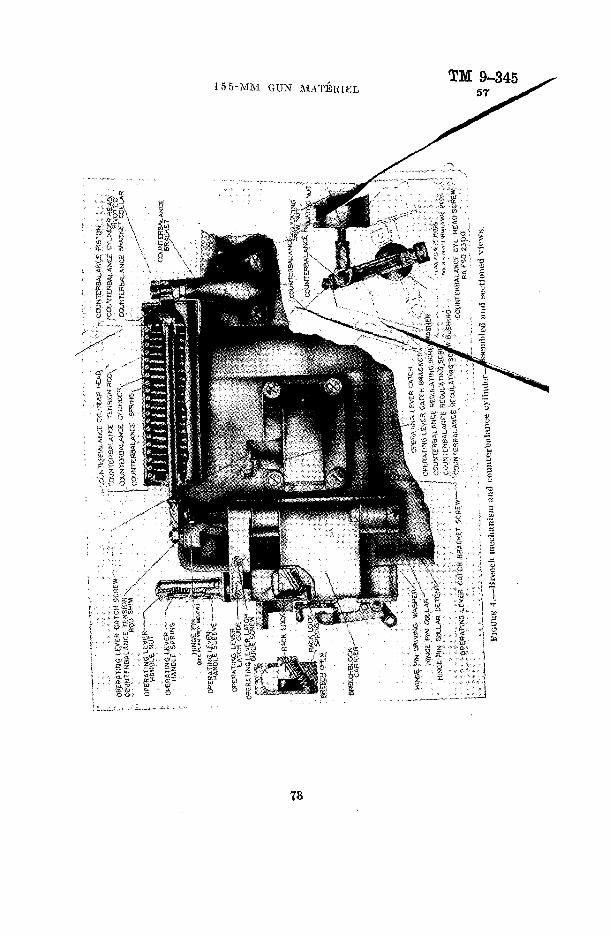
155-MM GUN MATEKIELTM 9-345
73

TM 9-34557 ORDNANCE DEPARTMENT

155-MM GUN" MATERIELTM 9-345
57
FIGUEE 6.—Uccoil mechanism—side view.
75

~-~*
4>U
JG, F
lltm
AND
ORI
UN
PIST
ON,
REP
IEN1
SHER
--HQ
LE.'R
ecO
IL C
YLIN
DER
FtlU
NS
i, RE
PLEN
tJHE
R•a
JlD
E,R
egi,E
NiS
HER
W
5TO
N £{,
...
RO
O,-C
ON
l«C
TlN
S
SPRI
NG,
REPL
ENIS
HER
PIST
ON
o a c B SS f? B
RA F
SO 2
303
FIG
URE
7.—
Kep
leni
sher
—as
sem
bled
vie
ws.

155-MM GUX MATERIELTM 9-345
57
NUT. COUNTERi-RECOIL PISTON ROC- PLUG, FiLLiNG AND DRAIN - i
: : — MECHANISM, RECOIL, MI918AI, ASSEMBly4;; ; '{«:'
-ROD, CONNECTINGj :,f ;: LONG GROOVE IN CONTROL ROD ! V . . • BUFFER EKD OF : -CAM GROOVE IN ACTUATING CAM '; PIN, VALVE TURNING CAM , • ,
j j'j'1 '-ROD, VALVE TURNING; ; t ^ -.COVER, VALVE TURNING GEAR .
i; | \™ SEGMENT, VALVE TURNING GAMr i r ,SEGMENT, CONTROL ROD '"
NUT, RECOIL ;: 'PISTON!ROD
RA PSD 233fl
FIOURE S.—15i3-iiiiii gun nirriiijH! ill'.HS—(linj,r r:uiiiiiiitie sections of recoil nieclKini.sm.
PLUS,FILLING A
«:\t>l .RECUPERATOR FILUNS VAD.I:
PLUS,FlLUNStASB DRAIN ,„', , ,* i ' * • . ..• ( <* '»**>'*
RA FSD ZS05
FIGURE 9.—Recoil mechanism—rear view.
77

TM 9-345 57 ORDNANCE DEPARTMENT
CUt» «L,«(?iCIAL, ASSEMBLY
, TRAVERSING AND ELEVATIf.6 WORM GEAR
FiGDitK 10.--Top carriage—front view.
78

155-MM GUN MATERIELTM 9-345
57
79

TM 9-34557 ORDNANCE DEPARTMENT
80

•GAS
KET,
HUB
CAP
r -
WH
EEL,
RUB
BER
TIR
ED, A
SSEM
BLY
r-DR
UM
, BR
AKE
-LIN
ER
, HU
B.-A
XLE,
GUN
.,
ftOC
KE
R.L
EFT
;:
RO
CK
ER
,BR
AK
E
-BR
AC
KE
T, B
RAK
E, L
EFT,
ASS
EMBL
Y ,
-BOL
T, AD
JUST
ING,
SHA
CKLE
-P
LATE
,TOP
SPRIN
G '-S
HACK
L£,U
PPER
SPR
ING,AS
SEMB
LY
—WA
SHER
.SPRI
NG C
ENTE
RING
BOL
T\
>.Ii;-
i :
>.j
"SH
AC
KLE
, LQ
fER
SP
RING
•.
,, --
BO
Hf-G
EN
TER
INS
, SPR
ING
, i
• SP
RING
, GU
N A
XLE
, A
SS
Effl
Lf'
'' "•
' '
' '
'"
-PLA
TE
, BO
TTO
M
SPR
iNG
'
: --B
OLT
,SPR
ING
PLA
TE
,': ;
--•PI
N .''S
PRIN
G'E
YE,
ASSE
MBL
Y "'•
'"' ''•
' .
"'Pi
N.
LOW
ER
SHAC
KLE
HING
E .
. R
A FS
D 2
309
• __
b'lu
uitK
II!
.- A
xle
niul
whe
el—
asse
mbl
ed.
Cn
Oi
I O d H
en

TM 9-34557 ORDNANCE DEPARTMENT
82

155-MiVl GUN MATERIELTM 9-345
57

TM 9-34557 ORDNANCE DEPARTMENT
MECHANISM, RECOfc, MfSI8A),ASSEM8l*
• WHEEL, RUBBER TIRED, ASSEMBL'
AXLE, GUN SHOES, WHEEL
BARREL, ASSEMBLY '" ' '-IfK:, SECTOR.ELEVATING, ASSEMBLY ""•' TRAVERSING MECHANISM ELEVATING MECHANISM
- COUNTERBALANCE, ASSEMBLY — M£CM»SM,8REECH,
TRAVELIMG LOCK DEVICE r TRAIL, RIGHT, ASSEMBLY
CHASSIS, ASSEMBLY - \ CARRIAGE, TOP, ASSEMBLY
SPADE, ASSEMBLY H
FIGURE ](i.—n.~>.>-mm gun earriuse—longitudinal section in battery.
84

BO
LT,
CLA
MP
INS
, T
RA
IL
HA
ND
LE,T
RA
IL
CLA
MP
ING
BO
LT
NU
T,
AS
SE
MB
LY
TR
AN
SO
M,C
LAM
PIN
G
TR
AIL
"R
OC
KE
R,C
AB
LE
, R
IGH
T
TRA
IL-
TRA
NS
OM
, R
EA
R
SH
AC
KLE
t,Li
MB
ER
S
PR
ING
RA
IL,
SID
E,
RIG
HT
TIE
, D
RA
WB
AR
--
^.--
BO
LT,
PIN
TLE
, A
SS
EM
BLY
-TR
AW
SO
M,
FOR
WAR
D
'•"•'•
'
-KE
YS
, D
RA
WB
AR
PIM
.OR
AW
8AR
-D
RA
WB
AR
, A
SS
EM
BLY
HA
NG
ER
, SP
RIN
G,
FOR
WA
RD
.L
EF
T
SP
RIN
G,
LIM
8E
R,
AS
SE
MB
LY
CLI
PS
,LIM
BE
R
SP
RIN
G,L
AR
GE
AX
LE
WH
EE
L '
;"
-PIE
CE
, O
UTE
R U
NiV
ER
SA
L JO
INT
, M
ALE
, A
SS
EM
BLY
RA F
S-Q
23)3
FICU
HE 1
7.—
155-
mni
gun
car
riag
e lim
ber—
long
itudi
nal
sect
ion.
C q
I

TM 9-34557 ORDNANCE DEPARTMENT
-HAND BRAKE "LEVER-.•:'.-ELECTRIC BRAKE MECHANISM
FIGURE 18.—Wheel modified for high speed.
86

155-MM GUN MATERIELTM 9-345
57
fSD 23!§jFIGUKE 10.—Electric and hand controlled brakes.
87

\TE
RM
INA
L
CO
ND
UIT
, FL
EXIB
LE-
CO
ND
UIT
, FL
EXIB
LE-
TER
MIN
AL-
00 oo
CO
ND
UIT
.RIG
ID
CA
BLE
, JU
MP
ER
-
BOX,
BA
TTE
RY
FIOU
HE 2
0.—
Elec
tric
brak
e ho
ok-u
p.
BRAK
ES .W
HE
EL
-SO
CK
ET
, C
OU
PLIN
G
SOC
KET
, C
OU
PLIN
G
CA
BLE
, JU
MP
ER
CA
BLE
, JU
MP
ER
(EN
D)
SW
ITC
H, S
AFE
TY
CH
AIN
,SA
FETY
SW
ITC
H
LEV
ER
, SA
FETY
SW
ITC
H
SOC
KET,
CO
UPL
ING
BR
AK
ES
, WH
EE
L
RA F
SD 2
316
o s G O H a B 1 B
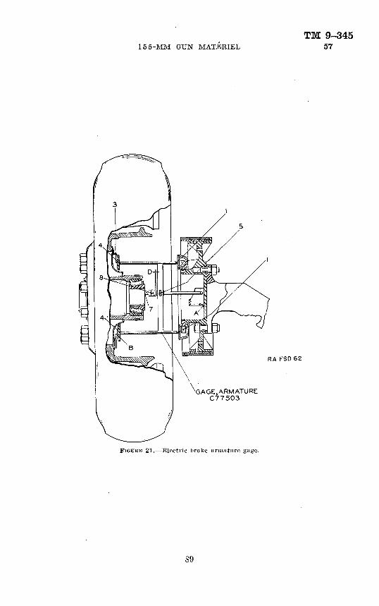
155-MM GUN MATERIELTM 9-345
57
RA FSD62
GAGE,ARMATURE C77503
FIGURE 21.—Electric brake armature gage.

TM 9-345 57 ORDNANCE DEPARTMENT
METAL HOOD
-BATTERY CASE
ORD 14668
FIGUKH 22.— Ught, aiming post. M14.
90

155-MM GUM MATERIELTM 9-345
57
-BATTERY , BA-30
-BATTERY, BA-30
ORD 14669 FIGURE 23.—Light, aiming post. AI14—component parts.
91

TM 9-345•58-59 ORDNANCE DEPARTMENT
CHAPTER 3
SIGHTING AND FIRING-CONTBOL EQUIPMENTParagraphs
SECTION I. Sighting equipment__________________ 58-66II. Fire-control equipment________________ 67-73
III. Plotting room fire-control equipment___———— 74-84
SECTION I
SIGHTING EQUIPMENTParagraph
Light, aiming post, M14________-_________________————___ 58 Mount, telescope, M6A1, and telescope, panoramic, M8_———____————__ 59 Mounts, telescope, M6 and M4; telescopes, panoramic, M4 and M3A1;
telescope, 2-inch, M1909A1_____-___________—______—__- 60 Post, aiming, Ml___________________________________________ 61Quadrant, gunner's, Ml________—_________——____————__ 62 Quadrant, gunner's, M1918_____—______________________ 63 Sight, bore__________—___________———________———__ 64Sight, quadrant, M1918; telescope, panoramic, M6 and M2A1______—_ 65 Target, testing_______________________________________ 66
58. Light, aiming post, M14.—The light, aiming post, M14, is a satisfactory device for illuminating ranging poles for night survey. It is a replacement for aiming lanterns, Ml and M2.
a. The light, aiming post, M14, consists of a battery case for two BA-30 batteries (one in each end to obtain a parallel circuit), with a lamp housing and a toggle switch. A metal hood for the lamp is pro vided which is carried around the battery case when not in use. Illumi nation is furnished by 3-volt aircraft instrument panel lamp with which standard instrument lights are now equipped. A reflector is mounted in the back of the lamp and a color filter can be attached to the front of the lamp housing.-
l>. A clamp is provided to secure the lamp to the aiming post.c. A chest is provided to carry a section set comprising two lights,
aiming post (one with red, one with green filters) ; eight BA-30 batteries; and two spare lamps.
d. The batteries should always be removed from the battery case when not in use in order that their deterioration on long standing will not damage the light. When not in use, the various parts of the light should be kept in the chest provided.
59. Mount, telescope, M6A1, and telescope, panoramic, M8.—a. M,ount, telescope, M6AL— (1) The telescope mount M6A1 is
92

TM 9-345155-MM GUN MATERIEL 59-60
designed for use on the 155-mrn gun carriages, M1918 and M1918A1, when used by coast artillery organizations, for pointing the guns in both elevation and azimuth.
(2) The mount is bolted to the left side of the top gun carriage to the .rear of the trunnion with the principal axis of the actuating arm parallel to the trunnion. It moves only in azimuth with the top carriage as the gun is traversed. The index arm adapter is bolted to the left trunnion and rotates in elevation as the gun is elevated.
(3) The mount is of the azimuth compensating type which, when cross leveled, automatically corrects for any error in azimuth resulting from elevating the gun with the trunnions out of level. The level vials, matching indexes and scales on the mount and telescope, and the telescope reticle are provided with artificial illumination from a 6-volt system, the power being supplied by a storage battery on the gun mount.
5. Telescope, panoramic, MS.— (1) The panoramic telescope M8 is the sighting element of the sighting equipment used for pointing the gun in azimuth. It is mounted in the socket of the telescope mount on the left side of the gun carriage.
(2) The telescope is a six-power instrument handling a field of view of 6°40' and an exit pupil of 0.20 inch. It is provided with a prism erecting system, a separate dial for case II pointing, a diopter adjust ment, and ray filters.
(3) The reticle is provided with horizontal and vertical cross lines. The vertical line is continuous and the horizontal line broken for a short distance on each side of the optical center. A horizontal mil scale extending for 55 mils on each side of the center is etched above the horizontal cross line.
c. Reference.—Detailed description of the construction and opera tion of the mount, telescope, M6A1, and telescope, panoramic, M8, can be found in TM 9-2554.*
60. Mounts, telescope, M6 and M4; telescopes, panoramic, M4 and M3A1; telescope, 2-inch, M1909A1.—a. Application.— (1) These items, used by Coast Artillery Corps for aiming the gun in direction and for aiming or laying it in elevation, form two distinct sighting combinations, as follows:
(a) For the continental United States and departments other than Panama—mount, telescope, M6; telescope, panoramic. M4: telescope, 2-inch, M1909A1.
(6) For Panama only—mount, telescope, M4; telescope, panoramic, M3A1; telescope, 2-inch, M1909A1.
*See Appendix.
93

TM 9-34560 ORDNANCE DEPARTMENT
(2) The parallel mounts and panoramic telescopes in these combi nations are similar in design with the exception of the unit of gradua tions. The telescope mount M6 and panoramic telescope M4 have mil graduations. The telescope mount M4 and panoramic telescope M3A1 have degree graduations.
(3) It is intended that both of the above combinations will eventu ally be superseded by the single combination consisting of the telescope mount M6A1 and the panoramic telescope M8.
&. General description.—The telescope mount is used with either the 2-inch telescope M1909A1 for direct aiming or with the pano ramic telescope for direct or indirect aiming. The telescope mount is attached to the left side of the top carriage of the gun mount. It moves with the top carriage in azimuth as the gun is traversed but does not move directly with the gun in elevation, this motion being transmitted by means of a matching index arrangement on the cradle trunnion. The sight mount body is designed to receive either the telescope cradle for the telescope M1909A1 or the telescope socket for the panoramic telescope. The level vials, matching indexes, scales, and telescope reticles are provided with illumination, the cur rent being supplied by a five-cell alkaline type storage battery.
c. Description of telescope mounts, M6 and M4-— (1) These mounts (figs. 24, 25, and 26) are of the azimuth compensating type, auto matically applying any necessary correction to compensate for error in azimuth caused by cant (tilt) of the cradle trunnions as the gun is elevated.
(2) The body of the mount is positioned with respect to the bracket by means of the rocker worm knob and the cross level worm knob. The cross level worm knob removes crosswise tilt from the body as indicated by the cross level bubble, which rests in the central posi tion when the sight body is in the vertical plane. The rocker worm knob rotates the body about the central axis of the sight as indicated by the angle of site level bubble, which rests in the central position when the telescope mounting lugs on the body are at the inclination indicated by the angle of site scale and micrometer. Added to this motion is the rotation of the elevation worm gear within the sight body, as indicated by the elevation scale and elevation micrometer. The combined motion of the body and worm gear is transmitted by a link arrangement to the index arm which pivots on the index arm adapter. The index arm adapter is fastened to the cradle trunnion and therefore rotates with the gun as the gun is elevated. In opera tion, the gun is elevated to the point where the indexes on the index arm and index arm adapter are matched, thereby transferring the
94

155-MM GTj'X MATERIELTM 9-345
60
elevation and angle of site indications of the telescope mount to the gun.
(3) In the telescope mount M6 the elevation scale is graduated at 100-mil intervals from 0 to 1,000. The elevation micrometer is graduated at 1-mil intervals. One turn of the micrometer knob cor responds to 100 mils movement of the elevation scale and displaces the index arm a like amount. The angle of site scale is graduated at 100-mil intervals from zero to 600, with the 3-graduation indicat ing the normal or level position. The angle of site micrometer is graduated at 1-mil intervals. One turn of the micrometer knob regis ters 100 mils on the angle of site scale and displaces the level a like amount.
SOCKET, TELESCOPE, ASSEMBLY
— LEVEL, ANGLE OF S : TESCALE, ANGLE OF SITE
_ MICROMETER, ANGLE OF
ADAPTER, INDEX ASM "———»^ftfeirll* ;*S "
"SNOB, ELEVATiGN MlCROMETER-
MIGROMETER, ELEVATJON-
SGSLE, ELEVATIONRA FSO 1741
FIGURE 24.—Telescope mount MO (with panoramic telescope M4)—side view.
(4) In the telescope mount M4 the elevation scale is graduated at 1° intervals from 0 to 60. The elevation micrometer is graduated at 1-minute intervals. One turn of the micrometer knob registers 4° on the elevation scale and displaces the index arm a like amount. The angle of site scale is graduated in single degrees from zero to + 20 (white) and from zero to —20 (red), with the zero indicating the normal or level position. The angle of site micrometer is gradu ated at 1-minute intervals with two sets of numbers colored to cor respond to the plus and minus portions of the scale. One turn of the micrometer knob displaces the level 1°.

TM 9-34560 ORDNANCE DEPARTMENT
r-ARM, ACTUATifjG
, ROCKER
-KN'33, ROtXER WORM
RA FSD 5742
mourn M(i (with (Hi'scope Ml!10il-\1)—reur view.
CRADLE:, TELESCOPE, ASSCMBLY
NUT, HEX
- — LEVEL, AN§L£'0F SiTE
*— 'SCALE, ANGLC OF SfTE
•-•MiC».CV.f:TER, ANGLE; Qf- Si
KNOB, ROCKER WORM
KNOB, ANSLE OF Si'f
» CROSS t.CVCt WORM
FIGURE 26.—Telescope mount M4 (with cradlo for telescope M1009A1)—sitle view.
96

155-MM: GUN MATERIELTM 9-345
60
(5) The telescope cradle and telescope socket are separate parts of the mount. They can be mounted interchangeably on the body mounting lugs as shown in the figures, each being secured by two hexagon nuts and lock washers. Close fitting mounting bolts and a transverse locating shoulder provide accurate alinement.
d. Description of panoramic telescope M4-— (1) The panoramic telescope M4 (fig. 27) is a four-power fixed-focus telescope with a ro tating head and azimuth mechanism by which the line of sight may be directed to any desired azimuth, and with a movable prism which permits the line of sight to be elevated or depressed through a limited angle as required to keep the aiming point within the field of view. The reticle contains a vertical and a horizontal cross line and a hori zontal mil scale.
—— KNOB, ELEVATING
ELEVATION INDEX (FINE)-———
ELEVATION INDEX (COARSE)——
MICROMETER, AZIMUTH-
NUT, WINS-
INDEX, AZIMUTH MIGROMETE
iNDEX,-D£.FUECTION SCALE
SCALE, DEFLECTION •-•
SCREW, CLAMP1NS, DEFLECTION SCALE INDEX-
SCALE, AZIMUTH-
SIGHT, OPEN
'—-KNOB, AZIMUTH SCALE. PINION
--PIN
— SHUTTER, ELBOW
FKJUKE 27.—Panoramic telescope M4.
RA FSD 1739
(2) The line of sight is elevated or depressed by means of the knob at the top, and coarse and fine index graduations are provided for the normal (zero elevation) position. There is no provision for reading other angles of elevation.
(3) The azimuth scale is graduated in 100-mil steps numbered from 0 to 64. The telescope is moved in azimuth by means of the azimuth worm knob (opposite the azimuth micrometer) which has a throwout lever to permit disengagement for rapid motion when required. Thfi mil indications of the azimuth micrometer against the deflection scale
410703°—41- 97

TM 9-34560 ORDNANCE DEPARTMENT
index supplement the 100-mil indications 011 the azimuth scale. In creasing the azimuth reading while keeping the telescope on the same aiming point effects movement of the gun to the right. -
(4) For making orientation settings when using indirect aiming in directon, the azimuth scale can be turned by means of the azimuth scale pinion knob, and the azimuth micrometer can be turned by loosen ing the wing nut. The azimuth micrometer index and the reference line on the ring below the azimuth scale mark the normal zero posi tions of the azimuth micrometer and azimuth scale. To operate the the azimuth scale pinion knob, the cotter pin must be tem porarily removed and the knob pushed inward.
(5) Arbitrary corrections are applied on the deflection scale by moving the deflection scale index. Opposite portions of the deflection scale are marked L and R. indicating gun movement to the left or right, respectively. Normal setting of the deflection scale index is at the zero graduation.
(6) The panoramic telescope fits in the cylindrical locating sur faces of the telescope socket and lias a projecting lug to locate it cor rectly in azimuth.
e. Description of panoramic telescope M3A1.—The panoramic tele scope M3Al is similar to the panoramic telescope M4 described in d above, with the exception of the units of azimuth graduations. The azimuth scale of this telescope is graduated at 1° intervals from 0 to 360. The micrometer is graduated at .05° intervals. One turn of the azimuth worm knob registers 4° on the azimuth scale.
/. Description of telescope, 2-inch, MJ909A1, and telescope cradle assembly.— (I) The 2-inch telescope M1909A1 (fig. 28) is used for direct aiming. It has a magnification of eight-power and a field of view of 4°30'. In use, it is mounted in the cradle of the telescope mount. The eyepiece is focused by turning the knurled portion of the diopter scale and can be preset to the scale reading when the required eye correction is known. The zero reading marks the setting for a nor mal eye. Two ray filter levers are located below the eyepiece. These levers, marked S and A, control a smoked ray filter and an amber ray filter, respectively. The objective cap shown in the closed position is swung open when the telescope is in use. The lamp bracket assembly is arranged to control the intensity of illumination on the vertical and horizontal reticle cross wires either separately by means of knurled reflectors (not shown) or simultaneously by means of the knurled shutter plug.
(2) The cradle of the telescope mount (figs. 25 and 26) 'has an elevating knob for raising or lowering the telescope line of sight and
98

155-MM GUN MATERIELTM 9-345
60
a deflection mechanism which is graduated in mils for the telescope mount M6 and in degrees for the telescope mount M4. The deflec tion scale for the telescope mount M6 is graduated at 100-mil inter vals from 100 to 300 with the graduation marked 200 indicating the normal position or zero deflection. The micrometer is graduated at 1-inil intervals. One turn of the micrometer registers 100 mils on the deflection scale. The deflection scale for the telescope mount M4 is graduated at 1° intervals from 3 to 17 with the graduation marked 10 indicating the normal position or zero deflection. The micrometer is graduated at .01° intervals. One turn of the micrometer knob registers 1° on the deflection scale.
SOCKET, LAMP, ASSEMBLY-
FIGUKK US.--Telescope, 2-inch, Ml'JO'JAl.
RA FSD (743
g. Operation.— (1) Preliminary operating procedure.—This pro cedure applies for either direct or indirect aiming.
(a) To mount the telescope, 2-inch, M1909A1, and telescope cradle assembly, when required, remove the telescope socket assembly by unscrewing the two hexagon nuts, using the wrench provided, and in its place mount the telescope cradle assembly. Secure by means of the hexagon nuts and lock washers. Open the telescope cradle clamps by loosening the knurled clamping screws and place the telescope in position as shown in figure 24. Secure by tightening the clamping screws. When sufficient time is available before commencing opera tion, verify the telescope alinement by bore sighting as subsequently described.
(&) To mount the panoramic telescope and telescope socket assem bly, when required, remove the telescope cradle assembly by unscrew ing the two hexagon nuts, using the wrench provided, and in its place
99

TM 9-34560 ORDNANCE DEPARTMENT
mount the telescope socket assembly. Secure by means of the hexa gon nuts and lock washers. Turn the wing knob to its extreme coun terclockwise position and place the panoramic telescope gently in the socket. Exert slight pressure downward to insure that both top and bottom alining surfaces are firmly engaged. When sufficient time is available before commencing operations, verify the telescope aline- ment by bore sighting as subsequently described.
(c) When the telescope mount is in operation, keep it cross- leveled (cross level bubble centralized) at all times by means of the cross level worm knob.
(2) Direct aiming.—Either the 2-inch telescope M1909A1 or the panoramic telescope may be used for this type of fire. The use of the 2-inch telescope is convenient in that it eliminates the necessity for shifting the azimuth setting of the panoramic telescope when changing from direct to indirect fire or conversely. This telescope has a higher magnifiying power than the panoramic telescope. The panoramic telescope because of its greater range of movement in elevation is used when aiming at terrestrial targets.
(a) Na/vai or terrestrial targets using panoramic telescope.1. By means of the azimuth scale pinion knob set the azimuth
scale against the lower index line to correspond to the normal reading. The azimuth micrometer should read zero opposite the azimuth micrometer index. Thereafter, make the azimuth settings in the usual manner by means of the azimuth worm knob, setting the azimuth scale against the upper index and the azimuth micrometer against the deflection scale index, according to the an nounced corrected deflections.
$. Apply arbitrary corrections, when required, by offsettingthe deflection scale index on the deflection scale.
3. Rotate the elevation micrometer knob of the telescope mount until the announced angle of elevation is indicated on the elevation scale and elevation .micrometer opposite the respective indexes. The procedure thereafter differs according to whether the gun is to be aimed in elevation or laid in elevation.
4- When it is desired to aim the gun in elevation, set the elevating knob of the panoramic telescope to normal (coarse and fine elevation indexes alined with the respec tive zero lines) and leave in this position as long as this type of fire is being used. Disregard the position of the angle of site level of the telescope mount. Traverse the
100
TM 9-345155-MM GUK MATERIEL 60
gun until the target appears on the vertical cross line of the telescope reticle and operate the rocker worm knob of the telescope mount until the target is centered on the horizontal cross line. Elevate the gun until the indexes on the index arm and index arm adapter are in coincidence thus causing the gun to be elevated the required amount.
5. When it is desired to lay the gun in elevation, set off the announced angle of site on the angle of site scale and micrometer. Keep the angle of site level 'bubble central ized by means of the rocker worm knob. Traverse the gun until the target appears on the vertical cross line of the telescope reticle. If necessary, raise or lower the line of sight by means of the elevating knob at the top of the panoramic telescope. Elevate the gun until the indexes on the index arm and index arm adapter are in coincidence, thus causing the gun to be elevated the required amount.
(&) Naval targets using 2-inch telescope M1909A1.1. Set the deflection scale and micrometer of the telescope
cradle to the announced corrected deflection.2. Rotate the elevation micrometer knob of the telescope mount
until the announced angle of elevation is indicated on the elevation scale and elevation micrometer opposite their respective indexes.
3. Set the angle of site scale and micrometer of the telescope mount to the normal reading (300 mils on M6, zero on M4). Keep the angle of site level bubble centralized by means of the rocker worm knob.
4- Traverse the gun until the target appears on the verticalcross wire of the telescope reticle, raising or lowering thetarget in the field of view by means of the telescope cradleelevating knob. Elevate the gun until the indexes on theindex arm and index arm adapter are in coincidence,thus causing the gun to be elevated the required amount.
(3) Indirect aiming.—The panoramic telescope only is applicablefor this type of fire. It must be initially oriented with, respect tothe bore of the gun and the reference or aiming point.
(a) To orient the telescope, bore sight the gun on a distant point of known azimuth, then bring the vertical line in the telescope on the same point by rotating the azimuth worm knob of the tele scope. Withdraw the cotter pin from the azimuth scale pinion knob, press in the knob to engage the azimuth scale, and rotate the knob
101

TM 9-34560 ORDNANCE DEPARTMENT
until the scale reading against the lower index, visible through the window, is equal to the azimuth of the reference point, including the fractional part of the graduation as closely as can be estimated. Loosen the wing nut on the azimuth micrometer index and slip the micrometer until the graduation corresponding to the number of tens and units registers against the deflection scale index (set to zero on the deflection scale), then tighten the wing nut. Check the setting by rotating the azimuth worm knob and note when an integral graduation of the azimuth scale is against the upper index whether a zero on the micrometer is against the deflection scale index. It is necessary that this condition obtain, otherwise it will be possible to make errors of one main scale division when making settings. Reset the azimuth scale if necessary and again check the setting by bringing the vertical line back on the aiming point. Re assemble the cotter pin in the azimuth scale pinion knob to prevent accidental disturbance of the scale.
(5) When the panoramic telescope has been oriented, set the de flection scale index to the required arbitrary correction and then by means of the azimuth worm knob set the azimuth scale and microm eter to indicate the announced corrected azimuth of the target. Use the throwout lever for rapid setting when necessary to accomplish large movements of the azimuth scale.
(c) Set off the announced angle of site on the angle of site scale and micrometer. Keep the angle of site level bubble centralized by means of the rocker worm knob. Note that when the angle of site is not set at normal, azimuths are measured in the plane of site rather than the horizontal plane; this applies both when orienting and when aiming.
(d) Set off the announced quadrant elevation on the elevation scale and elevation micrometer.
(e) Elevate the gun until the indexes on the index arm and index arm adapter are in coincidence and traverse the gun until the vertical line in the panoramic telescope falls on the aiming point. Should the aiming point not appear near the center of the field when using this method, the elevating knob at the top of the telescope may be turned to raise or lower the line of sight.
h. Tests and adjustments.— (1) Telescope moim.t.—To test the telescope mount, level the gun longitudinally (axis of bore) and hori zontally (axis of trunnions), bore sight the gun on the testing target provided or on a distant aiming point, then with the panoramic tele scope in position and with all scales, indexes, and micrometers set at their zero or normal positions, and with angle of site and cross
102

TM 9-345155-MM GUN MATERIEL 60
level bubbles centralized, note the position of the cross lines in the telescope with respect to the testing target or aiming point. If the horizontal and vertical lines in the telescope do not fall on the aiming point or corresponding lines on the testing target, it will be necessary to calibrate the telescope mount in the following manner:
(a) Remove the panoramic telescope from the telescope socket and place a gunner's quadrant (on a parallel bar) on the top surfaces of the socket, parallel to the bore of the gun; or, if desired, the telescope socket may be removed and the gunner's quadrant placed on the mounting surfaces of the body. The mount should be cross-leveled and the gunner's quadrant set at zero. With the elevation scale and micrometer indicating zero, center the level bubble in the gunner's quadrant by means of the rocker worm knob of the telescope mount. When these settings have been made, centralize the angle of site level bubble by means of the angle of site knob. If the reading of the angle of site scale and micrometer with the bubble so centralized is other than the normal reading, reset the scale to normal reading after loosening its two fastening screws, and reset the micrometer to normal reading after loosening the slotted-head nut in the center of the knob. Tighten the fastening screws and nut securely when adjustment is completed. Verify the adjustments and do not disturb this setting until after the other adjustments which are described below are completed.
(b) With the telescope socket mounted and in the vertical position, and with the angle of site level adjusted as described in the preceding paragraph, place the gunner's quadrant (on a parallel bar) on the top surfaces of the socket parallel to the axis of the gun cradle trunnions. With the telescope mount accurately cross-leveled, the gunner's quad rant should then indicate zero within a tolerance of 2 mils. If be yond this tolerance, the cross level must be adjusted. This adjust ment is to be performed only by authorized ordnance personnel.
(c) With the angle of site scale and cross level in adjustment as described above, place the gunner's quadrant, set at zero, across the two finished pads on the actuating arm and centralize the bubble in the quadrant by means of the elevation micrometer knob. If the elevation scale and elevation micrometer then read other than zero, reset the elevation index to read zero on the scale after loosening its two fastening screws, and reset the micrometer to read zero after loosening the three fastening screws in the end of the micrometer knob. Tighteai the fastening screws securely when adjustment is completed.
103
TM 9-34560 OKDKANCE DEPAKTMEN'J."
(d) When the adjustments outlined above have been completed, cross-level the mount, set all scales and micrometers at zero or normal position, and centralize the angle of site level bubble by means of the rocker worm knob. Level the bore of the gun by use of the gunner's quadrant and note the relation of the index arm with respect to the adjustable index on the index arm adapter. If not in exact coincidence, loosen the fastening screws on the adjustable index and reset the index to coincide with the one on the index arm. Elevate the gun to 400 mils (22.5°) by means of the elevating handwheel of the gun carriage, using a gunner's quadrant to determine the angle. Set off the same angle on the elevation scale and micrometer of the telescope mount. If the matching indexes are not in precise coin cidence, adjustment is necessary. Loosen the lock nuts at each end of the link coupling and take up part of the error by turning the coupling, then reset the adjustable index to coincidence. Level the gun and telescope mount and note if the matching indexes remain in coincidence. If necessary, repeat the operation of adjusting the link coupling and adjustable index several times until the indexes remain in proper coincidence when the gun and telescope mount are set at the same angle of elevation anywhere within the operating range.
(e) Should any play develop between the body and the cross- leveling worm gear segment, the accuracy of the compensating mech anism will be impaired. Refer the matter to the authorized ordnance personnel for the necessary adjustment.
(2) Panoramic telescoqie.—With the telescope mount in ad justment as described above, with the gun bore sighted on the testing target or distant aiming point, and with the panoramic telescope mounted, set all scales, indexes, and micrometers at zero or their normal positions and centralize the angle of site and cross level bub bles. If the horizontal and vertical lines in the telescope do not fall on the aiming point or corresponding lines on the testing target, it will be necessary to adjust the panoramic telescope in the following manner:
(a) Horizontal adjustment.—Loosen the headless screw at the front of the telescope socket which locks the adj listing screw (fig. 24). Turn the adjusting screw in or out until the vertical line in the telescope intersects the vertical line on the testing target or the distant aiming point. Tighten the headless locking screw.
(&) Vertical adjustment.—Turn the elevating knob at the top of the panoramic telescope until the horizontal line in the telescope intersects the horizontal line on the testing target or the distant aiming point.
104
TM 9-345155-MM GUN MATERIEL 60
Reset the knob to zero by loosening the locking screw at the top and slipping the knob as required. Tighten the locking screw securely when adjustment is completed.
(3) Two-inch telescope.—With the telescope mount in adjust ment as previously described, with the gun bore sighted on the test ing target or distant aiming point, and with the 2-inch telescope mounted, set all scales, indexes, and micrometers at zero or their normal positions and centralize the angle of site and cross level bubbles. If the vertical line in the telescope does not fall on the aiming point or corresponding line on the testing target it will be necessary to adjust the telescope in the following manner:
(a) Turn the deflection micrometer knob until the vertical line on the reticle intersects the vertical line on the testing target or the distant aiming point. Adjust the deflection scale to normal reading by temporarily loosening its fastening screws and moving the scale until the normal graduation is opposite the index. Adjust the microm eter to read zero by temporarily loosening the nut in the end of the micrometer knob and turning the micrometer until the zero gradu ation is opposite the index. Tighten the screws and nut securely and check the adjustments.
(b) The horizontal line of this telescope does not require calibration as the line of sight is raised or lowered when desired by turning the elevating knob.
(4) Routine check.—Check the adjustments frequently, particu larly before use.
i. Care and preservation.— (1) Refer to paragraph 73 for general instructions pertaining to the care and preservation of instruments.
(2) Remove the panoramic telescope from the socket and place it in its case when not in use. Keep the 2-inch telescope and all the wiring in the packing chest when not in use. The telescope cradle or the telescope socket, whichever is not in use, should also be kept in the chest.
(3) Do not attempt to force the rotation of any of the knobs beyond their limits.
(4) Keep the level vials covered at all times when not in use to prevent breakage.
(5) Oil fittings are provided for lubricating the principal bear ing surfaces of the telescope mount. A small compressor type oiler is issued with each mount. Keep other moving parts and bearings oiled. Wipe off any lubricant that, seeps from the moving parts to prevent the accumulation of dust und grit.
105

TM 9-34560-62 ORDNANCE DEPARTMENT
(6) Keep the locating surfaces of the telescope mount and tele scopes lightly greased. Exercise particular care to prevent denting or burring of the locating surfaces.
(7) General information and instructions for the operation and care of the storage battery are contained in the book of instructions which accompanies each battery.
61. Post, aiming, Ml.—Two of these aiming posts are furnished, with each 155-mm gun and carriage M1918. Each aiming post (fig. 29) consists of two tubular sections, each approximately 4 feet long. The lower section has a metal point for embedding in the ground and the upper section is provided with a joint and catch fitting in the upper end of the lower section. The parts are painted with alternate 4-inch red and white bands. A canvas cover holding both sections is provided. Should it be necessary to drive the lower sec tion into the ground, interpose a wood block or use other means to insure that the surface mating with the upper part will not be injured.
62. Quadrant, gunner's, Ml.—«. Description.—This quadrant (fig. 30) includes a sector-shaped frame to which is pivoted an arm carrying a level. Notches on the frame engaging with a plunger in the arm permit rapid setting of the arm to the desired angle. The frame has two reference surfaces, one used for elevations from 0 to 800 mils and the other from 800 to 1,600 mils. Separate scale and micro meter indications on opposite sides of the quadrant are used for the two different regions.
b. Operation.— (1) To measure the elevation of the piece, place the proper reference surface of the quadrant on the leveling plates, par allel to the bore, with the associated arrow pointing in the direction of fire. Set the micrometer to zero. Disengage the plunger from the notches in the frame, lift the arm and slowly lower it until the bubble is seen to pass through the central point. Allow the plunger to en gage with the notches and turn the micrometer until the level bubble is accurately centered. Face the side of the quadrant which bears the arrow in use and read the scale and micrometer indications. A note engraved below the micrometer indicates whether the red or the black micrometer figures are to be read; a zero micrometer indica tion is read as "0 mils" when the auxiliary indexes are matched (as shown) and as "10 mils" when they are not matched. The elevation of the piece in mils is equal to the sum of the scale and micrometer readings. Kemove the quadrant from the piece before firing.
106

UPP
ER
SEC
TIO
N
LOW
ER
SEC
TIO
N
FIGU
RE 2
9.—
Aim
ing
post
Ml.
O a
RA
igS
D
'494
> ESS

TM 9-34562 ORDNANCE DEPARTMENT
(2) To measure depression angles, proceed as above, but with the arrow pointed in the reverse direction.
(3) To lay the piece to a given elevation, set the scale and microme ter to the required angle and place the corresponding fiducial surface on the leveling plates of the piece. Elevate the piece, then depress it until the level bubble is centered. . Eemove the quadrant from the piece before firing.
o. Test and adjustment.—No adjustment of the quadrant by the using arm is permitted. The zero indication may be verified by set ting the quadrant to zero elevation, elevating or depressing the piece
REFERENCE SURFACE (0-800 MILS)
SCALE
LEVEL
MICROMETER
AUXILIARY INDEX MARKS
INDEX PLATE
•PLUNGER
SHOE
FIGURE 30.—Gunner's quadrant Ml.
to center the bubble, then turning the quadrant end for end. If the bubble is not centered, determine the elevation or depression angle necessary to center it; one-half of this angle is the error and a cor responding correction should be applied to all subsequent indications in the 0-800 mil region.
d. Care and preservation.— (1) Exercise particular care to prevent burring, denting, or nicking of the shoes and of the notched portion of the frame.
(2) Never leave the quadrant on the piece when firing.
108
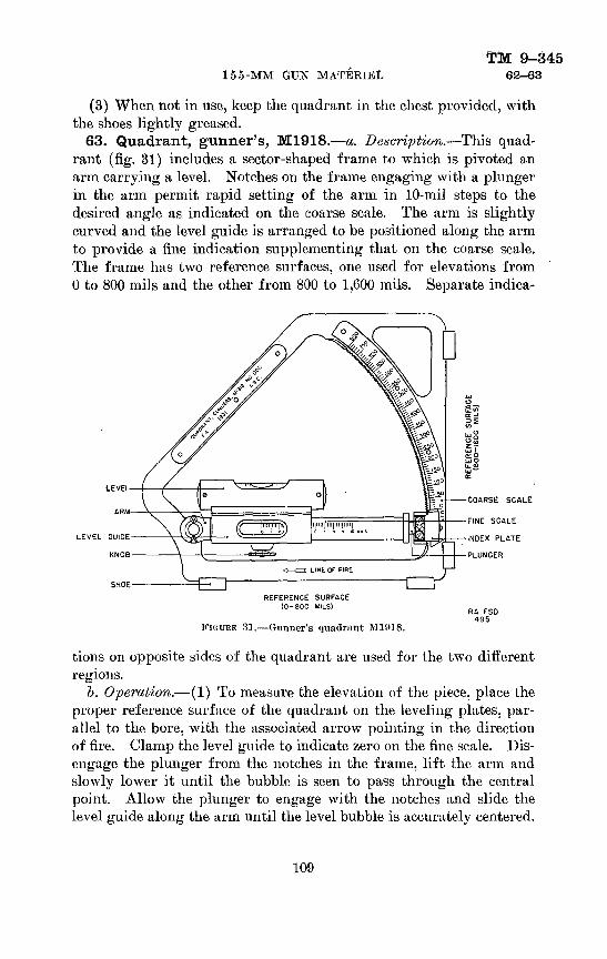
155-MM GUN MATERIELTM 9-345
62-63
(3) When not in use, keep the quadrant in the chest provided, with the shoes lightly greased.
63. Quadrant, gunner's, M1918.—a,. Description.—This quad rant (fig. 31) includes a sector-shaped frame to which is pivoted an arm carrying a level. Notches on the frame engaging with a plunger in the arm permit rapid setting of the arm in 10-mil steps to the desired angle as indicated on the coarse scale. The arm is slightly curved and the level guide is arranged to be positioned along the arm to provide a fine indication, supplementing that on the coarse scale. The frame has two reference surfaces, one used for elevations from 0 to 800 mils and the other from 800 to 1,600 mils. Separate indica-
LEVEL GUIDE
KNOB
REFERENCE SURFACE (0-800 MILS)
FIGURE 31.—Gunner's quadrant M1918.
COARSE SCALE
FINE SCALE
INDEX PLATE
PLUNGER
RA FSD 495
tions on opposite sides of the quadrant are used for the two different regions.
b. Operation.— (1) To measure the elevation of the piece, place the proper reference surface of the quadrant on the leveling plates, par allel to the bore, with the associated arrow pointing in the direction of fire. Clamp the level guide to indicate zero on the fine scale. Dis engage the plunger from the notches in the frame, lift the arm and slowly lower it until the bubble is seen to pass through the central point. Allow the plunger to engage with the notches and slide the level guide along the arm until the level bubble is accurately centered.
109

TM 9-34563-64 ORDNANCE DEPARTMENT
Face the side of the quadrant which bears the arrow in use and read the coarse and fine scales. The elevation of the piece in mils is equal to the sum of the coarse and fine scale readings. Remove the quad rant from the piece before firing.
(2) To measure depression angles, proceed as above, but with the arrow pointed in the reverse direction.
(3) To lay the piece to a given elevation, set the scale and mi crometer to the required angle and place the corresponding reference surface on the leveling plates of the piece. Elevate the piece, then depress it until the level bubble is centered. Remove the quadrant from the piece before firing.
(4) The gunner's quadrant, may also be used in lieu of a ma chinist's level during verification and adjustment of the sights. When so used, it is important that the zero indication be accurately verified as described below. In some cases it is necessary to interpose a parallel plate or parallel bar between the surface to be leveled and the reference surfaces on the frame, in which case the verification of the zero indication on the quadrant should be performed so as to correct for any error of the parallel plate or bar.
o. Test and adjustment.—No adjustment of the quadrant by the using arm is permitted. The zero indication may be verified by setting the quadrant to zero elevation, elevating or depressing the piece to center the bubble, then turning the quadrant end for end. If the bubble is not centered, determine the elevation or depression angle necessary to center it; one-half of this angle is the error, and a corresponding correction should be applied to all subsequent indi cations in the 0-800 mil region.
d. Care and preservation.— (1) Refer to paragraph 73 for general instructions pertaining to the care and preservation of instruments.
(2) Exercise particular care to prevent burring, denting, or nicking of the reference surfaces and of the notched portion of the frame.
(3) Do not leave the quadrant on the piece when firing.(4) When not in use, keep the quadrant in the chest provided,
with the shoes forming the reference surfaces lightly greased.64. Sight, bore.—a. Description.—The bore sight (fig. 32) con
sists of a breech bore sight and muzzle bore sight designed for insertion in the respective ends of the gun bore.
l>. Operation.—With the two elements in place, look through one of the large holes in the breech bore sight and move the gun until the aiming point can be seen through the muzzle bore sight, then look through the small hole and move the gun until the object appears in the opening at the center of the straight edge.
110
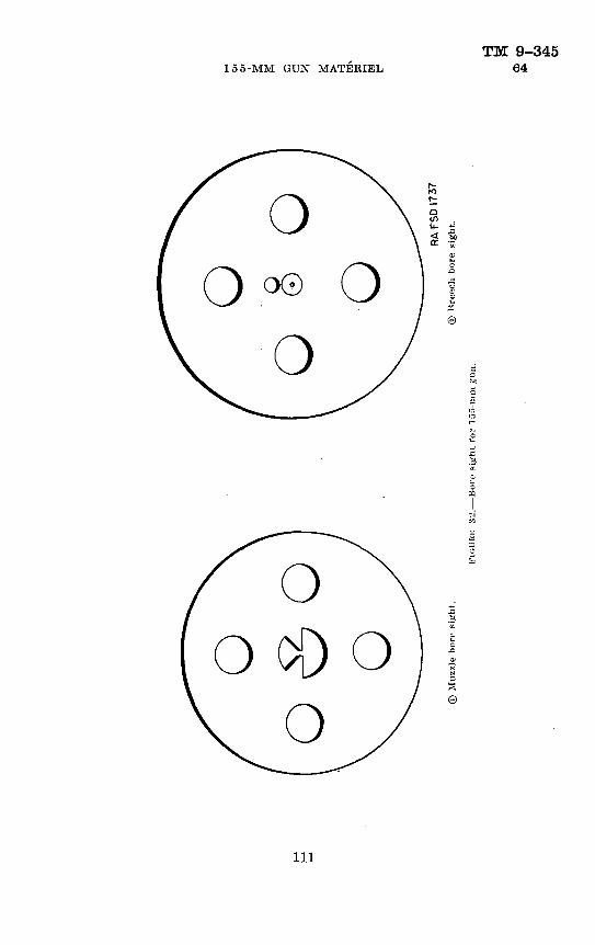
155-MM GUIS* MATERIELTM 9-345
64
U_ 4J
©
e
111

TM 9-34564-65 ORDNAXCE DEPARTMENT
G. Care and 'preservation.—Handle the bore sights carefully to prevent occurrence of nicks and burs. Keep the bore sights lightly greased when not in use.
65. Sight, quadrant, M1918; telescope, panoramic, M6 and M2A1.—The quadrant sight M1918 is used with either the panoramic telescope M6 or the panoramic telescope M2A1 for aiming the gun in direction and for aiming or laying the gun in elevation. The quadrant sight and panoramic telescope M6 form the authorized sighting combination for use by Field Artillery. This quadrant sight and the panoramic telescope M2A1 form the sighting combina tion used by the Coast Artillery Corps when other authorized sighting combinations (pars. 59 and 60) are not available.
a. Description of quadrant sight M1918.— (1) The quadrant sight mounts on the left trunnion of the gun. The principal parts of the quadrant sight are the cross level, elevation and angle of site mech anisms, and the sight shank designed to receive the panoramic tele scope. The quadrant sight with panoramic telescope mounted is shown in figure 33.
(2) Rotation of the cross leveling worm causes tilting of the sight body, which movement is indicated by the bubble of the cross level. The cross level clamping screw clamps the sight body to prevent disturbance of the cross level position during firing. When the cross level bubble is centered, the sight is in the true vertical plane.
(3) The angle of site and elevation mechanisms introduce and add together their respective elements of data. The elevation scale is graduated in mils and contains two rows of graduations. The outer row reads elevation from 0 to 800 mils (0° to 45°) ; the inner row forms a continuation of the outer row and reads from 800 to 1,160 mils (45° to 65°). Rapid movement in elevation is accomplished by rotating and holding the throwout lever so that the sight shank can be raised or lowered with the hand.
(4) The angle of site level establishes a horizontal datum plane. The gun is laid in elevation so that the bubble of this level is cen tered. The angle of site scale is graduated at 100-mil intervals, numbered from 0 to 6, and the angle of site micrometer is graduated at 1-mil intervals numbered from 0 to 100. The angle of site setting is the sum of the values indicated on the scale and micrometer. The 300-mil setting is the normal setting corresponding to zero angle of site.
(5) The quadrant sight M1918A1 incorporates an alternative con struction of the angle of site level but is in all other respects the
112

155-MM GUN MATERIELTM 9-345
65
same as the M1918. Operation procedure is the same with either model.
6. Description, of panoramic telescope M6.— (1) The panoramic telescope M6 (fig. 34) is a four-power fixed-focus telescope with a ro tating head and azimuth mechanism by which the line of sight may be directed to any desired azimuth, and with a movable prism which
•• ., : • RATQHET
' .;':; KNIGHT S««NK-
AN6LE OF SITE SCALE?
. ;ANCLE OF SITE -LEVEL
THROWOUT LEVER- """
"CROSS'LEVEL 'CLAMPING SCREW
CROSS ;LeVELtN6 WORM
ANSLE OF SITjEWICROMETfR-;.:
ELEVA1INS,,:^NOB ;.!!
ELEVATION: a"' t,'. -' '..";:.::•
;:RA FSD 1182
FIGUHE 33.—Quadrant sight M1018 with panoramic telescope MO.
permits the line of sight to be elevated or depressed through a limited angle as required to keep the aiming point within the field of view. The reticle contains a vertical and a horizontal cross line and a horizontal mil scale.
(2) The line of sight is elevated or depressed by means of the knob at the top, and coarse and fine index graduations are provided
416763°—41- 113
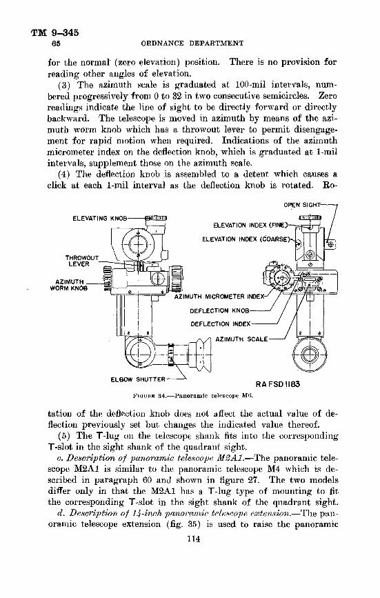
TM 9-34565 ORDNANCE DEPARTMENT
for the normal' (zero elevation) position. There is no provision for reading other angles of elevation.
(3) The azimuth scale is graduated at 100-mil intervals, num bered progressively from 0 to 32 in two consecutive semicircles. Zero readings indicate the line of sight to be directly forward or directly backward. The telescope is moved in azimuth by means of the azi muth worm knob which has a throwout lever to permit disengage ment for rapid motion when required. Indications of the azimuth micrometer index on the deflection knob, which is graduated at 1-mil intervals, supplement those on the azimuth scale.
(4) The deflection knob is assembled to a detent which causes a click at each 1-mil interval as the deflection knob is rotated. Eo-
ELEVATING KNOB
OPEN SIGHT-
fillKllllliillllHIIIiELEVATION INDEX
ELEVATION INDEX (COARSEH
AZIMUTH MICROMETER INDEX-
DEFLECTION KNOB-
DEFLECTION INDEX
AZIMUTH SCALE
ELBOW SHUTTER -RAFSDII83
FIGUKHJ 34.—Panoramic telescope M6.
tation of the deflection knob does not affect the actual value of de flection previously set but changes the indicated value thereof.
(5) The T-lug on the telescope shank fits into the corresponding T-slot in the sight shank of the quadrant sight.
c. Description of panoramic telescope M2A1.—The panoramic tele scope M2A1 is similar to the panoramic telescope M4 which is de scribed in paragraph 60 and shown in figure 27. The two models differ only in that the M2A1 has a T-lug type of mounting to fit the corresponding T-slot in the sight shank of the quadrant sight.
d. Description of llf-inch panoramic telescope extension.—The pan oramic telescope extension (fig. 35) is used to raise the panoramic
114
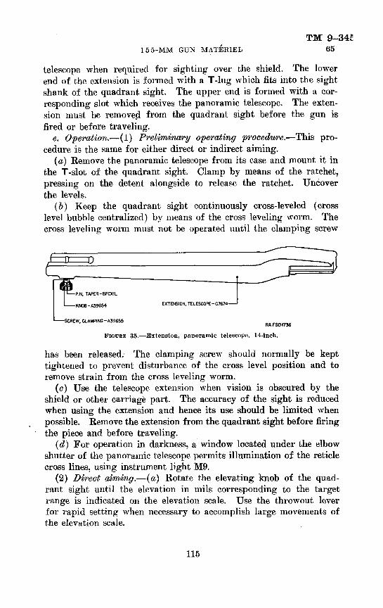
155-MM GUN MATERIELTM 9-34E
65
telescope when required for sighting over the shield. The lower end of the extension is formed with a T-lug which fits into the sight shank of the quadrant sight. The upper end is formed with a cor responding slot which receives the panoramic telescope. The exten sion must be removed from the quadrant sight before the gun is fired or before traveling.
e. Operation.— (1) Preliminary operating procedure.—This pro cedure is the same for either direct or indirect aiming.
(a) Remove the panoramic telescope from its case and mount it in the T-slot of the quadrant sight. Clamp by means of the ratchet, pressing on the detent alongside to release the ratchet. Uncover the levels.
(&) Keep the quadrant sight continuously cross-leveled (cross level bubble centralized) by means of the cross leveling worm. The cross leveling worm must not be operated until the clamping screw
1——SCREW, CLAMPING-A39655RAFSDI734
FIGDBE 35.—Extension, panoramic telescope, 14-inch.
has been released. The clamping screw should normally be kept tightened to prevent disturbance of the cross level position and to remove strain from the cross leveling worm.
(o) Use the telescope extension when vision is obscured by the shield or other carriage part. The accuracy of the sight is reduced when using the extension and hence its use should be limited when possible. Remove the extension from the quadrant sight before firing the piece and before traveling.
(d) For operation in darkness, a window located under the elbow shutter of the panoramic telescope permits illumination of the reticle cross lines, using instrument light M9.
(2) Direct aiming.—(a) Rotate the elevating knob of the quad rant sight until the elevation in mils corresponding to the target range is indicated on the elevation scale. Use the throwout lever for rapid setting when necessary to accomplish large movements of the elevation scale.
115
TM 9-34565 ORDNANCE DEPARTMENT
(&) Set the rotating head of the panoramic telescope to the normal or zero elevation position by means of the elevating knob. In this setting, the coarse and fine elevation indexes coincide with their respective zero lines.
(c) By means of the azimuth worm knob of the panoramic tele scope, set the azimuth scale and micrometer to indicate zero. De flection corrections, where required, are inserted before making the above setting by turning the deflection knob of the panoramic tele scope M6 or by moving the deflection index of the panoramic tele scope M2A1. The orientation setting of the latter telescope is at normal.
(d) Elevate and traverse the carriage until the reticle cross lines fall on the target. Use the open sight on the side of the rotating head to secure approximate direction.
(e) When it is desired to lay the gun in elevation, set the quadrant sight elevation scale to correspond to the target range, as before, and set the angle of site scale and micrometer to the announced set ting, corresponding to the angle of site to the target. Elevate the carriage until the angle of site level bubble is centralized, and traverse until the target appears on the vertical cross line of the reticle. Should the target not appear near the center of the field when using this method, the elevating knob at the top of the telescope may be turned to raise or lower the line of sight. This, however, cannot be done when using the previously described method of aiming in elevation.
(3) Indirect aiming.— (a) Rotate the elevating knob of the quad rant sight until the elevation in mils corresponding to the target range is indicated on the elevation scale. Use the throwout lever for rapid setting when necessary to accomplish large movements of the elevation scale.
(5) Set the angle of site scale and micrometer to the announced setting corresponding to the angle of site to the target. For naval targets this setting will generally be 300.
(c} In this type of fire, direction is obtained by aiming on an aiming post or sighting point other than the target. The method of directing the panoramic telescope differs for the two models.
1. Panoramic telescope M6.—By means of the azimuth worm knob, set the azimuth scale and azimuth micrometer index to indicate the firing angle. (Firing angle is the hori zontal clockwise angle measured from the target to the aiming point, whose apex is at the piece.) Arbitrary cor rections are applied before setting azimuth by setting the
116

TM 9-345155-MM GUN MATERIEL 65
deflection knob against the correction index to indicate the correction angle. If desired, the correction angle can be included with the firing angle, in which case the de flection knob is set to zero. Use the throwout lever for rapid setting when necessary to accomplish large move ments of the azimuth scale.
. 2. Panoramic telescope M%A1.—Before commencing fire, the panoramic telescope must be oriented with respect to the bore of the gun and the reference or aiming point. To orient the telescope, bore sight the gun on a distant point of known azimuth, then bring the vertical line in the telescope on the same point by rotating the azimuth worm knob of the telescope. Withdraw the cotter pin from the azimuth scale pinion knob, press in the knob to en gage the azimuth scale, and rotate the knob until the scale reading against the lower index visible through the win dow is equal to the azimuth of the reference point, in cluding the fractional part of the graduation as closely as can be estimated. Loosen the wing nut on the azimuth micrometer index and slip the micrometer until the gradu ation corresponding to the number of tens and units registers against the deflection scale index (set to zero on the deflection scale), then tighten the wing nut. Check the setting by rotating the azimuth worm knob and note, when a 100-mil graduation of the azimuth scale is against the upper index, whether a zero on the micrometer is against the deflection scale index. It is necessary that this condition obtain, otherwise it will be possible to make errors of one main scale division when making settings. Reset the azimuth scale if necessary and again check the setting by bringing the vertical line back on the aiming point. Reassemble the cotter pin in the azimuth scale pinion knob to prevent- accidental disturbance of the scale. When the panoramic telescope has been oriented, set the deflection scale index to the required arbitrary correction, and then by means of the azimuth worm knob set the azi muth scale and micrometer to indicate the announced cor rected azimuth of the target. Use the throwout lever for rapid setting when necessary to accomplish large move ments of the azimuth scale.
(d) Elevate the carriage until the angle of site level bubble is centralized and traverse until the target appears on the vertical cross
117

TM 9-34565 ORDNANCE DEPARTMENT
line of the reticle. Should the target not appear near the center of the field, the elevating knob at the top of the telescope may be turned to raise or lower the line of sight. Use the open sight for approxi mate aiming. Note that when the angle of site is not set at normal, azimuths or firing angles are measured in the plane of site rather than the horizontal plane; this applies when both orienting and sighting.
(4) Preparing the night for traveling.—Remove the panoramic tele scope and place it in the case provided. Lower the sight shank until the elevation scale reads approximately zero, cover the levels, and tighten the leveling worm clamping screw so as to remove the strain from the cfoss leveling worm. Place the cover over the quadrant sight.
/. Tests and adjustments.—Only the adjustments specifically authorized may be performed by the using arm.
(1) Verification and adjustment of angle of site level.—Level the carriage transversely (axis of trunnions) and longitudinally (axis of bore). Cross-level the quadrant sight. With elevation set at zero and angle of site set at normal (300), the angle of site level bubble should be centered with respect to the graduations on its vial. If the bubble is not centered, rotate the angle of site knob until the vial is level. Loosen the headless set screw which holds the micrometer knob in place and loosen the plug at the center of the micrometer knob, using the triangular head quadrant sight socket wrench pro vided. Slip the micrometer without turning the worm until the index on the worm housing points to zero. Tighten the plug and set screw.
(2) Verification and adjustment of cross level.—With the carriage level, as above, direct the panoramic telescope on a distant target and then elevate the carriage to maximum elevation, at the same time elevating the quadrant sight. If the point where the line of sight pierces the target appears to move either to the right or left, it indi cates that the cross level of the quadrant sight is out of adjustment. Find by trial a cross level position in which the carriage can be ele vated or depressed to the full extent of its travel with no apparent deviation of the line of sight. Using the triangular head quadrant sight socket wrench provided, loosen the clamping screw directly above the cross level holder and carefully move the cross level holder until the bubble in the level vial is centered between the reference marks and tighten the set screw.
(3) Bore sighting.—With the carriage level, as above, place the testing target in a plane perpendicular to the bore of the gun and at a distance of about 50 yards. Place the bore sights in the gun and
118
TM 9-345155-MM GUN MATERIEL 65
move the testing target until the center line of the bore, as determined by the bore sights, pierces the lower circle of the target. The place ment of the target in the vertical plane should be verified by a plumb line. Set quadrant sight elevation at zero and set panoramic tele scope azimuth, deflection, and elevation at zero. The circle corre sponding to the line of sight of the panoramic telescope should then appear exactly at the intersectioii of the cross lines on the reticle.
(a) Failure to coincide vertically indicates that the elevating knob of the panoramic telescope is out of adjustment. Rotate the knob until the line of sight pierces the target on the horizontal center line. Loosen the locking screw at the center of the knob and slip the knob until the zero is in line with the index then tighten the locking screw. Do not lift the knob during this adjustment, as such action may cause the stop rings within the knob to become disarranged.
(b) Failure to coincide laterally indicates that the azimuth mi crometer is out of adjustment. Rotate the azimuth worm knob until the line of sight pierces the corresponding target on the vertical center line, and proceed as follows:
1. Panoramic telescope M6.—Rotate the azimuth worm knob until the line of sight pierces the target on the vertical center line. Loosen the locking screw at the center of the micrometer index and slip the index until the arrow is in line with the zero of the deflection knob (set to zero against the deflection index), then tighten the locking screw. If the azimuth scale and micrometer index do not both indi cate zero simultaneously, or if the coarse and fine elevation indexes do not indicate simultaneously, the matter should be brought to the attention of qualified ordnance personnel.
2. Panoramic telescope M2A1.—Set the deflection scale index to zero. Loosen the wing nut on the azimuth micrometer index and slip the micrometer until the zero graduation registers with the deflection sca.le index. The azimuth scale should read exactly zero against the upper index. If not, bring the scale to zero by means of the azimuth scale pinion knob. Note the reading of the azimuth mi crometer index on the azimuth micrometer so that the micrometer may be readily reset when changing from indirect aiming to direct aiming.
g. Tools.—The following tools are issued with the quadrant sight:(1) Wrench, quadrant sight socket.—The quadrant sight socket
wrench is a double-head wrench with 6.3-mm and 9.3-mm triangular
119

TM 9-34565-67 ORDNANCE DEPARTMENT
openings. The wrench is used in adjusting the quadrant sight but is not to be used for other than authorized operations.
(2) Wrench, socket. 3%-mm hex.—This wrench fits the quadrant sight bracket bolt and is used by ordnance personnel when mounting or dismounting the quadrant sight.
h. Care and preservation.— (1) Eefer to paragraph 73 for general instructions pertaining to the care and preservation of instruments.
(2) Keep the T-lugs and T-slots clean and lightly greased. Be careful to avoid denting or burring.
(3) Do not attempt to force the rotation of any of the knobs beyond their limits..
66. Target, testing.—The testing target is used during the bore sighting operation for the alinement of sights and subcaliber equip ment with the axis of the bore of the gun. . The several aiming points are plainly designated. It is essential that the proper aiming points be selected for the materiel and equipment employed and that the target be positioned in a vertical plane when in use. The normal distance from the gun at which the target should be located is about 50 yards.
SECTION II
FIRE-CONTROL EQUIPMENTParagraph
Circle, aiming, Ml__,_________________________________ 67Finder, range, horizontal base, 15-foot or 0-foot_________________ 68Instrument, azimuth, M1910A1 (degrees)________-_____________ 69Instrument, azimuth, M1918 (mils)_________________________ 70Setter, fuze, hand, M1913_______________________________ 71Telescope, BO, M1915_________________________________:__ 72Care and preservation._________________________________ 73
67. Circle, aiming1, Ml.—a. Description.—This instrument (fig. 36) is used for measuring angles in azimuth and site and for general topographical work. It includes a four-power telescope with a later ally and vertically graduated reticle, two levels, a declinator, elevating, orienting, and azimuth mechanisms, and azimuth scales and microm eters. Azimuth indications are in mils, numbered to correspond to the scale indications of other instruments commonly used with the aiming circle. No scale other than that on the reticle is provided for vertical angles. The instrument is furnished complete with tripod and carrying case. (See TM 6-220.)
1). Description of instrument light.—All aiming circles Ml are being equipped with the instrument light M2 which includes a battery case connected by flexible cords to a reticle unit and a finger light. The battery case, containing one flashlight cell, is arranged
120

155-MM GUN MATERIELTM 9-345
67
to be clamped to a tripod leg and has a switch controlling both lamps. The reticle unit snaps in place in a dovetailed slot over the reticle illuminating window. The finger light has a soft rubber housing and is held in a spring clip on the battery case when not in use. The aiming circle carrying case is being modified to permit storage of the flashlight cell separately from the battery case.
o. Operations.—(I) To set up the instrument, clamp the tripod legs at the desired length and embed them firmly in the ground. Clamp the sliding support of the tripod at the desired height. Level the instrument using the circular level and the ball-and-socket
FIGURE 3U.—Aiming circle ill—without instrument light.
joint. Focus the telescope as required, using the sleeve on the eyepiece.
(2) To orient the instrument, either a datum point of known azimuth or magnetic bearings may be used.
(a) To orient on a datum point of known azimuth, set the main azimuth scale (100-mil steps) and micrometer (1-mil steps) to the azimuth of the datum point and turn one of the orienting knobs until the datum point appears on the vertical cross line of the reticle. The instrument may also be relocated on the tripod spindle, using the orienting clamping screw for large angular changes. The
121

TM 9-34567 OBDNANCE DEPARTMENT
telescope may be elevated or depressed as required to bring the point in the field of view.
(b) To orient on magnetic north, set the main azimuth scale and micrometer to indicate zero. Press the plunger releasing the mag netic needle and turn one of the orienting knobs until the north- seeking (knife edge) end of the magnetic needle appears approxi mately opposite the "N" index at the front of the instrument, then refine the setting so that the south-seeking (rectangular) end of the needle is centered in the reticle, viewed through the magnifier. The instrument may also be relocated on the tripod spindle, using the orienting clamping screw for large angular changes. The aiming circle will then indicate magnetic azimuths.
(c) To orient on grid north, proceed as for magnetic north but set the azimuth to the magnetic declination of the locality (sub tracting west declinations from 6,400 mils) instead of to zero. The instrument will then indicate grid azimuths.
(d) When orientation by magnetic bearings has been completed, press the red plunger to clamp the magnetic needle.
(3) To read angle of site, rotate the elevating knob so that the bubble of the telescope level is centered. The angle of site of an object is then indicated by its position on the graduations at 5-mil intervals along the vertical cross line of the reticle. Angles of site thus measured are limited to ±85 mils and no other indicating means are provided.
(4) To read azimuth, bring the object on the vertical cross line of the reticle using the azimuth knob; the throwout lever may be depressed for making large azimuth changes rapidly. The azimuth indications of this instrument may be read either directly in mils or in terms of the indications on the panoramic telescope:
(a) Azimuths from 0 to 6,400 mils are read, directly on the azimuth scale, using the main (upper) graduations for values from 3,200 mils up. Indications on this scale are at 100-mil intervals and are supplemented by those on the azimuth micrometer which is graduated at 1-mil intervals.
(b) Angular indications corresponding to those of the panoramic telescope M6 (0-3,200, 0-3,200 mil scales) are similarly read, using the auxiliary (lower) graduations for azimuths over 3,200 mils.
(c) Small angles may be measured along the horizontal cross line of the reticle which is graduated at 5-mil intervals.
(d) The azimuth plateau scale and micrometer are for use with the sighting equipment on certain 75-mm gun carriages.
122
TM 9-345155-MM GUN MATERIEL 67-68
(5) To prepare the instrument for traveling, place it in the carry ing case provided. Do not remove the instrument from the tripod.
d. Tests and adjustments.— (1) The azimuth and plateau microm eters should read 0 and 100. respectively, when the azimuth scale indicates zero. Three screws in the end of the azimuth micrometer may be temporarily loosened for this adjustment.
(2) The telescope level should indicate the line of sight determined by the center of the reticle to be horizontal. This may be verified by sighting on a distant point at the same level as the telescope, the error, if any, being read on the reticle. No corrective adjustment by the using arm is permitted. A celluloid strip is provided on the front of the instrument, on which any correction should be recorded.
(3) To check the accuracy of the declinator it is necessary to set up the instrument in a position not subject to local magnetic attraction and sight on one or (preferably) more points of known azimuth. The average error should be noted and the necessary correction recorded on the celluloid strip. No adjustment by the using arm is permitted.
e. Care and preservation.— (1) Kefer to paragraph 73 for general instructions pertaining to the care and preservation of instruments.
(2) Exposed moving parts should be oiled occasionally. Interior parts are not to be lubricated by the using arm. Keep excessive lubricant that seeps from the mechanisms wiped off to prevent accumu lation of dust and grit.
(3) When storing aiming circles equipped with instrument lights, remove the flashlight cell from the battery case and place it in the compartment of the aiming circle carrying case.
68. Finder, range, horizontal base, 15-foot or 9-foot.—The 15-foot and 9-foot horizontal base range finders are instruments used by coast artillery organizations to determine the range of a target by direct observation.
a. Fifteen-foot horizontal base range finder (fig. 37).— (1) Descrip- tion.—(a) This range finder is of the coincidence type, in which two partial images of the target are viewed simultaneously in the eyepiece and brought into coincidence to determine the range. The two images appear erect in a circular field and are separated by a horizontal di viding line known as the halving line. The images appear continuous when in coincidence.
(b) Two eyepiece powers are provided, giving magnifications of 15 and 28 diameters according to the setting of the magnification knob. The eyepiece can be focused by means of the diopter scale thereon and can be moved in a direction at right angles to the axis of the instrument
123

TM 9-34568 ORDNANCE DEPARTMENT
for alinement with the optical system. A ray filter containing a smoked ray filter and an amber ray filter is operated by the ray filter knob below the eyepiece. The astigmatizer knob at the right of the eyepiece is used when observing points of light at night, the effect being to draw the lights out into vertical streaks suitable for coinci dence work.
(c) The range indicator dial indicates 10-yard intervals between 2,000 and 15,000 yards which supplement the readings of the inside scale. Beyond 15,000 yards, a sliding shutter passes over the 10-yard figures.
(d) The altitude knob raises or lowers the line of sight. The azimuth handwheel moves the range finder in azimuth. An azimuth scale and micrometer, operated by the handwheel, reads the azimuth position to the hundredth of a degree. Rapid change of azimuth can be obtained by operating the throwout crank handle, thereby throwing the worm out of mesh.
(e) Calcium chloride cells are provided which absorb any moisture that may gather in the interior of the instrument.
(/) The periscopic finder is fitted with cross wires which enable the trainer to obtain an accurate sight on the target and bring it promptly into the field of view of the observer. The objective end of the finder is at the center of rotation so that accurate azimuth readings can be made when sighting through the finder.
(g) The instrument is equipped with 6-volt lamps controlled by a snap switch and rheostat.
(h) Accessory equipment provided with the instrument includes an awning and awning frame, electrical equipment, V^ -pound can of calcium chloride, cover for finder and mount, and the necessary tools and brushes.
(2) Operation,.— (a) The instrument is operated by two men. an observer and a trainer.
(&) Before proceeding to the taking of ranges, the adjustments outlined below should be checked carefully.
1. OrientMt'ion.—-Approximate orientation of the azimuth scale is made at the time the instrument is set up by turning the the pedestal to the proper position. Final accurate orienta tion is made by sighting on a datum point of known azimuth and moving the azimuth scale index and micrometer as required to cause the azimuth reading to agree with the known azimuth. The micrometer can be turned by loosen ing the knurled clamp ring thereon.
124

155-MM GUN MATERIELTM 9-345
68
Focusing.—Special care should be exercised in focusing the eyepiece as otherwise the eye may become tired and the accuracy of the observation impaired.
DIAL, CORRECTION WE06E ——j j , j ,— OI-U, S.VvSf INDICATOR f til
'CELL, C4LC!)J»:CELL, CALCIUM CMi_OR10S
SEAT, OBSFRVER3
--HWS1.E, THROWOUT CRANK
HANDWHEEI., AZIMUTH
£AT, TRAINEFfS
RA FSO 1895
iK 37.—Fifteeii-foot horizontal biist' range finder.
© <D
©© Lack of coincidence.® Coincidence with proper halving adjustment.® Incorrect halving (deficiency).© Incorrect halving (duplication).(D Lack of coincidence, astigmatizer in use.(?) Coincidence, astigmatizer in use.
FIGURE 38.—Coincidence and halving adjustments.
©
RA FSD 1896
125

TM 9-34568 OEDNANCE DEPARTMENT
3. Halving adjustments.—An object viewed in the eyepiece may appear partly duplicated (fig. 38©) or it may appeal- deficient (fig. 38©). A large error of this kind will be noticed readily. A small error can be detected most easily on tapering objects of long vertical dimensions as church spires and flagpoles. To detect this error with certainty, move the instrument in elevation until the object is seen only in the lower field; then gradually alter the elevation until the image rises to the separating line. If halving is correct, the top of the object will appear above the divid ing line at the instant it disappears from the lower field. If the partial image appears too soon, there is an error of duplication; if too late, an error of deficiency. To correct the error, the halving adjusting knob, which af fects only the upper image, is rotated downward to correct deficiency and upward to correct duplication.
4- Coincidence adjustment (known ranges).—Revolve the measuring knob until the measuring scale registers the known range of the image. If the partial images do not coincide, carefully move the correction wedge dial until coincidence of the partial images is properly defined. The coincidence adjustment should be checked at two or more known ranges, one of which should be at as long a range as possible to obtain good definition. This adjustment should be made with great care, preferably under favor able weather conditions.
5. Coincidence adjustment (infinite).—When there are no ob jects at known ranges from the instrument or when the adjustment must be made at night and there are no fixed lights at known ranges, the moon or a bright star may be used as an infinite point for obtaining coincidence. The astigmatizer is employed in making this adjustment, causing the star or moon to appear as a streak of light. Proceed as for an object at known range, revolve the meas uring knob until the measuring scale registers infinity, and then rotate the correction wedge until the lower and upper halves of the streak of light are in coincidence.
(c) To identify a target indicated by azimuth and description, the observer directs the instrument to the azimuth indicated and verifies the approximate direction of the target by sighting over the eyepiece. The trainer identifies it by using the periscopic finder, bringing the intersection of the finder cross wires on the portion of the target most
126

TM 9-345155-MM GUN MATERIEL 68
suitable for observation. The observer brings the two partial images of the target into alinement by sighting through the eyepiece. When coincidence is exact, he reads r.he range from the inside range scale or from the outside range indicator dial.
(d) To insure the greatest accuracy, the alinement of the partial images should be made on a clearly defined portion of the target. The friction clutch and the worm gear operated by the traversing handwheel permit the observer to turn the range finder slowly in azimuth. When the friction clutch is loose, the observer and trainer can turn themselves and the instrument freely in azimuth. Either method of turning may be used in following a target but, it will be found convenient to release the friction clutch when changing targets or when following a fast-moving target.
(e) The left hand operates the elevation knob from time to time to keep the separating line on the most favorable part of the target or to move it slowly up and down while coincidence is being obtained. This latter operation often assists in determining whether or not coincidence is exact. More accurate ranges will be obtained if the observer is not required to take ranges at fixed intervals, as on the stroke of a bell, but is permitted to announce the ranee when a satisfactory coincidence has been obtained.
(/) Small lights rather than large luminous objects provide better observing points when using the astigmatizer. Proper precaution should always be taken to assure that the partial images of the same light are made to coincide.
(3) Care and preservation.— (a.) Eefer to paragraph 73 for gen eral instructions pertaining to the care and preservation of instruments.
(b) The instrument, should he kept in a dry place. When not in actual use, the finder and mount should be protected with the cover provided, the tension relief knob should be turned to the "clamped" position to relieve the strain on the internal tension wires, and all covers should be placed over their respective windows.
(c) To prevent burning out of the electric lamps, the rheostat should be set for minimum brilliancy when the lamps are turned on, and then regulated to produce the desired illumination.
(d) General information and instructions for the operation and care of the storage battery are contained in the book of instructions which accompanies each battery. '
(e) If shelter for the range finder is not provided, the telescope body should be removed after use, placed in its packing chest, and kept in a dry place.
127

TM 9-34568-69 ORDNANCE DEPARTMENT
b. Nine-foot horizontal base range finder.—This range finder is of the coincidence type and is similar to the 15-foot horizontal base range finder previously described. It has two eyepieces for observation of the field of view and the scale, respectively, and a third eyepiece for the finder. The pedestal mount has traversing motion and is equipped to read azimuth to the nearest degree. Azimuth indica tions are not suitable for accurate position finding but are sufficiently accurate for the purpose of identification of targets. The instrument is electrically illuminated and is furnished with the necessary elec trical equipment and tools. Operation procedure is essentially the same as for the 15-foot model.
69. Instrument, azimuth, M1910A1 (degrees).—a. Descrip tion.—This instrument (fig. 39) is used by coast artillery organizations as a base-end observing instrument when degree firing (naval targets) is involved and for measurement of deflection errors in the observa tion of fire. The major components of the instrument are the mount, telescope, and type A tripod. The instrument is furnished complete with carrying cases and tools, and electrical equipment for night illumination of the reticle and scales.
&. Operation.— (1) Setting up and leveling,— (a) Extend the tri pod legs and clamp them so that the tripod head is approximately level and at a convenient height. The legs should be spaced at least 21/2 feet apart at the ground to insure stability. Use the plumb bob provided to center the tripod over the point on the ground from which the observations are to be made. Readjust the length of the tripod legs as required to center the bubble in the circular level vial within the tripod head. Brace the tripod legs by means of the tele scoping tube braces thereon, pinning the braces in position and clamping at the proper length.
(b) Remove the mount from its packing chest and thread the leveling plate carefully onto the tripod head. Extreme care must be exercised at this point to see that the threads engage properly. Turning pressure should be exerted only on the leveling plate and not on other parts of the mount. Approximately four turns are required for secure mounting.
(c) Remove the telescope from its carrying case, place it carefully in the yoke bearings, and secure by means of the yoke cap clamping screws. For convenience in assembling, temporarily retract the spring plunger on the yoke by means of the adjusting screw knob. Attach the mask and open the objective shutter.
(d) Level the instrument, using the two level vials on the yoke and the four leveling screws above the leveling plate. Best results
128

TM 9-345155-MM GUN MATERIEL 69
in performing the leveling operation will be had with the level vials oriented so that each is parallel to a pair of diagonally opposite leveling screws; each level is then affected only by the corresponding pair of leveling screws. The leveling screws are operated by turning each of the screws of a diagonally opposite pair so that one screw is lowered as the other is raised. The screws are tightened only until a snug contact is made.
(2) Focusing.—The telescope is provided with two interchangeable eyepieces for 10-power or 15-power magnification. Focusing pro cedure is the same for either eyepiece. First focus the eyepiece on the reticle by turning it until the reticle graduations appear clear and distinct when the telescope is pointed toward the sky. Then
SHUTTER, OBJECTIVE
THUMBSCREW, BEPSESS'ON SLO>V MOTiC.N
KNOB, ADJUSTING SCREW-
SCREW, AZiMUTH CE
PLATE,, LEVELING————.-...——.-..
TRSPQO, TYPE A-
•••• ' RA FSD 1897
FIGURE 39.—Azimuth instrument M1910A1.
focus the objective by means of the objective focusing nut until an object at which the telescope is pointed appears clear and distinct. When the image appears to be satisfactory as to clearness, move the eye from side to side as far as possible, keeping the image still in view. If the vertical line on the reticle appears to remain upon exactly the same point on the object the focusing is satisfactory, otherwise not. Eefocus the objective until a satisfactory result is obtained. This focusing varies with the range, and it may be nec essary to refocus the objective when objects at greatly different ranges are to be observed. The eyepiece focusing, however, should not require change after it has once been set for a given observer.
(3) Orienting.—Set the azimuth slow motion thumbscrew so that
416763° -41- 129

TM 9-34569 ORDNANCE DEPARTMENT
the slow motion arm is approximately in midposition. This thumb screw is clamped or undamped by its auxiliary thumbscrew. If necessary, temporarily loosen the azimuth clamping screw and turn the yoke until the telescope is in the position shown in figure 39. This renders the azimuth worm crank convenient to the right hand of the observer. Select a datum point of known azimuth and by means of the azimuth worm crank set the azimuth scale and microm eter to the exact number of degrees and hundredths of this azimuth. Eel ease the four leveling screws and rotate the entire upper part of the mount (not the leveling plate) until the datum point appears approximately in the center of the field of view of the telescope. Relevel the instrument and then by means of the azimuth slow motion thumbscrew bring the vertical line on the reticle to appear exactly on the datum point.
(4) Observing.—(a) Motion of the telescope in azimuth is ob tained by means of the azimuth worm crank. This crank may be disengaged, if desired, by operating the throwout lever so as to permit rapid traversing of the instrument, but final setting and reading should be made with the worm in mesh. Azimuth indica tions from 0° to 360° are read on the azimuth scale (coarse, 1° divi sions) and azimuth micrometer (fine, 0.01° divisions).
(b) The telescope reticle contains a horizontal degree scale which is numbered from 1.6° to 4.4°. the 3° graduation being the central one. A movable pointer operated by the lead screw moves across the scale and indicates lateral deviations of fire by marking the point of splash.
(a) Rapid motion of the telescope in depression or elevation is obtained by loosening the clamping screw which clamps the depres sion slow motion arm to the telescope trunnion. With the clamping screw tightened, the telescope is actuated by means of the depression slow motion thumbscrew. There is no provision for reading the angle of depression or elevation.
c. Tests and adjustments.—Only the adjustments specifically au thorized herein are permitted.
(1) The levels are in correct adjustment when the bubbles are midway between the lines on the vials with the azimuth axis of the instrument vertical. This condition can be readily verified when the instrument is set up and leveled by observing the level bubbles as the instrument is rotated slowly in azimuth. If they remain central no adjustment is required. If the bubble of one or both levels does not remain central, adjustment is performed in the following manner: Set the level to be adjusted parallel to a pair of diagonally opposite
130
TM 9-345155-MM GUN MATERIEL 69
leveling screws and level the instrument so that the bubble is midway between the lines. Turn the instrument 180° in azimuth. Return the bubble halfway to its original central position, using the group of three screws which is located at one end of the level vial holder. The two outer screws of this group are operated as a pair and act in opposition to the central screw, so that each screw locks the others. In the final adjustment, each of the screws should be set up tight but not overstrained. Level the instrument again and repeat the above procedure if necessary.
(2) Tests for vertical and horizontal positioning of the cross lines on the reticle may be performed by sighting on a vertical line,, such as a plumb line, with the instrument level. No adjustment by the using arm is permitted.
(3) The azimuth micrometer should read zero when the azimuth scale is set to indicate exactly on a degree graduation line. Adjust ment, when required, is performed by loosening the three micrometer clamping screws and turning the micrometer relative to the worm. The micrometer clamping screws should be tightened securely when adjustment is completed.
(4) The azimuth worm should turn freely when actuated by the azimuth worm crank and should cause the instrument to respond immediately to reversals of motion. Should backlash develop, ad justment can be made as follows:
(a) Rotate the throwout lever to disengage the azimuth worm and tighten the fillister head screw in the hub of the azimuth worm crank until the worm rotates freely but without longitudinal play. In some instruments the fillister head screw is locked by a headless flat lock screw which may be temporarily loosened to permit adjustment.
(&) Reengage the azimuth worm and uncover the opening in the rear surface of the mount below the azimuth slow motion thumb screw. This opening is concealed either by a spring cover or by a large fillister head screw. Set the adjusting screw for minimum backlash. It will be found that as the screw is turned a point is reached where backlash is completely eliminated and that further turning beyond this critical point merely increases friction on the gear teeth. The correct adjustment is at this critical point. Cover the opening when adjustment is completed.
d. Care and preservation,— (1) Refer to paragraph 73 for general instructions pertaining to the care and preservation of instruments.
(2) One of the eyepieces should always be assembled in the tele scope. The other eyepiece should be kept in the pocket provided in the telescope carrying case.
131

TM 9-34569-70 ORDNANCE DEPARTMENT
(3) The mount should be oiled occasionally, placing a few drops only in the oil cups provided. The instrument should be kept clean from any excess lubricant, and particular care should be exercised that no oil or grease is allowed to come in contact with the optical surfaces. Before the telescope is assembled in the yoke, the trunnions and trunnion bearings should be carefully wiped clean and then covered with a light coating of oil.
70. Instrument, azimuth, M1918 (mils). — a. Description. — This instrument (fig. 40) is used by coast artillery organizations as a base-end observing instrument when mil firing (land targets) is in volved and for measurement of deflection errors in the observation of fire. The major components of the instrument are the mount.
MICROMETER, 6L6v*Tio*
LEVER, THROWOUT-
f HUM8SCRSW, AZI^TH St-OW MOTION
1— KNOB, ELEVATING WORM
LEVELS
MICflOWETER, jSZlMOTH
OSANK, AZIMUTH WOSM
CAP, oajECTiVE
SCOLE, 'AZIMUTH
PLATE, LEVELING
;TRIPOD, TWp'.H •- ::
II'IUUUK 4U. — Azimuth instrument M1918 (mils).
telescope, and type H tripod. The instrument is furnished complete with carrying cases and tools, and electrical equipment for night illumination of the reticle and scales.
&. Operation. — (1) Setting up and leveling. — (a) Extend the tripod legs and clamp them so that the tripod head is approximately level and at a convenient height. The legs should be spaced at least 2i/2 feet apart at the ground to insure stability. Use the plumb bob provided to center the tripod over the point on the ground from which the observations are to be made. Readjust the length of the legs as required to center the bubble in the circular level vial within the tripod head. . --

TM 9-345155-MM GUN MATERIEL 70
(6) Remove the mount from its packing chest and thread the level ing plate carefully onto the tripod head. Extreme care must be exercised at this point to see that the threads engage properly. Turn ing pressure should be exerted only on the leveling plate and not on other parts of the mount. Approximately four turns are required for secure mounting.
(c) Remove the telescope from its carrying case, place it carefully in its bearings, and secure by means of the clamping screws. The V-shaped locating surface of the left-hand trunnion seat should fit squarely in the corresponding surface of the worm gear segment. Remove the telescope objective cap.
(d) Level the instrument, using the two level vials on the yoke and the four leveling screws above the leveling plate. Best results in performing the leveling operation will be had with the level vials oriented so that, each is parallel to a pair of diagonally opposite leveling screws: each level is then affected only by the corresponding pair of leveling screws. The leveling screws are operated by turning each of the screws of a diagonally opposite pair so that one screw is lowered as the other is raised. The screws are tightened only until a snug contact is made.
(2) Focusing.—The telescope is provided with two interchangeable eyepieces for 10-power or 20-power magnification. The use of the lower power eyepiece results in a wider field of view and a brighter, steadier image than that obtained with the higher power eyepiece, but with either eyepiece the focusing procedure is the same. To focus, rotate the diopter scale until the reticle markings appear clear and distinct; if the correct diopter setting for the observer is known, it may be set indirectly. Targets at normal ranges will then be sharply defined, and there will be no parallax (apparent relative motion between the target image and the reticle as the observer's eye is shifted) for targets beyond 400 yards. Should parallax be apparent when sighting at short ranges, it may be eliminated by placing before the objective an opaque diaphragm of paper or similar material with a comparatively small circular opening.
(3) Orienting.—Set the azimuth slow motion thumbscrew so that the slow motion arm is approximately in midposition. This thumb screw is clamped or undamped by its auxiliary thumbscrew. If necessary, temporarily loosen the slow motion arm clamping screw on the left side of the instrument and turn the yoke until the tele scope is in the position shown in figure 40. This renders the azi muth worm crank convenient to the right hand of the observer. Select a datum point of known azimuth and, by means of the azi-
133

TM 9-34570 ORDNA1STCE DEPARTMENT
muth worm crank, set the azimuth scale and micrometer to indicate the exact number of mils and tenths of mils of this azimuth. Release the four leveling screws and rotate the entire upper part of the mount (not the leveling plate) until the datum point appears ap proximately in the center of the field of view of the telescope. Re- level the instrument and then by means of the azimuth slow motion thumbscrew bring the vertical line on the reticle to appear exactly on the datum point.
(4) Observing.— (a) Motion of the telescope in azimuth is ob tained by means of the azimuth worm crank. This crank may be disengaged, if desired, by operating the throwout lever so as to permit rapid traversing of the instrument, but final setting and i-eading should be made with the worm in mesh. Azimuth indica tions from 0 to 6,400 mils are read on the azimuth scale (coarse, 10-mil divisions) and azimuth micrometer (fine, 0.1-rnil divisions).
(b) The telescope reticle contains horizontal and vertical cross lines and a horizontal mil scale which indicates 5-mil intervals to the right and to the left of the vertical line. A movable pointer, oper ated by the lead screw, moves across the scale and indicates lateral deviations of fire by marking the point of burst.
(<?) Motion of the telescope in elevation is obtained by means of the elevating worm knob. Elevation indications from 0 to 500 mils and depression indications from 0 to 300 mils are read on the eleva tion scale (coarse, 10-mil divisions) on the left side of the instru ment, and on the elevation micrometer (fine, 0.2-mil divisions). The elevation graduations on both the scale and micrometer are colored white, and the depression graduations are red. The graduations of corresponding color are to be read in conjunction with each other and are not to be confused with those of opposite color.
c. Tests and adjuxtmenf.—Only the adjustments specifically author ized herein are permitted.
(1) The levels are in correct adjustment when the bubbles are midway between the lines on the vials with the azimuth axis of the instrument vertical. This condition can be readily verified when the instrument is set up and leveled by observing the level bubbles as the instrument is rotated slowly in azimuth. If they remain central no adjustment is required. If the bubble of one or both levels does not remain central, adjustment is performed in the fol lowing manner. Set the level to be adjusted parallel to a pair of diagonally opposite leveling screws and level the instrument so that the bubble is midway between the lines. Turn the instrument 180° (3,200 mils) in azimuth. Return the bubble halfway to its original
134

TM 9-345155-MM GUN MATERIEL 70
central position, using the group of three screws which is located at one end of the level vial holder. The two outer screws of this group are operated as a pair and act in opposition to the central screw, so that each screw locks the others. In the final adjustment, each of the screws should be set up tight but not overstrained. Level the instrument again and repeat the above procedure if necessary.
(2) Tests for vertical and horizontal positioning of the cross lines on the reticle may be performed by sighting on a vertical line, such as a plumb line, with the instrument level. No adjustment by the using arm is permitted.
(3) The azimuth micrometer should read zero when the azimuth scale is set to indicate exactly on a graduation line. Adjustment, when required, is performed by loosening the retaining nut on the end of the azimuth worm, using the pin face adjustable teat wrench provided, and turning the micrometer relative to the worm. The retaining nut should be tightened securely when adjustment is completed.
(4) The elevation mechanism is in correct adjustment when the elevation scale and micrometer indicate zero with the instrument level and the line of sight of the telescope horizontal. The horizontal position of the line of sight can be determined by sighting on a dis tant point at the same height, as determined by a level or other in strument of known accuracy. Adjustment, when necessary, is per formed by temporarily loosening the two retaining screws on the elevation scale index and moving the index to zero, and by tempo rarily loosening the retaining screw at the center of the elevation micrometer and turning the micrometer to zero. If more convenient, the adjustment may be performed by using a datum point of known elevation or depression and adjusting the scale index and micrometer to the corresponding reading.
d. Care and preservation.— (1) Kefer to paragraph 73 for general instructions pertaining to the care and preservation of instruments.
(2) One of the eyepieces should always be assembled in the tele scope. The other eyepiece should be kept in the pocket provided in the telescope carrying case. The ray filter fits in either eyepiece and is transferred from one to the other as required.
(3) The mount should be oiled occasionally, placing a few drops only in the oil cups provided. The instrument should be kept clean from any excess lubricant, and particular care should be exercised that no oil or grease comes in contact with the optical surfaces. Be- fore the telescope is assembled in the yoke, the trunnions and trunnion bearings should be carefully wiped clean and then covered with a.
135

TM 9-34570-71 ORDNANCE DEPARTMENT
light coating of oil, lubricating, for aircraft instruments and machine guns.
(4) General information and instructions for the operation and care of the storage battery are contained in the book of instructions which accompanies each battery.
(5) Electrical equipment plugs and sockets have colored bands which serve to identify each plug for its particular use. Each plug should connect only in the socket for which intended. When prop erly connected, the reticle illuminating lamp is controlled by the rheostat.
71. Setter, fuze, hand, M1913.—This fuze setter (fig. 41) is used for setting powder-train fuzes. It is furnished complete with carrying case.
a. Operation.— (1) Check to see that the time scale and corrector scale correspond to the materiel and ammunition in use. The time scale is marked "45 sec. comb, fuze" and the corrector scale is marked "155-mm guns." The guide ring on the under side of the fuze setter- is marked "155-mm gun or how."
(2) Pull out the detent knob and while holding rotate the range worm crank until the desired setting is indicated on the time scale, then release the knob.
(3) Rotate the corrector worm knob until the desired corrector is indicated on the corrector scale. If no corrector is desired, make this setting at the 30 graduation (marked by arrow).
(4) Place the fuze setter over the point of the fuze and rotate the fuze setter in a clockwise direction, as indicated by the arrow on the case, until the rotating pin on the fuze enters the slot in the setting ring. Press the fuze setter firmly onto the fuze and continue rota tion until a stop is encountered, which indicates that the setting operation has been completed.
(5) Verify the fuze setting by noting that the safety pointer coin cides with the line on the closing cap of the fuze.
(6) Lift off the fuze setter without rotating it.(7) Rotate the fuze setter only in a clockwise direction. Incorrect
settings and loosening of the fuze from the projectile may result from failure to follow these instructions.
&. Tests and adjustments.—The accuracy of the fuze setter may be verified by comparing the values of range indicated on the range scale with those actually set on the fuze, at several different ranges. A corrector may then be applied to minimize the error. No other adjustment by the using arm is permitted.
136

155-MM GUN MATERIELTM 9-345
71
c. Care and preservation.— (1) Refer to paragraph 73 for general instructions pertaining to the care and preservation of instruments.
(2) Occasionally oil the range worm through the oil hole in the side of the case. This hole is normally plugged by a round head screw which should be removed for oiling and replaced immediately thereafter.
(3) Oil the corrector worm occasionally through the oil hole in the guide ring. This hole is located directly below the worm and is normally plugged by a guide ring retaining screw which should be removed for oiling and replaced immediately thereafter.
CORRECTOR WORM KNOB : ,
t,,. . .._ ,£.... -,';.....„......'k,.......................... RAF.SD 1186 ........FIOUHK 41.—Hand fuzo setter M1913.
(4) When turning the range worm crank, withdraw the detent knob sufficiently to prevent scraping of the detent on the ratchet teeth. Scraping will eventually wear the detent to such an extent as to permit accidental turning of the crank.
(5) Do not lay or drop the fuze setter on the ground. Setters which become clogged with dirt will be turned in to ordnance personnel for repair.
(6) Keep the fuze setter in the carrying case when not in use.
137

TM 9-34572 ORDNANCE DEPARTMENT
72. Telescope, BC, M1915.—The battery commander's telescope (figs. 42 and 43) is a 10-power binocular instrument used for observa tion and for measurement of azimuth and angle of site. It is furnished complete with mount and tripod, and the necessary carrying cases, storage chest, and cleaning brushes.
ANGLE OF SITEKNOB
MICROMETERSCALE LEVEL
AZIMUTHKNOB
THROWOUT LEVER MICROMETER
SCALE
RETICLE ROTATING RING
DIOPTER SCALES
INTERPUPILLARY SCALE
LEVEL
RA FS0 489
FIGURE 42.—Battery commander's telescope M3935—rear view.
a. Description.— (1) The telescopes are arranged so that they may be positioned vertically, as shown, or swung down horizontally so as to provide an accentuated stereoscopic effect.
138

155-MM GUN MATERIELTM 9-345
72
(2) Modified instruments, designated M1915A1. are equipped for reticle illumination and designed to receive the instrument light Ml. Illumination for such instruments may be supplied by flashlight until such time as the instrument light becomes available.
5. Operation.— (1) To set up the instrument, remove the tripod and mount from the tripod carrying case, clamp the tripod legs at
TELESCOPE CLAMPING KNOB
ORIENTING KNOB
ORIENTING CLAMPING- •;• KNOB
TRIPOD LEG CLAMPING LEVERS
ELEVATING KNOB
LOCKING PLUNGER
CLAMPING LEVER •FOR BALL AND SOCKET JOINT
RA FSO
FiGUiM'i 43.—Buttery eomniundei''s telescope M1915—front view.
the desired length, embed them firmly in the ground, and tighten the leg clamping levers. Remove the telescope from its carrying case and place it on the vertical spindle extending from the mount, de pressing the locking plunger and turning the telescope until the mat ing surfaces of telescope and mount engage properly, then releasing the plunger. Level the mount using the circular level and the ball-
139

TM 9-34573 ORDNANCE DEPARTMENT
and-socket joint at the bottom of the mount and clamp with the lever when the level bubble is centered.
(2) To prepare the telescope, remove the caps from the eyepieces and objectives. If required, place the sunshades over the objectives and the amber filters over the eyelenses. Sunshades and filters are carried in compartments of the telescope case. Release the telescope clamping knob and turn the telescopes to the vertical or horizontal position as required, at the same time setting the proper interpupillary distance in millimeters on the associated scale, and clamp in place. If the interpupillary distance for the observer is not known, it may be found by observing the sky and moving the eyepieces apart or together until the field of view changes from two overlapping circles to one sharply defined circle. Focus each eyepiece independently, looking through the telescope with both eyes open at an object several hundred yards away, covering the front of one telescope and turning the diopter scale until the object appears sharply defined, then re peating for the other eye. A diopter scale is provided for each eye and if the observer remembers the values for his own eyes, the settings may be made directly on the scales. Turn the reticle rotating ring until the reticle appears erect.
(3) To orient the instrument, select a datum point of known azi muth and set this value on the azimuth scale (100-mil steps) and mi crometer (1-mi.l steps). The throwout lever may be used to disengage the worm drive for making large changes in azimuth rapidly. Turn the telescope by means of the orienting knob until the datum point appears at the center of the reticle of the right-hand telescope. The orienting clamping knob may be temporarily released for making large angular changes rapidly. Thereafter, use only the azimuth knob or, for large changes, the azimuth throwout lever and the correct azimuth of the point observed will be indicated. For azimuths in the 3,200-6.400-mil region additional numbers (0-3,200 mils) are provided, corresponding to the azimuth scales on panoramic telescopes and other instruments used by field artillery organizations.
(4) To read angle of site, swing the angle of site mechanism into a substantially vertical plane. Direct the telescope on the object and rotate the elevating knob until the object appears at the center of the reticle. By means of the angle of site knob, center the bubble of the angle of site level in its vial. The angle of site is then read on the angle of site scale (100-mil steps) and micrometer (1-mil steps). An indication of 300 mils corresponds to a horizontal line of sight,
(5) Angular indications are on the reticle. The horizontal axis of the reticle is graduated at 5-mil intervals for 30 mils on each side of the
140

TM 9-345155-MM GUN MATERIEL 72-73
center. The two short lines above the horizontal line are spaced 3 mils apart.
(6) To prepare the instrument for traveling, remove the sunshades and filters, if used, and place them in the pockets of the telescope carrying case. Cover the objectives and eyepieces. With the tele scope shanks in a vertical position, press the locking plunger and lift the telescope from the mount. Loosen the telescope clamping knob and swing the elevating mechanism against the right- or left-hand telescope. The instrument will then fit snugly into the blocking of the case. Do not remove the mount from the tripod. Tripod leg clamping levers should not protrude.
c. Tests and, adjustments.— (1) The azimuth micrometer and azimuth scale should read zero simultaneously. The screw in the end of the micrometer may be temporarily loosened to permit slip ping the micrometer to the desired position.
(2) The angle of site mechanism may be checked by observing a datum point of known angle of site. Small errors may be corrected by temporarily loosening the screw in the end of the knob and slipping the micrometer and knob to the correct position. Should the angle of site scale and micrometer then fail to indicate 3 and 0, respectively, simultaneously, the instrument should be turned in for adjustment by authorized ordnance personnel.
(3) The ball-and-socket joint of the mount should have a snug friction fit when the associated clamping lever is released. Exces sive tightness or lost motion may be adjusted by means of the plug in the center of the bottom of the mount. This plug is locked by the retaining ring concentric therewith, which must be loosened for adjusting; tighten the retaining ring securely when adjustment is completed.
d. Care and preservation.— (1) Refer to paragraph 73 for general instructions pertaining to the care and preservation of instruments.
(2) Exposed moving parts should be oiled occasionally. Interior parts are not to be lubricated by the using arm. Keep excess lubri cant that seeps from the mechanisms wiped off to prevent accumula tion of dust and grit.
73. Care and preservation.—a. General.— (I) The instructions given hereunder supplement instructions pertaining to individual instruments included in preceding paragraphs.
(2) Fire-control and sighting instruments are, in general, rugged and suited for the purpose for which they have been designed. They will not, however, stand rough handling or abuse. Inaccuracy or malfunctioning will result from mistreatment.
141

TM 9-34573 ORDNANCE DEPARTMENT
(3) Disassembly and assembly by the using arm is permitted only to the extent authorized in the paragraphs dealing with the indi vidual instruments. Unnecessary turning of screws or other parts not incident to the use of the instrument is expressly forbidden.
(4) Keep the instruments as dry as possible. Do not put an instrument in its carrying case when wet.
(5) When not in use. keep the instruments in the carrying cases provided, or in the condition indicated for traveling.
(6) Any instruments which indicate incorrectly or fail to function properly after the authorized tests and adjustments have been made are to be turned in for repair by ordnance personnel. Adjustments other than those expressly authorized in the paragraphs dealing with the individual instruments are not to be performed by the using arm.
(7) No painting of fire-control equipment by the using arm is permitted.
(8) Many worm drives have throwout mechanisms to permit rapid motion through large angles. When using these mechanisms, it. is essential that the throwout lever be fully depressed to prevent injury to the worm and gear teeth.
(9) When using a tripod with adjustable legs, be certain that the legs are clamped tightly to prevent possibility of collapse.
(10) When setting up tripods on sloping terrain, place two legs on the downhill side to provide maximum stability.
l>. Leather articles.—Care and preservation of leather articles are covered in paragraph 53a.
G. Optical parts.— (I) To obtain satisfactory vision, it is neces sary that the exposed surfaces of the lenses and other parts be kept clean and dry. Corrosion and etching of the surface of the glass, which greatly interfere with the good optical qualities of the instrument, can be prevented or greatly retarded by keeping the glass clean and dry.
(2) Under no condition will polishing liquids, pastes, or abrasives be used for polishing lenses and windows.
(3) For wiping optical parts use only lens paper specially in tended for cleaning optical glass. Use of cleaning cloths in the field is not permitted. To remove dust, brush the glass lightly with a clean camel's-hair brush and rap the brush against a hard body in order to knock out the small particles of dust that cling to the hairs. Repeat this operation until all dust is removed. With some instru ments an additional brush with coarse bristles is provided for clean ing mechanical parts; it is essential that each brush be used only for the purpose intended.
142

TM 9-345155-MM GUN MATERIEL 73-74
(4) Exercise particular care to keep optical parts free from oil and grease. Do not wipe the lenses or windows with the fingers. To remove oil or grease from optical surfaces, apply ethyl alcohol with a clean camel's-hair brush and rub gently with clean lens paper. If alcohol is not available, breathe heavily on the glass and wipe off with clean lens paper; repeat this operation several times until clean.
(5) Moisture due to condensation may collect on the optical parts of the instrument when the temperature of the parts is lower than that of the surrounding air. This moisture, if not excessive, can be removed by placing the instrument in a warm place. Heat from strongly concentrated sources should not be applied directly, as it may cause unequal expansion of parts, thereby resulting in damage of optical parts and inaccuracies in observation.
d. Lubricants.— (1) Where lubrication with oil is indicated, use oil, lubricating, for aircraft instruments and machine guns.
(2) Where lubrication with grease is indicated, use grease, special, low temperature.
SECTION Til
PLOTTING ROOM FIKE-CONTKOL EQUIPMENT
ParagraphBoard, adjustment, fire, Ml_—————————____—_____________ 74Board, correction, range, Ml_——————————_-_—_____________ 75Board, correction, range, M1A1————_—____________________ 76Board, deflection, Ml_______————-————_________________ 77Board, plotting and relocating, Cloke, M1928____________________ 78Corrector, percentage, Ml____————_———_——_______________ 79Indicator, wind component, Ml__________—__-_______________ 80Rule, set forward, type B_______-__-_—__-________-____ 81Scales, prediction_______——_———————————————_———————__ 82Unit, generating, Ml_____—————————————————————————————— 83Care and preservation_____——————————————————_—_———____ 84
74. Board, adjustment, fire, Ml.—a. Description.—(1) The fire adjustment board Ml (fig. 44), formerly known as the impact board, is used to determine the range correction to be applied as a result of the observation of fire.
(2) This board furnishes means for locating rapidly by inspection the center of impact of any number of previously fired shots and pro vides a record of the corrections applied and the resultant deviations.
(3) This board includes two principal components: a wood draw ing board with a correction scale arranged to slide in a manner similar to a T-square; and a slide rule at the top for converting
143

TM 9-34574r-75 ORDNANCE DEPARTMENT
range deviations to deviation reference numbers which are functions of percent of range.
b. Operation.— (1) The board may be used in a horizontal, vertical, or inclined position.
(2) To place the board in operation, fasten a piece of cross section paper (10 divisions per inch) to the board so that the horizontal lines are parallel to the T-square blade. Draw a pencil line over the heavy vertical line nearest the center. This Line is the zero axis of percentage corrections and deviations plotted on the paper. The vertical scale may be a scale of time to any convenient dimension, or shots may be numbered and plotted at equal vertical intervals.
(3) To plot the percentage deviation of a shot, move the correction scale vertically until the edge of the scale coincides with the hori zontal line corresponding to the numbered graduation for that shot, or to the proper time graduation. Place the 300-graduation on the correction scale at the point indicating the correction that was ap plied for that shot (or on the vertical axis if no correction has been applied) and plot the deviation opposite the corresponding deviation reference number.
(4) To measure and plot the correction to be applied to any shot, move the correction scale vertically until the edge of the scale co incides with the horizontal line corresponding to the numbered grad uation for that shot, or to the proper time graduation. Determine by inspection the center of impact (center of gravity) of the devia tions of the previously fired shots on which the correction is to be
• based and plot its position using the correction symbol. Place the 300-graduation of the correction scale on the point plotted and read the correction reference number on the correction scale opposite the zero correction axis.
(5) The pointer on the correction scale serves as a sliding marker for checking and rejecting wild shots readily.
75. Board, correction, range, Ml.—a. Description.— (1) The range correction board Ml (fig. 45) is used to compute mechanically the correction to be applied to the set forward range indicated on the plotting board, due to the following factors:
(a) Variation from standard muzzle velocity.(b) Variation from normal atmospheric density. (o) Variation of the tide effect.(d) Variation of the wind effect.(e) Variation from the standard weight of the projectile. (/) Variation in the atmospheric temperature-elasticity effect. (g) Variation in the effect of the rotation of the earth.
144

[-SC
ALE
, RA
NGE
^PO
INT
OIN
TER
, RA
NGE
r-S
CA
LE,
DEV
IATI
ON
_3°c
OPE
RATIO
N:-
; "f'n
™'",'J
a"'™
' „
0
(—F1
1 b
i«»
BOAR
D, D
RAW
ING
-'—
PLAT
E, N
AME
FIGU
RE 4
4.—
Fire
adj
ustm
ent
boar
d M
l.
SCAL
ES,
DEV
IATI
ON
RE
FERE
NCE
NUM
BER
- SH
ORT
-OV
ER
-SC
ALE
. CO
RREC
TIO
N
-PO
INTE
R
H-—
——
FRAM
E
RA
FS
DI6
96
o cl H f
V

TM 9-34575 ORDNANCE DEPARTMENT
(2) The board provides rapid means for determining the values of the various corrections and for combining them into a single net range correction. Provision is also included for the insertion of an adjustment correction, if desired. Corrections are expressed either as range corrections or as percentage range corrections, depending upon the scale of the chart in use. The chart also carries several other elements of range table data for ready reference.
(3) This board consists primarily of a pair of rollers, operated by a knob for rolling the chart to the desired position, and a range cor rection ruler assembly for combining the individual corrections and indicating the net correction. The charts used with this board are furnished by the Coast Artillery Corps.
(4) The rollers are connected by a sprocket chain. A torsion spring arrangement within the lower roller takes up'any slack and keeps the chart taut. The chart is attached to each roller by a flat strip held in place by 15 small screws.
(5) The range correction ruler assembly is held in place by two wing nuts and is readily removable when installing or changing charts; the mounting holes are slotted so that the ruler may be alined readily with the range graduations on both sides of the chart by means of the range indexes near the extremities of the ruler.
(6) The ruler assembly includes a stationary bar and a movable bar. The latter is driven by the correction knob, through a rack-and- gear drive, and carries an index opposite which the range correction scale is read. The latter scale is arranged to be offset manually for the insertion of an adjustment correction read opposite the associated index, projecting knobs being provided on the scale for this purpose.
(7) Seven pointers, one for each set of curves on the chart, are pro vided. Each pointer is mounted on both the stationary and the mov able bar and has a clamping knob with three positions. In the extreme clockwise position of the knob (designated S) the pointer is clamped only to the stationary bar; in the extreme counterclockwise position (designated M) the pointer is clamped only to the movable bar; in the midposition (designated L) the pointer is clamped to both bars and hence the movable bar is locked in position.
(8) A notation strip is provided at the top of the board for record ing pertinent data.
b. Operation.— (1) The instrument may be operated in a horizontal, vertical, or inclined position. The roller operating knob may be at tached to either end of the upper or lower roller, as convenient, by means of a wing screw concentric with the knob.
146

[-PO
INTE
R,
RANG
E pC
HA
RT
pPO
INTE
RS
,MO
VA
BLE
rC
UP
.OIL
pSTR
IP,
NOTA
TIO
N
BAR
, STA
TIO
NA
RY
—'
-NU
T, W
ING
,RU
LER
ALI
GN
MEN
T
SCAL
E, R
ANG
E C
OR
REC
TIO
N
LSCA
LE, A
DJUS
TMEN
T CO
RREC
TION
HNDE
X, A
DJUS
TMEN
T CO
RREC
TION
L-KN
OB,
RAN
GE
CO
RR
ECTI
ON
NU
T, W
ING
, RU
LER
ALI
GN
ME
NT—
'
"-IN
DE
X, R
ANG
E C
OR
REC
TIO
N
KNO
B. R
OLL
ER
POIN
TER,
RAN
GE
c*
PLAT
E, N
AME
RA F
SD 1
697
FIGU
BE 4
5.—
Ran
ge c
orre
ctio
n bo
ard
Ml—
cove
r re
mov
ed.'
00

TM 9-34575-76 ORDNANCE DEPARTMENT
(2) Turn the rollers until the proper chart appears and the set for ward range falls opposite both range pointers. If necessary, aline the rule to indicate the same range at both sides.
(3) Set the clamping knobs on all pointers to the M position. By means of the range correction knob, bring each pointer in succession to the normal (zero-correction position) of its respective set of curves and clamp in that position by turning the clamping knob to S.
(4) In regular succession, starting at one side of the board, turn the clamping knob on the first pointer to the M position, bring the pointer to the proper curve by means of the range correction knob, return the clamping knob to S, and repeat for each of the other pointers in turn.
(5) When all pointers have been set, turn the knob on one of the pointers to the L position, thus clamping the movable bar against inad vertent displacement. Do not attempt to turn the range correction knob when the movable bar is so clamped.
(6) Set any required adjustment correction by sliding the asso ciated scale to indicate the proper value. Bead the range correction or percentage range correction on the associated scale.
(7) To prepare the instrument for traveling, set all pointers and scales to normal, clamp the movable bar by turning one or more point ers to the L position, remove the roller knob and wing screw concentric therewith, and attach to the holder provided inside the lid.
(8) Exercise particular care to avoid the following mistakes in oper ation; these will result in incorrect data, often difficult to detect and requiring complete resetting of all pointers and corrections to normal.
(a) Failure to return one pointer to S before setting to a curve with the next, thereby moving two pointers at a time.
(b) Turning the correction knob with no pointer at M.c. Lubrication.—This board requires the occasional application of
a few drops of lubricating oil in the oil cup located just above the range correction index.
76. Board, correction, range, M1A1.—This board is a modifica tion of the Ml board, arranged to prevent the incorrect operating pro cedure noted in paragraph 7oZ>(8). This modification provides point ers of a new design and a locking bar (fig. 46) arranged as follows:
a. When all pointers are set at S, the locking bar is up and move ment of the range correction knob becomes locked.
b. When one pointer is turned to M the locking bar is down, caus ing all other pointers to be locked in their original S positions and releasing the range correction knob.
c. The locking bai' may be pulled down manually to release the range correction knob for making the initial normal setting.
148

155-MM GUN MATERIELTM 9-845
77
77. Board, deflection, Ml.—-a. Description.—The deflection board Ml (fig. 47) is used for the computation of the necessary data for aim ing the gun in direction.
(1) The following data are utilized in making the settings on the board:
(a) Uncorrected azimuth of the set forward point.(5) Corrected range of the set forward point.(c) Wind velocity.(d) Wind azimuth.(e) Azimuth of the distant gun from the directing gun or point
(indirect aiming).(/) Displacement of the distant gun from the directing gun or point
(indirect aiming).(g) Time interval of predetermined length (direct aiming).
RA FSD 1899 FIGURE 46.—Range correction board M1A1—arrangement of locking bar.
(2) The following data are indicated by the board:(a) Range component of wind velocity.(b) Corrected azimuth of directing gun (indirect aiming).(c) Corrected azimuth of distant gun (indirect aiming).(d) Corrected lateral deflection (direct aiming).(3) The charts used on this instrument are furnished by the Coast
Artillery Corps.&. Operation.—(1) Placing in service.— (a) Release the four trunk
bolts and remove the cover. Place the two knobs with jointed shafts in their operating positions and slide the sleeves over the joints.
(Z>) Ascertain that the proper scales and gear ratios for degrees or mils, as the case may be, are in use and, if direct aiming is to be em ployed, that the "normal" graduation on the deflection scale corre sponds to that on the telescope cradle. Ascertain that the proper
149

CORR
ECTE
D A
ZIM
UT
H
KNOB
, ADJ
USTM
ENT
CLAM
PING
PLAT
E. N
AME
POIN
TER,
FIN
E, D
ISTA
NT G
UN
INDE
X, F
INE,
DIR
ECTI
NG G
UN
INDE
X, C
OARS
E-
—
rSC
REW
. CL
AMPI
NG 1
INDEX
[-AR
BITRA
RY C
ORRE
CTION
;CAL
E)"P
ARAL
LAX
CORR
ECTIO
N
DIST
ANT
__
AZ
IMUT
H I S
CREW
i CL
AMP
|NG
Oi
O
WIN
D AZ
IMUT
H
WIN
D VE
LOCI
TY-J
DEFL
ECTI
ON C
OMPO
NENT
(S
CALE
, RAN
GE C
OMPO
NENT
SCAL
E i..
. cIN
DEX
(ONE
OF T
HREE
) J h
"Nt
SC
AL
Efo
N C
HA
RT
'KNO
B
POINT
ER ^A
NGUL
AR T
RAVE
L(RAT
E) LE
VER.
RESE
TTING
] CORR
ECTE
D DE
pLEC
TIO
N
-ARM
1 AN
GUL
AR T
RAV
EL
UNCO
RREC
TEO
AZIM
UTH
KNOB
. RAN
GE S
ETTI
NG-
[CUR
VES(
ON C
HART
' EA
RTH
ROTA
TION
EFF
ECT-
| KN
OB-
H-C
URVE
S (O
N CH
ART)
[-CRO
SS W
IND
a D
RIFT
EF
FECT
S —
——
—KN
OB
JRA
FSD
169
8
o » o O
K O
H
hi
> a g
FIGL
-KK
47.--
Def
lect
ion
boar
d M
l.

TM 9-345155-MM GUN MATERIEL 77
charts are in place for the scales (degrees or mils), weapon, projectile, and muzzle velocity in use.
(c) Verify the adjustment of the board and readjust if necessary.(2) Parallax settings.—These parallax settings are required only
when indirect aiming is to be employed and a distant gun is in use.(a) Orient the gun displacement scale so that the associated
pointer indicates the gun displacement in yards when the azimuth of the distant gun (viewed from the directing gun or point) appears under the associated pointer.
(b) To orient the above scale, it is necessary to loosen the two fiathead screws in the central clamping ring which are accessible only on removal of several parts. Take off the parallax index arm by removing the central screw, and remove the transverse guide thereunder, held by two screws at the extremities. The screws in the clamping ring become accessible when the slide carrying the pointer is lifted off.
(c) When the scale is properly oriented and the screws in the clamping ring are tightened, replace the slide and clamp it by means of the clamping screw to indicate the proper azimuth. Replace the transverse guide and parallax index arm, securely tightening the screws therein.
(d) The foregoing settings, once properly made, require no change unless the location of the distant gun is changed.
(3) Preliminary operating procedure.—This procedure is the same for either direct or indirect aiming.
(a) Roll the wind-drift chart to the corrected range.(b) Bring the earth rotation effect index into coincidence with
the associated curve.(<?) Set the uncorrected azimuth of the set forward point. Make
the "coarse" setting (tens of degrees 01: hundreds of mils) first, then the "fine" setting (degrees, tenths and hundredths of mils). The latter setting must be made using the same one of the three index graduations for which the board has been adjusted. If this index is obstructed from view, one of the other indexes must be selected and the board readjusted accordingly. The index at the extreme right should be employed where possible; when this index is em ployed, similarly painted (black or white, as the case may be) sectors on both fine and coarse scales fall opposite their respective indexes at the same time. For setting azimuth, the associated knob is ordinarily used, but the fine scale itself may be rotated manually for large changes.
151
TM 9-34577 ORDNANCE DEPARTMENT
(d) Set the required value of arbitrary correction by displacing the scale and clamping it by the screw provided. Arrows on the scale indicate the direction of motion to displace the trajectory to the right or to the left.
(e) Make the following settings to introduce corrections for wind and drift:
1. Set the wind azimuth (direction from, which the wind is blowing) by rotating the wind scale until the pointer indicates the proper azimuth (hundreds of mils). Use the pointer at the side near the "50" graduation for this setting. Note that the reference line from which wind azimuth is measured must be the same as that from which the unconnected azimuth was measured, when this pointer is used.
#. Set the wind velocity pointer to indicate the proper value(miles per hour).
3. Read the reference number of the deflection wind compo nent and bring the index into coincidence with the similarly numbered curve on the wind-drift chai't. Read the reference number of the range wind component.
(4) Removal from service.— (a) Slide back the sleeves on the two jointed shafts and fold the two knobs back so as to be cleared by the cover.
(b) Place the cover in position and secure in place by means of the trunk bolts.
c. Disassembly and assembly.— (1) Disassembly by the using arm of the parallax mechanism for orientation of the gun displacement scale is permitted as described in 6(2) above.
(2) This instrument is constructed so that settings and readings may be in mils or in degrees and hundredths, as required. Con version from one system to the other necessitates reversal or change of scales, replacement of wind-drift and travel charts, and a change of gearing, and is not to be performed by the using arm.
(3) This instrument is also constructed so that each deflection scale reading in degrees and hundredths may be removed and re placed by a smiliar scale with another value for the normal gradu ation. Scales with normal graduations of 10°, 6°, and 3° are avail able. This change is not to be performed by the using arm.
d. Adjustment.—Adjustment of the board is performed by chang ing the relative position of the arbitrary correction index with respect to the wind-drift curve index. Readjustment becomes nec essary when changing from one set of wind-drift curves to another,
152

TM 9-345155-MM GUN MATERIEL 77-78
from one azimuth index graduation to another, or from one method of aiming (direct or indirect) to the other.
(1) Preliminary settings.—(a) Data for the adjustment will be found on an arc near the midrange position of the wind-drift curves.
(&) Roll the chart to the range specified in the adjustment data.(<?) Set the arbitrary correction to zero.(d) Procedure thereafter depends upon whether direct or indirect
aiming is to be employed.(2) Adjustment for direct aiming.—(a) Set the angular travel
chart arm to the normal (6°) graduation on the chart.(&) Release the adjustment clamping knob.(c) Rotate the deflection scale so that the proper deflection setting,
obtained by subtracting algebraically the uncorrected azimuth from the corrected azimuth* indicated by the adjustment data, appears opposite the index.
(d) Without disturbing the foregoing setting, match the wind- drift chart index to the point on the chart indicated in the adjusting data.
(e) Tighten the adjustment clamping knob and verify all foregoing settings; if unchanged, the adjustment is correct.
(3) Adjustment for indirect awning.— (a) Set the earth rotation correction index to the point on the associated curve indicated in the adjusting data.
(5) Make the setting of uncorrected azimuth indicated by the adjust ment data. The same "fine" index graduation must be used for adjust ment as is to be used subsequently in operation. Whenever possible, the index nearest the center of the wind-drift chart should be employed.
(c) Release the adjustment clamping knob.(d) Displace the "fine" corrected azimuth index to indicate the cor
rected azimuth specified in the adjusting data.(e) Without disturbing the foregoing setting, match the wind-drift
chart index to the point on the chart indicated in the adjusting data.(/) Tighten the adjustment clamping knob and verify all foregoing
settings; if unchanged, the adjustment is correct.78. Board, plotting and relocating, Cloke, M1923.—a. De
scription.—This board (fig. 48) reproduces to scale the field of fire of the battery and provides means for plotting course and for measuring range. The board possesses great flexibility of arrangement.
"Example: Suppose the adjustment data Indicate an uncorrected azimuth 0.00° and a corrected azimuth 359.43°. The angular value of the deflection is —0.57°. For deflection scales with normal graduations at 10°, 6°, or 3°, the respective deflection settings should he 0.43°, 5.43°, or 2.43°.
153
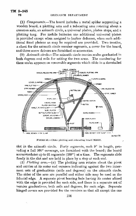
TM 9-34578 ORDNANCE DEPARTMENT
(1) Components.—The board includes a metal spider supporting a wooden board, a plotting arm and a relocating arm rotating about a common axis, an azimuth circle, a universal platen, platen stops, and a plotting targ. For mobile batteries one additional universal platen is provided except when assigned to harbor defenses, when such addi tional fixed platens as may be required are provided. Two trestles, a chest for the azimuth circle number segments, a cover for the board, and three screw drivers are furnished as accessories.
(2) Azimuth circle.—The azimuth circle carries scales graduated in bo.th degrees and mils for setting the two arms. The numbering for these scales appears on removable segments which slide in a dovetailed
SCALES. RELOCATING ARM——[j]
VERNIER-
CIRCLE. AZIMUTH
5. PLOTTING ARM
(-SEGMENTS. NUMBER
-LEVER. CLAMPING
LEVER. CLAMPING
ARM. PLOTTING-VERNIER
RIDER
STRIPS, RIDER
•ARM. RELOCATING
STRIP, NUMBER
INDEXES. RANGE PLATEN. UNIVERSAL
HANDLE, PLATEN CLAMFSLIDE, PLATEN
BUTTON, PLATEN SLIDE
SCREWS. ADJUSTING SCREWS. LOCKING
RAFSDI738
FIGURE 48.—Cloke plotting and relocating board M1923.
slot in the azimuth circJe. Forty segments, each 9° in length, pro viding a full 360° coverage, are furnished with the board; the board accommodates up to 21 segments (189°) at a time. The segments slide freely in the slot and are held in place by a stop at each end.
(3) Plotting arm.—(a) The plotting arm rotates about the pivot and carries at its outer end verniers indicating against the two inner most sets of graduations (mils and degrees) on the azimuth circle. The sides of the arm are parallel and either side may be used as the fiducial edge. A separate pivot bearing hole having its center alined with the edge is provided for each side, and there is a separate set of vernier graduations, both mils and degrees, for each edge. Separate hinged covers are provided for the verniers so that all except the one
154

TM 9-345155-MM G'U-N MATKR1EL 78
in use may be rendered invisible. An additional hinged cover is arranged to be turned to leave exposed either the mil or the degree graduations on the azimuth circle, as required. Covers are marked "degrees" or "mils" to correspond with the angular units indicated on exposed scales. One edge of the plotting arm is graduated to pro vide an indication of range. Removable number strips are furnished making possible the use of different scale ratios in plotting.
(&) A clamping lever is provided at the outer end of the arm. This lever when depressed permits movement of the arm.
(c) The platen arm serves as a guide for the platen slide. A strip beyond the pivot stops the slide in the zero-range position, which is used for orienting. Indexes on the slide provide a range indication on the plotting arm graduations.
(d) A rider which is arranged to be clamped along the arm as desired may be used for a maximum range stop or marker. The pro jecting strip extending from the under side of this rider terminates under the center of the platen slide button when the rider and slide are in contact.
(4) Universal platen.— (a) The platen is pivoted with respect to the platen slide and is arranged to be clamped in fixed angular rela tion to the plotting arm by means of the platen clamp handle.
(6) The slide is reversible so that the platen may extend from either side of the plotting arm. as desired. The platen is removable from its pivot and may be turned upside down.
(c) Located in the center of the pivot is a small button which, when depressed, causes a sharp point to indent the paper or map on the board along the edge of the plotting arm. This button corre sponds to one observing station (B") on the scale reproduction, and its location determines which edge of the plotting arm shall be con sidered the fiducial edge. When the platen is in the orienting posi tion, the axis of this button coincides with the axis of the azimuth circle.
(d) The gun button, which also has a point to indent the paper or map when depressed, corresponds to the gun or directing point on the scale reproduction and is arranged to be clamped in any desired relation to the platen. Slides permitting this movement are clamped by means of central screws; the slides are reversible and the button may be clamped either above or below the platen and on either side of the transverse guide as desired.
(e) The gun plate, on which may be pasted a plot to the proper scale showing the, position of the individual guns of the battery when different data are required for each, is also arranged to be clamped
155
TM 9-34578 ORDNANCE DEPARTMENT
as desired in relation to the platen and gun button. When data are required for only a single gun or directing point, the gun plate is ordinarily not used; it may. however, be necessary to use it instead of the gun button when the gun location is so close to one of the observing stations that interference results. When the gun plate is used, the gun button may be omitted.
(/) The station center consists of a triangular index with a button concentric with the edge. The station center, which represents the other observing station (B') on the scale reproduction, is likewise arranged to be clamped in any desired relation to the platen, and the button has a point to indent the paper or map when depressed. The triangular index may be turned suitably to indicate against the range scale graduations on the relocating arm.
(5) Fixeed platen.—Fixed platens, made of sheet metal, are used with fixed batteries or with mobile batteries occupying prepared lo cations. Where more than one arrangement of guns and observing points may be employed, the various locations may all be included on a single fixed platen, or a separate fixed platen may be made up for each combination. The fixed platen pivots about the plate slide but ton and is clamped by the platen clamp handle in the same manner as the universal platen.
(6) Relocating arm,.—The relocating arm lies above the platen and plotting arm and is pivoted about an axis in prolongation with that of the latter. It carries at its outer end verniers indicating against the two outermost sets of graduations (mils and degree) on the azimuth circle.
(a) The sides of the arm are parallel and either may be used as the fiducial edge. A separate pivot bearing hole having its center alined with the edge is provided for each side, and there is a separate set of vernier graduations, both mils and degrees, for each edge.
(Z>) Separate hinged covers are provided for the vernier so that all except the one in use may be rendered invisible. An additional hinged cover is arranged to leave exposed either the mil or the degree graduations on the azimuth circle as required. Covers are marked "degrees" or "mils" to correspond with the angular units indicated on exposed scales.
(c) Both edges of the relocating arm are graduated to provide indications of range, measured from the pivot which represents the target. Removable number strips are furnished, making possible the use of different scale ratios in plotting.
(d) The platen stop is mounted on an adjustable slide which can be clamped to stop the platen in any desired position. The.stop may
156

155-MM GUN MATERIELTM 9-345
78
be located on either side of the board as required. Two stops are provided, one with a short slide and one with a long slide.
(7) Targ.—The plotting targ has an edge perpendicular to the bottom surface and is used to project any desired point to the grad uated edge of the relocating arm. for measurement of range or azi muth, or to project a point to the map or paper for plotting. For the latter purpose a button on the top of the targ. when depressed, causes a point at the end of the vertical edge of the targ to indent the paper or map.
(8) Number segment chest.—This chest provides for the orderly storage of the azimuth circle number segments and of the screw drivers required for clamping the range scale number stops and platen parts in position. Range scale number strips are not kept in this chest as a rack on the under side of the board is provided for them.
(9) Trestles.—The trestles are adjustable in height, pins being inserted in holes in the verticle sliding members to maintain proper adjustment.
(10) ('over.—The cover for the board is a rectangular sheet of white cotton duck approximately 6 by 9 feet.
b. Operation-.— (1) General.—The pivol axis about which the arms rotate corresponds to the target oil a scale reproduction. The points on the platen, when properly oriented, correspond to fixed positions of guns, directing points, or observing stations. The fiducial edges of the arms correspond to lines of sight to the target from the points on the platen.
(2) Preliminary operations.— (a) Select the range number strips for the scale ratio (yards per inch) desired and attach them to the plotting and relocating arms.
1. Scale ratios and maximum and minimum range limits are as follows:
SCALE RATIO(Yards per inch)
300. -----------..._........600- — — — — — — — — — — - — —750.-- — — — - — — — . —— —900 l -1,200!. _ . ..
Range limits (yards)
Plotting arm
Minimum
0 0 0 0 0
Maximum
11, 750 23, 500 29, 375 35, 250 47, 000
Relocating arm
Minimum
750 1, 500 1,875 2, 250 3, 000
Maximum
12, 850 25, 700 32, 125 38, 550 51, 400
Number strips of 900 and 1,200 yards per inch are issued on special order only.
157 '

TM 9-34578 ORDNANCE DEPARTMENT
8. The above data apply to boards with arms graduated 30 divisions per inch. For boards with arms graduated 40 divisions per inch, the scale ratios are 200, 400, 800, and 1,000 yards per inch; when the replacement of such arms and associated parts becomes necessary or desirable, arms graduated 30 divisions per inch will be furnished.
3. Each strip is marked with its scale ratio in yards per inch. The same scale ratio must be employed on both arms; however, when there are two observing stations no range indication on the plotting arm is required and no number strip need be attached thereto.
4. When inserting the strips into the slots, push the strip in the plotting arm slot until it stops, then insert the screw; push the strip in the relocating arm just far enough into its slot to permit insertion of the screw.
(J) The number segments selected for the azimuth circle should be such that the platen will be near the midboard position. Place the segments in their proper order in the slot of the azimuth circle and slide them along until the numbers fall opposite the major scale graduations. For indications in both angular units (mils and degrees), the numbers must fall opposite major scale graduations common to both scales (integral multiples of 9° and of 160 mils are in alinement on the number segments) ; for indications in only one angular unit, it is necessary only that the numbers fall opposite major graduations on the one scale in use. The segments are secured in their proper position by sliding the clamps against the ends and tightening the clamp knobs.
(c) Uncover the verniers corresponding to the angular units in use. Note that either side of each arm may be used as the fiducial (reference) edge and that each such edge has a separate vernier Avith its zero-graduation alined with the edge, as well as a separate pivot-bearing hole with its center also alined with the edge. It is essential that both the proper vernier and the proper pivot-bearing hole be employed for the edge in use in all cases.
(3) Orientation.—This operation consists of locating the station center, gun button, and platen stop in their correct positions. The procedure described is considered preferable; however, other methods which will accomplish the same result are possible and may be used if desired.
(a) The platen slide button corresponds to the secondary (B") observing station. Azimuth settings as used in orientation are those
158

TM 9-345155-MM GUN MATERIEL 78
of the secondary (B") stations as observed from the gun, directing point, or observing station for which the setting is made.
(b) Slide the platen slide toward the pivot axis until a stop is encountered, thus alining the platen slide button with the pivot axis. Unclamp the platen.
(c) Swing the relocating arm to indicate the azimuth of the base Hne as observed from the primary station (B'), looking toward the secondary station (B").
(d) Locate the station center so that the triangular index thereon indicates the length of the base line (B"B') against the range gradu ations along the edge of the relocating arm and clamp the station center to the platen in that relation.
(e) Clamp the platen stop so that it rests against the edge of the platen when the station center is against the edge of the relocating arm. When the platen is against this stop it is said to be in the orienting position.
(/) Swing the relocating arm to indicate the azimuth of the secon dary station (B") as observed from the gun with the platen still in the orienting position, and clamp the gun button to the platen so that the center falls under the range graduation corresponding to the distance from the gun to that station. Use the plotting targ to aline the button with the proper range graduation.
(g) If separate data for individual guns are desired, paste a piece of paper or tracing cloth on the gun plate and locate the position of each gun thereon in the manner described for locating the gun button. When using the gun plate, the gun button may be retained to represent one of the guns or all may be located on the gun plate.
(h) If a fixed platen is used, the procedure is similar, but location of individual gun positions (except when initially laying out a new platen) is not necessary. If the fixed platen provides for several primary (B') observing stations, be certain that the one correspond ing to the station in use is selected for the station center and that the proper azimuth is used in orienting.
(i) The universal platen may be reversed or inverted, should it be found that the gun button fails to clear. The only case where in terference of this character cannot be avoided is when the secondary station (B") and gun are extremely close together, in such a case, mark the gun position on the platen in the same manner as in mark ing the gun plate.
(j) The platen is left in the orienting position until the plotting arm has been properly located in azimuth; the platen is then clamped
159

TM 9-34578 ORDNANCE DEPARTMENT
and remains parallel to its original position as it is moved along the plotting arm.
(k) The setting of the platen stop and the location of platen parts are not to be altered as long as the positions of guns and observing stations remain unchanged, unless the azimuth number strips are shifted. If any of the elements mentioned are changed, it is neces sary to repeat the orientation procedure.
c. Tests and adjustments.— (1) Test data.—The following test data may be used for checking the accuracy of the board. Ranges and base line distances in the table are in yards, for use with the 300 yards per inch scale graduations; increase the values proportionally for other scale graduations. Azimuths are in degrees and are suit able when the zero azimuth graduation is near the center of the scale; for other midscale indications, all azimuths given may be in creased or decreased equally by any desired amount to bring the problems within the operating range of the board. When conversion of degrees to mils is required, the relations: 1° = 17.778 mils or 360° = 6400 mils, may be used.
Target data
Range from B'
Range from B" --- . . .
Base line, data
Azimuth, B" from B' ' _.
Problem number
1
340. 44 8, 301.
315. 11, 000.
324. 88 10, 174.
89. 50 5, 000.
74. 25 2, 000.
2
45. 18 9, 644.
15. 25 7. 000.
27. 30 8,211.
89. 505, 000.
74.25 2, 000.
3 41
357. 25 1 8, 000.
10. 24 8, 672.
• 74. 25 2, 000.
318. 25 5, 912.
345. 75 4, 000.
333. 25 5, 251.
280. 25 3, 000.
300. 50 1, 600.
5
7. 67 4, 137.
44. 50 5, 000.
25. 90 4, 867.
280. 25 3, 000.
300. 50 1, 600.
i Indicates a setting; other values are readings.
(2) Platen slide.—The platen slide should slide freely but with out play the entire length of the plotting arm. If necessary to adjust it, back off the four locking screws in the platen slide and adjust the four adjusting screws as required to produce the proper fit.
d. Care and preservation.— (1) Handle the number strips and seg ments with care to prevent the occurrence of nicks and burs. Keep
160
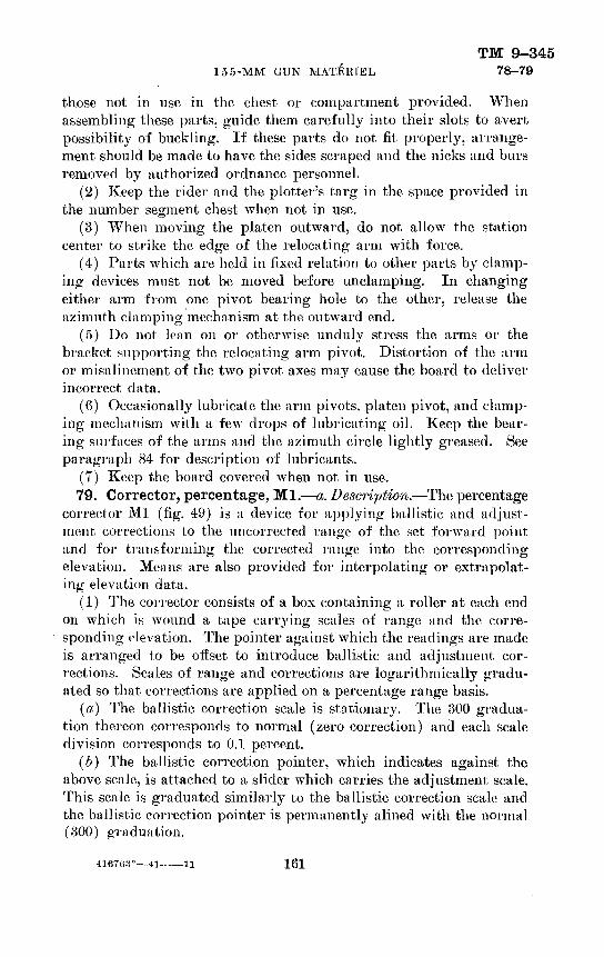
TM 9-345155-MM GUN MATERIEL 78-79
those not in use in the chest or compartment provided. When assembling these parts, guide them carefully into their slots to avert possibility of buckling. If these parts do not fit properly, arrange ment should be made to have the sides scraped and the nicks and burs removed by authorized ordnance personnel.
(2) Keep the rider and the plotter's targ in the space provided in the number segment chest when not in use.
(3) When moving the platen outward, do not allow the station center to strike the edge of the relocating arm with force.
(4) Parts which are held in fixed relation to other parts by clamp ing devices must not be moved before unclamping. In changing either arm from one pivot bearing hole to the other, release the azimuth clamping mechanism at the outward end.
(5) Do not lean on or otherwise unduly stress the arms or the bracket .supporting the relocating arm pivot. Distortion of the arm or misalinement of the two pivot axes may cause the board to deliver incorrect data.
(6) Occasionally lubricate the arm pivots, platen pivot, and clamp ing mechanism with a few drops of lubricating oil. Keep the bear ing surfaces of the arms and the azimuth circle lightly greased. See paragraph 84 for description of lubricants.
(7) Keep the board covered when not in use.79. Corrector, percentage, Ml.—a. Description.—The percentage
corrector Ml (fig. 49) is a device for applying ballistic and adjust ment corrections to the uncorrected range of the set forward point and for transforming the corrected 7-ange into the corresponding elevation. Means are also provided for interpolating or extrapolat ing elevation data.
(1) The corrector consists of a box containing a roller at each end on which is wound a tape carrying scales of range and the corre sponding elevation. The pointer against which the readings are made is arranged to be offset to introduce ballistic and adjustment cor rections. Scales of range and corrections are logarithmically gradu ated so that corrections are applied on a percentage range basis.
(a) The ballistic correction scale is stationary. The 300 gradua tion thereon corresponds to normal (zero correction) and each scale division corresponds to 0.1 percent.
(b) The ballistic correction pointer, which indicates against the above scale, is attached to a slider which carries the adjustment scale. This scale is graduated similarly to the ballistic correction scale and the ballistic correction pointer is permanently alined with the normal (300) graduation.
—ii 161

TM 9-345 79 ORDNANCE DEPARTMENT
162

TM 9-345155-MM GUN MATERIEL 79
(<?) The reading pointer is attached to a sliding carrier. When the edge of this pointer is set to the desired indication on the adjust ment scale, it receives a total displacement equal to the combined effects of the ballistic and adjustment corrections.
(d) The index line on the transparent window, alined with the zero-correction position of the reading pointer, is used for setting the tape to the proper uncorrected range indication.
(e) The cloth-backed tape with range and elevation graduations is furnished by the Coast Artillery Corps. It is operated by means of knobs and rollers which have internal springs to keep the tape taut.
(2) The interpolator is used for computing elevations at intervals more frequent than the predicting interval. It includes a tape, marker, and splitter.
(a) The splitter is an aluminum plate graduated with converging lines. It may be moved in or out so that the central and outer lines indicate opposite elevations corresponding to the start and finish of a 30-second interval; the intermediate line then indicates the elevation corresponding to the finish of a 15-second interval. The markings "1" and "3" on these lines indicate the corresponding number of strokes of the bell of the time interval system.
(&) The cloth-backed tape is graduated in terms of elevation angles. It is operated by means of knobs and rollers which have internal springs to keep the tape taut.
(c) The marker is arranged to clip on the edge of the tape.&. Operation.— (1) Corrector.— (a) Roll the tape so the uncorrected
plotting board range of the set forward point is indicated under the index mark.
(b) Set the required ballistic correction by displacing the asso ciated pointer along the scale.
(c) Set the required adjustment correction by displacing the read ing pointer and carrier along the adjustment scale.
(d) Read the corrected range or elevation on the tape opposite the reading pointer.
(e) Note that the edges of the pointers used for indication are the edges perpendicular to the longitudinal axis of the corrector; do not use the slanting edges for indicating purposes.
(2) Interpolator.—The interpolator splitter is graduated to pro vide for 15-second intervals; it may, however, be turned over and an improvised graduation sheet attached, should it be desired to use other intervals.
163

TM 9-345 80 ORDNANCE DEPARTMENT
80. Indicator, wind component, Ml.—a. Description.—This in dicator (fig. 50) is used to compute the wind component (range arid deflection) reference numbers for use on the range correction board and on the deflection board. Its use is not required when the deflection board" Ml is employed, as that board incorporates a wind component device.
~b. Operation.— (1) Set the end of the pointer to the wind velocity and clamp in position.
•BRACKET
-SCALE-INDEX
-CLAMPING THUMBSCREW
AZIMUTH. (MILS)
RA FSD 1992
TARGET AZIMUTH, (DEGREES)
Wind velocity—20 mph.Wind azimuth—4,800 mils (from north).Target azimuth—315° (from north).
FIGURE 50.—Wind component indicator Ml.
Indications Uiinge component—35.9.
Deflection component—35.0.
(2) Clamp the target azimuth index to indicate the target azimuth (degrees) on the associated scale.
(3) Clamp the wind azimuth scale to indicate the wind azimuth opposite the associated index. Wind azimuth is the direction from which the wind is blowing and, together with the velocity, is de termined from the meteorological message. (See TM 11-420 (now published as TR 1236-1)). This instrument is primarily designed
164

TM 9-345155-MM GUN MATERIEL 80-83
for target azimuths measured from the south and for wind azimuths measured from the north; when both azimuths are measured from the same direction (either north or south) add or subtract 3,200 mils to or from the wind azimuth.
(4) Bead the range and deflection component reference numbers along the associated scales. These scales have normal (zero com ponent velocity) indications of 50. and the range and deflection com ponent reference numbers read thereon are for application on the range correction board and on the deflection board, respectively.
81. Rule, set forward, type B.—a. Description.—This rule (fig. 51) is a white celluloid slide rule of conventional design with two stationary scales and a movable slide.
b. Operation.—(1) Place the slide so that the arrow indicates the rate of travel in yards per minute.
(2) Opposite the time of flight in seconds, obtained from firing tables or from the data on the side of the chart of the range correction board, read the yards of travel during the time of flight plus 1 minute.
82. Scales, prediction.—These scales (fig. 52) are used for meas uring and laying out distances on the plotting and relocating board. They are available with the same scale ratios as those of the plotting board number strips. It is necessary that the ratios of the plotting board number strips and prediction scale in use be the same.
83. Unit, generating1, Ml.—a. Description.—This generating unit (fig. 53) is a portable gasoline-engine-driven generator of the type extensively used commercially on boats, camps, and farms. It is furnished complete with storage batteries, control panels, portable cables, extension lamps, spare lamps, hydrometer, and trunk type metal box. This unit is employed to illuminate plotting rooms and command stations.
(1) Generator.—The generator is a shunt-wound, direct-current generator rated at 650 watts, 12 volts.
(2) Engine.—The engine is a single-cylinder, air-cooled, two-cycle (fires every stroke) high compression unit. It is mounted on spring feet. Ignition is furnished by magneto. Lubrication is accom plished by oil mixed with gasoline. The speed is controlled auto matically by a built-in governor.
(3) Batteries.—Three 6-volt 115 ampere-hour lead storage bat teries are provided.
(4) Control panels.—A socket panel (fig. 54) and a charging panel (fig. 55) connected as shown in figure 56 are provided. The former has fourteen automotive-type receptacles for attaching the extension lamps and the latter has an internal resistor for reducing the 12-volt
165

TM 9-345 83 ORDNANCE DEPARTMENT
OOEI-0931—ooa—0511—OOII—osa—ooa—096—006—
058 —008—
OSi —
OOi —
OS9-E
009 -^
OSS^
DOS—
OSf—
OOfr—-
OS£—-
-
00£—
.-
093 —-
ooz—
OSI —_
_
-
001 —NIWH-LHDHJJ03WLIlima«roiSQMW
0
— Si— Oi— 99
— 59— OS_,-»g— O*K— — OC fS£g — OC*— <&.<£ sc Q:
<x -03 K
«
cno§o(A
z
— OOi
^099
f-0093
E-09SIr-OOSIz-ost-^
— OOb-
— oscI
— oos
— osz— OfrJ — 0£Z— ozz— 013 — OOZ— 061— 081
— Oil— 091
— OSI
— OW
— oci
— OZI
— Oil
— OOI
— 06
— 08
— Oi
— 09
-OS
AWUJ WH3dOMVA
£
ga
166

REC
EPTA
CLE
FO
R —
C
ABLE
AN
D
PLU
G, I_
AS
SEM
BLY
TO
CHAR
GIN
G P
ANEL
—'
I——
FIEL
D RH
EOST
AT
STO
P BU
TTO
N
Oi en I O I
FIGD
EE 5
3.—
Gen
erat
ing
unit
Ml.

TM 9-34583 ORDNANCE DEPARTMENT
generator potential to 6 volts for battery charging. Eeceptacles for the portable cables which connect the charging panel to the other elements are polarized to insure connection in the correct relation.
RA FSD 1996 FIGURH 54.—Generating unit Ml socket panel.
Auxiliary binding posts are provided near each polarized receptacle so that improvised connections may be employed.
(5) Portable cables.—Two-conductor portable cable and plug as semblies are provided for connecting the charging panel to the gen-
168
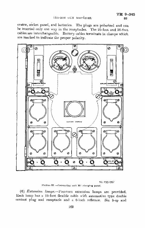
155-MM UUN MATERIELTM 9-345
83
erator, socket panel, and batteries. The plugs are polarized and can be inserted only one way in the receptacles. The 25-foot and 50-foot cables are interchangeable. Battery cables terminate in clamps which are marked to indicate the proper polarity.
RA FSD 1997 FIOORH 5R.—Generating unit Ml charging panel.
(6) Extension lamps.—Fourteen extension lamps are provided. Each lamp has a 15-foot flexible cable with automotive type double contact plug and receptacle and a 6-inch reflector. Six 3-cp and
169

TO C
HARG
ING
PAN
EL
/TO
GEN
ERAT
OR
,
CH
ARG
ING
PA
NEL
—
—-s
^ -=
-
-TO
SO
CK
ET
PAN
EL
TO C
HAR
GIN
G P
ANEL
GEN
ERAT
OR
STO
RAG
E BA
TTER
IES
14 R
ECEP
TAC
LES
SO
CK
ET
PAN
EL
ARM
ATU
RE
|
FIEL
D
l\f^]
FIX
ED R
ESIS
TOR
AM
/ R
HEO
STAT
©
VO
LTM
ETE
R
@
AM
ME
TER
°] SW
ITC
H
-=-
LEAD
STO
RAG
E C
ELL
f.
POLA
RIZ
ED R
ECEP
TACL
E W
ITH
AU
XILI
ARY
BIND
ING
PO
STS
3t
POLA
RIZ
ED P
LUG
©
PILO
T LI
GH
T AN
D S
WIT
CH
<£
6V R
ECEP
TAC
LE
(AU
TOM
OTI
VE T
YP
E)
(D
CO
OX
O § O H g
I
FIGU
RE 5
6.—
Gen
erat
ing
unit
Ml—
sche
mat
ic d
iagr
am
of c
onne
ctio
ns.
RA
FSD
199
8

TM 9-345155-MM GUN MATERIEL 83
eight 21-cp double-contact 6-8-volt miniature lamps are furnished for use in these extensions; an equal number of spare lamps is also provided.
&. Operation.— (1) Set the generating unit on any firm level base. Secure it in place, if desired, by means of screws in the loops of the spring feet. If the unit is to be operated indoors, improvise a flexible connection for conducting exhaust gases to the outside.
(2) Fill the fuel tank with gasoline to each gallon of which has been added and thoroughly mixed i/2 pint of class D lubricating oil, SAE 50 (extra heavy) (U. S. A. Spec. No. VV-O-496). Turn the shut-off cock in the fuel line to the open (vertical) position.
(3) Locate the control panels where desired, within the limit of available cable runs, throw all switches to the "off" position, and connect the various cables. It is essential that the battery clamps be connected to posts of the proper polarity as marked; connect these clamps to the battery before inserting the plug in the receptacle.
(4) Extension lamps may be lighted by closing the light switch on the socket panel. As indicated on this panel, do not close the switch when the voltage materially exceeds 6 volts and do not allow the current to exceed 25 amperes.
(5) Unless the battery is fully charged, indicated by a hydrometer reading of 1.280 (specific gravity, 1.28*), start the generating unit by depressing the starting button and operating the choke lever. If necessary, the unit may be spun by means of a rope wound around the drum on the shaft extension. As soon as the engine starts, release the starting button immediately and allow the choke lever to return slowly to the open position. Close the battery charging switch; the ammeter then indicates the charging rate which may be adjusted as required by means of the field rheostat. The battery should be charged until a hydrometer indicates the fully charged condition to be reached. Battery gravity should not be allowed to fall below a hydrometer reading of 1.150 (specific gravity. 1.15) either with or without connected load.
(6) To use the generator for auxiliary charging, connect the bat tery to be charged to the battery cable and insert the plug in the receptacle marked for auxiliary charging. Close the associated switch and adjust the rate as required by means of the rheostat.
(7) To stop the engine, press the "stop" button located on the fuel • tank. Turn the shut-off cock in the fuel line to the closed (hoizontal) position.
•Based on a temperature of 80° F. : increase (decrease) by .01 for each 30° F. decrease i increase) from 80° F.
171

TM 9-34583 ORDNANCE DEPARTMENT
c. Care and preservation.— (1) Always add oil to gasoline (6(2) above) and thoroughly mix before pouring into fuel tank.
(2) Do not allow the generator to run continuously without load.(3) Connect the equipment only in the manner indicated; never
connect the socket panel directly to the generator.(4) Exercise care to prevent conducting objects from coming into
contact with live parts, such as plug fingers, terminal nuts, etc.(5) Observe the following procedure in the care of batteries: (a) Do not allow any spark, fire, or flame near the battery, particu
larly when charging.(i) Do not allow any conducting material to come into contact
with the tops of the battery cells.(c) Keep all battery connections, both between cells and external
leads, clean, tight, and well-coated with petrolatum.(d) Keep the tops of the battery cells clean.(e) Keep the level of the liquid in each cell at the liquid level mark
by adding distilled water as required.(/) Add only distilled water to the cells. Many impurities com
mon in local sources of water are extremely harmful to lead storage batteries. Under no circumstances may additional electrolyte be
4, added to the cells as such a procedure will increase the acid concentra tion and cause injury to the battery.
(g) Periodically check the condition of the battery by taking hy drometer readings.
(h) Keep the battery fully charged, never allowing it to remain in a discharged condition for any appreciable length of time nor to be discharged beyond its rating.
(«) In freezing weather pay special attention to the instructions in (h) above, as, while the electrolyte of a fully charged battery will not freeze at any temperature to be expected in service, at a specific gravity of 1.08 (hydrometer reading, 1080) the freezing point of the electrolyte is only 22° F.
(6) Be sure to use a spark plug of the proper temperature range for the engine. Use Champion C-7 spark plug or equivalent.
(7) Keep the strainer in the fuel inlet on top of the carburetor free from sediment. When this strainer is being inspected, open the shut- off cock in the fuel line to make sure there is a free now of fuel; if the fuel does not flow freely, drain the fuel, remove the shut-off cock, and clean the fuel tank strainer.
(8) Do not run the engine unless it is free to float on the four springs. Never use a rigid connection for the external exhaust pipe..._.
172

TM 9-345155-MM GUN MATERIEL 83-84
(9) Adjustment of carburetor needle valve, governor, and breaker points by the using arm is not permitted.
84. Care and preservation.—a. Instructions given hereunder supplement instructions pertaining to individual instruments included in preceding paragraphs.
5. The design of plotting room equipment is such that the original alinement of parts must be retained for accurate operation. The equipment is sufficiently rugged to furnish accurate data for a long period of time if carefully handled. Bumping, dropping, leaning on or otherwise improperly handling the equipment must be avoided.
(;. On motions equipped with clamping devices be certain that the clamps are released before making settings.
d. Keep the equipment clean and dry; when not in use. keep it covered.
e. Disassembly and assembly by the using arm are permitted only to the extent authorized in paragraphs pertaining to the individual in struments. Unnecessary turning of screws or other parts not incident to the use of the equipment is expressly forbidden.
/. No painting of this equipment by the using arm is permitted.g. Keep metal scales, arms, and reference edges and surfaces lightly
coated with grease, special, low temperature. Occasionally oil metal pivots and sliding surfaces sparingly with oil, lubricating, for aircraft instruments and machine guns.
173

TM 9-345ORDNANCE DEPARTMENT
CHAPTER 4
AMMUNITIONParagraph
General_____________________________________________ 85 Nomenclature________________________________________ 86 Classification _____________.. _________.._________________ 87 Firing tables—___________ ..__....._____..— _______________ 88Identification ________________ .___ .._.________._______ 89 Mark or model-______________ ._. . _ _-__.-__________-__._-_____ 90Ammunition lot number._______——___.— ____———__———_————__ 91Ammunition data card------_-________.__ . _ _________._____ 92Painting and marking_________________ _ _______—_____ 93Weight zone markings_____________ ..___ . ..___________ 94Care, handling, and preservation_________ ... ._ ___________ 95Authorized rounds___________________._____________ 96Preparation for firing____________________________________ 97 Projectiles____________._____.. _ ... _. - ...____...______ 98Shell, gas, persistent, HS, Ml 04, unfnzed, 155-mm gun_____________ 99 Shell, gas, persistent, HS, Mk. VIIA1, unfuzed, liio-mm gun___________ 100 Shell, HE, MIDI, unfuzed, 155-mni gun________________________ 101 Shell, HE. Mk. Ill, unfnzed, 155-mm gun______________________ 102 Shell, HE, Mk. IIIA1, unfuzed, 155-mm gun_____________________ 103 Shell, smoke, FS, JI104. unfuzed, 155-mm gun____________________ 104 Shell, smoke, FS, Mk. VIIA1, unfuzed, 155-mm gun_______________ 105 Shell, smoke, phosphorus, WP, Ml04, unfuzed, 155-mm guu_—_________ 106 Shell, smoke, phosphorus, WP, Mk. VI1A1, unfuzed, 155-mm gun________ 107 Shrapnel, Mk. I, fuzed (or unfuzed), 155-mm gun or howitzer_________ 108 Propelling charges_____________________________________ 109 Charge, propelling, 155-mm guns, M1917, M1917A1, and M1918MI______ 110 Charge, propelling, NH powder, 155-mrn guns, M1917, M1917A1, and M1918MI- 111 Fuzes_____________________________________________ 112 Fuze, P. D., M46_______________________________________ 113 Fuze, P. I)., M47_________________________________________114 Fuze, P. D., M51, w/booster, M21______________________________ 115Fuze, combination, 45-second, M1907M______————_————__———__ 116Fuze, combination, 45-second, M1914________————_———__—___ 117 Primer, percussion, 21-grain, Mk. !!_„________.._____________ 118Primer, percussion, 21-grain, Mk. IIA_________________________ 119 Primer, percussion, 21-grain, Mk. IIA1_______ ..--.._____________ 120Packing__._———————————___________ _—._—. ___——__ 121Subcaliber ammunition_________________——____—__—___ 122 Field reports of accidents______________—___-_____-___ 123
174

TM 9-345155-MM GUN MATERIEL 85-90
85. General.—The 155-mm guns, M1917, M1917A1, and M1918MI, being chambered alike, fire the same ammunition. The ammunition is known as separate loading ammunition because the loading of each complete round into the cannon requires three separate operations: loading the projectile, the propelling charge, and the primer. These components, as well as the fuze for the projectile, are shipped sep arately, the projectile being shipped nnfuzed except that in time of war shrapnel is shipped fuzed.
86. Nomenclature.—Standard nomenclature is used herein in all references to specific items of issue.
87. Classification.—Dependent upon the kind of filler, projectiles may be classified according to type as explosive, chemical, or inert. Explosive projectiles comprise high explosive, practice, and shrapnel. High explosive projectiles contain a high explosive bursting charge, whereas shrapnel and practice projectiles contain a relatively small quantity of low explosive filler. The low explosive filler for practice projectiles is intended solely as a spotting charge and for some pur poses may be omitted.' Shrapnel are projectiles which carry a large number of spherical shot to a distance from the gun and there dis charge them over an extended area. Chemical projectiles comprise those containing a chemical filler, that is, a chemical agent which pro duces either a toxic or an irritating physiological effect, a screening smoke, incendiary action, or a combination of these. Dummy or drill projectiles are always inert (contain no explosive).
88. Firing tables.—For applicable firing tables see appendix.89. Identification.—Ammunition, including components, is com
pletely identified by means of the painting, marking (includes ammu nition lot number), and accompanying data card or tag. Other essen tial information is marked on the components. For example, on the projectile, the weight zone and kind of filler; on the propelling charge, the weight of igniter, designation of each section, etc. See figures 57 to 69. inclusive, and following paragraphs.
90. Mark or model.—To identify a particular design, a model designation is assigned at the time the design is classified as an adopted type. This model designation becomes an essential part of the stand ard nomenclature and is included in the marking on the item. Prior to July 1, 1925. it was the practice to assign mark numbers. The word "Mark , abbreviated "Mk.", was followed by a roman numeral; for
175

Til 9-34590-93 ORDNANCE DEPARTMENT
example, shell, HE, Mk. III. The first modification of a model was indicated by the addition of MI to the mark number, the second by Mil, etc. The present system of model designation consists of the letter M followed by an arabic numeral. Modifications are indicated by adding the letter A and appropriate arabic numeral. Thus M1A1 indicates the first modification of an item for which the original model designation was Ml.
91. Ammunition lot number.—When the ammunition is manu factured, an ammunition lot number, which becomes an essential part of the marking, is assigned in accordance with pertinent specifications. In the case of separate loading ammunition, such a lot number is as signed and marked on each of the components—projectile, fuze, pro pelling charge, and primer—as well as on all packing containers and the accompanying data card. It is required for all purposes of record. To provide for the most uniform functioning, all of the components in any one lot are manufactured under as nearly identical conditions as practicable. For example, in the case of projectiles, any one lot consists of projectiles made by one manufacturer, loaded by one manu facturer, and of one weight zone. Therefore, to obtain the greatest accuracy, when firing separate loading ammunition, successive rounds should consist of projectiles of one lot number, propelling charges of one lot number, fuzes of one lot number, and primers of one lot number.
92. Ammunition data card.—A 5 by 8 inch card, known as an ammunition data card because of the data contained thereon, is placed in the packing box with the ammunition or ammunition components. However, a data card is not attached to projectiles which are shipped unboxed or uncrated. In the case of separate loading propelling charges, a linen tag containing similar data is attached to the charge in lieu of a data card.
93. Painting and marking1.—a. Painting.—All projectiles are painted to prevent rust and, by means of the color, to provide a ready means for identification as to type. The color scheme is as follows:
High explosive__ Yellow; marking in black. Chemical______. Gray; one green band painted on a chem
ical projectile indicates nonpersistent gas; two green bands, persistent gas; one yellow band, smoke. Marking on the projectiles is in the same color as the band.
176

TM 9-345155-MM GUN MATERIEL 93-94
Shrapnel______- Red; marking in black.Practice______. Blue; marking in white. Projectiles may
be inert or may contain a live fuze and spotting charge of black powder.
Dummy or drill (in- Black; marking in white.ert).
&. Marking.—For purposes of identification, components of sep arate loading ammunition are marked as follows:
(1) Onprojectile, except shrapnel.— (On shrapnel the only marking is that of caliber and type of cannon in which fired; the lot number is stamped on the rotating band.)
Caliber and type of cannon in which fired.Kind of filler, for example, TNT, CN gas, etc.Mark or model of projectile.Weight zone marking.Lot number.
(2) On propelling charge.Designation of section—"Base" on base section, "Increment"
on increment section. Powder lot number.Caliber and type of cannon in which fired. Weight of igniter charge.
(3) On fuze (stamped on body). Type and model of fuze. Loader's initials. Month and year loaded. Loader's lot number.
(4) On primer (sta/mped on head).Initials of loader.Loader's lot number.Year of loading.Mark number.
94. Weight zone markings.—Because it is not practicable to manufacture high explosive or chemical projectiles within the narrow •weight limits required for the desired accuracy of fire, projectiles are grouped into weight zones in order that the appropriate ballistic corrections indicated by firing tables may be applied. The, weight zone of the projectile is indicated thereon by means of squares with a prick punch in the center of each square—one, two, three, four, or
41676H' .|;l— 12 177
TM 9-34594-95 ORDNANCE DEPARTMENT
more—dependent upon the weight of the projectile. For 155-mm projectiles, four squares indicate normal weight. The color of the squares is in the same color as the marking. When manufactured, shrapnel is adjusted to standard weight by the addition of more or fewer shrapnel balls, hence requires 110 weight zone markings.
95. Care, handling, and preservation.—a. Ammunition compo nents are packed to withstand conditions ordinarily encountered in the field. For shipment, all 155-mm projectiles, except shrapnel, are fitted with an eyebolt lifting plug and a rope grommet, hence a shipping crate is not required. Shrapnel are shipped in packing boxes. Fuzes, charges, and primers are packed in moisture-resistant containers. Nevertheless, since explosives are adversely affected by moisture and high temperature, due consideration should be given to the following:
(1) Do not break moisture-resistant seal until ammunition is to be used.
(2) Protect the ammunition, particularly fuzes and primers, from high temperatures, including the direct rays of the sun. More uni form firing is obtained if the rounds, propelling charges especially, are at the same temperature.
5. Do not attempt to disassemble any fuze.o. Do not remove the eyebolt lifting plug from urifuzed rounds
until the fuze is to be assembled thereto. The eyebolt lifting plug is provided for convenience in handling and to keep the fuze opening free of foreign matter.
d. Primers must always be stored in a dry place. Prolonged ex posure to moisture or dampness may cause malfunctioning.
e. Handle fuzes and primers with care. The explosive elements are particularly sensitive to undue shock and high temperature.
/. Each of the separate loading components should be free of foreign matter—sand, mud, grease, etc.—before loading into the gun.
g. Do not remove protection or safety devices from fuzes until just before use.
h. Components of rounds prepared for firing but not fired will be returned to their original condition and packings, and appropriately
178

TM 9-345155-MM GUN MATERIEL 95-98
marked. Fuzes will be inspected prior to repacking. Such compo nents will be used first in subsequent firings, in order that stocks of opened packings may be kept at a minimum.
96. Authorized rounds.—Being chambered alike, the 155-mm guns, M191Y, M1917A1, and M1918MI. fire the same ammunition. The ammunition authorized for use in these guns is listed below:
179

TM 9-345• 96 ORDNANCE DEPARTMENT
x^•dC
O
Os>"c.S oc
'o
2 "00 ,0
S -c1-1 ?^
^ w
- "-I< M
? *r5 ^- 1^ bb
^5 ^i„
^P -H
S o51 '55*^ wto 5i-H OJ
5 s"<3 •£p3 ^p =fe S* s"2 1& -S <z -g1 i§ a«! So o
a?53
5_5I+J""5"ShH
o3
J
a."ti
B3
f/3
1513
^i£
„*o
£"sS
_5o
**1
^•oO^
1
1o^
IP*J
•
g
™I
¥PM
p^ c« ^c1
a-*ioo .c^
tr;>
i — i
«
i-! c" M T:§
CT:
pq
CT:
c•c
cT:
i<iii
I
i
0 Ct! -C
,
Ct:
t- > ^
' Oli °^ -7 S2'-1
O r~
C C
r-1 C-IN -C
oT3 TT TT
- - - (_, r-i
c•c
c•c
c•c
1"w -»' T-H OJ ^ Qj " '~^ C ^^ G *^ lO '"^Cjp ^1 N -^-tJ c'^fl'O ^"0 iC*Os i-! = ^^ w> TJH jjj g tjg ^S
s'l |l 1? |l -s•S S^ ~ ^" ^ - S "d" «ci aT f W S § 1 •" § Q" §
g ^~g.^"S5ii'w2':L| 3 _jf^ HA ^3 4S So 02 ^H si ^.2 -SSt.1o3.o-r 2 *-!=>-S V1
fe "^CO |
"• — ' 0) 02 £3 ~^~ Q •— *" e*_i
^"^^^^r— i^ ^i*""1
— O n. »O " S O ^ ^ ^ -5i)'~t in ^ t*-
llPfJffilxgp" in '^5 »• *<— " ^^ " T* C^l *~ TJ
10 "0 ~
-Qr "P" |0at *c PH
- *S - if 2<D — <U •< 3
" ^ S ^ > StH ^ (H JC )rt
'G Jvi ^2 *C J^i X" ^~ Jv>^Sfe QJ S rfc ^ £!
"|^ » "§^ <B A^
^~^ O fa * — ' O j; bJD O O 7f- O 03 O
- — ,C " ~ j^1 •> C ,C
js " -e s ji"~'"'^: v~'j: &c j3 j: pOO CO CO O3 a) oo
180

Shel
l, sm
oke,
pho
spho
rus,
WP,
M1U
4, u
n-
fuzc
d, 1
55-iu
m g
un (
adap
ted
for f
uze,
P.
D.,
M51
, w/b
oost
er M
21).
Shel
l, sm
oke,
pho
spho
rus,
WP,
Mk.
VII
Al,
unfu
zed,
155
-mm
gun
(ad
apte
d fo
r fu
ze,
P. D
., M
51,
w/b
oost
er M
21).
Shra
pnel
, M
k. I
, fu
zed,
15
5-m
m
gun
or
how
itzer
.Sh
rapn
el,
Mk.
I,
unfu
zed,
155
-mm
gun
or
how
itzer
. Prac
tice
amm
uniti
on
Shel
l, em
pty
for
sand
loa
ding
, 95
-lb.,
Mk.
II
J, u
nfuz
ed,
155-
mm
gun
(ad
apte
d fo
r in
ert f
uze,
P.
D.,
Mk.
IV
or
M47
).
.Dum
my
amm
uniti
on 4
Proj
ectil
e, d
umm
y, 9
5-lb
., M
k. I
, 15
5-m
m
gun.
-___
_do-
_-__
____
____
do
. __
..
.
.--.
..do... -
----
-
-.--
.do..--
----
.
..-.
. do
___
____
_
Mk.
I d
umm
v_-
____
-do_
-_-_
-.._
__
___-
_do-
_. _
____
___
M19
07M
____
__.
_ .
____
. do_
. ___
____
__
M47
ine
rt
M19
07M
ine
rt
____
_do_
____
-___
-___
-do-
--__
_.
_
cuss
ion.
.....d
o.. ...
....
M19
14.
. .
____
____
_do-
_. ._
.__.
Mk.
TV
iner
t _
Tim
e an
d pe
r cu
ssio
n.
Do.
B &
I—Ba
se a
nd I
ncre
men
t.D
el—
Del
ay.
SQ—
Supo
rqui
ok.
1 Prim
er, p
ercu
ssio
n, 2
1-gr
ain, M
k. I
I or
Mk.
IIA
, aut
horiz
ed fo
r use
whe
n pr
imer
, per
cuss
ion,
21-
grain
, Mk.
IIA
1, is
not
ava
ilabl
e.2 S
tand
ard
char
ge is
des
igna
ted:
Cha
rge,
prop
ellin
g, N
H p
owde
r, 15
5-m
m g
uns,
M19
17,
M19
17A
l, an
d M
1918
M1.
3 Sub
stitu
te fo
r she
ll, s
mok
e, ph
osph
orus
, WP,
M10
4. un
fuze
d, 1
55-m
m g
un.
4 A fi
red
serv
ice p
rimer
is u
sed
for d
rill p
urpo
ses.
H B "I CR
TM 9-34597-98 ORDNANCE DEPARTMENT
97. Preparation for firing.—Prior to loading, it is necessary to assemble the fuze to the projectile as described in paragraph 98 and the paragraph devoted to the particular fuze. Also, the igniter protector cap must be removed from the propelling charge and the charge adjusted for the zone to be fired as described in paragraph 109.
98. Projectiles.—a. General.—Projectiles for 155-mm guns, ex cepting shraptiel, are of two general design types: those of earlier design, distinguished by two narrow rotating bands, each approxi mately 0.06-inch wide (figs. 58, 59, and 61) ; and those of current design, distinguished by a broad rotating band approximately '2 inches wide (figs. 57 and 60). Shrapnel (fig. 62) have a rotating band approximately l 1 inches wide. The particular models of projectiles authorized for use in the gun, 155-mm, M1917, M1917A1, and M1918MI, are listed in paragraph 6.
5. Description.— (1) The projectiles of current design (figs. 57 and 60) are adapted for the new standard contour fuzes with booster, such as the fuze, P. D.. M51, w/booster M21, while those of earlier design as originally manufactured (fig. 58) are adapted for fuzes such as the fuze, P. D., M46. In a recent modification (figs. 59 and 61), the adapter of the projectiles of earlier design has been changed to take the new standard contour fuzes; thus both the projectiles of current design and those of earlier design which have been modified are adapted for the new standard contour fuzes. For these projec tiles the booster is assembled to the fuze as shipped, whereas in the projectiles of earlier design (unmodified) the booster is an integral part of the loaded projectile. Except for shrapnel, all of these projectiles are provided with an ogival head of nearly 11 calibers and are boat-tailed (conical surface to the rear of the rotating band). Only the high explosive projectiles have base covers. The weight zone is included in the marking on each projectile as described in paragraph 94. Shrapnel (fig. 62) has a "square base" (cylindrical surface to rear of rotating band), an ogival head approximately 2y? calibers, a rotating band approximately 1.27 inches wide, and is suitable for use in either the howitzer (M1917, M1917A1, or M1918) or gun (M1917. M1917A1, or M1918MI—not the Ml).
NOTE.—Although projectiles for the 155-mm gun and 155-mm howitzer are of the same size and shape, they are readily distinguished by the marking as well as by the rotating bands. The howitzer projectiles have one narrow rotating band (0.60 inch wide) ; the gun projectiles have bands as described above.
(2) Explosive and chemical projectiles are shipped with an eyebolt lifting plug in the fuze cavity and a rope grommet to protect the
182

TM 9-345155-MM GUN MATERIEL 98—102
rotating band. In peacetime, shrapnel are shipped unfuzed; in time of war they are fuzed.
G. Preparation for firing.— (1) Remove rope grommet.(2) Unscrew eyebolt lifting plug.(3) Screw fuze or fuze with booster, as the case may be, into the
projectile. Tighten with fuze wrench.(4) Prepare fuze for firing as described in the paragraph refer
ring to the fuze being used.99. Shell, gas, persistent, HS, M104, unfuzed, 155-nim
gun.—This projectile has the same contour as the shell, HE, M101, and is adapted for fuzes of the standard contour type with booster, such as the fuze, P. D., M51, w/booster M21. It contains a burster which extends from the adapter to the base of the shell. The boat-tailed base has a taper of 8.5°. A single broad rotating band approximately 2 inches wide is located approximately 3y2 inches forward of the base. The shell as shipped weighs approximately 92 pounds. It contains approximately 11 pounds of the persistent gas filler, HS. and 0.50 pound of burster explosive.
100. Shell, gas, persistent, HS, Mk. VIIAl, unfuzed, 155-mm gun.—This projectile is similar to the shell, smoke, phos phorus, WP, Mk. VIIAl, unfuzed, 155-mm gun, shown in figure 61. It contains approximately 11 pounds of the persistent gas filler, HS. and 0.59 pound of burster explosive. The shell is adapted to take fuzes of the standard contour type with booster such as the fuze. P. D., M51 ; w/booster M21. The shell as shipped weighs approxi mately 95 pounds. (
101. Shell, HE, M101, unfuzed, 155-mm gun.—This re cently designed projectile (fig. 57) is similar to the Mk. IIIAl shell described in paragraph 103, differing chiefly in that it has a single wide rotating band (2.02 inches) and the angle of taper of the boat- tailed base is i/£° greater. The rear of the rotating band is located approximately 3.48 inches forward of the base. The projectile is adapted for fuzes of the standard contour type with booster such as the fuze. P. D., M51, w/booster M21. As shipped the projectile weighs approximately 94 pounds and contains an explosive filler of approximately 16 pounds.
102. Shell, HE, Mk. Ill, unfuzed, 155-mm gun.—This pro jectile (fig. 58), of earlier design, is adapted for fuzes of the type fuze, P. D., M46. The angle of taper of the boat-tailed base is 8°. The two narrow rotating bands are each 0.59 inch wide, and the rear band is located approximately 3.23 inches forward of the base. The projectile as shipped weighs approximately 95 pounds and con-
183

TM 9-345102-108 ORDNANCE DEPARTMENT
tains an explosive filler of approximately 15 pounds. Some amatol- loaded shell contain a smoke composition which is indicated by a green band painted around the shell just below the marking. Such projectiles will not be fired. Should any be discovered in storage, they will be reported to the proper authority for disposition.
103. Shell, HE, Mk. IIIA1, unfuzed, 155-mm gun.—This projectile (fig. 59) is a modification of the Mk. Ill shell described in paragraph 102. In the modified shell the adapter has been changed to take fuzes of the standard contour type with booster such as the fuze, P. D., M51, w/booster M21. As shipped the projectile weighs approximately 96 pounds and contains an explosive filler of approxi mately 15 pounds.
104. Shell, smoke, FS, M104, unfuzed, 155-mm gun.—This projectile has the same contour as the shell, HE, M101, and is adapted for fuzes of the standard contour type with booster such as the fuze, P. D., M51, w/booster M21. The shell as shipped weighs approximately 98 pounds. It contains approximately 16 pounds of the smoke producing filler, FS, and 0.50 pound of burster explosive.
105. Shell, smoke, FS, Mk. VIIA1, unfuzed, 155-mm gun.— This projectile is similar to the shell, smoke, phosphorus, WP, Mk. VTIA1, unfuzed, 155-mm gun, shown in figure 61. It contains ap proximately 16 pounds of the smoke producing filler, FS, and 0.56 pound of burster explosive. The shell is adapted to take fuzes of the standard contour type with booster such as the fuze P. D., M51, w/booster M21. The shell as shipped weighs approximately 100 pounds.
106. Shell, smoke, phosphorus, WP, M104, unfuzed, 155-mm gun.—This projectile (fig. 60) has the same contour as the shell, HE. M101, and is adapted for fuzes of the standard contour type with booster, such as the fuze, P. D., Mol, w/booster M21. The shell as shipped weighs approximately 97 pounds and contains approxi mately 16 pounds of the smoke producing chemical filler, WP, and 0.5 pound of burster explosive.
107. Shell, smoke, phosphorus, WP, Mk. VTIA1, unfuzed, 155-mm gun.—This projectile (fig. 61) is adapted to take fuzes of the standard contour type with booster such as the fuze, P. D.. M51, w/booster M21. The shell as shipped weighs approximately 98 pounds. It contains approximately 15 pounds of the smoke produc ing chemical filler, WP, and 0.59 pound of burster explosive.
108. Shrapnel, Mk. I, fuzed (or unfuzed), 155-mm gun or howitzer.—This projectile (fig. 62) is suitable for use in either the 155-mm howitzer or gun. A relatively small charge of black powder
184
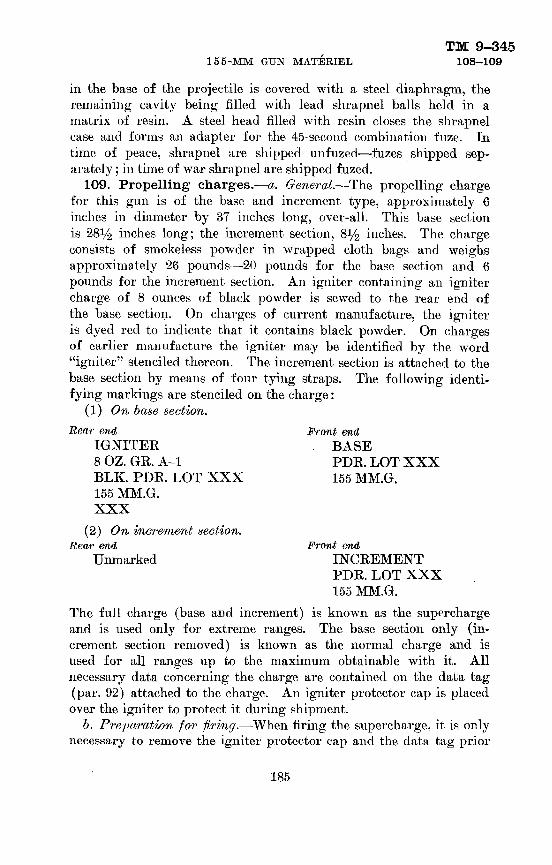
TM 9-34515 5-MM GUN MATERIEL 108-109
in the base of the projectile is covered with a steel diaphragm, the remaining cavity being filled with lead shrapnel balls held in a matrix of resin. A steel head filled with resin closes the shrapnel case and forms an adapter for the 45-second combination fuze. In time of peace, shrapnel are shipped unfuzed—fuzes shipped sep arately ; in time of war shrapnel are shipped fuzed.
109. Propelling charges.—a. General.—The propelling charge for this gun is of the base and increment type, approximately 6 inches in diameter by 37 inches long, over-all. This base section is 28^/2 inches long; the increment section, 8^/2 inches. The charge consists of smokeless powder in wrapped cloth bags and weighs approximately 26 pounds —20 pounds for the base section and 6 pounds for the increment section. An igniter containing an igniter charge of 8 ounces of black powder is sewed to the rear end of the base section. On charges of current manufacture, the igniter is dyed red to indicate that it contains black powder. On charges of earlier manufacture the igniter may be identified by the word "igniter" stenciled thereon. The increment section is attached to the base section by means of four tying straps. The following identi fying markings are stenciled on the charge:
(1) On base section.Rear end Front end,
IONITEE BASE 8 OZ. GE. A-l PDE. LOT XXX BLK. PDE. LOT XXX 155 MM.G. 155 MM.G. XXX
(2) On increment section. Rear end, Front end
Unmarked INCEEMENTPDE. LOT XXX 155 MM.G.
The full charge (base and increment) is known as the supercharge and is used only for extreme ranges. The base section only (in crement section removed) is known as the normal charge and is used for all ranges up to the maximum obtainable with it. All necessary data concerning the charge are contained on the data tag (par. 92) attached to the charge. An igniter protector cap is placed over the igniter to protect it during shipment.
l>. Preparation for firing.—When firing the supercharge, it is only necessary to remove the igniter protector cap and the data tag prior
185

TM 9-345109-112 ORDNANCE DEPARTMENT
to loading. When firing the normal charge, in addition to removing the igniter protector cap and data tag, it is also necessary to untie the tying straps and remove the increment section. Caution: When loading the charge be sure that the igniter is to the rear (breach end). If the igniter end is loaded first, the charge will not burn properly and might result in a serious accident should a hangfire occur.
110. Charge, propelling, 155-mm guns, M1917, M1917A1, and M1918MI.—This charge, except for the powder which is pyro- cellulose smokeless powder, is otherwise the same as the charge described in paragraph 111. For additional information, including preparation for firing, see paragraph 109.
111. Charge, propelling, NHpowder, 155-mm guns, M1917, M1917A1, and M1918MI.—This charge (fig. 63) is the present standard for use in the 155-mm guns, M191T, M1917A1, and M1918MI. It differs from the charge described in paragraph 110 chiefly in that it contains a nonhygroscopic (NH) powder. For additional informa tion, including preparation for firing, see paragraph 109.
112. Fuzes.—a. General.—A fuze is a mechanical device used with a projectile to explode it at the time and under the circumstances desired. Artillery point detonating fuzes of current design conform to a standard weight and contour, hence are ballistically inter changeable. They are known as standard contour fuzes to dis tinguish them from older types. In the case of standard contour fuzes for 155-mm projectiles, the booster is assembled to the fuze as shipped.
NOTE.—No attempt whatsoever will be made to disassemble any fuze. The only authorized assembling or disassembling operation is that of assembling the fuze to the projectile or, if not fired, unscrewing the fuze from the projectile. (See also par. 95.)
&. Types.— (1) Point detonating fuzes may be classified into two principal types: those which function by time action a certain number of sections after firing; and those which function as a result of impact with a resistant object such as earth, water, or structural material.
(2) Further subdivision of the impact types is dependent upon quickness of action—classifications being superquick, nondelay, and short delay.
(3) Dependent upon the manner of arming, certain fuzes are con sidered to be boresafe as distinct from those which are not bore- safe. A boresafe fuze is one in which the explosive train is so interrupted while the projectile is in the bore of the gun that prema-
186

TM 9-345155-MM GUN MA'riRIEL 112-115
ture functioning of the projectile cannot occur therein, even though the more sensitive explosive elements in the fuze should function prematurely.
c. Boresafe and nonboresafe fuses.—Of the fuzes described herein, those classified as boresafe and nonboresafe are as follows:
Boresafe Nonboresafe Fuze, P. D., M51. w/booster M21 Fuze, P. D., M46
Fuze, P. D., M47113. Fuze, P. D., M46.—a, General.—This fuze, a superquick
type, is shown in figure 64. The firing mechanism has been modi fied to eliminate the spiral and split rings. A lighter firing pin is supported on a brass cup which is sufficiently strong to resist the setback produced by acceleration in the gun, but which is crushed when the firing pin is driven into the primer on impact. Although the external form of this fuze is the same as that of the fuze, P. D., M47 (par. 114), it is readily identified by "P. D. F. M46" stamped on the body and by its head which is painted white. The fuze, P. D., M47, is stamped "P. D. F. M47" and has a black head.
&. Preparation for firing.—To fuze the projectile proceed as follows:
(1) Eemove eyebolt lifting plug from the projectile.(2) Visually inspect fuze cavity and threads. They should be
free of any foreign matter which would interfere with the proper assembly of the fuze.
(3) Screw fuze into adapter by hand. (It is essential that the felt washer provided with the fuze be under the detonator socket flange when the fuze is screwed into the adapter.) Tighten with fuze wrench. The projectile is now fuzed, ready for firing.
114. Fuze, P. D., M47.—a. Description.—This fuze, a delay type, shown in figure 65, is identical ballistically with the fuze, P. D., M46. It is distinguished from the latter fuze by the marking and the black head—the M46 fuze has a white head. (See also par. 113.) To provide for delay action, a delay pellet (0.05 second) is incor porated in the explosive train between the upper and lower deto nator.
o. Preparation for firing.—To fuze the projectile proceed as in paragraph 1135.
115. Fuze, P. D., M51, w/booster M21.—a. Description.—In this fuze (fig. 66), the booster instead of being a component of the loaded projectile is permanently attached to the fuze at the time of manufacture. The fuze contains two actions, superquick (SQ) and delay, and is classified as boresafe. Although both actions are ini-
187

TM 9-345115-118 ORDNANCE DEPARTMENT
tiated on impact, functioning of the shell depends upon the setting of the fuze. When the fuze is set delay, the superquick action is so interrupted that the projectile functions with delay action. It should be noted, however, that if the superquick action should malfunction when the fuze is set SQ, the projectile will function with delay ac tion rather than be a dud. On the side of the fuze near the base is a slotted "setting sleeve" and two registration lines: the one paral lel to the axis is marked "SQ," the other "delay." As shipped the fuze is set SQ. To set the fuze for delay action it is only necessary to turn the setting slee've so that its slot is alined with delay. A delay pellet—0.05 second—incorporated in the delay action train provides for the delay action. The setting may be made or changed at will with a screw driver or other similar instrument any time before tiring, even in the dark, by noting the position of the slot— parallel to the fuze axis for superquick action, at light angles thereto for delay. A cotter pin with pull ring is assembled to the booster to prevent accidental movement of the detonator during shipment. This cotter pin is to be withdrawn just prior to assembling the fuze with booster to the projectile.
l>. Preparation for firing.—To fuze the projectile proceed as fol lows :
(1) Remove eyebolt lifting plug from the projectile.(2) Visually inspect fuze cavity and threads. They should be
free of foreign matter which would interfere with the proper assem bly of the fuze.
(3) Remove cotter pin from- booster.(4) Screw fuze with booster into projectile. Tighten with fuze
wrench.(5) Set fuze. If delay action is required, aline slot in setting
sleeve with delay; if superquick. aline slot with SQ—setting as shipped. Fuze may be reset as required.
116. Fuze, combination, 45-second, M1907M.—a. Descrip tion,.—This fuze (fig. 67) is a combination percussion time type de signed for use with shrapnel. The fuze contains two actions, percus sion and time. The percussion action is always operable and will function on impact unless prior functioning has been caused by the time action. When percussion action is required, it is only necessary to set the graduated time train ring at safe (S) or for a time longer than the expected time of flight. The time train ring is similar to that of other powder time train fuzes and is graduated for 45 seconds. The fuze is set for time by means of a fuze setter. In the particular case of zero (0) setting, canister effect is obtained; that is, the fuze func-
188

TM 9-345155-MM GUN MATERIEL 116-120
tions just beyond the muzzle of the cannon with the result that the shrapnel balls are projected from the shrapnel case somewhat similar to shot from a shotgun. Because the powder time train is adversely affected by moisture, every effort will be made to keep the fuze dry. In time of war this fuze is assembled to shrapnel as issued; in time of peace the fuze is issued separately for assembly in the field. A safety wire which passes through the nose of the fuze prevents accidental functioning during shipment. The fuze as shipped is set safe.
b. Preparation for firing.— (1) As issued in time of war (fuze assembled to shrapnel)—
(a) Remove waterproof fuze cover and safety wire.(5) Set fuze as described in (2) (e) below.(2) As issued in time of peace (fuze issued separately for assembly
in the field) —(a) Remove fuze hole closing plug from shrapnel.(~b) Visually inspect fuze cavity and threads. They should be. free
of any foreign matter which would interfere with the proper assem bly of the fuze.
(o) Screw the fuze into the shrapnel head. Tighten with fuze wrench,
(d) Remove safety wire from nose of fuze.(e) Set fuze. If percussion action is required, the graduated time
train ring is set safe (S) or for a time greater than the expected time of flight. If time action is required, the graduated time train ring is set for" the required time of burning by means of a fuze setter. If canister action is required, the graduated time ring is set for zero (0) time of burning.
117. Fuze, combination, 45-second, M1914.—This limited standard fuze is similar to and is authorized for use in lieu of the fuze, combination, 45-second. M1907M, until present stocks are exhausted.
118. Primer, percussion, 21-grain, Mk. II.—This primer is similar to and is authorized for use in lieu of the primer, percussion, 21-grain, Mk. IIA1, until present stocks are exhausted.
119. Primer, percussion, 21-grain, Mk. IIA.—This primer is similar to and is authorized for use in lieu of the primer, percussion, 21-grain, Mk. IIAl, until present stocks are exhausted.
120. Primer, percussion, 21-grain, Mk. IIAl.—This primer (fig. 68) is standard for use in the 155-mm guns. It consists of a brass case containing a percussion element and 21 grains of black powder. The percussion element in the head of the primer contains a sensi-
189
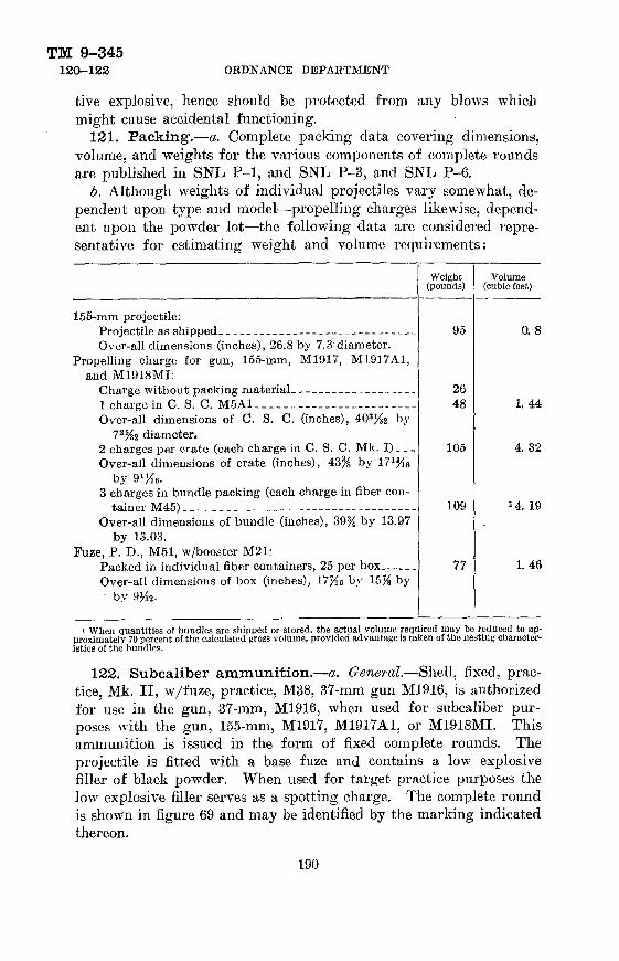
TM 9-345120-122 ORDNANCE DEPARTMENT
tive explosive, hence should be protected from any blows which might cause accidental functioning.
131. Packing.—a. Complete packing data covering dimensions, volume, and weights for the various components of complete rounds are published in SNL P-l, and SNL P-3, and SNL P-6.
6. Although weights of individual projectiles vary somewhat, de pendent upon type and model—propelling charges likewise, depend ent upon the powder lot—the following data are considered repre sentative for estimating weight and volume requirements:
155-mm projectile:Projectile as shipped--__--__.-_._-_..-___---__-_._ Over-all dimensions (inches), 26.8 by 7.3 diameter.
Propelling charge for gun, 155-mm, M1917, M1937A1, and M1918MI:
Charge without packing material- ____.-_._---_-._..1 charge in C. S. C. M5A1-.---..--....__-.-.-... Over-all dimensions of C. S. C. (inches), 40% by
72 %2 diameter.2 charges per crate (each charge in C. S. C. Mk. !).__ Over-all dimensions of crate (inches), 43% by 17%
by 9%.3 charges in bundle packing (each charge in fiber con
tainer M45) ____._____--_._-_.--..--__--_-----. Over-all dimensions of bundle (inches), 39% by 13.97
by 13.03. Fuze, P. D., M51, w/booster M21:
Packed in individual fiber containers, 25 per box.--... Over-all dimensions of box (inches), 17%e by 15ji by
' by 9^2.
Weight (pounds)
95
2648
105
109
77
Volume (cubic feet)
0.8
1. 44
4. 32
J 4. 19
1.46
i When quantities of bundles are shipped or stored, the actual volume required may be reduced to ap proximately 70 percent of the calculated gross volume, provided advantage is taken of the nesting character istics of the bundles.
122. Subcaliber ammunition.—a. General.—Shell, fixed, prac tice, Mk. II, w/fuze, practice, M38, 37-mm gun M1916, is authorized for use in the gun, 37-mm, M1916, when used for subcaliber pur poses with the gun, 155-mm, M1917, M1917A1, or M1918MI. This ammunition is issued in the form of fixed complete rounds. The projectile is fitted with a base fuze and contains a low explosive filler of black powder. When used for target practice purposes the low explosive filler serves as a spotting charge. The complete round is shown in figure 69 and may be identified by the marking indicated thereon.
190

155-MM GTJN MATERIELTM 9-345
122-123
6. Packing.—Two standard packings of 60 rounds each are pro vided : one, a wooden box with metal liner for oversea shipments; the other, a wooden box without metal liner for domestic shipments. Data for these packings are as follows :•
Oversea shipments: Box with metal liner (60 rounds) _ .. _ _ .Over-all dimensions of box (inches), 23% 6 bv 13iK 6 bv
11MB.
Domestic shipments:
Over-all dimensions of box (inches), 21J4 by 12^6 by
Weight (pounds)
1. 62
128
115
Volume (cubic feet)
1.99
1.60
123. Field reports of accidents.—Any serious malfunctions of ammunition must be promptly reported to the ordnance officer under whose supervision the material is maintained and issued (see par. 7, AR 45-30).
-."-'T, . .; : 'f .WEIGHT ZONE MARKING
CALIBER AND TYPE OF CANNON'-'n '"•'• '• KINO OF FILLER -: :\' I'
LOT NUMBER — -! •.] MODEL OF SHELL-V ' ;' !
-YELLOW-* ——YELLOW (MARKifsfG IN BLACK) ..... ...„..,.,....,-26J9
FIGURE 57.—Shell, HE, M101, unfuzed, 155-mm gun (adapted tor luze, P. D., M51.w/booster M21).
191
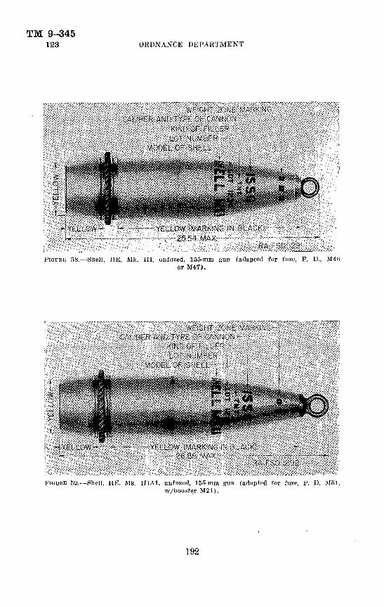
TM 9-345123 ORDNANCE DEPARTMENT
FIGURE 58.—Shell, HE, Mk. Ill, uufuzed, 155-mm gun (adapted for fuze, P. D., M4Gor M4T).
FIGURE 59.—Shell, HE, Mk. HIA1. uufuzed, 155-mm gun (adapted for fuze, P. D. Mol.w/booster M21).
192

155-MM GUN MATERIELTM 9-345
123
WEIGHT ZONE MARKING CALIBER AND TYPE OF CANNON —i
LOT NUMBER -—, , ' MODEL OF SHELL—, ' i
KIND OF FILLER •—:- ' i , YELLOW BAND -
» 3 r
i.H-GRAY —GRAY (MARKING IN YELLbW) - - *•
— —26.73 MAX- — - - - • - -RA FSD 1302,
FIUDKE 00.—Shell, smoke, phosphorus, WP, M104, untuzcd, 155-mm gun (adapted for fuze, P. D., M51, w/booster M21).
WEIGHT ZONE MARKING ••- CALIBER AND TYPE OF CANNON - ->
LOT NUMBER--- 1 MODEL OF SHELL---! . i
KIND OF FILLER - YELLOW BAND
GRAY - - •- GRAY (MARKING IN YELLOW)-----• 26.81 MAX
RA FSD 1294
FII;URB 61.—Shell, smoke, phosphorus, WP, Mk. THAI, unt'uzed, 155-mm gun (adapted for fu/e, P. D., M51, w/booster J121).
4107()o 0 41- ——13 193

TM 9-345• 123 ORDNANCE DEPARTMENT
KICUHIC 02.— Slir;ipnel, Mk. I, fuzed, loo-mm ^uii or howit/er.
194

O
FIGU
RE 6
3.—
Cha
rge,
pro
pelli
ng,
NH
pow
der.
155-
mm
gun
s, M
1917
. M
1017
A1.
and
M19
18M
I.
K>
BCO

TM 9-345123 ORDNANCE DEPARTMENT
FIGURE 64.—Fuze, T. D., M46.
FIGURE 65.—Fuze, P. D., M47.
196
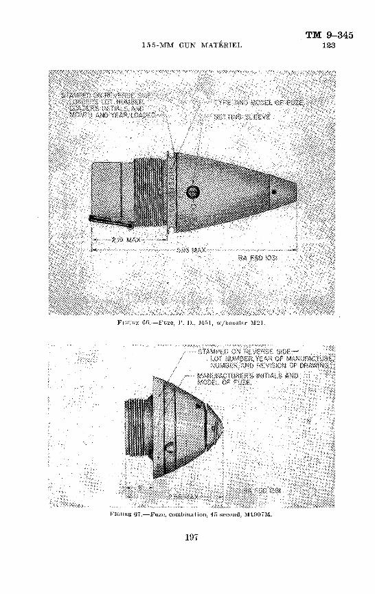
155-MM GUN MATERIELTM 9-345
123
FIOUUE 66.—Fuze, P. D., Mol, w/booster M21.
-STAMPED ON REVERSE SIDE . LOT NUMBER, YEAR Of
NUMBER/AND REVISION OFMANUFACTURER'S-INITIALS AMD 'MODEL OF FUZE, - . '.:,
FIOUUE 6T.—Fuze, combination, 45-second, M1007M.
197

TM 9-345123 ORDNANCE DEPARTMENT
•LOADER'S INITIALS AND LOT NUMBER' ^
-YEAR OF LOADING . "•'-
-MODEL OF PRIMER
——1595 MAXr——"•-•——•
fiA FSD S282
FiGuitE 68.—Primer, percussion, L'1-grniu. Mk. 1IA1.
-CAUSER OF CANNON ma MODEL OF CARTRIDGE C&SE;:•• MANUKaCTURER'S INITIALS AND YEAR OF MANUFACTURE
' tor NUMBER AMD WADER'S INITIALS .CAUSER AND TYPE 0- CANNON •
" MODEL OF SHEtL~5
ON REVERSE Steraw OR FILLER,
PIGUIIE 69.—Shell, fixed, practice, Ilk. II. w/fuze, practice, M3S, 37-mm gun JI1916.
198

155-MM GUN MATERIELTM 9-345
123
RA FSD 2518
II'IGURK TO.—Accessories for 15o-mm gun Ml'JJS.
FIGURE 71.—Accessories tor 155-mm gun M1918.
THE A9RMY UBRARY4* O.C.

TM 9-345123 ORDNANCE DEPARTMENT
FIGURE 72.—Mount, subcaliher, 37-mm, Ml.
200

TM 9-34S155-MM GUN MATERIEL 124-125
CHAPTER 5
SPARE PARTS AND ACCESSORIES
ParagraphSpare parts____.. ________—————————————————— ————————— 124 Accessories_..______________————____———————_——————— 125
124. Spare parts.—a. Parts become unserviceable through break age or through wear resulting from continuous usage. For this reason certain parts are provided for replacement purposes. These parts are divided into two groups, spare parts and basic spare parts. The using arm has no concern with basic spare parts except possibly in an emergency to draw a part from the ordnance maintenance company.
b. Spare parts are extra parts provided with the materiel for replace ment of those most likely to fail and are for use by the using arm in making minor repairs. Sets of spare parts should be maintained as complete as possible at all times and should be kept clean and oiled to prevent rust. The allowances of spare parts are prescribed in the pertinent Standard Nomenclature List.
125. Accessories.—a. General.—Accessories include the tools and equipment required for such disassembling and assembling as the using arm is authorized to do, and for the cleaning and preservation of the materiel. They also include chests, covers, tool rolls, etc., necessary for storage and protection when the materiel is not in use, or when traveling. Additional accessories and supplies of a general nature are provided for battery use. Accessories should not be used for purposes other than as prescribed. There are a number of ac cessories, the names or general characteristics of which indicate their uses or application. Therefore, detailed descriptions or methods of use are not outlined herein. However, accessories embodying special uses are described in b to u, inclusive, below.
b. Ammeter.—The ammeter is for use with the gun carriages equipped with electric brakes. Its use is described in paragraph 52.
c. Band, caterpillar.— (1) The band is for the purpose of providing more bearing surface under wheels in both traveling and firing po sitions. The caterpillar band is assembled over the rubber tires of the gun carriage and limber wheels. The band consists of a chain of 12 segments to which are hinged by segment pins, 12 shoes. Initially,
201

TM 9-345125 ORDNANCE DEPARTMENT
each band consists of one type B segment and eleven type A segments. After a tire wears to a smaller diameter and the segment pins wear at their bearing surfaces, the type B segment is replaced by a smaller type A segment.
(2) To facilitate handling, the caterpillar band is divided into two half-sections. During assembly the segment pins should be lubricated by rubbing with graphite grease and then oiling. However, the pins should not be oiled when traveling through sand or loose, dry earth, as those materials mix with the oil and form a cutting compound.
d. Beam, jack, MS.—The purpose of the jack beam is to facilitate the maneuvering of the trails to the traveling or firing position. The jack beam is an I-beam of 103-inch length having an end piece fitted at each end. In the center of the beam is a fulcrum member which is riveted to the top side. A fin of the fulcrum fits within a slot in the maneuvering lug at the rear of the bottom carriage which is held in position by a pin.
e. Bit, vent cleaning.—The vent cleaning bit (fig. 70, No. 10) is for cleaning the obturator spindle vent.
/. Book, artillery gun.—The gun book (O. O. Form 5825) is used for the purpose of keeping an accurate record of the materiel regard less of where it may be sent. This book should be in the possession of the organization at all times. The completeness of records and the book's whereabouts are responsibilities of the battery commander. The book is divided as follows: record of assignments, battery com mander's daily gun record, inspector's record of examination, as well as a reference to forms to be filled out in case of premature explosions. It should also contain date of issuance of the materiel, to and by whom issued, and place where issued. If a new gun is installed on the carriage, all data in the old book with reference to sights, carriages, etc., must be copied into the new book before the old book is relinquished.
NOTE.—Data pertaining to record of assignments must be removed and destroyed prior to entering combat.
g. Extractor, elevating worm sliaft.—The extractor (fig. 70, No. 1) is used to withdraw the elevating worm shaft.
h. Filler, oil screw.—The oil screw filler (fig. 71, No. 7) is a high pressure hand pump. It is used to reestablish the oil reserve of the recoil and counterrecoil system when and as may be necessary in lieu of the oil pump. Its use is explained in paragraph 18.
i. Gage, armat,ure.—The armature gage is used for checking the distance between the armature and the magnet of the electric brakes.
202

TM 9-345155-MM GUN MATERIEL 125
j. Gage, snap.—The snap gage is for checking the length of the safety lug on the percussion hammer. The back of the percussion hammer opposite the safety lug has a smooth surface for use as a reference in determining the wear 011 this lug. If the gage will go over the hammer with one of its faces over the safety lug and the other face over the reference plane on the back of the hammer, the safety lug is too short and the percussion hammer is unsafe for further use.
k. Lock, traveling.—The traveling lock consists of an irregularly shaped beam with a locking screw near the center and a pinion housed at each end. The traveling lock is provided for retracting the gun to its traveling position or for moving the gun into its firing position. Instructions as to its methods of use may be found in paragraph 12.
1. Opener, container.—The container opener (fig. 71, No. 9) is used for opening the zinc gas check pad container and prevents cutting the enclosed pad. <
m. Pump, oil, M2A1.—The pump is provided for filling the recoil and counterrecoil systems with oil. This pump is housed in a wooden . chest which is clamped to the trail of the gun carriage when required. The pump is driven by a lever which is fulcrumed in a bracket. In the bracket are two holes which may be utilized to increase or decrease the leverage to suit the back pressure of the pump. Secured to the pump outlet valve is a coiled copper tubing which may be attached to the filling and drain valve of either the recoil or counterrecoil cylinder. When the pump is being filled, the oil must be strained through a clean cloth so that no foreign matter enters the pump reservoir.
n. Rammer.—This consists of a bronze head which is recessed to clear the fuze of a projectile. It is attached to the sponge staff for removing a projectile if for any reason it is not desired to fire it.
o. Release, filing and drain valve.—The filling and drain valve release (fig. 71, No. 6) carried in the pump chest is used to drain the reserve oil from the recoil and counterrecoil cylinders.
p. Reamer, primer seat cleaning.—The cleaning reamer is composed of a bronze reamer affixed to a wooden handle. It is used for removing fouling from the primer seat.
q. Spacer, counterbalance tension rod.—The spacer (fig. 71, No. 10) is used when removing the counterbalance assembly from the breech mechanism.
r. Sponge and staff.—This consists of a sponge head which is a cylindrical block of wood covered with carpet and a three-sectioned
203
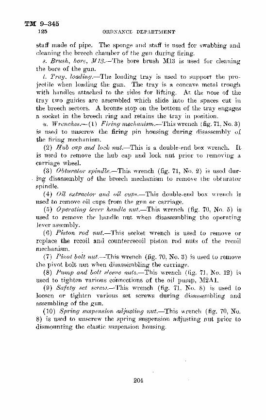
TM 9-345125 ORDNANCE DEPARTMENT
staff made of pipe. The sponge and staff is used for swabbing and cleaning the breech chamber of the gun during firing.
s. Brush, bore, M13.—The bore brush M13 is used for cleaning the bore of the gun.
t. Tray, loading.—The loading tray is used to support the pro jectile when loading the gun. The tray is a concave metal trough with handles attached to the sides for lifting. At the nose of the tray two guides are assembled which slide into the spaces cut in the breech sectors. A bronze stop on the bottom of the tray engages a socket in the breech ring and retains the tray in position.
u. Wrenches.— (1) Firing mechanism.—This wrench (fig. 71. No. 3) is used to unscrew the firing pin housing during disassembly of the firing mechanism.
(2) Hub cap and lock nut.—This is a double-end box wrench. It is used to remove the hub cap and lock nut prior to removing a carriage wheel.
(3) Obturator spindle.—This wrench (fig. 71, No. 2) is used dur ing disassembly of the breech mechanism to remove the obturator spindle.
(4) Oil extractor and oil cups.—This double-end box wrench is used to remove oil cups from the gun or carriage.
(5) Operating lever handle nut.—This wrench (fig. 70, No. 5) is used to remove the handle nut when disassembling the operating lever assembly.
(6) Piston rod nut.—This socket wrench is used to remove or replace the recoil and counterrecoil piston rod nuts of the recoil mechanism.
(7) Pivot bolt nut.—This wrench (fig. 70, No. 3) is used to remove the pivot bolt nut when disassembling the carriage.
(8) Pump and bolt sleeve nuts.—This wrench (fig. 71. No. 12) is used to tighten various connections of the oil pump. M2A1.
(9) Safety set screw.—This wrench (fig. 71. No. 8) is used to loosen or tighten various set screws during disassembling and assembling of the gun.
(10) Spring suspension adjusting nut.—This wrench (fig. 70, No. 8) is used to unscrew the spring suspension adjusting nut prior to dismounting the elastic suspension housing.
204

TM 9-345155-MM GUN MATERIEL 126-128
CHAPTER 6
SUBCALIBER EQUIPMENTParagraph
General ____________________________________________ 126 Description and operation of mount__________________________ 127 Assembly and disassembly_______________________________ 128 Bore sighting___________________________________________129 Care and preservation__________________________________ 130 Miscellaneous operations________________________________ 131 Spare parts and accessories_____________________________ 132
126. General.—Subcaliber equipment is used to provide a means for a greater amount of training with small caliber ammunition than would be obtained by the use of regular 155-mm ammunition. Al though the handling and loading, as well as the range obtained, differ from those of the regular piece, the results obtained in elevat ing, traversing, sighting, etc., are adequate for instructional pur poses. Subcaliber firing is accomplished by the use of the 37-mm gun with tank cradle M1916 mounted on the 155-mm gun by means of the 37-mm subcaliber mount Ml.
127. Description and operation of mount.—The 37-mm sub- caliber mount Ml is composed of the mounting bracket (C6270), to which are secured the mounting band (B102747), two trunnion caps (A17940), a U-bolt (B10274S), with the necessary nuts and lock wash ers, four cap screws, and two set screws. The mounting bracket fits on top of the 155-mm gun as shown in figure 72. The front end of the mounting bracket is drilled for the U-bolt while the rear end has a milled slot which engages the elevating screw latch catch of the 37-mm gun tank cradle.
128. Assembly and disassembly.—a. Place the mounting bracket on top of the 155-mm gun with its front edge approxi mately 117% inches from the muzzle or just in front of the reduc tion in diameter of hoop (4A). Place the U-bolt around the gun from underneath and up through the holes in the mounting bracket and secure with lock washers and nuts. Tighten the set screws of the mounting band. This will force the lower ends of the mounting band against the cradle flanges and draw the rear end of the mounting bracket firmly to the gun.
b. Remove trunnion caps from the mounting bracket. Lift the 37-mm gun with tank cradle and assemble the elevating screw latch catch in the milled slot of the mounting bracket; then lower the
205

TM 9-345128-132 ORDNANCE DEPARTMENT
gun with tank cradle into the trunnion bearings and replace the trunnion caps. It is essential that the trunnion caps be assembled to the side to which they pertain as they are not interchangeable.
c. Disassembling is accomplished by reversing the procedure required for assembling.
129. Bore sighting1.—a. As the subcaliber gun is to be laid with the regular sighting ard maneuvering mechanism of the 155-mm gun, the bores of the guns must be parallel.
&. Verification of the gun sights having been accomplished as described in section I, chapter 3, it only remains to aline the 37-mm gun with the 155-mm gun. The procedure is as follows:
(1) Make a testing target by wrapping two pieces of black tape of equal width around the aiming post with the lower edges exactly 13.72 inches apart. By the use of the aiming post as a testing target it will not be necessary to level the 155-mm gun as the aiming post can be canted to conform to the angle of the gun so that the vertical line of the bore of the 155-mm gun will coincide with the side of the aiming post. The testing target should be placed about 50 yards from the gun.
(2) Use the bore sights to line up the bore of the 155-mm gun with the lower edge of the lower tape on the aiming post.
(3) Use the bore sights for the 37-mm subcaliber gun and sight it on the lower edge of the upper tape on the aiming post.
(4) The adjustment of the 37-mm gun upon the testing target is made by placing shims upon the mounting bracket. Weld shims to the mounting bracket.
130. Care and preservation.—Repairs to the mount will be minor in nature and will involve only the removal of burs when neces sary and the replacement of parts. When the subcaliber mount is dismounted from the 155-mm gun. all lock washers, screws, nuts, etc., must be assembled to the mount to prevent their being lost.
131. Miscellaneous operations.—The normal position for oper ating the subcaliber equipment is from the right side. Caution is re quired on the first round as the gunner is compelled to reach across the gun to cock the firing mechanism. Subsequent firing automatically cocks it.
132. Spare parts and accessories.—The spare parts and acces sories for the subcaliber equipment are listed in the Standard Nomen clature List of the major equipment.
206
TM 9-345155-MM GUJSf MATERIEL 133-134
CHAPTER 7
MATEKIEL AFFECTED BY GASParagraph
Protective measures________________________-_-__-_-_— 133 Decontamination of materiel_____________________ ._-—————— 134
133. Protective measures.—a. For materiel in constant danger of gas attacks, whether from chemical clouds or chemical shells, care should be taken to keep all unpainted metal parts of materiel, includ ing instruments, but excluding ammunition, lightly coated with oil and protected with covers while not in use. Care must be taken that the oil does not come in contact with the optical parts of instruments or with leather or canvas fittings. Ammunition should be kept in sealed containers.
&. Ordinary fabrics offer practically no protection against mustard and lewisite. Kubber and oilcloth are penetrated if sufficient time is given. The greater the length of time allotted for penetration, the greater the danger of wearing these articles. For example, rubber boots which have been worn in an area contaminated with mustard may offer a grave danger to men who wear them several days after the bombardment. Impermeable clothing will resist penetration for over an hour but should not be worn longer than that length of time.
134. Decontamination of materiel.—a. Gleaning.— (1) All un painted metal parts of materiel that have been exposed to any gas except mustard and lewisite must be cleaned as soon as possible with solvent, dry cleaning, or alcohol, denatured, and wiped dry. Follow ing this cleaning all parts should be coated with engine oil or sperm oil.
(2) In the event ammunition has been exposed to gas, it must be thoroughly cleaned before it can be fired. To clean ammunition, use agent, decontaminating, noncorrosive, or if this is not available, strong soap and cool water should be used. After cleaning, wipe all ammu nition dry with clean rags. Do not use dry powdered agent, decon taminating (chloride of lime), on or near ammunition supplies, as naming occurs through the use of the chloride of lime on liquid mus tard.
~b. Decontamination procedure.—The following measures should be taken for the removal of liquid chemicals (mustard, lewisite, etc.) from materiel. For all of these operations it is necessary that a complete suit of impermeable clothing and a service gas mask be worn. Imme diately after the removal of the suit, a thorough bath with soap and
207

TM 9-345134 ORDNANCE DEPARTMENT
water (preferably hot) must be taken. If any skin areas have come in contact with mustard, if even a very small drop of mustard gets into the eye, or if the vapor of mustard has been inhaled, it is impera tive that complete first-aid measures be given within 20 or 30 minutes after exposure. First-aid instructions are given in TM 9-850* and in FM 21-40.
Garments exposed to mustard can be decontaminated. If imper meable clothing has been exposed to vapor only, it may be decontam inated by hanging in the open air, preferably sunlight, for a couple of days. It may also be cleaned by steaming for 2 hours. If the im permeable clothing has been contaminated with liquid mustard, steam ing for 6 to 8 hours will be required. Various kinds of steaming de vices can be improvised from materials available in the field.
(1) Commence by freeing materiel of dirt through the use of sticks, rags, etc., which must be burned or buried immediately after this operation.
(2) If the surface of the materiel is coated with grease or heavy oil, this grease or oil should be removed before decontamination is under taken. Solvent, dry-cleaning, or other available solvents for oil should be used with rags attached to ends of sticks. Following this, decon taminate the materiel with bleaching solution made by mixing one part agent, decontaminating (chloride of lime), with one part water. This solution should be swabbed over all surfaces. Wash off with water, dry, and oil all surfaces.
(3) All unpainted metal parts and instruments exposed to mustard or lewisite must be decontaminated with agent, decontaminating, non- corrosive, mixed one part solid to fifteen parts solvent( acetylene tetra- chloride). If this is not available use warm water and soap. Bleach ing solution must not be used because of its corrosive action. Instru ment lenses may be cleaned only with paper, lens, tissue, using a very small amount of alcohol, ethyl. Coat all metal surfaces lightly with engine oil or sperm oil.
(4) In the event that an agent, decontaminating (chloride of lime) r is not available, materiel may be temporarily cleaned with large vol umes of hot water. However, mustard lying in joints or in leather or canvas web is not removed by this procedure and thus will remain a constant source of danger until the materiel can be properly decon taminated. All mustard washed from materiel in this manner lies un changed on the ground, necessitating that the contaminated area be plainly marked with warning signs before abandonment.
*See Appendix.
208

TM 9-345155-MM GUN MATERIEL 134
(5) The cleaning or decontaminating of materiel which has been contaminated with lewisite will wash aresenic compounds into the soil, poisoning many water supplies in the locality for either men or animals.
(6) Leather or canvas web that has been contaminated should be scrubbed thoroughly with bleaching solution. In the event this treat ment is insufficient it may be necessary to burn or bury such materiel.
416763°—41———14 209

TM 9-3451-2 ORDNANCE DEPARTMENT
APPENDIX
LIST OF REFERENCES
1. Standard Nomenclature Lists.Major items—heavy field artillery-————————— SNL D-lMateriel, ' 155-mm gun, M1918—parts and
equipment-_____________———————— SNL D—11Materiel, 155-mm gun, M1917—parts and equip
ment___________________________ SNL D-19Materiel, 155-mm gun, M1918A1—parts and equip
ment___________________________ SNL D-25Materiel, 155-mm gun, M1917A1—parts and
equipment _____________________ SNL D-26Major items—small arms, automatic gun, trench
mortar, and field artillery sighting equipment and fire-control instruments________________ SNL F-l
Major items—harbor defense, railway, and antiair craft artillery sighting equipment and fire-control instruments_______________________ SNL F-2
Projectiles, separate loading, for harbor defense,heavy field, and railway artillery___—____ SNL P-l
Charges, propelling, separate loading, for harbordefense, heavy field, and railway artillery____ SNL P-3
Fuzes, primers, blank ammunition, and miscel laneous items for harbor defense, heavy field, and railway artillery___________________ SNL P-6
Ammunition instruction material, for harbor de fense, heavy field, and railway artillery_____ SNL P-7
Current Standard Nomenclature Lists are as tabu lated here. An up-to-date list of SNL's is main tained as the "Ordnance Publications for Supply Index"_________________________ OPSI
2. Firing Tables.Gun. 155-mm, M1917, M1917A1, M1918M1:
Shell HE, Mk. Ill, fuze, P. D., M46, M47, and Mk. IV, shell, chemical, Mk. VII, and shell, empty, for sand loading, 95-lb___ FT 155-B-5
Shrapnel, Mk. 1,155-mm____________ FT 155-C-2
210

TM 9-345155-MM GUN MATERIEL 2-5
Shell, HE, Mk. M101. and shell, HE, Mk. IIIA1___________________________ FT 155-U-l
Shell, HE, Mk. III. fuze, P. D., M46, M47,charge, normal___________ TD 155-B—4a
Shell, HE, Mk. III. fuze, P. D., M46, M47,charge, super_________________ TD 155-B-4b
Gun, 37-mm, M1916:Shell, practice, Mk. II______________ FT 37-O-1
Current, firing tables are as tabulated here. An up- to-date list of firing tables is maintained in____ SNL F-69
3. Technical Manuals.Field artillery fire-control instruments________ TM 6-220 Ammunition, general__________________ TM 9-1900
(now published as TR 1370-A)Cleaning and preserving materials_________ TM 9-850
(now published as TR 1395-A) Instruction guide, telescope mount M6A1 and pano
ramic telescope M8__________________ TM 9-25544. Army Regulations.
Range regulations for firing amunition in time ofpeace_________________._______ AR 750-10
Ordnance field service in time of peace_______ AR 45-305. Field Manuals.
Coast Artillery Field Manual, Seacoast Artillery:Gunnery_________________________ FM 4-10 Fire control and position finding_________ FM 4-15 Service of the piece, 155-mm gun___—___ FM 4-25
211


TM 9-345INDEX
INDEXParagraph Page
Abrasives, use______ — — _ — __- —_ — — _ — — — — ____..__ — - 53 64Accident reports, ammunition.____________________________ 123 • 191Accessories-..___. _---_-_--_-_---_-___-_--__---_--.__--_ 125 201
Subcaliber equipment-— — _ — — - — — __ — — _ — — _•- — — 132 206Aiming circle, Ml_ —— — - — -_ — ____ — —_ — — _ — — _ — — __ 67 121Aiming post, Ml-_ ——— _ — — _ — — _______________... 61 106Ammunition:
Care.--.----._____--____-_____________ 95 178Classification___-____-..__-._____.___.____-.____.__ 87 175Datacard------------------------------------------ 92 176Firing tables.----------.- — -----------_--__--__ 2, App. 210Fuzes. (See Fuzes.)Handling— — . — — — — ------- — -__--____-_______ 95 178Identification.-.--_--_-_____-_-___-_____-______ 91 176Lot number—- —_- — ---__- — ------_--------__.__ — — 91 176Markings:
Identifying model-._---._----__-_-____-_---_-_-- 90 175Paint--..-------------------_____--__-_---_-_ 93 176Weight zone.__ — __ — __- — __-- — _-_ — _ — -___-__- 94 177
Nomenclature_____-----------____— — _____ 86; 1, App. 175,210Packing —- — _ — ---- — -- — --- — — — - — -- — - — - — — — 121 190Painting______ — — __ — — — - — — -__ — -_ — —______ 93 176Preparation for firing-_--__ — _____ —_-_ — ____ — — ____ 97 182Preservation.. —— - — .-- — — - — — --__--- — -- — --____ 95 178Primer, percussion, 21-grain:
Mk. II--_----------.-------------------------- 118 189Mk. IIA__ ——— — — - —- — - — — — — —— — _- 119 189Mk. IIAl____. — _ — _ —— ____- —_-__.._--_.__ 120 189
Projectiles------------------------------------------ 98 182Propelling charges.- —— -- — — -- — . — — -___ — — — __ 109, 110 185, 186
NH powder_-___ — -_ — ___-_-_______- — — _ — ___ Ill 186Rounds authorized_-- — __ — ____ — ___ — ___ —— — ____ 96 179Shells:
Gas, persistent, HS, unfuzed, 155-mm gun:M104.-- —-----------------------------_ 99 183Mk. VIIAl----------------------------__ 100 183
HE, unfuzed, 155-mm gun:M101 —- — - — — - — - — — — - — — — - ---------- 101 183Mk. III-.--.. —-_---------------...-. —... 102 183Mk. II1A1__— — _- — — -._ — . — — — — ____ 103 184
Smoke, FS, unfuzed, 155-mm gun:M104—— — — — — —— — — — — — —------------ 104 184Mk. VIIAl-___.-___.-___--___-___-_-_-_-_-_ 105 184
Smoke, phosphorus, WP, unfuzed, 155-mm gun:M104---------------------------------__ 106 -184Mk. VIIAl-_______-___-__________.- 107 184
213

TM 9-345INDEX
Paragraph PageShrapnel, Mk. I, fuzed or unfuzed, 155-mm gun or howit
zer.____________--_--____-_-_-_________---______ 108 184Subcaliber._-_-__________.-_-_______-_._____ 122 190
Assembly:Breech mechanism___________________________________ 42 28
. Carriage_____-__-___-.____-._________„__________ 43 30Counterbalance—- —------ — — — — _---- — _--------- 38 26
Regulating screw._______________________________ 36 26Firing mechanism------_--___----___.___-_-_-__----_ 34 26Operating lever_——___-----_____---_________________ 30 25
Catch bracket_______________________________ 40 27Percussion mechanisna-_-_-___-_______---_____.-__-___ 32 25Subcaliber mount_______________________________ 128 205Wheels. -- — — _--. — — — - — - — ---- — - — -_--_- — — — . 44 33
Axle, bottom carriage.— - — — _ — ___ — _ — _ — _ v __. — __.._ — _ 20 19 Azimuth instruments:
M1910A1 (degrees).---.____..-_-_-____.____.. 69 128M1918 (mils)..- —— — — — — —---- — — - — — -— 70 132
Ballistics, 155-mm gun_____--__--__----___________-____.- 5, 6 3, 4Barrel assembly----------------------------------------- 15 13Boards:
Deflection, Ml_____--------_.--__________-.-_. 77 149Fire adjustment, Ml--__-_._-_-------___--_----_--_-__ 74 143Plotting and relocating, Cloke, M1923_____________ _. 78 153Range correction, Ml, M1A1_________________.___ 75,76 144,148
Bore sight---.-------..---- —--------------------------- 64 110Subcaliber gun-____-_-____________________-____. 129 206
Bottom carriage and axle.__-__--___-_______--_-______-_-- 20 19Brakes:
Electric----.----------------- — -----------------_ 25 22Care and preservation____________________________ 52 62Wiring__-----_______-__-_-----______---______-- 26 23
Hand-controlled_________________________________ 25 22Breech mechanism:
Assembly___________--_______.__.___________-- 42 28Description..----------.---------------------------- 16 14Disassembly,--------------------------------------- 41 27Operation, M1918MI, and M1917________--_-___-____- 8,9 6,7
Card, ammunition data.--__--________--_-____-___-_-____ 92 176Care and preservation:
Abrasives___--__-___---_---_____---.._-_-____--_-- 53 64Ammunition.__------_________-----_________________ 95 178Cleaners__----------_ — — _- — ---_ — ___-_--.-. 53 64Carriage__.__-________-_-______-_--__-______-___ 50 49'Electric brakes----------_----_---------_-___-------- 52 62Gun-_..____-________.-_---_____--_---___ 49 46Limber_-----------__________......--.--..... 50 49Lubricants________-___-___-------___. ._.-..-__-_-_ 56 69Lubrication instructions-_-_. __________ .__-_----.-. 51 55
214

TM 9-345INDEX
Paragraph PageMaterials, miscellaneous. __________________________ 57 70Paints____________________________________________ 55 66Plotting room instruments.___________________________ 84 173Preservatives_____-_----___-------__________ ________ 54 65Subcaliber equipment----_----------__________-__-___ 130 206Tools---------------------_----------______________ 57 70
Carriage:Assembly___--_--_._---__--..---__L-_-____-_____-___ 43 30Care and preservation___-______-___-_________________ 50 49Description. ________________________________________ 10 8Disassembly________________-_______________________ 43 30Inspection. _________________________________________ 45 33Limber:
Description______..___________________________ 13,14,24 11,12,21Wheels, disassembly and assembly.- ____________ 44 33
Operation ____-----___-_____--__-__________________ i 11 9Wheels, disassembly and assembly.____________________ 44 33
Circle, aiming, Ml_____________________________________ 67 121Cleaners, 155-mm gun materie]__---_______________________ 53 64Corrector, percentage, Ml_ ______________________________ 79 161Counterbalance:
Assembly_________________________________________ 38 26Description___-_______________________________-_____ 17 16Disassembly__-_-_---_-___---------_-_---___---_--_- 37 26Regulating screw____________________________________ 35, 36 26
Cradle_ ________________________________________________ 18 17
Data card, ammunition-_________________________________ 92 176Data on weights, dimensions, ballistics,____________________ 5, 6 3,4Decontamination, materiel_-____--___-_____-_-_-_-______-_ 134 207Deflection board, Ml__________________________________ 77 149Descriptions:
Axle, bottom carriage_______--_____-_-_-_--__-__----_ 20 19Barrel assembly__------____-------------_--------___ 15 13Bottom carriage..___________________________________ 20 19Brakes...__________________________________________ 25,26 22,23Breech mechanism__________________________________ 16 14Carriage__________________________________________ 10 8Counterbalance mechanism__-_-_-__-__-_-_-_________- 17 16Crad]e--__-_____-_____-__---__-_--__-_--__--_----__ 18 17Gun, 155-mm_---______-__-__-__-___-------_-----_-_ 7 5Limber___________________________________________ 24 21
M1917 and M1918___________________________ 13 11M1917A1 and M1918A1._____-_______-_._-_-_._ 14 12
Seacoast emplacement._____-_______---__-__-________ 27 24Subcaliber mount._________________________________ 127 205Telescopes________________________________________ 59, 60 92, 93Top, carriage_______________________________________ 19 19Trails____________________________________________ 23 20Wheels___________.________________________________ 21 ' 20
Modified for increased speed_______________________ 22 20
215

TM 9-345INDEX
Paragraph PageDimensions, 155-mm gun, etc_-___________________________ 5,6 3,4Disassembly:
Breech mecfianism_--_________________-_-___-________ 41 27Carriage__________________________________________ 43 30Counterbalance. ___. ________________________________ 37 26
Regulating screw._______________________________ 35 26Firing mechanism_____________,_____________________ 33 26Operating lever____________________________________ 29 25
Catch bracket_______________________________ 39 27Percussion mechanism________________________________ 31 25Bubcaliber mount__________________________________ 127 205Wheels____________________-__----__-___-_______-_-_ 44 33
Electric brakes-____.____________________________________ 25 22Care and preservation__________________-___-_________ 52 62Wiring______ T ____________'_________________________ 26 23
Emplacement, seacoast, 155-mm gun______________________. 27 24
Finder, range, horizontal base, 15-foot or 9-foot-________-_-_ 68 123Fire adjustment board, Ml______________-_____________.__ 74 144Fire-control equipment:
Azimuth instruments:M1910A1 (degrees)-.---------------------------- 69 128M1918 (mils)_______________________________-___ 70 132
Circle, aiming, Ml__________________________________ 67 121Finder, range, horizontal base_______________________.. 68 123Fuze setter, hand____________________________________ 71 136Plotting room equipment. (See Plotting room fire-control
equipment.) Telescope, BC, M1915______________ __-___-_____-__- 72 138
Tiring, ammunition, preparation. __________________________ 97 182Firing mechanism- ____________________________________ 33, 34 26Firing position, emplacement of weapon in ________________ 12 9Firing tables, __________________________________________ 2, App. 210Functioning. (See Malfunctioning; Operation.)Fuze setter, hand, M1913___-------___---__-_-----_--_ 71 136Fuzes:
Combination, 45-second:Ml907M-____________..__-_-_-_--_________-_____ 116 188M1914-_____--.__-__--__________________---___- 117 189
P. D., M46___________________-.__--._______________ 113 187P. D., M47____-_________________________-__-------- 114 187P. D., M51, w/booster, M21____________--_----_______ 115 187
Gas:Decontamination of mat6riel__________________________ 134 207Protective measures,_ ____________________________ 133 207
Gas shell, persistent, unfuzed, 155-mm gun:HS, M104______-___..__.„._____-___________ 99 183HS, Mk. VIIIA1-.-_____________---________-_-_----_ 100 183
Generating unit, Ml______________________-_---__----_- 83 165
216

TM 9-345INDEX
Qung . Paragraph PageCare and preservation__--__________-___„..---_-_----- 49 4*5Inspection ___________________________________________ 45 33Malfunction...........________________________... 46 37
Handling ammunition____-___-____________-__,_-_______-- 95 178
Identification, ammunition.................._-,_-_______ — 89 175Indicator, wind component, Ml__________._.__,______--__. 80 164Inspection, guns, carriages, and limbers. ________-_-_--_-_--- 45 133
Light, aiming post, M14___.__-____-__--____-_-^--------_-- 58 92Limber:
Care and preservation________-___-__-_-_-.----------- 50 49Description--------_---_____--_-_----_-_,_____-- — -- 13, 14 11, 12Inspection. _-_-_--__--._______-_-_-_-__-_______----.. 45 33Wheels, disassembly and assembly_________,----___-_-_ 44 33
Lot number, ammunition.__-_________--__-___,_______--_- 91 176Lubricants______ ________._________-_-__-___-,---------__ 56 ,69Lubrication instructions____--------__________.----------- 51 55
Malfunctioning:Carriage_______________________ — — _, — - —____ 47 38Electrical equipment___-__--____--------_..-----_----_ 48 44Gun—----------- — ----- — — — — ——— — -- — — — — - 46 37
Markings, ammunition:Model designation.-.-.,--_-_-___________.----_-- — -- 90 175Painting____________-___________-____-_---_----_ 93 176Weight zone__________-_______________-_------------ 94 177
Materials, miscellaneous, care and preservation_----------- 57 70
Nomenclature lists________________-__-----_--_---------- 1, App. 210
Operating lever:Assembly___________-___-_-____ — ___,.---_-___-_-_ 30 25Catch bracket:
Assembly_________--_._-__________-_____ 40 27Disassembly------._______________-_---__--_ 39 27
Disassembly--_______________--------______ 29 25Operation:
Breech mechanism:M1917.______________________-_-..__----------- 9 7Ml918MI--______-_-_-_-___________---_-------- 8 6
Carriage____--__-______________-__-_______---------- 11 9Emplacement, putting gun in firing positiorf------------ 12 9Malfunctioning. (See Malfunctioning.)Subcaliber equipment_-__-----_-_-_-_-___------------ 131 206
Packing, ammunition__--___-_--_______-_-____-----_-_-_- 121 190Paint, and related materials.__-______________------_---_ 55 66Painting, ammunition--_____-___--___________.----------- 93 176Parts, spare--____-_________----______-____-.------------ 124 201
Subcaliber equipment.___________________-----_------ 132 206Percentage corrector, Ml—------------ _-_-__-_--- — — — — 79 161
217

TM 9-345INDEX
Paragraph Page Percussion mechanism.- — _-_-_-_----_ __ — — — — ____._ — 31,32 25
• Plotting and relocating board, Cloke, M1923 _ ..... _ ...._ 78 153Plotting room fire-control equipment:
Boards :Deflection------------------------------..------ 77 149Fire adjustment, Ml __ — — — — — — — — — _. — — — 74 143Plotting and relocating, Cloke, M1923— — — — __-_, 78 153Range correction:
Ml.------.----------------------..------ 75 144M1A1- —— -- — — — -- — — —— -- — —— — - 76 148
Care and preservation— — —____-___ — ___ — ___ — __ — __ 84 173Corrector, percentage, Ml-------------------.-------- 79 161Indicator, wind component, Ml__-_- — ___ — — _. — -_- — 80 164 Rule, set forward, type B_______- — _ — _-_ — -_ — — — — - 81 165Scales, prediction.. __ — — — _ — - — — — __ — — ____ __ __ ._ 82 165Unit, generating, Ml ___ — — - — — — _- — — — — - — — — 83 165
Position for firing _ _________ _ -____ — __ — __ — _--_ — _____ 12 9Post, aiming, Ml __ - — -- — — -- — — _- — — — — — - — _-- — - 61 106Prediction scales-.--------------------------------.------ 82 165Preparation, ammunition, for firing - _-__- — ______ — — — — — 97 182Preservation. (See Care and preservation.) Primer, percussion, 21-grain:
Mk. II—.- _- — — . — — _--.__ — _._ — -_. — ___.. — .— 118 189 Mk. IIA ___ ---------- — --...--- — _----.-.---.- — -- 119 189Mk. IIA1-— - — — - — — — . — — - — — — - — — -- — - — - 120 189
Projectiles- — ---------------------------------- ____ .. 98 182Propelling charges. (See Ammunition.)Protective measures, materiel affected by gas _.__ — .__ — — _. 133 207
Quadrant, gunner's:Ml —— — — — — — — - — — — -- — -- — — -- —— — —— 62 106M1918 _ — — — — — - — — — — — - — - — _ -..------. 63 109
(Quadrant sight, M1918 ___ -_ __ -_„ _ _- _ _-- ___ _ -- 65 112
correction board:Ml —— — — -- — —— — — —— - — —— — —— — ——— — - 75 144M1A1 _ — .--- — . — - — .--- — —— .. — — .--- — .---.- 76 148
Range finder, horizontal base_ — — _ — ____ — ____- — — - — _ — 68 123References—. - — — — . — — — — - — — — — — — — — - — — — -- — App. 210Regulating screw, counterbalance.— — -__ — __________ — ____ 35,36 26Repairs, when and by whom made__— ___ — _____.__. ...__._ 2 1Reports, accidents from ammunition _ — — — — — _ — __ — ___ — 123 191Rounds, ammunition authorized. — — — — . — . — ._----.- — — 96 179Rule, set forward, type B __ _____ _ _ _ — — .__ — — _____ — 81 165
Scales, prediction... — — — — — — — -- — — -- — — — — -- — — .- 82 165Seacoast emplacement, 155-mm gun_ — — ___ — _ — — _ — — — _ 27 24Setter, fuze, hand, M1913----..— — — — —— — — — — — — — 71 136Shells. (See Ammunition.)Shrapnel, Mk. I, fuzed or unfuzed ___ — __ — — .. _ _..-.— 108 184
218

TM 9-345INDEX
Sighting equipment: Paragraph PageLight, aiming post, M14-____________________________ 58 92Post, aiming, Ml________.___________________________ 61 106Quadrant, gunner's:
Ml__________________________________________ 62 106M1918----_._-___-_ —_-_-_-_---_----__--_-'-_.__ 63 109
Quadrant sight, M1918_____________________________ 65 112Sight, bore________________________________________ 64 110Target, testing_____.________________________________ 66 120Telescopes. (See Telescopes.)
Slide rule, type B______________________-___-__-____-___._ 81 165Spare parts______________..____._________________________ 124 201
Subcaliber equipment.-___---__-___---_-__--___--__-_ 132 206Standard nomenclature lists_____________-______-__---___- 1, App. 210Subassemblies, M1918MI gun_--------------_--_-----__-._ 28 24Subcaliber ammunition_____._______-___-___-___-___-___._ 122 190Subcaliber equipment:
Assembly_-_-_-__-__-___-_____._______-__--___._ 128 205Bore sighting_-__-_---_--_-----_-__--_----_---___- 129 206Care and preservation_--_-_-___-_____-_-___-_________ 130 206Disassembly...___,__--__--___-_____---____________ 128 205Mount-------_-__---------.__-___---_---_---_---_._ 127 205Position for operating._______________________________ 131 206Purpose.------..--------.-------------------------- 126 205Spare parts and accessories.______-------------__--___ 132 206
Target, testing......._.._._-__-.__-_-_---_.--_---_-. 66 120Telescopes:
B. C. M1915—_ — — — — .----- —---•- — — — -- — -_-— 72 138Mount:
M4.--___..__-____---_----------___-_ 60 93M6_------_____..__.-__._---_--__..___.___. 60 93M6A1_.._--__--_-_._-__--__--_---_---_.__ 59 .92
Panoramic:M2A1-.._.__. __-__-._--__-___.__-__--__--._--._ 65 112 M3A1__.-____.__-__-.-_-.__-___-_____-___--._.. 60 93M4----.------.--_--__--_----------------_-__-. 60 93M6----------------_--__---_-----------_--_---_ 65 112MS--.-...--._-------------_----------__--__--_ 59 92
Tools, care and preservation_______________-_-___-__.__-._ 23 20Top carriage_____________-___-__-_-__--__--__---__-_--_-_ 19 19Trails.,._______________________________________________ 23 20Unit, generating, Ml —— ----------_--_----_-_--__--.---- 83 165Weight zone markings________-___-_-_._____-___-_--__--___ 94 177Weights, 155-mm guns, carriages, and limbers_____-_-___-_-- 5,6 3,4
219

TM 9-345INDEX
Paragraph 21 44 22 80
Page 20 33 20
164
Wheels,.._______.._______________________Disassembly and assembly_______________________Modified for increased speed_.___._______________
Wind component indicator, Ml_____________________[A. G. 062.11 (5-20-41).]
BY ORDER or THE SECRETARY or WAR :G. C. MARSHALL,
Chief of Staff. OFFICIAL :
E. S. ADAMS,Major General,
The Adjutant General. DISTRIBUTION :
IB 4 (3); B 6 (2); IE 4, 6 (3); IBn 4. 6 (3). 9 (2); 1C 4 (6),6 (12),9 (4).
(For explanation of symbols see FM 21-6.)
220
U. S. GOVERNMENT PRINTING OFFICE: 1941
For sale by the Superintendent of Documents, Washington, D. C.
TM 9-345c i
TECHNICAL MANUAL
155-MM GUN MATERIEL, M1917, M1918, AND MODIFICATIONS
CHANGES! WAR DEPARTMENT, No. 1 j WASHINGTON, April 16, 1942.
TM 9-345, November 1, 1941, is changed as follows:-50. Carriage and limber.*******
g. Filling of recoil cylinder.*******
(2) When the replenisher piston (fig. 7) is at a point 100 mm (3.93 inches) or less from the rear face of the replenisher, oil should be removed from the recoil cylinder before firing is continued.
NOTE.—When in an emergency it is necessary to continue firing without interruption, firing may be permitted until the reading is down to 50 mm.*******
[A. G. 062.11 (2-3-42).] (C 1, April 16, 1942.)
BY ORDER OF THE SECRETARY OF WAR:G. C. MAKSHALL,
Chief of Staff. OFFICIAL :
J. A. ULIO,Major General,
The Adjutant General.453595°—42
U. 5. GOVERNMENT PRINTING OFFICE: 1942