Embed Size (px)
Citation preview
Cost Estimate for Gun Liner Emplacement
by William S. de Rosset
ARL-CR-0677 August 2011
Prepared by
Dynamic Science, Inc.
8443 Black Canyon Hwy.
Phoenix, AZ 85021
Approved for public release; distribution unlimited.

NOTICES
Disclaimers
The findings in this report are not to be construed as an official Department of the Army position
unless so designated by other authorized documents.
Citation of manufacturer’s or trade names does not constitute an official endorsement or
approval of the use thereof.
Destroy this report when it is no longer needed. Do not return it to the originator.
Army Research Laboratory Aberdeen Proving Ground, MD 21005-5069
ARL-CR-0677 August 2011
Cost Estimate for Gun Liner Emplacement
William S. de Rosset
Weapons and Materials Research Directorate, ARL
Prepared by
Dynamic Science, Inc.
8443 Black Canyon Hwy.
Phoenix, AZ 85021
Approved for public release; distribution unlimited.
ii
REPORT DOCUMENTATION PAGE Form Approved OMB No. 0704-0188
Public reporting burden for this collection of information is estimated to average 1 hour per response, including the time for reviewing instructions, searching existing data sources, gathering
and maintaining the data needed, and completing and reviewing the collection information. Send comments regarding this burden estimate or any other aspect of this collection of information, including suggestions for reducing the burden, to Department of Defense, Washington Headquarters Services, Directorate for Information Operations and Reports (0704-0188), 1215 Jefferson Davis Highway, Suite 1204, Arlington, VA 22202-4302. Respondents should be aware that notwithstanding any other provision of law, no person shall be subject to any penalty for failing to comply with a collection of information if it does not display a currently valid OMB control number.
PLEASE DO NOT RETURN YOUR FORM TO THE ABOVE ADDRESS.
1. REPORT DATE (DD-MM-YYYY)
August 2011
2. REPORT TYPE
Final
3. DATES COVERED (From - To)
Jan–May 2011 4. TITLE AND SUBTITLE
Cost Estimate for Gun Liner Emplacement
5a. CONTRACT NUMBER
W911QX09-C-0057 5b. GRANT NUMBER
5c. PROGRAM ELEMENT NUMBER
6. AUTHOR(S)
William S. de Rosset
5d. PROJECT NUMBER
AH 84 5e. TASK NUMBER
5f. WORK UNIT NUMBER
7. PERFORMING ORGANIZATION NAME(S) AND ADDRESS(ES)
Dynamic Science, Inc.
8443 Black Canyon Hwy.
Phoenix, AZ 85021
8. PERFORMING ORGANIZATION REPORT NUMBER
ARL-CR-0677
9. SPONSORING/MONITORING AGENCY NAME(S) AND ADDRESS(ES)
U.S. Army Research Laboratory
ATTN RDRL-WMM-F
Aberdeen Proving Ground, MD 21005-5069
10. SPONSOR/MONITOR’S ACRONYM(S)
11. SPONSOR/MONITOR'S REPORT
NUMBER(S)
12. DISTRIBUTION/AVAILABILITY STATEMENT
Approved for public release; distribution is unlimited
13. SUPPLEMENTARY NOTES
14. ABSTRACT
Recent firing success of an explosively-bonded tantalum alloy gun liner has prompted an examination of other gun liner
emplacement techniques. One of them is Gun Liner Emplacement with an Elastomeric Material (GLEEM). Costs for this
approach are compared to those of explosive bonding, and on a qualitative basis GLLEM is found to be less expensive. The
absolute costs to use GLEEM will depend primarily on the cost of the liner and machining the rifling in the barrel. Different
materials and manufacturing technologies are suggested to reduce these costs.
15. SUBJECT TERMS
gun liners, refractory metals, explosive bonding, medium caliber cannons
16. SECURITY CLASSIFICATION OF: 17. LIMITATION
OF ABSTRACT
UU
18. NUMBER
OF PAGES
36
19a. NAME OF RESPONSIBLE PERSON
William S. de Rosset a. REPORT
Unclassified
b. ABSTRACT
Unclassified
c. THIS PAGE
Unclassified
19b. TELEPHONE NUMBER (Include area code)
(410) 306-0816
Standard Form 298 (Rev. 8/98)
Prescribed by ANSI Std. Z39.18
iii
Contents
List of Figures iv
Acknowledgments v
1. Introduction 1
2. Liner Emplacement Technologies 2
2.1 GLEEM ...........................................................................................................................2
2.2 Explosive Bonding ..........................................................................................................3
3. Qualitative Comparison: GLEEM vs Explosive Bonding 4
4. GLEEM Costs 7
5. Summary 11
6. References 12
Appendix 15
List of Symbols, Abbreviations, and Acronyms 25
Distribution List 26
iv
List of Figures
Figure 1. Idealized representation of the loading steps in the GLEEM process. ............................3
Figure 2. Schematic of explosive bonding process. ........................................................................4
Figure 3. Grooves cut in a Ta-10W liner with a water jet. .............................................................9
Figure 4. Ta-5W-2Mo liner with an EDM notch. .........................................................................10
v
Acknowledgments
It is difficult to project costs of a technology that is still being developed, but thanks to the many
contributors listed in the reference section the author was able to establish an order-of-magnitude
cost to apply Gun Liner Emplacement with an Elastomeric Material (GLEEM) to a medium
caliber gun tube.
vi
INTENTIONALLY LEFT BLANK.
1
1. Introduction
For decades the United States Army has used chromium-coated tubes in small-, medium-, and
large-caliber cannons. While chromium is an excellent material to resist wear and erosion in gun
tubes, it is applied by an electrolytic process that involves hexavalent chromium, a known
carcinogen. A recent Department of Defense memorandum has strongly urged that, wherever
possible, processes involving hexavalent chromium be eliminated from usage (1). Soon after
this memorandum was written, the Army demonstrated that a medium-caliber barrel with a
tantalum-10% tungsten (Ta-10W) liner had superior wear and erosion characteristics as
compared to those of a chromium-coated barrel (2–4). The success of the demonstration can be
attributed to two main factors: first, a liner was used, rather than a coating; and second, a
tantalum alloy with much higher melting point than chromium was used as the liner material.
It has been long recognized that liners offer superior wear and erosion resistance as compared to
coatings (5). A case in point is the use of a Stellite 21 liner in the M2 0.50-cal machine gun.
However, liners have generally been difficult to place into gun tubes. The simplest approach
would be to shrink fit the liner. However, the dimensional tolerances needed are quite high, and
any contact between the heated barrel and cooled liner before the emplacement process is
completed generally results in premature joining of the liner and barrel. This problem can be
alleviated by having only part of the tube lined, as has been done with the M2 machine gun.
However, there is still the issue of partial liners having a sufficiently strong bond between the
liner and gun tube so that the liner does not move or allow propellant gasses to enter between the
liner and gun tube as has been observed in some cases (6, 7).
A major impediment to using liners is the cost of the material and manufacture of the liner.
Refractory metals, the leading candidates for liner materials, are expensive. The cost to
completely line a full-length 120-mm gun tube with a tantalum alloy would be prohibitive. (In
this case, another possibility is to use cold spray to coat the inside of a tube to a thickness that
might be affordable.) Other refractory metals, such as the Stellite series, BioDur CCM* (a
cobalt, chrome, molybdenum alloy), or niobium are less expensive. However, the final choice of
material will depend on the properties (strength, melting point, etc.) that are required for a
particular application.
The extra costs incurred in the manufacturing of the lined tubes can be recouped through the
extension in service life provided by the liners. A detailed cost estimate for using Ta-10W liners
in a Bushmaster 25-mm M242 medium caliber cannon has been carried out by the Rowan
Technology Group. This cost estimate was provided to Benét Laboratories as part of a Strategic
Environmental Research and Development Program (SERDP) and can be found in appendix 1 of
*BioDur CCM is a registered trademark of Carpenter Technology, Wyomissing, PA.
2
reference 3. This cost estimate, hereafter referred to as the Rowan estimate, suggested that
doubling the service life of the M242 would make explosive bonding of Ta-10W liners cost
effective. In fact, the recent tests at Yuma Proving Ground demonstrated that a tube lined with
Ta-10W extended the life of the tube by a factor of three as compared to that of a chrome-coated
tube (8). There was such minimal wear observed on the lined tube that the life extension could
actually be far greater than a factor of three.
Another process for emplacing gun tube liners is in the late stages of development at the U.S.
Army Research Laboratory (ARL). Gun Liner Emplacement with an Elastomeric Material,
otherwise known as Gun Liner Emplacement with an Elastomeric Material (GLEEM), has been
used to emplace Stellite 25 liners in a several metal cylinders, including a truncated M242 gun
barrel (9–12). A cost estimate has been made for using this process to line a medium caliber gun
barrel, drawing heavily on the approach used by the Rowan estimate. With some exceptions,
both explosive bonding and GLEEM can be similarly adapted to the production cycle of the
M242 cannon. In order to understand the cost differences between GLEEM and explosive
bonding, short summaries of both technologies are presented in the next section. Section 3 then
compares the relative costs of GLEEM and explosive bonding. It will be shown that there are
certain cost advantages for GLEEM. However, since the exact details of the explosive bonding
process are proprietary, this comparison is only qualitative. A quantitative estimate for the
GLEEM production costs is given in section 4, where it is shown that some of the assumptions
used in the Rowan estimate may no longer be valid. The final section provides an extended
summary of the findings.
2. Liner Emplacement Technologies
2.1 GLEEM
GLEEM is a process by which a metal liner is attached to a gun tube (9–12). The first step
involves obtaining a liner equal in length to the gun tube and filling the liner with an elastomeric
material. The ends of the elastomeric material are sealed with inexpensive plastic discs, and then
the arrangement is inserted into the gun tube. The elastomer is then loaded with a push rod that
pressurizes the elastomer and expands the metal liner against the gun tube wall. With enough
pressure, a residual stress is generated in the steel tube that is sufficient to produce a frictional
bond between the liner and gun tube.
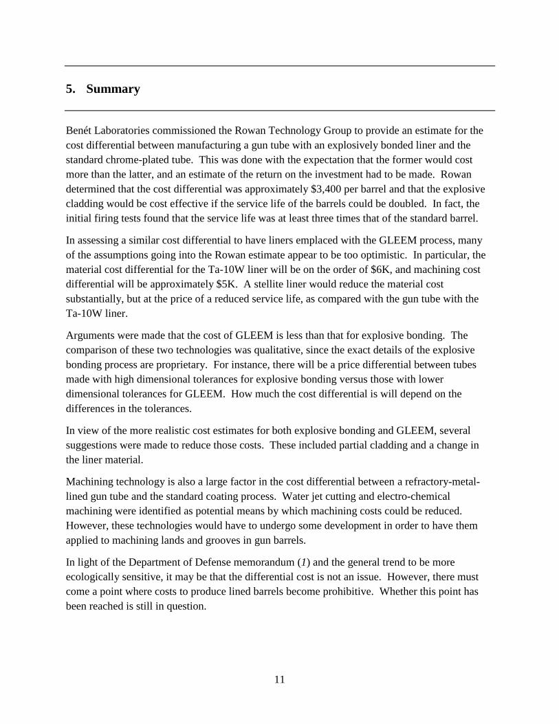
In practice, this procedure may be undertaken in several steps, as shown in figure 1. The figure
is highly idealized, and the taper of the gun tube is exaggerated. The separate steps are necessary
because it has been found that the friction between the elastomer and gun tube prevents the
applied load from being uniformly distributed over long lengths of the liner wall. The steps are
3
also necessary to cover portions of the tube that are not pressurized due to the displacement of
the push rod. Note also that the fixturing needed for this process is not shown in the figure.
The bond shear strength produced by GLEEM can be as high as 6 ksi, although values around
3 ksi are more typical. This bond strength level is at least an order of magnitude less than that
achieved with explosive bonding.
Figure 1. Idealized representation of the loading steps in the GLEEM process.
2.2 Explosive Bonding
The general idea behind explosive bonding of liners to gun tubes is relatively simple. The liner
tube to be clad is filled with a low-velocity explosive and placed inside the gun tube. When the
explosive is detonated, it accelerates the liner material at high speed, driving it into the gun tube
wall. The collision of the liner with the wall usually results in plastic deformation of the liner
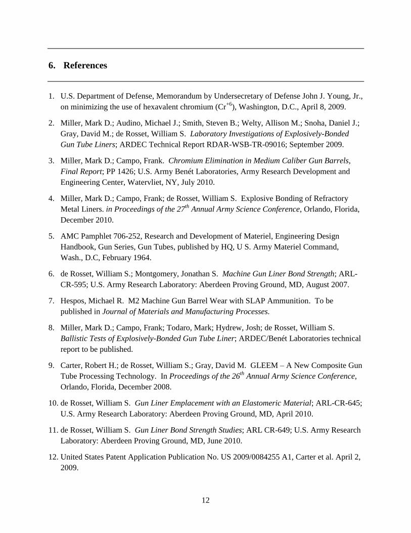
material, and a metallic bond is formed. A schematic of the process is shown in figure 2.
The critical parameters associated with the explosive bonding process are the collision angle α,
the detonation velocity Vd, the ratio of explosive mass to metal mass (C/M), and the initial
distance between the liner tube wall and the inner bore of the gun tube (stand off). To get a good
bond to form, these parameters must lie in a narrow window that produces just the right collision
velocity. If the velocity is too low, the yield strength of the liner material is not overcome, and
no plastic deformation occurs. This generally results in a flat or smooth interface between the
liner and gun tube, and a low-strength bond is made. If the collision velocity is too high, the
liner material might fragment. There is also the increased possibility of creating intermetallic
compounds near the liner-gun tube interface. In the final analysis, creating a strong bond is a
combination of art and science.
Base Plate
Gun Tube
Seal
Liner
Push Rod
Elastomer
4
Figure 2. Schematic of explosive bonding process.
3. Qualitative Comparison: GLEEM vs. Explosive Bonding
M242 tubes that have been lined with refractory metal liners with either the GLEEM process or
explosive bonding can be inserted into the production line at the same point. From the Rowan
estimate, the steps needed to make a complete chrome-coated barrel are as follows:
1. Obtain D6AC billet, 5.5-in diameter by 33-in long
2. Hammer forge to near net outer diameter shape: 85-in long
3. Heat treat: quench and temper
4. Straighten to 0.005 in runout
5. Stress relieve
6. Grind steady rest
7. Cylindrically grind outer diameter (tapered)
8. Gun drill breech
9. Gun drill barrel inner diameter
Detonation Velocity, Vd
Gun Barrel Substrate
Donor Tube
Detonation Products
Low Detonation Velocity
Explosive Formulation
Final Donor Tube Diameter.
Initial Donor Tube
Dia.
Stand off
Plasma Jet
Vd = 1800 m/s
Vd = 2500 m/s
Vd = 2800 m/s
Vd = 2100 m/s
Bond Interface
Collision Angle,
Plasma Jet Scrubs Surface in Advance
of Donor Tube
5
10. Hone inner diameter
11. Finish outer diameter concentric with bore
12. Form cut flutes on outer diameter
13. Broach rifling in the inner diameter 0.022-in deep
14. Finish outer diameter: thread muzzle and chamber
15. Machine lugs
16. Stress relieve
17. Final straighten
18. Inspect
19. Clean and electropolish
20. Chrome plate barrel and chamber (0.004 to 0.008 in)
21. Final inspection
If a liner would be applied to a barrel, the barrel would have to be gun drilled oversize. After
cladding has occurred by either technology, the liner would be processed in the standard manner
(except for the chrome plating, steps 19 and 20).
GLEEM is amenable to implementation in a production line. Explosive bonding, on the other
hand, requires a remote site for processing. The Rowan cost estimate included a new explosive
bonding facility at a cost of $500K. Currently, the explosive bonding is done in an open pit in a
remote location with very little additional infrastructure. Therefore, while the estimated cost for
a new facility may be high, there will certainly be additional costs incurred for maintaining the
site, assuring safe explosive operations, and transporting the tubes to and from the site. These
costs are expected to be greater than those for the additional space needed on the production line
for GLEEM.
The raw material costs for making the liners should be the same for both processes. However,
the tolerances on the liners used in explosive operations are much higher than those used for
GLEEM. This is because the standoff distance between the liner and gun barrel must be
carefully controlled in order for the explosive bonding process to work. All that is required for
the GLEEM liners is that they fit reasonably well within the gun barrel. The expansion of the
liner due to the pressure from the elastomer accounts for any variation in the distance between
the liner and gun barrel wall. Therefore, manufacturing costs for liners used in explosive
bonding is expected to be greater than those for GLEEM.
6
Explosive bonding produces large residual stresses in the gun tube (13). These stresses must be
relieved before the liner is machined. GLEEM also produces residual stresses in the liner but are
much smaller, and to date there has not been a need for an extra stress relief for the gun tube.
(The Rowan cost estimate includes the extra thermal soak for the explosive bonding process.)
The cost for the extra stress relief is estimated to be $100 per barrel and will depend on how
many barrels can be processed at one time.
It was found in one of the Ta-10W lined barrels first produced as part of the SERDP program
that a portion of the liner inner diameter was too large, and the barrel could not be machined (8).
The diameter enlargement was caused by the thinning of the liner due to the action of the
explosive, which tends to stretch the liner both axially and radially. This problem can be solved
by using a thicker tube to begin with and then machining the excess material to the final desired
dimension. Another solution would simply be to accept a certain rejection rate of the bonded
tubes. In either case, a cost differential between explosive bonding and the GLEEM process
arises. A better solution would be to understand the explosive bonding process to the extent that
this thinning can be avoided. Efforts are currently underway to do so.
The explosive bonding process also produces a non-uniform cross-section of the liner and tube.
Basically, the central part of the liner has a slight increase in the inner diameter, and the ends are
in a “bell shape” (14). This requires an extra effort to hone the inner diameter of the liner to the
correct dimension. The extra cost can be avoided with the GLEEM process.
The explosive used in the explosive bonding process is expendable. However, the elastomer
used in GLEEM is re-usable.
The one aspect of GLEEM that is more expensive than explosive bonding is the load machine
necessary to apply pressure to the elastomer. This would be a sunk cost amortized over the
number of tubes processed. As this number increases, the cost per tube decreases (see section 4).
There is no expensive fixturing needed for explosive bonding, other than the arrangement needed
to align the liner inside the gun barrel and firing lines.
The GLEEM process is amenable to refurbishing worn-out tubes. That is, old tubes can be
reamed out to the appropriate bore diameter and a refractory metal liner inserted into the barrel.
This would save the production costs of a new barrel and provide one with an extended life.
While this can also be done with explosive bonding, it would require that a momentum trap be
used, incurring additional costs. (Currently, blank forgings with thick walls are used in the
explosive bonding process. The forging is then machined to final dimensions.)
The same considerations hold for processing new, large-caliber gun tubes. The wall thickness of
these tubes can be on the order of 0.5 in, necessitating a momentum trap if explosive bonding is
used.
7
4. GLEEM Costs
The calculation of GLEEM costs will draw heavily on the Rowan cost estimate, making updates
in the figures where necessary. The estimates presented here will not consider the total costs of
manufacturing the gun tube as was done with the Rowan estimate but will concentrate on the
differential cost to process a barrel with GLEEM. All the estimates assume that an M242
Bushmaster gun tube is being processed. The current cost for an M242 chromium-plated tube is
$5,600 (3).
The major difference in costs between the standard chromium-plated tube and the tube processed
by GLEEM is the cost of the liner. The same costs would be incurred with explosive bonding,
except for the higher tolerances needed. Rowan estimated that the cost of a Ta-10W tube that
had the appropriate tolerances would be $2K. Raw material costs will vary according to the
demand placed on that particular commodity, so this number can change. A better estimate is the
current cost per tube: $5–6K (15). If the $6K figure is closer to reality than $2K, then the
Rowan estimate of doubling the life of the processed gun tube to make it cost competitive would
be too low. It is possible that the additional costs in using Ta-10W (and associated standard
machining costs, see the following) in either explosive bonding or the GLEEM process may
make the liner approach unaffordable.
Costs for the liner could be substantially reduced if (1) the tube were only partially lined, or (2) if
another material were considered as a lining material. The M2 machine gun has a Stellite 21
liner that covers only about one-half of the barrel length. It has been successful in reducing the
wear and erosion near the breech end of the barrel where those effects are the greatest.
A partially- lined M242 Bushmaster cannon was produced by Concurrent Technology
Corporation as part of the Navy’s Advanced Gun Barrel Initiative (16). The liner material was
Ta-10W, and the liner was 648-mm long. The liner was simply inserted into the breech end of
gun tube and held in place at the front with a niobium washer and at the rear by a retaining ring.
No mention was made about difficulty in machining the Ta-10W liner. The cannon was never
test fired.
Use of Ta-10W as a liner material has been so successful in reducing wear and erosion that
consideration of other materials is difficult. An alternate material would have to show that it was
as effective in reducing wear and erosion as the Ta-10W. Stellite 21 has already been proven in
the M2 machine gun. Other materials would require time and resources to demonstrate wear-
reducing properties. One candidate for the alternative liner material is Stellite 25. It does not
have the high degree of hot hardness that the Ta-10W has, but this should not be a problem so
long as single-base propellants are used, as is currently the case.
8
Several inquiries were made concerning the cost of a Stellite 25 liner for the M242 tube. Both
Carpenter Technology (Wyomissing, PA) and H.C. Starck (Newton, MA) declined to provide an
estimate. True Tube of Paso Robles, CA was contacted and provided an estimate for the
production of both 220 tubes a year and 4,000 tubes a year. (These were the same numbers that
the Rowan cost estimates were based upon.) The dimensions were given as 1.090-in OD by
0.95-in ID by 82-in long. The costs were $1,045 and $964 per tube for the low and high
production rates, respectively (17). Note that this is not a quote but simply the best estimate of
the cost for each tube based on material and labor costs currently in use. These numbers suggest
that there is very little economy of scale. That is, the price is not substantially reduced for a
larger number of liners. This implies that most of the cost of the liner is the starting stock
material.
Dynamic Flowform, Inc. also provided estimates for the same items and quantities. Their
numbers were $2,400 and $1,750 for the low and high production rates, respectively (18).
Again, these were not official quotes but best guesses based on current rates. It was pointed out
by the company representative that the flowform process imparts specific material properties to
the final product that may not be required for our application. Hence, the costs for the flowform
product might be expected to be higher than other manufacturing technologies.
The Rowan cost estimate included a $225 cost differential for machining the liner in each Ta-
10W liner, as opposed to machining them in steel. This estimate was based on the assumption
that the cost of the special tooling required to cut the lands and grooves in the liner material
would be minimal. In fact, the rifling of the liner turned out to be more difficult than anticipated,
and a concentrated research effort by Benét Laboratories and ARL was required to overcome
those difficulties. Even more work is needed to optimize the process and attempt to reduce the
machining costs. Currently, the cost of three sets of cutting tools needed to rifle a Ta-10W liner
is $9K (19). The decision to use three tooling sets per barrel was made in an attempt to reduce
the risk of tool failure and to insure that proper tolerances were maintained throughout the
machining process. It may be that fewer tool sets would be needed in actual production (20).
More expensive tooling (higher precision, different materials) can also be used that does not
require frequent re-sharpening for a cost of $24K per set (19). All the tooling has only a certain
lifetime, with the more expensive tooling lasting longer than the inexpensive set of cutters. In
addition, it has been found that honing costs for the Ta-10W liner are much higher (16 hours
machining time vs. 2 hours for a steel barrel) (21). At $25 per hour, this cost differential is $350.
For sake of discussion, assume that a single cutter set with optimized material properties can be
used for each barrel. Then the machining cost per barrel in production (including honing) is on
the order of $5K.
Recently a truncated (half-length) M242 barrel with a Stellite 25 liner was produced with the
GLEEM process. It was shipped to ARES, Inc. of Port Clinton, OH to have the liner honed and
the rifling machined into it. The set of carbide cutters used in this machining process cost $4K.
Add labor costs to this figure, and the final total to machine the liner is over $5K. ARES has
9
found that just honing the Stellite liner in the truncated M242 tube took 50% longer as compared
to the time needed for a normal steel tube (22). One set of cutters was used for the rifling;
however, there was some fracturing of the carbide tips observed. If it is assumed that this set
could complete another half-length barrel, then it is reasonable to expect that one set of cutters
would be needed for each full length tube.
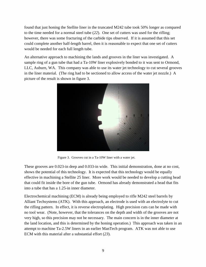
An alternative approach to machining the lands and grooves in the liner was investigated. A
sample ring of a gun tube that had a Ta-10W liner explosively bonded to it was sent to Ormond,
LLC, Auburn, WA. This company was able to use its water jet technology to cut several grooves
in the liner material. (The ring had to be sectioned to allow access of the water jet nozzle.) A
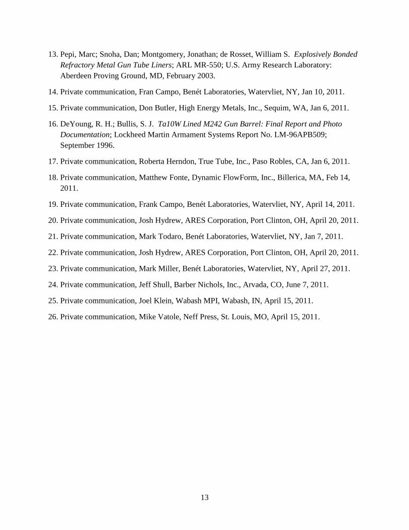
picture of the result is shown in figure 3.
Figure 3. Grooves cut in a Ta-10W liner with a water jet.
These grooves are 0.023-in deep and 0.033-in wide. This initial demonstration, done at no cost,
shows the potential of this technology. It is expected that this technology would be equally
effective in machining a Stellite 25 liner. More work would be needed to develop a cutting head
that could fit inside the bore of the gun tube. Ormond has already demonstrated a head that fits
into a tube that has a 1.25-in inner diameter.
Electrochemical machining (ECM) is already being employed to rifle M242 steel barrels by
Alliant Techsystems (ATK). With this approach, an electrode is used with an electrolyte to cut
the rifling pattern. In effect, it is reverse electroplating. High precision cuts can be made with
no tool wear. (Note, however, that the tolerances on the depth and width of the grooves are not
very high, so this precision may not be necessary. The main concern is in the inner diameter at
the land location, and this is determined by the honing operation.) This approach was taken in an
attempt to machine Ta-2.5W liners in an earlier ManTech program. ATK was not able to use
ECM with this material after a substantial effort (23).

10
ECM depends on the conductivity of the metal being machined. It was surmised that a tantalum
alloy with a higher tungsten content might be machineable with this approach. A sample of a
Ta-10W liner was sent to Barber Nichols (Arvada, CO). They have been able to machine this
sample with their standard approach (24).
A third alternative to conventional machining is electrical discharge machining (EDM). Here, an
electrode is used to produce a spark between it and the piece to be cut. The spark causes a small
amount of material to be removed from the piece. EDM is generally applied to very hard
materials that are conductive. It is carried out with the part that is to be cut in a bath. The bath
not only provides an electrical path but also cools the part. For many metals, the bath is simply
water, so the only waste coming out of the process is the removed material. With EDM, there is
tool wear.
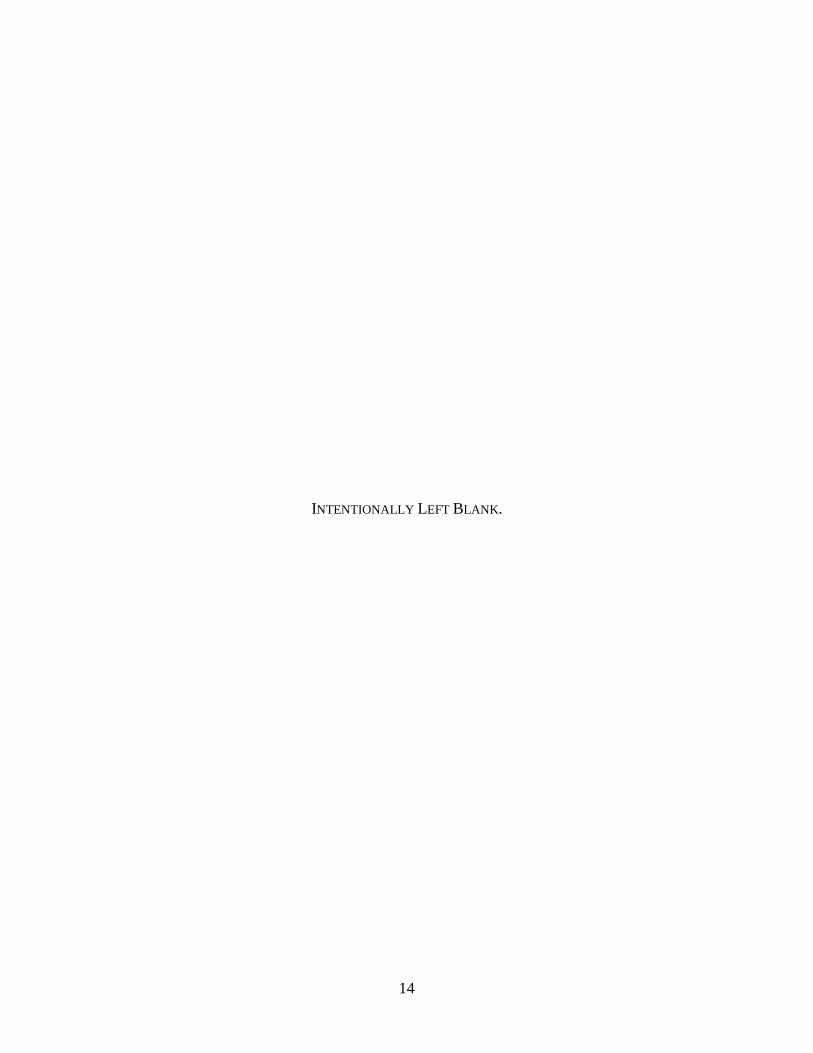
A quick look was taken with this process as it would be applied to explosively-bonded liners. A
sample ring, taken from a gun tube that had a Ta-5W-2Mo liner explosively bonded to it, was cut
with EDM. Figure 4 shows the notch made by the EDM. Again, more effort would be needed to
actually implement this process to rifle a full-length gun tube and obtain a cost estimate for the
process. However, there does not appear to be any physical impediment for using EDM on
liners.
Figure 4. Ta-5W-2Mo liner with an EDM notch.
The cost of the press needed in the GLEEM process is not expected to be great. Some cost
estimates were obtained for a 75-ton press with four posts. A range of figures was obtained.
Machineco of Quebec, Canada had a four-post machine that sold on its Web site for $13,500.
An estimate from Wabash MPI came in at $32,900 (25), and the highest estimate was from Neff
Press at $80,000 (26). Beckwood Press provided a detailed estimate of $48,300 (see appendix).
The price differences are likely due to the controls on the equipment. Assuming an approximate
press cost of $50,000, a production rate of 220 barrels a year, and a 20-year life of the
equipment, the cost per barrel is a little over $11 each. Thus, this cost is not a significant factor
in the cost for GLEEM.
11
5. Summary
Benét Laboratories commissioned the Rowan Technology Group to provide an estimate for the
cost differential between manufacturing a gun tube with an explosively bonded liner and the
standard chrome-plated tube. This was done with the expectation that the former would cost
more than the latter, and an estimate of the return on the investment had to be made. Rowan
determined that the cost differential was approximately $3,400 per barrel and that the explosive
cladding would be cost effective if the service life of the barrels could be doubled. In fact, the
initial firing tests found that the service life was at least three times that of the standard barrel.
In assessing a similar cost differential to have liners emplaced with the GLEEM process, many
of the assumptions going into the Rowan estimate appear to be too optimistic. In particular, the
material cost differential for the Ta-10W liner will be on the order of $6K, and machining cost
differential will be approximately $5K. A stellite liner would reduce the material cost
substantially, but at the price of a reduced service life, as compared with the gun tube with the
Ta-10W liner.
Arguments were made that the cost of GLEEM is less than that for explosive bonding. The
comparison of these two technologies was qualitative, since the exact details of the explosive
bonding process are proprietary. For instance, there will be a price differential between tubes
made with high dimensional tolerances for explosive bonding versus those with lower
dimensional tolerances for GLEEM. How much the cost differential is will depend on the
differences in the tolerances.
In view of the more realistic cost estimates for both explosive bonding and GLEEM, several
suggestions were made to reduce those costs. These included partial cladding and a change in
the liner material.
Machining technology is also a large factor in the cost differential between a refractory-metal-
lined gun tube and the standard coating process. Water jet cutting and electro-chemical
machining were identified as potential means by which machining costs could be reduced.
However, these technologies would have to undergo some development in order to have them
applied to machining lands and grooves in gun barrels.
In light of the Department of Defense memorandum (1) and the general trend to be more
ecologically sensitive, it may be that the differential cost is not an issue. However, there must
come a point where costs to produce lined barrels become prohibitive. Whether this point has
been reached is still in question.
12
6. References
1. U.S. Department of Defense, Memorandum by Undersecretary of Defense John J. Young, Jr.,
on minimizing the use of hexavalent chromium (Cr+6
), Washington, D.C., April 8, 2009.
2. Miller, Mark D.; Audino, Michael J.; Smith, Steven B.; Welty, Allison M.; Snoha, Daniel J.;
Gray, David M.; de Rosset, William S. Laboratory Investigations of Explosively-Bonded
Gun Tube Liners; ARDEC Technical Report RDAR-WSB-TR-09016; September 2009.
3. Miller, Mark D.; Campo, Frank. Chromium Elimination in Medium Caliber Gun Barrels,
Final Report; PP 1426; U.S. Army Benét Laboratories, Army Research Development and
Engineering Center, Watervliet, NY, July 2010.
4. Miller, Mark D.; Campo, Frank; de Rosset, William S. Explosive Bonding of Refractory
Metal Liners. in Proceedings of the 27th
Annual Army Science Conference, Orlando, Florida,
December 2010.
5. AMC Pamphlet 706-252, Research and Development of Materiel, Engineering Design
Handbook, Gun Series, Gun Tubes, published by HQ, U S. Army Materiel Command,
Wash., D.C, February 1964.
6. de Rosset, William S.; Montgomery, Jonathan S. Machine Gun Liner Bond Strength; ARL-
CR-595; U.S. Army Research Laboratory: Aberdeen Proving Ground, MD, August 2007.
7. Hespos, Michael R. M2 Machine Gun Barrel Wear with SLAP Ammunition. To be
published in Journal of Materials and Manufacturing Processes.
8. Miller, Mark D.; Campo, Frank; Todaro, Mark; Hydrew, Josh; de Rosset, William S.
Ballistic Tests of Explosively-Bonded Gun Tube Liner; ARDEC/Benét Laboratories technical
report to be published.
9. Carter, Robert H.; de Rosset, William S.; Gray, David M. GLEEM – A New Composite Gun
Tube Processing Technology. In Proceedings of the 26th
Annual Army Science Conference,
Orlando, Florida, December 2008.
10. de Rosset, William S. Gun Liner Emplacement with an Elastomeric Material; ARL-CR-645;
U.S. Army Research Laboratory: Aberdeen Proving Ground, MD, April 2010.
11. de Rosset, William S. Gun Liner Bond Strength Studies; ARL CR-649; U.S. Army Research
Laboratory: Aberdeen Proving Ground, MD, June 2010.
12. United States Patent Application Publication No. US 2009/0084255 A1, Carter et al. April 2,
2009.
13
13. Pepi, Marc; Snoha, Dan; Montgomery, Jonathan; de Rosset, William S. Explosively Bonded
Refractory Metal Gun Tube Liners; ARL MR-550; U.S. Army Research Laboratory:
Aberdeen Proving Ground, MD, February 2003.
14. Private communication, Fran Campo, Benét Laboratories, Watervliet, NY, Jan 10, 2011.
15. Private communication, Don Butler, High Energy Metals, Inc., Sequim, WA, Jan 6, 2011.
16. DeYoung, R. H.; Bullis, S. J. Ta10W Lined M242 Gun Barrel: Final Report and Photo
Documentation; Lockheed Martin Armament Systems Report No. LM-96APB509;
September 1996.
17. Private communication, Roberta Herndon, True Tube, Inc., Paso Robles, CA, Jan 6, 2011.
18. Private communication, Matthew Fonte, Dynamic FlowForm, Inc., Billerica, MA, Feb 14,
2011.
19. Private communication, Frank Campo, Benét Laboratories, Watervliet, NY, April 14, 2011.
20. Private communication, Josh Hydrew, ARES Corporation, Port Clinton, OH, April 20, 2011.
21. Private communication, Mark Todaro, Benét Laboratories, Watervliet, NY, Jan 7, 2011.
22. Private communication, Josh Hydrew, ARES Corporation, Port Clinton, OH, April 20, 2011.
23. Private communication, Mark Miller, Benét Laboratories, Watervliet, NY, April 27, 2011.
24. Private communication, Jeff Shull, Barber Nichols, Inc., Arvada, CO, June 7, 2011.
25. Private communication, Joel Klein, Wabash MPI, Wabash, IN, April 15, 2011.
26. Private communication, Mike Vatole, Neff Press, St. Louis, MO, April 15, 2011.
14
INTENTIONALLY LEFT BLANK.
15
Appendix
QUOTATION
BECKWOOD PRESS COMPANY DIVISION OF
THE BECKWOOD CORPORATION
889 Horan Drive, St. Louis, Missouri, USA 63026-2405
Phone 800-737-0111 or (636) 343-4100
Fax: 800-737-0444 or (636) 343-4424
www.beckwoodpress.com
TO: William de Rosset DATE: 4/26/2011 Army Research Laboratory ATTN: RDRL-WMM-F JOB: 75 Ton Hydraulic Press APG, MD 21005 PHONE: (410) 306-0816 QUOTE NO: BD042611A E-MAIL: [email protected] We are pleased to offer the following for your consideration: 1.....Beckwood Model: SS75F610 heavy-duty four column, down acting hydraulic press. STANDARD FEATURES:
Forming capacity: 75 Tons
Stripping capacity: 50 Tons
The bed bolster is 4” Thick x 6" Deep x 10" Wide. Designed for Point Loading
Left to right clearance between the posts is 10.
Modular tie rod assembly utilizing SuperBolt® pre-tensioning nuts for optimum performance.
GUIDANCE SYSTEM: Cylinder guidance is provide by the rod bushing.
This appendix appears in its original form, without editorial change.
MADE IN THE
USA
16
WORK HOLDING FEATURES:
None Specified (See Option MS-1 Below) SAFETY FEATURES:
Terminals are provided on the main control panel terminal strip for the connection of safety devices such as safety gates, light curtains, safety mats and other devices.
APPROXIMATE SIZE: 30 " front to rear x 20" left to right footprint; 127" tall. STROKE: 10" stroke Parker Industrial Grade Hydraulic Cylinders with full rated tonnage throughout the stroke. Stroke is fully adjustable from 0" to 10" to reduce any point of operation hazards and to reduce the cycle time where less stroke is required. Parker Cylinders feature their exclusive "Jewel" TS-2000 rod seal which compensates automatically for pressure, temperature and wear conditions. The wiping characteristics of the TS-2000 rod seal, keeps the oil in the cylinder, as evidenced by a "dry" rod on extension, and dirt and foreign matter out. This unique seal gland is also threaded which provides for minimal down time when replacing. Parker Cylinders' carry a three-year extended warranty when a Parker filter is maintained on the press. SHUT HEIGHT (distance between the working surfaces of the bed and ram bolsters when the ram is fully extended): 86" (or to specification) ± ¼" Note: The press is designed to perform work anywhere in the stroke up to ¼" short of full extension or retraction of the ram cylinder(s). This ¼" should be allowed for in the shut height specification. If work must be performed at full extension of the cylinder(s) or to a precise shut distance, please consult factory for options. DAYLIGHT (shut height plus stroke): 96" BED HEIGHT: as low as possible" POWER SYSTEM FEATURES:
The reservoir and power system are mounted around the top of the press.
A 7.5 HP / 4.62 GPM hydraulic power unit is provided featuring a piston pump.
Reservoir Capacity is 24 gallons. Reservoir is equipped with a 40 Micron breather, visual sight gage, clean out covers and manually operated ball valve on drain/fill port. The press will require oil be added prior to start up. The suggested oil is Connoco Super Hydraulic Oil AW-46 (or comparable 46 weight hydraulic oil with Anti-Wear properties)
The system is equipped with Parker 10 micron return line filtration with replaceable filter elements.
Kidney loop filter/cooler circuit is provided. The kidney loop provides continues flow through the filter and oil cooler for an increased level of fluid conditioning over a traditional system with a return filter only.
A TEFC (behind the pump motor) motor mounted oil cooler is provided for oil cooling.
Press is equipped with low level float switch and high temperature shut down switch to ensure oil is within safe operating parameters.
17
The low pressure supply line and case drain lines from the hydraulic reservoir to the pump(s) are provided with ball valves for reservoir isolation from the pump for maintenance purposes. It is the responsibility of the user to ensure that these valves are in the open position prior to start up of the machine.
Main control panel mounted disconnect switch with lockout/tag out capability provided.
Notes: (1) Hydraulic Pump Drive Motors are sized using the Root Mean Squared (RMS) Method. Motors are sized to use Low Power at fast approach, Momentary Peak Power for full press tonnage and Medium Power for ram retract. This optimizes motor efficiency for standard press operations, minimizing cost, installation and operating expense. Motors are not sized for sustained operation at Full GPM and Maximum PSI unless otherwise requested. (2) Transformers when provided are sized for the press' requirements only. All ancillary equipment such as feed systems will need their own transformers. Larger or additional transformers can be provided for an additional cost. CALCULATED RAM SPEEDS: Pressing 21 IPM; Return 35 IPM IPM = Inches Per Minute CONTROLS: (Unless otherwise specified, the press controls are mounted directly to the press. Remote or pedestal mounted controls are available, P.O.R.)
Primary Power Requirements: 460 Volt, 3 Phase, 60 Hz (optional power configurations available, P.O.R.)
Control Voltage: 120VAC or 24VDC
Enclosure rating: NEMA 12 PROG-1: Programmable Cycle Parameters The logic control of the press will be by an Allen Bradley Micrologix 1500 PLC. An Automation Direct C-More touch screen operator interface allows operators to make quick and simple adjustments to the press cycle parameters. The press will utilize linear and pressure transducers for position and pressure feedback. The Control System has the following features: Operator controls will consist of:
HMI: 6” Color TFT touch panel 64K colors, 320 x 240 pixel QVGA screen resolution.
Off / On Selector Key Switch with removable key
Motor On Illuminated Pushbutton
E-Stop Palm Button
Dual Ergonomic Zero Force Touch Buttons
Ram Retract Pushbutton Standard Programming Features:
System Diagnostics and PLC Input/Output display
18
Mode Selection (Inch / Semi Auto / Full Auto Mode)
Alarm Handling
Multi-level pass word protection
Simple Entry of Cycle parameters including, but not limited to: Retract Limit, Slow Down Position, Return Limit or Return Pressure
Batch Cycle Counter
All system screens and functionality will be programmed for specific machine operation as determined by customer and Beckwood Press.
Proportional Dwell Timer: Dwell Time entered in seconds and Dwell Pressure is entered in Tons. System includes a proportional relief valve on the compensator port of a variable volume piston pump.
System Modes:
Inch Mode/Set Up Mode o Ram is extended manually be maintaining pressure on the Dual Extend
Touch buttons. o Ram is manually retracted by maintaining pressure on the Ram Retract
Pushbutton.
Semi-Auto Mode/Single Cycle o Cycle must be initiated when the ram is at the programmable up Retract
Limit position. o The operator maintains the Dual Extend Touch Buttons to lower the ram.
The ram will extend. o In pressure mode, the ram will then dwell under pressure for the preset
period of time as programmed in the operator interface. o The ram will then automatically return to the programmed retract position,
completing the cycle.
Full Auto Mode- Used with automated feed systems. o Cycle must start with the ram at the programmed up limit position. The
cycle is initiated by a momentary signal from the customer provided feed system.
o Once initiated, the ram will extend. o In pressure mode, the ram will then dwell under pressure for the preset
period of time as programmed in the operator interface. o The ram will then automatically return to the programmed retract position
and send a sustained signal to the feed system indicating the press cycle is complete.
DOCUMENTATION:
- An electronic copy of the operating manual is provided in .pdf format. - Manuals are provided in English. - Maintenance Manuals to include PM schedule, full schematics, hydraulic flow
diagrams, recommended spare parts list, ladder diagrams, control/interface programs, etc.
19
PAINT COLOR: "Safety Blue" - Custom Colors are available, P.O.R., color chip is required. PRICE EACH FOB FENTON, MO .................................................... $48,300.00 Prices do not include any local, state or federal taxes which may apply, installation, unloading or freight. Prices are subject to change due to material price increases. This quotation is valid for 30 days. NOTE: A STEEL SURCHARGE MAY BE INCURRED IF ORDER IS PLACED AFTER 30 DAYS. STEEL SURCHARGES ARE DIRECT COST INCREASES THAT FLUCTUATE DUE TO LACKING STEEL PLATE INVENTORY. PLEASE VERIFY IF YOUR ORDER IS SUBJECT TO A STEEL SURCHARGE AT THE TIME OF ORDER. APPROXIMATE SHIP DATE: Completion of machine fabrication is currently estimated to be 16 weeks after receipt of order, Down Payment and return of signed quotation and specification approval drawings. Any design changes or pending design information after the receipt of the down payment and approval drawings may affect the completion date. Actual Ship date will be established immediately following the completion of Quality Control Certification Testing (Q.C.C.T., estimated to be 2-3 days). SUPPLEMENTAL PRESS EQUIPMENT: Option LC-1: A light curtain is installed to guard the front opening of the press (light curtain brand to be Jokab, Allen Bradley Guardmaster, SICK, or STI). $ 6,000.00 Option G-1: Bolt-on expanded metal guards with interlocks are installed on the side & rear openings of the press. $ 1,500.00 Option LS-1: An automatic ram slide lubrication system with reservoir is installed. This system includes lube system failure signals for low reservoir level and high pressure. Each lubrication point will be plumbed using Lincoln ‘Quick Linc’ Dacron braided tubing. For ease of refilling the reservoir, a user friendly and easily accessible fill port will be provided and located remotely of the grease reservoir with access from the ground. Price $ 4,200.00. Option MS-1: Machining services such as Tapped Holes, T-Bolt Slots, Through Holes etc. are available from the factory at an additional charge. Advise of number, size and layout for pricing. T-bolt slot pricing may include a required additional bolster thickness charge. Standard ANSI t-slots up to 1” are available @ $105.00/linear foot. (Note: Standard layout tolerance of machined holes is within 1/32”, closer tolerances are available, P.O.R. The alignment of hole positions from bed to ram will be within 1/32”, closer alignment tolerances are available, P.O.R.)
20
Option IS-1: Installation Supervision provided at $728.00 per day plus travel time and expenses (expenses include transportation, food, lodging, etc.)
TERMS AND CONDITIONS OF SALE
1. CONTRACT TERMS Only those terms and conditions set forth or incorporated herein shall be binding on Buyer and Seller. Acceptance
of this Quotation is expressly conditioned on acceptance of the terms and conditions contained herein. Terms and
conditions contained in a purchase order, or accompanying payment for delivery of the equipment specified herein,
which are different from or in addition to these Terms and Conditions of Sale shall not be binding on Seller, whether
or not they would materially alter this Quotation and whether or not Seller expressly objects thereto. Written
quotations automatically expire 30 days from the date issued, unless previously accepted in writing by Buyer and are
subject to immediate termination by written notice from Seller within that period and prior to receipt of Buyer’s
written acceptance.
2. PAYMENT TERMS Sales under $100,000 50% w/order, 40% before shipment, 10% Net 30. Sales over $100,000 25% w/order, 25% midway, 40% before shipment, 10% Net 30. International Orders 50% w/order, 25% midway, 25% before shipment. Seller shall establish a delivery schedule upon receipt of Buyer’s down payment. Payments are due upon receipt of invoice. If shipment of equipment is delayed by Buyer beyond the scheduled date, and the equipment is ready for delivery, the before shipment payment and final payment shall be due 30 days after such scheduled date. Storage charges will also be applicable if the shipment is delayed by Buyer, more than sixty (60) days. Amounts that are outstanding more than sixty (60) days from the date of invoice shall bear an interest rate of one and one-half percent per month (eighteen percent (18%) annually) until fully paid, including any interest payments thereon. In the event Buyer does not pay within the terms of this Quotation, all collection costs incurred by Seller, including attorney’s fees, will be paid by Buyer. Payment for the sale of equipment furnished under this Quotation shall not be subject to offset or deduction by Buyer, unless such offset or deduction is expressly accepted by Seller. Any sums that have been deducted by Buyer in violation of this paragraph shall be considered overdue and are subject to the above interest charge. 3. TRANSPORTATION AND INSTALLATION The equipment shall be shipped F.O.B. Seller’s factory with freight routing at the discretion of the shipper, unless otherwise specified by Buyer. If freight charges are quoted Prepaid by Seller and Buyer requests special transportation service, any additional charges incurred shall be paid by Buyer. Title and risk of loss for all products
21
sold by Seller shall pass to Buyer on delivery by Seller to a common carrier, regardless of the freight terms stated or method of payment for transportation charges. Buyer is responsible for all civil work and foundations, unloading and positioning of equipment, prealigning and anchoring of equipment, and connecting all electrical wiring and utility services required for the equipment. 4. DRAWINGS AND DESIGNS All drawings submitted, if any, with the quotation are approximate and are submitted only to indicate the general style, arrangement, and approximate dimensions of the equipment quoted. Nothing in the quotation shall be interpreted as an understanding or agreement that detail shop drawings of any part of the equipment will be furnished to Buyer. Buyer shall make available to Seller all information reasonably necessary for Seller to complete the work specified herein, including drawings, diagrams, specifications of electrical, mechanical, and structural interfaces where applicable, and including access to information from Buyer’s personnel having relevant knowledge. 5. CHANGES Changes to the design, specifications, delivery schedule or shipping instructions of the equipment may be made upon execution by Buyer and acceptance in writing by Seller of a Change Order, stating their agreement on (i) change in the specifications, designs, delivery schedule or shipping instructions for the equipment, (ii) an adjustment to the purchase price, and/or (iii) an adjustment in Seller’s period of performance. In the event Buyer has communicated changes to Seller, Seller shall not be required to continue performance of the Quotation and may cease work on the equipment until an acceptable Change Order has been issued by the Buyer. 6. CANCELLATION This Quotation once accepted by buyer may be canceled by Buyer upon issuance of an executed Change Order and reasonable cancellation charges which shall include all incurred costs on the completed work plus fifteen percent (15%) of the Quotation Price. 7. DEFAULT/DISPUTES This Quotation and the sale of products hereunder shall be governed by the laws of the State of Missouri as to its interpretation, construction and enforcement. Any suit or litigation related thereto shall be conducted in the St. Louis County, Missouri Circuit Court or in the United States District Court for the Eastern District of Missouri. If Buyer fails to perform any of its material obligations hereunder, including without limitation, failure to make payments as provided for in Section 3, or if Buyer fails to give reasonable assurances of future performance when requested by Seller, then Seller may, upon five (5) days written notice to Buyer, declare Buyer to be in default and Seller may suspend performance of the obligation hereunder without liability and retain all rights and remedies Seller may possess at law, in equity or as provided in this Quotation.
22
8. TAXES, PERMITS, FEES, LAWS Unless expressly stated in Seller’s invoice, the Purchase Price for the equipment furnished hereunder excludes all federal, state, or local taxes, all of such taxes shall be paid by Buyer. Except to the extent expressly assumed by Seller, Buyer shall secure and pay for all permits and fees necessary for the delivery and installation of the equipment. It is the Buyer’s duty to ascertain that the equipment proposed by Seller is in accordance with applicable federal, state and local laws, statutes, ordinances and building codes. Seller shall not be responsible for compliance of the equipment to such laws, but shall promptly notify Buyer of any discrepancies that come to Seller’s attention between the specifications and laws. 9. SAFETY The end user is the party responsible under the terms of the Occupational Health and Safety Act of 1970 to ensure the equipment meets such requirements. Seller hereby disclaims any liability for any violations of the Act that may be imposed respecting the equipment furnished hereunder. Although some guarding and safety devices may be included with this equipment, ultimate point of operation guarding is the sole responsibility of the user of the machine. The user agrees to provide any additionally required guarding and hold harmless, indemnify and defend the manufacturer and seller, even against our own negligence, if user fails to properly guard the point of operation. It is the customer’s responsibility to protect all personnel from injury by furnishing the proper guards and safety devices applicable for each operation planned for this equipment.
10. DELIVERY, DELAYS The scheduled dates for shipment of the equipment are estimated based on production loading at the time of quotation and may be quoted as weeks after receipt of order and down payment. All delivery and installation dates are estimates only, and Seller shall not be liable for any damages relating to failure to ship the equipment as of a certain date. Seller shall not be liable for loss or damage of any kind, resulting from delay in performance or inability to deliver its products on account of acts of God, force majeure, fire, labor disputes, accidents, acts of civil or military authorities, war, terrorism, riot, default or delay by supplier, breakdown in manufacturing facilities, machinery or equipment, delays in transportation or difficulties in obtaining necessary materials, labor or manufacturing facilities due to such causes or any other cause beyond Seller’s reasonable control. 11. DEMONSTRATION If Buyer requires a demonstration of the equipment at Seller’s plant prior to delivery, then the successful demonstration of the equipment shall constitute acceptance by Buyer of equipment. Seller will demonstrate the equipment, only to the extent that the equipment purchased hereunder allows. If tooling or material is required, Buyer is responsible to furnish, freight prepaid, all necessary tooling and material and additional charges will be billed to Buyer for Seller’s time and material as applicable. 12. WARRANTY Beckwood warrants to the original purchaser only that the equipment provided hereunder shall be free from defects in material or workmanship for a period of one (1)
23
year from the date of shipment from Beckwood’s Plant. Buyer assumes all risk and liability for loss, damage or injury to persons or property of Buyer, arising out of the use of any products sold by Beckwood. Beckwood’s liability with respect to products furnished hereunder shall be limited to replacement or repair, at Beckwood’s option, of any defective product and Buyer’s sole and exclusive remedy against Beckwood shall be to obtain such replacement or repair of any defective product. Products alleged to be defective must be returned to Beckwood, freight prepaid. Beckwood shall under no circumstances be liable to anyone for damages of any kind or character, whether direct, indirect, special, consequential, incidental or otherwise. This warranty excludes equipment such as motors, pumps, hydraulic valves, cylinders, coolers, hoses, fittings, feeders, levelers, shears, etc. not manufactured by Beckwood, which may be incorporated into the equipment sold by Beckwood. They shall be covered by warranties of their respective manufacturers, if any. NO EXPRESS WARRANTIES AND NO IMPLIED WARRANTIES, WHETHER OF MERCHANTABILITY OF FITNESS FOR ANY PARTICULAR USE, OR OTHERWISE (EXCEPT AS TO TITLE), OTHER THAN THOSE EXPRESSLY SET FORTH ABOVE, SHALL APPLY TO ANY PRODUCT SOLD BY BECKWOOD, AND NO WAIVER, ALTERATION OR MODIFICATION OF THE FOREGOING CONDITIONS SHALL BE VALID UNLESS MADE IN WRITING AND SIGNED BY AN EXECUTIVE OFFICER OF BECKWOOD. 13. PATENT INDEMNITY Buyer shall indemnify and hold Seller harmless from and against any and all claims, demands, actions, lawsuits, proceedings, liabilities, losses, costs, expenses (including without limitation attorneys fees) arising from or related to any actual or alleged infringement of any United States patent of any third party resulting from the methods, directions, specifications or design of the equipment supplied or required by Buyer for the equipment. The provisions of this section shall survive the performance or termination of this Quotation. LEASING OPTIONS AVAILABLE: Beckwood has leasing options available upon request. Please notify your Sales Engineer of your interest and they will provide the necessary information. Thank you for the opportunity of providing this quotation for your review. Please do not hesitate to call for any additional information. Please sign below and return a copy of this quotation to order.
24
THE BECKWOOD CORPORATION
BECKWOOD PRESS COMPANY DIVISION ________ ________ Approved By: ______________________ Order Date: _________________ Order Number: _____________________ Return by fax to 1-800-737-0444
25
List of Symbols, Abbreviations, and Acronyms
ARL U.S. Army Research Laboratory
ATK Alliant Techsystems
ECM electrochemical machining
EDM electrical discharge machining
GLEEM Gun Liner Emplacement with an Elastomeric Material
SERDP Strategic Environmental Research and Development Program
Ta-10W tantalum-10% tungsten
NO. OF
COPIES ORGANIZATION
26
1 DEFENSE TECHNICAL
(PDF INFORMATION CTR
only) DTIC OCA
8725 JOHN J KINGMAN RD
STE 0944
FORT BELVOIR VA 22060-6218
1 DIRECTOR
US ARMY RESEARCH LAB
IMNE ALC HRR
2800 POWDER MILL RD
ADELPHI MD 20783-1197
1 DIRECTOR
US ARMY RESEARCH LAB
RDRL CIO LL
2800 POWDER MILL RD
ADELPHI MD 20783-1197
1 DIRECTOR
US ARMY RESEARCH LAB
RDRL CIO MT
2800 POWDER MILL RD
ADELPHI MD 20783-1197
NO. OF NO. OF
COPIES ORGANIZATION COPIES ORGANIZATION
27
1 COMMANDER
US ARMY TACOM ARDEC
AMSTA AR TOC
J HEDDERICH
BLDG 94
PICATINNY ARSENAL NJ 07806-5000
1 COMMANDER
US ARMY TACOM ARDEC
AMSRD AAR AEM J
G FLEMING
BLDG 65N
PICATINNY ARSENAL NJ 07806-5000
1 COMMANDER
US ARMY TACOM ARDEC
SFAE GSSC TMA
R DARCY
BLDG 354
PICATINNY ARSENAL NJ 07806-5000
1 COMMANDER
US ARMY TACOM ARDEC
SFAE AMO MAS SE
R JOINSON
BLDG 354
PICATINNY ARSENAL NJ 07806-5000
1 COMMANDER
US ARMY TACOM ARDEC
SFAE AMO MAS LC
D RIGOGLIOSO
BLDG 354
PICATINNY ARSENAL NJ 07806-5000
1 COMMANDER
US ARMY TACOM ARDEC
AMSTA AR WEA
D KAPOOR
BLDG 25
PICATINNY ARSENAL NJ 07806-5000
1 COMMANDER
US ARMY TACOM ARDEC
AMSRD AAR AEE P
S KERWIEN
BLDG 60
PICATINNY ARSENAL NJ 07806-5000
4 PM ARMS
SFAE AMO MAS SMC
R KOWALSKI
F HANZL
P RIGGS
M BULTER
BLDG 354
PICATINNY ARSENAL NJ 07806-5000
2 BENET LABS
RDAR WSB L
A CRAYON
E KATHE
1 BUFFINGTON ST
WATERVLIET NY 12189 4050
3 BENET LABS
RDAR WSB LC
F CAMPO
M MILLER
M TODARO
1 BUFFINGTON ST
WATERVLIET NY 12189 4050
1 US ARMY TARDEC
AMSTA TAR S
D TEMPLETON
6501 E 11 MILE RD
WARREN MI 48397-5000
4 US ARMY RSCH OFC
J PRATER
D STEPP
D KISEROW
L WALKER
PO BOX 12211
RESEARCH TRIANGLE PARK NC
27709-2211
NO. OF
COPIES ORGANIZATION
28
ABERDEEN PROVING GROUND
25 DIR USARL
RDRL LOA F
M ADAMSON
RDRL WM
P PLOSTINS
J MCCAULEY
B FORCH
J NEWILL
RDRL WML
M ZOLTOSKI
RDRL WML D
P CONROY
RDRL WML G
W DRYSDALE
RDRL WMM
R DOWDING
RDRL WMM A
R EMERSON
RDRL WMM B
T BOGETTI
B CHEESEMAN
RDRL WMM D
E CHIN
D GRANVILLE
W ROY
RDRL WMM E
J SWAB
RDRL WMM F
H MAUPIN
R CARTER
W DE ROSSET
L KECSKES
J MONTGOMERY
D SNOHA
RDRL WMM G
M MINNICINO
RDRL WMP C
T BJERKE


