Embed Size (px)
Citation preview
WARRANTY CONDITIONS
Warranty Provisions :
LS Mtron's liability under this warranty is subject to the observance by the Purchaser of the followingprovisions:
It is further understood and agreed that the defect should be immediately reported to the Selling Dealer.The Selling Dealer will generally perform Warranty repairs or replacements and the Purchaser shall deliverthe LS Mtron Backhoe to the Dealer's place of business or repair.
The obligation of LS Mtron to the Purchaser under this Warranty is limited to the repair or replacementof defective parts by an authorized LS Mtron dealer. Repair or replacement in accordance with thisWarranty shall constitute fulfillment of all liabilities of LS Mtron and the Selling Dealer in respect toLS Mtron Backhoe.
There are no warranties beyond those which expressly appear herein. Any implied warranty ofmerchantability or fitness for a particular purpose is specifically exclude here from.
Warranty Coverage :
LS Mtron Tractor Division, herein referred to as LS Mtron, undertakes to replace or repair any part of aLS Mtron Backhoe where damage has been proven to be caused by defects in material or workmanship.
This Warranty is valid for a period of 1 year from the date of the original retail sale. Parts replaced orrepaired under the terms of this Warranty are guaranteed only until the original warranty expires. Warrantyonly applies to the original purchaser.
- 1 -
− Temporary repairs or additional costs due to the work being performed after normal working hours will not be compensated.
− The above warranty is in lieu of all other warranties on LS Mtron's behalf and neither party assumes any other liability in connection with LS Mtron's Products.
Right To Make Design and Product Changes :
LS Mtron reserves the right to make changes in the design and other changes in its LS Mtron Products atany time without incurring any obligation with respect to any product previously ordered, sold or shipped.
− Compensation is not paid for physical harm, deadlock, resulting damages or other losses.
− To obtain warranty service, the Purchaser must (1) report the product defect to an authorized LS Mtron dealer and request repair within the applicable warranty term and (2) present evidence of purchase.
− The Warranty shall be void if the LS Mtron Backhoe has been altered or repaired outside of a LSMtron dealership or travel of dealer personnel to customer location for Warranty repair. The customer shall
also pay any premium for overtime labor requested by the customer
provisions:
− The purchaser shall at all times in the operation of any LS Mtron Product, use those brands and grades of lubricating oils, lubricants or fuel and spare parts officially approved by LS Mtron.
− The LS Mtron Backhoes shall have been used in accordance with the procedures specified in the Operator's Manual. This Warranty does not extend to damage resulting from misapplication, abuse, misuse, failure to preform maintenance, negligence, fire, accidents or changes or faulty mounting carried out by the Purchaser. When making a Warranty exchange of parts, the Purchaser shall compensate LS Mtron for the time that the parts have been used if they have been exposed to extreme wear.
- 1 -
PLEASE NOTE :
Make sure all potential operators of the this equipment review this manual and all safety messagescontained within.
- 2 -
This safety symbol indicates important safety messages in this manual. When you see this symbol, carefully read the message that follows and be alert to the possibility of personal injury or death.
- 2 -
Table of Contents
Safety Precautions 4
Safety Decals 6
Backhoe Specifications 9
Introduction 10
Tractor Preparation 11
Backhoe Operation 12
Backhoe Removal 16
Backhoe Mounting 18
Tractor Hydraulic Kit Mounting 20
Tractor Seat Mounting 21
Lubrication and Maintenance 22
- 3 -
Lubrication and Maintenance 22
Trouble Shooting 24
Hydraulic System Schematic 28
Torque Tightening Chart 29
Parts IIlustrations 30
General Information 30Subframe Assembly 31Bucket, Dipperstick Assembly 32Boom Assembly 34Swing Frame Assembly 35Mainframe Assembly 37Hose Fitting Assembly 40Bucket Cylinder Assembly 42Dipperstick Cylinder Assembly 43Boom Cylinder Assembly 44Swing Cylinder Assembly 45Stabilizer Cylinder Assembly-LH 46Stabilizer Cylinder Assembly-RH 47Control Valve Assembly-WALVOIL SD 5/6 48Decals 50
Service Manual 52
- 3 -
SAFETY PRECAUTIONS
The safety information given in this manual doesnot replace any safety codes, insurance needs,federal, state and local laws. Make sure yourmachine has the correct equipment required byyour local laws and regulations.
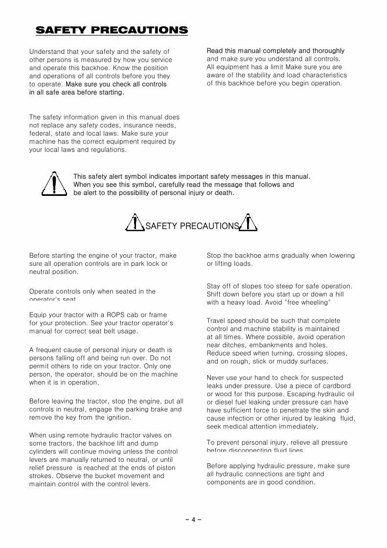
This safety alert symbol indicates important safety messages in this manual. When you see this symbol, carefully read the message that follows and be alert to the possibility of personal injury or death.
SAFETY PRECAUTIONS
Understand that your safety and the safety ofother persons is measured by how you serviceand operate this backhoe. Know the positionand operations of all controls before you theyto operate. Make sure you check all controlsin all safe area before starting.
Read this manual completely and thoroughlyand make sure you understand all controls.All equipment has a limit Make sure you areaware of the stability and load characteristicsof this backhoe before you begin operation.
- 4 -
Before leaving the tractor, stop the engine, put allcontrols in neutral, engage the parking brake andremove the key from the ignition.
When using remote hydraulic tractor valves onsome tractors, the backhoe lift and dumpcylinders will continue moving unless the controllevers are manually returned to neutral, or untilrelief pressure is reached at the ends of pistonstrokes. Observe the bucket movement andmaintain control with the control levers.
To prevent personal injury, relieve all pressurebefore disconnecting fluid lines
Before applying hydraulic pressure, make sureall hydraulic connections are tight andcomponents are in good condition.
Equip your tractor with a ROPS cab or framefor your protection. See your tractor operator'smanual for correct seat belt usage.
A frequent cause of personal injury or death ispersons falling off and being run over. Do notpermit others to ride on your tractor. Only oneperson, the operator, should be on the machinewhen it is in operation.
Stay off of slopes too steep for safe operation.Shift down before you start up or down a hillwith a heavy load. Avoid "free wheeling"
Operate controls only when seated in theoperator's seat
Travel speed should be such that completecontrol and machine stability is maintainedat all times. Where possible, avoid operationnear ditches, embankments and holes.Reduce speed when turning, crossing slopes,and on rough, slick or muddy surfaces.
Never use your hand to check for suspectedleaks under pressure. Use a piece of cardbordor wood for this purpose. Escaping hydraulic oilor diesel fuel leaking under pressure can havehave sufficient force to penetrate the skin andcause infection or other injured by leaking fluid,seek medical attention immediately.
Stop the backhoe arms gradually when loweringor lifting loads.
Before starting the engine of your tractor, makesure all operation controls are in park lock orneutral position.
- 4 -

SAFETY PRECAUTIONS
Add recommended rear tire liquid weight or rearwheel weights for increased stability
A backhoe attachment should be transported ina low position at slow ground speeds. Make turnsslowly and use the tractor brakes cautiously.A loaded attachment in the raised position altersthe center of gravity location of the machine andincreases the possibility of mishaps.
When using a backhoe, be alert of bucket,boom and arm position at all times
Contact with overhead power lines can causesevere electrical burn or death from electrocution.Make sure there is enough clearance betweenraised equipment and overhead power lines.
Make sure all parked backhoe on stands areon a hard level surface with all safety devicesengaged to prevent backhoe from falling andbeing damaged or injuring someone.
- 5 -- 5 -
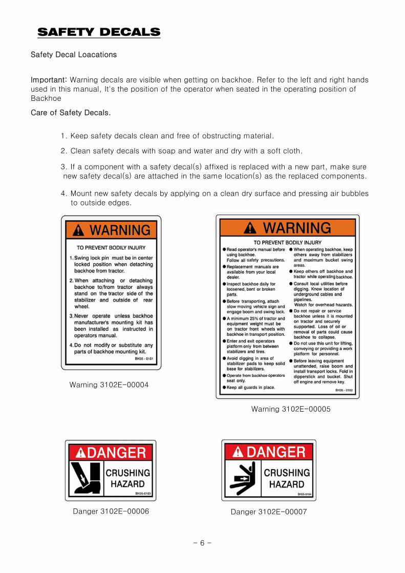
SAFETY DECALS
Safety Decal Loacations
Care of Safety Decals.
1. Keep safety decals clean and free of obstructing material.
2. Clean safety decals with soap and water and dry with a soft cloth.
3. If a component with a safety decal(s) affixed is replaced with a new part, make sure new safety decal(s) are attached in the same location(s) as the replaced components.
4. Mount new safety decals by applying on a clean dry surface and pressing air bubbles to outside edges.
Important: Warning decals are visible when getting on backhoe. Refer to the left and right handsused in this manual, It's the position of the operator when seated in the operating position ofBackhoe
Warning 3102E-00004
Warning 3102E-00005
Danger 3102E-00006 Danger 3102E-00007
- 6 -
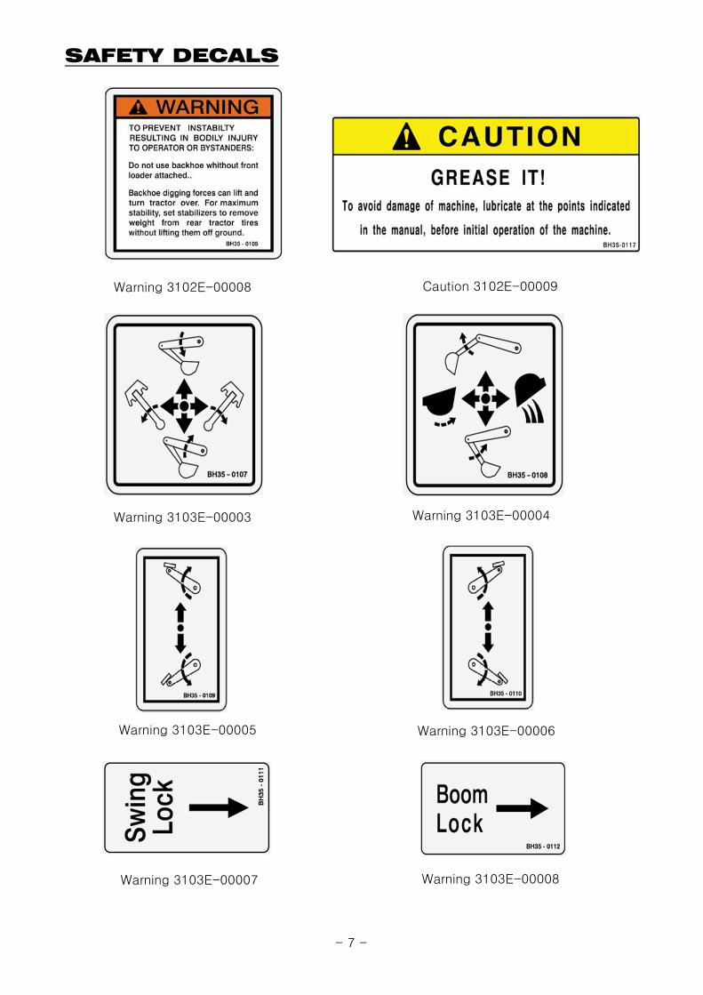
SAFETY DECALS
Warning 3102E-00008 Caution 3102E-00009
Warning 3103E-00003
Warning 3103E-00005
Warning 3103E-00007
Warning 3103E-00004
Warning 3103E-00006
Warning 3103E-00008
- 7 -
SAFETY DECALS
Inspection 3102E-00032 Ls Name 3101E-00227
- 8 -
Model 3101E-00476Ls Name 3101E-00228
Name Plate 3104E-00016
- 8 -
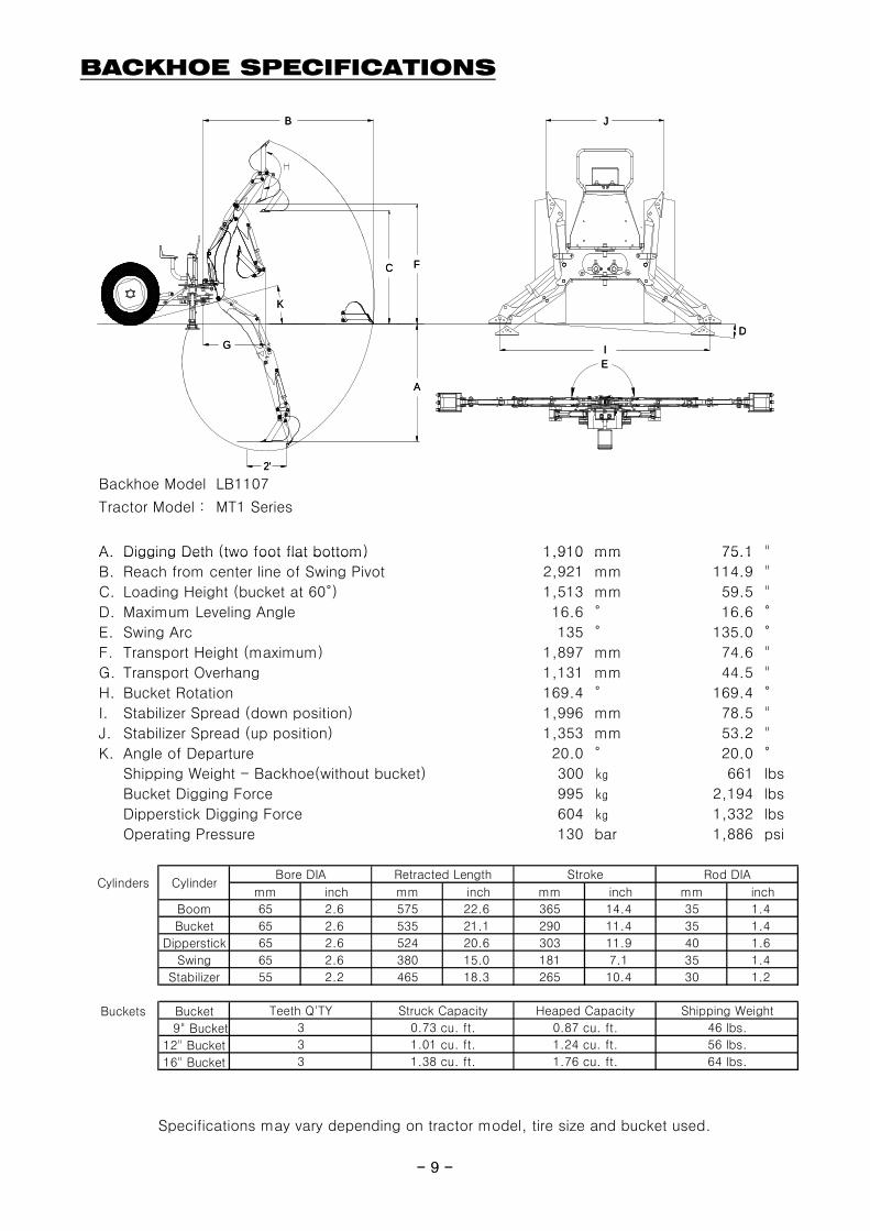
BACKHOE SPECIFICATIONS
Backhoe Model LB1107
Tractor Model : MT1 Series
A. Digging Deth (two foot flat bottom) 1,910 mm 75.1 "
mm inch mm inch mm inch mm inch
Boom 65 2.6 575 22.6 365 14.4 35 1.4
Bucket 65 2.6 535 21.1 290 11.4 35 1.4
Dipperstick 65 2.6 524 20.6 303 11.9 40 1.6
Swing 65 2.6 380 15.0 181 7.1 35 1.4
Stabilizer 55 2.2 465 18.3 265 10.4 30 1.2
Buckets Bucket
9" Bucket
12" Bucket
16" Bucket
Rod DIA
Teeth Q'TY Struck Capacity Heaped Capacity Shipping Weight
Bore DIA Retracted Length
3 1.38 cu. ft. 1.76 cu. ft. 64 lbs.
56 lbs.
3 0.73 cu. ft. 0.87 cu. ft. 46 lbs.
3 1.01 cu. ft. 1.24 cu. ft.
StrokeCylinders Cylinder
I
D
C
G
F
B J
A
E
2'
K
- 9 -
A. Digging Deth (two foot flat bottom) 1,910 mm 75.1
B. Reach from center line of Swing Pivot 2,921 mm 114.9 "
C. Loading Height (bucket at 60°) 1,513 mm 59.5 "
D. Maximum Leveling Angle 16.6 ° 16.6 °
E. Swing Arc 135 ° 135.0 °
F. Transport Height (maximum) 1,897 mm 74.6 "
G. Transport Overhang 1,131 mm 44.5 "
H. Bucket Rotation 169.4 ° 169.4 °
I. Stabilizer Spread (down position) 1,996 mm 78.5 "
J. Stabilizer Spread (up position) 1,353 mm 53.2 "
K. Angle of Departure 20.0 ° 20.0 °
Shipping Weight - Backhoe(without bucket) 300 ㎏ 661 lbs
Bucket Digging Force 995 ㎏ 2,194 lbs
Dipperstick Digging Force 604 ㎏ 1,332 lbs
Operating Pressure 130 bar 1,886 psi
Specifications may vary depending on tractor model, tire size and bucket used.
mm inch mm inch mm inch mm inch
Boom 65 2.6 575 22.6 365 14.4 35 1.4
Bucket 65 2.6 535 21.1 290 11.4 35 1.4
Dipperstick 65 2.6 524 20.6 303 11.9 40 1.6
Swing 65 2.6 380 15.0 181 7.1 35 1.4
Stabilizer 55 2.2 465 18.3 265 10.4 30 1.2
Buckets Bucket
9" Bucket
12" Bucket
16" Bucket
Rod DIA
Teeth Q'TY Struck Capacity Heaped Capacity Shipping Weight
Bore DIA Retracted Length
3 1.38 cu. ft. 1.76 cu. ft. 64 lbs.
56 lbs.
3 0.73 cu. ft. 0.87 cu. ft. 46 lbs.
3 1.01 cu. ft. 1.24 cu. ft.
StrokeCylinders Cylinder
I
D
C
G
F
B J
A
E
2'
K
- 9 -
INTRODUCTION
Important:
Warranty Registration
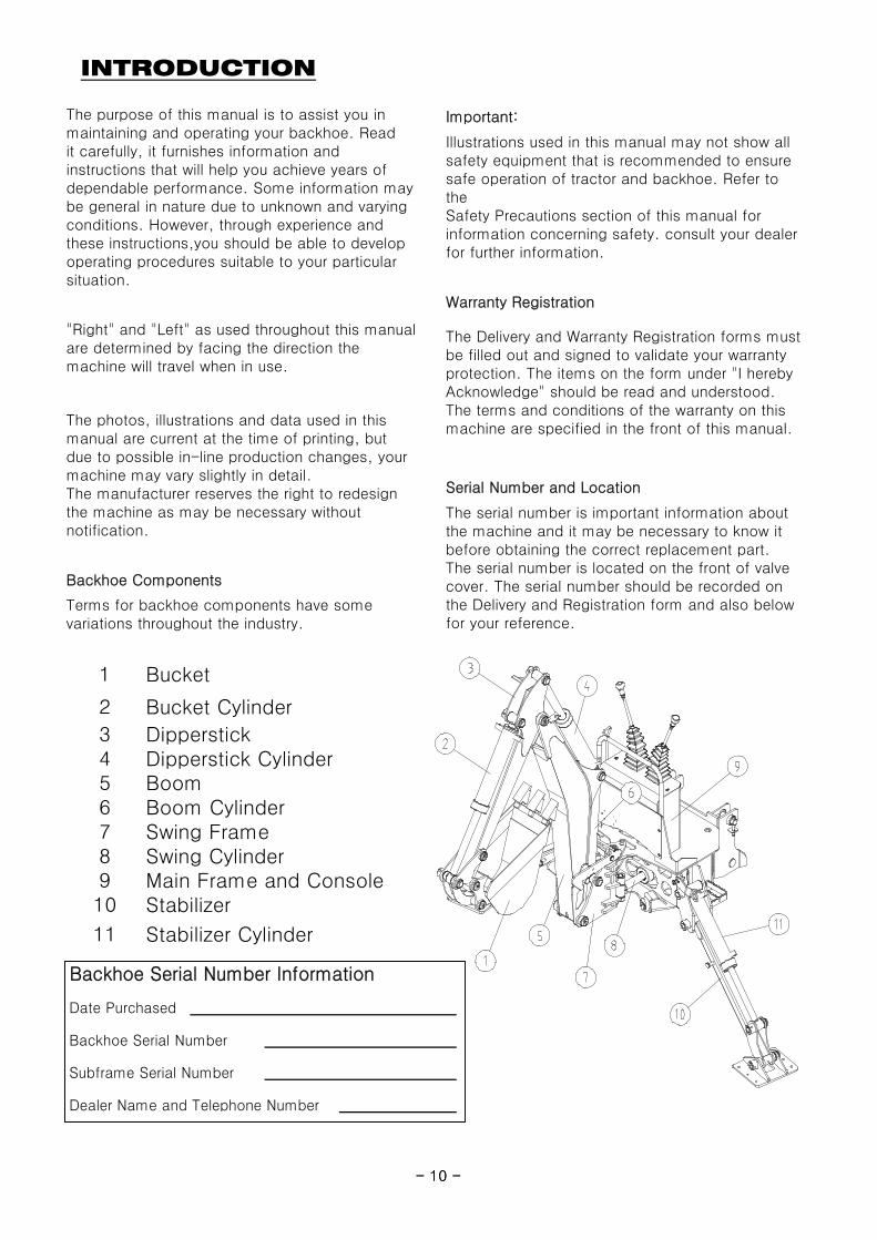
Serial Number and Location
The serial number is important information aboutthe machine and it may be necessary to know itbefore obtaining the correct replacement part.
The purpose of this manual is to assist you inmaintaining and operating your backhoe. Readit carefully, it furnishes information andinstructions that will help you achieve years ofdependable performance. Some information maybe general in nature due to unknown and varyingconditions. However, through experience andthese instructions,you should be able to developoperating procedures suitable to your particularsituation.
Illustrations used in this manual may not show allsafety equipment that is recommended to ensuresafe operation of tractor and backhoe. Refer totheSafety Precautions section of this manual forinformation concerning safety. consult your dealerfor further information.
"Right" and "Left" as used throughout this manualare determined by facing the direction themachine will travel when in use.
The photos, illustrations and data used in thismanual are current at the time of printing, butdue to possible in-line production changes, yourmachine may vary slightly in detail.The manufacturer reserves the right to redesignthe machine as may be necessary withoutnotification.
The Delivery and Warranty Registration forms mustbe filled out and signed to validate your warrantyprotection. The items on the form under "I herebyAcknowledge" should be read and understood.The terms and conditions of the warranty on thismachine are specified in the front of this manual.
1 Bucket
2 Bucket Cylinder
3 Dipperstick4 Dipperstick Cylinder5 Boom6 Boom Cylinder7 Swing Frame8 Swing Cylinder9 Main Frame and Console10 Stabilizer
11 Stabilizer Cylinder
Backhoe Serial Number Information
Date Purchased
Backhoe Serial Number
Subframe Serial Number
Dealer Name and Telephone Number
- 10 -
Backhoe Components
Terms for backhoe components have somevariations throughout the industry.
The serial number is located on the front of valvecover. The serial number should be recorded onthe Delivery and Registration form and also belowfor your reference.
1 Bucket
2 Bucket Cylinder
3 Dipperstick4 Dipperstick Cylinder5 Boom6 Boom Cylinder7 Swing Frame8 Swing Cylinder9 Main Frame and Console10 Stabilizer
11 Stabilizer Cylinder
Backhoe Serial Number Information
Date Purchased
Backhoe Serial Number
Subframe Serial Number
Dealer Name and Telephone Number
- 10 -
TRACTOR PREPARATION
CAUTION:
CAUTION:
CAUTION:
The tractor/backhoe must only be operated with all safety equipment properly installed
Do not exceed the manufacturer's rating formaximum gross vehicle weight. Refer toOperator's Manual or ROPS serial plateprovided with tractor.
ROPS System
Tractor Hydraulic System
Tractor operation in a backhoe applicationsignificantly increase demands on the tractorHydraulic System. Check the tractorHydraulic system fluid level daily. Refer toyour tractor Operator's Manual maintenancesection for instructions regarding tractorhydraulic system maintenance.
Adhere to recommendation in your TractorOperator's Manual concerning hydraulicfluid and filter specifications, and changeintervals
Certain specific conditions may not permitsafe use of backhoe at backhoe rating ormay require more careful restrictedoperationat the rated load.
The tractor must be equipped with an approvedROPS System to ensure adequate operator'sprotection.
- 11 -
The tractor/backhoe must only be operated with all safety equipment properly installed.
Tire Inflation
Front tires must be maintained at the maximumrecommended inflation to maintain normal tireprofile with the added weight of backhoe/material.
Rear tires must be maintained at equal pressurewithin the recommended tire inflation range.Unequal rear tire inflation can prevent backhoeattachment from contacting the ground across itsfull width.
Wheel Tread Settings
Tractor front wheel tread setting must berestricted to wheel tread spacing recommendedin the tractor Operator's Manual.
- 11 -
BACKHOE OPERATION
CAUTION:
Precautionary Notes
We urge you to follow this advice:1. Read and understand this manual as well as the Tractor Operator's Manual.2. Remember and observe the Safety Precautions brought to your attention in this manual, the tractor manual and on the machinery itself.3. Use good common sense in the everyday operation of this unit. Safety recommendations can never be all- inclusive and you are responsible for watching out for and avoiding unsafe conditions.
- Check the hydraulic fitting lines to be correct and set tightly.- Maintain and repair (if it is needed) the parts or assemblies, check bolts and pins to be sure they are positioned tightly.- Check tractor with the tractor operator's manual that it can prepared for operating.- Warm up and operate the tractor and backhoe carefully. Purge any air in the hydraulic lines and cylinders by fully cycling all cylinders several times.
Position vehicle so that the backhoe is as nearto the pile as possible and in such a direction asto minimize the amount of tractor turningrequired to dump.
Keep the unit clean and perform regular service.Observe safety messages whenever cleaning,servicing, or lubricating.
- Read and understand this manual to avoid accidents.
The tractor/backhoe should only be operatedwith all safety equipment properly installed.Keep assistants or bystanders a safedistance from the equipment operating area.
- Check below items before operating for your safety.
- 12 -
conditions.4. Never exceed the limits of a piece of machinery. If its ability to do a job or to do so safely is in question, don't try it.5. Don't hurry the learning process or take the unit for granted. Ease into it and become familiar with your new backhoe and tractor.
CAUTION: When lowering a heavy load,ease it downward slowly. Never drop a
Important:
CAUTION: Before disconnecting hydrauliclines, relieve all hydraulic pressure.
Important:
CAUTION: Do not operate the backhoe ifImportant: the fittings are leaking or if the hoses are
cycling all cylinders several times.- Check hydraulic level in the tank. It should be full (Refer to the Tractor Operator's Manual).- Do not operate the hydraulics when not seated in the backhoe operator's seat.
- Do not allow riders other than the operator to be on the tractor while operating.
- Keep all assistants out of area of operation.- Do not operate rapidly.
Use tractor engine speed that your experiencepermits. At first set PTO RPM of the tractor toslow.Do not use the boom, dipperstick, swing andstabilizers to lift, push or pull objects. Useonly to maneuver and operate the bucket.
Escaping hydraulic oil under pressure can havesufficient force to penetrate the skin causingserious personal injury. If injured by escapinghydraulic oil seek medical attention immediately.
loaded attachment and "catch it hydraulically".Stopping a load after it has gained downwardmomentum places undue strain on the unit andmay cause unnecessary damage to the backhoeor tractor or even worse, personal injury.
damaged. A sudden line burst would cause themainframe to drop suddenly, causing damageto the tractor or backhoe or injury to personnel.
Practice quickly turning off the engine orstopping the backhoe immediately in case ofan emergency situation.
Do not operate while the rear tractor wheelsare off the ground by stabilizer. It isdangerous to operate the backhoe while rearwheels are off the ground.
- 12 -
BACKHOE OPERATION
Initial Backhoe Operation
CAUTION: Cold Weather Operation
CAUTION:
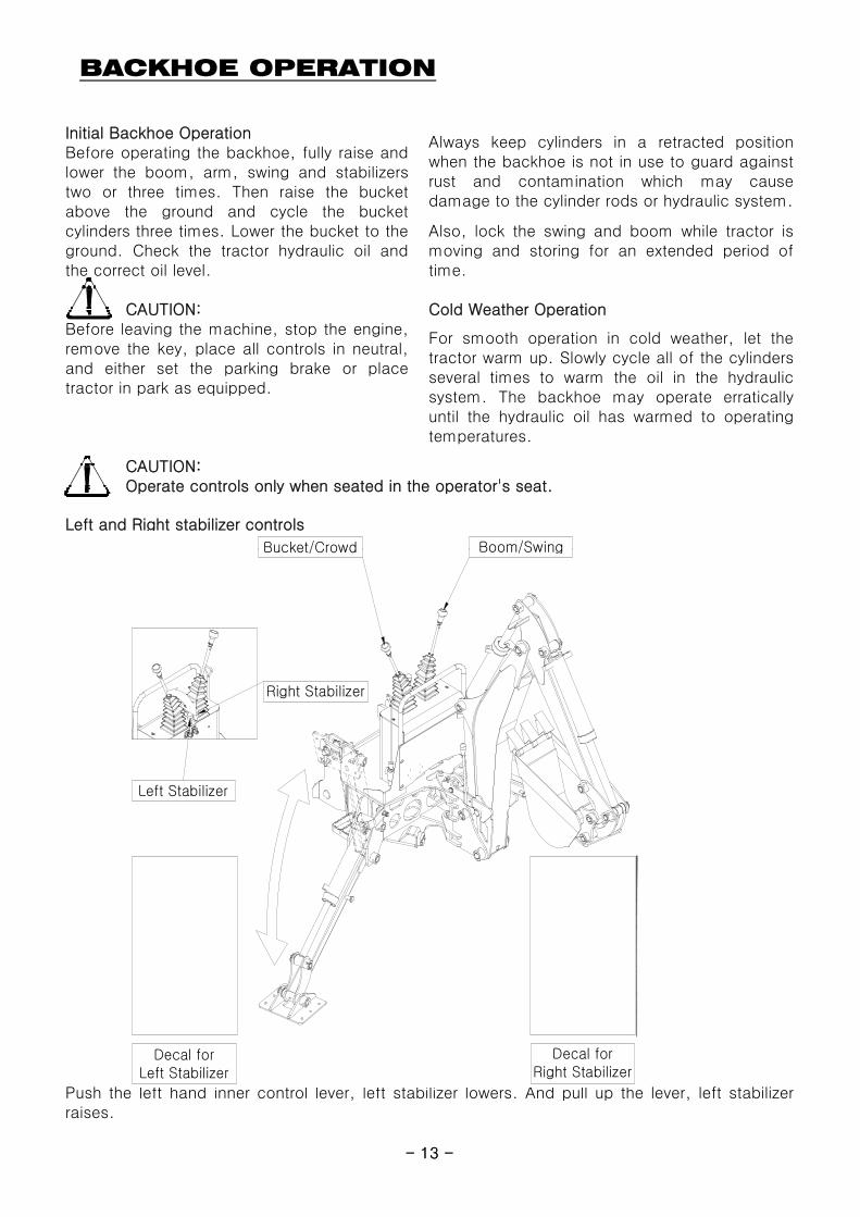
Left and Right stabilizer controls
Before operating the backhoe, fully raise andlower the boom, arm, swing and stabilizerstwo or three times. Then raise the bucketabove the ground and cycle the bucketcylinders three times. Lower the bucket to theground. Check the tractor hydraulic oil andthe correct oil level.
Before leaving the machine, stop the engine,remove the key, place all controls in neutral,and either set the parking brake or placetractor in park as equipped.
Also, lock the swing and boom while tractor ismoving and storing for an extended period oftime.
Always keep cylinders in a retracted positionwhen the backhoe is not in use to guard againstrust and contamination which may causedamage to the cylinder rods or hydraulic system.
For smooth operation in cold weather, let thetractor warm up. Slowly cycle all of the cylindersseveral times to warm the oil in the hydraulicsystem. The backhoe may operate erraticallyuntil the hydraulic oil has warmed to operatingtemperatures.
Operate controls only when seated in the operator's seat.
Boom/SwingBucket/Crowd
Decal forRight Stabilizer
Right Stabilizer
Left Stabilizer
Decal forLeft Stabilizer
- 13 -
Push the left hand inner control lever, left stabilizer lowers. And pull up the lever, left stabilizerraises.
Boom/SwingBucket/Crowd
Decal forRight Stabilizer
Right Stabilizer
Left Stabilizer
Decal forLeft Stabilizer
- 13 -
BACKHOE OPERATION
Do not dig near the stabilizers to avoid possible accident.
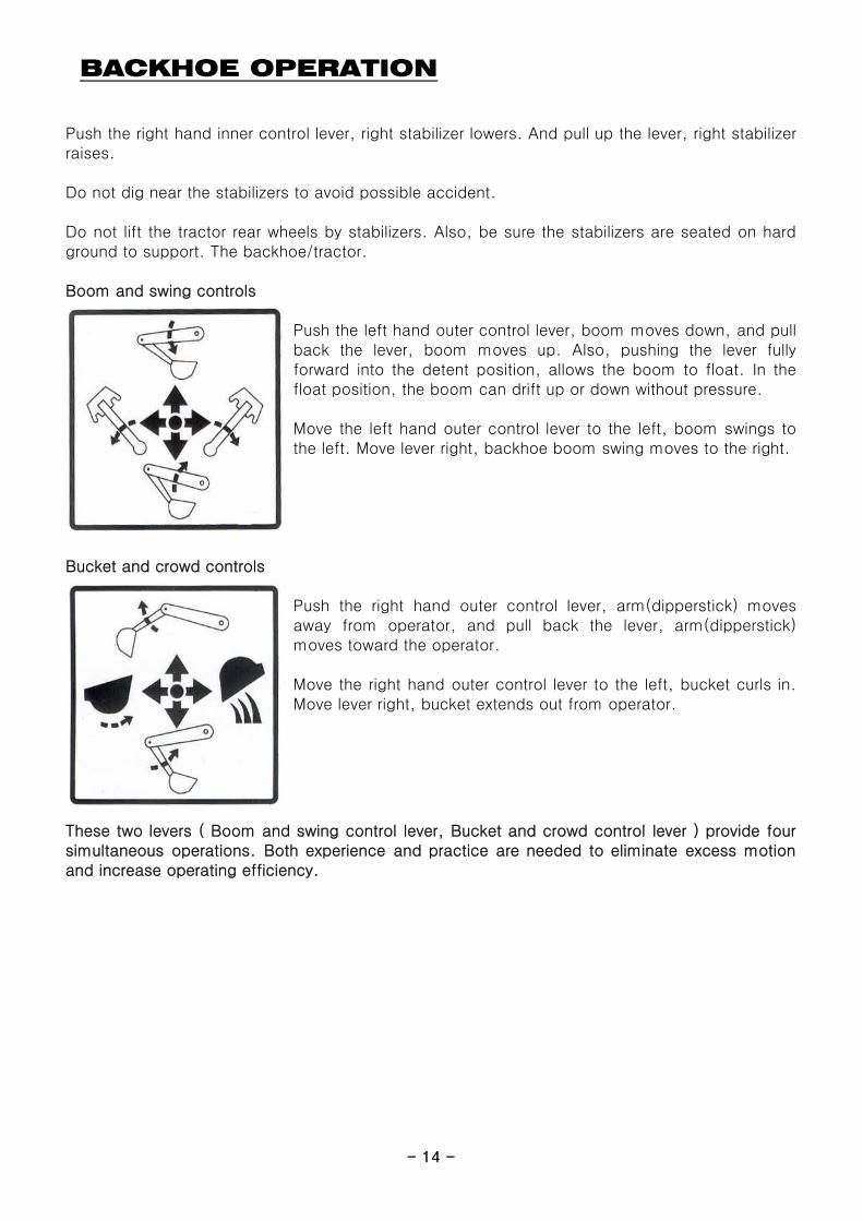
Boom and swing controls
Push the left hand outer control lever, boom moves down, and pullback the lever, boom moves up. Also, pushing the lever fullyforward into the detent position, allows the boom to float. In thefloat position, the boom can drift up or down without pressure.
Move the left hand outer control lever to the left, boom swings tothe left. Move lever right, backhoe boom swing moves to the right.
Push the right hand inner control lever, right stabilizer lowers. And pull up the lever, right stabilizerraises.
Do not lift the tractor rear wheels by stabilizers. Also, be sure the stabilizers are seated on hardground to support. The backhoe/tractor.
- 14 -
Bucket and crowd controls
Push the right hand outer control lever, arm(dipperstick) movesaway from operator, and pull back the lever, arm(dipperstick)moves toward the operator.
Move the right hand outer control lever to the left, bucket curls in.Move lever right, bucket extends out from operator.
These two levers ( Boom and swing control lever, Bucket and crowd control lever ) provide foursimultaneous operations. Both experience and practice are needed to eliminate excess motionand increase operating efficiency.
- 14 -
BACKHOE OPERATION
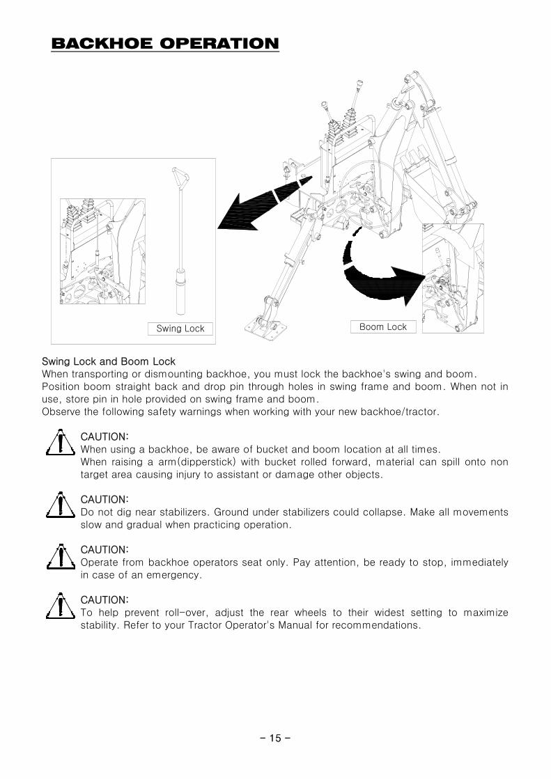
Boom LockSwing Lock
- 15 -
Swing Lock and Boom LockWhen transporting or dismounting backhoe, you must lock the backhoe's swing and boom.
Observe the following safety warnings when working with your new backhoe/tractor.
CAUTION: When using a backhoe, be aware of bucket and boom location at all times.
CAUTION:
CAUTION:
CAUTION: To help prevent roll-over, adjust the rear wheels to their widest setting to maximizestability. Refer to your Tractor Operator's Manual for recommendations.
Operate from backhoe operators seat only. Pay attention, be ready to stop, immediatelyin case of an emergency.
Position boom straight back and drop pin through holes in swing frame and boom. When not inuse, store pin in hole provided on swing frame and boom.
Do not dig near stabilizers. Ground under stabilizers could collapse. Make all movementsslow and gradual when practicing operation.
When raising a arm(dipperstick) with bucket rolled forward, material can spill onto nontarget area causing injury to assistant or damage other objects.
Boom LockSwing Lock
- 15 -
BACKHOE REMOVAL
CAUTION:
Move the backhoe to flat, firm and wide place to remove the equipment.
CAUTION:
WARNING:
Center the boom and then lock the swing with lock pin.
STEP 4.
STEP 2.
Use the inner two levers to lower the stabilizers until they contact to the ground. Use the boom anddipperstick control lever to raise the boom & dipperstick completely.
STEP 3.
Do not allow to be removed without bucket and stabilizers. Also, Dump the remainingmaterial from the bucket to empty.
Use other lifting equipment to remove when the backhoe has damage.
Move the tractor to backhoe storage place.
STEP 1.
- 16 -
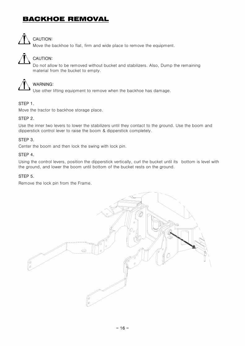
Remove the lock pin from the Frame.
STEP 4.
Using the control levers, position the dipperstick vertically, curl the bucket until its bottom is level withthe ground, and lower the boom until bottom of the bucket rests on the ground.
STEP 5.
Lock Pin
- 16 -
BACKHOE REMOVAL
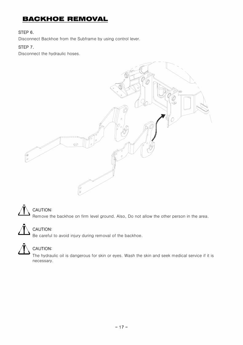
STEP 7.
Disconnect the hydraulic hoses.
STEP 6.
Disconnect Backhoe from the Subframe by using control lever.
Backhoe
- 17 -
CAUTION:
CAUTION:
CAUTION:
The hydraulic oil is dangerous for skin or eyes. Wash the skin and seek medical service if it isnecessary.
Remove the backhoe on firm level ground. Also, Do not allow the other person in the area.
Be careful to avoid injury during removal of the backhoe.
Subframe
- 17 -
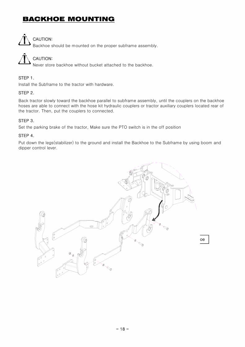
BACKHOE MOUNTING
CAUTION:
Backhoe should be mounted on the proper subframe assembly.
CAUTION:
Never store backhoe without bucket attached to the backhoe.
STEP 1.
Install the Subframe to the tractor with hardware.
STEP 2.
Back tractor slowly toward the backhoe parallel to subframe assembly, until the couplers on the backhoehoses are able to connect with the hose kit hydraulic couplers or tractor auxiliary couplers located rear ofthe tractor. Then, put the couplers to connected.
Set the parking brake of the tractor, Make sure the PTO switch is in the off position
STEP 4.
Put down the legs(stabilizer) to the ground and install the Backhoe to the Subframe by using boom anddipper control lever.
STEP 3.
- 18 -
Backhoe
Subframe
Mounting
- 18 -
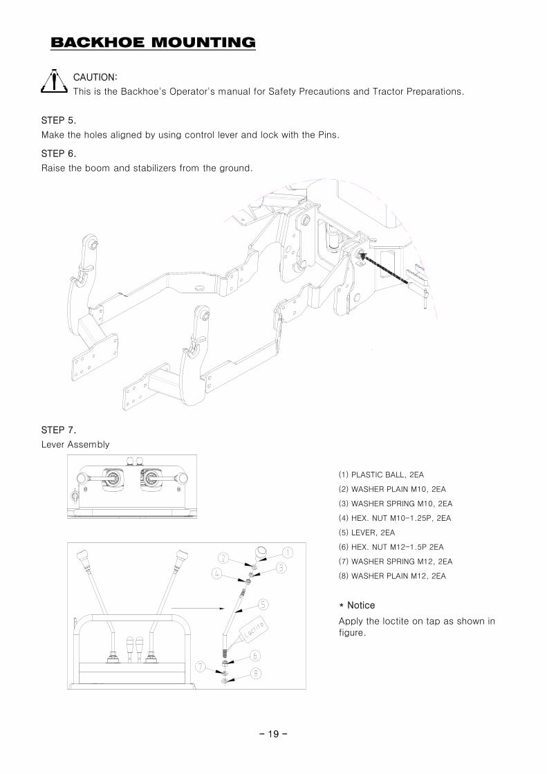
BACKHOE MOUNTING
CAUTION:
STEP 6.
Raise the boom and stabilizers from the ground.
This is the Backhoe's Operator's manual for Safety Precautions and Tractor Preparations.
STEP 5.
Make the holes aligned by using control lever and lock with the Pins.
- 19 -
(7) WASHER SPRING M12, 2EA
(8) WASHER PLAIN M12, 2EA
STEP 7.
(1) PLASTIC BALL, 2EA
(2) WASHER PLAIN M10, 2EA
Lever Assembly
(3) WASHER SPRING M10, 2EA
(4) HEX. NUT M10-1.25P, 2EA
(5) LEVER, 2EA
(6) HEX. NUT M12-1.5P 2EA
* Notice
Apply the loctite on tap as shown infigure.
Lock Pin
- 19 -
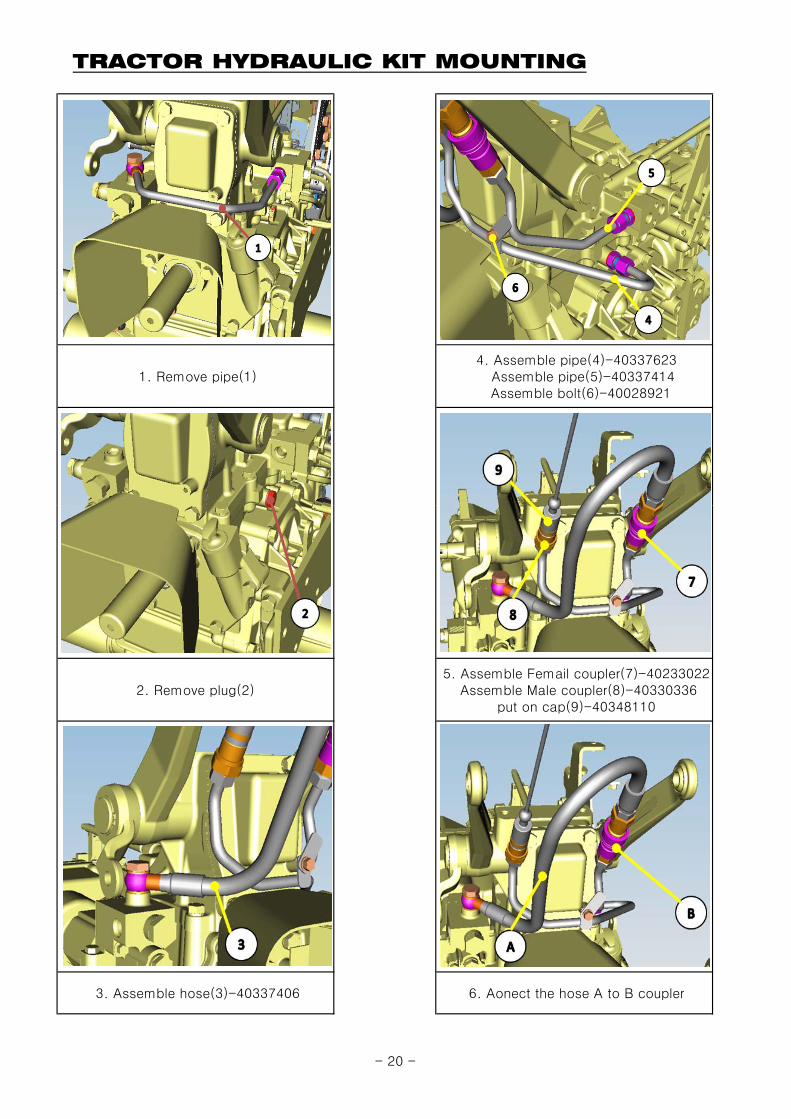
TRACTOR HYDRAULIC KIT MOUNTING
1. Remove pipe(1) 4. Assemble pipe(4)-40337623 Assemble pipe(5)-40337414 Assemble bolt(6)-40028921
2. Remove plug(2)
3. Assemble hose(3)-40337406
5. Assemble Femail coupler(7)-40233022 Assemble Male coupler(8)-40330336
put on cap(9)-40348110
6. Aonect the hose A to B coupler
- 20 -
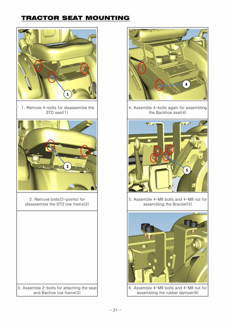
TRACTOR SEAT MOUNTING
1. Remove 4-bolts for disassemble theSTD seat(1)
4. Assemble 4-bolts again for assemblingthe Backhoe seat(4)
3. Assemble 2-bolts for attaching the seatand Bachoe low frame(3)
5. Assemble 4-M8 bolts and 4-M8 nut forassembling the Bracket(5)
6. Assemble 4-M8 bolts and 4-M8 nut forassembling the rubber damper(6)
2. Remove bolts(2-points) fordisassemble the STD low frame(2)
- 21 -
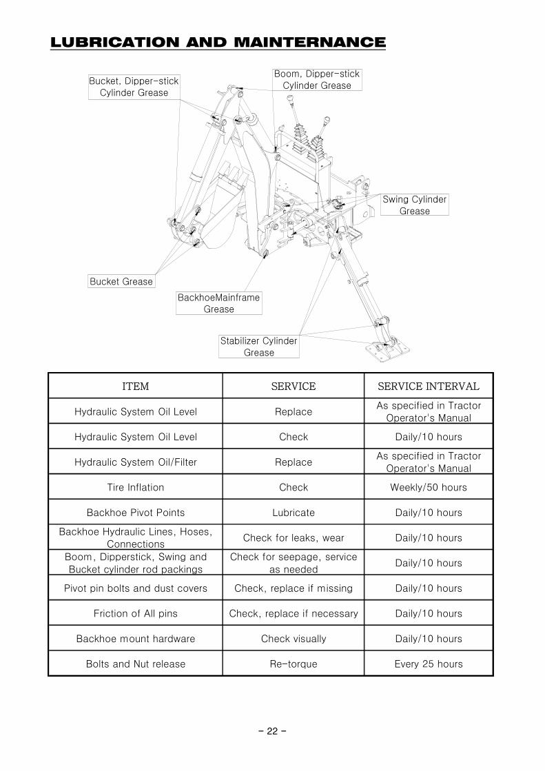
LUBRICATION AND MAINTERNANCE
ITEM SERVICE SERVICE INTERVAL
Hydraulic System Oil Level ReplaceAs specified in Tractor
Operator's Manual
Hydraulic System Oil Level Check Daily/10 hours
Hydraulic System Oil/Filter ReplaceAs specified in Tractor
Operator's Manual
Tire Inflation Check Weekly/50 hours
Backhoe Pivot Points Lubricate Daily/10 hours
Backhoe Hydraulic Lines, Hoses,Connections
Check for leaks, wear Daily/10 hours
Boom, Dipperstick, Swing andBucket cylinder rod packings
Check for seepage, serviceas needed
Daily/10 hours
Pivot pin bolts and dust covers Check, replace if missing Daily/10 hours
Friction of All pins Check, replace if necessary Daily/10 hours
Backhoe mount hardware Check visually Daily/10 hours
Bolts and Nut release Re-torque Every 25 hours
Bucket Grease
BackhoeMainframeGrease
Stabilizer CylinderGrease
Swing CylinderGrease
Bucket, Dipper-stickCylinder Grease
Boom, Dipper-stickCylinder Grease
- 22 -
LUBRICATION AND MAINTERNANCE
CAUTION:
Important:
CAUTION:
CAUTION:
Escaping fluid under pressure can have sufficient force to penetrate the skin, causing seriousinjury. Before disconnecting lines, be sure to relieve all pressure. Before applying pressure to thesystem, be sure all connections are tight and that lines, pipes and hoses are not damaged. Fluidescaping from a very small hole can be almost invisible. Use a piece of cardboard or wood ratherthan your hands to search for suspected leaks. If injured by escaping fluid, seek medical attentionimmediately. Serious infection or reaction can develop if correct medical treatment is notadministered immediately.
Refer to "Lubrication and Maintenance Chart" for quick reference to Maintenance Operations.
Do not perform service or maintenance Operations with backhoe raised off the ground.For additional access to tractor components remove backhoe.
Lower the backhoe to the ground and relieve pressure in backhoe hydraulic lines prior to performing anyservice or maintenance operations on the tractor or backhoe.
- 23 -
CAUTION:
CAUTION:
Note:
Check the tractor hydraulic system as outlined in the Tractor Operator's Manual.
When checking hydraulic system oil level, the backhoe should be on the ground and bucket fullyretracted(all cylinders in retracted position).
Inspect hydraulic hoses, connections, control valve and cylinders for evidence of leakage.
Tractor tires should be maintained at maximum recommended inflation to maintain normal tire profilewith added weight of backhoe/material. Unequal rear tire inflation can result in bucket not being level tothe ground.
Grease all backhoe pivot points daily(10 hours). Refer to Tractor Operator's Manual for lubricantrecommendations.
Do not operate the backhoe if the fittings are leaking or if the hoses are damaged. A suddenline burst could cause the boom, dipperstick or bucket to drop suddenly, causing damageto the tractor or backhoe or injury to personnel.
Operate the backhoe from the operator seat only.
Do not stand or walk under a raised backhoe. Accidental movement of control lever or leak inhydraulic system could cause boom or dipperstick to drop, causing severe injury.
- 23 -
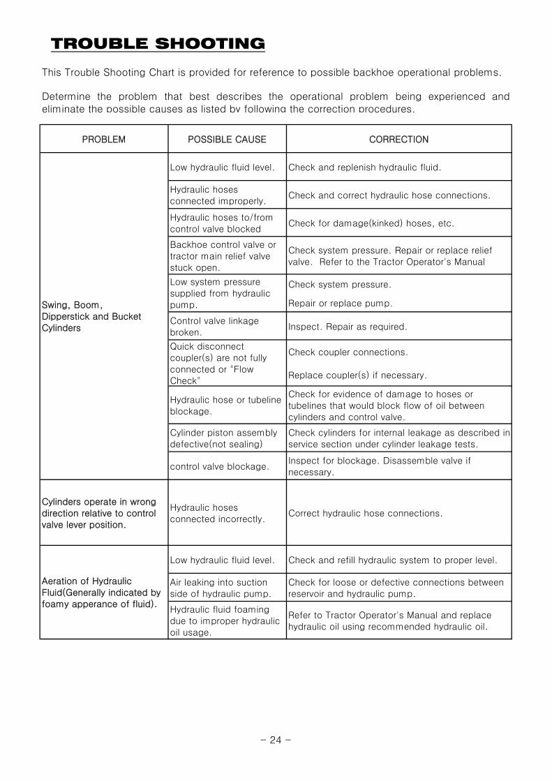
TROUBLE SHOOTING
This Trouble Shooting Chart is provided for reference to possible backhoe operational problems.
PROBLEM POSSIBLE CAUSE CORRECTION
Low hydraulic fluid level. Check and replenish hydraulic fluid.
Hydraulic hosesconnected improperly.
Check and correct hydraulic hose connections.
Hydraulic hoses to/fromcontrol valve blocked
Check for damage(kinked) hoses, etc.
Backhoe control valve ortractor main relief valvestuck open.
Check system pressure. Repair or replace reliefvalve. Refer to the Tractor Operator's Manual
Check system pressure.
Repair or replace pump.
Control valve linkagebroken.
Inspect. Repair as required.
Check coupler connections.
Replace coupler(s) if necessary.
Hydraulic hose or tubelineblockage.
Check for evidence of damage to hoses ortubelines that would block flow of oil betweencylinders and control valve.
Cylinder piston assemblydefective(not sealing)
Check cylinders for internal leakage as described inservice section under cylinder leakage tests.
control valve blockage.Inspect for blockage. Disassemble valve ifnecessary.
Cylinders operate in wrongdirection relative to controlvalve lever position.
Hydraulic hosesconnected incorrectly.
Correct hydraulic hose connections.
Low hydraulic fluid level. Check and refill hydraulic system to proper level.
Air leaking into suctionside of hydraulic pump.
Check for loose or defective connections betweenreservoir and hydraulic pump.
Hydraulic fluid foamingdue to improper hydraulicoil usage.
Refer to Tractor Operator's Manual and replacehydraulic oil using recommended hydraulic oil.
Determine the problem that best describes the operational problem being experienced andeliminate the possible causes as listed by following the correction procedures.
Swing, Boom,Dipperstick and BucketCylinders
Low system pressuresupplied from hydraulicpump.
Quick disconnectcoupler(s) are not fullyconnected or "FlowCheck"
Aeration of HydraulicFluid(Generally indicated byfoamy apperance of fluid).
- 24 -
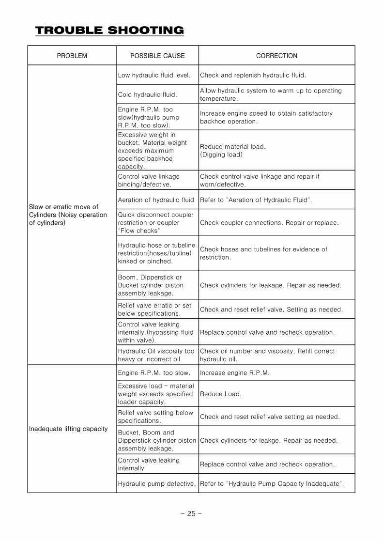
TROUBLE SHOOTING
PROBLEM POSSIBLE CAUSE CORRECTION
Low hydraulic fluid level. Check and replenish hydraulic fluid.
Cold hydraulic fluid.Allow hydraulic system to warm up to operatingtemperature.
Engine R.P.M. tooslow(hydraulic pumpR.P.M. too slow).
Increase engine speed to obtain satisfactorybackhoe operation.
Excessive weight inbucket. Material weightexceeds maximumspecified backhoecapacity.
Reduce material load.(Digging load)
Control valve linkagebinding/defective.
Check control valve linkage and repair ifworn/defective.
Aeration of hydraulic fluid Refer to "Aeration of Hydraulic Fluid".
Quick disconnect couplerrestriction or coupler"Flow checks"
Check coupler connections. Repair or replace.
Hydraulic hose or tubelinerestriction(hoses/tubline)kinked or pinched.
Check hoses and tubelines for evidence ofrestriction.
Boom, Dipperstick orBucket cylinder pistonassembly leakage.
Check cylinders for leakage. Repair as needed.
Relief valve erratic or setbelow specifications.
Check and reset relief valve. Setting as needed.
Control valve leakinginternally.(hypassing fluidwithin valve).
Replace control valve and recheck operation.
Hydraulic Oil viscosity tooheavy or Incorrect oil
Check oil number and viscosity, Refill correcthydraulic oil.
Engine R.P.M. too slow. Increase engine R.P.M.
Excessive load - materialweight exceeds specifiedloader capacity.
Reduce Load.
Relief valve setting belowspecifications.
Check and reset relief valve setting as needed.
Bucket, Boom andDipperstick cylinder pistonassembly leakage.
Check cylinders for leakge. Repair as needed.
Control valve leakinginternally
Replace control valve and recheck operation.
Hydraulic pump defective. Refer to "Hydraulic Pump Capacity Inadequate".
Slow or erratic move ofCylinders (Noisy operationof cylinders)
Inadequate lifting capacity
- 25 -
TROUBLE SHOOTING
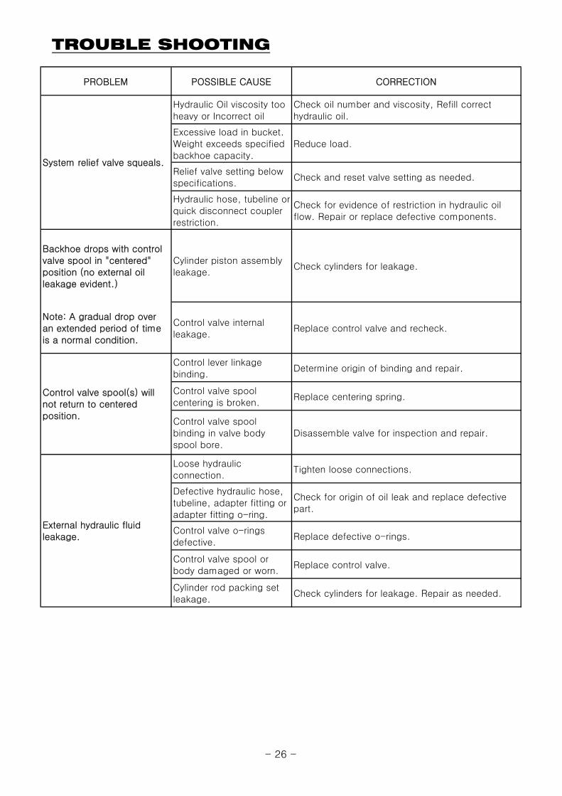
PROBLEM POSSIBLE CAUSE CORRECTION
Hydraulic Oil viscosity tooheavy or Incorrect oil
Check oil number and viscosity, Refill correcthydraulic oil.
Excessive load in bucket.Weight exceeds specifiedbackhoe capacity.
Reduce load.
Relief valve setting belowspecifications.
Check and reset valve setting as needed.
Hydraulic hose, tubeline orquick disconnect couplerrestriction.
Check for evidence of restriction in hydraulic oilflow. Repair or replace defective components.
Backhoe drops with controlvalve spool in "centered"position (no external oilleakage evident.)
Cylinder piston assemblyleakage.
Check cylinders for leakage.
Note: A gradual drop overan extended period of timeis a normal condition.
Control valve internalleakage.
Replace control valve and recheck.
Control lever linkagebinding.
Determine origin of binding and repair.
Control valve spoolcentering is broken.
Replace centering spring.
Control valve spoolbinding in valve bodyspool bore.
Disassemble valve for inspection and repair.
Loose hydraulicconnection.
Tighten loose connections.
Defective hydraulic hose,tubeline, adapter fitting oradapter fitting o-ring.
Check for origin of oil leak and replace defectivepart.
Control valve o-ringsdefective.
Replace defective o-rings.
Control valve spool orbody damaged or worn.
Replace control valve.
Cylinder rod packing setleakage.
Check cylinders for leakage. Repair as needed.
External hydraulic fluidleakage.
System relief valve squeals.
Control valve spool(s) willnot return to centeredposition.
- 26 -
TROUBLE SHOOTING
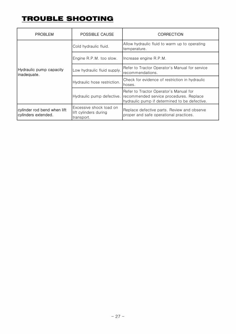
PROBLEM POSSIBLE CAUSE CORRECTION
Cold hydraulic fluid.Allow hydraulic fluid to warm up to operatingtemperature.
Engine R.P.M. too slow. Increase engine R.P.M.
Low hydraulic fluid supply.Refer to Tractor Operator's Manual for servicerecommendations.
Hydraulic hose restriction.Check for evidence of restriction in hydraulichoses.
Hydraulic pump defective.Refer to Tractor Operator's Manual forrecommended service procedures. Replacehydraulic pump if determined to be defective.
cylinder rod bend when liftcylinders extended.
Excessive shock load onlift cylinders duringtransport.
Replace defective parts. Review and observeproper and safe operational practices.
Hydraulic pump capacityinadequate.
- 27 -
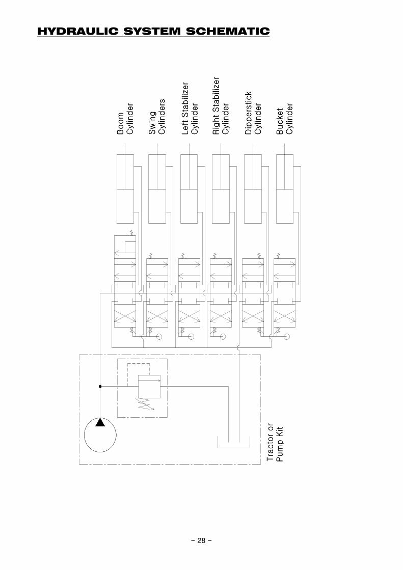
HYDRAULIC SYSTEM SCHEMATIC
Boom
Cyl
inder
Sw
ing
Cyl
inders
Left
Sta
bili
zer
Cyl
inder
Dip
pers
tick
Cyl
inder
Bucke
tC
ylin
der
Rig
ht
Sta
bili
zer
Cyl
inder
Tra
cto
r or
Pum
p K
it
- 28 -
Boom
Cyl
inder
Sw
ing
Cyl
inders
Left
Sta
bili
zer
Cyl
inder
Dip
pers
tick
Cyl
inder
Bucke
tC
ylin
der
Rig
ht
Sta
bili
zer
Cyl
inder
Tra
cto
r or
Pum
p K
it
- 28 -
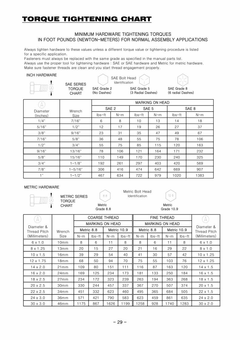
TORQUE TIGHTENING CHART
INCH HARDWARE
SAE SERIESTORQUECHART
lbs-ft N-m lbs-ft N-m lbs-ft N-m
1/4" 7/16" 6 8 10 13 14 18
5/16" 1/2" 12 17 19 26 27 37
3/8" 9/16" 23 31 35 47 49 67
7/16" 5/8" 36 48 55 75 78 106
1/2" 3/4" 55 75 85 115 120 163
9/16" 13/16" 78 106 121 164 171 232
MARKING ON HEAD
SAE 2 SAE 5 SAE 8Diameter(Inches)
SAE Grade 2(No Dashes)
SAE Grade 5(3 Radial Dashes)
SAE Grade 8(6 radial Dashes)
Always tighten hardware to these values unless a different torque value or tightening procedure is listedfor a specific application.Fasteners must always be replaced with the same grade as specified in the manual parts list.Always use the proper tool for tightening hardware : SAE or SAE hardware and Metric for metric hardware.Make sure fastener threads are clean and you start thread engagement properly.
MINIMUM HARDWARE TIGHTENING TORQUESIN FOOT POUNDS (NEWTON-METERS) FOR NORMAL ASSEMBLY APPLICATIONS
WrenchSize
SAE Bolt HeadIdentification
- 29 -
5/8" 15/16" 110 149 170 230 240 325
3/4" 1-1/8" 192 261 297 403 420 569
7/8" 1-5/16" 306 416 474 642 669 907
1" 1-1/2" 467 634 722 979 1020 1383
METRIC SERIESTORQUECHART Metric
Grade 8.8 Metric Grade 10.9
METRIC HARDWAREMetric Bolt Head
Identification
N-m lbs-ft N-m lbs-ft N-m lbs-ft N-m lbs-ft
6 x 1.0 10mm 8 6 11 8 8 6 11 8 6 x 1.0
8 x 1.25 13mm 20 15 27 20 21 16 29 22 8 x 1.0
10 x 1.5 16mm 39 29 54 40 41 30 57 42 10 x 1.25
12 x 1.75 18mm 68 50 94 70 75 55 103 76 12 x 1.25
14 x 2.0 21mm 109 80 151 111 116 87 163 120 14 x 1.5
16 x 2.0 24mm 169 125 234 173 181 133 250 184 16 x 1.5
18 x 2.5 27mm 234 172 323 239 263 194 363 268 18 x 1.5
20 x 2.5 30mm 330 244 457 337 367 270 507 374 20 x 1.5
22 x 2.5 34mm 451 332 623 460 495 365 684 505 22 x 1.5
24 x 3.0 36mm 571 421 790 583 623 459 861 635 24 x 2.0
30 x 3.0 46mm 1175 867 1626 1199 1258 928 1740 1283 30 x 2.0
Metric 8.8
FINE THREAD
MARKING ON HEAD MARKING ON HEADDiameter &Thread Pitch(Millimeters)
WrenchSize
COARSE THREAD
Diameter &Thread Pitch(Millimeters)
Metric 10.9 Metric 8.8 Metric 10.9
- 29 -
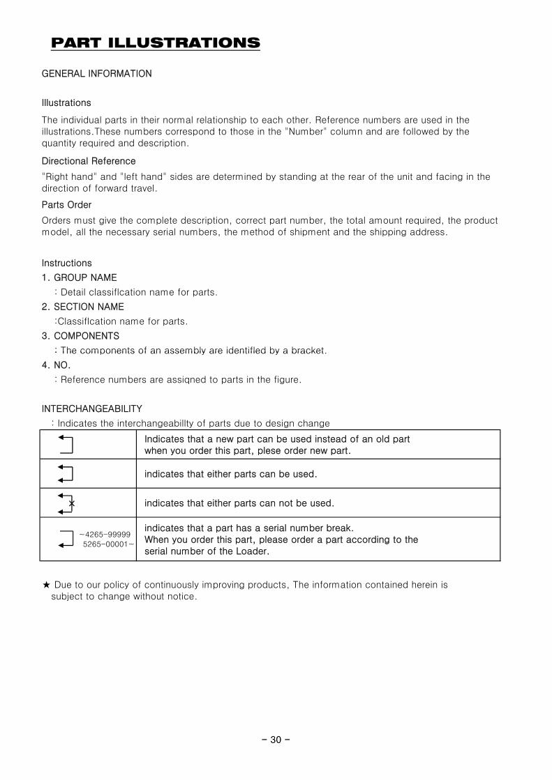
PART ILLUSTRATIONS
GENERAL INFORMATION
Illustrations
Directional Reference
Parts Order
Instructions
1. GROUP NAME
: Detail classiflcation name for parts.
2. SECTION NAME
:Classiflcation name for parts.
3. COMPONENTS
: The components of an assembly are identifled by a bracket.
The individual parts in their normal relationship to each other. Reference numbers are used in theillustrations.These numbers correspond to those in the "Number" column and are followed by thequantity required and description.
"Right hand" and "left hand" sides are determined by standing at the rear of the unit and facing in thedirection of forward travel.
Orders must give the complete description, correct part number, the total amount required, the productmodel, all the necessary serial numbers, the method of shipment and the shipping address.
- 30 -
: The components of an assembly are identifled by a bracket.
4. NO.
: Reference numbers are assiqned to parts in the figure.
INTERCHANGEABILITY
: Indicates the interchangeabillty of parts due to design change
indicates that either parts can be used.
indicates that either parts can not be used.
Indicates that a new part can be used instead of an old part when you order this part, plese order new part.
★ Due to our policy of continuously improving products, The information contained herein is subject to change without notice.
~4265-99999 5265-00001~
indicates that a part has a serial number break. When you order this part, please order a part according to the serial number of the Loader.
- 30 -
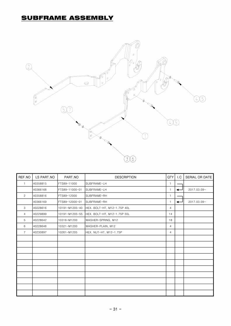
SUBFRAME ASSEMBLY
- 31 -
REF.NO LS PART.NO PART.NO DESCRIPTION QTY I.C SERIAL OR DATE
1 40358815 FTS89-11000 SUBFRAME-LH 1
40366168 FTS89-11000-01 SUBFRAME-LH 1 2017.03.09~
2 40358816 FTS89-12000 SUBFRAME-RH 1
40366169 FTS89-12000-01 SUBFRAME-RH 1 2017.03.09~
3 40228616 10191-M1205-40 HEX. BOLT-HT, M12-1.75P 40L 4
4 40229899 10191-M1205-55 HEX. BOLT-HT, M12-1.75P 55L 14
5 40228642 10316-M1200 WASHER-SPRING, M12 18
6 40228648 10321-M1200 WASHER-PLAIN, M12 4
7 40230897 10261-M1205 HEX. NUT-HT, M12-1.75P 4
- 31 -
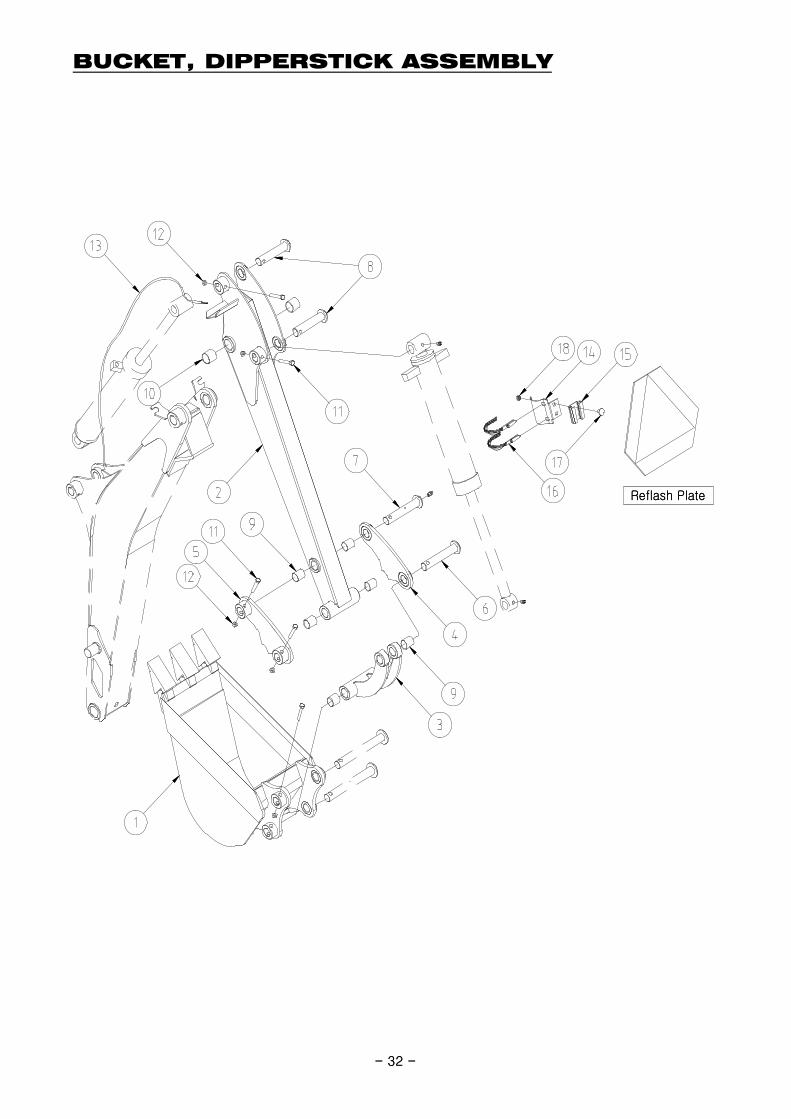
BUCKET, DIPPERSTICK ASSEMBLY
Reflash Plate
- 32 -
Reflash Plate
- 32 -
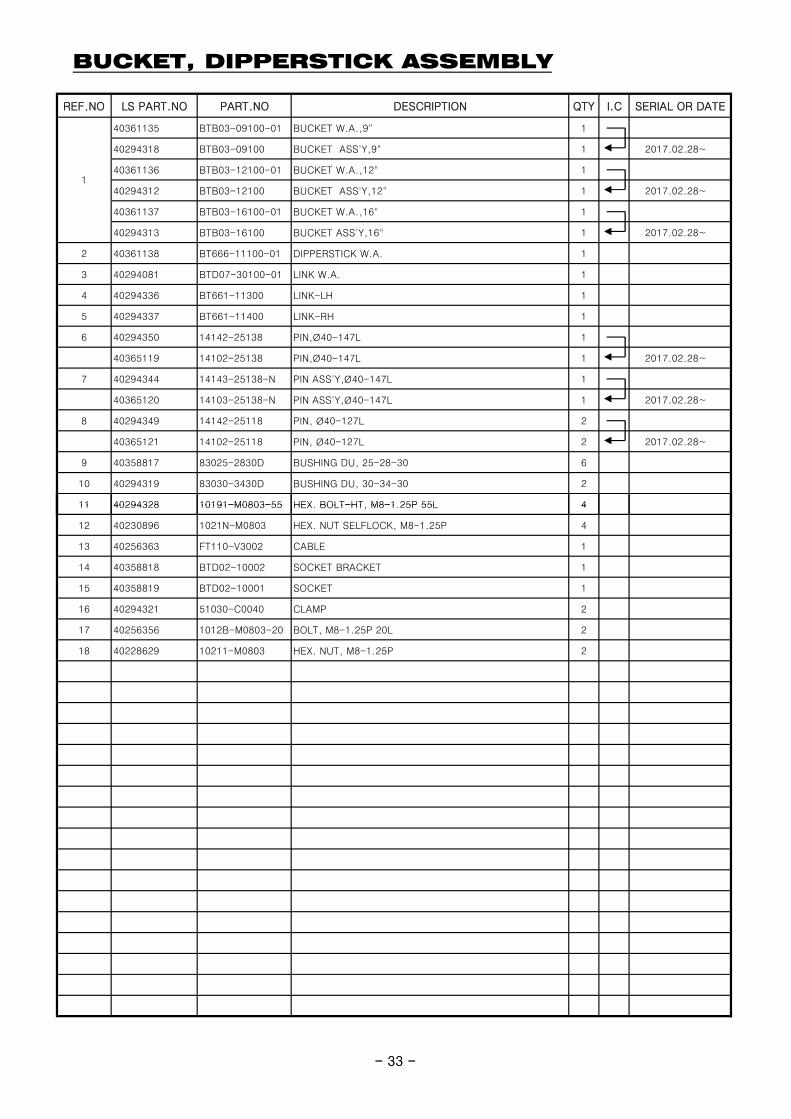
BUCKET, DIPPERSTICK ASSEMBLY
REF.NO LS PART.NO PART.NO DESCRIPTION QTY I.C SERIAL OR DATE
40361135 BTB03-09100-01 BUCKET W.A.,9" 1
40294318 BTB03-09100 BUCKET ASS'Y,9" 1 2017.02.28~
40361136 BTB03-12100-01 BUCKET W.A.,12" 1
40294312 BTB03-12100 BUCKET ASS'Y,12" 1 2017.02.28~
40361137 BTB03-16100-01 BUCKET W.A.,16" 1
40294313 BTB03-16100 BUCKET ASS'Y,16" 1 2017.02.28~
2 40361138 BT666-11100-01 DIPPERSTICK W.A. 1
3 40294081 BTD07-30100-01 LINK W.A. 1
4 40294336 BT661-11300 LINK-LH 1
5 40294337 BT661-11400 LINK-RH 1
6 40294350 14142-25138 PIN,Ø40-147L 1
40365119 14102-25138 PIN,Ø40-147L 1 2017.02.28~
7 40294344 14143-25138-N PIN ASS'Y,Ø40-147L 1
40365120 14103-25138-N PIN ASS'Y,Ø40-147L 1 2017.02.28~
8 40294349 14142-25118 PIN, Ø40-127L 2
40365121 14102-25118 PIN, Ø40-127L 2 2017.02.28~
9 40358817 83025-2830D BUSHING DU, 25-28-30 6
10 40294319 83030-3430D BUSHING DU, 30-34-30 2
11 40294328 10191-M0803-55 HEX BOLT-HT M8-1 25P 55L 4
1
- 33 -
11 40294328 10191-M0803-55 HEX. BOLT-HT, M8-1.25P 55L 4
12 40230896 1021N-M0803 HEX. NUT SELFLOCK, M8-1.25P 4
13 40256363 FT110-V3002 CABLE 1
14 40358818 BTD02-10002 SOCKET BRACKET 1
15 40358819 BTD02-10001 SOCKET 1
16 40294321 51030-C0040 CLAMP 2
17 40256356 1012B-M0803-20 BOLT, M8-1.25P 20L 2
18 40228629 10211-M0803 HEX. NUT, M8-1.25P 2
- 33 -
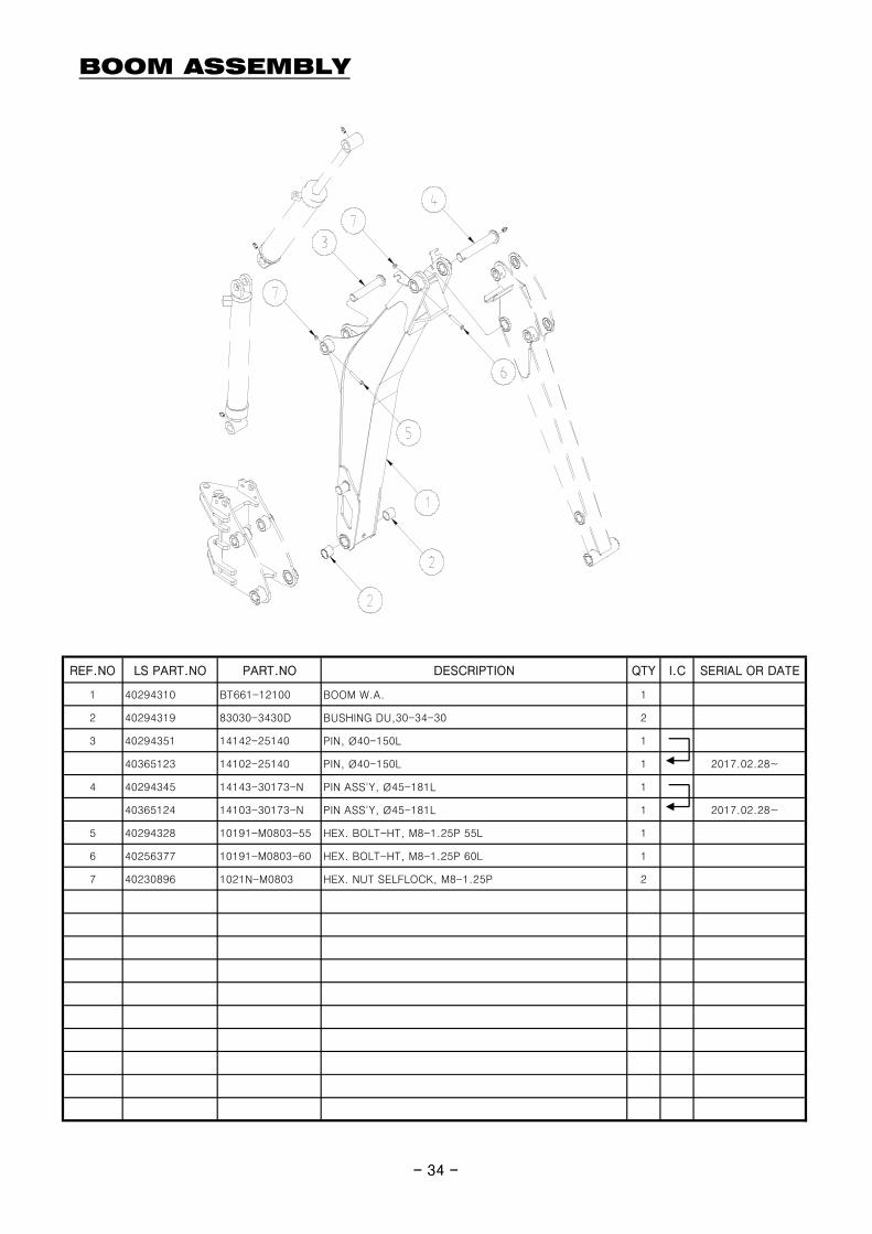
BOOM ASSEMBLY
- 34 -
REF.NO LS PART.NO PART.NO DESCRIPTION QTY I.C SERIAL OR DATE
1 40294310 BT661-12100 BOOM W.A. 1
2 40294319 83030-3430D BUSHING DU,30-34-30 2
3 40294351 14142-25140 PIN, Ø40-150L 1
40365123 14102-25140 PIN, Ø40-150L 1 2017.02.28~
4 40294345 14143-30173-N PIN ASS'Y, Ø45-181L 1
40365124 14103-30173-N PIN ASS'Y, Ø45-181L 1 2017.02.28~
5 40294328 10191-M0803-55 HEX. BOLT-HT, M8-1.25P 55L 1
6 40256377 10191-M0803-60 HEX. BOLT-HT, M8-1.25P 60L 1
7 40230896 1021N-M0803 HEX. NUT SELFLOCK, M8-1.25P 2
- 34 -
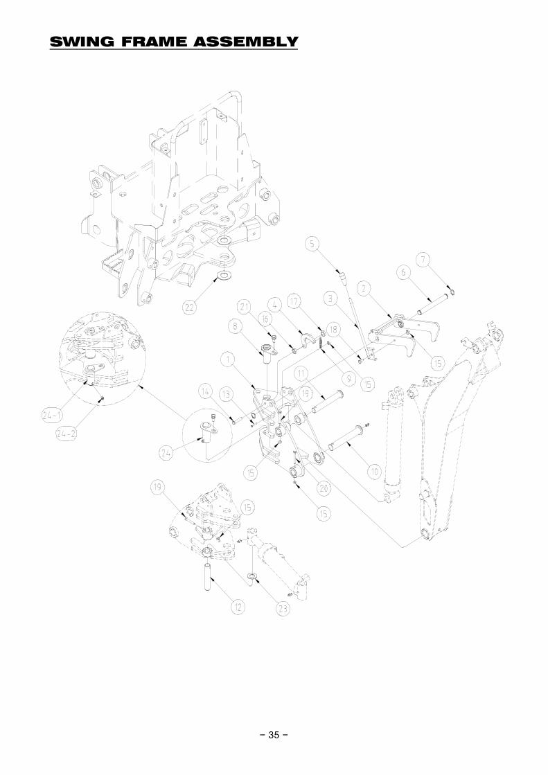
SWING FRAME ASSEMBLY
- 35 -
* Notice- Assemble pin first and
Grease Nipple.
- 35 -
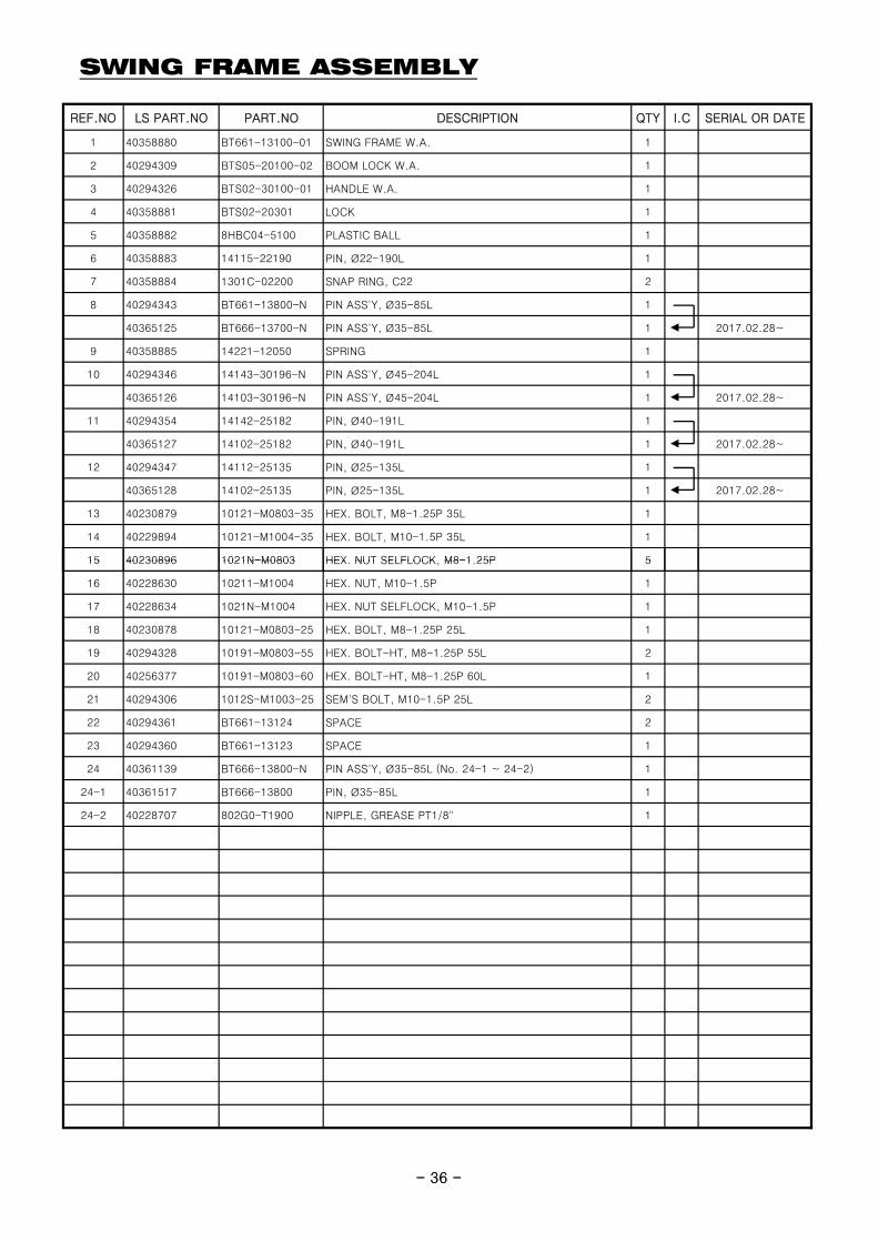
SWING FRAME ASSEMBLY
REF.NO LS PART.NO PART.NO DESCRIPTION QTY I.C SERIAL OR DATE
1 40358880 BT661-13100-01 SWING FRAME W.A. 1
2 40294309 BTS05-20100-02 BOOM LOCK W.A. 1
3 40294326 BTS02-30100-01 HANDLE W.A. 1
4 40358881 BTS02-20301 LOCK 1
5 40358882 8HBC04-5100 PLASTIC BALL 1
6 40358883 14115-22190 PIN, Ø22-190L 1
7 40358884 1301C-02200 SNAP RING, C22 2
8 40294343 BT661-13800-N PIN ASS'Y, Ø35-85L 1
40365125 BT666-13700-N PIN ASS'Y, Ø35-85L 1 2017.02.28~
9 40358885 14221-12050 SPRING 1
10 40294346 14143-30196-N PIN ASS'Y, Ø45-204L 1
40365126 14103-30196-N PIN ASS'Y, Ø45-204L 1 2017.02.28~
11 40294354 14142-25182 PIN, Ø40-191L 1
40365127 14102-25182 PIN, Ø40-191L 1 2017.02.28~
12 40294347 14112-25135 PIN, Ø25-135L 1
40365128 14102-25135 PIN, Ø25-135L 1 2017.02.28~
13 40230879 10121-M0803-35 HEX. BOLT, M8-1.25P 35L 1
14 40229894 10121-M1004-35 HEX. BOLT, M10-1.5P 35L 1
15 40230896 1021N-M0803 HEX NUT SELFLOCK M8-1 25P 5
- 36 -
15 40230896 1021N-M0803 HEX. NUT SELFLOCK, M8-1.25P 5
16 40228630 10211-M1004 HEX. NUT, M10-1.5P 1
17 40228634 1021N-M1004 HEX. NUT SELFLOCK, M10-1.5P 1
18 40230878 10121-M0803-25 HEX. BOLT, M8-1.25P 25L 1
19 40294328 10191-M0803-55 HEX. BOLT-HT, M8-1.25P 55L 2
20 40256377 10191-M0803-60 HEX. BOLT-HT, M8-1.25P 60L 1
21 40294306 1012S-M1003-25 SEM'S BOLT, M10-1.5P 25L 2
22 40294361 BT661-13124 SPACE 2
23 40294360 BT661-13123 SPACE 1
24 40361139 BT666-13800-N PIN ASS'Y, Ø35-85L (No. 24-1 ~ 24-2) 1
24-1 40361517 BT666-13800 PIN, Ø35-85L 1
24-2 40228707 802G0-T1900 NIPPLE, GREASE PT1/8" 1
- 36 -
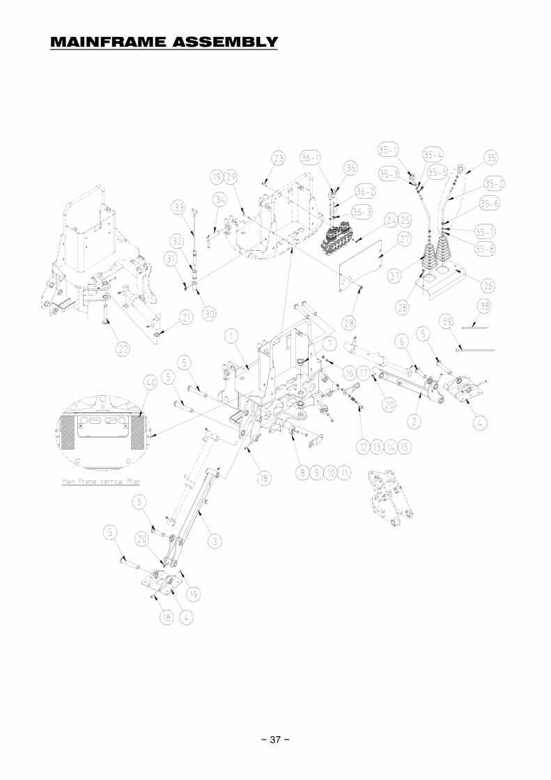
MAINFRAME ASSEMBLY
- 37 -- 37 -
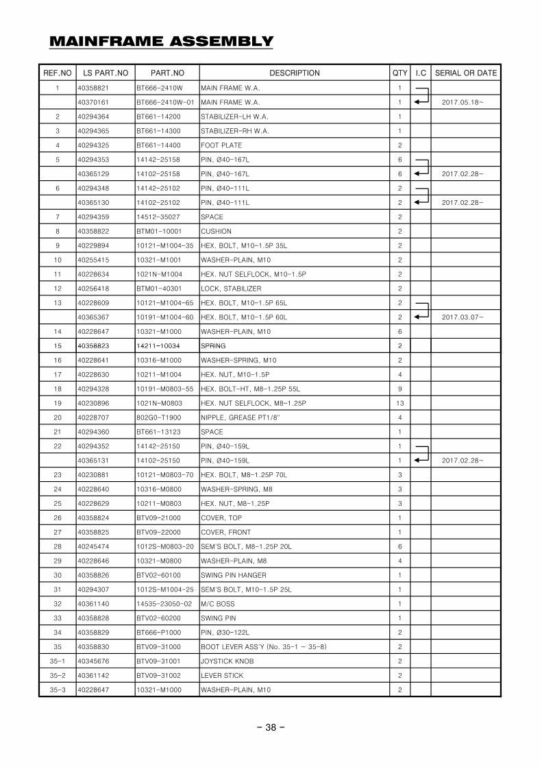
MAINFRAME ASSEMBLY
REF.NO LS PART.NO PART.NO DESCRIPTION QTY I.C SERIAL OR DATE
1 40358821 BT666-2410W MAIN FRAME W.A. 1
40370161 BT666-2410W-01 MAIN FRAME W.A. 1 2017.05.18~
2 40294364 BT661-14200 STABILIZER-LH W.A. 1
3 40294365 BT661-14300 STABILIZER-RH W.A. 1
4 40294325 BT661-14400 FOOT PLATE 2
5 40294353 14142-25158 PIN, Ø40-167L 6
40365129 14102-25158 PIN, Ø40-167L 6 2017.02.28~
6 40294348 14142-25102 PIN, Ø40-111L 2
40365130 14102-25102 PIN, Ø40-111L 2 2017.02.28~
7 40294359 14512-35027 SPACE 2
8 40358822 BTM01-10001 CUSHION 2
9 40229894 10121-M1004-35 HEX. BOLT, M10-1.5P 35L 2
10 40255415 10321-M1001 WASHER-PLAIN, M10 2
11 40228634 1021N-M1004 HEX. NUT SELFLOCK, M10-1.5P 2
12 40256418 BTM01-40301 LOCK, STABILIZER 2
13 40228609 10121-M1004-65 HEX. BOLT, M10-1.5P 65L 2
40365367 10191-M1004-60 HEX. BOLT, M10-1.5P 60L 2 2017.03.07~
14 40228647 10321-M1000 WASHER-PLAIN, M10 6
15 40358823 14211-10034 SPRING 2
- 38 -
15 40358823 14211-10034 SPRING 2
16 40228641 10316-M1000 WASHER-SPRING, M10 2
17 40228630 10211-M1004 HEX. NUT, M10-1.5P 4
18 40294328 10191-M0803-55 HEX. BOLT-HT, M8-1.25P 55L 9
19 40230896 1021N-M0803 HEX. NUT SELFLOCK, M8-1.25P 13
20 40228707 802G0-T1900 NIPPLE, GREASE PT1/8" 4
21 40294360 BT661-13123 SPACE 1
22 40294352 14142-25150 PIN, Ø40-159L 1
40365131 14102-25150 PIN, Ø40-159L 1 2017.02.28~
23 40230881 10121-M0803-70 HEX. BOLT, M8-1.25P 70L 3
24 40228640 10316-M0800 WASHER-SPRING, M8 3
25 40228629 10211-M0803 HEX. NUT, M8-1.25P 3
26 40358824 BTV09-21000 COVER, TOP 1
27 40358825 BTV09-22000 COVER, FRONT 1
28 40245474 1012S-M0803-20 SEM'S BOLT, M8-1.25P 20L 6
29 40228646 10321-M0800 WASHER-PLAIN, M8 4
30 40358826 BTV02-60100 SWING PIN HANGER 1
31 40294307 1012S-M1004-25 SEM'S BOLT, M10-1.5P 25L 1
32 40361140 14535-23050-02 M/C BOSS 1
33 40358828 BTV02-60200 SWING PIN 1
34 40358829 BT666-P1000 PIN, Ø30-122L 2
35 40358830 BTV09-31000 BOOT LEVER ASS'Y (No. 35-1 ~ 35-8) 2
35-1 40345676 BTV09-31001 JOYSTICK KNOB 2
35-2 40361142 BTV09-31002 LEVER STICK 2
35-3 40228647 10321-M1000 WASHER-PLAIN, M10 2
- 38 -
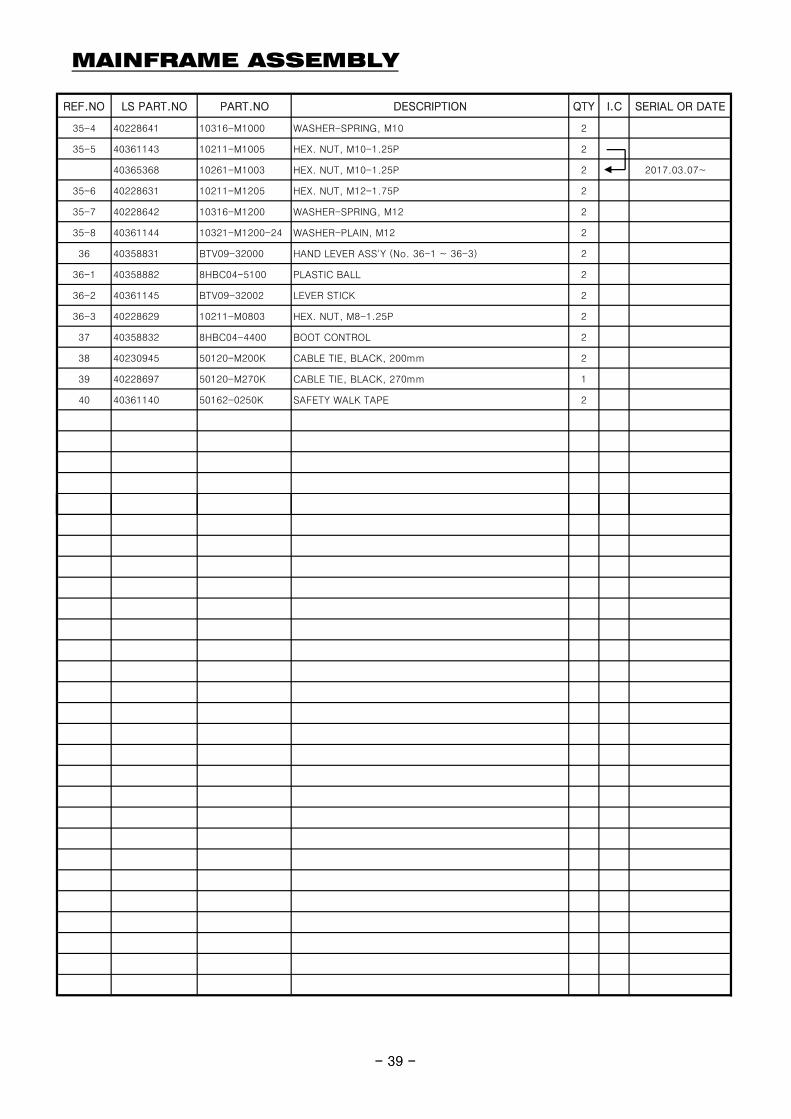
MAINFRAME ASSEMBLY
REF.NO LS PART.NO PART.NO DESCRIPTION QTY I.C SERIAL OR DATE
35-4 40228641 10316-M1000 WASHER-SPRING, M10 2
35-5 40361143 10211-M1005 HEX. NUT, M10-1.25P 2
40365368 10261-M1003 HEX. NUT, M10-1.25P 2 2017.03.07~
35-6 40228631 10211-M1205 HEX. NUT, M12-1.75P 2
35-7 40228642 10316-M1200 WASHER-SPRING, M12 2
35-8 40361144 10321-M1200-24 WASHER-PLAIN, M12 2
36 40358831 BTV09-32000 HAND LEVER ASS'Y (No. 36-1 ~ 36-3) 2
36-1 40358882 8HBC04-5100 PLASTIC BALL 2
36-2 40361145 BTV09-32002 LEVER STICK 2
36-3 40228629 10211-M0803 HEX. NUT, M8-1.25P 2
37 40358832 8HBC04-4400 BOOT CONTROL 2
38 40230945 50120-M200K CABLE TIE, BLACK, 200mm 2
39 40228697 50120-M270K CABLE TIE, BLACK, 270mm 1
40 40361140 50162-0250K SAFETY WALK TAPE 2
- 39 -- 39 -
HOSE FITTING ASSEMBLY
- 40 -- 40 -
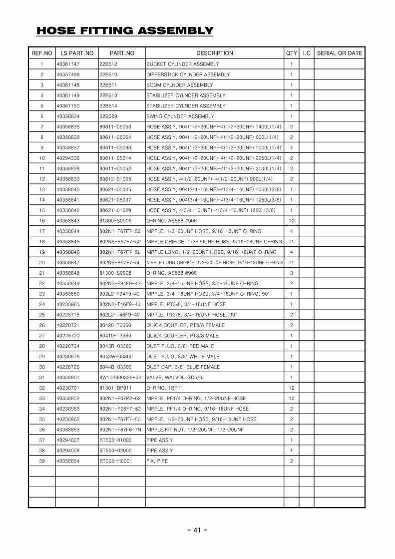
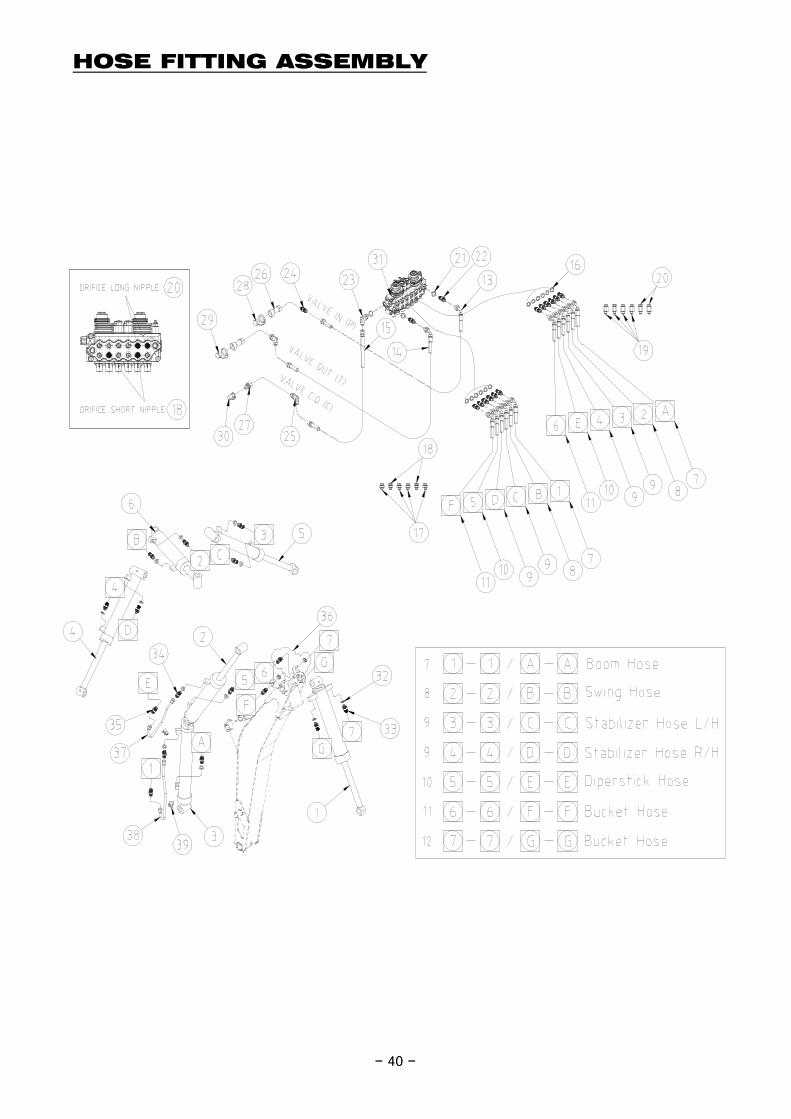
HOSE FITTING ASSEMBLY
REF.NO LS PART.NO PART.NO DESCRIPTION QTY I.C SERIAL OR DATE
1 40361147 22B512 BUCKET CYLINDER ASSEMBLY 1
2 40357498 22B510 DIPPERSTICK CYLNDER ASSEMBLY 1
3 40361148 22B511 BOOM CYLNDER ASSEMBLY 1
4 40361149 22B513 STABILIZER CYLNDER ASSEMBLY 1
5 40361150 22B514 STABILIZER CYLNDER ASSEMBLY 1
6 40358834 22B509 SWING CYLNDER ASSEMBLY 1
7 40358835 80611-05053 HOSE ASS'Y, 904(1/2-20UNF)-4(1/2-20UNF) 1400L(1/4) 2
8 40358836 80611-05054 HOSE ASS'Y, 904(1/2-20UNF)-4(1/2-20UNF) 600L(1/4) 2
9 40358837 80611-05096 HOSE ASS'Y, 904(1/2-20UNF)-4(1/2-20UNF) 1000L(1/4) 4
10 40294332 80611-05014 HOSE ASS'Y, 904(1/2-20UNF)-4(1/2-20UNF) 2250L(1/4) 2
11 40358838 80611-05052 HOSE ASS'Y, 904(1/2-20UNF)-4(1/2-20UNF) 2100L(1/4) 2
12 40358839 80612-01005 HOSE ASS'Y, 4(1/2-20UNF)-4(1/2-20UNF) 900L(1/4) 2
13 40358840 80621-05045 HOSE ASS'Y, 904(3/4-16UNF)-4(3/4-16UNF) 1050L(3/8) 1
14 40358841 80621-05037 HOSE ASS'Y, 904(3/4-16UNF)-4(3/4-16UNF) 1250L(3/8) 1
15 40358842 80621-01029 HOSE ASS'Y, 4(3/4-16UNF)-4(3/4-16UNF) 1250L(3/8) 1
16 40358843 81300-S0906 O-RING, AS568 #906 12
17 40358844 802N1-F67F7-52 NIPPLE, 1/2-20UNF HOSE, 9/16-18UNF O-RING 4
18 40358845 802NS-F67F7-52 NIPPLE ORIFICE, 1/2-20UNF HOSE, 9/16-18UNF O-RING 2
19 40358846 802N1-F67F7-5L NIPPLE LONG 1/2-20UNF HOSE 9/16-18UNF O-RING 4
- 41 -
19 40358846 802N1-F67F7-5L NIPPLE LONG, 1/2-20UNF HOSE, 9/16-18UNF O-RING 4
20 40358847 802NS-F67F7-5L NIPPLE LONG ORIFICE, 1/2-20UNF HOSE, 9/16-18UNF O-RING 2
21 40358848 81300-S0908 O-RING, AS568 #908 3
22 40358849 802N2-F94F9-42 NIPPLE, 3/4-16UNF HOSE, 3/4-16UNF O-RING 2
23 40358850 802L2-F94F9-42 NIPPLE, 3/4-16UNF HOSE, 3/4-16UNF O-RING, 90° 1
24 40230965 802N2-T46F9-40 NIPPLE, PT3/8, 3/4-16UNF HOSE 1
25 40228715 802L2-T46F9-40 NIPPLE, PT3/8, 3/4-16UNF HOSE, 90° 2
26 40228721 80420-T3360 QUICK COUPLER, PT3/8 FEMALE 2
27 40228720 80410-T3360 QUICK COUPLER, PT3/8 MALE 1
28 40228724 8043R-03300 DUST PLUG, 3/8" RED MALE 1
29 40230676 8043W-03300 DUST PLUG, 3/8" WHITE MALE 1
30 40228726 8044B-03300 DUST CAP, 3/8" BLUE FEMALE 1
31 40358851 8W102600339-02 VALVE, WALVOIL SD5/6 1
32 40230701 81301-BP011 O-RING, 1BP11 12
33 40358852 802N1-F67P2-62 NIPPLE, PF1/4 O-RING, 1/2-20UNF HOSE 10
34 40230963 802N1-P26F7-52 NIPPLE, PF1/4 O-RING, 9/16-18UNF HOSE 2
35 40230962 802N1-F67F7-50 NIPPLE, 1/2-20UNF HOSE, 9/16-18UNF HOSE 2
36 40358853 802N1-F67F6-7N NIPPLE KIT NUT, 1/2-20UNF, 1/2-20UNF 2
37 40294007 BT500-01000 PIPE ASS'Y 1
38 40294008 BT500-02000 PIPE ASS'Y 1
39 40358854 BT005-H0001 FIX, PIPE 2
- 41 -
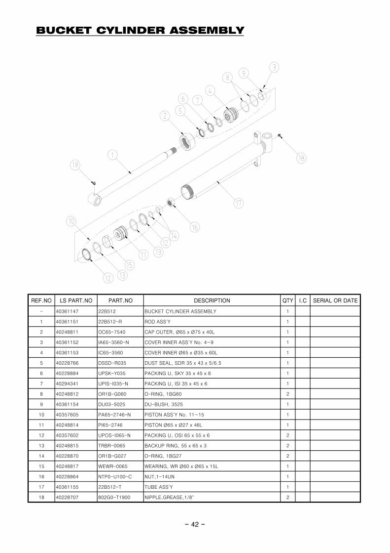
BUCKET CYLINDER ASSEMBLY
- 42 -
REF.NO LS PART.NO PART.NO DESCRIPTION QTY I.C SERIAL OR DATE
- 40361147 22B512 BUCKET CYLINDER ASSEMBLY 1
1 40361151 22B512-R ROD ASS'Y 1
2 40248811 OC65-7540 CAP OUTER, Ø65 x Ø75 x 40L 1
3 40361152 IA65-3560-N COVER INNER ASS'Y No. 4~9 1
4 40361153 IC65-3560 COVER INNER Ø65 x Ø35 x 60L 1
5 40228766 DSSD-R035 DUST SEAL, SDR 35 x 43 x 5/6.5 1
6 40228884 UPSK-Y035 PACKING U, SKY 35 x 45 x 6 1
7 40294341 UPIS-I035-N PACKING U, ISI 35 x 45 x 6 1
8 40248812 OR1B-G060 O-RING, 1BG60 2
9 40361154 DU03-5025 DU-BUSH, 3525 1
10 40357605 PA65-2746-N PISTON ASS'Y No. 11~15 1
11 40248814 PI65-2746 PISTON Ø65 x Ø27 x 46L 1
12 40357602 UPOS-I065-N PACKING U, OSI 65 x 55 x 6 2
13 40248815 TRBR-0065 BACKUP RING, 55 x 65 x 3 2
14 40228870 OR1B-G027 O-RING, 1BG27 2
15 40248817 WEWR-0065 WEARING, WR Ø60 x Ø65 x 15L 1
16 40228864 NTP0-U100-C NUT,1-14UN 1
17 40361155 22B512-T TUBE ASS'Y 1
18 40228707 802G0-T1900 NIPPLE,GREASE,1/8" 2
- 42 -
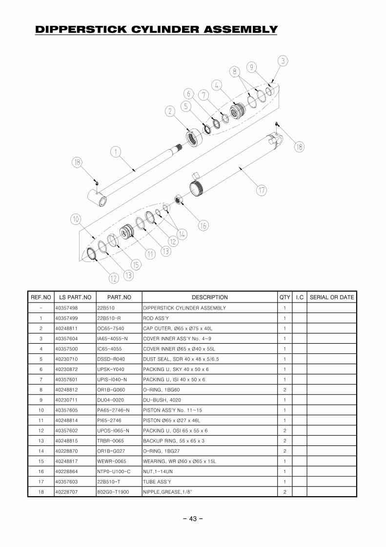
DIPPERSTICK CYLINDER ASSEMBLY
- 43 -
REF.NO LS PART.NO PART.NO DESCRIPTION QTY I.C SERIAL OR DATE
- 40357498 22B510 DIPPERSTICK CYLINDER ASSEMBLY 1
1 40357499 22B510-R ROD ASS'Y 1
2 40248811 OC65-7540 CAP OUTER, Ø65 x Ø75 x 40L 1
3 40357604 IA65-4055-N COVER INNER ASS'Y No. 4~9 1
4 40357500 IC65-4055 COVER INNER Ø65 x Ø40 x 55L 1
5 40230710 DSSD-R040 DUST SEAL, SDR 40 x 48 x 5/6.5 1
6 40230872 UPSK-Y040 PACKING U, SKY 40 x 50 x 6 1
7 40357601 UPIS-I040-N PACKING U, ISI 40 x 50 x 6 1
8 40248812 OR1B-G060 O-RING, 1BG60 2
9 40230711 DU04-0020 DU-BUSH, 4020 1
10 40357605 PA65-2746-N PISTON ASS'Y No. 11~15 1
11 40248814 PI65-2746 PISTON Ø65 x Ø27 x 46L 1
12 40357602 UPOS-I065-N PACKING U, OSI 65 x 55 x 6 2
13 40248815 TRBR-0065 BACKUP RING, 55 x 65 x 3 2
14 40228870 OR1B-G027 O-RING, 1BG27 2
15 40248817 WEWR-0065 WEARING, WR Ø60 x Ø65 x 15L 1
16 40228864 NTP0-U100-C NUT,1-14UN 1
17 40357603 22B510-T TUBE ASS'Y 1
18 40228707 802G0-T1900 NIPPLE,GREASE,1/8" 2
- 43 -
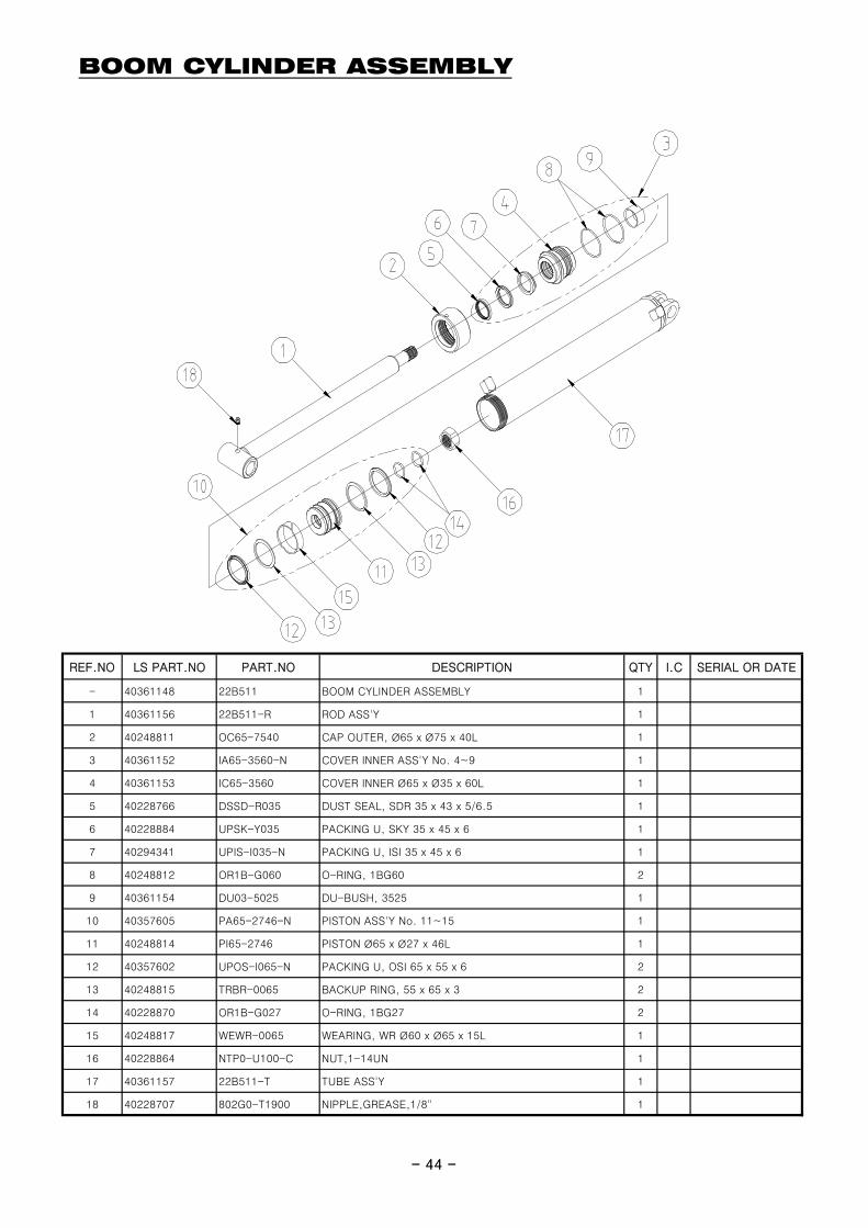
BOOM CYLINDER ASSEMBLY
- 44 -
REF.NO LS PART.NO PART.NO DESCRIPTION QTY I.C SERIAL OR DATE
- 40361148 22B511 BOOM CYLINDER ASSEMBLY 1
1 40361156 22B511-R ROD ASS'Y 1
2 40248811 OC65-7540 CAP OUTER, Ø65 x Ø75 x 40L 1
3 40361152 IA65-3560-N COVER INNER ASS'Y No. 4~9 1
4 40361153 IC65-3560 COVER INNER Ø65 x Ø35 x 60L 1
5 40228766 DSSD-R035 DUST SEAL, SDR 35 x 43 x 5/6.5 1
6 40228884 UPSK-Y035 PACKING U, SKY 35 x 45 x 6 1
7 40294341 UPIS-I035-N PACKING U, ISI 35 x 45 x 6 1
8 40248812 OR1B-G060 O-RING, 1BG60 2
9 40361154 DU03-5025 DU-BUSH, 3525 1
10 40357605 PA65-2746-N PISTON ASS'Y No. 11~15 1
11 40248814 PI65-2746 PISTON Ø65 x Ø27 x 46L 1
12 40357602 UPOS-I065-N PACKING U, OSI 65 x 55 x 6 2
13 40248815 TRBR-0065 BACKUP RING, 55 x 65 x 3 2
14 40228870 OR1B-G027 O-RING, 1BG27 2
15 40248817 WEWR-0065 WEARING, WR Ø60 x Ø65 x 15L 1
16 40228864 NTP0-U100-C NUT,1-14UN 1
17 40361157 22B511-T TUBE ASS'Y 1
18 40228707 802G0-T1900 NIPPLE,GREASE,1/8" 1
- 44 -
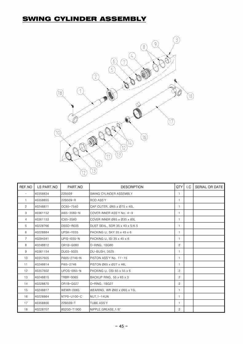
SWING CYLINDER ASSEMBLY
- 45 -
REF.NO LS PART.NO PART.NO DESCRIPTION QTY I.C SERIAL OR DATE
- 40358834 22B509 SWING CYLINDER ASSEMBLY 1
1 40358855 22B509-R ROD ASS'Y 1
2 40248811 OC65-7540 CAP OUTER, Ø65 x Ø75 x 40L 1
3 40361152 IA65-3560-N COVER INNER ASS'Y No. 4~9 1
4 40361153 IC65-3560 COVER INNER Ø65 x Ø35 x 60L 1
5 40228766 DSSD-R035 DUST SEAL, SDR 35 x 43 x 5/6.5 1
6 40228884 UPSK-Y035 PACKING U, SKY 35 x 45 x 6 1
7 40294341 UPIS-I035-N PACKING U, ISI 35 x 45 x 6 1
8 40248812 OR1B-G060 O-RING, 1BG60 2
9 40361154 DU03-5025 DU-BUSH, 3525 1
10 40357605 PA65-2746-N PISTON ASS'Y No. 11~15 1
11 40248814 PI65-2746 PISTON Ø65 x Ø27 x 46L 1
12 40357602 UPOS-I065-N PACKING U, OSI 65 x 55 x 6 2
13 40248815 TRBR-0065 BACKUP RING, 55 x 65 x 3 2
14 40228870 OR1B-G027 O-RING, 1BG27 2
15 40248817 WEWR-0065 WEARING, WR Ø60 x Ø65 x 15L 1
16 40228864 NTP0-U100-C NUT,1-14UN 1
17 40358856 22B509-T TUBE ASS'Y 1
18 40228707 802G0-T1900 NIPPLE,GREASE,1/8" 2
- 45 -
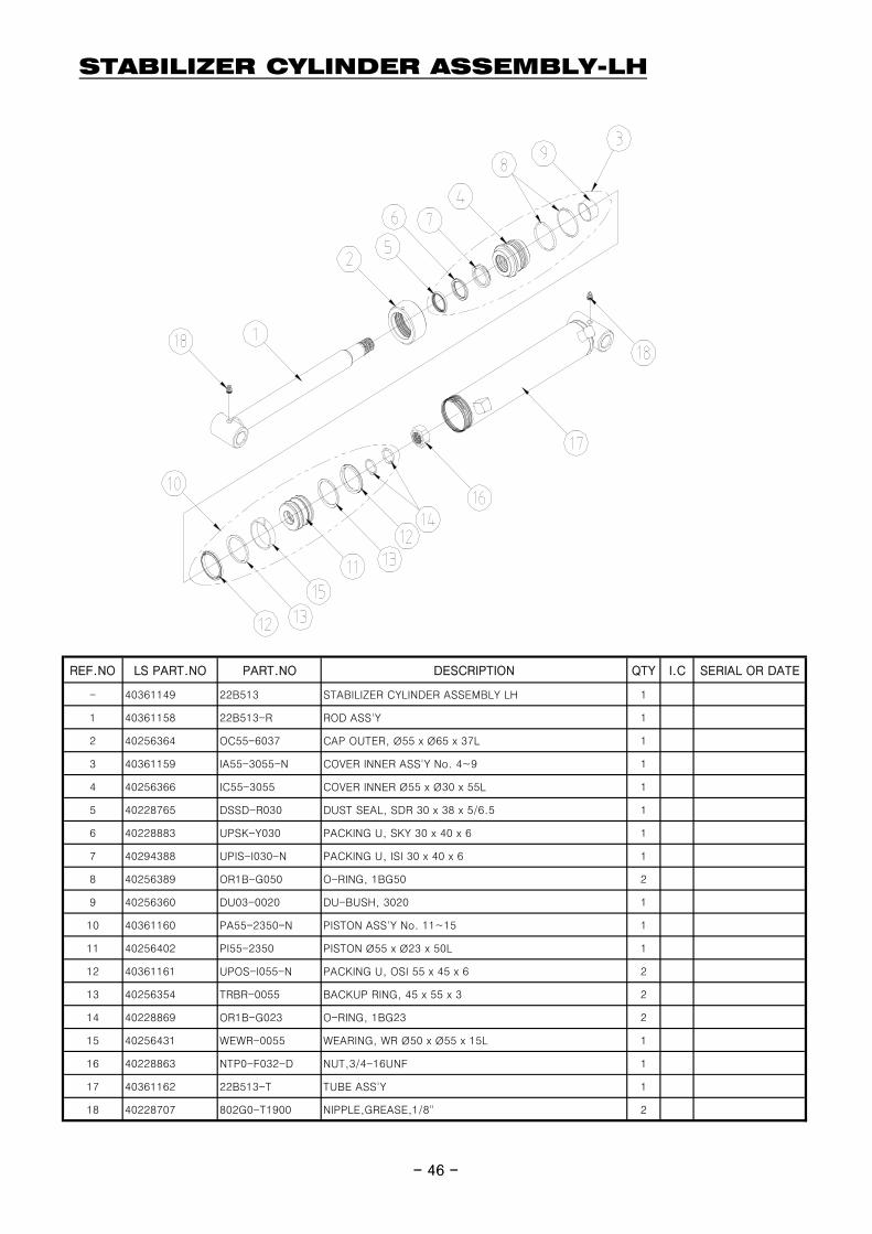
STABILIZER CYLINDER ASSEMBLY-LH
- 46 -
REF.NO LS PART.NO PART.NO DESCRIPTION QTY I.C SERIAL OR DATE
- 40361149 22B513 STABILIZER CYLINDER ASSEMBLY LH 1
1 40361158 22B513-R ROD ASS'Y 1
2 40256364 OC55-6037 CAP OUTER, Ø55 x Ø65 x 37L 1
3 40361159 IA55-3055-N COVER INNER ASS'Y No. 4~9 1
4 40256366 IC55-3055 COVER INNER Ø55 x Ø30 x 55L 1
5 40228765 DSSD-R030 DUST SEAL, SDR 30 x 38 x 5/6.5 1
6 40228883 UPSK-Y030 PACKING U, SKY 30 x 40 x 6 1
7 40294388 UPIS-I030-N PACKING U, ISI 30 x 40 x 6 1
8 40256389 OR1B-G050 O-RING, 1BG50 2
9 40256360 DU03-0020 DU-BUSH, 3020 1
10 40361160 PA55-2350-N PISTON ASS'Y No. 11~15 1
11 40256402 PI55-2350 PISTON Ø55 x Ø23 x 50L 1
12 40361161 UPOS-I055-N PACKING U, OSI 55 x 45 x 6 2
13 40256354 TRBR-0055 BACKUP RING, 45 x 55 x 3 2
14 40228869 OR1B-G023 O-RING, 1BG23 2
15 40256431 WEWR-0055 WEARING, WR Ø50 x Ø55 x 15L 1
16 40228863 NTP0-F032-D NUT,3/4-16UNF 1
17 40361162 22B513-T TUBE ASS'Y 1
18 40228707 802G0-T1900 NIPPLE,GREASE,1/8" 2
- 46 -
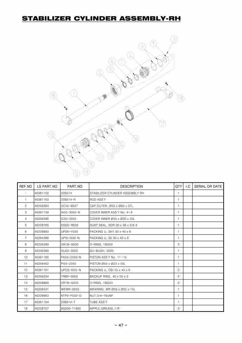
STABILIZER CYLINDER ASSEMBLY-RH
- 47 -
REF.NO LS PART.NO PART.NO DESCRIPTION QTY I.C SERIAL OR DATE
- 40361150 22B514 STABILIZER CYLINDER ASSEMBLY RH 1
1 40361163 22B514-R ROD ASS'Y 1
2 40256364 OC55-6037 CAP OUTER, Ø55 x Ø65 x 37L 1
3 40361159 IA55-3055-N COVER INNER ASS'Y No. 4~9 1
4 40256366 IC55-3055 COVER INNER Ø55 x Ø30 x 55L 1
5 40228765 DSSD-R030 DUST SEAL, SDR 30 x 38 x 5/6.5 1
6 40228883 UPSK-Y030 PACKING U, SKY 30 x 40 x 6 1
7 40294388 UPIS-I030-N PACKING U, ISI 30 x 40 x 6 1
8 40256389 OR1B-G050 O-RING, 1BG50 2
9 40256360 DU03-0020 DU-BUSH, 3020 1
10 40361160 PA55-2350-N PISTON ASS'Y No. 11~15 1
11 40256402 PI55-2350 PISTON Ø55 x Ø23 x 50L 1
12 40361161 UPOS-I055-N PACKING U, OSI 55 x 45 x 6 2
13 40256354 TRBR-0055 BACKUP RING, 45 x 55 x 3 2
14 40228869 OR1B-G023 O-RING, 1BG23 2
15 40256431 WEWR-0055 WEARING, WR Ø50 x Ø55 x 15L 1
16 40228863 NTP0-F032-D NUT,3/4-16UNF 1
17 40361164 22B514-T TUBE ASS'Y 1
18 40228707 802G0-T1900 NIPPLE,GREASE,1/8" 2
- 47 -

CONTROL VALVE ASSEMBLY-WALVOL SD 5/6
- 48 -- 48 -

CONTROL VALVE ASSEMBLY-WALVOL SD 5/6
REF.NO LS PART.NO PART.NO DESCRIPTION QTY I.C SERIAL OR DATE
- 40358851 8W102600339-02 VALVE, WALVOIL SD5/6 1
2 40358857 3CU1210230 SPOOL 1CEX/SD5 6
9 40358858 3XGIU527470 CONNECTOR AE/SD5-SAE8 1
11 40358859 3XTAP822150-K PLUG TCEI SAE8 2
28 40358860 5V08105000 KIT COMANDO 8/S5 6
29 40358861 5KC1357000 KCO SD5/6-P/SAE 1
30 40358862 5KIT105413-H KIT VALVOLAVMD5/1(JG3) 1
31 40358863 5LEV105000S KIT LEVALSG/S5 2
32 40358864 5CLO305101-W SD5 LCN KIT(LCN2, LCN3) 2
- 49 -- 49 -
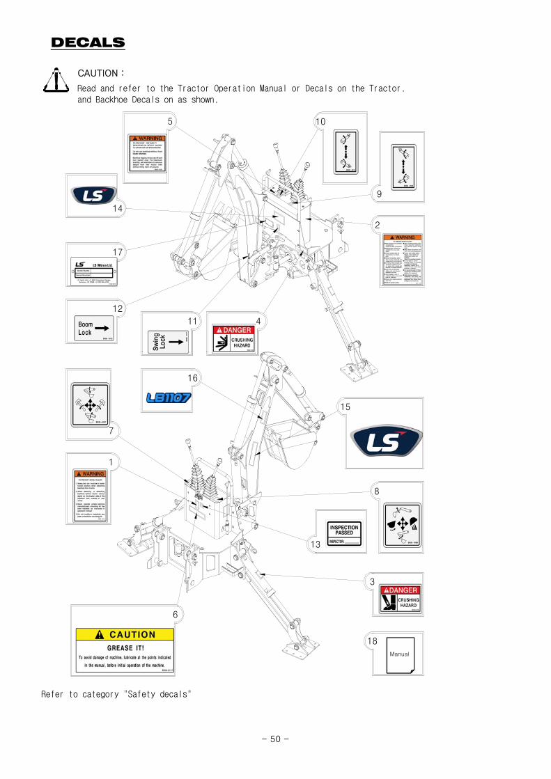
DECALS
CAUTION :
Read and refer to the Tractor Operation Manual or Decals on the Tractor.and Backhoe Decals on as shown.
5 10
9
2
17
14
12
11 4
Refer to category "Safety decals"
Manual
1
16
7
6
8
13
3
15
18
- 50 -
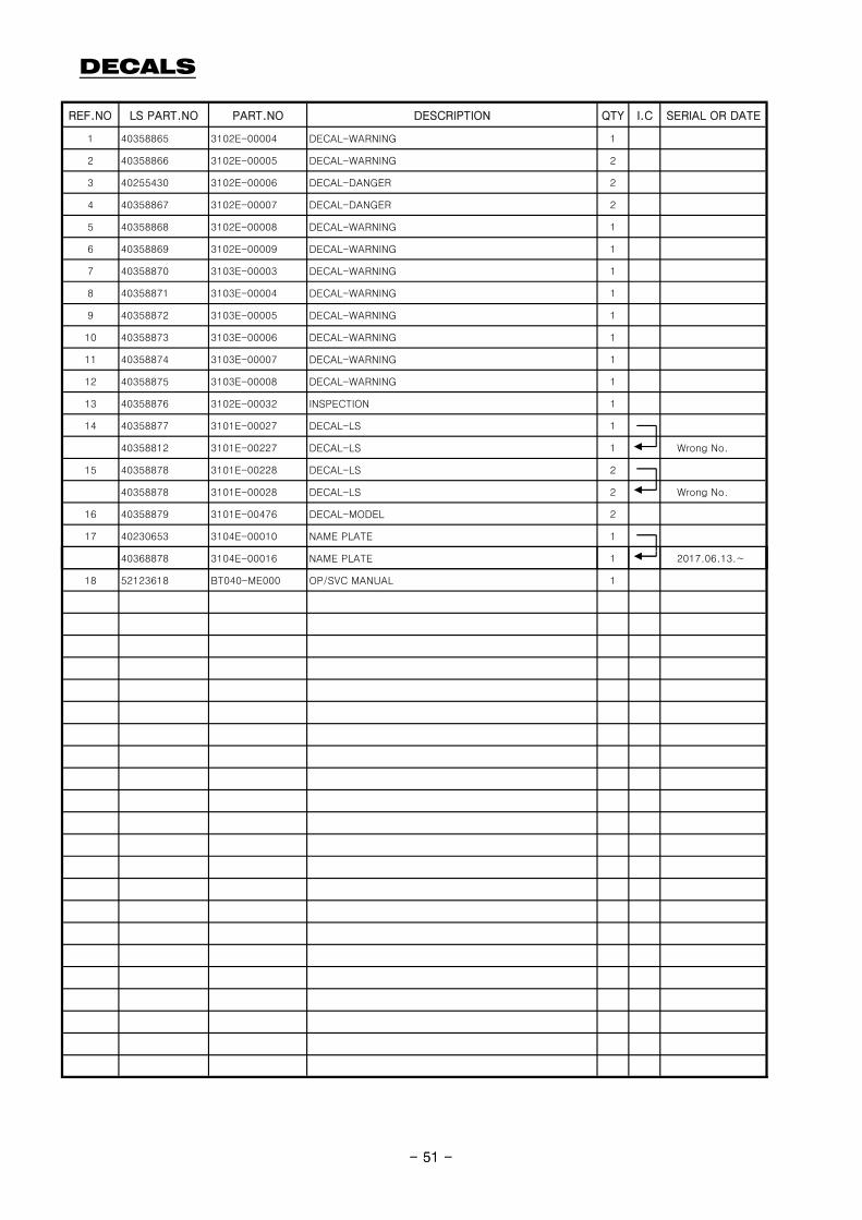
DECALS
REF.NO LS PART.NO PART.NO DESCRIPTION QTY I.C SERIAL OR DATE
1 40358865 3102E-00004 DECAL-WARNING 1
2 40358866 3102E-00005 DECAL-WARNING 2
3 40255430 3102E-00006 DECAL-DANGER 2
4 40358867 3102E-00007 DECAL-DANGER 2
5 40358868 3102E-00008 DECAL-WARNING 1
6 40358869 3102E-00009 DECAL-WARNING 1
7 40358870 3103E-00003 DECAL-WARNING 1
8 40358871 3103E-00004 DECAL-WARNING 1
9 40358872 3103E-00005 DECAL-WARNING 1
10 40358873 3103E-00006 DECAL-WARNING 1
11 40358874 3103E-00007 DECAL-WARNING 1
12 40358875 3103E-00008 DECAL-WARNING 1
13 40358876 3102E-00032 INSPECTION 1
14 40358877 3101E-00027 DECAL-LS 1
40358812 3101E-00227 DECAL-LS 1 Wrong No.
15 40358878 3101E-00228 DECAL-LS 2
40358878 3101E-00028 DECAL-LS 2 Wrong No.
16 40358879 3101E-00476 DECAL-MODEL 2
17 40230653 3104E-00010 NAME PLATE 1
- 51 -
40368878 3104E-00016 NAME PLATE 1 2017.06.13.~
18 52123618 BT040-ME000 OP/SVC MANUAL 1
- 51 -
SERVICE MANUAL(TERMINONOGY)
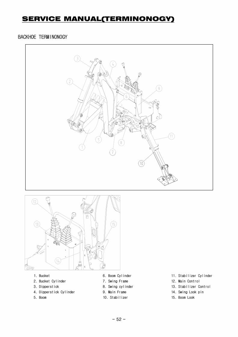
BACKHOE TERMINONOGY
- 52 -
1. Bucket 6. Boom Cylinder 11. Stabilizer Cylinder
2. Bucket Cylinder 7. Swing Frame 12. Main Control
3. Dipperstick 8. Swing cylinder 13. Stabilizer Control
4. Dipperstick Cylinder 9. Main Frame 14. Swing Look pin
5. Boom 10. Stabilizer 15. Boom Look
- 52 -
SERVICE MANUAL(COMPONENTS)
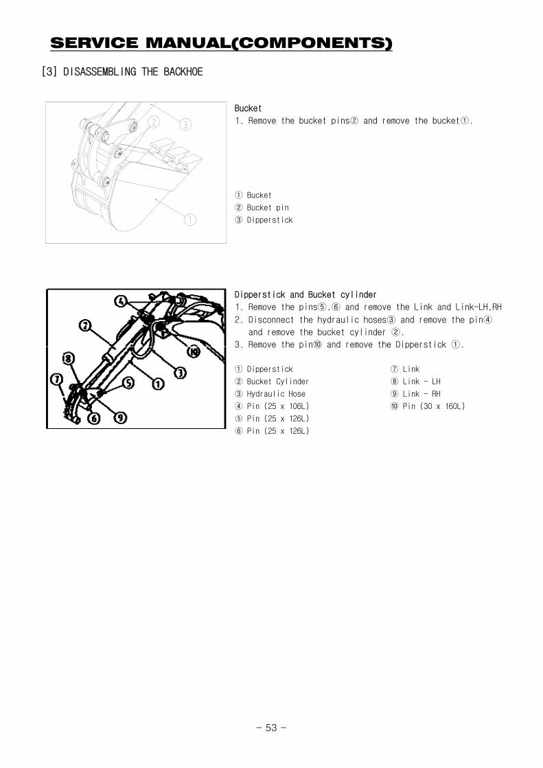
[3] DISASSEMBLING THE BACKHOE
① Bucket
② Bucket pin
③ Dipperstick
2. Disconnect the hydraulic hoses③ and remove the pin④
and remove the bucket cylinder ②.
3. Remove the pin⑩ and remove the Dipperstick ①.
Bucket
1. Remove the bucket pins② and remove the bucket①.
Dipperstick and Bucket cylinder
1. Remove the pins⑤,⑥ and remove the Link and Link-LH,RH
3. Remove the pin⑩ and remove the Dipperstick ①.
① Dipperstick ⑦ Link
② Bucket Cylinder ⑧ Link - LH
③ Hydraulic Hose ⑨ Link - RH
④ Pin (25 x 106L) ⑩ Pin (30 x 160L)
⑤ Pin (25 x 126L)
⑥ Pin (25 x 126L)
- 53 -
SERVICE MANUAL(COMPONENTS)
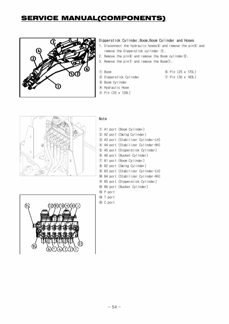
1. Disconnect the hydraulic hoses④ and remove the pin⑤ and
remove the Dipperstick cylinder ②.
2. Remove the pin⑥ and remove the Boom cylinder③.
3. Remove the pin⑦ and remove the Boom①.
① Boom ⑥ Pin (25 x 170L)
② Dipperstick Cylinder ⑦ Pin (30 x 183L)
③ Boom Cylinder
④ Hydraulic Hose
⑤ Pin (25 x 129L)
① A1 port (Boom Cylinder)
② A2 port (Swing Cylinder)
③ A3 port (Stabilizer Cylinder-LH)
④ A4 port (Stabilizer Cylinder-RH)
Dipperstick Cylinder,Boom,Boom Cylinder and Hoses
Note
④ p ( y )
⑤ A5 port (Dipperstick Cylinder)
⑥ A6 port (Bucket Cylinder)
⑦ B1 port (Boom Cylinder)
⑧ B2 port (Swing Cylinder)
⑨ B3 port (Stabilizer Cylinder-LH)
⑩ B4 port (Stabilizer Cylinder-RH)
⑪ B5 port (Dipperstick Cylinder)
⑫ B6 port (Bucket Cylinder)
⑬ P port
⑭ T port
⑮ C port
- 54 -
SERVICE MANUAL(COMPONENTS)
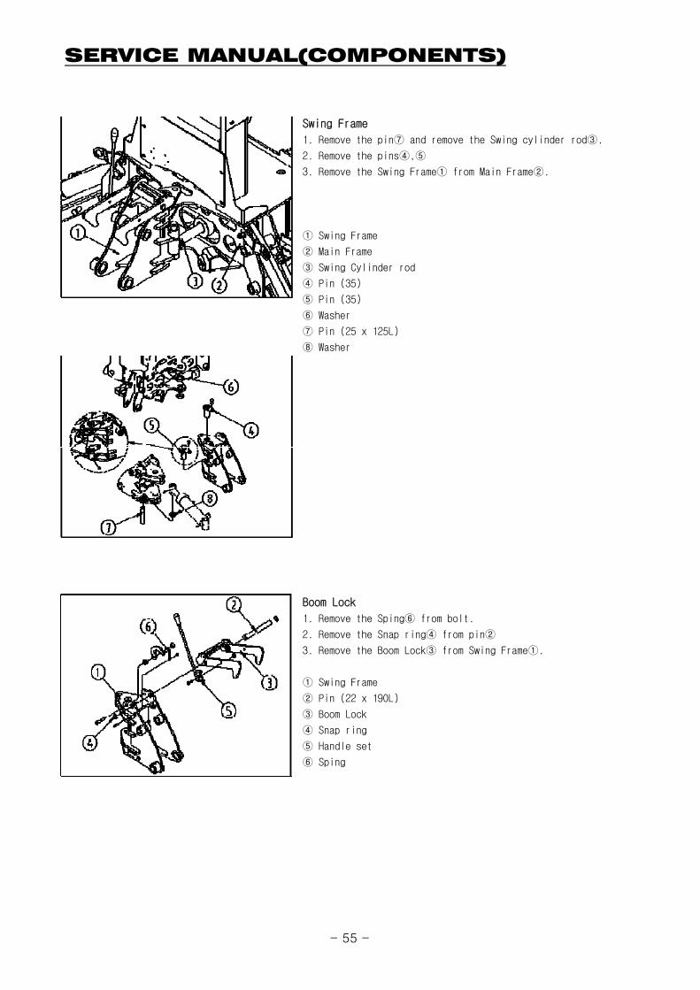
1. Remove the pin⑦ and remove the Swing cylinder rod③.
2. Remove the pins④,⑤
3. Remove the Swing Frame① from Main Frame②.
① Swing Frame
② Main Frame
③ Swing Cylinder rod
④ Pin (35)
⑤ Pin (35)
⑥ Washer
⑦ Pin (25 x 125L)
⑧ Washer
Swing Frame
1. Remove the Sping⑥ from bolt.
2. Remove the Snap ring④ from pin②
3. Remove the Boom Lock③ from Swing Frame①.
① Swing Frame
② Pin (22 x 190L)
③ Boom Lock
④ Snap ring
⑤ Handle set
⑥ Sping
Boom Lock
- 55 -
SERVICE MANUAL(COMPONENTS)
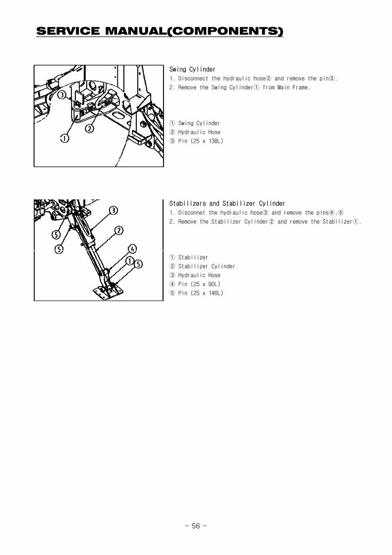
1. Disconnect the hydraulic hose② and remove the pin③.
2. Remove the Swing Cylinder① from Main Frame.
① Swing Cylinder
② Hydraulic Hose
③ Pin (25 x 138L)
1. Disconnet the hydraulic hose③ and remove the pins④,⑤
2. Remove the Stabilizer Cylinder② and remove the Stabilizer①.
Swing Cylinder
Stabilizers and Stabilizer Cylinder
① Stabilizer
② Stabilizer Cylinder
③ Hydraulic Hose
④ Pin (25 x 90L)
⑤ Pin (25 x 146L)
- 56 -
SERVICE MANUAL(CYLINDERS)
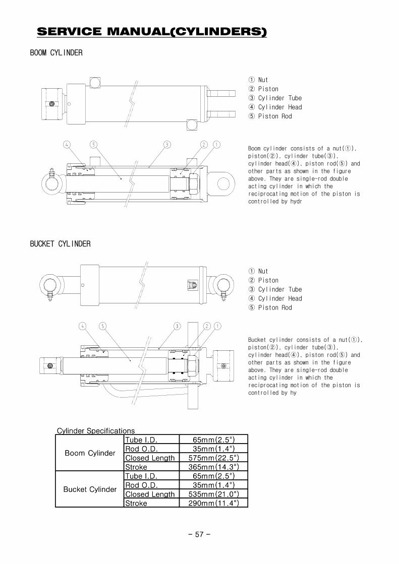
BOOM CYLINDER
① Nut
② Piston
③ Cylinder Tube
④ Cylinder Head
⑤ Piston Rod
BUCKET CYLINDER
Boom cylinder consists of a nut(①),piston(②), cylinder tube(③),cylinder head(④), piston rod(⑤) andother parts as shown in the figureabove. They are single-rod doubleacting cylinder in which thereciprocating motion of the piston iscontrolled by hydr
Cylinder SpecificationsTube I.D. 65mm(2.5")Rod O.D. 35mm(1.4")Closed Length 575mm(22.5")Stroke 365mm(14.3")Tube I.D. 65mm(2.5")Rod O.D. 35mm(1.4")Closed Length 535mm(21.0")Stroke 290mm(11.4")
Boom Cylinder
Bucket Cylinder
- 57 -
① Nut
② Piston
③ Cylinder Tube
④ Cylinder Head
⑤ Piston Rod
Bucket cylinder consists of a nut(①),piston(②), cylinder tube(③),cylinder head(④), piston rod(⑤) andother parts as shown in the figureabove. They are single-rod doubleacting cylinder in which thereciprocating motion of the piston iscontrolled by hy
Cylinder SpecificationsTube I.D. 65mm(2.5")Rod O.D. 35mm(1.4")Closed Length 575mm(22.5")Stroke 365mm(14.3")Tube I.D. 65mm(2.5")Rod O.D. 35mm(1.4")Closed Length 535mm(21.0")Stroke 290mm(11.4")
Boom Cylinder
Bucket Cylinder
- 57 -
SERVICE MANUAL(CYLINDERS)
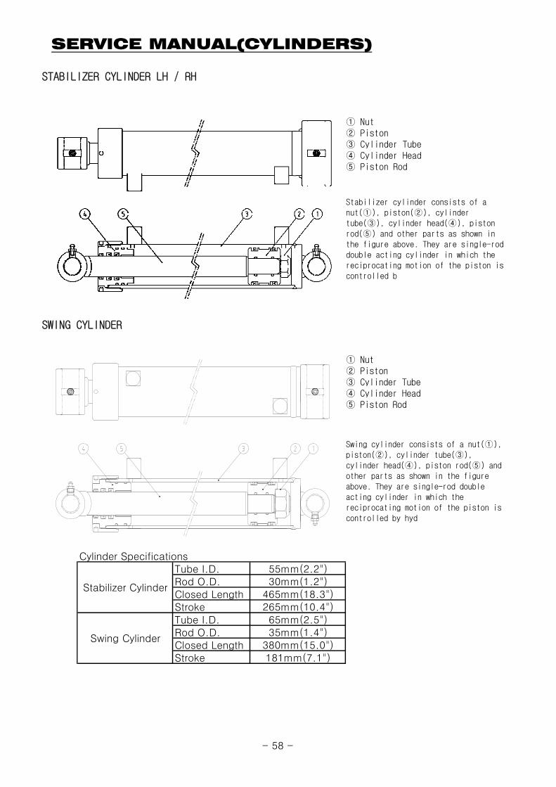
STABILIZER CYLINDER LH / RH
① Nut② Piston③ Cylinder Tube④ Cylinder Head⑤ Piston Rod
SWING CYLINDER
①
Stabilizer cylinder consists of anut(①), piston(②), cylindertube(③), cylinder head(④), pistonrod(⑤) and other parts as shown inthe figure above. They are single-roddouble acting cylinder in which thereciprocating motion of the piston iscontrolled b
① Nut② Piston③ Cylinder Tube④ Cylinder Head⑤ Piston Rod
Swing cylinder consists of a nut(①),piston(②), cylinder tube(③),cylinder head(④), piston rod(⑤) andother parts as shown in the figureabove. They are single-rod doubleacting cylinder in which thereciprocating motion of the piston iscontrolled by hyd
Cylinder SpecificationsTube I.D. 55mm(2.2")Rod O.D. 30mm(1.2")Closed Length 465mm(18.3")Stroke 265mm(10.4")Tube I.D. 65mm(2.5")Rod O.D. 35mm(1.4")Closed Length 380mm(15.0")Stroke 181mm(7.1")
Stabilizer Cylinder
Swing Cylinder
- 58 -
SERVICE MANUAL(CYLINDERS)
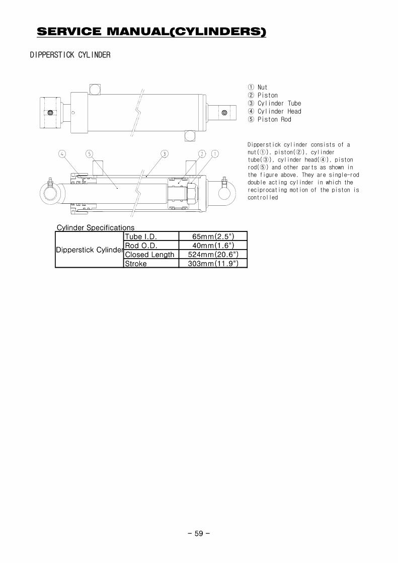
DIPPERSTICK CYLINDER
① Nut② Piston③ Cylinder Tube④ Cylinder Head⑤ Piston Rod
Dipperstick cylinder consists of anut(①), piston(②), cylindertube(③), cylinder head(④), pistonrod(⑤) and other parts as shown inthe figure above. They are single-roddouble acting cylinder in which thereciprocating motion of the piston iscontrolled
Cylinder SpecificationsTube I.D. 65mm(2.5")Rod O.D. 40mm(1.6")Closed Length 524mm(20.6")Stroke 303mm(11.9")
Dipperstick Cylinder
- 59 -
Cylinder SpecificationsTube I.D. 65mm(2.5")Rod O.D. 40mm(1.6")Closed Length 524mm(20.6")Stroke 303mm(11.9")
Dipperstick Cylinder
- 59 -
SERVICE MANUAL(CYLINDERS)
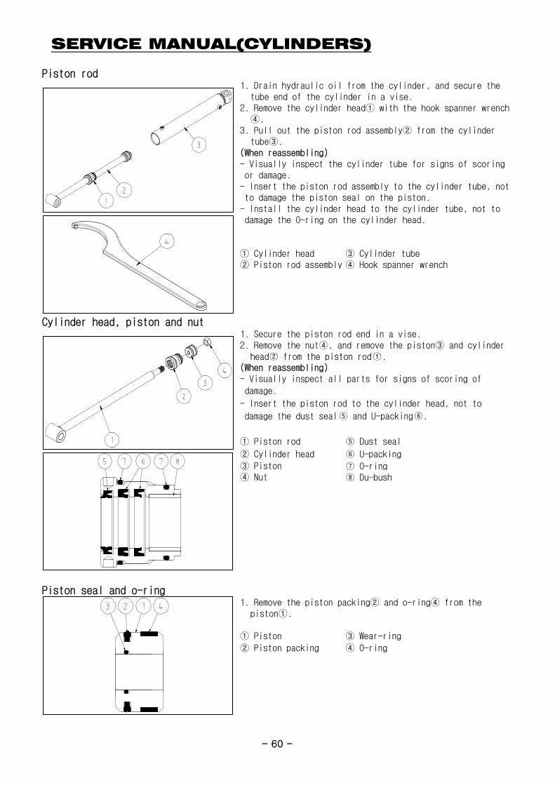
Piston rod1. Drain hydraulic oil from the cylinder, and secure the
tube end of the cylinder in a vise.2. Remove the cylinder head① with the hook spanner wrench
④.3. Pull out the piston rod assembly② from the cylinder
tube③.(When reassembling)- Visually inspect the cylinder tube for signs of scoring or damage.- Insert the piston rod assembly to the cylinder tube, not to damage the piston seal on the piston.- Install the cylinder head to the cylinder tube, not to damage the O-ring on the cylinder head.
① Cylinder head ③ Cylinder tube② Piston rod assembly ④ Hook spanner wrench
Cylinder head, piston and nut1. Secure the piston rod end in a vise.2. Remove the nut④, and remove the piston③ and cylinder
head② from the piston rod①
- 60 -
head② from the piston rod①.(When reassembling)- Visually inspect all parts for signs of scoring of
damage.
- Insert the piston rod to the cylinder head, not to
damage the dust seal⑤ and U-packing⑥.
① Piston rod ⑤ Dust seal
② Cylinder head ⑥ U-packing
③ Piston ⑦ O-ring④ Nut ⑧ Du-bush
Piston seal and o-ring1. Remove the piston packing② and o-ring④ from the
piston①.
① Piston ③ Wear-ring
② Piston packing ④ O-ring
- 60 -
SERVICE MANUAL(VALVE)
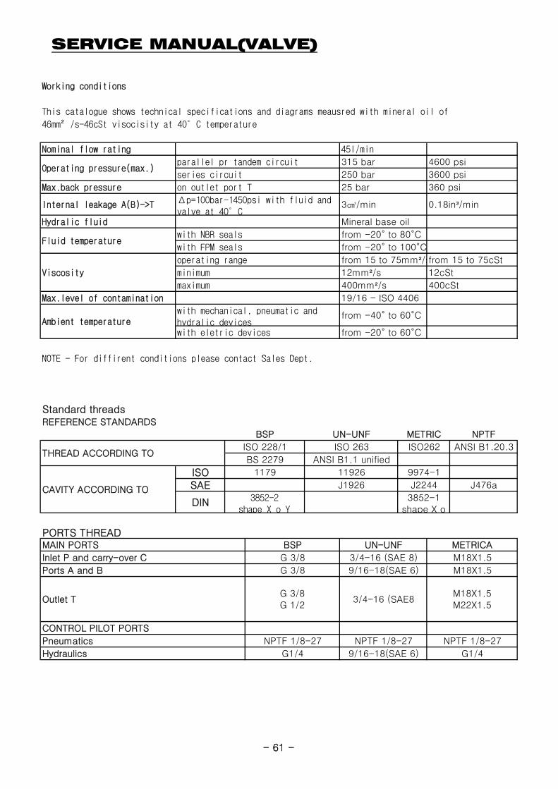
Working conditions
This catalogue shows technical specifications and diagrams meausred with mineral oil of
46mm²/s-46cSt visocisity at 40°C temperature
NOTE For diffirent conditions please contact Sales Dept
45I/min
with NBR seals
315 bar
250 bar
25 bar
3㎤/min
Mineral base oil
with mechanical, pneumatic andhydralic deviceswith eletric devices
Δp=100bar-1450psi with fluid andvalve at 40°C
with FPM seals
operating range
minimum
maximum
12cSt
from 15 to 75cSt
400cSt
from -40° to 60°C
4600 psi
3600 psi
360 psi
0.18in³/min
12mm²/s
400mm²/s
19/16 - ISO 4406
Ambient temperature
Max.level of contamination
Viscosity
from -20° to 60°C
from 15 to 75mm²/s
parallel pr tandem circuit
from -20° to 80°C
from -20° to 100°C
Internal leakage A(B)->T
Hydralic fluid
Fluid temperature
Nominal flow rating
Operating pressure(max.)
Max.back pressure on outlet port T
series circuit
- 61 -
NOTE - For diffirent conditions please contact Sales Dept.
Standard threadsREFERENCE STANDARDS
PORTS THREAD
J476a
9974-1
J2244
NPTFMETRIC
UN-UNF METRICA
3852-1shape X o
ANSI B1.20.3ISO 263
UN-UNFBSP
ISO 228/1
BS 2279
ISO262
J1926
119261179
ANSI B1.1 unifiedTHREAD ACCORDING TO
CAVITY ACCORDING TO
ISOSAE
DIN 3852-2shape X o Y
NPTF 1/8-27
9/16-18(SAE 6)
G 3/8
G 3/8
G1/4
BSP
G 3/8G 1/2
NPTF 1/8-27
M18X1.5
M18X1.5M22X1.5
3/4-16 (SAE 8)
9/16-18(SAE 6)
3/4-16 (SAE8
NPTF 1/8-27
G1/4
MAIN PORTS
Inlet P and carry-over C
Ports A and B
Outlet T
CONTROL PILOT PORTS
Pneumatics
Hydraulics
M18X1.5
- 61 -
SERVICE MANUAL(VALVE)
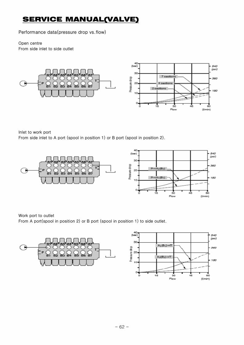
Performance data(pressure drop vs.flow)
Open centre
From side inlet to side outlet
Inlet to work port
From side inlet to A port (spool in position 1) or B port (spool in position 2).
Work port to outlet
From A port(spool in position 2) or B port (spool in position 1) to side outlet.
- 62 -
SERVICE MANUAL(VALVE)
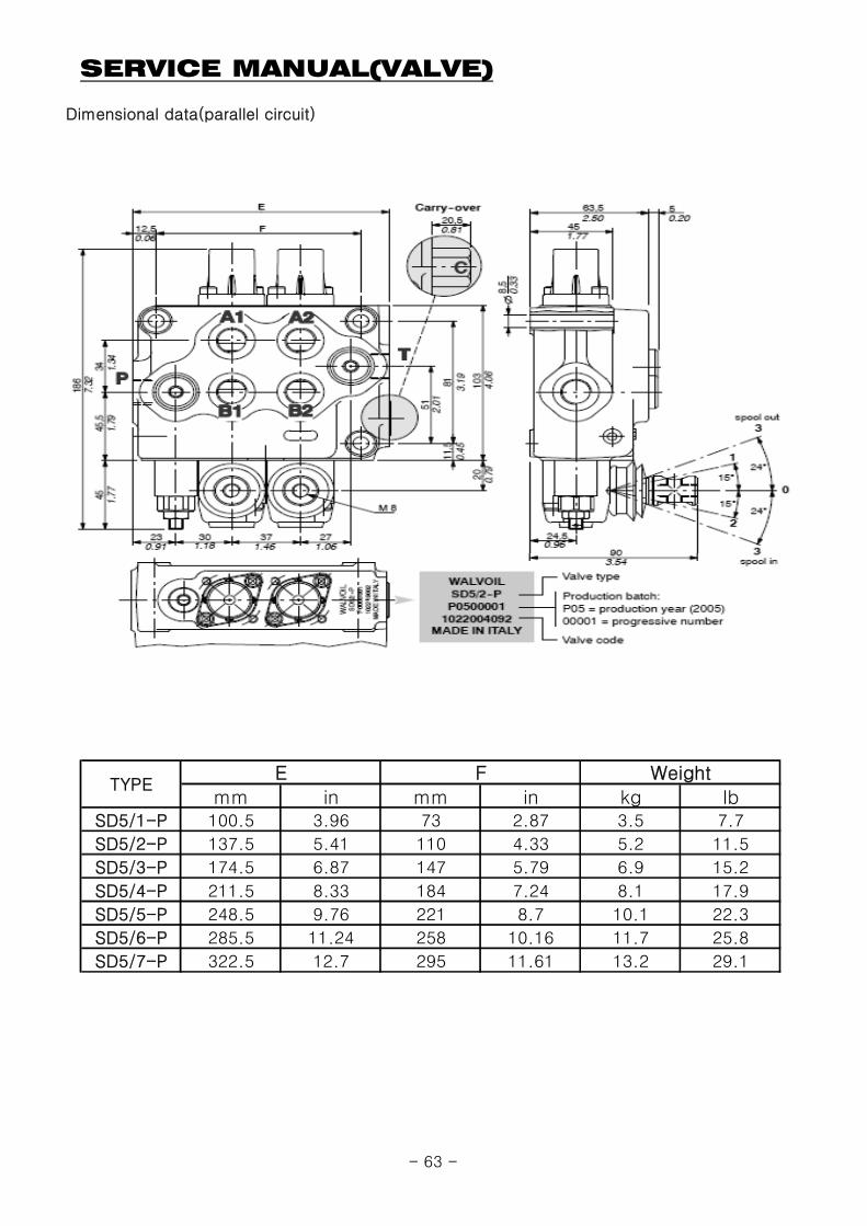
Dimensional data(parallel circuit)
mm in mm in kg IbSD5/1-P 100.5 3.96 73 2.87 3.5 7.7
SD5/2-P 137.5 5.41 110 4.33 5.2 11.5
SD5/3-P 174.5 6.87 147 5.79 6.9 15.2
SD5/4-P 211.5 8.33 184 7.24 8.1 17.9
SD5/5-P 248.5 9.76 221 8.7 10.1 22.3
SD5/6-P 285.5 11.24 258 10.16 11.7 25.8
SD5/7-P 322.5 12.7 295 11.61 13.2 29.1
WeightE FTYPE
- 63 -
SERVICE MANUAL(VALVE)
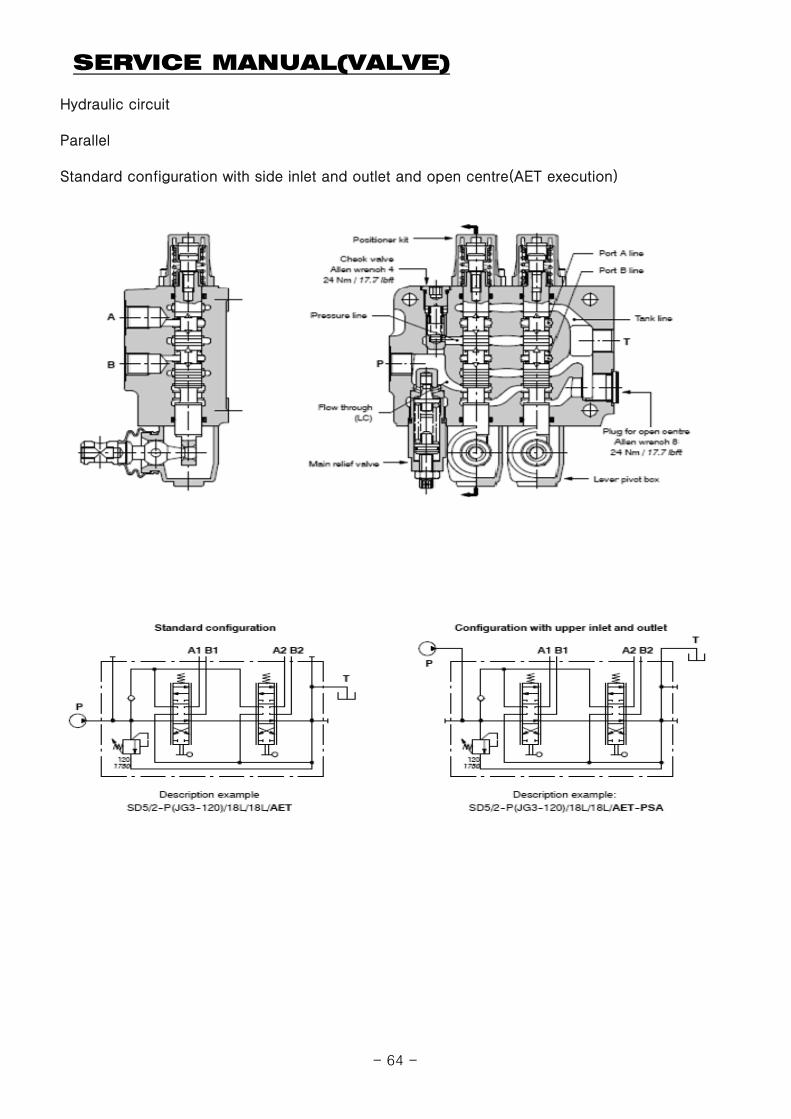
Hydraulic circuit
Parallel
Standard configuration with side inlet and outlet and open centre(AET execution)
- 64 -
SERVICE MANUAL(VALVE)
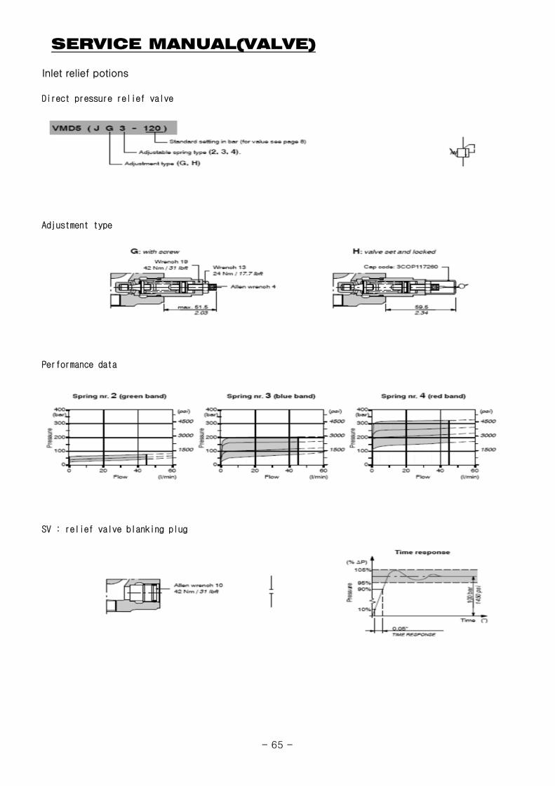
Inlet relief potions
Direct pressure relief valve
Adjustment type
Performance data
SV : relief valve blanking plug
- 65 -
SERVICE MANUAL(VALVE)
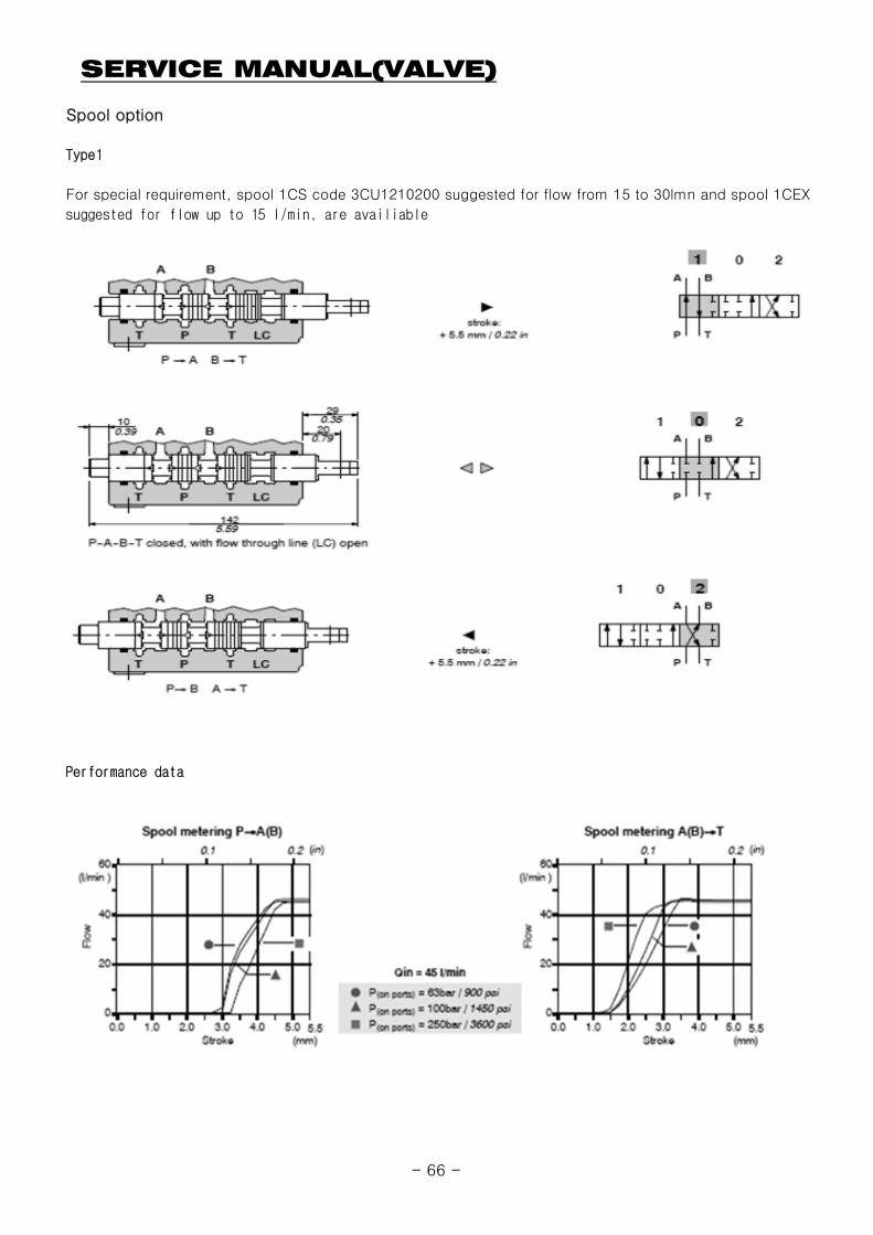
Spool option
Type1
For special requirement, spool 1CS code 3CU1210200 suggested for flow from 15 to 30lmn and spool 1CEX
suggested for flow up to 15 l/min, are availiable
Performance data
- 66 -
SERVICE MANUAL(VALVE)
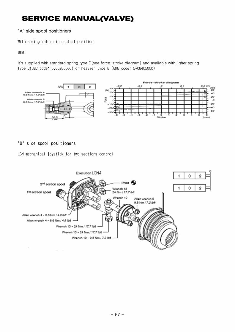
"A" side spool positioners
With spring return in neutral position
8kit
It's supplied with standard spring type D(see force-stroke diagram) and available with ligher spring
type C(8MC code: 5V08205000) or heavier type E (8ME code: 5v08405000)
"B" side spool positioners
LCN mechanical joystick for two sections control
- 67 -
SERVICE MANUAL(VALVE)
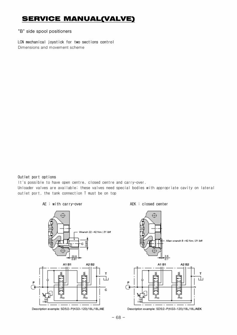
"B" side spool positioners
LCN mechanical joystick for two sections control
Dimensions and movement scheme
Outlet port options
It's possible to have open centre, closed centre and carry-over.
Unloader valves are available; these valves need special bodies with appropriate cavity on lateral
outlet port, the tank connection T must be on top
AE : with carry-over AEK : closed center
- 68 -
SERVICE MANUAL(VALVE)
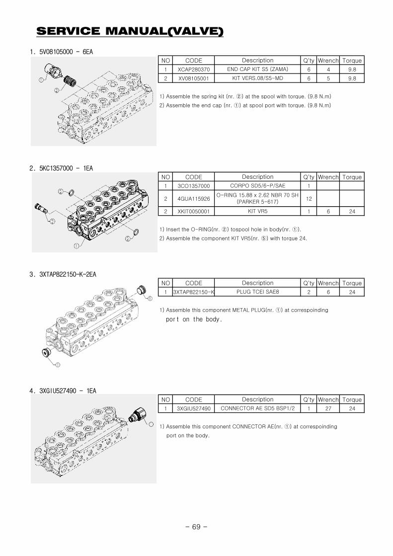
1. 5V08105000 - 6EA
NO CODE Q'ty Wrench Torque
1 XCAP280370 6 4 9.8
2 XV08105001 6 5 9.8
1) Assemble the spring kit (nr. ②) at the spool with torque. (9.8 N.m)
2) Assemble the end cap (nr. ①) at spool port with torque. (9.8 N.m)
2. 5KC1357000 - 1EA
NO CODE Q'ty Wrench Torque
1 3CO1357000 1
2 4GUA115926 12
2 XKIT0050001 1 6 24
1) Insert the O-RING(nr. ②) tospool hole in body(nr. ①).
2) Assemble the component KIT VR5(nr. ⑤) with torque 24.
Description
END CAP KIT S5 (ZAMA)
KIT VERS.08/S5-MD
Description
CORPO SD5/6-P/SAE
O-RING 15.88 x 2.62 NBR 70 SH(PARKER 5-617)
KIT VR5
3. 3XTAP822150-K-2EA
NO CODE Q'ty Wrench Torque
1 3XTAP822150-K 2 6 24
1) Assemble this component METAL PLUG(nr. ①) at correspoinding
port on the body.
4. 3XGIU527490 - 1EA
NO CODE Q'ty Wrench Torque
1 3XGIU527490 1 27 24
1) Assemble this component CONNECTOR AE(nr. ①) at correspoinding
port on the body.
CONNECTOR AE SD5 BSP1/2
PLUG TCEI SAE8
Description
Description
- 69 -
SERVICE MANUAL(VALVE)
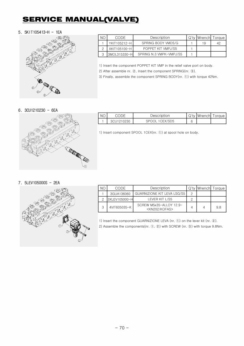
5. 5KIT105413-H - 1EA
NO CODE Q'ty Wrench Torque
1 YKIT105212-H 1 19 42
2 XKIT105100-H 1
3 3MOL315330-H 1
1) Insert the component POPPET KIT VMP in the relief valve port on body.
2) After assemble nr. ②, Insert the component SPRING(nr. ③).
3) Finally, assemble the component SPRING BODY(nr. ①) with torque 42Nm.
6. 3CU1210230 - 6EA
NO CODE Q'ty Wrench Torque
1 3CU1210230 6
1) Insert component SPOOL 1CEX(nr. ①) at spool hole on body.
Description
SPRING N.3 VMPK-VMPJ/S5
Description
SPOOL 1CEX/SD5
SPRING BODY VMD5/G
POPPET KIT VMPJ/S5
7. 5LEV105000S - 2EA
NO CODE Q'ty Wrench Torque
1 3GUA136060 2
2 3XLEV105000-H 2
3 4VIT605035-K 4 4 9.8
1) Insert the component GUARNIZIONE LEVA (nr. ①) on the lever kit (nr. ②).
2) Assemble the components(nr. ①, ②) with SCREW (nr. ③) with torque 9.8Nm.
Description
GUARNIZIONE KIT LEVA LSG/S5
LEVER KIT L/S5
SCREW M5x35-ALLOY 12.9-<KN202/KOFAS>
- 70 -
SERVICE MANUAL(VALVE)
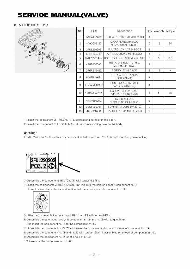
8. 5CLO305101-W - 2EA
NO CODE Q'ty Wrench Torque
1 4GUA115618 4
2 4DAD608120 6 13 24
3 3FUL220202 2
4 XART106043 4 13 -
5 3VIT705014-K 8 3 6.6
6 4ART006000 2
7 3PER515450 2 13 -
8 3POR340241 2
9 4ROS306410-K 6
10 4VIT606027-K 6 5 15
11 4TAP680080 2
12 3SOF200701 2
13 4ACC210-K 2
1) Insert the component O-RING(nr. ①) at corresponding hole on the body.
BOLT TSEI UNI-5933/M5x14-10.9
ARTICOLAZIONE M6-LCN/S5
FULCRO LCN/LCA2-3/SD5
TAPPO 4° FOROCLOCHE S5 (Ref.P0250)
SOFFIETTO LCB5 (PR2210)
FASCETTA TY26MX-3,6x300
O-RING 15.60X1.78 NBR 70 SH
DADO FLANG.TRIBLOCM8 Zn/bianco (DS008)
SCREW TCEI UNI-5931/M6x25-12.9 Nichelata
ROSETTA A6 DIN-7980Zn/Bianca/Deidrog.
PORTA ARTICOLAZIONELCB5(ZAMA)
PERNO LCN-LCA/S5
TESTA DI BIELLA TUTHILLM6 Ref. SPF4157*
Description
2) Insert the component FULCRO LCN (nr. ③) at corresponding hole on the body.
Warning!
LCN3 : Verify the 'nr.3' surface of component as below picture. 'Nr. 3' is right direction you're looking
3) Assemble the components BOLT(nr. ⑤) with torque 6.6 Nm.
4) Insert the components ARTICOLAZIONE (nr. ④) in to the hole on spool & component nr. ③.
It has to assemble in the same direction that the spool eye and component nr. ③
5) After than, assemble the component DADO(nr. ②) with torque 24Nm.
6) Assemble the other spool eye with component nr. ⑦ and nr. ② with torque 24Nm.
And Insert the component nr. ⑦ to the component nr. ⑥.
7) Assemble the component nr.⑧. When it assembled, please caution about shape of component nr. ④.
8) Assemble the component nr. ⑨ and nr. ⑩ with torque 15Nm. It assembled on thread of component nr. ④.
9) Assemble the component nr. ⑪ on the hole of nr. ⑧.
10) Assemble the component nr. ⑫, ⑬.
- 71 -


