Embed Size (px)
Citation preview
}
" ~~ ,.... ~
ilRONI .~ SPA
USER AND MAINTENANCE MANUAL ROTARY CULTIVATOR
~ ENGLISH
Code MUM-FLFM-EN-US_Rev-00 Date: 22-11-2007
According to Directive 2006/42/CE as further modified
We
CARONI S.P.A., Via castelletto stura 46 1-12100 CUNEO - ITALY,
Declare under our own responsibility that the following models of our horizontal and vertical :
ROTARY TILLERS
FL0800/FL0900/FL1000/FL1100/FL1200/FL1300/FL1400 FM1100/FM1300/FM1500/FM1700
comply with the relevant basic safety and health requirements of the Directive 2006/42/CE.
In order to check the conformity with the above mentioned directives. the following harmonized standards have been taken into consideration: EN 1553 - EN 12100/1 -EN 12100/2 - EN 294 - EN 708.
Cuneo, November 22, 2006
The President and Managing director
~RONI
< .... .'
CARON I SPA - COSTRUZIONI MECCANICHE ·VIA CASTELLETTO STURA, 46 -12100 CUNEO ITALY ·TEL ++39 0171 401346n • FAX ++39 0171 403750 • E-MAIL: [email protected] w w w c a r 0 n t
INDEX
1 Declaration of conformity 2 Marking and identification
2.1 Marking 2.2 Warning pictograms 2.3 Aerial noise and technical test data 2.4 Third point hitch categories
3 Conditions and limits of use 4 Use in safety 5 Startup
5.1 Mounting connections and protections 6 Adjustments
6.1 Transmission chain stretch adjustment 6.2 Working depth adjustment
7 Maintenance 7 .1 Oil quantity 7 .2 Tine replacement
8 Transport and Storage 9 Technical features and available models IO Figures 1 to 4
FOREWORD
page page 2 page 2 page 2 page 3 page 3 page 3 page 5 page 6 page 7 page 7 page 7 page 7 page 8 page 8 page 8 page 8 page 10 page 11 -13
CARON I SPA would like to thank you for your preference in choosing our quality machines. Aiming at obtaining the longest possible efficiency of the machines you have purchased, we kindly invite you to read and thorougly understand the instructions for use and maintenance in this manual. A careful compliance with these instructions permits to prevent troubles and accidents or injuries caused by carelessness or lack of compliance with the safety standards and in that case our company shall not be held liable.
This manual complies with the requirements of the machine directive 98/37/EC. The manual is integral with the machine and shall therefore accompany the machine should it be sold to a new user.
& The presence of this symbol of danger in the manual points out important instructions concerning safety. It is first of all meant for the operator. The operator shall comply with the compliance with the warning contained in the message by himself but also by other people exposed to the machine risks. Lack of compliance with the instructions can cause damage to people which could sometimes even be cause of death .
[I] This "instruction" symbol in the manual points out important instructions concerning the correct startup, operation and in general conditions which could jeopardize the life of the product.
The instructions contained in this manual should be read carefully before carrying out any operation with and on the machine, in order to work in safoty and preserving its correct operation.
Apml fr om lho moln tochnicol nml 111 1l11ly loaturos of the machines, the manufacturer reserves the rlghl of c1111ylr1u 0111 rnodlflc11Jlc111 M 111 11111 11mchlno at any time for reasons of ongoing technical and tocl111oloql1.11l 11v11h1th111 wlll11111t li11 v111u 1111!11 flruul lnr thnt
1'11J1. I ~
Furthermore we stress the fact that the only expected use of this machine is the one described in the manual. Any other application is forbidden.
2 Marking and identification
2.1 Marking
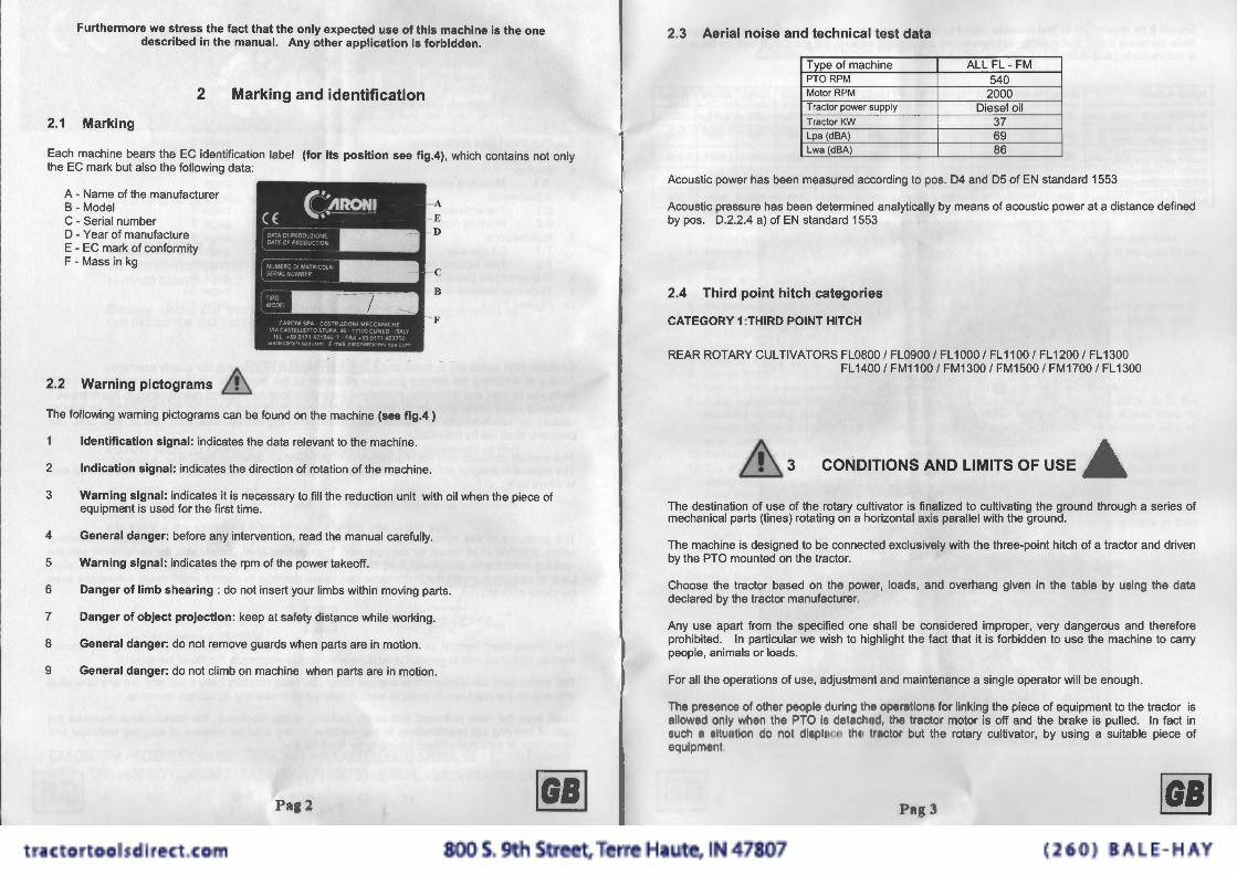
Each machine bears the EC identification label (for its position see fig.4) , which contains not only the EC mark but also the following data:
A - Name of the manufacturer B - Model C - Serial number D - Year of manufacture E - EC mark of conformity F - Mass in kg
2.2 Warning pictograms &.
c B
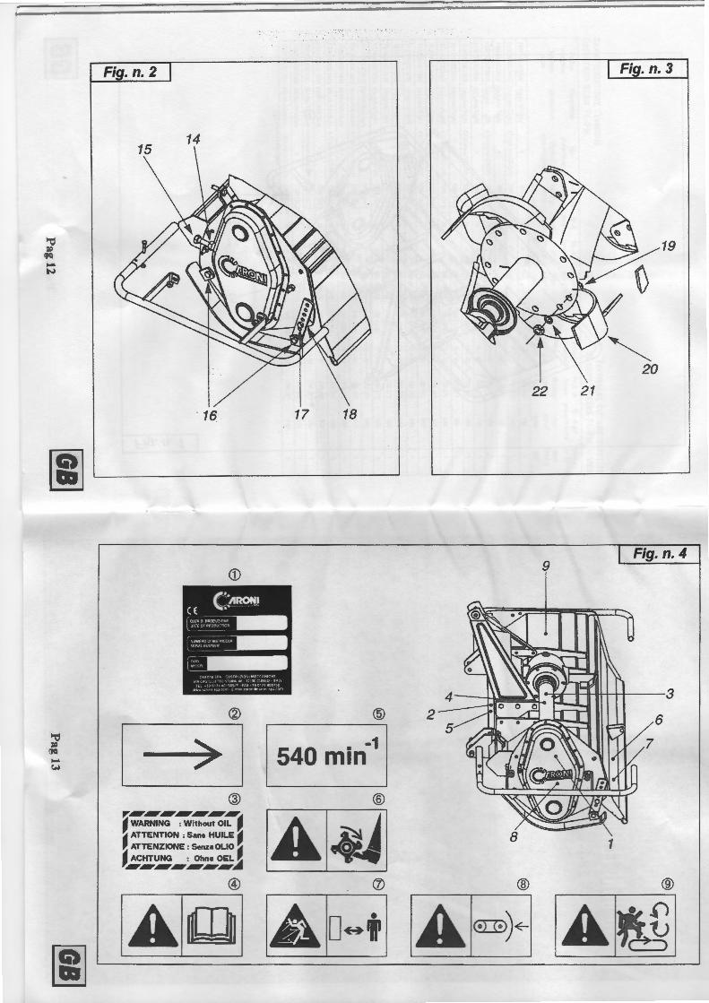
The following warning pictograms can be found on the machine (see fig.4)
Identification signal: indicates the data relevant to the machine.
2 Indication signal: indicates the direction of rotation of the machine.
3 Warning signal: indicates it is necessary to fill the reduction unit with oil when the piece of equipment is used for the first time.
4 General danger: before any intervention, read the manual carefully.
5 Warning signal: indicates the rpm of the power takeoff.
6 Danger of limb shearing : do not insert your limbs within moving parts .
7 Danger of object projection: keep at safety distance while working.
8 General danger: do not remove guards when parts are in motion.
9 General danger: do not climb on machine when parts are in motion.
Pa~ 2 ~
2.3 Aerial noise and technical test data
Tvoe of machine ALL FL- FM PTO RPM 540 Motor RPM 2000 Tractor power supply Diesel oil Tractor KW 37 Lpa (dBA) 69 Lwa (dBA) 86
Acoustic power has been measured according to pos. 04 and 05 of EN standard 1553
Acoustic pressure has been determined analytically by means of acoustic power at a distance defined by pos. D.2.2.4 a) of EN standard 1553
2.4 Third point hitch categories
CATEGORY 1 :THIRD POINT HITCH
REAR ROTARY CULTIVATORS FLOBOO I FL0900 I FL 1000 I FL 1100 I FL 1200 I FL 1300 FL 1400 I FM1100 I FM1300 I FM1500 I FM1700IFL1300
&3 CONDITIONS AND LIMITS OF USE
The destination of use of the rotary cultivator is finalized to cultivating the ground through a series of mechanical parts (tines) rotating on a horizontal axis parallel with the ground.
The machine is designed to be connected exclusively with the three-point hitch of a tractor and driven by the PTO mounted on the tractor.
Choose the tractor based on the power, loads, and overhang given in the table by using the data declared by the tractor manufacturer.
Any use apart from the specified one shall be considered improper, very dangerous and therefore prohibited. In particular we wish to highlight the fact that it is forbidden to use the machine to carry people , animals or loads.
For all the operations of use, adjustment and maintenance a single operator will be enough.
Tho presence of other people during tho oporollons for linking the piece of equipment to the tractor is llowod only whon tho PTO is dolncllrnl, lho tractor motor is off and the brake is pulled. In fact in
sucll fl !111111111011 ctn 1101 c1l 11plnr;n 1111 1 11111 .10 1 but the rotary cultivator, by using a suitable piece of equlpn1011I
l':lg 3 ~
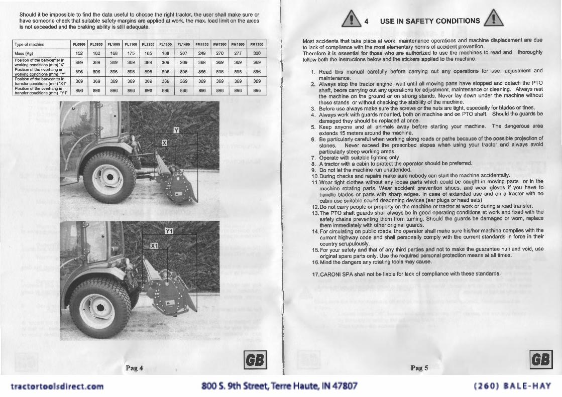
Should it be impossible to find the data useful to choose the right tractor, the user shall make sure or have someone check that suitable safety margins are applied at work, the max. load limit on the axles is not exceeded and the braking ability is still adequate.
Type of machine FL0800 FL0900 FL1000 FL1100 FL1200 FL1300 FL1400 FM1100 FM1300 FM1500 FM1700
Mass (Kg) 152 162 168 175 185 188 207 249 270 277 320 Position of the barycenter in 369 369 369 369 369 369 369 369 369 369 369 workinQ conditions (mm) "X" Position of the overhang in 896 896 896 896 896 896 896 896 896 896 896 workina conditions <mm) ·Y' Position of the barycenter in 369 369 369 369 369 369 369 369 369 369 369 transfer conditions (mm) "X1 " Position of the overhang in 896 896 896 896 896 896 896 896 896 896 896 transfer conditions (mm) "Y1 "
Pag4 ~
&4 USE IN SAFETY CONDITIONS & Most accidents that take place at work, maintenance operations and machine displacement are due to lack of compliance with the most elementary norms of accident prevention . Therefore it is essential for those who are authorized to use the machines to read and thoroughly follow both the instructions below and the stickers applied to the machine.
1. Read this manual carefully before carrying out any operations for use, adjustment and maintenance.
2. Always stop the tractor engine, wait until all moving parts have stopped and detach the PTO shaft, beore carrying out any operations for adjustment, maintenance or cleaning. Always rest the machine on the ground or on strong stands. Never lay down under the machine without these stands or without checking the stability of the machine.
3. Before use always make sure the screws or the nuts are tight, especially for blades or tines. 4. Always work with guards mounted, both on machine and on PTO shaft. Should the guards be
damaged they should be replaced at once. 5. Keep anyone and all animals away before starting your machine. The dangerous aroa
extends 15 meters around the machine. 6. Be particularly careful when working along roads or paths because of tho possible projection of
stones. Never exceed the prescribed slopes whon using your tractor and always avoid particularly steep working areas.
7. Operate with suitable lighting only 8. A tractor with a cabin to protect the operator should be preferred . 9. Do not let the machine run unattended. 10. During checks and repairs make sure nobody can start the machine accidentally. 11 . Wear tight clothes without any loose parts which could be caught in moving parts or in the
machine rotating parts. Wear accident prevention shoes, and wear gloves if you have to handle blades or parts with sharp edges. In case of extended use and on a tractor with no cabin use suitable sound deadening devices (ear plugs or head sets)
12. Do not carry people or property on the machine or tractor at work or during a road transfer. 13. The PTO shaft guards shall always be in good operating conditions at work and fixed with the
safety chains preventing them from turning . Should the guards be damaged or worn , replace them immediately with other original guards.
14. For circulating on public roads, the operator shall make sure his/her machine complies with the current highway code and shall personally comply with the current standards in force in their country scrupulously.
15. For your safety and that of any third parties and not to make the guarantee null and void, use original spare parts only. Use the required personal protection means at all times.
16. Mind the dangers any rotating tools may cause .
17. CARON I SPA shall not be liable for lack of compliance with these standards.
Pag5 ~
[i] 5-STARTUP III Carry out all the operations for startup when the tractor engine is stopped, the PTO shaft is disconnected and all the transmission parts to the tools are stopped.
Before starting working fill the gearbox with oil HD 80 W 90 (see paragraph 7 .1 ). When closing the cap do not tighten it too tight in order to prevent gasket deformation which could generate oil leaks.
Check the direction of rotation and the rpm of the tractor and of the machine PTO, which shall necessarily be the same as the ones signaled on the machine next to the PTO with two yellow stickers.
.I.\. Danger: it is forbidden to use the machine at a speed either than the one specified in the LU label.
.I.\. Use only CE marked PTO shaft with guards. Lll Once the machine has been hitched to the tractor, check the exact length of the PTO
shaft.
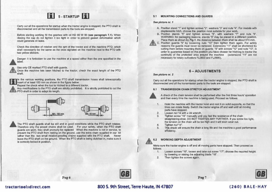
lil ln the various working positions, the PTO shaft transmission hoses shall telescopically insert of at least 150 mm as shown in the figure below. Repeat the check when the tool is hitched to a different tractor .
.I.\. Any modifications to the PTO shaft are strictly prohibited. It is strictly prohibited to cut the Lll PTO shaft in order to adapt its length.
Mln.150mm ~ .I.\. The PTO shaft guards shall be still and in good conditions while the PTO shaft rotates
l.ll Therefore only the preset chains shall be used. For your safety, when the PTO shaft guards are worn, they shall promptly be replaced When the machine is not in service, to prevent the PTO shaft from resting on the ground, use the extra chain supplied in our kit rather than the two small rotation-proofing chains supplied with the PTO shaft. Never leave the PTO shaft on the ground. When the PTO shaft is being clutched in, make sure it is correctly locked in position.
Pag 6 ~
\ I.
f
i
5.1 MOUNTING CONNECTIONS AND GUARDS
See picture nr. 1
A. Position stand "1" and tighten screws "2", washers "3" and nuts "4". ror models with displaceable hitch, choose the position most suitable for your work.
B. Position stands "5" and tighten screws "6", with washers "7" and nuts "8''. WARNING: for packaging reasons, stands "5" may be placed in a different position.
.I.\. Place them as shown by Fig.1, the distance between them shall be about 670 mm. Lll C. Position guards "9" by loosening nuts "10" then tighten them again. For safety
reasons the guards must never be removed . Extensions "11" shall be shortened by cutting them before mounting them on guards "9" with screws "12" and nuts "13'', in order to guarantee based on the position you have chosen for hitching to tractor the continuity of the protected area around the machine (extensions "11" are not necessary for rotary cultivators FL0800 and FL0900) .
6 - ADJUSTMENTS See picture nr. 2
Carry out all the operations for startup when the tractor engine is stopped, the PTO shaft is disconnected and all the transmission parts to the tools are stopped.
6.1 TRANSMISSION CHAIN STRETCH ADJUSTMENT
& A check of the chain tension shall be performed after the first three hours' operation and then every time the machine is being used. Proceed as follows:
1. Hoist the machine with the tractor hoist and rest it on solid supports, so that the tines can rotate freely. Switch the tractor engine off and wait until all moving parts have stopped.
2. Loosen nut 14 with a 24 wrench . 3. Tighten screw "15" manually until you feel the resistance of the chain
straightening shoe. DO NOT TIGHTEN ANY FURTHER. If you screw too tight, the tension on the chain will be too high and it will soon wear out.
4. Tighten nut"14". 5. This check will ensure the chain a long life and the machine a good performance
efficiency.
&. 6.2 WORKING DEPTH ADJUSTMENT
Make sure the tractor engine is off and all moving parts have stopped. Then proceed as follows:
1.
2.
Loosen screws "16", loosen and take out screw "17"; choose the required height by lowering or raising the adjusting blade "18". Then tighten the screws again.
Pag 7 ~
7 - MAINTENANCE
.& Carry out all the operations for startup when the tractor engine is stopped, the PTO shaft is disconnected and all the transmission parts to the tools are stopped.
[i]Once your work is over, wash the underframe thoroughly in order to keep the machine perfectly effective .
.I.\ Use only original tines, in order to guarantee your safety and that of any third parties (also £.ll for guarantee purposes).
7 .1 OIL QUANTITY
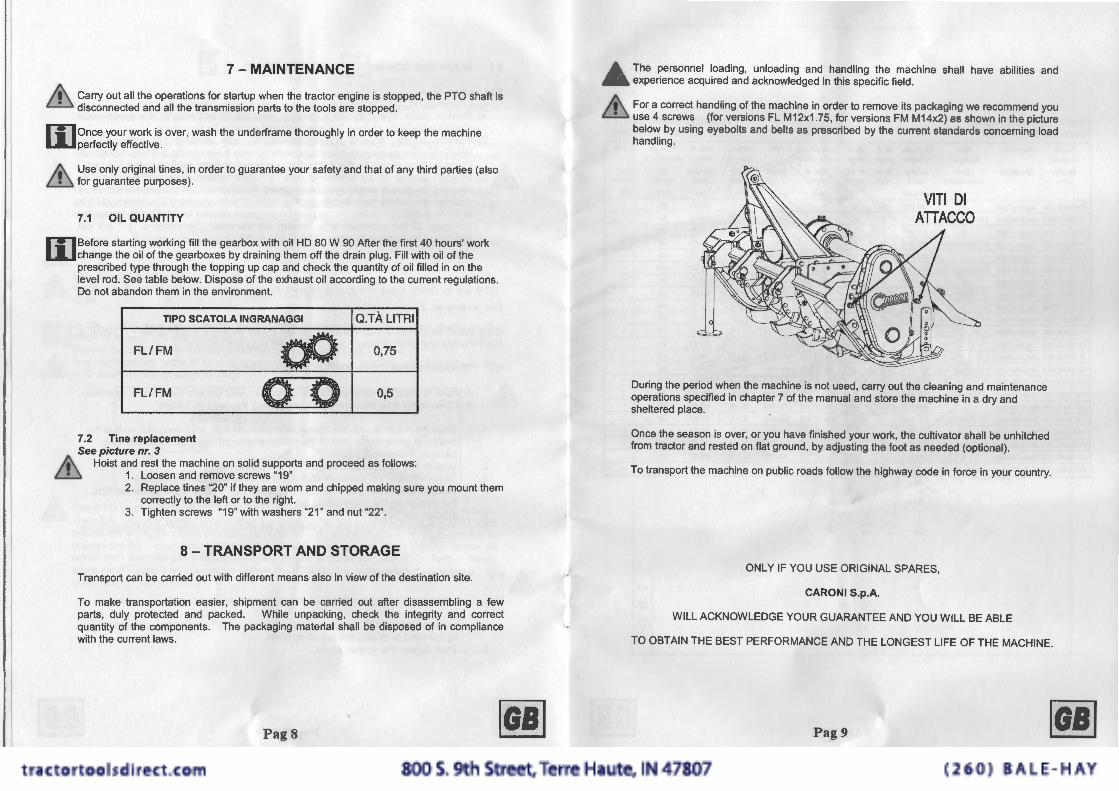
[i]Before starting working fill the gearbox with oil HD 80 W 90 After the first 40 hours' work change the oil of the gearboxes by draining them off the drain plug. Fill with oil of the prescribed type through the topping up cap and check the quantity of oil filled in on the level rod . See table below. Dispose of the exhaust oil according to the current regulations. Do not abandon them in the environment.
TIPO SCATOLA INGRANAGGI Q.TA LITRI
FL/FM dJ 0,75
FL/FM 0 0 0,5
7.2 Tine replacement See picture nr. 3
.I.\ Hoist and rest the machine on solid supports and proceed as follows: L.ll 1. Loosen and remove screws "19"
2. Replace tines "20" if they are worn and chipped making sure you mount them correctly to the left or to the right.
3. Tighten screws "19" with washers "21 " and nut "22".
8 - TRANSPORT AND STORAGE
Transport can be carried out with different means also in view of the destination site.
To make transportation easier, shipment can be carried out after disassembling a few parts, duly protected and packed. While unpacking, check the integrity and correct quantity of the components. The packaging material shall be disposed of in compliance with the current laws.
Pag8 ~
/,;/... The personnel loading, unloading and handling the machine shall have abilities and ~ experience acquired and acknowledged in this specific field .
~ For a correct handling of the machine in order to remove its packaging we recommend you Lll use 4 screws (for versions FL M 12x1 . 75, for versions FM M14x2) as shown in the picture
below by using eyebolts and belts as prescribed by the current standards concerning load handling.
During the period when the machine is not used, carry out the cleaning and maintenance operations specified in chapter 7 of the manual and store the machine in a dry and sheltered place.
Once the season is over, or you have finished your work, the cultivator shall be unhitched from tractor and rested on flat ground, by adjusting the foot as needed (optional).
To transport the machine on public roads follow the highway code in force in your country.
ONLY IF YOU USE ORIGINAL SPARES,
CARONI S.p.A.
WILL ACKNOWLEDGE YOUR GUARANTEE AND YOU WILL BE ABLE
TO OBTAIN THE BEST PERFORMANCE AND THE LONGEST LIFE OF THE MACHINE.
Pag9 ~
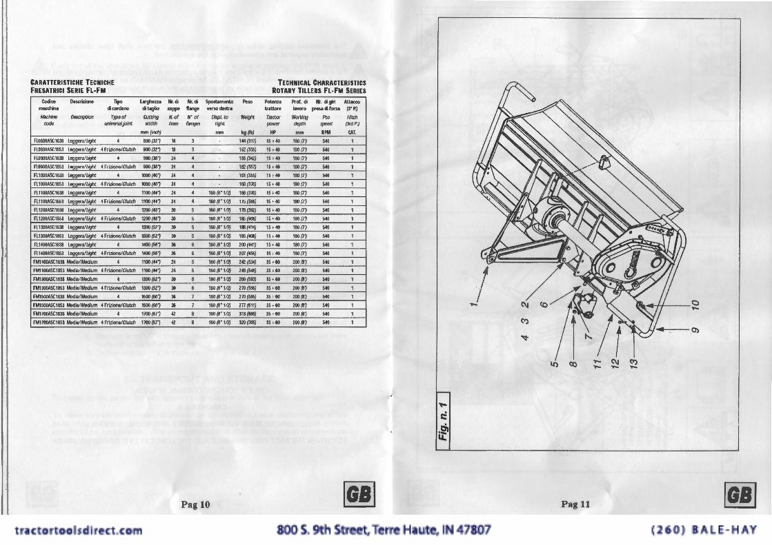
CARATTERISTICHE TECNICHE FRESATRICI SERIE FL·FM
Codice Descrizione Tipo macchina di cardano
Machine Description Type of code lX1iversaljoint
FL0800ASC16.18 leggera/Light 4
Fl0800ASC1853 leggera/Light 4 Frizione/Clutch
Fl0900ASC1638 leggera/Light 4
FL0900ASC1853 leggera/Light 4 Frizione/C/utch
Fl1000ASC16.18 leggera/Light 4
Fl1000ASC1853 leggera/Light Hrizione/C/u!ch
Fl1100ASC16.18 leggera/Light 4
Fl1100ASC1853 leggera/Light Hrizione/C/utch
FL1200ASC16.18 leggera/Light 4
Fl1200ASC1853 Leggera/Light Hrizione/C/utc/J
FL1300ASC16.18 Leggera/Light 4
Fl1300ASC1853 leggera/Light Hrizione/C/utch
Fl1400ASC1638 leggera/Light 4
Fl1400ASC1853 leggera/Light Hrizione/C/utch
FM1100ASC16.18 Media/Medium 4
FM1100ASC1853 Media/Medium Hrizione /Clutch
FM1300ASC1638 Media/Medium 4
FM1300ASC1853 Media/Medium 4 Frizione/C/utch
FM1500ASC16.18 Media/Medium 4
FM1500ASC1853 Media/Medium 4 Frizione/C/utch
FM1700ASC16.18 Media/Medium 4
FM1700ASC185l Media/Medium Hrizione!Clutch
Larghezza di taglio
CUtting width
mm (inch)
BOO (327
BOO (327
900 (36/
900 (36/
1000 (40/
1000 (fi!i
1100 (44/
1100 (ff/
1200 (48/
1200 (48i
1300 (527
1300 (52/
1400 (561 1400 (561 11001441
1100 (ff/
1300 (5Zi
1300 Mi 1500 (601 1500 (601 1100 (671
1100 (67")
Nr. di Nr. di Spostamento .. ppe flange verso destra
N.of N' of Displ. to hoe$ flatr}OS nght
mm
18 3
18 3
24 4
24 4
24 4
24 4
24 4 160 (6'112)
24 4 160 (6'112)
]) 5 160 (6.112)
]) 5 160(6'112)
]) 5 160 (6'112)
]) 5 160 (6"112)
36 6 160 (6"112)
36 6 160 (6'112)
24 5 160 (6'112)
24 5 160(6"112)
]) 6 160(6'112)
]) 6 160(6'112)
36 7 160 (6'112)
36 ) 160 (6'112)
42 8 160(6' 112)
42 8 160 {6'112)
Pag 10
Peso
Weight
kg ~hi
144(317)
152 (335)
155 (342)
162 (357)
161 (355)
168 (370)
168 (Jro)
175 (386)
178 (391)
185 {4<ll)
1118 (41f)
185 (4<ll)
ZOO(W)
Z07 {f56)
242 (53f)
Z49 (549)
Z69 (593)
270 (595)
270 {595)
111 (611)
313(600)
320 (705)
TECHNICAL CHARACTERISTICS ROTARY TILLERS FL·FM SERIES
Potenza Prof. di Nr. digiri Attacco trattore lavoro presadiforu (3'P.)
Tmctor WOl1<ing Pto Hitch power depth speed (3rdP.)
HP mm RPM CAT.
75 +40 180171 540 1
15 +40 180171 540 1
15 + 40 180171 540 1
15 t40 180171 540 1
15 + 40 180171 540 1
15 +40 180171 540 , 15 +40 180171 540 , 15 + 40 180171 540 , 15 +40 180171 540 1
15 +40 180171 540 1
15 +40 180171 540 , 15 +40 180171 540 1
15 +40 180171 540 1
15 +40 180171 540 1
35 +60 200 (BJ 540 1
35 +60 200 !Bl 540 1
35 +60 zoo 1111 540 1
35+60 zoo 1111 540 1
35 +60 zoo (BJ 540 1
35 +60 200 i8l 540 1
35 +60 200 (BJ 540 1
35 +60 200 i81 540 1
~
..... c::
.e> u:
lO Q:)
Pag 11
ela-411 ~
I..,,_ 0)
~
'"Cl ~
fJCi .... N
Fig. n. 2
14
16 17 18
[;] I---------'
CD
CV @
'"Cl
~ -1 ~
(JQ 540 min .... ~
@ ® ,-:..,,..,,..,, ___ ,,.,. ~I
'- WARNING : Without OIL I. A '- ATTENTION : Sans HUILE ~ J ATTENZIONE : SenzaOLIO-. ACHTUNG : Ohne OEL:..ilf
6/IT6/IT_..,, _..,,..,,.
@ <J)
[;] I IA w A o~t
Fig. n. 3
22 21
9 Fig. n. 4
3
2 1~6 5
..., 1
® ®
Al©:B)~ A •D I~ I


