Embed Size (px)
Citation preview

| HAO WAKATI MWILINIAI TU MAU MALATT US009952135B2
( 12 ) United States Patent Ayliffe
( 10 ) Patent No . : US 9 , 952 , 135 B2 ( 45 ) Date of Patent : Apr . 24 , 2018
( 54 ) MICROFLUIDIC INTERROGATION DEVICE ( 71 ) Applicant : E . I . SPECTRA , LLC , Ketchum , ID
( US ) etc
2300 / 0887 ( 2013 . 01 ) ; BOIL 2400 / 0487 ( 2013 . 01 ) ; GOIN 33 / 49 ( 2013 . 01 ) ; GOIN 2015 / 1037 ( 2013 . 01 ) ; GOIN 2015 / 1062 ( 2013 . 01 ) ; GOIN 2015 / 1087 ( 2013 . 01 ) ;
( Continued ) Field of Classification Search CPC . . . . GO1N 21 / 64 ; GOIN 15 / 1404 ; GOIN 35 / 00 ;
GOIN 15 / 12 ; GOIN 15 / 1484 See application file for complete search history .
( 72 ) Inventor : Harold E . Ayliffe , Ketchum , ID ( US ) ( 58 ) ( 73 ) Assignee : E . I . Spectra , LLC , Ketchum , ID ( US ) ( * ) Notice : Subject to any disclaimer , the term of this
patent is extended or adjusted under 35 U . S . C . 154 ( b ) by 0 days . ( 56 ) References Cited
U . S . PATENT DOCUMENTS ( 21 ) Appl . No . : 15 / 006 , 332 ( 22 ) Filed : Jan . 26 , 2016 ( 65 ) Prior Publication Data
US 2016 / 0282254 A1 Sep . 29 , 2016
2 , 656 , 508 A 10 / 1953 Coulter 3 , 910 , 702 A 10 / 1975 Corll
( Continued ) Primary Examiner — David Porta Assistant Examiner — Faye Boosalis ( 74 ) Attorney , Agent , or Firm — P . G . Scott Born ; Foster Pepper PLLC
( 63 ) Related U . S . Application Data
Continuation of application No . 13 / 666 , 131 , filed on Nov . 1 , 2012 , now Pat . No . 9 , 293 , 311 , which is a
( Continued ) ( 57 )
( 51 ) Int . Cl . GOIN 15 / 14 ( 2006 . 01 ) HOIJ 49 / 00 ( 2006 . 01 )
( Continued ) ( 52 ) U . S . CI .
CPC . . . GOIN 15 / 1404 ( 2013 . 01 ) ; BOIL 3 / 502715 ( 2013 . 01 ) ; BOIL 3 / 502761 ( 2013 . 01 ) ; GOIN 15 / 1056 ( 2013 . 01 ) ; GOIN 15 / 12 ( 2013 . 01 ) ; GOIN 15 / 1209 ( 2013 . 01 ) ; GOIN 15 / 1456
( 2013 . 01 ) ; GOIN 15 / 1463 ( 2013 . 01 ) ; GOIN 27 / 00 ( 2013 . 01 ) ; GOIN 35 / 00 ( 2013 . 01 ) ; HOIJ 49 / 0013 ( 2013 . 01 ) ; HO1J 49 / 0022 ( 2013 . 01 ) ;
BOIL 99 / 00 ( 2013 . 01 ) ; BOIL 2300 / 0645 ( 2013 . 01 ) ; BOIL 2300 / 0874 ( 2013 . 01 ) ; BOIL
ABSTRACT A portable , stand - alone microfluidic interrogation device including a microprocessor and a touch - screen display . The touch - screen display can receive one or more user input to select a particular particle interrogation procedure , and sub sequently show interrogation results . A microfluidic path extending through the interrogation device includes align ment structure that defines an interrogation zone in which particles carried in a fluid are urged toward single - file travel . Operable alignment structure may define sheath - , or non sheath fluid flow . Desirably , a portion of the alignment structure is removable from the device in a tool - free proce dure . The device may operate under the Coulter principle , and / or detect Stokes ' shift phenomena , and / or other opti cally - based signal ( s ) .
19 Claims , 44 Drawing Sheets
otpada kedu olunan penem
aweanpur
fitter tuudicados FEMPITATII ?????????????????
“ ?????????? wy ???
504
US 9 , 952 , 135 B2 Page 2
Related U . S . Application Data continuation - in - part of application No . 12 / 985 , 536 , filed on Jan . 6 , 2011 , now Pat . No . 8 , 616 , 048 , which is a continuation - in - part of application No . 12 / 381 , 252 , filed on Mar . 10 , 2009 , now Pat . No . 8 , 171 , 778 , which is a continuation - in - part of application No . 11 / 800 , 167 , filed on May 4 , 2007 , now Pat . No . 7 , 520 , 164 , application No . 15 / 006 , 332 , filed on Jan . 26 , 2016 , which is a continuation - in - part of applica tion No . 13 / 629 , 784 , filed on Sep . 28 , 2012 , now Pat . No . 9 , 452 , 429 , which is a continuation - in - part of application No . 12 / 378 , 757 , filed on Feb . 19 , 2009 , now Pat . No . 8 , 072 , 603 , which is a continuation - in part of application No . 11 / 701 , 711 , filed on Feb . 2 , 2007 , now Pat . No . 7 , 515 , 268 , said application No . 13 / 629 , 784 is a continuation - in - part of application No . 12 / 936 , 243 , filed as application No . PCT / US2009 / 002172 on Apr . 7 , 2009 , now Pat . No . 8 , 182 , 635 .
( 60 ) Provisional application No . 60 / 798 , 155 , filed on May 5 , 2006 , provisional application No . 60 / 764 , 697 , filed on Feb . 2 , 2006 , provisional application No . 61 / 124 , 121 , filed on Apr . 14 , 2008 , provisional application No . 61 / 123 , 248 , filed on Apr . 7 , 2008 .
5 , 459 , 406 A 10 / 1995 Louge 5 , 516 , 564 A 5 / 1996 Root et al . 5 , 695 , 092 A 12 / 1997 Schrandt 5 , 800 , 690 A 9 / 1998 Chow et al . 5 , 933 , 707 A 8 / 1999 Ayliffe et al . 6 , 045 , 676 A 4 / 2000 Mathies et al . 6 , 091 , 975 A 7 / 2000 Daddona et al . 6 , 169 , 394 B1 1 / 2001 Frazier et al . 6 , 285 , 807 B1 9 / 2001 Walt et al . 6 , 382 , 228 B1 5 / 2002 Cabuz et al . 6 , 396 , 584 B1 5 / 2002 Taguchi et al . 6 , 426 , 615 B1 7 / 2002 Mehta 6 , 437 , 551 B1 8 / 2002 Krulevitch et al . 6 , 440 , 725 B1 8 / 2002 Pourahmadi et al . 6 , 454 , 945 B1 9 / 2002 Weigl et al . 6 , 488 , 896 B2 12 / 2002 Weigl et al . 6 , 638 , 482 B1 . B1 10 / 2003 Ackley et al . 6 , 656 , 431 B2 12 / 2003 Holl et al . 6 , 663 , 353 B2 12 / 2003 Lipscomb et al . 6 , 674 , 525 B2 1 / 2004 Bardell et al . 6 , 703 , 819 B2 3 / 2004 Gascoyne et al . 6 , 749 , 877 B2 6 / 2004 Hodson et al . 6 , 816 , 257 B2 11 / 2004 Goix 7 , 204 , 139 B2 4 / 2007 Takayama 7 , 223 , 363 B2 5 / 2007 McNeely et al . 7 , 223 , 371 B2 5 / 2007 Hayenga et al . 7 , 235 , 400 B2 6 / 2007 Adey 7 , 332 , 902 B1 2 / 2008 Vermeire et al . 7 , 392 , 908 B2 7 / 2008 Frazier 7 , 410 , 809 B2 8 / 2008 Goix et al . 7 , 417 , 418 B1 8 / 2008 Ayliffe 7 , 515 , 268 B14 / 2009 Ayliffe et al . 7 , 520 , 164 B1 4 / 2009 Ayliffe 7 , 547 , 904 B2 * 6 / 2009 Schmidt . . . . . . . . . . . . B01L 3 / 502715
250 / 573 7 , 579 , 823 B1 8 / 2009 Ayliffe 7 , 670 , 559 B2 * 3 / 2010 Chien . . . . . . . . . . . . . . BOIL 3 / 502715
422 / 504 7 , 835 , 000 B2 11 / 2010 Graves et al . 8 , 153 , 949 B2 4 / 2012 Kiesel et al . 8 , 188 , 438 B2 5 / 2012 Li 8 , 743 , 352 B2 6 / 2014 Gong
2002 / 0061260 A1 5 / 2002 Husar 2002 / 0117517 Al 8 / 2002 Unger et al . 2002 / 0149766 A1 10 / 2002 Bardell et al . 2003 / 0180965 Al 9 / 2003 Yobas et al . 2004 / 0037739 A1 2 / 2004 McNeely et al . 2004 / 0151629 A1 8 / 2004 Pease et al . 2005 / 0054078 AL 3 / 2005 Miller et al . 2005 / 0083522 A1 * 4 / 2005 Aravanis . . . . . . . . . . . BO1L 3 / 502715
356 / 317 2005 / 0118705 A1 6 / 2005 Rabbitt et al . 2005 / 0255600 AL 11 / 2005 Padmanabhan et al . 2006 / 0073609 AL 4 / 2006 Shimizu 2010 / 0086441 A1 * 4 / 2010 Lee . . . . . . GOIN 21 / 253
422 / 68 . 1
( 51 ) Int . Ci . GOIN 35 / 00 ( 2006 . 01 ) GOIN 27 / 00 ( 2006 . 01 ) BOIL 3 / 00 ( 2006 . 01 ) GOIN 15 / 12 ( 2006 . 01 ) GOOF 17 / 40 ( 2006 . 01 ) G06F 19 / 00 ( 2018 . 01 ) BOIL 99 / 00 ( 2010 . 01 ) GOIN 15 / 10 ( 2006 . 01 ) GOIN 33 / 49 ( 2006 . 01 ) U . S . CI . CPC . . . GOIN 2035 / 00306 ( 2013 . 01 ) ; G06F 17 / 40
( 2013 . 01 ) ; G06F 19 / 00 ( 2013 . 01 )
( 52 )
( 56 ) References Cited U . S . PATENT DOCUMENTS
4 , 130 , 754 A 4 , 164 , 870 A 4 , 488 , 814 A 4 , 873 , 875 A 5 , 126 , 022 A 5 , 338 , 427 A 5 , 376 , 878 A
12 / 1978 Fosslien 8 / 1979 Scordato et al .
12 / 1984 Johnson 10 / 1989 Cork 6 / 1992 Soane et al . 8 / 1994 Shartle et al .
12 / 1994 Fisher * cited by examiner
U . S . Patent Apr . 24 , 2018 Sheet 1 of 44 | US 9 , 952 , 135 B2
4??
MAMAH?? ???????????? ? ??1444 ??? , ????????????ft ? Airitr?????????????? Airitty??? “ Str? “ szik ? , ??????????? + ???????
??? ???444444444444444444 www MM nig … … … … www H ???? ' ' ' FFEEL . Presurer ry ?126 #
? ? 444444444441 914 AAwaitFFEETA 14 ' Amafarm thTA =
?FFETT - Furu EsTzuilt + 4 ? 1 + 1 + 1 444 does ????????????????????????
?? ??
WW . MMMM HANNAHAMPAN
HE Tauku . Taift 82 4344Tips TTLETTLT 31 ???????? ???????????????????? ?????rystartifi ? f1 * * * ?????????????F?????? ?????????????????1 Stud * thtyarniatright thirth
FIG . 1
U . S . Patent Apr . 24 , 2018 Sheet 2 of 44 US 9 , 952 , 135 B2
130
154 wwwwwwwwwwwww wwwwwwww wwwwwwwwwww
148 1 50 anything in 102
Q152 152 instra rowe tant Thanthirt w 126 * * * * *
get ! *
1 122 mm ????
+ + + +
www compare and 106 - 144 + 14 + + + + + + + + + + + + + + + + wwwwwwww + + + + + + + + + + + + + + + + + + + + + + + +
134 136 | 140 194 ) 138 142 146
FIG . 2
U . S . Patent Apr . 24 , 2018 Sheet 3 of 44 US 9 , 952 , 135 B2
w ysuwRRY
LAW
148 ta 148 on vodonepron W
oooooooooooooww continencia para os
og om 150 102
YuxView s Waxinu Www
www . sun . 150 Posimo Wew de 104
moderatoren kinope d ia
vari work
148 to Sor150 148 mm bremenom 1545 122
14342 1582 dopo 1126 134 136 138 140 142 146
148 . www
Time 15 me 126
170 106 ! * mene
wak minine imwang
18 14 ' ta The wory mana
amfibisinin Monary l iputi
158 " 148mm
W 160 mamman 150
Warmus
112 + F lus 156 156 mototeke
m ist onoma
7 162 mo m s missingen V
fingrelington 150 150 4W
148 mb
IZUALIZADO tintiri
110 Motowanierendim
i entowienikinda wanita 1
FIG . 3
U , S , Patent Apr . 24 , 2018 Sheet 4 of 44 US 9 , 952 , 135 B2
56
148 ?? ? ? 150 ??
10 1 ?? 6 ; ???????????????????????????????????? ????????????????????????????????????????????????????????????????
??????? ???? ? ??????? ????? 150435158 ?????????? ? 2 ?? ?? ????
??????????????????
158 L08 ? ?????????? ???? ??????????????????????????????????????? _ 168 , 1545 164 _ 166 ?????????????? . .
67 124 ???????? ? ?? ??? ? ?? ?????? 152 ? ?? 15 } } J . ?
? ? ??????????????????????? . ???????????????????????????????????????????????????????????? ? ?????????????????????????????????????????????????????? ???????????
148 ??? ?? ??? ? & ???????????????????????? ??????????? ????????????
? ? ? ? 104 ??????????????????????????????????????????????????????? ?????????????????????????????????????????????????????????????????? ?????????? 6 3
48 L ?????? 8 ????
102 ??????? ???????????????????????????????????
FIG . 4
U . S . Patent Apr . 24 , 2018 Sheet 5 of 44 US 9 , 952 , 135 B2
130 166 166 168 122 162 | 164 164 156
?? issot 1111111111111111111111111111111111111111111111111 148
097 tahes montre 124
1
1
1
your yan 11
FIG . 5
U . S . Patent Apr . 24 , 2018 Sheet 6 of 44 US 9 , 952 , 135 B2
5164557inis
tuaestitextsntity * * * * * * * *
* * * * * * * * 183 * * * * * * * * * * * * * * 182 _ t 182
T yott Matt h samt 1664 0 L83
. yttat ttttt *
O * * * 9715 * * * 17914
Fittsast & 184 * * * * * * natuu TILMELDUR is ? 180 2 180 ttttttttttttttt diretament in
with his
FIG . 6
U . S . Patent A pr . 24 , 2018 _ Sheet 7 of 44 US 9 , 952 , 135 B2
??
? ???????? :
*
49 +
+
+ + +
+ + ??? + + +
+
+ ?? , ??? 19 + ?? ???? ??? ,
??? , ? 2 2 ??????????? ? ? ??????????? ?? ? 84 94 +
4??? ???????
? ??188 ???? ? ? 233
?? - 228 ??? ? 186???????????????? $ ???????? , ???????? ????? Q ?
2????? ? ?
? * ????????s * ????st + ????? ????? ? ?
38 , s ???????? ?? ?? ???? ?j3?? 229 ? ??????? ??????????????????????????? ? 1 9f
? ?? ????????????????????????? ??? ? ? ?186 ????????????????? ? ???s???? # ?????•??? + ?????? ????????????????????210 * Maxwxwx9
xx ??????? 1 ( ?????????????? ? 34 ?? ?•?? + +
? ? ?? + ????????
xiii ; j4j?? + + + + / + E
?????•?t????? ???ut?? ??? ?????? 3 ?????????? *
?? ?? ???
? - 200 ??186????????
??? ? 184 ????? ??????????? ???????? ????????? ??? ??? 3
??

U . S . Patent A pr . 24 , 2018 _ Sheet 8 of 44 US 9 , 952 , 135 B2
# – ???
? ??????????????????????? ????????
+ AAAAA AAAAAAAAAA -
, , ??????????????? ? 182 •A
?????
148 , 184 448 , 19??? 1 ) ? 150 , 186 ? 183 ? ? ? 8
????????????????????????????????????????????????
FIG , 8
US 9 , 952 , 135 B2
olamennum . 182
hty
* * * * * *
* * * * *
Subtitle "
YYYYY .
V
wwwwwwwwwwwwwwwwwwwwwwwwww Wwwwwwwwwwww ww
\ 232
w
wwvvwvvvwvvvvvvvvvvvvvvvvvvv
wwwwww wwwww
wwrrrrrr Ju
n nnnnnnnnnnnnn
* * * *
Sheet 9 of 44
881
ZEZ Watt
FIG . 9
Wwwwwwwwwwwww
SE "
Apr . 24 , 2018
OTTI -
-
-
-
-
-
-
-
-
- -
WANAWA WWWWWWWWWWY , rowego
wywanie
www
* * *
U . S . Patent
2009
U . S . Patent Apr . 24 , 2018 Sheet 10 of 44 US 9 , 952 , 135 B2
5 *
*
* * * * = ?????????? * * * *
* * *
* * * * * * A
3
1G . 10
US 9 , 952 , 135 B2
183 new
mm 224
Sheet 11 of 44
FIG . 11
?? ?? ?? ?? ?? ?? ???? ???? ???? ?? ?? ?? ???? WWW
24444444444444444444444
Wwww
wwwwwwwwwwwwwwwwwww w
wwwwwwwwwwwx + + + + + + + + + + + + + +
7 + 41
+ + +
Apr . 24 , 2018
18 mm
U . S . Patent
180 mawwww
U . S . Patent Apr . 24 , 2018 Sheet 12 of 44 US 9 , 952 , 135 B2
gommun 256 246 56 746 CY
??????? ?? wwwww F wwwwww
unudul LY
T260 262 . uwon LLLLLLL LLLLLLLLL LURER URLALU LILULILL www 258
???? ???? ZZZZZZZZZ FIG , 13 FIG . 13 242 264
055555556575 S * Is L 260 Ple 4
7
* * * *
244 wwwwwwwwwwwwwwwwwwwwwwwwwwwww » www A wwwwwwwwwwwwwwww
. . - - -
ool o 186
WWWWWWWWWWWWWWW * * * * * * * 44493
FIG . 12

U . S . Patent Apr . 24 , 2018 Sheet 13 of 44 US 9 , 952 , 135 B2
240 Viw
10
???????????? ? ? ? ?????????????????
wwwwwwwwwwwwwwwwwwwwwwwwwwwwwwwwwwwwwwwwwwwwwwwww LEYLESS
RSS 3 - 1101101111
. . . . . . . .
260 1 1111111111111111
O
FIG . 14
U . S . Patent Apr . 24 , 2018 Sheet 14 of 44 US 9 , 952 , 135 B2
w
w
240 248 shtni
250 ! 254 | 248 240 TIT , ?
* * *
246 masin 246F 7246 fa 246 er torr
258 258 w
W
W
FIG . 15

U . S . Patent Apr . 24 , 2018 Sheet 15 of 44 US 9 , 952 , 135 B2
? 01 ??? 1 ? 1 ?
138114 ???????????????????????????????? ??????? ? ?? ??? ??? ???? ??
??????? ??????????????? ??? ??????
???? ?
?????
????
FIG . 16

U . S . Patent Apr . 24 , 2018 Sheet 16 of 44 US 9 , 952 , 135 B2
$ $
* 100 0000OOOWWWWWW
2998 4 . 458
wwwwwwwwwwwwwwwwww
1 . 5585 111111111112 2
mwson Cell Noise 4 . 458 rrrrrrrrrrrrrrrrrrrrrrrrrrrrrrrrrrrrrrrrrrrrrrrrrrrrrrrrrrrrrrrrrrrrrrrrrrrrrrrrrrrrrrrrrrrrrrrrrrrrrrrrrrrrrrrrrrrrrrrrrrrrrrrrrrrrrrrrrrrrrrrrrrrrrrrrrrrrrrrrrrrrrrrrrrrrrrrrrrrrrrrrrrrrrrrrrrrrrrrrrrrrrrrrrrrrrrrrrrr 4675 time ( sec )
467 FIG . 17 V
$ webwer
466 VA
466 VILLA XXXM211212 . . . . . .
4 . 4565
- - - * * * * * * * * * * * - - - - - - - - - -
4 . 965 O DE
3 . 14 - - BW Voltage ( V )
U . S . Patent Apr . 24 , 2018 Sheet 17 of 44 US 9 , 952 , 135 B2
250 -
•
Number of Cells 100 - YYYYYYYYYYYYYYYYYYYYYYYYYYYYYYYYYYYYYYYYYYYYYYYYYYYYYYYYYYYYYYYYYYYYYYYYY 50 WWWWWWWWWWWWWWWWWWWWWWWWWWWWWWWWWWW YYYYYYYYYYYYYYYYYYYYYYYYYYYYYYYYYYYYYYY w wwwwwwwyyyyy WWWWWWWWWWWWWWWWW
0 0 . 01 0 . 02 0 . 06 0 . 07 0 . 08 0 . 09 0 . 03 0 . 04 0 . 05 Cell Size ( Volts )
FIG . 18
U . S . Patent Apr . 24 , 2018 Sheet 18 of 44 US 9 , 952 , 135 B2
WWWWWWWWWW of F2
A????????????????? goooooooooooooooooooooo 00600wooooooooooooooooo omogooodacsopoo oooooo
WLY
FIG . 19
U . S . Patent Apr . 24 , 2018 Sheet 19 of 44 US 9 , 952 , 135 B2
vwwwwwwwwwwww 744444444444444444 ????????
no ] G - 210 310 306
Lou + - + www
LLLLLLLL LALALA www +
W
, Duuuuuuuuuttttttttttttttttttttttt 20€ LALALALALALA titiritetit ,
a - - - -
* Q 310 * * *
* * * 314 AAAAAAAAAAA
7284
FIG . 20A
U . S . Patent Apr . 24 , 2018 Sheet 20 of 44 US 9 , 952 , 135 B2
tttttttttttttttttttttttttttt mitettiin - - -
O wwwwwww *
444444
* 310
17414 want hentes
th
FIG . 20B
U . S . Patent Apr . 24 , 2018 Sheet 21 of 44 US 9 , 952 , 135 B2
L - 286
WWWMWMMMMMMMMMMMMMMMMMWAY - - - 326
32 32244b 302
282 ottat * * * *
TITTITTERTE www 374
mm 28
FIG . 21
U . S . Patent Apr . 24 , 2018 Sheet 22 of 44 US 9 , 952 , 135 B2
334 336 en
5444 * * * * * * * * * * * * * * * * * * * * * * * * * * * * * * * * * * * * * * *
wwwwwwwww wwwwwwwwwwwwwwwwwwwwww * * * * * * *
Www 1 ???????????????????? wwwwww OLI AN
www www www www 322 min * * * Anam * #
330 328 326 WWW
FIG . 22
U . S . Patent Apr . 24 , 2018 Sheet 23 of 44 US 9 , 952 , 135 B2
336 Home e . n
medias -
the 1 way 334 it whermopane
wit am 28 1
362
whiccarnotrawy 354
about one would strips
more poput
FIG . 23
US 9 , 952 , 135 B2
400
376
$ 0
wowo + + + + + 1111111
+ + + + + + + + + + + + + + + + + + + + + + + + + + + + + + + + + + + + + + + + + + + + + + + + + + + + + + + +
ttttttttttttttttttttttttttttttttttttttttttttttttttttttttttttttttt HHHHHHHHHHHHHHH
wwwwwwwwwwwwwwwwwwwwwwwwwwwwwww wwwwwwwwwwwwwwwwwwwwwwwwwwwwwwww
wamesh
-
doccoordox
*
twitttttty
wwwwwwwwwwwwwwwwwwwwwwwwwwwwwwwwwwwwwwwwwwwwwwwwwwwwwwwwwww w
www
92
att
W
WWWWWWWWWWWWWWWWWWWWWWWWWWWWWWWWWWWWWWWY
4444444444444
4444444444444444444
Www
WA
Sheet 24 of 44
906092
Shawwwwwwwwwwwwwwwwwww 428
wwwwwwwwwww
wwwwwwwww wwwwww www
FIG . 24
+ - + - + - - + - + - + - + - + - + - + - + - + - + - + - + - + - - + - + - +
144444444444444444444446
426
aaaaaaaaaaaaaaaang
w
wwwwwwwwwwwwwwwwwww
wwwwwwwwwwwwwwwwwwwwwwwww
pina
w
wwwwwwwwwwwwwwwwwwwwwwwwwwww
ana
wwwwwwwwwwwwwwwwwwwwww wwwwwwwwwwwww /
Apr . 24 , 2018
www V
AVAVAVAVVY
atent

U . S . Patent
8
ww
w
w
www wwwwwwwwwwwwwwwwwwwwwwwwwwwwwwwwwwwwwwwwwwwwwwww * *
* *
* * * * *
* * * * * *
-
- - - - -
- - - - - - - -
- - -
- -
Apr . 24 , 2018
MANNER WWWAAAAAAAAAAAAAAAAAAAAAAAAAAAAAAAAAAAAAAAAAAAAAAAAAAAAAAAAAA MAAAAAAAAAAAAAAAAAAAAAAAAAAAAAAAAAAAAAAAAAAAAAAAAAAAAAAAAAAAAAAAAAAAAAAAAAAAAAAAAAAAAAAAAAAAAAAA MAAAAAAAAAAAAAAAAAAAAAAAAAA A WWWWWWWWWWWWWWWWWWWWWWWWWWW
wwwwwwwwwwwwwwwww
91 %
432
9
* *
* * *
1
34 trt
with
wwwwwwwwwwwwwwwww
FFFFFFFFFFFFFFFFFFFFFFFFFFFFFFFFFFFFFFFFFFFFF " . . . . . . . . . . . . . . . . ( rrrrrr177777777777777777777FFFFF
1tttttttttttttttttttttttttttttttttttt ht
mmmmwwwwwwwwwwwwwwww + + + + + + + + + + + + +
FIG . 25
wwwwwwwwwwwwwwwwwwwwwwwwwwwwwwwwwwwwwwwwwwww wwwwwwwwwwwwwwwwwwww
Wwwwwwwwwwwwwwwwwwwwwwwwwwwwwwwwwwww * * * * * * * *
4YYYYYYYYYYY
* * * * *
Sheet 25 of 44
# 444444444444
*
WWWWWWWWWWWWWWWWWWWWWWWWWWWWWWWWWWWWWWWWWWWWWWWWWWWWWW wwwwwwwwwwwwwwwwwwwwwwwwwwwwwwwwwwwwwwwwwwwwwwwwwwwwwwwwww
wwwwwwwwwwwwwwwwwwww
WAKE
WWWWWWWWWWWWWWWWWWWWWWWWWWWWWWWWWWWWWWWWWWWWWWWWWWWWWWWWWWWWWWWWWW A
- * - * - - * - * - * - * - * - * - * - * - * - * - * - * - * - - * - * - * - * - * - * - * - - - * - * - * - * - * - - * - * - * - * - * - * - * - * - * - - - * - * - * - * - * - * - - * - * - * - * - * - * - * - * - * - * - * - * - * - * - * - * - * - * - * - * - * - * - * - * - * - * - * - * - * - * - * - * - * - * - * - * - * - * - * - * - *
222222 16
006
US 9 , 952 , 135 B2
atent
s
ana na na na na na na na na na na na na naaaaaaaaaaaaaaaaaaaaaaaaaaaaaaaaaaaaaaaaaaaaaaa
wwwwwwwwwwwwwwwwwwwwwwwwwwwwwwwwwwwwwwwwwwwwwwwwwwwwwwwwwwwwwwww Apr . 24 , 2018
wwwwwwwwwwwwwwwwwww
WWWWWWWWWWWWW
?
www ve
FIG . 26
wwwwwwwwwwwwwwwwwwww
YYYYYYYY www .
wwwwwwwwwwwww
$ 36
wwwwww wwwy
Sheet 26 of 44
wwwwwwwwwwwwwww
*
YYYYYYYYYYYYYYYYYYYYYYYYYYYYYYYYYYYYYYYYYYYYYYYYYYYYYYYYYYYYYYYYY ham 0
US 9 , 952 , 135 B2
4006
atent
w wwwwwwww
wwwwwww wwwwwwwwwwwwwwwwwwwwwwwwwwwwwwwww
Apr . 24 , 2018
WANANNYWNNA wwwwwwwwwwwwwwwwwwwwwwwwwwwwwwwwwwwwwwwwwwwwww
FyY
- + - + - + - + - + - + - + - + - + - + - + - + - + - + - + - + - + - + - + - +
* * * * * * * * * * * * * * * * * * * * wwwwwwwwwwwwwww 24 FYYYYYYYYYYYYYYY
wwwwwwwwwwwwwwwwwwwwwwwwwwwwwwwwwwwwwwwwwwwwwwwww
FFFFFFFFFFFFFFFFFFFFF
wwwwwwwwww
wannnnnnnnnnnnnnn + + + + - + - + - + - + - + - + - +
WWWWWWWWWWWWWW
FIG . 27
+ + + + + + + + + + + +
7447 wwwwwwwwwwwwwwwww
wwwwwwwwwwww
wwwwwwwwwwwwwwwwwww
Sheet 27 of 44
7 - 7 - 7 - 7 - 7 - 7 7 - 7 - 7 - 7 - 7 - 7 - 7
* - * - - - * - * - * - * - * - - * - * - * - * - * - * - * WWW
+ - + - + - + - + - + - + - + - + - + - + - + - + - + - + - + - + - + - + - + - + - + - + - + - + - + - + - + - + - + - + - + - + - + - + - + - + - + - + - + - + - + - + - +
worrow 777777
TANAMAN wwwwwwwwwwwwwwwwwwwww
wwwm ooooooooooooooooooooooooooooo Woooooooooooo
* - * - * - * - * - * - * - * - * - * - - * - * - * - * - * - * - * - * - * - * - * - * - * - * - * - * - * - * - * - * - * - * - - * - * - * - * - * - * - * - * - * - * - * - * - * - * - * - - * - * - * - * - * - * - * - * - * - * - - * - * - * - * - * - * - * - * - * - * - * - * - * - * - * - * - * - * - * - - * - * - *
2006
US 9 , 952 , 135 B2
U . S . Patent Apr . 24 , 2018 Sheet 28 of 44 US 9 , 952 , 135 B2
384 372
SES 1
multiple time 386
pour 389
386 500
rudit . c
tel * * * * *
om . brauwwar that *
denganishwywanini nitr * *
*
it Award petites AR
466 PAROLA women 68 Warna
Gafparende minut
eh relater
7 e o warhitecturepunitetuilletwagen e
wartenfoto 380 o
A o mar
o L wane
FIG . 28

U . S . Paten atent Apr . 24 , 2018 Sheet 29 of 44 US 9 , 952 , 135 B2
FFFFFFFF FFFFFFFFFFFFFFFFFFFFFFFF " Swin * * * * * * * * * * * * * * * * * * *
+ + + + + + + + + + + +
FFFFFFFFFFFFFFFFFFFFFFFFFFFFFFFFFFFFFFFFFFFFFFFFFFFFFFFFFFFFFFFFF * *
W4 * *
* 478 Co 480
W * * * * *
FIG . 29
U . S . Patent Apr . 24 , 2018 Sheet 30 of 44 US 9 , 952 , 135 B2
H
inta s
yuwa wimming * * * * * * * * * * men vet ingentina
NITELY M - L22
Y
- - - -
7 . - - - Thun - - -
8 : - - x - W -
H - - - - - - Menon
. N . N . * * * * * * * * * *
Nik
Am .
FIG . 30
* *
US 9 , 952 , 135 B2
* * * *
. .
, * * , * * *
- - - - - -
4 . . 4 . .
- - -
. . .
)
???
- 14 .
nirrrrr
"
. . . .
"
-
"
-
- - - - - - - - " "
* * *
* * *
* * * wi
??????????????????????
f = " 34 "
* * * * *
IG , 32
Sheet 31 of 44
? ?? * * * *
“ ???
*
*
* * *
" : -
1
4 . . .
?? ? -
?
* “
!
*
sexy?? *
?
* * * *
* *
*
* *
*
?
Apr . 24 , 2018
Retro
S 3
* * * ???????
| |
Prries 1 0 0
* * ???
0 0 0 1 0
U . S . Patent
0 0 0 1 1 0 0
U . S . Patent Apr . 24 , 2018 Sheet 32 of 44 US 9 , 952 , 135 B2
8
nevert
wwwwwwwww WA VW * * * wwwwwwwwwwww wwwwwwwwwwwwwww w ww
terbury ibu YA KUUWWW .
* * * * * * * * * * * * * *
NANNA MAI WWVWwwwwww MAMMA ooooooooooooooooo000000022992290999999 Sharmanna www ESATANEET AAAAAAAAAAwwwwwww A
www MAMA with Randera ya Way * * * * * * * * * * w * * * * * * * * * * * * * * * * * * * * * * * * * * * * * * * * * * * * * * * * * * * * * * * * * *
* nyataannien isprysword tutis agodowigoera
wwwww htt newwwwwwwwwwww * * * 444444444 * www www
ennwwwwwwwwwww WASTANE STAR
FIG . 33
LELAKA tutti ettetrich ann haben en h
re
fututukadutetty mini WSSSEX B4tech E
in
Piers * * * * * * * * * terest # * * * * * * * * * * * * * * * * *
h S
MRGLEIKI MELUutcutstattuty incident
for the 222222222 4 Antal ite ???
inesses thesattamentininger Wasanii s
Bu We
????? ZZZZZ un tonton on tehty Wowkw wwwwwwwwwwwwwwwwwwwwodoodossasascossosdos By
506
FIG . 34
U . S . Patent Apr . 24 , 2018 Sheet 33 of 44 US 9 , 952 , 135 B2
522
$ 32
1111111111111 Section * * *
FIG . 35
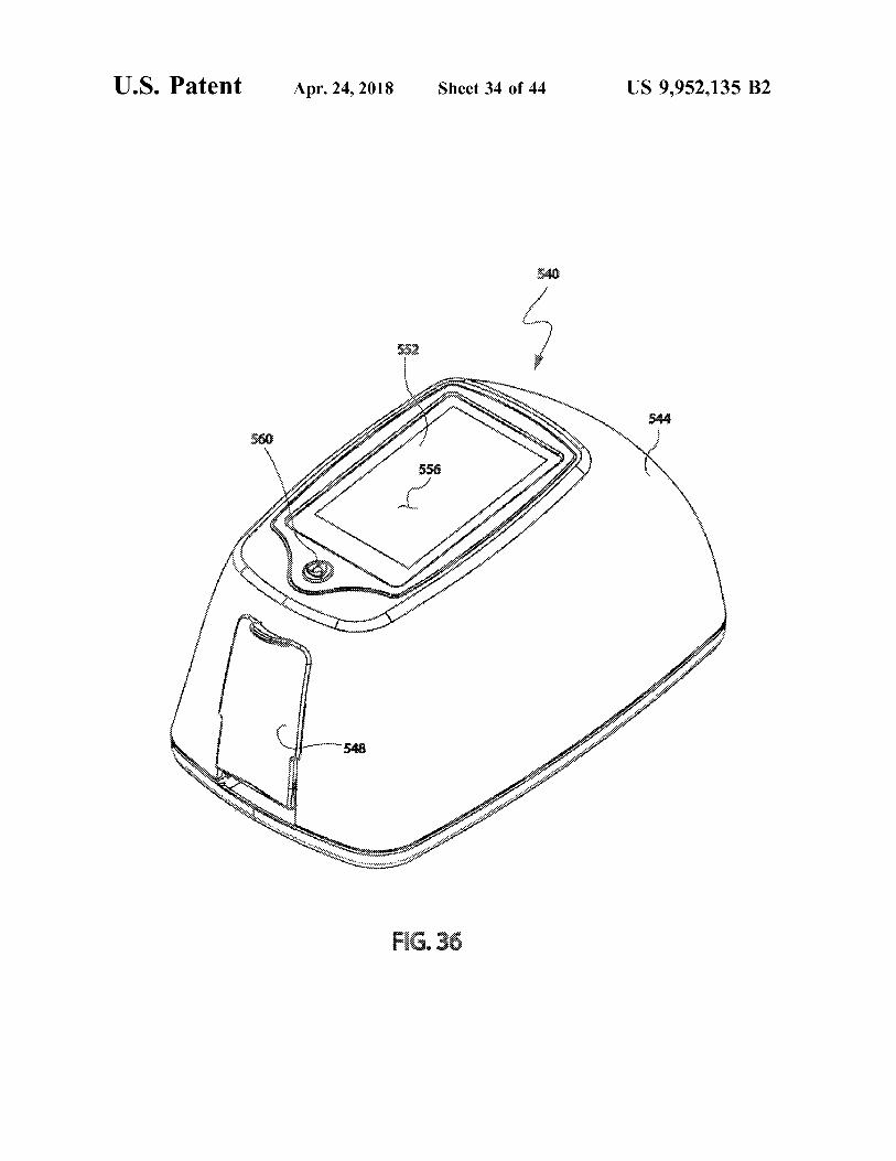
U . S . Patent Apr . 24 , 2018 Sheet 34 of 44 US 9 , 952 , 135 B2
Veitin
att Contatti ri W
TIMA T
THAT territo 15H62
MALFI 1 ya + mpattomat
ponto rural
ments inter
treat Swisstytus 45 Where
thuhet 11
+
stanova i nutit
m no
Y
monwerin Gu opout *
OW
Assamente 16 * *
nstitutas WAN to our i
FIG . 36

U . S . Patent Apr . 24 , 2018 Sheet 35 of 44 US 9 , 952 , 135 B2
uttet Cheche 114
w *
*
t
* * * Hittit * * *
* * * * * * * *
* * * * * * * * * * * * *
* * * * * * * *
W W 1 + 43681
1 + AWDHR quas * * *
+ 1 + Mittett . ttf th * * *
ETS is * * * * * * * * * 111
nimi imeretter sanaththepitetsinntekter * ittin
cher W
h
*
FITTI i
we
Anna where there unutartim wamewo Arom AD www hubungi FIG . 37

U . S . Patent Apr . 24 , 2018 Sheet 36 of 44 US 9 , 952 , 135 B2
* * + 1241
552 * *
W
interfloruits Spontan antaminat utt
tyminen i * * * * T
o nen the Thamestnantot with
568
unut
FIG . 38
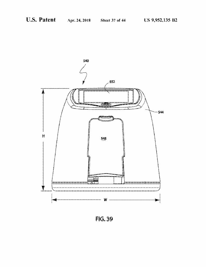
FIG . 39
* * IUM * * * LLLL LLLL * * * * * * * * * * * * * * * * 447444 WWWWWW
* * * * * * * * * * * * * * * * * * * * * * * * * * * * * * * * * * * * * * * * * * * * * * * * * * * * * * * * * * * * * * * * * * * * * * * * * * * * * * * * * * * * * * * * * * * * * * * * * * * * * * * * * * * * * * * * * * * * * * * * * * * * * * * * * * * * * * * * * * * * * *
WW143 . 255 somhet
wwwwwwwwwww mmwwwwwwwwwwwwwwwwwwwwwwww wwwwwwwwwwwwww www
Set sele
w
E
www . w wwwwwwwwwallow the
wwwwwwwwwwwwwwwwww alewwww w ww
wwwwwwwww tahetiden mustrigatenie 14 HFFFFFFFFFRF Yasmin Wwwsador ma33 * * * 11444
w w * wwwwwwwwwwwwwwwwwwwwwwwwwwwwwwwwwwwwwwwwwwwwwwwwwwwwwwwwwwwwwwwwwwwwwwwwwwwww wwwwww 9 0 * * * * * * 0002009 - 09 - 2002 www
PV
US 9 , 952 , 135 B2 Sheet 37 of 44 Apr . 24 , 2018 U . S . Patent
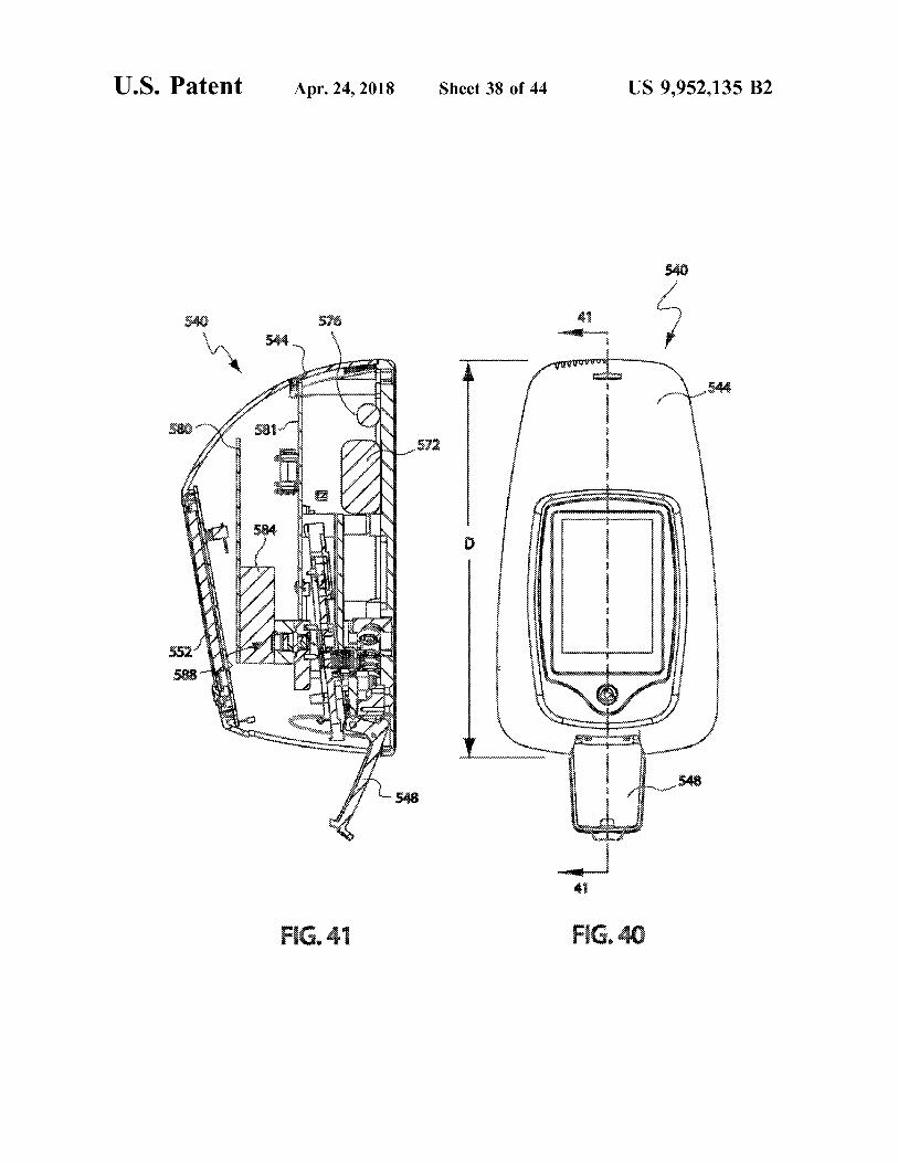
U . S . Patent Apr . 24 , 2018 Sheet 38 of 44 US 9 , 952 , 135 B2
web
AL * AM
wetter tutti
SHAWUtttt * pessoas sooogoosos MAMAMAMANTAN MAMAMARAAN through
Net # 3 PHALAM W
w
wwwda WWW womeMELAY inn71472 M
is mwafundam med been wanneer mw
powerpomp pasangannya de 1441414141411111111111 wwwwwwwwwwww WWorshi 4842434 A ning 1 wwwww 9 92434444444444444444444444319
w wwwwwwwwwwwwwwwwwww O
* * * *
11111111 * MWIMITETENIMENT * * * * * * * * *
opony AKAKKARA wa ngan agama ARKALAR swintermaalmunny 1
timur W by * *
ykonywa chowania www ?? A
.
YAMAN AN wa Soodnodiel
FIG . 41 FIG . 40
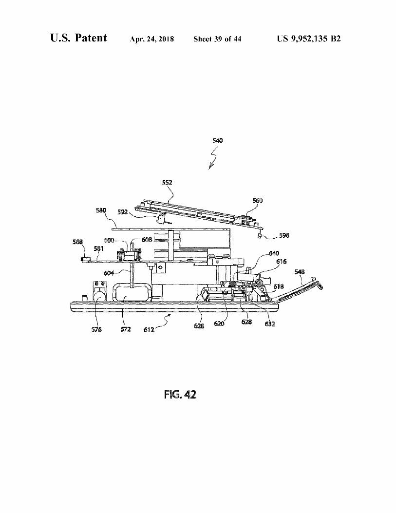
U . S . Patent Apr . 24 , 2018 Sheet 39 of 44 US 9 , 952 , 135 B2
wifikimit 3 wwwwwwwww 580 580 592 , og won wwwwwwwvisions
wwwwwwwwwwwwwwwwwwwwwwwwwwwwwwwww
Q - 596 568 600mm SIN wo
?????????? ??????
TTY WWWWWWWWWWWW 616 PFFRFFFFFFTARA VAAVX wwwwwwwwwww 548
um > > wwwxx
uwa Y?Y -
? ?? ??? ??????????????????????????????????????????????????????????????????????????????????????????????????? ??????????????????????
628 620 26 I 620 612 628 576 572 632 572 612
FIG . 42
U . S . Patent Apr . 24 , 2018 Sheet 40 of 44 US 9 , 952 , 135 B2
2 sro
wwwwwwwww w wwwwwwwwwww wwwwwwwwwwwwwwwwwwwwwww
tutte wwwwwwwwww
Fristadt 608
berapa www W
* * * * * wowania
eite ! 3 wy
wwwwwwwwwwwwww wwww wwwwwww
oooowooowww merrymuromi V
n iskush W
iew Amwa KM WYNIK : 600 There
T
urun
www Bernama wwwwwwww are twomentar Hirtretimi PANTAA Eurospodang Wooooo999 LYSSN w wwwwwwwwwwwww
www 61 w w wwwwwww wwwwwwwww wwwwwwwwwwwww w wwwwwwwwwwwwwAANNUAL www W
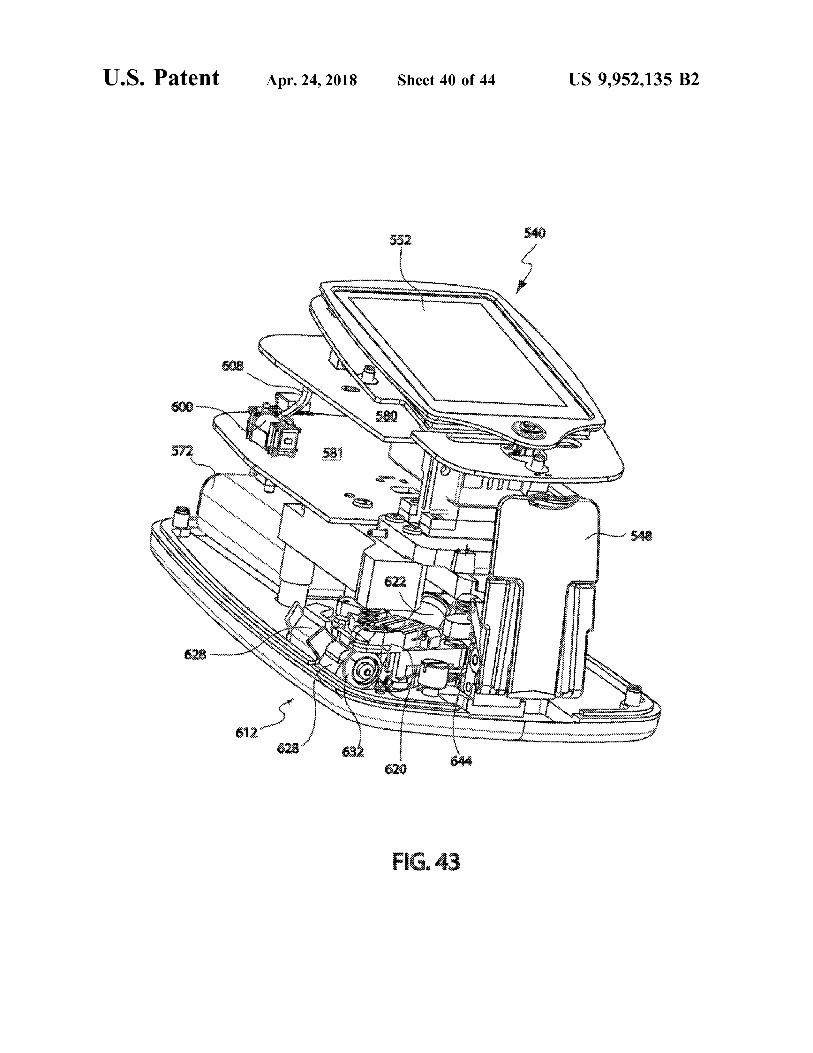
und 644
FIG . 43

U . S . Patent Apr . 24 , 2018 Sheet 41 of 44 US 9 , 952 , 135 B2
Sve * * * Tarot
THE
youturniture AMMA hiisiis
tany he wwwy
WAKO ? wirst www t Art WAY
W ooco Www wriques 636 Awit ma * Tema
sitten
7 * * WW * * *
FIG . 44
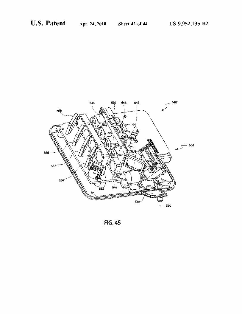
U . S . Patent Apr . 24 , 2018 Sheet 42 of 44 US 9 , 952 , 135 B2
$ 45 46 47 homem
m
e Wychowww Irwirretorn t tonight Paibu Waziri hu transwer september
Whitro THIRUNA that It was there
PAUTHIERRA WYSY * * * * hurtittelromlotteriet Benningtyaspiring * * * * ytowe doc hilo *
FIG . 45
U . S . Patent Apr . 24 , 2018 Sheet 43 of 44 US 9 , 952 , 135 B2
X
elo coood
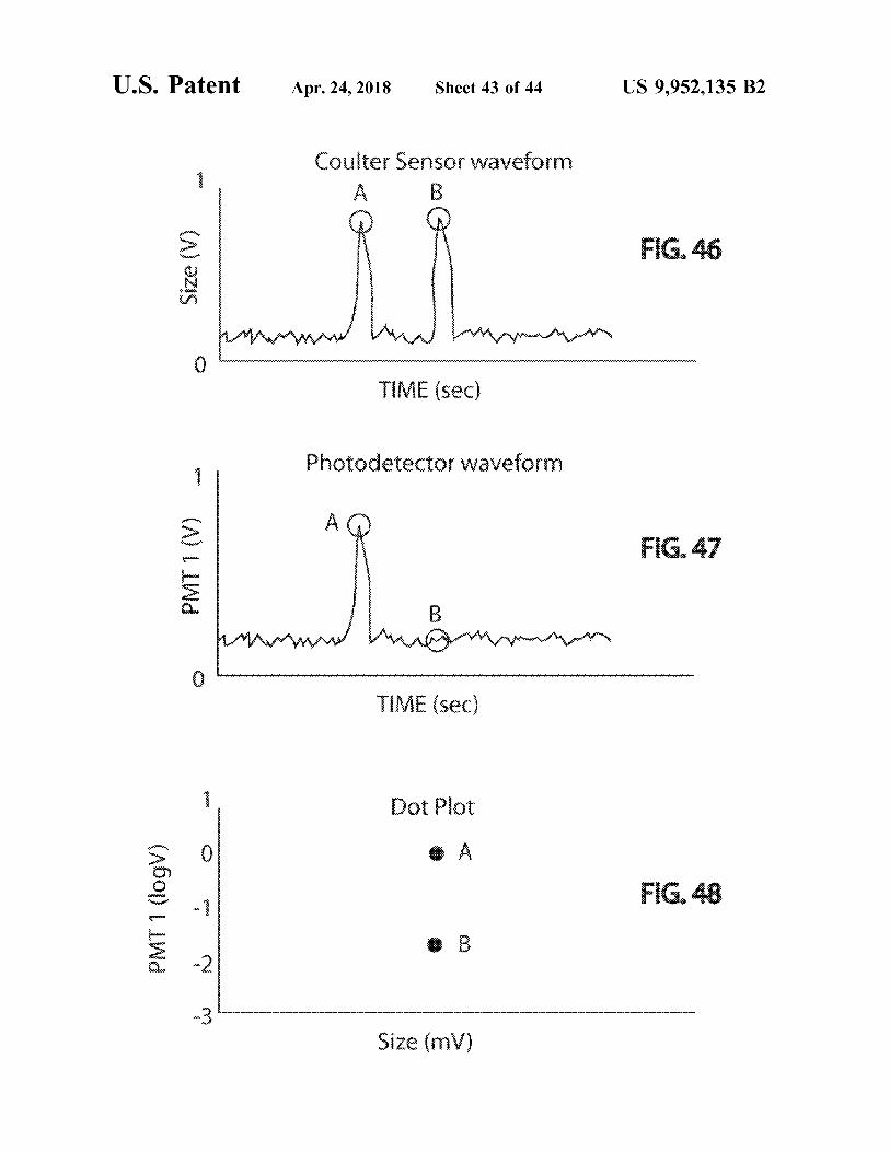
Coulter Sensor waveform A
c
FIG . 46 ( ?ZS
w w bramborot alma
TIME ( sec )
wanita Photodetector waveform * * * *
* *
A + - + * + - FIG . 47 www PMT 1 ( V ) * * *
R
P
w hummmunen What PAR Air -
FUR * *
ww TIME ( sec )
some o 1
wwwwwwwwwwwwwww Dot Plot
. A FIG . 48 PMT 1 ( logV )
o
f wwwwwwwwwwwwwwwwwwwwwwwwwwww . B
my Size ( mV )
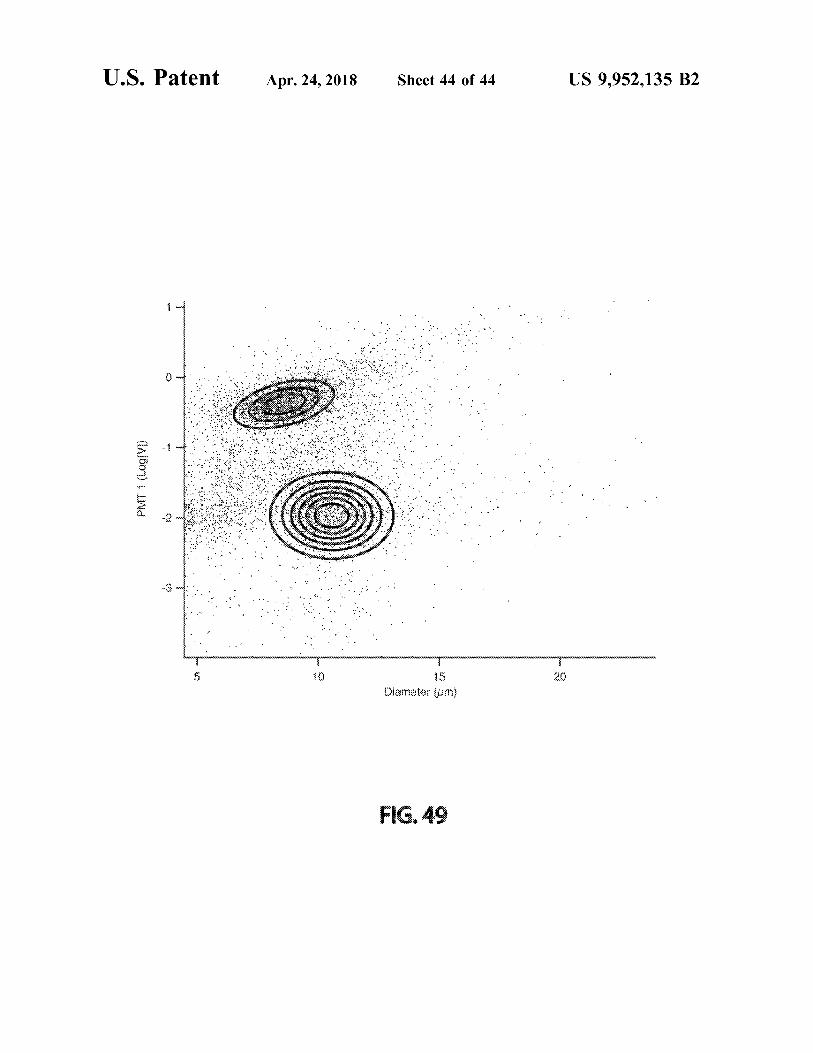
U . S . Patent Apr . 24 , 2018 Sheet 44 of 44 US 9 , 952 , 135 B2
-
: . -
wwwvN ,
i NHL
??????? . * * . !
. 1
( A160 ) ii .
* iwijania cambiamenti .
.
. Wd * * * *
*
. . " . . ; . : : . . " , T . ' wiki : immánujúnimimemwand .
duymus
Diameter ( um )
FIG . 49
US 9 , 952 , 135 B2
MICROFLUIDIC INTERROGATION DEVICE though set forth herein in their entireties , for their disclo sures of relevant technology and structure employed in
PRIORITY CLAIM various sensor arrangements . Flow cytometry is a well established technique that is
Related Applications 5 used to determine certain physical and chemical properties of microscopic particles by sensing certain optical properties
This application is a continuation of U . S . Utility applica of the particles . Many books and articles are available tion Ser . No . 13 / 666 , 131 filed on Nov . 1 , 2012 which is a detailing aspects of this useful investigational tool . For continuation - in - part ( CIP ) of U . S . Utility application Ser . example , operational principles of , and procedures for use No . 12 / 985 , 536 , filed Jan . 6 , 2011 , now U . S . Pat . No . 10 of , modern cytometers are set forth in “ Practical Flow 8 , 616 , 048 issued on Dec . 31 , 2013 which is a CIP of U . S . Cytometry ” by Howard M . Shapiro , the contents of which Utility application Ser . No . 12 / 381 , 252 , filed Mar . 10 , 2009 , are hereby incorporated by this reference . How cytometry is now U . S . Pat . No . 8 , 171 , 778 issued on May 8 , 2012 which currently used in a wide variety of applications including is a CIP of U . S . Utility application Ser . No . 11 / 800 , 167 , filed hematology , immunology , genetics , food science , pharma May 4 , 2007 , now U . S . Pat . No . 7 , 520 , 164 , issued on Apr . 15 cology , microbiology , parasitology and oncology . 21 , 2009 and claims the benefit under 35 U . S . C . 119 ( e ) of In flow cytometry , microscopic panicles entrained in a the filing date of US Provisional Patent Application No . carrier fluid are typically arranged in single - file inside a core 60 / 798 , 155 , filed May 5 , 2006 . This application is also a CIP stream using hydrodynamic focusing ( sheath fluid flow ) . of U . S . Utility application Ser . No . 13 / 629 , 784 filed on Sep . The particles are then individually interrogated by an optical 28 , 2012 which is a CIP of U . S . Utility application Ser . No . 20 detection system . The interrogation typically includes 12 / 378 , 757 , filed Feb . 19 , 2009 , now U . S . Pat . No . 8 , 072 , directing a light beam from a radiation source , such as a 603 , issued Dec . 6 , 2011 which is a CIP of U . S . Utility laser , transversely across the focused stream of single - file application Ser . No . 11 / 701 , 711 , filed Feb . 2 , 2007 , now U . S . particles . The light beam is scattered by each particle , to Pat . No . 7 , 515 , 268 , issued Apr . 7 , 2009 which claims the produce a scatter profile . The scatter profile may be analyzed benefit under 35 U . S . C . 119 ( e ) of the filing date of U . S . 25 by measuring the light intensity at both small and larger Provisional Patent Application No . 60 / 764 , 697 , filed Feb . 2 , scatter angles . Certain physical and / or chemical properties 2006 . U . S . Utility application Ser . No . 13 / 629 , 784 is also a of each particle can then be determined from the scatter CIP U . S . Utility application Ser . No . 12 / 936 , 243 filed on profile . Currently available now cytometers are generally Oct . 4 , 2010 , now U . S . Pat . No . 8 , 182 , 635 , issued May 22 , large , permanently - installed devices , and can not reasonably 2012 which is a 371 National Stage Entry of the Interna - 30 be considered to be portable devices . tional Patent Application filed on Apr . 7 , 2009 , under the It is also known to apply fluorescing markers to selected PCT . Serial No . PCT / US2009 / 002172 , which claims the particles of interest prior to processing such particles in a benefit under 35 U . S . C . 119 ( e ) of the filing dates of U . S . cytometer . For example , particles such as blood cells can be Provisional Patent Application Nos . 61 / 123 , 248 , filed Apr . 7 , tagged with fluorescent molecules by using conjugated 2008 and 61 / 124 , 121 , filed Apr . 14 , 2008 , the entire disclo - 35 monoclonal antibodies . The wavelength of the radiation sures of which are all hereby incorporated by this reference source ( typically a laser ) , is matched to the excitation as though set forth in their entirety herein with the exception wavelength of the fluorescing molecule marker . The tagged of application Ser . Nos . 13 / 629 , 784 and 12 / 936 , 243 . particles fluoresce in the cytometer when excited by the
transversely oriented laser beam . The fluorescence given off BACKGROUND 40 by the excited particle can be detected by an appropriately
configured detector , which is conventionally mounted trans Field of the Invention verse to the path of the particles in the interrogation portion This invention relates generally to electrically - based , and of the cytometer . Therefore , cells tagged with fluorescing
or optically - based , interrogation devices for use in detecting , markers can be easily detected for counting , or other data quantifying , qualifying , or otherwise sensing , particles car - 45 manipulation . ried by a fluid . It is particularly directed to a portable , Unfortunately , flow cytometers are undesirably complex table - top , stand - alone interrogation device for use in such and expensive pieces of equipment . Care must be taken to particle characterization . ensure the machine is set up correctly , and properly cali
State of the Art brated . It would be an advance to provide a robust , inex Pioneering work in particle detection by measuring 50 pensive apparatus that can be used to promote single - file
impedance deviation caused by particles flowing through a particle travel through an optically based interrogation zone small aperture between two containers of electrically con - to promote rapid processing of a plurality of different ductive fluid is disclosed in U . S . Pat . No . 2 , 456 , 508 to W . H . particle - bearing fluid samples . Coulter . Coulter ' s name is now associated with the principle While considerable progress has been made in the con of particles causing a change in electric impedance as they 55 struction and use of microfluidic interrogation devices incor occlude a portion of the aperture . Since publication of his porating sheathed fluid flow , a need remains for microfluidic patent , considerable effort has been devoted to developing interrogation devices that are less expensive , reduced in size and refining sensing devices operating under the Coulter to be portable e . g . easily moved between sites of operation , principle . Relevant U . S . patents include U . S . Pat . No . 5 , 376 , and permit enhanced manipulation of a fluid sample and / or 878 to Fisher , U . S . Pat . No . 6 , 703 , 819 to Gascoyne et al . , 60 data obtained , therefrom . It would be an improvement to U . S . Pat . No . 6 , 437 , 551 to Krulevitch et al . , U . S . Pat . No . provide a sensitive and accurate interrogation device struc 6 , 426 , 615 to Mehta , U . S . Pat . No . 6 , 169 , 394 to Frazier et al . , tured to couple with a single - file particle alignment element U . S . Pat . No . 6 , 454 , 945 and U . S . Pat . No . 6 , 488 , 896 to that is sufficiently robust as to permit its use to serially Weigl et al . , U . S . Pat . No . 6 , 656 , 431 to Holl et al . , and U . S . interrogate a plurality of samples . Desirably , such an Pat . No . 6 , 794 , 877 to Blomberg et al . Patent application 65 improved particle , alignment element would be removable 2002 / 117 , 517 to Unger et al . is also relevant . Each above - from the interrogation device , and even potentially referenced document is hereby incorporated by reference , as exchanged for a different alignment element having different
US 9 , 952 , 135 B2
15
interrogation capabilities . It would be another improvement is defined , at least in part , by a portion of a microcapillary to provide an interrogation device structured to permit lumen . In certain preferred embodiments , an interrogation interrogation of a fluid sample having a pre - defined volume , zone is defined , at least in part , by an aperture disposed to which can be a sub - set of an over - size fluid sample that was permit fluid flow from a first channel disposed in a first thin extracted from a bulk container of fluid and loaded into the 5 film layer , through the aperture , and into a second channel interrogation device . Another improvement would provide disposed in a second thin film layer . an interrogation device that can operate as a portable , One operable microfluidic particle detector includes a stand - alone test - and - display station . Still further improve - laser configured and arranged in operable combination with ments would provide verification of sample presence at one a heat sink to permit turning the laser on momentarily for or more desired position in the device , verify particle sensor 10 purpose of particle interrogation and turning the laser off functionality or health ) and / or fluid sample , integrity , and before it overheats . A workable microfluidic particle detec permit estimation of the flow rate and / or volumetric particle tor may include a laser and an adjustable laser mounting count of an interrogated fluid sample . mechanism , with the laser mounting mechanism being
BRIEF SUMMARY OF THE INVENTION adjustable responsive to feedback from a sensor ( e . g . a photodetector ) to permit orienting the laser for impingement
One aspect of this invention provides microfluidic inter - of energy emitted by the laser onto a desired location in an rogation devices structured sufficiently small in both weight interrogation zone . and enclosed volume as to permit a single person , by hand Interrogation devices according to certain principles of and without tools , to move the entirety of the interrogation 20 the invention include a microfluidic path that extends device from a first location to a second location . To be through a portion of the housing and is arranged to urge portable , interrogation devices typically are structured to particles carried in a fluid into substantially single - file travel weigh less than about 50 pounds , and desirably , to weigh through an interrogation zone . In preferred embodiments , a less than about 15 pounds . portion of the microfluidic path is removable from the
Preferred embodiments are structured and arranged as 25 housing . Sometimes , the microfluidic particle detector self - contained interrogation devices to permit their stand includes the removable , portion of the microfluidic path . alone operation to perform a microfluidic interrogation on a Preferably , the portion of removable microfluidic path is fluid sample , to process resulting microfluidic interrogation removable , in a tool - free operation . data , and to display a corresponding test result without A display device is generally carried by the housing and requiring input from a remote computing device . However , 30 is disposed operably in - circuit with the microprocessor . A interrogation devices according to certain principles of the currently preferred display device includes a touch - sensitive invention may be structured and arranged to permit coupling surface to receive user input . However , user input may by to a remote computing device effective to upload data effected by way of a keyboard and / or mouse , or other known obtained from particle interrogation by the microfluidic communication device . An operable display device can interrogation device . 35 present a visual image representative of particle interroga
An exemplary interrogation device , according to certain tion data resulting from microfluidic interrogation per principles of the invention includes a bench - top housing and formed by the interrogation device . A display device of a a microprocessor and associated memory that are protected currently preferred interrogation device includes a touch by the housing . An operable housing is sired to fit inside a screen disposed in - circuit with the microprocessor and struc volume of about 24 inches in height by about 24 inches in 40 tured to receive input from a user effective to perform a task width by about 24 inches in depth . A more preferred housing that may be selected from a plurality of programmed tasks . defines a volume that is smaller than defined by a plan form Certain embodiments of an interrogation device may of about 12 inches by about 9 inches and an orthogonal include a source of radiation disposed to impinge radiation height of about 9 inches . One currently preferred interroga - onto particles in the interrogation zone . In such case , at least tion device is sired about 41 / 2 inches in both maximum width 45 a first photodetector is disposed to detect radiation propa and height , and about 8 inches in maximum depth . gating from the interrogation zone , and arranged in - circuit to
The microprocessor and memory are operably disposable communicate a signal , corresponding to detected radiation , in - circuit with a microfluidic particle detector to receive to the microprocessor . particle - related data from the particle detector . Preferably , An interrogation device structured according to certain the microprocessor is capable of being programmable , to 50 principles of the invention will generally be capable of perform a plurality of different particle interrogation and illustrating test results soon after performing a test . In certain data display tasks . One preferred microprocessor runs under cases , a microprocessor may be programmed for signal the Linux operating system , although microprocessors oper - processing that performs peak finding in the raw data by ating under other operating systems are also workable . combining raw data from a plurality of optically - based An operable microfluidic particle detector may be struc - 55 detectors , and displaying a result on the display device .
tured to operate under , or detect , either or both of , the Optionally , a microprocessor can be programmed for signal Coulter principle and optically - based phenomena . That is , processing that performs peak finding in the raw data by one or mute electrical signal may be applied to , and as combining data from one or more electrically - based detector corresponding electrical property may be detected from , an and ( typically ) from at least one optically - based detector . interrogation zone . Similarly , radiation may be applied to , 60 and corresponding emission or scatter radiation may be BRIEF DESCRIPTION OF THE DRAWINGS detected from , an interrogation zone . An operable particle detector may also include a plurality of optically - based , or In the drawings , which illustrate what are currently con electrically - based , sensors or detectors . sidered to be the best modes for carrying out the invention ;
In an exemplary embodiment , an interrogation zone may 65 FIG . 1 is a cross - section schematic of a multi - layer sensor be defined by structure forming non - sheath fluid flow . An component structured according to certain principles of the operable embodiment may include an interrogation zone that instant invention ;
US 9 , 952 , 135 B2
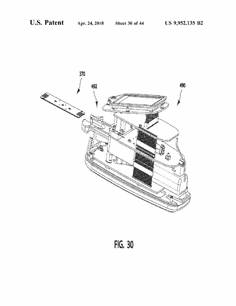
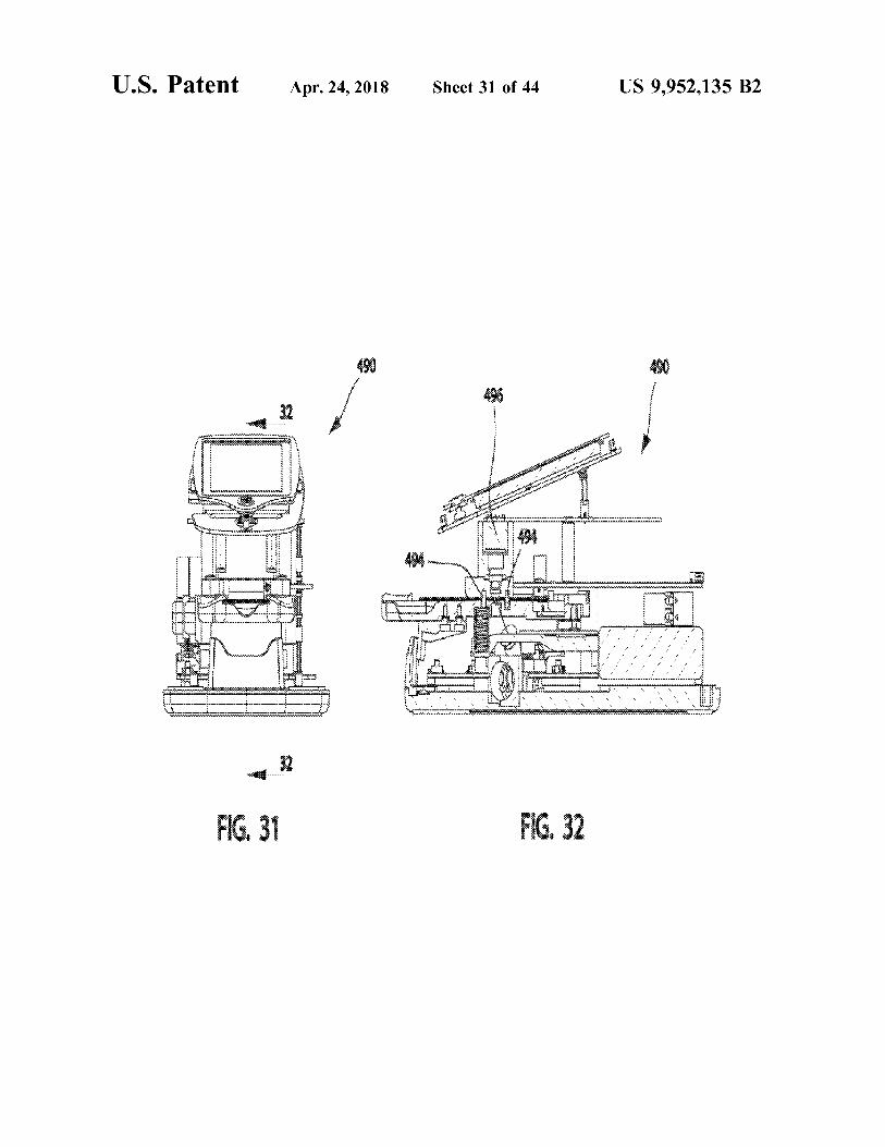
FIG . 2 is a top view of an exemplary multi - layer sensor FIG . 30 is a view in perspective of a currently preferred component ; sensor poised for docking with an interrogation device ;
FIG . 3 is an exploded assembly view in perspective from FIG . 31 is an end view in elevation of the interrogation above of the multi - layer sensor component of FIG . 2 ; device illustrated in FIG . 30 ;
FIG . 4 is an exploded assembly view in perspective from 5 FIG . 32 is a cross - section view taken through section below of the multi - layer sensor component of FIG . 2 ; 32 - 32 in FIG . 31 and looking in the direction of the arrows ;
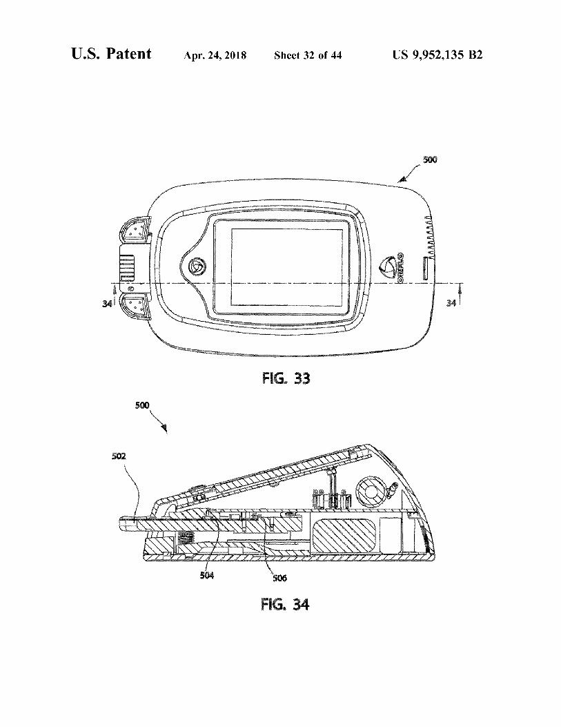
FIG . 5 is a bottom view of the multi - layer sensor com FIG . 33 is a top view of an alternative interrogation device ponent of FIG . 2 ; FIG . 34 is a cross - section view in elevation taken through
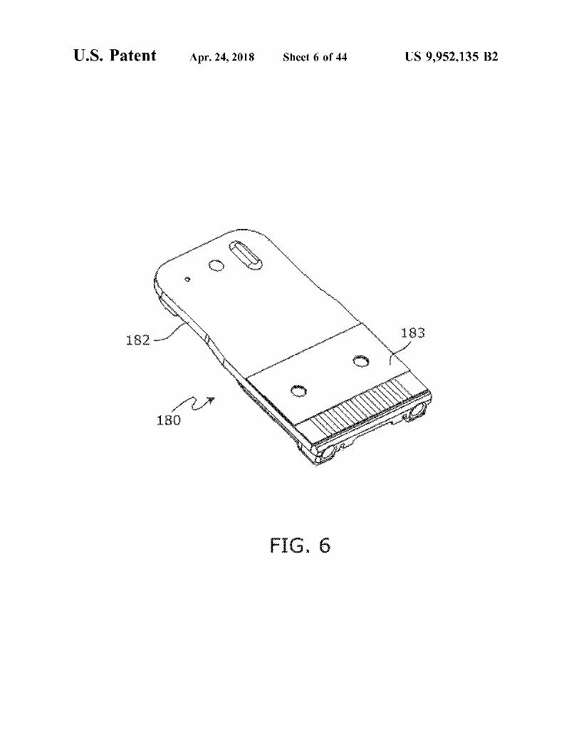
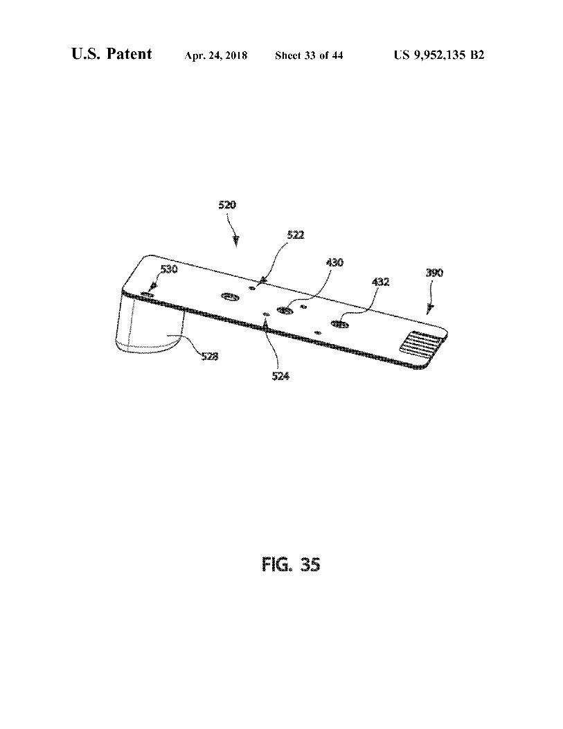
FIG . 6 is a view in perspective from above of a sensor section 34 - 34 in FIG . 33 and looking in the direction of the component carried by a cartridge ; 10 arrows ;
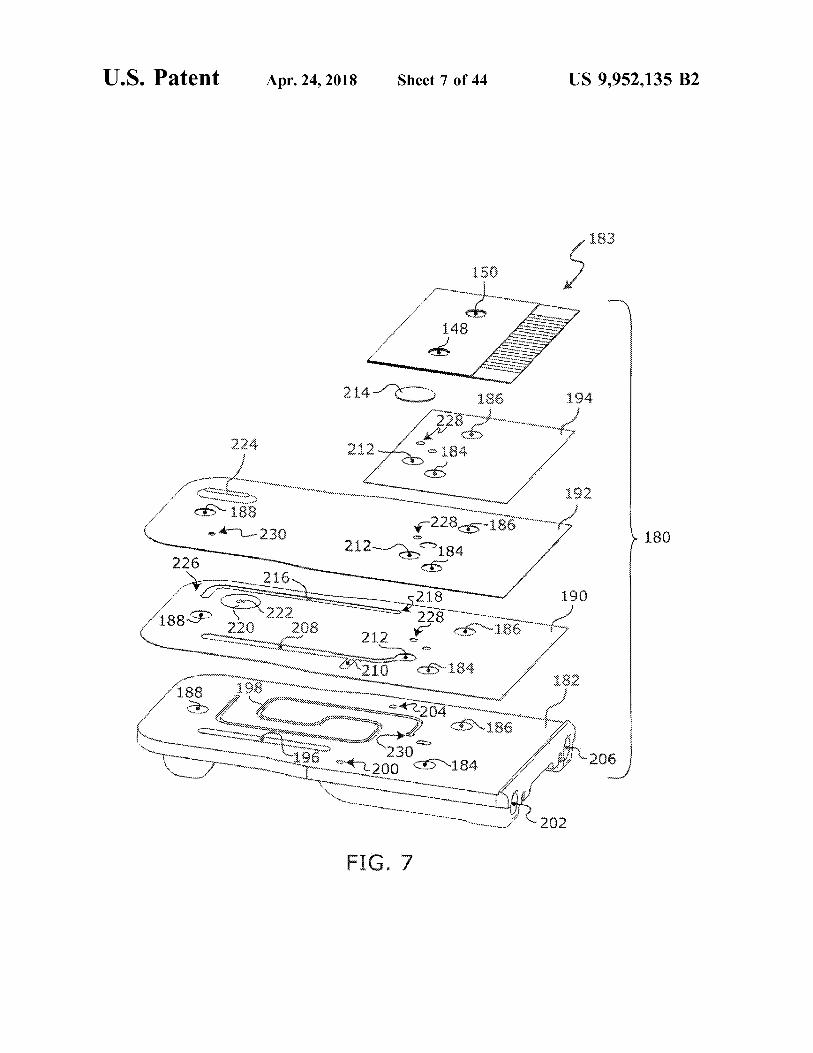
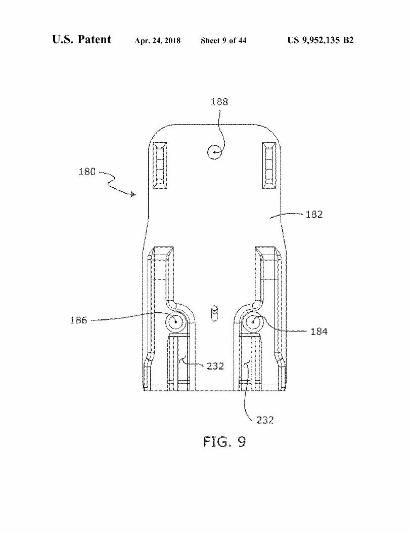
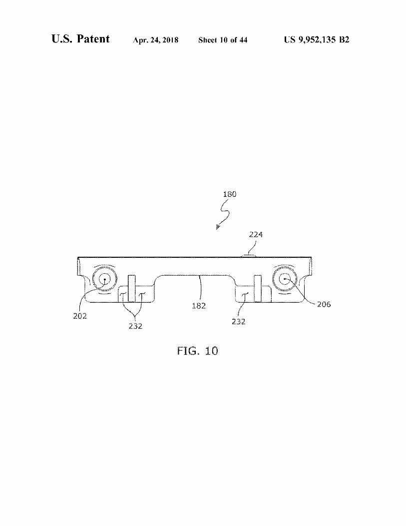
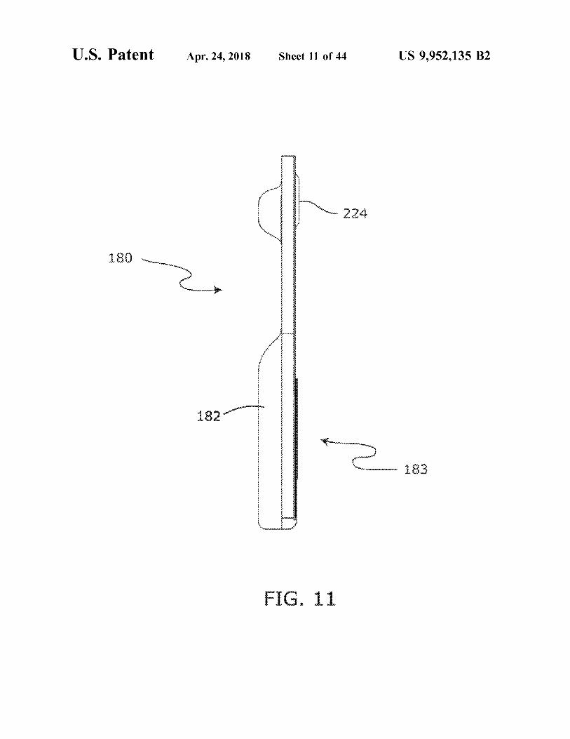
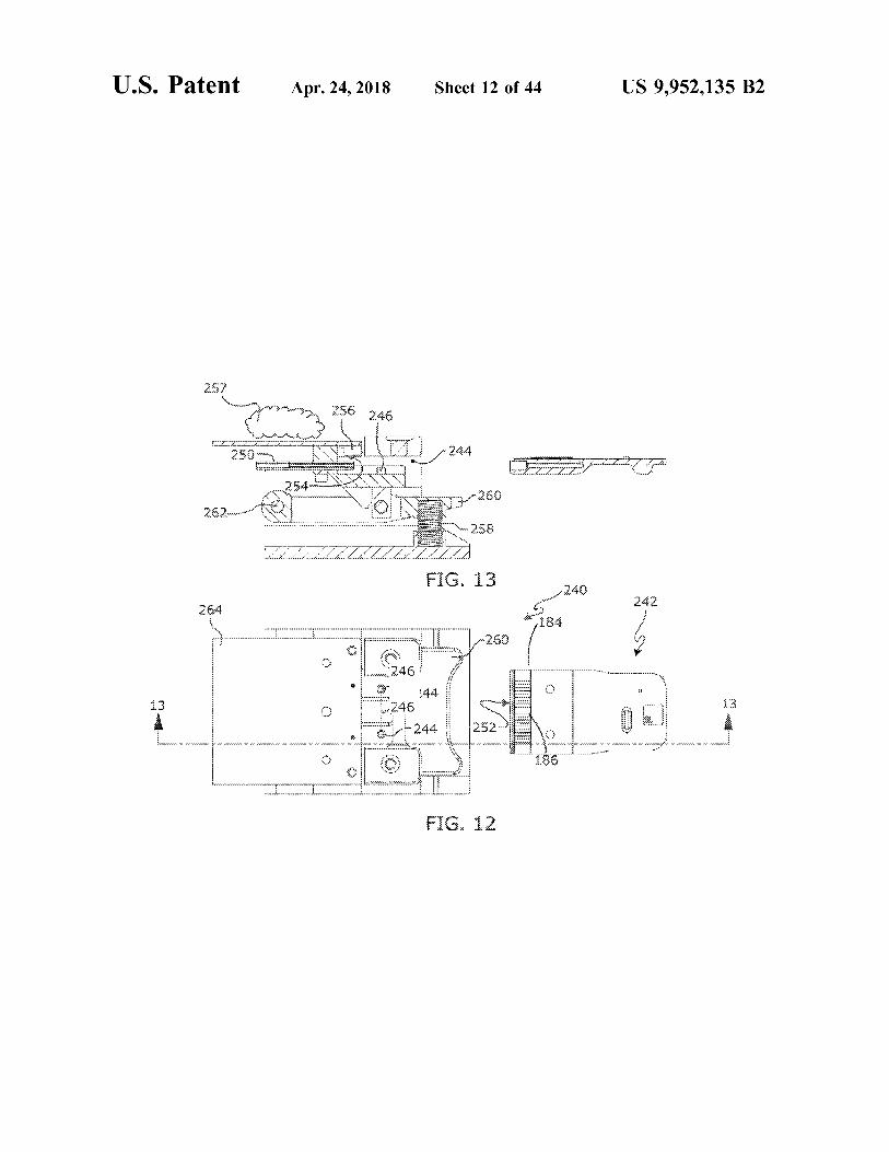
FIG . 7 is an exploded assembly view in perspective from FIG . 35 a view in perspective of an alternative sensor embodiment adapted for serial processing of a plurality of above of the cartridge of FIG . 6 ; fluid samples ; FIG . 8 is a top view of the cartridge of FIG . 6 ; FIG . 36 is a perspective view from above , looking at the FIG . 9 is a bottom view of the cartridge of FIG . 6 : 15 front of a currently preferred interrogation device ; FIG . 10 is an end view of the cartridge of FIG . 6 ; FIG . 37 is a view similar to that in FIG . 36 , but with a door FIG . 11 is a side view of the cartridge of FIG . 6 ; of the device in an open position ; FIG . 12 is a top view of a cartridge in position for its FIG . 38 is a view in perspective from above , looking at installation into an interrogation device ; the rear of the device in FIG . 36 ;
FIG . 13 is a cross - section view , taken through section 20 FIG . 39 is a front view in elevation of the device in FIG . 13 - 13 in FIG . 12 , and looking in the direction of the arrows ; 36 ;
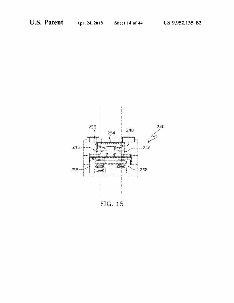
FIG . 14 is a side view of the assembly of FIG . 12 ; FIG . 40 is a top plan view of the device in FIG . 36 ; FIG . 15 is a cartridge - loading end view of the interroga FIG . 41 is a cross section view taken through section
tion device of FIG . 12 ; 41 - 41 in FIG . 40 , and looking in the direction of the arrows ; FIG . 16 is a schematic of a workable interrogation circuit 25 FIG . 42 is a side view in elevation of the device in FIG .
for use with a sensor such as illustrated in FIG . 6 ; 36 , with the external cover substantially removed ; FIG . 17 is an X - Y plot representative of certain electri - FIG . 43 is a front view in perspective of the device in FIG .
cally - based interrogation data obtainable using certain pre - 42 ; ferred sensor embodiments ; FIG . 44 is a view in perspective of a laser - aiming portion
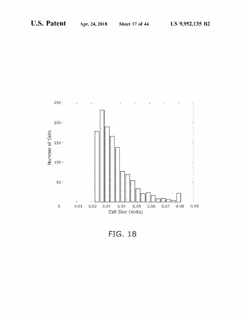
FIG . 18 is a bar chart depicting , data related to particle 30 of the device in FIG . 43 ; size distribution , that may be obtained using certain pre - FIG . 45 is a view in perspective of an alternative sensor ferred sensor embodiments ; arrangement in an alternative interrogation device structured
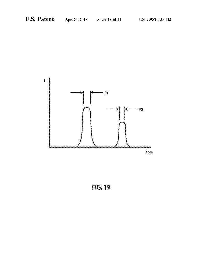
FIG . 19 is an X - Y plot representative of optically - based according to certain principles of the invention ; and interrogation data obtainable using certain preferred sensor FIGS . 46 through 49 are plots of exemplary data obtain embodiments ; 35 able with certain embodiments structured according to cer
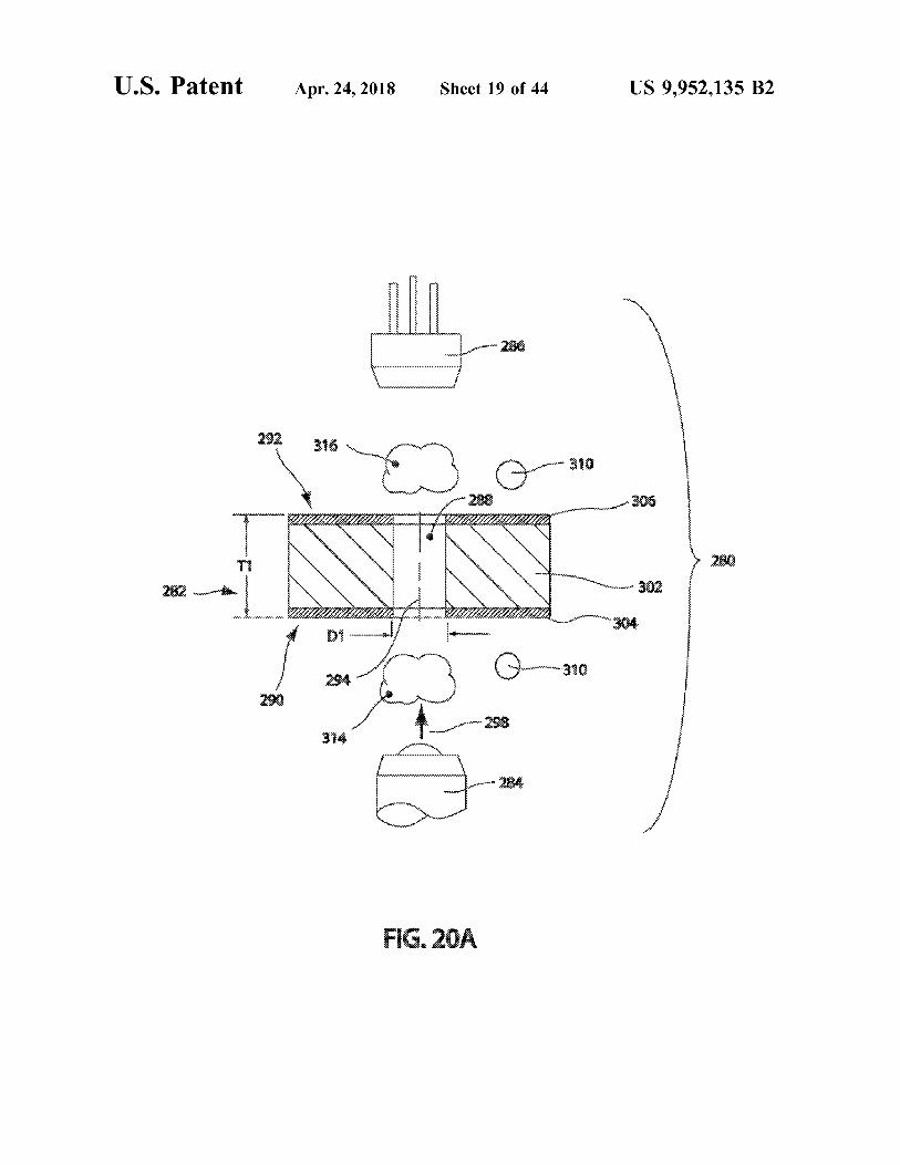
FIG . 20A is a schematic of a cross - section taken through tain principles of the invention . an embodiment illustrating general principles of optically based operation of certain embodiments of the invention ; DETAILED DESCRIPTION OF THE
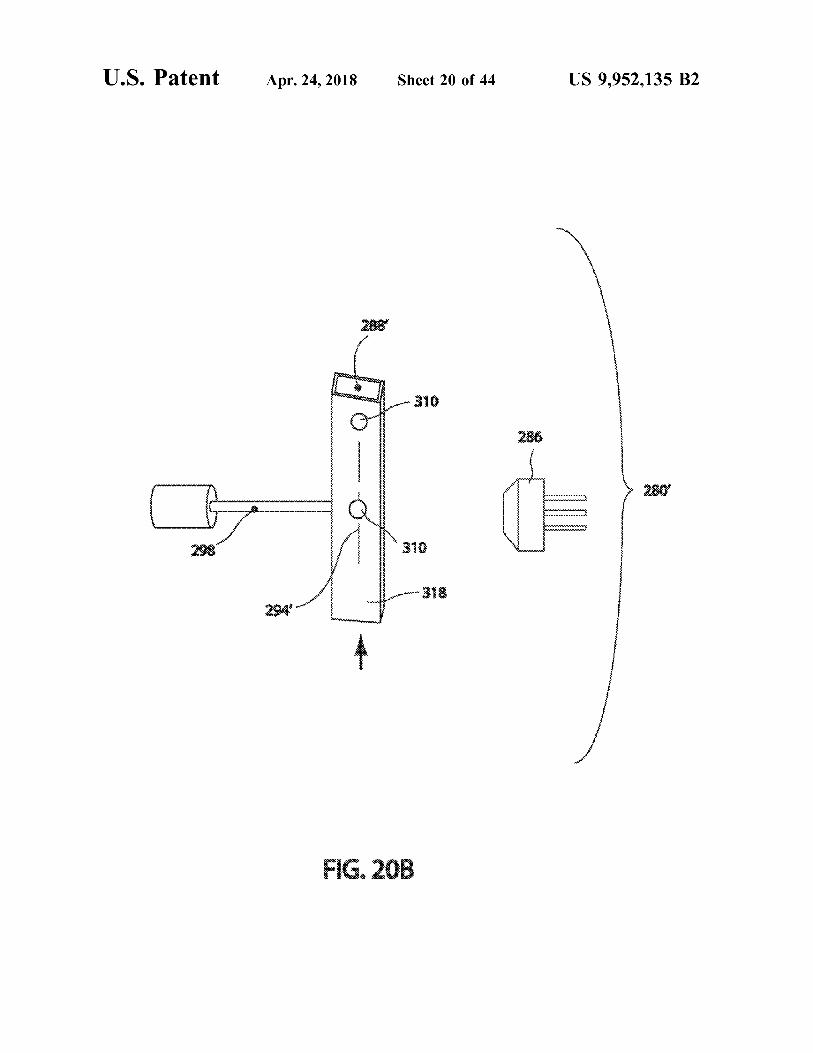
FIG . 20B is a schematic of an alternative embodiment ILLUSTRATED EMBODIMENTS illustrating general principles of optically - based operation of 40 certain embodiments of the invention ; Reference will now be made to the drawings in which the
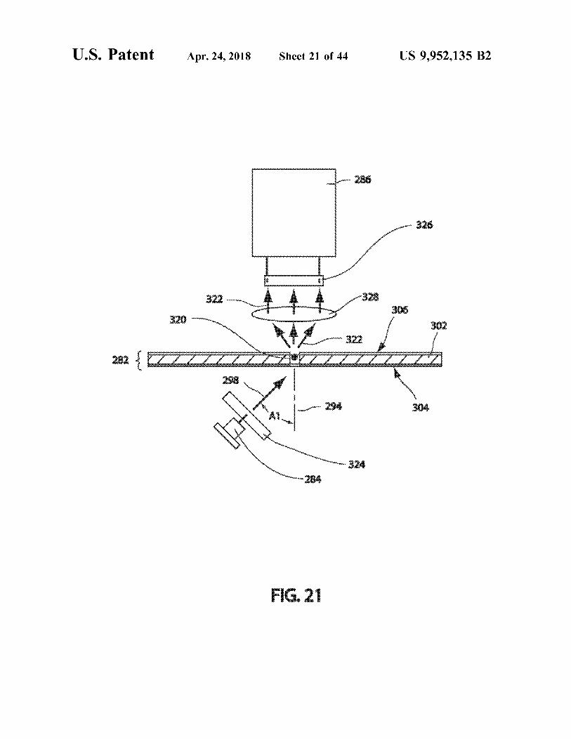
FIG . 21 is a view in elevation of a currently preferred various elements of the illustrated embodiments will be arrangement for certain structure of an operable interroga - given numerical designations and in which the invention tion device ; will be discussed so as to enable one skilled in the art to
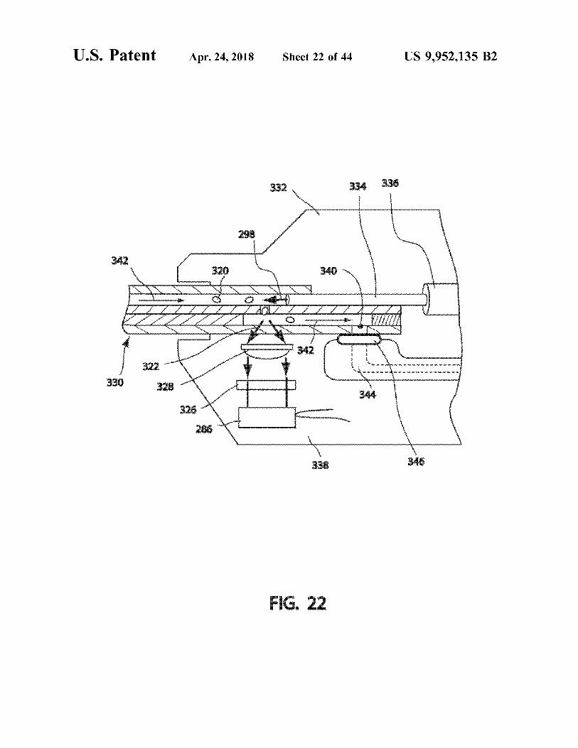
FIG . 22 is a cross - section in elevation , illustrating certain 45 make and use the invention . It is to be understood that the details of a sensor structured as a pipette in association with following description is only exemplary of the principles of a portion of an interrogation device ; the present invention , and should not be viewed as narrow
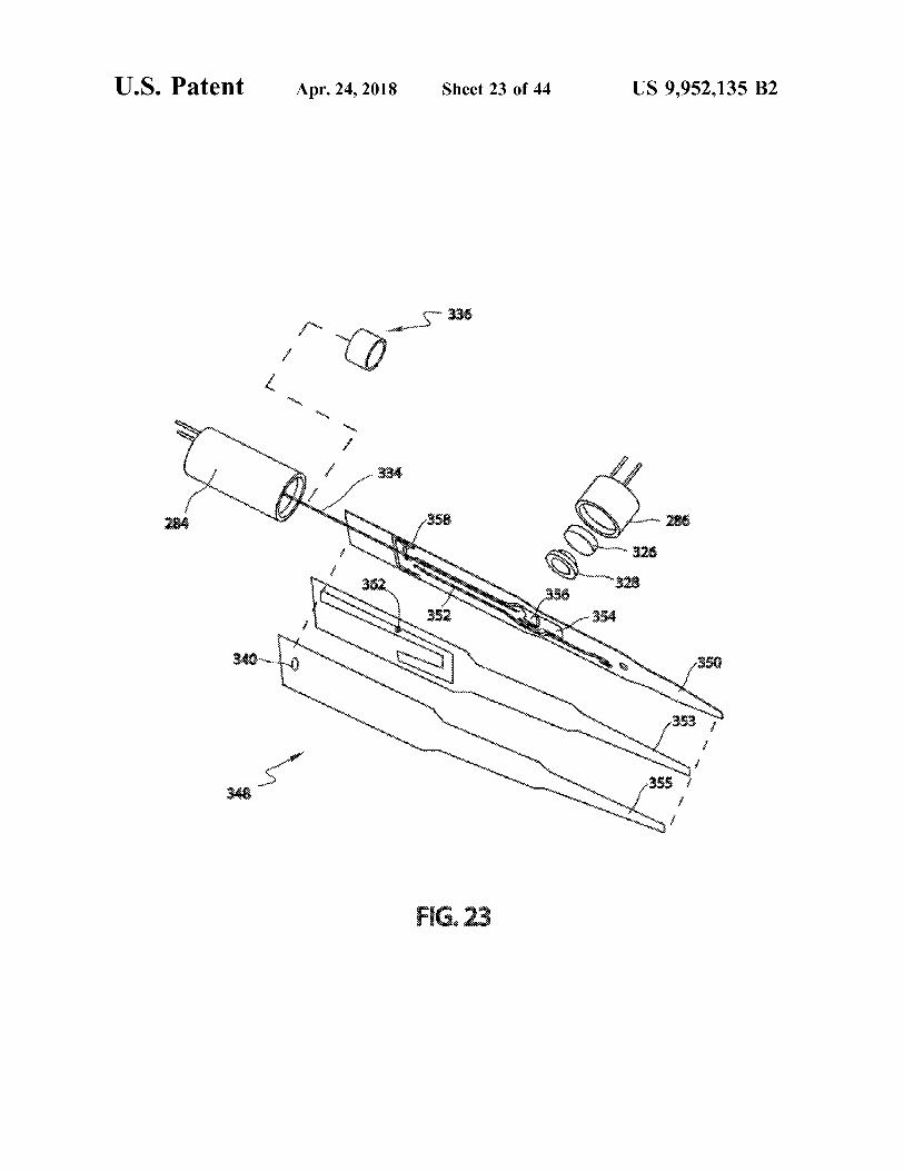
FIG . 23 is a view in perspective , partially exploded , of an ing the claims which follow . electrically instrumented opaque member portion of a sensor Currently preferred embodiments of the present invention structured as a pipette , with the assembly illustrated in 50 provide stand - alone , reliable , accurate , and relatively low operable association with a radiation source and a detector ; cost , particle characterization devices . Preferably , a device
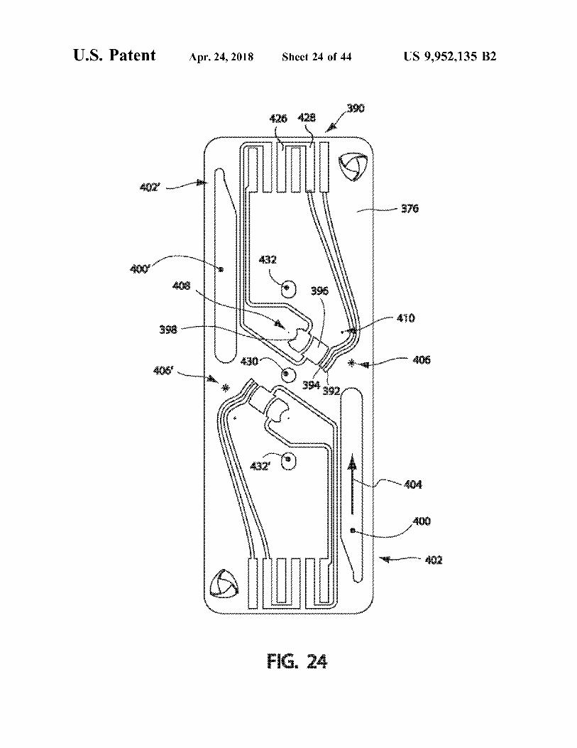
FIG . 24 is a top view of an interrogation layer of a structured according to certain principles of the invention is preferred sensor that may be structured as a cassette , or sufficiently portable that it may be moved from one location cartridge ; to another location by a single person and without requiring
FIG . 25 is a bottom view of the interrogation layer in FIG . 55 use of tools . Certain interrogation devices may be structured 24 ; to interface with a removable element that provides a
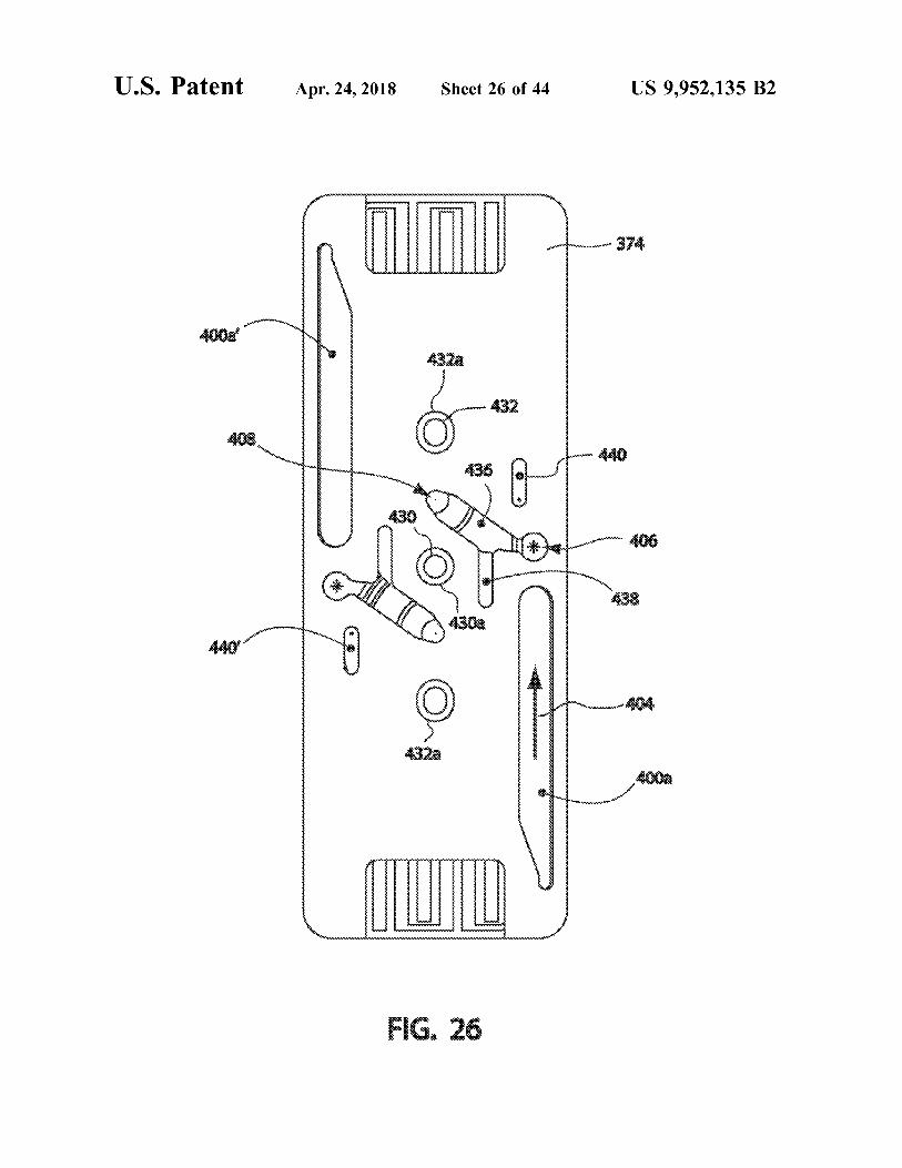
FIG . 26 is a top view of the interrogation layer in FIG . 24 , microfluidic fluid channel , configured to urge particles car with a channel layer also installed ; ried by a fluid into substantially single - file travel . Some
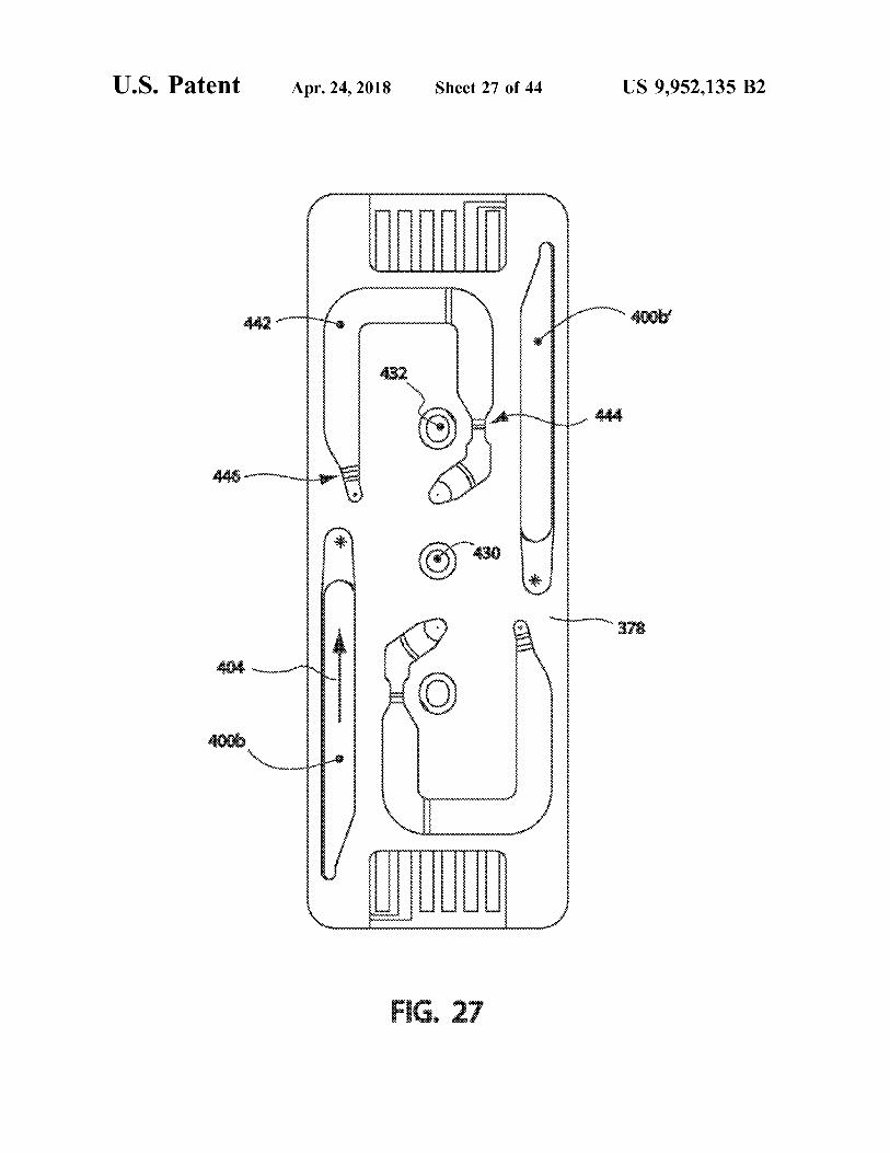
FIG . 27 is a bottom view of an interrogation layer similar times such removable element is disposable , although it is to that illustrated in FIG . 24 , with a channel layer also 60 within contemplation to reuse certain such removable chan installed ; nels , e . g . after suitable cleaning , in any case , an interrogation
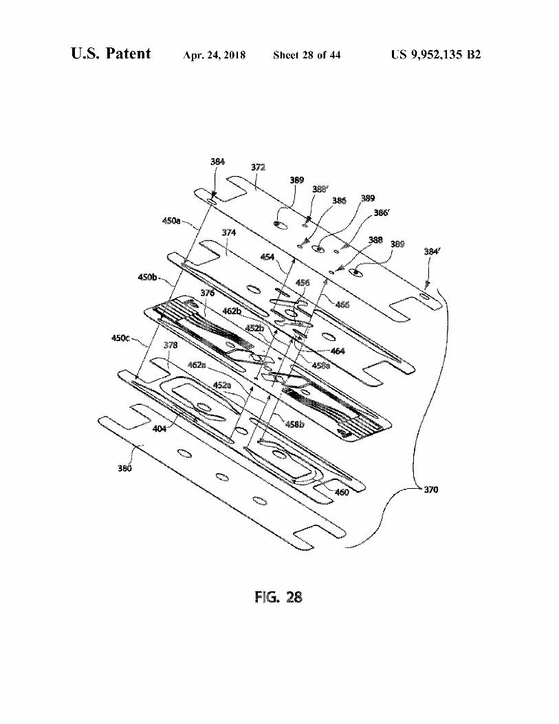
FIG . 28 is an exploded view in perspective of a sensor device provided by the instant invention is operable to structured as a cassette and including the interrogation layer perform analyses of various sorts on particles that are carried in FIG . 24 ; in a fluid .
FIG . 29 is a top view of a workable test arrangement 65 Examples of analyses in which embodiments of the including a vacuum source to urge fluid movement through invention may be used to advantage include , without limi a sensor ; tation , counting , characterizing , or detecting members of
or
US 9 , 952 , 135 B2
any cultured cells , and in particular blood cell analyses such column of fluid into a ( generally faster - moving ) surrounding as counting red blood cells ( RBCs ) and / or white blood cells “ sheath ” of fluid to hydrodynamically focus the interior ( WBCs ) , complete blood counts ( CBCs ) , CD4 / CD8 white column and thereby urge particles toward single - file travel . blood cell counting for HIV + individuals ; whole milk analy The term “ iron - sheath fluid flow ” is defined as encompass sis ; sperm count in semen samples ; and generally those 5 ing microfluidic fluid flow in e . g . channels spaced apart by analyses involving numerical evaluation or particle , size an orifice ; capillary fluid flow ; and other stationary struc distribution for a particle - bearing fluid ( including non - bio - tures ; that directly urge particles carried in a fluid toward logical ) . Embodiments of the invention may be used to single - file travel , but not including sheath fluid flow . There provide rapid an point - of - care testing , including home mar - fore , sheath fluid flow to urge particles into single - file travel ket blood diagnostic tests . Certain embodiments may be 10 is expressly outside such definition . used as an automated laboratory research cell counter to FIG . 1 illustrates certain operational details of a currently replace manual hemacytometry . It is within contemplation to preferred sensor component , generally indicated at 100 , combine , certain embodiments of the instant invention with structured according to certain principles of the instant additional diagnostic elements , such as fluorescence , to invention . Sensor component 100 is typically used in remov permit sophisticated cellular analysis and counting ( such as 15 able combination with ancillary interrogation structure CBC with 5 - part WBC differential ) . It is further contem described below , and operates , at least in - part , to urge plated that embodiments of the invention may be adapted to single - file travel of particles in a carrier fluid . Sensor com provide a low - cost fluorescence activated cell sorter p onents having alternative configurations are within con ( FACS ) , and may be used to determine somatic cell counts templation , including alternative structural arrangements in milk for the dairy industry . 20 effective to produce substantially single - file travel of par
For convenience in this disclosure , the invention will ticles in a carrier fluid . It is believed that embodiments generally be described with reference to its use as a particle structured according to email ) principles of the instant detector . Such description is not intended to limit the scope invention could include a removable sensor component of the instant invention in any way . It is recognized that based upon sheathed fluid now , capillary fluid flow , and / or certain embodiments of the invention may be used simply to 25 micro - channel fluid flow . detect passage of particles , e . g . for counting . Other embodi - As illustrated , sensor component 100 includes a sandwich ments may be structured to determine particle characteris - of five layers , which are respectively denoted by numerals tics , such as size , or type , thereby permitting discrimination 102 , 104 , 106 , 108 , and 110 , from top - to - bottom . A first analyses . Furthermore , for convenience , the term " fluid ” portion 112 of a conduit to carry fluid through the sensor may be used herein to encompass a fluid mix including , a 30 component 100 is formed in layer 108 . Portion 112 is fluid base formed by one or more diluents and particles of disposed parallel to , and within , the layers . A second portion one or more types suspended or otherwise distributed in that 114 of the fluid conduit passes through layer 106 , and may fluid base . Particles are assumed to have a characteristic be characterized as a tunnel . A third portion 116 of the fluid " size ” , which may sometimes be referred to as a diameter , conduit is formed in layer 104 . Fluid flow through the for convenience . Currently preferred embodiments of the 35 conduit is indicated by arrows 118 and 118 . Fluid flowing invention are adapted to interrogate particles found in whole through the first and third portions flows in a direction blood samples , and this disclosure is structured accordingly . generally parallel to the layers , whereas fluid flowing in the However , such , is not intended to limit , in any way , the second portion flows generally perpendicular to the layers . application of the invention to other fluids including fluids It is within contemplation that two or mom of the illus with particles having larger or smaller sizes , as compared to 40 trated layers may be concatenated , or combined . Rather than blood cells . carving a channel out of a layer , a channel may be formed
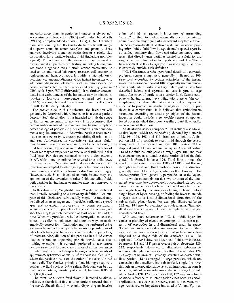
In this disclosure , " single - file travel ” is defined different in a single layer by machining or etching a channel into a than literally according to a dictionary definition . For pur - single layer , or by embossing , or folding the layer to include pose of this disclosure , substantially single - file travel may a space due to a local 3 - dimensional formation of the be defined as an arrangement of particles sufficiently spread 45 substantially planar layer . For example , illustrated layers apart and sequentially organized as to permit reasonably 102 and 104 may be combined in such manner . Similarly , accurate detection of particles of interest . In general , we illustrated layers 108 and 110 may be replaced by a single , shoot for single particle detection at least about 80 % of the concatenated layer . time . When two particles are in the interrogation zone at the With continued reference to FIG . 1 , middle layer 106 same , it is called coincidence , and there are ways to math - 50 carries a plurality of electrodes arranged to dispose a plu ematically correct for it . Calibration may be performed using rality of electrodes in a 3 - dimensional array in space . solutions having a known particle density ( e . g . solutions of Sometimes , such electrodes are arranged to permit their latex beads having a characteristic size similar to particle ( s ) electrical communication with electrical surface connectors of interest ) . Also , dilution of the particles in a fluid carrier disposed on a single side of the sandwich , as will be may contribute to organizing particle travel . As a non - 55 explained further below . As illustrated , fluid now indicated limiting example , it is currently preferred to use sensor by arrows 118 and 118 ' passes over a pair of electrodes 120 , devices structured to have sizes disclosed in this document 122 , respectively . However , in alternative embodiments for interrogation of fluid samples having a particle density of within contemplation , one or the other of electrodes 120 , approximately between about 3x10 to about 3x10 cells / ml , 122 may not be present . Typically , structure associated with where the particle size is on the order of the size of a red 60 flow portion 114 is arranged to urge particles , which are blood cell . The Coulter principle ( and biology ) require a carried in a fluid medium , into substantially single - file travel conductive fluid such as 0 . 9 % saline . Solutions can be run through an interrogation zone . Such an interrogation zone is that have a particle , density ( particles / ml ) between 1000 / ml typically , but not necessarily , associated with one , of , or both to 2 , 000 , 000 / ml . of electrodes 120 , 122 . Electrodes 120 , 122 may sometimes
The term “ non - sheath fluid flow ” is intended to distin - 65 be made reference to as interrogation electrodes . In certain guish over sheath fluid flow to urge particles toward single applications , an electrical property , such as a current , volt file travel . Sheath fluid flow entails dispensing an interior age , resistance , or impedance indicated at VA and VB , may
US 9 , 952 , 135 B2 10
be measured between electrodes 120 , 122 , or between one portion 116 . It is currently preferred for electrodes 124 , 126 of , or both of , such electrodes and a reference . to also be carried on a surface of interrogation layer 106 ,
Certain embodiments of workable sensor components , although other configurations are also workable . Note that such as illustrated sensor component 100 , may employ an an interrogation layer , such as an alternative to illustrated electrical stimulation signal based upon driving a desired 5 single layer 106 , may be made up from a plurality of current through an electrolytic fluid conductor . In such case , sub - component layers . In general , electrodes 124 , 126 are it can be advantageous to make certain fluid flow channel disposed on opposite sides of the interrogation zone , and portions approximately as wide as possible , while still may sometimes be made reference to as stimulated elec achieving complete wet - out of the stimulated electrodes . trodes . In certain applications , a signal generator 128 is Such channel width is helpful because it allows for larger 10 placed into electrical communication with electrodes 124 surface area of the stimulated electrodes , and lowers total and 126 to input a known stimulus to the sensor 100 . circuit impedance and improves signal to noise ratios . However , it is within contemplation for one or both of Exemplary embodiments used to interrogate blood samples
electrodes 124 , 126 to not be present in alternative operable include channel portions that are about 0 . 10 " wide and about 0 . 003 " to about 0 . 005 " high , or so , in the vicinity of the 15 DE Sensors structured according to certain principles of the stimulated electrodes . instant invention . In alternative configurations , any elec One design consideration concerns wettability of the trode in the sensor 100 may be used as either a stimulated
electrodes . At some aspect ratio of channel height to width , electrode or interrogation electrode . the electrodes MAY not fully wet in some areas , leading to One currently preferred sensor component , generally indi unstable electrical signals and increased noise . To a certain 20 cated at 130 , will now be described with reference to FIGS . point , higher channels help reduce impedance and improve 2 - 5 . Sensor 130 includes five thin film layers that are stacked wettability . Desirably , especially in the case of interrogation to form a thin film sandwich , similar to the embodiment electrodes , side - to - side wetting essentially occurs by the depicted in FIG . 1 . FIG . 2 is a top view of sensor component time the fluid front reaches the second end of the electrode 130 , and shows how the top cap layer 102 and top channel along the channel axis . Of course , wetting agents may also 25 layer ( e . g . 104 , FIG . 3 ) form a window arranged to permit be added to a fluid sample , to achieve additional wetting access to a portion of interrogation layer 106 . In the illus capability . The desire is to obtain fully wetted electrodes . trated embodiment , the exposed portion includes an edge of The ratio of channel height to width is one design driver . It layer 106 . The exposed surface of the edge of interrogation has been determined safe to not an wider than about 0 . 16 " layer 106 carries a plurality of conductors ( 134 through 146 , in channel width for a channel layer thickness of 0 . 010 " 30 respectively ) that are configured to form an electrical inter ( channel height ) . Wider than that , consistency of electrode face , to interrogation circuitry . That is , a portion of each of wet - out drops off . conductors 134 - 146 is desirably exposed to form a plurality
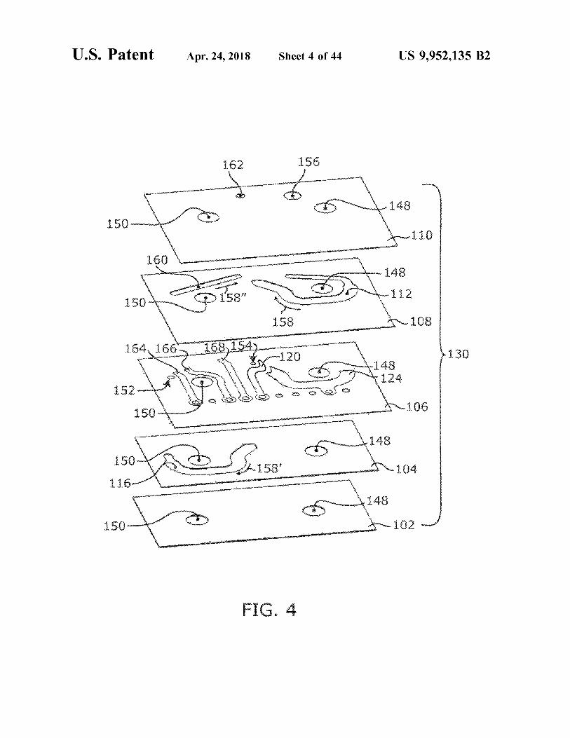
Still with reference to FIG . 1 , note that electrodes 120 and of surface connectors of an electrically communicating 122 are illustrated in an arrangement that promotes complete interface . One operable such interface may be formed in wet - out of each respective electrode independent of fluid 35 harmony with a commercially available multi - pin electrical flow through the tunnel forming flow portion 114 . That is , in connector , such as part No . SIB - 110 - 02 - F - S - LC , available certain preferred embodiments , the entire length of an elec - from Samtec having a place of business located in New trode is disposed either upstream or downstream of the Albany , Ind . Other workable connector structure includes tunnel terming flow portion 114 . In such case , the “ length ” touch - down probes , and other electrically - conductive , con of the electrode is defined with respect to an axis of flow 40 tact - forming probes known in the art . along a portion of the conduit in which the electrode resides . Also shown in FIG . 2 are alignment holes 148 and 150 , The result of such an arrangement is that the electrode is at respectively . Because top layer 102 is illustrated as being least substantially fully wetted independent of tunnel flow , transparent ( although such is not required in all cases for and will therefore provide a stable , repeatable , and high - practice of the invention ) , electrode 126 disposed in channel fidelity signal with reduced noise . In contrast , an electrode 45 portion 116 is visible . Similarly , fluid via 152 may be seen . having a tunnel passing through itself may provide an As will be detailed further below , via 152 passes through unstable signal as the wetted area changes over time . Also , interrogation layer 106 , and permits fluid flow downwardly one or more bubble may be trapped in a dead - end , or through the thickness of the sensor component 130 . Elec eddy - area disposed near the tunnel ( essentially avoiding trode 122 is also visible , disposed in association with the downstream fluid flow ) , thereby variably reducing the wet - 50 interrogation zone , generally indicated at 154 . ted surface area of a tunnel - penetrated electrode , and poten - With particular reference now to FIGS . 3 and 4 , a pair of tially introducing undesired noise in a data signal . fluid vias pass through bottom cap layer 110 . Via 156 is a
In general , disposing , the electrodes 120 and 122 closer to fluid entrance via , through which sample fluid enters the the tunnel portion 114 is better ( e . g . , gives lower solution sensor component 130 for continued flow through channel impedance contribution , but the system would also work 55 portion 112 , as indicated by fluid flow direction arrow 158 . with such electrodes being disposed fairly far away . Simi - Channel portion 112 is disposed in layer 108 and introduces larly , a stimulation signal ( such as electrical current ) could fluid into the interrogation zone 154 ( or tunnel - like channel be delivered using alternatively structured electrodes , even portion 114 in FIG . 1 ) . Downstream from the interrogation such as a wire placed in the fluid channel at some distance Zone 154 , fluid flows through channel portion 116 as indi from the interrogation zone . The current may be delivered 60 cated by fluid flow direction arrow 158 ' . Channel portion 116 from fairly far away , but the trade of is that at some distance , is disposed in layer 104 and communicates to via 152 the electrically restrictive nature of the extended channel passing through layer 106 . Fluid via 152 communicates fluid will begin to deteriorate the signal to noise ratios as total cell into channel portion 160 disposed in layer 108 . Fluid via 167 sensing zone impedance increases ) . is a fluid exit via , through which fluid flowing through
With continued reference to FIG . 1 , electrode 124 is 65 channel portion 160 may leave the Sensor component 130 . disposed for contact with fluid in conduit flow portion 112 . A direction of fluid flow in channel 160 is indicated by arrow Electrode 126 is disposed for contact with fluid in flow 158 .
US 9 , 952 , 135 B2
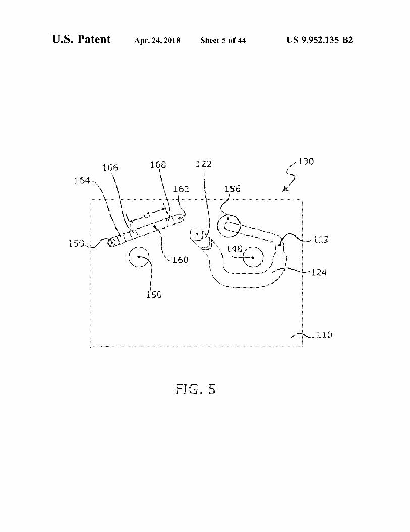
As best seen with reference to FIGS . 4 and 5 , certain trodes . It is currently preferred to simplify such calculation embodiments of a thin film sensor component 130 may by bolding both the cross - section and depth of channel include one or more additional and optional electrodes . portion 160 constant between electrodes . Layers 102 and 104 are illustrated as being transparent , Electrodes , such as 166 and 168 , may be disposed as first although such is not required for practice of the invention . 5 and second triggers operable to indicate respective start and As illustrated , electrodes 164 , 166 , and 168 are disposed on stop signals based upon detection of a fluid boundary . The layer 106 and are arranged for contact with fluid carried in first and second triggers can be located to have locations of channel portion 160 . Electrode 164 is in electrical commu effective operation that are disposed spaced apart by a lumen nication with conductor 146 ; electrode 166 is in electrical defining a known volume . Such triggers may be used for communication with conductor 142 ; and electrode 168 is in 10 non - limiting example , to start and stop data acquisition for electrical communication with conductor 140 . Such optional a sample having at known volume . It is preferred for electrodes may be used , for examples , to verify the presence cooperating trigger electrodes to have substantially the same of sample fluid at one or more known locations in sensor 130 , to estimate the rate of fluid flow through the sensor , conformation wetted area and axial length ) , to promote and / or as start or stop triggers for an activity such as data 15 com 5 consistent electrical response of each subsequent down acquisition . stream trigger . Sometimes , the channel may be narrowed in
It should be noted that certain electrodes carried by sensor the vicinity of an electrode to reduce possible variations in component 130 ( e . g . 120 , 124 , 164 - 168 ) , are in electrical the shape of the fluid front as it makes contact with the communication with their respective conductor that is dis - electrode . posed on an opposite side of layer 106 by way of a 20 A sensor component 130 may be formed from a plurality conductive path disposed through a respective , electrical via of stacked and bonded layers of thin film , such as a polymer 170 ( see . FIG . 3 ) . Such conductive path is conveniently film . In an exemplary sensor component 130 used in con formed during a laminating or metallizing step during manu - nection with interrogation of blood cells , it is currently facture of the sensor component . In any case , it should be preferred to form top and bottom layers 102 and 110 from appreciated that a complex pattern of electrodes can be 25 Polyamide or Mylar film . A workable range in thickness for disposed to interrogate fluid in 3 - dimensional space , even in Polyamide layers is believed to be about 0 . 1 micron to about the illustrated case where the electrodes are carried by a 500 microns . A currently preferred Polyamide layer 102 , 110 single metallized layer . is about 52 microns in thickness for a sensor component
The conductive elements forming conductors ( e . g . 134 - used to interrogate particles in blood . It is further within 146 ) and / or electrodes ( e . g . 120 - 126 ) must simply conduct 30 contemplation that a pair of top and / or bottom layers can be electricity , and can include one or more metal , such as formed from a single layer including fluid channel structure Copper , Silver , Platinum , Iridium , Chromium , and Gold , or formed e . g . by etching , molding , or hot embossing . alloys , or multiple layers of metals or alloys . The vias 170 It is currently preferred to make the spacer layer 106 from permit conduction of electricity from top to bottom through Polyamide also . However , alternative materials , such as spacer layer 106 , and enable surface conductors to be 35 Polyester film or Kapton , which is less expensive , are also disposed on only one side of the spacer layer , for convenient workable . A film thickness of about 52 microns for spacer interface with a commercially available electrode interface layer 106 has been found to be workable in a sensor used to ( i . e . connector ) . Of course , it is realized that certain interface interrogate blood cells . Desirably , the thickness of the spacer probe - electrodes of an interrogation device may be struc - layer is approximately on the order of the particle size of the tured to avoid vias on the sensor , e . g . that surface electrodes 40 dominant particle to be interrogated . A workable range is can be provided on both sides of the spacer layer , in currently believed to be within about 1 particle size , to about alternative sensor constructions . 1 . 5 times particle size , or so .
An electrical property at an elect ode may be monitored Vias 170 are typically formed in the layer 106 prior to to determine arrival , of fluid at that electrode . For example , dual - sided deposition of the conductive elements onto such the impedance measured at an electrode undergoes a sig - 45 layer , although alternative manufacturing techniques are nificant change in value , as the wave - front , or the leading workable . Alignment apertures , 148 , 150 and via 152 may be edge , an electrolyte fluid passes over the electrode . In one formed at the same time as vias 170 , or subsequent to the currently preferred use of the sensor component 130 ( see metallizing step . Such void elements , and channel portions , FIG . 4 ) , a stimulus electric signal ( such as a 1 kHz square may be formed by cutting through the respective , layer with wave ) is applied to electrode 164 . A sudden change in the 50 a laser , water jet , die stamping , drilling , or by some other impedance values measured at electrodes 166 and 168 machining technique . Deposition of conductive film ele indicates the successive arrivals of the wave - front of the ments to layer 106 may be effected using well - known sample fluid at each respective electrode . In the illustrated metal - deposition techniques , including lamination . Metal embodiment 130 , first verification of fluid at electrode 166 sheets may be laminated to a polymer layer using thin ensures that sample fluid is in place for interrogation , and a 55 adhesive . Double clad sheets formed in such manner are test run can begin . Feedback from electrode 166 may commercially available , and can be patterned as desired to therefore serve as a first trigger to begin interrogation of the form electrodes . It is believed that workable sensors can be fluid sample . made having test electrodes that are 0 . 5 microns in thick
A change in impedance at electrode 168 indicates the ness , or perhaps even less . Electrodes for use in currently wave - front has reached that electrode as well . A time dif - 60 preferred blood cell sensors may be up to about 36 microns ferential between the impedance changes at electrodes 166 in thickness . Sometimes , a pair of metals , such as Cu or Cr and 168 can be used , in harmony with a known volume and Au may be deposited in the current process . The Cu or there - between , to estimate a fluid flow rate through the Cr layer may be thin , typically goes on first , and acts as a sensor component 130 . The volume , between electrodes 166 bonding layer between the polymer film and the Au . It is and 168 may be calculated , by integrating the function of the 65 currently preferred to configure the electrodes and conduc cross - section area of channel portion 160 along the length tive elements by wet etching subsequent to deposition of the L1 of such channel portion disposed between those elec electrically conductive material .
US 9 , 952 , 135 B2 13 14
Impedance at the electrode / electrolyte interface is propor cessed fluid chamber 198 . Vent aperture 200 is in fluid tional to wetted electrode surface . Electrodes may be con - communication through base 182 with vent connection figured having a desired useful size of surface area disposed access port 202 . Similarly , vacuum aperture 204 is in fluid for contact with fluid in a channel . It is currently preferred communication through base 182 with vacuum connector to apply a stimulation signal to stimulated electrodes to 5 access port 206 . cause at least about 0 . 1 mA RMS current flow through the Channel layer 190 may be formed from a thin film of interrogation zone . The currently preferred signal is at 100 polymer film , similar to layers 104 , 108 of the sensor 130 . kHz , although signals at lower frequency or higher frequen Preferably , layer 190 is made from a two - sided adhesive cies , such as 200 kHz , or more , are operable . The surface tape , such as Polyamide tape . Layer 190 includes cut - out area of the stimulated electrodes are sized to accommodate 10 area shaped to form additional void elements , including a desired current flow and signal frequency . It is currently channel 208 , a portion of which augments a volume pro believed that electrodes should be sized to have a current vided by chamber 196 in which to receive a fluid sample . density of less than about 5 mA / cm . Transverse portion 210 of channel 208 communicates to
In one embodiment of sensor component 130 adapted to vent aperture 200 , effective to permit escape of air from impart a constant 1 mA RMS current stimulation at about 15 chamber 196 during infusion of a sample for interrogation . 100 kHz , interrogation electrodes 120 , 122 have a wetted Continuing to refer to FIG . 7 , aperture 212 extends as a surface area of about 0 . 036 cm² , and stimulated electrodes fluid - flow channel or via through layers 190 , 192 and 194 124 , 126 have a wetted surface area of about 0 . 45 cm² . In effective to introduce fluid received from chamber 196 into such case , it is thought that the stimulated electrodes 124 , sensor component 183 . An optionally enlarged portion of 126 could be reduced in size to about 1 / 5 cm² , or less , without 20 channel 212 permits fluid to spread out over a sufficiently suffering a lack of performance due to degradation of the large filter area prior to passing though optional filter ele electrode during such stimulation . ment 214 and entering sensor element 183 . It typically is
The channel portion 114 is typically laser drilled through desirable to include a filter element 214 to resist entrance layer 106 ( and any electrodes carried thereon that are also into the interior of sensor component 183 of clots or debris disposed in the fluid path ) . A diameter of 35 microns for 25 that might plug channel portion 114 . A preferred filter channel 114 is currently preferred in certain preferred element 214 resists passage of particles larger than those embodiments to urge blood cells toward single - file travel approaching the characteristic size of the interrogation zone through the interrogation zone 154 . Other cross - section 154 . A workable filter 214 includes a Nylon Net Filter NY30 shapes , other than circular , can also be formed during available from Millipore Cat : NY3004700 , which has fil construction of channel 114 . Naturally , the characteristic 30 tering pores that are about 30 microns in size . Desirably , the size of the orifice formed by drilling channel 114 will be filter essentially consists of openings having a characteristic dependent upon the characteristic size of the particles to be size that is smaller than a characteristic size of a minimum characterized or interrogated . Counter - boring can be per - cross - section of the interrogation zone . formed on thicker layers to reduce the " effective thickness " Still with reference to FIG . 7 , layer 190 also includes of the sensing zone . 35 vacuum channel 216 , which communicates at end 218 with
Alignment holes 148 , 150 passing through each layer may vacuum aperture 204 . As will be discussed in more detail be used to align the various layers using guide pins during below , fluid may be transported through certain conduits of assembly of the plurality of layers . A double - sided adhesive sensor 180 using a vacuum source that may be connected to polymer film is currently preferred as a material of compo port 206 . It is recognized that fluid flow may be urged in sition for combination bonding - channel layers 104 and 108 . 40 alternative ways , including positively pressurized fluid flow , Layers 104 and 108 in as currently preferred sensor 130 are and capillary attraction , as non - limiting examples . made from double - sided Polyamide ( PET ) tape having a In certain preferred embodiments , a harder element 220 is thickness of about 0 . 0032 inches . Alternatively , a plain film disposed in association with aperture 222 passing through layer may be laminated to an adjacent plain layer using heat layer 190 . A workable barrier element 220 permits escape of and pressure , or adhesively bonded using an interposed 45 air from chamber 198 , but resists escape of fluid from such adhesive , such as acrylic or silicone adhesive . chamber . A preferred barrier 220 includes a PTFE gasket ,
A currently preferred embodiment structured according to such as a 0 . 2 micron pore size Fluoropore , FGLP , which can certain principles of the instant invention is generally indi - be purchased from Millipore Cat . No . FGLP01300 . Gasket cated at 180 in FIG . 6 , and may sometimes be characterized 220 is illustrated in FIG . 7 as being installed in a preferred as a cartridge or cassette . Cartridge 180 includes a base 182 50 blocking position on the bottom of layer 190 , but may be on which to hold a sensor component , such as some sort of disposed in a blocking position on either side of layer 190 . thin film sensor component , generally 183 , or other plumb - Barrier 220 is an exemplary embodiment of flow termination ing arrangement effective to urge suitable particle alignment structure disposed downstream from the interrogation zone for interrogation . A workable base may be formed by and arranged to resist flow of fluid beyond a boundary injection molding a plastic , or plastic - like , material . It is 55 associated with the microfluidic sensor . Other operable flow preferred to configure base 182 having a small size to reduce termination structure includes porous materials that turn to a required volume of constituent material , but still form a gels when wet ; hydrophobic porous membranes or plugs ; cartridge 180 that is sufficiently large to facilitate its han and very small laser drilled holes in films ( e . g . < 10 microns ) . dling and manipulation under control of a human hand . Continuing to refer to FIG . 7 , an exemplary layer 192 may
With reference now to FIG . 7 , base element 182 includes 60 be made from polymer film , and functions as a cap layer , alignment holes 184 , 186 , and 188 , which also extend to similar to layer 110 of sensor component 183 . An embossed pass through channel layer 190 , cap layer 192 , and adhesive portion 224 is formed in layer 192 to create a simple channel layer 194 . Holes 184 and 186 are configured and arranged to structure , through which air can communicate between end cooperate with alignment holes 148 and 150 , respectively , to 226 of vacuum channel 216 and aperture 222 . The vacuum permit component alignment using in elements of a common 65 side fluid conduit communicating between port 206 and a fixture during assembly of the cartridge 180 . Base element sensor exit ( such as exit via 162 of sensor 130 ) , is completed 182 also holds sample receiving chamber 196 , and pro - by way of aperture 228 , which forms a fluid conduit or via
US 9 , 952 , 135 B2 15 16
extending from end 230 of chamber 198 , through layers 190 , electrical communication with test circuitry 257 that is 192 , and 194 , for communication with a fluid exit via of an typically carried by an interrogation device and is adapted to installed thin film sensor component 183 . interrogate panicles passing through the sensor .
In one use of the device , a micro - pipette tip may be When the cartridge 242 is fully inserted , the alignment inserted for fluid - tight reception into sample - receiving aper - 5 pins 246 seat inside the alignment holes 184 , 186 in the ture or port 230 . A raw fluid sample can then be infused from bottom of the cartridge via force imparted by springs 258 . the micro - pipette into chamber 196 , while air is permitted to The cartridge is now fully engaged , aligned , and ready for escape through channel 210 and vent port 202 . The size for testing . To remove a cartridge , the release latch 260 is a raw fluid sample for characterization of blood cells in one pressed downward , thereby retracting the alignment pins representative device is 50 ul , although the sensor conduits 10 246 from the cartridge body as the latch rotates about pivot and chambers may be sized to accommodate samples having axle 262 . The cartridge , can then be easily pulled out of the an alternative desired size . Vent port 202 is then occluded , interrogation device in a tool - free procedure . either manually or using an automated structure . A vacuum The interrogation device may include circuitry that may source is they applied to port 206 to promote fluid flow from be carried on printed circuit board 264 , or otherwise holding chamber 196 , through channel 208 , aperture 212 , 15 arranged to communicate to , or interact with , an installed optional filter 214 , and into a fluid entrance of the sensor sensor component . A plurality of different test circuits may component . be provided by simply exchanging the circuit board 264 to
After flowing through the sensor component , fluid is one having the desired configuration . Such circuitry may drawn through aperture 228 and into holding chamber 198 . include structure arranged to apply a first time - varying Once chamber 198 is filled , fluid is barred from further flow 20 stimulus signal to stimulated electrodes . A currently pre by barrier element 220 , which is one example of operable ferred first stimulus signal is a constant current source , flow termination structure that resists additional flow . The although a constant voltage source is also workable . A volume of fluid encompassed by chamber 198 can help to preferred first stimulus signal is about 100 kHZ : 1 m rms . determine as known volume for processed fluid . In the second stimulus signal may be provided , and coupled to representative device , the processed fluid volume , defined 25 electrodes adapted to detect presence of a fluid wave front . by chamber 198 in combination with a small upstream A preferred second signal is a 1 kHz square wave input to a volume contained in conduit structure stretching to as fluid first electrode and permitting measurement of an electric front presence verification , structure , such as electrode 166 property by using at least one other electrode . Impedance or ( see FIG . 4 ) , is 25 ul . voltage may be evaluated at or between measurement elec
Additional details of construction of an exemplary car - 30 trodes . Sometimes , a differential may be measured between tridge 180 are illustrated in FIGS . 8 - 11 . Notably , ramp electrodes . Other times , ground may be enforced at one structure 232 , best seen in FIGS . 9 and 10 , can be helpful to electrode , and an electrical property measured at the other assist in coupling the cartridge with certain interrogation electrode , it is within contemplation for one or more elec devices . Other structure associated with the base 182 , such trode 10 be eliminated entirely , and to use a global ground as alignment holes 186 and 188 , may also be employed to 35 reference . assist in coupling a cartridge with an interrogation device . FIG . 16 illustrates one workable interrogation circuitry
An interrogation device desirably provides three func - adapted to interrogate a sensor 130 . In the cell interrogation tions ; 1 ) apparatus configured in harmony with the sensor loop , a signal generator 268 is applied between conductors ( or cartridge , cassette , etc . ) effective to detect particles of 134 and 144 . It has been determined that electrical , ground interest , 2 ) fluid - flow control , and 3 ) alignment . A workable 40 may be enforced at one of such conductors . In current interrogation device is indicated generally at 240 in FIGS . sensors adapted to interrogate blood cells , it is preferred to 12 - 15 apply a constant RMS current signal of about 1 mA at about
A cartridge 242 is illustrated in position for its insertion in 100 kHz . Values for voltages VA and VB , are measured at registration with socket . 244 ( see FIG . 13 ) . As the cartridge conductors 136 and 135 , respectively for calculation of a is inserted into the socket 244 , ramps 232 on the bottom side 45 differential voltage across the cell interrogation zone . It has of the cartridge body press the two alignment pins 246 been determined that an electrical ground may be enforced down . The cartridge 242 then comes into contact with the at one such conductor , and the voltage directly measured at vent and vacuum connectors , 248 and 250 , respectively . the other conductor may be used in place of a true differ
In the illustrated interrogation device 240 , the vent con ential voltage . It is also possible to allow one electrode to nector 248 and vacuum connector 250 are made from 50 “ float ” ( ix , not be connected to anything ) and measure the silicone rubber tubing . The robber tubes mote with respec - voltage , compared to a different electrode . In the fluid tive connection ports ( e . g . 204 , 202 and 206 , see FIG . 10 ) to detection loop , a signal generator 270 can be applied form an airtight seal . The silicone rubber tubing is supported between conductor 146 and each of conductors 140 and 142 . on the inside by a smaller , more ridge piece of tubing . The The impedance or voltage signal Vsi and Vs2 can then be rigid , internal tubing imparts the required mechanical sta - 55 measured to determine the presence of the fluid wave - front . bility while the soft , flexible rubber tubing conforms to make sudden drop in the measured impedance indicates pres an airtight seal . This airtight seal is actually made because ence of the wave - front of electrolytic fluid . A workable the rubber tube extends sufficiently to contact the bottom of signal includes a square wave at about 1 kHZ at about 3 the cartridge mating hole before the cartridge is fully seated . volts . FIGS . 17 and 18 present electrically - based interroga When the cartridge is inserted slightly further into the 60 tion data that may be collected using certain preferred interrogation device , the rubber tube is forced to expand sensors . radially outward , thereby making an airtight seal against its In a method of using one embodiment of a device to count receiving socket ( e . g . 202 or 206 ) . cells in a blood sample , 50 micro - liters of fluid are added to When seated in socket 244 , the electrical contact pads ( on the sensor via a pipette - tip hole which is sized to form an air
the top of the cartridge and generally indicated at 252 in FIG . 65 tight fit with the pipette tip . As the sample enters the sample 12 ) contact biased pins 254 of the electrical connector 256 . storage channel , air displaced by the fluid exits the cartridge The electrical connector 256 places the sensor 242 in through a vent port that connects to the interrogation device .
US 9 , 952 , 135 B2 17 18
The sample can be added to the cartridge before or after it and to have only one particle inside the orifice at a time . In has been connected to the interrogation device . Once the the case where the apparatus is used to interrogate blood sample is in the cartridge , and the cartridge is installed in an cells , the thickness of the opaque member may typically interrogation device , the user starts the test by activating one range between about 10 microns and about 300 microns , or more " start " control of the system . The " start " causes a 5 with a thickness of about 125 microns being currently valve connected to the vent port to close , thereby not preferred . The diameter , or other characteristic size of the allowing the sample to flow into the vent port . The " start " orifice in such an embodiment , may range between about 5 also opens the vacuum valve to start pulling the fluid sample and 200 microns , with a diameter of about 60 microns being into the sensor . Because the vent is sealed , fluid is drawn currently preferred in an embodiment adapted to interrogate from the sample storage chamber and though the thin film 10 blood cells . sensor component . A “ start ” may also initiate a stimulus ( e . g . An operable opaque member 282 functions , in part , to 1 kHz ) to the sample detection electrodes embedded in the reduce the quantity of unwanted background radiation , thin film sensor component . Once the fluid is through the including primary radiation 298 ( sometimes also called sensing orifice and has wet the stimulus and measurement stimulation radiation ) that is emitted by source 284 , which electrodes , it flows over a pair of sample detection elec - 15 is received and detected by radiation detector 286 . Primary trodes . As the fluid wave - front reaches the detection position radiation 298 is illustrated as a vector having a direction . at the second electrode , a large drop in electric impedance is Desirably , substantially all of the primary radiation 298 is detected and the constant current source is activated ( e . g . prevented from being detected by the radiation detector 286 . 100 kHz @ 1 mA ) , A differential voltage is measured across In any case , operable embodiments are structured to resist the interrogation zone ( 4 electrode configuration , currently 20 saturation of the detector 286 by primary radiation 298 . As preferred ) and used to determine cell size ( and / or count ) illustrated in the arrangement depicted in FIG . 20A , primary subsequent to the time of wave - front detection . Fluid con - radiation 298 may simply pass through orifice 288 for tinues to flow until it reaches the end of the “ dead - end ” reception by the radiation detector 286 . Therefore , as will be channel and no more cells are detected . The volume that is further detailed below , certain embodiments may employ processed in a test run is determined by the volume accom - 25 one or more selective radiation filters as a measure to control modated downstream of the wave - front detection location , radiation received by detector 286 . and is 25 micro - liters in a preferred single - use device . The T he opaque member 282 illustrated in FIG . 20A includes method may also include monitoring one or more additional a core element 302 , carrying a first coating 304 disposed on sample detection electrode placed further down the channel , first side 110 , and a second coating 306 disposed on second i . e . to determine the approximate flow rate during , or prior 30 side 112 . A workable core 302 for use in detecting small to starting , the cell counting . sized particles , such as certain blood cells , can be formed
Certain sensor components may include structure to from a thin polymer film , such as PET having a thickness of optionally , or alternatively , permit optically - based interro - about 0 . 005 inches . Such polymer material is substantially gation of particles entrained in a fluid . It should be noted , for permeable to radiation , so one or more coatings , such as purpose of this disclosure , that the term " wavelength ” is 35 either or both of coating 304 and 306 , is typically applied to typically employed not with reference only to a single such core material . A workable coating includes a metal or specific wavelength , but rather to encompass a spread of alloy of metals that can be applied as a thin layer , such as by wavelengths grouped about a characteristic , or representa - sputtering , vapor deposition , or other well - known technique . tive , wavelength . With reference to FIG . 19 , the character - Ideally , the metal layer should be about 2 - times as thick as istic wavelength F1 ( e . g . excitation wavelength ) of a pri - 40 the wavelength of the primary radiation , e . g . about 1 um in mary radiation source is sufficiently different from the one operable embodiment . The resulting metallized film characteristic wavelength F2 of the fluorescence ( e . g . emis - may be essentially impervious to transmission of radiation , sion wavelength ) to enable differentiation between the two . except where interrupted by an orifice , such as orifice 288 . Furthermore , the difference between such characteristic Aluminum is one metal suitable for application on a core wavelengths , or Stokes shift , is desirably sufficiently differ - 45 302 as a coating 304 and / or 306 . Of course , it is also within ent to enable , in certain embodiments , including a selective contemplation to alternatively use a bare core element that pass filter element between the radiation source and optical is , itself , inherently resistant to transmission of radiation . detector effective to block transmission of primary radiation For example , a sheet of metal foil may harm an effective toward the detector , while permitting transmission of the Opaque member in certain operable embodiments . fluorescence through the selective - pass filter to the detector . 50 The apparatus 280 is configured to urge a plurality of
A schematic illustrating an generalized operable arrange - particles 310 into substantially single - file travel through ment of structure employed in embodiments structured orifice 288 . A particle 310 typically passes through an according to certain principles of the invention , and enabling excitation zone as the particle approaches , passes through , optically - based interrogation is indicated generally at 280 in and departs from the orifice 288 . Of note , the direction of FIG . 20A . As illustrated embodiment 280 includes an 55 particle - bearing fluid flow may be in either direction through opaque member , generally indicated at 282 , disposed orifice 288 . In certain cases , an excitation zone may include between a radiation source 284 and a radiation detector 286 . the through - channel or tunnel defined by orifice 288 . An At least one orifice 288 is disposed in opaque member 282 excitation zone may also include a volume indicated by to provide a flow path between a first side , generally lower cloud 314 , which encompasses a volume in which a indicated at 290 , and a second side , generally indicated at 60 particle may reside and be in contact with primary radiation . 292 . Orifice 288 may be characterized as having a through - An excitation zone may further include , a volume indicated axis 294 extending between the first and second sides 290 by upper cloud 316 , which also encompasses a volume in and 292 of opaque member 282 , respectively . which a particle may reside and be in contact with primary
Both of the thickness , T1 , of an opaque member and radiation . characteristic size , D1 , of an orifice 288 are typically sized 65 In certain cases , e . g . where there may be a plurality of in agreement with as size of a particle of interest to promote orifices , the term “ zone ” may include a plurality of such single - file travel of the particle through the opaque member , distributed , zones . However , the appropriate meaning of the

US 9 , 952 , 135 B2 20
term “ zone ” is believed to be aduceable in context . In the Certain embodiments apply a red diode laser , and include excitation zone , primary radiation 298 causes certain par - a short pass filter ( after the diode , laser ) that passes primary ticles to fluoresce , thereby emitting radiation at as different light radiation with wavelengths shorter than 640 nm . Such wavelength compared to the primary radiation 298 and in embodiments also may include a band pass filter ( prior to the substantially all three - dimensions . The fluorescence radia - 5 photodetector ) with a peak that matches a particular selected tion emitted by those certain particles may then be detected fluorescence peak . Commercially available dyes may be by the radiation detector 286 . obtained having characteristic fluorescent peaks at 660 , 694 ,
With reference again to FIG . 20A , the embodiment 280 123 , and 175 nanometers . With continued reference to FIG . 21 , sometimes it is may essentially be disposed in a suitably sized container that is divided into two portions by the opaque member . Flow of f 10 preferred to include a post filter 126 that resists transmission fluid ( and particles entrained in that fluid ) through the orifice of radiation outside the characteristic wavelength of the
fluorescence 322 . Such an arrangement helps to avoid false 288 could be controlled by a difference in pressure between readings indicative of presence of a particle , of interest in an the two divided portions . However , it is typically desired to excitation zone . Also , to assist in obtaining a strong signal , provide more control over the flow path of particles in the 15 ano 15 an optical enhancement , such as a lens 328 , can be included vicinity of the orifice 288 than such an embodiment would to gather fluorescence 322 and direct such radiation toward permit . For example , a clump of particles disposed near an the radiation detector 286 . Illustrated lens 328 may be entrance or exit of the orifice 288 could shield a particle , of characterized as a convex focusing lens , and typically is interest from the primary radiation 298 to the extent that disposed to focus on a point located inside the orifice 288 . fluorescence , does not occur , thereby causing a miscount , or 20 With reference now to FIG . 22 , an exemplary plumbing preventing detection of such a shielded particle of interest . arrangement effective to interrogate particles 320 entrained Also , clumped , or stacked particles could shield fluores - in fluid is indicated generally at 330 . The interrogation cence that is emitted from a particle of interest from contact arrangement 330 is illustrated in an installed position with with the detector , thereby reducing detection accuracy . respect to an interrogation device 332 . A workable interro
FIG . 20B illustrates an interrogation arrangement , gener - 25 gation device 332 may be embodied in various forms , for ally 288 , that is generally analogous to the system illustrated example as a bench top device , or as a hand - held instrument , in FIG . 20A . Analogous elements are sometimes designated such as a band - held pipette adapted to extract one or mote with primes . For example , microcapillary tube 318 has a sample from a bulk container of fluid . cross - section area 288 ' and through - axis 294 ' that are analo - Desirably , coupling the interrogation arrangement 330 to gous to the aperture 288 and through - axis 294 in FIG . 20A . 30 the interrogation device 332 also places a waveguide , such Primary radiation 298 may be variously detected by radia - as light pipe 334 ( which , for example , may be a fiber optic tion detector 286 as scatter , obstructed , or Stokes ' shift cable ) , into communication with a radiation source . An radiation . Note that the cross - section area 288 ' is arbitrarily operable coupling may either be done in “ free space " by drawn as a generally rectangular shape , but no particular simply shining the laser into a fiber ( or waveguide ) , or by shape is required for operation of the device 280 ' . However , 35 butt - coupling two fibers together . The radiation source , such one important function of the microcapillary tube 318 is to as a laser , can be located at virtually any convenient location inherently urge particles 310 into substantially single - file in the interrogation device when using the butt - coupling travel through an interrogation zone . approach .
Because fluorescence propagates from a tagged and As illustrated in FIGS . 22 and 23 , an end of light pipe 334 excited particle of interest in substantially all directions , the 40 may be engaged by coupling device 336 upon insertion of primary radiation may be directed to an excitation zone from arrangement 330 into seated engagement in device 332 . a side , instead of only from directly below such zone . With Coupling device 336 is structured to orient the end of light reference now to FIG . 21 , sometimes it is preferred to apply pipe 334 in an operable receiving position with respect to primary radiation 298 at an angle A1 to axis 114 of orifice radiation provided by a radiation source 284 . Desirably , the 228 . In such case , the opaque member 282 may even 45 inner surface of coupler 336 is shaped somewhat like a function substantially as an operable filter to resist direct funnel , to facilitate insertion of a light pipe 334 . Therefore , transmission of primary radiation 298 to a radiation detector excitation radiation 298 may be impinged through a coupled 286 . As illustrated , radiation vector 298 can be oriented to light pipe 334 onto an interrogation zone , causing emission pass through , or partially into , orifice . 288 without being or scatter radiation 322 from particles of interest to propa detected by radiation detector 286 . However , when a tagged 50 gate toward a radiation detector 286 . In an alternative particle 320 is present in an excitation zone ( such as orifice interrogation device , coupling 336 may place a fiber optic 288 as illustrated ) , the resulting fluorescence 322 may still cable ( e . g . extending from a more remotely located radiation be detected by the radiation detector 286 . While a workable source ) into communication with a light pipe 334 , or other angle A1 may be between 0 and 90 degrees , it is currently waveguide associated with an interrogation arrangement . preferred for angle A1 to be between about 15 and about 75 55 Of note , radiation detector 286 may be disposed in degrees for certain operable embodiments . proximity to the interrogation site , as suggested by FIG . 22 .
A radiation source 284 may be formed from a broad In such case , wires 338 typically extend from detector 286 spectrum radiation emitter , such as a white light source . In to remotely located data collecting devices . Alternatively , such case , it is typically preferred to include a pre - filter 324 radiation detector 286 may be located at as more convenient adapted to pass , or transmit , radiation only in a relatively 60 remote location of the interrogation device 332 , and radia narrow band encompassing the characteristic value required tion 322 may be communicated to such remote location by to excite to particular fluorescing agent associated with a way of a light pipe . As previously indicated , sometimes a particle of interest . It is generally a good idea to limit the focusing element 328 , and / or a filter 326 may be included to quantity of applied radiation 298 that is outside the excita - modify radiation that is transmitted toward detector 286 , it tion wavelength to reduce likelihood of undesired saturation 65 desired . of the radiation detector 286 , and consequent inability to Also as illustrated in FIG . 22 , coupling the interrogation detect particles of interest . arrangement 330 to the device 332 desirably places a source
US 9 , 952 , 135 B2 21
of suction into fluid communication with flow aperture 340 of air ) . Also , the test volume may be substantially controlled , to cause a desired flow of sample fluid through interrogation by a known quantity of fluid being aspirated into a cassette arrangement 330 , indicated by arrows 342 . In the exemplary or cartridge . illustrated embodiment , a source of suction ( not illustrated ) With reference still to FIG . 23 , an electrode ( e . g . 354 ) may communicates through passageway 344 , which is in sealed 5 be desirably disposed to indicate the presence of a fluid wave communication through an O - ring 346 to aperture 340 . front at the beginning of a length of channel defining a
With reference again to FIG . 21 , sometimes a plumbing chamber having to known volume corresponding to as desired sample volume size . The signal monitored at elec arrangement operable to interrogate particles radiologically trode 354 may provide a useful start - test signal . A second may also include structure adapted to interrogate a fluid
sample in one or more alternative way . For example , one or 10 electrode ( e . g . 358 ) may be disposed at the other end of the known - volume chamber to provide a stop - test signal . A more electrodes may be carried by a plumbing arrangement discontinuous change in impedance measured at an elec and arranged to permit interrogation of one or more elec trode ( essentially changing from open - circuit to a measur trical property related to a fluid sample . The partially able value as an electrolytic fluid doses the circuit ) can be
exploded plumbing arrangement of a disposable embodi - 15 used to indicate arrival of the fluid wave - front . Such start ment generally indicated at 348 includes an opaque layer and stop - signals may be used to advantage to substantially 350 that carries a plurality of electrically conductive traces automate data collection during radiological tests of fluid ( e . g . trace 352 ) , it should be recognized that layers 353 and samples . 355 are illustrated , as being slightly distorted ( stretched ) to Elements of a currently preferred sensor arrangement that provide clarity as to indicated structure . The conductive 20 may be structured as a cassette , or cartridge , are illustrated traces am configured and arranged to form interrogating with reference to FIGS . 24 - 28 . An exemplary such sensor electrodes ( e . g . , 354 , 356 , 358 ) that are in electrical com - arrangement is structured from a plurality of thin film layers munication with connection electrodes or electrically con - that are stacked and bonded together to form cartridge 370 , ductive contact pads ( e . g . generally indicated at 252 in FIG . and consequently provides a microchannel structured to urge 12 ) . 25 particles into substantially single - file travel . With reference
Embodiment 348 exemplifies a multifunction pipette tip to FIG . 28 , cartridge 370 includes top cap layer 372 , top that is configured to incorporate both electrical and radio channel layer 374 , interrogation layer 376 , bottom channel logical interrogation of fluid in as single disposable , or layer 378 , and bottom cap layer 380 . layer sometimes reusable , device . Illustrated embodiment 348 is a The currently preferred top cap layer 372 anti bottom cap
multilayer device structured somewhat similarly to a com - 30 30 layer 380 may be made from 0 . 005 " thick transparent bination of embodiment 130 in FIG . 2 and embodiment 280 polyester film . Workable channel layers 374 and 378 may be
made from 0 . 010 " thick double sided acrylic based adhesive , in FIG . 20A . As pipette tip 348 is coupled to a pipette ( not in such case , the center carrier layer may be 0 . 007 " thick illustrated ) , light pipe 334 is directed by the internally conic polyester with 0 . 0015 " thick adhesive coated on each side . section of coupling 336 effective to align a proximal end of 25 35 A currently preferred Interrogation layer 376 may be made light pipe 334 with a discharge from radiation source 284 . A from an assortment of materials , depending upon the fully installed tip 348 automatically has its light pipe 334 intended use for the particular sensor that will be con positioned to receive radiation from source 282 . Stimulation structed . A clear 0 . 005 " thick polyester film may be used for radiation ( light ) may then be applied along light pipe 334 to sensors structured to interrogate impedance measurements impinge on an interrogation zone associated with the tunnel 40 only . It is preferred to employ an opaque polyamide film , for generally indicated at 228 . Further , coupling pipette tip 348 sensors structured to interrogate impedance and fluores with as pipette also desirably places a vacuum source into cence ( or just fluorescence ) . The opaque film inherently communication with flow aperture 340 . resists transmission of undesired radiation toward the Stokes
Also , surface contact electrodes ( disposed on the side shift detection sensor . facing away for the illustrated embodiment 348 ) are desir - 45 Although such is not required , the illustrated cartridge ably placed into electrical communication with electrical 370 is a two - ended arrangement structured to provide dupli interrogation circuitry when the pipette tip 348 is seated in cated structure forming first and second sensors on the same an electrically instrumented pipette . Among other uses ( such removable device . Such an arrangement permits associating as direct particle counting using measured impedance and the cassette 370 at a first orientation with an interrogation the Coulter principle ) , the electrodes may be arranged to 50 device , running a first test , then removing and reversing the indicate presence of a fluid wavefront at particular locations cassette 370 to interface , with the interrogation device at a along a channel , such as a portion of channel 362 . In a second orientation to perform a second test . The first and preferred arrangement , one or more electrode ( s ) may be second tests may be the same type of test , performed on arranged to start and stop a test based upon a feedback different fluid samples . It is within contemplation that the obtained from the electrode ( s ) . 55 first and second tests may not be the same , and may also be
In general , some sort of feedback signal can be used to performed on at least a portion of the same fluid sample . For indicate a start condition for a test of a fluid sample ( e . g . a clarity , the duplicated structures included in the second signal may be generated electrically or optically to detect the sensor are indicated with a prime . It is within contemplation fluid wave - front at a known location along a channel ) . to provide a multi - ended arrangement providing a further Similarly , some sort of feedback signal can be used to 60 increased number of sensors ( e . g . 3 , or 4 , or more ) on the indicate a stop condition for a test on a sample ( e . g . same cassette , or cartridge . electrically or optically detect the wave - front after filling a Top cap layer 372 provides a sample loading port 384 , a desired / known volume . Alternatively , a vacuum shut - off vent 386 , and a vacuum application port 388 . A plurality of signal may be generated by monitoring amperage of the over - size alignments holes 389 are also included . Alignment vacuum pump , which may spike when fluid flow terminates 65 holes 389 are oversized to provide clearance for other by fluid encountering as barrier at the end of a known - precise alignment structure during assembly of the cartridge volume chamber that resists fluid , flow but permits passage 370 . Alternative precision alignment , structure may be pro
23 US 9 , 952 , 135 B2
24 vided for certain layers , such as 372 , 374 , 378 and 380 . Such a fluid sample when using the known volume method with alternative alignment structure may then be redacted from respect to the volume in channel 442 . the finished cassette during a manufacturing step . Also , in For convenience , electrode surface contact pad 424 is in certain embodiments , vent ports 386 are not included . electrical communication with both of electrode 418 and
With reference now to FIG . 24 , interrogation layer 376 5 420 , and can therefore be used to apply a common reference carries a plurality of electrical contact pads , generally indi - signal , such as ground . On the other side of layer 376 , cated at 390 . While alternative deposition of conductive electrical contact pads 426 and 428 are in electrical com material is operable , it is currently preferred to print the munication and may be used in a continuity check to verify contact pads 390 and other conductive traces and structures proper insertion of a sensor into engagement in a preferred using electrically conductive ink and a web based screen 10 interrogation device . It should be noted that certain sensors printing process that lends itself to mass production . may be constructed having a different number driving ,
As illustrated in FIG . 24 , a first trigger electrode 392 and detecting , verification , and / or trigger electrodes , or even as second trigger electrode 394 are disposed upstream of none . first driving electrode 396 and first detection electrode 398 Layer 376 also includes a plurality of alignment apertures . may therefore detect a trailing , or fluid flow termination , 15 Alignment aperture 430 is common to alignment structure boundary . Such an arrangement permits electrode 392 and used for both ends of the cartridge 370 , and imposes an X - Y 394 to operate as an electrically - based trigger that is inher - location at a known reference spot on the cartridge 370 with ently tripped by a fluid flow boundary , and can be used to respect to a currently preferred interrogation device . Align terminate data collection . For example , impedance can be ment slot 432 imposes substantially only a rotational orien monitored between electrode 392 and electrode 394 . In 20 tation of an installed cartridge 370 with respect to that X - Y general , it is desirable for trigger electrodes to be narrow and location . Desirably , one of the apertures 430 , 432 is slotted , disposed as close together as possible . The printing capa and the other is not . Such an arrangement is effective to bility of the preferred manufacturing method is believed to provide as complete rigid body constraint in a plane , and be the current limit . Nonetheless , an electrode area can be helps to avoid binding of the cassette during its installation fairly small ( e . g . 0 . 02 " x0 . 65 " ) and the current printing 25 into , or removal from , an interrogation device . The radius of process can easily maintain a 0 . 015 " spacing between illustrated round alignment aperture 430 is 0 . 050 " . The printed electrodes . distance between the radii of alignment slot 432 is 0 . 025 "
With continued reference to FIG . 24 , a plurality of aper - and the radii are 0 . 050 " . Cooperating alignment pins in the tures and channels are removed from the film forming preferred interrogation device , have diameters of 0 . 1000 " , interrogation layer 376 . As illustrated , a partial length chan - 30 and the pins are precision ground to a tolerance of + 0 . 0001 " , nel 400 disposed to receive a fluid sample for interrogation . Planar orientation of the cartridge is typically enforced by The sample is typically loaded at proximal end 402 , and other clamping structure associated with the preferred inter flows in the direction indicated by arrow 404 , debris filter r ogation device . 406 . An exemplary debris filter resists passage of undesired With reference now to FIG . 26 , top channel layer 374 particulate matter toward the interrogation aperture 408 . It is 35 includes a plurality of channel structures . Partial - length fluid currently preferred to laser drill a plurality of small apertures receiving , channel 400a cooperates with channel 400 in in combination to form a sort of screen - like debris filter 406 . layer 376 to permit introduced sample fluid to flow in the An additional aperture structure includes fluid exit vent 410 . direction indicated by arrow 404 . Bridge channel 436 trans Desirably , exit vent 410 is structured to permit application ports fluid from debris filter 406 toward interrogation aper vacuum to cause fluid flow through passages in the cartridge 40 ture 408 . An optional dogleg channel portion 438 may 370 , and to apply capillary attraction to resist flow of fluid communicate to an optional vent 386 ( see FIG . 28 ) at the top beyond the vent 410 , itself . of the cartridge 370 , and facilitates loading a fluid sample
With particular reference to FIG . 25 , the other side of into the cartridge 370 . Buffer channel 440 communicates interrogation layer 76 includes additional electrical contact from exit vent 410 toward a vacuum port 388 ( see . FIG . 38 ) pads , generally 390 in the illustrated embodiment , the elec - 45 on top of the cartridge 370 . Along with over - size apertures trical contact pads 390 disposed on one side are not integral 389 , alignment apertures 430a and 432a are also pulled back with electrical contact pads 390 on the other side . Electri during a manufacture step to avoid causing a potential cally conductive traces are configured to provide a second structural interference with respect to alignment apertures interrogation electrode 412 and a second driving electrode 430 and 432 disposed in penetration though the interrogation 414 . 50 layer .
Still with reference to FIG . 25 , a third trigger electrode With reference now to FIG . 27 , bottom channel layer 378 416 and a fourth trigger electrode . 418 are disposed down carries full - length sample receiving channel 400b . Channel stream of second detection electrode 412 a and second 400b communicates introduced fluid underneath layer 376 to driving electrode 414 and may therefore detect a fluid flow the bottom of debris filter 406 . Channel 442 receive fluid arrival boundary . Such an arrangement penults trigger elec - 55 downstream of interrogation aperture 408 . In certain trode 416 and trigger electrode 418 to operate an electri - embodiments , a first electrically - based trigger , generally cally - based trigger that is inherently tripped by a fluid flow indicated at 444 , is disposed near one end of the chamber boundary , and can be used to begin data collection during formed by channel 442 . A workable trigger may be formed the test of a fluid sample . between two dedicated electrodes , or sometimes between
A fifth trigger electrode 420 and a sixth trigger electrode 60 one dedicated electrode and a shared electrode . Illustrated 422 are also illustrated in FIG . 25 as being disposed down trigger 444 in FIG . 27 is formed between electrodes 414 and stream of second detection electrode and second driving 418 ( see FIG . 25 ) . A trigger at a location such as trigger 444 electrode 414 and may therefore cooperate to detect a fluid is operable as a " start " trigger , to begin collection of data flow arrival boundary at a second location . This third trigger during an interrogation of a fluid sample . It has been is disposed near the vent aperture 410 . Such an arrangement 65 determined that a single impedance - detecting electrode , permit electrode 420 and 422 to operate as an electrically such as 418 , cooperating with a sink electrode 414 is more based trigger that can be used to detect the " end of test ” for reliable than a cooperating dedicated pair of electrodes ( e . g .
US 9 , 952 , 135 B2 25 26
414 and 416 , FIG . 35 ) disposed in very close association water with detergents , saline , and low bleach concentration with a sink electrode such as 414 . in water . In certain cases , a gas , such as air , may be used as
A second electrically - based trigger , generally 446 , may be an operable cleaning fluid . The level of stored fluid 476 can disposed spaced apart from trigger 444 by a known volume be monitored by a level control system , generally 478 . An provided by channel 442 . Illustrated trigger 446 is formed by 5 operable control system may include a simple float switch , electrodes 420 and 422 ( see FIG . 25 ) . In certain cases , a or an electrical impedance sensing circuit , it is alternatively second known volume may be defined by channel and within contemplation to use an optically based monitoring aperture structure disposed between trigger 444 and an system for level control , or simply to keep track of the upstream trigger , such as may be formed between electrodes individual sample volume ( s ) and number of tests performed 292 and 294 ( see FIG . 24 ) . 10 since the holding chamber was emptied or replaced . A Known volumetric trigger spacing and collection of data holding chamber 474 may be structured as a portion of an
signals including common time component or base , permit ; interrogation device , generally 480 . Alternatively , storage starting and stopping test data collection ; control for appli - container 474 may be included as a portion of an alternative cation of vacuum ; confirmation of processing a desired sensor 482 . sample volume ; and calculation of volumetric rate of pro - 15 FIGS . 30 - 32 illustrate one currently preferred interroga cessing , among other attributes . tion device , generally 490 , for use with certain preferred
With reference again to FIG . 28 , the fluid flow path will sensor arrangements structured according to certain prin now be described . In one type of test a sample is typically ciples of the instant invention . In FIG . 30 , a representative introduced to sample loading port 384 pipette instrument to sensor arrangement 370 is ready to load into the device 490 . accurately dispense a desired test volume , or sometimes a us 20 Cassette 370 is received in entrance structure 492 , which volume . Entering fluid flow is represented by arrows 450a , facilitates alignment of the cassette , and orients the cassette 450b and 450c . Sample fluid then flows along a channel 370 in a plane . Alignment pins 494 enforce an X - Y position formed by channel portions 400 , 400a , and 400b in the on an installed cassette 370 and also a rotational relationship direction indicated by arrow 404 . As indicated by arrows of the cassette 370 with respect to that X - Y position . Such 452a and 452b , fluid flow through debris filter 406 to 25 alignment urges the interrogation aperture 408 into operable channel 436 . Air may be passed out aperture 386 , as indi - alignment with an applied source of radiation and with cated by arrow 454 . During a test , fluid flows along channel respect to optical detector 496 effective to detect Stokes ' 436 in the direction indicated by arrow 56 . Fluid then flows shift phenomena that may occur in the interrogation zone . through interrogation aperture 408 indicated by partially Electrical contact prongs e . g . edge connectors ) and appro hidden arrows 458a and 4586 . Fluid flow in channel 442 is 30 priate electronic devices , may be included in a device 490 to indicated by arrow 460 . Fluid then flows through vent 410 permit electrically - based particle interrogation , as well , or as indicated by arrows 462a and 462b . Fluid then flows instead . The vacuum ports are desirably located near the along channel 440 in layer 374 , in the direction indicated by alignment pins so the cassette only needs to be clamped in arrow 464 , before potentially exiting vacuum port 388 , one location . The clamping step preferably makes the indicated by arrow 466 . In certain cases , channel 440 may 35 vacuum seal and accurately positions the interrogation ori provide a buffer to resist escape of fluid from a cartridge 370 . fice .
Typically , an Excimer laser is used to form the interro FIGS . 33 and 34 illustrate an alternative interrogation gation apertures 408 and alignment apertures 430 and 432 . device , or device , generally at 500 . Installation of a test A DPSS laser is generally used to form all of the other cassette 502 causes a clamping force between the cassette channel and aperture structure ( filters , vents , channels , etc . ) 40 502 and a vent seal , such as O - ring 504 , as well as places a The excimer can cut the currently preferred 55 um diameter vacuum source into communication With a vacuum appli interrogation aperture 408 within + 2 microns . Repeatability cation port 388 . An air resistant connection may be effected of the DPSS is more like plus / minus 5 microns . The large at the vacuum port with an O - ring , as well . Electrical contact alignment holes 432 are manufactured ( laser cut ) extreme pads 390 of an installed cassette 502 are inherently placed precision relative to the laser drilled interrogation aperture 45 into electrical communication with appropriate pins of elec 108 . Use of the more accurate laser allows the interrogation trical connectors , such as edge connector 506 . Of course , aperture 408 to be mechanically aligned , from cassette to such electrical connectors are disposed for contact with cassette , to the laser beam of a cooperating docking station electrodes 390 that are carried on either of , or both of , top of a preferred interrogation device with an accuracy of about and bottom of an installed cassette 502 , as the case may be . 20 um to 50 um . Here , " accuracy ” means that the center of 50 With reference now to FIG . 35 , the particle sensor embod the aperture is disposed within a certain radius of the ied in the test cassette generally indicated at 520 is adapted theoretical centerline of an interrogation zone provided by a to permit interrogating a plurality of discrete fluid samples cooperatingly structured interrogation device . in series . Each successive fluid sample may be input to
With reference now to FIG . 29 , it is within contemplation cassette 520 by way of pipetting a dose of fluid into sample to use a single sensor a plurality of times . For example , it 55 part 522 . Desirably , successive fluid samples may be input single cartridge , or cassette , generally indicated at 470 , can into the cassette 520 without removing the cassette from an be used to process a plurality of similar , or different , fluid interrogation device between samples . A vent 524 may be samples in series . Cartridge 470 may be double - ended as provided to facilitate loading each fluid sample into cassette illustrated , further multiple - ended , or a single - ended car - 520 . Alignment apertures 430 and 432 help to align the tridge , as desired . In any case , a source to urge fluid motion , 60 cassette 520 upon installation in an interrogation device , such as vacuum pump 472 , may be applied to a container in such as device 490 or device 500 . Certain cassettes 520 may which to receive a quantity of fluid samples and potential include electrode contact pads 390 , and generally be struc cleaning flushes between tests . Suction from the container tured similar to the cartridge 370 . One difference , however , may be applied to the cartridge 470 to effect a test , and the is the reservoir 528 , which permits storing a plurality of fluid sample ( and optional flush fluid ) may then be extracted 65 interrogated fluid sample on - board the cassette 520 . Desir from the cartridge 470 for storage in the container 474 . ably , reservoir 528 is sized to contain a plurality of fluid Workable cleaning / flushing fluids include distilled water , samples and also a plurality of doses of cassette - cleaning
27 US 9 , 952 , 135 B2
28 flush fluids that may be vacuumed through the cassette 520 samples are generally stored in a container , which may be between each interrogated fluid sample . Vacuum is applied carried by a cassette , or associated with an interrogation at vacuum port 530 , and samples ( and flush or cleaning device . In certain situations , it is desirable for the cassette to fluids , if used ) collect inside reservoir 528 . The embodiment remain installed in the interrogation device between of a cassette is structured to perform at least 10 tests . 5 samples , although such is not required . It is further within Providing for about 75 ul fluid sample per test ( times 10 ) , contemplation to flush , or clean , a lumen through a cassette plus about 50 ul of cleaner fluid in between test samples by drawing a quantity of cleaning fluid ( potentially includ ( times 9 ) requires a reservoir 528 to accommodate at least ing a gaseous fluid , such as air ) through the cassette between 1 . 25 ml total fluid volume . A cassette 529 may be structured serial interrogation of fluid samples . to permit interrogation of fluid samples using Stokes ' Shift 10 It is desirable to monitor the “ health ” of a particle phenomena , and / or by monitoring an electrical phenomena , alignment element , to verify that the interrogation zone is such as the Coulter principle , or difference between an not compromised , i . e . clogged by particulate matter . One open - circuit and a closed - circuit . way to do so includes use of a differential + 15V / - 15V
In one method of use of a preferred embodiment , a sensor constant current stimulus ( e . g . apply the - 15V on a “ sink " structured as a cassette is loaded into registration , at a first 15 electrode ) and a differential measurement technique across orientation , in an interrogation device . A fluid sample may an interrogation aperture . Therefore , the measured voltage be loaded into the cassette either before , or after , installing across the aperture is close to zero when the sensor is filled the cassette in the interrogation device . The fluid sample is with conductive media . When a cell passes through the urged to flow through the cassette , typically by application aperture , the measured voltage increases momentarily , if a of a vacuum , at an end of a lumen opposite the sample 20 blockage occurs , the voltage usually rails to + 15V ( momen entrance port . tarily ) . It generally settles back down shortly thereafter ,
Sometimes , a known volume of fluid is transferred to the because the interrogation device is AC coupled . A lack of cassette for a given sample . In certain such cases , the fluid particle , or scatter data ( e . g . electrically , or optically sample may be urged to flow through the cassette , and one detected ) would indicate blockage of a capillary lumen , or a or more triggers may indicate a " start " and / or " stop " for 25 dry central column of a sheathed - flow arrangement , it is also collection of test data . For example , impedance at a first preferred to measure the total time of the counting and if it location along a lumen ( e . g . downstream of fully wetted exceeds some amount ( like one minute ) , to stop the test and interrogation electrodes or a Stokes shift interrogation zone ) report " aperture block , or an analogous information state may be monitored , and when a fluid wave front is detected , ment . data collection may be started . Data collection may be 30 One exemplary embodiment of a microfluidic interroga stopped when a fluid wave front is detected at a second tion device structured according to certain principles of the location ( e . g . upstream of fully wetted interrogation elec - invention , generally 540 , is illustrated in FIGS . 36 - 42 . trodes or a Stokes shift interrogation zone ) . The known Illustrated device 540 includes a housing 544 structured to volume of the lumen between the first and second locations protect internally contained elements . A door 548 may be may then be subtracted from the transferred volume of fluid 35 included to provide access for loading a fluid sample ( e . g . in to calculate a volume of interrogated fluid . a cassette or cartridge ) , for interrogation of the fluid sample
For example , in one currently preferred arrangement , the in a microfluidic path extending through a portion of the user just pipettes 75 uL of sample into the receiving channel housing 544 . Desirably , some sort of tab , handle , or mecha of a cassette , it helps to tilt the cassette to have gravity assist nism 550 ( see FIG . 37 ) is provided to facilitate opening , the filling . The cassette is installed in registration in an 40 closing , or maintaining closed , the door 548 . interrogation device , and vacuum is applied . Counting A currently preferred microfluidic interrogation device begins when the approaching fluid wave front is detected at 540 is structured and arranged as a self - contained , or stand a start trigger location , e . g . disposed downstream of the alone , device to permit its operation to perform a microflu interrogation aperture and all driving and detecting elec - idic interrogation on a fluid sample , to process resulting trodes . Counting is stopped , and vacuum removed , once a 45 microfluidic interrogation data , and to display a correspond stop trigger detects the trailing fluid wave front . In a ing result on a display device , all without requiring input preferred cassette , about 25 ul of fluid is disposed in the from a remote computing device . For purpose of this dis volume between the start and stop triggers , so a 50 ul sample closure , " remote ” is defined as being disposed exterior to is interrogated . protection provided by the housing . Further , the term “ self
In steps of another method , data collection may be ter - 50 contained " or " stand - alone ” means being able to perform the minated , when a fluid wave front is detected at a trigger recited interrogation , processing , and display tasks without location spaced apart downstream of the first location by a requiring communication to another device ( e . g . without known volume ( at a third location ) . Sometimes , the trigger requiring communication with a separate : stand - alone com at the third location may be used as a redundant signal , or puter , normally stationary computerized work station , or safety signal , to resist undesired escape of fluid from con - 55 non - integrated portable hand - held computing device ) . How finement inside the cassette . For example , a safety signal can ever , microfluidic interrogation devices structured according be used to terminate application of vacuum to stop flow of to certain principles of the invention may be configured to fluid through the cassette . permit coupling to a remote computing device effective , to
In certain cases , after a first fluid sample is processed , the upload data obtained from particle interrogation by the cassette is removed , and reinstalled in registration in the 60 interrogation device , or otherwise structured to permit off interrogation device at a second orientation to process a loading such data . subsequent second fluid sample . Sometimes , certain two - Preferred embodiments of a device 540 are “ portable ” . ended cassettes are rotated by 180 degrees between such first That means , a single person can move the device 540 , and second fluid samples . In certain alternative cases , a without assistance or requiring use of tools , from a first vacuum is used to pull all fluid of one fluid sample past the 65 location to a second location that is remote from the first interrogation zone and / or electrodes , and a new sample may location . Therefore , it is desired that a device 540 weighs subsequently be introduced to a cassette . Successive fluid less than about 50 pounds , and preferably less than about 15
US 9 , 952 , 135 B2 29 30
pounds . Also , it is desirable for a device 540 to be sized interrogation structures . For example , it is desirable that any small enough to permit ergonomic handling by a single electrical connectors of a cassette are automatically posi person to effect a move between such first and second tioned to couple with cooperating electrical connectors of a locations . Desirably , a device 540 is sized smaller than device 540 . Similarly , an interrogation zone of an installed certain kitchen appliances , such as a microwave , toaster 5 cassette is desirably caused to be positioned in a at least oven , or large toaster . That is , workable embodiments will substantially consistent desired position with respect to an typically fit into a volume of about 24 inches in height H ( see applied beam of stimulation radiation . FIG . 39 ) , by about 24 inches in width W , by about 24 inches In certain cases , provision may be made to couple an in depth D ( see FIG . 40 ) . A preferred embodiment has a interrogation device 540 to an external computer or electri housing 544 that defines a volume smaller than that defined 10 cal utility . With reference now to FIG . 38 , a USE port , by a plan form of about 12 inches by about 9 inches and an generally 568 , is provided on the rear of housing 544 . Such orthogonal height of about 9 inches . One currently preferred embodiment is about 41 / 2 inchesxabout 41 / 2 inchesxabout 8 USB port 568 permits uploading , test data as well as
powering the device 540 directly , or recharging an on - board inches in H , W , D , respectively . A display screen 552 is typically used to provide user 15 battery . Of course , a power cord can also be provided in
inputs to a microfluidic interrogation device 540 and to show certain alternative devices 540 to permit plugging in to an results of interrogation . One operable display screen 552 is electrical wall socket for electrical power . embodied as a custom color LCD touch display with an Certain internal elements of an exemplary device 540 are integrated touch controller . A user can either touch the illustrated in FIG . 41 , including battery 572 , and pump 576 . screen surface 556 to enter data ( e . g . in response to a 20 On - board battery 572 permits operation of device 540 question or to make a selection from one or more choice untethered from an electric utility . Electric air pump 576 is shown on the screen , like input to an iPadTM or to a “ smart ” one example of as fluid motive source effective to urge flow telephone ) , or move a cursor around to select options ( such of fluid for purpose of particle interrogation . Automatic , as to analyze data , or insert or remove a cassette ) . There is automated , or even manually - operated , such as a syringe typically also a power on / off button 560 . An operable 25 pump , fluid - motive sources are also workable . A workable display screen 552 is exemplified by a model from Truly source can apply either positive or negative , pressure to urge Displays currently available on the world wide web at fluid flow through an interrogation zone . It should be noted trulydisplays . com / tft / index . html . The display screen 552 is that certain fluid motive sources do not require application generally run and managed by a primary microprocessor . of pressure differential , such as in certain capillary - based One operable microprocessor is exemplified by a ColdFire 30 systems . processor currently available on the world wide web at Also illustrated in FIG . 41 are printed circuit boards freescale . com / webapp / sps / site / ( PCB ) s 580 , 581 and photo - multiplying tube 584 . PCB 580 homepagejsp ? code = PC68KCF . An operable microfluidic interrogation system 540 can is attached to PMT 584 for convenience in packaging . As is
include a display screen 552 embodied as either 1 ) a 35 wel well known in the art . PCBs 580 , 581 carry exemplary touchscreen display ( e . g . LCD , preferably color - capable conductive elements effective to place certain elements driven by a microprocessor running Linux WindowsTM carried inside housing 544 operably in - circuit . Any of the WindowsTM or some other operating system ; or 2 ) an PCBs can carry electric circuit elements , such as illustrated off - the - shelf tablet or personal computing device from a in FIG . 16 , effective to form electrical property interrogation third party such as HP ( Slate 2TM ) , Microsoft ( SurfaceTM ) , 40 circuits ( e . g . to detect the Coulter effect ) , disposed in - circuit Apple ( iPadTM ) , etc . In the latter case , the tablet or personal with the microprocessor . The ribbon connector 592 ( see computing device can be used to control the microprocessor FIG . 42 ) is part of another well - known assembly effective , in a device 540 to start and / or stop tests , collect , analyze , and to place elements of a device 540 operably in - circuit . Ribbon display the data , etc . , as desired . Such a tablet or personal cable or individual wires provide , a convenient way to computing device may also sometimes completely replace 45 communicate between PCBs and / or elements of a device the microprocessor . Desirably , the tablet or personal com 540 to place such elements operably in - circuit . puting device would be sufficiently integrated into a stand With reference again to FIG . 41 , it is currently desirable alone bench - top microfluidic interrogation device 540 so to include a focusing assembly , generally 588 . Illustrated that it appears to be an integral part of the system . focusing assembly 585 includes a lens and filters to increase
In general , fluid to be interrogated flows through a micro - 50 the amount of desired radiation received by PMT 584 . fluidic path , channel , or conduit structure that is at least With reference now to FIG . 42 , sometimes a proximity partially encased inside the housing 544 . Desirably , a por sensor , such as IR sensor 596 may be employed to ensure the tion of such a microfluidic channel may be removed from a device is in a desired test configuration such as to make sure microfluidic interrogation device 540 . For example , the door 548 is closed ) . The solenoid 600 is connected through removable channel portion may be cleaned and reinstalled , 55 tubing 604 ( only partially illustrated ) to pump 576 . Solenoid or replaced by an alternative portion having different opera - 600 may be used to regulate the applied pressure , as previ tional capabilities . Such removable structure provides flex - ously detailed . Partially illustrated tubing fragment 608 ibility in particle analysis , and robust , reliable , test perfor - communicates to an installed cassette effective to urge fluid mance . A removable min portion may sometimes be flow through an interrogation zone . embodied within structures previously made reference to as 60 FIGS . 42 - 44 illustrate an operable arrangement to couple a sensor , sensor component , cassette , cartridge , or capillary a laser aiming assembly , generally 612 , and a cassette tray tube , and the like . 616 effective to permit positional adjustment between an
In FIG . 37 , door 548 is shown in the open position , to interrogation zone of an installed cassette and an applied permit installation of a cassette in registration with receiving beam of stimulation radiation . In the embodiment illustrated structure 564 . Desirably , receiving structure 564 is config - 65 in FIG . 42 , cassette tray 616 is structured cooperatively with ured to orient a successive plurality of cassettes in substan - individual cassettes to receive , each one of a consecutive tially the same orientation with respect to communication or plurality of cassettes in substantially the same orientation

32 US 9 , 952 , 135 B2
31 and position . Structure such as door linkage 618 may be and / or radiation , such as Stokes ' shift , or even simple side provided , to urge a cassette into seated engagement when scatter . Therefore , electronic circuitry to apply one or more door 548 is closed . signal and detect one or more electrical property in an
In general , an operable laser aiming assembly 612 interrogation zone may be included in certain devices 540 . includes one or more mechanism effective , to fine - tune the 5 Further one or more sensor effective to detect radiation ( e . g . location into which excitation radiation is impinged . In a PMT ) , may be included in certain devices 540 , general , the position of a cassette ( or other device containing A portion of an exemplary alternative interrogation device the interrogation zone ) can be moved with respect to the is illustrated generally at 540 ' in FIG . 45 . Interrogation excitation radiation ; or , the excitation radiation can be device 540 ' includes a plurality of PMTs 644 - 647 . Radiation moved with respect to the interrogation zone . Excitation 10 from an interrogation zone may be filtered by a filter element radiation can be directed to a desired position by aiming its 648 before reflecting from mirror 652 for parsing by a origination beam , or redirecting that beam ( e . g , with one or plurality of downstream dichroic elements 656 - 658 . Any more mirror ) . remaining radiation is reflected from mirror element 660
Exemplary laser aiming assembly 612 illustrated in FIGS . toward PMT 644 . Of course , electronic circuitry to apply 42 - 44 includes a laser mount 620 that is structured to hold 15 one or more signal and detect one or more electrical property a device , such as laser 622 , which can impinge excitation in an interrogation zone may also be included in certain radiation 624 into a desired interrogation location . The laser devices 540 ' . Of note , embodiment 540 ' includes a mirror beam 624 is aimed by a pan motors 628 and their respec - tilting mechanism , generally indicated at 664 , effective to tively driven cams 632 . The laser mount 620 is held at a aim excitation radiation to a desired location . pivot location , generally indicated 636 in FIG . 44 . The 20 Preferred embodiments may be programmed for signal motors 628 and cams 632 variably press on laser mount 620 processing that performs peak finding in the raw data by to sweep the laser beam 624 to a desired impingement combining raw data from two or more detectors . Operable location . Laser mount 620 urged toward engagement with such detectors include both optical property - based and elec cams 632 by a compression spring , generally 640 , and a trical property - based sensors or detectors . Usually , we tell torsion spring , generally 644 . Alternative mechanisms effec - 25 the system to peak find ( i . e . , detect an " event " ) using either tive to steer the output of a laser are within the abilities of an electrical property - based signal or an optically - based one of ordinary skill in the art . signal . We then use either 1 ) a floating base line average Known cytometers employ thermal electric cooling unit method , or 2 ) a simple threshold method to detect when an
with closed loop temperature feedback in the conventional actual peak occurs . The floating base - line methods just looks approach of one - time laser alignment during initial manu - 30 at the last certain number of points and averages them to facture . Such systems generally require the lasers be turned determine , a value for the electrical property - based signal of on about 30 min before use , so that the system thermally the base line at that moment in time . Such certain number of stabilizes . In contrast , currently preferred interrogation points may be a pre - programmed value , or a user input devices 540 structured according to certain principles of the parameter . If a new measured electrical property - based invention do the opposite . 35 signal value is greater than some ( pre - determined ) value
Importantly , laser mount 620 is structured as a heat sink MORE than the average base - line value , then this is con to cool off the laser 622 . A plurality of fins 640 are provided sidered to be a peak and the maxima is found . The simple to facilitate dissipation of heat from laser 622 . It is currently threshold method just looks for peaks in a monitored signal preferred to turn the laser 622 on just when needed , and for greater than some predetermined value , and finds the it off before it overheats . The preferred laser mount 620 40 maxima of each such peak . Once a peak is found on either includes an Aluminum substrate operable as a heat sin and an electrical property - based signal or optically - based signal that is machined to have fins 640 on it to help dissipate the channel , data from one or more other channel , is scrutinized heat . It is also generally desirable to provide a small fan ( not ( e . g . to determine the value in a corresponding peak , or illustrated ) to blow air on the heat sink fins 640 . sometimes , simply to extract the measured value ) .
It is preferred for the alignment to occur on demand 45 For some operable devices 540 , an optically - based ( PMT ) automatically under software control , or on user demand , or signal occurs about 20 microseconds before the correspond during each test , or as otherwise desired even manually . ing electrical property - based signal peak , but other systems Instead of aligning the laser once at the factory so that it ' s have the peaks occurring at almost the exact same time . With perfect , and hope that it doesn ' t move ( which it always reference to FIGS . 46 - 48 , point A is found as a peak in does ) , it is preferred to align the case to the interrogation 50 Coulter phenomena data . The value of the PMT signal at a zone , and then perform that alignment each time prior to corresponding time is found in FIG . 47 , and the X - Y value performing a test ( e . g . when a cassette is inserted into the is plotted in FIG . 48 . If an electrical property - based signal is device 540 ) . This way , the is never out of alignment and used to find the an event ( and measure the particle size such never requires service to bring it back into alignment . In one as point B in FIG . 46 ) but no corresponding PMT peak can embodiment feedback from a PMT is used to determine 55 be found , we simply use the PMT voltage level measured at when the laser is perfectly aligned to the interrogation zone . the same time that the electrical property - based signal peak Alignment may be automated and very quickly performed . was found ( e . g . FIG . 47 ) and plot the corresponding point B The entire heat sink / mount illustrated in FIG . 44 pivots on as in FIG . 48 . Plots for PMT vs . PMT data are very similar the post on the far right that threads into the base plate . A in concept as PMT vs . electrical property - based signal ( e . g . spring pushes down on the hole about the post ( spring not 60 Stokes ' shift vs . Coulter effect ) . The PMT vs . PMT method shown ) . The two cams 632 are mounted on separate gear would look for signals indicating presence of cells ( par motors 628 with encoder - based position feedback . As each ticles ) on one of the PMTs and then look for corresponding motor 628 is turned , the cams 632 move the laser mount 620 peaks on another PMT ( at corresponding times ) . up and down thereby causing the laser beam 624 to sweep Desirably , particle data can be plotted on the display 552 the target ( e . g . aperture 114 ) . 65 in real time . One embodiment 540 generates a dot plot ( see .
It is within contemplation that an interrogation device 540 FIG . 49 ) for display , although a histogram may also , or may be structured to detect Coulter principle phenomena , alternatively be shown , as well as various X - Y plots ,
33
15
US 9 , 952 , 135 B2 34
numeric values , pie charts , and other known graphical 10 . The apparatus according to claim 1 , wherein : and / or numerical forms of display . said microfluidic particle detector operates to detect scat
While the invention has been described in particular with ter radiation . reference to certain illustrated embodiments , such is not 11 . The apparatus according to claim 1 , wherein : intended to limit the scope of the invention . The present 5 said microfluidic particle detector comprises a laser con invention may be embodied in other specific forms without figured and arranged in operable combination with a departing from its spirit or essential characteristics . The heat sink to permit turning said laser on momentarily described embodiments are to be considered as illustrative for purpose of particle interrogation and turning said and not restrictive . The scope of the invention is , therefore , laser off before it overheats .
12 . The apparatus according to claim 1 , wherein : indicated by the appended claims rather than by the fore - 10 said particle detector comprises a plurality of optically going description . All changes which come within the mean based detectors . ing and range of equivalency of the claims are to be 13 . The apparatus according to claim 1 , wherein : embraced within their scope . said microprocessor is programmed for signal processing
that performs peak finding in the raw data by combin The invention claimed is : 15 ing raw data from a plurality of optically - based detec 1 . A microfluidic interrogation apparatus , comprising : tors . a housing ; 14 . The apparatus according to claim 1 , wherein : a microprocessor and an associated memory protected by said microprocessor is programmed for signal processing
said housing and operably disposable in - circuit with a that performs peak finding in the raw data by combin microfluidic particle detector to receive particle - related 20 ing data from an electrically - based detector and from at data from said particle detector , wherein said micro least one optically - based detector . fluidic particle detector is structured to operate under , 15 . The apparatus according to claim 1 , wherein : or detect , either or both of , the Coulter principle and said apparatus is structured and arranged as a self - con optically - based phenomena ; tained device to permit operation of said apparatus to
a microfluidic path extending through a portion of said 25 perform a microfluidic interrogation on a fluid sample , housing and arranged to urge particles carried in a fluid to process resulting microfluidic interrogation data , and
through an interrogation zone of said particle detector ; to display a corresponding result on said display device and without requiring input from a remote computing
a display device carried by said housing and disposed device . operably in - circuit with said microprocessor , said dis - 30 16 . The apparatus according to claim 1 , wherein : play device being operable to present a visual image said apparatus is structured and arranged to permit cou representative of particle interrogation data resulting pling said apparatus to a computing device that is from microfluidic interrogation performed by said disposed exterior to said housing effective to upload apparatus . data obtained from particle interrogation by said appa
ratus . 2 . The apparatus according to claim 1 , further comprising : 35 17 . A microfluidic interrogation apparatus , comprising : a source of radiation disposed to impinge radiation onto particles in said interrogation zone ; and a housing ;
a first photodetector disposed to detect radiation propa a microprocessor and an associated memory protected by gating from said interrogation zone and arranged in said housing and operably disposable in - circuit with a circuit to communicate a signal , corresponding to 40 microfluidic particle detector to receive particle - related
data from said particle detector ; detected radiation , to said microprocessor . 3 . The apparatus according to claim 1 , wherein : a microfluidic path extending through a portion of said a portion of said microfluidic path is removable from said housing and arranged to urge particles carried in a fluid housing . through an interrogation zone of said particle detector ;
4 . The apparatus according to claim 3 , wherein : and said microfluidic particle detector comprises said remov a display device carried by said housing and disposed
able portion of said microfluidic path . operably in - circuit with said microprocessor , said dis 5 . The apparatus according to claim 3 , wherein : play device being operable to present a visual image said portion of said microfluidic path is manually remov representative of particle interrogation data resulting
able in a tool - free operation . 50 from microfluidic interrogation performed by said 6 . The apparatus according to claim 1 , wherein : apparatus , wherein said housing is sized to fit inside a volume of about 24 said interrogation zone is disposed in said microfluidic
inches in height by about 24 inches in width by about path , and is defined by structure forming non - sheath
24 inches in depth . fluid flow . 7 . The apparatus according to claim 1 , wherein : 55 18 . The apparatus according to claim 17 , wherein : said housing defines a volume that is smaller than defined said interrogation zone is defined , at least in part , by a by a plan form of about 12 inches by about 9 inches and microcapillary lumen .
19 . The apparatus according to claim 17 , wherein : an orthogonal height of about 9 inches 8 . The apparatus according to claim 1 , wherein : said interrogation zone is defined , at least in part , by an said apparatus is structured to weigh less than about 50 60 aperture disposed to permit fluid flow from a first pounds . channel disposed in a first thin film layer , through said
9 . The apparatus according to claim 1 , wherein : aperture , and into a second channel disposed in a said apparatus is structured to weigh less than about 15 second thin film layer . pounds . * * * * *
45
50


![Ka lira Hawaii [microform] : he mau mele himeni a me na melo](https://img.dokumen.tips/doc/110x75/633b58d377ef254b84012274/ka-lira-hawaii-microform-he-mau-mele-himeni-a-me-na-melo-.jpg)


