Embed Size (px)
Citation preview
• .', 8 8 O 8 z.z;t:.# 8••
# ).• • . ,
•g-1.;:.7hOil '`
•,•••••-• ••• : ... •
. „
•.• --•••• ••••-• "?.; - "r" ' ; " •
• '- • ; 71 -7,- •
:#Itto 4# '' ''' ' I:: .!:: . • • - - : • -... , ;......; e`• - ......-
-0,-
r r- ,....:.-"rf ...: ---..r.:- 7. ;'. .. -• ....1' .; ,. ‘.;" - ;..r• -Ni • • ;;;;;•;-- • i. -,5,..-.1.;;r vs.,- -4..; •-, 1......... 7. --.3t--wr..- --;;;...„- 5C-'-_-"oi= Ida „ . . ;. - , ••••1., - .. Z •• •I ..4,-............-,,,,,.........,!•-....-• 4.1 ..-,2.....t.......-2.11.7.7, -,......., 7 ..r.. ......i.......-„....s.......................-..............n.
r.. •41.......-„--,.. rrr../,--,--.Y. 9.-;-..
i ' I-1..L.r +2,:,,.... ;44 ..:1
--'' • -,- 1 1••-t . ,...-:.4'.i -4'-',. - - r...,,-f-r• : ---,-:: -: . - :--"
f•Z i4; I P.i. i I :." (1 i ;IX, -7---1-14—.- -e- .r".; .t-'1,0.7".";:c -.---" ;'."4 -.. • . '. -.;-; : •,;-,,... .9';;IX;-.." ' • • trl-'"",Mr.,'N.74!? "' -.9. , -.4, .,-;-• " ..7 . ..i.," n''; c ., -4; ..' - - ' ' 'd T,..,"--ck7.7":,- ":',F(...ii r...;:„ .74:',.--i,--t,.:: -7.-7-7 ii.7.4$ Lei.....!,...es...sifto 73'; ''
, ...4 ,,,5 ./„..1.- \ v."--,r-.*„....r.,..1-..fr:.,*tzr..e.;-D.....: Ltz
„.1
' 4.,''''' 'iLlti-,,4.I-11'.,!,1'.."4 G. t'''A ♦-.'''':itt-t Ne7--44.•;-- Yv.7-iq --4" or, , -IP'4.r•ti-1.:;•5:-541̀-'4.1.,•1.-_ .. .......--o‘.# . #-'.:1 .-:•:,- -...‘,,, ,I,':!:•1:-.16,-...-, -s...*.. i..-....
1 • t • 0.
"-- ' ' '` ''-''' ; . : : ... . '''-'7:: ' ' •;.--7,C•:•.i 4̂'; ...-::t3:,.e-'....t...1P.ii .6.... , 7 ' ...,::;:' ;'•''.> - i'' '...;'-'444::::+ ',.',..717-"+ •:' 7.... ,Ir..7. • „..
•:: 6' . . .t:,=-6".-V.. ,,:. .1-:• -•,: '-it-','••.', ..1.• ..,...r. •'. irr.".. '. - ••., ',.:-...t..f -, -, ' --':;,! \ :-e.;6-.:-.-• : - • •-• • - ,... 1-- :,-', . . ..r , .. - • • --ft, • i. . - .
.
,:.,„,t,-.'::::::::„.;..',.., ..,%;;4t ' ,r ;• •;:t.''-',...i;if"
... ....' '4 ‘1',7 .,'' . .' ' !.- ; i,. - -- 7 '. '' -,, '• ,..' '4 ...,.:,. ..,,, , ^..,:",
:..',',',.• .- ; ELECTRICAL ":,r,. . ._ . • .....„:::;_:... .. ,: • : .. ,...' ‘'.:
'''''
'.i. :'', '-'7:'.73' : ..' . '' ' '. • . . ' . '. '',...„.; 1'. • 1... •I . ' • • :77: -- ...... ,';',1,. -,
. EQ91.PM ENT, 7. •L .• , • , .. = ...r-.• „,,. • . ..•. „ . , , •:-.
f
' • •Af--
• -
• ". . L-7 - " ." Illustration •
. 6
, ̀-•`• - • :• • • r
-44:4 f , 56+A56 - • •
• • - • • - - , „iy.t•-• •• •••,,.r.L.t.c...-i• . .
57 ; • • •
A 57 •
• 58
58 58
• ' . 59 ' •
A S9 . •
- • 60 .•
47 . Interiorlighi ' . . .
,.. f." • 4.T:57-Ittv-Spe , .h.i, - - "4,4. ...' ii-t-c-.•,- --• A4 - 41.4‘; W '
;.-..
, - - .i ..:'-i7r2.1=Elileiriiiiiiingtalf. d.t" ..1111.::-........"1-..„ ."'..tig.,,T4-444;.,-1f5.3...:•;*0'. j
.. - --•-• '55 . . .- • .';,-144'.-..,.*72.
- r ... .-;; fyr....„'; l'`,1.? '..,;•15;,„ liTki...; 0..;`.., VI:,..*. 1- .7' 47?).. Tlr,r;f0:-' •-i-l'••• ' ,••• ..j....,":„.-7,-~...,,-,7f. it ....:„.
-, toil( 7 ?-• c...'"'
- .- '1,1- . c ti:i-V''‘ '' 4 . -.„
: ' -;:::2•'•it„zzlr'-^P-5k •
: -..., .„. v't-f•••.,v,-:.,,,,K0A .--..,,,..-,=--• -,.,407.4ii.4....u. Etl• ,"'""'.6- ,7,-".'.:1'...'4Vt"-S*
.-,X55T§TWiiiesi
- ' : 4.1.--k411-'-' --- •
n .
: X e -1:4 '....,',..*°•••1"1Y,*.g...4•°.b,'1,,. r -,
::,...5,5 , '4,. Wipe o„sto...r-Rarrts;;;,..-
......5„....1:F........4..H43.in,...„4- z; '' --- ,..::11,::Ir..!.. l4.„--,...7„. : ..-..:z...„.--.141.,.-71-"(1._ ,. .. r,...„ Akti•,-",?,-. ' . ' +' --.' •.7 :: : t -.. .":'',:(..;_. ...
,..;...0........-- .-49p•neivpir.--rk-wiy...7.r-,c,....--7,.-4.., -4.7,70,,w17,1y4,.....z.
49 . indicator !"' . =
53c.*ADiredionIndicato04..
-I • '
... -.1-41"kiT::'"':- \-- - . - - -',,r'-, . •
... ,.... N,,,• . 4 4•4'
.1.4.?.1.1 .42,beArVaTte-A"-. •.'elc`e61"4.,-= t‘'`i." 1.3,t':4:-.-Vir .-..7.1.4.A 't=
rA • '''....1..1.. .."6,1:-PA iii .•rir,;_ .......A..Ve. .. .:.;-;:-.1'`;•1"F.'2 ••'7:..4,..14-Wi, 7.7:7: 't
_
_ ,,- - '7,:•••
, ;r-m•;..,. Ofet -..: x. '..r.-'.--r• .:•••• •-
.,..... ,....;;;'4,47'.t... 7¢...1..... :r ,v, c ...p.r.k.utiie.
'-'. ' "- "- ....''tE:....514 '4 4 *
tIA'k:'
liSe44-klik j05T.55,r0", -42 -.,----r.P:
-.J-t ?•••••,'-r..J.:."-t : I: X
.,,,,t,}140
...--.41
iL.I.!4
4 ,
---
'., W:4371;iW;•az--;•.••
•
•
- '
03. Generator . •
05 Ignition
11 Starting motor
15 Battery mounting, Battery cover and circuit breaker
19 Instruments
,., 25 'Instrument panel
• 27 Control switch — Automatic
37 Fuse box
41 Headlamp
41 Back-up light, Push-pull type switch, relay
43 Licence plate:light
45 • Tail light
". .
61, • r
; • ; :;•,-rFo.---..1.3?ur
,,
61 •;.
;171 • =of
- •
••••••,•-•,- stbeerame=cerammorasTr----re,wr‘r. -̂ =_....-"antre
. • ;“:` 4111̂ -
• ,'"" •.'s .
•6 .."
- _ . ..• - • '
, , . . • .
-1.9 '

, . •
62 61 20 52 '53
•;.F.T. ` ?;7:•...
cmo
uo N
OV
W
. •e. \ 17 18 16 55 21 7 <8..._ 29
- -44 •4•4! 11 10
15 • 25 62 61 20 57 56 52 53 nir
AN
Ewi ii
nom
1V3
1Z11
, 313
54 53 , 15 24 fliU4
t's.;111.4474,074.
V-64 fft
@Q3
L 13 17 18 16 55 21 29 --cS .31115. 410A1 40 39
32 'NO 3
15
19
25
Battery mounting, Battery cover and circuit breaker
Instruments
'instrument panel
. • Cal.ri..re•r1.1.•••••.••••.,‘,11.1.11.14. „.->p•ni• 011.1
.374
• • g — -
•
....... ' ' •
731/1-11 .
• -
1-11. iZ3111(12,•8;c73fi "7•%!''-`
w,^5, • ' • • • . ; - •
• • r
•-• •
I N'''"=" -
•
• L ' • * ELECTRIC EQ I PM ENT ▪ •
Arr., 01,
tr
4.1
' .
' - • • 1
'06
:7 7.: ."-7 : ' — • ̂77:: •Tr. ^..r.• sr; - '.•," -
. .
• " •• 4, . •t 4, • .... •' .71 J.J1 64, • • a, K1.
hnIZ), ,41.11 4 A .4 ow.. • •Nr% r,.
vd.1-*.m.rix.irrts,r-Tn-rxsIs7
. ▪ ••lic • • :a 7.'11
• 1?-1, ; Nhe • 8.4P tAte*,t7'
•
•:.4)
• / .....;;‘11. 44
..„
03 Generator
05 Ignition
11 Starting motor
27 Control switch — Automatic
37 Fuse box
41 Headlamp
41 Back-up light, Push-pull type switch, re
43 Licence platetight
•
5f -r YE"— •
. . 14,55:#44.4'.Wipe ofo
iii --7.7
-
'351-ffikin :-- 4'-'1"T • •
. - 57;5 ep
Illustration . . , ••••
-••••• I
17,P.Ii,44Pg4:•••z!" •-• Fr i
:•••••—• • Yh
45 Tail light - - - • . • -
47 -
. • - • ' ' - 49 _Siditilihing indiFafor '77.-°•:- •
- •-• •
, - ,.••• • : - • ,
ire ton- n Ica or:tr.-"-r----z 4,-.4.f....0_72.1.2,4..
r=parts',,.•- ••,:".. _
- ...;e4&.• e as _ cr... ...
- e r'-'.. :4'40. 'AA.: -1.1-?. .• • ...'.. 't ft .
, •••• . - 56+ A 56
• • L
A A57 •
' • 58
58 .
58 • • •
58 •
59 " '•..- " • .
A 59. . • • 60
.45Ci„
•
1. fig.. ":4154/ 4W1-7AWSP ‘3.-..V":5954:1 -J.., w 901. l'. '4' TA.-V•PA-7 ';'Z.T".. – '.-t.:1714.kt'41.:•.'Z•1•'•-.• !:, ...e
aw-A .. . tempt_....k... - 2,- • - .,-,- 05,7-- ----x,;,--•:•7Yrrr•--1.,4•7-F-qt,',.yr-t1-,kv.-,-,?-,-,-4:174 ,•v:ix•xlv • i..:'':-..1.:711-Ele`tfiiegifthigi hitig,;.-.r....2.7-:-' •••,4--,s.s.........413,',44 alat,,,,, .,..-.?
• ✓
.4, -,. •
„ . , "fr-i-AIVErt.24,Te6M•'ti."..tt
&A-
./4)(./000111311451/39.1,10,50-151){/{)<.6
,, ,
• • • •• "
(.1
rt. 'SA ell,:
-; •
4 '4%. - • • •
.,+15 I,.
▪ -'6
7•••••,:,.....4.31
i."t"' - •- •,0,.
9 8 58
\\rit
62 61 20 52 '53
. , 1 r • T,".f..• • fa 0®
0
17 18 16 55 21 7 (8– 29 373t— 40 39 4 31 j
6261 20 57 56 52 53
sec' 22
ME
Wd
OrI
C IE
1V
DR
i133
13
• •
16. 4039 17 15i.
0,41
o1
• 13 17 18 16 55 21 29-
38354O41 I 40 39 32
3 a
en*\,
111


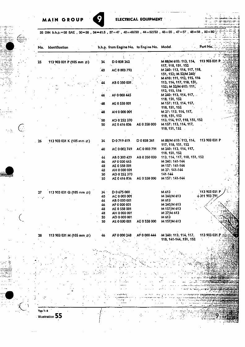
M 88/M 610: 113, 114, 113 903 031 117, 118, 151, 152 M 240: 113, 114, 117, 118, 151, 152; M 52/M 240/ M 610: 111, 112, 115, 116 113, 114, 117, 118, 151, 152; M 52/M 610: 111, 112, 115, 116 ' M 240: 113, 114,.117, 118, 151, 152 M 157:113, 114, 117, 118, 151, 15i M 27: 113, 114, 117, 118, 151, 152 113, 114, 117, 118,151, 152 M 157: 113, 114, 117, . 118, 151, 152 .
113 903 031 P (105 mm 0) 34 D 0 838 262
40 AC 0 003 792
AB 0 350 001.:
46 . AF 0 000 1145
•48 AE 0 SS8 001
48 AH 0 000 001
-50 AD 0 252 370 50 AE 0 416 836 AE 0 558 000
•'•
27 113 903 031 Q (105 mm 0) 34 D 0 675 000 M 613 .113 903 031 P 40 AC 0 000 001 M 240/M 613 4-311 903 7,91 • 44 AB 0 000 001 M613 46 AF 0 000 001 M 2401M 613 48 AE 0 558 001 M 157/M 613
. . - 48 AH 0 000 001 M 27/M 613 704 50 AD 0 000 001 M 613 50 AE 0 000 001 AE 0 558 000 M 157/M 613 .
28 113 903 031 M (105 mm 0) 46 AF 0 000 248 AF 0 000 444 M 240: 113, 114, 117, 113 903 031.P • 440 1 4 144 151 152 ',
• :•:••• •
•-•• • • ,t •• 41,
•
• '..my.alte
Typ
. 'Illustration 55
MAIN GROUP ELECTRICAL EQUIPMENT .
"•.
25 DIN b.h.p.=30 SAE , 30=36 , 34=41.5 , 37=47 , 40=49/50 , 44=52/53 , 46=55 , 47=57 , 48=58 , 50=60-
No. Identification
b,h.p. from Engine No. to Engine No. Model- . Part NO::
26 113 903 031 K (105 mm 0) 34 D 0 719 419. D 0 838 261 M 88/M 610:'113, 114, 113 903 031 P 117, 118, 151, 152
40 AC 0 002 749 AC 0 003 791 M 240: 113, 114, 117, 118, 151, 152
44 AB 0 300 429 AB 0 350 000 113, 114, 117, 118, 151, 152 46 AF 0 000 445 M 240: 141-144 48 AE 0 558 001 M 157: 141-144 48 AH 0 000 001 M 27: 141-144 50 AD 0 252 370 141-144 50 AE 0 416 836 AE 0 558 000 M 157: 141-144
•
•
• •4.1,4°- ° •
4." • . ; •
' Ia.,: .71.1;1: t--; •
"tg•I:Pash1,009;;="4-•.+1..--.V....1,11V+95.-1•14,91.try..tg.+.19.”vo9.•:9-• ; . •
• ' - -
41 ̂1 • , ;
,97.0. • • - 111"-te
;•
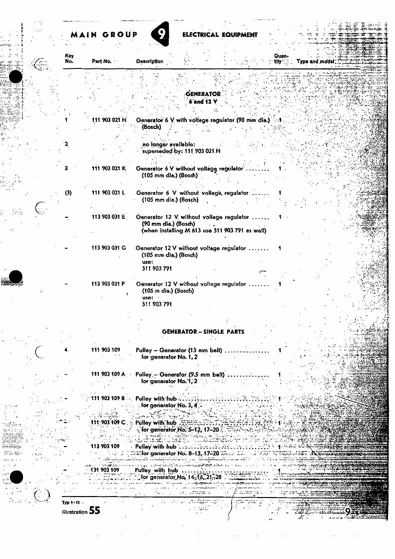
113 903 031 G Generator 12 V without voltage regulator 1 (105 mm dia.) (Bosch) use: 311 903 791
113 903 031 P Generator 12 V without voltage regulator 1 (105 m dia.) (Bosch) use: 311 903 791
Pulley with hub • • 1 ' -- tor-generatar No, 1411621-28 ,•
. .
• • . ,
113 903 109
Pulley--with hub . • . ••• •
• gerieratoi No: 8-13,17L21:17:;,..,..„ •
• 131 903 109
ELECTRICAL EOUIPMENT
• •-!, ; , .
- ••, • 'f•-•••-4,,,,,,t•-.4 .vmxte..0
Key No. Part No. • • Description
2. no longer available: • superseded by: 111.903 021.H
. e,...•••: -71 i4;11 ...••••74- • • • •••4•1
•G-PENERATOR . • '6-and 12V
• , . , ' 1 111 903 021 ii Generator 6 V. with voltage regulator (90 min. die.) -.•
(Bosch) .,-- - . ' • e • • , „ ••-• , . . . • : . e „. • . , •
Quan-
• 3 • 111 903 021 K Generator 6 V without volfeig9 regulator'
(105 mm dia.) (Bosch).
• (3) 111 903 021 L Generator 6 V without voltage. regulator (105 mm dia.) (Bosch)
113 903 031 E Generator 12 V without voltage regulator 1 (90 mm dia.) (Bosch) (when installing M 613 use 311 903 791 as well)
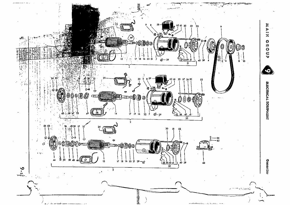
GENERATOR - SINGLE PARTS
4 111 903 109 Pulley - Generator (13 mm belt) for generator No.1, 2
111 903 109 A • Pulley.7. Generator 49.5 mm belt) . for generatai No.'1;-2
• .. , ,
111 903 109 R - Pulley with'hub-. . . ' . : . : .. : . for generator No. 3,4. - • (, •
111-103 109 C PUlley with:hub • -̀•-•-" ..1 '- 14 . .
C A tor gerierator•No'.."5-12,. 17.-10 ;
Typ 1-11
Illustration 55
S.--,•••11,;•••••;;•:::• • •
":•"••-•:.
az•tes74:411f4
Armature with ball bearing •Genercifis No.:I, 6,y8-10, 12 ' 7 re.ITT
••4
Quan- tity
. • Type and model
46=55 , 47=57 , 48=58 , 50=60
1
1 25 b.h.p.
1 30, 34-, 37-, 40-, 44-, 46-, 47-, 48-. 50 b.h.p.
1
1
1
1•
1
1
1
25 DIN b.h.p.=30 SAE , 30=36 , 34=41.5 , 37=47 , 40=49150 , 44=52/53 ,
Key No.
MAIIN GROUP
Part No. Description
ELECMICAL ECU IPMErd
111
111
903
903
115
123
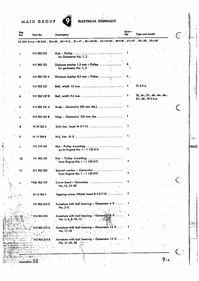
5 111 903 131 A
111 903 137
6 111 903 137 D
7 113 903 141 A
113 903 141 B
8 N 10 242 5
9 N 11 008 8
111 119 141
10 111 903 181
11 211 903 183
*181 903 197
Strap — Generator (90 mm die.)
Strap — Generator 105 mm dia.
Bolt, hex. head M 8 X 25
Nut, hex. M 8
Nut Pulley mounting
Nut — Pulley mounting
Special washer — Generator from Engine No. 1 —1 120 615
Cover band — Generator No. 16, 24-28
Belt, width 13 mm
Belt, width .9.5 mm
Hub — Pulley for Generator No. 1, 2
Distance washer 0.5 mm — Pulley
Distance %wisher 1.5 mm — Pulley for genbrator No. 1, 2'
• from Engine No. 1 —1 120 615
up to Engine No. 1 — 1 120 614
N 13 9641 Tapping screw, fillister head B 4.2X16
111 903 213 C Armature with ball bearing — Generator 6 V No. 2-5
113 903 213
„A'` 113 903 213 'A •
P.'
113 903 213 B ' ” • '
,•••1•4". • . • -
•,- Illustration
Armature -with bail be'firing Generator 12 V .... No. 17-20
Armature with ball bearing — Generator 12 V .... - No. 21-24, 28 "..•"•
Generator 12 V ":
•
•
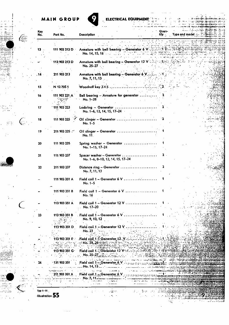
Spring washer - Generator No. 1-15, 17-24
Spacer washer - Generator No. 1-6, 8-10, 12, 14, 15, 17-24
Distance ring - Generator No. 7, 11, 13
Field coil 1 - Generator 6 V No. 1-5
Field coil 1 - Generator 6 V No. 1.6
Field coil 1 - Generator 12 V 1 • No. 17-20
20 111 903 235
21 111 903 237
22 211 903 237
111 903 351 A
- 111 903 351 B
113 903 351 A
, 'i .. ....: . . - ...
. . ' : .. _.....::-.... J: ...j• , • -
:Field c9K!-
1 7'Penetafor,..12..y.•; . ";.,.. •." . '.;•,.....: -.-"..1."'". - ..-..-.:;•-No:•24r..28 -&,-,-,i.:?:...:;.•_' ':77..::r. .. ...° . ',".': ....!, '''"..- „
23
•
• • ••••:. • - . 113 903 351 G• Field coil 1:=:Pineialor- 12 W:4 . 7•2
• No 25-27 •-• ' ' ; .41 Kt
• , _
. Field coil 1 - Generator 6 V No. 9, 10, 12
Field coil 1 Generator 12 V No. 23 • •
113 903 351 B
• • •
413 903 351 D
113 903 351 E• •• or 4
g•:
• - - •
1
2 .
2
1
• - • 131 903 351 • field coil 1-- —Generator 6 V - . r tft. ta 24 .7.
44'7. 7 211 903 351 A .Fieid coil.„1„zpenereloch V.; 1'gg umti• :
No.'7,
. No. 14,15
Typ 1.11
Illustration 55
• ve
- •
13
111 903 213 D • Armature with ball bearing - Generator 6 V..':::: No. 14,15, 16
113.903 213 D
Armature with bell bearing - No. 25-27 • .
. • ,14 211 903 213 Armature with ball bearing - Geneiator 6 y:.._.,.
No. 7,11,13 , - • •
15 N 12 705 1 Woodruff key 3 X5
16 111 903 221,A Ball bearing - .Armature for - No. 1-28
17 ' 111 903 223 Lodging - Generator No. 1-6, 12, 14, 15, 17-24
18 111 903 225 Oil stinger - Generator No. 1-5
MAIN GROUP ELECTRICAL EQUIPMENT -
Key No. Part No. Description
• -Quan- • tity Type and model..„,-.
generator 2
'2
19 211 903 225 •'" Oil slinger - Generator 1 No. 11.
MMG4 GROUP ELEgnICAL EOLEOPMEElt„
• . Description . Key ' •
No. Part No. Quan- tity Type and model
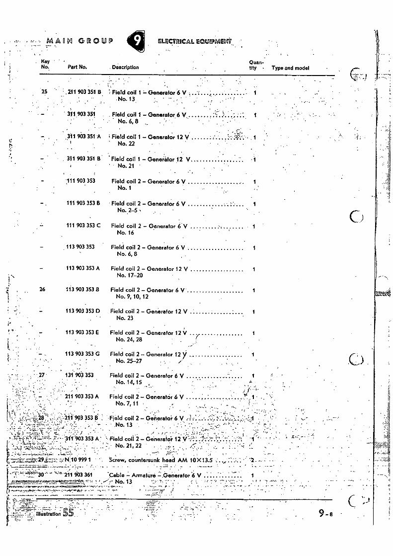
•• • 25 .211 903 351 8 .; Field coil Generator 6 V
• No. 13 • •
0 • • 311903 351 • Field coil 1 - Generator 6 V..
1 Field coil 2 - Generator 6'V No. 16
1 Field coil 2 - Generator 6 V No. 6, 8
No. 25-27 . .
Field coil 2 - Generator 12 >'
1
1
1
•. • .
ti
ct •
' # 311 903 351 8
111 903 353
311 903 351 A ; Field coil 1 - Generator 12 V 1
111 903 353 B
111 903 353 C
113 903 353
113 903 353 A
26 113 903 353 8
i • , •
113 903 353 D •
e.• 113 903 353 E
113 903 353 G •
-• • --:•27 131 963 353 . .
- • - • • ' 211 903 353 A
No. 14,15
Field coil 2 - Generator 6 V 1 - No. 7, 11 ,
k„
• , "
-' '..:. 1): : .*t2!1 ,"1, -1 ';:. ,1.-;--'2 0'903 353 B' ;
,:' • • : ,......,,-..z........., . :,...,• .•.: f.
. . .
. :L.: ...:, • "....- 7: "......-_, .::-...s ::-.- ., •••• ' -
Field coil 2 - • - No. 13
; efieratoi 6 V a' • • 11' • • • • •
• • .1 . • 1T.
Field coil 2 - Generator 12” V;1-1-..1"".- " • • -1 r*" ' • • No• 21, 22 ' - ••• - -
Screw, countersunk head AM 10X 13.5 - • - • •
-. • . Cable - Armature -.Generator 6 V
No. 13
•1
No. 22 •
Field coil 1 - Generator 12 V No. 21
. •
Field coil 2 - Generator 6 V 1 No. 1
Field coil 2 - Generator 6 V . 1 No.2-5
Field coil 2 - Generator 12 V 1 No. 17-20
Field coil 2 - Generator 6 V 1 No. 9, 10, 12
Field coil 2 - Generator 12 V No. 23
Field coil 2 - Generator 12 V No. 24, 28
Field coil 2 - Generator 6 V
' • - • .• - 't • , 7;4- - '311.'903 353 A '
" , ,
. • •
N.10 99.91 •
- - - '
!""*.'.°30 ''44 211 903 361 •
••• ••• •-
9-8
MAIN GROUP ELECTRICAL EQUIPMENT. • . . •
" • • .'•' • • , • '•• " -,-!•;;:r
..Quan-' •
Alt/ • . Type
•
• 25 DIN b.h.p.=30 SAE , 30=36 , 34=41.5 , 37=47 ,'40=48/50 [44=52/53 ; 46=55; 47=57;; 48=58 50=60
• - -
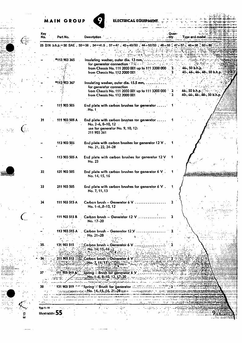
*113 903 365 Insulating washer, outer dia. 13 .... . .... . , . for generator connection .1°4.; - - • - = . • :
; •
from Chassis No. 111 2000 001 up to 111 3200 000. 2 2 • , 46-, 50 b.h4o. • - from Chassis No. 112 2000001 ̂. • 2 , 40-, 44-, 46-, la., 50 h.h.p.
.. ' .•:•7 .---":!' --:• ' • • ; 1-,.' *1.11403 367 Insulating washer, outer dia. 15.5 mm, .. .
for generator connection ' 1 , from Chassis No. 111 2000 001 up to 111 3200 000 • 2 • from Chassis No. 112 2000 001
Key No. Part No. Description ' .
46-, 50 is.h.p.';;• 40-,•44-, 48-,^50 ti.h.
•
111 903 505 End plate, with carbon brushes for generator 1 No. 1.
31 , 111 903 505 A End plate with carbon brushes tor generator 1 • No. 2-6, 8-10, 12
use for generator No. 9, 10, 12: 211 903 361
113 903 505
113 903 505 A
32 131. 903 505
33 211-903 SOS
34 111 903 515A
111 903 515 B
113903.515k . • •
End plate with carbon brushes for generator 12 V . No. 21, 22, 24-28
End plate with carbon brushes for generator 12 V 1 No. 23
End plate with carbon brushes for generator 6 V . No. 14, 15, 16
End plate with carbon brushes. for generator 6 V . No. 7, 11, 13
Carbon brush - Generator 6 V No. 1-6,2-10, 12
Carbon brush - Generator •12 V 2 No. 17-20
Carbon brush - - No. 21-28
Generator 12y " 2 - _
357 • 131.903 515 • :-.._,Carbon brush .GiineratOr. 6 V ......., ........7. . . . -„,....,....., • ...,-:-..,T...,..-'::: No..14;•-15;746',4., - I. • ,.. • ., ' • •
_ ...-.....;!"5,1‘,. :',.•• ':•...•-:,!-7,,,,,-,...-1-j....Aqi.. ,,.'..- ...,,,•:=.1„,:.-5.. - .... :.-3'c' ,Z.:!:' 7.• L',. ;•.'>;`,.,A;,..:£ .. r
211.103 51 ...--,:,-"*„1,""CirbOri brissii I.:- inerator.6 Virrf :`,..'•:.c:7'..•';';i:?-''';'''''-, F.: 7.-.-,-,-. t....- .r-.-1: .......,- i.40, 7 1 1.1 3.4......,-,•=rimit.v, .--,--.'s-- s' i r.- -,7‘,..i5--- .~.:-,t‘r,§ • t Fi,..ee4.-,'% 4.1.1;12tr7:"•fit. .-...,..1:77;1:4'.:;2,.."::-:t..t.:.,:),E1 ... • ...4_, . r.„ •-a-1.:'-Rr';-7.1›,iiVi... -••%,,,,c .' •:1 • ?.. •e-r-Ve.!, ,'-..r.....p,..r .;`..7, . ‘,.c.--....,
•-•." rt. Spring - Brush tor .6 ginirator V .... -2 _ . •,!-:
No1-1-6 - 12 •I,70 • •. • 1.- • • •• 11.1, •:••• 1?.• .••••
.. •
Typ 7 -it
Illustraticin.55
38 " ' 131 903 519 4'' "Spring.'"-Bitisii. for 'gen'erator • • ' .4 r, No. 1445,46, -41 S.cm
^- • - ^-• • - •
• .
MAD GROUP ELECTRICAL EQUIPMENT
• - 9 -10 - , fp - _
Illustration 52 •
Description Quan-tity Type and model
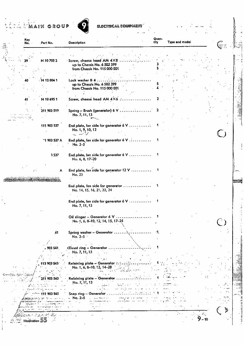
• Screw, cheese head AM 4X8" up to Chassis No. 6 502 399 from Chassis No. 115 000 001
• 3 5
Lock washer B 4 up to Chassis No. 6 502 399 from Chassis No. 115 000 001 4
Screw, cheese head AM 4 X6 •
Spring 7. Brush (genefator) 6 V 2 No. 7, 11, 13
End plate, fan side for generalor 6 V 1 No. 1, 9, 10, 12
V End plate, fan side for generator 6 V 1 • No. 2-5
End plate, Ian side for generator 6 V 1 No. 6, 8, 17-t20
••• End plate, fan side for generator 12 V 1
No. 23
End plale, fan side for generator 1 No. 14, 15, 16, 21, 22, 24
End plate, fan side for generator 6 V 1 No. 7,11,13
Oil stinger - Generator 6 V No. 1, 6, 8:10, 12, 14, 15, 17-24
Spring washer - Generator 1. No. 2-5
•
'Thrust ring - Generator 1 • No. 7,11,13
Retaining plate = Generator• -.-..:.:•.: . ' ........ ... 1 • No. 1, 6, 8-10, 12, 14-28 - ,- , „: _ •
, • •
- Retaining plate -.Generator '. . - •
1 : • •r
• - No. 7, 11, 13 . .
• .._
Snap ring - Generator - . , No. 2-5
• ' - • ' • •-••••-4 -
•
Key No. 4 Part No.
N 10 703 2
40 4-)N 12 004 1
41 N 10 695 1
211 903 519
111 903 537
'1 903 537 A
3 537
A
61
T. • •
903 541
113 903'543''
I.,- -• . •. .
‘-,--=:.Ni•,• :0':-• .•'•5•!*q.' „ • . • - ,• it 211 903 543 -
•-•-•-• 111 903 545 '
Quan- tity • Type and model -
,2
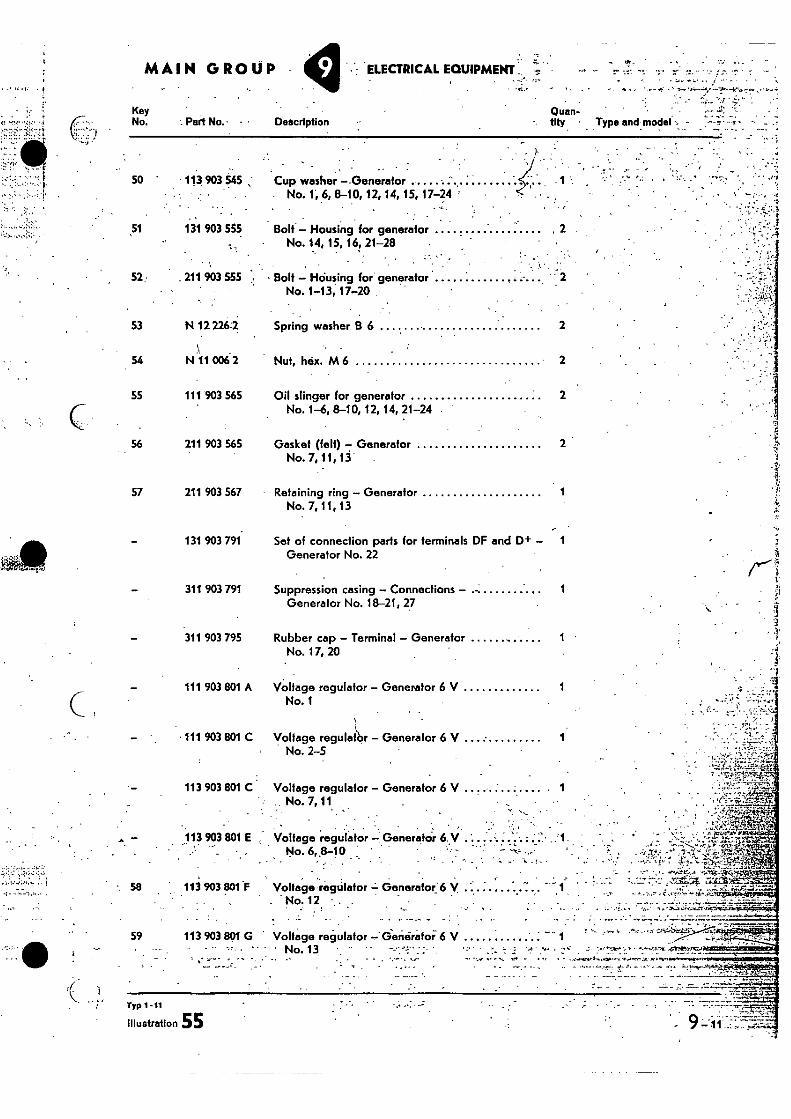
111 903 801 A Voltage regulator — Generator 6 V
1 No. 1
111 903 801 C Voltage reguldbr — Generator 6 V 1 No. 2-5
113 903 801 C Voltage regulator — Generator 6 V 1 No. 7, 11
• ,.
• • - •.• 113 903 801 E Voltage regulator — Generator 6,y ' No. 6„8-10 -
113 903 801 •F Voltage regulator = Generator:6 V - No. 12 • ,
. •
113 903801 G Voltage regulator—`Generator 6 V
-. 58
59
- ••,,:a..,2
Typ 1-11
Illustration 55 9 •
eq:e3;;: t k 111:41: 4.3
MAIN GROUP y • - ELECTRICAL EOUIPMENT
51
52
-• Part No. Description
113 903 545 , Cup washer --Generator .• No. 1', 6, 8-10, 12, 14, 15, 17-24
• • •
131 903 555 Bolt — Housing for generator No. 14, 15, 16, 21-28
•.•
. 211 903 555 • Bolt — Housing for generator No. 1-13, 17-20
Key No.
•
50
53 N 12 226,2 Spring washer B 6 2
54 N 11 006 2 Nut, hex. M 6 2
55 111 903 565 Oil stinger for generator 2 No. 1-6, 8-10, 12, 14, 21-24
56 211 903 565 Gasket (fell) — Generator No. 7, 11,13 '
57 211 903 567 Retaining ring — Generator 1 No. 7, II, 13
131 903 791. Set of connection parts for terminals DF and D+ 1 Generator No. 22
311 903 791 Suppression casing — Connections — 1 Generator No. 18-21, 27
•
311 903 795 Rubber cap — Terminal — Generator 1 No. 17, 20

Key No.
v, Part No.
60 111 903 801 D
/
113 903 803 C
.•
113 903 803 D
113 903 803 E
211 903 803 E
61 N 12 005 1
62 N 10 811 1
63 N 12 225 1
64 N 15 892 2
N 14 130 1
Nut, hex. BM 5
MAO GROUP
Voltage regulator — Generator 12 V No. 21
Voltage regulator — Generator 12 V No. 22-28 use: 111 971 945 B/2 X111 971 949
1.
1
Voltage regulator — Generator 12 V 1 No. 17, 20 use: 111 971 945 B
Lock washer B 5 up to Chassis No. 6 502 399 2 141-144 up to Chassis No. 116 1021 300 2 111-118.151,152
Screw, fillisfer head AM 5X8 up to Chassis No. 6 502 399 2 141-144 up to Chassis No. 116 1021 300 2 111-118, 151, 152
Spring washer B 5 from Chassis No. 115 000 001 up to 116 1021 300 2 t41-144 from Chassis No. 117 000 001 2
Tapping screw, Mister head A 4.9 X19 from Chassis No. 115 000 001 up to 116 1021 300 2 141-144 from Chassis No. 117 000 001 2
Screw, fillisfer head AM 5 X11 1
ELECTRICAL EQUIPMENT -
Vollage!regulator — Generator 12 V • No. 18,19 ,
Quan- Description
tity Type and model
Voltage regulator — Generator 6 V I No. 14,15 use:. - 111 971 94513/2 X111 971 949
•
Illustration SS 9-12
v.••. 6.4
• t.t.7 ••••V4. - 4•1-";`l.
'7.1 4: -4...-77,1'`",, A • '...•••'-r4li-g 'AY .4-P-f '951141
‘-'STS•trp.;„g'ta„
• .v yy
. • '...
". — • . , ...' •• . c'....;::.'4 rtz. 4. ,
,..",„.-1-,1-• ,...:-.E..e?‘....A.:.....-_-_ .._tr • -
...,!-...,..._ , • ...,,,,,,,....,..r , 7,,,,,,4 , , . -,.(5 . - ,• .....,;41*Isan,r.,....)r An. i ,._,.......0.=-c-r., ------- -.,- 2- -,-,...,........, 4-:
- , .-1.`"*.m., - 4. a -7, , ,,,,,P.,.i..•,..•I'...,',.,..., 7---t..... 7 . • ,,,- -7,1./.47P 'Pr :71.,.....7..,,,, ' '1.0`,:t:47.:7•117.77177 . te-Y ,,,:,..:.: -......-, -,:.--,. -,-1,11,,,i; 7 er, 2 - ..2-" ,,..- cf 0•14k4".'S ••"' •V'c'O'' 1.1 r -,, , ..,-; - ,:...7,-'•;7? -.A.....t tzd.%.• Z.:7"Zrt,q.,53..074"
,-. .:'','....f.,::-,:,', .",'.;-.:',:.: Lr::-,;`...)1..F,..17,.%Z.0--;-, „;,..: 'I...* --T. --.n: .t...":!„- . 1, ::-..:,,,,,..4-441 x.i.ri.-.4.1i..6.Z1V,9, : f , , 4.-4 d.,....- -•_--.., A ti • -...11..,-....k...... ...,.... .... ',. „ . t ' , ' -. .` :,&,,.. r1'.. 4 . •,:. 4. .1-.C,. .7...7 .. )...,:t..T......Z74.? t'..:',•::.4-Zrt..?•Er.1„,&.- ...:.‘ V.a.. X't.it ,I. A- :PT.. - ''. "1.:47.."''''''.,:t..7 ..'„i 'irf ' -!...;"2..r..,"..'.'..'‘'.• .-",'.V L,.-',... '!' :-..et:-.......:;;,, ,.....---!;":• :744%,.§._ZW=14.7..........,. .,:;.......-..... ..... , _
. ..... -1......4..... '
• • -7;:. •
0 -,..5. , ......1}...--94..,...--r. ,•-.. .T.t :h,.:• ..,...-4---,‘"__ .3.•'• .. It .-_. :•.`t --...81.--,at ,..-1,--,-.: '.1. ......--...12 ..,,, -'44=1,1241.25r&r. 1 -: “.. ..,L- '...1. ..--r i....1.-..... ,..'..i...'.........-..,t- . ,...7r , •_-_'14:••• ••7.--'i.Ar=517InitelV . ...... — .........- - _ .... - .. . . . -... , - . ,......--.., ..........,.,,,,,,,,,,,,...,,,,,......,..,-....,---,,......,.-...1. •,,.......,-,.. • -.....,..............-,- ...-0-........-0,......-.1”-.........ana•maft....... ...•'.....,,......I. t•tapei,L,SPAR,S a...rv...,-..... ,.,...-70.r..,..-a... . . _
, :r , -• : . tt-r ." ,r. - , . _.• . ,.-,1, ..4-. ' ,.,• • f• .,.. c b..; 411,,,,, 4 ••Z)_ ,..41-1'. ifi..4.‘nS.,'•''k•••a•tt,'$Vaiir
. , •
- TYP 1-22
• ',.., • .14. 1041.-9,1:00"-
.2
, 13
38 35
33 0 32
} 21
74 91 73
`90 92
.16
59
60 51 44 50
LIN
SINal
1n
031
1Y31
11L,
3131 57 1 10
36
. „ 41
5 79 80 82 83
••--13 14-73 93 65 68-66-61- 12' 52 45
42
73 74
7 52 45 43
• 15
fl fl
97 103 103
104
4 105 3
11
14 40
39 9
•
27 28 29
• :1•
31
82 81.
, 1
0 ot r\)°V °5' 1 i
1 j2 I
201 79
85
55 47
54
8
------ 22 Xzn.F,
32 24
0 25 6 •
56
94
37 \\<-
22 88 87 86 —78 76
89 19
58
96' 47°-
20
915
61
20 19 75
2
O
e 53 46 43 42 41 60 .72 73 74
23 7—.677,,; cit*
.;:!• 34
0
r .
Typ I -22
••?-4,-/••••••
• • : -... --. • - • ••, • -
- - 4. •
•
_ .. . - .. .,:— :- .... --•, -.,-..-..,•-•:,..r...p.....r.---..• •.••••,- Ly• L. , , , •...., - •.. .. .^.4.•••,..•• '. ,'- • ••.• (...':-... ^.... • ••••'. ". •-^ ,--5.: -...m ::'-c,), ri,701
. - . - - -- - " ' " . ' " ' i" l''',:".!.- '.•'7".Y.W,• $ . "• • ' ''- • rk': '1' i
- • 1" ' ,...i:',,,S.,. • . ;1::;.L ' ...1 '.. '-'' ri.-.;.Itcl . . '. • •
. 04 •-i'• 1-1;..."Z"'l t.s.11
, • •f., re:
• • •••:4.,..-
, -
' I' • ' •-• • " :•4
-. •
.i••• • ' •
—!4.44-1 • -41;4 • I f ' . 4."'114•••v•:'''. • • A-4 7•ro,fig ••• • -1 L • - ' A
3-•
: -
. •
,• . v4-;;•;,••••..
. • . •. _ • %?.t" t 1E, T. a,
. • t--"; ,,,•• ' • '0- ' • ' -••••r.,:-.4 , •
• • ri.1---,,,-tnt7 ;14. - -‘71,ty
y. .-- --e-r. , -.,... . , . ,,,..-.7 .. ,,,. ....Are, .,-,-sti..). :i.ic . t, - ,,, . ..-C4. ,C,i,- ..1•.,:,., ., ...,- • - • • 4 -, -.t 7,. '' . -,,,4a-- -A-0, -..* * •'• • . ,•,,,s-.5.4 ,••f:-•::•..sris•-.094r,
- • .
. • . . •
• .214 r rrArriprrir-.1,LIAra.134).PrIrtrIV,
• •• - . . .- 1..4='.
,., ;s= ,• •••4•4444+ Y.
•
9-16
k4.
r
. • . •
. •
" •
' • . • .
MARVI GROUP y ELECTRICAL EGUIPMEIAT Ignition
+4," •, t
•••
MAIN GROUP .T. -ELECTRICAL EOUIPMENT-------4,7 . . _ .
25 DIN bh.p.4=30 SAE , 30=38 , 34=41.5 ; 37=47•, 40=49/50 ,-44=52/53 ;48=55747=57 , 48=58 ", 50=60 -
•
• . - . ........
- - -!,- r " ^,.:it.pir:rT"•4•14 •
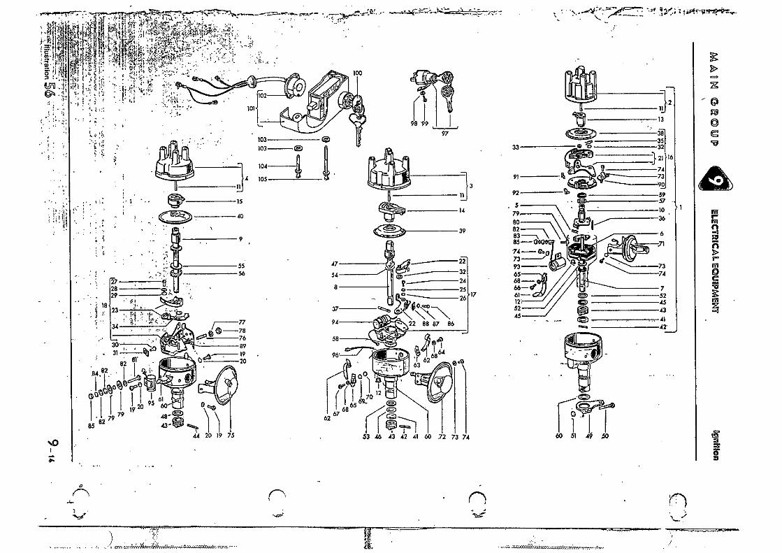
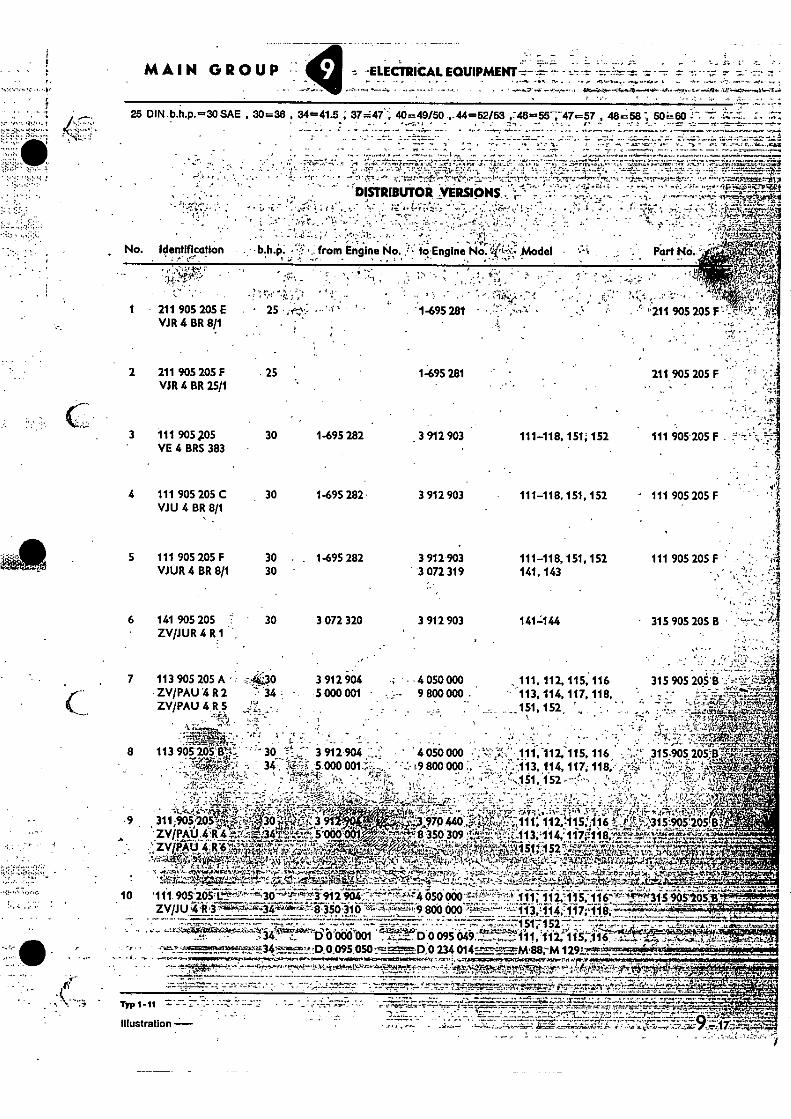
DISTRIBUTOR VERSIONS •
, • , 1ti • 41 t •••t.. • t••
- • ;- •
-t••••• " MOJA N
111 . No. Identification
1 • 211 905 205 E VJR 4 BR 8/1
2 211 905 205 F VJR 4 BR 25/1
3 111 905 P5 VE 4 BRS 383
4 111 905 205 C
30 1-695 282. 3 912 903 Viii 4 BR 8/1
5 111 905 205 F 30 . . 1-695 282 3 912 903 VJUR 4 BR 8/1 30 '3 072 319
6 141 905 205 • 30
3 072 320 3 912. 903 ZV/JUR 4 R1
, •
7 113 905 205 A • 3 912 904 4 050 000 ZWPAU 4 R 2 7 •34 5 000 001 • 9 800 000: ZWPAU4 S R
•
8 113 905 205..13'4:,.
• 25 • •
. 25 1495 281
30 1-695 282 3 912 903
211 905 205 F
111-118, 151; 152
111-118, 151, 152
111-118, 151, 152 141, 143
141=144
111, 112, 115, 116 113, 114, 117. 118,
._151,152,
- 111 905 205 F
111 905 205 F
• 315 905 205 B
315 905 205'6
7.1 Yig•il
111 905- 205 F . ‘47.
44 t . 11-1":;. 4
7 •
• 9 ' t`fz 3 t2.3.070 440.riPr,,,'-'• 111; 112.115:116g 016A15i9115105B,,titlik.4:''V. •
•-•••,- • • -8350.309 '4;r4""';-:-'Z+t-. 113;,114,.117q118
i 51 'tr417,:.:44.442r4,7:41.1Sr"M. jr.774 •
•
"""' .̀7k;r. •
1 0 '1 1 1. 905'205' r7_,3 912 4 050 000 +' 111 ▪ 117,7115; 15 .905.205a
ZVp U Zli'37.4.Pr14.5,17,-73Vegarb;Id:4 873507-316'''WX.W.:.,IL...'19 860 000 • 117;F1 1 k;:":7`..-W.a.' • • • azikaitti.o- • • - • -- - 34 D 0'000 001 D0 095 111,'112,115, 116
• • 0 095 050 234 014=-;11'..7-...M..88.--M .10.4,1.1041.74,..M.POPISTWV.CON. , 71,1111113126.01.1P3MAK,r.h.F7x...1.47rn ifir.•
• . . , . .
7:-.1,7 ." - - t. t • . - _
Illustration
, •
.
• -7277 . ..9
MAORI GROUP ELECTRICAL EOLIIPMENT
Part No. No. -Identification . b.h.p. from Engine No. to Engine No. - Model
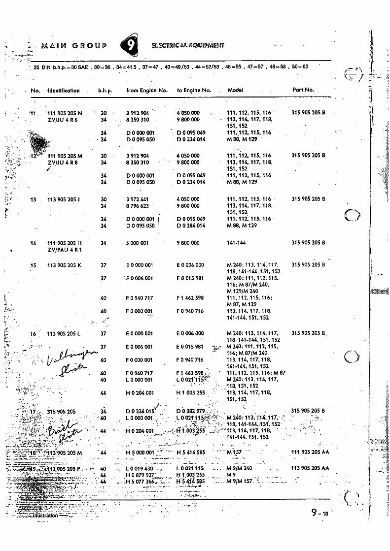
'11 . 111 905 205 N ZWILJ 4 R6
• 30 3 912 904 34 • . 8 350 310
34 34
D 0 000 001 D 0 095 050
9-18 •
' 25 DIN b.h.p.= 30 SAE , 30=36 34=.41.5 , 37=47 • 40=49/50 , 44=52/53 , 46=55 , 47=57 , 48=58 50=60
7: 315 905 205
,P•t• •••-•
• •*•
3"905 205 M
').,- 7-1-,..•-iitA-49.,4,,:•.4,113,$05 205 P ,••• 40
•
• 5'7. •
• • • • ustrat on -
4 .050 000 9 800 000
D 0 095 049 D 0 234 014
4 050 000 • 9 800 000
D 0 095 049 D 0 234 014
•
•
•
111, 112, 115, 116 113, 114, 117, 118, 151,152 111;112, 115, 116 M 88, M129
111,112, 115, 116 113, 114, 117, 118, 151, 152 111, 112, 115, 116 M 88, M 129
315
315
905 205 B
905 205 B
4 050 000 111, 112, 115, 116 • 315 905 205 13 9 800 000 113, 114, 117, 118, -
151, 152 D 0 095 049 111, 112: 115, 116 - D 0 284 014 M 88, M 129
9 800 000 141-144 315 905 205 8
£ 0 006 000 M 240: 113, 114, 117, 315 905 205 8 118, 141-144, 151. 152
E0015981 M 240:111, 112, 115, 116; M 87/M 240, M 129/M 240
F 1 462 598 111, 112, 115, 116: M 87, M 129
F 0 940 716 113, 114, 117, 118, 141-144, 151, 152
E 0 006 000 M 240: 113, 114, 117, 315 905 20S B. 118, 141-144, 151, 152
E 0 015 981 M240:111,112,115, 116; M 87/M 240
F 0 940 716 113, 114, 117, 118, 141-144, 151, 152
F 1 462 598 ,,, ' 111,112, 115,116;M 87 L 0 021115?: M240:113,114.117,
• 118 151 152 H 1 003 255 113, 114, 117,118,
151,152
' 0 0 382 979 , ,.! . • ,
, . , . 315 905 205 B 40 L 0 000 001 ..-. • • L 0 021:1115pK•Tr'--M 240: 113, 114, 117, • ..',.
• •- ': - ' . • .., .,...c : •• .:'7 ' --:-- 118, 141-144,151, 152. 44 . 1 -' 14 0 204 001 ,,---;'1.003255- -" 113, 113, 114, 117, 118,
. 141-144, 151, 152
H 5 000 col H 5 414 585 '
L 0 019 430 L 0 021 115 . . M 9/M 240 H 0 879,927 . H 1,003 255 M 9 H 5 077 366.. H 4145$5 . M 9/M 157. ,
•
ose..
16 113 905 205 L 13. •
•34 D 0 000 001
, • 34 D 0 095 050
111 905 205 M ZVOU 4 R 8
,1"
13 . 113 905 205.1
30 • 3 912 904 34 8 350 310 •
30 3 972 441 34 8 796 623
34 D 0 000 001 34 D 0 095 050
-„:;• •
f• .
••• •
t" r
14 111 905 205 H 34 5 000 001 ZV/PAU 4 R 1
15 113 905 205 K 37 E 0 000 001
37 E 0 006 001
40 F 0 940 717
40 F 0 000 001
37 E 0 000 001
37 E 0 006 001
40 F 0 000 001
40 F a 940 717 40 L 0 000 001
44 H 0 264 001
34 0 0 234 015 ••41".
.•.Y3
.111 905 205 AA
113 905 205 AA
23
No. identification b.h.p. •- from Engine No. Engine No..- - -Model . Part No: • k 4
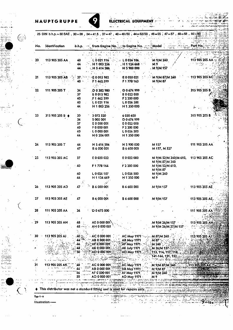
- 20: 113 905 205 AA 40 L 0 021 11C . L0024.106. 44 •" . H1 003 256 H 1 124 668 • 44 • :. H 5 414586- H 5 900 000
. '
•• •- ..
'M 9/M240., M9
.M 9/M157
113 905 205
• •-•' • 41.."7-•
21 113 905 205AB 37 - E 0 015 982 •
40 - F 1 462.599 • •E 0 020 021 • • • M 9/M 87/M 240
F 1 778 163 M 9/M 87 ' • 113 905 205-ACt4 ia7;
• • ".•,i":•"ip&I.
315 905205 B
••• .,
315 905 205 B
.HAUPTGRUPPE . .
ELECTRICAL EQUIPMENT
25 DIN b.h.p.=30 SAE , 30=36 , 34=41.5 . 37=47 , 40=49/50 "„ 44=52/53 , 46=55 ; 47=57 , 48=58 ,
111. 905 205 T 34 .D 0 382 980 37 E 0 015.982 40 ,F 1 462599 40 L 0 021 116 44 H 1 003 256
D 0 674 999 E 0 022 000 F 2 200 000 L 0 026 500 H 1 350 000
. . 315 905 205 13 4 30 3 072 320 4 050 600
34 5 000 001 D 0 674 999 37 E 0 000 001 E 0 022 000 40 F 0 000 001 F 2 200 000 40 10 000 001 10 026 500 44 H 0 204 001 H 1 350 000
111 905 205 AA
113 905 205 AC
24 113 905 205 T 44
H 5 414 586 H 5 900 000 47
B 6 000 001 136 600 000
• 25 113 905 205 AC 37 E 0.020 022 E 0 022 000
• 40 F 1 778 164 F 2 200 000
40 L 0 024 107 I. 0 026 500 44 H 1 124 669 H 1 350 000
26 113 905 205 AD 47 • B 6 000 001 B 6 600 000
••.•,• 27 113 905 205 AE 47 B 6 000 001 136 600 000 '
28 111 905 205 AA 34 ' D 0 675 000 "
AE 0 000 001\ . .
All 0 000 001 . •• .29 113 905 205 AH
M 157 M 157, M 527
M 9/M 52/M 240/M 610, M 9/M 87/M 240 M 9/M 52/M 610, M 9/M 87 M 9/M 240 M9
M 9/M 157 113 905 205 AE
M 9/M 157 113 905 205 -' •
• • 111 905 205 kik%
s
.M 9/M 26/M 157 • . 113 905 295 AH.f. . M9fM 26/M 27/M 157 ' , .!` -
• ; 113.905 205 AJ5,.:".
;•".4.,•/•,1:WL'i!
. •=-1 424,14,1t1t.
...LtVieitiirj.Ter& • r1.9+0.0‘.,"M.
• 30 11.3 905 205 A.1
• ., . ' ••••::•.:, .. ', •-. .... :,. ',.. ....6--,--4,.....4:-.-A..4",,.:,. • " '..: : ',. .. .:. .... ..•..._ ;L:;::, '... - ' e -- 1 e •:',..-.;: .•!"j r. • :"..-.0.7-r•••' ' .i:-__+-P,,ei.,:•!.., . ' !"".•%-.. F - - ' . . ,.. ... • . ..,;., •._-_....,... -- t..,..."-...."."..L?-2.4.417L...0
--; AC 0 000 °OIL._ '.:'•ii,•:AC may 1971 .
•.4.;•-: 7.4'.. .- -., . - ..- ', ' .,M .9/4871M;4,411?-t.,,,..,•:7-7.i. .::_11340
-A6 AB 0 000 ow '17.--L-7.,..„'-'1.'Ars Mai -1971 • -- :,- - M 9/M 87 .........,...................-.. ... .000'001 -,::-..•%.AF, May 1971 ' M 9/M 240 •••" • •
•• ' -
50 AD 0 000 001 ' • AD May1971 • M 9 ..t,. -:.1...:-..,,,•,•..r,p.....0,..4.61, .. .. .
• ... :.. ........„ ., .....-.. • ........ • ....,,, .........r., .- .;,.v.,-,•• ; •'; It -.-tfrItt=ne , . -• .. ' .. .7 ..:.,14-. &" . !-....,7 ,1:1C,t4.1.1VIOLIX2
- . - - ..-.......... ..- — -.. - e., %. .,ceppe-....r. ,...."..reyeanee. ...re .er . ,,,,,,rate.tepoz,e,,. e •,..,.. to s• t, •:.1 W , .40 .4.174..-ee eLL 'L.+, ..)....-.....arOrrsirPtimon.....euwaift . -
This distributor was not a standard fitting and Is used for repairs only.;
.. -,-..•?, ,•, .. : .
11,1-6 • . 1". ,
—..
Illustration — • •
r.
K._
AC 0 000 001 • • AC May 1971' M87/M 240 t•-.AB 0 000 - AB May 1971 M 87
46 -••••••:,-,-.AF 0 000001' • • •I"TAF May 1971: 240 48. AE 0 0130 001; July 1971 ▪ M 26/M
,.• 50 ;:;•?.;-1AD 0 000.-0011:4:;f:;'.':,qAD.May 1971 'w; X113,`114,117;118, • ▪ 14'1-144, 151! •152,„
t mtg.. 31 113 905.205 T '40
•
MAIM GROUP ELECTRICAL EQUIPMENT
25 DIN b.h.p.. 30 SAE , 30=36 , 34 = 41.5 , 37 =47 , 40 = 49 /50 , 44=52153 , 46=55 , 47=57 , 48=58 , 50 = 60
No. identification. • b.h.p. from Engine No. • to Engine No.. Model Part No. r -'
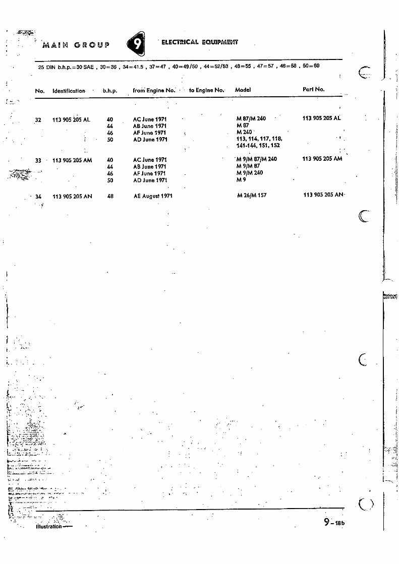
32 113 905 205 AL 40 AC June 1971 M 87/M 240 • 113 905 205 AL 44 AB June 1971 M 87 46 AF June 1971 M 240 • 50 AD June 1971 113, 114, 117, 118,
141-144, 151, 152
33 • 113 905 205 AM 40 AC June 1971 . M 9/M 87/M 240 113 905 205 AM . ,
.;''ts
4 9:23..• -14 '--,0-
44 •‘ 46
AB June 1971 AF June 1971
M 9/M 87 M 9/M 240
''',-,....- • 50 AD June 1971 M9
• 34 113 905 205 AN 48 AE August 1971 M 26/M 157 113 905 205 AN-
•
- • .,••• •
.• Illustration- 5L 18 b
Quan- lily Typo and model . "
• _
'•
1,
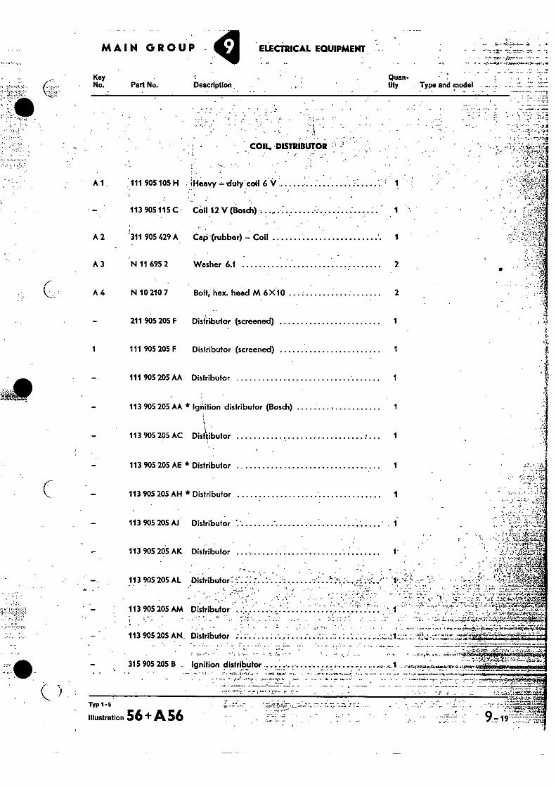
- COIL, .DISTRIBUTOR •
A 1 111 905 105 H ;Heavy — duty' coil 6 V
113 905 115 C Coil 12 V (Bo sch)-..... 1
A 2 311 905 429 A Cap -(rubber) — Coil 1
A 3 N 11 695 2 Washer 6.1 2
A 4 N 10 210 7 Bolt, hex. head M6 X10 2
211 905 205 F Distributor (screened) 1
1 111 905 205 F Distributor (screened)
111 905 205 AA Distributor 1
113 905 205 AA * Ignition distributor (Bosch) 1
113 905 205 AC Distributor 1
113 905 205 AE * Distributor 1
113 905 205 AH * Distributor 1
— 113 905 205 Al Distributor ' ' 1
:.• :.: 113 905 205 AK Distributor
• . _ _ . i - •
. . ,
113 905 205 AL Distributor': -:`. -- .. :' .. :' .. ..': . . ..... ,, , . . .,
: • --..- . ...1: :4'. :•. : .;'..',;-:;....''
,
-..•i., . - • ,: ,. ;,.., .. ..,,, ..,.,....• ':',1. • ,
.. . . • . 4 1 .4 ..• • .4 .;. , . .. .7, ...
113 905 205 AM Distributor 1 • .0 .
- • . - . • . • — , . • • . . .
. ti•
113 905 205 AN, Distributor .. ... . . ... :
315 905 205 B . Ignition distributor • . . . , . •v., 6.1 .-z-.4.6te,n...vbier-Q ktrame,
Key No. Pert No. Description .
C •
"
MAIN GROUP , ELECTRICAL EQUIPMENT - •
" --,. t.,2;•.•',E
7,1„.••',1F' i-F.Cq ..--4- ..i
.4 -.AVAV irti: ., .4
Illustration 56 + A 56 TYP 1-5 ; : 7:
•,..1,• •
ACIAllti GROUP [ELECTRICAL ECUIPMEIC
Key No. Part No. Description
Quan- tity Type and model
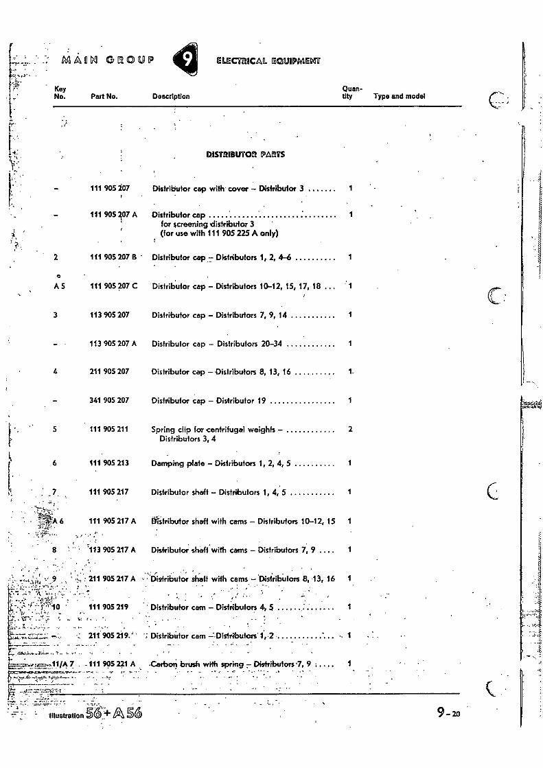
DISTRIBUTOR PARTS
111 905 207
111 905 207 A
111 905 207 B -
A5 111 905 207 C
3 113 905 207
113 905 207 A
4 211 905 207
- 341 905 207
5 111 905 211
6 111 905 213
111 905 217
111 905 217 A
8 " ' -113
-4, 9 • , ••• , • 211
1 .'10 ' 111 • 7.: ' •
, 211
905 219
905 219•,'
905 217 A
905 217 A
1••• • 7 . -111 995 241 A
Distributor cap with cover - Distributor 3
Distributor cap for screening distributor 3 " (for use with 111 905 225 A only)
1
1
Distributor cep:: Distributors 1, 2, 4-6 1
Distributor cap - Distributors 10-12, 15, 17, 18
Distributor cap - Distributors 7, 9, 14 1
Distributor cap - Distributors 20-34 1
Distributor cap - Distributors 8, 13, 16 1-
Distributor cap - Distributor 19 1
Spring clip for centrifugal weights - 2 Distributors 3, 4
Damping plate - Distributors 1, 2, 4, 5 1
Distributor shaft - Distributors 1, 4, 5 1
tilitrilxrtor shaft with cams - Distributors 10-12, 15 1
Distributor shaft with cams - Distributors 7, 9 1
• Distributor shaft with cams - 'Disiributors 8, 13, 16 1
•
Distributor cam - Distributors 4, 5 1
. •
Distributor cam Distributors' 1, 2 1
•Cerbar, brush with spring 7 Distributors 1, 9 • 1
. -
••••• r
Illustration ASS
MAIN GROUP -- -- ELECTR !CAL EQUIPMENT
Key
Quan-
• • I No. Part No. Description
tity Type and
del: . r..
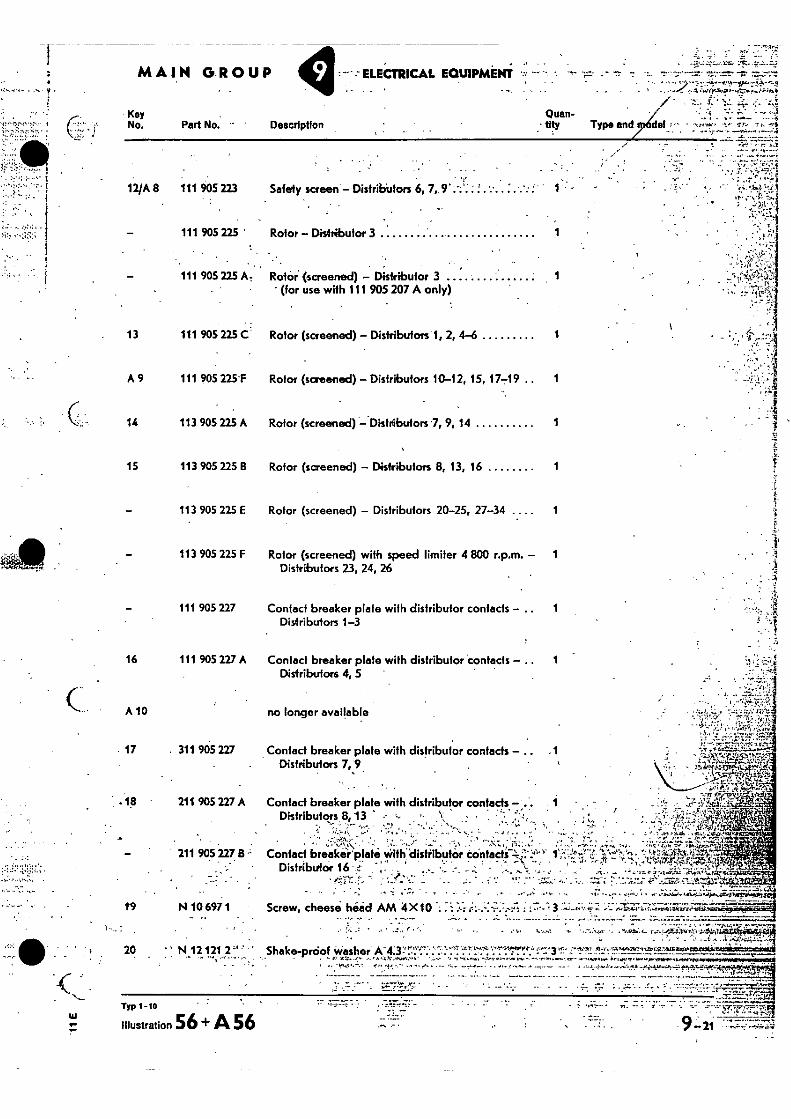
12/A 8 111 905 223 Safely screen - Distributors 6, 7,. 9
- 111 905 225 ' Rotor - Distributor 3 1
- 111 905 225 At Rotor. (screened) - Distributor 3 1 (for use with 111 905 207 A only)
13 111 905 225 C.' Rotor (screened) - Distributors 1, 2, 4-6
1
A 9 111 905 225'F Rotor (screened) - Distributors 10-12, 15, 17-19 .. 1
14 113 905 225 A Rotor (screened) -Distribufors 7, 9, 14
1
15 113 905 225 B Rotor (screened) - Disiributors 8, 13, 16 1
113 905 225 1 Rotor (screened) - Distributors 20-25, 27-34 1
113 905 225 F
Rotor (screened) with speed limiter 4 800 r.p.m. - 1 Distributors 23, 24, 26
111 905 227 Contact breaker plate with distributor contacts 1 Distributors 1-3
16 111 905 227 A Contact breaker plate with distributor contacts 1 Distributors 4, 5 '
A 10 no longer available
17 . 311 905 227 Contact breaker plate with distributor contads - -1, Distributors 7, 9 .
.18 • 211 905 227.A Contact breaker plate wi Distributors 8,13
• 211 905 227 113 Contact breaker'platei wi
DistributOr 16 ' • •.'
th distributor contads
A • • •
• . ' • :
th- distributor contacts -4 •• -a. • • .
PAT114.:41tt.
— . .. •
Screw, cheese hied AM 4 X 10 •-• • 3 ---:;‘,1;Z:i:71-7,:;;;;i7-0:;;.ttr: 19
N 10 697 1
20 " N 12121 2"
. ., -• ''''' ' • , • • . ' ' ... -...,..-= 4 • • .. 7 ......".,...^.711 • , , t. -r. A , '. a er ' . r- .. ,.....181i. 4. v...--..,.i..94°.',Y1.-.61.1.-Ae•Mr401114f$11.11
... • .. . '... , ' - --.' . -i .... . 3.`,4,",k, ......•,.....,
Shake-proof washer A.4.3- ....-.-........-...':....., '... . : . . . -• • 3 _ .zranainuic6st,ciA4 ' 'r..,,,,' •,'''' , , • ,.',' ,,, ••' S....,,,L, •-•01,1•1.4.1rYt,.. ••,,,, -Ii, :,-,1•10 41,..1704,,P71,1•122,02:4t1Saldl. . • ,. . , ii. , . po..erm-pe apr.p.,..fion.."
• Typ 1 -10
illustration 56 + A 56 . • —
1,-f. • „ r••••.--::--:.--:-MAON GROUP ELIECTE9CAL-EQUIPME*
Key • No. - Part No. . . Description
Quan- tity - Type and model
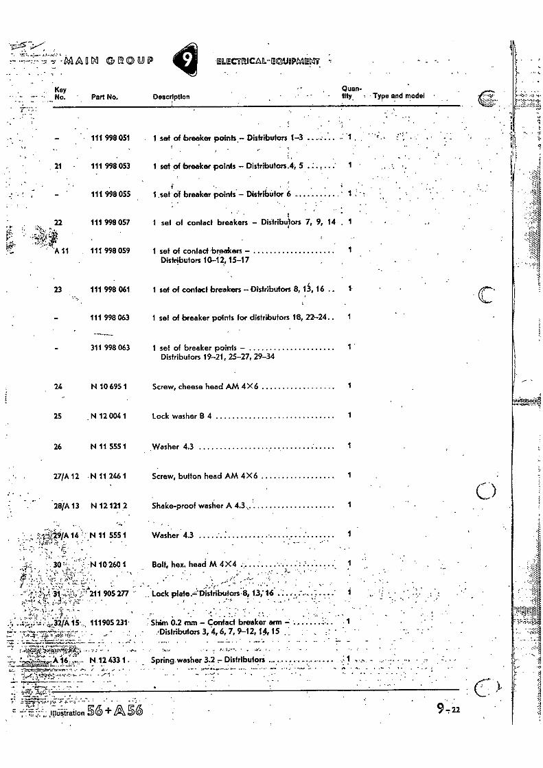
•••••:. ' 111 998051 1 set of breaker points,- Distributors 1-3 -
21 • 111 998 053 1 set of breaker points - Distributors.4, 5 . .' 1
111 998 055 1 sef of breaker Points - Distributor 6
• r 22 111 998 057 1 set of contact breakers - Distributors 7, 9. 14 1
-44
A 11 111 998 059 1 set of contact breakers - 1 Distributors 10-12, 15-17
111 998 061 1 set of contact breakers -Distributors 8, 13, 16 .. 1
111 998 063 1 set of breaker po4nis for distributors le, 22-24.. 1
311 998 063 1 set of breaker points - 1 Distributors 19-21, 25-27, 29-34
24 N 10 695 1 Screw, cheese head AM 4 X6
25 N 12 004 1 Lock washer 8 4 1
26 N 11 555 1 Washer 4.3 1
27/A 12 N 11 246 1 Screw, button head AM 4X6 1
28/A 13 N 12 121 2 Shake-proof washer A 4.3 , 1
•.?.-r-429/A 14 N 11 555 1 Washer 43 1 " •
:N 10 260 1 Bolt, hex, head M 4X4
, , ,..• ,.. . , ;•,?, 1 ';'. ̀,,7„ :,..a.
i.:-..--1 , ,c.....,... ,-...,....,:' . '•.. - . . !
,.,!. ."-: : • , • 9 211 905 277 - .. Lock plate .,=-Distributors -8, 13;16
r -,...,,.); • J. ':.. ... 1 «
. •• .:1 ' . I; :' .• -....t .1'.. ... . * • - .
.'1, .:.;:z:• `•:;'.:,-,32/A 15-,, 111905 231.. .. Shim 0.2 mm - contact breaker arm • „....., ..,-...-.;--_,....._...... . ,Distributors 3, 4, 6, 7, 9-12, 1,4, 15 , , •
•-•' ',0,--4-• 4:- '=•!•l•-•rf-•:..' ' -, — -7:-.• _ ....4:...:::..7.,--::=',;::.2..--«':---:;— ..:_- .-- . ........r . . ........ . —, . ••• ....-,--1,—,"",-!1", tr,-.}.
. ...,.,L-'-:"..:A';16,..-%,., N 12 4331.. Spring.washer 3.2 Distributors ....... - . ...,_ -:-..ro..=_—......,,_-,...,,,-.,- ..- ..,-, .- a- ,
• 7.
,IdUSTration gb + A SG
• •
A
9-22
' 47 113 905 249
• ••. • , •,..44A44.14
Diifance Washer,' • ---
MAIN GROUP - ELECTRICAL EQUIPMENT • - - -7.
Part No. Description •
•• •
Quan- tity Type and model
•
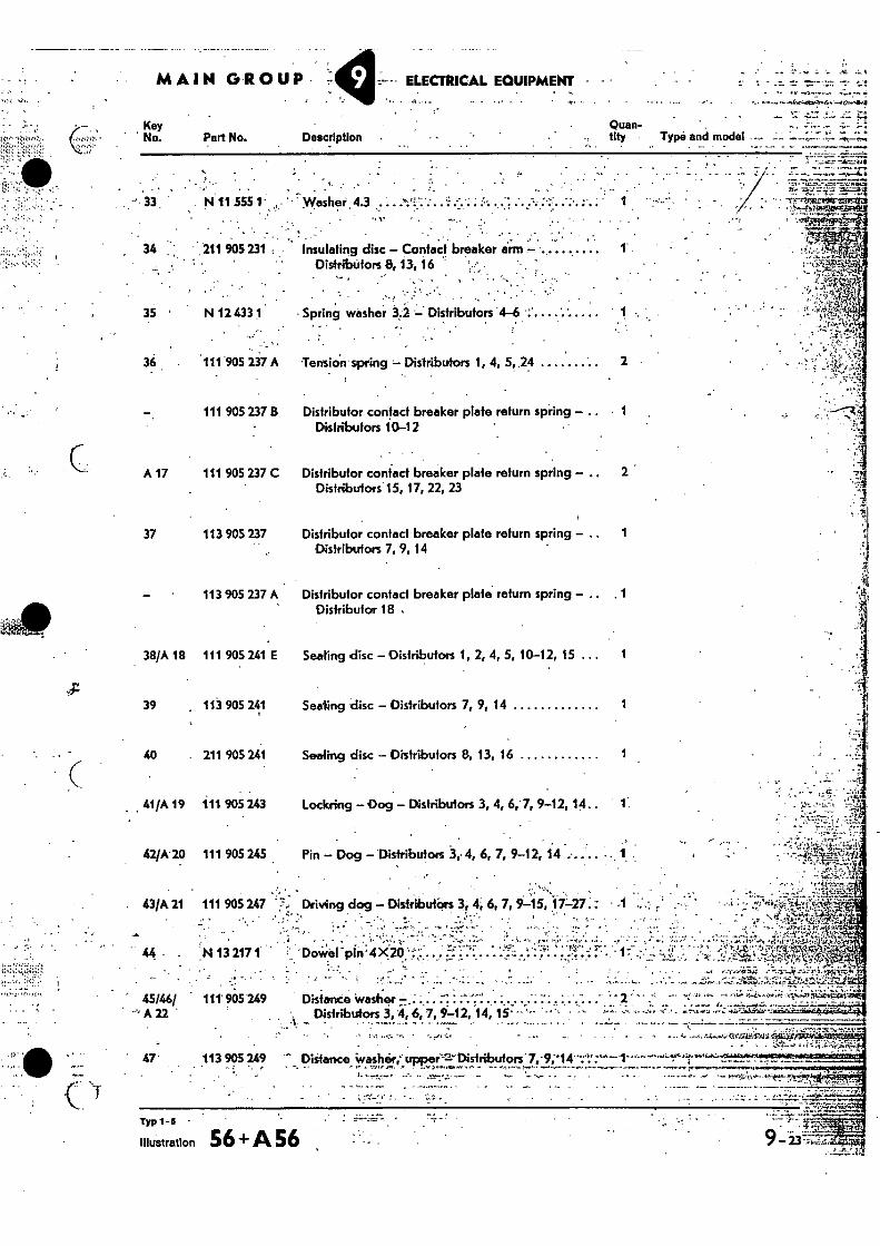
33 . . N11 555 1 - • Washer 4.3 .. . . .
34 211 905 234 , Insulating disc - Contact breaker arm - - DistribUtors.8, 13, 16 •
• ' •
35 N 12 433 1 • Spring washer 34 Distributors '4-6 - •
. •
' •
36 111 905 237 A •Tensitin spring - Distributors 1, 4, 5, 24 2
111 905 237 B Distributor confect breaker plate return spring - 1
Distributors 10-12 •
A 17 111 905 237 C Distributor contact breaker plate return spring - 2 Distributors 15, 17, 22, 23
37 113 905 237 Distributor contact breaker plate return spring - 1
Distributors 7, 9, 14
113 905 237 A Distributor contact breaker plate return spring - Distributor 18 ,
38/A 18 111 905 241 E Seating disc - Distributors 1, 2, 4, 5, 10-12, 15 ... 1
39 , 113 905 241 Seating disc - Distributors 7, 9, 14 1
40 . 211 905 241 Sealing disc - Distributors 8, 13, 16 1
41/A 19 111 905 243 Lockring -Dog - Distributors 3, 4, 6,-7, 9-12, 14 1.
42/A 20 111 905 245 Pin - Dog - Distributors 3,• 4, 6, 7, 9-12, 14 • ,
43/A 21 111 905 247 • Driving dog - DistributOrs 3, 4; 6, 7, 9-15, 17-27:: • •
. IN 13 217 1 .
•
45/46/ 111' 965249 = A22
Distance Washer - Distr1nsfors 3, 4,6, 7, 9-12, 14, 15- --'••• -
.
• _ -•••, • .,•• . _
TYP 1-5 •
Illustration 56 + A 56
•
9 -- - 237;•-i.Z.r
9-24
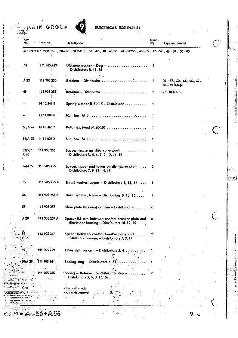
" Distributors 3, 6, 8, 13, 16 •
' 4444=7-"-1k3o • discontinued: no-replacement
• . . •
ELECTRICAL E410.14PAAERIT - 4-61,!-, •
'Key Quan- No., • Part No. Description tity Type and model
1 I .25 DIN b.h.p.--30 SAE , 30=36 , 34=41.5 , 37=47 , 40=49/50 , 44=52/53 , 46=55 , 47=57 , 48=58 , 50=80
211 905249
113 905 250
111 905 251
Distance washer - Dog - Distributors 8, 13, 16
Retainer - Distributor
Retainer - Distributor
1
1 34-, 37-, 40-, 44-, 46-, 47-, 48-, 50 b.h.p.
1 • 25, 30 b.h.p.
N 12 241 2 Spring washer 13 8 X15 - Distributor 1
N 11 008 8 ,Nut, hex. M 8 1
N 10 346 2 Bolt, hex. head M 6X30 1
N 11 006 2 Nut, hex. M 6 1
111 905 255 Spacer, lower on distributor shaft - 1 Distributors 3, 4, 6, 7, 9-12, 14, 15
113 905 255 Spacer, upper and lower on distributor shaft - 2 Distributors 7, 9-12, 14, 15
211 905 255 A Thrust washer, upper - Distributors 8, 13, 16 1
211 905 255 B Thrust washer, lower - Distributors 8, 13, 16 1
111 905 257 Shim plate (0.3 mm) on cam - Distributor 4 x
111 905 257 A Spacer 0.1 mm between contact breaker plate and distributor housing - Distributors 10-12, 15
x
113 905 257 Spacer between contact breaker plate and distributor housing - Distributors 7, 9, 14
1
111 905 259 Fibre shim on cam - Distributors.3, 4 ,
11 905 261 Sealing ring - Distributors 1-31. 1
•
111 905 265 - Spring --Retainer for distributor cap - 2
'i r !.• ir L• • 48
i,r
A 23
49
-
-
50/A 24
51/A 25
52/53/ A 26
54/A 27
55
56
57
A 28
%:60/A 29'.
4,6 •
GROLDEP
MAIN GROUP ELECTRICAL EOUIPMENT •
•
•••— .11"- 7-.""r .o. YK
• .
Key No. Part No. Description •
poen, . '
•
Type end model. •
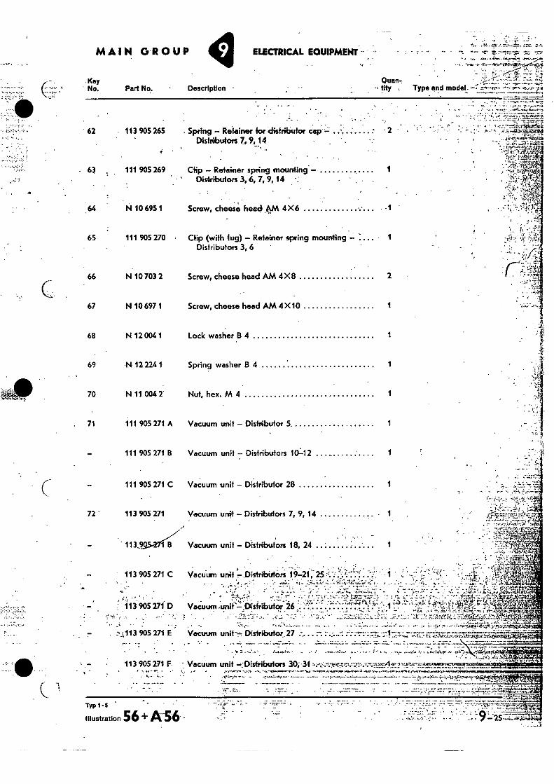
62
- 63
- 113 905 265
111 905 269
Spring - Retainer for distributor cap Distributors7, 9, 14
Clip - Retainer spring mounting - Distributors 3, 6, 7, 9, 14
64 N 10 695 1 Screw, cheese head- ,OA 4X6 -1
65 111 905 270 • Clip (with lug) - Retainer spring mounting 1 Distributors 3, 6
66 N 10 703 2 Screw, cheese head AM 4X8 2
67 N 10 697 1 Screw, cheese head AM 4 X10 1
68 N 12 004 1 Lock washer B 4 1
69 N 12 224 1 Spring washer B 4 1
70 N 11 004 2' Nut, hex. M 4 1
71 111 905 271 A Vacuum unit - Distributor 5 1
111 905 271 B Vacuum unit - Distributors 10--12 1
111 905 271 C Vacuum unit - Distributor 28 1
72 ' 113 905 271 Vacuum unit - Distributors 7, 9, 14 1
113.29.5-2-7(BV Vacuum unit - Distributors 18, 24
- ' 113 905 271 C Vacuum unit 7.Distribiotars 19-21, 25 ‘'.•''',
. -•••-•.:-°-....-......... ":. '..."-.7,.."' .:"!...?...,":-.,.... c .-,,,,,...zirt-Kr., . . , -2,..A.._;:.... • ...... .... . ...-- r ,> 1,=-1--.,•• , • ' 1-.;..;,,: > 2;1.,,J4 g--4:0r.'4.;,,J5E tly ., ,
Vacuum -unit'-.0ksfributor 26 ....-:-....... • - . :-- ....' r 1 • 4 . ... . .")... • ..= i , ', . ,71., ,, , ',.1 Sh. i :'... ::715:m.:-.,-,: ..17. --- o4.114t,.," 74'.'
113 905 271 D ....- - ,;....,..c... 1-,44: • ._.,.1:4,:-Tilcc )t. ;„....,......•....,...:„;, ..- • , ...:;.'21.-..-Y.z.... - •,-..-.:. ' :.", .•. .'.--,:;.,.;---. ....:11-.......,.!;:k!...2.......::..';-...., -...,-,.1-.,.'..--... "..:1.-: -.•..,.;,::-;;Tazt:L...;:ta41,111-4--;:ar......f...7,-.-.&-t ' ..,
..- - .:..t.,-,113 905 271 E Vacuum unit-- Distributor.27 : ....... .... • • '..7. •,. a...A ..,.-... .....i1.-ii. e;.:Ai..ti--...14-.Zi. --. ':sr" '"Z7-.A•AsomArAcAl.:1'44; ,. . - --- •
1 „ .
113 905 271 F. Vacuum unit :Distributors • .• ••OrY•r. •••••••••••
•
_
Typ 1-3
Illustration 56 + A-56 -
•
Key •No.
A 31
73/A
74/A
75
76
77
78
79
81
•
•
e2 •
e3 .
•-'1= -84 ek
r r
: *
•- MAIM GROUP ELECTEIICAL ECLIIIPMEMT
Part No. Description Quan- tity Type and model
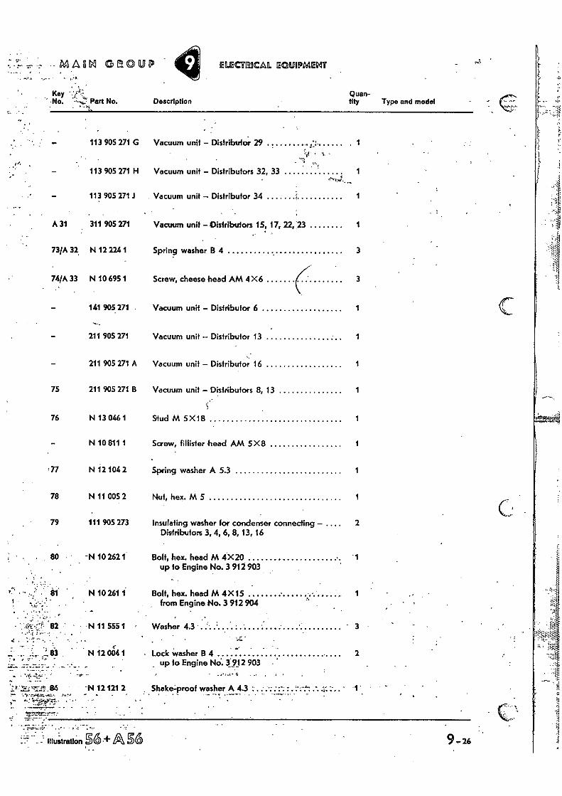
113 905 271 G Vacuum unit – Distributor 29 1
113 905 271 H Vacuum unit – Distributors 32, 33 1
113 905 271 Vacuum unit – Distributor 34 1
311 905 271 Vacuum unit –Distributors 15, 17, 22,23 1
32, N 12 224 1 Spring washer B 4 3
33 N 10 695 1 Screw, cheese head AM 4X6 3
141 905 271 Vacuum unit – Distributor 6 1
211 905 271 Vacuum unit – Distributor 13 1
211 905 271 A Vacuum unit – Distributor 16 1
211 905 271 B Vacuum unit – Distributors 8, 13 1
S.- N 13 046 1 Stud M 5X18 1
N 10 811 1 Screw, fillisler head AM 5X8 1
N 12 104 2 Spring washer A 5.3 1
N 11 005 2 Nut, hex. M 5 1
111 905 273 Insulating washer for condenser connecting – , . 2 Distributors 3, 4, 6, 8, 13, 16
• -N 10 262 1 Bolt, hex, head M 4X20 up to Engine No. 3 912 903
1
N 10 261 1 Bolt, hex. head M 4X 15 from Engine No. 3 912 904
1
N 11 555 1 Washer 4.3 3
• .. .
N 12 00r4 1 - Lock washer B 4 up to Engine No.. 3:912 903 •
2
'N 12 121 2 : Shake=proof washer A 4.3 .. ..... : . . —1". •
26 . . . _
Illustration 06.+ASS
Key No. Part No. Description
Quan- tity Type and model -
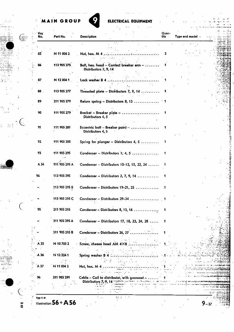
86 113 905 275 . Bolt, hex. head — Contact breaker arm — Distributors 7, 9,•14
• 87 N 12 004 1 Lock washer B 4 1
••,
113 905 277 Threaded plate — Dis4ibufors 7, 9, 14 1
• 1
93 111 905 295 Condenser — Distributors 1; 4, 5
.0 0 A 34 111 905 295 A Condenser — Distributors 10-12, 15, 22, 24 .... 1
94 113 905 295 Condenser — Distributors 2, 7, 9, 14 1
, • - , •
113 905 295 B Condenser — Distributors 19-21, 25 .1
113 905 295 C Condenser — Distributors 29-34
95 211 905 295 Condenser — Distributors 8, 13, 16 1
311 905 295 A Condenser — Distributors 17, 18, 23, 24, 28 1
— 311 905 295 B Condenser — Distributors 26, 27 1
A 35 N 10 703 2 • Screw, cheese head AM 4X8 '
. A 36 N 12 224 1 Spring washer B 4 •
.A 37 N 11 004. 2 Nut, hex. M 4
- •
sAmirmaii
4 L. - "tr
311 905 299 Cable — Coil to distributor, .with grommet — 1 Distributors 7;9,
MAIN GROUP ELECTRICAL EQUIPMENT
'‘z 85 N 11 004 2 Nut, hex. M 4 2
89 211 905 279 Return spring — Distributors 8, 13 1
90 111 905 279 Bracket — Breaker plate — 1 Distributors 4, 5
91 111 905 281 Eccentric bolt — Breaker point — 1 Distributors 4, 5
92 111 905 285 Spring for plunger — Distributors 4, 5 1
TiP 5 53.1 illustration 56 + A 56 0) 9 -27
, 1 ;
S •
MAIM GROUP ELECTRICAL ECIUIPMEgir
Key No. Part No. Description
Quan- • tlty Type and model
25 DIN b.h.p.=30SAE , 30=36 , 34=41.5 , 37=47 , 40=49/50 , 44-52/53, 46=55 , 47=57 , 48=58 , 50=60
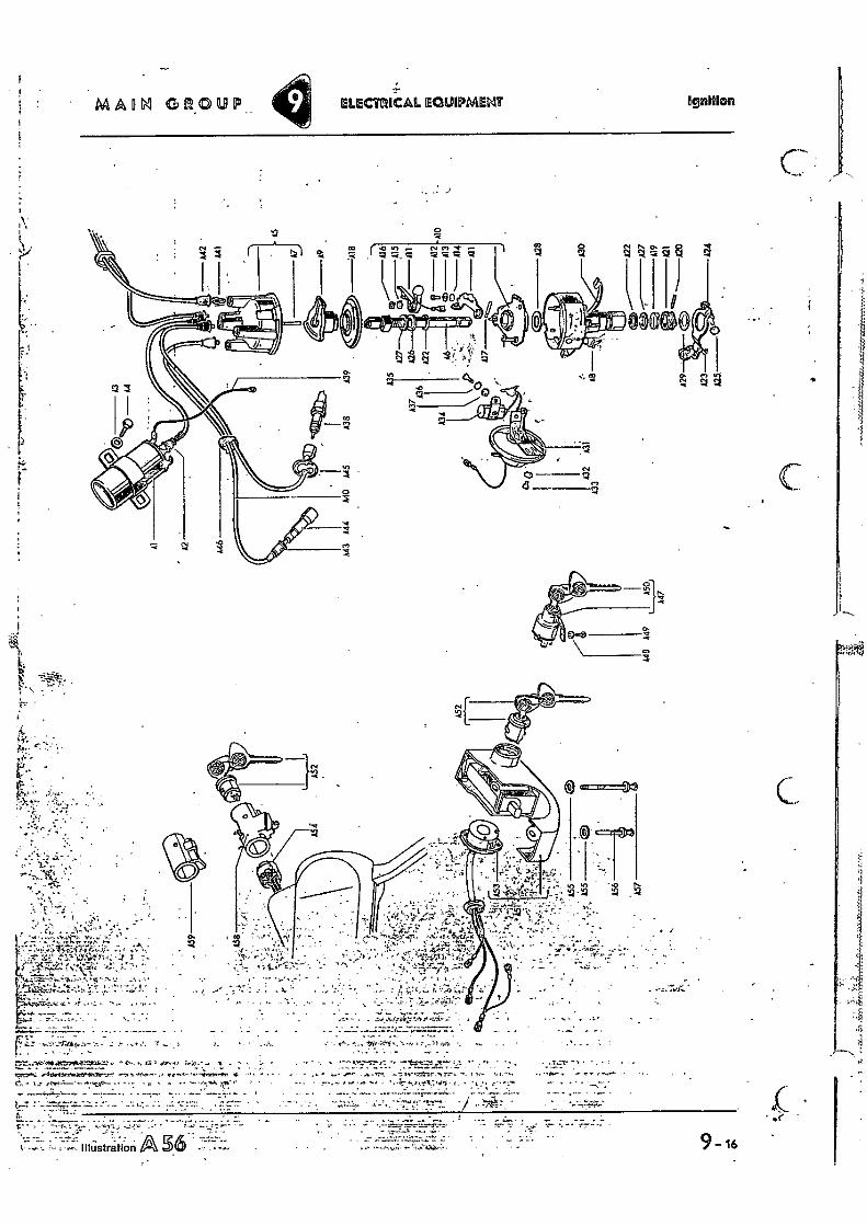
SPARKING, CONNECTOR — SPARKING PLUG
,. •
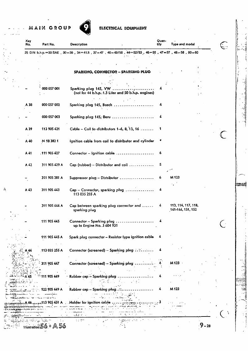
— ; 000 057 001 Sparking plug 145, .VW 4 I
(not for 44 b.h.p.-1.3 Liter and 50 b.h.p. engines)
. A 38 000 057 002 Sparking plug 145, Bosch 4
— 000 057 003 Sparking plug 145; Beru 41
.. i
A 39 113 905 421 Cable — Coil to distributors 1-6, 8, '13, 16 1
C A 40 N 18 382 1 Ignition cable from coil to distributor and cylinder *
A 41 .111 905 427 Connector — Ignition cable 6
A 42 311 905 429 A Cap (rubber) — Distributor and coil 5
311 905 281 A Suppressor plug — Distributor 6 M 123
A 43 311 905 443 Cap — Connector, sparking plug 4 113 035 255 A
311 905 444 A Cap between sparking plug connector and 4 113, 114, 117, 118, sparking plug .141-144, 151, 152
111 905 445 Connector — Sparking plug 4 up to Engine No. 3 604 931
111 905 445 A Spark plug connector — Resistor type ignition cable 4
113 035 255 A Connector (screened) — Sparking plug
311 905 447 Connector (screened) — Sparking plug M 123
' ...-r---,,:;--n-K45 • ':'-'r 111 905 449 - Rubber cap`--- Sparking plug
.. . ; .; ..,";;gz.-.'..:ii-!..':. 1.; • . . •
— -- •, •- — . — - • • 122 905 449 A Rubber cap — Sparking plug..:--
:.
••••••0 • •••,..•_:.
....113 905 451 A . Holder for ignition cable .. ... e... C7gir }•••••CtervIt.noongcm. *saw.* •
MA Illustration. 60- A 56 :9 -28
4 M123
3
•
Quan- _ .
ttty = Type ancimodel"•'?"-"'" Key No: Part No.- - e Description _- _
• •
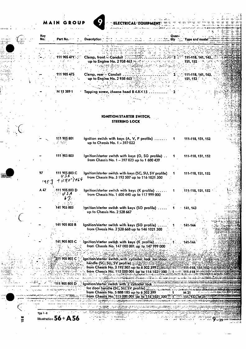
111 9054711.-2;
. 111 905 475
•
. MAIN GROUP ELECTRICAL= EGUIPMEM7.,
Chimp, front,-;:Corithiit 4; . up to Engine No. 2 938 463 f.t.; • • - -• •
, .
• • ••..• -—e'."-• • - • •••••_r • • • • • •
• 111-118,141,143,....:,.:, . 151. 152 • a, • .,r-A„
" . . . - • Clamp, rear - Conduit 111-118,141,143,
up to Engine No. 2 938 463 151,152 ',. • '
•
N 1,1 389 1 Tapping screw, iheese head B 4.8X 13 . -
IGNITION/STARTER SWITCH,
STEERING LOCK
111 905 801 .„;
111 905 803
Ignition switch with keys (A, V, P profile)
1 111-118,151, 152 up to Chassis No. 1 -397.022
Ignilion/starter switch with keys (G, SG profile) .. 1 111-118, 151,152 from Chassis No. 1 - 397 023 up to 1 600 439
1 111.118, 151,152
Ignition/starter switch with keys (K profile) 1 111-118, 151,152 ' . from Chassis No. 1 600 440 up to 117 999 000
Ignition/starter switch with keys (SG profile) 1 • 141,143 up to Chassis No. 2 528 667
A 47 .-111 905 803 D r••-••tI SA
.141 905803
97 111 905 803.0 ignition/starter switch with keys (SC, SU, SV profile) ,,, from Chassis No. 3 192 507 up fo 116 1021 300
/1ri firte(" Y
141 905 803 B Ignition/starter switch with keys (SG profile) 1 141444 from Chassis No. 2 .528 668 up fo 146 1021 300
141,905 803 C ' Ignition/strider switch , with keyse•(K profile), '141-144 from Chassis No. 147 000 001, Up. to, 147.999 000
- - for, door handle (SC; SU- SV 110) • • • • D r0 f • . - .
• • from Chaisis No. 5 888 185 up lo b 502 399 • 1 M 21 A• • • '• No.'1•15.00KI 0017ipiCi1 1'61 621'
-••• - • - frorri Chassis Nil. 115009001 tip- to:116 -1021'300 :-...r„F_,1 •;'"i.' 111-118- "":4-1"t.....1-PA!14qM.4. • ,...-....._.,,, -„:.• ; , -r.. i•;_ ; . ••::.....:::.!3.....,_ ...•--.1:-.....J....11,..;.......yt,r1..:..-.L.....„,1.:::,:-.....",..-,,,....,:.,;:_.-7.-..za.c- ..;___ ..:4,4: ...:71:4.1,-.1.,111Mtre..
1,...-V - --, . , .. . . .. . , „ . 7 7„ .. .._.,...:.. , .. , .., 4 „: ,... .....- _ .. - :._ ..i,;.q....--,-, ... ,....,--1-k.:.t....._ -4-.. tvii0;...- .....U.,..- ... . 4., ...Ix .?.-s-, .....-. - -14 ....;..it...- -.v. . 3c4.;.........-.0...,-netitSW,.....rt,...4.1417
' ' . -t.'-' ^•• " . '111 . 05 80513 . 7.- Ignition/stai-iiiifeWiich"with't•CYlirideliiiar ''''''''' '
''11 905 805 C r; ,711gnitio.--n/starte"i-4w.
handle (SO,: SU,;sy-rpr.4/file) Hd.:3 -192-507 up to765020Mag', ,(A11-118;:151;11524:4#
( •
Typ I -2 . . ...• . .
Illustration 56 + A 56 , .
..„ "--; -" — •
Ignition/starter switch with 2 cylinder lock 1 ,151, 152; M 21 • for door handle (K profile) from Chassis No. 117000.001 up to 117 999 000
MAON1 Of OUP ELECTEPICAL EQUIPMENT
Key No. Part No. Description Type and model
trn-
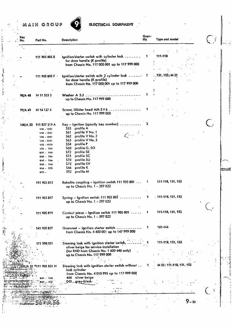
111 905 805 E Ignition/starter switch with cylinder lock 1 111-118 for door handle (K profile) from Chassis No. 117 000 001 up io 117 999 000
111 905 805 F •
98/A 48 N 11 523 3
99/A 49 N 14 127 4
100/A 50 111 837 219 A 1/46 - 12/51
1/46 - 12/51
1/46 - 12/51
1/46 - 12/51
1/52 - 12/53
1/54
7159
8/59 - 7/60
8/60
7/66
8/60 - 7166
8160 - 7166
8/66 - 7170
6/70 -
Washer A 5.3 1 up to Chassis No. 117 999 000
Screw, fillister head AM 5X 6 1 up to Chassis No. 117 999 000
Key — Ignition (specify key number) 2 S53 profile A S61 profile V No. 1 562 profile V No. 2 S63 profile V No. 3 S54 profile P 560 profile G, SG S72 profile SE 573 profile SC 574 profile SU S75 profile SV S66 profile K S92 profile M
C
111 905 815
111 405 817
111. 905 819
• 141 905 827
111 998,021
Bakelite coupling — Ignition switch 111 905 801 ... up to Chassis No. 1 — 397 022
Spring — Ignition switch 111 905 801 up to Chassis' No. 1 — 397 022
Contact piece — Ignition switch 111 905 801 up to Chassis No. 1 — 397 022
Grommet — Ignition starter switch from Chassis No. 4 400001 up to 147 999 000
Steering lock with ignition starter -swifcb, silver beige for service installation (for RHD from Chassis No. 1 600 440 only) up to Chassis No. 117 999 000
111-118, 151,152
- 111-118. 151, 152
111-118, 151, 152
141 -144
111-118, 151, 152
. • •...,73
...,..-41;.,....'"%t-•—ct--16 . 1/A 5,1 *111 905 851 H Steering lock with ignition starter switch without .. 1 : M 55:1'11418, 151, 152
-,!•:-- F-..?-.04,-.?1,=.;,.4.i- ,, 9i - lock cylinder from Chassis No, 4 010 995 up to 117 999 000
- 7/65 4-66 silver beige 7167 043sire -1L)i!t.._,k- '
1 .
•
• 9- 30
111 905 865 B ignition starter switch 28 mm dia. for steering lock* • from Chiis No.3 192 507 up to 116 1021 300 • - 1 • • .,
. . .
•
- 30a
MAIN GROUP V ELECTRICAl. EOU1PMENT •
Key
Quan- • No. Part No. , Description
tity
Type and model •
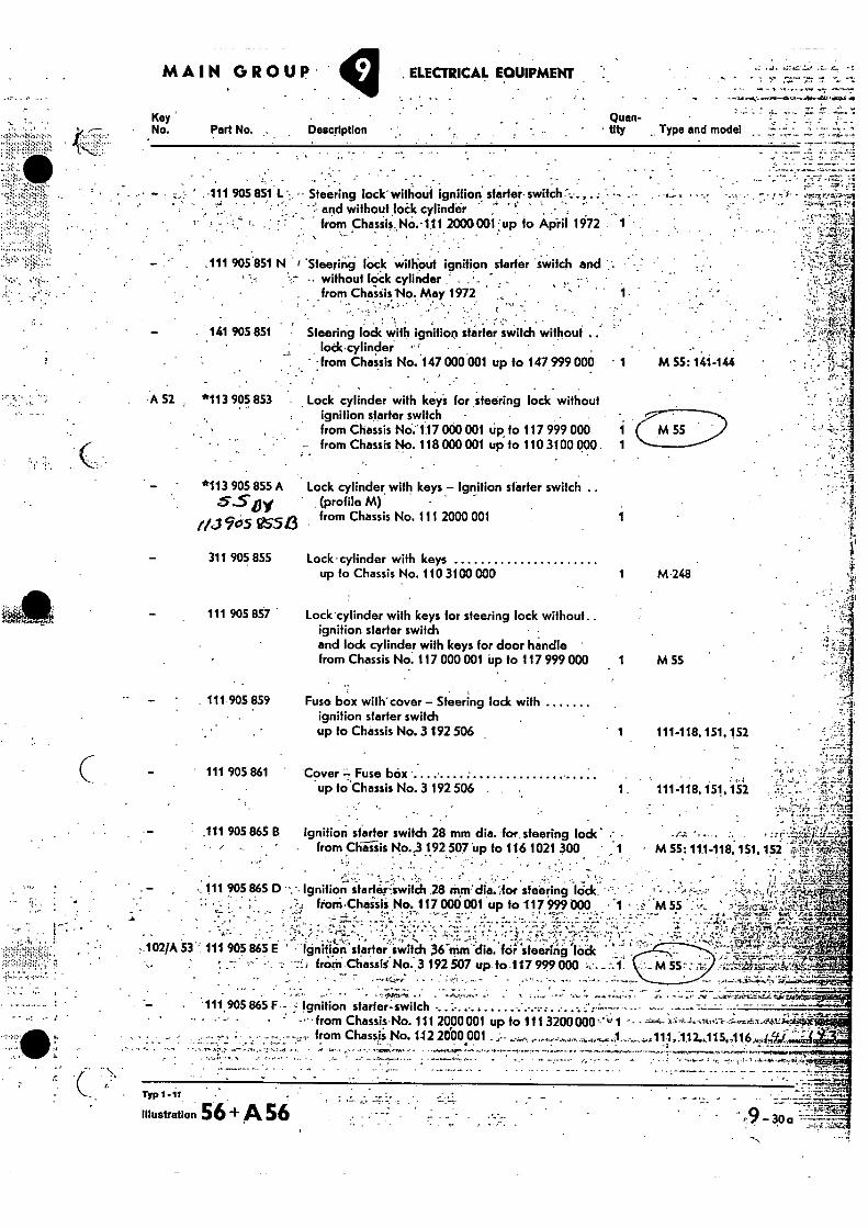
- • .... • . -111 905 851 L • Steering lock' without ignition sfartei-switCh .
and withoidloik cylinder ̀:- *- • • . from Chassis„No.•111 2000001', up to Apiil 1972 1
.111 905 851 N 'Steering lock without ignition starter switch and •• without lock cylinder : . •
from ChaisisNo. May 1972
141 905 851 • : • •
Steering lock with ignition starter switch without .. lock•cylinder • .
• • from Chassis No. 147 000 001 up to 147 999 000 ' . M 55: 141-146 . : • .;
-A 52 *113 905 853
Lock cylinder with key's for steering lock without ignition starter switch
• from Chassis No.'117 000 001 up fo 117 999 000 -• from Chassis No. 118 000 001 up fo 110 3100 000 .
*113 905 855 A Lock cylinder with keys — Ignition starter switch ..
5.Siiy (profile M) - -
ai vs54 from Chassis No. 111 2000 001
311 905 855
Lock-cylinder with keys up to Chassis No. 110 3100 000
1 M-248
111 905 857 Lock cylinder with keys for steering lock without ignition starter switch and lock cylinder with keys for door handle from Chassis No. 117 000 001 Up to 117 999 000 1 M 55
•
111 905 859
Fuse box with' cover — Steering lock with ignition starter switch up to Chassis No. 3 192 506
1 111-118, 151, 152
• 111 905 861 Cover 7 Fuse box • •up to Chassis No. 3 192 506 . 111-118, 451, 152
• A -, M SS : 111-118. 151, 152 •
Tf
• +,1•4''‘'"
111 905 865 D Ignition starteriwitch 28 riundis.',for steering lack ••• : froni.Chaiiii No. 117 006001 up to 117999000 L -• • • .„ •
. - • .`" ; 'r; •
102JA 53' 111 905 865 E • ignitionstarter 'switch 36'0m dia. tar ̀steering lock _ •-* - , train Chassil No.3 192 507 up to 117 999 000
• • - -
111 905 865 F.- Ignition starter-switch - • •-• • from Chassis-No. 111 2000001 up to 111 3200000.'4a 1 -• A "‘"`
• • - from Chassis. No. 142 2000.001
• •
Typ 1-11 •
Illustration 56 + A 56
• MAIN GROUP ELECTRICAL EQUIPMENT
Key No. Part No.
111 965 865k
A 54 311 905 865 A
131 905 867
4 103/A 55 *111 905 877
104/A 56 *111 905 881
105/A 57 *111 905 881 A
111 905 881 C
111 905 881 D
131 905 881
N 11 652.1
A 58 113 905 887
- .N130422
,A 59'
113 919 105
Description Quan-tity Type and model
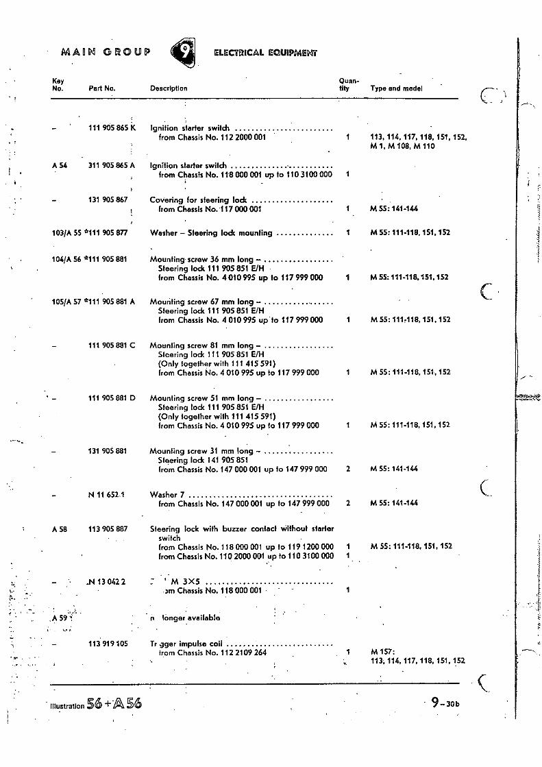
ignition starter switch from Chassis No. 112 2000 001 1 113, 114, 117, 118, 151, 152,
ignition starter switch from Chassis No. 118 000 001 up to 110 3100 000 1
M 1, M 108, M 110
Covering for steering lock from Chassis No. 117 000 001 1 M 55:141-144
Washer — Steering lock mounting 1 M 55:111-118, 151, 152
Mounting screw 36 mm long — Steering lock 111 905 851 E/H from Chassis No. 4 010 995 up to 117 999 000 1 M 55: 111-118. 151. 152
Mounting screw 67 mm long — Steering lock 1 1 1 905 851 E/H from Chassis No. 4 010 995 up to 117 999 000 1 M 55: 111418, 151.152
Mounting screw 81 mm long— Steering lock 1 11 905 851 E/H (Only together with 111 415 591) from Chassis No. 4 010 995 up to 117 999 000 1 M 55: 111-118, 151, 152
Mounting screw 51 mm long — Steering lock 111 905 851 E/H (Only together with 111 415 591) from Chassis No. 4 010 995 up to 117 999 000 1 M 55: 111-118,151,152
Mounting screw 31 mm long — Steering lock 141 905 851 from Chassis No. 147 000 001 up to 147 999 000 2 M 55:141-144
Washer 7 from Chassis No. 147 000 001 up to 147 999 000 2 M 55:141-144
Steering lock with buzzer contact without starter switch from Chassis No. 118 000 001 up to 119 1200 000 1 M 55: 111-118, 151, 152 from Chassis No. 110 2000 001 up to 110 3100 000 1
' M 3X5 3M Chassis No. 118 000 001 •
longer available
1
Tr gger impulse coil from Chassis No. 112 2109 264 1 M 157:
113, 114, 117, 118, 151, 152
illustration 36 +A S6 - 9- 30 b •
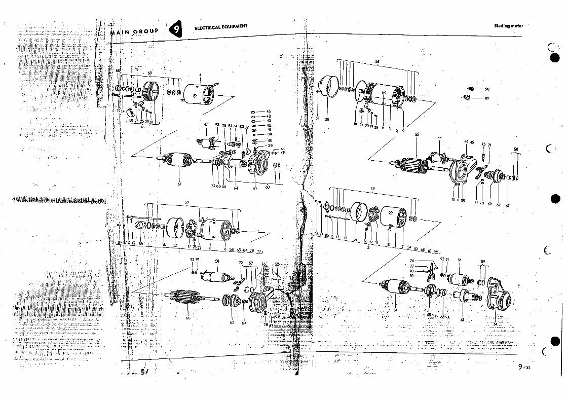
Starting motor
58
— 90
• ft,- 89
• 3 30
79 81 74 18 24 28 8
4- I 151 t •
• 16
1, 3 5 9 8382
55
0- 43 cE,- 42 et- 43 cE.- 42. 0)- 41 a 38
39 48
®0 ,9
75 71 46 45
I 58
QC
cpao 57 736680
59 64 37 60
tOiftigaioiear- 10 11 35 59 T7 78 69 62 67
!,""'••
f.reOP' 100@CD
/$71213 32 17 25 71 6 56 63.84 78 77
- • ; 1
°6 87 18 32 85 13 1 4.41,
6 22 17 2
7 54 65 68 .61 34
92 91 76 51 . I I 1 . 92 91 50 72 59 76:.
11:35:7/
59
78 70
61
• - • . •
• -..
• -7.'77 •
. •,
-32 a
. !'• .• ; MN GROUP
• •
ELECTRICAL EQUIPMENT
4
16E 1'
• !:
from Chassis No. to-Chassis No.. Model : , • . , No. IdentifiCation
" I • - ..".• -1
Part No.-;;• •,-,
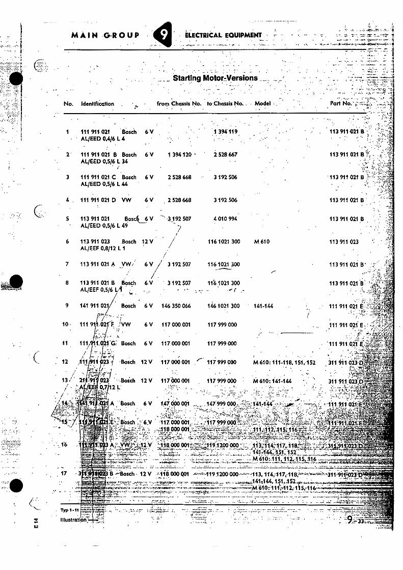
_ Starting MotornVers19os , • • _
•
- ELECTRICAL. EQUIPMENT • - -4.- • -.V.-,
•
•• • •
1 111 911 021 Bosch 6 V 1 394119 .• 113 911 021 B AL/EED 0,4/6 L 4 • '
2 111 911 021 B Bosch 6 V 1 394 120 • 2 528 667 113 911 021 B • ' •
AL/EED 0,5/6 L 34
; '
3 111 911 021 C Bosch 6 V 2 528 668 3 192 506 . 113 911 021 B AL/EED 0,5/6 L 44 . ' • ;
4 . 111 911 021 D VW 6 V 2 528 668 3 192 506 113 911 021 B
5 113 911 021 Bosc4_6 V ' -3192 507 4 010 994 113 911 021 B • .-, AL/EED 0,5/6 L 49 :/ .. .•
6 113 911 023 Bosch 12 V . / 116 1021 300 M 610 113 911 023 ,.. -:.! AL/EEF 0,8/12 L 1 / ,....„
7 113 911 021 A yw,' 6 V 3 192 507 116 1021 300 113 911 021 B'
8 113 911 021 B Bosch 6•V 3 192 507 11'6 1021 300 113 911 021 El,• :;.•,:e - AL/EEF 0,5/6 L4
oi
..., - • - - -
9 141 911 021 Bosch 6 V 146 350 066 1461021 300 141-144 , - 111 911 021 E ''' 4,
10- 111911,02 F 'VW 6V 117000 001 r/ --'.. -.1--
! • •
. ...-!:•1̂ 117 999 000 •
. 111 911 021 E , ...• . ,10
11 111,91.1.0.1-G;. Bosch 6 V 117 000 001 117 999 000 •111 911430-5-'rEi;,2541,.',1 1. • ' ,:,A:..-..: 4T-.,:
• -'
MAIN GROUP
4`ti , 12 111 • Bosch
13 / 21li-=91• on • -.Bosch .0,7/12 L.'
..:-:
A Bosch 6 V 1.47 000 00 .._.,,..,. 147 999. 000. -: 1417144 ..,:•:••:;iier ......--1•••'.:: ,- .1.11 911 021itt,x.," . ....- , .
, .....iji;:.. .: • ' -'''..--.4 7.V......_ ..i, . L .... 3....:-''....... ii,::.. .: . :7' • -:;rY 'L ''' ''' ' ':. ." ..i.:6 ..':::;t1'.. . ' 4 ''''.
. ' • : ' ., - 7.' . . -,.':•"'"':-"?. ri-7 .-.- '!..'"it:::: Z.4' . ; %'- 7.-•'''': . .1'; -f.' ..C..S.' .,: : '....:;,'..-,-...,: ,11'.."-.1-:'''S ‘..2:.- .BOsch.... .4--.6,V .1_1_7.; 000 001 ...- ..L.,.<17..:i11! ?...9p2BB;'1;;.-....-'.1:......:-'-'-:•,,;,.:1'f,,-̀=; -̀:"::,,r,4%.';:t;:;A-4,i,•-,ter,.::'1 /211.-if9i;t.ii2•.'?1;:i: '1144: :.
• ..v,..9.tf.. - .., _ 4-?..,-,......--..-sr.- -!... fir .'_..-. ,•..- -•••••-•••,, .--,-..-.....- --•,4,-,.....-......., 1-4': ••,,..--..,:-.": $: .*Alt-rPr';:t2Zi'.4 - - •
_ . , ,. 01 a.„ uu9 arui..--;:, --:-.:-:•'-,--, ----- - - 111112115-116-71- "•••.'-',' i ''''''' •-...„ „.„.,-, :2, -;„,,r..-.:,„,-......2 .,.. -....2 ,•:47...„:„-L,,,',...:.--.., ,,. , . , ......4 • •*. - ,.- •;.;;.-.7-4,...',Z:-i........- -..-... - ri,-ss-•••..P...- :. .. --:.:----..w:4'..,.., t ..-4::-...,,,,,4,-..,
...... yvvr •12.V 118'- 000 001'•'' 1191200 000 ' i_:., 113 114 117 118:--7 :', , •,.,. ,3119-14, la
• --- -;:4-r..7-,,,v717 -Ain, sme--.•....
_,.. _ < , ,g . ...: . _ . . 141.444, 151 152 . : •,. '. ..;,:t.a.‘.4....4.,..z7---...
.1-,... i -,:...,-. • F., , - M 610 :•1 1-1 , 112,11e, 116 ,t,,,,,- 0.....„.v,,,4,1 .',--
12 V 117 000 001 • •"- 117 999000 - • -
M 610:111-118, 151,152 , 311 911 023 D, . •
12 V 117 000 001 117 999 000 M 610: 141-144
' • 77 -
311 91,1 .023D
'1111"11IC • B •••'Bosch • 12 V A 116 0001101 1200 000,•-''-•••••113, 114, 117,-118,-"--m":"-31141filiiiiT 41,144, ..ont • 4.1 1 ,211170:r I, • 44!..1?!.3,1•2Wpam • 52 40
eu~ .a ryaon 7 r 610: 1 1 1 ;,112; 115,-116 , .
Typ .11 _
Illustration
17
MACIt1 GROUP ELECTRICAL EQUIPMENT
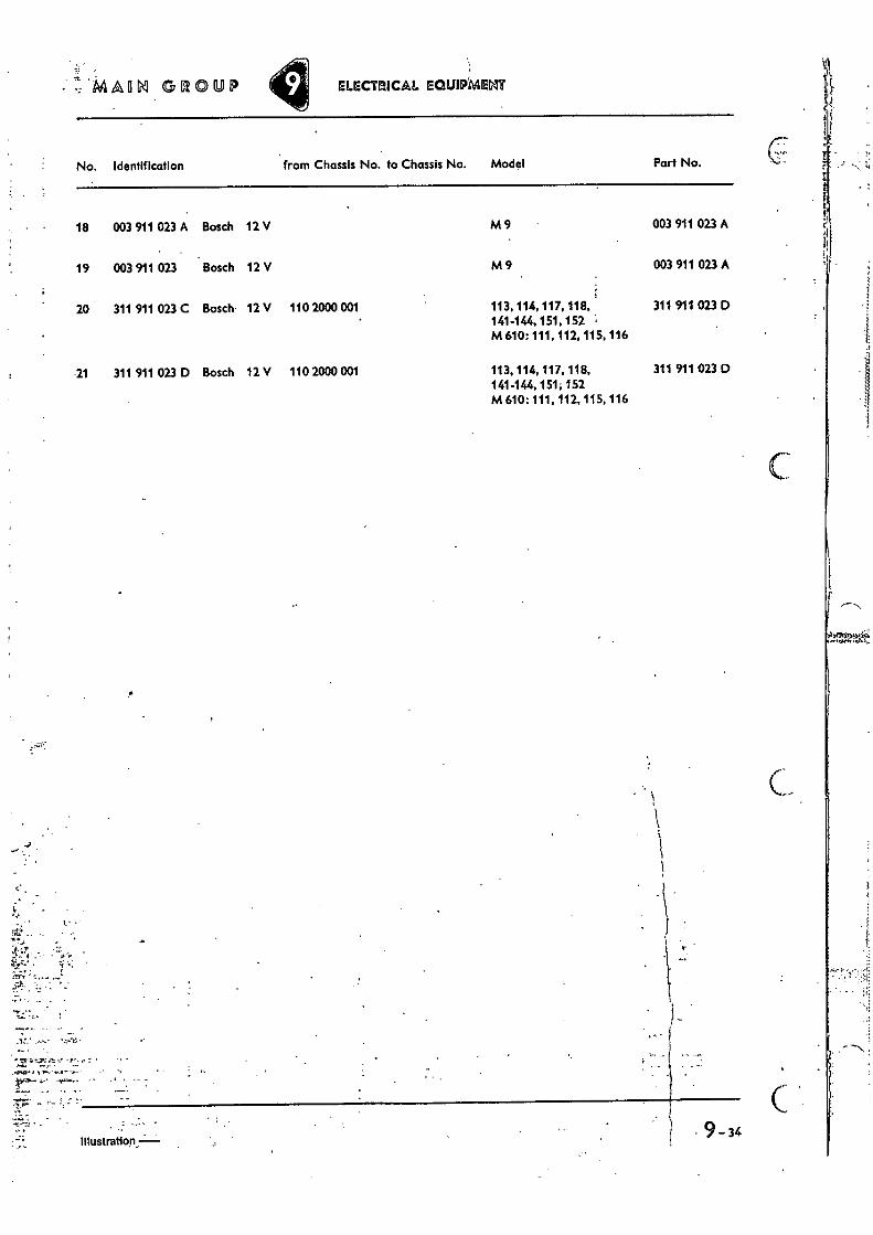
No. Identification from Chassis No. to Chassis No. Model Part No.
18 003 911 023 A Bosch 12 V M9 003 911 023 A
19 003 911 023 Bosch 12 V M 9 003 911 023 A
20 311 911 023 C Bosch. 12 V 110 2000 001 113, 114, 117, 118, 311 911 02.3 D 141-144, 151, 152 M 610: 111, 112, 115, 116
21 311 911 023 D Bosch 12 V 110 2000 001 113, 114, 117, 118, 311 911 023 D 141-144, 151; 152 M610: 111, 112,115, 116
•
Illustration • 9-34
MAIN GROUP ELECTRICAL EQUIPMENT • ::: 7.14 . 71:
Key No. Part No. Description
Quan- tity Type and model , • ••-•• • = - 41,
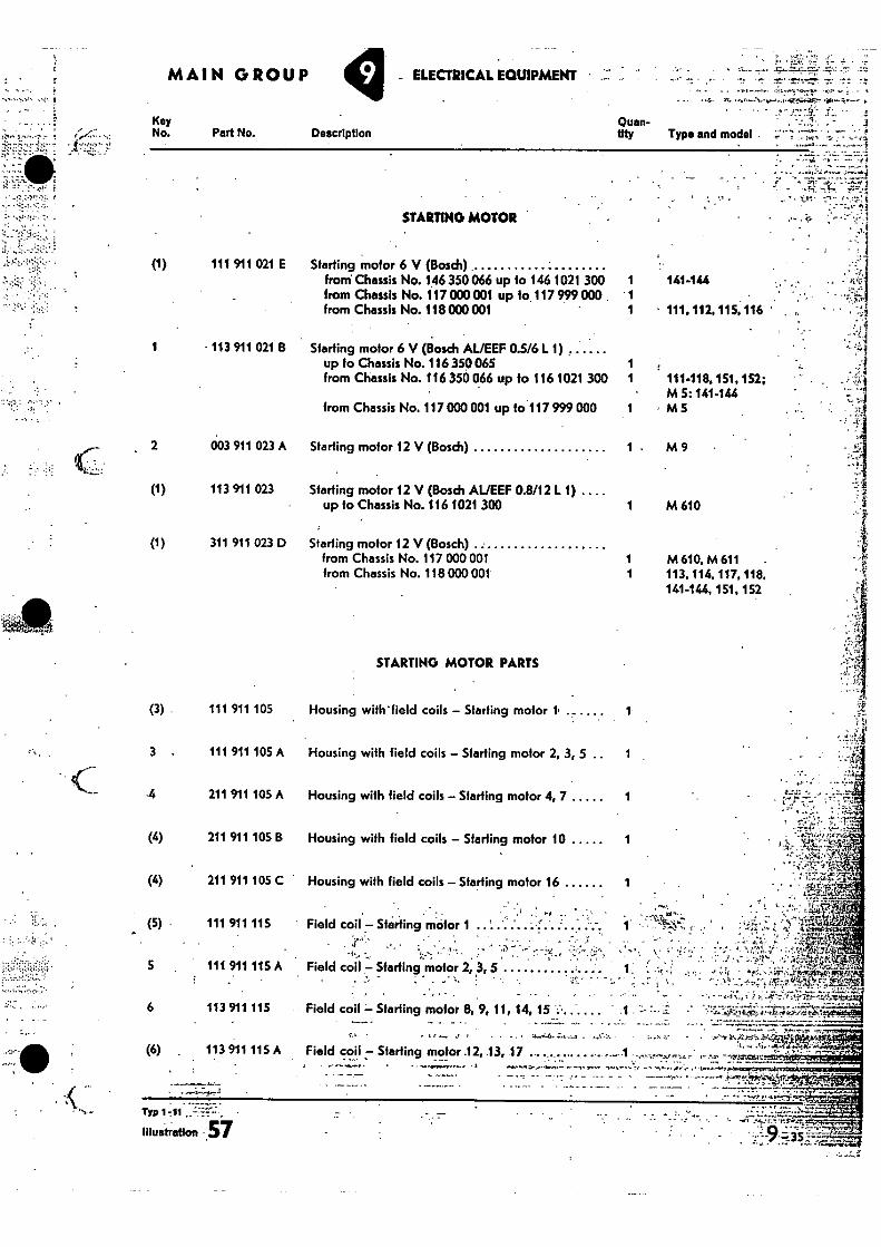
STARTING MOTOR
(1) 111 911 021 E Starting motor 6 V (Bosch) from Chassis No. 146 350 066 up fo 146 1021 300 from Chassis No. 117 000 001 up 10.117 999 000 . from Chassis No. 118 000 001
1 113 911 021 B Starting motor 6 V (Bosch AL/EEF 0.5/6 L 1) up to Chassis No. 116 350 065 from Chassis No. 116 350 066 up to 116 1021 300
from Chassis No. 117 000 001 up to 117 999 000
003 911 023 A Starting motor 12 V (Bosch)
113 911 023 Starting motor 12 V (Bosch AL/EEF 0.8/12 L 1) .... up to Chassis No. 116 1021 300
311 911 023 D Starting motor 12 V (Bosch) - from Chassis No. 117 000 001 from Chassis No. 118 000 001
1 1 1
1 1
141-144
• 111, 112, 115.116
111-118. 151, 152;
• 44ir,
M 5:141.144 M 5
1 M 9
-••••••E
1 M 610 • t•
M 610, M 611 • 1 113,114. 117, 118.
141-144, 151, 152
STARTING MOTOR PARTS
(3)
111 911 105 Housing withheld coils — Starting motor 1,
3 . 111 911 105 A Housing with field coils — Starting motor 2, 3, 5 .. 1
•4 211 911 105 A Housing with field coils — Starting motor 4, 7 1
(4) 211 911 105 B Housing with field coils — Starting motor 10 1
(4) 211 911 105 C Housing with field coils — Starling motor 16 1
(5) 111 911 115 Field coil — Starting motor 1
5 111 911 115 A Field coil — Starling .motor 2, 3, 5
• • -4,;\.;;
w:.; 6 113 911 115 Field coil •— Starting motor 8, 9, 11, 14, 15 ••• - -- . .. . .... .
-. — — --- .7.--":-. —"...------ c..._ • . „ _ „ • ,, r.A.,-.,--A4,--.4i.i.irt (6) . 113911115A Field coil — Starting motor •12, 13, 17 .•. •.•.• •. 4444 • 4 r --k• 1 , ..:e.-;,..,1 rr..., : - .-• - qtrtzlefas; .- ' * ." — '
. L r '-.: . ,i • ' A 41:Zige:' . -. ..... • . . ...
- . ... • ...... , V. 4. . • 1..^..," ..1..§.•0, 1,1.
• - ,••4 . _ • . y _1 • • •
illustration ..57
Key No.
- 7
(7)
it M •,
r I i . 8
t 1.
• 9
JO
11
12
13
(12)
(13)
. : 14
(14)
- (14)
15
,:- ' -'4k:•• :
'• 16
17'
(17)
-.V
' MAGN GROUP ELECTRICAL EGUIPMEM
Part No. Description Quan- tity Type and model
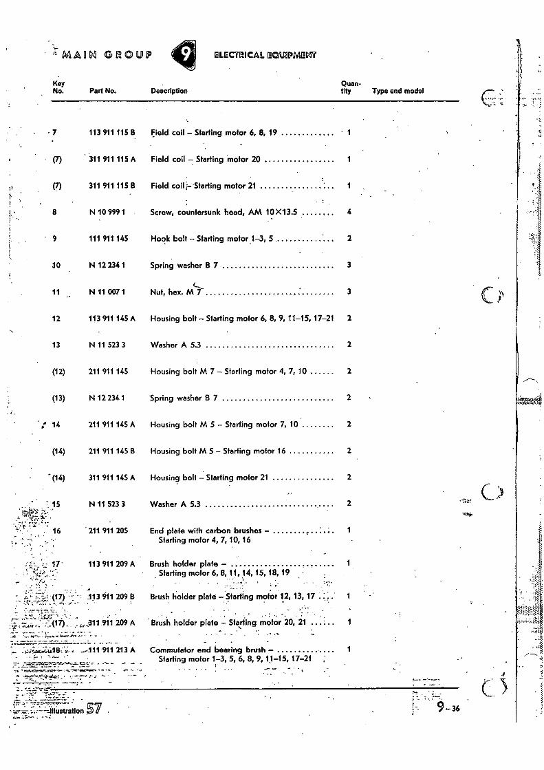
113 911 115 B Field coil - Starling motor 6, 8, 19 1
311 911 115 A Field coil - Starting motor 20 1
311 911 115 B Field coil i•-- Starting motor 21
N 10 999 1 Screw, countersunk head, AM 10 X13.5 4
111 911 145 Hook bolt - Starting motor 1-3, 5 2
N 12 234 1 Spring washer B 7 3
N 11 007 1 Nut, hex. ML,- 3
113 911 145 A Housing bolt - Starting motor 6, 8, 9, 11-15, 17-21 2
N 11 523 3 Washer A 5.3 2
211 911 145 Housing bolt M 7 - Starting motor 4, 7, 10 2
N 12 234 1 Spring washer B 7 2
211 911 145 A Housing bolt M 5 - Starting motor 7, 10 2
211 911 145 B Housing bolt M 5 - Starting motor 16 2
311 911 145 A Housing bolt - Starting motor 21 2
N 11 523 3 Washer A 5.3 2
' 211 911 205 End plate with carbon brushes - . 1 Starling motor 4, 7, 10, 16
113 911 209 A Brush holder plate Starting motor 6, 8, 11, 14, 15, 18, 19
' •
113 911 209 B Brush holder plate Starting motor 12, 13, 17 . . 1
311 971 209 A Brush holder plate - Starting motor 20, 21 1
• • •
I *0111 911 213 A Commutator end bearing brush - 1 Starling motor 1-3, 5, 6, 8, 9, 11-15, 17-21
.
xer.41.1, •-•
- 7 . . ••• • •
9 -36
27 211 911 219 Spring - Brush - Starting motor 4, 7, 10, 16 2
•.4.•••v 28 N 10 695 1 Screw, cheese head AM 4X6
rrr
MAIN GROUP ELECTRICAL EQUIPMENT --
Key Quan- No. Part No. Description tity - Type and model- _
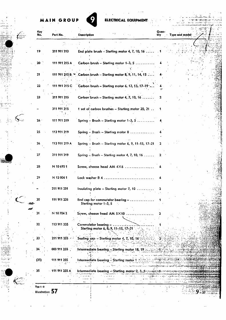
44.?; •-: .4,4 19 211 911 213 End plate brush -; Slatting motor 4, 7, 10, 16 1
- 20 111 911. 215 A Carbon brush - Starting motor 1-3, 5 4
21 111 911 215 B Carbon brush - Starting motor 8, 9, 11, 14, 15 44
•
22 111 911 215 C Carbon brush - Starling motor 6, 12, 13, 17-19 4 r•
23 211 911 215 Carbon 'brush - Starting motor 4, 7, 10, 16 2
311 911 215 1 set of carbon brushes - Starling motor 20, 21 1
24 111 911 219 Spring - Brush - Starting motor 1-3, 5
25 113 911 219 Spring - Brush - Starting motor 8 4
26 113 911 219 A Spring - Brush - Starting motor 6, 9, 11-15, 17-21 2
29 N 12 004 1 Lock washer B 4 4
- 211 911 2.31 Insulating plate - Starling motor 7, 10 2 4.
r- 30 111 911 235 End cap for commutator bearing -
Starting motor 1-3, 5
goo,"
31 N 10 704 2 Screw, cheese4head AM 5 X10
$ . ..."-"-----
32 113 911 235 Commutator bearing - "---...,...„
Starting motor 6, 8,.9,11-15, 17-21
33 211 911 235 Sealing ..cap -; Starting nicItor 4, 7, 10,' .
34 003 911 255 Intermediate bearing -.Starting motor, 18, 19,
• . . . (35) 111 911 255 Intermediate bearing 4:4:Starting' mofor41 . - _
;•41 • - ••
35 111 911 255 A - Intermediate bearing -,Starting .motor '.5,4"44 4,44•••if- 1:4-4
TYP 1 -3
Illustration 57
'ttAAIMI GROUP . ELECTRICAL EOUIPMEIM
Key No. Part No. Description
Quan- tity Type and model
. .
Ss I 36
37
(37)
(37)
(37)
(37)
'1 38
(38)
39
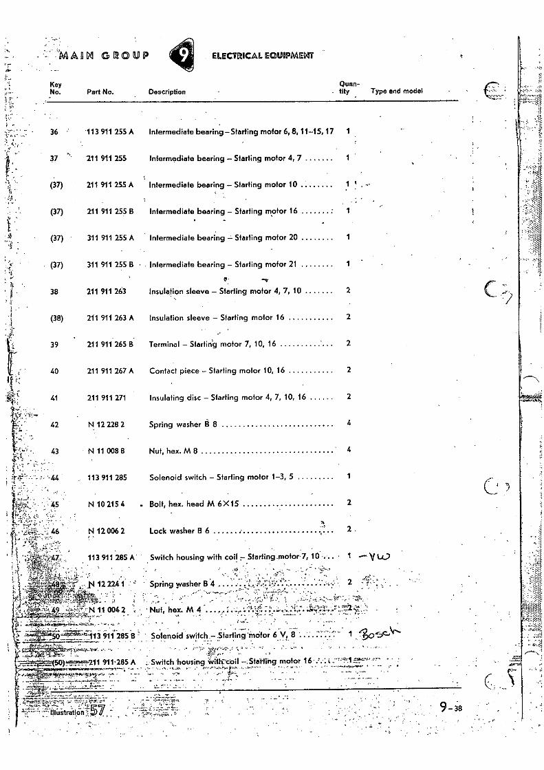
113 911 255 A Intermediate bearing—Starting motor 6,8, 11-15, 17
211 911 255 Intermediate bearing — Starting motor 4, 7 1
211 911 255 A Intermediate bearing — Starting motor 10 1 '
211 911 255 B Intermediate bearing — Starting motor 16 1
311 911 255 A Intermediate bearing — Starting motor 20 1
311 911 255 B • Intermediate bearing — Starting motor 21 1
211 911 263 Insulation sleeve — Starting motor 4, 7, 10 2
211 911 263 A Insulation sleeve — Starting motor 16 2
211 911 265 B Terminal — Starting motor 7, 10, 16 2
211 911 267 A Contact piece — Starting motor 10, 16 2
211 911 271 Insulating disc — Starting motor 4, 7, 10, 16 2
N 12 228 2 Spring washer 13 8 4
N 11 008 8 Nut, hex. M 8 " 4
113 911 285 Solenoid switch — Starling motor 1-3, 5 1
N 10 215 4 . Bolt, hex. head M 6 X15 2
Ts
N 12 006 2 Lock washer B 6 2
113 911 285 A Switch housing with coil r Starting _motor 7, 10.. 1 -yth,
40
41
42
43
5
_ • . -4 .. ..
. t, • Nut, hex. M 4 • • , • . •Af rost.,, , '1.7. •
.
113 911 285 B ' Solenoid switch :Starting "incrfor 6 V, 8
,3;f
. ' :
50)11 911.285 A Switch .housing Witt coil Stating motor 16 •* .. •
. .
9- 38
:MAIN GROUP
Key No. • Part No. . Description •
ELECTRICAL EQUIPMENT •- 47
423
. • • r• •
Type and model -„L" ","e
4
Quan-11tY.
,.• . .
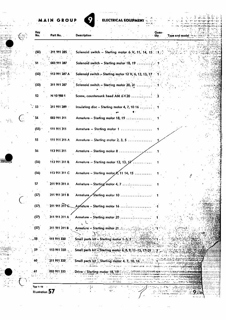
• 311 911 285 Solenoid switch - Starting motor 6. Vi, 11; 14, 15'. • • .
51 '.003911 287 Solenoid switch Starting mofor 18, 19
(50) .113 9112.87 A Solenoid switch 7 Starting motor 12 12, 13, 17 1
(50) 311 911 287 Solenoid switch - Starting motor 20, 24• ..... •
52 N 10 988 1 Screw, countersunk head AM 6X20
211 911 289. • insulating disc - Starting motor 4, 7, 10 16 1
.•••• •
54 003 911 311 Armature - Starting motor 18, 19
(55) • 111 911 311 Armature - Starling motor 1 1
55 , 111 911 311. A Armature - Starting motor 2, 3, 5
113 911 311. Armature - Starting motor 8 1
(56) 113 911 311 B Armature - Starting motor 12, 13, 1
(56) 113 911 311 C Armature - Starting motor , 11 14, 15 1
57 211 911 311 A Arrhature - Starti motor 4, 7
(57) 211 911 311 B Armature Starting motor 10 1
(57). ' • 211 911 afure 7 Starting motor 16
.(57) 311 911.311 A Armature - Staking motor 20
(57) 311 911 311 B Armature. = Starting mEifo'r..21:. • •
•• • •*:
p.":" '7.- 111 911 320 : Small Oarts 1 4•
• •
59 . 113 911 320 Small arts motar 6,8,9,-11 . 5.'1 7121- ti74'"41:4-k • • •
• •
. • •
`c rplc 211 911 'Small parti'kit L'Sfarling motor 4 7, 10 . "':1'"'
--• .- • - - • , t."
61 :'003 911 335 • DriveSfailing motor 18;19:7';
Typ 1-IS
Illustration 57
(50)
. , • • • - - • '" ::""" '•
1
MAR4 GROUP
Key No. Part No. Description • V.
Quan- tity Typo and modal
•
, •
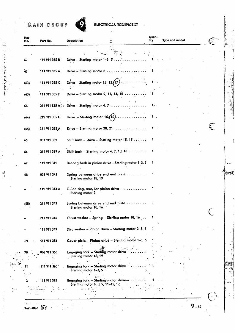
62 111 911 335 B Drive - Starting motor 1-3, 5
63 113 911 335 A Drive - Starting motor 8 1
(63) 113 911 335 C Drive - Starting motor 12, 13 1
(63) 113 911 335 D Drive - Starting motor 9, 11, 14, 115 • 1
64 211 911 335 A Drive - Starting motor 4, 7 1
(64) 211 911 335 G Drive - Starting motor 10, 16 1 ,
(64) 311 911 335. A Drive - Starting motor 20, 21 1 .
65 003 911 339 Shift bush - Drive - Starting motor 18, 19 1
66 211 911 339 A Shift bush - Starling motor 4, 7, 10, 16 1
67 111 911 341 Bearing bush in pinion drive - Starling motor 1-3, 5 1
68 003 911 343 Spring between drive and end plate 1 Starling motor 18, 19
111 911 343 A Guide ring, rear, for pinion drive - 1 Starting motor 2
(68) 211 911 343 Spring between drive and end plate 1 Starling motor 10, 16 •
211 911 345 Thrust washer - Spring - Starting motor 10, 16 1
111 911 349 Disc washer - Pinion drive - Starting motor 2, 3, 5 1
69 • 111 911 351 Cover plate - Pinion drive - Starting motor 1-3, 5 1
• 1=4-
• 70 063 911 365 Engaging fork - Starting motor drive - 1 •
• Starting motor 18,19
• ••• 71 • 111 911 365 Engaging fork -Starting motor drive
- Starting motor 1-3,5
2 113 911 365 - Engaging fork - Starting motor drive- 1 Starting motor 6, 8, 9, 11-15,17 •
ELECT:MAL ECIADIPMENT
9-40 _Illustration 57
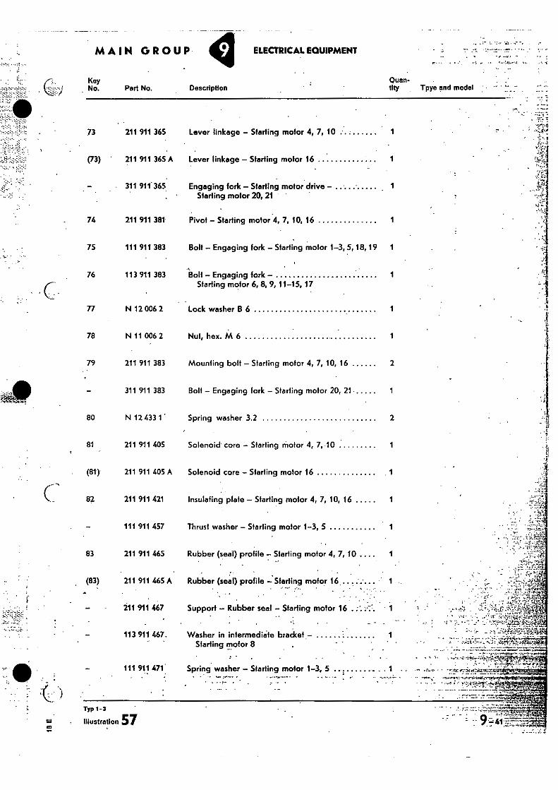
Description Quan-tity
Lever linkage - Starting motor 4, 7, 10
Lever linkage - Starting motor 16 1
Engaging fork - Starting motor drive - • Starling motor 20, 21 "
Pivot - Starting motor 4, 7, 10, 16 1
Bolt - Engaging fork - Starting motor 1-3, 5, 18, 19 1
Bolt - Engaging fork - 1 Starting motor 6, 8, 9, 11-15, 17
Lock washer B 6 1
Nut, hex. M 6 1
Mounting bolt - Starting motor 4, 7, 10, 16 2
Bolt - Engaging fork - Starling motor 20, 21 • 1
Spring washer 3.2 2
Solenoid core - Starting motor 4, 7, 10
Solenoid core - Starting motor 16 1
Insulating plate - Starting motor 4, 7, 10, 16 1
Thrust washer - Starting motor 1-3, 5
78 N 11 006 2
79 211 911 383
311 911 383
80 N 12 433 1
81 211 911 405
(81) 211 911 405 A
82 211 911 421
111 911 457
83 211 911 465 Rubber (seal) profile - Starting motor 4, 7, 10 .. •
(83) 211 911 465 A Rubber (seal) profile - Starting motor 16 • .
Part No.
73 211 911 365
(73) 211 911 365 A
311 911 365 .
74 211 911 381
75 111 911 383
76 113 911 383
77 N 12 006 2
••
- - - • -,-`• P ,
MAIN GROUP y ELECTRICAL EQUIPMENT
211 911 467 Support - Rubber seal - Starting motor 16 . •,-
- .
Typ 1-3
Illustration 57
3
Tpye and model
- 113 911 467- Washer in intermediede braCket- Startingmofor 8 , • !ATI-MI ''..2w
, - . ---•-•,-,.--tit4.:-',IiNkm,*_ •• ,-. . . X. - 111 911 471: Spring washer - Starting motor 1-3, 5 1 — -, ,... • ---ze rsir...r.114M.r.th'. „..,,,... •
• • . ... fe.TP. I Ie
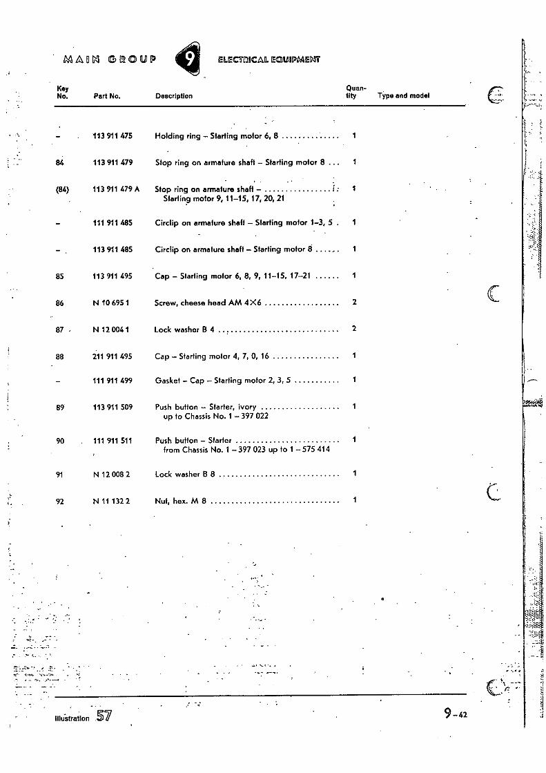
MADLI GROUP ELlECTilliCAL EQUIPMEMIT
Key No. Part No. Description
Quan-tity
113 911 475 Holding ring — Starting motor 6, 8 1
84 113 911 479 Stop ring on armature shaft — Starting motor 8 ... 1
(84) 113 911 479 A Stop ring on armature shaft — f
Starting motor 9, 11-15, 17, 20, 21
111 911 485 Circlip on armature shaft — Starting motor 1-3, 5 . 1
113 911 485 Circlip on armature shaft — Starting motor 8 ....... 1
85 113 911 495 Cap — Starling motor 6, 8, 9, 11-15, 17-21 1
86 N 10 695 1 Screw, cheese head AM 4X6 2
87 N 12 004 1 Lock washer B 4 2
88 211 911 495 Cap — Starting motor 4, 7, 0, 16 1
111 911 499 Gasket — Cap — Starting motor 2, 3, 5 1
89 113 911 509 Push button — Starter, ivory up to Chassis No. 1 — 397 022
1
90 . 111 911 511
Push button — Starter
from Chassis No. 1 397 023 up to 1 — 575 414 1
91 N 12 008 2 Lock washer B 8 1
92 N 11 132 2 Nut, hex. M 8 1
Type and model
- - .
111u-stration 57
. . . .
• • • • •••••••'..;•.' • ••
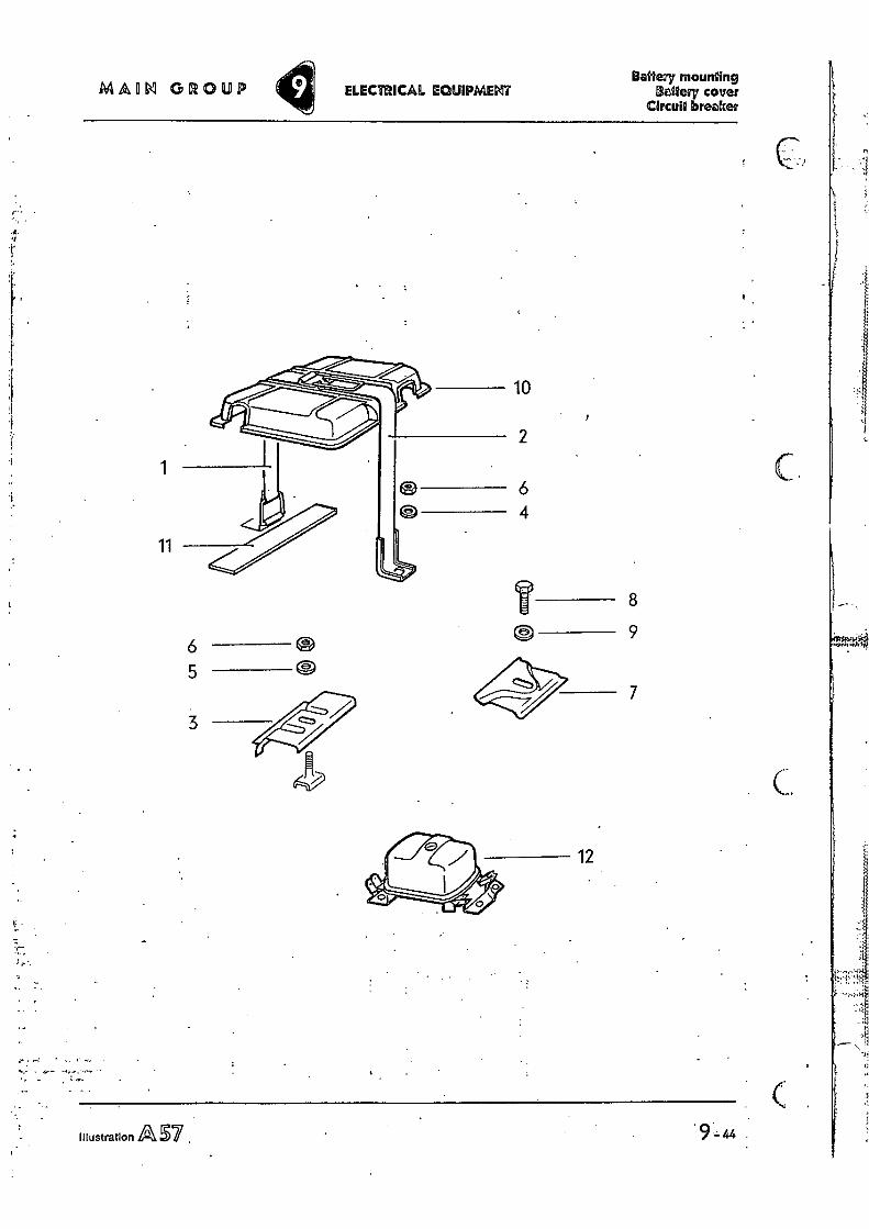
5
3
7
12
MAIM GROUP ELECTRICAL EQUIPMENT Balteay mounting
Salem cover Circuit breaker
10
2
1 6 4
11
8
a 9 6
.; I
9 -44 Illustration Lel S7
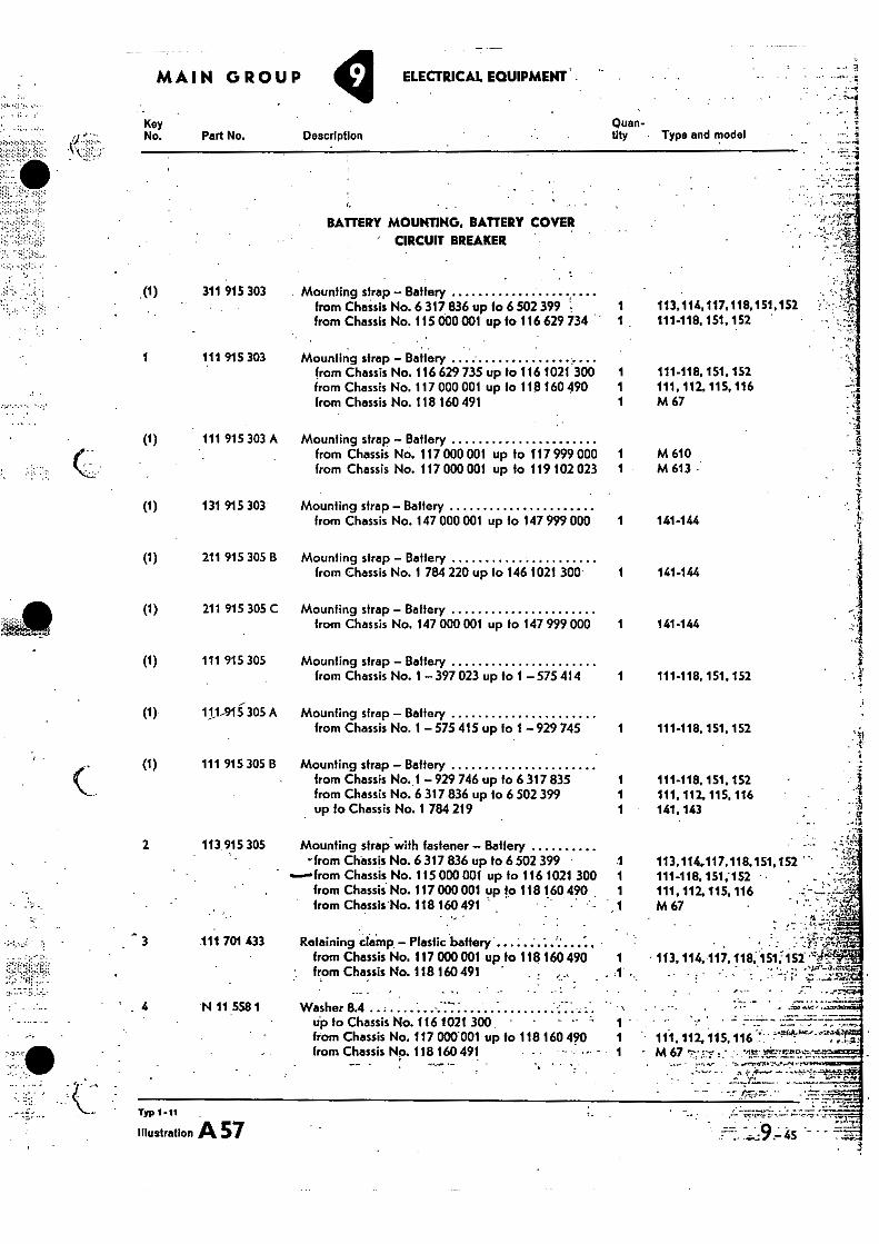
Description
• '
1 •• 11-1.112 .115,116 - - - m 67 • . • rim—roe-4.= --to--
• r
. 4 141-144
141-144
141-144
111-118,151,152
111-118, 151, 152
111-118, 151, 152 111, 112, 115, 116 141,143
113,114117,118,151,152 111-118,151;152 111, 112 115, 116 M 67
• 113, 114,-117,118, 151;152
3
Key No. Part No.
•v•;••'•
•(1) 311 915 303
MAIN GROUP ELECTRICAL EQUIPMENT .
BATTERY MOUNTING. BATTERY COVER ' CIRCUIT BREAKER
Mounting strap — Battery from Chassis No. 6 317 836 up to 6 502 399 from Chassis No. 115 000 001 up to 116 629 734
Quan- tity • Type and model
113,114,117.118,151,152 111-118. 151, 152
1
111 915 303 Mounfing strap — Battery from Chassis No. 116 629 735 up to 116 1021 300 1 111-118, 151, 152 horn Chassis No. 117 000 001 up to 118 160 490 1 111, 112, 115, 116 from Chassis No. 118 160 491 1 M 67
(1) 111 915 303 A Mounting strap — Battery from Chassis No. 117 000 001 up to 117 999 000 1
from Chassis No. 117 000 001 up to 119 102 023 1 M 610 M 613
- ?-1
I.
131 915 303 Mounting strap — Battery
from Chassis No. 147 000 OM up to 147 999 000 1
211 915 305 B Mounting strap — Battery from Chassis No. 1 784 220 up to 146 1021 300 1
211 915 305 C Mounting strap — Battery
from Chassis No. 147 000 001 up to 147 999 000 1
111 915 305 Mounting strap — Battery from Chassis No. 1 397 023 up to 1 — 575 414 1
111-911305 A Mounfing strap — Battery from Chassis No. 1 — 575 415 up to 929 745 1
(I)
(1)
CO
(1)
(1)
(1)
2
3
111 915 305 B Mounting strap — Battery from Chassis No. 1 — 929 746 up to 6 317 835 1 from Chassis No. 6 317 836 up to 6 502 399 1 up to Chassis No. 1 784 219 1
Mounting strap with fastener — Battery -from Chassis No. 6 317 836 up to 6 502 399
.from Chassis No. 115 000 001 up to 116 1021 300 from Chassis. No. 117 000 001 up to 118 160 490 , from Chassis No. 118 160 491
.1
.111 701 433 Retaining clamp — Plastic battery .•
from Chassis No. 117 ow 001 up to 118 160 490 1 from Chassis No. 118 160491
4 N 11 558 1 Washer 8.4 up to Chassis No. 116 1021 300 from Chassis No. 117 000001 up to 118 160 490 from Chassis No. 118 160 491
Typ I-11 -
Illustration A 57
113.915 305
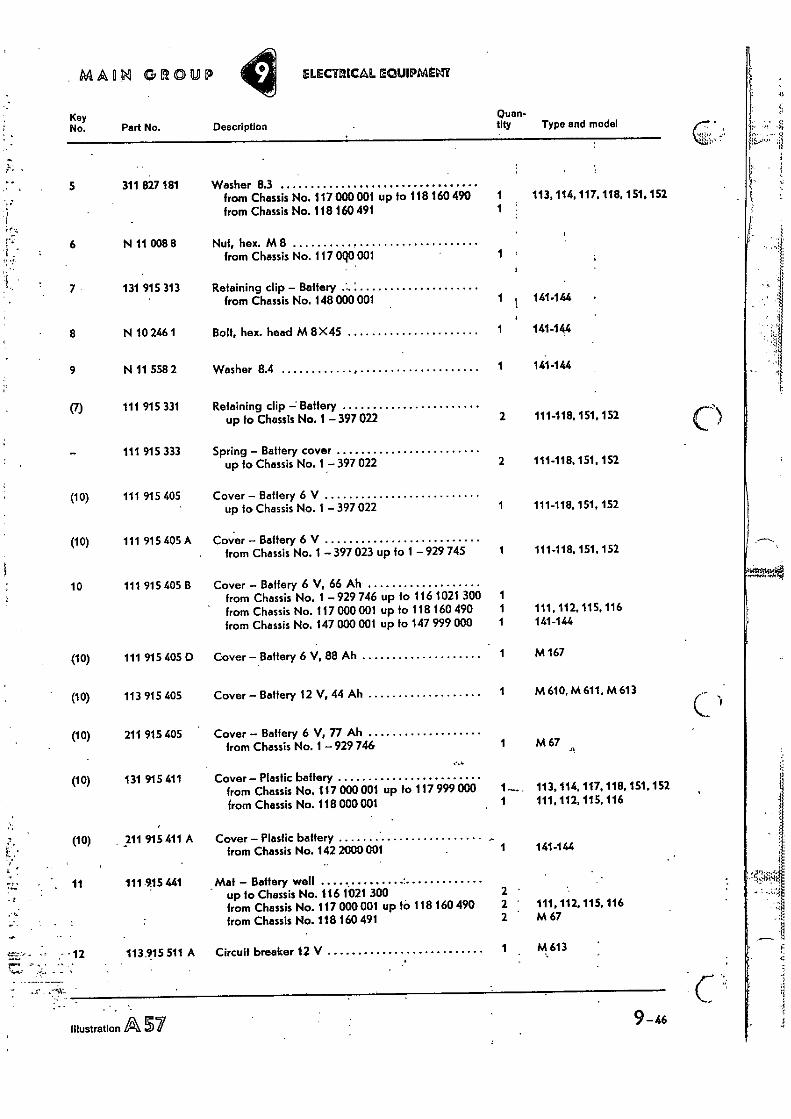
5;
MAORI 011011.11? ELECTRICAL
Key Quan- No. Part No. Description tity Type and model
5 311 827 181 Washer 8.3 from Chassis No.117000001 up to 118 160 490 1 113, 114, 117, 118, 151, 152 from Chassis No. 118 160 491 1
6 N 11 008 8 Nut, hex. M 8 from Chassis No. 117 0q0 001 1
7 131 915 313 Retaining clip — Battery from Chassis No. 148 000 001 1 t 141-144
8 N 10 246 1 Bolt, hex. head M 8X45 1 141144
9 N 11 558 2 Washer 8.4 , 1 141-144
(7) 111 915 331 Retaining clip —' Battery up to Chassis No. 1 —397 022 2 111-118,151,152
111 915 333 Spring — Battery cover up to Chassis No. 1 —397 022 2 111-118, 151, 152
(10) 111 915 405. Cover — Battery 6 V up to Chassis No. 1 — 397 022 1 111-118, 151, 152
(10) 111 915 405 A Cover Battery 6 V from Chassis No. 1 — 397 023 up to 1 — 929 745 1 111-118, 151, 152
10 111 915 405 B Cover — Battery 6 V, 66 Ah from Chassis No. 1 929 746 up to 116 1021 300 1 from Chassis No. 117 000 001 up to 118 160 490 1 111, 112, 115, 116 from Chassis No. 147 000 001 up to 147 999 000 1 141-144
(10) 111 915 405 D Cover — Battery 6 V, 88 Ah 1 M 167
(10) 113 915 405 Cover — Battery 12 V, 44 Ah 1 M 610, M 611, M 613
(10) 211 915 405 Cover — Battery 6 V, 77 Ah from Chassis No. 1 — 929 746 1 M 67
a
Cover — Plastic battery from Chassis No. 117 000 001 up to 117 999 000 from Chassis No. 118 000 001
1-...... 1
113, 114, 111, 112,
117, 115,
118, 116
Cover — Plastic battery from Chassis No. 142 2000001 1 141.144
_Mat — Battery well, up to Chassis No. 116 1021 300 2 - from Chassis No. 117 000 001 up to 118 160 490 from Chassis No. 118 160 491
2 • 2 -
111, 112, M 67
115, 116
Circuit breaker 12 V 1
151, 152 (10) 131 915 411
(10) 211 915 411 A
; ! 11 111.915 441
-,-----, — - • 12 113.915 511 A
- - . .
Illustration A 57
9-46
-,., r.,.. 1....,.r ..7.7,47.7 ref.! t i arr.
,,11 ,,, i .1 1,1... 0I 1,i 11 , • .1,1;11 • 4 1, f..f J it .i]..1.- • ••1 4.. ;14:-,i• • • ,[ t, ir i 1.1, ; i I,. 1 i: ilk:i; , a , ,..1 ., . , „ . I- 1; •,, • .,. •.,. • ' V '1,1'4 I, t I' 1.'1 1'
..0 .11 . 0 t 1,--:4t2 ':'11
4. tl '... k ! • i . i 3 i . .. 11-• I .(•• -., •i'. i . 1
,, I, ,'• - •
•••;:E.••
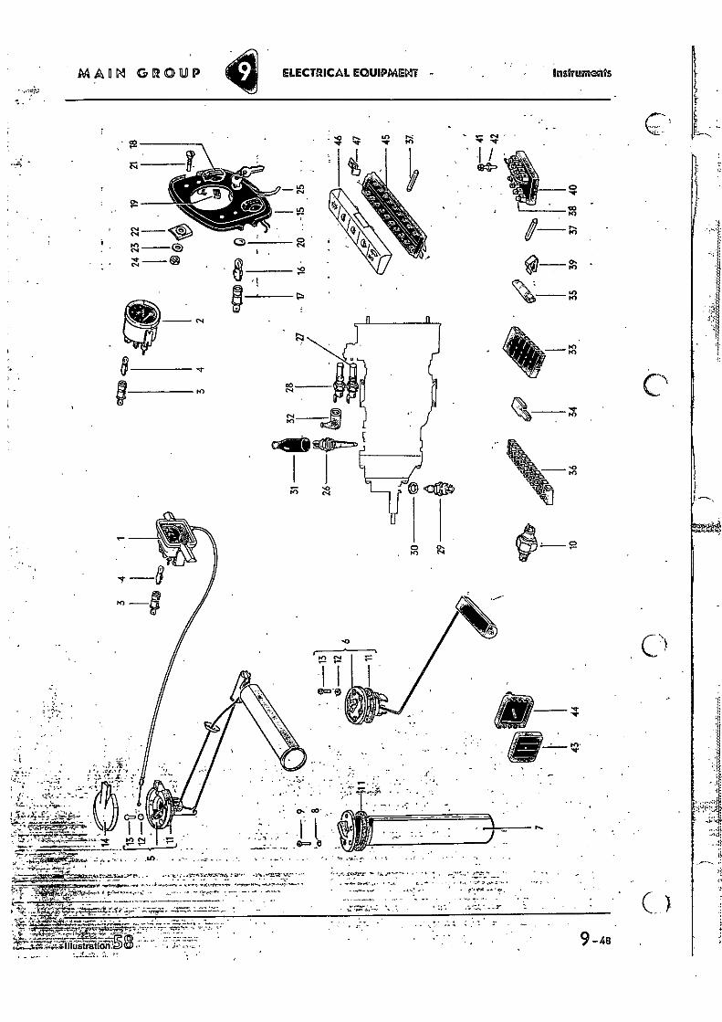
MAIIN GROUP Instruments ELECTRICAL EQUIPMENT -
164
C
.„, _.-....... •
to) 9- 48
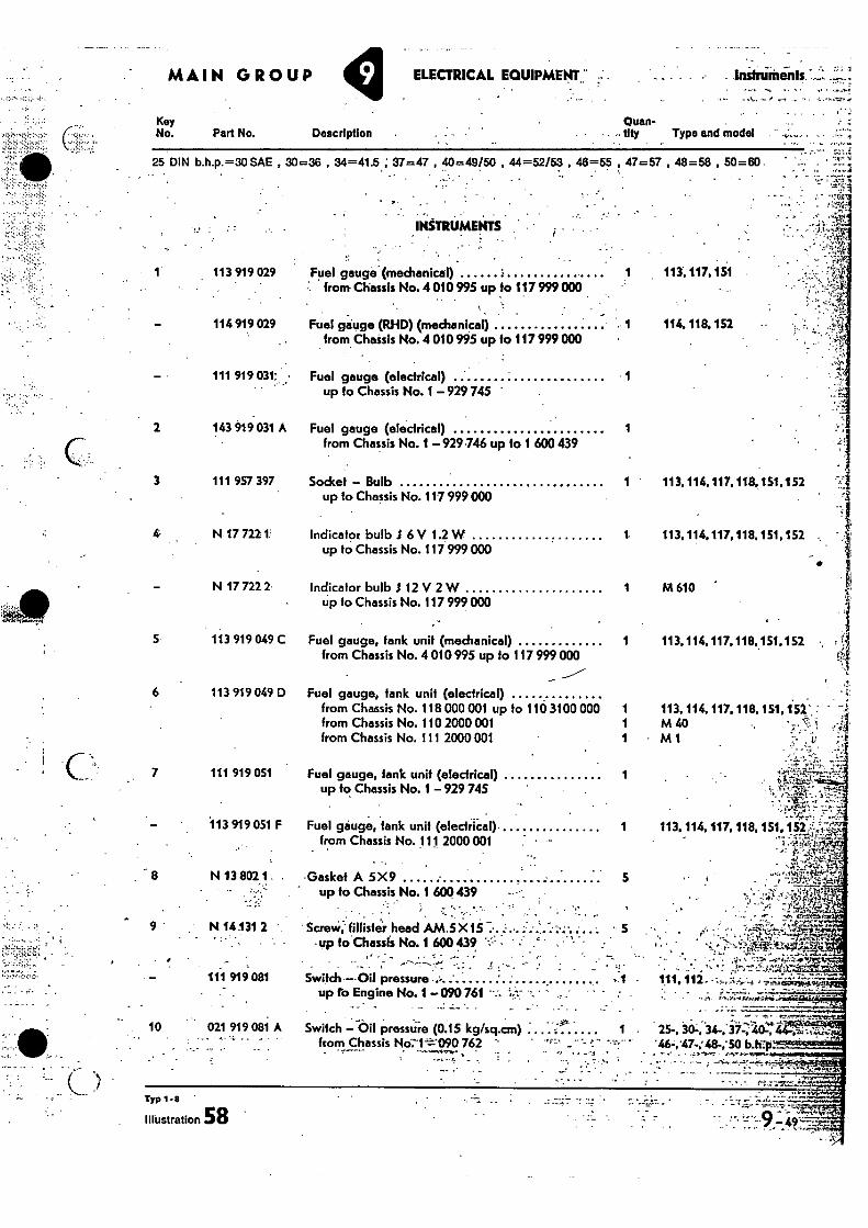
MAIN GROUP ELECTRICAL EQUIPMENT: " Inshumenls
Key No. - • 1-
Quan- tity Type and model Part No. Description
113 919 029 Fuel gauge (mechanical) from• Chassis No. 4 010 995 up to 117 999 000
113, 117,151
Typ 1-8
Illustration 58 -
25 DIN h.h.p.=30 SAE , 30=36 , 34=41.5 ; 37=47 , 40=49/50 , 44=52/53 , 46=55 , 47=57 , 48=58 , 50=60 .
INSTRUMENTS
114 919029 Fuel gauge (RHD) (mechanical) 1 114, 118. 152 from Chassis No. 4 010 995 up to 117 999 000
111 919 031: • Fuel gauge (electrical) 1 up to Chassis No. 1 — 929 745
143 919 031 A Fuel gauge (electrical) 1 from Chassis No. 1 —929 746 up to 1 600 439
3 111 957 397 Socket — Bulb 1 113,114,117.118,151.152 up to Chassis No. 117 999 000
N 17 7221rIndicator bulb 6 V 1.2 W 1. 113.114,117,118,151,152 „ up to Chassis No. 117 999 000
N 17 722 2 indicator bulb .1 12 V 2 W 1 M 610 • • up to Chassis No. 117 999 000
5 113 919 049 C Fuel gauge, tank unit (mechanical) 1 113,114,117,118,151.152 from Chassis No. 4 010 995 up to 117 999 000
----" 6 113 919 049 D Fuel gauge, tank unit (electrical)
from Chassis No. 118 000 001 up to 110 3100 000 1 113, 114, 117.118, 151, 152` : • from Chassis No. 110 2000 001 1 M 60 ' • •Cr.'• i from Chassis No. 111 2000 001 1 M 1 :-- . i;
r.:...iz&'• " ...--;-.-iLf.,....... - 1. -"m.•-•-
- ' . ,• g,.:1..--.'.! '
— 113 919 051 F Fuel gauge, tank unit (electrical) 1 113. 114.117. 118,151, 152 ,--,,,,7, from Chassis No. 111 2000 001
7 111 919 051 Fuel gauge, lank unit (electrical) 1 up to Chassis No. 1 — 929 745
8 N 13 802 1 - -Gasket A 5X 9
up to Chassis No. 1 600 439 -- • ; • -
9 • N 14.131 2 ScreW, fillistei head AM.5 X15 ' • °up to Chassis No. 1 6001439 •
111 919 081 Switch —.Oil pressure -
' up to Engine No. 1 —090 761
- -
crag -
epo
• . ; 4. - • 't • - k", 111, 112. • :
•
10 021 919 081 A Switch —Oil pressure (0;15 kg/sq.cm) 1 . 25-, 30-, 34-, 37-, . • •,
from Chassis No7-1--=-'-090 762 '46- -47-'48- 'SO b
•
• r 5
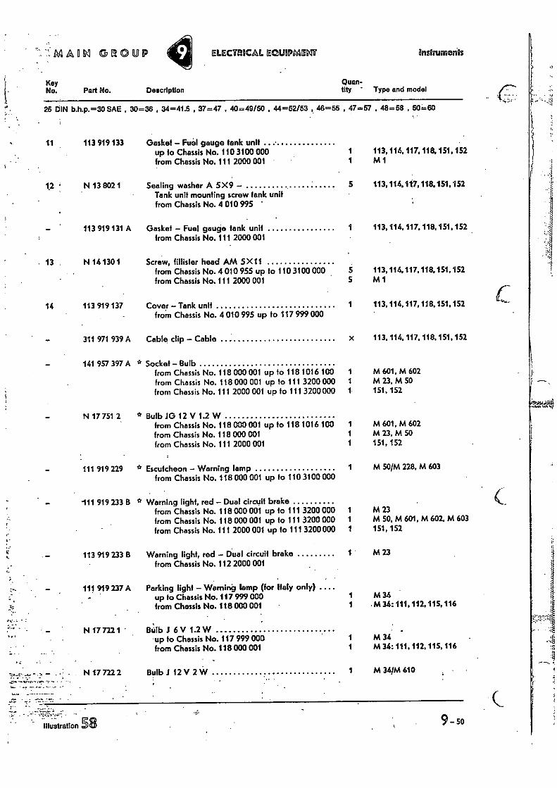
--'44114114j 51310UP ELECTRICAL EQUIPMDIT Instruments
Key No. Description Part No.
Quan- tity Type and model
25 DIN b.h.p.=30 SAE , 30=36 , 34=41.5 , 37=47 , 40=49150 , 44=52/53 46=55 , 47=57 , 48=58 , 50=60
1i 113 919 133 Gasket — Feel gauge tank unit up to Chassis No. 110 3100 000 1 from Chassis No. 111 2000 001 1
113, 114, 117, 118.151,152 M1
12 N 13 802 1 Sealing washer A 5X9 — Tank unit mounting screw tank unit from Chassis No. 4 010 995
5 113,114.117,118.151.152
113 919 131 A Gasket — Fuel gauge tank unit from Chassis No. 111 2000 001
1 113.114,117, 118, 151, 152
13 N 14 130 1 Screw, fillisler head AM 5 X 11 from Chassis No. 4 010 955 up to 110 3100 000 5 from Chassis No. 111 2000 001 5
14 113 919 137 Covey — Tank unit 1 from Chassis No. 4 010 995 up to 117 999 000
113,114,117,118.151.152 M1
113, 114, 117, 118,151.152
311 971 939 A Cable clip — Cable
141 957 397 A * Socket — Bulb from Chassis No. 118 000 001 up to 118 1016 100 from Chassis No. 118 000 001 up 10 111 3200 000 from Chassis No. 111 2000 001 up to 111 3200 000
N 17 751 2
* Bulb JO 12 V 1.2 W from Chassis No. 118 000 001 up to 118 1016 100 from Chassis No. 118 000 001 from Chassis No. 111 2000 001
111 919 229 * Escutcheon — Warning lamp from Chassis No. 118 000 001 up to 110 3100 000
111 919 233 B * Warning light, red — Dual circuit brake from Chassis No. 118 000 001 up to 111 3200 000 from Chassis No. 118 000 001 up to 111 3200 000 from Chassis No. 111 2000 001 up to 111 3200 000
113 919 233 B Warning light, red — Dual circuit brake from Chassis No. 112 2000 001
111 919 237 A Parking light — Warning lamp (for Italy only) .... up to Chassis No. 117 999 000 from Chassis No. 118 000 001
N 17 722 1 BUIb 1 6V 1.2W up to Chassis No. 117 999 000 from Chassis No. 118 000 001
N 17 722 2 Bulb 112 V 2 W
x 113,114, 117, 118, 151, 152
1 M 601, M 602 1 M 23, M 50 1 151, 152
1 M 601, M 602 1 M 23, M 50 1 151, 152
1 M 50/M 228, M 603
1 M 23 1 M 50, M 601, M 602, M 603 1 151, 152
1 M 23
1 M34 1 M 34: 111, 112, 115, 116
1 M 34 1 M 34: 111, 112, 115, 116
1 M 34/M 610
9-50 illustration 58
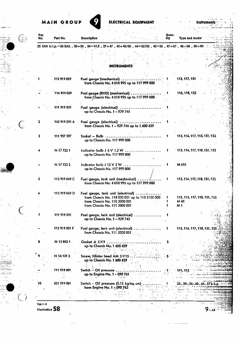
113 919 049 D Fuel gauge, tank unit (electrical) from Chassis No. 118 000 001 up to 110 3100 000 1 from Chassis No. 110 2000 001 1 from Chassis No. 111 2000 001 1
Fuel gauge, lank unit (electrical) from Chassis No. 111 2000 001
7 111 919 051
Fuel gauge, tank unit (electrical) 1 up to Chassis No. 1 — 929 745
113 919 051 F
Switch Oil pressure up to Engine No. 1 090 761
8 N 13 802 1 Gasket A 5X9 5 up to Chassis No. 1 600 439
- •
9 . • N 14131 2 Screw, filthier head AM 5X15 . . ..... up to Chassis No. 1 600 439
111 919 081
10 021 919 081 Switch — Oil pressure (0.15 kg/sq. cm), from Engine No. 1 t 090 762
INSTRUMENTS'
1 113 919 029 Fuel gauge Imechanical) from.Chassis No.. 4 010995 up to 117 999 000
114 919 029 Fuel gauge (RHD) (mechanical) , 1 from Chassis No. 4 010 995 up to 117 999 000
111 919 031 Fuel gauge (electrical) 1 up to Chassis No. 1 — 929745
143 919 031 A Fuel gauge (electrical) 1 from Chassis No. 1 —929 746 up to 1,600 439
111 957 397 Socket — Bulb up to Chassis No. 117 999 000
N:17 7221' Indicator bulb .1 6 V 1.2 W up to Chassis No. 117 999 000
N 17 722 2 Indicator bulb J 12 V 2 W up to Chassis No. 117 999 000
113 919 049 C Fuel gauge, tank unit (mechanical) from Chassis No. 4 010 995 up to 117 999 000
2
3
4
5 6
.114.118, 152
25-, 30-, 34-,40-,44-.47 b.h.p.
• •
• 7:7 '
111,112
• 1 113.117,151
1 113,114.117.118.151,152
1 113,114, 117, 118,151,152
1 M 610
1 113, 114, 117.118, 151.152
1 113, 114, 117, 118, 151, 152 :vr% Fzi•!•1V1 •
4‘.g
• 113, 114, 117,118,151, 152 M 40 M1
_ _ •
9_ 49 .
MAIN GROUP ELECTRICAL EQUIPMENT - Instruments -
Key Quan-
No. Part No. Description
tity Type and model
25 DIN b.h.p.=30 SAE , 30=36 , 34=41.5 , 37=47 , 40=49/50 , 44=52/53 , 46=55 . 47=57 , 48=58 , 50=60 : •
Typ 1 5
Illustration 58
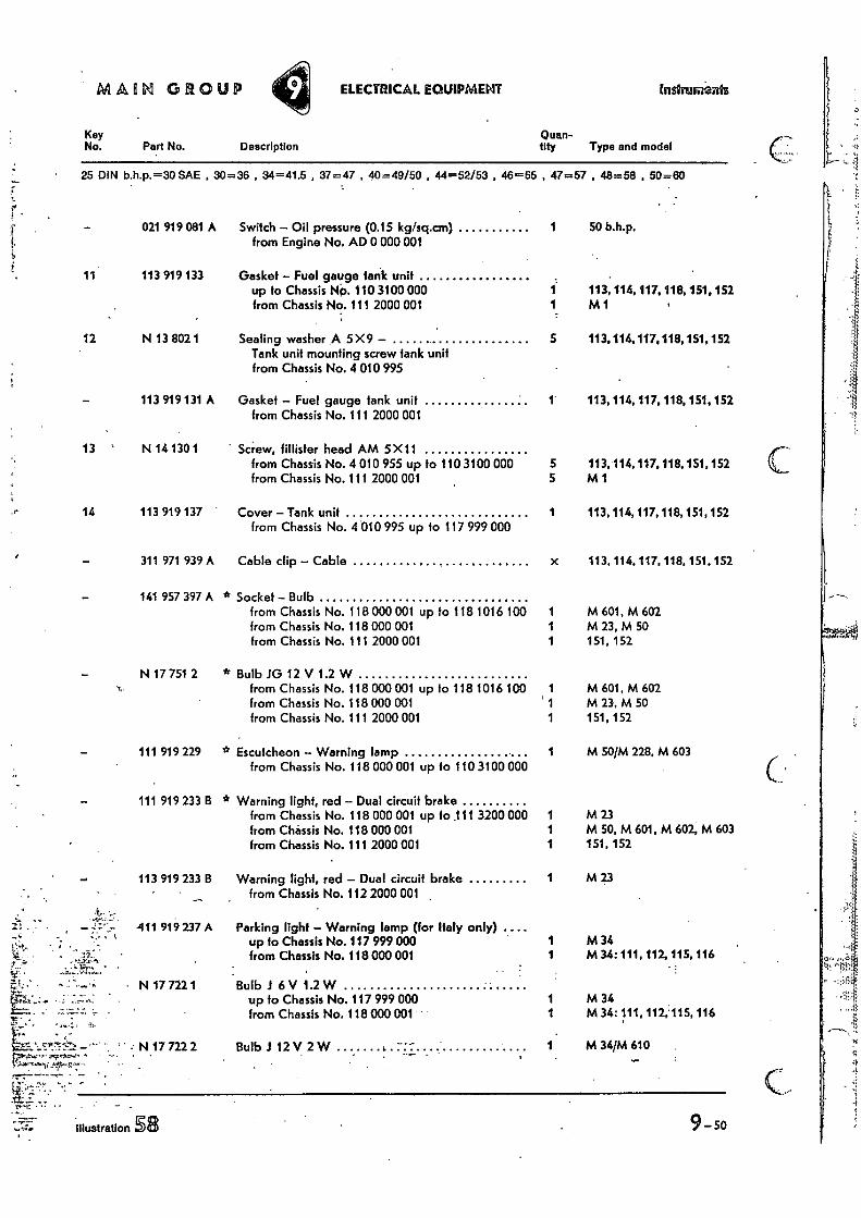
MAHN GROUP ELECTRICAL EQUIPMENT
Key No. Part No. Description
25 DIN b.h.p.=30 SAE , 30=36 , 34=41.5 , 37=47 , 40=49/50 44=52/53 46=55
021 919 081 A Switch - Oil pressure (0.1S kg/sq.cm) from Engine No. AD 0 000 001
11 113 919 133 Gasket - Fuel gauge lank unit up to Chassis NO. 110 3100 000 from Chassis No. 111 2000 001
12 N 13 802 1 Sealing washer A 5X9 - Tank unit mounting screw tank unit from Chassis No. 4 010 995
113 919 131 A Gasket - Fuel gauge lank unit from Chassis No. 111 2000 001
14 113 919 137 Cover-Tank unit from Chassis No. 4 010 995 up to 117 999 000
311 971 939 A Cable clip - Cable
141 957 397 A * Socket - Bulb from Chassis No. 118 000 001 up fo 118 1016 100 from Chassis No. 118 000 001 from Chassis No. 111 2000 001
- N 17 751 2 * Bulb IG 12 V 1.2 W N.
from Chassis No. 118 000 001 up fo 118 1016 100 from Chassis No. 118 000 001 from Chassis No. 111 2000 001
111 919 229 * Escutcheon - Warning lamp from Chassis No. 118 000 001 up to 110 3100 000
111 919 233 B * Warning light, red - Dual circuit brake from Chassis No. 118 000 001 up to .111 3200 000 from Chassis No. 118 000 001 from Chassis No. 111 2000 001
113 919 233 B Warning light, red - Dual circuit brake from Chassis No. 112 2000 001 ,
411 919 237 A Parking light - Warning lamp (for Italy only) .... up to Chassis No. 117 999 000 from Chassis No. 118 000 001
N 17 722 1 Bulb I 6 V 1.2 W up to Chassis No. 117 999 000 from Chassis No. 118 000 001
Quan-tity
Instrimients
Type and model
, 47=57
1
, 48=58 , 50=60
50 b.h.p.
1 113, 114, 117, 118, 151. 152 1 M 1
5 113.114.117,118, 151, 152
1 113, 114, 117. 118, 151, 152
113.114,117,118, 151, 152 M 1
1 113, 114, 117,118,151, 152
x 113, 114. 117, 118, 151, 152
1 M 601, M 602 1 M 23, M 50 1 151, 152
1 M 601, M 602 ' 1 M 23, M 50 1 151, 152
1 M 50/M 228, M 603
1 M 23 1 M 50, M 601, M 602, M 603 1 151, 152
1 M 23
1 M 34 1 M 34: 111. 112, 115, 116
1 M 34 1 M 34: 111, 112;115, 116
1 M 34/M 610
9-50
'• N 17 722 2 Bulb .1 12V_ 2 W
L.! ^
. •
illustration 5 4,
5 13 N 14 130 1 Screw, fillisfer head AM 5X11
from Chassis No. 4 010 955 up to 110 3100 000
from Chassis No. 111 2000 001 5
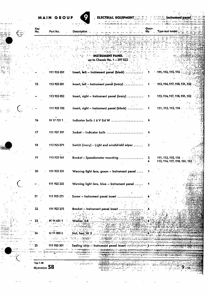
MAIN GROUP ELECTRIAL EQUIPMENT,: ' ' InstrunieiNtiatol' "'" •
• qc•• •rt.,
Quan- - tity • _Type and model s y • •
airw
Key No. Part No. . Description
-
15
23
111 925 301 ' Sealing' strip - Instrument panel insert. - 2.4-'•-v 'Y.t.K4'1-1151..-.6. 6 • •.„ . ♦ d't-•
• •e• ..-....i. • 4-4,7Kr40.4.1“,, 4 0,44 r
25
Typ 1-22
Illustration 58
7,7; 7 • -••• •
• -, ; '•
-INSTRUMENT PANEL up to Chassis No. 1 - 397 022 -
111 925 051' Insert, left.- Instrument panel (black) ... . . '. ; . '.:.
113 925 051 Insert, [eft: Instrument panel (ivory) 1
113 925 052 Insert, right - Instrument panel (ivory) 1
111 925 102 Insert, right - Instrument panel (black) 1
N 17 721 1 Indicator bulb J 6 V 0.6 W 4
111 957 397 Socket Indicator bulb 4
113 925 079 Switch (ivory) - Light and windshield wiper 2
113 925161 Bracket - Speedometer mounting 2 4
111 925 231 Warning light lens, green - Instrument panel .... 1
111 925 235 Warning light lens, blue - Instrument panel
111 925 271 • Screw - Instrument panel insert
111 925 275 Bracket - -Instrument panel insert ........ ....... 22
111, 112, 115, 116 .
111, 112, 115, 116 • : 113, 114, 117.118, 151, •
11 651 •• •
N 11 005 •
1 •
•
2
„
•
• Waslier,5:8 . ......... . • - • • .TA.r.,-'11.!
4. ,
Nut heiC.M .. • 4i
,
.
...
• - _ _
_
... t
• .
'Z.:: -
• -
? a. . ..; :
• =.•,
• .• •
• •••• • _ .. • a
Z•ii-7-;1724: „
•
a a. - ..,••••• • 2, -
. u- Vt.7..),V.ZA:41:;•
• - •
v".
16
17
18
19
20
21
--"
t: •11 - -111, 112. 115016 ;.•
• 4• `.1:-‘:1111.h
113, 114, 117,118, 151,152 --
113.114, 117, 118, 151, 152 . •
.4 art...4,, sTe
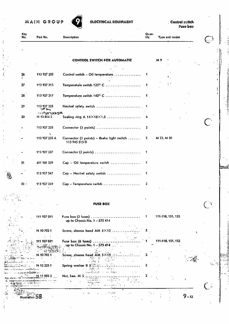
MAIM GROUP ELECTRICAL EQUIPMENT Control st7lIch Fuse bolt
Key Quan-
No. Part No. Description tity Type and model
26
27
28
29
113 927 205
113 927 215
113 927 217
113 927 225
CONTROL SWITCH FOR AUTOMATIC
Control switch - Oil temperature
Temperature switch 125° C
Temperature switch 140° C
Neutral safety switch
30 N 13 814 2 Sealing ring A 14 X18 X1.5
113 927 235 Connector (3 points)
113 927 235 A Connector (3 points) - Brake light switch 113 945 515 D
113 927 237 Connector (2 points)
31 411 941 539 Cap - Oil temperature switch
113 927 247 Cap - Neutral safety switch '44
32 113 927 249 Cap - Temperature switch
•
FUSE BOX
- . 111 937 011 Fuse box (3 fuses) up to Chassis No. 1 575 414
M9
4
2
2 M 23, M 50
1
1
1
2
111-118,151,152
N 10 702 1
• ... - TA,
.. • ,.. , N 12 225 1
Screw, cheese head AM 5 X15 2
Fuse box (6 fuses) 1 111-118,151.152 - , up to Chassis No. 1 -575 414. _
• - . Screw, cheese head AM 5 X 2
• ": •
Spring washer B
2
111 937 031
N 10 702 1
fr;.. -Li;
Nut, hex. M 5 ... ......... ........... - :
- • • N 11 005 2 - •
2 .
1
9 -52 • illuse-ratiait 58
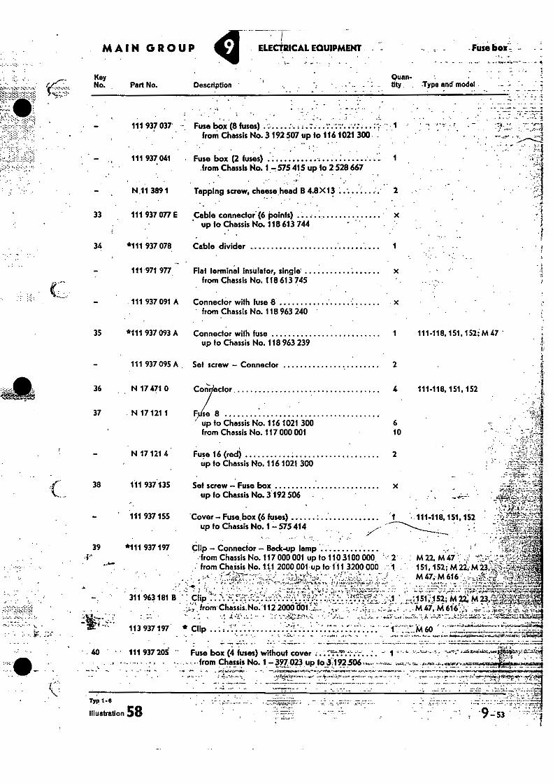
. MAIN GROUP 9 ELEORICAL EQUIPMENT •
• Fuse box;
4
Key No. Part No. Description
Quan- • tity . Type and model .
•
1- y
111 937 037' - Fuse box (8 fuses) from Chassis No. 3 192 507 up fa 116 1021 300
111 937 041 Fuse box (2 fuses) 1 from Chassis No. 1- 575 415 up 10 2 528 667
. . ''. . . • .. . . — N.11 389 1 Tapping screw, cheesebead B 4.8X 13 . .. . . .
•
33 111 937 077 E Cable connector (6 points) up to Chassis No. 118 613 744
34 *111 937 078 Cable divider 1 ' • •
• . .
111 971 977 Flat terminal insulator, single from Chassis No. 118 613 745
111 937 091 A Connector with fuse 8 ' from Chassis No. 118 963 240
35 *111 937 093 A Connector with fuse 1 111-118.151,152;M 47 ' up to Chassis No. 118 963 239
111 937 095 A • Set screw — Connector 2
36 . N 17 471 0 Corn odor 4 111-118, 151, 152
37 N 17 121 1 Fu se 8 ' up to Chassis No. 116 1021 300
6
from Chassis No. 117 000 001
10
N 17 121 4 Fuse 16 (red) 2 up to Chassis No. 116 1021 300
38 111 937 135 Set screw — Fuse box up fo Chassis No. 3 192 506
111 937 155 Cover — Fuse-box (6 fuses) 1 • 111-118, 1St 152 up to Chassis No. 1-- 575 414
39 *111 937 197 Clip — Connector — Beck-up -lamp -.from Chassis No. 117 000 001 up to 110 3100 000. '-: 2 from Chassis No.1.1,1 2000.001. up to 111 3200 000 .
•
M 22, M 47 151, 152;: M 22,•M 13;: M 47;, M 616
A
li.'1....„. .....,:.?.
... •-.. -:-17.,'..:,..' -. 311 963 181 B ' : Clip ..... :-. f --4..-.:,.....,.. -...... 2..r., 1 1
. . .. ,.1. from ChiSsii.No;112 2000401.: .. - - •
: :2. • - . . -. , -... .i. .,_ "- .._ : - • -...- •. --..-:':i,". ,..::+ ,.... • .... ....1 ._:_ .... 4 • 11.4; -....t
113 937 197 * Clip ' - ' .-.
•
',151;1 ; S ;2; M ....M 47, M 616 z
141Z. ••• ..., •
m6o
40 - 111 937205 '' Fuse box (4 fuses) without cover ••• ' - 1 • - • from Chassis No. 1-397 023 up to 3 1n506,
; •;..,•!••••• --•••/••••,4?•-- •••• '••• t•••-• • ••••• •
• z.:
Typ 1-6 -•------, -- • • • - • .
illustration 58
.9=53 • ' •
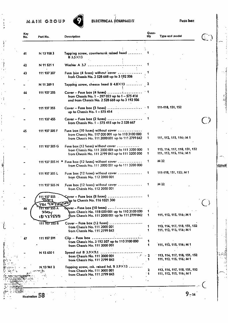
over - Fuse box (8 fuses) fo Chassis No. 116 1021 300
ver - Fuse box (10 fuses) • om Chassis No. 118 000 001 up fa 110 3100 000 om Chassis No. 111 2000 001 up lo 111 2799 842
Cover - Fuse box (12 fuses) from Chassis No. 111 2000 001 from Chassis No. 111 2799 843
47 111 937 591 Clip - Fuse box from Chassis No. 3 192 507 up to 110 3100 GOO from Chassis No. 111 2000 001
• "17 74 .7: 7ft. • n
C.4 ....;- -1' ...4,.-14,- -4. • , from Chassis No. 111 2000 001
N 15 430 1 Speed nut B 3.9 X9.1 from Chassis No. 111 2000 001 from Chassis No. 111 2799 843
N 13 961 2 Tapping screw, csk. raised hd. B 3.9 X13
t • ..;-, from Chassis No. 111 2799 843
MMN GROUP ELECIfUCAL k.ClUIPIMENT Foam bon
Key No, Part No. Description Type and model
Quan- tity
41 N 13 958 3 Tapping screw, countersunk raised head 133.5X13
42 N 11 521 1 Washer A 3.7 1
43 111 937 207 Fuse bOx (4 fuses) without 'cover 1 from Chassis No. 2 528 668 up to 31,92 506
N 11 389 1 Tappihg screw, cheese head 8 4.8X13 2 !
44 111 937 255 Cover - Fuse box (4 fuses) 4 • 1 from Chassis No. 1 -397 023 up to 1 - 575 414 and from Chassis No. 2 528 668 up to 3 192 506
111 937 355 Cover - Fuse box (3 fuses) up to Chassis No. 1 -575 414
111 937 455 Cover - Fuse box (2 fuses) from Chassis No. 1 - 575 415 up to 2 528 667
45 111 937 505 F Fuse box (10 fuses) without cover from Chassis No. 117 000 001 up to 110 3100 000 from Chassis No. 111 2000 001 up to 111 2799 842
111 937 505 G Fuse box (12 fuses) without cover from Chassis No. 111 2000 001 up fo 111 3200 000 from Chassis No. 111 2799 843 up lo 111 3200 000
1 111-118, 151, 152
1
1 1 111, 112, 115, 116; M1
113, 114, 117, 118, 151, 152 111, 112, 115, 116; M1
111 937 505 H
111 937 505
111 937 505 N
* Fuse box (12 fuses) without cover from Chassis No. 111 2000 001 up to 111 3200 000
Fuse box (12 fuses) without cover from Chassis No. 112 2000 001
Fuse box (12 fuses) without cover from Chssis No. 112 2000 001
M 22
111-118,151, 152:M 1
M22
1 111. 112, 115, 116; M1
1 113, 114, 117, 118, 151, 152 1 111, 112, 115, 116; M 1
111, 112, 115, 116; M1
2 • 113, 114, 117, 118.151, 152 . 1 111, 112, 115, 116; M1
2 113.114, 117. 118, 151, 152 • 1 111, 112, 115, 116;. M 1
•
e- T•2:.•.•.''.! r..-":•• .• SS
......z.•'..,....•_ .....-,._-••• . -
.ttit"....,,.••'•••7..""••••:-.:•.•-•".- -• - 4!••••41-•-e-1-.te:.!: •• - - • . •
7,...7..!-•..--.. • ••• ,
• i '2,• • ,..
' .. • . , . ., •
- •
• " !•.r." ! ••••••., r - • • - -•
•
...; ,
'., . ,..7 ..
:.''-• • • -. ' • ,,,•"'
. ..,
• : • 7 ..... ,• • ..
..i ' .' • ,!...;,-• rA', , ..... ,
,
' • ' ' •.•
gl• '• ;fi,....•-,4-41.5,:::7i'''..;-;,.. 1,14•3%.*:•.1.,".•,••.•••• ,
'Wai:'144'';:ei.;'.it'l. .stV,VZ S:L. '• ...,,, •••it.....ei‘l, i.r...: „.
..;41.4%. ,.....4' j'-', l'g,:•-• •• Z.,'• --,:,;,:•,,..:•.... . '. r • • r-
•
4.:1:i:;_‘,7 . '''''14 ,•'' .11! • ,. :. e' • .'•- . • ' ', ••. . 14C4' 1-s‹. •"" . ,) , ,
•
.. •
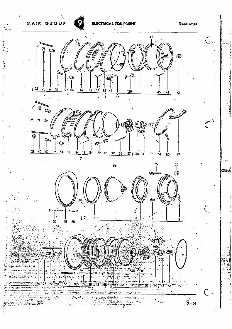
Headlamps MAIN GROUP ELECTRICAL EQUIPMENT
43
1 47
2
I . 9 54 it 14 38 41 49
56 25 30
. 1
9-56
• ....IP, • • L'.. • — 24 26 27' 28 53 10';•+,'55 :13 , 415 + .33 37 =IC:" P44401060141,1~.....ro .
.19 • 'N-•
•
: ••• • • 40,
A. I
+•.• 4—.4 • ;
• • ..-7•t
e ; • „k•-d • ,••••
.iTtall0. 1. • L ?Se
- . "ts;. 'Pt.; ,tt•te,70: el tt . - . i.....,;...: —.....
..1 ..f.: i -2..4,4.• .: t...1"..t .., "..1.-! . ... .......7 -' ....1. A.0114 ..7...44 -.. ,....r...1'..t.t.. e ' ..1 ..,•• N:.. I , ' t r I
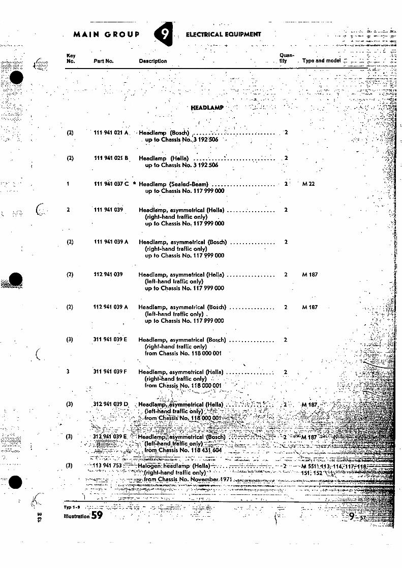
Quan-tity
Key No.
- • •:.• Type and model . Part No. Description
2 M 187
2 M 187
Headlamp, asymmetrical (Hella) (left-hand traffic only) up to Chassis No. 117 999 000
Headlamp, asymmetrical (Bosdi) (left-hand traffic only) , up 10 Chassis No. 117 999 000
.311 941 039 F 3
: . tfrAis_rY..y.fl " r- • . ... "
r tAttroW41•11**-1A.•
• • • ̀. - • • 44. • .i••=f,-=•7.-,,,0••=74,1!.
- , •-•ertr,,r1, r
. MAIN GROUP ELECTRICAL EQUIPMENT
' HEADLAMP
111 941 037 C * Headlamp (Sealed-Beam) up to Chassis No. 117 999 000
2 111 941 039
(2) 111 941 039 A
(2) 112 941 039
. (2) 112 941 039 A
(3) 311 941 039 E --;
7.11,,:t.P7 • 7
2
2 M22
Headlamp, asymmetrical (Hella) ........ (right4uind traffic only) from Chassis No. 118 000001 , .
2
. 312 941 039 D ..: HeadlarniicAiymmetrical (Hello)...:i..'..kA- Y: " '`.- •
. . . , .-•,
. (left-hind.fraffic anti) '-Vkei-.:-.::: =•-:','. ' - ' f i-7'`'• •, ..from•Chaliii'NO. 118'001)....,001 -..4.'•-,;.i'c'
4 -,.....,...„„.„ . --, .----...i.:. '44- -:. .•...-_-"--,' :1. - . . , , ). ...:-:-....:P -r .r:" -..-,„!•:',.•' • . -.,t, - : --,• -ft- ,;- -... ...''', ...t.5"Z. -... . .;') '-t.:...: 9' .... -z,Tr4.:•-,.:,--,.' -...;-. ,,,,..,.• Lit
.•-• •-, - - -- -;.:',...1,,li,4,:$'"„,.4:,....i5 •.: ,-,,- ' ,..,i:7-7' - - .
- (3) . 312 941'039 E. 7. -,:Headlimpissianirtietilcil IBOsci9 i:;:-...;':!-+?:- .4P: . , . .
.. a •.-
- 4,10.6.1‘
-- -2— --M `--'- 151; 152 -
(3)
(3)
• • (lefthand t tfic on lyr-1.:-7::;7-.2: . • , fromChassis No. 118 431664
7113 941 753 ... . "'"" ' ' '''',:',",,(right-hand traffic only):' - •
M I 87 4:D41';7LO"
- .
:from Chassis No. November.1971 _
Typ 1.9 • _1.17 -
Illustration-59 "
Headlamp, asymmetrical (Heila) 2 (right-hand traffic only) up to Chassis No. 117 999 000
Headlamp, asymmetrical (Bosch) 2 (right-hand traffic only) up to Chassis No. 117 999 000
Headlamp, asymmetrical (Bosch) 2 (right-hand traffic only) from Chassis No. 118 000 001
• . . . (2) 111 941 021 A . • • Headlamp (Bosch).
. up to Chassis No..3 192'506 ' •
(2) 111 941 021 B Headlamp (Hella) up to Chassis No. 3 192 506
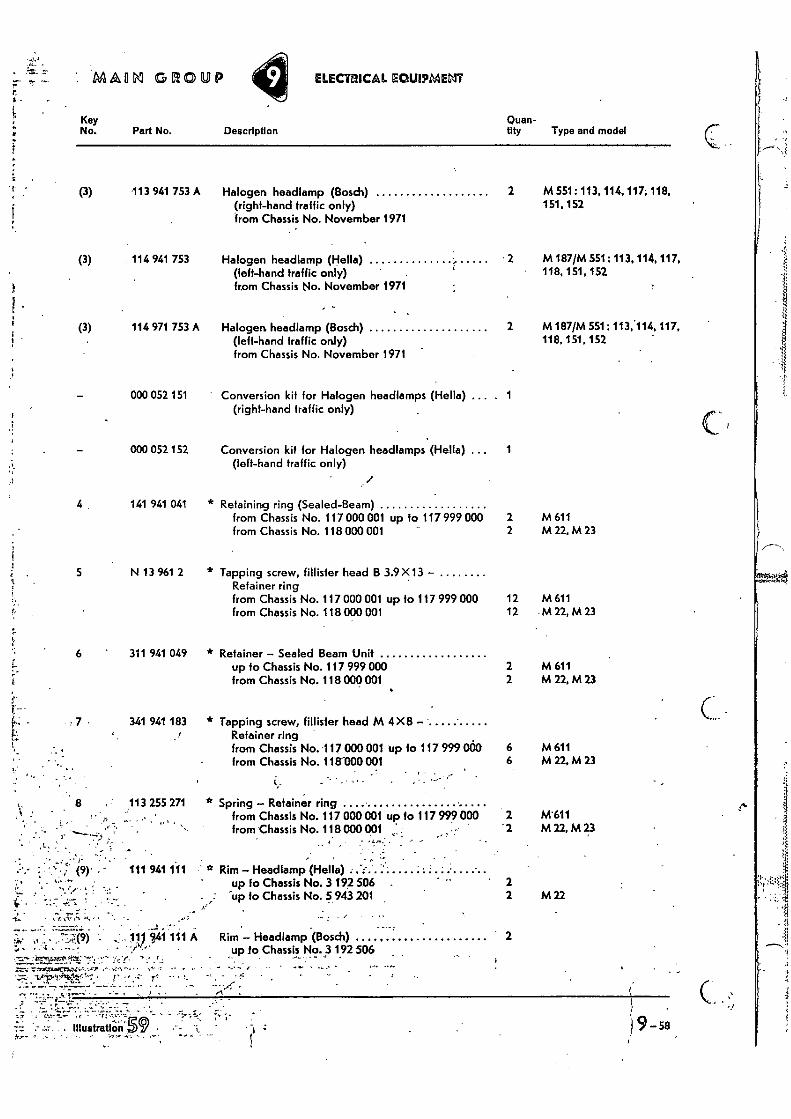
AAMM GROUP ELECTRICAL EOUIPMENT
• -I
; • )9—sa
- .
. Illustration
, .
Part No. Key No.
5 N 13 961 2
•
(3) 113 941 753 A
(3) 114 941 753
(3) 114 971 753 A
000 052 151
000 052 152
141 941 041
311 941 049
341 941 183 .1
.113 255 271 ..•
111 941 111
11 41 111 A •
• L
-••1t • • , • • ••
• • -•
7 •
„ • .77;zi(9)
1"r".:11:.,"• t̂ 1
6
Description Quan-tity Type and model
Halogen headlamp (Bosch) (right-hand traffic only) from Chassis No. November 1971
2 M 551: 113, 114, 117, 118, 151, 152
Halogen headlamp (Hells) (left-hand traffic only) from Chassis No. November 1971
2 M 187/M 551: 113, 114, 117, 118, 151, 152
Halogen headlamp (Bosch) (left-hand traffic only) from Chassis No. November 1971
2 M 187/M 551: 113,•114,117, 118, 151,152
Conversion kit for Halogen headlamps (Melia) (right-hand traffic only)
1
Conversion kit for Halogen headlamps (Hello) (left-hand traffic only)
1
* Retaining ring (Sealed-Beam) from Chassis No. 117 000 001 up to 117 999 000 2 M 611 from Chassis No. 118 GOO 001 2 M 22, M 23
* Tapping screw, fillisier head B 3.9 X13 — Refainer ring from Chassis No. 117 000 001 up lo 117 999 000 12 M 611 from Chassis No. 118 000 001 12 •M 22,M 23
* Retainer — Sealed Beam Unit up to Chassis No. 117 999 000 2 M 611 from Chassis No. 118 000 001 2 M 22, M 23
* Tapping screw, Hider head M 4X8 — Retainer ring from Chassis No. 117 000 001 up to 117 999 000 6 M 611 from Chassis No. 118-000 001 6 M 22, M 23
_ -. •
* Spring — Retainer ring from Chassis No. 117 000 001 up to 117 999 000 2 M'611 from Chassis No. 118 000 001 '2 M 22, M 23
. - . Rim — Headlamp (Hello)
up to Chassis No. 3 192 506 ' 2 -up fo Chassis No. 5 943 201 2 M 22
Rim — Headlamp (Bosch) up to Chassis No. 3 192 506 ,
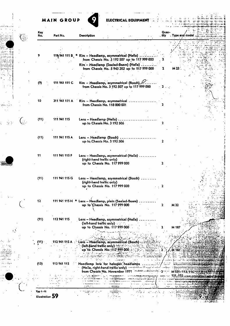
2 (11) 111 941 115 Lens Headlamp (Hells)
up to Chassis No. 3 192 506
2 (11) 111 941 115 A Lens -.Headlamp (Bosch)
up to Chassis No. 3 192 506
11 111 941 115 F Lens - Headlamp, asymmetrical (Hells) (right-hand traffic only) up to Chassis No. 117 999 000
9 1111941 111 B * Rim - Headlamp, asymmetrical (Haifa) from Chassis No. 3 192 507 up to 117. 999 000
Rim Headlamp (Sealed-Beam) (Helia) from Chassis No. 5 943 202 up to 117 999 000
(9) ' 111 941 111 C Rim - Headlamp, asymmetrical (Bosch)P from Chassis No. 3 192 507 up fp 1.17 999 000
10 311 941 111 A Rim - Headlamp, asymmetrical ......... from Chassis No. 118 000 001
(11) 111 941 115 G Lens - Headlamp, asymmetrical (Bosch) (right-hand traffic only) up to Chassis No. 117 999 000
(13) 113 941 115 Headlamp lerii 'for halogein7headlainPs .........
. 2 M 187
12 111 941 115 H * Lens -14eadlamp, plain (Sealed-Beam) up to 'chassis No. 117 999 000
(11) 112 941 115 Lens - Headlamp, asymmetrical (Hells) (left-hand traffic only) up to Chassis No. 117 999 000 • -
- • • t ' • - - •
(11) 112 941 115 A : Loris -Headlamp, ; 7 (left-(land traffic only) • - !A.% •
uplo ,Chassis 09 000 . •
.. e
••-• r.e.nsarla r . . . - (Hells, right-hand traffic:only)
.
from Chaisis No. November 1971 -2``°'•'Mt551:113;1147T118
1 • -
•
•
. — . . . - - • - • -- — — • ••••.. ••• .
• Typ 1-11
Illustration 59 --•-'-•3-•••;••
ELECTRICAL EQUIPMENT • • .. - N. • -__ • --
.• • .t A
• - • ""•“1
Quan-
tity Type and model
-L-.1 • t .
-•—• •
t • I
2
?:
2
2
Key No. Part No. Description
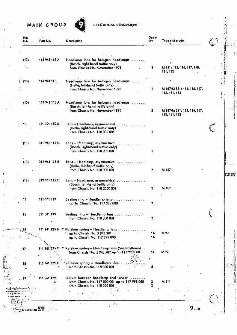
MAIM GROUP ELECTRICAL lEOUIPMEM
Key Quan- No. . Part No. Description tity Type and model
(13) 113 941 115 A Headlamp lens for halogen headlamps (Bosch, right-hand traffic only) from Chassis No. November 1971
(13) 114 941 115 Headlamp lens for halogen headlamps left-hand traffic only)
from Chassis No. November 1971
(13) 114 941 115 A Headlamp lens for halogen headlamps (Bosch, left-hand traffic only)
'from Chassis No. November 1971
13 311 941 115 B Lens — Headlamp, asymmetrical (Hella, right-hand traffic only) from Chassis No. 118 000 001
(13) 311 941 115 C Lens — Headlamp, asymmetrical (Bosch, right-hand traffic only) from Chassis No. 118 000001
(13) 312 941 115 B Lens — Headlamp, asymmetrical (Hella, left-hand traffic only) from Chassis No. 118 000 001
(13) 312 941 115 C Lens — Headlamp, asymmetrical (Bosch, left-hand traffic only) from Chassis No. 118 2000 001
14 111 941 119 Sealing ring — Headlamp lens up to Chassis No. 117 999 000
15 311 941 119 Sealing ring — Headlamp lens from Chassis No. 118 000 001
6 111 941 125 t3 * Retainer spring — Headlamp lens up to Chassis No. 5 943 201 up to Chassis No. 117 999 000
17 111 941 C * Retainer spring — Headlamp lens (Sealed-Beam) from Chassis No. 5 943 202 up fo 117 999 GOO .
r.yj
18 311 941 125 A 'Retainer spring — Headlamp !ins - from Chassis No. 118 000 001
.14 111 941 129 Gasket between headlamp and fender from Chassis No. 117 000 001 up to 117 999 000 from Chassis No. 118 000 001
2 M 551:: 113, 114, 117, 118, 151.152
2 M 187/M 551: 113, 114, 117, 118, 151, 152
2 M 187/M 551: 113, 114, 117, 118, 151, 152 •
2
2
2 M 187
2 M 187
2
2
14 M 22 14
14 M 22
8
2 M 611 2
7,14
illustration 9-60
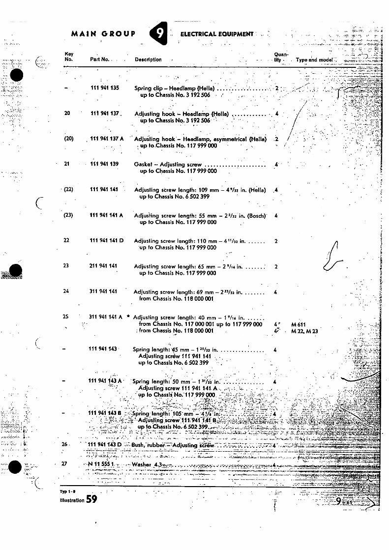
Description Quan- tity • Type and model
Spring clip - Headlamp (Helia) up to Chassis No. 3 192 506
Adjusting hook - HeadlaMp (Hello) up to Chassis No. 3 192 506 •
, - Adjuiting hook'- Headlamp, asyMmetrical (Hella)
up to.Chassis No. 117 999 000 - •
Gasket - Adjusting screw 4. up to Chassis No. 117 999 000
Adjusting screw length: 109 mm - 4 9/a2 in. (Hello) .4
up to Chassis No. 6 502 399
Adjusting screw length: 55 mm - 2 5/32 in. (Bosch) 4 up to Chassis No. 117 999 000
• y--61-----,
MAIN GROUP
Key No. Part No.. .
111 941 135
20 111 941 137
(20) , 111 941 137 A
.. ,
21 111 941 139
(22) 111 941 141
(23) 111 941 141 A
22 111 941 141 D
23 211 941 141
24 311 941 141
25 311 941 141 A
111 941 143
111 941 143 A •
ELECTRICAL. EQUIPMENT
•
•
s
Adjusting scrOw 111 941 141
up to Chassis No. 6 502 399
' up to Chassii No.-117 999 000
Adjusting screw length: 110 mm - 4 "/32 in. 2 up fo Chassis No. 117 999 000
Adjusting screw length: 65 mm - 2'116 in.. 2 up fo Chassis No. 117 999 000
Adjusting screw length: 69 mm 2 23/32 in, 4
from Chassis No. 118 000 001
* Adjusting screw length: 40 mm - 1 5/16 in.
from Chassis No. 117 000 001 up to 117 999 000 4 M 611 ; from Chassis No. 118 000 001 M 22. M 23
•s Spring length:15 mm 1 25/33 in. 4
Spring length: 50 mm 1 31/12 in: ... : .. ... . ... Adjusting screw 111 941 141. A ,..7 • .
- 27
•
•-• ri ,..,...1.• : +Ir.' '....t., tArop.i.r....c.V....:11, ....: • " . '.4" ."". • : .
r:..7-74'..-.....r..,,,,...A1 4-fv.4.1.7 -r..1!
...S .• i ...:oV-Ii .;:th,''....,.. L41' -'7,10"-: .,',247:P;:-.1.1FAr r11:0q. . 1--KIF L'.**7'1i-4 r-4.0Rit4;ikr* , '';- - • - :...AL,..":1, 7 .7.-.1...:..,''..1 -itT: :ft-
, -_. • 4 •,':"..i...- ' up to Chassis No. 6.502 399 ....-r-,-z--...---- -- , - - •-•-.........,.- .-,, .. - -- ., - „:..:. ..-- •-ev,..• . •
_ - ' ''. • .. -',-z•.'.•:.-.,..;,,- .;:' il :..' .....'_',.."-+..;-::" ..-_:':::._' . 7.-.7:...';;,..w.:-T.r.2,ize.-......j.G4-11...:.- .......:.tr-i ,...z.f.-::-..':,-.; ..'.'..fi ,.-..7i.t.z.,-,Y.VT,-:_v,1-`"t- T-z•-r&-.1..'"V• - . _-. . ..... , .._ . . . ,
. . .. . . _. • • . . _ . _. • ..
. . ...
26 . ' ' 111 941 143 D -,-,7•Bush,"i•ubbilir7Adjusting screw. ....,..,,•.--... :-,.....-:-.,--, -.,4 -...---r-6-:':.--.'..t4.--€40!.`44;f7;A4i5-- . ... -- , --_ -- - ___ .. --_
. I.... __
. — ._ _ . _ _
- . • 4,1 , c... , • •
•
111. 9.4 143 B;:t:;.Spring• length.: 105-, mm
r ̀Adjusting . scriwi .1 1 1;941:141.118:
• • N 11 555 1 - Washer 4.3vo- .. •
it,- • 1.. • ....I, • r•• ir-r*E-rr• • •••• rrprertr o.rur.r. • ,1...u_. — . r • „ . • • tki•
- •
. • •
Typ 1-9
Illustration 59
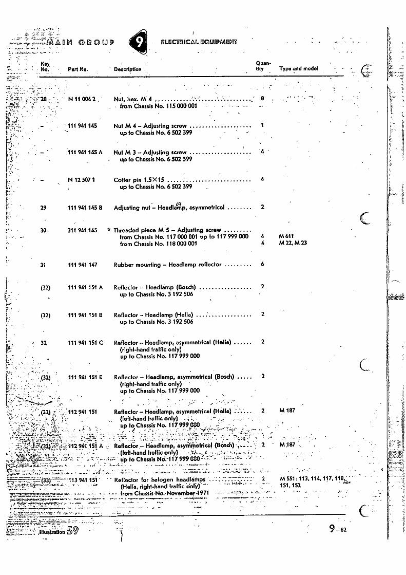
' DeocrIption
Reflector — Headlamp, asymmetrical (Hello) ' (left-hand traffic only) • ; ' . -- . up to,Chassis No. 117 999 000 • • •
. • _
Reflector — Headlamp, asyniritotricel (Bosch) • (left-hand traffic only) - • •-• - • - tip to Chassis No: 999 000'7- '
• - . —•••••
113 941 15:1 Reflector for halogen headlamps .. . . (Hella, right-hand traffic only)
-n7-2c.ertzt-x•tat•-•'0•> • •• -• • •'•.• • - •••• • from Chassis No.- November-4971
rtt2r: .}44Ztaets:--,,t.14.c--.: • .
Key, No.Part No. _ .
Quan- tity Type and model
ELECTIIICAL EQUIPMENT
• , •
N 11 0042 , Nut, hex. M 4 • from Chassis No. 115 000 001
. 941 145
Nut M 4 — Adjusting screw up to Chassis No. 6 502 399
I
111 941 145 A Nut M 3 — Adjusting screw • up to Chassis No. 6 502 399
N 12 507 1
29 111 941 145 B
30 311 941 145
31 111 941 147
(32) 111 941 151 A
(32) 111 941 151
32 111 941 151 C
111 941 151 E
.4.4
A32) 112 941151 A •
Coffer pin 1.5 X15 up to Chassis No. 6 502 399
Adjusting nut — Headlamp, asymmetrical
* Threaded piece M 5 — Adjusting screw from Chassis No. 117 000 001 up to 117 999 from Chassis No. 118 000 001
Rubber mounting — Headlamp reflector
Reflector — Headlamp (Bosch) up to Chassis No. 3 192 506
Reflector — Headlamp (Hella) up to Chassis No. 3 192 506
Reflector — Headlamp, asymmetrical (Hella) (right-hand traffic only) up to Chassis No. 117 999 000
Reflector — Headlamp, asymmetrical (Bosch) (right-hand traffic only) up to Chassis No. 117 999 000
•
4
000 4 M 611 4 M22,M23
6
2
2
2
2
2 M 187 , • .
,
•,,,... 2 M 187
- •
2 M 551: 113, 114,117, 118,e; 151.152 •
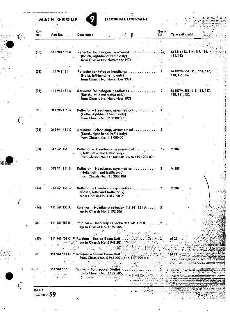
M 551: 113, 114, 117, 118, - 151,152
M 187/M 551: 113, 114, 117, 118, 151,152 ,
M 187/M 551: 113, 114, 117, 118, 151. 152
a
Typ 1-9
Illustration 59
MAIN GROUP ELECTRICAL EQUIPMENT
Key Q.uan- 'No. Part No. Description tity Type and model
• (33) 113 941 151 A Reflector for halogen headlamps
(Bosch, right-hand Traffic only) from Chassis No. November 1971
(33) 114 941 151 Reflector for halogen headlamps 2 (Hello, left-hand traffic only) from Chassis No. November 1971 •
(33) 114 941 151 A Reflector for halogen headlamps ,. 2 (Bosch, left-hand traffic only) from Chassis No. November 1971
33 311 941 151 B Reflector - Headlamp, asymmetrical
2 (Hella, right-hand traffic only) from Chassis No. 118 000 001
(33) 311 941 151 C Reflector - Headlamp, asymmetrical (Bosch, right-hand traffic only) from Chassis No. 118 000 001
(33) 312 941 151 Reflector - Headlamp, asymmetrical 2. M 187 (Hello, left-hand traffic only) from Chassis No. 118 000 001 up to 119 1200 000
2
(33) 312 941 151 B Reflector - Headlamp, asymmetrical 2 M 187 (Hella, left-hand traffic only) from Chassis No. 110 2000 001
(33) 312 941 151 C Reflector - Headlamp, asymmefrical 2 M 187 (Bosch, left-hand traffic only) from Chassis No. 118 2000 001
(34) 111 941 153 A Retainer - Headlamp reflector 111 941 151 A .... 2 up fo Chassis No. 3 192 506
, M 22 .
34 111 941.153 8 Retainer - Headlamp reflector 111 941 151 B up to Chassis No. 3 192 506
(35) 111 941 153 C * Retainer - Sealed Beam Unit .......... .. • . up to Chassis No. 5 943 201
35 111 941 153 D *. Retainer - Sealed Beam Unit : . . ... . : from Chassis No. 5 943 202 up to 117 . 999 000
••L, 36 111 941 157 Spring - Bulb socket (Hella). ..... . up to Chassis No. 3 192 506_ , . •.•
,---•-•-gms•-Au.o..14.,..-r1mAncciliti4igiobticithumt.hicPmze9
•—•••• • - '• •-'1,-..;0., • , ,=•:::•-•-••• -C.' ,•,"- •'',:•• ,•-•, ..0„,- C-.•,..2...4•7,-,.t.1,0,2&...'cilfr4t .., .,..,.....„,;• _- .,...„i,
_ . . . . _......... - - . - . .. ... . .. ,
- .
_ • • ..
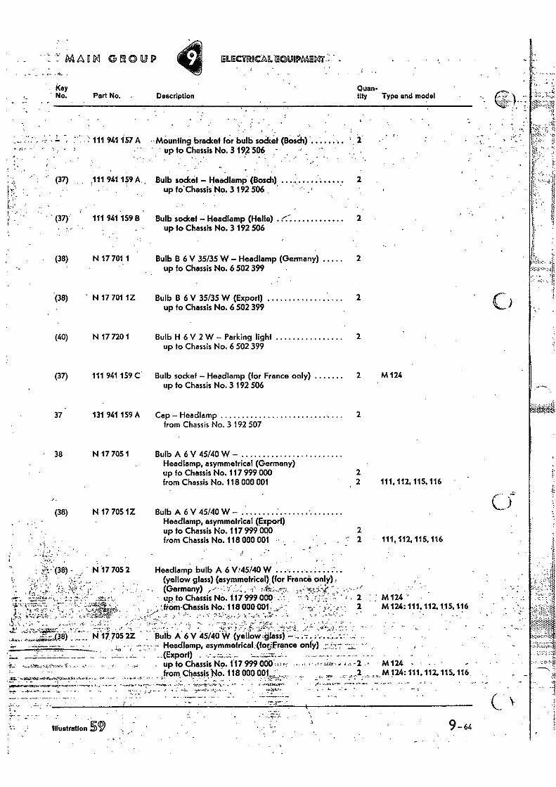
MAORI GROUP ELECTRICAL -20UIPMENT::—
Quan- tity Type and model
Key No. 'Part No. Description
, • .
(37) 111 941 159 A. , Bulb socket – Headlamp (Bosch) up to'Chassis No. 3 192 506
(37) 111 941 159 B Bulb socket – Headlamp (Hello) up to Chassis No. 3 192 506
- from Chassis .No. 118 000 001 . up to Chassis No.117 999 000 ,.: .• - M 124
2 M 124:111 , 112, 115, 116
9-64
. : .
Illustration 59
;• 111 941 157 A Mounting bracket for bulb socket {Bosch) up to Chassis No. 3 192 506 -
: • ,
(38) N 17 701 1
Bulb B 6 V 35135 W– Headlamp (Germany) up fo Chassis No. 6 502 399
(38) N 17 701 1Z Bulb B 6 V 35/35 W (Export) up fo Chassis No. 6 502 399
(40) N 17 720 1 Bulb H 6 V 2 W– Parking light up to Chassis No. 6 502 399
(37) 111 941 159 C Bulb sockef – Headlamp (for France only) up to Chassis No. 3 192 506
37 131 941 159 A Cap – Headlamp from Chassis No. 3 192 507
38 N 17 705 1 Bulb A 6 V 45/40 W – Headlamp, asymmetrical (Germany) up to Chassis No. 117 999 000 from Chassis No. 118 000 001
2
2
2
2
2 M 124
2
2 2 111. 112. 115, 116
(38) N 17 705 1Z Bulb A 6 V 45/40 W – Headlamp, asymmetrical (Export) up to Chassis No. 117 999 000 from Chassis No. 118 000 001 111,112,115,116
1%1'17 705 2 Headlamp bulb A 6 Vi45/40 W (yellow glass) (asymmetrical), (for France-) only) , (Germany) ,••• -. 'I .,.. i 4:-'...,, ,,-::ny.,,,..: ' , •
up fo Chassis No. 117 999 000 -. ' - : ' 2 ; : M 124 ' frOm-Chassis No. 118 000001: 2 M 124: 111. 112, 115, 116 . -
• ,
rg;:tr. ., • .
- • '
Bulb A 6 V 45/40 W (yellow::dIass) – - Headlamp, asymmetrical,(for„france only)
(Export)
,-!.; • (36) N 17,705 2Z
y • • .
• • . . •
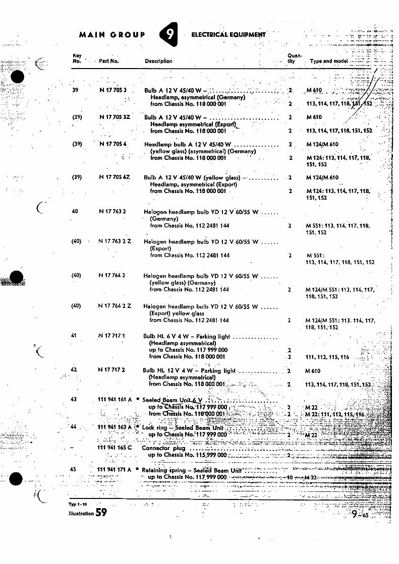
Typ 1-1D -
illustration 59
4
MAIN GROUP • ELECTRICAL EQUIPMENT
Quan-tity Deacilption • Type and model
Kay No. ' - Part No.
• 39 N 17 705 3 •
(39) N 17 705 3Z
• • ,
Bulb A 12 V 45/40 W - Headlamp asymmetrical (Export) from Chassis No. 118 000 001
(39) N 17 705 4. Headlamp bulb A 12 V 45/40 W . (yellow glass) (asymmetrical) (Germany)
• from Chassis No. 118000001 •
(39) N 17 705 4Z Bulb A 12 V 45/40 W (yellow glass) -• Headlamp, asymmetrical (Export) from Chassis No. 118000 001
40 N 17 763 2 Halogen, headlamp bulb YD 12 V 60/55 W ' (Germany)
from Chassis No. 112 2481 144
(40) N 17 763 2 Z Halogen headlamp bulb YD 12 V 60/55 W (Export) from Chassis No. 112 2481 144
(40) N 17 764 2 Halogen headlamp bulb YD 12 V 60/55 W (yellow glass) (Germany) from Chassis No. 112 2481 144
•
(40) N 17 764 2 Z Halogen headlamp bulb YD 12 V 60/55 W (Export) yellow glass from Chassis No. 112 2481 144
2 M 610
2 113,114.117,118.151.152
2. M 124/M 610
2 M124: 113,114.117.118; 151.152
- 2 M 124/M 610
2 M124: 113, 114,117, 118,- 151, 152
2 M 551: 113, 114, 117. 118, 151,152
2 M 551: 113, 114, 117, 118, 151, 152
2 M 124/M 551:113, 114, 117, 118, 151, 152
2 M 124/M 551: 113. 114, 117, 118,151,•152
41 N 17 717 1 Bulb HL 6 V 4 W — Parking light (Headlamp asymmetrical) up to Chassis No. 117 999 000 .2 from Chassis No. 118000 001
42 N 17 717 2 Bulb HL 12 V 4 W — Parking light (Headlamp asymmetrical) , from Chassis No. 118 000 001, ,.
Sealed Beam ynit.ky .1: ..''.... :1. '.-...'..• . . .... '.- . .. up to.thiliis No.-11.7 999 000 E. %:.7-4-----,.. -, .2,-; • r • - . 2
• from Ch-asis No..1t8000961:44:='...;f•. ,:: .:::: ti:;;. ' 1-' :,- 2
- -.••••!.. .:"•• • • ...-.; ..._: ••••••••••?!.-”itaiti:_4,̀.' ='''.'7 : '. 7 . f.."Li!..i:L' -.' 7.- ,.: .: ' 111 941 163 A %'..*. Lodc ring:• Sealed ealed feai:LriC
up to.Chaisis No.'117 999 003..7T "‘
.7'' '
:-::. ' ;i .:• '''- ''- .*: .'''* '-:''"2
.. '1' - ,---?..!_'1.: ''-'' • -3.;;..7 -.i..4-''''':"-:t.,:' -4_,:rii:c.-, -,..--‘----:' - :-..-7:--'-,:-• .-; • ; Connector plug . •• . , --,
up to Chassis No.-115;999000 -,•.-..,,„:- •-•• - 2
- • • 45 , 111'941.171 A * Retaining ipring — Seifi'd Beam "
- up to Chassis No. 417.999 000 . . _
43 111 941 161 A *
• .
% • • ••
111 941 165 C
Bulb A 12 V 45/40.W Headlamp, asymmetrical (Germany)
from Chassis No. 118 000 001 •
M 610
113,114,117.118; 52
. .
113, 114,117,118, 151,152,-:' •
• M22 : M22 111;.112. 11 .5;116
111.112, 115, 116
M 610
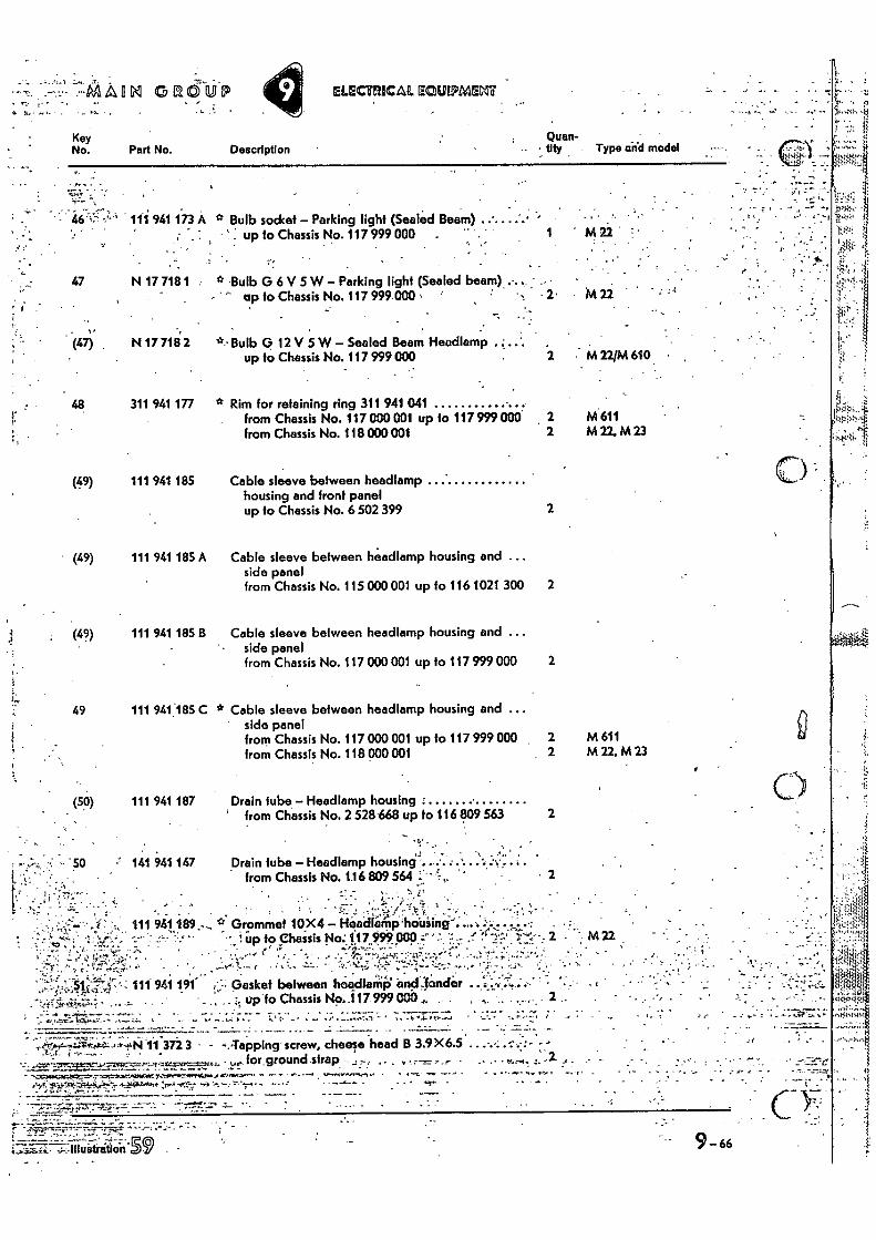
(47) . Bulb G 12 V 5 W — Sealed Beam Headlamp , up to Chassis No. 117 999 000
N 17 718. 2 M 22/M 610. •
2
(49) 111 941 185 Cable sleeve between headlamp housing and front panel up to Chassis No. 6 502 399
- •
4:451•••• •
Key No. Part No. Description
tiQtyuan- Type and model
461:- 111 941 173 A * Bulb socket — Parking light (Sealed Beam) ' . up to Chassis No. 117 999 000 . • •
47 N 17 718 1 * Bulb G 6 V 5 W — Parking light (Sealed beam) . up fo Chassis No. 117 999.000 2 M 22
48 311 941 177 * Rim for retaining ring 311 941 041 from Chassis No. 117 000 001 up to 117 999 000 2 M 611 from Chassis No. 118 000001 2 M22,A423
(49) 111 941 185 A Cable sleeve between headlamp housing and ... side panel
from Chassis No. 115 000 001 up to 116 1021 300 2
(49) 111 941 185 B Cable sleeve between headlamp housing and ... side panel from Chassis No. 117 000 001 up to 117 999 000 2
04.
--2 , MAIIIM GROUP IELECTRICAP., ECUIPMEM
49 111 941,185 C * Cable sleeve between headlamp housing and ... • side panel
from Chassis No. 117 000 001 up to 117 999 000 2 M 611 from Chassis No. 118 000 001 2 M 22, M 23
(50) 111 941 187 Drain tube — Headlamp housing - ' from Chassis No. 2 528'668 up to 116 809 563 2
141 941 147 Drain tube — Headlamp housings from Chassis No. 1.16 809 564
:••
2 1•
.... , •. . . . . ,, , ' ' :' . ..::-:•.! Headlamp
•:`.,'_ . ---;''', ,.. ' • 111 941 189 -, 17 Grommet 10 X4 — •hobiing-: .,.,..'-. ... . . .: _ ,.. . . „
• 1 up to Chassis No: 117.999. peck c .:_ .1... ,t.. :..-,..-,!,. -.:----r.z., 2 — - --• -- ' • ....• .; .
:.• •:-. ...• ...- S . ,' '.. '''• " . ,,,.• 1. . ' ... . .• • ,::, ..-. :', ,.. :..a.,. 4 ..- ...!'.: , ......• . t. .•'' ••
, . ,. . . • • ' • - • ..,...,- , '1.14•....', ., . Si • - ) - . 111 941 191 i''.., Gasket between headlamp' and fonder ....., .,.. ..•-•....;:.:-.....4....,- • -
ff., ."M'ss.'• ' • • . •s' ' ' ' • . % uplo Chassis No..117 999 000—' • • •
11 372 3 - 4.,Tapping screw, cheese head B 3.9X6.5 for ground strap • . V •••-•••• , ..•• •
• • -
•
- • '
_2
lustration
9-66 - •
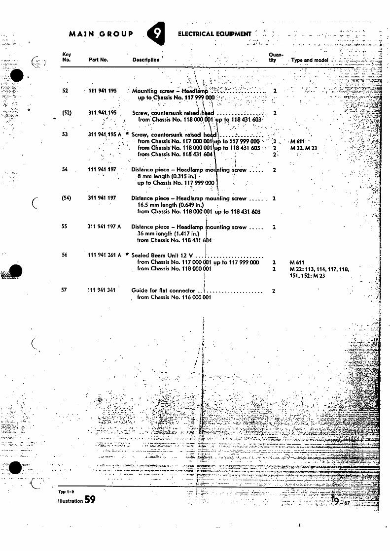
. • •
MAIN GROUP ELECTRICAL EQUIPMENT .
Key No. Part No. Description
. . Quan- tity Type and model
• - • -•'"z• 52 • 111 941 195 .'• Mounting screw — •Headlamp ... . .... 2
up to Chassis No.117 - • :
(52) 311.941195 . Screw, countersunk raiseu- .1 .• from Chassis No. 118 000 t up to 118 431.603'
•
53 311 941,195 A Screw, countersunk raised h _ . from Chassii No. 117 000 001 up to 117 999 000 ' 2 , • M 611
• • , from Chasiis"No. 118 000 001 up to 118 431 603 2 M 22, M 23 from Chassis No. 118 431 604
111 941 197 - Distance piece — Headlamp-moi sting screw 2 8 mm length (0.315 in.) up to Chassis No. 117 999 000
. t • •
(54) 311 941 197 Distance piece — Headlamp mounting screw 2 16.5 mm length (0.649 in.) • from Chassis No. 118 000 001 up to 118 431 603
55 311 941 197 A Distance piece — Headlamp mounting screw 2 36 mm length (1.417 in.) from Chassis No. 118 431 604
56 111 941 261 A * Sealed Beam Unit 12 V from Chassis No. 117 000 001 up to 117 999 000 2 M 611 from Chassis No. 118 000 001 2 M 22; 113, 114,117, 118,
151, 152; M 23 •
57 111 941 341 Guide for flat connector
It• •
2 from Chassis No. 116 ODD 001 •
4
ik -
I
. .,•V17.. 1:.f.,... • J:ii...,*----V4-,
, ._:- .. • ye, ; • --.
• .k '..n.-.;-•:
T : '1 -'1.
.I.̀: -. . ;Y. ... 1•71..?
''. ''...."..1 :.... . . - - ., .....'.'-'7,•:::.7.•..-:3742'
-..,4..,--...07..-... . A-: ie'L.e.:7:'2,1It...-..,-...%•-• !..‘-',..7,4.1.•: ,... ..... 1., • -'..!"‘... r._
• ; - 0-7-.---..-'••• -̀• - -----Wr• •••••,/,7",•:',11,,,,..ret...r.., •••••::•:•'''' ' ..V t 4'.;'' ...... .r.: .' tl ...;.)..p),,,, 0 ; ' • - -1. r•I I . - ,
;.' ..1' ,,.,::1..''.."-c:::. n - 7 ..4'/.11-1.,,••,:e1.5ttii.V.± 4 ,-,4r..n. • --...,..i,..2. ., . . -.;... •itft...d.,.0.—' .• --..4
. ...,:c -'4'.5.T."4::s7.-;.•;•-k• ,:r.,:?.•'.-",....,..0,-..-z:::,. ?,:.•:.":4.tw."f--.. 2•4,7;:30,W,....:...:...1:::4173, :, ..;-, .! :. ,,••.' . 0. _. • .., • ,_ • -: • , f..,,tzp....F,--i..•ri..,-...-...-...i .:::.' If...Z.- .. ' , .'::'-,._ :: : .4.'5..4.: ...'47,.:7—r'.....r..7:7-",...1.1.:....-‘.:',P 1 -.:.:NZI:.'411::;.:-". _ P.' . ,•4i." - '- 'tz.-47'7, ;:-r-:-
-....... ...... •-'. , - .. ...1,1....., , f....::::.....:- ..-,_,.....,,..4-,-;.:,4-0:-:;31,--e•.•#p+... '
•
, - • . • 7. t", • •
• A ..:•••
•
. • .
(
- . .
Typ 1 -9
Illustration 59
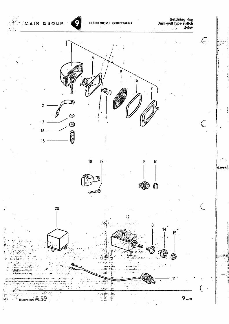
Regaining ring Push-pull type switch
Relay ELECTRICAL EQUIPMELIT s... : MAUI GROUP
•
18 19 - 9 10
• Illustration p9
12
8 14
15
• '"
. ... • . 7..0 • •
- • -•• :A,
20
9 - 68
2
17
16
13
C
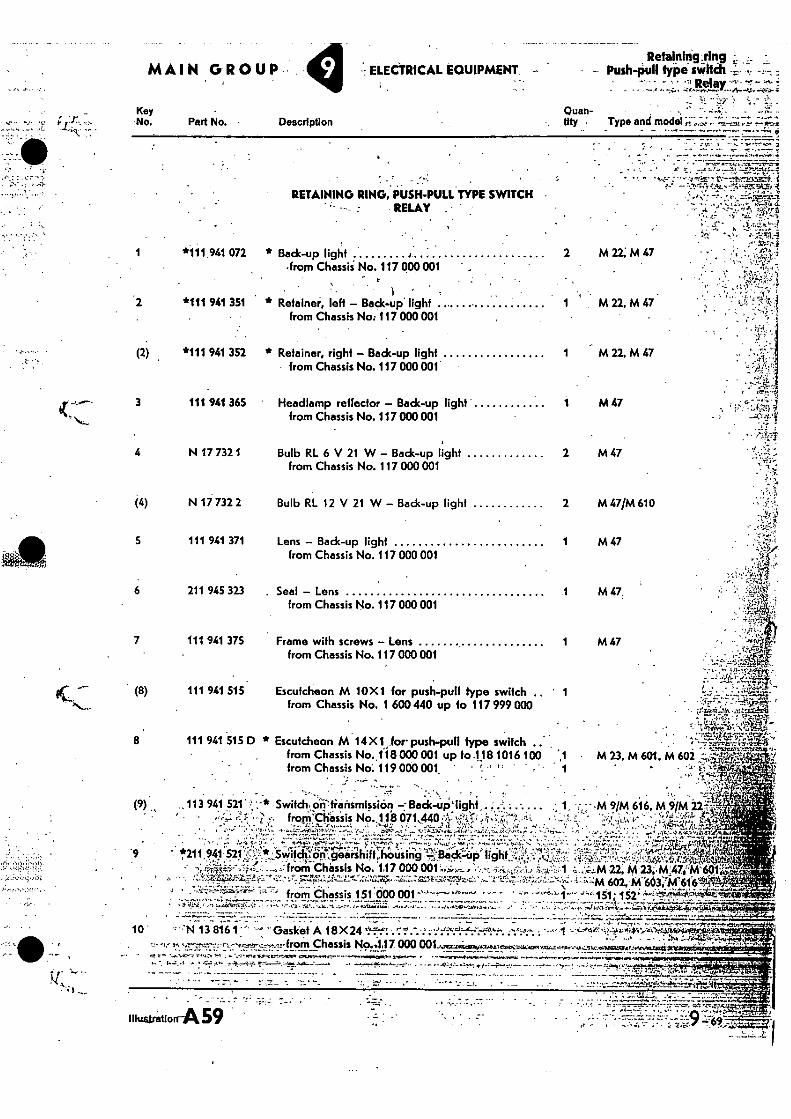
Quan- lily • Type and model
Retaining ring Push-pull type switch
' - • -•-•
ELECTRICAL EQUIPMENT.
Key No. Part No. Description
••• • • - • +4.1,-
RETAINING RING, PUSH-PULL TYPE SWITCH 1;*
RELAY
1 *111 941 072 * Back-up light J. 2
M 22; M47
-from Chassii No. 117 000 001 .
• I ̀ : 2 *111 941 351 * Retainer, left - Back-up light
1 M 22, M 47
from Chassis No: 117 000 001
*111 941 352 * Retainer, right - Back-up light from Chassis No. 117 000 001
M 22, M 47
M 47
2 M 47
2 M 47/M 610
1 M 47
1 M47,
1 M 47
3
111 941 365 • Headlamp reflector - Back-up light' from Chassis No. 117 000 001
4 N 17 732 1
Bulb RL 6 V 21 W - Back-up light from Chassis No. 117 000 001
(4) N 17 732 2 Bulb RL 12 V 21 W - Back-up light
5 111 941 371 Lens - Back-up light from Chassis No. i 17 000 001
6 211 945 323 . Seal - Lens from Chassis No. 117 000 001
7 111 941 375 Frame with screws - Lens from Chassis No. 117 000 001
(8)
111 941 515 Escutcheon M 10X1 for push-pull type switch ' 1 from Chassis No. 1 600 440 up to 117 999 000
8 111 941 515 0 * Escutcheon M 14 X 1 .for push-pull type switch from Chassis No. 118 000 001 up fo .1113 1016 100 from Chassis No: 119 000 001. • -` " 1
. . . • 113 941 521' Switcb.or):tiaiismission Back-uplight,. (9) • • • fropj'Cliassis No..118 671,440 .•A• %'V•i5 • • %v....?
- ' . ., - . ••••• ,••••---•;;Irs''' 7 ..:4 : ';"i,',....."4:;:; , ••••"••4•••:;:•-: •::'",74.!-:W";•"' ., ., . .. • • , . , r ...
,„.. che".-cingearsh1A:66sing'.-r:t3adc.... li9ht: 9 • *211 941.521 • ,., •Swit . .. , flii from Chassis No. 117 000 001 g.-s--..'i.t...„....... .-..,...-- ,.., ,-...-i.......4, ,t ,;,,,,,..- ,..:, .., 7,.
.-• • .- :•:';''yq4.g'4..54-,1", -;!..z.,-..74..r.11Z2::::_-.4,,r,::zzq,.. :7,z;:.....4...-*;;:„,#4,7iz,i4.: .„, -..r,..-:;',:;7 7;7,,::;!,::•4„;-;,,' -r
• ---"- "- . from Chassis 151'000 001 '''''''"t--- `''' ' •;'-'1-"'. • . - ...:__,..._. . . _ ,
...... A.-. • .-.. , . .— 10 . ''''N 13 816 1 ''' "--- "Gasket A 18 X 24 ''..""-':•:'''.-..-.'? . -.'::-."%i=r'''.6'n '."--'5..: :7 .''':-- I .-1 --4-' 4'-4?-41."'.ii--v•o-ez-iniougraio.'4%
..-•....- ,-..,------•.,---.....,,,---..-from Chassis No...117 000 00114,1=INPLIZOW.U.Vararc...i.,:.ti+,,W.L.,4".,-'4,."11x.e.50193.0.1"V-...11,AFIIIi " .
. • --- -...._ _ ... ...- 1-- •,.......1, .1 ,..17• ., . 07,5.... c.r.n.•,.....Fr,---••-........row.4•6..."... . ......,,,,........,...,,,,,,,,,,,.....,,,...-....,,......,,,,,....,..,.*.i........
•••••• ,""•••' ' ..7."-.....• --'4---i‘.. T.'"-•-=. --'•••-..--"•—• - .••••-•-fr..—•:-.-.--P- • - --••••÷%,.,-.•,:••-: .....,-i.••-•:•::-- - • --4 -•'•,- i --":•••- s2•Tmit'l•PIE:14..7...•;,.* . •
-.. _ ::::'.1.-- ,--,:rrt.'"4:Ii-litt---r!i«::•--- 'il.:.; CI
iliwaratiorrA59
-,M . 9/M 616, M 9/M 2.2:;•'7-
'2" 151; 152'
tiF6F --77Zerref.,1". • M 23, M 601, M 602 ••••̀ `.2.."'s
• P'
)4(
M 22, M 23,M4764k601;`,44j7:'-fl' 602, M
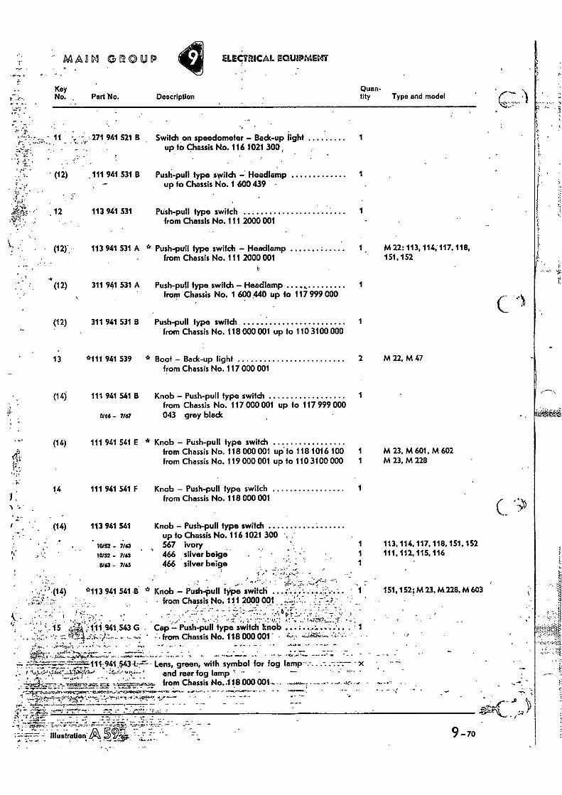
•
••••,•^.
MAUI GROUP IEGUIPMEIAT
Key Quan- No. Part No. Description tity Type and model
. • 11 : 271 941 521 B Switch on speedometer — Back-up light 1 up to Chassis No. 116 1021 300
• (12) , 111 941 531 B Push-pull type switch — Headlamp 1 up to Chassis No. 1 600 439 •
113 941 531 Push-pull type switch 1 from Chassis No. 111 2000 001
(12)- 113 941 531 A * Push-pull type switch — Headlamp 1 M 22: 113,114, 117, 118, from Chassis No. 111 2000 001 151,152
(12) 311 941 531 A Push-pull type switch — Headlamp 1 from Chassis No, 1 600440 up to 117 999 000
(12) 311 941 531 13 Push-pull type switch 1 from Chassis No. 118 000 001 up to 110 3100 000
13 *111 941 539 * Boot — Back-up light 2 M 22, M 47 from Chassis No. 117 MO 001
(14) 111 941 541 B Knob — Push-pull type switch from Chassis No. 117 000 001 up to 117 999 000
wee - 7167 043 grey black
(14) 111 941 541 E * Knob — Push-pull type switch
from Chassis No. 118 000 001 up' lo 118 1016 100 1
from Chassis No. 119 000 001 up fo 110 3100 000 1
14 111 941 541 F Knob — Push-pull type switch 1 from Chassis No. 118 000 001
M 23, M 601, M 602 M 23, M 228
(14) 113 941 541
Knob — Push-pull type switch up to Chassis No. 116 1021 300
10152 - 7/63 567 ivory 1 113, 114, 117, 118, 151, 152
10152 - 7/63 466 silver beige 1 111, 112, 115, 116
3/63 - 7/43 466 silver beige 1
. • *113 941 541 B * Knob — Push-pull type switch
• from Chassis No. 111 2000 octi 151, 152; M 23, M 228, M 603
,--. - . - , ---' ," • ' " ' ' • , VI: 1-- • , 7 .. . - ..., ".• ' ' ...., . • ; ,-,..' .-• " :-:._ , 1' 7- ".- 4.1." 4 , ..' ‘.:-.0.;37-. L:„,,,,
i' .i5 i
9M - ...ill 543 G . Cap -, Push-pull type switch knob ... . ; . .....;...'..'.. 1 . - --"..`-%":‘ `'.' :-- .7, •,' .5-1-•:"1:-;-- . - ,•-: ' :- from Chassis No. 118 000 001 ' • T-..,, ---',,k;:4;..-- -:',;•'--.- •
..; . . • - • -
4`;;T:-F,..1„.0 • Lens, green, with symbol for fog lamp- - - --- • x
and rear fog lamp from Chassis No..118000 001•- -4,
fit° -- •
^ •••, "
• " .
9-70 litustratIod •••••
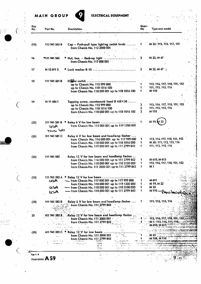
SSA
•
MAIN GROUP ELECTRICAL EQUIPMENT
Key No. Part No. Description
Quan- tity Type and model
(15) 113 941 543 B Cap - Push-pull type lighting switch knob from Chassis No. 112 2000 001
•
16 *111 941 545 * Nut, hex. - Back-up light from Chassis No. 117 000 001
17 N 12 011 2 . * Lock washer B 10
1 M 23: 113, 115, 117, 151
2 M 22, M 47
2 M22,M47
18 111 941 561 8 DiriPer switch up to Chassis No. 115 999 000 1 up to Chassis No. 118 1016 100 1 from Chassis No. 118 000 001 up to 118 1016 100 1
113, 114, 117, 118, 151, 152 111, 112, 115, 116 M 110
19 N 11 484 1 Tapping screw, countersunk head B 4.8 X 38 up to Chassis No. 115 999 000
2 113, 114, 117, 118, 151, 152
up to Chassis No. 118 1016 100
2 111, 112, 115, 116 from Chassis No. 118000 001 up to 118 1016 100
2 M110
(20) 311 941 581 B *
krk)
Relay 6 V for low beam from Chassis No. 115 000 001. up to 119 1200 000
M 19,
(20) 111 941 583
Relay 6 V for low beam and headlamp flasher ... from Chassis No, 116 000 001 up to 117 999 000 from Chassis No. 118 000 001 up to 118 1016 000 from Chassis No. 119 000 001 up to 111 2799 842
Relay 12 V for low beam and headlamp flasher .. from Chassis No. 116 000 001 up to 111 2799 842 1 from Chassis No. 118 000 001 up to 110 3100 000 1
' from Chassis-No. 111 2000 001 up to 111 2799 842 1
(20)
311 941 581 C 113, 114, 117, 118, 151, 152 M 30: 111,112, 115, 116 111, 112, 115, 116
M 610, M 613 113, 114. 117, 118, 151, 152 M1
(20) 111 941 583 A * Relay 12 V for low beam USN -. from Chassis No. 117 WO 001 Up to 117 999 000
from Chassis No. 118 000 001 up to 119 1200 000 from Chassis No. 118 000 001 up to 110 3100 000
- from Chassis No. 118 000 001 up to 111 2799 842 1
(20) 111 941 583 B Relay 6 V for low beam and headlamp .flasher from Chaisis No. 1112799 843
, . •
20 411 941 583 a ' .Relay 12 V for low beam and headlamp flasher from Chassis No. 111 2000 001 from Chassis No. 111 2799 843
. . (20) 411 941 583 C * Relay 12 y for low beam
from Chassis No. 111 2000 001 from Chassis No.111 2799 843
- .
USA
1 M 611 • 1 M 19,M 22- 1 M 23
M 110 --.eickioNikodi
111, 112, 115, 116
• • -1 -; 113,11k 117;11051; .45f,F42
113,. 114, 117;118;„" M 610,''M 613 • •„ . , , _
1 ••••••=F-P1.:.s., 1 •Ni 108, M110 s
„ I
Typ 1-9
illustration A 59 •
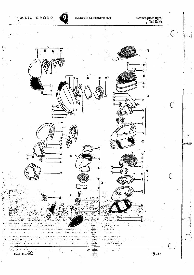
MAOM GROUP ELECTRICAL EQUIPMENT Licence plaice Ilehls
•
- I tfustration 60
9 72
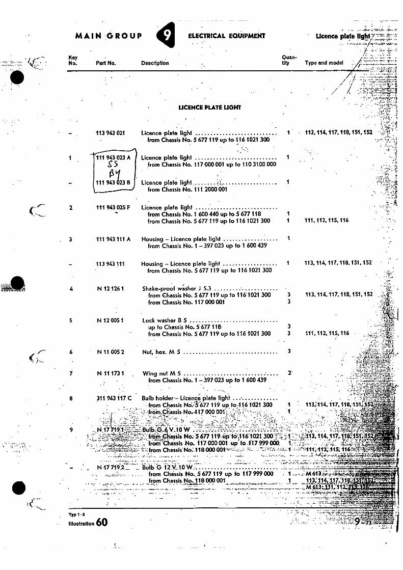
licence plate light MAIN :GROUP ELECTRICAL EQUIPMENT
Key No. Part No. Description
Quan- tity Type and model
111, 112, 115,116 •
113,114, 117,118.151, 152
113, 114, 117, 118, 151, 152
•!!"
1
—
2
3
—
4
5
6
7
8
9
.•
113 943 021
LICENCE PLATE LIGHT
Licence plate light from Chassis No. 5 677 119 up 10 116 1021 300
Licence, plate light from Chassis No. 117 000 001 up to 110 3100 000
Licence plate light .. from Chassis No. 111 2000 001
Licence plate light from Chassis No. 1 600 440 up to 5 677 118 from Chassis No. 5 677 119 up fo 116 1021 300
Housing — Licence plate light
from Chassis No. 1 397 023 up to 1 600 439
Housing — Licence plate light from Chassis No. 5 677 119 up to 116 1021 300
Shake-proof washer I 5.3 from Chassis No. 5 677 119 up to 116 1021 300 from Chassis No. 117 000 001
Lock washer B 5 up to Chassis No. 5 677118- from Chassis No. 5 677 119 up to 116 1021 300
Nut, hex. M 5
Wing nut M 5
from Chassis No. 1 397 023 up to 1 600 439
Bulb holder— Licence plate from Chassis NO.T677 119 up. to 416 1021 300
,- •,trOM.chassis No...117 0000011. = ° 1̀`,
-!. • d
v!!f. •;!-'.•^-•• • ' ; • Bulb, p...4 v. to w . .... - • - No. 5 677 119. up- to:.11•51021' 300
frOM'diassis No. 1.0 000 001 up ' to .1i 7 999 000 ;: from Chassis
. No: -118 000 001•ce- • -"--;
_. Bulb b 12 M.10 W • •
111 943
111 943123
111 943
111 943
.113 943
N 121261
N 12
N 11
N 11
311 943
17
N47
g 5 023 A
B
025 F
111 A
111
005 1
005 2
173 1
117 C
191
719.2_ : •,. -_,..7.•-,- . — . from Chassis No..5 677 119 up to 117 999 000 , 1... ,, .,:' M 613,,-*4..iiafrd.4
from Chassis No. 118 000 001 1 113:114,117,ais- -‘,....-...6-. „:4-t-.4.6- -,...t T.- -...,••7 - • .. •• ,-,.. ,--, ...r3 - °•-...,
. • '. • ' - . • "' "1 ,.rte-5''. '7 i4'P
' - -,,k,--,...,'- -.--. "-
Typ 1- 5
• Illustration 60
A
-
•
.• c".7 •••zry—.1,4o*Alr.g. • •1,— ' ••;
• 113, 114, 117, 118, 151, 152
1
1
111, 112, 115, 116
3 3
3 3
3
2'
113:114, 117, 118,451;45 =
: , . • ,.:,tIrgrw,4!:
•?. • 114. 117; 1.11 ,151:4 •,;. • • • • •
"III ;414 115, • !--
1.
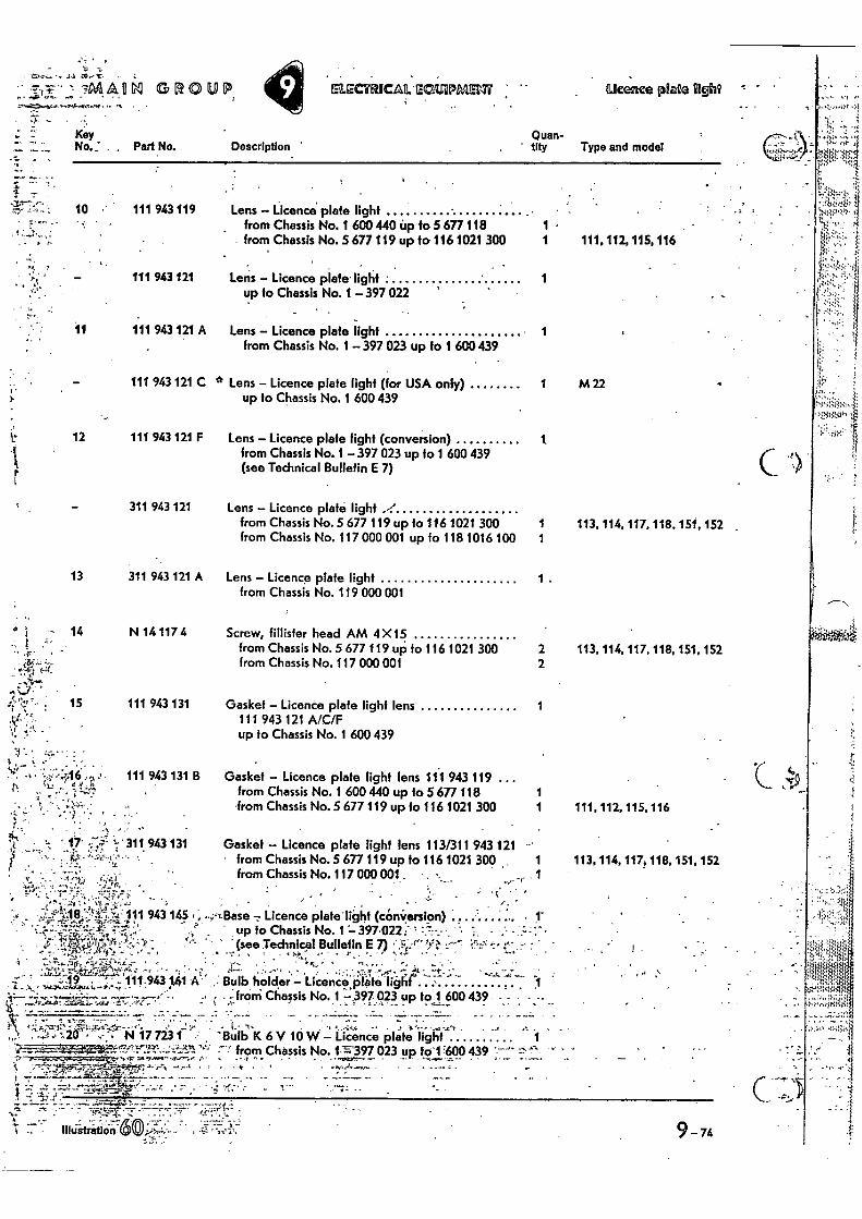
111 943 121
11 111 943 121 A
111 943 121 C
St' 15 111 943 131
•
-:-;0,6. 11 .., 111 943 131 B fit 1'
•
' • 311 943 131
• •
- 1--1,-.--- -7MAON GROUP •
ELI CTRICAMICHMMEM " Ilteence plate iigh2
10 111 943 119
Description ' Quan-
' tIty Type and model
Lens — Licence plate light from Chassis No. 1 600 440 Up fo 5 677 118 1 • from Chassis No. 5 677 119 up to 1161021 300 1 111, 112, 115, 116
Lens — Licence plate. light up fo Chassis No. 1— 397 022
1
Lens — Licence plate light from Chassis No. 1 397 023 up to 1 600 439
1
11' Lens — Licence plate light (for USA only) 1 M 22
-Key
, Part No.
up to Chassis No. 1 600 439
12 111 943 121 F Lens — Licence plate fight (conversion) from Chassis No. 1 — 397 023 up fo 1 600 439 (see Tedmical Bulletin E 7)
1
Gasket --Licence plate light lens 113/311 943 121 - • from Chassis No. 5 677 119 up to 116 1021 300 1
from Chassis No. 117 000 001. . • -
1 113, 114, 117, 118, 151, 152
1 .
2 113, 114. 117. 118, 151, 152 2
1
1 1 111, 112, 115. 116
113, 114, 117, 118, 151, 152
311 943 121 Lens — Licence plate light from Chassis No. 5 677 119 up to 116 1021 300 from Chassis No. 117 000 001 up to 118 1016 100
13 311 943 121 A Lens — Licence plate light from Chassis No. 119 000 001
14 N 14 117 4 Screw, fiilisfer head AM 4 X15 from Chassis No. 5 677 119 up. to 116 1021 300 from Chassis No. 117 000 001
Gasket — Licence plate light lens 111 943 121 A/C/F up to Chassis No. 1 600 439
Gasket — Licence plate light lens 111 943 119 ... from Chassis No. 1 600 440 up to 5 677 118 from Chassis No. 5 677 119 up to 116 1021 300
k 11 943 145 •
-;f'
0"." • •• • 111.9431,4119 "1 .. A • 3--
. .....:, 11ase - Licence plateli6ht (cOnVersion) • 1-
up to Chassis No. 1 397.0221- - (see Tedinicp1Bullefin E 7) t • 7
• . e • • ""-ecr` Bulb hOlcler' Licence:jilate noir 1. -from Chassis No. 1 —.397 023 up to 1 600439. •
.. • .' • -; • 1- q07 , N 17 723 1 -; 'Bulb K 6 V 10 W— 1:icence plate light 1
•-"7' from Chassis No. 1-=;397 023 u t '1400439 -7";.'1,Mkr..-77*"..ttft • • • - * • '
•
.rc
9-74
I
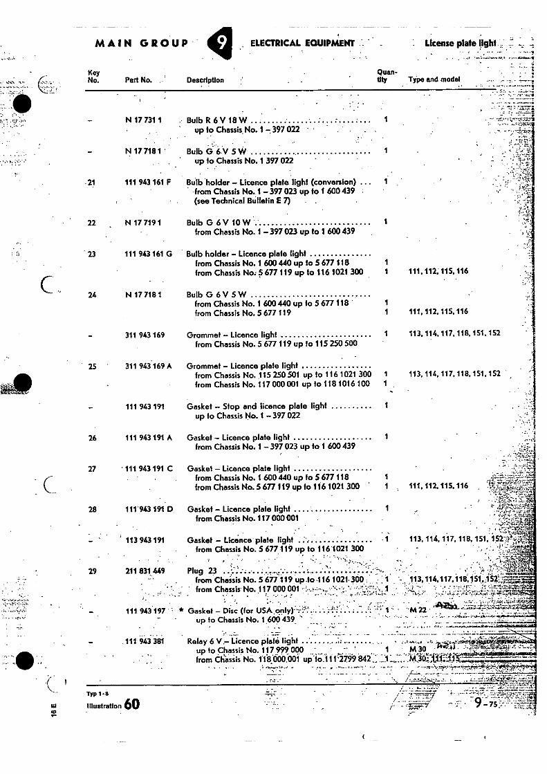
License plate tight.; MAIN GROUP ELECTRICAL EGUIPAAENT
Key No.
Quan- tity Type and model Part No. Description
•
- .7 w
co
Typ 1-8
Illustration 60
---"777.1
N 17 731 1 Bulb R 6 V 18 W 1 up to Chassis No. 1 —.397 022
• N 17 718 1 ' BulbG6V5W 1
up fo Chassis No. 1 397 022
- 21 111 943 161 F Bulb holder — Licence plate light (conversion) ... 1 -from Chassis No. 1-397023 up to 1 600 439 (see Technical Bulletin E 7) .
22 N 17 719 1 Bulb G 6 V 10 W 1 from Chassis No. 1 — 397 023 up to 1 600 439
23 111 943 161 G Bulb holder — Licence plate light from Chassis No. 1 600 440 up to 5 677 118 1 from Chassis No: 5 677 119 up to 116 1021 300 1
24 N 17 718 1 Bulb 0 6 V 5 W from Chassis No. 1 600 440 up to 5 677 118 1 from Chassis No. 5 677 119 1
311 943 169 Grommet — Licence light from Chassis No. 5 677 119 up to 115 250 500
25 ' 311 943169 A Grommet — Licence plate light from Chassis No. 115 250 501 up to 116 1021 300 1 from Chassis No. 117 000 001 up to 118 1016 100
111 943 191 Gasket — Stop and licence plate light 1 up to Chassis No. 1 — 397 022
26 111 943 191 A Gasket — Licence plate light from Chassis No. 1 397 023 up to 1 600 439
27 • 111 943 191 C Gasket — Licence plate light from Chassis No. 1 600 440 up to 5 677 118 1 from Chassis No. 5 677 119 up fo 116 1021 300 1
28 111'943191 D Gasket — Licence plate light 1 from Chassis No. 117 000 001
113 943 191 Gasket — Licence plate light from Chassis No. 5 677 119 up to 116'1021 300
• •
29 211 831 449 Plug 23 . : .... . . ....... . _ . from Chaisis No. 5 677119 up ,to -116 1021- 300 : I ' from Chassis No. 117 000 001 „ ' Y . 1
111 943 197 * Gasket — Disc (for USA .. : ... up to Chassis No. 1 600 439_
lb
• ! ".7 •
111 943 381 Relay 6 V,— Licence plate light ' up to Chassis No. 117 999 000 ' 1 from Chassis No. 11000,001 upctc;i11 -2799 211,2:
• • '"
. -
.4 • •'-t.-;-1'1,,,,•••
, Z= . „ .
111, 117..115. 116
111, 112, 115, 116
113, 114, 117. 118,
113, 114, 117, 118,
111, 112. 115. 116
113, 114, 117, 118,
113,114, 117.118. 151,A-521T' / • = '
• .,2 .7S54-4142. . , , . •'
m n .
151, 152-"?,4`
• .
151. 152
151. 152
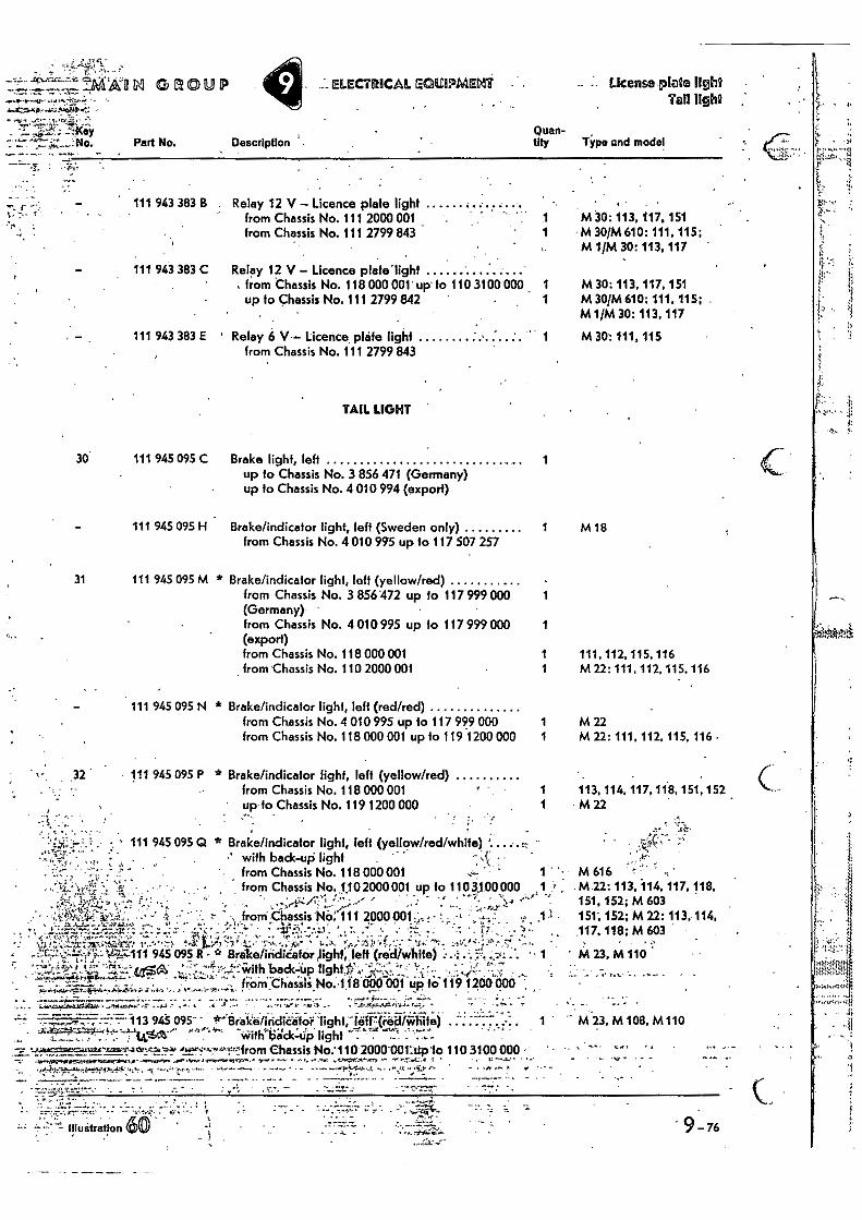
Part No.
...ELECTRICAL a AC; ISIPMEMIT . License plate light Tall light
Quan- Description tity Type and model
L',11:'•• •
• • • . _ 1
111 943 383 8 . Relay 12 V - Licence plate light from Chassis No. 111 2000 001 from Chassis No. 111 2799 843
111 943 383 C Relay 12 V - Licence plafelight , from Chassis No. 118 000 001 up fo 110 3100 000 _ 1
up to Chassis No. 111 2799 842 1
111 943 383 E ' Relay 6 V.- Licence, plafe light from Chassis No. 111 2799 843
TAIL LIGHT
• M 30: 113, 117, 151 M 30/M 610: 111, 115; M 1/M 30: 113. 117
M 30: 113, 117, 151 M 30/M 610:111, 115; M1/M 30: 113, 117
M 30: 111,115
30 111 945 095 C Brake light, left 1 up to Chassis No. 3 856 471 (Germany) up fo Chassis No. 4 010 994 (export)
111 945 095 H Brake/indicator light, left (Sweden only) from Chassis No. 4 010 995 up to 117 507 257
31 111 945 095 M * Brake/indicator light, left (yellow/red) from Chassis No. 3 856 472 up to 117 799 000 (Germany)' from Chassis No. 4 010 995 up to 117 999 000 (export) from Chassis No. 118 000 001 from Chassis No. 110 2000 001
111 945 095 N * Brake/indicator light, left (red/red) from Chassis No. 4 010 995 up to 117 999 000 from Chassis No. 118 000 001 up lo 119 1200 000
32 111 945 095 P * Brake/indicator fight, left (yellow/red) from Chassis No. 118 000 001 up fo Chassis No. 119 1200 000
1 M18
1
111, 112, 115, 116 M 22: 111, 112, 115, 116
M 22 1 M 22: 111, 112, 115, 116 •
113, 114, 117, 118, 151, 152 1 M 22
111 945 095 Q * Brake/indicator light, left (yellow/red/white) ; ••
with back-up light • from Chassis No. 118 000 001 from Chassis No. 1,102000 001 up to 110 3,100000
- • ' ' ▪ A
froni Chassis 'NO: 111 2000 001, • •; :
.1.11;k ,
M616 ••• M22: 113, 114, 117.118, 151, 152; M 603 151; 152; M 22: 113, 114, 117, 118; M 603
1.z .
;;-,1;3;;••,:::,, 1• •,'" 1- ON • 3 ".f. *, • ••• • . •-• 945 095 R * Brake/iiidica▪ tor jighf, left (midAirhite) .. •
, A t" 1.L;'ttaSIA, back-tip light.!' "'•-* 17.2. ' • - • r• - from Chassis No.118 000 001 up f;:;117 1200i!cto ,
. •
7- 113 945 095 - , - -inithli'cic:dp light
02._,.•••,-,-.,'”•••1•A•2from Chassis No:110 2000 00I:lip10 110 3100 000 411 lAreln"....L. • ••• ••• "": •
J"...-4.1:':Y.T ....,:i"elel?",,,•PF • , -.X t•,••••,,, • - .
M 23, hillo
M 23, M 108, M110
"Lt ilf uatration •
- , • - 76
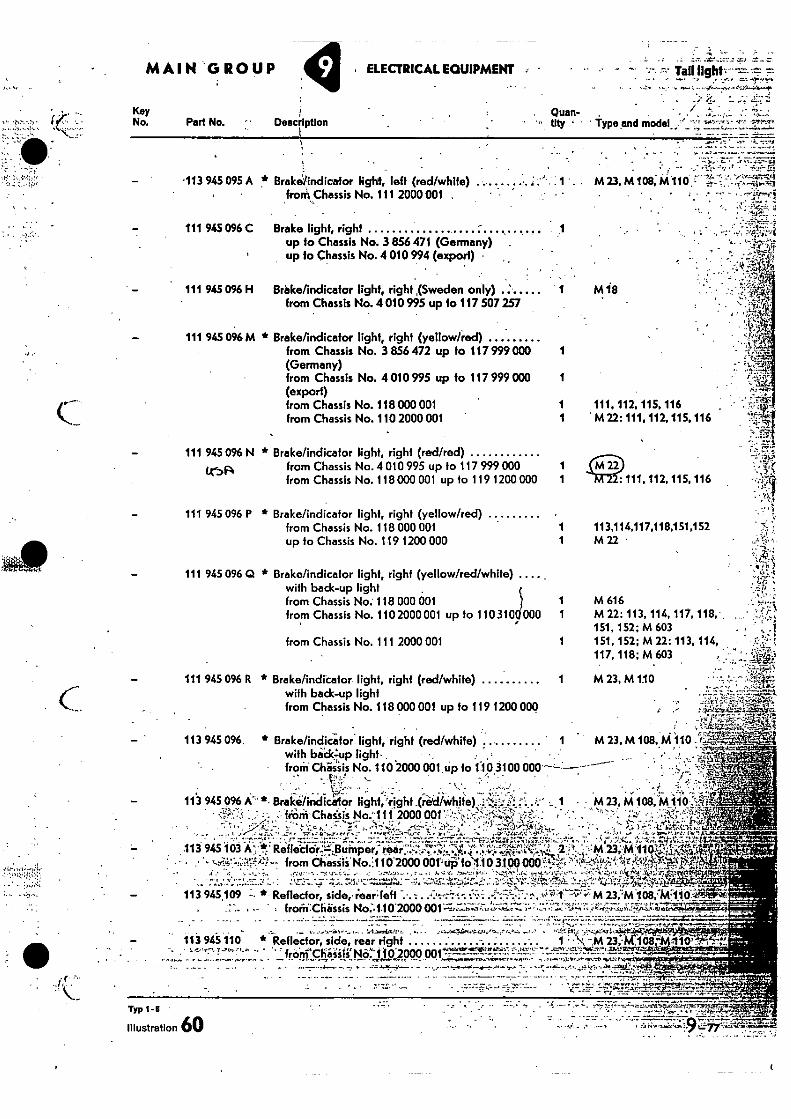
Key No. Part No.
. Quart- Description ' Type and model_
1 113,114,117,118,151,152 1 M 22 •
MAIN 'GROPP y ELECTRICAL EQUIPMENT • — Tali
- "r• - • ••••,-•
113 945 095 A Brake/indicalor light, left (red/white) ...... . . frorkChassis No. 111 2000 001 . •
111 945 096 C Brake fight, right •
up to Chassis No. 3 856 471 (Germany) . up to Chassis No. 4 010 994 (export) •
111 945 096 H Brake/indicator light, right ,(Sweden only) from Chassis No. 4 010 995 up to 117 507 257
111 945 096 M Brake/indicafor light, right (yellow/red) from Chassis No. 3 856 472 up to 117999000 1 (Germany) from Chassis No. 4 010 995 up to 117 999 000 1 (export) from Chassis No. 118 000 001 1 from Chassis No. 110 2000 001 1
111 945 096 N * Brake/indicator light, right (red/red)
ISA from Chassis No.4 010 995 up to 117 999 000 1 from Chassis No. 118 000 001 up to 119 1200 000 1
111 945 096 P * Brake/indicator light, righf (yellow/red) from Chassis No. 118 000 001 up to Chassis No. 119 1200 000
111 945 096 Q * Brake/indicator light, right (yellow/red/white) with back-up light from Chassis No. 118 000 001 from Chassis No. 110 2000 001 up to 110 310, 000
from Chassis No. 111 2000 001
111 945 096 R * Brake/indicator light, right (red/white) with back-up light from Chassis No. 118 000 001 up fo 119 1200 000
-• from No.:110b2000 001' uO'fo 10 3100 000 -t
113 945 109 - * Reflector, side,. rear; left . .. 23,'M 108,447110.'. frorif-Chassis No:%110 2000 001 .--:-1;;;;•7.-, •-••Ir..." "
• , -
• ...• . ••• • J. . - •
11.3 945 096 A *- Brake/indiceior light 'right .(ried/White) •a V,: • frinii'Chaists No.'111 2000 001 Z.:
• _ •
113 945 103 A `,71!",' •
113 945 096. • , i-- .i6= ,......2„;,., .-.
* Brake/indicator light, right (red/white) 1 M 23. M 108, M110 - e:-
t---..,01
., with back. light- - ; .
from Chassis No. 110.2000 061 up to 1-16 3100 000 ----------- .'
• M 23, M 108,'Mlir
23,
' •
•:MIlltig a :‘2*
• . . . . . c. . 113 945 110 * Reflector, side, rear right 1--.14,;x4 234/1163
• • R. •• kart) Chassis No. t jp 2000 • ••••-
- - . .
- •
M 23, M 108, M110 - • t.Parr'.3 t.t.• •
. • -- • , „
M is
111, 112, 115. 116 M 22: 111, 112, 115, 116
: 111, 112, 115, 116 •
M 616 M 22: 113, 114, 117,118. ,
. .
151, 152; M 603 151, 152; M 22: 113, 114, 117, 118; M 603
M 23, M 1.10
mrg
Typ 1-s
Illustration 60
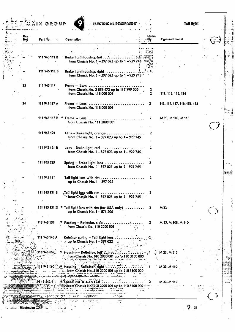
111 945111 B
1 4 •
4.•
' from Chassis No, 110 2000 001
. 111 945 145 A Retainer spring - Tail light lens up to Chassis No. 1 - 397 022
, •
C
: - •
-" -&:":„71.! ' • ' • • .'17-'7ViL,"'"": '
• • --NI A fl M GROUP - - ELECTRICAL ECISIPMELIT t Tall lls'ht
• 4"
- . ,
Key • Noi Part No. • Description
Quan- tity Type and model
•
Brake'light housing, left - .7:4-1 from Chassis No. 1. -397 023 up 10 1 -92974.5
111 945 112 13
Brake light housing; right f
ti from Chassis No. 1 - 397 023 up to 1 -929745 -
33 111 945 117
Frame - Lens from Chassis No. 3 856 472 up to 117 999 000 2 from Chassis No. 118 000 001
2 111. 112, 115,116
34 111 945 117 A Frame - Lens 2 113,114,117,118,151,152 from Chassis No. 118 000 001
111 945 117 B * Frame - Lens from Chassis No. 111 2000 001
2 M 23, M108, M 110
111 945 121 Lens - Brake light, orange 2 from Chassis No. 1- 397 023 up to 1 929 745
111 945 121 B Lens - Brake light, red 2 from Chassis No. 1 -397 023 up to 1 - 929 745
111 945 125 Spring - Brake light lens 2 from Chassis No. 1 - 397 023 up to 1 -929 745
111 945 131 Tail light lens with' rim 2 up to Chassis No. 1 - 397 022
111 945 131 B Xail light lens with rim 2 -."---fr.cun- as s No. 1 -397 023 up to 1 -929 745 •
111 945 131 D * Tail light lens with rim (for USA only)
2 M22 up to Chassis No. 1 - 871 206
113 945 139 * Packing - Reflector, side 2 M 23, M 108, M 110
44,
945 159
`.113 945 166
- • '4".."-a-f.-̀7;"7:77Z- • , .
'140,7; • A 15 442 1
M23, M110
423, M 110
M 23,M 110
° HOU"sing Reflector, leff ...... .. . 1 •,"-; from Chassis No. 1-10 Iooti oat up to 110,3100 000
. from Chassis No 11;0 2000 001 43;110 3100 000
''"5'from Chassis Nck:110 2000 001 up to 110 3100 000
7 7:
Illustration- 7:1:7 •
9-76
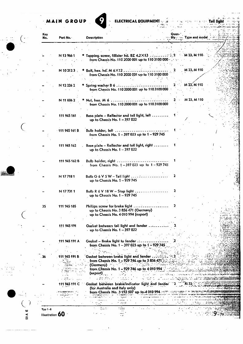
ELECTRICAL EQUIPMENT . .
Tail light - • --v.,
• •.
Key No. Part No.- Description
Quan-' •-•• tity ; L Type and model •-•-•.. • ,•rh
N 13 966 1 * Tapping screw; fillister hd. BZ 4.2X13 . 'M 23, M 110.
from Chassis No. 110 2000 001 up to 110 3100 000 - = •
- N 10 212 3 • * Bolt, hex. hd: M 6 X12 . . M23,M 110
from Chassis No. 110 2000 001 •up to 110 3100 000 . •• ! '
///' - . N 12 226 2 * Spring washer B 6 • M 23, M 110
• from Chassis No.110 2000 001 up to 1103100000 •
• M 23,M 110 N 11 006 2 * Nut, hex. M 6 - from Chassis No. 110 2000 001 up to 110 3100 000
111 945 161 Base plate - Reflector and fail light, left up to Chassis No. 1 -397 022
111 945 161 B Bulb holder, left from Chassis No. 1 - 397 023 up to 1 -929745
111 945 162 . Base plate - Reflector and tail light, right 1 up to Chassis No. 1 - 397 022
111 945 162 B Bulb holder, right 1
from Chassis No. 1 - 397 023 up to 1 - 929 745
N 17 718 1 Bulb G 6 V 5 W Tail light 2 up to Chassis No. 1 -929 745
N 17 731 1 Bulb R 6 V 18 W- Stop light 2
up to Chassis No. 1 - 929 745
35 111 945 185 Phillips screw for brake light 2 up to Chassis No. 3 856 471 (Germany) up to Chassis No. 4 010 994 (export) .
111 945 191 Gasket between tail light and fender up to Chassis No. 1 - 397 022
1
111 945 191 A
Gasket - Brake light to fender • from Chissis No. 1 - 397 023 up to 1 - 929 745
.36 111 945 191 B -Gasket between brakii light and fender ::::••-:':.'^;2 ., '- from Chassis No. 1!929 746_up to 3 856 471 '-: ..:-...-:'
- • • • • . 4••:,,..- , '- • : :• (Germany) - ,, • - • • - • - •_,„__;:!.. - :--......,., ..:;'...
from .Chassis No. 1 -929 746 up to 4 010 994 ' .. • -' • ' ..•' • - (export)
r,
111 945 191 C Gaiket befWeen brakefindicafor light , and fender' 2 —• • (for Australia and Italy only)
• Aita51
.• ,
. ...,...-i1:::1 • ' .44
';': ,f- '.1..--.' vc.1.....V.w-V;.t `..a. 0 q• -.._...r.• • -,-- "." '.:"..! -•4,;‘;:r.- ..y.
' „ • : . r 0 da ...C."-." VI
•-:_.-... • ...3.-7-• -.::.7Z-It...r -CI.. ..
. P•34,15.14.,,,V1,7
- • •
(iu Typ 1 -5
Illustration 60 Cr]
from Chassis No. 3;192 507 up to.4 010994
L'Itirlik0
-N4
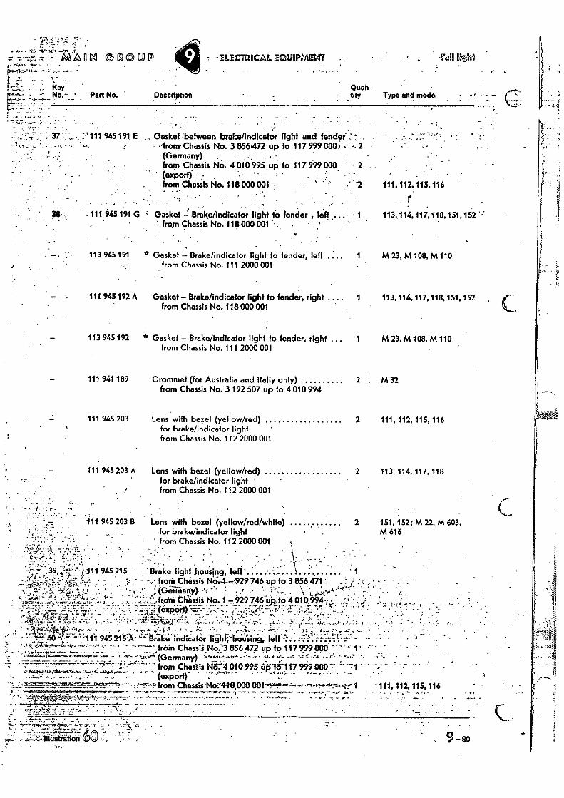
- AA-A 11 GA 041.1.4.41:74•-•1•144-•••,• •
SE/OUP - -ELECIRICAL EQUIPMEVIT Tall f.th0
- 7 V Key
Part No. Description Quail- tity Type and model
7 -377" ;-'111945191
fo 117 999 000 • 2
111,112,115,116
r . 3 • . 111 945 191 G ;, Gaiket Brake/indicator light to fender li;ft - • 1 113,114,117,118,151,152 '
from Chassis No. 118 000 001 • ,
Gasket between brake/indicator from Chassis No. 3 856472 up (Germany)
.. , . • -
from Chassis NO. 4 010 995 up • (export) ' •
from Chaisis No. 118 000 001
•
light and fender" , to 117 999 000.• -. 2
113 945 191
* Gasket — Brake/indicator light to fender, left . from Chassis No. 111 2000 001
111 945 192 A Gasket — Brake/indicator light to fender, right .... from Chassis No. 118 000 001
113 945 192 * Gasket — Brake/indicator light to fender, righf from Chassis No. 111 2000 001
111 941 189 Grommet (for Australia and Italiy only) from Chassis No. 3 192 507 up to 4 010 994
1 M 23, M 108, M 110
1 113, 114, 117, 118,151,152 ,
1 M 23,M 108,M 110
2 , M32
111 945 203 Lens with bezel (yellow/red) 2 111, 112, 115, 116 for brake/indicator light ' from Chassis No. 112 2000 001
111 945 203 A Lens with bezel (yellow/red) 2 113, 114, 117, 118 for brake/indicator light ' from Chassis No. 112 2000 001
111 945 203 B Lens with bezel (yellow/red/white) , -for brake/indicator light
' from Chassis No. 112 2000 001
•
2 151, 152; M 22, M 603, M 616
-"f".'"'.;;-111 945 215
• 444,144.44.1,"4.4
44.7.1-% „
• ,•44,..... ,,,..;:44-.(Germany) — • A.4,...••••1•1.
froth- CChassiskir 4 010 995 iiii"fik117 999 000'7" • 1 (export)
Chassis Nor448,000 1 • ...••4444-. • .•-••••••••••••••••••••..,••••••••notrm ry ••-•••-www441......-- ••••••••••,..44,r-4.-4. • 2.4. 111.112. 115. 116
. • - , . • , . 7 . .4 • - - 4-* "1
.40 -"-111 945 2.15:A ̀ '.1° Brake. indicator fighti-hOtIsing; trifi+; '' rein Chassii No '3 856 472 up to 917 999 000 ' 1" ,
Brake light .housIng, left froth Chassis 746 up to 3 856 471 . (Germany) ~r •
..fro ri Cha_ssis No 1 929 746:uilto.4 010994•,..:„. .1;7
" ' • —•-•: • • • •...•+•-• •
•Z.••••:. A 4 : .
- _ - - •..17.--'..t.:••tr-‘- . • -
. • -
.--,EA-4011ustration ,
9 - 80
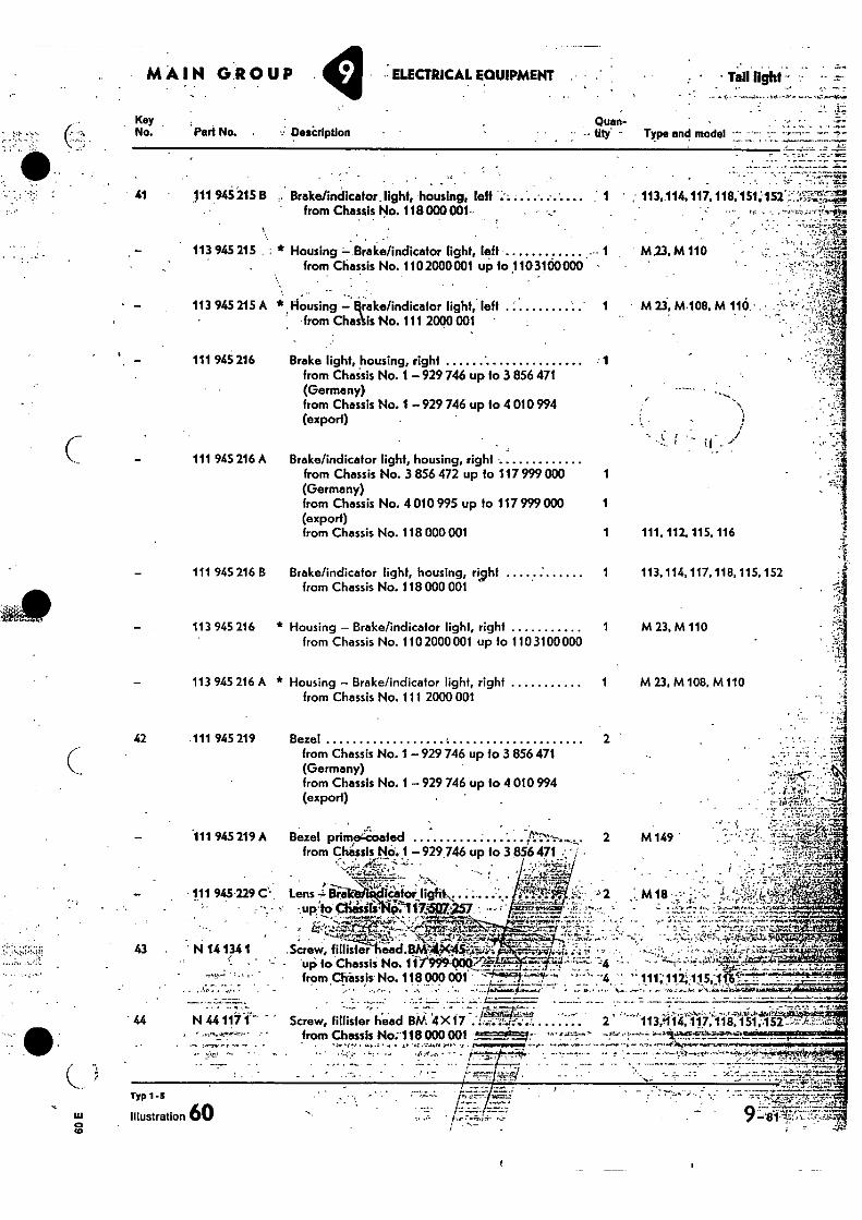
MAIN GROUP ELECTRICAL EQUIPMENT • • Tail light .
Key No.
Quan- My: - Type and model 1. Part No. . Description
1
1
113 945 215 A * Housing — qrake/indicafor light, left ' from Chaslis No. 111 2000 001 •
111 945 216 Brake light, housing, right from Chassis No. 1 — 929 746 up to 3 856 471 (Germany) from Chassis No. 1 —929 746 up to 4 010 994 (export)
2 42 -111 945 219 Bezel
• Typ 1-5
Illustration 60 •.,
41 111 945215 B Brake/indicator. light, housing, left : 1 from Chassis No. 118000001-
. • 113 945 215 * Housing — Brake/indicator light, left 1
from Chassis No. 1102000001 up 1o1103100000 -
••
• 113,.114,117,118;151;152'::::',
M,23,M 110
•
• • M 23, M.108, M 110.• . •
• •
cL•
•
113 945 216 * Housing — Brake/indicator light, right from Chassis No. 110 2000 001 up to 110 3100 000
113 945 216 A * Housing — Brake/indicator light, right from Chassis No. 111 20004301
111 945 216 A Brake/indicator light, housing, right from Chassis No. 3 856 472 up to 117 999 000 1 (Germany) from Chassis No. 4 010995 up to 117 999 000 1 (export) from Chassis No. 118 000 001 1
111 945 216 B Brake/indicator light, housing, right 1 from Chassis No. 118 000 001
111, 112, 115, 116
113,114, 117, 118, 115, 152
1 M 23,M 110
1 M 23, M 108, M110
from Chassis No. 1 — 929 746 up to 3 856 471 (Germany) from Chassis No. 1 — 929 746 up to 4 010 994 (export)
— 111 945 219 A Bezel primeCoated • ,tr,!--.....„ ,.....„. from Chassis NO. 1 — 929.746 up to 3 856 471 . ' /
' --.;;:, 4',-, ;-• -- - . .- -•::.tl-r:C
— 111 945129 C.- Lens .1 117-a icafor ligh1N, .. : ... -'. . a 44-1
. • 41. '-' 2
.• - up. to 4;h4WIS' %11 76a257 ' ,.... -,:..'...,.r.'1....V7:- ;...,..'---.4-w......
• ; 1_;1.V.>': s ::-c=k,- ;-rr4,7,- •. ---.4—'1:5_,.7..Y.---47,"',;D, - -..-- .
.!. ,..v....-: :, • a...••1•;4:.f.--4"-..1-tz,_%-....--\11t.4..4...
43 N 14134 1 Screw, fillisterThead.BMAK454•Aiii: 4.4: ..-..il. - - - up to Chassis No. fir90-0007fP.-.. . -....—
------- ' '" from CErinsis No. 118000001 ' ---7"....'--1;- ---' '4 " . l',.-.- ,__:. 7
„...... ...z..-..=.
C.
.. •
2 M149
N 44 1171 - Screw, Ulster head BM 4X17 r 1 3 /41- eii'7:1113741 •!.5r-• •
• I •
from Chassis Ho:118 000 001 0.3==ii6=zr.
" F.
. - '7 -
• 44
• • t
- • •
.•:: j.:10:i. .. . ,...,,, _ ...
:.• 1.AT.4-1.... . ,
••' .% ,7- =1'4' i'.':-- c-
M 18
• 4,.-„d-kricad. ,--•„•," • 4..isat
111; 112;115,1'
•
• - • • I 17;41, • . . -
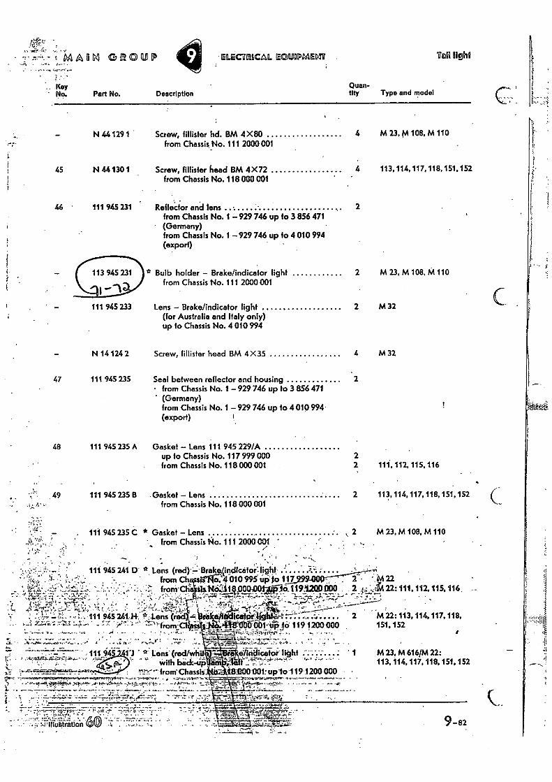
111 945 233
N 14 124 2
7,3-irrr-,. ;147i
MAOM GROUP • ELECT/MAL ECIIISIPMENT . 'UP light
Description Quan-tity Type and model
Screw, fillister hd. BM 4X80 from Chassis No. 111 2000001
4 M 23, M 108, M 110
Screw, Binder head BM 4X72 from Chassis No. 118 000 001
4 113, 114, 117, 118,151,152
Reflector and lens from Chassis No. 1 — 929 746 up to 3 856 471
2
- (Germany) from Chassis No. 1 —929 746 up to 4 010 994 (export)
Bulb holder — Brakefindicafor light from Chassis No. 111 2000001
2 M 23, M 108, M 110
Lens — Brake/indicator light (for Australia and Italy only) up to Chassis No. 4 010 994
2 M 32
Screw, fillister head BM 4X35 4 M 32
Seal between reflector and housing 2 • from Chassis No. 1 — 929 746 up to 3 856 471 ' (Germany)
from Chassis No. 1 — 929 746 up fo 4 010994 (export)
48 111 945 235 A Gasket — Lens 111 945 229/A up to Chassis No. 117 999 000 from Chassis No. 118 000 001
111, 112, 115, 116
•
49
111 945 235 B Gasket Lens 2 113, 114, 117,118, 151, 152 from Chassis No. 118 000 001
111 945 235 C * Gasket — Lens S 2 M 23, M 108, M 110 from Chassis No. 1 11 2000 001
`
...Key Pia Part No.
N 44 129 1
45 N 44130 1
46 111 945 231
47 111 945 235
-
er4 k.• • • 111 945 24114. Lens. (red '
111 945 241 0' 0 Lens (red)..::•Brake4inclictitor--Itoplit from Ch o. 4 010 995 up to 11,17,99,000 M 22
• ; from' Cl; sis NO3181300-00110716, 1191200 000 2 r . 22: 111, 112, 115, 116
icafotligith M 22: 113,114, 117, 118, `O00001'.:41.iii 119 1200 000 , 151,152 • • $
• ••-•••.••14- - ••••
• — 111 945- teni' (red/whit c grikelitglicelOr-11ght ... ; 1 M23, M 6161M.22:
5,07 with bick-Lija n.•. •• . 113, 114,117,118,151.152
" • . . from 1300001:up10 -1191200000 •
--,••••••atat ••••••Mmi••••".••••••.i...4•1rrAPP•Nr4,11•• . • ...••mr9`M,••••inT•5.0" 1 •••••••••••-••-.• .•••••• •••••••••••••.,--.
..."'-.P•a•Oie4g*;••'• OP:•-•14•••,-!•- • ' il'0•4•••,*.•• • k•••;•°.:4",..• • • - • •••- .••• ••-•-••*
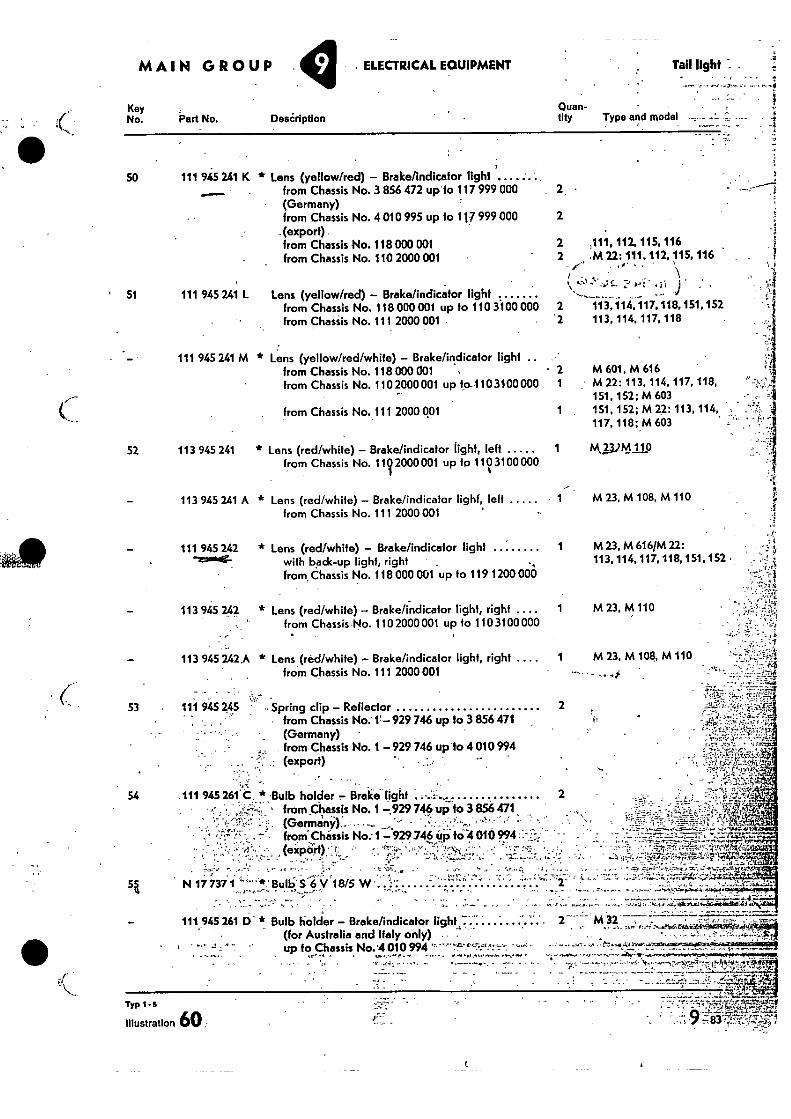
Key No. Part No. DesCriptIon
Quan-tity Type and model
.
. „ • .4.;i2.4,
MAIN GROUP • ELECTRICAL EQUIPMENT Tail light I •
50 111 945 241 K * Lens (yellow/red) - Brake/indicator light from Chassis No. 3 856 472 up to 117 999 000 (Germany) from Chassis No. 4 010 995 up to 117 999 000 2
. (export) from Chassis No. 118 000 001
2 .111, 112, 115, 116
from Chassis No. 110 2000 001
2 .M 22: 111, 112,115,116
51 111 945 241 L Lens (yellow/red) - Brake/indicator light from Chassis No. 118 000 001 up to 110 3-100 000 from Chassis No. 111 2000 001
X', I •
2 113,114, 117, 118,151,152 '2 113, 114, 117, 118 •
111 945 241 M * Lens (yellow/red/white) - Brake/indicator light .. from Chassis No. 118 000 001 - 2 from Chassis No. 110 2000 001 up to-110 3400 000 1
from Chassis No.111 2000 001
1
52 113 945 241 * Lens (red/white) - Brake/indicator light, left 1 from Chassis No. 11 2000 001 up to 110 3100 000
113 945 241 A * Lens (red/white) - Brake/indicator lighf, left from Chassis No. 111 2000 001
M 601, M 616 M 22: 113, 114, 117, 118, 151, 152; M 603 151, 152; M 22: 113, 114, 117, 118; M 603
14,13.)M1,19
M 23, M 108, M 110
- 111 945 242 * Lens (red/white) - Brake/indicator light 1 M 23, M 616/M 22: ',moor- with bpck-up light, right , .,
from. Chassis No. 118 000 001 up to 119 1200000
113 945 242 * Lens (red/white) - Brake/indicator light, right .... 1
M 23. M 110 from Chassis No. 110 2000 001 up to 110 3 t 00 000
113 945 242.A * Lens (red/white) - Brake/indicator light, right .... 1 M 23, M 108, M 110 from Chassis No. 111 2000 001
53 111 945 245 . .
• •,
• •• Spring clip - Reflector 2
_ (Germany) • from Chassis No:17 -929 746 up to 3 856 471
. from Chassis No. 1 - 929 746 up 'to 4 010994 (export)
54 .111 945 261 C , * 'Bulb holder Brake- light - • from _Chassis No. -,929 746 up 3 856 471
. •
from Chassis No.- 1 7 929746 up hi4 010 994 ::- (export) r. •
. . 4,4 • 442ar 5i N 17 737 1 '*: Bulb' 6 V 18/5. W • .. ..... .. „
:•
111 945 261 6. * Bulb holder - Brake/indicator light (for Australia and Italy only) up to Chassis No.'4 010 994 ”
113, 114. 117, 118, 151, 152
2
...1.4-.440:745.1.11 •4•••• - •
qvckA(.,,•&zialitzr
• • • 1 .• 1.4 4.i.$1.1sruivimfr.04.ritkei.4$.4..
2 M 32
'rye 1-5
Illustration 60.
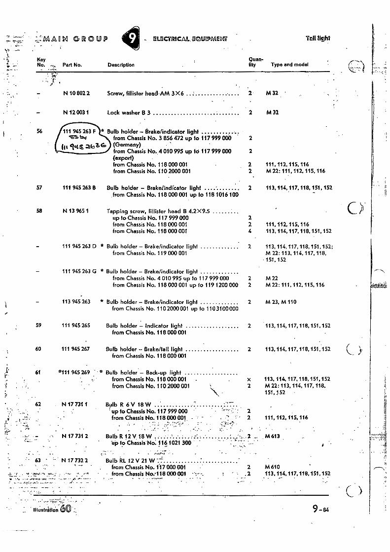
up to Chassis No. 117 999 000 from Chassis No. 118 000 001
62 N 17 731 1 Bulb R 6V 18W
ti.. M 613 N 17 731 2 Bulb R 12 V 18 W
"up to Chassis No: 116 1021 300
63 N 17 732 2 Bulb kr. 12 V 21 W -
•
- t
•• • -• • •••••-• • • • •
from Chassis No.1'17000 001 from Chassis No.118 000001
2 M 610 113,114,117,118,151,152 • .
9-84 illustration
111, 112, 115, 116
• 2
• 2
:::114A111M GROUP IELIECTRICALEMMEInir Taill401
Key •o•• No. Part No. Description
Quan- tity Type and model
-r
Screw, fillister head•AM 3X6
Lock washer B 3
56 Bulb holder - Brake/indicator light from Chassis No.
N 10 802 2
N 12 003 1
111 945 263 F stab
(ft ' a(91' (Germany) from Chassis No. (export) from Chassis No. from Chassis No.
3 856 472 up to 117 999 000
,4 010 995 up 16 117 999 000
118 000 001 110 2000 001
2 M 32 •
M 32
2
2
2
111, 112, 115, 116 2
M 22: 111, 112, 115, 116
113, 114, 117, 118,
111, 112, 115, 116 113, 114, 117, 118,
113, 114, 117, 118,
57 111 945 263 B Bulb holder - Brake/indicator light
2 from Chassis No. 118 000 001 up fo 118 1016 100
58 N 13 965 1 Tapping screw, fillister head B 4.2X9.5 up to Chassis No. 117 999 000
2
from Chassis No. 118 000 001
2 from Chassis No. 118 000 001
4
111 945 263 D * Bulb holder - Brake/indicator light
2 from Chassis No. 119 000 001
111 945 263 G * Bulb holder - Brake/indicator light from Chassis No. 4 010 995 up to 117 999 000 2 from Chassis No. 118 000 001 up 10 119 1200 000 2
151, 152
151, 152
151, 152: M 22: 113, 114, 117, 118,
• 151,152
M 22 M 22: 111, 112,115, 116
1 7,
113 945 263 * Bulb holder - Brake/indicator light from Chassis No. 110 2000 001 up fo 110 3100 000
59 111 945 265 Bulb holder - Indicator light from Chassis No. 118 000 001
60 111 945 267 Bulb holder - Brake/fail light from Chassis No. 118 000 001
61 *111 945 269 Bulb holder - Back-up light from Chassis No. 118 000 001 . from Chassis No. 110 2000 001
x 2 M 22: 113, 114, 117, 118,
151,152
2 M 23, M 110
2
2
113, 114, 117,118, 151, 152
113, 114, 117, 118, 151,152
113, 114, 117,118, 151, 152
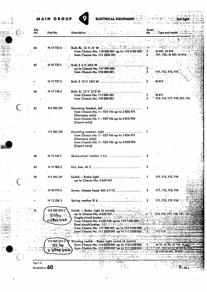
111 945 292
67 111 945 291' Mounting bracket, left 1 from Chassis No. 1 — 929 746 up to 3 856 471. (Germany only) from Chassis No. 1 929 746 up to 4 010 994 (Export only)
Mounting bracket, right 1 from Chassis No.-1 — 929 746 up to 3 856 471 (Germany only) from Chassis No. 1 — 929 746 up to 4 010 994 (Export only)
4
4
1 111, 112, 115. 116
Shake-proof washer .1 5.3
Nut, hex. M 5
Switch — Brake light up to Chassis No. 4 630 937
N 12 126 1
N 11 005 2
111 945 511
68
69
70
. . . 111,112,115,116:--:
• •••
Spring washer B 6 •-•
MAIN GROUP ELECTRICAL • EQUIPMENT = 7 ,s" TaWlIghi
Description QuanL -.' • • • • - . • .. tity Type and model ' 1"
2 '111.112,115,116'-_., . • ..„
-• up to Chassis No.! 117 999 000. ' 2' . from Chassis No. 118000 001,..
N•17 738 2 . 66
Bulb RL•12 V 21 W • • -•
-. from Chassis NO. 118 000 001 up to 110 3100 000' 2 M 601, M 616. " - from Chassis No. 111 2000 001 - 2 151, 152; M 603, M 616, • •;.-
64 .N 17 732 2 - •-•
65 N 17 737 1
Key No. Part No.
Bulb. S 6 V.:18/5 W .
Bulb SL 12 V 21/5 W from Chassis No. 117 000 001 from Chassis No. 118 000 001
2 M613
2 •M611 2 1 113,114,117,118,151,152
N 17 737 2 Bulb S 12V 18/5W
Screw, cheese head AM 6X 15 2 111, 112, 115, 116
113, 114,117, 118; 151;15.2
No. 4 63.0.938 ep)to 119 1200 rake
from Chassis
Switch — Brake up to Chassis Single drilla •from Cbassis. Dual circultb
light (2 points) -No. 4 630 'brake:1
, 1,1
N
;
A;•
No. 117 000 001 •up to 110 3100 000 L.2.: 1, No. 111 20Q0 001, up' fc';'111 3200 000 -•2 .111-118 - - • •
A-7:
• .N107152.
N 12 226 2
• • 71
II Warning switch —Brake light switch (3 points) - from Chassis No. 1102400601 up to 1103100 000 2 M 23, M 50, M 110; from Chaisii No. 111;2000001'6i:it& i 11 3200000 2 LV't! -̀-'•-:151,-152-qM13NiX5enoi
113 945515 D by
- —39$5.5S.G
Typ 1 -5
Illustration 60
•
84
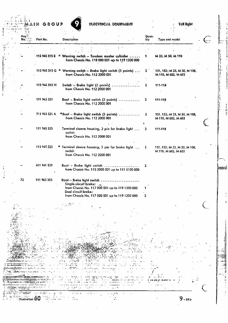
Description
- --Y--44,MM GROUP ELECTRICAL EGLPIPMEIgir : Ta11 light
•••• -••• o• •••• ),•••1•••• •
1 " -,•-•
Key
No.`;.'!: Part No.
• -
113 945 515 E
113 945 515 G
113 945 515 H
111 945 521
113 945 521 A
111 945 525
113 945 525
411 941 539
72 111 963 355
Quan-tity Type and model
1 M 23. M SO, M 110
2 151, 152; M23, M 50, M 108, M 110, M 602, M 603
2 111-118
2 111-118
2 151, 152; M 23,M 50, M 108, M 110, M 602, M 603
2 111-118
2 151, 152; M 23, M 50, M 108, M 110, M 602, M 603
2
1
2
Switch Brake light (2 points) from Chassis No. 112 2000 001
Boot — Brake light switch (2 points) from Chassis No. 112 2000 001
*Boot — Brake light switch (3 points) from Chassis No. 112 2000 001
Terminal sleeve housing, 2 pin for brake light switch from Chassis No. 112 2000 001
* Terminal sleeve housing, 3 pin for brake light ... switch from Chassis No. 112 2000 001
Boot — Brake light switch from Chassis No. 110 2000 001 up to 111 3100 000
Boot — Brake light switch Single circuit brake: „, from Chassis No. 117 006 001 up to 119 1200 000 Dual circuit brake: from Chassis No. 117 000 001 up fo 119 1200 000
Warning switch — Tandem master cylinder from Chassis No. 118 000 001 up to 1191200 000
Warning switch — Brake light switch (3 points) ... from Chassis No. 112 2000 001
• ▪ •••
• "F• 4!. • -
••`
•
A 41,••••• I •
c , ••
inustranon 9 -84b
.tt • •••:•:.;•-j=" •••-• ••••••,-. -,•!•t•••••,•-•-•
-.4 • • -4,•••• • 44 •-••••44.-4.4.-1,144=444•414.4a....ect-445.14.4:4ma
, • • • . • • 4.tr_r.e2+b,kal-ArC
• x'r 14
• .
• .
• •••• :77 CZ: ;.1. 7 :; ;.; . =Z . • 17.4;.• q..14.1N-3=1;4;41144},,,,A=.41, •74.4
, -•
4“,rk.1:4410
' .•
z ';'• zr 'z't-''•••• • • 4. .;•”; .rt ••••,- t 71.
I .
_ - s• ,
- • • ••••
. - ---. - r• ,--.,--.---,57,,Ar ,"....-., .... , , ..___....,...„.,-1-,-X-........... ..--— ='..
.-.:= I..* u-> 1-' rf..17'. '..2?";17. 112
..:1:11,,,,,, . • ...,.. . 9....11,85 ,;•• TYP
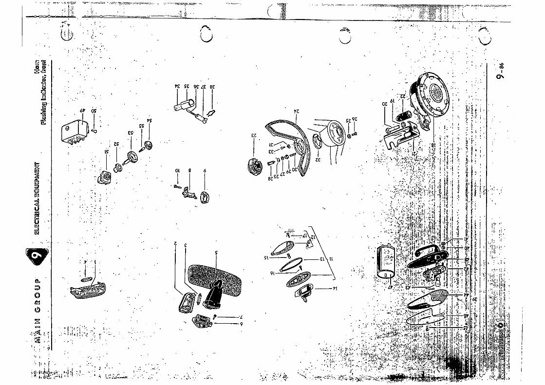
Ot
1 • it 4,14
ELEC
OR
ICA
L E
GU
EPM
ENT
0
. 4
L
EZ
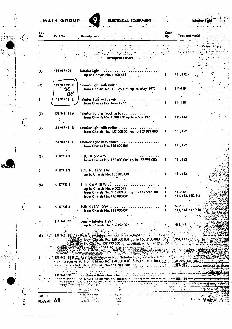
Key No. Part No.'
• . • . .
•
• INTERIOR LIGHT
Interior light up to Chassis No. 1 600439 .
Interior light with switch
from Chassis No. 1 397 023 up to May 1972
Interior light with switch
1 111-118 from Chassis No. June 1972
(1) ,
.A1)
151147.103
111 947 111 D • • SS
1 111 947 111 E
(2) 151 947 111 A
(2) 151 947 111 B
2 151 947 111 C
(3) N 17 717 1
3 N 17 717 2
(4) N 17 723 1
N 17 723 2
111 947 125
f•
•
U)
1.1.1
• MAIN GROUP : ELECTRICAL-EQUIPMENT • Interior 1Ighl
Quan- Description - tity Type and model -• -•• • - •• •
Interior light without switch from Chassis No. 1 600 440 up fo 6 502 399
151,152
Inferior light with switch from Chassis No. 155 000001 up to 157 999 000 1 151,152
Interior light with switch from Chassis No. 158 000 001
1 151,152
BulbHL 6V 4 W • from Chassis No. 155 000001 up to 157 999 000 1 151.152
Bulb HL 12 V 4 W up to Chassis No. 158 000 001
1 151,152
Bulb K 6 V 10 W up to Chassis No. 6 502 399 1 from Chassis No. 115 000 001 up to 117 999 000 1 111-118 from Chassis No. 118 000 001 1 111, 112, 115.116
Bulb K 12V 10W 1 M610: from Chassis No. 118000 001 1 113, 114, 117, 118
•
•
Lens - Interior light - up to Chassis No. 1 - 397 022
• • Rear vieWirrirror Without:interior/light
. • , • - .-1Zr„,fi?. friailiithliiiii; No. . 158 ocKoo, ;00101 SO 3100 000.• ;.J151, 152 ! ;,,,if...' "..
- • --- Ari';'' (tOCII: „No. 157 999 000:•-- .' , '-';',7,5-4-1-7.322-;' -..'-'- ''.'',J--- •-. - • - --: . ., ..,, - •
,.. • .•..---... • --- ..t.t1:27•E="'-'-•",'4-4,7::41,1•7„.71",,.. r2;:,.•,•••••,'"•T•431_, .T:540.1 •,§57- .511/A)::--Ir-;:r.,•7"-I'.7''":"."'F'"--c.::-.: ...... .7.7-7 _...7.t • - ,--.7. • ; ---.t t ,•..••.-•'.:----.,-417.:?=4:-.• ,'-1,,•7 -t,.;..t:,:r... „ ...,„ . . v — --..:,, ,,‘,...:A ..,•g,.:, -.4r.,:. , , ........t.:. 41.1;:tr.z.;-.4•.• .- - •.. , 1° 2,7r4.3 R., ..;-.1:110VII,«
5..._ . . . .,' 1. •-••0,.......--.........!....,....,.,....,,i47-tkii,....
' .. f. 151. 9C-131. 8 ::;..Raiii:(viii1;0 mirror ;:vithaiit : ..loterip:rjight; ,_41-itji,dizle ,,.). 4: : i ....--ik.s,-..:2,,,.". -..=2,.„z,..1v-y--,7,,,r-„,7t,„--ttz.,_._ ,c9_ — • ...-, ---. . from; Chassis No 158;000 V101 up to 150 3100000 •- -1 ' M 206- 151, 152--.----z,;•',7:-;•:.:z-r•.7-A-%..-r- • -
- , :---• -,, .,^:.- ".-- :'..-: from diiiissis No. 151-2000001 ;•-•:,--.----- - - - -• - : --1, ., -•,- 151,152 .
6 151 947 133 Retainer - Rear view Mirror • from-Chassis No. 158 000 001---•'•• •-•'!1
• -r - a.•• ey•K hr•Ira pore-e-r.i., - . rt.r* •• • • •••-.9 • -1.• 4.n.
„
Typ 1-71
61
9
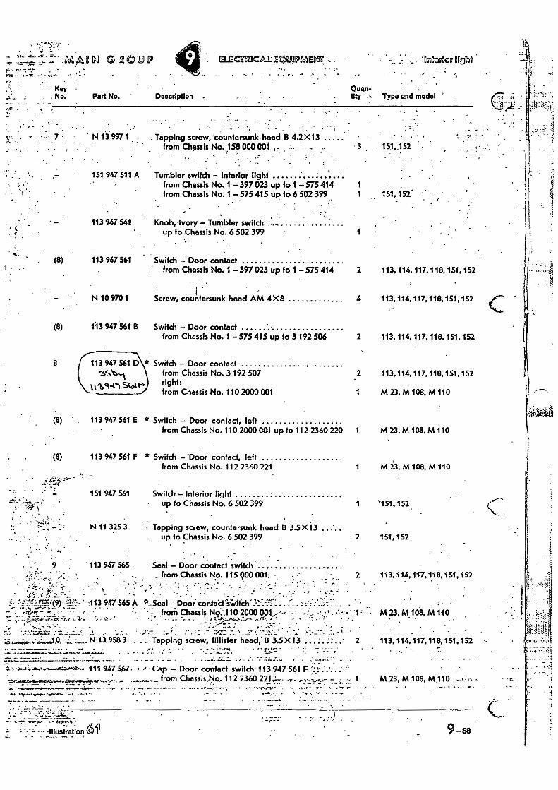
151,152
. . • 4 • , . •
N 13 997 1 ; . Tapping screw, 'countersunk • head B 4.2 X13 from Chassis No. 158 000 001
•
151 947 511 A
113 947 541
Tumbler switch - Interior light from Chassis No. 1 - 397 023 up 10 1 575 414 1 from Chassis No. 1 - 575 415 up fo 6 502 399 1 151,152-
Knob, ivory. - Tumbler switch up to Chassis No. 6502 399
.41 _MAOM GE101:91,
Key . No. Part No.
ELECTRICAL EOLIPMEM: - • • -„ Eatorloo BEN
Quan- tity t Type and model Description _
(8)
(8)
If
-113 947 565 A • •:z a--Seal V-; Door • ;;; ,from Chassis No..110 2000 001,,-'--
113 947 561 Switch -.Door contact from Chassis No. 1 -397 023 up to 1 - 575 414 2 113,114. 117, 118, 151, 152
N 10 970 1
Screw, countersunk head AM 4X8 4 113, 114, 117,118,151, 152
(8) 113 947 561 B Switch - Door contact from Chassis No. 1 575 415 up to 3 192 506 2 113, 114, 117, 118, 151, 152
8 J 113 947 561 D\* Switch - Door contact from Chassis No. 3 192 507 2 113,114,117, 118, 151, 152
Scotto right:
from Chassis No. 110 2000 001 1 M 23, M 108, M 110
113 947 561 E ° Switch - Door contact, left from Chassis No. 110 2000 001 up fo 112 2360 220 1 M 23, M 108, M 110
ti 1 M23,M108,M110
1 "151,152
2 151,152
2 113,114,117.118,151,1.52
Ait 23. M hi no
2 113, 114,117,118,151.152
113 947 561 F
Switch - -Door contact, left from Chassis No. 112 2360 221
151 947 561
Switch - Interior light up to Chassis No. 6 502 399
N 11 325 3. Tapping screw, countersunk head B 3.5 X13 up to Chassis No. 6 502 399
- - 113 947 565
Seal - Door contact switch from Chassis No. 115900 001, • ; . - : • •- ..
13.958 Tapping screw, fillisfer ftead; B 3.5X 13
• ..
'4t,_..
• - , 111 947 547. t f Cap - Door contact switdi 113 947 561 F . . . :
.4441..4 44.. from Chassis,No, 112 2360 221-; - • 1 M 23, M 108, M110. •
. •
— —
• - -•• -Illustration 191
9-88
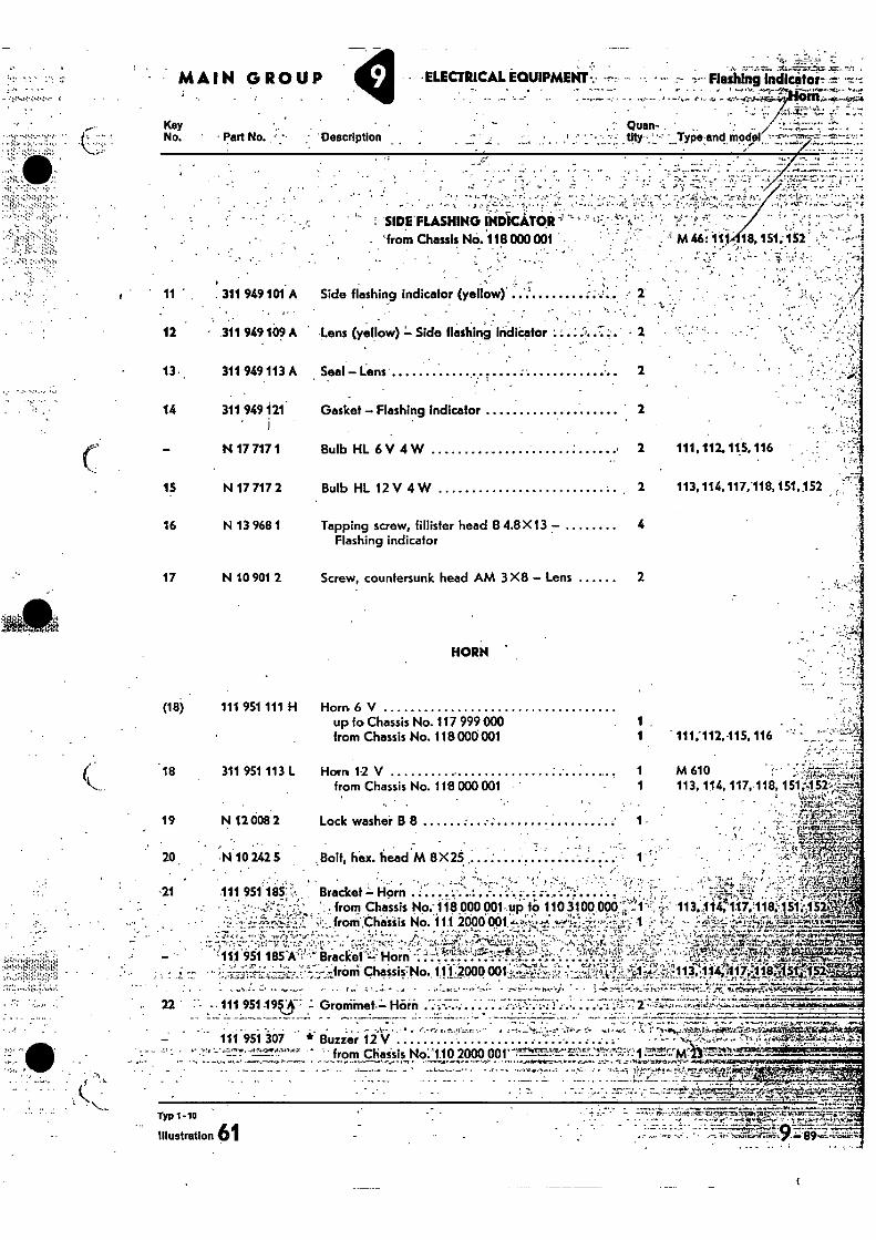
•
19 N 12 008 2
20 . N 10242 5
Lock washer B 8 1
..Boit, hex. head M 8X25
SIDE FLASHING INDICATOR' from Chassis No. 118 000 OW •
• ,
- Side flashing indicator (yellow).
Lens (yellow) = Side flashing indicator • -•
!V.
M46;1118,151;152 . • • .
•• • • . .•
• . • .
111, 112.115.116
113,114,117,118,151,152
12
13 ,
14
15
16
11 311 949 101A
- 311 949 109 A
17 N 10 901 2 Screw, countersunk head AM 3X8 — Lens 2
(18) 111 951 111 H
HORN
Horn 6 V up to Chassis No. 117 999 000 from Chassis No. 118 000 001 " 111;112,115, 116
-21 .111 951 185'
••••• •
Ail 951 185Al'• "•••:: •
22 -111 951 195:5: Groniinet — Horn . .; ...... • .... .7 2 ,--10-=•• • • •-••1•'4', ..••=•••i•r-k(*#-•,,jarr•L _ . . -
- - - - - • •••-•
Typ 1 -10
Illustration 61
Bracket = Horn • • • '., from Chassis 116 POO 001.4 ft; 110 3.100 0013!:..
:••,„frorriChreisiis No. 11.1 2000 001 •
iacket''4HOM ' -̀;vi••F••;
from Chossis7No. 10,2000
.113.,11•4;117.118,?1;:,„152. ; ...V..srsumva
4^̀1.7 1714.'
113-4:114.;?,117=:11815-g - SL
111 951 307 * Buzzer 12 V • •••,-.. • • - • from Chaisis No..•1.1.0 2000 001,
• . , . . • - • • -. • - . • - - • - ' - •T'"e
"
••••• •.;
311 949 113 A Seal — Lens 2
Gasket — Flashing indicator 2
Bulb HL 6 V 4 W 2
Bulb HL 12 V 4 W 2
Tapping screw, fillister head B 4.8 X13 — 4 Flashing indicator
.18 311 951 113 L Horn 1-2 V 1 from Chassis No. 116 000 001 1
• 113, 114, 117,118, 151.452.
. .
M 610
MAIN GROUP
• Part No. .:
-ELECTRICAL EQUIPMENT -L. Flashing Indlcitor---t-
Type anti-Mod"! Key No.
311 949 121' .
N 17 717 1
N 17 717 2
N 13 968 1
, • Quan- Description
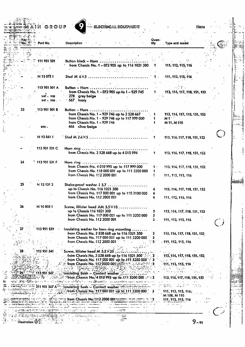
•=• Lk1 S R ®U 9 ELECIlifiCAL ECOAPMECIP
• . F•ri' 4:"-t Quan-
Part No. Description • tity . Type and model
7.` 111 951 501 Button biadc - Horn • , • .1
' from Chassis No. .1 - 072 905 up to 116 1021 300 1 111,112, 115! 116
• N 13 075 1 Stud M4X5 1 111, 112, 115, 116
113 951 501 A Button - Horn 3 • from Chassis No. 1 -072 905 up•to 1- 929 745 1 113, 114, 117.118.151, 152
7i55 278 grey beige 1M7 - 7,55. 567 ivory
23 . 113 951 501 B Button - Horn from Chassis No. 1 - 929 746 up fo 2 528 667 ' , 1 113, 114, 117. 118, 151. 152 from Chassis No. 1 - 929 746 up to 117 999 000 1 M 1 from Chassis No. 1 - 729 746 1 M 11. M110
I3(55 - 466 silver beige
N 13 041 1 Stud M 2.6X5 1 113, 114,117, 118,151,152
113 951 531 C Horn ring from Chassis No. 2 528 668 up to 4 010 994 1 113, 114, 117, 118, 151, 152
24 113 951 531 F Horn ring from Chassis No. 4 010 995 up to 117 999 000 1 • 113, 114, 117, 118, 151, 152 from Chassis No. 118 000 001 up fo 111 3200 000 1 from Chassis No. 112 2000 001 1 111, 112, 115, 116
25 N 12 131 2 Shake-proof washer J 3.7 up to Chassis No. 116 1021 300 6 113. 114,117, 118, 151, 152 from Chassis No. 117 000 001 up to 110 3100 000 • 6 from Chassis No. 112 2000 001 6 111, 112, 115, 116
26 N 10 803 1 Screw, faster head AM 3.5 X10. up to Chassis 116 1021 300 3 113, 114, 117, 118, 151. 152 from Chassis No. 117 000 001 up to 111 3200 000 3 from Chassis No. 112 2000 001 3 111, 112, 115, 116
. . . ,
27 113 951 539 - Insulating washer for horn ring mounting ,... from Chassis No. 2 528 668 up fo 116 1021 300 3 113, 114, 117, 118.151, 152
from Chassis No. 117 000 001 up to 111 3200 000 3 from Chassis No. 112 2000 001 7 - . . . -1'3 ' .. 111., 112, 115, 116
I ...• . ,
' . '28 • : 113 951 541 ' Screw, filiister head M 3.5 X21' •.- '•'-- ., - .,..'-' , ' • , , . • . . . from Chassis No. 2 528 668 up io .116 1021,-300' ,', • , 3 . 1:13'014, 1 i7,118, 151, 152. • • ' . from Chossis Nci. 117 ciao 001 tii3,10_1 i I 3200 006' ,'-' 3 - , ..... ,' • . ,..
-.,..•!....', ; ../. -v-..k from Chassis No. 112-2000 001;$1r4:;:t•--t. -y•-%.2--.7.-7,7-: :3 - 111, 112,115,116 ,•,.. _, -- •%-...-.. • .!-.r.,•. •:, -..',.-- ,-4-,t . •., .., . . i- •.• -1:- i'...4r../....' " ',,l-t ....Ns...-. -. -', -... ..,, ‘,... -.:....--.-1-,•; • , 1-, ,•.,.., •:.
11?.. tT.' 113 951 547 ..--..:;insulating-'1Stish - Cooled 'Via-sfie ' ' '-'' ' ''•:'' ' .5v Oti.11.., • 4,,,,- 1..:.,„ „ ...... .... _ . .. ....1.' ...4:."--5L -4.1...:1.71..., Al ' -,:ii,--„....!;'. 'horn g-hassis No.P4 010 995 • up .to ..111 3200 000 '" --....-. 3
. .. . ..
.'.:., - 4••••"---,,. ,--4.• 211 951 547 A '4"--•lnsulating-bush .- Contact - washer . .' .;:.%- .-:-:-.:-:.•:'--.-- -- . -- ...--. - - • - - - • . --...-e-franTChaisii-No:117`000001-tifi fii 111 3200 000 - - 111, 112, 115, 116;
--`';''''-'4.-to.,. '''.(' • .. • •-•-•• ........11 •:.c-1.: --,••-•,•'= .! --..‘',.', - -". V ' .--- --,-,r4 -
' ; - . e • M 108, M 110
4.(X
• '
113,114:117,118,151,152
r.
from Chassis No:1.12- 200(1001 -•=. • 3 yre,'h µ • Sv ;rev Stu • • •.•
s. a - t • i• • r- ti • •-'• "•••-•••• • -• • .---•••• • - - •
111, 112, 115, 116
9- 90
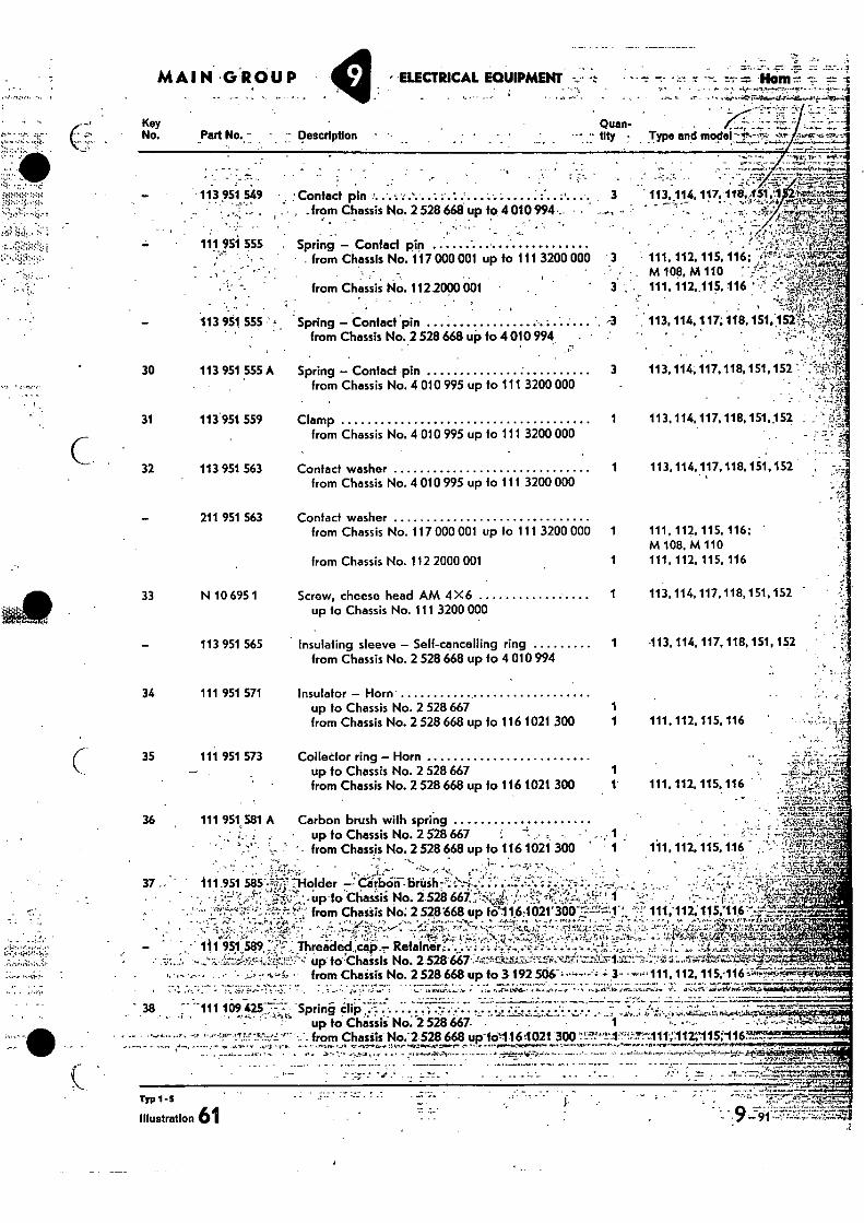
•
113, 114, 117,110,451,1 .1,4•Intwat:. •- v • - •••• • • -7... -
r..
Spring - Contact pin
3 113,114,117,118,151,152 from Chassis No. 4 010 995 up to 111 3200 000
Clamp 1
113,114.117,118,151,152 from Chassis No. 4 010 995 up to 111 3200 000
Contact washer .
1 113,114,117,118.151,152 from Chassis No. 4 010 995 up fo 111 3200 000
Contact washer
MAIN-G jROUP • -ELECTRICAL EQUIPMENT • -Mawr. 7--
Key
Quan- . •
No. Part No. - - Description
tlty - Type and model•-r--T,,,
..17-711
113 951 549 ' Contact pin - • _ • , from Chassis No. 2 528 668 up to 4010994,
• . •
111 951 555 Spring - Contact pin - . from Chassis No. 117 000 001 up to 111 3200 000
from Chassis No. 112.2000 001 , •
113 951 555 • 1 * Spring - Contact *pin from Chassis No. 2 528 668 up to 4 010 994
30 113 951 555 A
31 113 951 559
32 113 951 563
211 951 563 from Chassis No. 117 000 001 up to 111 3200 OM 1
from Chassis No. 112 2000 001
33 N 10 695 1 Screw, cheese head AM 4 X6 up 10 Chassis No. 1 1 1 3200 000
113 951 565 Insulating sleeve - Self-cancelling ring from Chassis No. 2 528 668 up to 4 010 994
34 111 951 571 Insulator - Horn
111, 112, 115, 116; M log, t..4 110
• 3 . 111. 112,.115, 116
. ' 113, 114, 117; 118, 151.1 52 ;'1-;;;,4....
111, 112, 115, 116; M 108, M 110
1 111, 112, 115, 116
1 113,' 114,117,118,151,152
113, 114, 117, 118, 151, 152
up to Chassis No. 2 528 667 1 from Chassis No. 2 528 668 up to 116 1021 300 1 111.112. 115,116
36 111 951.581 A Carbon brush with spring • " r_. : - • up to Chassis No. 2 528 667
•
' - from Chassis No. 2 528 668 up fo 116 1021 300 * .• 1 111, 112, 115, 116. • '
' - • •• ••-„,-••.--IP.--•••••-. 37 - ill_951 585%.",'.•7 Holder -Ciitbciii"--briiih 7.;' .̀.\:i..... 4: : o'...;.'....'• i ;
Chassis
, ' . AY ..!:, I.4 '. • !AA.
' •. oliT. . . up to No. 1.528 667•;!•••7;Q",;tt. .i!..;•• -..."i., -"I% .,.., ..,J'' 1 _'.;:..""•.; ,.; •".,-• ...p,-,.,..,.,...,..••-,4, 'I. a'''''' -' -... . .7.14,,i7.4i1 -., --'4";',:t'••• from Chatiis No. 2 52/3668 up fol1,61021`3007i;;•-A"'„ ''-"--; 111;112; 115;116".'-'"41-•
• • • .--... -c.:0.- ..•.; 7.::.-- 'A.:.04... - '' • ' • /1' 3.-,4,.. --..•.:r„..' .....1....ATWa,--, • '..'"';''-'-'".--"''-.--rAl...; :',' -I- —; .,-. .1:,..••.4.-ci.-.:.-•.;'.-,. .;zr;‘, ,:;.:.',. .-(--K, p.,":4'1,,,,::..4sl'itl',i.-7,,2flzif ,O 14;74.11?•,•. • - "1- 1 ,,,,' ' '' .'"-.'- ' ' .---'" '' • % ..; ...S. • - ' . ' • ..r... .),..,-.- 1.-A......",.4.,: ;I 71•17...',:-,c...r_.-' .-...e....i;,..:.:':.,14..-....._', ..V.,.!7•7-NYI4-k...'..74-474 .1V.,:iti-,-": . - . 1 11 951589 ;*:-,;:F : "ihrea-iied„caP _7- RefaIner.4. -.:.v '': .:.-. :•-„,.,-i;i:•......--...-: ....,...-V: ',-•,,.. .,, .._, 1-,.. • ,.,., ....'14.,, -4...,-,,._,t.i.,•;::„.4•••- -
.-.• - .. . ... _ . .. .. . . .
,.....:..i.7i.;.zi.•'::t....'...'--. up' fo'''Chaisis No. 2 528'667•:44!..r.b.:-.1%-,72...1-1:il,'"-7:1.-";"--71V1.112-::.-'- -71:.:::."1- 2;•-•-'s1:,7ib:r1S7igiP;:',aD# .. '....11':'-''''14.i41-V-0•;',1. •.
3. • . -. ',..- .. . , , .4 - .L A .., '%,.. A'',- '- from Chaitis No. 2 528 668 up to 3192r506, •-------"-,:-; 3- • -•-••••111, 11Z 115;116 ••••,,. ,!•-s..,-A...lair-i51-,_._,_.
up to Chassis No. 2 528667. • - -- • • -•'• 7 from Chasiis" No:2.528 668 up-te-1161021 300 v..•2?,•-t-4-"..-'....-411•,:112.:415;-116—..-
. •s-d- 1.1,
- • - - , . _ . •
Typ 1-5
Illustration 61
35 111 951 573 Collector ring - Horn up to Chassis No. 2 528 667 from Chassis No. 2 528 668 up to 116 1021 300 111.112.115,116
38 -- -111 188 as 7.7_7 -s • clip . , , • . •- prmg . .......... . . ..... 7 ... . .7... . .
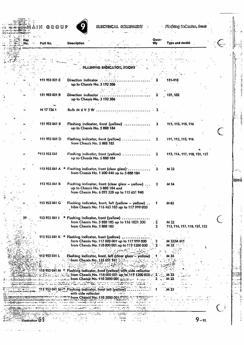
v. •••
. „ • PE.4.314i1G umbleAlroa, vricwr
111 953 021 E Direction indicator • • 2 111-118 up to Chassis No: 3 192 506
151 953 021 13 ,Direction indicator 2 151.152 up to Chassis No. 3 192 506
N 17 i26 1 Bulb M 6 V 3 W • 2
111 953 041 .13 Flashing indicator, front (yellow) 2 111,112, 115, 116 up to Chassis No. 51388 184
111 953 041 D Flashing indicator, front (yellow) 2 111, 112, 115, 116 from Chassis No. 5 888 185
•
•••. 0113 953 041 Flashing indicator, front (yellow) 2 113, 114, 117. 118, 151, 152 up to Chassis No. 5 888 184
113 953 041 A * Flashing indicator, front (clear glass)• 2 M 22 from Chassis No. 1 600 440 up to 5 888 184
113 953 041 B Flashing indicator, front (clear glass - yellow) ... 2 M 34 up to Chassis No. 5 888 184 and from Chassis No. 6 093 328 up to 115 651 940
• 113 953 041 G Flashing indicator, front, left (yellow - yellow) .. 1 M 82 . .frbm Chassis No. 116 463 103 up to 117 999 000
39 113 953 041 J * Flashing indicator, front (yellow)
from Chassis No. 5 888 185 up to 116 1021 300 - 2 M 22 from Chassis No. 5 888 185 2 113, 114, 117,118, 151,152
113 953 041 K * Flashing indicator, front (yellow)
from Chassis No. 117 000 00t' upto 117 999 OW 2 . M 221M 611
from Chassis No. 118 000 001,up fo 112 1200000 ,' - M 22 !-•.•
1.• ', . . ,-, , .. ••. • !_. t-':""--" -, • ....,. --..,...:.:i.i: -' • r. 'i
u w 113 953 041 L Flashing Indicator, front, -left (clear glass'7 yellow) , 1 - M 34 ' r")' '1'44.iA • • - . .' - from Chassis No..-L15 651 941 :;-,'-'..'.. 4 , :-...;,.....'.1. -.`..• _.: .;.• - ' ' -!,':......"-- .4.:`.:1-.7'..::-.- 4e..-N'. --. - • ..-z- - -'4:'•.....ii.1"--rn. ;A"T.,-7,..r..S.f.., „. , , . . ., . ..r ..: ..- ..'; ,•,, ,,,.....:: ..........,../. ,,..4.1•-•!.::::....... .,......;:. ,.... - , - -...,-? ,.......-
1 '1 1. 4 ',......., T•4''''''.1 V, ".';-4:: 113 -953 041 M * Flashing indicator, front
..
-(yelloie) with side reflector - . -- - '"'• ......,•,.,,,,•••••.- • .... ,
,.7.1e ,•0.tn-2.4. 0...---.e; 4.,..,••.11.,,.; , • -,.:. .--..„,-.71-"fiOrn Chassikfrio. 118 000 001 up:te`..-1•19 1200 000:, 2 ',.:::„..,M 23 • ........,• ' .
..;-.. I ...4...;,;:i.;.“,,,-4..,. ,,,.. Z.,. :.., .,..„ . ,... ....,....4.,...... from Chaisli No.•110 2000 001.i,--7,-;;•...T. , . : ...„ 2 -, . M 22
• .... is Mi3i i.4 . •,S..' 7 • • 4-4 a e... . •
.7, — -- -- --- - 113 953 041 p..6*. Fle-shirig indied—or, Wont left (yelloi;)• — = 1 .M 23 with side reflector
L'-'-'--- ••••'-••:'!"'"-- ''''"5:r:•&"-:-'"'" t-?-•• •-••'-' •''''''!'-from ChWisie N(4;1102000 OOPYrr-72- -'•-•.7'--rmr-.:'''''' • • —.lc
• • • . -
• 9-92
A I:2 0 11,1) • -
•71:', Key - No.
0.[ECYRICAIL Seg.EOPME/44 - PE.4ifi* t2CZaity4 &Mit
Quan- tity Typo and model Part No. Description
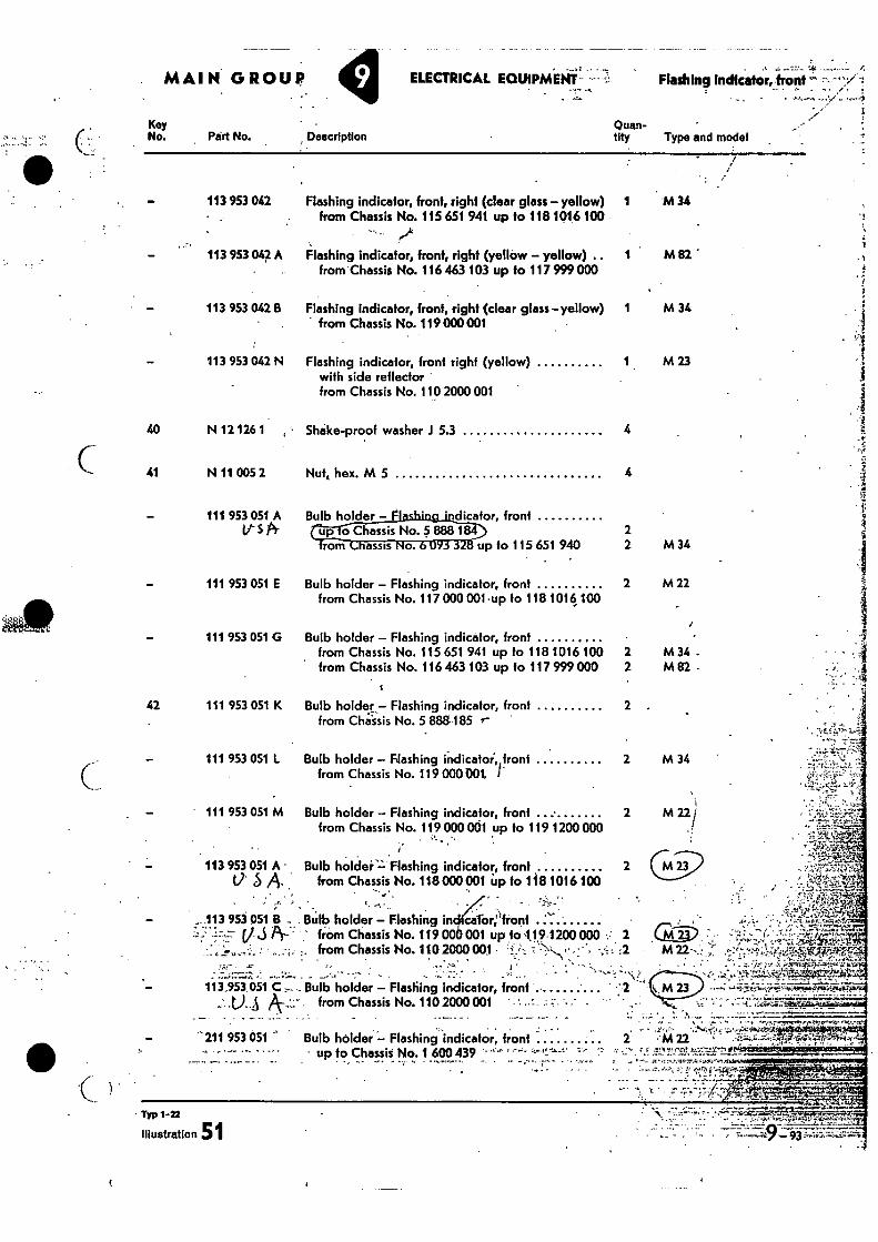
• .--•'•-.4.14a'V,45°MirtAl 211 953 051 Bulb holder - Flashing indicator, front 2 •'M 22
- •- - • -' • up to Chassis No. 1 600 439 '•"" '" , n •
TIT 1-22
Illustration S
MAIN GROUP
ELECTRICAL EQUIPMENT'-. Fluffing Indlcator,•front
— • ...
Key
Quan- •
No. Peirt No. Description
tity Type and model
113 953 042 Flashing indicator, front, right (clear glass - yellow) 1 M 34 from Chassis No. 115 651 941 up to 118 1016 100
113 953 042 A Flashing indicator, front, right (yellow - yellow) .. 1 M 82 from Chassis No. 116 463 103 up to 117 999 000
113 953 042 B Flashing indicator, front, right (clear glass-yellow) 1 M 34 from Chassis No. 119 000001
113 953 042 N Flashing indicator, front right (yellow) 1 M 23 with side reflector from Chassis No. 110 2000 001
40 N 12 126 1 • Shake-proof washer 5.3 4
41 N 11 005 2 Nut, hex. M 5 4
- 111 953 051 A Bulb holder - F1 ' dicator, front VS A ( tnCraassis No. S 888 184 2
fro m Foams No. up to 115 651 940 2 M 34
111 953 051 E Bulb holder - Flashing indicator, front 2 M 22 from Chassis No. 117 000 001 -up to 118 1016, 100
111 953 051 G Bulb holder - Flashing indicator, front •
from Chassis No. 115 651 941 up to 118 1016 100 2 M 34 . from Chassis No. 116 463 103 up to 117 999 000 2 M 82
42 111 953 051 K Bulb holder - Flashing indicator, front 2 from Chiissis No. 5 888185
111 953 051 L Bulb holder - Flashing inclicatoi,, front 2 M 34 from Chassis No. 119 000001. I"
111 953 051 M Bulb holder - Flashing indicator, front from Chassis No. 119 000 001 up to 119 1200 000
113 953 051 A • Bulb hOlder:iF lashing indicator, front 2 if 5 A . from Chassis No. 118 000 001 Up to 138 1016 100
-
- .113 953 051 B -. Bulb holder - Flashing in calor;.'front ''-- .,........ 7 i ..ci ..,...7.
(7 3 8-: ' from Chassis No. 119 00 001 up to 11 9-1200 000 : 2
Cm_.. . - . 2,- - •-• i'.. ... - -4 ,...-.. ''. ......,
I • •
" \ , • - . • (:-',.:_.:::,x4=-.. .4:414.4:4:11"E74.;' - ,
. ..-0.-".. • . 4. z. from Chassis No. 110 2000 001 i:. : 'f..... . - -, .: :2 M 22•-..! :r' F : 1-
-- -"NY .... k'...-- ....4._.*:, ...... A
113,953 051C .,.... Bulb holder - Flashing indicator, front .-....
: 7- from Chassis No. 110 2000 001 : .: - -" • ...- •
---..-: -L rt Z„i-k--,,,-;,.: ---,e t...ovek rr'i-
- - - - - -- - - '
2 m 22)
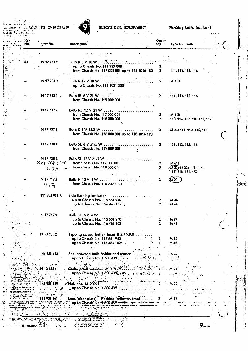
•
Key -- No. Part No.
43 N 17 731 1
N 17731 2
N 17 732 1 .
N 17 732 2
N 17 737 1
N 17 738 1
N 17 738 2 Zu (tr 0 3
U S A
N 17 717 2
s .7
111 953 061 A
N 17 717 1
N 13 905 2
141 953 153
N•12 135 1 te,-;: •
• -
•
7:-. MrAfi M 1:20[10
Description Quan- tity • Type and model
Bulb R 6 V 18W ' ' up to Chassis No. 117'999000 - • from Chassis No. 118000001 up to 118 1016 100 111,112, 115, 116
- . •
Bulb g 12 V 18 W up to Chassis' No. 116 1021 300
2 M 613
Bulb R1. 6 V 21 W from Chassis No. 119 000 001
2 111. 112, 115, 116
Bulb RI 12 V 21 W • from.Chassis No. 117 000 001 2 M 610 from Chassis No. 118000001 2 113, 114, 117.118, 151, 152
Bulb S 6 V 18/5 W from Chassis No. 118 000 001 up to 118 1016 100
2 M22:111,112,115,116
Bulb SL 6 V 21/5 W from Chassis No. 119 000 001
2 111, 112.115,116
Bulb SL 12 V 21/5 W '1 from Chassis No. 117000 001 2 M 611 w from Chassis No. 118 000 001 2 M 22: 113, 114,
18, 151, 152
Bulb H 12 V 4 W from Chassis No. 110 2000 001
2
Side flashing indicator up to Chassis No. 115 651 940 2 M 34 up to Chassis No. 116 463 102 2 M 46
Bulb HL 6 V 4 W up to Chassis No. 115 651 940 • M 34 up to Chassis No. 116 463 102 2 M 46
Tapping screw, button head B 2.9X9.5 up to Chassis No. 115 651 940 2 M 34 up to Chassis No. 116463 102/' • 2 M 46
Seal between bulb holder and fender up to Chassis No. 1 6004391 - • • - ;A:"
= • , •
- • e • • ;/ • •••••-•' • ... ,
2 M 22
- Shake-proof washppi21. .... : . up to Chassis No.,1 600 439,
2 . „
M 22
ELECTRICAL ECIWIPMENT, FlashInsi Inefcator, front
.,” es. , - 1'41 9i3 159 „c• Nuf, hex. M 26k1 2 M22_
- - - up fo Chassis No.-1 600 439_.— - - - - - _ • , • --L. • . I .
. • • < • ..v •
111 953 161 'Lens (clear glass) =- Flashing indiCator, front 2 M 22 D - - • up to Chassis' No:-1-600439
EP 152r. xCl• ..,;fir r - - t • r
• -•
7
9-94
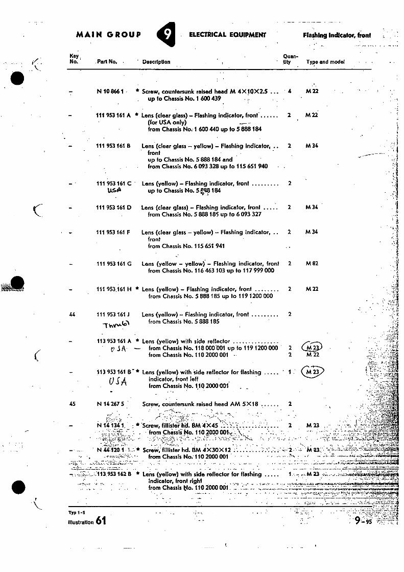
Description
MAIN GROUP
Key No. Part No. •
ELECTRICAL EQUIPMENT Flashing Indicator, front
Quan- • .11ty Type and model
111 953 161 B Lens (clear glass – yellow) – Flashing indicator, .. front up to Chassis No. 5 888 184 and from Chassis No. 6 093 328 up to 115 651 940
111 953 161 C• • LLSA
111 953 161 D
111 953 161 F
from Chassis No. 5 888 185 44 111 953 161 .1 Lens (yellow) – Flashing indicator, front 2
VriAl4I
113 953161 r
SA * Lens (yellow) with side reflector for flashing
indicator, front left from Chassis No. 110 2000.001 ,
Screw, countersunk raised head AM 5X18 2 45 N 14 267 5
Typ 1 - 5
Illustration 61 9=-95
N 10 866 1 • * Screw, countersunk raised head M 4X 11)X 2.5 ... . up to Chassis No. 1 600 439
111 953 161 A * Lens (clear glass) – Flashing indicator, front. (for USA only) __ -- from Chassis No. 1 600 440 up to 5 888 184
4 M 22
2 M 22
2 M 34
Lens (yellow) – Flashing indicator, front 2 up to Chassis No. 54.18 184
Lens (clear glass) – Flashing indicator, front 2 M 34 from Chassis No. 5 888 185 up to 6 093 327
Lens (clear glass – yellow) – Flashing indicator, 2 M 34 front from Chassis No. 115 651 941
Lens (yellow – yellow) – Flashing indicator, front 2 M 82 from Chassis No. 116 463 103 up to 117 999 000
111 953 161 G
111 953.161 H * Lens (yellow) – Flashing indicator, front 2 M 22 from Chassis No. 5 888 185 up to 119 1200 000
113 953 161 A * Lens (yellow) with side reflector ei .3 Fl — from Chassis No. 118 000'001 up to 119 1200000 • 2
from Chassis No. 110 2000 001 2 M 22
N 14 13i 1, * 'Screw, MI1514.1;11. BM 4X45 ":7 C; from Chisiii.No. 110 2000 0014)., ,
•
N 44'•1201 I. * ScreW;fitlister hd. BM 4X30X 12 " • • • from Chassis No.' 110 2000 001 • -
. „ . , ; . _ . . . .
• — • - t's%
- - - •
2 •
162 B * Lens (yellow) with side reflector for flashing 1 ,M 23 indicator, front right
• • •-t . • - from Chassis tio. 110 2000 001
• 'd
--, A
A
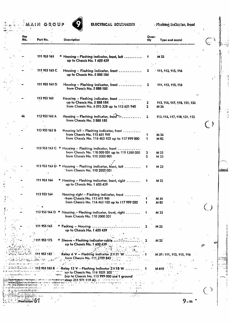
- -‘AilAgM GROUP ELECTRICAL ECIUPMEMT - FIeshint InelerIAN, fren2
Key Quan- No.. ' Part No. Description tity Type and model
up to Chassis No. 116 1.021 300'" " "4"-- (up to' Chassis N. 115 999 000 use` 1 ground
,6gatadatokkeza. 4. ttr, .strap 211 971 119 A)„
'7-
;IL ?, . ..111ustratiOn-
111 953 163 * Housing - Flashing indicator, front, left up to Chassis No. 1 600 439
1 M 22
' 111 953 163 C Housing - Flashing indicator, front' up to Chassis No. 5 888 184
2 - 111, 112, 115,116
111 953 163 13 Housing - Flashing indicator, front from Chassis No. 5 888 185
2 111, 112, 115, 116
113 953 163 Housing - Flashing indicator, front up to Chassis No. 5 888 184 2 113, 114, 117, 118. 151, 152 from Chassis No. 6 093 328 up to 115 651 940 2 M 34
113 953 163 A Housing Flashing indicator, front-- from Chassis No. 5 888 185
2 113,114, 117, 118, 151,152
113 953 163 B Housing left - Flashing indicator, front from Chassis No. 115 651 941 1 M 34 from Chassis No. 116 463 103 up to 117 999 000 1 M 82
113 953 163 C * Housing - Flashing indicator, front from Chassis No. 118 000 001 up to 119 1200 000 2 M 23 from Chassis No. 110 2000 001 2 M 22
I 113 953 163 D * Housing - Flashing indicator, fr'ont, left 1 M 23
• from Chassis No. 110 2000 001
111 953 164 * Housing - Flashing indicator, front, right up to Chassis No. 1 600 439
1 M 22
113 953 164 Housing right Flashing indicator, front • from Chassis No. 115 651 941 1 M 34 from Chassis No. 116 463 103 up to 117 999 000 1 M 82
113 953 164 D * Housing :- Flashing indicator, front, right from Chassis No. 110 2000 001
1 M 23
111 953 165 * Packing - Housing 2 M 22 • up to Chassis No. 1 600 439 •
. . 111 953 175 * Sleeve Flashing indicafor•cable . :
up to Chassis No. i 600 439. . • • . • 2 M 22
111 953183 - ' Relay 6 V - Flashtrig indicator 2X21 'W • from Chassis No. 111 2799 843' • '
•
4 M 37: 111, 112, 415,.116 •
, 113 953 183 B Relay 12 V - Flashing indicator 2 X18 W 1 M 610
•
46
9- 96
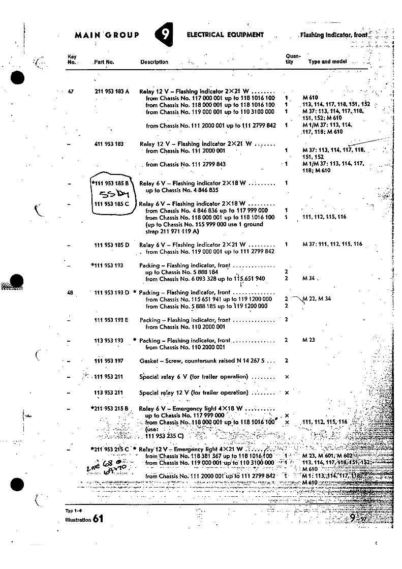
- .111 953 211
113 953 211
- *211.953 215 B
Typ 1-8
Illustration 61
- • • • •— -• • 11'•'...4,
r • • :• rz. •-•••• .•:.rir'74;••*:1,51.7:: •
MAIN . GROUP y ELECTRICAL EQUIPMENT
Flashing indicator, front:
Key No. Part No.
411 953 183 •
- *111 953 185 B
111 953 185 C
Description
Relay 12 V — Flashing indicator 2 X 21 W from Chassis No. 117 000 001 up to 118 1016 100 from Chassis No. 118 000 001 up fo 118 1016 100 from Chassis No. 119 000 001 up to 110 3100 000
from Chassis No. III 2000 001 up to 1,11 2799 842
Relay 12 V — Flashing indicator 2X21 W from Chassis No. 111 2000 001 •
. from Chassis No. 111 2799 843
fluan- tity Type and model
1 M 610 . 1 .113, 114. 117, 118, 151, 152 1 M 37: 113, 114, 117, 118. .•
151, 152; M 610 - 1 MIN 37; 113, 114,
117,118; M 610
1 M 37: 113, 114, 117, 118, • 151,152
• 1 MIN 37: 113, 114, 117, . 118; M 610
1 M 37: 111, 112, 115, 116
2 2 M 34 ,
2 22, M 34 2
- • 47
211 953 183 A
111 953 185 D Relay 6 V — Flashing indicator 2X21 W from Chassis No. 119 000 001 up to 111 2799 842
- *111 953 193 Packing — Flashing indicator, front up to Chassis No. 5 888 184 from Chassis No. 6 093 328 up to 115.651 940
• 48 111 953 193 D * Packing — F1'ashing indicator, fronf
from Chassis No. 115 651 941 up to 119 1200 000 from Chassis No. 5 888 185 up to .119 1200 000
Relay 6 V — Flashing indicator 2X18 W -
1
up to Chassis No. 4 846 835
Relay 6 V— Flashing indicator 2 X18 W from Chassis No. 4 846 836 up to 117 999 000 1 from Chassis No. 118 000 001 up to 118 1016 100 1 111.112. 115, 116 (up to Chassis No. 115 999 000 use 1 ground strap 211 971 119 A)
•
111 953 193 E
Packing — Flashing indicator, front from Chassis No. 110 2000 001
113 953 193 * Packing — Flashing indicator, front
2 M 23 from Chassis No. 110 2000 001
111 953 197 Gasket — Screw, countersunk raised N 14 267 5 2
Special relay 6 V (for trailer operation)
Special relay 12 V (for trailer operation)
Relay 6 V — Emergency tight 4X 18 W
- — from Chassis No.118 000 ow up to 118 1016 100° up io Chaisis No. 117 999 000 ' . x
..• .. • x111,112.115.116:
, 111 953 235 C) . ,• , .. • ••
- *211.953 21'5 C Relay- 12 V Emergency light 4X 21 W ''':' ''' ' - ' "" °' from Chassis-No. 118 381 367 Up to 118 1016. 00 - 1
woe frOin Chaisis No. 111 2000 001' UP:18 111 2799 842 1• :1M 1i' 113;i1it,117;:
• e m 610 •71,,ro . • • • •
•
• •
63,3 — from Chassis No. 119 000 001 -up"id 110 3106000 • ',4 1-
•• . ' 7 .749rp,"...V..=.1,4:..-e.1., • ••7 -
M 23, a601;'M 113. 114, 117;11 6;;451:i4
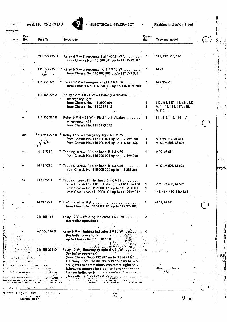
Key No.
MALIN G DP ©M Y • .IELECMOCAL EGUOPMELIP
Flashhig links2ow, front
Description Quan-tity Type and model
Relay 6 V — Emergency light 4X21 W from Chassis No. 119 000 001 up to 111 2799 842
1 . 111.112,115,116
* Relay 6 V — Emergency light 4X18 W from Chassis No. 116 000 001 up
' 10117'999 000
I M 22
* Relay 12 V — Emergency light 4X18 W from Chassis No. 116 000 001 up fo 116 1021 300
1 M 221M 610
Relay 12 V 4 X21 W — Flashing indicator/ emergency light from Chassis No. 111 2000 001 1 113,114,117, 118,151, 152 from Chassis No. 11.1 2799 843 M1: 113, 114, 117, 118;
M610
Relay 6 V 4X21 W — Flashing indicator/ emergency light . from Chassis No. 111 2799 843
1 111, 112, 115; 116 '
If Relay 12 V — Emergency light 4X21 W from Chassis No. 117 000 001 up to 117 999 000 1 M 22/M 610, M 611 from Chassis No. 118 000 001 up to 118 381 366 M 23, M 601, M 602
* Tapping screw, fillisler head B 4.8X55 from Chassis No. 116 000 001 up to 117 999 000
1 ' M 22, M 611
* Tapping screw, fillisler head B 4.8X45 from Chassis No. 118 000 001 up to 118 381 366
1 M 23, M 601, M 602
* Tapping screw, fillister head B 4.8X22 from Chassis No. 118 381 367 up to 118 1016 100 from Chassis No. 119 000 001 up to 110 3100 000 from Chassis No. 111 2000 001 up to 111 2799 842
M 23. M 601, M 602
111, 112, 115, 116; MI
* Spring washer B 5 from Chassis No. 116 000 OM up to 117 999 000
M 22, M 611
Relay 12 V — Flashing indicator 3X21 W (for trailer operation)
211 953 231 D
Part No.
211 953 215 D
111 953 225 B
111 953 227
111 953 227 A
111 953 227 B
49 *211 953 227 B
Lel 14° N 13 978 1
N 13 952 1
50 N 13 971 1
_ . . ,s..•••••• • it r • r • • - • ...er....tOr
' .....a",‘;-4,2-r • " ,
N 12 225 1
211 953 187
261 953 187 8 Relay 6 V — Flashing indicator 3 X18 W . (for trailer operation) • • ' - • .
•• LIP to Chassis No. 118 1016 100 , 7•7;
• *.f . - Relay 12 V,— Emorgencir light 6c21,A4r:':;...
(for trailer operatiOn) •(from Chassis No. -3 192 507 up to 3 8564711'; . . Germany, from Chassis No. 3 192 507 up fo 4 010.994: export markets, convert taillights to twin-compartments for stop light and - - flashing indicators)•' - • ' - •'•''' • - (Use switch 211 953.235 A •
• • Ca
-4.1$
'yr - • . - • . - • - •
•
Iflusirailon-611 9-98
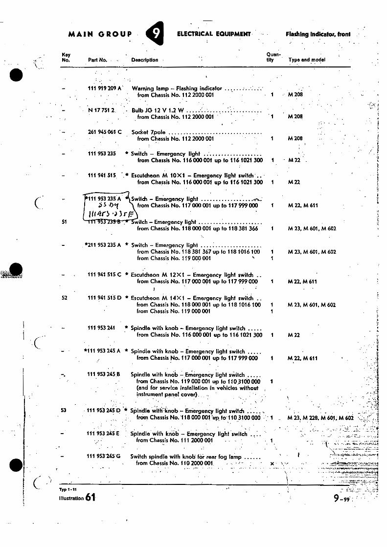
MAIN GROUP ELECTRICAL EQUIPMENT Flashing Indicator, front •
Key tp ity uan- No. Part No. , Description Type and model
111 919 209 A' Warning lamp — Flashing indicator from Chassis No. 112 2000 001 • 1 M 208
— N 17 751 2. . - Bulb JG 12 V 1.2 W • from Chassis No. 112 2000 001 ' ' 1 M208
261 945 061 C Socket 7pole from Chassis No. 112 2000 001 1 M 208
111 953 235 * Switch — Emergency light from Chassis No. 116 000 001 up to 116 1021 300 1 • M 22 •
111 941 515 Escutcheon M 10X 1 — Emergency light switch .. from Chassis No. 116 000 001 up to 116 1021 300 1 M 22
111 953 235 A Switch — Emergency light r, • 01 from Chassis No. 117 000 001 up to 117 999 000 1 M 22, M 611
itor5. r 51 witch — Emergency light
from Chassis No. 118 000 001 up to 118 381 366 1 M 23, M 601, M 602
*211 953 235 A * Switch — Emergency light from Chassis No. 118 381 367 up to 118 1016 100 1 M 23, M 601, M 602 from Chassis No. 119 000 001 • 1
111 941 515 C * Escutcheon M 12 X1 — Emergency light switch .. from Chassis No. 117 000 001 up to 117 999 000 1 M 22. M 611
52 111 941 515 D * Escutcheon M 14 X1 — Emergency light switch .. from Chassis No. 118 000 001 up to 118 1016 100 1 M 23, M 601, M 602 from Chassis No. 119 000 001 1
111 953 241 * Spindle with knob — Emergency light switch from Chassis No. 116 000001 up to 116 1021 300 1 M 22
- *111 953 245 A * Spindle with knob — Emergency light switch ..... from Chassis No. 117 000 001 up to 117999000 1 M22, M 611
111. 953 245.13 Spindle with knob — Emergency light switch from Chassis No. 119 000 001 up 101103100 000 1 (and for service installation in vehicles without , instrument pane! cover). •.
. _
53 111 953 245 D * Spindle with:knob — Emergency light switch . — . .
from Chassis No. '118 000 001 'up to'110 3100000 • ' 1 M 23, M 228, M 60.1; M 602 '•- '
— 111 953 245 E Spindle with knPb — Emergency light switch . , : . ' •,,.. • _ from Chassis No. 111 2000 001 • • .
111 953245 G Switch spindle with knob for rear fog lamp from Chassis No. 110 2000 001, • • - ' -
• ""
.3
ql
1 . • -
• „: .
•
rypt-11
Illustration 61.
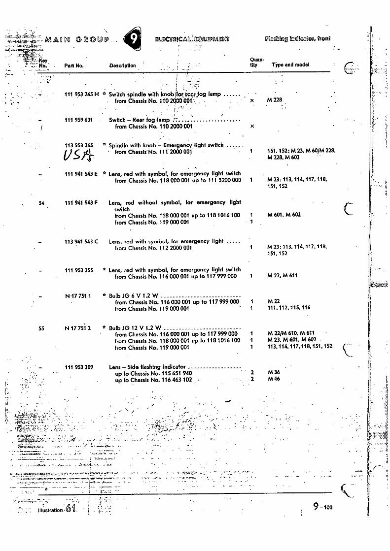
9-10o • II Illustration .6 u . -..
A A
-.Z....." ynt"..j."'` - m A 0 b GROUP.. ELECTRICAL -...saUIPMENT F6EfsaL5 teacior, Irani 1:7-. 7" .-- - ...t...4.1,, - .
• Part No. Description Quan-tity Type and model
• , • ; 111 953 245 H * Switch spindle with knobilor vocr,og lamp
• from Chassis No. 110 2900 001.:. . x M 228
111 959 631 Switch - Rear fog-lamp from Chassis No. 110 2000 001 x
113 953 245 * Spindle with knob - Emergency light switch from Chassis' No. 111 2000 001 - 1 151,152; M 23, M 60/M228,
M 228. M 603
111 941 543 E * Lens, red with symbol, for emergency light switch from Chassis No. 118 000 001 up to 111 3200000 1 M 23: 113, 114, 117, 118,
151, 152
111 941 543 F Lens, red without symbol, for emergency light switch from Chassis No. 118 000 001 up lo 118 1016 100 from Chassis No. 119 000 001
1 M 601, M 602
113 941 543 C Lens, red with symbol, for emergency light from Chassis No. 112 2000 001 1 M 23: 113, 114, 117, 118.
151,152
111 953 255 * Lens, red with symbol, for emergency light switch from Chassis No. 116 000 001 up to 117 999 GOO 1 M 22, M 611
N17 751 1 * Bulb JG 6 V 1.2 W from Chassis No. 116 000 001 up to 117 999 OM 1 M 22 from Chassis No. 119 000 001 1 111, 112, 115, 116
N 17 751 2 * Bulb JO 12 V 1.2 W from Chassis No. 116 000001 up to 117 999 000 1 M 22/M 610, M 611 from Chassis No. 118 000 001 up to 118 1016 100 1 M 23, M 601, M 602 . from Chassis No. 119 000 001 1 113,114.117, 118,151, 152
111 953 309 Lens - Side flashing indicator • up to Chassis No. 115 651 940 2 M34
up to Chassis No. 116 463 102 - 2 M 46 •
4 AtZ ZArox ril.A • .7 ....44- •
C....-:::.: .
'17=;146.:' -4(ey
54
55
• • - • •
••
,r410 .0.1z • • • • -
.r
• ••••••••,, ker....e - • -
- 7
• • A. I/ / 73 ,:"
, 1414?4,-,•jr - • . . n• . . • N • - I -,-• - • ^ •
, • 1 y
• • . • , . 1,
" %•••• ' • ."7" "" ' " - . • - --r• • -t :
. 4-4. 7. • ••• • - 4 . 4. • • • - .4: ."4.0
• .. • • ;
• , 7 . ,. - - •.• .4', -
.• '44 4:4e.`,,,"..'•:rili..;..P.:y<7.2,-..r 4W4.:•;,.-p
r.
. . _ . . .i.:_-:::-. f.:,-_, ._ :..'.:,•.::::..-...-7'.. ;:. ...::::::;2;z1.17C:.T.Z....•72,-;47-7:./,12*:: •:".-:',27:',,:;:::- .:,::1, .,;.` , -!"--..;;E...--:;;;;fl.-7;"T.........-1.7;",:r."" • --•_-_ ..--z . L.- .,.:.,,t___. .:.--4,. ,y7..'_,.:;:r : •-.._. ..,... —4:-..-.,.. „1:.<!-;:sir,••..ziv„4•;,1,71 ...(..,:,...!.:.,;,34,17, .:-‘07-.2.i.,./'..-:ris• ..kr.54Z,AtTlax4A11'."4;la t
. 1
7-1•0' --;,̀-sre17•-"':',..r;cJA,f-' •,;•••:.• .
- • 4,1,1 474 • • • •• 4 r. ": ?P l.': 11r-c," - - -4.- --4• 7- • .. • — • - • kr -14. .," ;-•„;,1-.„,,:t
•
-
- " -.7.• • - 4, -44 .
• : -;"." -7.-*""'""
'i :...... •: 1 ' ..1 '...:•--....'1;'N.. ..,,......,:.. :..-.... ,r ' .•••-•,-.-',:r.s;i1,tr ., • . ... .''. " ' ,,; ' '-..!,',..1.•!.r.'''',.n''''
•. ."' . • ',-1, • ' ' ? . ...,•,,..licrr..:'' „...*; ...-•,,,,. ....'5'.
:' '•;; "•••.'".;',zi.'4.
. . ' ' • ..;,::.Fr,',.• • . . • ••.' '.,.. ,...,,,I.;-'.....i-
• • ;',-,•:-..,..!•. . • . , ..
•
— r, •
•
•
• : •
• \ 1"...":4';`.4rt . - • -4 -• . • - -• ..-••,......E•4444.^411._,.. 41 .4 A ••ra, 4.7 •-• • T42.• .r7
• , , . • , .. I
4,..hab.“11.444,441,4441,1,1114A74,1V24.5742.-:747tWer--7.14,...;.71.7,103,1- 7.1., 44*-r.141`..,7,1=1:24,"
•
. •.2*,•,••• nmd.......••••••••••.M1.,•••••Ini
Typ 1-5
r..
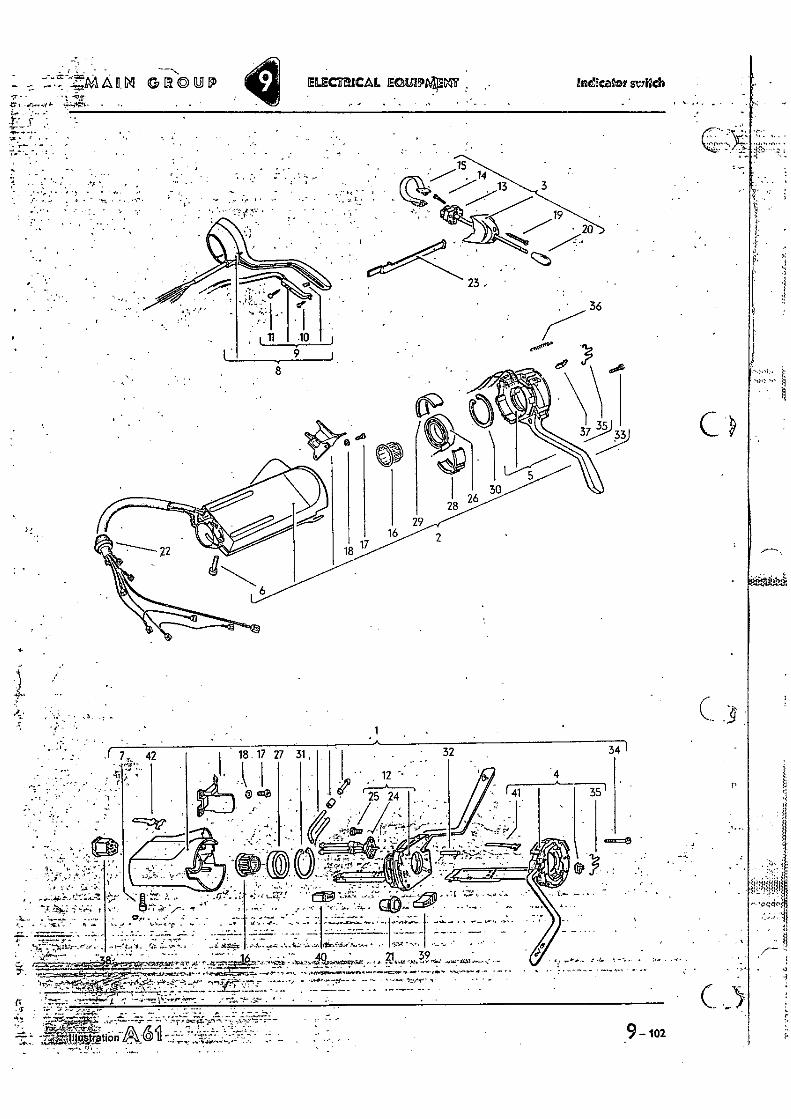
• VIAIIVI GROUP ELECTRICAL ECISIPAAMT Ind!cam' sr/12cl9
zr
•
10
8
4
." .
34 1 . .( 7, 42 . •
• 12 • e . 25 24 /
• , • r.a o.-a •arsLLa u.cr=r 39
, _
. — ' • "
,
•
. 13
9 — 102
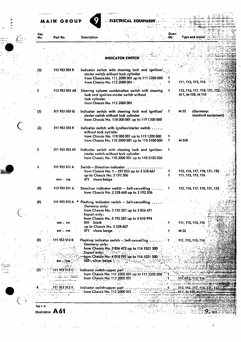
MAIN GROUP ELECTRICAL EQUIPMENT .---.= -
Gum- tlty .
Key No. Part No. Description Type and model ;-•• ;•;-•-••••-•
111, 112, 115, 116
113.114, 117, 118, 151, 152:- Ml,M108,M110 •
starter switch without lock cylinder . from Chassis-No. 111,2000 001 up to 111 3200 000 1 from Chassis No. 112 2000 001 •• 1
Steering column combination' switch with steering lock and ignition-starter switch without lock cylinder - from Chassis No.112 2000 001
M 55 (Germany: standard equipment) :
Indicator switch with steering lock and Ignition/ 1 starter switch without lock cylinder . from Chassis No. 118000 001 up to 119 1200000
M 248
Indicator switch with ignition/starter switch without lock cylinder from Chassis No. 118 000 001 up to 119 1200000 from Chassis No. 110 2000 001 up to 110 3100 000
111,112,115.116 •
Switch - Direction indicator from Chassis No. 1 - 397 023 up to 2 528 667 1 113,114, 117, 118, 151.152 up to Chassis No. 3 192 506 471 stone beige
Direction indicator switch - Sell-cancelling 1 113, 114,117, 118.151, 152 from Chassis No. 2 528 668 up to 3 192 506
11 .111. • 12,115:116 4., • -•-•
'"1.11 953-513'C": Indicator Swilch-Uppei Part ' • " • from Chassis No. 111 2000 001 up to. 111 3200 000 'T'1
"'"•' ' from Chassis No: 112 2000 001 • . .
- • - • • • • •.•.••••_•.1!.,..,!,•••••4..•2;ei..',.--..larty, •••• 4 111 953 513 E Indicator svititch7upper,pert .. . ....... , air •
_ - from'Chast is No. 112 2000 001 ,- • ' 1!• -.
•
Ar.1 0 3 ;•7r
• I -11 frr'sr7-1
..• -
Indicator switch with steering lock and ignition/,, •,
Indicator switch with steering lock and ignition- 1 starter switch without lock cylinder from Chassis No. 110 2000 001 up to 110 3100 000
•
!3)
SM. 466`S.-silver beige ,a;---•- •
(2) 113 953 503 R
113 953 503 AE
(2) 311 953 503 Q
(2) 311 953 503 R
2 311 953 503 AF
3 111 953 511 A
10/52 - 7/60
(8) 113 953 511 A
(8) 111 953 513 A * Flashing indicator switch - Self-cancelling Germany only: from Chassis No. 3 192 507 up to 3 856 471 Export only: from Chassis No. 3 192 507 up to 4 010 994
6/60 - 7161 041 black up to Chassis No. 2 528 667
8157 7159 471 stone beige
111 953,513 B Flashing indicator' switch' - Self-cancelling 1 Germany only: • - r ••• '
, • •• from Chaisis No."31356472 up to 116 1021 300 • • Export only:, • • •1-:-
m Chaiiis 4010.99511p to 116 1021 300
INDICATOR SWITCH
• Artr4I'''
r‘-'7•' • • • • • •
-
!% .".("j-r
•
• ..
Typ 1 -5
Illustration A 61.. •
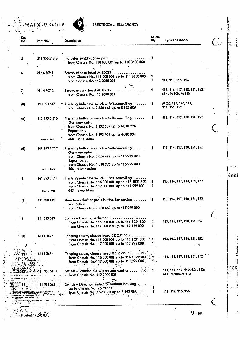
•OC/0101!) ELECTRICAL Ecnewarn
9-104 illustration
Description Quan-tity Type and model
Indicator switch-upper part from Chassis No. 118 000 001 up to 110 3100 000
1
Screw, cheese head M 8X22 from Chassis No. 118 000 001 up to 111 3200 000 1 from Chassis No. 112 2000 001 1 111, 112, 115, 116
Screw, cheese head M 8X 15 1 113, 114, 117, 118,151, 152; from Chassis No. 112 2000 001 M1, M 108, M 110
° Flashing indicator switch - Self-cancelling 1 M 22: 113. 114, 117. from Chassis No. 2 528 668 up to 3 192 506 118, 151. 152
Flashing indicator switch - Self-cancelling 1 113. 114,117, 118, 151, 152 Germany only:
• from Chassis No. 3 192 507 up to 4 010 994 ' Export only: from Chassis No. 3 192 507 up to 4 010 994 468 sand stone
Flashing indicator switch - Sell-cancelling 1 113, 114, 117, 118, 151.152 Germany only: from Chassis No. 3 856 472 up to 115 999 000 Export only:
. from Chassis No. 4 010 995 up to 115 999 000 466 silver beige
Flashing indicator switch - Self-cancelling from Chassis No. 116 000 001 up to 116 1021 300 1 113, 114, 117, 118, 151, 152 from Chassis No. 117 000 001 up to 117 979 000 1 043 grey-black
Headlamp flasher press button for service installation
1 113, 114. 117, 118. 151, 152
' from Chassis No, 2 528 668 up to 115 999 000
Button - Flashing indicator from Chassis No. 116 000 001 up to 116 1021 300 1 113, 114, 117, 118, 151, 152 from Chassis No. 117 000 001 up to 117 999 000 1
Tapping screw, cheese head BZ 2.2 X 6.5 from Chassis No. 116 000 001 up to 116 1021 300 ' 1 113,114,117,118,151,152 from Chassis No. 117 000 001 up to 117 999 000 1
2rb
Tapping screw, cheese head BZ 2.2 X11. ..... , - from.Chassis No. 116 000 001 up .to 116.1021 300 113, 114, 117, 118, 151,152 from 'Chassis No:117 000 001 up to 117999 000 1 .
Switch - Windshield wipers and washer 1 113, 114, 117, 118, 151, 152; • from Chassis No. 112 2000 001 M 1, M 108, M 110
Switch wit Direction indicator hout housing up to Chassis No. 2 528 667 1
•••" • from Chassis No. 2 528 668.2p fo 3 192 506 1 111012, 115.116
Kay No. Part No.
5 311 953 513 8
6 N 1 7o9 1
7 N 14 707 2
(8) 113 953 517 B
$mo - 7/61
141 953 517 C
- 7/65
8 141 953 517 F
11/65 - 7/67
(8)
(8) 113 953 517
' 10
(9) 111 998 111
9 311 953 529
N 11 362 1
, 111,953*S21
• ' .•••4. • .."..Stv -
"i • '-",•774'7"".•••"7-'•'7••:•`''''''''" • . '
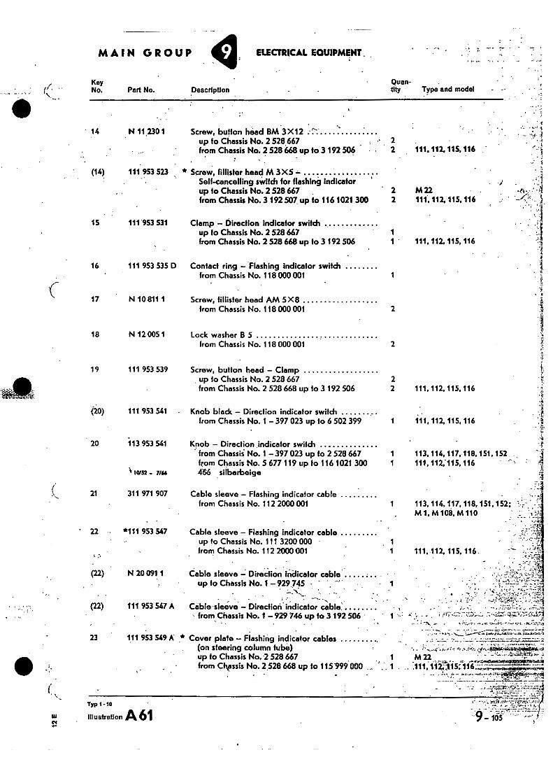
•
MAIN GROUP ELECTRICAL EQUIPMENT.
Key Quan- No. Part No. Description City Type and model
14 N 112301 Screw, button head BM 3X12 up to Chassis No. 2 528 667 .• 2 from Chassis No. 2 528 668 up to 3 192 506 2 111, 112, 115. 116
(14) 111.953 523 * Screw, (Mister head M 3X5 Self-cancelling switch for flashing indicator up to Chassis No. 2 528 667 2 M 22 • from Chassis No. 3 192 507 up to 116 1021 300 2 111, 112, 115, 116
15 111'953 531 Clamp - Direction Indicator switch up fo Chassis No. 2 528 667 1 from Chassis No. 2 528 668 up to 3 192 506 1 111. 112. 115, 116
16 111 953 535 D Contact ring — Flashing indicator switch from Chassis No. 118 000 001 1
17 N 10 811 1 Screw, (Mister head AM 5X8 from Chassis No. 118 000 001
2
18 N 12 005 1 Lock washer B 5 from Chassis No. 118 000 001
2
19 111 953 539 Screw, button head — Clamp _ up to Chassis No. 2 528 667 2 from Chassis No. 2 528 668 up to 3 192 506 2 111, 112, 115, 116
(20) 111 953 541 - Knob black — Direction indicator switch from Chassis No.1 — 397 023 up to 6 502 399 1 111, 112, 115, 116
20 113 953 541 Knob — Direction indicator switch ' from Chassii No. 1 — 397 023 up to 2 528 667 1 113,114,117.118, 151, 152
from Chassis No. 5 677 119 up to 116 1021 300 1 111, 112,115, 116 1. tam - 7/ff 466 silberbeige
21 311 971 907 Cable sleeve — Flashing indicator cable from Chassis No. 112 2000 001 1 113, 114, 117, 118, 151, 152;
M1, M 108, M 110
•
22 *111 953 547 Cable sleeve — Flashing indicator cable up to Chassis No. 111 3200 000 from Chassis No. 112 2000001
(22) N 20 091 1 Cable sleeve -; Direction Indicator cable up to Chassis No. 1- 929 745 • , • 1
111. 112, 115, 116 .
- •.• "e;.2.,1
(22) 111 953 547 A Cable•sleeve - Direction. indicator cable: . , •
from Chassis No. f — 929 746 up to 3 192 506 1 - , ,....:-...--: - 7`.....)... .- .-......=- 1-Ei::...if:•::...471 • ... ..c
. • - , 23 111 953 549 A * Cover plate — Flashing indicator cables
.. . ,, . .......,_ ..----.-.-- i..,...-...,,.....4...i.......---..
(on steering column tube) -ice;
, : - ., ,..........,...-..fr.,-.....a,,..452614441504.
.
0411‘,1
from CIrssis No. 2528 668 up to 115999'000 - .. ,111,112:<1.15 116 ' -,'- 4.-...4:1,....- ., up to Chassis No. 2 528 667 M 22 ....,.........„,,,,i,
2-, 7 . - ,.,...........2,-.7 .t...T...-4.:.'"'W"....".."1,,t44.......1. ::,......::
Yip 1- lo VCS
SU illustration Ak 61
-9 -
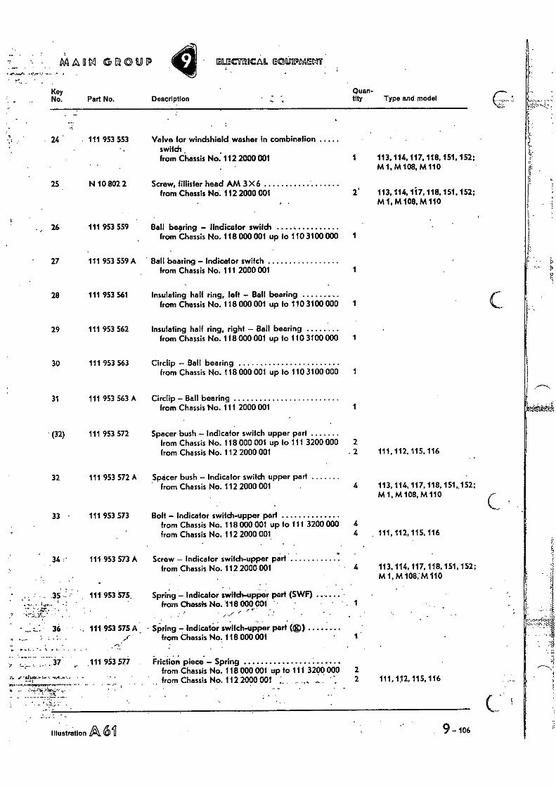
Illustration A, 611 9 - 106
MM GL1©UI maamicia mccknomm
Description Quan-tity Type and model
Valve for windshield washer in combination switch from Chassis No. 112 2000 001 1 113, 114, 117, 118,151,152;
M 1, M 108, M 110
Screw, 'Mister head AM 3 X 6 from Chassis No-. 112 2000 001 113, 114,1i7, 118, 151.152;
M1, M 108, M 110
Ball bearing - 'indicator switch from Chassis No. 118 000 001 up fo 110 3100 000 1
Ball bearing - Indicetor switch from Chassis No. 111 2000 001 1
Insulating half ring, left - Ball bearing from Chassis No. 118 000 001 up to 110 3100 000 1
Insulating half ring, right - Ball bearing from Chassis No. 118 000 001 up to 110 3100 000 1
Circlip - Ball bearing from Chassis No. 118 000 001 up to 110 3100 000 1
Circlip - Ball bearing from Chassis No. 111 2000 001 1
Spacer bush - Indicator switch upper part from Chassis No. 118 000 001 up to 111 3200 000 2 from Chassis No. 112 2000 001 2 111.112, 115, 116
Spacer bush - Indicator switch upper part from Chassis No. 112 2000 001 4 113. 114, 117, 118, 151,152;
Ml, M108, M 110
Bolt - Indicator switch-upper part from Chassis No. 118 000 001 up to 111 3200 000 from Chassis No. 112 2000 001. 4 111, 112, 115, 116
Screw - Indicator switch-upper part from Chassis No. 112 2000 001 113, 114, 117, 118, 151, 152;
MI, M 108,44110
Spring - Indicator switch-upper part (SWF) from Chassis No. 118 000 COI - •
Key No. Part No.
111 953 553
2.5 N 10 802 2
26 111 953 559
27 111 953 559 A
28 111 953 561
29 111 953 562
30 111 953 563
31 111 953 563 A
• (32) 111 953 572
32 111 953 572 A
33 111 953 573
34 :• 111 953 573 A
35 - 111 953 575,
36 • • 111 953 575 A - Spring - Indicator switch-upper part (g,i) from Chassis No. 118 000 001
Friction piece - Spring from Chassis No. 118 000 001 up to 111 3200 000 from Chassis No. 112 2000 001 L
„(
_
. 37 111 953 ,57.4 2 2 111, 112, 115, 116
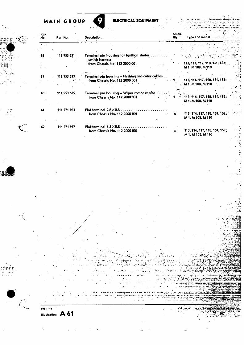
Typ 1 -10
Illustration A 61
. e a . , t.air ' ,t .
. vaiy, aft,..«.42., :!•="ACCIK1014 LIMICSII •
• - • •
:t1 •
•
MAIN GROUP
Key No. Part No. Description
ELECTRICAL EQUIPMENT
Quan-tity Type and model
•••• 4MG•ikr
• .
3? 111 953 631 Terminal pin housing for ignition starter , ..... harness _switch
from Chassis No. 112 2000 001 113, 114, 117.118, 151, 152; , M 1, M 108, M110
. •
39 111 953 633 Terminal pin housing — Flashing indicator cables .. from Chassis No. 112 2000 001 113, 114, 117, 118.151, 152; •
M1,M108,M 110 •
40 • 111 953 635 Terminal pin housing — Wiper motor cables • ` ,„ •
• • ..c
• from Chassis No. 112 2000001 1 •-; 113,114,•117,118,151,152; M 1, M 108, M1.10
41 111 971 983 Flat terminal 2.8X0.8 from Chassis No. 112 2000 001 x 113, 114, 117, 118, 151, 152; •
M 1. M 108, M 110
42 111 971 987 Flat- terminal 6.3 X0.8 from Chassis No. 112 2000 001 x 113, 114, 117.118, 151, 152;
Ml, M 108, M110
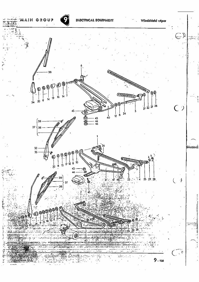
•
istiation- •
ELECTRICAL EOUIPMENT WInclAileld wiper
26
g cLe 20
1 113
12 10
'••• " 41 47 46:-:` .• 23 4
43 44
25 29. 28 ,
.,•• • S, 1,47, 4-rk,
At--,....-;,. 1 ' • i.• :::.--.L. - .!., ,_. • _ • ,: -• , ,
"t'..: : • 4.. . tV1.- -**.el j• ..17,4,) .• • ..-r",... ....0. 'C.' • , 4 i
' '-' -•':' ,- ''. -'i '...;;-•,..A.) ,--:-.
;
.:. 0
.. . ..,,, .,... ir Ai .,,r,, .. ,. Ic•••;! . .91- 11-76. 5.. ."•••;:, . . .. 4 .,......,,,,,_. 7•,,r a.; .. ,.. 21. • y -17- , .....• _ 4..,-; 1 , - • . ..,
......)!-t4X I' IL;
, • • - • - ' 42 " '1 • - • -
rok
t 43-7 414.— • -1̂ ,
r.'•'" • ;
• "
.•-••i•. • •
gra 'in.:,
, . . .
• — . pia! • •
•
!""-.-÷1;.• -Fa - • - • _ . ,
ot. tt itt,trtt 9 — los
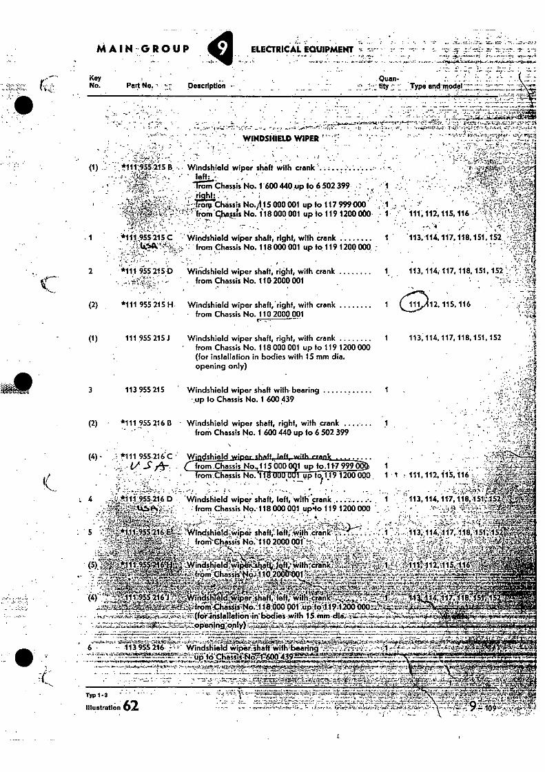
MAIN-GROUP
Key No. Part No. -
Description
• .z (1) , *111.'55215 B .. Windshield wiper shaft with crank ' '
9 ',It?.
fromchalsis No. 118000 001 up to 1191200000' • 1. 111; 11Z 115, 116 • •
1 955215 C
2 *111 955 215 D
• . -,-411, • • • .
- • , - ' Ae-,-• - - :', • • left: • •t,' -• .
, --,,-;-, -- • "Trorn Chassis No. 1 600 440.up to 6 502 399 . : -1 : . • k • • .., t-r.,,
• i....-.i, ': - • ' • • • . - ...,7 c..,-.:-.-‘. ,,...,,,.. . , . ri.._...
hf• . . • . . ..L, • •L -, 1
.-- 11:31.v Chassis No./1.15000 001 up to 117 999000 ; 1 .... .. . .' ' ̂:t
, .... • . . , ,
,
".. Windshield wiper shaft, right, with crank 1 ' .113,114,117,118,151, 152 •
,,...- from Chassis No. 118000001 up fo 119 1200000 ;
',r, -f
Windshield wiper shaft, right, with crank 1 113,114, 117, 118, 151, 152 ',.''.- r ; , -
from Chassis No. 110 2000001 ".. c.
•• ri (2) *111 955 216 B - Windshield wiper shaft, right, with crank
from Chassis No. 1 600 440 up fo 6 502 399 • .
•
1 up to.11'7 999 yp, to 1 19 1200 000.
(4) • 1!111 955.216C Wi ritshield wiper shed
' • ,1:3 • V S . . from .Chassis 115 000 - - -- • from Chassis No. 1
I •
: ill it
ELECTRICAL EQUIPMENT :"•='" ".Z •
„ - -
tity = . Typo and-model"*" -- .
. '
• • • . , . . .
-., • - . l ' - ' ' .. . -,:..... " v..41......, ea'-',--amt` .e.-----7,-?..--1,--"- • ,...": ,,..."---.T. ..•• -::".• i.......ze. ,t,...-rt.t.z.s.7:;7•:- o_•:::-..-:-.‘ . .... -... • .., •,..:„: : -7. "•,,, -i--- _ •... - r g . ..,,,, ,.....l.".,-,a; ...., V. ,t: , -4:-,t . 1 A • • .. ., ,...irInt.....,..1. 7.- .i:...-01,-. f.c., i'. ..cc,4 zit,...; 2,..,,,• ..,: 4
„ .
. . . . , WINDSHIELD WIPER ' ..':' : -
• • . V' .
.
„ . ... • • ......-
I
, . , .. .. .
- .. . . . ' -- :. - ---. P. .
- .-----,,--•••=
- -' 1 2...
• 7.7.77:r-rj---...i....-1..,......1';:....7.7, A. .. ''̀.:14..-:.111•74iliiaiki-41.7
Windshield wiper shaft,righf, with crank 1 12, 115, 116 .
from Chassis No. 110 2000 001
Windshield wiper shaft, right, with crank 1 113, 114,117, 118, 151, 152
' from Chassis No. 118 000 001 up to 119 1200 000 (for installation in bodies with 15 mm dia. opening only)
Windshield wiper shaft with bearing 1
up to Chassis No. 1 600 .439
• .
1 1 : 111, 112,11S, 116
•
• • • t 1 113, 114, 11-7, 1113,:1510r.ii
• - ...._ -.... • ..,:•"-:.,..:-.."4.41•1 . '",- • ,;.'"-e.:* ....,_, • r -.-'-', , •
6 • .,..,.....-., '"Zi41,1ii•elt±rt..^..7:61.hAk.i.; .1.4.;:,,t..._• -,=•!"'ii,r.4*ra4.414"4,[1...4. ....i*i-riiii. .S.c.O.t.u- .".L...,..q...kcjf!-2.4.30.9;1:.7.4i47-.4.4f,i; - ..- - :,.. . .i.. ,;,:,. •,,,-
• • 113.955 216. Windshield itipei...-shaft.wifh'beinng -'.'•---...-;'..--.•••••". •-• 0.:-.. • ;.,...-.• . ..- . _. • .
'''':'"'2'11;•'1!"t;•:--'xn't"'" ••••'''F'?'77L.ifitii..Chiiiiiilfiger600'43918'''""...*:'-'4*4-;5-74 . •-• ----,....----,,,.,......1101•41,W4V.I.4,,,T1,.,, ..."...4.1 . ,-......V5,,IPS.r.i./11-1.Z16 4.1.11,... _..... .. a .,.........a. a . ..... ,,r.4.....1.....4. kr , -...' :7•-•......!„1,1".,:i.e.!„.F alq,^.r.'71 ......,..."...;.'.:4'.11."--1.r:.71.; 1 • • . ..
. ...,.
• • - .. . t .. , •.. .•,-.. . ,z..- f51, ,10....r . .."4..:' ....°1,.7... g:...Tr-?*M...j.i.,- ,..-...r....,-.- - ,•,..
.
.„ 1. ".
"4..-*I ....; -.t ....'Ir:e.. ..
....It -..7..r. ...,..... ...Tis
em, rj
1.4 5 . 4. y ' --. ....',.....-:....7.-.........7,r,41,-....:7:Cr:V..!...,,,,,..-.--_,..- ...........,t,...._-..„--.....2- -....:,..r.....,... . .1. ti:r..1'.....re. 4 .' ... ".7 ,
.. ........ , .., - ;.:.7.2 at :1.t.{±:-.,- : - ....- ..: .C. ..f., _ :2.F...*'.;:-;.-;....ft-'•:;:i':.''....Ft:':,' ' "r -, "",------- • ' "1"," -J., • •,. -..r...:.r.,., i L.:v ' ' - ' -. -2,":,-- -..., 7-1--- •• • - • .. ....--..-i•-•,-;---•• .•-•:•=4-ti.,.:1:;:".e.7":";...:L7".:;.. -7;,--..."...-,-;,t'A -•••;--,,...--,. ..•
• .. • • ' ,. ! ...-•-•" 7--10 4:-.,,..4.4.
4
from Chassis No. 118 000 001 up:to 119 1200 000 h i▪ i41r.r.▪ 3I. . • •
•
5
7;t 4-1-1--,!=vg% (4) I 1, ,
0
; 4114.! indshield- wiper fefiNiih,cpn F..f • •• • • .4
el . 1.# -,... 4-lronii-r_hasiistNO.'11R000 001
,,••••1_, (f (.1 n st a at ion =in les with 15 mm ,HJ ri •
• • L...,.--'a.ti.P.,.operim,oply)
yL 1'-‘955 216 EL4..-IWindshia1dokiper shaft', left •:,1 113;-,114,.:117, 118,151:15
•:1?-.:;-....7,,,, ., ,e,.
11.#4.1401:-;..,;:p.,,,,,i.i-r!.....,...-.,,..._:„,..:.J.,-,-_._ • 4::::,..,'...,....'':Y?.'' ......1'..2,...'..
- .. :,.Windshieldr. -iVoiyi, : :: 4114;1.1: ff:'-filia'iiel'- bilit.V.-4'0,11.":?'"
i.iii
51, ., .';;,"‘;::i":"'NXIli
12--A15.1t671 (10.09,..,
-t. e,:--jrom. Chaste+16:1110.2 11,..",-..::'-' .'-`-i."-'-'--s--= ,.-, '-- ' ''' •••••• .,,,.....-ihr...:.•;:,....,-..,:iy.4,,.....,,,,,, , • ... - , -- .--:"- .,,... .. .Al
.t.4 s..1,101.1.1).4.41,1,-.5.,14.11411.011.larbi,
D 'Windshield wiper shaft, left, with' crank ... .•
/,' '•!'.72';`;'•1:•;;•;,•,•1,11471 •••••:-Atf ,1!•1,,t±S41.74r./..rorfV.44,63.-tiNfr
Mg,
' -a, • - • "- -
• g . 1
• , • :".•,• S. '-'....;:.1''Er.". ' from Chassis No:110 2000 0014'1,, -.-1:4.
illustration 62
(2)
*111 955 215 H.
(1)
111 955 215
3
113 955 215
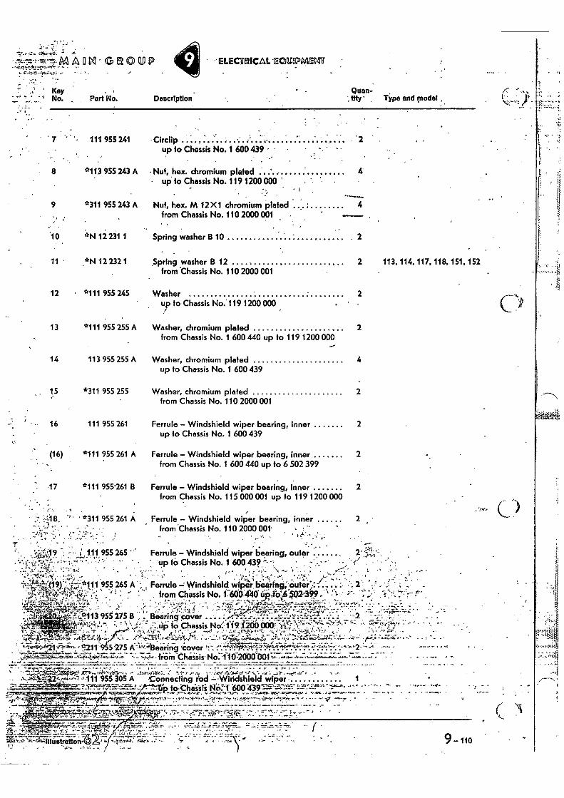
M A N • GROUP
.• . • •
• • - ••
ELECTRICAL SZYUNDIAENir
' Kay 's No. , Part No. Description
Quan- tity • Tips and modal
111 955 241 • Circlip '2 up to Chassis No. 1 600 439 • •
8 *113 955 243 A - Nuf, hex. chromium plated ' 4 • up to Chassis No. 119 1200 000 '.
9 *311 95S 243 A Nut, hex. M 12X1 chromium plated 4 from Chassis No. 110 2000 001 —. ,
'10 *N 12 231 1 Spring washer B 10 2
11 *N 12 232 1 Spring washer B 12 2 113, 114, 117, 118, 151, 152 from Chassis No. 110 2000 001
12 *111 955 245 Washer 2 up to Chassis No.' 119 1200 000
13 *111 955 255 A Washer, chromium plated 2 from Chassis No. 1 600 440 up to 119 1200 000
14 113 955 255 A Washer, chromium plated 4 up to Chassis No. 1 600 439
15 *311 955 255 Washer, chromium plated 2 from Chassis No. 110 2000 001
16 111 955 261 Ferrule - Windshield wiper bearing, inner 2 up to Chassis No. 1 600 439
(16) *111 955 261 A Ferrule - Windshield wiper bearing, inner 2 from Chassis No. 1 600 440 up to 6 502 399
17 *111 955'261 B Ferrule - Windshield wiper bearing, inner 2 from Chassis No. 115 000 001 up to 119 1200 000
' *311 955 261 A Ferrule - Windshield wiper bearing, inner 2 from Chassis No. 110 2000 001
. , • . - •
7
,.:-;e,;.1p - - - 1: All, 955 265 " ' Ferrule - Windshield wiper bearing, outer 2' 5...,-,,, up to Chassis No. 1 600 439 --- ' - ..
' -:-.•-,,..: .., , . .
, f ., • . 19 ' , ,.*111 955 265 A ; i Ferrule -; Windshield wiper bearing, outer;.
.e. , 4 44/. , . • from Chassis No. 17600 AV ":,.ttiA 592-399 . ` f
.:-.-.4,t-',.,--r,zp.c.;-,:y..., % • .: ".".:"$", "; .. -. ... rzr,.-Y. --..... ,,,I, . 4̂.•;-.7•....t:77::-... `7`,..„'"::. .: 17:',IY .77:-.' r-,(... ,•:,,, .1.4. ,; , - Ir. .-: ,:-.1;: -1 !'. - -- '- T-1.-t.).7.-.)....*,:t4••it -!.•,:i. , _..'z 't,7--'t,,'' .•-: '. ' .':....rt113 955 27513 . Bearing cover .. • ...4-',,. - '''•••" k. "...' ''' .̀73: • '' • ' -2
,'"^e4..,`"-':4.7. ,-.; 3'?.1;1;"'.::'". .. ' '' '...;':'.. ' 2...tip fo Chassis No', 1191200 0007 W: 't. ..
T , .-. .. 1.. • . , . ..,,,, 2•.... e , .% Met , . ..1g rik,- 4.-r l , e,' '",Y•'4 • • •.. . '1; ,--• ..r.; . .*•;'•- 0-•1,:. :-;atet-Yr•-•:- ' ,•; - e9-',!---14IX...r.-.c.eiY,,,,ln_ :. j . : .1 17,_ :*-4 .3;,,..:i.,;;.z1... ,.,..:!,--c2.7,:..,4-..414...,: _ .., -2 ,...;_;:.z: ..: - .
''-'5T... ''''-.--.` • '-'• tr" --:- -• .4• .1;." ... --. ...' - - ... , ... ., avow. ir.4`'''. 'call 5/75 A---1,•443ea-ring •Cover ,1,--. r.t'. ,.-1,:),AgiZ ,;91;fr.lt".. 4. .'':.'"..t` ..'17".':`. ''-' 2" ' ' ''''''
,-.4''''' r''''f'$' '",:rr'7,--,174.4*•-c-ra.--- ---,,,---- fio-m.Chaisis• No:1110-2000 001 -•.--,----,-..;,•..-...---,---•----••-•-•,J - —
- -
. t...........• •
' . 1.1...-..71:44V.,:t ,Wr--..,=44,,itia•—, . , 4-”,[1,-414:.. ..' .9 • , , .s. • .;.n.' i.. ,.......0 m.--..--e..._". ..,...-....„:... 1... ....... ....,- e . -. ._... -04"4.1 424'/!"#--"; j'111 955 305 A ,Connecting rod --Windshield wiper 1
----:----- -iie--->i''''''''‘'''''''.±- .̀ ' to•Chis3i; 46'1 '600-4197,--a7 !;If-"-."7 "---'' '-'' ' ''' ' ' - '' ,...., H -,r , •• "74Plik:;:ca.p...7.:*.r? ,!.-tr.f. .7 F-... 4 4 r,...,.14-r,t '-. ;',.. I . •-,,f..) • .......',..Pt,-• '..:r ',L. P7.3.'.• , .. -Let ....."„%+ r ''. . . - - .... -0 -„.. •
._... . i . '--4i.r,,T„...,:t.--445.7,r,-",_:1„'W --,5 ---.. .-, .":-..-..: .---.t.,-......:::-.7-4;-. • .- , - tr ‘,...• .:-- . t- : • • .
q ..or c ..4. .:,--, v• ..-17 - . _.:".:".= t%
,--*'7, - ,....-s....t...ri':•,.; e..............., ,......-
4, • • -i. 6 -0 r ' ,.- -, (..t, MI...-•'K-4.1-tillustration• 9-110
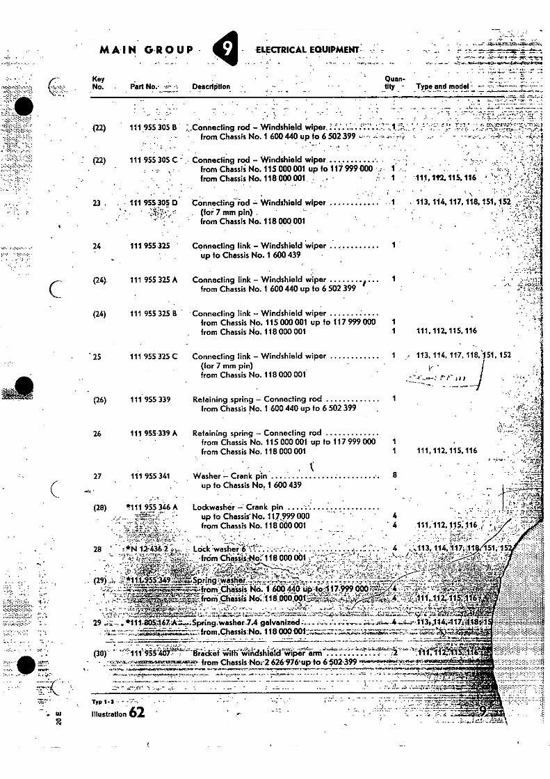
111, 112, 115. 116
•• 113, 114, 117, 1182151, 152
. •
. 113, 114,117, 118, 151.152
(28) till 955 346 A
MAIN G-ROUP - - -ELECTRICAL EQUIPMENT
" -
. • , ZUNtla
.6, • -.Tr .:r '..'•.'e
Key
Quan- No. Part No., -:•-• Description • tity -Type and model -
(22) 111 955 305 B :„Connecting rod - Windshield wiper ' * " fr,:
• :.
• ......7%"..".i_ti.`•Z •••''
•r: •••.•
from Chassis No. 1 600 440 up to 6 502 399 - • •• • • ",-• r" `• •
(22) 111 955 305 C" . Connecting rod - Windshield wiper
• a
from Chassii No. 115 000001 up fo 117 999 000 . - from Chassis No. 118 000001 • . •
23 . • 111 955 305 0 Connecting rod = Windshield wiper ••• . • (foi 7 mm pin) '
• from Chassis No. 118 000 001
24 111 955 325 " Connecting link - Windshield wiper up to Chassis No. 1 600 439 •
1
27 111 955 341
Washer - Crank pin 8
up fo Chassis No, 1 600 439
(24) 111 955 325 A
(24) 111 955 325 B
25 111 955 325 C
(26) 111. 955 339
26 111 955.339 A
Connecting link - Windshield wiper
from Chassis No. 1 600 440 up to 6 502 399
Connecting link - Windshield wiper from Chassis No. 115 000001 up to 117 999 000
. from Chassis No. 118 000 001
Connecting link - Windshield wiper (for 7 mm pin) from Chassis No. 118 000 001
Retaining spring - Connecting rod from Chassis No. 1 600 440 up fo 6 502 399
Retaining spring - Connecting rod from Chassis No. 115 000 OM up to 117 999 000 1 from Chassis No. 118 000 001
1 111, 112. 115. 116
Lockwasher - Crank pin up fo Chassis No. 117,999 000 from Chassis No. 118 000 001
4 4
28 ' - Lock 7W8511'er.-:;:16.•'"11 ... ... . ;,.. •
.from Chassis,Nci' 118 000 001 •
Lies,•--.Spring -masher - ,n• .'..*;4",-1).Z "
crr-,1-- =t r.
- • -...-.A.94, ''' . 1)::-1,:".--÷
1 .,:•,-..,:,.14111ZIAW"4"47,:,7.474Srifrom,Chisiiii Nci:118.000001x4'147-k,,5-4'1 4,A-4f- - • —,--- - -,- - • - • •
•,..,,,,,f,., A 111"f ,,11 2;115,1 , 44,p174:':.-.
.,,,.. .;.#4, - - .-.:-. • ...- -, ,....---: •,•,, •-•• -• .• - • , • -4-':v4-47.- . • A--..T.''. -',.?.:27..' i • -....6., .: A . .1 ..N-,-.Se....-i .e.;;N:e•tr--Juiii;-.7,7',---T,,e
...,..z. '""",
...--i:At.:,-,-7-7.--r2zzli:4:.... 7....7.L.i.7.4111.1.T.;:rt 1.7::::...,z--..7.1•4..77-411.;..7.47,:.-,...;',.:7"7.;.-rt-,:;::t.;.IM:.&,, A,4.12.;;;:N...,...V.2.:0*?7,....e-,-, , : k 29 .4-,.*111.80067AZ-,,:.,tpring.washer.7Agalvanized •:.,.. -,..... .7. .-..:-.---. -;•4:.,..i..,..4...,4„. .,--. 2.13i.!1.4..;..1.17A#1!ii '
-.‘,..ii.kv-ii:. , fro .,--mchassiso. 118 009.001 -N •:•=4;.",:.z...7z. ,":::,:•;-74:1•Tzi.Iii.i.,7-;:,:, %.-17;r.i., ______ ____-. . ._ . . .. __ . _
ti
• , --- k .11 4 r.
(30) . - 111 955 407:: Bracket with windshield wiper arm ' - ;2 ' ' J11 41{2A1 'i • '1';'-'0,-,.f.,.•25TP _.;,?!..".!Ar.m•• from Chassis No: 626176vp•to 6.P2.399 ••!.'N'4...? *'+1e-44r-",.:1k3......_____.
• •ffiglto• ,1111•6,114, -'_-.,,--,#-- .--.-'-,,-'--.--a. •;•••••••••••••••• -^ • • • ^••••?•••-•••,••••••::A;?/*
r . . . • - - ...• . :•_
Typ 1 - ̂
Illustration 62 •.•
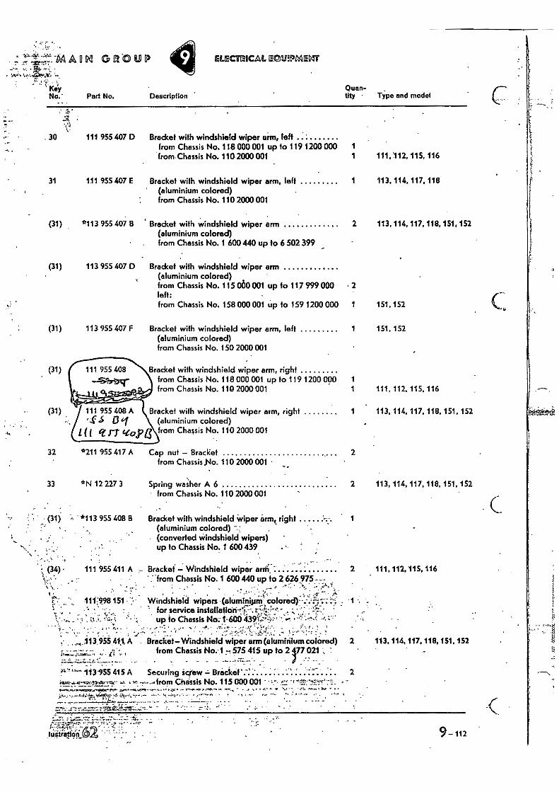
EILECIMICALIECIRPMEMT ottou " _7 •
• .
' key No.' Part No.
„. .
Chian- Description ' tity • Type and model
Bracket with windshield wiper arm, left ' from Chassis No. 118 000 001 up to 119 1200 000 1 from Chassis No. 1102000 001 1
1 113, 114, 117, 118, 151, 152 (31) 111 955 408 A Bracket with windshield wiper arm, right s 13 c1 (aluminium colored)
it q J7 Kopf from Chassis No. 110 2000 001
hY
32 *211 955 417 A
33 *N 12 227 3
• (31) •••• *113 955 408 B
Cap nut — Bracliet 2 from Chassis No. 110 2000 001 •
Spring washer A 6 2 113, 114, 117, 118, 151,152 from Chassis No. 110 2000 001
•
Bracket with windshield wiper arm,. right 1 (aluminium colored) (converted windshield wipers) up fo Chassis No. 1 600 439
(34) . 111 955 411 A -•
Bracket — Windshield wiper arrii • • 2 :from Chassis No. 1 600 440 up to 2 626,975- -
Windshiek1 wipers (aluminiiim colored) for service installatiOn-t17,03 *••.- • •
' •
111:098151
up to Chassis. No: 1-600 4391;:•-•?,:. . .̀
-...-- = • - ' ' , 113 955 41,1, A . Bracket—Windshield wiper arm (aluminium colorOd) 2
____,..,... ., . from Chassis Nor 1 -_-, 575 415 up fo 2 477 021 , ' . . . •
t.
Bracket with windshield wiper arm 2 (aluminium colored) from Chassis No. 1 600 440 up 10 6 502 399
Bradcet with windshield wiper arm (aluminium colored) from Chassis No. 115 060 001 up to 117 999 000 • 2 left: from Chassis No. 158 000 001 up to 159 1200 000 1 151,152
Bracket with windshield wiper arm, left 1 151. 152 (aluminium colored) from Chassis No. 150 2000001
• •
30 111 955 407 D
31 111 955 407 E
(31) *113 955 407 B
(31) 113 955 407 D
111,112, 115, 116
113, 114, 117, 118
113, 114, 117, 118, 151, 152
(31) 113 955 407 F
Bracket with windshield wiper arm, Jeff 1 (aluminium colored) from Chassis No. 110 2000 001
Bracket with windshield wiper arm, right from Chassis No. 118 000 001 up to 119 1200 ogo 1 from Chassis No. 110 2000 001 1
111 955 408
---51-brPacr 111, 112. 115, 116
113955 415 A Securing Screw Bracket' 2 •-•••••• ---,from Chassis No. 115 000 001 -; : -
111, 112, 115, 116
113,114, 117. 118, 151, 152
9-112
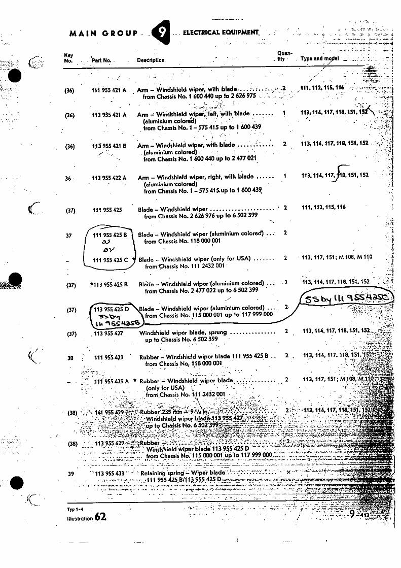
111,112,115.116 -
•
113, 114, 117, 118.151,
113, 114,117, 118, 151, 152
•
1 113.114,117.178,151,152
lade - Windshield wiper (aluminium colored) ... , from Chassis No. 115 000 001 up to 117 999 000
113 955 427
Windshield wiper blade, sprung up to Chassis No. 6 502 399 -
(.'..'' 4 •••.•••
113.114, 117, 118, 151, 152
2 113, 114, 117,118, 151, 152 a7 ',
• "14 • •
113, 117, 151; M
113, 114.117, 118, 151. 152
5.$b ILL 9ss:4asc.;
Quan-tity •
MAIN GROUP
Key No. . Part No. • DeadriptIon
.. ELECTRICAL EQUIPMENT.
Type and m„,..41i II .
(36) 114 955 421 A
(36) 113 955 421 A
Arm - Windshield wiper, with blade. • from Chassis No. 1 600 440 up to 2 626 975 • . ,
. • ,•-•
Arm Windshield wipeileft, with blade
(aluminium colore'd) 1 .' from Chassis No. 1 -575 415 up to 1 600 439
, (36) 113 955 421 B Arm - Windshield wiper, with blade (aluminium colored) • • • from Chassis No. 1 600 440 up to 2 477 021.
•
36 • 113 955 422 A Arm - Windshield wiper, right, with blade (aluminium •colored) from Chassis No. 1 -575 415.up to 1 600 439,
(37)
111 955 425 Blade - Windshield wiper • 2
111.112,115,116 from Chassis No. 2 626 976 up to 6 502 399
37 111 955 425 B Blade - Windshield wiper (aluminium colored) ... 2 from Chassis No. 118 000 001
111 955 425 C Blade - Windshield wiper (only for USA) frorwchassis No. 111 2432 001
2 113, 117, 151; M108. M110
*113 955 425'B Blida - Windshield wiper-(aluminium colored) ... 2 from Chassis No. 2 477 022 up fo 6 502 399
38 • 111 955 429 Rubber - Windshield wiper blade 111 955 425 B from Chassis No, 118 000 001
.
(37)
(37)
(37)
111 955 429 A * Rubber - Windshield wiper blade •. (only for USA) : , from No. 111,2432 001 ,,
. .., , „0„,r,,,, • (38) .1' •'.- 141 955 429C4%,,(.1t• RUbbe'r23. .S.-ctn---'.- 91/A)n,...,--." '1,-1--.4-5'.'..t-......-42..''.-' . 2.A.---.... ,113, 114, 117, 11805f:10 1' • •• r • . lV-
.._, .. . • 4 -Windshield wiper 44108,..1 i 3 955427..... -,!....„q. .4 ? ...... - - ,' `; , '. : t 1:'. 71' .3..-Ig A711% 0 Ir4.':• 1 ..'
up to Chassis No, 6 502 399 4 . -4,g- -, ,.1.7.:: p.
.......-:....L,!...7..., • i - ,•,•, •,-- .-,-,. :a •.:..• ....,,,-,- ••.:. : ,...,,,, :•: • ,....,,, '-',,,f,"-7-•'''ilr '-'11474-'r- ..11i- :,',.4 4:-.--, 1 •-• . . • ..
V.•ii/c.',-.01--.. .• .:C te..‘ ,, A ..... .114,.r.,:-.-. ,. 7-c,1_?: ..t..c._,.4 t. '''' '- ' . --4---"" '' .-`0.147.4.-...:4767.-Lii.42, (38) - . 113 955 429 ':.,4;','-Rubber ' -4',• ;%' •• -': ';(-5,•-7-F-% 1 • ,%, ••, .--, • -, - • :..
•, • • •-4,•-• •.:
..,.T.1 V 16....4,N...01,—.•,,Ns14 '•••'./..6'4..;.'-i''; '....-.1'...,..--.T.' "1 ,̀....414.7.....:4'4'
..., • t..• • • • • • • • • • 4 • • • • • • • • '9 • • i 4.' • ..• •:• .• • •,..,,,
WindshieldWiger blade 113 955 425 D ' ..,,..... -....,,, ,-....f ..-. m 9.. •,. 4, o, n WA:44Z i \ild • • • • --,• •-•• . from Chassis No. 115 000 001 up to 117 999 000._ -
. . . - . .
• . 39 ' 113 955 433 Retaining spring- Wiper blade . : -
• "4% :111 955 425 B/113 955 •-• A.wg 4.0-11,,W,,,,,914 ..1..M.,••••••,........",,,,,••••,•••••••,,,•• • h.•••••••••••••,,,••••,..,,...'..e....•
••r_ • • " • - • v*-", '
• 4'4
Typ 1-4
Illustration 62
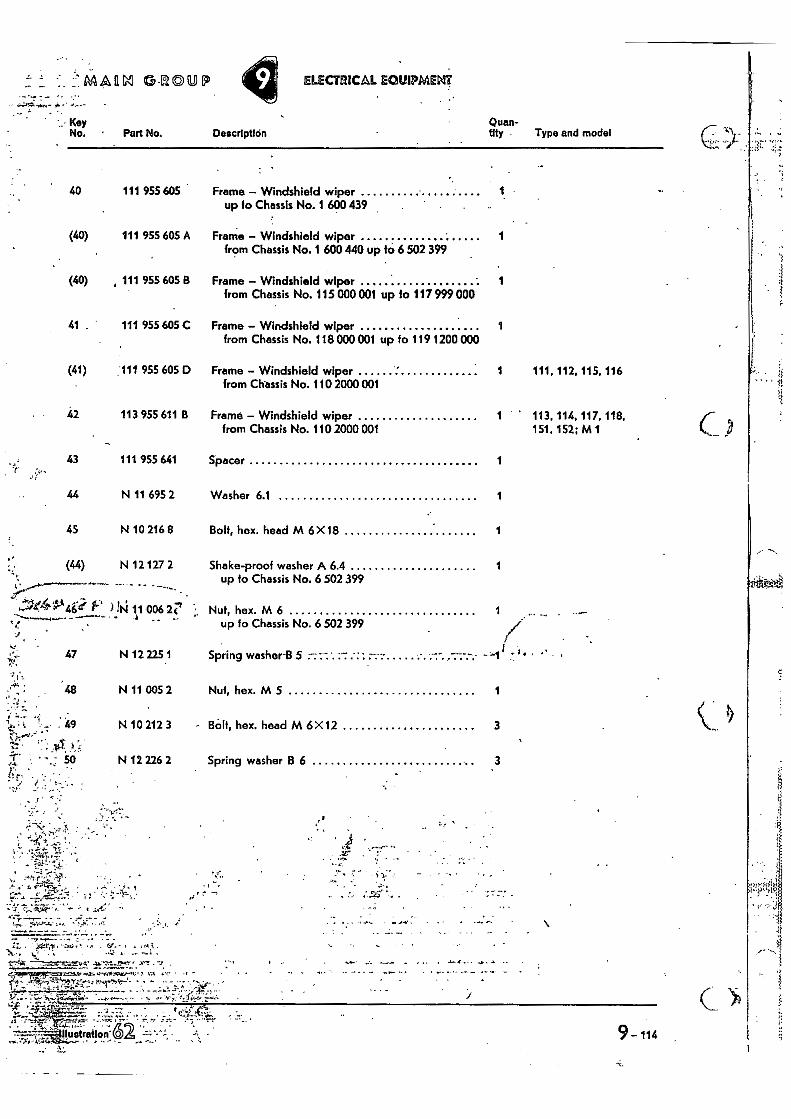
9 114 ,
• 44.41A-Non.- ok •
f.MARN 0-ROUP ELECTRICAL ECILIIPMEMT
i.- Key No. • Part No. Description
Quan- tity • Type and model
40 111 955 605 Frame — Windshield wiper 1 up fo Chassis No. 1 600 439
(40) 111 955 605 A Frame — Windshield wiper 1 from Chassis No. 1 600 440 up fo 6 502 399
(40) , 111 955 605 B Frame — Windshield wiper 1 from Chassis No. 115 000001 up to 117 999 000
41 . 111 955 605 C Frame — Windshield wiper 1 from Chassis No. 118 000 001 up fo 119 1200 000
(41) 111 955 605 D Frame — Windshield wiper 1 111, 112, 115, 116 from Chassis No. 110 2000 001
42 113 955 611 B Frame — Windshield wiper 1 113, 114, 117, 118, from Chassis No. 110 2000 001 151, 152; M I
43 111 955 641 Spacer 1
44 N 11 695 2 Washer 6.1 1
45 N 10 216 8 Boit, hex. head M 6 X18 1
.• (44) N 12 127 2 Shake-proof washer A 6.4 1
up to Chassis No. 6 502 399 47"'" , . •
4714"4"°4•E f."' )114 11 006 2r Nut, hex. M 6 1 up to Chassis No. 6 502 399
/ ) , 1
' 47 N 12 225 1 Spring washer-B 5 -- — — • ' ' ---
I ,
,-., : 48 N 11 005 2 Nut, hex. M 5 1 _ •
49 N 10 212 3 - BOB, hex. head M 6 X 12 3 /IT
:r". • - 50 N 12 226 2 Spring washer B 6 3
, • e
• 7
•••••• ••• .
", • .
• .r. kilk --;:..W •-•'• , Sn • • tr.. • ., • 1 f•S,:t .
.x;- ...1...., , .1....6 ' . •s'Z s• .— ,s e •
?.... AO,....r.t...,-...11=..7 0. .7 :-.‘"e1.17cur,,....C , .. S:71. s,. • .r -
t•2 -.
,1 2. , -ar . _
IlustratIon- •
1:.
- : . • -..., :•••.:------..;••••••••••7 "7.77:::,77,•:•7q.7:74. i
•
• 4;',.-;17. •
• ..
•s
•
• • -
• .• r.:•••••• . . .
,l—rf."fter
• • wo- • - _
- - -- • - - - • - - - - - . •
"7 •
tra-,:p•
Typ 1-6 fi
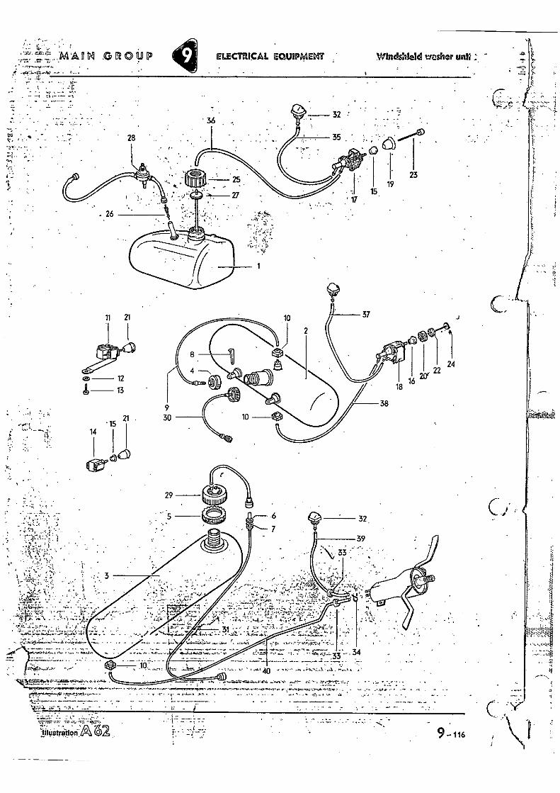
4 _„t` WA lil .0 ROUP ELECTRICAL EQUIPIVIEIXIT Windshield washer
. - - . • •
10
2
100`..e' ! • 4
8
38 0.-411111
41.*
9
15 21 30
. 10
14
29
. 5 32,
39
33
i••••4•••• • . .
— • • • •
• • , ' , —•Aft.••••••••••:•••.4., • • . .
L•7:77.,1,1,72•,•••,10',••‘••••••••k."•h•,•• • —
• !—: 33 • ' . .... 1 . ...- •
•
4,,•••••••••••••.0.11,11,.• AA*, V... ••••••1.•••••••••••••••••••,••••••••••,•••••••••••,••••••••••••••••-.0.,•••••••••••••,..14••••• .1••• • •
. •••••••••1•4Z,74,,,,,C•fa
•
rra-
illustration 62
• a. . 1. •
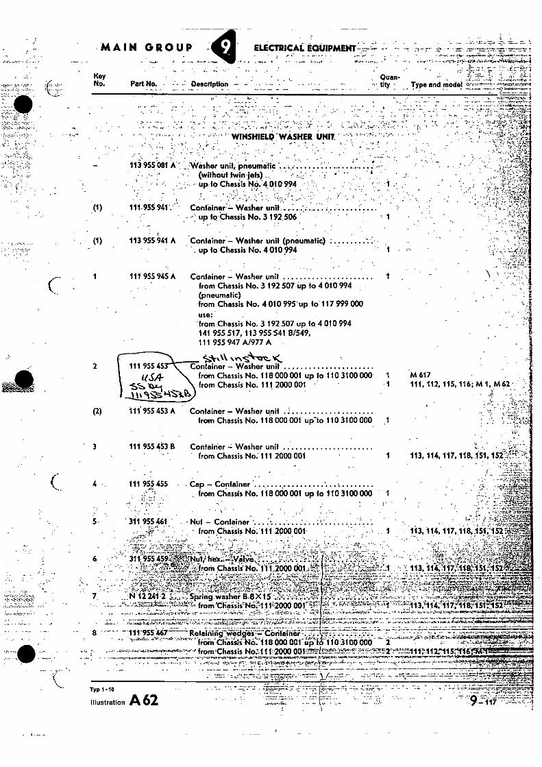
MAIN GROUP • 7
ELECTRICAI: - • - .....
6
Container - Washer unit 1 , from Chassis No. 3 192 507 up to 4 010 994 (pneumatic) from Chassis No. 4010 995' up to 117 999 000 use: from Chassis No. 3 192 507 up to 4 010 994 141 955 517, 113 955 -541 8/549, 111 955 947 A/977 A
'4A-A•%k ve-Ns-Vere... Container - Washer unit
from Chassis No. 118 000 001 up fo 110 3100 000 I from Chassis No. 111 2000 001 • • 1
3 111 955 453 B 1 113, 114, 117, 118, 151,152'. •
„. • •
Contairier -- Washer unit from Chassis No: 111 2000 001
4 - 111 955 455 • Cap - Container : , from Chassis No. 118 000 001 up to 110 3100 000 1
- -
Typ
Illustration A 62 , •••=-T-- -
- 747 7-7 9-11i
Part No. • Description - • •••• • — • •
-": Quan- tity • Type and model
Key No.
-•• • •.•
; -•
• ' WINSHIELD :WASHER UNIT ' • • •
• . • , . ,
113 955 081 A. ' _Washer unit, pneumatic .. ... . .. . .. ......... i. •
• . • - • • • • (without twin-jets) •. • • •
- ' ••••
:-.1•13?-11
up to Chasiis i's1§.4 010 9.94 • . , . •
Container =- Washer unit .. ; ....... : ... • up to Chassis No. 3 192 506 • ' 1
Container - Washer unit (pneumatic) • . up to Chassis No. 4 010 994
Container - Washer unit from Chassis No. 118 000 001 up-to 110 3100 000 .1
111.955 941'. •
• •
113 955 941 A
111 955 945 A
2
(2)
111 955 45
fleCAL
111955 453 A
-••••••••-- ••••• •---•-•
froin Chassis 113,114.,:117,%118:1 51,1'152
-'-'•••••••• • = ; ' • • from.thaiis':Ncill11'.L2000 '141 85151..
•-7, - •
311 955 . „
N 12 24._ pr-!: 1-2
7 7-d- 7•L'E.:-': • .;n.:01••:' 4:4,--.••••,. 4.Ltl.;,....•!•' -'! .•• t-:•••••+,71":-". l'A'&7C7 1.'47 '7" • ..••••• 3
• •-• •;•,.
5 - 311 955 461 . - Nut - Container - from Chissi No.'i 11.2000 001
: r c . • • •. • • - • 113, 114, 117. 118,151;152%F4-4
---,--, •
8 —111-955'467--Retaining wedges •- Container- •
daci oa . ,1314, 110 3t ao ono i • from'ChassiS No 1 f 1.2000 001: El 3 t-f-tf :_,••_''.1•:711111".-112:115:116ricc-1 -11!
•"• • " .'" • • - r7 • •i-q. --. • • -, • . • : •
• .2..,;.:74:7••=. •;,1- s7r.z2-4.7.,, • • --7.% A • •;•oc-pri.c„
M 617 111, 112, 115, 116; M 1, M62
•• I ac
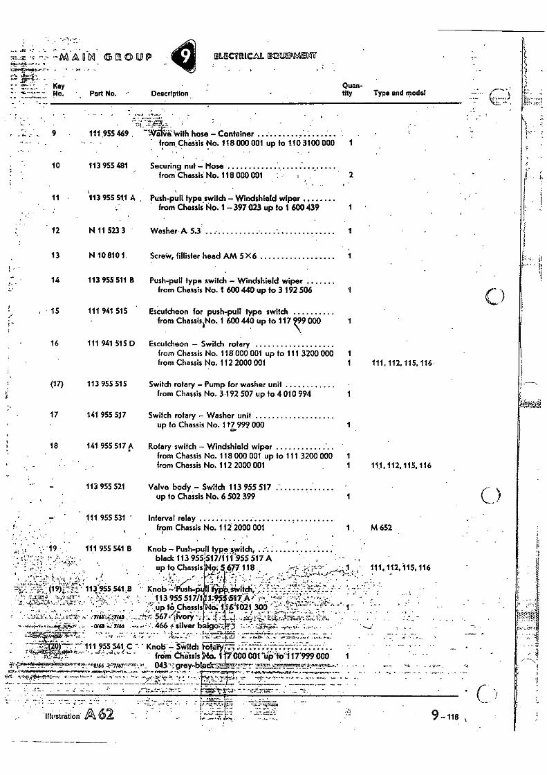
Quan- tity Type and model Part No. Description .
".7
. • 111 955541.0 • Knob— ---- .. .. r*: 414'f assts No. ' '420' from ribcto 001-4116i 17999 000 1
4.-17/67,P.MAUI 043 . . .0, • ra- • • • , ••••••••,,,,...••••- r •
""-1.4'44*.1"....."' tet., ••-• •••
Lrr • •
••• 4. a -• • -Tu -fr. • Tr.2 r •••, 1••••- •
at --118 , •liteistration
111 941 515 D Escutcheon — Switch rotary from Chassis No. 118 000 001 up to 111 3200 000 1 from Chassis No. 112 2000 001 1 111, 112, 115. 116
113 955 515 Switch rotary — Pump for washer unit from Chassis No. 3'192 507 up to 4 010 994 1
141 955 517 Switch rotary — Washer unit up to Chassis No. 117 999 000 1
141 955 517 .1k Rotary switch — Windshield wiper from Chassis No. 118 000 001 up to 111 3200 000 1 from Chassis No. 112 2000 001 1 111,112,115,116
.-MA ono up . _
SLECTRICAL EZIEESPMEM
• - • . , (19)74:-'71 113.955 541,8 •
-• v.' .. 4 , • . •- ,
to chassis.N!),..11 61.1021 300
7 St: 5674tV0r/ , .Ova ;166 1: silver boisto7.7,
113 955 521 Valve body — Switch 113 955 517 • up to Chassis No. 6 502 399
111 955 531 '
111 955 541 B
Interval relay from Chassis No. 112 2000 001
Knob — Push-pull typa.v.vitch, • bladc 113 955!517/111 955 517 A • up to Chassis No; 677 118 1 •
• , •
113 955517/1 Knob --' us -p
' " • ;17h
_ _ 1 ;:14'517A
1 M 652
1
111,112,115,116
- •
, . •
Key No.
9 •
10
11
12
13
• - 14
15
16
(17)
17
18
..e
111 955 469. --WifeWith hose — Container , from. Chafsis No. 118 000 001 up to 110 3100 000
113 955 481 Securing nut — Hose from Chassis No. 118 000 001
'113 955 511 A Push-pull type switch — Windshield wiper from Chassis No. 1 — 397023 up to 1 600 439 1
N 11 523 3 Washer- A 5.3' 1
N 10 810 1. Screiv, fillister head AM 5X6 1
113 955 511 B Push-pull type switch — Windshield wiper from Chassis No. 1 600 440 up to 3 192 506 1
111 941 515 Escutcheon for push-pull type switch from Chassis No. 1 600 440 up to 117 Z99 000 1
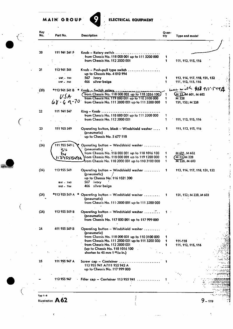
MAIN' GROUP ELECTRICAL EQUIPMENT
Key Quan- No. Part No. Description tity Type and model
111, 112, 115, 116
113, 114, 117, 118, 151, 152 111. 112. 115. 116
20 111 941 541 F
21 113 941 541
1147.- nal i'47 - 7/61
(20)
*113 941 541 B
Ar - 0 -7°
Knob - Rotary switch from Chassis No. 118 000 001 up to 111 3200 000 1 from Chassis No. 112 2000 001
1
Knob - Push-pull type switch up 10 Chassis No. 4 010 994 567 ivory 1 466 silver beige 1
Kno 1443-4-,4.0 At- fra 10.,r4or from Chassis No. 118 000 001 u • to 118 1016 100
1 Q-2-". 601, M 602 o. 001 up to 10 3100 000 1 M 228
from Chassis No. 111 2000 001 up to 111 3200 000 1 151,152; M 228
22
23
Ring - Knob from Chassis No. 118 000 001 up to 111 3200 000 1 from Chassis No. 112 2000 001
Operating button, bladc - Windshield washer .... (pneumatic) up to, Chassis No. 5 677 118
111 941 547
111 955 549
1 ' 111, 112, 115, 116
111, 112, 115, 116
(24) *Operating button - Windshield washer ' (pneumatic)
from Chassis No. 118 000 001 up to 118 1016 100 from Chassis No. 118 000 001 up fo 119 1200 000 rom Chassis No. 110 2000 001 up to 110 3100 000
111 955 549
IC3c1555cfci
1 M 601, M 602 1 M 228 1 • 28. M 603
(24) 113 955 549 Operating button - Windshield washer 1 113, 114, 117, 118, 151, 152 (pneumafic) / up to Chassis No 116 1021 300
1/61 - IASI 567 ivory I
11/63 - 7/66 466 silver beige
(24)
*113 955 549 A * Operating button - Windshield washer
1 151, 152; M228, M 603 (pneumatic) from Chassis No. 111.2000 001 up to 111 3200 000
(24)
113 955 549 B Operating button - Windshield washer 1 - (pneumatic) from Chassis No. 117 000001 up to 117 999 000
• 24 411 955 .549 B Operating button - Windshield washer (pneumatic) from Chassis No. 118 000 001 up fo 110 3100 000 from Chassis No. 111 2000 001 up to 111 3200 000 from Chassis No. 112 2000 001 (up to Chassis No. 118 1016 100 shorten to 45 mm 1 2•5/u in.)
1 1 111-118 1 111, 112, 115, 116
25 111 955 947 A Screw cap - Container 1 113 955 941 A/111 955 945 A up to Chassis No. 117 979 000
' • zgori.i.."4:1.1
113 955 947 • Filler cap - Container 113 955 741 1
Typ 1 -
Illustration A 62 9 - 119
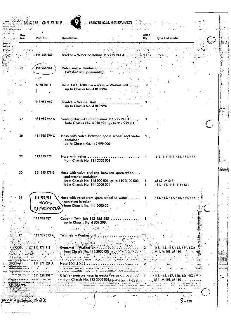
Quan- • Description
tity Type and model
Bracket - Water container 113 955 941 A -- • 1
Valve unit - Container • 1 (Washer unit, pneumatic)
1,•
- • 111 955 949 :t
• 26 / 111'955 951
Key No. Part No.
`. • 14t- A 62
Hose 5X1.5X15 • - •
..111.971 521 A I - •
9 - 120
3
Hose with valve from spare wheel to water 1 113, 114, 117, 118, 151, 152 ' • container bracket
from Chassis No. 111 2000 001
113 955 987 Cover - Twin jets 113 955 985 4 up to Chassis. No. 6 502 399.
32 - 111 955 993 A Twin jets - Washer unit
''''.. '.. ' ..`...-- .• I ' .. . '''' :_%; ''•z; -17'g"-;',,..'r 1,_! , • '. ', f - 1
=.;:7:-:33-. i ."',5-'' 311 971 913 ',: Grommet 'Washer :..`,-.l:::-.::-... ' --t:'''-' •••-` '• ,' 2 ' 113, 114, 117, 118, 151, 152'; - r c. 4 • -,..i,/•,••,•• • •••,.. 17":4-. . • • . , ... 1.*: 11...'.-', ''" '•;•%.:, • '- '-; . .;• f 7'... • froin•Chissis No;,112 2000 001! .?...i.!..„ ......-$! .1- ..,-;:!.., - ., -, •• . - ,..M 1, M 108, M 110 ' ..' 1 . • ' ...,,.!cs,.. ,.........:1;,"...5.. • .• ": • , • -.. i, _, .: 1 ...::, _ , .....e„..;., :.„ . ... , r .:',...t , : 7. ; ... 1: .... , i L .. ; ....,t. .• . ,. : . . . • .. • ::
. . •
- .
•••-• • . - -. • .... • •
--'211 259. 295'' °Clio' for preisure hoselo washer 'value' 1 ' 113, 114, 117, 118, 151, 152;'-' ' 3 ,4", •,•3 -:.4..s3 • 33 from Chassis No. 112200D M 1, M 108. M 110 7.1 -• r
31
4-0
11 11k5 . ir911 GROUP. .. ELECTRICAL. ECIEMENT -
N 20 301 1
Hose 4X 1, 1600 mm - 63 in. - Washer unit
x up to Chassis No. 4 010 994 •
27
28
113 955 975
111 955 977 A
111 955 979 C
T-valve - Washer unit 1 . up to Chassis No. 4 010 994
Sealing disc -.Fluid container 111 955 945 A from Chassis No. 4 010 995 up to 117 999 000
Hose with valve between spare wheel and water 1 container up to Chassis No. 117.999 000
29 113 955 979 Hose with valve 1 113, 114, 117, 118, 151, 152 from Chassis No. 111 2000 001
30 311 955 979 B Hose with valve and cap between spare wheel ... and washer container from Chassis No. 118 MO 001 up fo 110 3100 000 1 M 62, M 617 from Chassis No. 111 2000 001 1 111, 112, 115, 116: M 1

39
540 mm - 21 1 /4 in. 1 113, 114, 117, 118, 151, 152; from Chassis No. 112 2000 001 M 1
9 -121
Typt-6
Illustration A 62
(40) 1920 mm - 75"/32 in. from Chassis No. 111 2000 001 up fo 111 3200 000 1 113. 114, 117, 118, 151, 152 from Chassis No. 112 2000 001 1 M 1 • '
• . .
- • - • • --,
MAIN GROUP ELECTRICAL EQUIPMENT
Key • • No. Part No. Description • .•
Quan- • tity Type and model
N 18 057 1 Hose 2.5 X 1.75 •
35 250 mm -•9 22/32 in. • up fo Chassis No. 117 999 000
36
3/
1 111, 113, 115, 117,151
1 111, 115
(37) 250 mm - 9 22/32 in. from Chassis No. 118 000 001 up to 111 3200 000 1 112, 114, 116, 118. 152 from Chassis No. 112 2000 001 1 .112,116 •
38
1850 mm - 72 22/33 in. from Chassis No. 118 000 001 up to 110 3100000 1 111, 113, 115, 117, 151 from Chassis No. 111 2000 Obi up to 111 3200 000 1 111, 115; M 1: 113. 117 1rom Chassis No. 112 2000 001 1 111, 115
(38) 2000 mm - 78 3/4 in. from Chassis No. 118 000 001 up to 110 3100 000 1 112, 114, 116, 118, 152 from Chassis No. 111 2000 001 up to 111 3200 000 1 112, 116; M 1: 114, 118 from Chassis No. 112 2000 001 1 112, 116
1500 mm - 59 i/e4 in. up to Chassis No. 117 999 000
- • 200 mm 7 7 Vs in. from Chassis No. 118 000 001 up to 111 3200 000.
from Chassis No. 112 2000 001
5
40 2360 mm - 92 29/32 in. 1 • 113, 117, 151 from Chassis No. 112 2000 001
(40) 1720 mm - 67 23/32 in. 1 114, 118,152 from Chassis No. 112 2000 001
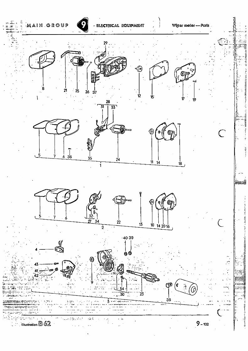
Wipez 171020/ —Peas ELECMICAL ECI6SIPME:17 r •
MAIM1 _GROUP
12 15'
29..
• 25 26 37
18
.40 39
4 iiivs1,6.
4 @0
•
t " ' • ••-.
_ . e -
7.:`..::==ftrd.1.100.t.17131'.ic4r17.:t1.• 7: r
..
•.1:• . .• • • .
; ..: -. 34 , .
23
3 -- 38 J-r
• e-
• t: -arc 1•1;)
t t sem !̀=~
• ,̀1,.
-
2.
• • .7 3.
t • a
9-in
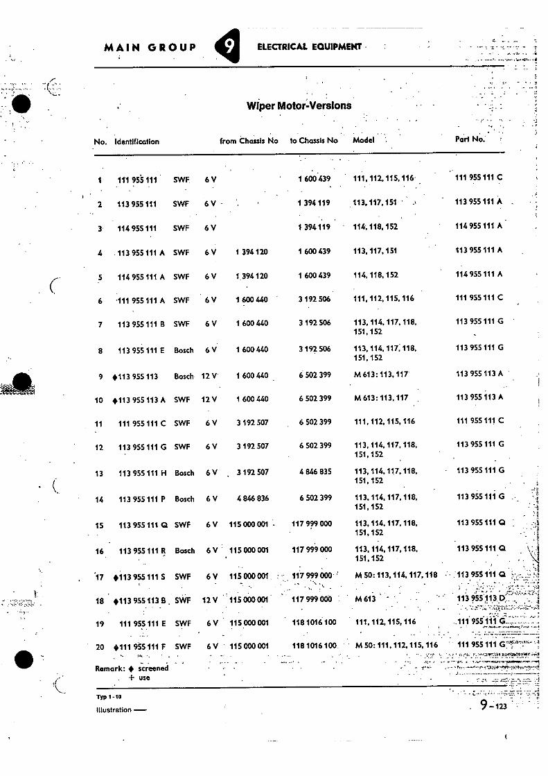
•
MAIN GROUP ELECTRICAL EQUIPMENT
. ,. -.,, ......,...,-.. ,."
...,
•... Wiper Motor:Versions
No. Identification
from Chassis No to Chassis No Model
Par! No:
1 .111 955111 • SWF
2 113 955 111 SWf
3 114 955 111 SWF
4 .113 955 111 A SWF
5 114 955111 A SWF
6 111 955 111 A SWF
7 113 955 111 B SWF
8 113 955 111 E Bosch
9 #113 955 113 Bosch
10 +113 955 113 A SWF
11 111 955 111 C SWF
12 113 955 111 G SWF
13 113 955 111 H Bosch
14 113 955 111 P Bosch
15 113 955 111 Q SWF
16. 113 955 111 R Bosch
.17 #113 955 111 S SWF
16 #113 955.1138 SWF
19 111 955111 E SWF
20 #111 955 111 F SWF
Remark: ♦ screened + use
111 955 111 C
113 955 111 A ,
114 955 111 A
113 955 111 A
114 955 111 A
111 955 111 C
113 955 111 G •
113 955 111 G
113 955 113 A •
113 955 113 A
111 955 111 C
113 955 111 G
- 113 955 111 G
113 955 111 G
•
113 955 111 Q
113 955 111 Q
• :113955 111 Q
113 955 113 p: , ; •
•
.111 955 111 G-.........
111 955 111
. _
6 V
1 600 439 111, 112, 115. 116.
6 V - 1 394 119 113, 117.151
6 V
1 394 119 ' 114; 118, 152
6 V 1 394120 1 600 439
113, 117, 151
6 V 1. 394120 1 600 439
114, 118,152
6 V 1 600 440 3 192 506
111, 112, 115, 116
6 V 1 600 440 3 192 506
113, 114, 117, 118, 151, 152
6 V 1 600 440 3 192 506
113, 114, 117. 118. 151, 152
12 V 1 600 440 6 502 399
M 613: 113, 117
12 V 1 600 440 6 502 399
M 613: 113, 117
6 V 3 192 507 6 502 399
111, 112, 115, 116
6 V 3 192 507 6 502 399
113, 114, 117. 118, 151,152
• 6V 3 192 507 4 846 835
113, 114, 117, 118, 151,152
• 6 V 4 846 836 6 502 399
113, 114, 117, 118, 151, 152
6V 115 000 001 - 117 999 000
113, 114, 117, 118, 151,152
6 V 115 000 001 117 999 000
113.114, 117, 118, 151,152
6 V 115000 001 117 999 000 M 50: 113, 114, 117,118 - .
12V 115000001 •• 117999000 M613
6 V 115000001 118 1016 100 111, 112, 115, 116
6 V 115 000 001 118 1016 100 M 50: 111,112. 115, 116
Typ 1-10 •
illustration -
9-123
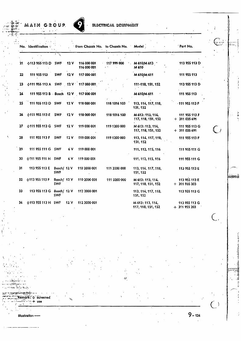
MAIM GLIQUP. ELECTRICAL ECUIPINAIEVIT
9-124 Illustration -
No. Identification . from Chassis No. to Chassis No. Model Part No.
21 0113 955 .113 D SWF 12 V 116 000001 117 999 000 - M 610/M 613 . 113 955113 D 116 000 001 M 610
22 111 95511,3 SWF 12 V 117 000 001 M 610/M 611 111 955 113
23 0111 955 113 A SWF 12 V ' 117 000 001. • 111-118, 151, 152 113 955 113 D
24 111 955 113 B • Bosch 12 V , 117 000 001 M 610/M 611 111 955 113
25 111 955 113 D SWF 12V 118 000 001 118 1016 100 113, 114, 117, 118, .111 955 113 F 151, 152
26 0111 955 113 E SWF 12 V 118 000 001 118 1016 100 M 613: 113, 114, 111 955 113 F 117, 118, 151, 152 + 311 035 691
27 0111 955 113 G SWF 12 V 119 000 001 119 1200 000 M 613: 113. 114, 111 955 113 G 117, 118, 151, 152 + 311 035 691
28 111 955 113 F SWF 12 V 119 000 001 119 1200 000 113, 114, 117, 118, 111 955 113 F 151,152
29 111 955111 G SWF 6 V 119 000 001 111, 112, 115,116 111 955 111 G
30 0111 955 111 H SWF 6 V 119 000 001 111. 112, 115, 116 111 955 111 G
31 113 955 113 E Bosch/ 12 V 110 2000 001 111 3200 000 113, 114, 117, 118, 113 955 113 E SWF 151, 152
32 0113 955 113 F Bosch/ 12 V 110 2000 001 111 3200 000 M 613: 113, 114, 113 955 113 E SWF 117, 118, 151,152 ± 311 955 203
33 113 955 113 G Basch/ 12 V 112 2000 001 113, 114. 117, 118, 113 955 113 G SWF 151,152
34 0113 955 113 H SWF 12 V 112 2000 001 M 613: 113, 114, 113 955 113 G 117, 118, 151, 152 + 311 955 203
. _ •
:REM al: lc FO' "screened • + use
•
.
•
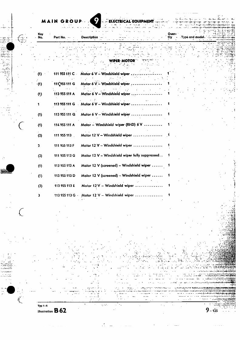
MAIN GROUP--
Key No. Part No. Description
--ELECTRICAL-EQUIPMENT f, ^ • •• ;•••• ▪ t*.
. 4.•-•-•"#Ar.0.7•;••-•-.1.e....hh•-•>4ri....R.,••• - •
Quan- tity • Type and model-'
. • ai
• r • "...Vt....7,, 'r • • -
•‘• •••:`"!7•••44 7
(1)
(1)
111 955 111 C .
111'4955111 G
•
WIPER 'MOTOR-- •
Motor 6 V — Windshield wiper
Motor 6 Windshield wiper
„ (1) 113 955 111 A Motor 6 V — Windshield wiper
1 113 955 111 G Motor 6 V — Windshield wiper 1
(1) 113 955 111 Q Motor 6 V — Windshield wiper 1
(1) 114 955 111 A Motor — Windshield wiper (RI-11)) 6 V 1
(2) 111 955 113 , Motor 12 V — Windshield wiper
2 111 955 113 F Motor 12 V — Windshield wiper 1
(2) 111 955 113 G Motor 12 V — Windshield wiper fully suppressed 1
113 955 113 A Motor 12 V (screened) — Windshield wiper 1
(1) 113 955 113 R Motor 12 V (screened) — Windshield wiper 1
(3) 113 955 113 E Motor 12 V — Windshield wiper 1
3 113 955 113 G • Motor 12 V — Windshield wiper 1
- • .
• ••••.--1 • - , , , 1
. . , . •
. _
. ,40
Typ 1- s
Illustration B 62 _ 125 9 - • • r
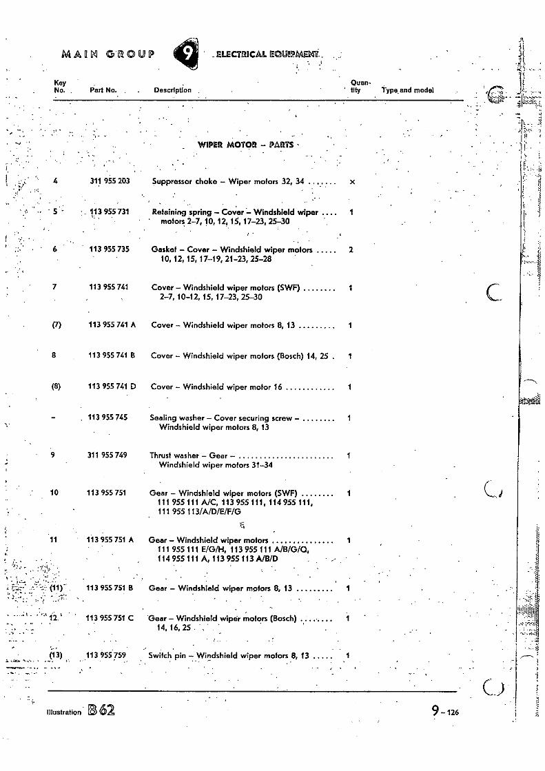
t z. AAAIIN GROUP ELECTRICAL ECRP/PMED4T
Key Quan- No. . Part No. Description ' tity Type. and model
7.311"L>ti:i:
. •!
WIPER MOTOR — PARTS •
• t 6 113 955 735 Gasket — Cover — Windshield wiper motors 2
10, 12, 15, 17-19, 21-23, 25-28
7 113 955 741 Cover — Windshield wiper motors (SWF) 1 2-7, 10-12, 15, 17-23, 25-30
(7) 113 955 741 A Cover — Windshield wiper motors 8, 13 1
8 113 955 741 B Cover — Windshield wiper motors (Bosch) 14, 25 . 1
(8) 113 955 741 D Cover — Windshield wiper motor 16 1
. 113 955 745 Sealing washer — Cover securing screw — 1 Windshield wiper motors 8, 13
9 311 955 749 Thrust washer — Gear — 1 Windshield wiper motors 31-34
10 113 955 751 Gear — Windshield wiper motors (SWF) 1 111 955 111 A/C, 113 955 111, 114 955 111, 111 955 113/A/D/E/F/G
c.
11 113 955 751 A Gear — Windshield wiper motors 1 111 955 111 E/G/H, 113 955 111 A/B/G/0, 114 955111 A,113 955113 A/B/D
(11) 113 955 751 B Gear — Windshield wiper motors 8, 13 1
12 113 955 751 C Gear — Windshield wiper motors (Bosch) 1 „ - 14, 16,25.
(13) 113 955 759 Switch pin —Wir!dshield wiper motors 8, 13 1
Illustration is 62
;•;.
•.is-
4 311 955 203 Suppressor, choke — Wiper motors 32, 34 x
• • •
• r • 5 113 955 731 Retaining spring — Cover — Windshield wiper .... 1
' motors 2-7, 10, 12, 15, 17-23, 25-30
9 _ 126

is '•
0.••
C
Switch pin Windshield wiper motors 1 10, 15, 17, 18, 21-23, 25-28
Switch pin — Windshield wiper motors 8, 13 1. •
Cover plate — Windshield wiper motors 8, 13
Gear cover gasket — Windshield wiper motors ... 1 2-7, 10-12, 15, 17-23, 25-30
Gear cover gasket — Windshield wiper motors ... 1 14, 16
• - - • . -•
• •
••• #
• • :4' a
Gear cover with gear and crank — 1 Windshield wiper motor 1
Gear cover with gear and crank — 1 Windshield wiper motors 25-28
Gear cover with gear and crank — 1 • Windshield wiper motor 4
Gear cover with gear and crank — 1 Windshield wiper motors 8, 13
Gear cover with gear and crank — 1 Windshield wiper motor 14
Gear cover with gear and crank — 1 Windshield wiper motors 15, 17—.19, 21
• 11.f.t10,‘,.....7enItIrctlIve=iffill
Description
113 955 783 Gear — Crank — Windshield wiper motors 8, 13 .. - 1
MAIN GROUP
Kay • No. Part No.
-13 113 955 759. A ' .
. (13) 113 955 789
— 113 955 763
14 113 955 779
15 113 955 779 A
(16) 111 955 781
16 111,55 781 A
(17) 113 955 781 A
(17) 113 955 781 C
17 113 955 781 D
(17) - 113.955 781 E
(17) 113 955 781 F
18 N 10 803 2
19 N 10 697 1
;4.
. . Quan- • thy , Type and model
ELECTRICAL EQUIPMENT
Gear cover with gear and crank — 1 Windshield wiper motor 16
Screw,.fillister.head AM 3.5 X 10 -
Screw, cheese head AM 4 X10 5
• • • •.. • 6i1
_ - • • -
Typ 1 - 5
w Illustration B 62 a 9 —126a
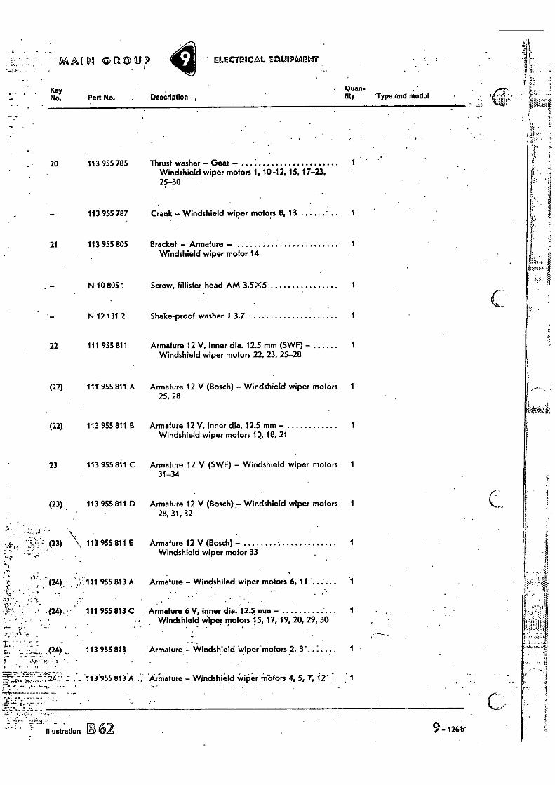
MALIN GROUP ELECTRICAL EQ21.0IPMEVIT
Key No.
Doan., City -Type and modal Part No. Description ,
20 113 955 785
113 955 787
21 113 955 805
Thrust washer - Gear - Windshield wiper motors 1,10-12, 15, 17-23, 25-30
Crank - Windshield wiper motors B, 13 1
Bracket - Armature - 1 Windshield wiper motor 14
N 10 805 1 Screw, filiisler head AM 3.5X5 1
N 12 131 2 Shake-proof washer J 3.7 1
22 111 955 811 Armature 12 V, inner dia. 12.5 mm (SWF) - 1 Windshield wiper motors 22, 23, 25-28
(22) 111 955 811 A Armature 12 V (Bosch) - Windshield wiper motors 1 25, 28
(22) 113 955 811 B Armature 12 V, inner dia. 12.5 mm - 1 Windshield wiper motors IQ, 18, 21
23 113 955 811 C Armature 12 V (SWF) - Windshield wiper motors 1 31-34
(23) 113 955 811 D Armature 12 V (Bosch) - Windshield wiper motors 1 28, 31, 32
3) \ 113 955 811 E Armature 12 V (Bosch) - 1 Windshield wiper motor 33
(24) - 111 955 813 A Armature - Windshiled wiper motors 6, 11
,(24) 113 955 813 Armature Windshield wiper motors 2, 1
113'955 813.A . Armature - Windshield.WiPer'inafors 4, 5, 7, 12-;.
: • .
Illustration 1362 9 -1266-
. (24). 1• 111 955 813 C Armature 6 V, inner dia. 12.5 mm - 1
- Windshield wiper motors 15, 17, 19, 20, 29, 30 - - .
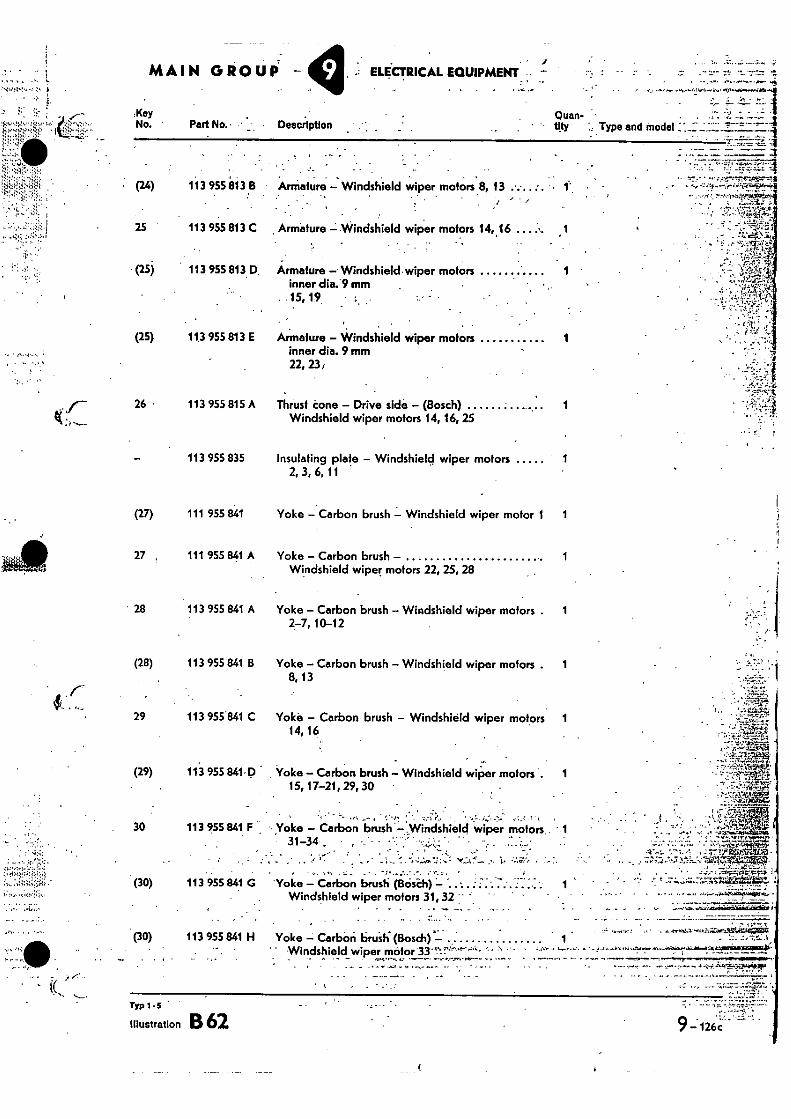
Typ 1-5
Illustration B62
ELECTRICAL EQUIPMENT -
Description
•
Quan- • tyy
• Type and model
. •
Armature — Windshield wiper motors 8, 13 • • •
•
ArMature — Windshield wiper motors 1406 .. 1
Armature — Windshield wiper motors inner dia. 9 mm
1 •
.15, 19
Armature — Windshield wiper motors inner dia. 9 Mtn
1
22, 23,
Thrust cone — Drive side — (Bosch) 1 Windshield wiper motors 14, 16, 25
Insulating plate — Windshield wiper motors 1 2, 3, 6, 11
Yoke — Carbon brush — Windshield wiper motor 1 1
Yoke — Carbon brush — 1 Windshield wiper motors 22, 25, 28
Yoke — Carbon brush — Windshield wiper motors . 1 2-7, 10-12
Yoke — Carbon brush — Windshield wiper motors . 1 8, 13
Yoke — Carbon brush — Windshield wiper motors 1 14, 16
Yoke — Carbon brush — Windshield wiper motors . 1 15, 17-21, 29, 30
Yoke — Carbon brush — .Windshield wiper motors
• , . •••:,ir,- •
'Yoke — Carbon brush (Boleti) Windshield wiper motors 31, 32
:Key No. Part No. •
• (24) 113 955813 B
25 113 955 813 C
(25) 113 955 813 D
(25) 11.3 955 813 E
26 113 955 815 A
113 955 835
(27) 111 955 841
27 111 955 841 A
28 113 955 841 A
(28) 113 955 841 B
29 113 955 841 C
(29) 113 955 841-D
30 113 955 841 F
(30) 113 955 841 G
(30) 113 955 841 H
•
'
MAIN GROUP
". • ' ' Windshield wiper . motor
.- - Yoke Carbini bruit; (Bosch)
. 7' 7 - —7-771
.Iftro;
2
1
-•'..-.q*-41401t* • • -
- - ̂1-4:1 •
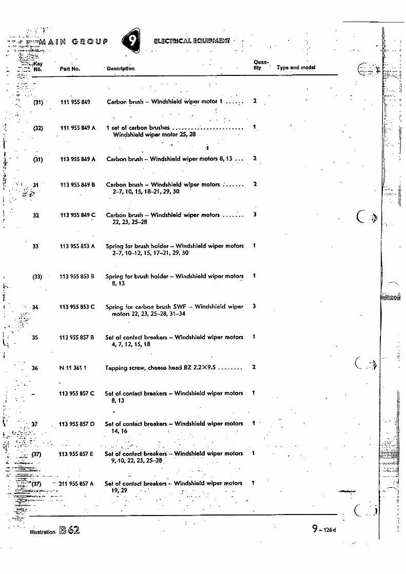
---44EARRI GROUP
•
ELECTRICAL EC5_111.POPMEM • •
' Descriptf On Quan- tity Type and model
Illustration 1362 9-126d
—4 No• Pail No.
(31)
(32)
111 955 849
111 955 849 A
113 955 849 A
31 113 955 849 B
1
32 113 955 849 C
33 113 955 853 A
(33) 113 955 853 B
• 34 113 955 853 C
35 113 955 857 B
;
36 N 11 361 1
... • 113 955 857 C
37 . 113 955 857 D
.7 •
(37) 113 955 857 £
111661
(37) 211 955 857 A
Carbon brush — Windshield wiper motor 1 2
Carbon brush — Windshield wiper motors 3 22, 23, 25-28
Spring for brush holder — Windshield wiper motors 1 2-7, 10-12, 15, 17-21, 29, 30
Spring for brush holder — Windshield wiper motors 1 8, 13
Spring for carbon brush SWF — Windshield wiper 3 motors 22, 23, 25-28, 31-34
Set of contact breakers — Windshield wiper motors 1 4, 7, 12, 15, 18
Tapping screw, cheese head BZ 2.2X9.5 2
..• 19, 29
. •
4
(31)
1 set of carbon brushes 1 Windshield wiper motor 25, 28
Carbon brush — Windshield wiper motors 8, 13 2
Carbon brush — Windshield wiper motors 2 2-7, 10, 15, 18-21, 29, 30
Set of contact breakers — Windshield wiper motors 8, 13
Set of contact breakers — Windshield wiper motors 14,16
Set of contact breakers — Windshield wiper motors 9, 10, 22, 23, 25-28
Set of contact breakers — Windshield wiper motors 1
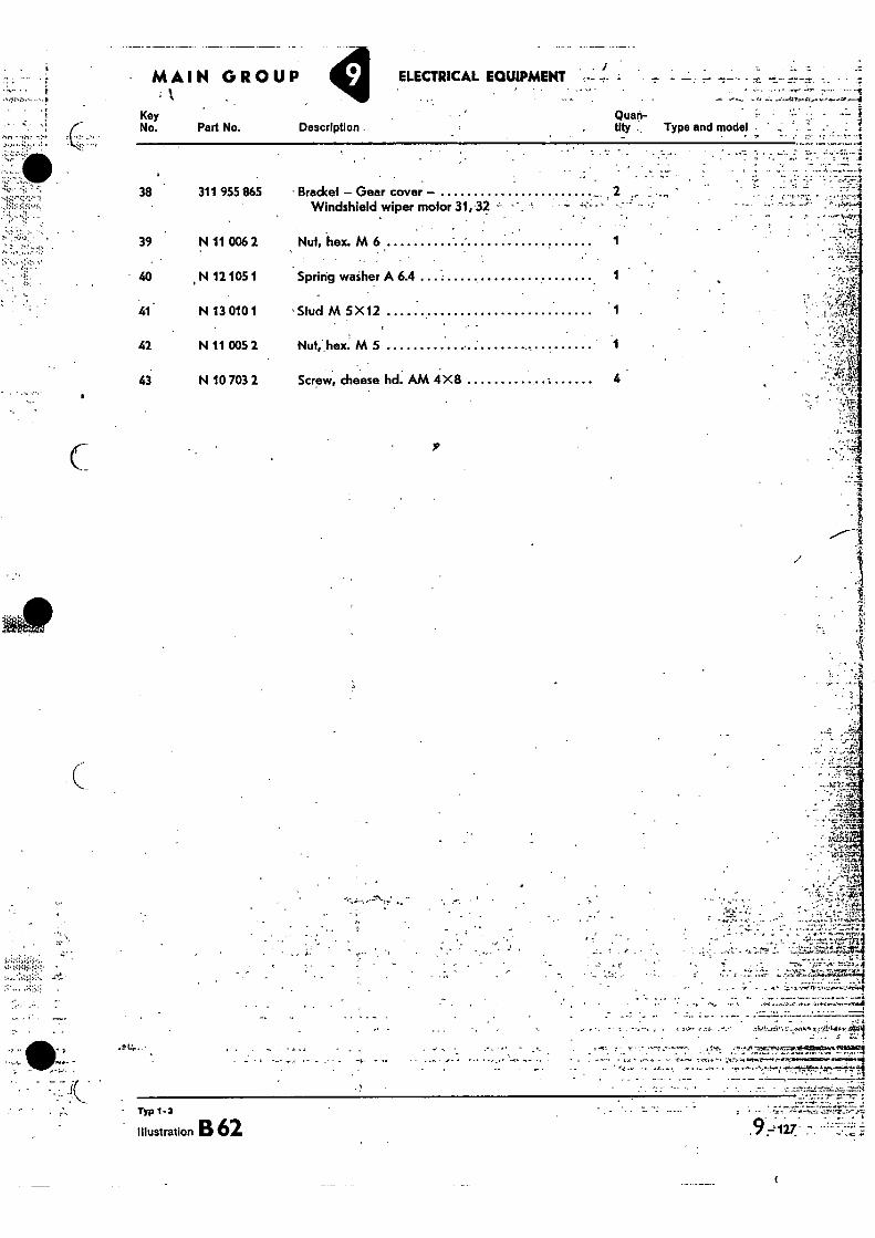
ELECTRICAL. EQUIPMENT •
.1.
Key No. Part No. Description .
Quan-fly Type and model • ' 4
38 311 955 865 13rackel — Gear cover — 2 ,. .,., ' C . Windshield wiper motor 31, 32 :- -.. ..
39 N 11 006 2 Nut, hex. M 6 1
40 N 12 105 1 Spring washer A 6.4 1
41 N 13 0101 'Stud M 5)(12 1
42 N 11 005 2 Nut, hex. M 5 1 • --4A ' •
43 N 10 703 2 Screw, cheese hd. AM 4X8 4
- MAIN GROUP
•
C P
1 ,'
---
•
• -rB r . •
•
' • •
,••
1.1 , •, ••••-•.' .':: .•.''_-.)...'.;:....Pq;-"i I • • .;..... ..„,;.•. ,...'.. f.T• ..- .....U.,:l*:
a . :
, . •• 1 • .."" ' .a ..1" “H•••,...74pla14111:•4
• 4#01
— • • .7 •
TYP 1'2
Illustration B 62
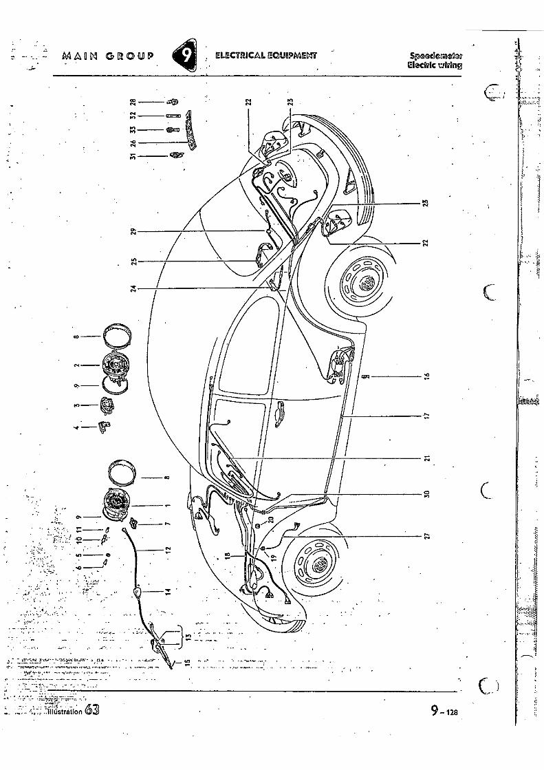
ELECTRICAL EQUIPMENT MAEIVI GROUP Speederaelicn EIGCSIAC tiring
-
••- os... • . - • . •
•
I. -Illustration 9- 128
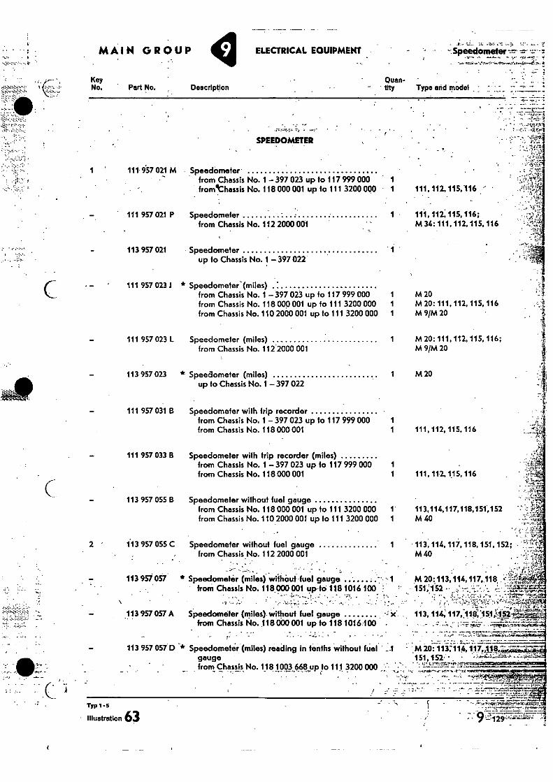
-Spee-donseterfr.- MAIN GROUP ELECTRICAL EQUIPMENT
Key No. Part No.
Quan- tItY Type arid model
• Description
TYP 1-5
• illustration 63 • ••••2-•••;.1••••••-7-.•-.4.
• .• -
111 957 021 M
111 957 021 P
113 957 021
111 957 023.1
111 957 023 L
113 957 023
111 957 031 B
111 957 033 B
113 957 055 13
2 113 957 055 C
113 957057.
113 957 057 A
113 957 057 D
C
Speedometer (miles) reading in tenths without fuel gauge from Chassis No. 118 1003 668 up to 111 3200 000 „ •
* Speedometer (miles) from Chassis No. 1 - 397 023 up fo 117 999 000 1 from Chassis No. 118 000 001 up to 111 3200 000 1 from Chassis No. 110 2000 001 up to 111 3200 000 1
Speedometer (miles) 1 from Chassis No. 1122000 001
* Speedometer (miles) up to Chassis No. 1 - 397 022
Speedometer with trip recorder from Chassis No. 1 - 397 023 up to 117 999 000 1 from Chassis No. 118 000 001 1
Speedometer with trip recorder (miles) from Chassis No. 1 - 397 023 up to 117 999 000 1 from Chassis No. 118 000 001 1
Speedometer without fuel gauge from Chassis No. 118 000 001 up to 111 3200 000 from Chassis No. 110 2000 001 up to 111 3200 000 1
Speedometer without fuel gauge 1 from Chassis No. 112 2000 001
* Speedometin. (miles) withOut fuel gauge from Chassis No. 118.000 001 up fo' 118 1916 100
Speedometer (miles) without fuel gauge from Chassis No.118 000 001 up to 118 1016.100 -
M 20 M 20: 111, 112, 115, 116 M 9/M 20
M 20: 111, 112, 115, 116; M 9/M 20
5-
- 113, 114, 117, 118, 151, 152; • ' 1 9 M 40
M 20:113,114, 117, 118 151,152 . '- -7 --.. :•31-u"4r2
• := • •", • • •••
t.* 113. 114; 117;11 ff,'.1S1012. 1, • - . -
i441,1
M 20:113;114,117„448, 151,152:. ,
SPEEDOMETER
Speedometer from Chassis No. 1 - 397 023 up to 117 999 000 1 fromthassis No. 118 000 001 up to 111 3200 000 1
Speedometer from Chassis No. 112 2000 001
Speedometer up to Chassis No. 1 397 022
11.1, 112, 115,116
111, 112, 115, 116; M 34: 111.112, 115. 116
•
• . ,
M 20
111, 112, 115, 116
111, 112. 115, 116
113,114,117,118,15'1,152 M 40
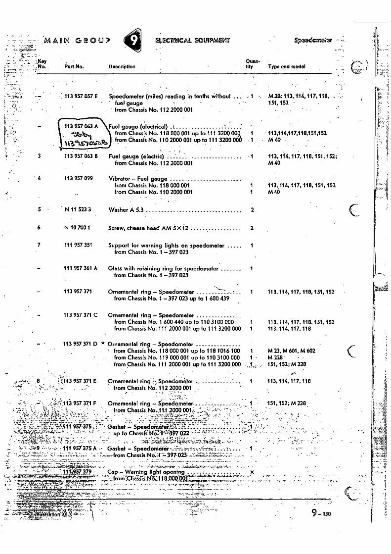
• • mAam GROUP
7 • •
Key . • ;•• .= •• •n- - • •No. Part No. Description
•••
ELECTRICAL EGUIPMENT Aisnecale2er
Oven- • tity Type and model
•
• 113 957 057 E Speedometer (miles) reading in tenths without ... 1 •• M20.: 113,114,117, 118, • fuel gauge 151,152 •
from Chassis No. 112 2000 001
113 957 063 A Fuel gauge (electrical) .1 -35,\11 from Chassis No. 118 000 001 up to 111 3200 001 1 ' 113,114,117,118,151,152
13‘triCaS
113 957 063 B Fuel gauge (electric) 1 from Chassis No. 112 2000 001
4 113 957 099 Vibrator — Fuel gauge from Chassis No. 118 000001 1 from Chassis No. 110 2000001 1
5 - N 11 523 3 Washer A 5.3 2
6 N 10 700 1 Screw, cheese head AM 5 X 12 2
7 111 957 351 Support for warning lights on speedometer from Chassis No. 1 — 397 023
111 957 361 A Glass with retaining ring for speedometer 1 from Chassis No. 1 — 397 023
113 957 371 Ornamental ring — Speedometer
1 113, 114, 117, 118, 151, 152
from Chassis No. 1 — 397 023 up to 1 600 439
113 957 371 C Ornamental ring — Speedometer from Chassis No. 1 600 440 up to 110 3100 000 1 from Chassis No. 111 2000 001 up 10 111 3200 000 1
113, 114, 117. 118. 151, 152 113, 114, 117, 118
As from Chassis No. 110 2000 001 up to 111 3200 101 • 1 t •
• M 40 •
113,1i4, 117, 118, 151, 152; M 40
113,114, 117, 118, 151, 152 M 40
113 957 371 10 Ornamental ring — Speedometer • from Chassis No. 118 0400 001 up fo 118 1016 100 1 M 23, M 601, M 602
from Chassis No. 119 000 001 up to 110 3100 000 1 M 228' from chassis No. 111 2000 001 up to 111 3200 000 „1,4;• 151, 152; M 228
8 • 013 957 371 E- Ornamental ring _Speedometer . 1 113, 114, 117, 118 • 1 • : from Chassis No. 112 2000 001
4'013 957 371 F Ornamental ring — Speedometer.... ... .. .. • - ' , from Chassis NO:11.1 2000001;:. • -qt..% • • L • " '
•••• 7.4: • • • - • •••••••=.14,,.„.••;. 957-375 ,'.•:: .7- Gasket — Speeeloill§teri.744
„t ... .
• "•”' - • up to Chassis No:,i 17197 022 -"! -̀'r -'•-
• .'4:4•144.":114. 7. .!..f..•:•:..,',,.• .•,:•••• . • 111.957'375 A •• Gasket — Speedometer • •..,•-:,•-•••••••.4---4-nr:-. • •4. • •
Chassis•NO.47 397•023. • • •
. • • , ' • ..!;
• • "
111457 379 - Cap — Warning light opening •• „ •
151,152;M 228
•:••
•
• ” " • -
• C ; •
9-130
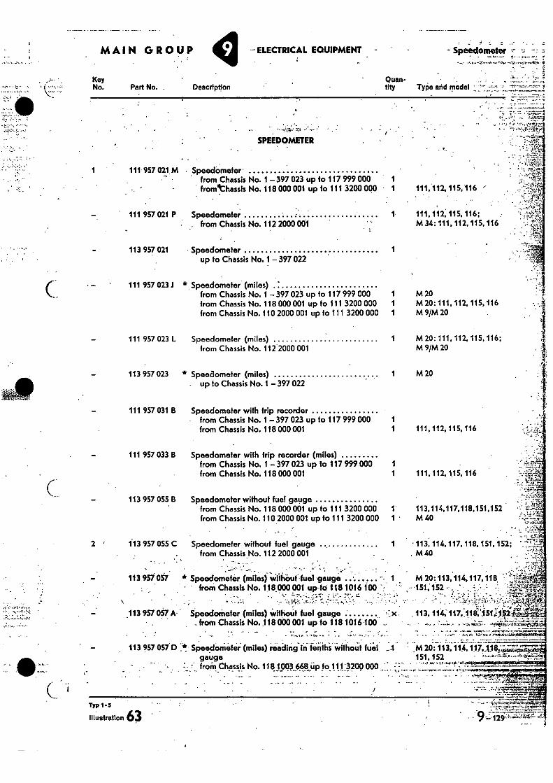
SPEEDOMETER
1 111 957 021 M • Speedameter - ...• • from Chassis No. 1 - 397 023 up to 117 999 000 fromthassis No. 118 000 001 up to 111 3200 000 1
• -47:"!-T, 2 ' 113 957 055 C
• '1‘
Speedometer without fuel gauge from Chassis No. 112 2000 001
•
113 957 057 * Speedometir, (miles) wiihOut. fuel gauge • from Chassis No. 118.000 001 up-to 118 1016 100 .•
. I .
MAIN GROUP ELECTRICAL EQUIPMENT - r.r • •
- Speedometer -•••• • -
Key No. Part No. . Description
Quan-tity Type and model • —
• •-•:.=.7-,•-•'
• • ` • .7 ‘''- ',•„f”.,_11:?,,
': •
111, 112, 115,116 -•
111 957 021 P Speedometer • from Chassis No. 112 2000 001
1 111,112, 115, 116; M 34: 111. 112,115, 116
113 957 021 Speedometer 1 up to Chassis No. 1 - 397 022
111 957 023 J * Speedometer (miles) from Chassis No. 1 397 023 up to 117 999 000 1 from Chassis No. 118 GOO 001 up to 111 3200 000 1 from Chassis No. 110 2000 001 up to 111 3200 000 1
M 20 M 20: 111, 112. 115, 116 M 9/M 20
111 957 023 L Speedometer (miles)
1
M 20: 111, 112, 115, 116; from Chassis No. 112 2000 001
M 9/M 20
113 957 023 * Speedometer (miles) up to Chassis No. 1- 397 022
1 M 20
111 957 031 B Speedometer with trip recorder from Chassis No. 1 - 397 023 up to 117 999 000 1 from Chassis No. 118 000 001 1
111 957 033 B Speedometer with trip recorder (miles) from Chassis No. 1 - 397 023 up to 117 999 000 1 from Chassis No. 118 000 001 1
113 957 055 B Speedometer without fuel gauge from Chassis No. 118 000 001 up to 111 3200 000 1 from Chassis No. 110 2000 001 up to 111 3200 000 1
111, 112. 115, 116
111, 112, 1.15, 116
113,114,117.118,151,152 M 40
113 957 057 A- SpeedoMeter (miles) ‘iihoUt fuel gauge x. from Chassis No. 118 000 001 up to 118 1016 100 -
113 957 057D :*,.' Speedometer (miles) readingin tenths without fuel. gauge froM Chassis No. 11 819q0BUp 10.1 l:.4200 000
1 • 113, 114, 117, 118, 151, 152; . M 40
M 20: 113, 114,117,118, , -151;152 •
14.T7r...1-kcart - • •• • -,A,••1•Vir"
• . - , •••• ,113.114;117.,118;151,t1pz. - • •
..7.7
M 20: 113, 114, 151.152
Typ 1'5
Illustration 3 `• -•.,
. . 1219
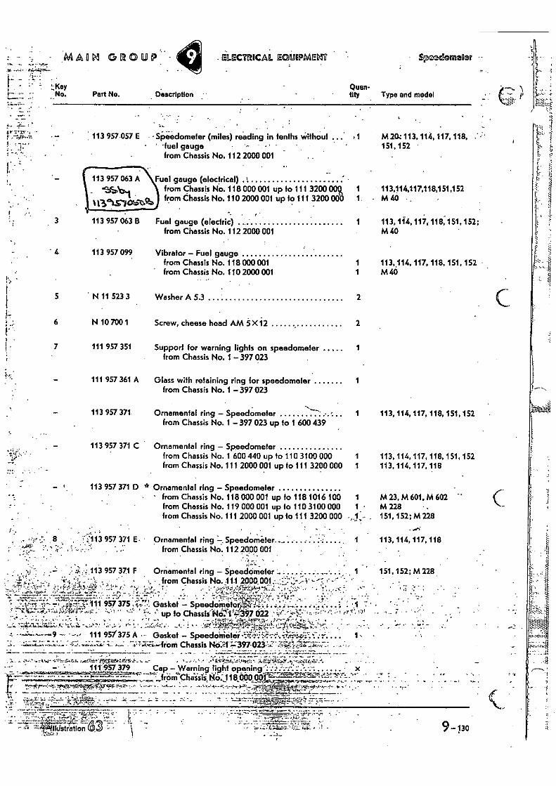
Fuel gauge (electrical) .1 from Chassis No. 118 000 001 up to 111 3200 009, from Chassis No. 110 2000 001 up to 111 3200 OOD
113 957 063 B Fuel gauge (electric)
from Chassis No. 112 2000 001
1.
MM GROUP ELECTRICAL E UIPMEM 4mdcometer
[7 Key No. Pert No. Description
()man- tity Type and model
-44
7.1%. • - 113 957.057 E
t 1- • Speedometer (miles) reading in tenths without •
• -fuel gauge from Chassis No. 112 2000 001
M204 113, 114, 117, 118, 151,152 •
113414,117,118,151,152 • M 40 • .
113, 1i4,11, 118,151, 152; M40
• 4 113 957 099 Vibrator - Fuel gauge from Chassis No. 118 000 001 1
' from Chassis No. 110 2000 001 1 .•
5 • N 11 523 3 Washer A 5.3 2
6 N 10 700 1 Screw, cheese head AM 5 X12 2
113, 114, 117, 118, 151, 152 M40
7 111 957 351 1
111 957 361 A Glass with retaining ring for speedometer 1 from Chassis No. 1 - 397 023
Support for warning lights on speedometer from Chassis No. 1 - 397 023
113 957 371 Ornamental ring - Speedometer 1 from Chassis No. 1 - 397 023 up to 1 600 439
•
113 957 371 C Ornamental ring - Speedometer from Chassis No. 1 600 440 up to 110 3100 000 1 from Chassis No. 111 2000 001 up to 111 3200 000 1
r 113 957 371 D * Ornamental ring - Speedometer • from Chassis No. 118 000 001 up to 118 1016 100
from Chassis No. 119 000 001 up to 110 3100 000
1- from Chassis No. 111 2000 001 up to 111 3200 000
: -
• " .:7113 957 371 E • Ornamental ring —. Speedometer. - from Chassis No. 112 2000 001
hflU ,
113 957 371 F Ornamental ring - Speedometer . .. . . • from Chassis No. 11.1 2000 , •
•• : - — ---,—• • --..----.,:,...,-.---* —z, . • .:: -'.., -; .." .-.1'• ', : 7.', .,...,•-.::•!..n..t.'-i...2„:..• . . — . ••• ...A.-A-. .:7--. .•-- :.• 7.--..4-',,-44,-'7 ' " ,
.. . ..-1,11- v,-. T , ,,FM ;,,-.,,r 111 957375 ,"it .. Gasket - Speedonetoftt,i,t. ....-..-.., ...-.,, . 'c ; -'''-'1" ;'''''547-''' • ''' ''' ':::* * .... ''' up to ChassiINCI'•,a97 022 • :•-,,"•'',,•-',i; :-...,•••• ,:-..,.;..,.,,...... '"',... ',. : , . , , , ,-••,- .,, . .- c!..ur.,,,. '4,1,-, -.4-F=15;,-. , 7.-., - .. :-• J •-•••• ' , .• s -•4•• ,'. wAg•,.. I , •-••• ••• - .!•,, .-: . r- ' •••-• kr: • .1 ' !. ^ ' :t•Ff '.t!"..f_le2f;21. ;'*-54;:••4:'-i•,::-̂41f,:r7 , ,,"..c:••1:.-",!t
• -•--'-----4 -- ' -•-• - 111 95/375 A • • Gasket - Speedometer , -;. .r.:-,:•••-•.1. 4,..i._c;"Z-
•-•.; ' 1, •••.,.;;L:...:1:••:•-•-•,--::•.;•,;•;--W;-s ,.••••: -7,: .7' ' :, X....Z. • , - ' from Chassis NO-.41 ,12• 2. ,:397-023 .AW.T..742;-7,7: • - • : •
•
113, 114, 117, 118, 151, 152 •
113, 114, 117, 118, 151, 152 113, 114, 117, 118
113,114,117,118
151.152; M 228
M23,M601,M 602 M 228 • • 151, 152; M 228
6-....
. .. . • .
, IF. . ... .`•,-,.` 4 -,04, .C.V.:,-27. V.A. ,..,!".111'Eq-10,..:171-5,4-_,. s- • ' -.' ' •'- • • . Vc-4'"tl:,,P•se; t .:i....24.47-.},.*" -,,:rx.1.4,S: i.... ... r ' . • . 111'957 379 Cap - Warning jigilf
NO oRening",-,•:,±.--;•.,,-,,• • .. . ... , • x
. --- -. 4*I'f'' '''"4".' '--" n4Clia`iiii118000 opi".-- "- '''''''''. •-• • . ,•••- IrOr
.• ......• • ....• ••••••:-.4,....--,-...._......,,,,„0„:4.4-0,,,,,...,,,•,......., .,..,•.._ . •• . .• .._
•
• 9-130
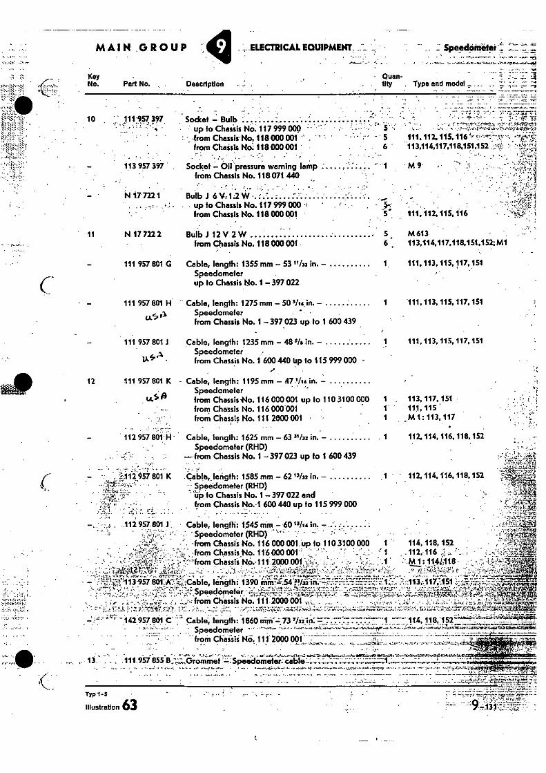
MAIN GROUP _..ELECTRICAL EOUIPMENT, .• _ Spepcbiniipse: • . -,...--
- • •
• - -."?` • • •
a
111,112. 115. 116 113,114.117.118.151,152 •
,4-11;7•••-.-..t.
111 957 801 H Cable, length: 1275 mm - 50 silk in. - 1
(..k
111, 113, 115,117, 151
Speedometer • from Chassis No. 1 - 397 023 up to 1 600 439
, S112.957 801 K • •
Key No. Part No. Description
- Quan-tity Type and model , „,
10 111-957 397 • 5 -
11
Socket - Bulb • up fo Chasiis NO. 117 999 000 • ,from Chassis-No, 118 000 001 " ' from Chaisis No: 118 000001 ' • .. •
• • • • • ' • - ' • „ .•- 113 957 397 . Socket - Oil 'pressure warning lamp -
from Chassis No. 118 071 440
N 17 7221 Bulb J 6)1,1.2* • • . . up to Chassis No. 117 999 000 •-•
from Chassis No. 118 000091
N 17 722 2 BulbJ 12 V 2W from Chassis No. 118 000 001 6 ,
111 957 601 G Cable, length: 1355 mm 53 ''/32 in. - 1. Speedometer up to Chassis No. 1 - 397 022.
111, 112.,.115, 116
M 613 113,114,117,118,151,152:M1
111, 113, 115017,151
111 957 801 1 Cable, length: 1235 mm - 48 5Ia in. - Speedometer from Chassis No. 1 600 440 tip 10 115 999 000 •
12 111 957 801 K - Cable, length: 1195 mm - 47'/+a in. - Speedometer
tALS A from Chassis No. 116 000 001 up to 110 3100 000 1 from Chassis No. 116 000001 1 from Chassis No. 111 2000 001 • 1
112 957 sai Cable, length: 1625 mm - 63 31/32 in. - 1 Speedometer (RHD)
— from Chassis No. 1 - 397 023 up to 1 600 439
Cable,, length: 1585 mm - 62"132 in. - 1
Speedometer (RHD) •
up to Chassis No. 1- 397 022 and tram Chassis No. 1 600 440 up to 115 999 000
111, 113, 115,117, 151
. 113, 117.151 111, 115 M 1: 113, 117
112. 114, 116, 118..152
. 112. 114. 1'16,118,152
Cable, length: 1545 aim -.60 "las in. . ' - . - Speedometer(RHD) ''". . ...- • ''"- . -from CbassiS No. 116 000 001. up to 110 3100 000 1 ' 114,118, 152
.' ',..from Chassis_No. 116000 001" ::..!'. • f .,...!=..: .111-116 J ... 'I. , • - - 4- -1'"from Chase's 146.-111.opo 001;•-.,. - - ' ,',M 1: 114
N118 4'
• ,-,,_•....-:
'.i,?-1:113-957 801:k `;;-•,•Cable, length i 1390 iiiii-.54'.nriiiin.- ;.•:::::'-i7.:FF:',;T:=:-...7..!...1.7.1..:......----.:113,-,117.1 51 .:•-•,•-•- ..,,,. ---- '" ' •----, ,.7-..,.:,.. ,
...o.,-, "L'il.17.17.7-'!•:''' ' ',1'-7.-zteiz-,•,7-t.T..74;....;.r: -.;.•:;.--.:.:;c.:.:.--:̀,1i.1;:E;.;;;;Pz.I.ri,,;,...;i4...%*-13.3,1t*.;'-.1p,:t..., - . Speedometer - --'• .-'r`--- -r'--- .-- --5.',z- --.•-'.'c ,-"^' • 7. ''• r-"-1 "11-1", '1?-'47 ' ''''' '-!..' ' ••,?7,...,L':_21- VZ.k: '''..; ....t,*-
. from Chassis No. 111 2000 001 -- •-' - - 7.-- ' - • '_:•.' ' 7 : -' '-1 ••-• . ._,. .. , -• . • •• .....4.•,,, • ...—...• ,-• • . ..;.7.. ,.• • a:....... 4 -....1-:-,....1.4.7.4•.W,4 . .
,.;•17....1. . z r:i:-.7..titz,q9.., 1!"::...;..1,.., • .....;.- .i..%-;... --- .,,..:•,.:4;55y.,7-..,;,z. t;;:gh:2{..,........,-.-.-..z.:.7,41...„..,....,....,,-„44-...17.;:v44;..;..,J.:4.&,:l.:,-..,,..v.;TrArzi.11114.d.',:.= 4. - - •4 .". Lv; "142:957. 801 C' • : Cable, length: 1860 ninif-z,73 Thi:in:7'7.".77:7• -.:7.7:',.7",:1.7-__114, 118,'152.'''''''''';'-::477;7' -
1 .._,....., . : Speedometer ' - "--"'- --'" -..`------"---•-- ------"--h- 0.--,••••- -,:---,..----4-- .•-•,-..-0..;.....,G,••=4-..i..7&-ta.,-...,....,.r. _
.....,..:...-.!-......, .•
• . •• • "from Chaiiii No. 111 2000 001 ., ....,
, ....17-3.•••-"t „ .......... ... .
.._ .. . •:.:.T.:..,.i.-'i...4.1,........., ... ,......7
• . • . .. ••-.._!.. , ....1.; e,.. '• ..ir • - -,". ' .. .. a•ea-al..e...,,..1,421.1.-C•itri.,4‘•W!....- &•..,e..10.1.Ktillf......:44.-7e.....4./..V.i..4:- 1.1.1.
. • 13. - . - . • 111-.957 055 B..",:;,..Grommet "-•_.•Speedometer:cable---..-.........;;;.:•-;;;;;;1:-..--;—;:...-.• ! . _ . . .
• . • • ."tr.,n7."
• Typ 1 - s
illustration 63
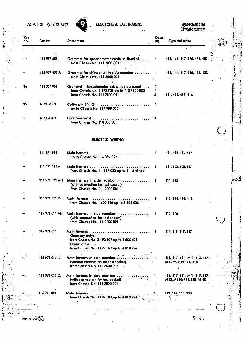
ELECTRIC WIRING
111 971 011
Main harness up to Chassis No. 1 — 397 022
111 971 011 A
Main harness from Chassis No. 1 7397 023 up to 1 — 575 414
111 971 011 All Main harness in side member (with connection for lest socket) from Chassis No. 111 2000 001
112 971 011 D Main harness from Chassis No. 1 600 440 up to 3 192 506
112 971 011 AH Main harness in side member (with connection for test socket) from Chassis No. 111 2000 001
113 971 011
113 971 011
113 971 011 DJ
114 971 011
Main harness in side member (with connection for test socket) • from Chassis No. 111 2000 001
Main harness from Chassis No. 3. 192 507,up fo 4 010 994
Main harness Germany only: from Chassis No. 3 192 507 up fo 3 856 471 Export only: from Chassis No. 3 192 507 up to 4 010 994
Main harness•in side member (without connection for test socket) from Chassis No. 112 2000 001
MARL GROUP ELECTRICAL EQUIPMECTi Speademolea ralAne
Key No. Part No. Description
Quan-tity Type and model
113 957 855 Grommet for speedometer cable in Bracket from Chassis No. 111 2000 001
1 113, 114, 117, 118, 151. 152
113 957 855 A Grommef for drive shaft in side member from Chassis No. 111 2000 001
1 113, 114, 117. 118, 151, 152
14 111 957 861 Grommet — Speedometer cable In side panel 1 from Chassis No. 3 192 507 up to 110 3100 000 1 from Chassis No. 111 2000 001 .1 '111, 117., 115. 116
15 N 12 512 1 Cotter pin 2 X12 up to Chassis No. 117 999 000
1
N 12 434 1 Lock washer 4 from Chassis No. 118 000 001
1
1
1
111, 113,
111, 113,
115. 117
115, 117
1 111,115
1 112, 114, 116, 118
1 112, 116
1'
1 111, 113, 115, 117
1 113,117, 151; M 1: 113, 117; M 52/M 610: 111,115
113, 117, 151; M 1 : 113, 117: M52/M610:111,115;M102
112, 114, 116, 118
9-132 le -Illustration 63
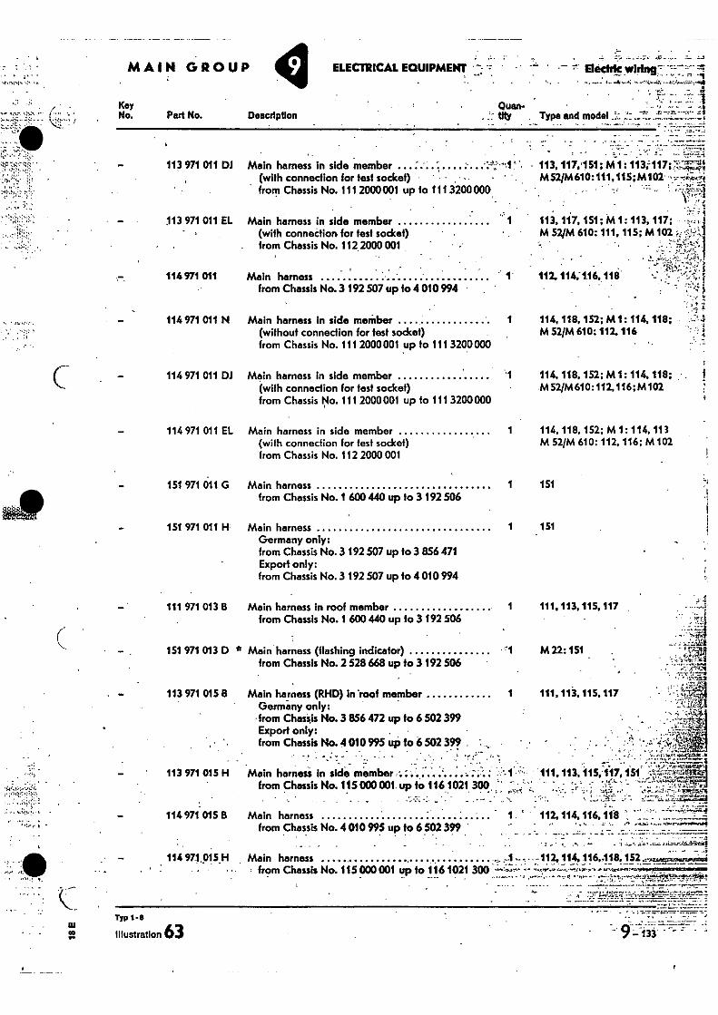
44)04,,
. •
• / •
•
s.. r
MAIN GROUP
Key No. Part No. Description
114, 118, 152; M 1: 114, 113 M 52/M 610: 112. 116: M 102
151
151
111, 113, 115. 117
M 22:151
111, 113. 115, 117
• .
Main harness from Chassis No.4010995 up to 6 502 399
•
Main harness • . from Chassis No. 115 000 001 up to 1161021 300 .. ---- • .
• 1 '
. .1,_ -•,-• ',- ...--•-•-.:,
_
. • - ' . '. , ',""'...;',..,l,%7C5 ..-.'
.. ..
Main harness in side member ,- - r ' ' ' . 1 -, 111. 113, 115,117. 1.51 '1".,7 .4F.,,,e, from Chassis No. 115000001. up fo 116 1021 300 " - ''' "" - ̀- ' - ' ` '' '''"-k 'f'4-:it"' • . - • • • - ........,4. 4- ...-. T r ; A2;1.. • l ..0.4•;_;;;::::- .p .:17;
...'' ':. .• 1: ',.14:':: ..; -; ,..',..:2:-LE.,'-'4za ....
- -112, 114. 116,118, 152,• Ocitt0cOlig. .
- --,.•---- ---- .. ''---'-'-h•.*"-̂ "."''"N- .---t--- -g---- --, •••,•-•••..--.0,.t.ii•itttink.2....1,.---e2v.
-.' ?:-.;,-..-z.i 112, 114, 116, 118 1 " .- — -4 ' '4
4 :'7;4 COO • . .,?..,-.'.,; n';.....C....../ ..;
; .;.. 7.•
ELECTRICAL. EQUIPMENT =• ••"'" Eledrk •
• Quan- tity Type and model
•
113 971 011 DJ Main harness in side member -1:•11 -• • 113,117,'151; M 1: 113;117:7'.7-,:4 (with connection for test socket) - • • . M52/M610:111,115;M102 ---..- frorp Chassis No. 1112000001 up to 111 3200000.
. _ I
113 971 011 EL Main harness in side member
113, 147,151; M1: 113;117; (with connection for test socket)
M 521M 610: 111, 115; M 102 „ •zt,
from Chassis No. 112 2000 001 ' -
114 971 011 Main harness from Chassis No.3 192507 up 10 4 010 994
112,114,-1.16.118
114 971 011 N Main harness in side member (without connection for test sodcet) from Chassis No. 111 2000001 up to 111 3200000
1 114, 118,152; M 1: 114, 118; M 52/M 610: 112, 116
114 971 011 DJ Main harness in side member
.•1 (with connection for test socket) from Chassis No. 111 2000001 up fo 111 3200000
114 971 011 EL Main harness in side member 1 (with connection for test socket) from Chassis No. 112 2000 001
151 971 011 G Main harness from Chassis No. 1 600 440 up to 3 192506
151 971 011 H Main harness 1 Germany only: from Chassis No.3 192 507 up to 3 856 471 Export only: from Chassis No. 3 192 507 up to 4010994
114,118. 152; M 1: 114. 118; • M 52/M610:112,116:M102
113 971 015 8
Main harness (RHD) in *roof member 1 Germany only:
-from Chass,is No. 3 856 472 up to 6 502 399 Export only: from Chassis No. 4 010 995 up to 6 502 399
113 971 015 H
114 971 015 8
114 971,015_H
ur CO .•••
Typ 1-8
Illustration 63 9133 - -
111 971 013 B Main harness in roof member 1 from Chassis No. 1 600 440 up to 3 192 506
151 971 013 D * Main harness (flashing indicator) 111
from Chassis No. 2 528 668 up to 3 192 506
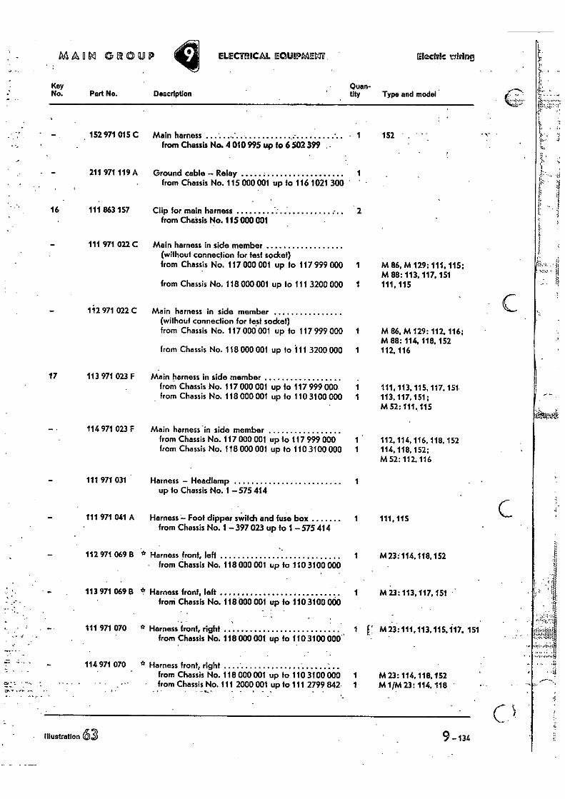
MAO GROUP ELECHHCAL Eat/1MM Electric wiring
Key No. Part No. Description
Quan-thy Type and model
152 971 015 C
211 97i 119 A
Main harness from Chassis No. 4 010 995 up to 6 502 399 .
Ground cable — Relay from Chassis No. 115 000 001 up to 116 1021 300
1
1
152 . '
16 111 863 157 Clip for main harness from Chatsis No. 115 000 001
2
111 971 022 C Main harness in side member (without connection for test socket) from Chassis No. 117 000 001 up to 117 999 000 1 M 86, M 129: 111. 115;
M 88: 113, 117, 151 from Chassis No. 118 000 001 up to 111 3200 000 1 111, 115
112 971 022 C Main harness in side member (without connection for test socket) from Chassis No. 117 000 001 up to 117 999 000 1 M 86, M 129: 112.116;
M 88: 114, 118, 152 from Chassis No. 118 000 001 up to 111 3200 000 1 112,116
17 113 971 023 F Main harness in side member from Chassis No. 117 000 001 up to 117 999 000 1 111, 113, 115, 117, 151 from Chassis No. 118 000 001 up to 110 3100 000 1 113, 117, 151;
M 52: 111.115
114 971 023 F Main harness 'in side member from Chassis No. 117 000 001 up to 117 999 000 1 112, 114, 116, 118, 152 from Chassis No. 118 000 001 up to 110 3100 000 1 114, 118, 152;
M 52: 112. 116
111 971 031 Harness — Headlamp up to Chassis No. 1 — 575 414
1
111 971 041 A Harness — Foof dipper switch and fuse box from Chassis No. 1 — 397 023 up to 1 — 575 414
1 111.11s
112 971 069 B * Harness front, left from Chassis No. 118000 001 up to 110 3100 000
1 M 23:114,118,152
113 971 069 B ' Harness front, left froni Chassis No. 118000 001 up to 110 3100 000
1 M 23: 113, 117, 151
111 971 070 * Harness front, right from Chassis No. 118 000 001 up to 110 3100 000
1 M 23:111,113.115,117, 151 . • f;R1'4
114 971 070 * Harness front, right from Chassis No. 118 000 001 up to 110 3100 000 1 M 23: 114, 118, 152
• from Chassis No. 111 2000 001 up to 111 2799 842. _ . .„. . . 1 M 1/M 23: 114,118 '
. illustration 63 9 -134
•
• It
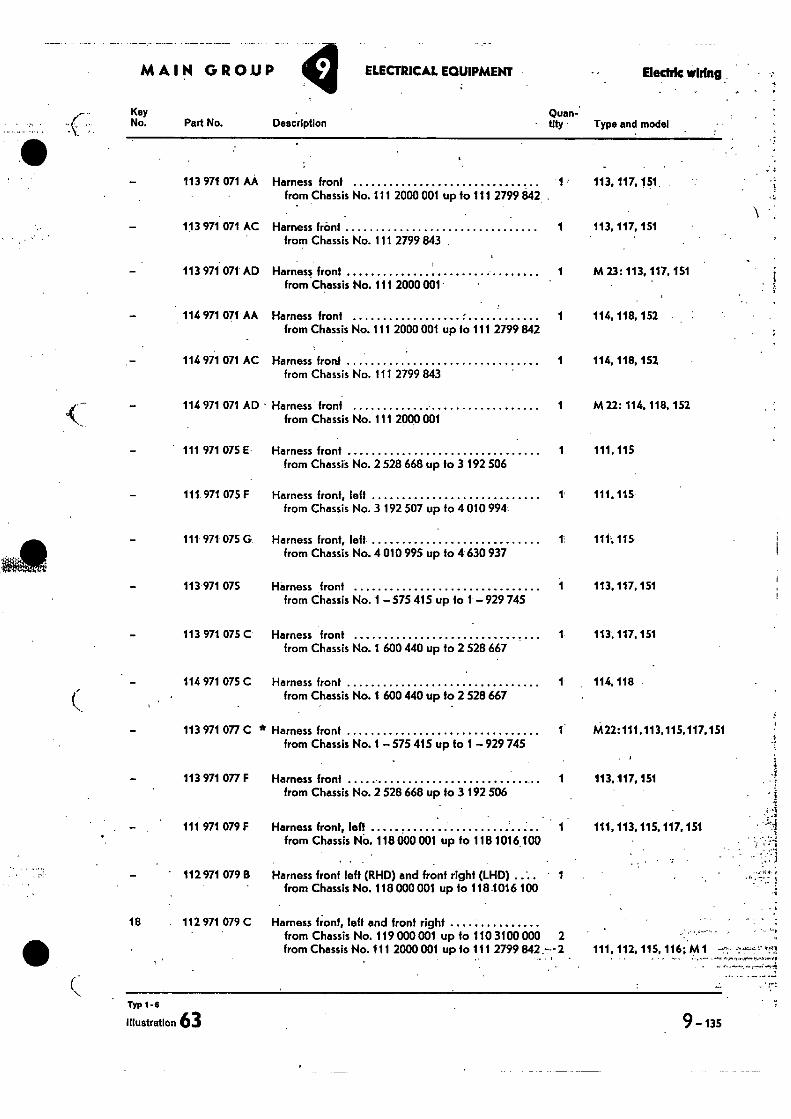
MAIN GROUP y ELECTRICAL EQUIPMENT Electric wiring.
Key No. Part No. Description
Quan-. - tity • Type and model
113 971 071 AA Harness front 1 from Chassis No. 111 2000 001 up to 111 2799 842
113 971 071 AC Harness front 1 from Chassis No. 111 2799 843
113 971 071 AD Harness front 1 from Chassis No. 111 2000 001
114 971 071 AA Harness front 1 from Chassis No. 111 2000 001 up to 111 2799 842
114 971 071 AC Harness fronf 1 from Chassis No. 111 2799 843
114 971 071 AD • Harness front 1 from Chassis No. 111 2000 001
111 971 075 E• Harness front 1 from Chassis No. 2 528 668 up to 3 192 506
111 971 075 F Harness front, left 1 from Chassis No. 3 192 507 up to 4 010 994
111 971 075 G Harness front, left 1 from Chassis No. 4 010 995 up fo 4 630 937
113 971 075 Harness front from Chassis No. 1 – 575 415 up to 1 – 929 745
113 971 075 C Harness front 1 from Chassis No. 1 600 440 up to 2 528 667
114 971 075 C Harness front 1 from Chassis No. 1 600 440 up to 2 528 667
113 971 077 C * Harness front 1 from Chassis No. 1 – 575 415 up fo 1 – 929 745
113 971 077 F Harness front 1 from Chassis No. 2 528 668 up to 3 192 506
111 971 079 F Harness front, leff from Chassis NO. 118 000 001 up to 118 1016 100
112 971 079 B Harness front left (RHD) and front right (LHD) 1 from Chassis No. 118 000 001 up 10 1184016 100
18 112 971 079 C Harness front, left and front right from Chassis No. 119 000 001 up to 110 3100 000 2 from Chassis No. 111 2000 001 up to 111 2799 842.— 2
113, 117, 151
113, 117, 151
M 23: 113, 117, 151
114, 118, 152
114, 118, 152
M 22: 114. 118, 152
111, 115
111.115
111.115
113, 117, 151
113, 117, 151
114,118 -
M22:111,113,115,117,151
113, 117, 151 1
111, 113. 115. 117, 151 = t
, • • .1
111, 112. 115, 116; M 1 t41
Typ 1-6
Illustration 63
9-135
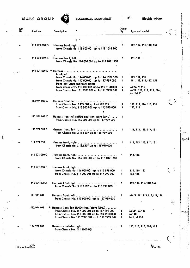
MAIM GROUP ELECTRICAL EGUIPMENT 41: Electric rifting
Key No. Part No. Description
Quan-tity Typo and model
— '112 971 080 D Harness front, right from Chassis No. 118 000 001 up to 118 1016 100
1 112, 114, 116, 118, 152
111 971 089 C Harness front, left from Chassis No. 116 000 001 up to 116 1021 300
1 111,115 .
111 971 089 D * Harness front, left:
• from Chassis No. 116 000001 up to 116 1021 300 1 113, 117, 151 from Chassis No. 117 000 001 up to 117 999 000 front left (LHD) and •front right:
1 111, 113,115, 117, 151
from Chassis No. 118 000 001 up to 110 3100 000 2 M 22,M110 from Chassis No. 111 2000 001 up to 111 2799 842 2 M 22: 111, 112, 115, 116;
M 1/M 22
112 971 089 A Harness front, left from Chassis No. 3 192 507 up to 6 502 399 1 112, 114, 116, 118,152 from Chassis No. 115 000 001 up to 115 999 000 1 112,116
112 971 089 C Harness front left (RHD) and front right (LHD) from Chassis No. 116 000001 up to 117 999 000
1
113 971 089 B Harness front, left from Chassis No. 3 192 507 up to 115 999 000
1 111.113, 115, 117, 151
111 971 090 Harness front, right from Chassis No. 3 192 507 up to 115 999 000
1 111, 113, 115, 117, 151
112 971 090 C Harness front, right from Chassis No. 116 000 001 up to 116 1021 300
1 112, 116
112 971 090 D Harness front, right from Chassis No. 116 000 001 up fo 117 999 000 1 114, 118, 152 from Chassis No. 117 000 001 up to 117 999 000 1 112, 116
114 971 090 A Harness front, right from Chassis No. 3 192 507 up to 115 999 000
1 112,114,116,118,152
111 971 091 Harness front, left from Chassis No. 117 000001 up to 117 999 000
1 M611:111,113,115,117,151
112 971 091 * Harness front, left (RHD) front,' right (LHD) from Chassis No. 117 000 001 up to 117 999 000 M 611, M110 from Chassis No. 118 000 001 up to 110 3100 000 1 M110 from Chassis No. 111 2000 001 up to 111 2799 842 1 M 1,M 110
114 971 101 Harness — Inferior light from Chassis No. 111 2000 001
1 113, 114, 117, 118; M 1
.
Illustration 63 7- 136
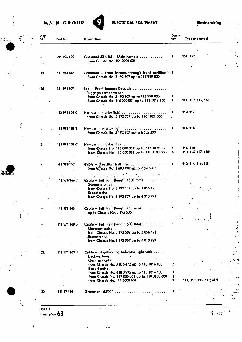
MAIN GROUP: 9 ELECTRICAL EQUIPMENT Electric wiring •
Key No. Part No.
311 906 105
19 111 953 547 •
20 141 971 907
113 971 105 C
114 971 105 B
21 114 971 105 C
Grommet 33X8.5 - Main harness 1 151, 152 from Chassis No. 151 2000 001
Grommet - Front harness through front partition .1 from Chassis No. 3 192 507 up to 117 999 000
Seal - Front harness through luggage compartment • from Chassis No. 3 192 507 up to 115 999 000 1 from Chassis No. 116 000 001 up to 118 1016 100 1 111, 112,,115, 116
Harness - Interior light 1 113.117 from Chassis No. 3 192 507 up to 116 1021 300
Harness - interior light 1 114, 118 from Chassis No. 3 192 507 up to 6 502 399
Harness Interior light
from Chassis No. 115 000 001 up fo 1.161021' 300 1
114,118
from Chassis No. 117 000 001 up to 110 3100 000. 1
113, 114, 117.118
Quan- Description tity Type and model
1149711145; Ca151e. DirocliOn indicator 1 117.114, 116, 118t from; ciiassis 600` 440• up: to, 2.528 667
111 971 167 B
111 971 168
111 971 168 B
22 111 971 169 H
23 111 971 911
Cable - Tail light (length 1300 mm) Germany only: from Chassis No; 3 192 507 up fo 3 856 471 Export only from Chassis NO. 3 1.92 507 up to 4 010 994
Cable - Tail light (length 750 mm) up to Chassis No. 3 192 506
Cable - Tait light (length 500 mm) Germany only: from Chassis No. 3 192 507 up to 3 856 471 Export only: from Chassis No. 3 192 507 up to 4 010 994
Cable - Stop/flashing Indicator light with back-up lamp Germany only: from Chassis No. 3 856 472 up to 118 1016 100 2 Export only: • from Chassis No. 4 010 995 up to 118 1016 100 2 from Chassis No. 119 000 001 up to 110 3100 000 2 from Chassis No. 111 2000 001 2 111.112, 115, 116; M1
Grommet 16.5X4 2
Typ 1-4
illustration 63 1 - 137
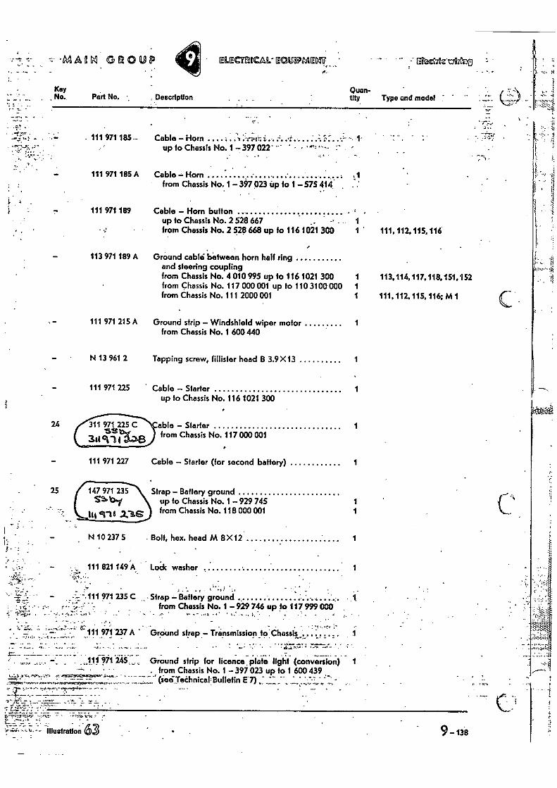
111 971 227
25 (
147 971 235 55. %Di
lls cilltii .2.3e
N 10 237 5
'4-11\ •
'Cc
GROUP ELECTRICAL" EOUPMELIT ' ,-"ErcadAzug,47.10
Kay , No. Part No. Description
Quan- tity Type and model
- 111 971 185-
24
Cable - Horn • 7 —.41- • up to Chassis No. 1 - 397 022''
Cable - Horn button up fo Chassis No. 2 528 667 from Chassis No. 2 528 668 up to 116 1021 300
Ground cabisi between horn half ring and steering coupling from Chassis No. 4 010 995 up to 1161021 300 from Chassis No. 117 000 001 up to 110 3100 000 from Chassis No. 111 2000 001
from Chassis No. 1 600 440
Tapping screw, fillisfer head B 3.9X13
Cable - Starter up to Chassis No. 116 1021 300
able - Starter from Chassis No. 117 000 001
Cable - Starter (for second battery)
Strap - Battery ground up to Chassis No. 1 929 745 from Chassis No. 118 000 001
Boit, hex. head M 8 X12
1 1 111, 112. 115.116
1 113,114, 117. 118. 151, 152 1 1 111. 112, 115, 116; M 1
1
1
1
1
1
1 1
1
1
111 971 215 A Ground strip - Windshield wiper motor
111 971 185 A Cable Horn from Chassis No. 1- 397 023 up fo 1- 57S 414 , :
111 971 189
113 971 189 A
N 13 961 2
111 971 225
111 821 149 A
Lodc washer •
111 971 235 C • Strap -- Balfery ground from Chassis No. 1 -929 746 up to 117 999 000
111 971 237 A Ground strap - Transmission torChassiL, _
A. -• 111.971 2,45, • •• 1.4. •
.6"'" " •
71. • • -
_ • • • • - • •
Ground strip for licence. plate light (conversion) 1 . from Chassis No. 1 397 023 up to 1 600 439
(ietilTethnice Bulletin El)
• • r1- ..vta r
Illustration 6 9 - 138
•
;. •
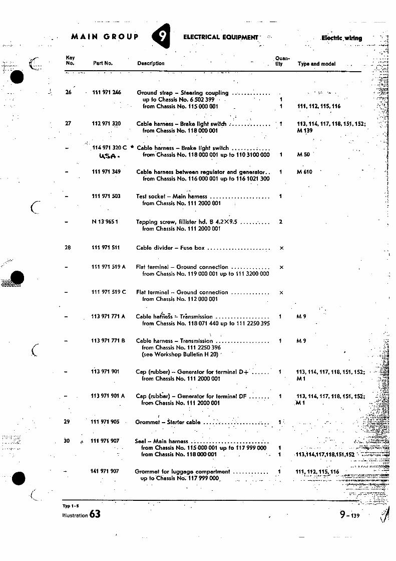
Cable divider — Fuse box
Flat terminal — Ground connection x from Chassis No. 119 000 001 up to 111 3200 000
Flat terminal — Ground connection from Chassis No. 112 000 001
Cable hait-rieis Transmission 1 M 9 from Chassis No. 118 071 440 up to 111 2250 395
Cable harness — Transmission 1 M 9 ,-.,, from Chassis No. 111 2250 396 . .:,%
. _, :.A (see Workshop Bulletin H 20) ' • -4
,1
Cap (rubber) — Generator for terminal D-I- 1 113, 114, 117, 118, 151, 152; from Chassis No. 111 2000 001 M1
Li...g
- - ' ,,v..;
1-...' Cap (rubber) — Generator for terminal DF 1 113, 114, 117, 118, 151, 152; .-:•::".. - from Chassis No. 111 2000 001
Grommet — Starter cable
Seal — Main harness • from Chassis No. 115 000 001 up to 117 999 000 1 from Chassis No. 118 000 001 .
Grommet for luggage compartment up to Chassis No. 117 999 000_
-113,114,117,118,151,152
111, 112, 115, 116 • . . ' .
..:..,. 'M 1
• MAIN GROUP ELECTRICAL EOUIPMEM— •••-• .Electric wiring
Key Quan- No. Part No. Description tity Type and model
- 111 971 246 Ground strap — Steering coupling • up to Chassis No. 6 502 399 • 1 from Chassis No. 115 000 001 1 111. 112.115.116
27 112 971 320 Cable harness — Brake light switch • 1 113, 114, 117, 118, 151, 152; from Chassis No. 118 000 001 M 139
114 971 320 C * Cable harness — Brake light switch
tk$,F1 • from Chassis No. 118 000 001 up to 110 3100 000 1 M 50
111 971 349 Cable harness between regulator and generator.. 1 M 610 ' from Chassis No. 116 000 001 up to 116 1021 300
111 971 503 Test socket — Main harness 1 from Chassis No. 111 2000 001
N 13 965 1 Tapping screw, fillister hd. B 4.2 X 9.5 2 from Chassis No. 111 2000 001
28 111 971 511
111 971 519 A
111 971 519 C
113 971 771 A
— 113 971 771 B
— 113 971 901
113 971 901 A
29 111 971 905 •
30 e. 111 971 907
141 971 907
Typ 1 -5
illustration 63 9-139 "
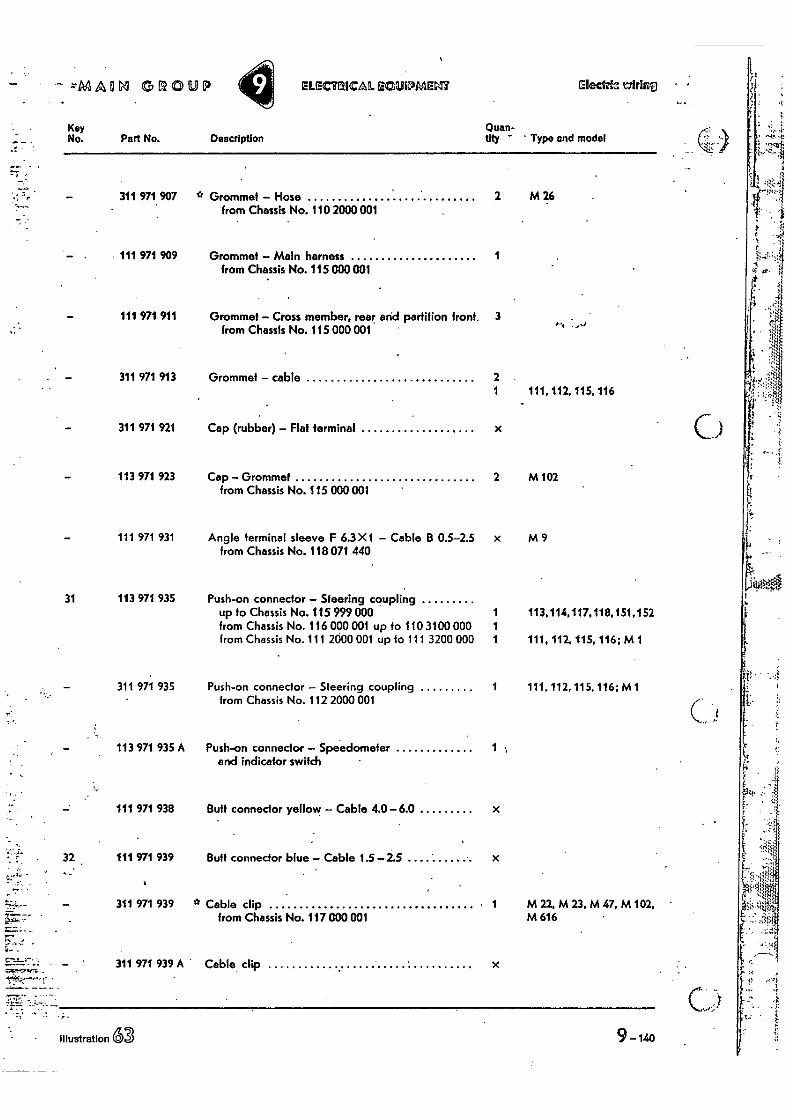
ELIEMICAL ffe3iliPMEL17 Elect& trirliTo •
Quan- My — Type and model Description
• zMAURI GROUP
•
Key No. Part No.
311 971 907
111 971 909
111 971 911 •
311 971 913
311 971 921
113 971 923
111 971 931
31 113 971 935
311 971 935
113 971 935 A
111 971 938
32 111 971 939 • -
- 311 971 939
311 971 939 A •
<.1•V
Angle terminal sleeve F 6.3X1 - Cable B 0.5-2.5 x M 9 from Chassis No. 118 071 440
Push-on connector - Steering coupling up to Chassis No. 115 9991300 1 113,114,117,118,151,152 from Chassis No. 116 000 001 up to 110 3100 000 1 from Chassis No. 111 2600 001 up to 111 3200 000 1 111, 112, 115, 116; M 1
BuH connector yellow - Cable 4.0-6A
Butt connector blue - Cable 1.5 -2.5 x
* Cable clip • 1 M 22, M 23, M 47, M 102, -
Ai 1
from Chassis No. 117 000 001 M 616 ;;10
Cable clip 4q 7
Illustration 63 9-140
•
* Grommet - Hose 2 M 26 from Chassis No. 110 2000 001
Grommet - Main harness 1 from Chassis No. 115 000 001
Grommet - Cross member, rear arid partition front. 3 from Chassis No. 115 000 001 4^1
Grommet - cable 2 1 111, 112, 115, 116
Cap (rubber) - Flat terminal
Cap - Grommet 2 M 102 from Chassis No. 115 000 001
Push-on connector - Steering coupling 1 111, 112, 115, 116; M 1 from Chassis No. 112 2000 001
Push-on connector Speedometer 1 ; and indicator switch
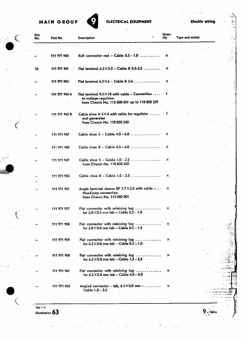
"Mr
MAIN GROUP ELECTRICAL EQUIPMENT Elixirlc wiring •
Key No. Part No. Description
Quan-thy Type and model
- 111 971 940 Butt connector red - Cable 0.5 -1.0 x
33 111 971 941 Hat terminal 63X2.5 - Cable B 0.5-25 x
- 111 971 943 Flat terminal 6.3X6 - Cable B 3-6 x
111 971 945 A Flat terminal 95X 10 with cable - Connection to voltage regulator from Chassis No. 115 000 001 up to 118 850 239
1
111 971 945 B Cable shoe A 5X4 with cable for regulator and generator from Chassis No. 118 850 240
1
111 971 947 Cable shoe 5 - Cable 4.0-6.0
111.971 948 Cable shoe 8 - Cable 4.0-6.0
111 971 949 Cable shoe 5 - Cable 1.0-2.5 from Chassis No. 118 850 240
111 971 950. Cable shoe 8 - Cable 1.0-2.5
111 971 951 Angle terminal sleeve EF 7.7X2.5 with cable - x Headlamp connection from Chassis No. 115 000 001
111 971 957 Flat connector with retaining lug for 2.8 X0.5 mm tab - Cable 0.5 -1.0
111 971 958 Flat connector with retaining lug for 2.8 X 0.8 mm tab - Cable 0.5 -1.5
111 971 959 Flat connector with retaining lug for 63 X0.8 mm tab - Cable 0.5 - 1.0
111 971 960 Flat connector with retaining lug for 6.3 X0.8 mm tab - Cable 1.5-2.5
•
111 971 961 Flat connector with retaining lug for 6.3 X0.8 mm tab - Cable 4.0-6.0
111 971 965 Angled connector - tabs 6.3X0.8 mm - Cable 1.0- 2.5
Typ 1 - 4
Illustration 63
9-140a
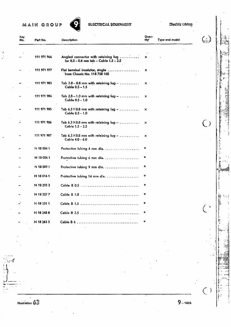
MAIIN GROUP ELECMICAL ocauoMagif Methlz
Key No. Part No. Description
Quan- tity- Type and model
111 971 966 Angled connector with retaining lug for 8.0-0.8 mm tab - Cable 1.5-2.5
111 971 977 Flat terminal insolator, single from Chassis No. 118 758 160
111 971 983 Tab 2.8-0.8 mm with retaining lug - Cable 0.5-1.5
111 971 984 Tab 2.8-1.0 mm with retaining lug - Cable 0.5- 1.0
111 971 985 Tab 6.3X0.8 mm with retaining lug - Cable 0.5- 1.0
111 971 986 Tab 6.3X0.8 mm with retaining lug - Cable 1.5 - 2.5
111 971 987 Tab 6.3X0.8 mm with retaining lug - Cable 4.0-6.0
N 18 004 1 Protective tubing 4 mm dia.
- N 18 006 1 Protective tubing 6 mm dia. *
- N 18 009 1 Protective tubing 9 mm dia. *
- N 18 014 1 Protective tubing 14 mm dia. *
- N 18 203 3 Cable B 0.5 *
- N 18 227 7 Cable B 1.0 *
N 18 231 1 Cable B 1.5 *
- N 18 248 8 Cable B 2.5 *
N 18 263 3 Cable B 6 *
63 Illustration
9-uob
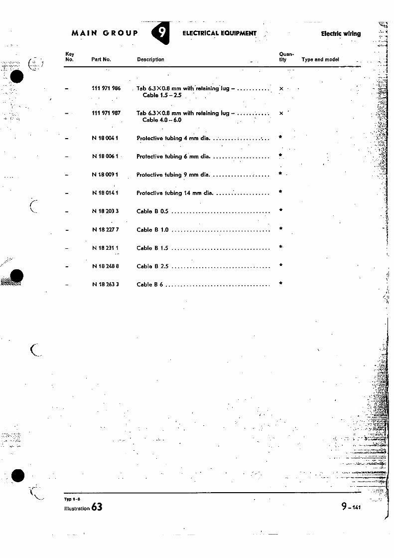
MAIN GROUP ELECTRICAL EQUIPMENT
Key No. Part No. Description
Electric wiring
Quan- tity Type and model
111 971 986 Tab 6.3X0.8 mm with retaining lug - x Cable 1.5- 2.5 . •
111 971 987 Tab 6.3X0.8 mm with retaining lug - x Cable 4.0 - 6.0
N 18 004 1 Protective tubing 4 mm dia.
*
N 18 006 1 Protective tubing 6 mm dia.
N 18 009 1 Protective tubing 9 mm dia. *
N 18 014 1 Protective tubing 14 mm dia. *
N 18 203 3 Cable 13 0.5
- N 18 227 7 Cable B 1.0 *
- N 18 231 1 Cable B 1.5
- N 18 248 8 Cable B 2.5
- N 18 263 3 Cable B 6
• _r
Typ 1-8
illustration 63 9 _141
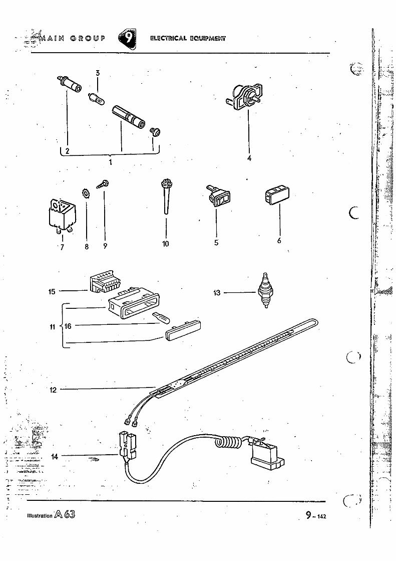
illustration A 63 9 — 142
7 8 9
O
15
11
12.
. ;
4 4 •
• 14
10 6
C
'. :14AfIti GROUP •
n •
ELECTRICAL ECU:MASI?
4 1
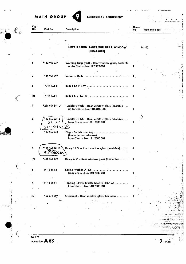
Key No. Part No. Description
Quan- tity Type and model •
Tumbler switch — Rear window glass, heatable from Chassis No. 111 2000 001 1
5
6
113 959 623
Plug — Switch opening (heatable rear window) from Chassis No. 111 2000 001
MAIN GROUP ELECTRICAL EQUIPMENT
INSTALLATION PARTS FOR REAR WINDOW M 102 (HEATABLE)
1
*113 919 237 Warning lamp (red) — Rear window glass, heatable -up to Chassis No. 117 5199 000 1
2 111 957 397 Sodcet — Bulb
3 N 17 722 2 Bulb1 12 V 2 W 1
(3) N 17 722 1 Bulb 1 6 V 1.2 W 1
4 *211 947 511 D Tumbler switch — Rear window glass, heatable .. Up to Chassis No. 110 3100 000 1
*1113 141 B Relay 12 V — Rear window glass (heatable) 1
3t19C
*311 963 139
Relay 6 V — Rear window glass (heatable) 1
N 12 104 2 Spring washer A 5.3 from Chassis No. 110 2000 001 1
9 N 13 968 1 Tapping screw, faster head B 4.8X9.5 from Chassis No. 110 2000 001
, 10 143 971 919 Grommet — Rear window glass, heatable
7
(7)
8 •
7:1
Typ 1 -11
Illustration A 63 9-142a.
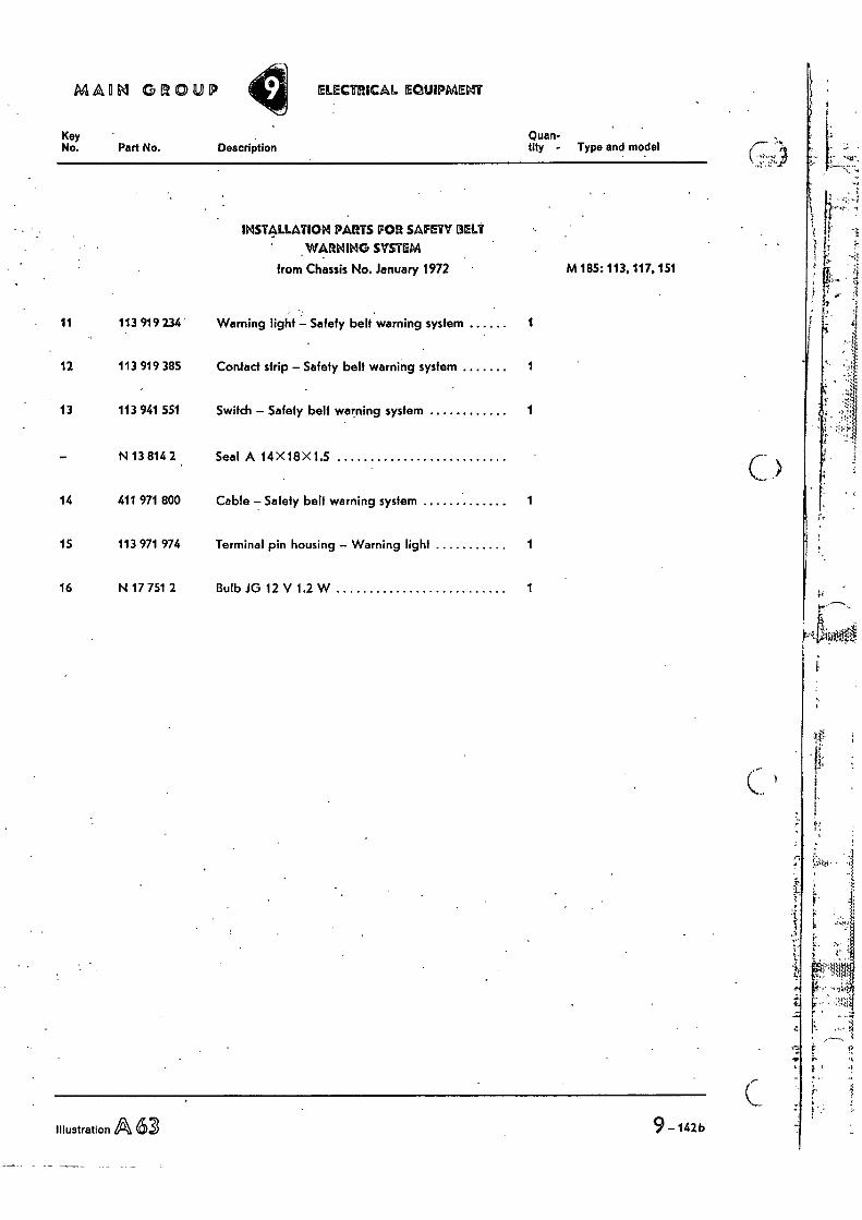
IMAM GROUP ELECTRICAL EaLlIPMENT
Key No. Part No. Description
Quan- tify - Type and model
INSTALLATION PARTS FOR SAFETY BELT WARNING SYSTEM
from Chassis No. January 1972 M 185: 113, 117, 151
11 113 919 234 Warning light — Safety belt warning system 1
12 113 919 385 Confad strip — Safely belt warning system 1
13 113 941 551 Switch — Safety belt warning system 1
— N 13 814 2 Seal A 14 X18 X1.5
14 411 971 800 Cable — Safety belt warning system 1
15 113 971 974 Terminal pin housing — Warning light 1
16 N 17 751 2 Bulb JG 12 V 1.2 W 1
Illustration A 63 9 —142b
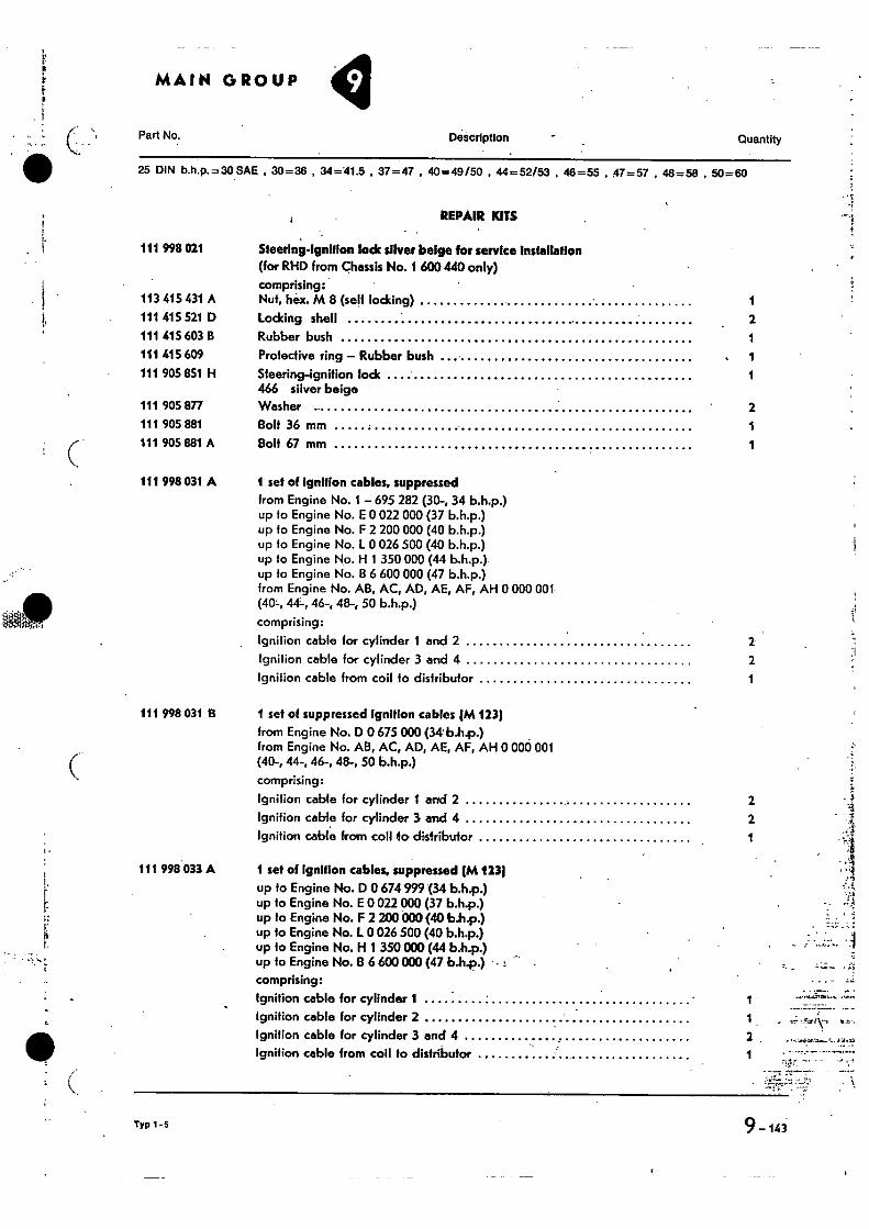
MAIN GROUP
Part No. Description Quantity
25 DIN b.h.p.=30 SAE , 30=36 , 34=41.5 , 37=47 , 40=49/50 , 44=52153 , 48=55 , 47=57 , 48=58 , 50=60
REPAIR KITS
111 998 021 Steering-Ignition lode sliver beige for service Installation (for RHD from Chassis No. 1 600 440 only) comprising:
113 415 431 A Nut, hex. M 8 (self locking) 111 415 521 D Locking shell 2 111 415 603 B Rubber bush 1 111 415 609 Protective ring — Rubber bush 1 111 905 851 H Steering-ignition lock 1
466 silver beige 111 905 877 Washer 2 111 905 881 Bolt 36 mm 111 905 881 A Bolt 67 mm 1
111 998 031 A I set of Ignition cables, suppressed from Engine No. 1 — 695 282 (30-, 34 b.h.p.) up to Engine No. E 0 022 000 (37 b.h.p.) up to Engine No. F 2 200 000 (40 b.h.p.) up to Engine No. L 0 026 500 (40 b.h.p.) up to Engine No. H 1 350 000 (44 b,h.p.) up to Engine No. B 6 600 000 (47 b.h.p.) from Engine No. AB, AC, AD, AE, AF, AH 0 000 001 (40-, 44-, 46-, 48-, 50 b.h.p.)
comprising:
Ignition cable for cylinder 1 and 2 2 Ignition cable for cylinder 3 and 4 2 Ignition cable from coil to distributor 1
111 998 031 B 1 set of suppressed Ignition cables (M 123) from Engine No. D 0 675 000 (34 b.hp.) from Engine No. AB, AC, AD, AE, AF, AH 0 000 001 (40-, 44-, 46-, 48-, 50 b.h.p.)
comprising:
Ignition cable for cylinder I and 2 2 Ignition cable for cylinder 3• and 4 2 Ignition cable from coil to distributor 1
i.
111 998 033 A 1 set of Ignition cables, suppressed (M 123)
up to Engine No. D 0 674 999 (34 b.h.p.) up to Engine No. E 0 022 000 (37 b.h.p.) up to Engine No. F 2 200 000 (40 b.h.p.) up to Engine No. L 0 026 500 (40 b.h.p.) up to Engine No. 1-1 1 350 000 (44 b.h.p.) up to Engine No. B 6 600 000 (47 b.h.p.) • - comprising:
ignition cable for cylinder 1 Ignition cable for cylinder 2 1 Ignition cable for cylinder 3 and 4 2 Ignition cable from coil fo distributor
1
Typ 1 -5 9- 141
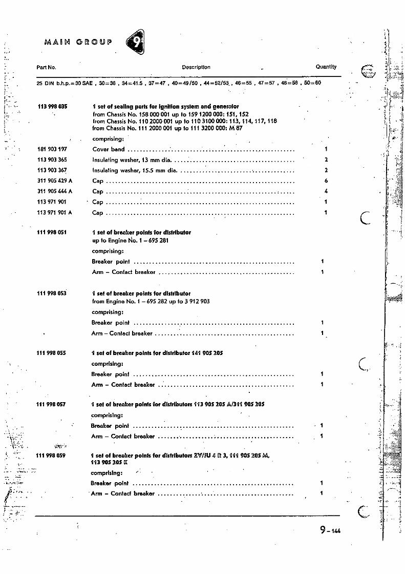
MARL GROUP
Part No.
Description Quantity
25 DIN b.h.p.= 30 SAE , 30=36 , 34=41.5 , 37=47 , 40=49/50 , 44=52/53_, 46=55 , 47=57 , 48=58 , 50=60
113 998 035 1 set of sealing parts for ignition system and generator from Chassis No. 158 000 001 up fo 159 1200 000: 151, 152 from Chassis No. 110 2000 001 up to 110 3100 000: 113, 114, 117, 118 from Chassis No. 111 2000 001 up to 111 3200 000: M 87
comprising:
181 903 197 Cover band 1
113 903 365 Insulating washer, 13 mm dia. 2
113 903 367 Insulating washer, 15.5 mm dia. 2
311 905 429 A Cap 6
311 905 444 A Cap 4
113 971 901 Cap 1
113 971 901 A Cap 1
111 998 051
111 998 053
set of breaker points for distributor up fo Engine No. 1 — 695 281
comprising:
Breaker point 1
Arm — Contact breaker
I set of breaker points for distributor from Engine No. 1 695 282 up to 3 912 903
comprising:
Breaker point 1
Arm — Contact breaker 1
111 998 055 1 set of breaker points for distributor 141 905 205
comprising:
Breaker point
1
Arm — Contact breaker 1
111 998 057 1 set of breaker points for distributors 113 905 205 A/311 905 205
comprising:
Breaker point • 1
Arm — Contact breaker
111 998 059 1 set of breaker points for distributors XV/2U 4 LI 3, 1111 905 20514 193 905 205 Et
comprising:
Breaker •point
1
Arm — Contact breaker 1
9-144
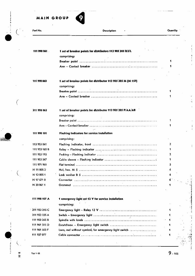
Part No. Description Quantity
111 998 061 1 set of breaker points for distributors 113 905 20S 0/1/L
comprising:
Breaker point
1
Arm — Contact breaker 1
111 998 063 1 set of breaker points for distributor 113 905 205 M (M 157(
comprising:
Breaker point
1
Arm — Contact breaker 1
311 998 063 1 set of breaker points for distributor 113 905 205 P/AAFAII
comprising:
Breaker point
1
Arm — Contact breaker 1
111 998 101 Flashing Indicators for service installation
comprising:
113 953 041 Flashing indicator, front 2
111 953 185 B Relay — Flashing indicator 1
111 953 193 Packing — Flashing indicator 2
111 953 547 Cable sleeve — Flashing indicator 1
111 971 941 Flat terminal 5
N 11 005 2 Nut, hex. M 5 4
N 12 005 1 Lock washer B 5 4
N 17 471 0 Connector 6 -
N 20 061 1 Grommet 1
111 998 107 A 1 emergency light set 12 V for service Installation
comprising:
• 211 953 215 C Emergency light — Relay 12 V 1
211 953 235 A Switch — Emergency light 1
111 953 245 B Spindle with knob 1
111 941 515 D Escutcheon — Emergency light switch 1
111 941 543 F Lens, red without symbol, for emergency light switch 1
111 937 077 Cable connector 1
Typ 1-22
9-145
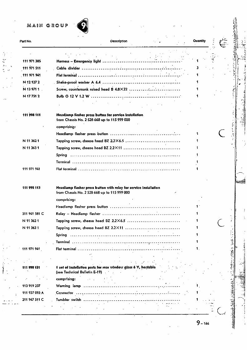
MADM GROUP
Part No. Description Quantity •
111 971.385 Harness -EmergenCy light 1
111 971 511 Cable divider
3
111 971 941 Flat terminal 1
N 12 127 2 . Shake-proof washer A 6.4 1
N 13 971 1 Screw, countersunk raised head 9 4.8X22 1
N 17 751 2 Bulb G 12 V 1.2 W 1
111 998 111 Headlamp flasher press button for service Installation from Chassis No. 2 528 668 up to 115 999 000
comprising:
Headlamp flasher press button 1
N 11 362 1 Tapping screw, cheese head BZ 2.2X6.5 1
N 11 363 1 Tapping screw, cheese head BZ 2.2 X11 1
Spring 1
Terminal 1
111 971 941 Flat terminal 1
111 998113 Headlamp flasher press button with relay for service Installation from Chassis No. 2 528 668 up fo 115 999 000
comprising:
Headlamp flasher press button 1 -
311 941 581 C Relay - Headlamp flasher
N 11 362 1 Tapping screw, cheese head BZ 2.2X6.5
N 11 363 1 Tapping screw, cheese head BZ 2.2 X11
Spring
Terminal
111 971 941 . Flat terminal
. - 111 998 131 1 set of installation parts for rear window glass 6 V, heatable
(see Technical Bulletin E-19) . '
comprising:
113 919 237 Warning lamp
111 937 093 • A Connector
211 947 511 C Tumbler switith
9- 146
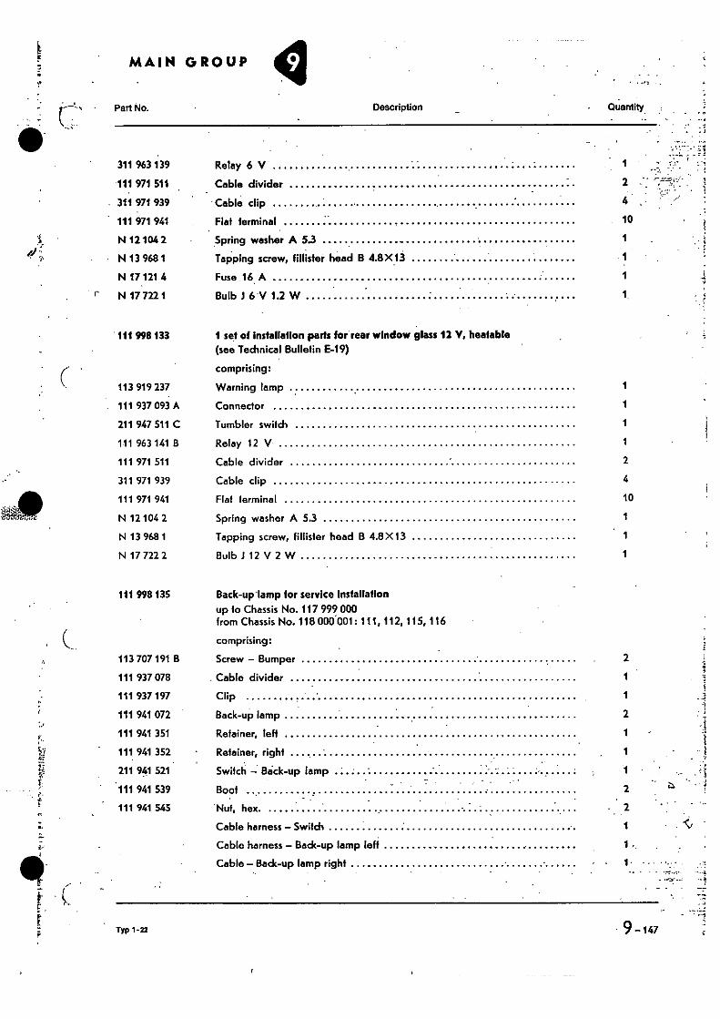
• i
2
4
10
•
MAIN GROUP
Part No.
Description • Quantity, • 311 963 139 Relay 6 V
111 971 511 Cable divider
311 971 939 Cable clip
111 971 941 Flat terminal
N 12 104 2 Spring washer A 5.3 1
N 13 968 1 Tapping screw, fillister head B 4.8X13 1
N 17 121 4 Fuse 16. A 1
N 17 722 1 Bulb J 6'V 1.2 W
111 998 133
1 set of Installation parts for rear window glass 12 V, heatable (see Technical Bulletin E-19)
comprising:
113 919 237 Warning lamp 1
111 937 093 A Connector 1
211 947 511 C Tumbler switch 1
111 963 141 B Relay 12 V 1
111 971 511 Cable divider 2
311 971 939 Cable clip 4
111 971 941 Flat terminal 10
N 12 104 2 Spring washer A 53 1
N 13 968 1 Tapping screw, fillister head B 4.8 X13 1
N 17 722 2 Bulb 1 12 V 2 W 1
111 998 135
Back-up -lamp for service Installation up to Chassis No. 117 999 000 from Chassis No. 118 000.001: 111, 112, 115, 116
s.
comprising:
113 707 191 B Screw — Bumper 2
111 937 078 Cable divider 1
111 937 197 Clip 1
111 941 072 Back-up lamp 2
111 941 351 Retainer, left 1
111 941 352 Retainer, right 1
211 941 521 Switch — BOck-up lamp 1
.111 941 539 Boot 2
111 941 543 Nut, hex.
Cable harness — Switch
Cable harness — Back-up lamp left
Cable — Back-up lamp right 1 •
Typ 1-22 • 9-147
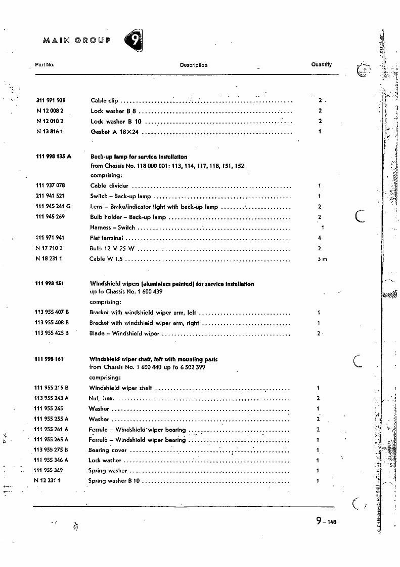
MAIIN GROUP
Part No. Description Quantity
311 971 939 Cable clip
2.
N 12 008 2 Lock washer B 8
2
N 12 010 2 Lock washer B 10
2
N 13 816 1 Gasket A 18X24
111 998 135 A Back-up lamp for service installation
from Chassis No. 118000 001: 113, 114, 117, 118, 151, 152
comprising:
111 937 078 Cable divider 1
211 941 521 Switch — Back-up lamp 1
111 945 241 G Lens — Brake/indicator light with back-up lamp 2
111 945 269 Bulb holder — Back-up lamp 2
Harness — Switch 1
111 971 941 Flat terminal 4
N 17 710 2 Bulb 12 V 25 W 2
N 18 231 1 Cable W 1.5 3 m
111 998 151 Windshield wipers (aluminium painted( for service installation up to Chassis No. 1 600 439
comprising:
113 955 407 B Bracket with windshield wiper arm, left 1
113 955 408 B Bracket with windshield wiper arm, right 1
113 955 425 B Blade — Windshield wiper 2
111 998 161 Windshield wiper shaft, left with mounting parts from Chassis No. 1 600 440 up to 6 502 399
comprising:
111 955 215 B Windshield wiper shaft 1
113 955 243 A Nut, hex. 2
111 955 245 Washer 1
111 955 255 A Washer 2
111 955 261 A Ferrule — Windshield wiper bearing 2
111 955 265 A Ferrule — Windshield wiper bearing I J 1
113 955 275 B Bearing cover
111 955 346 A Lock washer 1
111 955 349 Spring washer
N 12 231 1 Spring washer B 10 1
9-148
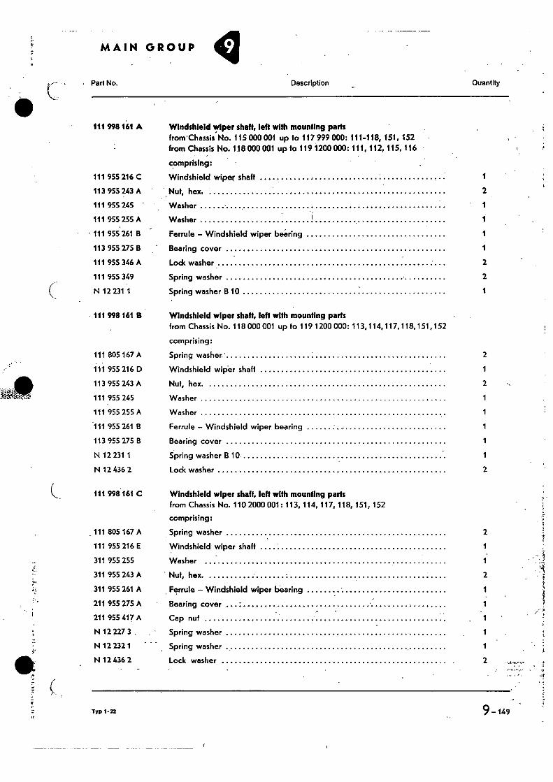
111 998 161 B
111 805 167 A
111 955 216 D
113 955 243 A
111 955 245
111 955 255 A
111 955 261 B
113 955 275 B
N 12 231 1
N 12 436 2
111 998161 C
111 805 167 A
111 955 216 E
311 955 255
311 955 243 A
311 955 261 A
211 955 275 A
211 955 417 A
N 12 227 3 ,
N 12 232 1
N 12 436 2
•
MAIN GROUP
Perak).
Description Quantity
111 998 161 A Windshield wiper shaft, left with mounting parts trom'Chassis No. 115 000 001 up to 117 999 000: 111-118, 151, 152 from Chassis No. 118 000 001 up to 119 1200 000: 111, 112, 115, 116
comprising:
111 955 216 C
113 955 243 A
111 955 245
111 955 255 A
111 955 261 B
113 955 275 B
111 955 346 A
111 955 349
N 12 231 1
Windshield wiper shalt 1
" Nut, hex. 2
Washer 1
Washer r 1
Ferrule — Windshield wiper bearing 1
Bearing cover 1
Lock washer 2
Spring washer 2
Spring washer B 10 1
Windshield wiper shaft, left with mounting parts from Chassis No. 118 000 001 up to 119 1200 000: 113,114,117,118,151,152
comprising:
Spring washer' 2
Windshield wiper shaft 1
Nut, hex. 2
Washer 1
Washer 1
Ferrule — Windshield wiper bearing 1
Bearing cover 1
Spring washer B 10 1
Lock washer 2
Windshield wiper shaft, left with mounting parts from Chassis No. 110 2000 001: 113, 114, 117, 118, 151, 152
comprising:
Spring washer 2
Windshield wiper shaft 1
Washer 1
Nut, hex. 2
Ferrule — Windshield wiper bearing 1
Bearing cover 1
Cap nuf 1
Spring washer 1
Spring washer 1
Lock washer 2
Typ 1-22
9-149
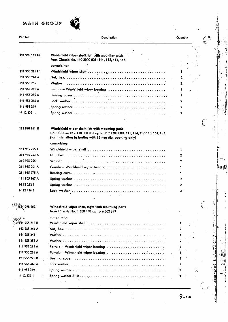
MAORI GROUP
Pan No. Description Quantity
111 998 161 D Windshield wiper shaft„ left with illeuntirm pCNS ' from Chassis No. 110 2000 001: 111, 112, 114, 116
comprising:
111 955 215 H Windshield wiper shaft 1
311 955 243 A Nut, hex. 2
311 955 255 Washer 2
311 955 261 A Ferrule — Windshield wiper bearing 1
211 955 275 A Bearing cover 1
111 955 346 A Lock washer 2
111 955 349 , Spring washer 2
N 12 232 1 • Spring washer
. Windshield wiper shaft 1
Nut, hex. 2
Washer 2
Ferrule — Windshield wiper bearing 1
Bearing cover 1
Spring washer 2
Spring washer 2
Lock washer 2
•...-4;.%-.-:-.: .' •
Windshield wiper shaft, right with mounting parts from Chassis No. 1 600 440 up to 6 502 399
comprising:
Windshield wiper shaft 1
Neit, hex. 2
Washer 1
Washer 2
Ferrule — Windshield wiper bearing 2
Ferrule — Windshieldwiper bearing 1
_ • Bearing cover 1
. Lock washer 2
Spring washer 2
Spring washer B 10 1
111 998161 E Windshield wiper shaft, left with mounting parts from Chassis No. 118 000 001 up to 119 1200 000: 113,114, 117, 118,151, 152 (for installation in bodies with 15 mm dia. opening only)
comprising:
111 955 215.1
311 955 243 A
311 955 255
311 955 261 A
211 955 275 A
111 805 167 A
N 12 232 1
N 12 436 2
.., . 1 j 998 162
" ;Tit.1,1*11 955 216 B
113 955 243 A
111 955 245
111 955 255 A
111 955 261 A
111 955 265 A
113 955 275 B
111 955 346 A
111 955 349
N 12 231 1
9-150
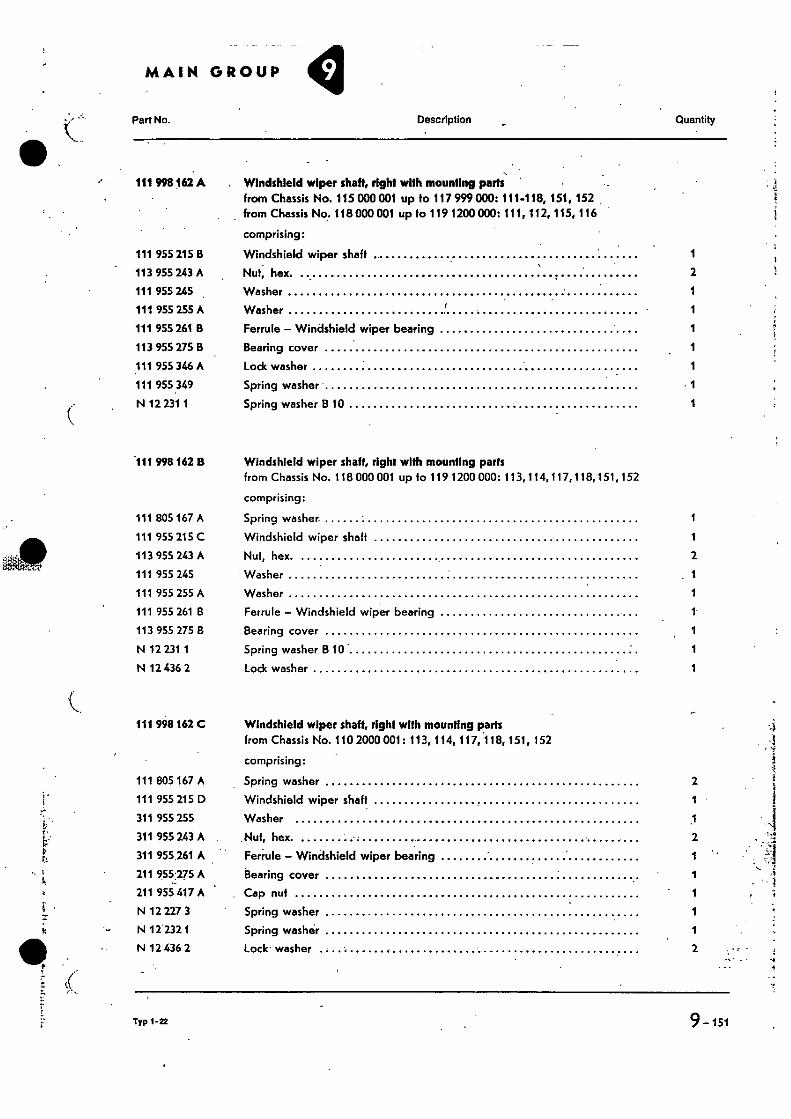
•
•
Part No. Description Quantity
111 998 162 A Windshield wiper shaft, right with mounting path from Chassis No. 115 000 001 up to 117 999 000: 111-118, 151, 152 from Chassis No. 118 000 001 up to 119 1200 000: 111, 112, 115, 116
comprising:
111 955 215 B Windshield wiper shaft 1
113 955 243 A Nut, hex. 2
111 955 245 Washer 1
111 955 255 A Washer r 1
111 955 261 B Ferrule — Windshield wiper bearing 1
113 955 275 B Bearing cover 1
111 955 346 A Lock washer 1
111 955 349 Spring washer • 1
N 12 231 1 Spring washer 13 10 1
.111 998 162 8 Windshield wiper shaft, right with mounting parts from Chassis No. 118 000 001 up to 119 1200 000: 113, 114,117,118, 151, 152
comprising:
111 805 167 A Spring washer. 1
111 955 215 C Windshield wiper shalt 1
113 955 243 A Nut, hex. 2
111 955 245 Washer 1
111 955 255 A Washer 1
111 955 261 B Ferrule — Windshield wiper bearing 1
113 955 275 8 Bearing cover 1
N 12 231 1 Spring washer B 10 1
N 12 436 2 Lock washer 1
111 998 162 C Windshield wiper shaft, right with mounting parts from Chassis No. 110 2000 001: 113, 114, 117, 118, 151, 152
comprising:
111 805 167 A Spring washer 2
111 955 215 D Windshield wiper shaft 1
311 955 255 Washer 1
311 955 243 A Nut, hex. 2
311 955.261 A Ferrule — Windshield wiper bearing 1
211 955.275 A Bearing cover 1
211 955 417 A Cap nut 1
N 12 227 3 Spring washer 1
N 122321 Spring washer 1
N 12 436 2 Lock washer 2
Typ 1.22
9-151
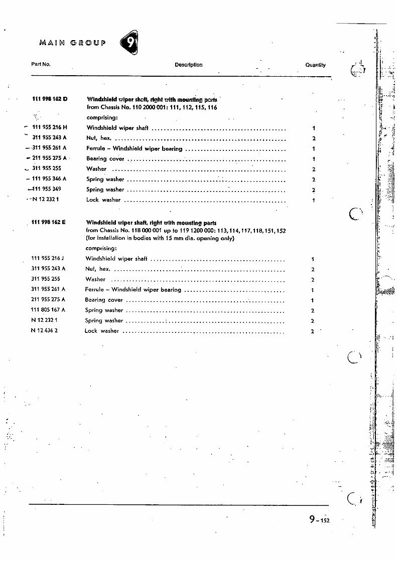
MADNI GROUP
Part No. Description Quantity
111 998 162 D Windshield wiper shaft, right with mounting ports from Chassis No. 110 2000 001: 111, 112, 115, 116
comprising:
- 111 955 216 H Windshield wiper shaft 1
311 955 243 A Nut, hex, 2
—311 955 261 A Ferrule - Windshield wiper bearing 1
211 955 275 A - Bearing cover 1
311 955 255 Washer 2
- 111 955 346 A Spring washer 2
—111 955 349 Spring washer
- - N 12 232 1 Lock washer 1
111 998 162 E Windshield wiper shaft, right with mounting parts from Chassis No. 118 000 001 up to 119 1200 000: 113,114,117,118,151,152 (for installation in bodies with 15 mm dia. opening only)
comprising:
111 955 216 J Windshield wiper shaft
311 955 243 A Nut, hex. 2
311 955 255 Washer 2
311 955 261 A Ferrule - Windshield wiper bearing 1
211 955 275 A Bearing cover 1
111 805 167 A Spring washer 2
N 12 232 1 Spring washer 2
N 12 436 2 Lock washer 2
9 -152


![ifurd Isreai cll ag] ent to I end r](https://img.dokumen.tips/doc/110x75/63144bedb1e0e0053b0eb3ae/ifurd-isreai-cll-ag-ent-to-i-end-r.jpg)


