Embed Size (px)
Citation preview
Electrochimica Acta 169 (2015) 416–423
Band edge engineering of composite photoanodes for dye-sensitizedsolar cells
Venkata Manthina a,b, Alexander G. Agrios a,b,*aDepartment of Civil & Environmental Engineering, University of Connecticut, 261 Glenbrook Rd Unit 3037, Storrs, CT 06269, USAbCenter for Clean Energy Engineering, University of Connecticut, 44 Weaver Rd, Storrs, CT 06269, USA
A R T I C L E I N F O
Article history:Received 13 February 2015Received in revised form 14 April 2015Accepted 15 April 2015Available online 16 April 2015
Keywords:zinc oxidetitanium dioxidedopingcharge transfernanocomposites
A B S T R A C T
As dye-sensitized solar cells (DSSCs) transition from iodide/triiodide-based electrolytes to organome-tallic complex redox couples with higher rates of recombination with electrons in the semiconductor,there is a need for semiconductor nanostructures that can rapidly transport electrons out of the devicewhile maintaining high surface areas for the semiconductor/dye/electrolyte interface. A previouslyreported composite, with TiO2 nanoparticles coating ZnO nanorods, met these criteria but suffered from abarrier to electron transfer from the TiO2 to the ZnO. Here, the band edge positions of the TiO2 and ZnOhave been shifted by doping with Zr4+ and Co2+, respectively, to arrive at the desired energetic alignment.The materials were characterized using diffuse-reflectance spectroscopy and a three-electrodemeasurement of the open circuit photovoltage under bandgap excitation (OCV). The OCV measurementindicated that the doping moved the conduction band minimum of ZnO to a more positive potential thanthat of the TiO2, enabling electron transfer from dye-sensitized TiO2 nanoparticles to the underlying ZnOnanorods for efficient charge collection. However, DSSC devices fabricated with the compositenanostructures did not show improved performance. This paper details a methodology for producing andmeasuring band-edge shifts along with the benefits and limitations thereof.
ã 2015 Elsevier Ltd. All rights reserved.
Contents lists available at ScienceDirect
Electrochimica Acta
journal homepa ge: www.elsev ier .com/locate /e lectacta
1. Introduction
One-dimensional nanostructured metal oxides are promisingmaterials for applications such as dye sensitized solar cells [1,2](DSSCs) and water splitting [3] where rapid electron transport andhigh interfacial area are needed. This becomes especially impor-tant as DSSCs move away from iodide/triiodide-based electrolytesand toward redox couples, such as cobalt(II/III) [4] or ferrocene/ferrocenium (Fc/Fc+), [5] that have faster rates of recombinationwith electrons in the photoanode, necessitating fast electrontransport out of the photoanode for efficient charge collection. ZnOhas been found particularly useful in DSSCs [1,6–9] since it can begrown in 1-D morphologies using facile methods and has otherfavorable material properties such as a high electron mobility andappropriate band edge positions.
The major drawbacks of ZnO nanorods in DSSCs, as compared tothe standard TiO2 nanoparticle film [10], are a reduced surface areaand reactions with carboxylic dyes resulting in partial dissolutionof the surface. Some ZnO–TiO2 and ZnO–ZnO composite nano-structures have been proposed to address one or both of these
* Corresponding author. Tel.: +1 860 486 1350.E-mail address: [email protected] (A.G. Agrios).
http://dx.doi.org/10.1016/j.electacta.2015.04.0800013-4686/ã 2015 Elsevier Ltd. All rights reserved.
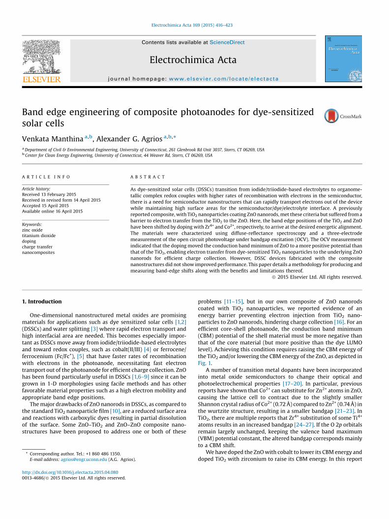
problems [11–15], but in our own composite of ZnO nanorodscoated with TiO2 nanoaparticles, we reported evidence of anenergy barrier preventing electron injection from TiO2 nano-particles to ZnO nanorods, hindering charge collection [16]. For anefficient core-shell photoanode, the conduction band minimum(CBM) potential of the shell material must be more negative thanthat of the core material (but more positive than the dye LUMOlevel). Achieving this condition requires raising the CBM energy ofthe TiO2 and/or lowering the CBM energy of the ZnO, as depicted inFig. 1.
A number of transition metal dopants have been incorporatedinto metal oxide semiconductors to change their optical andphotoelectrochemical properties [17–20]. In particular, previousreports have shown that Co2+ can substitute for Zn2+ atoms in ZnO,causing the lattice cell to contract due to the slightly smallerShannon crystal radius of Co2+ (0.72 Å) compared to Zn2+ (0.74 Å) inthe wurtzite structure, resulting in a smaller bandgap [21–23]. InTiO2, there are multiple reports that Zr4+ substitution of some Ti4+
atoms results in an increased bandgap [24–27]. If the O 2p orbitalsremain largely unchanged, keeping the valence band maximum(VBM) potential constant, the altered bandgap corresponds mainlyto a CBM shift.
We have doped the ZnO with cobalt to lower its CBM energy anddoped TiO2 with zirconium to raise its CBM energy. In this report
e-
Con
duct
ing
Gla
ss (F
TO)
ZnO
VALENC EBAND
COND .BAND
TiO2
LUMO
HOMO
Dye
VALENC EBAND
COND.BAND
Fig. 1. Schematic of band edge engineering to overcome barrier to electron transferfrom TiO2 to ZnO.
V. Manthina, A.G. Agrios / Electrochimica Acta 169 (2015) 416–423 417
we will discuss the effect of doping on those band potentials and onperformance of the DSSCs in two different electrolytes: onecontaining the standard iodide/triiodide couple and one with thefast recombining Fc/Fc+ couple.
2. Experimental
2.1. Reagents and Materials
All chemicals were purchased from Sigma-Aldrich and wereACS grade or better, except where noted. N719 dye was purchasedfrom Dyesol (Australia). Fluorine-doped tin oxide glass (FTO, sheetresistance 8 V /&) was purchased from Hartford Glass Co (USA).
2.2. Electrode Fabrication
ZnO nanorods were synthesized by a two-step chemical bathdeposition (CBD) technique, then coated with TiO2 nanoparticlesby electrostatic layer-by-layer deposition, as previously reported[28]. The ethanolic ZnO seed layer precursor solution was modifiedby the addition of 0.6 M H2O to increase the spacing between thenanorods [29]. Doping ZnO with Co2+ and TiO2 with Zr4+ wasachieved by substituting 10 mol% of the zinc nitrate with cobalt(II)nitrate and 5 or 10 mol% of titanium tetraisopropoxide withzirconium tetraisopropoxide, respectively.
2.3. Surface/Structure Characterization
Scanning electron microscopy (SEM) of the nanomaterials onFTO glass was performed using an FEI Quanta FEG250 SEM in highvacuum mode. Elemental analysis of the doped and undoped ZnOand TiO2 was made using the EDX attached to the SEM. The ZnOnanorods and TiO2 nanoparticles were additionally characterizedby X-ray powder diffraction (XRD) using a Bruker D8 Advance X-ray diffractometer using Cu Ka radiation (l = 0.154178 nm) at ascanning rate of 0.04� s�1 in the 2 u range from 10� to 90�.
2.4. Optical Characterization
The UV–vis spectra of doped and undoped TiO2 and ZnO wereobtained by using Cary 50 UV–vis spectrophotometer. The diffusereflectance spectra were obtained using a Shimadzu 2450 UV–visspectrophotometer with an ISR-240A integrating sphere attach-ment with barium sulfate as the standard.
2.5. Photoelectrochemical Characterization
Illuminated open circuit photovoltage (OCV) was measured tofind the flat band potential of each semiconductor in solution. A
ZnO nanorod array or TiO2 nanoparticle film on FTO glass wasimmersed in a three-electrode electrochemical cell and served asthe working electrode, along with a Ag/AgCl reference electrodeand Pt wire counter electrode. The electrolyte was aqueous 0.1 MLiClO4 basified to pH 11 with NaOH. The working electrode wasilluminated from the back (non-conducting) side with a 300-W Xearc lamp (Oriel). The cell open-circuit voltage was monitored as ashutter kept the sample dark for 30 s, then illuminated for 60 s,then dark for 60 s. To avoid reaction of photogenerated electronswith dissolved oxygen in the electrolyte, the solution was purgedwith nitrogen gas for 10 minutes before measurement. Accordingto data from the manufacturer, the lamp outputs about 100 mW inthe spectral region between the bandgap edge of ZnO (370 nm) andthe cutoff of FTO transmission (350 nm); this is the power availablefor bandgap excitation of ZnO, with somewhat more available forTiO2 (with a bandgap edge of 385 nm). Focused onto a 1 cm2 area,for either semiconductor this was judged to be more than enoughUV intensity to achieve a saturation condition in which the bandsflatten and the Fermi level (measured as the working electrodepotential) is close to that of the conduction band edge potential[30].
2.6. Solar Cell Assembly
After sintering, films were allowed to cool to 100 �C thenimmediately immersed in 0.3 mM N719 in ethanol. After 12 h theywere removed and rinsed in acetonitrile and dried in air. Eachsensitized electrode was sealed against a counter electrode on ahot plate at 120 �C using a hot-melt plastic frame (Solaronix,Meltonix 1170, 25 mm thick) applying light pressure with a glassrod. The assembled cell was filled with electrolyte through twoholes in the counter electrode. The holes were then sealed usinghot-melt plastic and a thin glass cover slide. The exposedconducting glass leads of each electrode were coated with coppertape (3M) for improved electrical conductivity.
2.7. Electrolyte Composition
Iodide/triiodide (I�/I3�) electrolyte was prepared with 0.5 Mtetrabutylammonium iodide and 0.05 M iodine (I2) in 3-methox-ypropionitrile. The ferrocene/ferrocenium (Fc/Fc+) electrolytecontained 0.1 M ferrocene and 0.05 M ferrocenium hexafluoro-phosphate in 3-methoxypropionitrile and was deoxygenated bybubbling nitrogen for 10 minutes prior to cell fabrication tominimize reaction of ferreocene with oxygen [5,31]. Additives suchas 4-tert-butylpyridine were avoided to minimize complicationsarising from band-edge energy shifts.
2.8. Solar Cell Characterization
Current-voltage (J–V) measurements were made using aKeithley 2400 source/meter controlled by a PC, while irradiatingat 1000 W/m2with AM 1.5G simulated sunlight produced by a solarsimulator (Newport 91160). The DSSC photocurrent and photo-voltage were measured with an active area of 1 cm2.
2.9. Transient Measurements
Measurements of electron transport time were made usingtransient decay of photocurrent under square wave modulation ofa white light LED as described previously except with a 40-Vresistor [16]. Electron lifetime was measured in a similar way usingthe photovoltage transient at open circuit. At least 50 transientswere averaged for noise reduction.
418 V. Manthina, A.G. Agrios / Electrochimica Acta 169 (2015) 416–423
3. Results and Discussion
3.1. Synthesis and morphology of cobalt-doped ZnO nanorods andzirconium-doped TiO2 nanoparticles
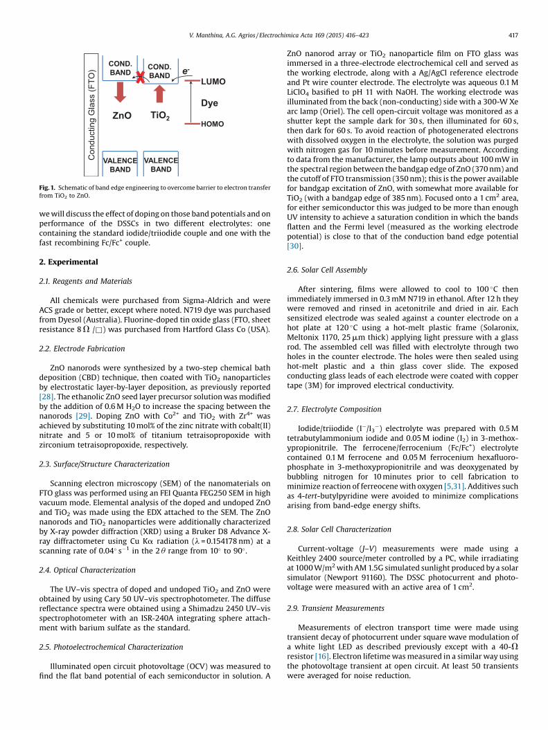
Cobalt-doped ZnO nanorods were fabricated on FTO bychemical bath deposition. Scanning electron microscope (SEM)images of the doped nanorods are shown in Fig. 2. No phaseseparation of the Co2+ dopant is observed in these images, which isconsistent with the growth of a solid solution of (Zn0.9Co0.1)O.Dopant elements can alter the thermodynamics of crystal growthand affect growth kinetics, [32–34] and this was reflected inaltered nanorod dimensions in this study. Compared to undopednanorods, the presence of Co2+ in solution increased the averagediameter from 600 nm to 1100 nm, increased the average lengthincreased from 5 mm to 6 mm, and decreased the number densityfrom 1.2 � 108 rods per cm2 to 0.9 � 108 rods per cm2. EDX analysisof the broken rod cross-section (shown in Fig. 2c) shows thepresence of the Co2+ in the ZnO matrix with a ratio of Co/(Co + Zn)equal to 0.08. The voids seen in the cross section have beenobserved in other annealed ZnO nanorods [35].
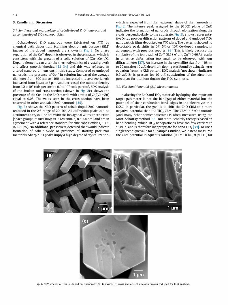
Fig. 3a shows the XRD pattern of cobalt-doped ZnO nanorodsrecorded in the 2 u range of 20–70�. All diffraction peaks can beattributed to crystalline ZnO with the hexagonal wurtzite structure[space group: P63mc(186); a) 0.3249 nm, c) 0.5206 nm] and are inagreement with a reference standard for zinc cobalt oxide (JCPDS072-8025). No additional peaks were detected that would indicateformation of cobalt oxide or presence of starting precursormaterials. Sharp XRD peaks imply a high degree of crystallization,
Fig. 2. SEM images of 10% Co-doped ZnO nanorods: (a) top view, (b
which is expected from the hexagonal shape of the nanorods inFig. 2. The intense peak assigned to the (0 0 2) plane of ZnOindicates the formation of nanorods through elongation along thec-axis perpendicularly to the substrate. Fig. 3b shows representa-tive X-ray powder diffraction patterns of doped and undoped TiO2
nanoparticle films deposited on FTO glass. The patterns showed nodetectable peak shifts in 0%, 5% or 10% Co-doped samples, inagreement with previous reports [36]. This is likely because thesimilarity of the ionic radii of Co2+ (0.58 Å) and Zn2+(0.60 Å) resultsin a lattice deformation too small to be observed with ourdiffractometer [37]. An increase in the crystallite size from 16 nmto 20 nm after 10 at% zirconium doping was found by using Schererequation from the XRD pattern. EDX analysis (not shown) indicates9.9 at% Zr is present for 10 at% substitution of the zirconiumprecursor for titanium during the TiO2 synthesis.
3.2. Flat Band Potential (Efb) Measurements
In altering the ZnO and TiO2 materials by doping, the importanttarget parameter is not the bandgap of either material but thepotential of their conduction band edges in the electrolyte in aDSSC. In particular, the goal is to shift the ZnO CBM to a morenegative potential than the TiO2 CBM. The CBM in ZnO nanorods(and many other semiconductors) is often measured using theMott–Schottky method [38]. But Mott–Schottky theory is based onband bending, which TiO2 nanoparticles have too few carriers tosustain, and is therefore inappropriate for nano TiO2 [39]. To use asingle technique valid for all samples studied, we instead measuredthe CBM potential in aqueous solution (0.1 M LiClO4 at pH 11) for
) cross section, (c) area of a broken rod used for EDX analysis.
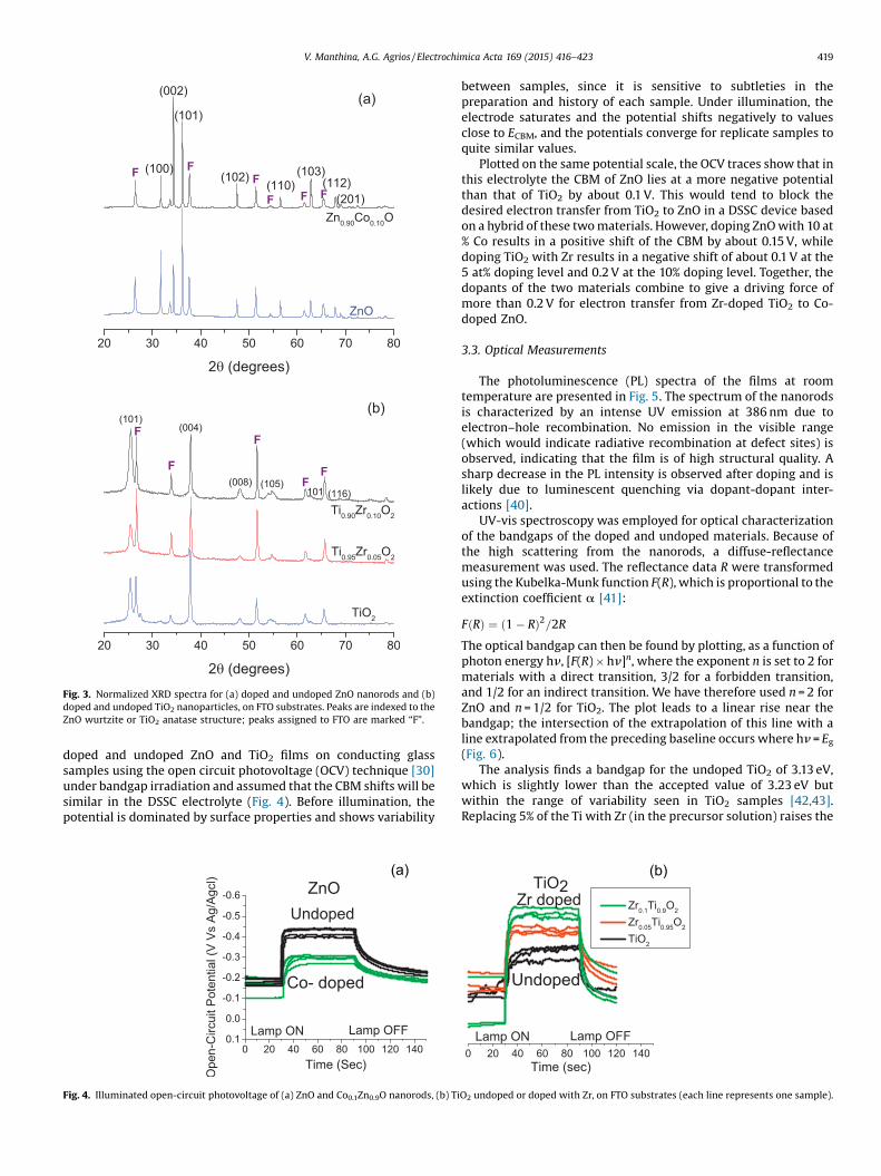
Fig. 3. Normalized XRD spectra for (a) doped and undoped ZnO nanorods and (b)doped and undoped TiO2 nanoparticles, on FTO substrates. Peaks are indexed to theZnO wurtzite or TiO2 anatase structure; peaks assigned to FTO are marked “F”.
V. Manthina, A.G. Agrios / Electrochimica Acta 169 (2015) 416–423 419
doped and undoped ZnO and TiO2 films on conducting glasssamples using the open circuit photovoltage (OCV) technique [30]under bandgap irradiation and assumed that the CBM shifts will besimilar in the DSSC electrolyte (Fig. 4). Before illumination, thepotential is dominated by surface properties and shows variability
(a)
Fig. 4. Illuminated open-circuit photovoltage of (a) ZnO and Co0.1Zn0.9O nanorods, (b) Ti
between samples, since it is sensitive to subtleties in thepreparation and history of each sample. Under illumination, theelectrode saturates and the potential shifts negatively to valuesclose to ECBM, and the potentials converge for replicate samples toquite similar values.
Plotted on the same potential scale, the OCV traces show that inthis electrolyte the CBM of ZnO lies at a more negative potentialthan that of TiO2 by about 0.1 V. This would tend to block thedesired electron transfer from TiO2 to ZnO in a DSSC device basedon a hybrid of these two materials. However, doping ZnO with 10 at% Co results in a positive shift of the CBM by about 0.15 V, whiledoping TiO2 with Zr results in a negative shift of about 0.1 V at the5 at% doping level and 0.2 V at the 10% doping level. Together, thedopants of the two materials combine to give a driving force ofmore than 0.2 V for electron transfer from Zr-doped TiO2 to Co-doped ZnO.
3.3. Optical Measurements
The photoluminescence (PL) spectra of the films at roomtemperature are presented in Fig. 5. The spectrum of the nanorodsis characterized by an intense UV emission at 386 nm due toelectron–hole recombination. No emission in the visible range(which would indicate radiative recombination at defect sites) isobserved, indicating that the film is of high structural quality. Asharp decrease in the PL intensity is observed after doping and islikely due to luminescent quenching via dopant-dopant inter-actions [40].
UV-vis spectroscopy was employed for optical characterizationof the bandgaps of the doped and undoped materials. Because ofthe high scattering from the nanorods, a diffuse-reflectancemeasurement was used. The reflectance data R were transformedusing the Kubelka-Munk function F(R), which is proportional to theextinction coefficient a [41]:
FðRÞ ¼ ð1 � RÞ2=2RThe optical bandgap can then be found by plotting, as a function ofphoton energy hn, [F(R) � hn]n, where the exponent n is set to 2 formaterials with a direct transition, 3/2 for a forbidden transition,and 1/2 for an indirect transition. We have therefore used n = 2 forZnO and n = 1/2 for TiO2. The plot leads to a linear rise near thebandgap; the intersection of the extrapolation of this line with aline extrapolated from the preceding baseline occurs where hn = Eg(Fig. 6).
The analysis finds a bandgap for the undoped TiO2 of 3.13 eV,which is slightly lower than the accepted value of 3.23 eV butwithin the range of variability seen in TiO2 samples [42,43].Replacing 5% of the Ti with Zr (in the precursor solution) raises the
(b)
O2 undoped or doped with Zr, on FTO substrates (each line represents one sample).
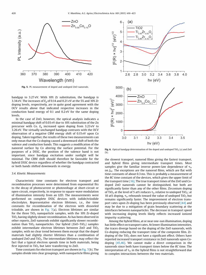
Fig. 5. PL measurement of doped and undoped ZnO nanorods.
Fig. 6. Optical bandgap determination of the doped and undoped TiO2 (a) and ZnO(b).
420 V. Manthina, A.G. Agrios / Electrochimica Acta 169 (2015) 416–423
bandgap to 3.27 eV. With 10% Zr substitution, the bandgap is3.34 eV. The increases of Eg of 0.14 and 0.21 eV at the 5% and 10% Zrdoping levels, respectively, are in quite good agreement with theOCV results above that indicated respective increases in theconduction band energy of 0.1 and 0.2 eV for the same dopinglevels.
In the case of ZnO, however, the optical analysis indicates aminimal bandgap shift of 0.03 eV due to 10% substitution of the Znprecursor with Co. Eg increased upon doping from 3.23 eV to3.26 eV. The virtually unchanged bandgap contrasts with the OCVobservation of a negative CBM energy shift of 0.15 eV upon Codoping. Taken together, the results of these two measurements canonly mean that the Co doping caused a downward shift of both thevalence and conduction bands. This suggests a modification of thenanorod surface by Co altering the surface potential. For thepurposes of a DSSC, the position of the valence band is notimportant, since bandgap excitation under sunlight will beminimal. The CBM shift should therefore be favorable for thehybrid DSSC device regardless of whether the bandgap contractedor both bands shifted downwards in energy.
3.4. Kinetic Measurements
Characteristic time constants for electron transport andrecombination processes were determined from exponential fitsto the decay of photocurrent or photovoltage at short-circuit oropen-circuit, respectively, in response to square-wave modulationof illumination intensity from an LED. The measurements wereperformed on complete DSSC devices with iodide/triiodideelectrolytes. Representative electron lifetimes, i.e., the timeconstants for recombination of the electron with dissovledtriiodide, are shown in Fig. 7(a). Electron lifetimes are similarfor the three TiO2 nanoparticle samples, with the 10% Zr-dopedTiO2 having slightly slower recombination. As has been observed inother reports, ZnO nanorods exhibit significantly slower recombi-nation than TiO2 nanoparticles. Our hybrid (ZnO–TiO2) samplesexhibit intermediate electron lifetimes between ZnO and TiO2
samples, with no clear trend between them except that the dopedmaterials had slightly shorter lifetimes than a combination ofundoped ZnO and TiO2. The intermediate lifetimes may reflect thefact that a typical electron spends time in both materials, beingfirst injected in TiO2 but later transferring to ZnO.
Time constants for electron transport are shown in Fig. 7(b). Thesamples divide into clear groupings, with nanoparticle films giving
the slowest transport, nanorod films giving the fastest transport,and hybrid films giving intermediate transport times. Mostsamples give the familiar inverse power-law dependence of ttron JSC. The exceptions are the nanorod films, which are flat withtime constants of about 0.3 ms. This is probably a measurement ofthe RC time constant of the devices, which gives the upper limit ofthe transport time [16]. The true transport times of the ZnO and Co-doped ZnO nanorods cannot be distinguished, but both aresignificantly faster than any of the other films. Zirconium dopingof TiO2 at the level of 5 at% reduces ttr relative to undoped TiO2; at10 at% doping, ttr rebounds toward the value of undoped TiO2 butremains significantly faster. The improvement of electron trans-port rates upon Zr-doping has been previously observed [44] andmay be due to a mitigation of grain boundary scattering at theinterfaces between nanoparticles. The decrease in transport speedwith increasing doping levels likely reflects increased ionizedimpurity scattering.
Among the hybrid films, at or near one-sun illumination, dopinghas little effect on transport rates. At lower illumination intensities,the traces diverge based on the doping of the ZnO nanorods, withCo-doping reducing the transport time of the composite film. Zr-doping of the TiO2 does not have a significant effect. Others havereported increased transport resistance in ZnO nanorods upon Co-doping [45,46]. We cannot make a direct comparison in thenanorods since both have transport times below the RC time. Theinterpretation of ttr in the hybrid films is not straightforward dueto complex interactions between the two materials.
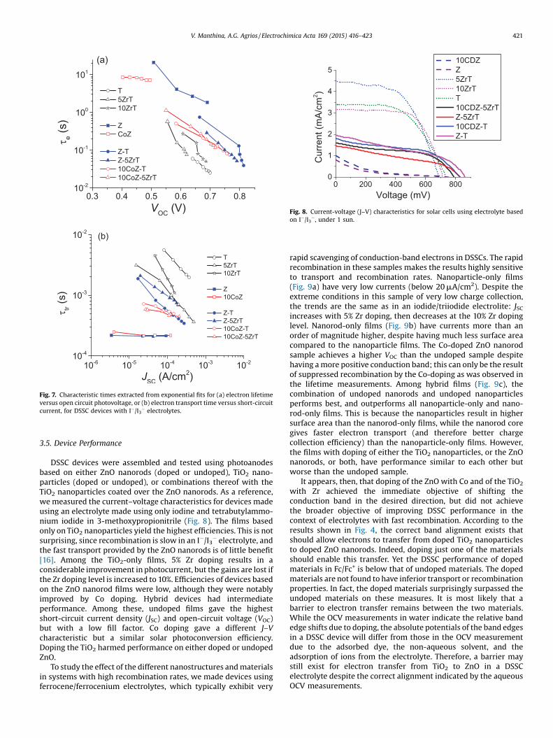
Fig. 7. Characteristic times extracted from exponential fits for (a) electron lifetimeversus open circuit photovoltage, or (b) electron transport time versus short-circuitcurrent, for DSSC devices with I�/I3� electrolytes.
Fig. 8. Current-voltage (J–V) characteristics for solar cells using electrolyte basedon I�/I3�, under 1 sun.
V. Manthina, A.G. Agrios / Electrochimica Acta 169 (2015) 416–423 421
3.5. Device Performance
DSSC devices were assembled and tested using photoanodesbased on either ZnO nanorods (doped or undoped), TiO2 nano-particles (doped or undoped), or combinations thereof with theTiO2 nanoparticles coated over the ZnO nanorods. As a reference,we measured the current–voltage characteristics for devices madeusing an electrolyte made using only iodine and tetrabutylammo-nium iodide in 3-methoxypropionitrile (Fig. 8). The films basedonly on TiO2 nanoparticles yield the highest efficiencies. This is notsurprising, since recombination is slow in an I�/I3� electrolyte, andthe fast transport provided by the ZnO nanorods is of little benefit[16]. Among the TiO2-only films, 5% Zr doping results in aconsiderable improvement in photocurrent, but the gains are lost ifthe Zr doping level is increased to 10%. Efficiencies of devices basedon the ZnO nanorod films were low, although they were notablyimproved by Co doping. Hybrid devices had intermediateperformance. Among these, undoped films gave the highestshort-circuit current density (JSC) and open-circuit voltage (VOC)but with a low fill factor. Co doping gave a different J–Vcharacteristic but a similar solar photoconversion efficiency.Doping the TiO2 harmed performance on either doped or undopedZnO.
To study the effect of the different nanostructures and materialsin systems with high recombination rates, we made devices usingferrocene/ferrocenium electrolytes, which typically exhibit very
rapid scavenging of conduction-band electrons in DSSCs. The rapidrecombination in these samples makes the results highly sensitiveto transport and recombination rates. Nanoparticle-only films(Fig. 9a) have very low currents (below 20 mA/cm2). Despite theextreme conditions in this sample of very low charge collection,the trends are the same as in an iodide/triiodide electrolite: JSCincreases with 5% Zr doping, then decreases at the 10% Zr dopinglevel. Nanorod-only films (Fig. 9b) have currents more than anorder of magnitude higher, despite having much less surface areacompared to the nanoparticle films. The Co-doped ZnO nanorodsample achieves a higher VOC than the undoped sample despitehaving a more positive conduction band; this can only be the resultof suppressed recombination by the Co-doping as was observed inthe lifetime measurements. Among hybrid films (Fig. 9c), thecombination of undoped nanorods and undoped nanoparticlesperforms best, and outperforms all nanoparticle-only and nano-rod-only films. This is because the nanoparticles result in highersurface area than the nanorod-only films, while the nanorod coregives faster electron transport (and therefore better chargecollection efficiency) than the nanoparticle-only films. However,the films with doping of either the TiO2 nanoparticles, or the ZnOnanorods, or both, have performance similar to each other butworse than the undoped sample.
It appears, then, that doping of the ZnO with Co and of the TiO2
with Zr achieved the immediate objective of shifting theconduction band in the desired direction, but did not achievethe broader objective of improving DSSC performance in thecontext of electrolytes with fast recombination. According to theresults shown in Fig. 4, the correct band alignment exists thatshould allow electrons to transfer from doped TiO2 nanoparticlesto doped ZnO nanorods. Indeed, doping just one of the materialsshould enable this transfer. Yet the DSSC performance of dopedmaterials in Fc/Fc+ is below that of undoped materials. The dopedmaterials are not found to have inferior transport or recombinationproperties. In fact, the doped materials surprisingly surpassed theundoped materials on these measures. It is most likely that abarrier to electron transfer remains between the two materials.While the OCV measurements in water indicate the relative bandedge shifts due to doping, the absolute potentials of the band edgesin a DSSC device will differ from those in the OCV measurementdue to the adsorbed dye, the non-aqueous solvent, and theadsorption of ions from the electrolyte. Therefore, a barrier maystill exist for electron transfer from TiO2 to ZnO in a DSSCelectrolyte despite the correct alignment indicated by the aqueousOCV measurements.
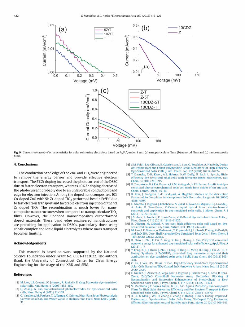
Fig. 9. Current-voltage (J–V) characteristics for solar cells using electrolyte based on Fc/Fc+, under 1 sun: (a) nanoparticulate films, (b) nanorod films and (c) nanocompositefilms.
422 V. Manthina, A.G. Agrios / Electrochimica Acta 169 (2015) 416–423
4. Conclusions
The conduction band edge of the ZnO and TiO2were engineeredto remove the energy barrier and provide effective electrontransport. The 5% Zr doping increased the photocurrent of the DSSCdue to faster electron transport, whereas 10% Zr doping decreasedthe photocurrent probably due to an unfavorable conduction bandedge for electron injection. Among the doped nanocomposites, 10%Co-doped ZnO with 5% Zr-doped TiO2 performed best in Fc/Fc+ dueto fast electron transport and favorable electron injection of the 5%Zr doped TiO2. The recombination is much lower for nano-composite nanostructures when compared to nanoparticulate TiO2
films. However, the undoped nanocomposites outperformeddoped materials. These band edge engineered nanostructuresare promising for application in DSSCs, particularly those usingcobalt complex and ionic liquid electrolytes where mass transportbecomes limiting.
Acknowledgements
This material is based on work supported by the NationalScience Foundation under Grant No. CBET-1332022. The authorsthank the University of Connecticut Center for Clean EnergyEngineering for the usage of the XRD and SEM.
References
[1] M. Law, L.E. Greene, J.C. Johnson, R. Saykally, P. Yang, Nanowire dye-sensitizedsolar cells, Nat. Mater. 4 (2005) 455–459.
[2] Q. Zhang, G. Cao, Nanostructured photoelectrodes for dye-sensitized solarcells, Nano Today 6 (2011) 91–109.
[3] O. Varghese, M. Paulose, T. LaTempa, C. Grimes, High-Rate Solar PhotocatalyticConversion of CO2 and Water Vapor to Hydrocarbon Fuels, Nano Lett 9 (2009)31.
[4] S.M. Feldt, E.A. Gibson, E. Gabrielsson, L. Sun, G. Boschloo, A. Hagfeldt, Designof Organic Dyes and Cobalt Polypyridine Redox Mediators for High-EfficiencyDye-Sensitized Solar Cells, J. Am. Chem. Soc. 132 (2010) 16714–16724.
[5] T. Daeneke, T.-H. Kwon, A.B. Holmes, N.W. Duffy, U. Bach, L. Spiccia, High-efficiency dye-sensitized solar cells with ferrocene-based electrolytes, Nat.Chem. 3 (2011) 211–215.
[6] K. Tennakone, G.R.R.A. Kumara, I.R.M. Kottegoda, V.P.S. Perera, An efficient dye-sensitized photoelectrochemical solar cell made from oxides of tin and zinc,Chem. Comm. (1999) 15–16.
[7] K. Keis, J. Lindgren, S.-E. Lindquist, A. Hagfeldt, Studies of the AdsorptionProcess of Ru Complexes in Nanoporous ZnO Electrodes, Langmuir 16 (2000)4688–4694.
[8] E. Azaceta, J. Idigoras, J. Echeberria, A. Zukal, L. Kavan, O. Miguel, H.-J. Grande, J.A. Anta, R. Tena-Zaera, ZnO-ionic liquid hybrid films: electrochemicalsynthesis and application in dye-sensitized solar cells, J. Mater. Chem. A 1(2013) 10173–10183.
[9] J.A. Anta, E. Guillén, R. Tena-Zaera, ZnO-Based Dye-Sensitized Solar Cells, J.Phys. Chem. C 116 (2012) 11413–11425.
[10] B. O'Regan, M. Grätzel, A low-cost, high-efficiency solar cell based on dye-sensitized colloidal TiO2 films, Nature 353 (1991) 737–740.
[11] M. Law, L.E. Greene, A. Radenovic, T. Kuykendall, J. Liphardt, P. Yang, ZnO-Al2O3
and ZnO-TiO2 Core-Shell Nanowire Dye-Sensitized Solar Cells, J. Phys. Chem. B110 (2006) 22652–22663.
[12] R. Zhao, L. Zhu, F. Cai, Z. Yang, X. Gu, J. Huang, L. Cao, ZnO/TiO2 core–shellnanowire arrays for enhanced dye-sensitized solar cell efficiency, Appl. Phys. A(2013) 1–7.
[13] Y. Feng, X. Ji, J. Duan, J. Zhu, J. Jiang, H. Ding, G. Meng, R. Ding, J. Liu, A. Hu, X.Huang, Synthesis of ZnO@TiO2 core–shell long nanowire arrays and theirapplication on dye-sensitized solar cells, J. Solid State Chem. 190 (2012) 303–308.
[14] C. Xu, J. Wu, U.V. Desai, D. Gao, High-Efficiency Solid-State Dye-SensitizedSolar Cells Based on TiO2-Coated ZnO Nanowire Arrays, Nano Lett. 12 (2012)2420–2424.
[15] E. Guillén, E. Azaceta, A. Vega-Poot, J. Idígoras, J. Echeberría, J.A. Anta, R. Tena-Zaera, ZnO/ZnO Core–Shell Nanowire Array Electrodes: Blocking ofRecombination and Impressive Enhancement of Photovoltage in Dye-Sensitized Solar Cells, J. Phys. Chem. C 117 (2013) 13365–13373.
[16] V. Manthina, J.P. Correa Baena, G. Liu, A.G. Agrios, ZnO–TiO2 NanocompositeFilms for High Light Harvesting Efficiency and Fast Electron Transport in Dye-Sensitized Solar Cells, J. Phys. Chem. C 116 (2012) 23864–23870.
[17] X. Lü, X. Mou, J. Wu, D. Zhang, L. Zhang, F. Huang, F. Xu, S. Huang, Improved-Performance Dye-Sensitized Solar Cells Using Nb-Doped TiO2 Electrodes:Efficient Electron Injection and Transfer, Adv. Func. Mater. 20 (2010) 509–515.
V. Manthina, A.G. Agrios / Electrochimica Acta 169 (2015) 416–423 423
[18] X. Feng, K. Shankar, M. Paulose, C.A. Grimes, Tantalum-Doped TitaniumDioxide Nanowire Arrays for Dye-Sensitized Solar Cells with High Open-Circuit Voltage, Angew. Chem. Int. Ed. 48 (2009) 8095–8098.
[19] M. Xu, P. Da, H. Wu, D. Zhao, G. Zheng, Controlled Sn-Doping in TiO2 NanowirePhotoanodes with Enhanced Photoelectrochemical Conversion, Nano Lett. 12(2012) 1503–1508.
[20] K. Nagaveni, M.S. Hegde, G. Madras, Structure and Photocatalytic Activity ofTi1-xMxO2�d (M = W, V, Ce, Zr, Fe, and Cu) Synthesized by Solution CombustionMethod, J. Phys. Chem. B 108 (2004) 20204–20212.
[21] W.K. Liu, G.M. Salley, D.R. Gamelin, Spectroscopy of Photovoltaic andPhotoconductive Nanocrystalline Co2+-Doped ZnO Electrodes, J. Phys. Chem.B 109 (2005) 14486–14495.
[22] X. Qiu, L. Li, G. Li, Nature of the abnormal band gap narrowing in highlycrystalline Zn1-xCoxO nanorods, Appl. Phys. Lett 88 (2006) 114103.
[23] D. Li, Z.T. Liu, Y.H. Leung, A.B. Djuriši�c, M.H. Xie, W.K. Chan, Transition metal-doped ZnO nanorods synthesized by chemical methods, J. Phys. Chem. Solids69 (2008) 616–619.
[24] M. Dürr, S. Rosselli, A. Yasuda, G. Nelles, Band-gap engineering of metal oxidesfor dye-sensitized solar cells, J. Phys. Chem. B 110 (2006)21899–21902.
[25] Y. Gnatyuk, N. Smirnova, O. Korduban, A. Eremenko, Effect of zirconiumincorporation on the stabilization of TiO2mesoporous structure, Surf. InterfaceAnal. 42 (2010) 1276–1280.
[26] K.V. Bineesh, D.-K. Kim, D.-W. Park, Synthesis and characterization ofzirconium-doped mesoporous nano-crystalline TiO2, Nanoscale 2 (2010)1222–1228.
[27] B. Gao, T.M. Lim, D.P. Subagio, T.-T. Lim, Zr-doped TiO2 for enhancedphotocatalytic degradation of bisphenol A, Appl. Catal. A 375 (2010) 107–115.
[28] L. Vayssieres, Growth of Arrayed Nanorods and Nanowires of ZnO fromAqueous Solutions, Adv. Mater. 15 (2003) 464–466.
[29] V. Manthina, T. Patel, A.G. Agrios, Number Density and Diameter Control ofChemical Bath Deposition of ZnO Nanorods on FTO by Forced Hydrolysis ofSeed Crystals, J. Amer. Ceram. Soc. 97 (2014) 1028–1034.
[30] R. Beranek, (Photo) electrochemical methods for the determination of theband edge positions of TiO2-based nanomaterials, Adv. Phys. Chem. 2011(2011) 786759.
[31] T.W. Hamann, O.K. Farha, J.T. Hupp, Outer-Sphere Redox Couples as Shuttles inDye-Sensitized Solar Cells. Performance Enhancement Based onPhotoelectrode Modification via Atomic Layer Deposition, J. Phys. Chem. C112 (2008) 19756–19764.
[32] V. Gandhi, R. Ganesan, H.H. Abdulrahman Syedahamed, M. Thaiyan, Effect ofCobalt Doping on Structural, Optical, and Magnetic Properties of ZnO
Nanoparticles Synthesized by Coprecipitation Method, J. Phys. Chem. C 118(2014) 9715–9725.
[33] J.D. Ye, S.T. Tan, S. Pannirselvam, S.F. Choy, X.W. Sun, G.Q. Lo, K.L. Teo, Surfactanteffect of arsenic doping on modification of ZnO (0001) growth kinetics, Appl.Phys. Lett. 95 (2009) 101905.
[34] B.L. Zhu, S.J. Zhu, X.Z. Zhao, F.H. Su, G.H. Li, X.G. Wu, J. Wu, Characteristics ofundoped and Sb-doped ZnO thin films prepared in different atmospheres bypulsed laser deposition, Phys. Status Solidi A 208 (2011) 843–850.
[35] J.M. Stiegler, R. Tena-Zaera, O. Idigoras, A. Chuvilin, R. Hillenbrand, Correlativeinfrared–electron nanoscopy reveals the local structure–conductivityrelationship in zinc oxide nanowires, Nat Commun 3 (2012) 1131.
[36] V.A.L. Roy, A.B. Djuriši�c, H. Liu, X.X. Zhang, Y.H. Leung, M.H. Xie, J. Gao, H.F. Lui,C. Surya, Magnetic properties of Mn doped ZnO tetrapod structures, Appl.Phys. Lett. 84 (2004) 756–758.
[37] B.D. Yuhas, D.O. Zitoun, P.J. Pauzauskie, R. He, P. Yang, Transition-Metal DopedZinc Oxide Nanowires, Angew. Chem. Int. Ed. 45 (2006) 420–423.
[38] I. Mora-Seró, F. Fabregat-Santiago, B. Denier, J. Bisquert, R. Tena-Zaera, J. Elias,C. Lévy-Clément, Determination of carrier density of ZnO nanowires byelectrochemical techniques, Appl. Phys. Lett. 89 (2006) 203117.
[39] J.W. Ondersma, T.W. Hamann, Conduction band energy determination byvariable temperature spectroelectrochemistry, Energy Environ. Sci. 5 (2012)9476–9480.
[40] M. Pal, U. Pal, J.M.G. Jimenez, F. Perez-Rodriguez, Effects of crystallization anddopant concentration on the emission behavior of TiO2:Eu nanophosphors,Nanoscale Res. Lett. 7 (2012) 1.
[41] P. Kubelka, F. Munk, Ein Beitrag zur Optik der Farbanstriche, Z. Tech Phys. 12(1931) .
[42] M.M. Khan, S.A. Ansari, D. Pradhan, M.O. Ansari, D.H. Han, J. Lee, M.H. Cho,Band gap engineered TiO2 nanoparticles for visible light inducedphotoelectrochemical and photocatalytic studies, J. Mater. Chem. A 2 (2014)637–644.
[43] K. Gupta, R.P. Singh, A. Pandey, A. Pandey, Photocatalytic antibacterialperformance of TiO2 and Ag-doped TiO2 against S. aureus. P. aeruginosa andE. coli, Beilstein J. Nanotechnol. 4 (2013) 345–351.
[44] S. Kim, M. Kang, Synthesis of Zr-incorporated TiO2 using a solvothermalmethod and its photovoltaic efficiency on dye-sensitized solar cells, Bull.Korean Chem. Soc. 32 (2011) 3317–3322.
[45] T.Y. Ko, M.H. Tsai, C.S. Lee, K.W. Sun, Electron transport mechanisms inindividual cobalt-doped ZnO nanorods, J. Nanopart. Res. 14 (2012) 1–12.
[46] N. Sharma, S. Granville, S. Kashyap, J.-P. Ansermet, Low-temperature hoppingand absence of spin-dependent transport in single crystals of cobalt-dopedZnO, Phys. Rev. B 82 (2010) 125211.