Embed Size (px)
Citation preview

ROS-Based 3D On-Line Monitoring
for LMD Robotized Cells Jorge Rodríguez-Araújo1, Juan J. Rodríguez-Andina2
1AIMEN Technology Center, Porriño, Spain 2Department of Electronic Technology, University of Vigo, Spain
INDIN2015, Cambridge, 23-7-2015

www.aimen.es | [email protected] 2
Index
1. Motivation and Innovative Character.
2. Proposed Solution.
3. 3D Geometrical Monitoring.
4. Self-Calibration.
5. Experimental Results.
6. Conclusions and future work.
Index
4 www.aimen.es | [email protected]
Motivation and Innovative Character
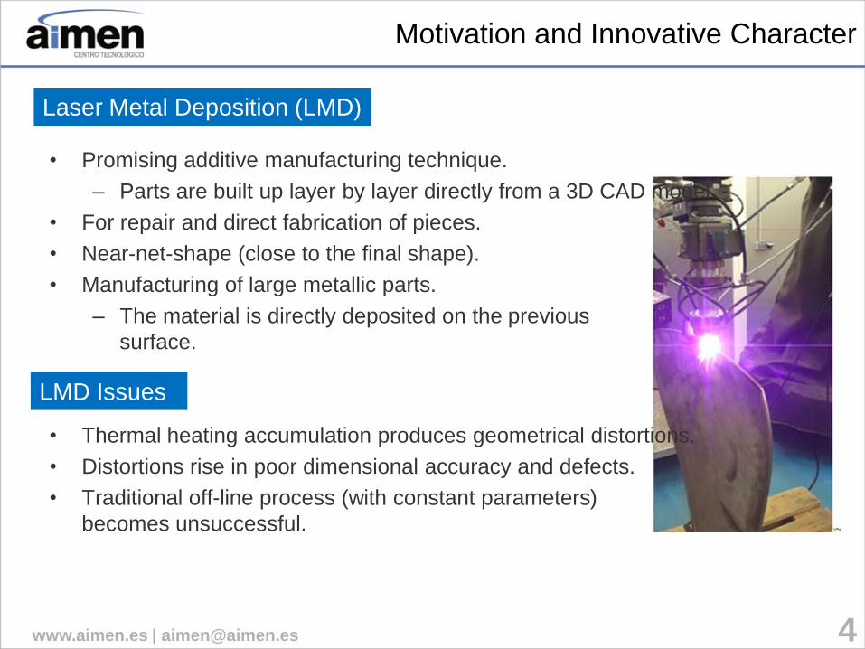
• Promising additive manufacturing technique.
– Parts are built up layer by layer directly from a 3D CAD model.
• For repair and direct fabrication of pieces.
• Near-net-shape (close to the final shape).
• Manufacturing of large metallic parts.
– The material is directly deposited on the previous
surface.
• Thermal heating accumulation produces geometrical distortions.
• Distortions rise in poor dimensional accuracy and defects.
• Traditional off-line process (with constant parameters)
becomes unsuccessful.
Laser Metal Deposition (LMD)
LMD Issues

5 www.aimen.es | [email protected]
Motivation and Innovative Character
• There are a lot of industrial robotized laser cells.
• Empower robotized laser cells for effective AM.
• Retrofit current industrial facilities.
• Apply state of the art robotic
software solutions.
Motivation
Robotized
Cladding Cell
Motion
Controller
Main Controller
Off-line
Path Planning
6-Axis
Robot Laser
Powder
Feeder
Power
Controller
Flow
Controller
Innovation
3D
triangulation
laser
fiber
working
table
power
control
6-axis
robot
powder
feeder
nozzle
7 www.aimen.es | [email protected]
Proposed Solution
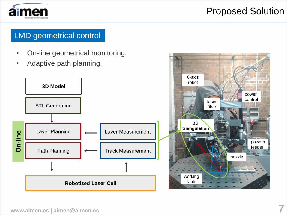
• On-line geometrical monitoring.
• Adaptive path planning.
LMD geometrical control
Robotized Laser Cell
Track Measurement Path Planning
3D Model
Layer Planning Layer Measurement
STL Generation
On
-lin
e
8 www.aimen.es | [email protected]
Proposed Solution
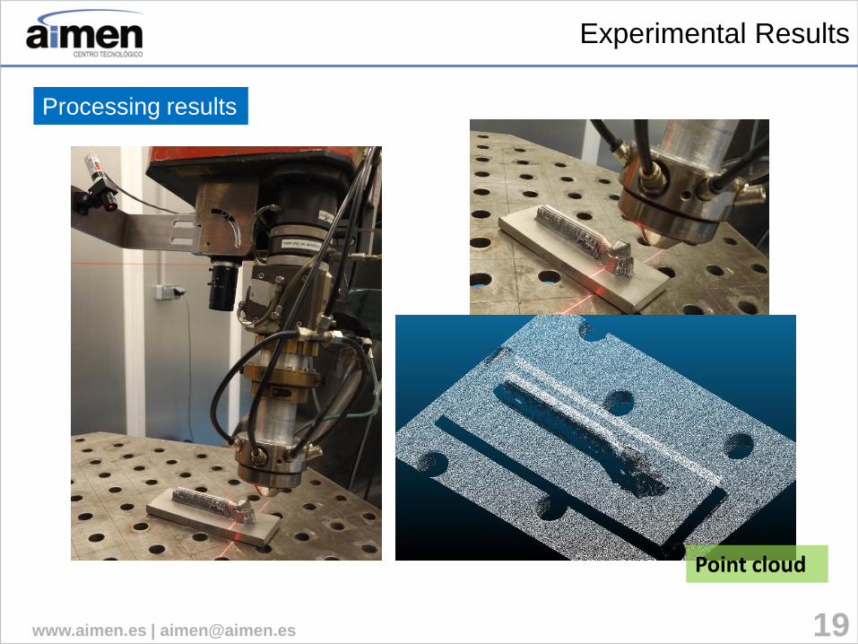
3D scanning setup
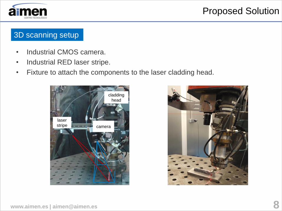
• Industrial CMOS camera.
• Industrial RED laser stripe.
• Fixture to attach the components to the laser cladding head.
laser
stripe camera
cladding
head
10 www.aimen.es | [email protected]
3D Geometrical Monitoring
3D Geometrical Monitoring
Industrial Robotic Laser Cell
Peak
Finder
CAMERA
IDS DRIVER
3D Point Cloud
Working Cell Coordinates
ROBOT
ROS-DRIVER
State
Publisher
Laser
Triangulation
Robot Pose
Tool-Camera
3D Profile Camera Pose
Timestamp
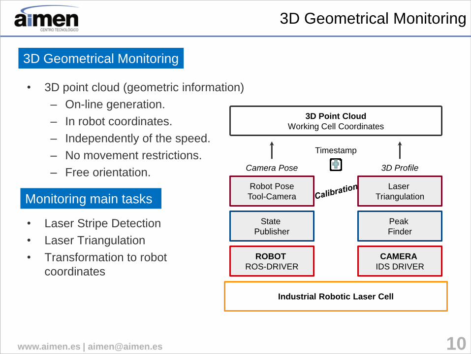
• 3D point cloud (geometric information)
– On-line generation.
– In robot coordinates.
– Independently of the speed.
– No movement restrictions.
– Free orientation.
• Laser Stripe Detection
• Laser Triangulation
• Transformation to robot
coordinates
Monitoring main tasks

11 www.aimen.es | [email protected]
3D Geometrical Monitoring
• Center Of Gravity method as peak finder.
• Point correspondence for 2D-to-3D mapping solution.
• ROS-based
– Tf library
(interpolation)
3D profile calculation
Point cloud reconstruction
Peak
Finder
3D Point Cloud
Working
Cell Coordinates
Laser
Triangulation 3D Profile
Camera Pose
Timestamp
Calibration
3D Profile
12 www.aimen.es | [email protected]
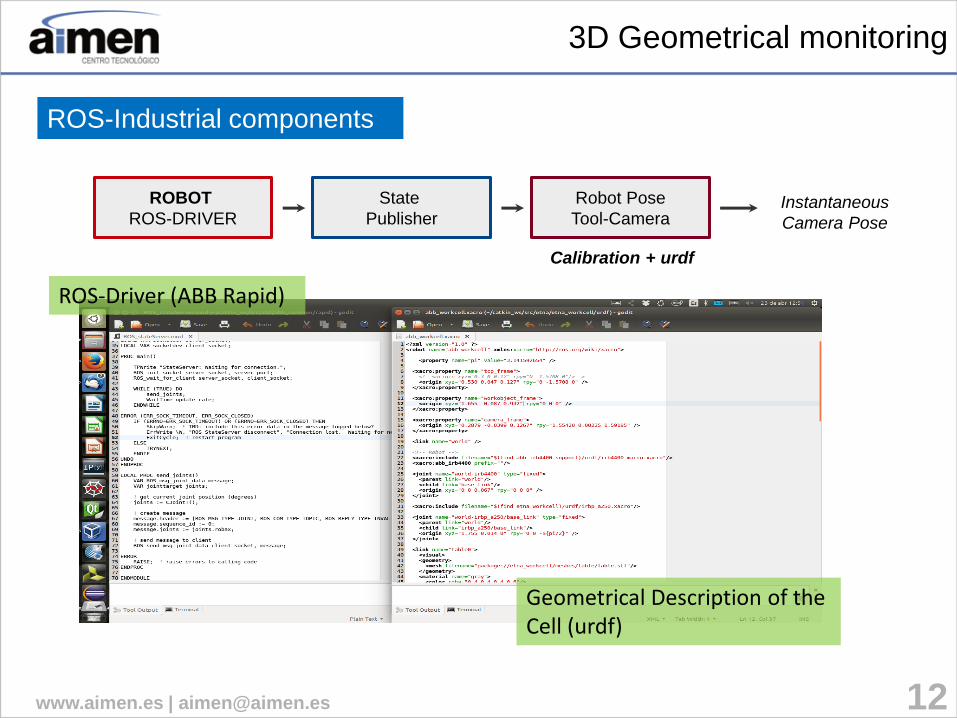
3D Geometrical monitoring
ROS-Industrial components
ROBOT
ROS-DRIVER
State
Publisher
Robot Pose
Tool-Camera Instantaneous
Camera Pose
Calibration + urdf
ROS-Driver (ABB Rapid)
Geometrical Description of the Cell (urdf)
14 www.aimen.es | [email protected]
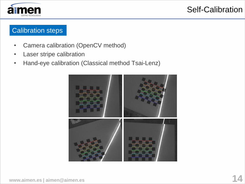
Self-Calibration
• Camera calibration (OpenCV method)
• Laser stripe calibration
• Hand-eye calibration (Classical method Tsai-Lenz)
Calibration steps

15 www.aimen.es | [email protected]
Self-Calibration
1. Checkerboard localization.
2. Laser stripe detection (RANSAC).
3. Laser plane estimation (RANSAC).
4. 2D-to-3D transformation matrix estimation.
Laser stripe calibration steps
1
2
3
21 www.aimen.es | [email protected]
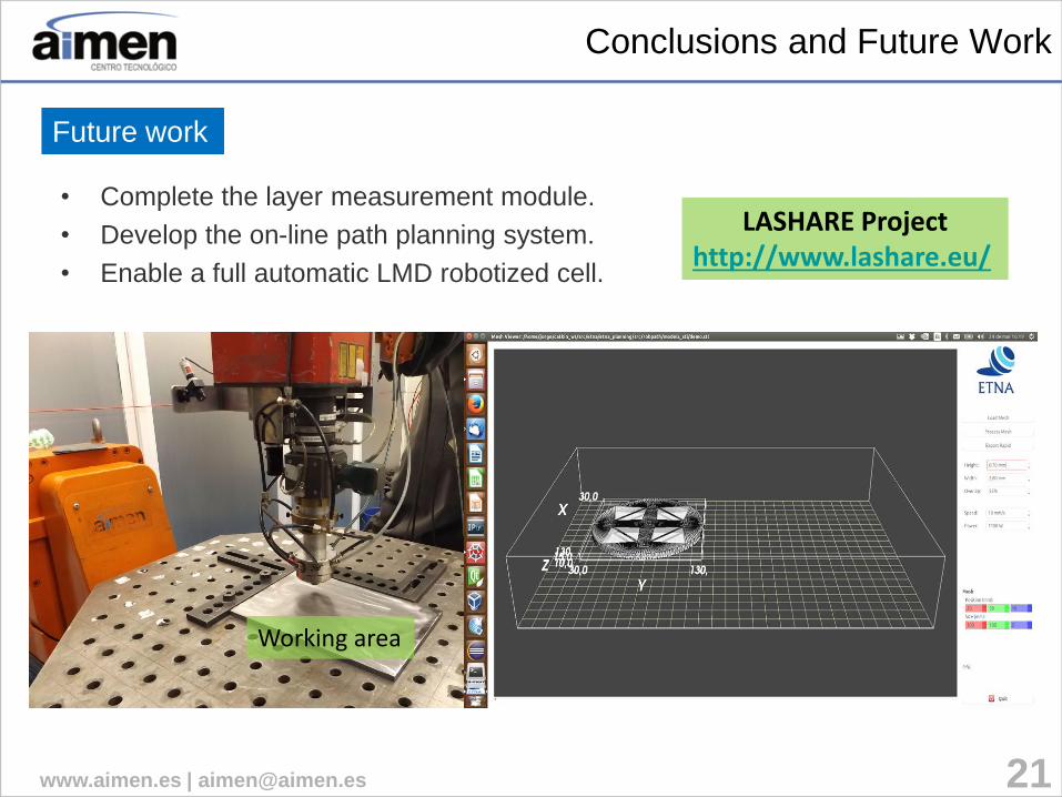
Conclusions and Future Work
• Complete the layer measurement module.
• Develop the on-line path planning system.
• Enable a full automatic LMD robotized cell.
Future work
Working area
LASHARE Project http://www.lashare.eu/

www.aimen.es | [email protected] 22
AIMEN – Central y Laboratorios
c/ Relva 27 A
36410 – O PORRIÑO (Pontevedra)
Telf.+34 986 344 000 – Fax. +34 986 337 302
Delegación Tecnológica Madrid
Avda. del General Perón, 32, 8 A
28020 – MADRID (Madrid)
Telf.+34 687 448 915
Delegación Tecnológica A Coruña
Fundación Mans – Paideia
Pol. Pocomaco - Parcela D-22 - Oficina 20A
15190 – A CORUÑA (A Coruña)
Telf. +34 617 395 153
Thank you for your attention Jorge Rodríguez Araujo | Research Engineer
Ph +34 986 344 000 | [email protected]