Embed Size (px)
Citation preview
Objetivo General
Al término del curso, el participante explicará la
arquitectura de OTN,
Temario
1. Descripción de la Tecnología OTN
2. Señales de Mantenimiento
Capítulo 1
Descripción de la Tecnología OTN
Contenido
1. Jerarquía de Transporte Óptico
2. Estructura de OTN
3. Multiplexación y Mapeo
4. Descripción de los Encabezados
Introducción
� La arquitectura de las redes de transporte actuales están basadas en las redes de transporte de SDH.
� Las redes de SDH sean diseñado y están optimizadas básicamente para el transporte de trafico de Voz.
� Actualmente se está experimentando un crecimiento exponencial del volumen de tráfico de datos .
Ha surgido la necesidad de emigrardesde las actuales redes
hacia una estructura más flexible y dinámica
Introducción
� El resultado consiste en una red de transporte Óptico ( OTN ) basada en la tecnología WDM.
� La red de transporte óptica es una nueva jerarquía de transporte óptico definida por ITU-T G.709, G.805, G.806, G872, G798
� Consiste de una capa óptica y una capa eléctrica
G. 709
� Define los requisitos para el módulo de transporte óptico de orden n, (OTN-n)
� Define las señales de la red de transporte óptico, en términos de:
� Jerarquía de transporte óptico (OTH)� La funcionalidad del encabezado en el soporte de múltiples
longitudes de onda� Estructura de trama� Frecuencia de bits� Formatos para la asignación de señales de cliente
OTN – Optical Transport Network
� Está compuesta de un conjunto de Elementos de Red Ópticos.
� Interconectados con enlaces de fibra óptica.
� Capaz de proporcionara funciones de transporte, multiplexación, enrutamiento, gestión, supervisión y control de las señales del cliente
� De acuerdo a los requerimientos de la recomendación G. 872
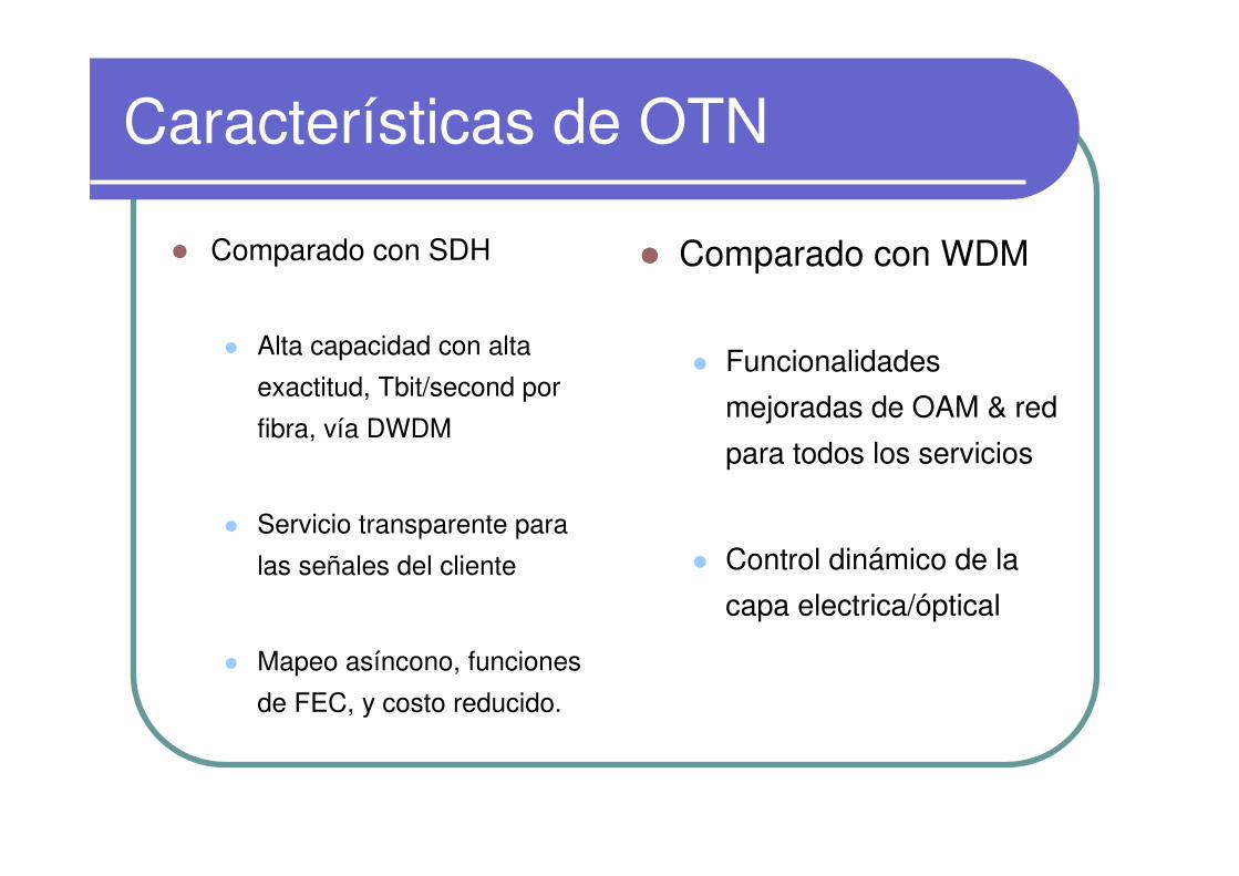
Características de OTN
� Comparado con SDH
� Alta capacidad con alta
exactitud, Tbit/second por
fibra, vía DWDM
� Servicio transparente para
las señales del cliente
� Mapeo asíncono, funciones
de FEC, y costo reducido.
� Comparado con WDM
� Funcionalidades
mejoradas de OAM & red
para todos los servicios
� Control dinámico de la
capa electrica/óptical

Recomendaciones OTN
GestiónJitter y Wander
Protección de Red
Funciones y Característicasde los Equipos
Estructura y mapeo
Característicasde la capa
FísicaArquitectura
�G.874�G.874.1
�G.8251�G.8201
�G.873.1�G.873.2
�G.798�G.806
�G.709�G.7041�G.7042
�G.959.1�G.693�G.694
�G.872�G.8080
OTN

Estructura OTN
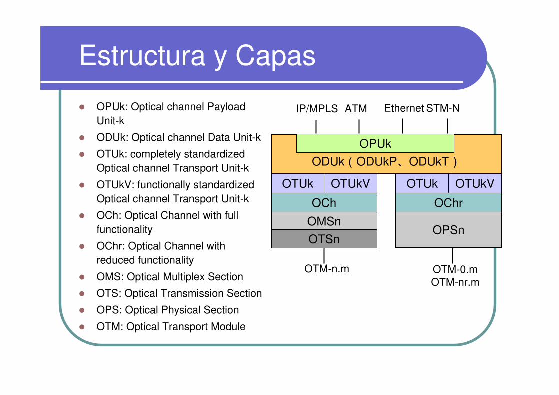
Estructura y Capas
ODUk(ODUkP、ODUkT)OPUk
OTUk OTUkV OTUk OTUkV
OCh OChr
OMSn
OTSnOPSn
IP/MPLS ATM Ethernet STM-N� OPUk: Optical channel Payload Unit-k
� ODUk: Optical channel Data Unit-k
� OTUk: completely standardized Optical channel Transport Unit-k
� OTUkV: functionally standardized Optical channel Transport Unit-k
� OCh: Optical Channel with full functionality
� OChr: Optical Channel with reduced functionality
� OMS: Optical Multiplex Section
� OTS: Optical Transmission Section
� OPS: Optical Physical Section
� OTM: Optical Transport Module
OTM-0.mOTM-nr.m
OTM-n.m
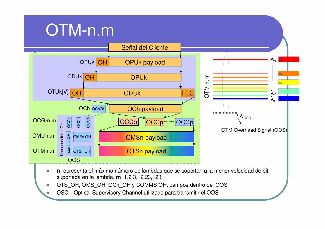
OTM-n.m
� n representa el máximo número de lambdas que se soportan a la menor velocidad de bit suportada en la lambda, m=1,2,3,12,23,123;
� OTS_OH, OMS_OH, OCh_OH y COMMS OH, campos dentro del OOS � OSC:Optical Supervisory Channel utilizado para transmitir el OOS
OMSn payload
OCCp OCCp OCCp
OCh payload
ODUk FECOH
OPUkOH
Señal del Cliente
OPUk payloadOHOPUk
ODUk
OTUk[V]
OCh
OCG-n.m
OTM-n.m OTSn payloadOTSn OH
OMSn OH
OC
Co
OChOH
OC
Co
OC
Co
OMU-n.m
Non
-ass
ocia
ted
OH
OOS
com
ms
OH
OT
M-n
.m
OTM Overhead Signal (OOS)
λ2
λ1
λn
λOSC
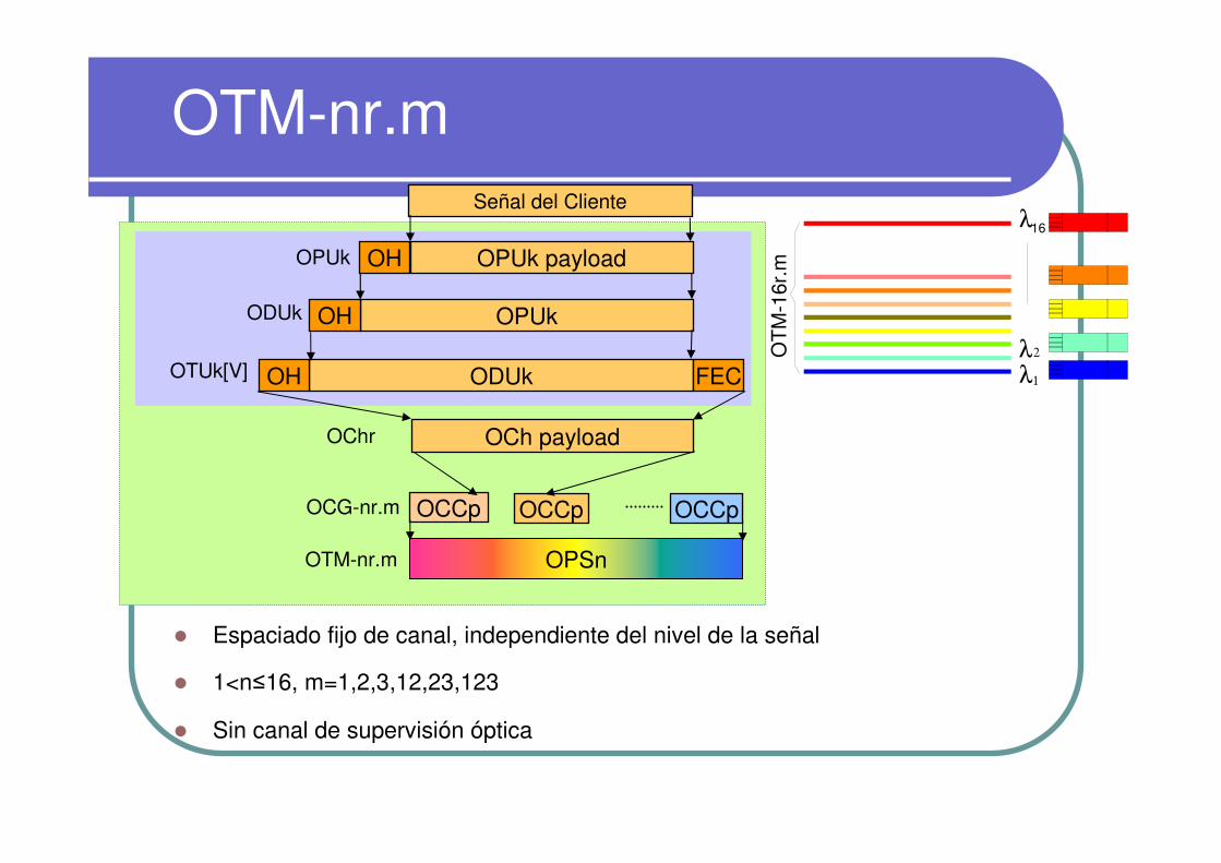
OTM-nr.m
� Espaciado fijo de canal, independiente del nivel de la señal
� 1<n≤16, m=1,2,3,12,23,123
� Sin canal de supervisión óptica
OPSn
OCCp OCCp OCCp
OCh payload
ODUk FECOH
OPUkOH
Señal del Cliente
OPUk payloadOHOPUk
ODUk
OTUk[V]
OChr
OCG-nr.m
OTM-nr.m
OT
M-1
6r.m
λ2
λ1
λ16

OTM-0.m
� El OTM 0.m soporta un canal óptico no coloreado en un solo enlace óptico con regeneración 3R en cada extremo.
� m=1,2,3
� Sin canal de supervisión óptico
OCh paylaod
ODUk FECOH
OPUkOH
Señal del Cliente
OPUk payloadOHOPUk
ODUk
OTUk[V]
OChr
OTM-0.m OPS0
OT
M-0
.m
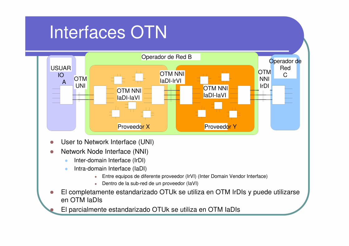
Interfaces OTN
� User to Network Interface (UNI)
� Network Node Interface (NNI)� Inter-domain Interface (IrDI)� Intra-domain Interface (IaDI)
� Entre equipos de diferente proveedor (IrVI) (Inter Domain Vendor Interface)� Dentro de la sub-red de un proveedor (IaVI)
� El completamente estandarizado OTUk se utiliza en OTM IrDIs y puede utilizarseen OTM IaDIs
� El parcialmente estandarizado OTUk se utiliza en OTM IaDIs
OTMUNI
OTM NNIIaDI-IrVI
OTM NNIIaDI-IaVI
OTM NNIIaDI-IaVI
Operador de Red B
Proveedor X Proveedor Y
OTMNNIIrDI
Operador deRedC
USUARIO
A
Multiplexación
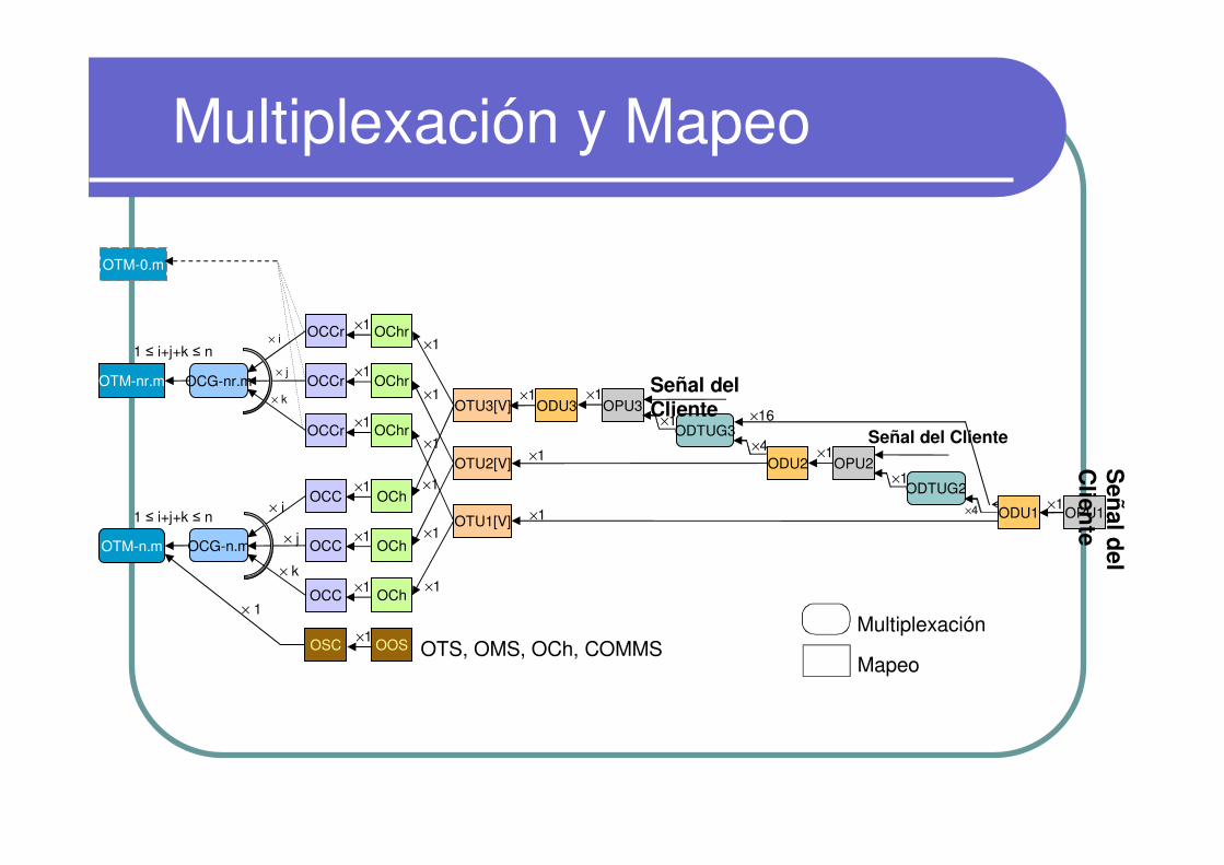
Multiplexación y Mapeo
Mapeo
Multiplexación
ODTUG3
ODTUG2
OChr
OChr
OChr
OCh
OCh
OCh
OTU3[V]
OTU2[V]
OTU1[V]
Señal del Cliente
Señal del Cliente
OPU3ODU3
OCCr
OCCr
OCCr
OCC
OCC
OCC
OCG-nr.m
1 ≤ i+j+k ≤ n
OCG-n.m
1 ≤ i+j+k ≤ n
OPU2ODU2
×1OPU1ODU1
OTM-nr.m
OTS, OMS, OCh, COMMSOSC OOS
OTM-n.m
×4
×1
×1×4
×16×1
×1×1
×1
×1
×1
×1
×1
×1
×1
×1
×1
×1
×1
×1
×1
×1
× i
× j
× k
× i
× j
× 1
Se
ña
ld
el
Clie
nte
×1
OTM-0.m
× k
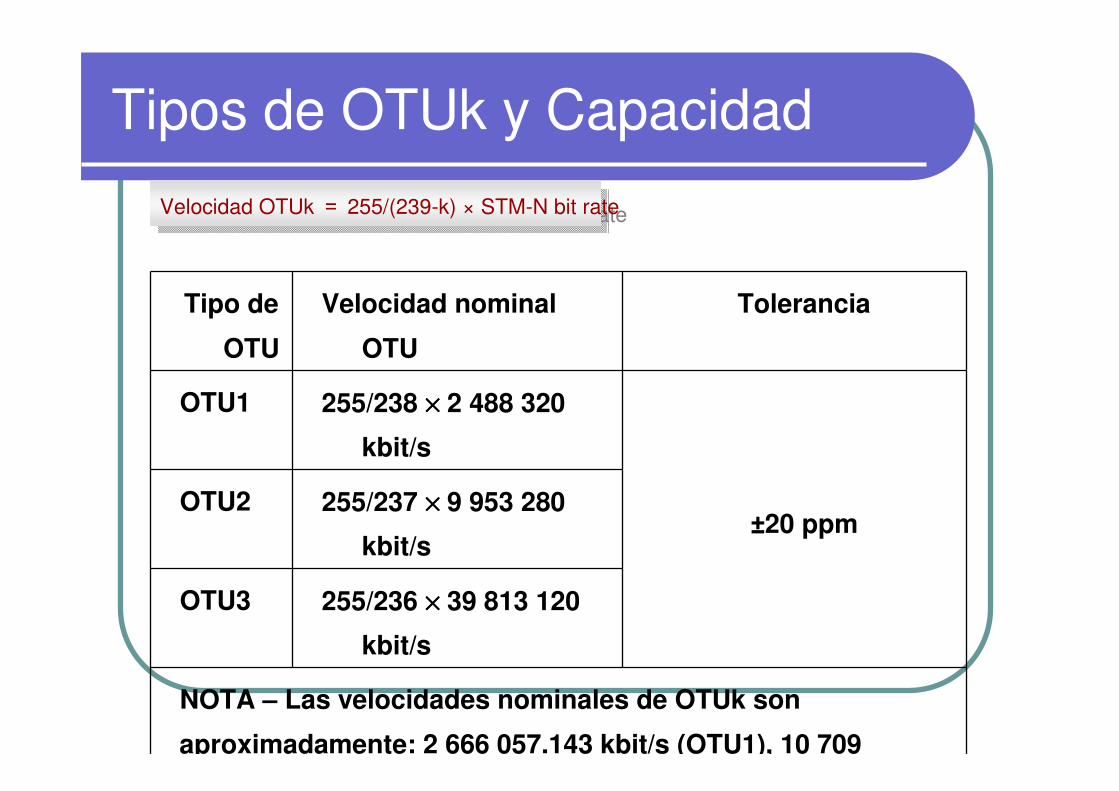
Tipos de OTUk y Capacidad
Tipo de
OTU
Velocidad nominal
OTU
Tolerancia
OTU1 255/238 ×××× 2 488 320
kbit/s
±20 ppmOTU2 255/237 ×××× 9 953 280
kbit/s
OTU3 255/236 ×××× 39 813 120
kbit/s
NOTA – Las velocidades nominales de OTUk son
aproximadamente: 2 666 057.143 kbit/s (OTU1), 10 709
Velocidad OTUk = 255/(239-k) × STM-N bit rateVelocidad OTUk = 255/(239-k) × STM-N bit rate
Page21
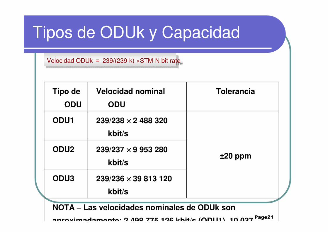
Tipos de ODUk y Capacidad
Tipo de
ODU
Velocidad nominal
ODU
Tolerancia
ODU1 239/238 ×××× 2 488 320
kbit/s
±20 ppmODU2 239/237 ×××× 9 953 280
kbit/s
ODU3 239/236 ×××× 39 813 120
kbit/s
NOTA – Las velocidades nominales de ODUk son
aproximadamente: 2 498 775.126 kbit/s (ODU1), 10 037
Velocidad ODUk = 239/(239-k) ×STM-N bit rateVelocidad ODUk = 239/(239-k) ×STM-N bit rate
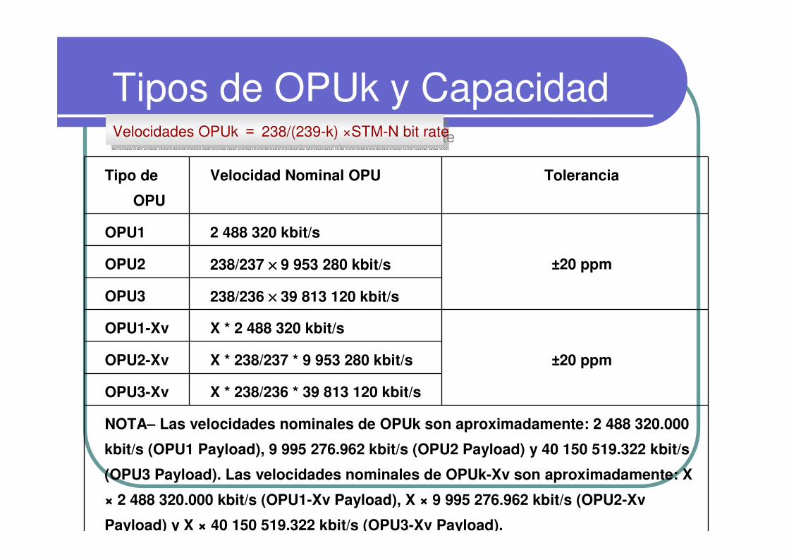
Tipos de OPUk y Capacidad
Tipo de
OPU
Velocidad Nominal OPU Tolerancia
OPU1 2 488 320 kbit/s
±20 ppmOPU2 238/237 ×××× 9 953 280 kbit/s
OPU3 238/236 ×××× 39 813 120 kbit/s
OPU1-Xv X * 2 488 320 kbit/s
±20 ppmOPU2-Xv X * 238/237 * 9 953 280 kbit/s
OPU3-Xv X * 238/236 * 39 813 120 kbit/s
NOTA– Las velocidades nominales de OPUk son aproximadamente: 2 488 320.000
kbit/s (OPU1 Payload), 9 995 276.962 kbit/s (OPU2 Payload) y 40 150 519.322 kbit/s
(OPU3 Payload). Las velocidades nominales de OPUk-Xv son aproximadamente: X
× 2 488 320.000 kbit/s (OPU1-Xv Payload), X × 9 995 276.962 kbit/s (OPU2-Xv
Payload) y X × 40 150 519.322 kbit/s (OPU3-Xv Payload).
Velocidades OPUk = 238/(239-k) ×STM-N bit rateVelocidades OPUk = 238/(239-k) ×STM-N bit rate

ODUk(TDM)� Las señales de baja velocidad ODUk se
multiplexan en señales de alta velocidadODUk utilizando TDM:
� Hasta 4 señales ODU1 se multiplexan en un ODU2
� Es posible multiplexar una mezcla de señales j (j ≤4) ODU2 y 16-4j ODU1 en un ODU3
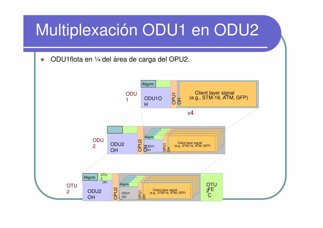
Multiplexación ODU1 en ODU2
� ODU1flota en ¼ del área de carga del OPU2.
OTU2
OTU2FEC
Client layer signal(e.g., STM-16, ATM, GFP)
ODU1 ODU1O
H
Alignm
ODU2
x4
Client Layer Signal(e.g. STM-16)ODU1
OH
OP
U1
OH Client Layer Signal
(e.g. STM-16)ODU1 OH
OP
U1
OH Client Layer Signal
(e.g. STM-16)ODU1 OH
OP
U1
OH Client layer signal
(e.g., STM-16, ATM, GFP)ODU1 OH
ODU2 OH O
PU
2 O
H
OPU2 PayloadODU2
OH
Alignm
OP
U2
OH
OTU2
OH Client Layer Signal(e.g. STM-16)ODU1
OH
OP
U1
OH Client Layer Signal
(e.g. STM-16)ODU1 OH
OP
U1
OH Client Layer Signal
(e.g. STM-16)ODU1 OH
OP
U1
OH Client layer signal
(e.g., STM-16, ATM, GFP)ODU1 OH
OP
U1
OH
Alignm
Alignm
OP
U1
OH
OP
U1
OH

Descripción de los Encabezados
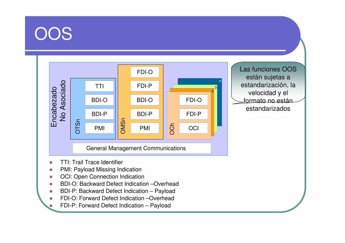
OOS
� TTI: Trail Trace Identifier� PMI: Payload Missing Indication � OCI: Open Connection Indication � BDI-O: Backward Defect Indication –Overhead� BDI-P: Backward Defect Indication – Payload� FDI-O: Forward Defect Indication –Overhead� FDI-P: Forward Defect Indication – Payload
Enc
abez
ado
No
Aso
ciad
o
OT
Sn
n
32
OC
h
1
General Management Communications
OM
Sn
FDI-O
FDI-P
OCI
BDI-O
BDI-P
PMI
FDI-P
FDI-O
BDI-O
BDI-P
PMI
TTI
Las funciones OOS están sujetas a
estandarización, la velocidad y el
formato no estánestandarizados
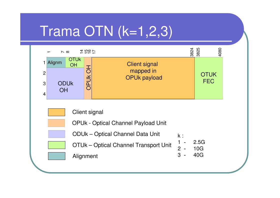
Trama OTN (k=1,2,3)
3825
40801 7 8 14 15 16 17
3824
1
2
3
4
OPU k payload
OP
Uk
OH
OPUk - Optical Channel Payload Unit
ODUkOH
ODUk – Optical Channel Data Unit
Client signal mapped in
OPUk payload
Client signal
OTUKFEC
OTUkOH
OTUk – Optical Channel Transport Unit
Alignm
Alignment
k :1 - 2.5G2 - 10G3 - 40G

Encabezado Eléctrico OTN
� ODUk OH� TCMACT: Tandem Connection Monitoring Activation/deactivation control channel� TCMi:Tandem Connection Monitoring i� FTFL:Fault Type & Fault Location reporting channel
� PM: Path Monitoring� EXP:Experimental� GCC1/2: General Communication Channel1/2� APS/PCC:Automatic Protection Swiching
coordination channel/Protection Communication Control channel
� Alignment OH� FAS: Frame Alignment Signal� MFAS: MultiFrame Alignment Signal
� OTUk OH� SM: Section Monitoring� GCC0:General Communication Channel0� RES: Reserved for future international
standardisation
� OPUk OH � PSI: Payload Structure Identifier� JC: Justification Control � NJO: negative justification opportunity
RES
1 2 3 4 5 6 7 8 9 10 11 12 13 14 15 16
1
2
3
4
TCM3
TCM6 TCM5
TCM2 TCM1
TCM4
PM
TCMACT
GCC1
FTFL RES JC
RES JC
NJOPSIGCC2 APS/PCC RES
EXP
FAS MFAS SM GCC0 RES JCRES
17
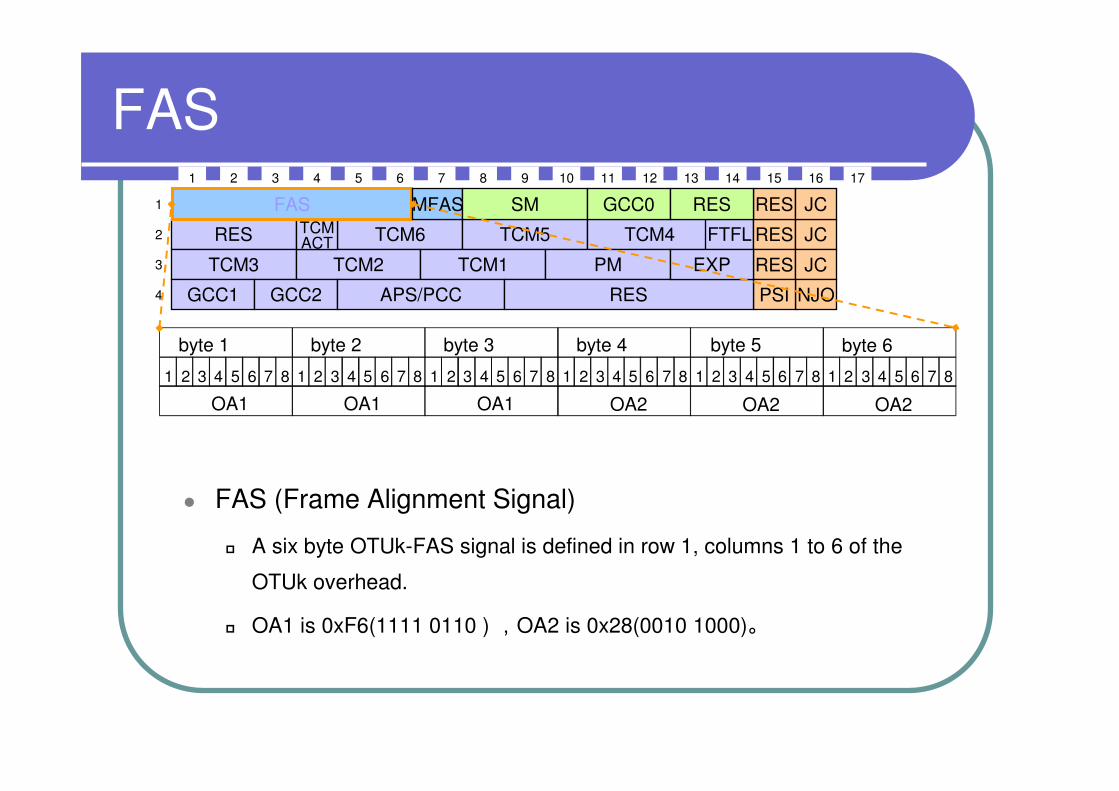
FAS
byte 1 byte 2 byte 3 byte 4 byte 5 byte 6
1 2 3 4 5 6 7 8 1 2 3 4 5 6 7 8 1 2 3 4 5 6 7 8 1 2 3 4 5 6 7 8 1 2 3 4 5 6 7 8 1 2 3 4 5 6 7 8
OA1 OA1 OA1 OA2 OA2 OA2
RES
1 2 3 4 5 6 7 8 9 10 11 12 13 14 15 16
1
2
3
4
TCM3
TCM6 TCM5
TCM2 TCM1
TCM4
PM
TCMACT
GCC1
FTFL RES JC
RES JC
NJOPSIGCC2 APS/PCC RES
EXP
FAS MFAS SM GCC0 RES JCRES
17
� FAS (Frame Alignment Signal)
� A six byte OTUk-FAS signal is defined in row 1, columns 1 to 6 of the
OTUk overhead.
� OA1 is 0xF6(1111 0110 ) ,OA2 is 0x28(0010 1000)。
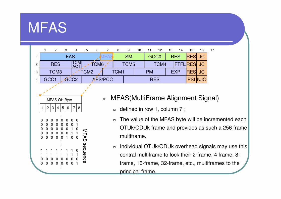
MFAS
MFAS OH Byte
MF
AS
sequence
1 2 3 4 5 6 7 8
0 0 0 0 0 0 0 00 0 0 0 0 0 0 10 0 0 0 0 0 1 00 0 0 0 0 0 1 10 0 0 0 0 1 0 0
....
.
.
1 1 1 1 1 1 1 01 1 1 1 1 1 1 10 0 0 0 0 0 0 00 0 0 0 0 0 0 1
..
� MFAS(MultiFrame Alignment Signal)
� defined in row 1, column 7;� The value of the MFAS byte will be incremented each
OTUk/ODUk frame and provides as such a 256 frame
multiframe.
� Individual OTUk/ODUk overhead signals may use this
central multiframe to lock their 2-frame, 4 frame, 8-
frame, 16-frame, 32-frame, etc., multiframes to the
principal frame.
RES
1 2 3 4 5 6 7 8 9 10 11 12 13 14 15 16
1
2
3
4
TCM3
TCM6 TCM5
TCM2 TCM1
TCM4
PM
TCMACT
GCC1
FTFL RES JC
RES JC
NJOPSIGCC2 APS/PCC RES
EXP
FAS SM GCC0 RES JCRES
17
MFAS

Page31
Encabezado SM de OTUk
� TTI (Trail Trace Identifier)
� a one-byte overhead is defined to transport the 64 byte
TTI signal
� The 64-byte TTI signal shall be aligned with the OTUk
multiframe and transmitted four times per multiframe.
� TTI struture:� 16 bytes SAPI:Source Access Point Identifier
� 16 bytes DAPI:Destination Access Point Identifier
� 32 bytes operator specific
Operatorspecific
TTI BIP-8
BEI/BIAE BD
I
RES
1 2 3 4 5 6 7 8
1 2 3
IAE
63
32
0
1516
31
SAPI
DAPI
RES
1 2 3 4 5 6 7 8 9 10 11 12 13 14 15 16
1
2
3
4
TCM3
TCM6 TCM5
TCM2 TCM1
TCM4
PM
TCMACT
GCC1
FTFL RES JC
RES JC
NJOPSIGCC2 APS/PCC RES
EXP
FAS GCC0 RES JCRES
17
MFAS SM
Encabezado SM de OTUk
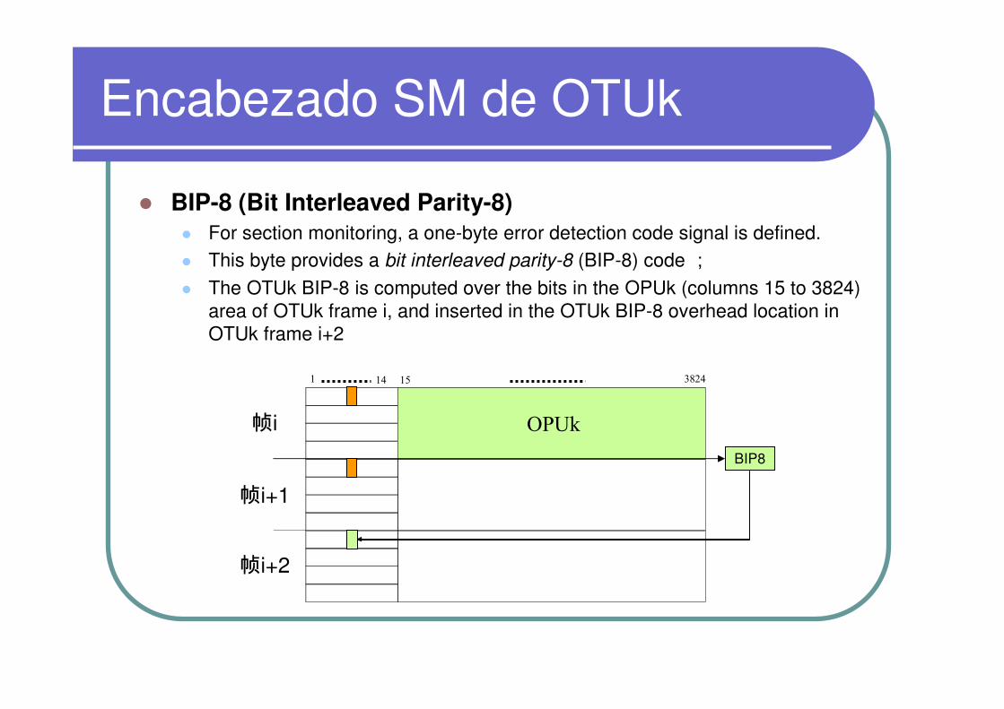
� BIP-8 (Bit Interleaved Parity-8)� For section monitoring, a one-byte error detection code signal is defined. � This byte provides a bit interleaved parity-8 (BIP-8) code ;� The OTUk BIP-8 is computed over the bits in the OPUk (columns 15 to 3824)
area of OTUk frame i, and inserted in the OTUk BIP-8 overhead location in OTUk frame i+2
BIP8
OPUk
1 14 15 3824
帧i
帧i+1
帧i+2
Encabezado SM de OTUk
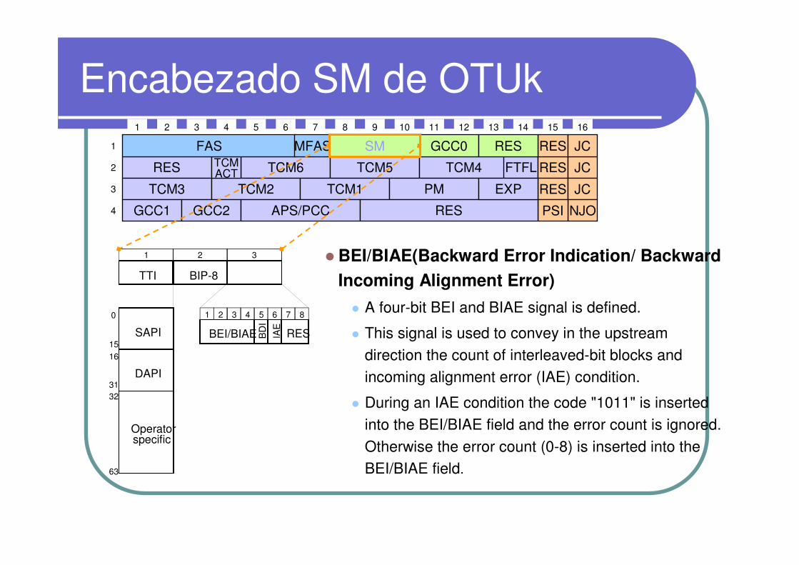
� BEI/BIAE(Backward Error Indication/ Backward
Incoming Alignment Error)
� A four-bit BEI and BIAE signal is defined.
� This signal is used to convey in the upstream
direction the count of interleaved-bit blocks and incoming alignment error (IAE) condition.
� During an IAE condition the code "1011" is inserted
into the BEI/BIAE field and the error count is ignored.
Otherwise the error count (0-8) is inserted into the BEI/BIAE field.
Operatorspecific
TTI BIP-8
BEI/BIAE BD
I
RES
1 2 3 4 5 6 7 8
1 2 3
IAE
63
32
0
1516
31
SAPI
DAPI
RES
1 2 3 4 5 6 7 8 9 10 11 12 13 14 15 16
1
2
3
4
TCM3
TCM6 TCM5
TCM2 TCM1
TCM4
PM
TCMACT
GCC1
FTFL RES JC
RES JC
NJOPSIGCC2 APS/PCC RES
EXP
FAS GCC0 RES JCRESMFAS SM
Encabezado SM de OTUk
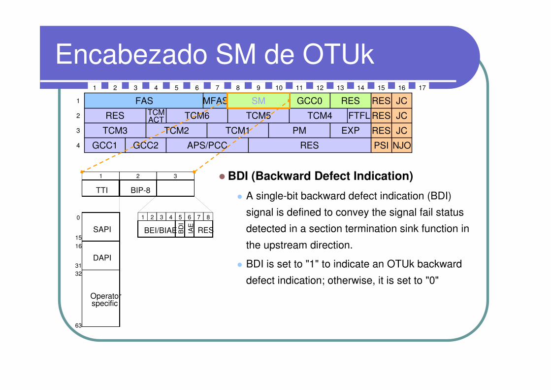
� BDI (Backward Defect Indication)
� A single-bit backward defect indication (BDI)
signal is defined to convey the signal fail status
detected in a section termination sink function in
the upstream direction.
� BDI is set to "1" to indicate an OTUk backward
defect indication; otherwise, it is set to "0" Operatorspecific
TTI BIP-8
BEI/BIAE BD
I
RES
1 2 3 4 5 6 7 8
1 2 3
IAE
63
32
0
1516
31
SAPI
DAPI
RES
1 2 3 4 5 6 7 8 9 10 11 12 13 14 15 16
1
2
3
4
TCM3
TCM6 TCM5
TCM2 TCM1
TCM4
PM
TCMACT
GCC1
FTFL RES JC
RES JC
NJOPSIGCC2 APS/PCC RES
EXP
FAS GCC0 RES JCRES
17
MFAS SM
Encabezado SM de OTUk
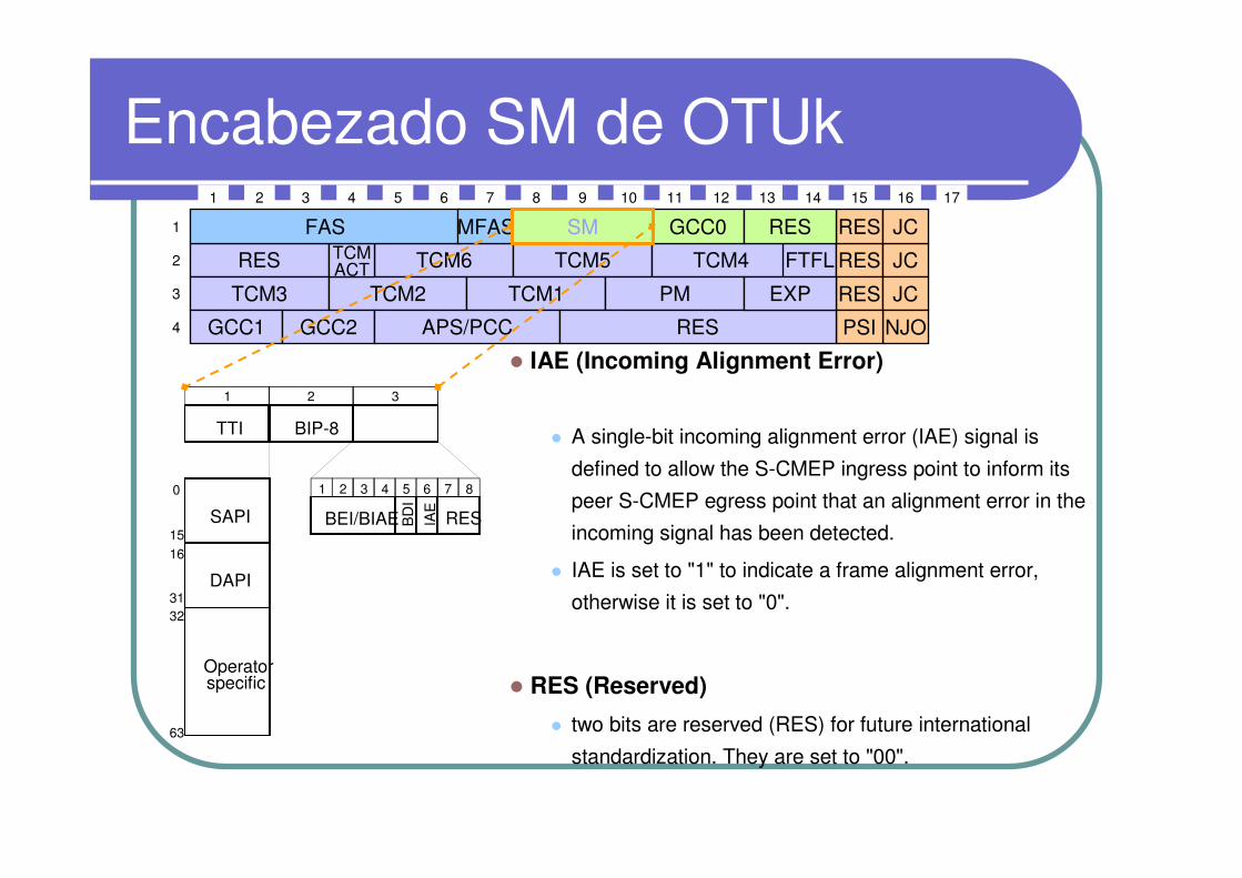
� IAE (Incoming Alignment Error)
� A single-bit incoming alignment error (IAE) signal is
defined to allow the S-CMEP ingress point to inform its
peer S-CMEP egress point that an alignment error in the
incoming signal has been detected.
� IAE is set to "1" to indicate a frame alignment error,
otherwise it is set to "0".
� RES (Reserved)
� two bits are reserved (RES) for future international
standardization. They are set to "00".
Operatorspecific
TTI BIP-8
BEI/BIAE BD
I
RES
1 2 3 4 5 6 7 8
1 2 3
IAE
63
32
0
1516
31
SAPI
DAPI
RES
1 2 3 4 5 6 7 8 9 10 11 12 13 14 15 16
1
2
3
4
TCM3
TCM6 TCM5
TCM2 TCM1
TCM4
PM
TCMACT
GCC1
FTFL RES JC
RES JC
NJOPSIGCC2 APS/PCC RES
EXP
FAS GCC0 RES JCRES
17
MFAS SM
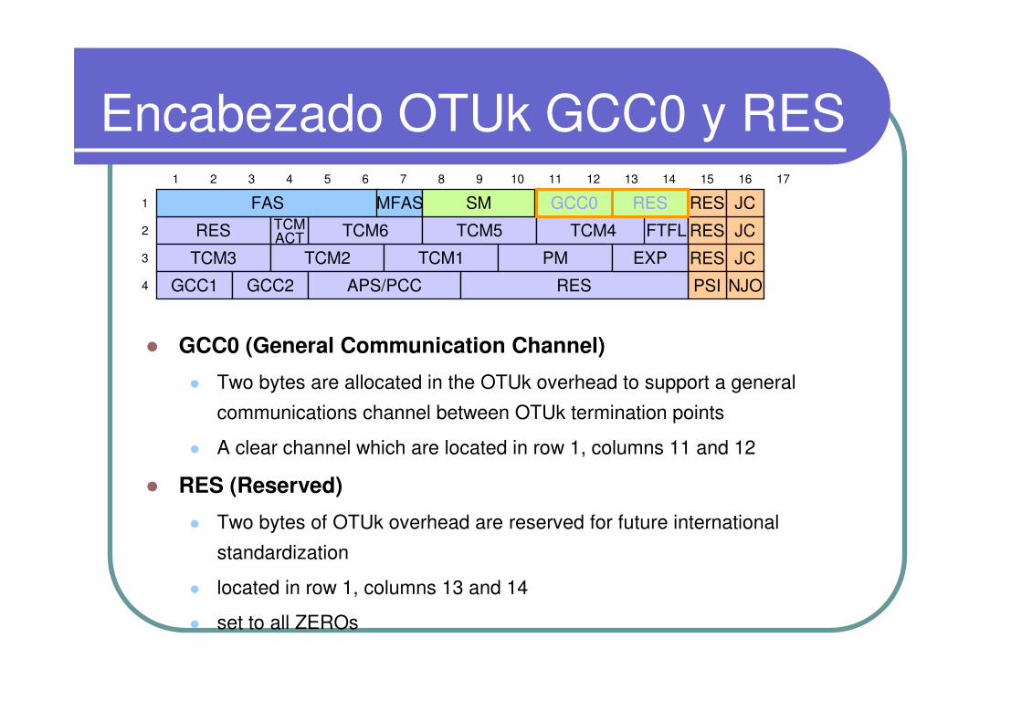
� GCC0 (General Communication Channel)
� Two bytes are allocated in the OTUk overhead to support a general
communications channel between OTUk termination points
� A clear channel which are located in row 1, columns 11 and 12
� RES (Reserved)
� Two bytes of OTUk overhead are reserved for future international
standardization
� located in row 1, columns 13 and 14
� set to all ZEROs
RES
1 2 3 4 5 6 7 8 9 10 11 12 13 14 15 16
1
2
3
4
TCM3
TCM6 TCM5
TCM2 TCM1
TCM4
PM
TCMACT
GCC1
FTFL RES JC
RES JC
NJOPSIGCC2 APS/PCC RES
EXP
FAS RES JCRES
17
MFAS SM GCC0
Encabezado OTUk GCC0 y RES
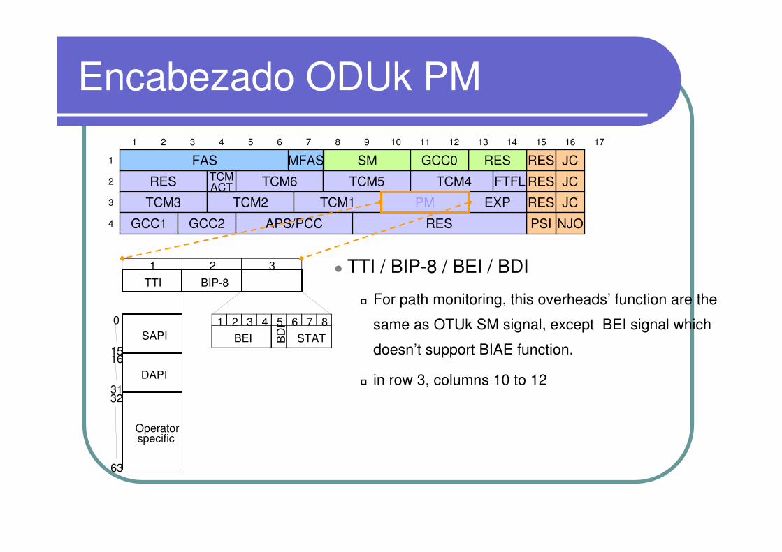
Encabezado ODUk PM
� TTI / BIP-8 / BEI / BDI
� For path monitoring, this overheads’ function are the
same as OTUk SM signal, except BEI signal which
doesn’t support BIAE function.
� in row 3, columns 10 to 12
Operatorspecific
TTI BIP-8
BEI BD
I
STAT
1 2 3 4 5 6 7 8
1 2 3
63
32
0
1516
31
SAPI
DAPI
RES
1 2 3 4 5 6 7 8 9 10 11 12 13 14 15 16
1
2
3
4
TCM3
TCM6 TCM5
TCM2 TCM1
TCM4TCMACT
GCC1
FTFL RES JC
RES JC
NJOPSIGCC2 APS/PCC RES
EXP
FAS RES JCRES
17
MFAS SM GCC0
PM
Encabezado ODUk PM
Operatorspecific
TTI BIP-8
BEI BD
I
STAT
1 2 3 4 5 6 7 8
1 2 3
63
32
0
1516
31
SAPI
DAPI
RES
1 2 3 4 5 6 7 8 9 10 11 12 13 14 15 16
1
2
3
4
TCM3
TCM6 TCM5
TCM2 TCM1
TCM4TCMACT
GCC1
FTFL RES JC
RES JC
NJOPSIGCC2 APS/PCC RES
EXP
FAS RES JCRES
17
MFAS SM GCC0
PM
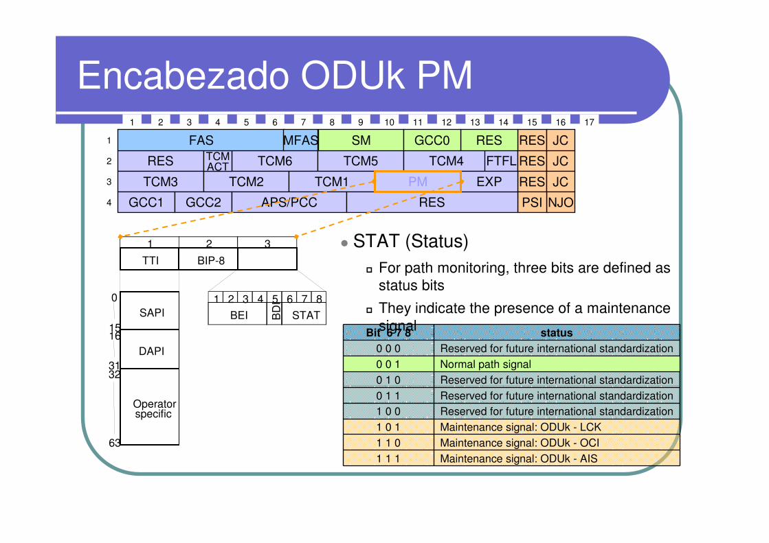
Bit 6 7 8 status
0 0 0 Reserved for future international standardization 0 0 1 Normal path signal0 1 0 Reserved for future international standardization 0 1 1 Reserved for future international standardization 1 0 0 Reserved for future international standardization 1 0 1 Maintenance signal: ODUk - LCK 1 1 0 Maintenance signal: ODUk - OCI 1 1 1 Maintenance signal: ODUk - AIS
� STAT (Status)� For path monitoring, three bits are defined as
status bits
� They indicate the presence of a maintenance signal
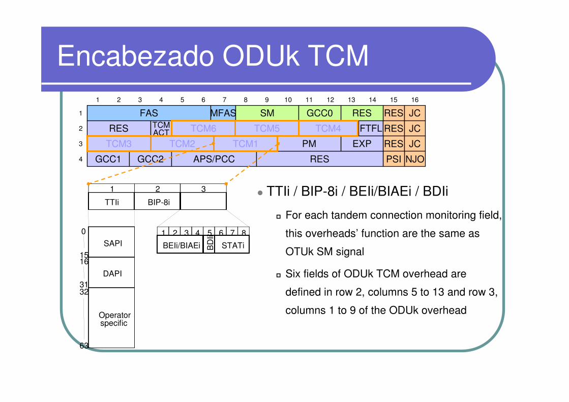
Encabezado ODUk TCM
� TTIi / BIP-8i / BEIi/BIAEi / BDIi
� For each tandem connection monitoring field,
this overheads’ function are the same as
OTUk SM signal
� Six fields of ODUk TCM overhead are
defined in row 2, columns 5 to 13 and row 3,
columns 1 to 9 of the ODUk overhead
TTIi BIP-8i
BEIi/BIAEi BD
Ii
STATi
1 2 3 4 5 6 7 8
1 2 3
63
32
0
1516
31
SAPI
DAPI
Operatorspecific
RES
1 2 3 4 5 6 7 8 9 10 11 12 13 14 15 16
1
2
3
4
TCMACT
GCC1
FTFL RES JC
RES JC
NJOPSIGCC2 APS/PCC RES
EXP
FAS RES JCRESMFAS SM GCC0
PMTCM1TCM2TCM3
TCM6 TCM5 TCM4
Encabezado ODUk TCM
TTIi BIP-8i
BEIi/BIAEi BD
Ii
STATi
1 2 3 4 5 6 7 8
1 2 3
63
32
0
1516
31
SAPI
DAPI
Operatorspecific
RES
1 2 3 4 5 6 7 8 9 10 11 12 13 14 15 16
1
2
3
4
TCMACT
GCC1
FTFL RES JC
RES JC
NJOPSIGCC2 APS/PCC RES
EXP
FAS RES JCRES
17
MFAS SM GCC0
PMTCM1
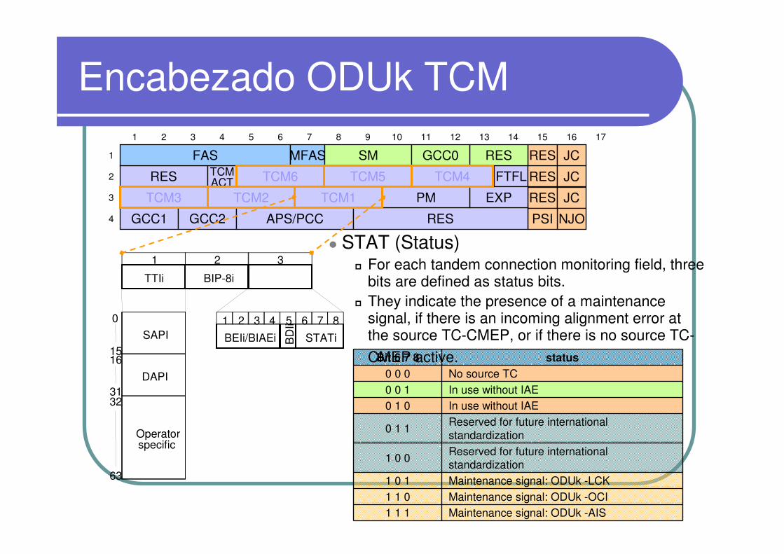
Bit 6 7 8 status
0 0 0 No source TC 0 0 1 In use without IAE0 1 0 In use without IAE
0 1 1Reserved for future international standardization
1 0 0Reserved for future international standardization
1 0 1 Maintenance signal: ODUk -LCK 1 1 0 Maintenance signal: ODUk -OCI 1 1 1 Maintenance signal: ODUk -AIS
TCM2TCM3
TCM6 TCM5 TCM4
� STAT (Status)� For each tandem connection monitoring field, three
bits are defined as status bits. � They indicate the presence of a maintenance
signal, if there is an incoming alignment error at the source TC-CMEP, or if there is no source TC-
CMEP active.

Page41
Monitoreo de Conexiones Anidadasy en Cascada de ODUk
A1 B1 C1 C2 B2 B3 B4 A2
A1 - A2
B1 - B2
C1 - C2
B3 - B4
TCM1 TCM1
TCM2
TCM1
TCM2
TCM3
TCM1
TCM2
TCM1 TCM1
TCM2
TCM1
TCM2
TCM3
TCM4
TCM5
TCM6
TCMi TCM OH field not in use TCMi TCM OH field in use
TCM2
TCM3
TCM4
TCM5
TCM6
TCM2
TCM3
TCM4
TCM5
TCM6
TCM3
TCM4
TCM5
TCM6
TCM3
TCM4
TCM5
TCM6
TCM3
TCM4
TCM5
TCM6
TCM4
TCM5
TCM6
Page42
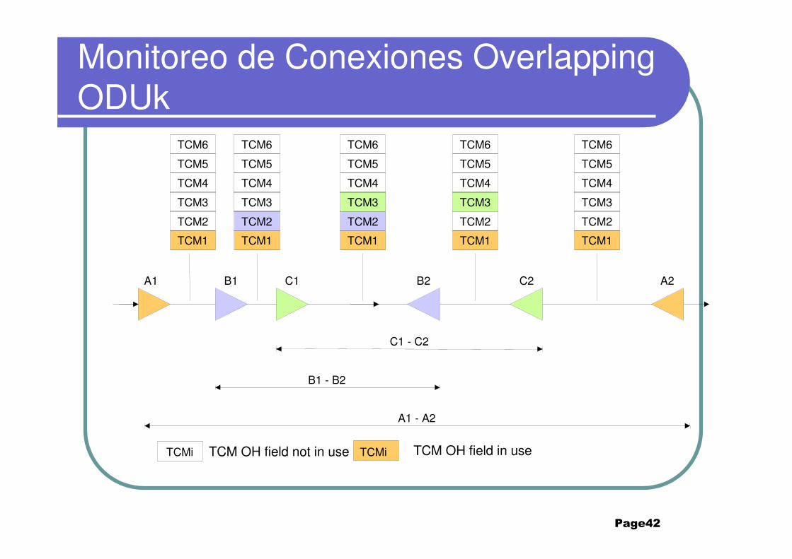
Monitoreo de Conexiones Overlapping ODUk
A1 B1 C1 C2B2 A2
A1 - A2
B1 - B2
C1 - C2
TCM1 TCM1
TCM2
TCM1
TCM2
TCM3
TCM1
TCM2
TCM1
TCMi TCM OH field not in use TCMi TCM OH field in use
TCM2
TCM3
TCM4
TCM5
TCM6
TCM2
TCM3
TCM4
TCM5
TCM6
TCM3
TCM4
TCM5
TCM6
TCM3
TCM4
TCM5
TCM6
TCM4
TCM5
TCM6

ODUk TCM ACT
RES
1 2 3 4 5 6 7 8 9 10 11 12 13 14 15 16
1
2
3
4
TCM3
TCM6 TCM5
TCM2
TCM4TCMACT
GCC1
FTFL RES JC
RES JC
NJOPSIAPS/PCC RES
EXP
FAS RES JCRES
17
MFAS SM GCC0
PMTCM1
GCC2
� TCMACT (TCM Activation/Deactivation)
� A one-byte TCM activation/deactivation field is located in row 2,
column 4.
� Its definition is for further study.
ODUk GCC1/GCC2
RES
1 2 3 4 5 6 7 8 9 10 11 12 13 14 15 16
1
2
3
4
TCM3
TCM6 TCM5
TCM2
TCM4TCMACT
GCC1
FTFL RES JC
RES JC
NJOPSIAPS/PCC RES
EXP
FAS RES JCRES
17
MFAS SM GCC0
PMTCM1
GCC2
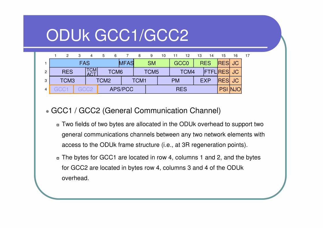
� GCC1 / GCC2 (General Communication Channel)
� Two fields of two bytes are allocated in the ODUk overhead to support two
general communications channels between any two network elements with
access to the ODUk frame structure (i.e., at 3R regeneration points).
� The bytes for GCC1 are located in row 4, columns 1 and 2, and the bytes
for GCC2 are located in bytes row 4, columns 3 and 4 of the ODUk
overhead.

Canal ODUk APS/PCC
RES
1 2 3 4 5 6 7 8 9 10 11 12 13 14 15 16
1
2
3
4
TCM3
TCM6 TCM5
TCM2
TCM4TCMACT
GCC1
FTFL RES JC
RES JC
NJOPSIRES
EXP
FAS RES JCRES
17
MFAS SM GCC0
PMTCM1
GCC2 APS/PCC
� APS/PCC (Automatic Protection Switching/Protection
Communication Control)
� A four-byte ODUk-APS/PCC signal is defined in row 4, columns 5 to 8 of the
ODUk overhead.
� For linear protection schemes, the bit assignments for these bytes and the bit
oriented protocol are given in ITU-T Rec. G.873.1. Bit assignment and byte
oriented protocol for ring protection schemes are for further study.
� Up to eight levels of nested APS/PCC signals may be present in this field.
Canal ODUk FTFL
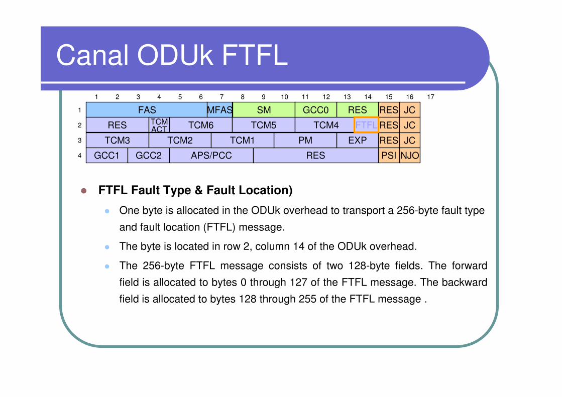
� FTFL Fault Type & Fault Location)
� One byte is allocated in the ODUk overhead to transport a 256-byte fault type
and fault location (FTFL) message.
� The byte is located in row 2, column 14 of the ODUk overhead.
� The 256-byte FTFL message consists of two 128-byte fields. The forward
field is allocated to bytes 0 through 127 of the FTFL message. The backward
field is allocated to bytes 128 through 255 of the FTFL message .
RES
1 2 3 4 5 6 7 8 9 10 11 12 13 14 15 16
1
2
3
4
TCM3
TCM6 TCM5
TCM2
TCM4TCMACT
GCC1
RES JC
RES JC
NJOPSIAPS/PCC RES
EXP
FAS RES JCRES
17
MFAS SM GCC0
PMTCM1
GCC2
FTFL
Encabezado ODUk Experimental y Reservado
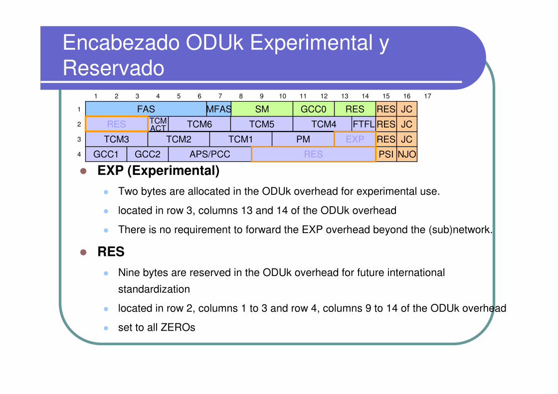
� EXP (Experimental)
� Two bytes are allocated in the ODUk overhead for experimental use.
� located in row 3, columns 13 and 14 of the ODUk overhead
� There is no requirement to forward the EXP overhead beyond the (sub)network.
� RES
� Nine bytes are reserved in the ODUk overhead for future international
standardization
� located in row 2, columns 1 to 3 and row 4, columns 9 to 14 of the ODUk overhead
� set to all ZEROs
1 2 3 4 5 6 7 8 9 10 11 12 13 14 15 16
1
2
3
4
TCM3
TCM6 TCM5
TCM2
TCM4TCMACT
GCC1
FTFL RES JC
RES JC
NJOPSIAPS/PCC
FAS RES JCRES
17
MFAS SM GCC0
PMTCM1
GCC2
EXP
RES
RES
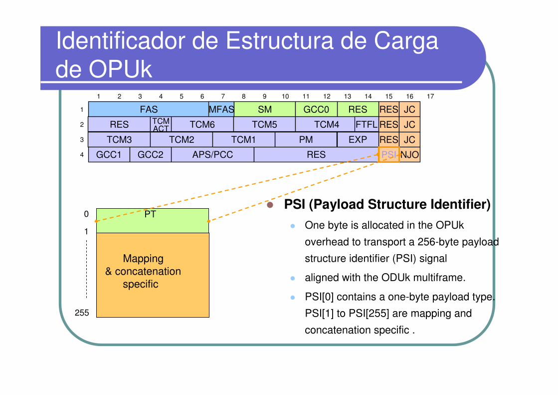
Identificador de Estructura de Carga de OPUk
� PSI (Payload Structure Identifier)
� One byte is allocated in the OPUk
overhead to transport a 256-byte payload
structure identifier (PSI) signal
� aligned with the ODUk multiframe.
� PSI[0] contains a one-byte payload type.
PSI[1] to PSI[255] are mapping and
concatenation specific .
255
0
1
PT
Mapping& concatenation
specific
RES
1 2 3 4 5 6 7 8 9 10 11 12 13 14 15 16
1
2
3
4
TCM3
TCM6 TCM5
TCM2
TCM4TCMACT
GCC1
RES JC
RES JC
NJOAPS/PCC RES
EXP
FAS RES JCRES
17
MFAS SM GCC0
PMTCM1
GCC2
FTFL
PSI
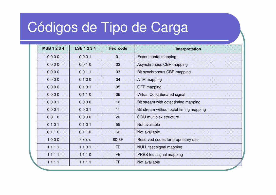
Códigos de Tipo de CargaMSB 1 2 3 4 LSB 1 2 3 4 Hex code Interpretation
0 0 0 0 0 0 0 1 01 Experimental mapping
0 0 0 0 0 0 1 0 02 Asynchronous CBR mapping
0 0 0 0 0 0 1 1 03 Bit synchronous CBR mapping
0 0 0 0 0 1 0 0 04 ATM mapping
0 0 0 0 0 1 0 1 05 GFP mapping
0 0 0 0 0 1 1 0 06 Virtual Concatenated signal
0 0 0 1 0 0 0 0 10 Bit stream with octet timing mapping
0 0 0 1 0 0 0 1 11 Bit stream without octet timing mapping
0 0 1 0 0 0 0 0 20 ODU multiplex structure
0 1 0 1 0 1 0 1 55 Not available
0 1 1 0 0 1 1 0 66 Not available
1 0 0 0 x x x x 80-8F Reserved codes for proprietary use
1 1 1 1 1 1 0 1 FD NULL test signal mapping
1 1 1 1 1 1 1 0 FE PRBS test signal mapping
1 1 1 1 1 1 1 1 FF Not available

Encabezado OPUk
� JC / NJO / RES (contorl de justificación / oportunidad de
justificación negativa / reservado)
� Se reservan siete bytes en el encabezado OPUk para mapeo y
concatenación
� Estos bytes se localizan en las filas 1 a 3, columnas 15 y 16 y columna 16 fila 4.
� 255 bytes en el PSI están reservados para propósitos específicos de
concatenación
RES
1
2
3
4
TCM3
TCM6 TCM5
TCM2
TCM4TCMACT
GCC1
RES JC
JC
APS/PCC RES
EXP
FAS RES JCRESMFAS SM GCC0
PMTCM1
GCC2 PSI
FTFL
1 2 3 4 5 6 7 8 9 10 11 12 13 14 15 16 17
RES
NJO

Señales de Mantenimiento

Señales de Mantenimiento
� FDI((((forward defect indication))))
� FDI is a signal sent downstream as an indication that an upstream defect
has been detected.
� An FDI signal is detected in a trail termination sink function to suppress
defects or failures that would otherwise be detected as a consequence of
the interruption of the transport of the original signal at an upstream point..
� AIS and FDI are similar signals. AIS is used as term when the signal is in
the digital domain. FDI is used as the term when the signal is in the optical
domain.
� FDI is transported as non associated overhead in the OTM overhead
signal (OOS).
Señales de Mantenimiento
� AIS((((alarm indication signal))))
� AIS is a signal sent downstream as an indication that an upstream defect has been detected. An AIS signal is generated in an adaptation sink function
� An AIS signal is detected in a trail termination sink function to suppress defects or failures that would otherwise be detected asa consequence of the interruption of the transport of the original signal at an upstream point.

Señales de Mantenimiento
� AIS((((alarm indication signal))))
� ODUk-AIS is specified as all "1"s in the entire ODUk signal, excluding the frame alignment overhead (FA OH), OTUk overhead (OTUk OH) and ODUk FTFL
� The presence of ODUk-AIS is detected by monitoring the ODUk STAT bits in the PM and TCMi overhead fields
1
2
3
4
1 17 3824
All-1s pattern
87 14
FT
FL
FA OH OTUk OH
ST
AT
ST
AT
ST
AT
ST
AT
ST
AT
ST
AT
ST
AT
Señales de Mantenimiento
� BDI (Backward Defect Indication)
� Backward Defect Indication Payload defect (dBDI-P) is monitored at
the OTS and OMS layers. The purpose of monitoring this parameteris to allow for single ended supervision of the trail
� BDI-P (dBDI-P) defect shall be declared/cleared at the trail
termination sink function within X ms/Y ms of detecting the far-end
defect causing the insertion of BDI-P into the OOS.
� X and Y are for further study.
� During signal fail conditions of the overhead signal, dBDI-P shall be set to false

Señales de Mantenimiento
� PMI (Payload Missing Indication)
� PMI defect is monitored at the OTS and OMS layers. The purpose of
monitoring this parameter is to suppress downstream loss of signal alarms
at the trail termination sink due to upstream defects causing missing
payload at the start of the trail.
� PMI defect (dPMI) shall be declared/cleared at the trail termination sink
function within X ms/Y ms of detecting the missing payload condition
causing the insertion of PMI into the OOS
� During signal fail conditions of the overhead signal, dPMI shall be set to
false .
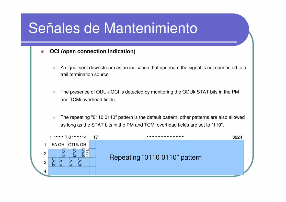
Señales de Mantenimiento � OCI (open connection indication)
� A signal sent downstream as an indication that upstream the signal is not connected to a trail termination source
� The presence of ODUk-OCI is detected by monitoring the ODUk STAT bits in the PM
and TCMi overhead fields.
� The repeating "0110 0110" pattern is the default pattern; other patterns are also allowed
as long as the STAT bits in the PM and TCMi overhead fields are set to "110".
1
2
3
4
1 17 382487 14
FT
FL
FA OH OTUk OH
ST
AT
ST
AT
ST
AT
ST
AT
ST
AT
ST
AT
ST
AT Repeating “0110 0110” pattern
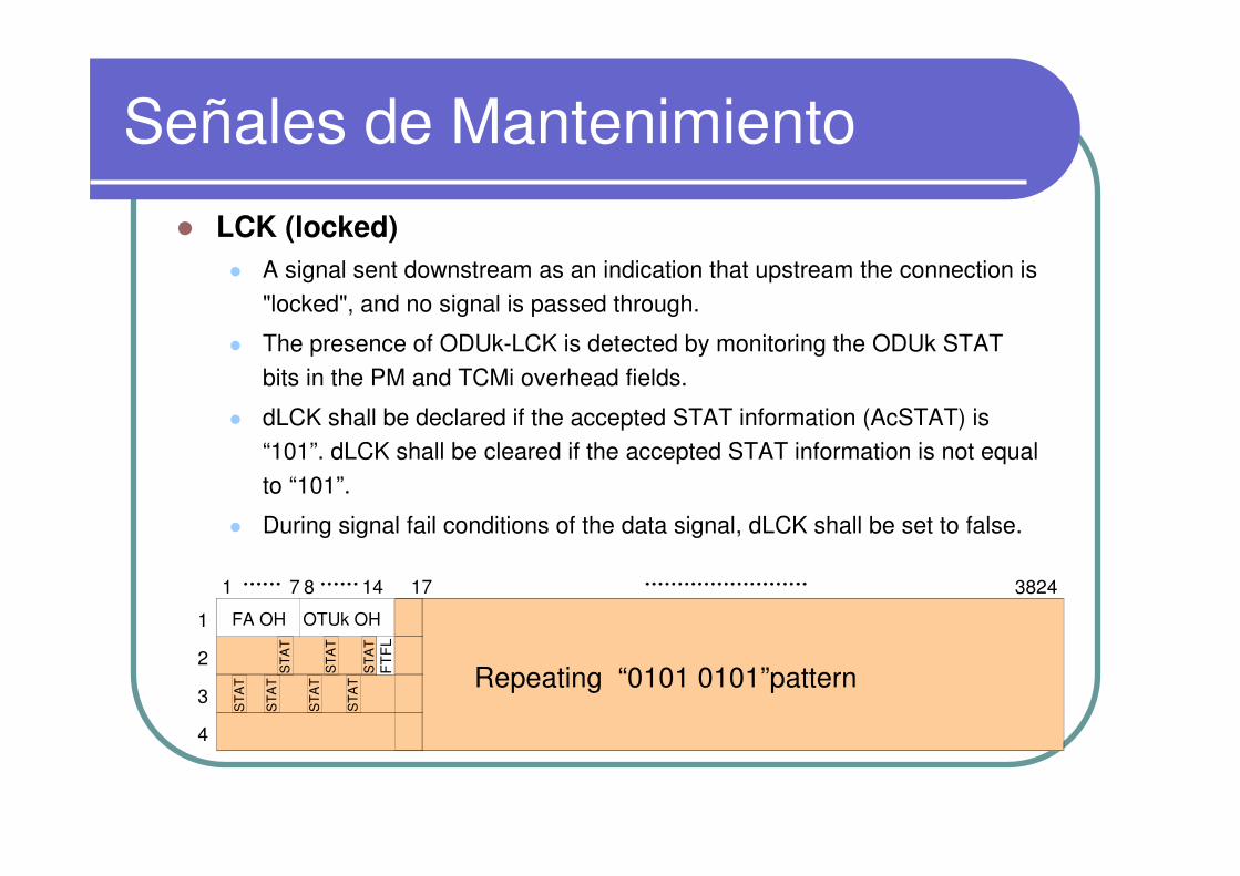
Señales de Mantenimiento
� LCK (locked)
� A signal sent downstream as an indication that upstream the connection is
"locked", and no signal is passed through.
� The presence of ODUk-LCK is detected by monitoring the ODUk STAT
bits in the PM and TCMi overhead fields.
� dLCK shall be declared if the accepted STAT information (AcSTAT) is “101”. dLCK shall be cleared if the accepted STAT information is not equal
to “101”.
� During signal fail conditions of the data signal, dLCK shall be set to false.
1
2
3
4
1 17 382487 14
FT
FL
FA OH OTUk OH
ST
AT
ST
AT
ST
AT
ST
AT
ST
AT
ST
AT
ST
AT Repeating “0101 0101”pattern
Señales de Mantenimiento
� IAE (Incoming Alignment Error)
� IAE at the OTUk layer: dIAE shall be declared/cleared if the IAE bit in
the SM overhead field (byte 3, bit 6) is “1”/ “0” for X consecutive frames.
X shall be 5.
� IAE at the ODUkT layer: dIAE shall be declared/cleared if the accepted
STAT information (AcSTAT) is/is not “010”.
� During signal fail conditions of the data signal, dIAE shall be set to
false .
� BIAE (Backward Incoming Alignment Error)
� dBIAE shall be declared/cleared if the BEI/BIAE bits in the SM/TCM overhead
field (byte 3, bit 1 to 4) are/are not “1011” for X consecutive frames. X shall be 3.
� During signal fail conditions of the data signal, dBIAE shall be set to false .

Page60
Señales de Mantenimiento y Administración
Management
functionsignal
Network layers
OTUk ODUkP ODUkT
Alignment LOF/LOM Y Y –
Connectivity TTI Y Y Y
Maintenance
Signal
AIS Y Y Y
OCI – Y Y
LCK – Y Y
LTC – – Y
BDI Y Y Y
BEI Y Y Y
IAE/BIAE Y – Y
Signal quality BIP-8 Y Y Y

Page61
OTN Layer Network Trail
� NODE A using general OTU, generate SM、PM、TCM1。
� NODE B using regenerator OTU, terminate SM, generate SM。
� NODE C using Line unit OTU, terminate SM、TCM1, generate SM。
� NODE D using general OTU, terminate SM、PM。
NODE ATM
NODE DTM
NODE BREG
NODE CODU ADM
OTS OTS OTS
OMS OMS OMSOTU/OCH OTU/OCH OTU/OCH
ODUkT
ODUkP
Client signal
Eventos de Alarma y Desempeño
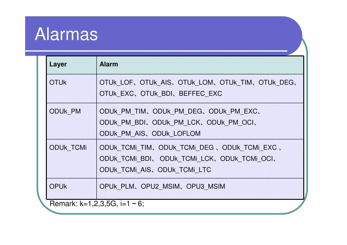
Alarmas
Layer Alarm
OTUk OTUk_LOF、OTUk_AIS、OTUk_LOM、OTUk_TIM、OTUk_DEG、
OTUk_EXC、OTUk_BDI、BEFFEC_EXC
ODUk_PM ODUk_PM_TIM、ODUk_PM_DEG、ODUk_PM_EXC、
ODUk_PM_BDI、ODUk_PM_LCK、ODUk_PM_OCI、
ODUk_PM_AIS、ODUk_LOFLOM
ODUk_TCMi ODUk_TCMi_TIM、ODUk_TCMi_DEG 、ODUk_TCMi_EXC 、
ODUk_TCMi_BDI、 ODUk_TCMi_LCK、ODUk_TCMi_OCI、
ODUk_TCMi_AIS、ODUk_TCMi_LTC
OPUk OPUk_PLM、OPU2_MSIM、OPU3_MSIM
Remark: k=1,2,3,5G, i=1~6;
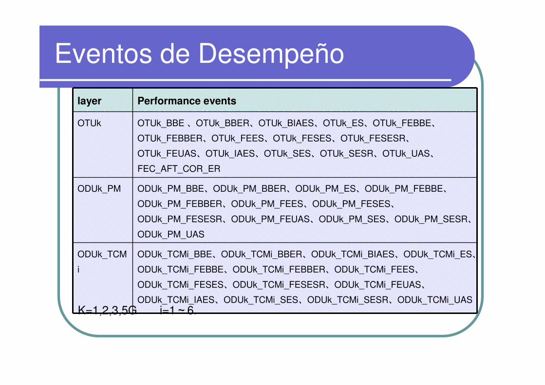
Eventos de Desempeño
layer Performance events
OTUk OTUk_BBE 、OTUk_BBER、OTUk_BIAES、OTUk_ES、OTUk_FEBBE、OTUk_FEBBER、OTUk_FEES、OTUk_FESES、OTUk_FESESR、OTUk_FEUAS、OTUk_IAES、OTUk_SES、OTUk_SESR、OTUk_UAS、FEC_AFT_COR_ER
ODUk_PM ODUk_PM_BBE、ODUk_PM_BBER、ODUk_PM_ES、ODUk_PM_FEBBE、ODUk_PM_FEBBER、ODUk_PM_FEES、ODUk_PM_FESES、ODUk_PM_FESESR、ODUk_PM_FEUAS、ODUk_PM_SES、ODUk_PM_SESR、ODUk_PM_UAS
ODUk_TCM
i
ODUk_TCMi_BBE、ODUk_TCMi_BBER、ODUk_TCMi_BIAES、ODUk_TCMi_ES、ODUk_TCMi_FEBBE、ODUk_TCMi_FEBBER、ODUk_TCMi_FEES、ODUk_TCMi_FESES、ODUk_TCMi_FESESR、ODUk_TCMi_FEUAS、ODUk_TCMi_IAES、ODUk_TCMi_SES、ODUk_TCMi_SESR、ODUk_TCMi_UAS
K=1,2,3,5G i=1~6.
Escenarios Típicos de OTN

Page66
Illustration
� XXXX = color (255/153/0) hypothetical condition (e.g. fiber broken, insert LCK)
� XXXX = color (102/153/0) Consequent Action(e.g. insert AIS,BDI)� XXXX = color (0/0/0) detect defect(e.g. R_LOS,ODUK_PM_AIS)
fiber
NODEA
Page67
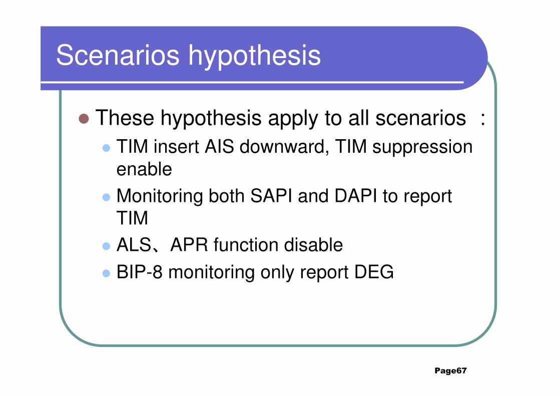
Scenarios hypothesis
� These hypothesis apply to all scenarios :� TIM insert AIS downward, TIM suppression
enable� Monitoring both SAPI and DAPI to report
TIM� ALS、APR function disable
� BIP-8 monitoring only report DEG
Page68
Contents
2. Typical Scenarios of OTN2.1 point to point ODU2
2.2 ODU1 ADM 2.3 4*GE service convergence
2.4 TCM nested2.5 TCM cascaded
Page69
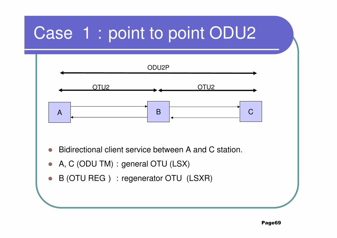
Case 1:point to point ODU2
� Bidirectional client service between A and C station.
� A, C (ODU TM):general OTU (LSX)
� B (OTU REG):regenerator OTU (LSXR)
A B C
OTU2 OTU2
ODU2P
Page70
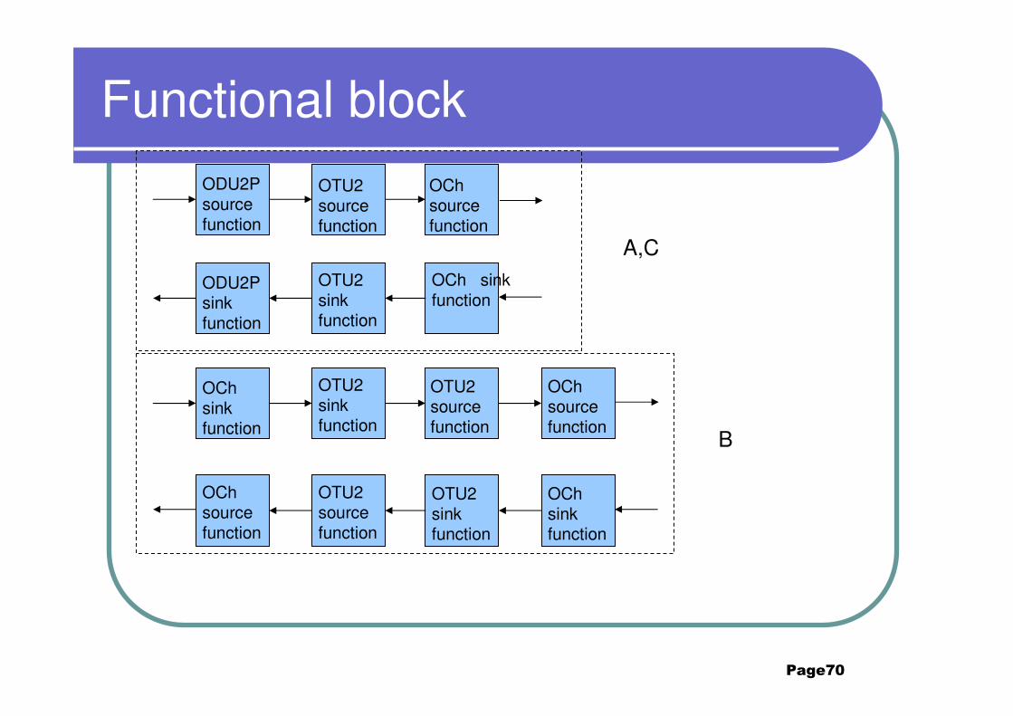
Functional block
OCh source function
ODU2P source function
OTU2 source function
ODU2P sink function
OTU2 sink function
OCh sink function
OCh sink function
OTU2 sink function
OTU2 source function
OCh source function
OTU2 source function
OTU2 sink function
OCh source function
OCh sink function
A,C
B

Page71
Insert LCK at node A
A B C
ODU2_PM_LCK
ODU2_PM_BDI
ODU2_LCKODU2_PM_aBDI
Page72
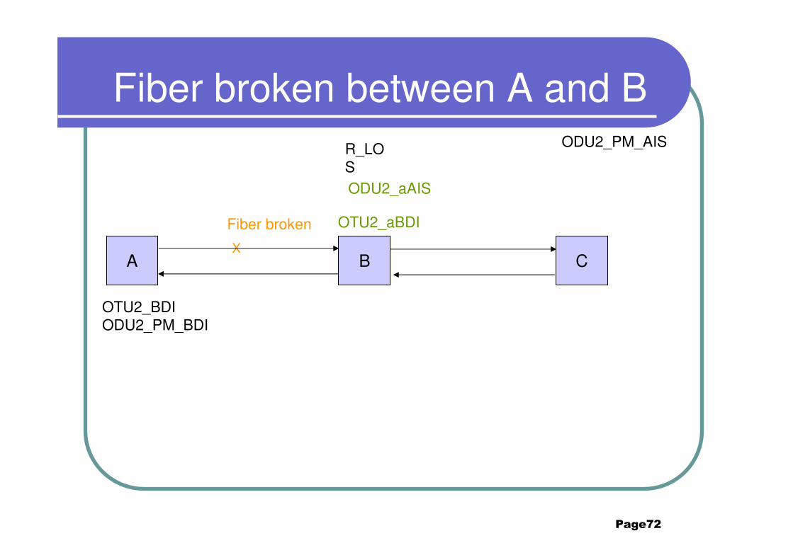
Fiber broken between A and B
A B C
ODU2_PM_AIS
OTU2_BDIODU2_PM_BDI
R_LOS
Fiber broken
X
ODU2_aAIS
OTU2_aBDI
Page73
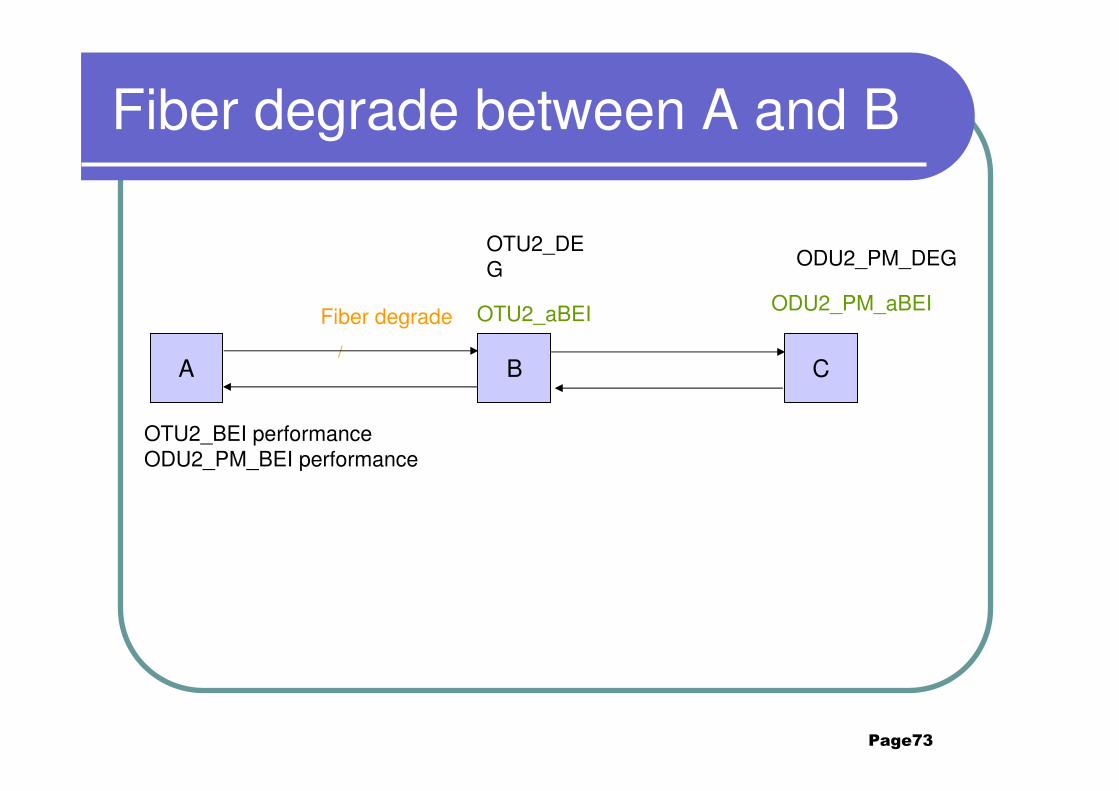
Fiber degrade between A and B
A B C
ODU2_PM_DEGOTU2_DEG
/
Fiber degrade OTU2_aBEI ODU2_PM_aBEI
OTU2_BEI performanceODU2_PM_BEI performance
Page74
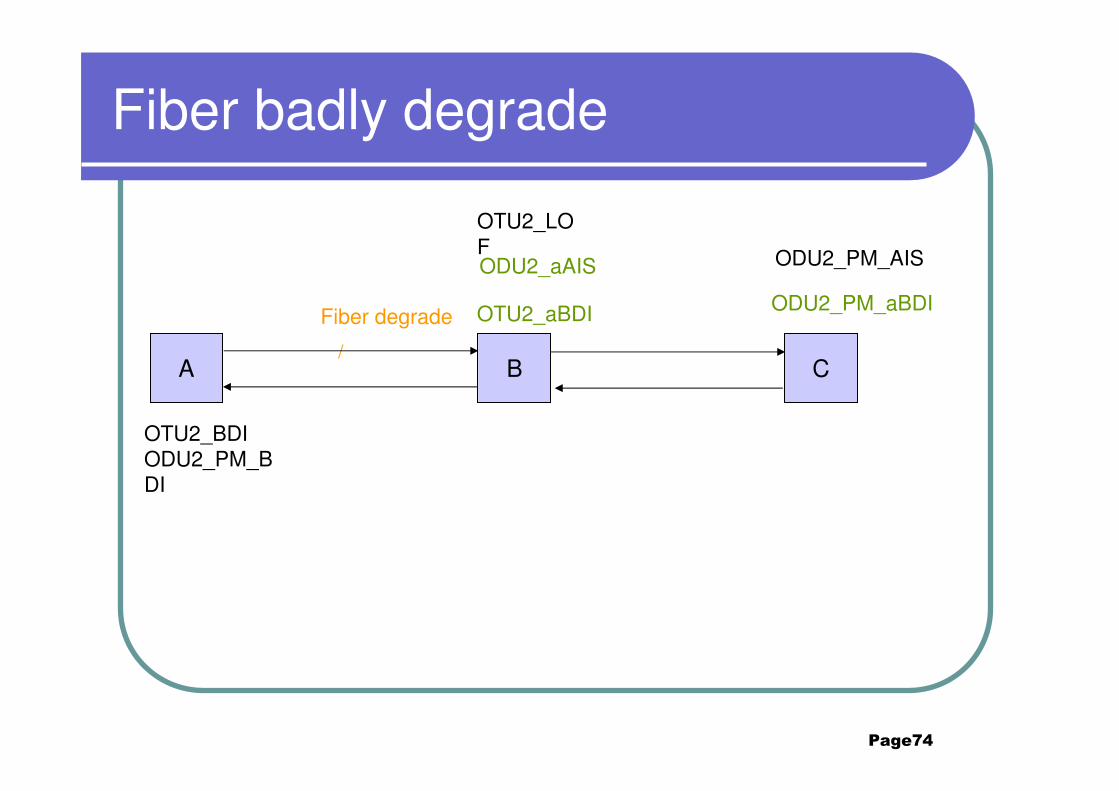
Fiber badly degrade
A B C
ODU2_PM_AIS
OTU2_LOF
/
Fiber degrade OTU2_aBDI ODU2_PM_aBDI
OTU2_BDIODU2_PM_BDI
ODU2_aAIS

Page75
Receiving TTI is mismatch at B
A B C
ODU2_PM_AISOTU2_TIM
OTU2_BDIODU2_PM_BDI
SM_ExDAPI mismatch
ODU2_aAIS
OTU2_aBDI ODU2_PM_aBDI

Page76
Receiving TTI is mismatch at C
A B C
ODU2_PM_TIM
ODU2_PM_BDI
PM_ExDAPI mismatch
ODU2_PM_aBDI
Page77
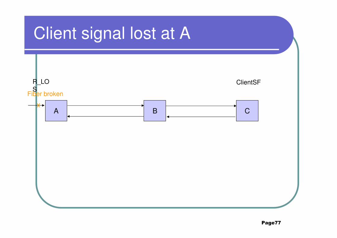
Client signal lost at A
A B Cx
Fiber broken
ClientSFR_LOS
Page78
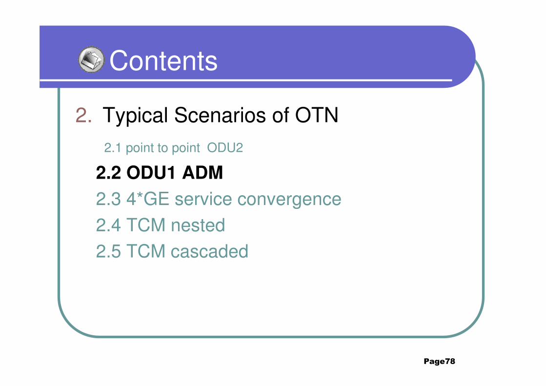
Contents
2. Typical Scenarios of OTN2.1 point to point ODU2
2.2 ODU1 ADM
2.3 4*GE service convergence
2.4 TCM nested2.5 TCM cascaded
Page79
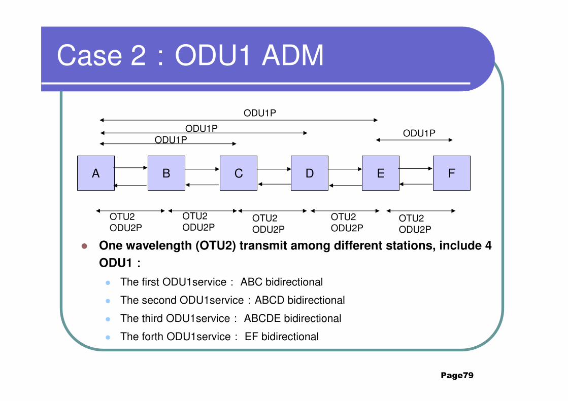
Case 2:ODU1 ADM
� One wavelength (OTU2) transmit among different stations, include 4
ODU1::::
� The first ODU1service: ABC bidirectional
� The second ODU1service:ABCD bidirectional
� The third ODU1service: ABCDE bidirectional
� The forth ODU1service: EF bidirectional
A B C D E F
ODU1P
ODU1PODU1P
ODU1P
OTU2ODU2P
OTU2ODU2P
OTU2ODU2P
OTU2ODU2P
OTU2ODU2P
Page80
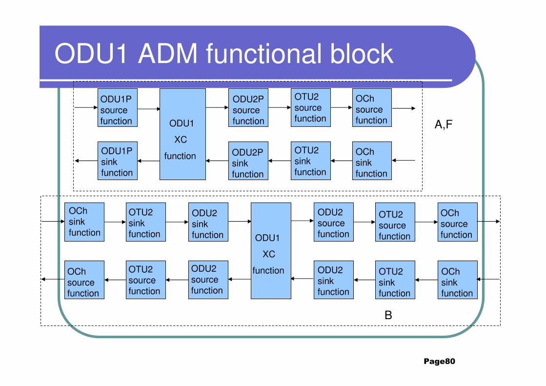
ODU1 ADM functional blockOCh source function
ODU2P source function
OTU2 source function
ODU2P sink function
OTU2 sink function
OCh sink function
ODU2 source function
OTU2 source function
ODU2 sink function
OTU2 sink function
OCh source function
OCh sink function
ODU1P source function
ODU1P sink function
ODU1
XC
function
OCh sink function
OTU2 sink function
OCh source function
OTU2 source function
ODU2 sink function
ODU2 source function
ODU1
XC
function
A,F
B
Page81
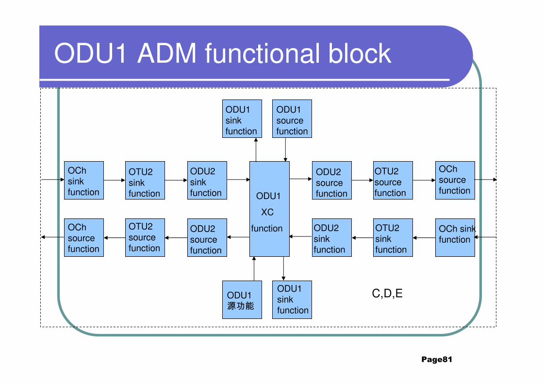
ODU1 ADM functional block
ODU2 source function
OTU2 source function
ODU2 sink function
OTU2 sink function
OCh source function
OCh sink function
OCh sink function
OTU2 sink function
OCh source function
OTU2 source function
ODU2 sink function
ODU2 source function
ODU1
XC
function
ODU1 source function
ODU1 sink function
ODU1 sink function
ODU1 源功能
C,D,E
Page82
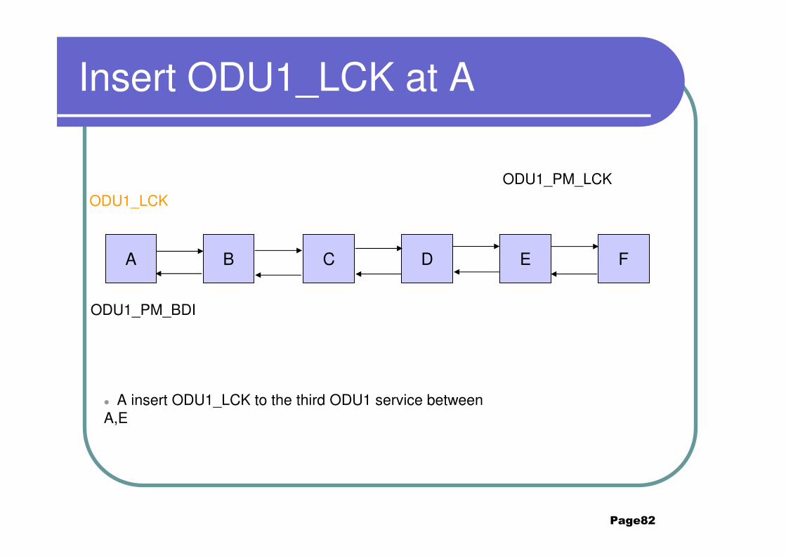
Insert ODU1_LCK at A
A B C D E F
ODU1_LCK
ODU1_PM_LCK
ODU1_PM_BDI
� A insert ODU1_LCK to the third ODU1 service between A,E
Page83
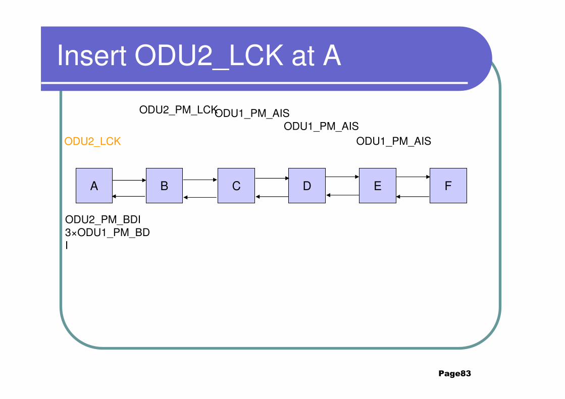
Insert ODU2_LCK at A
A B C D E F
ODU2_LCK
ODU2_PM_LCK
ODU2_PM_BDI3×ODU1_PM_BDI
ODU1_PM_AISODU1_PM_AIS
ODU1_PM_AIS
Page84
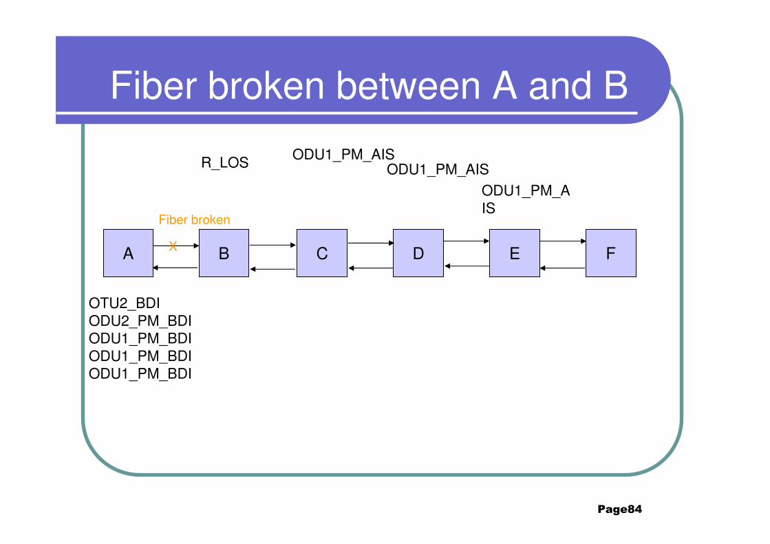
Fiber broken between A and B
A B C D E F
OTU2_BDIODU2_PM_BDIODU1_PM_BDIODU1_PM_BDIODU1_PM_BDI
R_LOS
Fiber broken
X
ODU1_PM_AIS
ODU1_PM_AISODU1_PM_AIS
Page85
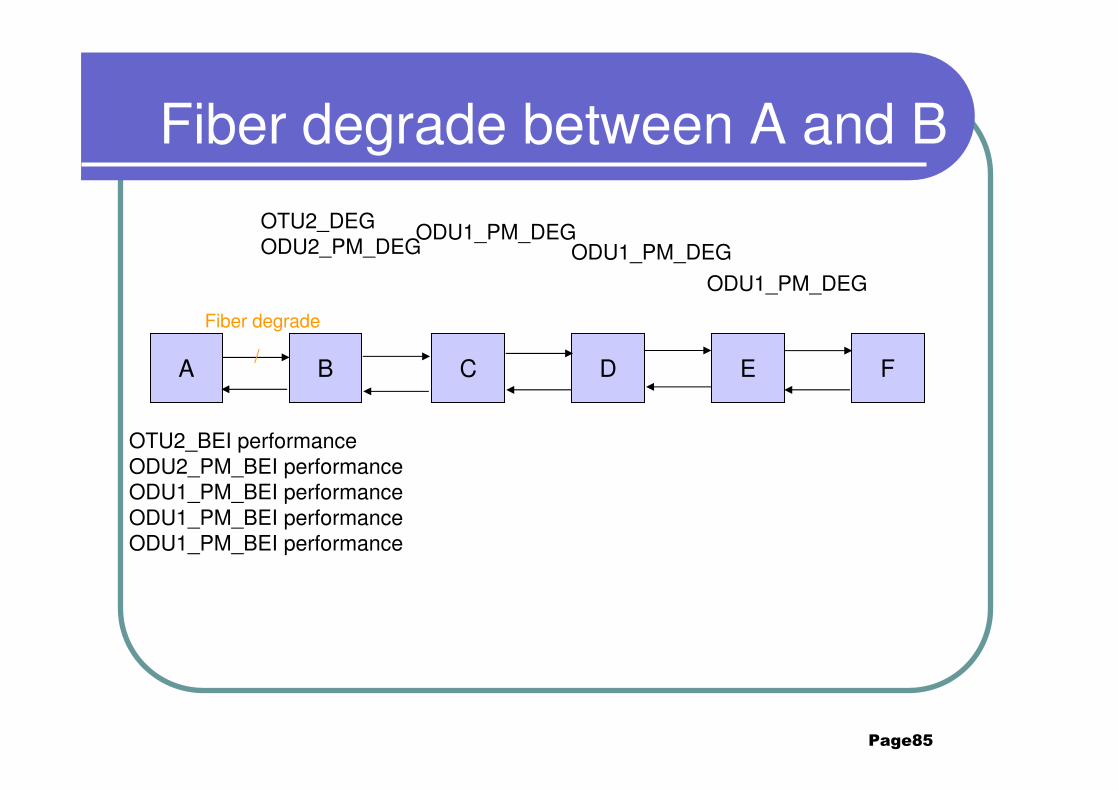
Fiber degrade between A and B
A B C D E F
OTU2_DEGODU2_PM_DEG
ODU1_PM_DEGODU1_PM_DEG
ODU1_PM_DEG
/
Fiber degrade
OTU2_BEI performanceODU2_PM_BEI performanceODU1_PM_BEI performanceODU1_PM_BEI performanceODU1_PM_BEI performance
Page86
Contents
2. Typical Scenarios of OTN2.1 point to point ODU2
2.2 ODU1 ADM 2.3 4*GE service convergence
2.4 TCM nested2.5 TCM cascaded

Page87
Case 3:4*GE service convergence
� 4*GE service converge at node C using one wavelength (5G) in
network:
� The first GE service : BC bidirectional
� The second GE service: ABC bidirectional
� The third GE service: DC bidirectional
� The forth GE service: EDC bidirectional
A B C D E
GE GE
GE GE
OTU5GODU5G
OTU5GODU5G
OTU5GODU5G
OTU5GODU5G

Page88
Functional blockOCh source function
ODU5G source function
OTU5G source function
ODU5G sink function
OTU5G sink function
OCh sink function
ODU5G source function
OTU5G source function
ODU5G sink function
OTU5G sink function
OCh source function
OCh sink function
GE
XC
function
OCh sink function
OTU5G sink function
OCh source function
OTU5G source function
ODU5G sink function
ODU5G source function
GE
XC
function
A,E
B,C,D
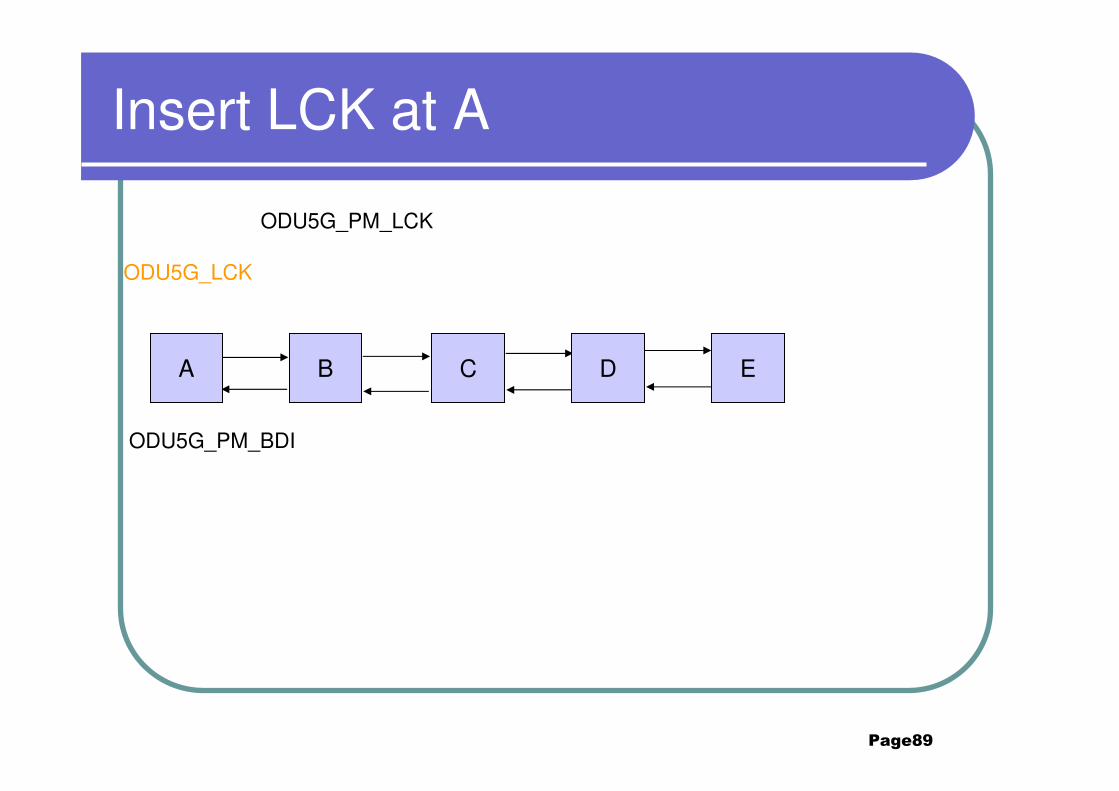
Page89
Insert LCK at A
ODU5G_PM_LCK
ODU5G_LCK
ODU5G_PM_BDI
A B C D E
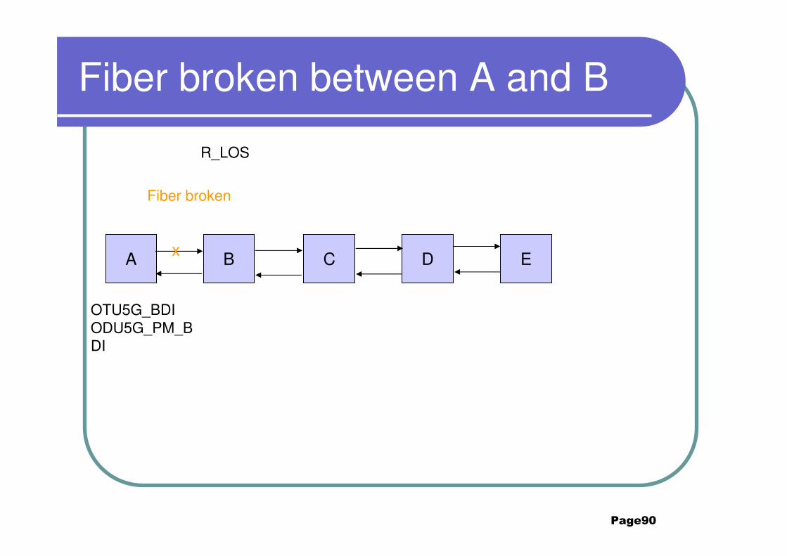
Page90
Fiber broken between A and B
A B C D E
Fiber broken
OTU5G_BDIODU5G_PM_BDI
x
R_LOS
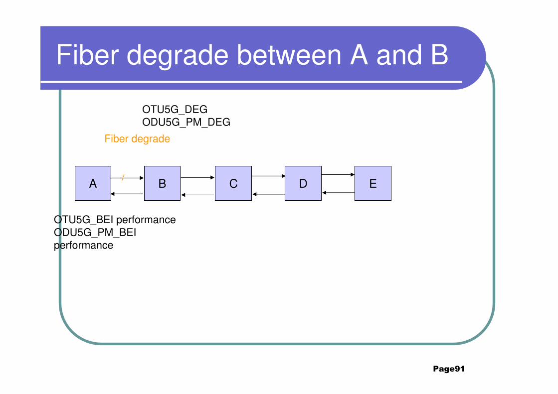
Page91
Fiber degrade between A and B
A B C D E
Fiber degrade
OTU5G_BEI performanceODU5G_PM_BEI performance
/
OTU5G_DEGODU5G_PM_DEG
Page92
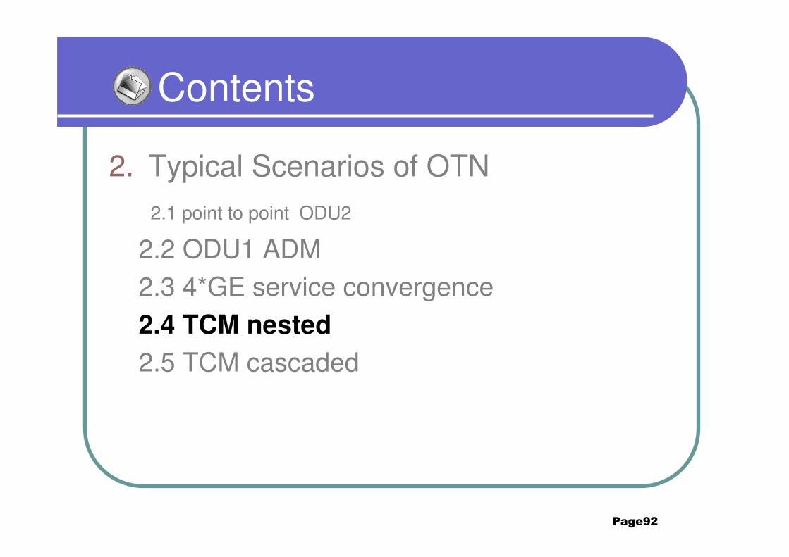
Contents
2. Typical Scenarios of OTN2.1 point to point ODU2
2.2 ODU1 ADM 2.3 4*GE service convergence
2.4 TCM nested
2.5 TCM cascaded
Page93
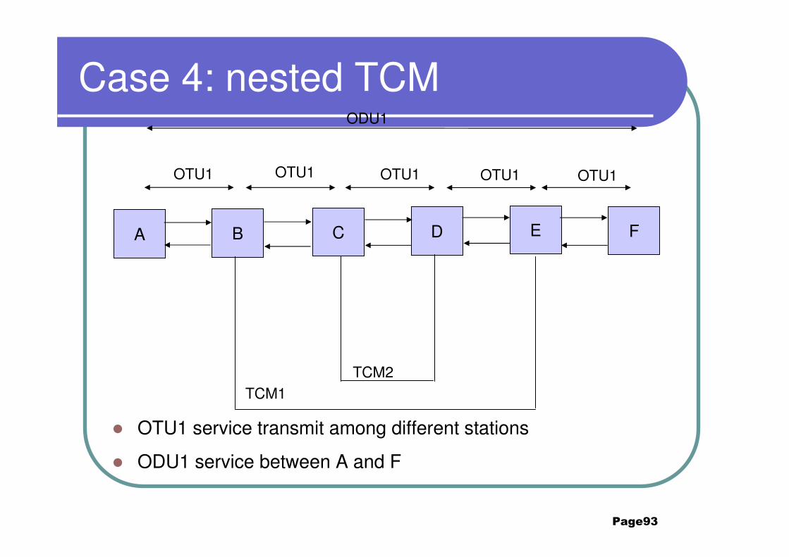
Case 4: nested TCM
� OTU1 service transmit among different stations
� ODU1 service between A and F
A B C D E F
TCM2TCM1
OTU1 OTU1OTU1OTU1OTU1
ODU1

Page94
OCh sink function
OTU1 sink function
OCh source function
OTU1 source function
Functional block
TCM1 source function
OTU1 source function
TCM1 sink function
OTU1 sink function
OCh source function
OCh sink function
ODU1P source function
ODU1P sink function
ODU1
XC function
OCh sink function
OCh source function
OTU1 sink function
OTU1 source function
ODU1
XC function
B
TCM2 source function
OTU1 source function
TCM2 sink function
OTU1 sink function
OCh source function
OCh sink function
OCh sink function
OCh source function
OTU1 sink function
OTU1 source function
ODU1
XC function
A,F
C
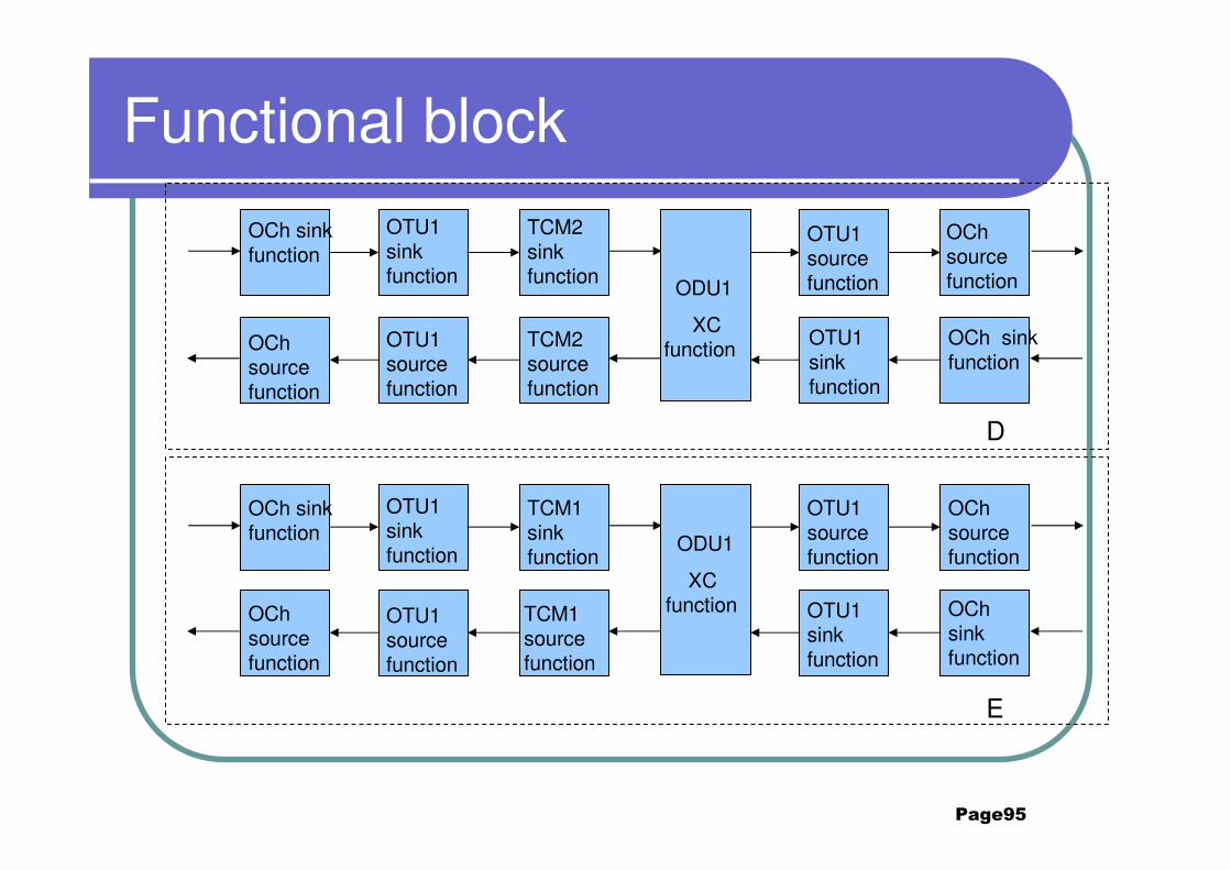
Page95
Functional block
OTU1 source function
OTU1 sink function
OCh source function
OCh sink function
OCh sink function
OTU1 sink function
OCh source function
OTU1 source function
TCM2 sink function
TCM2 source function
ODU1
XC function
OTU1 source function
OTU1 sink function
OCh source function
OCh sink function
OCh sink function
OTU1 sink function
OCh source function
OTU1 source function
TCM1 sink function
TCM1 source function
ODU1
XC function
D
E
Page96
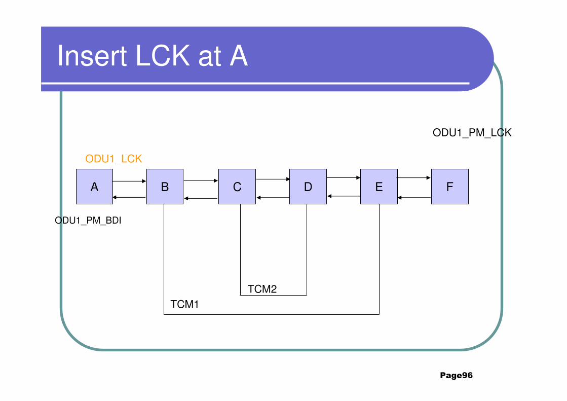
Insert LCK at A
A B C D E F
ODU1_LCK
ODU1_PM_LCK
ODU1_PM_BDI
TCM2TCM1
Page97
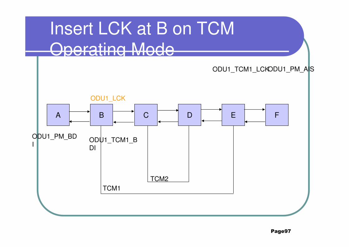
Insert LCK at B on TCM Operating Mode
A B C D E F
ODU1_LCK
ODU1_TCM1_LCKODU1_PM_AIS
ODU1_PM_BDI
ODU1_TCM1_BDI
TCM2TCM1
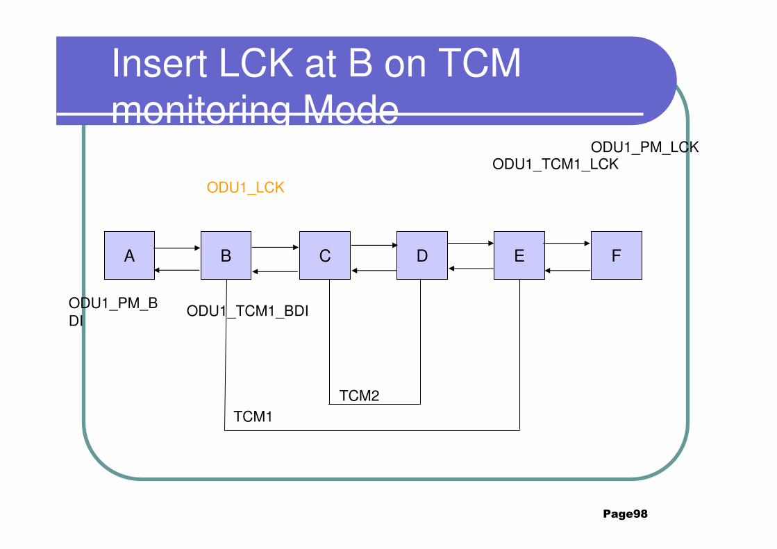
Page98
Insert LCK at B on TCM monitoring Mode
A B C D E F
ODU1_LCK
ODU1_TCM1_LCKODU1_PM_LCK
ODU1_PM_BDI
ODU1_TCM1_BDI
TCM2TCM1
Page99
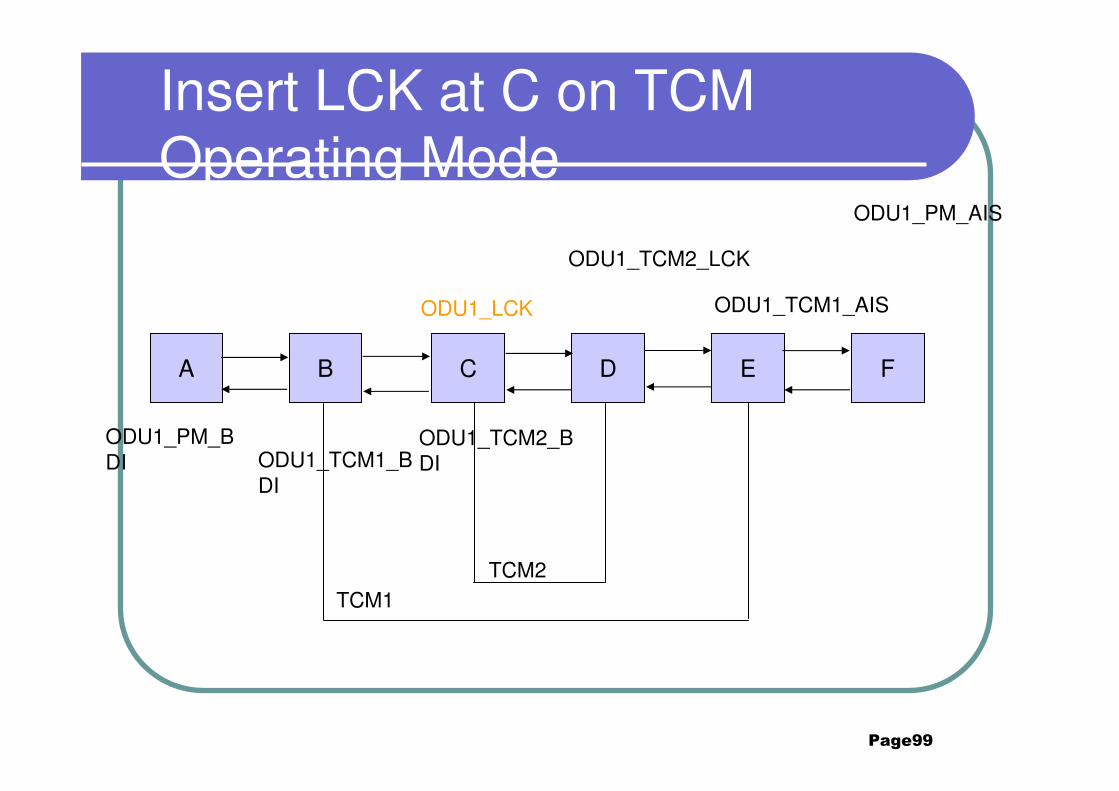
Insert LCK at C on TCM Operating Mode
A B C D E F
ODU1_LCK
ODU1_TCM2_LCK
ODU1_TCM1_AIS
ODU1_PM_AIS
ODU1_PM_BDI ODU1_TCM1_B
DI
ODU1_TCM2_BDI
TCM2TCM1
Page100
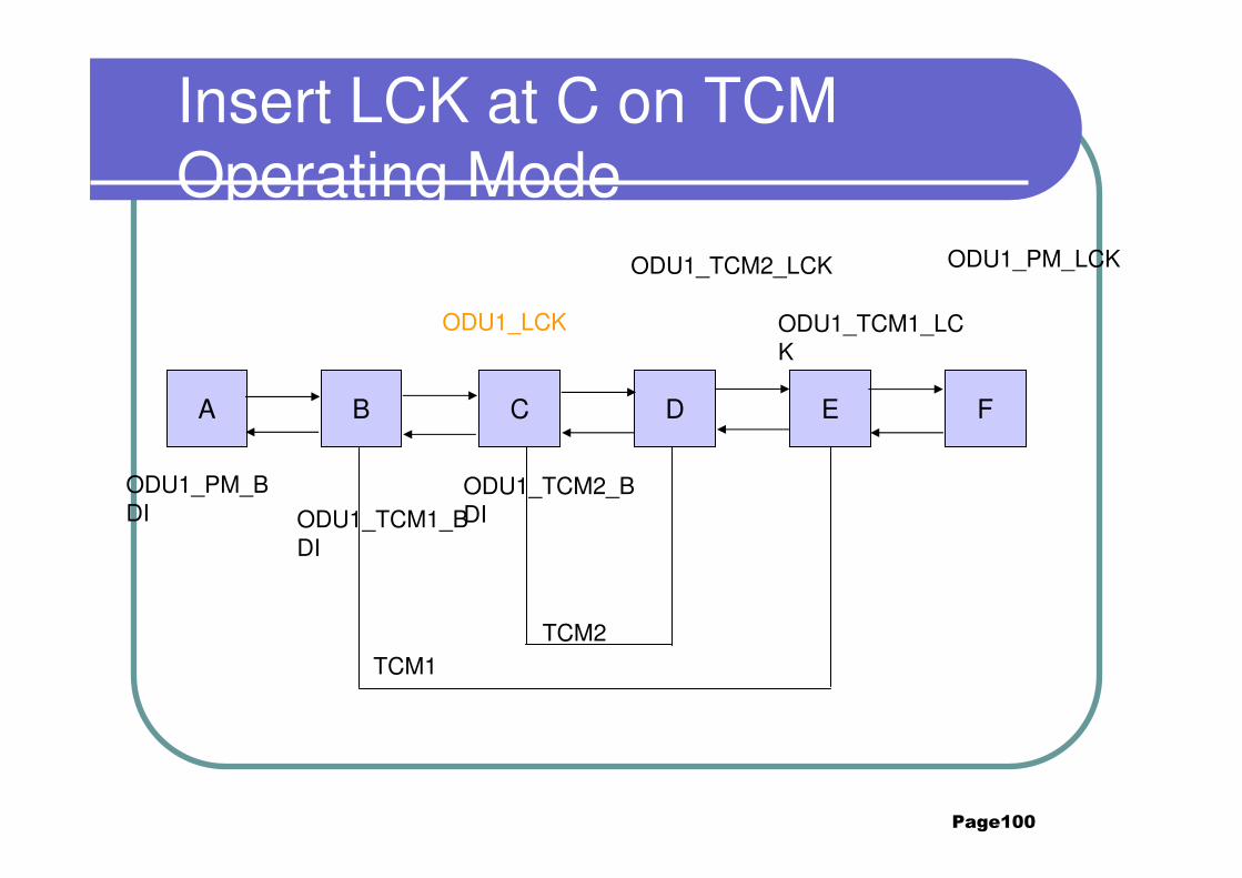
Insert LCK at C on TCM Operating Mode
A B C D E F
ODU1_LCK
ODU1_TCM2_LCK
ODU1_TCM1_LCK
ODU1_PM_LCK
ODU1_PM_BDI ODU1_TCM1_B
DI
ODU1_TCM2_BDI
TCM2TCM1
Page101
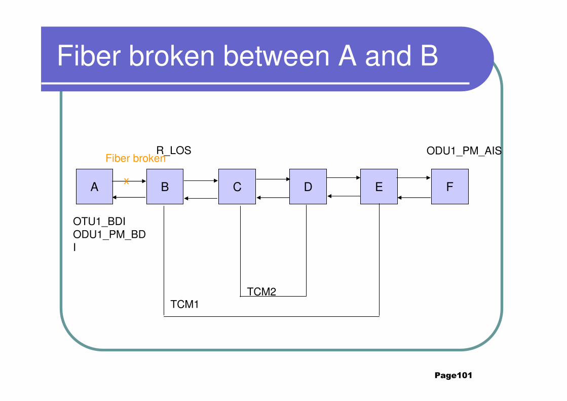
Fiber broken between A and B
A B C D E F
Fiber brokenR_LOS ODU1_PM_AIS
x
OTU1_BDIODU1_PM_BDI
TCM2TCM1
Page102
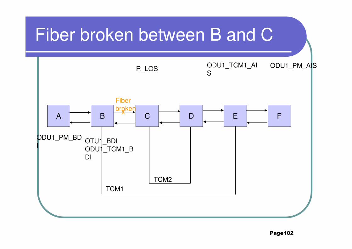
Fiber broken between B and C
A B C D E F
Fiber broken
R_LOS ODU1_PM_AIS
x
ODU1_TCM1_AIS
ODU1_PM_BDI
OTU1_BDIODU1_TCM1_BDI
TCM2TCM1
Page103
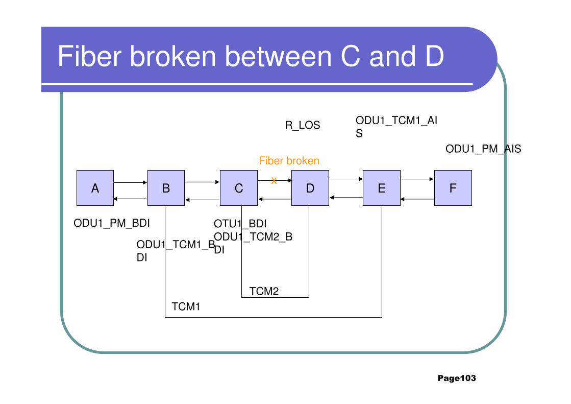
Fiber broken between C and D
A B C D E F
Fiber broken
R_LOS
ODU1_PM_AIS
x
ODU1_TCM1_AIS
ODU1_PM_BDI
ODU1_TCM1_BDI
OTU1_BDIODU1_TCM2_BDI
TCM2TCM1
Page104
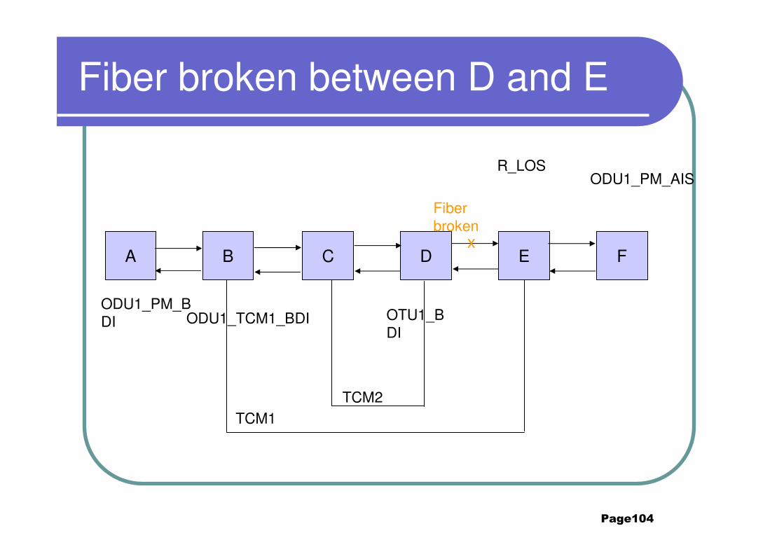
Fiber broken between D and E
A B C D E F
Fiber broken
R_LOSODU1_PM_AIS
x
ODU1_PM_BDI ODU1_TCM1_BDI OTU1_B
DI
TCM2TCM1
Page105
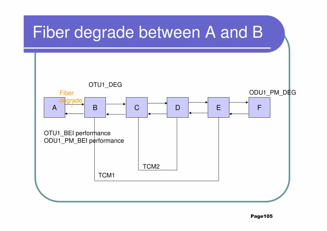
Fiber degrade between A and B
A B C D E F
ODU1_PM_DEGFiber degrade
/
OTU1_DEG
OTU1_BEI performanceODU1_PM_BEI performance
TCM2TCM1
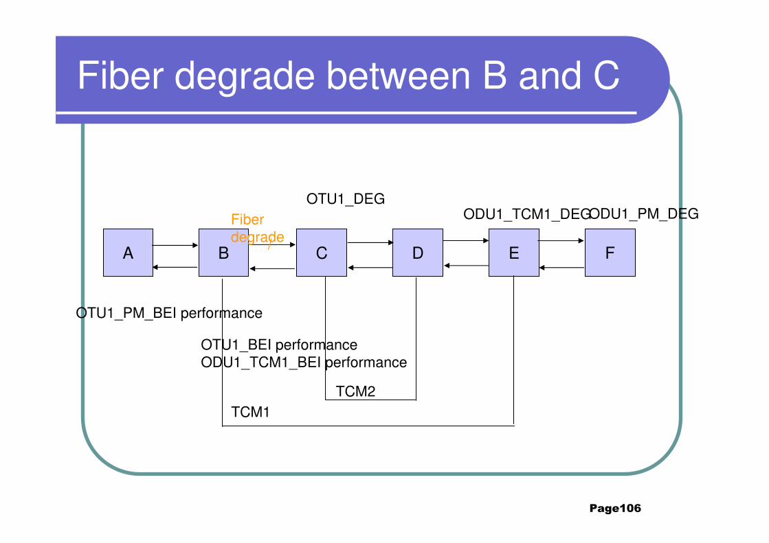
Page106
Fiber degrade between B and C
A B C D E F
ODU1_PM_DEGFiber degrade/
OTU1_DEGODU1_TCM1_DEG
OTU1_PM_BEI performance
OTU1_BEI performanceODU1_TCM1_BEI performance
TCM2TCM1
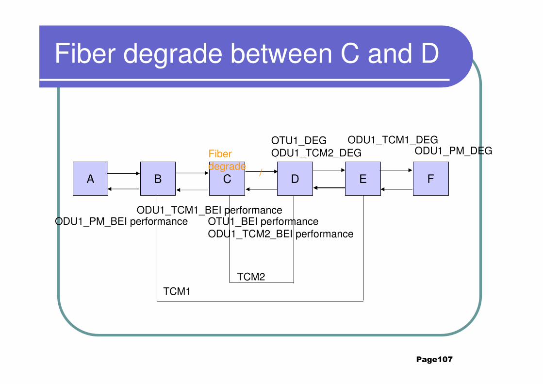
Page107
Fiber degrade between C and D
A B C D E F
ODU1_PM_DEGFiber degrade
/
ODU1_TCM1_DEGOTU1_DEGODU1_TCM2_DEG
ODU1_TCM1_BEI performanceODU1_PM_BEI performance OTU1_BEI performance
ODU1_TCM2_BEI performance
TCM2TCM1

Page108
Without TCM1 source on operating mode
A B C D E F
ODU1_PM_AIS
Without TCM1 source ODU1_TCM1_LTCODU1_TCM1_TIM
ODU1_PM_BDI ODU1_TCM1_BD
I
TCM2TCM1
Page109
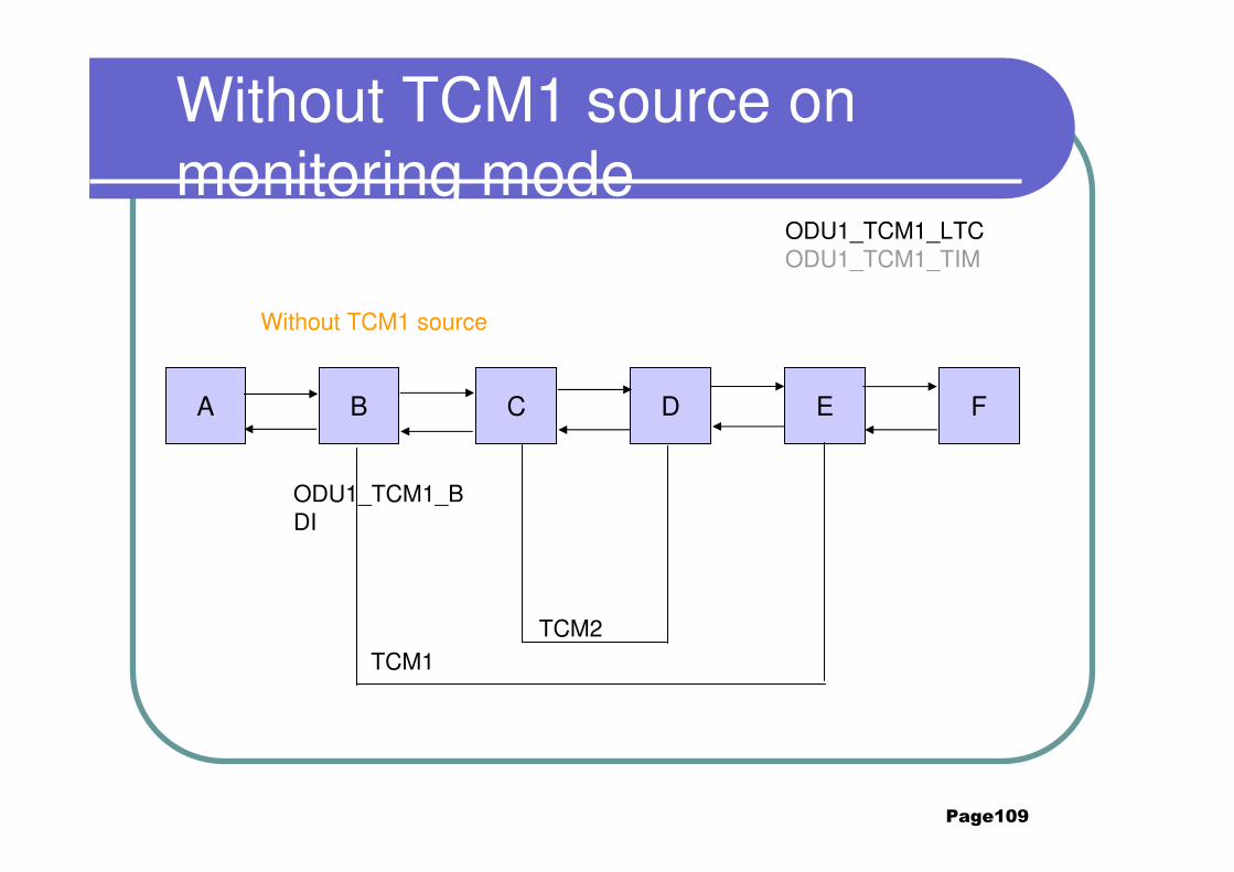
Without TCM1 source on monitoring mode
A B C D E F
Without TCM1 source
ODU1_TCM1_LTCODU1_TCM1_TIM
ODU1_TCM1_BDI
TCM2TCM1
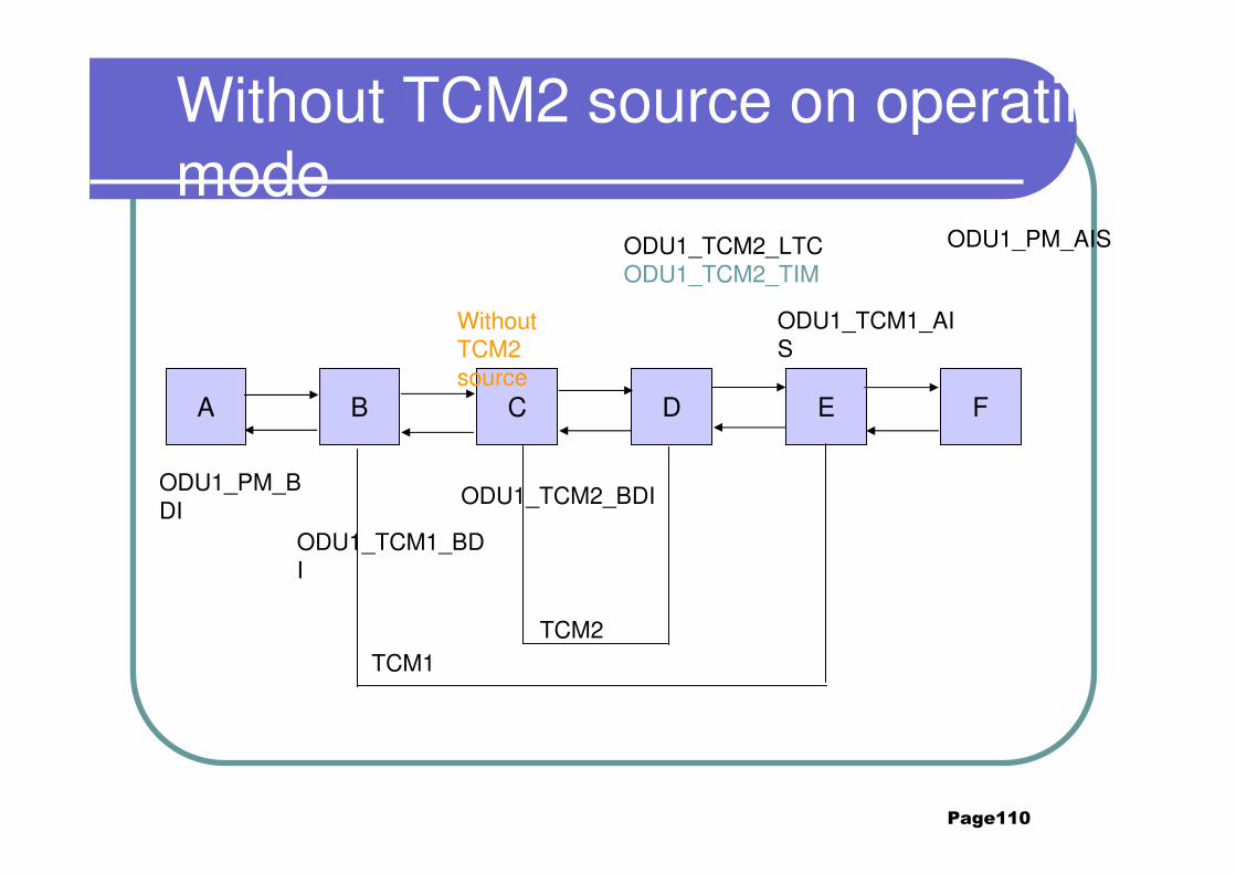
Page110
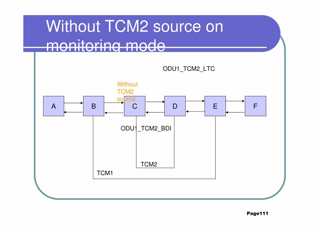
Without TCM2 source on operating mode
A B C D E F
ODU1_PM_AIS
Without TCM2 source
ODU1_TCM2_LTCODU1_TCM2_TIM
ODU1_PM_BDI
ODU1_TCM1_BDI
ODU1_TCM1_AIS
ODU1_TCM2_BDI
TCM2TCM1
Page111
Without TCM2 source on monitoring mode
A B C D E F
Without TCM2 source
ODU1_TCM2_LTC
ODU1_TCM2_BDI
TCM2TCM1
Page112
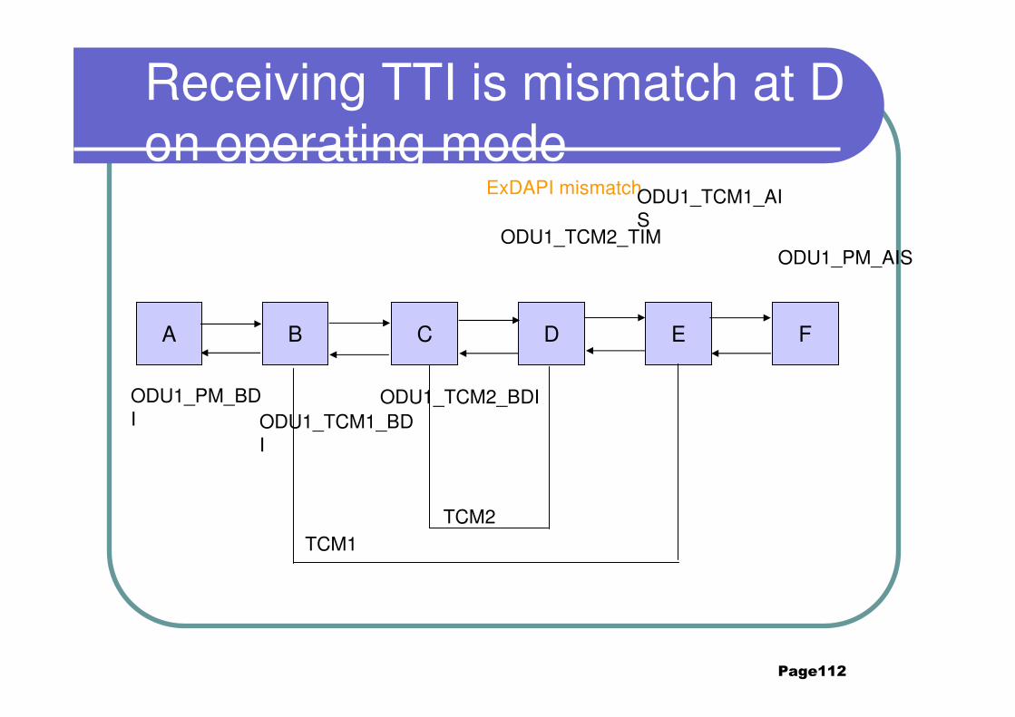
Receiving TTI is mismatch at D on operating mode
A B C D E F
ODU1_PM_AIS
ExDAPI mismatchODU1_TCM1_AIS
ODU1_TCM2_TIM
ODU1_PM_BDI ODU1_TCM1_BD
I
ODU1_TCM2_BDI
TCM2TCM1
Page113
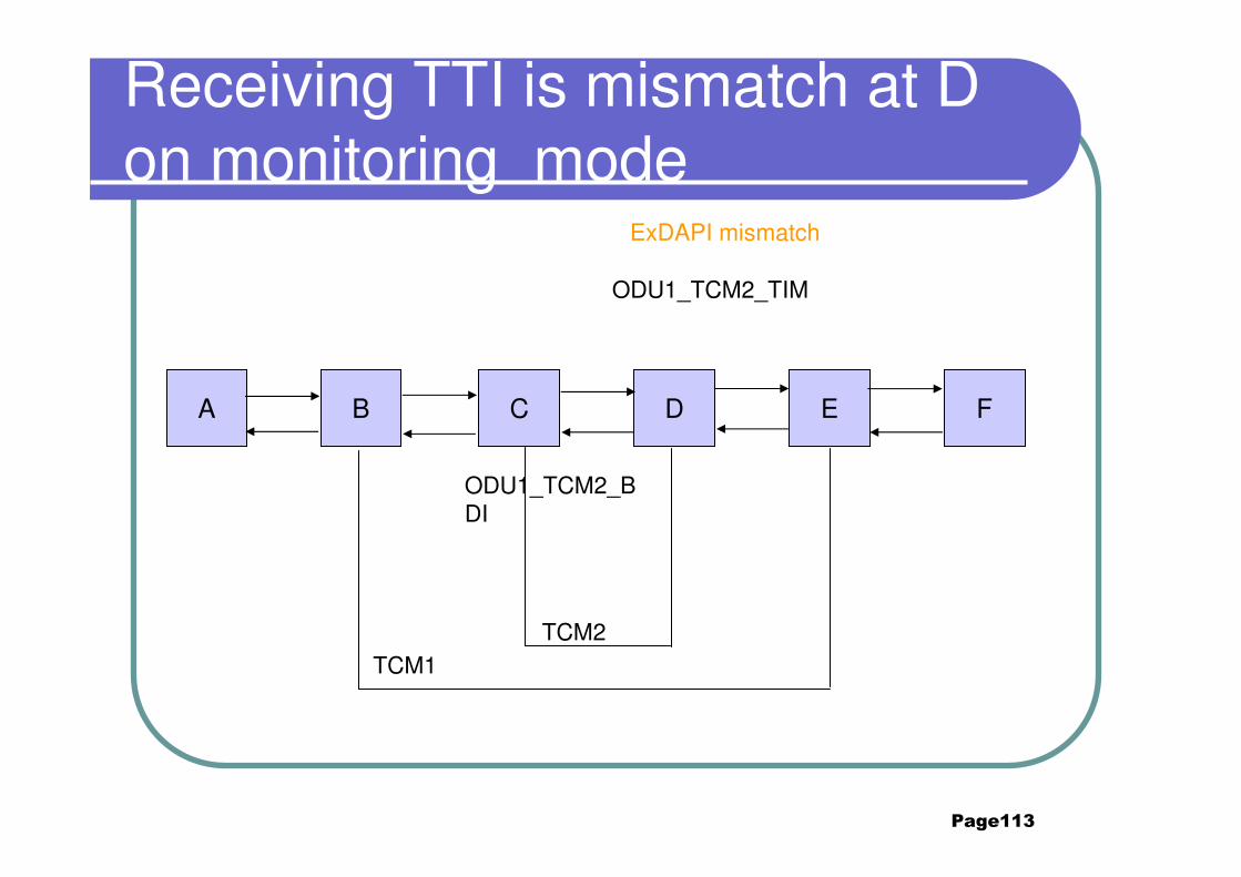
Receiving TTI is mismatch at D on monitoring mode
A B C D E F
ExDAPI mismatch
ODU1_TCM2_TIM
ODU1_TCM2_BDI
TCM2TCM1
Page114
Contents
2. Typical Scenarios of OTN2.1 point to point ODU2
2.2 ODU1 ADM 2.3 4*GE service convergence
2.4 TCM nested2.5 TCM cascaded
Page115
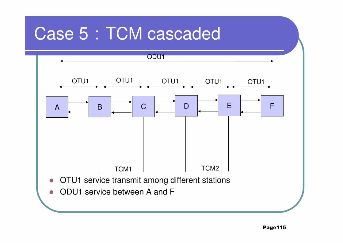
Case 5:TCM cascaded
� OTU1 service transmit among different stations� ODU1 service between A and F
A B C D E F
TCM1 TCM2
OTU1 OTU1OTU1OTU1OTU1
ODU1
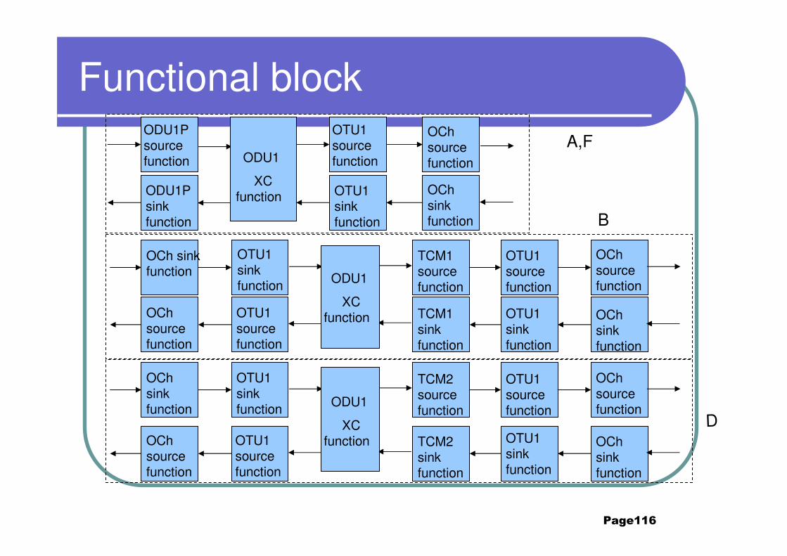
Page116
Functional block
OCh sink function
OTU1 sink function
OCh source function
OTU1 source function
TCM1 source function
OTU1 source function
TCM1 sink function
OTU1 sink function
OCh source function
OCh sink function
ODU1P source function
ODU1P sink function
ODU1
XC function
OCh sink function
OCh source function
OTU1 sink function
OTU1 source function
ODU1
XC function
B
TCM2 source function
OTU1 source function
TCM2 sink function
OTU1 sink function
OCh source function
OCh sink function
OCh sink function
OCh source function
OTU1 sink function
OTU1 source function
ODU1
XC function
A,F
D
Page117
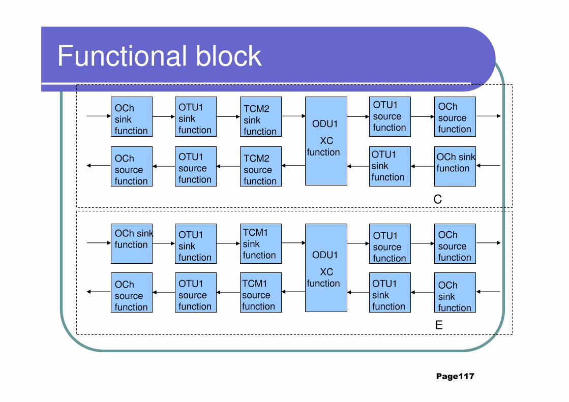
Functional block
OTU1 source function
OTU1 sink function
OCh source function
OCh sink function
OCh sink function
OTU1 sink function
OCh source function
OTU1 source function
TCM2 sink function
TCM2 source function
ODU1
XC function
OTU1 source function
OTU1 sink function
OCh source function
OCh sink function
OCh sink function
OTU1 sink function
OCh source function
OTU1 source function
TCM1 sink function
TCM1 source function
ODU1
XC function
C
E
Page118
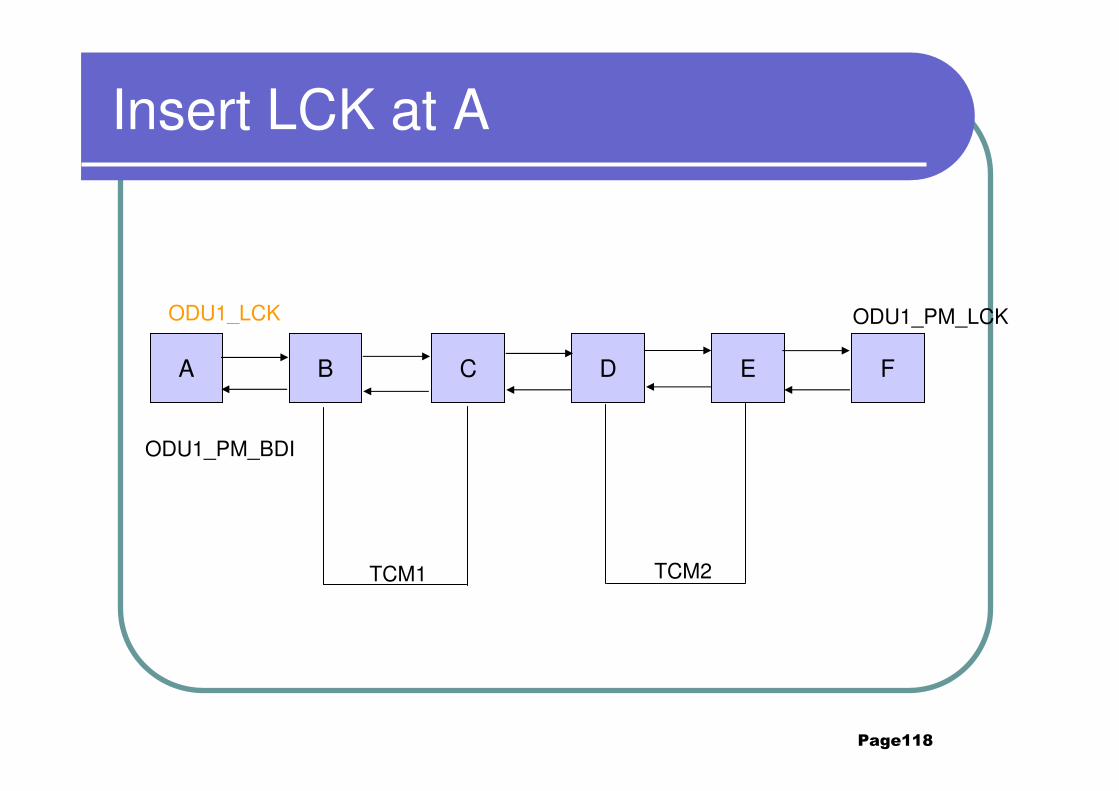
Insert LCK at A
A B C D E F
ODU1_LCK ODU1_PM_LCK
TCM1 TCM2
ODU1_PM_BDI
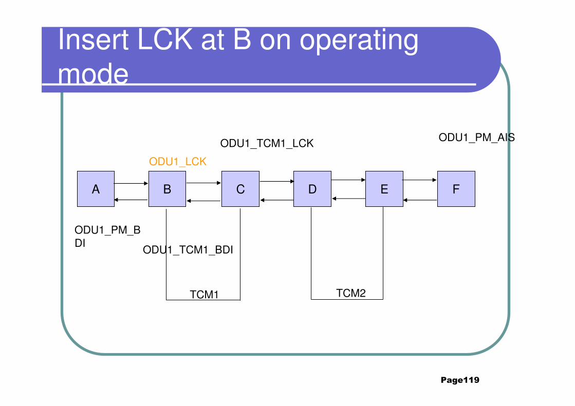
Page119
Insert LCK at B on operating mode
A B C D E F
ODU1_LCK
ODU1_TCM1_LCK ODU1_PM_AIS
ODU1_PM_BDI
ODU1_TCM1_BDI
TCM1 TCM2
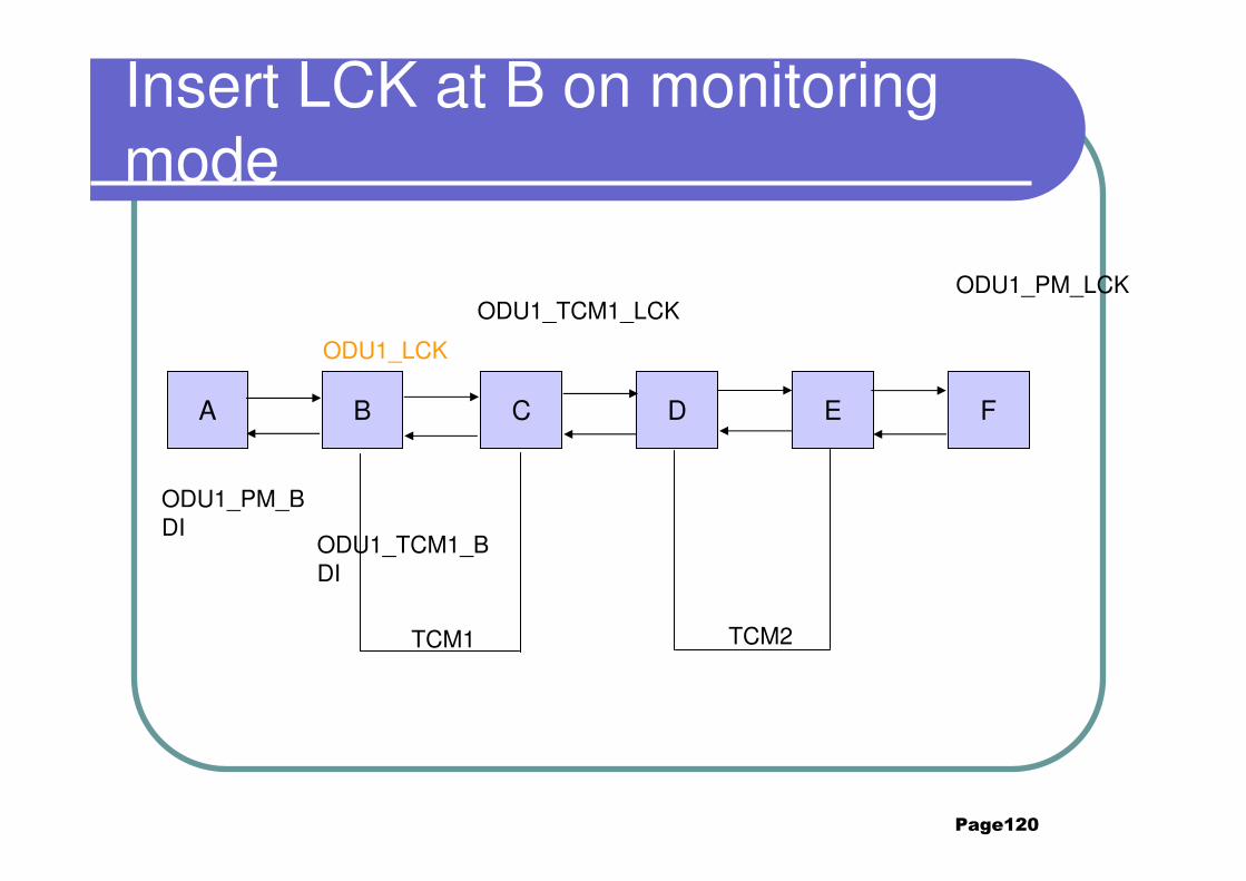
Page120
Insert LCK at B on monitoring mode
A B C D E F
ODU1_LCK
ODU1_TCM1_LCKODU1_PM_LCK
ODU1_PM_BDI
ODU1_TCM1_BDI
TCM1 TCM2
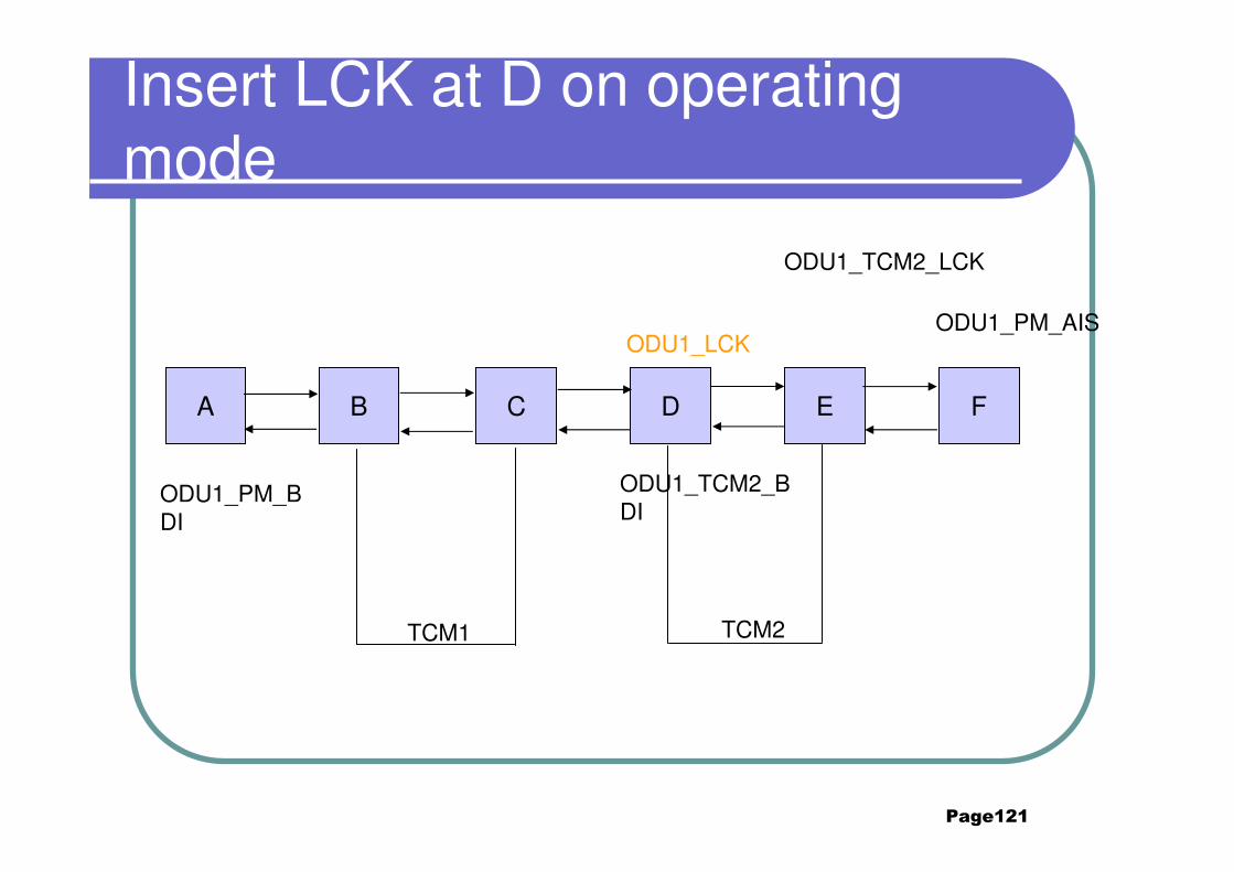
Page121
Insert LCK at D on operating mode
A B C D E F
ODU1_LCK
ODU1_TCM2_LCK
ODU1_PM_AIS
ODU1_PM_BDI
ODU1_TCM2_BDI
TCM1 TCM2
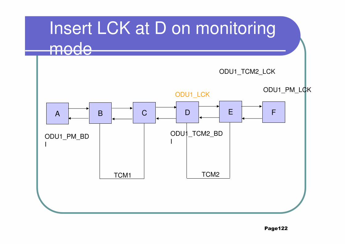
Page122
Insert LCK at D on monitoring mode
A B C D E F
ODU1_LCK
ODU1_TCM2_LCK
ODU1_PM_LCK
ODU1_PM_BDI
ODU1_TCM2_BDI
TCM1 TCM2
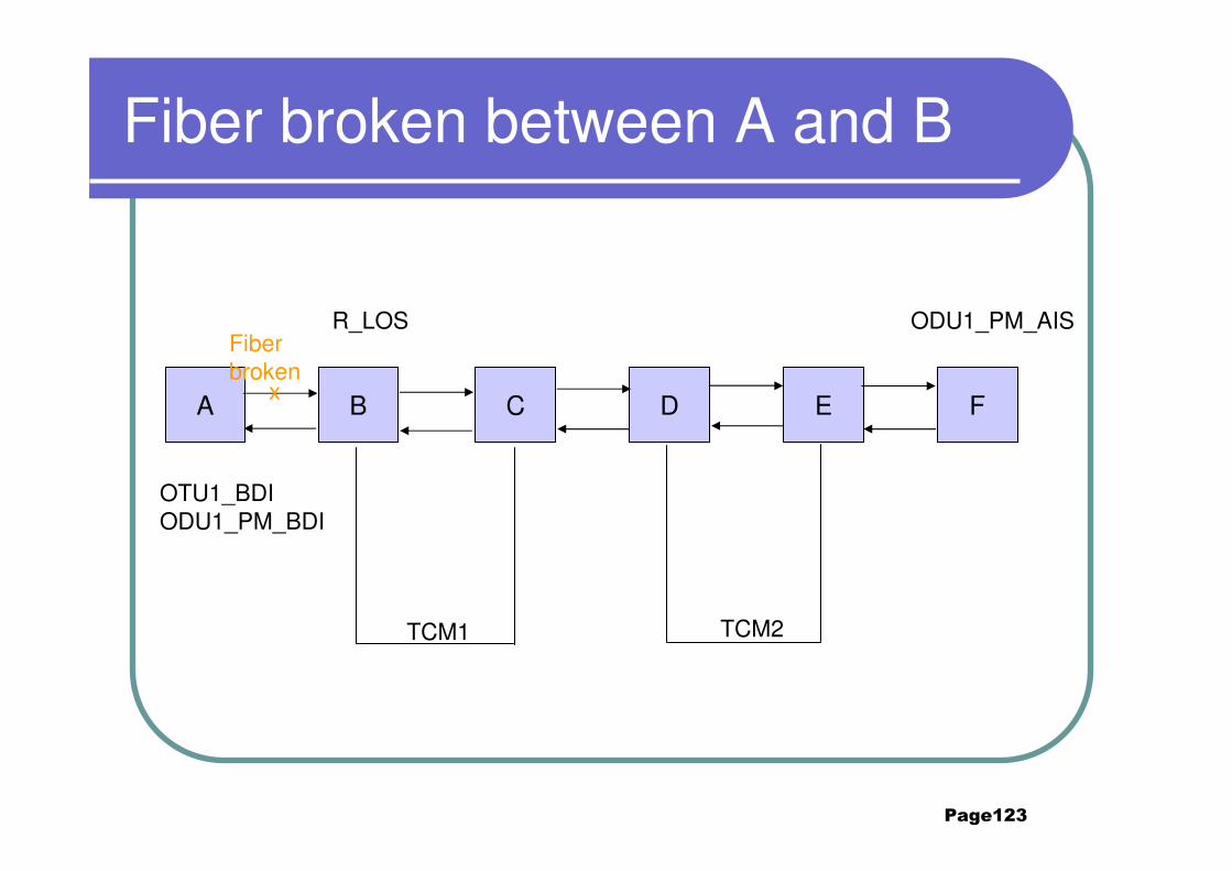
Page123
Fiber broken between A and B
A B C D E F
Fiber broken
R_LOS ODU1_PM_AIS
x
OTU1_BDIODU1_PM_BDI
TCM1 TCM2
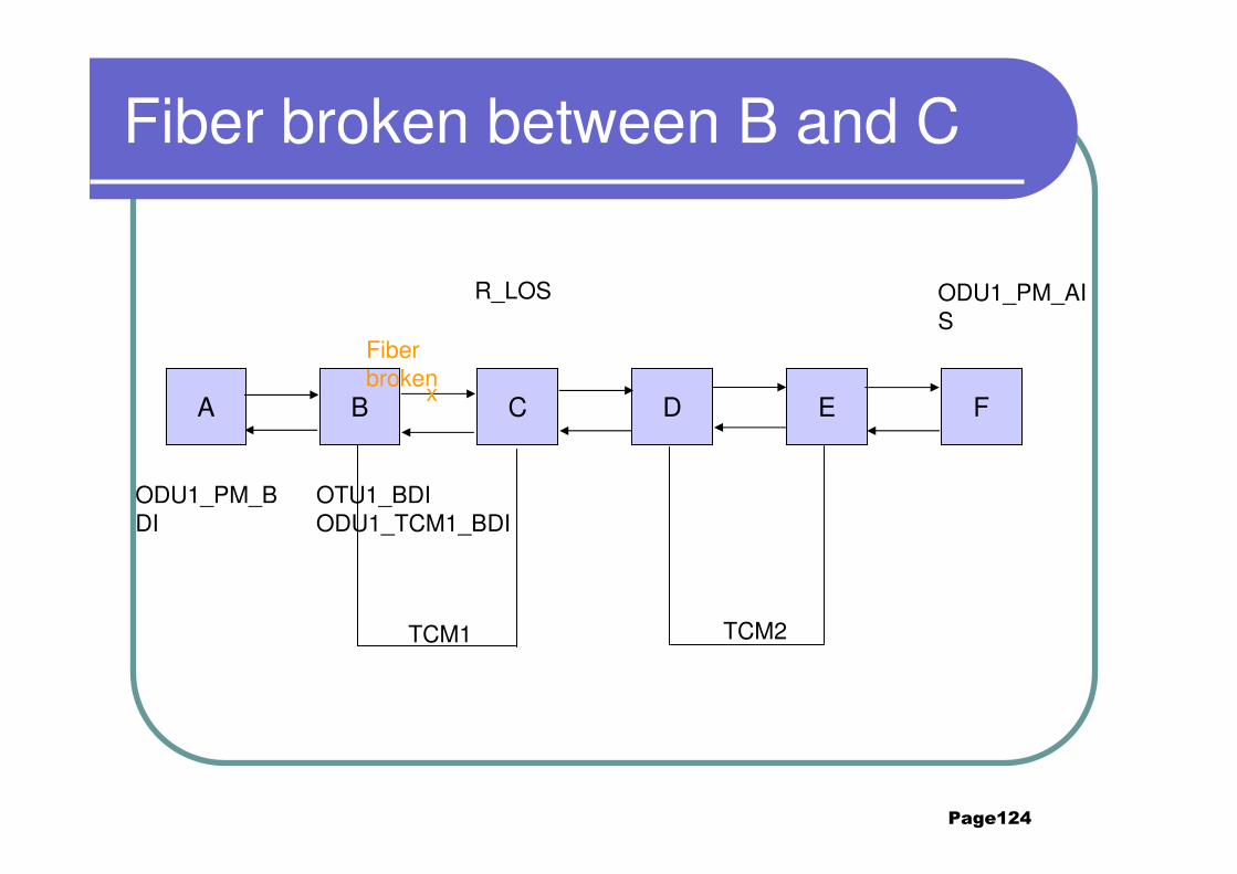
Page124
Fiber broken between B and C
A B C D E F
Fiber broken
R_LOS ODU1_PM_AIS
x
ODU1_PM_BDI
OTU1_BDIODU1_TCM1_BDI
TCM1 TCM2
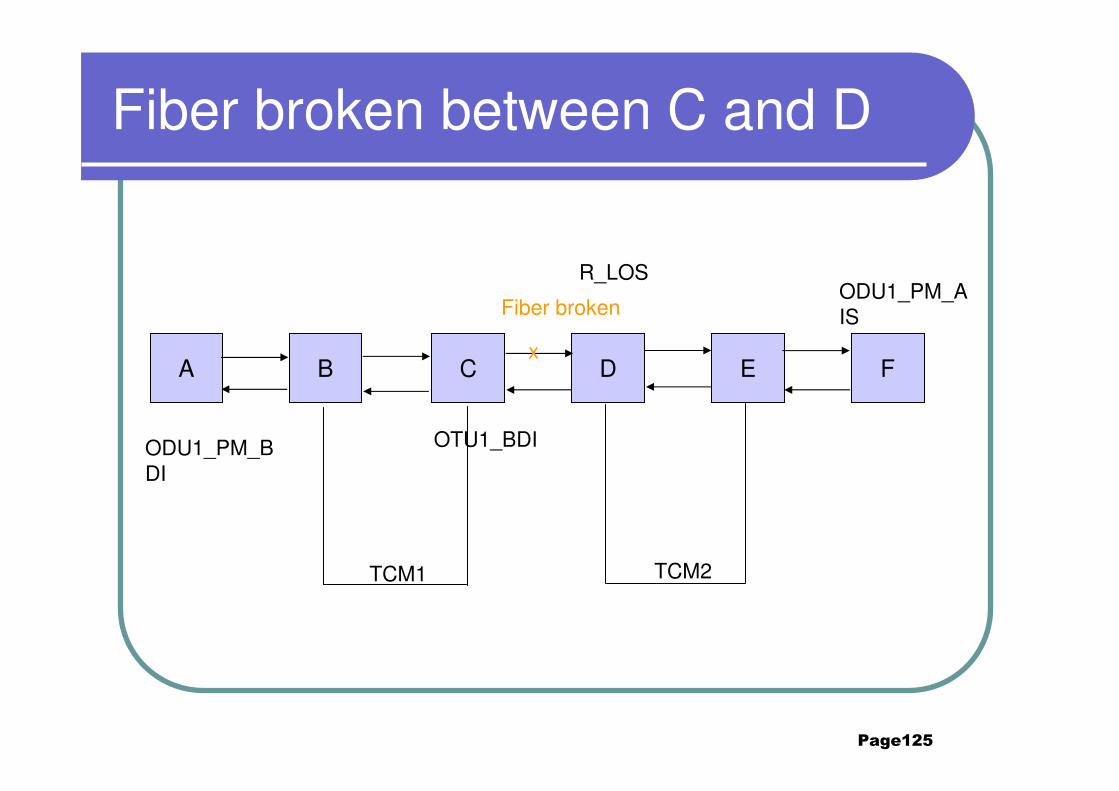
Page125
Fiber broken between C and D
A B C D E F
Fiber broken
R_LOSODU1_PM_AIS
x
ODU1_PM_BDI
OTU1_BDI
TCM1 TCM2
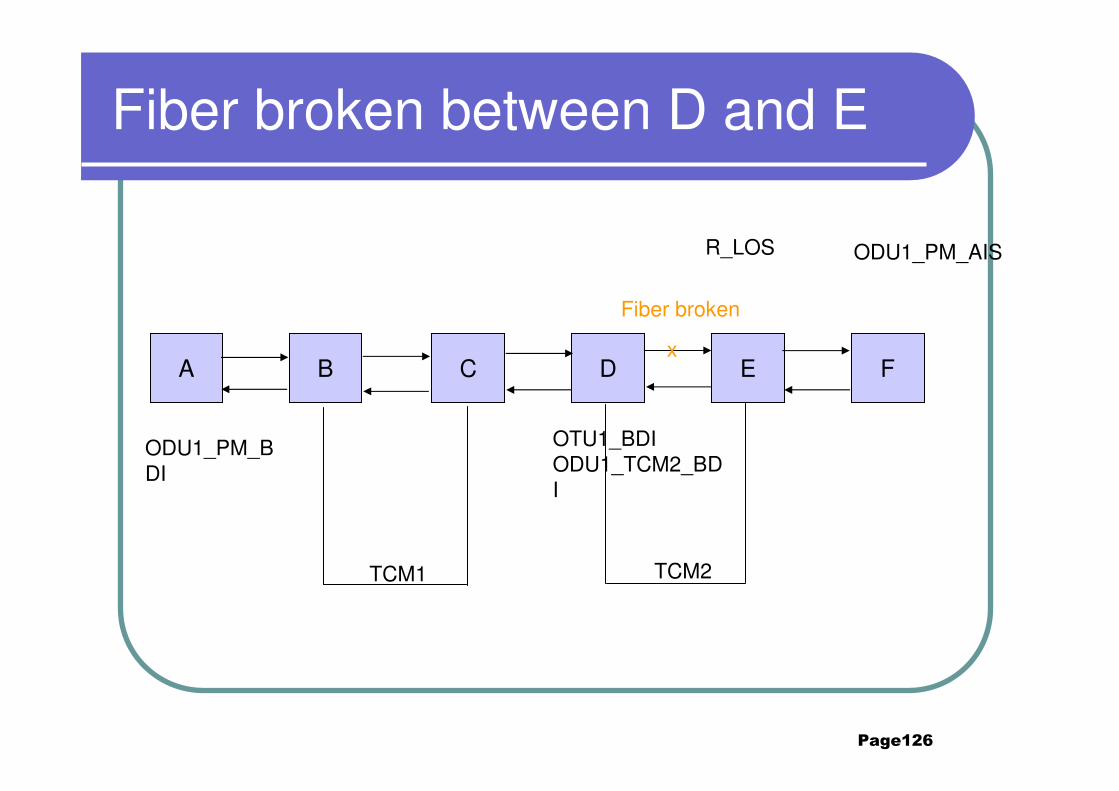
Page126
Fiber broken between D and E
A B C D E F
Fiber broken
R_LOS ODU1_PM_AIS
x
ODU1_PM_BDI
OTU1_BDIODU1_TCM2_BDI
TCM1 TCM2
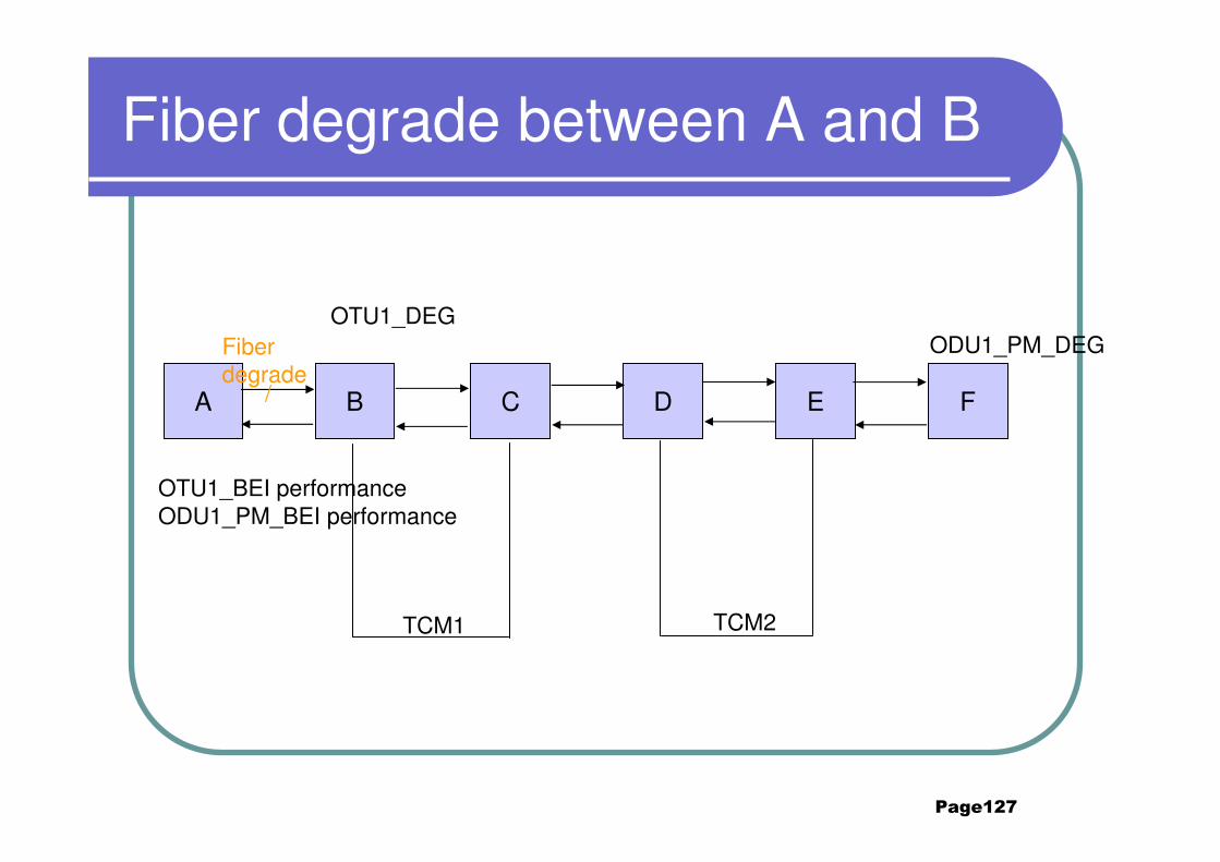
Page127
Fiber degrade between A and B
A B C D E F
ODU1_PM_DEGFiber degrade
/
OTU1_DEG
OTU1_BEI performanceODU1_PM_BEI performance
TCM1 TCM2
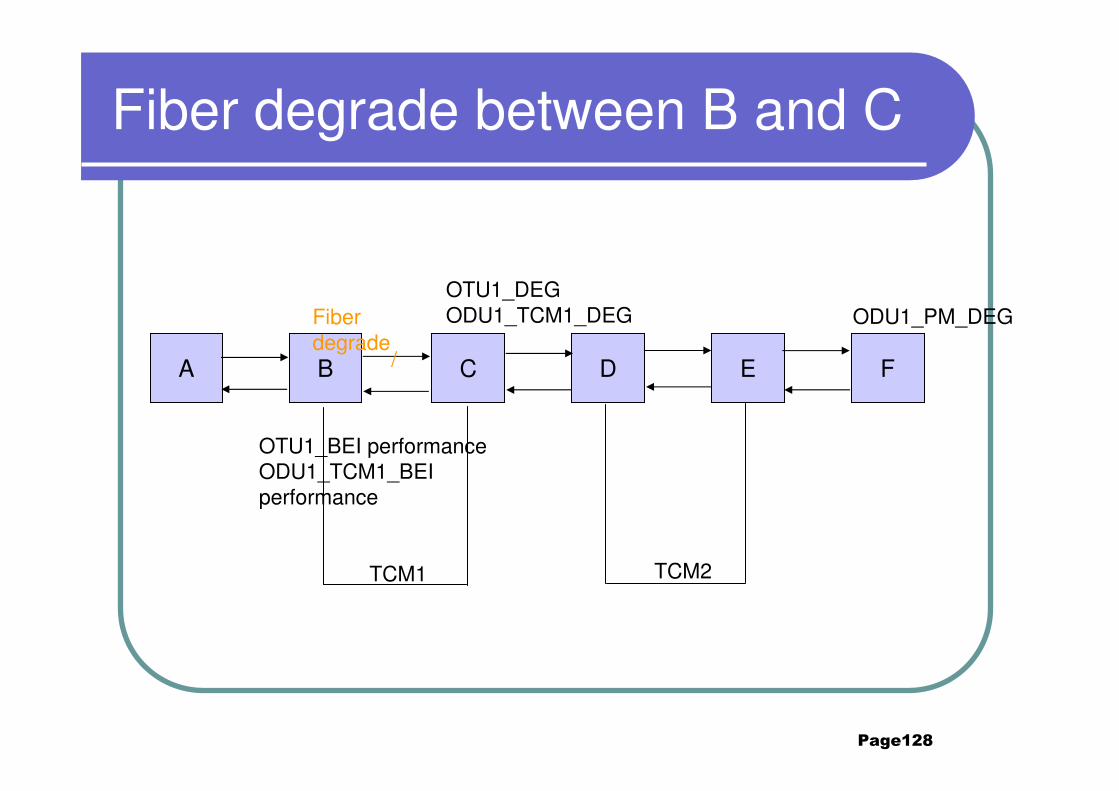
Page128
Fiber degrade between B and C
A B C D E F
ODU1_PM_DEGFiber degrade
/
OTU1_DEGODU1_TCM1_DEG
OTU1_BEI performanceODU1_TCM1_BEI performance
TCM1 TCM2
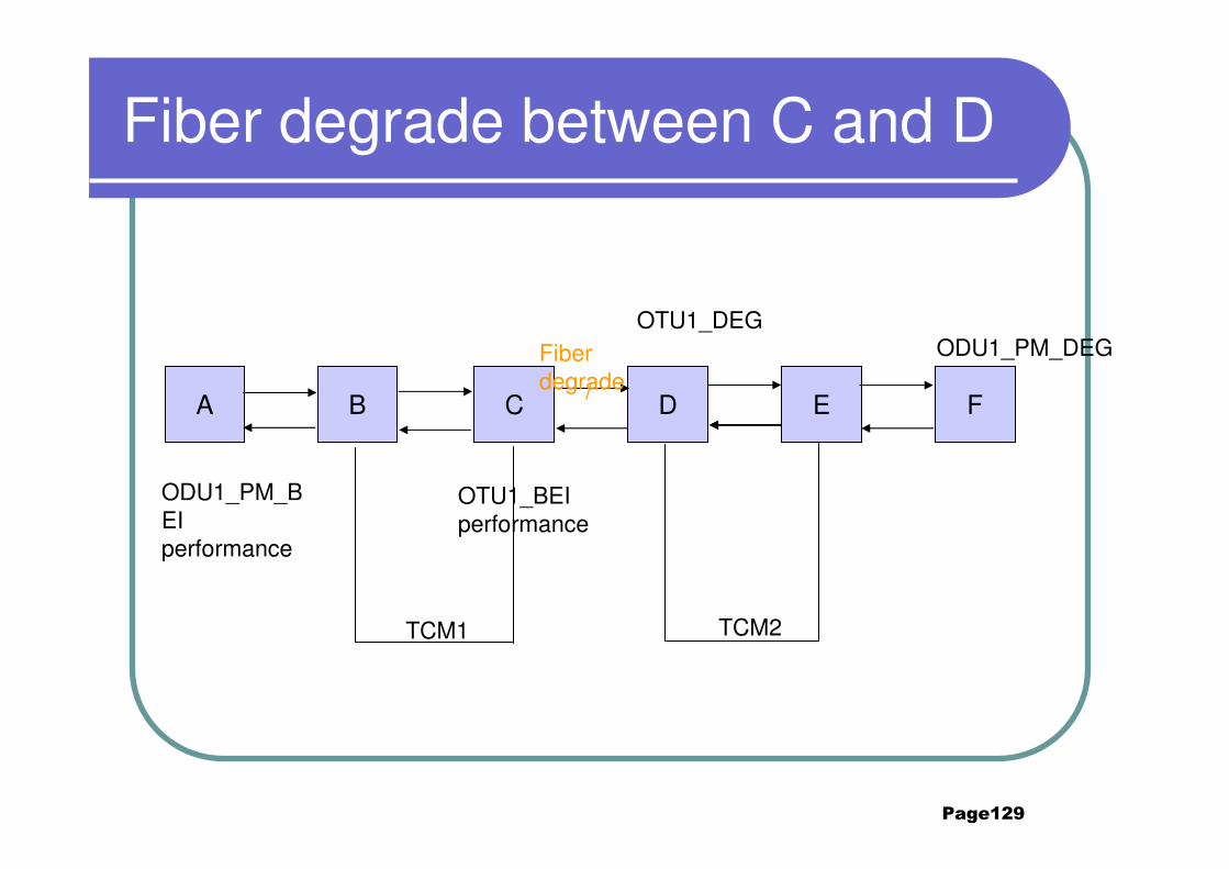
Page129
Fiber degrade between C and D
A B C D E F
ODU1_PM_DEGFiber degrade/
OTU1_DEG
OTU1_BEI performance
ODU1_PM_BEI performance
TCM1 TCM2
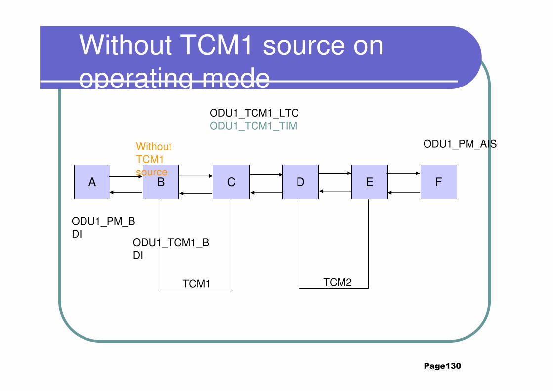
Page130
Without TCM1 source on operating mode
A B C D E F
ODU1_PM_AISWithout TCM1 source
ODU1_TCM1_LTCODU1_TCM1_TIM
ODU1_PM_BDI
ODU1_TCM1_BDI
TCM1 TCM2
Page131
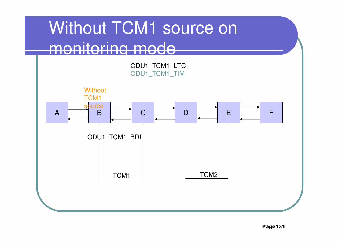
Without TCM1 source on monitoring mode
A B C D E F
Without TCM1 source
ODU1_TCM1_LTCODU1_TCM1_TIM
ODU1_TCM1_BDI
TCM1 TCM2
Page132
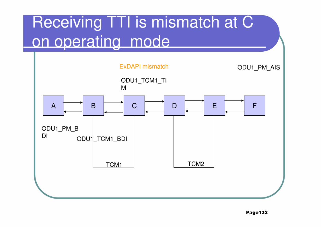
Receiving TTI is mismatch at C on operating mode
A B C D E F
ODU1_PM_AISExDAPI mismatch
ODU1_TCM1_TIM
ODU1_PM_BDI ODU1_TCM1_BDI
TCM1 TCM2
Page133
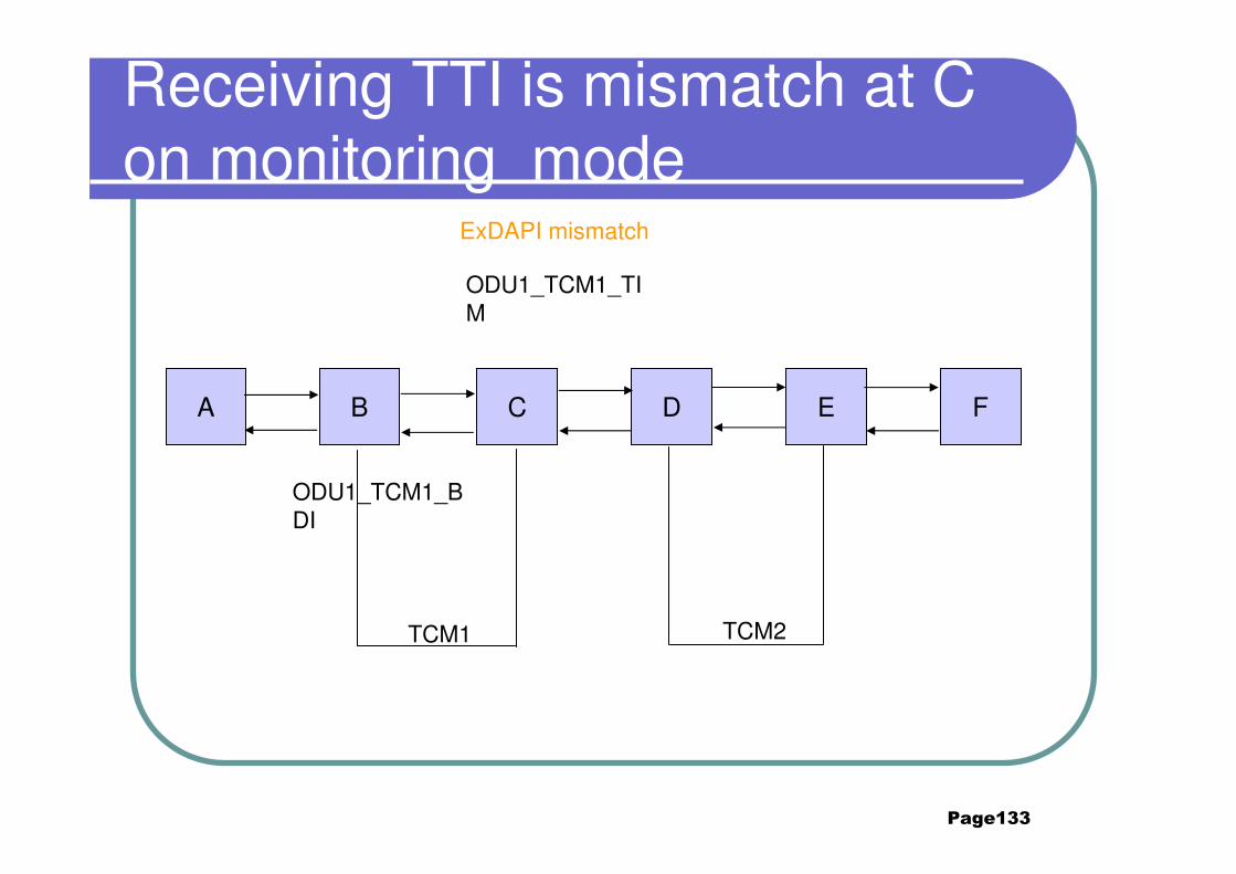
Receiving TTI is mismatch at C on monitoring mode
A B C D E F
ExDAPI mismatch
ODU1_TCM1_TIM
ODU1_TCM1_BDI
TCM1 TCM2

Page134
Questions
� What kind of the components compose the OTM-n.m?� OTSn, OMSn, OCh, OTUk/OTUkV, ODUk,
OPUk
� What’s the difference with the BIP-8 byte function among SM,PM,TCMi?� All of them the BIP-8 is computed over the
bits in the OPUk (columns 15 to 3824) area, but for different layers on OTUk, ODUkP, ODUKT.
� How many types of the TCM applications we have?
Page135
Summary
1. Optical transport hierarchy 2. OTN interface structure3. Multiplexing/mapping principles and bit rates4. Overhead description5. Maintenance signals and function for different layers6. Alarm and performance events 7. Typical Scenarios of OTN
Page136
Abbreviations and Acronyms
� 3R Re-amplification, Reshaping and Retiming
� AI Adapted Information
� AIS Alarm Indication Signal
� APS Automatic Protection Switching
� BDI Backward Defect Indication
� BDI-O Backward Defect Indication Overhead
� BDI-P Backward Defect Indication Payload
� BEI Backward Error Indication
� BI Backward Indication
� BIAE Backward Incoming Alignment Error
� BIP Bit Interleaved Parity
� CBR Constant Bit Rate
Page137
Abbreviations and Acronyms� CMEP Connection Monitoring End Point
� DAPI Destination Access Point Identifier
� EXP Experimental
� ExTI Expected Trace Identifier
� FAS Frame Alignment Signal
� FDI Forward Defect Indication
� FDI-O Forward Defect Indication Overhead
� FDI-P Forward Defect Indication Payload
� FEC Forward Error Correction
� GCC General Communication Channel
� IaDI Intra-Domain Interface
� IAE Incoming Alignment Error
Page138
Abbreviations and Acronyms
� IrDI Inter-Domain Interface
� JOH Justification Overhead
� MFAS MultiFrame Alignment Signal
� MFI Multiframe Indicator
� MSI Multiplex Structure Identifier
� NNI Network Node Interface
� OCC Optical Channel Carrier
� OCCo Optical Channel Carrier – overhead
� OCCp Optical Channel Carrier – payload
� OCCr Optical Channel Carrier with reduced functionality
� OCG Optical Carrier Group
� OCGr Optical Carrier Group with reduced functionality

Page139
Abbreviations and Acronyms
� OCh Optical channel with full functionality
� OChr Optical channel with reduced functionality
� OCI Open Connection Indication
� ODTUG Optical channel Data Tributary Unit Group
� ODTUjk Optical channel Data Tributary Unit j into k
� ODU Optical Channel Data Unit
� ODUk Optical Channel Data Unit-k
� OH Overhead
� OMS Optical Multiplex Section
� OMU Optical Multiplex Unit
� ONNI Optical Network Node Interface
� OOS OTM Overhead Signal
� OPS Optical Physical Section
Page140
Abbreviations and Acronyms� OPU Optical Channel Payload Unit
� OPUk Optical Channel Payload Unit-k
� OSC Optical Supervisory Channel
� OTH Optical Transport Hierarchy
� OTM Optical Transport Module
� OTN Optical Transport Network
� OTS Optical Transmission Section
� OTU Optical Channel Transport Unit
� OTUk completely standardized Optical Channel Transport Unit-k
� OTUkV functionally standardized Optical Channel Transport Unit-k
� PCC Protection Communication Channel
� PLD Payload
� PMI Payload Missing Indication
Page141
Abbreviations and Acronyms� PRBS Pseudo Random Binary Sequence
� PSI Payload Structure Identifier
� PT Payload Type
� RES Reserved for future international standardization� SAPI Source Access Point Identifier
� Sk Sink
� SM Section Monitoring
� So Source
� TCM Tandem Connection Monitoring
� TS Tributary Slot
� TxTI Transmitted Trace Identifier
� UNI User-to-Network Interface