Embed Size (px)
Citation preview

ITU/BDT Arab Regional Workshop on “4G Wireless Systems” – Tunisia 2010
ITU/BDT Arab Regional Workshop onITU/BDT Arab Regional Workshop on“4G Wireless Systems”
LTE Technology
Session 3 : LTE Overview – Design Targetsand Multiple Access Technologiesand Multiple Access Technologies
Speakers M. Lazhar BELHOUCHETM Hakim EBDELLIM. Hakim EBDELLI
Date 27 – 29 January 2010
www.cert.nat.tn1 LTE Overview

ITU/BDT Arab Regional Workshop on “4G Wireless Systems” – Tunisia 2010
Agenda
• Standardization
• Motivation for LTEMotivation for LTE
• LTE performance requirements
• LTE challenges• LTE challenges
• LTE/SAE Key Features
• LTE technology basics• LTE technology basics
• Air Interface Protocols
www.cert.nat.tn2 LTE Overview
ITU/BDT Arab Regional Workshop on “4G Wireless Systems” – Tunisia 2010
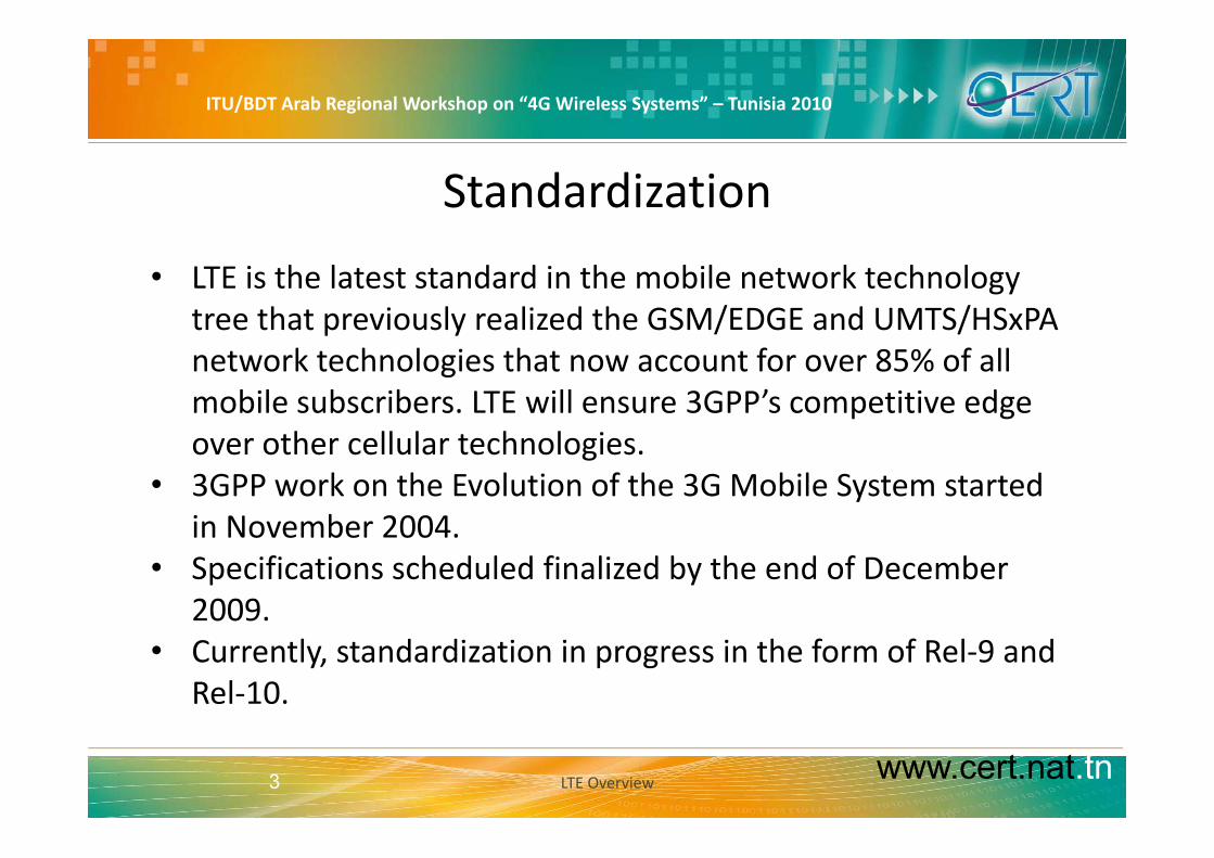
Standardization
• LTE is the latest standard in the mobile network technology tree that previously realized the GSM/EDGE and UMTS/HSxPAp y / /network technologies that now account for over 85% of all mobile subscribers. LTE will ensure 3GPP’s competitive edge over other cellular technologies.
• 3GPP work on the Evolution of the 3G Mobile System started in November 2004in November 2004.
• Specifications scheduled finalized by the end of December 2009.
• Currently, standardization in progress in the form of Rel‐9 and Rel‐10.
www.cert.nat.tn3 LTE Overview

ITU/BDT Arab Regional Workshop on “4G Wireless Systems” – Tunisia 2010
Motivation for LTE
• Need for higher data rates and greater spectral efficiency– Can be achieved with HSDPA/HSUPA/
– and/or new air interface defined by 3GPP LTE
• Need for Packet Switched optimized system– Evolve UMTS towards packet only system
• Need for high quality of services– Use of licensed frequencies to guarantee quality of services
– Always‐on experience (reduce control plane latency significantly)
R d d t i d l– Reduce round trip delay
• Need for cheaper infrastructureSimplify architecture reduce number of network elements
www.cert.nat.tn4
– Simplify architecture, reduce number of network elements
LTE Overview
ITU/BDT Arab Regional Workshop on “4G Wireless Systems” – Tunisia 2010
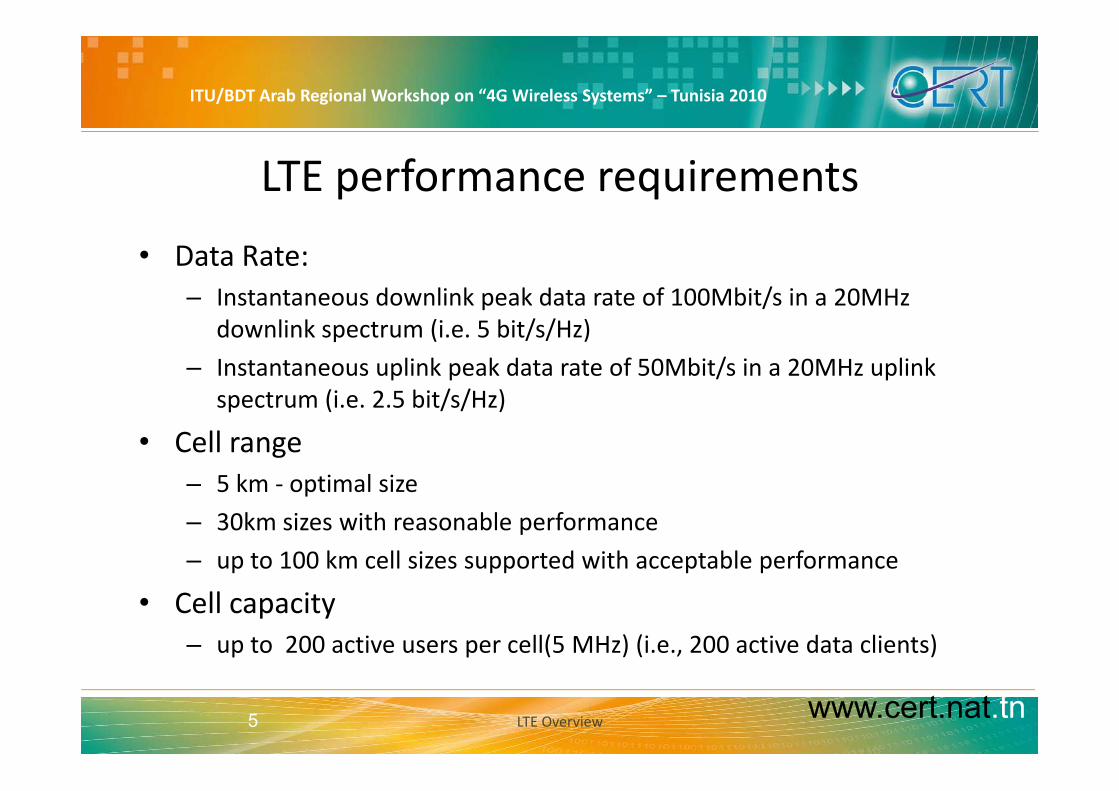
LTE performance requirements
• Data Rate:– Instantaneous downlink peak data rate of 100Mbit/s in a 20MHz p /
downlink spectrum (i.e. 5 bit/s/Hz)
– Instantaneous uplink peak data rate of 50Mbit/s in a 20MHz uplink spectrum (i e 2 5 bit/s/Hz)spectrum (i.e. 2.5 bit/s/Hz)
• Cell range– 5 km ‐ optimal size– 5 km ‐ optimal size
– 30km sizes with reasonable performance
– up to 100 km cell sizes supported with acceptable performance
• Cell capacity– up to 200 active users per cell(5 MHz) (i.e., 200 active data clients)
www.cert.nat.tn5 LTE Overview

ITU/BDT Arab Regional Workshop on “4G Wireless Systems” – Tunisia 2010
LTE performance requirements – Cont.
• Mobility – Optimized for low mobility(0‐15km/h) but supports high speedp y( / ) pp g p
• Latency – user plane < 5ms
– control plane < 50 ms
• Improved spectrum efficiency
• Improved broadcasting
• IP‐optimized
• Scalable bandwidth of 20, 15, 10, 5, 3 and 1.4MHz
• Co‐existence with legacy standards
www.cert.nat.tn6 LTE Overview

ITU/BDT Arab Regional Workshop on “4G Wireless Systems” – Tunisia 2010
The way to LTE: 3 main 3G limitations
1.The maximum bit rates still are factor of 20 and more behind the current state of the systems like 802.11n and 802.16e/m.y /
2.The latency of user plane traffic (UMTS: >30 ms) and of resource assignment procedures (UMTS: >100 ms) is too big to handle trafficassignment procedures (UMTS: 100 ms) is too big to handle traffic with high bit rate variance efficiently.
3 The terminal complexity for WCDMA or MC‐CDMA systems is quite3.The terminal complexity for WCDMA or MC CDMA systems is quite high, making equipment expensive, resulting in poor performing implementations of receivers and inhibiting the implementation of other performance enhancements.
www.cert.nat.tn7 LTE Overview

ITU/BDT Arab Regional Workshop on “4G Wireless Systems” – Tunisia 2010
LTE Overview – Design Targets and Multiple Access Technologies
LTE CHALLENGESLTE Overview Design Targets and Multiple Access Technologies
www.cert.nat.tn8 LTE Overview

ITU/BDT Arab Regional Workshop on “4G Wireless Systems” – Tunisia 2010
What are the LTE challenges?
Best price, transparent flat rateF ll I t t
reduce cost per bitid hi h d t t
The Users’ expectation… ..leads to the operator’s challenges
Full Internet Multimedia
provide high data rateprovide low latency
User experience will have an impact on ARPU
Price per Mbyte has to be reduced to remain profitable
Cost per MByteThroughput Latency
HSPA LTE HSPA LTE
www.cert.nat.tn9
UMTS HSPA I-HSPA LTEHSPA LTE HSPA LTE
LTE Overview

ITU/BDT Arab Regional Workshop on “4G Wireless Systems” – Tunisia 2010
Comparison of Throughput and Latency
• Peak data rates around 300Mbps/80 Mbps• Low latency 10-20 ms
Enhanced consumer experience:drives subscriber uptake
Latency (Rountrip delay)*
allow for new applicationsprovide additional revenue streams
Max. peak data rate
DownlinkUplink
350
300
250
Latency (Rountrip delay)
GSM/EDGE
HSPAR l6
Mbp
s
200
150
100
HSPAevo (Rel8)
LTE
Rel6
HSPA R6 Evolved HSPA (Rel. 7/8, 2x2 MIMO)
LTE 2x20 MHz (2x2 MIMO)
LTE 2x20 MHz (4x4 MIMO)
50
0
LTE
DSL (~20-50 ms, depending on operator)
0 20 40 60 80 100 120 140 160 180 200
min max
ms
www.cert.nat.tn10
* Server near RAN( , p g p )
ITU/BDT Arab Regional Workshop on “4G Wireless Systems” – Tunisia 2010
Scalable BandwidthScalable Bandwidth
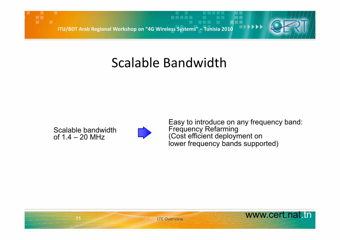
E t i t d f b d• Scalable bandwidth
of 1.4 – 20 MHz
Easy to introduce on any frequency band: Frequency Refarming(Cost efficient deployment on lower frequency bands supported)q y pp )
www.cert.nat.tn11 LTE Overview

ITU/BDT Arab Regional Workshop on “4G Wireless Systems” – Tunisia 2010
Increased Spectral Efficiency
• All cases assume 2‐antenna terminal reception
• HSPA R7, WiMAX and LTE assume 2‐antenna BTS transmission (2x2 MIMO)
ITU contribution from1 82.0
Downlink ITU contribution from WiMAX Forum shows downlink 1.3 and uplink 0.8 bps/Hz/cell
1.21.41.61.8
/cel
l
Uplink
Reference:0 40.60.81.0
bps/
Hz/
Reference: - HSPA R6 and LTE R8 from 3GPP R1-071960- HSPA R6 equalizer from 3GPP R1-063335- HSPA R7 and WiMAX from NSN/Nokia simulations
0.00.20.4
HSPA R6 HSPA R6 + HSPA R7 WiMAX LTE R8
www.cert.nat.tn12 LTE Overview

ITU/BDT Arab Regional Workshop on “4G Wireless Systems” – Tunisia 2010
Reduced Network Complexity
Flat, scalable IP based architecture Flat Architecture: 2 nodes architectureIP based Interfaces
Flat, IP based architecture
Access Core Control
Flat networks are
IM
S
HLR/H
SS I t t
MM
E
characterized by fewer network elements, lower latency, greater flexibility and lower operation cost
Evolved Node B GateWay
S SS InternetEp
www.cert.nat.tn13 LTE Overview

ITU/BDT Arab Regional Workshop on “4G Wireless Systems” – Tunisia 2010
LTE Overview – Design Targets and Multiple Access Technologies
LTE/SAE KEY FEATURESLTE Overview Design Targets and Multiple Access Technologies
www.cert.nat.tn14 LTE Overview

ITU/BDT Arab Regional Workshop on “4G Wireless Systems” – Tunisia 2010
LTE/SAE Key Features – OverviewEPS ( Evolved Packet System ) /
SAE ( System Architecture Evolution ) /LTE ( Long Term Evolution )
EUTRAN( Evolved UTRAN ) EPC ( Evolved Packet Core ) IP Network
IP Network
E l d N d B /PS Domain only,
IP Network
Evolved Node B / No RNC
IP Transport Layer
UL/DL resource
No CS Domain
IP Transport Layer
QoS Aware3GPP (GTP) or
OFDMA/SC-FDMA
MIMO ( beam-forming/spatial multiplexing)
HARQscheduling
QoS Aware
Self Configuration
IETF (MIPv6)
Prepared for Non-3GPP Access
HARQ
Scalable bandwidth(1.4, 3, 5, 10, .. 20 MHz)
www.cert.nat.tn15 LTE Overview
ITU/BDT Arab Regional Workshop on “4G Wireless Systems” – Tunisia 2010
LTE/SAE Key Features• Evolved NodeB
– No RNC is provided anymore
– The evolved Node Bs take over all radio management functionality.
– This will make radio management faster and hopefully the network architecture simplerarchitecture simpler
• IP transport layer– EUTRAN exclusively uses IP as transport layery p y
• UL/DL resource scheduling– In UMTS physical resources are either shared or dedicated
– Evolved Node B handles all physical resource via a scheduler and assigns them dynamically to users and channels
This provides greater flexibility than the older system
www.cert.nat.tn16
– This provides greater flexibility than the older system
LTE Overview

ITU/BDT Arab Regional Workshop on “4G Wireless Systems” – Tunisia 2010
LTE/SAE Key Features – Cont.• Frequency Domain Scheduling :
Resource block
Carrier bandwidth
– Frequency domain scheduling uses those
bl k th t
Resource block
resource blocks that are not faded
Not possible in CDMA– Not possible in CDMA based system
FrequencyTransmit on those resource blocks that are
not faded
www.cert.nat.tn17 LTE Overview
not faded

ITU/BDT Arab Regional Workshop on “4G Wireless Systems” – Tunisia 2010
LTE/SAE Key Features – Cont.• HARQ
– Hybrid Automatic Retransmission on reQuest
HARQ Hybrid Automatic Repeat Request
on reQuest
– HARQ has already been used for HSDPA and HSUPA.
– HARQ especially increases the performance (delay and throughput) for cell edge users.g p ) g
– HARQ simply implements a retransmission protocol on layer 1/2 that allows to send1/2 that allows to send retransmitted blocks with different coding than the 1st one.
www.cert.nat.tn18 LTE Overview

ITU/BDT Arab Regional Workshop on “4G Wireless Systems” – Tunisia 2010
LTE/SAE Key Features – Cont.
• QoS awareness– The scheduler must handle and distinguish different quality of service g q y
classes
– Otherwise real time services would not be possible via EUTRAN
– The system provides the possibility for differentiated service
• Self configurationC tl d i ti ti– Currently under investigation
– Possibility to let Evolved Node Bs configure themselves
• It will not completely substitute the manual configuration andIt will not completely substitute the manual configuration and optimization.
www.cert.nat.tn19 LTE Overview
ITU/BDT Arab Regional Workshop on “4G Wireless Systems” – Tunisia 2010
LTE/SAE Key Features – Cont.
• Packet Switched Domain onlyNo circuit switched domain is provided– No circuit switched domain is provided
– If CS applications are required, they must be implemented via IPvia IP
• Non‐3GPP accessTh EPC ill b d l t b d b 3GPP– The EPC will be prepared also to be used by non‐3GPP access networks (e.g. LAN, WLAN, WiMAX, etc.)
This will provide true convergence of different packet radio– This will provide true convergence of different packet radio access system
www.cert.nat.tn20 LTE Overview

ITU/BDT Arab Regional Workshop on “4G Wireless Systems” – Tunisia 2010
LTE/SAE Key Features – Cont.
• MIMO Multiple Input Multiple Output– Multiple Input Multiple Output
– LTE will support MIMO as an option,
It describes the possibility to have multiple transmitter and– It describes the possibility to have multiple transmitter and receiver antennas in a system.
– Up to four antennas can be used by a single LTE cell (gain:– Up to four antennas can be used by a single LTE cell (gain: spatial multiplexing)
– MIMO is considered to be the core technology to increaseMIMO is considered to be the core technology to increase spectral efficiency.
www.cert.nat.tn21 LTE Overview

ITU/BDT Arab Regional Workshop on “4G Wireless Systems” – Tunisia 2010
LTE Overview – Design Targets and Multiple Access Technologies
LTE TECHNOLOGY BASICSLTE Overview Design Targets and Multiple Access Technologies
www.cert.nat.tn22 LTE Overview

ITU/BDT Arab Regional Workshop on “4G Wireless Systems” – Tunisia 2010
LTE key parametersFrequency Range UMTS FDD bands and UMTS TDD bands
Channelb d id hbandwidth, 1 ResourceBlock=180 kHz
1.4 MHz 3 MHz 5 MHz 10 MHz 15 MHz 20 MHz
6 RB 15 RB 25 RB 50 RB 75 RB 100 RB6 RB 15 RB 25 RB 50 RB 75 RB 100 RB
ModulationSchemes
DL: OFDMA (Orthogonal Frequency Division Multiple Access)UL: SC‐FDMA (Single Carrier Frequency Division Multiple Access)
Multiple Access DL: OFDMA (Orthogonal Frequency Division Multiple Access)Multiple Access DL: OFDMA (Orthogonal Frequency Division Multiple Access)UL: SC‐FDMA (Single Carrier Frequency Division Multiple Access)
MIMOtechnology
DL: Wide choice of MIMO configuration options for transmit diversity, spatial multiplexing, and cyclic delay diversity (max. 4 antennas at base station and handset)UL M lti ll b ti MIMOUL: Multi user collaborative MIMO
Peak Data Rate DL: 150 Mbps (UE category 4, 2x2 MIMO, 20 MHz) 300 Mbps (UE category 5, 4x4 MIMO, 20 MHz)UL: 75 Mbps (20 MHz)
www.cert.nat.tn23
p ( )

ITU/BDT Arab Regional Workshop on “4G Wireless Systems” – Tunisia 2010
LTE Overview – Design Targets and Multiple Access Technologies
OFDM/OFDMA/SC‐FDMALTE Overview Design Targets and Multiple Access Technologies
www.cert.nat.tn24 LTE Overview

ITU/BDT Arab Regional Workshop on “4G Wireless Systems” – Tunisia 2010
OFDM: Orthogonal Frequency Division Multi‐Carrier
• LTE uses OFDM for the DL– that is, from the base station to the terminal. OFDM meets the LTE requirement for spectrum q pflexibility and enables cost‐efficient solutions for very wide carriers with high peak rates.
• The basic LTE downlink physical resource can be seen as a time‐frequency grid. In the frequency domain, the spacing b t th b i Δf i 15kH I dditi th OFDMbetween the subcarriers, Δf, is 15kHz. In addition, the OFDM symbol duration time is 1/Δf + cyclic prefix. The cyclic prefix is used to maintain orthogonality between the sub‐carriers evenused to maintain orthogonality between the sub carriers even for a time‐dispersive radio channel.
• One resource element carries QPSK, 16QAM or 64QAM.
www.cert.nat.tn25
Q , Q Q
LTE Overview
ITU/BDT Arab Regional Workshop on “4G Wireless Systems” – Tunisia 2010
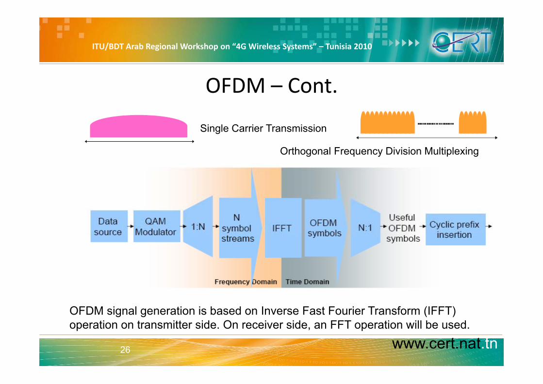
OFDM – Cont.
Single Carrier Transmission
O th l F Di i i M lti l iOrthogonal Frequency Division Multiplexing
OFDM signal generation is based on Inverse Fast Fourier Transform (IFFT) operation on transmitter side On receiver side an FFT operation will be used
www.cert.nat.tn26
operation on transmitter side. On receiver side, an FFT operation will be used.

ITU/BDT Arab Regional Workshop on “4G Wireless Systems” – Tunisia 2010
Pulse shaping and SpectrumTh ti d i t ti• Two characteristics are
important for a Signal:
The time domain presentation
– The time domain presentation:
• It helps recognize “how long the symbol lasts on air”
FourierTransform
– The frequency domain presentation:
• to understand the required spectrum in terms of bandwidth The frequency domain presentation
www.cert.nat.tn27 LTE Overview
q y p

ITU/BDT Arab Regional Workshop on “4G Wireless Systems” – Tunisia 2010
The rectangular Pulse
• It is one of the most simple time‐domain pulses.
• It simply jumps at time t=0 to its maximum amplitude andIt simply jumps at time t=0 to its maximum amplitude and after the pulse duration Ts just goes back to 0.
mpl
itude
TiFrequency Domain
Ts f s =1Ts
FT
a
time
Time Domain
IFT
www.cert.nat.tn28 LTE Overview

ITU/BDT Arab Regional Workshop on “4G Wireless Systems” – Tunisia 2010
Multi‐Path Propagation and Inter‐Symbol Interference
www.cert.nat.tn29 LTE Overview
ITU/BDT Arab Regional Workshop on “4G Wireless Systems” – Tunisia 2010
Multi‐Path Propagation and Inter‐Symbol Interference
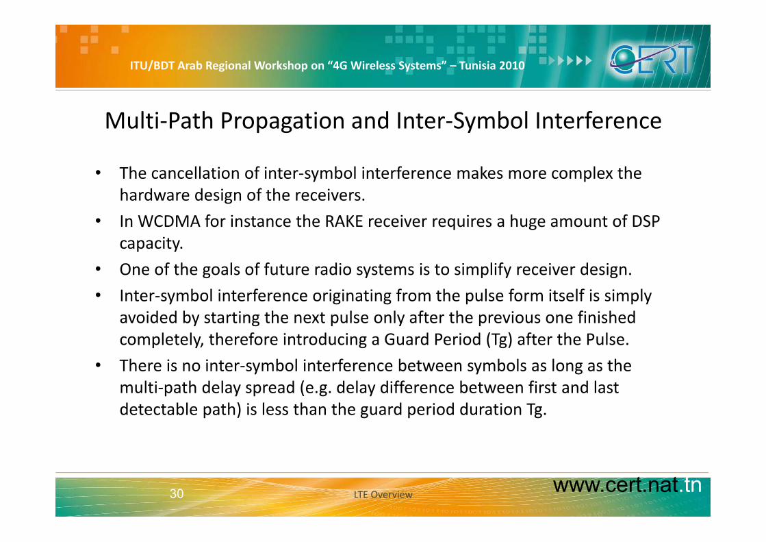
• The cancellation of inter‐symbol interference makes more complex the hardware design of the receivers.
• In WCDMA for instance the RAKE receiver requires a huge amount of DSP capacity.
• One of the goals of future radio systems is to simplify receiver designOne of the goals of future radio systems is to simplify receiver design.
• Inter‐symbol interference originating from the pulse form itself is simply avoided by starting the next pulse only after the previous one finished
l l h f d d d ( ) f h lcompletely, therefore introducing a Guard Period (Tg) after the Pulse.
• There is no inter‐symbol interference between symbols as long as the multi‐path delay spread (e.g. delay difference between first and last p y p ( g ydetectable path) is less than the guard period duration Tg.
www.cert.nat.tn30 LTE Overview

ITU/BDT Arab Regional Workshop on “4G Wireless Systems” – Tunisia 2010
Multi-Path Propagation and the Guard Periodp g
2
TSYMBOL
Time Domain
1
3
T
timeT
Tg
1 Guard Period (GP)
time
ti
TSYMBOL
T
2 Guard Period (GP)
timeTSYMBOL
3 Guard Period (GP)
www.cert.nat.tn31
time
LTE Overview
ITU/BDT Arab Regional Workshop on “4G Wireless Systems” – Tunisia 2010
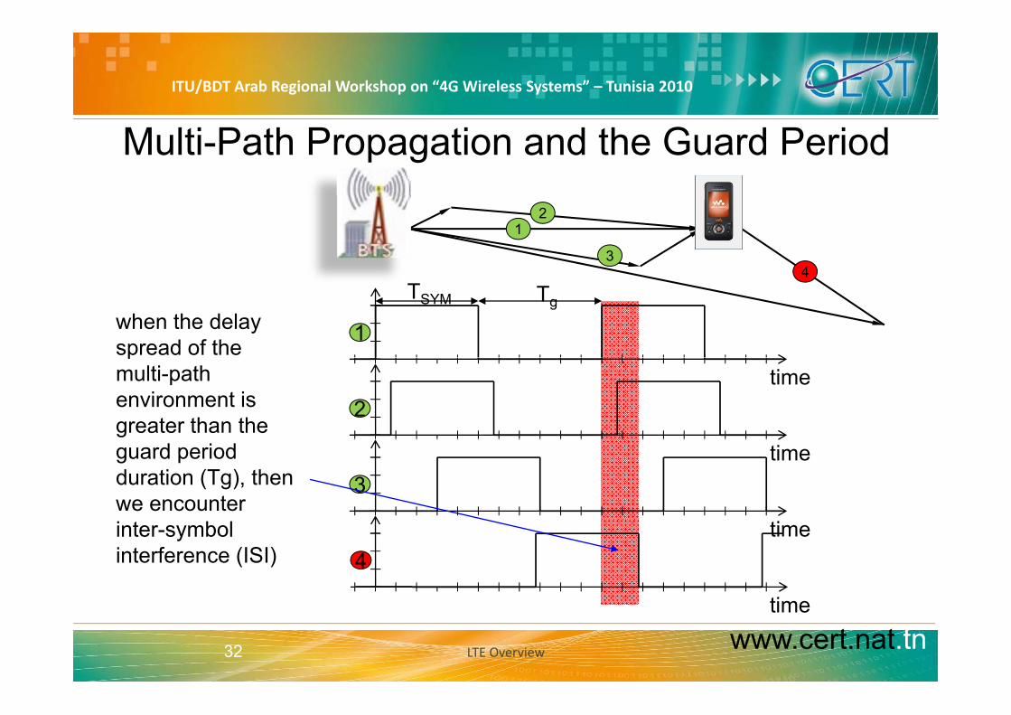
Multi-Path Propagation and the Guard Period
12
344
TSYM Tg
1when the delay spread of the
time2
pmulti-path environment is greater than the
time3
guard period duration (Tg), then we encounter
time
time
4inter-symbol interference (ISI)
www.cert.nat.tn32
time
LTE Overview
ITU/BDT Arab Regional Workshop on “4G Wireless Systems” – Tunisia 2010
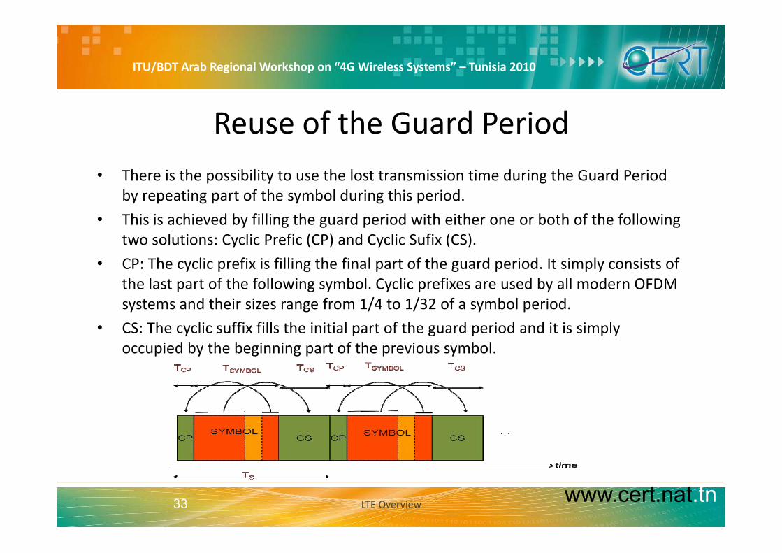
Reuse of the Guard Period• There is the possibility to use the lost transmission time during the Guard Period
by repeating part of the symbol during this period.
h h d b f ll h d d h h b h f h f ll• This is achieved by filling the guard period with either one or both of the following two solutions: Cyclic Prefic (CP) and Cyclic Sufix (CS).
• CP: The cyclic prefix is filling the final part of the guard period. It simply consists of the last part of the following symbol. Cyclic prefixes are used by all modern OFDM systems and their sizes range from 1/4 to 1/32 of a symbol period.
• CS: The cyclic suffix fills the initial part of the guard period and it is simply occupied by the beginning part of the previous symbol.
www.cert.nat.tn33 LTE Overview

ITU/BDT Arab Regional Workshop on “4G Wireless Systems” – Tunisia 2010
Cyclic Prefixl h• In multi‐path propagation
environments the delayed versions of the signal arrive with a time offset, so that the start of the symbol of the earliest path falls in the cyclic prefixes of the y pdelayed symbols.
• As the CP is simply a repetition of the end of the symbol this is not athe end of the symbol this is not a inter‐symbol interference and can be easily compensated by the f ll i d di b dfollowing decoding based on discrete Fourier transform.
www.cert.nat.tn34 LTE Overview

ITU/BDT Arab Regional Workshop on “4G Wireless Systems” – Tunisia 2010
Limitations of the Single‐Carrier Modulation
• Using a single radio frequency carrier with rectangular pulse shaping has a major drawback:
• The cyclic prefix duration is fixed by the maximum expected delay spread over the multi‐path propagation models for the systempropagation models for the system.
• The symbol duration can be made as small as the cyclic prefix size, but then only one half of th ti i d f d t t i i th th h lf i f th li fi idi
CPTdelay =max
the time is used for data transmission, the other half is for the cyclic prefix, providing a very low efficiency (E)
• Also shorter symbol duration mean a broader spectrum bandwidth (f ) to be used for aCPSYMBOL
SYMBOL
TTTE
+=
• Also shorter symbol duration mean a broader spectrum bandwidth (fS) to be used for a carrier.
• To increase efficiency the symbol duration must be made longer but then the symbol rate isCPSYMBOLS
S TTTf
+==
11
• To increase efficiency the symbol duration must be made longer, but then the symbol rate is reduced.
www.cert.nat.tn35 LTE Overview
ITU/BDT Arab Regional Workshop on “4G Wireless Systems” – Tunisia 2010
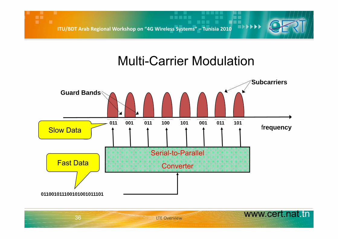
Multi-Carrier ModulationSubcarriers
Guard Bands
Multi Carrier Modulation
Guard Bands
frequency011 001 011 100 101 001 011 101
Slow Data
Serial-to-Parallel
ConverterFast Data
011001011100101001011101
www.cert.nat.tn36 LTE Overview

ITU/BDT Arab Regional Workshop on “4G Wireless Systems” – Tunisia 2010
Multi-Carrier Modulation –Cont.The center frequencies must be spaced so that interference between different carriers, known as Adjacent Carrier Interference ACI, is minimized; but not too much spaced as the total bandwidth will be wasted.
Each carrier uses an upper and lower guard band to protect itself from its adjacent carriers. Nevertheless, there will always be some interference between the adjacent carriers.
∆fsubcarrier
∆f b d∆fsub-used
f0 f1 f2 f3 fN
ACI = Adjacent Carrier Interference
www.cert.nat.tn37
ACI Adjacent Carrier Interference
LTE Overview

ITU/BDT Arab Regional Workshop on “4G Wireless Systems” – Tunisia 2010
OFDM: Orthogonal Frequency Division Multi‐Carrierh l l h• For the rectangular pulse there is
a better option possible and it is even easier to implement. Single carrier
• We must just notice that the spectrum of a rectangular pulses shows null points exactly atshows null points exactly at integer multiples of the frequency given by the symbol durationduration.
• The only exception is the center frequency (peak power)
fs fs fs fs fs fsfs fs fs fs fs fs
f/fs
www.cert.nat.tn38 LTE Overview

ITU/BDT Arab Regional Workshop on “4G Wireless Systems” – Tunisia 2010
OFDM: Orthogonal Frequency Division Multi‐CarrierTh OFDM i l l h i l i h fi ll i f hThus OFDM simply places the next carrier exactly in the first null point of the previous one. With this we don’t need any pulse‐shaping.B OFDM i i hBetween OFDM carriers using the same symbol duration Ts, no guard bands are required. fs
Orthogonal Subcarriers: it means that at the subcarriers centerfs subcarriers center
frequencies, there is no Adjacent Carrier Interefence (ACI)
Two carriers( )
f/fs
www.cert.nat.tn39 LTE Overview

ITU/BDT Arab Regional Workshop on “4G Wireless Systems” – Tunisia 2010
Spectrum Overlapping of multiple OFDM carriers21011
−=+=+= nnfnfff KK .2,1,0,100 −=+=+= nT
nfnfffs
sn
f0 f1 f2 f3 f4
www.cert.nat.tn40
No ACI (Adjacent Carrier Interference)
LTE Overview

ITU/BDT Arab Regional Workshop on “4G Wireless Systems” – Tunisia 2010
OFDM: Orthogonal Frequency Division Multi‐Carrier
OFDM allows a tight packing of small carrier ‐ called the subcarriersinto a given frequency band.
nsity
sity
Pow
er D
en
ower
Den
s
SavedBandwidth
P Po
Frequency (f/fs) Frequency (f/fs)
www.cert.nat.tn41 LTE Overview

ITU/BDT Arab Regional Workshop on “4G Wireless Systems” – Tunisia 2010
The OFDM Signal
www.cert.nat.tn42 LTE Overview

ITU/BDT Arab Regional Workshop on “4G Wireless Systems” – Tunisia 2010
OFDM and Multiple Access
• Up to here we have only discussed simple point‐to‐point or broadcast OFDM.point or broadcast OFDM.
• Now we have to analyze how to handle access of multiple users simultaneously to the system eachmultiple users simultaneously to the system, each one using OFDM.
OFDM b bi d ith l diff t• OFDM can be combined with several different methods to handle multi‐user systems:
l– Plain OFDM
– Time Division Multiple Access via OFDM
www.cert.nat.tn43
– Orthogonal Frequency Division Multiple Access OFDMA LTE Overview

ITU/BDT Arab Regional Workshop on “4G Wireless Systems” – Tunisia 2010
Plain OFDM• Plain OFDM: Normal OFDM
has no built‐in multiple‐access mechanismaccess mechanism.
• This is suitable for broadcast• This is suitable for broadcast systems like DVB‐T/H which transmit only broadcast and ymulticast signals and do not really need an uplink feedback channel (although such systems exist too).
www.cert.nat.tn44 LTE Overview

ITU/BDT Arab Regional Workshop on “4G Wireless Systems” – Tunisia 2010
Time Division Multiple Access via OFDM i i i i l i l iTime Division Multiple Access via OFDM: The simplest model to implement multiple access handling is by putting a ti lti l i t f OFDMtime multiplexing on top of OFDM.
The disadvantage of this simple mechanism is, that every user gets the
t f it ( b i )same amount of capacity (subcarriers) and it is thus rather difficult to implement flexible (high and low) bit rate servicesservices.
Furthermore it is nearly impossible to handle highly variable traffic (e.g. web t ffi ) ffi i tl ith t t htraffic) efficiently without too much higher layer signaling and the resulting delay and signaling overhead.
www.cert.nat.tn45 LTE Overview
1 2 3UE 1 UE 2 UE 3 common info

ITU/BDT Arab Regional Workshop on “4G Wireless Systems” – Tunisia 2010
Orthogonal Frequency Division Multiple Access OFDMAh b i id i i b iThe basic idea is to assign subcarriers to users based on their bit rate services. With this approach it is quite easy to h dl hi h d l bit t
Orthogonal FrequencyMultiple Access
OFDMA
timehandle high and low bit rate users simultaneously in a single system.But still it is difficult to run highly variable traffic efficiently
1 1 2......1 2
traffic efficiently.The solution to this problem is to assign to a single users so called resource blocks or scheduling blocks
1
. . . . .
...
...1 22
2 2
carri
er
11 1 1
RBblocks or scheduling blocks.
Such block is simply a set of some subcarriers over some time.
.
...
.
...
.
. ......1 1 1
subc
111
33 3 3 3
RB
subcarriers over some time. A single user can then use one or more Resource blocks.
3.........3 33 3 3
3 3 333 3 3 33
1 2 3UE 1 UE 2 UE 3 common info
www.cert.nat.tn46 LTE Overview
1 2 3UE 1 UE 2 UE 3 common info

ITU/BDT Arab Regional Workshop on “4G Wireless Systems” – Tunisia 2010
Difference between OFDM and OFDMA
OFDM allocates users in timedomain only
OFDMA allocates users in timeand frequency domainy q y
www.cert.nat.tn47

ITU/BDT Arab Regional Workshop on “4G Wireless Systems” – Tunisia 2010
SC‐FDMA
• SC‐FDMA :Single Carrier Frequency Division Multiple Access
• SC‐FDMA is a new hybrid modulation scheme that cleverly combines the low PAR of single‐carrier systems with the multipath resistance and flexible subcarrier frequency allocation offered by OFDM.
• SC‐FDMA solves this problem by grouping together the resource blocks inSC FDMA solves this problem by grouping together the resource blocks in such a way that reduces the need for linearity, and so power consumption, in the power amplifier. A low PAPR also improves coverage and the cell‐edge performanceedge performance.
• SC‐FDMA signal processing has some similarities with OFDMA signal processing, so parameterization of DL and UL can be harmonized.
• SC‐FDMA is one option in WiMAX (802.16d) and it is the method selected for LTE in the uplink direction.
www.cert.nat.tn48 LTE Overview
ITU/BDT Arab Regional Workshop on “4G Wireless Systems” – Tunisia 2010
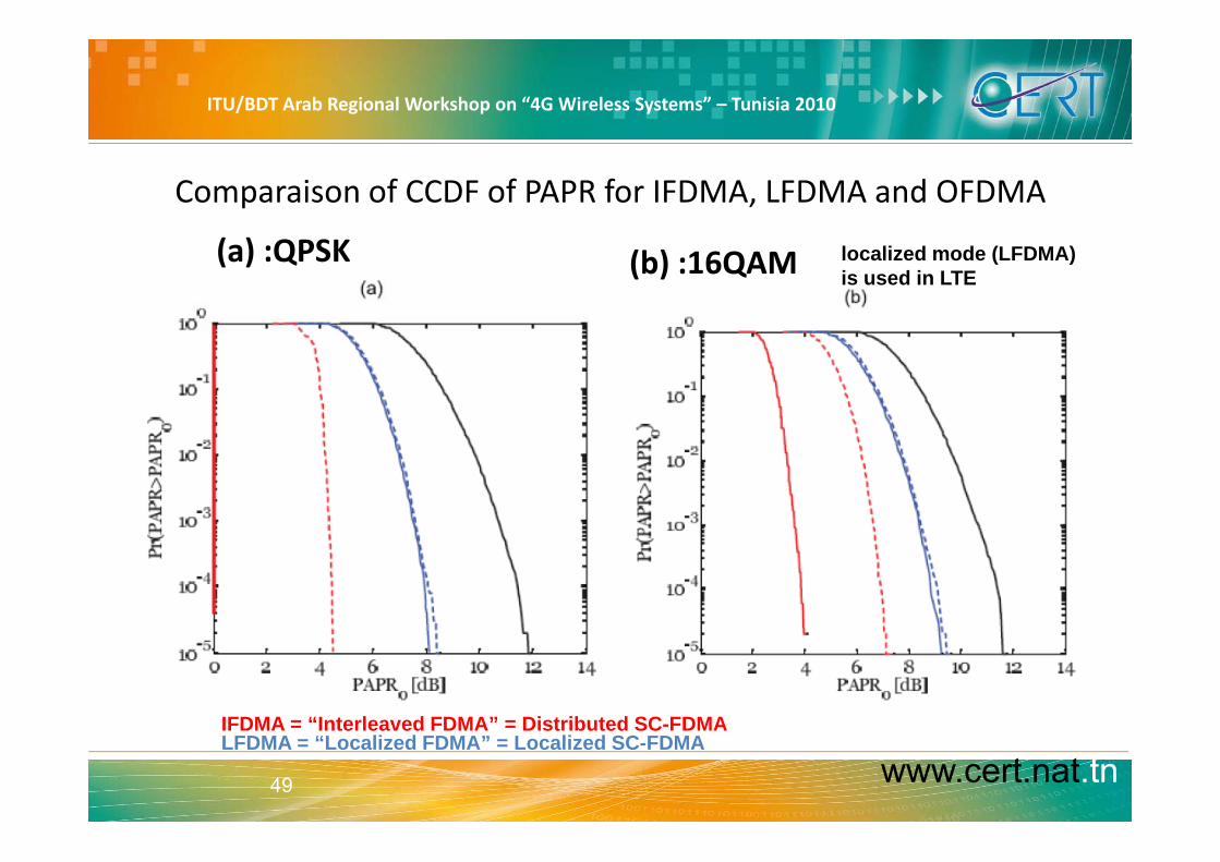
Comparaison of CCDF of PAPR for IFDMA, LFDMA and OFDMA
(a) :QPSK (b) :16QAM localized mode (LFDMA)is used in LTE
IFDMA = “Interleaved FDMA” = Distributed SC-FDMA
www.cert.nat.tn49
IFDMA = Interleaved FDMA = Distributed SC-FDMALFDMA = “Localized FDMA” = Localized SC-FDMA

ITU/BDT Arab Regional Workshop on “4G Wireless Systems” – Tunisia 2010
How does a SC‐FDMA signal look like?
• Similar to OFDM signal, but…– in OFDMA, each sub‐carrier only carries information related to one specific y p
symbol,
– in SC‐FDMA, each sub‐carrier contains information of ALL transmitted symbols.y
www.cert.nat.tn50

ITU/BDT Arab Regional Workshop on “4G Wireless Systems” – Tunisia 2010
Comparing OFDMA & SC‐FDMA
www.cert.nat.tn51 LTE Overview

ITU/BDT Arab Regional Workshop on “4G Wireless Systems” – Tunisia 2010
LTE downlink : conventional OFDMA• LTE provides QPSK, 16QAM,
64QAM as downlink modulation schemesmodulation schemes
• Cyclic prefix is used as guard interval differentinterval, different configurations possible:– Normal cyclic prefix with 5.2 µs
15 kHz
(first symbol) / 4.7 µs (other symbols)
– Extended cyclic prefix with 16 7 µsExtended cyclic prefix with 16.7 µs
• 15 kHz subcarrier spacing
• Scalable bandwidthf0 f1 f2 f3 f4
www.cert.nat.tn52
Scalable bandwidth

ITU/BDT Arab Regional Workshop on “4G Wireless Systems” – Tunisia 2010
OFDMA time‐frequency multiplexing
*TTI = transmission time interval** For normal cyclic prefix duration
www.cert.nat.tn53

ITU/BDT Arab Regional Workshop on “4G Wireless Systems” – Tunisia 2010
spectrum flexibility• LTE physical layer supports
any bandwidth from 1.4 MHz to 20 MHz in steps ofMHz to 20 MHz in steps of 180 kHz (resource block)
• Current LTE specificationCurrent LTE specification supports a subset of 6 different system
Channel BWbandwidths
• All UEs must support the
Channel BW[MHz] 1.4 3 5 10 15 20
Number of RBs 6 15 25 50 75 100
maximum bandwidth of 20 MHz
www.cert.nat.tn54

ITU/BDT Arab Regional Workshop on “4G Wireless Systems” – Tunisia 2010
Bandwidth ScalabilityS l bl b d idth 1 4 20 MH i diff t b f b iScalable bandwidth 1.4 – 20 MHz using different number of subcarriers Large bandwidth provides high data rates Small bandwidth allows simpler spectrum reframing, e.g. 450 MHz and 900 MHz
1.4 MHz
BandwidthNarrow Spectrum Reframing
3.0 MHz
5 MHz5 MHz
10 MHz High Data Rates
15 MHz
20 MHz
www.cert.nat.tn55 LTE Overview

ITU/BDT Arab Regional Workshop on “4G Wireless Systems” – Tunisia 2010
LTE Frame Structure
• LTE frames are 10 msec in duration. They are di id d i t 10 bf h bfdivided into 10 subframes, each subframe being 1.0 msec long. Each subframe is further divided into two slots, each of 0.5 msec duration. Slots consist of either 6 or 7 ODFM symbols, depending on whether the normal or extended cyclic prefix is employedextended cyclic prefix is employed
www.cert.nat.tn56 LTE Overview

ITU/BDT Arab Regional Workshop on “4G Wireless Systems” – Tunisia 2010
LTE Slot
• The LTE Slot carries:b l h h l f– 7 symbols with short cyclic prefix
– 6 symbols with long prefix
www.cert.nat.tn57 LTE Overview

ITU/BDT Arab Regional Workshop on “4G Wireless Systems” – Tunisia 2010
OFDM Resource Block for LTE/EUTRANb b l• EUTRAN combines OFDM symbols in
so called resource blocks RB.
• A single resource block is always 12 g yconsecutive subcarriers during one subframe (2 slots, 1 ms):
12 subcarriers * 15 kHz= 180 kHz– 12 subcarriers 15 kHz= 180 kHz
• It is the task of the scheduler to assign resource blocks to physical channels belonging to different users or for general system tasks.
• A single cell must have at least 6 gresource blocks (72 subcarriers) and up to 110 are possible (1320 subcarriers)
www.cert.nat.tn58
subcarriers).
LTE Overview

ITU/BDT Arab Regional Workshop on “4G Wireless Systems” – Tunisia 2010
LTE DL frame structure type 1 (FDD), DL#00
#01
#02
#03
#04
#05
#06
#07
#08
#09
#10
#11
#12
#13
#14
#15
#16
#17
#18
#19
1 slot = 0.5 ms1 subframe = 1 ms1 subframe = 1 ms
www.cert.nat.tn59

ITU/BDT Arab Regional Workshop on “4G Wireless Systems” – Tunisia 2010
LTE DL frame structure type 2 (TDD)
# # # # # # # # # # # # # # # # # # # #
1 slot = 0.5 ms1 subframe = 1 ms
00 01 02 03 04 05 06 07 08 09 10 11 12 13 14 15 16 17 18 19
Special subframes containing:DwPTS: downlink pilot time slotUpPTS: uplink pilot time slotUpPTS: uplink pilot time slotGP: guard period for TDD operation
Possible UL-DL configurationsg
UL‐DL config Subframe number0 0 1 2 3 4 5 6 7 8 91 D S U U U D S U U U2 D S U D D D S U D D3 D S U U U D D D D D4 D S U U D D D D D D5 D S U D D D D D D D6 D S U U U D S U U D
www.cert.nat.tn60
6 D S U U U D S U U D

ITU/BDT Arab Regional Workshop on “4G Wireless Systems” – Tunisia 2010
Modulation Schemes for LTE/EUTRANh b l h• Each OFDM symbol even within a resource
block can have a different modulation scheme. b0 b1b2b3
16QAM
b bQPSK
• EUTRAN defines the following options: QPSK, 16QAM, 64QAM.
• Not every physical channel will be allowed to
Im
Re
1111 b0 b1
Im
Re10
11
00
01
• Not every physical channel will be allowed to use any modulation scheme: Control channels to be using mainly QPSK.
0000
64QAM
b b b b b b
1000
• In general it is the scheduler that decides which form to use depending on carrier quality feedback information from the UE.
Imb0 b1b2b3 b4 b5
q yRe
www.cert.nat.tn61 LTE Overview

ITU/BDT Arab Regional Workshop on “4G Wireless Systems” – Tunisia 2010
LTE Overview – Design Targets and Multiple Access Technologies
MIMOLTE Overview Design Targets and Multiple Access Technologies
www.cert.nat.tn62 LTE Overview

ITU/BDT Arab Regional Workshop on “4G Wireless Systems” – Tunisia 2010
Multiple Antenna Techniques
• MIMO employs multiple transmit and receive antennas to substantially enhance the air interface.
• It uses space‐time coding of the same data stream mapped onto multiple transmit antennas, which is an improvement over traditional reception diversity schemes where only a single transmit antenna is deployed to y y g p yextend the coverage of the cell.
• MIMO processing also exploits spatial multiplexing, allowing different data streams to be transmitted simultaneously from the different transmitstreams to be transmitted simultaneously from the different transmit antennas, to increase the end‐user data rate and cell capacity.
• In addition, when knowledge of the radio channel is available at the transmitter (e.g. via feedback information from the receiver), MIMO can also implement beam‐forming to further increase available data rates and spectrum efficiency
www.cert.nat.tn63
p y
LTE Overview

ITU/BDT Arab Regional Workshop on “4G Wireless Systems” – Tunisia 2010
Advanced Antenna Techniques
• Single data stream / user
• Beam forming• Beam‐forming– Coverage, longer battery life
• Spatial Division Multiple AccessSpatial Division Multiple Access (SDMA)– Multiple users in same radio resource
• Multiple data stream / user Diversity– Link robustness
• Spatial multiplexing– Spectral efficiency, high data rate support
www.cert.nat.tn64 LTE Overview

ITU/BDT Arab Regional Workshop on “4G Wireless Systems” – Tunisia 2010
MIMO – Beamforming• Enhances signal reception
through directional array gain, while individual antenna haswhile individual antenna has omni‐directional gain
• Extends cell coverageExtends cell coverage
• Suppresses interference in space domainp
• Enhances system capacity
• Prolongs battery lifeProlongs battery life
• Provides angular information for user tracking
www.cert.nat.tn65
g
LTE Overview

ITU/BDT Arab Regional Workshop on “4G Wireless Systems” – Tunisia 2010
LTE Overview – Design Targets and Multiple Access Technologies
AIR INTERFACE PROTOCOLSLTE Overview Design Targets and Multiple Access Technologies
www.cert.nat.tn66 LTE Overview

ITU/BDT Arab Regional Workshop on “4G Wireless Systems” – Tunisia 2010
Radio Protocols Architecture
• It is quite similar to the WCDMA protocol t k f UMTSstack of UMTS.
• The protocol stack defines three layers:
• the physical layer (layer 1)
d li k d l (l 2)• data link and access layer (layer 2)
• layer 3 (hosting the AS, the NAS control y ( g ,protocols as well and the application level)
www.cert.nat.tn67 LTE Overview

ITU/BDT Arab Regional Workshop on “4G Wireless Systems” – Tunisia 2010
Radio Protocol architecture‐ User plane
eNBUE
PDCPPDCP
Header compression (ROHC)In‐sequence delivery of upper layer PDUs
MAC
RLC
MAC
PDCPPDCP
RLC
In sequence delivery of upper layer PDUsDuplicate elimination of lower layer SDUsCiphering for user/control planeIntegrity protection for control plane
PHYPHYTimer based discard…
AM, UM, TMARQ(Re‐)segmentation ConcatenationIn‐sequence deliveryDuplicate detection
Mapping between logical andtransport channels(De)‐MultiplexingScheduling information reporting Duplicate detection
SDU discardRe‐establishment…
Scheduling information reportingHARQPriority handlingTransport format selection…
www.cert.nat.tn68 LTE Overview
ITU/BDT Arab Regional Workshop on “4G Wireless Systems” – Tunisia 2010
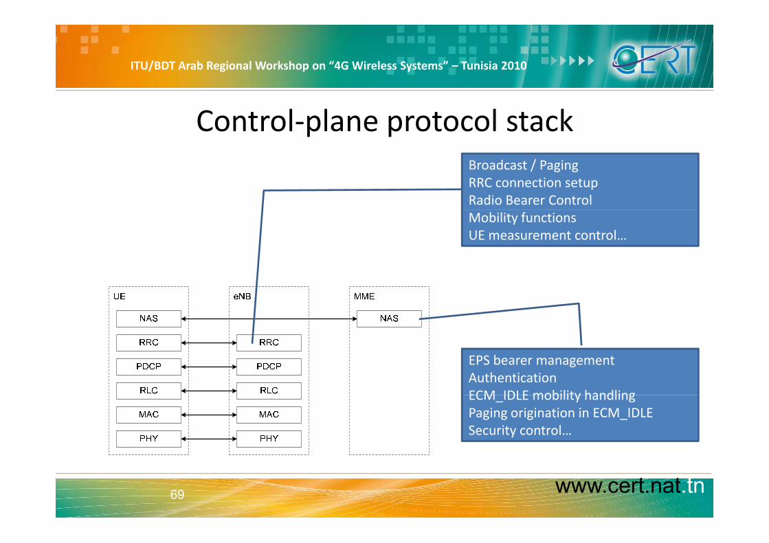
Control‐plane protocol stackBroadcast / PagingRRC connection setupRadio Bearer ControlMobility functionsUE measurement control…
EPS bearer managementAuthenticationECM IDLE mobility handlingECM_IDLE mobility handlingPaging origination in ECM_IDLESecurity control…
www.cert.nat.tn69

ITU/BDT Arab Regional Workshop on “4G Wireless Systems” – Tunisia 2010
Physical Layer
• It provides the basic bit transmission functionality over air.
• the physical layer is driven by OFDMA in the downlink and SC‐FDMA in the uplink.
• Physical channels are dynamically mapped to the available resources (physical resource blocks and antenna ports)(physical resource blocks and antenna ports).
• To higher layers the physical layer offers its data transmission functionality via transport channels.
• Like in UMTS a transport channel is a block oriented transmission service with certain characteristics regarding bit rates, delay, collision risk and reliability.y
• in contrast to 3G WCDMA or even 2G GSM there are no dedicated transport or physical channels anymore, as all resource mapping is dynamically driven by the scheduler
www.cert.nat.tn70
dynamically driven by the scheduler.
LTE Overview

ITU/BDT Arab Regional Workshop on “4G Wireless Systems” – Tunisia 2010
Medium Access Control (MAC)
• MAC is the lowest layer 2 protocol.
• Its main function is to drive the transport channels.
• From higher layers MAC is fed with logical channels which are in one‐to‐one correspondence with radio bearers.
• Each logical channel is given a priority and MAC has to multiplex logical• Each logical channel is given a priority and MAC has to multiplex logical channel data onto transport channels (demultiplexing in reception)
• Further functions of MAC will be collision handling and explicit UE identification.
• An important function for the performance is the HARQ functionality which is official part of MAC and available for some transport channelwhich is official part of MAC and available for some transport channel types.
www.cert.nat.tn71 LTE Overview

ITU/BDT Arab Regional Workshop on “4G Wireless Systems” – Tunisia 2010
Radio Link Control (RLC)
• There is a one to one relationship between each Radio Bearer and each RLC instance
• RLC can enhance the radio bearer with ARQ (Automatic Retransmission on reQuest) using sequence numbered data frames and status reports to trigger retransmission.
• The second functionality of RLC is the segmentation and reassembly that divides higher layer data or concatenates higher layer data into data chunks suitable for transport over transport channels which allow only a certain set of transporttransport channels which allow only a certain set of transport block sizes.
www.cert.nat.tn72 LTE Overview

ITU/BDT Arab Regional Workshop on “4G Wireless Systems” – Tunisia 2010
Layer 3 Radio Protocols
• PDCP (Packet Data Convergence Protocol)– Each radio bearer also uses one PDCP instance.
– PDCP is responsible for header compression (ROHC: RObust Header Compression; RFC 3095) and ciphering/deciphering.
– Obviously header compression makes sense for IP datagram's, but not for signaling. Thus the PDCP entities for signaling radio bearers will usually do ciphering/decipheringThus the PDCP entities for signaling radio bearers will usually do ciphering/deciphering only.
• RRC (Radio Resource Control)h f l l f– RRC is the access stratum specific control protocol for EUTRAN.
– It will provide the required messages for channel management, measurement control and reporting, etc.
l• NAS Protocols– The NAS protocol is running between UE and MME and thus must be transparently
transferred via EUTRAN.
www.cert.nat.tn73
– It sits on top of RRC, which provides the required carrier messages for NAS transfer
LTE Overview
ITU/BDT Arab Regional Workshop on “4G Wireless Systems” – Tunisia 2010
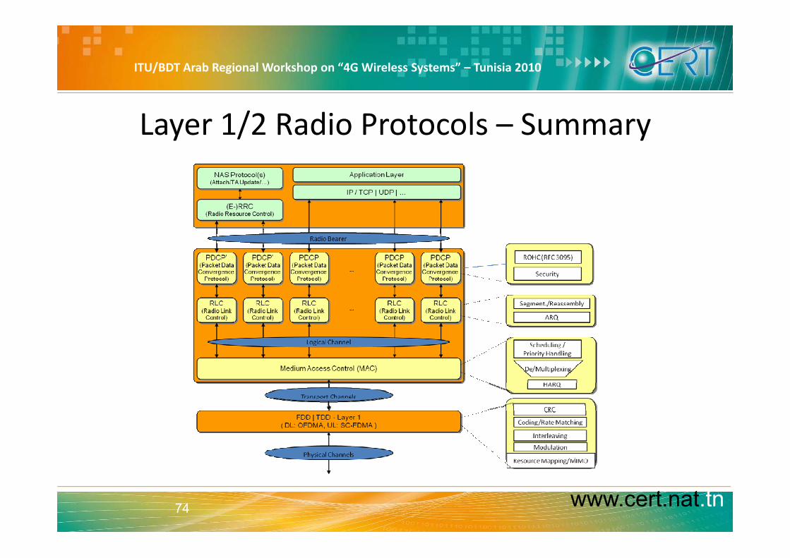
Layer 1/2 Radio Protocols – Summary
www.cert.nat.tn74

ITU/BDT Arab Regional Workshop on “4G Wireless Systems” – Tunisia 2010
RRC Protocol
www.cert.nat.tn75 LTE Overview
ITU/BDT Arab Regional Workshop on “4G Wireless Systems” – Tunisia 2010
LTE MBMS Concept• MBMS (Multimedia Broadcast Multicast Services) is an essential requirement for
LTE. The so‐called E‐MBMS will therefore be an integral part of LTE.
b f d l ll• In LTE, MBMS transmissions may be performed as single‐cell transmission or as multi‐cell transmission. In case of multi‐cell transmission the cells and content are synchronized to enable for the terminal to soft‐combine the energy from multiple t i itransmissions.
• The superimposed signal looks like multipath to the terminal. This concept is also known as Single Frequency Network (SFN).
• The E‐UTRAN can configure which cells are part of an SFN for transmission of an MBMS service. The MBMS traffic can share the same carrier with the unicast traffic or be sent on a separate carrier.
• For MBMS traffic, an extended cyclic prefix is provided. In case of subframescarrying MBMS SFN data, specific reference signals are used. MBMS data is carried on the MBMS traffic channel (MTCH) as logical channel.
www.cert.nat.tn76 LTE Overview

ITU/BDT Arab Regional Workshop on “4G Wireless Systems” – Tunisia 2010
LTE vs WiMAX− Both are designed to move data rather than voice and both are IP networks based
on OFDM technology.
b d d d ( ) d l k h h l ff− WiMax is based on a IEEE standard (802.16), and like that other popular IEEE effort, Wi‐Fi, it’s an open standard that was debated by a large community of engineers before getting ratified. The level of openness means WiMax equipment is standard d th f h t band therefore cheaper to buy.
− As for speeds, LTE will is faster than the current generation of WiMax.
− However, LTE will take time to roll out, with deployments reaching mass adoption by 2012 . WiMax is out now, and more networks should be available later this year.
− The crucial difference is that, unlike WiMAX, which requires a new network to be built, LTE runs on an evolution of the existing UMTS infrastructure already used by over 80 per cent of mobile subscribers globally. This means that even though development and deployment of the LTE standard may lag Mobile WiMAX, it has a crucial incumbent advantage.
www.cert.nat.tn77 LTE Overview

ITU/BDT Arab Regional Workshop on “4G Wireless Systems” – Tunisia 2010
Summary
• The 3GPP Long Term Evolution (LTE) represents a major advance in cellular technology. gy
• LTE is designed to meet carrier needs for high‐speed data and media transport as well as high‐capacity voice support well into the next decade.
• LTE is well positioned to meet the requirements of next‐generation mobile networks. It will enable operators to offer high performance, mass‐market mobile broadband services, through a combination of high bit rates and systemthrough a combination of high bit‐rates and system throughput – in both the uplink and downlink – with low latency.
www.cert.nat.tn78
y
LTE Overview

ITU/BDT Arab Regional Workshop on “4G Wireless Systems” – Tunisia 2010
Summary– Cont.
• LTE infrastructure is designed to be as simple as possible to deploy and operate, through flexible technology that can be p y p , g gydeployed in a wide variety of frequency bands.
• LTE offers scalable bandwidths, from from 1.4 MHz up to 20MHz, together with support for both FDD paired and TDD unpaired spectrum.
• The LTE–SAE architecture reduces the number of nodes, supports flexible network configurations and provides a high level of service availabilitylevel of service availability.
• Furthermore, LTE–SAE will interoperate with GSM, WCDMA/HSPA TD‐SCDMA and CDMA
www.cert.nat.tn79
WCDMA/HSPA, TD SCDMA and CDMA.
LTE Overview

ITU/BDT Arab Regional Workshop on “4G Wireless Systems” – Tunisia 2010
Summary – Cont.
Technologies/Features Benefits RequirementsTechnologies/Features Benefits Requirements
OFDMA with CP/SC‐FDMA with CP + Equalizer simplerScheduling time/frequencyBetter PAPR (SC‐FDMA)Better PAPR (SC FDMA)ISI suppression (CP)
QPSK, 16 QAM, 64 QAM + Higher bitratesAdaptative modulationp
Canaux communs + Variable trafficBetter capacity
‐ Scheduling isneeded
TTI = 1 ms + Better response to channelTTI = 1 ms + Better response to channelvariationHigher bitrates
www.cert.nat.tn80 LTE Overview

ITU/BDT Arab Regional Workshop on “4G Wireless Systems” – Tunisia 2010
Summary– Cont.
Technologies/Features Benefits
TTI = 1 ms +Better response to channelvariationHigher bitrates
Flat architecture +Simpler ArchitectureBetter latency
All IP +Architecture simpler Scheduling with
All IP +p
Convergenceg
priorities is needed
MIMO + Higher bitrates
Bande passante flexible(1 4 20Bande passante flexible(1.4 20 MHz)
+
Universal frequency reuse (1/1) + Better spectral efficiency ICIC
www.cert.nat.tn81 LTE Overview

ITU/BDT Arab Regional Workshop on “4G Wireless Systems” – Tunisia 2010
Thank you for your AttentionThank you for your Attention
www.cert.nat.tn82 LTE Overview