Embed Size (px)
DESCRIPTION
Citation preview

Internet copy.
ADVANCED MAGNETIC PROPULSION SYSTEMS(UFOs, Magnocraft, Free Energy Devices)
Part 3The Evidence Confirming the Validity
of the Theory of the Magnocraft
by
Dr Jan Pajak
Scientific MonographDunedin, New Zealand, 1990
ISBN 0-9597698-9-7© 1990 by Dr Jan Pajak

SCIENTIFIC MONOGRAPH
Author: Jan PAJAK, Doctor of Technical Sciences, Master ofEngineering, Engineer (Technical University of Wroclaw, Poland).
Title: "Advanced Magnetic Propulsion Systems" (UFOs, Magnocraft, Free Energy Devices).
Editorial data: Monograph, 1st New Zealand edition, ISBN 0-9597698-9-7, Dunedin, 1990.
Copyright © 1990 by Dr Jan Pajak.
All rights reserved. Copying, transmission, or storing of this monographis subject to the following conditions:
#1. A facsimile (copy) of this copyright page must also be includedwith any copy made of either part or all of this monograph, if this copyis to be used independently from other texts. In the case of incorporatinga copy of this monograph into another text, information on the author,title, and editorial data must also be included.
#2. For all non-profitable purposes (e.g. studies, education,research, etc.) this monograph can be copied, transmitted, or storedwithout restrictions, providing that the copies are distributed (oraccessible) free of charge, or for the reimbursement of costs only.
#3. There are no restrictions on the inclusion of brief quotationsfrom this monograph in a review, private studies, research, or criticism,providing that in any such a quotation the authors contribution is fullyacknowledged (i.e. author, title, editorial data, and page number, of thismonograph are stated).
#4. For purposes involving financial profit (e.g. reprinting injournals, books; presentation in TV programmes; etc.), no part of thismonograph may be reproduced in any form or by any means without priorpermission in writing from the author.
National Library of New Zealand Copyright Deposit No.: PO # 00-017004.Published in Dunedin, New Zealand, 9 October 1990. A private edition bythe author.
Date of distribution (printing) of this copy: 27 November 2000. (Notethat in case of having access to several copies of this monograph, it isrecommended to read the copy which has the latest date ofdistribution/printing.)
This monograph is available from Internet through addresses:<http://ufo.zakopane.top.pl>, <http://ufo.zakopane.top.pl/index2a.htm>,<www.ufo.hg.pl>. It can also be accessed through links from the followingWeb sites: <totalism.50megs.com>, <www.kki.net.pl/~ufo-album>,<http://www.hkpm.org.pl>.
Contacts with the author of this monograph: - All correspondence should be addressed to: Dr Jan Pajak P.O. Box 284 Timaru 8615 New Zealand. - E-mails: <[email protected]> or <[email protected]>.

3
CONTENTS of ISBN 0-9597698-9-7 PageABOUT THE AUTHOR
A.INTRODUCTION A-1 A1. The organization of this monograph A-1 A2. Reference to resource publications A-1 A3. This monograph formally proves that UFOs do exist A-2 A4. How to read this monograph A-3 A5. The history of this monograph A-4 A6. The aims of this monograph A-5 A7. Sponsorship for the building of the Oscillatory Chamber is sought A-5 A8. Constructive criticism as a motive force for the further development of the Theory of the Magnocraft A-7 A9. Milestone Journal articles by the author A-7
PART 1: THE PHILOSOPHICAL FOUNDATIONS
B.THE PERIODIC PRINCIPLE IN THE DEVELOPMENT OF PROPULSION SYSTEMS B-1 B1. Everything in our environment, including the formulation of inventions, is governed by appropriate laws B-2 B2. The basics of propulsion B-2 B2.1. The working medium B-3 B2.2. The primary requirement for building a controllable propulsion system B-4 B3. The content of the Periodic Principle B-4 B4. The first generation of the magnetic propulsion systems B-6 B4.1. The Magnocraft B-7 B4.1.1. The general design and components of the Magnocraft B-7 B4.1.2. Flight control B-8 B4.1.3. The specifications of the Magnocraft B-9 B4.2. The second motor-propulsor pair in the first generation of magnetic propulsion systems B-9 B5. Three successive generations of magnetic propulsion systems B-10 B5.1. How the "omnibus trend" should culminate in three conventions of the Magnocraft's operation B-10 B6. Second generation of magnetic propulsion systems, operating in the telekinetic (teleportative) convention B-12 B6.1. Phenomenon utilized in the second generation of magnetic propulsion systems B-12 B6.1.1. Action of the Telekinetic Effect explained by the Concept of Dipolar Gravity B-13 B6.1.2. Summary of the Telekinetic Effect activated technologically B-16 B6.2. Telekinetic power-stations (or "free energy devices") B-17 B6.2.1. Periodic Table postulating the future completion of telekinetic power-stations B-18 B6.2.2. Review of the main types of telekinetic power-stations built so far B-20 B6.2.3. Future directions in utilization of the Telekinetic Effect B-26 B6.3. Teleportation Vehicle as the Magnocraft of the second generation B-28B7. Third generation of the Magnocraft (Time Vehicles) B-32 C.EVEN IF ANTIGRAVITY EXISTED, MAGNETIC PROPULSION WOULD STILL REMAIN THE ONLY FEASIBLE ALTERNATIVE FOR SPACECRAFT

4
TRAVELING INTERSTELLAR DISTANCES C-1 C1. The antigravitational spacecraft would be impossible to maneuver and difficult to stabilize C-2 C2. The maneuverable antigravitational spacecraft would simply be an advanced version of contemporary rockets C-3 C3. With self-rechargeable propulsion, gravity does not affect energy consumption C-4 C4. The field of the antigravitational spacecraft would absorb huge amounts of energy C-5 C5. For the purpose of landing, the energy of the antigravitational field must be disposed of C-6 C6. The strong field would repel everything from the antigravitational spacecraft C-6 C7. The forces of reaction caused by the repulsion of other objects, would also hurl the antigravitational craft through space C-7 C8. Antigravity would induce a number of dangers C-7 C9. Even without knowing about the Concept of Dipolar Gravity there are no known premises suggesting any possibility of achieving the antigravitational field C-8 C10.Summary C-8
D.THE CONCEPT OF DIPOLAR GRAVITY D-1 D1. Why the Concept of Dipolar Gravity was formulated D-2 D2. The operation of our Universe ruled by dipolar gravity D-5 D2.1. Counter-matter: the thinking substance from the counter-world D-9 D2.2. Software models (registers) of material objects D-11 D2.3. Possible gains from the mastery of the counter-world D-12 D3. The interpretation of time in the Concept of Dipolar gravity D-13 D4. The interpretation of electromagnetic phenomena in the Concept of Dipolar Gravity D-14 D4.1. What is a magnetic field? D-14 D5. Why, according to the Concept of Dipolar Gravity, paranormal phenomena must display electromagnetic character D-16 D6. Telekinesis - a power source for free energy devices and a principle of operation for Teleportation Vehicles D-17 D7. The model of the brain as an input-output device D-20 D8. ESP - a key to instant benefits from the counter-world D-24 D8.1. Perfect Data Base (PDB) as a theoretical model of ESP D-27 D8.2. How to develop a simplest pendulum assisted ESP technique D-29 D9. How the Concept of Dipolar Gravity explains some mysterious phenomena D-30 D10.How the Concept of Dipolar Gravity merges science with religion D-33 D10.1.The Universe as a whole possesses its own intellect D-33 D10.2.Moral laws D-35 D10.3. Consistency - the measure of intellectual perfection D-37 D11.An experimental proof for the existence of the counter-world D-37 D12.To conclude D-40 D13.Reference publications D-40 E.PHILOSOPHICAL REQUIREMENTS FOR GIVING RECOGNITION TO NEW IDEAS E-1 E1. Everything is possible: we only need

5
to find out how to achieve it E-2 E2. All facts are equal - each of them deserves the same consideration E-3 E3. All statements of others are true unless they are proven to be untrue E-4 E4. Everything can be improved further E-6 E5. Knowledge is responsibility E-7 E6. What is totalism? E-8
PART 2: THEORY OF THE MAGNOCRAFT
F.THE OSCILLATORY CHAMBER F-1 F1. Why there is a necessity to replace the electromagnet by the Oscillatory Chamber F-1 F2. The principle of operation of the Oscillatory Chamber F-3 F2.1. The electrical inertia of an inductor as the motive force for oscillations in a conventional oscillatory circuit with a spark gap F-3 F2.2. In the modified oscillatory circuit with a spark gap, the inductance of a stream of sparks replaces the electrical inertia of an inductor F-4 F2.3. The combination of two modified circuits forms an "Oscillatory Chamber" producing a bipolar magnetic field F-6 F3. The future appearance of the Oscillatory Chamber F-7 F4. The condition under which the sparks will oscillate within the Oscillatory Chamber F-8 F4.1. Resistance of the Oscillatory Chamber F-8 F4.2. Inductance of the Oscillatory Chamber F-8 F4.3. Capacitance of the Oscillatory Chamber F-9 F4.4. The "sparks' motivity factor" and its interpretation F-9 F4.5. Condition for the oscillatory response F-10 F5. How the Oscillatory Chamber eliminates the drawbacks of electromagnets F-10 F5.1. Mutual neutralization of the two opposite electro-magnetic forces F-10 F5.2. Independence of the magnetic field production from the continuity and efficiency of the energy supply F-12 F5.3. Elimination of energy loss F-12 F5.4. Releasing the structure of the chamber from the destructive action of electric potentials F-14 F5.5. Amplifying control of the period of field pulsation F-15 F6. Advantages of the Oscillatory Chamber over electromagnets F-16 F6.1. Formation of the "twin-chamber capsule" able to control the output without altering the energy involved F-16 F6.2. Formation of the "spider configuration" F-18 F6.3. The non-attraction of ferromagnetic objects F-19 F6.4. Three-dimensional transformation of energy F-20 F6.5. Perpetual oscillating - a unique electromagnetic phenomenon allowing the Oscillatory Chamber to absorb unlimited amounts of energy F-20 F6.6. Function as an enormously capacious accumulator of energy F-21 F6.7. Simplicity of production F-22 F7. Advancements in the practical completion of the Oscillatory Chamber F-22
F7.1. Experimental devices F-23 F7.2. Stages, goals, and ways of their achieving in

6
the experimental building of the Oscillatory Chamber F-24 F7.3. The author's policy of the public ownership of the Oscillatory Chamber principles F-26 F8. The energy conservation and energy production potentials of the Oscillatory Chamber F-27 F8.1. Characteristics of the first period (change-over) of the chamber's implementation F-28 F8.2. Characteristics of energy management during the second, stable period of the Oscillatory Chamber's utilizationF-28 F9. Future applications of the Oscillatory Chamber F-30 F10.Monographs describing the Magnocraft, the Oscillatory Chamber and other corresponding devices F-32 F11.Symbols used in chapter F F-33
G. THE MAGNOCRAFT G-1 G1. The magnetic propulsor G-2 G1.1. The principle of tilting the magnetic axis in a Magnocraft's propulsor G-3 G1.2. The propulsion unit G-4 G1.3. Using propulsors as searchlights G-5 G2. The shell of the Magnocraft G-5 G2.1. Terminology describing various parts of the Magnocraft's shell G-6 G2.2. The Magnocraft's compartments G-7 G2.3. The Magnocraft's facilities G-8 G2.4. Materials for the Magnocraft's shell G-8 G2.4.1. The electrodynamic model of magnetoreflectiveness G-9 G3. Shapes of the coupled Magnocraft G-9 G3.1. The six classes of the Magnocraft arrangements G-10 G3.1.1. Flying complexes G-11 G3.1.2. Semi-attached configurations G-12 G3.1.3. Detached configurations G-13 G3.1.4. Carrier platforms G-13 G3.1.5. Flying systems G-14 G3.1.6. Flying clusters G-14 G3.2. The principles of coupling and decoupling G-16 G3.3. The hydraulic substance filling the space between the craft ("angel's hair") G-17 G3.4. The black bars of the magnetic field G-18 G4. The conditions defining the shape of the Magnocraft's shellG-18 G4.1. The condition of equilibrium between the thrust and stabilization forces G-19 G4.2. The basic condition for the force stability of the structure of a craft which uses magnetic propulsors G-19 G4.3. The condition for expressing the "K" factor by the ratio of outer dimensions G-21 G4.4. The condition for optimum coupling into flying systems G-21 G4.5. The condition under which the flanges coincide G-22 G4.6. Types of Magnocraft G-22 G4.7. Identifying the types of Magnocraft G-23 G4.8. The magnetic framework G-24 G5. The magnetic field of the Magnocraft G-24 G5.1. The starting flux G-25 G5.2. The naming of the magnetic poles G-26 G5.3. The effective length of the Oscillatory Chamber and the net magnetic force G-26
G5.4. The determination of the value for the starting flux G-27

7
G5.5. The energy of the Magnocraft's field G-28 G5.6. The energy of the Magnocraft's field is self-rechargeable G-30 G5.7. Why the Earth's magnetic field should not be called "weak" G-30 G5.8. The Earth's magnetic field is able to carry out technically useful work G-30 G6. The maneuvering of the Magnocraft G-31 G6.1. Ascent, hovering, and descent G-31 G6.2. Meridional flights G-32 G6.3. Latitudinal flights G-32 G6.3.1. An experiment showing the existence of the latitudinal thrust force G-32 G6.3.2. The deduction that explains the principles of the latitudinal thrust force formation G-33 G6.3.3. How to determine the direction of the thrust force created by the magnetic whirl (the "rolling sphere rule") G-34 G6.4. The rotation of the Magnocraft G-34 G7. The magnetic whirl G-35 G7.1. The magnetic circuits in the Magnocraft G-35 G7.2. Creation of a magnetic whirl G-36 G7.3. The ionic picture of a whirl G-37 G8. Three modes of the Magnocraft's operation G-38 G8.1. Visual recognition of the mode G-39 G8.2. The SUB system for indicating the Magnocraft's mode of operation G-40 G9. The properties of the Magnocraft G-41 G9.1. The properties of the Magnocraft during the magnetic whirl mode of operation G-41 G9.1.1. Properties of the tunnels made in rocks by the Magnocraft G-42 G9.2. The properties of the Magnocraft during the throbbing mode of operation G-44 G9.3. Humming noises appearing in both the magnetic whirl and throbbing modes of operation G-44 G9.4. The properties of the Magnocraft during the magnetic lens mode of operation G-45 G9.4.1. The magnetic lens action in ascending Magnocraft G-46 G10. The landing sites of the Magnocraft G-46 G10.1. Environmental damage caused by the landed MagnocraftG-47 G10.2. Three main classes of the Magnocraft's landings G-50 G10.3. The landing sites for the magnetic circuits looped under the ground G-51 G10.3.1.Determination of the Magnocraft's dimensions from the scorch marks left at landing sites G-52 G10.4. The landing sites with magnetic circuits looped along the surface of the ground G-53 G10.5. The landing sites for circuits looped in the air G-54 G10.6. The landing sites formed by arrangements of the Magnocraft G-54 G11. Explosion sites of the Magnocraft G-55 G12. Summary of the attributes of the Magnocraft G-58 G13. Military aspects of the Magnocraft G-62 G13.1. Use of the Magnocraft as a weapons platform or transportation facility G-62 G13.2. Use of the Magnocraft as a selectively acting weapon G-63

8
H.PERSONAL PROPULSION H-1 H1. The standard garment of Personal Propulsion H-1 H2. A special version of Personal Propulsion with cushions around the hips H-2 H3. The garment with main propulsors in epaulets H-2 H3. Principles of operation of magnetic Personal Propulsion H-3 H4. The attributes of Personal Propulsion H-4
I.THE FOUR-PROPULSOR SPACECRAFT I-1 I1. The general design of the Four-Propulsor Spacecraft I-1 I2. The operation of the Four-Propulsor Spacecraft I-2 I3. The properties of the Four-Propulsor Spacecraft I-3 I4. Identification of the type of Four-Propulsor Spacecraft I-4
PART 3: THE EVIDENCE CONFIRMING THE VALIDITY OF THE THEORY OF THE MAGNOCRAFT
J.FORMAL PROOF THAT "UFOs ARE ALREADY OPERATIONAL MAGNOCRAFT" J-1 J1. Principles of selecting the relevant UFO evidence J-3 J2. Matching of the Magnocraft's attributes with those observed in UFOs J-5 J2.1. The observed shapes of solo flying vehicles J-5 J2.1.1. The vision distorting factors J-6 J2.2. The observable arrangements of coupled vehicles J-7 J2.3. The absence of mechanically co-operating parts J-8 J2.4. The predetermined (Magnocraft-like) location of propulsors J-9 J2.5. The utilization of magnetic interactions for producing the propelling forces J-10 J2.5.1. Why the Magnocraft's principles could not be formulated 40 years earlier J-10 J2.6. The formation of a magnetic whirl J-11 J2.7. The ability to change the mode of the UFO's operation J-12 J2.8. The induction of electric currents J-13 J2.9. The emission of various light signals J-13 J2.10.The interference with electromagnetic radiation J-15 J2.11.The ability to control the resources of the UFO's energy J-17 J2.12.The magnetic manner of flying which contradicts laws of hydromechanics J-17 J3. Concluding the reasoning and evidence from this chapter J-20 J4. Chapter J reference material J-22
K.THE VALIDATION OF THE CONCEPT OF DIPOLAR GRAVITY K-1 K1. Premises for the telepathic beacon system installed on Earth K-1 K2. Observations of Teleportation Vehicles in operation K-3 K3. The evidence confirming the existence of Time Vehicles K-5
L.EVIDENCE CONFIRMING THE VALIDITY OF THE OSCILLATORY CHAMBER L-1 L1. Observations and photographs of Oscillatory Chambers used in UFO propulsors L-1 L1.1. Columns of magnetic field yield from UFO propulsors are square in the cross-section L-2 L1.2. Outlets of UFO propulsors are square and reveal gold or yellow bands of electric sparks rotating inside L-2 L1.3. Twin-chamber capsules formed from two Oscillatory Chambers are frequently observed in UFOs

9
and even photographed L-4 L1.4. Oscillatory Chambers have been seen on the decks of UFOs as described by numerous abductees L-5 L1.5. Indirect confirmations that UFOs use Oscillatory Chambers L-7 L2. Material evidence left by UFO Oscillatory Chambers L-8 L3. Ancient descriptions of the Oscillatory Chamber L-8 L4. Conclusion L-11 L5. Chapter L reference material L-11
M.THE MATERIAL EVIDENCE AVAILABLE THAT CONFIRMS THE LONGSTANDING USE OF MAGNOCRAFT-TYPE UFOs M-1 M1. Material evidence on UFO landing sites M-2 M1.1. All three known types of landing sites are formed by visiting extraterrestrial vehicles M-2 M1.2. The value of the Cosmic Cubit can be determined from UFO landing sites M-3 M1.3. The diameters of landing sites confirm the existence of eight basic types of extraterrestrial vehicles M-5 M1.4. Some marks left on the ground document the landing of entire configurations of UFOs (including flying systems) M-6 M1.5. Why UFO landing sites could not be formed by the growth of mushrooms or by any other natural cause M-6 M1.6. There is a critical landing duration after which sites become permanent M-8 M1.7. More that else we can learn from UFO landing sites M-9 M2. Long, straight, geometrically-shaped underground tunnels - material evidence of the ancient operation of the Magnocraft M-10 M3. UFO explosion sites M-12 M3.1. The Tapanui Crater M-12 M3.2. The Tunguska Explosion M-19 M3.3. What can be learned from both explosion sites (i.e. Tapanui and Tunguska) M-22 M4. Fragments of UFO vehicles found on Earth M-24
N.OBSERVATIONS OF UFONAUTS WHO USE MAGNETIC PERSONAL PROPULSION N-1 N1. The characteristic appearance of the wearers of personal propulsion N-1 N2. The extraordinary abilities of UFOnauts wearing personal propulsion garments N-2 N3. The scorched footprints left by personal propulsion of a UFOnaut N-3 N4. The consequences of the observation of personal propulsion of UFOnauts N-4
O.CONTEMPORARY OBSERVATIONS OF FOUR-PROPULSOR UFOs O-1 O1. Classic sightings of four-propulsor UFOs O-1 O2. Photographs of four-propulsor UFOs O-3 O3. Concluding this chapter O-3
APPENDIX P.
INDEX OF NEW TERMINOLOGY

10
PART 3
THE EVIDENCE CONFIRMING THE VALIDITY OF THE THEORY OF THE MAGNOCRAFT
Professor Tom Stonier in his book, "The Wealth of Information", (Thomas Methuen,London 1983, ISBN 0-423-00800-5 pb, page 12) says:
"Unlike earlier times when practical experience laid the foundation for new science, theflow of information is now generally in the opposite direction. For example, in the nineteenthcentury, the experience with the steam engine led to the science of thermodynamics. In contrast,the development of the transistor in the middle of the twentieth century was dependent on thesolid-state physics conducted decades earlier."
This statement very precisely reflects the revolution which we are observing in technologyat present. From now onwards our inventions will become so complex and so sophisticated thatthere is no way we can come upon them accidentally while conducting other experiments.Behind each major device now completed stands some complicated theory which is anaccumulation of an enormous amount of knowledge, and we must accept that this process willescalate in the future. Therefore the time when we could expect from an inventor that he/shewould provide working hardware in support of his/her claims belongs to the irreversible past.From now on new inventions will be first presented on paper - like the Oscillatory Chamber andMagnocraft in this monograph - and then will come the long, expensive and difficult task ofactually building them, involving the co-ordinated effort of many people.
This new situation with regard to inventions also requires the developing of new methodsfor evaluating the validity and usefulness of a particular creation, before the construction of it isin fact started. These methods must be able to ascertain whether an invention is correct, feasibleand useful when it is still on paper and presented in theoretical form only. Unfortunately, suchmethods do not exist as yet. We must start to create and develop them as soon as possible.
In the part of this monograph that follows, the author's approach in developing such amethod is presented. This approach takes the form of logical deductions and supportingevidence which prove that the propelling devices described in the previous part of thismonograph are already used on Earth by some extraterrestrial civilizations. At the moment whenthe deductions prove this, they also prove that the completion of the Magnocraft and theOscillatory Chamber by our civilization must be feasible as well. This is because the laws of theuniverse work the same for everyone. Therefore no matter who implements a particularinvention, its principles must still be valid and its completion feasible. The principles working forextraterrestrials must eventually work also for us. Thus conclusive proof for the use of aparticular device by extraterrestrials is equivalent to actually seeing a working model of thisdevice. Of course, because such a working model is "imported" (not built here on Earth), ourcivilization still faces the problem of its completion. But our aim becomes clearly defined, thefinal success assured, and the completion procedure justified.

J-1
Chapter J
FORMAL PROOF THAT "UFOs ARE ALREADY OPERATIONAL MAGNOCRAFT"
It is obvious that the best way of convincing someone about the feasibility of building aMagnocraft is to demonstrate this vehicle when it is already built and operational. By anextraordinary coincidence, advanced spaceships are observed on Earth whose attributesexactly correspond to those of the operational Magnocraft. These spaceships are called UFOs(an acronym from "Unidentified Flying Objects"). Of course, in order to use UFOs to validate theMagnocraft, formal proof that "UFOs are already operational Magnocraft" must first beconducted. This proof is presented in the chapter that follows.
The Magnocraft is entirely an Earth vehicle, i.e. it has been invented, developed, and itis proposed to build it on Earth without any extraterrestrial influence or inspiration. It was onlyafter all the attributes of this vehicle were fully identified and published that numerous readerscontacted the author and reported that they have actually seen the Magnocraft in operation -only they called it differently, i.e. a UFO. Although at that stage the author did not envisage anyconnection of his Magnocraft and UFOs, just in case there was one he followed these reportsand tried to identify the differences or similarities existing between both these vehicles. Soonafterwards, with the weight of the evidence that he collected, he realized that in fact there areUFO vehicles already operational on Earth which display all the attributes that have beentheoretically predicted for the Magnocraft. Subsequently the formal proof that "UFOs are alreadyoperational Magnocraft" has been worked out and published. It appeared for the first time in thePolish Journal "Przeglad Techniczny Innowacje", no 12/1981, pp.43-5. The proof presented inthis chapter is only an extension, with additional evidence, of this original proof published in thePolish Journal.
The formal proof that "UFOs are already operational Magnocraft" is based on a very oldmethodology adopted by present science and called the methodology of "matching theattributes". In this methodology two sets of attributes describing two independent objects arecompared (matched), in order to prove that both these objects are identical. An ancient exampleof using this methodology would be a hunter who matches the attributes of a trail with attributesof an animal known to him in order to determine as to whether this animal made the trail. Thismethodology is one of the most reliable, successful, and frequently used ways of identifyingunknown objects. It is used in the majority of identification procedures, including criminalinvestigations (matching the evidence with a suspect), medicine (matching symptoms with adisease), military reconnaissances, etc. In order to prove with this methodology that theMagnocraft and UFOs are identical vehicles, a total match between the theoretically deducedattributes of the Magnocraft and the observed attributes of UFOs must be documented.Therefore, this proof is formulated as a logical structure comprising the following 4 steps:
1. Proposing the working thesis that "UFOs are already operational Magnocraft" anddefining a way of proving the truth of this thesis. (The introductory part of chapter J achievesthis).
2. Identifying the Magnocraft's attributes, to be subjected to matching. Through applyingthe theory of the Magnocraft, 12 most representative attributes that will characterize theoperational Magnocraft were theoretically identified and are listed in subsection G12. Thereason why, in the proof presented here, only 12 attributes are used (instead of, for example,13 or 24) is that from the probability point of view 12 attributes suffice for this purpose (see thejustification from subsection A3). But the complexity of the Magnocraft enables us to identify anddescribe a large number of further attributes not considered here. Therefore, almost any

J-2
required number of the Magnocraft's attributes can be included in this proof later, if required.3. Documenting the corresponding attributes of UFOs. By analyzing various UFO
observations and photographs, corresponding 12 attributes of UFOs were revealed anddocumented.
4. Matching each attribute of the Magnocraft deduced theoretically with the correspondingattribute observed on UFOs. If this matching is total, it automatically proves the truth of theworking thesis, thus constituting formal proof that "UFOs are already operational Magnocraft".
The completion of the above logical structure is achieved in 3 sections of this chapter.The first section J1 explains the principles applied during the selection of evidence concerningUFOs to be presented here. The second section J2 conducts the matching of both groups ofattributes, i.e. those deducted theoretically for the Magnocraft and those observed on UFOs. ThisJ2 section is further sub-divided into 12 subsections, each one of which describes the nextrepresentative attribute of the Magnocraft, and then matches this attribute with thecorresponding evidence collected during observations of UFOs. The section J3 presents thefinal conclusions derived from the presentation of the logical structure of this proof.
The completion of the proof that "UFOs are already operational Magnocraft" introducesa number of important implications. The three most significant of these are as follows:
(1) It constitutes proof that "UFOs do exist". (2) It validates the theory behind the Magnocraft. From the point of viewof the
Magnocraft's validity, the existence of UFOs which employ the Magnocraft's principles ofoperation has the same value as the presentation of a working model of the Magnocraft.
(3) It stresses the importance of UFO research. The scientific observation of UFOs is vitalfor rapid progress towards the completion of the Magnocraft. Thus, it is also vital for theachievement by our civilization of a capability for interstellar transportation.
The methodology of "matching attributes" applied here to prove formally that "UFOs arealready operational Magnocraft" also provides an additional benefit. It introduces the important"postulate of interchange between UFOs and the Magnocraft". According to this postulate everycorrect equation, principle and fact established for the Magnocraft must also apply to UFOs; aswell, every fact observed on UFOs must apply to the Magnocraft. The practical utilization of thispostulate allows for the more rapid solving of the UFO's secrets by applying to them all thefindings concerning the Magnocraft, and also allows for faster progress in the building of ourMagnocraft through utilizing technical solutions that are already observed on UFOs.
There have been already, and will be in the future, numerous attempts to discredit thevalidity of deductions presented here (e.g. see OMNI, February 1984, Vol. 6, no. 5, page 87).However, in spite of these attacks from opponents of the Magnocraft, so far no one hasmanaged to invalidate the theory behind this vehicle, or refute the validity of the proof based onthis theory. Every single objection against the Magnocraft that has been raised to date is a resultof critics overlooking an important solution already postulated by the theory of this vehicle. Onthe other hand, success in the experimental completion of the devices postulated by theMagnocraft's theory (such as the Oscillatory Chamber and free energy devices) reinforces thevalidity of this vehicle.
The proof is based on the methodology of "matching the attributes" in definition allowsan unlimited number of comparisons (i.e. every fact gathered from a UFO observation can becompared to a corresponding fact derived theoretically from the Magnocraft). Therefore, this kindof proof still remains valid even if the individual attributes of UFOs that it utilizes could not bevalidated for some reason. This characteristic of the proof presented here completely neutralizesthe debunking strategy used so far by skeptics to abolish previous attempts proving theexistence of UFOs. We know that all these previous attempts were based on single facts (e.g.single observation, single event, single material evidence). On the other hand, there is no singlefact that can't be put in doubt by scientists who are so willing. Therefore, by adopting the strategyof continually putting such single facts in doubt, the UFO skeptics have managed to invalidate

J-3
every other proof put forward to date. Fortunately, with regard to the proof presented here, thisstrategy used by skeptics would simply not work. In order to put it in doubt they would need toprove conclusively that all the evidence of UFO manifestations is non-existent (philosophically,proving this is impossible). For this reason, the structure of logical proof presented in thischapter is "skeptic-proof".
The impossibility of discrediting the proof presented here puts UFO skeptics in a ratheruncomfortable position. Their reaction observed so far is to ignore its existence. But suchignoring has no significance in the long run - it delays the official recognition of the proof, butis unable to prevent it. The proof is there, it was formally published, no-one is able to disproveit, therefore every person involved in UFO research is obliged to respect its validity.
As is usually the case with the acceptance of new scientific developments,acknowledgment of the author's formal proof that "UFOs are already operational Magnocraft"is progressing very slowly. Probably even when the first Magnocraft built on Earth will carryambassadors from our planet to other civilizations, some individuals will still refuse to recognizeall the implications that this vehicle introduces (similar to the situation where believers in a "flatEarth" still refuse to accept that our planet is round). However, in spite of this, the Magnocraftsteadily gains further adherents in an ever increasing number of countries. At present it isalready well established in such countries as: New Zealand, Poland, Switzerland, USA, USSR,and West Germany. Further investigators from other countries display a growing interest in thisvehicle, and in the ideas that it introduces.
J1. Principles of selecting the relevant UFO evidence
There is an overwhelming wealth of evidence available at present concerning UFOmanifestations. If "UFOs are already operational Magnocraft", then all these UFO manifestationsmust correspond exactly in every detail to the future effects of the Magnocraft's operation. Ofcourse it would be impossible to present all the evidence concerning UFOs in one smallchapter. For this reason, only selected samples of "court-type" evidence are used here. Thesesamples represent evidence that would be recognized in any court during trials involving humanlives, and include UFO photographs and eye witness reports. Apart from this court-typeevidence, there is a wealth of material evidence available on UFOs, such as marks left on theground during landing of UFOs, sites where UFOs exploded, glassy tunnels made in rocksduring underground flights of UFOs, etc. This material evidence is referred to here, but itsdetailed presentation will be contained in the next chapters in support of more specific aspectsof the Magnocraft's theory. Most of it has a stationary, permanent character, thus it can besubjected to scientific investigations without the need for altering traditional researchmethodologies (e.g. the marks left on the ground during landing or the explosion sites of UFOsdo not fly away when scientists approach them). Its interpretation significantly advances ourability to commence the building of the Magnocraft.
Included in the court-type UFO evidence are a vast number of UFO photographs andeye-witness reports. This number is too large to be reviewed fully in one small chapter. Also themain goal of this presentation is more to explain the principles of matching the attributes ofUFOs with those of the Magnocraft, rather than to accommodate all the UFO evidence availablefor this purpose. Therefore for each topic addressed, the author selected only one single sampleof evidence which in his opinion is the most representative of all the material collected on thistopic. Everywhere, where it is possible, the author has used photographs to illustrate hisdeductions, as they constitute the most objective evidence. In some topics, however, where thedeductions concern matters impossible to be photographed (e.g. course of events, electriccurrents, etc.), appropriate eye-witness reports are provided.
All evidence used in this chapter has been selected from the most classic examples of

J-4
UFO photographs and observations. Therefore copies and descriptions of this evidence arecontained in various books and periodicals dedicated to UFOs. In order to save readers' time,the author has listed at the end of this chapter some resources known to him of UFO evidence.Although these books contain all the descriptions of cases referred to in this chapter, they arenot the only sources which supply the details of the evidence discussed here and which allowfor the verification of this evidence. For scientific exactitude, each time deductions are supportedby UFO evidence, the author has also provided the source materials where the originaldescription of this evidence can be found. Such a reference takes the form explained insubsection A2, i.e. "[...J] page number". For example "[4J] p. 134" means: look at page 134 inthe 4th book in the list provided on the last page of chapter "J". (Notice that the first book in thelist at the end of chapter J is written in German. But because, in the author's opinion, it containsthe best atlas of UFO photographs ever published, it is highly recommended for Englishspeaking readers also.)
The author has dedicated an enormous amount of time and effort to provide readers withthe best possible quality of evidence. He has searched for the authors of UFO books andphotographs, has written numerous letters to them, has asked for copyright permission, higherquality copies of photographs, details which were lacking on some evidence, etc. Unfortunatelymost of these efforts have not produced results. Thus some evidence of key importance mustbe presented here in the form which is available to the author, i.e. sometimes with importantdata unavailable, or not of the highest quality copy. But he will continue his effort and in the nextedition of this monograph the quality of the evidence presented should be improved further. Theauthor would like to take this opportunity to issue an appeal for assistance in contacting ownersof UFO photographs, in finding the sources of the higher-quality UFO pictures, in the collectingof unavailable details (e.g. authors, dates, places, etc.) on the evidence already presented here,etc. To improve this monograph is not just to expand one more book on UFOs, but to strengthenthe scientific foundations on which the rationalized research of UFO manifestations can be built.
As is obvious from the content of chapters G, H and I, UFOs are not one type of vehicle,but a mixture of three kinds of devices which in this monograph are called the Magnocraft,Personal Propulsion, and Four-Propulsor Spacecraft. In the deductions from this subsection onlythe Magnocraft-like (i.e. disc-shaped) UFOs will be considered and analyzed. The personalpropulsion of UFOnauts will be discussed in chapter N, whereas the four-propulsor UFOs willbe commented on in chapter O.
The many distinguishable differences between the anatomy of occupants from variousUFO spaceships allow us to deduce that numerous civilizations have sent their vehicles toEarth. This is even confirmed by the claims of UFOnauts themselves. In the author's private filesthere is a report of a New Zealand citizen abducted onto a UFO deck for a medical examination(the Auckland incident of abduction, Auckland, New Zealand, December 1979) who discussedthis matter with an alien doctor. In this report the information provided by the UFOnaut isrecorded. Below is quoted what the abducted person repeated of the alien's statements:
"They have planets of people who are above them and planets who are below. We arebelow - not in any space, time or anything, simply in development. As he said and alwaysemphasizes, knowledge is responsibility. They know about us, they have a responsibility to helpus, as those higher than them have a responsibility to help them."Because the level of development of the civilizations sending UFOs varies, so also thetechnological advancement of their vehicles must differ. Thus Earth is most probably visited bya mixture of vehicles which are equivalent to all three generations of the Magnocraft. But weknow from subsection B5 that each one of these generations is able to operate in the magneticconvention also. Therefore all UFOs in some stages of their flight display the attributes of theMagnocraft of the first generation. In this chapter, such magnetic attributes only will beconsidered. The UFOs flying in other conventions, i.e. teleportative and time travel, arediscussed in chapter K.

J-5
As was proven in subsection G4, the general shape of all vehicles which employ theMagnocraft's operation is strictly predefined by the set of laws utilized in their propulsion. Thisshape must obey the set of equations listed in Figure G23. The only details which could vary forvehicles of different civilizations are the dimensions, materials and the internal divisions intocrew compartments. But a common logic says that for practical reasons (e.g. rescue missionsin space) the dimensions of UFOs should also be standardized by various civilizations who usethese vehicles. Therefore, it is almost certain that all civilizations who have already builtMagnocraft-like vehicles are organized into an "intergalactic confederation" whose aims alsoinclude the standardization of these vehicles' dimensions. (Various reports from UFO abducteesmention the existence of this confederation, e.g. the abduction of Serg. Moody on 13 August1975, Alamogordo, New Mexico, USA - see Xenolog (New Zealand), no 104, May-June 1976,pp. 11-14.) The assumption adopted in this chapter is that such an intergalactic confederationin fact does exist. This assumption allows for a consistent approach in considering alldisc-shaped (discoidal) UFOs, without determining which civilization produced them.
J2. Matching of the Magnocraft's attributes with those observed in UFOs
The order of the Magnocraft's attributes discussed in the subsections that follow coincideswith that from subsection G12. Therefore for the better comprehension of subsequent topics,readers are recommended to refer to subsection G12.
J2.1. The observed shapes of solo flying vehicles
Although UFOs never pose for photographs and it is extremely difficult to obtain a clearpicture of these vehicles, throughout the years a number of legible photos have beenaccumulated. While reviewing these photographs it becomes evident that the shapes ofdiscoidal UFOs correspond to the shape of the Magnocraft in every detail - compare the Figuresthat follow with the description from subsection G.1. As we may see from Figure J1 an outlineof a UFO reminds us of an inverted saucer (see also Figures N1 and G4). Identical to theMagnocraft, UFOs also possess the flange that surrounds these vehicles around their base - seeFigure J2. In the center of their base there is an underside concave - see Figure J3. In the centerof the UFOs' topside convex, a central propulsion compartment containing the main propulsoris located - compare Figures J4 and G5.
Similarly as is the case with the Magnocraft, UFOs are also built in the eight basic typesK3 to K10, which differ from one another by the value of their "Krotnosc" factor (see subsectionG4.7) and also by all attributes which depend on this "K" factor (e.g. number of side propulsors,general shape, dimensions). The existence of these eight types of UFOs can easily be revealedduring the geometrical analysis of the objects photographed. The object shown in Figures J1and J17 represents the UFO type K3. Figures J5 and J2 show respectively UFOs type K4 andK5. A UFO type K6 is shown in Figures J11 and J19. Type K7 is presented in Figures L2 andJ30. The three largest types of UFOs, i.e. K8, K9 and K10 are presented respectively in FiguresJ6, J7 and J8.
The geometrical analysis of the photographs of discoidal UFOs reveals that each typeof these objects exactly fulfills the set of equations listed in Figure G23. This means that thedesign conditions, which for the Magnocraft were described in subsection G4, are alsooperational in the structure of UFOs (these conditions are only operational when a given vehicleemploys the Magnocraft-like propulsion system).
Mechanical protrusions which strongly confirm the similarity between the structures ofUFOs and those of the Magnocraft are the telescopic legs of UFOs positioned beneath at anangle. As can be learned from Figure B1, the legs in the small types of Magnocraft (i.e. K3 to K5

J-6
type) must be extended at an angle in relation to the vehicle's base. There are a number of UFOphotographs - see Figures J9 and J22 - which show that the legs of these extraterrestrialvehicles are in fact extended beneath at an angle. It should be stressed here that frequently atlanding sites of UFOs very clear prints from these legs remain. An example of such a print isshown in Figure M1. The determinations of the weight of UFOs which made these imprintsindicate that they are very close to the predicted weight of the Magnocraft, listed in Table G1.
The most direct confirmation of the similarity between the designs of UFOs and theMagnocraft originates from the reports of people taken onto the deck of UFOs (so-calledabductees). If we omit from consideration the internal partitions dividing the crew's cabins intosmaller rooms (which in various UFOs must be placed in different ways to suit the specificspecialization of a particular vehicle) the design of every UFO's shell corresponds exactly to thatof the Magnocraft. In almost every report the central cylinder containing the main propulsor (see13 in Figure G5) is either directly mentioned or its existence can be deduced. Here is howAntonio Villas Boas (Brazil), abducted onto a UFO deck on October 15, 1957, describes theinterior of the spaceship which he visited - see [5J] p. 20:
"... this room was in the center of the machine. In the middle of the room there was a metalcolumn running from ceiling to floor".Similar central cylinders, sometimes even including accounts of the Oscillatory Chamber, canbe found in numerous other well-known descriptions of a UFO interior, e.g. see the classicalbook by Jonathan Swift, "Gulliver's Travels", chapter III of a voyage to Laputa, where the interiorof the Laputians' "flying island" (i.e. a UFO) is described in detail.
Moreover, almost every UFO abductee in his/her report also mentions the flange with sidepropulsors. Even from such brief quotations of abductees, like those provided in subsectionsL1 and K2, the similarity of UFO and Magnocraft shapes is evident (see also Figure G5).
J2.1.1. The vision distorting factors
The evidence presented above indicates that the saucer-like shapes of all discoidalUFOs should be perceived by various witnesses as almost identical. On the other hand, weknow from practice that individual witnesses may differ in their perception of this shape almostto the extreme. In Figure J10 only a small sample of the almost unlimited variety of shapes andforms of UFOs which are observed and photographed is presented. So what is the reason forsuch significant differences between the objective shape of discoidal UFOs and theirsubjectively perceived picture? The deductions that follow explain this.
With UFOs, the unique principles of operation, the changes caused in the environment,the materials used for the shell, and the coupling capabilities, introduce seven "vision distortingfactors" which may completely alter our perception of these vehicles. In appropriate situations,the distorting factors affect, at random, our observations, causing the same UFO to be perceivedcompletely differently by various witnesses. Let us now examine each factor separately,considering them in the order of their distorting power. (Readers should notice that theidentification and evaluation of each factor is only possible because the Theory of theMagnocraft so clearly defines them.)
#1. The ionic picture of a whirl. In the magnetic whirl mode of a UFO's operation, thespinning cloud of ionized air may completely cover the surface of a vehicle (this cloud is calledhere the ionic picture of a whirl). Because this cloud is nontransparent, intensive, and withclearly defined boundaries, it is taken by numerous witnesses to be the surface of UFOs. Theclassic shape of an ionic picture of a whirl (see Figure G32) is easily deformed by the vehicle'smotion, magnetic field configuration, etc. It also depends strongly on the type of UFO vehicle thatformed it and on the intensity of the magnetic whirl, which (intensity) can change smoothly fromzero to maximum. Thus the ionic picture of a whirl can provide witnesses with hundreds of

J-7
various perceptions of the same vehicle - see Figures J9, J22, J23, J26 and J33.#2. The coupling of a number of discoidal UFOs into various flying arrangements. The
shapes of these arrangements drastically differ from the shapes of vehicles flying solo.Subsection G3 reveals how many different final forms can be obtained from such couplings.Figures J11 to J16 and also Figure L2 confirm that UFOs in fact produce each one of theseforms. For example, the vehicle D/2 from Figure J10 is not a UFO of an entirely new shape, buta flying system formed from a number of discoidal UFOs - compare this D/2 shape and FigureG16.
#3. The action of a magnetic lens. This action is especially confusing as it maysignificantly alter the apparent shape of a UFO. It manifests itself through two different effects,i.e. (1) making parts of vehicles located close to the propulsors (i.e. flanges and topside domes- see Figures J5 and J30) become partially or totally invisible, and (2) distorting the apparentshape of visible parts of the vehicles in a similar way as objects partially submerged in atransparent liquid can be distorted. The second effect causes the hemispheres to be seen asovals, spheres to be seen as egg-shaped, and flanges from behind objects may appear on theside of UFOs or on top of them - giving an impression of wings, tails, etc. An excellent exampleof this type of distortion is an apparent deformation of a lower UFO in detached configurations(compare Figures G13 and L1, which both show exactly the same configuration of vehicles).
One of the frequently reported results of the magnetic lens action is revealed to a witnesswho observes a UFO from underneath. In such cases the entire body of a vehicle maydisappear, with only the twin-chamber capsule from the main propulsor remaining visible -compare Figures G37 and J31. In this way the discoidal UFOs are perceived by eye-witnessesas diamond-shaped or square objects. This phenomenon was reported by the witness of theUFO from Figure N1. Also the shape D/7 from Figure J10 was formed in the same way - see thedescription from subsection J2.10.
#4. The emission of various light signals. During darkness or poor visibility,eye-witnesses and photographs reveal only the shapes of light emitted by UFOs. Thus the realform of UFOs remains hidden behind these lights. Figures J19, J21, J25 and J28 illustrate howmuch distortion and concealing of the real shape of a UFO such lights may induce - see alsothe descriptions from subsection J2.9.
#5. The black bars of a magnetic field. The columns of a strong magnetic field yielded bypropulsors of UFOs may trap light and look as though they were made of a black material. Thus,for some witnesses they may appear as solid elements protruding from vehicles. Whencombined with the action of a magnetic lens these black bars may significantly alter theappearance of UFOs - see Figure L1 which was the model for the drawing B/6 from Figure J10.
#6. The transparency of the UFOs' shell. The shells of UFOs is made of transparentmirror-like material whose degree of light reflection is controlled by the crew. Therefore, if thecrew so wishes, the shell can be completely transparent or, like a mirror, may completely reflectthe light. All the stages of the continuum between these two extremes can also be obtained. Thisability to become transparent causes some internal elements of vehicles to be observed(especially when the shell of a UFO is looked through at an angle close to 90 degrees), whilethe outlines of the external shell remain unnoticeable. For example in Figure J8 the mainpropulsor and the crew's cabin ceiling are clearly visible through the transparent topside dome.Thus, while analyzing this photograph, one could obtain a completely false impression aboutthe shape, size and location of topside domes in UFOs type K10.
#7. The various elements protruding from UFOs (e.g. legs, periscopes). These may alsosignificantly change the appearance of the observed vehicles - see Figures J9 and J22.
If during an actual observation more than one of the above factors acts simultaneously,the resultant perception of the UFO's shape is able to confuse even the most experiencedinvestigator. For this reason the factors listed have contributed to forty years of difficulty inpiecing together the enigma of UFOs. A theoretical approach to the problem, achieved through

J-8
the formulation of the Theory of the Magnocraft, allowed a breakthrough in this ocean ofmisinformation and the discovery of a single source from which the shapes of all UFOs originate.Thus, thanks to the Theory of the Magnocraft, all UFO shapes can now be explained.
J2.2. The observable arrangements of coupled vehicles
It is confirmed that UFOs are also able to create all the arrangements which are describedfor the Magnocraft in subsection G3. The most frequently observed arrangement of UFOs is thespherical flying complex - see Figure J11. In numerous photographs of such complexes not onlyare both vehicles visible, but also the double flange which fastens the complex around its centercan be distinguished - see also Figure J30.
The spherical complex is not the only arrangement observed. There are numerousphotographs and reports revealing the existence of cigar-shaped flying complexes of UFOs -see Figure J12. The various sources reveal that such cigar shapes are reported in 5% to 8% ofall UFO sightings (see [4J] p. 132). Also the fir-tree flying complexes of UFOs have been seenin some observations - see Figure J13.
Different classes of UFO arrangements, not just physical flying complexes, are alsoreported. Frequently detached configurations of UFOs are sighted - see Figures J14, K4 and L1.Some photographs and witnesses reports confirm the appearances of semi-attachedconfigurations - see Figures J15 and L2. On sporadic occasions the carrier platforms (seeFigure J16), flying systems (see shape D/2 from Figure J10) and even flying clusters (compareFigures J20, G17 and M31) have been witnessed and photographed.
UFOs have not only been observed flying while already formed in all these numerousarrangements, but also have been seen when performing in-flight maneuvers of coupling anddecoupling. For example, the photograph from Figure J1 was taken when a spherical complexwas observed to split (decouple) into two solo flying UFOs.
The maneuver of decoupling the spherical complexes of UFOs is frequently accompaniedby the falling to Earth of the hydraulic substance which in subsection G3.1.1 and G3.3 is called"angel's hair". The use of this substance confirms that between the main propulsors of thecoupled UFOs there also appears the forces of magnetic attraction, identical to those predictedfor the Magnocraft. Thus the falling of "angel's hair" not only indicates the arranging of UFOs ina way similar to the Magnocraft, but also proves that both these vehicles (i.e. UFOs and theMagnocraft) utilize exactly the same propulsion systems. Described below are examples ofcases of "angel's hair" falling - refer to [4J] p. 101. Notice that in each case the presence of aspherical flying complex of UFOs, which dropped the substance is reported.
1. Oloron, France, 17 October 1952. At 12.50 p.m. a huge white cylindrical object tiltedat a 45 degree angle and moved silently across the skies accompanied by about thirty domeddiscs traveling in pairs. Lightning-like flashes arced between each pair. The top of the cylinderspewed out white vapor while wispy filaments of material fell to the ground in large amountswhere it evaporated.
2. Sadbury, Massachusetts, USA, October 22, 1973. Jane was house-cleaning when herfour year old son burst into the house to proclaim that huge spiderwebs were falling from thesky. She stepped outside to see masses of web-like material draped over the bushes, telephonelines, and on the lawn. ...While collecting samples, she glanced upward to see where the wispythreads were coming from. She noticed a type of globe, a ball-shaped object in the sky.
3. Watson/Zachary, Louisiana, USA, 18 October 1973. At 4:30 a.m. early morning workersat a neighborhood store in the town of Baton Rouge were frightened by loud whirring soundsand flashing colored lights in the sky. A few hours later, at nearby Watson, R.E. Clark and otherssighted a fast maneuvering object that emitted swirling white material which left circular trailsin the sky. Later the same day, a cigar-shaped object streaked across the skies trailing white

J-9
streamers in its wake. The substance was described as a "long white silky substance" with somestrands as much as 2 meters long. One worried mother removed the fallen substance from herlittle boy. It evaporated on contact with her skin!
In the late 1970s Polish UFO investigating groups accessed a document called theAzaps' Report (dated 24 November 1977). It contained the summary of official UFOinvestigations conducted by the Academy of Science USSR, Section on UnderwaterPhenomena. This document stated that an examination of the "angel's hair" was conducted inseven scientific Institutes of the USSR. The scientist Pietranow-Sokolow determined that thissubstance represents a compound of boron with silicon, which Earth's technology, to date, hasbeen unable to produce (compare the above with subsection G3.3).
J2.3 The absence of mechanically co-operating parts
The principal drawback of every contemporary means of transportation built on Earth isthat it must contain thousands of parts co-operating mechanically. For example, the new Boeing747 - 400 contains about four million individual parts. The precise manufacture of all these partsmakes our vehicles expensive, whereas their failure to operate causes numerous catastrophesthat take many human lives. The Magnocraft is free of this drawback. Its operation does notrequire any mechanically co-operating parts (theoretically speaking the whole Magnocraft canbe produced like a plastic balloon, i.e. from only one part). Thus the cost of the Magnocraft'sproduction will be low, the potential for its failure insignificant, and the length of time for its usealmost unlimited as its use is not prevented by the wearing out of mechanical parts.
Even the most thorough analysis of the evidence available on UFOs at present does notprovide any indication that these vehicles require any mechanically co-operating parts for theiroperation. There has never been reported any movable wings, propellers, rudders, stabilizers,or other protrusions which would be necessary for the control or propulsion of these spacecraft.The only movable parts that there are, like doors, legs, periscopes or ladders, are used in UFOsfor the convenience of the crew, not because their existence is necessary for the vehicle'soperation. Such relative motions observed of UFOs, as the spinning of lights, swirling of air, orwhirling of electric sparks, are all confirmed to be caused in the electro-magnetic manner.
The absence of mechanically co-operating parts in UFOs is also confirmed by witnessestaken on to the decks of these vehicles. For example, the quotation presented in subsection L1.3(the Auckland abduction incident, Auckland, New Zealand, December 1979) reveals that eventhe main twin-chamber capsule is free-floating in the central cylinder of the UFO, suspendedonly by invisible strings of a magnetic field (see also the description from subsection G1.1).
That the operation of UFOs does not require any co-operating (and thus liable to breakdown) mechanical parts is also confirmed by the extremely low potential for failure of thesevehicles. Because of the enormous amount of energy contained in the magnetic propulsors ofUFOs (see subsection G5.5), any accident involving these vehicles must result in a giganticexplosion, comparable only to the blast from a hydrogen bomb. The instruments capable ofregistering such an explosion have been at the disposal of our civilization for more than acentury. In this period of time only one known destruction of a UFO has occurred (the previousdestruction, namely near Tapanui, New Zealand, has occurred in 1178 - see subsection M3).This was the famous Tunguska Blast that took place on 30 June 1908 and is described inchapter M. But how many of our space rockets were destroyed during the last 25 years becauseof malfunctioning?
J2.4. The predetermined (Magnocraft-like) location of propulsors

J-10
There is a wealth of evidence available which documents that in UFOs the propulsors arelocated in exactly the same place as in the Magnocraft. The first such evidence consists ofphotographs of UFOs in which the areas of glowing air indicate the location of propulsors.Perhaps the best known of these photographs is the one taken over Butterworth, Malaysia, andsubsequently published in the 4th January 1979 edition of the "National Echo", Penang. A copyof this photograph was presented in the MUFON UFO Journal, February 1980 issue, page 8(see Figure J17). A similar photograph was also taken in New Zealand at Motunau Beach - seeFigure J18.
Other evidence revealing the location of the propulsors from UFOs is the scorchedpatterns left at landing sites of these vehicles. Analysis of such patterns confirms that theycorrespond exactly to the marks which the Magnocraft would leave when landing. The mostfrequent UFO landing sites contain a ring of scorched vegetation, which usually includes anumber of strongly scorched patches which correspond to the location of the vehicle's sidepropulsors (see Figure M3). Within this ring there is an additional scorched patch usually shiftedeither southward (when single vehicles land in the Southern Hemisphere) from the geometricalcenter of this ring, or shifted northward (when flying complexes land in the SouthernHemisphere) from this center. An extensive description of the marks formed at UFO landing sitesis provided in subsection M1.
Finally, there is evidence available which confirms UFOs are capable of forming the socalled "magnetic framework". This evidence originates from observation of UFOs on the bottomof oceanic trenches (i.e. submerged over 12 kilometers), where the pressure of water is so highthat even the strongest of our submarines would be instantly crushed. Note that such magneticframework can only be created when the propulsion system of these vehicles fulfills the"condition of the force stability" described in subsection G4.2. Therefore, the evidence that UFOsform this framework represents confirmation that the propulsion system of these vehicles isidentical to that utilized by the Magnocraft.
J2.5. The utilization of magnetic interactions for producing the propelling forces
UFOs, as with the Magnocraft, utilize the principles of magnetic attraction and repulsionfor producing the propelling forces. Such exploitation of the magnetic interactions by thepropulsion system of UFOs induces a number of manifestations which are now able to be clearlyidentified. The most important of these manifestations is the formation of magnetic circuits,whose presence in UFOs can be revealed by photographs. Amongst numerous photographsshowing these magnetic circuits the most evidential is the one taken by Enrique Hausmann overMallorka, Spain - see Figure J19. It presents the outlet from the main propulsor of a K6 typeUFO, from which spreads five spirals of the spinning field's strands formed from the force linesof the UFO's main magnetic circuits - compare this photograph to Figure G30 (c). Hausmann'sphotograph shows the UFO's magnetic circuits in an overhead view. The other picture, alsoavailable, shows the magnetic circuits of UFOs in a different, side view - see Figure J20 andcompare it with Figure G30 (b).
The other manifestation of the magnetic activity of UFOs is the impact these vehicles haveon permanent magnets and magnetic materials. An example of such an impact can be thespinning of compasses caused by a UFO hovering above them. Observations of spinningcompasses were made on a number of occasions. The most widely known of these took placeduring the Army Helicopter Incident (Mansfield, Ohio, USA) on October 18, 1973 - see [2J] p. 94,[4J] p. 83. When a UFO hovered just above this helicopter, Captain Coyne noticed and reportedlater that "the magnetic compass was spinning wildly and had to be replaced" (see also thebook [1J2.5] by Ronald D. Story, "UFOs and the limits of science", ISBN 0-450-04817-9, page164).

J-11
UFOs not only produce a strong magnetic field, but this field also pulsates similarly to theone produced by the propulsors of the Magnocraft. The photographic confirmation of thepulsating character of the magnetic output from UFOs provides the night-time pictures thatreveal the multiple images of these vehicles - see Figure J21. The principles used for theobtaining of such multiple images are explained for the Magnocraft in Figure G34.
Apart from the photographic evidence discussed above, there is a wealth of descriptiveevidence available that also confirms the production of a strong, pulsating magnetic field by thepropulsion systems of UFOs. Almost every UFO book contains numerous reports describingcases where car engines stop by being blocked by magnetic interactions, magnetic tapes areerased, humming noises are heard, and so on - see item #5 from subsection G12. The magneticeffects caused by UFOs are even employed practically in the construction of so-called "UFOdetectors" - see [7J] p. 186.
J2.5.1. Why the Magnocraft's principles could not be formulated 40 years earlier
The evidence available at present reveals that the magnetic effects accompanying UFOmanifestations are frequently reported and definitely confirmed. When the first observationsshowed the link between UFOs and magnetic phenomena, some investigators speculated thatthese extraterrestrial vehicles probably utilize magnetic propulsion systems. But these earlyspeculations were very quickly extinguished by "experts" who condemned the possibility of suchmagnetic propulsion - see [2J] p. 219. The arguments of "experts" damning the magneticpropulsion of UFOs has been based on the following:-
#1. The physical dimensions of UFOs are too small for a sufficient gradient of the Earth'smagnetic field to be encompassed within the vehicle's size. Therefore the magnetic field ofUFOs, in the experts' opinion should not be able to produce a significant lifting force - see [2J]p. 219.
#2. If UFOs used magnetic propulsion systems then, in the experts' opinion, they shouldattract all ferromagnetic objects (acting like huge magnetic cranes). But no such attraction hasbeen observed.
#3. There are numerous UFO observations reported which are not accompanied by theeffects which our contemporary science could recognize as "magnetic".
Although this monograph demonstrates that none of the above arguments has any merit,in the past they were sufficiently strong to destroy all attempts to proceed with the formulationof a magnetic explanation for UFO manifestations. Thus, the correct line of thinking, which couldhave led to the devising of the Magnocraft's principles almost 40 years earlier, wasunnecessarily abandoned because of the effect of "expert" intervention.
When the Theory of the Magnocraft was developed it proved that all the above argumentscompletely missed the point. The reason why each one of them has no merit is explained below.
Refer to #1. The geometric size of UFOs would only be relevant if the field produced bythem would have the strength comparable to the strength of the Earth's field. But the field ofUFOs has its strength more than 10 times greater. Thus the interaction of UFOs with the Earth's12
magnetic field is dependent on the so-called "effective length" of their propulsors, not on anyphysical length - see subsection G5.3. This effective length in UFOs is so enormously high thatit easily encompasses the gradient of the Earth's magnetic field sufficiently to produce arepulsive force having the ability to propel these vehicles (see also subsection G1).
Refer to #2. Most of the time UFOs produce a pulsating magnetic field whose parameterslie on the curve of "interactions in equilibrium" - see Figure F8. The magnetic field withparameters from this curve neither attracts nor repels ferromagnetic objects. Therefore, themagnetic field of UFOs behaves like a speculative "antigravitational" field rather than a magneticone, thereby confusing the majority of "experts" (for details refer to subsection F6.3).

J-12
Refer to #3. The Cyclic Principle (see Table B1) indicates that only a small number ofUFOs (i.e. those originating from the least developed of the civilizations visiting us) alwaysoperate in a strictly magnetic convention. The majority of UFOs should implement the principlesof the Magnocraft of the third generation or at least the Magnocraft of the second generation -see subsections B6.3 and B7. Therefore, the majority of discoidal UFOs use the magneticconvention of flight only sometimes, and they mostly operate in the conventions of teleportativeoperation or time travel. For the above reason, although these vehicles implement veryadvanced versions of magnetic propulsion (see subsections D3 to D5), their magnetic effectsextend beyond the categories recognizable by contemporary science. As such, these effects cannot be detected and identified by our present magnetic equipment.
As is shown in the above explanations, the "anti-magnetic" campaign of "experts"claiming that UFOs do not utilize magnetic propulsion has no merit in the light of the Theory ofthe Magnocraft. It is unfortunate, to say the least, that in the name of knowledge the hollowarguments of these people have prevented the advancement of properly directed UFO researchfor over 40 years.
J2.6. The formation of a magnetic whirl
There are also numerous photographs available which prove that UFOs form a magneticwhirl identical to the one produced by the Magnocraft. An excellent example of such a whirl wasalready presented in Figure J19. The different photographs of the so-called "ionic picture of awhirl" provide another evidence for the existence of these magnetic whirls - see Figure J22. Insuch pictures all the elements inferred theoretically for the whirl of the Magnocraft are present(compare Figure J22 to Figure G32). Notice that the correlating sizes of these elements dependson the type of UFO which created them and also on the maneuver that this UFO was actuallyperforming - see Figure J23.
The different class of photographs documenting the formation of a magnetic whirl byUFOs provides the accidental capturing on film of very fast moving UFOs (i.e. faster than theheat barrier). The objects from these photographs move so fast that they cross a significant partof the frame in a fraction of a second - see Figure J24. Attaining such a speed can only bepossible if UFOs have no friction with the atmosphere. Thus, the photographs of such fastmoving UFOs document that these vehicles must create a local vacuum bubble - which, in orderto be formed, requires the employment of a magnetic whirl.
The non-photographic evidence confirming the formation of a magnetic whirl by UFOsincludes the action of the so-called "inductive shield". There are already a number of reportscollected, which provide information on the destruction of aeroplanes and missiles when theyattacked UFOs. The descriptions available of such destructions precisely correspond to theexpected action of an inductive shield. The most famous of these involved the destroying of aF-51 Mustang fighter plane flown by Captain Thomas Mantell, Jr, near Fort Knox, Kentucky,USA, on 7 January 1948 - see [2J] p. 220. An examination of the debris from Mantell's aeroplaneindicated that numerous bubbles and pores were formed in the aircraft's metal. Moreover, asignificant part of the aeroplane simply evaporated.
Plasma whirls and inductive shields combined together provide UFOs with verydestructive abilities (see subsection G13.2). There are cases on record where UFOs haveactually demonstrated these abilities. An example of this is the damage to the small village ofSaladare in Ethiopia, at 11:30 on the morning of 7 August 1970. The event lasted only about tenminutes, but during this time a red glowing ball swept over the village, destroying houses,knocking down the stone walls of a bridge, uprooting trees, and melting asphalt and metalcooking utensils. That the destruction caused by this vehicle had its origin in the magnetic whirlis confirmed by the fact that no fire was started in the environment which was filled with

J-13
flammable materials, and also that all metals were molten (see description from the book [1J2.6],"Into the Unknown", Reader's Digest, Sydney, 1982, ISBN 0-909486-92-1, page 313).
One of the manifestations of the destructive power of a magnetic whirl of UFOs is theability of these vehicles to penetrate through solid matter. The glassy tunnels left in the wake ofsuch action are described in subsection M2.
J2.7. The ability to change the mode of the UFO's operation
The evidence already available confirms that UFOs can operate in three different modesof operation. In each mode, the properties of UFOs correspond exactly to those of theMagnocraft when it operates in the same mode (see the descriptions from subsection G9). Thephotographic evidence documenting the operation of UFOs in a particular mode can beclassified into two categories, depending on whether the particular picture was taken duringdaylight or at night.
In the daytime photographs of UFOs operating in the throbbing mode, the shapes andoutlines of these vehicles are very clearly shown - compare Figures J1, J6 and J8. But thedaytime photographs of UFOs operating in the magnetic whirl mode reveal only various shapesof the ionic picture of a magnetic whirl, behind which are hidden the real outlines of thesevehicles - see Figures J9, J12, and J23.
With night time photography, the appearance of UFOs changes and the only visible formsbecome the areas where the ionized air emits a registrable glow. Thus, photos of motionless,throbbing UFOs taken with a delayed time exposure show only the single glowing outlet fromthe main propulsor located in the center of the vehicle and a ring of glowing outlets from the sidepropulsors located along the flange - see Figure J25. When UFOs operate in the magnetic whirlmode, photographs reveal only a cloud of glowing air spinning around these spacecraft - seeFigure J26.
UFOs operating in the magnetic whirl mode and the throbbing mode also drastically differin their effects on the wires of electric conductors. In the magnetic whirl mode of operation UFOsform electrical "corks" which block the flow of currents in electric power mains. The appearanceof such "corks" is caused by the eddy currents induced by the vehicles' whirling magnetic fields.The blocking of these electric currents in turn causes car lights to fade, engines to stop (becausethe entire electrical systems of engines fail to work), the electricity supply to homes or cities tobe extinguished, etc. The most classic example of such effects connected with the appearanceof a UFO are the Levelland (Texas, USA) landings, observed on the night of 2/3 November 1957- see [2J] page 210.
In the Levelland sightings, the electric wires in seven different cars temporarily failed toperform their functions because of a UFO appearing in close proximity. In all seven caseswitnesses reported a similar object. Their descriptions revealed that the UFO displayedcharacteristics of a magnetic whirl mode of operation with a low intensity of whirl rotation.
When UFOs operating in the magnetic whirl mode hover close to electrical powerlines,they can also cause blackouts of individual homes or even entire cities. The principles involvedin such blackouts are similar to those which cause car engines to stop. There are numerouspower failures reported in connection with UFOs. The most famous of these is the New York Cityblackout on November 9, 1965 - see a description of its causes contained in [3J] p. 154. Theother cases of blackouts which are connected with the operation of UFOs are described in [3J]page 19.
There are also reports of UFOs causing the opposite effects, i.e. while electric currentsare in fact generated in closed circuitry. UFOs causing such effects always display thecharacteristics of the throbbing mode of operation. Probably the most imaginative illustration forthis ability of UFOs was presented in the film, "Close Encounters of the Third Kind" (Columbia

J-14
Pictures, 1977) - a movie which reconstructs in part the precise events that take place duringreal UFO encounters. One scene from this movie shows electrical appliances which aredisconnected from the power supply, begin to operate when a UFO approached the home.
When UFOs operate in the magnetic lens mode, their field should deflect the light comingfrom outside. But the light produced by vehicles themselves should penetrate the lenses frominside, and thus this light should be registrable on sensitive photographic film. There arenumerous cases of stationary UFOs captured on film when witnesses claimed that the skyappeared to be empty. An example of such a photograph is presented in Figure J27. This kindof picture confirms the ability of UFOs to become invisible. There also exists further directevidence which documents the presence of a magnetic lens in UFOs. It will be described insubsection J2.10 and presented in Figures J30 and J31.
In Warsaw there exists a group "OSSA" who specialize in photographing such invisibleUFOs. The OSSA members claim to have taken over 200 photographs of such objects. Theaddress of this group is: Klub OSSA Sekcja UFO, ul. Bernardynska 17 m. 58, 02-904 Warszawa,Poland.
J2.8. The induction of electric currents
The ability of UFOs to induce electric currents is confirmed by the numerous side effectsaccompanying the appearance of these vehicles. Some of these effects have been discussedearlier, e.g. an inductive shield and the plasma whirl (see subsection J2.6). But there are alsoeffects which directly involve the accumulation of electric charges. An example of these can bethe electrical charging of non-conductive materials, e.g. hair or clothing. Below is a descriptionof the sighting that took place along Route 133 near Sagamore Hill, Ipswich, in the north-eastcorner of Massachusetts, USA, on September 3, 1965 - see [4J] p. 143.
"As his car approached the crest of the hill overlooking Candlewood Golf Course, Dennisfelt the hairs rise on the back of his neck. As he reached the top of the hill and started down theother side, a feeling like static electricity coursed through his body. Simultaneously he wasstartled by a strange glow just off the road to his left. Moments later he was almost broadsideto it. He noticed an object like an inverted saucer with a flat dome floating nearby. Surroundedby a weird grayish glow with a reddish tint, it seemed about 12 meters in diameter. Denniscontinued his driving. He wanted no part of it."
J2.9. The emission of various light signals
UFOs are well known for emitting a large variety of light signals. These signals usuallyimpress the eye witnesses and confuse the UFO investigators. However, if UFOs utilize theMagnocraft's principles of operation, all the light signals observed on these extraterrestrialvehicles must correspond to the signals described in item #9 from subsection G12. Thus, weshould be able to recognize and interpret them easily.
Let us firstly identify the "natural sources of light", i.e. those resulting from the UFOs'operation. As was shown in subsection J2.6, in the magnetic whirl mode of operation UFOsdefinitely produce a glowing whirl of ionized air. This whirl forms the ionic picture of a whirl.Some examples of photographs revealing pictures of such a whirl glowing intensely arepresented in Figures J12, J22, and J26.
In the throbbing mode of operation, the natural sources of light are the glowing areaslocated at the outlets from the UFOs' propulsors. Figures J17, J18, J25, and J28 in fact documentthe existence of such glowing areas in UFOs. Also, according to the Theory of the Magnocraft,in this throbbing mode of operation the outlet from each separate magnetic pole of any

J-15
propulsor must glow in a different color, i.e. a yellow-red color at an outlet from the north (N) poleand a violet-green at an outlet from the south (S) pole. In all color photographs of glowing UFOs,such a separation of colors occurring in the throbbing mode is confirmed - see Figure J25 andJ28.
Mr Karol Burchardt, a retired Captain of the Polish Merchant Navy who is well known inPoland through his book "Znaczy Kapitan", had also documented the change of colors of UFOsafter they flew over one of the Earth's magnetic poles. He published a short report in the PolishJournal "PrzekrEj", in which he described observations of UFOs during their flights over theAntarctic. He indicated that while passing above a pole, UFOs always change their color fromblue to red or from red to blue. It should be stressed here that, according to the Theory of theMagnocraft, those vehicles which pass over the Earth's pole must change the orientation of theirmagnetic poles (e.g. from attraction into repulsion - see subsection G6.2). Because such achange in orientation reverses the polarity of the vehicles' propulsors, eye witnesses observeit as a shift to a glow of different color (i.e. a color that glows the opposite pole).
The sources of "artificial" light signals emitted by UFOs will now be reviewed. Thesesources should include searchlights formed from the appropriately re-controlled propulsors (seesubsection G1.3) and lamps of the SUB system (see subsection G8.2).
The use of UFO propulsors as searchlights is confirmed by numerous witnesses.Moreover, there are photographs available which show the thin beams of light produced by thepropulsors of these extraterrestrial vehicles - see Figure J29.
It should be stressed that numerous observations of UFOs operating in the throbbingmode also reveal the use of an equivalent of the lamps of the SUB system by these vehicles.(The location of such SUB systems in the Magnocraft is shown in Figures G4 and G35). TheUFO's SUB system of lamps detailed in [4J] page 133 is now described. The reported incidenttook place in South Hampton, New Hampshire, Massachusetts, USA.
"On June 6, 1974, Vivian (47), her son Richard (11), daughter Barbara (10) and nieceHelen (30), were driving home from a PTA meeting at Amesbury, Massachusetts. Richard andBarbara called attention to a bright red beacon-like light in the sky a few miles ahead. As theypassed an open area, Helen slowed the Volkswagen stationwagon, fully expecting to see abeacon on a tower or tall crane. To their amazement, a large red illuminated dome was hoveringover the edge of the clearing. Beneath the dome was a bright rectangular opening withsomething like "blades spinning around inside". The whirling blades seemed to protrude outsideas well. Within this lighted rectangle was centered a dark square, like a darkened window. Fromthe bright opening emanated white, blue, and yellow sparks in simultaneous double bursts, 180degrees apart.
Helen stopped her car. As soon as she cautiously stepped out (the others felt saferobserving from inside), a band of soft-glowing colored lights appeared around the object'sperimeter, greenish-yellow, then deep red, pinkish-red, dark green, and finally a deep blue, likea "string of beads". The colored lights flickered on and off, one by one.
The reflection from these multicolored lights revealed a lower, larger, invertedbowl-shaped section, to which a central dome was attached. After the colored lights blinked offand on for a short time, all of the lights would go on at once with just one solid color: first red,then blue, then green. Helen stood transfixed at this sight until the object began moving aroundthe field in a "jerky motion" and began to descend towards the ground. Helen thought it wasgoing to land! As Barbara dived onto the backseat floor, Helen jumped back in the car and drovequickly to Vivian's house to call the police."
Because every-day English was used in the above report, its general expressions willnow be translated into the terminology from this monograph. Thus what actually had been seenwill be revealed. Notice that the details provided in the report allow us to identify the observedvehicle as a UFO type K3, which shape exactly corresponds to that shown in Figure G4.
The "illuminated dome" was the "topside convex" of the UFO (see (4) in Figure G5). The
J-16
"bright rectangular opening" was the outlet from the outer chamber of the "twin-chambercapsule" performing the function of the "main propulsor" in this UFO (see (M) in Figure G5). Thiscapsule operated in the mode of outer flux prevalence. The "blades spinning around inside"were in fact the strands of a magnetic field forming the magnetic whirl of the UFO. These"whirling blades protruded outside as well" because they formed the main magnetic circuits -compare Figure G30 (c) and Figure J19. A "dark square" centered in the lighted rectangle wasthe inner Oscillatory Chamber from the main twin-chamber capsule, whose entire output wasused for the circulating flux (see Figures F5 (b) and J31 together with the relevant explanationsfrom subsections F6.1 and J2.10). "Double bursts, 180 degree apart" were two main magneticwaves (see subsection G7.2) circulating around the vehicle. The existence of only two suchwaves indicates that the observed UFO was type K3 whose eight side propulsors allow for onlytwo magnetic waves to be formed (for example UFOs type K6 form five such waves, as can beseen in Figure J19). A "band of soft-glowing colored lights" was a set of lamps from the SUBsystem - see Figure G35. When the "colored lights flickered on and off, one by one", the SUBsystem indicated that the vehicle operates in the magnetic whirl mode - see the explanationsfrom Table G3. When "the lights go on at once with just one solid color", the UFO's crew turnedthe vehicle's propulsors into a throbbing mode of operation, which is safer for witnesses. A"lower, larger, inverted bowl-shaped section" was in fact the upper shell of the flange (see (8)in Figure G5) in which the lamps of the SUB system are assembled (compare also Figures G35and J1).
J2.10. The interference with electromagnetic radiation
Observations of UFOs reveal that these extraterrestrial vehicles also cause all types ofinterference with electromagnetic radiation which is characteristic for the Magnocraft'spropulsion. The three basic types of interference are: (1) the TV, radio, radar, andradio-telephone disturbances, (2) the so-called "black bars" and (3) the "Magnetic lens" - seethe descriptions from item #10 in subsection G12.
The strong correlation between the disturbances in telecommunications (especially inTV reception) and close-range sightings of UFOs are often reported. A summary of suchelectromagnetic disturbances as well as the descriptions of individual cases can be found inmany UFO books - see [2J] p. 111, [4J] p. 47.
The columns of a strong magnetic field from the propulsors of UFOs frequently form the"black bars" envisaged for the Magnocraft - see the description from subsection G3.4. Theevidence for these black bars in UFOs is discussed in subsection L1 - see Figures L1 and L2.
The most unusual disturbance of electromagnetic radiation caused by UFOs is theformation of "magnetic lenses". There are two categories of evidence available at present whichdefinitely confirms the operation of magnetic lenses in UFOs. These are:
a) Photographs of UFOs on which some parts of the vehicles are lacking, whereas it isdefinitely known from other evidence (e.g. photographs taken in different conditions) that theseparts must be present.
b) Witnessed reports certifying that certain parts of UFOs gradually faded from view whilethe observer was looking at them.
There are a number of UFO photographs which show that parts of these vehicles locatedin close vicinity to the propulsors are absent. These missing parts include flanges that hold theside propulsors and the topside spherical domes in which the main propulsors are placed. Aclassic photograph that reveals this effect is presented in Figure J30. The evidential value of thisphoto is increased by the fact that it was taken as one of a series (see also Figure J32), so theexistence of the absent parts can be confirmed by an analysis of the other photos from the sameseries - see [1J] p. 159. Also, on high quality copies of this photograph a faint outline of the
J-17
topside dome is slightly distinguishable. The other example of this same effect is shown inFigure J5.
The magnetic lens can also distort the shape of a whole UFO or the shape of any otherobject that could be located behind this UFO. An example of such action of a magnetic lens ispresented in Figure L1. Notice that in this Figure the lower object from a detached configurationof two UFOs is almost completely suppressed.
The most convincing evidence documenting the operation of magnetic lenses in UFOsoriginates from witnesses who observed an ascending object. These people frequently noticedthat at a certain angle the entire sides of the vehicle gradually disappeared from view, and theonly visible element remaining was a small "diamond-shaped" device located in the center ofthe UFO. This device, in fact, is the twin-chamber capsule from the vehicle's main magneticpropulsor, which - when looked at from an angle - takes the shape of a diamond. Exactly thiseffect was observed by Stanislaw Maslowski whose report is presented in subsection L1.4 andillustrated in Figure N1. Also the evidence presented in Figures J10 (shape D/7), L5, and J31(discussed below) originates from such effects.
The Theory of the Magnocraft provides the explanation of why, for ascending UFOs, theirside edges diminish from view. When UFOs ascend the output from their main propulsorssignificantly exceeds the output from the side propulsors. Therefore, the field force linessurrounding the UFO take a course similar to the one presented in Figure G37. As is shown inthis Figure, the UFO's structure is hermetically locked inside the loop from a super strongmagnetic field. Anything contained inside this loop becomes invisible to an observer lookingfrom underneath, as the picture of it (i.e. light reflected from it) would need to pass across thefield. But the picture of the twin-chamber capsule from the main propulsor does not need tocross the force lines - it simply passes along them. Therefore, this capsule remains visible to thewitnesses. Notice that the situation described above changes drastically when UFOs terminatetheir ascent. With UFOs which are hovering or descending, their main magnetic circuit is not sodominant, thus the entire vehicle must appear again to witnesses.
The twin-chamber capsules from the diminishing UFOs are not only observed, but arealso photographed. One of the best examples of such photographs is presented in Figure J31.As can be seen from this Figure, the shell of the photographed UFO completely disappeared.The only visible element that remains is the outlet from the main twin-chamber capsule. Thisoutlet takes the form of a diamond with two back edges being hidden behind the cone-likecolumn of a magnetic field extending downward from the capsule. Such a conical column of themagnetic field was also observed by Stanislaw Maslowski, who even drew it as a triangleappearing beneath the main propulsor of the vehicle from Figure N1. In subsection F6.1 it wasstated that the output from the twin-chamber capsules is divided into two fluxes. The first of theseis the circulating flux (C) whereas the other one is the resultant flux (R) - see Figure F5 "a". It isup to the computer controlling a particular capsule which of its chambers - inner or outer -produces the resultant flux and which one produces the circulating flux. But because thecirculating flux forms a consistent magnetic circuit looping entirely inside the capsule, it is easilyrecognizable because it must produce a kind of "black bar" similar to the one described insubsection G3.4. Therefore during the observation of a working capsule, the interior of thechamber which produces the resultant flux remains open to outside witnesses. Thus the flashesfrom its sparks should be visible to observers as a kind of gold or yellow glow. In the photographfrom Figure J31 the resultant flux (gold) is produced by the inner chamber, whereas thecirculating flux (black) is produced by the outer chamber. In the description from subsection J2.9(South Hampton, New Hampshire, Massachusetts, USA case - 6 June 1974) the situation isreversed. These witnesses reported that the dark square was in the center (i.e. the innerchamber), whereas the yellowish glowing rectangle was on its peripherals (i.e. the outerchamber) - see Figure F5 "b" and Figure L5.
The extent to which UFOs interfere with electromagnetic radiation imposes on

J-18
investigators a requirement for extra care in tests aimed at distinguishing between a genuinephotograph of these vehicles and a possible fake. The theory behind the Magnocraft states thatthe central magnetic circuit of a genuine UFO may produce in some computer analyses (e.g.digital image enhancement) an effect similar to that caused by a thread running through thecenter of the photographed object. Because of this, the field configuration around genuine UFOsmay be the reason for unfortunate discrediting some valuable photographs - see Figure J32.The above reasoning practically means that the value of some computer analyses concerningUFO photographs is at least doubtful, if not totally useless, and that a revision of verdicts isnecessary for many photographs condemned in this way.
J2.11. The ability to control the resources of the UFO's energy
UFO observations provide the evidence that the energy used for propelling thesevehicles is obtained through the use of stored resources, not through the continuous burningof a fuel. There are no exhaustion products dispersed by UFOs. Also witnesses visiting thedecks of these vehicles report that the only propelling devices are the glowing cubes (i.e. theOscillatory Chambers). No combustion apparatus that could be used for burning fuel has beendescribed.
The Oscillatory Chambers of a UFO carry a vast amount of energy which is sufficient forthe entire journey (see subsection M3). But the evidence available clearly indicates that therelease and the effectiveness of this energy is strictly controlled. This in turn conforms that theUFOs' ability to control their resources of energy closely corresponds to that characteristic of theMagnocraft's principles of operation.
One of the most frequent confirmations for the ability of UFOs to control their resourcesof energy is the capability these vehicles have for a rapid change in behavior and the effects onthe environment. The same UFO in one moment can be terrorizing witnesses with the power ofits induced glow; in another it can look as if completely "inert". Then again it may burstinstantaneously into light and glow. The only explanation not involving the burning of fuels,which justifies such transformations from a powerful vehicle to an inert object and vice versa,is that which involves the application of twin-chamber capsules or spider configurations - seesubsections F6.1 and F6.2. With any other solution the vehicles' energy, once released, mustbe spent or it remains active all the time. Reports from UFO investigators are filled withdescriptions of vehicles that drastically changed their state. An example of these can be the nextstage of the South Hampton observation dated 6 June 1974, already described in subsectionJ2.9 (see [4J] page 135), where a powerful UFO rapidly extinguished all its lights and turneditself into an inert-looking object.
J2.12.The magnetic manner of flying which contradicts the laws of hydromechanics
If UFOs utilize the Magnocraft's principles of operation, their behavior in space should bedescribed by the laws of magnetism, not by the laws of hydromechanics. We know that theaerodynamic flight of contemporary aeroplanes is controlled by a set of hydromechanical laws.From these laws the main attributes of present flying machines result, such as: aerodynamicshapes, various protrusions (wings, rudders, stabilizers) attached to every aircraft, smooth,flowing flights, etc.
If we now consider those vehicles whose operation is based on the laws of magnetism(e.g. Magnocraft and UFOs), their attributes will be completely different from those of aircraft. Themagnetic vehicles are not required to have aerodynamic shapes, but their shells must fulfill theset of equations listed in Figure G23. They will not have any controls or protrusions, as their

J-19
flight and maneuvers are achieved by appropriate changes in outputs from the magneticpropulsors hidden inside their shells. Also their behavior in space will be drastically differentfrom that of contemporary aircraft, because they must obey the laws of magnetism. These lawscause the flight of such magnetic vehicles to be characterized by the following main factors:
1. Creating the resultant motion as a vectorial sum of three independent movementsobtained by drastically different principles (i.e. (1) buoyancy, (2) magnetic translation force, and(3) the Pajak Effect - see subsection G6). Thus the final motion of these vehicles will be jerky,intermittent and with rapid changes of direction.
2. The necessity to orient the vehicles' bases perpendicular to the local course of theforce lines of the environmental magnetic field. The author estimates that in dynamically stableflights, the average slant of the vehicle's base from such a perpendicular orientation should notexceed 30 degrees. However, for the duration of landing this angle can be increased, becausethe static stability of magnetic vehicles should still be preserved when the angle of their slantingis within the range of 70 degrees.
3. Flying mainly along the force lines of the Earth's magnetic field, as flights across theselines require the switching on of the action of a magnetic whirl which in many cases is highlyundesirable. Therefore descending or ascending vehicles will favor paths which coincide withthe local course (inclination) of the Earth's magnetic field, whereas vehicles flying horizontallywill favor the magnetic north-to-south or south-to-north directions.
An analysis of UFO sightings confirms the presence of the above factors. Let us reviewthe evidence which ascertains this.
In order to describe the resultant motion of UFOs, numerous witnesses use expressionswhich very precisely reflect their combined, magnetic character - see [2J] p. 122, [4J] p. 133. Thetypical maneuver patterns reported from observations are:
1. A pendulum or jerky step-by-step motion like a falling leaf, when descending.2. Wobbling on an axis and yawing in one location, especially when stopping suddenly.3. A forward up-and-down movement similar to a wave. 4. Rotating around its central axis while remaining motionless. 5. Making abrupt right-angle turns without the benefit of a curve radius.6. Coming to a sudden stop, accelerating with a sudden burst of speed, or reversing
direction suddenly. The flight pattern of UFOs is frequently described by eye-witnesses asresembling the "flight of a dragon fly".
Reports from UFO observations are also full of other expressions which could not beused to describe aerodynamic flight, but which are fully justified for magnetic propulsion. Thoseexpressions concerning UFOs which are most frequently used are: zigzagged across the sky,rocked back and forth, swayed from side to side, shot up, darted away, etc.
A wealth of evidence for the magnetic flights of UFOs also results from the requirementthat magnetically propelled vehicles must always orientate their bases perpendicularly to theforce lines of the environmental magnetic field. At the beginning of 1986, the author requestedto five Polish UFO investigation groups to re-examine the sightings contained in their files todetermine whether any case exists of a UFO that flew with its base non-perpendicular (i.e.parallel) to the force lines of the Earth's magnetic field. No such case was found. Moreover, theauthor determined the geographic orientation of UFOs in all sightings he personallyinvestigated, and of all the UFO photographs whose topographic situation he could establish.In all cases which the author examined, the orientation of the vehicles' bases perpendicular tothe Earth's magnetic field were confirmed.
An example of a UFO sighting which exactly confirms the favoring by UFOs of flight pathsthat coincide with the course of the Earth's magnetic field force lines was reported by Mr. PeterT. McClunie of Atiamuri, New Zealand. His observation took place during a frosty, clear starlitnight, at 0:30 a.m. on 25 June 1978, above the north-eastern side of the Ohakuri hydro-lake, inthe North Island of New Zealand. The witness was standing approximately south-west from the

J-20
UFO, at a distance of about 1.2 kilometer from the take-off point. The vehicle wassaucer-shaped, about 4.4 metres in diameter, 1.5 meter high (i.e. K3 type UFO - see Table G1),and surrounded with a strong glow that rotated counter-clockwise. This glow was dazzling-whitenear the vehicle's main propulsor, and bright, shimmering, bluish-white near the vehicle's sidepropulsors (i.e. along the crew cabin and flange). The observation took only about 7 seconds,but during this time the UFO completed a flight about 1 kilometer long, maneuvering in absolutesilence along a vertical parabolic trajectory which consisted of a sharp ascent, rounded downturn and an almost vertical descent, terminated by vanishing in mid-air at approximatelytwo-thirds the height of its trajectory. The UFO completed almost all of these maneuvers whileits central axis remained parallel to the local course of the Earth's magnetic field.
The maneuvers of this UFO were as follows. Initially the vehicle ascended towards amagnetic north-west direction. Its trajectory was inclined about 70(, i.e. the angle correspondingto the inclination of the Earth's magnetic field in that area. The UFO's base was directedsouthward, and maintained perpendicular to the Earth's magnetic field force lines. The witness,who was standing south-west from the vehicle, saw its base clearly. The vehicle's magnetic whirlwas rotating counter-clockwise. The witness noticed a slight westward drift of the UFO from thetrajectory that otherwise would follow exactly the Earth's magnetic field force lines. (Theprinciples of magnetic flight require that to follow exactly the Earth's field force lines, the UFOwould need to totally extinguish its magnetic whirl, thus employing only the forces of repulsiveinteractions.) After reaching the apex of its trajectory, the UFO slowed down, floated for amoment, and then tilted over to direct its top towards the magnetic south pole, so that the witnesscould now see its upper side. In this new orientation the UFO's central axis was again alignedwith the Earth's magnetic field force lines. Moreover, during this tilting, the rotation of the UFO'smagnetic whirl ceased and was then restored to its original counter-clockwise rotation. Then thevehicle dropped down almost vertically. During this drop a significant drift into a westwarddirection was again observed by the witness. This drift exactly corresponded to that caused bythe action of the 'rolling sphere rule' for a counter-clockwise rotation - see Figure G27. Finallythe vehicle vanished in mid-air, approximately 400 metres above a local hydro-dam. Itsdisappearance resembled a bulb being switched off.
In addition to eye-witness reports, the author has collected material evidence confirmingthe magnetic flight of UFOs. A significant part of this evidence also confirms that UFOs alwaysfly with their base perpendicular to the force lines of the Earth's magnetic field. The first sourceof this material evidence is the underground tunnels formed by UFOs. The shapes of thesetunnels are triangular when they lead in an east-west direction, and elliptical when they leadin a south-north direction - see the descriptions of these tunnels provided in subsection M2.Note that such a radical difference in the shapes of these tunnels is a direct result ofsaucer-shaped UFOs always flying with their base perpendicular to the Earth's magnetic fieldforce lines - see Figure G36. Because the orientation of these vehicles is constant, dependingon the direction in which they fly, the tunnels they make either reflect their face (circular)outlines, or their side (triangular) outlines. The second source of material evidence confirmingthe magnetic flight of UFOs is the landing sites scorched on the ground by these vehicles. Theevidence belonging to this category is going to be discussed extensively in subsection M1. Itreveals that the shapes of almost all the UFO landing sites fulfill the requirement of the vehicle'sbase being kept perpendicular to the Earth's magnetic field. For example the great majority ofelliptical UFO landings have their long axis oriented towards a magnetic north-to-southdirection. (Note that the capability of UFOs to also slant their base in any other direction from thepreferred north/south orientation accounts for the existence of a few randomly oriented ellipticalUFO landing sites.) On the other hand, UFO landings formed on the slopes of hills are scorchedinto complete circles only if the surfaces of slopes are close to being perpendicular to the forcelines of the Earth's magnetic field. (Of course UFOs can hover above every slope, but when thesurface of the ground is close to being parallel with the local field's force lines, the scorched ring

J-21
of the landing site will not be shaped into a complete circle, and also a mark formed by the mainpropulsor will be dislocated from the center.) The author examined a number of UFO landingsites, and he established that all the sites shaped into complete circles are located on slopeswhose orientation does not divert by more than about 30( from being perpendicular to the forcelines of the Earth's magnetic field. An especially good confirmation of this fact is illustrated inFigures M11 and M16.
The magnetic character of UFO flights can also be determined from an analysis of shapesthat the ionic picture of a whirl shows on some photographs. In the photograph from Figure J33a formation of flying UFOs is captured, and the vehicles' ionic picture of a whirl displays a veryunusual "shoe" shape. We know from the mechanism which forms such ionic pictures thatunless special dynamic conditions occur which cause the deformation of these pictures, theirshape should be symmetrical towards the vertical axis (refer to subsection G7.3). The Italianinvestigator, Renato Vesco (see [1J] p. 212) analyzed the dynamic conditions forming thepictures presented in Figure J33 and he made some very interesting discoveries. According tohis findings, UFOs need to fly slanted in relation to the direction of their motion in order toproduce such a "shoe" shaped ionic picture of their whirls - see Figure J34. This means thatwhenever a clash occurs between the magnetic requirement of flying with the baseperpendicular to the environmental field's force lines and the aerodynamic requirement ofminimal resistance orientation, UFOs always fulfill the magnetic requirement. Thus the picturein Figure J33 presents photographic confirmation for the magnetic flights of UFOs.
J3. Concluding the reasoning and evidence from this chapter
In previous subsections of this chapter, a number of individual facts were presented insupport of the thesis that "UFOs are already operational Magnocraft". The common attributesof all of these facts are as follows:
1. They belong to evidence recognized by the courts and by scientific methodologies asthe most objective, i.e. they include: (a) photographs; (b) reports of multiple witnesses frequentlyconducting independent observations; (c) material marks such as the scorched patterns,underground tunnels, remains of explosions, etc.
2. They originate from various sources, independent from one another. For example,almost every single UFO photograph presented in this chapter was taken by a different person,and most of these people had not seen any other photographs of these vehicles beforehand.
3. They document an extremely wide range of phenomena, starting from clearphotographic records of disc-shaped flying vehicles, through to machines malfunctioning,electrical phenomena, sounds, smells, lights in the sky, and concluding with the effects ofexplosions, melted tunnels, and scorched vegetation.
4. They present only a fraction of an enormously large body of evidence available atpresent from various sources. Although for the presentation in this subsection only the mostrepresentative evidence was selected, there are available thousands of other facts which wouldlead to the same conclusions that have not been included here.
5. They all consistently confirm the same truth: that a working model of the Magnocraftis already operational on Earth, and that this model is observed under the popular name of"UFO".
While looking at these common attributes, every scientist must admit that many alreadyrecognized scientific theories are based on a much smaller number of facts, whose variety andquality may not even be compared to those presented in this chapter.
When a variety of independent facts combined together into a logical deduction lead toone consistent conclusion, they constitute formal proof. Because the reasoning and evidencefrom chapter J in fact reveals a common conclusion which states that "UFOs are already

J-22
operational Magnocraft", then the content of this conclusion must be recognized as formallyproven.
Since formal proof that "UFOs are already operational Magnocraft" is finally formulatedand published, the initial period of speculation on "what UFOs are" should be definitely closed.Now is the time to open the next stage in our development, i.e. the actual building of the Earth'sversion of this vehicle. The theoretical foundation contained in this monograph provides thestarting point for such construction, whereas observation of UFOs supplies further inspirationand guidance.
Proof that UFOs are already operational Magnocraft introduces numerous implications,some of which were mentioned at the beginning of this chapter. Because the Magnocraft arematerial vehicles, obtained technologically, and can only be built and controlled by intelligentbeings, this proof incorporates a whole series of fractional proofs, namely that:
1. UFOs are material, thus they must exist objectively.2. UFOs are vehicles.3. UFOs need to be built and controlled by intelligent beings.4. The civilization(s) sending UFOs must be extraterrestrial as mankind has not yet
developed technology sufficiently sophisticated for the completion of such vehicles.At this point we should establish the significance of the formal proof presented in this
chapter, to a routine of including the UFO phenomena in the scope of scientific recognition. Theepistemology (i.e. the science of science) states that each scientific proof must pass through thefollowing four stages:
#1. Collection of a body of evidence. At this stage various facts which later will be usedfor completion of the proof are observed, identified and recorded.
#2. Legal disclosure. An expert combines the available evidence, experience andknowledge and presents formal proof publicly. This proof can be delivered in one of manypossible forms, e.g. as a theoretical publication, demonstration of a working device, experiment.
#3. Approval. An authoritative institution or a panel of individual investigators thoroughlyexamines the merit of the legal disclosure and issues a statement which confirms its functionas formal proof.
#4. Implementation. The substance of the proof together with the statement of its approvalare made accessible for public appraisal so it can be used by other interested members ofsociety.
How the above routine works can be explained through historic analysis of the courseof events concerning scientific recognition of meteorites.
The proof for the existence of meteorites followed the same pattern to which at presentUFO manifestations seem to be subjected. The body of evidence concerning "stones falling fromheaven" has been collected since ancient times. In the eighteenth century the facts accumulatedon meteorites were so overwhelming that the scientific establishment needed to use theadministrative restrictions and authoritative pressure in order to maintain its original(condemning) stance. At that time the "anti-meteorite" hysteria reached the level of the present"anti-UFO" campaign, where UFO witnesses are ridiculed, scoffed at, and even lose public jobsbecause authorities feel that their credibility has diminished (see the fate of police chief JeffGreenhaw - the author of a photograph from Figure N3 - described in [3J] page 116, and alsothe statement of President Jefferson quoted in subsection E1). After the enormous fall ofmeteorites in the French village of L'Aigle on April 26, 1803, the scientist Jean-Baptiste Biotprepared a document in which he presented proof that stones in fact fall from heaven. Thisdocument was soon approved of by the French Academy of Science. After Biot's proof wasofficially disseminated by the Academy documents, the entire scientific establishment changedits views on meteorites. Now these "stones from heaven" are the source of extremely importantinformation, and the development of significant areas of our knowledge depends oninvestigations of them. If we transfer the above routine to UFO manifestations, we will see

J-23
that the first two stages are already completed. UFO observations recorded since KennethArnold's famous flight on 24 June 1947 - when the first UFO sighting was officially reported -supply us with a sufficient body of evidence. The publication of this monograph provides a legaldisclosure of the required proof. Thus, in order to complete the entire UFO recognition routine,only two stages remain, i.e. approval and implementation.
Formal approval of the proof presented here can be achieved in the following four ways:(a) Someone will complete a working model of a device described in this monograph
(e.g. the Oscillatory Chamber) in this way providing the hardware approval for the deductionspresented.
(b) One of the bodies which exists already, for example the USA National Enquirer BlueRibbon UFO Panel (see [2J] page 245) or the USSR center for the co-ordination of UFOresearch (lately very interested in the Magnocraft) will provide official approval.
(c) An appropriate body will be specially formed for the issuing of such approval (e.g.UFO investigators from a progressive country will organize a special assembly for this purpose).
(d) There will be no institutional approval, but the ever increasing number of UFOinvestigators will individually accept the deductions from this chapter and thus the statisticalmajority of the public will recognize this monograph as formal proof. In order to establish thisapproval, publishing this monograph in the form of a widely accessible book should suffice.
So far, (d) seems to be taking its natural course in heightening public awareness. Since the proof is formulated and the routine of its formal establishment is defined, it
becomes the responsibility of everyone to make the best use of these. The right conditions forthe success in officially recognizing UFOs are now fully crystallized. All that remains is theimplementing of the facts established here.
J4. Chapter J reference material
[1J]Adolf Schneider, Hubert Malthaner: "Das Geheimnis der unbeakannten Flugobjekte"(means: "The secret of the unidentified flying objects"). Hermann Bauer Verlag KG - Freiburgim Breisgau, West Germany, 1976, ISBN 3-7626-0197-6.
[2J] Ronald D. Story (editor): "The Encyclopedia of UFOs". New English Library, London 1980,ISBN 0-450-04118-2.
[3J] Nigel Blundell, Roger Boar: "The World's Greatest UFO Mysteries". Octopus Books Limited,London 1983, ISBN 0-7064-1770-4.
[4J] Raymond E. Fowler: "Casebook of a UFO investigator, a personal memoir". Prentice-Hall,Inc., Englewood Cliffs, New Jersey, 1981, ISBN 0-13-117432-0.
[5J] Joshua Strickland: "There are aliens on earth! Encounters". Grosset & Dunlop, New York,1979, ISBN 0-448-15078-6.
[6J] Milt Machlin, Tim Beckley: "UFO". Quick Fox, New York, 1981, ISBN 0-8256-3182-3.
[7J] Allan Hendry (Foreword by J. Allen Hynek ): "The UFO Handbook". Sphere Books Limited,London, England, 1980.
[8J] David C. Knight: "UFOs: A Pictoral History from Antiquity to the Present". McGraw-Hill BookCompany (Avenue of the Americas, New York, NY 10020, USA), New York, 1980, ISBN0-07-035103-1.

J-24
Fig. J1. A UFO photograph selected from a sequence of four color pictures taken by AugustoArranda near Yungay, Peru, in March 1967 - see [1J] p. 119, [2J] p. 39. The whole sequencepresents two UFOs type K3 captured in the various stages of their decoupling (from a sphericalflying complex shown in Figure G7) and separating. Both vehicles fly in the throbbing mode ofoperation, thus their shape is clearly visible. The geometrical analysis shows the strikingsimilarities of these K3 type UFOs to the Magnocraft type K3 - see also Figure G4. The outlineof this UFO reminds us of an inverted saucer. In its center the topside convex is clearlydistinguishable (in the Magnocraft it houses the crew cabin and the central propulsioncompartment where the main propulsor is located). The UFO also possesses a lens-shapedflange that fastens around the vehicle's base.

J-25
Fig. J2. A photograph of a UFO type K5 taken by Ralph Ditter over Zanesville, Ohio, USA, onNovember 13, 1966 - see [1J] p. 103, [2J] p. 253, [6J] p. 92, [8J] p. 140. The Sun was sopositioned that its line of shadow revealed the outline of the crews' cabin and a flange. Thus,this photograph documents clearly that there is a horizontal flange at the base of UFOs, whoseshape and location is identical to the flange of the Magnocraft - see also Figures G6 and G12.In the Magnocraft this flange houses the vehicle's side propulsors. Note that the apex angle ofthe conical side walls of the crew cabin is significantly wider in this K5 type of UFOs than thesame angle in UFOs type K3 (compare outline of crew cabins in Figures J1 and J2).

J-26
Fig. J3. One of the photographs of a UFO taken by George Stock, Passaic, New Jersey, USA,on 29 July 1952 - see [1J] page 94, [8J] pp. 54-5. The vehicle is flying in the inverted position- compare this photo with Figure G3 "b". The shadow caused by the orientation of this UFO inrelation to the Sun reveals that in the centre of the UFO's base there is an underside concave(see also (12) and (14) in Figure G5) identical to the one appearing in the Magnocraft's shell.

J-27
Fig. J4. An aerial photograph of a cigar-shaped UFO, taken from an aeroplane (at 2500 metres)by Inake Oses, over Calabozo Reservoir in Guarico, Venezuela, on 13 February 1966 - see [1J]p. 185, [2J] p. 256. The Sun's location shades the black round space in the middle of thisspaceship and so reveals that through the centre of UFOs a type of vertical cylinder must run.An identical cylinder, designed to house the main magnetic propulsor, must appear in thestructure of every vehicle that utilizes the Magnocraft's principles of operation (see (3) and (5)in Figure G5 and also Figure G8).

J-28
Fig. J5. Frame no. 9 from the series of 12 color photographs of a UFO type K4 taken by RudiNagora, 8 km south of Deutschlandsberg, Austria, on 21 May 1971 - see [1J] page 125. Theaction of a magnetic lens caused the parts of the UFO located close to the magnetic propulsors,i.e. the flange and the topside dome, to remain partially invisible in this photograph (see alsoFigure J30). Notice a slight difference between the apex angle of the conical crew cabin wallsfrom the above vehicle type K4 and the same angle in UFOs type K3 and K5 shown in FiguresJ1 and J2 (see also Figure G24).
a) The entire photograph.b) A close-up enlargement of the UFO.

J-29
Fig. J6. A photograph of a K8 type UFO taken by an unknown person from Grenoble, France,on 12 February 1971. The object was photographed over Corsica, near Olmo, 20km from Bastia- see [1J], p. 129. Although the object in this photo is clearly visible, its shape differs from thesmall types of UFOs (i.e. K3 to K5) known to the majority of investigators as "typical". This isbecause all the UFOs type K6 to K10 contain an additional complementary flange (see (6) inFigure G5) which deforms the outlines of their topside dome. Therefore, for some "UFO experts"this difference in shape sufficed to proclaim the above photograph as a "hoax" or at least a"controversy" (using a similar argument some "UFO experts" also tried to disqualify thephotograph from Figure J8). Of course geometrical analysis confirms that the shell's formationin this UFO exactly corresponds to the equations from figure G23 (for K=8). Moreover, there arealso other UFO photographs available which display the same shape (e.g. see the photopublished in OMNI magazine, Vol. 7, No. 6, March 1985, page 95). This confirms that the abovephotograph is in fact genuine, and also proves that all the equations deduced about theMagnocraft are applicable to the description of UFO shapes.

J-30
Fig. J7. A photograph of a UFO type K9. This object was taken around 1954 while following aMartin (Canberra) B-57 bomber near Edwards Air Force Base in California, USA (see [1J] p.118; [2J] p. 36).
a) The entire photograph. The position of the UFO is indicated by an arrow.b) A close-up enlargement of the UFO.

J-31
Fig. J8. One of the best photographs of a UFO type K10 taken to date. The object wasphotographed by Ed Keffel and Joao Martins, two journalists from the "O Cruzeiro" magazine,over Bara de Tijuca, Brazil, on May 7, 1952 - see [1J] p. 108, [2J] p. 43, [6J] p. 6, [8J] pp. 48-9.The geometrical shape of this vehicle strictly fulfills the equations from figure G23. Note thespherical casing of the main propulsor visible through the transparent shell of the topside dome.See also Figure G24.
a) The entire photograph (one from a series of five shots of the same object).b) A close-up of the UFO.

J-32
Fig. J9. The so-called Yorba Linda UFO photograph. It was taken on January 24, 1967 by afourteen year-old boy (name withheld by request) 60km from Los Angeles, California, USA,through a window of his home in Yorba Linda - see [1J] p. 182, [2J] p. 398. It presents a UFOflying in the magnetic whirl mode of operation, while four of its telescopic legs are still extended(the fourth leg is invisible on this photo but it was reported by the witness). The angularpositioning of the legs of this object perfectly match the identical orientation of legs predictedfor the small types of the Magnocraft (e.g. K3 type - see also Figure B1). The UFO is surroundedby a whirl of ionized air which in daylight gives the impression of a dark cloud - see also FiguresG32 and J22. Although this whirl would destroy external objects, the vehicle's legs andperiscopes are protected by magnetic deflectors and so they can protrude through the layer ofa whirling plasma. Various details of this UFO (e.g. the shape of the magnetic whirl that itcreates) indicate that it belongs to a small type, most probably K3.

J-33
Fig. J10. The compendium of UFO shapes compiled by Knut Aasheim and published in the book[1J2.1.1] by Francis Hitching, "The World Atlas of Mysteries", Book club Associates & Pan BooksLtd., London 1981, page 188. According to the Theory of the Magnocraft, all the shapes shownin this diagram may represent various appearances of the same class of discoidal UFOs. Thereason for such a variety of witnesses' perceptions of the same shaped objects lies in the "visiondistorting factors" listed in subsection J2.1.1. These factors in certain conditions cause the UFOs'appearance to drastically differ from their true shape. For example, the shape D/7 in the abovediagram represents a slanted twin-chamber capsule from the main magnetic propulsor,observed from below, when the remaining shell of a discoidal object diminishes because of theaction of a magnetic lens (see also the encounters illustrated in Figures N1 and L5 to L6). Theshape D/2 is obtained when many discoidal UFOs are coupled together into a flying system -see also Figure G16.

J-34
Fig. J11. A spherical flying complex of two UFOs, type K6, photographed over Sweden by LarsThorn on 6 May 1971 (see also Figure G7).
a) The entire frame of Thorn's photograph.b) The enlargement of the photographed complex of the UFOs.c) The reconstruction of the shape of this complex, prepared by the Stockholm
investigating group GICOFF. This reconstruction, together with the above photographs, ispublished in [1J] p. 81.

J-35
Fig. J12. Day and night photographs of two cigar-shaped flying complexes of UFOs. Both theseobjects fly in the magnetic whirl mode of operation, so their real shapes are concealed by thewhirling cloud of ionized air. But the visible irregularities in the plasma whirls reveal thesegmental structure of the complexes hidden inside (compare also the photograph publishedin OMNI magazine, September 1982 issue, page 99, and [8J] p. 42). Thus, the abovephotographs confirm that the cigar-shaped UFOs are in fact composed of a number of smallerdiscoidal vehicles - as explained in Figure G8.
a) The double-ended cigar-shaped complex of UFOs photographed by George Adamski,over Palomar Gardens, USA, on May 1, 1952 - see [1J] p. 191.
b) A night-time photograph of a stacked-cigar complex of UFOs, taken by a police patrolover Palermo, Sicily, Italy, on 13 December 1978.

J-36
Fig. J13. Two illustrations documenting that UFOs also form "fir-tree" flying complexes (see alsoFigure G10).
a) A UFO witnessed by Mrs. Josephine Hewison of Lower Broadmoor Farm, West Wales,England, at about 8 a.m. on Saturday, 26 March 1977. This drawing is published in [2J2] "TheUnexplained" magazine, Vol. 4, Issue 44, p. 877;
b) The object witnessed by a woman who wishes to be known as Mrs. W. The sightingtook place about 50 kilometres north-east of Launceston, Tasmania, Australia, at 5:20 p.m. on22 September 1974. Published in [3J2] "The Unexplained", Vol. 7, Issue 74, p.1480.

J-37
Fig. J14. A detached configuration formed from two UFOs type K3 (see also Figure G13). It wasobserved by Captain Chrysologo Rocha and his family (eight witnesses in all) on 10 January1958, near Curitiba, Brazil. The first presentation of this drawing that came in the author'spossession was published in [4J2] "The Unexplained", Vol. 5, Issue 57, page 1140.

J-38
Fig. J15. The so-called Oregon UFO. This object was taken by a Ph.D. biochemistry consultantwhile it was hovering over the forest in Willamette Pass, northern Oregon, USA, on November22, 1966 - see [1J] p. 84, [4J] p. 114, [6J] p. 114. The object represents a semi-attachedconfiguration formed from two spherical complexes of K6 type vehicles, joined by their domes(see also Figure J11). The final shape corresponds precisely to the configuration of theMagnocraft shown in figure G12.

J-39
Fig. J16. A carrier platform formed from a large mother ship carrying a number of small UFOs(see also Figure G14). This arrangement was photographed over West New York, New Jersey,USA, on July 7, 1967 - see [6J] p. 111, [8J] p. 159. A similar carrier platform, but captured at aless spectacular angle, was photographed by W. D. Hall over Australia in 1954 - see [6J] p. 56,[8J] p. 66.

J-40
Fig. J17. A UFO type K3 photographed from beneath while hovering over Butterworth, Malaysia,on 3 January, 1979. The above photograph was published in the January 4 1979 edition of the"National Echo", Penang, Malaysia, and subsequently reproduced in the February 1980 issueof the "Mufon UFO Journal", page 8. It shows the glowing areas appearing at the outlets fromthe vehicle's propulsors. Thus, the photograph allows us to determine the location of thesepropulsors in the shell. The mutual orientation of the propulsors (the main one is placed in thecentre of the UFO and is surrounded by eight side propulsors), also their number andpositioning in relation to the edges of the shell, correspond exactly to the details of the K3 typeof Magnocraft (compare Table G1 and Figure G33).

J-41
Fig. J18. The Motunau Beach UFO taken on October 27th 1979. This photograph belongs to MrNorman Neilson of Greta Valley Road, Motunau Beach, North Canterbury, New Zealand. Itshows the areas of ionized air at the outlets of the spacecraft's side propulsors - compare withFigure J17. Because of the unfavorable light conditions when this photograph was taken, theoutline of the spacecraft itself remains elusive. This photo was an object of study conducted bya former Air Force photography expert, the late Mr Dickeson of Timaru, New Zealand. Hediscovered that each light source consists of two segments varying in intensity, like the sidewalls of a cube. This endorses the interpretation that the columns of magnetic field producedby the UFO's propulsion are square in cross-section, and that each pair of segments in thephotograph represent two side surfaces of these columns. Therefore the above photograph isadditional evidence supporting the hypothesis that UFOs utilize Oscillatory Chambers toproduce a magnetic field used by their propulsion.

J-42
Fig. J19. The photograph of a UFO type K6 flying in the magnetic whirl mode of operation. It wastaken by Enrique Hausmann over Mallorka (Palma Island), Spain, on 24 April 1950 - see [1J]page 218. The UFO traveled from east to west, appeared to rotate, and produced a loud buzzingsound. The photograph captures, from below, an outlet of the vehicle's main propulsor. Fivestrands of spinning force lines of the main magnetic circuits are spiraling radially from this outlet- compare the above photo with Figure G30 (c). At the edges of the photograph, each one ofthese five strands splits into three separate streams of the field's force lines. Notice that eachmiddle stream engages more energy from the field than the two side streams. This results fromthe sinusoidal distribution of the outputs from the vehicle's side propulsors (compare Figure G30(c) and the description from subsection G7.2).

J-43
Fig. J20. A night-time photograph of two UFOs type K6 published in the Journal [5J2] "UFOSightings" (USA), January 1981 edition, page 15. This photo is the best presentation known tothe author of the magnetic circuits of a UFO shown from the side view. It definitely confirms thatthe strands of magnetic field force lines join the outlet from the vehicle's main propulsor with theoutlets from side propulsors. Compare the above photograph with part (b) of Figures G30.

J-44
Fig. J21. Examples of UFO photographs which document the pulsating character of the vehicles'magnetic field. On each of these pictures it was only possible to see the fragment of the vehicle'smagnetic circuit, which was oriented in the direction of the photographer. (The principles for theformation of such multiple images from a single magnetic circuit are explained in Figure G34).Notice that because of poor light conditions (night or evening) and the high speed of thephotographed UFOs, the above pictures only captured flashes of the air ionized by the strandsof the pulsating magnetic field, whereas the vehicles' shell remained invisible.
a) Photo taken by Ken Chamberlain, over Quterbelt, Ohio, USA, about 10 p.m. on 17October 1973 - see [1J] page 205.
b) Photo taken by Karl Maier, over Wolfsburg, West Germany, on 26 February 1962 - see[1J] page 235.

J-45
Fig. J22. A night-time photograph of a landed UFO type K4 taken by an anonymousphotographer in Genui, Italy, on 23 June 1963 - see [1J] page 184. It was first published in theJournal "Domenica del Corriere", 8 September 1963. The above photograph perfectly illustratesthe ionic picture of the UFO's magnetic whirl and its similarities to the Magnocraft's picture -compare this photo with Figure G32. Shown are all the elements characteristic for such an ionicpicture of a whirl. The photograph also illustrates the three telescopic legs extended to supportthe landed vehicle, a ladder, and a set of periscopes allowing for the visual observation of theenvironment. Notice that the legs are located at an angle slanted towards the vehicle's base -see also Figure B1.

J-46
Fig. J23. Two classic UFO photographs taken in daylight that illustrate various forms of the ionicpicture of a magnetic whirl. Both vehicles ascend with the magnetic whirl mode of operation.See also Figure G32.
a) The photograph of a UFO type K7 taken by Mr Paul Trent of McMinnville, Oregon, USA,on May 11, 1950, at about 7:45 p.m. - see [1J] p. 105, [2J] p. 223, [5J] p. 71, [6J] p. 72, [8J] pp.41-2.
b) The photograph of a UFO type K8 taken by a pilot over Rouen, France, in March 1954- [1J] p. 107, [2J] p. 330, [7J] p.14, [8J] p.42.

J-47
Fig. J24. An extremely fast moving UFO taken by Mrs Edwards B. of Devona Street, Aspley,Brisbane, Australia, on 12 May 1973. She took this photograph while on holiday when Mr Sinel(her friend) fell from a yacht into the water, approximately 6km off the south-east Bay of MayorIsland (Tuhua Rocks), New Zealand. After the film was developed, a vehicle unnoticed bywitnesses at the time appeared to fly just above the horizon. The estimated speed of this UFOwas about 60,000 kilometres per hour. On the next frame, taken a few seconds later, the vehicledid not appear.
a) The entire frame.b) The blow-up of the flying UFO.

J-48
Fig. J25. A night photo of a UFO type K3 flying in a throbbing mode of operation. The abovephotograph (originally in color) was taken on 2 August 1965 by 14 year old Alan Smith, overTulsa, Oklahoma, USA - see [1J] p. 241 and [2J] p. 371. In the centre of this UFO, at the outletfrom its main propulsor, a layer of ionized air glowing a blue color is visible. Around the vehicle'sflange the air ionized by the magnetic field from the side propulsors is glowing a yellow-redcolor. The non-glowing main body of the UFO remains invisible in darkness. Compare theabove photograph with Figures G33 and J28.

J-49
Fig. J26. A night photograph of a spherical flying complex formed from two K3 type UFOs flyingin a magnetic whirl mode of operation - compare also Figures G7 and G32. This illustrationshows only a single frame from the large color movie film taken over Kaikoura, New Zealand,on the night of December 31, 1979, from the deck of a cargo airliner "Argosy". The history of thismovie is the subject of two books: [8J2] by Captain Bill L. Startup and Neil Illingworth, "TheKaikoura UFOs" (Hodder and Stoughton Ltd., Auckland 1980, ISBN 0-340-256893); and [9J2]by Quentin Fogarty, "Let's hope they're friendly" (A.H.&A.W. Reed Ltd., Wellington, New Zealand1982, ISBN 0-598-01463-3). The interesting detail revealed by the above frame is the lack ofsymmetry between the ionic whirls produced by the lower and upper vehicles. The ionic pictureof a whirl formed by the lower (inverted) UFO of this complex takes a regular, hemisphericalshape. The location of the characteristic whirl elements in this lower picture is indicated throughthe changes in density of the air ionization, not through the course of the whirl outlines (as is thecase with the upper part of this picture). Such a dynamic asymmetry in the whirl's shape of thisspherical complex results from the principles of the magnetic buoyance formation, i.e. the weightof the UFO compresses the magnetic circuits under a lower vehicle in a way similar to a cushionbeing squashed by a person who sits on it, whereas the spinning of these circuits shapes theminto a regular hemisphere.

J-50
Fig. J27. A photograph of a stationary UFO taken when the sky was apparently empty. Theabove picture documents the ability of UFOs to create a very efficient magnetic lens. It was takenby Andy Collins in May 1979 over Prestatyn, England, and subsequently published in the book[10J2] by J. Randles & P. Whetnall, "Alien Contact", Neville Spearman Ltd., Suffolk, England,1981, ISBN 85435-444-1, page 45. Notice two white spots which reveal the vehicle's sidepropulsors oriented towards the photographer in such a way that their strong glow penetratedfrom inwards through the magnetic lens.

J-51
Fig. J28. A single frame from a color movie film of a UFO taken at night by Ellis E. Matthewsabove Alberton, South Australia, in 1967 - see book by Bruce Cathie & P.N. Temm, "Harmonic695" (Wellington, N.Z., 1971, ISBN 0-589-01054-9) page 134. It presents a stationary vehicletype K5 hovering in darkness in the throbbing mode of operation. The film captured only a glowof air, ionized by the magnetic field from the vehicle's propulsors. The main body of the UFOremained invisible in darkness. In the above photograph the colors of the glowing air provideperfect confirmation for the statements of the Theory of the Magnocraft. The air at the singleoutlet from the main propulsor, whose axis is slanted from the centre, glows a yellow-orangecolor, whereas the ring of outlets from the side propulsors induces a blue-green glow. Thismeans that the UFO's topside was oriented towards the photographer, so in the main propulsora north (N) magnetic pole prevails, whereas in the side propulsors their south (S) poles aredisplayed - see also Figure G33. Compare the colors from this frame taken in the southernhemisphere with the colors in the photograph from Figure J25 taken in the northern hemisphere.(Notice that in the different hemispheres the polarity of the UFOs' propulsors must be reversed.)

J-52
Fig. J29. A night photograph of a UFO published in the book [7J], page 48. The searchlightbeam is emanating from the centre of the vehicle, i.e. from the place where the main propulsoris located. The unusual stratification of this beam of light suggests that it is directed along thecolumn of a magnetic field from the vehicle's central circuit.

J-53
Fig. J30. A frame from a large set of daylight photographs taken by Antonio Pardo over San Josede Valeras (Spain) about 8:30 p.m. on June 1, 1966 - see [1J] p. 159. This photograph showsa spherical complex of two K7 type UFOs (see also Figures L1 and K4 showing UFOs of thesame type only that coupled into different arrangements). The outlines of both vehicles aredistorted by the strong action of the magnetic lens. The areas affected by this lens areconcentrated around the propulsors of the UFOs. Thus the flanges containing the sidepropulsors are only partially visible, whereas the spherical bowls that cover the ceilings of thecrews' cabins are completely diminished. On high quality copies of this photograph a faintoutline of the spherical bowl at the top of the upper vehicle is slightly distinguishable.

J-54
Fig. J31. One of the best color photographs of a twin-chamber capsule from the main propulsorof an ascending UFO. It was taken by a teacher in Hawaii and subsequently published in thebook [7J2], "Into the Unknown", Reader's Digest, Sydney, Australia, 1982, ISBN 0-909486-92-1,page 315. In the above photograph the vehicle's main magnetic circuits form an effectivemagnetic lens which dissipates the outer parts of the UFO - see also Figure G37. But becausethe central magnetic circuit radiates from this lens and forms a type of vision channel directedtowards the photographer, the twin-chamber capsule that produced this circuit remains clearlyvisible. In the photographed capsule the resultant flux is provided by the inner chamber,whereas the entire output from the outer chamber is drawn into the circulating flux - see FigureF5 (a). Therefore in higher quality copies of this photograph, a cone-like column of a magneticfield yielded by the inner chamber can be clearly distinguished. (A similar cone-like column ofa magnetic field is indicated under the main propulsor from the vehicle presented in Figure N1.)This cone conceals the outlines of the remaining two edges of the capsule located behind it. Themagnetic field bent by the outer chamber into the circulating flux has a clearly distinguishableboundary and therefore acts as a trap for light (see the description of "black bars" - subsectionG3.4). Thus, the inside of the outer chamber is visible as a blackened area. Notice that thisphotograph allows one to determine the relation between the side edges of the outer "ao" andinner "ai" chambers in the twin-chamber capsules of UFOs. This relation is: ao = �3#ai - see alsoFigure F4 and equation (F8).

J-55
Fig. J32. An example of an unjustified claim for a genuine UFO photograph being a hoax, onlybecause the computer technique of "digital image enhancement" revealed a form thatresembles a vertical "thread" running above the object. The deductions from subsection J2.10indicate, however, that the "thread" is in fact an effect of the light being dissipated by the centralmagnetic circuit of this UFO. This invisible circuit of the highly concentrated magnetic fieldyielded from the vehicle's main Oscillatory Chamber: (1) must be positioned exactly in theindicated place, (2) should take the presented proportions of dimensions, and (3) its interactionwith light should produce the impression of a rectangular column - in fact appearing on theimage (hoaxers would not use a rectangular thread!). Moreover, the same computer image alsorevealed edges of the "topside alignment cone" and the "complementary flange" visible at theupper side of the vehicle. These edges are distinguishable features for the UFO type K7 - see(2) and (6) in Figure G5 and Figure G24. But the so-called hoaxers could not possibly haveknown about them. Therefore, the edges additionally testify to the authenticity of thisphotograph.
a) An original photograph of the K7 type UFO, taken by an anonymous photographercalling himself "N.N." on 1 June 1966 over San Jose de Valderas, Spain - see [1J] p. 161, [8J]p. 161. It is one of a series of photographs of the same object taken by two independentphotographers - see also Figure J30.
b) A computer image of the object from this photograph, produced with the use of the"digital image enhancement" technique and published in the book [7J] p. 208. This image isclaimed to be the "undisputed proof" that the photograph is a hoax. No investigator to-date hashad the courage to argue with such "scientific evidence" and to provide a fair interpretation ofthe image.

J-56
Fig. J33. A formation of UFOs taken by Carl R. Hart, Jr. above Lubbock, Texas, USA, on theevening of 31 August 1951 - see [1J] p. 211, and [2J] p. 215, [8J] p. 46. Five pictures were takenof the two UFO formations flying in two different directions were taken. The above photographshows the V-formation of UFOs flying in a magnetic whirl mode of operation. The ionic picturesof the vehicles' whirls take the very unusual shape of "shoes". As it is explained in Figure J34such "shoe-shapes" result from the requirement that UFOs must always fly with their baseperpendicular to the local course of the force lines of the Earth's magnetic field. Thus thisphotograph adds significantly to the proof that UFOs obey the laws of magnetic flight.

J-57
Fig. J34. The drawings illustrating the deductions by Renato Vesco. They are published in [1J]p. 212. In 1972, an Italian investigator Renato Vesco proved that UFOs flying slanted from theleast aerodynamic resistance orientation must produce a "shoe-shaped" ionic picture of a whirl.His proof supported by the photograph presented in Figure J33 confirms that UFOs fly in thenon-aerodynamic magnetic manner that contradicts the laws of hydromechanics. The primarycondition always fulfilled during this flight is that UFOs are oriented so that their bases areperpendicular to the force lines of the Earth's magnetic field.

K-1
Chapter K.
THE VALIDATION OF THE CONCEPT OF DIPOLAR GRAVITY
In chapter D every individual aspect of the Concept of Dipolar Gravity, after beingpresented, was immediately confronted with various facts taken from reality. In this way thegeneral statements of the Concept of Dipolar Gravity were instantly validated on the existingevidence. Moreover, such facts as: photographs of the extraction glow, achievements of ESPpractitioners (e.g. Plank's pump), effects of the Boomerang Principle, Kirlian Photography,Wave-Particle Duality of Matter, and many others, could only appear when the Concept ofDipolar Gravity is correct and valid. Therefore the general formulation of this concept does notrequire further confirmation. However, independently from statements of the general nature, theConcept of Dipolar Gravity found a specific application in the building of advanced propulsionsystems (i.e. Teleportation Vehicles and Time Vehicles). This applicational aspect of the conceptmentioned is of major importance to the subject of this monograph. Because of this, theapplication of the Concept of Dipolar Gravity for transportation purposes will be additionallyvalidated in this chapter.
There are three categories of evidence which confirm that the findings of the Concept ofDipolar Gravity have a direct application for transportation purposes. These are:
1. Premises for the existence on Earth of a navigational beacon system whichdemonstrates the operation based on some form of technological telepathy.
2. Observations of the Teleportation Vehicles which represent the Magnocraft of thesecond generation utilizing a psychokinetic propulsor.
3. Observations of the Time Vehicles which represent the Magnocraft of the thirdgeneration.
Let us review the evidence accumulated so far for each of these categories.
K1. Premises for the telepathic beacon system installed on Earth
On 10 May 1978, Jan Wolski, a farmer from the small village of Emilcin (51(08'N,22(05'E) near Lublin, Poland, was abducted onto a deck of a four-propulsor UFO by twohumanoids. The course of his abduction is briefly described in subsection O1. The investigationthat followed revealed that the trail of Wolski's abductors led to a strange stone, locally calleda "devil stone", which has distinctive imprints of human feet and hands deeply embedded in itssurface - see Figure K1 (c). UFO investigators examining the stone discovered that humanoidsactually manipulated something on it. In the result it was established that this particular stone,not Wolski's abduction, was the main reason for the UFO visit.
When the author obtained a report showing that the Emilcin UFOnauts were manipulatingsomething on the stone with hand- and footprints, he recalled the old family stories from hischildhood about an other similar stone located in the vicinity of Zemanow village, near Milicz(also present-day Poland). In these stories Zemanow's devil stone was also the centre ofmysterious "devil" activity which contemporary people would interpret as the frequent visits fromUFOnauts. This inspired the author to propose a hypothesis that devil stones may contain somedevices hidden inside them, and that these devices may be still in use by UFOs (e.g. asnavigation beacons).
After the formulating of this hypothesis, the author devoted his 1981 summer vacation tothe search for further devil stones. As a result of this search he discovered two more such stoneslocated in Kamie= Pomorski (the English translation for the Polish name of this city is "Seaside

K-2
Stone") - 53(59'N, 14(43'E, and Stopka (the name translates as "Footprint") - 53(20'N, 17(55'E.The subsequent processing of co-ordinates of all four stones by a computer revealed that theyare located in a regular "diamond-shaped" net. The author calculated the remaining locationsof this network and then he directed other UFO investigators to the determined areas. In a fewcases (but not in all) other devil stones were discovered, exactly as was predicted by acomputer. Further stones were reported by various people when an article dedicated to the"devil network" was published in the Polish newspaper "Kurier Polski", no. 79, 1982, page 5.The discovery of these other stones confirmed that the area of central Europe, including WesternRussia, Poland, Germany and even England, is uniformly covered by a network of devil stones.{One of such stones, discovered in Addingham High Moor, England, 53(57'N, 1(53'W, isdescribed in Journal "The Unexplained, Mysteries of Mind Space & Time", Volume 10, Issue110, 1982, page 2193 - see Figure K1 (d)}. Research into the devil stones reveals that they areall characterized by the following attributes:
1. Their upper surface contains a very clear footprint or handprint embedded on it. In thisimprint, or very close to it, a shallow indentation is located (compare Figure K1 (d) with FigureK3). Each stone has a stable, usually pyramidal, shape that favors an upward directing of theimprint, and a large size of about 1 to 10 metres.
2. They are geographically located along straight lines, exactly in the points ofintersections of two opposite sets of lines. Each of these two sets is tangential from the oppositeside, to the elliptical path that the magnetic pole of Earth follows in its motion around the northgeographic pole.
3. All stones have a very similar legend describing their origin. In most of these legends,stones were delivered by devils or angels to their present locations. The most representativeof such legends was published in the German Journal "Heimat-Blätter für ben KreisMilitsch-Trachenberg", no. 2/1925, page 12, and concerns the stone from the village ofZemanEw, near Milicz (51(36'N, 17(32'E) - see Figure K1 "a". The English translation of thislegend from the German is as follows:
"The devil was furious because citizens of Trzebicko village were planning to build achurch. He decided to destroy the construction which had just been started. One pitch blacknight he picked up a huge stone in his hand and flew in the direction of Trzebicko in order tosmash the church. However the strong westerly wind impeded his flight. He had only justreached a place where the village of ZemanEw now stands, when the first rays of the rising sunappeared and a rooster began to crow. The devil had to drop the stone and then flew back towhere he came from. On the surface of the stone was left the impression of a large clawed paw."
4. The historic proximity of the dates of the placing of these stones at their presentlocations. When the historic facts in the legends describing the stones' origins are analyzed,they always point to the same two years, i.e. c. 1570 or c. 990 A.D. It is an amazing coincidencethat in these two years the north magnetic pole of the Earth in relation to the area of Poland waslocated most eastwards (c. 1570) or most westwards (c. 990) while moving around the northgeographic pole (see the book by A.E. Scheidegger: Foundations of Geophysics, ElsevierScientific Publishing Company, Amsterdam-Oxford-New York, 1976, page 67, which collects thehistoric observations of the motion of the north magnetic pole).
5. Unusual phenomena, such as strange lights, voices, the trampling of plants, andunexpected panic shown by animals (especially horses and dogs) occur frequently aroundthese stones.
However, the most unusual fact about devil stones is that they generate a discrete (i.e.not continuous) emission of a penetrating radiation of the "extraction glow" type. This radiationcan be registered on a photographic film that is factory-wrapped in black paper. The first time,this radiation was detected by coincidence - see Figure K2. It was when the author calculatedthe theoretical locations for the missing devil stones, and asked other investigators to checkthese locations. To one of these locations, i.e. between the villages of Wilkowice and Miedary

K-3
near Strzybnica, Eng. Wieslaw Jablo=ski (ul. Kotlarza 11c/50, 40-338 Katowice, Poland) wasdirected. Unfortunately after coming to this location, he found that the stone had recently beenblown up by dynamite. But he still managed to take some photographs of the debris, shown inFigure K2. He also noticed that the weather that day was quite cloudy and misty. In hisphotographs, after they were developed, a geometrical source of strong light located within thedebris appeared unexpectedly. Because of the cloudy weather and the lack of a flash, this lightcould not be any reflection - it must have been emitted by the stone itself. Moreover, two differentphotographs of debris taken from two directions revealed the same tube-like source of lightpenetrating through one piece of stone. Eng. Jablo=ski himself did not notice any glow emittedby the stone. But he discovered and photographed an unusual "technological" structure withinthe debris, rounded-square in shape, which looked like a contemporary microprocessor, onlyit was made of similar material to the rest of the stone. Moreover, the skin of the hand which heused to examine the debris later appeared to be strangely "burned" and took a long time to heal.
Jablo=ski's accidental discovery was passed on to other UFO investigators, with therecommendation to check their nearest devil stones for the same radiation. In one other case,i.e. in the stone from the village of Stopka near Bydgoszcz, the emission of this radiation wasalso registered - see Figure K3. Frequent research of the Stopka stone revealed that theemission is not continuous - the radiation appears and diminishes at random, thus making someregistrations successful, others unsuccessful.
An analysis of the characteristics of the radiation emitted from both devil stones leads tothe conclusion that this radiation represents an emission similar to the "extraction glow"described in subsections D2 and D11. This in turn suggests that inside devil stones someprocesses similar to technological telekinesis occur. It is most probable that these processestake the form of "technological telepathy" which when activated send out navigational messagesto a nearby UFO. Because the registration of the extraction glow on these stones is not alwayssuccessful, probably the telepathic processes inside them are not continuous, but are activatedby an outside signal or by the destruction of the stone.
The registration of the technological extraction glow emitted from devil stones confirmsthat various potentials contained in the Concept of Dipolar Gravity are already utilized fortransportation purposes by an extraterrestrial civilization.
In 1982 the author left Poland and consequently he discontinued any further researchon devil stones. After his departure the Polish UFO research groups involved in this researchhave also terminated their investigations. This is a pity, because they could contributesignificantly to our knowledge of technologically induced telepathy.
K2. Observations of Teleportation Vehicles in operation
The findings of the Concept of Dipolar Gravity reveal that there is a possibility of buildingTeleportation Vehicles and garments of Teleportative Personal Propulsion (see subsection D6and subsection B6.3). The use of such vehicles and garments should be quite easilyidentifiable, as they would display the following two attributes absent in other propulsionsystems:
1. In the teleportative convention, the surface of these vehicles and garments would becovered with a thin layer of the extraction glow. This would make them look as if they were "oiledwith light".
2. The vehicles and garments could move through solid objects without any damage tothese objects or to the vehicles' own consistency.
There is vast evidence available which confirms the presence of both the above attributesin some contemporary UFO observations. This allows us to deduce that some UFOs can alreadyutilize the teleportative convention of operation. Further deductions lead to the conclusion that

K-4
the part of the Concept of Dipolar Gravity which concerns propulsion systems ultilizingtechnological telekinesis is valid and correct. Let us now examine some examples of evidencethat confirms each of the attributes listed above.
There are numerous UFO photographs available which illustrate shapes exactlycorresponding to those deducted for the Magnocraft, but in which the vehicle looks as if it is"oiled with light". An example of such a photograph is shown in Figure K4. In this photographthe light covering the surface of a UFO displays all the properties of the extraction glow.Moreover, the fact that a single frame shows exactly the same vehicle twice, but moveddiscretely to two different locations, indicates that the vehicle moves in a telekinetic state - seesubsection B6.3. The above is additionally reinforced by the fact that in any of the magneticmodes of the Magnocraft's operation (i.e. magnetic whirl mode, throbbing mode, or magneticlens mode) the appearance of the vehicle as in Figure K4 can not be induced. To conclude theabove, in order to achieve all the attributes recorded in the photograph from Figure K4, the UFOneeded to employ a technological version of telekinesis.
Garments of personal propulsion used by UFOnauts can also look as if they are "oiledwith light". Such an appearance is reported in the following eye-witness report by Miss JockLaing, 7 Smith St., Roxburgh, Central Otago, New Zealand. The events reported by her tookplace one weekend in December 1958, when she was 9 years old.
"I was lying on my bed and reading a book. The bed was a heavy construction, made ofbrass, with three horizontal bars at the foot of the bed. Behind the foot of the bed there was awindow, closed that day, through which could be seen branches of a huge apple tree. For someunknown reason I lifted my eyes from the book and saw three little beings of about 85 cm inheight, dressed in shiny, radiant clothes. They were suspended in the air, exactly in the placewhere the three horizontal bars at the foot of the bed were located. The metal of these barspenetrated through their bodies. The outlines of these beings were also unusual. The entiresurface of their bodies and clothes was covered with a thin layer of white light. This light madetheir outlines quite fuzzy. The beings were not intimidating, and somehow I felt a calmness andfriendliness emanating from them. They communicated with me without a sound - just by puttingthe information straight into my head. When they finished this silent talk, they departed rapidly,still facing in my direction. They accelerated backwards in a straight line, passing through theglass of the closed window and through branches of a tree behind it. The brass of my beddisplayed no damage afterwards. Also the glass in the window was untouched. When Idescribed the events to my family they laughed at me, telling me that I was too old to see fairies.No-one had heard about UFOnauts in those days."
In the above observation both attributes unique to the use of teleportative propulsionsystems were confirmed, i.e. the appearance of the extraction glow on the surface of thepersonal propulsion garments, and the ability to penetrate solid matter without any damage tothat matter or to the UFOnauts themselves.
Probably it is also worth mentioning here that in 1987 the author conducted a researchof UFO landing sites in the Roxburgh area. Some of the landings investigated there arepresented in Figure M12. On the slope of hills range that passes behind the garden of MissLaing, the author noticed numerous old landings of a UFO type K4. These landings could havebeen scorched in 1958.
Very similar attributes were revealed in another case of use of the teleportativepropulsion, known to the author. On the night of 29 May 1983, at 1:30 a.m., Mr Witold Rusek, ul.Wiktorska, Warsaw, Poland, was abducted by two UFOnauts onto the deck of a spherical UFOcomplex (similar to the one shown in Figure J11) where he was subjected to a medicalexamination. Here are some excerpts from his written report describing the event.
"... I stayed near the window in my room and observed this huge sphere, with two blackhorizontal flanges fastened round the middle of it, which gently hovered above the ground,emanating a brown-red color. ... Rapidly from the wall near my window emerged two beings

K-5
about 2 metres high, dressed in white glowing garments. ... They grabbed my wrists and beganto pull me in the direction of the wall. It terrified me because I could become stuck inside thewall. But when I thought this, they sent back to me, probably telepathically, the feeling of theiramusement and this relaxed my resistance. ... Inside the spaceship there was a square room,the ceiling of which curved on one side into a wall. ... On one of the walls protruded somethingthat appeared to me to be like a square window. I tried to look through it but I could not seeanything. ..."
The last two sentences of this excerpt concern the observation of the OscillatoryChamber, and are connected with the content of subsection L1.
There are also opposite situations reported, when UFOnauts are motionless, whereasmaterial objects (e.g. people) penetrate through them. A highly evidential observation whichclearly confirms such an ability of UFOnauts was made on Starr Hill, Warminster, England (thisobservation is described in [3J] page 132). In this incident a team of eight witnesses waspresent, which included Sally Pike, who reported it, and her husband Neil. The witnesses hadspotted two high-flying UFOs when they all felt the air become warmer (compare the conversionof thermal energy during telekinetic release - subsection D11). Then two aliens appeared. Theywere about 2 metres tall, and it was as if they were made out of smoke (see transparentproperties of psychokinetic state - subsection B6.3). The observing team could see their outlinesdown to their waists, then they gradually started to dissipate. When Neil approached them, heseemed to blend in with them. He couldn't see them when he got close, but the team ofobservers watched him walk straight through the figures and out the other side. The aliensremained in the same place for about half-an-hour, then disappeared.
K3. The evidence confirming the existence of Time Vehicles
The content of subsections D3 and B7 indicate that it is possible to complete theMagnocraft of the third generation capable of time travel (i.e. Time Vehicle). On the other hand,it is proven in chapter J that the vehicles popularly known by the name of UFOs representMagnocraft which are already operational and which are manufactured by some extraterrestrialcivilization. By merging together both the above premises, a working thesis of this subsectioncan be formulated. This thesis states that:
"our planet is visited by extraterrestrial civilizations which already use TimeVehicles". The descriptions that follow present the evidence accumulated by the author so far, whichconfirms that the above thesis is true.
Various UFO observations provided a significant body of evidence which confirms thatsome UFOs operate as Time Vehicles. This evidence can be classified into the following fourcategories:
1. UFOnauts' statements (i.e. various abductees reported that UFOnauts claim theirvehicles to be capable of time travel).
2. Cases of abductions onto a UFO deck which took less time than the timespan ofindividual activities which were completed during these abductions.
3. The documented cases of the time acceleration on wristwatches of people havingclose encounters with UFOs (i.e. these watches registered time which was significantlyaccelerated in comparison to the time shown by other clocks).
4. Reports from observations of the "state of suspended animation" which was describedin the fifth paragraph before the end of subsection B7 (this state can be caused only as the resultof the operation of Time Vehicles).
Reviewed below are examples of the most representative evidence belonging to eachone of these categories.

K-6
#1. An example of an UFOnaut's statement claiming the capability of their vehicle to travelin time is supplied by a New Zealand citizen abducted onto a UFO deck for a medicalexamination (The Auckland Case of Abduction, Auckland, New Zealand, December 1979). Thespoken and written report from this abduction, given under hypnosis, is contained in the author'sfiles (notice that the same case is quoted in subsection L1.4). A few selected statements fromthis report are repeated below. The excerpt quoted is limited only to the the alien's explanationsconcerning time travel. The person reporting refers to the alien guide who provided theseexplanations as "he".
"He told me about time too, that time - actually doesn't move but we move over time, sothat he can actually meet me once - or come together once, but we can meet many times. Sohe can actually meet me in the future as well, so sometimes when I get the feeling that I've beento see him at night or something I only have met him once but, and we come together once atthat point or that's, but, but you see because time doesn't move he can, he can, oh how can Iexplain this. But those points are there for him to be at when I pass through them, and that's whyI sometimes get the impression that he's there again. ... He told me so much about, or showed me the way time works and space and things but I, I
just haven't got the words. ... He showed me but he, their navigating is so, is so different because they actually, they're
operating more on, on more than three dimensional, it's five, six, seven, it's, it's because they'regoing through space and through time, and through holes and up ...".
Notice that in the above quotation the capability of alien vehicles to travel in time isdefinitely confirmed. Moreover, this quotation reveals that the aliens' understanding of time veryclosely corresponds to that derived from the concept of Dipolar Gravity - compare the first(underlined) statement in the above quotation with the content of subsection D3.
#2. An example of abduction, which took less time than the duration of individual activitiestaking place during it, is the case of the abduction of Carl Higdon that took place on October 25,1974 (see [2J] page 171, [5J] page 16, and compare these with the description under FigureN4). A brief description of events taking place during Higdon's abduction is as follows:
About 4:15 p.m. he began elk hunting on the north edge of the Medicine Bow NationalForest, south of Rawlings, Wyoming, USA. "I walked over this hill and saw five elk. I raised myrifle and fired, but the bullet only went about fifty feet and dropped." When picking up the bullethe noticed a man standing near by. The appearance of this man is illustrated in Figure N4. Theman called himself "Ausso". Ausso gave Higdon a pill which he said was to satisfy his hungerfor four days. Then he took him into a transparent cubicle (i.e. four-propulsor UFO, see FigureO1). Inside was another similar alien. After they took off, Higdon saw a basket-ball-shapedobject under the cubicle, which he took to be Earth. Ausso said they had traveled 163,000 "lightmiles". They landed near a strange tower with a bright, dazzling light. There were fivehuman-like people around. Ausso took him into the tower and subjected him to what looked likean X-ray. Afterwards he announced that Higdon was not what they needed and that they wouldtake him back. He placed Higdon on the seat inside his cubicle and moved a control lever.Instantaneously, without any noticeable travel, Higdon found himself in the same place wherehe picked up his bullet, prior to his unusual encounter. Time seemed to shift backward to thebeginning of his experience. At this moment Higdon didn't know who or where he was. Hestarted to wander around, walking about a mile past his truck. This walk was estimated to takehim over two hours. Then he returned to the truck and about 6:30 p.m. he called for help by CBradio. He was taken to hospital where he had no appetite for another 3 days. He displayedsymptoms of exposure to some kind of radiation.
By our measure of time Higdon's entire abduction took only about 2 hours, i.e. between4:15 p.m. (when he began his elk hunt) and 6:30 p.m. (when he called on the CB radio afterreturning to his truck). But during this time he visited his abductor's planet, was medicallyexamined, returned back to Earth, had a long wander in the forest, found his car and called for

K-7
help. Even if the speed of his abductor's vehicle was hundreds of times that of the speed of light,reaching a planet from a distant star in less than 2 hours would be impossible. On the otherhand, all the other elements of Higdon's story, including the personal propulsion of his abductor- see Figure N4, were confirmed by the evidence. So there is no reason to dismiss his report ofvisiting the alien's planet. But to make this possible, some form of time travel (e.g. reversingbackward the elapse of time) must be involved. Thus, the abduction of Carl Higdon providesfurther evidence confirming the ability of some UFOs to time travel.
#3. A case of accelerating time as shown by a wristwatch after a close encounter with ahuge UFO, is well illustrated by the so-called "Kentucky abduction" that took place nearHustonville, Kentucky, on 31 January 1976. This abduction involved three women: LouiseSmith, Mona Stafford and Elaine Thomas. Quoted below is a sentence taken from the report thatdescribes this abduction (see [2J] page 193):
"Prior to washing her hands, Louise had taken off her watch and was startled to see thatthe hands of her watch were moving at an accelerated rate of speed, the minute hand movingat the speed of a second hand, and the hour hand was moving also."
#4. An excellent observation of the "state of suspended animation" is provided by Mr.Richard B. (surname suppressed on request) of Dunedin, New Zealand. Here is how hedescribes his experience (a spoken record of his observation is contained in the author's files):
"The events that I am reporting took place on one week day in July 1975 (most probablyon Tuesday, 12 July 1975) around 12:50 p.m. As well as me, it was witnessed by three of myfriends, namely Pat S., Nancy T., and Ross K. Because all of them used to be well known figuresin Dunedin, I will not reveal their full names. That day four of us had lunch together in a coffeebar, "Stewarts", located on the south side of Dunedin's Octagon. This lunch was one of manythat we have together in the same coffee bar, as our everyday meetings here had a longtradition. On that particular day our conversation didn't spark, as the weather was cold anddamp, Pat had flu, Nancy had migraine, Ross cut the top of his finger, and I had a headache.We sat around our table located opposite the stairs and quietly ate our lunches. All of a suddentime stood still. The noisy and busy coffee bar occupied by about 80 people turned into anabsolutely silent place where everything froze. This looked like a still frame from a movie film.People were twisted in strange positions, frozen whilst performing movements. Their bodieslooked comic and their positions seemed to be very unstable. I remember a cloud of steamsuspended motionlessly in a dynamic configuration above the expresso machine. I alsoremember a waitress pulling out burning hot cakes from the oven, and sustaining their heat inthe motionless hands. In the whole cafe only four of us seemed to remain non-affected, thushaving the occasion to observe what actually happened.
At the top of the stairs that led down to the coffee bar from street level, an unusual manappeared. He was about 1.75 metres high and looked about 19 years old. He was dark, thin,with olive skin and black wavy hair. His clothes looked normal, but displayed high taste andelegance. Everything about him looked strikingly perfect. The man was surrounded by abeautiful white glow, especially around his head and chest. The light seemed to be emitted notfrom him, but from the air that surrounded him. He glided down the stairs without moving hislegs. He actually floated in the air slightly above the level of the stairs. Then he moved to thecounter and stood first in the queue. As soon as he got there, everything started to happennormally again. People continued their actions from the point when they were suspended inmotion. Steam continued to rush from the expresso. Everything looked as though nothing hadhappened. The man bought a glass of fruit juice and sat at the last free chair left at a 12 persontable. He acknowledged our attention by a smile. We wanted to talk to him and find out moreabout his unusual arrival, but there was no access to his chair. So we decided to leave thecoffee bar and wait for him upstairs at the only way out. After about 5 minutes waiting and notseeing him pass, I went back down to find that he was gone. There is no other exit from thiscoffee bar. This day we were also surprised to find out that Pat's flu and Nancy's migraine were

K-8
gone, I had no more headache, and the top of Ross's finger looked as though it never had beencut.
We talked about this experience almost continually, and really wanted to learn moreabout this unusual young man. About six weeks later we spotted him again. He stood at the topof the stairs, intending to enter the cafe. He moved his head in our direction in a kind of greeting.His clothes were the same, except that this time he was surrounded by a faint green glow (notwhite). When he appeared nothing actually happened. He walked down as normal people do(his steps looked somehow more light then ours) unnoticed by anyone but us. He again boughta glass of fruit juice and again sat in the same place. A few times he acknowledged our attentionby a friendly look at us. This time we decided to interrupt him, and to find out who he was. Wewanted to stand up and come closer, but none of us could move. When finally we managed tostand up, we directed ourselves out of the coffee bar (seemingly against our will). Patdesperately tried to turn back to him, but her efforts failed. After a while Pat decided to returnback to the coffee bar, only to find out that he had already gone. We never met him again. Theexperience shook our lives and has remained the deepest mystery."
The above mystery was resolved on 1 October 1988, when Richard B. described theseunusual events to the author. In the impulse of the moment the author read to him the fifthparagraph from the end of subsection B7 that describes the "state of suspended animation". Theauthor previously described this state theoretically, solely from the analysis of the operation ofTime Vehicles. Thus, Richard B. was the first person known to the author who actually witnessedthis state, without any prior knowledge of the theory behind it. Therefore his report provides anextremely valuable confirmation that Time Vehicles in fact already do exist. In March 1989the author discussed the "state of suspended animation" with Mr. Mac X. of Waikouaiti nearDunedin. During this discussion Mac admitted that he also witnessed such a state.Unfortunately, because of various pressures, he was unable to give a written or a recordedreport as to what he has seen. But he was willing to describe verbally his experience. Mac'sobservation had a very similar course to that of Richard B. It occurred around 11 a.m. one weekday, sometime between June and August 1976. During the experience Mac was siting at thetable nearest to the stairs in the Dunedin coffee bar, "Stewarts", drinking his coffee. His attentionwas alerted when an unusual silence fell on the busy coffee bar. He witnessed all the peoplein the coffee bar, except for himself, frozen motionlessly for about 4 minutes in extremelyuncomfortable positions. It is worth mentioning here that Richard B. and Mac X. never met andremained unaware of each others independent observation of so similar events.
* * *The evidence provided in this subsection reveals that the interpretation of time provided
by the Concept of Dipolar Gravity is confirmed by the statements of extraterrestrials, and alsothat there are numerous observations of UFOs which operate as Time Vehicles. Thus, theexisting evidence proves the validity of the main thesis of this subsection.

K-9
Fig. K1. Photographs illustrating the characteristics of the mysterious network of "devil stones"existing in Poland and some parts of Western Europe (e.g. Ukraine, Germany, England andItaly).
(a) The devil stone from the village of ZemanEw near Milicz (51(36'N, 17(32'E) blown upby dynamite in 1925. This photo by O. Stahr taken in 1912, together with the legend quoted insubsection K1, was published in "Heimat-Blätter ...", No 2, 1925, page 12.
(b) The wooden church in Trzebicko to which, according to the legend, the devil carriedthe ZemanEw's stone. The first historic mention of this church is dated 1571.
(c) Footprints on the devil stone from the village of Emilcin (51(08'N, 22(05'E). Theresearch of the abduction of a local farmer, Jan Wolski, on 10 May 1978, revealed that a UFOcrew manipulated something on this stone.
(d) The footprint on the stone from Addingham High Moor, England (53(57'N, 1(53'W),published in "The Unexplained" Volume 10, Issue 110, page 2193.

K-10
Fig. K2. The emission of the extraction glow registered on the debris of a "devil stone" locatedbetween the villages of Wilkowice and Miedary, near Strzybnica (50(27'N, 18(46'E).Photographed by Mgr. Eng. Wieslaw Jabloñski of Katowice, on 20 september 1981. Twophotographs taken from different angles show two opposite outlets from a single, perfectlycylindrical source of light that penetrates through the same piece of stone.

K-11
Fig. K3. The "angel stone" from the village of Stopka near Bydgoszcz (53(20'N, 17(55'E). In theheel of the footprint from this stone a shallow indentation appears, similar to the one from thestone illustrated in Figure K1 (d). The above photographs were taken by Mr. Ryszard Zudzin ofBydgoszcz.
(a) The general view of the stone. The photographed ruler is 0.3 [m] in length.(b) The placement of the photographic material samples while the stone was being
checked for radiation. (c) The emission of the extraction glow from the heel of the footprint registered on the
sample of photographic material.

K-12
Fig. K4. A photograph (originally in colour) of two UFOs type K7 published in Journal "TheUnexplained. Mysteries of Mind, Space & Time", Volume 1, Issue 1, 1980, page 4. Both vehiclesare coupled together into a detached configuration, which formation is explained in Figure G13and which other example (but operating in the magnetic convention) is shown in Figure L1. Inhigh quality copies of this photograph the vehicles look as if they are "oiled with white light", thusconfirming their emission of the extraction glow. Moreover, the same configuration issimultaneously captured in two subsequent pulses of the telekinetic state (see explanationsfrom subsection B6.3), i.e. a state so distinctive to the teleportative convention. This in turn certifythat the photographed UFOs must represent the Teleportative Vehicles.

L-1
Chapter L.
EVIDENCE CONFIRMING THE VALIDITY OF THE OSCILLATORY CHAMBER
In this monograph two groups of premises are confronted. On one hand there are thetheoretical premises which highlight the importance of Oscillatory Chambers for all magneticallypropelled space vehicles. Examples of these can be indicated (1) the logical deductions fromchapter D which lead to the conclusion that every spacecraft traveling interstellar distances mustapply the Magnocraft's principles of operation, and (2) the presentation from subsection G2which reveal that the Oscillatory Chambers must be seen from every compartment of theMagnocraft. On the other hand this monograph also contains some empirical premises whichshow that our planet is continually visited by some extraterrestrial civilizations that already haveoperational Magnocraft. Examples of these empirical premises are: (1) the formal proofcompleted in chapter J which reveals that UFOs are already operational Magnocraft, and (2) theevidence from chapter O that reports sightings of four-propulsor UFOs (the propulsors offour-propulsor UFOs utilize arrangements of Oscillatory Chambers, called spider configurations,which simulate the operation of a simplified Magnocraft propulsion system - see chapter I).Combining both these groups of premises allows the proposal for the main thesis of this chapter.This thesis states that:
"The Oscillatory Chamber is already utilized in UFOs as their power source (propulsor)and energy storage".The goal is to prove the truth of this thesis.
The proof that UFOs utilize the Oscillatory Chamber as their propulsor is easy to provide.It only requires the collecting of evidence that the Oscillatory Chamber is included in thestructure of these vehicles. Subsections that follow contain such evidence in plenty. The moredifficult task is to prove that UFOs do not use any fuel for their operation, and that their entireenergy supply is stored in the form of a magnetic field within the arrangements of theirOscillatory Chambers (e.g. twin-chamber capsules). To complete this proof it is necessary toprovide evidence that the Oscillatory Chambers of discoidal UFOs are in fact arranged intotwin-chamber capsules whose circulating flux allows the storage of huge amounts of energy.Fortunately, the author has managed to find extensive evidence which documents this.Moreover, the energy storage function of these devices in UFOs was confirmed verbally byUFOnauts on a number of occasions.
To prove the truth of the main thesis of this chapter, the author completed large-scaleinvestigations aimed at identifying the evidence required. As a result, numerous facts have beenestablished, all of which indicate the long-standing and continuous use of Oscillatory Chamberson Earth by some advanced civilizations. These facts can be classified into three followingcategories:
1. Contemporary observations and photographs of the Oscillatory Chambers used in thepropulsors of UFOs.
2. Material evidence left on Earth that originates from the Oscillatory Chambers of UFOs.3. The historic descriptions of the device called the Ark of the Covenant which seems to
represent the ancient version of the Oscillatory Chamber.The first three subsections of this chapter present the evidence from each subsequent categoryin support of the main thesis. The conclusion is presented in subsection L4.
L1. Observations and photographs of Oscillatory Chambers used in UFO propulsors

L-2
According to the previously mentioned proof from chapter J, which states that UFOs arealready operational Magnocraft, the most noticeable components of every UFO spacecraftshould be the arrangements of Oscillatory Chambers constituting the propulsors and the energystorage for this vehicle. These arrangements should be seen by every human visitor enteringa UFO deck, as well as being seen by observers of a flying UFO. Moreover, the magnetic fieldproduced by UFO Oscillatory Chambers should affect the environment in a manner that isunique for these devices. The four separate categories of evidence originating from the abovesources, which all confirm the presence of Oscillatory Chambers in UFOs, are presented in thesubsequent subsections. Notice that in this chapter only the evidence which concerns thearrangement of the Oscillatory Chambers utilized in discoidal UFOs and called thetwin-chamber capsule is presented (see the description of the twin-chamber capsule containedin subsections F6.1. and G1). The use of the arrangements of Oscillatory Chambers calledspider configurations by UFOs will be discussed in chapter O.
L1.1. Columns of magnetic field yield from UFO propulsors are square in thecross-section
The columns of magnetic field yielded from the propulsors of a UFO must reflect theshape of the device that produced them. If these columns are yielded by Oscillatory Chambers,they must be square in the cross-section, thus they would differ from the circular columns of thefield yielded by any other device that may possibly have produced them. As it is easy torecognize the shape of the columns of magnetic field yield by UFOs, there is an opportunity todetect whether these extraterrestrial spacecraft in fact use the Oscillatory Chamber.
The easiest way of recognizing the shape of the field's columns is by observing the blackbars formed from this field. (The formation of these black bars is described in subsection G3.4).These black bars must reflect the shape of the field's columns and therefore they must also besquare in the cross-section.
In the majority of observations the shape of the black bars seen at the outlets from UFOpropulsors was not determined. However, there is still a number of such cases when thewitnesses took special notice of this shape, and remember it exactly. In all these cases the blackbars appear to be square. Let us now review examples of such observations, whose detaileddocumentation has come into the files of the author of this monograph.
On 12 July 1981 Mrs and Mr Thew of Temuka, New Zealand, witnessed two UFOshovering over their home, which were coupled together in the so-called detached configuration.The observed configuration was identical to the one shown on the photograph from Figure L1.In the Temuka vehicle, however, the shape of the second, inverted spacecraft was not warpedby the action of a magnetic lens, and therefore this lower spacecraft was as clearly visible asthe upper one. It is stressed by the Theory of the Magnocraft that in such detachedconfigurations the facing outlets of the side propulsors of both spacecraft must be joined by thecolumns of a highly concentrated magnetic field (see Figure G13 "upper") taking the shape ofblack bars. Mrs and Mr Thew saw these black bars and very definitely noted that they weresquare in the cross-section.
In the book [5J] page 11 is published an illustration of the semi-attached configurationof two UFOs, which kidnaped a Brazilian soldier named José Antonio da Silva - see Figure L2and compare it with Figure G11. The black bars observed on this vehicle were clearly indicatedto be square in the cross-section.
One of the most objective types of evidence confirming the square cross section ofcolumns of magnetic field yield by UFOs are the scorched marks left on the ground by thesevehicles during their landings. Such marks, called in this monograph "UFO landing sites",usually take the shape of a ring with a single scorched patch in the centre. (A detailed

L-3
description of these marks is provided in subsection M1.) When a UFO lands in an invertedposition, the outlet from its main propulsor almost touches the ground. In such a case, a centralmark scorched on the ground by this propulsor must correspond to the shape of a column ofmagnetic field yield from this propulsor. The author has investigated some UFO marks resultingfrom such landings, and in fact has discovered sites which contain a clearly burnt square markin their centre. An example of such a site is shown in Figure L3 (compare the central mark fromthis Figure with the outlines of the twin-chamber capsule shown in Figure L5). The existence ofthese permanently burnt square marks in UFO landing sites provides vital evidence in supportof the main thesis of this chapter.
L1.2. Outlets of UFO propulsors are square and reveal gold or yellow bands of electricsparks rotating inside
The shape of the columns of the magnetic field yielded by UFOs can also be recognizedfrom the observations of layers of ionized air that glows at the outlets of vehicles' propulsors, orfrom the outlines of the propulsors' contours. The evidence that follows will document thisaspect.
On october 1979, Mr Norman Neilson of Motunau Beach, North Canterbury, NewZealand, took a slide photograph of a K5 type UFO in which the areas of ionized air at theoutlets from the side propulsors of this spacecraft are clearly visible. His photograph ispresented in Figure J18. A former Air Force photography expert, Mr Fred Dickenson of Timaru,New Zealand, conducted some research on the Motunau UFO picture. His enlargementsrevealed that the columns of a magnetic field yield from the outlets of the side propulsors of thespacecraft display the features characteristic for the square shape in the cross-section. Theabove mentioned photograph and its enlargement have been published in the "Xenolog UFOMagazine" (New Zealand), no 122, January/March 1980, pp. 10-12.
In the book [4L] page 599, there is the description of a landed UFO observed by MrGabriel Gachignard, a customs official from Marignane Airport (France). He noticed the squareshape of the forms which he took to be windows, but which in fact were the layers of air ionizedby the pulsating magnetic field at the outlets of the vehicle's side propulsors. Here is the relevantquotation from [4L], which describes Gachignard's UFO observation:
"It had the shape of a football, he recalls, with very pointed ends. He estimated theobject's dimensions to be 3 ft. high and 15 ft. long (i.e. around 0.9 and 4.5 metres). Theunderside was in a shadow, but along the top was a row of four SQUARE windows, from whichemanated a pulsating light, ghostly and soft, which changed colours from bluish to greenish ina sort of throbbing pattern."To make the above quotation more understandable, perhaps it is worth presenting the formalinterpretation of this sighting, prepared on the basis of the Theory of the Magnocraft. Thisinterpretation states that Mr Gachignard saw only the upper surface of two side flanges in aspherical complex formed from two UFOs type K3. (The manner of forming such a complex ispresented in Figure G7, whereas the exact shape of single vehicles that were combined into thiscomplex is illustrated in Figure G4). This complex was slightly slanted towards the observer, sothe outlines of its flange took the oval appearance. The main body of the vehicle, namely its twodomes containing crew cabins, was hidden from the sight in darkness. The orientation of thevehicle allowed the witness to see the outlets from four side propulsors (outlets from theremaining four side propulsors were hidden behind the unseen crew cabin of the the uppervehicle).
On 20th January 1982, Mr Wayne Lockwood of Wanganui, New Zealand, wasmomentarily dazzled by a beam of white light emitted from the centre of a UFO hovering overhim. It is known from the Theory of the Magnocraft that such a light is produced when a rod of

L-4
special substance is inserted into the Oscillatory Chamber (see subsection G1.3). Therefore theoutlet of the device which produces this beam of light should be square-shaped. Mr Lockwoodlooked up to the source of light and noted clearly that it was square in contour.
On 23 July 1981 at 10:30 PM Mr James L. McCabe of 49 Highland Avenue, Dover, NewJersey, USA, observed for about 20 seconds a metallic object approaching his home at theheight of approximately 500 metres. On the upper surface of this UFO he noticed someRECTANGULAR-shaped forms which he described as windows or port-holes made ofmagnifying lenses. They were set back from the surface in two steps similar to graduations. Theleft form had an irregular band of YELLOW light running down and around the edges of itscentral part. McCabe's description of the above forms corresponds perfectly to the facingsurfaces of the twin-chamber capsules from the side propulsors of the observed UFO, operatingin the mode of inner flux prevalence - see Figure F5 (a). The impression of magnifying anddislocation was probably caused by the light being bent by the circulating flux yield from theouter chamber. The description of Mr McCabe's sighting is published in the April-May 1983issue of the "CUFOS Associate Newsletter", pages 4 to 5.
L1.3. Twin-chamber capsules formed from two Oscillatory Chambers are frequentlyobserved in UFOs and even photographed
The central magnetic circuits of ascending discoidal UFOs produce a uniquemagnetic-lens effect which facilitate visual observation of twin-chamber capsules from the mainpropulsors of these vehicles. This effect allowed a number of outside witnesses to see and toprecisely describe twin-chamber capsules in UFOs, and to even photograph this capsule onnumerous occasions (see Figures L5 and J31). The mechanism involved in producing thismagnetic-lens effect is the subject of explanations in subsection G9.4.1. But for the consistencyof presentation, this effect is also briefly summarized below.
In the ascending UFOs the power of a magnetic field involved in vehicles' centralmagnetic circuit exceeds many times the power involved in the main and side circuits. For thisreason force lines of the central magnetic circuit hermetically surround not only the entire bodyof such an ascending UFO, but also its main and side magnetic circuits, which became wrappedin a kind of a magnetic donut. Principles involved in the formation of this donut are illustratedin Figure G37. As this was stressed in subsection G9.4, the extremely concentrated magneticfield of a UFO interferes with light. This interference in general depends on allowing the light topass easily along the field force lines, but bending paths of the light which tries to pass acrossthese lines. The mentioned magnetic donut formed around the ascending UFO means that toreach the vehicle's shell the light would need to pass across the donut's field force lines. But inorder to reach the main propulsor, the light would need to follow these lines. For this reason, theoutside observer who witnesses such an ascending UFO can easily see a twin-chambercapsule from the main propulsor, but he/she is unable to see any other part of the vehicle's shell.
Stanislaw Maslowski of Poland drew the author's attention to this magnetic-lens effect.He observed a UFO that took-off from ground level. While watching the rise of this UFO, henoticed to his astonishment that the entire body of the vehicle gradually diminished to his eyesand only a small diamond-shaped device (i.e. a twin-chamber capsule from the main propulsor)in its centre became visible. Below is provided a description of his sighting.
On the 29 August 1979 at about 7 PM, 9 year old Stanislaw Maslowski of Wroclaw,Poland, encountered a K3 type UFO in the Popowice Park of Wroclaw. The object was hoveringat a height of about a half a metre, and two (out of three) members of its crew had left the deck.The witness came to the vehicle at a distance of about 6 metres, approaching the nearestUFO-naut at a distance of about 2 metres. The encounter took about 10 minutes and providednumerous technical details of the object and its crew - see also the description with reference

L-5
to Figure N1. Afterwards, Stanislaw observed this UFO taking-off. When the vehicle only slightlyincreased its height, the body of its shell began fade away, although the UFO was still too closefor Stanislaw to loose his clear visibility because of the distance. Simultaneously, exactly in thecentre of the former body of this ascending vehicle appeared a much smaller device emanatinga strong, dark-yellow light. Stanislaw described the shape of this device as resembling a"diamond", i.e. a shape which is obtained when one observes a square from an angle.
After Stanislaw Maslowski revealed the existence of the above effect, the author begancollecting other evidence. The analysis of the evidence accumulated so-far leads to theconclusion that the majority of witnesses who see and describe a square, rectangular, ordiamond-shaped UFO which emits from the inside a strong, gold or yellow glow, in fact do notsee the whole vehicle, but only the twin-chamber capsules of their main propulsors. Theadditional confirmation that these rectangular objects represent the arrangements of OscillatoryChambers, not the entire vehicles (e.g. four-propulsor UFOs described in chapter O) is theunique glow of gold electric sparks always emitted from their inside.
A good example of a typical sighting of a twin-chamber capsule from the main propulsorof an ascending UFO is the observation by Mr Wayne Hill of Invercargill, New Zealand. Adrawing of the device that Mr Hill observed is presented in Figure L4. This is how he describeshis sighting:
"It was about 11:30 PM, on 20th December 1978, shortly after sunset. I was having a lonewalk along a road about 7 kilometers south of Nelson, New Zealand. The road in that place runsexactly in the south to north direction. I was walking northward. Rapidly, an uneasy feeling ofbeing followed made me look up. Above my head, at a height of about 30 metres, a litdiamond-shaped outlet having the edge of about 10 metres, was silently passing through thesky. It was flying from south to north. Then it stopped moving and hovered above me. I noticedthe edges of an outer cube, lit up by a kind of glow. In the centre of this lit cube, a face wall ofanother black one was visible. Between the edges of both cubes I noticed a strong yellow glow,which seemed to be more concentrated in the corners of the diamond. I had the impression thatthis glow came from a filament of a square bulb. The remaining, non-glowing space betweenboth cubes was grayish in colour. Behind the edges of the outer cube I did not notice anyremaining parts of a vehicle. My observation lasted only about 20 seconds. After this time thevehicle begin to ascend sharply and then disappeared from my view into cloud."
Sightings of twin-chamber capsules from the main propulsor of ascending UFOsconstitute a large portion of all UFO observations. For example such a sighting was the blueprintfor shape D/7 drawn in Figure J10. It is also described in page 93 of the February 1982 issue(Vol. 4 No. 5) of OMNI magazine, it is discussed in [4J] page 133, etc.
The most objective documentation of twin-chamber capsules from ascending UFOs isprovided in photographs. A number of photographs of these capsules have already been taken,although their authors do not realize what their pictures reveal. Examples of such photographsare shown in Figures L5 and J31. In order to be able to recognize their meaning, it is necessaryto know about the action of the UFO's magnetic lens (explained at the beginning of thissubsection) and also to know the characteristics of the twin-chamber capsules in their "inner fluxprevalence" and "outer flux prevalence" modes of operation (these characteristics are illustratedin Figure F5 and discussed in subsection F6.1).
L1.4. Oscillatory Chambers have been seen on the decks of UFOs as described bynumerous abductees
Probably the most important source of evidence that UFOs already utilize the OscillatoryChamber originate from the reports of people taken on the decks of UFOs. The author of thismonograph has collected four such reports. Each one of these originates from a different,

L-6
independent witness. But all of them seem to describe in detail the same device whoseproperties correspond exactly to the envisaged appearance and operation of the OscillatoryChamber. Let us review the key information from these reports.
The greatest luck in respect of seeing the Oscillatory Chamber was had by nine-year-oldGaynor Sunderland, who observed this device twice: once as an outside witness of a landedUFO and next time as an abductee on the deck of a UFO. The description of the device that shesaw is contained in [1L] pages 9 to 13, and 76.
The first of the mentioned encounters took place in Oakenholt near Flint, North Wales,England, one afternoon (around 2 PM) on a Saturday in July 1976. The girl observed a landedUFO (probably K4 type) from a distance of about 30 metres. On the top of this vehicle shenoticed a cubical device visible through the transparent topside dome. Its attributes and thelocation suggest that it was a twin-chamber capsule from the vehicle's main propulsor. Quotedbelow is Gaynor's description of the vehicle and its mysterious device (see [1L] page 9):
"The object was flat at the bottom with a kind of rim surrounding it. It glinted silvery in thesunshine as if made of metal or tinfoil, and stretched about thirty feet (9 metres) from rim to rim,rising to a shallow dome of about ten feet (3 metres). On top was a small, square box - dull redin colour."Four pages later (i.e. on page 13) the UFO prepares itself for a departure. The cubical deviceis mentioned again:
"Immediately the red box on top of the dome began to flash brightly, on and off. It wasapparent that preparations for departure were being made."On page 76 of the same book there is a report of Gaynor's September 1979 abduction on thedeck of a UFO. Again she saw the main twin-chamber capsule of this vehicle, occupying thecentre of the crew cabin. Here is its description:
"In the centre of the floor ... stood an octagonal object in a box. It looked like a crystal withplug sockets and wires leading from it into one end of the wall. She was told that this crystalgenerated the power needed by the object to move, although how was not explained."Here it should be noted that the free suspension of the inner chamber in the twin-chambercapsule allows this inner chamber to slightly revolve around its magnetic axis during themagnetic whirl mode of vehicle's operation. This revolving may result in the re-orienting of theinner chamber in relation to the outer chamber, so that the side walls of both chambers are notparallel to each other (but the top walls always remain parallel!). After such mutual re-orientationof both chambers, the twin-chamber capsule would appear to the witness as an octagonalobject.
In December of 1979 a New Zealand citizen (surname and address have beensuppressed) was taken on a UFO deck for a medical examination. When touring this spacecraft,after the completion of the examination, this person observed a fascinating device in the shapeof a cubical block. It was glowing strongly and emitted countless lightening flashes. A view ofit was provided from every compartment of the spacecraft. During the first series of investigationsunder hypnosis, the person quoted gives the following details of the observed device:
"... there's a big cylinder going right down the middle of the spaceship; it looks like it'smade out of crystal or something but I'm sure there's some big white glowing block or somethingin there. That's got something to do with power, lightning or something."In the next stage of touring, the alien guide explained:
"The whole universe revolves on the positive and negative, that is, that is our power, thatis how we fly, using the positive and negative ...".
The spoken and written records of the above report, given in an hour-long session underhypnosis are in the files of the author. While reading this report, it is difficult to imagine a betterdescription of the central cylinder of a UFO together with its main propulsor, (see 3, 13, and Min Figure G5) given by a non-trained observer.
In January 1985 the author of this monograph met the above-mentioned witness

L-7
personally. As a result of this meeting a number of further details on the device utilized by UFOswas revealed. In the January meeting, again the information was confirmed that the device usedby UFOs for propulsion and energy storage, has the shape of a transparent chamber, squarein cross-section, along the inner surfaces of which golden streams of flickering sparks zig-zaghorizontally. The thickness and pattern of these sparks reminded the observer of the "systemof veins on the hand of an overworked person".
The most evidential and informative sighting of the UFO Oscillatory Chamber is containedin [2L] page 69. This sighting is part of the report from Mr Robert Luca's medical examinationconducted on a UFO deck. This is how he described his observation (the description quoted isreproduced by kind permission from Mrs Betty A. Luca, copyright holder):
"Then there's a box on the other side that's behind this bench and I can see fromstanding. It looks like a glass cube and it fascinates me 'cause it's filled with, looks like blacksmoke. It looks like there's lightning inside it or something gold. Looks like it has streaks of goldrunning all through it - a bright, bright gold. It's a cube, maybe not a yard square. No, it's lessthan three feet and it's got all little lightning bolts inside it. It's all black with these gold streaksrunning through it (Figure 13). It looks like the lightning has been frozen right in its path."
Figure 13 from [2L] presents also the reconstruction (drawing) of the appearance of theabove-mentioned cube, prepared by Mrs Betty A Luca. This reconstruction is reproduced inFigure L6. The drawing corresponds exactly to how we envisage the future appearance of theOscillatory Chamber (compare Figures L6 and F2). Notice that although UFO propulsors utilizetwin-chamber capsules, instead of single Oscillatory Chambers, because of the mode in whichthis particular capsule operated (i.e. inner flux prevalence), the outlines of the inner chamberwere unrecognizable to the witness behind a black bar of the magnetic field (see also FigureF5).
In answer to the inquiry of the author of this monograph about how the assumedappearance of the Oscillatory Chamber corresponds to the cube sighted by him on a UFO deck,Mr Robert Luca replied:
"Yes! Your Fig. F2 illustration looks very much like what was seen."His wife, Mrs Betty A. Luca, in her letter of 4th March 1985 supplemented the above descriptionwith the following data:
"There is a second book called, "The Andreasson Affair". This pertains to my 1947encounter. I did see a hatch (square with rounded corners) that had wind and lightning comingout of it. It appeared to be in suspended animation. This was their stored energy. At the bottom(after the wind and lightning was withdrawn) I saw four coils and one hollow cylinder. At theother end of the hatch (coming from the curved wall) I then saw the square like devicepulled partially out of the wall. The outer edge was sort of honeycombed. Inside had thinprotruding stems with tiny glass droplets on the end. There were also clusters of needle wirespointing outward."One may wonder at this point if it is possible to receive a more precise description of atwin-chamber capsule from an untrained observer who never saw it before or after, and who donot know the theory behind it.
L1.5. Indirect confirmations that UFOs use Oscillatory Chambers
The evidence collected in previous subsections probably represents only a small fractionof the vast amount of facts spread amongst various publications, which directly document thatUFO vehicles already utilize Oscillatory Chambers in their propulsors. The identification andrevealing of this evidence turned out to be a slow process, as it involves a lot of research.
In the process of searching for such a direct evidence, the author encountered someindirect evidence as well. This indirect evidence also leads to the conclusion that the Oscillatory

L-8
Chamber is used in UFOs. But this conclusion is not obvious and must be reached by logicaldeduction. However, because the use of such indirect evidence in the proof concerning UFOscould be the subject of criticism on the part of skeptically inclined investigators, the presentationof facts belonging to this indirect class will be omitted. But to give readers some idea as howconsistently these facts support the main thesis of this chapter, the main groups of them will benamed. These groups are as follows:
(1) Observations that a magnetic field of UFOs does not attract or repel ferromagneticobjects. As it is explained in subsection F6.3, only the appropriate arrangements of OscillatoryChambers can produce such a non-interacting (antigravity-type) magnetic field.
(2) Observations that UFOs frequently hover close to powerlines and seem to "tank" ourelectric energy. Of course, in order to absorb the energy from powerlines these vehicles mustposses the capability of electric transformers and storage for electric energy. The OscillatoryChamber in fact provide such a capability - see Table F1.
(3) Observations that UFO structures always include a flange and a central cylinder thatruns vertically in the middle of vehicles. Both these components are only justified if UFOs utilizeOscillatory Chambers for propelling themselves.
(4) UFO crews never mention that a fuel supply is required for their vehicles, although thesame crews frequently mention that the cubical devices (Oscillatory Chambers) witnessed intheir spacecraft store their reserves of energy - see subsection L1.4.
L2. Material evidence left by UFO Oscillatory Chambers
In addition to all the observational evidence described in the previous subsection,needle-shaped electrodes from UFO Oscillatory Chambers were found in USSR. The presenceof such needle-shaped electrodes inside of the UFO Oscillatory Chambers was for the first timereported by Mrs Betty A. Luca, in her letter quoted in subsection L1.4. Unfortunately, her findingwould have remain unrecognized, if Mr Ryszard Zudzin of Poland, who without knowing abouther observation, had not discovered during his experiments that in order to make the OscillatoryChamber operational, needle-shaped electrodes must be used (see Figures F9 and F10). MrsLuca's report and Mr Zudzin's finding reinforce each other, thus helping to establish that UFOOscillatory Chambers utilize conductive needles for their electrodes. Establishing this, alertedthe author to evidence indicating the connection between conductive needles and UFOs. In factmaterial evidence documenting this connection was found. It is described in the book [3L] page148. Here is the relevant quotation:
"Zigel talks of another form of UFO 'left-over' found by geophysicist Alexander Zayekinat Tambov, south of Moscow. He calls it 'space tumbleweed' and claims it contained 'intertwiningmetal needles each about five to eight centimetres long and a half a millimetre in diameter'. 'Theneedles,' he goes on, 'were of an unknown brittle, gray-coloured metal'."It seems that at Tambov a UFO crew changed the worn out electrodes from the OscillatoryChambers of their vehicle, and afterwards threw away or forgot the packets of old, damagedelectrodes.
L3. Ancient descriptions of the Oscillatory Chamber
Numerous ancient sources contain descriptions of a mysterious device which we knowby the name of the Ark of the Covenant. As well as in the Bible, this device is also mentioned inthe Jewish cabalistic work, "Zohar", the Ethiopian epic, "Kebra Nagast", and in the Indian epics,"Mahabharata" and "Ramayana". Throughout history, a number of scientists have tried to revealthe secret of the Ark and to determine what kind of device it was. Various investigators came to

L-9
different conclusions, on one occasion describing the Ark of the Covenant as "a fairly completesystem of electrical instruments" (a German philosopher and mathematician, LazarusBendavid), and on another occasion as the "manna machine" (see the book "The MannaMachine", by George Sassoon and Rodney Dale, London 1978). A review of the conclusionsdrawn by various investigators in this matter is contained in the book [5L].
In 1984, when the first monograph [2F] on the Oscillatory Chamber was published, anumber of readers drew the author's attention to the fact that the attributes of the OscillatoryChamber very closely correspond to those of the Ark of the Covenant. The author followed upall these suggestions and the results of his findings are presented in this subsection.
From the material available at present it can not be conclusively proven that the Ark ofthe Covenant was in fact the ancient version of the Oscillatory Chamber. But it seems to behighly probable that the Ark was, in its entirety, an Oscillatory Chamber, or contained thechamber as one of its vital parts. The evidence that supports such a conclusion is as follows:
#1. The simplicity of the Ark corresponds to that of the Oscillatory Chamber. God providedMoses only with written instructions and with a display of a working model in operation, but theArk itself was made by Jewish craftsmen entirely of materials accessible to them. Therefore itcould not require skills, tools, or materials (e.g. radioactive isotopes) only available to societieshaving highly advanced technologies. The Oscillatory Chamber, in contrast to a nuclear reactoror fusion installation, is a simple device - sufficiently straight-forward to be completed withoutdifficulties a few thousands years ago, if, of course, the instructions for its production wereprovided by someone holding the necessary knowledge.
#2. The shape, structure, and materials of the Ark are identical to those required by theOscillatory Chamber. The Ark also took the form of a chamber, empty inside, and square in oneof its cross-sections. The ratio of its dimensions (width:height:length) was 1:1:1.75. Similarly tothe chamber, the chest of the Ark was made of an electric insulator (i.e. acacia wood) whichincorporated some conductive elements (i.e. gold plates and nails).
#3. The Ark was without doubt the source of a very strong field, possessing an identicalnature to a magnetic one. This field caused an illness quite similar in symptoms to exposure tostrong radiation (e.g. the fatal illness of the Philistines - see Samuel I 5:6). The Levities worespecial protective clothing as a screening from this field. The power emitted from the Ark isreferred to in the book "Zohar", as "the Ancient of Days".
Various deductions contained in chapter D and in this subsection reveal that there is astriking correspondence between the present concept of "magnetic field" and the ancientconcept of "The Ancient of Days". This correspondence extends to all interpretations thatchristian tradition assigns to the Ancient of Days. To realize this, commonly known propertiesof a magnetic field ('), together with relevant conclusions from this monograph, are combinedin pairs with some old interpretations for the Ancient of Days (").
A: (') Subsection D4.1 revealed that the force field which contemporary sciencedescribes with the term "magnetic field" is in fact a circulating stream of the invisible substancecalled "counter-matter". Oscillatory Chambers will be the most powerful sources of such acirculating stream of counter-matter (chapter F). Some properties of this force field include:invisibility, silent interactions, transmission of power, induction of glows, relation to light.
(") The Ancient of Days was interpreted as a name for the mysterious poweremitted from the Ark of the Covenant. Following hymns still in use in Presbyterian churches (see:Hymns 32 and 35, "The Psalms and Church Hymnary", Oxford University Press, London 1973)describe some properties of the Ancient of Days:
32: "Immortal, invisible, God only wise In light inaccessible hid from our eyes Most blessed, most glorious, the Ancient of Days... Unresting, unhasting, and silent as light... Great Father of Glory, pure Father of light ..."

L-10
35: "O worship the King all glorious above;... Our Shield and Defender, the Ancient of Days,Pavilioned in splendour and girded with praise ...".
To comprehend more precisely the identical meaning of both concepts (i.e. the circulationof counter-matter known to us as a magnetic field, and the Ancient of Days), one should imaginehow one would explain to the ancient Israelites what a magnetic field actually is (using thedefinition of a magnetic field provided by the Concept of Dipolar Gravity - see subsection D4.1).In this explanation only the terms and phenomena known and conceivable to them could beused. And then imagine also what would be left of this explanation after a few thousand years.
B: (') A magnetic field is a manifestation of the circulating counter-matter. Counter-matter in turn is an invisible carrier of the Universal Intellect whose interpretation in DipolarGravity corresponds to that of God in various religions.
(") The Ancient of Days was interpreted as an invisible presence of God himself.C: (') In the Concept of Dipolar Gravity counter-matter carries the registers that
describe all past events occurring in our Universe - see subsection D7. So the manifestation ofcounter-matter (i.e. magnetic field) in fact contains the records of ancient times (i.e. of ancientdays).
(") The Ancient of Days recorded the past. The term Ancient of Days itself, as wellas the context in which it is used in the Bible (see Daniel 7:13) may suggest that thephenomenon behind this concept has something to do with memorizing the events which tookplace in the days that passed (ancient).
D: (') Counter-matter is also a thinking substance which executes the fulfillment ofMoral Laws - see subsection D10.2. On the other hand christian commandments are specificinterpretations of these Laws - see evidence #3D10.2. Merging the above together we could saythat counter-matter is a medium which expresses Moral Laws, including the part of these Lawswhich was described by the set of christian commandments.
(")The Ancient of Days indirectly seemed to be a medium on which the set ofcommandments was expressed. This interpretation is implied indirectly by statements which onone hand suggest that the Ark of the Covenant was inhabited by the Ancient of Days, whereason the other hand claim that the same Ark was storage for the commandments.
When each pair of the above interpretations (i.e. that of a magnetic field from the Conceptof Dipolar Gravity and that of the Ancient of Days from christian tradition) are compared, therecognizable correspondence between both interpretations seems to be obvious.
#4. The Ark induced electric currents in its external metallic parts and probably also innearby conductive objects. The people who touched its outside gold parts were killed by anelectric shock (e.g. Uzza's death - see Samuel II, 6:3-7). When transported from Israel to Ethiopiait destroyed a number of objects in Egypt, probably by inducing strong electric currents withinthem (compare the description from "Kebra Nagast" with the "inductive shield" formed by thefield of the Magnocraft).
#5. The Ark produced strong external forces which acted on its transporters. In this matterthe Ark was identical to the behaviour of the Oscillatory Chamber whose powerful magnetic fieldwill also produce forces of interaction with the Earth's magnetic field. For carrying thesmall-sized Ark (or perhaps to prevent it from ascending) it was necessary to apply the strengthof six Levities. The Ethiopian book, "Kebra Nagast", says that the Ark lifted people, loads andanimals up into the air.
#6. The Ark produced strong forces acting on the environment. These forces can beexplained as the interaction between the Ark's magnetic field and nearby objects. An exampleof such forces could be the destruction of Jericho's fortifications. Also the famous formation ofthe channel within the Red Sea can be explained as an interaction between the strong,pulsating magnetic field produced by the Ark and particles of surrounding sea water. A quitesimilar effect of repulsion of sea water is sometimes observed within the range of a UFO's

L-11
magnetic field.#7. A vital component of the Ark could be stolen, when the Ark itself physically remained
untouched. It is claimed in the epic, "Kebra Nagast", that the Ethiopian hero named"Bayna-lehkem" stole the Ark of the Covenant and delivered it to Ethiopia - see the descriptionin [5L], page 39. The epic explains in detail that in order to achieve this, he needed to preparean exact copy of the Ark, according to the original descriptions obtained from Solomon. But thisEthiopian claim contradicts Jewish sources which although seem to confirm the theft, butsimultaneously document that the Ark still remained operational in Israel after this event tookplace. The above could mean that a part of the precious magnetic energy contained in theoriginal Ark was in fact stolen by the Ethiopian hero, who used an exact copy of the Ark to carryit away. But the operational Ark itself, with the remaining part of its energy, still stayed in Israel.Thus Israelites perhaps got upset because the "Bayna-lehkem" stole the non-replaceableenergy from the Ark, not the Ark itself.
Some readers at this point may wonder why the author tries to establish if the Ark was infact an ancient version of the newly rediscovered Oscillatory Chamber. Justification lies in thechance of benefiting from old instructions for the building of this device. The detailed descriptionof the Ark of the Covenant is contained in many ancient manuscripts, only a small fraction ofwhich is listed at the beginning to this subsection. For example the Jewish "Zohar" devotesalmost 50 pages to this purpose. Therefore, if in fact the Ark was an Oscillatory Chamber, thenthe documentation describing how to complete it is readily available - see Figure L7. Becausethe tools, materials, and knowledge accessible to every contemporary hobbyist, are withoutdoubt superior to those available to ancient craftsmen, there should be no problems with theconstruction of this device. All we need to do is follow strictly the old instructions.
The above assumption already proved itself to work. Mr Ryszard Zudzin of Poland, whocompleted the first working model of the Oscillatory Chamber, based his device on the ancientdescriptions of the Ark of the Covenant (a photograph of his working device is shown in FigureF9). One of the vital solutions which he acquired from these ancient descriptions wereneedle-shaped electrodes - see Figure F10. He took the idea of using these electrodes from thedescriptions of gold nails driven into the Ark's wooden walls.
L4. Conclusion
The vast body of evidence presented in this chapter consistently confirms the truth of thethesis proposed in the introduction and stating that: the Oscillatory Chamber is already utilizedin UFOs as their propulsor and energy storage.
The proof that UFOs already use the Oscillatory Chamber introduces numerousimplications. The most important of these is the confirmation that the idea of the OscillatoryChamber is valid and feasible. Such a confirmation represents almost an equivalent to thepresentation of a working model of the Oscillatory Chamber. Thus the mentioned proof shouldbe vital encouragement to become involved in the building of this device as soon as possible.The other important implication is that the observations of UFO Oscillatory Chambers facilitatethe more rapid and less expensive completion of these devices on Earth, through directimplementations of ready-made technical solutions espinaged from UFOs.
As a final reflection it is worth stressing that before the author of this monograph inventedthe Oscillatory Chamber, all the reports from UFO observations, which described a transparentcube witnessed on decks of these space vehicles, remained unnoticed. It seems that people areable to recognize only the objects whose meaning is known to them previously. Now everyonehas the opportunity to learn the hidden significance of the plain transparent cube with lightninginside. Thus, it becomes our common responsibility to glean every new fact that may contributeto the completion of this device on Earth.

L-12
L5. Chapter L reference material
[1L] J. Randles & P. Whetnall, "Alien Contact", Neville Spearman Ltd., Suffolk, Great Britain,1981, ISBN 85435-444-1.
[2L] Raymond E. Fowler, "The Andreasson Affair, Phase Two", Prentice Hall, Inc., EnglewoodCliffs, New Jersey 07632, USA, 1982, ISBN 0-13-036624-2.
[3L] Jack Stoneley, "Tunguska: Cauldron of Hell", A Star Book, A Howard and WyndhamCompany, 123 King Street, London 1977, ISBN 0-352-39619-9.
[4L] David Wallechinsky and Irving Wallace, "The People's Almanac #2", A Bantam Book, Inc.,New York 1978, ISBN 0-553-01137-5.
[5L]Erich von Däniken, "Signs of the Gods?", Souvenir Press, London, 1980, ISBN0-285-62435-0.
[6L]Alec MacLellan, "The Lost World of Agharti, The Mystery of Vril Power", Souvenir Press,London 1982, ISBN 0-62521-7.

L-13
Fig. L1. Two frames from the series of colour photographs of a low flying UFO taken by Paul Villaof Alberquerque, New Mexico, USA, on 16 June 1963. The best reproduction of this series ispublished in one of the earlier issues of OMNI magazine (probably 1979 issue). Selectedphotographs are also reproduced in: "The Unexplained" magazine, Vol 1, No 1, 1980, page 10(in colour); [7J] page 210, and [8J] pages 110-111. The UFO illustrated above represents adetached configuration formed from two K7 type vehicles, whose manner of coupling isexplained in Figure G13. The outlines of a lower vehicle, flying in the inverted position, arewarped by the action of a magnetic lens and therefore only partially visible. In high qualitycopies of these photographs, eleven black bars running between the side propulsors of thelower and upper vehicle are clearly distinguishable. The shape of these black bars isunfortunately impossible to determine here. But in similar cases, eye witnesses have firmlyreported them as square in the cross-section (see subsection L1.1).

L-14
Fig. L2. A diagram illustrating clearly that the black bars formed from a highly concentratedmagnetic field yield by the propulsors of a UFO are square in the cross section. This in turnprovides further evidence that the propulsors of UFOs utilize Oscillatory Chambers for themagnetic field production. The above diagram of a spool-shaped UFO is reproduced from thebook [5J], page 11. It illustrates a witness's recollection of the spaceship which on May 9, 1969abducted a soldier named Jose Antonio da Silva from Victoria, Brasil. He was found 4 days laterin Bebedouro, 800 kilometres away. From the point of view of the Theory of the Magnocraft, theillustrated spaceship represents the semi-attached configuration obtained through couplingtogether by their topside domes two type K3 vehicles, mutually facing each other - see FigureG11. In such a configuration between the main propulsor of the lower craft and the sidepropulsors of the upper vehicle there must appear columns of a highly concentrated magneticfield that traps light and therefore are visible as black bars (shown on the sides of the aboveillustrated vehicle). The cross-section of these columns must reflect the shape of the devices(Oscillatory Chambers) used to generate the magnetic field.

L-15
Fig. L3. A photograph of marks scorched by a UFO type K5 when it landed on the grass of afootball field that belongs to the "Pirates Football Club", Dunedin, New Zealand. This UFOlanded in the inverted position (see Figure G3 "b"), slightly slanted magnetic northward, and theoutlet from its main propulsor almost touched the grass. Therefore marks that its propulsorsscorched in the grass consist of two separate parts: (1) a slightly deformed (i.e. having a smallconcavity on its north side) ring of bare soil, 8.5 metres in outer diameter, and (2) a square markburnt in the centre of this ring. (In the above photograph a reference circle of exactly 1 meter indiameter is placed near this square mark, with its arrow pointing magnetic north.) The squaremark has a side dimension of 1.55 meters, and an inner square of grass is left unscorchedinside it (the side dimension of this inner square is 0.89 meters). This means that the UFO's mainpropulsor operated in the mode of "outer flux prevalence" - see Figure F5 "b". The landing tookplace around 15 January 1989, but the author photographed this site on 17 February 1990.Apart from scorching the above landing marks, the same vehicle also flattened a large lamplocated in the same football field and scorched a similar ring under it. Mrs Kathy Morrison (17Taupo Street, Ravensbourne, Dunedin) witnessed this UFO when it approached the landing.
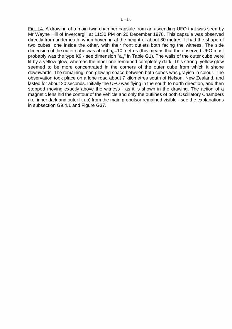
L-16
Fig. L4. A drawing of a main twin-chamber capsule from an ascending UFO that was seen byMr Wayne Hill of Invercargill at 11:30 PM on 20 December 1978. This capsule was observeddirectly from underneath, when hovering at the height of about 30 metres. It had the shape oftwo cubes, one inside the other, with their front outlets both facing the witness. The sidedimension of the outer cube was about a =10 metres (this means that the observed UFO mostM
probably was the type K9 - see dimension "a " in Table G1). The walls of the outer cube wereM
lit by a yellow glow, whereas the inner one remained completely dark. This strong, yellow glowseemed to be more concentrated in the corners of the outer cube from which it shonedownwards. The remaining, non-glowing space between both cubes was grayish in colour. Theobservation took place on a lone road about 7 kilometres south of Nelson, New Zealand, andlasted for about 20 seconds. Initially the UFO was flying in the south to north direction, and thenstopped moving exactly above the witness - as it is shown in the drawing. The action of amagnetic lens hid the contour of the vehicle and only the outlines of both Oscillatory Chambers(i.e. inner dark and outer lit up) from the main propulsor remained visible - see the explanationsin subsection G9.4.1 and Figure G37.
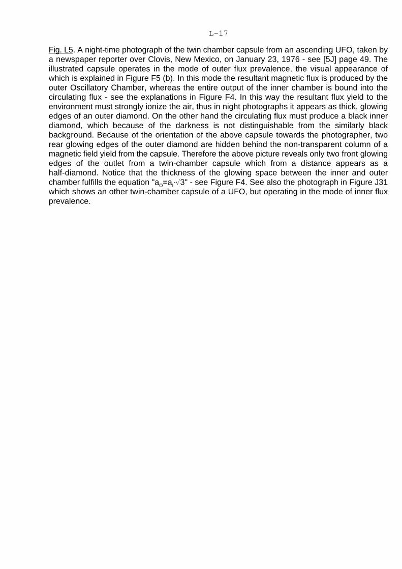
L-17
Fig. L5. A night-time photograph of the twin chamber capsule from an ascending UFO, taken bya newspaper reporter over Clovis, New Mexico, on January 23, 1976 - see [5J] page 49. Theillustrated capsule operates in the mode of outer flux prevalence, the visual appearance ofwhich is explained in Figure F5 (b). In this mode the resultant magnetic flux is produced by theouter Oscillatory Chamber, whereas the entire output of the inner chamber is bound into thecirculating flux - see the explanations in Figure F4. In this way the resultant flux yield to theenvironment must strongly ionize the air, thus in night photographs it appears as thick, glowingedges of an outer diamond. On the other hand the circulating flux must produce a black innerdiamond, which because of the darkness is not distinguishable from the similarly blackbackground. Because of the orientation of the above capsule towards the photographer, tworear glowing edges of the outer diamond are hidden behind the non-transparent column of amagnetic field yield from the capsule. Therefore the above picture reveals only two front glowingedges of the outlet from a twin-chamber capsule which from a distance appears as ahalf-diamond. Notice that the thickness of the glowing space between the inner and outerchamber fulfills the equation "a =a ·�3" - see Figure F4. See also the photograph in Figure J31O I
which shows an other twin-chamber capsule of a UFO, but operating in the mode of inner fluxprevalence.

L-18
Fig. L6. The illustration of a transparent cube with electric sparks which looked like lightninginside, sighted by Mr Robert Luca on a UFO deck. (Compare this illustration with Figure F2 thatshows the appearance of the Oscillatory Chamber.) The above diagram and description arereproduced from the book by R. E. Fowler, "The Andreasson Affair, Phase Two" (Prentice-Hall,Inc., USA, ISBN 0-13-036624-2, page 70) by kind permission from Mrs Betty A. Luca, copyrightholder. It presents the outer Oscillatory Chamber from the twin-chamber capsule whichconstituted the main propulsor of this UFO. The above illustration introduces a breakthrough inour certainty of the Magnocraft's principles, as it not only confirms through an eye-witness'sreport that the Oscillatory Chambers are already utilized in the propulsion of UFOs, but it alsoproves that our intention to built the Oscillatory Chamber on Earth is feasible and valid.

L-19
Fig. L7. A drawing that was found by Mr Ryszard Zudzin of Poland in an ancient manuscriptoriginating from Tibetan Buddhists. He postulates (and the author agrees with it) that thedrawing illustrates either a technical design of the Oscillatory Chamber, or the entire sphericalpropulsor containing such a chamber. While analyzing this drawing, one may notice clustersof needles which exactly correspond to the following description of a UFO Oscillatory Chamberprovided by Mrs Betty A. Luca (see the end of subsection L1.4): "inside had thin protrudingstems with tiny glass droplets on the end". It seems to be relevant to mention at this point thatall ancient sculptures show the Buddha as having extraordinary long ears, but the samesculptures show the other people surrounding him as having normal, human ears. On the otherhand it is reported by numerous witnesses that UFOnauts have exactly these kinds of ears.Thus, such a vital anatomic difference could mean that the Buddha was an ancient UFOnaut,and that his priests knew the design of the Oscillatory Chamber.

M-1
Chapter M.
THE MATERIAL EVIDENCE AVAILABLE THAT CONFIRMS THE LONGSTANDING USE OF MAGNOCRAFT-TYPE UFOs
There is a wealth of material evidence available at present which indicates that Earth iscontinually explored by UFO vehicles whose operation is identical to that of the Magnocraft. Thisevidence is the subject of various "natural" explanations that refuse to acknowledge itstechnological origin. But the existing facts do not conform to any of these "natural" explanations.The more desperate the search for a "natural" cause, the more apparent it becomes that thisevidence is technologically formed. The chapter that follows provides the technologicalexplanation for this evidence. In this way the evidence not only reinforces the proof from chapterJ that "UFOs are already operational Magnocraft", but it also discloses the answers to a numberof vital secrets concerning UFO vehicles.
The author has collected examples from four categories of such material evidence. Thesecategories all exhibit the active involvement of extraterrestrial vehicles applying the Magnocraft'sprinciples of operation. They are: (1) UFO landing sites, (2) glassy tunnels made byunderground flights of UFOs, (3) UFO explosion sites, and (4) fragments of UFOs shells. Let ussummarize each of these categories separately.
#1. The marks left at UFO landing sites. These marks, which most frequently appear asrings of scorched vegetation, are continually being discovered in various parts of our planet. Innumerous cases eye witnesses report that they in fact have observed a landed UFO in the areawhere such scorched rings have appeared. Also the attributes of these rings in every detailcorrespond to those of the Magnocraft's landing sites (see subsection G10). The above providessufficient evidence to consider the circles as landing sites of vehicles that utilize theMagnocraft's principles of operation.
#2. Long, straight, geometrically shaped glassy underground tunnels exist in numerousareas around the world. Two well known examples of these are: the Ecuador system of tunnelsshown in Figure M17, and the Cocklebiddy Cave in Western Australia shown in Figure M18. Allthe properties of these tunnels revealed so far correspond exactly to the predicted propertiesof tunnels left after the underground flight of a Magnocraft - compare the properties listed insubsection G9.1.1 with the description of these tunnels provided in subsection M2.
#3. UFO explosion sites. Two catastrophic areas whose attributes correspond exactly toexplosion sites of the Magnocraft have been discovered and investigated. These are: theTapanui Crater (formed on 19 June 1178 in West Otago, South Island, New Zealand) and theTunguska Blast Site (formed on 30 June 1908 in Central Siberia, USSR). All facts collected sofar at these sites indicate that their cause was the accidental releasing of vast energy containedin the Oscillatory Chambers of a cigar-shaped stack of spacecraft that applied the Magnocraft'sprinciples of operation.
#4. Fragments of UFO spaceships. The most thoroughly researched fragment was foundin 1976 near the Vashka River, USSR (i.e. at the extension of the trajectory followed by the UFOvehicles which exploded in Tunguska in 1908). It represents a part of the central cylinder froma UFO type K4. Its structure and properties correspond exactly to the magnetoreflective materialpredicted for use in the Magnocraft's protective shell - see subsection G2.4.1.
The common attribute of all four classes of evidence listed above is that it has astationary, permanent character. Therefore it can be subjected to investigation with the use ofpresent research methodologies. Moreover, it provides a unique opportunity for all those peoplewhose personal philosophy requires them "to see in order to believe". This is because theevidence is available, it can be seen, touched, investigated, and won't fly away or disappearwhen someone approaches it.

M-2
It should also be mentioned again that in addition to the above evidence of a permanent,material character, a wealth of the "court-type" evidence concerning UFOs has also beenaccumulated. But because this court-type evidence is already presented in chapter J, it isunnecessary to repeating it.
M1. Material evidence on UFO landing sites
Taking into account the statements of countless eye-witnesses who reported sightingsof UFOs, the enormous body of other evidence documenting visits of these vehicles on Earth,and the formal proof that "UFOs are already operational Magnocraft" presented in chapter J; theinitial axiom adopted for this subsection is that our planet is continually visited by members ofan advanced extraterrestrial civilization who have already operational Magnocraft at theirdisposal. According to subsection G10.1, in such a case the spaceships of this civilization mustcause noticeable damage during their landing. This environmental damage should be easilydetectable, as it must exactly match the unique properties of the Magnocraft landing sitespresented in subsection G10.
To detect and identify examples of this damage, the author initiated extensive fieldresearch aimed at discovering possible UFO landing sites and verifying their correspondenceto the envisaged Magnocraft landing sites. The effect of this research was overwhelming, as itnot only provided further evidence to confirm the validity of the Magnocraft's principles, but alsoled to additional findings, for example: (1) the exact dimensions of each type of UFO, (2) thevalue of the "Cosmic Cubit" - i.e. the unit of measure used by extraterrestrial civilizations inbuilding their spacecraft (see equation G30), etc. In this subsection the evidence collected sofar and the results of relevant research are presented.
All the deductions presented in this subsection are based on empirical data gatheredduring extensive field investigations. Where appropriate, relevant photographs documentingthe evidence are also included (to illustrate the size of the marks presented in thesephotographs, either a person was photographed or a so-called "reference circle", i.e. a whitecircle exactly one meter in diameter whose black arrow points magnetic north, is shown).
So far, the author has discovered in New Zealand five areas of mass UFO landings (i.e.Weka Pass, Moeraki Boulders, Waikoikoi, Roxburgh and Cadrona), each of them containingfrom about 30 to over 100 landings concentrated in a relatively small area; plus a number ofreconnaissance UFO landing areas (e.g. Wanaka, Maitland, Invercargill, Middlemarch) whichcontain from 1 to 5 scorched landings in close proximity. There are probably three reasons forthe author's success in this search: (1) New Zealand seems to be a favorite target for UFO visits,(2) the type of farming (sheep and cattle grazing) existing in New Zealand tends to conserve theUFO landing sites, and (3) the Theory of the Magnocraft has given the author very exactknowledge of what he is looking for.
During his investigations of the landing sites, the author also tried to establish theconnection between the landing marks left on the ground and the observation of an UnidentifiedFlying Vehicle (UFO) that could have formed them. In numerous cases, a UFO was observedeither hovering exactly over the spot where the landing site was formed, or flying in closeproximity to this spot. In many other cases the involvement of such a vehicle was confirmedindirectly, for example through the presence of large imprints of its three or four telescopic legs(like the imprints shown in Figure M1) spaced symmetrically and embedded within the site.
M1.1. All three known types of landing sites are formed by visiting extraterrestrial vehicles
Subsections G10.2 to G10.5 describe three basic types of Magnocraft landing sites which

M-3
are caused when this vehicle hovers with its magnetic circuits looping (1) under the ground, (2)on the surface of the ground and (3) entirely in the air - see Figures G39, G40, and G41. Theauthor found perfect examples of UFO landing sites which confirm that extraterrestrial vehiclesalso form these three types of sites. Let us have a close look at the evidence that documentsthis.
#1. As could be expected, the most frequently discovered UFO landing site is formedwhen the vehicle hovers with its magnetic circuits looped under the ground - see Figure G39.When a landed UFO operates in the magnetic whirl mode the site contains a ring of scorchedvegetation, within which there is an additional scorched spot shifted southward or northwardfrom the centre. An excellent example of such a site, discovered near Invercargill, New Zealand,is shown in Figure M2.
There are also cases where a UFO, whose propulsors operate in a throbbing or magneticlens mode, landed so that its magnetic circuits loop under the ground. Then the site containsonly a circular pattern of scorched spots representing the outlets from the side propulsors, plusone asymmetrical central spot scorched by the main propulsor. (No trail joining the sidepropulsor is present.) An example of such a site is shown in Figure M3.
#2. The UFOs that hover with their magnetic circuits looped along the surface of theground produce entirely different landing sites. The shapes of these sites are illustrated inFigure G40. This type of landing site is rather rare and its discovery represents a more difficulttask. However, after numerous field searches and many hours of reviewing the availableliterature, the author had the good luck to succeed, and examples of these sites were found. AUFO landing site formed during the throbbing mode of operation should contain a number oflinear scorched trails aligned in a radial direction towards one central mark - see Figure G40(b). An example of such a UFO landing site is presented in Figure M4. A site formed during themagnetic whirl mode of operation, when a vehicle touches the ground with its magnetic circuits,should contain a wide ring of vegetation and soil which has been totally destroyed - see FigureG40 (c). An example of such a site is also presented in Figure M4.
#3. The last type of UFO landing site is made when the vehicles hover with their circuitslooped entirely in the air. These sites take the shape of a pattern or a "nest" of swirledvegetation. The task of finding these sites is extremely difficult, as their validity requires the"catching on the spot" of the vehicle that formed them. Again the author was lucky, andappropriate examples of such landings are presented in Figure M5. Notice that through the useof the "rolling sphere rule" (see subsection G6.3.3) the direction of a UFO flight can bedetermined from such swirled nests. The author completed these checks, and the resultsobtained confirm the theory presented in subsection G6.3.3.
M1.2. The value of the Cosmic Cubit can be determined from UFO landing sites
With the discovery of each UFO landing site, the author conducted precise measurementsof the patterns left on the ground. In this way an extensive bank of data about UFO landing siteswas gradually gathered. From this data, determination of the value of the "Cosmic Cubit (C )"C
(i.e. the unit of measure used by the manufacturers of UFOs - see equation G30) becamepossible.
The methodology for determination of this C unit from the dimensions of UFO landingC
sites incorporated the following four basic stages:1. The selection of the valid data. As was illustrated in Figure G38, depending on the
height at which a particular vehicle hovered, the diameter of the circle scorched by its propulsorswill differ. Therefore only that data which originated from the sites clear enough to guaranteesuccessful application of the correction techniques described in subsection G10.3.1 could beused for the calculations. So this stage depended on selecting for further processing only

M-4
samples of such valid data from all the data gathered during numerous field measurements.2. The correction of the empirical measurements. Data selected for further calculations
were processed by the appropriate correction equations presented in subsection G10.3.1. Thus,nominal diameters "d" of the vehicles that formed these sites were obtained. An example of anapplication of the first correction technique, based on equation G32, is presented in Figure M6.The same technique was also used for sites shown in Figures M7, M10, and M11.
3. The determination of the empirical value of the Cosmic Cubit through the applicationof equation (G30). When the set of nominal (corrected) dimensions of the various types oflanding sites was established, the determination of the empirical value for the Cosmic Cubit "C "C
was only a matter of using the appropriate calculations based on equation (G30).After analysis of the various data, to which the above methodology was applied, the
author determined the following empirical value for the Cosmic Cubit: C = 0.55 [meter] (i.e. almost 22 [inches]) (M1)C
This value indicates that the builders of the UFO vehicles are using a cosmic unit of length whichis slightly greater than half of our meter. In the British Imperial System its value is almost 22inches.
4. The increase of precision of the Cosmic Cubit so determined. This stage involvedfinding and utilizing other, historical data that was available, which allowed the accuracy of theempirically determined C unit to be increased. C
The technique applied to increase the precision of the empirical value of C {seeC
equation (M1) above} is based on the author's assumption that if "UFOs are already operationalMagnocraft", then members of the civilizations that visit Earth in these vehicles would have leftsomewhere a sample of the exact value of their unit of measure. (For example members of thesecivilizations could have built on Earth some monuments using this unit of measure). Afterformulating this assumption the author began to search for an ancient unit of length that wouldcorrespond to the empirical value of C - see equation (M1). The results again wereC
overwhelming. Quoted below is what is written in the book [1M1] by John Perry, "The Story ofStandards" (Funk & Wagnalls Co., New York 1955, p. 9) about a unit of length called a "cubit"that was used in ancient Egypt for building pyramids:
"... another cubit, measuring a little less than 21.6 inches, was used in laying some of theupper courses of the Pyramids. This dimension is almost exactly one million times thewavelength of light from a mercury 198 lamp, a lamp employing a rare isotope of mercury madeby bombarding gold with neutrons. Surely one can conclude that those wonderful Egyptianswere familiar with nuclear physics!".
Ancient Assyria also used a cubit of exactly the same length (i.e. 21.6 English inches).Moreover, the cubit recorded in the Bible had a similar length (see the book [2M1] by WilliamD. Johnstone, "For good Measure", Holt, Rinehard and Winston, New York, 1975, ISBN0-03-013946-6, page 10).
English Professor Alexander Thom measured stone circles and standing stones(menhirs) throughout the British Isles, as well as in the northern part of France. He submitted thecollected dimensions in his book [3M1] entitled, "Megalithic Sites In Britain" (Oxford UniversityPress, Oxford, England, 1967). A great many of these circles had diameters of 261.12 inches,or 6.632 metres (which correspond surprisingly well to the outer diameters "do" of scorchedrings left by the K4 type of UFOs whose bases touched the ground). Because all the mostpopular systems of measure in ancient times were developed on the basis of 12 (dozen), itcould be assumed, that the above circles also contain 12 elementary units of length. Thus bydividing the diameters by 12, a value very close to the ancient "cubit" discussed above isobtained (a small difference between both these values can be attributed to the wrong diameterof the stone circles being measured - e.g. outer instead of middle).
All the above data suggests that there is a justification for assuming that the "CosmicCubit" used by the builders of UFO vehicles is also represented on Earth in numerous ancient

M-5
monuments. Therefore through narrowing down the value of the cubit from equation (M1) to theexact value of this ancient unit of length, any required precision of the Cosmic Cubit should beachieved. For the purpose of this monograph, the exact value of the Cosmic Cubit has beendetermined as:
C = 0.5486 [metres] (or C =21.6 inches) (M2)C C
Such a precise value of the C unit allows us to calculate the dimensions of UFOs with a marginC
of error of less than one millimeter. In the future, this will permit us to build Magnocraft preciseenough to couple with UFOs in perfectly fitting flying configurations.
After applying the value (M2) to the equation (G30) a set of precise nominal diameters"d" for eight subsequent types of UFOs can be theoretically determined. These diameters takethe values (see column "d" in Table G1): 3.10, 6.20, 12.41, 24.82, 49.65, 99.30, 198.61 and397.22 metres. All the empirical measurements completed by the author so far confirm that thedimensions of every single UFO landing site arise from one of these eight theoretical diameters.
M1.3. The diameters of landing sites confirm the existence of eight basic types ofextraterrestrial vehicles
UFO landing sites are the extraterrestrial equivalent to tracks made on the ground by thetyres of our automobiles. Therefore the dimensions of these circular landing sites must reflectthe type of vehicle which made them, similarly as the span of our automobile marks reflects thetype of car that imprinted them.
After the value of the C was precisely determined, the author began his search forC
landing sites that would confirm the existence of eight basic types of UFOs. He reasoned thatif the Theory of the Magnocraft is valid, then UFOs, as with the Magnocraft, must be constructedin eight basic types. Moreover, the measurements of the shape and dimensions of these eightbasic types of UFOs should correspond exactly to the theoretical shape and dimensions of 8basic types of the Magnocraft (this is because the shape and dimensions of all magneticallypropelled vehicles result more from the laws of magnetism than from the creativity andinclination of their builders - see subsection G4).
The author partially succeeded in his search, and so far landing sites scorched by the firstsix of eight basic types of UFOs have been found. Unfortunately, the two biggest UFO vehicles(types K9 and K10) either land extremely infrequently on Earth, or their landing sites (becauseof the size) are very difficult to discover. Therefore the landing sites of UFOs type K9 and K10have not been found as yet. But there is photographic evidence already accumulated (seeFigures J7 and J8 together with the relevant descriptions from subsection J2.1) which certifiesthat these last two types of UFOs are being used on Earth. So, there is a significant likelihoodthat their landing sites will probably be discovered soon.
Landing sites formed by the UFOs types K3 to K8 are shown in subsequent Figures M7to M11. Notice that all the remaining Figures also show the landing sites that were made byvarious types of these vehicles (e.g. Figure M3 presents another site left by a UFO type K5).
Figure M11 illustrates also the principle that UFO vehicles, in order to fly, must orient theirbase perpendicularly to the local course of the force lines of the Earth's magnetic field, whereasto land they try to orient their base parallel to the surface of the ground - see Figure M11 andcompare it with Figure M16. Wherever the configuration of the ground makes it impossible forUFOs to have their base simultaneously parallel to the ground and perpendicular to the forcelines of the Earth's magnetic field, the landing site is either elliptical (see Figure M7) or takes theshape of a half-circle (see Figure M16).
It should be noted that to enable us to identify precisely a particular UFO landing site withone of the eight main types (K3 to K10), it must be clear enough to give us an exactmeasurement of its two diameters, i.e. "do" and "da" - see equation G38 (b), or "do" and "di" - see

M-6
equation G38 (c). Only after these diameters are established, the nominal diameter "d" of thesite can be exactly determined, thus allowing us to assign the type of landed UFO to this site.Unfortunately, there are numerous sites left by UFOs that remain motionless for only a very shorttime, making their marks very unclear. The dimensions of these "transient" landing sites aredifficult, or even impossible, for exact measurement. Although in many cases they have quiteclear outlines of "do" diameter (produced by the side propulsors that attract the Earth's magneticfield), the mark left by the main propulsor oriented repulsively towards the field of the Earth isnot sufficiently clear, thus making it impossible to establish "di" or "da" diameters. This kind ofsite can still be categorized as one of the eight main types of UFOs, because its diameter "do"is equal to, or slightly (i.e. up to 40%) smaller than the nominal diameter "d" (i.e. this diameter"do" still significantly exceeds the diameter "d" of a previous, smaller type of UFO). But such"transient" sites can not be used for scientific purposes, e.g. to determine the dimensions ofUFOs or to verify the findings described in this monograph.
The author would like to stress at this point that every clear UFO landing site that he hasfound so far, always yields the nominal diameter "d" equal to, or very close to, one of thefollowing values: d =3.1, or d =6.2, or d =12.4, or d =24.8, or d =49.6, or d =99.3 metres.K3 K4 K5 K6 K7 K8
(Note that it is very easy to remember all these diameters, because if we know the first one, i.e.d =3.1, then the next one is simply the previous diameter multiplied by two, e.g. d =2#3.1.) NoK3 K4
UFO landing site has been found in which the corrected nominal diameter differs from thevalues resulting from equations G30 and M2.
M1.4. Some marks left on the ground document the landing of entire configurations ofUFOs (including flying systems)
UFO landing sites found so far by the author were formed not only by solo flying vehicles,but also by entire flying arrangements. The most distinctive sites are formed by the flyingcomplexes and flying clusters (illustrated in Figures G16 and G17). A perfect example of sucha site, left by a single cell of a flying system formed from K3 type UFOs, is shown in Figure M12.(The theoretical shape that this site should display is illustrated in Figure G42 (A), whereas themutual arrangement of UFOs in a cell that possibly could have made it is shown in Figure G16.)Apart from that shown in Figure M12, a number of further sites formed by flying systems of UFOswere also found. The important detail of all these landing sites is that their dimensionscorrespond exactly to those resulting from the Theory of the Magnocraft (compare Figure G42with Figures M12) and from the C unit of measure applied by UFOs.C
There has been a lot of publicity recently about crop circles of a very distinctive shapewhich have appeared in southern England. An example of such a site is shown in Figure M13.Even a brief analysis of the shape, dimensions, and characteristic features of these English sitesconfirm that they are formed by flying clusters of UFOs (compare Figure G17 and Figure M13).
More difficult to discover are landing sites left by configurations of UFOs that werecoupled into the vertical arrangements (e.g. cigar-shaped flying complexes). Rings scorchedby such vertical arrangements have the same dimensions and shape as those left by solo flyingvehicles. But there exists a distinguishable attribute of such vertical configurations, i.e. tomaintain their stability the scorched mark formed by their main propulsor must be displaced fromthe centre of the site in the opposite direction from the mark left by solo flying vehicles. Thereforein New Zealand (which is located in the Southern Hemisphere) UFOs flying solo scorch themain mark dislocated towards the magnetic south direction from the centre of the site. But thecigar-shaped flying complexes scorch this mark displaced towards magnetic north direction(compare Figure M10 with Figures M2 and M8).
M-7
M1.5. Why UFO landing sites could not be formed by the growth of mushrooms or by anyother natural cause
Present science refuses to acknowledge the technological origin of UFO landing sites.As an excuse for this refusal, a misinterpretation of the biological effects (namely the explosivemushroom growth) that landed UFOs have on the soil is used. It was explained in subsectionG10.1, that the Theory of the Magnocraft determined the following cause-effect mechanism forUFO landing sites:
THE CAUSE is a strong, pulsating magnetic field of a landed UFO that cooks (like amicrowave oven) and totally exterminates all parasitic micro-organisms that normally keep themushroom population under control,
THE EFFECT is an explosive growth of mushrooms within former UFOs landing siteswhich may last up to a hundred years after the landing took place (such a technologicallyinduced growth of mushrooms is known by the name "fairy rings").
Present science completely misinterprets the above cause-effect mechanism occurringwithin UFO landing sites, and claims that everything occurs in a reversed order, i.e. that themushroom growth in a radial direction is the CAUSE, and that the rings of scorched andpoisoned vegetation are the EFFECTS of this growth.
Of course, after understanding the above misinterpretation of the cause-effect mechanismconcerning UFO landing sites, the author initiated vigorous research aimed at correcting thiserror of the scientists. The first task of this research was to prove that the UFO landing sitessustain their dimensions unchanged for many years (as we know, the present explanation for"fairy rings" claims that these rings grow outwards from their center thus increasing theirdiameter each year). In 1987 the author placed under strict observation a number of UFOlanding sites in four mutually distant areas of New Zealand (i.e. Roxburgh, Waikoikoi, MoerakiBoulders, and Weka Pass), marking their outer edges by wooden pegs and systematicallychecking the measurements of these rings. No changes in the nominal diameter of the UFOlanding sites being observed were detected, in spite of such verification being continued forthree subsequent years (and to be continued after completion of this the edition of themonograph). The only change in dimensions of these rings which the author has observed withthe elapse of time is the increase in width of scorched patches (i.e. the increase in differencebetween the inner "di" and outer "do" diameter of the same ring) and also the decay of the sharpedges of the scorched areas (i.e. their edges become curved and non-continuous). But thesechanges radiate from the ring in both directions (i.e. towards the inside as well as towards theoutside of the ring) at the same rate, so that the nominal (mean) diameter "d" of the ring remainsunchanged.
The second task of this research was to prove that in former UFO landing sites, anexplosive growth of mushrooms occurs. This was easy to prove, as the microscopic analysis ofsoil samples taken from numerous UFO landing sites clearly shows the presence of mushroomspawn (this is also confirmed by the research of other investigators - see [7J] page 131). Also,in each UFO landing site an intensive mushroom growth was noticeable in the appropriateseasons (in New Zealand: March-May) - see Figure M14 (lower).
The third task the author has undertaken was to prove that physical properties of the soilaffected by landed UFOs differ from the properties of the soil affected by mushroom growth only.For this purpose he measured the electrical resistance of soil. It turned out that the magneticallyaffected soil from the ring scorched by a landed UFO has, on average, about three times greaterelectrical resistance than the same soil only few metres from the edge of the ring. On the otherhand, identical measurements of the electrical resistance of the compost used by commercialmushroom growers showed that after mushrooms germinate, the resistance of the compost isactually lower than the resistance of the same compost before mushroom spore were plantedin it. This means that the presence of mushrooms in the soil from UFO landing sites is not
M-8
responsible for the increase in the electrical resistance of this soil. Thus, the change in theresistance of the soil must be caused by an additional factor, i.e. by a powerful magnetic fieldof a UFO that altered the physical state of this soil.
The experimental findings discussed above, reinforced by their agreement with theTheory of the Magnocraft, indicate the total irrelevance of the present claims by scienceconcerning fairy rings. These findings prove that UFO landing sites are in fact formedtechnologically by magnetically propelled vehicles, and that the mushroom growths observedat these sites are the effect of UFO landings that took place earlier (not the cause of theappearance of these scorched marks).
After the "mushroom explanation" for UFO landing sites is proved to be discreditable, thevalidity of all other possible natural explanations for these sites should also be considered. Buteven a brief analysis of the attributes of UFO landing sites eliminates any natural cause for theappearance of these rings. No natural factor is able to form circles that display the followingattributes characteristic of all UFO landing sites:
(A) the diameters of UFO landing sites, similar to the span of the tracks left by a car,correspond exactly to the dimensions of the vehicles that made them. Thus, the nominaldiameters "d" of UFO landing sites (or fairy rings), after being determined and correctedaccording to the rules described in subsection G10.3.1, fulfill the equation (G30) and correspondto the data from column "d" of Table G1.
(B) The dimensions of all UFO landing sites are based on the unit of length called herethe Cosmic Cubit. This unit was also used by builders of the pyramids and other ancientmonuments.
(C) The sizes of subsequent UFO landing sites comprise the elements of a geometricprogression with the ratio of 2, and thus they repeat the binary progression of the "d" diametersfrom K3 to K10 types of the Magnocraft. It means that every subsequent type of ring is twice asbig as the previous one - a good illustration of this is provided in Figure M8. Notice that thedimensions of these sites depend only on the type of vehicles that produced them, and for thesame type they must remain exactly the same independently of soil conditions, the type ofmushrooms that populated the landing site, the area, country or continent where the sites arefound, etc.
(D) Types of mushrooms that populate subsequent landing sites vary from area to area(in New Zealand the most frequent are meadow {agaricus campester}, horse {macrolepiotaprocera} and toadstall {marasmius oreades} mushrooms). Because the physiology ofmushrooms implies that each type should exert different biological effects on the soil, suchattributes of UFO landing sites as dimensions, shape, response to stimuli (e.g. magneticsouth/north asymmetry), and seasonal changes in appearance, should also vary from area toarea. However, field research shows that independently of the types of mushrooms, all the sites'attributes remain unchanged.
(E) UFO landing sites are scorched in a strictly defined manner which corresponds to thelocation of the propulsors and to the operation mode of these magnetically propelled vehicles.This goes so far that mutual relationships between various characteristics of the landing sitescan be expressed in the form of mathematical equations. Apart from equations G32 and G33mentioned earlier, other examples of such equations are: (1) the number "n" of scorch marksleft by the side propulsors is correlated to the type factor "K" of a particular landed vehicle - seeequation B1; (2) this number "n" has a direct correlation with the nominal diameter "d" of a UFOthat landed - see equations G30 and G6; (3) the mean ratio of outer diameters of the ellipticalUFO landing sites measured in the east-west "do " and north-south "do " directions is a(E-W) (N-S)
direct function of the local inclination angle "I" of the Earth's magnetic field and the slope of theground, etc.
(F) Most of the sites, as well as the ring of scorched vegetation, also incorporate a singlecentral mark made by the main propulsor, the location of which is displaced towards a magnetic

M-9
south or a magnetic north direction. (G) UFO landing sites remain in precisely the same locations and shapes year after year.
No slow drifting away or transformations, so typical of natural growths, are observed.(H) Some UFO landing sites last for many decades. The oldest sites discovered so far
have been in existence (in the same place) for over sixty years - see Figure M14.(I) They maintain exactly the same diameter from year to year. Notice that if the rings
would grow naturally, they should increase their diameter by not less than about two metreseach year.
(J) They have a perfect circular or elliptical shape, independently of the soil andtopographic conditions that may stimulate a monotropic growth. Elliptical sites almost alwayshave their long axis oriented exactly towards the magnetic north/south direction, whereas theshort axis is oriented towards the magnetic east/west direction (defining this more precisely:elliptical landing sites display the shape which results from the intersection of the surface of theground with a perfectly circular tube formed from the vehicle's magnetic circuits oriented parallelto the Earth's magnetic field force lines).
(K) They are sometimes accompanied by three or four symmetrical imprints of thevehicle's legs located within the circle - see Figure M1.
None of the above attributes could appear if these rings were formed in a natural manner.Therefore the presence of the above attributes in UFO landing sites completely rules out theirnatural origin, proving in this way that they are formed technologically by landed extraterrestrialvehicles.
M1.6. There is a critical landing duration after which sites become permanent
The destructive biological impact that the super-strong UFO field exerts on the soil dividesall landing sites into two categories, i.e. permanent and transient. Permanent sites are thosewhere UFO vehicles landed for a period of time sufficient to exterminate (cook) all the parasiticmicro-organisms which keep mushroom growth under control. Therefore in permanent sitesmushroom spawn takes over the soil completely. These sites can be easily recognized becausein some parts their scorched rings display soil which is totally burnt and bare. The authorestimates that about 100 years will pass before the biological balance returns back to normal(in uncultivated soil). Until the balance is restored, these UFO landing sites remain visiblestaying year after year in exactly the same place and with exactly the same shape. Transientsites are all those in which a UFO remained in one place for too short a period of time to put thesoil out of biological balance. Grass in these sites remains unburned, but displays a different,darker color. Also various types of beans (which have the ability to absorb nitrogen from the air)and some types of grass grow much faster there. The soil in these transient sites is not takenover by mushroom spawn. Experience shows that such sites disappear about three months aftera UFO landing took place.
The existence of permanent and transient sites indicate that there must be a "criticallanding duration" after which the biological balance of the soil is destroyed. (This criticalduration can be compared to the time needed to cook micro-organisms in a microwave oven.)All the sites on which the landing took less than this critical duration disappear after about threemonths, whereas all landings whose time-span exceeds the critical duration remain visible formany decades. At present we do not know exactly how long this critical duration is. But on thebase of the sparse data already available, the author estimates that for K3 type of UFOs itexceeds ten minutes. If we could determine it precisely then landing sites would become a richsource of further data on UFOs. For example, these sites would then allow us to estimate: theduration of UFO landings, the strength of their magnetic fields, the efficiency of their equipmentand activities, etc.

M-10
M1.7. More that else we can learn from UFO landing sites
UFO landing sites provide us with extremely valuable sources of information on thisextraterrestrial spacecraft. The most important data derived from these sites has already beendiscussed in previous subsections. Let us now list additional information that the author hasgathered from these sites.
#1. Only a small fraction of UFO landing sites (the author estimates it to be about 1 sitein 200) is scorched by vehicles that actually landed. Most of the sites are left by vehicles thathovered motionless for some time at a height exceeding half of their effective diameter "d". Onthe paddock of Mr Allan M. Chapman of Goodwood (R.D. 1, Palmerston, New Zealand) a K5type UFO produced marks that allowed the precise determination of the height at which thesespacecraft usually hover - see Figure M15. This particular UFO simultaneously broke the top ofa tree and scorched an elliptical landing site under this tree. The top of the tree was broken ata height of 6.8 meters from the ground (i.e. at about d/2). The dimensions of the scorched ellipseleft under this tree were: do =12.0, do =14.4, and a =0.65 [metres]. Because in this site the(E-W) (S-N) s
scorched ring was distinctively visible and its dimensions were more close to the nominaldiameter "d" of K5 type UFOs than the dimensions of many other sites, the above evidencerevealed that in normal circumstances K5 UFOs produce sites while hovering at a height evengreater then 6.8 metres.
#2. The orientation of the flying or high-hovering (i.e. hovering at a height exceeding halfof their diameter) UFOs fulfills the two following conditions: (1) their base is horizontal along itseast-west axis, and (2) this base is simultaneously kept slanted along its north-south axis, sothat the vehicles' propulsors are directed towards the local course of the Earth's magnetic field.Therefore, all the measurements of UFO landing sites should be done in an east-west directionto obtain correct dimensions. But when the configuration of the ground is such that the east-westdirection runs down a slope, then correction of measurements for the angle of slanting of thisslope should additionally be made. Marks scorched by such south-north slanted UFOs usuallytake the shape of an ellipse. On very steep slopes the above conditions may cause the markscorched to take the shape of a half-circle - see Figure M16. All the landed or low-hovering (i.e.hovering at a height below a half of their diameter) UFOs try to orient their bases parallel to thesurface of the ground - if the local course of the Earth's magnetic field allows for this. The UFOsso oriented leave landing sites that are almost perfectly circular in shape.
#3. The crews of UFOs consist of scientists who are vitally interested in our planet. Forexample, a significant number of UFO landing sites are accompanied by square soil-samplingindentations - see Figures M8 and M6. In a number of cases this removal of soil occurred in thesame paddock over many subsequent years (always approximately in the same month of eachyear). Moreover, a team of K5 and K7 UFO vehicles landed consecutively in various footballfields throughout New Zealand. In January 1989 a lamp from the floodlights of the PiratesFootball Club in Dunedin was even smashed by a K5 type UFO.
#4. UFOs appear to visit our planet in fleets. These fleets arrive here about a year beforethere is a maximum of solar activity (i.e. a maximal number of spots on the Sun), and stay onEarth for about three subsequent years. In the 20th century solar activity reached its maximumin the years: 1907, 1917, 1928, 1937, 1947, 1957, 1968, 1979, 1989, 1999 - see [4M1] D.J.Schove: "Sunspot Cycles", Hutchison Co., USA, 1983, ISBN 0-87933-424-X, page 14. Theseyears also coincide with waves of increased UFO activity. (The above book [4M1] stresses thatduring periods of maximal solar activity, there is also an extremely intensive wave of politicalevents occurring on our planet, i.e. wars, revolutions, changes of governments, etc. This mayexplain why UFO scientists tend to visit us at these times.)
#5. UFOs keep returning to the same areas of interest. In a number of cases the authordiscovered the appearance of completely new UFO landing sites near ones that were already

M-11
nine to twelve years old (i.e. originated from the previous period of maximum solar activity).Notice that this discovery is the first step in determining the predictability of UFO behavior. Thismeans that we may soon be able to predict where and when UFOs will appear next, and beready for them.
#6. Each type of UFO seems to specialize in a different task. For example the authorestablished that type K6 UFOs always land near unusual stone or other interesting geologicalformations. Thus K6 UFOs seem to specialize in geological research.
#7. There appear to be three different strategies of UFO landings: (1) reconnaissance,(2) survey, and (3) task. If they land for reconnaissance purposes, only one or a few landingsappear at random. If they conduct a survey, they choose an area of about 12x60 kilometers andinvestigate it systematically, inch by inch. For this, a fleet of about 400 UFO vehicles spreads ina front-line formation so that it covers the width of the entire area being surveyed, and thensimultaneously moves along this area. Because each UFO vehicle stops every 30 to 50 metres,sets of parallel lines of subsequent landings can be found afterwards along the surveyed area.If they conduct a task research, then mass landings appear in a relatively small area (i.e.sometimes over 100 landings can be found in an area less then 9 square kilometres). Betweenthe areas of such concentrated landings, large gaps of about 30 to 120 kilometres exist whereno UFO landings can be found at all.
#8. Areas of mass UFO landings usually conceal some kind of mystery. For example aconcentration of UFO landing sites appears along the line of China Stones that spread from theTapanui Crater - see line "C" in Figure M21. Such areas as Waikoikoi (see Figures M6, M8,M15), Maitland (Figure M3) and Roxburgh (Figure M12) all lie on this line of China Stones.Another large concentration of UFO landings is located near the mysterious Moeraki Boulders(see Figure M7) described in so many books, including those by von Däniken.
The above information was possible to gather even though our investigations of the UFOlanding sites are still in their initial stage. But now, when our understanding of these sites isincreasing, it should be possible to wrest a large number of further secrets out of them.
M2. Long, straight, geometrically-shaped underground tunnels - material evidence of theancient operation of the Magnocraft
Our science attributes a solely natural origin to all underground caves existing on Earth.However, it seems that there are a number of cases where a technological origin could explainperfectly well the properties of some underground tunnels, whereas none of the naturalexplanations is supported by existing facts.
The best known case is the system of tunnels extending thousands of miles under thearea of Ecuador and Peru - see Figure M17. Descriptions and photographs of these arepublished in two books by Erich von Däniken: [1M2] "In Search of Ancient Gods", SouvenirPress, Leeds, England 1973; and [2M2] "The Gold of the Gods" (First published in Germany byEcon-Verlag under the title "Aussaat und Kosmos"), Redwood Press Ltd., Towbridge, England1973. All the properties of the Ecuador tunnels described in von Däniken's books correspondexactly to those which one would expect to find in the tunnels made by a Magnocraft's flightunderground - compare the quotation that follows with the properties presented in subsectionG9.1.1. To highlight the similarities between them let us quote a few sentences from "The Goldof the Gods":
"The passages all form right angles. The walls are smooth and often seem to be polished.The ceilings are flat and at times look as if they were covered with a kind of glaze. When I triedto use my compass to find out where these galleries lead, it went on strike. I shook it, but theneedle did not move."For further details, the books indicated above are recommended.

M-12
Numerous examples of such long, straight and geometrically shaped undergroundtunnels are described and illustrated in various other books. For example the book [3M2] by BenLyon, "Venturing Underground - the new speleo's guide" (E.P. Publishing Ltd, 1983, ISBN0-7158-0825-7), provides photographs and descriptions for a whole series of tunnels. Thetunnel shown in this book that deserves our special attention is the Mammoth Cave System inKentucky, USA. To date it has been found to have over three hundred kilometres ofunderground passages. Other examples of similar tunnels, one located under the Island ofMalta and another leading from Cuzco in Peru through Lima to Bolivia (together almost 2000kilometres long), are described in the book by William Gordon Allen, "The Steiner-Tesla EnigmaFantastique", pages 80 to 85.
Unusual underground tunnels - glassy and regularly (technologically) shaped, have evenbeen presented in some recent television programmes. In the TV series, "The Wonders ofWestern Australia", produced by Guy Baskin, Channel 9, Perth, Australia, exploration of theCocklebiddy Cave system located in the Nullarbor Plain of South Australia was shown. The filmmakers were quite puzzled by the unnatural, continuous, and smooth shapes of these endlesspassages, but they did not suggest or investigate their technological origin.
That the Cocklebiddy Cave has a technological origin is almost certain after reviewingphotographs of it published in the Australian magazine, "People", December 5, 1983, page7-10. The cross-section of this cave is elliptical, i.e. typical for the north-south direction of aMagnocraft's flight (compare Figure M18 with Figure G36). It also extends exactly in the directionfrom south (exit) to north (the direction of the tunnel's path). It is unnaturally straight and alwaystakes a course which suggests it was formed by a moving disc. The lower part of the tunnel iscovered with solidified rock vapors and debris. Also on the walls of the tunnel there are regular,repetitive wave-like indentations which indicate the sawing action of a magnetic whirl (see item10 in subsection G9.1.1).
A different pattern from those already mentioned, left on a wall of this type of tunnel, waspresented in the TV documentary programme "Skydive to Autana" by RKO ProgrammesInternational (Producer: Adrian Warren). This programme showed the mysterious tunnelspassing through the summit of Autana in Venezuela. They are also straight and geometrically(i.e. Magnocraft-like) shaped. In one cave, formed at an intersection of two tunnels, a perfectspiral pattern was shown indented in the rock. This pattern had the exact shape of the magneticwhirl of a Magnocraft - just like the one presented in Figure G30 (c).
Other technological tunnels, located under Mount Chester, USA, were presented in theAmerican series, "More Real People", produced by George Schlatter Production, Los Angeles,California. The locals are quite serious in their claims that these tunnels are inhabited by somekind of telepathic beings. The unusual geometry of these passages and the arguments of thelocals apparently did not induce any more extensive investigations.
If a spacecraft from a different civilization formed any of the tunnels described, it is logicalto expect that such activity could also be repeated in many other areas. Therefore there is achance for the accidental discovery of similar tunnels during underground engineering work(e.g. tunneling, mining, building subways), during cave exploration or in deep-sea diving. (Theauthor has come across information suggesting that tunnels have been found underWashington D.C., but there is difficulty regarding access to the source of this information.) It ispossible that while reading this monograph, someone will be reminded of the details of similardiscoveries. In such a situation the author would be extremely grateful for any information.
It is understandable that methodology, rationality and a sense of proportion are veryimportant in science. Undoubtedly in the majority of typical cases, the natural origin ofunderground caves is the only correct explanation. However, there are occasions when sucha general application of one explanation may cause some exceptions to be overlooked. Theseexceptions may represent evidence of extreme importance for the progress of our civilization.To avoid losing vital information, perhaps we should revise our approach to the causes of some

M-13
phenomena and take the activity of extraterrestrials into consideration. The time now seems tobe ripe to reinvestigate a number of facts. The tunnels described in this subsection provide anexcellent opportunity for this because they cannot disappear, and anyone who does not believein their technological origin may visit, see, touch and investigate them.
M3. UFO explosion sites
Any extensive use of Magnocraft-like spacecraft (UFOs), whose Oscillatory Chambers areheavily loaded with magnetic energy, should eventually lead to accidental damage of some ofthese vehicles, and consequently to their explosion. If we accept the possibility of the long termobservation of our planet by members of an advanced extraterrestrial civilization who alreadyhave the Magnocraft at their disposal, then the natural consequence of this would be to expectthat some of their vehicles exploded on Earth. As the sites where such vehicles have explodedmust exhibit a number of unique attributes (described in subsection G11) that are absent innatural land formations, it should be easy to check if any catastrophe of a magnetically propelledvehicle in fact took place on Earth. The author has already completed such a check and hasidentified two catastrophic formations, all attributes of which exactly correspond to those of theMagnocraft explosion sites. These formations are the Tapanui Crater and the Tunguska BlastSite. They are discussed below.
M3.1. The Tapanui Crater
The Tapanui Crater (see Figure M19) is located on the west side of the Otago Provinceof the South Island of New Zealand in the centre of a triangle defined by the three followingtowns: Tapanui, Waipahi, and Mataura. (It should be noted here that the indigenous meaningin the Maori language for the words "Ta-pa-nui" is "The-big-explosion", for the words "Wai-pa-hi"it is "The-place-of-the-exploding-fire", whereas the words "Mata-ura" can be interpreted as"The-glowing-spacecraft".) Its geographical co-ordinates are: 46( 04' S and 169( 09' E. Theshape of the Tapanui Crater is elliptical with its long axis declined at -37( (westward) from thegeographic north direction. Such a declination angle coincided with the magnetic south-northdirection around the year 1178. The size of the Tapanui Crater (i.e. length x width x depth) isabout 900x600x130 [metres]. The owner of the Tapanui Crater and some surrounding fields isMr Rex Hellier of Pukerau (notice that in the Maori language the words "Puke-ruau" can beinterpreted as "The-hill-which-shook-the-Earth").
Detailed descriptions of the Tapanui Crater are the subject of a separate monograph [5F]by the author entitled: "Tapanui Cataclysm - an explanation for the Mysterious explosion inOtago, New Zealand, 1178 A.D.", ISBN 0-9597698-7-0, Dunedin 1989. But for consistency ofpresentation, the most important evidence concerning this Crater is summarized below.
Within a relatively small area surrounding the Tapanui Crater, a number of meaningfulfeatures appear which all seem to originate from the same event. Let us list the most importantof these features. (1) The centre of this area contains a huge crater whose axis points in themagnetic north direction, whose inner topography suggests that it originated from a series ofexplosions, and whose floor is strewed with remains of burnt trees. (2) The entire area ismagnetized. (3) There is a triangular spread (radiating from the Crater) of unusual baked rockscalled "china stones" and artificial glassy sand called "trinitite". (4) Splinters of magnetized iron(in some cases, pieces of stainless steel) are scattered around. (5) There are remains of fallentrees scattered around, whose trunks point at the Crater, and which carbon dating gives resultsof around the year 1178 thus corresponding to the date of the Crater's formation. (6) In theindigenous (Maori) language, names of the surrounding settlements carry meanings that

M-14
indicate explosions, fires, destruction, etc. (7) There are numerous Maori legends that directlyrefer to the explosion over Tapanui of a glowing, horn-shaped spacecraft.
The three following hypotheses try to explain the origin of the Tapanui Crater: (1)geological, (2) a meteorite impacting with Earth, and (3) an exploding extraterrestrial spacecraft.The geological hypothesis, disseminated through official publications, states that it is an erosionformation, namely a landslip (some maps even mark this crater as a "landslip crater"). Thesecond hypothesis states that the Crater represents a meteor impact site. The third hypothesis,which is proposed by the author of this monograph, states that the Tapanui Crater is anexplosion site of a Magnocraft-like spacecraft.
The evidence gathered so far eliminates the geological hypothesis, as this does notmatch most of the existing facts. This hypothesis deals separately with each single item ofevidence present in the Crater area, overlooking the complexity of the interrelationship betweenthe facts and their dating. For example, the geological hypothesis explains the Crater itself asa landslip, the china stones spread from it as fossilized native rock millions of years old, the"trinitite" as volcanic glass, the magnetization of the area as magnetite deposits, the fallen treesas the result of local floods (the orientation of these trees toward the Crater is supposed to bepure coincidence), and so on. Thus the geological hypothesis runs against the guideline forscientific investigations which states that "what is apparent represents only a symbol of what ishidden underneath" (Freudian Theory). In order to comply with this guideline the complexevidence appearing in the Crater's area needs to be explained in a complex manner.
If we consider separately each single explanation of the geological hypothesis, it alsodisplays numerous flaws. As an example let us list the most important facts that testify againstthe landslip explanation for the Tapanui Crater: (1) it is unsatisfactory as a justification for theCrater-like shape, especially for: (a) the presence of four clearly distinguishable craters nestedone inside of the other, (b) the presence of a clearly distinguishable edge at the side towardswhich the land was supposed to have slipped, (c) the presence of perfectly elliptical corners atboth ends of the Crater, (d) the presence of burnt trees at the bottom of the Crater, (e) thesplashing of the sand from the bottom of the Crater up hill at its eastern edge (this splashingruns against the direction of the slip); (2) the ground is too stable to produce a landslip in thisplace (there are no other landslips in this area to suggest a tendency of the ground to producethese formations); and (3) the equilibrium of volumes is not fulfilled (i.e. the ground that "slipped"from the Crater should still be present below it). Notice that the erosive appearance of thenorth-west side of the Crater on which the geological hypothesis is based could be simply aresult of violent rain falls that must have accompanied such a powerful explosion.
Out of the two remaining hypotheses, the facts presented in this subsection seem toconfirm that of an exploding spacecraft. While discussing below the evidence that confirms thishypothesis, the author also highlights facts that negate the possibility of a meteor impacting withEarth.
At this initial stage of research, the Tapanui explosion is dated the morning of 19 June1178 A.D. (Julian Calendar). This particular date is derived from reference to the record dated1178 made by Brother Gervase, a Chronicler at Canterbury Cathedral (England). The recordreports unusual visual distortions of the Moon's appearance that were witnessed by a group ofmonks from Canterbury Cathedral (i.e. the Moon was shaking and swinging, looking as if it wason fire, changing color, etc.). Such distortions could have been caused by the shockwaves anddust spread into the upper atmosphere originating from the powerful explosion occurring in NewZealand. (During the Tunguska Explosion in 1908, the shockwaves circulated three timesaround our globe and the dust sprays caused unusual atmospheric phenomena that wasnoticeable in many countries.) Moreover the carbon dating of trees felled by the explosion pointsto the same date, given the margin for error in the technique itself. In addition, the inclinationangle of the local magnetic field for the year 1178 (this can be determined from the circulationof the south magnetic pole around the south geographic pole) roughly corresponds to the

M-15
orientation of the central axis of the Tapanui Crater - see #6.In subsection G11 a list of attributes unique to the Magnocraft's explosion sites is
provided. Below, each of these attributes will be matched to that manifested by the TapanuiCrater. Therefore, while reading this subsection, it should be easier to follow the logic of thesedeductions if a simultaneous reference to the appropriate attributes listed in subsection G11 isapplied.
The body of evidence gathered so far indicates that the Tapanui Crater exhibits all theunique attributes that should be present in the Magnocraft's explosion sites, and which couldnot be caused by a natural catastrophe. Let us now review these attributes and the evidencethat supports them:
#1. The energy yield for the Tapanui explosion is comparable to that of the most powerfulblasts of thermonuclear bombs. This enormous yield is documented by the size andconfiguration of the Tapanui Crater. Its value can be determined by calculating the volume ofthe crater (from contemporary near-ground thermonuclear explosions it is known that theremoval of 1 [m ] of soil requires an explosion of over 1 tonne of TNT). Because this volume3
exceeds 60 million [m ], even a rough estimation gives the Tapanui blast an energy yield of over3
60 megatons of TNT, i.e. an equivalent of about 4800 atomic bombs of the size comparable tothose at Hiroshima. The explosion has spread huge lumps of baked native soil (china stones- see #9) as far as Mount Cook, a location in direct line from the Tapanui Crater which is about350 kilometers away.
#2. The devastation caused around the Tapanui Crater is typical for a powerful explosion(not for the impact of a heavenly body). There are a number of facts already accumulated, allof which contradict the possibility that the Tapanui Crater was formed as the result of a heavenlybody (e.g. a meteorite) impacting with Earth. The most important of these facts are as follows:
- All impact craters have the remains of a rim that the impact formed around their edge.But the Tapanui Crater has no rim at all. Its configuration simply represents a big hole createdpartially on flat ground and partially on the non-disturbed slope of a hill - see the distant viewof this Crater shown in Figure M19.
- If a heavenly body impacts with Earth, its debris should be detectable around the impactarea. There is no large space debris present around the Tapanui Crater.
- Impacting heavenly bodies usually create a shower of splinters that should cut, breakand tear into small pieces the trees located in the vicinity of the Crater. Thus pieces of thesetrees should lie scattered around at random, or pointing in the direction opposite from where thesplinters came from. But in Tapanui the remains of the huge trees that fell around the Craterdisplay a concentric order in their orientation (some can still be found buried under the ground).They all lie parallel to one another with their trunks pointing to, and roots oriented towards thecentre of this explosion - see Figure M20. Such an orientation of trees is distinctive ofexplosions, not of destruction caused by an impact. Moreover, locals describe these trees ascomplete trunks whose surface was impregnated with a fine sand. This also indicates that nosplinters were formed, and that the only agents felling the trees were the powerful shockwavesand sand dust spread by the explosion.
- The object that exploded at Tapanui was witnessed by the Maori (indigenous people)living in that area, who recorded their observations in numerous oral legends. In these legendsthe object descended above Stewart Island, and then continued in a horizontal flight at a verylow height. Furthermore, the reported path of this object drastically contradicts the orientationof the central axis of the Crater and the devastation area - see the map from Figure M21 (noticethat for impacting bodies this axis must be an extension of their paths). Therefore the Crater andthe destruction must be caused by an explosion, not by the impact of an object.
#3. The Tapanui Crater was formed by a sequence of detonations, not by a singleexplosion. The internal configuration of the Crater, when examined thoroughly, indicates thepresence of four subsequent craters clearly outlined (and three further ones which are not so

M-16
clear), each of which is nestled within the boundaries of the other. The mutual positioning ofthese four craters is shown in Figure M22. The existence of subsequent craters located oneinside the other clearly indicates that the Tapanui explosion had a serial character in which anumber of subsequent vehicles were detonated in sequence. This in turn indicates that acigar-shaped flying complex, containing about seven vehicles stacked one on top of the other,exploded over the Crater (such a complex is shown in Figure G8). Also it should be mentionedthat if any records of the acoustic effects accompanying the Tapanui explosion have survived,a series of about seven loud "bangs" should be registered in a sequence.
From the inner configuration of the Tapanui Crater it is possible to reconstruct the courseof the explosions which formed it. The evidence shows that these explosions were ignited fromthe top spacecraft and then spread down along the cigar-shaped stack of vehicles. Thus thepressure field created by the explosion of each subsequent vehicle formed a kind of cushion(or a deflecting screen) above the vehicles that had not yet exploded. In turn this expandingcushion of pressure deflected further downwards the shockwaves created by the explosion ofthe next vehicle from the remaining stack. Therefore each subsequent explosion was morecentrally directed and limited to a smaller area, forming another crater inside those alreadymade.
#4. The explosion in Tapanui had a cumulative character which is unknown in naturalexplosions and which can only be caused by technological devices. The inner configuration ofthe Tapanui Crater and the spread of soil blasted from it both indicate the cumulative characterof the explosion. The Crater is deeper and its edges steeper at the south end where theshockwaves entered the ground. Also the long-range post-explosion falls are spread onto oneside only, i.e. towards the magnetic north (no long-range falls of trinitite or china stones werediscovered at the south side of the Crater - see the map from Figure M21).
#5. The devastation area caused by the Tapanui explosion has a roughly triangularshape. The spread of the baked native soil blasted from the Crater (i.e. "trinitite" and "chinastones" - see the descriptions from item #9) forms a triangle pointing geographic north-east,whose apex is based in the Crater. The apical angle of this triangle is about 100 degrees. Thisindicates that the shockwaves of the explosion were directed to the ground at exactly the sameangle that the axis of a magnetically propelled vehicle would occupy. The shape and the extentof the direct devastation area caused by the Tapanui explosion is shown in Figure M21. Itshould be stressed that the range of the post-explosion falls was much greater than this directdevastation area and exceeded a radius of 350 kilometres. Extremely hot china stones spreadby the explosion ignited bush fires as far away as the Canterbury Plains and Kaikoura. Over halfof the South Island of New Zealand was totally devastated by the effects of the Tapanuiexplosion.
#6. The Tapanui Crater is oriented in the magnetic south/north direction. This orientationof the Crater is clearly illustrated by the aerial photographs shown in Figure M23. The long axisof the elliptical Tapanui Crater, as well as the central axis of the area of the post-explosion dustfalls, is declined -37 degrees (westward) from the geographical north direction. Such anorientation of both axes corresponds to the magnetic south/north direction in the year 1178. Themagnetic south-north orientation of the Crater confirms in two ways the Magnocraft origin of theTapanui explosion, contradicting its possible meteorite origin. These are:
- the flight path of the vehicle as described by eye witnesses (see the evidence #10 andthe path marked "P" in Figure M21) is perpendicular to the axis of the explosion, whereas for ameteorite impact this path should be an extension of the explosion axis.
- the general direction of meteorite falls lies roughly in an east/west vertical plane, thusthe magnetic south-north orientation of the axis of the Tapanui explosion is contradictive to thisgeneral direction of meteorite flights.
The above evidence and deductions indicate that the Tapanui explosion is orientedexactly as the blasting Magnocraft would have been directed, and as an impacting heavenly

M-17
body could not have been directed.#7. The entire area of the Tapanui Crater is magnetized in a turbulent, disorganized
manner. This magnetization manifests itself in the following manner:- It can be detected by a sensitive compass, which, when carried in the hand, spins its
needle in varying directions. The local pilots are known for their complaints that compasses intheir aeroplanes react erratically above the Crater. It is also possible to find near the Crater twolocations, only about a meter from each other, where a sensitive compass shows oppositedirections.
- The china stones spread out from the crater are magnetized. The magnetic needle ofa sensitive compass placed near a large stone is deflected from the right direction.
- Around the Crater unusual atmospheric phenomena frequently occur, the cause ofwhich could only be as a result of the strong magnetization of the entire area. For example alocal farmer, Mrs Diane Chittock of Waikoikoi, photographed a tornado which unexpectedlyappeared above the Crater but quickly diminished when the air currents shifted it a fewkilometres further - see Figure M24. This particular tornado was unusual for two reasons:
(1) it lasted only until its cloud drifted away from the Crater, and (2) tornadoes are unknown in West Otago, and in areas away from the Crater even the
very old people have never heard of them. Therefore, a rational conclusion seems to be that this tornado had some connection with themagnetic properties of the Crater.
#8. There are some indications of a magnetic stimulation of the environment around theTapanui Crater. Although to the author's best knowledge no formal research has beencompleted to detect such a stimulation and compare it with that from the Tunguska Blast site,the vicinity of the Crater is recognized for its selenium deficiency. Because selenium is knownfor its sensitivity to any environmental stimulations there is a probability that the deficiency of thiselement represents the first and the most easily noticeable sign of the magnetic stimulation ofthe Crater's environment.
The author believes that there could also be an indirect link between the Tapanuiexplosion and local instances of the illness called Tapanui Flu (Myalgic Encephalomyelitis orME syndrome). The magnetic stimulation of the environment can cause slight changes in theproportions of vital micro-elements contained in the soil (i.e. selenium is one of these). Changesin these proportions, in turn, may have an indirect impact on people living in the area, creatingconditions encouraging the development of the Tapanui Flu. Unfortunately the author doesn'thave the medical expertise necessary for the investigation of such a link. The only reason hementions Tapanui Flu here is that he hopes to inspire other scientists to investigate such apossibility (especially when a similar illness was reported amongst the local population aroundthe Tunguska Blast site).
It could be interesting also to complete some specialized investigations to detect plantmutations in the Crater area, as this kind of mutation was observed around the Tunguska Blastsite.
#9. Unusual metallic splinters can also be found in the vicinity of the Tapanui Crater.Research on their structure revealed that they consist of 60% silicon, 30% magnetized iron, and10% aluminum. They look like pieces of a spacecraft torn apart by an explosion, melted, mixedwith molten sand and soil, magnetized, and then deposited in the vicinity of the explosion site.A photograph of a sample of such a splinter is shown in Figure M25.
#10. Around the Tapanui Crater are present two unique minerals composed of the nativesoil blasted from the Crater. The soil was compressed, baked, and subsequently deposited inand around the triangular devastation area. These minerals take the forms of "trinitite" and"china stones".
The "trinitite" is composed of small globules of silicate glass, originating from the grainsof local soil sucked into the air by the explosion, melted, hardened, and then deposited as part

M-18
of the post-explosion dust falls. More information about this mineral is contained in the article[1M3.1] by Ron Ratkevich, "Trinitite: the origin of a rare atomic mineral", Lapidary Journal,January 1981, pp. 2276-2278. There seems to be large deposits of trinitite-like sands in theWaimea Plains, near the town of Mandeville in North Southland, an area located over 30kilometres north-west from the Tapanui Crater and positioned at the western edge of thepost-explosion falls - see Figure M21. The local geologists call these deposits "loess dunes".They take the form of dunes about 1.5 km long and 200 metres wide, of which the long axiscoincides with a line drawn from the Tapanui explosion. The deposits were drilled and foundto be up to 5.5 metres deep, with traces of more heavy glass droplets at the bottom. Theirdescription is provided in a paper [2M3.1] by Peter McIntosh, "Aeolian Deposits in a LoessSource Area of Northern Southland", Geological Society of New Zealand NEWSLETTER, No.71, March 1986, pages 40-41.
The present geological explanation for the Mandeville trinitite deposits is that they consistof traces of volcanic glass originating from the Kawakawa eruption. Of course this explanationdoes not take into account the exceptional circumstances of the Tapanui explosion, in particular:(1) that the soil from the Tapanui Crater could also contain some deposits of the Kawakawaglass, and (2) that shockwaves from the explosion would mix the trinitite originating from theCrater with other local deposits (i.e. also with Kawakawa glass). Therefore the presentgeological explanation for the Mandeville deposits is insufficient to rule out the possibility of theirorigin being from the Tapanui explosion.
The "china stones" are formed from big lumps of local soil, clay, native rock and otheroriginal materials which were blasted from the Crater by the power of the explosion,aerodynamically shaped during flight, baked (fired) by the heat, glazed on the surface, and thendeposited as part of the post-explosion falls. Research on these stones completed by a WestGerman impact specialist, Dr Johannes Fiebag, indicated that they are quartzites, i.e.metamorphic sandstones (sand) which were deformed by high temperature and pressure.Examples of china stones are shown in Figure M26. China stones display many unusualfeatures, some of which directly point to their origin as being from an explosion. These distinctfeatures are: (1) the detectable magnetization of the stones (see item #7 above), (2) smokebaked into the glaze of some stones, (3) the gradual change in the aerodynamic shape of thestones (i.e. stones spread in the vicinity of the crater are rough, but when the distance from thecrater grows, their outlines become more smooth), (4) the formation of small impact craterswhere they were originally deposited (the topography of these impact craters indicate theairborne arrival of the stones from the direction of the crater), and (5) the presence of negativeimprints of local leaves, trees, grass and other organic matter embedded inside the stones.These imprints found in china stones resemble the imprints found in Pompeii near Vesuviusvolcano in Italy. They reflect the outer structure and shape of organic objects trapped inside thestone. In most cases the original organic matter has decayed since the explosion took place,thus only negative copies of the external shapes of objects remain. But there are still some chinastones left which contain fresh (i.e. non-fossilized) organic matter trapped inside.
There is also a geological explanation for the china stones which claims that they havea non-explosive origin. It states that china stones are the fifteen million year-old remains ofnative rock that occasionally contains some prehistoric fossils from that period. But theformulation of this explanation seems to overlook the following factors which are of extremeimportance: (1) the sampling methodology that helped to establish this explanation could betendentious in the choice of material for research (e.g. by some coincidence, only samples ofnative rocks from the various rocks in the area were picked for research, whereas real chinastones were ignored); (2) the research would have been completed without any considerationfor the agents and conditions involved in an explosive formation of these stones; (3) some chinastones could contain much older rocks deposited earlier in the soil which was blasted from theCrater; and (4) a sound explanation for the china stones should also account for: (a) their

M-19
aerodynamic shape, (b) the smoke baked into their glaze, (c) their unnatural magnetization, and(d) the presence of non-fossilized (fresh) organic matter inside them. Because of the abovereasons, the present geological explanation for the origin of these stones can not be taken asconclusive.
The evidence available at present seems to indicate that large china stones are groupedat the east edge of the post-explosion falls, whereas the fine trinitite deposits occupy the westernedge of the falls area - see the map from Figure M21. In between these two edges the size ofthe pieces changes gradually. Such a gradation of post explosion falls probably results from thetopography of the hill on the slopes of which the explosion occurred, and also from theconstituents of materials that originally filled the present Crater.
#11. Eye witness descriptions (Maori legends) of a spacecraft that caused the Tapanuiexplosion are also recorded. A Maori tribe used to live near the present town of Mataura. Theirlegend directly refers to the horn-shaped glowing spacecraft "with the moon-like face" thatdescended to Earth above the present Stewart Island, took an eastward course, flew aboveMataura, and then exploded at the Tapanui Site. The author has a VHS video-recording of thecontent of the Mataura legend as described by Mr Allan Chittock of Waikoikoi (5 R.D., Gore, NewZealand).
The Mataura legend is additionally supported by numerous other Maori stories describinga horn-shaped flying vehicle (a low flying cigar-shaped flying complex, seen from underneath,would resemble a horn - see Figure G8) glowing like the Moon, that split apart above theTapanui site causing enormous disaster, fires, the extinction of Moa birds, etc. Even the Maoriname for Stewart Island is connected with one of these legends. In the Maori language thisname is "Raki-ura" which means "The-glowing-sky". The origin of this name is explained by aromantic legend. Supposedly, once upon a time a chief of the "warriors from the sky" was in lovewith a beautiful Maori lady who lived on this Island, and he visited her regularly in his spaceship.But her husband was not impressed, and when the next visit was due he took his wife to themainland and hid her in a cave. After the huge glowing spaceship of the chief descended onStewart Island, local Maori people informed him about the escape of the couple. The angry chiefbegan to chase them, and flew horizontally towards Tapanui scanning the ground. But when(at Tapanui) he realized that he could not find his lady love, he blushed with rage andmortification, burning with fire the whole sky.
Maori people have the custom of naming places after significant events that happenedthere. In this way a collection of another type of record of the Tapanui cataclysm also exists.These records take the form of the Maori names for local hills, rivers, settlements, etc. Most ofthe Maori names surrounding the Tapanui Crater refer to an explosion, fire, destruction, and amoon-like glowing spacecraft.
#12. The Tapanui Crater is the centre of intensive UFO activity. Around this Crater,especially along the lines of china stone and trinitite deposits (see lines C and T in Figure M21)there is a massive concentration of UFO landing sites. A photograph of one of these sites,whose unique shape, dimensions, and properties may NOT be explained by any other causeexcept by a UFO landing, is shown in Figure M12. The material marks left on the ground bylanded UFOs are additionally supplemented by reports of numerous eye witnesses whofrequently observe these vehicles in the Tapanui Crater area.
* * *Each item of evidence presented above supports on its own the hypothesis that the
Tapanui Crater was made by a powerful explosion of a magnetically propelled space vehicle.All of the above facts linked together stand for almost conclusive proof that the destructionoccurring at the Tapanui Site was caused by the near ground explosion of a stack ofMagnocraft-type flying vehicles. So far, no other explanation matches the existing facts soperfectly.
The almost exact correspondence between evidence present around the Tapanui Crater

M-20
and the theoretical attributes of the Magnocraft UFO explosion sites (outlined in subsection G11)indicate that this crater represents an almost perfect illustration of the course and consequencesof an explosion of magnetically propelled UFOs.
The existence of the Tapanui Crater is of significance to investigators from New Zealandand also from other countries. So far only two such places have been identified on Earth, andthe second one (the Tunguska Blast site located in Central Siberia) is extremely difficult to gainaccess to. The main reasons for the importance of the Tapanui Crater are as follows:
1. The Tapanui Crater displays some unique features, and it holds a number of worldrecords, namely:
- it is the youngest large crater so-far found on Earth (according to the research todate, the Tapanui Crater is only 810 years, whereas the next youngest Crater found so far isabout 2,000 years old {see the Ilumetsy Crater, Estonia, USSR, 57(58'N, 25(25'E} and itsdiameter is only about 80 metres);
- it is the Earth's only crater of that shape (i.e. it has no central uplift, no rim, and ithas not less than four inner craters nested one inside of the other);
- it is the only example investigated so far of a Crater made by an explosion of aMagnocraft-like flying vehicle (no crater has been left at the Tunguska site),
- it is the only large crater known so-far that was formed as the result of an aerial(but near the ground) explosion. (All other large craters were formed either by undergroundexplosions or by explosions that occurred on the surface of the ground.)
2. The Tapanui explosion is responsible for an enormously wide range of geological,climatic, biological, and ecological changes in the South Island of New Zealand, theconsequences of which are noticeable even today. The most important of these changesinclude:
- the postshock uplift of originally deep-seated materials (e.g. gold, deposits whichwere discovered in the range of the Tapanui shockwaves);
- the total burn-out of vast areas of forest along the East Coast of the South Island,extending as far as from Bluff in the south to Kaikoura in the north (i.e. over a half of the SouthIsland); these forests never fully regerminated and even today the vast grasslands that replacedthem have significantly altered the local climate;
- the contribution to the mass extinction of Moa birds;- the significant changes in the micro-elements content of local soil (e.g. selenium
deficiency). 3. It represents an easily accessible tourist attraction of world-wide significance which is
as impressive as the famous Meteor Crater at Canyon Diablo in the Arizona desert nearWinslow, USA (see Figure M28), but which in addition has more mystery attached to it,
4. It represents a natural scientific laboratory which would enable the long-termconsequences of magnetic explosions to be investigated.
It seems that we have a treasure in New Zealand of which hardly anyone knows. The timeis right for people to become aware of its existence and importance.
M3.2. The Tunguska Explosion
At 7:17 a.m. on the morning of June 30, 1908, a cylindrical object was observed bynumerous eye witnesses blazing westward across the cloudless skies of the Central SiberianPlateau near the Stony Tunguska River. The object then exploded with cataclysmic force, 113kilometres north of the small trade station Vanavara. The explosion devastated over 500 squarekilometres of the native taiga forest, felling trees sometimes up to 75 kilometres distant from thecentre of the explosion. All these felled trees were found lying parallel to each other - see FigureM27 - with their trunks pointing in one direction, i.e. the centre of the explosion. The whole

M-21
devastation area formed a unique triangular pattern - pointing magnetic south, and similar tothe pattern already described for the Tapanui explosion.
Descriptions of events and evidence from the Tunguska explosion are contained innumerous books devoted entirely to this catastrophe. To enable the deductions from thissubsection to be furthered, the author would like to recommend the reading of some of thesebooks, especially: [1M3.2] John Baxter & Thomas Atkins, "The Fire Came By", MacDonald andJane's, London 1976, ISBN 0-354-04012-X; [2M3.2] Jack Stoneley, "Tunguska: Cauldron ofHell", A Star Book, London 1977, ISBN 0-352-39619-9.
A summary of the Tunguska explosion can also be found in books listed at the end ofchapter J (see [2J] page 371 and [3J] page 78). The following quotation from the book [3J] page78, gives a brief idea as to what actually happened: "It was just after dawn when the fireballwas first spotted. Caravans winding their way across China's Gobi Desert stopped to watchit across the skies. Soon people in southern Russia picked it up, a cylindrical tube shape,glowing bluish-white, leaving a multicolored vapor trail. It was getting lower allthe time. Then at 7:17 a.m. came the explosion. To the peasants of the sparsely-populated area of swamps and forests, it seemed like the end of the world."Initially the Tunguska explosion was attributed to a gigantic meteorite plunging from theheavens. Neither the physical evidence available at the site, nor the testimony of eye witnessesmatched the course of events expected for this cause. Then a number of other "natural"explanations were proposed (e.g. a comet, cluster of antimatter, black hole). But again, noneof them matched the existing evidence. In 1961 Soviet scientist Dr A. Kazantsev and a groupof his followers proved conclusively that the event previously called the Tunguska Meteorite wasin fact the technological explosion of a powerful spaceship. The main facts which confirm thetechnological origin of the Tunguska Blast are as follows (compare the items listed below withcorresponding items from subsection G11):
#1. The energy yield of the Tunguska Blast is estimated at about 30 megatons of TNT.In comparison, the atomic bomb exploded over Hiroshima had a yield of "only" 12.5 kilotons(see the book [3M3.2] by Dr. C. Phillips and Dr. I. Ross, "The Nuclear Casebook", ISBN0-904919-83-8, page 10.) It means that over Tunguska the equivalent of 2,400 bombs similarto the one at Hiroshima was exploded. This total energy was released before the object hit theground. No material object can produce such a vast amount of energy solely because of frictionwith the atmosphere. But if a release of the energy contained in the Oscillatory Chambers of theMagnocraft-like spaceship is considered to be the possible cause for the Tunguska Blast, thenonly about three of the K6 type vehicles, joined into a cigar-shaped flying complex, would beneeded to produce a 30 megaton explosion (compare subsection G5.5).
#2. Whenever a large meteorite has hit Earth it has left a crater. In Arizona, a hole of 183metres deep and about 1200 metres wide has been made by the largest meteorite known sofar - see Figure M28. Experts claim that a blast caused by a black hole hitting from space mustalso leave a crater (apart from that the black hole must also cause a similar explosion to occuron the other side of Earth - no such explosion was registered at that time in the Atlantic Ocean).But in the Tunguska Blast there was no crater left at all. Moreover, in the exact centre of theexplosion trees were still standing after losing their foliage and branches, though for milesaround all the trees had been blown away - see Figure M29. Such trees left standing in thecenter is also characteristic of a mid-air nuclear explosion. At Hiroshima, for example, treesdirectly under the blast stayed intact, while those at an angle to it were flattened. This all provesthat the impact of the Tunguska explosion originated from the explosive material carried onboard the object, not from the kinetic energy of this object.
#3. Numerous witnesses reported hearing three series of detonations. Each of theseseries contained about 20 loud "bangs" similar to a sequence of artillery cannonade. Witnesseswho had served in the artillery estimated the total number of individual bangs at about 60. It isworth stressing that exactly this type of sound effect would accompany the explosion of three

M-22
UFOs type K6 stacked into a cigar-shaped configuration. Each of these vehicles contains 20side propulsors (i.e. Oscillatory Chambers heavily loaded with energy) plus one main propulsor.Thus, an explosion of each such vehicle would produce a series of 21 loud bangs. This serieswould be repeated three times because three subsequent vehicles exploded (i.e. producingaltogether 63 individual bangs - a number close to that provided by eye-witnesses).
One of the curiosities of the Tunguska explosion is that it created two separate series ofsound effects. The first traveled in a straight line with the speed of light, whereas the second oneaccounted for the curvature of the Earth but traveled with the speed of sound. The first of theseeffects was extremely loud and regardless of the distance from the explosion was heard at themoment when flashes appeared. The second series of sound effects was much lower inintensity and arrived (depending on the distance) about 15 to 25 minutes after the flashes. Theexplanation for this unusual phenomenon lies in the magnetic character of the Tunguskaexplosion. Thus, the carrier of the first series of bangs was a magnetic field that shook theionized air particles, whereas the second series was carried by ordinary sonic waves.
#4. The shape and topography of the devastated area certifies that the Tunguskaexplosion had a cumulative character. Only a cumulative explosion could produce thetriangular-shaped devastation described in item #5.
#5. The area of destruction had a roughly triangular (or butterfly) shape - see Figure M30,whereas every natural phenomena must produce an oval-shaped site. The re-examination ofthe evidence by an aerodynamic expert, Prof. Felix Zigel, and a geophysicist, A.V. Zolotov,revealed that the area of destruction must be formed by a technological explosion with adirected impact. An explosion whose impact is directed can be produced in only two ways, i.e.by shielded detonation or by cumulative detonation - both impossible occurrences in nature. Inthe shielded detonation, explosive material must be blasted on one side of a larger, consistentand non-explosive object, so the impact of the explosion is deflected into a selected direction.In Tunguska this could only happen when an exploding part (e.g. a nuclear reactor) was locatedat one end of a large cylindrical spaceship. In a cumulative detonation a number of explosiveloads forming the shape of a parabolic mirror must be detonated. In Tunguska this could havehappened when a number of Oscillatory Chambers, placed so that they form a shape similarto that of the mirror in a torch, would explode. (Propulsors in a UFO are located in exactly thatway).
#6. The main axis of the Tunguska devastation area lies in the magnetic North to Southdirection, exactly as this direction was oriented in the year 1908 - see Figure M30. At this pointit should be stressed that shortly before the explosion occurred numerous eye witnessesobserved the westward course of the exploding object in its final flight. This means that for aheavenly body impacting with Earth the main axis of the devastation area should also beoriented westward, thus forming an extension of the object's flight path. Therefore the magneticsouthward orientation of the devastation area eliminates all the existing hypotheses aboutTunguska which claim that some kind of natural heavenly body impacted with Earth.
Vital evidence concerning the magnetic character of the Tunguska explosion was givenby an eye witness named N.I. Inleszyn of Niepa. He saw the cylindrical object before theexplosion, and reported that it flew slanted from its vertical orientation. (Cigar-shaped UFOsmust fly with their central axis slanted so that they adjust to the local course of the Earth'smagnetic field.) The report of this witness was reinforced by laboratory experiments whichproved that the fallout of trees identical to that from Tunguska can only be obtained when acigar-shaped explosive charge is blasted after being slanted from its vertical orientation.
#7. Evidence of turbulent magnetization can be found at the site of the Tunguska Blast.The most common evidence is a vast number of small "trinitite-like" grains, composed ofsimilarly dimensioned spherical globules of silicate and magnetite (i.e. magnetized iron oxide).Because of the magnetization of these globules, it means that they must have been subjectedto a powerful magnetic field. There is also additional evidence of the magnetic character of the

M-23
Tunguska explosion. An example can be the observation of Professor Fowler of SouthKensington (England) made on the night of the explosion and published in [2M3.2] page 20 and[1M3.2] page 27. Here is a quotation from his statement: "There was a slight, but plainly markeddisturbance of the magnets on Tuesday night ...". (Independently of his observation, an identicalgeomagnetic effect was also observed in Irkuck, Russia.)
#8. At the moment of the explosion, a powerful "magnetic flash" was generated whichmagnetically stimulated the environment. This flash caused radiation exposure and eventualradiation sickness amongst local people, the appearance of small "magnetic burns" on the skinof local reindeers, the appearance of strange plant mutations, more intensive growth of treesand vegetation, etc. It also caused an inductive melting of metal kitchen utensils near theexplosion site, an explosive mushroom growth amongst fallen trees (similar to the explosivemushroom growth on UFO landing sites - see subsection M1.5), an increase in backgroundradioactivity without a change in the presence of radioactive isotopes in the soil, etc.
#9. In the vicinity of the explosion site some Tungus reported finding small pieces of shinyplate "brighter than the blade of a knife and resembling the color of a silver coin" - see [3J] page80. These pieces looked more like fragments of a vehicle's shell than debris from any heavenlybody. Most probably the magnetite globules, of which large numbers are present in Tunguska(see item #10 that follows), also represent fragments of a space vehicle.
#10. Around the Tunguska Blast site artificial minerals are present which confirm theexistence of a powerful, technological explosion. Close to the center of this site a vast numberof small "trinitite-like" grains were found. These have the shape of similarly dimensionedspherical globules, some of which are made of silicate, whereas the others are of magnetite (i.e.magnetized iron oxide). The silicate globules appear to have originated from the local soil dustsucked into the air by the power of the explosion. But the magnetite globules must haveoriginated from fragments of the vehicle's shell or metallic equipment, liquidated and subjectedadditionally to a powerful magnetic field (debris of a large solid meteorite would varysignificantly in dimension and shape). Also, in 1930 K. D. Jankowski (a member of Kulik'sexpedition) found and photographed the Tunguska equivalent to china stones from the Tapanuiexplosion.
#11. In Tunguska numerous eye-witnesses reported the technological appearance of theobject before it exploded. The shape of this object resembled a cylindrical tube, glowingbluish-white and leaving a multicolored vapor trail (see quotation from the beginning of thissubsection). Similar trails are produced by modern UFOs. For example one was seen duringan observation of a UFO over Petrozavodsk, USSR (not far from the Tunguska site) on 20September 1977. A description of this observation is contained in the book by Hilary Evans,"The Evidence for UFOs" (The Aquarian Press, Wellingborough, Great Britain, 1983, ISBN0-85030-350-8) page 134, and a photograph of the Petrozavodsk UFO is published in OMNImagazine, November 1980, Vol. 3, No 2, p. 32. Moreover, Professor Felix Zigel determined fromthe reports of eye-witnesses in Tunguska that in the last stage of flight (just before it exploded)the object slowed down to subsonic speed and carried out a maneuver in the sky, changingdirection through an arc of 600 kilometres. This indicates that the object had intelligent controland that it was searching for a place to land.
#12. Around the Tunguska Blast site increased UFO activity has been observed. Themost significant of such observations occurred a few hours after the explosion took place. SergeiBulantsev, the Moscow commentator on the television programme "UFO Cover-up",broadcasting live from Washington D.C. via satellite on 15 October 1988, said that:
"The most astonishing fact about the Tunguska explosion is that, actually, there were twoobjects, I would say two UFOs. The first one had been seen early in the morning. It explodedover the Tunguska forest. And the second one had been seen in the afternoon. One can get theimpression that the second object was looking for the first one."
While all the above facts definitely confirm the origin of the Tunguska Blast as being an

M-24
explosion of a Magnocraft-like spacecraft (UFO), there is no single item of evidence availablewhich would contradict it and which would support a natural cause of the phenomenon. Eachfact which the adherents of these natural causes quote to support their views (e.g. vapor trail,glowing sky, pre-impact orbit) also supports the spaceship origin of the blast. On the other hand,each natural cause contains some strongly contradictory facts. For example, a meteorite leavesa crater and debris, a comet should form an oval (not triangular) devastation area that would bean extension of its path and also it could not produce so much energy, etc. Summarizing theabove, if there are still people who ignore the facts and persist in claiming that a natural objectfell to Earth in Tunguska, the source of their claims lies in the irrationality of their philosophies(compare chapter E) and not in their evidence and logical deductions.
M3.3. What can be learned from both explosion sites (i.e. Tapanui and Tunguska)
The Tunguska explosion created a precedence that was previously unknown. When theevidence of a similar explosion in Tapanui was also discovered, a pattern began to emerge. Ananalysis of this pattern leads to findings that can contribute to many areas of our knowledge.Some of these findings are summarized below. #1. Extraterrestrial vehicles are not perfectand can explode occasionally. Because such explosions seem to happen around every 730years, about half a dozen should have already occurred since the first documented observationsof UFOs on Earth. This means that a number of sites similar to those at Tunguska and Tapanuiare still waiting to be discovered. All these sites should display the attributes described insubsection G11.
#2. It seems that there is only one dangerous maneuver of the Magnocraft-type vehicles,which in both cases (i.e. Tunguska and Tapanui) turns out to be the cause of these explosions.This maneuver is the disconnection of the uppermost vehicles from the cigar-shapedconfiguration that flies in the magnetic whirl mode of operation (i.e. flies in an east/west orwest/east direction). It is highly probable that the other such sites thought to exist on Earth werealso caused by a similar maneuver. This narrows down the possible differences incharacteristics of such sites, allowing for easier identification of them.
#3. Both sites (in Tapanui and Tunguska) have revealed a repetitive pattern by which theexplosion sites of the Magnocraft-type vehicles are characterized. This pattern makes thediscovery of similar sites more easy. Below are listed various clues which should lead thepotential discoverer to the sites of such explosions:
(a) Various legends (which originate from eye-witness reports) that describe conflagrationand destruction initiated by a "bird of fire".
(b) The existence of grasslands and steppes in areas where the climatic conditionsshould encourage the growth of forests. With more recent explosions, these grasslands can becovered with the remains of burnt trees.
(c) The radial spread of minerals characteristic of magnetic explosions, i.e. trinitite andchina stones.
(d) The uplift of gold and other heavy minerals to the surface of the ground.(e) The appearance of unusual atmospheric phenomena, coinciding with the presence
of local magnetic anomalies. (f) The existence of a huge crater (in some cases only) having a meridian orientation of
axis and whose topography reveals a number of smaller craters nested one inside the other.The above clues suffice for the preparation of a list of sites "suspected" of concealing
ancient UFO explosion sites. Apart from the commonly known candidates such as Ecuador(where there is an area of grassland surrounded by bush on all sides and scattered withremains of burnt trees), ancient Atlantis, and the biblical Sodom and Gomora (Israel), thefollowing two new areas are considered by the author to be most likely:

M-25
- Ukraine. There is a high probability that the famous Ukraine Steppes, in ancient timessurrounded on all sides by forest, originate from an explosion of UFOs. This possibility isreinforced by the many legends of "birds of fire" recorded by all the nations surrounding theUkraine. Such legends are known in old Russian traditions. Balkan nations speak of "birds offire". Mesopotamia has its legends of Phoenix. Ancient Greece has its "Prometheus" and "Firesof Kolchida", etc.
Recently the author was contacted by A. V. Arkhipov'a from the Institute ofRadio-Astronomy in Kharkov (Acad. of Scien. of the Ukr. SSR; 4, Krasnoznamennaya Str.;310002, Kharkov, USSR). Mr Arkhipov reported on a "Kon'ksko-Jalynsk Crater" in the Ukrainelocated between towns: Donieck, Zhdanow i Pologi (co-ordinates: 47(20'N, 37(00'E), i.e. nearthe boundaries of an ancient Greek colony called "Kolchida". Research of this crater revealedminerals that are present in the Tunguska and Tapanui explosion sites. Some research of theseminerals is published in the paper by G.K. Eremenko et al, "Kocmogennye mineraly v poltavskihotlozenijah Kon'ksko-Jalynskoj vpadiny" (Mineralogija ocadocnyh obrazovanij, Vol 1, Kijev,1974, pp. 66-76). Extremely interesting are the Ukrainian names for some settlements from thevicinity of this crater, e.g. "Staroignat'yevka" (Place-ignited-in-ancient-times), or "KrasnajaPolana" (Glowing-area-of-forest). It would be interesting if someone could investigate as towhether this Ukrainian crater is in fact another site of a UFO explosion.
- Libya. In the book by Robin Collyns, "Did Spacemen Colonise the Earth?" (MayflowerBooks Ltd., St. Albans, England, 1975, pp. 117) an ancient crater located in the Libyan desertis described. Its co-ordinates are: 22(18'N i 25(30'E. According to the descriptions from thisbook, this unusual crater has all the attributes of being technologically made. Also, in its vicinityare strange minerals called "tektites" containing about 75% of silicone with the traces ofaluminum and iron (i.e. having a composition closely corresponding to metallic debris found inthe vicinity of the Tapanui Crater - see Figure M25). Structural analysis of these tektites revealedthat their chemical composition is identical to the composition of sand in the surrounding Libyandesert.
In 1870 the German amateur archaeologist, Heinrich Schliemann, went into the historybooks because of his successful search for Troy based on clues from Homer's Iliad andOdyssey. His success proved that the nuclei of every legend originates from a real event. Nowthere is a chance to repeat this same procedure in the search for UFO explosion sites. For someof these sites (e.g. Ukraine) the number of clues available seems to exceed that for Troy.
#4. Any destruction of a UFO must be accompanied by a powerful explosion whoseenergy yield exceeds a minimum of one megaton (see subsection G5.5). After the effect of suchan explosion no large debris of a UFO can remain, and also this catastrophe itself could not bekept secret. Therefore, all speculation about alleged catastrophes of UFOs in the USA andNorway should be dismissed. No such catastrophe could leave a vehicle intact if the OscillatoryChambers were damaged. Of course theoretically it can be assumed that a catastrophe couldkill the UFO's crew but leave the Oscillatory Chambers undamaged. But if this was the case, norationally thinking person would stay in the vicinity while an alien's vehicle was beinginvestigated. This would be like gathering around an armed hydrogen bomb which is beingdisassembled by people who have no idea of its construction and operation.
M4. Fragments of UFO vehicles found on Earth
From time to time debris alien to our technology are found on Earth. Investigators classifythem as fragments of UFO vehicles. Although there are a number of such findings reported, onlyone piece can be definitely confirmed as being a fragment of a UFO vehicle. This positivelyidentified fragment was found in 1976 near the Vashka River, USSR. Some results of itsresearch are published in a number of Russian papers. English-speaking readers can learn

M-26
about it from the [1M4] "Ancient Skies" magazine (published by the Ancient Astronaut Society,1921 St. Johns Ave., Highland Park, Illinois 60035, USA), Vol. 16, no 5, November-December1989.
The Vashka debris takes the form of a fragment from a metallic cylinder, about 1.2 meterin diameter. When subjected to the slightest coercion (e.g. cut by a saw or a file), its materialemits a powerful stream of sparks.
Research on the Vashka fragment showed that it is an alloy consisting of the elements:67.2% of cerium, 10.9% of lanthanum, 8.78% of neodymium. Small amounts of the followingelements were also found: iron, magnesium, uranium, molybdenum (the last two in an amountless than 0.04%). X-ray structural and electrographic analyses indicated that the debris wasmade of a mixture of powders with various crystalline structures. Each particle of the finestpowder contains only about several hundred atoms. The magnetic properties of the alloy differin various directions by more than 15 times.
The Theory of the Magnocraft provides an unambiguous interpretation of what theVashka debris actually is. According to this interpretation, it represents a fragment of the centralcylinder (see cylinder 3 in Figure G5) from a K4 type of UFO. Because this cylinder houses thevehicle's main propulsor, its material must display the property called magnetoreflectiveness- see description in subsection G2.4.1. This property explains the unusual structure of thematerial, composed of very fine powders, its chemical composition, and also the surprisingmonotrophy in its magnetic properties. Because the magnetoreflective shell represents almost80% of the total shell of the UFO, it also explains why on the site of the Tunguska Blast anoticeable increase in the concentration of lanthanum and cerium has occurred.
The Vashka debris bears a vital significance to the Theory of the Magnocraft. This isbecause it provides a sample of material to copy from during the production of a shell for the firstMagnocraft. As well, it confirms that the theoretically deduced properties and composition ofmaterials for the Magnocraft's shell are already implemented by civilizations which build UFOs.

Fig. M1. Photographs of two different imprints of vehicles' legs left on the ground by landedUFOs. In both cases the main edge of the imprints (clearly visible in the above photographs) hadthe same dimension of about 0.55 meter, thus probably being equal to one Cosmic Cubit - seethe equation M2). The author found further imprints similar to the above within the boundariesof landing sites presented in Figures M6, and M8. Notice that although the type and size oflanded vehicles in each case differed, both (top) and (bottom) imprints display the same shape(i.e. of a "duck foot") and dimensions. To reflect their dimensions and orientation towards amagnetic south-north direction, the reference circle of 1 meter in diameter is also photographed.The arrow of this reference circle points towards magnetic north. Both photos were taken on 24October 1987.
(Upper) The imprint left at the Maitland landing site of the K5 type UFO (this site is shownin Figure M3). Four imprints were embedded symmetrically within the boundaries of thisscorched ring, and a further two were formed outside of the site.
(Lower) One of four symmetrical leg imprints found within the boundaries of the WaikoikoiK6 type UFO landing site.

Fig. M2. A perfect example of a landing site formed by a UFO operating in the magnetic whirlmode with its magnetic circuits looped under the ground (see the situation illustrated in FigureG39). The above photograph presents one of three circles of scorched vegetation made by lowhovering UFOs on the paddock of Mr Barry Badman, Wrights Bush, Invercargill, New Zealand,on 6 December 1978. Both photographs are of the same landing site. In the the lower one, agroup of children are standing on the perimeter to illustrate the size of the landed vehicle. Allthree circles contain a number of scorch marks uniformly spaced on the circumference of thethinner circular line - see also Figure G38 (b). These scorch marks correspond to the expectedlocation of the outlets from the vehicles' side propulsors. On the other hand the circle of a thinnerline that links these marks looked like the path followed by the whirling force lines of the mainmagnetic circuits of the UFOs. The single large mark left by the main propulsor in each site wasdisplaced towards the direction of magnetic south and was almost touching the circular line. Inthe above photographs, this single main mark is visible on the right hand side. An inspectionof these landing sites made by the author in December 1984 revealed that in intensivelyscorched areas located directly under the outlets from the propulsors, the vegetation has stillnot regenerated after six years.

Fig. M3. A UFO landing site formed during the throbbing mode of operation when the vehicle'smagnetic field was entirely looped under the ground. This site was formed on a paddock of MrGraham Harvie of Merino Downs near Maitland (South Island, New Zealand) by a UFO type K5.Its diameter is do=12.40 metres. The land owner claims that it was formed about 1979, thisphotograph was taken eight years later. Within the site four symmetrical imprints of telescopiclegs were found. A further two legs were imprinted outside the site. One of these imprints ispresented in Figure M1.
(Upper) A close-up photograph of the site taken on November 29, 1987. Scorched marksleft by individual side propulsors are clearly visible.
(Lower) The same site but photographed from a distance. The members of the InvercargillUnexplained Phenomena Society are walking around this site to illustrate its dimensions. Takenon 1 November 1987.

Fig. M4. UFO landing sites formed when the vehicles' magnetic circuits looped back along thesurface of the ground.
(Upper) The landing site of a UFO formed in manuka scrub at Ngatea, New Zealand, on6 October 1969. It consists of four linear trails directed towards one central mark (the sticks inthe above photograph indicate the exact location of these particular marks). The configurationof marks from this site corresponds exactly to the situation when a vehicle that operates in thethrobbing mode hovers with its magnetic circuits tangential to the surface of the ground. Sucha situation is explained in Figure G40 "b". The diameter of the patch of scorched vegetation inthis landing site was about 17 metres. The photograph shown here is published in the book byB. L. Cathie and P. N. Temm, "Harmonic 695", ISBN 0-589-01054-9, page 80.
(Lower) The landing site of a UFO found in a wheat field at Tooligie Hill, South Australiain 1971. The above photograph is published in the book, "Into the Unknown", edited by Reader'sDigest Services Pty Limited, Sydney, Australia 1982, ISBN 0-909486-92-1, page 316. It showsthe ring-like area of destruction left by the magnetic whirl of a vehicle which hovered in anupright position with its main magnetic circuits tangential to the surface of the ground (see alsothe situation from Figure G40 "c").

Fig. M5. Two examples of swirled patterns left in vegetation by UFOs hovering high above theground so that their magnetic circuits looped entirely in the air. The vegetation was flattened bythe whirlwinds formed from the vehicles' magnetic whirls. In both cases the UFO that formedthese patterns was observed. The above photographs illustrate the case shown in Figure G41and described in subsection G10.5.
(Upper) A landing site made on the farm of George Pedley, Tully, Queensland, Australia,on January 19, 1966, around 9 a.m. - see [2J] p.370. The UFO hovered at a height of about 18metres and flattened reeds in a clockwise direction. Mr Pedley observed it departing to thesouth-west (see the "Rolling Sphere Rule" - subsection G6.3.3).
(Lower) A landing site made in Nourradons, France, on 29 March 1971. A UFO was seenhovering about 10 metres above the grass. It then flew horizontally.
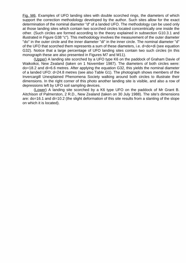
Fig. M6. Examples of UFO landing sites with double scorched rings, the diameters of whichsupport the correction methodology developed by the author. Such sites allow for the exactdetermination of the nominal diameter "d" of a landed UFO. The methodology can be used onlyat those landing sites which contain two scorched circles located concentrically one inside theother. (Such circles are formed according to the theory explained in subsection G10.3.1 andillustrated in Figure G38 "c"). This methodology involves the measurement of the outer diameter"do" in the outer circle and the inner diameter "di" in the inner circle. The nominal diameter "d"of the UFO that scorched them represents a sum of these diameters, i.e. d=do+di (see equationG32). Notice that a large percentage of UFO landing sites contain two such circles (in thismonograph these are also presented in Figures M7 and M11).
(Upper) A landing site scorched by a UFO type K6 on the paddock of Graham Davie ofWaikoikoi, New Zealand (taken on 1 November 1987). The diameters of both circles were:do=18.2 and di=6.6 metres. After applying the equation G32, this yields the nominal diameterof a landed UFO: d=24.8 metres (see also Table G1). The photograph shows members of theInvercargill Unexplained Phenomena Society walking around both circles to illustrate theirdimensions. In the right corner of this photo another landing site is visible, and also a row ofdepressions left by UFO soil sampling devices.
(Lower) A landing site scorched by a K6 type UFO on the paddock of Mr Grant B.Aitchison of Palmerston, 2 R.D., New Zealand (taken on 30 July 1988). The site's dimensionsare: do=16.1 and di=10.2 (the slight deformation of this site results from a slanting of the slopeon which it is located).

Fig. M7. Landing sites of K3 type UFOs. The sites shown on the above photographs were leftin a silage paddock of Mr Geoff Genmell, Horse Range Rd, No 2 R.D., Palmerston, NewZealand. To reflect their dimensions, both sites are photographed with the reference circle of1 meter in diameter (whose arrow points in the magnetic north direction). The upper site consistsof two concentric rings, whose diameters are do=2.1 [m] and di=1 [m]. Thus, according to thecorrection routine expressed by the equation (G32), the "d" diameter of this UFO was d=3.10 [m](see also Table G1). The lower site was elliptical, having the axes: do =4.06, and do =3.1(N-S) (W-E)
metres.

Fig. M8. Examples of two K4 type landing sites which allowed a precise measurement of theirdimensions. The diameters of these sites in both cases were identical, i.e. do=6.40 metres, andda=0.2 metre (see equation G33).
(Upper) The site found in the paddock of Mr Graham Davie of Waikoikoi (South Island,New Zealand), only 12 metres distant from the site where a K6 UFO landed. Inside this ringimprints of three legs symmetrically located were found. The edges of the scorched ring wereso clear that they allowed for an exact measurement of the width of the columns of the magneticfield produced by the side propulsors. This width was a=0.30 of a meter. At the edge of the sitea square soil sample was taken by a UFO. The indentation left by this sample is visible on thephotograph.
(Lower) Three sites formed by K4 (top), K6 (middle) and K7 (bottom) types of UFOs,photographed by the author on 3 January 1988, shortly after they appeared. They were foundin the Weka Pass (Frog Rock area) on the west side of State Highway 7: Christchurch to HanmerSprings. On the K4 site the scorch mark formed by the main propulsor was displaced in thesouth direction. This photograph perfectly illustrates the major principle of sizing the UFOs,which states that the diameter of each larger type of these vehicles is equal to two diameters ofthe previous type. (This means that the nominal diameter "d " of a landing ring produced by aK
UFO of a particular "K" type is always equal to two such diameters "2·d " of a smaller type "K-1"K-1
UFO, or to half the diameter "0.5·d " of the next larger type "K+1" of a UFO, i.e.:K+1
d =2·d =0.5·d . The equation which describes the nominal diameter of any type of UFOK K-1 K+1
landing site is: d =(0.5486·2 )/�2 [meters].)KK

Fig. M9. The landing site produced by a UFO type K5. This site was photographed by the authoron 30 July 1988 in the Puketapu Road, paddock of Mr. Grant B. Aitchison of Palmerston (R.D.,Palmerston, New Zealand). Its dimensions were do=13.6, da=1.2 and a =1.5 metres. Thus thes
nominal diameter "d" of this vehicle was d=12.4 metres - see equation (G33). (Compare the sitein this photograph with the one shown in Figure M3 which was also made by a UFO type K5.)

Fig. M10. Examples of the landing sites left by UFOs type K7. The nominal diameter of thisvehicle is d=49.65 metres.
(Upper) The site scorched in the paddock of Mr A.E. Herbert of "Shellrock Farm", WekaPass (Frog Rock area), North Canterbury, New Zealand. It was photographed by the author on2 September 1987. The reference circle of 1 meter in diameter was placed on the markscorched by the main propulsor (this mark is displaced northward from the centre of the site).The dimensions of the site are: do=47.8 metres and di=1.8 meters. Note that on this photographan extremely clear K5 type landing site is also visible. It has a diameter do=12.8 metres. ThisK5 site was scorched about 50 metres further up the hill from the K7 one.
(Lower) The landing site scorched in the paddock of Mr Allan Chapman, Goodwood,R.D.1, Palmerston. Its diameter is do=48.5 metres.

Fig. M11. A photo of the landing site left by a UFO type K8, taken by the author on 30 May 1987.This is the first photograph of two landing sites formed by (probably) the same K8 type UFO.Another photo is presented in Figure M16. The site shown here contains a pattern of twoconcentric rings of scorched soil, located one inside of the other. It was discovered on thenorth-west slope of Coromandel Peak in Glendhu Bay, Wanaka, New Zealand. The land ownerof this site is Mr Don McRae. The outer and inner diameters of both scorched rings are do=77.5[m] and di=22 [m] (thus, according to the equation G33, the nominal "d" diameter of the UFO thatscorched this site was about d=99.5 metres). Various local farmers claim that the patternsappeared between the years 1900 (this year was given by Mr. A.S. Scaife, 81 Tenby St,Wanaka, Tel: 443-7166 - the earlier, retired owner of this land) and 1955 (this year was givenby the present owner), so when photographed they were at least thirty years old. To the bestknowledge of the author the above photograph presents the biggest UFO landing site that hasbeen found to-date. The total diameter of the vehicle that formed it was D=140.44 metres (seeTable G1). This photograph supplements additionally the one shown in Figure M6 in illustratingthe principles of the correction methodology applied by the author and explained in subsectionG10.3.1 (see also Figure G38 "c").

Fig. M12. A landing site left by a flying system of K3 type UFOs. Numerous such sites are causedby the effect of massive UFO landings occurring in the vicinity of the Tapanui Crater (especiallyalong the lines of china stone and trinitite deposits - see lines C and T in Figure M21). Illustratedabove is the landing site discovered in the paddock of Mr Gerrard Eckhoff of Coal Creek nearRoxburgh (on the line of china stones). A characteristic attribute of such a system is that itscorches on the ground a unique "clover" shape which can not be formed in any naturalmanner. A field examination of the above site confirmed the presence of all the attributespredicted by the Theory of the Magnocraft.
(a) General appearance of a flying system. Notice that this configuration of UFOs andMagnocraft is obtained when four flying complexes shown in Figure G8 are coupled togetherby their flanges (see Figure G16).
(b) The shape and attributes of a scorched pattern left on the ground by a landed flyingsystem. Notice that the equations G13 and G9 allow for an exact prediction of the expecteddimensions "du" and "di" of this pattern for all subsequent types of UFOs (see Figure G42).
(c) An aerial photograph of this Roxburgh landing site taken by Mr Harry Latham ofInvercargill on 15 November 1987. The measurement of the dimensions of the site yieldedvalues: du=7.5 and di = 6.2 metres. Notice that apart from this site, the photograph also revealsa number of other UFO landing sites scattered around.
(d) A ground-level photograph of the same site taken by the author. Inside the scorched"clover" a white reference circle (1 meter in diameter) was placed with the arrow pointed towardsmagnetic north.
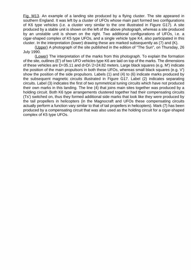
Fig. M13. An example of a landing site produced by a flying cluster. The site appeared insouthern England. It was left by a cluster of UFOs whose main part formed two configurationsof K6 type vehicles (i.e. a cluster very similar to the one illustrated in Figure G17). A siteproduced by a stable unit is shown on the left of the above photograph, whereas a site producedby an unstable unit is shown on the right. Two additional configurations of UFOs, i.e. acigar-shaped complex of K5 type UFOs, and a single vehicle type K4, also participated in thiscluster. In the interpretation (lower) drawing these are marked subsequently as (7) and (K).
(Upper) A photograph of the site published in the edition of "The Sun", on Thursday, 26July 1990.
(Lower) The interpretation of the marks from this photograph. To explain the formationof the site, outlines (E') of two UFO vehicles type K6 are laid on top of the marks. The dimensionsof these vehicles are D=35.11 and d=D/�2=24.82 meters. Large black squares (e.g. M') indicatethe position of the main propulsors in both these UFOs, whereas small black squares (e.g. V')show the position of the side propulsors. Labels (1) and (4) to (6) indicate marks produced bythe subsequent magnetic circuits illustrated in Figure G17. Label (2) indicates separatingcircuits. Label (3) indicates the first of two symmetrical tuning circuits which have not producedtheir own marks in this landing. The line (4) that joins main sites together was produced by aholding circuit. Both K6 type arrangements clustered together had their compensating circuits(Ts') switched on, thus they formed additional side marks that look like they were produced bythe tail propellers in helicopters (in the Magnocraft and UFOs these compensating circuitsactually perform a function vary similar to that of tail propellers in helicopters). Mark (7) has beenproduced by a compensating circuit that was also used as the holding circuit for a cigar-shapedcomplex of K5 type UFOs.

Fig. M14. Examples of permanent UFO landing sites (which may last even up to 100 years)formed because of the biological destabilization of the soil and its subsequent population withmushrooms.
(Upper) The oldest UFO landing sites discovered so far. They were scorched nearWairoau Station which is owned by Mr John Lee of Cardrona, New Zealand. These rings werenoticed for the first time around the year 1920 by the father of the present property owner. Thus,when photographed by the author (i.e. 31 May 1987) they were definitely over sixty years old.The paddock containing these circles has been ploughed twice since. The land owner confirmsthat the dimensions of these sites have not changed in sixty years. Also measurements by theauthor confirm that these dimensions correspond to those left by UFOs types K3, K4 and K5.
(Lower) Mushrooms that grow on a UFO landing site (taken by the author in April 1989).This photograph illustrates the theory explained in subsection G10.1 that the strong magneticfield of the landed UFO sterilizes the soil thus providing perfect conditions for the growth ofmushrooms. The population of mushrooms once established in the soil takes then many yearsto get rid of.

Fig. M15. A pine tree broken by a hovering UFO type K5. This tree is located in the corner of asmall pine forest owned by Mr Allan Chapman of Goodwood, R.D.1, Palmerston, New Zealand.The UFO broke off the top of this tree at a height of 6.8 metres and simultaneously leftunderneath it a ring of scorched vegetation. The dimensions of the ring were as follows:do =12, do =14.4 and a =0.65 metres. This evidence is extremely valuable as it allows us(E-W) (N-S) S
to determine the average height at which UFOs hover when scorching their landing marks. Itseems that this height equals about a half of the vehicles' outer diameters.

Fig. M16. The landing site which confirms that UFOs always fly with their bases perpendicularto the force lines of the Earth's magnetic field. The above photograph shows the second of twolanding sites found on the slopes of Coromandel Peak, Glendhu Bay, Wanaka, New Zealand(the first site is shown in Figure M11). This site is located on the slope pointing exactly towardsthe magnetic westward direction. It has the shape of two half rings with circumferences touchingeach other. It was either scorched by a solo flying K8 type UFO while it descended twice at a lowheight, or perhaps by a flying system composed of four cigars stacked from UFOs type K8 (theshape of a complete mark scorched by such a flying system is illustrated in Figure M12). Thepeculiar half-circle shape of both marks was caused because the descending UFO needed tobe slanted in relation to the ground. When the landing of this vehicle took place on thenorth-west side of Coromandel Peak - see photo from Figure M11 - it allowed the UFO to keepits base simultaneously: (1) perpendicular to the Earth's magnetic field force lines and (2)parallel to the ground. Thus the mark left on the north-west slope is circular in shape. But duringlanding approaches made by the same UFO on the slope directed exactly to the west (see photofrom this Figure) the Earth's field force lines were parallel to the surface of the ground. Thereforethe UFO was unable to land with its base parallel to the slope. Thus it needed to slant itself inrelation to the ground, forming the above landing sites in the shape of half-circles.

Fig. M17. One of the long, glassy, geometrically shaped tunnels from Ecuador. A gigantic systemof similar tunnels, thousands of miles in length, has been discovered in the Province of Morona- Santiago (Ecuador) by Mr. Juan Moricz in June 1965. The above photograph is reproducedwith the permission of Erich von Däniken from his book "In Search of Ancient Gods" (SouvenirPress, England, 1973, ISBN 0-285-62134-3, page 341). The saucer-shaped tunnel presentedhere was probably formed by a spacecraft (type K6) flying in an east-west or west-east direction.Particles of melted rock fell down and subsequently hardened after the flight of the craft, causingthe formation of a rough and craggy floor which hides the lower half of the tunnel, symmetricalto its ceiling - compare this diagram with Figure G36 (c).

Fig. M18. The Cocklebiddy Cave from the Nullarbor Plain in Western Australia displays all theattributes of a long, straight and geometrically shaped tunnel made technologically by theunderground flight of a vehicle utilizing the principles of the Magnocraft. The shape of this caveis elliptical, typical for a north-south direction of flight of such a vehicle (this tunnel in fact isdirected south-north). Its lower part is buried under a thick layer of debris and particles ofhardened rock - see Figure G36 (b). The walls display the monotropic structure reflecting thedirection of the expansion of vapors from melted rocks. The shallow indentations on the walls,perpendicular to the axis of the tunnel, correspond to the motion of the craft's magnetic whirl. (Adescription of this cave, illustrated by numerous photographs, is published in the Australianmagazine "People", December 5, 1983, pages 8 to 10.)
(a) The photograph illustrating perfectly the technological attributes of the cave.(b) The shape of the part of the Cocklebiddy Cave which has been explored so far. It
should be stressed here that the geographic orientation of this part is exactly in the south-northdirection, whereas its geometry reflects the motion of a disc traveling through the ground.

Fig. M19. Photographs of the Tapanui Crater showing its shape and inner configuration.(Upper) A distant view of the Tapanui Crater. This photograph was taken by Alister
Raymond of Invercargill on 1 November 1987 from the entry to McPhail Road that connectsWaikoikoi with Pukerau. The entry to this Road is located in the geographic north-west directionfrom the centre of the Crater. The "crow's flight" distance between the photographer and theCrater was about five kilometres. The photograph clearly illustrates that the soil removed fromthe crater does not appear below it (this means that the crater could not have been formed bya landslip). Moreover, it shows that the Tapanui Crater displays a complete lack of an upliftedrim (therefore it also could not have been made by a heavenly body impacting with Earth,because in all cases of such an impact a clearly distinguishable rim must be created).
(Lower) A photograph of the Tapanui Crater taken from its eastern edge. Because of theshade caused by the Sun, the outlines of the subsequent inner craters can be easilydistinguished. Notice that the front edge of each inner crater has a local depression caused bythe shockwaves' turbulence.
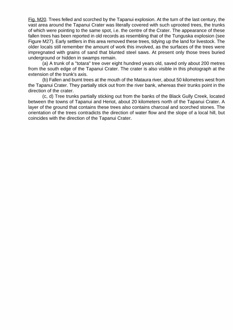
Fig. M20. Trees felled and scorched by the Tapanui explosion. At the turn of the last century, thevast area around the Tapanui Crater was literally covered with such uprooted trees, the trunksof which were pointing to the same spot, i.e. the centre of the Crater. The appearance of thesefallen trees has been reported in old records as resembling that of the Tunguska explosion (seeFigure M27). Early settlers in this area removed these trees, tidying up the land for livestock. Theolder locals still remember the amount of work this involved, as the surfaces of the trees wereimpregnated with grains of sand that blunted steel saws. At present only those trees buriedunderground or hidden in swamps remain.
(a) A trunk of a "totara" tree over eight hundred years old, saved only about 200 metresfrom the south edge of the Tapanui Crater. The crater is also visible in this photograph at theextension of the trunk's axis.
(b) Fallen and burnt trees at the mouth of the Mataura river, about 50 kilometres west fromthe Tapanui Crater. They partially stick out from the river bank, whereas their trunks point in thedirection of the crater.
(c, d) Tree trunks partially sticking out from the banks of the Black Gully Creek, locatedbetween the towns of Tapanui and Heriot, about 20 kilometers north of the Tapanui Crater. Alayer of the ground that contains these trees also contains charcoal and scorched stones. Theorientation of the trees contradicts the direction of water flow and the slope of a local hill, butcoincides with the direction of the Tapanui Crater.

Fig. M21. A map of the South Island, New Zealand, showing the type and extent of damagecaused by the Tapanui explosion. The approximate outlines from this map are based on thepresent sparse information available to the author and further research may be needed toincrease their precision. The triangular area of devastation is highlighted. Symbols used inmarking this map are as follows: I - the total range of the total bush fire ignited by the fall ofred-hot china stones and spread by the reversed cyclone of implosion. Within this range no treeor seed survived. Beyond this broken line fires ignited by the china stones had only a local,limited spread, which left some trees untouched; D - the line along which unusual metallicdebris (probably remains of the spaceships) have been found - see Figure M25; T - the majorline of glassy "trinitite" deposits; C - the major line along which the heaviest fraction of "chinastones" was deposited - see Figure M26; L - the area of trees felled by the cyclone of implosionI
(their tops are oriented towards the Tapanui Crater); L - the area of trees felled by theE
shockwaves from the explosion (the trunks of these trees lie along the lines that cross in thecentre of the explosion, whereas their roots are directed towards the Tapanui Crater - see FigureM20); F - the range of bush fires ignited directly by the fireball from the explosion; O - theTapanui Crater where the explosion occurred; R - forests that regerminated before the first whitesettlers arrived in New Zealand in the 19th century; P - the path followed by the vehicle prior tothe explosion, as recorded in Maori legends. Notice that this path is contradictory to theorientation of the central axis of the explosion. This again confirms that the destruction could nothave been caused by a heavenly body (e.g. a meteorite) impacting with Earth; S /N - theG G
geographic south to north direction; S /N - the central axis of the elliptical Tapanui CraterM1178 M1178
and the devastation area. This axis coincides with the magnetic south/north direction from theyear 1178.

Fig. M22. The inner topography of the Tapanui Crater. The presence of at least four craters(marked by numbers 1 to 4), each one located inside the other, is visible. This shows that theTapanui Crater was formed not by one, but by not less than four subsequent explosionsoccurring in a series. Each of these explosions created a further crater within the boundariesof the previous one. The existence of these four craters indicates that a cigar-shaped flyingcomplex (see Figure G8) consisting of not less than four of the Magnocraft-like vehicles (UFOs)exploded top-down at Tapanui. Symbols: Sm/Nm - magnetic south/north direction for the year1178; C/C - the main direction of heavy china stone deposits (see also the map from FigureM21); T/T - the main direction of the "trinitite" falls; E - the "tongue" of the eroded Crater's edgeformed by the strong rain falls that followed the Tapanui explosion; H - the hummocks formedby the breaks in shockwaves; R - the cylindrical entry to the Crater that seems to reflect theshape and dimensions of the exploding spacecraft; W - five waves forming thetriangular-shaped entry to the Crater (the number of these waves may have a connection withthe number of spacecraft which exploded); L - small indentations, some are little lakes, formedas a forerunner to the breaks in the shockwaves.
(Upper) A sketch of the Crater's topography as seen from above (see also Figure M23).Notice that the shape of this Crater contains the same elements that are distinctive for theTunguska devastation area - see Figure M30.
(Lower) The cross-section through the Crater along the axis of the explosion: S /N . M M

Fig. M23. Two aerial photographs of the Tapanui Crater, placed together to allow forstereoscopic vision of the area, if someone looks at them through stereoscopic glasses. (In theN.Z. Lands and Survey Department the aerial photographs of this area have the cataloguenumbers S170/5/C and S170/6/A.) The Crater is positioned in the centre of a triangle definedby three towns in the South Island of New Zealand: Tapanui, Waipahi and Mataura. Itsgeographical co-ordinates are: 46( 04' S and 169( 09' E. The evidence accumulated to dateindicates that this large elliptical depression with the dimensions of 900x600x130 metres wasformed by the effect of an explosion of a magnetically propelled flying vehicle. It should bestressed that the indigenous meaning in the Maori language for the words "Ta-pa-nui" is"The-big-explosion", for the words "Wai-pa-hi" it is "The-place-of-the-exploding-fire", whereasthe words "Mata-ura" mean "The-glowing-spacecraft". The Theory of the Magnocraft reveals thatwhen a magnetically propelled vehicle explodes, the central axis of the destruction area mustbe oriented exactly in the magnetic south/north direction. Thus the long axis of the TapanuiCrater should be pointed in the direction where at the date of the explosion, magnetic north waslocated. As this axis is declined -37( (westward) from the geographic north direction, theorientation of the Crater's axis confirms that the explosion took place in 1178 (this date was alsoestablished from other sources).

Fig. M24. Two photographs of a tornado taken by Mrs Diane Chittock of Waikoikoi at 5:15 p.m.on 19 December 1969. This tornado appeared exactly above the Tapanui Crater (tornadoes areunknown in this area of New Zealand) and lasted for only a few kilometers before it diminished.The strong turbulent magnetization of the Tapanui Crater is directly responsible for numerousunusual weather phenomena occurring in the area.
(Upper) The tornado develops its embryo funnel exactly above the Tapanui Crater (notethe forest right to the Crater's southern edge).
(Lower) The fully developed tornado drifting eastward.

Fig. M25. A piece of magnetized iron found in the close vicinity of the Tapanui Crater. It lookslike a metallic splinter from a spacecraft, torn apart by the explosion, melted, mixed with grainsof local sand, and smoothed on the surface by a flight in hot air. It is magnetized in a turbulentmanner, and its surface is covered with a layer of molten silicone. Spectrographic analysis hasshown its chemical composition to be about 60% of silicone, 30% of iron, and 10% of aluminum.To reflect its dimensions, a coin of 31 [mm] in diameter is also photographed. It should bestressed that four pieces of such material have so far been found. Except for the one from theauthor's collection presented above, another almost identical piece is held by Mr Ken Goldfinch(26 Lothian Street, Maori Hill, Dunedin). Two further pieces that look like they have been cut outfrom a gold nugget are in the possession of the Geology Department at Otago University,Dunedin, New Zealand.
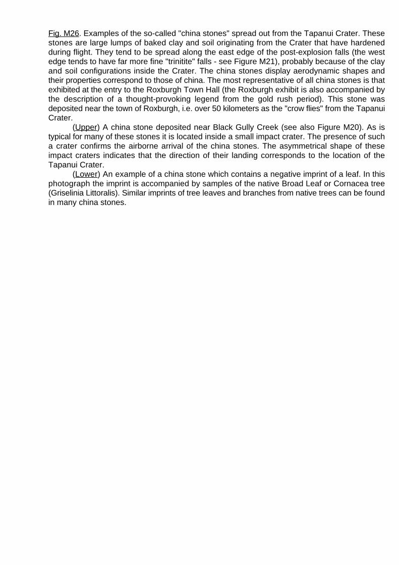
Fig. M26. Examples of the so-called "china stones" spread out from the Tapanui Crater. Thesestones are large lumps of baked clay and soil originating from the Crater that have hardenedduring flight. They tend to be spread along the east edge of the post-explosion falls (the westedge tends to have far more fine "trinitite" falls - see Figure M21), probably because of the clayand soil configurations inside the Crater. The china stones display aerodynamic shapes andtheir properties correspond to those of china. The most representative of all china stones is thatexhibited at the entry to the Roxburgh Town Hall (the Roxburgh exhibit is also accompanied bythe description of a thought-provoking legend from the gold rush period). This stone wasdeposited near the town of Roxburgh, i.e. over 50 kilometers as the "crow flies" from the TapanuiCrater.
(Upper) A china stone deposited near Black Gully Creek (see also Figure M20). As istypical for many of these stones it is located inside a small impact crater. The presence of sucha crater confirms the airborne arrival of the china stones. The asymmetrical shape of theseimpact craters indicates that the direction of their landing corresponds to the location of theTapanui Crater.
(Lower) An example of a china stone which contains a negative imprint of a leaf. In thisphotograph the imprint is accompanied by samples of the native Broad Leaf or Cornacea tree(Griselinia Littoralis). Similar imprints of tree leaves and branches from native trees can be foundin many china stones.

Fig. M27. The Siberian Taiga Forest felled by the Tunguska Explosion. All the uprooted treesare lying parallel and oriented in the same direction, with their roots positioned towards the blastand with their trunks pointing exactly to the centre of the explosion. Along the central axis of theexplosion the range of felled trees extends up to 75 kilometers from its centre. A scene similarto the above was also reported around the Tapanui Crater by early New Zealand settlers(compare this photograph with Figure M20).

Fig. M28. A perfect example of an impact crater. These photographs show the famous Meteor(Barringer) Crater at Canyon Diablo in the Arizona desert near Winslow, USA (35(02'N,111(01'W). Its main dimensions (i.e. length x width x depth) are about 1200 x 1100 x 183[metres]. The age of this Crater is estimated at 25,000 years. Notice the presence of featurescharacteristic of impact craters, especially: (1) a distinctive, uplifted rim surrounding its edge, (2)fragments of a heavenly body occupying its center, and (3) an east-west orientation (thephotographs were taken from S to N).
a,b,c - aerial photographs of the Crater taken from various angles,d - schematic cross section of the principal elements of the Crater formed in crystalline
rocks (see the paper by Richard A.F. Grieve, "Terrestrial impact structures", Ann. Rev. EarthPlanet. Sci., 1987, 15, page 247).

Fig. M29. Shown above are two photographs that illustrate the similarities between theTunguska Blast site and the centre of the mid-air nuclear explosion above Hiroshima in Japan.In both cases the trees located directly under the blast were still standing after loosing theirfoliage and branches, although everywhere around this area they had been blown over.Numerous photographs which document close similarities between these two explosions arepublished in the book [1M3.2] by J. Baxter and T. Atkins, "The Fire Came By", MacDonald andJone's Publishers Ltd., London 1976, ISBN 0-354-04012-X (see Figures 31 and 30 in the book[1M3.2]).
(a) The "telegraph pole" forest left standing exactly in the centre of the Tunguska Blast.About 5 km directly above this forest, a 30 megaton blast occurred on June 30, 1908. If thisexplosion took place near the ground, a crater similar to that at Tapanui (see Figure M19) wouldhave been left.
(b) The upright black and leafless trees surrounding Hiroshima Castle, photographedafter a 12.5 kiloton atomic bomb exploded about 550 metres directly above the castle on August6, 1945.

Fig. M30. An illustration of the similarities between the configurations of the Tapanui Crater andthat of the Tunguska Blast Site. Notice the apparent correspondences in: (1) the manner inwhich the explosion shockwaves entered the ground, (2) the relationship between the apicalangle of the triangular entries to both sites and their distance from the nearest magnetic poleof the Earth (i.e. at the moment of the explosion the Tapanui Crater was located much closer tothe magnetic pole then the Tunguska Site, thus its apical angle is also much wider), (3) thebreaking points of the explosion shockwaves, (4) the location of the centre of the explosions,(5) the magnetic meridian orientation of the sites, etc. Symbols: S /N - geographic south-northG G
direction, S /N - magnetic south-north direction.M M
(a) The Tapanui Crater (co-ordinates: 46(04'S, 169(09'E).(b) The Tunguska Blast Site (co-ordinates: 60(55'N, 101(57'E). This chart is based on
the 1958 Tunguska summary map, published in [1M3.2] page 124 and [2M3.2] page 102 (thismap shows the outlines of the area of a complete fall of trees, whereas later maps also includeareas where only part of the trees were felled). Symbols: O - centre of the explosion, F - rangeof scorched trees, P - path followed by the vehicle prior to the explosion as reported bynumerous eye-witnesses, L - range of trees felled by the shockwaves of the explosion (thetrunks of these trees point to the centre of the explosion).

N-1
Chapter N.
OBSERVATIONS OF UFONAUTS WHO USE MAGNETIC PERSONAL PROPULSION
Recent observations of UFOnauts provide strong evidence that these extraterrestrialbeings already use the type of personal propulsion whose attributes correspond in every detailto those listed in subsection H5. The most representative of this evidence is presented in thischapter. Unfortunately, the need for consistency does not permit comment on all the manyencounters in which the attributes of the aliens' personal propulsion were reported. But theanalyses presented here formulate the rules of interpretation which can be extended easily toall other cases we have knowledge of.
The evidence that supports deductions from this chapter was chosen from classic casesof UFOlogy. Therefore, detailed descriptions of each of these cases is contained in numerousbooks. For each case discussed in this chapter the author has provided references to resourcematerials. Most of these references point to one of the books from the list contained in the lastpage of subsection J.
N1. The characteristic appearance of the wearers of personal propulsion
In all reports describing UFOnauts, the attributes of a personal propulsion garment areevidently present. The suits worn by aliens are designed as one-piece overalls (usually silver,gray, or green color) that limit to a minimum the area of skin exposed to the action of a powerfulmagnetic field. Moreover, almost always these suits include a heavy belt, shoes with thick soles(or noticeable epaulets), and a hood or helmet. One of the better investigated encounters withUFOnauts wearing such belts and shoes was that of Stanislaw Maslowski of Wroclaw, Poland- see Figure N1 (details of Maslowski's encounter are presented in subsection L1.3.) Frequentlythe shoes and belt are of a different color (e.g. red) from the rest of the garment. Also numerouswitnesses confirm that during poor light conditions the belt and shoes (or epaulets) emit a glow.One of the many examples of such observations is shown in Figure N2.
In order to use the personal propulsion garments containing the main propulsors in theshoes, the UFOnauts must adopt a very characteristic body stance. The first of two possiblestances requires that both legs are permanently set apart - see subsection H4. The photographfrom Figure N3 shows a UFOnaut in such a pose. This photograph is one of four flash picturestaken on the night of 17 October 1973 just after 10 p.m., by police chief Jeff Greenhaw ofFalkville, Alabama, USA - see [3J] page 116. In spite of the fast motion of the photographedalien "faster than any human I ever saw", in all of the four photos the position of the UFOnaut'slegs remain set apart. This can only be explained by the action of the forces "B" of reciprocalrepulsion occurring between the main propulsors from the soles of the alien's shoes (seesubsection H4).
The second possible stance to be used by the wearers of the personal propulsiongarments containing the main propulsors in the shoes is when the legs are tucked up into asquat position. This stance is caused when the balance between the compressing forces "Q"and tensing forces "A" and "R" is disturbed by the wearer of this garment - see Figure H4. Insuch a case the attracting forces "Q" between the propulsors in the shoes and those in the beltbecome dominant, folding the wearer's legs. The upper UFOnaut in Figure N1 displays exactlythis squat stance.
Use of the personal propulsion garments induces electric charges in the non-conductivematerials from the vicinity. Thus the hair on heads and hands which are uncovered must standerect. Carl Higdon met an UFOnaut at the northern edge of Medicine Bow National Forest (south

N-2
of Rawlings), Wyoming, USA, on 25 October 1974, shortly after 4:15 p.m. - see [2J] page 171and [5J] page 15. He noticed that the hair on the alien's scalp was standing on end - see FigureN4. (More details of Higdon's encounter are contained in subsection K3 - item #2.) AlsoStanislaw Maslowski during his encounter, illustrated in Figure N1, was surprised and amusedbecause the blood-red hair on the face and hands of the nearest alien was standing on end.
N2. The extraordinary abilities of UFOnauts wearing personal propulsion garments
The most distinctive characteristic of the UFOnauts wearing their personal propulsiongarments is that they are able to fly noiselessly. This ability of aliens is confirmed by numerouswitnesses who actually saw UFOnauts flying in the air.
A well-known case when the flights of aliens were observed is the Hopkinsville incidentdiscussed further in this subsection. After one of the aliens was shot off the kitchen roof, he/shefloated in the air to a distance of about 12 metres - see description in [2J] page 191.
There are also some encounters in which the flying alien is the main focus of the entireobservation. An example is the multiple sighting of the flying alien known locally as "mothman"who terrorized residents of Point Pleasant in West Virginia, USA, during 1966/67; or thesightings of "big bird" creatures in Rio Grande Valley, Texas, USA, in 1976 - see [2J] page 236and [6J] page 117. Also the UFOnauts presented in Figure N1 were witnessed hovering (notstanding) about a half meter above the ground. The grass under their feet was noticed to movevigorously (i.e. their personal propulsion must work in the "magnetic whirl" mode of operation).
The personal propulsion of UFOnauts also gives them the ability to perform various othermovements which contradict our understanding of physical laws. For example, a UFOnaut whowalks a vertical wall like an insect is shown in Figure N5 (see [5J] page 14).
The most extraordinary ability of UFOnauts is their resistance to bullets fired at them. Thebest account of this ability is contained in the reports from the Hopkinsville, Kentucky, USA (anarea where people "shoot first, then ask questions"). The Hopkinsville encounter took place onAugust 21, 1965 - see [2J] page 190 and [3J] page 108. Here is a brief summary.
The family of Langfords from Sutton Farm (eight adults and three children) saw a brightlyglowing object descending behind a barn. A creature in a glowing silver suit, about a meter tall,came towards them. Two men grabbed a 12-gauge shotgun and a 22-caliber pistol, and firedat close range. The being was knocked over - but to the amazement of the watchers, it thenjumped up again and scurried away. The stunned family locked themselves inside their home.Then one of the women looked out of the dining room window and saw a face peering in at her,with wide slit eyes behind a helmet visor. The men rushed into the room and fired, but again thecreature, although hit, ran away. A total of almost 50 rounds were fired at the five aliens over thenext 20 minutes, but none of the bullets stopped them. Whenever one of the creatures was hit,it would float or fall over or run for cover. All the shots that struck them sounded as though theywere hitting a tin bucket. The beings made no sound. The undergrowth would rustle as theywent through it, but there was no sound of walking. The beings were seemingly weightless, asthey would float down from trees rather than fall from them.
The entire Hopkinsville incident is a perfect confirmation of the formation of an inductiveshield by the personal propulsion garments of UFOnauts.
The other important manifestation of the personal propulsion in operation is the inductionof electric currents in the closed circuits of wiring, especially when these circuits contain atransformer at their entry. In this way television sets or radio receivers can malfunction or evenburn out completely. An example which documents such effects caused by UFOnauts is thefollowing chain of incidents, the first of which took place in Broadhaven, England, in the earlyhours of April 24, 1977 - see [3J] page 140.
Billy and Pauline Coombs were sitting in their front room at 1 a.m., when Pauline
N-3
suddenly turned to look out the window. Blocking it was a towering, eerie figure wearing a silversuit. Billy turned in his seat and also saw the monstrous outline. It was wearing a helmet withsome sort of shiny visor. A pipe went from the mouth to the back of the head. The creatureradiated a sort of luminous light and when it touched the window, the pane started to rattle asif all hell had broken loose - yet there was no wind. The family had two souvenirs of the incident- a burned out television set, and a rose bush near the window which was badly scorched. Fora year after that, inexplicable happenings made the family's life a misery. The children frequentlysaw bright lights landing in the fields and found scorch marks next morning. On a trip to thecoast at nearby St. Bride's Bay, they saw two silvery-suited figures and a flying disc whichseemed to disappear into rock (refer to subsection K3!). Two of the children received strangeburns. Five television sets and eight cars mysteriously burned out. Then, as suddenly as theincidents had begun, they stopped (i.e. a scientific expedition of UFOnauts returned to itsplanet).
There are also quite frequent observations of UFOnauts during which the aliens' abilityto become invisible is manifested. Classic examples of this ability are the cases of the LeBelfamily (taking place in New England, USA, during 1977 and 1978 - see [4J] page 157) and theAndreason family (described in the book [1N2] by R.E. Fowler, "The Andreasson Affair, PhaseTwo", Prentice Hall, Inc., 1982, ISBN 0-13-0366-2). This kind of evidence confirms that extremelyefficient magnetic lenses can also be formed by the personal propulsion garments of UFOnauts.
N3. The scorched footprints left by personal propulsion of a UFOnaut
The magnetic propulsors mounted in the shoes of the UFOnauts are also capable ofmaking scorch marks on some organic matter. The marks left by such personal propulsiondisplay physical attributes similar to the ones caused by landings of UFO vehicles (comparesubsections M1 and G10). The best evidence of the scorching abilities of personal propulsionof UFOnauts in the author's files concerns the case of Jerzy Wasilewski of Wroclaw, Poland,which description follows.
On 4 September 1979, around 9:30 a.m., the flat of Mr Jerzy Wasilewski (ul. Kruszwicka53/9, Wroclaw, Poland), located on the 4th (highest) floor of the building, was visited by aUFOnaut. The alien entered the flat through an open window in the kitchen and investigated thedwelling as he/she flew around. Then the being descended into the corridor and walked backto the kitchen window from which he/she flew out. While walking along the tiles of PVC(PolyVinyl Chloride) that covered the floor, his/her propulsors from the shoes scorched 17 marksarranged into a "footprint trail". Each mark resembled a circle about 13 [mm] in diameter - seeFigure N6. The mean distance between subsequent "steps" was about 0.4 meter.
The PVC tiles containing these marks were examined thoroughly by scientists from theInstitute of Organic Chemistry at the Technical University of Wroclaw, Poland. Listed below arethe properties of the marks on these tiles, which were established during this examination:
1. The substance of the PVC tiles remained in its original structure inside the marks.2. The surface of the marks displayed no trace of any mechanical deformation or
crushing. 3. Any unfamiliar substances (even a trace quantity) were absent in the native material
in the marks. 4. There was no trace of burned Polyvinyl Chloride. This substance burns if the plates are
exposed to a temperature greater than 130 (C. 5. The monotrophic, wavy, black patterns were distinguishable on the surface of the
marks. Their thickness is several microns. The chemical composition of the patterns indicatesthat their cause could only be the action of an active ozone attacking the Polyvinyl Chlorideparticles.

N-4
6. The tiles in the area surrounding the marks were strongly discolored. This indicatesthat a high energy agent (i.e. a powerful magnetic field) acted upon the tiles.
The above properties of the marks led to establishing that the following causes must beexcluded as a possible cause:
(a) Burning by contact with a hot, solid object. (b) Burning by a stream of hot gases, plasma or electrons.(c) Mechanical imprint or obliteration.(d) Impact by a decompressing stream of a cold medium.
In conclusion of the research, the only cause for these marks must be the concentrated actionof an extremely strong, pulsating magnetic field, accompanied by a simultaneous action of theair ionized by this field (especially highly active ozone) that was in contact with the surface ofthe tiles.
On the day of their appearance, the alien's footprints had a very intensive, chalk-whitecolor which contrasted with the bluish-gray background of the rest of the PVC tiles. On thesewhite marks the black wavy pattern of the ozone action was clearly distinguishable. But, as timepassed, the intensity of the whiteness of the marks gradually diminished. The restoration of thetiles' original color resembled the curve of radioactive isotope disintegration, in which the periodof half-life was equal to about 120 days. When in 1982, just before leaving Poland, the authorlast saw these tiles, the color of the marks was indistinguishable from their background. But theblack ozone pattern remained unchanged.
When the footprints were first reported, the Wroclaw UFO research organization "WzgorzePartyzantow" was aware of their extreme importance as being material evidence of UFO activity.Therefore, an instant decision was made to exchange the PVC floor from Mr Wasilewski's flatto a parquet floor in order to collect and preserve the marked tiles. As the assigning ofgovernment finances (the "Wzgorze Partyzantow" was a government funded organization)required some time, Mr Eugeniusz Rolewski, then the organization's chairman, disbursed hisown private funds for this operation. Until 1982 the PVC tiles with the UFOnaut footprints werecarefully stored in Wroclaw amongst other UFO evidence. The author believes that they are stillthere.
At approximately the same time two other similar incidents took place in Wroclaw.Unfortunately the footprints from these other incidents were not preserved for research. In onecase a woolen carpet in which holes caused by steps had been found was simply thrown outbefore the owners realized what the evidence represented. In the other case, occurring after theWasilewski tiles became well known, the PVC tiles containing the next lot of footprints werequickly taken away by unknown private collectors before authorities reached them. All threecases showed that incidents of scorched marks left by the personal propulsion of UFOnauts arequite common, and that only a lack of knowledge or the fear of being ridiculed discourages thepeople involved in such incidents from officially reporting them.
N4. The consequences of the observation of personal propulsion of UFOnauts
The evidence provided in this chapter represents only a small fraction of a huge oceanof similar facts which overflow the files of UFO investigating organizations and the collectionsof private researchers. If one analyses these facts it becomes evident that they all display aperfect correspondence to the expected properties of magnetic personal propulsion (seesubsection H5). The logical determination of such a correspondence constitutes formal proofthat UFOnauts already use magnetic personal propulsion garments. Completion of this proofintroduces numerous consequences, the most important of which are listed below:
1. The proof confirms the correctness of this part of the theory of the Magnocraft whichdescribes magnetic personal propulsion. This is because it indicates that the operational

N-5
models of magnetic personal propulsion already exist.2. It confirms again that UFOs have a strictly technological origin which results from the
advancement of appropriate technical devices. It also reassures us that there is nothingsupernatural in the abilities of UFOnauts, and that all of their actions can be rationally explainedwith our present level of knowledge.
3. It testifies that UFO manifestations have an extraterrestrial origin, as human technologyis yet unable to produce such propulsion devices. Also it provides the theoretical base for thepiecing together of further secrets of the UFOnauts.
4. It creates a scientific foundation from which the future completion of magnetic personalpropulsion can be launched.
The evidence accumulated in this chapter indicates also that the collection ofobservational data concerning the personal propulsion of UFOnauts serves a very practicalpurpose. It facilitates and expedites our completion of these devices.
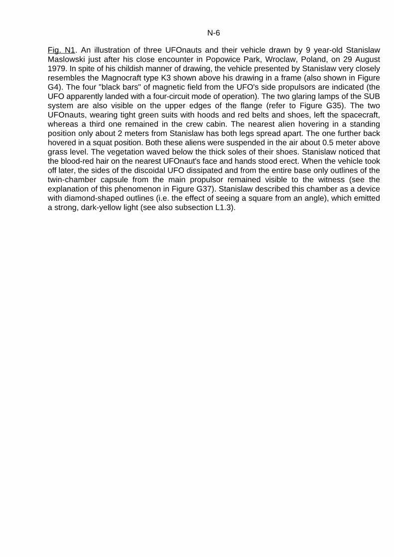
N-6
Fig. N1. An illustration of three UFOnauts and their vehicle drawn by 9 year-old StanislawMaslowski just after his close encounter in Popowice Park, Wroclaw, Poland, on 29 August1979. In spite of his childish manner of drawing, the vehicle presented by Stanislaw very closelyresembles the Magnocraft type K3 shown above his drawing in a frame (also shown in FigureG4). The four "black bars" of magnetic field from the UFO's side propulsors are indicated (theUFO apparently landed with a four-circuit mode of operation). The two glaring lamps of the SUBsystem are also visible on the upper edges of the flange (refer to Figure G35). The twoUFOnauts, wearing tight green suits with hoods and red belts and shoes, left the spacecraft,whereas a third one remained in the crew cabin. The nearest alien hovering in a standingposition only about 2 meters from Stanislaw has both legs spread apart. The one further backhovered in a squat position. Both these aliens were suspended in the air about 0.5 meter abovegrass level. The vegetation waved below the thick soles of their shoes. Stanislaw noticed thatthe blood-red hair on the nearest UFOnaut's face and hands stood erect. When the vehicle tookoff later, the sides of the discoidal UFO dissipated and from the entire base only outlines of thetwin-chamber capsule from the main propulsor remained visible to the witness (see theexplanation of this phenomenon in Figure G37). Stanislaw described this chamber as a devicewith diamond-shaped outlines (i.e. the effect of seeing a square from an angle), which emitteda strong, dark-yellow light (see also subsection L1.3).

N-7
Fig. N2. An artist's reconstruction of the appearance of a UFOnaut who was observed in Lindley,New York, USA, on July 23, 1977, just after 1 a.m., by two girls Janine (aged thirteen) andMonica (aged twenty-six) - both surnames are kept confidential. The alien wore a belt fromwhich a green light glowed. He/she also seemed to have a flashlight. The UFOnaut made atombstone levitate while shining a light on it. Throughout this incident both witnesses got severeheadaches, ringing ears, dry throats, and a shortened sense of time (they thought that thethree-hour experience had lasted only an hour). All these symptoms indicate that the girls wereunder the influence of a powerful field emitted by the personal propulsion of this alien.
This illustration is published in the book by Allan Hendry, "The UFO handbook", SphereBooks Limited, 1979, page 123.

N-8
Fig. N3. This photograph is one of four flash pictures of a very fast-moving UFOnaut, taken bypolice chief, Jeff Greenhaw, on the night of 17 October 1963, just after 10 p.m. in a remote fieldwest of the town called Falkville, Alabama, USA. In all four photographs the alien keeps his/herlegs apart in a motionless, standing position. Because all the photos were taken while the alienwas moving extremely fast, this indicates that his/her motion was produced by personalpropulsion, not by a physical movement of the legs (stepping). The characteristic stance of thelegs spread apart indicates that the alien wore a version of the personal propulsion, having themain propulsors located in the soles of his/her shoes. The UFOnaut was about the size of alarge human, and was clad in a silvery suit that looked like tin-foil. Antennae appeared to sproutfrom the head.
It is worth mentioning here that after taking these photographs, Mr Greenhaw lost his jobbecause the authorities decided that a person who photographed a UFOnaut could not betrusted any more (he is not the only victim of an official anti-UFO inquisition).
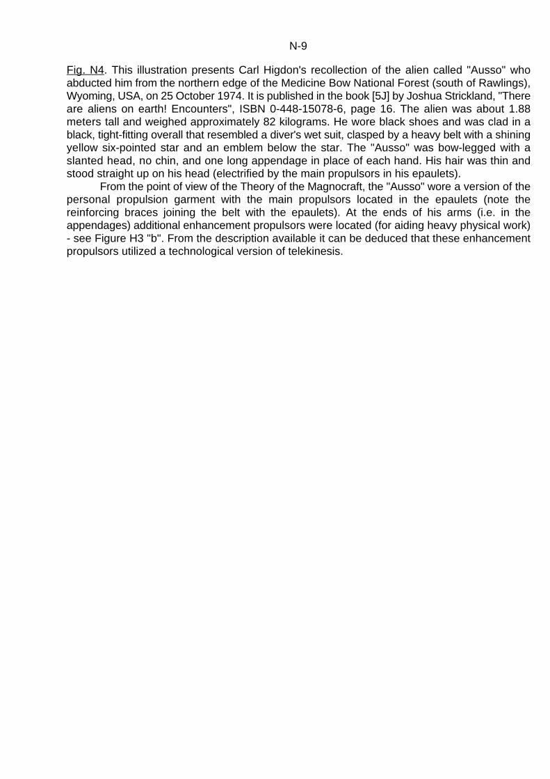
N-9
Fig. N4. This illustration presents Carl Higdon's recollection of the alien called "Ausso" whoabducted him from the northern edge of the Medicine Bow National Forest (south of Rawlings),Wyoming, USA, on 25 October 1974. It is published in the book [5J] by Joshua Strickland, "Thereare aliens on earth! Encounters", ISBN 0-448-15078-6, page 16. The alien was about 1.88meters tall and weighed approximately 82 kilograms. He wore black shoes and was clad in ablack, tight-fitting overall that resembled a diver's wet suit, clasped by a heavy belt with a shiningyellow six-pointed star and an emblem below the star. The "Ausso" was bow-legged with aslanted head, no chin, and one long appendage in place of each hand. His hair was thin andstood straight up on his head (electrified by the main propulsors in his epaulets).
From the point of view of the Theory of the Magnocraft, the "Ausso" wore a version of thepersonal propulsion garment with the main propulsors located in the epaulets (note thereinforcing braces joining the belt with the epaulets). At the ends of his arms (i.e. in theappendages) additional enhancement propulsors were located (for aiding heavy physical work)- see Figure H3 "b". From the description available it can be deduced that these enhancementpropulsors utilized a technological version of telekinesis.

N-10
Fig. N5. This manner of climbing up (passing) a vertical wall is contrary to our understandingof physical laws, yet M. Ivorde of Belgium observed a UFOnaut doing precisely this. He reporteda greenish man about 1 meter high in a helmet and space suit that was seen with what lookedlike a metal detector. The alien had pointed ears and large luminous yellow eyes surroundedby green rims. When the UFOnaut lowered his/her eyelids, the face, deprived of the glow fromthe eyes, became invisible (this luminescence confirms that the alien used a personalpropulsion system whose powerful field was able to cause the eyes to glow). When M. Ivordeshone a flashlight at him/her, the UFOnaut walked up a wall in the manner presented in theabove illustration (we tend to believe that only insects are able to climb up walls in this way).
This diagram is published in the book [5J] by Joshua Strickland, "There are aliens onearth! Encounters", ISBN 0-448-15078-6, page 14.

N-11
Fig. N6. This photograph presents one of the seventeen scorched footprints left by the mainpropulsors of an UFOnaut that walked along a PVC floor in the flat of Jerzy Wasilewski (ul.Kruszwicka 53/5, Wroclaw, Poland) on 4 September 1979. Each of these marks looked like achalk-white droplet left on a bluish-gray background of the floor. Marks were (on average) about13 millimeters in diameter and had a black wavy pattern produced by an active ozone thatattacked the PVC particles. All of the marks formed a "footprint trail" leading along a PVC(PolyVinyl Chloride) floor of the flat's inside hall. The relative distance between two successivefootprints was about 40 cm. The research completed by a team from the Institute of OrganicChemistry of the Technical University of Wroclaw, Poland, revealed that the footprints wereproduced by a highly concentrated pulsating magnetic field acting upon the surface of thePolyvinyl Chloride tiles. Thus these footprints represent conclusive evidence that UFOnauts usemagnetic personal propulsion. To the best of the author's knowledge, the PVC tiles containingthese footprints are still held (together with other material evidence on UFOs) by a governmentsponsored UFO investigation group in Wroclaw, Poland.

O-1
Chapter O.
CONTEMPORARY OBSERVATIONS OF FOUR-PROPULSOR UFOs
Since it is formally proven that UFOs are already operational Magnocraft (see thedeductions from chapter J), the validity of all conclusions derived from the Theory of theMagnocraft became verifiable through the observation of UFOs. So far, in chapters J to N, thefeasibility of building the Magnocraft together with its miniaturized version called MagneticPersonal Propulsion was validated. The deductions that follow will check the validity of thetheory behind the four-propulsor spacecraft, described in chapter I.
The magnetic propulsors used by the four-propulsor spacecraft are based on theso-called "spider configuration" (see subsection F6.2) and thus they drastically differ inappearance and properties from those used by the Magnocraft and Magnetic PersonalPropulsion (the propulsors of the Magnocraft are based on the "twin-chamber capsule" - seesubsections F6.1 and G1). Also the shape and general design of this vehicle is different - seechapter I. For these reasons the attributes of four-propulsor UFOs should easily bedistinguishable from those of the discoidal UFOs. The author carefully examined evidenceavailable on UFOs, and has selected a number of cases which confirm that four-propulsor UFOshave been observed. The most representative of this evidence is discussed below.
O1. Classic sightings of four-propulsor UFOs
Probably the most documented and investigated observation of a four-propulsor UFO,is the case of abduction of a Polish farmer, late Jan Wolski from the small village of Emilcin nearOpole Lubelskie, Poland, that took place on 10 May 1978. (His postal address was: Mr. JanWolski, Emilcin kolo Opola Lubelskiego, 24-325 Skokow, Poland.) Here is a brief descriptionof this abduction together with details of the vehicle.
"On 10 May 1978 early in the morning Mr Wolski drove his horse wagon through aforestry road near his village. He noticed two small humanoids (about 1.10 metre high) walkingalong this road, dressed in tight gray overalls with hoods. They moved in a clumsy and strangeway, keeping their legs apart (see the properties of Magnetic Personal Propulsion). WhenWolski began overtaking them, they jumped from both sides into his wagon, surprising him withtheir nimbleness. Sitting either side of him, they impetuously discussed something betweenthemselves, using "devil" kind of language, consisting of sharp, quick sounds - coo and chucklelike. This convinced him that they were not humans. When the wagon reached a small clearing,Wolski noticed an unusual vehicle hovering above the ground at a height of about 30 metres- see Figure O1.
The vehicle had the shape of a small rectangular hut with a gable roof. Its square bodyslightly resembled that of a twin-rotor helicopter. It had no windows, only an open doorwaylocated in the centre of the facing wall. The doorway revealed the thickness of the wallsestimated by Wolski to be about 0.2 metre. The UFO had no flanges, wings, legs or wheels. Theonly elements protruding from its body were four barrel-like devices (propulsors) located exactlyat the corners of the main body. From each of these barrels a dark, spinning, vertical "drill"extended downward. The medium that constituted these "drills" looked like very dark smoke. Itsappearance resembled that of a solid substance, but it permeated underground without causingany visible opening or disturbance of the soil. All four "drills" were spinning very rapidly,although there was no noticeable motion of the air. While spinning they emitted a faint hummingnoise, quite similar to the sound produced by a bumblebee.

O-2
From the door of the UFO a small platform attached to four plastic ropes descended. Oneof the humanoids stepped on it and invited Wolski to follow him. The platform was firm andsurprisingly steady under foot, although it looked fragile and unstable. It lifted Wolski and oneof the humanoids to the vehicle, where another two humanoids were already waiting. The fourthhumanoid joined the rest in a second descent of the platform. Inside the vehicle there was adark, right-angled room. The only source of light was the door opening. The door was rolled upnear the doorway into a vertical tube. Floor, walls and the flat ceiling looked as though they werecasted from a material similar to glass, which was hard to the touch. The room was empty, withno furniture, only a few chairs attached to the wall opposite the door, and two control levers thatwere near the door sticking out from the wall.
After a brief medical examination and an activity that looked like taking photographs, thehumanoids released Wolski. When rushing his horses home he noticed that the vehicledeparted. While flying at a low speed above Emilcin, the UFO was also seen by another witnesswho described it as a "flying bus". Shortly after passing above this village, the vehicleaccelerated, produced a loud sonic bang and disappeared from the view. The examination ofthe site revealed material marks left by the UFO and its crew, including small imprints of thehumanoids shoes, scorched vegetation at the cleaning, and a mysterious "devil stone" (shownin Figure K1c) which turned out to be the main subject of this UFO visit."
The events following Wolski's abduction took a course tragically similar to so many otherencounters with UFOs. The initial investigation of evidence and events proved the validity of hisdescription and his experience. This, however, was unbearable to many close minded "experts"whose narrow personal philosophies allow no room for extraterrestrials. They began acampaign of "debunking", using irrational arguments. Finally, to cut off the escalating argumentsthat seemed to be out of control, Polish authorities decided to intervene, and they officiallyannounced that Wolski's abduction was a "joke" played to him by a group of students (thisannouncement was not accompanied by the reason and explanation behind such anenormously sophisticated and expensive "joke"). Although this announcement wasunconvincing and contrary to the evidence, it invalidated any further investigations and publicityfor this case, thus squandering the scientific value of this extremely informative UFOobservation. Mr Jan Wolski died on 8 January 1990, at the age of 83.
All properties of Wolski's UFO correspond exactly to those envisaged for a four-propulsorspacecraft. The appearance and operation of its barrel-like propulsors also match in every detailthose unique to spider configurations. This makes Wolski's abduction one of the bestdocumented observations of a four-propulsor UFO.
A four-propulsor UFO was also observed in the Roseneath suburb of Dunedin, NewZealand, by a local resident who prepared a detailed report of his sighting but requested hisname and address be kept confidential. The sighting took place during a clear autumn night,when strong moonlight increased visibility. It provided excellent confirmation for the expectedconfiguration of UFO's magnetic circuits that ionize the air. Figure O2 illustrates what was seen.Here is the eye-witness report which describes this sighting:
"It was 2.56 a.m. on 23 March 1989. I was awoken by a loud sonic bang similar to thatcaused by a supersonic aeroplane crossing the sound barrier (I remembered that a similar bangalso awoke me about 4 months earlier). I decided to glance through my window. It was a clearnight with strong moonlight shinning on the landscape. I noticed a vehicle hovering above apatch of bush on the other side of the valley, about 1 kilometer away from my home. It wassuspended motionless, about 10 metres above ground level on the non-populated slope of thehill known locally as "Blue Skin Hill", slightly to the right of the Sawyers Bay water reservoir. Theposition of this vehicle was approximately level with my house and located in the direction ofNNW from my window, i.e. on the magnetic azimuth 330(. The UFO was clearly distinguishableagainst the background of the moonlight slope, because of the lines of bluish-white steady lightthat outlined its body. It had the shape of a transparent, cubical-type hut, covered by a gable
O-3
roof. The side dimension of its square walls I estimate at about 9 metres. From the vehicle'scorners four columns of white-blue glitter light shone downwards. The glitter light grains of thesecolumns resembled something like the flickering of 'white noise' visible on TV screens whenworking sets do not receive any station. Each side wall of the vehicle was crossed by strandsof steady (i.e. non-glittering) bluish-white light. Also each edge of the vehicle was outlined bythe layer of the same light. The lines of light appearing on the rear of the vehicle were alsovisible through its transparent body.
After observing the vehicle for a few minutes I stopped looking. But the strange viewaroused my curiosity, so about 10 minutes later I had another look. The vehicle was still abovethe same spot. After a short observation I stopped looking. At about 3:15 I looked again andchecked for the third time. The vehicle was gone. Four days later I prepared a drawing of whatI saw, which I have enclosed with this report."
The field analysis of this sighting conducted by the author allowed a number of technicaldetails to be established about this UFO. For example it revealed that the UFO represented atype T4 vehicle, whose design and day-time appearance is illustrated in Figure I1. Also itconfirmed that the observed geometry and mutual relationship of dimensions of this vehiclecorrespond exactly to those described theoretically by the equations contained in chapter I. Inaddition the analysis revealed that this UFO was positioned so that its right rear wall was facingmagnetic north. Moreover, the vehicle hovered slanted from the vertical position at the angle ofabout 20( so that the four columns of flickering light which extended down from its corners wereparallel to the force lines of the local magnetic field. (The magnetic inclination for Dunedin isabout I=70(.) Both these findings confirm that the vehicle's propulsion system utilized the Earth'smagnetic field, and for this reason the UFO needed to remain aligned to the force lines of thisfield.
Another classic observation of a four-propulsor UFO was the abduction of Carl Higdonon 25 October 1974, which has already been mentioned in subsection K3 (evidence #2) andwith reference to Figure N4 ([2J] page 171, [5J] page 16). The UFO that abducted Mr. Higdonalso had the shape of a "cubicle". Unfortunately the descriptions available to the authorconcentrate more on the events than on the vehicle, therefore it is impossible to determine atthis stage whether Mr. Higdon noticed barrel-shaped propulsors protruding from the corners ofthis UFO.
O2. Photographs of four-propulsor UFOs
In some instances four-propulsor UFOs have been photographed. The best example isthe photograph taken above Albiosc, France, in 1974 - see Figure O3. The four columns ofspinning ionized air yield at the corners of this vehicle could only be produced by propulsorsthat utilize the spider configuration of Oscillatory Chambers. The number of these columns andtheir location in relation to the body of this vehicle indicate that the photographed spaceshiprepresents a four-propulsor UFO.
O3. Concluding this chapter
Although this chapter, when compared with chapters L, M, and N, presents not sofrequently appearing type of UFOs, it still adds a further contribution to the vast body of evidencethat confirms the validity of the Theory of the Magnocraft elaborated in this monograph. Thisevidence constantly ascertains that various vehicles known under the general name of UFOs:(1) exist objectively, (2) are explainable on the basis of contemporary knowledge, (3) documentthe successful technical implementation of the propulsion systems whose construction on Earth

O-4
is proposed by this monograph, and (4) should be thoroughly pursued and investigated as theircopying may win to us precious time and save us a lot of research and expenses.

O-5
Fig. O1. A reconstruction (from descriptions) of the appearance of a four-propulsor UFO whichabducted a Polish farmer Jan Wolski of Emilcin near Opole Lubelskie on 10 May 1978. Thevehicle had the shape of a windowless hut, or "cubicle", with a pitched roof and adoorway. On the corners of the vehicle four vertical barrel-like propelling devices were located.These devices produced thin, long, and extremely fast spinning columns, which the witnessdescribed as looking like "black drills". The columns permeated under the ground, withoutopening or disturbing the soil. Also the rotation of these columns did not induce any motion tothe stationary air. The UFO had a single square room inside, with a flat ceiling that did notcorrespond to the shape of the roof. The crew and abductee entered the UFO by a fragile (butstable) platform lifted to the doorway by four plastic ropes.

O-6
Fig. O2. The night appearance of a motionless four-propulsor UFO. The only visible features arestrands of a white-blue light emitted by the magnetically ionized air that outlines the magneticcircuits and edges of the spaceship (the day-time appearance of this vehicle is illustrated inFigure I1). The lights at the vehicle's rear are also seen through its transparent body. Theillustrated UFO was observed in the Roseneath suburb of Dunedin, New Zealand, at 2.56 a.m.on 23 March 1989. It hovered about 10 metres above ground level on the non-populated slopeof the hill locally known as "Blue Skin Hill". During the sighting the object was about 1 kilometerdistant from the observer, and positioned in the NNW direction (at the magnetic azimuth 330().
(a) The witness's original drawing of this UFO prepared from memory 4 days after thesighting took place.
(b) The author's reconstruction of the exact appearance of this UFO,based on the theorybehind the four-propulsor Magnocraft and the field research of the sighting. Shown are: R,L,B,F- right, left, back and forth columns of a "white noise" type glittering light that was emittedby the spinning magnetic circuits of the vehicle's propulsors; 1 - layers of the ionized air glowingblue-white that outlines all the sharp edges of the vehicle; 2 - the crossed strands of glowing airthat was ionized along the paths of magnetic circuits passing from each magnetic pole of everypropulsor to the opposite magnetic poles of the next propulsors; 3 - the transparent walls of themain Oscillatory Chamber from each propulsor.

O-7
Fig. O3. A photograph of a four-propulsor UFO taken near Albiosc in the Vosges mountains inFrance, at 11:30 pm on 23 March 1974, by a local doctor who insisted on remaining anonymous- see [1J] page 223. It presents a vehicle flying in the magnetic whirl mode of operation, whosecrew cabin is surrounded by a red glow. Notice that in New Zealand (southern hemisphere) thisred glow is replaced by a blue one - see Figure O2. This in turn corresponds perfectly to theexpected colours of the air glow within the range of the propulsors' magnetic poles (i.e. red nearN poles and blue near S poles). In the four corners of the UFO, white, glowing columns of aspinning magnetic field are clearly distinguishable. Such columns of a whirling magnetic fieldcan be produced only by magnetic propulsors that contain spider configurations. The mutualorientation of these columns in the above photograph, and the relative proportion of theirdimensions, indicate that the pictured vehicle represented a four-propulsor spacecraft, similarto the one shown in Figure O1.
P-1
Appendix P.
HOW TO ORGANIZE EDUCATIONAL COURSES DEDICATED TO"EXPLAINING THE UNEXPLAINED"
It is unfortunate to say the least that unexplained phenomena are pushed into a deadlock.On one hand numerous manifestations of these phenomena are continually registered (e.g.UFO observations, ESP manifestations, faith healings, etc.) and there are scientific theoriesavailable which rationally explain them. On the other hand there is a condemnation anddiscrimination of these phenomena. It is the author's believe that one of the major reasons forsuch a situation lies in the lack of easy access to factual knowledge about them. To eliminatethis, an educational programme familiarizing the general public with the facts concerning thesephenomena must urgently be initiated. Because of an institutional denial of the existence ofthese phenomena, the implementation of this educational programme must be carried outprivately by individual people.
This leaflet is to assist in the development of non-profitable educational courses aimedat the dissemination of scientific explanations for all previously unexplained phenomena suchas UFOs, ESP, dowsing, etc.
Anyone who is interested in extending their own and others knowledge about thesephenomena is encouraged to organize such courses. Below are listed and explained the mainactivities required when organizing them.
1. Forming a "Curriculum Committee". The Curriculum Committee is a formal body thatwill be responsible for the organization and conducting of the mentioned educational courses.Initially a group of 5 to 10 friends interested in unexplained phenomena is sufficient to gathertogether and to form this Committee. So as to not overwhelm members by an overformalizedtitle, the Committee should adopt a less formal name, e.g. the "Unexplained Phenomena Club","UFO Research Society", etc. Later, after courses begin to run, each person who completesthem should be offered participation in this Committee. It helps if the Committee's meetings arerun in a formal way, i.e. are lead by the elected chairman and according to protocol.
2. (OPTIONAL) Finding a sponsor (e.g. local newspaper, radio station, bank, etc.) whichwould be interested in demonstrating open minded support to modern ideas.
3. Planning the first course. At one of the Committee meetings the technical realizationof the first course should be decided. Especially the following activities should be completed(the Committee should note which member is co-ordinating which activity):
(3A) Finding a teacher for the first course. The teaching in this course is a relativelyeasy task, as it mainly depends on the presentation and explanation of numerous diagrams andphotographs provided. Therefore an articulate dedicated hobbyist should be able to carry outthis task.
(3B) Finding a location (classroom) where the course will be held. This is usuallyconnected with some kind of formalities, and with the registration of the course in some kind offormal institution (e.g. WEA, Polytechnic, etc.). While choosing the classroom for the course, theavailability of a blackboard (or whiteboard) and an overhead projector (OHP) should be verified.
(3C) Determining the timetable for the first course, especially starting date (e.g. thefirst week of June), time (e.g. 7 PM to 9 PM, each Wednesday), and duration (e.g. 10 subsequentweeks).
(3D) Preparation of teaching materials for the course. A course should haveorganized beforehand the following materials: (1) Textbook for the teacher. As this textbook themonograph No [4] by the author of this leaflet, entitled "The Magnocraft - Earth's version of aUFO" (ISBN 0-9597698-6-2, Dunedin 1990) is recommended (in the reduced size it has avolume of about 250 A4 leaves). This monograph contains about 150 illustrations. (2) OHP

P-2
transparencies of all diagrams to be presented during the course (these transparencies aresimply copies of diagrams presented in the teacher's textbook). (3) Wooden models of thevehicles used for demonstrations during the lectures (see Figures P1 and P2). (4) Courseoutline (i.e. objectives and general content of lectures). (5) Detailed lecture plans. (6) Videoson UFOs and ESP to be presented during lectures. (7) (OPTIONAL) Pendulums for practicingESP skills.
(3E) Determining the manner of providing textbooks for students. Each courseparticipant should have a copy of his/her own textbook. This textbook can be either ordered fromthe author of this leaflet or, perhaps even less expensively and quickly prepared on the spot.Notice that copying the author's monograph No [4] (recommended as a textbook for thesecourses) for teaching purposes is allowed without any special permission.
(3F) Establishing costs of the course.4. Organizing a preview of the course. The course teacher should present to the
Curriculum Committee the material that he/she is going to teach. This presentation should takethe form of an informal session, in which all materials and presentations appearing in the actualcourse would be tested.
There is a possibility that the author of this leaflet would find mutually agreeable termsto come for a few days (minimum 3 days are necessary) and to hold such a preview. In such acase the author would NOT charge for giving the lectures. The only costs that would need to bemet by the Curriculum Committee would be those of travel from Dunedin and back. Alsoaccommodation and meals should be organized by the Committee (to decrease the costs thesecould be provided in private homes of the Committee members).
5. Advertising, enrollment and holding the course. 6. Post-course interest groups. It is recommended that the people who attended the
course should automatically become members of an appropriate Society (e.g. UnexplainedPhenomena Society). This Society should maintain regular meetings (e.g. once per month) andfurther develop the interests of its members in the area of unexplained phenomena.
Note: the author of this information is prepared to give all the assistance possible (in anon-profitable manner) in the establishment of such courses. On request the following leafletscan be provided free of charge: (1) a proposal for the structure of the Curriculum Committee, (2)a proposal for the course's outline, (3) detailed plans for 10 subsequent lectures, (4) drawingsof demonstration models (i.e. Figures P1 and P2), (5) a proposal (and useful hints) for thecourse advertisement, (6) a copy of the Magnocraft's promoters directory which providescontacts with other people developing similar courses, and (7) a copy of this leaflet. To obtainany one of these, contact: Dr Jan Pajak, 116 Rolla Street, NEV, Dunedin, New Zealand(providing a self-addressed, stamped envelope would facilitate a reply). All remaining materialsmentioned in this leaflet (e.g. textbooks, OHP transparencies, etc.) can also be obtained afterthe receipt of costs involved (the information on current costs can be obtained on request).

P-3
Fig. P1. The technical drawing of a reduced model of the K3 type Magnocraft. The originaldimensions of this vehicle are reduced 18.29 times. This model should be used as a teachingaid. Its purpose is to visualize the Magnocraft's shape and coupling abilities. Eight identical suchmodels are sufficient to demonstrate the principles of the Magnocraft coupling into various flyingconfigurations shown in Figures G7 to G17. The model should be turned on a lathe from acylinder of light material (e.g. aluminum or wood) of approximate dimensions 243x85. Noticethat all the dimensions from the above diagram are obtained through appropriate reduction ofthe dimensions presented in Table G1. The equation applied for this reduction is as follows:Y=X/s (where "X" is any dimension of the original vehicle taken from Table G1, "Y" is the samedimension but expressed for a reduced model of this vehicle, and "s" is the scale of reductionapplied in the model). For example, the diameter D which in Table G1 for a K3 type ofMagnocraft equals to D=4.39 [m], to be expressed in the reduction scale of s=18.29 should becalculated as: Y=4390/18.29=240.

P-4
Fig. P2. The technical drawing of a geometrical model of the K6 type Magnocraft. The originaldimensions of this vehicle are reduced s=146.29 times in comparizon to those dimensionsshown in Table G1. The above model contains all vital elements present in the shell of everytype of the Magnocraft. Therefore it can be used as a teaching aid to demonstrate theMagnocraft's shape and coupling abilities. Two identical models are sufficient to demonstratethe principles of coupling into spherical and cigar-shaped flying configurations (see Figures G7and G8). Note that in order to change the scale of reduction all dimensions from the abovedrawing need to be determined from the equation presented in the description to Figure P1.

P-5
INDEX OF NEW TERMINOLOGY
Below are listed the basic terms newly introduced by the author, or re-defined from otherdisciplines, so as to suit the new ideas formulated in this monograph. The terminology usedhere describes various properties, possibilities, or effects, unique to the Magnocraft andunknown before this vehicle was invented. Each new term is supplied with reference to the pagenumbers on which the meaning of this term is explained. The page which contains the definitionof a particular term is underlined.
angel's hair - G-11, G-17/G-18, G-59, J-8antigravity - C-1/C-8, D-2/D-3, F-20, J-11antigravitational spacecraft - C-1/C-8biological destabilization of the soil - G-47/G-48, M-2/M-10black bars - G-12, G-18, G-61, J-7, L-2Boomerang Principle - D-35/D-36china stones - G-57, M-13/M-17carrier platforms - G-10, G-13conventions of the Magnocraft's operation:- B-10/B-12
magnetic - B-11, B-28, J-4teleportative - B-28, K-3time travel - B-32, J-4, K-5
Cosmic Cubit (C ) - G-23, G-52, M-3/M-4C
critical landing duration - G-48, M-8cubit - G-23, G-52curve of interactions in equilibrium - F-20, Fig. F8, J-11detached configurations - G-10, G-14, J-8, L-2dispersion glow - D-38/D-40, K-7ether/counter-matter - D-9/D-11, D-15, D-33, L-9explosion: sites of the Magnocraft - G-55/G-58
sites of UFOs - M-1, M-12/M-24cumulative - G-56, M-15
extraction glow - D-8, D-38/D-40, K-3/K-4fairy rings - G-48, M-6/M-8flying complexes - G-10/G-11, J-7flying systems - G-11, G-14, J-8, M-6flying clusters - G-11, G-14, J-8, M-6Four-Propulsor Spacecraft - I-1/I-4, J-4, O-1generations of the Magnocraft: - B-10/B-11, J-4
first - B-10/B-11, J-4second - B-28, K-3third - B-32, K-5
homogenous arrangements of vehicles - G-12, G-14inductive shield - G-42, G-62/G-63, H-4, J-12ionic picture of a whirl - G-37, G-41, J-11Krotnosc (or: "K" factor) - B-7, G-21, G-58, J-5landing sites: - G-46/G-55, M-2/M-10
permanent - M-8transient - M-5, M-9

P-6
UFO - M-2/M-10magnetic: circuits - G-35/G-36, G-50/G-55
convention of flight - B-11, J-4framework - G-21, G-24, G-62, H-3lens - G-2, G-45, G-63, H-4, J-16manner of flying - G-61, J-17/J-20whirl - G-36/G-37, G-41, I-2, J-11
magnetic field - D-14/D-16, L-9/L-10Magnocraft - B-7/B-10, G-1/G-2, G-6model of the brain: - D-20
as an input-output device - D-20/D-24, D-35modes of operation (magnetic): - G-35, G-38, G-60
four-circuit mode - G-39, G-51magnetic lens mode - G-45, G-60, G-62magnetic whirl mode - G-41, G-51throbbing mode - G-44, G-51
moral laws - D-35/D-37motor - B-2/B-3mushroom: spawn - G-47, M-6/M-9
explanation for UFO landing sites - M-6/M-9nominal diameter (d) - G-52/G-53, M-4/M-6number of side propulsors (n) - B-7, G-20omnibus trend - B-10/B-12Oscillatory Chamber - B-7, F-1/F-32, L-1/L-11outer (inner) flux prevalence - F-17, Fig. F5Periodic Principle - B-1/B-6perpetual oscillating - F-20/F-21Personal Propulsion: - H-1/H-4
magnetic - H-1/H-4teleportative - B-28/B-29, K-3/K-4time travel - B-33, K-5/K-7
plasma saw - G-42propulsion unit - G-4/G-5, H-1propulsor: magnetic - B-3, B-7, G-2/G-4, H-1, I-1
teleportative - B-28psychokinesis (human telekinesis) - B-15, B-28, D-17rolling sphere rule - G-34, M-3searchlights - G-5/G-6second generation of the Magnocraft - B-28, K-3self-mobility (inertia in reverse) - D-5, D-9, D-17/D-18self-rechargeable propulsion - C-4, G-30semi-attached configurations - G-10, G-12slip points - G-36, G-38span of automobile wheel marks - G-48, M-5spider configuration - F-18, I-1/I-3starting flux - G-2, G-25/G-26SUB system - G-40/G-41, M-14Tapanui Crater - M-1, M-12/M-19Tapanui Flu (ME syndrome) - M-16telekinesis - B-14, D-7/D-9, D-18, K-3Telekinetic: Effect - B-13/B-17

P-7
motors - B-20, D-18, F-29powerstations - B-18/B-26, D-19, F-29
teleportation - B-28, D-17/D-20, K-3Teleportation Vehicles - B-28/B-31, K-3time travel - B-32/B-34, D-14, K-5/K-8Time Vehicles - B-32/B-34, D-14, K-5totalism - E-8trinitite - G-57, M-15, M-22twin-chamber capsule - B-7, F-16, G-46, J-15, L-1types of the Magnocraft - B-7, G-21, G-22/G-24Universal Intellect - D-33/D-35vacuum bubble - B-9, G-41, G-60, I-3vision distorting factors - J-6/J-7