Embed Size (px)
Citation preview

International Journal of Engineering Research and Development
e-ISSN: 2278-067X, p-ISSN: 2278-800X, www.ijerd.com
Volume 11, Issue 09 (September 2015), PP.06-15
6
Influence of tensile behaviour of slab on the structural
Behaviour of shear connection in composite
Beam subjected to hogging moment
Hyun-Seop Shin1
1Structural Engineering Research Division, Korea Institute of Construction Technology,
283 Goyangdae-Ro, ilsanseo-Gu, Goyang-Si, Gyeonggi-Do, 411-712, South Korea
Abstract:-A composite beam is composed of a steel beam and a slab connected by means of shear connectors
like studs installed on the top flange of the steel beam to form a structure behaving monolithically. This study
analyzes the effects of the tensile behavior of the slab on the structural behavior of the shear connection like slip
stiffness and maximum shear force in composite beams subjected to hogging moment. The results show that the
shear studs located in the crack-concentration zones due to large hogging moments sustain significantly smaller
shear force and slip stiffness than the other zones. Moreover, the reduction of the slip stiffness in the shear
connection appears also to be closely related to the change in the tensile strain of rebar according to the increase
of the load. Further experimental and analytical studies shall be conducted considering variables such as the
reinforcement ratio and the arrangement of shear connectors to achieve efficient design of the shear connection
in composite beams subjected to hogging moment.
Keywords:-steel-concrete composite beam, push-out test, shear connection, horizontal shear behaviour
I. INTRODUCTION A composite beam is composed of a steel beam and a slab connected by means of shear connectors like
studs installed on the top flange of the steel beam to realize monolithic behavior. Thanks to the numerous
studies that have been conducted to date, the stiffness and deformation characteristics relative to the composite
action brought by the shear connector is well known for composite beams subjected to positive moments [1-5].
Besides, research results are relatively poor on the behavior of shear connectors installed on composite beams
subjected to hogging moments. The following gives a summary of the survey of dedicated literature.
According to previous studies [6-9], the slip stiffness of the shear connection in hogging moment zone
where the slab is in tension is lower than that observed in push-out test, and the maximum shear force sustained
by the shear connector is also reduced. Bode [8] reported that this reduction runs around 10% to 20%. Shariati et
al. [10] stated that the shear strength and slip stiffness of the shear connection depend not only on the strength of
the shear connector itself but also on the cracking behavior and tensile strength of the slab. Furthermore,
Johnson [11] reported that the extent of reduction of the shear strength is not significantly great, but the slip
stiffness of the shear connection is reduced approximately twice.
In view of this survey, the structural behavior of the shear connector in composite beams subjected to
hogging moment is not in agreement with the one that can be obtained through push-out test. It appears that the
structural behavior of the shear connector in composite beams subjected to hogging moment is significantly
influenced by the cracking and tensile behaviors of the slab.
However, it is difficult to find detailedresearch analyzing the effects of the tensile behavior of the slab
in hogging moment zone on the behavior of the shear connectors as well as on their causes. This can be
explained by the extreme complexity in evaluating experimentally the effect of the loss of stiffness of the slab
on the composite action of the longitudinally arranged shear connectors with respect to the initiation and
propagation of tensile cracks in the slab of the composite beam subjected to hogging moment. In addition, the
finite element analysis using the load-slip curves obtained from push-out test evaluates the flexural behavior of
the whole structural system assuming that the load-slip relation is known. Consequently, this approach cannot
analyze the behavior of the shear connector in a strict sense.
Accordingly, this study develops a 3D-finite element model enabling to analyze the composite action
of the composite beam subjected to hogging moment by modeling as realistically as possible the shape and
properties of the components of the composite beam that are its slab, steel beam and shear studs. This finite
element model is applied to analyze the local and flexural behaviors of the entire composite beam. The
corresponding results are compared to the experimental results of previous studies [12, 13] so as to evaluate
analytically the influence of the tensile behavior of the slab and structural behavior of the shear connectors on
the composite action of the composite beam subjected to hogging moment.

Influence of tensile behaviour of slab on the structural behaviour of shear connection in composite...
7
II. COMPOSITE BEAM FOR ANALYSIS In order to evaluate the effect of the tensile behavior of the slab on the structural behavior of the shear
connection by finite element analysis, need is to verify if the analytical model is fitted to this purpose. In this
study, results from finite element analysis are compared to previous experimental results [12, 13] for the
composite beam B400 as shown in table 1 and Fig. 1.
Table 1: Details of specimen B400 [13].
Details B400
Steel beam HEA300 (290×300×8.5×14)
Concrete slab 1200×100
Longitudinal rebar 48∅8
Traverse rebar ∅8@200
Reinforcement ratio, ρ (%) 2
Arrangement of studs 1×27
Degree of shear connection (%) 100
Compressive strength of concrete (N/mm2) 100
Tensile strength of concrete (N/mm2) 5
Elastic modulus of concrete (N/mm2) 32673
Yield strength of steel beam (N/mm2) 525
Tensile strength of steel beam (N/mm2) 617
Yield strength of rebar (N/mm2) 616
Tensile strength of rebar (N/mm2) 679
Fig. 1:Composite beam B400 considered in the analysis [13]
III. MATERIAL AND ANALYSIS MODEL FOR FINITE ELEMENT ANALYSIS
A. Material Model
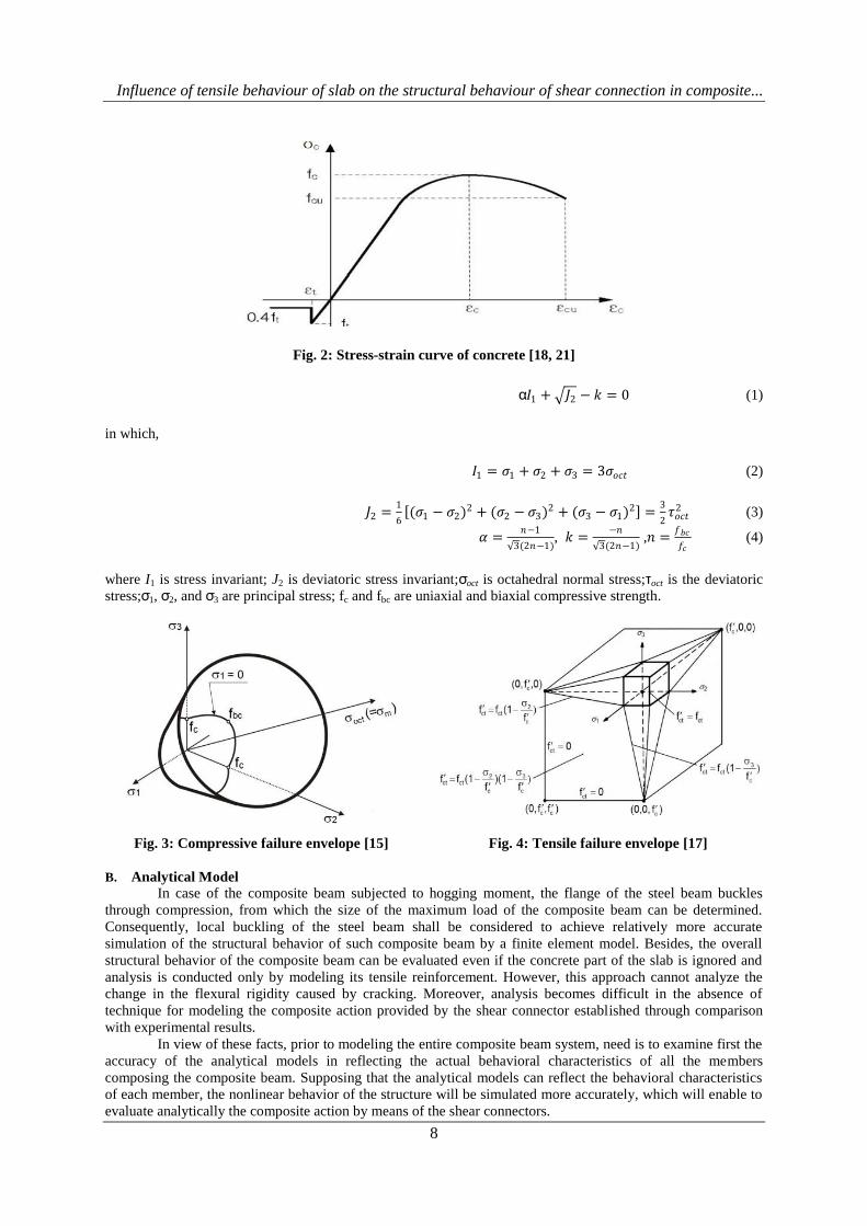
The material model for steel is the common model used in plastic analysis. The concrete model
considers the stress-strain relationship of concrete in compressive and tensile states as shown in Fig. 2. Here, a
constant stress (0.4ft) is maintained after the initiation of tensile cracks to account analytically for the tension
stiffening [14]. The adopted failure criterion shown in Fig. 3 and Eq. (1) is the one proposed by Khan and Saugy
[15]. The uni-axial maximum compressive stress is chosen to be the compressive strength under multi-axial
stress condition [16]. As pictured in Fig. 4, the maximum strength under pure tension is defined by the failure
envelop connecting the points corresponding to the uni-axial compressive strength and uni-axial tensile strength
under multi-axial stress condition [17]. Moreover, the failure of the concrete element is set with reference to the
failure of smeared model occurring inside the element and not at the nodes of the 3D solid element [18-21].
Influence of tensile behaviour of slab on the structural behaviour of shear connection in composite...
8
Fig. 2: Stress-strain curve of concrete [18, 21]
α𝐼1 + 𝐽2 − 𝑘 = 0 (1)
in which,
𝐼1 = 𝜎1 + 𝜎2 + 𝜎3 = 3𝜎𝑜𝑐𝑡 (2)
𝐽2 =1
6 (𝜎1 − 𝜎2)
2 + (𝜎2 − 𝜎3)2 + (𝜎3 − 𝜎1)
2 =3
2𝜏𝑜𝑐𝑡2 (3)
𝛼 =𝑛−1
3(2𝑛−1), 𝑘 =
−𝑛
3(2𝑛−1) ,𝑛 =
𝑓𝑏𝑐
𝑓𝑐 (4)
where I1 is stress invariant; J2 is deviatoric stress invariant;σoct is octahedral normal stress;τoct is the deviatoric
stress;σ1, σ2, and σ3 are principal stress; fc and fbc are uniaxial and biaxial compressive strength.
Fig. 3: Compressive failure envelope [15] Fig. 4: Tensile failure envelope [17]
B. Analytical Model
In case of the composite beam subjected to hogging moment, the flange of the steel beam buckles
through compression, from which the size of the maximum load of the composite beam can be determined.
Consequently, local buckling of the steel beam shall be considered to achieve relatively more accurate
simulation of the structural behavior of such composite beam by a finite element model. Besides, the overall
structural behavior of the composite beam can be evaluated even if the concrete part of the slab is ignored and
analysis is conducted only by modeling its tensile reinforcement. However, this approach cannot analyze the
change in the flexural rigidity caused by cracking. Moreover, analysis becomes difficult in the absence of
technique for modeling the composite action provided by the shear connector established through comparison
with experimental results.
In view of these facts, prior to modeling the entire composite beam system, need is to examine first the
accuracy of the analytical models in reflecting the actual behavioral characteristics of all the members
composing the composite beam. Supposing that the analytical models can reflect the behavioral characteristics
of each member, the nonlinear behavior of the structure will be simulated more accurately, which will enable to
evaluate analytically the composite action by means of the shear connectors.

Influence of tensile behaviour of slab on the structural behaviour of shear connection in composite...
9
(1) Steel Beam Model
The possibility to simulate local buckling by the finite element model of the steel beam to be used in
the analysis of the composite beam should be verified. To that goal, finite element analysis is conducted on the
steel beam experiencing local buckling similar to the steel beam of the composite beam B400. Comparison is
done with the experimental and analytical results of Spangemacher[22]. The steel beam used for the analysis
and test of Spangemacher[22] is a 3 m-long HEA280 beam and uses S460 steel (fy = 460 N/mm2) identically to
the steel of the composite beam considered in this study.
Fig. 5 shows the analytical model of the steel beam adopted for the simulation of the behavior of the
steel beam in the composite beam [22]. Here, initial imperfection is introduced in the shells used for the web and
the flange subjected to flexural compression so as to enable the analysis of local buckling due to flexural
compression. The conditions at both end supports of the beam are fixed to prevent movement in the loading
direction and in the transverse direction. Loading is applied through displacement control method in the analysis
by increasing the displacement at mid-span.
Fig. 6 depicts the overall deformed shape of the beam given by the analysis. Fig. 7 compares the
analytical results obtained in this study with the analytical and experimental results of Spangemacher[22]. The
results are seen to be in good agreement with initial linear behavior until the peak load by buckling and followed
by the decrease of the load. This indicates that the finite element model established in this study is able to
analyze the local buckling of the steel beam flange under compression, and that this model can be applied for
the steel beam in the composite beam subjected to hogging moment.
Fig. 5:FE Model of steel beamFig. 6:Deformed shape of steel beam
Fig. 7: Moment-rotation curves
(2) Slab Model
In the reinforced concrete member, the tensile force in the cracked zone is mainly sustained by the
reinforcement. However, the concrete present between the cracks also sustains the tensile force to a certain
extent owing to the bond action between the reinforcement and concrete, and contributes thus to the stiffness of
the whole member. In order to search for a modeling method adapted to the analysis of the composite beam
subjected to hogging moment, analysis is carried out on a reinforced concrete bar member (20×20×400)
subjected to uni-axial tension and the results are compared to the experimental results of Bergner [23]. In the

Influence of tensile behaviour of slab on the structural behaviour of shear connection in composite...
10
analysis, the compressive and tensile strengths of concrete are respectively 108 N/mm2and 3.1 N/mm
2, the yield
strength of the rebar is 500 N/mm2with a reinforcement ratio of about 1.55%, and loading is applied through
displacement control.
Fig. 8 depicts the finite element model of the reinforced concrete bar. Only the half of the original
specimen is modeled considering its symmetry. The concrete part is modeled by three-dimensional 8-node
elements. Axial elements are used for the reinforcement to allow only tension or compression, and the nodes are
shared with those of the concrete elements.
Fig. 9 compares the analytical and experimental results. It can be seen that the overall tensile behavior
is comparatively well simulated by the finite element model with the linear region before the initiation of cracks
and the region after deformation of 1.5 mm/m. However, there is some difference in the region between 0.1 to
1.5 mm/m in which cracks develop continuously. The cause of such discrepancy can be found in the
impossibility of the simplified model to reproduce the continuous occurrence of brittle and irregular cracks and
simulate the corresponding deformation and stress redistribution.
Fig.8: FEModel of RC bar Fig. 9: FE analysis results.
(3) Model of the entire composite beam including shear connection
The model shown in Fig. 10 and developed for the analysis of the shear composite action in push-out
specimen is applied for the shear connection at the interface between the concrete slab and steel beam [18-21].
The studs are modeled by beam elements for simplicity. In addition, the contact area between the stud and
concrete in the FEM model is modeled so as to enable interaction by establishing a constraint equation for the
displacement occurring at the common node. The verification of the validity of the adopted model is skipped
here as it has been already provided in former research results [18-21]. Fig. 11 depicts the three-dimensional
finite element model of the entire composite beam including the shear connection. The modeling methods for
the steel beam and the slab are those analyzed in sections 3.2.1 and 3.2.2. The composite interface between the
slab and the upper flange of the steel beam is modeled by contact surface element so as to enable load transfer
through contact between the members.
Figs. 12 and 13 compare respectively the deflection at mid-span and the slip developed between the
steel beam and slab at 1/4 of the span with the experimental results [13]. The comparison of the load-deflection
curves reveals the accuracy of the model in simulating the loss of stiffness after the initiation of cracks and the
flexural compressive buckling of the upper flange of the steel beam after yielding of the reinforcement.
In Fig. 13, the experimental load-slip curves indicate that slip does practically not occur due to the
action of the chemical bond before load of about 290 kN but show comparatively good agreement between the
analytical and experimental results after fracture caused by repeated loading. As observed in the preparatory
steps of main experiment of Sedlacek et al. [13], the chemical bond developed at the composite interface was
seen to fail after 25 cycles under loading corresponding to approximately 40% of the peak load. Accordingly,
the composite action provided by this chemical bond is not considered in the finite element analysis.

Influence of tensile behaviour of slab on the structural behaviour of shear connection in composite...
11
Fig. 10:Model of the shear connection[18-21] Fig. 11: 3D FE model of the composite beam
Fig. 12:Comparison of load-deflection curve. Fig. 13:Comparison of load-slip curve
Fig. 14: Comparison of rebar strain Fig. 15: Comparison of steel beam strain
Figs. 14 and 15 compare the strains measured at mid-span in the tensile reinforcement and steel beam
to the analytical values. The load-strain curves obtained analytically show relatively good agreement with the
experimental results. The error in the ratio of the increase of the load relative to the enlargement of the strain is
seen to remain limited indicating that the analytical results are close to the experimental ones.
Influence of tensile behaviour of slab on the structural behaviour of shear connection in composite...
12
In view of these observations, we have seen that the analysis is able to reproduce adequately the overall
load-deflection behavior of the composite beam as well as the slip behavior at the composite interface. Similarly
to the comparison of the strain, local deformation can also be comparatively well simulated by the analysis.
Therefore, it can be presumed that the effect of the tensile behavior of the concrete slab on the composite action
provided by the studs can be evaluated through the examination of the analytical results.
IV. INFLUENCE OF THE TENSILE BEHAVIOR OF THE SLAB ON THE BEHAVIOR
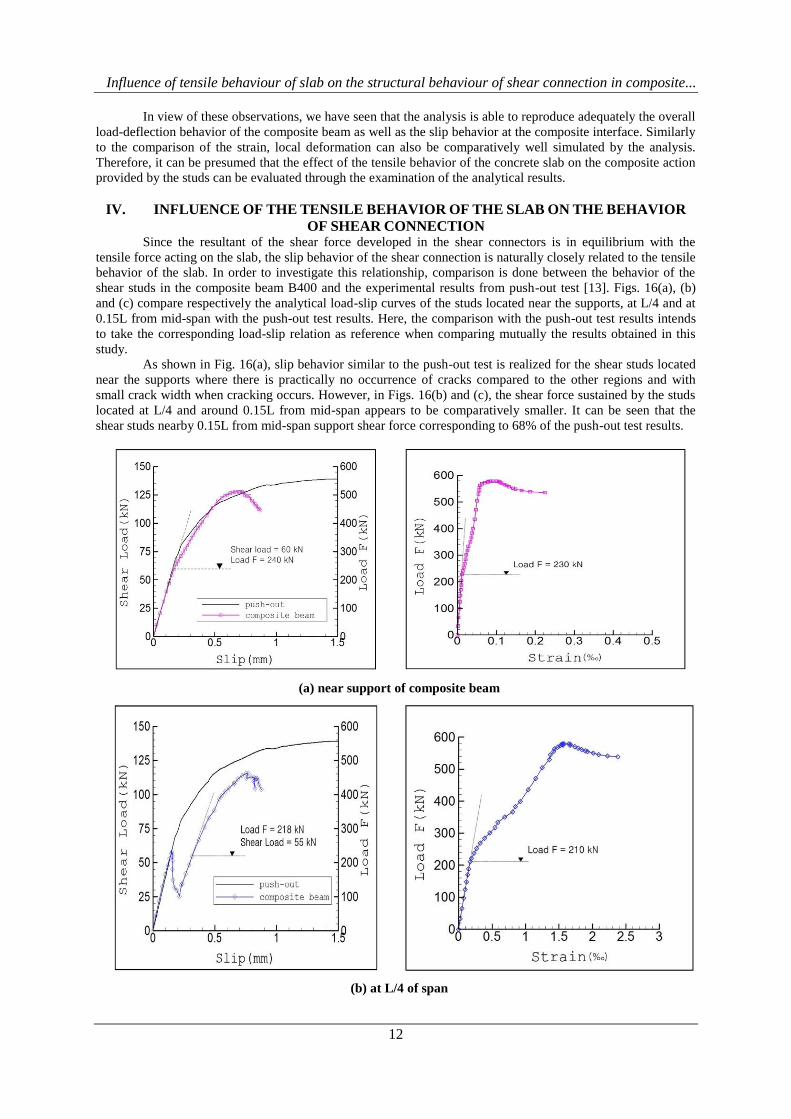
OF SHEAR CONNECTION Since the resultant of the shear force developed in the shear connectors is in equilibrium with the
tensile force acting on the slab, the slip behavior of the shear connection is naturally closely related to the tensile
behavior of the slab. In order to investigate this relationship, comparison is done between the behavior of the
shear studs in the composite beam B400 and the experimental results from push-out test [13]. Figs. 16(a), (b)
and (c) compare respectively the analytical load-slip curves of the studs located near the supports, at L/4 and at
0.15L from mid-span with the push-out test results. Here, the comparison with the push-out test results intends
to take the corresponding load-slip relation as reference when comparing mutually the results obtained in this
study.
As shown in Fig. 16(a), slip behavior similar to the push-out test is realized for the shear studs located
near the supports where there is practically no occurrence of cracks compared to the other regions and with
small crack width when cracking occurs. However, in Figs. 16(b) and (c), the shear force sustained by the studs
located at L/4 and around 0.15L from mid-span appears to be comparatively smaller. It can be seen that the
shear studs nearby 0.15L from mid-span support shear force corresponding to 68% of the push-out test results.
(a) near support of composite beam
(b) at L/4 of span

Influence of tensile behaviour of slab on the structural behaviour of shear connection in composite...
13
(c) at 0.15L from center of composite beam
Fig. 16:Load-slip curves of studs and load-strain curvesof rebar
atrepresentativelocationsin the composite beam
The transient reduction of the load appearing in the analytical results of Figs. 16(b) and (c) can be
explained as follows. The load sustained by the concrete part of the slab decreases with the occurrence of cracks
in the slab and becomes gradually more supported by the rebar. The transient reduction of the load can be seen
as reflecting the tensile behavior of concrete owing to the direct contact between the studs and concrete as
shown in the analytical model of Fig. 10. For example, it can be assumed that continuous load-slip relation
would be achieved if the studs are modeled by 3D solid elements and if contact surface elements are applied for
the interface. However, such modeling method would be unaffordable in term of the efficiency of analysis.
In view of the change in the slip stiffness appearing in the load-slip curve, an initial stiffness of 381.3
kN/mm is developed for the studs at the supports and is similar to that observed for the studs at mid-span and
L/4 of the span. However, the stiffness after cracking of the slab drops down respectively to 251.3 and 251.8
kN/mm, which indicates a stiffness loss at identical loading stage. Thereafter and according to the increasing
load, the slip stiffness tends to experience clear decrease at each location compared to the initial values. For
example, in the push-out test, a stiffness of 140.9 kN/mm corresponding to approximately 37% of the initial
stiffness is observed under the action of a shear force of 85 kN. However, a stiffness of 62.6 kN/mm is
developed by the studs located near mid-span in loading stage supporting shear force running around 60 to 85
kN. This stiffness corresponds to 16.4% of the initial stiffness and 24.9% of the post-cracking stiffness.
The point to be stressed here is the quasi-synchronous occurrence of the start of the clear decrease in
the slip stiffness of the studs and the change in the increase of strain of the rebar as can be observed by
comparing the load-slip curves of the studs and load-strain curves of the rebar in Fig. 16. Consequently, the
load-slip behavior of the studs in the composite beam subjected to hogging moment appears to be influenced by
the tensile behavior of reinforced concrete. Compared to the supports with small bending moment and relatively
less occurrence of cracks, the studs located at L/4 and mid-span experience larger loss of stiffness. Especially,
the stiffness loss is more pronounced in the studs at mid-span.
In view of these results, the slip stiffness and shear force sustained by the studs appears to be
significantly smaller in regions with concentrated occurrence of cracks than in other regions. As reported in the
experimental works of Fabbrocino&Pecce [9]andLoh et al. [24], it seems favorable to conduct design so as to
avoid the arrangement of shear studs or to achieve partial composition by providing larger spacing between the
studs in regions with crack concentration not only in term of the ductility of the entire structure but also in term
of design efficiency.
V. CONCLUSIONS This study developed a 3D finite element model reproducing as possible the actual shape and material
properties of the concrete slab, steel beam and shear studs composing the composite beam so as to analyze the
behavior of the composite beam subjected to hogging moment. With regard to the verification of the validity of
the adopted analytical model, the 3D model appeared to be also appropriate for the analysis of local behaviors
like the slip behavior of the shear connection. The analytical model enabled us to examine the influence of the
tensile behavior of the slab in the composite beam subjected to hogging moment on the structural behavior
including the slip stiffness and maximum shear force of the shear connection. From the analysis results, it was
seen that the shear studs located in regions with crack concentration sustained significantly smaller shear force
and developed smaller slip stiffness than the studs in other regions. Moreover, the reduction in the slip stiffness
of the shear connection appeared to be closely related to the change in the strain of tensile rebar according to the

Influence of tensile behaviour of slab on the structural behaviour of shear connection in composite...
14
increase of the load. In the future, experimental and analytical studies shall be conducted considering variables
such as the rebar ratio and arrangement of shear connectors to achieve efficient design of the shear connection in
composite beams subjected to hogging moment.
ACKNOWLEDGMENT This research was supported by a grant from Constructional Research & Development
Program(14SCIP-C078607-01), “Development of Korea Performance-Based Evaluation Techniques of
Performance-Centered Management and Operation for SOC Structures” funded by Ministry of Land,
Infrastructure and Transport(MOLIT) of Korea government and Korea Agency for Infrastructure Technology
Advancement(KAIA).
REFERENCES [1]. Johnson, R.P., Oehlers, D.J.: The Strength of Stud Shear Connectors in Composite Beams. The
Structural Engineer, Volume 65/B2, 1987.
[2]. Aribert, J.M.: Design of composite beams with a partial shear connection. IABSE Symposium Mixed
Structures including New Materials, IABSE Reports Vol. 60, S. 215-220, Brussels, Belgium, 1990.
[3]. Bode, H., Künzel, R.: ZurTraglast von
VerbundträgernunterbesondererBerücksichtigungeinernachgiebigenVerdübelung. Abschlußberichtzum
DFG-Forschungsvorhaben, Kaiserslautern, 12/1988.
[4]. Döinghaus, P.: ZumZusammenwirkenhochfesterBaustoffe in Verbundträgern. Dissertation. Lehrstuhl
und InstitutfürMassivbau, RWTH-Aachen. 2001.
[5]. Hanswille, G.: ZurRißbreitenbeschränkungbeiVerbundträgern. Dissertation. Ruhr-Universität Bochum,
1986.
[6]. Johnson, R.P., Greenwood, R.D., van Dalen, K.: Stud shear-connectors in hogging moment regions of
composite beams, The Structural Engineer, 47, pp.345-350, 1969.
[7]. Johnson, R.P.Composite Structures of Steel and Concrete - Volume 1: Beams, Slabs, Columns, and
Frames for Buildings. Blackwell Scientific Publications, 1994.
[8]. Bode, H.: European steel-concrete composite structure, construction and calculation. Werner Verlag,
1998.
[9]. Fabbrocino, G.,Pecce, M.: Experimental tests on steel-concrete composite beams under negative
bending, Proc. of 2000 Annual Conf. of Canadian Society for Civil Engineering, Montreal, Canada,
2000.
[10]. Shariati, A., RamliSulong,N.H.,Suhatril, M.,Shariati, M.: Various types of shear connectors in
composite structures: A review, International Journal of Physical Sciences, vol.7, No.22, pp.2876-2890,
2012.
[11]. Johnson, R.P.: Some Research on Composite Structures in the U.K., 1960-1985, Proc. of Engineering
Foundation Conference, Irsee, Germany, June 9.-14, 1996.
[12]. Hegger, J.,Doinghaus, P.: High Performance Steel and High Performance Concrete in Composite
Structures, International Symposium on High Performance Concrete, Orlando, USA, pp.494-505, 2000.
[13]. Sedlacek, G.,Hegger, J.,Hanswille, G.: Use of High Strength Steel S460, ECSC Research Project,
RWTH-Aachen University, 2000.
[14]. König, G., Fehling, E.:ZurRissbreitenbeschränkungimStahlbetonbau, Beton- und Stahlbetonbau 83,
Heft 6, pp.161-167, 1988.
[15]. Khan, M.H., Saugy, B.: Evaluation of the Influence of some Concrete Characteristics on Nonlinear
Behavior of Prestressed Concrete Reactor Vessel, ACI Publication SP-34, pp.159-179, 1972.
[16]. Balmer, G.G.: Shearing Strength of Concrete under High Triaxial Stress-Computation of Mohr's
Envelope as a Curve, Structural Research Laboratory Report No. SP-23, U.S. Department of the
Interior, 1949.
[17]. Bathe, K.J.,Ramaswamy, S.: On Three- Dimensional Nonlinear Analysis of Concrete Structures,
Nuclear Engineering and Design 52, pp.385-409, 1979.
[18]. Shin, H.S.:A contribution to the numerical analysis of the load carrying behavior of the composite
beams with high strength steel and high strength concrete. Dissertation, RWTH- Aachen University,
2004.
[19]. Shin, H.S.: Analysis of a Load Carrying Behavior of Shear Connection at the Interface of the Steel-
Concrete Composite Beam, Journal of Korean Society of Steel Construction, vol. 17, No. 6, pp.737-
747, 2005.(in Korean)
[20]. Shin, H.S.: FE Analysis of the Composite Action in the Composite Beam, Journal of the Korea
academia-industrial cooperation society, vol. 14, No. 8, pp.4048-4057, 2013.(in Korean)

Influence of tensile behaviour of slab on the structural behaviour of shear connection in composite...
15
[21]. Shin,H.S.: FEM Analysis of the Horizontal Shear Behaviour In the Steel-Concrete Composite Beam,
International Journal of Engineering Research and Development, vol. 10, Issue 9, pp.11~19, 2014.
[22]. Spangemacher, R.: ZumRotationsnachweis von Stahlkonstruktionen, die
nachdemTraglastverfahrenberechnetwerden. Dissertation. LehrstuhlfürStahlbau, RWTH-Aachen, 1992.
[23]. Bergner, H.: RißbreitenbeschränkungzwangbeanspruchterBauteileaushochfestemNormalbeton.
DeutscherAusschussfürStahlbeton, Heft 482, 1997.
[24]. Loh, H.Y., Uy, B., Bradford, M.A.: The effects of partial shear connection in the hogging moment
regions of composite beams, Journal of constructional steel research, vol. 60, pp.897-919, 2004.