Embed Size (px)
Citation preview

STUDY OF THE BEHAVIOUR OF MASONRY INFILLED REINFORCED CONCRETE FRAMES SUBJECTED TO SEISMIC LOADING
R.zARNIé, Research Engineer M.TOMAzEVIc, Senior Research Engineer Institute for Testing and Research in Materials and Structures, Dimiceva 12, Ljubljana, Yugoslavia
ABSTRACT The behaviour Df masonry infilled stiff reinforced concrete frames subjected to cyclic lateral loading has been investigated. The effect Df three different types Df both unreinforced and reinforced infill on strength and deformability characteristics of the infilled frame system has been studied. The failure mechanism has been defined and simple analytical model for the calculation Df the strength and deformability characteristics has been proposed. The infill increased the frame stiffness in average for 20-times and the lateral resistance Df frame in average for 2.5-times. However, no significant effect Df horizontal infill reinforcement on the lateral resistance and deformability Df the system has been observed. A slight increase in lateral resistance only has been obtained by means of anchoring the infill reinforcement into the frame.
1. INTRODUCTION The earthquake resistance of buildings considerably depends on their structural systems. One has to be very careful when designing a mixed structural system, composed of structural elements and materials which have different mechanical properties. When subjected to earthquake loading the interaction forces between the different structural components of the structural system of the building develop which must be proper~vtaken account.
The reinforced concrete frame-work, infilled with masonry, represents a very frequent structural system. In the current design practice, however, the effect of the filler-wall on the basic frame system is in most cases neglected. This consequently leads to the sometimes unexpected behaviour of buildings during earthquakes, with possible severe damage or even collapse ofstructural element~ Therefore, knowing the interaction mechanism between the masonry filler-walls and the basic reinforced concrete frame system is very important. Based on the experiences obtained after earthquakes, two alternative approaches for the design and construction of such structural systems are recommended: - the filler-wall is constructed as a secondary structural element, separated from the main structural system by means of adequate joints, hence enabling the system to deform freely during an earthquake;
- the filler-wall is constructed as a constituent part of the structural system. In this case, however, the effect Df interaction forces between the masonry filler-wall and the reinforced concrete frame must be taken into account when designing the structural system. The filler-walls significantly increase the stiffness Df the whole structuraT system. As a consequence, the dynamical properties Df the structural system as well as the distribution of seismic loading onto the individual structural elements are also changed. Proportionally to the increased stiffnesses, the individual structural elements must carry an increased portion of load. Hhen designing the building, it is therefore necessary to know both the stiffness and the resistance characteristics of individual structural elements, so that they can be properly distributed over the whole structural system Df the building.
Within this paper, the behaviour of the so called "stiff infilled frame" is disscussed introducing the simple analytical method based on the test results. By
1315
means of the proposed method fundamental parameters, which define the lateral load - displacement hysteresis envelope are defined.
2. DESCRIPTION OF TESTS The following testing specimens, constructed in reduced size 1:2 scale, have been tested: Ml - reinforced concrete frame without infill, M2 - reinforced concrete frame with unreinforced masonry filler-wall, M3 - reinforced concrete frame with horizontally reinforced masonry filler-wall, M4 - reinforced concrete frame with horizontally reinforced masonry filler-wall,
connected to the frame . The configuration and dimensions of test specimens are shown Fig.l
. ~ " i I
'. - t
~~~_ ;d;;~ !!.-': L~ '-~ , ........
rUi FI. ....... '. ~Gl;;;'G'Ú'
n 1111 I a., "1 ... _ _ ----,
111 11 11111
I I I I
! ~
I!
W • 1 t 11 01--11 ... .. ....
__ 10 ....
~
I~ ~
IllU ' 11111 11111 @ I 111 1 11111 1 11 1 1
t-- ~ ~ .n : - , n __ . ... ----4
--- -- ---+
. ~ fu-/ 'r~
IA í/ L
1 ' ~
IlULI 11111111 111 11111 l /I li 111 11 1
Fig.1: CDNFIGURATIDN AND DIMEN SIDNS DF TEST SPECIMENS
I"T
t- .. +- n _~ .. ~ ---- ...... - ~
M 15 grade concrete and deformed bars were used for the construction of frames, and normal format bricks laid in 1:1:6 (lime: cement:sand) mortar and mild steel smooth bars for the construction of the infill. The frames were heavily reinforced for flexure and shear (PL = 3,4% in PT = 0,8% respectively), whereas the filler walls were reinforced with minimum reinforcement only (p = 0,22%). During the construction of test specimens, a special attention has been paid to the frame to infill contact. The specimens were fixed into the testing floor and subjected to constant vertical load, acting on each column (100 kN) and to cyclic horizontal load, acting on the beam, as shown in Fig.2. During the tests, the deformations of specimens were measured by means of LVDT-s, and strains of reinforcement by means of strain-gages. Specially designed electric resistance dilatom,eters were used for measuring the strains of masonry infill. Photogrammetric method was used to determine the deformations of the whole structural system.
The mechanical properties of the constituent materials are given in Table 1.
1316

lIb l e 1: Me<:hanieal Properties of Constituent ~terials
CoIapress lve stren.gth Compressfve strength Str41 n at .aJ[ . Elastle .,du 1u s
. eubes fe (MPll) ~ prf sms f~r (l4Pa) stress ( (If EC (lIFa )
Concrete 1.41 17 860 15.15 11.97
Br iel COOIpresslve strength: f e , b • 28.s.t MPa
COnIpressive strenqth Compressive strength 8ending streogth
- eubes f~,/JI (MP. ) - prisms f (MPa ) C._ - pr1$111s fb •• ( ~a ,
"tlrtllr at 28 I at the age at 28 at the llQe .~It the ' g" LL6 days of tes t f ng days of test i"9 days of testlng
9.9 I 11.5 10.9 11.9 1. ' I 1.8
Compressive strength Strain at ma ..:. Elast1e IIOdu1us
"",sonry f (MP. ) C.' stress l ( " • • ) E~r (MPa)
PrlStns 15.1 3.06 7967
Cornpressive Tensi le [last i c She", Ultlaa te Wa l J strength strengtn modulus rrodu'u~ st,...1n
Pane J f (M!'. ) f ti" ( !1Pa ) Ew{MPa) Gw(~' ) , (\.) C. ' 14.47 0.72 5466 354 2.77
Yie ld 1111ft Yield str1l1n Elast ie Tensl1e Ultl.ate
Reinforc emert modu1us strength straln
f y (MP, ) (y r/ •• ) E,(MPa) fu( "P. ) ' u ('1,,)
CO . 200 320 0.15 208 700 470 26 .7 ; 6 "'"
tBR-4 0-2 ' 56 0.22 210 500 736 13.3
, 16 Iml
Fig.2 : TEST SET - UP
tB R 40-1 551 760 22.8 ; 8 "'"
3. TEST RESUL T5 Studying the relationships between the lateral load and deformations of the testing specimens as well as the relationships between the lateral load and strains of the infill masonry and strains of the frame and infill reinforcement, the failure mechanism of the system has been defined. In the large deformation range, the photogrammetric measurements were very useful for determination of the deformation state of the whole structural system. Several phases can be distinguished in the behaviour of the tested infilled frame system, when subjected to lateral loading:
- diagonal cracking of the filler-wall, - separation of the filler-wall, caused by severe cracking of the filler-wall, - failure of the whole structural system.
Within the first phase, the whole structural system behaved as a cantilever shear-wall. After the separation of the filler-wall, the system behaved as a frame, having a laterally supported column on the windward side of the structural system. Both mechanisms, confirmed also by means of photogrammetric measurements, are shown in Fig.3.
Fig.3: THE BEHAVIOUR NECHANIS~lS DF THE TESTEO INFILLEO FRAME SYSTEM BEFDRE ANO AFTER THE SEPARATIDN DF THE FILLER - WALL
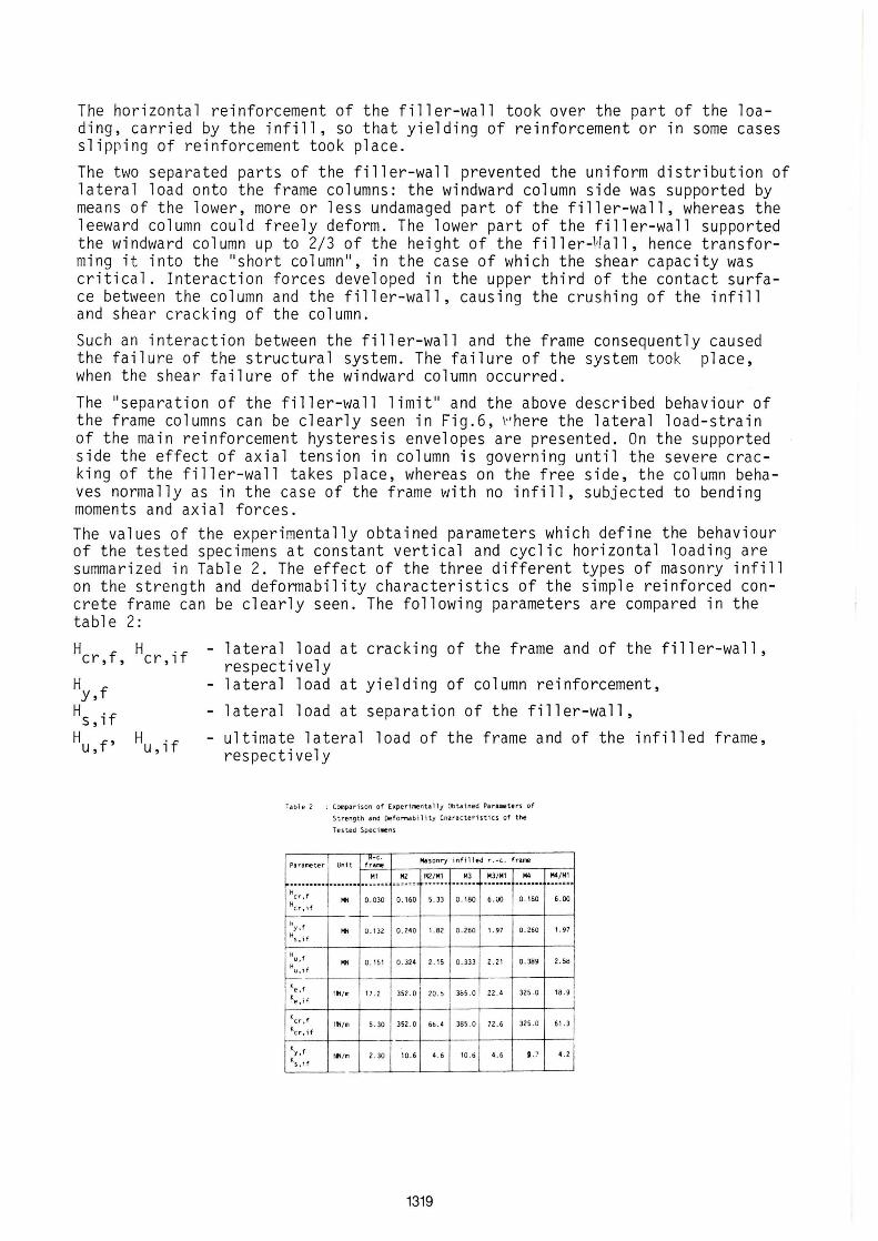
The behaviour of the infilled frame system within the first phase can be best explained by analyzing the lateral load-strain of the filler-wall and lateral load-strain of the column reinforcement hysteresis envelopes, as shown in Fig.6.
The system behaved elastically until the diagonal cracking of the filler-wall occurred. Frame columns were loaded with axial forces and practically no bending moments could be noticed when studying the strain measurements of the longitudinal column reín forcement . The strain of the filler-wall reinforcement was very
1317
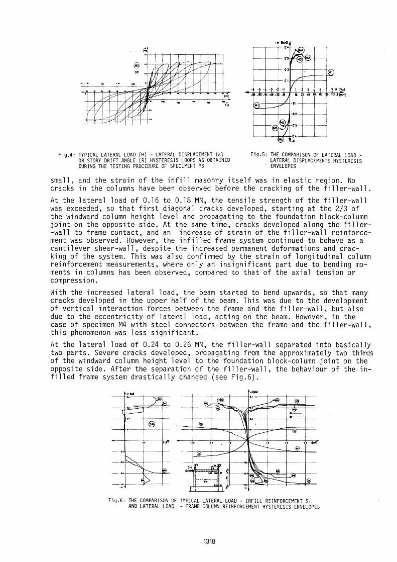
Fig.4: TYPICAL LATERAL LOAO (H) - LATERAL OISPLACEMENT (ó) OR STORY ORIFT ANGLE (R) HYSTERESIS LOOPS AS OBTAINEO OURING THE TESTING PROCEOURE DF SPECIMUH f13
Fig.5 : THE COMPARISON OF LATERAL LOAO -LATERAL OISPLACEMENTS HYSTERESIS
. ENVELOPES
small, and the strain of the infill masonry itself was in elastic region. No cracks in the columns have been observed before the cracking of the filler-wall.
At the lateral load of 0.16 to 0.18 MN, the tensile strength of the filler-wall was exceeded, so that first diagonal cracks developed, starting at the 2/3 of the windward column height level and propagating to the foundation block-column joint on the opposite side. At the same time, cracks developed along the filler-wall to frame contact, and an increase of strain of the filler-wall reinforcement was observed. However, the infilled frame system continued to behave as a cantilever shear-wall, despite the increased permanent deformations and cracking of the system. This was also confirmed by the strain of longitudinal column reinforcement measurements, where only an insignificant part due to bending moments in columns has been observed, compared to that of the axial tension or compression.
With the increased lateral load, the beam started to bend upwards, so that many cracks developed in the upper half of the beam. This was due to the development of vertical interaction forces between the frame and the filler-wall, but also due to the eccentricity of lateral load, acting on the beam. However, in the case of specimen M4 with steel connectors between the frame and the filler-wall, this phenomenon was less significant.
At the lateral load of 0.24 to 0.26 MN, the filler-wall separated into basically two parts. Severe cracks developed, propagating from the approximately two thirds of the windward column height level to the foundation block-column joint on the opposite side. After the separation of the filler-wall, the behaviour of the infilled frame system drastically changed (see Fig.6) .
.....
Fig.6: THE COMPARISON OF TYPICAL LATERAL LOAO - INFILL REINFORCEMENT SI. ANO LATERAL LOAO - FRAME COLUMN REINFORCEMENT HYSTERESIS ENVEL O PE ~
1318
The horizontal reinforcement of the filler-wall took over the part of the loading, carried by the infill, so that yielding of reinforcement or in some cases slipr ing of reinforcement took place. The two separated parts of the filler-wall prevented the uniform distribution of lateral load onto the frame columns: the windward column side was supported by means of the lower, more or less undamaged part of the filler-wall, whereas the leeward column could freely deformo The lower part of the filler-wall supported the windward column up to 2/3 of the height of the fi 11 er-1'la11 , hence transforming it into the "short column", in the case of which the shear capacity was critical. Interaction forces developed in the upper third of the contact surface between the column and the filler-wall, causing the crushing of the infill and shear cracking of the column.
Suc h an interaction between the filler-wall and the frame consequently caused the failure of the structural system. The failure of the system took place, when the shear failure of the windward column occurred.
The "separation of the fi11er-wa11 limit" and the above described behaviour of the frame columns can be clearly seen in Fig.6, ~I here the lateral load-strain of the main reinforcement hysteresis envelopes are presented. On the supported side the effect ofaxial tension in column is governing until the severe cracking of the filler-wall takes place, whereas on the free side, the column behaves normally as in the case of the frame with no infill, subjected to bending moments and axial forces. The values of the experimentally obtained parameters which define the behaviour of the tested specimens at constant vertical and cyclic horizontal loading are summarized in Table 2. The effect of the three different types of masonry infill on the strength and deformability characteristics of the simple reinforced concrete frame can be clearly seen. The following parameters are compared in the table 2:
H cr,f, H cr, i f
H y,f H s, if H u,f' H u, i f
- 1 a tera 1 load at cracking of the frame and of the fi 11 er-wa 11 , respectively
- 1 a tera 1 load at yielding of column reinforcement,
- 1 a tera 1 load at separation of the filler-wall,
- ultimate lateral load of the frame and of the infilled respectively
Table 2 : Compa r 'ison of Experi mental'j Obta1ned Pararaeters of
Strength 4nd De for1lldbilHy Cnaracteristics of the
Tesled Speci lAe ns
. R,..C . Ma sonry infil1ed r .·c. f r ame Para me ter Uni t I-2f~r'''~_-.------,_-.-_-.---_,---l ., H2 142/Hl " 3 H3/Hl MO 144 /1<41 .... .,",.==3 " .,,,,,::.,,, .. ... ::= ••• " ..... :: • ",."z'"' =." .... . ........ ",,"' ..... ....... H cr ,f ... 0.030 0.160 1.33 0.180 6.00 0. 180 6.00 Hcr . if
- -H "f '" 0.132 0.240 1.82 0 .260 1.97 0.260 1.97
Hs . if
H " f ... 0.111 0.324 2. 11 0.333 2.21 0 . 389 2.SH
H u . H I--
Ke.f l tl /m 17 .2 352.0 t 20 . ~ 3BI . 0 22.4 321.0 lB.9
Ke. if
KCI'" . f r ~ /m 1 . 30 312. 0
Kc r . if 6b . 4 381 . 0 72.6 321.0 61.3
""y , f t~/m 2 . 30 10.6 4 . 6 10. ti 4. 6 t . ~ ' .2
Ks . if
1319
frame,

K f' K °f e, e, 1
K 0f s , 1
- elastic stiffness of the frame, and of the infilled frame, respectively
- stiffness of the frame after cracking of columns, and after plastic hingening of columns, respectively,
- stiffness of the infilled frame after the separation of filler--wa 11 .
As it can be seen from Table 2, the masonry filler-wall increased the lateral resistance of frame up to 2.6 times and the lateral stiffness of frame up to 22 times. However, no significantdifference was observed in the behaviour of the three different types of masonry infill. A slight increase in lateral resistance only was observed in the case of specimen M4, having horizontally reinforced filler-wall, connected to the frame with vertical and horizontal steel connec tors.
4. ANALYTICAL METHOD FOR THE ANALYSIS OF THE BEHAVIOUR OF THE INFILLED FRAMES The behaviour of a composite structural system cannot be represented as a simple superposition of the behaviour of the constituent elements at the same loading conditions. Because of interaction between the constituent structural elements, the behaviour of the system is significantly different as the superposed behaviour of each component acting as a single structural element would be. The proposed analytical method is based on the observed failure mechanisms : - before the shear failure of the filler -wall, both the frame and the filler-
-wall behave as a monolithic structural system, forming a simple shear canti-lever,
- after the shear failure of the filler-wall, the infilled frame behaves as a combination of a diagonally braced frame and a confined masonry panel.
4.1 Analytical Model of the Infilled Frame Before the Separation of the Ffller-WalT
In the assumed simple shear cantilever model, the effective horizontal crosssectional area of the infilled frame system i s governing the stiffness of the system, whereas the shear resistance of the filler -wall is defining the lateral resistance of the system (at the filler-wall separation limit the contribution of the frame to the lateral resistance of the system was estimated to approximately 2%). Of course, although treated as a monolithic structural system, interaction forces develop between the frame and the filler-wall which characterize the behaviour of the infilled frame system, as shown in Fig.? Good contact between the frame and the filler-wall, as assured during the construction of the specimens, is the condition for the development of interaction forces. The proposed equations for the calculation of the strength and the deformability characteristics of the shear cantilever are based on the shear resistance of masonry walls theory (see ref. 5).
~ffj~~~-Q~~=":"-I--l I I I
W---l,..-.D..~~~~ I
Figo?: ANALYTICAL MDDEL DF THE INFILLED FRAME BEFDRE THE SEPARATIDN DF FILLER - WALL
1320

On the basis of previous investigations of the behaviour of walls subjected to constant vertical load and cyclic lateral load reversals, the referential tensile strength of the wall was proposed as the parameter, defining the lateral resistance of wall as a homogeneous panel at shear failure. The tensile strength can be expressed by means of the following equation (Ref.5):
f = O . 5 a + /( O ,5 a ) 2 + (b T ) 2 , (1 ) t,w o O u where:
Generally speaking, the normal stresses in the wall a are due to external vertical load, acting on the beam and transfered onto thg filler -wall, as well as due to interaction forces, developed between the frame and the filler-wall in case of laterally loaded frame (Fig.?):
hw H Vz ao - ex 1 . A +-
W w Aw __ (3)
From equations (1), (2), and (3) the expression for the shear capacity of the filler-wall (H ), which represents the lateral load at the separation of the filler-wall (Hu'~f)' can be desired: S,l ,-____________ _
1 hw Aw / 1 w 2 v Hu w = Hs if = 1a -1 ~ ft w (1 +vI(2a b~) (1 + ~
" wb' w w f ) + 1) _(4) t,w
The effectve stiffness of the cantilever shear-wall (K ), which is considered as the initial stiffness of the infilled frame (K 'f)~ 'W is obtained byassuming the pure cantilever action of the structurale,l element, taking into account both the shear and the flexural deformations:
3 K h h + w ) - 1 K - K = (---3 -=-~ e,w - e,if Ew Ie Gw Ae
_ _ (5)
where:
Ie - effective moment of inertia of the horizontal cross-section of the infilled frame system
Ec E 2 Iw + 2 I + 2 ~ A (1/2) ;
Ew c Ew c
Ae - effective horizontal cross-sectional area of the i nfilled frame system G
Ae = A + 2 A ~ w c Gw Aw = t 1 w w
4. 2 Analytical Model of the Infilled Frame after the Separation of the Filler-Wall
- -(7)
After the separation of the filler-wall, the behaviour of the infilled frame system can be best represented as a combination of the behaviour of 'a diagonally braced frame with the compressed strut connected tú the windward column, simulating the effect of the infill support, and of a confined masonry panel.
The lateral resistance of a confined masonry panel H as given in Eq.(4) sho-uld be reduced by the shear capacity reduction facto~,wCR:
HA
= CR . H (8 ) u,W u,W
1321
rNl J ,
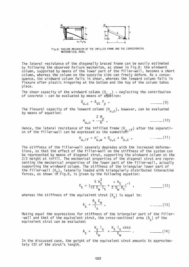
Figo8 : FAILURE MECHANISM OF THE INFILLED FRAME AND THE CORRESPONDING MATHEMATICAL ~'ODEL
The lateral resistance of the diagonally braced frame can be easily estimated by following the observed failure mechanism, as shown in Fig.8: the windward column, supported by means of the lower part of the filler-wall, becomes a short column, whereas the column on the opposite side can freely deformo As a consequence, the windward column fails in shear, whereas the leeward column fails in flexure after plastic hingening at the bottom and the top of the column takes place.
The shear capacity of the windward column (Q ) - neglecting the contribution of concrete - can be evaluated by means of e~~~tion:
Qu,c = Ast fy , (9)
The flexural capacity of the leeward column (Hu,c)' however, can be evaluated by means of equation:
2 M Hu,c = ~ , (10)
Hence, the lateral resistance of the infilled frame (H °f) after the separation of the filler-wall can be expressed as the summatioH~l
H °f = W + Q + H , U,l U,W U,C u,c _ _ (11)
The stiffness of the filler-wall severely degrades with the increased deformations, so that the effect of the filler-wall on the stiffness of the system can be represented by means of diagonal strut, supporting the windward column at the 2/3 height at infill. The mechanical properties of the diagonal strut are representing the mechanical properties of the lower part of the filler-wall, actually supporting the windward column. The stiffness of the triangular lower part of the filler-wall (Kt ), laterally loaded with triangularly distributed interaction forces, as shown i~ Fig.8, is given by the following equation:
5 h3 t
Kt = (12 E I + w t
K ht -1 2 G A) ,
w t
whereas the stiffness of the equivalent strut (Ks) is equal to:
As Ew Ks = ls '
__ (12)
__ (13)
Making equal the expressions for stiffness of the triangular part of the filler-wall and that of the equivalent strut, the cross-sectional area (As) of the equivalent strut can be evaluated:
__ (14)
In the discussed case, the geight of the equivalent strut amounts to approximately 13% of the strut's length.
1322
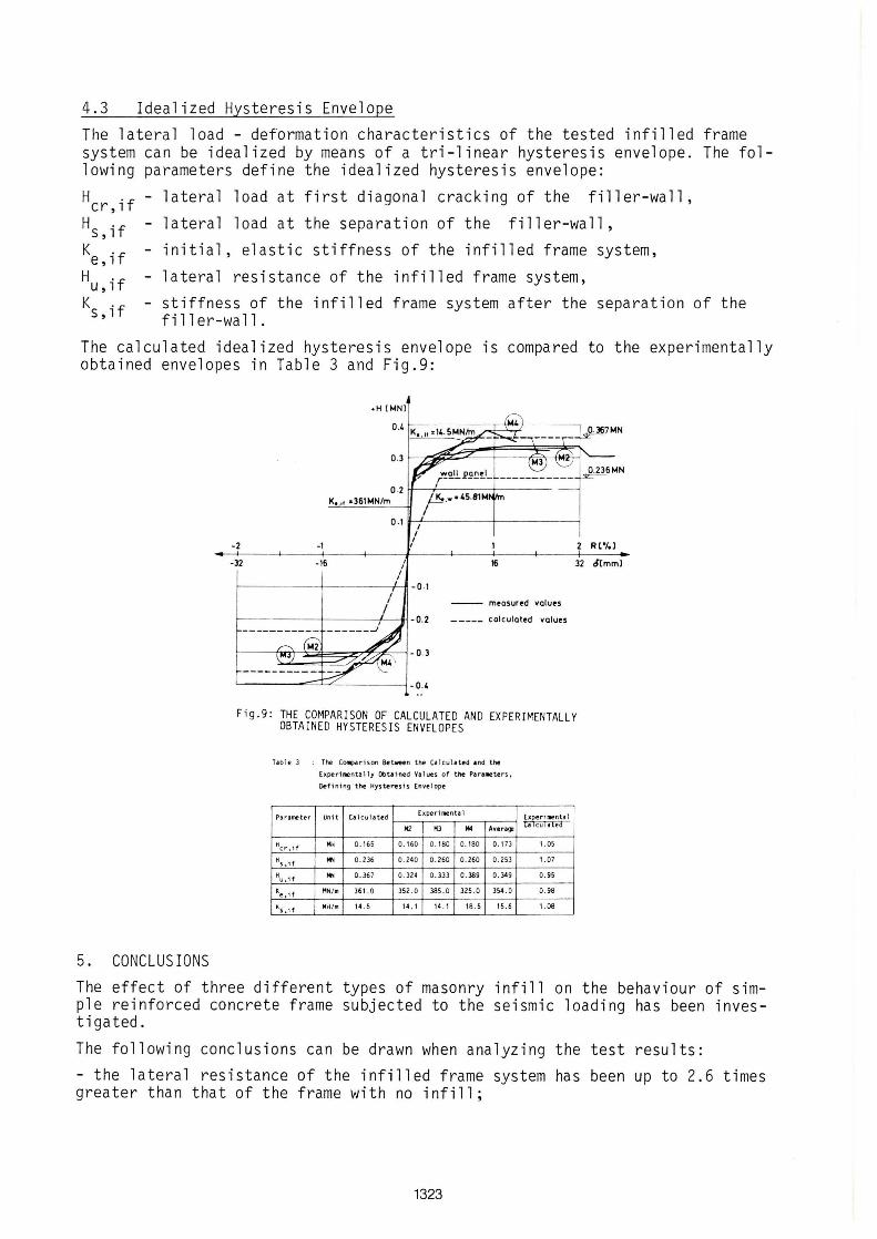
4.3 Idealized Hysteresis Envelope The lateral load - deformation characteristics of the tested infilled system can be idealized by means of a tri-linear hysteresis envelope. lowing parameters define the idealized hysteresis envelope:
Hcr,if - lateral load at first diagonal cracking of the filler-wall,
H °f - lateral load at the separation of the filler-wall, s , 1
K 0f e,l - initial, elastic stiffness of the infilled frame system,
H °f u , 1 - lateral resistance of the infilled frame system,
frame The fol-
K °f s , 1 - stiffness of the infilled frame system after the separation of the
filler-wall.
The calculated idealized hysteresis envelope is compared to the experimentally obtained envelopes in Table 3 and Fig.9:
5. CONCLUSIONS
.H {Io4NJ
0 ·2 I-I--+-----t---1< • . 11 a361tr.4N/m
0 .1 It-:'-, -----t-----1 I
-2 -1 I
I 2 Rl'loJ
-32 -16 I I
I I
16 32 ó[mml
f-------+-------t'-ll - O. 1 I
/ -- mtasured values
f-------l----+---fj -0.2 _____ calculat.d .alu ..
Figo9: THE COMPARISON OF CALCULATEO ANO EXPERIMENTALLY OBTAINEO HYSTERESIS ENVELOPES
Tab l e 3 : lhe C~rison Between the Ca l cuhted .nd tne
Parameter
Hcr. if
Hs, i(
H u. if
~e . i (
':'s,if
[xperillentally Obuined va l ~s of the Parl_ters.
Oef i ning the Hyster-esis Enve lope
lO, 0. 165 0.160 0. 180 0. 180 0 .113
'" 0.236 0 . 240 0.260 0 . 260 0.253
... 0.367 0.324 0.333 0 . 389 0 . 349
I1N / m 361. 0 352 . 0 385.0 325 .0 354.0
Hi4!m 14 . 5 14 .1 14 . 1 18 .5 15.6
1.05
1.07
0. 95
0.98
1.08
The effect of three different types of masonry infill on the behaviour of simple reinforced concrete frame subjected to the seismic loading has been investigated.
The following conclusions can be drawn when analyzing the test results:
- the lateral resistance of the infilled frame system has been up to 2.6 times greater than that of the frame with no infill;
1323
- the type of the infill had no effect on the strength and deformability of the infil l ed frame system. Practically no difference has been observed between the beha viour of frames with unreinforced and horizontally reinforced filler-wall, whereas an increase of 15% in lateral resistance has been observed when testing the frame with horizontally reinforced filler-wall , connected to the frame; - the infill increased the initial lateral stiffness of the frame up to 22-ti mes;
- the lateral resistance of the infilled frame system has been attained at sig nificantly smaller storey drift angle than that of the frame with no infill. At the displacement level, where the column reinforcement only started to yield, severe strength degradation of the infilled frame system has already been observedo
On the basis of the analysis of test results, as well as on the basis of the observations of the behaviour of the system under constant vertical in cyclic lateral load conditions the failure mechanism of the infilled frame has been de fined.
An attempt has also been made to calculate the strength and deformability characteristics of the tested type of infilled frame. A simple analytical model has been proposed: the shear cantilever representing the infilled frame before the separation of the fi l ler-wall and the diagonally braced frame representing the infi l led frame after the separation of the filler-wall. By taking into account the experimentally obtained data on the mechanical characteristics of the constituent materials, very good correlation between the calculated and experimentally obta i ned values defining the strength and deformability characteristics of the infilled frame, has been obtained.
6. LIST OF SYMBOLS
Ac'
At'
Ast CR Ec'
GC' H
Ic'
r~ y
Vz b
f t,w fy
A w A s
Ew G w
I , w It
f, hw' ht
- cross-sectional area of column and filler- wall, respecti vely,
- cross-sectional area of the lower, triangular part of the sepa-rated filler-wall and of the equivalent strut, respectively,
- effecti ve area of the transverse reinforcement (stirrups ) ,
- shear capacity reduction factor,
- elastic m0dulus of concrete and filler-wall, respectively,
- shear modulus of concrete and filler-wal l , respectively,
- latera l l oad, - moment of inertia of the frame column,of the filler-wal l horizon-
tal cross-section, and of the bottom horizontal cross-section of the lower triangular part of the separated filler-wall, respective ly,
- bending moment at yielding of the column reinforcement,
- external vertical load, acting on the frame beam, - shear distribution coefficient,
- tensile strength of filler-wall
- yield limit of reinforcing steel - height of the frame, filler-wall, and the lower triangular part
of the separated filler-wall, re spectively,
1324
1, 1 , 1 w s
t w
a
B
K
T U
- span of the frame, length of the filler -wall ,and length of the equivalent strut, respectively,
- thickness of the filler-wall, - factor defining the position of vertical compo net of interaction
forces (a = 7/8), - angle between the equivalent strut and horizontal edge of filler -
-wa 11 ,
- shear factor, - average normal stress acting in the horizontal cross - section area
of the filler -wa11 due to vertical load, - average shear stress in the horizontal cross -sect ional area of the
filler-wall at the ultimate lateral l oa d.
7. ACKNOWLEDG E~1 E NT
The investigations, reported in the present paper, were sponsored by the Research Community of Slovenia and by t he National Science Fou ndat ion,USA.th ro ugh funds made available by t he U.S .-Y ugo sl av Joint Board on Scient i fic and Tech nological Cooperation. Their fi nanci al support is gratefuly acknowledged.
8. LIST OF REFERE NCES (1) Fi ora to, A.E, Sozen M.A . and Gamble W. L. : "An Investigation of the Interac
tion of Rei nforced Concrete Frames with Masonry Filler Walls", University of Il l inois, Nov. 1970.
(2 ) Leuchars, J. ~1. and Scrivener J.C.: "Masonry Infill Panels Subjected to Cyc l ic In-P l ane Loading" Proc.South Pacific Regional Conference of the NZNSEE, Wallington, N.Z., May 1975 .
(3) Riddington, J.R. and Stafford Smith D. "Analysis of Infilled Frames Subjected to Racking with Design Recommendations", The Structural Engineer, NO.6. Vol . 55, June 1977, p.p. 263-268.
(4) Stafford Smith, B. and Carter C. "A ~~ethod of Analysis for Infilled Frames", ICE Vo1. 44 Sep/Dec 1969, pp 247-257.
(5 ) Turns ek,V. and cacovic,F. "Some Experimental Results on the Strength of Bri ck ~1asonry Halls" Proc.2-nd International Br ick Masonry Conference, Sto ke-on-Trent, 1971.
(6 ) za r nié ,R., and Tomazevic,~~. "Study of the Behaviour of Masonry Infilled Rei nforced Concrete Frames Subjected to Seismic Loading - Part One", Pub1ica t ion ZRMK/ IKPI No.84/04, Ljubl j ana 1984.
1325

1326