Embed Size (px)
Citation preview

American Journal of Engineering Research (AJER) 2015
w w w . a j e r . o r g
Page 133
American Journal of Engineering Research (AJER)
e-ISSN : 2320-0847 p-ISSN : 2320-0936
Volume-4, Issue-2, pp-133-145
www.ajer.org
Research Paper Open Access
Computer Aided Design and Comparative Study of Copper and
Aluminium Conductor Wound Distribution Transformer
Md. Abdullah-Al-Imran
1,Md. Mehedy Hasan Sumon
2 , Kazi Md. Shah
Emran3, Dilip Kumar Sarker
4
1,2,3 Department of Electrical & Electronic Engineering, Pabna University of Science & Technology,
Bangladesh. 4Associate Professor, Department of Electrical & Electronic Engineering, Pabna University of
Science & Technology, Bangladesh.
ABSTRACT: This paper describes design and performance analysis for copper and aluminium conductor
wound distribution transformers using computer programs. The different parts of the transformer are designed
by developing a MATLAB program according to designing algorithm. The design data sheets have been
prepared from program outputs and working performances for different KVA ratings with various loading have
been analyzed. This study also represents a comprehensive comparison of designing and performance of copper
and aluminium windings. It can influence the selection of copper against aluminium windings for distribution
transformer. This study establishes the high rate of performance calculation and provides the ability to carry
out logical decisions.
KEYWORDS- Copper and aluminium wound, Distribution transformer, Maximum efficiency, MATLAB coding.
I. INTRODUCTION The application of transformer in power transmission and distribution is vital for the proper use of
power and it is impossible to think of a large power system without transformers. So the designing of
transformer is very important for proper power management. The manual design procedure is time consuming,
needs more manpower and accuracy level is lower. The objective of this research work is to accomplish a
computer aided design of distribution transformer. This design procedure enables us to analyze the performance
and it represents a comprehensive comparison of copper and aluminium windings. From this study we will be
able to determine how to obtain better performance of transformer. It also establishes the high rate of
performance calculation and provides the ability to carry out logical decisions for the selection of proper
winding material. For this reason an engineer has to take in to the consideration of several factors such as losses,
efficiency, voltage regulation etc. This study represents a computer aided design using MATLAB and the use of
the result of coding to analyze the performance for both copper and aluminium windings of transformer.
II. DESIGN OF TRANSFORMER
Transformers may be designed to make one of the following quantities as minimum.
(i)Total Volume, (ii) Total weight, (iii) Total cost and (iv) Total losses.
In general, these requirements are contradictory [1] and it is normally possible to satisfy only one of them. All
these quantities vary large core with ratio r = Øm/AT. If we choose a high value of r, the flux becomes larger and
consequently a large core cross-section is needed which results in higher volume, weight and cost of iron and
also gives a higher iron loss. On the other hand, owing to decrease in the value of AT, The volume, weight and
cost of copper required decrease and also I2R losses decrease. Thus we conclude that the value of r is a
controlling factor for the above mentioned quantities:
Let us consider a single phase transformer. In KVA output is:
Q = 2.22fBmδKwAwAi ×10-3
= 2.22fBmAcAi× 10-3

American Journal of Engineering Research (AJER) 2015
w w w . a j e r . o r g
Page 134
Assuming that the flux and current densities are constant, we see that for a transformer of given rating the
product AcAi is constant.
Let this product AcAi = M2 (1)
The optimum design problem is, therefore, that of determining the minimum value of total cost.
Now, r = Øm/AT and Øm = DmAi and AT = KwAw/2 = δAc/2
r = or, = r= β (2)
Where β is a function of r only as Bm and δ are constant.
Thus from (1) and (2) we have
Ai = M and Ac = M/
Let Ct = total cost of transformer active materials, Ci = Total cost of iron, and
Cc = total cost of conductor
Ct = Ci + Cc = CiGi + CcGc
= cigiIiAi + cvgcLmtAc
Where Ci and Cc are the specific costs of iron and copper respectively.
Now, Ct = cigiIiAi M√β + ccgcLmt M/√β
Differentiating Ct with respect to β,
dCt/dβ =0.5 cigiIiAi Mβ-0.5
- 0.5ccgcLmt Mβ-1.5
For minimum cost, dCt/dβ = 0
cigiIi = ccgcLmtβ-1
Ci = Cc
Hence, for minimum total cost, the cost of iron must equal the cost of conductor.
Now Gi/Ge = cc/ci , for minimum cost
Knowing the value of specific costs of iron and conductor the ratio of weight of iron to conductor can be
determined. Similar conditions apply to other quantities e.g. for minimum volume of transformer,
Volume of iron = Volume of conductor
Gi/gi = Gc/gc i.e. Gi/Gc = gi/gc
For minimum weight of transformer,
Weight of iron = Weight of conductor i.e. Gi = Gc
For minimum losses in transformer i.e., for maximum efficiency [2],
Iron loss = I2R loss in the conductor or, Ps = x
2 Pc
Total losses at full load = Pi + Pc
At any fraction x of full load, the total losses are Pi + x2Pc
If Q is the output at full load, the output at fraction x of the full load is xQ.
Efficiency at output xQ, ηx =
This efficiency is maximum, when dηc/dx = 0
Differentiating we have, dηc/dx =
For maximum efficiency, (xQ + Pi + x2 PC)Q - xQ(Q + 2xPc) = 0
Or, Pi = x2Pc
So, the maximum efficiency is obtained, when the variable losses are equal to the constant losses.
Pi/Pc = PiGi/PcGc
x2 = PiGi/PcGc
or, Gi/Gc = x2Pc/Pi for maximum efficiency. Now, knowing the values of densities in iron and copper the
specific losses pi and pc can be determined and the value of x i.e., the fraction of full load where the maximum
efficiency occurs depends upon the service conditions of the transformer and is, therefore, known. Thus ratio
Gi/Gc is known to get the core area for maximum efficiency [2].
III. MATLAB CODING, DESIGN PROBLEM AND PROGRAM OUTPUT This research work implements a MATLAB program for designing distribution transformers and analyzing their

American Journal of Engineering Research (AJER) 2015
w w w . a j e r . o r g
Page 135
working performance. Here we design a 25 KVA, 11000/433 V, 50 Hz, 3 phase, delta/star, core type, oil
immersed natural cooled distribution type transformer. The transformer is provided with 5% tapping on the HV
side. Program Outputs for 25 KVA Transformer:
**************************************
CORE DESIGN OF THE TRANSFORMER
**************************************
The KVA rating of the transformer is 25.000000 KVA
Voltage per turn Et 2.25 V
Line frequency: 50.000000 Hz
The number of phase of transformer: 3
Flux in the core is 0.010135 Wb
Flux density: 1.0000 Wb/m^2
The net iron area is 0.010135 m^2
Stacking factor is 0.900000
Gross iron area is: 0.011261 m^2
Type of core is Cruciform
Diameter of the core is 0.1345 m
The dimension is: 0.114 X 0.071
**********************************************
WINDOW DIMENSION OF THE TRANSFORMER
**********************************************
Primary winding voltage is: 11.000000 KV
Current density: 2.30 A/mm^2
Window space factor is: 0.195
Modified window space factor is: 0.180
Area of the window: 0.035785 m^2
Ratio height to width of window is 2.5
Height of the window is 0.299
The calculated height and width of the window are 0.299 m and 0.120 m
The modified height and width of the window are 0.300 m and 0.120 m
Distance between adjacent cores is 0.255 m
************************************
YOKE DESIGN OF THE TRANSFORMER
************************************
Area of the yoke is 15 to 25 percent larger than the core (0.010135 m^2) of the transformer
The ratio-area of the yoke to limbs is 1.20
Flux density in the yoke 0.833333 Wb/m^2
Area of the yoke is 0.012162 m^2
Gross area of the yoke is 0.013514 m^2
Select the section of the yoke is rectangular
The depth of the yoke is 0.1140 m
Height of the yoke 0.1185 m
************************************ ********
OVERALL DIMENSION OF THE TRANSFORMER
********************************************
Distance between adjacent cores centers 0.255 m
Height of the frame is 0.537 m
Width of the frame is 0.623 m
Depth of the frame 0.114 m
*************************
LOW VOLTAGE WINDING

American Journal of Engineering Research (AJER) 2015
w w w . a j e r . o r g
Page 136
*************************
Secondary line voltage is 433.00 V
Connection type is star
Phase voltage is 249.993 V
Turn per phase is 111
Secondary current per phase is 33.334 A
Current density in secondary phase is 2.30 A/mm^2
Total area of secondary conductor is 14.493 mm^2
Area of each conductor is 14.493 mm^2
Dimension of the conductor is 7.500 X 2.000
Modified area of the conductor is 15.000 mm^2
Modified current density in secondary phase is 2.22 A/mm^2
Covering of conductor is 0.500 mm
Dimension of the conductor with covering is 8.000 X 2.500
The number of layer is used is 6
Turns along the axial depth is 19
Axial depth of the LV winding is 152.000 mm
Clearance is 74.000 mm
Thickness of the pressboard cylinders is 0.500 mm
Radial depth of the LV winding is 16.000 mm
The insulation for the circumscribing circle is 0.500 mm
The insulation between LV winding and core is 1.500 mm
Diameter of the circumscribing circle is 0.135 mm
Inside diameter is 138.031 mm
Outside diameter is 170.031 mm
*********************************************************
HIGH VOLTAGE WINDING DESIGN OF THE TRANSFORMER
*********************************************************
Primary line voltage is 11000.00 V
Connection type is delta
Primary phase voltage is 11000.000 V
Primary turn per phase is 4884
Tapping is considered here
Percentage of tapping is 5.000 percent
Primary turn per phase with 5.000 tapping is 5128
Actual number of turn per phase 5128
Cross over winding is used here
The value of voltage per coil is 1500.000 V
Number of coil is 7
Modified number of coil is 8
Modified value of voltage per coil is 1375.000 V
Turns per coil is 641 Number of normal coil is 7
Turns for the normal coil are 672
Reinforced turns in remaining 1 coil is 424
Total turn is 5128
Number of layers 24
Number of turn per layer 28
Primary current per phase is 0.758 A
Current density in primary conductor is 2.400 A/mm^2
Area of primary conductor is 0.316 mm^2
Calculated Diameter of the primary conductor is 0.634Standard value of the diameter proper insulation is 0.805
mm
Modified area of primary conductor is 0.322 mm^2
Modified current density in the primary conductor is 2.355 A/mm^2 Axial depth of one coil is 22.540(mm)
Space between adjacent coils (mm) is 5.0
American Journal of Engineering Research (AJER) 2015
w w w . a j e r . o r g
Page 137
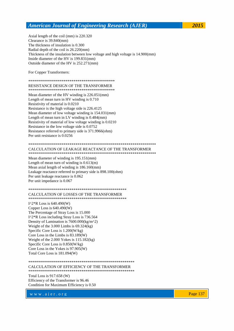
Axial length of the coil (mm) is 220.320
Clearance is 39.840(mm)
The thickness of insulation is 0.300
Radial depth of the coil is 26.220(mm)
Thickness of the insulation between low voltage and high voltage is 14.900(mm)
Inside diameter of the HV is 199.831(mm)
Outside diameter of the HV is 252.271(mm)
For Copper Transformers:
********************************************
RESISTANCE DESIGN OF THE TRANSFORMER
********************************************
Mean diameter of the HV winding is 226.051(mm)
Length of mean turn in HV winding is 0.710
Resistivity of material is 0.0210
Resistance is the high voltage side is 226.4125
Mean diameter of low voltage winding is 154.031(mm)
Length of mean turn in LV winding is 0.484(mm)
Resistivity of material of low voltage winding is 0.0210
Resistance in the low voltage side is 0.0752
Resistance referred to primary side is 371.9966(ohm)
Per unit resistance is 0.0256
*****************************************************************
CALCULATION OF LEAKAGE REACTANCE OF THE TRANSFORMER
*****************************************************************
Mean diameter of winding is 195.151(mm)
Length of mean turn of winding is 0.613(m)
Mean axial length of winding is 186.160(mm)
Leakage reactance referred to primary side is 898.100(ohm)
Per unit leakage reactance is 0.062
Per unit impedance is 0.067
**************************************************
CALCULATION OF LOSSES OF THE TRANSFORMER
**************************************************
I^2*R Loss is 640.490(W)
Copper Loss is 640.490(W)
The Percentage of Stray Loss is 15.000
I^2*R Loss including Stray Loss is 736.564
Density of Lamination is 7600.000(kg/m^2)
Weight of the 3.000 Limbs is 69.324(kg)
Specific Core Loss is 1.200(W/kg)
Core Loss in the Limbs is 83.189(W)
Weight of the 2.000 Yokes is 115.182(kg)
Specific Core Loss is 0.850(W/kg)
Core Loss in the Yokes is 97.905(W)
Total Core Loss is 181.094(W)
******************************************************
CALCULATION OF EFFICIENCY OF THE TRANSFORMER
******************************************************
Total Loss is 917.658 (W)
Efficiency of the Transformer is 96.46
Condition for Maximum Efficiency is 0.50

American Journal of Engineering Research (AJER) 2015
w w w . a j e r . o r g
Page 138
**********************************************************
NO LOAD CURRENT CALCULATION OF THE TRANSFORMER
**********************************************************
Value "at" of Core corresponding to the flux density (1.000 Wb/m^2) in Core is 120.00(A/m)
Value "at" of Core corresponding to the flux density (0.833 Wb/m^2) in yoke is 80.00(A/m)
Total Magnetizing Current is 207.690(A)
Magnetizing mmf per phase is 69.230(A)
Magnetizing Current is 0.01002(A)
Loss component of no load Current is 0.00549(A)
No load Current is 0.01143(A)
No load Current as a percentage of full load current is 1.5(A)
For Aluminium Transformers:
*******************************************
RESISTANCE DESIGN OF THE TRANSFORMER
*******************************************
Mean diameter of the HV winding is 226.051(mm)
Length of mean turn in HV winding is 0.710
Resistivity of material is 0.0300
Resistance is the high voltage side is 323.4465
Mean diameter of low voltage winding is 154.031(mm)
Length of mean turn in LV winding is 0.484(mm)
Resistivity of material of low voltage winding is 0.0300
Resistance in the low voltage side is 0.1074
Resistance referred to primary side is 531.4238(ohm)
Per unit resistance is 0.0366
*****************************************************************
CALCULATION OF LEAKAGE REACTANCE OF THE TRANSFORMER
*****************************************************************
Mean diameter of winding is 195.151(mm)
Length of mean turn of winding is 0.613(m)
Mean axial length of winding is 186.160(mm)
Leakage reactance referred to primary side is 898.100(ohm)
Per unit leakage reactance is 0.062
Per unit impedance is 0.072
**************************************************
CALCULATION OF LOSSES OF THE TRANSFORMER
**************************************************
I^2*R Loss is 914.986(W)
Copper Loss is 914.986(W)
The Percentage of Stray Loss is 15.000
I^2*R Loss including Stray Loss is 1052.234
Density of Lamination is 7600.000(kg/m^2)
Weight of the 3.000 Limbs is 69.324(kg)
Specific Core Loss is 1.200(W/kg)
Core Loss in the Limbs is 83.189(W)
Weight of the 2.000 Yokes is 115.182(kg)
Specific Core Loss is 0.850(W/kg)
Core Loss in the Yokes is 97.905(W)
Total Core Loss is 181.094(W)

American Journal of Engineering Research (AJER) 2015
w w w . a j e r . o r g
Page 139
******************************************************
CALCULATION OF EFFICIENCY OF THE TRANSFORMER
******************************************************
Total Loss is 1233.328 (W)
Efficiency of the Transformer is 95.30
Condition for Maximum Efficiency is 0.41
**********************************************************
NO LOAD CURRENT CALCULATION OF THE TRANSFORMER
**********************************************************
Value "at" of Core corresponding to the flux density (1.000 Wb/m^2) in Core is 120.00(A/m)
Value "at" of Core corresponding to the flux density (0.833 Wb/m^2) in yoke is 80.00(A/m)
Total Magnetizing Current is 207.690(A)
Magnetizing mmf per phase is 69.230(A)
Magnetizing Current is 0.01002(A)
Loss component of no load Current is 0.00549(A)
No load Current is 0.01143(A)
No load Current as a percentage of full load current is 1.5(A)
IV. COMPARATIVE STUDY AND ANALYSIS The effect of variation of percentage of I
2R loss on KVA ratings of transformer has been shown in
Fig.1. In this observation the value of transformer KVA rating is varied from 5 KVA to 100 KVA with the
variation of percentage of I2R loss has been observed. The value of percentage I
2R loss is higher when the KVA
rating is lower and vice versa. The value of percentage of I2R loss is decreased with increasing of KVA rating.
This observation is same for both copper and aluminium winding transformer but I2R loss of aluminium wound
transformer is higher than that of copper wound transformer for same KVA rating.
Figure 1: Transformer KVA Rating vs. Percentage of I2R Losses for both Copper and Aluminium Wound
Transformer
The effect of variation of efficiency on KVA ratings of transformer has been shown in Fig 2. In this observation
the value of transformer KVA rating is varied from 5 KVA to 100 KVA and the variation of all-day efficiency
has been observed. The value efficiency is higher when the KVA rating is higher and vice versa. The value of
efficiency is increased with increasing of KVA rating. This observation is same for both copper and aluminium
winding transformer but efficiency of aluminium wound transformer is lower than that of copper wound
transformer for same KVA rating. It is seen that 93.5% to 98.2% all-day efficiency has been achieved for
aluminium winding transformer and 94.9% to 98.5% all-day efficiency has been achieved for copper winding

American Journal of Engineering Research (AJER) 2015
w w w . a j e r . o r g
Page 140
transformer.
Figure 2: Transformer KVA Rating vs. Percentage of I
2R Losses for both Copper and Aluminium Wound
Transformer
The effect of variation of loading causes the variation of I2R loss of transformer. The graph of variation
of I2R loss for copper winding transformer is shown in Fig.3 and the graph of variation of I
2R loss for
aluminium winding transformer is shown in Fig.4. In this observation the value of percentage of KVA loading
changes from 10% to 100% for KVA ratings varied from 5 KVA to 100 KVA. The value of I2R loss is lower
when the percentage of KVA loading is lower and vice versa. The value of I2R loss is increased with increasing
of percentage of KVA loading. This observation is same for both copper and aluminium winding transformer
but I2R loss of aluminium transformer is higher than that of copper transformer for same percentage of KVA
loading.
Figure 3: I
2R Loss of Copper Wound Transformer vs. Percentage of KVA Load

American Journal of Engineering Research (AJER) 2015
w w w . a j e r . o r g
Page 141
Figure 4: I2R Loss of Aluminium Wound Transformer vs. Percentage of KVA Load
The effect of variation of transformer efficiency with loading the value of percentage of KVA loading
changes from 10% to 100% for KVA ratings varied from 5 KVA to 100 KVA. The value of percentage of I2R
loss is increased with increasing of percentage of KVA loading. The core loss remains constant for different
loading. Efficiency was maximum when copper loss and core loss was equal. This observation is same for both
copper and aluminium wound transformer but efficiency of aluminium wound transformer is lower than that of
copper wound transformer for same percentage of KVA loading. Fig.5 shows the effect of loading on copper
wound transformer and Fig.6 shows the effect of loading on aluminium wound transformer.
Figure 5: Variation of Efficiency vs. Loading of Copper Wound Transformer

American Journal of Engineering Research (AJER) 2015
w w w . a j e r . o r g
Page 142
Figure 6: Variation of Efficiency vs. Loading of Aluminium Wound Transformer
Voltage regulation is increased with increasing of percentage KVA load. In this observation the value of KVA
load is varied from 10% to 100 % whereas KVA ratings are considered from 5 KVA to 100 KVA. Fig.7 shows
the variation of voltage regulation for different loading of copper transformer and Fig.8 shows the variation of
voltage regulation for different load of aluminium transformer. Voltage regulation of aluminium transformer is
higher than that of copper transformer for same percentage KVA loading. Here we use 0.8 lagging power factor.
Figure 7: Voltage Regulation vs. KVA Load of Copper Wound Transformer

American Journal of Engineering Research (AJER) 2015
w w w . a j e r . o r g
Page 143
Figure 8: Voltage Regulation vs. KVA Load of Aluminium Wound Transformer
Efficiency is increased with increasing of power factor (lagging). In this observation the value of power factor is
varied from 0.7 to 1.00 whereas KVA ratings are considered from 5 KVA to 100 KVA. Fig.9 shows the
variation of efficiency for different power factor of copper wound transformer and Fig.10 shows the variation of
efficiency for different power factor of aluminium wound transformer.
Figure 9: Efficiency vs. power factor of copper wound transformer

American Journal of Engineering Research (AJER) 2015
w w w . a j e r . o r g
Page 144
Figure 10: Efficiency vs. Power Factor of Aluminium Wound Transformer
V. CONCLUSION This paper implements a MATLAB program for designing distribution transformers and analyzing
their working performance. It represents a comparative study based on the analysis of program outputs for the
selection of copper against aluminium windings for distribution transformers. This research work has not only
been of interest to transformer designers, but the comparison of copper and aluminium conductor wound
distribution transformers has been discussed.The advantages of use of MATLAB program for the design of
transformer may be summed up as:
i. It is easily accessible to engineers with little experience in transformer engineering.
ii. The high rate of performing calculation at reasonable cost can be obtained.
iii. It eliminates a large number of non-useful combinations of design parameters.
iv. The results are highly accurate and reliable.
v. It can design a series of machines having different ratings to fit into a given frame size.
vi. It is capable of taking logical decisions and save man hour of the design engineers.
vii. The outputs can be integrated for further analysis.
The design data sheets have been prepared and these results have been observed for performance
analysis. From the program outputs, it was observed that the better performance can be achieved for higher
KVA ratings of transformer. Design data sheet is used in graphical representation to show the performance
variation at different ratings. Performance has been also analyzed for various KVA loading and load power
factor. It is usually tried to operate the transformer at close to full load condition because maximum efficiency
of transformer has been achieved in this condition.
Although the variation characteristics were same for copper and aluminium winding transformer, the
working performance of both transformers were not equal. The variation of physical properties of copper and
aluminium conductors offer higher losses for aluminium windings and greater efficiency for copper windings.
The summary of analysis helps the designer to compare the performance of copper and aluminium windings. By
calculating the windings volume using the program, the total cost can be obtained for desired efficiency.
Aluminium wound transformer needs more conductors (greater volume) to obtain the same efficiency as like
copper windings transformer that may increase the cost. But aluminium conductor is cheaper than copper thus
the overall cost analysis vs. efficiency may be dissimilar for different KVA ratings. Since many factors are
related for the design of transformer thus the selection of winding material between aluminium and copper is not
an easy task.

American Journal of Engineering Research (AJER) 2015
w w w . a j e r . o r g
Page 145
VI. ACKNOWLEDGEMENTS Foremost, we would like to express our sincere gratitude to our supervisor Mr. Dilip Kumar Sarker,
Associate Professor, Dept. of Electrical & Electronic Engineering, Pabna University of Science & Technology,
for his patience, motivation, enthusiasm and immense knowledge. His guidance helped us in all the time of
research and writing of this thesis. We could not have imagined having a better supervisor and mentor for our
research work. REFERENCES
[1] Easwarlal, C., Palanisamy, V., Sanavullah, M. Y. and Gopila, M.,“Graphical estimation of optimum weights of iron and copper
of a Transformer”, PEDES 06 IEEE International conference, New Delhi, 2006, pp. 1-5.
[2] A.K. Sawheny & Chakrabarti, A course in electrical machine design. (Dhanpati Rai and sons, 1984).