Embed Size (px)
Citation preview

Series/Parallel Wiring of a Humbucker pickup with 4
conductors
Luca Finzi Contini

Humbucker Pickup Scheme
• This is the usual schematic for a 4-conductor Humbucker pickup. North coil and South coil are depicted.
• Colour scheme here is DiMarzio’s: – North start: red
– North finish: black
– South start: white
– South end: green
• Seymour Duncan colour scheme is:– North start: Black
– North finish: White
– South start: Red
– South finish: Green
+
-
+
-
Red
Black
White
Green
New Wiring for Series / Split / Parallel wiring
2

Useful colour scheme page
• http://www.seymourduncan.com/support/schematics/schematics.php?schematic=color_codes
New Wiring for Series / Split / Parallel wiring
3

DPDT Switch
• Left: DPDT switch in the ‘push’ position: 2 -> 3; 5 -> 6
• Right: DPDT switch in the ‘pull’ position: 2 -> 1; 5 -> 4
1
2
3
4
5
6
Push
1
2
3
4
5
6
Pull
New Wiring for Series / Split / Parallel wiring
4

DPDT Switch - split• This is the connection in a on-on-on DPDT
switch , typically in the middle position.
• It is useful to achieve a series – split –parallel wiring. 1
2
3
4
5
6
Pull
New Wiring for Series / Split / Parallel wiring
5

Series Wiring
• Maximum DC Resistance
• Maximum output
• Standard wiring
• The two coils are traversed in series
+
-
+
-
-
+
Red
Black
White
Green
New Wiring for Series / Split / Parallel wiring
6

Parallel Wiring
• ‘+’’s are connectedtogether and ‘-’’s are connectedtogether
• Roughly half DC resistance
• Less Output
• More Brightnessand Trebly sound
+
-
+
-
+
-
-
+
Red
Black
White
Green
New Wiring for Series / Split / Parallel wiring
7

Standard DPDT Wiring
• This is the standard wiring as per SD and DiMarzio docs.
• Let’s see how this allows Series / Parallel switching.
1
2
3
4
5
6
DPDT
+
-
-
+
Red
Black
White
Green
+ Hot
- Gnd
New Wiring for Series / Split / Parallel wiring
8
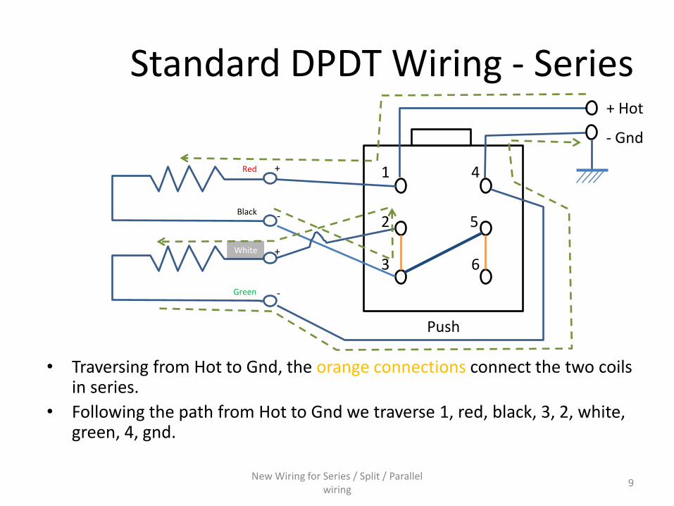
Standard DPDT Wiring - Series
• Traversing from Hot to Gnd, the orange connections connect the two coils in series.
• Following the path from Hot to Gnd we traverse 1, red, black, 3, 2, white, green, 4, gnd.
1
2
3
4
5
6
Push
+
-
-
+
Red
Black
White
Green
+ Hot
- Gnd
New Wiring for Series / Split / Parallel wiring
9

Standard DPDT Wiring - Parallel
• Here we notice how Red and White (+) are connected through 1 -> 2, aswell as Black and Green are connected through 4 -> 5. This demonstratesthat this is a parallel connection.
1
2
3
4
5
6
Pull
+
-
-
+
Red
Black
White
Green
+ Hot
- Gnd
New Wiring for Series / Split / Parallel wiring
10

Standard DPDT Wiring – Split coil
• The same wiring allows for a Single Coil operation when using an on/on/on DPDT switch
• North coil is connected from hot to ground, while South coil has both White and Green connected to ground, so it is not used. We can check that by looking from the Gndconnection backwards:
– Gnd, 4, 5, 3, 2, White, Green, 4, Gnd.
1
2
3
4
5
6
DPDT
+
-
-
+
Red
Black
White
Green
+ Hot
- Gnd
New Wiring for Series / Split / Parallel wiring
11

The need for new wiring
• Standard wiring is a little bit cumbersome to understand because there are crossing lines
• Needs the diagonal piece of wire solderedbetween 3 and 5
• So I came up with a new design…
New Wiring for Series / Split / Parallel wiring
12

New DPDT Wiring
• This new wiring has no wire crossings. • The connection between 3 and 6 can conveniently be realized by using a piece of
condenser ‘leg’ that you cut away if replacing your tone pot with a DPDT push-pull pot, just inserting it in the holes and placing a bit of solder.
• Let’s see how this works as before.
1
2
3
4
5
6
DPDT
+
-
-
+
Red
Black
White
Green
+ Hot
- Gnd
New Wiring for Series / Split / Parallel wiring
13

New DPDT Wiring - Series
• By following the path from Hot to Ground we easily find all the coils:– Hot, 1, Red, Black, 5, 6, 3, 2, White, Green, 4, Gnd
1
2
3
4
5
6
Push
+
-
-
+
Red
Black
White
Green
+ Hot
- Gnd
New Wiring for Series / Split / Parallel wiring
14
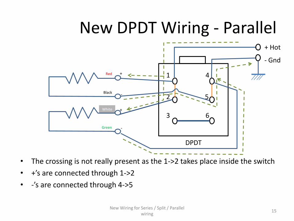
New DPDT Wiring - Parallel
• The crossing is not really present as the 1->2 takes place inside the switch
• +’s are connected through 1->2
• -’s are connected through 4->5
1
2
3
4
5
6
DPDT
+
-
-
+
Red
Black
White
Green
+ Hot
- Gnd
New Wiring for Series / Split / Parallel wiring
15

New DPDT Wiring - Split
• This new wiring was not meant to deal with Split configuration, but let’s see what happens• North coil is correctly running from hot to ground:
– Hot,1,Red,Black,5,4,Gnd.
• South coil has Green connected to ground but White (+) is actually floating– Probably not suitable – never actually tested.
1
2
3
4
5
6
DPDT
+
-
-
+
Red
Black
White
Green
+ Hot
- Gnd
New Wiring for Series / Split / Parallel wiring
16

Application: Telecaster Bridge Series/Parallel
• My Telecaster project features a DiMarzio The Chopper T on the bridge position and a DiMarzioTwang King Neck on the neck position
• Neck pickup is considerably lower in output thanBridge pickup
• I want to have Series/Parallel capability on the 4-conductor bridge pickup
BUT…
• Standard wiring is for series in Push mode, Parallel in Pull mode
New Wiring for Series / Split / Parallel wiring
17

Application: Telecaster Bridge Series/Parallel (cont’d)
• I need to have Parallel mode in ‘push’ position and Series mode in ‘pull’ position so that the standard situation (with pot in the rest, pushposition) will feature comparable output pickup configuration
New Wiring for Series / Split / Parallel wiring
18

Solution: flipping vertically
• This allows for my desired operation: – Push: parallel– Pull: series
• Let’s check…
New Wiring for Series / Split / Parallel wiring
19
1
2
3
4
5
6
DPDT
+
-
-
+
Red
Black
White
Green
+ Hot
- Gnd

Solution: Push = Parallel
• +’s are connected through 1->2
• -’s are connected through 4->5
New Wiring for Series / Split / Parallel wiring
20
1
2
3
4
5
6
Push
+
-
-
+
Red
Black
White
Green
+ Hot
- Gnd
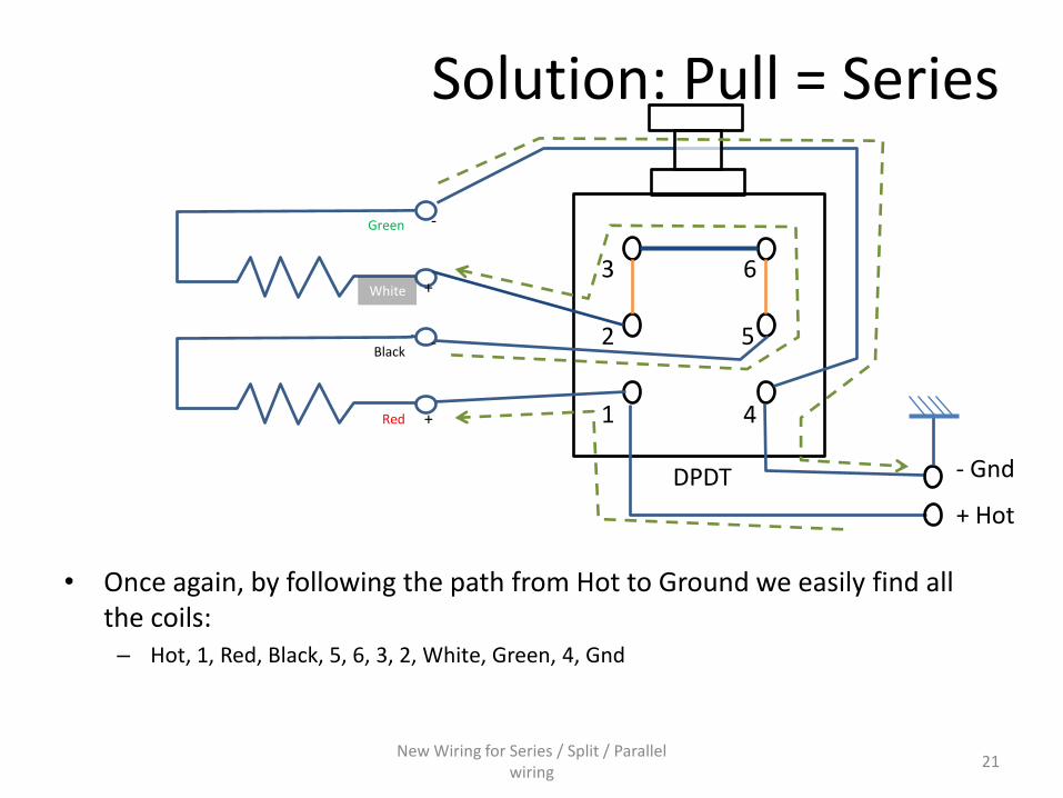
Solution: Pull = Series
• Once again, by following the path from Hot to Ground we easily find allthe coils:– Hot, 1, Red, Black, 5, 6, 3, 2, White, Green, 4, Gnd
New Wiring for Series / Split / Parallel wiring
21
1
2
3
4
5
6
DPDT
+
-
-
+
Red
Black
White
Green
+ Hot
- Gnd

Pictures (1)
New Wiring for Series / Split / Parallel wiring
22
Push/Pull pot with condenser beforesoldering the wiresand ‘bridge’NOTE: The picture shows the condensersoldered to the *WRONG* leg of the pot: if the signalis soldered to the central lug, the condenser must be soldered to the LEFT lug, and not the RIGHT as here – mymistake.

Pictures (2)
New Wiring for Series / Split / Parallel wiring
23
Here I soldered a piece of the condenser‘leg’ I had previously cut in order to create the bridge 3->6. Great move!It passed perfectly through the holes of the DPDT lugs.

Pictures (3)
New Wiring for Series / Split / Parallel wiring
24
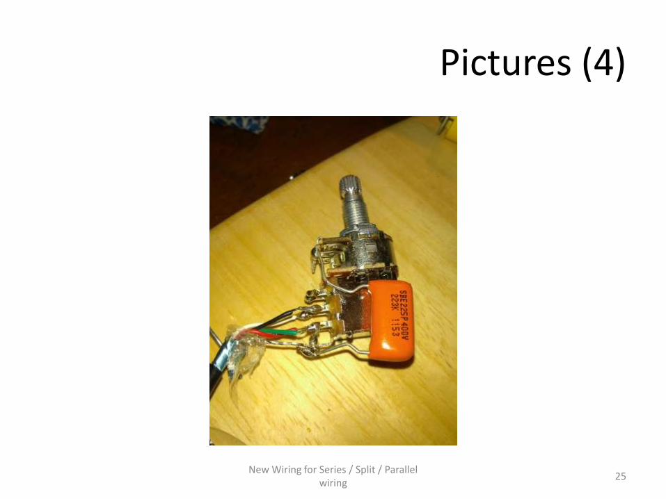
Pictures (4)
New Wiring for Series / Split / Parallel wiring
25
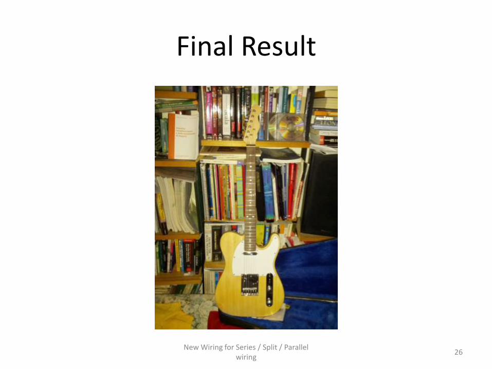
Final Result
New Wiring for Series / Split / Parallel wiring
26

Thank you!
• Thank you for looking at this presentation!
Luca Finzi Contini
New Wiring for Series / Split / Parallel wiring
27