Embed Size (px)
Citation preview
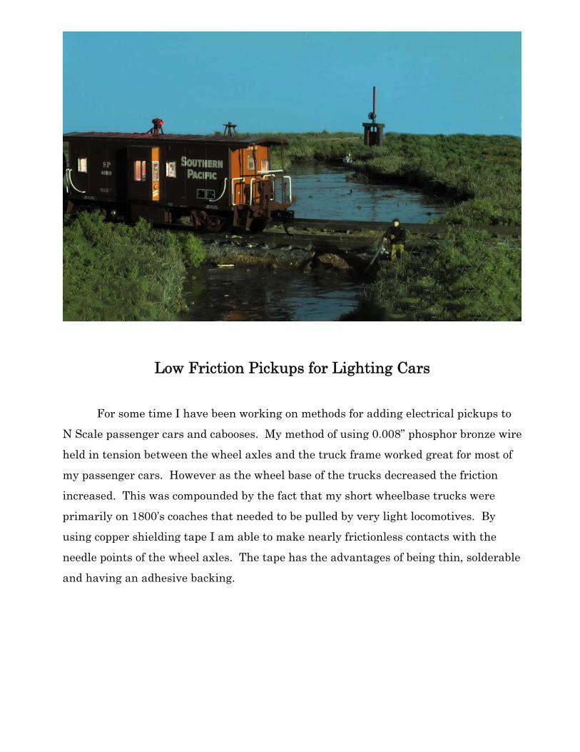
Low Friction Pickups for Lighting Cars
For some time I have been working on methods for adding electrical pickups to
N Scale passenger cars and cabooses. My method of using 0.008” phosphor bronze wire
held in tension between the wheel axles and the truck frame worked great for most of
my passenger cars. However as the wheel base of the trucks decreased the friction
increased. This was compounded by the fact that my short wheelbase trucks were
primarily on 1800’s coaches that needed to be pulled by very light locomotives. By
using copper shielding tape I am able to make nearly frictionless contacts with the
needle points of the wheel axles. The tape has the advantages of being thin, solderable
and having an adhesive backing.
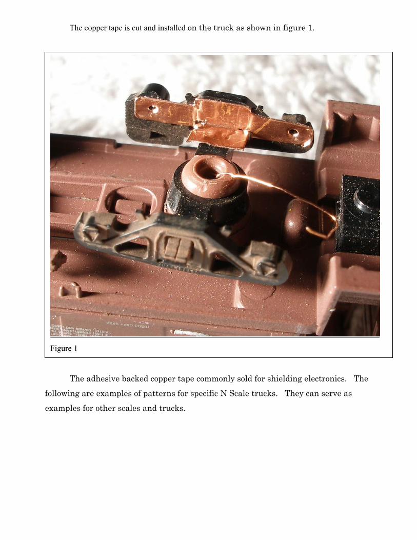
The copper tape is cut and installed on the truck as shown in figure 1.
The adhesive backed copper tape commonly sold for shielding electronics. The
following are examples of patterns for specific N Scale trucks. They can serve as
examples for other scales and trucks.
Figure 1
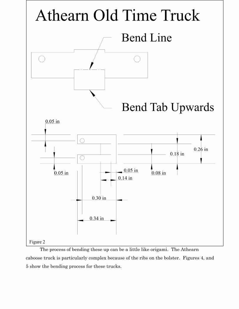
The process of bending these up can be a little like origami. The Athearn
caboose truck is particularly complex because of the ribs on the bolster. Figures 4, and
5 show the bending process for these trucks.
Figure 2
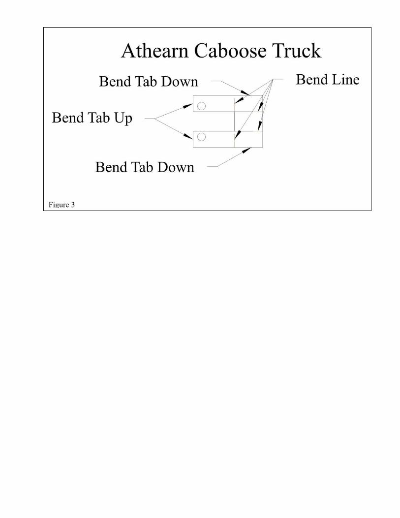
Figure 3
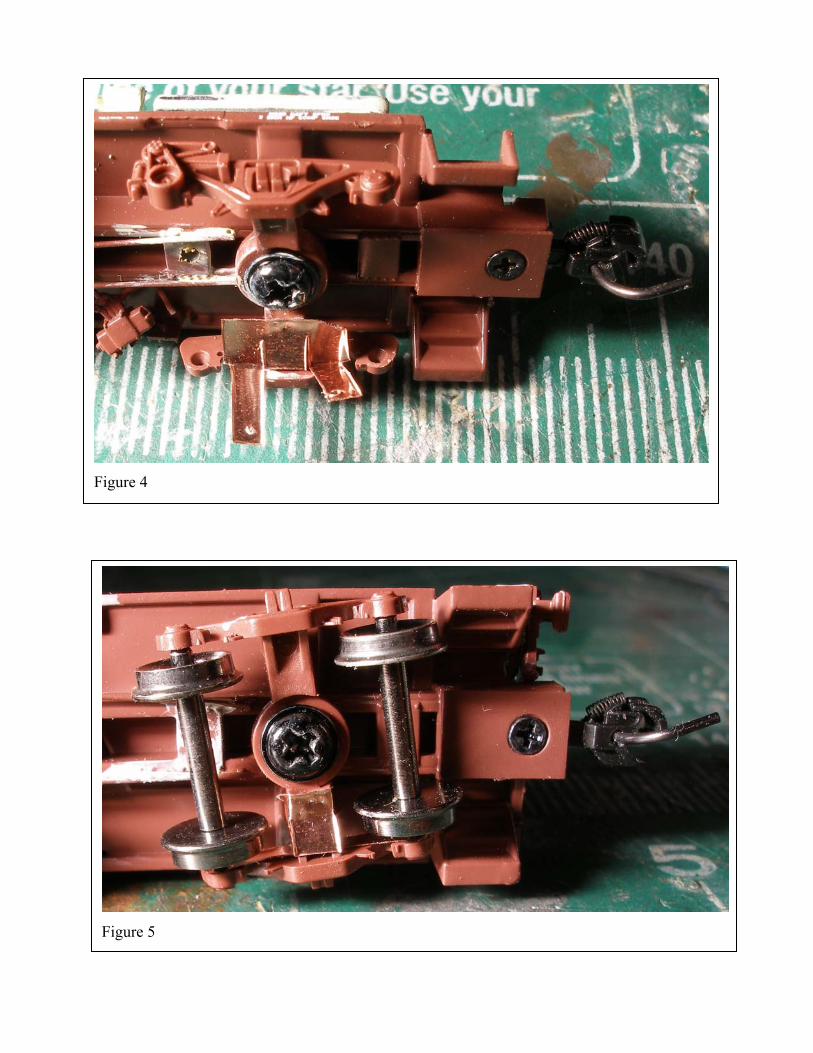
Figure 4
Figure 5
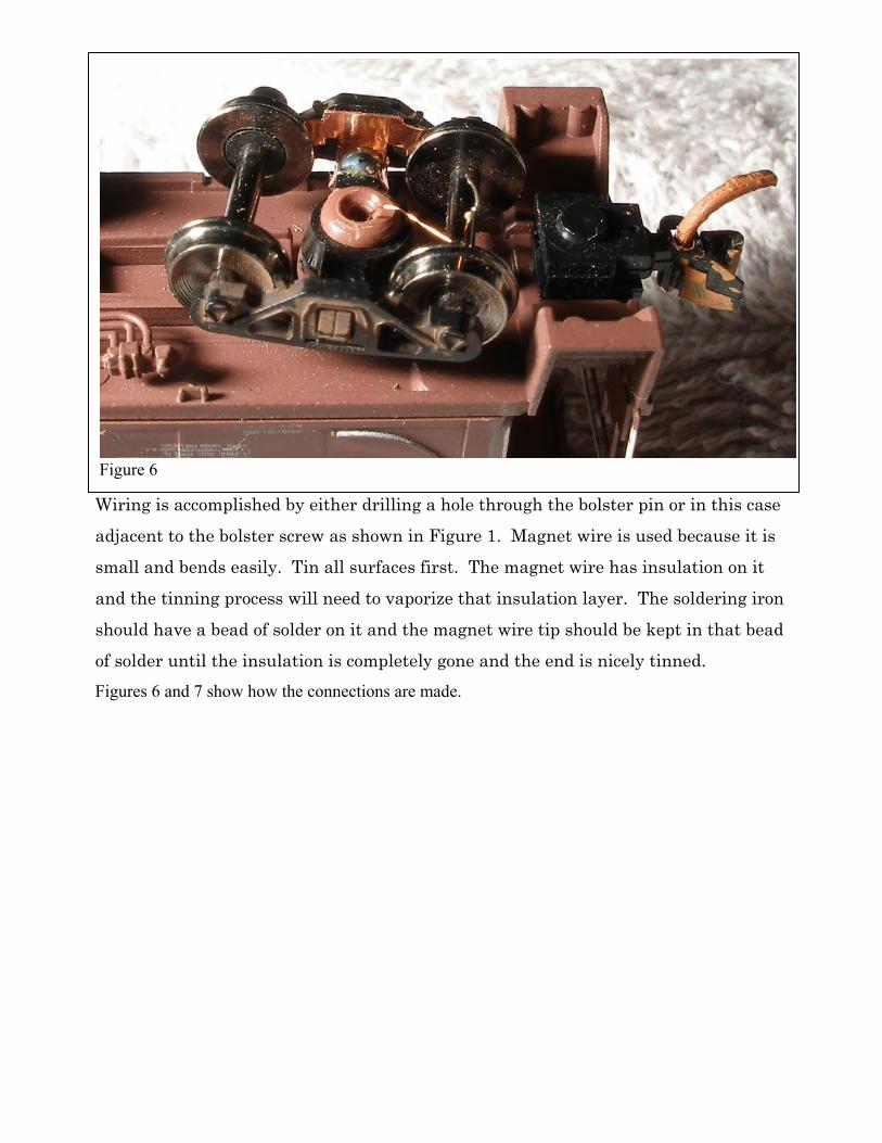
Wiring is accomplished by either drilling a hole through the bolster pin or in this case
adjacent to the bolster screw as shown in Figure 1. Magnet wire is used because it is
small and bends easily. Tin all surfaces first. The magnet wire has insulation on it
and the tinning process will need to vaporize that insulation layer. The soldering iron
should have a bead of solder on it and the magnet wire tip should be kept in that bead
of solder until the insulation is completely gone and the end is nicely tinned.
Figures 6 and 7 show how the connections are made.
Figure 6
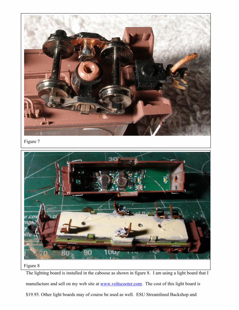
The lighting board is installed in the caboose as shown in figure 8. I am using a light board that I
manufacture and sell on my web site at www.voltscooter.com. The cost of this light board is
$19.95. Other light boards may of course be used as well. ESU Streamlined Backshop and
Figure 7
Figure 8
Richmond Controls for example make good boards. It is important to have good flicker control for
a number of reasons. The contacts are only on
one side of each truck. And the cars are very
light. This all leads to intermittent contacts and
therefore flicker. On my light board that is
provided by a super capacitor as standard. On
some light boards the flicker control is an
expensive add-on. Also the storage capacity of
the anti flicker capacitors varies from 0.2 Farad
on my board to 0.00022 Farad (220 ufd) on some.
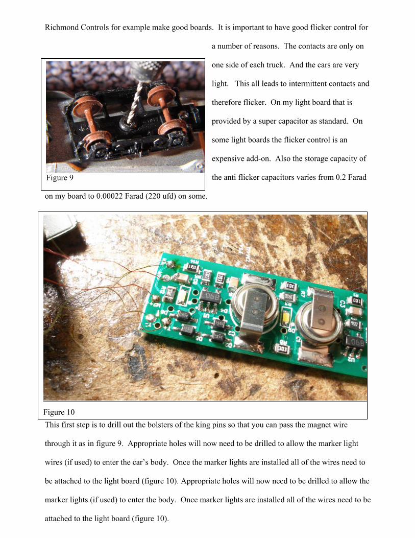
This first step is to drill out the bolsters of the king pins so that you can pass the magnet wire
through it as in figure 9. Appropriate holes will now need to be drilled to allow the marker light
wires (if used) to enter the car’s body. Once the marker lights are installed all of the wires need to
be attached to the light board (figure 10). Appropriate holes will now need to be drilled to allow the
marker lights (if used) to enter the body. Once marker lights are installed all of the wires need to be
attached to the light board (figure 10).
Figure 9
Figure 10

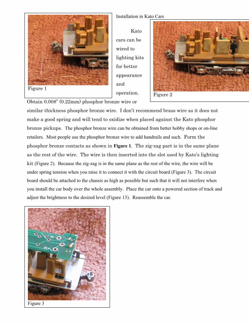
Installation in Kato Cars
Kato
cars can be
wired to
lighting kits
for better
appearance
and
operation.
Obtain 0.008” (0.22mm) phosphor bronze wire or
similar thickness phosphor bronze wire. I don’t recommend brass wire as it does not
make a good spring and will tend to oxidize when placed against the Kato phosphor
bronze pickups. The phosphor bronze wire can be obtained from better hobby shops or on-line
retailers. Most people use the phosphor bronze wire to add handrails and such. Form the
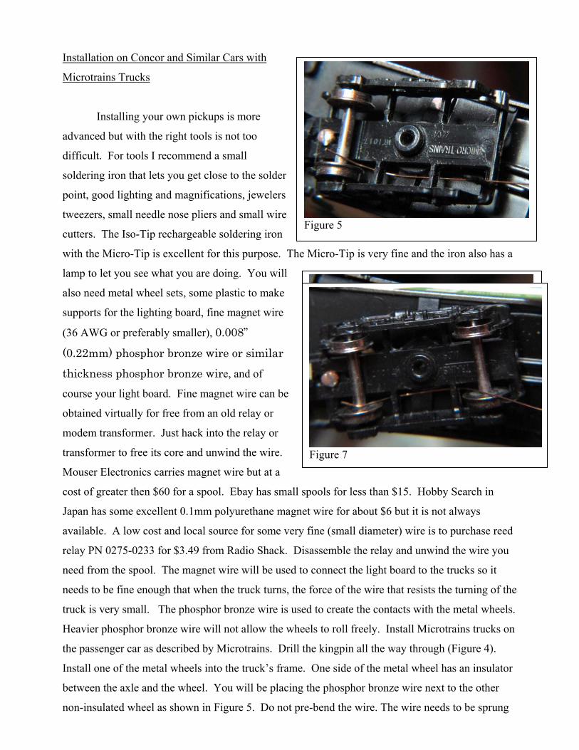
phosphor bronze contacts as shown in Figure 1. The zig-zag part is in the same plane
as the rest of the wire. The wire is then inserted into the slot used by Kato’s lighting
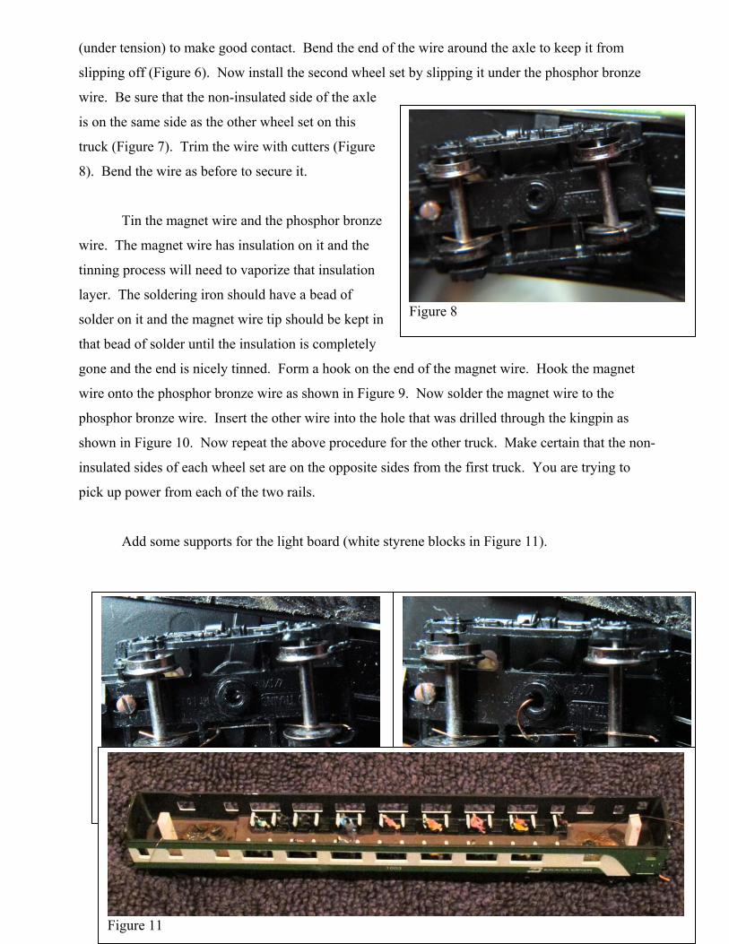
kit (Figure 2). Because the zig-zag is in the same plane as the rest of the wire, the wire will be
under spring tension when you raise it to connect it with the circuit board (Figure 3). The circuit
board should be attached to the chassis as high as possible but such that it will not interfere when
you install the car body over the whole assembly. Place the car onto a powered section of track and
adjust the brightness to the desired level (Figure 13). Reassemble the car.
Figure 1
Figure 2
Figure 3
Installation on Concor and Similar Cars with
Microtrains Trucks
Installing your own pickups is more
advanced but with the right tools is not too
difficult. For tools I recommend a small
soldering iron that lets you get close to the solder
point, good lighting and magnifications, jewelers
tweezers, small needle nose pliers and small wire
cutters. The Iso-Tip rechargeable soldering iron
with the Micro-Tip is excellent for this purpose. The Micro-Tip is very fine and the iron also has a
lamp to let you see what you are doing. You will
also need metal wheel sets, some plastic to make
supports for the lighting board, fine magnet wire
(36 AWG or preferably smaller), 0.008”
(0.22mm) phosphor bronze wire or similar
thickness phosphor bronze wire, and of
course your light board. Fine magnet wire can be
obtained virtually for free from an old relay or
modem transformer. Just hack into the relay or
transformer to free its core and unwind the wire.
Mouser Electronics carries magnet wire but at a
cost of greater then $60 for a spool. Ebay has small spools for less than $15. Hobby Search in
Japan has some excellent 0.1mm polyurethane magnet wire for about $6 but it is not always
available. A low cost and local source for some very fine (small diameter) wire is to purchase reed
relay PN 0275-0233 for $3.49 from Radio Shack. Disassemble the relay and unwind the wire you
need from the spool. The magnet wire will be used to connect the light board to the trucks so it
needs to be fine enough that when the truck turns, the force of the wire that resists the turning of the
truck is very small. The phosphor bronze wire is used to create the contacts with the metal wheels.
Heavier phosphor bronze wire will not allow the wheels to roll freely. Install Microtrains trucks on
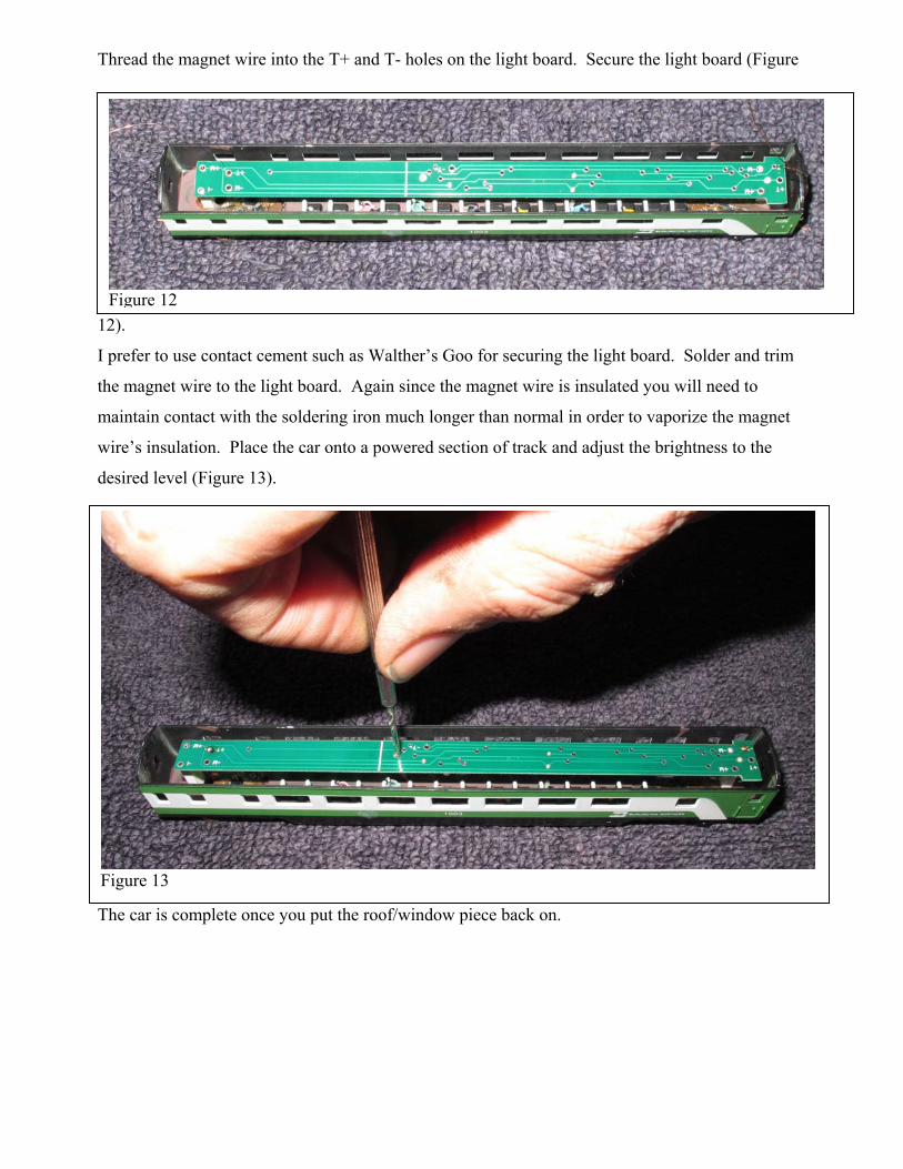
the passenger car as described by Microtrains. Drill the kingpin all the way through (Figure 4).
Install one of the metal wheels into the truck’s frame. One side of the metal wheel has an insulator
between the axle and the wheel. You will be placing the phosphor bronze wire next to the other
non-insulated wheel as shown in Figure 5. Do not pre-bend the wire. The wire needs to be sprung
Figure 5
Figure 6
Figure 7
(under tension) to make good contact. Bend the end of the wire around the axle to keep it from
slipping off (Figure 6). Now install the second wheel set by slipping it under the phosphor bronze
wire. Be sure that the non-insulated side of the axle
is on the same side as the other wheel set on this
truck (Figure 7). Trim the wire with cutters (Figure
8). Bend the wire as before to secure it.
Tin the magnet wire and the phosphor bronze
wire. The magnet wire has insulation on it and the
tinning process will need to vaporize that insulation
layer. The soldering iron should have a bead of
solder on it and the magnet wire tip should be kept in
that bead of solder until the insulation is completely
gone and the end is nicely tinned. Form a hook on the end of the magnet wire. Hook the magnet
wire onto the phosphor bronze wire as shown in Figure 9. Now solder the magnet wire to the
phosphor bronze wire. Insert the other wire into the hole that was drilled through the kingpin as
shown in Figure 10. Now repeat the above procedure for the other truck. Make certain that the non-
insulated sides of each wheel set are on the opposite sides from the first truck. You are trying to
pick up power from each of the two rails.
Add some supports for the light board (white styrene blocks in Figure 11).
Figure 8
Figure 9
Figure 10
Figure 11
Thread the magnet wire into the T+ and T- holes on the light board. Secure the light board (Figure
12).
I prefer to use contact cement such as Walther’s Goo for securing the light board. Solder and trim
the magnet wire to the light board. Again since the magnet wire is insulated you will need to
maintain contact with the soldering iron much longer than normal in order to vaporize the magnet
wire’s insulation. Place the car onto a powered section of track and adjust the brightness to the
desired level (Figure 13).
The car is complete once you put the roof/window piece back on.
Figure 12
Figure 13
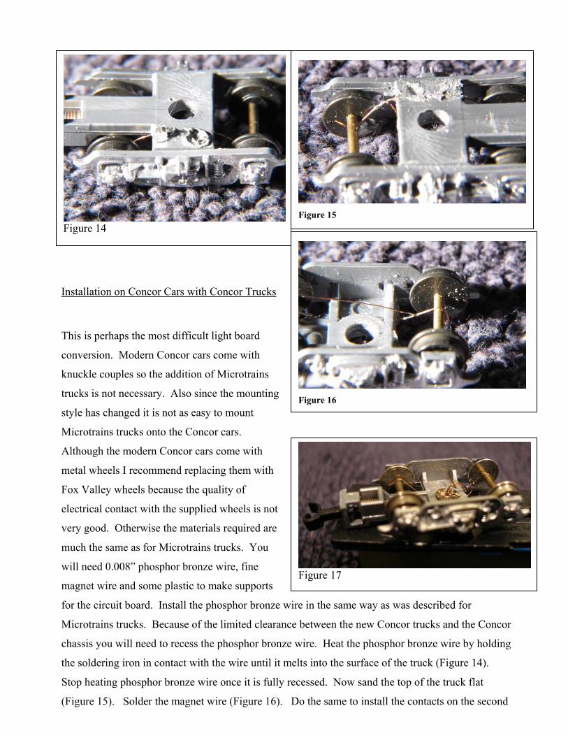
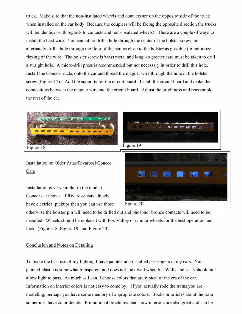
Installation on Concor Cars with Concor Trucks
This is perhaps the most difficult light board
conversion. Modern Concor cars come with
knuckle couples so the addition of Microtrains
trucks is not necessary. Also since the mounting
style has changed it is not as easy to mount
Microtrains trucks onto the Concor cars.
Although the modern Concor cars come with
metal wheels I recommend replacing them with
Fox Valley wheels because the quality of
electrical contact with the supplied wheels is not
very good. Otherwise the materials required are
much the same as for Microtrains trucks. You
will need 0.008” phosphor bronze wire, fine
magnet wire and some plastic to make supports
for the circuit board. Install the phosphor bronze wire in the same way as was described for
Microtrains trucks. Because of the limited clearance between the new Concor trucks and the Concor
chassis you will need to recess the phosphor bronze wire. Heat the phosphor bronze wire by holding
the soldering iron in contact with the wire until it melts into the surface of the truck (Figure 14).
Stop heating phosphor bronze wire once it is fully recessed. Now sand the top of the truck flat
(Figure 15). Solder the magnet wire (Figure 16). Do the same to install the contacts on the second
Figure 14
Figure 15
Figure 16
Figure 17
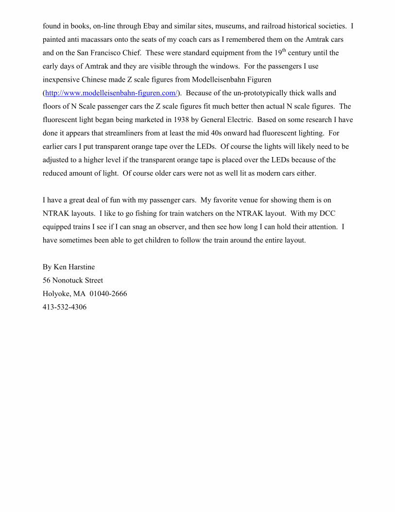
truck. Make sure that the non-insulated wheels and contacts are on the opposite side of the truck
when installed on the car body (Because the couplers will be facing the opposite direction the trucks
will be identical with regards to contacts and non-insulated wheels). There are a couple of ways to
install the feed wire. You can either drill a hole through the center of the bolster screw, or
alternately drill a hole through the floor of the car, as close to the bolster as possible (to minimize
flexing of the wire. The bolster screw is brass metal and long, so greater care must be taken to drill
a straight hole. A micro-drill press is recommended but not necessary in order to drill this hole.
Install the Concor trucks onto the car and thread the magnet wire through the hole in the bolster
screw (Figure 17). Add the supports for the circuit board. Install the circuit board and make the
connections between the magnet wire and the circuit board. Adjust the brightness and reassemble
the rest of the car.
Installation on Older Atlas/Rivarossi/Concor
Cars
Installation is very similar to the modern
Concor car above. If Rivarossi cars already
have electrical pickups then you can use those
otherwise the bolster pin will need to be drilled out and phosphor bronze contacts will need to be
installed. Wheels should be replaced with Fox Valley or similar wheels for the best operation and
looks (Figure 18, Figure 19. and Figure 20).
Conclusion and Notes on Detailing
To make the best use of my lighting I have painted and installed passengers in my cars. Non-
painted plastic is somewhat transparent and does not look well when lit. Walls and seats should not
allow light to pass. As much as I can, I choose colors that are typical of the era of the car.
Information on interior colors is not easy to come by. If you actually rode the trains you are
modeling, perhaps you have some memory of appropriate colors. Books or articles about the train
sometimes have color details. Promotional brochures that show interiors are also great and can be
Figure 18
Figure 19
Figure 20
found in books, on-line through Ebay and similar sites, museums, and railroad historical societies. I
painted anti macassars onto the seats of my coach cars as I remembered them on the Amtrak cars
and on the San Francisco Chief. These were standard equipment from the 19th century until the
early days of Amtrak and they are visible through the windows. For the passengers I use
inexpensive Chinese made Z scale figures from Modelleisenbahn Figuren
(http://www.modelleisenbahn-figuren.com/). Because of the un-prototypically thick walls and
floors of N Scale passenger cars the Z scale figures fit much better then actual N scale figures. The
fluorescent light began being marketed in 1938 by General Electric. Based on some research I have
done it appears that streamliners from at least the mid 40s onward had fluorescent lighting. For
earlier cars I put transparent orange tape over the LEDs. Of course the lights will likely need to be
adjusted to a higher level if the transparent orange tape is placed over the LEDs because of the
reduced amount of light. Of course older cars were not as well lit as modern cars either.
I have a great deal of fun with my passenger cars. My favorite venue for showing them is on
NTRAK layouts. I like to go fishing for train watchers on the NTRAK layout. With my DCC
equipped trains I see if I can snag an observer, and then see how long I can hold their attention. I
have sometimes been able to get children to follow the train around the entire layout.
By Ken Harstine
56 Nonotuck Street
Holyoke, MA 01040-2666
413-532-4306