Embed Size (px)
Citation preview
Wear, 139 (1990) 195-208 195
THE FORMATION OF A PROTECTIVE OXIDE LAYER IN MACHINING RJ3SULPHURIZED FREE-CUTI’ING STEELS AND CAST IRONS*
Y. YAMANE, H. USUKI, B. YAN and N. NARUTAKI
Deparhnent of Mechanical Engineering, Hiroshima University, Shitami Sajjo-Cho, Higashi-Hiroshima-City, 724 (Japan.
The effect of a protective oxide layer on tool surfaces in machining resulphurized steels and cast irons has been studied. In the case of resulphurized steels a protective layer was formed on Tic-added carbide tools and alumina ceramic tools when cutting steels containing a high level of oxygen and proper contents of ahuninium and silicon, and the layer suppressed the wear of these tools. A protective layer was also observed on silicon nitride ceramic tools when turning cast irons containing a high level of oxygen and a proper content of aluminium. The wear of the ceramic tool in cutting FeSi deoxidized resulphurized steels was serious, and in some cases the crater depth of the tool became larger than that of the carbide tool.
1. Introduction
For newly developed automatic manufacturing processes such as flexible manufacturing cell (FhIC) or flexible manufacturing system (FMS), the ma- chinability of the work material (especially the tool wear and the breakability of the chips) is an important factor in improving productivity. One of the steels which has outstanding chip breakability is resulphurized steel. However, since the steel was developed in the age of high speed steel (HSS) tools, it has insufficient machinability from the point of view of tool wear when cutting with carbide or ceramic tools under high cutting speed. Cast iron also shows excellent chip breakabiliw, though its machinability under high cutting speed is not so good.
On the other hand, it is well known that a protective oxide layer is deposited on tools when cutting work materials that have undergone some kind of deoxidation process [ 1, 21.
The purpose of this paper is to clarify the machinability of resulphurized steels treated with several kinds of deoxidation process under high cutting
*Paper presented at The Institute of Metals 1st International Conference on the Behaviour of Materials in Machining, Stratford-upon-Avon, U.K., November 8-10, 1988.
Elsevier Sequoia/Printed in The Netherlands

speed, and to study the relation between the tool wear and the contents of aluminium, silicon and oxygen in the work materials.
2. Work materials and cutting conditions
The chemical composition and hardness of the tested work materials are listed in Table 1. The materials are separated into two groups. Group 1 comprises resulphurized steels melted in a 150 kG high frequency furnace; the steels marked 1OCS and 30CS are not deoxidized while the other steels are deoxidized with FeSi or FeSifAl. Group 2 comprises cast irons; grey cast iron (FC25), continuous cast iron (FC25CC) and ductile cast iron (FCD40) were tested. The diameters of these work materials were 70-100 mm and the lengths were 600-700 mm.
Turning tests were conducted under dry cutting conditions using a 11 kW stepless speed-controlled lathe. Tic-added carbide tools (IS0 PlO), pure alumina ceramic tools and silicon nitride ceramic tools were mainly used. All tools were commercially available inserts (IS0 SNGN120408) and the tool angles were (- 5”, -5”, 5”, 5”, 15”, 15”, 0.8”). Other cutting conditions, such as cutting speed (v), cutting time (t), depth of cut (d) and feed rate v), are listed in each figure.
In order to check the composition of the adhered layer on the worn surface of the tested tools, an energy-dispersive X-ray analysis (EDXA; Horiba, Model 1700) was used.
3. Results
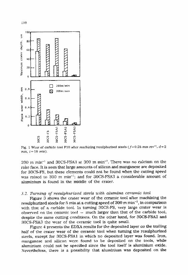
3.1. Turning of resulphurized steels with carbide tool Figure 1 shows the tool wear after machining the resulphurized steels
for 10 min at cutting speeds of 200 and 300 m mm-‘. Concerning the influence of deoxidation on flank wear, it is seen that the deoxidized steels show better machinability than rimmed steel 30CS at both cutting speeds. In particular, in turning 30CS-FSA3, the flank wear of the tool is very small even at a cutting speed of 300 m min-I. The crater wear was also the smallest in machining 3OCS-FAS3. However, in turning 300CS-FS, 3OCSFSAl and 30CS-FSA2, the crater wear of the tool is relatively small at a cutting speed of 200 m mm-‘, while at 300 m mm-’ the wear becomes very large and is almost the same as that of rimmed steel 30CS.
The deposited layer on the worn surface of the tool was examined by EDXA. However, in turning 3OCS, 30CS-FSAl and 30CS-FSA2, there were found to be no deposited elements on the worn part except for iron, manganese and sulphur, which have no effect on reducing the carbide tool wear by themselves at high cutting speed [3].
Figure 2 shows the distribution of iron, manganese, aluminium and silicon on the rake face of the carbide tool in turning 30CS-FS at

TA
BL
E
1
Ch
emic
al
com
posi
tion
an
d ha
rdne
ss
of
wor
k m
ater
ials
Gro
up
DeS
i@T
UlI
ion
Deo
xidi
zer
Che
mic
al
com
posi
tion
(w
t.%)
Har
dnes
s H
B
1ocs
3o
cs
3ocs
-Fs
3OC
S-F
SA
l 3o
cs-F
SA
2 3O
CS
-FS
A3
FC
25
FC
25-C
C
FC
D40
- - FeS
i F
eSi+
Al
FeS
i +
Al
FeS
i+A
l
c S
i M
n P
S
Al
0 (m
m)
0.08
0.
006
1.00
0.
065
0.33
2 0.
003
164
0.28
0.
05
0.84
0.
011
0.10
1 0.
001
102
0.27
0.
17
0.93
0.
011
0.10
5 T
race
10
2 0.
30
0.19
1.
00
0.10
0.
098
0.01
8 16
0.
25
0.19
0.
95
0.01
1 0.
111
0.00
49
39
0.28
0.
19
0.99
0.
011
0.10
5 0.
006
80
3.35
2.
08
0.58
0.
140
0.09
7 0.
011
71
3.28
2.
59
0.37
0.
091
0.01
3 0.
001
27
3.44
2.
15
0.41
0.
016
0.01
4 0.
013
15
106
123
133
139
130
142
168
174
140
E 0.8
c) 200mimin
_c ij 0.6 .- 3
k T 0.4
Y = 5
0.2
LL
n
Fig. f Wear of carbide toot PI0 after machining resufphurized steels (f=O.‘& mm rev-‘, d=2 mm, I= IO min).
200 m min‘-’ and 30CS-FSA3 at 300 m min-l. There was no calcium on the rake face. It is seen that large amounts of silicon and manganese are deposited for 3OCS-FS, but these eIements could not be found when the cutting speed was raised to 300 m min-‘; and for 3~~S-FSA3 a considerable amount of aluminium is found in the middle of the crater.
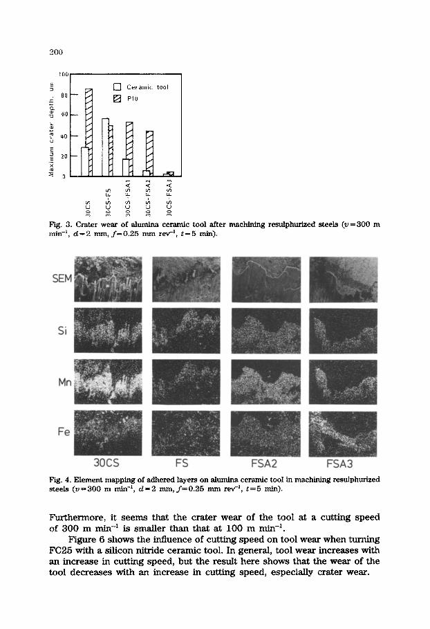
3.2. Turning of resulphurized steels with alumina ceramic tool Figurt? 3 slsows the crater wear of the ceramic tool after mach~~g the
resulphurized steels for 5 min at a cutting speed of 300 m mine’, in comparison with that of a carbide tool. In turning 30CS-FS, very large crater wear is observed on the ceramic tool - much larger than that of the carbide tool, despite the same cutting conditions. On the other hand, for 3OCS-FSAZ and 30CS-FSA3 the wear of the ceramic tool is quite small.
Figure 4 presents the EDXA results for the deposited layer on the trailing half of the crater wear of the ceramic tool when turning the resuiphurized steels, except for 3OCS-FSAI in which no deposited layer was found. Iron, manganese and silicon were found to be deposited on the tools, while aluminium could not be specified since the tool itself is aluminium oxide. Nevertheless, there is a possibility that aluminium was deposited on the

199
3OCS-FS 3OCS- FSA3 (v200 basin) (v=3OO~~~in)
Fig. 2. Eiement mapping of adhered layers on carbide tool in machining SOCS-Es and 3OCS- FSA3 (f=0.25 mm rev-, (1=2 mm, t=lO min).
ceramic tool when cutting 3OCS-FSA3, because a large amount of aluminium was detected in the deposited layer on the carbide tool when cutting the same steel.
3.3. Turning of ccist irons Generally, a WC-Co-type carbide tool or an alumina ceramic tool is
used for cutting cast irons. However, it has been reported that a silicon nitride ceramic tool shows superior cutting performance for cast iron [4]. Therefore a silicon nitride ceramic tool was used for the cast irons here.
Figure 5 shows the wear patterns of the silicon nitride ceramic tool when turning cast irons. in the ease of continuous cast iron FC25-CC and ductile cast iron FCD40, large flank wear and crater wear are seen. On the other hand, the tool shows very little wear when cutting grey cast iron FC25.
80
[7 Ceramic tool
fg PlO
Fig. 3. Crater wear of ale ceramic tool after machining resulphurized steels (v=300 m min-‘, d=2 mm, f=O.25 mm reVi, t=5 min).
3ocs FS
Fig. 4. Element mapping of adhered layers on alumina ceramic tool in machining resulphurized steels (v=300 m min-‘, d=2 mm, ~=0.25 mm rev-‘, t=5 min).
Furthermore, it seems that the crater wear of the tool at a cutting speed of 300 m min-’ is smaller than that at 100 m min-‘.
Figure 6 shows the influence of cutting speed on tool wear when turning FC25 with a silicon nitride ceramic tool. In general, tool wear increases with an increase in cutting speed, but the result here shows that the wear of the tool decreases with an increase in cutting speed, especially crater wear.

FCDLO Fig. 5. Wear patterns of sticon nitride ceramic tool in machining cast irons (f=O.21 mm rev-‘, d = 1 mm).
Cutting speed mimin
Fig. 6. Influence of cutting speed on tool wear when machining FC25 with silicon nitride ceramic tool (ft0.21 mm rev-‘, d=l mm, t=lO min).
In order to verify whether this phenomenon is based on the characteristics of the silicon nitride ceramic tool or not, a WC - Co-type carbide tool grade KlO, a complex carbide tool grade PlO and an alumina ceramic tool were also tested on the cast irons. The WC-Co-type carbide tool showed normal wear characteristics, i.e. the wear of the tool increased with an increase in cutting speed. No conclusions could be drawn concerning the alumina ceramic tool since the tool showed no crater wear. However, the PlO carbide tool showed the same tendency as the silicon nitride ceramic tool, though the tendency was unstable. Therefore it can be said that the tendency appears

FC25 FC25-CC FCD40 1 I
10pm
Fig. 7. SEM photomicrographs of silicon nitride ceramic tool after cleaning in an ultrasonic bath with 10% hydrochloric acid (v=300 m min-‘, d= 1 mm, f=0.21 mm rev-‘, t= 1 min).
strongly when cutting FC25 with the silicon nitride ceramic tool. The worn part of the tool was next observed in detail by a scanning electron microscopy (SEM).
Figure 7 shows SEM microphotographs of the worn surfaces of the silicon nitride ceramic tools after machining cast irons. These tools were cleaned in an ultrasonic bath with 10% hydrochloric acid in order to eliminate metallic adhesives. Scale-like adhesives can be observed on the crater wear surface of the tool which machined FC25. On the other hand, the crater surface of the tool which machined FC25-CC looks very smooth, and a glass- like surface, as if caused by plastic deformation, can be observed on the tool which machined FCD40.
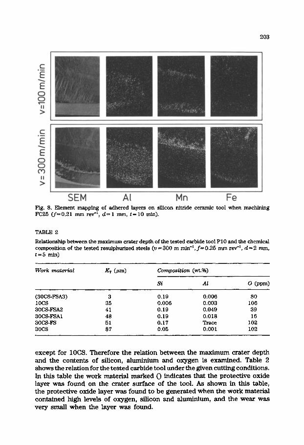
Before and after cleaning, the tools were examined by EDXA. After cleaning, no elements could be found on the worn parts, except for the elements of the tool itself, when machining FC25-CC and FCD40. However, in the case of FC25, elements which were not included in the tool were detected on the crater wear part of the tool as shown in Fig. 8. Ahuninium, manganese and iron are observed in this figure. These elements seem to have adhered in the form of oxides, because if they were adhering in metallic form they would be dissolved by the hydrochloric acid.
4. Discussion
4.1. Eflects and deposition conditions of protective oxide lager on carbide tool
As shown in Table 1, the contents of carbon, manganese, phosphorus and sulphur are almost the same among the tested resulphurized steels,
I
SEM Al Mn Fe Fig. 8. Element mapping of adhered layers on silicon nitride ceramic tool when machkdng FW5 (+0.21 mm rev-‘, d-l mm, t=10 min).
TABLE 2
Relationship between the rn~~ crater depth of the tested carbide tool PlO and the chemical com~sition of the tested r~~ph~ed steels (ZI = 300 m min-‘, f= 0.25 mm rev’, d = 2 mm, t=5 min)
Work vnatwial XT (m) cmnpositim (wt.%)
(3OCSxW3) 3 0.19 0.006 30 1ocs 35 0.006 0.003 106 3ocsF!u2 41 0.19 0.049 39 3ocs-FsA1 48 0.19 0.018 16 3ocs-Fs 51 0.17 Trace 102 3ocs 87 0.05 0.001 102
except for 1OCS. Therefore the relation between the maximum crater depth and the contents of silicon, ahm&dum and oxygen is examined. Table 2 shows the relation for the tested carbide tool under the given cutting conditions. In this table the work material marked 0 indicates that the protective oxide layer was found on the crater surface of the tool. As shown in this table, the protective oxide layer was found to be generated when the work material contained high levels of oxygen, silicon and ahuninium, and the wear was very small when the layer was found.

204
It is fairly certain that one of the largest effects of the protective oxide layer on the carbide tool is that it acts as a barrier to diffusion between the tool and the work material [3, 51 as shown in Fig. 9.
In order to produce the protective oxide layer on the tool surface, elements of the layer must be included in the work material as inclusions, and at the same time it is necessary that the inclusions be placed under the proper conditions whereby the layer can remain stable on the tool surface. Concerning the existence of the elements, this is performed by deoxidation processes. However, adhesion of the inclusions to the tool surface is not so easy, because the oxides which display a superior effect of suppressing tool wear based on diffusion, such as Al,O,, Si02 or CaO, have very poor bondability with the carbide tool under normal cutting conditions [3].
The mechanism of oxide deposition on the carbide tool is probably that the Tic in the carbide tool is oxidized by some inclusions in the work material, and the products, such as TiO or TiOz, combine with the inclusions. Therefore, in order to cause the deposition, the same oxides have to oxidize the Tic. However, A1203, SiOz and CaO cannot act as the oxidizer for the Tic, because these oxides are more stable than titanium oxide. Accordingly, oxides which are less stable than titanium oxide, such as Fe0 or MnO, are necessary to oxidize the Tic.
However, in general, Fe0 and MnO are deoxidized by deoxidation processes, especially in fully kiIled steels, whereas if the deoxidation is modified, i.e. a certain amount of oxygen remains in the work material, these oxides will be able to remain in the work material.
As regards the oxygen, it has been pointed out by Wither and Pape [ 6 ] that the oxygen content in the work material is related to the formation of the protective oxide layer on the carbide tool. Furthermore, Konig and Diederich [ 7) have pointed out that the oxygen from a cutting fluid promoted the formation of the layer during the turning operation. In addition, we have reported [8] that the oxygen from the atmosphere stimulated the formation of the layer during the milhng operation in which the oxygen content was
--“;“~ch,p jw.T~.Ta C Co Fe WC 1
Chip flow
Oxldes *
(a) @I Fig. 9. Model of (a) diffusion wear of WC- (Ti,Ta,W)C-Co cemented carbide tools [S] and (b) tool-chip interface with oxide protective layer.

205
controlled, even if the work material had so low an oxygen content as to produce no protective oxide layer during the turning operation.
4.2. Eflects of protective oxide layer on alumina ceramic tool The relationship between the oxygen, silicon and ahuninium content of
the tested ahuni.na ceramic tool is given in Table 3. The protective oxide layer was found on the crater wear of the tool when cutting the material in which oxygen, silicon and ahuninium were included at a high level, just as with the carbide tool.
However, it can be assumed that the effect of the protective oxide layer on the ah_unina ceramic tool is different from that on the carbide tool, because the ahunina ceramic tool itself is stable towards iron. However, the ceramic tends to react with other oxides. Thus if oxides which react with the alumina ceramic easily and produce low melting point complex oxides are included in the work material, the ahunina ceramic tool will show heavy wear. On the other hand, if there is no oxide in the work material or the oxides hardly react with the alumina ceramic, the wear of the tool will be less. Also, if the oxides have a suitable melting point so as to form a layer on the ceramic tool, the layer will suppress the subsequent reaction between the tool and the inclusions as shown in Fig. 10.
Therefore the melting point of the complex oxide made by the reaction between the tool and oxide inclusions is important for the ahunina ceramic tool. From this point of view, resulphurized steel has low machinability for the tool, since the MnS or MnO inclusions tend to react with the alumina ceramic, especially in the presence of SiOa. From the equilibrium diagram, the lowest melting point of the MnO -A1203 - SiOz is below 1200 “C [9].
However, if the amount of MnO in the resulphurized steel can be de- creased by ahnninium deoxidation processes, the reaction described above will be suppressed. Therefore the protective oxide layer on the ahunina ceramic tool does not act as a diffusion barrier to the reaction between the tool and iron as in the case of a carbide tool, but is the result of the reaction
TABLE 3
Relationship between the maximum crater depth of the tested ahunIna ceramic tool and the chemical composition of the tested resulphurized steels (v=300 m mine’, f-0.25 mm rev-‘, d-2 mm, t-5 min)
Work material KT (LLm) co??zpos+tion (wt.%)
Si Al 0 @pm>
(3OCSFSA3) 3 0.19 0.006 80 3ocs-FsA2 4 0.19 0.049 39 1ocs 11 0.006 0.003 106 3ocs-FSAl 15 0.19 0.018 16 3ocs 28 0.05 0.001 102 BOCS-Fs 53 0.17 Trace 102

206
/ Chip flow
-.--SW Chip flow
_----.-_- Chip flow
-3-
Oxrde layer
F’ig. 10. Model of ceramic tool-chip interface (a) with no oxide layer, (b) with low melting point oxide layer and (c) with stable oxide layer.
FSg. 11.. Fkiction coefficients calculated from cutting forces under orthogonal cutting of deoxidized steels with alumina ceramic tool (v-300 m mix+, f-O.25 mm rev-‘, d-2 mm, t-30 s).
between the tool and the inclusions in the work material. However, of course, the protective layer suppresses the subsequent reaction between the tool and the inclusions; and furthermore, the layer seems to act as a lubricant, since the coefficient of friction between the tool and the work material becomes small as shown in Fig. 11.
4.3. @$ects of protective o& lager on silicon nittide ceramic tool As shown in Fig. 5, the wear of the tested silicon nitride ceramic tool
became extremely large in cutting FC25-CC and FCD40, while in cutting FC25 the wear of the tool became very small and a large amount of aluminium was found on the rake face of the tool.
It is well known that a silicon nitride ceramic tool shows extremely large wear in cutting steels. Also, it has been reported that the predi&ed reiative dissolution wear rate of S&N, for steel is 16 times larger than that

207
of WC [lo]. Consequently, it is almost certain that a silicon nitride ceramic tool has very poor wear resistance for steels.
Therefore, in order to suppress the tool wear, a protective layer which acts as a diEusion barrier is effective. As the protective layer, two different cases can be supposed, i.e. oxide inclusions in a work material deposited on the tool surface, or the tool surface itself is oxidized.
In the former case the deposition conditions must be satisfied, i.e. the elements of the layer must be included in the work material and the inclusions have to oxidize the tool surface, just as in the case of a carbide tool. The chemical composition of the tested grey cast iron FC25 satisfies the deposition conditions.
The latter case is based on the fact that SiOz is far more stable towards iron than Si3N4. In fact, the wear of the silicon nitride ceramic tool is influenced by the oxygen content of the atmosphere in face milling [8].
5. Conclusions
In order to improve the machinability of resulphurized steels using carbide tools or ahunina ceramic tools under high cutting speed, a protective oxide layer deposited on the tool surface is effective. The protective oxide layer was found when cutting steels which have relatively high contents of oxygen, silicon and ahnninium.
The wear of the tested alumina ceramic tool was larger than that of the carbide tool when cutting FeSi deoxidized resulphurized steel at high cutting speed, even though the same cutting conditions were used.
In the case of cutting grey cast iron FC25 with a silicon nitride ceramic tool, the wear of the tool at high cutting speed was smaller than that at low cutting speed, and a protective oxide layer was found on the tool surface at high cutting speed.
References
1 H. Opitz and W. Konig, Zerspanbarkeit von Werkstucken aus verschiedenen Schmenzen des Stahles CK45, Arch. Eisenhui., Wes., 33 (1962) 831.
2 H. Opitz, M. Gappisch, W. Konig, R. Pape and A. Wither, Ein6u oxidischer Einschhrsse auf die Bearbeitbarkeit von Stahl CK45 mit Hartmetah-Drehwerkzeugen, Arch. Eisenhti., Wes., 33 (1962) 841.
3 N. Narutaki and Y. Yamane, Effect of non-metallic inclusions on the diffusion wear of cutting tools, J. JSPE, 48 (4) (1982) 463.
4 M. Pukuhara, K. Pukaaawa and A. Fukawa, Physical properties and cutting performance of silicon nitride ceramic, Wear, 102 (1985) 195.
5 Y. Naerheim and E. M. Trent, Diffusion wear of cemented carbide tools when cutting steel at high speeds, Met. Techml., 4 (12) (1977) 548.
6 A. Wither and R. Pape, MetaRurgische Voraussetzungen Pur die Bildung oxydischer Belage auf Hartmetallwerkzeugen bie Zerspanung von Stahl, Stahl u. Eisen, 87 (1967) 1262.
7 W. Konig and N. Diederich, Cutting fluids improve tool-life of carbide tools by chemical reactions, Ann.CIRP, 17 (1969) 17.

208
8 Y. Yamane, H. Usuki and N. Narutaki, The effects of oxygen in workpiece or in atmosphere on tool wear, Proc. 6th Znt. Cm. cm Production Engineering, The Japan Society of Precision Engineering, 1987, p.161
9 R. B. Snow, Equilibrium relationship on the liquids surface in part of the MnO -Al,03 - SiOz system, J. Am. Gram. Sot., 26 (1943) 11.
10 B. M. Kramer, On tool materials for high speed machining, Trans. ASME, .J. Eng. Znd.,
109 (1987) 87.