Embed Size (px)
Citation preview
High-speed machining of cast iron and alloy steels fordie and mold manufacturing
P. FallboÈhmer, C.A. RodrõÂguez, T. OÈ zel, T. Altan*
Engineering Research Center for Net Shape Manufacturing, The Ohio State University, 339 Baker Systems Building,
1971 Neil Avenue, Columbus, OH 43210-1271 USA
Abstract
This paper gives a brief overview of HSC technology and presents current progress in high performance machining of cast iron and alloy
steels used in die and mold manufacturing. This work covers: (a) theoretical and experimental studies of tool failure and tool life in
high-speed milling of hard materials, (b) optimization of CNC programs by adjusting spindle RPM and feed rate (program OPTIMILL) to
maintain nearly constant chip load in machining sculptured surfaces, and (c) prediction of chip ¯ow, stresses and temperatures in the cutting
tool as well as residual stresses in the machine surface layer. Experimental studies are conducted using a 4-axis high-speed milling machine.
Tool materials evaluated include carbides, coated carbides, and PCBN. Workpiece materials investigated include H-13 at 46 HRC, P-20 at
20±40 HRC and cast iron. # 2000 Elsevier Science S.A. All rights reserved.
Keywords: HSC technology; CNC programs; Cast iron
1. Introduction
As a result of the advances in machine tools and cutting
tool technology, end milling at high rotation speeds, `̀ High-
speed Milling/Machining (HSM)'', became a cost-effective
manufacturing process to produce parts with high precision
and surface quality. Until recently, high-speed milling was
applied to machining of aluminum alloys for manufacturing
complicated parts used in the aircraft industry. This tech-
nology has been successfully utilized with signi®cant
improvements in machine tools, spindles and controllers
[1]. Recently, with the advance of cutting tool technologies,
HSM has been employed for machining alloy steels (usually
hardness > 30 HRC) for making dies/molds used in the
production of a wide range of automotive and electronic
components, as well as plastic molding parts [2]. The
de®nition of high-speed machining is based on the type
of workpiece material being machined. Fig. 1 shows gen-
erally accepted cutting speeds in high-speed machining of
various materials [3]. For instance, a cutting speed of 500 m/
min is considered high-speed machining for cutting alloy
steel whereas this speed is considered conventional in cut-
ting aluminum.
Major advantages of high-speed machining are reported
as: high material removal rates, the reduction in lead times,
low cutting forces, dissipation of heat with chip removal
resulting in decrease in workpiece distortion and increase
part precision and surface ®nish. However, problems related
to the application of high-speed machining differ depending
on the work material and desired product geometry. The
common disadvantages of high-speed machining are
claimed to be: excessive tool wear, need for special and
expensive machine tools with advanced spindles and con-
trollers, ®xturing, balancing the tool holder, and lastly but
most importantly the need for advanced cutting tool materi-
als and coatings.
Parallel to the increase in high-speed machining applica-
tions, there is also an increase in research for the develop-
ment of new cutting tool materials, improved design of
cutting tool inserts, new strategies in CNC cutter path
generation, and improvement of cutting process conditions.
Furthermore, computer aided simulation of cutting pro-
cesses are emerging as useful techniques for predicting tool
temperatures and stresses and for extending tool life.
Along with machining of castings, die and mold manu-
facturing represents a signi®cant area of application for HSC
of cast iron, cast steel and alloy steels. In leading industrial
countries, in die and mold manufacturing, a signi®cant
portion of the lead-time is spent for machining and polishing
Journal of Materials Processing Technology 98 (2000) 104±115
* Corresponding author. Tel.: +1-641-292-9267; fax: +1-614-292-7219.
E-mail address: [email protected] (T. Altan)
0924-0136/00/$ ± see front matter # 2000 Elsevier Science S.A. All rights reserved.
PII: S 0 9 2 4 - 0 1 3 6 ( 9 9 ) 0 0 3 1 1 - 8

operations, as illustrated in Fig. 2. Therefore, the machining
and polishing portion of dies/molds takes approximately two
third of the total manufacturing costs [4]. High-speed
milling is being used to reduce lead-times and manufactur-
ing costs.
1.1. High-speed cutting: process technology
Machining of alloy steels in hardened state (usually
hardness > 30 HRC) is a cost-effective technology using
advanced machine tools and cutting tools. Furthermore,
machining of alloy steels in hardened state and at high
cutting speeds, offers several advantages such as: reduction
of ®nishing operations, elimination of distortion if the part is
®nish-machined after heat treatment, achievement of high
metal removal rates, lower machining costs and improved
surface integrity [5,6]. In manufacturing of dies and molds
from tool steels, HSM at hardened state replaces the slow
EDM processes in many applications. HSC of hard steels,
however, result in high temperatures and stresses at the
workpiece-tool interface. Consequently, cost-effective
application of this technology requires a fundamental under-
standing of the relationships between process variables on
one hand and tool life and machined surface integrity on the
other hand. Thus, it is necessary to understand how tem-
peratures and stresses developed during HSC, in¯uence tool
wear and premature tool failure (or chipping) as well as
residual stresses on machined surfaces.
Experimental data show that when machining hardened
steels workpiece material microstructure (not only the hard-
ness) and thermal properties affect the chip ¯ow. It is
common to observe higher cutting forces with higher work-
piece hardness. However, it is also observed that different
thermal properties of the tool material may result in lower
cutting forces [7,8]. Therefore, in order to understand the
process better and improve the performance of cutting tools,
the use of deformation theory and advanced numerical
techniques is recommended.
In machining hard materials, continuous chip formation is
observed at conventional to high cutting speeds and low to
moderate feed rates (see Fig. 3(a)). However, at higher feed
rates `̀ saw-tooth'' chips are produced, (see Fig. 3(b)) [9].
The latter type of chip formation can cause cyclic variations
of both cutting and thrust forces and can result in high
frequency vibrations that affect tool life and failure [10].
Recent studies using interrupted cuts and micrographic
investigations illustrate that the formation of `̀ saw-tooth''
chips is due to periodic formation of cracks ahead of the
tool, as seen in Fig. 3(b), [6,11]. The fracture on the surface
of the workpiece propagates inside the chip until the stress
state is altered from a low to high compressive stress region
[12,13].
Common chip types observed in hard part machining are
continuous chips at low undeformed chip thicknesses and
saw-tooth shape at high undeformed chip thickness (usual-
ly > 0.1 mm). According to recent observations, the fre-
quency of shear localized saw-tooth shape chips is very
high [10]. The cutting edge is subjected to a high frequency
force variation. The in¯uence of chip formation on tool wear
and surface integrity is not yet well understood. However,
the chip formation certainly affects the cutting forces.
Fig. 1. High-speed cutting ranges in machining of various materials [3].
Fig. 2. Lead-times in production of dies/molds.
Fig. 3. Illustration of chip formation during machining of hard steels [6].
P. FallboÈhmer et al. / Journal of Materials Processing Technology 98 (2000) 104±115 105

1.2. High-speed cutting: machining system
1.2.1. Machine tools and controllers
In high-speed machining, various con®gurations of
machine tools are being used. However, three-axis horizon-
tal and vertical milling centers (HMC/VMC) are the most
common con®guration. Although vertical machining centers
have disadvantages concerning chip removal, they are the
less expensive choice and, therefore, are presently more
widely used than horizontal machining centers. However, in
making new investments in HSM, the trend is certainly to
use HMC's. CNC four-axis milling offers the option of
tilting the milling cutter to improve the cutting conditions
[14]. Five-axis machines with interchangeable spindle units
allow to rough, semi-®nish and ®nish machine with a single
set-up [17].
There are many high-performance (10 000±50 000 rpm
spindle speed, 7.5�40 kW spindle power and 10±60 m/
min feed rate) machining centers available on the market
and details are given in a recent work [2]. High-speed
machining requires high levels of rigidity, rigid spindles
with very low vibration characteristics and balanced tool
holders with shrink ®ts. The servos and controls must be
advanced enough to support look-ahead and quick response
times, and a high data transfer capability to handle larger
sized programs and avoid `̀ data starvation''. The CAM
system and look±ahead systems must allow the machine
tool to accelerate and decelerate most ef®ciently for tool
compensation [22]. Present machine tool technology allows
increasingly the use of high velocity linear motor drives, 3D
contouring feed rates over 12 m/min, and acceleration and
deceleration rates approaching 1.0 g [23]. In high-speed
machining research at the Net Shape Manufacturing Labora-
tory, a four-axis horizontal machining center (Makino A55
Delta) was used, Fig. 4.
1.2.2. Cutting tools
Among the cutting tools used for machining castings and
alloy steels, carbide is the most common cutting tool
material. Carbide tools have a high degree of toughness
but poor hardness compared to advanced materials such as
cubic boron nitrite (CBN) and ceramics. In order to improve
the hardness and surface conditions, carbide tools are coated
with hard coatings such as TiN, TiAlN and TiCN, and
recently with double/soft coatings such as MOVIC. Other
cutting tool materials used are; ceramics (AlO, SiN), cermet
and polycrystalline diamond (PCD) [15].
In general, tools ranging from 1.5 to 0.5 in. in diameter,
carbide insert tools with TiCN coatings are suf®cient for
materials with less than 42 HRC, while AlTiN coatings are
used for materials with 42 HRC and over [16]. However,
depending on the application, materials and coatings for the
best performance vary. The properties of cutting tool mate-
rials are given in Table 1. High-speed cutting application for
such tool materials and coatings can be classi®ed as: CBN
and SiN for cast iron, TiN and TiCN coated carbide for alloy
steel up to 42 HRC and TiAlN and AlTiN coated carbide for
alloy steels 42 HRC and over. For special applications,
especially hard turning (HRC 60±65), PCBN inserts with
appropriate edge preparation are also successfully used.
1.3. High-speed machining of castings, dies and molds
Dies and molds are composed of functional and support
components that generally are cavity and core inserts in
injection molding and die casting, die cavities in forging,
and punch and die in stamping. Cavity and core inserts are
usually machined out of solid blocks of die steel. However,
large stamping dies and punches are often cast to near-®nal
geometry with a machining allowance. Support components
are standard parts and assure the overall functionality of the
tooling assembly in such areas as alignment, part ejection,
and heating or cooling. By using standard die and mold
components, the time necessary for manufacturing a die is
reduced, and machining is mainly devoted to producing the
core and cavity, or the punch and the die.
1.3.1. Die and mold materials
According to a recent survey [4], 50% of the surveyed die
and mold manufacturers are involved in manufacturing
Fig. 4. High-speed milling center used in present research.
106 P. FallboÈhmer et al. / Journal of Materials Processing Technology 98 (2000) 104±115

injection molds. In US, the most common mold material is
P20 mold steel in prehardened conditions of 30 HRC.
Forging dies as well as die-casting dies mainly consist of
H13 at a hardness range from 45 to 60 HRC for forging dies
and 46±50 HRC for die-casting dies. The most common die
and mold materials are listed in Table 2.
1.3.2. Surface quality
Finish machining requires the largest share of manufac-
turing lead time for injection molds, die-casting dies and
forging dies (25±30% of total lead time). In the speci®c case
of large automotive stamping dies, ®nish machining is also a
signi®cant portion of the total production time [4]. Finish
machining also has an impact on benching time (grinding
and polishing) which is about 15% for injection molds and
die-casting dies and about 20% is sheet metal forming dies
[4]. By ®nish machining with smaller step over distances,
the scallop height is reduced, allowing in turn a reduction of
the benching time.
Surface requirements for injection molds are higher than
that for forging and stamping dies. The average values for
dimensional and form error are given in Table 3. In die/mold
manufacturing, the main purpose of high-speed milling is to
reduce or even eliminate manual polishing and reduce the
time for ®nish machining. An improved surface ®nish can be
achieved through (a) an increased number of ®nishing paths
or (b) a cutter with a larger diameter. The stepover distance
ae in combination with the cutter diameter D determines the
theoretical surface roughness Rth:
Rth � D
2ÿ
����������������D2 � a2
e
4
r: (1)
Since the maximum cutter diameter is often limited by the
part geometry, the theoretical surface roughness can only be
minimized by decreasing the stepover distance. If the step-
over distance is decreased by 50%, the number of cutter
paths automatically increases by 100%, which means it
takes twice as long to ®nish the part. To compensate for
the increased time, higher feed rates are necessary. Higher
feed rates require higher spindle speeds to assure a constant
chip thickness, which automatically results in higher cutting
speeds. Elevated temperatures and accelerated tool wear are
the unavoidable consequences.
2. Applications of high-speed milling
High-speed milling of aluminum alloys is well known and
practiced extensively in aerospace industry for more than a
decade. Recent applications of HSM are mainly in hard
turning, die/mold manufacturing and machining of castings.
At ERC/NSM, the materials listed in Table 2, cast iron, D2
(59 HRC), P20 (30 HRC), and H13 (46 HRC) were inves-
tigated as workpiece materials for the high-speed milling
applications. The alloyed cast iron with the GM speci®ca-
tion GM241 (at hardness of 210 HBN) is primarily utilized
for manufacturing stamping dies. P20 mold steel is by far the
most common steel for injection molds. Due to its low
carbon content, it is usually machined in its pre-hardened
state (30 HRC) and is subsequently case hardened to 50�55
HRC. In die casting die applications the hot work die steel
H13 is ®nish machined at 46 HRC.
The goal of the high-speed milling research, presented
here, was to determine the performance of advanced cutters,
identify recommended cutting speeds and feed rates. At the
same time, the investigation was focused on machining time
and surface ®nish. For this purpose, the milling experiments
were performed on a four-axis high-speed horizontal milling
center (Fig. 4). Indexable ball end milling inserts were used
and one of the two cutting edges was ground to avoid the
in¯uence of tool runout on tool wear.
Table 1
Properties of advanced cutting tool materials and coatings [4]
Tool materials Coatings
PCD CBN WC SiN AlO TiN TiCN TiAlN
Micro hardness (HV) 6000 3500 1500±1800 1700 1600 2900 3000 3300
Coefficient of friction against steel in dry contact ± 0.24 0.6 ± ± 0.4 0.4 0.3±0.5
Maximum working temperature (8C) 600 600 400 815
Thermal conductivity (W/m K) 500 100 40±80 15±35 14±17 ± ± ±
Transverse rupture strength (MPa) 690±965 690 1700±2000 480±750 275±345 ± ± ±
Table 2
Die and mold materials most commonly used in the US
Application Material
Injection molds Mainly P-20, S-7, H-13 and A-2
Stamping dies Mainly cast iron, D-2 and A-2
Die casting dies Mainly H-13 also S-7, 4140, P-20
Forging dies H-11, H-12, H-13 and FX steels
Table 3
Tolerance requirements for dies and molds [4]
Average dimensional
error (mm)
Average form
error (mm)
Injection molds 0.020 0.015
Die casting dies 0.046 0.041
Stamping dies 0.061 0.043
Forging dies 0.028 0.023
P. FallboÈhmer et al. / Journal of Materials Processing Technology 98 (2000) 104±115 107

The performance of PCBN, uncoated, TiN, TiCN, and
TiAlN coated carbide inserts were compared. Tool geometry
and cutter speci®cations are shown in Fig. 5. PCBN 2 with
90% CBN and a metallic binder phase was selected for all
four workpiece materials. Tests in cast iron were also
performed with PCBN 0, which contains 65% CBN and a
ceramic binder phase based on titanium nitride (TiN). The
PCBN inserts consisted of an approximately 0.8 mm thick
layer of PCBN brazed on a carbide base. For machining cast
iron, P20 and H13, the cutting edge of the PCBN inserts was
prepared with a 25 mm hone only, whereas the cutting edge
of inserts for machining D2 was prepared with a
20 � 0.1 mm chamfer and an additional 25 mm hone.
2.1. High-speed milling of cast iron
In machining of cast iron, coated carbides, CBN and SiN
are most commonly used tools. In the present study, selected
CBN grades and coated carbides were investigated. Using
TiN-coated carbide tools instead of uncoated carbide tools
increases productivity in terms of cutting speed by 25%
while tool life increases by more than 500%. In addition,
TiAlN-coated inserts ran at least three times as long as TiN-
or TiCN-coated inserts at any cutting speed, Fig. 6. How-
ever, PCBN inserts outperformed the coated carbide inserts.
Tests were aborted after A � 1.6 m2 of surface area was
machined and tool wear on PCBN 2 was measured at
VBmax � 60 mm and on PCBN 0 at VBmax � 85 mm. Abra-
sion and thermal fatigue were identi®ed as the main wear
mechanisms. Higher CBN content and higher hardness
exhibited favorable wear resistance.
To investigate the in¯uence of cutting speed on surface
®nish CBN tools were run at feed per tooth fz � 0.5 mm and
cutting speeds from Vc � 2.8 to 750 m/min. At comparably
low cutting speeds from Vc � 2.8 to 10 m/min the surface
quality was unacceptable due to the formation of built-up
edge. Surface roughness decreased with increasing cutting
speed. Once the cutting speed exceeded Vc � 300 m/min
this effect tapered off. Rz � 8.3 mm was measured at the
maximum cutting speed of Vc � 750 m/min (see Fig. 7).
Similar results were obtained for various coatings (TiN,
TiCN, TiAlN) and CBN.
Based on studies conducted at ERC/NSM and experience
gained in various die shops, the application of CBN cutting
tools in ®nishing of gray cast iron is highly recommended
because of their superior performance in terms of tool life
and surface ®nish. Harder grades of PCBN with metallic
binder phases and high CBN content such as PCBN 2 are
expected to perform better than PCBN materials with cera-
Fig. 5. Geometry and tool life criterion used for the cutting tools.
Fig. 6. Summary of all tool life experiments in pearlitic cast iron (symbols
explained in Fig. 5).
Fig. 7. Influence of cutting speed on surface finish when cutting cast iron.
108 P. FallboÈhmer et al. / Journal of Materials Processing Technology 98 (2000) 104±115

mic binder phases and lower CBN content. The difference in
tool life and surface ®nish between conventional milling and
climb milling can be neglected.
2.2. High-speed milling of P20
In machining of P20 mold steel, the performance of the
uncoated carbide inserts was inferior to the other cutting tool
materials even at the lowest cutting speed of Vc � 300 m/
min due to accelerated ¯ank and crater wear (Fig. 8). It can
be assumed that the temperatures on the cutting edge already
exceeded T � 7008C, which is the oxidation barrier for
carbide tooling. TiN-coated carbide tools performed better
than TiAlN and TiCN-coated inserts. PCBN 2 exhibited less
¯ank wear than TiN-coated tools, but failed due to chipping
after the area A � 0.56 m2 was ®nish machined.
The tests run at Vc � 550 m/min showed wear on coated
inserts developing at similar rates. Even at these conditions,
TiAlN and TiCN coatings did not outperform the TiN
coating. Wear in PCBN 2 was developing at a very slow
rate, therefore, the test was aborted after A � 1.27 m2. At
this stage, the ¯ank wear on this insert was measured to be
VB � 82 mm. The PCBN 2 insert run at Vc � 800 m/min
wore out after A � 0.375 m2 was machined. Nevertheless,
when comparing the tests run at Vc � 550 and 800 m/min, it
can be said that for approximately the same tool life,
productivity can be increased by 30% when using PCBN
2 instead of coated carbide.
As in the machining of cast iron, the PCBN 2 tools also
yielded the best surface ®nish when cutting P20, Fig. 9. The
roughness measurements were taken after the inserts
reached the end of tool life at VB � 150 mm with the
exception of PCBN 2 run at Vc � 550 m/min. With the
PCBN inserts surface roughness values Rz of less than
5 mm could be achieved at 550 m/min as well as at
800 m/min. Despite the comparably low workpiece hard-
ness, the use of a PCBN 2 cutting tool can be recommended
for ®nish-machining of P20. However, it has to be consid-
ered that the conditions prevailing at cutting speeds around
Vc � 300 m/min lead to insert fracture.
2.3. High-speed milling of H13
In machining H13 die steel, TiN-coated carbide inserts
outperformed the other coated carbide inserts as well as the
PCBN 2 inserts at cutting speeds of Vc � 300 m/min and
450 m/min, Fig. 10. For the PCBN insert, the longest tool
life in terms of ®nished area was reached at a cutting speed
of Vc � 800 m/min (A � 1875 cm2). In comparison, at these
conditions the TiN-coated inserts reached the end of tool life
criterion after an area of 750 cm2 was ®nished. Compared to
stamping dies and large injection molds, die casting dies and
forging dies consist of fairly intricate geometries. If a proper
chip thickness is supposed to be maintained, a cutting speed
of 800 m/min would require a feed rate of 6.9 m/min.
Considering the acceleration and deceleration capabilities
of machining centers available on the market today, this is
impossible to achieve on fairly small geometries. Conse-
quently, PCBN 2 inserts should not be considered and TiN
Fig. 8. Performance of different cutting materials in high-speed milling of
P20 mold steel.
Fig. 9. Surface finish achieved with different cutting materials in HSM of P20 mold steel.
P. FallboÈhmer et al. / Journal of Materials Processing Technology 98 (2000) 104±115 109

coated carbide inserts are recommended for the ®nishing of
H13 dies. The optimum cutting speed was found to be
Vc � 450 m/min.
2.4. High-speed milling of D2
In machining of D2 tool steel (59 HRC) cutting distances
were signi®cantly shorter than in the cases of H13 and P20,
though the cutting edge was prepared with a 0.1 mm � 208chamfer to improve its stability. The results of the tool life
experiments in machining D2 tool steel are shown in
Fig. 11. All inserts showed similar wear behavior. After
the ¯ank wear developed continuously to VB � 100 mm, the
end of tool life was characterized by a chipping of the cutting
edge. A maximum area of 90 cm2 was machined at a cutting
speed of 150 m/min. At Vc � 60 m/min tool life was twice as
high for PCBN than for TiN coated inserts. When the cutting
speed was increased to Vc � 150 m/min, PCBN tool life
increased by another 65%. Cutting speeds of more than
550 m/min were not practicable under these engagement
conditions, because the inserts shattered due to overstress.
It can therefore be concluded that a chip thickness of
h � 81 mm is too high for this application, because the load
on the insert exceeds its mechanical strength.
It is recommended to decrease the depth of cut, the
stepover and the feed per tooth to smaller values.
3. Advances in process analysis via finite elementmodeling
High-speed milling of hard alloy steels utilized in dies and
molds is a highly demanding operation because of the high
temperatures and stresses generated on the cutting tools due
to the high deformation rates. The fundamental relations
between the process variables (i.e. tool forces, temperatures
and stresses) and the tool performance (i.e. tool life and
surface integrity) can be better understood using computer
simulation of the cutting process. For this purpose, FEM-
based process simulations of the chip ¯ow may be utilized.
3.1. Methodology for estimating flow stress and chip-tool
contact friction
In HSM, extremely high strain rates (about l.67 � 105 sÿ1
at 500 m/min cutting speed and 0.05 mm feed) and tem-
peratures (about 14008C) at the chip-tool interface occur in
the primary and secondary deformation zones, respectively.
The material ¯ow stress (yield strength of the workpiece
material) behavior corresponding to these regimes is usually
unknown. In addition, the frictional conditions at the chip-
tool contact become dif®cult to predict as both sticking and
sliding frictions occur simultaneously. To address the issues
of ¯ow stress and friction, a methodology was developed for
determining simultaneously both the ¯ow stress of work-
piece material and the friction conditions at the chip-tool
contact interface (see Fig. 12) [18].
In high-speed orthogonal end turning experiments, cut-
ting forces, chip thickness, and chip-tool contact length are
Fig. 10. Performance of different cutting materials in HSM of H13 tool
steel.
Fig. 11. Performance of different cutting materials in high-speed milling
of D2.
Fig. 12. Methodology for determination of workpiece flow stress and
friction at chip-tool interface.
110 P. FallboÈhmer et al. / Journal of Materials Processing Technology 98 (2000) 104±115
measured. Later, FEM simulations of continuous chip ¯ow
in orthogonal cutting process were conducted. The ¯ow
stress data is iterated and FEM simulations are repeated
until the prediction error for cutting force is minimized.
Thus, matching the measured values of the cutting forces
with the predicted results from FEM simulations, a curve
®tted ¯ow stress equation and the friction parameters at the
chip-tool contact are obtained. The ¯ow stress data under
machining conditions is represented with the following ¯ow
stress model [19]:
�� � K eaT � Aeb�TÿT0�2� � _�"
_�"R
� �c
��"�d; (2)
where �� represents ¯ow stress and _�", �", T represent strain
rate, strain, and temperature, respectively. The parameter _�"R
is the reference strain rate and usually taken as 103/s. The
unknown ¯ow stress coef®cients a, b, c, A, K and T0 were
identi®ed by applying the least squares method at different
temperatures, strain rates and strains for the determined ¯ow
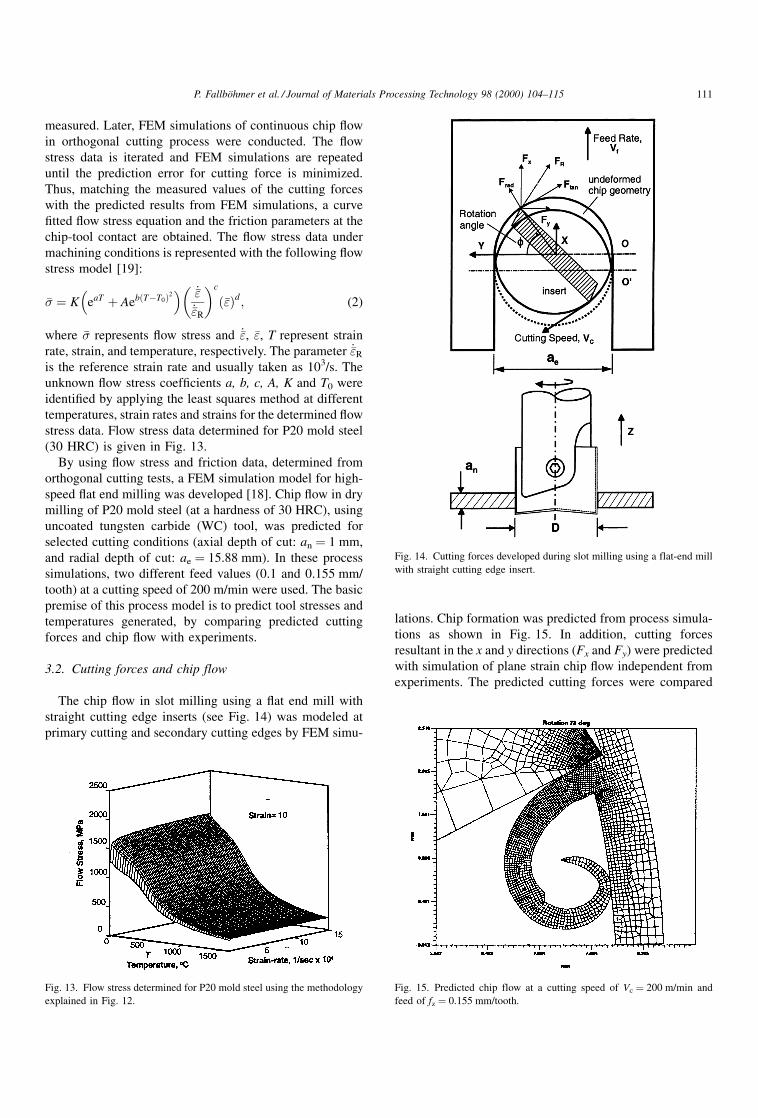
stress data. Flow stress data determined for P20 mold steel
(30 HRC) is given in Fig. 13.
By using ¯ow stress and friction data, determined from
orthogonal cutting tests, a FEM simulation model for high-
speed ¯at end milling was developed [18]. Chip ¯ow in dry
milling of P20 mold steel (at a hardness of 30 HRC), using
uncoated tungsten carbide (WC) tool, was predicted for
selected cutting conditions (axial depth of cut: an � 1 mm,
and radial depth of cut: ae � 15.88 mm). In these process
simulations, two different feed values (0.1 and 0.155 mm/
tooth) at a cutting speed of 200 m/min were used. The basic
premise of this process model is to predict tool stresses and
temperatures generated, by comparing predicted cutting
forces and chip ¯ow with experiments.
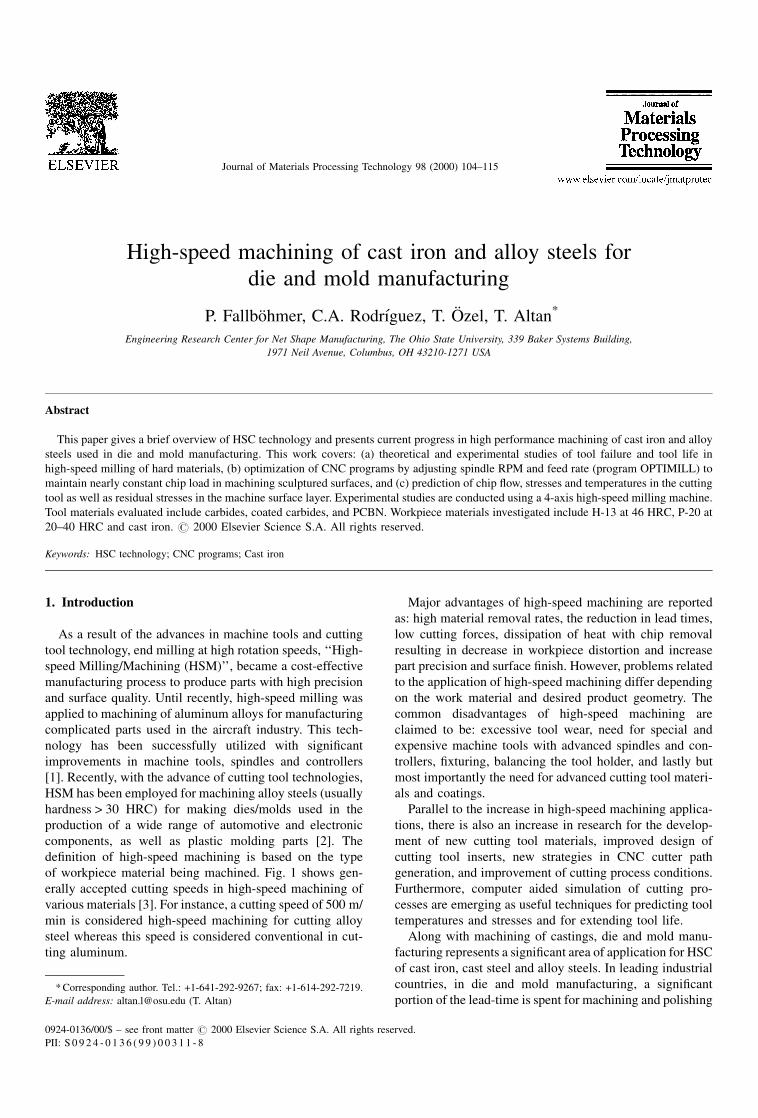
3.2. Cutting forces and chip flow
The chip ¯ow in slot milling using a ¯at end mill with
straight cutting edge inserts (see Fig. 14) was modeled at
primary cutting and secondary cutting edges by FEM simu-
lations. Chip formation was predicted from process simula-
tions as shown in Fig. 15. In addition, cutting forces
resultant in the x and y directions (Fx and Fy) were predicted
with simulation of plane strain chip ¯ow independent from
experiments. The predicted cutting forces were compared
Fig. 13. Flow stress determined for P20 mold steel using the methodology
explained in Fig. 12.
Fig. 14. Cutting forces developed during slot milling using a flat-end mill
with straight cutting edge insert.
Fig. 15. Predicted chip flow at a cutting speed of Vc � 200 m/min and
feed of fz � 0.155 mm/tooth.
P. FallboÈhmer et al. / Journal of Materials Processing Technology 98 (2000) 104±115 111

with experiments and reasonable agreement was found
(Fig. 16) [20].
3.3. Stress and temperatures in tool and workpiece
In addition to cutting forces, all components of tool stress
are predicted [20]. As an example, effective stress distribution
in the tool for cutting conditions of fz � 0.155 mm/tooth,
Vc � 200 m/min is given in Fig. 17. For the same cutting con-
ditions, tool temperatures are also predicted as seen in Fig. 18.
This information could be used in cutting tool design and
to reduce the stresses and temperatures in high-speed cut-
ting. The process model can also accommodate the edge
radius or other type of edge preparations. This feature also
allows FEM simulations to predict surface integrity more
accurately than other models that can only consider sharp
cutting edges.
As an example, the stresses in the workpiece during high-
speed cutting process were predicted as shown in Fig. 19.
With this information, it is possible to estimate residual
stresses. Furthermore, the ideal edge preparation for high-
speed cutting can be designed by using such predictions. The
temperatures left on the machined surface were also pre-
dicted, Fig. 20. Thus, using FEA, the surface integrity as a
function of temperature and stress can be investigated and
improved.
Fig. 16. Comparison of cutting forces (fz � 0.1 mm/tooth, Vc � 200 m/min) in slot milling.
Fig. 17. Effective stress distribution at the primary cutting edge.
Fig. 18. Temperature distribution at the primary cutting edge.
Fig. 19. Predicted stresses in the workpiece during high-speed cutting.
112 P. FallboÈhmer et al. / Journal of Materials Processing Technology 98 (2000) 104±115

4. Cutting strategies and optimization
4.1. Roughing
In roughing operations, whenever possible it is desirable
to enter the workpiece from the top. The preferred method is
to use a helical motion such as that shown in Fig. 21. The
helical motion should maintain a constant diameter and
downward velocity. In order not to have any material left
on the top, the diameter of the helical motion should be
suf®ciently lower than two times the diameter of the tool. It
is very important to remember that the plunging capability
of some tools is limited. When a cutter approaches a corner
the chip thickness as well as the engagement angle increase
dramatically, causing a thermal and mechanical shock in the
tool, Fig. 22. This can be signi®cantly reduced by placing a
small arc in the tool path. This condition improves with an
increasing arc angle, but with the aftereffect of an increase of
material left in the corner. The corner material can be
removed using a smaller tool.
4.2. Finishing
The main purpose of the high-speed milling technology is
to diminish the effort for manual polishing and, at the same
time, get the ®nishing job done as quickly as possible.
Improved surface ®nishes are achieved through an increased
number of ®nishing paths. The step over distance or pick
feed in combination with the tool radius determines the
theoretical surface roughness. Since the maximum cutter
radius is limited by the part geometry, especially ®llet radii,
the only way to minimize the theoretical surface roughness
is to minimize the stepover distance, which results in
increased machining time. To compensate for this change,
higher feed rates and spindle speeds, which result in higher
Fig. 20. Predicted temperatures at the machined surface during high-speed
cutting.
Fig. 21. Entering a workpiece with a 2 in. button cutter utilizing helical interpolation.
Fig. 22. Change in chip thickness when cutting corners in pocketing operations.
P. FallboÈhmer et al. / Journal of Materials Processing Technology 98 (2000) 104±115 113

cutting speeds, are used. Higher temperatures and acceler-
ated tool wear are the unavoidable consequences.
4.3. Tool path optimization for machining sculptured
surfaces
With nearly all current CAM systems, the generation of
tool paths for the milling of sculptured surfaces is mainly
based on geometrical considerations. These systems provide
little assistance for the selection of appropriate milling
strategies and parameters. This means that there is some
potential to improve the milling process by applying dif-
ferent types of tool path optimization. At our center, the
work related to technology-based CAM focuses on optimi-
zation of tool paths for the ®nish milling operations of
sculptured surfaces. With the proposed technique (adaptive
®nish milling), existing tool paths are modi®ed by adding
the appropriate spindle speed and feed rate words to main-
tain the local cutting conditions (cutting speed and chip
thickness) within narrow ranges. Compared to conventional
milling techniques, optimized ®nish milling results in reduc-
tions of total milling time and, under certain conditions,
longer tool life. So far, only ®nish milling operations with
ball end mills have been studied. A prototype computer
package (OPTIMILL) was developed to apply the concept of
adaptive ®nish milling, Fig. 23. This software takes an
existing NC program in APT format and generates a mod-
i®ed version of the same NC program, with added `SPINDL'
and `FEDRAT' words to achieve a narrow range of cutting
conditions [21]. OPTIMILL performs tool path optimization
with three major modules. First, the analysis module pro-
vides tool engagement and cutting condition data, at a
speci®c tool location. Based on these data, the optimization
module computes the appropriate spindle speed and feed
rate. This module also adds `SPINDL' and `FEDRAT' words
to the original APT ®le, if necessary. In a ®nal step, the
workpiece geometry is updated according to the material
removed by the current tool path. Limited testing of OPTI-
MILL has shown that, compared to conventional NC pro-
grams, reductions in machining time of 20�50% are
possible [21].
5. Summary and discussion
The success of HSC in machining aluminum alloys is well
known. In recent years this technology is increasingly used
in machining of castings, especially for manufacturing
stamping dies, and in machining of hardened alloy steels,
especially in manufacturing of forging and die casting dies
and injection molds. The objectives are to reduce hard
®nishing and lead times while increasing dimensional tol-
erances and surface integrity. The cost-effective application
of HSC requires advances in all components of the HSC
system [22,23]:
� Machine tools: rigidity of the machine tool structure,
drives providing high feed rates (rapid and reverse around
40 m/min, 3D contouring at 10 m/mm), machine
dynamics that provide acceleration and deceleration rates
of 0.4±1.0 g.
� Spindles and tool holders: rigidity, speeds from 10 000 to
50 000 rpm and more (depending on power and size),
balanced and shrink fit tool holders with runout less than
0.0002 inch, through the spindle pressurized air or cool-
ant capability.
� Controllers: with 32 or 64 bit RISC processors and
NURBS interpolaltion allowing high data transfer rate,
look ahead and automatic decelaration/acceleration cap-
abilities.
� NC programming strategy: to accommodate high feed
rates and uniform chip load capability.
� Tool materials and coatings: to withstand high cutting
temperatures and avoid premature failure by wear and
chipping.
� Reliability and process knowledge: to allow for high level
of availability (about 6000 h/yr) and unmanned machin-
ing, process modeling to understand the relations
between cutting conditions and tool life.
� Process modeling: to predict temperatures and stresses.
This can be achieved by using commercially available
FEM codes, developed for the analysis of large plastic
deformations.
Similar to other relatively new and leading edge manu-
facturing technologies, the application of HSC will continue
to increase with the knowledge base and the detailed under-
standing of the process. The high temperatures and stresses,
developed in HSC, are greatly in¯uenced by tool insert
design (geometry, material and coating). Ongoing research
indicates that cutting temperatures and stresses can be
predicted with reasonable accuracy, using FEM analysis.
These predictions have the potential to allow the (a) pre-Fig. 23. Tool path optimization software `OPTIMILL'.
114 P. FallboÈhmer et al. / Journal of Materials Processing Technology 98 (2000) 104±115

diction and control of tool failure (diffusion, wear and
chipping), (b) optimization of cutting variables to extend
tool life and improve surface integrity, and (c) design of
inserts for speci®c applications. In the future, we can expect
process simulation will be very helpful to optimize tool
design and eliminate premature tool failure, thus contribut-
ing to expand the area of application of HSC technology.
References
[1] J. Tlusty, High-speed machining, Annals of the CIRP 42(2) (1993)
733±738.
[2] R.C. Dewes, D.K. Aspinwall, A review of ultra high speed milling of
hardened steels, J. Mater. Processing Technol. 69 (1997) 1±17.
[3] H. Schulz, T. Moriwaki, High-Speed Machining, Annals of the CIRP
41(2) (1992) 637±643.
[4] P. FalloÈhmer, T. Altan, H.K. ToÈnshoff, T. Nakagawa, Survey of the
Die and Mold Manufacturing Industry, J. Mater. Processing Technol.
59 (1996) 158±168.
[5] H.K. ToÈnshoff, W. Bussmmn, C. Stanske, Requirements on Tools and
Machines when Machining Hard Materials, Proceedings of the 26th
Int. Mach. Tool Res. Conference, 1986, pp. 349±357.
[6] W. KoÈnig, A. Berktold, K.-F. Koch, Turning versus grinding ± a
comparison of surface integrity aspects an attainable accuracies,
Annals of the CIRP 42(1) (1993) 39±43.
[7] E.G. Ng, D.K. Aspinwall, An analytical approach to the machining of
AISI H13 hot work steel using PCBN tooling, Int. Conference and
Exhibition on Design and Prod. of Dies and Molds, 1997, pp. 123±
130.
[8] M.A. Elbestawi, L. Chen, C.E. Beeze, T.I. El-Wardany, High-speed
milling of dies and molds in their hardened state, Annals of the CIRP
46(1) (1997) 57±62.
[9] K. Nakayama, The formation of saw-tooth chips, Proceedings of the
International Conference on Prod. Engr., Tokyo, 1974, p. 572.
[10] M.A. Davies, Y. Chou, C.J. Evans, On chip morphology, tool wear
and cutting mechanics in finish hard turning, Annals of the CIRP
45(1) (1996) 77±82.
[11] G. Poulachon, A. Moisan, A contribution to the cutting mechanisms
during high speed machining of hardened steel, Annals of the CIRP
47(1) (1998) 73±76.
[12] M.A. Elbestawi, A.K. Srivastava, T.I. El-Wardany, A model for chip
formation during machining of hardened steel, Annals of the CIRP
45(1) (1996) 71±76.
[13] M.C. Shaw, A. Vyas, The mechanism of chip formation with hard
turning steel, Annals of the CIRP 47(1) (1998) 77±82.
[14] V. Gehring, M. Becker, J.H. Camacho, Entwicklungstendenzen in
Werkzeug- und Formenbau, VDI-Z 132 (8) (1990) 12±16.
[15] D.A. Stephenson, J.S. Agapiou, Metal Cutting Theory and Practice,
Marcel-Dekker Publications, New York, 1997.
[16] Makino Machine Tool Company, The myths of high-speed machin-
ing, Moldmaking Technology, April/May 1998, pp. 53±56.
[17] W. KoÈnig, Fertigungsverfahren Band I: Drehen, FraÈsen, Bohren,
VDI-Verlag, DuÈsseldorf, 1990.
[18] T. OÈ zel, T. Altan, Determination of workpiece flow stress and friction
at the chip-tool contact for high-speed cutting, Int. J. Machine Tools
and Manufacture (1998), submitted.
[19] K. Maekawa, H. Ohhata, T. Kitigawa, T.H.C. Childs, Simulation
analysis of machinability of leaded Cr±Mo and Mn±B structural
steels, J. Mater. Processing Technol. 62 (1996) 363±369.
[20] T. OÈ zel, M. Lucchi, C. Rodriguez, T. Altan, Prediction of chip
formation and cutting forces in flat end milling: comparison of
process simulations with experiments, Transactions of NAMRI/SME
26 (1998) 231±236.
[21] T. Bergs, C.A. RodrõÂguez, N. Akgerman, T. Altan, Tool path
optimization for finish milling of die and mold surface ± software
development, Transactions of NAMRI/SME 24 (1996) 81±86.
[22] F. Mason, Die and mold finishing ± how fast? Manufacturing Eng. (9)
(1995) 35.
[23] C. Barthelson, High velocity comes to die machining, Manufacturing
Eng. (7) (1998) 70.
P. FallboÈhmer et al. / Journal of Materials Processing Technology 98 (2000) 104±115 115