Embed Size (px)
Citation preview
NASA’S SPACE LAUNCH SYSTEM:A HEAVY-LIFT PLATFORM FOR ENTIRELY NEW MISSIONS
GOKUL LAKSHMANAN
M.TECH THERMAL AND FLUID ENGINEERING
Contents
• Cryogenic Engine
• Construction
• One-dimensional analysis of gas flow in rocket engine
nozzles
• Rocket cycles
• Liquefaction and storage of cryogenic fuel
• Combustion Zones in Thrust Chamber
• Regenerative Cooling

Cryogenic Engine
• 4 engines
• Used in core stage
• Initial flights will use engines left over from the Space
Shuttle program
• Later flights use cheaper version of the engine not
intended for reuse
• Use LH / LOX
• LH at -2530c and LOX at -1830c
• Provides 7440KN thrust

Construction
• Combustion chamber
• Pyrotechnic initiator (igniter): zirconium – potassium
perchlorate mixture
• Fuel injector and fuel pumps
• Oxidizer pumps
• Gas turbine
• Fuel tanks
• Rocket engine nozzle

ROCKET ENGINE NOZZLE
ONE-DIMENSIONAL ANALYSIS OF GAS FLOW IN ROCKET
ENGINE NOZZLES
The analysis of gas flow through de Laval nozzles involves a number of assumptions:
1. The combustion gas is assumed to be an ideal gas.
2. The gas flow is isentropic i.e., at constant entropy, as the result of the assumption of non-viscous fluid, and adiabatic process.
3. The gas flow is constant during the period of the propellant burn.
4. The gas flow is non-turbulent
5. The flow behavior is compressible since the fluid is a gas.
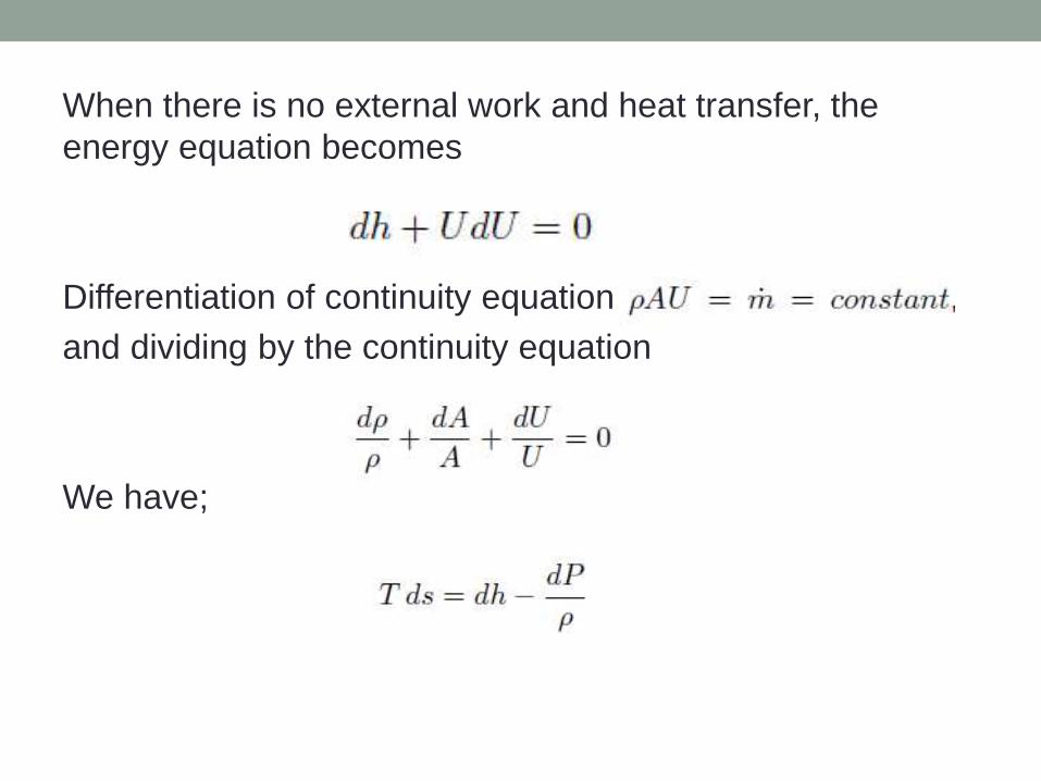
When there is no external work and heat transfer, the
energy equation becomes
Differentiation of continuity equation,
and dividing by the continuity equation
We have;

For isentropic process ds=0 and combining equations
Differentiation of the equation and dividing the
results by the equation
Obtaining an expression for dU/U from the mass balance
equation
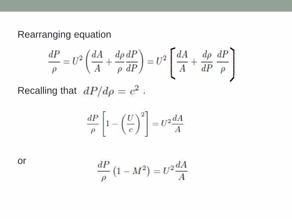
Rearranging equation
Recalling that
or
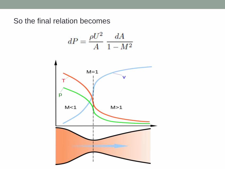
So the final relation becomes
Flow characteristics
• At entry into the nozzle flow is subsonic
• As the throat constricts, the gas is forced to accelerate
until at the nozzle throat
• At throat velocity becomes sonic
• From the throat the cross-sectional area increases
• The gas expands and the linear velocity becomes
progressively more supersonic.

The linear velocity of the exiting exhaust gases can be
calculated using the following equation
M = the gas molecular mass, kg/kmol
ɣ = cp/cv (isentropic expansion factor)
Pe = absolute pressure of exhaust gas at nozzle exit
p = absolute pressure of inlet gas

Types of Expansion
1. Under expanded
2. Ambient
3. Over expanded
4. Grossly over expanded
Expansion varies with altitude
If the exit pressure is too low jet separate from the nozzle.
This is often unstable, and the jet will generally cause large
off-axis thrusts and may mechanically damage the nozzle.
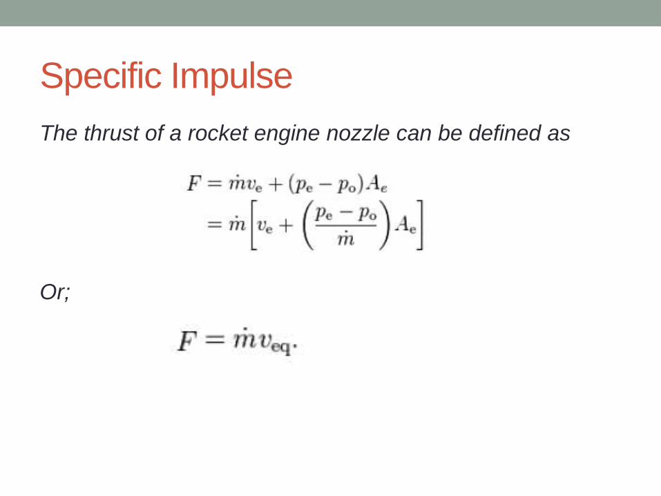
Specific Impulse
The thrust of a rocket engine nozzle can be defined as
Or;
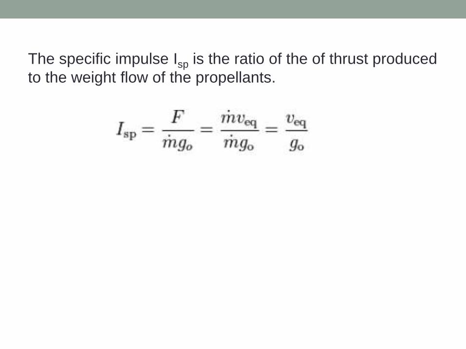
The specific impulse Isp is the ratio of the of thrust produced
to the weight flow of the propellants.
Rocket cycles
• Pressure-fed engine cycle
• Expander cycle
• Gas-generator cycle
• Staged combustion cycle

Pressure-fed engine
• Propellant tanks are
pressurized to supply fuel
and oxidizer to the engine,
eliminating the need for
turbo pumps.
• Pressurized Helium is often
used
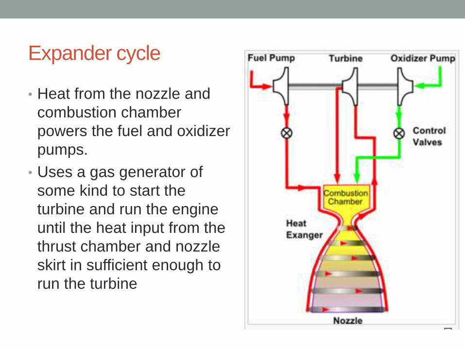
Expander cycle
• Heat from the nozzle and
combustion chamber
powers the fuel and oxidizer
pumps.
• Uses a gas generator of
some kind to start the
turbine and run the engine
until the heat input from the
thrust chamber and nozzle
skirt in sufficient enough to
run the turbine

Gas-generator cycle
• Some of the fuel and
oxidizer is burned
separately to power the
pumps and then discarded.
Most gas-generator engines
use the fuel for nozzle
cooling.
• Some of the fuel used to
cool the nozzle and
combustion chamber.

Staged combustion cycle
• All of the fuel and a portion
of the oxidizer are fed
through the pre-burner,
generating fuel-rich gas.
After being run through a
turbine the gas is injected
into the combustion
chamber and burned.
• Advantage: No loss of heat
compared to gas generator
cycle
• USED IN SPACE LAUNCH
SYSTEM

How to Liquefy cryogenic fuel
Critical temperature for hydrogen -2530c
1. At first gaseous hydrogen is compressed to 180 atm.
2. Compressed gas is cooled by allowing it to expand
rapidly.
3. The cooled expanded gas then passes through a heat
exchanger where it cools the incoming compressed gas
4. The cycle is repeated until hydrogen liquefies
How to store cryogenic fuel
• Cryogenic Dewar wall: Vacuum flask used for storing cryogenic fuels
• Have walls constructed in two or more layers of silver with a high vacuum maintained between the layers.
• Provides very good thermal insulation
• Reduces the rate at which the contents boils away
• Dewar allow the gas to escape through an open top to avoid risk of explosion
• More sophisticated Dewar trap the gas above the liquid, and hold it at high pressure
• This increases the boiling point of the liquid, allowing it to be stored for extended periods
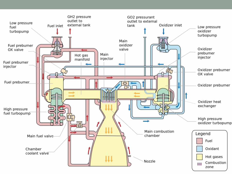
The cryogenic Engine
• Fuel and oxidizer from the rocket's core stage will flow
directly into the fuel lines
• The fuel and oxidizer each branch out into separate paths
to each engines
• In the engine fuel and oxidizer follows various paths to
reach into the combustion chamber
Fuel Injection
• Injector introduce and meter the flow of liquid propellants
to the combustion chamber
• Hole pattern of the injector is closely related to feed
passages within the injector
• A large manifold allows low passage velocities and good
distribution.
• A small manifold allows for a lighter weight injector and
reduces the amount of "dribble" flow after the main valves
are shut.

• Dribbling results in afterburning, which is an inefficient
irregular combustion that gives a little "cutoff" thrust after
valve closing.
• For accurate vehicle velocity requirements, the cutoff
impulse has to be very small.
Types
1. Impinging-stream-type
2. Non-impinging
3. Coaxial injector

1. Impinging-stream-type : Fuel and oxidizer streams
impinge upon each other. Impingement aids atomization
of the liquids into droplets also its distribution.
2. Non-impinging type: relies on turbulence and diffusion
to achieve mixing

3. Coaxial injector It has been used for liquid oxygen and
gaseous hydrogen. This type of injector is used by SLS

Combustion Zones in Thrust Chamber
1. Injection/Atomization Zone
2. Rapid Combustion Zone
3. Stream Tube Combustion Zone

Injection/Atomization Zone
1. Injection, atomization and
vaporization occurs here
2. Fuel and Oxidizing agent are
introduced in this zone at
velocities between 7 and 60
m/sec
3. The individual jets break up
into droplets by impingement of
one jet with another
4. Heat is transferred to the
droplets by radiation from rapid
combustion zone and by
convection from moderately hot
gases in the first zone.
5. Chemical reactions occur in
this zone, but the rate of heat
generation is relatively low
• If one of the propellants is a gas:
• this occurs with liquid oxygen and gaseous hydrogen
propellant from thrust chambers or pre-combustion
chambers
• The gas usually has a much higher injection velocity
(above 120 m/sec) than the liquid propellant
• This cause shear forces to be imposed on the liquid jets
• Thus Coaxial injectors are used in such cases
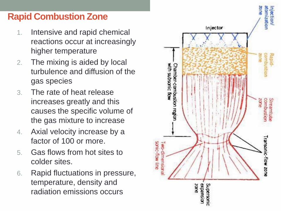
Rapid Combustion Zone
1. Intensive and rapid chemical
reactions occur at increasingly
higher temperature
2. The mixing is aided by local
turbulence and diffusion of the
gas species
3. The rate of heat release
increases greatly and this
causes the specific volume of
the gas mixture to increase
4. Axial velocity increase by a
factor of 100 or more.
5. Gas flows from hot sites to
colder sites.
6. Rapid fluctuations in pressure,
temperature, density and
radiation emissions occurs

Stream Tube Combustion Zone
1. Axial velocities are high (200 to
600 m/sec)
2. Streamlines are formed and
there is relatively little
turbulence
3. Residence time in this zone is
very short
4. Usually less than 10
milliseconds
5. Volumetric heat release being
approximately 370 MJ/m3sec
6. The higher temperature in the
chamber causes chemical
reaction rates to be several
times faster
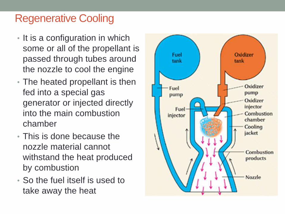
Regenerative Cooling
• It is a configuration in which
some or all of the propellant is
passed through tubes around
the nozzle to cool the engine
• The heated propellant is then
fed into a special gas
generator or injected directly
into the main combustion
chamber
• This is done because the
nozzle material cannot
withstand the heat produced
by combustion
• So the fuel itself is used to
take away the heat