INCORPORATING Wl~ELESS WORLD
MAY 1998 £2.45
The route to pcb CAD Enhanced radiation detector
~n-system • programming
56k modems exposed
Sweeping: past and present
Designing with low-voltage op-amps
Film capacitors
Austria Asch. 68.00 Denmark DKr. 69.00 Germany DM 18.00 Greece Dra.1300.00
Holland Dfl. 12.50 Italy L 9000.00 Malta Lm. 1.65
IR £3.30 Singapore 5$7.50
Spain Pts. 900 USA $6.50
A REED BUSINESS PUBLICATION SOR DISTRIBUTION
th. th e· n· d,~• Is 1s e · L . · • 1 L ··
Couple all the power of the latest Windows PCs (not just the fraction that you can squeeze down an RS232 connection) to the latest synthesised receiver design techniques, and you'll get the ultimate in wide range, all mode programmable radio reception.
The WR3000iDSP include AD hardware signal processing for total signal processing.
as we know it .• · WiNRADiO™ provides a complete• communications system on a full"! ., length ISA PC Card, with softwa~e for Windows 3, NT or 95.
New optional Digital Suite software includes facilities
for recording , audio spectrum, packet radio, oscilloscope display, HF fax, Squelch-controlled
Audio Recorder and Playback, Signal Classifier,
DTMF, ACARS. CTSS -•. use with SoundBlasterrM compatible
audio cards. f
Your choice of virtual front panel
'-- 11..:11 .•. ,. ,,..,.
VisiTune TM spectrum tuning display
Use WiNRADiO™ scanning PC communications receiver sy~tems for ... 1
Broadcast • Media monitoring • Professional and amateur radio communications • Scanning
Spot frequency and whole spectrum monitoring • Surveillance (and recording) • Instrumentation
yes yes yes yes yes yes yes yes yes
< lh'( II,,> Ill/<>'\ I..IJ'f~ ( \l{/1
New! Digital Suite Software option- only £69+vat (requires a SoundBlaster 16 compatible sound card), and currently features facilities for: 0 WEFAX / HF Fax
0 Packet Radio for HF and VHF
O Aircraft Addressing and Reporting System (ACARS)
O Audio Oscilloscope, real time Spectrum Analyzer with
calibration cursors
O Squelch-controlled AF Recorder and Playback 0 DTMF, CTSS decode and analyse
Contents •••••••••••••••••••••
363 COMMENT Love story or shotgun wedding?
364 NEWS Mobile phones: new health risk? Robot the size of an Oxo cube, University for all, Euro brain drain threat.
370 THE ROUTE TO PCB CAD
376
• -·•
First article in a new series of pcb CAD reviews by Rod Cooper features an explanation of what to watch out for, and looks in detail at the new Proteus IV.
CIRCUIT IDEAS
• PTlOO lineariser
• Call-sign generator
• Low-ripple de supply
• Dumping stored high voltages
• Timebase event positioner
• Cheap time-delay relay
• ~-- -~----------
384 READER OFFER 10% reader discount on any of the Proteus series CAD packages - see page 384.
385 SWEEPING BACK Ian Hickman looks at some ingenious methods for generating linear timebase sawteeth, both ancient and modem.
391 UNDERSTANDING CAPACITORS Plastic film capacitors - second in popularity only to ceramic types - are examined in detail by Cyril Bateman.
May 1998 ELECTRONICS WORLD
397 SPEAKERS CORNER John Watkinson looks at an often overlooked loudspeaker design aspect -diffraction.
402 VERSATILE RADIATION METER Disappointed with current Geiger-tube circuits, Darren Heywood set about designing a more versatile meter with voltage, 4-20m.A and audio outputs.
408 HANDS-ON INTERNET Want a browser that fits on a floppy? Interested in circuit simulation CAD? See Cyril Bateman's monthly report.
4 13 SINGLE-SUPPLY OP-AMPS Knowing the trade-offs involved when manufacturers make single-supply op-amps helps you design better circuits.
418 DISK CAMERA UPDATE Leslie Warwick reports on new broadcast video cameras using disk storage, and their emerging domestic counterparts.
421 56K MODEMS EXPOSED WiJI your 56k modem ever run at 56k? Steve Bush investigates.
424 BOOKS TO BUY A new selection of electronics and computing titles from Wiley.
427 AIR WAVES New European mobile phone standard.
431 NEW PRODUCTS Four pages of densely packed product infonnation, selected by Phil Darrington.
436 IN-SYSTEM PROGRAMMABLE LOGIC Having a logic device that can be altered without removing it from the board makes designing a lot easier, quicker and cheaper. Geoff Newton looks at what's available.
Photography Philippe Sion
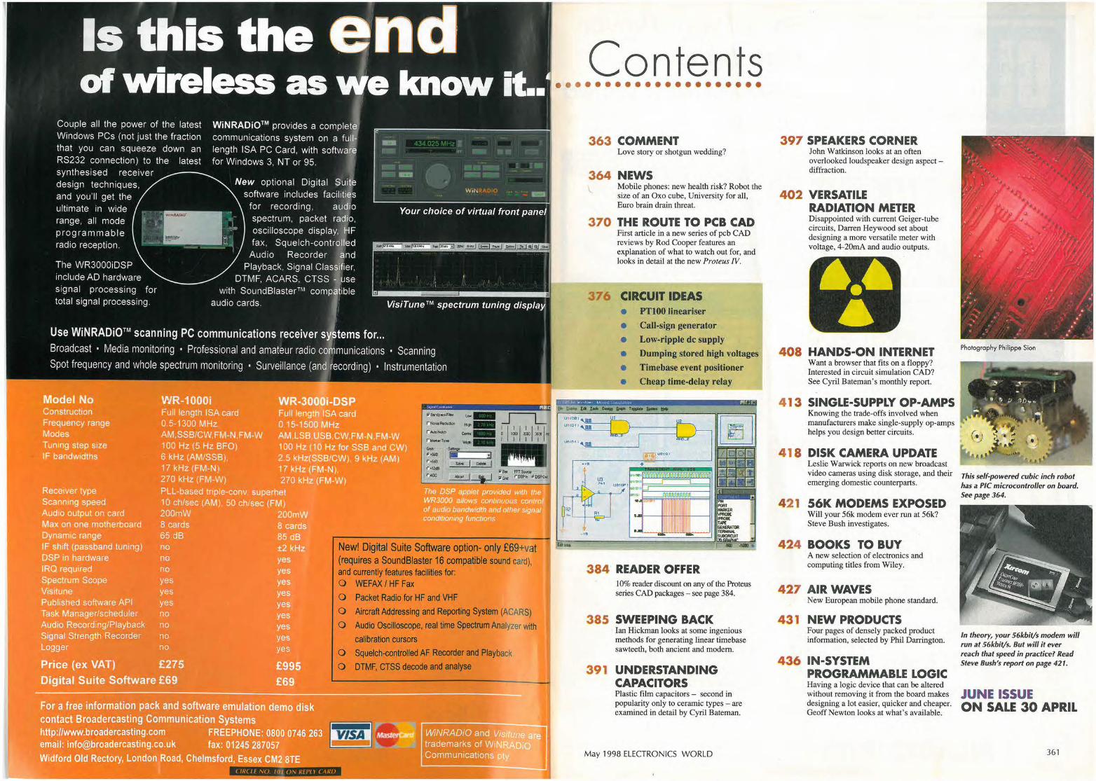
This self-powered cubic inch robot has a PIC microcontroller on board. See page 364.
In theory, your 56kbit/s modem will run at 56kbit/s. But will it ever reach that speed in practice? Read Steve Bush's report on page 421.
JUNE ISSUE ON SALE 30 APRIL
361
® For all your Power Distribution Olson offer a varied choice
Earth Leakage Distriblrtion Units
~
-~~~
-~~· i -'-f i·Ct ·1 ·- -1 · ., ... ·I·:. ·I
111] fj 1] / II" Hf CTRDNICS LIMDED ( IR( Lf NU. Ill(, UN REPLY CARD
FOUNTAYNE HOUSE, FOUNTAYNE RD., LONDON N15 4QL TEL: 0181-8$5 2884 FAX: 0181-885 2496
EDITOR
Mortin Eccles
0 181 6523128
CONSULTANTS
Ian Hickmon
Philip Darrington Frank Ogden
EDITORIAL ADMINISTRATION
Jackie Lowe 0181-652 3614
E-MAIL ORDERS
jackie [email protected]. uk
ADVERTISEMENT MANAGER
Richard Napier
018 1-652 3620
DISPLAY SALES EXECUTIVE
Joannoh Cox 0181-652 3620
ADVERTISING PRODUCTION
0181-652 3620
PUBLISHER
Mick Elliott
EDITORIAL FAX
0181-652 8111
CLASSIFIED FAX
018 1-652 8938
NEWSTRADE ENQUIRIES
0171 261 7704
ISSN 0959-8332
SUBSCRIPTION HOTLINE 01622 778000
SUBSCRIPTION QUERIES [email protected]
Tel 0 1444 445566 Fax 0 1444 445447
For a full llstlng of RBI magazines: http//www.reedbuslness.com
~ REED ra BUSINESS Ill INFORMATION
Mayl 998 ELECTRONICS WORLD
Love story or shotgun wedding? W hen Reeves invented pcm, it became possible to
represent any analogue waveform by a bit stream. From that point on convergence of video, audio, computers and communications became inevitable. The timing has been controlled by the technology - primarily the economics of LSI number crunching and the cost-perbit of data recording.
When the cost of implementing real time Reed-Solomon error correction fell to consumer levels, the compact disc arrived overnight and eclipsed the vinyl disc. Audio had become economic data rather than laboratory data. When the blossoming pc market caused the price of hard drives to plummet, the digital audio workstation arrived and -with the help of the DAT format - eclipsed the analogue stereo tape recorder.
Now LSI technology has advanced to the point where real time discrete cosine transforms are possible at consumer prices and suddenly MPEG video compression arrives. Video becomes economic data, and analogue television broadcasting will be eclipsed by it. In comparison with MPEG, analogue video compression techniques such as interlace and composite video are simply less efficient and use up to much radio spectrum.
Governments the world over want to make broadcast television digital not to improve our lives - but simply so that the existing analogue television channel bandwidth can be sold. This has a ring of inevitability about it.
Another inevitability is that now broadcast video is economic data, the computer companies with their mastery of storage and processing naturally want a piece of the action and are in the process of taking it.
When a television set contains an MPEG decoder, it has become digital to the extent that there isn't much difference between a television and a pc. Both require a cabinet, crt, power supply and scan systems and some logic.
The pc industry wants to combine the features of a computer and a television by using communications to make television viewing interactive. While only an example, a hybrid television could have a split screen where one half is video of a sports event and the other half is data about the competitors sourced via Internet. Links in the system would allow the viewer to jump immediately to web pages related to the event such as sporting goods suppliers or the products of the sponsors. The hard drive could be set to loop record the last few minutes of action so that instant replay is under control of the viewer.
While not everyone would want this degree of interactivity, the same system could download the program guide to save having to buy a paper one. When not in use as a television, the system becomes a general purpose pc and for many households a single unit would represent a significant saving in space, cost and power consumption.
The only thorn in the side of this concept is that traditional broadcast television signals uses interlace, where odd and even screen lines are sent in alternate
Electronic. World is published monthly. Sy posl, current issue £2.45, bock i,sues {if ovoiloble £3.001. Orders, payments and generol correspondence lo L333, Electronlca World, Quadrant Houae, The Quadrant, Sutton, Surrey SM2 SAS. Tlx:892984 REED BP G. Cheques should be mode poyable lo Reed Business Information ltd Newstrude: Distributed by Morketforce lUKI Ud, 247 Tottenham Court Road London Wl P OAU 0171 261-5108. Subscriptions: Quodronl Subscription Services, Oakfield House Perrymounl Rood, Hayword, Heath, Sussex RHl 6 3DH. Telephone 01444 445566. Please notify change of oddre». Subscription rotes 1 year UK £34.00 2 yeors £54.00 3 years £68.00. Europe/Eu t year £49.00 2 years £78.00 3 years £98.00 ROW 1 year £59.00 2 years £94.00 3 years£ 119
fields. Computer graphics uses progressive scan where all of the lines are sent in every frame.
Advanced televisions use up-conversion to put more lines on the screen than are in the video standard. This makes the raster structure invisible. Progressive scan video contains all of the data about a picture in each frame and up-conversion and resizing for split screen is easy. In interlaced video the vertical resolution is shared between two fields which were captured at different times. When there is motion the two fields cannot be de-interlaced to a frame and up-conversion and re-sizing becomes much harder.
In short, a computer/television becomes simpler and cheaper and gives better pictures if the broadcast television signals are progressive scan. Interlaced broadcast signals would require the use of an additional de-interlacing stage.
However, the broadcasters have a huge infrastructure of interlaced production equipment and they naturally want to keep interlace. Consequently war has broken out to the extent that the A TSC - the advanced television systems
Governments the world over want to make broadcast television digital not to improve our lives, but simply so that the existing analogue television channel bandwidth can be sold.
committee - in the USA was unable to recommend a single standard. As this is why it was formed, the result is called failure.
In the mean time it is becoming clear that MPEG compression gives better pictures for the same bit rate, or lower bit rate for the same quality if progressive scan is used. I predicted it theoretically, and tests by Panasonic and Microsoft have confirmed the results practically.
It transpires that what the broadcasters are saying is that they want to use a higher data rate than necessary to send pictures to televisions which cost more than necessary. This doesn't make sense.
Surely the broadcasters can continue to produce in interlaced formats if they wish, but the conversion to progressive scan should be done leaving the studio prior to MPEG encoding.
Interlace was the best that could be done with vacuum tubes fifty years ago and it's become a tradition. Tradition means not questioning what you do. John Watkinson
John Is a Chartered Information Systems Practitioner and Fellow of the Audio Engineering Society. He is a lso an international consultant and director of Celtic Audio ltd. www.cullnaire.se/JWA.
Oversea, advertiaing agenta: France and Belgium: Pietro Mu»ord, 18-20 Place de lo Madeleine, Paris 75008. United Stoles of America: Ray Sarnes, Reed Susine» Publishing Ltd, 475 Park Avenue South, 2nd Fl New York, NY 10016 Tel; (2121679 8888 Fax; (212) 679 9455 USA malling agents: Mercury Airfreight International lid Inc, 1 0(b) Englehard Ave, Avenal NJ 07001. Period ides Postage Poid al Rahway NJ Poslmasler. Send address changes lo above. Printed by SPCC Magazines (Corlislel lid, Newtown Trading Eslole Carlisle. Cumbria, CA2 7NR Typeset by Marlin Imaging 2-4 Powerscrott Road, Sidcup, Kenl DAI 4 SOT ,
© Reed Business Information Ltd 1997 ISSN 0959 8332
363
UP DATE •••••••••••••••••••
Mobile phones: new health risk fears The effects of mobile phones on
human memory and learning capacity have now been added to the list of potential health risks - notably cancer - under investigation.
The Department of Health is spending more than £100000 on two investigations. The larger project, costing £100000, is being undertaken by the government's Porton Down research establishment in Wiltshire. This is into learning deficiencies in rats caused by the radiation. Rats have been chosen as a suitable lower mammal with similarities to humans for early research.
The second study, costing £3 000, is being conducted at Bristol University into the effect of microwaves on human memory and
reaction times. To date, mobile phone safety
research has included an Australian study on the risk of cancer while the EU is undertaking a study on the neurophysiological effects and damage to the immune system.
Both of the UK investigations are expected to take a year to complete and the results will be reported to Health Secretary Frank Dobson.
A government spokeswoman said the investigations had been launched following concerns expressed by medical experts, but would not detail their fears.
"As part of its radiations protection research programme, the Department supports a number of projects investigating the possible health effects of electromagnetic fields,"
said the spokeswoman. "It has recently commissioned a short study of the effects of microwave radiation on memory and reaction times in humans."
It is also currently funding a study into electromagnetic field risk perception. This follows on from a study by Australian doctor Andrew Davidson which showed a rise of more than 50 per cent in brain tumour cases in Western Australia between 1982 and I 992.
He believes this may have been caused by the growth of analogue mobile phone usage in that period.
The EC is looking to set up a research programme into possible dangers while the World Health Organisation is also considering a "major epidemiological study".
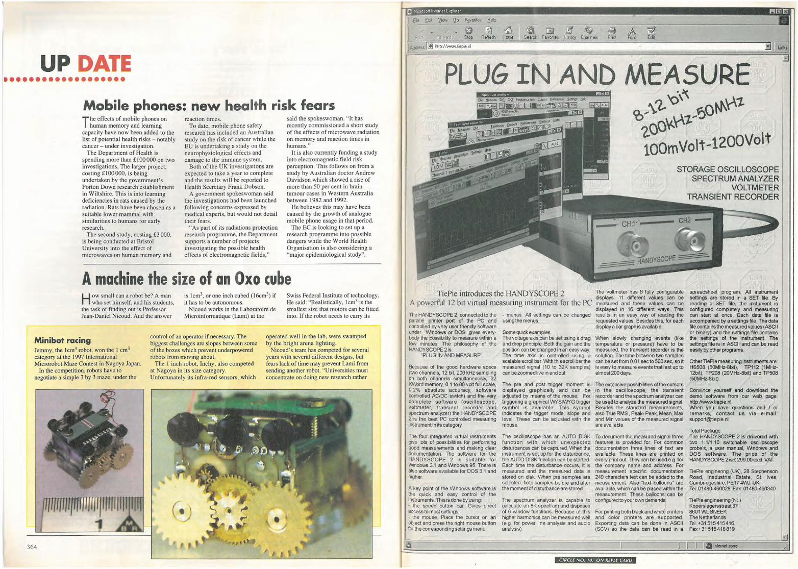
A machine the size of an Oxo cube H ow small can a robot be? A man
who set himself, and his students, the task of finding out is Professor Jean-Daniel Nicoud. And the answer
is lcm3, or one inch cubed (16cm3) if it has to be autonomous.
Nicoud works in the Laboratoire de Microinformatique (Larni) at the
Swiss Federal Institute of technology. He said: "Realistically, Icm3 is the smallest size that motors can be fitted into. If the robot needs to carry its
Minibot racing control of an operator if necessary. The biggest challenges are slopes between some of the boxes which prevent underpowered robots from moving about.
operated well in the lab, were swamped by the bright arena lighting.
Jemmy, the Icm3 robot, won the l cm3
category at the 1997 International Microrobot Maze Contest in Nagoya Japan.
In the competition, robots have to negotiate a simple 3 by 3 maze, under the
364
The l inch robot, Inchy, also competed at Nagoya in its size category. Unfortunately its infra-red sensors, which
Nicoud's team has competed for several years with several different designs, but fears lack of time may prevent Lami from sending another robot. "Universities must concentrate on doing new research rather
0 ~ ~ L!IJ {ff ~ (f; ~ ~ Stop Refresh Home F av01~es H1slo19 Channels Pnnt Font Edit
Address j i!J http:/ IY1ww. tiepie.nl
PLUG IN AND MEASURE
TiePie introduces the HANDYSCOPE 2 A powerful 12 bit vi1tual measuring instrument for the PC The HANDY SCOPE 2, connected to the parallel printer port of the PC and controlled by very user friendly software under \Mndows or DOS, gives everybody the possibility to measure within a few minutes The philosophy of the HANOYSCOPE 21s:
"PLUG IN ANO MEASURE".
Because of the good hardware specs (two channels, 12 bit, 200 kHz sampling on both channels simultaneously, 32 KV\/ord memory, 0, 1 to 80 volt full scale, 0 2% absolute accuracy, software controlled AC/DC switch) and the very complete software (oscilloscope. voltmeter, transient recorder and spectrum analyzer) the HANOYSCOPE 2 Is the best PC controlled measuring instrument in its category
The four integrated virtual instruments give lots of possibilities for performing good measurements and making clear documentation The software for the HANDYSCOPE 2 Is suitable for V'.indows 3 1 and 1/\Andows 95. There 1s also software available for DOS 3.1 and higher
A key point of the 1/\Andows software is the quick and easy control of the instruments. This is done by using: · the speed button bar Gives direct access to most settings. • the mouse Place the cursor on an ObJect and press the nght mouse button for the corresponding settings menu
• menus. All settings can be changed using the menus
Some quick examples. The voltage axis can be set using a drag and drop principle Both the gam and the position can be changed in an easy way The time axis is controlled using a scalable scroll bar \Mth this scroll bar the measured signal (10 to 32K samples) can be zoomed live in and out
The pre and post trigger moment Is displayed graphically and can be adjusted by means of the mouse For tnggering a graphical WYSIWYG trigger symbol is available This symbol indicates the trigger mode, slope and level These can be adjusted with the mouse
The oscilloscope has an AUTO DISK function with which unexpected disturbances can be captured When the instrument is set up for the disturbance, the AUTO DI SK function can be started. Each time the disturbance occurs, It Is measured and the measured data Is stored on disk When pre samples are selected, both samples before and after the moment of disturbance are stored
The spectrum analyzer Is capable to calculate an 8K spectrum and disposes of 6 window functions. Because of this higher harmonics can be measured well (e.g for power line analysis and audio analysis)
-~ <o~"i. '<>' 5ot-f\01-
ioov.01-~ 100m Volt-1200Volt
STORAGE OSCILLOSCOPE SPECTRUM ANALYZER
VOLTMETER TRANSIENT RECORDER
The voltmeter has 6 fully configurable displays 11 different values can be measured and these values can be displayed In 16 different ways. This results m an easy way of reading the requested values. Besides this, for each display a bar graph is available.
When slowly changing events (like temperature or pressure) have to be measured, the transient recorder is the solution. The time between two samples can be set from 0.01 sec to 500 sec, so it is easy to measure events that last up to almost200days.
The extensive possibilities of the cursors in the oscilloscope, the transient recorder and the spectrum analyzer can be used to analyze the measured signal Besides the standard measurements, also True RMS, Peak- Peak, Mean, Max and Min values of the measured signal are available
To document the measured signal three features Is provided for. For common documentation three lines of text are available. These lines are printed on every pnnt out They can be used e g. for the company name and address. For measurement speaf1c documentation 240 characters text can be added to the measurement. Also 'lext balloons" are available, which can be placed within the measurement. These balloons can be configured to your oWn demands.
For printing both black and white printers and color printers are supported Exporting data can be done in ASCII (SCV) so the data can be read m a
spreadsheet program All instrument settings are stored in a SET file. By reading a SET file, the instument is configured completely and measuring can start at once. E:ach data file is accompanied by a settings file. The data file contains the measured values (ASCII or binaiy) and the settings file contains the settings of the instrument The settings file is in ASCII and can be read easily by other programs.
Other TiePie measuring instruments are: HS508 (50MHz-8bIt), TP112 (1MHz. 12b1t), TP208 (20MHz-8bit) and TP508 (50MHz-8bit)
Convince yourself and download the demo software from our web page: http:/t-.w.w.tiepie.nl. When you have questions and / or remarks, contact us via e-mail· [email protected]
Total Package: The HANOYSCOPE 2 is delivered with two 1·111·10 switchable oscilloscope probe's, a user manual, 1/\Andows and DOS software. The price of the HANDYSCOPE2 1s£299.00excl. VAT.
TiePie engmering (UK), 28 Stephenson Road, lnsdustrial Estate, St Ives, Cambridgeshire, PE17 4WJ, UK Tel· 01480-460028, Fax: 01480-460340
TiePie engineering (NL) Koperslagersstraat 37 8601 Wt. SNEEK The Nether1ands Tel. +31515415416 · Fax +31 515418819
T lrtemetzone
CIRCLE NO. 107 ON REPLY CARO
UPDATE
366
own batteries rather than be powered over wire links, the size has to increase."
To prove the point, ex-watchmaker Andre Guignard has built robots to Nicoud's designs. Each has multiple infra-red distance sensors on-board as well as a PIC 16C54 microcontroller to link the sensors to the motors and provide intelligence. "The PIC is the smallest microcontroller available," said Nicoud.
One cubic inch has given Nicoud "plenty of room" in which to fit a battery, but finding a suitable one has been difficult. "Most smiill high power density batteries are made to
supply a low current for a long period of time, powering a clock for instance," he said, "these have too much internal resistance to supply motors, which need 20 to 50mA." Salvation came in the form of an experimental battery from a Swiss cell-maker.
"Leclanche made ten small experimental NiMH batteries for a medical application. I was offered one of those."
There were only just enough made to supply Leclanche's own needs and someone at the company started to get cold feet. "I drove over here myself and picked one up before they
changed their minds," said Nicoud. The battery enables the bigger robot
to run for half an hour, and achieve the creditable speed of 30cm/s.
But these automatons have not just been made for fun. "We are investigating the limits of costeffectively making small machines by conventional [watchmaking] and semiconductor fabrication techniques. There is still a gap, where micromachining is too small and watchmaking too coarse. This limit of cost-effective microsystems is slowly moving down, Jet us say with a factor of two every ten years." Steve Bush, Electronics Weekly
New brain-drain threQt for Europe Abattle is brewing in the US whose
outcome could threaten Europe and the Far East with a brain drain.
Large US electronics firms have been telling a US Senate hearing that the current limit on immigration visas is hurting their businesses. Critics, meanwhile, counter the claims saying that the companies' goal is to undermine salaries with cheap labour.
Senior executives from Texas Instruments, Sun Microsystems, Cypress Semiconductor and Microsoft spoke in front of a special Senate Judiciary Committee claiming that US immigration restrictions are harming their competitiveness.
"The high technology industry added some 290000 new jobs to the US economy in the 1990's.
Unfortunate)y, the future growth of our industry is being threatened by a limited supply of skilled workers," testified Step!J.en Leven, Tl's director of worldwide human r~sources.
US electronics companies want the current 65 000 visa limit on foreign professionals to be increased or scrapped, allowing them to recruit tens of thousands of high-tech staff from anywhere in the world.
But the US Institute of Electrical and Electronics Engineers (IEEEUSA), representing more than 220000 electronics engineers and IT professionals, says that the worker shortage is a myth. The IEEE points out that if there were a major shortage, engineering salaries would have increased tremendously, yet there has
Internet telephony imminent UK-based start-up Vega-Stream
~ays it will have two Intern~! telephony products available by June.
The company, set up this month with£ I .2m raised by the founder and former CEO of Tricom Communications, Mike Hafferty, is employing seven people to develop the products.
"We have four development engineers who are creating the two main products: an Internet telephony gateway and an audio conferencing bridge," said Hafferty.
The gateway will allow people to
Hafferty . . . "With Internet telephony standards available, like H.323, quality is well established."
phone their local Internet service provider and route an international call for the price of a local telephone call. The conferencing bridge, costing less than £4000, will work with Microsoft's NetMeeting software, enabling up to 30 people to converse while viewing the same screen of data.
Rafferty scoffed at the suggestion that lost packets and the slowness of the Internet would disrupt calls. "That position is changing almost week by week," he said. "With Internet telephony standards available, like H.323, quality is well established. I don' t think that anyone - including the big phone companies - can dispute that."
been little or no increase in engineering salaries over recent years.
Dr John Reinert, president of the IEEE-USA, told the committee that if there is a worker shortage, the focus should be on retraining workers and attracting more women and other minorities. "By raising the visa limits, the government would provide a powerful incentive to squander these important national resources and cause an increasing erosion of our domestic technical infrastructure," Reinert testified.
He pointed out that more than 80 per cent of IT workers have degrees in different fields, and the solution is to train domestic workers and recruit older engineers who have been forced out due to early retirement or layoffs.
Free E-mail . addresses BT is to bring electronic communications to the masses with the launch of a free E-mail address service. Called Mill-eMail, the initiative is parl of the Millennium project. It will provide users with an E-mail address and directory which can be accessed from anywhere in the world. The scheme will be open to nine-year-olds and above and will be airi1ed particularly at the education sector. "We want to raise the agenda for E-mail and Internet use ," said a BT spokesman.
ELECTRONICS WORLD May 1998
CROWNHILL ASSOCIATES LIMITED The Old Bakery, New Barns Road, Ely, Cambs. CB4 7PW
Tel: +44 (0) 1353 666709 Fax: +44 (0) 1353 666710
http://www.towitoko.co.Lik
CHIP DRIVE - PROFESSIONAL Smart Card Programming System
lntelligenf programmer for Smart Cards using the International Standard T =0 or T =1 protocols also Memory and Secure Memory using 1 'C, 2· wire & 3-wire interfaces
Supplied with software to read and write to most popuiar secure smart cards, Inc GSM, PAY PHONE and ACCESS CONTROL cards.
http://www.crownhill.co.uk
NEW CHIPDRIVE - micro Fully Compatible with TOOLBOX
for applicaiion Deve lopment SMARTCARDS
Available from Stock: GemPlus, Atmel, Xicor, Siemans, SGS
Crownhi/1 and more ...... .
SLE4442, 4432, 4418,4428, 4404 AT88SCxx, AT24c01-16 GPM/03, GFMIK, 2K, 4K, GPM416 Phone Cards, Loyalty Cards
Cards specified, engineered and p roduced to your specification.
T=0 orT=1 @3.579MHz RS232 @ 9600 · 11500 bps TOOLBOX Internal Supply/ Ni-MH
I
Size: 100x70x80 mm Weight 660 Gram
Supplied with CardServer API for easy development of SmartCard Applications
Driver and application software is available for th!:! .CHIPDRIVE family of terminals including the command set DLL for Windows 3.11 /95NT, easy to
Chip Drive Internal 3.ofloppy bay version of the CHIPDRIVE
using Visual Basic, Delphi or C++ Supplied with Sample Memory cards & Secure Smart cards
use 16 and 32 Bit DLLs with just one function call to the CardServer, a powerful Background task with relieves the applica
CE Compliant
tion programmer from device and card administration. Featuring a utomatic protocal and card type detection con· trolling access of several application to one terminal dependent on the inserted card
Applications are available to provide SmartCard controlled access of data on Hard drives or "PC-LOCK", to control access to the whole PC Fully Compatible with TOOLBOX for systems development.
CIRCLE NO . 108 ON REPLY CARD
Control EssentialSfrom Milford Instruments
BASIC Stamps - low cost alternative to PLCs
BASIC Stamps ore small, low cost re-progrommoble controllers running eosy•loprogromme BASIC. They con source/sink up to 20mA ond supporl buttons/keypods/LCDs/ tEDs/Comms/Seriol Driver Chips etc. Once programmed from the PC. Stomps ore fully a ulonom01Js and will find mony uses in ATE equipmenl, oneoffs and as on olternolive to expensive PLCs.
B51-IC
£as21 . . 5,c ' . 1:1~- a£s32
-i9c 8 1/0 lines Up lo 80 programme lines 2,000 lines/sec Com ms lo 2,400 baud B52-IC 16 1/0 lines Up to 500 programme lines SPI, DTMF elc
De~elopmenl kils from £79 which include application. notes, softwa re, coble a nd Stamp.
Data Logging
Comm, lo 19,200 baud
Serial LCD Modules - banish led hassle Three qua lity, backlil LCD modules eoch fitted wilh an easy-to-use serial driver board. SirTiple 3.wire inlerface lo PC, micro or Stomp l+5vdc, Gnd and signoll . Enha nced driver board supports full.screen height numera ls, standard characters and soltwore swilchable bocklighl. RS232 inlerfoce al 2.400 or 9,600 ba ud. Standard driver boards {wilhoul led) a nd bulk driver chips for OEM use a lso availa ble.
£85
BS2.IC based Doto collection board with reo~lime dock/calendar, up 10 32k8ytes EEprom, dual J 2.blt ADC and user development area, Kit complete wilh extensive manual and ready•
to-go software roulines tha t may be user customised. £65
Serial Maths Processors I Number crunching? let our serial math, [ 1.
processors lake the strain-
£35
DC Servo Control DC Motor con~ol chipsel for use with incremental encoders.
• 32.bil fl00Hn9 poinl • SPI {3•wirel inlerfoce _.--,_-RS232/ RS485 inlerfoce copobility,
• Multiply, divide, odd, subtract, sine 1 log,
squore-rool, • 32-progrommable counter, £20 e 4-chonnel ADC,
All prices exclude shipping and VAT www.milinst.demon.co.uk
Positional control.Velocity control and Trapezoidal profiling, Progrommable P.I.D filter 32-bit position~ velocity and acceleration
Eva luation board available. £29
To order or request further information, please call M ilford Instruments at O 1977 683665, fax 681465
CIRCLE NO. 109 ON REPLY CARD
May 1998 ELECTRONICS WORLD 367
UPDATE
IN BRIEF
8-bit micro
Battle over BDB set-top box plans British Sky Broadcasting (BSkyB)
will sue British Digital Broadcasting (BDB) if it does not change its digital set-top box plans, BSkyB's chief executive has warned.
The Murdoch-backed pay television company is furious with the digital terrestrial group's decision to use the SECA conditional access system -used for access control - within its set-top boxes because it believes SECAboxes will be incompatible with its own.
BSkyB chief executive Mark Booth pointed out that the decision is bad for consumers. "We are committed to
interoperability and what matters here is that consumers are not disadvantaged by being faced with set-top boxes that are not compatible," he said.
But according to a BDB spokesman, interoperability has nothing to do with the choice of conditional access system. He explained that BDB, with the help of BSkyB, will need to design a "sidecar" device that will plug into the set-top to allow consumers to access BSkyB's services. "Interoperability is a twoway street," he said. "We are perfectly happy to co-operate. The
door is open and we'd like them to come and sit at the table with us."
According to BDB, the decision to use SECA - already used in over 1.5 million set-tops across Europe- means the company will remain on schedule for the launch of its terrestrial service in the last quarter of the year.
Pace Micro Technology, the Yorkshire-based set-top box manufacturer, believes the BOB decision increases its chances of winning a contract from BDB. The company uses the SECA system in the set-tops it is shipping to French broadcaster Canal Plus.
'University for everyone' outlined The government has given more
details of its University for Industry (UFI) which will enable people to keep up with developments in technology from their workplaces or homes. Computers and the Internet will be central to bringing about the learning scheme.
The UFI will publish its pathfinder prospectus in March and will begin next year. While one target group will
be adults who missed out on their school education, retraining staff in new skills will be a key role for the scheme.
Whitehall sources said that the electronics industry - where the pace of technological change was extremely rapid - was one of the sectors of the economy where the UFI could be of most use.
People wishing to make use of the
UFI will start individual learning accounts into which they, their employer and the government may invest.
The proposals are outlined in a Green Paper 'The Learning Age' published last week which stressed that high-tech information now kept only in universities and colleges will become available to all workers wanting to retrain through the UFI.
Will SCSI give way to fibre? External storage systems will be forced to move from SCSI to Fibre Channel, says interface company Adaptec.
into new areas. Typical projects are developing Asics, multichip modules, FPGAs and microcontroller systems.
for less than 50 cents "As storage disk farms grow, the only way
they can communicate is by SCSI. You're going to need to go to fibre," said Ray Castle, Adaptec's sales director in Northern Europe.
"It shows that our success in spreading the FUSE message in our own area has been recognised by the controllers of the project in Brussels," said Richard Fairbank, director of the Bolton Centre. In the initiative's first two years, the Bolton Centre has helped in 26 company projects. "Forty per cent of those are with companies that have never used electronics before," said Fairbank. Contracts for the second phase of FUSE have now been signed. E-mail [email protected]
The first 8-bit microcontroller to be launched at under 50 cents is the claim made for Motorola's 68HC705KJ1 which puts together a 68HC05, 8kbits of EPROM, 512bits of SRAM, memory mapped i/o registers, and ten bi-directional i/o pins. It draws lOmA and comes in 16-pin SOIC and DIP packaging. Windowed packages for uv erase and reprogramming are available.
Ferroelectric led research tie-up Ferroelectric lcds, the understudy to today's TFT and STN displays, should be boosted from a tie-up between research organisations in the UK and Japan. "We will be pooling our knowledge to get a more rounded attack on the problems," said Peter Raynes, director of research at Sharp's UK research labs. Other members of the group are Sharp's Functional Device Laboratory in Japan and the UK's Defence Evaluation Research Agency (DERA). Apart from a Canon display, direct view ferroelectric displays have yet to make it into the commercial arena.
368
SCSI is limited to 15 devices, while Fibre Channel can handle up to 126 devices such as external disks.
A degree more relevant Today's engineering degrees may lose their relevance within four years, according to David Jefferies the new president of the IEE, who calls for an approach of life-long learning amongst engineering employers. "Engineering knowledge is expanding so rapidly that a good engineering degree has a 'half life' of only four years," said Jefferies.
FUSE programme extended Bolton Institute Microelectronics Centre, agent for the European Commission's FUSE programme in the North of England, is extending its remit to cover Scotland and Northern Ireland.
FUSE - First User Action initiative -gives financial assistance to firms moving into microelectronics for the first time or
Survey highlights increasing skills shortage Skills shortages in sectors such as electronics are worsening if the findings of a survey carried out by venture capitalist firm 3i are a good indication. The survey, dubbed the Enterprise Barometer, said that 60 per cent of medium-sized businesses questioned believed a Jack of skilled staff was restricting growth. Almost a quarter of firms identified the skills issue as their single most important problem. Engineering sectors like electronics and computing, where the skills shortages are particularly acute, could see pressure on rising salary levels.
ELECTRONICS WORLD May 1998
Data Acquisition Environmental Monitoring
Pico Technology
Virtual Instrumentation • 'Pica's Virtual Instrument is ,.,
'the most powerful~ flexible test equipment in my lab.'
\ l
Pico's virtual instruments emulate the functions of traditional instruments such as Oscillscopes, Spectrum Analysers and Multimeters. Controlled using the standard Windows interface, the software is easy to use with full on line help.
~ ~
~9:fJlO rLrLO (: iJ U U UUU U; ~. ' ... • • " •• ;r
/'l'De-200 Dual Channel High Speed T 100, 50 or 20 MS/s sampling. T 50, 25 or 10 MHz spectrum analysis. T Advanced trigger modes - capture
intermittent one-off events. T Less than half the cost of a
comparable benchtop scope.
-"'Z>e 2()()-t()() £549.oo -"'Z>e 2()()-5() £499.oo -"'Z>e 2()()-2() £359.oo
Supplied with cables and power supply.
/'l'De-100 Dual Channel 12 bit resolution
The ADC-100 offers both a high sampling rate 1 O0kS/s and a high resolution. Flexible input ranges (±50mV to ±20V) make the unit ideal for audio, automotive and education use.
rl'Z>6- I()() with PicoScope software £199.00 with PicoScope & Picolog software £219.00
Single Channel • low cost T 20 kS/s sampling. T 1 0 kHz spectrum analysis. T ± 5V input range.
,-'/Z>6-4() 8 bit resolution £59.00 rl'Z>6-42 12 bit resolution £85.00
call for free demo disk or download our web site: http://www.plcotech.com All prices exclusive of VAT.
Broadway House, 149·151 St Neots Rd, Hardwick, Cambridge. CB3 7QJ UK Tel: (0)1954 211716 Fax: (0)1954 211880 E-mail: [email protected]
C/RCL E NO. 1 10 ON Rf PLY ( AR/J
May 1998 ELECTRONICS WORLD
FABTRACI< Fabtrack is the latest development from Warth's Fabshield
family of EMC gaskets utilising conductive fabric as a
shie lding medium . It outperforms a ll similar flame reta rdant
environmenta l sealing gaskets by the use of multiple
shie lding planes which provide maximum shielding
performance. Manufactured in the UK by Warth to 1S09002,
Fabtrack is qualified to UL and IP65 standards
Warth Commitment to innovation makes the difference
warth Warth International Ltd
Birches Industrial Estate, East Grinstead, West Sussex RH19 1XH
tel 01342 315044, fax 01342 312969, http://www.warth.co.uk ( Ill( II '\ () 111 U '\ llfl'II ( \Ill)
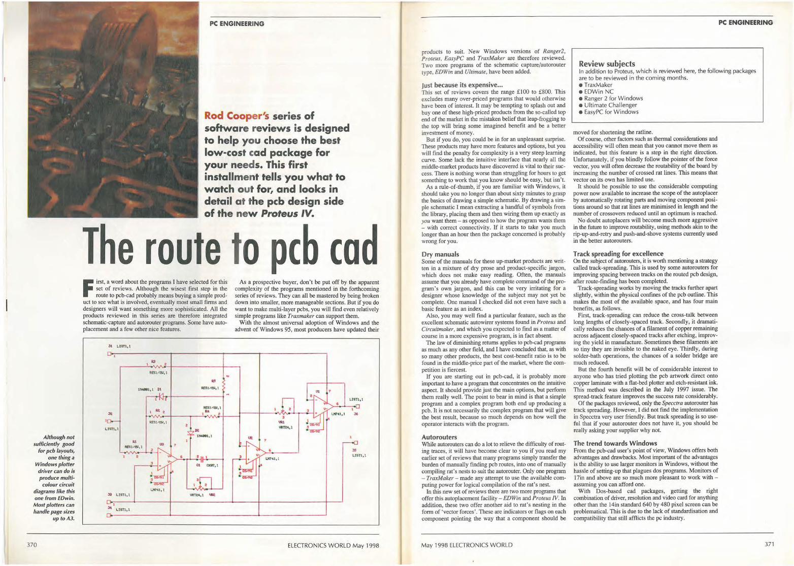
Although not sufficiently good
for pcb layouts, one thing a
Windows plotter driver can do is produce multi-
colour circuit diagrams like this one from EDwin. Most plotters can handle page sizes
up toA3.
370
PC ENGINEERING
Rod Cooper's series of software reviews is designed to help you choose the best low-cost cad package for your needs. This first installment tells you what to watch out for, and looks in detail at the pcb design side of the new Proteus IV.
The route to pcb cod F irst, a word about the programs I have selected for this
set of reviews. Although the wisest first step in the route to pcb-cad probably means buying a simple prod
uct to see what is involved, eventually most small firms and designers will want something more sophisticated. All the products reviewed in this series are therefore integrated schematic-capture and autorouter programs. Some have autoplacement and a few other nice features.
31 LISTI , I
ltS 2
1114111, l ~I
I Ill 2
RESl/&11 1
LISTI, I
us 7
t.!1Nl,l
I J4 LISTl,1
6
R:£$1 1'81,t
RE'St-"2M, 1
1 M e
Dl lfk881,1
e l
Cl CK87, l
3 a
"«it4, t '-'I?
.,
As a prospective buyer, don't be put off by the apparent complexity of the programs mentioned in the forthcoming series of reviews. They can all be mastered by being broken down into smaller, more manageable sections. But if you do want to make multi-layer pcbs, you will find even relatively simple programs like Traxmaker can support them.
With the almost universal adoption of Windows and the advent of Windows 95, most producers have updated their
lit
g JS
UC741, 1 LlSTl,l
ELECTRONICS WORLD May 1998
products to suit. New Windows versions of Ranger2, Proteus, EasyPC and TraxMaker are therefore reviewed. Two more programs of the schematic capture/autorouter type, EDWin and Ultimate, have been added.
Just because its expensive ... This set of reviews covers the range £100 to £800. This excludes many over-priced programs that would otherwise have been of interest. It may be tempting to splash out and buy one of these high-priced products from the so-called top end of the market in the mistaken belief that leap-frogging to the top will bring some imagined benefit and be a better investment of money.
But if you do, you could be in for an unpleasant surprise. These products may have more features and options, but you will find the penalty for complexity is a very steep learning curve. Some lack the intuitive interface that nearly all the middle-market products have discovered is vital to their success. There is nothing worse than struggling for hours to get something to work that you know should be easy, but isn't.
As a rule-of-thumb, if you are familiar with Windows, it should take you no longer than about sixty minutes to grasp the basics of drawing a simple schematic. By drawing a simple schematic I mean extracting a handful of symbols from the library, placing them and then wiring them up exactly as you want them - as opposed to how the program wants them - with correct connectivity. If it starts to take you much longer than an hour then the package concerned is probably wrong for you.
Dry manuals Some of the manuals for these up-market products are written in a mixture of dry prose and product-specific jargon, which does not make easy reading. Often, the manuals assume that you already have complete command of the program's own jargon, and this can be very irritating for a designer whose knowledge of the subject may not yet be complete. One manual I checked did not even have such a basic feature as an index.
Also, you may well find a particular feature, such as the excellent schematic autowirer systems found in Proteus and Circuitmaker, and which you expected to find as a matter of course in a more expensive program, is in fact absent.
The law of diminishing returns applies to pcb-cad programs as much as any other field, and I have concluded that, as with so many other products, the best cost-benefit ratio is to be found in the middle-price part of the market, where the competition is fiercest.
If you are starting out in pcb-cad, it is probably more important to have a program that concentrates on the intuitive aspect. It should provide just the main options, but perform them really well. The point to bear in mind is that a simple program and a complex program both end up producing a pcb. It is not necessarily the complex program that will give the best result, because so much depends on how well the operator interacts with the program.
Auto routers While autorouters can do a lot to relieve the difficulty of routing traces, it will have become clear to you if you read my earlier set of reviews that many programs simply transfer the burden of manually finding pcb routes, into one of manually compiling rat's nests to suit the autorouter. Only one program - TraxMaker - made any attempt to use the available computing power for logical compilation of the rat's nest.
In this new set of reviews there are two more programs that offer this autoplacement facility - ED Win and Proteus IV. In addition, these two offer another aid to rat's nesting in the form of 'vector forces' . These are indicators or flags on each component pointing the way that a component should be
May 1998 ELECTRONICS WORLD
PC ENGINEERING
Review subjects In addit ion to Proteus, which is reviewed here, the fol lowing packages are to be reviewed in the coming months. • TraxMaker • EDWin NC • Ranger 2 for W indows • U ltimate Challenger • EasyPC for Windows
moved for shortening the ratline. Of course, other factors such as thermal considerations and
accessibility will often mean that you cannot move them as indicated, but this feature is a step in the right direction. Unfortunately, if you blindly follow the pointer of the force vector, you will often decrease the routability of the board by increasing the number of crossed rat lines. This means that vector on its own has limited use.
It should be possible to use the considerable computing power now available to increase the scope of the autoplacer by automatically rotating parts and moving component positions around so that rat lines are minimised in length and the number of crossovers reduced until an optimum is reached.
No doubt autoplacers will become much more aggressive in the future to improve routability, using methods akin to the rip-up-and-retry and push-and-shove systems currently used in the better autorouters.
Track spreading for excellence On the subject of autorouters, it is worth mentioning a strategy called track-spreading. This is used by some autorouters for improving spacing between tracks on the routed pcb design, after route-finding has been completed.
Track-spreading works by moving the tracks further apart slightly, within the physical confines of the pcb outline. This makes the most of the available space, and has four main benefits, as follows.
First, track-spreading can reduce the cross-talk between long lengths of closely-spaced track. Secondly, it dramatically reduces the chances of a filament of copper remaining across adjacent close ly-spaced tracks after etching, improving the yield in manufacture. Sometimes these filaments are so tiny they are invisible to the naked eye. Thirdly, during solder-bath operations, the chances of a solder bridge are much reduced.
But the fourth benefit will be of considerable interest to anyone who has tried plotting the pcb artwork direct onto copper laminate with a flat-bed plotter and etch-resistant ink. This method was described in the July 1997 issue. The spread-track feature improves the success rate considerably.
Of the packages reviewed, only the Specctra autorouter bas track spreading. However, I did not find the implementation in Specctra very user friendly. But track spreading is so useful that if your autorouter does not have it, you should be really asking your supplier why not.
The trend towards Windows From the pcb-cad user's point of view, Windows offers both advantages and drawbacks. Most important of the advantages is the ability to use larger monitors in Windows, without the hassle of setting-up that plagues dos programs. Monitors of 17in and above are so much more pleasant to work with -assuming you can afford one.
With Dos-based cad packages, getting the right combination of driver, resolution and video card for anything other than the 14in standard 640 by 480 pixel screen can be problematical. This is due to the lack of standardisation and compatibility that still afflicts the pc industry.
371
PC ENGINEERING
Windows has its own set of drivers applicable to every program -regardless of its origin. However, the generic graphics drivers provided in Windows may not get the best out of any particular card. As cad is an area where good graphics performance is vital, it is always worthwhile taking the trouble to install the card maker's specific driver for Windows 3.x or 95.
Screen redraws are slower in Windows, but this problem has lessened due to the overall speed increase - even in current low-cost entry-level pcs. If you still have a slower 386, it may well be a problem.
Remember that for the real task of pcb-cad - i.e. that of drawing schematics and artwork - the screen area available in a Windows program is invariably less than that of a Dos program. This is especially significant if you have a 14 or 15in monitor
Now for the plot Generally, printers are well catered for in Windows, but pen plotters continue to present a few difficulties - even though the drivers in Windows 95 are much improved over those in its predecessor. The drivers provided in Windows are not really suitable for the demanding work of pcb artwork, although they will of course produce an image.
Typically, when driven by a driver from Windows, the pen will execute a rapid see-saw action when called on to produce thick tracks. A specialised pcb-cad driver on the other band will execute a series of straight overlapping lines, providing much better results. With a see-saw action, if there is any play whatsoever in the plotter mechanism, or if a resonant mode is struck, a roughly-drawn outline will result. There are a few other oddities like this, as the designer who persists in using the Windows driver will find out.
The choice of pen width ceases at 0.3mm, whereas pen widths of 0.2mm and less are used frequently in pcb-cad. There is no incremental adjustment of pen width, although this is often essential in pcb-cad to achieve the fine clearances that are necessary.
But you will get results of a sort with Windows - especially if you stick to thin lines and small pads and don't attempt anything too ambitious. Because plotters can generate such excellent artwork with the right driver, a specialised driver provided by the pcb-cad program makers should be a standard item in every Windows pcb-CAD product. This is not always the case.
PROTEUS IV
On reflection Some programs cannot mirror the artwork for plotting or printing. For example, this used to be true on Ranger2, although you could always get round this by using the Gerber import/export utility. The new Windows version of Ranger2 has this feature built-in.
You should check that mirror-imaging actually works on the pcb-CAD program of your choice, with your particular printer or plotter. Sooner or later you will want to mirror the artwork, even if you don' t plot direct to copper.
One disadvantage of Windows programs is their higher cost. Because individual Windows programs are not encumbered any more with numerous drivers for printers, video etc. and because the development tools are more advanced, Windows packages should be cheaper than their Dos counterparts. Usually, though the opposite is true. There seems no justification for this.
Recently two different program makers commented to me, without prompting, that sometimes a Dos-based program can be easier to operate - a sentiment that I can sympathise with. Over-reliance on the mouse, and over-use of icons in Windows programs could be to blame.
Identifying icons Although it is easy to memorise icons that have become universally recognisable, like the + and - magnifying glass for zoom in/out, it is well-nigh impossible to identify the 50 icons or so that some programs display.
In an attempt to get round this difficulty, pop-up text, sometimes called 'tooltips', is now widely used to identify each icon - but this rather defeats the object of having an icon in the first place. In my view, it would be easier to have the text permanently displayed with, or actually on, the icon. There is usually a delay before the text appears to give you time to remember the icon, and this is adjustable on some programs. However, such a device is an unsatisfactory compromise solution to over-use of icons, so beware of programs with too many of them.
My advice is to look closely at the icons of any program you are interested in buying as they are very much a personal like/dislike subject. Are there too many for you? Are they distinctive? Are they appropriate to the job? And most importantly, are they memorable?
In Windows programs, there is probably a happy medium between menus and icons, but not many programs manage to achieve it. At one end of the spectrum there is Ranger2 with just a handful of icons and more menus, and at the other end is EDWin, with dozens of icons.
Reviewed in the January 1997 issue, the dos version of Proteus emerged as one of the recommended systems. All its original features have been retained in the newer Windows version, - the subject of this review. Much of what was said in the first review still applies. But this version, in addition to running under Windows instead of Dos, has had several significant new features.
floppy disks, and this version, at £550, is limited to 1000 pins. Other versions with different pin limits are available. Security is by registering name and number.
graphics presentation in Part l of the review, so this is an interesting development by Labcenter.
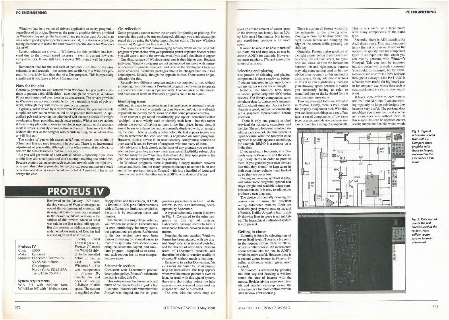
A typical schematic screen in shown in Fig. 1. Compared to the other programs in this set of reviews, Labcenter's package seems to have a reasonable balance between icons and menus.
Proteus IV Cost; £550 Maker; Labcenter Supplier; Labcenter Electronics
53-55 Main Street Grassington North Yorks 8023 SAA Tel. 01756 753440
System requirements WIN 3.1 with 8Mbyte ram, WIN95 o r NT with 16Mbyte ram.
372
Being 32-bit throughout, Proteus IV needs the WIN32S driv-er to be installed before it can be used with Windows 3. l. The two components of Proteus IV, namely Isis and Ares IV, occupy 9.5Mbyte of disk space. The system is supplied on four
The manual is a single large volume, well written and concise. Labcenter has its own terminology for many items, but explanations are given. References to the dos version have now been removed, making the manual easier to read. It is split into three sections covering the schematic, layout, and simulator program - supplied as an extra -and each section has its own comprehensive index.
Schematic section Consistent with Labcenter's product description policy, Proteus's schematic section is called/ sis IV.
This sub-package has taken on board much of the character of Propak's Isis Illustrator. Readers will remember that Propak was singled out for its good
Note that the non-standard Windows format has been retained, with the original 'map' area, icon area and parts bin, and the absence of scroll-bars. Previous users of Labcenter's products will therefore be able to transfer readily to Proteus fV without much re-learning.
Relative to its earlier Dos version, / sis !V's icons are easier to use as pop-up help has been added. This help appears whenever the mouse pointer is over an icon. As usual with this type of system, there is a short delay before the help appears, so experienced users working at speed will not be distracted.
The area with the icons, map etc
ELECTRONICS WORLD May 1998
takes up a fixed amount of screen space so the drawing area is only fair, at 7 .Sin by 5.5in on a 14in monitor. Not having any scroll-bars provides a bit more room.
It would be nice to be able to tum off the parts bin and map area, as can be done in ED Win for example. However, on larger monitors, 17in and above, this is less of an issue.
Selecting and placing The p rocess of selecting and placing components is done exactly as before. If you are interested in this aspect, consult my earlier review for an insight.
Notably, the libraries have been expanded, particularly with 4000 series devices. The library components carry simulator data for Labcenter's integrated Lisa circuit simulator. Access to the libraries is good, and you automatically get a graphical representation before selection.
There is only one generic symbol provided for resistors, capacitors and the like. The pcb footprint is entered on editing each symbol. But this system is rapid because what the footprint code signifies is readily apparent on editing, for example RES40 is a resistor on a 0.4in pitch.
If you need extra footprints, it is relatively easy in Proteus to edit the existing library items in order to provide them. If you generate your own devices like this, they should be kept apart in their own library volume - and backed up so they are never lost.
Placing and moving symbols is easy, and unlike some programs, symbol-text stays upright and readable when symbols are rotated. It is easy to edit text to produce a neat diagram.
The choice of manually drawing the connections or using the excellent wiring autorouter remains. Both are well-designed systems, easy to use and effective. Unlike Propak's Isis, in Isis fV drawing lines in space is not inhibited. The hierarchical multi-sheet system is still present.
Getting in closer Zooming is done by selecting one of
seven fixed levels. There is a big jump in the sequence from 100% to 200%, which is rather coarse. An incremental zoom feature like the one in EDWin would be more useful. However there is a second zoom feature in Proteus IV called shift-zoom which gives more control.
Shift-zoom is activated by pressing the shift key and drawing a window round the area of interest with the mouse. Besides giving more zoom levels and detailed close-up views, the advantage is a lot more control over the area in view after zooming.
May 1998 ELECTRONICS WORLD
There is a zoom-all feature which fits the schematic to the drawing area. Panning is done by holding down the right mouse button and bumping the edge of the screen while pressing the shift key.
Generally, Proteus makes good use of the right mouse button to perform other functions like edit and select, for symbols and wires. At first the interaction between left and right mouse buttons may take some getting used to, but my advice to newcomers to this method is to persevere. Using both mouse buttons in this way can significantly increase your drawing speed because it avoids you constantly having to refer to menu/tool bars or the keyboard for the most common operations.
Two heavyweight tools are available in Proteus. Firstly, there is PAT, short for property assignment tool. With this, you can label such things as a set of bus taps, a set of components of the same type, or a common device package size can be fixed for a string of components.
RV1
R2 4k7
R1 RES
PC ENGINEERING
This is very useful on a large board with many components of the same type.
Secondly, there is ADI, standing for Ascii data import. This was mentioned in my first set of reviews. It allows the operator to specify data for component types in a simple text file, which you can readily generate with Window's Notepad. This can then be imported into any design with a single command. You could, for example, fix the value, tolerance and cost for 0.125W resistors throughout a design. Like PAT, ADI is a feature most useful for big-board use, or for company use, where data such as cost, stock numbers etc. is more significant.
It takes some effort to learn bow to use PAT and ADI, but if you are working regularly on large pcb designs they become very useful. The package does not oblige you to use them and you can get along very well without them. In this respect, Isis can be operated on two levels; simple but flexible, which would
.R23 . RES , ·
C9
Fig. 1. Typical schematic screen from ISIS IV. Compare these graphics with those in Propak, reviewed in the December 1996 issue.
Fig. 2. Rat's nest of one of the test circuits used in the review. Note yellow vector arrows to assist placement.
373
PC ENGINEERING
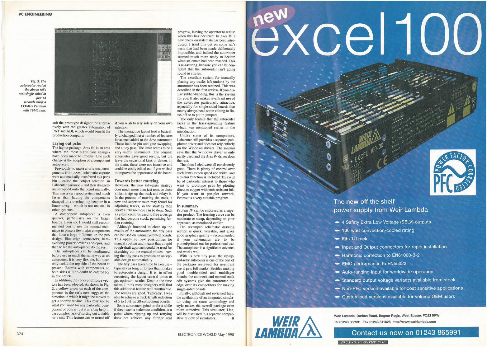
Fig. 3. The autorouter routed
the above rat's nest single-sided in
just 14 seconds using a
133MHz Pentium with 16Mb ram.
374
suit the prototype designer, or alternatively with the greater automation of PAT and ADI, which would benefit the production company.
Laying out pcbs The layout package, Ares IV, is an area where the most significant changes have been made to Proteus. One such change is the adoption of a component au top lacer.
Previously, to make a rat's nest, components from Ares' schematic capture were automatically transferred to a parts bin - called the "object selector" in Labcenter parlance - and then draggedand-dropped onto the board manually. This was a very good system and much faster than having the components dumped in a overlapping heap or in a linear array - which is not unusual in other systems.
A component autoplacer is even quicker, particularly on the larger boards. Even so, I would still recommended you to use the manual technique to place a few major components that have a large influence on the pcb design, like edge connectors, heatevolving power devices and cpus, and then to let the auto-placer do the rest.
The auto-placer can be configured before use in much the same way as an autorouter. It is very flexible, but it can only tackle the top side of the board at present. Boards with components on both sides will no doubt be catered for in due course.
In addition, the concept of force vectors has been adopted. As shown in Fig. 2, a yellow arrow on each of the components in the rat's nest suggests the direction in which it might be moved to get a shorter rat-line. This may not be what you want for any particular component of course, but it is a big help in the complex task of sorting out a viable rat's nest. This feature can be turned off
if you wish to rely solely on your own intuition.
The interactive layout tool is basically unchanged, but a number of features have been added to the Ares autorouter. These include pin and gate swapping, and a tidy pass. The latter seems to be a very useful instrument. The original autorouter gave good results, but did leave the occasional kink or detour. In the main, these were not intrusive and could be easily edited out if you wished to improve the appearance of the board.
Towards better routeing However, the new tidy-pass strategy does much more than just remove these kinks; it rips up the track and relays it. In the process of moving the track, a new and superior route may found for adjoining tracks, so the strategy then iterates until no more can be done. Such a system could be used to free a design that had become stuck, permitting further routeing.
Although intended to clean up the results of the autorouter, the tidy pass can be used on manually-routed boards. This opens up new possibilities for manual routing and means that a rapid rough-draft approach could be used for sketching out the manual routes, leaving the tidy pass to produce an acceptable design automatically.
The tidy pass takes time to execute -typically as long or longer than it takes to autoroute a design. It is, in effect rerouteing the layout several times to get optimum results. Despite the time taken, I think most designers will find this additional feature well worthwhile. The results are good. Typically, I was able to achieve a track length reduction of 5 to 10% on SO-component boards.
Some autorouters grind on for a while if they reach a stalemate condition, at a point where ripping up and retrying does not achieve any further real
progress, leaving the operator to realise when this has occurred. In Ares IV a new check on stalemate has been introduced. I tried this out on some rat's nests that had been made deliberately impossible, and indeed the autorouter seemed much more ready to declare when stalemate had been reached. This is re-assuring, because you can be confident that the autorouter isn ' t going round in circles.
The excellent system for manually placing any tracks left undone by the autorouter has been retained. This was described in the first review. If you dislike rubber-banding, this is the system for you. It also makes re-entrant use of the autorouter particularly attractive, especially for single-sided boards that nearly always need some editing to finish off or to put in jumpers.
The only feature that the autorouter lacks is the track-spreading feature which was mentioned earlier in the introduction.
Unlike some of its competitors, Labcenter still provides a separate penplotter driver and does not rely entirely on the Windows drivers. The manual says that the Windows driver is only partly used and the Ares IV driver does the rest.
The plots I tried were all consistently good. There is plenty of control over such items as pen speed and width, and a mirror function is included This will be of particular interest to those who want to prototype pcbs by plotting direct to copper with etch-resistant ink. If you want to pen-plot artwork, Proteus is a very suitable program.
In summary ProteusJV can be endorsed as a superior product. The learning curve can be moderate or steep, depending on your approach, as mentioned earlier.
The revamped schematic drawing section is quick, versatile, and gives good graphics quality - recommended if your schematics are to be plotted/printed out for professional use. The autoplacer is a significant advance and works well.
With its new tidy pass, the rip-upand-retry autorouter is one of the best of the packages reviewed; for re-entrant use it gets full marks. Besides making good double-sided and multilayer boards, the autoneck and manual track edit systems give the autorouter the edge over its competitors for making single-sided boards.
Finally, although not reviewed here, the availability of an integrated simulator using the same terminology and style makes the overall package even more attractive. This simulator, Lisa, will be discussed in a separate comparative review of simulators. •
ELECTRONICS WORLD May 1998
WEIR~ LAMBDAf&.
Weir Lambda, Durban Road, Bognor Regis, West Sussex PO22 9RW
Tel 01243 865991 Fax 01243 841628 http://www.weirlambda.com
Contact us now on 01243 865991 CIRCLE NO. 11 l ON Rf PLY CARO
CIRCUIT IDEAS •••••••••••••••
Over £600 for a circuit idea? New awards scheme for circuit ideas • Every circuit idea published in Electronics World receives £35 .
• The pick of the month circuit idea receives a Pico Technology ADC42 - worth over £90 - in
addition to £35. • Once every six months, Pico Technology and Electronics World wil l select the best ci rcuit idea
published during the period and award the winner a Pico Technology ADC200-50 - worth £586.
How to submit your ideas The best ideas are the ones that save readers time or money, or that solve a problem in a better or more elegant way than existing circuits. We will also consider the odd solution looking for a problem - if it has a degree of ingenuity.
Your submission will be judged on its originality. This means that the idea should certainly not have been f ublished before. Usefu modifications to existing circuits will be considered though -provided that they are original.
Don't forget to say why you think your idea is worthy. We can accept anything from clear hand writing and hand-drawn c ircuits on the back of an envelope. Type written text is better. But it helps us if the idea is on disk in a popular pc or Mac format. Include an ascii file and hard-copy drawing as a safety net and please label the disk with as much information as you can.
376
fJlc t:• - - It 1· .crn~ 11-1e xix> l•I
,v
flJ1JlJ1J_ ,.ij~i\l I S181521125 ll J5.45W • F- •I• - . -
82Hz ...
"iU_w_w : _,. ... -
U LZ L4 U U 1.1 1.2 1.A
-"'-
r• .,,,. a .,
illliuilJ_ U I.Z ..... U U ... 1.t 1.A
• II
·ti
150Hz C ,. a
., ·l
Turn your PC into a high-performance virtual instrument in return for a circuit idea. The ADC200-50 is a dual-channel 50MHz digital storage oscilloscope,
a 25MHz spectrum analyser and a multimeter. Interfacing to a pc via its
parallel port, ADC200-50 also offers non-volatile storage and hard-copy
facilities. Windows and DOS virtual instrument software is included.
ADC42 is a low-cost, high-resolution a-to-d converter sampling to 12
bits at 20ksample/s. This single-channel converter benefits from all the
instrumentation features of the ADC200-50.
ELECTRONICS WORLD May 1998
CIRCUIT IDEAS
ADC-42 WINN Conditioning temperature sensor output Arecent task was to design a
temperature monitoring system using some 400 sensors and this required a rethinking of the basic sensor conditioning amplifier .
This circuit uses a single op-amp to perform all the functions, usually implemented in a four op-amp configuration, needed by a PtlOO temperature-sensor conditioning amplifier: sensor wire resistance compensation, current-source sensor drive, a three-wire sensing scheme, IOmV/K sensitivity, the Celsius scale offset and induced-noise filtering.
Resistance of.the PtlOO platinum sensor relates to the temperature as :
where R0 =100Q at T0 =273K and a is the temperature coefficient of 3850ppm/K, giving 6l.5Q and 138.5Q at-100°C and +100°C. With such low resistance, wire resistance compensation is necessary and separate current supply and voltage sensing wires are normally used. Differential circuit configuration allows the use of only three wires, instead of four.
Also, a high-impedance current source must supply the sensor to preserve linearity. In th is amplifier, the current source impedance is limited only by the op-amp open-loop d.c. gain and resistor tolerances.
In the circuit shown, RT is the sensing element; Rw; are the wire resistances; R 1 2 3 4 around the op-amp form a conventi~~al bipolar current source; and Rx and R0 subtract the wire resistance error and set the output voltage to·zero for 0°C. Resistor Rb compensates for the opamp input offset currenf and C1,2,3 provide input filtering of any noise picked up by the long sensing wires. If a reference current of 2.597mA is
used (the inverse of the temperature coefficient value), the basic sensitivity of lmV/K is achieved. A further 10 times gain is needed by the circuit to get the lOmV/K, which can be fed directly to a digital volt-meter with a 2V full-scale range. This gain of ten is set by making R4=9R3. Then, the current source confi$uration requests the same nine times ratio for R2 and R i.
If Rx is chosen to be the parallel combination of R3 and R4,
May 1998 ELECTRONICS WORLD
and, to ensure that the reference current is fairly independent of either Rw or RT,
where,
A=l +R 1/R2+R 1/R,+(R 1/R2)(l +R,JR3) B= 1- (R if R2)(R4/R3), C=2(1 +R1/R2)+R1IRx,
Since R0 is constant, A can be of any value. The B factor is cancelled by the current-source configuration requirement: R1= kR3 and R2 = kR4. Substituting R,, R 1 and R2 in C, it also becomes evident that C can be minimised by making k small, say 0.1, so C=2.31, much less than the system gain. With the same substitution, A is
R1
3k
8.417V Vref
1
equal to C, so the equation for reference current becomes,
With l Om of 0 .2mm diameter wire, Rw is 4 .6Q. If R1 is 3kQ, lrer will be in error by less than ±0.33% for values of Rw of up to SQ.
Figure 2 shows that this means some 0.3°C. error for each 100°C, but this error is constant for a given wire resistance and can be corrected by readjusting V,ef· To minimise the errors, use 0.1 % resistors and pay attention to op-amp input offset voltage, since it is amplified by the system gain and a O. lm V offset becomes a 0.1 K reading error; use an OP-07, which has an input voltage offset below 50µV.
R2
27k
Rw1 Ro C2 V1 I
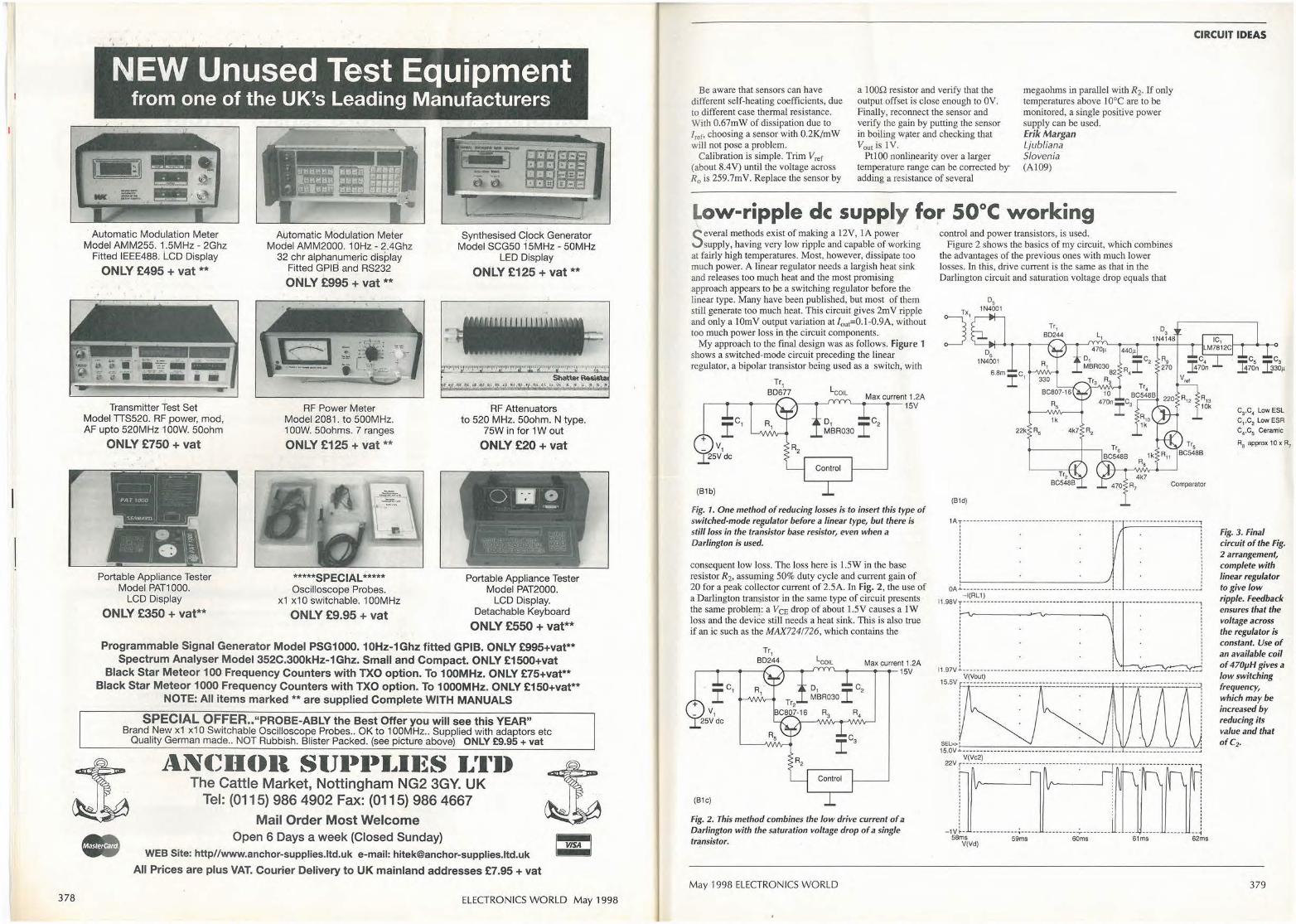
Fig. 1. In spite of the use of only one op-amp instead of the usual four, this conditioning amplifier
5 +-- 100 100nF I C1 lref=2.597mA 10nF Rw2 Rb
1 -for resistance temperature sensors still provides all the V2
R(Rw1) 13k
RT Rxa Rxb
vout requirements for a '>----41--- Pt100 sensor,
Pt100 270k 30k 100•( 1+0.00385•(T-To))
including three-wire sensing and 10mV/K sensitivity. Rw3
1 00
060
020
-0.20
-0.60
R3 V3 =V2
R4
270k
pt100 Amplifier temperature response for various wire resistance values
Vout Error '100 for W"'5 Ohm
Rw=2Ohm
W"'0.5 Ohm
,,/ /
/ / Vout(T)
lref Error.• 10000
Rw=
Rw=0.5.0hm
-1.00~ Temperature [deg. CJ ~ ~ ~ m -100
1 e+4 '(t(Ro)+0.002597) 1 e2'(v(Vout)-O 01 'v(V1)) v(V1)
Fig. 2. Temperature response of the amplifier when using wires of different resistances.
377
378
NEW Unused Test Equipment from one of the UK's Leading Manufacturers
· Automatic Modulation Meter Model AMM255. 1.5MHz - 2Ghz
Fitted IEEE488. LCD Display
ONLY £495 +vat**
. - 111111 ~:; -
, iii 111111111 -
Transmitter Test Set Model TTS520. RF power, mod, AF upto 520MHz 1 00W. 50ohm
ONLY £750 + vat
' . .--1 ,.,.,, , ,ooo l
- _I 'UAW,qltll _I
Portable Appliance Tester Model PAT1000.
LCD Display
ONLY £350 + vat**
Automatic Modulation Meter Model AMM2000. 10Hz - 2.4Ghz
32 chr alphanumeric display Fitted GPIB and RS232
ONLY £995 +vat**
RF Power Meter Model 2081. to 500MHz. 1 00W. 50ohms. 7 ranges
ONLY £125 +vat**
*****SPECIAL***** Oscilloscope Probes.
x1 x10 switchable. 100MHz
ONLY £9.95 + vat
Synthesised C)ock Generator Model SCG50 15MHz - 50MHz
LED Display
ONLY £125 +vat**
RF Attenuators to 520 MHz. 50ohm. N type.
75W in for 1 W out
ONLY £20 + vat
Portable Appliance Tester Model PAT2000.
LCD Display. Detachable Keyboard
ONLY £550 + vat**
Programmable Signal Generator Model PSG1000. 10Hz-1Ghz fitted GPIB. ONLY £995+vat** Spectrum Analyser Model 352C.300kHz-1Ghz. Small and Compact. ONLY £1500+vat
Black Star Meteor 100 Frequency Counters with TXO option. To 100MHz. ONLY £75+vat** Black Star Meteor 1000 Frequency Counters with TXO option. To 1000MHz. ONLY £150+vat**
NOTE: All items marked ** are supplied Complete WITH MANUALS
SPECIAL OFFER .. "PROBE-ABLY the Best Offer you will see this YEAR" Brand _New x1 x10 Switchable Oscilloscope Probes .. OK to 1 00MHz .. Supplied with adaptors etc
Quality German made .. NOT Rubbish. Blister Packed. (see picture above) ONLY £9.95 + vat
11.N(~ll()Il SIJl•t•I ... Il~S I ... '111) The Cattle Market, Nottingham NG2 3GY. UK
Tel: (0115) 986 4902 Fax: (0115) 986 4667 Mail Order Most Welcome
Open 6 Days a week (Closed Sunday) WEB Site: http//www.anchor-supplies.ltd.uk e-mail: [email protected]
All Prices are plus VAT. Courier Delivery to UK mainland addresses £7.95 + vat
ELECTRONICS WORLD May 1998
CIRCUIT IDEAS
Be aware that sensors can have different self-heating coefficients, due to different case thermal resistance. With 0.67mW of dissipation due to lrer, choosing a sensor with 0.2K/mW will not pose a problem.
a IO0Q resistor and verify that the output offset is close enough to 0V. Finally, reconnect the sensor and verify the gain by putting the sensor in boiling w11ter and checking that Voutis IV.
megaohms in parallel with R2. If only temperatures above 10°C are to be monitored, a single positive power supply can be used. Erik Margan Ljubliana
Calibration is simple. Trim V,ef (about 8.4V) until the voltage across R0 is 259.?mV. Replace the sensor by
Ptl00 nonlirearity over a larger temperature range can be corrected by adding a resistance of several
Slovenia (A109)
Low-ripple de supply for 50°C working Several methods exist of making a 12V, IA power
supply, having very low ripple and capable of working at fairly high temperatures. Most, however, dissipate too much power. A linear regulator needs a largish heat sink and releases too mu~h heat and the most promising approach appears to pe a switching regulator before the linear type. Many have been published, but most of them still generate too much heat. This circuit gives 2mV ripple and only a I Om V output variation at lout=0. I-0.9A, without too much power loss in tJ-ie circuit components.
My approach to the final design was as follows. Figure 1 shows a switched-mode circuit preceding the linear regulator, a bipolar transistor being used as a switch, with
(81b)
Tr1 8D677
Max current 1.2A 15V
o, Ic2 MBR030
Control
Fig. 1. One method of reducing losses is to insert this type of switched-mode re[Julator before a linear type, but tfiere is still loss in the transistor base resistor, even when a Darlington is used.
conseqµent low loss. The loss here is 1.5W in the base resistor R2, assuming 50% duty cycle and current gain of 20 for a peak collector current of 2.5A. In Fig. 2, the use of a Darlington tran&istor in the same type of circuit presents the same problem: a V CE drop of about 1.5V causes a I W loss and the device still needs a heat sink. This is also true if an ic such as the MAX724!726, which contains the
(B1c)
Tr1 8D244 Max current 1.2A
'--.----...-15V
Control
Fig. 2. This method combines the low drive current of a Darlington with the saturation voltage drop of a single transistor.
May 1998 ELECTRONICS WORLD
control and power transistors, is used. Figure 2 shows the basics of my circuit, which combines
the advantages of the previous ones with much lower losses. In this, drive current is the same as that in the Darlington circuit and saturation voltage drop equals that
A,, 10k
Comparator
(81d)
1 A:·----------------------------------------- -- ---------------------1
' ' '
i . . I · i OA .!. .. -- -- ------- -- -- -- ---- -- --- ----- ------........ 1.... .. .. -- .... - -- ------- - -- - .. J
-l(RL1) I1.98V T--- --- -- - - -- -- -------- - - - • ---------- -- ----,-- - ----- --• ------- - ----,
: I : I !
' ' ' ' : I '
I1.97V .1. .... ---- --- -- - ----- -- -- ------- ------- ...... ____ .. __ - ----- --- - - - -- - - - --- • .J
V(Voul) 15.5V r:-:.-.::::.-.::::.::.:::.:.-.::-:.-.:.::.:.::.:.::.::.:::.:.::.:r:.- .:::.:.-.:::.:.-.:.::.:.::.:.::..:-1
' ' ' ' ' ' ' ' ' ' ' ' ' ' ' ' ' ' ' ' ' ' ' ' ' ' ~=· ' 15.0V ~ --- --------- -- ----------- -- ------ ---- --- --- -- -- --- -- --------------.
V(Vc2) 22V r --- - - --------- -- ------ -------- --- ---- --- -- - , - - ---- --- ------- - - - --- - 1
I • • I
' '
' ' '
-1V ~- --------------,-----58ms 59ms
V(Vd) 60ms 61ms
C3,C4 Low ESL C1 ,C2 Low ESR C4,C5 Ceramic
R8 approx 10 x R7
Fig. 3. Final circuit of the Fig. 2 arrangement, complete with linear regulator to give low ripple. Feedback ensures that the voltage across the regulator is constant. Use of an available coil of 470µH gives a fol¥ switching frequency, which may be increased by reducing its value and that of C2,
379
CIRCUIT IDEAS
of Fig. l, loss being only 0.25W; no heat sink is needed. Voltage spikes caused by the use of an electrolytic, with its higher equivalent series inductance, at C 2 are reduced by the 1-p filter in the drive transistor collector.
The final circuit is that of Fig. 3, in which the input voltage to the regulator is 25V on C 1 at 0 .1 A load and 20V at l.2A. I wanted to make the voltage drop across the LM7812 linear regulator 3V, regardless of the ±5% output tolerance, so used Vout as reference; at worst, a ·fixed reference can give an additional power'lqss of 1.2W at lA. The diode is for safety and is biased by R13.
Maximum voltage at th'e input of the LM7812 is determined by R 9,10 and i·s, '
V;n=(CVoutf R 10)+(0.68/R I 1))R9+ Vout·
The minimum depends on Rs,12 and, slightly, R11 :
0 68 x (1 + R X ( -1
- -1- )) + V x Rs
. 8 RII R 12 OUI R 12
v:u, = 1J 1+~
R1 2
Since, when power is first applied, there is no reference voltage, make R7,s such that V0 u1R7/(R7+Rs)=l V. To ensure that Tr 4 5 ·define the switching, make R 11 greater than 2. 7Q. E. -Vanderfeesten Genk Belgium (Bl)
Dumping st~r~d high voltages
A nyone working with valve equipment will know, probably from hard-won experience; that high-value,
high-voltage capacitors will store a charge for many hours and still provide entertainment for colleagues, if not worse.
04
D2 1 N4001
1N4007 HT R/ Cap+
+ C1 6.3V
1N4001 220µ Heater ALA circuit
(B4a)
ncyo RL1
This little circuit prevents all that. When power goes off, the normally open relay closes
and th.e ht capacitors discharge to earth through R 1, D3 indicating the current flow. In principle, you can connect any number of capacitors, wire-Ored via diodes, which isolate capacitors from each other.
The relay may be any 6V type with a changeover contact rated at the relevant voltage and about lA. Choose R2 to drop any excess voltage from the heater line. Jeff Macaulay'. Chichester. West Sussex (B4a)
Discharger for lingering dangerous voltages on capacitors in valve equipment; only two dischargers are shown, but more may be connected.
Timebase-controlled event positioner
If an oscilloscope's timebase waveform is brought out to the front panel, this circuit
allows the viewing of an event at any point on the sweep, rather in the manner of a delaying sweep.
An LM311 comparator switches the optoisolator at a time after the start of a sweep determined by the setting of the potentiometer, the output terminals being taken to the circuit providing the "e~ent" to
be examined. At any timebase speed, the event is always at the same point on the screen.
Several types of optoisolator can be used:
_____ _________ _ _____ +J2V
the HI 1 F 1, which turns on and off in 20µs, is used for audio; for fast logic, the H 11 Ll; when looking at mains frequency, the H 11 C6 scr output or the S2JM.E3 triac 68k
33k 22k
380
Turn ott t = 20µs
Turn on t = 20µs
Ron = 1500 (1 OmA)
device are useful; and for analogue switching, the TLP59G may be used. · ' 1
I used the circuit to examine the operation of an age circuit, a step level change being placed in the centre of the screen.
Using an oscilloscope's sweep output to position Peter Kenyon an occurrence in the middle of the trace. '• Almancil
(82b)
Portugal (B2)
ELECTRONICS WORLD May 1998
Surely not Surely someone somewhere has developed a portable programmer that has even more features, even greater flexibility and is even better value for money.
Actually, no. But don't take our word for it. Use the feature summary below to see how
other manufacturers' products compare.
• Plugs straight into parallel port of PC or laptop
• Programs and verifies at 2, 2.7, 3.3 and SV • True no•adaptor programming up to 48 pin
OIL devices • Free universal 44 pin PLCC
adaptor
for go·anywhere programming .r,,·
/NT, · . -. . 7 11 t ... .. .F/._LIGL:Nr . .. . r I.
. . . /J_NIVERSAL. . . . .. .. · · PRDGR · ..
If you do not agree that these truly are the most powerful portable programmers you
can buy, simply return your Dataman product within 30 days for a full refund
• Package adaptors available for TSOP, PSOP, QFP, SOIC and PLCC
• Optional EPROM emulator
~· FREE
. · 4~~ER
·.t\\tirii~t~ ··•t} · _ still I -4
DAY TRlAl
· -Ip?)Jgf£Hlr11"l?Psrtable
~ C
'':::J 8
•":'-; </
~.,.-.···· .·; r-::-i ··,r-::, - ~ ,-,... C7!J - ~ f:'7) ,.._
0 -· ,.1~
€: F . --
/ 4 8 ·~
0 1
6 7 J
:l J
Orders received by 4pm will normally be despatched same day. Order today, get it tomorrow!
Programs 8 and 16 bit EPROMs, EEPROMs, PEROMs, 5 and 12V FLASH, Boot-Block FLASH, PICs, 8751 microcontrollers and more
• EPROM emulation as standard
• Rechargeable battery power for total portabil ity
• All-in•one price includes emulation leads, AC charger, PC software, spare library ROM, user.friendly manual
• Supplied fully charged and ready to use
• Programs wide range of 20 and 24 pin logic devices from the major GAL vendors
• Supports JEDEC files from all popular compilers
Beware of cheap imitations. Beware of false
promises. Beware of hidden extras. If you want the best, there's still only one choice • Dataman.
Order via credit card hotline • phone today, use tomorrow. Alternatively, request more detailed
information on these and other market· leading programming solutions.
,' ' ' \ l; \_\ ,I 1· : '
GUARANTEE
• 3 year parts and labour guarantee
• Windows/DOS software included • Free technical support for life • Next day delivery • always in stock
• Dedicated UK supplier, established 1978
Dataman Programmers Ltd, Station Road, Maiden Newton, Dorchester, Dorset, DT2 OAE, UK
Telephone +4410 1300 320719
Fax +44/0 1300 321012
BBS +4410 1300 321095 (24hr) Modem V.34N.FCN32bis
Home page: http://vwM1.dataman.com
FTP: ftp.dataman.com
Email: [email protected]
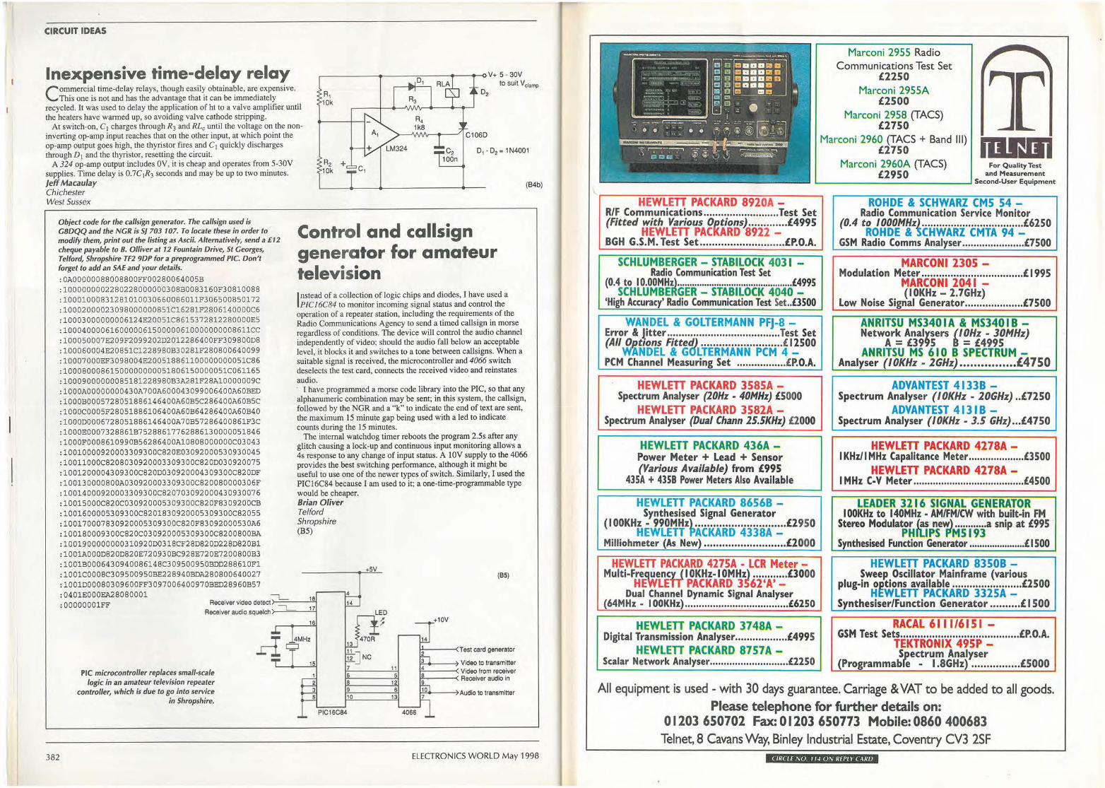
CIRCUIT IDEAS
Inexpensive time-delay relay Commercial time-delay relays, though easily obtainable, are expensive.
This one is not and has the advantage that it can be immediately recycled. It was used to delay the application of ht to a valve amplifier until the heaters have warmed up, so avoiding valve cathode stripping.
to suit V clamp
At switch-on, C I charges through R3 and RLc until the voltage on the noninverting op-amp input reaches that on the other input, at which point the op-amp output goes high, the thyristor fires and C I quickly discharges through D 1 and the thyristor, resetting the circuit.
A 324 op-amp output includes OV, it is cheap and operates from 5-30V supplies. Time delay is 0.7C1R3 seconds and may be up to two minutes. Jeff Macaulay Chichester West Sussex
Object code for the cal/sign generator. The cal/sign used is GBDQQ and the NGR is SJ 703 107. To locate these in order to modify them, print out the listing as Ascii. Alternatively, send a £12 cheque payable to 8. Olliver at 12 Fountain Drive, St Georges, Telford, Shropshire TF2 9DP for a preprogrammed PIC. Don't forget to add an SAE and your details. :OA00000088008800FF00280064005B :1000000002280228000000308B0083160F30810088 :10001000831281010030660086011F306500850172 :10002000023098000000851Cl6281F2806140000C6 :10003000000006124E20051C8615372812280000E5 :1000400006160000061500000610000000008611CC :100050007E209F2099202D2012286400FF309800D8 :100060004E20851C1228980B30281F280800640099 :10007000EF3098004E200518861100000000051C86 :10008000861500000000051806150000051C061165 :10009000000085181228980B3A281F28A10000009C :1000A00000000430A700A600043099006400A60BED :1000B0005728051886146400A60B5C286400A60B5C :1000C0005F28051886106400A60B64286400A60B40 :1000D0006728051886146400A70B57286400861F3C :1000E0007328861B75288617762886130000051846 :1000F0008610990B56286400Al0808000000C03043 :10010000920003309300C820E03092000530930045 :10011000C8208030920003309300C820D030920075 :1001200004309300C820D030920004309300C820DF :100130000800A030920003309300C820080000306F :10014000920003309300C820703092000430930076 :10015000C820C030920005309300C820F8309200CB :1001600005309300C8201830920005309300C82055 :100170007830920005309300C820F83092000530A6 :100180009300C820C030920005309300C8200800BA :1001900000000310920D0318CF28D820D228D820Bl :1001A000D820D820E720930BC928E720E7200800B3 :1001B0006430940086148C309500950BDD288610Fl :1001C0008C309500950BE228940BDA280800640027 :1001D00080309600FF3097006400970BED28960B57 :0401EOOOEA28080001 :OOOOOOOlFF
382
PIC microcontroller replaces small-scale logic in an amateur television repeater
controller, which is due to go into service in Shropshire.
{B4b)
Control and callsign generator for amateur television
Instead of a collection of logic chips and diodes, I have used a PIC16C84 to monitor incoming signal status and control the
operation of a repeater station, including the requirements of the Radio Communications Agency to send a timed callsign in morse regardless of conditions. The device will control the audio channel independently of video; should the audio fall below an acceptable level, it blocks it and switches to a tone between callsigns. When a suitable signal is received, the microcontroller and 4066 switch deselects the test card, connects the received video and reinstates audio. · I have programmed a morse code library into the PIC, so that any alphanumeric combination may be sent; in this system, the callsign, followed by the NGR and a "k" to indicate the end of text are sent, the maximum 15 minute gap being used with a led to indicate counts during the 15 minutes.
The internal watchdog timer reboots the program 2.5s after any glitch causing a lock-up and continuous input monitoring allows a 4s response to any change of input status. A lOV supply to the 4066 provides the best switching performance, although it might be useful to use one of the newer types of switch. Similarly, I used the PIC16C84 because I am used to it; a one-time-programmable type would be cheaper. Brian Oliver Telford Shropshire (B5)
18
17
16
+SV
4
14
LED
13 470R
11 12 J Nc 7 6 8 9 10
~
(B5)
I-'-----< Test card generator
~---, Video to transmitter ------s. Video from receiver i-=-,-------< Receiver audio in
ELECTRONICS WORLD May 1998
f ;..,.------,---··_-_ .. _____ __ ;..-1 .I . ' ,, r ·•:
.. .. .., .. . , ............... , .. .. _ .. __ . '
Marconi 2955 Radio Communications Test Set
£2250 Marconi 2955A
£2500 Marconi 2958 (TACS)
£2750 Marconi 2960 (TACS + Band Ill)
£2750 Marconi 2960A (TACS) For Quality Test
£2950 and Measurement .__ __________ _ _..., Second-User Equipment
HEWLETT PACKARD 8920A -R/F Communications .......................... Test Set (Fitted with Various 01?.(ions) ............. £4995
HEWLETT PACKARD 8922 -BGH G.S.M. Test Set ............................ £P.O.A.
SCHLUMBERGER - STABILOCK 4031 -Radio Communication Test Set
(0·\~
0Hlt~;~~GE·R··:·Ir Aa·itoci<·404l4!95
'High Accuracy' Radio Communication Test Set .. £3500
WANDEL & GOLTERMANN PFJ-8 -Error & Jitter ....................................... Test Set (All_ pptions Fitted) ........................... £ I 2500
WANDEL & GOLTERMANN PCM 4 -PCM Channel Measuring Set ................. £P.O.A.
HEWLETT PACKARD 3585A -Spectrum Analyser (20Hz - 40MHz) £5000
HEWLETT PACKARD 3582A -Spectrum Analyser (Dual Chann 25.SKHz) £2000
HEWLETT PACKARD 436A -Power Meter + Lead + Sensor (Various Available) from £995
435A + 435B Power Meters Also Available
HEWLETT PACKARD 86568 -Synthesised Signal Generator
( I OOKHz - 990MHz) .............................. £2950 HEWLETT PACKARD 4338A -
Milliohmeter (As New) ........................... £2000
HEWLETT PACKARD 4275A - LCR Meter -Multi-Freg~~nc1 ( I OKHz-10MHz) ............ £3000
HEWLETT PACKARD 3562'A' -Dual Channel Dynamic Signal Analyser
(64MHz • I OOKHz) ..................................... £6250
HEWLETT PACKARD 3748A -Digital Transmission Analyser .................. £4995
HEWLETT PACKARD 87S7A -Scalar Network Analyser ............................ £2250
ROHDE & SCHWARZ CMS 54 -Radio Communication Service Monitor
(0.4 to I OOOMHzl ................................... £6250 ROHDE & SCHWARZ CMTA 94 -
GSM Radio Com ms Analyser ...................... £7500
MARCONI 2305 -Modulation Meter ................................... £ 1995
MARCONI 2041 -(IOKHz - 2.7GHz)
Low Noise Signal Generator .................... £7500
ANRITSU MS340 I A & MS340 I B -Network Analysers 'I OHz - 30MHz)
A= £3995 = £4995 ANRITSU MS 610 B SPECTRUM -
Analyser (IOKHz - lGHz) •••••••••••••••• £4150
ADVANTEST 4133B -Spectrum Analyser ( I OKHz - 20GHz) .. £7250
ADVANTEST 4131 B -Spectrum Analyser (IOKHz - 3.5 GHz) ..• £4750
HEWLETT PACKARD 4278A -I KHz/I MHz Capalitance Meter .................... £3500
HEWLETT PACKARD 4278A -I MHz C-V Meter ........................................ £4500
LEADER 3216 SIGNAL GENERATOR I OOKHz to 140MHz - AM/FM/CW with built-in FM
Stereo Modulator (as new) ............ a snip at £995 · PHlllPS F'MS 193
Synthesised Function Generator ...................... £ 1500
HEWLETT PACKARD 83508 -Sweep Oscillator Mainframe (various
plug-in options available ........................ £2500 HEWLETT PACKARD 3325A -
Synthesiser/Function Generator .......... £ I 500
RACAL 611 1/6151 -GSM Test Sets ....••.••...•••••...•••••••••••••.•.•••.• £P.O.A.
TEKTRONIX 495P -Spectrum Analyser
(Programmabre - 1.8GHz) ................ £5000
All equipment is used - with 30 days guarantee. Carriage & VAT to be added to all goods. Please telephone for further details on:
01203 6S0702 Fax: 01203 6S0773 Mobile: 0860 400683 Telnet, 8 Cavans Way, Binley Industrial Estate, Coventry CV3 2SF
CIRCLE NO 11-' O N REPLY CAR/J
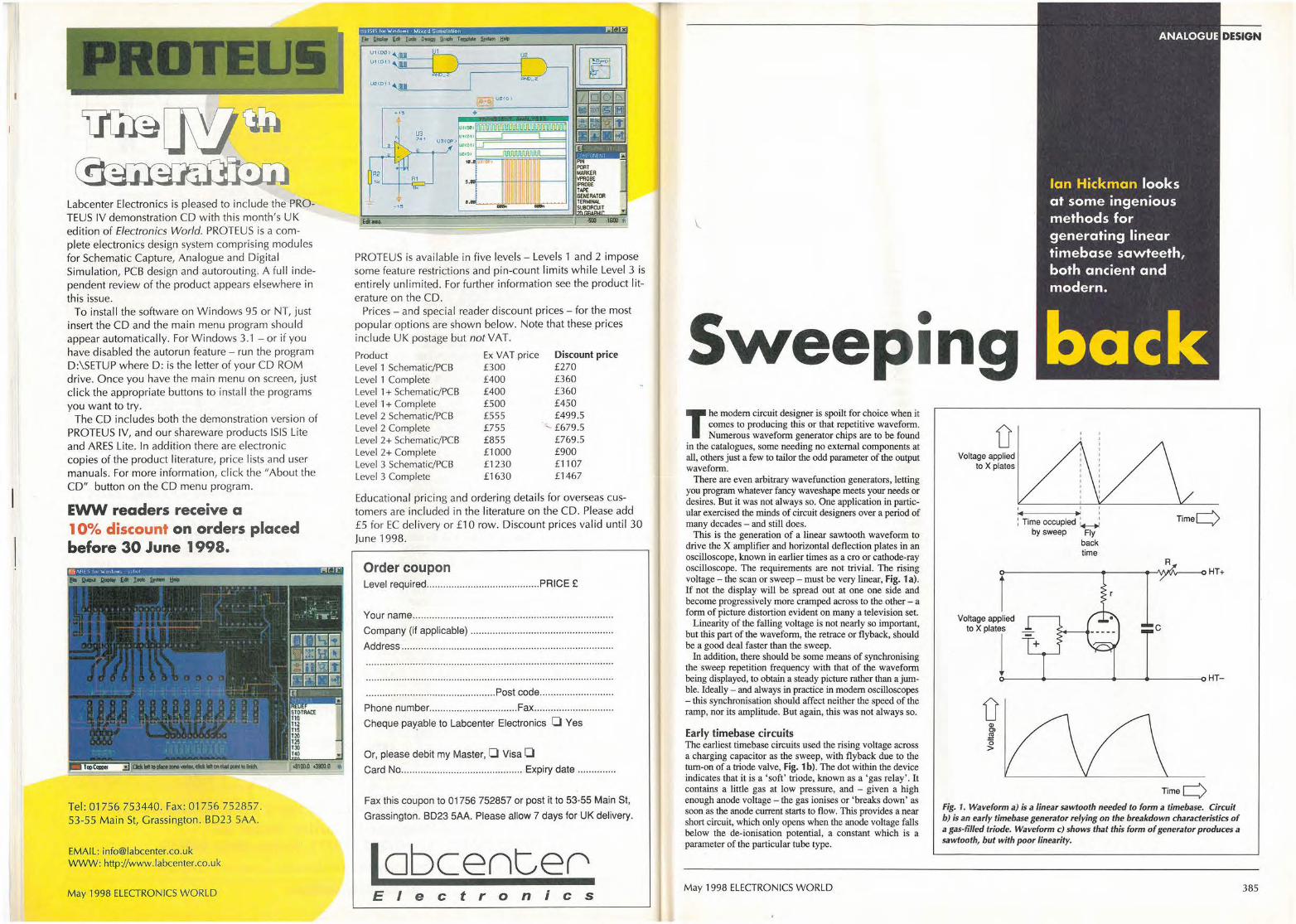
U!i
Labcenter Electronics is pleased to include the PROTEUS IV demonstration CD with this month's UK edition of Electronics World. PROTEUS is a complete electronics design system comprising modules for Schematic Capture, Analogue and Digital Simulation, PCB design and autorouting. A full independent review of the product appears elsewhere in this issue.
To install the software on Windows 95 or NT, just insert the CD and the main menu program should appear automatically. For Windows 3.1 - or if you have disabled the autorun feature - run the program D :\SETUP where D: is the letter of your CD ROM drive. Once you have the main menu on screen, just click the appropriate buttons to install the programs you want to try.
The CD includes both the demonstration version of PROTEUS IV, and our shareware products ISIS Lite and ARES Lite. In addition there are electronic copies of the product literature, price lists and user manuals. For more information, click the "About the CD" button on the CD menu program.
EWW readers receive a 10% discount on orders placed before 30 June 1998.
Tel: 01756 753440. Fax: 01756 752857. 53-55 Main St, Grassington. BD23 SAA.
EMAIL: [email protected] WWW: http://www.labcenter.co.uk
May 1998 ELECTRONICS WORLD
M@titttlMfflteWtHtii•fiihiim
U1(00}
UHOO "'111=---i
IJ2'(0-1)
... '
PROTEUS is available in five levels - Levels 1 and 2 impose some feature restrictions and pin-count limits while Level 3 is entirely unlimited. For further information see the product l iterature on the CD.
Prices - and special reader discount prices - for the most popular options are shown below. Note that these prices include UK postage but not VAT.
Product Level 1 Schematic/PCB Level 1 Complete Level 1 + Schematic/PCB Level 1 + Complete Level 2 Schematic/PCB Level 2 Complete Level 2+ Schematic/PCB Level 2+ Complete Level 3 Schematic/PCB Level 3 Complete
Ex VAT price £300 £400 £400 £500 £555 £755 £855 £1000 £1230 £1630
Discount price £270 £360 £360 £450 £499.5
.__ £679.5 £769.5 £900 £1107 £1467
Educational pricing and ordering details for overseas customers are included in the literature on the CD. Please add £5 for EC del ivery or £10 row. Discount prices valid until 30 June 1998.
Order coupon Level required ......................................... PRICE £
Your name ....................................................................... ..
Company (if applicable) ................................................... .
Address .... ......... .................................. ............................. .
.................... ........................... Post code .......................... .
Phone number ................................ Fax ........... ........... ...... .
Cheque pay_able to Labcenter Electronics O Yes
Or, please debit my Master, 0 Visa 0 Card No ............................................ Expiry date ............. .
Fax this coupon to 01756 752857 or post it to 53-55 Main St,
Grassington. 8D23 5AA. Please allow 7 days for UK delivery.
lobcent,er Electronics
ANALOGUE
Ian Hickman looks at some ingenious methods for generating linear timebase sawteeth, both ancient and modern.
DESIGN
Sweeping T he modem circuit designer is spoilt for choice when it
comes to producing this or that repetitive waveform. Numerous waveform generator chips are to be found
in the catalogues, some needing no external components at all, others just a few to tailor the odd parameter of the output waveform.
There are even arbitrary wavefunction generators, letting you program whatever fancy waveshape meets your needs or desires. But it was not always so. One application in particular exercised the minds of circuit designers over a period of many decades - and still does.
This is the generation of a linear sawtooth waveform to drive the X amplifier and horizontal deflection plates in an oscilloscope, known in earlier times as a cro or cathode-ray oscilloscope. The requirements are not trivial. The rising voltage - the scan or sweep - must be very linear, Fig. 1 a). If not the display will be spread out at one one side and become progressively more cramped across to the other - a form of picture distortion evident on many a television set.
Linearity of the falling voltage is not nearly so important, but this part of the waveform, the retrace or flyback, should be a good deal faster than the sweep.
In addition, there should be some means of synchronising the sweep repetition frequency with that of the waveform being displayed, to obtain a steady picture rather than a jumble. Ideally - and always in practice in modern oscilloscopes - this synchronisation should affect neither the speed of the ramp, nor its amplitude. But again, this was not always so.
Early timebase circuits The earliest timebase circuits used the rising voltage across a charging capacitor as the sweep, with flyback due to the turn-on of a triode valve, Fig. 1 b). The dot within the device indicates that it is a 'soft' triode, known as a 'gas relay'. It contains a little gas at low pressure, and - given a high enough anode voltage - the gas ionises or 'breaks down' as soon as the anode current starts to flow. This provides a near short circuit, which only opens when the anode voltage falls below the de-ionisation potential, a constant which is a parameter of the particular tube type.
May 1998 ELECTRONICS WORLD
D Voltage applied
to X plates
: Time occupied :,._: by sweep Fly
back time
Timec:)
R o-------------J\/\,1(1,.,.--ciHT+
1 Voltage applied
C
+ to X plat1
o----------+--+------oHT-
D (I)
$ 0 >
Timec:)
Fig. 1. Waveform a) is a linear sawtooth needed to form a timebase. Circuit b) is an early timebase generator relying on the breakdown characteristics of a gas-filled triode. Waveform c) shows that this form of generator produces a sawtooth, but with poor linearity.
385
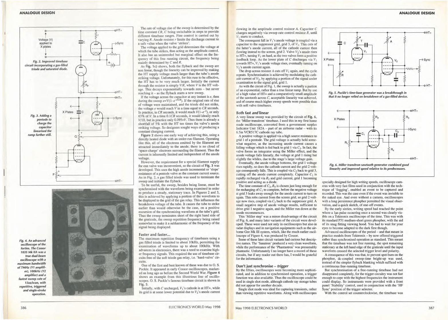
ANALOGUE DESIGN
0---------....----....---------vHT+
i Voltage (V) applied to X plates
! Fig. 2. Improved timebase
circuit incorporating a gas-filled triode and saturated diode.
C Sync
---------...HT..----------~r----<>HT+
Fig. 3. Adding a pentode to charge the capacitor
linearised the ramp further still.
Fig. 4. An advanced oscilloscope of the forties. The Cossor 1035 Mk /IA was a
true dual-beam oscilloscope with a
maximum bandwidth o f 7MHz (Y1 amplifi
er), 100kHz (Y2 amplifier) and a
fastest sweep rate of 15us/scan, with
repetitive, triggered and single-stroke
operation.
386
+ p >•-c--------~ '-----------------oHT-
The rate of voltage rise of the sweep is determined by the time constant CR, C being switchable in steps to provide different timebase ranges. Fine control is carried out by varying R. Anode resistor r limits the discharge current to a safe value when the valve 'strikes'.
The voltage applied to the grid determines the voltage at which the tube strikes, thus acting as the amplitude control. It also has an unintended but marginal effect on the frequency of this free running circuit, the frequency being mainly determined by C and R.
As Fig. 1 c) shows, both the flyback and the sweep '.1fe non linear, though the linearity can be improved by making the HT supply voltage much larger than the tube's anode striking voltage. Unfortunately, for this ruse to be effective, the HT has to be very much larger. Initially the current through the resistor is simply VIR, where Vis the HT voltage. This decays exponentially towards zero - but never reaching it - as the flyback starts a new sweep.
If the voltage across the capacitor at any instant is e, then during the sweep e=V(1-e-11CR). If the original rate of rise of voltage were maintained, and the triode did not strike, the voltage e would reach Vin a time equal to CR seconds. In practice, in CR seconds, it would reach V(l-e-1
), or only 63% of V. ln a time 0. lCR seconds, it would ideally reach V/10, but in practice only 0.095xV. Thus there is already a shortfall of 5% with the HT ten times the valve's anode striking voltage. So designers sought ways of producing a constant charging current.
Figure 2 shows one early way of achieving this, using a directly heated diode with an under-run filament. Operatmg like this, all of the electrons emitted by the filament are attracted immediately to the anode; there is no cloud of 'space-charge' electrons surrounding the filament. Thus the current is inherently limited and independent of the anode voltage.
However, the requirement for a special filament supply for one valve was inconvenient, so the circuit of Fig. 3 was developed. This uses the high anode incremental or 'slope' resistance of a pentode valve as the constant current source. As in Fig. 2, a gas filled triode was used to terminate the sweep and initiate the flyback.
To be useful, the sweep, besides being linear, must be synchronised with the waveform being examined in order to produce a steady, stationary trace. In Figures 2 and 3, this is achieved by applying a portion of the waveform to be displayed to the grid of the gas relay. This influences the breakdown voltage of the tube. It causes the tube to strike earlier than would otherwise be the case, on a positive excursion of the synchronising waveform at the tube's grid. Thus the sweep terminates short of the right hand side of the graticule, the sweep repetition frequency being raised somewhat to make it a subharmonic of the frequency of the signal being displayed.
Faster and faster ... The maximum repetition frequency of timebases using a gas filled triode is limited to about 1 0kHz, permitting the examination of waveforms up to about I 00kHz. With advances in electronics, there was a need to examine higher frequency signals. This required the use of timebase circuits free of the soft triode gas relay, i.e. 'hard-valve' circuits.
One of the first and best known of these was due to 0. S. Puckle. It appeared in early Cossor oscilloscopes, marketed as long ago as before the Second World War. Figure 4 shows an example from this illustrious line of oscilloscopes. 0. S. Puckle's famous timebase circuit is shown in Fig. 5.
Initially, with C uncharged, V1 's cathode is at HT+, while its grid is at some lower potential due to V2's anode current
ELECTRONICS WORLD May 1998
flowing in the amplitude control resistor A. Capacitor C charges negatively via sweep rate control resistor R, until VI starts to conduct.
The consequent fall in V1 's anode voltage is coupled via a capacitor to the suppressor grid, grid 3, of V1• This cuts of the latter's anode current, au of the cathode current then flowing instead to the screen, grid 2. Valve V2's anode rises to HT+, tuming V1 on hard, as the two valves form a positive feedback loop. As the lower plate of C discharges via V1 towards HT+, V1 's anode voltage rises, eventually turning on V2's anode current again.
The drop across resistor A cuts off V1 again, and the cycle repeats. Synchronisation is achieved by modulating the cathode current of V2, by applying a portion of the signal under examination to the signal grid, grid I .
As with the circuit of Fig. 1, the sweep is actually a portion of an exponential, rather than a true linear ramp. But by use of a high value of HT+ and a comparatively small amplitude of the sawtooth across C, acceptable linearity was achieved, and of course much higher sweep speeds were possible than with soft valve timebases.
Both fast and linear A very linear sweep was provided by the circuit of Fig. 6, the 'Miller transitron' timebase. I used this in my first home made oscilloscope, converted from a government surplus Indicator Unit 182A - part of an airborne radar - with its 6.Sin VCR5 l 7C cathode ray tube.
A positive voltage is applied via a high source resistance to grid 1 of a pentode. The grid voltage is actually held somewhat negative, as the increasing anode current causes a falling voltage which is fed back to grid l via C1. In fact, the valve forms an integrator using the Mi.lier effect, and the anode voltage falls linearly, the voltage at grid l rising but slightly the whiles, due to the stage's large voltage gain.
Eventually, the anode voltage bottoms, the grid l voltage rises rapidly, so does the cathode current and the grid 2 voltage consequently falls. This is coupled via C2 back to grid 3, cutting off the anode current completely. Capacitor C1 is rapidly recharged via R2 and grid current, grid l becoming positive and acting as a diode.
The time constant of C2, R4 is cbosen just long enough for the recharging of C1 to complete, before the negative voltage at grid 3 leaks away enough for the anode current to tum on again. This robs current from the screen grid, so grid 2 voltage now rises, coupled via C2 back to the suppressor grid. A small negative step of anode voltage results, sufficient to drive grid I negative again, and the Miller run down at the anode recommences.
This 'Miller step' was a minor disadvantage of the circuit of Fig. 6, and many later variants of the circuit were developed. These were used not only in oscilloscopes but also in radar displays and in navigation equipments such as the airborne Gee Mk ill system, which, like the much earlier oscilloscope of Figure 4, was produced by Cossor.
Some of these later circuit variants had curious but descriptive names. The 'Sanatron' produced a very clean waveform, while the performance of the 'Phantastron' was presumably phantastic. Unfortunately I no longer have a record of these circuits, but if any reader out there has, I would be grateful for the information.
Don't just synchronise - trigger By the fifties, oscilloscopes were becoming more sophisticated, and in addition to synchronised operation, a trigger function was also available. Thus the oscilloscope could be used in single shot mode, although cathode ray storage tubes did not appear for another decade.
Single shot mode was ideal for capturing transients, rather than viewing repetitive waveforms. Along with oscilloscopes
May 1998 ELECTRONICS WORLD
ANALOGUE DESIGN
~----------------------<>HT+
C
X Plates Sync
R
'-------------------• -----oHT-
Fig. 5. Puck/e's time-base generator was a breakthrough in that it no longer relied on breakdown of a gas-filled device.
<--------------- ---~--oHT+
X Plates
c,
R,
'------+-----<i.-------oHT
Fig. 6. Miller transitron sawtooth generator combined good linearity and improved speed relative to its predecessors.
specially designed for high writing speeds, oscilloscope cameras with very fast films used in conjunction with the technique of 'fogging', enabled an event to be captured and recorded. This was the case even if the event was invisible to the naked eye. And even without a camera, oscilloscopes with a long persistence phosphor permitted the visual observation, and a quick sketch, of one-off events.
By the early sixties, writing speed had reached the point where a lµs pulse occurring once a second was clearly visible on a Tektronix oscilloscope of the time. This was with its standard P31 medium-short green phosphor, with the aid of its snug fitting viewing hood. You had to wait for your eyes to become adapted to the dark first though.
Advanced oscilloscopes of the period - and that meant in practice models from Tektronix - by now offered triggered rather than synchronised operation as standard. This meant that the timebase was not free running, the spot remaining stationary at the left hand edge of the graticule until the input waveform crossed the selected trigger level and polarity.
A consequence of this was that, to prevent spot-bum on the phosphor, de-coupled sweep-time bright-up was used, instead of the simpler flyback blanking which sufficed with a continuous free-running timebase.
But synchronisation of a free-running timebase had not disappeared completely, for the trigger circuitry was not fast enough to cope with the highest frequencies the instrument could display. So instruments were provided with a front panel 'Stability' control, used in conjunction with the 'HF Sync' position of the trigger selector.
With the control set counterclockwise, the timebase was
387
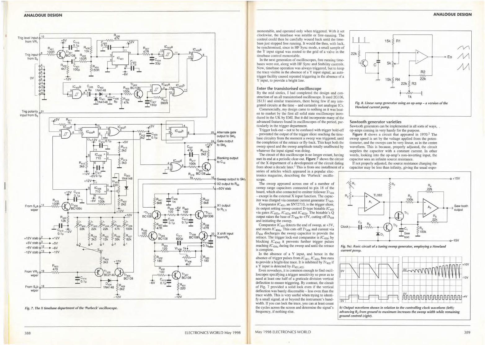
ANALOGUE DESIGN
Trig level input ~ 10=--------------, from VR1 +SV
-12V
R404 150R
-6V
T rig polarity c¢.2.!...1 ______________________________ _,
input from S6
+ 12V
From S4a o.:.14-'---J\/\,'V'v-+-t
wiper
D L
C419_12V 0.1µ
+12V stab + 12V
+SV stab !L-.. +SV
-6V stab J!L- -6V
-12V stab 1-12V
Vr402 22k
R423 470
From VR3 ,,..:.;19"--J\/\,'V'v-----+-----+-t wiper
From S4b ,,..:.;18::...,._ ___ _________ ___,
wiper
2
+12V
Tr405 BC214k
0404 1 N4148
Tr4os BC108
4
1-"6'--------'2"'5'<> Alternate gate output to Sklg
L_ _ ________ "'""':=;-24.:.0 Gate output + 12V to Skt8
Blanking output to c,a
~-------------'"-l..11/1/1.f\r--.:.:16
'-Q Sweep output to Skt7
~--------------------0 X2 output to R22
~---------'-1-o +S0V stab
Vr4oa 4k7
Tr407 BC108
L-1_2_2_,, X shift input fromVR6
-12v;__ ____________ - ..;.12;;.v _______ _.
Fig. 7. The X timebase department of the 'Purbeck' oscilloscope.
388 ELECTRONICS WORLD May 1998
ANALOGUE DESIGN
monostable, and operated only when triggered. With it set
LU_ 15k clockwise, the timebase was astable or free-running. The control could then be carefully wound back until the timebase just stopped free running. It would the then, with luck, be synchronised, since in HF Sync mode, a small sample of the Y input signal was routed to the grid of a valve in the timebase control monostable.
/V1
In the next generation of oscilloscopes, free running timebases were out, along with HF Sync and Stability controls. Now, timebase operation was always triggered, but to keep the trace visible in the absence of a Y input signal, an autotrigger facility caused repeated triggering in the absence of a Y input, to provide a bright line.
22k Eo /\/\
C Sk M
I
Enter the transistorised oscilloscope By the mid sixties, I had completed the design and construction of an all transistorised oscilloscope. It used 2G 106, 2S 131 and similar transistors, there being few if any integrated circuits at the time - and certainly not analogue I Cs.
Commercially, my design came to nothing as it was beaten to market by the first all solid state oscilloscope introduced in the UK by EMI. But it did incorporate many of the advanced features found in oscilloscopes of the period, particularly in the trigger department.
Trigger lock-out - not to be confused with trigger hold-off - prevented the output of the trigger slicer reaching the timebase circuitry from the moment a sweep was triggered, until the completion of the retrace or fly-back. This kept both the sweep speed and the sweep amplitude totally unaffected by whatever the input signal was doing.
The circuit of this oscilloscope is no longer extant, having met its end at a periodic clear-out. Figure 7 shows the circuit of the X department of a development of the circuit dating from about a decade later. 1 This is from one installment of a series of articles which appeared in a popular electronics magazine, describing the 'Purbeck' oscilloscope.
The sweep appeared across one of a number of sweep range capacitors connected to pin 18 of the board, which also connected to emitter follower Tr404 - except in the external X input function. The capacitor was charged via constant current generator Tr 405.
R2
15k 22k
1k
Fig. 8. linear ramp generator using an op-amp - a version of the Howland current pump.
Sawtooth generator varieties Sawtooth generators can be implemented in all sorts of ways, op-amps coming in very handy for the purpose.
Figure 8 shows a circuit that appeared in 1970.2 The sweep speed is set by the voltage applied from the potentiometer, and the sweeps can be very linear, as in the centre waveform. This is because, properly adjusted, the circuit supplies the capacitor with a constant current. In other words, looking into the op-amp's non-inverting input, the capacitor sees an infinite source resistance.
If not properly adjusted, the source resistance charging the capacitor may be less than infinity, giving the usual expo-
,--------------------------0 +15V
Comparator /C4o1, an SN72710, is the trigger slicer, its output setting sweep control D-type bistable /C405
via gates /C402a, /C403a and /C402d• The bistable's Q output raises the base of Tr 406 to + 5V, cutting off D 404 and initiating the sweep.
Tr1
Saw-tooth >---- output
Comparator /C405 detects the end of sweep, at +3V, and resets /C4043 • This cuts off Tr 406 and current via D404 discharges the sweep capacitor to provide the retrace. The trigger Jock-out comparator is /C406; by blocking JC404d it prevents further trigger pulses reaching /C404a during the sweep and until the retrace is complete.
In the absence of a Y input, and hence in the absence of trigger pulses from /C401, /C4020 free runs to provide a bright-line trace. It is inhibited by Tr4o2 if a Y input is detected by D401,402·
Even nowadays, it is common enough to find oscilloscopes specifying a trigger sensitivity so poor as to need at least one half of a graticule division vertical deflection to ensure triggering. By contrast, the circuit of Fig. 7 provided a solid Jock even if the vertical deflection was barely discernable - less even than the trace width. This is very useful when trying to identify a small signal, at or beyond the instrument's bandwidth. If you can lock the trace, you can at least count the cycles across the screen and determine the signal's frequency, if nothing else.
May 1998 ELECTRONICS WORLD
C2
Clock>----1--v,,vv---+--,, c, Isee
text --------------- - - - ------0-lSV
Fig. 9a). Basic circuit of a tuning sweep generator, employing a Howland current pump.
- ~ nl l H\n ~ - f\J \j'\ I~' ~ n1 ' ' ...
l l
Wr n n , .... nr n n nr n r n JU .J u Wl u u UL U L LI J U U L
b) Output waveform shown in relation to the controlling clock waveform (left); advancing R2 from ground to maximum increases the sweep width while remaining ground centred (right).
+10V
-10V
+4V
389
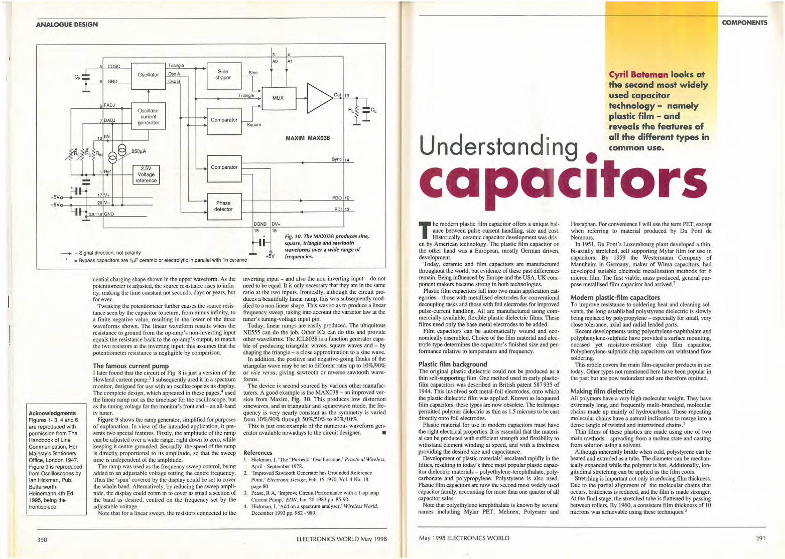
ANALOGUE DESIGN
5 cosc
CF sl Oscillator
GND
8 FADJ Oscillator
current generator
250µA
2.SV Voltage
reference
+SV0----1------'1~7'~V~+--1-___,------ SV,.,_ __ _.;1-----"2~0~V~- ....__..._ ___ _
---+ = Signal direction, not polarity
Triangle
OscA
OscB
Sine shaper
Comparator
Comparator
Phase detector
3 4
AO A1
Sine
Triangle MUX Out 19
RL
Square
MAXIM MAX038
Sync 14
POO 12
POI 13
OGNO DV+ 15 16
= Bypass capacitors are 1 µF ceramic or electrolylic in parallel with 1 n ceramic +SV
Fig. 1 O. The MAX038 produces sine, square, triangle and sawtooth waveforms over a wide range of frequencies.
Acknowledgments Figures 1- 3, 4 and 6 are reproduced with permission from The Handbook of Line Communication, Her Majesty's Stationery Office, London 194 7. Figure 9 is reproduced from Oscilloscopes by Ian Hickman, Pub. ButterworthHeinemann 4th Ed. 1995, being the frontispiece.
390
nential charging shape shown in the upper waveform. As the potentiometer is adjusted, the source resistance rises to infinity, making the time constant not seconds, days or years, but for ever.
Tweaking the potentiometer further causes the source resistance seen by the capacitor to return, from minus infinity, to a finite negative value, resulting in the lower of the three waveforms shown. The linear waveform results when the resistance to ground from the op-amp's non-inverting input equals the resistance back to the op-amp's output, to match the two resistors at the inverting input: this assumes that the potentiometer resistance is negligible by comparison.
The famous current pump I later found that the circuit of Fig. 8 is just a version of the Howland current pump.3 I subsequently used it in a spectrum monitor, designed for use with an oscilloscope as its display. The complete design, which appeared in these pages,4 used the linear ramp not as the timebase for the oscilloscope, but as the tuning voltage for the monitor's front end - an all-band tv tuner.
Figure 9 shows the ramp generator, simplified for purposes of explanation. In view of the intended application, it presents two special features. Firstly, the amplitude of the ramp can be adjusted over a wide range, right down to zero, while keeping it centre-grounded. Secondly, the speed of the ramp is directly proportional to its amplitude, so that the sweep time is independent of the amplitude.
The ramp was used as the frequency sweep control, being added to an adjustable voltage setting the centre frequency. Thus the 'span' covered by the display could be set to cover the whole band. Alternatively, by reducing the sweep amplitude, the display could zoom in to cover as small a section of the band as desired, centred on the frequency set by the adjustable voltage.
Note that for a linear sweep, the resistors connected to the
inverting input - and also the non-inverting input - do not need to be equal. It is only necessary that they are in the same ratio at the two inputs. Ironically, although the circuit produces a beautifully linear ramp, this was subsequently modified to a non-linear shape. This was so as to produce a linear frequency sweep, taking into account the varactor law at the tuner's tuning-voltage input pin.
Today, linear ramps are easily produced. The ubiquitous NE555 can do the job. Other ICs can do this and provide other waveforms. The ICL8038 is a function generator capable of producing triangular waves, square waves and - by shaping the triangle - a close approximation to a sine wave.
In addition, the positive and negative-going flanks of the triangular wave may be set to different rates up to 10%/90% or vice versa, giving sawtooth or reverse sawtooth waveforms.
The device is second sourced by various other manufacturers. A good example is the MAX038 - an improved version from Maxim, Fig. 10. This produces low distortion sinewaves, and in triangular and squarewave mode, the frequency is very nearly constant as the symmetry is varied from 10%/90% through 50%/50% to 90%/10%.
This is just one example of the numerous waveform gen-erator available nowadays to the circuit designer. •
References I. Hick.man, I, 'The "Purbeck" Oscilloscope,' Practical Wireless,
April - September 1978. 2. ' Improved Sawtooth Generator has Grounded Reference
Point,' Electronic Design, Feb. IS 1970, Vol. 4 No. 18 page 80.
3. Pease, RA, 'Improve Circuit Performance with a 1-op-amp Current Pump,' EDN, Jan. 20 1983 pp. 85-90.
4. Hickman, I, 'Add on a spectrum analyser,' Wireless World, December 1993 pp. 982- 989.
ELECTRONICS WORLD May 1998
Cyril Bateman looks at the second most widely used capacitor technology - namely plastic film - and reveals the features of
U d t d • all the different types in
n ers On Ing • common use.
ca ac1tors The modern plastic film capacitor offers a unique bal
ance between pulse current handling, size and cost. Historically, ceramic capacitor development was driv
en by American technology. The plastic film capacitor on the other hand was a European, mostly German driven, development.
Today, ceramic and film capacitors are manufactured throughout the world, but evidence of these past differences remain. Being influenced by Europe and the USA, UK component makers became strong in both technologies.
Plastic film capacitors fall into two main application categories - those with metallised electrodes for conventional decoupling tasks and those with foil electrodes for improved pulse-current handling. All are manufactured using commercially available, flexible plastic dielectric films. These films need only the base metal electrodes to be added.
Film capacitors can be automatically wound and economically assembled. Choice of the film material and electrode type determines the capacitor's finished size and perfonnance relative to temperature and frequency.
Plastic film background The original plastic dielectric could not be produced as a thin self-supporting film. One method used in early plasticfilm capacitors was described in British patent 587 935 of 1944. This involved soft metal-foil electrodes, onto which the plastic dielectric film was applied. Known as lacquered film capacitors, these types are now obsolete. The technique permitted polymer dielectric as thin as 1.5 microns to be cast directly onto foil electrodes.
Plastic material for use in modem capacitors must have the right electrical properties. It is essential that the material can be produced with sufficient strength and flexibility to withstand element winding at speed, and with a thickness providing the desired size and capacitance.
Development of plastic materials1 escalated rapidly in the fifties, resulting in today's three most popular plastic capacitor dielectric materials - polyethylene-terephthalate, polycarbonate and polypropylene. Polystyrene is also used. Plastic film capacitors are now the second most widely used capacitor family, accounting for more than one quarter of all capacitor sales.
Note that polyethylene terephthalate is known by several names including Mylar PET, Melinex, Polyester and
May 1998 ELECTRONICS WORLD
Hostaphan. For convenience I will use the term PET, except when referring to material produced by Du Pont de Nemours.
In 1951, DuPont's Luxembourg plant developed a thin, bi-axially stretched, self supporting Mylar film for use in capacitors. By 1959 the Westermann Company of Mannheim in Germany, maker of Wima capacitors, had deve loped suitable electrode metallisation methods for 6 micron film. The first viable, mass produced, general purpose metallised film capacitor had arrived.2
Modern plastic-film capacitors To improve resistance to soldering heat and cleaning solvents, the long established polystyrene dielectric is slowly being replaced by polypropylene - especially for small, very close tolerance, axial and radial leaded parts.
Recent developments using polyethylene-naphthalate and polyphenylene-sulphide have provided a surface mounting, uncased yet moisture-resistant chip film capacitor. Polyphenylene-sulphide chip capacitors can withstand flow soldering.
This article covers the main film-capacitor products in use today. Other types not mentioned here have been popular in the past but are now redundant and are therefore omitted.
Making film dielectric All polymers have a very high molecular weight. They have extremely long, and frequently multi-branched, molecular chains made up mainly of hydrocarbons. These repeating molecular chains have a natural inclination to merge into a dense tangle of twisted and intertwined chains. 1
Thin films of these plastics are made using one of two main methods - spreacling from a molten state and casting from solution using a solvent.
Although inherently brittle when cold, polystyrene can be heated and extruded as a tube. The diameter can be mechanically expanded while the polymer is hot. Additionally, longitudinal stretching can be applied as the film cools.
Stretching is important not only in reducing film thickness. Due to the partial alignment of the molecular chains that occurs, brittleness is reduced, and the film is made stronger. At the final stage, the stretched tube is flattened by passing between rollers. By 1960, a consistent film thickness of IO microns was achievable using these techniques.3
COMPONENTS
397
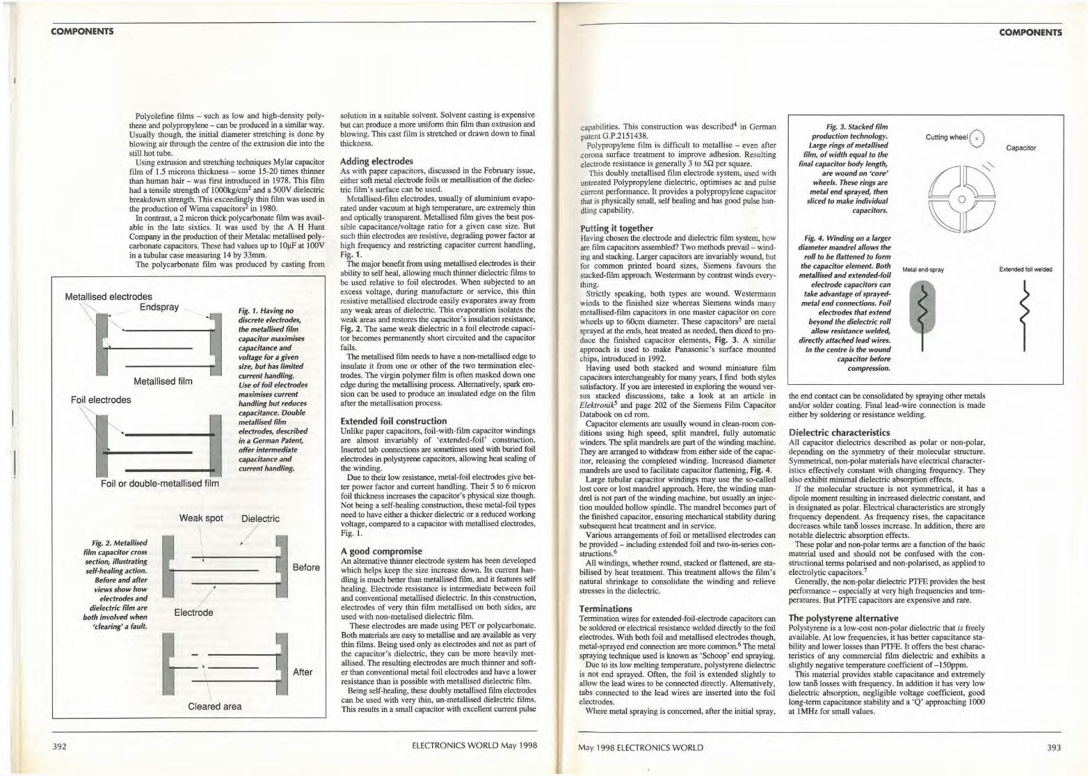
COMPONENTS
Polyolefine films - such as low and high-density polythene and polypropylene - can be produced in a similar way. Usually though, the initial diameter stretching is done by blowing air through the centre of the extrusion die into the still hot tube.
Using extrusion and stretching techniques Mylar capacitor film of 1.5 microns thickness - some 15-20 times thinner than human hair - was first introduced in 1978. This film had a tensile strength of I 000kg/cm2 and a 500V dielectric breakdown strength. This exceedingly thin film was used in the production ofWima capacitors2 in 1980.
In contrast, a 2 micron thick polycarbonate film was available in the late sixties. It was used by the A H Hunt Company in the production of their Metalac metallised polycarbonate capacitors. These had values up to lOµF at lOOV in a tubular case measuring 14 by 33mm.
The polycarbonate film was produced by casting from
Metallised electrodes
392
'\ ' Endspray
Metallised film
Foil electrodes
"'
Foil or double-metallised film
Fig. 2. Metallised film capacitor cross section, illustrating self-healing action.
Before and after views show how
electrodes and dielectric film are
both involved when 'clearing' a fault.
Weak spot
I Electrode
\
Fig. 1. Having no discrete electrodes, the metallised film capacitor maximises capacitance and voltage for a given size, but has limited current handling. Use of foil electrodes maximises current handling but reduces capacitance. Double metallised film electrodes, described i11 a German Patent, offer intermediate capacitance and current handling.
Dielectric
/ >
Before
After
Cleared area
solution in a suitable solvent. Solvent casting is expensive but can produce a more uniform thin film than extrusion and blowing. This cast film is stretched or drawn down to final thickness.
Adding electrodes As with paper capacitors, discussed in the February issue, either soft metal electrode foils or metallisation of the dielectric film's surface can be used.
Metallised-fi1m electrodes, usually of aluminium evaporated under vacuum at high temperature, are extremely thin and optically transparent. Metallised film gives the best possible capacitance/voltage ratio for a given case size. But such thin electrodes are resistive, degrading power factor at high frequency and restricting capacitor current handling, Fig. 1.
The major benefit from using metallised electrodes is their ability to self heal, allowing much thinner dielectric films to be used relative to foil electrodes. When subjected to an excess voltage, during manufacture or service, this thin resistive metallised electrode easily evaporates away from any weak areas of dielectric. This evaporation isolates the weak areas and restores the capacitor's insulation resistance, Fig. 2. The same weak dielectric in a foil electrode capacitor becomes permanently short circuited and the capacitor fails.
The metallised film needs to have a non-metallised edge to insulate it from one or other of the two termination electrodes. The virgin polymer film is often masked down one edge during the metallising process. Alternatively, spark erosion can be used to produce an insulated edge on the film after the metallisation process.
Extended foil construction Unlike paper capacitors, foil-with-film capacitor windings are almost invariably of 'extended-foil' construction. Inserted tab connections are sometimes used with buried foil electrodes in polystyrene capacitors, allowing heat sealing of the winding.
Due to their low resistance, metal-foil electrodes give better power factor and current handling. Their 5 to 6 micron foil thickness increases the capacitor's physical size though. Not being a self-healing construction, these metal-foil types need to have either a thicker dielectric or a reduced working voltage, compared to a capacitor with metallised electrodes, Fig. 1.
A good compromise An alternative thinner electrode system has been developed which helps keep the size increase down. Its current handling is much better than metallised film, and it features self healing. Electrode resistance is intermediate between foil and conventional metallised dielectric. In this construction, electrodes of very thin film metallised on both sides, are used with non-metalised dielectric film.
These electrodes are made using PET or polycarbonate. Both materials are easy to metallise and are available as very thin films. Being used only as electrodes and not as part of the capacitor's dielectric, they can be more heavily metallised. The resulting electrodes are much thinner and softer than conventional metal foil electrodes and have a lower resistance than is possible with metallised dielectric film.
Being self-healing, these doubly metallised film electrodes can be used with very thin, un-metallised dielectric films. This results in a small capacitor with excellent current pulse
ELECTRONICS WORLD May 1998
capabilities. This construction was described4 in Gennan patent G.P.2151438.
Polypropylene film is difficult to metallise - even after corona surface treatment to improve adhesion. Resulting electrode resistance is generally 3 to 50 per square.
This doubly metallised film electrode system, used with untreated Polypropylene dielectric, optimises ac and pulse current performance. It provides a polypropylene capacitor that is physically small, self healing and has good pulse handling capability.
Putting it together Having chosen the electrode and dielectric film system, how are film capacitors assembled? Two methods prevail - winding and stacking. Larger capacitors are invariably wound, but for common printed board sizes, Siemens favours the stacked-film approach. Westermann by contrast winds everything.
Strictly speaking, both types are wound. Westermann winds to the finished size whereas Siemens winds many metallised-film capacitors in one master capacitor on co.re wheels up to 60cm diameter. These capacitors5 are metal sprayed at the ends, heat treated as needed, then diced to produce the finished capacitor elements, Fig. 3. A similar approach is used to make Panasonic's surface mounted chips, introduced in 1992.
Having used both stacked and wound miniature film capacitors interchangeably for many years, I find both styles satisfactory. If you are interested in exploring the wound versus stacked discussions, take a look at an article in Elektronik5 and page 202 of the Siemens Film Capacitor Databook on cd rom.
Capacitor elements are usually wound in clean-room conditions using high speed, split mandrel, fully automatic winders. The split mandrels are part of the winding machine. They are arranged to withdraw from either side of the capacitor, releasing the completed winding. Increased diameter mandrels are used to facilitate capacitor flattening, Fig. 4.
Large tubular capacitor windings may use the so-called Jost core or lost mandrel approach. Here, the winding mandrel is not part of the winding machine, but usually an injection moulded hollow spindle. The mandrel becomes part of the finished capacitor, ensuring mechanical stability during subsequent heat treatment and in service.
Various arrangements of foil or metallised electrodes can be provided - including extended foil and two-in-series constructions.6
All windings, whether round, stacked or flattened, are stabilised by beat treatment. This treatment allows the ftlm's natural shrinkage to consolidate the winding and relieve stresses in the dielectric.
Terminations Termination wires for extended-foil-electrode capacitors can be soldered or electrical resistance welded directly to the foil electrodes. With both foil and metallised electrodes though, metal-sprayed end connection are more cornmon.6 The metal spraying technique used is known as 'Schoop' end spraying.
Due to its low melting temperature, polystyrene dielectric is not end sprayed. Often, the foil is extended slightly to allow the lead wires to be connected directly. Alternatively, tabs connected to the lead wires are inserted into tbe foil electrodes.
Where metal spraying is concerned, after the initial spray,
May 1998 ELECTRONICS WORLD
Fig. 3. Stacked film production technology.
Large rings of metallised film, of width equal to the
final capacitor body length, are wound on 'core'
wheels. These rings are metal end sprayed, then
sliced to make individual capacitors.
Fig. 4. Winding on a larger diameter mandrel allows the
roll to be flattened to form the capacitor element. Both metallised and extended-foil
electrode capacitors can take advantage of sprayed
metal end connections. foil electrodes that extend
beyond the dielectric roll allow resistance welded,
directly attached lead wires. In the centre is the wound
capacitor before compression.
Cutting wheelo
Metal end-spray
the end contact can be consolidated by spraying other metals and/or solder coating. Final lead-wire connection is made either by soldering or resistance welding.
Dielectric characteristics All capacitor dielectrics described as polar or non-polar, depending on the symmetry of their molecular structure. Symmetrical, non-polar materials have electrical characteristics effectively constant with changing frequency. They also exhibit minimal dielectric absorption effects.
If the molecular structure is not symmetrical, it has a dipole moment resulting in increased dielectric constant, and is designated as polar. Electrical characteristics are strongly frequency dependent. As frequency rises, the capacitance decreases. while tanB losses increase. In addition, there are notable dielectric absorption effects.
These polar and non-polar terms are a function of the basic material used and should not be confused with the constructional terms polarised and non-polarised, as applied to electrolytic capacitors. 7
Generally, the non-polar dielectric PTFE provides the best performance - especially at very high frequencies and temperatures. But PTFE capacitors are expensive and rare.
The polystyrene alternative Polystyrene is a low-cost non-polar dielectric that is freely available. At low frequencies, it has better capacitance stability and lower losses than PTFE. It offers the best characteristics of any commercial film dielectric and exhibits a slightly negative temperature coefficient of -150ppm.
This material provides stable capacitance and extremely low tanB losses with frequency. In addition it has very low dielectric absorption, negligible voltage coefficient, good long-term capacitance stability and a 'Q' approaching 1000 at 1MHz for small values.
COMPONENTS
Capacitor
Extended foil welded
393
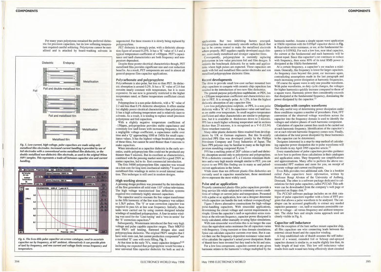
COMPONENTS
Foil
\
For many years polystyrene remained the preferred dielectric for precision capacitors, but its low softening temperature required careful soldering. Polystyrene cannot be metallised and is attacked by board-washing solvents in
Dielectric Endspray
Metallisation
Foil and double-metallised film
Metallisation
Foil and metallised film
l~ Metallised film
Metallisation /
Fig. 5. Low-current, high-voltage, pulse capacitors are made using only metallised film electrodes. Increased current handling is provided by use of foil electrodes with a conventional series metallised film dielectric, or the doubly mefalli~d non-dielectric film electrode, as used in the original Wima FKP1 samples. This represents a trade-off between capacitor size and current handling.
-1,1
u
o.t
D,1
\
\ \ ~
f',, 1' ,._
u
r---1D ID
, ...... .,, 1111111 fD
Fig. 6. The Evox-Rifa pulse capacitor on-screen catalogue, used to ascertain capacitor esr by frequency, at 60° ambient. Alternatively it can provide plots of tano by frequency, and rms current and voltage limits versus frequency and temperature.
394
unprotected. For these reasons it is slowly being replaced by polypropylene.
PET dielectric is strongly polar, with a dielectric absorption figure of around 0.25%. It has a 'K' value of 3.3 and a typical temperature coefficient of +400ppm. PET's capacitance and tan6 characteristics are both frequency and temperature dependent.
Despite these poorer electrical characteristics though, PET metallised film provides significant size and cost reduction benefits. As a result, PET components are used in almost all general-purpose film-capacitor applications.
Polycarbonate and polypropylene Polycarbonate is also polar, but less so than PET. Its dielectric absorption is around 0.2%. It has a 'K' value of 2.8 that remains nearly constant with temperature, but it is more expensive. Its use now is generally restricted to the higher temperature rated, or flatter temperature coefficient circuit needs.
Polypropylene is a non-polar dielectric, with a 'K' value of 2.2 and less than 0.1 % dielectric absorption. It offers similar but slightly poorer electrical characteristics than polystyrene. It has a high softening temperature and is relatively inert to solvents. As a result, it is tending to replace small precision polystyrene and foil capacitors.
With a slightly negative temperature coefficient of -150ppm, polypropylene provides stable capacitance and extremely low tan6 losses with increasing frequency. It has a negligible voltage coefficient, a capacitance stable over time and a 'Q' approaching 1000 at 1MHz for small capacitance values. It has the highest voltage breakdown strength of these films, but cannot be used thinner than 4 microns to make capacitors.
When introduced as a capacitor dielectric in the early seventies, usable polypropylene film could not be produced any thinner than 9 microns. But its excellent ac characteristics, combined with the pressing market need for a good 250V ac mains capacitor, led to its first commercial introduction.
The Erie 54000 polypropylene film capacitor was wound on a lost core for long term mechanical stability. 8 It used two metallised-film windings in series to avoid internal ionisation. This technique is still used in modern designs.
High working stresses A pressing design problem was presented by the introduction of the first generation all solid state 110° colour televisions. The high voltage transistorised line deflection systems required two extremely highly stressed capacitors.
The capacitor used to resonate the line output transformer to the fifth harmonic of the line scan frequency was subject to l.5kV pulses. The 'S' or scan correction capacitor was required to pass 6A at line scan frequency. Initially, these tasks were carried out by using custom designed tubular windings of metallised polypropylene. A four-in-series winding was used for the 'Line-tuning' and a ' two-in-series' for the 'S' correction capacitors. 8
Subsequently, Westermann introduced the first very high voltage and pulse capable capacitor ranges. Their MKPlO and FKPl self healing, flattened designs also used polypropylene dielectric. The original FKPI samples that I have were resin cast, but current production components4 use a moulded 'E' case with resin filling, Fig. 5.
At that time in the early 70's, many capacitor designers9,10
including me expected that polypropylene would become a near universal film capacitor dielectric for both ac and de
ELECTRONICS WORLD May 1998
applications. But two inhibiting factors emerged. Polypropylene has an extremely smooth surface finish that has to be corona treated to make the metallised electrode adhere·properly. PET suppliers rapidly developed much thinner, more easily metallised and stronger capacitor films.
Consequently, polypropylene is currently replacing polystyrene in low value precision foil and film designs. It remains the benchmark dielectric for ac tasks and applications where high pulses are expected. These capacitors are made with foil and metallised film carrier electrodes and non metallised polypropylene dielectric films.
Recent dev~lopments The drive to provide small low-cost surface mounted bare chip capacitors to compete with ceramic chip capacitors has resulted in the introduction of two new film dielectrics.
The general-purpose polyethylene-naphthalate, or PEN, has a +200ppm temperature coefficient and characteristics similar to PET. It is strongly polar. At 1.2%, it has the highest dielectric absorption of any capacitor film.
Low-loss polyphenylene-sulphide, or PPS, is a non-polar dielectric with a 'K ' of 3. Its capacitance value and tan6 losses are stable over temperature. Its small negative temperature coefficient and other characteristics are similar to polypropylene, but it is available in thicknesses down to 2 microns. PPS has a much higher softening temperature and in sections thicker than 25 microns, it is recognised as a V-0 (UL94) flame retardant material.
Many older plastic dielectric films resulted from developments by UK or .German engineers. But this bi-axially stretched PPS film was developed jointly by the Phillips Petroleum Company and Toray Industries of Japan. The basic PPS polymer may be familiar to many as the high temperature moulding compound R yton. 11
PPS has a melting point of 285° celsius a tan6 and dielectric absorption second only to polystyrene and polypropylene. With a dielectric constant of 3, a 2 micron minimum thickness and a very high tensile strength similar to PET, you can expect to see PPS fiim finding use in many ac and pulsedcurrent applications in the future.
While more than ten different plastic-film dielectrics are currently used in capacitor manufacture, those mentioned above represent the most widely used.
Pulse and ac applications Properly constructed plastic-film pulse capacitors provide a long service life while subjected to extremely severe conditions of voltage or current pulse and temperature. Presented with a pulse or ac application, how can a designer determine which capacitor can handle the task without overspecifying?
Figure 5 shows alternative constructions for high-voltage pulse-handling capacitors. With sinusoidal applications, determining the circuit voltage and current requirements is simple. Given the capacitor's tan6 or equivalent series resistance at the relevant frequency, capacitor power dissipated is easily calculated, either manually or using Spice simulations.
With non-sinusoidal waveforms this is no longer the case since the equivalent series resistance for all capacitors varies with frequency. Using transient or time domain simulations, Spice can calculate capacitor currents over time. But it cannot then use the frequency-dependent resistance value needed to calculate the capacitor's actual power dissipation. Rules of thumb have been invented but they tend to be hit and miss.
For a low-loss component, capacitor current at any given harmonic relates to the harmonic's voltage multiplied by the
May 1998 ELECTRONICS WORLD
harmonic number. Assume a simple square wave application at 1 Ok.Hz repetition with the 0.056µF capacitor shown in Fig. 6. Equivalent series resistance, or esr, at the fundamental frequency is 0.0593Q. For such a low loss, near ideal capacitor, the current at the fundamental and each harmonic will be almost equal. Since this capacitor's esr continues to reduce with frequency, then some 80% of its total RMS power is dissipated at the lOkHz fundamental.
At a certain frequency, a capacitor's esr reaches a minimum. Generally, this frequency is lower for larger capacitors. As frequency rises beyond this point, esr increases again, contradicting assumptions made in the last paragraph and much increasing power dissipation at harmonic frequencies.
Of course the square wave is only one possible waveform. With pulse waveforms, as duty cycle changes, the voltages for higher harmonics quickly increase compared to those of a square wave. Harmonic power then considerably exceeds that dissipated at the fundamental frequency, dominating the power dissipated by the capacitor.12
Dissipation with complex waveforms The only useful way of detennining power dissipation under these conditions requires a number of procedures. First, FFf conversion of the observed voltage wavefonn across the capacitor into the frequency domain is used to identify the voltages and relative phases of each harmonic component.
Calculation of capacitor current then needs to be carried out at each harmonic frequency. Identification of the capacitor's esr at each relevant harmonic frequency comes next. Finally, calculation of the total power dissipated by these hannonics in the .capacitor. can be determined.
Designers interested in a step-by-step method of calculating capacitor power dissipation due to pulse waveforms will find details in my April 1995 capacitor article. 12
Every manufacturer of pulse capacitors provides guidance on how best to perform these calculations in their catalogues and application notes. They frequently use simplifications and approximations. Many offer to perform the above recommended FFf routines and more for you, on receipt of accurate voltage and current oscillograms.
Evox Rifa provides two additional aids. One is a booklet called Pulse capacitors basic information, written by Professor Bengt Alvsten of the University of Aolberg, Denmark. The other is a software package dedicated to calculations for their pulse capacitors, called PCCAD. This software can be downloaded from the company's web page or requested on floppy disk.13
The PCCAD software package includes an on disk catalogue of pulse capacitors together with a form of FFf program that allows a pulse waveform to be analysed. The catalogue can be accessed graphically to extract any needed capacitor parameter- esr, tan6 or maximum permissible current or voltage - all versus frequency and ambient temperature. The slider bars and simple menu approach used are clearly visible in Fig. 6.
Capacitor self inductance With the exception of the bare surface mount capacitor chip, all film capacitors use wire connecting leads between the external circuit board and the capacitor winding.
A long established rule of thumb assumes the self inductance of a wound, extended foil or Schoop end-sprayed capacitor element is similar to, or maybe slightly less than, its body length of lead wire. This low self inductance value results from each wound tum being effectively short circuited
COMPONENTS
395
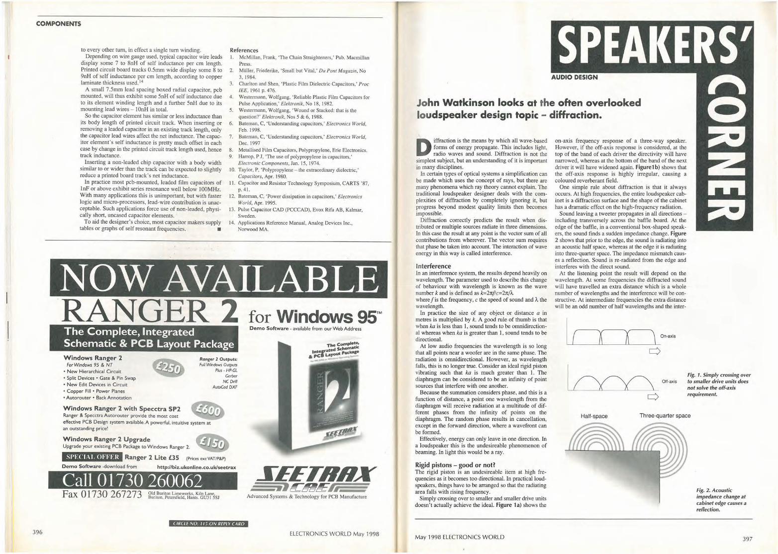
COMPONENTS
396
to every other tum, in effect a single tum winding. Depending on wire gauge used, typical capacitor wire leads
display some 7 to 8nH of self inductance per cm length. Printed circuit board tracks 0.5mm wide display some 8 to 9nH of self inductance per cm length, according to copper laminate thickness used. 14
A small 7.5mm lead spacing boxed radial capacitor, pcb mounted, will thus exhibit some 5nH of self inductance due to its element winding length and a further 5nH due to its mounting lead wires - l0nH in total.
So the capacitor element has simiJar or less inductance than its body length of printed circuit track. When inserting or removing a leaded capacitor in an existing track length, only the capacitor lead wires affect the net inductance. The capacitor element's self inductance is pretty much offset in each case by change in the printed circuit track length used, hence track inductance.
Inserting a non-leaded chip capacitor with a body width similar to or wider than the track can be expected to slightly reduce a printed board track's net inductance.
In practice most pcb-mounted, leaded film capacitors of I nF or above exhibit series resonance well below 100MHz. With many applications this is unimportant, but with faster logic and micro-processors, lead-wire contribution is unacceptable. Such applications force use of non-leaded, physically short, uncased capacitor elements.
To aid the designer's choice, most capacitor makers supply tables or graphs of self resonant frequencies. •
References I. McMillan, Frank, 'The Chain Straighteners,' Pub. Macmillan
Press.
2. Millier, Friederike, 'Small but Vital,' Du Pont Magazin, No 3, 1984.
3. Charlton and Shen, 'Plastic Film Dielectric Capacitors,' Proc IEE, 1961 p. 476.
4. Westermann, Wolfgang, 'Reliable Plastic Film Capacitors for Pulse Application,' Elektronik, No 18, 1982.
5. Westermann, Wolfgang, 'Wound or Stacked: that is the question?' Elektronik, Nos 5 & 6, 1988.
6. Bateman, C, 'Understanding capacitors,' Electronics World, Feb. 1998.
7. Bateman, C, 'Understanding capacitors,' Electronics World, Dec. 1997
8. Metallised Film Capacitors, Polypropylene, Erie Electronics. 9. Harrop, P J, 'The use of polypropylene in capacitors,'
Electronic Components, Jan. I 5, 1974.
IO. Taylor, P, 'Polypropylene - the extraordinary dielectric,' Capacitors, Apr. 1980.
11. Capacitor and Resistor Technology Symposium, CARTS '87, p. 41.
12. Bateman, C, 'Power dissipation in capacitors,' Electronics World, Apr. 1995.
13. Pulse Capacitor CAD (PCCCAD), Evox Rifa AB, Kalmar, Sweden.
14. Applications Reference Manual, Analog Devices Inc., Norwood MA.
NOW AVAILABLE RANGER 2 The Complete, Integrated Schematic & PCB Layout Package Windows Ranger 2
For Windows 95 & NT • New Hierarchical Circuit • Split Devices • Gate & Pin Swap • New Edit Devices in Circuit • Copper Fill • Power Planes • Autorouter • Back Annotation
Windows Ranger 2 with Specctra SP2 Ranger & Specctra Autorouter provide the most cost
Ranger 2 Output,: Full Windows Outputs
Plus· HP-GL Gerber
NC Drill AutoCod DXF
effective PCB Design system available. A powerful, intuit ive system at an outstanding price!
Windows Ranger 2 Upgrade Upgrade your existing PCB Package to Windows Ranger 2.
SPECIAL OFFER Ranger 2 Lite £3S (Pr ices excVAT/P&P)
Demo Software -download from http://biz.ukonli!}e.eo.uk/seetrax
Call 0 1730 260062 Fax O 1730 267273 Old Buriton Limeworks, Kiln Lane
Buriton, Petersfield, Hams. GU3 I 5SJ
CIRCLE NO. I IS ON REPLY CARD
for Windows 95™ Demo Software • available from our Web Address
The Comple~, d Schematic
tntegraLte out Package & pcs ay
XEETRHX .,~tmt!f:1.
Advanced Systems & Technology for PCB Manufacture
ELECTRONICS WORLD May 1998
SPEAKERS' • • • •
John Watkinson looks at the often overlooked loudspeaker design topic - diffraction.
D iffraction is the means by which all wave-based forms of energy propagate. This includes light, radio waves and sound. Diffraction is not the
simplest subject, but an understanding of it is important in many disciplines.
In certain types of optical systems a simplification can be made which uses the concept of rays, but there are many phenomena which ray theory cannot explain. The traditional loudspeaker designer deals with the complexities of diffraction by completely ignoring it, but progress beyond modest quality limits then becomes impossible.
Diffraction correctly predicts the result when distributed or multiple sources radiate in three dimensions. In this case the result at any point is the vector sum of all contributions from wherever. The vector sum requires that phase be taken into account. The interaction of wave energy in this way is called interference.
Interference In an interference system, the results depend heavily on wavelength. The parameter used to describe this change of behaviour with wavelength is known as the wave number k and is defined as k=2nf!c=2n(),,, where f is the frequency, c the speed of sound and ')... the wavelength.
In practice the size of any object or distance a in metres is multiplied by k. A good rule of thumb is that when ka is less than 1, sound tends to be omnidirectional whereas when ka is greater than 1, sound tends to be directional.
At low audio frequencies the wavelength is so long that all points near a woofer are in the same phase. The radiation is omnidirectional. However, as wavelength falls, this is no longer true. Consider an ideal rigid piston vibrating such that ka is much greater than 1. The diaphragm can be considered to be an infinity of point sources that interfere with cine another.
Because the summation considers phase, and this is a functioi:i of distance, a point one wavelength from the diaphragm will receive radiation at a multitude of different phases from the infinity of points on the diaphragm. The random phase results in cancellation, except in the forward direction, where a wavefront can be formed.
Effectively, energy can only leave in one direction. In a lou(ispeaker this is the undesireable phenomenon of beaming. In light this would be a ray.
Rigid pistons - good or not? The rigid piston is an undesireable item at high frequencies as it becomes too directional. In practical loudspeakers, things have to be arranged so that the radiating area falls with rising frequency.
Simply crossing over to smaller and smaller drive units doesn't actually achieve the ideal. Figure la) shows the
May 1998 ELECTRONICS WORLD
on-axis frequency response of a three-way speaker. However, if the off-axis response is considered, at the top of the band of each driver the directivity will have narrowed, whereas at the bottom of the band of the next driver it will have widened again. Figure1 b) shows that the off-axis response is highly irregular, causing a coloured reverberant field.
One simple rule about diffraction is that it always occurs. At high frequencies, the entire loudspeaker cabinet is a diffraction surface and the shape of the cabinet has a dramatic effect on the high-frequency radiation.
Sound leaving a tweeter propagates in all directions -including transversely across the baffle board. At the edge of the baffle, in a conventional box-shaped speakers, the sound finds a sudden impedance change. Figure 2 shows that prior to tbe edge, the sound is radiating into an acoustic half space, whereas at the edge it is radiating into three-quarter space. The impedance mismatch causes a reflection. Sound is re-radiated from the edge and interferes with the direct sound.
At the listening point the result will depend on the wavelength. At some frequencies the diffracted sound will have travelled an extra distance which is a whole number of wavelengths and the interference will be constructive. At intermediate frequencies the extra distance will be an odd number of half wavelengths and the inter-
..____,_I L ____._..A----'-'--A _____.._J On-axis
OH-axis
Half-space
Fig. 1. Simply crossing over to smaller drive units does not solve the off-axis requirement.
Fig. 2. Acoustic impedance change at cabinet edge causes a reflection.
397
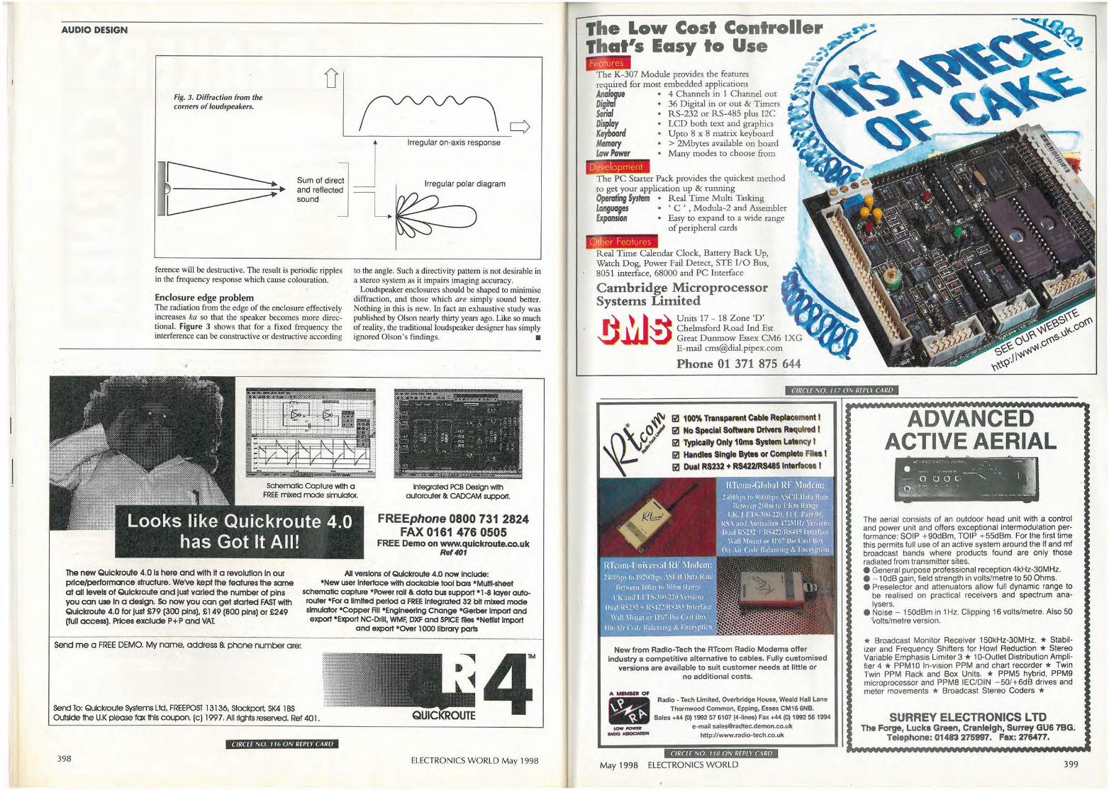
AUDIO DESIGN
Fig. 3. Diffraction from the corners of loudspeakers.
D
c) L_ _ _ _ ___________ _
Sum of dire~t J and reflected I sound L
Irregular on-axis response
Irregular polar diagram
ference will be destructive. The result is periodic ripples in the frequency response which cause colouration.
Enclosure edge problem The radiation from the edge of the enclosure effectively increases ka so that the speaker becomes more directional. Figure 3 shows that for a fixed frequency the interference can be constructive or destructive according
.. ,
to the angle. Such a directivity pattern is not desirable in a stereo system as it impairs imaging accuracy.
Loudspeaker enclosures should be shaped to minimise diffraction, and those which are simply sound better. Nothing in this is new. In fact an exhaustive study was published by Olson nearly thirty years ago. Like so much of reality, the traditional loudspeaker designer has simply ignored Olson's findings. •
Integrated PCB Design with autorouter & CADCAM support.
FREEphone 0800 731 2824 FAX 0161 476 0505
FREE Demo on www.quickroute.co.uk Ref401
The new Qulckroute 4.0 Is here and with It a revolution In our price/performance structure. We've kept the features the same at all levels of Qulckroute and Just varied the number of pins you can use In a design. So now you can get started FAST with Qulckroute 4.0 for Just £79 (300 pins), £149 (800 pins) or £249 (full access). Prices exclude P+P and VA1
All versions of Qulckroute 4.0 now Include: *New user Interface with dockable tool bars *Muni-sheet
schematic capture *Power rail&. data bus support *1-8 layer autorouter *For a limited period a FREE Integrated 32 bit mixed mode simulator *Copper FIii *Engineering Change *Gelber Import and export *Export NC-Drill, WMF. DXF and SPICE flies *Nettlst Import
and export *OVer 1000 library parts
Send me a FREE DEMO. My name, address & phone number are:
Send To: Qulckroute Systems Ltd, FREE POST 13136, stockport, SK4 1 BS Outside the U.K please fax this coupon. (c) 1997. All rtghts reserved. Ref 401 .
CIRCLE NO. 1 ll, ON REPLY CARD
398
QUICKROUTE
ELECTRONICS WORLD May 1998
Development The PC Starter Pack provides the quickest method to get your application up & running Operating System • Real Time Multi Tasking l.angua,es • ' C ' , Modula-2 and Assembler Expansion • Easy to expand to a wide range
of peripheral cards
O ther Features Real Time Calendar Clock, Battery Back Up, Watch Dog, Power Fail Detect, STE I/0 Bus, 8051 interface, 68000 and PC Interface
Cambridge Microprocessor Systems Limited
ul~ Units 17- 18 Zone 'D' ·
l
'wt Chelmsford Road Ind Est Great Dunrnow Essex CM6 lXG E-mail [email protected]
Phone 01 371 875 644
CIRCLE NO. 117 ON REPLY CARD
iJ 100% Tran1partntC.b'4t R~nt I 1i1 No Spoclal Softwa,. Dl'lwr1 Rtqulrld I Iii ·TyplQlly Only 10ms Syattm Llttncy l (ti Handt" Single Bytet or Complete FIi" I Ii! Dual RS232 + RS422/RMIS lnt.erft~ I
New from Radio-Tech the RTcom Radio Modems offer industry a competitive alternative to cables. Fully customised
versions are available to suit customer needs at little or no additional costs.
A MIMID OI'
a Radio - Tech limited, Overbridge House, Weald Hall Lane Thornwood Common, Epping, Essex CM16 6NB.
Sales +44 (0) 1992 57 6107 (4-lines) Fax +44 (0) 1992 56 1994 ,_ ..,_ e-mail [email protected]
.,._ ._ http://www.radio-tech.co.uk
CIRCLE NO. 118 ON REPl Y CARD
May 1998 ELECTRONICS WORLD
ADVANCED ACTIVE AERIAL
• .'I.O',, ~NCf.OACT1:t A f illA L • ..:7 . .... .. . .. ~••·• ..... : .. :· , .... 0 0 0 C: '-
l,..~'. .. ...... .,._ ......... -~.,
The aerial consists of an outdoor head unit with a control and power unit and offers exceptional intermodulation performance: SOIP + 90dBm, TOIP + 55dBm. For the first time this permits full use of an active system around the If and ml broadcast bands where products found are only those radiated from transmitter sites. • General purpose professional reception 4kHz-30MHz. • - 1 0dB gain, field strength in volts/metre to 50 Ohms. • Preselector and attenuators allow full dynamic range to
be realised on practical receivers and spectrum analysers.
• Noise - 150dBm in 1 Hz. Clipping 16 volts/metre. Also 50 ·volts/metre version.
* Broadcast Monitor Receiver 150kHz-30MHz. * Stabilizer and Frequency Shifters for Howl Reduction * Stereo Variable Emphasis Limiter 3 * 10-Outlet Distribution Amplifier 4 * PPM1 0 In-vision PPM and chart recorder* Twin Twin PPM Rack and Box Units. * PPM5 hybrid, PPM9 microprocessor and PPM8 IEC/DIN - 50/+ 6dB drives and meter movements * Broadcast Stereo Coders *
SURREY ELECTRONICS LTD The Forge, Lucks Green, Cranleigh, Surrey GU& 7BG;
Telephone: 01483 275997. Fax: 276477.
399
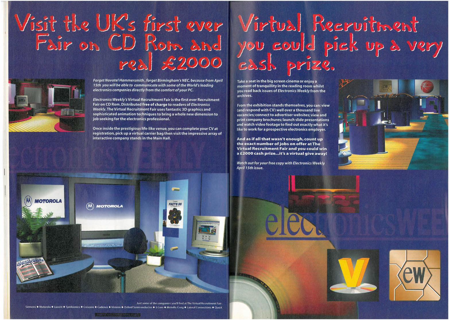
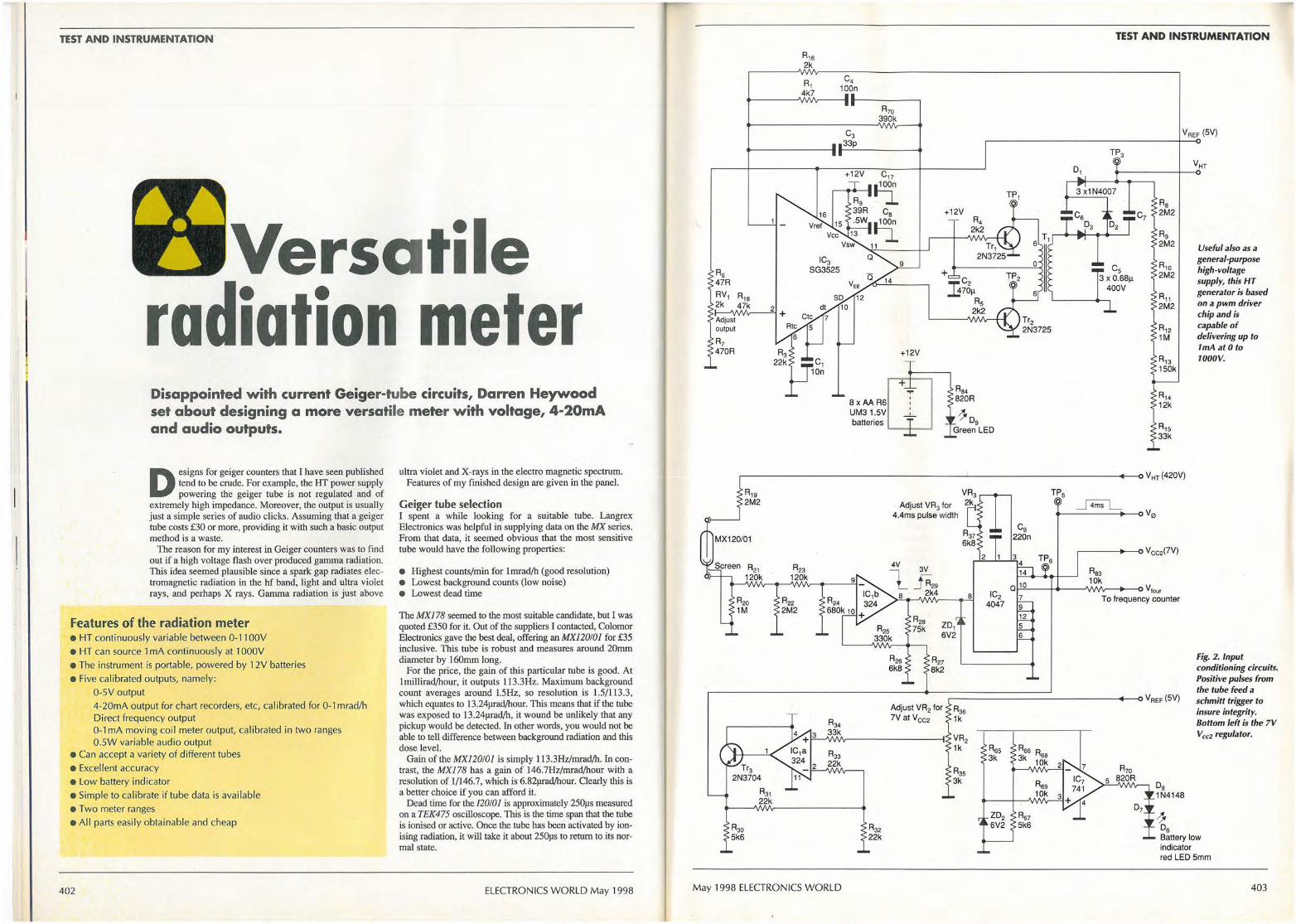
TEST AND INSTRUMENTATION
Versatile radiation meter Disappointed with current Geiger-tube circuits, Darren Heywood set about designing a more versatile meter with voltage, 4-20mA and audio outputs.
D esigns for geiger counters that I have seen published tend to be crude. For example, the HT power supply powering the geiger tube is not regulated and of
extremely high impedance. Moreover, the output is usually just a simple series of audio clicks. Assuming that a geiger tube costs £30 or more, providing it with such a basic output method is a waste.
The reason for my interest in Geiger counters was to find out if a high voltage flash over produced gamma radiation. This idea seemed plausible since a spark gap radiates electromagnetic radiation in the hf band, light and ultra violet rays, and perhaps X rays. Gamma radiation is just above
Features of the radiation meter • HT continuously variable between 0-11 00V
• HT can source 1 mA continuously at 1 000V
• The instrument is portable, powered by 12V batteries
• Five calibrated outputs, namely: 0-SV output
4-20mA output for chart recorders, etc, calibrated for 0-1 mrad/h Direct frequency output 0-1 mA moving coil meter output, calibrated in two ranges 0.SW variable audio output
• Can accept a variety of different tubes
• Excel lent accuracy
• Low battery indicator • Simple to calibrate if tube data is available
• Two meter ranges • Al l parts easily obtainable and cheap
402
ultra violet and X-rays in the electro magnetic spectrum. Features of my finished design are given in the panel.
Geiger tube selection I spent a while looking for a suitable tube. Langrex Electronics was helpful in supplying data on the MX series. From that data, it seemed obvious that the most sensitive tube would have the following properties:
• Highest counts/min for lrnrad/h (good resolution) • Lowest background counts (low noise) • Lowest dead time
The MX178 seemed to the most suitable candidate, but I was quoted £350 for it. Out of the suppliers I contacted, Colomor Electronics gave the best deal, offering an MX120!01 for £35 inclusive. This tube is robust and measures around 20mm diameter by 160mm long.
For the price, the gain of this particular tube is good. At lmillirad/hour, it outputs 113.3Hz. Maximum background count averages around l.5Hz, so resolution is 1.5/113.3, which equates to 13.24µrad/hour. This means that if the tube was exposed to 13.24µrad/h, it wound be unlikely that any pickup would be detected. In other words, you would not be able to tell difference between background radiation and this dose level.
Gain of the MX120!01 is simply 113.3Hz./rnrad/h. In contrast, the MX/78 has a gain of 146.7Hz/rnrad/hour with a resolution of 1/146.7, which is 6.82µrad/hour. Clearly this is a better choice if you can afford it.
Dead time for the /20/01 is approximately 250µs measured on a TEK475 oscilloscope. This is the time span that the tube is ionised or active. Once the tube has been activated by ionising radiation, it will take it about 250µs to return to its normal state.
ELECTRONICS WORLD May 1998
R15 2k
C4 100n
R70 390k
C3 33p
+12V C17
110.1
Cs
110.1
11
Q
8 xAA R6 UM3 1.SV
... '
batteries .._ __ I--~
+12V
R84 820R
/. ;,- Dg
Green LED
D1
TEST AND INSTRUMENTATION
Cs 3 X 0.68µ
400V
C1
VREF (SV)
Useful also as a general-purpose high-voltage supply, this HT generator is based on a pwm driver chip and is capable of delivering up to 1mAat0to 1000V.
,----------------------'---'------------ - -<>VHr(420V)
R20 1M
Tr3 2N3704
R30 5k6
R31 22k
May 1998 ELECTRONICS WORLD
R32 22k
Adjust VR3 for 4.4ms pulse width
ZD1 6V2
R25 R21 6k8 8k2
8 IC2 4047
Cg 220n
3 4 14
TP6
R83 10k
Q 10 "'----+---'\Nl/\,----0 v,our 7 To frequency counter 9 12 5 6
Fig. 2 . Input conditioning circuits. Positive pulses from the tube feed a
Adjust VR2 for ,--- - ------ ----------0 VAEF (SV) schmitt trigger to
R35 7Vat Vcc2 1k
VR2 1k Ass
3k
Ass 3k
ZD2 6V2
Ds 1N4148
1' Ds
insure integrity. Bottom left is the 7V Vcc2 regulator.
Battery low indicator red LED 5mm
403
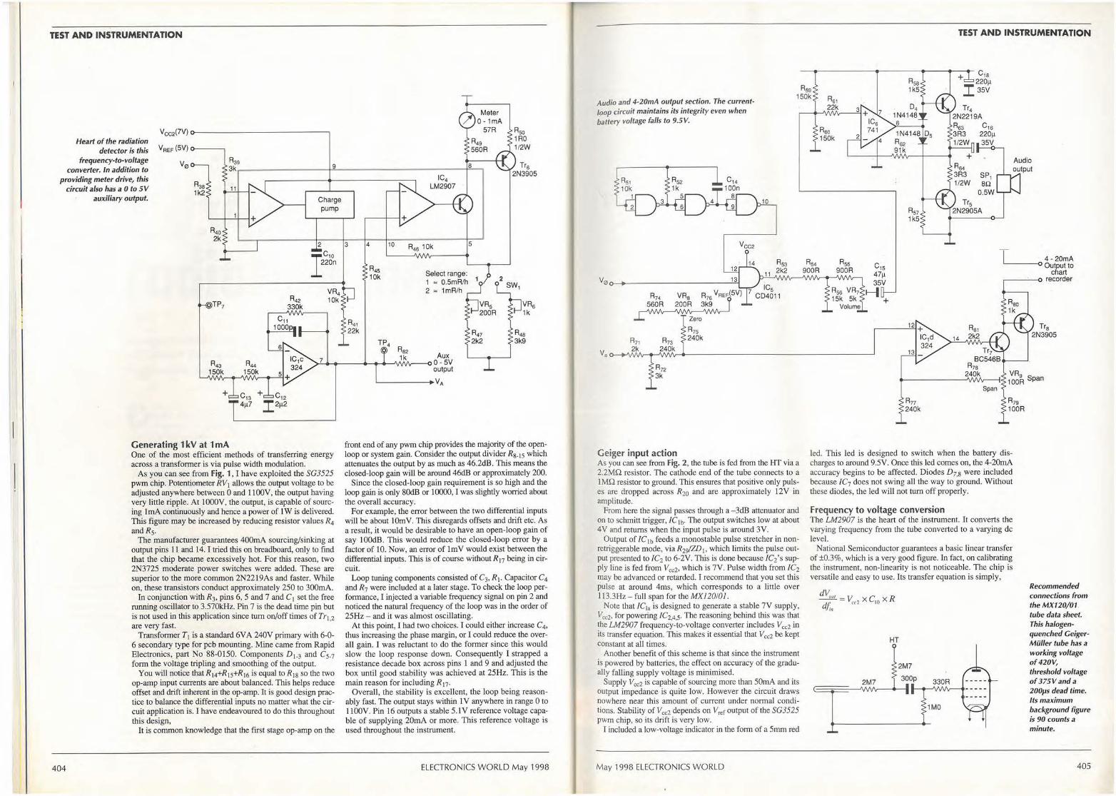
TEST AND INSTRUMENTATION
Heart of the radiation detector is this
frequency-to-voltage converter. In addition to
providing meter drive, this circuit also has a Oto 5V
auxiliary output.
Vcc2(7V) o----------------,
V REF (5V) o---~
V0
R35 1k2
TP7 A42
330k
9
Charge pump
2
220n IC10
VR4 10k
3 4 10
A45 10k
IC4 LM2907
R46 10k
Select range: 1 " 0.5mR/h 2 " 1mR/h
Ra2
5
Tr6 2N3905
VR6 1k
1k Aux -7------------'\AM,---00-5V
404
Generating 1 kV at 1 mA One of the most efficient methods of transferring energy across a transformer is via pulse width modulation.
As you can see from Fig. 1, I have exploited the SG3525 pwm chip. Potentiometer RV1 allows the output voltage to be adjusted anywhere between O and I IO0V. the output having very little ripple. At lOOOV, the output, is capable of sourcing I mA continuously and hence a power of l W is delivered. This figure may be increased by reducing resistor values R4 and R5.
The manufacturer guarantees 400mA sourcing/sinking at output pins 11 and 14. I tried this on breadboard, only to find that the chip became excessively hot. For this reason, two 2N3725 moderate power switches were added. These are superior to the more common 2N2219As and faster. While on, these transistors conduct approximately 250 to 300mA.
In conjunction with R3, pins 6, 5 and 7 and C I set the free running oscillator to 3.570kHz. Pin 7 is the dead time pin but is not used in this application since tum on/off times of Tr1 2 are very fast. ·
Transformer T1 is a standard 6VA 240V primary with 6-0-6 secondary type for pcb mounting. Mine came from Rapid Electronics, part No 88-0150. Components D 1•3 and C5•7 form the voltage tripling and smoothing of the output.
You will notice that R14+R15+R16 is equal to R1g so the two op-amp input currents are about balanced. This helps reduce offset and drift inherent in the op-amp. It is good design practice to balance the differential inputs no matter what the circuit application is. I have endeavoured to do this throughout this design,
It is common knowledge that the first stage op-amp on the
output
'-------VA
front end of any pwm chip provides the majority of the openloop or system gain. Consider the output divider R 8. 15 which attenuates the output by as much as 46.2d.B. This means the closed-loop gain will be around 46dB or approximately 200.
Since the closed-loop gain requirement is so high and the loop gain is only 80dB or 10000, I was slightly worried about the overall accuracy.
For example, the error between the two differential inputs will be about lOrnV. This disregards offsets and drift etc. As a resulj, it would be desirable to have an open-loop gain of say lOOdB. This would reduce the closed-loop error by a factor of 10. Now, an error of lmV would exist between the differential inputs. This is of course without R 17 being in circuit.
Loop tuning components consisted of C3, R1. Capacitor C4 and R7 were included at a later stage. To check the loop performance, I injected a variable frequency signal on pin 2 and noticed the natural frequency of the loop was in the order of 25Hz - and it was almost oscillating.
At this point, I had two choices. I could either irtcrease C4,
thus increasing the phase margin, or I could reduce the overall gain. I was reluctant to do the former since this would slow the loop response down. Consequently I strapped a resistance decade box across pins 1 and 9 and adjusted the box until good stability was achieved at 25Hz. This is the main reason for including R17•
Overall, the stability is excellent, the loop being reasonably fast. The output stays within 1 V anywhere in range 0 to 1100V. Pin 16 outputs a stable 5.1 V reference voltage capable of supplying 20mA or more. This reference voltage is used throughout the instrument.
ELECTRONICS WORLD May 1998
TEST AND INSTRUMENTATION
+ C1s
Audio and 4-20mA output section. The currentloop circuit maintains its integrity even when battery voltage falls to 9.5V.
R59 150k Rs1
22k
220µ I35V
V0~-+------------=-i
A74 VRa R76 VREF(5V) 9
Zero
R75
R71 R73 240k
2k 240k
R72 3k
Geiger input action As you can see from Fig. 2, the tube is fed from the HT via a 2.2MQ resistor. The cathode end of the tube connects to a IMQ resistor to ground. This ensures that positive only pulses are dropped across R20 and are approximately 12V in amplitude.
From here the signal passes through a -3d.B attenuator and on to schmitt trigger, /Cib• The output switches low at about 4V and returns when the input pulse is around 3V.
Output of /C1b feeds a monostable pulse stretcher in nonretriggerable mode, via R29/ZD1, which limits the pulse output presented to /C2 to 6-2V. This is done because /C2's supply line is fed from Vcc2, which is 7V. Pulse width from /C2
may be advanced or retarded. I recommend that you set this pulse at around 4ms, which corresponds to a little over l 13.3Hz - full span for the MX120l01.
Note that /C10 is designed to generate a stable 7V supply, V cc2, for powering /C2.4,5. The reasoning behind this was that the LM2907 frequency-to-voltage converter includes Vcc2 in its transfer equation. This makes it essential that Vcc2 be kept constant at all times.
Another benefit of this scheme is that since the instrument is powered by batteries, the effect on accuracy of the gradually falling supply voltage is minimised.
Supply Vcc2 is capable of sourcing more than 50mA and its output impedance is quite low. However the circuit draws nowhere near this amount of current under normal conditions. Stability of V cc2 depends on V ref output of the SG3525 pwm chip, so its drift is very low.
I included a low-voltage indicator in the form of a 5mm red
May 1998 ELECTRONICS WORLD
R60 150k
C1s 220µ 35V
SP1 an
0.5W
C1s 47µ 35V
T 4- 20mA 0 output to
chart ~---o recorder
Rs6 VR7 1-) 15k 5k +
Volume
Rn 240k
14
led. This led is designed to switch when the battery discharges to around 9.5V. Once this led comes on, the 4-20rnA accuracy begins to be affected. Diodes D7,s were included because /C7 does not swing all the way to ground. Without these diodes, the led will not turn off properly.
Frequency to voltage conversion The LM2907 is the heart of the instrument. It converts the varying frequency from the tube converted to a varying de level.
National Semiconductor guarantees a basic linear transfer of ±0.3%, which is a very good figure. In fact, on c;alibrating the instrument, non-linearity is not noticeable. The chip is versatile and easy to use. Its transfer equation is simply,
dV .--E!!!..=V xC xR dJ;,, cc2 10
HT
2M7
300p
1MO
Tr8 2N3905
Recommended connections from the MX120/01 tube data sheet. This halogenquenched CeigerMiiller tube has a working voltage of 420V, threshold voltage of 375Vand a 200µs dead time. Its maximum background figure is 90 counts a minute.
405
TEST AND INSTRUMENTATION
406
where R=RV4+R41 . Voltage Vcc2 is fixed at 7V but may be varied to accommodate other configurations. For the MXJ20/01 tube,
t.V0., = 0 to 5V
t./;. = 0 to l 13.3Hz
t.V0"
1 = 0.044V/Hz /if;.
Capacitor C10 is 220nF and, 0.044=7x220xl0-9xR. As a result, R is 28647 .SQ. Hence potentiometer RV4 is used to trim the output on pin 7 of IC1 to 5V at 113.3Hz. The only component that you may have to change to accommodate a different tube is R41 •
For an in depth discussion on exactly how the LM2907 charge pump operates, refer to National's Linear Applications Handbook 1994, Application Note AN162, p. 345.
Output of the charge pump is injected into a Butterworth type second-order low-pass filter which has a break frequency of about 0.33Hz. Its output will be around 40dB down at 3.3Hz. The output of the filter feeds the 0-lmA meter drive circuitry within the LM2907 converter.
There are two ranges to choose from. The first is 0-500µrad/h and the second 0-l00Oµrad/h.
Transistor Tr6 was included simply to redirect meter current should it exceed about 1.2mA, thus meter protection is incorporated in the design. Should a 0-5V output be required for external purposes, R82 provides suitable output.
Voltage V,ef, from the pwm chip supplies R39 and R40-The hysteresis span on the input amplifier is about 0.6V.
I thoroughly recommend the use of an analogue meter as opposed to a digital type. The output of the tube is a continuously varying frequency being largely dependent on the nature of radiation. Although the low-pass filter does a good job at averaging or integrating, the output still varies according to the intermittent bombardment of the tube.
4-20mA output Here, output from IC I is fed directly to R71/Rn which drops it from 0-5 to 0-3V full scale. Th.is allows a greater voltage drop to occur in the 4-20mA output loop. Again, V ref from the S03525 is used, affording a stable low drift zero setting via RV8. Th.is potentiometer is used in conjunction with RV9,
which sets the span. Transistors Tr1,8 form a compound or current feedback
structure. The inclusion of Tr8 greatly increases the input impedance of Tr7, allowing IC ld to exercise its maximum gain. This increases overall accuracy.
The 4-20mA output easily drives a standard 250.Q, 0.1 % resistor - even with the battery supply as low as 9.5V.
Unfortunately, I do not, have access to a chart recorder, but I thoroughly recommend this output since the peaks and troughs would be exposed for further analysis.
Audio output The audio section of the instrument is straight forward. Running at 5kHz, oscillator IC5 is gated with the output of the 4047 monostable (pin 10).
Maximum output at RV7 is about 3V pk-pk of 5kHz 'packets'. Potentiometer RV1 may be adjusted for a comfortable audio output.
In conjunction with Tr4,5, IC6 makes up a low impedance buffer amplifier. It is capable of outputting around half a watt into an 8.Q speaker. The audio output is a convincing series of 5kHz clicks.
Setting up Set a frequency generator on square wave and adjust this signal for 0-12V peak. Set the frequency generator for l 13.3Hz
- assuming you are using the MX120/0J - and inject th.is signal between ground and negative terminal of the tube connection on the pcb. The tube is obviously removed at this stage. Adjust RV1 for comfortable audio output. Connect a volt meter between ground and TP6 and adjust VR2 for Vcc2
of7V exactly. Next, with the aid of an oscilloscope, connect the probe
between ground and TP5 and adjust the pulse width for 4ms. With the function generator precisely set to l 13Hz, adjust RV4 for 5V exactly at TP 4. With S I on range 2, adjust RV6 for 1 mA reading on the moving coil meter.
With a current meter connected between the 4-20mA terminals, adjust the span potentiometer RV9 for 20mA, then switch off the function generator (OHz) and adjust RV8 zero for 4mA. Switch the generator back on and re-adjust the span pot RV9 for 20mA. Repeat this procedure until you get satisfactory results.
Once the above has been completed, set the frequency generator for 113/2==56.5Hz, switch S I to range 1 and adjust RV5 for full span on the moving coil meter , i.e. 1 mA. Connect a volt meter across ground and HT and adjust RV1 for 420V, again assuming you are using the MXJ20/0I. Your instrument is now ready for use.
How do I know if it works? Elsewhere in the article, I mentioned that HT flash over perhaps radiates gamma radiation. Sadly this is not the case. Further to this, I picked up no appreciable radiation reading from house bricks, luminous watches, uv lamps or television screens. In fact, television screens probably emit low level X-rays instead of gamma radiation.
What I found to worked extremely well was the mantle as used in Calor gas lamps. This is that little piece of material that covers the flame and glows, emitting light. These are available in abundance at the local ironmonger.
With three of these mantles wrapped around the MXJ20/0J tube, it is possible to obtain a reading of between 250µrad/h and 300µrad/h rising to sometimes to 400µrad/h. I have no idea what the safe permitted dose actually is.
Other thoughts With regards to the various op-amps used in the instrument, only one exhibited hf on its output, namely !Ctc· Th.is is why C 11 is strapped across its input/output terminals. I suspect the reason for th.is is the high source/feedback resistance used. I expected hf on the 4-20mA amplifier, IC Id, but it was stable. This leads me to th.ink that the LM324 quad op-amps are well compensated internally. •
The LM324 quad op-amp will swing all the way to ground and its common mode input range includes ground. I recommend that the tube connection be of twin screened audio cable, the screen being connected to ground.
The MX series of tubes are old Mullard types. I believe that tube performance has changed little over the years. Also, the new unit for radiation is the gray, I have used millirads per hour to quantify absorbed dose throughout th.is article but, lmrad/h is simply 0.0lmGy/h. •
Technical support Linear Applications Specific ICs databook 1993,
National Semiconductor. Linear Applications Handbook AN-162, p. 345, 1994,
National Semiconductor. 1990 Linear Databook, Linear Technology Corp. Page
5-97, (SG3525 data sheet). Langrex, 0181 684 11 66, fax 0181 684 3056. Colomor, 0181 743 0899, fax. 0181 749 3934.
ELECTRONICS WORLD May 1998
CONNECT WITH THE UK'S -
NO. 1 READ F0R~ELEC1RONICS ,: '\ , .
Electronics Weekly HyperActiv9Jis more than ju~t a magazine on the Web. Check oi1t the site and ycfu'II see why thout andj of electronics professio~als around t': world reguiarly log onto www.electronicsweekly.co.uk/ } '-' ~ :.
F~r News HyperA~tive':Oaily News Service brings you the latest n: ws in the industry - ijS it breaks. For Jobs l!vperActive has theJargest,.and most varied collection of jobs ~vail: ble in the electronics market. Now we bring you the improved Jobs and Careers service tyith a .whole ~ange of new_.!.and exciting features. . •
All this plus, the latest technology, market inform,ation, to_plkit's, a searchable archive, and loads more ... .
Don't miss out. . o·n -you or.ow er at}~ P;liww.w1_!L_ectrcfriic·swee , • .
· ~~~~,~.1st~.r n.o Ot;f.J!lit!@°l _ SPONSORED BY
TOSHIBA SIEMENS . . --.
ADVERTISER INFORMATION:·0181 652 3639 OR E-MAIL: [email protected] -
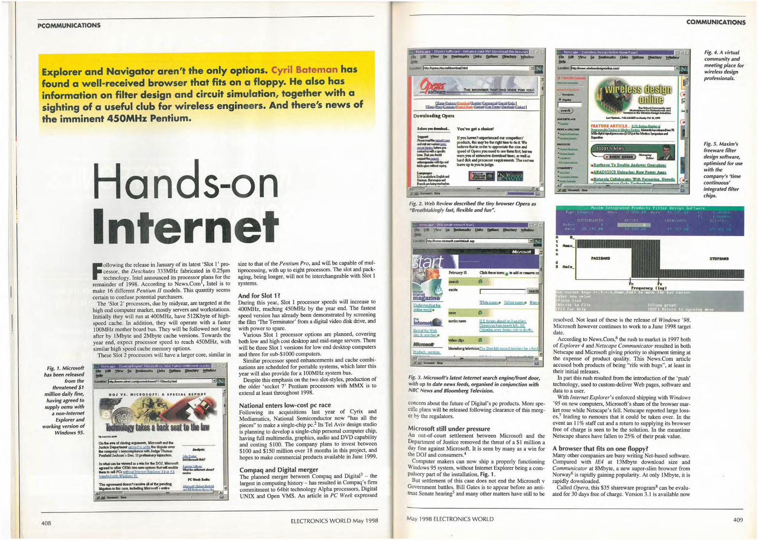
PCOMMUNICATIONS
Explorer and Navigator aren't the only options. Cyril Bateman has found a well-received browser that fits on a floppy. He also has information on filter design and circuit simulation, together with a sighting of a useful club for wireless engineers. And there's news of the imminent 450MHz Pentium.
fig. 1. Microsoft has been released
from the threatened $1
million daily fine, having agreed to
supply oems with a non-Internet
Explorer and working version of
Windows 95.
408
Hands-on Internet F
ollowing the release in January of its latest 'Slot 1' processor, the Deschutes 333MHz fabricated in 0.25µm technology. Intel announced its processor plans for the
remainder of 1998. According to News.Com 1, Intel is to make 16 different Pentium Il models. This quantity seems certain to confuse potential purchasers.
The 'Slot 2' processors, due by midyear, are targeted at the high end computer market, mostly servers and workstations. Initially they will run at 400MHz, have 512Kbyte of highspeed cache. In addition, they will operate with a faster 100MHz mother board bus. They will be followed not long after by lMbyte and 2Mbyte cache versions. Towards the year end, expect processor speed to reach 450MHz, with similar high speed cache memory options.
These Slot 2 processors will have a larger core, similar in
tlpf,;( ,IPf' hpf'C1,ll RPpOr1 t 11<ro~nfl V\ 1)0J Paf11al Si"rtlf'men11e ,·uhe1
oo, vs. ••c•oson , A SPECIAL eE•o•r
Ontia""" of closing•~. llliaosoft mdtia Ju:slice ~ agreed •o setttetw displJN O'V"ef ... -· s....,..,....,. _Judge Thous Penfield Jocl<S«i' s Dec. 11 po-eliiiilmlry ......-,_
In-cmbe-.i os awil for fla OOl. lliaosoft ,e,oadlO ofltl' OElls-rwwopio<,s M""11- Lt::'f.'::..-, .._., sa1 Pei ':Mtbout Internet Ewloter 3 O or • O .,._. bundled \\o'ith Windows 95
The ,._11oem,,..-.. c(fla pendW,g ~mtm ""'8,ildldinglficrosolls mlir•
PC--
size to that of the Pentium Pro, and will be capable of multiprocessing, with up to eight processors. The slot and packaging, being longer, will not be interchangeable with Slot l systems.
And for Slot 1? During this year, Slot 1 processor speeds will increase to 400MHz, reaching 450MHz by the year end. The fastest speed version has already been demonstrated by screening the film 'The Terminator' from a digital video disk drive, and with power to spare.
Various Slot l processor options are planned, covering both low and high cost desktop and mid-range servers. There will be three Slot 1 versions for low end desktop computers and three for sub-$1000 computers.
Similar processor speed enhancements and cache combinations are scheduled for portable systems, which later this year will also provide for a 100MHz system bus.
Despite this emphasis on the two slot-styles, production of the older ' socket 7' Pentium processors with MMX is to extend at least throughout 1998.
National enters low-cost pc race Following its acquisitions last year of Cyrix and Mediamatics, National Semiconductor now "has all the pieces" to make a single-chip pc.2 Its Tel Aviv design studio is planning to develop a single-chip personal computer chip, having fuH multimedia, graphics, audio and DVD capability and costing $100. The company plans to invest between $100 and $150 million over 18 months in this project, and hopes to make commercial products available in June 1999.
Compaq and Digital merger The planned merger between Compaq and Digital3 - the largest in computing history- has resulted in Compaq's firm commitment to 64bit technology Alpha processors, Digital UNIX and Open VMS. An article in PC Week expressed
ELECTRONICS WORLD May 1998
Do1'1lloadiag Opera -.. -Sw-t _ _, .. ~ ----~-... catlltu,o,lh.,,.._ ;,,,,,,n...,._ _ ... _ _,,......,., .... ---... ~;,E ..... ..t -11 ........ ..i ---bong-on.
If you 11mm, uperienced our compelitms· produds, tis m,:y be the right time to do ii. We believe lll4t in order to appreciale the size 4nd 1peed ofOperayouneed to seetunafirsl, bulwe worn you of elllensMI d°"""'4d limes, ., wea., hud disk cul )lfotessor requir""'8111S. Tu rest we lem, up to you to judge.
- .. Fig, 2, Web Review described the tiny browser Opera as "Breathtakingly fast, flexible and fun",
tne -. 1111an...a1p Bes1 ot 11te Wsb 11tes & ie,,rne, 0 ..... Produd$ servicrs
wleo clip,
US f01g@s ahead gn ft'a.gpl9ns c~me1oon tr~m wi erk k1U.: !00 Colombt6 army denies rqle ,n de~,h~
Fig. 3. Microsoft's latest Internet search engine/front door, with up to date news feeds, organised in conjunction with NBC News and Bloomberg Television.
c?ncem about the future of Digital 's pc products. More specific plans will be released following clearance of this merger by the regulators.
Microsoft still under pressure An out-of-court settlement between Microsoft and the Department of Justice removed the threat of a $1 million a day fine against Microsoft. It is seen by many as a win for the DOJ and consumers.4
~omputer makers can now ship a properly functioning Windows 95 system, without Internet Explorer being a compulsory part of the installation, Fig. 1 .
But settlement of this case does not end the Microsoft v Government battles. Bill Gates is to appear before an antitrust Senate hearing5 and many other matters have still to be
May 1998 ELECTRONICS WORLD
COMMUNICATIONS
c '.§ -I -") ---·--··-·.......,,_.. -·• ;.-.,_ . ..___
Fig. 4. A virtual community and meeting place for wireless design professionals.
Fig. 5. Maxim's freeware filter design software, optimised for use with the company's 'time continuous' integrated filter chips.
.. _~ .,. .,-- Max1mL1l nU:9rd l cd, t'ro d tu..: ls t" Jllt.:r lh:sqp 1 $uf twdrc l 11p• I r ,w1,-1 11m,, • , • ! •, ,1 l 11111 1 11 I
I l:I J'l 11 HLJI I I{ rtl l , f 1 1. ! tit t,, ' ,JI , 1! l I I I 1
fl t t e n
• B
11 , ,1, . I -6W ltflll 11 jr! l 11 , Iii J j , • ' t, • •
resolved. Not least of these is the release of Windows ' 98. Microsoft however continues to work to a June 1998 target date. .
According to News.Com,6 the rush to market in 1997 both of Explorer 4 and Netscape Communicator resulted in both Netscape and Microsoft giving priority to shipment timing at the expense of product quality. This News.Com article accused both products of being "rife with bugs", at least in their initial releases.
In part this rush resulted from the introduction of the 'push' technology, used to custom-deliver Web pages, software and data to a user.
With Internet Explorer's enforced shipping with Windows '95 on new computers, Microsoft's share of the browser market rose while Netscape's fell. Netscape reported large losses,7 leading to rumours that it could be taken over. In the event an 11 % staff cut and a return to supplying its browser free of charge is seen to be the solution. In the meantime Netscape shares have fallen to 25% of their peak value.
A browser that fits on one floppy? Many other companies are busy writing Net-based software. Compared with !E4 at 13Mbyte download size and Communicator at 8Mbyte, a new super-slim browser from Norway6 is rapidly gaining popularity. At only lMbyte, it is rapidly downloaded.
Called Opera, this $35 shareware program8 can be evaluated for 30 days free of charge. Version 3.1 is available now
409
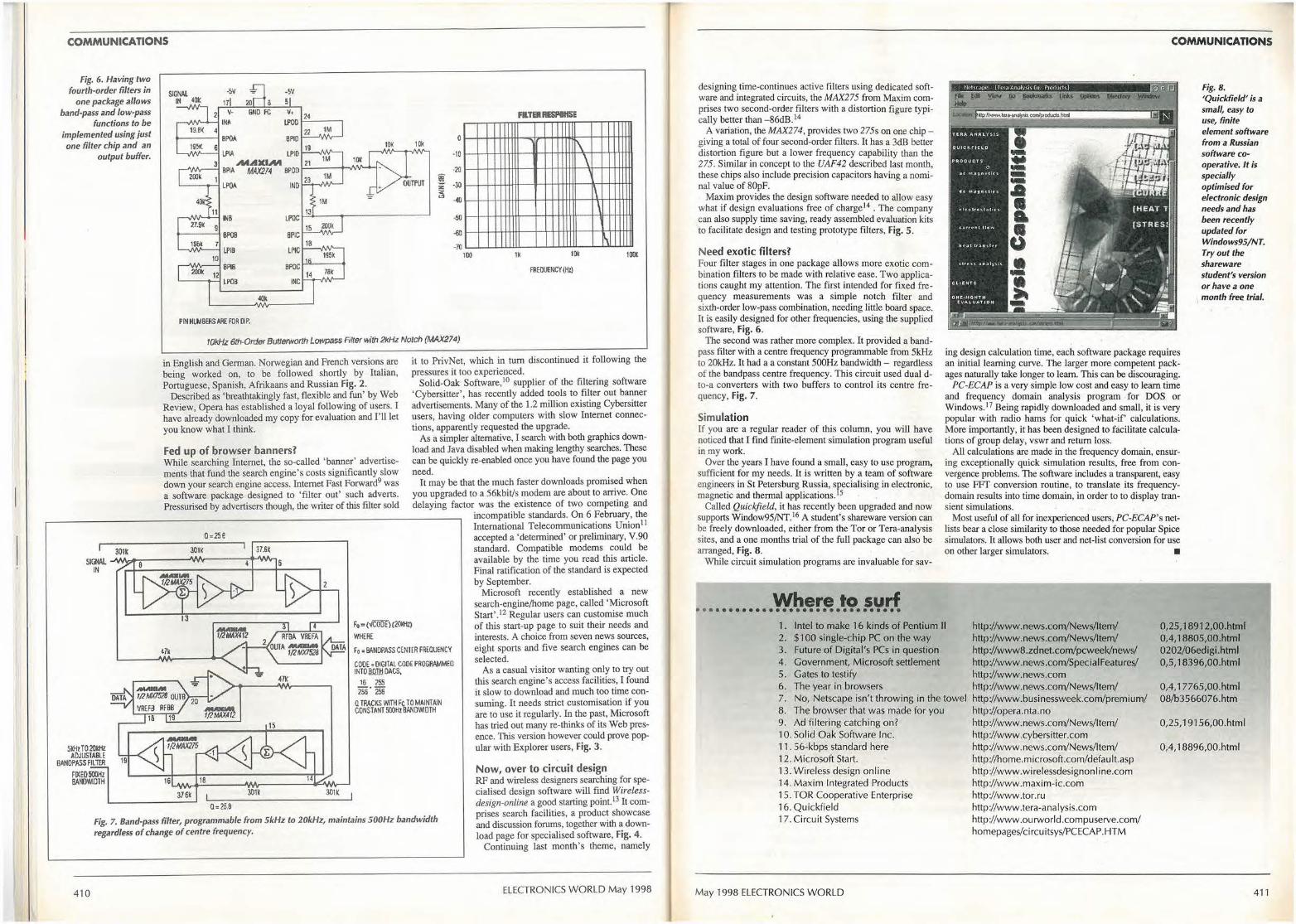
COMMUNICATIONS
Fig. 6. Having two fourth-order filters in
one package allows band-pass and low-pass
functions to be implemented using just one filter chip and an
output buffer.
I 301k
-5V
8 5
2 v- GND fC V+
IN~ IJ>OO 19.B~ 4
BPOA BPIO 19!'«.
6 IJ>IA LPIO 3 M.AXIA'I
BPIA MAX214 SPOD WJK 1
LP°" IND
401: 11
INS LfOC 27.91(
8P08 BPIC 1Sfik
LPIB LPIC 10
200k BPl8 BPOC
12 LPOB INC
PIN NUMBERS APE. FDR Ill P.
24
22 1M
19 10K lll<
21
23 i z
-= < <!I
13
15 200k
18
195k
14 78k
0
·10
-20
·30
-40
-50
-60
-70 100
Fil TEii RESPIIISE
I\
1K 10ft
FREOllfNCY (Hll
\
\
' ~
100!
tOkHz 6th-Order Butterworth Lowpass Filter with 2kHz Notch (MAX274)
in English and German. Norwegian and French versions are being worked on, to be followed shortly by Italian, Portuguese, Spanish, Afrikaans and Russian Fig. 2.
Described as 'breathtakingly fast, flexible and fun' by Web Review, Opera has established a loyal following of users. I have already downloaded my copy for evaluation and I'll let you know what I think.
Fed up of browser banners? While searching Internet, the so-called 'banner' advertisements that fund the search engine's costs significantly slow down your search engine access. Internet Fast Forward9 was a software package designed to 'filter out' such adverts. Pressurised by advertisers though, the writer of this filter sold
3O1K 37.&t
it to PrivNet, which in tum discontinued it following the pressures it too experienced.
Solid-Oak Software, 10 supplier of the filtering software 'Cybersitter', has recently added tools to filter out banner advertisements. Many of the 1.2 million existing Cybersitter users, having older computers with slow Internet connections, apparently requested the upgrade.
As a simpler alternative, I search with both graphics download and Java disabled when making lengthy searches. These can be quickly re-enabled once you have found the page you need.
SIOOL -M/\dl>-:----....1\/1~----.+"Mlr-,
It may be that the much faster downloads promised when you upgraded to a 56kbit/s modem are about to arrive. One delaying factor was the existence of two competing and
incompatible standards. On 6 February, the International Telecommunications Union11
accepted a 'determined' or preliminary, V.90 standard. Compatible modems could be available by the time you read this article. Final ratification of the standard is expected by September.
IN
5kHzT020kHz ADJUSTABLE
BANDPASS FIL Tf.R
FIKE0500/iz BA!fl'MDTH
47k
376k 301K
0=25.8
2
301K
WHERE
Fo; BANDPASSCEN1£R FREQUENCY
CODE, DIGITAL CODE PROGRAMMED INTOll.lilllDACS,
16 ]55 256. 256
Q TRACKS WITH Fe TO MAlt-rfAIN CONSTANT 500Hz BANDWIDTH
Fig. 7. Band-pass filter, programmable from SkHz to 20kHz, maintains 500Hz bandwidth regardless of change of centre frequency.
410
Microsoft recently established a new search-engine/home page, called 'Microsoft Start' .12 Regular users can customise much of this start-up page to suit their needs and interests. A choice from seven news sources, eight sports and five search engines can be selected.
As a casual visitor wanting only to try out this search engine's access facilities, I found it slow to download and much too time consuming. It needs strict customisation if you are to use it regularly. In the past, Microsoft has tried out many re-thinks of its Web presence. This version however could prove popular with Explorer users, Fig. 3.
Now, over to circuit design RF and wireless designers searching for specialised design software will find Wirelessdesign-online a good starting point. I3 It comprises search facilities, a product showcase and discussion forums, together with a download page for specialised software, Fig. 4.
Continuing last month's theme, namely
ELECTRONICS WORLD May 1998
designing time-continues active filters using dedicated software and integrated circuits, the MAX275 from Maxim comprises two second-order filters with a distortion figure typically better than -86dB.14
A variation, the MAX274, provides two 275s on one chip -giving a total of four second-order filters. It has a 3dB better distortion figure but a lower frequency capability than the 275. Similar in concept to the UAF42 described last month, these chips also include precision capacitors having a nominal value of 80pF.
Maxim provides the design software needed to allow easy what if design evaluations free of charge14 • The company can also supply time saving, ready assembled evaluation kits to facilitate design and testing prototype filters, Fig. 5.
Need exotic filters? Four filter stages in one package allows more exotic combination filters to be made with relative ease. Two applications caught my attention. The first intended for fixed frequency measurements was a simple notch filter and sixth-order low-pass combination, needing little board space. It is easily designed for other frequencies, using the supplied software, Fig. 6.
The second was rather more complex. It provided a bandpass filter with a centre frequency programmable from 5kHz to 20kHz. It had a a constant 500Hz bandwidth - regardless of the bandpass centre frequency. This circuit used dual dto-a converters with two buffers to control its centre frequency, Fig. 7.
Simulation If you are a regular reader of this column, you will have noticed that I find finite-element simulation program useful in my work.
Over the years I have found a small, easy to use program, sufficient for my needs. It is written by a team of software engineers in St Petersburg Russia, specialising in electronic, magnetic and thermal applications. 15
Called Quickfield, it has recently been upgraded and now suppons Window95/NT. I6 A student's shareware version can be freely downloaded, either from the Tor or Tera-analysis sites, and a one months trial of the full package can also be arranged, Fig. 8.
While circuit simulation programs are invaluable for sav-
Where to surf , ..•...... ...•.•....•.. ....•..•
COMMUNICATIONS
ing design calculation time, each software package requires an initial learning curve. The larger more competent packages naturally take longer to learn. This can be discouraging.
PC-ECAP is a very simple low cost and easy to learn time and frequency domain analysis program • for DOS or Windows.17 Being rapidly downloaded and small, it is very popular with radio hams for quick 'what•if' calculations. More importantly, it has been designed to facilitate calculations of group delay, vswr and return loss.
All calculations are made in the frequency domain, ensuring exceptionally quick simulation results, free from convergence problems. The software includes a transparent, easy to use FFf conversion routine, to translate its frequencydomain results into time domain, in order to to display transient simulations.
Most useful of all for inexperienced users, PC-ECAP's netlists bear a close similarity to those needed for popular Spice simulators. It allows both user and net-list conversion for use on other larger simulators. •
Fig. 8. 'Quickfield' is a small, easy to use, finite element software from a Russian software cooperative. It is specially optimised for electronic design needs and has been recently updated for Windows95/NT. Tryout the shareware student's version or have a one
, month free trial.
1. Intel to make 16 kinds of Pentium II http://www.news.com/News/ltem/ http://www.news.com/News/ltem/
0,25, 18912,00.html 0,4, 18805,00.html 0202/06edigi.html 0,5, 18396,00.html
2. $100 single-chip PC on the way 3. Future of Digital's PCs in question 4. Government, M icrosoft settlement 5. Gates to testify 6. The year in browsers 7. No, Netscape isn't throwing in the towel 8. The browser that was made for you 9. Ad filtering catching on? 10. Solid Oak Software Inc. 11. 56-kbps standard here 1 2. Microsoft Start. 13. Wireless design on line 14. Maxim Integrated Products 15. TOR Cooperative Enterprise 16. Quickfield 17. Circuit Systems
May 1998 ELECTRONICS WORLD
http ://www8.zdnet.com/pcweek/news/ http://www.news.com/Specia1Features/ http://www.news.com http://www.news.com/News/Item/ http://www.businessweek.com/prem i um/ http://opera.nta.no http://www.news.com/News/Item/ http://www.cybersitter.com http://www.news.com/ News/Item/ http://home.microsoft.com/defau lt .asp http://www.wirelessdesignonline.com http://www.maxim-ic.com http://www.tor.ru http//www.tera-analysis.com http//www.ourworld.compuserve.com/ homepages/c i rcu itsys/PCECAP. HTM
0,4, 17765,00.html 08/b3566076.htm
0,25, 19156,00.html
0,4, 18896,00.html
411
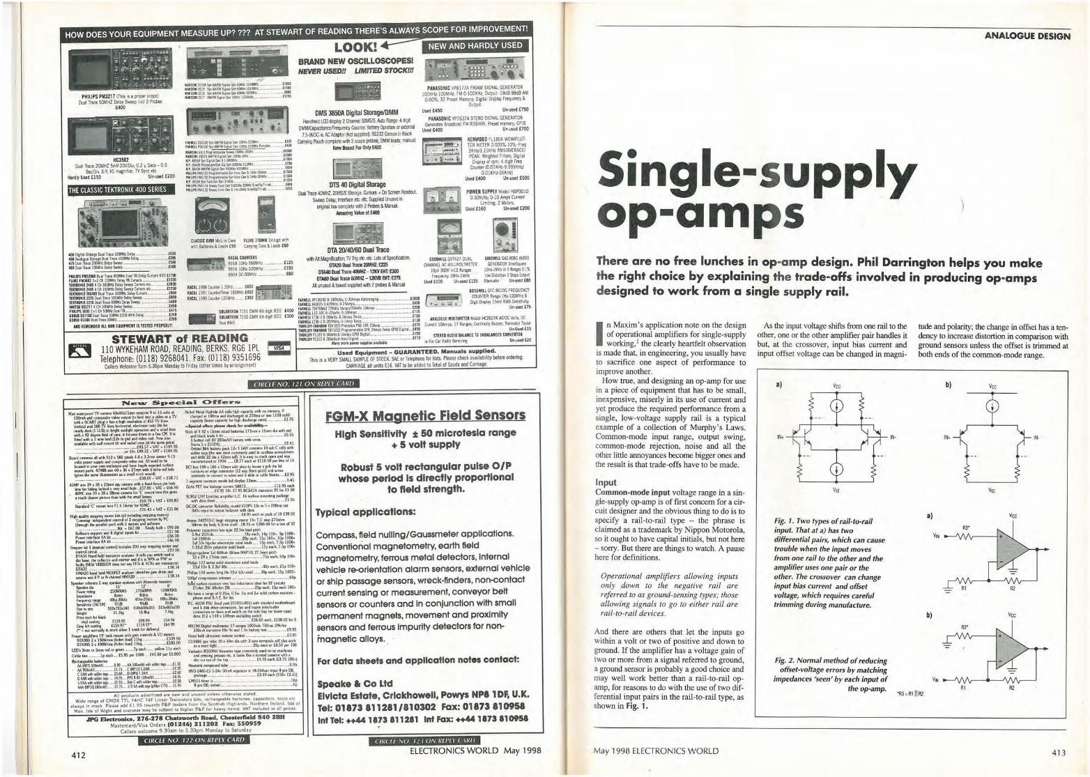
HOW DOES YOUR EQUIPMENT MEASURE UP? ??? AT STEWART OF READING THERE'S ALWAYS SCOPE FOR IMPROVEMENT!
.. -~- : --· 1--;;;:•.:- :•s.;;..::,c.-;; I ~I -. - "; ~ i • ;
• ~~~f "'~,:,f.'i =- ;., J .. -::.~ .. ~;~:-·
~ .-I _QI ,-.,,. , ':; _ 'J"";, I -- "; ,i.
PHILIPS PM321 J (This b a p,Cjler SCOJlO) Dual Troc:e 50MH1 Oelay S-p loci 2 Probes
£400
HC35D2 Dual Trace 20MHZ 5mV.20V/Di~ 0.2 US.CS -0.5
Se:/Div, X,Y; X5 magnifre,; TV Sync etc Hardly Used £150 Un,used £200
THE CLASSIC TEKTRONIX 400 SERIES
ii CLASSIC AVOS 1',111.S in Case rtUKE 17Dlr'M 31iSdrg.1. with ,r.t~ Batttrill!:S &: Leads £50 C~,ry1ng Cast & le~s £60
RAC1,1,COU"1ERS 9918 IOllz,56QMHz .............. £125 9916 t0Hl-520MHz ............... £150 9904 OC-SOMHz ........................ £60
~~~n~m~f~ r~= ~e•JJ~~~~-~~~~~.~g~ nDROIIIX 2:-4$5 t Ch JOOMltt Delay Sweep Cl.lmn ,tc. .. - ..... JttlOO RACAL 1998 Counter t.3GHz .... ,P, . £6SO ll!IC::::::CII'!!~
BRAND NEW OSCILLOSCOPES! NEVER USED!f UMITED STOCK!!!
OMS 3850A Digital Storage/DMM H.rlllleld LCO ciS\)la'/ 2 Crawlel SOMS/S.Auto Range. 4 dig! OM~ erunter. Batt,ryOpatioo or exmm~
7_,-9'/DC ~. PC AdlC)IO( (Not~. RS232 Comes in Blad< ~ Pooch complete wilh 2 scope i:,ooes; OMM lead$; maooal.
New Boxed for Only £400 •
DTS 40 Digital Storage Dual Trace 4DMHZ. 2(»,IS/S Slolage. cursors + tJo Screen P.eadcxrl
Swtel) Delay; Interface elt. etc. Supplied Urused in aigllal llOll compklte wilh 2 P!ooes & Mnral.
Amazing Value at £400
OTA 20/40/60 Dual Trace wilh AA Magrlocaliln; TV T19 ell:. elc. lJJls of Specifcaoon.
DTA20 Dual Traee :ln',IIIZ; £225 DTA40 Dual Traee 40MHZ -12KV 00: £300
DTASO Dual Trace 60MHZ -12KVB 00: £375 /111 LV'rUSed & bmced ~ with 2 ixooes & Manual
NEW AND HARDLY USED
PAH~ONIC VP8177A FWAM SIGNAL GENERATOR tOOKH!-l OOMHz· FM 0-!00KHz; Outpul -!9d8-99d8 AM 0<i0%; 32 Pr~ Memory; Digilal Display Freqtlel!C\' &
Output. Us,d £450 Un,used £750
PAN~OHIC VP7637A smo SIGNAL GENERAIOR Generate, Sroadmt fM,RDS/ARI. Preset me"""!: GPIS
Used £400 Un,used £700
~EIIWDOD Fll80A WOW,R.UTTER METER 0.003%·10%; freq 3KH113.15KHz RMS/AVERAGE/ PEAK: We~hled Fill"'; O,gital
o~play al rpm; 4 digll Freq Counter (0.0tKH,,9.999KHu
0.0IKHz-55KH!} Ustd £400 Un..iitd £500
POWER SUPPLY Model HSP3010 0-30Volls: 0-1D Amps Current
Limibf11. 2 Meters. Us,d £160 Un-used £200
&OODWIIL GVl427 OUAl CIIANNEL M; MllllVOI.TM ETER
ltlj/1 'JOCN ml2 R>ng,s freq~ l0H1-lWfz
Ustd £100 Un-us.td £125
IOOOWIU GAG-808G AUDIO GEHERATOO S-e
t0Hz,IMHziil5 R,ne,s0.1% L0< o;i-5 Sap, 0u<o,1
A:terua-:M UIHlsed £80
TlltlU)llll2445 'Cll150MHIOdrj'~CUfSOB"1:- ... _l12!IO UCAL 1991 Coonlettr.mer 160Mliz£450 .-:.·
~:i::~~~Oua~~!~J=~~~:::=::::::=:::~: 120M £300 ., • EIIOO ( an:::iill 1
TEKmNIIZ2\$Chn1Tr10t~lOeltrS..... ----·- '"''~M .. ,t4eD RACAL l<mCoomer HZ.,n,.,. • ~=ru:=:~~:2~~p,Aut«&Jlll'll<----·· 00 ' ~ .. A z . ~~~:sS::l;i11~1=8:~1~·==========~;~ sawTR0N 7151 D'-'tif 61' digit IEEE £450 :!:lli~:~!1=~~~s !1».iap,,- - ---g~
GOODWlll GFC 8010G fRtoUENCY C(MJNTER 11>¥ IHz-120MHz 8
Dle1t Oisplil)' l 5mV RMS Sen$il1vity Un·ustd £7S
50UUOS1\D0 1lm1 Trate.30Mlllt200Wi1h0el,, .. _,...,_ ...... ....£l.(O ~ SOWTRON 71500MM6Kcf:q:~IE.EE £300 fARNtu lT30--20-30'folls,<l•~f#i".'t £~= GOUtDGS3000v-11lrkt20htll- - ---- ~ ·
200 - JnieftMS ;::~y~~~~~~~';;! ff,ro;i,;p._ .. l$
ANALOGUE MUtTIM£TER Model HC260TR Af'JOC Volts; DC Currefll lOArnps: 17 Rariges;: Conliilurty 8uuet; Transistor lesCer
Un-Used US SIHEO AUDIO 8ALANCE 10 UNSWNCIO CONYEIUOR
~_:All::0:_:A:EM:,::EM:8::::EA:.:1,1,:L_:OU::R_:EQ::U::_IPM::E:::,NT:_:,IS:_:T,:ES::_:TE::_0 ;_PR:;,OP;_[;_RIY;_! _______ ------:-::-:-::------7
TNLIRUY•THAll1llR ISPJ222 Proerimmi.bk J2'¥: v.ps Wet CP1J DtPU1-t4SII
STEWART Of READING · ::::~:::1:~'o;;!t';,.,, ...... ----,:~ ~ Maq more ,owe, u,pllts rollaW.
110 WYKEHAM ROAD, READING, BERKS. RG6 lPL ..;. . Used Equipment_ GUARANTEED. Manuals su~plied. .
le F« Car Radio $ervic1(1 Un·ustd t20
Telephone: (0118) 9268041. Fax: (0118) 9351696 This is a VERY SMALL SAMPLE OF STOCK. SA£ or Telephone lor lists. Please check ava,lab,htybefore ordering. Callers Welcome 9am-5.30pm Monday 10 Friday (other times by arrangemen11 CARRIAGE all untts £16. VAT 1D be added to Total ol Goods and Carnage.
CIIKLE NO. 121 ON REl'L l' CARO
~~ .. ~~=~~u~b:~~ cap.Idly Power~ for fig~ clb<hargc ra1~ ........ MM•-·£3.1S
-$pedal offaw pkaH check for HalbbHity.-Slidl ol 4 42 • 16rrm~bltt~ 11hmia 161111ffl dladh red
-1ndb&ttklil.-d$"4.8\l ....... tt f.S.95
~°s:~~ .. ~~•tthllrtrfl [2.45 Owbictl $66 battay pack 12'- l.6AH f:Otllains 10 ~ C tth -.ith IOldtt •{thcM IIIOM ~med ~~~ffl Md drib 22 dia x 42lffll ~ . 11 b: WI} to <,.ck open and w;u MMllfauuted In 1994 ....... £8.?l nch or U t0.50 pubtlx of 14
BClbox 190x l~x SOrtvndhilolJ'Ohcmt: B pd>lhllid eot'llaiM Ml ed9'f connecior (12 --ay&n,n pitch) a,nd it:N/'&'
tmnlNb 10 ~onnect IO w.ffl ,UK! 5 lldt: ln ~ blanki •• ~.t2.9S 7 1C9f1ffi to1M10C1 anode kd~• 121'1'1111 ......................... - .0.45 GoAJ FETlow1ukagtamtt1t S887~ £12.95 tKh
····•-•·--.. -•-····[9.95 10. £7.95 BC547A IUllsbtOf 20 kif [1.00
SL9;:h~~~~LC. 16 Wff11.4rr,owt;ng·~ ·~·95 oc;.oc CMIYfflcr Rdlebilry modd Vl2PS 12v In 5,.. 200tna aut
~~.~~ .. '.~~.~~ .. ~:.:~ach o, j)ICl of 10 [39.SO
~:0~"61!i~.~~J!i"li5r;:.:itt~~of30 p~M ~:.~.~ .. ~~.:~~ ~ ~ t4p 100 •• 9p 1000.
tm 250\!ck .,.--,--:-c---c-:'°Peach. lSp 100•. lOp 1000+ 1111 SO,., btpolar dfct~ a.xi.I '"""·- ····1Spoch. 7.S., 1000+ 0.12m 250¥ ~" ~-i,.I ~ .............. .I Sp m.h. 7.Sp 100•
Polypropo;tent Jul 40()\od( (U111M MKPIO) 27.5mm pilch 32x19x l71mlUM- ---1Spud,. 60p IOO-.
Philp,5123MnUtolidmnlriun:lulal~ 33.Jf 10... & 2.2uf 4DY .... ~ ........... _ .............. 40p each. 2Sp 100•
Ptilllps 108 Mria '°"1 lilt 2'2111 63u a:&1....,MJ,Op Nd,. !Sp 1000+ SOOpf coiq,rim.on tl'lnwnilr _______ 60p
~ c.-1rbon raisl0r$ wry low hlut:IM!Ct Ideal lo, Rf drtuitS 21ohm 21,1.1• 68ohm 2W .M ... M .............. 2Sp ,btb., ISp uch 100•
Wt ~-1~.tl·~u2,..sw, lw and 2w solid urbon ~umi •
PC. 400W PSU (lnlel p..11 20103,S.OOl)v.ith sandard mothe,t,oa,rd • Ind S dl$lt driYt ttM'ltll!«OB. IM Ind IND inllVoudtt
connetlOn on bKk and iw.ildi on lht. lick (kip b l0'IWf uMt
~~·~·~·~·~.~~~-~.~.~~.~~.m~ ooi. £138.00 '°' 6 MXl80Dl,itilmu21imctcr lldtl9U looo.dc7SO,.'K?Molvn
200rru\ 1~1\$CStOJ Hfe 9v and l.SV b.ttay tal-············ ..... £"9.95 Kand Mid ulbJ.iONC nmot<t conllcl ········•-... M• .. M•• ·•• ... ... ~ ..... t3.95 CV2486 g,., rtlay 3Gx 10m i:lawfthJ."ft~•· l iJG'&'Clli:
~1aneiot11g',! 2flJ)tat:hOJ£8.50perlOO Vrrballm R300NH 5o't-ltnt;r u,~ <OCwnonl,; osed 0r1 nc l'NlduMs
•ndpriNingptmest1c.1tlooksl~ a 1IOtl't'lalasstne~h 1 slot cui: OUf of thl lOIJ ......... - ···-·· ........ £4.95 ucb jtl.75 100°)
Ht-llMl\k~rubt .... ----··~···-·················0·95 HV3•2405-ES 5•24v SOmA rcg,.il,t0r it IS.264~-ac lnpu1 8 pin OIL
PKk . .......................... H ............. M .... U.49 U<h ,100. rus1
l.Mi~~L~~·i··....... ---- ........... :.:~ All products e,dvutlsed ,o,re new and unvsed unless othsrwiu: s t.oted
FGM-X Magnetic Field Sensors High Sensitivity :t 50 mlcrotesia range
+ 5 volt supply
Robust 5 volt rectangular pulse O /P whose period is directly proportional
to field strength.
Typical appllcations:
Compass, field nulllng/Gaussmeter applications. Conventional magnetometry, earth field magnetometry, ferrous metal detectors, internal vehicle re-orientation alarm sensors, external vehicle or ship passage sensors, wreck-finders, non-contact current sensing or measurement, conveyor belt sensors or counters and In conjunction with small permanent magnets, movement and proximity sensors and ferrous impurity detectors for nonmagnetic alloys ..
For data sheets and application notes contact:
Speake & Co Ltd
f CMOS TTL. 74HC 74F Unear Transistors k11s. rechargeable batteries. opadtors. tools etc Wide ranijC: Pl dd £ l g5 towe,rds P&P (orders lrom the Scot11sh Hlghlands. Northern heland. Isle of ,11t~:~~ :~1:i:t \Vigh~a;~da oveu~a,s may be subjec.t 10 hlgher P&P fo1 heavy items) VAT included in all ptkes.
Elvlcta Estate, Crlckhowell, Powys NP8 lDF, U.K. Tel: 01873 811281/810302 Fax: 01873 810958 Int Tel: ++441873 811281 Int Fax: ++441873 810958 JPG Electronics, 276-278 Cbauworth Road, Chesterfield S40 2BH
Maslercatd/Visa OrdeTS (01246) 211202 Fax: 550959 Callers welcome 9.30am to 5.30pm Monday to Saturda y-_ _ ____ ~ ._ _______ _
CIR( LE NO I 12 ON Rf Pl Y CARD
412
UI/( LI 1\0 /_ ! o,, 1/U I l ( ,\RI
ELECTRONICS WORLD May 1998
ANALOGUE DESIGN
Single-supply op-amps )
There are no free lunches in op-amp design. Phil Darrington helps you make the right choice by explaining the trade-offs involved in producing op-amps designed to work from a single supply rail.
I n Maxim's application note on the design of operational amplifiers for single-supply working, 1 the clearly heartfelt observl\tion
is made that, in engineering, you usually have to sacrifice one aspect of performance to improve another.
How true, and designing an op-amp for use in a piece of equipment that has to be small, inexpensive, miserly in its use of current and yet produce the required performance from a single, low-voltage supply rail is a typical example of a collection of Murphy's Laws. Common-mode input range, output swing, common-mode rejection, noise and all the other little annoyances become bigger ones and the result is that trade-offs have to be made.
Input Common-mode input voltage range in a single-supply op-amp is of first concern for a circuit designer and the obvious thing to do is to specify ·a rail-to-rail type - the phrase is claimed as a trademark by Nippon Motorola, so it ought to have capital initials, but not here - sony. But there are things to watch. A pause here for definitions.
Operational amplifiers allowing inpurs only down to the negative rail are referred to as ground-sensing types; those allowing signals to go to either rail are rail-to-rail devices.
And there are others that let the inputs go within a volt or two of positive and down to ground. If the amplifier has a voltage gain of two or more from a signal referred to ground, a ground sensor is probably a good choice and may well work better than a rail-to-rail opamp, for reasons to do with the use of two differential input pairs in the rail-to-rail type, as shown in Fig. 1.
May 1998 ELECTRONICS WORLD
As the input voltage shifts from one rail to the other, one or the other amplifier pair handles it but, at the crossover, input bias curr~nt and input offset voltage can be changed in magni-
a) Voe
Ill+
Fig. 1. Two types of rail-to-rail input. That at a) has two differential pairs, which can cause trouble when the input moves from one rail to the other and the amplifier uses one pair or the other. The crossover can change input bias current and offset voltage, which requires careful trimming during manufacture.
Fig. 2. Normal method of reducing offset-voltage errors by matching
impedances 'seen' by each input of the op-amp.
IN-
tude and polarity; the change in offset has a tendency to increase distortion in comparison with ground sensors un less the offset is ~mmed at both ends of the common-mode range.
b) Voe
Ill+ IN-
a) Vr,;,
b) Vee
v,. R1 R2
413
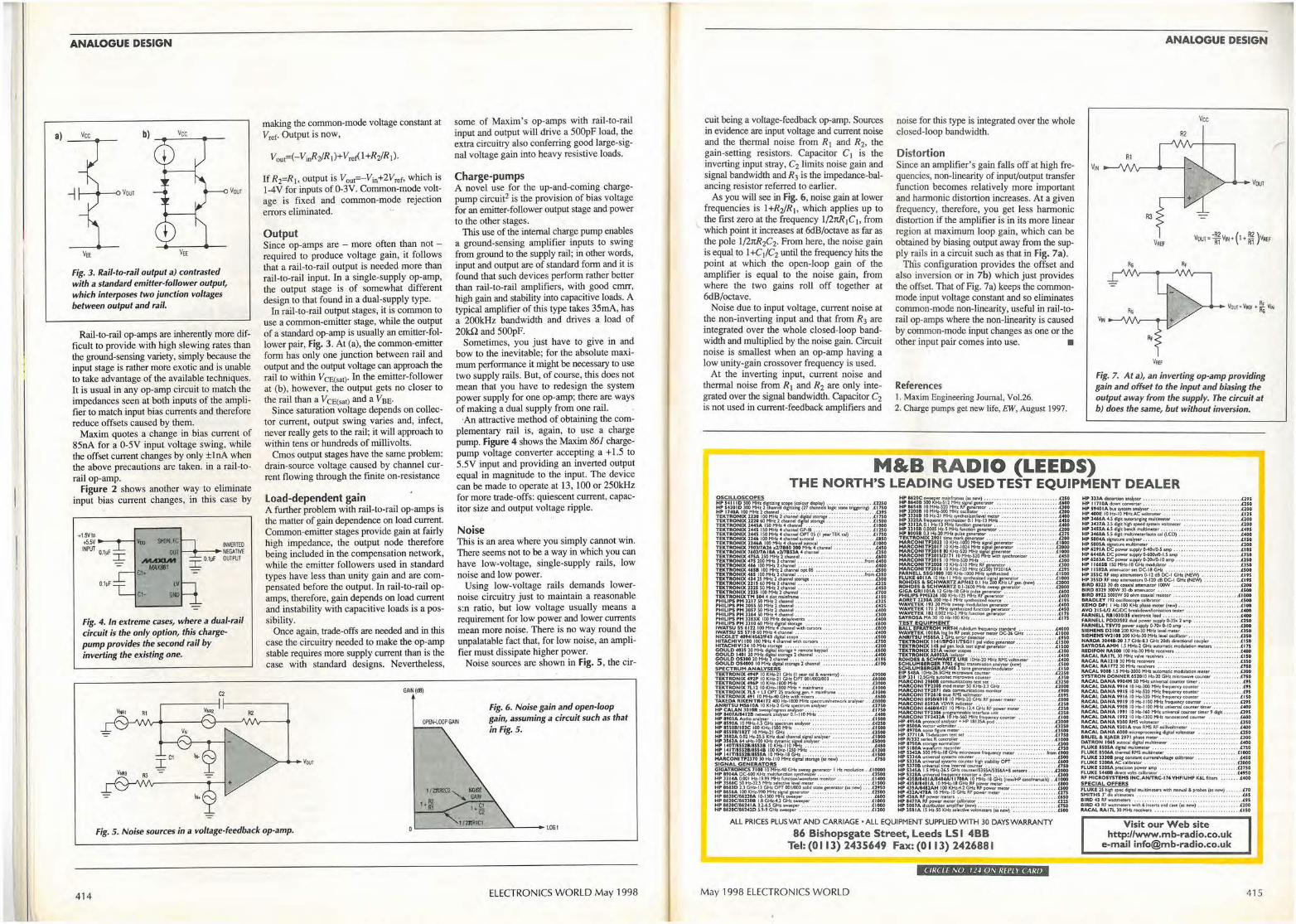
a)
ANALOGUE DESIGN
b)
Fig. 3. Rail-to-rail output a) contrasted with a standard emitter-follower output, which interposes two junction voltages between output and rail.
Vour
Rail-to-rail op-amps are inherently more difficult to provide with high slewing rates than the ground-sensing variety, simply because the input stage is rather more exotic and is unable to take advantage of the available techniques. It is usual in any op-amp circuit to match the impedances seen at both inputs of the amplifier to match input bias currents and therefore reduce offsets caused by them.
Maxim quotes a change in bias current of 85nA for a 0-SV input voltage swing, while the offset current changes by only ±lnA when the above precautions are taken. in a rail-torail op-amp.
Figure 2 shows another way to eliminate input bias current changes, in this case by
+1.5Vlo +5.SV ---t>---l'foo SIOI.FC IIMRTEO INPUT O lpF OUT 1-_.. _ __.• NEGATIVE
. I MAXIM I O.lpF OUTPUT MAA'IBI
C1+
0.11Jf LV
Ct· GIil
Fig. 4 . In extreme cases, where a dual-rail circuit is the only option, this chargepump provides the second rail by inverting the existing one.
C1
making the common-mode voltage constant at V,ef· Output is now,
If R2=R1, output is V0 u1=-V;n+2V,0r, which is I-4V for inputs of0-3V. Common-mode voltage is fixed and common-mode rejection errors eliminated.
Output Since op-amps are - more often than not -required to produce voltage gain, it follows that a rail-to-rail output is needed more than rail-to-rail input. In a single-supply op-amp, the output stage is of somewhat different design to that found in a dual-supply type.
In rail-to-rail output stages, it is common to use a common-emitter stage, while the output of a standard op-amp is usually an emitter-follower pair, Fig. 3. At (a), the common-emitter form has only one junction between rail and output and the output voltage can approach the rail to within V CE(sat)· In the emitter-follower at (b), however, the output gets no closer to the rail than a VcE(sat) and a Vse•
Since saturation voltage depends on collector current, output swing varies and, infect, never really gets to the rail; it will approach to within tens or hundreds of millivolts.
Cmos output stages have the same problem: drain-source voltage caused by channel current flowing through the finite on-resistance
Load-dependent gain A further problem with .rail-to-rail op-amps is the matter of gain dependence on load current. Common-emitter stages provide gain at fairly high impedance·, the output node therefore being included in the compensation network, while the emitter followers used in standard types have less than unity gain and are compensated before the output. In rail-to-rail opamps, therefore, gain depends on load current and instability with capacitive loads is a possibility.
Once again, trade-offs are needed and in this case the circuitry needed to make the·op-amp stable requires more supply current than is the case with standard designs. Nevertheless,
GAIN (d8)
some of Maxim's op-amps with rail-to-rail input and output will drive a 500pF load, the extra circuitry also conferring good large-signal voltage gain into heavy resistive loads.
Charge-pumps A novel use for the up-and-coming chargepump circuit2 is the provision of bias voltage for an emitter-follower output stage and power to the other stages.
'This use of the internal charge pump enables a ground-sensing amplifier inputs to swing from ground to the supply rail; in other words, input and output are of standard fonn and it is found that such devices perform rather better than rail-to-rail amplifiers, with good cmrr, high gain and stability into capacitive loads. A typical amplifier of this type takes 35mA, has a 200kHz bandwidth and drives a load of 20kQ and SOOpF.
Sometimes, you just have to give in and bow to the inevitable; for the absolute maximum performance it might be necessary to use two supply rails. But, of course, this does not mean that you have to· redesign the system power supply for one op-amp; there are ways of making a dual supply from one rail.
·An attractive method of obtaining the complementary rail is, again, to use a charge pump. Figure 4 shows the Maxim 861 chargepump voltage converter accepting a + 1.5 to 5.5V input and providing an inverted output equal in magnitude to the input. The device can be made to operate at 13, 100 or 250kHz for more trade-offs: quiescent current, capacitor size and output voltage ripple.
Noise This is an area where you simply cannot win. There seems not to be a way in which you can have low-voltage, single-supply rails, low noise and low power.
Using low-voltage rails demands lowernoise circuitry just to maintain a reasonable s:n ratio, but low voltage usually means a requirement for low power and lower currents mean more noise. There is no way round the unpalatable fact that, for low noise, an amplifier must dissipate higher power.
Noise sources are shown in Fig. 5, the cir-
OPEN-LOOP GAIN
Fig. 6. Noise gain and open-loop gain, assuming a circuit such as that in Fig. 5 .
I I 2ltR2C2 '- NOISE Al 'Ii.YI
hili 1,§
Fig. 5. Noise sources in a voltage-feedback op-amp. ._ _ ___ 1~/_fflll_t~ ___ ~-- -- lOGI
414 ELECTRONICS WORLD May 1998
cuit being a voltage-feedback op-amp. Sources in evidence are input voltage and current noise and the thermal noise from R1 and R2, the gain-setting resistors. Capacitor C I is the inverting input stray, C2 limits noise gain and signal bandwidth and R3 is the irnpedance-balancing resistor referred to earlier.
As you will see in Fig. 6, noise gain at lower frequencies is l+R,iJRi, which applies up to the first zero at the frequency l/2rtR 1 C 1, from which point it increases at 6dB/octave as far as the pole l/2rtR2C2. From here, the noise gain is equal to l+C1/C2 until the frequency hits the point at which the open-loop gain of the amplifier is equal to the noise gain, from where the two gains roll off together at 6dB/octave.
Noise due to input voltage, current noise at the non-inverting input and that from R3 are integrated over the whole closed-loop bandwidth and multiplied by the noise gain. Circuit noise is smallest when an op-amp having a low unity-gain crossover frequency is used.
At the inverting input, current noise and thermal noise from R1 and R2 are only integrated over the signal bandwidth. Capacitor C2 is not used in current-feedback amplifiers and
noise for this type is integrated over the whole closed-loop bandwidth.
Distortion Since an amplifier's gain falls off at high frequencies, non-linearity of input/output transfer function becomes relatively more important and harmonic distortion increases. At a given frequency, therefore, you get less harmonic distortion if the amplifier is in its more linear region at maximum loop gain, which can be obtained by biasing output away from the supply rails in a circuit such as that in Fig. 7a).
Th'is configuration provides the offset and also inversion or in 7b) which just provides the offset That of Fig. 7a) keeps the commonmode input voltage constant and so eliminates common-mode non-linearity, useful in rail-torail op-amps where the non-linearity is caused by common-mode input changes as one or the other input pair comes into use. •
References I. Maxim Engineering Journal, Vol.26. 2. Charge pumps get new life, EW, August 1997.
ANALOGUE DESIGN
R2
V111,
Fig. 7. At a), an inverting op-amp providing gain and offset to the input and biasing the output away from the supply. The circuit at b) does the same, but without inversion.
M&B RADIO (LEEDS) THE NORTH'S LEADING USED TEST EQUIPMENT DEALER
ALL PRICES PLUS VAT AND CARRIAGE •ALL EQUIPMENT SUPPLIED WITH 30 DAYS WARRANTY
86 Bishopsgate Street, Leeds LS I 488 Tel: (0 I 13) 2435649 Fax: (0113) 2426881
CIIICLE NO. 11~ ON REPLY CARD
May 1998 ELECTRONICS WORLD
HPJllAdi1it01"dol"l~lys.er . • • • • • ••••• , , •• , . . .... . . . .. . . . .. . . . . ,,il:29S HP 11710A down COIIYlftW, • •••• , ••• , , •• •• , , . ... , , •• • , • • •. , •.• . . ,1so HP $940 I A but syuem anily'l.er . . . . . • . • . . • • . , , •• , • . , •• • , , ••• , , ••• . ll00 HP 400f 10 Ht-10 HHl:AC w,'11,,,e.te,- • •• . • • •• . • • •• . . • ••• • , ••• . • • •. ,4:125 HP l4UA • .S cip auto~ muldm«.cr . • • . , . , • , , , • , , , , , , •• , ••• . . U00 HP HUA l .S &ck~ l.pefd lyillm voltmitter , . . . • , • , •• • . . ,., • . • ,., ,t200 HP 1'UA 6..S &&ft btndi l'l'IUltk'nec.tr , ... . . , • • . • • • • . . , • • , . . • • , . , •• . . • UfS H, lfflA S.S (lgit Ml.tineterh11to gj (LCD) . . . •••. , , •• , , , , •. , , •• , , ,U-00
=:::::==~·::::::::::::.::::::::::::::::.::::::g: HP 6291A OCpowertufftly~~ SU\() .. , . ... . , , . ..... . ..... , • . . .l!U HP 6••1A 0C pow,er ~ 0400¥}0.I.S amp . •. • . . . • . , • . . • , • , .• • • , . . USO HP 6161A DC .,_r 5UJ1PI)' O.lOvlO,.JO amp • . •••• , • . •• ,, . , • • • . • . •• . , .tl.SO HP 116451 ISOHHz. tlGH1 modiAcor • • • • . ••• .. • . . • . . . .• .. . •. •. . • .tlSO MP IISl1A utenuuoo«OC-18GHi , .... . .... . . . . . .. . .. . . . . . . . . . . £500 =: ~::g :: :::=::;:t god:a~1~HP(~; :::: :: : : :: : : : :~!::; Bl.RD 811) ) 0 db ~1'1 :attenuator IOO'N . , , ••••• • •• • . •• •• • , , •••• , , noo BIRD lllf 'JfRN 30 db uttl'IUltor • • • • •• • •• • • • . • •• • • . • •• . . • • • .. •. . . UOO BIRD 8911 5000WS0ohffl~oud;d rub~, . ••• . . .••. . . , •• . . . •• , . . . • . ,t:1000 BRADLEY 192 osdloscope calibrator . • •• •. • •. •.•• ••• . •• , •• , . .. . .... UOO
!~~~l~~..h'~:4:~1111: :~~~;:::::::::::::::::::::::!~~ FAftNELL R.B1030/)5 11Kcronk: load •• . • , . • . . . . . • • . • . •• , • . , . . .. . . . ,UOO
~::~:tt~~7~5;!!,•=~~~~~~.:::::::::::::::::::::: SIEMENS D2101 lOO KJ-b.-30MH1 ...... l mK1r , •. •• , . ••• • , ••• , • • , •• , .(350 SJE.HEMSW210t lOO Kt-tz,lOHH1kYel oscllbtor •• •• . •• • • • , ••• • •• • • , ,USO MAROA 30•• 8 -10 3,7 GH1-&.J GH:.t 20db diNttion:11 ~pier . . • • •• . • • • . . I.IJ0 SA.YROSAAMH I.S MH1•2 GHiau(omatk modw~ffllCvt • • •• , •• , • .• I.IJS REDIFON IU.500 100 Hl,)0 HHt rKfflfln . .. . . . ... .. . ....... . .. . . .. U OO RACAL RAl7Ll0 MHivatva r.clhwl , . ., • • . . . •. ..• . . . . . . , • . .. . . . . . ti SO RACAL RAl211 l O HHi recffi'ln . . . . . . . . . ..... . . , •• . , ••• , . , , • • • , .USO AACAL IU.1772 30 MHi NCINlrs • , . • . ••. •. • ••• . • . • • . • . •• . • . . • . . . .1.JJO RACAL 9008 1.5 MH:r.•2000 HMi :au\Cll'Ndc ~don ITMtff , • • • , •••.• • .LJOO SYSTR.ON DONNER 6$2010 Mi ,20 GM!r: microwaw couam • • . , . ••. . , , l.7.50 RACAL DA.NA HO•H S0 HH1 unk,,a,W (OUM41r tbtr , • • • • . •• • . . . • .. . • .L9S A.ACAL DANA 991• 10Hz, 200M>tzf~cycout11er ., , . , ., •• , ., •• , •• U S A.ACAL DANA 9911 10 Hr-520 HHt t~y «tutic.!t • • . • , • • •• . ••• .. • .1.9S RACAL DANA HI' 10 Hz,520 H~ r hqulf'IQ' <Olll'IW- , . , •••• • • • • • , •• .ll50 RACAL DANA 9919 10 Hr• l 100 MHz. ftt,quel'IC)' c~ nter .. • ••• . ••• . , ••• U9S RAC.AL DANA 99011 10 Hi• l lOO HHi IJIINV'AI c.ou,utr dm« • , , , • • • . • • . t•OO RACAL DANA 1991 10 Hr.•160 MMtunffl!rsal cOIJnter tl~ r 9 digit •• • , • •• tlts RACAL DANA 1992 10 Hr.-1)00 MHz. ..i1os:1<ond COUMff ••.• . • • • .. .• . U OO RACAL DANA 9300 RMS vokmttu . .. . . . . .. . ..... . .. .. ., ........ . USO RA CAL DANA 9 30 I A tNI RMS llF mlW...oltmK•r • , • . •. • • • • . .•. • . • •• . 1.400
::5:~~t~:0::/;'~~~~~~~~.:::::::::::::::::g: ~tJ:~~S~~d~oulnw~t~~~~~.: ::::: :: '.'. '. : :: : :: : :: :: :: :: :::~~ FLUKE U06A thtt'1NI A.HS t'l'IU!timtitr . • • • .. • .• . . . •• . . • . • • , , .• •• . . LIOOO FLUKE ])308 Pl'OI corut2t1t ~ ullbntof' . . ••• . .• . , , . . .• • . ,U SO FLUKE 5200A AC ca!ibratCf' . . . ..• . . . . •• . .. .. .. . . . . . • . . • . . . •. • . . . LlOOO FLUKE S205A prec4lon ~r '""'°" . . , .... , , ... ... .. , , ..... ..... . .OJSO FLUKE S•.C08 dlrec:c volts a libntOf' .• • •.•• . • •• .. ••• • • , ••• , ., •• • , , .L.C950 RF H ICROSYSTE"t1S INC.ANfTRC-17' VHFIUk.F K&l Men . . . . .l.•00 SPECIAL O FFERS FLUKE 25 hith spec dl&("uJ mi..iltim~cr1 "'4th ma-I a probft (n - ) . •••• . • l.70 SMITHS l~ dA.lltlmeten . . ••• . , . • • • • . . ••• . . •••. , •••. . • . •• . ..•. . .•• £411 BIRD •l JI.Fw:nim1tct1 , , , •• , • , • , • ••• • •• ... • • • . . •• • . . . • • • . • , •. . . • • 1.95 BIRD •l AF ws.tttneten with 6 iruuts Md cne (u n-> .. .. , . , , . , . , . . , . .l100 RACAL M17L lOHH1: r1<1Mn •• , . .. . .. . . .. . . .. .... . . . .. . .. ... ... USO
Visit our Web site http://www.mb-radio.co.uk
e-mail [email protected]
415
lnte cing with C ELECTRONICS WORLD • \\IHll l\\ \\OHi ll
Interfacing
Without an engineering degree, a pile of money, or an infinite amount of time, the revised 289-page Interfacing With C is worth serious consideration by anyone interested in controlling equipment via the PC. Featuring extra chapters on Z transforms, audio processing and standard programming structures, the new Interfacing with C will be especially useful to students and engineers interested in ports, transducer interfacing, analogue-to-digital conversion, convolution, digital filters, Fourier transforms and Kalman filtering. Full of tried and tested interfacing routines.
'ff-!
.,~ • Ir IL 11 ... ,.., .,
Howard Hutchings
r-----------------------------------Use this coupon to order
Please send me:
Title Price
Enhanced Interfacing with C book@ £14.99
Enh. Interfacing with C book+ disk@ £22.49
Interfacing with C disk@ £15
Original Interfacing with C book @ £7.50
Price £14.99.
Listings on disk - over 50k of C source code dedicated to interfacing. This 3.Sin PC format disk includes all the listings mentioned in the book Interfacing with C. Note that this is an upgraded disk containing the original Interfacing With C routines rewritten for Turbo C++ Ver. 3. Price £15, or £7.50 when purchased with the above book.
Especially useful for students, the original
Interfacing with C, written for Microsoft C
Version 5. 1, is still available at the special
price of £7 .50. Phone 0181 652 3614
for bulk purchase price.
------------------------------------------------------------------- l
Qty
Name
Address
Total
£ ...... .
£ ...... .
£ .... .. . Phone number/fax
I I I I I I I I I I I I I I I I I I I I I I I I I I I I £.... ... Make cheques payable to Reed Business Publishing Group Ltd i
Or, please debit my Master, Visa or Access card. ,
, Postage + packing per order UK £3.50 £....... Card type (AccessNisa) Card No ! I I
! Postage + packing per order Eur £7 £.... .. . Expiry date ! ! Mail this coupon to Electronics World Editorial, Ouadr~n, House, .The ,Ouadrant, Sutton, Surrey, SM2 l : Postage+ packing per order ROW £12 £....... SAS together with payment. Alternativelylaxfullcred1tcarddeta1Isw,thorderon 0181 6528956or e· : I maii'them to [email protected]. Orders will be dispatched as quickly as possible, but please : i Total £....... allow 28 days for delivery. i I I I I
I - ------------------ --------------- ------------~
L _____________________________________________________________________________________ _
lltcttl!LLUL·y l!f tu lnllll! Lltcu With over 9000 entries and 250
illustrations, this book is an invaluable
reference work for anyone involved with
electronics and communications.
Dictionary of Communications Technology
provides comprehensive coverage of data
and communications and has entries on
PC lans, the Internet, communications
testing and client-server applications - in
500 pages.
Over 20 major companies helped
prepare the Dictionary of Communications
Technology, including AT&T, IBM and
Digital Equipment Corporation.
Gilbert Held, author of Dictionary of
Communications Technology, is an
internationally respected author who has
used his enormous expertise to make this
work one of the most comprehensive
sources of telecommunications
information.
Please mail this coupon to Electronics World, together with payment. Alternatively fax credit card details with order on 01816528111. You can also telephone your order on 0181 652 3614,buton~Mondays, Tuesdaysoron Friday mornings. Address 9rders and all correspondence relating to this order to, Electronics World, Quadrant House, The Quadrant, Sutton, Surrey SM2 5AS.
ions Technglq:g,yl ~ ·.-- ~~ .-· ;·&- ---- _.;__J, - • hi ·v~ .... . • -~ l ."'f ,p_., .
abol.il liabpaml \lack to tbc odp n.aiot. I a 1oeric.SofniKQ>pUof~ ~ d lncaaccPTolocol(IP)-trich~ MU1,11umcae ~ il:l&tic,q, «bo, c,;1to Rply. pttlttle1tt
lh1t~1bkWJll10li.tnction11111irlf)c,llfJcvfmatJ llld"'Vfk.. 2. W\CIIWl\l1U1 in t1~lr&rnel ~t'e:n IO tht- X"l of inwconneckd netW\llb di.It s.han. (he. PIM M'ol'Cd: ldchfl IClla'nt and Ille lllcTQ>l!Pprococ,oL
lnttrnd Acthtdu Board (L\.B} ~ poup whidt KU Ulil i.ecbl'licaJ diteetiOl!I and decid=i whidl P")IOco4 ~ 1 rcquitcdpuu of the TCP/'CP tulle.
=~=~~-~-=~·~•:::.i...___...--.. _________ .._.._-..J live fidos; as indictlCdbtl Dba (dB,- ..t_Jimtel)
FIIW ~t.,_.} :..:.:..:.:::.c:..:=c:.....------------h'lttmtl addrus A3"l-bit .addcw~ idc:11Qiks
lbcnel"WOfklO Wl'lldlcaeb~CctMITCPllP nccwort. II 1ttaelled as wd \ u lhe eompuler's " niqu,e idenlific1tion.. The dlfCc mjor cypc,. of lddtwe:a ttt- llhlJtniWI bekww and deimtid as follows:
AClua:A addtt.ub r(lfnc,two,b lhalhaYC,fflOl'C
lhm216(6S536)"°"'-
1'po OM (dllno ..i,JuMII) A u.nltolnolte
b I cimiil M .... PlA.llnt. « KA-l-ffiCd-.r 'lll'lll1bd.a,O d8ebnolte'°"""or:J..1,p~ (-154Bm.),.~k10dllni (-904m«I pi,:,awlllri:l~~-'iuJlc4to FIA.~111.
D"Ba(l'lA) no .... mwtsl -.~,;,a1li.tb1• IIIJue lllelJllffltl ,e( I\IWIC'IA.,lia!I$~
A Cius B lddrc&&ed is wed (or netwalb that hal'Cl21 (2S6)D02l6 hosts,.
l• ~met d.1ta,p-111J, The. Dal (HA-I} Ths --,-1 _._., aavu (hi,
nia!~ rof1 Xl2-l.1pe« dmilll~..,.,,,I ~b711ait1CC .. "1f11 Hl\.•I•~ .,.ilhlins•
W1icOft1acurN:I. A ClusC~st is lor nct"WO!ts lbal h1ve
lfwt!r lhm21 "°"'- IA~.--t EQcjflffri-& 'IN poupill thelllCC:nldAcciv CODCttl~ OIi shOrtC.Cri"I~
lnC.tr11el Ardrlltt .. ~ ...... dcwlof'lr1110D1
IMtncl Coo.trol porti011oflkln mdcoatn;il
ffldl'loslsOIIIIA
= :-c i}-· [=---(•· ' ..... ':::--
- r--( : ;::;:;, =-[ :
..........,. ) Wlicllti•c -n-.tln,: I melAplll -Iba -.,;111, ..
nillltidla•d ,,_,,.o1 1 -muvwl 1D derioie. t""VOJIIIOft~IM;Up~or d111$4iYl,-ll'lltl~
Mumi-lm A tndflnutol~11$)'tlffllt off',:cwB~MN.»~ l1r1 1 knnillllcma• lot1o1t.,...---,ot.c1)UU!c,anf.(!qlpcd r« l~ 11110 I PC t.04 }'111117 oc.-.-1 ellllllalianlm 6k llllWerlClflwue.
.,.,~• _._....1,: tit IBM•, SNA. • ~ ~oflWCIOfllKQke•~ ~III
~co•aol poiaa,\ht.Mll'J fl'llolli-m...-,.l'lld.
aMll.cld.nopDuc;riba1 teiqlllon,lliiM~ ia'flflichair• p:.~f1dh,;y llltl..lftidb)' -i~.--.
-.Jtldnof, II• tine « dmail ln~ N:'ICAl~AJto~fl'lloltiOC)iMliM.
-ltithlM NI ~ '-doftlill KIIJIIC=IKC o( lnmu a, • naki~ diJilll circuil. '"'Mulli&t.mc.# i.s lile CC!Tf tbnd.,j t,i,,a lor 1 ~ •
Dt>.A.U Dillhcl-,,-Arwlwul.lnit.
DBaO ne'°"""~«IIOi1e~- • ~~it , Qra.glkd "d!Bm -.1 11116S~~ .. -
..,ad-11ootNiio...A OOA1p11tJwillltwoor 111Qt1C. ~___._~ Mullilaa S..udli 4)1.LS) A produd allhttld tt,"
Allolic,cof~CA,.,.flidlCVMec:Uop lOIO lllbuadlA'11olnriow-.1J1.-t~CMbc. pscdwkllow,~---11and -...
-llliln ...... A ~ ol - ~ . oritnlod praocols 111 ....-11 ~ 1N111 OM jOb', ..-o10,1ac.1bclr-..iGld,-nnix.td,, At the
Mlltdli11t C-~ Prv«-,- 4)fLCP) A ~lt•u1au.~tciclllni1 Jll'O«NOf and -«-oomllNltlDOOIII •"'"'-Thr-MLC'<anbe:~1111 ~ ~c--.kllicasde~
M11W-1,.in. lDA. A:2.0U~primary rau: ISDN Mr,iec;~ll18cl~ T~iialkt.rx.. 111i11etVk:e l1 blkd11po,1 Bfililo nloc,)m-. ~ lipali.._ 1y-b pri,W, to ,-ik adimp. and - °" Ille 00TT Q,'tJI ia1$rnlllocuJS1Mdlo~
Mvhi~lioa eaw-, l'lllll (.MC,, NI, AT.t'l bUlk•n.oocl ll'IUlti•ioe.iora dacOIIIII KMOt dill. i-,ida~WlbkleAdll~ ~....,.°'~ • tlnslec:uorntt oi -- 111_. Ill opocll ~ . fiber, and pWiwe ~ wrhidtJuiderDi111aoob.l.AIJ!CeM_., l""""'Mdsndod.fafu.6k!s'"-lil:node.. A 11~--~cllPlbleot~ inc.,_ si~oinioor-~o,,..._.,
- l lifflo,M llb.:.- TM !Wlti¥Cly 1arJG core ol liiil li,t.11uideallo:w,,sU,tllP,-.iodpqa-,•11y d,t!,:,n:;«palll. lft;diul for q:111 ~larsu lhlnllKIS.JUGb u ~
..:t!Sfflode~ftkr Ai5bn-dlat-iUalbwmon!1 INll°"'bcadl!IOOGIO,-vpa.a.lllle. M..ybedi:lietpadedlade..i:o,-,lllda: ftbu.
t.Abtolute m beq11al .... 1000 btnr.
Ill lOOO HI.
IOmdinote on.,, ""
nlio(llldB) laqdnrto
effllc:C,oifll:
c:ir;vili,,, \ )dllb!,kl4' -
itlbe~ ~ ~ lc¥dC111 0, t irnilc?II- IUltddl,e~;
- l • (-U dBfllO) • - l ~ ta.
DIIMS Oa1'i bilk Mwit1DU111S1-.
,0.V ~ Milli'to11, TfliJ IIICUll!mltflt I dpal ii11 '8 NillMID I aV..:nunouu. IHOdillAblel)'-
Or• TM attw..iwo• lor <1ridbcltt;f~aob l• lklr~ io lll.it.c~cui«for d l«llllldlA, INc cwt., k lieo cact,-n CfleWd Mi'll31&1Qtlt,fcw~llw~lcdllfl'> po,l!J~ 111,1fflbrn forlq,rr cuaba-lol~n UfO 4ilrcrmn, mril in lkxnllln,-. 11 _, d!rnor O dSra.Thr-~~ 11#1 lW011tU.1i1.,_,, bi dle~c.hle.. b: lmpo!WII IOtemc-.Oret fitni, 1 -.uurtl!IQ
of tout. It i1 MO ~ ID tt.rncmbu • nl~torOAJ11Ple-60dBtallf.lQlill11D -3 dl!ia.
#m dilfe dBm I&.
,0 '° - J to -I )0 - 6 ,0 - i JO - 1 60 - ) 10 - • $0 -• 0 - 9
tl.9 t11C Thoa~for4Klibcl n:;(ffi!IN.._ Cmesap,~.Noltt~inqul• Wl"t(Offl'UI Miell ~ I -.Ilk ~ of mQIM;IIC:KSlllldpa-!R,Allho•pa,ayflOlst ~.-•c-1lolllluadqrMilf e&c:l.~lllfk~Jllo9ifl0.IWJ c~ il ~ 11 1'-...... ofk¥Dlu~ band.Toobtaa.1-11.t!-.--ollk ~l\ldl'(ICCof~-'IKW8ll~lldet C!OfllrilMilll ilD llkO"f;rall noi• - ~ ~ ~IO~ir«bdw,ffi~&<;t.nil wdl)'mll& lt a«ompliit!Gd ~ 1 wclpmf norWOII: or Miu. TIie tlw Mliell dolcl:, fmvia«J thui:~ k cllrid1C~ --d9....ct 1lic ~ioo fOJ drmel ~ IIOUl!~~Ledw,,t-.ioalr¥CI
Use this coupon to order your copy of. Dictionary of Communications Technology
Please send me ....... copies of Dictionary of Communications Technology Each copy of the book costs £32.50. plus £4 UK p+p, £8 Europe, £12 ROW per book.
Total amount
Name
Company (if any)
Address
Phone number/fax
£ .•......•.
Make cheques p~yable to Reed Business Information Group. Or, please debit my Master, Visa or Access card.
Card type {Access/Visa)
card No
Expiry date
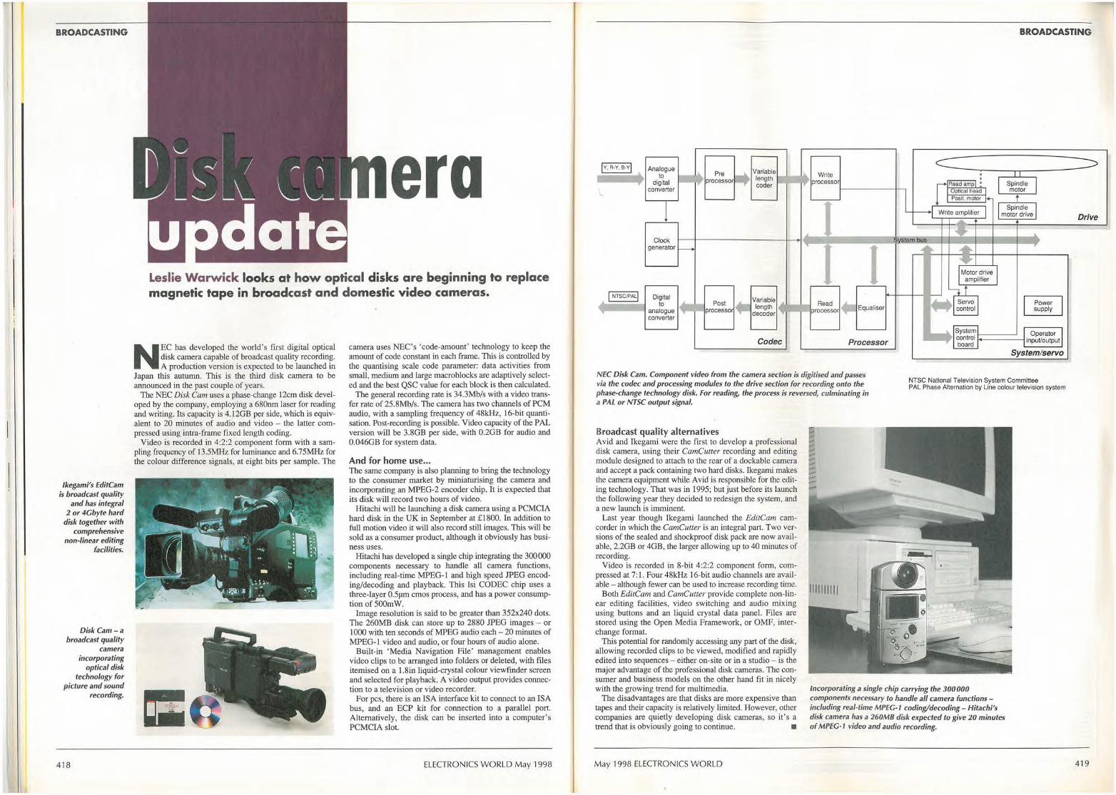
BROADCASTING
lkegami's EditCam is broadcast quality
and has integral 2 or 4Gbyte hard
disk together with comprehensive
non-linear editing facilities.
Disk Cam-a broadcast quality
camera incorporating
optical disk technology for
picture and sound recording.
418
~ vi j / , ,
1 · I ~_; ; r \
I_ ..__/ ;_\_ \_ L era u date Leslie Warwick looks at how optical disks are beginning to replace magnetic tape in broadcast and domestic video cameras.
NEC has developed the world's first digital optical disk camera capable of broadcast quality recording. A production version is expected to be launched in
Japan this autumn. This is the third disk camera to be announced in the past couple of years.
The NEC Disk Cam uses a phase-change 12cm disk developed by the company, employing a 680nm laser for reading and writing. Its capacity is 4.12GB per side, which is equivalent to 20 minutes of audio and video - the latter compressed using intra-frame fixed length coding.
Video is recorded in 4:2:2 component form with a sampling frequency of 13.5MHz for luminance and 6.75MHz for the colour difference signals, at eight bits per sample. The
camera uses NEC's 'code-amount' technology to keep the amount of code constant in each frame. Th.is is controlled by the quantising scale code parameter: data activities from small, medium and large macroblocks are adaptively selected and the best QSC value for each block is then calculated.
The general recording rate is 34.3Mb/s with a video transfer rate of 25.8Mb/s. The camera has two channels of PCM audio, with a sampling frequency of 48kHz, 16-bit quantisation. Post-recording is possible. Video capacity of the PAL version will be 3.8GB per side, with 0.2GB for audio and 0.046GB for system data.
And for home use ... The same company is also planning to bring the technology to the consumer market by miniaturising the camera and incorporating an MPEG-2 encoder chip. It is expected that its disk will record two hours of video.
Hitachi will be launching a disk camera using a PCMCIA hard disk in the UK in September at £ 1800. In addition to full motion video it will also record still images. Th.is will be sold as a consumer product, although it obviously has business uses.
Hitachi has developed a single chip integrating the 300000 components necessary to handle all camera functions, including real-time MPEG-1 and high speed JPEG encoding/decoding and playback. This lsi CODEC chip uses a three-layer 0 .Sµm cmos process, and has a power consumption of S00mW.
Image resolution is said to be greater than 352x240 dots. The 260MB disk can store up to 2880 JPEG images - or 1000 with ten seconds of MPEG audio each - 20 minutes of MPEG-1 video and audio, or four hours of audio alone.
Built-in 'Media Navigation File' management enables video clips to be arranged into folders or deleted, with files itemised on a 1.8in liquid-crystal colour viewfinder screen and selected for playback. A video output provides connection to a television or video recorder.
For pcs, there is an ISA interface kit to connect to an ISA bus, and an ECP kit for connection to a parallel port. Alternatively, the disk can be inserted into a computer's PCMCIAslot.
ELECTRONICS WORLD May 1998
BROADCASTING
Iv, R-Y. s-vl
I NTSC/PAq
Analogue to
digital converter
Clock generator
Digital to I•
analogue 1~
converter
j
Post - processor
Codec
Equaliser
Processor
rReadamp • Optical head Posit. motor
Spindle motor
Spindle motor drive
Power supply
t;::===:::::::::'--1 Operator " inpuVoutput
System/servo
NEC Disk Cam. Component video from the camera section is digitised and passes via the codec and processing modules to the drive section for recording onto the phase-change technology disk. For reading, the process is reversed, culminating in a PAL or NTSC output signal.
NTSC National Television System Committee PAL Phase Alternation by Line colour television system
Broadcast quality alternatives Avid and Ikegami were the first to develop a professional disk camera, using their CamCutter recording and editing module designed to attach to the rear of a <lockable camera and accept a pack containing two hard disks. Ikegami makes the camera equipment while Avid is responsible for the editing technology. That was in 1995; but just before its launch the following year they decided to redesign the system, and a new launch is imminent.
Last year though Ikegami launched the EditCam camcorder in which the CamCutter is an integral part. Two versions of the sealed and shockproof disk pack are now available, 2.2GB or 4GB, the larger allowing up to 40 minutes of recording.
Video is recorded in 8-bit 4:2:2 component form, compressed at 7:l. Four 48kHz 16-bit audio channels are available - although fewer can be used to increase recording time.
Both EditCam and CamCutter provide complete non-linear editing facilities, video switching and audio mixing using buttons and an liquid crystal data panel. Files are stored using the Open Media Framework, or OMF, interchange format.
This potential for randomly accessing any part of the disk, allowing recorded clips to be viewed, modified and rapidly edited into sequences - either on-site or in a studio - is the major advantage of the professional disk cameras. The consumer and business models on the other hand fit"in nicely with the growing trend for multimedia.
The disadvantages are that disks are more expensive than tapes and their capacity is relatively limited. However, other companies are quietly developing disk cameras, so it's a trend that is obviously going to continue. •
May 1998 ELECTRONICS WORLD
1111111111
Incorporating a single chip carrying the 300000 components necessary to handle all camera functions -including real-time MPEG-1 coding/decoding - Hitachi's disk camera has a 260MB disk expected to give 20 minutes of MPEG-1 video and audio recording.
Drive
419
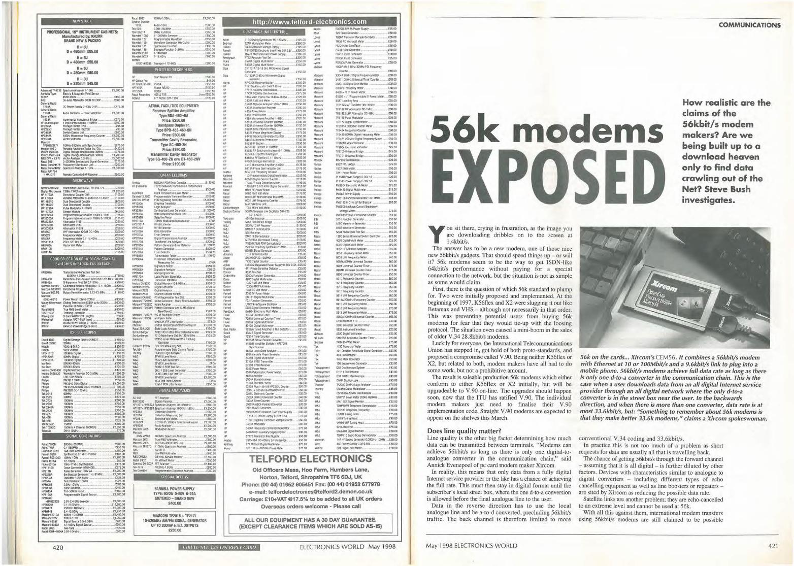
rilw sroc~
PROfESSlONAL 19• INSTRUMEIIT CABINETS: Manufactured by: KNURR
BRAND NEW & PACICEO
H=6U o = 480mm m .oo
H = 3lJ D • 480mm £55.00
H,.6lJ 0 = 280mm £60.00
H=JU D = 2110mm £45.00
~TIW132 $pedlu'n~1-1GHz.. , __ , ... -1'1,800.00 Alrltala Typrt: Elflctric & M3gMtc Aeld Sensor TE307 •KHl·2'ilHl.- . ... -- ... - .£150..00 Bird Co•UialAneRJator30085021(W ,.__,~ J:300.00 GenetalRildio ,,.,. -·-1308A ...., .. ..,. I.,,. HFMullieollPI« HP2225A ltP22250 HP348M "'53<1A
""""" -tleretne,ita!~ BMDt---.£375.00 1 ir1)11'13116~ 1•40MHl •• ... 00000 --111'19-- - ··-· _,f.'95.00 T'"'1Qel - RSmC --- --- -··. -,£95.00 SWICb ConltOl ld - ·-- ,,_ta1J0,00 18GtuMla'OWl'tl~Ccx.nler .,_,_£1,20000 YeaorYoJUneter_,_,_. ··--•·-····£:2,500.00
Tf201512171 10MH.!•S20Mlfl WO'I Synctrcwilur .. _,. - ·· .£215.00 Megoe,"PAf2 PQ1aole~Ta-1erlnc.CAL - ____ r,2000 -PM3305 DlgitlJSI011Qe-l5MHi ___ .. £37500 - PMl3S2A l);gllO SICl100 D,ci-50MHz ___ £1 200 DD A&S lPV • E3 P.I Vedor Anilpef 0.3-2GHz: .. ___ ,,_,_,. _____ ,£2,000.0D -9001 S-__ _,_....,..,, .. _,_m5.00 Alea Dana 9478 Fr~ Olltr'1tlvlJon 1.Wt ,,,.,,_,,_,,_,,,_,_,,_£200,00 Flaeal Dina 9702 ~.wt,ser 1·1GHz...- .,-.. -·-··- ,_,[t,.300.00 Raeal P.41784
..- MA1072 flemo(e ~ If RlioeMlr _,,_,_,,_,_,,_[S0(),00
MICROWAVE
Cottinetrt8' Mic liansroiffef Cl:tltrol VML TR-240-1/1.,,_,_,_,£750.00 -"""""" 12Gll,.110!lX{rmw) ____ . .£1,200.00 HP H 752A OireaO'III ~ 308 .... - ... ,. ··-·-·--·-· £1~-00 HP X 3a2A VanableAl:IPAJator 0·50d8 8.2-124GHz .•.• - .. £120..00 HPl16910 OualOi'ee;t.lorla,i~r ----!""100 HPl 16920 Dual Di'ect'O'lal Cc\lpler ..... - ... -·-"··•-•·· ,.£700.00 HP11~ Pullse~ior2-18GHz: ·-··--···-·-··- .. - .. £720.00 Hl'l 1722A Sensor ModUle .. - ·--- .. -•· .,_, ... .t600.00 HP333G4A Pro!JamrnableMl!l'iUMOr 11KJU.0-110B ,_ . .£175..00 HP33305A ProgramrnableA!t81'1.11tor tBGHl0-11°"8 _ . .£175.00
fP33l20A Aae!Utor 11<18 - •·-•-.. ·-·-· . -· t250.00 HPl33206 Atln.iamr i1dB _._ ......... _,_ ·- ... . ,_ .. £'250.00 tF.l3322A AtlltllltOt 1 IOdlB ,_, , .. ,, __ .. __ ,_ ... £250.00 HP3350 VHF Ar.etulllo, 120IIIOC-16Kt. - ·- ··- .. ···• ... f3(Nl00 lf>S3l8 - M----· --··-·-·-··-·· ... .. _ ... £200.DD lF53tiA frequentJMt::eJ3.7•tZ.4G8L..--..... - ... £200.00 HP54111A 2GHl-S"SrmSeC-----~,.,,.oo HPM05A Vedo'W.Metet-----·-mclOO HP$4t08 ··- ·- ···-·- ······- ··-··· ...... ........... £200.00 HPM14A _____ _.,1s.oo
GOOD SELECTIOIJ OF 18·20 GH, COAXIAL SWITCHES IN STOCK £65 00 EACH
ttP8$02A T~TtMStl SOClml:·1,3GHl------..>.'SO.DD
HP87-t36 AllltdJM.,lraJ'MIIWOII Tntl.lnil 2·12.4GHz £600,00 HP874:-,A S·Pn--neter Tast Set 0.1·2GKI .... _ ..... - ...... . £:560.00 Pilatconl 001M C&libraDed~Anlt'UPU 12A·l8GHz ._,£200,00 Marconi 15031Y10 Dlreclia'lal ~ X Band .. _,. __ ,_.,_.,_.,_.£200.00 Mal'CO'lle213 Aow,,1/AlAtteruator8.1'2-1~-iGHz .. _ ..... _,t\~.(N) -6960•6910 Power Meier IOMH1·200Ht _ ._ .. ___ ........ _.[g()(),00 M...-,Mlaowa'tll Slld~TerrnllltiM8035Huoto20GHz.. . .,_,E'6CJOoo NE:C ~ 50 500Hz TX/RX £500.00 Racal9303 TrueRMSLMMet« -· .. -· .,_,._._,,_ .. _,,_,£800-0() TEKTR502 {reckklQGenera\or ..... --·- ·· ··---... .. - ..... £75000 W.aw:~ X&ar-,WG16H)ftl.englhs: £3011) Wmsehtil Maofa N'CI-SMA tnew, - ·- ..... .. - .. - ..... _._£65.00 Wlllrvn 87A50VSWR&ddge.2-18GH2 ..... ,_ .. _.,_ . .£600..00 Wirtton 6-4tlf50'/S.lill8(10ge3-8'Gltl ._ .. _ ........ _. £400.00
OSCILLOSCOPES
eo.,,4030 01>Ha15-20MHz2<JMS1S .. _ .. ---··-·-·=·oo -= 21>,IH, ··-·~·- ·------~•211.00 Hitacli VC601S D.S.O ... .......... _ .. _ .. ... _ .. _ .. - ... . _ .. ..£300.00 ~ V2222'1i!Hl ____ ,._._ .£22S.00 ~1110 500friltl~ltal -----~1.950.00 HP$4l(IOA 50MHz ~I , -·-.. - .. _ .. _ .. _,._ .. _ ... - ·- .. -· .£750.00 HP54501A 100Mll! Dlgita! ,_.. . ,._,_,,_ ... ..,_,. ··- CUi00.00 ISo-Tec:11 $1164040MHl. ... ____ .... .. £300.00 ISo•Tedl l$Ri4040tl.Hl-------·--·tm.DO tM!itstJOMS6430 ~Mttnory _____ ,, .. ..£47~00 t.laltsuSASat30 Wamom,Nt¥fSl!IOC..3..5GHz _ . .,_._,._.,_£1,500.00 leader LB0•522 2QMHz ____ -·--- £200,00 ~ ~t750t.1Hz _____ 050.00
...... ""33«> 2GIO Olgll,L.._._ ._··-·· ........ £3.DDD.DD ,._ PM3325A tiOMHz O.S.O tOOMSfs .... - .. -·-•·£1200.00 PWJiOS PM32G2 OC-100Yiz ----.£250.00 Tdli 2215 60MHZ ,_,_ , ... .. ... - ......... _._,. .. £350.00 Tefi:; 2225 50MIU ______ .,. ,._,. .£375.00
Tele 223S 100MHz ------······- EtiOO·OO let: 223fi lCIOMHl ...... _ .... £750.00 lele 224.SA 100MHz ------........ £950.00 let 23Jlli 100MHz ----., .... _.,_ ....... .£150.00 Tet:'65 100MHz ____ ....... C3$0..00
Tek 466 UJOMHl .. - --·- ·- .. · --- .. . .... _ .. _.£300..00 Td: 475 200MHz .,_.,....... - ·--.,_ .... ,_._ .. , ... _ .. _,£425.00 Tet: SCS02 151'..ttz - ............. _.. . ............. _._ ,_, £300.00 Tek TDS-4'20 150MHz 4 CtlaMel 100MSIS ··-·· .. -··-·-.. tU50.00 leleQIJo [)gl,A IOMHL._ ... ...... ~ ___ ._.,:,SOO
Adrtt 71008 Adr!t74M Cbslwnan CEt2 , ..... = Far~P$GIOOO Rann 4l11A Flal501M HP\17108 HP21'8 HP3325A Hf'•21MA HP8W. --HP8015A HPilW. Hl''"20C
SIGNAL GENERATORS
JO(IOl:r•650MHz _____ _.,oo_oo
0. l·560MHl ... - ·-·-··-..... ·- £150..00 fiNO rooe General'l'.lf._ .. - .- ..... - .. -· ., .... . ,£150.00 S),,lheslzed Q.1MHl:·l10JOtt ._ .. _,,_,,_._ .. - .. £l85.00
Ult<Hz-1GHl ..... - .. - ·---· .. ~·---· .. - · tl,200.00 IM8C'Hi----- .. ,_£50.00 10Kl:•11MHl~-----'175.00 llownC:O-W(HP00<08) ..... - ,_-··-·-··---t21SOO Pulse Genera~ t(WH2A_ ..... a .. - ..... _ ... .. .£I,200.00 ~lzer Genlolor 1Hz·Z1MKI .......... _ .. £1,500.00 Odlal« l0Ht•1Mlfl-----t125.00 rest Otcnitgr 10MHz ____ ->.£'12500 0.:lu:•1(1.0tt -------<30000 10Hl-200MHr-------'45000 1Hl-5ClMJtlPulse .. -·····-.. ····---- --·· . . ... i4.50.00 Progtemrnal>IS5iOMISOlscl. ,,,_ .. _, .fl,200.00
t-HP882228 0.01·2.• Gl-1l ~ ----£1,500.00 HP8642M o.1-1100M1-tz, _ ____ ,_,t12.soo.oo HP3647A 2501ctt.z·1D00Mtb .-.. • .. - ·----·-·- ---•- "- £2,300.00 HP86&4B 5.4--12.SGHZ .... ,-.. ---~ 1.950.00 Mi1'oonl~19A tl(»(>U•IO&OMHz ... _., ____ _.,,450.00 Marton12022 l®tt•t!:Mz •. , _____ _.,1,250.00 Maroonl6057 SilJla] SoLw'ct5.5•B,5Qlz ---~£M'l.OO M~conl~ 1l 18GHz$qWSouCl!I __ • - ,_ .....£20000 Rac:119053 JWotone __ , _________ ... r:12000 Racal 90641-9'934A0.01·104Mttt _,, __ ,_, __ .,_ .. _,. •. ....,£500.00
420
_,,.., """"'""'"' 1102
"'"" TeHG501A WIWlr.ek 1000 Wl\ieietc 157 Wevelek 159 ~Wlftt171 W'.!Wlr.dt 185 W8<ntek2001 Wmr.ek907A W111rCn
lm0•1Eiifl ·- m:>0.00 OOCJ1•?40MHl. ·~ ,_.,_.. t350 00 2MHz F'uncticfl .. - ··- •- ··--- ·-··· . ..... .£250.00 1-lOOOl,IKr Sweeoer ,_,._.. . [600.00 FW,gl'arnmable Wl¥t1Drl'I £150.00 WJve!tml Gc!net'at.,;w 1 H'z:·lMH.l ·-· _,_,_ooo 00 Syn!hesllfflftnC'tlon_. ·- -·· ___ £400 00 Swffl)el'Jfu'lno'I O·SMHl. £3SIJ 00 M 400Mttz ---- £60000 7-12.,GHz ____ __.£9l"IO.OO
6100t62238 Sweeper -4 12.41& ,_.£SOD.DD
PLOTTERS/RECORDERS
HP o.aftMast:ttRX.. ... -•·-·· ......... . .. -,£500.00 HPCOb.r'Pto ··--·-·-- ..... - · .-.. - £-iS-00 HPOrlA~0Xl. 757SA . ----· .mo.DD +f>7•7~ Plol::erR.523? ._.. .. ...... - . .£1~ HP75W Pkmer - - ...... .£250.00 Raeal R&oonJffl '-DS & 70S .. -·-·-~ ..... -. .._._.m £200.00 Ho!IM X•Y P101tet OX't-1300 . £120.00
AERIAL FACILITIES EQUIPMENT: Receiver Splitter Arnptilfer
Type RSA-460-4M Price: £250.00
Bandpass Duplexer, Type BP0-453-460-6N
Price: £300.00 Transmitter Cavity Resonator,
Type SC-450-2N Price: £190.00
Transmltte-r Cavity Resonator Type SG·450·ZH c/w OT--453-2NV
Price: £190.00
OATA/TELECOMS
All'lbl.l ~A Pl)! EncrDeteaor .. _ ...... .... - ... _,_ .£120.00 6T (FLiaum) T102CI ttdw!rt Trill!imlSSlon Pl~
°""""' Dat!hbot.1000 GNEIMlfllf\31 HP1350A t1P16310 t<P:3336A H~97A HP'.IS861l ttP3717A. HP37201A HP37204 t<P:3762'. HP3763A HP3™-' Hf':m<>I HP3~ HP3781A Hf'3782A HP4935A HP-1~4A
~8/ .- .. w•-n••• •--•-.. w .. - , - £500.IJO CE2• FX Selecttw le\'el Meter .. , ..... _ ._,,_,_ .. _,.£40() Programmable fra!)l)lenl Flecordllf .. _ ._., _ ___ .£250.00 PCM~ ~ -·- .. -·. iS,000.00 - , ................. ----- . _,,£200.00 Loglc:Ana..~r •. , ·-··-··-·-··"-·• -·-·--··£650.00 S~er/le1'fll Genemor ..... _.. ... £1,300.00 Data~Ufie..... .. ••.•.. .£-40000 SdectiYt Mete, _ , _ ,.From £6SO.OO 10MHl _,,.,_ .... -··- ··- ······- · .. ..ll'OA HP-II Ex!tnder . . .£300.00
HP-\B Eittnder ·-.. -·-·--·-··-- . £30000 Datl Genetata _ .. .,_,._,, _ _ £350.00 [n-(lf Oelecrx:r • £800..00 Oll)tallrawmsslon~ _..... £3.200.00 Teltl)hon1 li'le Analym ..... ,_.. £20CUXI ~ Gfflnu:w,tm)I' Oeciector _ -- £1,100.00 --"'----··- ··- ··..i50000 &rorOelect:w ______ . .J:500.00 frnmmlOnlestiw ._ .. _,_.___ _ £1,100.00 ... ___ I_
Me31S1rilrg$et ______ ,£PM
Hf'50058 Slgnatl.nlastll' -----~SO.DD HP5000A Sigoann _, ·------·-·--· .. .... - .t50.DD lifl'69.42A Mun.P'oonl~ll'ef .... _._..,_, ·-· ... _ ...... _ .. _.(100.00 ~170A Logie Pittm1 Generaf!Y ... _.. .._ .. _,,_,£600.00
~ trano9WIC l'llerfaoe ..... --·-·--·-"··•-··- .£600.00 IW'IISl.t0M2350 09talMemory10SIU2ln.. . T -•-•t•00.00 """" l$28A °"'"' ~-"' -·-··-·- .......... £200 00 Marcori 2829 Olgltaal,natfler ... -·-··· .£200.00 MNCOl'l:28ll Chwne!Aeee$S SWiten .. - .-~.-- i200.00 """"OA2,o; PCll-t<SI Se1 ··--··-·- ·-·-·-·=·oo ~COl1Tf2019C NcilseGennlor-~y~Available .£2S0.00 MareoniTF2092C lrtl!Se Recefvtr .. _ .......... . ·- ·- · .. - ... --... l'2SOOO MarCOIW ff2808/2 Patttm GenetalOt ft SUI$ (8m
N~.. . ....... .£120.00 Marctn TF2807.A P.C.M. Phi~ Testtl .. . ............ _._ .. _ .£200.00 MarCOl'iTF2830 "'~ resttr •· .,_., ... _, £200.00 Megu,o Mli:612AYT'RJ!tWMeler . ._£75.00 Plloenlx ~ lelecomrru.natkrcsAlal)'?er. . .. il.500.00 Raca.1202.205 SUttl.ogic;Aral)'ttr _ -·-.. •··-·· ....... - ,£15000 SCl'llulntlerO-- 7700140rn8Ns~rrneter~ . £12$00 ~,e, n10 Marl!Jltne.$el 34/140M ~ ·--.. _ .i.125.00 ~ D2155LMl~er/NJ155f~
-= Td<83-I ,_, O"""""--c-----f 15000 "'""'~Se• .... ... ....tWO.OO
Proortrnmabie Di'lfl O:tnmsle$1er ........ S,50.00 tM800 l.tJgt' Analtrler .. ,_. .. .... .£500.00
W&G W&G W&G W&G W&G W&G W&G W&G W&G
SPMISlf'tefMete:f .. __ , __ ,,_._. -·- .... .£500.00 PS12 t.evel Genen!o( _ 000 00 SPM12 Lewd Meter.~ .. -·-·· .. , •. _£90A PCM2·3PCMTestSf:1 .. _... ..... .._ ......... _00000 S8G 1 SS8 LMI ~ _ ........... _ .. _ .... £150 00 OlM3 D~ ln1estSet .•• ,. {500,00 SPM19 Le'l'l!I M~ar ._ .• .,_ .. _, .. __ ,,_ .. _,£:2,500.IXI MU3fesif'oll'ltseieet0t .. _ ....... ... ,_ ... •· ..... EJ'OA PJM,1 PCMJl!t«Melef , __ .. _ .. _ .. _._ .. ..£250,00
SIGNAL ANALYZERS
1,1)3,2 ffTAllll)ffi .... ··-·· .. . ... ... . -.£:lDDDD B&K2003 SlgnalAnatyzer .... _M_,_., _. _ - £2.CNXI.OO HPIEl2hHP8557A Spectnmkiatyn." .01-350MH.z -· .. - ·- ··- ·- .£800·00 ~82l•JRS58B Sf)ectMl~u., 100KHl-1..5GHz ......... £1,.350.00 H!>33.u. OtWn'non~e, · ·---.-..£25000 ~So\ ~MWu'~Sel - ·--- ..,£1,.200,00 HP3-581C Stlec:tive\folf Mt!er -· - · ·--··•·•· ·-•-- ttiOO 00 liP3S82A 002Hz.25.999IOClSpcctrurnANly'lt, ...... £1,50000 HP!903B AudioAnalym -·· _ .£'3,200,00 Mwconl 2305 Modulation Mecer _____ .x,,DDODO M>'m
2382•2380 -'OOMHzSpec(M!M,,.,.,_ .. .!3,50000 Ma,-conl 2501 Tn.e RMS Yc:llmelff'-.. - .. - ..... _ ,-...... - .. - .. £500.00 Marttn 29$5 1'" Slt+-29601ACS Unil .......... _ ... _ .. _ .. _ .. .£2,,00.00 M3Jcoollf237tl l10MHl~M»fl.N ...... ....... _ .. _,,_ .. £60000 R&S SMDttZ1 ... ~......... ....-... ~ ..... _.,_u. ,.._.,£,00.00 P.5,$ lke R\45 Yctlnele' .. _._ ..... _ ... _._ ........... .£800.00 1'&SCMSS2 C-omw.Serriee MoMGt ... -,. , _ _,_ .. _ . ..£:8.50000 ftacal 9302 RF Mlhol ~ter .~ ... ·-· ,_, ----· £3.50.JXI Spect,atOY. $037 FFl ~ -----~1,eoo.oo Tell 7l12 !oot:,Hz,1,8GH2 , .. _.,_. ---~800.00 ldt CtM08A Ptogrim,nlOle 0.Stcl'UOn AMl(lfJI _ .. _ .. _,._ .. .£700.00
SPECIAL OFFERS
FARNEI..L POWER SUPPLY TYPE: 60/25 IHiOV 0-25A MITTRED - BRANO NEW
£400.00
MARCONI TF2015 + mm 10·520MHz AM/FM SIGNAL GENERATOR
UP TO 200mV e.m.l. OUTPUTS £250.00
'"'"' 6oomon -· f• nel -· """""' "-'" ""' .. G,ia
..... ... HP HP HP ... HP HP Hf' Hf' ... NP Hf'
"' HP HP HP HP HP HP HP HP HI' HP HP ,..,,.,
"'-Ma,"" -""" """ """ -"""
http://www.telford-electronics.com CLEARANCE !NOT TESTED).
51CMOr,ingSyrrtrlesQer90-120MH.i._ .. £12500 a2A1) Mooulluon ~ ~ .. - -· ._.,£200.00 E3SOS110, ___ .. . .. mo.DD
A81031J1'35 E~ 1.080 1h.W 3M l5V ·-· £300.00 TSV70 MIQ ~Power~.. .._ .. £180 00 R1S2 Atoordel' Tat Sc1 __ ,_ .. _ .. - .. £200 00 8S20A 0;gilai M .. Mete, ···- ·-···-· ..... .£250.00 68WA.Dtg,,tal Mulb'Meter .. .... . .£150-00 Gfl1101A 12•18Gatz Mlctowa~I Sigraj Gentratof ............. - ..... ,-.. - .. ..-. . .£150.00 GU1328A 2•8Qtz MJcrowave Signal
Gamor .... ,,__ .£150.00 RFn:3C6'AeaMJlbrdltr _ ...... ..... ... .£20000 11713A AnerualOI' S'Mldl Omier -· . _ .£300 00 17-0A. IOCIMHl Oscillo$cOpe --·- ·- .. - · .. _, .£300 00 11°'2A IOOMHr OsaloaaJpe.. ., . .£275.00 t81AMain Frame tJw 1840A1-l82SA.. . .£12500 3400tllWSYattMelU ... ·-·-·-·- ... .£120.00 3570ANe!YoUII.Artatysllr50Hl·13M.ltl . .... .£150.00 4l33AOdlrCIWOONW'f5&' -·-· _ ..£30000 43,5A Power Meler ·-··- . ...£175.00 4359 Po-ll'l'ef Melef' , ._,,_,_ ....... ,_ • ...£250 00 48,9A ~OWJ.-eArnpf,fier 1-2GHl .. _ ._ ... ___ £125 DO S31~~Coult« 1DIJMHl ... _ ..... - £20000 5326A~Ccutttr 100MHz ·~-.. -·_£120.00 ~ Trne tllerwi P«tie,,_,_ .. _, __ ,. __ ..£150.00
8-1128"--D"""y·-·- ·~·· .£175.DD 84438 Tracking Cienentor/Co.m!ef . .... .£25CI.OO 84-'$8AIJloma:titPreseietu - ·- ··- ·- .. - ·- ·£300·00 mze: rF Sect,cri ·-·-.. - .. -·-·· ,._. __ .£250.oo ~8RFSecla10·100MHl: .. _ .......... . £200.00 asS3l F\F Spectrum Maly$« 0--1 1 O!l'il. . .. E200 .00 8S56,\lF---·-··-··-·· ... £200.DD B6601Aiu::s«tlOllll 1-11~Hz - ......... - .t:300.00 3750A S1tra~ ~Ile, .. _ .. ·-·- ··t200·00 491CMictowavtM"Cllllier2•4GHl - ...... £125.00 84!3APrlaseGan~tJnlt . .. £17.SOO W71D3ffequerey0Mri. .t,60.00 1g2 Pl'OIPMlable 0,Q1tal Mulllmelel ··--· £200.00 60568SlgNIScuct2·4GHl: - .tlSO.OO TF2l37AAI.IIOOiRortlonM~et ._,_, £15000 1105E/FT08·2.4QUSIQt'IIIGenlll'lb' .... .£250.00 91~ RF Poliitef' Meter ,, __ .. , £200.00 !nOORMS Will Mder .. - ... .£17S.00 9301AAFMtflNOl!meUrTtueRMS _.£180.00 9921 ~rfeque,icy~ ....... £27$.00 MA17200rJvtl.ril.. ...D'JOOO
0028YN2A_, s,.,,,ly -·-·--·-·-·----£2SOO T25NseGenetator--------'F"lO..OO TG66A ~ 0ecaoe ~kW'.,_,_., .... E:SCl.00 TM38i'CP-"<rO"IOIMetef _._ .. ...£50.00 PSl2""' c.,,;i,,.,, -·-· . -·· 125.00
=~~=~ '·•- ·:... "·::t= PG15NPulM:Generator- ... _ - .. _,,_ £25.00 PG75MPlltseGenffltcr.-- ___ £30.00
lOOOF ,.._ t 1 OHt•32MMl: PO. Fr~
Coo'(~ ------ - ~000 2304it60MIU:D~ FftQJMC)'/rllew _,. __ £30.00
24371CNW1vl)imnallfflerCoJ'll!f . .. _ .. £~5..00
28,33 •A D~•l 1.n Monl!a _., .... - .. - ,.--.£:25.00
6050/3 - Me<~·- ·-·· .£5000 6-460 • n in Power Wtet ............ - .. _ .. _,,_._ .£.50.00 6!006- • n PnqnmaCle 1ft ~ Mc1Cr ._.£20.00 6S87 leveillrlgArnp - ____ ..=.00 TF2102M Pi Oscllllel' J>Q•3CIOU _ .. £.30.00 1F2162MfARerulor0C•1MHl,_ - --· £30.00 l f21&3S UHf'Att¥1UalorOC-1GHz ,_ .... _ Eti0,00 TF21 M Pulse Mo!Matcf. _ .. _,_ ... - ..... - .. £20,00
Tn1130,,ilJI-----···-··-···-··· ·- · £60.00 TF2331A Ols!Mmfac1or Mttlf.-~.--. £50.00 m,2, fftQOMqCor.rlitf ___ ~ f'l'O.OO
TF2-130 81)1.tHz ~ Fr&qutrq Meter ...... - •. £50.00 TF2431 200MHz ~ Frl9q\B"ICJ' Mita ... v .. .£65.00
TF26008 Yllleollolmlter .. - ·--·- "- ·· --- --· .. .£30.00 1TI604 Electrumt ~lff ·--·- .. ... - .w .. .£25.00 IF2700_,al_ -··-· ..... ...... .£IS.DD
IF2101-..,---·-· ·-· ---·-··-·· ... £30.DD MS/500 Odbs<co, .... ·-·-·· ·-··- ··- ·· ..... 00.00 ""2"°-Bl>!oe ............. ___ _,_7~00 7832 5WA ~ er ___ .......... - . .151''1)0
7841 Pow$' Mete, ----~"'' DD PE1510 P0Wtf $1.w, 0.l5V IA -·-·-·•-i:20.00 PE1511 Powef ~ 0-:KW lit £25.00 PM2504ElfltttW~Mett, ·- £7$.00 PM2-i230lglta1M~ter ..... - .. - .. - .. M £15.00 P11288 ,._ Supp~ _____ "<l,00
PM5108 f\ll'dJM Gfflerator 1Ml•I MHZ.- .. - £9S..00 PM:Sl-12 O-OHU Lf s,nnemw ,,_,,_ .. _ ,,_,_£60..00 -S~onOOMe:r ,_ TOM MlefoV'OI Mcttr ·-·-.. --... ____ ..£15000
5000A Sweeper dw 09talt« 5014128 32·65Gltl. . ·- ·-r25000
46-t Oscil!OsMot .. £300.00
PM6509- Clm<t '""""'"" Yol!11Q111Me1er _____ _,,s.oo Pt«i6132SOMHz~CcuM .. _ .. _ .. _.£'50.00 3151 FuncllonGenerv.u;, ...... _ .. ,,_ .. _ ,._ .. _ .. _.£50.00 ... .,
W&J W&J W&J W&J W&J W&J "1<m ---/,Mn ,;,r -8•-c...o, Cr~!lt -°'"°" Dal,on
°""" , .... -· ,.,,., """' , .... ,_ ""' FUt
""' .... ""'·..... 6allO ... ... HP HP HP HP HP Hf' HP HP HP HP HP HP HP HP HP HP HP HP HP HP HP HP HP HP 1 ......
"'""" .....
576t Rc:stanct8'10ge ____ f20000 3731N10 HF~ - · . . t:120.00 DMS101 Otmoit.lia!Cf.... . C120.00 !)65 Floc8:Nfr . _,_.,._ ... _,£200.00 DM/1120emocUator ----~SO.DD Mff/106A Microwaw Tll'lrf , . • £150,00 WJ9518AE/9 FOM Om'lociJlato, .. . .. £250 llO mo,.-- 1MH, ... _ •• _ ..... _tso.DD 6303B 89111 Gttlerator ... . ..- --- .. - ·- .. -~£1:i 00 TCl7 llmei'!Colmr , ••. . . .. - .. - ..... - ... £15.00 5W1.cOQP20-100Mttl .. . ....... _ .. _ .. £15.00 7736 OlgQ.1 ~ ._ .. _,. IS.00 l'4W2 Re~lated Power~ 0-llW 0-2.A . .£25.00 ,111 PlllMSM,i!MI OeteCIIDr -·---·-·-- .£25.00 333A Tes:! Set . ~·· . .. ... ,_._ .. ...t:15.00 5300A F\l"ICtkr'l Genera:or , ...... ·•-·-·-... -·-··..t40.00 4200DlgftatMultlffle4er, _____ ti0.00
Hl30 AMS VOit Mfflt' • ,._,_ -··-· ,._.,_. __ ._£25.00 10304RMS'-1ol!Meter ------ .'2S.OO 10$5 DC Yott Meter .... ... ·•-·-· ..... ,_[25.00 ao&-5/IIPo-tilerMtlef ._ ----40.DD OM1ll Oiolt.a1MUl11rr-e1er ... -··-· ............ - .t3l100 FG1 fll'ICIIOrl Genntor_, .... . t:30.00 IAl2 Slne/Squafe Osclllltr ... ---· .. £:SS.00 SGl6 - Gtn,t,t<,, -- ---·-£30 00 EWW4 aecvonic wan llt'ler £50.00 I953A CW'l1.edllllltt ....... -....... .£60.00 7261A !Al,etsal Colsilcr/Tlnw ... ,£75.00 8000\~<tal Mt.ti"ne'.er .. _ .. _.,_._.,, . .,_ .. __ £SOOO 8010of!Dqtal~teel.. ...... £251.IO 1232/Afla'l94Amoli'ller&~Det!clor ... _,.C25.00 J3A+B Slgnl! Genetab' ...... - .. - .. - ·-.. .£50,00 TC314 Tlmt:r/Ccuitf.f "-·- ·"-·- .. ... - ..... . .... £20.00 10254A S.W.~allfrl Col'Mslor._ .. _ ..... _ .. _,.£25 00 118S98AfflrilifierSwit&h+tf>971)98 ~ .. _, .... .. ,._ , ... - ... ... .. ... £7S.OO
160(t,\ Logk; State Maly$,er ..•.. _,._ .. _ ._ .... _ . .£40.00
-·-..... - -·-··-----·-·-··.£2:5·00 346580fDitalllfUll,meter --·-· .. --···•-··£'(100 31l0AF188trnmme, ____ t 75.00 31208fi86Rece'ter-----75.00 .tllC Fower Met.et- --·-·--· .. ~.00 434A CalOrtrnelric Power "6el« .. - ·-·· .. - ...... ..£75.00
461A~ler ·-·- -·-·· --·- •--· .. f:50.00 5004AS.,O,,- .... ·-·- ·--·-£3000 s1~lfletrNI PM!er - ·· ,_ .. ..a;o.oo 52-154 P1tJg In th! & HP520t Cc:utter , __ .,_£!400 S2.4Sl • 5-2554 Cosrle,JO:lnyeftef ___ .,_£50.00 52<&.°""'""CW.,, .... .. ·-··-·-·-£30.DD 5302A SOt,lik lNwer'sal Ccutter . _ _._._ .. _ £4().00 530,$,A Tlme,/Coonter ....... _,_, ·- ,_,£40.00 $93Cll.OSCI Pnlle1 C0Mrter .,_,, ... _ .. _.t30.00 58l13A....0Corwerter., . ...~ .. ·-··-,C)0.00
SS&UA tO'/ifl ldal!d 0/A/Ptrl## ~ ···- £40.00 6111.AOCPowef'Supply0•2m'O-I.\ __ ......... £75.00 4130CDiQilallyc«t.rollldVobgltS0uce, .. ,_.£60.00 &fi(kJA ~or .. ,_,._,_.(ro.00
M~F~CombotidCiel'lefalOI' ·-·-.. - .£1500 $A18M«)I Al,aillary DfSplayHolder _, ..... .. _ .. t90.00 87176 fransistcf Bias SlQ)ly .. ,_. .£SO.Oil SS/><16A oc-,"""" ~ ------·-··£50·00 177 Mia',oloOIIIM!llliffleler _ ..... ~ .-. .£15 DO OPl 1111v- 100J0v Pha.1e Mt'.er ..... _ ..... _ .• £70.00
""' R&S _, _, _, ""'' Aoool Aaoll .. ,., """' "'"' --""" --· -"""' -------Scrilln SEL.lbs s,,men fd< ,,._ Td<
"" '"' Tt••··-· ,_ , __ , __ -Tl1<rily
T"' W&G W&J
W&J W&J W&J W&J W&J W&J W&J W!J ........ w.,
-<Ill
A100 WMbm Genetalol ...... - . ---••-·-·£50.00 A102W&1ei0fmGenetl40!' ~,£:5000
ScuaRadioCode:fcstSet - -·--·- £:50.00 1200 St1le:s lA'IMfl8I SwrtCfl Ccnroltr .£25.00 4009 ~ "41.llli Melef ·-· .. - .... ,.,_,. caoo 5001 OIQICalMulll Meler-- - ~ .00 9058 HF StlecM~ .-.. - .. - .. M•-"-· .• £40.00 gosg Fr81JJMCY PerlOd Mtttr .- .. - ·- .. -···- ·.£50.00 9639 Utf frequency Meter· ---~,W.DD 9902A. 5™Ht Urwersal C,(urler ·--.. - ··- ·- .. [tl().00
-9904 ~ Cot.nler Timer .... --·- .. - ·•· .. £75.00 9904M ~ Ccuitt Qne, ._ .. _,, _ ___ .. _ .. £75.00
9906 Untwrsal CwiterTimer .... __ .,_,,_._ .. £50,00 0,10-im,,,, ____ _,so.00
9911 Ffequoncy CwTler _,._·-··-"-· .... _ ... ..£$0.00 9912 Frcc,.iency Co!.r'IW , -· .. .S:50.00 9'iH3 Ft~ Coit'rtet . ,._ ... fS0.00
991• lff freqoerq-t:Dclrter' "- -· £00.00 11914A20(MizFrequmcyCotnet_. __ ..£50.oo
9915Ulffreo.,erieyt.'attt --•· ·-·•-·•-"· ... .r90.00 99161.JtffrequmtyMei.- ____ £10,00 991il.lf'fmlumcyMl!Cef, ___ __._,s_oo
996(1A200MH~ LJnryersal Counle,. . .... £65.00
GPl8 lfteftace 110 .. -···-•·- .. - ··- ... _,_,,_., £40.00 9905 lhhffial Ccutter finer ..... ®00
S9l2 fnMJmeot Jnt~c:e £20.00
A22001gita1Yo11Meter ,·--•-.. ··--- •- .... _£25.0Q $M2058 .Automaut Cwiter Tlrner ,.., __ ... MU ral.00
7K&t304 W1111 Mete,__ -·· --•·-· .,_,. .£1$ 00 1120rransl$10t Tt$1er ____ __.";·oo
191 ~nl~Sqla!GtrWator .• . - .£50.00 .. $,3 Os:ttJosoope._ ...... _ ... ______ .£60.00
Tlmie Mallil Geoeralor . ··- .£50.00 106$G,lare'WaYBCien8t.alOr .. .. - ..... ... ,_ .. _,£30.00 o&3 Oscillo,cope System ----<•40.00 01011 Ox!~scupe -------->.•40.00 03.t IOMI? ~ c:.-o.00 0 .... O _ _____ .c,o.00
TA2080 21»1Hl LOgiC Art:.llf'$ef .• ,_,._"_,,_._ •• £7S,00
OM358 SCOf)t MUltip:Oer "-· .. - .. -··-··- .. £•5.00 CS/156M20MHJ: C)scilloscope ... , ... - _,._ •. £60.00
S'i!P/311..M "6ler20C»iz•620!0tz ... ···--·..£80.00 SM/1B22Sig/lllM4nl«-~- _ .£3001) TOMl102l1 Tfllephooe~ ,., ___ ,.£15.00
TFC103 1~ Fl'fll!JMCY - ·- "- .. -• .. - . .£30,00 UIH01 ~ ttead ....... - ................. .... - · .£75.00 UH15 Tuni'r;j Head . . ... - .. ···-·--···•·...... • .. .£40.00 ~ 103Mlla'i'lgHf:ad .... . ....£75.00
52.IARl!lcdm: .. _ •. -.~ - ·-·-.. - ·- .. - .. - -- .. £75.00 SIA/610,Sigf,O"°"""-----""-"' TOM/llOBasic:G«l:,pDtrnodul:llor ·- --- ....... £10.00 147HFSwee(!Genera10f0.0005Hl•IOMHl ,,_£:50.0Q '60 PowerSu~O Y.O.l50Y .. _ ... _ , _ __ ....... ..£50.00
~1 LoglC ltvel Mtttf ,,_,. .. w,_._., ._,.,.. .£ro.00
TELFORD ELECTRONICS Old Officers Mess, Hoo Farm, Humbers Lane,
Horton, Telford, Shropshire TF6 6DJ, UK Phone: (00 44) 01952 605451 Fax: (00 44) 01952 677978
e-mail: [email protected] Carriage: £[email protected]% to be added to all UK orders
Overseas orders welcome - Please call
ALL OUR EQUIPMENT HAS A 30 DAY GUARANTEE. (EXCEPT CLEARANCE ITEMS WHICH ARE SOLD AS-IS)
( /RU[ NO. 12'i ON Rfl' L \ CARIJ ELECTRONICS WORLD May 1998 I
COMMUNICATIONS
56k modems How realistic are the claims of the 56kbit/ s modem makers? Are we being built up to a download heaven only to find data crawling out of the Net? Steve Bush investigates.
Y ou sit there, crying in frustration, as the image you are downloading dribbles on to the screen at 1.4kbit/s.
The answer has to be a new modem, one of those nice new 56kbit/s gadgets. That should speed things up - or will it? 56k modems seem to be the way to get ISDN-like 64kbit/s performance without paying for a special connection to the network, but the situation is not as simple as some would claim.
First, there is the question of which 56k standard to plump for. Two were initially proposed and implemented. At the beginning of 1997, K56flex and X2 were slugging it out like Betamax and VHS - although not necessarily in that order. This was preventing potential users from buying 56k modems for fear that they would tie-up with the loosing protocol. The situation even caused a mini-boom in the sales of older V.34 28.8kbit/s modems.
Luckily for everyone, the International Telecommunications Union has stepped in, got hold of both proto-standards, and proposed a compromise called V.90. Being neither K56flex or X2, but related to both, modem makers have all had to do some work, but not a prohibitive amount.
The result is saleable production 56k modems which either conform to e ither K56flex or X2 initially, but will be upgradeable to V.90 on-line. The upgrades should happen soon, now that the ITU has ratified V.90. The individual modem makers just need to finalise their V.90 implementation code. Straight V.90 modems are expected to appear on the shelves this March.
Does line quality matter? Line quality is the other big factor determining how much data can be transmitted between terminals. "Modems can achieve 56kbit/s as long as there is only one digital-to-analogue converter in the communication chain," said Annick Evenepoel of pc card modem maker Xircom.
Io reality, this means that only data from a fully digital Internet service provider or the like has a chance of achieving the full rate. This must then stay in digital format until the subscriber's local street box, where the one d-to-a conversion is allowed before the final analogue line to the user.
Data in the reverse direction has to use the local analogue line and be a-to-d converted, precluding 56kbit/s traffic. The back channel is therefore limited to more
May 1998 ELECTRONICS WORLD
56k on the cards ... Xircom's CEM56. It combines a 56kbit/s modem with Ethernet at 10 or 100Mbit/s and a 9.6kbit/s link to plug into a mobile phone. 56kbit/s modems achieve full data rate as long as there is only one d-to-a converter in the communication chain. This is the case when a user downloads data from an all digital Internet service provider through an all digital network where the only d-to-a converter is in the street box near the user. In the backwards direction, and when there is more than one converter, data rate is at most 33.6kbit/s, but: "Something to remember about 56k modems is that they make better 33.6k modems," claims a Xircom spokeswoman.
co·nventional V.34 coding and 33.6kbit/s. In practice this is not too much of a problem as short
requests for data are usually all that is travelling back. The chance of getting 56kbit/s through the forward channel
- assuming that it is all digital - is further diluted by other factors. Devices with characteristics similar to analogue to digital converters - including different types of echo cancelling equipment as well as line boosters or repeaters -are sited by Xircom as reducing the possible data rate.
Satellite links are another problem; they are echo-cancelled to an extreme level and cannot be used at 56k.
With all this against them, intemationa.l modem transfers using 56kbit/s modems are still claimed to be possible
421
COMMUNICATIONS
providing they don' t break the 'only on d-to-a converter' rule. Some coumries have political reasons for preventing digital trunks crossing their borders, so there is no chance of full speed transmission to them.
Taking all these factors together, and adding in the
How to get 56kbit/s Getting 56kbit/s through a telephone line requires a fundamental shift in technique from moving data at 33.6kbit/s. "33 .6kbit/s modems use a modified form of quadrature amplitude modulation (QAM),"said Dave Morley, managing director of software modem company Signals & Software, "This technique won't stretch to 56k."
Instead, developers assumed that data will be introduced to the network digitally and stay that way all the way to the pulse code modulation (PCM) D to A codec at the subscribers local street box.
"On the network, data is transmitted at in 8-bit words at 8kHz,"said Morley, "This gives a maximum data rate of 64kbit/s. On some systems, notably in America, one bits is stolen for the network clock and the rate comes down to 56kbit/s."
The subscriber's modem therefore has the job of deducing what 8-bit word was presented to the codec by measuring the voltage it produced.
As the voltage has been mangled by the subsequent analogue l ine between street box and user, the modem's first job is to remove phase and ampl itude distortions. This it does by developing an inverse filter during an initial training sequence. It then recovers a timing clock: "The complicated part," according to Morley, and finally regenerate the data stream.
congestion that occurs on networks, it should be possible to get some figures on real and expected data transfer rates.
However, network operators seem singularly unwilling to discuss the performance that modems can achieve across their networks for fear of unfavourable comparisons with other companies.
While stressing that it believes its performance matches that of other telecommunication companies for data transfer over the public network, BT in a statement said, "A recent test of modem performance showed that at least nine out of ten calls on BT's network can be handled at speeds of 24kbit/s or greater. These tests are ongoing.
"Historically, performance guarantees on modem calls have not been made because of the complexity and variety of modems themselves and the network equipment which modem calls will pass through."
Signals & Software is a UK-based software modem company that is currently developing a 56kbit/s modems for infrastructure and subscriber use. MD Dave Morley, said: "Despite what the marketing departments claim, I don't believe that anyone has got up to 56kbit/s yet. As of a couple of weeks ago, the best was 48kbit/s and people had been stuck between 45 and 46kbit/s for quite a while. The biggest debilitating effect is bit-stealing by the networks, especially when they are busy."
Even when 56kbit/s is not achievable, modems suited for it are claimed to be better than those that can only handle 33.6kbit/s maximum. "Something else to remember about 56k modems is that they make better 33.6k modems," claims Xircom's Evenepoel. •
Easy-PC for Windows95andNT!
422
• 4th Generation Schematic Design and Printed Circuit Layout.
• By Engineers, for Engineers. • Full links to our Analogue, Digital
and Electromagnetic simulators. • NO pin, net or layer limits! • Fast, Intuitive Operation! • Track and Component editing
- a dream! · • Superb User Interface! • Competitive pricing!
Number One Systems Write, fax, phone or e-mail for full information.
UK/EEC: Ref: WW, Harding Way, St.Ives, Cambridgeshire, ENGLAND, PE17 4WR. e-mail: sa/[email protected] Telephone UK: 01480 461778 (7 lines) Fax: 01480 494042 International +441480 461778/494042
USA: Ref: WW, 126 Smith Creek Drive, Los Gatos, CA 95030 Telephone/Fax: (408) 395-0249 htt ://www.numberone.com
CIRCLE NO. /l(, ON REPLY CARO adhlmul
ELECTRONICS WORLD May 1998
FOR PRODUCT DESIGNERS Widely regarded as the
standard text on EMC, Tim
Williams' book provides all
the information necessary
to meet the requirements of
the EMC Directive.
Most importantly, it shows
how to incorporate EMC
design principles into
products, avoiding the cost
and performance penalties,
meeting the needs of
specific standards and
resulting in a better overall
product.
"The title could equally well
have been 'EMC
Handbook' since the work
contains a wealth of
reference material on the
directive, the standards,
measurements and the
methods which can and
should be used to achieve
compliance" IEE Review.
May 1998 ELECTRONICS WORLD
SECONOEDmON
E C FOR
PRODl_TCT DESIGNERS
Please send me ........ copies of EMC for Product Designers
at £27.50 each, plus £2.50 UK postage and packing, £5 for EC
or £7.50 row. Total amount £.. ......... ..
Please tick following as appropriate: I enclose a postal order or
cheque payable to
Reed Business Information Ltd D or, here are my credit card details
Credit card type
Credit card number
Master • D
Visa D
Card expiry date ................................................................. ..
Name of card holder ............................................................. .
Credit card statement address ........................................... .......... .
... .......................... .................................. Post code .................. .
Day time telephone number ................................... ................ .
Post your order to Jackie Lowe, Room L333, Quadrant House, The Quadrant, Sutton, Surrey SM2 SAS. Alternatively Fax your card details on 0181 652 8111
4 23
l__ I I .. -,
L... -
[~_•_
l) I_ .,, ~ 0 0 la l__ I L -
'\ i --
l_~.2_
~-1
l . -.,, ~ 0 0 la i '--I
'\
I , ~ -
~)
I .,, ~ 0 0
Networks and Telecommunications Design and Operation Second Edilion .. ,
. --~~--
.... --=:;- - •
. ·.-
.. -··,_?~k l ~
' . .....
Networks and Telecommunications Design and Operation
Second Edition Martin P. Clark, Telecommunications Consultant, Frankfurt, Germany
Telecommunications network design and operation is now widely regarded as an issue of business management as well as electrical engineering. In this updated edition, Martin Clark, a pioneer of this perspective, applies it to the increasing complex and diverse realm of voice, and data and multimedia networks. Written in an accessible style and clearly illustrated throughout, this is a basic, practical and intuitive insight into modern network engineering and sections including:
• Technical accounts of modern voice, data and mu ltimedia networks
• Coverage of ATM, B-ISDN, SDH, mobile radio and satellite networks, Internet and TCP/IP
• Practical aspects of running and setting-up networks
• Running a business based on telecommunications
A text specifically for readers new to the whole subject of telecommunications, and professional telecommunications managers who need an introduction and reference work on all aspects of technology, operational techniques and regulation.
ISBN O 471 973 46 7
; 1 I Europe £86 ROW £10S
Introduction to Digital Mobile Communication Yoshihiko Akaiwa
A comprehensive treatment of the digital technologies that make personal mobile communication a reality
Although today's mobile communication engineers and designers can build upon the advances in digital telecommunications, specific technical requirements -robustness against fast fading,
spectrum and power efficiency, and the demand for low-priced equipment- post new technological challenges that demand creative solutions.
Introduction to Digital Mobile Communications is a comprehensive treatment of the digital technologies that are rapidly spawning new advances and applications. Written by a pioneer in the field, this book covers all the important concepts, from the fundamentals of signal analyses and digital communication to descriptions of the latest transmission systems. Rich in detail and broad in its coverage, th is remarkable book:
• Describes equipment and c ircuit implementation methods and their performance characteristics
• Discusses elements of and methods for digital modulation and demodulation schemes
• Provides practical designs and c ircuits for spectrumefficient modulations
• Covers mobile radio channels and digital mobile radio systems
• Includes extensive
mathematical treatments and mathematical models
• Presents the latest research results with detailed references
This valuable resource provides a solid introduction to mobile radio communication for the students or professional in related fields. Most important, for design engineers and equipment manufacturers, its up-to-date findings will stimulate new research and creative design and system development efforts.
Yoshihiko Akaiwa is a leading researcher in the digital mobile communication field. Currently a professor at Kyushu University, he worked as a researcher for over twenty years at the NEC Corporation ISBN O 471 17545 5 UK £57.SO Europe £60.50 ROW £73
Cellular Mobile Radio Systems Designing Systems for Capacity Optimization Husni Hammuda, Ericsson (UK) Ltd
Rapidly increasing demand for mobile radio frequency subscription is already pushing cellular networks to the point of overload. Of the various methods which are being explored to tackle this problem one of the most notable is the integration of advance modulation and multiple access techniques. In this book, Husni Hammuda, a pioneer of this hybrid, shows how it can be applied in practice to optimise the efficiency of mobile radio cells.
• Provides detailed criteria for
the evaluation of combinations of modulation and multiple access techniques
• Includes primary performance data -as well as predictive models
• Theoretical material is explained using examples from first and second generation transmission systems
• Covers recent innovations in personal communications
For the practising cellular communications engineer this is a systematic set of solut ions for improving traffic flow in cellular networks. It also includes complete theoretical and case material ideal for post-graduate network engineering researchers.
ISBN O 471 95641 4 UK £37.SO Europe £39.95 ROW £46.95
Network-Based Images .,a. A Practical Guide to Acquisition, Storage, Conversion, Compression and Transmission Gilbert Held, 4-Degree Consulting, Macon, Georgia, USA
Network-Based Images offers a fresh approach to the acquisition and manipulation of visual images on computer by focusing on the network application side.
This practical Guide explains the methods used to store images electronically and discusses the popular image-based applications, such as storage, conversion and compression. G ilbert Held reviews the procedures used to minimize the effects of other image-based applications to increase efficiency.
This network oriented book provides detailed information on the transmission of images to other systems and includes an overview of the associated problems.
Features include:
• Use of images on LANs includes LAN-based World W ide Web Servers
• Use of HTML image related statements
• Techniques to avoid costly network upgrades
• How to segment LANs • Network mod ifications to
counter the bandwidth effect of images upon LAN transmission
Essential reading for network managers and administrators as well as Web server administrators and personal computer users. This book will provide unique coverage of images oriented to efficient use on networks: storage, acquisition, and use in applications ISBN O 471 97357 2 UK £37.SO Europe £39.9S ROW £46.95
Stereophonic- Sound Recording Theory and Practice Christian Hugonnet and Pierre Walder
Recent advances in digital audio have heralded substantial innovations in sound recording techniques and increased the importance of applying the latest microphone techniques. The authors of this book focus on these innovations, giving numerous examples of their use within the framework of an analysis-based recording
engineering theory. The book provides a
complete overview of wellknown sound recordi ng procedures practised worldwide, whilst also presenting a methodology that will provide the reader with an efficient approach to sound recording of classical music, rock and pop music, drama and speech. The widely il lustrated theoretical knowledge is presented in clear and simple language.
Building on their considerable experience of creating innovative recording techniques, the authors
provide an authoritative analysis of the subject that offers valuable, practical guidance that will aid the development of new recording methods. Their inside knowledge of the requ irements of the phonographic, broadcasting, fi lm and other media industries ensures expert coverage of new products and approaches including:
• recording techniques for all types o microphones
• in-depth analysis of the principles and use of stereophonics
• influence and role of the venue acoustics on the sound recording
• guidelines for mastering and mixing different levels of sound from different sources
For professional audio engineers, this manual provides systematic advice for getting optimal performance from studio equipment. For students of audio engineering it w ill form a comprehensive introduction to the area of stereophonic recording, backed up by real-world c;:ase stud ies- and a wealth of practical experience. ISBN O 471 97487 0 UK £32.4S Europe £34.95 ROW £41.9S
Protect Your Privacy on fhe Internet Privacy defense tools and techniques yov can use right now Bryan Pfa ffenberger
•
CD-ROM includes a complete collection of Windows privacy software.
Is your complete life story available to anyone w ith Internet access? It's really not all that hard to snoop in
Continued over page
-- -
All prices are fully inclusive of packaging and delivery Retur111 to Jackie Lowe, Room L333, Quadrant House, The Quadrant, Sutton, Surrey, SM2 SAS
Please supply the following titles: Qty Title or ISBN Price
Total ------
Nome -------------------
Address -------------------
Postcode______ ~ Telephone. ____________ _
Method of payment (please circle)
Access /Mastercard/Visa/ Cheque /PO
Cheques should be made payable to Reed Business Information
Credit cord no. ___________ _
Cord expirey
Signed
Please allow up to 28 days for delivery ·
I
1
t
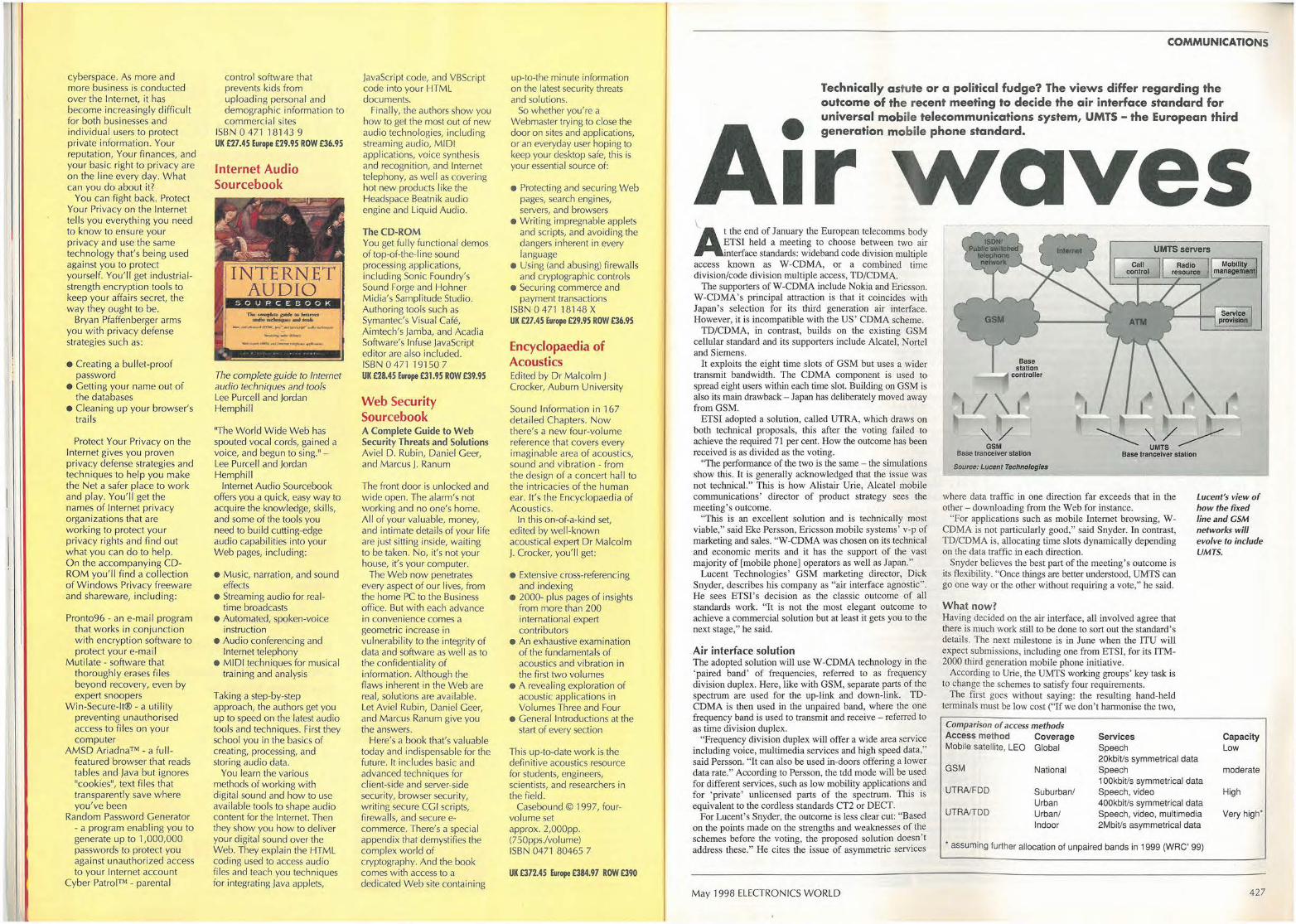
- -
cyberspace. As more and more business is conducted over the Internet, it has become increasingly difficult for both businesses and individual users to protect private information. Your reputation, Your finances, and your basic right to privacy a re on the line every day. What can you do about it?
You can fight back. Protect Your Privacy on the Internet t<~lls you everything you need to know to ensure your privacy and use the same technology that's being used against you to protect yourself. You' ll get industrialstrength encryption tools to keep your affairs secret, the way they ought to be.
Bryan Pfaffenberger arms you with privacy defense strategies such as:
• Creating a bul let-proof password
• Getting your nc~me out of the databases
• Cleaning up your browser's tra ils
Protect Your Privacy on the Internet gives you proven privacy defense strategies and techniques to help you make the Net a ~afer place to work and play. You'll get the names of Internet privacy o rganizations that a re working to protect your privacy rights and find out what you can do to help. On the accompanying CDROM you'll find a collection of W indows Privacy freeware and shareware, including:
Pronto96 - an e-mail program that works in conjunction with encryption software to protect your e-mail
Mutilate - software that thoroughly erases files beyond recovery, even by expert snoopers
Win-Secure-It® - a util ity preventing unauthorised access to files on your computer
AMSD Ariadna™ - a fullfeatured browser that reads tables and Java but ignores ''cookies", text files that transparently save where you've been
Random Password yenerator - a program enabling you to generate up to 1,000,000 passwords to protect you against unauthorized access to your Internet account
Cyber Patrol™ - parental
•
--
control software that prevents kids from uploading personal and demographic information to commercial sites
ISBN 0 471 18143 9 UK £27.45 Europe £29.95 ROW £36.95
Internet Audio Sourcebook
INTERNET7 AUDIO
- . .
---... _ _..... ... ,_,..~~-
The complete guide to Internet audio techniques and tools Lee Purcell and Jordan Hemphill
"The World W ide Web has spouted vocal cords, gained a voice, and begun to sing." -Lee Purcell and Jordan Hemphill
Internet Audio Sourcebook offers you a quick, easy way to acquire the knowledge, skills, and some Of the tools you need to build cutting-edge audio capabilities into your Web pages, including:
• Music, narration, and sound effects
• Streaming audio for realtime broadcasts
• Automated, spoken-voice instruction
• Audio conferencing and Internet telephony
• • MIDI techniques for musical training and analysis
Taking a step-by-step approach, the authors get you up to speed on the latest audio tools and techniques. First they school you in the basics of creating, processing, and storing audio data.
You learn the various methods of working with digital sound and how to use available tools to shape audio content for the Internet. Then they show you how to deliver your digital sound over the Web. They explain the HTML coding used to access audio fi les and teach you techniques for integrating Java applets,
JavaScript code, and VBScript code into your HTML documents.
Finally, the authors show you how to get the most out of new audio technologies, including streaming audio, MIDI applications, voice synthesis and recognition, and Internet telephony, as well as covering hot new products like the Headspace Beatnik audio engine and Liquid Audio.
The CD-ROM You get fully functional demos of top-of-the-line sound processing applications, including Sonic Foundry's Sound Forge and Hohner Midia's Samplitude Studio. Authoring tools such as Symantec's Visual Cafe, Aimtech's Jamba, and Acadia Software's Infuse JavaScript editor are also included. ISBN O 471 19150 7 UK £28.45 Europe £31.95 ROW £39.95
Web Security Sourcebook A Complete Guide to Web Security Threats and Solutions Aviel D. Rubin, Daniel Geer-, and Marcus J. Ranum
The front door is unlocked and wide open. The alarm's not working and no one's home. All of your valuable, money, and intimate details of your life are just sitting inside, waiting to be taken. No, it's not your house, it's your computer.
The Web now penetrates every aspect of our lives, from the home PC to the Business office. But with each advance in convenience comes a geometric increase in vulnerabil ity to the integrity of data and software as Well as to the confidentiality of information. Although the flaws inherent in the Web are real, solutions are available. Let Aviel Rubin, Daniel Geer, and Marcus Ranum give you the answers.
Here's a book that's valuable today and indispensable for the future. It includes basic and advanced techniques for client-side and server-side security, browser security, writing secure CCI scripts, firewalls, and secure ecommerce. There's a special appendix that demystifies the complex world of cryptography. And the book comes with access to a dedicated Web site containing
up-to-the minute information on the latest security threats and solutions.
So whether you' re a Webmaster trying to close the door on sites and applications, or an everyday user hoping to keep your desktop safe, this is your essential source of:
• Protecting and securing Web pages, search engines, servers, and browsers
• Writing impregnable applets and scripts, and avoiding the dangers inherent in every language
• Using (and abusing) firewal ls and cryptographic controls
• Securing commerce and payment transactions
ISBN047118148X UK £27.45 Europe £29.95 ROW £36.95
Encyclopaedia of J Acoustics Edited by Dr Malcolm J Crocker, Auburn University
Sound Information in 167 detailed Chapters. Now there's a new four-vo lume reference that covers every imaginable area of acoustics, sound and vibration - from the design of a concert hall to the intricacies of the human ear. It's the Encydopaedia of Acoustics.
In this on-of-a-kind set, edited by well-known acoustical expert Dr Malcolm J. Crocker, you'll get:
• Extensive cross-referencing and indexing
• 2000- plus pages of insights from more than 200 international expert contributors
• An exhaustive examination of the fundamentals of acoustics and vibration in the first two volumes
• A revealing exploration of acoustic applications in Volumes Three and Four
• General Introductions at the start of every section
This up-to-date work is the definitive ac;oustics resource for students, engineers, scientists, and researchers in the field.
Casebound © 1997, fourvolume set approx. 2,000pp. (750ppsJvolume) ISBN 0471 80465 7
UK £372.45 Europe £384.97 ROW £390
..
COMMUNICATIONS
-Technically a stute or a political fudge? The views differ regarding the outcome of the recent meeting to decide the air interface standard for universal mobile telecommunications system, UMTS - the European third generation mobile phone standard.
\
Ir the end of January the European telecomms body TSI held a meeting to choose between two air terface standards: wideband code division multiple
access known as W-CDMA, or a combined time division/code division multiple access, TD/CDMA.
The supporters of W-CDMA include Nokia and Ericsson. W-CDMA's principal attraction is that it coincides with Japan's selection for its third generation air interface. However, it is incompatible with the US' CDMA scheme.
TD/CDMA, in contrast, builds on the existing GSM cellular standard and its supporters include Alcatel, Nortel and Siemens.
It exploits the eight time slots of GSM but uses a wider transmit bandwidth. The CDMA component is used to spread eight users within each time slot. Building on GSM is also its main drawback - Japan has deliberately moved away from GSM.
ETSI adopted a solution, called UTRA, which draws on both technical proposals, this after the voting failed to achieve the required 71 per cent. How the outcome has been received is as divided as the voting.
'The performance of the two is the same - the simulations show this. It is generally acknowledged that the issue was not technical." This is how Alistair Urie, Alcatel mobile communications' director of product strategy sees the meeting's outcome.
"This is an excellent solution and is technically most viable," said Eke Persson, Ericsson mobile systems' v-p of marketing and sales. "W-CDMA was chosen on its technical and economic merits and it has the support of the vast majority of [mobile phone] operators as well as Japan."
Lucent Technologies' GSM marketing director, Dick Snyder, describes his company as "air interface agnostic". He sees ETSI's decision as the classic outcome of all standards work. "It is not the most elegant outcome to achieve a commercial solution but at least it gets you to the next stage," he said.
Air interface solution The adopted solution will use W-CDMA technology in the 'paired band' of frequencies, referred to as frequency division duplex. Here, like with GSM, separate parts of the spectrum are used for the up-link and down-link. TDCDMA is then used in the unpaired band, where the one frequency band is used to transmit and receive - referred to as time division duplex.
"Frequency division duplex will offer a wide area service including voice, multimedia services and high speed data," said Persson. "It can also be used in-doors offering a lower data rate." According to Persson, the tdd mode will be used for different services, such as low mobility applications and for 'private' unlicensed parts of the spectrum. This is equivalent to the cordless standards CT2 or DECT.
For Lucent's Snyder, the outcome is less clear cut: "Based on the points made on the strengths and weaknesses of the schemes before the voting, the proposed solution doesn't address these." He cites the issue of asymmetric services
May 1998 ELECTRONICS WORLD
aves
Base station
~-- controller
I I I __ ,...,
'\. / GSM
~ '\./ ~ UMTS
Base trancelver station Base trancelver station
Source: Lucent T11ehno/og/es
where data traffic in one direction far exceeds that in the other - downloading from the Web for instance.
"For applications such as mobile Internet browsing, WCDMA is not particularly good," said Snyder. In contrast, TD/CDMA is, allocating time slots dynamically depending on the data traffic in each direction.
Lucent's view of how the fixed line and GSM networks will evolve to include UMTS.
Snyder believes the best part of the meeting's outcome is its flexibility. "Once things are better understood, UMTS can go one way or the other without requiring a vote," he said.
What now? Having decided on the air interface, all involved agree that there is much work still to be done to sort out the standard's details. The next milestone is in June when the ITU will expect submissions, including one from ETSI, for its ITM-2000 third generation mobile phone initiative.
According to Urie, the UMTS working groups' key task is to change the schemes to satisfy four requirements.
The first goes without saying: the resulting hand-held terminals must be low cost ("If we don' t harmonise the two,
Comparison of access methods Access method Coverage Services Mobile satellite, LEO Global Speech
GSM National 20kbiVs symmetrical data Speech
UTRNFDD Suburban/ 1 0OkbiVs symmetrical data Speech, video
Urban 400kbiVs symmetrical data UTRA/TDD Urban/ Speech, video, multimedia
Indoor 2MbiVs asymmetrical data
• assuming further allocation of unpaired bands in 1999 (WRC' 99)
Capacity Low
moderate
High
Very high*
427
COMMUNICATIONS
the handsets will be more expensive.") UMTS's deployment wiJJ also be patchy at
first, claims Urie, and will use much smaller cells than GSM. "There will be UMTS islands in a sea of GSM," he said. Accordingly, UMTS will have to be harmonised with GSM: "The only practical terminal will be a triple mode one supporting the two modes of UMTS (frequency and time division duplex), and GSM. If we harmonise, this will be easy."
mode handsets, though," he said. to fight: the larger the standard the better for everyone: operators, vendors and users." Exactly how the two modes will co-exist also
has to be resolved. "The current spectrum allocation is 2 x 60MHz and 30MHz unpaired," said Urie. The easiest would be to use the unpaired spectrum for time division duplex but then it could be used anywhere in the spectrum.
Urie agrees, pointing out that the mobile phone operators have told the vendors in no uncertain terms that the time for fighting is over.
And what will happen after the submissions to the ITU in June? "The ITM-2000 will be a family of standards," believes Persson. "Designing one and only one standard is a major task and I'm not sure we will succeed in doing that. Anyway, it is the market that is driving the work not the ITU." •
Ericsson's Persson talks less of triple mode, expecting to see dedicated phones for each of the two modes. "We should not exclude dual-
Why should the two camps successfully merge their schemes when until recently they were fierce competitors? "Everyone realises the importance of this fast growing industry - the fastest in Europe," said Persson. "Europe is also leading at the moment. It is not in our interest
Microwave technology that is suddenly big news
Local multipoint distribution services (LMDS) in the US use a microwave-based broadband radio technology that offers data speeds of as much as 45Mbit/s. It is a microwave technology requiring lineof-sigbt broadcasts to subscribers and the range is limited from two to ten miles. The technology is affected by factors such as rain, which interferes with the microwave link, trees and their foliage, and buildings. These factors require LMDS operators to Jim.it the size of their cells, provide overlapping cells to overcome physical obstacles, and be able to boost the power of microwave transmissions during times of rain.
The technology was first developed almost 12 years ago by electrical engineer Bernard Bossard who received financial back.ing from the V.S. Hovnanian Group interested in LMDS as a cheap cable TV delivery system.
Field Electric Ltd. Tel: 01837 83736 Fax: 01837 83936
E-mail: [email protected] PO BOX 4, North Tawton EX20 2V J
NEC 9" Colour Monitor VGA 800 x 600 £35.00 Sony 9" RGB Colour Monitor (Trinitron Tube) £34.00 12" Colour VGA•SVGA 800x600 Monitors, from £35.00 14" Colour VGA 640x480 Monitors, from £45.00 1 r Dell Ultrascan SVGA Monitors from £165.00 Hewlell Packard 7475A Plotter Serial 6 Pen £86.00 Hewlett Packard 7550A Plotter HPIB Serial 8 Pen £199,00 Hewlett Packard 7470A Plotter Serial 6 Pen £75.00 Roland DXY 980 8 Pen Planer Serial Parallel £120.00 Tseng Dual Por1 $VGA ISA 16 Bit Graphics Card 1Mb runs 2 VDU from 1 PC £26.00 Adaptec t 6 Bil ISA SCSI Cards lrom £28.00 1Mb ISA t6 Bit Graphics Card SVGA £18.00 3Com Network Cards, various in stock, from £15.00 A Tl Mach 64 PCI 2mb SVGA Card £26.00 Hauppauge Windows TV Celebrity, ISA 16 Bit Frame, Caplure : TV Tuner etc £39.00 Quad Pro Plus/fseng etc. PCT SVGA Graphics, from £22.00 IBM 3.5• 160Mb SCSI Hard Drives £27.00 80MB 3.5" IDE Hard Disc Drives (Guaranteed) £19,95 1·44Mb 3-5" H.D. Disc Drives, from £8.00 Exabyte Tape Drives 2Gb lrom £60.00 Rose PC Swttching Boxes, from new £29.00 Marconi Digital Analyser 2829 £t 45.00 Marconi Multiplex Tester 2830 £130.00 Wallis lnsulalion Tester T30 £100.00 Sound Technology 1510A Tape Recorder & Audio Tesl Set wilh manual £375.00 Krohn-Hite 3343 Fitter £85.00 Hewlett Packard 8470A 8412A £375.00 Hewleu Packard 5345A £500.00 Hughes Scan Conversion Memory 639 £100.00 Tektronix DAS9100 £175.00 Lambda LK344A FMV 0·60VDC 4AIX £60.00 386 486 Laplops, please enquire, from £85.00 Oesktop 486 PCs, various specs from £85.00 Sound Technology 1510A Tape Recorder & Audio Test Set with Manual £375.00
428
OVERSEAS ENQ WELCOME. TELEPHONE ORDERS ACCEPTED. PAYMENT C/C, P.O., CHEQUE etc. C/P. DETAILS PLEASE RING.
ALL PRICES INC. 17.5% VAT UNLESS STATED. WE STOCK A LARGE SELECTION OF EQUIPMENT,
IF YOUR REQUIREMENT IS NOT LISTED PLEASE RING.
ClllCLf NO. 127 ON Rf PLY CARD
Thfa led to the creation of Cellular Vision, the first major provider ofLMDS services, operating in the Manhattan d.istrict of New York city. The company received back.ing in 1993 from Philips Electron.ics, Bell Atlantic and J.P. Morgan.
In an interesting move j ust two weeks ago, Hewlett-Packard agreed to sell its LMDS business unit to Lucent Technologies which is interested in developing a line of communications equipment for an LMDS market that market research firrn Strategis Group predicts will be an $8bn market within the next ten years.
The sale by HP was surprising since the company was an early pioneer in wireless broadband technologies. Byron Anderson, general manager of HP's M.icrowave and Communications Group said that the company recognised that without the add.itional commun.ications products that a company such as Lucent can provide, it would make it difficult for HP to build up much of a business.
B. BAMBER ELECTRONICS S STATION ROAD, LITTLEPORT, CAMBS. CB6 lQE.
Phone: 01353 860185 Fax: 01353 863245 Bridge rectifier type WO8, 800v at I SA. £1 for 10. Diodes Typc!N4007, lkv at IA,£1 for 50. Klockner MoeUer FAZG DIN rail mounting cin:uit breakers, single pole, 4A, 6A, 16A, 20A , £2 each. Seiko Epson Super Twist Graphics Blue Mode LCDs 320x240 Pixel Size, I 32x 103 Overal. £5 each. 3 for £10. No Driver or Details. Densitron Liquid C.rysial Displays, 5 Digit. Type LSH5060RP. £ 1 each. Proximity switches for doors and windows. surface mount, £1 each. Panel Meters moving coil, lmA/75mV,size 4½ x 2½. scale marl<ed 0-100, and 0-5. £5 .00 each,
Crabtree Ceiling Switches. 6A, Red Cord, £2.00 each. £10 per box. of 10. Capacitors,4.7mfd, 400v, radial electrolytic (Jamicom) 15x 10mm £2 per 200. Varistors, 275V 20J, 5mm pitch, Pan NoJVR7N431K. £5 per 500. Autornotiyc blade fuses, 5A and 15A. £ 1 per pack of 5. Resistors, CR25, ¼W. 4R7, 47R,470K£5 per box of 5,000. Weir Bench Power Units 'fype 460, 0-60v at I amp. £70.00. Flexible 'Goose Necks' used to mount in car computers etc, 14' long, £3 .00 each. Wiring Harnesses for car alanns, useful lengths of equipment wire etc, £1 per pack of 4. Her• Foot Switches. 250vac, 3 amp. £4. Siemens Min Relays Type CI062A307, 12v single pole 10 amp. 3 for £1 . Advance Signal Generator 'fype E2, AM/CW, IOOKHz to 100MHz. £75.00. Mains transfonners 12v, 2 amp. £2.00 each. Sullivan Decade Resistance Boxes, 4 Way. £20.00 each.
Tangential Fans, 240vac, 80mm. £4.00. DIP Switches, 6 Way. £1.00 each. PED Relays, PCB Mount, 2 pole C/0, 5v lype 51 SB05T. £ 1.00 each. Tektronix Oscilloscope type TDS350, Dual channel, 200mhz, I GS/s, £2200.
Black Star Meteor 600MHz frequency counter, mains or battery, £95.00.
PhiUps Oscilloscope Type PM3217, Dual Channel, 50MHz. £350.00. lwatsu Oscilloscope 'fype SS512I, Dual Channel, 1001\iffu. £450.00. Ttme DC Voltage Calibrator'fype 2003S. £250.00.
Time DC Curent Calibrator, 0-1 OmA . £250.00
Dipped Ceramic Capacitors 1 nF. 500v, 5mm pitch,£! .00 per 100.
Kingshill Power Unit 'fype NMI0300, I OOvdc, 3amp. £95 .00.
Avo AC/DC Breakdown leakage & Ionisation lester Type RM215-L2. £400.00. Image Powcrsense mains analyser. £600. Avo Megohmmeter Model R."'1290. £220. Zemco central locking interface kits type SA535 allows the Zemoo SA530 vehicle alarm to automatically lock and unlock the vehicle doors by use of the remote transmitter. £5 each. Zemco vehicle alarm Biaxial Piero Shock Sensor Type SA405. £5 each. Zemco add on quartz Ultrasonic Sensor Kits Type SA404. £5 each. RoUing Ball Fuel Flow Sensors suitable for Petrol and Diesel. £5 each. Pin Switches for Car Door/Boot/Bonnet etc. £ 1 perpack of4. MAIL ORDER ONLY. DELIVERY FR.EE, MIN ORDER £10. NO VAT. WANTED SURPLUS STOCK
CIRCLE NO. I ZB ON Rf PLY CARD
ELECTRONICS WORLD May 1998
SMALL SELECTION ONLY LISTED - EXPORT TRADE ANO QUANTITY DISCOUNTS - RING US FOR YOUR REQUIREMENTS WHICH MAY BE IN STOCK HP New Colour Spectrum Analysers HP141T+ 8552B IF+ 85536 RF-1KHz-110Mc/s- £700. HP141T +·8552B IF+ 8554B RF -100KHz-1250Mc/s-
1'900. HP141T + 8552B IF+ 8556A AF - 20Hz-300KHz - £700. HP141T+ 85528 IF + 8555A 10MC/S-18GHzS- £1200. HP8443A Tracking Generator Counter lOOKHz-11 OMc/s -
£200. HP8445B Tracking Preselector DC to 18GHz - £250. HP8444A Tracking Generator• 5-1300Mc/s- £700. HP8444A OPT 059 Tracking Generator • 5• 1500Mc/s -
1'950. HP35601A Spectrum Anz Interface - £500. HP4953A Protocol Anz - £400. HP8970A Noise figure Meter + 346B Noise Head - £3.SK. HP8755A Scalar Network Anz Pl - £250 + MF 180C - £200 Heads 11664 Extra, HP8756A Scalar Network Anz - £1000 Heads 11664 Extra. HP8757 A Scalar Network Anz - £2500 Heads 11664 Extra. HP8903AAudio Anz -£1500. HP8856A 100KHz -900 Meis, SIG AM-FM- £1450. HP3709B Constellation ANZ £2k. HP11715AAM-FM Test Source-£750, FARNELL TVS70MKII PU 0-70V 10 amps-£150. FARNELL PSG 520 SIG 10Mc/s AM-FM -£150. TEK 475 Oscilloscopes 200Mc/s - £350. 475A 250Mc/s -
£400. MARCONI 6500 Network Scaler Anz - £750. Heads available to 40GHz. HP3580A 5Hz-50KHz Spectrum ANZ £750-£1000 HP3582A .02Hz lo 25.6KHz Spectrum ANZ £1.5k TEK 7L5 + L3 - Opt 25 Tracking Gen - £900. TEK 7L12 -100KHz-1800Mc/s - £1000 TEK 7L18 - 1.S-60GHzs -£1500. Mixers are available for the above ANZ's to 60GHz HP8673D Signal Generator .05-26.5GHz _ £15K. Systron Donner 16188 Microwave AM FM Synthesizer 50Mc/s 2-18GHzs.
R&S SWP Sweep Generator Synthesizer AM FM 4-2500Mc/s - £1 k. ADRET 3310A FX Synthesizer 300Hz-60Mc/s -£600. HP5316B Universal Counter A+B. HP Plotters 7470A-7475A. Up to £250. HP3730A+3737 A Down Convertor Oscillator 3.5·6.5GHz. HP Microwave Amps 491-492-493-494-495· 1 GHz-12.4GHz - £250. HP105B Quartz Oscillator+ HP5087A Dis Amp £500. HP6034A System Power Supply 0-60V 0-10A-200W-£
500_
HP6131 C Digital Voltage Source + -1 OOV )! Amp. HP3779A Primary Multiplex Analyser- £200. HP3779C Primary Mul~plex Analyser - £300. HP1631 D Logic Analyser - £500. HP5316A Universal Counter A+B. HP8901A Modulation Meter AM-FM - £1 .5k. Marconi TF2374 Zero Loss Probe- £200. Marconi TF2305 Modulation Meter - £1.5k. Racal/Dana 2101 Microwave Counter - 1 OHz·20GHz -
Racal/Dana 1250-1261 Universal Switch Controller+ 200Mc/s Pl Cards.
£2k.
Racal/Dana 9303 True RMS Levelmeter+Head - £450. IFFE -£500.
TEKA6902A also A6902B tsolalo, - £300-£400. TEK FG5010 Programmable Function Generator 20Mcf1oo.
TEK2465A 350Mc/s Oscilloscope - £2.5k + probes-£150 each.
TEI< CT-5 High Current Transformer Probe - £250. TEK J16 Digital Photometer+ J6523-2 Luminance P,o~
0-0
_
HP745A+746A AC Calibrator - £600. HP11729C Carrier Noise Test Set .01-18GHz - LEF-
£2000. Marconi TF2008 -AM-FM signal generator-also sweeper - 10Kc/s- 510Mc/s-from £250 - tested to £400 as new with manual - PfObe kit in wooden carrying box. HP Frequency comb generator type 8406 -£400. HP Sweep Oscillators type 8690 A & B + plug-ins from 20Mc/s to 18GHz also 18-40GHz HP Network Analyzer type 8407 A + 8412A -. 8501 A - 100Kc/s-110Mc/s - ts00 -£1000. HP Amplifier type 8447A- HIOOMc/s £200 - HP8447A Dual-£300. HP Frequency Counter type 5340A - 18GHz £1000- rear output £800. HP 8410- A - B - C Network Analyzer 110MC/s to 12GHz or 18GHz - plus most other
units and displays used In this set-up - 8411 a - 8412 -8413 -8414 - 8418- 8740-
8741 -8742 -8743-8746 - 6650. From £1000. Racal/Dana 9301A·9302 RF Millivoltmeter - 1.5-2GHz -
£250-£400. Racal/Dana Modulation Meter type 9009-9008 -8Mc/s -1.5GHz - £150/£250. Marconi RCL Bridge type TF2700 - £150. Marconi/Saunders Signal Sources type - 6058B - 6070A - 6055A - 6059A - 605 7 A -
6056-£250-£350. 400Mc/s to 18GHz, Marconi Microwave 6600A sweep osc., mainframe with 6650 Pl - 18-26.5GHz o, 6651 Pl - 26.5-40GHz - £750 or Pl only £600. MF only £250. Tektronix Plug-Ins 7A13-7A14 - 7A18- 7A24- 7A26 -7A11 - 7M11- 7S11 - 7D10 - 7S12 -S1 - S2-S6-$52 - PG506 - SC504 - SG502 - SG503 - SG504 - DC503 -DC508 - 00501 - WA501 - DM501A - FG501A - TG501 -PG502 -DC50SA - FG504 - 7B80 + 85 - 7B92A. Gould J3B test oscillator + manual - £150. Tektronix Mainframes -7603 - 7623A- 7613- 7704A-7844-'il904 - TM501 - TM503 - TM506 - 7904A-7834 -7623 - 7633- 7844 - 7854 - 7104. Marconi 6155A Signal Source - 1 to 2GHz - LED re~f
4~
0•
Barr & Stroud Variable filte( EF3 0.1 Hz - 1 OOKc/s + high pass+ low pass -£150. Racal/Dana 9300 RMS voltmeter- £250. HP 8750A storage normalizer - £400 with lead + S.A or N, A Interface, Tektronix - 7S14 - 7T11-7S11 - 7S12 - S1 -S2 -S39 -S47 -S51 -S52 -S53 - 7M11. Marconi mod meters type TF2304 - £250. Systron Donner counter type 6054B - 20Mc/s - 24GHz -LED readout - £1 k. Farnell electronic load type AB1030-35 - £350. Racal/Dana counters-9904 -9905-9906-9915-9916 -9917 - 9921 - 50Mc/s -
3GHz- £100- £450 - all fitted with FX standards. HP180TA, HP182T mainframes £300-£500. Marconi 6700A sweep oscillator + 18GHz Pl's available. Rscal/Dana VLF frequency standard equipment. Tracer receiver type 900A + difference meter type 527E + rubidium standard type 9475-£2750. HP432A - 435A or 8 - 436A - power meters + powelheads to 60GHz. HP8614A signal generator 800Mc/s - 2.4GHz. new colour
£400. HP8616A signal gen 1.8GHz-4.5GHz, new colour £400. HP 3336A or B syn level generator - £500·£600. HP 3586B or C selective level meter- £750-£1000. HP 86830 SIG microwave 2.3-13GHz- opt 001 -003-
£2.5k. HP 8640B S/G AM-FM 512Mc/s Of 1024Mc/s. Opt 001 or 002 or 003 -£800-£1250. HP 86222BX Sweep Pl - 01 - 2.4GHz + ATT - £1400 -
£1750. HP 86290A sweep Pl - 2 - 18GHz - £1000 - HP 86~~50
HP 86 Series Pl"s in stock - splitband from 10Mc/s-18.6GHz - £250 - £1 k. HP 8620C Mainframe - £250. IEEE - £500. HP 6615A Programmable signal source-1MHz-50Mc/sopt 002 - £1 k. HP 8601A Sweep generator .1 -1 l OMc/s-£300. HP 8349A Microwave Amp 2 -20GHz Solid slate -£1500. HP 1980B Oscilloscope measurement system - £300. HP 345513456A Digital voltmel81'- £400. HP 5370A Universal time Interval counter - £1k. HP 5335A Universal counter - 200Mc/s - £500. HP 5328A Unive,sal counter - 500Mc/s - £250. HP 6034A System power suppty-0-60V -0 - 10 amps
£500. HP 3710A-3715A-3716A-37028- 37038 - 3705A-3711A - 3791B-3712A-3793B microwave !Ink analyser-
P.O.R. HP 3552A Transmission test set - £350. HP 3763A Error detector - £500. HP 3764A Digital transmission analyser - £600. HP 3770A Amp delay distortion analyser - £400 - + 3770B
-£400. HP 3780A Pattern gemarator detector - £400. HP 3781A Pattern generator - £400. HP 3782A Error detector - £400. Tektronix 577 Curve tracer + adaptors - £900. Tektronix 1502/1503 TDR cable test set -£400. Racal 1991-1992-1998- 1300Mc/s countef's-£400-£900. Fluke BOK-40 High voltage probe in case - BN - £50-£75, EIP 545 microwave 18GHz counter- £1200. Fluke 510A AC rel standard - 400Hz - £200. Fluke 355A DC voltage standard - £300. Wlltron 6100 Sweep Generator+ 6124C Pl- 4- 8GHz-
£400. Wittron610D Sweep Generator+ 610840 Pl -1Mc/s -1500Mc/s - £500. HP 8699B Sweep Pl YIG oscillator .01 - 4GHz - £300. 8690B MF - £250. Both £500. Dummy Loads & power alt up 10 2.5 kilowatts FX up to 18GHz - microwave par1s new and ex equip! - relaysattenuators - switches - wa~eguides - Yigs - SMA -Af'C7 plugs - adaptors. B&K Items in stock - ask for list. Power Supplies Heavy duty + bench in stock - Farnell -HP -Weir - Thurlby- AacaJ--m<:. Ask for list. Large quantity In stock, all types. Marconi 2955 Radio test set + calibration. £2000. Marconi 2955 + 2958 Tacs radio test set + calibration.
£2250. Marconi TF2015 SIG 10Mc/s-520Mc/s AM.FM. £150. Marconi TF2016A S/G 10Kc/s-120Mc/s. AM.FM. £150. Marcon; TF2171 or 2173 Digital syncronlzer for 2015/2016.
£100. Marconi TF2017 SIG .01-1024Mc/s.AM.FM. High grade.
£1500. Marconi TF2018 SIG 80Kc/s·520Mc/s. AM. FM. £800. Marconi TF2018A SIG 80Kc/s·520Mc/s. AM. FM. £1000. Marconi TF2019 SIG 80Kc/s-1040Mc/s. AM. FM. £1250. Marconi TF2019A SIG 80Kc/s-1040Mc/s. AM. FM. £1500. Marconi TF2022E SIG 10Kc/s-1.01GHzs. AM. FM. £1500. Marconi TF2022E As above but as new+ Cal cert. £1800. Marconi TF6311 Microwave Sweep SIG 1 OMc/s-20GHz c/w TF6500 amplitude Anz. p lus heads 10Kc/s-40GHz.
£4K-£5K. Farnell SIG ESG100010Hz-1000Mc/s. AM. FM. £1200. Farnell SIG PSG100010Hz-1000Mc/s. AM. FM. £1300. !FR 12005 Communications radio test set. £2500. TF2370 Spectrum Anz's 30Hz-110Mc/s. Large qty In stock to clear as received from Gov.all sold as is f rom pile complete or add £100 for basic testing and adjustment. Callers preferred - Pick your own from over sixty dnits. A. Early Model - Grey - Rear horizontal alloy cooling fins -
£200. B. Late Model - Grey-Vertical alloy coolin9 fins - £300.
~-a~~':,~~73 BE~:d-e1~i~5~~~£~b.g~~~ ~~~~, - esoo.
H.P. 3325A Synthesized function generator - £1000-£1500.
H.P. 3325B Synthesized function generator - £2500. H.P. 8505A Vector voltmeter - late colour - £400. H.P. 8508A Vector vottmeter - £2500, H .P. 8505A Networl< Anz 500KHz-1 .3GHz - £1750, H.P. 8505A + 8502A or 8503A test sets - £2000/£2250. H.P. 8505A + 8502A or 8503A+8501A normalizer - £2500. H .P. 8557A .01 Mc/s-350Mc/s--8558B 0, 1 •1500Mc/s • 8559A .01-21GHz 182T or 180C-D·T ts00-£2500. Tektronix 492 Spectrum Ani•OPT 3-SOKc/s-21 GHz -
£3500, Tektronix - HP Oscilloscopes -100Mc/s-465-465B-1740-1741 etc-£300. Phillips 3217 50Mc/s oscilloscopes - r 150-£250. Phillips 3296 350Mc/s IR remote control oscilloscope -
£1400. Hitachi VC6041 Digital storage oscilloscope - 40Mc/s -
£500. Tektronix 2430A Digital storage oscilloscope - 100Mc/s -
£2000. Tektronix 2440 Digital storage oscllloscope - 400Mc/s -
Tektronix 2245A Oscilloscope-100Mc/s- £1000. Tektronix 2445 + DMM - 250Mc/s - £1250. Tektronix 2445A - 150Mc/s- 4 CH- £1000.
£2200.
Schaffner NSG 200E Mainframe - NSG203A low volt var simulator - NSG222A. Interface simulator - NSG223 Interface generator - NSG224 Interface simulator - NSG226 Data line simulator - all she items at £1500. Schaffner NSG200E Mainframe - NSG203E low volt var simulator - NSG222A Interface simulator - all three items -
LIGHT & OPTICAL EQUIPMENT Anritsu ML93A & Optical Lead Power Meter, Anritsu ML93B & Optical Lead Power Metef'.
£1000.
Power Sensors for above MA96A - MA98A - MA913A -Battery Pack MZ95A. Anritsu MW97A Pulse Echo Tesl81'. Pl available· MH914C 1.3 - MH915B 1.3 - MH913B 0.85 • MH925A 1.3- MH929A 1.55 • MH925A 1.3GI,· MH914C 1.3SM. Anritsu MW98A Time Domain Renecror. Pl available• MH914C 1.3- MH915B 1.3 • MH913B 0.85 • MH925A 1.3-MH929A 1.55 -MH925A 1.3GI -MH914C 1.3SM. Anritsu MZ100A E/0 Converter. + MG912B (LO 1.35) Light Source + MG92B (LO 0.85) light Source. Anritsu MZ118A 0/E Converter. +MH922A 0.8 0/E unit + MH923 A 1.3 0/E unit. Anritsu ML96B Power Mel81' & Charger. Anritsu MN95B Variable Att. 1300. Barr & Stroud LS10 Light Source. BT Power Unit 85.J- 1300 • 1500. Photo Dyne 1950 XA Continuous Att. 1300 - 1500. Photo Dyne 1800 FA. Att. NKT Electronic OAM30 Att Meter (MN3032TX) 1300 out put. Electo Optic Developments F0-500 lX Laser. Cossor-Raytheon 108L Optical Cable Fault Locator O·l OOOM 0·10kM. lntelco 220 Single Mode Att 1532. TEK f>6701 Optical Convertor 700 MC/S-850. TEK Orionic,s 7000 Type Pl OTDA-103A. HP81512A Head 150MC/S 950-1700. HP84801 A Fibre Power Sensor 600-1200. HPB1588 ATT OPT 002+011 1300-1550. HP81519A RX DC-400MC/S 550·950. STC OFTX-3 Laser source. STC OFRX-3 STC OFR10 Renectometer. STC OFSK15 Machine JOintlng + eye magnifier. Anritsu ME453L AX Microwave ANZ. Anritsu ME453L TX Microwave ANZ. Anritsu MS420B Network Spectrum ANZ. Anritsu MH370A Jitter Mod Oscillator. Anrttsu MG642A Pulse Pait Gen. Complete MS65A Error DetectOf. System MS02A Timer & Digital Printer. Anritsu Ml612A Sel Level Meter. Anritsu MS2802A Spectrum ANZ 100Hz-32GHz. Anritsu ML244A Se! Level Meter. Advantest TR98201 Signal Gen Advantest TA9402 Digital Spectrum ANZ. Siemens D2108 Level Meter. Siemens D2150 Bit Error Meter W&G PCM3 Auto Measuring Set. W&G SPM14 Sel Level Meter. W&G SPM15 Sel Level Meter. W&G SPM16 Se! Level Meter. W&G PS19 Level Gen. W&G DA20+DA1 Data ANZ W&G PMG3 Transmission Measuring Set. W&G PSS16 Generator. W&G PS14 Level Generator W&G EPM-1 Plus Head Milliwatt Power Meter. W&G DLM3 Phase Jitter & Noise. W&G DLM4 Data Line Test Set. W&G PS10 & PM10 Level Gen.
ITEMS BOUGHT FROM HM GOVERNMENT BEING SURPlllS. l'lllCE IS EX WORKS. SAE FOR EHQUIRIES. PHONE FOR APPOINTMENT OR FOR OEMOIISTIIATION OF ANY ITEMS, AYAllABIUTY OR PRICE CHANGE. VAT ANO CARRIAGE EXTI\A. ITEMS MARKED TESTED HAYE 30 OAY WARRANTY. WANTED: TEST EQUIPMENT-VAlYES-PlUGS ANO SOCKETS·SYNCROS-TRANSMITTING ANO RECEIVING EQUIPMOO £TC.
Johns Radio, Whitehall Works, 84 Whitehall Road East, Birkenshaw, Bradford 8D11 2ER. Tel. No: (01274) 684007. Fax: 651160
CIT/CL[ NO. 12') UN RLPLr CARn
May 1998 ELECTRONICS WORLD 429
The Home of ';ilt-";uee44e. Its not what you do,
Hart Audio Kits and factory assembled units use the unique combination of circuit designs by the renowned John Linsley Hood, the very best audiophile components, and our own engineering expertise, to give you unbeatable performance and unbelievable value for money. We have always led the field for easy home construction to professional standards, even In the sixties we were using easily assembled printed circuits when Heathkit In America were still using tagboardsl. Many years of experience and Innovation, going back to the early Dinsdale and Balley classics gives us incomparable design background In the needs of the home constructor. This s imply means that building a Hart kit Is a real pleasure, resulting in a piece of equipment that not only saves you money but you will be proud to own. Why oot buy the reprints and construction manual for the kit you are Interested In to see how easy It Is to build your own equipment the HART way. The FULL cost can be credited against your subsequent kit purchase.
'AUDIO DESIGN' 80 WATT POWER AMPLIFIER.
·-~----'' - - - .
- - ~
This lantasric John Linsley Hood designed -amplifrer is the flagship of our range, and the Ideal powerhouse for your ultimate hlfl system, This kit is your way to get £K performance at bargain basement prices. UniQue design features such as fully FET stabilised power supplies give this amplifier World Class pertormance with sta~llng ciarlty and transparen<:y of sound, amed to the lamous HART quality components and ease of construction. Standard model comes with a versatile passive front•end giving 3 switched inputs, with ALPS precision "Blue Velvet'" low•noise volume and balance conlrols, no need for an external preamp!. Construction Is very slmple and enjoyable with all the difficult work done for you, even the wiring is pre-te,minaled, ready for instanI use!. AH versions are available wilh Standard components or specially selected Super Audiophile components and Gold Plated speaker terminals and all are atso available factory assembled. K1100 Complete STANDARD Slereo Amplifier Kit. . . . . . . £415.21 K11 OOS Complete SLAVE Amplffier Kil, . . . . . . . . ... £353.62 K1 100M Complete MONOBLOC Amplifier Ktt, . . . . .. £271.20 RLH11 Reprints of latest Amplifier articles . . ............. £1.80 Kl 1 OOCM Construction Manual with full par1S fists . . . .• £5.50
ALPS " Blue Velvet" PRECISION AUDIO CONTROLS.
Now you can throw out those noisy ill-matched carbon pets and replace with the famous Hart exclustve ALPS 'Blue Velvet' range components only used selectively in lhe very top flight of World class amplifiers. The improvement rn lrack accuracy and matching really is incredible giving better tonal balance between channels and rock solid image s1ab1Hty, Motorised versions have Sv DC molar.
MANUAL POTENTIOMETERS 2-Gang 1 OOK Lin. . . . . . . . . . . . . ......... £15.67 2•Gaog 1 OK, SOK or 1 OOK Log . . .. .. . . ....... . . . ..... £16.40 2-Gang 1 OK Special Balance, zero crosstalk and zero centre loss. . . .. .. . • .. . . .. . .. . .. . . . £17.48
MOTORISED POTENTIOMETERS 2-Gang 20K Log Volume Control .... .......... , ...... £26.20 2·Gang 10K RD Special Balance, zero crosstalk and less than 10% 1oss in cent,e position . . . .. ... . . . . , . . ..... . . £26.98
TOROIDAL MAINS & OUTPUT TRANSFORMERS for EL34, 32W VALVE AMPLIFIER
SpeciaJ set of toroida1 transfonners, 2 output & 1 mains for the •Hot Audio Power- varve amplilier design described fn the Oct. 1995 issue of 'Wireless World". TolaJ WI 4.8Kg. Special price for the set. £99, Post £8 RJMI. Photocopies of lhe Article by Jeff Macaulay. C2
PRECISION Triple Purpose TEST CASSETTE TC1 D.
Are you sure your tape recotder Is set up to give ils best? Our latest lliple purpose test cassette checks the three inosI Important lape
parameters without tesl equipment Ideal when filling new heads. A professional quality, digitally mastered test tape at a
ce anyone can afford est Cassette TC1 O Our pnce only . . . £9 99
its HOW you do it that counts! .
SHUNT FEEDBACK PICKUP PREAMPLIFIER
If you want the very best sound oul of vinyl discs then you need our high quality preamplifier with Shunl Feedback equalisallon. The K1450 also has an advanced front end, specialty optimised for low impedance moving coll cartridges as well as moving magnet types. Selected discrete componenls are us&d lhroughouI for ultimate sound quality. The combinalfon of John Linsley Hood design, high quality components and an advanced double sided printed circuit bOard layout make this a product al the leading edge ol technology lhat you will be proud to own. A recent review in •Gramophone'" magazine endorsing lhis view. Bought in kit form our step by step lnstructrons It is very easy and satisfying to assemble, or you can buy a faelory assembled version ii you wish. This magnillcenl kit. comes complete with all parts ready 10 assemble inside the fully ftnished 228 x 134 x 63mm case. Comes with full, easy to follow, instructions as wen as the Hart Guide to PCB Construction, we even throw in enough Hart Audiogr9-de Sitver Solder 10 construct your kit! K 1450 Complete Kit .. . .. .......... . . . ..... . . ... . £116.58 K1450SA Audiophile Kit . ...................... . ... £138.94 A1450SA Factory assembled Aud,ophileunil .... . ..... £188.94
"CHIARA" HEADPHONE AMPLIFIER.
Highest quality, purpose designed, 'single ended' class 'A' headphone amplifier for 'stand arone' use or to supplement those many powe, amplifiers lhat do not have a headphone lacility. Easy instarlation wllh special signal link-lhrough feature, the unit uses our 'Andante' Ultra High Quality power supply. Housed in lhe neat, black finished, Hart minibox it features the wide frequency response, low•dlstortlon and 'musicality' that one associates with designs from the renowned John Linsley Hood. Volume and balance controls are Alps "'Btue Vel\ret" components. Very easy to bulld. or available faciory assembled. the kit has very detailed instructions, and comes with Hart audlograde silver solder. A valuable personal listening option and an atlractlve and harmonious addition to any hifl system, K2100 Complete Slandard Kil ..... . .. .. . . .. . .... , .. £112-50 K21 OOSA 'Serles Audiophile' Kil with selected audiOphile components . . . . . . . . ............... £115.46 A2100SA 'Series AudiOphile', Factory Assembled • . .. .. . £115.46 CM2100 Construction Manual. . . . . . . . . .. . .. .. . .. .. . £2.50
"Andante" Linear Technology AUDIOPHILE POWER SUPPLIES
The HART "Andante" senes PoWM supplies are specially designed for exacting audio use requiring absolute minimum noise4 low hum field and total freedom from mechanical noise. Utilising linear techoolOgy throughout for smoothness and musicality makes it the pertect partner lor lhe above units, or any equipment requiring fully stabillsed ±1Sv supplies. There are two vetsions, K3550 has 2 % 1 Sv supplies and a single 1 Sv lor relays etc. K3565 is Identical in appearance and has one :t:15v. Both are In cases to match our 'Chiara' Headphone Amplifier and our K14SO •shunt Feedback"' Ptci<up preamp. K3550 Full Sopply wilh all outputs . . .. . ..•. . • , • ..• , .. £94.75 K3565 Power Supply for K1450 or 1<2100 • . . . . . .• ... . .. £84.42 A3550 Factory Assembled Full Supply .. . ... . ..... . . . . £147.25
SPEAKER DESIGN SOFTWARE. VISATON "SpeaKer Pro s· is a complete speaker design program for use on IBM maehines. Covers cabinel and crossover design and contains a lull expandable database ol drive units. Earning a "m<>st reccommendable• accolade it tests this program is Ideal for lhe professional speaker buikjer or serious audiophile. 0303 Speaker Pro 6. 3.S"Oisk • . . • . . ..... . . .. ... £45.51
SPEAKER DAMPING MATERIALS Polyester Wool and Pure Lambs Wool both have oplimal damping properlies and are pleasant to handle. Standard 125g bag is sufficient for 20 litres enciosure volume. 5070 Polyester Wool. 125g . . . 5069 Pure Lambs Wool. t 25g .. . ..... .
. . . . . £3.20
. . . , , [6.73
SPECIAL OFFER!. SOLENOID CONTROLLED FRONT LOAD CASSETTE DECK SFL800
High quality (0,08%W&FJ cassette mechanism with capabilily of using standard or downstream monitor RIP head. Offers all standard facilities under remote, logic or software control. The control requirements are so simple lhal for many applications not needing au functions manual switches will suffice. Power requi,ements are a1so sjmple with 12v solenoids and 12v speed controlled Motor, total power requirement being under 300mA. Logk: control and wiring circoils are included free with each deck. SFL800 Deck with Slandard stereo head .• . •... . •..•.. £29.50 SFL8000 Fitted wtth High Quality Downstream mon~or head. £44.90 (The Head alone is normally over £601)
HART TECHNICAL BOOKSHELF Try us loc- Bigger Range ol Books, Better Prices,
NO "28 Day Wail" New Titles. "A BEGINNER' S GUIDE TO TUBE AUDIO DESIGN" Bruce Roz.enblit A practical book that does exaclly what its lille says and takes a modem look at valve amplifier construction, 132pp. ISBN 1· 88280-13·3 . . . . . . • . . £18.20 " HIGH PERFORMANCE LOUDSPEAKERS" Edn.5. Martin Colloms. Latesl edloon, Just out A realty in-depth coverage of lhe whole Wortd ol speakers and hfgh quality sound reproduction, but entirely readable In style. Just reviewed in "HiFI World". 478pp. ISBN 0-4719•7089·1 . . £24.95'
"AUDIO ELECTRONICS" John Linsley Hood . . . "THE ART OF LINEAR ELECTRONICS"
. £19.95'
John Linsley Hood. 1994 . . . • £19.95-"THE ART OF ELECTRONICS" Horowitz & Hill . . . . . £35,00' " DIGITAL AUDIO AND COMPACT DISC TECHNOLOGY" 3rd.Edn. 0-240 51397 5 .. .. . .. . . . .. .. . . .... . . £19.95' "INTRODUCING DIGITAL AUDIO CD, DAT AND SAMPLING" ISBN 187ons 22 8 . . ......... . .... . , .. . . . . . £7.95 "ACTIVE FILTER COOKBOOK" Don Lancaster ....... . £19,95 "THE ART OF SOLDERING" 0·85935-324•3. 0 .. . .. .. . . . £3.95 "TOWERS' INTERNATIONAL TRANSISTOR SELECTOR" 0-572·0l062·1 ....... . ... . ... . ............... . . £19.95' "AUDIO" F.A.W"son. 8P1 11 . .. . .............. . ..... . £3.95 "HOW TO USE OSCILLOSCOPES & OTHER TEST EQUIPMENr' A.A.Penfold. BP267 . . . . .. . . .. .. £3.50 "THE HART PRINTED CIRCUIT BOARD CONSTRUCTION GUIDE." .. . . . .. £2.50 " A SIMPLE CLASS A AMPLIFIER" J.L.Unsley Hood M.I.E.E. 1969. RLH12 . .. ... . "CLASS-A POWER" Single Ended 15W Amp. J.L.Unsley Hood M.I.E.E. 1996. RLH13 ........ .
LOUDSPEAKERS; THE WHY AND HOW OF GOOD
. . [2,75
. . [2.50
REPRODUCTION. G.Brtggs. 1949 ... . ... . . ... , ...... . £8.95 ''THE LOUDSPEAKER DESIGN COOKBOOK" Vance Dickason. (5th Edn.) . .. ........... . ... . ..... £23.95· ELECTROSTATIC LOUDSPEAKER DESIGN AND CONSTRUCTION Ronald Wagner BKT6 . . . . .. £15.95 ''THE ELECTROSTATIC LOUDSPEAKER DESIGN COOKBOOK" Roger P.Sanders. 1995 ................... £24.95 " BULLOCK ON BOXES" Bullock & White .. , .......... £10.95 " AN INTRODUCTION TO LOUDSPEAKERS & ENCLOSURE DESIGN" V. Capel. 8P256 .. • . .. . .. .. . .. . .. .. . . . . . £3.95 " LOUDSPEAKERS FOR MUSICIANS" 8P297 . ... . .. . .. £3.95 ' 'THEORY & DESIGN OF LOUDSPEAKER ENCLOSURES" J.E.Benson . . . . . . , £21.95 "QUICK & EASY TRANSMISSION LINE SPEAKER DESIGN" Larry D.Sharp ...... : .... . .... . ... . ...... . £8.95 "THE COUPLED CAVITY HANBOOK" David Purton .• . .. . £4.90 "VISATON. HOME HI Fl CATALOGUE." Full Specifications and Thiele Small Data on all Drive Units . . . . . £4.50 "VISATON. CAR HI Fl CATALOGUE." In ca, guide. , .... . £3.50 "VISA TON. CABINET PROPOSALS" Boot< 1. In GERMAN £6.50 "VISATON. CABINET PROPOSALS" Book 2. In GERMAN ts.so " SPEAKER PRO 6." VISATON Cabinet Design Sottware . . £45.51 "SPEAKER PRO 6." Dem<> Version with dlive unit dalabase £9.28
"VALVE AMPLIFIERS" Morgan Jones. 199516 • . . . £24.50 THE VTL BOOK David Manley 1994. BKVTI . . . . . . . .. £17.95 MULLARD TUBE CIRCUITS FOR AUDIO AMPLIFIERS BKAA27
.. .... . .. . . . . . . . . ... £11.95 "THE WILLIAMSON AMPLIFIER." 0·9624-1918•4 • . . ..•• £6.95 AN APPROACH TO AUDIO FREQUENCY AMPLIFIER DESIGN. GEC 1957 . . . . . . . . . . . . . . . . . .... £17.95 AUDIO ANTHOLOGIES, articles from Audio Engineering. $ix volumes covering the days when audio was young and valves were kingl. 8KAA3/1 to 6. . .. .. . .... . .. . . . . All £12.95 each "THE RADIOTRON DESIGNERS HANDBOOK" (CD) .. . . £49.00 " PRINCIPLES OF ELECTRON TUBES" H.D.Reich PH.O. £25.95 "POWER AMP PROJECTS" Anthology. 1970-1989 ...... £15.50 "WORLD TUBE DIRECTORY" 1996-7 Sourcebook of valve related products ..... .... . ...... .. . , ......... . ..... £6.95 Fuller descriptions of the contents of all our boOks ls given in our full catalogue. price ... . . . .... . . . . . ... , . £4.50
Postage on all books. unless starred, is only £2 per book. maximum £4.50 for any number, any sizel. Slarred items are heavy books cosUng £3.50 to send. Don't forget No waiting at HARTi. All listed books are normally In stock!. Just ring wilh your Credit Card Number for instant despatch!.
Send for Your FREE copy WILMSLOW AUDIO Tel. 01455 288803 All Prices include UK/EC VAT. of our LISTS Fax. 01455 288805
CIRCLE NO. I IO ON Rf PLY CARD
NEW PRODUCTS CLASSIFIED ••••••••••••••••••••••••••••••
Please quote "Electronics World" when seeking further information
ACTIVE Data converters Audio d-to•a converter. BurrBrown's PCM171624-bit, 96kHz converter is a delta-sigma type to provide a dynamic range of 106dB and a distortion-plus-noise figure of - 96dB. A new enhanced, multi-level delta-sigma modulator reduces jitter and improves dynamic performance and an internal digital filter operates at 8x oversampling with selectable fast or slow roll-off. There is also digital de-emphasis, Land R independent digital attenuation, soft mute, zero detect mute, a zero flag and reversible output phasing. Analogue output is single-ended. Burr-Brown International. Tel., 01923 233837; fax, 01923 233979 Enquiry no 501
Discrete active devices low-drop, 3.3V Schottkys. A new family of 20C Schottky diodes from IR have a forward voltage drop of 300mV and are intended for use in 3.3V power supplies. Two devices are at present available. The 87CNQ020 40A type drops 300mV at 40A and is contained in standard, surfacemounted or clip-mounted D-61 packaging; it is rated at 80A and is suitable for 150-300W de-to-de converters. The second type, the 47CTQ020, is rated at 40A and drops 300mV at 20A, being packaged in TO-220, D2Pak or 1:!Paks. International Rectifier. Tel., 01883 732020; fax, 0 1883 733410. Enquiry no 502
Fast mosfet. FD$9412, a fast switching S0-8 mosfet by Fairchild, is intended for use in de-to-de converters. The company claims that it is over 3% more efficient than standard mosfets in converter circuits, having an Ros(on) of 0.220 at 1 0V VGS· Total gate charge is around 20nC and switching speed is compatible with >1MHz operation. Gate-source voltage is 30V maximum. Fairchild Ltd. Tel., 01703 211789; fax, 01703 211678. Enquiry no 503
High-gain transistors. Zetex's Super-beta range of 2.5W, SOT23 transistors now includes two more: the FZT 1047and FZT1053. Both have a typical gain of 450 and saturate at 70mV/1A, the 1047 possessing a VcEo of 1 0V and the 1053, 75V. For higher-current application, the 104 7 will handle SA continuously and 20A in pulses, on resistance being 44mn; the 1053, intended for automotive and industrial
use, has an on resistance of 78mn and handles 4.5A continuous and 1 0A pulsed. Zetex pie. Tel., 0161-627 5105; tax, 0161-627 5467. Enquiry no 504
Microprocessors and controllers Smallest eeprom controller. Measuring 26 square millimetres. Microchip's new P/Cmicro eeprom microcontrollers are said to be the world's smallest and still contain 16byte of eeprom for data and 512word otp program memory for the PIC 12CE518, and 1 024word otp program memory and 41 byte of user ram in the PIC12CE519. There are six multiplexed i/o pins with a 4MHz clock oscillator; 33 single-cycle, single-word instructions; 8-level-deep hardware stack; an 8-bit real-time clock/timer; a watchdog timer and direct led drive. Microchip also otter the P/Cmicro Plug-in Libra,y of virtual peripherals, assembly routines to emulate functions such as 16-bit maths, comms, a-to-d conversion and others. Download from http://www.microchip.com. Arizona Microchip Technology Ltd. Tel., 01628 851077; fax, 01628 850259. Enquiry no 505
Optical devices While leds. Sloan ag of Sw itzerland has introduced a range of chip-type, surface-mounted white leds, which have a viewing angle of 120° and take 20mA at a forward voltage of 3.6V to produce a luminous intensity of 200mCd. Roxburgh Electronics Ltd. Tel., 01724 281770; fax, 01724 281650. Enquiry no 506
Oscillators Oven-controlled oscillator. Anglia's new HCD360AT miniature, ovencontrolled crystal oscillator uses an AT-cut 3rd-overtone crystal and performs at a level comparable with more expensive SC-cut types. Output is a sinewave at either 5MHz or 10MHz to within 1x10⁻⁹tday, ageing at about 7.5x1 O~/year. Power supply needed is 12V de at SW for the oven and a 1-6V reference for frequency adjustment over a 2ppm range. To
order, options are Hcmos output, 15V or 1 av supply, 4-20MHz output and tighter specifications. Anglia Microwaves Ltd. Tel., 01277 630000; fax, 01277 631111. Enquiry no 507
PASSIVE Cameras Pc card earners. Complete with software on a PCMCIA card, the new camera system for video conferences from Premier Electronics comes with lhe card, digital colour camera and cables. Installation takes minutes and the system is suitable for point-to• point transmission or for Internet telephone connection. It w ill also connect using standard ISDN or lans and is H324-compliant. The software allows the computer to be used as a monitor wilh remote camera control and a test program enables the audio and video format to be changed to PAL, NTSC or SECAM. Frames are grabbable as .BMP files. and video as .AVI form. Premier Electronics Ltd. Tel., 01922 634652; fax, 01922 634616. Enquiry no 508
Communications equipment Subscriber line Interface circuit. A new slic by M itel, the MH88617, forms a complete analogue transmission and signalling link between a codec and a subscriber line, impedance, balance, gain and loop current all being externally programmable. There is two-to-four wire conversion, powerdown and wake-up, with battery feed to the line and o ff-hook and dial pulse detection. DIP International Ltd. Tel., 01223 462244; fax, 01223 467316. Enquiry no 5 10
Speech circuits. Ericsson has introduced two low-cost speech circuits tor use in electronic telephones: the PBL38572/3, which are similar 10 the earlier 38570 and 38541 but costing less. 38573 is for use with a constant-current feed at
Compact camera module. Dyna Image offers a new camera module, w ith full-feature cmos output in a package measuring 30 by 25 by 30mm. The OM 4508 interfaces with a pc by way of an EPP/Spp mode parallel port, runs from a 5V de supply and uses 0.35W. (tis based on a 1/3in colour cmos sensor (24-bit, millions of colours) with a resolution of 320 by 240 p ixels and uses a standard Video for Windows 95 driver. Requirements are 100MHz Pentium and 16Mb ram minimum, with 24Mb recommended. A monochrome version in the same package is available. Selectronic Ltd. Tel., 01993 778000; fax, 01993 772512. Enquiry no 509
May 1998 ELECTRONICS WORLD
less than 50mA tor the dil package and 40mA for devices In the SO form. For an extended current range, the 38572 includes 4-1 00mA at line voltages down to 2.2V. Functions that depend on the application such as line balance, frequency response and side-tone level are set by external components, although these are kept lo a minimum. There is provision for automatic loop-loss correction and the 38572 provides temperature and linecurrent-compensated supplies for diallers and other circuits. Ericsson Components AB. Tel., 01793 488300; fax, 01793 488301. Enquiry no 511
Connectors and cabling High-power rf connectors. For use at powers up to 100kW, and compatible with 0.875in, 1.625in and 3.125in EIA flanges, Deutsch's Series 480 son rf connectors accommodate the three flange diameters in six body sizes to take cable from 0.25in to 4in diameter, of solid, semi air-spaced or foam dielectric and a variety of sheaths and conductor materials. These connectors are designed for use in pressurised systems and conform to BS9210, being fitted with pressure valves and/or b lanking plug, flange 'O ' ring and coupling bolts where necessary. Typically, vswr is better than 1.02 at 400MHz. Deutsch Ltd. Tel. , 01342 410033; fax, 01342 410005. Enquiry no 512
Crystals Thin crystals. TC91 crystals by Total Frequency Control are surfacemounted devices only 2.5mm thick. Frequency range is 3.5-S0MHz in fundamental and temperature coefficient and frequency tolerance can be specified to order. Total Frequency Control Ltd. Tel., 01903 745513; fax, 01903 742208; e-mail, eddie @ tfc.co.uk. Enquiry no 513
Displays Led driver le. Memory, timing, control and power supply to drive a 128-segment liquid-crystal display for battery-powered equipment are ail contained in a single ic, the
431
NEW PRODUCTS CLASSIFIED
Please quote "Electronics World" when seeking further information
BU9728AKVby Rohm. Operating voltage can lie between 2.5V de and 5.5V de at currents down to 40mA and 0.0SµA on standby. Rohm Electronics UK Ltd. Tel., 01908 282666: fax, 01908 282528. Enquiry no 514
Led driver board. A flat-panel led driver module by Arcom, the AIM-104-LCD-3 is a PC/104 device to run VGA crts or lcds, whether mono single or dual scan stn, dual scan colour stn or colour tft. The embedded PC/1 04 single-board pc has the standard serial and parallel communications functions and dos running in flash eprom, having 512Kbyte of video memory to give 1024 by 768 format in 16 colours or 640 by 480 in 256 colours. Connection is via a 50-way ribbon cable and software is supplied. Arcom Control Systems Ltd. Tel., 0 1223 411200; fax, 01223 410457. Enquiry no 515
P-&-p led controller. lnelco announces a new plug-and-play controller card for le displays, which
75MHz hdtv filter. Forming part of a range of building blocks for digital television, Garfield Microelectronics' GF2246 filter provides 75MHz digital image data, coefficient input and computation rate needed for the hdtv system. It is suitable for pixel interpolation in image manipulation and filtering and will carry out b ilateral interpolation at real time video rates when used with an image resampling sequencer. It consists of an array of four 11 by 1 0 bit multipliers having individual data and coefficient inputs, feeding a 25-bit accumulator to allow word growth to 25 bits. Users may configure the inputs to accept 1 0-bit input data or 11-bit coefficient data. Garfield Microelectronics Ltd. Tel., 01256 384300; tax, 01256 384319. Enquiry no 517
432
produces 23 000 colours. It has 512K of on-board dram and comes complete with utility software. Video bios is programmable on-board to allow characteristics such as resolution and refresh rate timing to be tailored to requirements. A facility named Smart Map reproduces colour "intelligently" in a grey scale. The board goes into any 16-bit ISAbuscompatible pc slot. lnelco Ltd. Tel., 0118 9810799; fax, 0118 9810844. Enquiry no 516
Filters Feedthroughs for rfl suppression. Feedthrough capacitors and filters from Schaffner for the suppression of radio-frequency interference come in both ac and de types and in a wide choice of values and ratings. They provide good attenuation at frequencies to 1 GHz and are intended for use in systems with multiple input or output power lines. Current ratings are 1 0A-200A and all meet IEC 950 (EN60950). FN 75xx capacitors for de use are available in values from 2.2nF to 1 000nF and in de versions from 1 0nF to 4700nF. They are all of series design to reduce voltage stress on individual elements, so that the ac versions can be used at up to 300V ac. Direct current types are for use to 130V and 2.5kV pulse. Schaffner EMC Ltd. Tel., 0118 9770070; fax, 0118 9792969. Enquiry no 518
Hardware Slides. Widney offers two brochures on telescopic slides for equipment cabinets. One of them details slides to carry loads up to 70kg, the other for loads to 320kg and above. Two, three and four-beam types are described, with extensions from 50% to 140% and the range includes versions in aluminium or steel with caged bearings or in nylon-coated material. Widney Enclosures Ltd. Tel., 0121 327 5500; fax, 0121 328 2466. Enquiry no 519
Feet. More than just feet, really. Richco's Handy Grips are soft, sticky pads for use as feet, but also for vibration reduction, cushions between surfaces and as grommets. Richco will supply any shape in various thicknesses on rolls. Richco International Co., Ltd. Tel., 01474 327527; fax, 01474 327455. Enquiry no 520
Fan. Substantially heartier in performance than the earlier 614, Papst's new 614Hcooling fan pulls through 46 cubic metres per hour, against the 614's 40. It has an electronically commutated externalrotor de motor, and integrated electronics for commutation and reverse--polarity protection. There is also protection against blocking and overloading by positive temp. comp. resistor. The fans have ball-bearings,
noise produced is 44dBa and power needed 3.4W. XP pie. Tel., 01734 845515; fax, 01734 843423. Enquiry no 521
Test and measurement Portable digital weight indicator. Working with up to four load cells, the Model 758 weight indicator from Control Transducers will sit on a desk or can be wall-mounted. It is meant for industries such as food, shipping, materials handling-and may be organises to suit in respect of capacity, scale and units. The indicator is a full five-digit, sevensegment type with 18mm characters and may be battery powered or u_se an adaptor from the mains supply. Conversion rate is four per second. It also has a serial printer port. Control Transducers. Tel., 01234 217704; fax, 01234 217083. Enquiry no 522
1MHz waveform amplifier. Thurlby Thandar's WA301 amplifier is intended mainly to amplify the output from a function generator to 30V pk-pk emf out of son, a 6000 o·utput a lso being available; it will drive 300mA into a low impedance or a short circuit. Gain is variable between 1 and 10, adjustment being made by a rotary vernier, calibrated at the end stops, and a 20dB attenuator is provided. If output exceeds the ±1 SV, a led indicates the fact. Thurlby Thandar lnstruments, Ltd. Tel., 01480 412451; fax, 01480 450409. Enquiry no 523
Temperature Indicators. Two indicators from Lascar lay claim to being the world's honest and coolest. The DTM910uses a Pt100 sensor to measure temperatures between 0 and 200"C to 0.1 •c resolution or - 200"C and 850"C to 1 •c resolution, a PT-type probe being available to make the module a complete system. The second, the DTM995, uses a K-type thermocouple and works at temperatures in the -so0 c to 600°C range, on-board junction compensation eliminating effects due to ambient temperature. Both types are adjustable by means of 20-turn pots and both are in carriers for bolting in place or panel mounting. Lascar Electronics Ltd. Tel., 01794 884567; fax, 0 1794 884616. Enquiry no 525
Mixed-signal dso. Yokogawa's DL2700 is a digital storage oscilloscope having eight analogue signal-capture channels and 32 digital inputs for mixed-signal application. Memory holds up to 16Mword, or 512K to 8M/channel, and sampling is at S00Msample/s. Each channel has a 200Msample/s a-to-d converter and a bandwidth of 150MHz. A dual-zoom display shows the whole captured waveform and two selected parts of it and there is a history function to hold
Encapsulated panel meters. Panel meters in a range by Datel are encapsulated in epoxy resin and are therefore usable m areas in which they are likely to be washed down The DMS-20130/40 meters are in three sizes: 9.4mm, 13.2mm and 14.2mm to provide a choice of low-power or high intensity, with red or green as an option. Differential inputs are ±200mV, ±2V and ±20V to within ±1 count, or ±2 counts for the 20V type. DMS-20 has a power-down function and optional display hold. Display, hokl test are available on au Farnell Componen1a 0113 263 6311: fax 341 1 Enquiry no SM
up to 1 000 screens, while a sequential store captures signals at 10µs intervals. Maths functions include Fast Fourier transforms and built-in processing allows automatic waveform measurement with histograms, waveform calculations and scaling to convert voltages to physical values. There is a built-In printer and GPIB interface. Martron Instruments Ltd. Tel. , 01494 459200; tax, 01494 535002. Enquiry no 526
Arbitrary waveform generator. A pc-compatible bus card that will carry out 12-bit d-to-a conversion at 80Msample/s, LeCroy's SigGenCard 1100 converts a digital input to an analogue output waveform, providing arbitrary waveform generation with no need for programming. Conversion rate is faster than the ISA bus, so that digital data is placed in on-board memory and output at a high clock rate, memory being 512Ksample expandable to 16Msample. Data can also be downloaded continuously to the d-toa converter for process control or manufacturing by the use of dual-port memories on the card, which allow · downloading during conversion. Windows software is included, one of its features being the provision of data to create waveforms from equations and from a library. Lecroy Ltd. Tel., 01189 344882; fax, 01189 348900. Enquiry no 527
ELECTRONICS WORLD May 1998
Oscilloscope calibrator. Wavetek's Model 9500/3200 Scope Cal workstation uses the company's ·active head technique to calibrate oscilloscope bandwidth up to 3.2GHz, no other equipment being needed. The a~tive head senses signal amplitude close to the oscilloscope input and delivers, via an accurate son path, an input with ac flatness relative to S0kHz of 0.45dB, adjustable from 4.44mV to 2.22V to suit all the input ranges of the instrument under test. Other waveforms receiving the same treatment include fast pulse-testing signals. Five such active heads may be used by one workstation, wtth no changing of connections being needed. Relevant software is provided. Wavetek Ltd. Tel., 01603 256686; fax, 01603 483670. Enquiry no 528
Literature Enclosures. Vero offers the Patina range of small plastic enclosures, moulded in flame-retardant ABS in twelve sizes. They will a ll take pcbs vertically or horizontally and they can all be provided with an internal copper/silver screen to give a typical
available m eOne Plus
yser by Audio possesses the
Of lie earlier Portable but with additional One 1s the save/recall
lflat allows up to 30 ment configurations to be
NV8d and used again m the lulura all time-stamped by the internal clock and calendar. Another is the provision for an amplitude sweep, m which the horizontal trace corresponds to the amplitude of a signal and the Y direction to, for example, distortion There are also improved print facilities for various types of printer. All these features are available in upgrade form tor existing users. Thurlby-Thandar Instruments Ltd. Tel., 01480 412451; fax, 01480 450409. Enquiry no 529
NEW PRODUCTS CLASSIFIED
Please quote "Electronics World" when seeking further information
attenuation of over 60dB at 1 MHz or 20dB at 1 GHz. Aluminium front panels are provided. Vero Electronics Ltd. Tel., 01703 266300; fax, 01703 265126. Enquiry no 537
Osp on the Web. BORES Signal Processing has opened an Internet site to teach engineers the elements of digital signal processing in a practical way, from the basics of the subject, by way of time-domain processing, frequency analysis using Fourier, filtering, practical processing and systems to programming and operating systems. There are ample links forward and backwards and to other Internet sites for further reading. Site address is http://www.bores.com/courses/intro/in dex.htm. BORES Signal Processing. Tel., 01483 740138; fax, 01483 740136. Enquiry no 532
Materials Heat-shrink tubing. Birch Valley Plastics has a new type of adhesivelined heat-shrink tube, designed to provide a moisture-proof seal. It is available in black in 1 .2m lengths and is approved to Underwriters Laboratory standard 224 Birch Valley Plastics Ltd. Tel., 01752 696515; fax, 01752 696724. Enquiry no 533
Production equipment Fluid dispenser. For precision application of all low to medium viscosity fluids in the manufacturing process, the LCL Dis pens Tech TS5620 Diaphragm Valve is meant for use in component assembly in electronics. The valves are available as horizontal or vertical versions for incorporation into semi or automatic systems, in which they operate at frequencies up to 500cycles/min to dispense fluid in volumes from 0.002cc upwards. Fast, positive shutoff is achieved by the short stroke, which is calibrated, and the wet parts last for 5million cycles. Units can be supplied as systems, with controller and reservoir. LCL DispensTech. Tel., 01993 277571; fax, 01993 440273. Enquiry no 534
Power supplies Pwm controller. Unitrode's UCC3808 is a 1 MHz, low-power, push-pull pulse-width modulation controller for use in half-bridge voltage converters using the established methods of the UCC380x family. It contains control and drive circuits needed for off-line or de-to-de, fixed-frequency, currentmode switching power supplies and needs few external components. As a de-to-de converter, it will handle 5V de input to give ±12V de out at between 1 Wand 1 OW; two versions possess undervoltage lockout of 12.SV or 4.3V. The output drivers can supply S00mA peak source current or 1 A peak sink. Unitrode (UK) Ltd. Tel., 0181 318 1431: fax, 0181 318 2549. Enquiry no 535
2.BkW rectifier. With telecommunications in mind, Weir Lambda has introduced the Type WLR2800 ac-to-dc power supply, which is a switched-mode unit accepting a single-phase ac input and providing 24V de or 48V de output. It is rack-mounted, fan-cooled and meets the relevant international standards. Options include output trim and output 'droop', which is a method of arranging accurate current sharing. There are comprehensive protection and alarm facilities and the choice of various types of inpuVoutput connectors and mountings. Weir Electronics Ltd. Tel., 01243 865991 ; fax, 01243 868613. Enquiry no 536
Low drop-out regulators. All four of Rohm's surface-mounted BA028/030/032/038 voltage regulators are rated at dropout voltages of 90mV at S0mA. Ripple rejection is high at 66dB with a small C connected from output to bypass pin and output voltages are 2.8V etc. Power saving is via the output enable pin. Rohm Electronics UK Ltd. Tel., 01908 282666; tax, 01908 282528. Enquiry no 537
More low drop-out regulatoi:s. Amega's AS2804 family of SOT-23 regulators have a tolerance of 1-2%,
130°C l ithium cells. SL500 series high temperature tolerant lithium batteries are available from CMP Batteries Standby Division. Three sizes are half AA, two thirds AA and full AA. Outputs range from 0.65 to 1.SAh. Operating temperature of this thionyl chloride system extends from -55° to + 130"C. Terminal cell output is high, at 3.6V and energy density is up to 675Wh/dm. All components of the cell are optimised for maximum temperature resistance and can withstand continuous temperatures of 115°C (239°F) for 18 months or 85° (185°F) for ten years. Self discharge rate is 1 % during a shelf life of up to 1 0 years. CMP Batteries Standby Division, Tel 01483 359 090, 727684. Enquiry no 530
quiescent current S00µA at 30mA output and drop-out 500mV at S0mA. They are fixed or adjustable from 2.SV to 6V via the ref/bypass pin, which takes a small external capacitor for noise reduction. Other packages offered are TO-92 and SOT-89. Amega Technology Ltd. Tel., 01256 843166; fax, 01256 842956. Enquiry no 538
Power regulators. Hybrid switchedmode regulators in Allegro's STRF6600 series are capable of handling output power from 20W to 300W, a fully-protected control ic and avalanche-rated power mosfet in the package allowing the device to be set to the input voltage and power needed. Three operating modes are provided: a quasi-resonant mode to reduce emi and to confer maximum efficiency; contact off-time flyback for low-power standby; and flyback working in sync. to an external clock. Switching frequency is up to 300kHz. Hysteretic undervoltage lockout and thermal protection are incorporated.
May 1998 ELECTRONICS WORLD 433
-
NEW PRODUCTS CLASSIFIED
Please quote "Electronics World" when seeking further information
Allegro Microsystems Inc. Tel., 01932 253355; fax, 0 1932 246622. Enquiry no 539
Protection devices Varlstors. UltraMOV metal-oxide varistors are particularly suited to the protection from transients of acpowered equipment. They come in 7 , 10, 14 and 20mm radial-lead packaging , having surge current ratings of 1. 75kA to 1 OkA and energy ratings from 12.Sj to 400j . Each size has versions handling voltages from 130V ac to 625V ac. Harris Semiconducto r UK. Tel., 01276 686886; fax, 01276 682323. Enquiry no 540
Switches and relays Indicating rocker switch. From Defond comes the CRL rocker switch that gives the effect of illumination without the use of power; there is no light source. What happens is that a red, green or orange flag, very visible, shows through a circular , transparent window to show which position the switch is in. The switch function is spst and it is rated at 8A/250V de, 16A/125V ac. Roxburgh Electronics Ltd. Tel., 01724 281 770; fax, 01724 281650. Enquiry no 540
Miniature rotary switch. The 1 R3 miniature, surface-mounted rotary switch from EAO-Highland comes in two forms, having e ither two positions
with an end stop or three positions and no stop. It is meant to be used for setting up equipment and is therefore provided with screwdriver adjustment to avoid accidental turning. Operation is semi snap-action with non-shorting contacts and the unit is sealed to cope with soldering and cleaning. EAO-Highland Electronics Ltd. Tel., 01444 236000; fax, 01444 236641 . Enquiry no 541
Transducers and sensors Hole-punch solenoids. Solenoids producing enough force to punch 1 mm or 2mm holes in paper, card or plastic are on offer from Densitron, who intends them for ticket punching and the like. A profile is ground on the end of the hardened solenoid shaft and a mating die formed on the solenoid base. Densilron Europe Ltd., 01959 700100; fax, 01959 700300. Enquiry no 542
Mechanical encoders. Grayhill's Series 258 mechanical rotary encoders are made to IS0-9001 and military standards and come with up to four decks and a choice of mounting and terminations. Angles of throw vary between 10° for 36 positions and 90°, standard code being quadrature 2-bit, with binary and Gray codes being available in the 16-position version. Continuous rotation or a number of stop positions
Second workstation for £320. Sharedware Ltd can supply a second lowcost workstation to allow its user and the user of the shared workstation to work completely independently. The second station has an independent Windows 95 desktop. The setup consists of a standard Pentium pc running Windows 95 and containing a Sharedware ISA card. This card feeds a remote module for the second workstation. This module connects the second svga monitor, PS/2 keyboard and PS/2 mouse. The card fits into the host workstation and is connected to the remote station module by up to 1 Sm of cable. There is no proprietary operating system in the second station. Both users may access all files and applications on the hard d isk at the same time and may also use CD-rom, floppy disk, printer and scanner. In addition both may log on to a network simultaneously, as well as the Internet. Sharedware Ltd. Tel., 01274 401010; tax, 01274 200311. Enquiry no 544
434
may be specified by the user, as may shaft and panel sealing, shaft diameter and different throw angles. EAO-Highland Electronics Ltd. Tel., 01444 236000; fax, 01444 236641 . Enquiry no 543
Embedded pc. Advantech's compact 486 single-board computer, the PCM-4825, has on-board 32-bit svga and led interfaces and a 16-bit Sound Blaster Pro audio controller. Being about the size of a 3.Sin floppy disk, it will find application in G lobal Positioning systems, cars and portable instruments. A socket is provided for flash disk expansion up to 24Mbyte and there is a PC/104 connector. Optionally, the unit may be provided with a case and an led kit. Semicom UK Ltd. Tel., 01279 422224; fax, 0 1279 433339. Enquiry no 545
Data acquisition Faster acquisition. Oatel's families of analogue-input data acquisition boards for PClbus, ISA and VME use now contain faster members using a d ifferent mode of operation; they a re for use with Pentium-based, Windows95/NT computers. T he new boards have one a-to-d converter per channel - a speedier method than having a single, multiplexed converter, since each is on-line all the time. there are no delays for the multiplexer to switch and settle and in addition there is no crosstalk. Throughput is now in the megahertz range. The PCl-416M is a bus master with state-machine controller and fife; PCl-414Mhas four a-to-ds and 16K a-to-d sample deep fifo for streaming to ram or d isk; and the PCl-430M is a floating-point, 40MHz dsp co-processor. There are equivalents for the VMEbus. Daiei (UK) Ltd. Tel., 01256 880444; fax, 01256 880706. Enquiry no 546
Development and evaluation 3V PIC16I17 emulator Capable of running on a 3V supply , the RICE / 7 A emulator from Smart supports all PIC16f 17 and PIC 12CSOX m1crocontrollers vra 'personality' probes, the system including an 8k by 24-bi t, real t,me trace memory It overcomes. the problem of the extra instruction cycle needed by bondou1 chips before ilO can be updated. upd&UIIQ ports instantaneoosJy, check the working Of the latest PIC a diagnosttE: test functi0118f The emu MPASM WI
Data communications Etherne1 controllers. Small, low-cost Ethernet controllers by Crystal Semiconductors, the CS8900/8904 are meant for embedded systems and pc motherboards. The CS8900 is a 10BASE-T transceiver including buffer ram, transmit/receive f ilters and a direct ISA interface with 24mA drivers on-chip, the whole Ethernet circuit taking up only 1.5in2 of board space while also providing automatic accommodation of traffic patterns and system resources by means of its PacketPage feature. CS8904 has four endecs and transceivers with active, analogue filters, forming in the one package a four-port Ethernet implementation in under 1 in2 while supporting full or half duplex operation, automatically selected. Software for a number of operating systems is available. Sequoia Technology Ltd. Tel., 01734 258000; fax, 01734 258020. Enquiry no 547 •
ELECTRONICS WORLD May 1998
Surplus always wanted for cash!
THE ORIGINAL SURPLUS WONDERLAND! Surplus always wanted for cash! THIS MONTH'S SELECTION FROM OUR VAST EVER CHANGING STOCKS
LOW COST PC's -
SPEC/Al BUY 'AT 286'
40Mb HD + 3Mb Ram LIMITED QUANTITY only of lhese 12Mhz HI GRADE 286 systems Made in the USA to an industrial specification, the system was designed tor total reliatJility. The compact case houses the motherboard, PSU and EGA video card w~h single 5¼" 1.2 Mb floppy disk drive & Integral 40Mb hard disk drive to the front Real time clock with battery backup is provided as standard. Supplied in good used condition complele with enhanced keyboard, 640k + 2Mb RAM, DOS 4.01 and 90 DAY Full Guarantee. Ready to Run ! Order as HIGRADE 286 0Nl y £ f 2 9. 00 E
Optional Fitted ex1ras: VGA graphics card 1.4Mb 3½' floppy disk drive (instead of 1.2 Mb) Wordperfect 6.0 for Dos • when 3½' FOO option ordered NE2000 Ethernet (thick, thin or twisted) network card
£29.00 £19.95 £22.50 £29.00
LOW COST 486DX-33 SYSTEM Llml1ed quantity of this 2nd user, supurb small size desktop unit. Fully featured with standard simm connectors 30 & 72 pin. Supplied w~h keyboard, 4 Mb of RAM, SVGA monitor output, 256k cache and integral 120 Mb IDE drive with single 1.44 Mb 3.5" floppy disk drive. Fully tested and guaranteed. Fully expandable Only Many other optfons avaiable • call for details. £399.00 (EJ
FLOPPY DISK DRIVES 3½" -8" 5¼" or 3½" from only £18.95 !
Massive purchases of standard 5¼' and 3½• drives enables us to present prime product al industry beating low prices! AU unils (untess stated) are BRAND NEW or removed from otten brand new equipment and are fully tested, aligned and shipped to you with a 90 day guarantee and operate from standard vohages and are of standard si>e. All are IBM-PC compatible (11 3½" supponed on your PC). 3%'' Panasonic JU363/4 720K or equivalent RFE £24.951Bl 3½" Mitsubishi MF355C-L 1.4 Meg. Laplops only £25.95 B 3½" Ml1sublshi MF355C-0. 1.4 Meg. Non laptop £18.95 B 5¼" Teac FD-55GFR 1.2 Meg (tor IBM pc's) RFE £18.95 B 5¼" Teac FD·55F-03-U 720K 40/80 (for BBC's elc) RFE £29.95(6) 5¼" BRANO NEW Mitsubishi MF501 B 360K £22.95(6 Table lop case with integral PSU tor HH 5¼" Flopp or HO £29.95 B 8" Shugart 800/801 8" SS refurbished & tested £195.00 E 8" Shugart 81 o 5• SS HH Brand New £195.00 E 8" Shugart 851 8" double sided refurbished & tested £250.00 E Mitsubishi M2894-63 8" double sided NEW £275.00 E Mitsubishi M2896-63-02U 8" OS slimline NEW £285.00 E Dual 8" cased drives with integral power supply 2 Mb £499.00 E
HARD DISK DRIVES End of l ine purchase scoop! Brand new NEC 02246 8" 85 Mbyte drive with industry standard SMD interface, replaces Fujitsu equivalent model. Full manual. Only £299.00 or 2 for £525.00 (E)
3½" FUJI FK-309-26 20mb MFM 1/F RFE £59.95(C 3½" CONNER CP3024 20 mb IDE 1/F (or equiv )RFE £59.95(C 3½" CONNER CP3044 40mb IOE 1/F (or equiv.)RFE £69.00(C 3½" RODI ME R03057S 45mb SCSI 1/F (Mac & Acom) £69.00(C J½" WESTERN DIGITAL 850mb IOE 1/F Brand New £185.00(C 5¼" MINISCRIBE 3425 20mb MFM 1/F (or equiv.) RFE £49.95(C 5¼" SEAGATE ST-238R 30 mb RLL 1/F Relurb £69.95(C 5¼" CDC 94205-51 40mb HH MFM 1/F RFE tested £69.95{Cl 5¼" HP 9754B 850 Mb SCSI RFE tested £89.00 C 5¼• HP C3010 2 Gbyte SCSI different/at RFE tested £195.oolc a· FUJITSU M232.2K 160Mb SMD 1/F RFE tested £195.00(E Hard di~c controllers tor MFM , IDE. SCSI, RLL etc. from £16.95
THE AMAZING TELEBOX Converts your colour monitor into a QUALITY COLOUR TVII
TV SOUND& VIDEO TUNER CABLE COMPATIBLE '
Tne TELEBOX is an attractive fully cased mains powered unit, containing all electronics ready to plug in to a host of video monitors made by makers such as MICROVITEC, ATARI, SANYO, SONY, COMMODORE, PHILIPS, TATUNG, AMSTRAD etc. The composite video output will also plug directly into most video recorders, allowing receplion of TV channels not normally receivable on most 1elevlsion receivers• (TELEBOX MB). Push button controls on the front panel allow reception of 8 lully tuneabte 'off ai( UHF colour television channels. TELEBOX MB covers virtually all television frequencies VHF and UHF including the HYPERBAND as used by mos1 cable TV operators. A composite video output is located on the rear panel for direct connection lo most makes ol monitor or desktop computer video systems. For complete compalibility - even for monilors without sound • an integral 4 wall audio amplifier and low level Hi Fi audio oulput are provided as standard. TELEBOX ST for composite video input type monitors £36.95 ~m:g~ ~1L ~ ~1~:a~~·s~r/Ut tl~:;?~tl spe:i,~",;d tuner m:;~ For overseas PAL versions state 5.5 or 6 m~ound specification. 'For cable/ hyperband reception Telebox MB should be connected 10 a cable type service. Shipping code on all Teleboxe's is (B)
DC POWER SUPPLIES Virtually e very type of power supply you can imagine.Over
10,000 Power Supplies Ex Stock Call for info I list.
/C's -TRANSISTORS - DIODES OBSOLETE • SHORT SUPPLY • BULK
6,.000,000 items EX STOCK For MAJOR SAVINGS· CALL FOR SEMICONDUCTOR HOTUST
VIDEO MONITOR SPECIALS
19" RACK CABINETS Superb quality 6 foot 40U
Virtually New, Ultra Smart Less than Half Price!
Top quality 19" rack cabinets made in UK by Optima Encl osures L1d . Units feature
f , designer, smoked acrylic lockable front door
One O the highest specification full heigh! lockable half louvered back doo,
J.. mon1·torS YOU w•1ff eVef See J.. and louvered removable side panels, Fully • adjustable internal l ixlng struls, ready punct,ed
At this price - Don't miss it!! for any conr.guration of equipment mounting
F plus ready mounted inte~ral 12 way 13 amp
Mitsubishi A3415ETKL 14" SVGA Multisync oolour mon~or with lne socket switched mains distribution strip make 0.28 dol p,tch tube and resoU,on of 1024 x 768, A these racks some of the most versatile we ~~BM~s~J~ ~A°1&~ have ever sold. Raci<s may be slacked side by side and therefore
modes. BBC, COMMODORE (nr;kl,g Amiga 1200), o:;~~ ~~nr~?o~i~re~;~~:0Hs~~~J(nBI~ rl .zi.u~~e~'is~
ARCHMEDES and APPLE. Many leatures Etched OPT Rack 1 Complete wnh removable side panel £335 00 (G) laC8£18W, text sv&hong and LOW RADIATION MPR _ s. · specification Fully guaranteed, supplied in EXCEL- OPT Rack 2 Rack, Less side panels £225.00 (G)
~;';tf~used:m5 Only £119 (E) M~t8sv~ j a2u -High Quality- All steel RakCab I ~~~~ fblesor IBfM ~cltypesuded.~ _ •-CAU. Made by Eurocraft Enclosures Ltd to the hlghes1 possible spec, ~un,-ca or"""- Uf ....... ,...,... .... -a rack features all steel constructfon with removable
As New • Used on film set for 1 week only!! 15" 0.28 SVGA 1024 x 768 res. colour monitors.
Swivel & tilt etc. Full 90 day guarantee. £145.00 (E)
Just In • Mlcrovltec 20• VGA (800 x 600 res.) colour monitors. Good SH condition • from £299 • CALL for Info
PHILIPS HCS35 (same style as CM8833) attractively styled 14" colour monitor with l!Qlh RGB and standard composite 15.625 Khz video Inputs via SCART socket and separate phono jaci<s. Integral audio power amp and speaker for all audio visual uses. Will connect direct to Amiga and Atari BBC computers. Ideal tor all video monitoring/ security applications with direct connection to most colour cameras. H~ quality with many features such as front concealed flap controls, VCR correction button etc. Good
~t::;!;';~~i~;oii~~II! ~ei"J~ -xglu;~~nbeed Only £95 (EJ
PHILIPS HCS31 Ultra compact 9" colour video monitor with standard composite 15.625 Khz video input via SCART socket. Ideal for all monitoring / security applications. High quality, ex-equipmenr lully tested & guaranteed (possible minor screen bums). In attractive square black plastic case measuring w10· x H10" x 13l'.>" D. 240 V AC mains powered. Only £79.00 (D)
KME 10· 15M10009 high definition colour monitors with 0.28" dot pitch. Superb c larity and moolem styl ing. Operates from any 15.625 khz sync RGB video source. with RGB analog and composite sync such as Atari, Commodore Amiga, Acorn Archimedes & BBC. Measures only 13½' x 12· x 11·. Good used cond~ioo. Only £125 (E)
20" 22" and 26" AV SPECIALS Superbly made UK manulac1ure. PIL all solid state colour monitors, complete with composite video & optional sound input Attractive teak style case. Perfect tor Schools, Shops. Disco, Clubs, etc.In EXCELLENT little used condttion with full 90 day guarantee,
20" .... £135 22" .... £155 26" .... £185 (F)
SPECIAL INTEREST ITEMS MITS . .J. FA3445ETKL 14" Industrial spec SVGA monitors £245 2kW 1o 400 kW • 400 Hz 3 phase power sources· ex stock £POA IBM B230 Type 1, Token ring base untt driver £950 IBM 53F5501 Token Ring ICS 20 port lobe modules £750 IBM MAU Token rin~ distribution panel 8228·23·5050N £95 AIM 501 Low distortion Oscillator 9H> to 330Khz, IEEE £550 Trend DSA 274 Data Analyser with G703(2M) 64 Vo £POA Marconi 6310 Programmable 2 lo 22 GHz sweep generator £6500 HP1650B Logic Analyser £3750 HP3781A Pattern generator & HP3782A Error Detector £POA HP APOLLO RX700 system units £950 HP6621A Dual Programmable GPIB PSU 0-7 V 160watts £1800 HP3081A lndustrila workstation c\w Barcode swipe reader £175 HP6264 Rack mounl variable 0-20V @ 20A metered PSU £675 HP54121A DC lo 22 GHz lour channel test set £POA HP7580A A 1 8 pen HPGL high speed drum plotter £1850 EG+G Brookdeal 95035C Precision lock in amp £650 View Eng. Mod 1200 computerised inspection system £POA Ling Dynamics 2kW programmable vibration test system £POA Computer controlled 1056 x 560 mm X Y table & controller £1425 Keithley 590 CV capacitor/ vollage analyser £POA Racal ICR40 dual 40 channel voice recorder system £3750 Flskers 45KVA 3 ph On Une UPS· New balls Oec.1995 £9500 ICI R5030UV34 Cleanline ullrasonic cleaning system £POA Mann Tally MT645 High speed line printer £2200 Intel sec 486/133SE Multibus 486 sys1em. 8Mb Ram £1200 Zeta 3220-05 AO 4 pen HPGL last drum plollers £1150 Nikon HFX-11 (Ephlphot) exposure control untt £1450 Motorola VME Bus Boards & Components List. SAE / CALL £POA Trio 0-18 vdc linear, metered 30 amp bench PSU. New £550 Fujitsu M3041R 600 LPM band printer £1950 Fujitsu M30410 600 LPM printer wtth network interface £1250 Perkin Elmer 2998 Infrared spectrophotometer £POA VG Electron I cs 1035 TELETEXT Decoding Margin Meter £3750 Andrews LARGE 3.1 m Satellite Dish + mount (Fo,Voy1111orl) £950 Sekonlc SD 150H 18 channel digital Hybrid chart recorder £1995 TAYLOR HOBSON Tallysurt amplifier / recorder £750 System Video 1152 PAL wavelorm monitor £485 Test Lab • 2 mtr square quietlsed acoustic test cabinets £300 Kenwood 9601 PAL Vectorscope . NEW £650
Please call for further details on the above Items
side, front and back doors. Front and back doors are hinged for easy access and all are lockable with live secure 5 lever barrel locks. The front door is constructed of double walled steel with a 'designer s1yle ' smoked acrylic front panel 10 enable status indicators to be seen through the panel, yet remain unobtrusive. Internally the rack features fully slotted reinforced vertical fixing members to 1ake the heaviest of 19" rack equipment. The two movable venical fixing struts /extras available) are pre punched for standard cage nuts'. A mains dlstrlbuUon panel internal• ly mounted to the bottom rear. provides 8 x IEC 3 pin Euro sockets and 1 x 13 amp 3 pin switched utility socke1. Overall ventilation is provided fully louvered back door and double skinned top section with top and side louvres. The top panel may be removed lor filling ol Integral fans 10 the sub plate etc. Other features include; titted castors and floor levelers, prepunched utility panel al lower rear for cable I connector access etc. Supplied in excellent, slightly used condition with keys. Colour Royal blue. External dimensions mm~1625H x 6350 x 603 w. ( 64" H x 25" D x 23¾" W )
Sold at LESS than a third of makers price !I
A superb buy at only £195.00 (G)
Over 1000 racks - 19" 22" & 24" wide 3 to 44 U high. Available from stock!!
Call with your requirements.
TOUCH SCREEN SYSTEM The ultimate in 'Touch Screen Technology' made by the expeos • Micro Touch• but sold at a price below cost II System consists of a llal translucent glass laminated panel measuring 29.5 x 23.5 cm connected lo an electronic controller PCB. The controller produces a standard serial RS232 or TTL output which continuously gives srmple serial data conlaining positional X & Y co-ordfnates as to where a linger is touching 1he panel - as the finger moves, the da1a instantly changes. The X & Y rnlormation is given at an incredible matrix resolution of 1024 x 1024 posiHons over the entire screen si>e !! A hos1 of available translation software enables direct connection to a PC tor a myriad of applications including: control panels, pointing devices, POS systems, controllers for the disabled or computer un-l ra ined etc etc. Im agine using your finger with 'Windows', instead ol a mouse !I (a driver is indeed available I) The applications for this amazing product are only limited by your Imagination/I Complete syslem including Controller, Power Supply and Data supplied at an incredible price ol only: £f45 00 FufJ U ICROTOUCH sonware !Support pack · • (B) and manuals for IBM cx,mpatlbl• PC'!J £29.95 RFE - T•!Jt«J
LOW COST RAM & CPU'S INTEL 'ABOVE' Memory Expansion Board. Full lenglh PC-XT and PC-AT compatible card with 2 Mbytes ol memory on board. Card is fully selectable tor Expanded or Extended (286 processor and above) memory. Full data and driver disks su11plled. RFE. Fullr tested and guaranteed, Windows compatible. £59.95(A1) Hal length 8 bl1 memory upgrade cards for PC AT XT expands memory etther 256k or 5121< in 64k steps. May also be used lo till in RAM above 640I< DOS limit. Complete w~h data. Order as: XT RAM UG. 256k. £34.95 or512k £39.95 (Al)
SIMM SPECIALS 1 MB x 9 SIMM 9 chip 120ns Only £16.50 !A 1J 1 MBx9 SIMM 3chlp80 ns£19.50 or 70ns £22.95 Al 1 MB x 9 SIMM 9 chip 80 ns £21 ,50 or 70ns £23.75 A 1 4 MB 70 ns 72 pin SIMM -with parity- Only £95 ,00 A 1 INTEL486-DX33CPU £55.00 !Nrel.486-0X66CPU £69.00 A1 AJU. RANGE OF C~OCESSOR'S EX STOCK-CALL FOR£££
FANS & BLOWERS EPSOND0412 40x40x20mm 12vDC £7.95 10/£65 PAPST TYPE 612 60x60x25 mm 12v DC £8.~5 101 £15 MITSUBISHI MMF-D6012DL 60x60x25 mm 12v DC £4.95101 £42 MITSUBISHI MMF-08C1 2DM 80x80x25 mm 12v DC £5.25 10 I £49 MITSUBISHI MMF-09B12DH 92x92x25 mm 12v DC £5.95 10 / £53 PANCAKE 12-3.5 92x92x18 mm 12v DC £7.95 10 / £69 EX-EQUIP AC fans. AU TESTED 120 x 120 x 38 mm speci1y 110 or 240 v £6.95. 80 x 80 x 38 mm - specify 110 or 240 v £5.95 IMHOF 826 1900 rack mnt 3U x 19" Blower 110/240v NEW £79.95 Shipping on all tans (A). Blowers (B). 50,000 Fans Ex Stock CALL
Issue 13 of 'Display 'l{ews now avallable - send large SAE - PACKED with bargalnsl .... . ... .... . . ... : . . • • : • . . . . . : : : • . : . . • • ... .... :···: • •• . . . : . . . • . . . : . . . • .... . ... ..... . . .
ALL MAIL & OFFICES LONDON SHOP ~<DISTEL© ALL "D' ENQUIRIES Open Mon-Fri 9.00-5:30 Open Mon • Sa1 9:00 - 5:30 TheOri inal 0181 679 4414 Dept WW. 32 Blggln Way 215 Whitehorse Lane
On line ~atabase South Norwood Upper Norwood On SIA Bus Route Info on 20,000 + stock Items! ~ -Thornton HHth &
LONDON SE19 3XF Selhurst Park SR Rall St.Ilona RETURNING SOON ! FAX 0181 679 1927 -ELE[TRDIY/[5- Al prices tor UK Mainland. UK customers add 17.5% VAT 10 TOTAL order amounL Minill\ll1 order £10, Bona Fide aCCOU1t orders accepted from Government. Sch(>Cls, . Unlversh!s and Local Aulhorlies • mnmum account order £50. Cheques°""' £1CJO are subject to 10 worl<rlg days clearance. Carriage dlarges (A)=£3.00, (A1)=£4.00,
-- ~ I
2u.:, I (B)=£5.50, (C):£8.50, (D)=£1200, (E)=£15.00, (F):£18.00, (G):CALL Plc,N approx 6 days for shpping - faster CALL Scotland surcharge CALL Al goods supplied to "!'Ir
~ v Standard Con"1ilns of Sale and l.l'lless staled guaran!eed tor 90 days. Al guarantees on a return to base basis. Al rig,ts rese<Ved lo change prices / speci!;;:ations v.tho<Jt poor - YE AAS notice. Oroers subject to stock. Disoomts tor voltrne. Tep CASH prices paid tor surpkJs goods. Al trademarl<s e1e ad<nowtedged. © Display Eledroru:s 1996. E & 0 E. 06'6
CIRCLE NO. I II ON REPLY CA RD
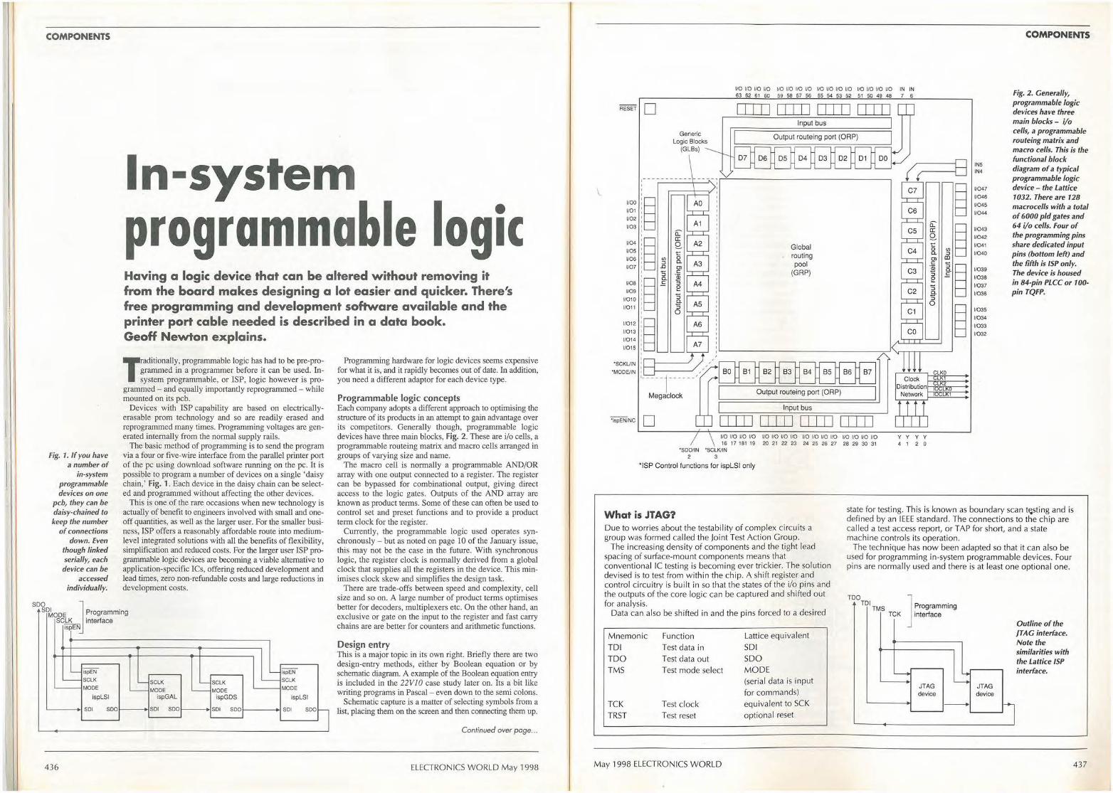
S00
COMPONENTS
Fig. 1. If you have a number of
in-system programmable devices on one
pcb, they can be daisy-chained to keep the number
of connections down. Even
though linked serially, each device can be
accessed individually.
In-system programmable logic Having a logic device that can be altered without removing it from the board makes designing a lot easier and quicker. There's free programming and development software available and the printer port cable needed is described in a data book. Geoff Newton explains.
Traditionally, programmable logic has had to be pre-programmed in a programmer before it can be used. Insystem programmable, or ISP, logic however is pro
grammed - and equally importantly reprogrammed - while mounted on its pcb.
Devices with ISP capability are based on electricallyerasable prom technology and so are readily erased and reprogrammed many times. Programming voltages are generated internally from the normal supply rails.
The basic method of programming is to send the program via a four or five-wire interface from the parallel printer port of the pc using download software running on the pc. It is possible to program a number of devices on a single 'daisy chain,' Fig. 1. Each device in the daisy chain can be selected and programmed without affecting the other devices.
This is one of the rare occasions when new technology is actually of benefit to engineers involved with small and oneoff quantities, as well as the larger user. For the smaller business, ISP offers a reasonably affordable route into mediumlevel integrated solutions with all the benefits of flexibility, simplification and reduced costs. For the larger user ISP programmable logic devices are becoming a viable alternative to application-specific !Cs, offering reduced development and lead times, zero non-refundable costs and large reductions in development costs.
Programming hardware for logic devices seems expensive for what it is, and it rapidly becomes out of date. In addition, you need a different adaptor for each device type.
Programmable logic concepts Each company adopts a different approach to optimising the structure of its products in an attempt to gain advantage over its competitors. Generally though, programmable logic devices have three main blocks, Fig. 2. These are i/o cells, a programmable routeing matrix and macro cells arranged in groups of varying size and name.
The macro cell is normally a programmable AND/OR array with one output connected to a register. The register can be bypassed for combinational output, giving direct access to the logic gates. Outputs of the AND array are known as product terms. Some of these can often be used to control set and preset functions and to provide a product term clock for the register.
Currently, the programmable logic used operates synchronously - but as noted on page lO of the January issue, this may not be the case in the future. With synchronous logic, the register clock is normally derived from a global clock that supplies all the registers in the device. This minimises clock skew and simplifies the design task.
SDI MODE
J Programming
There are trade-offs between speed and complexity, cell size and so on. A large number of product terms optimises better for decoders, multiplexers etc. On the other hand, an exclusive or gate on the input to the register and fast carry chains are are better for counters and arithmetic functions.
SCLK interface ispEN
- ispEN
~ SCLK - SCLK MODE - MODE
ispLSI ispGAL
SDI SDO SDI SDO
436
-~ SCLK -
- MODE -ispGDS
SDI SDO
ispEN
SCLK
MODE
ispLSI
SDI SDOl
Design entry This is a major topic in its own right. Briefly there are two design-entry methods, either by Boolean equation or by schematic diagram. A example of the Boolean equation entry is included in the 22VJO case study later on. Its a bit like writing programs in Pascal - even down to the semi colons.
Schematic capture is a matter of selecting symbols from a list, placing them on the screen and then connecting them up.
Continued over poge ...
ELECTRONICS WORLD May 1998
\
VO VO 110 l/0 VO l/0 1/0 110 VO 110 VO VO VO VO VO VO IN IN 63 62 61 60 59 58 57 56 55 54 53 52 51 50 49 48 7 6
RESET •
' r~ : !.·a .o~ 1107 B
I :5
voe •~ f V09
11010
11011
1/01 2
11013
1/01 4
1/015
·sCKUIN
•MODE/IN
~ !~~,/ ,u------~---/; •-----r -----'
Megaclock
·;spEN/NC •
I I I I I I I I I I I I I I I I I I I I Input bus
Output routeing port (OAP)
Input bus
I I I I I I I I I I I I I I I I I I I I 110 110 110 VO 1/0 110 110 1/0 1/0 110 VO 1/0 VO VO 1/0 VO 16 17 181 19 20 21 22 23 24 25 26 27 28 29 30 31
·sDonN ·scLKtlN 2 3
' ISP Control functions for ispLSI only
y y y y
4 1 2 0
INS IN4
1/047
11046
l/045
1/044
11043 V042
1/041
1/040
11039
1/038
11037
11036
11035
l/034
11033
V032
COMPONENTS
Fig. 2. Generally, programmable logic devices have three main blocks - i/o cells, a programmable routeing matrix and macro cells. This is the functional block diagram of a typical programmable logic device - the Lattice 1032. There are 128 macrocells with a total of 6000 pld gates and 64 i/o cells. Four of the programming pins share dedicated input pins (bottom left) and the fi fth is ISP only. The device is housed in 84-pin PLCC or 100-pin TQFP.
What is JTAG? Due to worries about the testabil ity of complex c ircuits a group was formed called the Joint Test Action Group.
state for testing. This is known as boundary scan ti;sting and is defined by an IEEE standard. The connections to the chip are called a test access report, or TAP for short, and a state machine controls its operation.
The increasing density of components and the tight lead spacing of surface-mount components means that conventional IC testing is becoming ever trickier. The solution devised is to test from within the chip. A shift register and control circuitry is built in so that the states of the i/o pins and the outputs of the core logic can be captured and shifted out for analysis.
Data can also be shifted in and the pins forced to a desired
Mnemonic Function Lattice equ ivalent
TOI Test data in SDI
TOO Test data out SDO TMS Test mode select MODE
(serial data is input for commands)
TCK Test clock equivalent to SCK
TRST Test reset optional reset
The technique has now been adapted so that it can also be used for programming in-system programmable devices. Four pins are normal ly used and there is at least one optional one.
TOO TOI
TMS TCK ]
--.
Programming interface
4
JTAG -device -
JTAG device
17
Outline of the }TAG interface. Note the similarities with the Lattice ISP interface.
May 1998 ELECTRONICS WORLD 437
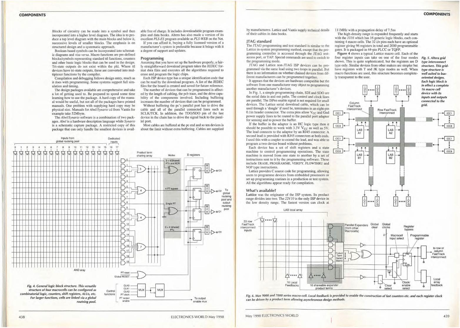
0
\,A
COMPONENTS
rv
2 3 4 5
"" ' \,A !\.A> V
6
Blocks of circuitry can be made into a symbol and then incorporated into a higher level diagram. The idea is to produce a top level diagram with the main blocks and below it, successive levels of smaller blocks. The emphasis is on structured design and a systematic approach.
Boolean-based symbols can be incorporated into schematic diagrams and visa versa. Macro functions are pre-defined blocks/symbols representing standard tll functions, counters and other basic logic blocks that can be used in the design. Tri-state outputs do not exist within the pld. Where ttl devices have tri-state outputs, these are converted into multiplexer functions by the compiler.
Compilation and debugging follows design entry, much as it does with programming. Some systems support full simulation and timing.
The design packages available are comprehensive and take a lot of getting used to. Be prepared to spend some time learning how to use the package. A hard copy of the manual would be useful, but not all of the packages have printed manuals. One problem with supplying hard copy may be physical size. Manuals for Abel/Synario cd from Yantis for example take 52Mbyte.
The Abe//Synario software is a combination of two packages. Abel is a hardware description language while Synario is a schematic capture package. A restricted copy of this package that can only handle the smallest devices is avail-
Inputs from global routeing pool
7 8 9 10 11
Dedicated
~ 12 13 14 15 16 17
able free of charge. It includes downloadable program examples and data books. Altera has also made a version of its excellent PLS-ES program available as PLS-WEB on the Net.
If you can afford it, buying a fully licensed version of a manufacturer's system is preferable because it brings with it a degree of support and updates.
Programming Assuming that you have set up the hardware properly, a fairly straightforward download program takes the JEDEC format data files and executes all the algorithms required to erase and program the logic chips.
Each ISP device type has a unique identification code that can be read by the download program. A list of the JED EC files for the board is created and saved for future reference.
The number of devices that can be programmed is affected by the length of cabling, the pcb trace, and the drive capability of the components involved. Including buffering increases the number of devices that can be programmed.
Without buffering the pc's parallel port has to drive the cable and all of the parallel connected lines such as SCLK/TCK. In addition, the TDO/SDO pin of the last device in the chain has to drive the signal back to the parallel port.
Most cables are buffered at the pc end and so ten devices is about the limit without extra buffering. Cables are supplied
l'v V rv v, l'v V V M v, rv v, \J Product term sha~ g array Modes D registers
~
0 I
D'-T I if 3
~ Q-.i. if
4 6 I
7
8
~ 0
4 ,_,_ ...
2
~
~ I
~ I 8 _j OJL-_
AND aray PT reset --
Global RESET
- -
3 + 4(Shared) PTsand XOR
I
4 PT bypass I
Single PT
I
3 + 4 (shared) I PTs
I
-
M u D Q X
~ [J ~ [J~
03
02 To global
routeing pool and output
routeing pool
01
00
Fig. 4. General logic block structure. This versatile CLKO -CLK1 -structure of four macrocells can be configured as Control MUX MUX rC CLK2 -
combinatorial logic, counters, shift registers, AL Us, etc. functions PT clock-
438
For larger funcltons, cells are lmked via a global routeing pool.
-- - -
ELECTRONICS WORLD May 1998
by manufacturers. Lattice and V antis supply technical details of their cables in data books.
JT AG standard The JTAG programming and test standard is similar to the Lattice in-system programming method, except that the programming controller is accessed through the JT AG testaccess port, or TAP. Special commands are used to switch to the programming mode.
JTAG and Lattice non-JTAG ISP devices can be programmed via the same lead using two loops in parallel. But there is no information on whether chained devices from different manufacturers can be programmed together. ' It appears that the devices are hardware compatible but the software from one manufacturer may object to programming another manufacturer's devices.
In Fig. I, a simple programming chain, SDI and SDO are the serial data in and out paths. The control and clock lines are parallel. The ISPen enable signal is not required for small devices. The Lattice serial download cable, which can be used through a 'dongle' if need be, terminates in an eight-pin O. lin header connector. The extra pins allow V cc and Gnd power supply lines to be routed to the parallel port adaptor for sensing and to power the buffer.
If the buffer in the adaptor is an HC logic type then it should be possible to work with 3.3V V cc as well as 5V. The lead connects to the adaptor by an RJ45 connector. A second lead is provided with RJ45 connectors at both ends. I used this with a coupler to extend the lead, and was able to program a two-device board without problems.
Each device has a set of shift registers and a state machine to control programming operations. The state machine is moved from one state to another by a set of instructions sent to it by the programming software. These include ERASE, PROGRAMME, VERIFY, FLOWTHRU and NOP type instructions.
Lattice provides C source code for programming, allowing users to programme devices from embedded processors or set up programming routines in a production or test system. All the algorithms appear ready for compilation.
What's available? Lattice was the originator of the ISP system. Its product range divides into two. The 22VJO is the only ISP device in the low density range. The fastest version can clock at
33row A •••• FastTrack
interconnect inputs
LAB local array
111MHz with a propagation delay of 7 .5ns The high-density range is expanded frequently and starts
with the JO I 6 which has 16 generic logic blocks, each containing 4 macro cells. The 32 i/o pins each have an optional register giving 96 registers in total and 2000 programmable gates. It is packaged in 44-pin PLCC or TQFP.
Figure 4 shows a typical Lattice macro cell. Each of the four register inputs can take on one of the four modes shown. This is quite sophisticated, but the registers are D type only. Similar devices from other makers are simpler but have registers with T and JK type modes as well. When macro functions are used, this structure becomes completely transparent to the user.
LAB A1
m .... ~ w ~ y m .... ~ w ~ y
Row F astT rack interconnect
-I-
LAB A2
COMPONENTS
Fig. 5 . Altera grid type interconnect structure. This gridtype structure is well suited to busoriented designs. Each logic block is in effect a complete 16 macro cell device with its inputs and outputs connected to the grid.
{ ~ ~-- : . ~
----- {' ,or I ~
m .... ~ w ~
LAB B2
m .... ~ w ~
Parallel Expanders Global Global {from other clear clocks Register
bypass Macrocells)
Macrocell \ Programmable input select register
~ ---1----1---+---
2
to row or column
FastTrack interconnect
16 Local Feedbacks 16 shareable expander
roduct terms
Lccal array
feedback
Fig. 6. Max 9000 and 7000 series macro-cell. Local feedback is provided to enable the construction of fast counters etc. and each register clock can be driven by a product term allowing asynchronous design methods.
May 1998 ELECTRONICS WORLD 439
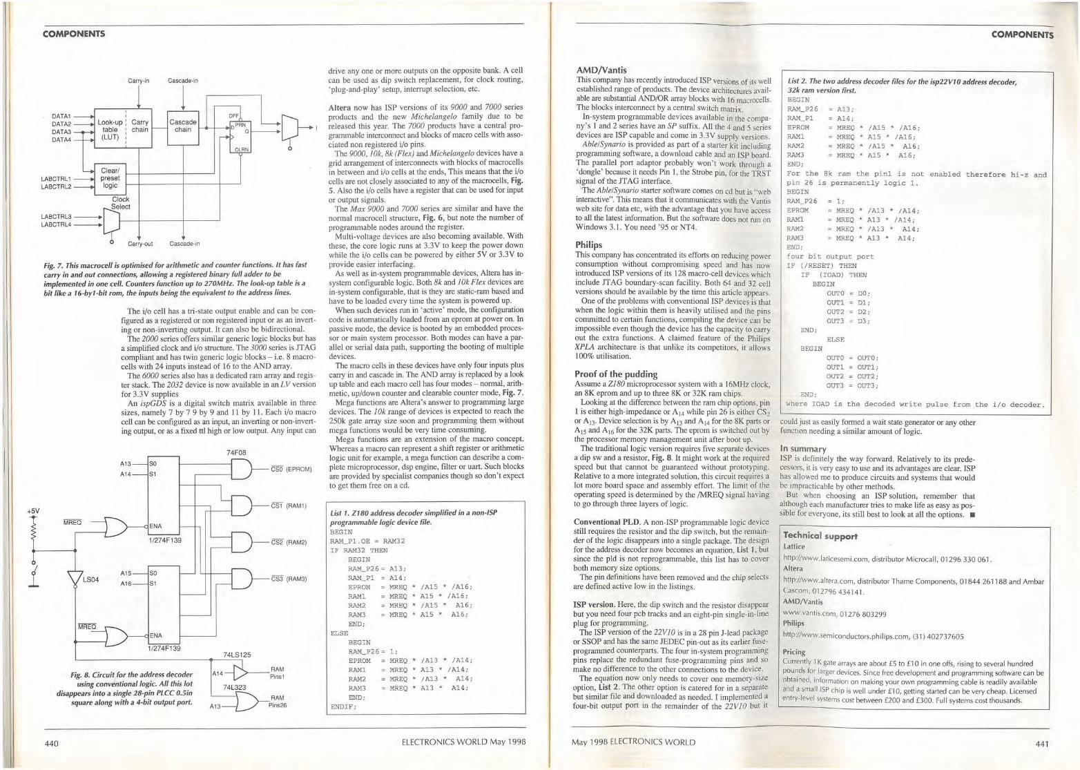
I
+5V
i
COMPONENTS
DATA1 DATA2 DATA3 DATA4
LABCTRL1 LABCTRL2
I I
Carry-in
Look-up : Carry table chain (LUT)
Clear/ preset logic
Cascade-in
l Cascade
chain 1-<1.....+-.i _11--1 CLRN ~
LABCTRL3-LABCTRL4-
Cascade-in
Fig. 7. This macrocell is optimised for arithmetic and counter functions. It has fast carry in and out connections, allowing a registered binary full adder to _be implemented in one cell. Counters function up to 270MHz. The look-up table is a
bit like a 16-by1 -bit rom, the inputs being the equivalent to the address lines.
LS04
The i/o cell has a tri-state output enable and can be configured as a registered or non registered input or as an inverting or non-inverting output. It can also be bidirectional.
The 2000 series offers simjJar generic logic blocks but has a simplified clock and i/o structure. The 3000 series is JT AG compliant and has twin generic logic blocks - i.e. 8 macrocells with 24 inputs instead of 16 to the AND array.
The 6000 series also has a dedicated ram array and register stack. The 2032 device is now available in an LV version for 3.3Y supplies
An ispGDS is a digital switch matrix available in three sizes, namely 7 by 7 9 by 9 and 11 by 11. Each i/o macro cell can be configured as an input, an inverting or non-inverting output, or as a fixed ttJ high or low output. Any input can
A13
A14
A15
A16
so S1
so S1
74F08
CSO (EPROM)
CS1 (RAM1)
CS2 (RAM2)
CS3 (RAM3)
74LS125
fig. 8. Circuit/or the address decoder using conventional logic. All this lot
disappears into a single 28-pin PLCC O.Sin square along with a 4-bit output port.
A14 >---RAM Pins1
74L323
440
drive any one or more outputs on the opposite bank. A cell can be used as dip switch replacement, for clock routing, 'plug-and-play' setup, interrupt selection, etc.
Altera now has ISP versions of its 9000 and 7000 series products and the new Michelangelo family due to be released this year. The 7000 products have a central programmable interconnect and blocks of macro cells with associated non registered i/o pins.
The 9000, JOk, 8k (Flex) and Michelangelo devices have a grid arrangement of interconnects with blocks of macrocells in between and i/o cells at the ends, This means that the i/o cells are not closely associated to any of the macrocells, Fig. 5. Also the i/o cells have a register that can be used for input or output signals.
The Max 9000 and 7000 series are similar and have the normal macrocell structure, Fig. 6, but note the number of programmable nodes around the register.
Multi-voltage devices are also becoming available. With these, the core logic runs at 3.3Y to keep the power down while the i/o cells can be powered by either SY or 3.3Y to provide easier interfacing.
As well as in-system programmable devices, Altera has insystem configurable logic. Both 8k and / Ok Flex devices are in-system configurable, that is they are static-ram based and have to be loaded every time the system is powered up.
When such devices run in 'active' mode, the configuration code is automatically loaded from an eprom at power on. In passive mode, the device is booted by an embedded processor or main system processor. Both modes can have a parallel or serial data path, supporting the booting of multiple devices.
The macro cells in these devices have only four inputs plus carry in and cascade in. The AND array is replaced by a look up table and each macro cell has four modes - normal, arithmetic, up/down counter and clearable counter mode, Fig. 7.
Mega functions are Altera's answer to programming large devices. The ]Ok range of devices is expected to reach the 250k gate arra.y size soon and programming them without mega functions would be very time consuming.
Mega functions are an extension of the macro concept. Whereas a macro can represent a shift register or arithmetic logic unit for example, a mega function can describe a complete microprocessor, dsp engine, filter or uart. Such blocks are provided by specialist companies though so don't expect to get them free on a ed.
List 1. Z180 address decoder simplified in a non-ISP programmable logic device file. BEGIN RAM_Pl . OE = RAM32 I F RAM32 THEN
BEGIN RAM_ P26 = A1 3; RAM_Pl A14 ; EPROM MREQ * / Al5 * /Al6; RAMl MREQ * Al 5 * / A1 6; RAM2 RAM3
END; ELSE
MREQ * / Al 5 * a= MREQ * Al 5 *
A16; A1 6;
BEGIN RAM_ P26 = 1;
EPROM RAMl
RAM2
RAM3 END;
ENDIF;
MREQ, * / Al3 * /A14; = MREQ * A13 * / Al4;
MREQ * / A13 * Al 4; = MREQ * A13 * Al 4;
ELECTRONICS WORLD May 1998
AMO/Yantis This company has recently introduced ISP versions of its well established range of products. The device architectures available are substantial AND/OR array blocks with 16 macrocells. The blocks interconnect by a central switch matrix.
In-system programmable devices available in the compa• ny's l and 2 series have an SP suffix. All the 4 and s series devices are ISP capable and come in 3.3V supply versions.
Able!Synario is provided as part of a staner kit including programming software, a download cable and an ISP board. The parallel port adaptor probably won't work through a 'dongle' because it needs Pin I, the Strobe pin, for the TRST signal of the JTAG interface.
The Able!Synario starter software comes on cd but is "web interactive". This means that it communicates with the Yantis web site for data etc, with the advantage that you have access 10 all the latest information. But the software does not run on Windows 3.1. You need '95 or NT4.
Philips Thls company has concentrated its efforts on reducing power consumption without compromising speed and has now introduced ISP versions of its 128 macro-cell devices which include JTAG boundary-scan facility. Both 64 and 32 cell versions should be available by the time this article appears.
One of the problems with conventional ISP devices is that when the logic within them is heavily utilised and the pins committed to cenain functions, compiling the device can be impossible even though the device has the capacity to carry out the extra functions. A claimed feature of the Philips XPLA architecture is that unlike its competitors, it allows 100% utilisation.
Proof of the pudding Assume a ZJ80 microprocessor system with a 16MHz clock, an 8K eprom and up to three 8K or 32K ram chips.
Looking at the difference between the ram chip options, pin l is either high-impedance or A14 while pin 26 is either CS2 or A ,3. Device selection is by A13 and A14 for the 8K parts or A1s and A16 for the 32K parts. The eprom is switched out by the processor memory management urut after boot up.
The traditional logic version requires five separate devices a dip sw and a resistor, Fig. 8. It might work at the required speed but that cannot be guaranteed without prototyping. Relative to a more integrated solution, this circuit requires a lot more board space and assembly effort. The limit of the operating speed is determined by the /MREQ signal having to go through three layers of logic.
Conventional PLD. A non-ISP programmable logic device still requires the resistor and the dip switch, but the remainder of the logic disappears into a single package. The design for the address decoder now becomes an equation, List 1, but since the pld is not reprogrammable, this List has to cover both memory size options.
The pin definitions have been removed and the chip selects are defined active low in the listings.
ISP version. Here, the dip switch and the resistor disappear but you need four pcb tracks and an eight-pin single-in-line plug for programming.
The ISP version of the 22VJO is in a 28 pin J-lead package or SSOP and has the same JEDBC pin-out as its earlier fuseprogrammed counterparts. The four in-system programming pins replace the redundant fuse-programming pins and so make no d.ifference to lhe other connections to the device.
The equation now only needs to cover one memory-size option, List 2. The other option is catered for in a separate but similar file and downloaded as needed. I implemented a four-bit output port in the remainder of the 22V JO but it
May 1998 ELECTRONICS WORLD
COMPONENTS
list 2. The two address decoder files for the isp22V10 address decoder, 32k ram version first. BEGIN · RAM_P26 Al3; RAM_Pl Al4; EPROM MREQ * /Al5 . / Al 6 ; RAMl MREQ * AlS * /Al6; RAM2 MREQ . /AlS * Al6 ; RAM3 MREQ . Al5 . Al 6 ; END; For t he Bk ram the p i n l i s n o t enabled therefor e hi- z a nd pin 26 is permane ntly l ogic 1 . BEGIN RAM_P26 1 ; EPROM MREQ * / A13 RAMl MREQ * A13 RAM2 MREQ * /A13 RAM3 MREQ * Al 3 END; four bit output port IF (/RESET) THEN
I F (IOAD) BEGIN
OUT0 OUTl OUT2 OUT3
END; ELSE
BEGIN OUT0 OUTl OUT2 OUT3
END;
THEN
DO ; D1; D2; D3;
OUT0; OUTl; OUT2 ; OUT3 ;
* / Al4 ; * /A14 ;
* Al4 ;
* Al 4 ;
where IOAD is t h e decoded wri t e pu lse f r om t he i / o decoder .
could just as easily formed a wait state generator or any other function needing a similar amount of logic.
In summary ISP is definitely the way forward. Relatively to its predecessors, it is very easy to use and its advantages are clear. ISP has allowed me to produce circuits and systems that would be impracticable by other methods.
Bu1 when choosing an ISP solution; remember that although each manufacturer tries to make life as easy as possible for everyone, its still best to look at all the options. •
Technical support lattice
http://www.laticesemi.com, distributor Microcall, 01296 330 061. Altera
http://www.altera.com, distributor Thame Components, 01844 261188 and Ambar Cascom, 012796 434141 . AMD/Vantis
www.vantis.com, 01276 803299 Philips
http//www.semiconductors.philips.com, (31) 402737605
Pricing Currently 1 K gate arrays are about £5 to £1 O in one offs, rising to several hundred pounds for larger devices. Since free development and programming software can be obtained, information on making your own programming cable is readily available and a small ISP chip is well under £1 o, getting started can be very cheap. Licensed entry-level systems cost between £200 and £300. Full systems cost thousands.
441
E LE CTR ON ICSAPPOINTMENTS Electronics World May 1998 Tel: 01816523620
Apple Recruitme11t - The Taste of Success
We currently have many vacancies on our books for RF, Microwave and Antenna Design, Development and Test Engineers. Below is a selection of
some positions we have on our records:
RF Engineers Herts £23-40k Our client has positions at all levels for engineers with 2.1/1 st class honours degrees with a good background in developing transmitters, receivers,filters, I.NAs and amplifiers.
Hants £25-36k Our client is looking for several RF engineers with good degrees and several years experience developing mobile telecommunications systems. Knowledge of CSM would be an advantage.
Berks £24-36k Applicants are sought from RF design engineers with a good degree and practical post-grad experience covering some of the following areas - RF to 2GHz, LNA design, PLLs, GSM, Filters, power amps, VCOs or EMC.
Rants £25-36k Our client is looking for several RF engineers with good degrees and several years experience developing mobile telecommunications systems. Knowledge of GSM would be an advantage.
Kent £28-32k Our client is looking to recruit degree qualified RF/Microwave engineers with good post-graduate experience of I.NAs, filters, diversity systems and measurement techniques.
Beds £26-34k A designer of cellular radio products is looking for experienced RF engineers to design receivers up to 2GHz. Familiarity with digital modulation and DSP would be beneficial.
Cambs £28-35k Engineers are sought with good degrees and several years post-graduate experience in developing RF circuits and systems. Some of the following skills are needed - GSM, PCN, DECT, wireless I.AN, antennas, superhet receivers, oscillators, synthesisers, amplifiers or EMC.
Antenna Engineers Surrey £23-35k Applicants should have two years experience in antenna design, ideally at l-3GHz. They should have knowledge of antenna manufacturing and testing techniques as well as the design of monopole, dipole, helical and planar antennas.
Essex £26-34k Our client is looking for qualified engineers with 2 or more years experience in antenna theory and design. You should know antenna arrays as well as near/far field measurements. Knowledge of Radar systems would be a benefit.
London £26-36k Our client, a major developer of mobile communications equipment, is looking to recruit a Senior Research Engineer in the field of Antennae and Propagation. You should have a good academic record in a relevant field.
Microwave Engineers Sussex £22-34k A major developer of radar systems is looking for experienced engineers to develop circuits and sub-systems up to 40GHz. Knowledge of antennas would be beneficial.
Hants £25-38k Our client is seeking qualified engineers to carry out circuit design and testing with MIC and Galls MMIC circuits (e.g. low noise amplifiers, phase and gain control units, oscillators and power amps) with operating frequencies from 0.5 to 100GHz.
Scotland £27-35k We are looking for several microwave design engineers with skills in oscillator design, amplifiers, filters and mixer design. Knowledge of HP EEsof design and layout packages would be of help.
Devon £22-34k A major developer of radar systems is looking for experienced engineers to develop circuits and sub-systems up to 40GHz. Knowledge of antennas would be beneficial.
Sussex £22-34k A major developer of radar systems is looking for experienced engineers to develop circuits and sub-systems up to 40GHz. Knowledge of antennas would be beneficial.
RF Test Engineers Surrey £16-21k We have several positions for Test Engineers with I year + experience testing RF systems and circuits using spectrum analysers, oscilloscopes and other test equipment
Hants £17-19k Applicants with experience of testing RF systems and circuits down to component level are sought by our clients.
Northan ts £16-20k With an HNC and 2 years experience oftesing RF/Microwave products up to 2GHz, you may just be the individual our client is looking for.
lst/2.1 Degree or Ph.D Nationwide £Attractive Many of our clients are looking for both fresh and experienced graduates/post graduates for positions in RF/ Analogue/Microwave design and development.
titpp1e Recruitment 3 Branksome Way, New Malden, Surrey KT3 3AX
Tel: 01815490100 Fax: 0181 549 9771 email: [email protected]
Web:http://applerec.u-11et.com/
\.
ELECTRONICSAPPOINTMENTS Electronics World May 1998 Tel: O 181 652 3620
I I I I I
__ Ir_____ ,fj
ANYWHERE THROUGHOUT .
BROA· CASTING TELECOM MS,
· ~ON THE LEADING EDGE.
NTL is the leading network service provider for blue chip companies in broadcasting, telecommunications and emergency services. Our expertise spans total capability in voice, video and data co mmunication. We have an outstanding track record in planning, b~ding and operating highly reliable, mission cnlical broadcast and mobile communications networks and, as a leading innovator in digital systems, we are set to play an even greater role. Our growth means we now need like-minded Engineers to join us;
SPECTRUM PLANNING ENGINEER You'll.be part of a group responsible for frequency planrung and propagation s tudies for future broadcasting and mobile radiocommunications systems. The group is making major contributions in many areas including the planning of Digital Terrestrial Television in the UK This is a key role offering a wide range of opportunities in leading edge technologies.
ANTENNA SYSTEMS ENGINEER Under the general direction of the Team Leader or Project Manager, you'U provide specialist support through the design, specification, procurement and commissioning of broadcast and communications antenna systems. With a degree or equjvalent in an engineering discipline affiliated to broadcasting, communications or electronics,. you must have several years; experience of the design, procurement and installation of broadcast and/ or communications antenna;s. Knowledge of the principles of Digital Terrestrial Television and Radio Systems is desirable. You must have the fitness and agility to work on tall structures, a dean driving licence and willingness to travel in the UK and abroad. Ref No 98/cc/034 Applications from graduates in a related field may also be considered. for a Trainee position within the Group.
• .N-j-~ Of graduate calibre, you must have an evident interest in radio propagation and a strong amb ition to develop your career in_ radio .coverage and frequency planning. Good computing skills are essential, with experience of pro~amming in C or s imilar high level languages desirable. You should also have a current driving licence and be willing to travel overseas.
Ref No: 98/cc/035
In addition to highly attractive salaries, you will enjoy a wide range of benefits including an excellent pension scheme and private health care provision. Our company is exceptional, so a.re our people, and career prospects are, naturally, likewise. Please send your full cv including current salary expectations to our consultants: TMP Worldwide, 32 Aybrook Street, London WlM 3JL quoting the appropriate reference number. Closing date: 27th March 1998.
SALES ENGINEER DataKinetics Ltd Is a rapidly-growing independent UK telec mmunications company with a global cust0mer base which includes P: Ts and major mult1-nat1onal equipment manufacturers.
We specialise in telecomrn lcac1ons protocols and 1n part1c lar, Dal Kinetics Is a world leader in access products for signa h11g Sr•em No. 7. These products have applications in the rapidly growing markets of Mobile and Int II gem Networks.
We are located In Fording rtdgt. Hampshire, on the outskirts o he Ne~ Forest. An attracave town, Fordingbndge Is a short stance from the south coast and the 1t1es of Salisbury, Bournemouth and Southampt0n all of wh c have good rail links to and from London.
Sales Engineer A challenglng r..w sale role has oeen created to help bulld on 0ur world-wide customer base and continue to exceed targ ed bus· 'less levels.This 1s a key position within the organisation and requires someone who 1s self•rn vated and responsible with a good knowledge of the telecommunications market and a technlca n1ng Given the international nature o the bus ness, language skills would be particular Y welcom pecia ly Spanish.
To apply for this posit 0 • or to flnd out more information. pleas concac c our retained consultant, Phil Atkinson al!·
Jones Resourcin1, T e Coa<.h House, Boxwen Road, Berichatn ed, Herts HP4 I AA Tel:01441870770 Fax:01-442 879779.
For further
information
on Recruitment
advertising
call:
0181 652 3620
May 1998 ELECTRONICS WORLD 443
ELECTRONICSAPPOINTMENTS Electronics World Moy 1998 Tel: 01816523620
4 TO CREATE JOBS ANO WE A LTH FOR THE PEOPLE OF SCOTLANOI IIS•, 1111fl'IPPSP• PS1'rftll'IPSf1•1,m•1E11 .
~~ ~
Scottish Enterprise
Senior Executive Semiconductor Design - fuward fuvesttnent
Central Scotland £22k - £36k Fixed Tenn: 3 years Locate in Scotland (LiS) markets Scotland as a location for inward in".es~ent. We do this by giving expert advice and assistance to potential investors_ and by negonaong and delivenng investment packages tailored to their needs. With Scotnsh Enterpns_e, Cad~nce Design Systems Inc. and four of Scotland's top universities, we are embarking on an mnovanve and challengmg project - Project Alba.
Desig,is on Scotland's
The project involves establishing the worlds first System Leve_l Integration design complex. It will create a unique environment which will enable comparues to undertake world lead1~g "system-on-chip " design with access to the right skills, design tools, methods and supporting infrastructure.
As Senior Executive, you'U work as part of the Project Alba team_to develop and secure further design based inward investment. Liaising closely with the twelve mter~anonal offices of . Locate in Scotland across North America, Europe and Asia, you'll proJeCt manage the Scomsh end of sales activities, designed to attract invesn:nent from global eleccronies and consumer product companies. This wiU involve using your well developed :'31es skills to gen~te interest in Scotland and then to conver t that interest to investment deos1ons. Considerable mteracnon with partner bodies is vital as you identify and dear!>'. quantify Scotla_nd's benefits in this highly competitive international arena. Involvement m the consrrucnon and negonanon o f development packages is a further snmulating aspect of your bnef.
Future Your graduate level intellect and sales or marketing background in semiconductors, electronics, or product design will have developed your wealth of prOJCCt management expenence. As such,
ou'll be familiar with the market and deadline pressures of design management A global ~utlook, demonstrated by an appreciation of the needs of foreign investors, will be supported by your first-class interpersonal skills.
Please write with your CV to Robert McDade, HR G roup, Scottish Enterprise, 120 Bmhwell Street, Glasgow G2 7J P. Closing date: Friday 20th M arch 1998. Altemanvely please apply on- line v,a http://www.monster.co.uk •~
Scottish Enttrprise is crnnmitted m athiroing tqual qpportunities. (~ it Working together to make Scotland a better place to live and work
(_) LOCATE IN SCOTLAND • nu. SCOTTISH OfrtCL
LEADERS IN PRESENCE DETECTING LIGHTING CONTROLS ROXBURGH F.\/(' Dt~ Due lo continui'ng growth. we require an additional
ELECTRONICS ENGINEER
The ideal candidate will be highly motivated and capable of original thought. A strong sense of responsibility is essential as the successful applicant will be required to take on product ownership from initial concept, through design and development, to production and customer support.
A member of the DELTRON ELECTRONICS GROUP
Roxburgh EMC is p~rt o f Dcllron Electronics Pie ,1nd is a major ma_nufacrurer ~>f RFIIEMC suppress ion componen ts operating from a custom bui lt factory 1n Scunthorpe. The design engineering sect ion is looking for an EMC Engineer to work within the filter design ream on an expanding range of customers requirements. The deal candidate would have experience in EMC fi lter design and practice, some knowledge of linear circuitry, abi li ty to work in Aut'?Cad or FastCad_ is preferable and a working knowledge of inverters and sw1tch1ng power supplies princip les would be useful.
Applicants must be able to demonstrate a thorough understanding of both analogue and digital electronics including assembler level embedded software.
Apply in writing, stating cu"ent and target salary to: The Managing Director, Ex-Or Limited
Haydock Lane, Haydock, Merseyiside WAil 9UJ
Spc..·<." tru m Ek<.:tronic rcn11i1m cnt l rnn: 1hc lt,llm\'ing ,·;Kc11H·ics 1(11' d iem~ wi1 l1 .-ipprox. XO 4..•111 p lc1p .. ·l·~.
SOFTWARE ENG. SURREY/LONDON/BERKS + OTHER LOCATIONS C+ + Emht·d<k tl .-.,·~1c111s Ritimt· d ata an1u<L 001) \ ' \ \\'orks S~s lksi~n. \Camion Eu .. . SOFTWARE ENG: SURR.EY/MIDDX/HANTS + OTHER LOCATIONS lksi1r11 ol Codl' & 'll-.,1 Soli\, a1l· l"\ "I \ C+ + ~IOTI F (:l b .
H~~WARE ENGS. HANTS/SURREY/BERKS/SUSSEX/MIDOX/HANTS/OTHER \ 'arious d ic..·nts rc111111"t· .\ ~.\, 1)1(: l)c:si~n E11J.,r:,. wi1h <·xpt:l'it·11n· o f" FP( :.\ .-.. Pl.It ... l)SI~ \ 'H ()I .. ( :, lhL'iil'. Pasc:al ( :.\(). ·1itki11J{ <k ~ig11~ from initi;.11 (onn.·p1 thrnu,;h dn dop11u:111 111 1m1clur11011.
TEST/REPAIR & FIELD SERVICE. ALL AREAS C:ood all rou11ct ·u.,~1.1Rc;pair1Calilmuion ~:11,g:-.. l11•l1011S<.· and worl<l•,,iclc ll'tln·I iut'.
T h<'!lt: an · .1 kw ,iu-,rnrit•,; 1hm ;.i.n.- \l l'g'C.:llL
444
Please call for further details and other d isciplines currently on fite: Mike Messina on 01932 221501, Fax: 01932 269100. Eve/Wk Ends 01932 242810
CV to Speclrum 37A The Cenlre, Wahon, Surrey KTl 2 IQY.
If you meet the above requirements, please w rite with full details and CV to: Mrs Celia Brown, Roxburgh Electronics Ltd, Roxburgh Ho use, Foxhill s Industrial Park, SCUNTHORPE, ON15 8QJ. Roxburgh Electronics Limited is an equal opportunities employer.
BARRIE PORTMAN RECRUITMENT LTD THE LISTENING AGENCY
TECHNICAL/ENGINEERING - LT. V C++/MS APPS (contract) - Hanis
Analogue/Dig Design/Comm perm - Surrey RF Design Contract/Perm - Hants
If you ar serious about advancing your career or need a new contract send your CV/contacl me on:
01703 276009 TEL/FAX day / evening/ weekend email [email protected]
ELECTRONICS WORLD May 1998
ELECTRONICSAPPOINTMENTS Electronics World Moy 1998
SALES & MARKETING Technical Marketing Specialist - Embedded Software to £50k package Our client Is a market leader in lhe supply of Real-Time Operating Systems on an intematlonal basis. An opportunity exiSts for a marketing specialist to take full responsibility f0< the formulation and lmplementatlon of produc t plans and marketing packages within the automotive sector. This is a senior role and you will need at least three yeats in an embedded software environment probably Jn a software development or technteal marketing r~ e. Automotive experience will be of particular interest. Extensive Eu,opear\/US travel will be required. Based Wills. Fleld Sales Engineer - Consumabres to £30k package Thls leading supplier of consumable products to the electronic manufacturing lnduslry wishes to appoint an FSE to develop sales In the SW of England. You will need a technical sales backgro und and an appreciation o f electronic assembly/ manufacruring processes. Consumables experience would certrunty be an advantage, Based M4 Corridor. European Product Specialist - Embedded Software Design & Test £30k Our c~ent is lhe marker leader in ha.rdware•assisted embedded software design, debug and tesl sofutions. This role Is to provide technfeal sales support and' training to UK and overseas customers and distributors. Some European travel will therefore be required. You will probably be working in a suppcrt role for a com ponent manufacturer or dlsl nbutor with some experience in writing and testing embedded CIC+-+ and assembler code. Based Bucks. Field Sales Engineer - Power Supplies £28k pack age Our clleot, a supplier of bespoke power suppty systems, is currentty experiencing strong growth and wishes to appoint an additional sales e><ecutive to develop business with both specifiers and end user customers. This is an excenent opportunity for an experienced sales executive with either a power supply or electrical background to Join a sman, but highly focused team. Alternatively, this position might suit a field engineer with a desire to move into a commercial role. Flexible Midlands/Southern location. Product Marketing Manager - Semiconductors c £25k Our client kS a rapidly growing high technology semiconductor distributor. Continued expansion has cre:at.~ opportunities for ~o additional product marketing managers to take total respons1bil1ty tor a range of semIconduct°' products from price and inventory manasement through to promotional actn,ity and maintaining close links with US based sup~lers. You will need a sound electronics engineering background a degree or HND and strong Interpersonal and communications skills. Based Hants. Field Applications Engln- - EMC Fitters W k+ The UK's leading supplier of power products is looking to appoint a technical specialist to work c losely with lhe sales team and with customers to support and d-op the sales of EMC/thermal producls. You will idealry be Qualified to HNC level in ektctronics with EMC experience gained In a sales or technical support role. ln return our-client Is offering an excellent package, including good basic. commission, ful'f expensed car/ phone, private heaithcare and re-location where approp<iate. Based Berks. Sales Office Manager - Components £25k Do you have Internal sales experience gained with either a distributor or manufacturer of eleclrooic components? Do you have a reasonable command of French? If s.o our clien1, a well respected manufacturer of etectronic components tor the communications fnclustry would be very interested to talk to you. Takrng responsibility for a smaJI team, the successful candidate will manage all aspects of this busy international sales department. Based Essex.
-
1'11< these and many more outstanding sale$ and martetlng f1111)0111lnltfes pie ... phone or send a copy ol your CV with current salary ,,.,,,,,. to Jeremy Boardman at
Parlcway Sean:11 & Selectlon, 22 Parttway, Welwyn Garden City, Herts A1.8 6116 Tel: 01707 395200 Fu: 01707 395201 E-mail Partwaytll(Oaol.com
, earkway Seafflh & Selootlon
DESIGNS THAT SNI\IDONfQle
SAVE LIVES
Shandon Scientific Ltd. Is a leader In the design and
manufact ure of Instruments for pathology laboratories,
developing products for healthcare professionals
world-wide.
we now have an opportunity for a keen and professional
Electronics Engineer to Join our team In Cheshire.
our Instruments are designed using microprocessors to
control a wide variety of mechanisms and devices. As a
key member of a small team, you wlll have the skills and
the opportunity to work across this technology range.
If you are looking for varied and challenging work In
an ambitious and successful companv, please send your
CV to:
Elalne Ellls-seabrldge, Human Resources Officer Chadwick Road, Astmoor lndustrlal Estate
Runcorn WA7 1PR E•mall: [email protected]
http:/ twww.shandon.com
May 1998 ELECTRO NICS WORLD
Tel: 0 1816523620
EMBEDDED SYSTEMS ENGINEER
EAST MIDLANDS EXCELLENT PACKAGE
KROHNE are manufacturers of advanced process measurement instrumentation. We seek a degree qualified engineer with 2-3 years' experience in embedded systems, both C/C++ software and digital/ analogue hardware.
Please send your Curriculum Vitae to:
Mrs Julie Meehan, Krohne Ltd Rutherford Drive, Park Farm Industrial Estate
Wellingborough, Northants NN8 6AE
TEST, REPAIR AND ASSEMBLY All Levels All Areas
Many of you will probably know my name, but not the company's. As a new organisation specialising in the Recruitment of Electronic Productjon Staff. I urgently need candidates for a wide range of opportunities at companies both large and small throughout the UK.
So if you are just starting to look, or have been looking for some while, you owe it to yourself to see the difference that ac tive marketing can make.
Don't just end up on.another mailing list!
Contact Tony Linehan Excalibur Recruitment
6A Pury Hill, Alderton Road, Towcaster, Northants NN12 7LS Tel: Daytime 01327 811146 or Eves: 01442 212495.
Fax: 01327 811070 Email: [email protected]
EMBEDDED SYSTEM DESIGNERS We are a medium-size progressive company specialising in electronic assiscive technology for disabled, elderly and hearing-impaired people. We require a software/hardware design engineer to take projects through from concept to production.
You should have at least cwo years' experience and a good working knowledge of analogue/digital electronics, microprocessor-based design and assembly language programming. Experience of any of 28, Z80, 8051, C++, Windows MFC, Microsoft Access, EMC and 1S09001 quality systems would be an advantage.
Contact Joyce Thomas on: 01296 481591 or alternatively write with your CV stating current salary to:
Possum Controls Limited, Unit 8 Farrnbrough Close Aylesbury Vale Industrial Park, Stocklake
Aylesbury, Bucks HP20 lDQ.
N o agencies
445
CLASSIFIED Tel: 0181 652 3620
ARTICLES FOR SALE
B/W 32mm lens or pinhole
I £39+vAT (5+ £35 each) I B/W 42mm with audio lens or
I pinhole £45+vAT (5+ £39 each) I Colour 42mm twin board with audio and lens £ 115 +v
l~EnRY'S 40-1 [dgw.irc Rd. London . \'12 1EO Tel: 0111 124 0323 Fdl: 0111 724 0322 01dcrs tinllrnc 0600 7316979 C'nl(lll S.'ll('<;.•I• h('rHy$ dt'lllOII CO.Uk
\'✓('b t111p -11www.henrys co uk Oll1t•.tl u1dc1s b11t11 .. ~11,1 st~tu~1 .S 1110)1 r. rt"t ,1 c~•tls ~r,~e111ci1
POWER SUPPLY DESIGN
Switched Mode PSU
Power Factor Correction
Linear PSU
Lomond Electronic Services Tel/Fax: 01243 842520
RF & Data/Comms Test Equipment (Ex Govt).
• HP. Tek1ronlx, Phillps, Gould. etc.
• Scopes (20MHz-20GHz DSO), Analysers, Sig Generators, and other
Items, Manuals, As New.
Cash Otters Invited for ll.llfillil.Sole
For Full Delo/ls call Victor on:
Tel: 01119 626866 Mobile: 0802.1$-&155
AUDIO & RF DESIGN · DC to 3GHz • Stereo Coder5 & proce55ors • RF Amplifier5 & Tran5mitter5 • Wireles5 Control Sy5tem5 • 2.4 GHz Audio & Videollnk5 • Aerilll com~ining Sy5tem5
So whlltever your need cllll us!
l1si.2a solutions Tel. 0181 ·428 2776
mnoanitglot,.alnet-.co.uk
RF DESIGN SERVICES
All aspects of RF hardware
development considered
from concept to production.
!WATERBEACH ELECTRONICS!
TEL: 01223 862550 FAX: 01223 440853
SPECTRUM ANALYSER- 100kHz-1800MHz, Tektronix 7Ll2 Plug-in, £675. May have spare mainframe. Marconi Tf2008 SlG Gen/Sweeper I0kHz-520MHz, £150. Telonic 2003 Modular Sweep Generator 100kHz-130MHz, £125. As above, but IMHz-1300MHz, £160. Tektronix 611 X· Y Storage Display with Write Through, new, £70. M=oni TF2700 Portable LCR Bridge, £75. TF270I Precision Inductor Analyser with r~:~i9 High Current Adaptor, £85. Tel: (01344)
MJCROCHIP - "PICMASTER", Emulator. lcelab 8031/5 I Emulator. Benchtop Vapour Piulse Soldering Machine. Offers. 01395 232658.
AIRCRAFT Rotary Conveners, 28 V 8000rpm 115V lph 1600Hz 360W. Integral regulator. £10. 28V 8000rpm, 115 V I ph 400Hz 770W. External regulator required. £20. Tel Bristol 0117 979 3883.
HP7000A - X/Yff Plotter £20. HP5245L 3GHZ £40. Resolver Synchro Angle IndiC'1tor £50. Clare A20JB Flash Tester £40. RS 555279 £35. 01476 550826.
PLEASE MENTION ELECTR'ONICS WORLD
WHEN REPLYING TO ADVERTISEMENTS
ARTICLES WANTED WANTED - Old cipher equipment and "spy radio sets". 0Z8RO Rag Onerstad, Hostertcobvej IO DK-3460 Birkcrod, Denmartc. Fax: ++45 44681514.
446
WANTED- W.W.11. Gennan and S.O.E. clandestine sets, receivers. Also incomplete sets. 0Z8RO
:i,ler~!,'~~~arti!~er~~;°i,6k ~ 5 l~K-3460
Fax 0181 652 8938
Most types considered but especially KT88, PX4/PX25, KT66, KT77, El34, EL37, ECC83. Valves must be UK manufacture to
achieve top prices. Also various valve-era equipment e.g. Garrard 301.
COURTEOUS, PROFESSIONAL SERVICE Ask for a free copy of our wanted List.
BILLINGTON EXPORT LTD., Billingshurst, Sussex RH14 9EZ Tel: 01403 784961 Fax: 01403 783519
VISITORS PLEASE PHONE FOR APPOINTMENT.
ADVERTISERS PLEASE NOTE
For all your future enquiries on advertising
rates Please contact
Joannah Cox on
Tel: 0181-652 3620 Fax: 0181-652 8956
TOP PRICES PAID For all your valves, tubes, semi
conductors ahd IC's.
Langrex Supplies Limited 1 Mayo Road, Croyd.on
Surrey CRO 2QP TEL: 0181-6841166 FAX: 0181-684 3056
**WANTED** Test equipment, Electronic Scrap, Valves, Transmitters/Receivers, Factory & Warehouse Clearance.
Confidentiality Assured.
TELFORD ELECTRONICS Phone: 01952 605451
Fax: 01952 677978
CAPACITORS Large volume availability of capacitors direct from manufacturer in pitch sizes 5, 1 .5 & 10. voe 63. , oo, 250, 400 & 630.
µF 0.00 - µF 0.68
For further derails please contact:
PALA CAPACITORS Tel: 01483 565090 Fax: 01483 566050
WANTED - "SPY RADIO SETS", Cipher Gear, W.W.2 German Sets. W.H.Y.? OZ8RO RAS Onerstad, Hostertcobu I 0, DK-3460 Birtcerod, Denmark. Tel: +45-4281 5205 evenings.
WANTED: PRE-WAR TV. Offered: Network Analyser HP8505A. Jae Janssen, Hogcham l 17D, NL-5104JD Dongen Netherlands. Fax: +3113 4624684. Thanks
ELECTRONICS WORLD May 1998
-SUPPLIER OF QUALITY USED TEST INSTRUMENTS
.CONTACT Cooke International Unit Four, Fordingbridge Site, Barnham,
Bognar Regis, West Sussex, PO22 OHO, U.K. Tel: (+44)01243 545111/2 Fax: (+44)01243 542457
Web: http://www.cooke-int.com E-mail: [email protected]
CIRCLE NO. 132 ON REl'LY CARD
-~ af
ook• 'lnternatron C _.o.,n1t\l,w,1n ,o11c0
"'C1.oot1~":..:~.~:.t"' ... ~--..,.., ... ,.,~~~:.!"'::.; t,11o11 -,.oo
•. ,,...-•
CONTACT Cooke International Unit Four, Fordingbridge Site, Barnham,
Bognar Regis, West Sussex, PO22 0HD, U.K. Tel: (+44)01243 545111/2 Fax: (+44)01243 542457
Web: http://www.cooke-int.com E-mail: info@cooke-int .com
CIRCLE NO. 111 ON REl'L Y CAR/J
ADVERTISERS' INDEX ADEPT SCIENTIFIC ................. .. .407 NUMBER ONE SYSTEMS ........... . ... 422 ANCHOR ............................ 378
OLSON ELECTRONICS ... . ......... . ... 362 B. BAMBER ELECTRONICS .. , ..... , .... 428
CMS ........................ ... • .... , .399 CROWNHILL ......................... 367
PICO ...... . . ........... ... .......... 369 PS CONSULTANTS . ....... ... . ........ IFC
DATAMAN ............................ 381 OUICKROUTE ........................ 398
DISPLAY ELECTRONICS .............. .435 RADIO TECH ......................... 399
EQUINOX TECHNOLOGY ............... IBC SEETRAX ........ . ................... 396
FIELD ELECTRIC ..................... .428 SPEAKE & CO LTD ................... .412 STEWART OF READING ............... .412
HART ELECTRONICS ... , ... . ......... .430 SURREY ELECTRONICS ............... 399
JOHNS RADIO ....................... .429 JPG ELECTRONICS .................. .412
TELFORD ELECTRONICS . . ............. 340 TELNET ......... ........... .. ..... .. 383
LABCENTER ELECTRONICS ........... OBC TIE PIE ......... . ....... ........... . . 365
M&BRADIO ........................ .415 WARTH .............................. 369 MILFORD INSTRUMENTS .... ... . .... ... 367 WEIR ....... . ... , ............ ........ 375
May 1998 ELECTRONICS WORLD 447
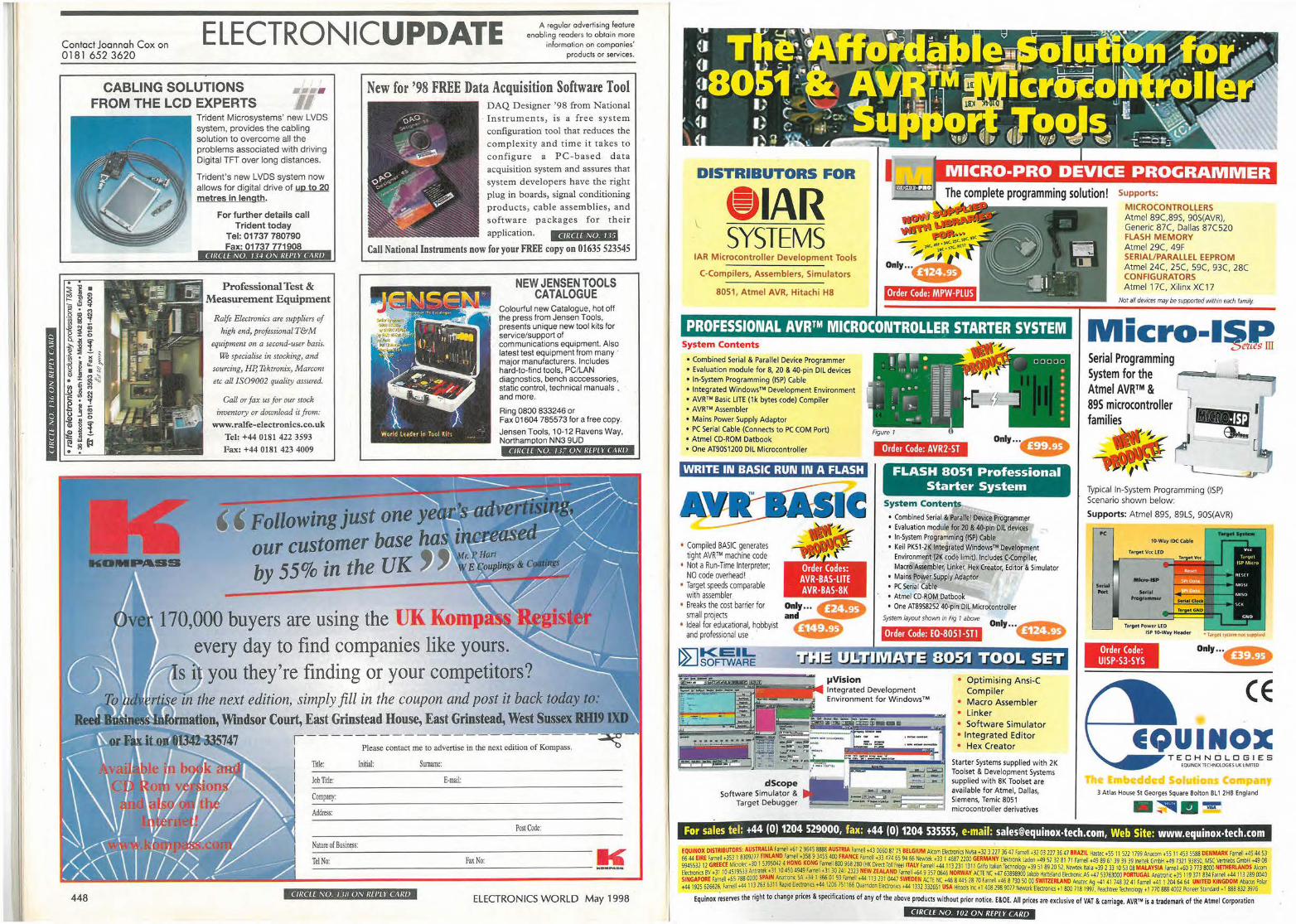
Contact Joonnoh Cox on 0181 652 3620
ELECTRONICUPDATE A regular advertising feature enabling readers to obtain more
information on companies' products or services.
448
CABLING SOLUTIONS •••• New for '98 FREE Data Acquisition Software Tool FROM THE LCD EXPERTS DAQ Designer '98 from N ational
Instrum ents, is a free system configuration tool that reduces the
complexity an d t ime it takes to configure a P C-based data acquisition system and assures that system developers have the right plug in boards, signal conditioning
produ cts, cable assemblies, and software packages for the ir
KOIIIPJ&II&
Trident Microsystems' new LVDS system, provides the cabling solut ion to overcome all the problems associated with driving Digital TFT over long distances.
Trident's new LVDS system now allows for digital drive of YQ..!Q.2Q metres in length.
For further details call Trident today
Tel: 01737 780790 Fax: 01737 771908
CIRCLE NO. 13-1 UN R[l'L Y CA/UJ
application. @iftilWl@iff Call National Instruments now for your FREE copy on 01635 523545
Professional Test & Measurement Equipment
Ra/fe Eleccronics are suppliers of high end, professional T&M
equipment on a second-user basis. \% specialise in stocking, and
sourcing, HP, Tektronix, Marconi etc a/I [SO9002 quality assured.
Call or fax us for our stock inventory or download it from:
www.ralfe-electronics.co.uk Tel: +44 0181 422 3593 Fax: +44 0181 423 4009
Following just one ye our customer base ha by 55% in the UK
NEW JENSEN TOOLS CATALOGUE
Colourful new Catalogue, hot off the press from Jensen Tools, presents unique new tool kits for service/support of communications equipment. Also latest test equipment from many ' major manufacturers. Includes hard-to-find tools, PC/LAN diagnostics, bench acccessories, static control, technical manuals . and more.
Ring 0800 833246 or Fax 01604 785573 for a free copy.
Jensen Tools, 10-12 Ravens Way, Northamoton NN3 gUD
CIRCLf NU 117 UN R£/'L Y Ct\RIJ
170,000 buyers are using the UK Komp every day to find companies like yours.
you they're finding or your competitors?
! ______ ______________ _..._, __ I Please contact me to advertise in the next edition of Kompass.
I I I
Title: Initial:
Job Title:
Company:
Address:
Nature ofBusiness:
Surname:
E-mail:
Post Code:
T ::e:..:IN.:.:o::...._ ____________ F.u_N_'o_: _ _________ ti' CIRCI f NU I lH UN REl'L I' Ct\RIJ
ELECTRONICS WORLD May 1998
DISTRIBUTORS FOR
9 1AR SYSTEMS
fAR Mkrocontroller Development Tools
( -Compilers, Assemblers, Simulators
80S1, Atmel AVR, Hitachi HS Order Code: MPW-PLUS
PROFESSIONAL AYR™ MICROCONTROLLER STARTER SYSTEM System Contents
• Combined Serial & Parallel Device Programmer ' p.- • 0 0 00 0 I
• Evaluation module for 8, 20 & 40-pin Dll devices • In-System Programming (ISP) Cable • Integrated Windows™ Development Environment • AVR™ Basic LITE (1k bytes code) Compiler • AVR™ Assembler • Mains Power Supply Adaptor • PC Serial Cable (Connects to PC COM Port)
. r.;;-,= • - "' '" • • ;5 a • . . . ~'i • r • == • -;J-: ~~ == • -· ,- -, • I
• Atmel CD-ROM Datbook • One AT90S1200 Dll Microcontroller Order Code: AVR2-ST Only •. •ff&t• WRITE IN BASIC RUN IN A FLASH FLASH 8051 Professional
Starter System
• Compiled BASIC generates tight AVR™ machine code
• Not a Run-Time Interpreter; NO code overhead!
• Target speeds comparable with assembler
• Brea ks the cost barrier for small projects
• Ideal for educational, hobbyist and professional use ·
~KEIL ~SOFlWARE
Order Codes: AVR-BAS-LITE AVR-BAS-BK
System Contents • Combined Serial &'Parallel Device Programmer • Evaluation module for 20 & 40-pin Oil devices • In-System Programmfng (ISP) Cable • Keil PK51·2J( Integrated Windom™ Development
Environment (2K code limit). Includes C•Compiler, Macro Assembler, Linker, Hex Creator, Editor & Simulator
• Mains Power Supply Adaptor • PC Serial Cable • Atmel CD·ROM Datbook • One AT89S8252 40.pin Oil Microcontroller
System layout shown in Fig 1 above
Order Code: EQ-8051-STl Only ... ,,,"!i-.1111 .. -..
•ttstt? UI/;; IIVIATE 8051 TOOL SET
1,1Vision • Optimising Ansi-C Integrated Development Environment for Windows1 "'
Compiler • Macro Assembler • Linker
~ ~ - - -· _,::..= _..,. ... ~. • Software Simulator • Integrated Editor • Hex Creator
,_Jn ,. r ,. r-'"' ~-t :"" ';':.~ ·- .. =, .. :~-=:-....
~ d~co; - /:.-:-a...... r en ~~ Starter Systems supplied with 2K Toolset & Development Systems supplied with SK Toolset are available for Atmel, Dallas, Siemens, Temic 8051 microcontroller derivatives
Software Simulator & - ~ ..._, :)::=::::::.::::=! Target Debugger · •-- •- ,-,, .... -i-- r.:; r
Supports:
MICROCONTROLLERS Atmel 89C,89S, 90S(AVR). Generic 87C, Dallas 87C520 FLASH MEMORY Atmel 29(, 49F SERIAL/PARALLEL EEPROM Atmel 24C, 25(, 59( , 93C, 28C CONFIGURATORS Atmel 17C, Xilinx XC17
Not arl devices may be supported within each family.
Micro-1$,~Pm Serial Programming System for the • · ~ -ceE;.~
Atmel AVR™ & 89S microcontroller J -..r.r-. f families ~
• ~· Et... ( I -L _ __ _,
Typical In-System Programming (ISP) Scenario shown below :
Supports: Atmel 89S, 89LS, 90S(AVR)
10-Way IDC C1blt
--Targtl Power LEO
ISP 10-Way Header • lt1tqct)Y,~l'IOliuppl,,td
Order Code: UISP-S3-SYS
CE
TECHNOLOG I ES EQUlHOX TECHNOI.OGJES UK LIMITED
3 Atlas House St Georges Square Botton Bll 2HB England
For sales tel: +44 (0) 1204 529000, fax: +44 (0) 1204 535555, e-mail: [email protected], Web Site: www.equinox-tech.com
EQUINOX DISTRIBUTORS: AUSTRALIA f,-.... +6129645 88& AUSTRIA Farnell t43 06o087 75 BELGIUM Akom Electronic1N\•lsa tll J 127 36,7 Farnell +31 03 227 3647 BRAZIL Hallee t55 I 1 5111 799 Anacom +55 11453 5188 DENMARK Farnell .45 44 53 66 44 EIRE Farnell +353 I 8309177 FINLAND Farnell +358 9 3455 400 FRANCE fatllei +ll 414 65 90 66 Newtek t ll I 4681 2100 GERMANY Ele,tron,l: Laden .49 51 31 81 71 Farnell +49 89 61 39 39 39 lnellek Gmbll +49 7321 93850, MIC Vertnebs Gmbll ,49 08 9945531 11 GREECE Micro'ec tlO I 53950-ll 4 HONG KONG Farnell 800 968 280!~K Direct 1~ free) ITALY Farnell +44 113131 Ill 1 Gnfo flalian Technology +39 51 89 20 51, Newtei ~al• +391 JJ 10 53 08 MALAYSIA Farnell ,60 J 773 8000 NETHERLANDS Alcom f~ic18V +JI 104519533 AnlratK +JI 10450 4949farnell +Jl 30141 2313 NEW ZEALAND Farnell +64 9 357 0646 NORWAY ACTE NC +4763898900!,\ob Haneland E~1onic AS t47 5376JOOO PORTUGAL Analron< •35119 371834 Fa,netl tM 113189 0040 SINGAPORE Farn~I +65188 0100 SPAIN AnatronK SA t34 I 366 01 59 Farn, .44113131 0441 SWEDEN ACTE ~'( +46 84451810 Fame'! t46 8 730 50 00 SWITZERLAND Ana,ec Ag +41 41 748 32 41 Farnell ; 41 · 204 64 64 UNITED KINGDOM Abacus Po~, , 44 1915 616616. farnell .04 113 163 6311 Rap,d !lectron,cs t<l4 120ti 751166 Quarnoon [lectron:cs •44 IJJl 332651 USA H tools lrK; 1 408 298 9017 Newark Electron CH I 800 718 1991, Peach1ree 'ecbnokrgy t 1 770 888 4001 P~nee, ltandar<I t 1 888 831 3916
Equinox reserves the right to change prices & specifications of any of the above products without prior notice. E&OE. All prices are exclusive of VAT & carriage. AVR'" is a trademark of tne Atmel Corporation
CIRCLE N O . 102 ON REPLY CARD
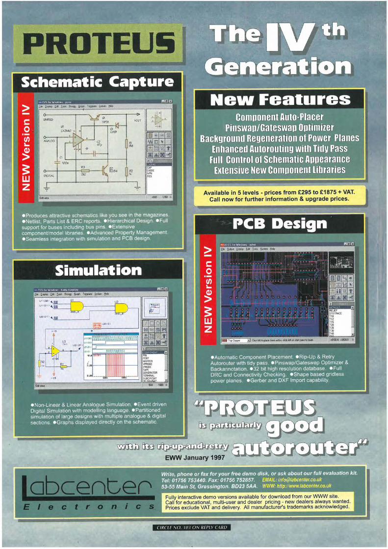
PROTEU!i l Schematic Capture
> -C: 0 ·-"' Lo.
~ ~ - -w z
.
1• 1·
NeVII Features Component Auto-P.lacer
P.inswapZGateswap Optimizer. Backgrounil Regeneration of P.owei ,P.lanes
Enhanceil Autorouting with il'idv P.ass Full Control of ScHematic Appearance
Extensive-New Component Liliraries
• Proauces attractive schematics like you see in ttie magazines. • Netlist, Parts List & ERG reports. • Hierarchical Design • F.ull support for buses including bus pins. • Extensive component/model libraries. • Advanced Property Management. • Seamless integration with simulation and !='CB design
Simulation
. . -~ . · , ~ - ·~ . :. . ·. • Non-Linear & Linear Analogue S1mulat,on; • Event driven Digital Simulation with modelling language. • P-artlt[oned•.·: • _ 5,imulat1on of large designs with multiple analogue & digital:
, -sections.·• Graphs displayed d1~ectly on the schem_abc}" ·•
~--~~~~,~~-~~}-~,-~-·· f - ~-·· -
- - ~ ... ~ ! ·,·
. ~Automatic Compo~eni•-Pl~icement. !Rip-Up & Retry ,. _ ·'Autorouter with ltdy pass • Pmswap/Gateswap Opt1m1zer &"
• ,Backannotat1on. • 32 bit high resolution database • Full ,,. DRC and Connectivity Checking. •Shape based godless· -power planes,· • Gerber, and DXF _Import capability,
~[3fil [D ~ ~
~ liD ~ EWW January 1997
~.-:·~ ... ~ .... >:W.. .
~• phone or fax for your free de!J!g disk, or ask about our ful(evaluation kit. Tel: 01756 753440. Fax:--01756 752857. EMAIL: [email protected] -53-55 Main St, Grassington. 8D23,SAA. WWW: htt~:Jlwww.labcenter.co.uk
Fully interactive demo versions available for download from our WWW site. Call for educational, multi-user and dealer pricing - new dealers always wanted. Prices exclude VAT and delivery. All manufacturer's trademarks acknowledged.
( /R( LE \0 Ill I 0\ 1/fl'l l ( \1//J
Recommended


