MAKING MODERN LIVING POSSIBLE
Technical Information
Orbital MotorOMSU Series 3
powersolutions.danfoss.com

Revision history Table of revisions
Date Changed Rev
July 2014 Changed to Danfoss layout BA
February 2013 Drawing dimension updated AB
September 2012 First edition AA
Technical Information OMSU Series 3 Orbital Motor
2 L1210649 • Rev BA • July 2014
A wide range of Orbital MotorsCharacteristic, features and application areas of Orbital Motors....................................................................................4Characteristic features of Danfoss Orbital Motors................................................................................................................4Technical features of Danfoss Orbital Motor..........................................................................................................................4Survey of literature with technical data on Danfoss Orbital Motors..............................................................................5
Code numbersOMSU Series 3 code numbers......................................................................................................................................................6
DimensionsOMSU dimensions............................................................................................................................................................................8
Connection dimensions, attached component
Internal spline data for the component to be attachedMaterial: ............................................................................................................................................................................................10Hardening specification: ............................................................................................................................................................ 10
General dataDrain connection on OMSU or attached component ......................................................................................................11Installing OMSU.............................................................................................................................................................................. 11Mounting.......................................................................................................................................................................................... 11Direction of rotation..................................................................................................................................................................... 12Maximum tightening torque .................................................................................................................................................... 12Checking OMSU..............................................................................................................................................................................12Exploded view OMSU................................................................................................................................................................... 13OMSU spare parts list ...................................................................................................................................................................14
Technical Information OMSU Series 3 Orbital Motor
Contents
L1210649 • Rev BA • July 2014 3
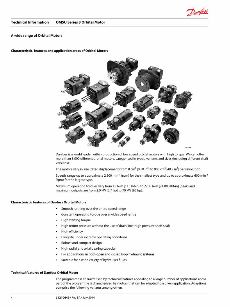
Characteristic, features and application areas of Orbital Motors
Danfoss is a world leader within production of low speed orbital motors with high torque. We can offermore than 3,000 different orbital motors, categorised in types, variants and sizes (including different shaftversions).
The motors vary in size (rated displacement) from 8 cm³ [0.50 in³] to 800 cm³ [48.9 in³] per revolution.
Speeds range up to approximate 2,500 min-1 (rpm) for the smallest type and up to approximate 600 min-1
(rpm) for the largest type.
Maximum operating torques vary from 13 N•m [115 lbf•in] to 2700 N•m [24.000 lbf•in] (peak) andmaximum outputs are from 2.0 kW [2.7 hp] to 70 kW [95 hp].
Characteristic features of Danfoss Orbital Motors
• Smooth running over the entire speed range
• Constant operating torque over a wide speed range
• High starting torque
• High return pressure without the use of drain line (High pressure shaft seal)
• High efficiency
• Long life under extreme operating conditions
• Robust and compact design
• High radial and axial bearing capacity
• For applications in both open and closed loop hydraulic systems
• Suitable for a wide variety of hydraulics fluids
Technical features of Danfoss Orbital Motor
The programme is characterised by technical features appealing to a large number of applications and apart of the programme is characterised by motors that can be adapted to a given application. Adaptionscomprise the following variants among others:
Technical Information OMSU Series 3 Orbital Motor
A wide range of Orbital Motors
4 L1210649 • Rev BA • July 2014
• Motors with corrosion resistant parts
• Wheel motors with recessed mounting flange
• OMP, OMR- motors with needle bearing
• OMR motor in low leakage version
• OMR motors in a super low leakage version
• Short motors without bearings
• Ultra short motors
• Motors with integrated positive holding brake
• Motors with integrated negative holding brake
• Motors with integrated flushing valve
• Motors with speed sensor
• Motors with tacho connection
• All motors are available with black finish paint
Survey of literature with technical data on Danfoss Orbital Motors
Detailed data on all Danfoss Orbital Motors can be found in our motor catalogue, which is divided intomore individual subcatalogues:• General information on Danfoss Orbital Motors: function, use, selection of orbital motor, hydraulic
systems, etc.• Technical data on small motors: OML and OMM
• Technical data on medium sized motors: OMP, OMR, OMH
• Technical data on medium sized motors: DH and DS
• Technical data on medium sized motors: OMEW
• Technical data on medium sized motors: VMP
• Technical data on medium sized motors: VMR
• Technical data on large motors: OMS, OMT and OMV
• Technical data on large motors: TMT
• Technical data on large motors: TMV
A general survey brochure on Danfoss Orbital Motors gives a quick motor reference based on power,torque, speed and capabilities.
Technical Information OMSU Series 3 Orbital Motor
A wide range of Orbital Motors
L1210649 • Rev BA • July 2014 5
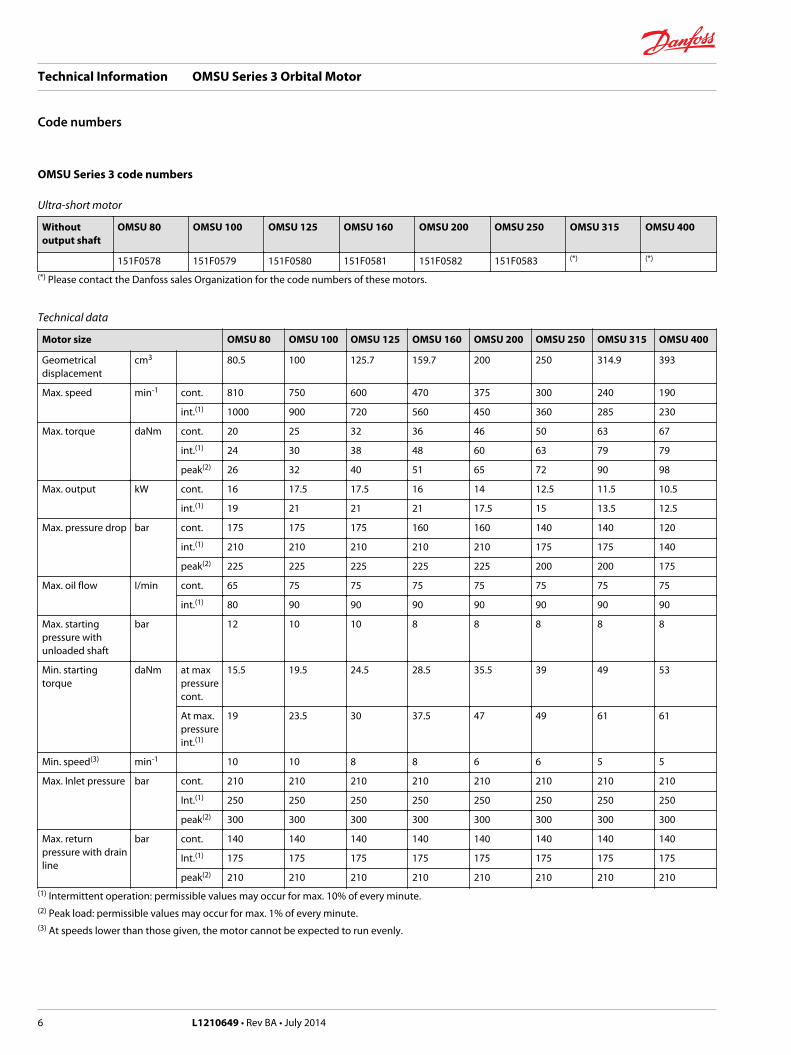
OMSU Series 3 code numbers
Ultra-short motor
Withoutoutput shaft
OMSU 80 OMSU 100 OMSU 125 OMSU 160 OMSU 200 OMSU 250 OMSU 315 OMSU 400
151F0578 151F0579 151F0580 151F0581 151F0582 151F0583 (*) (*)
(*) Please contact the Danfoss sales Organization for the code numbers of these motors.
Technical data
Motor size OMSU 80 OMSU 100 OMSU 125 OMSU 160 OMSU 200 OMSU 250 OMSU 315 OMSU 400
Geometricaldisplacement
cm3 80.5 100 125.7 159.7 200 250 314.9 393
Max. speed min-1 cont. 810 750 600 470 375 300 240 190
int.(1) 1000 900 720 560 450 360 285 230
Max. torque daNm cont. 20 25 32 36 46 50 63 67
int.(1) 24 30 38 48 60 63 79 79
peak(2) 26 32 40 51 65 72 90 98
Max. output kW cont. 16 17.5 17.5 16 14 12.5 11.5 10.5
int.(1) 19 21 21 21 17.5 15 13.5 12.5
Max. pressure drop bar cont. 175 175 175 160 160 140 140 120
int.(1) 210 210 210 210 210 175 175 140
peak(2) 225 225 225 225 225 200 200 175
Max. oil flow I/min cont. 65 75 75 75 75 75 75 75
int.(1) 80 90 90 90 90 90 90 90
Max. startingpressure withunloaded shaft
bar 12 10 10 8 8 8 8 8
Min. startingtorque
daNm at maxpressurecont.
15.5 19.5 24.5 28.5 35.5 39 49 53
At max.pressureint.(1)
19 23.5 30 37.5 47 49 61 61
Min. speed(3) min-1 10 10 8 8 6 6 5 5
Max. Inlet pressure bar cont. 210 210 210 210 210 210 210 210
Int.(1) 250 250 250 250 250 250 250 250
peak(2) 300 300 300 300 300 300 300 300
Max. returnpressure with drainline
bar cont. 140 140 140 140 140 140 140 140
Int.(1) 175 175 175 175 175 175 175 175
peak(2) 210 210 210 210 210 210 210 210(1) Intermittent operation: permissible values may occur for max. 10% of every minute.(2) Peak load: permissible values may occur for max. 1% of every minute.(3) At speeds lower than those given, the motor cannot be expected to run evenly.
Technical Information OMSU Series 3 Orbital Motor
Code numbers
6 L1210649 • Rev BA • July 2014
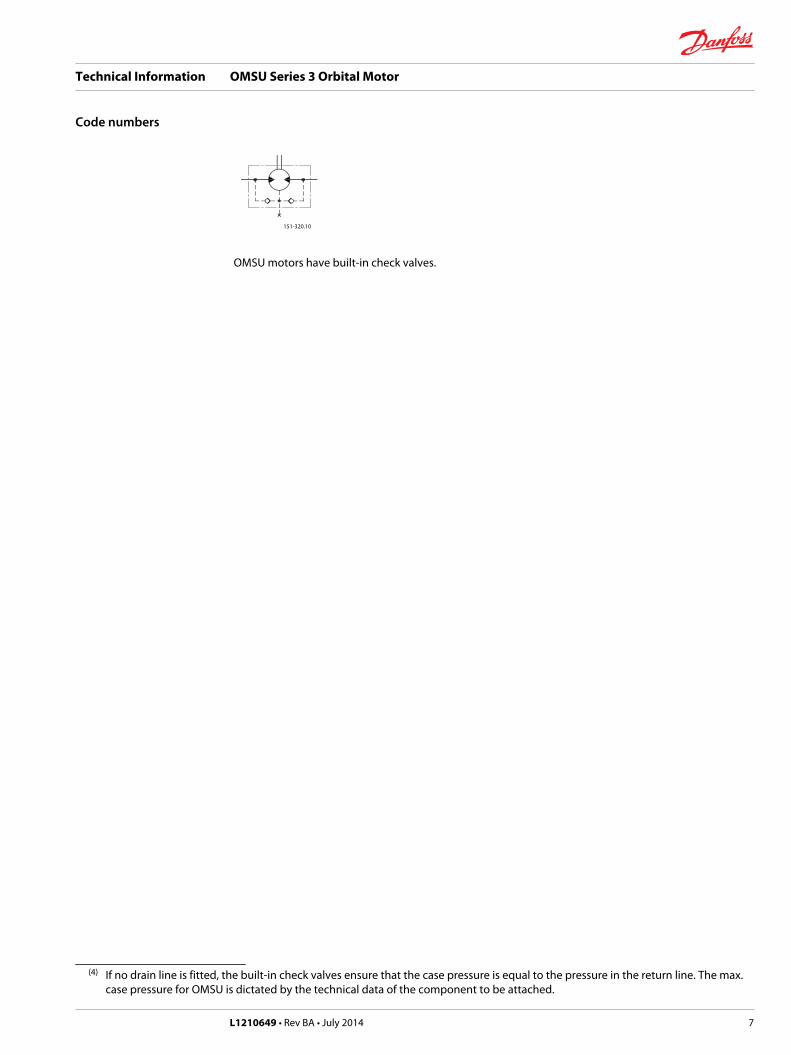
151-320.10
OMSU motors have built-in check valves.
(4) If no drain line is fitted, the built-in check valves ensure that the case pressure is equal to the pressure in the return line. The max.case pressure for OMSU is dictated by the technical data of the component to be attached.
Technical Information OMSU Series 3 Orbital Motor
Code numbers
L1210649 • Rev BA • July 2014 7
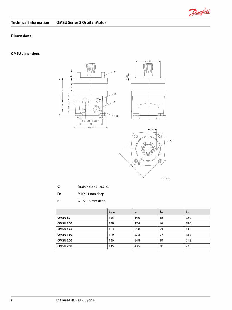
OMSU dimensions
D
E
R18
F
C
25.7
5452
70
max. 103
21 ±0.3 21 ±0.3
16 ±0.3 16 ±0.3
27 ±
0.6
5 ±0
.6
LL 2
L 3L 1
22 ±
0.6
7 ±0
.1
ø75 -0.04-0.12
ø104
A151-1826.11
C: Drain hole ø5 +0.2 -0.1
D: M10; 11 mm deep
E: G 1/2; 15 mm deep
Lmax L1 L2 L3
OMSU 80 105 14.0 63 22.0
OMSU 100 109 17.4 67 18.6
OMSU 125 113 21.8 71 14.2
OMSU 160 119 27.8 77 18.2
OMSU 200 126 34.8 84 21.2
OMSU 250 135 43.5 93 22.5
Technical Information OMSU Series 3 Orbital Motor
Dimensions
8 L1210649 • Rev BA • July 2014
A151-1827.12
ø0.5 ±0.4
0.006
0.25 K
1.6
2.3 ±0.05
min. 15
min. ø4
46 ±0.3
19 ±1
K
B
CA
min
. ø4
ø29
±0.5
ø35
±0.5
min
. ø40
min
. ø11
0
ø75
+0.0
8+0
.02
+0.2
0
ø82.
8
+0.5 07.5
1.6
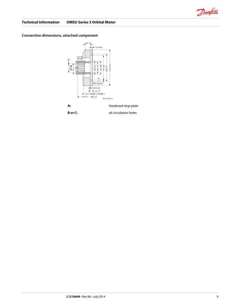
A: Hardened stop plate
B or C: oil circulation holes
Technical Information OMSU Series 3 Orbital Motor
Connection dimensions, attached component
L1210649 • Rev BA • July 2014 9
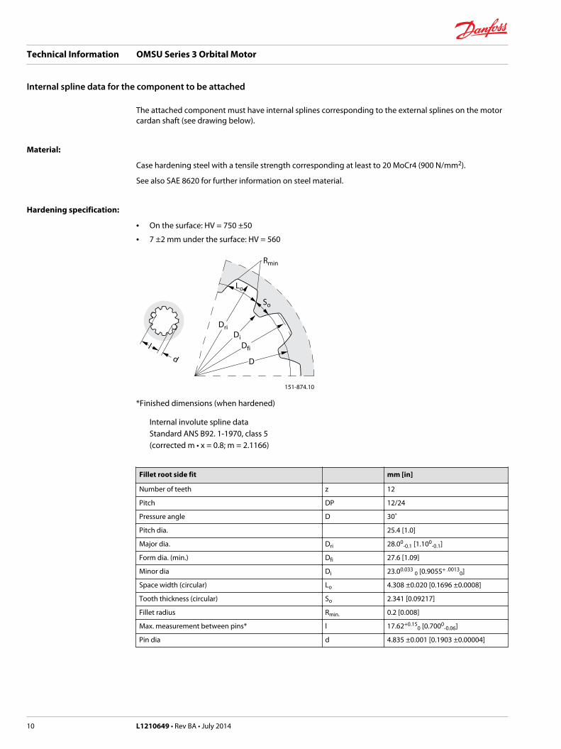
The attached component must have internal splines corresponding to the external splines on the motorcardan shaft (see drawing below).
Material:
Case hardening steel with a tensile strength corresponding at least to 20 MoCr4 (900 N/mm2).
See also SAE 8620 for further information on steel material.
Hardening specification:
• On the surface: HV = 750 ±50
• 7 ±2 mm under the surface: HV = 560
dl
D
DriDi
Dfi
So
Lo
Rmin
151-874.10
*Finished dimensions (when hardened)
Internal involute spline dataStandard ANS B92. 1-1970, class 5(corrected m • x = 0.8; m = 2.1166)
Fillet root side fit mm [in]
Number of teeth z 12
Pitch DP 12/24
Pressure angle D 30˚
Pitch dia. 25.4 [1.0]
Major dia. Dri 28.00-0.1 [1.100
-0.1]
Form dia. (min.) Dfi 27.6 [1.09]
Minor dia Di 23.00.033 0 [0.9055+ .00130]
Space width (circular) Lo 4.308 ±0.020 [0.1696 ±0.0008]
Tooth thickness (circular) So 2.341 [0.09217]
Fillet radius Rmin. 0.2 [0.008]
Max. measurement between pins* l 17.62+0.150 [0.7000
-0.06]
Pin dia d 4.835 ±0.001 [0.1903 ±0.00004]
Technical Information OMSU Series 3 Orbital Motor
Internal spline data for the component to be attached
10 L1210649 • Rev BA • July 2014

Drain connection on OMSU or attached component
The case pressure is released to the motor return pressure by the motor drain hole (ø 5 mm) and theincorporated check valves.
A drain line ought to be used when pressure in the return line can exceed the permissible pressure on theshaft seal of the attached component.
The drain line can only be connected to the drain connection of the attached component, i.e. the OMSUmotor has no external drain connection.
The drain line on the attached component allows oil to flow freely between component and the motor.
The drain line must be led to the tank in such a way that there is no risk of the motor and attachedcomponent being drained of oil during operational stop.
The maximum pressure in the drain line is limited by the attached component and its shaft seal.
Installing OMSU
To ensure that the splines connection of the cardan shaft receive sufficient oil, we recommended aconical sealing between shaft of the attached component and the motor intermediate plate as well as anoil circulation the attached component (see page 3). The conical sealing ring (code no. 633B9023) issupplied with the motor. We further recommend O-ring seal between motor and the counter part. The O-ring (code no. 633B1396) is supplied with the motor.
Mounting
A151-1412.10
Max. tightening torque
75 +5 0 Nm [660 +500 Ibf•in]
Technical Information OMSU Series 3 Orbital Motor
General data
L1210649 • Rev BA • July 2014 11

Direction of rotation
Maximum tightening torque
Maximum tightening torque
Screwed connection G 1/2 [7/8-14 UNF]
with steel washer 130 N•m [1150 lbf•in]
with aluminium washer 70 N•m [620 Ibf•in]
with cutting edge 130 N•m [1150 Ibf•in]
with O-ring Boss port 70 N•m [620 Ibf•in]
Checking OMSU
In order to make sure that the OMSU counterpart is correct, the drainflow should be messured on the firstof each new application. Any subsequent modification of the counterpart should imply new checking.When the motor is fitted onto the counter part with the correct tightening torque, the drain flow ismessured at Q = 30 I/min and an oil viscosity of 35 mm2/s at differential pressure:
Technical Information OMSU Series 3 Orbital Motor
General data
12 L1210649 • Rev BA • July 2014
Motor Differential pressure
OMSU 80 - 160 140 bar
OMSU 200 110 bar
OMSU 250 90 bar
OMSU 315 70 bar
OMSU 400 55 bar
After minimum 5 min. of operation the drainflow shall be minimum 0.03 l/min and maximum 1.00 l/minat maximum pressure of bar 6 in the drain line during testing.
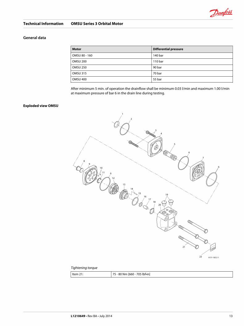
Exploded view OMSU
A151-1825.1122
21
20
19
1817
1615
14
13
12
89
10
11 6
1
2
34
5
6
7
6
Tightening torque
Item 21: 75 - 80 Nm [660 - 705 lbf•in]
Technical Information OMSU Series 3 Orbital Motor
General data
L1210649 • Rev BA • July 2014 13

OMSU spare parts list
OMSU spare parts list
Item Spare parts Codenumber
Number permotor
1 Seal ring 633B9023 1
2 O-ring 74 x 3 mm NBR ISO 1629 633B1396 1
3 Screw M5
OMSU 80 L = 45 mm 681X1512 2
OMSU 100 L = 50 mm 681X1702 2
OMSU 125 L = 55 mm 681X9282 2
OMSU 160 L = 60 mm 681X1703 2
OMSU 200 L = 70 mm 681X0354 2
OMSU 250 L = 80 mm 681X0568 2
4 Intermidiate plate 151F1717 1
5 Cardan shaft
OMSU 80 l = 70 mm 11075495 1
OMSU 100 l = 73 mm 11077519 1
OMSU 125 l = 78 mm 11077838 1
OMSU 160 l = 84 mm 11075528 1
OMSU 200 l = 91 mm 11077921 1
OMSU 250 l = 99.5 mm 11077919 1
6 O-ring 82.5 x 2 mm NBR ISO R 1629 633B1431 3
7 Gearwheel set
OMSU 80 w = 14 mm 151F1091 1
OMSU 100 w = 17 mm 151F1092 1
OMSU 125 w = 22 mm 151F1093 1
OMSU 160 w = 28 mm 151F1094 1
OMSU 200 w = 35 mm 151F1095 1
OMSU 250 w = 44 mm 151F1096 1
8 Valve drive 11030924 1
9 Channel plate 151F1822 1
10 Check valve ball ø 3/16 in 689X1005 2
11 Stop ring (only OMSU 200, 250, 315 and 400) 151F1542 1
12 Disc valve 151F1022 1
13 Balance plate 151F1738 1
14 Guide pin ø 4 mm l = 20 mm DIN 1481 682L9105 1
15 O-ring 45 x 2 mm
NBR, ISO R 1629 633B1429 1
FPM, ISO R 1629 633B1455 1
16 O-ring 24 x 2 mm
NBR, ISO R 1629 633B1428 1
FPM, ISO R 1629 633B1453 1
17 Spacer 151F1449 1
18 Spring washer 684X0097 1
Technical Information OMSU Series 3 Orbital Motor
General data
14 L1210649 • Rev BA • July 2014
OMSU spare parts list (continued)
Item Spare parts Codenumber
Number permotor
19 Seal plug G 1/2 633X0074 2
20 Valve housing 151F1803 1
21 Screw M10
OMSU 80, 100, 125 l = 120 mm 681X1349 4
OMSU 160 l = 130 mm 681X1350 4
OMSU 200 l = 140 mm 681X1352 4
OMSU 250 l = 150 mm 681X1353 4
22 Name plate
A Set of seals items 1, 6, 15, 16 151F0103
B Set of seals items 1, 2 151F1020
NBR: (Buna N, Perbunan); FPM (Viton)
Technical Information OMSU Series 3 Orbital Motor
General data
L1210649 • Rev BA • July 2014 15
Danfoss Power Solutions is a global manufacturer and supplier of high-quality hydraulic andelectronic components. We specialize in providing state-of-the-art technology and solutions thatexcel in the harsh operating conditions of the mobile off -highway market. Building on our extensive applications expertise, we work closely with our customers to ensure exceptional performance for a broad range of off -highway vehicles.
We help OEMs around the world speed up system development, reduce costs and bring vehicles tomarket faster.Danfoss – Your Strongest Partner in Mobile Hydraulics.
Go to www.powersolutions.danfoss.com for further product information.
Wherever off -highway vehicles are at work, so is Danfoss.
We off er expert worldwide support for our customers, ensuring the best possible solutions for outstanding performance. And with an extensive network of Global Service Partners, we also provide comprehensive global service for all of our components.
Please contact the Danfoss Power Solution representative nearest you.
Local address:
Danfoss Power Solutions GmbH & Co. OHGKrokamp 35D-24539 Neumünster, GermanyPhone: +49 4321 871 0
Danfoss Power Solutions ApSNordborgvej 81DK-6430 Nordborg, DenmarkPhone: +45 7488 2222
Danfoss Power Solutions US Company2800 East 13th StreetAmes, IA 50010, USAPhone: +1 515 239 6000
Danfoss Power Solutions(Shanghai) Co., Ltd.Building #22, No. 1000 Jin Hai RdJin Qiao, Pudong New DistrictShanghai, China 201206Phone: +86 21 3418 5200
Danfoss can accept no responsibility for possible errors in catalogues, brochures and other printed material. Danfoss reserves the right to alter its products without notice. This also applies toproducts already on order provided that such alterations can be made without changes being necessary in specifications already agreed..All trademarks in this material are property of the respective companies. Danfoss and the Danfoss logotype are trademarks of Danfoss A/S. All rights reserved.
L1210649 • Rev BA • July 2014 www.danfoss.com © Danfoss A/S, 2014
Products we off er:
• Bent Axis Motors
• Closed Circuit Axial Piston Pumps and Motors
• Displays
• Electrohydraulic Power Steering
• Electrohydraulics
• Hydraulic Power Steering
• Integrated Systems
• Joysticks and Control Handles
• Microcontrollers and Software
• Open Circuit Axial Piston Pumps
• Orbital Motors
• PLUS+1® GUIDE
• Proportional Valves
• Sensors
• Steering
• Transit Mixer Drives
Comatrolwww.comatrol.com
Schwarzmüller-Inverterwww.schwarzmueller-inverter.com
Turolla www.turollaocg.com
Valmovawww.valmova.com
Hydro-Gearwww.hydro-gear.com
Daikin-Sauer-Danfosswww.daikin-sauer-danfoss.com
Recommended