1
Content
1. SRI LANKA TELECOM ............................................................................................................. 6
Profile ............................................................................................................................. 6
SLT services .................................................................................................................... 8
Organizational structure .............................................................................................. 10
2. Asymmetric Digital Subscriber Line (ADSL) ......................................................................... 12
DSL Applications .......................................................................................................... 13
ADSL line quality parameters ...................................................................................... 14
ADSL Faults and Troubles ............................................................................................ 16
Troubleshooting ........................................................................................................... 16
Testing and maintenance equipment .......................................................................... 20
3. New connection section ...................................................................................................... 23
Customer premises equipment ................................................................................... 23
VPN (Virtual Private Network) ..................................................................................... 29
Ethernet VPN ............................................................................................................... 30
Ethernet Data Line ....................................................................................................... 30
4. Main Distribution Frame (MDF) or Testing Room ............................................................... 31
Fault handling process of MDF .................................................................................... 33
5. PSTN (Public Switched Telephone System) maintenance ................................................... 37
6. Switching ............................................................................................................................. 40
Function of a switch ..................................................................................................... 41
GENERAL STRUCTURE OF A SWITCH............................................................................ 46
7. Transmission ....................................................................................................................... 48
Transmission mediums ................................................................................................ 48
Transmission technologies .......................................................................................... 49
Transmission networks ................................................................................................ 50
Network protection and redundancy .......................................................................... 52
Fiber optic transmission .............................................................................................. 53
Radio transmission ...................................................................................................... 56
8. Power and A/C section ........................................................................................................ 60
Power operations and maintenance ........................................................................... 60
2
Power protection ......................................................................................................... 68
Air condition implementation and maintenance section ............................................ 71
Basic Refrigeration Cycle ............................................................................................. 71
9. Private Automatic Branch Exchange (PABX) ....................................................................... 73
Phone systems ............................................................................................................. 75
10. CDMA section ...................................................................................................................... 75
Spread spectrum technology ....................................................................................... 75
CDMA network Architecture ....................................................................................... 78
Advantages of CDMA technology ................................................................................ 80
Disadvantages of CDMA technology ........................................................................... 81
11. International transmission maintenance center (ITMC) and submarine cables ................. 81
International transmission maintenance center (ITMC) ............................................. 81
Submarine cables and landing station ......................................................................... 82
12. Conclusion ........................................................................................................................... 88
3
Index
List of figures
FIGURE 1.1 OPERATIONAL REGIONS ......................................................................................................................... 10 FIGURE 2.1 FREQUENCY ALLOCATION IN ADSL .......................................................................................................... 12 FIGURE 2.2 THE DISCRETE MULTI TONES OF ADSL ...................................................................................................... 12 FIGURE 2.3 ADSL NETWORK ARCHITECTURE .............................................................................................................. 13 FIGURE 2.4 ADSL ROUTER CONFIGURATION ............................................................................................................. 19 FIGURE 2.5 ADSL ROUTER CONFIGURATION ............................................................................................................. 19 FIGURE 2.6 WIRELESS CONFIGURATIONS ................................................................................................................... 20 FIGURE 2.7 CROSSOVER CABLE PIN OUTS .................................................................................................................. 21 FIGURE 2.8 PIN OUTS OF STRAIGHT THROUGH CABLES ................................................................................................. 21 FIGURE 2.9 ADSL TESTING METER/ CRIMPING TOOL/ NETWORK CABLE TESTER ................................................................ 22 FIGURE3.1CONNECTION PROCEDURE OF CUSTOMER EQUIPMENT FOR ADSL/PSTN AND PEO TV ....................................... 26 FIGURE 3.2 ROUTER CONFIGURATIONS FOR PEO TV.................................................................................................... 27 FIGURE 3.3 ROUTER CONFIGURATIONS FOR PEO TV.................................................................................................... 27 FIGURE 3.5 ROUTER CONFIGURATIONS FOR PEO TV ................................................................................................... 28 FIGURE 3.4 ROUTER CONFIGURATIONS FOR PEO TV.................................................................................................... 28 FIGURE 3.6 IP VPN .............................................................................................................................................. 30 FIGURE 3.7 ETHERNET VPN ................................................................................................................................... 30 FIGURE 4.1 DIAGRAM OF A MDF ............................................................................................................................ 32 FIGURE 4.2 LINE ARRESTERS ................................................................................................................................... 32 FIGURE 4.3 CRONE TOOL ....................................................................................................................................... 32 FIGURE 4.4 TEST BOARD ........................................................................................................................................ 33 FIGURE 4.5 STEPS TO ENTER TO THE FAULT INBOX ...................................................................................................... 34 FIGURE 4.6 FAULT INBOX....................................................................................................................................... 34 FIGURE 4.7 FAULT QUERY OF A REPORTED FAULT ....................................................................................................... 35 FIGURE 4.8 FAULT EDIT MODULE WHICH SHOWS THE FAULT’S DETAILS ............................................................................ 35 FIGURE 4.9 CIRCUIT DETAILS OF AN ADSL LINE .......................................................................................................... 36 FIGURE 4.10 WFM ANDROID APPLICATION .............................................................................................................. 36 FIGURE 5.1 CABLE MAINTENANCE TOOLS .................................................................................................................. 38 FIGURE 5.2 TYPICAL STRUCTURE OF A PSTN LINE ....................................................................................................... 39 FIGURE 5.3 TYPICAL INSIDE VIEW OF A MSAN ........................................................................................................... 39 FIGURE 5.4 NETWORK ARCHITECTURE DEVELOPED WITH MSANS .................................................................................. 40 FIGURE 6.1 DTMF FREQUENCIES OF THE KEYPAD ....................................................................................................... 42 FIGURE 6.2 SS7 SIGNALING POINTS ......................................................................................................................... 43 FIGURE 6.3 GENERAL STRUCTURE OF A SWITCH .......................................................................................................... 46 FIGURE 7.1 THREE LEVELS OF MULTIPLEXING ............................................................................................................. 51 FIGURE 7.2 SDH BIT RATES .................................................................................................................................... 51 FIGURE 7.3 SDH NETWORK ELEMENTS ..................................................................................................................... 52 FIGURE 7.4 RING PROTECTION OF A NETWORK ........................................................................................................... 53 FIGURE 7.7 CROSS SECTION OF A MULTI CORE FIBER CABLE ........................................................................................... 55 FIGURE 7.8 TYPICAL FIBER LINK ............................................................................................................................... 56 FIGURE 7.9 MAIN MODULES OF A RADIO TERMINAL .................................................................................................... 57 FIGURE 7.10 BASIC MICROWAVE LINK INCORPORATING A REPEATER ............................................................................... 58 FIGURE 7.11 SIMPLIFIED MICROWAVE LINK WITH SCHEMATIC DIAGRAM .......................................................................... 59 FIGURE 7.12 EXAMPLE OF A CLEAR LINE-OF-SIGHT PATH .............................................................................................. 59 FIGURE 7.13 EXAMPLE OF A MID-PATH REFLECTION PATH ............................................................................................ 59 FIGURE 8.1 COMMON RAIL FUEL SYSTEM .................................................................................................................. 61 FIGURE 8.2 THREE PHASE FOUR WIRE (SERIES OR PARALLEL) WYE (STAR) .......................................................... 63
4
FIGURE 8.3 POWER FEEDING SYSTEM ....................................................................................................................... 64 FIGURE 8.4 DIAGRAM OF AN OFF LINE UPS ............................................................................................................... 65 FIGURE 8.5 DIAGRAM OF A LINE INTERACTIVE UPS ..................................................................................................... 65 FIGURE 8.6 DIAGRAM OF AN ONLINE DOUBLE CONVERSION UPS ................................................................................... 66 FIGURE 8.7 SIMPLE BLOCK DIAGRAM OF RECTIFIER ...................................................................................................... 67 FIGURE 8.8 LIGHTENING CONDUCTORS WITH MESHED CAGE PROTECTION ........................................................................ 69 FIGURE 8.9 EARTHING OF TOWER AND THE BUILDING .................................................................................................. 69 FIGURE 8.10 TWO TYPES OF SPD CONNECTION IN A TT WIRING SYSTEM ......................................................................... 70 FIGURE 8.11 REFRIGERATION CYCLE......................................................................................................................... 71 FIGURE 8.12 THE MAIN PARTS AND THEIR SETUP OF THE AIR CONDITIONER ...................................................................... 72 FIGURE 9.1 PHYSICAL OVERVIEW OF A PABX SYSTEM .................................................................................................. 73 FIGURE 10.1 CDMA SPREAD SPECTRUM GENERATION & DECODING .............................................................................. 76 FIGURE 10.2 CDMA NETWORK ARCHITECTURE ......................................................................................................... 78 FIGURE 11.1 THE BASIC STRUCTURE OF ITMC CONNECTIONS ....................................................................................... 82 FIGURE 11.2 THE DIAGRAM OF THE SEA – ME – WE 4 CABLE SYSTEM .......................................................................... 83 FIGURE 11.3 BASIC SUBMARINE CABLE TYPES ............................................................................................................ 84 FIGURE 11.4 ROUTE SURVEYING ............................................................................................................................. 84 FIGURE 11.5 DIAGRAM OF THE WET PLANT OF THE SUBMARINE CABLE ............................................................................ 85 FIGURE 11.6 DRY PLANT OF THE SUBMARINE CABLE SYSTEM ......................................................................................... 86
List of tables
TABLE 2.1 COMPARISON OF DIFFERENT DSL TECHNOLOGIES ......................................................................................... 14 TABLE 2.2 LINE STATUS ACCORDING TO THE VARIATIONS OF SNR .................................................................................. 15 TABLE 2.3 LINE STATUS ACCORDING TO THE VARIATIONS OF LINE ATTENUATION ............................................................... 15 TABLE 2.4 DEFINITIONS FOR ROUTER ALARMS ............................................................................................................ 17 TABLE 2.5 VPI/VCI VALUES FOR ADSL & IPTV ......................................................................................................... 18 TABLE 2.6 PIN OUTS FOR CROSSOVER CABLE .............................................................................................................. 21 TABLE 2.7 PIN OUTS FOR STRAIGHT THROUGH CABLE ................................................................................................... 22 TABLE 3.1 COMPARISON BETWEEN ROUTER AND MODEM ............................................................................................ 25 TABLE 6.1 SWITCHING LAYERS ................................................................................................................................ 41 TABLE 7.1 IMPORTANT FACTS REGARDING TO RADIO SYSTEM PERFORMANCE ................................................................... 60 TABLE 8.1 ADVANTAGES AND DISADVANTAGES OF RECTIFIER TYPES ................................................................................ 67 TABLE 8.2 ADVANTAGES AND DISADVANTAGES OF OPEN AND SEALED TYPE BATTERIES ....................................................... 68
List of charts
CHART 1.1 ORGANIZATIONAL STRUCTURE OF SLT....................................................................................................... 11
5
Preface
The one year period of industrial training followed by the two years of academic study of the National Diploma
in Technology (NDT) which is offered by the Institute of technology, University of Moratuwa (ITUM) is the first
step of the professional career. The industrial training provided a great opportunity for me to gain the knowledge,
and to aware about the real world applications of the theories what learned during the first two years. The
technical knowledge is not the only thing what I exactly gained in this six months but improved the attitudes,
technical and other soft skills.
The first six months of the training period started from 3rd of March 2014, was successfully completed on 29th of
July 2014. The Sri Lanka Telecom PLC (SLT), granted me this opportunity through the contribution and
supervision of National Apprentice and Training Authority (NAITA). SLT offered me a well scheduled training
programme that covered a lot of technical areas regarding to the electronics and telecommunication field.
This final report on the industrial training represents the knowledge and experiences what I gained during the
last six month at Sri Lanka Telecom PLC. The content depends on the experiences what I had at Outside Plant
Maintenance Center, Negombo and the sections covered at the SLT Head office.
Acknowledgement
It is a great pleasure to thank all the organizations and individuals who helped and guided me to sail towards
the successful completion of first industrial training. First, I am glad to extend my gratitude to the director of
ITUM, head of the division of Electronics and Telecommunication, training engineer (ITUM) and all the academic
staff who guided me to success.
Furthermore, I would like to mentioned my feelings of gratitude for the guidance and supervision that provided
by the National Apprentice and Training Authority (NAITA). I am thankful to director – Industrial training and
other staff who contributes for the inspections of first six month training.
Finally, I would like to appreciate the support, guidance, ideas and knowledge which were given by the SLT
staff and the training planning section.
The whole respect regarding to the success of this report goes to all the individuals and organizations who
encouraged, support and equipped me with technical knowledge.

6
SRI LANKA TELECOM
Vision
“All Sri Lankans seamlessly connected with world-class information, communication and entertainment
services.”
Mission
“Your trusted and proven partner for innovative and exciting communication experiences delivered with passion,
quality and commitment”
Profile
Sri Lanka Telecom PLC is the pioneer telecommunication service provider in Sri Lanka which has a customer
base of over six million including multinational corporations, large and small corporate, public sector, retail and
domestic customers. The two main shareholders of Sri Lanka Telecom as at year end were the Government of
Sri Lanka which held 49.5% through the Secretary to the Treasury and Global Telecommunication Holdings
N.V. of Netherlands, which owned a 44.98% stake. The balance shares are publicly traded. The market
capitalization of Sri Lanka Telecom, as at 31 December 2013 topped Rs.66 billion. The SLT servers its huge
customer base through intelligent solutions, global services, backbone services, triple play services and mobile
services by using strong brand and reputation, dedicated work force, superior network/technology platforms
and innovation.
Sri Lanka Telecom has enhanced their services via a group of organizations into new areas including human
capital and property management services. Further, SLT consists of several organizations such as,
SLT Vision Com (Private) Limited - IPTV support services
Mobitel (Private) Limited - Mobile Service Provide
SLT Publications (Private) Limited - Directory publication services
SKY Network (Private) Limited - Wireless Broadband operations
Sri Lanka Telecom (Services) Limited - Providing total network solutions to corporate and small
business customers
SLT Human Capital Solutions (Private) Limited - Providing workforce solutions
SLT Property Management (Private) Limited - Managing Group’s properties for better utilization of
resources and stretching its operations into diversified businesses
One of the major strategic objective of Sri Lanka Telecom is to widen broadband services by expanding the
broadband foot print via “Next Generation Network (NGN)” and “National Backbone Network” using the
ADSL2+, VDSL2, fiber optic, Carrier grade WI-FI and both fixed and mobile 4G LTE technologies.
SLT aims to be the pioneer telecommunication partner in the island to become the “ICT and Communication
hub” of the Asia. SLT plans to be a key regional telecommunication company through its Global Services
through multiple international undersea cable systems through major investments in international submarine
cable systems such as SEA-ME-WE 5, SEA-ME-WE 4, SEA-ME-WE 3, Bharat-Lanka submarine cable system
and Dhiraagu-SLT submarine cable system.
SLT has become the most recognized service provider among the top enterprises and small and medium sized
enterprises (SME) as the best and reliable network provider. Also the company was entrusted by other
7
telecommunications operators in the country as the wholesaler of choice and the best network provider. SLT
provides ICT solutions for enterprises and SMEs which based on 0their key demands such as speed,
connectivity and security.
While being the national telecommunications solutions provider in the country, SLT has focused on the
cooperate responsibilities as a well trusted organization that serving the nation for over 150 years. Sri Lanka
Telecom ensures that best environment practices are followed during the course of our day-to-day business
operations so that negative impacts to the environment and our stakeholders, as a result of our activities are
eliminated or minimized as much as possible. SLT has already moved on to the energy management, electronic
and other waste management and eco systems. As a responsible corporate citizen, Sri Lanka Telecom
contributes to the development of the community in different aspects. In one sense, as the national
telecommunication service provider, SLT pay close attention to improving digital literacy across the country and
plays a key role in developing the ICT technologies in order to enrich the ICT education.
SLT’s Strategic Themes for the future
Offer world-class ICT and infotainment services to all Sri Lankans
Best in-class delivery of products and services
Modernize operational architecture to support efficiency
Enable a single transport aggregation network with multiple access technology
Enhance customer-centricity
An integrated group approach to promote business synergies
Contribute to national progress
SLT practices more efficient productivity concepts and uses modern ICT platforms to enhance the customer
experience while empowering the staff in order to protect the following values.
1. Customer Caring
2. Trustworthy
3. Innovative
4. Responsive
5. Teamwork
6. Excellence
7. Results Driven
8
SLT services
Personal and Business connections
SLT telephone connections are available as Megaline and Citylink. Both Megaline and Citylink offer a range of
value added services.
Megaline
Megaline is the most reliable and superior quality wire line telephone connection that enables customer to enjoy
uninterrupted Voice, Broadband and PEO TV.
Citylink
Citylink, the wireless telephone network that uses CDMA 2000 network technology offers high clarity voice
telephony and offers a diverse range of value added services to meet your communication needs.
VAS (Value Added Services)
Tele life
NGN VAS
SLT Plus
IVR Portal
SLT Ticketing
Sisu Connect
Doc Call
SLT Fiber
SLT Fiber to the Home (FTTH) connections are available in three different packages, depending on customer’s
requirement and range from Voice + Broad band ,Broad band + PeoTV or PeoTV to Voice+Broadband+PeoTV.
Internet
Broadband
Revolutionizing internet usage across the country whilst expanding Sri Lanka’s broadband capacity, SLT
Broadband offers consistent, uninterrupted, high-speed internet access up to 16 Mbps downloading speed.
Through the i-Sri Lanka project the company enhances and upgrades its existing fixed network, by expanding
the fiber network to bring it closer to customers through Fiber-to-the-Node (FTTN) deployment.
Wi – Fi
SLT is proud to introduce our latest broadband experience for valuable customers, the first ever
cutting-edge Carrier-grade public Wi-Fi network in Sri Lanka. Using SLT Wi-Fi hotspots, now
customers can get connected to the largest broadband network and experience the next evolution
in wireless broadband connectivity through any Wi-Fi enabled device.
Dial-up
SLT Net offers a wide range of postpaid and prepaid dial up packages to suit your needs.
9
Hosting services
SLT’s state-of-the art data center offers a range of hosting services to suit the personal and business needs
from DNS registration to mail server solutions to broaden the business horizons.
IDD
SLT offers the most premium quality international call service in Sri Lanka which is available for almost all
international destinations. So customers can now enjoy the highest voice quality for international calls which is
similar to your experience when making a local call on SLT landline. Also SLT now offers affordable rates to all
countries, with per second billing that ensures that pay only for the exact time which spend on the call.
Data
SLT’s Intelligent Solutions are aimed at equipping large enterprises and SME businesses with the full range of
ICT solutions to help succeed in the global arena. Speed, connectivity and security are key demands businesses
make and SLT’s wide portfolio of services is perfectly poised to meet and exceed these expectations.
Peo TV
SLT PEO TV gives the platform to enjoy the best of local and international news and entertainment from around
the world at a click of a button, revolutionizing traditional TV experience with characteristic features such as
digital quality pictures, Time Shifted TV, Rewind TV to play, pause live TV and Video on Demand with content
such as movies, music, educational and much more.
Wholesale
An array of wholesale services for fixed and mobile operators, ISPs, and communication services resellers,
external gateway operators (EGOs), data communication service providers and virtual service providers. As the
premier National Backbone Network (NBN) provider, SLT has deployed an island wide fully secured fiber
network to fulfil domestic transport requirements of service providers.
Mobile
Sri Lanka Telecom Mobitel, is a fully-owned subsidiary of SLT. The company offers mobile telephony services,
high-speed broadband, Enterprise Solutions, IDD services and a host of Value Added Services. Mobitel was
the pioneer in South Asia to launch a Super 3.5G network, to successfully demonstrate HSPA + MIMO
technology and successfully trial 4G/LTE technology. Introduction of Dual Carrier HSPA+ technology and 4G-
LTE service makes Mobitel’s mobile broadband speeds the fastest in the country.
10
Organizational structure
The management of the Sri Lanka Telecom is governed by the board of directors and the senior management
consists of a group of chief officers.
Board of directors
Mr. Nimal Welgama – Chairman/Director
Directors
Mr. Chan Chee Beng
Mr. Jeffrey Jay Blatt
Mr. Shameendra Rajapakse
Mr. Jayantha Dharmadasa
Mr. Kalinga Indatissa
Mr. Lawrence Paratz
Ms.Pushpa Wellappili
Ms. Lai Choon Foong
Senior management
Group Chief Executive Officer
Chief Administrative Officer
Chief Business Strategies Officer
Chief Corporate Officer
Chief Enterprise & Wholesale Officer
Chief Financial Officer
Chief Information Officer
Chief Marketing Officer
Chief Network Officer
Chief Regional Officer
Chief Transformation and Development
Officer
Chief Internal Auditor
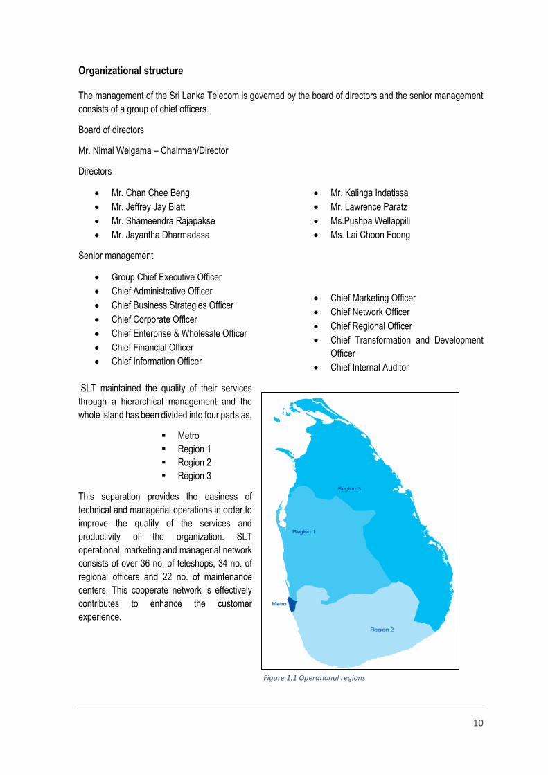
SLT maintained the quality of their services
through a hierarchical management and the
whole island has been divided into four parts as,
Metro
Region 1
Region 2
Region 3
This separation provides the easiness of
technical and managerial operations in order to
improve the quality of the services and
productivity of the organization. SLT
operational, marketing and managerial network
consists of over 36 no. of teleshops, 34 no. of
regional officers and 22 no. of maintenance
centers. This cooperate network is effectively
contributes to enhance the customer
experience.
Figure 1.1 Operational regions
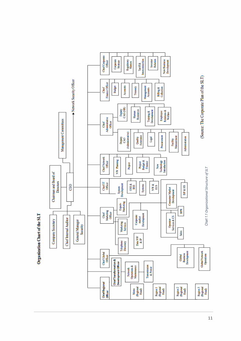
11
Cha
rt 1
.1 O
rga
niz
ati
on
al S
tru
ctu
re o
f SL
T

12
Asymmetric Digital Subscriber Line (ADSL)
Asymmetrical digital subscriber line (ADSL) has emerged as the optimal solution to high speed Internet access
technology. ADSL matches the asymmetric pattern of Internet traffic with speeds of up to 8 Mb/s downstream
from the network to the end user, and up to 640 kb/s upstream from the end user to the network. ADSL can
transmit both voice and data simultaneously over an existing single copper pair up to 18,000 feet long. With its
amazing speed and economical use of the installed base of copper cable, ADSL keeps the service cost low for
both service providers and end users.
Traditional plain old telephone service (POTS) uses a narrow 4-kHz baseband frequency to transmit analog
voice signals. The modem technology can only achieve throughput of up to 56 kb/s. To attain a much higher
throughput of up to 8 Mb/s, ADSL increases the usable frequency range from 4 kHz to 1.1 MHz. Frequency
division multiplexing (FDM) then allows ADSL to create multiple frequency bands to carry upstream and
downstream data simultaneously with the POTS signal over the same copper pair. The lower 4-kHz frequency
range is reserved for POTS, the middle frequency band is used to transmit upstream data, and the larger, higher
frequency band is used for downstream data.
Discrete multi-tone (DMT) modulation has been chosen by the American National Standards Institute (ANSI).
DMT divides the data bandwidth into 256 sub-channels, or tones, ranging from 20 kHz to 1.1 MHz. Upstream
data transfer frequencies range from 20 kHz to 160 kHz, and downstream data transfer frequencies range from
240 kHz to 1.1 MHz. The remaining tones are used as guard bands for dividing the three frequency bands, and
one pilot tone is used in each data stream, both upstream and downstream, for timing purposes. Each tone has
a spacing of 4.3 kHz and supports a maximum number of 15 bits, as limited by its signal-to-noise ratio. DMT
shifts signals between 256 channels for transmission.
Figure 2.1Frequency allocation in ADSL
Figure 2.2 The discrete multi tones of ADSL
13
ADSL uses quadrature amplitude modulation (QAM) to achieve the 15-bit maximum that any single tone can carry. QAM is a technique that employs a combination of amplitude modulation and phase shift keying.
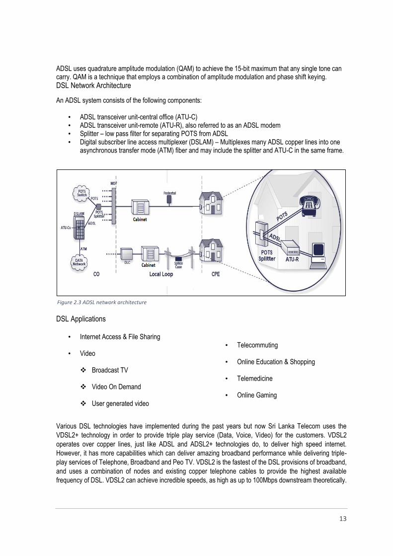
DSL Network Architecture
An ADSL system consists of the following components:
• ADSL transceiver unit-central office (ATU-C) • ADSL transceiver unit-remote (ATU-R), also referred to as an ADSL modem • Splitter – low pass filter for separating POTS from ADSL • Digital subscriber line access multiplexer (DSLAM) – Multiplexes many ADSL copper lines into one
asynchronous transfer mode (ATM) fiber and may include the splitter and ATU-C in the same frame.
DSL Applications
• Internet Access & File Sharing
• Video
Broadcast TV Video On Demand User generated video
• Telecommuting
• Online Education & Shopping
• Telemedicine
• Online Gaming
Various DSL technologies have implemented during the past years but now Sri Lanka Telecom uses the
VDSL2+ technology in order to provide triple play service (Data, Voice, Video) for the customers. VDSL2
operates over copper lines, just like ADSL and ADSL2+ technologies do, to deliver high speed internet.
However, it has more capabilities which can deliver amazing broadband performance while delivering triple-
play services of Telephone, Broadband and Peo TV. VDSL2 is the fastest of the DSL provisions of broadband,
and uses a combination of nodes and existing copper telephone cables to provide the highest available
frequency of DSL. VDSL2 can achieve incredible speeds, as high as up to 100Mbps downstream theoretically.
Figure 2.3 ADSL network architecture

14
This is much faster than ADSL and ADSL2+ technologies providing up to 16 Mbps downstream at present
around the country.
Telecommunication companies around the world are increasingly replacing many of their core networks and
access networks with fiber-optics, hence the reason behind operators choosing to deploy VDSL2 access
technology. In fact, many companies have Fiber-to-the-Cabinet (FTTC) in the pipeline. This will replace all
existing copper lines right up to the point where the telephone line branches off at the user location. Another
option that companies are looking at implementing is Fiber-to-the-Neighborhood/Node (FTTN). Instead of
installing fiber-optic cables along each street, FTTN has fiber going to the main junction box to a particular
neighborhood. This is the very same network architecture SLT has deployed for its ongoing network
modernization projects such as ‘i-Sri Lanka’ (access network) and the Next Generation Network (NGN) - the
core network.
ADSL line quality parameters
SNR (Sound to Noise Ratio)
In telecommunication the “noise” is a combination of unwanted interfering signal sources. Ex:- cross talk, radio
frequency, distortions, interferences etc. SNR often referred to as noise margin in telecommunication field. SNR
is defined as the power ratio between signal power and background noise.
High SNR values represent cleaner signals, the following chart describes the line status according to the SNR
values.
SNR = Signal Power / Noise Power
Table 2.1 Comparison of different DSL technologies
15
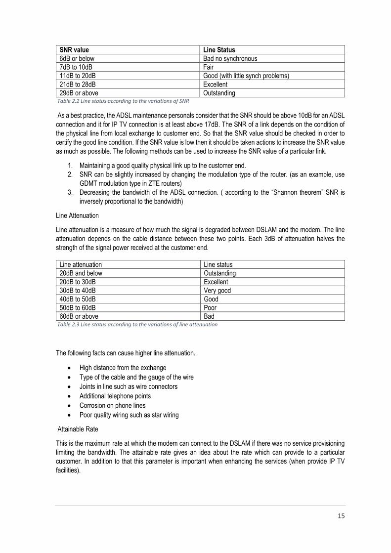
Table 2.2 Line status according to the variations of SNR
As a best practice, the ADSL maintenance personals consider that the SNR should be above 10dB for an ADSL
connection and it for IP TV connection is at least above 17dB. The SNR of a link depends on the condition of
the physical line from local exchange to customer end. So that the SNR value should be checked in order to
certify the good line condition. If the SNR value is low then it should be taken actions to increase the SNR value
as much as possible. The following methods can be used to increase the SNR value of a particular link.
1. Maintaining a good quality physical link up to the customer end.
2. SNR can be slightly increased by changing the modulation type of the router. (as an example, use
GDMT modulation type in ZTE routers)
3. Decreasing the bandwidth of the ADSL connection. ( according to the “Shannon theorem” SNR is
inversely proportional to the bandwidth)
Line Attenuation
Line attenuation is a measure of how much the signal is degraded between DSLAM and the modem. The line
attenuation depends on the cable distance between these two points. Each 3dB of attenuation halves the
strength of the signal power received at the customer end.
Table 2.3 Line status according to the variations of line attenuation
The following facts can cause higher line attenuation.
High distance from the exchange
Type of the cable and the gauge of the wire
Joints in line such as wire connectors
Additional telephone points
Corrosion on phone lines
Poor quality wiring such as star wiring
Attainable Rate
This is the maximum rate at which the modem can connect to the DSLAM if there was no service provisioning
limiting the bandwidth. The attainable rate gives an idea about the rate which can provide to a particular
customer. In addition to that this parameter is important when enhancing the services (when provide IP TV
facilities).
SNR value Line Status
6dB or below Bad no synchronous
7dB to 10dB Fair
11dB to 20dB Good (with little synch problems)
21dB to 28dB Excellent
29dB or above Outstanding
Line attenuation Line status
20dB and below Outstanding
20dB to 30dB Excellent
30dB to 40dB Very good
40dB to 50dB Good
50dB to 60dB Poor
60dB or above Bad
16
Max Rate
Max rate is the rate which is allowable for a particular customer. This rate is determined by the service provider
according to the line condition. The attainable rate, SNR margin and line attenuation should be considered when
determining the appropriate value for the link.
ADSL Faults and Troubles
Basically the ADSL related faults can be divided into two categories as,
Faults regarding to router or modem
Fault regarding to the telephone line
In addition these basic categories, the network failures can be a reason to fail the ADSL service (ex: break down
of a MSAN due to a power failure). The payment issues, misusing of services are also some reasons to
disconnect the ADSL service by the ISP.
Faults regarding to router and modem
Resetting of router
Improper router configurations
Router circuit problems
Incorrect username and password
Damages happened due to lightening and surges.
Faults regarding to ADSL link
Line disconnections, earthing and short circuiting
Low SNR due to poor line condition
Incorrect hardware setup
Unsuitability of max rates, SNR and attainable rate
Troubleshooting
Troubleshooting is the process of repairing the fault step by step in order to give a sustainable solution for the
customer. The first step is to identify the fault and the faulty part or the section. The set of indication lamps of
the router is an important interface which gives an idea about the router condition and its faults. Furthermore, it
can be logged into the router to check the line parameters and its configurations. In order to test the faults
regarding to an ADSL link, it is better to check the dial tone and it allows us to know if there is any noise in the
line also. To provide a best data and IP TV services to customer it is necessary to maintain a noise free link up
to the customer end.
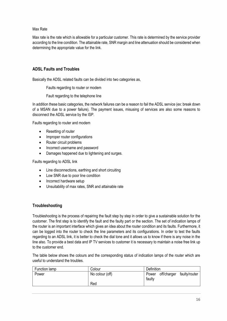
The table below shows the colours and the corresponding status of indication lamps of the router which are
useful to understand the troubles.
Function lamp Colour Definition
Power No colour (off) Red
Power off/charger faulty/router faulty
17
POST(Power On Self-Test)failure or router malfunction
DSL Blinking without been steady ADSL connection is not available Router fault
Internet Off Red
The system is under the bridge mode or ADSL line has not been connected. Authentication failure / router has not been configured or reset
LAN 1 -4 Off No Ethernet signal has detected. Fault of a router or Ethernet cable fault A fault of a NIC (Network Interface Card)
Table 2.4 Definitions for router alarms
The DSL indication lamp should be remain steady if the ADSL line is available up to the router. If the
lamp is blinking that means ADSL connection is not available to the router.
The power lamp should remain in green colour if the router consumes power without a disturbance.
The internet bulb should be in green colour but can blink time to time as it indicates the data sending
and receiving.
If it is red in colour that means, the authentication process has failed. The authentication fails due to
incorrect username and passwords and because of the router reset. So to recover the fault the correct
username and password should be given to the router.
The sudden fluctuations of the electricity may be the reason to reset the router.
The cu lines must be maintained properly in order to provide a good quality voice, data or IP TV service.
The noises in the line is a major reason to drop down the ADSL connection because it reduces the
useful signal.
When a line condition is not good the overhead cable, discharger, rosette and rosette code and the
internal wiring should be checked in order to identify the faulty location and the reason. It can be a fault
in underground cable which must be repaired first, and then the line can be tested up to the customer
end for the ADSL availability.
The line parameters are also useful when troubleshooting because the unsuitable values of line
parameters are also makes troubles in ADSL connections.
In addition to the basic router configurations, there are many other advanced configurations which
should be done before use it. However at the OPMC service center only the inserting of username,
password and wireless access activation are done but other configurations have already done.
Although the advanced configurations are not been done it is necessary have a basic idea about those
configurations in order to identify and recover the troubles regarding to DATA and ADSL connections.
A brief description about such configurations are given below.
DHCP (Dynamic Host Configuration Protocol)
DHCP is a protocol which uses in servers to assign IPs for network devices. DHCP servers allows
network devices to join an IP based network without having a predetermined IP address. DHCP
parameters includes a pool of IP addresses, the correct sub net mask, network gateway and
name server addresses. So the routers obtained a public IP from the DHCP server, because of
that the DHCP should be enabled while configuring a router.
18
NAT (Network Address Translation)
NAT is a method of using the IP addresses in an efficient way without wasting them. This method
translates the network address of a LAN into a network address of the WAN. The IP of inside
network (LAN) is known as the “Local Address” and the IP of outside network (WAN) is known as
“Global Address”. This method and another related method known as NAPT (Network Address
Port Translation) is used in ADSL routers. So that the NAT should be enabled when configure a
router.
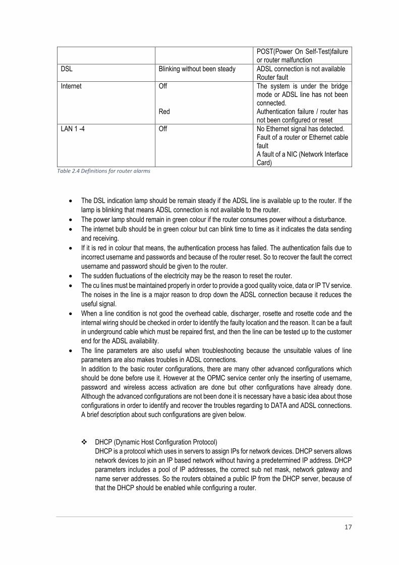
VCI (Virtual Channel Identifier ) / VPI (Virtual Path Identifier )
VPI/VCI setting are very important to establish the connection between the router and the internet
service provider (ISP). This two values are different from ISP to ISP. VPI refers to an 8-bit (user
to network packets) or 12-bit (network to network packets) field within the header of the data
packet. This field is important to reduce the switching table for some virtual circuits which have
common path. VCI is used to identify the next destination of a packet as it passes through a series
of switches. SLT uses the following VPI/VCI values for ADSL and IPTV connections.
SERVICE VPI VCI
ADSL 8 35
IPTV 8 36 Table 2.5 VPI/VCI values for ADSL & IPTV
Multicast – IGMP (Internet Group Message Protocol)
IP multicasting is defined as the transmission of an IP datagram to host group which
identified by a single IP destination address. That means multicasting is used to
discover the group members (hosts). IGMP is the protocol that is applied for ADSL
routers to enable the multicasting process.
PPPoE (Point to Point Protocol over Ethernet)
PPPoE is a network access layer protocol for encapsulating PPP frames inside
Ethernet frames. PPPoE enables to connect multiple computers on an Ethernet LAN
to share the common ADSL connection. So the PPPoE should be selected as the
encapsulation type.
The above settings are only few settings of an ADSL router, there are many other settings which have been
already configured when a router is installed for a new connection. There are some other specific configurations
that should be done in a router for IPTV and DATA connections.
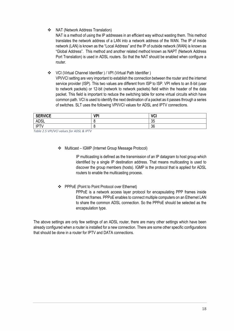
19
Helps to determine the
relevant VPI/VCI values
regarding to the service
Enter the username &
password
Figure 1.4.2 - ADSL router configurations Figure 2.5 ADSL Router Configuration
VPI 8
VCI 35
Select PPPoA/PPPoE (Point to point
over ATM/Ethernet)
Figure 2.4 ADSL Router Configuration
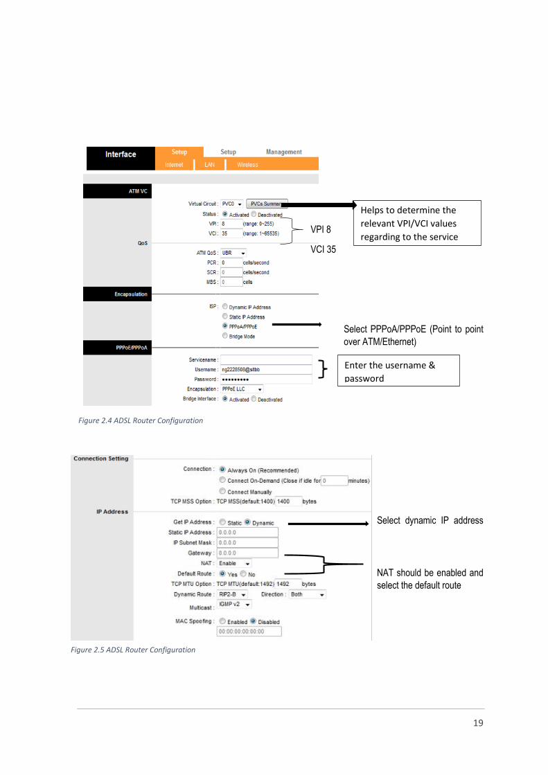
Select dynamic IP address
NAT should be enabled and
select the default route

20
Figure 2.6 wireless configurations
Testing and maintenance equipment
When testing or troubleshooting a ADSL connection it is necessary to use appropriate tools and equipment in
order to identify the faults and to provide sustainable solutions for them. There are some special equipment that
are used by the ADSL workgroups for the maintenance tasks. They are,
Crimping tool
ADSL testing meter
Ethernet cable tester
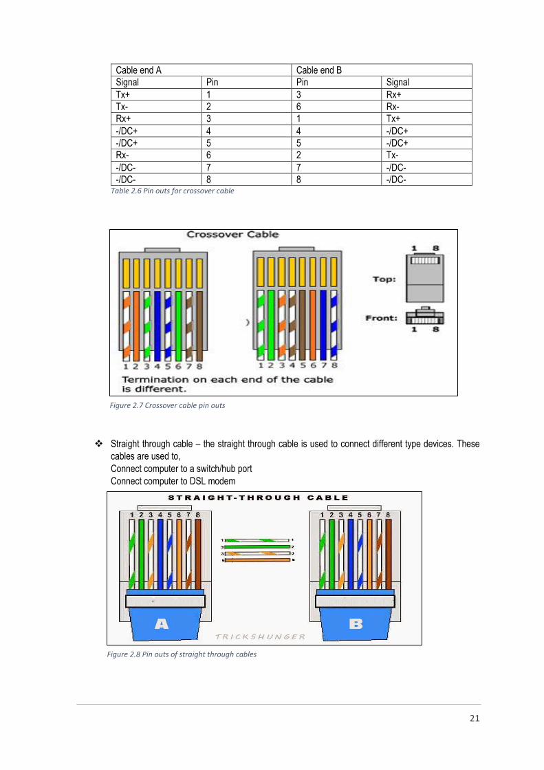
Crimping tool – The crimping tool is used to crimp the (Registered Jack) RJ45 and RJ11 connectors. The
Ethernet cable has fur pair of copper conductors, with specific colour code. When crimping a RJ45 connector,
it is necessary to prepare the eight wires according to the cable type that is required. There are two type cables
which are different from the wire arrangement of the ethernet cable. They are,
Crossover cable Straight through cable
Crossover cable – the crossover cable is used to connect same type of devices.
Connect two computers
Connect two switches/hubs
Connect router’s normal port to a
switch/hub’s normal port
Connect two switches, hubs
Set the Wi-Fi name
Select the
authentication
type
Enter the Wi-
Fi password
21
Cable end A Cable end B
Signal Pin Pin Signal
Tx+ 1 3 Rx+
Tx- 2 6 Rx-
Rx+ 3 1 Tx+
-/DC+ 4 4 -/DC+
-/DC+ 5 5 -/DC+
Rx- 6 2 Tx-
-/DC- 7 7 -/DC-
-/DC- 8 8 -/DC- Table 2.6 Pin outs for crossover cable
Straight through cable – the straight through cable is used to connect different type devices. These
cables are used to,
Connect computer to a switch/hub port
Connect computer to DSL modem
Figure 2.7 Crossover cable pin outs
Figure 2.8 Pin outs of straight through cables

22
Cable end A Cable end B
Signal Pin Pin Signal
Tx+ 1 1 Tx+
Tx- 2 2 Tx-
Rx+ 3 3 Rx+
-/DC+ 4 4 -/DC+
-/DC+ 5 5 -/DC+
Rx- 6 6 Rx-
-/DC- 7 7 -/DC-
-/DC- 8 8 -/DC- Table 2.7 Pin outs for straight through cable
ADSL Testing meter – ADSL testing meter is an advanced testing equipment that can be used to test an ADSL
link. The tester is capable to give the real values of the ADSL link parameters, and it has some other advanced
features. It also can be used during the process of installing an ADSL services to verify that the existing copper
pairs are up to the job or not. Although the link parameters can be tested by logging to the router at customer
premises but it is not practical to use a router when testing the link at any other point of a network. The tester
can be used for such situations efficiently to analyze the trouble of the line because the equipment consists of
both RJ45 and a RJ11 interface. The following features are there for testing purposes,
Downstream, upstream rates, maximum rate and SNR margin testing interface
Graphical charts of SNR deviation of a link
Ping, trace route, FTP and ATM tests
IPTV STB (Set Top Box) simulation
Internet browsing
Network cable tester – this testing tool has the capability to test the Ethernet cable for disconnections and
wrong cable setup. The network cables (cat5) can be tested with this tester by connecting the two parts of the
tester to both ends of the cable. The network cable tester can identify if the wires are paired correctly. It can
also shows if there is a break of wires or insulation which allows crosstalk between two wires that should not be
connected. Basic network cable testers can only test for simple connectivity issues but advanced cable testers
provide more information about the fault, reason and the where the fault is.
Figure 2.9 ADSL testing meter/ crimping tool/ Network cable tester
23
New connection section
Customer premises equipment
Discharger
The overhead copper cable terminates at the discharger inside the customer premises. Discharger is a
multipurpose unit which fulfills the following requirements of the network.
Termination point
Earthing point
Secured point (protect against lightening and electric surges)
Testing point
In order to achieve the above tasks the discharger consists of several arts such as,
Overhead cable termination point
Internal wire starting point
Fuse
Earthing point
Casing
The discharger can be used as a primary testing point that is used when the maintenance are done related to
telephone line. The telephone links must be earthed at various points to ensure the network and the customer
premises equipment. So the discharger is also acts as an earthing point. A copper plated steel rod and a copper
conductor is used to do the earthing of the discharger. Further, the discharger is the interface between the
internal and the external wiring. As a practice, the internal pair is connected to the top of the discharger and the
external pair to the bottom of the unit. In addition to that a fuse has been installed between these two parts to
ensure the protection against the lightening and the electric surges that can be flow through the conductors.
Rosette
The rosette box connects with the discharger via a twin cable and the rosette code connects to the other side.
The rosette box consists of a RJ11 interface which makes the link compatible to connect the rosette code. The
rosette consists of four wires but it can be used only two middle pins for data transmitting and receiving. So the
middle two wires of the rosette code are used and the other two wires remains spare.
Splitter
The splitter functions as a filter which filter out the high and low frequencies. The voice signals have low
frequency (below 4 kHz) and the ADSL data signals have high frequency (above 4 kHz). So the splitter is simply
an analog low pass filter and filter out the low frequency signals and allows the high frequency signals to flow
through towards the modem or router. So the splitter consists of three RJ11 interfaces. The rosette code
connects to a one side of the splitter and the other side has two RJ11 interfaces reserved for telephone code
and the router code. It makes problems in the ADSL line if these two interfaces are changed.
Set top box (STB)
STB is a device that necessary when providing an IPTV service to a customer. A set-top box is a device that
enables a television set to become a user interface to the Internet and also enables a television set to receive
and decode digital television (DTV) broadcasts. In the Internet sector, a set-top box is really a specialized
computer that can talk to the Internet that is, it contains a Web browser (which is really a Hypertext Transfer
24
Protocol client) and the Internet's main program, TCP/IP. The service to which the set-top box is attached may
be through a telephone line as “Peo TV”.
ADSL router
An ADSL router is also known as a DSL modem. The router connects the computer to the DSL phone line so
the ADSL service can be used. There are some ADSL routers that are also capable of sharing a single Internet
connection with a group of computers on a network. This system is also known as the residential gateway.
Every ADSL router has a functional block called ADSL Terminal Unit-Remote (ATU-R (transceiver). The ATU-
R is responsible for functions like demodulation, modulation, and framing. There are also other functional blocks
that perform specific functions like IP routing and bridging. The interfaces for the ADSL router are
either Ethernet or USB. The ADSL modem might have been assigned an IP address from the beginning for
management purposes, though an ADSL router that works as a bridge does not need an IP address.
While early routers provided several Ethernet ports for wired connections, most modern routers
offer wireless connectivity as well. These "wireless routers" often have one or two moveable antennas on the
sides, though some models house the antennas inside the enclosure. Wireless routers allow multiple computers
and other devices, such as smartphones and tablets, to join the same network.
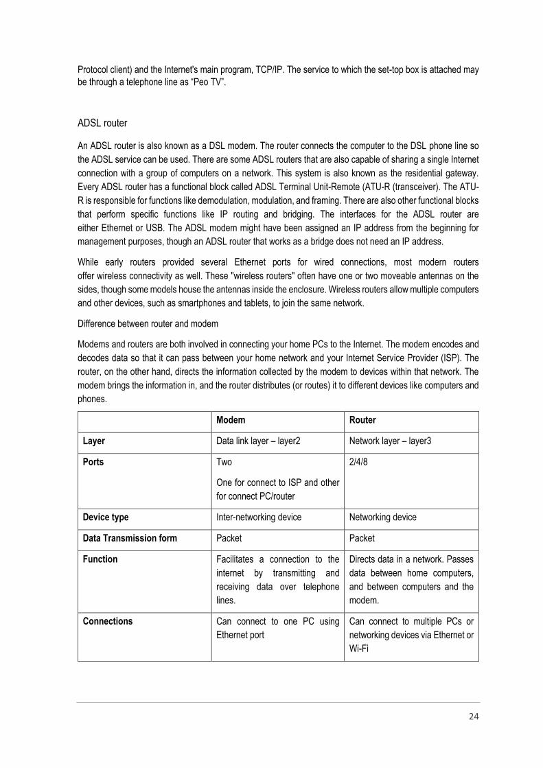
Difference between router and modem
Modems and routers are both involved in connecting your home PCs to the Internet. The modem encodes and
decodes data so that it can pass between your home network and your Internet Service Provider (ISP). The
router, on the other hand, directs the information collected by the modem to devices within that network. The
modem brings the information in, and the router distributes (or routes) it to different devices like computers and
phones.
Modem Router
Layer Data link layer – layer2 Network layer – layer3
Ports Two
One for connect to ISP and other
for connect PC/router
2/4/8
Device type Inter-networking device Networking device
Data Transmission form Packet Packet
Function Facilitates a connection to the
internet by transmitting and
receiving data over telephone
lines.
Directs data in a network. Passes
data between home computers,
and between computers and the
modem.
Connections Can connect to one PC using
Ethernet port
Can connect to multiple PCs or
networking devices via Ethernet or
Wi-Fi

25
Necessity for Internet
Connection
Yes No, but provides additional
security and allow for multiple
connections.
Independency Yes. A modem can work without a
router, delivering information
(such as Internet access) to a
single PC.
Routers can share information
between computers, but cannot
connect to the Internet without a
modem.
Security No security measures Provides security measures to
protect network
Table 3.1 Comparison between router and modem
Earth rod and earth conductor
The telecommunication network should be protected in order to ensure the 100% availability. So that when
establishing a new connection it is necessary to earth the discharger using an earth cable and the earth rod.
The earth rod should be properly buried in the earth and the earth conductor is used to connect the earth rod
and the discharger. A copper plated steel rod is used in order to increase the conductivity. Discharger earthing
rod should be inserted 50cm into the ground and ground earth resistance should be 100ohm maximum.
Basic steps of providing a new connection
Provisioning of new telephone or ADSL connection is an advance process which consists of number of steps.
All these steps should be proceed one by one in order to fulfill the need of customer. Basic steps of provisioning
of a new connection are listed below.
Applying for the new connection
Looking for a spare loop in closest DPs (Distribution Points)
It should be selected the closest DP to supply the services because the quality of the service
degrades when increasing the distance between the customer end and the local exchange.
If it is a Peo TV connection that distance should be below 3500m.
Allocating a particular loop and the switching location.
Completing the external wiring (wiring from the loop of the DP to the discharger using the drop wires).
There are some facts which should be considered while doing the external wiring and some of them
are given below.
1. When distance between two poles is less than 40m,maximum sag should be 0.4m.
2. If distance between two poles is in between 40m and 50m,maximum sag should be
0.7m.
3. The distances between power lines and telephone lines should be maximum 30cm
for 230V and minimum 100cm for 400V.
4. Discharger should be located 5 feet from ground level.
5. Discharger earthing rod should be inserted 50cm into the ground and ground earth
resistance should be 100ohm maximum.
Doing the internal wiring inside the customer premises to set up the telephone/router or set top box
using twin pair wire. Discharger should be earthed also to ensure the safety of customer equipment
and the ISP network.
Connecting the relevant cable side location and the DP side location at the external cabinet or the
MSAN.

26
Connecting the allocated switching location and the cable side location at the MDF(Main Distribution
Frame) using a jumper wire.
Configuring the particular switch location for the relevant subscriber then only the dial tone is provided
to the line.
Setting up the customer end accessories and configuring the routers and STBs(Set Top Boxes). Then
the connection is tested to certify the availability of the new connection.
Figure3.1Connection procedure of customer equipment for ADSL/PSTN and PEO TV
27
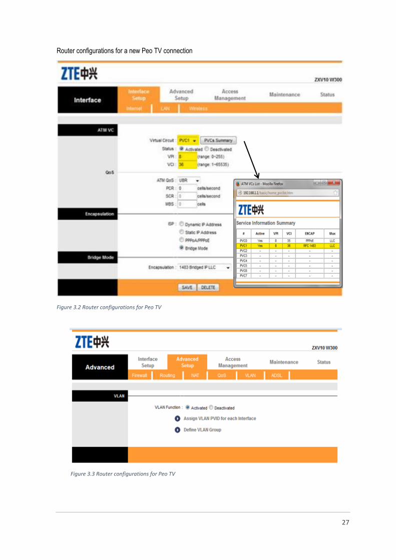
Router configurations for a new Peo TV connection
Figure 3.2 Router configurations for Peo TV
Figure 3.3 Router configurations for Peo TV
28
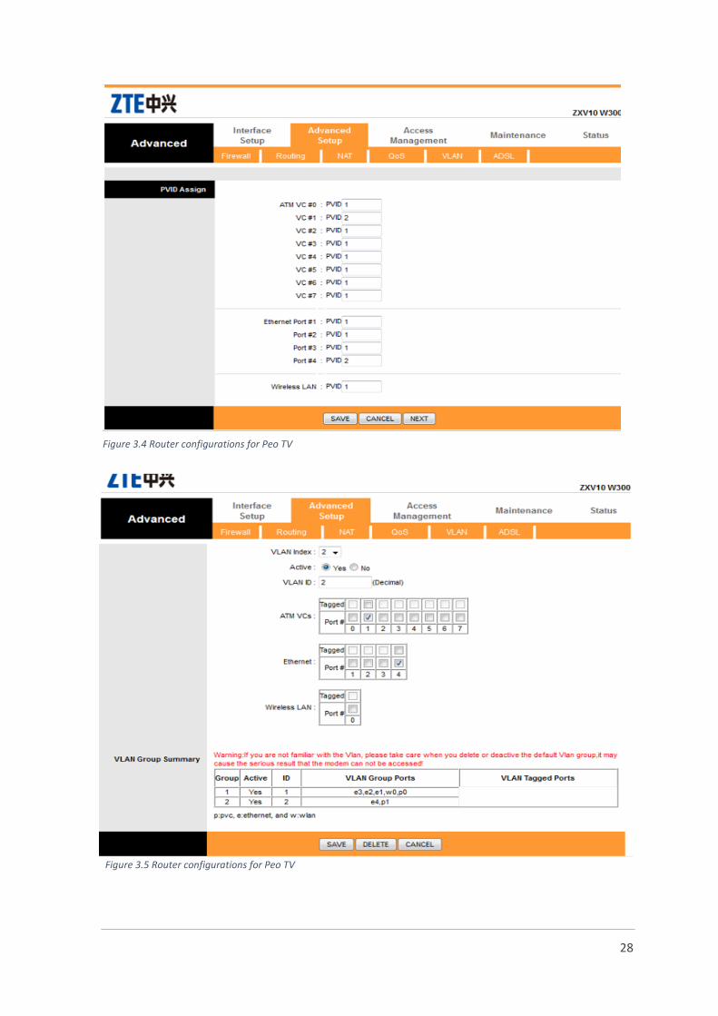
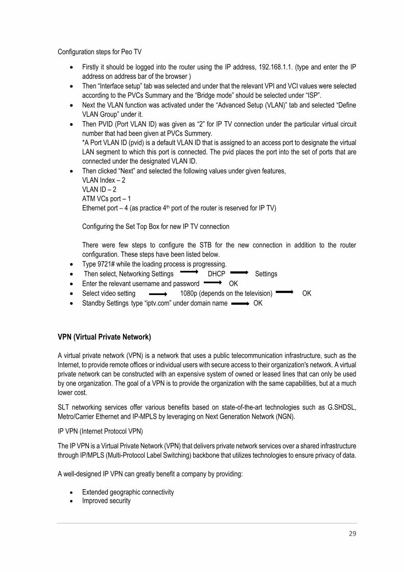
Figure 3.5 Router configurations for Peo TV
Figure 3.4 Router configurations for Peo TV
29
Configuration steps for Peo TV
Firstly it should be logged into the router using the IP address, 192.168.1.1. (type and enter the IP
address on address bar of the browser )
Then “Interface setup” tab was selected and under that the relevant VPI and VCI values were selected
according to the PVCs Summary and the “Bridge mode” should be selected under “ISP”.
Next the VLAN function was activated under the “Advanced Setup (VLAN)” tab and selected “Define
VLAN Group” under it.
Then PVID (Port VLAN ID) was given as “2” for IP TV connection under the particular virtual circuit
number that had been given at PVCs Summery.
*A Port VLAN ID (pvid) is a default VLAN ID that is assigned to an access port to designate the virtual
LAN segment to which this port is connected. The pvid places the port into the set of ports that are
connected under the designated VLAN ID.
Then clicked “Next” and selected the following values under given features,
VLAN Index – 2
VLAN ID – 2
ATM VCs port – 1
Ethernet port – 4 (as practice 4th port of the router is reserved for IP TV)
Configuring the Set Top Box for new IP TV connection
There were few steps to configure the STB for the new connection in addition to the router
configuration. These steps have been listed below.
Type 9721# while the loading process is progressing.
Then select, Networking Settings DHCP Settings
Enter the relevant username and password OK
Select video setting 1080p (depends on the television) OK
Standby Settings type “iptv.com” under domain name OK
VPN (Virtual Private Network)
A virtual private network (VPN) is a network that uses a public telecommunication infrastructure, such as the
Internet, to provide remote offices or individual users with secure access to their organization's network. A virtual
private network can be constructed with an expensive system of owned or leased lines that can only be used
by one organization. The goal of a VPN is to provide the organization with the same capabilities, but at a much
lower cost.
SLT networking services offer various benefits based on state-of-the-art technologies such as G.SHDSL,
Metro/Carrier Ethernet and IP-MPLS by leveraging on Next Generation Network (NGN).
IP VPN (Internet Protocol VPN)
The IP VPN is a Virtual Private Network (VPN) that delivers private network services over a shared infrastructure
through IP/MPLS (Multi-Protocol Label Switching) backbone that utilizes technologies to ensure privacy of data.
A well-designed IP VPN can greatly benefit a company by providing:
Extended geographic connectivity Improved security

30
Reduced operational costs versus traditional WAN Reduced transit time and transportation costs for remote users Improved productivity Simplified network topology Global networking opportunities Telecommuter support Broadband networking compatibility
Ethernet VPN
Ethernet VPN is a Layer 2 VPN that allows the connection of multiple Ethernet sites in a single domain over a provider managed IP/MPLS network. This gives the convenience and simplicity of Ethernet combined with all of the advantages of MPLS. All sites appear to be connected to a single VLAN. Since the interface is Ethernet it allows one interface type for data and voice. Widely used in a situation where all the customer sites are located in the Metro Ethernet service area, where the inter-branch communication requires a high bandwidth.
Also Ethernet VPN offers higher bandwidth choice for Layer 2 multipoint services. Since many of the organizations do not want to share their IP routing information and control through Ethernet VPN it gives the feasibility of the end customer to control the IP routing information.
A well-designed Ethernet VPN can greatly benefit a company by providing:
No protocol conversion between LAN and WAN
No expertise required The provider switches and the
Customer routes Customer maintains complete
control over routing
Ethernet Data Line
Ethernet Data Line is a point-to-point connection through the IP/MPLS network. Two locations will be connected through Ethernet link offering a high degree of transparency of data to be carried. This service shall be used to link two business locations at speed starting from 2 Mbps to 10Gbps and very much ideal for connecting your; Primary Data Centre with your DR (Disaster recovery) site.
Figure 3.6 IP VPN
Figure 3.7 Ethernet VPN

31
Primary Data Centre with your DR site hosted in SLT IDC (internet data center) Primary Data Center hosted in SLT IDC with your DR site hosted in SLT IDC DR Site High Speed Internet (HIS) service to your Business Office, Main Link of your IP VPN to your Head Office.
Main Distribution Frame (MDF) or Testing Room Main Distribution Frame is an interface between underground cable side and the exchange side. MDF connects
the telecommunication facilities to the subscriber ends. So the MDF is a large scale distribution panel that
consists of two sides, one side is the exchange side which has a large number of switching locations. There are
voice blocks which are connects to the voice cards and also data blocks that are connect to the combo cards
which has the ability to provide both data and voice facilities.
The MDF is acts as a flexible point of the network which provides testing ability and security (earthing
point). When providing a connection to a subscriber it is necessary to wire the relevant two locations at both
sides together in order to complete the circuit. This task is known as “jumpering” and a special tool is used to
jumper the jumper wire to the blocks.
As the MDF is a testing point different kind of maintenance groups (such as overhead maintenance group, new
connection groups and underground cable maintenance group) always contact the testing room in order test
the lines, to get information about lines and sometimes to get subscribers details. In order to provide these
details the testing room should has a properly maintained database.
The physical appearance of the MDF is simply a steel rack with a large number of ports in both sides. However,
the both sides have arranged according to a special manner which makes easy to identify the switching location
and the cable location.
The termination blocks of the cable side have been arranged vertically. Each block has been numbered with
the relevant cabinet number and the cable code. Every block consists of ten punch blocks and each block has
ten ports that means one block can serve hundred cables pairs. In other words a one block represents a
distribution point which connected to the other end of the corresponding cable’s pairs. So the relevant loops
could be identified with the cable code or by the cabinet – DP – loop number sequence.
The termination blocks of the exchange side have been arranged horizontally and each block of horizontal rack
consists of sixteen punch block that each has ten ports. Every block of a horizontal rack has been assigned
with an English letter.
Figure 4.0 – Termination block structure of exchange side
Example cable code of line side –108, F 379 or (108/38/9)
Example exchange location code – A3.14.4 (rack no, punch block no, port no)
32
Exchange
side
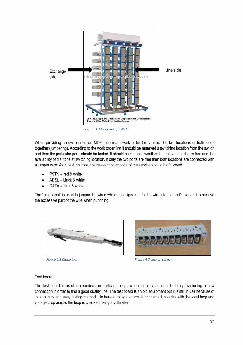
When providing a new connection MDF receives a work order for connect the two locations of both sides
together (jumpering). According to the work order first it should be reserved a switching location from the switch
and then the particular ports should be tested. It should be checked weather that relevant ports are free and the
availability of dial tone at switching location. If only the two ports are free then both locations are connected with
a jumper wire. As a best practice, the relevant color code of the service should be followed.
PSTN – red & white
ADSL – black & white
DATA – blue & white
The “crone tool” is used to jumper the wires which is designed to fix the wire into the port’s slot and to remove
the excessive part of the wire when punching.
Test board
The test board is used to examine the particular loops when faults clearing or before provisioning a new
connection in order to find a good quality line. The test board is an old equipment but it is still in use because of
its accuracy and easy testing method. . In here a voltage source is connected in series with the local loop and
voltage drop across the loop is checked using a voltmeter.
Line side
Figure 4.1 Diagram of a MDF
Figure 4.2 Line arresters Figure 4.3 Crone tool

33
The particular line can be tested up to the customer end using this equipment. First, the test line of the test
board should be plugged to the line side of the particular loop and then it can be tested with the equipment.
There are several tests which can be proceeded with the test board as follows,
Earth key – to check whether the line has
earthed or not
Short key – to check whether the line is short
circuited or not
In service key – to check the availability of dial
tone
Ring key – to ring the customer’s telephone
Talk key – to talk with customer end
Fault handling process of MDF
In addition to the above tasks there are some other operations that are done by the MDF. The major task is
fault handling regarding to the PSTN connections. The faults which related to the PSTN, are assigned to the
relevant MDF section of the region. The MDF work group should do the following tasks regarding to the PSTN
faults.
Acknowledging the faults assigned to the MDF section
Assigning the faults to relevant PSTN maintenance work groups
Closing the faults of the accounts after clearing the faults by the work groups
Changing the work groups when necessary
Providing the information regarding to the faults (ex: DP no, cabinet no, loop no, customer details)
SLT uses two software solutions, in order to automate the fault handling process and to increase the
productivity of the maintenance. This software solutions works as a,
Customer data base
Faults handling interface
An interface to update the information of the whole system
Create and modifying the voice and data circuit
In addition to above tasks there are many capabilities when considering the software solutions of SLT. The main
software solutions are,
Clarity software
WFM (work force management) system
Clarity
Clarity is an Operation Support System (SLT) that is used in SLT. Clarity is a global provider that enables its
customers to simplify their operations with an award winning unified telecommunications management solution.
It enables Service Providers to reduce the cost and risk of operations and improve the customer experience
Figure 4.4 Test board

34
across fixed, mobile, data and converged networks. So almost all the sections of the SLT uses the clarity OSS
to simplify the tasks as well as the maintenance process.
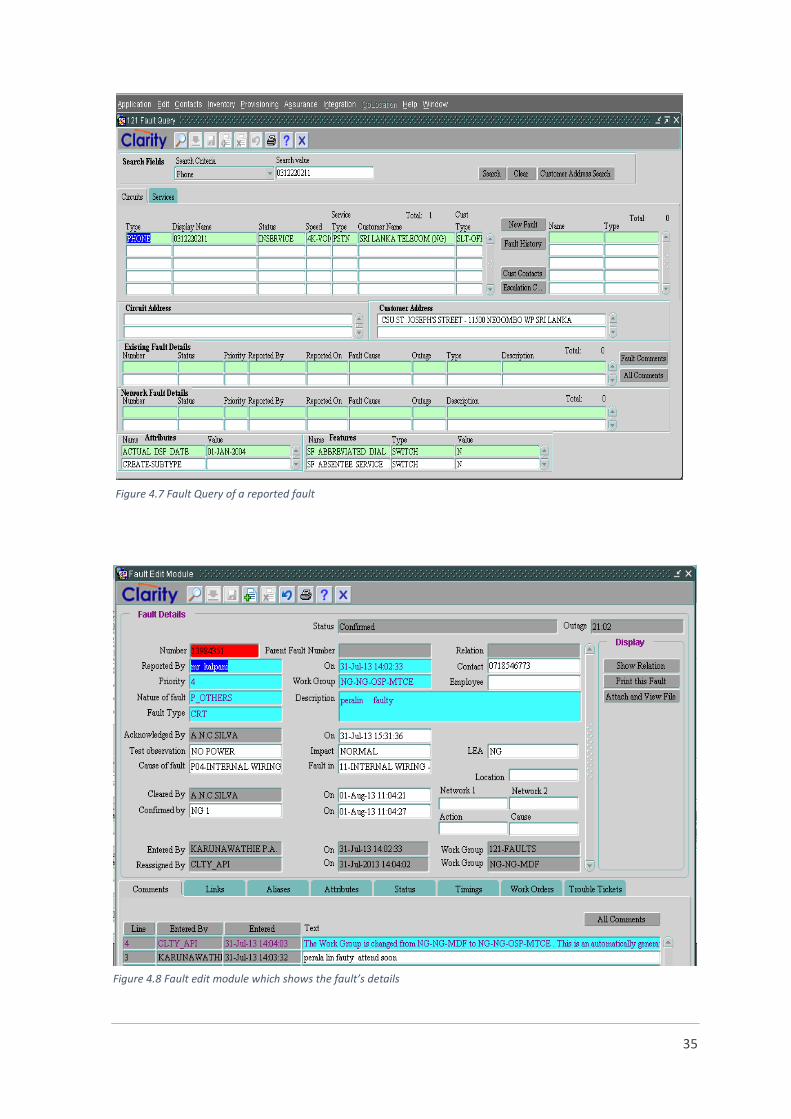
The assigned faults can be seen as follows using the Clarity
Figure 4.5 Steps to enter to the Fault Inbox
Figure 4.6 Fault Inbox
35
Figure 4.7 Fault Query of a reported fault
Figure 4.8 Fault edit module which shows the fault’s details
36
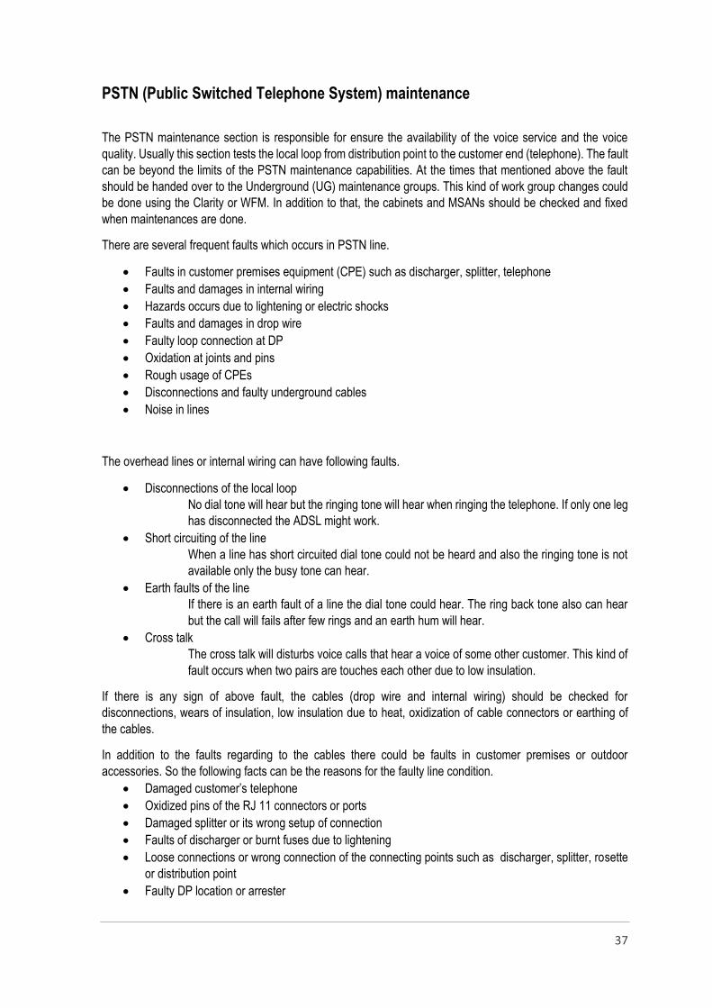
Work Force Management system (WFM)
WFMS integrates existing independent applications in Sri Lanka Telecom related to Faults, New Connections,
Development Management, CDMA Sales, OPMC activities and Material and Vehicle Movement Management
in order to enable centralized monitoring. As this is an android application this IT solution is much more familiar
for the technical personnel of the work groups. It is no need to ask the details regarding to the faults from the
MDF but the technical groups could easily refer the data of WFM which updates according to the data in the
Clarity OSS. This system helps to improve the efficiency of the maintenances and other field tasks.
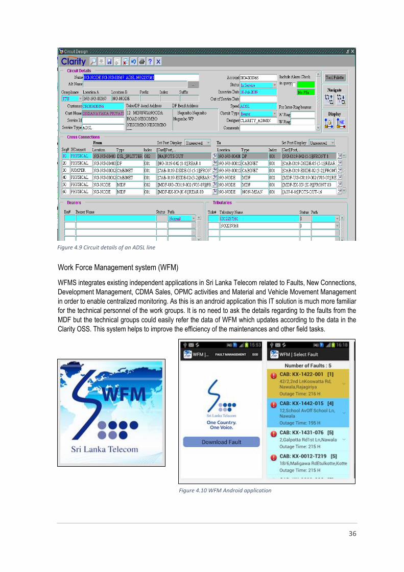
Figure 4.9 Circuit details of an ADSL line
Figure 4.10 WFM Android application
37
PSTN (Public Switched Telephone System) maintenance
The PSTN maintenance section is responsible for ensure the availability of the voice service and the voice
quality. Usually this section tests the local loop from distribution point to the customer end (telephone). The fault
can be beyond the limits of the PSTN maintenance capabilities. At the times that mentioned above the fault
should be handed over to the Underground (UG) maintenance groups. This kind of work group changes could
be done using the Clarity or WFM. In addition to that, the cabinets and MSANs should be checked and fixed
when maintenances are done.
There are several frequent faults which occurs in PSTN line.
Faults in customer premises equipment (CPE) such as discharger, splitter, telephone
Faults and damages in internal wiring
Hazards occurs due to lightening or electric shocks
Faults and damages in drop wire
Faulty loop connection at DP
Oxidation at joints and pins
Rough usage of CPEs
Disconnections and faulty underground cables
Noise in lines
The overhead lines or internal wiring can have following faults.
Disconnections of the local loop
No dial tone will hear but the ringing tone will hear when ringing the telephone. If only one leg
has disconnected the ADSL might work.
Short circuiting of the line
When a line has short circuited dial tone could not be heard and also the ringing tone is not
available only the busy tone can hear.
Earth faults of the line
If there is an earth fault of a line the dial tone could hear. The ring back tone also can hear
but the call will fails after few rings and an earth hum will hear.
Cross talk
The cross talk will disturbs voice calls that hear a voice of some other customer. This kind of
fault occurs when two pairs are touches each other due to low insulation.
If there is any sign of above fault, the cables (drop wire and internal wiring) should be checked for
disconnections, wears of insulation, low insulation due to heat, oxidization of cable connectors or earthing of
the cables.
In addition to the faults regarding to the cables there could be faults in customer premises or outdoor
accessories. So the following facts can be the reasons for the faulty line condition.
Damaged customer’s telephone
Oxidized pins of the RJ 11 connectors or ports
Damaged splitter or its wrong setup of connection
Faults of discharger or burnt fuses due to lightening
Loose connections or wrong connection of the connecting points such as discharger, splitter, rosette
or distribution point
Faulty DP location or arrester
38
Faulty ports, disconnections or low insulation of jumper wires at cabinet or MSAN
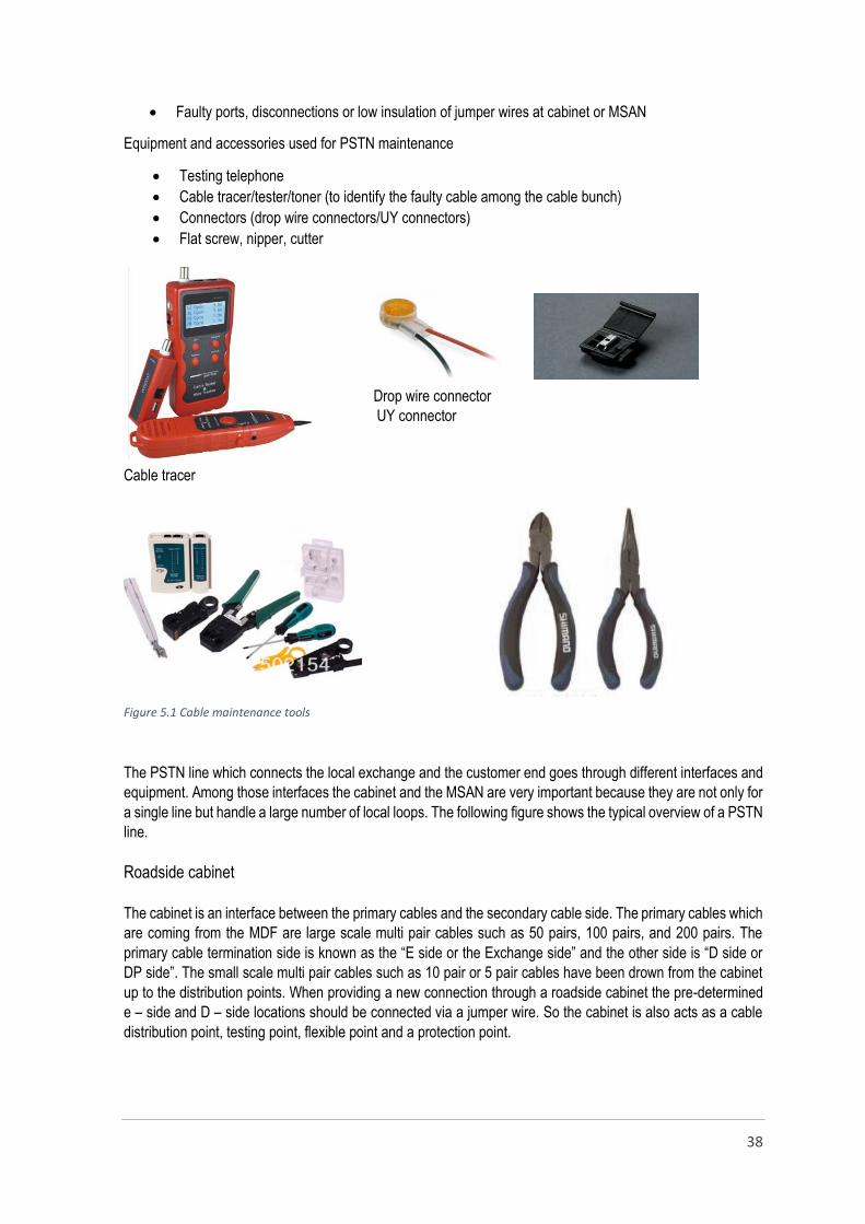
Equipment and accessories used for PSTN maintenance
Testing telephone
Cable tracer/tester/toner (to identify the faulty cable among the cable bunch)
Connectors (drop wire connectors/UY connectors)
Flat screw, nipper, cutter
Drop wire connector
UY connector
Cable tracer
The PSTN line which connects the local exchange and the customer end goes through different interfaces and
equipment. Among those interfaces the cabinet and the MSAN are very important because they are not only for
a single line but handle a large number of local loops. The following figure shows the typical overview of a PSTN
line.
Roadside cabinet
The cabinet is an interface between the primary cables and the secondary cable side. The primary cables which
are coming from the MDF are large scale multi pair cables such as 50 pairs, 100 pairs, and 200 pairs. The
primary cable termination side is known as the “E side or the Exchange side” and the other side is “D side or
DP side”. The small scale multi pair cables such as 10 pair or 5 pair cables have been drown from the cabinet
up to the distribution points. When providing a new connection through a roadside cabinet the pre-determined
e – side and D – side locations should be connected via a jumper wire. So the cabinet is also acts as a cable
distribution point, testing point, flexible point and a protection point.
Figure 5.1 Cable maintenance tools

39
MSAN (Multi Service Access Node)
Customer demands, market competition and technological development are the three driving forces behind the
accelerated development of modern communication networks. Traditionally the telephone line has only ever
provided voice but more recently this has expanded to include data, through the Internet, and in the future all
types of TV broadcasting for the home will be delivered over the phone line too. This triple play comprising
voice, data and video services has fundamentally changed the way telecommunications networks are used and
now these networks must themselves reflect this multi-service transformation in order to function most
efficiently.
SLT also faced to this when providing triple play service (Voice/ADSL/IP TV) to the customers few years before
specially, where the customers are located far away from the local exchange. The Multi-Service Access Node
(MSAN) is a multi-technology broadband solution to the challenge of providing voice, video and data services
over the existing fixed network of SLT.
Multi-Service access node or (MSAN) also known as MSAG or 'Multi-Service Access Gateway' is a device
typically installed in a telephone exchange (although sometimes in a roadside serving area interface cabinet)
which connects customers' telephone lines to the core network, to provide telephone, ISDN, and broadband
such as DSL all from a single platform. Typical outdoor MSAN cabinet consists of Narrowband (POTS),
Broadband (xDSL) services, batteries with rectifiers, optical transmission unit and copper distribution frame.
`
Figure 5.2 Typical structure of a PSTN line
Figure 5.3 Typical inside view of a MSAN
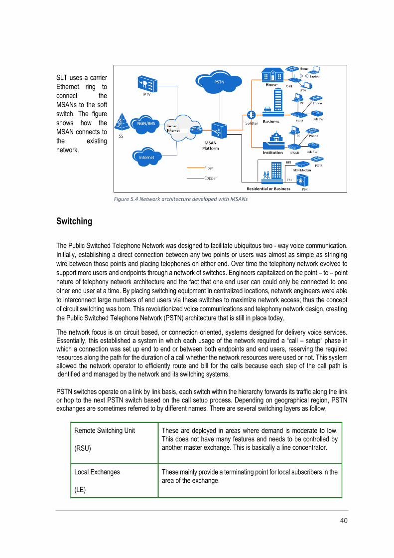
40
SLT uses a carrier
Ethernet ring to
connect the
MSANs to the soft
switch. The figure
shows how the
MSAN connects to
the existing
network.
Switching
The Public Switched Telephone Network was designed to facilitate ubiquitous two - way voice communication.
Initially, establishing a direct connection between any two points or users was almost as simple as stringing
wire between those points and placing telephones on either end. Over time the telephony network evolved to
support more users and endpoints through a network of switches. Engineers capitalized on the point – to – point
nature of telephony network architecture and the fact that one end user can could only be connected to one
other end user at a time. By placing switching equipment in centralized locations, network engineers were able
to interconnect large numbers of end users via these switches to maximize network access; thus the concept
of circuit switching was born. This revolutionized voice communications and telephony network design, creating
the Public Switched Telephone Network (PSTN) architecture that is still in place today.
The network focus is on circuit based, or connection oriented, systems designed for delivery voice services. Essentially, this established a system in which each usage of the network required a “call – setup” phase in which a connection was set up end to end or between both endpoints and end users, reserving the required resources along the path for the duration of a call whether the network resources were used or not. This system allowed the network operator to efficiently route and bill for the calls because each step of the call path is identified and managed by the network and its switching systems.
PSTN switches operate on a link by link basis, each switch within the hierarchy forwards its traffic along the link or hop to the next PSTN switch based on the call setup process. Depending on geographical region, PSTN exchanges are sometimes referred to by different names. There are several switching layers as follow,
Remote Switching Unit
(RSU)
These are deployed in areas where demand is moderate to low. This does not have many features and needs to be controlled by another master exchange. This is basically a line concentrator.
Local Exchanges
(LE)
These mainly provide a terminating point for local subscribers in the area of the exchange.
Figure 5.4 Network architecture developed with MSANs
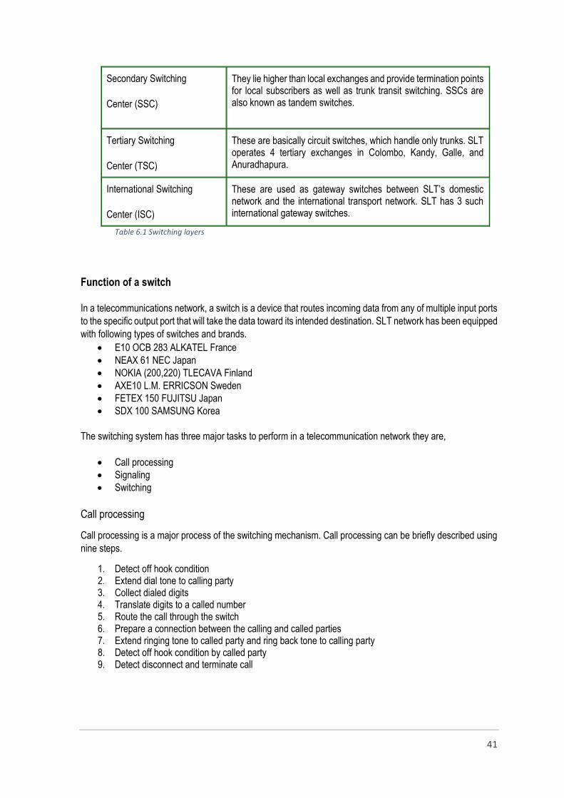
41
Secondary Switching
Center (SSC)
They lie higher than local exchanges and provide termination points for local subscribers as well as trunk transit switching. SSCs are also known as tandem switches.
Tertiary Switching
Center (TSC)
These are basically circuit switches, which handle only trunks. SLT operates 4 tertiary exchanges in Colombo, Kandy, Galle, and Anuradhapura.
International Switching
Center (ISC)
These are used as gateway switches between SLT’s domestic network and the international transport network. SLT has 3 such international gateway switches.
Table 6.1 Switching layers
Function of a switch
In a telecommunications network, a switch is a device that routes incoming data from any of multiple input ports
to the specific output port that will take the data toward its intended destination. SLT network has been equipped
with following types of switches and brands.
E10 OCB 283 ALKATEL France
NEAX 61 NEC Japan
NOKIA (200,220) TLECAVA Finland
AXE10 L.M. ERRICSON Sweden
FETEX 150 FUJITSU Japan
SDX 100 SAMSUNG Korea
The switching system has three major tasks to perform in a telecommunication network they are,
Call processing
Signaling
Switching
Call processing
Call processing is a major process of the switching mechanism. Call processing can be briefly described using
nine steps.
1. Detect off hook condition 2. Extend dial tone to calling party 3. Collect dialed digits 4. Translate digits to a called number 5. Route the call through the switch 6. Prepare a connection between the calling and called parties 7. Extend ringing tone to called party and ring back tone to calling party 8. Detect off hook condition by called party 9. Detect disconnect and terminate call
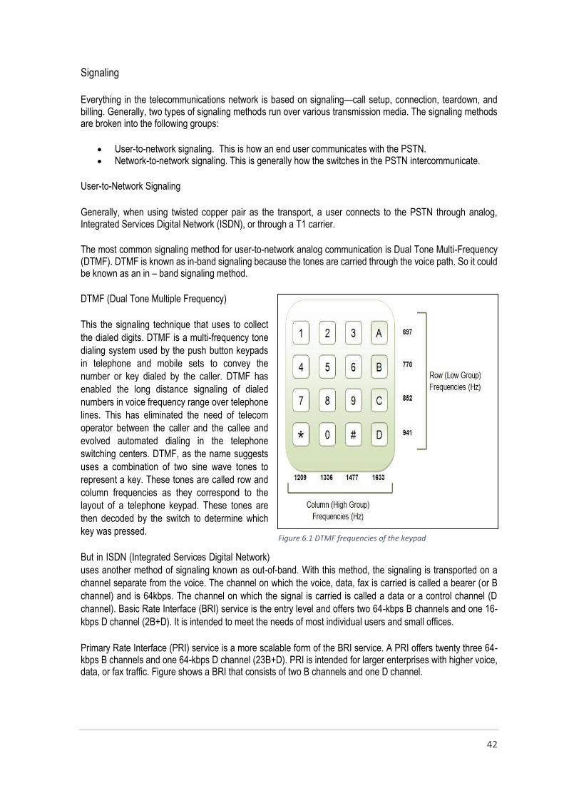
42
Signaling
Everything in the telecommunications network is based on signaling—call setup, connection, teardown, and billing. Generally, two types of signaling methods run over various transmission media. The signaling methods are broken into the following groups:
User-to-network signaling. This is how an end user communicates with the PSTN. Network-to-network signaling. This is generally how the switches in the PSTN intercommunicate.
User-to-Network Signaling
Generally, when using twisted copper pair as the transport, a user connects to the PSTN through analog, Integrated Services Digital Network (ISDN), or through a T1 carrier.
The most common signaling method for user-to-network analog communication is Dual Tone Multi-Frequency (DTMF). DTMF is known as in-band signaling because the tones are carried through the voice path. So it could be known as an in – band signaling method.
DTMF (Dual Tone Multiple Frequency)
This the signaling technique that uses to collect
the dialed digits. DTMF is a multi-frequency tone
dialing system used by the push button keypads
in telephone and mobile sets to convey the
number or key dialed by the caller. DTMF has
enabled the long distance signaling of dialed
numbers in voice frequency range over telephone
lines. This has eliminated the need of telecom
operator between the caller and the callee and
evolved automated dialing in the telephone
switching centers. DTMF, as the name suggests
uses a combination of two sine wave tones to
represent a key. These tones are called row and
column frequencies as they correspond to the
layout of a telephone keypad. These tones are
then decoded by the switch to determine which
key was pressed.
But in ISDN (Integrated Services Digital Network)
uses another method of signaling known as out-of-band. With this method, the signaling is transported on a
channel separate from the voice. The channel on which the voice, data, fax is carried is called a bearer (or B
channel) and is 64kbps. The channel on which the signal is carried is called a data or a control channel (D
channel). Basic Rate Interface (BRI) service is the entry level and offers two 64-kbps B channels and one 16-
kbps D channel (2B+D). It is intended to meet the needs of most individual users and small offices.
Primary Rate Interface (PRI) service is a more scalable form of the BRI service. A PRI offers twenty three 64-kbps B channels and one 64-kbps D channel (23B+D). PRI is intended for larger enterprises with higher voice, data, or fax traffic. Figure shows a BRI that consists of two B channels and one D channel.
Figure 6.1 DTMF frequencies of the keypad
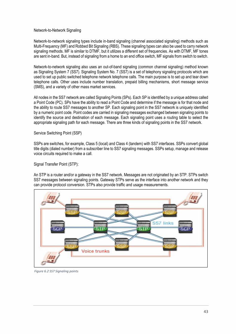
43
Network-to-Network Signaling
Network-to-network signaling types include in-band signaling (channel associated signaling) methods such as Multi-Frequency (MF) and Robbed Bit Signaling (RBS). These signaling types can also be used to carry network signaling methods. MF is similar to DTMF, but it utilizes a different set of frequencies. As with DTMF, MF tones are sent in-band. But, instead of signaling from a home to an end office switch, MF signals from switch to switch.
Network-to-network signaling also uses an out-of-band signaling (common channel signaling) method known as Signaling System 7 (SS7). Signaling System No. 7 (SS7) is a set of telephony signaling protocols which are used to set up public switched telephone network telephone calls. The main purpose is to set up and tear down telephone calls. Other uses include number translation, prepaid billing mechanisms, short message service (SMS), and a variety of other mass market services.
All nodes in the SS7 network are called Signaling Points (SPs). Each SP is identified by a unique address called a Point Code (PC). SPs have the ability to read a Point Code and determine if the message is for that node and the ability to route SS7 messages to another SP. Each signaling point in the SS7 network is uniquely identified by a numeric point code. Point codes are carried in signaling messages exchanged between signaling points to identify the source and destination of each message. Each signaling point uses a routing table to select the appropriate signaling path for each message. There are three kinds of signaling points in the SS7 network.
Service Switching Point (SSP)
SSPs are switches, for example, Class 5 (local) and Class 4 (tandem) with SS7 interfaces. SSPs convert global title digits (dialed number) from a subscriber line to SS7 signaling messages. SSPs setup, manage and release voice circuits required to make a call.
Signal Transfer Point (STP):
An STP is a router and/or a gateway in the SS7 network. Messages are not originated by an STP. STPs switch SS7 messages between signaling points. Gateway STPs serve as the interface into another network and they can provide protocol conversion. STPs also provide traffic and usage measurements.
Figure 6.2 SS7 Signaling points

44
Service Control Point (SCP)
An SCP provides application access. It is an interface to applications such as databases. An SCP communicates with applications using primitives. A primitive is an interface that provides access from one level of a protocol to another level.
Compared to in-band signaling, out-of-band signaling provides:
• Faster call setup times (compared to in-band signaling using multi-frequency (MF) signaling tones)
• More efficient use of voice circuits. • Support for Intelligent Network (IN) services which require signaling to network elements
without voice trunks (e.g., database systems) • Improved control over fraudulent network usage • Lowering network operating costs by reducing SS7 links.
Switching
When there are many devices, it is necessary to develop suitable mechanism for communication between any
two devices. The mesh topology is a one solution to ensure the point to point communication, but it is
impracticable to implement a meshed network with large number of nodes. A better alternative is to use
switching techniques leading to switched communication network. In the switched network methodology, the
network consists of a set of interconnected nodes, among which information is transmitted from source to
destination via different routes, which is controlled by the switching mechanism.
The switching performed by different nodes can be categorized into the following three types: • Circuit Switching • Packet Switching • Message Switching
Circuit switching
Communication via circuit switching implies that there is a dedicated communication path between the two stations. The path is a connected through a sequence of links between network nodes. On each physical link, a logical channel is dedicated to the connection. Circuit switching is commonly used technique in telephony, where the caller sends a special message with the address of the callee (by dialing a number) to state its destination. It involved the following three distinct steps, Circuit Establishment: To establish an end-to-end connect ion before any transfer of data. Some segments of
the circuit may be a dedicated link, while some other segments may be shared. Data transfer:
• The data may be analog or digital, depending on the nature of the network. • The connection is generally full-duplex. • Transfer data is from the source to the destination.
Circuit disconnect: • Terminate connection at the end of data transfer. • Signals must be propagated to de • Allocate the dedicated resources
Thus the actual physical electrical path or circuit between the source and destination host must be established before the message is transmitted. This connection, once established, remains exclusive and continuous for the complete duration of information exchange and the circuit becomes disconnected only when the source wants to do so.

45
Message Switching
With message switching there is no need to establish a dedicated path between two stations. When a station sends a message, the destination address is attached to the message. The message is then transmitted through the network, from node to node. Each node receives the entire message, stores it in its on disk, and then transmits the message to the next node. This type of network is called a store-and-forward network. A message-switching node is typically a general-purpose computer. The device needs sufficient secondary-storage capacity to store the incoming messages, which could be long. A time delay is there in this switching mechanism due to store- and-forward time, plus the time required to find the next node in the transmission path.
Packet Switching
Packet switching can be seen as a solution that tries to combine the advantages of message and circuit switching and to minimize the disadvantages of both. There are two methods of packet switching, datagram and virtual circuit. In both packet switching methods, a message is broken into small parts, called packets. Each packet is tagged with appropriate source and destination addresses.
Datagram packet switching
Different from circuit switching, datagram packet switching does not require to establish circuits prior
to transmission of data and terminate circuits after the transmission of data. The switches, called routers, have
to make a lookup in the forwarding table, called routing table, for each incoming packet. A routing table contains
a mapping between the possible final destinations of packets and the outgoing link on their path to the
destination. Routing tables can be very large and the full forwarding process relatively slow compared to circuit
switching. Each packet must carry the source address and the destination address to make a forwarding
decision. The routers do not need to modify the destination addresses of packets when forwarding packets.
Since each packet is processed individually by a router, all packets sent by a host to another host are not guaranteed to use the same physical links. If the routing algorithm decides to change the routing tables of the network between the instants two packets are sent, then these packets will take different paths and can even arrive out of order. If there is any network topology change such as a link failure, the routing protocol will automatically recompute the routing tables to identify the new route to flow packets and avoid the failed link. As opposed to circuit switching, no additional traffic engineering algorithm is required to reroute traffic.
Virtual circuit packet switching
Virtual circuit packet switching (VC-switching) is a packet switching technique which merges datagram packet switching and circuit switching to extract both of their advantages. VC-switching is different from datagram packet switching because the packets flow on logical circuits for which no physical resources are allocated. Each packet carries a circuit identifier which is unique to a link and updated by each switch on the path of the packet from its source to its destination. A virtual circuit is defined by the sequence of the mappings between a link taken by packets and the circuit identifier packets carry on this link. This sequence is set up at connection establishment time and identifiers are reclaimed during the circuit termination.
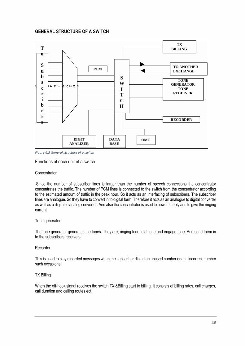
46
GENERAL STRUCTURE OF A SWITCH
Functions of each unit of a switch
Concentrator
Since the number of subscriber lines is larger than the number of speech connections the concentrator concentrates the traffic. The number of PCM lines is connected to the switch from the concentrator according to the estimated amount of traffic in the peak hour. So it acts as an interfacing of subscribers. The subscriber lines are analogue. So they have to convert in to digital form. Therefore it acts as an analogue to digital converter as well as a digital to analog converter. And also the concentrator is used to power supply and to give the ringing current.
Tone generator
The tone generator generates the tones. They are, ringing tone, dial tone and engage tone. And send them in to the subscribers receivers.
Recorder
This is used to play recorded messages when the subscriber dialed an unused number or an incorrect number such occasions.
TX Billing
When the off-hook signal receives the switch TX &Billing start to billing. It consists of billing rates, call charges, call duration and calling routes ect.
Figure 6.3 General structure of a switch

47
Digit analyzer
This is the unit which identifies the signals by the subscriber and makes the path according to that.
OMC
This is Operation and Maintenance Center. OMC acts as an interface between the operator and the switch. Most of time this is a computer terminal.
Data base
Database is the place which keeps subscribers data such as the subscribers’ name, address, telephone number ect.
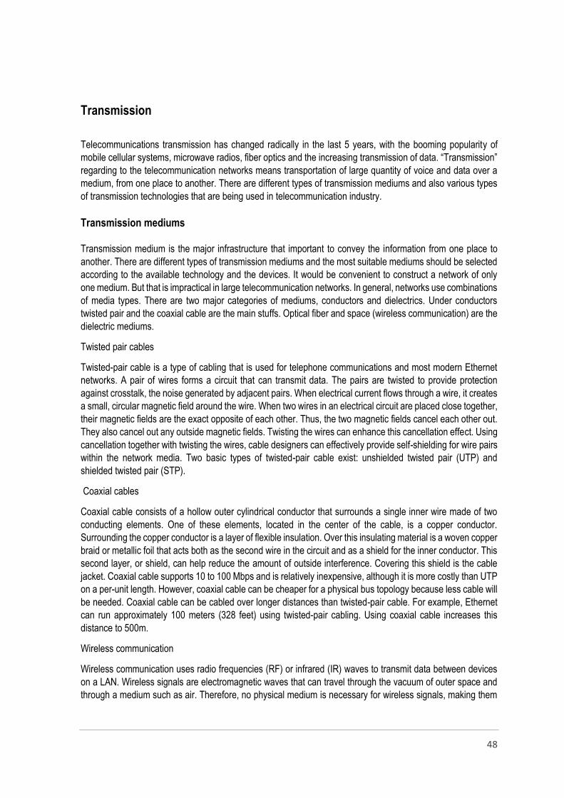
48
Transmission
Telecommunications transmission has changed radically in the last 5 years, with the booming popularity of
mobile cellular systems, microwave radios, fiber optics and the increasing transmission of data. “Transmission”
regarding to the telecommunication networks means transportation of large quantity of voice and data over a
medium, from one place to another. There are different types of transmission mediums and also various types
of transmission technologies that are being used in telecommunication industry.
Transmission mediums
Transmission medium is the major infrastructure that important to convey the information from one place to
another. There are different types of transmission mediums and the most suitable mediums should be selected
according to the available technology and the devices. It would be convenient to construct a network of only
one medium. But that is impractical in large telecommunication networks. In general, networks use combinations
of media types. There are two major categories of mediums, conductors and dielectrics. Under conductors
twisted pair and the coaxial cable are the main stuffs. Optical fiber and space (wireless communication) are the
dielectric mediums.
Twisted pair cables
Twisted-pair cable is a type of cabling that is used for telephone communications and most modern Ethernet
networks. A pair of wires forms a circuit that can transmit data. The pairs are twisted to provide protection
against crosstalk, the noise generated by adjacent pairs. When electrical current flows through a wire, it creates
a small, circular magnetic field around the wire. When two wires in an electrical circuit are placed close together,
their magnetic fields are the exact opposite of each other. Thus, the two magnetic fields cancel each other out.
They also cancel out any outside magnetic fields. Twisting the wires can enhance this cancellation effect. Using
cancellation together with twisting the wires, cable designers can effectively provide self-shielding for wire pairs
within the network media. Two basic types of twisted-pair cable exist: unshielded twisted pair (UTP) and
shielded twisted pair (STP).
Coaxial cables
Coaxial cable consists of a hollow outer cylindrical conductor that surrounds a single inner wire made of two
conducting elements. One of these elements, located in the center of the cable, is a copper conductor.
Surrounding the copper conductor is a layer of flexible insulation. Over this insulating material is a woven copper
braid or metallic foil that acts both as the second wire in the circuit and as a shield for the inner conductor. This
second layer, or shield, can help reduce the amount of outside interference. Covering this shield is the cable
jacket. Coaxial cable supports 10 to 100 Mbps and is relatively inexpensive, although it is more costly than UTP
on a per-unit length. However, coaxial cable can be cheaper for a physical bus topology because less cable will
be needed. Coaxial cable can be cabled over longer distances than twisted-pair cable. For example, Ethernet
can run approximately 100 meters (328 feet) using twisted-pair cabling. Using coaxial cable increases this
distance to 500m.
Wireless communication
Wireless communication uses radio frequencies (RF) or infrared (IR) waves to transmit data between devices
on a LAN. Wireless signals are electromagnetic waves that can travel through the vacuum of outer space and
through a medium such as air. Therefore, no physical medium is necessary for wireless signals, making them

49
a very versatile way to build a network. Wireless signals use portions of the RF spectrum to transmit voice,
video, and data. Wireless frequencies range from 3 kilohertz (kHz) to 300 gigahertz (GHz). The data-
transmission rates range from 9 kilobits per second (kbps) to as high as 54 Mbps.
Wireless communication increases the mobility of the network and much more cost effective than using large
amount of cables. Wireless transmission provides easy and fast setup and it is easy to expand the network
according to the requirements.
Fiber optics
Fiber optic cable has the ability to transmit signals over much longer distances than coaxial and twisted pair. It
also has the capability to carry information at vastly greater speeds. This capacity broadens communication
possibilities to include services such as video conferencing and interactive services. Fiber optic cabling consists
of a center glass core surrounded by several layers of protective materials. It transmits light rather than
electronic signals eliminating the problem of electrical interference. This makes it ideal for certain environments
that contain a large amount of electrical interference.
Transmission technologies
Multiplexing
Multiplexing is sending multiple signals or streams of information on a carrier at the same time in the form of a
single, complex signal and then recovering the separate signals at the receiving end. When more than one
senders tries to send over single medium, a device called Multiplexer divides the physical channel and allocates
one to each. On the other end of communication, a De-multiplexer receives data from a single medium and
identifies each and send to different receivers. There are different multiplexing technologies which can be either
analog or digital.
Frequency division multiplexing
Time division multiplexing
Code division multiplexing
Wave length division multiplexing
Frequency division multiplexing (FDM)
FDM is an analog technology. FDM divides the spectrum or carrier bandwidth in logical channels and allocates
one user to each channel. Each user can use the channel frequency independently and has the access of it. All
channels are divided such a way that they do not overlap with each other. Channels are separated by guard
bands. Guard band is a frequency which is not used by either channel.
Time division multiplexing (TDM)
TDM is applied primarily on digital signals but can be applied on analog signals as well. In TDM the shared
channel is divided among its user by means of time slot. Each user can transmit data within the provided time
slot only. Digital signals are divided in frames, equivalent to time slots. TDM works in synchronized mode. Both
ends, i.e. Multiplexer and De-multiplexer are timely synchronized and both switch to next channel
simultaneously.
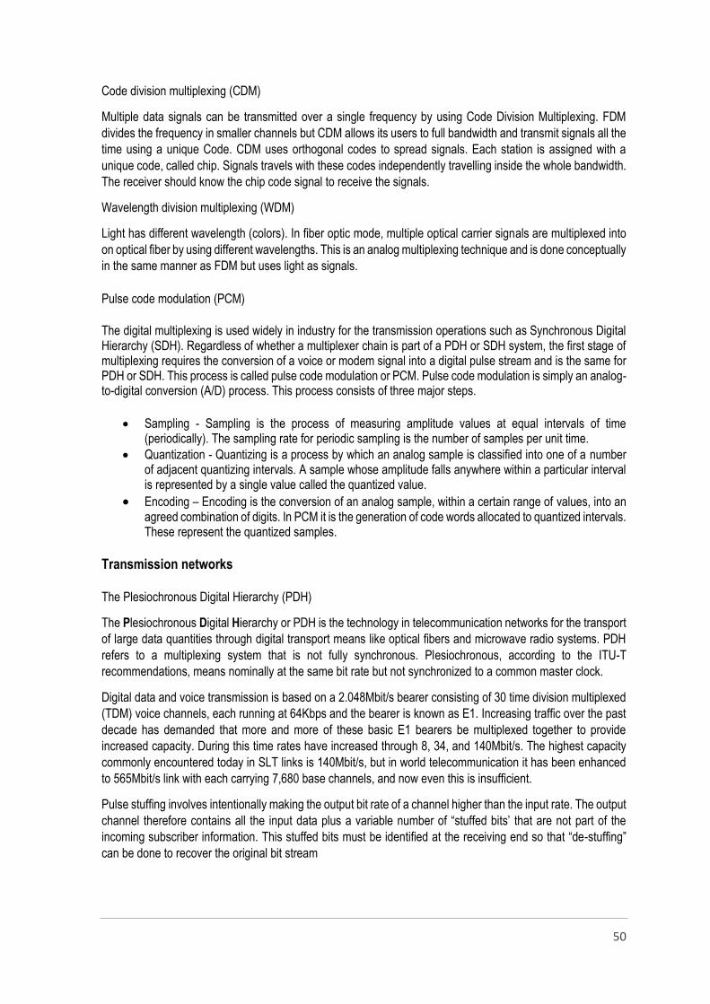
50
Code division multiplexing (CDM)
Multiple data signals can be transmitted over a single frequency by using Code Division Multiplexing. FDM
divides the frequency in smaller channels but CDM allows its users to full bandwidth and transmit signals all the
time using a unique Code. CDM uses orthogonal codes to spread signals. Each station is assigned with a
unique code, called chip. Signals travels with these codes independently travelling inside the whole bandwidth.
The receiver should know the chip code signal to receive the signals.
Wavelength division multiplexing (WDM)
Light has different wavelength (colors). In fiber optic mode, multiple optical carrier signals are multiplexed into
on optical fiber by using different wavelengths. This is an analog multiplexing technique and is done conceptually
in the same manner as FDM but uses light as signals.
Pulse code modulation (PCM)
The digital multiplexing is used widely in industry for the transmission operations such as Synchronous Digital Hierarchy (SDH). Regardless of whether a multiplexer chain is part of a PDH or SDH system, the first stage of multiplexing requires the conversion of a voice or modem signal into a digital pulse stream and is the same for PDH or SDH. This process is called pulse code modulation or PCM. Pulse code modulation is simply an analog-to-digital conversion (A/D) process. This process consists of three major steps.
Sampling - Sampling is the process of measuring amplitude values at equal intervals of time (periodically). The sampling rate for periodic sampling is the number of samples per unit time.
Quantization - Quantizing is a process by which an analog sample is classified into one of a number of adjacent quantizing intervals. A sample whose amplitude falls anywhere within a particular interval is represented by a single value called the quantized value.
Encoding – Encoding is the conversion of an analog sample, within a certain range of values, into an agreed combination of digits. In PCM it is the generation of code words allocated to quantized intervals. These represent the quantized samples.
Transmission networks
The Plesiochronous Digital Hierarchy (PDH)
The Plesiochronous Digital Hierarchy or PDH is the technology in telecommunication networks for the transport
of large data quantities through digital transport means like optical fibers and microwave radio systems. PDH
refers to a multiplexing system that is not fully synchronous. Plesiochronous, according to the ITU-T
recommendations, means nominally at the same bit rate but not synchronized to a common master clock.
Digital data and voice transmission is based on a 2.048Mbit/s bearer consisting of 30 time division multiplexed
(TDM) voice channels, each running at 64Kbps and the bearer is known as E1. Increasing traffic over the past
decade has demanded that more and more of these basic E1 bearers be multiplexed together to provide
increased capacity. During this time rates have increased through 8, 34, and 140Mbit/s. The highest capacity
commonly encountered today in SLT links is 140Mbit/s, but in world telecommunication it has been enhanced
to 565Mbit/s link with each carrying 7,680 base channels, and now even this is insufficient.
Pulse stuffing involves intentionally making the output bit rate of a channel higher than the input rate. The output
channel therefore contains all the input data plus a variable number of “stuffed bits’ that are not part of the
incoming subscriber information. This stuffed bits must be identified at the receiving end so that “de-stuffing”
can be done to recover the original bit stream
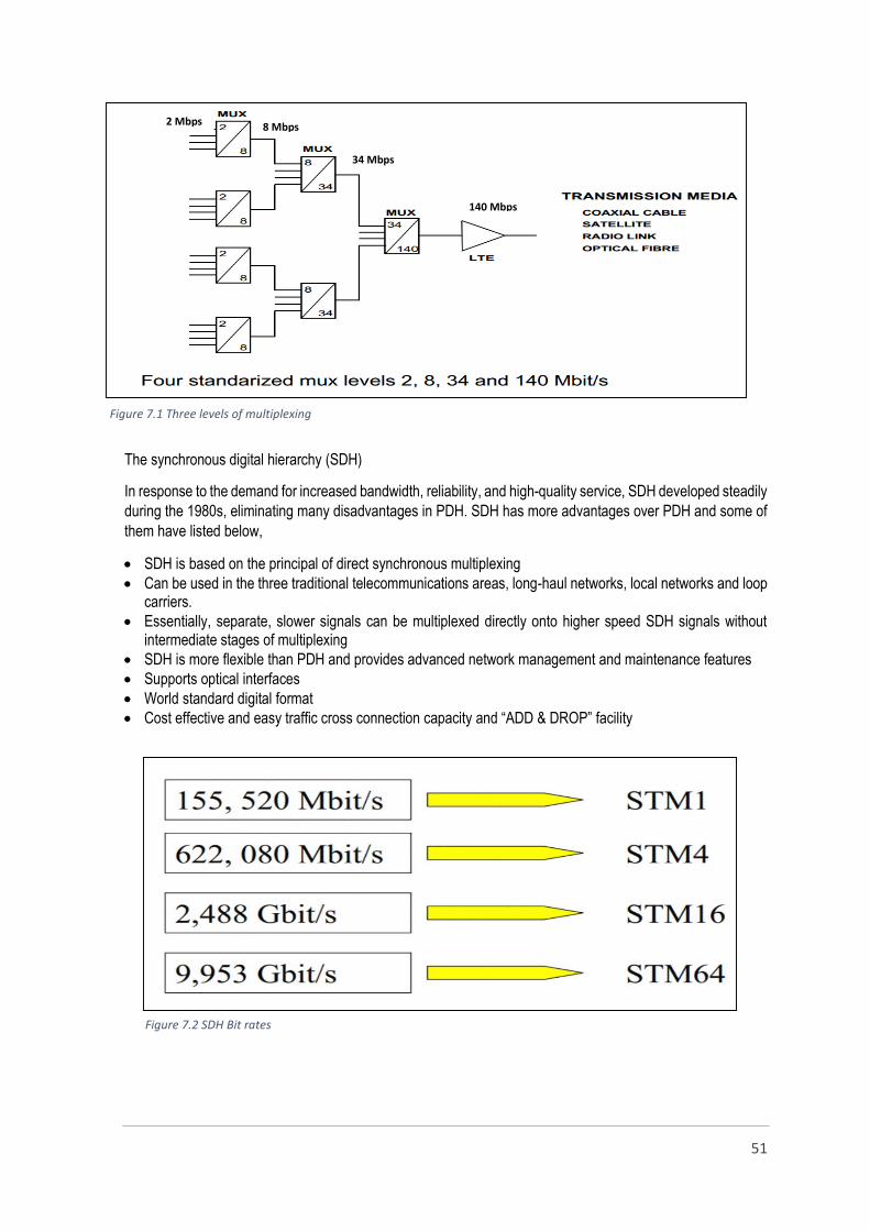
51
The synchronous digital hierarchy (SDH)
In response to the demand for increased bandwidth, reliability, and high-quality service, SDH developed steadily
during the 1980s, eliminating many disadvantages in PDH. SDH has more advantages over PDH and some of
them have listed below,
SDH is based on the principal of direct synchronous multiplexing
Can be used in the three traditional telecommunications areas, long-haul networks, local networks and loop carriers.
Essentially, separate, slower signals can be multiplexed directly onto higher speed SDH signals without intermediate stages of multiplexing
SDH is more flexible than PDH and provides advanced network management and maintenance features
Supports optical interfaces
World standard digital format
Cost effective and easy traffic cross connection capacity and “ADD & DROP” facility
2 Mbps
34 Mbps
8 Mbps
140 Mbps
Figure 7.1 Three levels of multiplexing
Figure 7.2 SDH Bit rates

52
SDH transmission networks usually use four types of bit rates or the multiplexing levels for the transmission
process. STM 1 (Synchronous Transfer Module) forms the basis of the SDH frame structure. The following
figure shows that bit rates.
The network elements of the SDH network
The synchronous network has the ability of transmit STM frames but it should be able to transmit plesiochronous
signals and be able to handle future technologies. So that the SDH network consists of several special network
elements.
Regenerators Regenerators, as the name implies, regenerate the clock and amplitude relationships for incoming data
signals that have been attenuated and distorted by dispersion.
Terminal multiplexers Terminal multiplexers are used to combine plesiochronous and synchronous input signals into higher-
bit-rate STM-N signals.
Add / Drop multiplexers Plesiochronous and lower-bit-rate synchronous signals can be extracted from or inserted into high-
speed SDH bit streams using add/drop multiplexers (ADMs). This feature enables ring structure setup,
which in the event of a fault, can automatically back up path switching using elements in the ring.
Digital cross – connect These devices can cross-connect at the STM level down to individual E1 streams. So an E1 stream on
one STM trunk could be cross-connected to another STM trunk.
Network protection and redundancy
Automatic protection switching (APS) is the method used to ensure the network protection. There are two types
of protection architectures are in used.
1. Linear protection The simplest form of back – up is called linear network which each working link is protected
by one protection link. If any defect occurs the both ends of the circuit, switched to the
protection line. In most cases several working lines are protected by a single back – up line.
Economically it is not suitable to install and maintain large number of back – up lines.
2. Ring protection The most popular network configuration is the Ring Architecture. Add/Drop multiplexers
interconnected by 2 fiber rings. The main advantage of this architecture is its survivability. If
Figure 7.3 SDH network elements
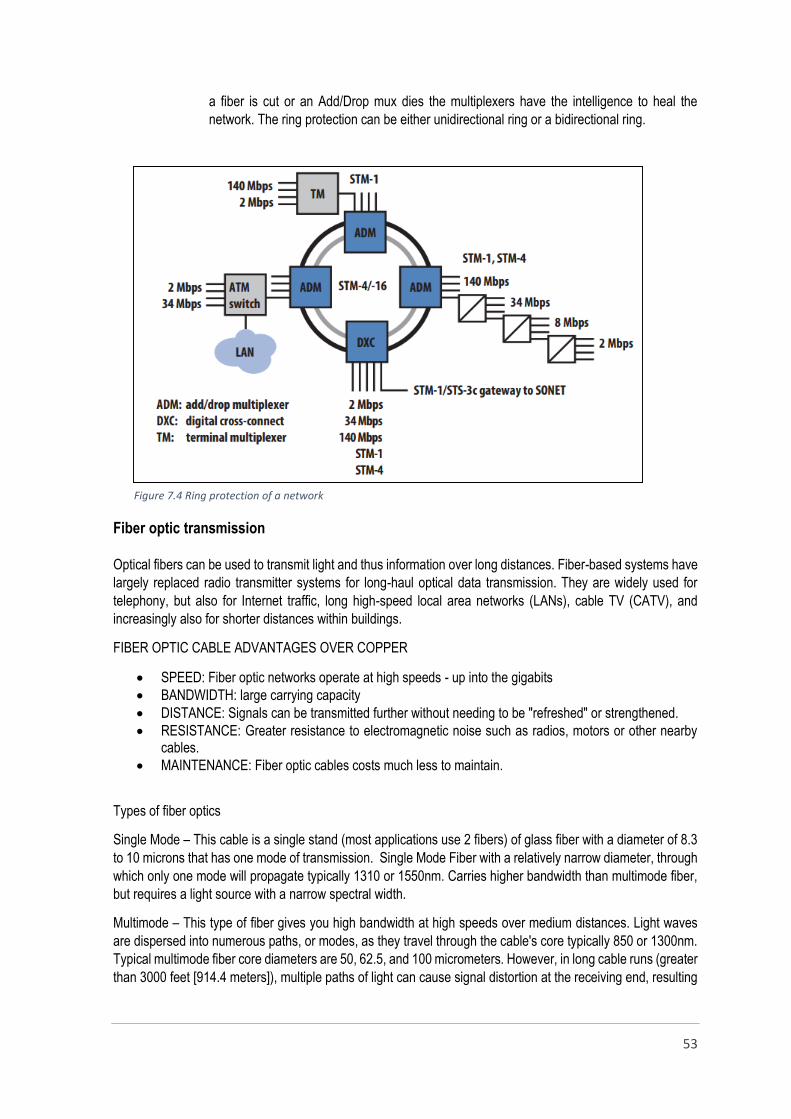
53
a fiber is cut or an Add/Drop mux dies the multiplexers have the intelligence to heal the
network. The ring protection can be either unidirectional ring or a bidirectional ring.
Fiber optic transmission
Optical fibers can be used to transmit light and thus information over long distances. Fiber-based systems have
largely replaced radio transmitter systems for long-haul optical data transmission. They are widely used for
telephony, but also for Internet traffic, long high-speed local area networks (LANs), cable TV (CATV), and
increasingly also for shorter distances within buildings.
FIBER OPTIC CABLE ADVANTAGES OVER COPPER
SPEED: Fiber optic networks operate at high speeds - up into the gigabits
BANDWIDTH: large carrying capacity
DISTANCE: Signals can be transmitted further without needing to be "refreshed" or strengthened.
RESISTANCE: Greater resistance to electromagnetic noise such as radios, motors or other nearby cables.
MAINTENANCE: Fiber optic cables costs much less to maintain.
Types of fiber optics
Single Mode – This cable is a single stand (most applications use 2 fibers) of glass fiber with a diameter of 8.3
to 10 microns that has one mode of transmission. Single Mode Fiber with a relatively narrow diameter, through
which only one mode will propagate typically 1310 or 1550nm. Carries higher bandwidth than multimode fiber,
but requires a light source with a narrow spectral width.
Multimode – This type of fiber gives you high bandwidth at high speeds over medium distances. Light waves
are dispersed into numerous paths, or modes, as they travel through the cable's core typically 850 or 1300nm.
Typical multimode fiber core diameters are 50, 62.5, and 100 micrometers. However, in long cable runs (greater
than 3000 feet [914.4 meters]), multiple paths of light can cause signal distortion at the receiving end, resulting
Figure 7.4 Ring protection of a network
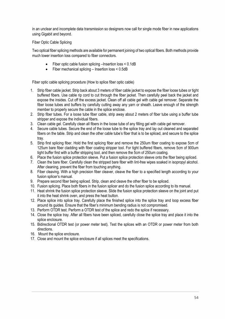
54
in an unclear and incomplete data transmission so designers now call for single mode fiber in new applications
using Gigabit and beyond.
Fiber Optic Cable Splicing
Two optical fiber splicing methods are available for permanent joining of two optical fibers. Both methods provide
much lower insertion loss compared to fiber connectors.
Fiber optic cable fusion splicing –Insertion loss < 0.1dB
Fiber mechanical splicing – Insertion loss < 0.5dB
Fiber optic cable splicing procedure (How to splice fiber optic cable)
1. Strip fiber cable jacket. Strip back about 3 meters of fiber cable jacket to expose the fiber loose tubes or tight buffered fibers. Use cable rip cord to cut through the fiber jacket. Then carefully peel back the jacket and expose the insides. Cut off the excess jacket. Clean off all cable gel with cable gel remover. Separate the fiber loose tubes and buffers by carefully cutting away any yarn or sheath. Leave enough of the strength member to properly secure the cable in the splice enclose.
2. Strip fiber tubes. For a loose tube fiber cable, strip away about 2 meters of fiber tube using a buffer tube stripper and expose the individual fibers.
3. Clean cable gel. Carefully clean all fibers in the loose tube of any filling gel with cable gel remover. 4. Secure cable tubes. Secure the end of the loose tube to the splice tray and lay out cleaned and separated
fibers on the table. Strip and clean the other cable tube’s fiber that is to be spliced, and secure to the splice tray.
5. Strip first splicing fiber. Hold the first splicing fiber and remove the 250um fiber coating to expose 5cm of 125um bare fiber cladding with fiber coating stripper tool. For tight buffered fibers, remove 5cm of 900um tight buffer first with a buffer stripping tool, and then remove the 5cm of 250um coating.
6. Place the fusion splice protection sleeve. Put a fusion splice protection sleeve onto the fiber being spliced. 7. Clean the bare fiber. Carefully clean the stripped bare fiber with lint-free wipes soaked in isopropyl alcohol.
After cleaning, prevent the fiber from touching anything. 8. Fiber cleaving. With a high precision fiber cleaver, cleave the fiber to a specified length according to your
fusion splicer’s manual. 9. Prepare second fiber being spliced. Strip, clean and cleave the other fiber to be spliced. 10. Fusion splicing. Place both fibers in the fusion splicer and do the fusion splice according to its manual. 11. Heat shrink the fusion splice protection sleeve. Slide the fusion splice protection sleeve on the joint and put
it into the heat shrink oven, and press the heat button. 12. Place splice into splice tray. Carefully place the finished splice into the splice tray and loop excess fiber
around its guides. Ensure that the fiber’s minimum bending radius is not compromised. 13. Perform OTDR test. Perform a OTDR test of the splice and redo the splice if necessary. 14. Close the splice tray. After all fibers have been spliced, carefully close the splice tray and place it into the
splice enclosure. 15. Bidirectional OTDR test (or power meter test). Test the splices with an OTDR or power meter from both
directions. 16. Mount the splice enclosure. 17. Close and mount the splice enclosure if all splices meet the specifications.
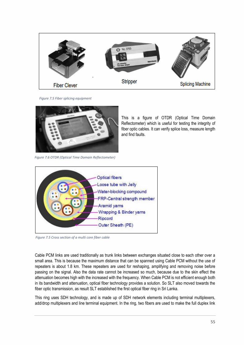
55
This is a figure of OTDR (Optical Time Domain
Reflectometer) which is useful for testing the integrity of
fiber optic cables. It can verify splice loss, measure length
and find faults.
Cable PCM links are used traditionally as trunk links between exchanges situated close to each other over a
small area. This is because the maximum distance that can be spanned using Cable PCM without the use of
repeaters is about 1.8 km. These repeaters are used for reshaping, amplifying and removing noise before
passing on the signal. Also the data rate cannot be increased so much, because due to the skin effect the
attenuation becomes high with the increased with the frequency. When Cable PCM is not efficient enough both
in its bandwidth and attenuation, optical fiber technology provides a solution. So SLT also moved towards the
fiber optic transmission, as result SLT established the first optical fiber ring in Sri Lanka.
This ring uses SDH technology, and is made up of SDH network elements including terminal multiplexers,
add/drop multiplexers and line terminal equipment. In the ring, two fibers are used to make the full duplex link
Figure 7.5 Fiber splicing equipment
Figure 7.6 OTDR (Optical Time Domain Reflectometer)
Figure 7.5 Cross section of a multi core fiber cable
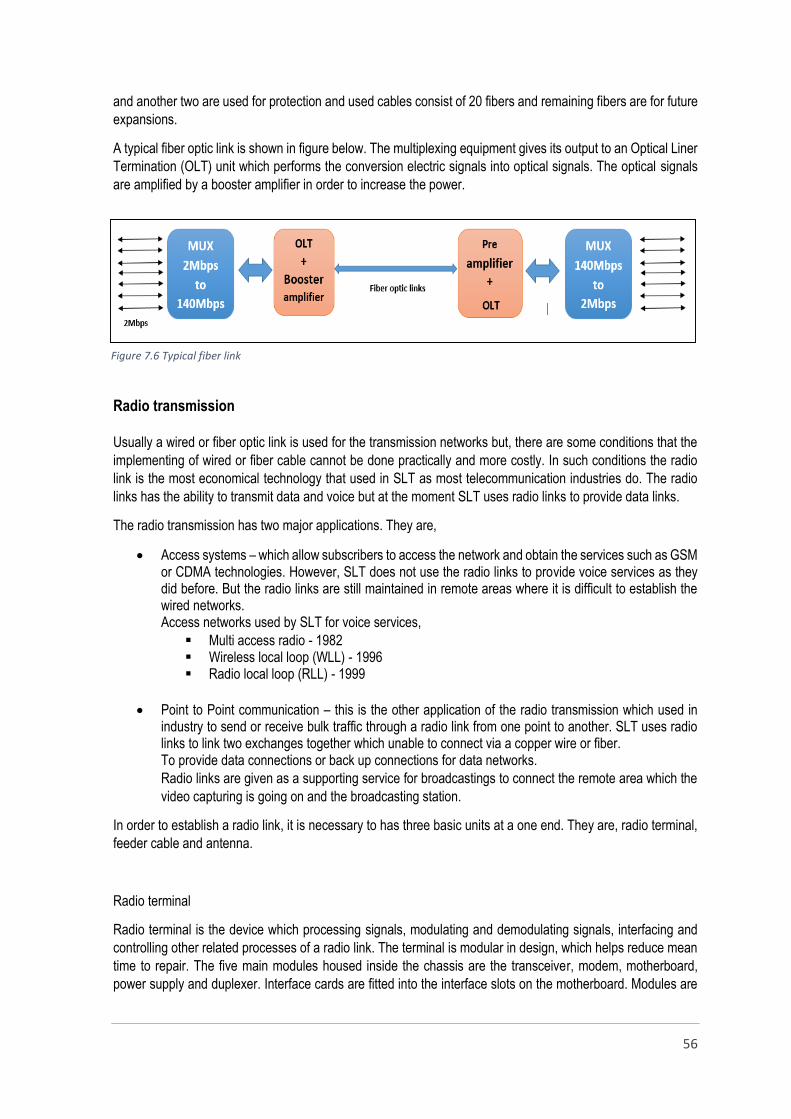
56
and another two are used for protection and used cables consist of 20 fibers and remaining fibers are for future
expansions.
A typical fiber optic link is shown in figure below. The multiplexing equipment gives its output to an Optical Liner
Termination (OLT) unit which performs the conversion electric signals into optical signals. The optical signals
are amplified by a booster amplifier in order to increase the power.
Radio transmission
Usually a wired or fiber optic link is used for the transmission networks but, there are some conditions that the
implementing of wired or fiber cable cannot be done practically and more costly. In such conditions the radio
link is the most economical technology that used in SLT as most telecommunication industries do. The radio
links has the ability to transmit data and voice but at the moment SLT uses radio links to provide data links.
The radio transmission has two major applications. They are,
Access systems – which allow subscribers to access the network and obtain the services such as GSM or CDMA technologies. However, SLT does not use the radio links to provide voice services as they did before. But the radio links are still maintained in remote areas where it is difficult to establish the wired networks. Access networks used by SLT for voice services,
Multi access radio - 1982 Wireless local loop (WLL) - 1996 Radio local loop (RLL) - 1999
Point to Point communication – this is the other application of the radio transmission which used in industry to send or receive bulk traffic through a radio link from one point to another. SLT uses radio links to link two exchanges together which unable to connect via a copper wire or fiber. To provide data connections or back up connections for data networks.
Radio links are given as a supporting service for broadcastings to connect the remote area which the
video capturing is going on and the broadcasting station.
In order to establish a radio link, it is necessary to has three basic units at a one end. They are, radio terminal,
feeder cable and antenna.
Radio terminal
Radio terminal is the device which processing signals, modulating and demodulating signals, interfacing and
controlling other related processes of a radio link. The terminal is modular in design, which helps reduce mean
time to repair. The five main modules housed inside the chassis are the transceiver, modem, motherboard,
power supply and duplexer. Interface cards are fitted into the interface slots on the motherboard. Modules are
Figure 7.6 Typical fiber link

57
interconnected via several buses on the motherboard. Sometimes the radio module can be designed as two
separate units as,
Outdoor unit (ODU) – consists of transceiver
Indoor unit (IDU) – consists of other modules
Feeder cable
Run feeder cable from the antenna to the terminal mounting location. Feeder cable is the medium that sends
radio signals to the antenna for the transmission and leads the received signals to the radio terminal.
Antenna
Antennas play a central role in microwave communications. The antenna is used to convert the time varying
electric current into an electromagnetic wave which can be propagate through air. There are several shapes of
antenna available for transmitting microwaves. Microwave telecommunication systems almost always use the
parabolic type, and sometimes the horn type. These antennas are highly directional. The microwave energy is
focused into a very narrow beam by the transmitting antenna and aimed at the receiving antenna, which
concentrates the received power by a mechanism analogous to the telescope. The microwave energy is
transmitted by a parabolic antenna, by placing the microwave guide opening at the focus of the parabola.
Figure 7.7 Main modules of a radio terminal
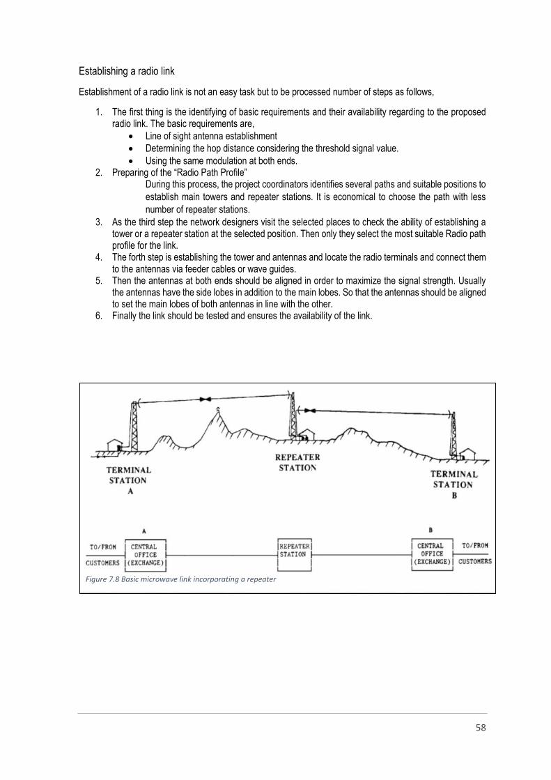
58
Establishing a radio link
Establishment of a radio link is not an easy task but to be processed number of steps as follows,
1. The first thing is the identifying of basic requirements and their availability regarding to the proposed radio link. The basic requirements are,
Line of sight antenna establishment
Determining the hop distance considering the threshold signal value.
Using the same modulation at both ends. 2. Preparing of the “Radio Path Profile”
During this process, the project coordinators identifies several paths and suitable positions to
establish main towers and repeater stations. It is economical to choose the path with less
number of repeater stations.
3. As the third step the network designers visit the selected places to check the ability of establishing a tower or a repeater station at the selected position. Then only they select the most suitable Radio path profile for the link.
4. The forth step is establishing the tower and antennas and locate the radio terminals and connect them to the antennas via feeder cables or wave guides.
5. Then the antennas at both ends should be aligned in order to maximize the signal strength. Usually the antennas have the side lobes in addition to the main lobes. So that the antennas should be aligned to set the main lobes of both antennas in line with the other.
6. Finally the link should be tested and ensures the availability of the link.
Figure 7.8 Basic microwave link incorporating a repeater

59
Figure 7.10 Example of a clear line-of-sight path Figure 7.11 Example of a mid-path reflection path
The figure below shows the basic parts of a radio wave transmitter and the receiver. There are two basic types
of transmitters and receiver as analog and digital. Nowadays digital systems are used in most cases which are
compatible with new technologies and enhanced services.
Important factors which should be set up when configuring a terminal
The number of E1 s which should allocated for the link
Modulation technique that is going to use
The frequency of transmission and receiving
Transmission power
Terminal IP address configurations
Modem performance settings
Clock settings
Duplexer settings
External alarm settings
SNMP settings
Antenna Siting
When siting antennas, consider the following points:
A site with a clear line of sight to the remote terminal is needed. It is necessary to pay particular
attention to trees, buildings, and other obstructions close to the antenna site.
Any large flat areas that reflect RF energy along the link path, for instance, water, could cause
multipath fading. If the link path crosses a feature that is likely to cause RF reflections, shield the
antenna from the reflected signals by positioning it on the far side of the roof of the equipment shelter
or other structure.
The antenna site should be as far as possible from other potential sources of RF interference such as
electrical equipment, power lines and roads.
Figure 7.9 Simplified microwave link with schematic diagram

60
The antenna site should be as close as possible to the equipment shelter.
The performance of the radio link should be tested continuously to ensure the availability of the link. The modern
radio systems provides information about the link performance and keep records of the history of performance.
There are some major facts which should be evaluated when test the link condition.
Power and A/C section
Power operations and maintenance
This is a one sub section of the power and A/C section which is responsible for maintaining the power system
of the SLT head office and other exchanges. The commercial power is the main power source and diesel
generators are used as the backup source. In addition to that rectifiers are used to convert AC into DC where
the telecommunication equipment are placed and the battery backups are maintained to use in case of
commercial power failures. The uninterrupted power supply (UPS) systems have been installed in the places
where the power sensitive telecom equipment are placed to avoid disturbances of sudden power failures.
Diesel engine generator (DEG)
DEG is a combination of a diesel engine and an electric generator. The DEG consists of different sub systems
such as,
Fuel system Lubrication system
Table 7.1 Important facts regarding to radio system performance
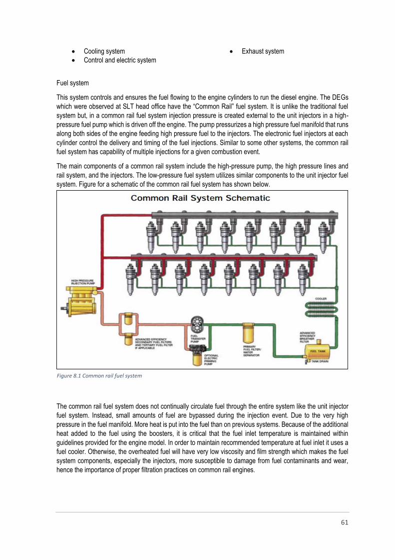
61
Cooling system
Control and electric system
Exhaust system
Fuel system
This system controls and ensures the fuel flowing to the engine cylinders to run the diesel engine. The DEGs
which were observed at SLT head office have the “Common Rail” fuel system. It is unlike the traditional fuel
system but, in a common rail fuel system injection pressure is created external to the unit injectors in a high-
pressure fuel pump which is driven off the engine. The pump pressurizes a high pressure fuel manifold that runs
along both sides of the engine feeding high pressure fuel to the injectors. The electronic fuel injectors at each
cylinder control the delivery and timing of the fuel injections. Similar to some other systems, the common rail
fuel system has capability of multiple injections for a given combustion event.
The main components of a common rail system include the high-pressure pump, the high pressure lines and
rail system, and the injectors. The low-pressure fuel system utilizes similar components to the unit injector fuel
system. Figure for a schematic of the common rail fuel system has shown below.
The common rail fuel system does not continually circulate fuel through the entire system like the unit injector
fuel system. Instead, small amounts of fuel are bypassed during the injection event. Due to the very high
pressure in the fuel manifold. More heat is put into the fuel than on previous systems. Because of the additional
heat added to the fuel using the boosters, it is critical that the fuel inlet temperature is maintained within
guidelines provided for the engine model. In order to maintain recommended temperature at fuel inlet it uses a
fuel cooler. Otherwise, the overheated fuel will have very low viscosity and film strength which makes the fuel
system components, especially the injectors, more susceptible to damage from fuel contaminants and wear,
hence the importance of proper filtration practices on common rail engines.
Figure 8.1 Common rail fuel system

62
Cooling system
Approximately 25 to 30 percent of the total heat input to the engine supplied by the fuel is absorbed by the
engine cooling system. If this heat is not removed, engine internal temperatures would soon reach a point of
component damage and engine failure. All commercial diesel engines use some form of cooling system to
absorb this heat and transfer it to a heat absorbing medium outside of the engine.
As many modern engines this DEGs are equipped with turbocharging systems to provide enough air to allow
the burning of the fuel required to produce the required power. The turbocharging system adds heat to the
combustion air. In order to ensure that sufficient pounds of air are provided for the combustion of the fuel, it is
necessary to cool the combustion air before it goes into the engine cylinders (to maintain the air density). This
is done by means of a radiator-like heat exchanger called the air intercooler, or after cooler, and mounted in the
piping between the turbocharger compressor outlet and the engine air manifold. This radiator removes excess
heat from the combustion air.
Most diesel engines use a closed loop jacket type cooling system. Coolant flows through the engine absorbing
heat from the cylinder liners, cylinder heads, and other engine components. Water is the most common coolant
used in diesel engines. However, water alone presents the possibility of corrosion, mineral deposits, and
freezing. The water used for engine coolant should be clean and free of deposits or scale forming substances.
De-mineralized water is most frequently used. The water should be slightly alkaline, specifically meaning a pH
of 8 to 9.5.
Major parts of the cooling system are,
Thermostats
Radiator
Water pump
Oil cooler
Control system
The control system is a very important module of modern DEGs which ensures the proper operation and the
safety of equipment. The control system is used to, Check whether the DEG is running accurately and
investigates its condition and to stop the operation of DEG before shutdown it permanently.
The DEG that is observed at SLT had a control system known as “EMCP 3.3”. EMCP means “Electronic Modular
Control Panel” because this system consists of number of sensors and other electronic devices which allows
the system to measure various engine parameters. Those parameters can be categorized into two as follow,
Engine parameters
Oil pressure
Coolant temperature
Engine speed
Battery voltage
Generator parameters
Average line to line AC voltage
Average current
AC frequency
Power factor

63
The connections between the generator and the EMCP 3.3 depend on the winding configuration as shown in
the connection diagrams below.
The EMCP 3.3 display can be used for monitoring the generator status, viewing and resetting events, and
configuring set points.
Exhaust system
The exhaust system collects exhaust gases from engine cylinders and dischargers then put out as quickly and
silently as possible. Primary system design considerations include,
Minimizing resistance to gas flow (back pressure) and keeping it within the limits specified for the particular engine model and rating to provide maximum efficiency.
Reducing exhaust noise emission to meet local regulations and application requirements.
Providing adequate clearance between exhaust system components and engine components, machine structures, engine bays, enclosures and building structures to reduce the impact of high exhaust temperatures on such items.
Ensuring the system does not overstress engine components such as turbochargers and manifolds with excess weight. Overstressing can shorten the life of engine components.
Ensuring the exhaust system components are able to reject heat energy as intended by the original design.
The main components of an exhaust system include,
The exhaust manifold
Turbocharger
Waste gate
Piping and the silencer
Engine exhaust manifolds collect exhaust gases from each cylinder and channel them into an exhaust outlet.
The manifold is designed to give minimum backpressure and turbulence. Turbochargers are employed to
achieve higher specific engine power output by converting some of the energy in the exhaust gas stream into
energy in the inlet system in the form of raised inlet pressure (boost). This raised inlet pressure forces more air
into the engine cylinders, allowing more fuel to be burned and thus resulting in higher power output.
Turbochargers equipped with a waste gate can efficiently operate in a much broader range of altitudes and
ambient conditions. The waste gate opens at a predetermined pressure and vents some of the exhaust flow
Figure 8.2 THREE PHASE FOUR WIRE (SERIES OR PARALLEL) WYE (star)

64
away from the turbocharger. The reduced exhaust flow slows the turbocharger to avoid over speed and
excessive boost pressure. The purpose of the silencer is to reduce the noise of the exhaust before it is released
to the atmosphere. The function of the exhaust piping is to convey the exhaust gases from the engine exhaust
outlet to the silencer and other exhaust system components, terminating at the system outlet. Piping is a key
feature in overall exhaust system layout.
Automatic transfer switch (ATS)
The ATS used for switching power between the primary (utility) and secondary (backup or supplemental) power
sources. The ATS can be one of the system that are listed below and the suitable system should be selected
according to the available power sources.
Utility-to-generator
Utility-to-utility
Generator-to-generator
Three-source system (two utilities and one generator) In Srilanka, usually use the utility to generator system, with a standby power system and a single utility feed.
The transfer switch senses when utility power has been lost, sends a start signal to the standby generator and
transfers the load.
The ATS used in SLT consists of three units for three generators and each unit has three modules. They are,
1. Utility sensing unit This unit is a combination of ATS controlling system and the generator synchronous breaker.
This unit always investigates the availability of the utility supply and switches to the backup
source in case of failure of main power supply. The display allows us to see the conditions of
the power system.
2. Generator breaker/utility breaker This breaker can be used to break each supply as the requirement and only one breaker is
at “ON” position at a time.
3. Bus bar coupler The bus bar connects all the generator supply together to feed to the load and this unit
consists of a feeder breaker which allows to isolate the load from the supply.
When the main supply fails the control system of the ATS sense the failure and gives the signal to start the
generators. The ATS does not feed generator power until the all generators become synchronous with each
Figure 8.3 Power feeding system

65
other. After the synchronizing of all generators the ATS automatically switches to the generator power and
remains at this position till the utility power available.
Uninterrupted power supply (UPS)
The functions of the telecommunication equipment should proceed continuously to ensure the services and
these functions are carried out by sophisticated and sensitive devices that may be affected by the disturbance
coming from the mains power supply. There are various types of electrical events that constantly endanger
electronic equipment, as there are various effects on the availability of the loads. As a solution for that dangers
the UPSs are established within the power system of the organization. There are various types of static UPS
systems on the market, such as: Off-Line, Line-Interactive, On-Line, Double Conversion, Digital On-Line, In-
Line, etc.
Off – line UPS
When the mains supply is on, the output
is identical to the input. The UPS attends
only when there is no input voltage and
powers the load using the inverter,
which in turn is powered by the
batteries.
Line interactive UPS
When the mains supply is on, the input
and output are separated by a filtering
and stabilization circuit (AVR:
Automatic Voltage Regulator), but
some of the disturbances and
waveform variations that may be at
the input may be found at the output.
As in Off-line systems, when there is a
power failure, the output is connected
to the inverter, which in turn is
powered by the batteries.
Figure 8.4 Diagram of an off line UPS
Figure 8.5 Diagram of a line interactive UPS
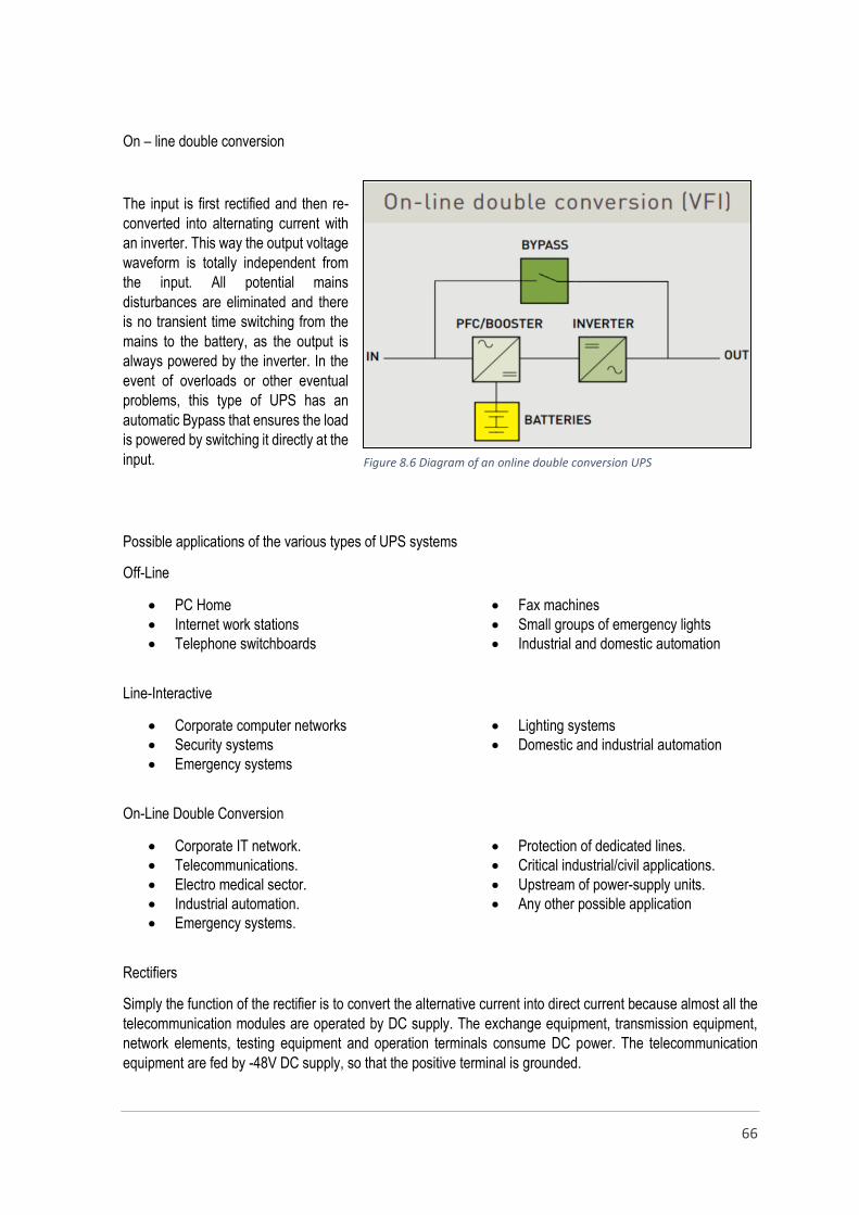
66
On – line double conversion
The input is first rectified and then re-
converted into alternating current with
an inverter. This way the output voltage
waveform is totally independent from
the input. All potential mains
disturbances are eliminated and there
is no transient time switching from the
mains to the battery, as the output is
always powered by the inverter. In the
event of overloads or other eventual
problems, this type of UPS has an
automatic Bypass that ensures the load
is powered by switching it directly at the
input.
Possible applications of the various types of UPS systems
Off-Line
PC Home
Internet work stations
Telephone switchboards
Fax machines
Small groups of emergency lights
Industrial and domestic automation
Line-Interactive
Corporate computer networks
Security systems
Emergency systems
Lighting systems
Domestic and industrial automation
On-Line Double Conversion
Corporate IT network.
Telecommunications.
Electro medical sector.
Industrial automation.
Emergency systems.
Protection of dedicated lines.
Critical industrial/civil applications.
Upstream of power-supply units.
Any other possible application
Rectifiers
Simply the function of the rectifier is to convert the alternative current into direct current because almost all the
telecommunication modules are operated by DC supply. The exchange equipment, transmission equipment,
network elements, testing equipment and operation terminals consume DC power. The telecommunication
equipment are fed by -48V DC supply, so that the positive terminal is grounded.
Figure 8.6 Diagram of an online double conversion UPS
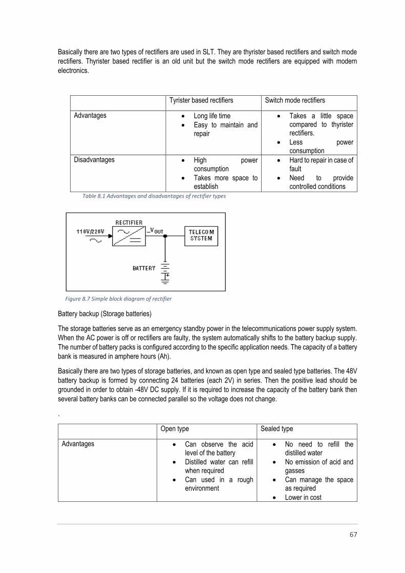
67
Basically there are two types of rectifiers are used in SLT. They are thyrister based rectifiers and switch mode
rectifiers. Thyrister based rectifier is an old unit but the switch mode rectifiers are equipped with modern
electronics.
Tyrister based rectifiers Switch mode rectifiers
Advantages Long life time
Easy to maintain and repair
Takes a little space compared to thyrister rectifiers.
Less power consumption
Disadvantages High power consumption
Takes more space to establish
Hard to repair in case of fault
Need to provide controlled conditions
Table 8.1 Advantages and disadvantages of rectifier types
Battery backup (Storage batteries)
The storage batteries serve as an emergency standby power in the telecommunications power supply system.
When the AC power is off or rectifiers are faulty, the system automatically shifts to the battery backup supply.
The number of battery packs is configured according to the specific application needs. The capacity of a battery
bank is measured in amphere hours (Ah).
Basically there are two types of storage batteries, and known as open type and sealed type batteries. The 48V
battery backup is formed by connecting 24 batteries (each 2V) in series. Then the positive lead should be
grounded in order to obtain -48V DC supply. If it is required to increase the capacity of the battery bank then
several battery banks can be connected parallel so the voltage does not change.
.
Open type Sealed type
Advantages Can observe the acid level of the battery
Distilled water can refill when required
Can used in a rough environment
No need to refill the distilled water
No emission of acid and gasses
Can manage the space as required
Lower in cost
Figure 8.7 Simple block diagram of rectifier

68
Can manage the irregular charging and discharging
Greater lifetime
Disadvantages Takes more space
Need to refill
Emission of acid and gasses
Expensive
Requirement of special conditions
Less life time Table 8.2 Advantages and disadvantages of open and sealed type batteries
Power protection
Power protection is very important to ensure the life time and service availability at the dangerous situations
such as lightning and electric surges. Lightning can be likened to a disruptive electrical discharge due to the
dielectric breakdown of the air between the clouds or between the clouds and the ground. The effects of lightning
are commonly divided into direct and indirect effects.
Direct effects (strikes on structures)
At the point of the strike, lightning generates:
Direct thermal effects (melting, fire) caused by the electric arc
Thermal and electro dynamic effects induced by circulation of the lightning current
Blast effects (shock wave and blast air) produced by heat and the expansion of the air. Protection against the direct effects of lightning is based on catching the current and discharging it to earth
(lightning conductor, catcher rods, etc).
Indirect effects (network over voltages)
Over voltages due to lightning can reach the installation by three means of access:
By conduction following direct lightning strikes on lines (power, telecommunications, TV, etc.) entering or exiting buildings
By feedback from earth via the earthing system, the protective conductors and the exposed conductive parts of equipment
By induction in the installation's conductive elements (structure of the building, etc.) and internal lines (power, telecommunications, etc.)
Protection of structures against lightings
Protection systems (lightning conductors)
The purpose of these is to protect structures against direct lightning strikes. By catching the lightning and
running the discharge current to earth, they avoid damage connected with the lightning strike itself and
circulation of the associated current. Lightning conductors are divided into four categories.
1. Single rod lightning conductors 2. Lightning conductors with sparkover device 3. Lightning conductors with meshed cage
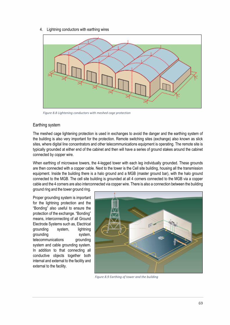
69
4. Lightning conductors with earthing wires
Earthing system
The meshed cage lightening protection is used in exchanges to avoid the danger and the earthing system of
the building is also very important for the protection. Remote switching sites (exchange) also known as slick
sites, where digital line concentrators and other telecommunications equipment is operating. The remote site is
typically grounded at either end of the cabinet and then will have a series of ground stakes around the cabinet
connected by copper wire.
When earthing of microwave towers, the 4-legged tower with each leg individually grounded. These grounds
are then connected with a copper cable. Next to the tower is the Cell site building, housing all the transmission
equipment. Inside the building there is a halo ground and a MGB (master ground bar), with the halo ground
connected to the MGB. The cell site building is grounded at all 4 corners connected to the MGB via a copper
cable and the 4 corners are also interconnected via copper wire. There is also a connection between the building
ground ring and the tower ground ring.
Proper grounding system is important
for the lightning protection and the
“Bonding” also useful to ensure the
protection of the exchange. “Bonding”
means, interconnecting of all Ground
Electrode Systems such as, Electrical
grounding system, lightning
grounding system,
telecommunications grounding
system and cable grounding system.
In addition to that connecting all
conductive objects together both
internal and external to the facility and
external to the facility.
Figure 8.8 Lightening conductors with meshed cage protection
Figure 8.9 Earthing of tower and the building
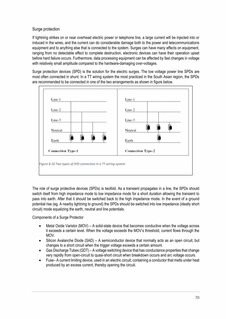
70
Surge protection
If lightning strikes on or near overhead electric power or telephone line, a large current will be injected into or
induced in the wires, and the current can do considerable damage both to the power and telecommunications
equipment and to anything else that is connected to the system. Surges can have many effects on equipment,
ranging from no detectable effect to complete destruction, electronic devices can have their operation upset
before hard failure occurs. Furthermore, data processing equipment can be affected by fast changes in voltage
with relatively small amplitude compared to the hardware-damaging over-voltages.
Surge protection devices (SPD) is the solution for the electric surges. The low voltage power line SPDs are
most often connected in shunt. In a TT wiring system the most practiced in the South Asian region, the SPDs
are recommended to be connected in one of the two arrangements as shown in figure below.
The role of surge protective devices (SPDs) is twofold. As a transient propagates in a line, the SPDs should
switch itself from high impedance mode to low impedance mode for a short duration allowing the transient to
pass into earth. After that it should be switched back to the high impedance mode. In the event of a ground
potential rise (eg. A nearby lightning to ground) the SPDs should be switched into low impedance (ideally short
circuit) mode equalizing the earth, neutral and line potentials.
Components of a Surge Protector
Metal Oxide Varistor (MOV) – A solid-state device that becomes conductive when the voltage across it exceeds a certain level. When the voltage exceeds the MOV’s threshold, current flows through the MOV.
Silicon Avalanche Diode (SAD) – A semiconductor device that normally acts as an open circuit, but changes to a short circuit when the trigger voltage exceeds a certain amount.
Gas Discharge Tubes (GDT) – A voltage switching device that has conductance properties that change very rapidly from open-circuit to quasi-short circuit when breakdown occurs and arc voltage occurs.
Fuse– A current limiting device, used in an electric circuit, containing a conductor that melts under heat produced by an excess current, thereby opening the circuit.
Figure7.10 Figure 8.10 Two types of SPD connection in a TT wiring system
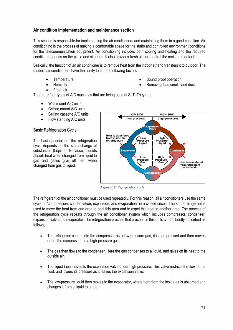
71
Air condition implementation and maintenance section
This section is responsible for implementing the air conditioners and maintaining them in a good condition. Air
conditioning is the process of making a comfortable space for the staffs and controlled environment conditions
for the telecommunication equipment. Air conditioning includes both cooling and heating and the required
condition depends on the place and situation. It also provides fresh air and control the moisture content.
Basically, the function of an air conditioner is to remove heat from the indoor air and transfers it to outdoor. The
modern air conditioners have the ability to control following factors,
Temperature
Humidity
Fresh air
Sound proof operation
Removing bad smells and dust
There are four types of A/C machines that are being used at SLT. They are,
Wall mount A/C units
Ceiling mount A/C units
Ceiling cassette A/C units
Flow standing A/C units
Basic Refrigeration Cycle
The basic principle of the refrigeration cycle depends on the state change of substances (Liquids). Because, Liquids absorb heat when changed from liquid to gas and gases give off heat when changed from gas to liquid.
The refrigerant of the air conditioner must be used repeatedly. For this reason, all air conditioners use the same
cycle of “compression, condensation, expansion, and evaporation” in a closed circuit. The same refrigerant is
used to move the heat from one area to cool this area and to expel this heat in another area. The process of
the refrigeration cycle repeats through the air conditioner system which includes compressor, condenser,
expansion valve and evaporator. The refrigeration process that proceed in this units can be briefly described as
follows,
The refrigerant comes into the compressor as a low-pressure gas, it is compressed and then moves out of the compressor as a high-pressure gas.
The gas then flows to the condenser. Here the gas condenses to a liquid, and gives off its heat to the outside air.
The liquid then moves to the expansion valve under high pressure. This valve restricts the flow of the fluid, and lowers its pressure as it leaves the expansion valve.
The low-pressure liquid then moves to the evaporator, where heat from the inside air is absorbed and changes it from a liquid to a gas.
Figure 8.11 Refrigeration cycle
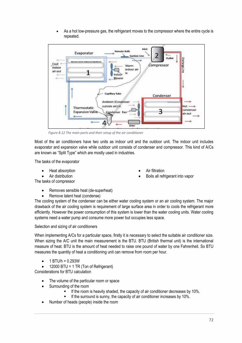
72
As a hot low-pressure gas, the refrigerant moves to the compressor where the entire cycle is repeated.
Most of the air conditioners have two units as indoor unit and the outdoor unit. The indoor unit includes
evaporator and expansion valve while outdoor unit consists of condenser and compressor. This kind of A/Cs
are known as “Split Type” which are mostly used in industries.
The tasks of the evaporator
Heat absorption
Air distribution
Air filtration
Boils all refrigerant into vapor The tasks of compressor
Removes sensible heat (de-superheat)
Remove latent heat (condense) The cooling system of the condenser can be either water cooling system or an air cooling system. The major
drawback of the air cooling system is requirement of large surface area in order to cools the refrigerant more
efficiently. However the power consumption of this system is lower than the water cooling units. Water cooling
systems need a water pump and consume more power but occupies less space.
Selection and sizing of air conditioners
When implementing A/Cs for a particular space, firstly it is necessary to select the suitable air conditioner size.
When sizing the A/C unit the main measurement is the BTU. BTU (British thermal unit) is the international
measure of heat. BTU is the amount of heat needed to raise one pound of water by one Fahrenheit. So BTU
measures the quantity of heat a conditioning unit can remove from room per hour.
1 BTU/h = 0.293W
12000 BTU = 1 TR (Ton of Refrigerant) Considerations for BTU calculation
The volume of the particular room or space
Surrounding of the room If the room is heavily shaded, the capacity of air conditioner decreases by 10%. If the surround is sunny, the capacity of air conditioner increases by 10%.
Number of heads (people) inside the room
Figure 8.12 The main parts and their setup of the air conditioner

73
If there are more than two heads, then add 600BTU per each
The requirement of the room or space If it is used as a kitchen, increases the capacity by 4000BTUs.
The condition of the room (walls, ceiling type, condition of the partitions, nature of the floor) High ceiling and unusual floor plans increases the BTU level by 10%
An air conditioner that has a smaller BTU rating than the room required, will run continuously but won’t cool the
room adequately. If the conditioner has bigger BTU rating than the room requires, then the unit will not control
the humidity properly.
Private Automatic Branch Exchange (PABX)
Private automatic branch exchange (PABX) is a technology used by call centers and other large organizations
that allows a single access number to provide several lines to outside callers while providing a range of external
lines to internal callers or staff.
PABX, the exchange is owned
and managed by the private
organization in which it is
installed and relies on computer
equipment to handle the
switching of calls. This is why the
system is considered both
private and automatic. PABX
performs all the switching
necessary for making internal
calls between extensions within
the organizations. It also allows
provides a connection between
extensions and external phone
lines.
A typical PABX system consists
of several units which form a
small scale telecommunication
system. So, the system usually
equipped with main system unit,
utility power supply, isolation
transformer, UPS/battery,
special protectors, MDF, DPs,
extension phones, operator
phones and trunk lines.
The main PABX system unit or the exchange is the most important part of the system. It provides not only the
intercom services but many other services. So that the PABX main unit includes various types of cards in order
to provide such services to the users. The unit has the expansion slots which supports to expand the capabilities
of the system. The major function cards of the main PABX unit has listed below,
CPU card
Line cards
Trunk cards
Operator consoles
DTMF cards
Trunk
lines
Multi pair cables
Figure 9.1 Physical overview of a PABX system
74
Each of these cards have their own functions such as call processing, signaling, switching, interfacing and tone
generation.
CPU card
Central Processing Unit card controls all the switching activities, routing of calls, call logging and many other
tasks related to call processing.
Line cards
Line cards or extension cards are modular units that could be plugged into the main unit in order to increase
the number of extensions given for the internal use. So all the extension phones are terminated at the RJ45 or
RJ11 interfaces of the extension cards at main system unit. Each phone need one pair to work and all the pairs
starts from the main system unit and terminate at the MDF. All the pairs coming from the extension phones also
terminate at the other side of the MDF. The service is given to the relevant customer equipment by connecting
ports at both sides using a jumper wire.
Trunk cards
Trunk cards allows the system to connect with the outside networks such as PSTN. The trunk ports of the trunk
cards are used to connect the system to outside. The trunk lines could be either analog or digital. When it is
digital the trunk cards are designed with digital interfacing like ISDN. Usually the high end (with more trunk lines)
PABXs use the digital trunks and low end systems use analog trunks.
Operator consoles
Operator consoles are the interfaces which allow to connect the operator phones with the PABX system. This
operator phones provides more facilities to the telephone operator to handle call traffic easily and confidently.
These telephone provides variety of service such as call transferring, call waiting, call forwarding, call blocking
or limiting, playing back ground sound and etc.
DTMF card
A DTMF (Dual Tone Multi Frequency) card has been installed for tone generation and signaling purposes.
DTMF is one of the signaling technique that is used to identify the digits which dialed by a customer. In addition
to that this card allows us to input an audio source as well as to obtain an audio output.
Safety measures
The trunk lines go through the MDF and the special protector/arrestor in order to ensure the protection of the PABX system from the outside effects. (Lightening, high voltages coming over the trunk lines). Then all trunks lines connect to the main system’s trunk interfaces.
An isolation transformer is connected before the UPS or battery to protect the system from the voltage fluctuation and the electric surges of the utility power supply.
The lightening arresters are installed at the MDF.
Steps of implementing a phone system
Firstly, it is necessary to identify the requirements regarding to the phone system such as, Customer equipment that are going to be used. Locations or the people that need the extensions and operator phones. Other facilities the customer expect.
Then it should be finalize the positions that are going to establish the phones, DPs, Main system unit and the power supply. In addition to that it is a must to discuss with the customer about the wiring of the system. The aesthetic appearance, conduits, cabling method are important to finalize.

75
After finalizing the above facts then the measurements are taken to draw the wiring diagram of the system.
The wiring diagram is drawn and a BOQ (Bill Of Quantity) and an estimation are prepared regarding to the wiring diagram.
The wiring and the system installation are done by the SLT after obtaining the customer’s approval.
Finally the operator phones and the system are configured. The system is tested to identify the troubles and troubleshooting.
Phone systems
Although, it has been described about the PABX phone systems in above paragraphs, basically there are two
types of phone systems. They are known as “Key phone systems” and “Private Branch exchange (PBX)
systems”.
Key systems are usually found in small companies where fewer telephones and features are required. Key
system typically have one system unit, an operator phone that acts as the controller for limited number of lines
for limited number of extensions. The key phones consists of multiple keys and lights that indicates which lines
are in use. When placing a call to the outside, it can be done by just pressing a key to directly select the service
provider’s line.
PBXs are found in large scale organization that uses hundreds of lines and thousands of extensions. The main
benefits of a PBX are its many automated features, easy setup and flexibility. A PBX connects telephone
company trunk lines with individual user lines and equipment inside the organization. PBX controls all the
incoming and outgoing calls, connecting outside callers with inside extensions and inside extensions with each
other. The digital IP based PABX systems are the modern trend of the phone systems which connects VOIP
(Voice Over IP) users together while allowing all users to share certain number of external lines.
CDMA section
CDMA (Code Division Multiple Access) is an air – interface or radio transmission technology and access
technology which supports wireless telecommunication. Although the FDMA (Frequency Division Multiple
Access) and TDMA (Time Division Multiple Access) are band limited and time limited techniques CDMA does
not has such limitations but the power control should be done strictly.
CDMA uses spread-spectrum technology to minimize the problems. Using spread-spectrum technology allows
for the signals to be transmitted over a wide spectrum of the electromagnetic spectrum. This is achieved by a
specific but complex mathematical function. The receiver must recognize the frequency-versus time function
used by the transmitter. That means the spread-spectrum signals are distributed over a wide range of
frequencies and then collected on their original frequency at the receiver.
Spread spectrum technology
When transmitting a CDMA spread spectrum signal, the required data signal is multiplied with what is known
as a spreading or chip code data stream. These special codes are called Pseudo Random Noise Codes or
Walsh codes. The resulting data stream has a higher data rate than the data itself.
Each bit in the spreading sequence is called a chip, and this is much shorter than each information bit. The
spreading sequence or chip sequence has the same data rate as the final output from the spreading multiplier.
The rate is called the chip rate, and this is often measured in terms of a number of M chips / sec. The baseband
data stream is then modulated onto a carrier and overall signal is spread over a much wider bandwidth.

76
To decode the signal and receive the original data, the CDMA signal is first demodulated from the carrier to
obtain the high speed data stream. This is multiplied with the spreading code to regenerate the original data.
When this is done, only the data with that was generated with the same spreading code is regenerated, all the
other data that is generated from different spreading code streams is ignored. There are two types of spread-
spectrum technologies, Frequency Hopping and Direct Sequencing.
Frequency Hopping - Frequency hopping is the easiest spread spectrum modulation to use. Frequency hopping
conversation requires the addition of pseudo-noise (PN) code generators. The idea behind frequency hopping
is to transmit across a broad spectrum, switching frequencies rapidly from one to another. De-hopping is
achieved by a synchronized PN code generator in the local receiver’s frequency synthesizer.
Direct Sequence - Direct Sequencing is the more practical and all digital form of spread-spectrum. A Direct
Sequence system uses a locally generated PN code to encode the data. The spread-spectrum receiver uses a
locally generated copy of the PN code to decode.
CDMA code channels
Code channels are characterized by mathematical code such as pseudo random codes (Pseudo Noise).
Code channels in forward link
Pilot channel
Sync channel
Paging channel
Forward traffic channel Code channels in reverse link
Access channel
Reverse traffic channel
CDMA Forward Channel
The forward link uses the same frequency spectrum as AMPS (824-849 Mhz), each carrier 1.25MHz.
There are 4 types of logical channels (A pilot, a synchronization, a paging, and 61 traffic channels). Channels are separated using different spreading codes.
A set of 64 mathematical codes is needed to differentiate the 64 forward code channels and the codes in this set are called “Walsh codes”.
After Walsh codes, they are further spread by short PN spreading codes.
Each sector in BS (Base Station) is transmitting a forward traffic channel containing up to 64 forward code channels.
A MS (Mobile Station) must be able to discriminate between different sectors of different BSs.
Short PN sequences (short PN codes) are defined for the purpose of identifying sectors of different BSs.
QPSK is the modulation scheme that used in forward channel.
Figure
- -
Figure 10.1 CDMA spread spectrum generation & decoding
77
The pilot channel
Used by the MS for initial system acquisition.
Transmitted constantly by BS.
Facilitates MS assisted hand off (Soft Hand off)
4 to 6 dB stronger than all other channels
The Sync channels
Used to acquire initial time synchronization
Synch message includes system ID (SID), network ID (NID), the offset of the PN short code, the state of the PN-long code, and the paging channel data rate (4.8/9.6 Kbps).
Operates at 1200 bps
The MS re – synchronizes at the end of every call.
The Paging channel
Used to page the MS in case of an incoming call, or to carry the control messages for call set up.
The rate is 4.8 Kbps or 9.6Kbps.
There is no power control
The traffic channels
Used for the transmission of user information and signaling information to a specific MS during a call.
Maximum number of traffic channel is 61.
But due to the power control limitations and difficulties the maximum number of users limits to 35 per sector.
CDMA reverse channel
The CDMA system must be able to identify each MS that may attempt to communicate with a BS.
One binary digit sequence called “Long pseudo noise sequence” is defined for the purpose of uniquely identifying each possible reverse code channel.
This sequence can be used in trillions of ways and each has a code that identify a particular user reverse channel.
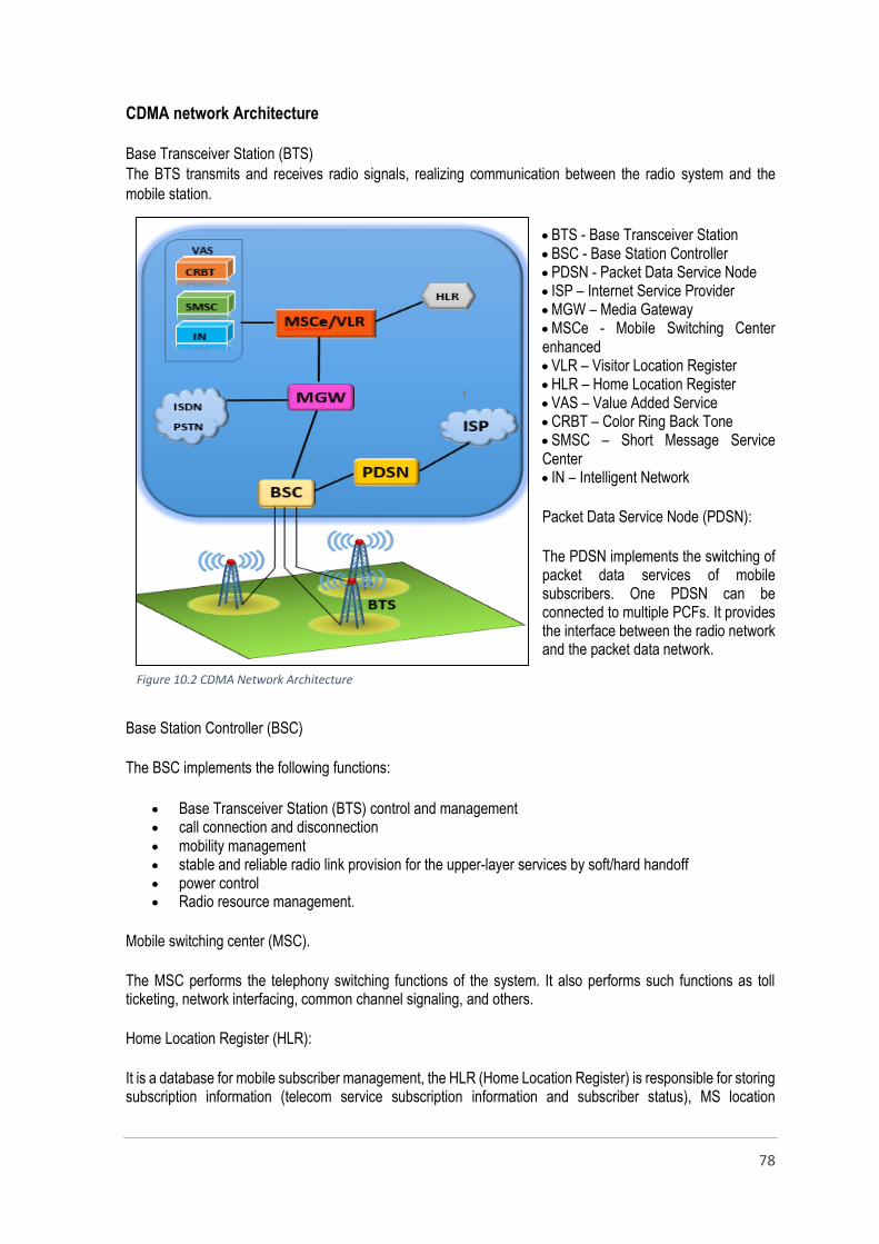
78
CDMA network Architecture
Base Transceiver Station (BTS)
The BTS transmits and receives radio signals, realizing communication between the radio system and the
mobile station.
BTS - Base Transceiver Station BSC - Base Station Controller PDSN - Packet Data Service Node ISP – Internet Service Provider MGW – Media Gateway MSCe - Mobile Switching Center enhanced VLR – Visitor Location Register HLR – Home Location Register VAS – Value Added Service CRBT – Color Ring Back Tone SMSC – Short Message Service Center IN – Intelligent Network
Packet Data Service Node (PDSN):
The PDSN implements the switching of packet data services of mobile subscribers. One PDSN can be connected to multiple PCFs. It provides the interface between the radio network and the packet data network.
Base Station Controller (BSC)
The BSC implements the following functions:
Base Transceiver Station (BTS) control and management call connection and disconnection mobility management stable and reliable radio link provision for the upper-layer services by soft/hard handoff power control Radio resource management.
Mobile switching center (MSC).
The MSC performs the telephony switching functions of the system. It also performs such functions as toll ticketing, network interfacing, common channel signaling, and others.
Home Location Register (HLR):
It is a database for mobile subscriber management, the HLR (Home Location Register) is responsible for storing subscription information (telecom service subscription information and subscriber status), MS location
Figure 10.2 CDMA Network Architecture
79
information, MDN, IMSI (MIN), etc. The AC (Authentication Center) is physically combined with the HLR. It is a functional entity of the HLR, specially dedicated to the security management of the CDMA system. It stores the authentication information. It also prevents unauthorized subscribers from accessing the system and prevents the radio interface data from being stolen.
Visitor Location Register (VLR):
It is a dynamic database, stores the temporary information (all data necessary to set up call connections) of the roaming subscribers in the local MSC area. VLR is used to store the subscriber information of all the MSs in its local area, which can be used to establish the incoming/outgoing call connections, to support basic services, supplementary services and mobility management.
Color Ring Back Tone (CRBT)
Color Ring Back Tone (CRBT) is one of the many value-added services that has seen incredible adoption in recent years. This service allows customization of the ring back tone. When a call is placed, the caller hears an audible alert through the phone. The alert indicating that a call is successfully going through is called the ring back tone.
Short Message Service Center (SMSC)
The Short Message Service (SMS) allows text messages to be sent and received to and from mobile telephones. The text can comprise words or numbers or an alphanumeric combination. SMS messages are transmitted within the same cell or to anyone with roaming capability. They can also be sent to digital phones from a web site equipped with a PC Link or from one digital phone to another. An SMS gateway is a web site that lets you enter an SMS message to someone within the cell served by that gateway or acts as an international gateway for users with roaming capability.
The SMS is a store and forward service. In other words, short messages are not sent directly from sender to
recipient, but via an SMS Center. Each mobile telephone network that supports SMS has one or more
messaging centers to handle and manage the short messages. Short messages can be sent and received
simultaneously with GSM voice, data and fax calls. This is possible because short messages travel over and
above the radio channel using the signaling path.
The network operator needs to purchase its first generation SMS Center as part of the network commissioning
plan. The initial SMS Center may simply be a voice mail platform module or a stand-alone SMS Center. It is not
possible to make the SMS available without an SMS Center since all short messages pass through the SMS
Center.
Intelligent Network (IN)
An intelligent network (IN) is a service independent telecommunications network. That is, intelligence is taken
out of the switch and placed in computer nodes that are distributed throughout the network. This provides the
network operator with the means to develop and control services more efficiently. New capabilities can be
rapidly introduced into the network. Once introduced, services are easily customized to meet individual
customer's needs.
Intelligent Networks are used by telephone operators for creation and management of value added services in
telecom networks. SLT CDMA provides prepaid services for the customers using the Intelligent Network (IN).

80
Media gateway (MGW)
MGW has two major functions to fulfill with in the network. They are switching and media conversion. MGW
also contributes for the switching process that is functioned by the MSC. In addition to that the MGW is the
gateway of the CDMA network which connects the network with the outside network such as ISDN (Integrated
service digital network), PSTN (Public switched telephone network). The media conversion between this two
parties are done by the MGW and as a result, the TDM based outside networks converts into a condition that
compatible with the IP based network.
Advantages of CDMA technology
Outstanding Voice and Call Quality
CDMA filters out background noise, cross-talk, and interference so it can be enjoyed clear voice quality,
greater privacy, and enhanced call quality. CDMA variable rate vocoder translates voice into digital
transmissions, zeroes and ones, at the highest translation rates possible (8kbps or 13kbps). This
allows for clear voice and also maximizes the system capacity.
Greatest Coverage for Lower Cost
CDMA's spread spectrum signal provides the greatest coverage in the wireless industry, allowing
networks to be built with far fewer cell sites than is possible with other wireless technologies. Fewer
cell sites reduced the operating expenses, which results in savings to both operators and consumers.
Packet Data
CDMA networks are built with standard IP packet data protocols. Other networks require costly
upgrades to add new data equipment in the network and will require new data phones. Standard
cdmaOne phones already have TCP/IP and PPP protocols built into them.
Improved Security and Privacy
CDMA's digitally encoded, spread spectrum transmissions resist eaves dropping. Designed with about
4.4 trillion codes, CDMA virtually eliminates cloning and other types of fraud.
Fewer Dropped Calls
CDMA's patented "soft handoff," method of passing calls between cells sharply reduces the risk of
disruption or dropped calls during a handoff. The process of soft handoff leads to fewer dropped calls
as 2 or 3 cells are monitoring your call at any given time.
Continuing Advances
CDMA technology enables users to access a wide range of new services, including caller identification,
short messaging services and Internet connections. Simultaneous voice and data calls are also
possible using CDMA technology.
Rapid Deployment
CDMA systems can be deployed and expanded faster and more cost effectively than most wire line
networks. And because they require fewer cell sites, CDMA networks can be deployed faster than
other types of wireless networks.
81
Greater Capacity
CDMA allows the largest number of subscribers to share the same radio frequencies, helping service
providers to increase their profitability. CDMA uses spread spectrum technology which can provide up
to 10-20 times the capacity of analog equipment and more than three times the capacity of other digital
platforms. With dual-mode phones, CDMA is compatible with other technologies for seamless
widespread roaming coverage.
Disadvantages of CDMA technology
Channel pollution is major drawback where, signals from too many cell sites are present in the subscriber’s phone but none of them is dominant. When this situation arises the quality of the audio degrades.
Lack of international roaming capabilities.
The ability to upgrade or change to another handset is not easy with this technology because the network service information for the phone is put in the actual phone unlike GSM which uses SIM card for this.
International transmission maintenance center (ITMC) and submarine cables
International transmission maintenance center (ITMC)
ITMC is the section or the main gateway which inks the local customers with the global communication network.
ITMC is the major party which control, regulate and assure the quality of the international links of the various
customers. In other hand ITMC is a testing interface that allows to test and identify the issues related to
international links. In order to provide various types of services for the customers, the ITMC has been equipped
with different types of units. The ITMC structure can be simply divided into two parts as local side and the
international side.
The international side consists of four submarine cables which are connected to the ITMC and the local side
includes more parties which obtain the global connectivity via the ITMC. The voice traffic of the SLT, which flow
through the switches connects to the international networks via the international switching center (ISC) and
other service providers connect via the PCM section of SLT. The data traffic achieves the global connectivity
through the DATACOM section of the SLT. In addition to those services ITMC connects the IPVPN customers
with their global branches and organizations. Almost all the transmission functions in submarine links are based
on the SDH technology but the equipment that established in the ITMC allows to provide services in different
levels such as PDH, fast Ethernet. SLT has launched a new project to form the OTN (Optical Transmission
Network) island wide, in parallel to the new project the new OTN equipment are being established at ITMC. As
a result of that the network is going to be empowered with an optical transmission and DWDM (Dense
Wavelength Division Multiplexing) technology. Using DWDM, up to 80 (and theoretically more) separate
wavelengths or channels of data can be multiplexed into a light stream transmitted on a single optical fiber.
Each channel carries a time division multiplexed (TDM) signal. In a system with each channel carrying 2.5 Gbps
(billion bits per second), up to 200 billion bits can be delivered a second by the optical fiber. In addition to those
equipment the ITMC includes many other units that work with other technologies such as PDH, SONET, SDH,
ATM and etc.
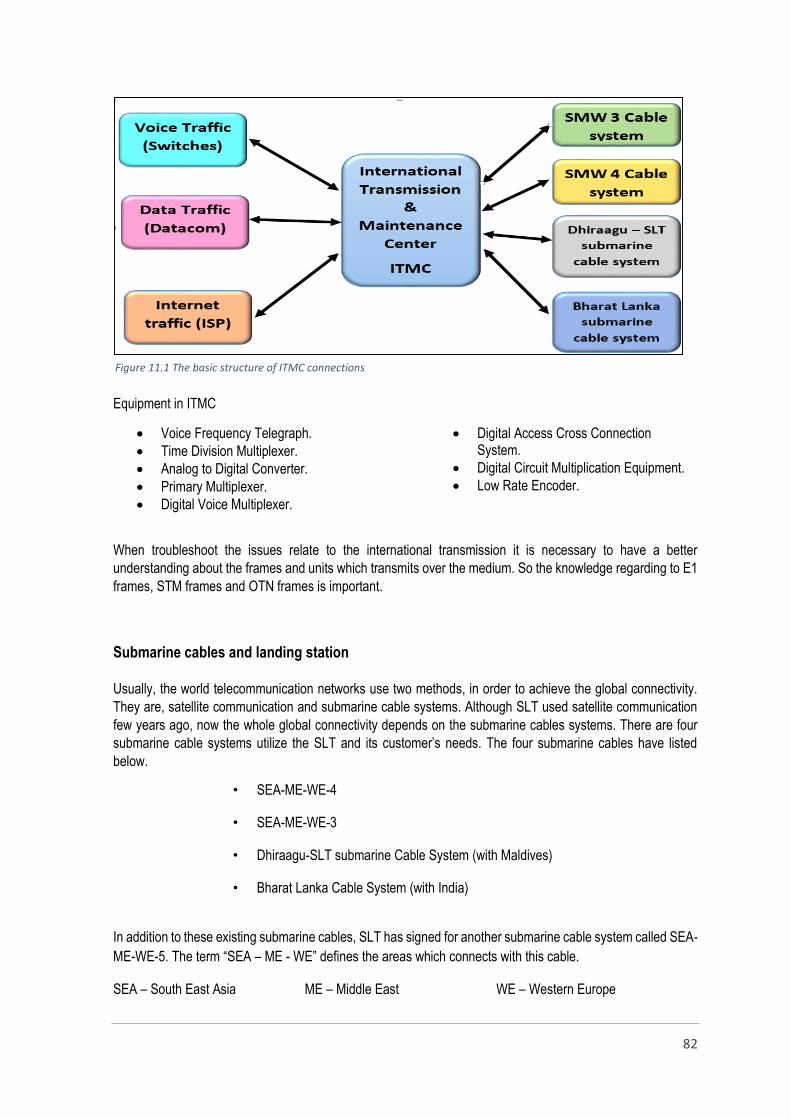
82
Equipment in ITMC
Voice Frequency Telegraph.
Time Division Multiplexer.
Analog to Digital Converter.
Primary Multiplexer.
Digital Voice Multiplexer.
Digital Access Cross Connection System.
Digital Circuit Multiplication Equipment.
Low Rate Encoder.
When troubleshoot the issues relate to the international transmission it is necessary to have a better
understanding about the frames and units which transmits over the medium. So the knowledge regarding to E1
frames, STM frames and OTN frames is important.
Submarine cables and landing station
Usually, the world telecommunication networks use two methods, in order to achieve the global connectivity.
They are, satellite communication and submarine cable systems. Although SLT used satellite communication
few years ago, now the whole global connectivity depends on the submarine cables systems. There are four
submarine cable systems utilize the SLT and its customer’s needs. The four submarine cables have listed
below.
• SEA-ME-WE-4
• SEA-ME-WE-3
• Dhiraagu-SLT submarine Cable System (with Maldives)
• Bharat Lanka Cable System (with India)
In addition to these existing submarine cables, SLT has signed for another submarine cable system called SEA-
ME-WE-5. The term “SEA – ME - WE” defines the areas which connects with this cable.
SEA – South East Asia ME – Middle East WE – Western Europe
Figure 11.1 The basic structure of ITMC connections

83
The cable landing station of the SEA – ME – WE 4 is established in the ITMC premises. The SEA – ME – WE
4 is the fourth Submarine cable system that SLT involved in the history. Sixteen telecommunication companies
of fourteen countries. The initial project was jointly done by Alcatel Submarine Networks, France & Fujitsu Ltd,
Japan. The cable consists of two optical fiber pairs – Omni Bus & Express Bus. Omni bus is the cable which
interconnects every landing stations. The express bus connects only few selected stations to serve large traffic.
Submarine cable design
A submarine cable is designed to protect its information carrying through, from water, pressure, waves, currents
and other natural forces that affect the seabed and over -lying waters. Most of these forces change with depth.
In addition to the natural facts the impacts of human activities also more considerable such as fishing and
shipping. So the sheathed and armoured cables are used to ensure the protection, but it is economical to vary
the protection of the cable depending on the nature of the sea bed and possibility of having human activities.
So that various wire types and layers were designed to meet different seabed conditions. Two-layered or double
armour helped protect against anchors and fishing gear, as well as abrasion under wave and current action in
coastal seas. Heavy single-armoured cable was designed for intermediate water depths beyond the reach of
anchors and most trawl fishing gear. Light single armour was a deep-water design that allowed cables to be
laid in full ocean depths.
Basic submarine cable types:
Double Armoured - DA (up to 200m)
Single Armoured – SA (up to 1500m)
Single Armoured Light –SAL (up to
2000m)
Lightweight Protected – LWP (up to
3500m)
Lightweight-LW (up to 8000m)
Figure 11.2 The diagram of the SEA – ME – WE 4 cable system

84
Survey, lay and maintain cables
Route Selection - A key part of route selection is the
identification and understanding of marine
geopolitical boundaries that is suitable for cable
laying.
Route survey - Following the identification of
potential cable landings that are to be connected, it
is most effective to conduct a survey in order to
define the most efficient and secured route. A route
survey commonly covers a swath of seabed one
kilometer wide in water depths down to about 1,500
m, reflecting the need to bury cables for protection
according to local conditions.
Laying operations on a modern ships undergo constant and accurate monitoring. The ship’s position and speed
over the ground are measured by the satellite-based differential global positioning system, and the water depth by
precision echo-sounders and seabed mapping systems, whereas cable pay-out speed and length are recorded by
a rotometer. Onboard, the cable engineers paying full attention on laying progress with constant reference to the
engineered route plan, making adjustments if necessary. In addition, there may be computerized tracking of the
entire laying operation that includes detection of external factors such as winds and ocean currents. Once laid, the
cable comes ashore and is connected to the terminal or cable station, which assumes full management of the
telecommunications system.
Figure 11.3 Basic submarine cable types
Figure 11.4 Route Surveying
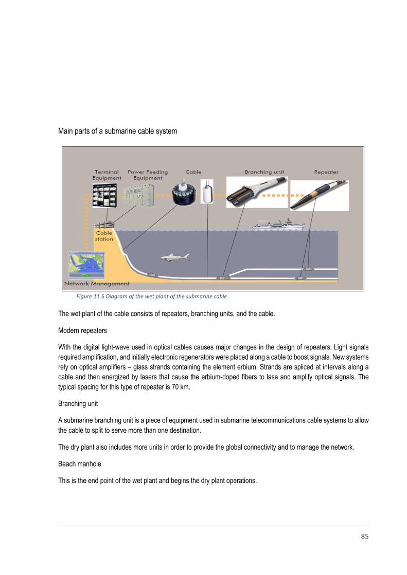
85
Main parts of a submarine cable system
The wet plant of the cable consists of repeaters, branching units, and the cable.
Modern repeaters
With the digital light-wave used in optical cables causes major changes in the design of repeaters. Light signals
required amplification, and initially electronic regenerators were placed along a cable to boost signals. New systems
rely on optical amplifiers – glass strands containing the element erbium. Strands are spliced at intervals along a
cable and then energized by lasers that cause the erbium-doped fibers to lase and amplify optical signals. The
typical spacing for this type of repeater is 70 km.
Branching unit
A submarine branching unit is a piece of equipment used in submarine telecommunications cable systems to allow
the cable to split to serve more than one destination.
The dry plant also includes more units in order to provide the global connectivity and to manage the network.
Beach manhole
This is the end point of the wet plant and begins the dry plant operations.
Figure 11.5 Diagram of the wet plant of the submarine cable
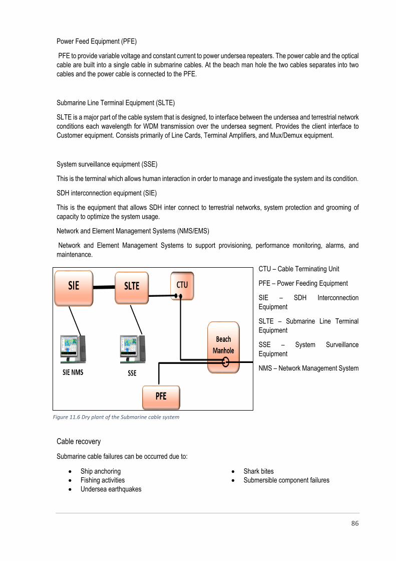
86
Power Feed Equipment (PFE)
PFE to provide variable voltage and constant current to power undersea repeaters. The power cable and the optical
cable are built into a single cable in submarine cables. At the beach man hole the two cables separates into two
cables and the power cable is connected to the PFE.
Submarine Line Terminal Equipment (SLTE)
SLTE is a major part of the cable system that is designed, to interface between the undersea and terrestrial network
conditions each wavelength for WDM transmission over the undersea segment. Provides the client interface to
Customer equipment. Consists primarily of Line Cards, Terminal Amplifiers, and Mux/Demux equipment.
System surveillance equipment (SSE)
This is the terminal which allows human interaction in order to manage and investigate the system and its condition.
SDH interconnection equipment (SIE)
This is the equipment that allows SDH inter connect to terrestrial networks, system protection and grooming of
capacity to optimize the system usage.
Network and Element Management Systems (NMS/EMS)
Network and Element Management Systems to support provisioning, performance monitoring, alarms, and
maintenance.
CTU – Cable Terminating Unit
PFE – Power Feeding Equipment
SIE – SDH Interconnection
Equipment
SLTE – Submarine Line Terminal
Equipment
SSE – System Surveillance
Equipment
NMS – Network Management System
Cable recovery
Submarine cable failures can be occurred due to:
Ship anchoring
Fishing activities
Undersea earthquakes
Shark bites
Submersible component failures
Figure 11.6 Dry plant of the Submarine cable system
87
Can be damaged basically in 3 different ways:
Both the optical and copper conductors damaged
Only copper conductor damaged
Only optical conductor damaged
When repair a damaged cable first it is necessary to identify the location of the cable using the cable charts and
maps. Then the faulted location of the cable should be identified correctly before lift the cable as it might be a
reason to increase the damage. OTDR (Optical Time Domain Reflectometer) testing (cable can be tested up to the
repeater only) or COTDR (Coherent Optical Time Domain Reflectometer) testing (can test the cable beyond the
repeaters) are used to identify the damaged location. The remotely operated under water vehicles (ROV) are used
to discover the cable condition and the damage. After identifying the damaged location the cable is retrieved with
specially designed grapnels deployed from the repair ship. Then the lifted cable is repaired by the specially trained
and skilled engineers and technicians.

88
Conclusion
The aim of this report is to summarize the training experience which I had during the last six month at Sri Lanka
Telecom. The training period was scheduled at the beginning of the session by the training and planning section of
the SLT considering our ideas and expectations. According to the schedule I started the training at Outside Plant
Maintenance Center (OPMC) at Negombo. After nearly three months I was appointed to the training at SLT head
office in order to gain knowledge and skills related to various engineering divisions.
During the training at SLT OPMC I was able to cover most of the maintenance sections which were ensure the
customer satisfaction about the services provide by the SLT. Almost all the tasks which were done at various
sections of the OPMC related to the maintenance and trouble shooting. It was an enthusiastic opportunity which
gave not only the knowledge but a good real world practice related to the certain sections.
The training session at the SLT head office made an opportunity to gain understanding about much more deep
technical and theoretical matters. However, the second training session did not effectively contribute to improve the
practical knowledge but gave wide knowledge on networks and their architectures, naval telecommunication
technologies and new trends in fixed telecommunication.
The 5S productivity concept which is practicing in SLT is really fruitful and it has made a pleasant working area
inside the office areas, test rooms and network operation centers. I am glad to admire the effective contribution of
the SLT staff during the training period but sometime I was disappointed by the lack of attention paid by some staff
members towards trainees when ask to clarify technical things. In my point of view it is better to maintain a well-
designed training program for each and every section in order to save time and reserve resources for trainees only
for a short period of time.
However this training programme made a real platform to study and experienced the working environment of an
organization and it will definitely be an advantage in adjusting for a new working environment. Finally I would like
to conclude this brief summary of the final report with thankful thoughts towards SLT, NAITA and ITUM.

89

90
TRAINING SHEDULE
Name of Organisation : ………………………………………………………………………......................................
Address of Organization / Worksite: …………………………………………………………....................................
Trainee’s Name with Initials: ………………………………………………………………………………………….…
Registration No: …………………………………………………………………………………………………………..
Division/Section
Areas of Training Received as
per Training Guidelines
Duration
Signature of Trainee: ………………………………………… Date: ………………………………………
This is to certify that the trainee concerned received the training stated above.
Name of the Officer in Charge of Training: …………………………………………………………………………….
Signature: ………………………………. Contact Telephone Number: ……………………………………….
CONFIDENTIAL

91
CONFIDENTIAL
NATIONAL APPRENTICE AND INDUSTRIAL TRAINING AUTHORITY 1ST SIX MONTH / 2ND SIX MONTH
ASSESMENT OF N.D.T. APPRENTICES 20…..
Place of Assessment: …………………………………….. Date of Assessment: ………………………….
..……………………………………. Time: ………………………….
Field: …………………………………………………………
Serial No.
Name
Assessment elements
Remarks
Dai
ly d
iary
Pro
gre
ss R
epo
rts
(2x5
)
Fin
al R
epo
rt
Tec
hn
ical
Kn
ow
led
ge
Att
end
ance
, Co
nd
uct
&
Hu
man
Rel
atio
ns
Ind
ust
rial
an
d L
abo
ur
Law
s
TO
TA
L
PA
SS
/FA
IL
15 10 20 40 10 05 100
1.
2.
3.
4.
5.
6.
7.
8.
9.
10.
11.
12.
NAME OF EXAMINER DESIGNATION SIGNATURE
1. 2. 3. 4. 5.
Recommended