Switching and linear technology1 charging levelVersions for non-sealed and sealed lead-acid batteries, 1.25 to 12A ratingsCharging current limitationselectable.
SEC. - PAGEd batteriesAutomatic batterry y chchhharararara gegegegeg rsrsrss for lead-acid bbbbatte
rsion .................................................................................................................... 24 - 2Switchingggg BCBCBCBCF seeeeeririririies,,,, momoooduddd lalalalaar version............................................................................................................................................ 24 - 3Swittttchchchchc inininii gggg BBBCB G seeririririr ess .... ....
s ...................................................................................................................................................... 24 - 4Linear BBBBCE sssserieess
Dimensions ............................................................................................................ 24 - 5Wiring diagrams ...................................................................................................... 24 - 6Technical characteristics ............................................................................................ 24 - 7
Autoommaattiionn aanndd ccontrol
AAuuuutommmmmmaaaaatic battery chargeeeeeeerrrrrrrssss24
AXIS & Stuifmeel B.V.Coenecoop 12741 PG WADDXINVEEN+31(0)[email protected]
24
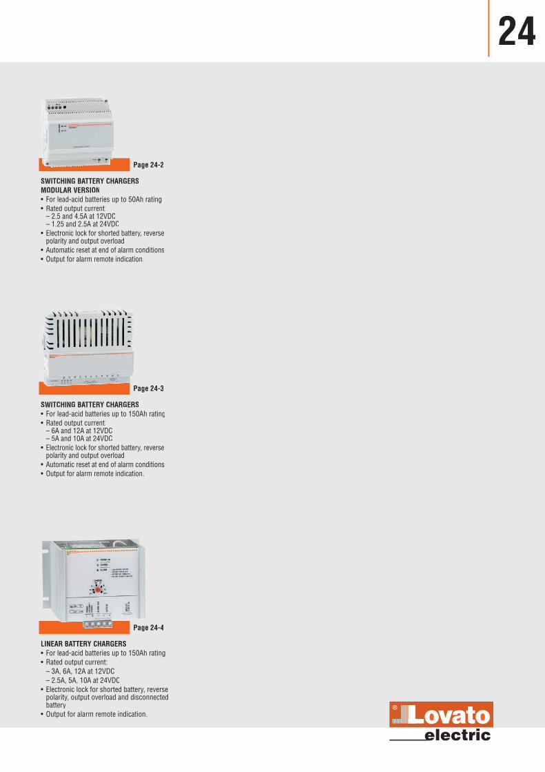
SWITCHING BATTERY CHARGERSMODULAR VERSION• For lead-acid batteries up to 50Ah rating• Rated output current: – 2.5 and 4.5A at 12VDC – 1.25 and 2.5A at 24VDC
• Electronic lock for shorted battery, reversepolarity and output overload
• Automatic reset at end of alarm conditions• Output for alarm remote indication.
Page 24-2
SWITCHING BATTERY CHARGERS• For lead-acid batteries up to 150Ah rating• Rated output current: – 6A and 12A at 12VDC – 5A and 10A at 24VDC• Electronic lock for shorted battery, reverse
polarity and output overload• Automatic reset at end of alarm conditions• Output for alarm remote indication.
Page 24-3
LINEAR BATTERY CHARGERS• For lead-acid batteries up to 150Ah rating• Rated output current: – 3A, 6A, 12A at 12VDC – 2.5A, 5A, 10A at 24VDC• Electronic lock for shorted battery, reverse
polarity, output overload and disconnectedbattery
• Output for alarm remote indication.
Page 24-4
24-2 Technical characteristics page 24-7
Wiring diagramspage 24-6
Dimensionspage 24-5
Automatic battery chargersSwitching BCF series
24
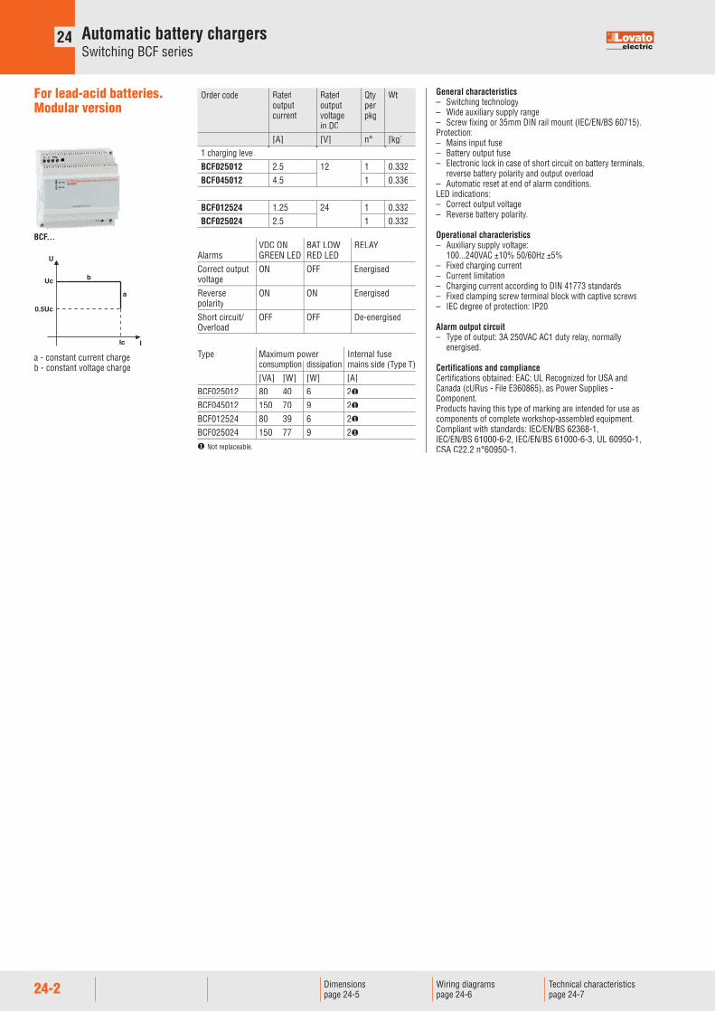
General characteristics– Switching technology– Wide auxiliary supply range– Screw fixing or 35mm DIN rail mount (IEC/EN/BS 60715).Protection:– Mains input fuse– Battery output fuse– Electronic lock in case of short circuit on battery terminals,
reverse battery polarity and output overload– Automatic reset at end of alarm conditions.LED indications:– Correct output voltage– Reverse battery polarity.
Operational characteristics– Auxiliary supply voltage: 100...240VAC ±10% 50/60Hz ±5%– Fixed charging current– Current limitation– Charging current according to DIN 41773 standards– Fixed clamping screw terminal block with captive screws– IEC degree of protection: IP20.
Alarm output circuit– Type of output: 3A 250VAC AC1 duty relay, normally
energised.
Certifications and complianceCertifications obtained: EAC; UL Recognized for USA andCanada (cURus - File E360865), as Power Supplies -Component.Products having this type of marking are intended for use ascomponents of complete workshop-assembled equipment.Compliant with standards: IEC/EN/BS 62368-1,IEC/EN/BS 61000-6-2, IEC/EN/BS 61000-6-3, UL 60950-1,CSA C22.2 n°60950-1.
VDC ON BAT LOW RELAYAlarms GREEN LED RED LED Correct output ON OFF EnergisedvoltageReverse ON ON EnergisedpolarityShort circuit/ OFF OFF De-energisedOverload
Type Maximum power Internal fuse consumption dissipation mains side (Type T) [VA] [W] [W] [A]BCF025012 80 40 6 2�
BCF045012 150 70 9 2�
BCF012524 80 39 6 2�
BCF025024 150 77 9 2�
� Not replaceable.
Order code Rated Rated Qty Wt output output per
current voltage pkg in DC [A] [V] n° [kg]1 charging level.BCF025012 2.5 12 1 0.332BCF045012 4.5 1 0.336
BCF012524 1.25 24 1 0.332BCF025024 2.5 1 0.332
For lead-acid batteries.Modular version
U
Uc
0.5Uc
Ic I
b
a
a - constant current chargeb - constant voltage charge
BCF...
24
24-3
Automatic battery chargersSwitching BCG series
24
Technical characteristics page 24-7
Wiring diagramspage 24-6
Dimensionspage 24-5
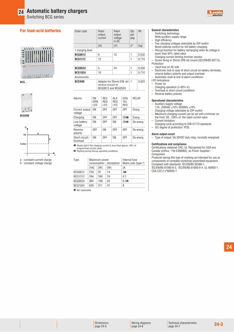
General characteristics– Switching technology– Wide auxiliary supply range– High efficiency– Two charging voltages selectable by DIP-switch– Boost external control for full battery charging– Hiccup function for battery recharging when its voltage is
lower than 50% rated value– Charging current limiting trimmer resistor– Screw fixing or 35mm DIN rail mount (IEC/EN/BS 60715).Protection:– Input fuse on AC side– Electronic lock in case of short circuit on battery terminals,
reverse battery polarity and output overload– Automatic reset at end of alarm conditions.LED indications:– Power on– Charging operation (I>30% Ic)– Overload or short circuit conditions– Reverse battery polarity.
Operational characteristics– Auxiliary supply voltage: 110...240VAC ±10% 50/60Hz ±10%– Charging voltage selectable by DIP-switch– Maximum charging current can be set with a trimmer on
the front: 20...100% of the rated current value– Current limitation– Charging cycle according to DIN 41773 standards– IEC degree of protection: IP20.
Alarm output circuit– Type of output: 5A 30VDC duty relay, normally energised.
Certifications and complianceCertifications obtained: EAC; UL Recognized for USA andCanada (cURus - File E360865), as Power Supplies -Component.Products having this type of marking are intended for use ascomponents of complete workshop-assembled equipment.Compliant with standards: IEC/EN/BS 62368-1,IEC/EN/BS 61000-6-2, IEC/EN/BS 61000-6-4, UL 60950-1,CSA C22.2 n°60950-1.
U
Uc
0.5Uc
Ic I
b
a
a - constant current chargeb - constant voltage charge
Order code Rated Rated Qty Wt output output per
current voltage pkg in DC [A] [V] n° [kg]1 charging level.BCG0612 6 12 1 0.532BCG1212 12 1 0.710
BCG0524 5 24 1 0.532BCG1024 10 1 0.710
Accessories.BCGX00 Adapter for 35mm DIN rail 1 0.022
vertical mount of BCG0612 and BCG0524
For lead-acid batteries
Alarms ON REV ALA CHG RELAY GRN RED RED YEL LED LED LED REDCorrect output ON OFF OFF OFF Energ.voltage Charging ON OFF OFF ON� Energ.Low battery ON OFF ON ON� De-energ.voltageReverse OFF ON OFF OFF De-energ.polarityShort circuit / ON OFF ON OFF De-energ.Overload� Steady light if the charging current is more than approx. 30% of
programmed current value.� Flashing during Hiccup operating conditions.
Type Maximum power Internal fuse consumption dissipation Mains side (type T) [VA] [W] [W] [A]BCG0612 230 97 14 4�
BCG1212 284 290 29 6.3BCG0524 364 158 20 6.3�
BCG1024 630 311 41 8� Not replaceable.
BCGX00
BCG...
24-4 Technical characteristics page 24-7
Wiring diagramspage 24-6
Dimensionspage 24-5
Automatic battery chargersLinear BCE series
24
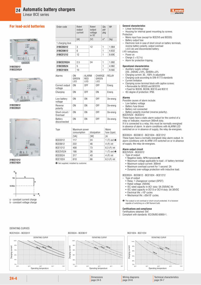
General characteristics– Linear technology– Housing for internal panel mounting by screws.Protection:– Mains input fuse (except for BCE2V5 and BCE03)– Battery output fuse– Electronic lock in case of short circuit on battery terminals,
reverse battery polarity, output overload (<0.5 Ue) and disconnected battery.
LED Indications:– Power on– Charge (I > 0.2 Ic)– Alarm for protection tripping.
Operational characteristics– Auxiliary supply voltage: 220...240VAC ±10%, 50/60Hz ±5%– Charging current: 30...100% Ie adjustable – Charging cycle according to DIN 41773 standards– Current limitation– Clamping screw terminal block with captive screws: • Removable for BCE03 and BCE2V5 • Fixed for BCE05, BCE06, BCE10 and BCE12– IEC degree of protection: IP00.
AlarmsPossible causes of alarm include:– Low battery voltage– Battery fuse blown– Battery not connected– Battery polarity inverted (reverse polarity).BCE2V524 - BCE0312 These types have a static alarm output for the control of arelay or indicator, maximum 300mA duty.If it is connected to a relay, this must be normally energisedin absence of alarm. In alarm conditions with ALARM LEDswitched on or in absence of supply, the relay de-energises.
BCE0524 - BCE0612 - BCE1024 - BCE1212These types have a normally energised relay alarm output. Inalarm conditions with ALARM LED switched on or in absenceof supply, the relay de-energises.
Alarm output circuitBCE2V524 - BCE0312– Type of output: • Negative static; NPN transistor� • Maximum voltage applicable to load: +V battery terminal • Maximum output current: 300mA • Maximum overload current for 1 second: 2A • Dynamic over-voltage protection with inductive load.
BCE0524 - BCE0612 - BCE1024 - BCE1212– Type of output • Relay: 1 changeover contact (SPDT) • Rated voltage: 250VAC • IEC rated capacity in AC1 duty: 5A 250VAC Ith • IEC rated capacity in DC13 or DC14 duty: 5A 30VDC • Electrical life: >105 cycles • Mechanical life: >30x105 cycles.
� The output is not overload or short-circuit protected. It is howevercapable of switching on a 3W filament bulb.
Certifications and complianceCertifications obtained: EAC.Compliant with standards: IEC/EN/BS 60950-1.
Order code Rated Rated Qty Wtoutput output per
current voltage pkg in DC [A] [V] n° [kg]1 charging level.31BCE0312 3 12 1 1.98431BCE0612 6 1 4.83231BCE1212 12 1 8.690
31BCE2V524 2.5 24 1 1.99231BCE0524 5 1 4.96031BCE1024 10 1 9.560
For lead-acid batteries
U
Uc
0.5Uc
Ic I
b
a
a - constant current chargeb - constant voltage charge
Type Maximum power Mains consumption dissipation fuse (type) [VA] [W] [A]BCE0312 117 24 1 (T) ext �BCE0612 222 46 4 (F) intBCE1212 400 73 6.3 (F) intBCE2V524 166 26 1 (T) ext �BCE0524 317 40 4 (F) intBCE1024 610 66 6.3 (F) int� Not supplied; installed by customer.
DERATING CURVES
BCE2V524 - BCE0312 BCE0524 - BCE0612 BCE1024 - BCE1224
DERATING CURVE100%
95%
90%
85%
80%
75%50°C 55°C 60°C 65°C 70°C
Char
ging
cur
rent 220V AC
230V AC240V AC
Operating temperature
75%
DERATING CURVE100%
95%
90%
85%
80%
50°C 55°C 60°C 65°C 70°C
Char
ging
cur
rent 220V AC
230V AC240V ACC
Operating temperature
75%
DERATING CURVE
100%
95%
90%
85%
80%
50°C 55°C 60°C 65°C 70°C
Char
ging
cur
rent 220V AC
230V ACC
240V AC2
Operating temperature
Alarms ON ALARM CHARGE RELAY GREEN RED GREEN LED LED LEDCorrect output ON OFF OFF Energ.voltageCharging ON OFF ON Energ. Low battery ON ON OFF De-energ.voltage Reverse ON ON OFF De-energ.polarityShort circuit / ON ON OFF De-energ.OverloadBattery ON ON OFF De-energ.disconnected
31BCE031231BCE2V524
31BCE061231BCE0524
31BCE121231BCE1024
24
24-5
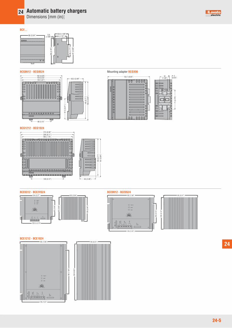
Automatic battery chargersDimensions [mm (in)]
24
70
--
ALAR
MOU
T
220-
240V
POW
ER
30%
60
40
50
++--
BATT
ERY
100%
FUSE
BATT
ERY
ALARM
80
90
POWER ON
CHARGE
134 (5.27”) 100 (3.94”)
100
(3.9
4”)
120.5 (4.74”)
65 (2
.56”
)
93 (3
.66”
)
BCE0312 - BCE2V524
220-
240V
COM
FUSE PO
WER
--
OUT
NC
ALAR
M
NO ++BA
TTER
Y
FUSE
BATT
ERY
60
40
30%
50 8070
100%
90
POWER ON
CHARGE
ALARM
140 (5.51”)192 (7.56”)
178 (7.01”)
80 (3
.15”
)
130
(5.1
2”)
BCE0612 - BCE0524
FUSE
POW
ER
POW
ER22
0-24
0V
NCCOM
OUT
ALAR
M
NO --
BATT
ERY
++ BATT
ERY
FUSE
50
30%
40
70
100%
90
80
POWER ON
ALARM
CHARGE
178 (7.01”)
140 (5.51”)192 (7.56”)
180
(7.0
9”)
230
(9.0
5”)
BCE1212 - BCE1024
90 (3.54”)50.6 (1.99”)5.6
(1.99”) 44 (1.73”)
45 (1
.77”
)91
(3.5
8”)
96 (3
.78”
)
BCF...
162 (6.38”)159 (6.26”)149 /5.87”)
80 (3.15”)
63.2 (2.49”)
81.5
(3.2
1”) 14
5 (5
.71”
)15
0.5
(5.9
2”)
BCG0612 - BCG0524
153.7 (6.05”) 35(1.38”)
9(0.35”)
71 (2
.79”
)
Mounting adapter BCGX00
213 (8.38”)206 (8.11”)198 (7.79”)
130 (5.12”) 63 (2.48”)
145
(5.7
1”)
151
(5.9
4”)
BCG1212 - BCG1024
24-6
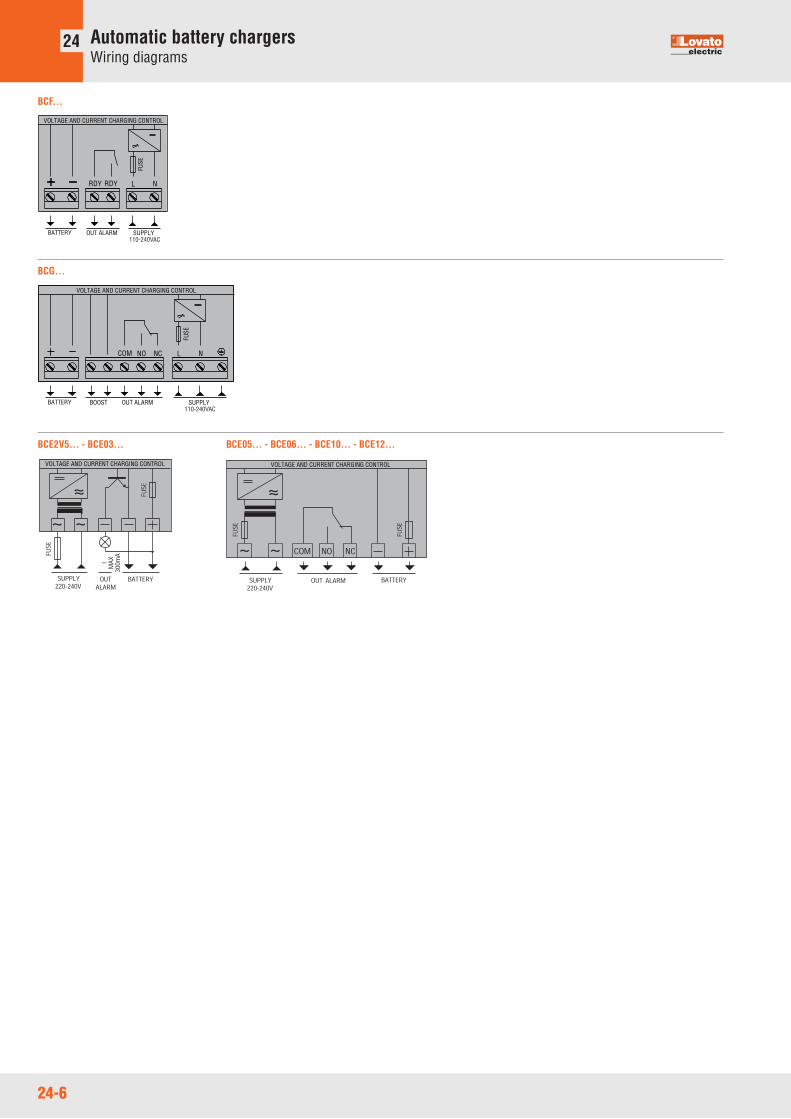
Automatic battery chargersWiring diagrams
24
BCF...
BCE2V5... - BCE03... BCE05... - BCE06... - BCE10... - BCE12...
VOLTAGE AND CURRENT CHARGING CONTROL VOLTAGE AND CURRENT CHARGING CONTROL
BCG...
SUPPLYBATTERY
FUSE
OUT ALARMBOOST110-240VAC
COM NO NC L N
VOLTAGE AND CURRENT CHARGING CONTROL
SUPPLYBATTERY
VOLTAGE AND CURRENT CHARGING CONTROL
FUSE
OUT ALARM110-240VAC
RDY RDY L N
24
24-7
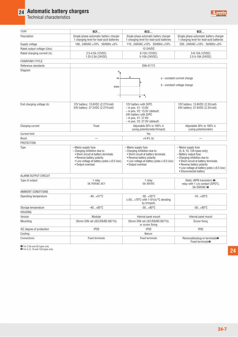
Automatic battery chargersTechnical characteristics
24
TYPE BCF... BCG... BCE...Description Single phase automatic battery charger Single phase automatic battery charger Single phase automatic battery charger 1 charging level for lead-acid batteries 1 charging level for lead-acid batteries 1 charging level for lead-acid batteriesSupply voltage 100...240VAC ±10% 50/60Hz ±5% 110...240VAC ±10% 50/60Hz ±10% 220...240VAC ±10% 50/60Hz ±5%Rated output voltage (Uoc) 12-24VDC Rated charging current (Ic) 2.5-4.5A (12VDC) 6-12A (12VDC) 3-6-12A (12VDC) 1.25-2.5A (24VDC) 5-10A (24VDC) 2.5-5-10A (24VDC)CHARGING CYCLEReference standards DIN 41773Diagram
a - constant current charge
b - constant voltage charge
End charging voltage Uc 12V battery: 13.6VDC (2.27V/cell) 12V battery with DIP2: 12V battery: 13.8VDC (2.3V/cell)24V battery: 27.2VDC (2.27V/cell) – in pos. V1: 13.8V 24V battery: 27.6VDC (2.3V/cell) – in pos. V2: 13.5V (default) 24V battery with DIP2: – in pos. V1: 27.6V – in pos. V2: 27.0V (default)
Charging current Fixed Adjustable 20% to 100% Ic Adjustable 30% to 100% Ic (using potentiometer/trimpot) (using potentiometer)Current limit YesBoost — +4.4% Uc —PROTECTION Type – Mains supply fuse – Mains supply fuse – Mains supply fuse
– Charging inhibition due to: – Charging inhibition due to: (5, 6, 10, 12A types only)• Short circuit at battery terminals • Short circuit at battery terminals – Battery output fuse• Reverse battery polarity • Reverse battery polarity – Charging inhibition due to:• Low voltage at battery poles (<0.5 Uoc) • Low voltage at battery poles (<0.5 Uoc) • Short circuit at battery terminals• Output overload • Output overload • Reverse battery polarity
• Low voltage at battery poles (<0.5 Uoc)• Disconnected battery
ALARM OUTPUT CIRCUITType of output 1 relay 1 relay Static (NPN transistor) �; 3A 250VAC AC1 5A 30VDC relay with 1 c/o contact (SPDT), 5A 250VAC �
AMBIENT CONDITIONS Operating temperature -40...+51°C -30...+55°C -10...+50°C (+55...+70°C with 1-5%Ic/°C derating
by trimpot)Storage temperature -40...+85°C -30...+80°C -30...+80°CHOUSINGVersion Modular Internal panel mount Internal panel mountMounting 35mm DIN rail (IEC/EN/BS 60715) 35mm DIN rail (IEC/EN/BS 60715) Screw fixing or screw fixing
IEC degree of protection IP20 IP20 IP00Cooling NaturalConnections Fixed terminals Fixed terminals Removable/plug-in terminals� Fixed terminals�
U
Uc
0,5Uc
Ic I
b
a
� For 2.5A and 3A types only.� For 5, 6, 10 and 12A types only.
Recommended


