Embed Size (px)
Citation preview

BHILAI STEEL PLANT BY – SAURABH CHAUDHARY

CONTENTS
STEEL AUTHORITY OF INDIA LIMITED (SAIL)BHILAI STEEL PLANT(BSP)COKE OVEN AND COAL DEPARTMENTCOMPRESSED AIR STATION DEPARTMENTCHILLED WATER PLANT DEPARTMENTBLOOMING & BILLET MILL DEPARTMENT

STEEL AUTHORITY OF INDIA LIMITED
• Steel Authority of India Limited (SAIL) is one of the largest state owned steel makers in India and one of the top steel
makers in the world, With a turnover of 8681 crore (US $10.71billion), the company is among top five highest profit
earning corporate of the country

4
Special Steel Plants
oSteel Authority of India Limited (SAIL), Kanpur, Uttar PradeshoAlloy Steels Plants (ASP), Durgapur, West BengaloSalem Steel Plant (SSP), Tamil NaduoVisvesvaraya Iron and Steel Limited (VISL), at Bhadravathi, Karnataka
Ferro Alloy Plant
oChandrapur Ferro Alloy Plant (CFP) in Maharastra
SAIL integrated Steel Plants
oBhilai Steel Plant (BSP) in Chhattisgarh setup with Soviet CollaborationoRourkela Steel Plant (RSP) in Orissa setup with German CollaborationoDurgapur Steel Plant (DSP) in West Bengal setup with British CollaborationoBokaro Steel Plant (BSL) in Jharkhand setup with Soviet CollaborationoIISCO Steel Plant (ISP) at Burnpur, West Bengal

BHILAI STEEL PLANT

BHILAI STEEL PLANT
THE GOVERNMENT OF INDIA AND USSR IN YEAR 1955 SIGNED THE AGREEMENT FOR THE ESTABLISHMENT OF THE IRON AND STEEL WORKS.
THE INITIAL CAPACITY OF PLANT WAS ONE MILLION TONS.IRON ORE FROM DALLI RAJHRA,DOLOMITE FROM HIRRI AND
LIMESTONE FROM NANDINI WERE DELIVERED.IT WAS Inaugurated IN THE YEAR 1959 BY THE PRESIDENT
OF INDIA DR. RAJENDRA PRASAD

COAL AND COKE OVEN DEPARTMENT

COAL AND COKE OVEN DEPARTMENT
• The main function of Coke Ovens is to convert coal into coke which is used as a fuel and reducing agent in the Blast Furnace. Its secondary function is to recover Volatile Matter and CO gas from coal and extract chemicals known as Coal Chemicals.CO gas produced is used for heating purposes in the plant.

BATTERIES

Coal blend to Battery
Coal in an oven converted to coke

Firing of spilled Coke
Mechanized door cleaner
Manual cleaning of frame

CHEMICAL DEPARTMENT
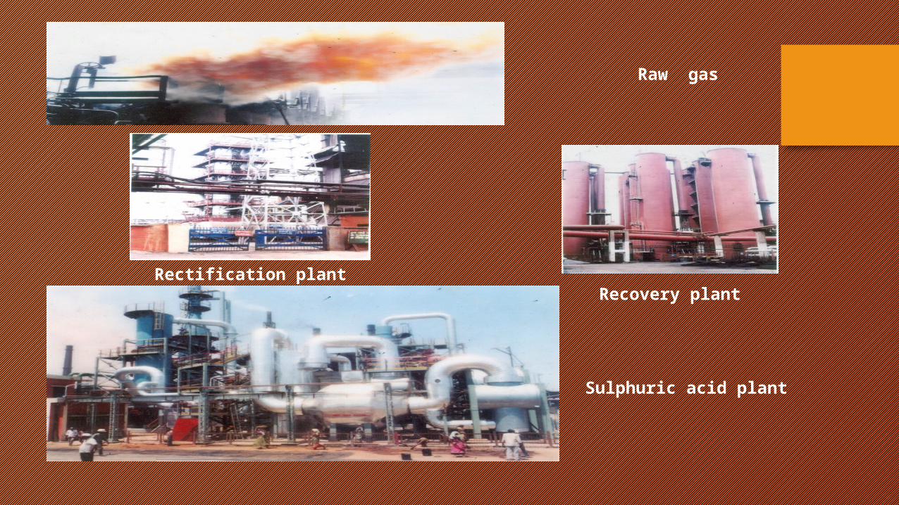
Rectification plantRecovery plant
Raw gas
Sulphuric acid plant

COMPRESSED AIR STATON
Compressed Air serves as an important means of power transmission system. It is used for operating various pneumatic tools and apparatus , monitoring controls and regulation system. It is also used for liquid fuel atomization in furnace.

AIR FILTER PANEL
THIS EQUIPMENT CONSISTS OF A TWO TIER SYSTEM OF CLEANING DUSTY AIR FOR SUPPLYING CLEAN AIR TO THE COMPRESSOR BY PASSING THE ATM. AIR FIRST THROUGH A FINE MESH COVERED WITH FINE LAYER OF OIAND THEN THROUGH A DRY AIR FILTER PANELOF15 TO 20 MICRONS

THROTTLE VALVE AND INTER COOLER
THIS VALVE CONTROLS THE FLOW OF AIR TO THE COMPRESSORTHROUGH AN PLC CONTROLLED AUTO MECHANISM.
THE HOT AIR PASSES THROUGH THE BUNDLES WHICH IS SURROUNDED BY SERVICE WATER.WATER TAKES THE HOT AIR TEMP. AND GETS HOT AND COOL AIR SENT TO NEXT STAGE.
THROTTLE VALVE
INTER COOLER

REDUCER AND OIL COOLER
THIS EQUIPMENT IS IN FACT A MULTIPLICATOR WHICH INCREASES THE SPEED OF 3000 R.P.M OF MOTOR TO 10935 R.P.M REQUIRED BY THE COMPRESSOR ROTOR
THIS EQUIPMENT HELPS IN COOLING THE OIL IN CIRCULATION THROUGH THE LUBRICATION SYSTEMOF THE COMPRESSOR TO BELOW 450C
REDUCER
OIL COOLER

DELIVERY,ANTI -SURGENT AND NON RETURN VALVEELECTROMECHANICAL VALVE OF THECOMPRESSOR THROUGH WHICH OUTPUT AIR IS DELIVERED.
IT IS FOR THE PROTECTION OF COMPRESSOR WHICH OPERATES (OPENS) WHEN THE PRESSURSE INSIDE THE RUNNING COMPRESSOR RISES ABOVE A CERTAIN SET PRESSURE VALUE
IT PROTECTS COMPRESSOR INTERNALS AGAINST BACKFLOW OFCOMPRESSED AIR FROM THE COLLECTOR ANDREVERSE ROTATION OF THE ROTOR.
NON RETURN VALVE
ANTISURGENT VALVE
DELIVERY VALVE

END COOLER,MOISTURE SEPERATOR,COLLECTOR VALVE AND LINE
COOLS THE OUTPUT COMPRESSED AIR AFTER 3 RD STAGE TO BELOW 720C BEFORE SUPPLYING IT TO THE MOISTURE SEPERATOR.
HELPS IN SEPERATING ALL PHYSICALLY MOISTURE AND OIL COMPONENTS PRESENT IN THE OUTPUT COMPRESSED AIR.
THIS VALVE HELPS IN ISOLATING THE COMPRESSOR FROM THE MAIN COLLECTOR OF COMPRESSED AIR FROM WHICH IT IS SUPPLIED TO THE CONSUMER THROUGH A NETWORK OF PIPELINES. THIS HELPS IN TAKING MAINTAINENCE WORK IN COMPRESSOR WITH SAFETY.
END COOLER
COLLECTOR LINE
MOISTURE SEPERATOR

BLOOM AND BILLET MILL

SOAKING PITS
• Heating of the ingots and soaking at a particular temperature is done in the soaking pits. There are 14 groups of soaking pits. Each group consists of 2 pits. Each pit is heated by two burners situated diagonally opposite in the upper part of the lateral wall of the pit. The fuel burnt is mixture of coke oven gas and blast furnace gas with a calorific value of 1450 - 1500 KCal./Cu.M. Air is preheated in ceramic recuperators and the gas in the metallic recuperators. The ingots are placed in the pits in such a way so that proper circulation of the flame around the ingot is ensured.Generally 16 ingots are placed in one chamber at a time. Strict records are maintained to avoid mix-up.
• Operational data of Soaking Pits• Dimensions of the pit• Length : 6.7m, Width : 4.2m , Depth : 4.5m• Soaking temp. : 1280 to 1320 deg

BLOOMING MILL
• Blooming mill is a 2-High horizontal stand, equipped with individually driven rolls. Each roll of the Blooming Mill is driven by 930 V, 8000 KW, 0-20-80 rpm motor. Length of Roll - 2800 mm, Dia. of Roll - 1150 mm are used in pairs.The used rolls are sent for redressing in Roll Turning Shop. The Top Roll is balanced by counter weights.There are manipulator side guards on both sides of the Roll stand. This is to manipulate the rolling stock on to the required pass section of the roll. Tilters are fitted in the front manipulator for tilting the rolling stock whenever required. The total rolls from ingot to bloom is done in 11 - 17 passes. The bloom proceeds to the shear where the front and back ends are cropped off to eliminate defects and the bloom is cut into required length. Blooms intended for further rolling in Billet Mill are sent directly after cutting the front and back end. The shear is of the up-cut crank shaft type with maximum cutting force of 1000 Ton and operating speed of up to 10 cuts per minute. The Mill can roll square and rectangular blooms and also narrow width slab. Common Sizes of Blooms and Narrow Width Slabs
• i) 320 x 320 mm• ii) 265 x 340 mm• iii) 260 x 300 mm

BILLET MILL
• It roll billets from blooms of cross section 325x325 sq.mm in 6 to 12 passes depending on cross section of billets.The Mill consists of 12 working stands arranged in three groups.These stands are equipped with rolls of diameter 500mm. Rolled billets after the roughing group of stands which are not to be rolled further are transported by transfer table and by pass roll table to the stationary 800T shear where they are cut into required length. The billets are gathered and transported to cooling bed by roll tables. Billets from roughing group intended for further rolling in finishing group are transferred to the last group of stands. If necessary, the front end of billet can be cropped off by 250 T shears installed in front of the group. After rolling in the finishing the billets are cut by flying shears into billets of length 5 to 12m.
• SECTION OF BILLETS ROLLED ARE• 1. 150 x 150 mm• 2. 110 x 110 mm• 3. 105 x 105 mm