Embed Size (px)
Citation preview

APPLICATION OF REMOTE SENSING AND
GEOGRAPHICAL INFORMATION SYSTEM IN
CIVIL ENGINEERING
Date:
INSTRUCTORS
DR. MOHSIN SIDDIQUE
ASSIST. PROFESSOR
DEPARTMENT OF CIVIL ENGINEERING

Earth, datum, Projections, Maps and coordinate systems
2

� Flat earth models are still used for plane surveying, over distances shortenough so that earth curvature is insignificant (less than 10 km).
� Spherical earth models (Earth centered model) represent the shape of theearth with a sphere of a specified radius. Spherical earth models are oftenused for short range navigation (VOR-DME) and for global distanceapproximations. Spherical models fail to model the actual shape of the earth.
� Ellipsoidal earth models are required for accurate range and bearingcalculations over long distances. Ellipsoidal models define an ellipsoid with anequatorial radius and a polar radius. The best of these models can representthe shape of the earth over the smoothed, averaged sea-surface to withinabout one-hundred meters.
� Although the earth is an ellipsoid, its major and minor axes do not varygreatly. In fact, its shape is so close to a sphere that it is often called aspheroid rather than an ellipsoid. But sometimes, the spheroid confusedpeople. SO I often call ellipsoid.
Earth Shape Models3

� Spherical Earth’s surface
-radius 6371 km
� Meridians (lines of longitude)
- passing through Greenwich, England as prime meridian or 0º longitude.
� Parallels (lines of latitude)
- using equator as 0º latitude.
� degrees-minutes-seconds (DMS),
� decimal degrees (DD)
Globe4

Spherical and Ellipsoidal Earth
Earth Centered X/Y/Z Geodetic Lat/Lon/Height
5

Ellipsoidal Parameters6

� The reference ellipsoidsurface (a map of averagesea level).
� The reference geoid surface(a mean sea level surface).
� The real surface of the Earth(the ground) also called thetopographic surface.
Earth Surface: Ellipsoid, Geoid, Topo7

THE GEOID and ELLIPSOID
SOURCE: National Geodetic Survey http://www.ngs.noaa.gov/GEOID/geoid_def.
html
Ellipsoid
Earth's
Surface
P
Po
h (Ellipsoid Height) = Distance along ellipsoid normal (Q to P)
N (Geoid Height) = Distance along ellipsoid normal (Q to P )
"Geoid"
h = H + N
h
N
H (orthometric height) = Distance along Plumb Line (P to P)o
Q
OCEAN
o
8

� Geodetic datum defines the size and shape of the ellipsoid earth and theorigin (or position) and orientation (or direction) with respect to the Earth.
� the direction of the minor axis of the ellipsoid. This is classically defined asbeing parallel to the mean spin axis of the earth
� the position of its center, either implied by adopting a geodetic latitude andlongitude (Φ, λ) and geoid / ellipsoid separation (N) at one, or more points(datum stations), or in absolute terms with reference to the Earth centre ofmass; and
� the zero of longitude (conventionally the Greenwich Meridian).
� True geodetic datums were employed only after the late 1700s whenmeasurements showed that the earth was ellipsoidal in shape. The science ofgeodesy.
Geodetic Datum9

Selected Ellipsoids
and Datums
Source: http://maic.jmu.edu/sic/standards/datum.htm
10

Common Datums used in U.S.
� North American Datum 1927 (NAD27)
� Uses the Clarke 1866 spheroid
� Reference point is located at Meades Ranch, Kansas
� Based on ground survey inrmation in the 1800’s
� North American Datum 1983 (NAD83)
� Uses GRS80 (Geodetic Reference System) spheroid
� Ellipsoid model from geocentric perspective
� Based on ground surveys and satellite information
� WGS 1984
� Most recently developed datum/ framework for measurements worldwide
� Earth centered, or geocentric, perspective
� This is the datum used by all GPS satellites
� Nearly identical to NAD83…therefore NAD83 is compatible with data collected in GPS using WGS84!
11

Transforming between datums
� Several methods available for transforming between NAD27 and NAD83
� Standard and most accurate is NADCON
� Available in ArcView 8.x (ArcToolbox)
� Many GPS devices transform using less accurate transformations
� If you your GIS data is in NAD27, you should considering collecting in NAD83/WGS84 and transform your coordinates using ArcToolbox
12

� A map projection is a mathematical model for conversion of locations from a three-dimensional earth surface to a two-dimensional map representation. This conversion necessarily distorts some aspect of the earth's surface, such as area, shape, distance, or direction.
� Every projection has its own set of advantages and disadvantages. There is no"best" projection. Some distortions of conformality (shape), scale, distance, direction, and area always result from this processes.
� Some projections minimize distortions in some of these properties at the expense of maximizing errors in others. Some projection are attempts to only moderately distort all of these properties
� The mapmaker must select the one best suited to the needs, reducing distortion of the most important features.
� Mapmakers and mathematicians have devised almost limitless ways to projectthe image of the globe onto a flat surface (paper).
Basics of Map Projections13

Basics of Map Projections
Azimuthal Cylindrical Conic
The Earth’s graticule projected onto azimuthal, cylindrical, and conic surfaces.
14

Basics of Map Projections
Azimuthal Cylindrical Conic
Examples of secant azimuthal, cylindrical, and conic map projections.
15

Basics of Map Projections
http://earth.rice.edu/mtpe/geo/geosphere/topics/mapprojections.html
16

Physical models:
� Cylindrical projections (cylinder)
- Tangent case
- Secant case
� Conic Projections (cone)
- Tangent case
- Secant case
� Azimuthal or planar projections (plane)
- Tangent case
- Secant case
Classes of Map projections
Distortion properties:� Conformal (preserves local angles and shape)
� Equal area or equivalent (area)
� Equidistant (scale along a center line)
� Azimuthal (directions)
17

Cylindrical Transverse Cylindrical Oblique
Cylindrical
Secant Cylindrical
Conical Secant Conical Planar Secant Planar
18

Tangent Vs Secant map projections
Scale distortions on a tangent map surface.
The central point is not distorted on the map.
Scale distortions on a secant map surface.
Line(s) of intersection are not distorted on the map.
http://plone.itc.nl/geometrics/Map%20projections/mappro.html
19

20

� This process of flattening the earth will cause distortions in one or more of the following spatial properties:
� Shape
� Conformal map projections preserve shape
� Area
� Equal area map projections preserve area
� Distance/Scale
� Equidistant map projections preserve distance
� Direction/Angle
� Azimuthal map projections preserve true direction
Basics of Map Projections21

� Mercator Projection (1569)
� - Directions are true along straight line of any two points, Distances are trueonly along equator, and reasonable correct within 15 of equator, in secantmodel, distance along two parallels are correct in scale instead of the Equator.Areas and shapes of large area are distorted. Distortion increases away fromEquator and is extreme in polar regions. However, map is conformal in thatangles and shapes within any small area is essentially true.
- Used for navigation or maps of equatorial regions.
Common Used Projections22

Common Used Projections
Source: Longley et al. 2001
23
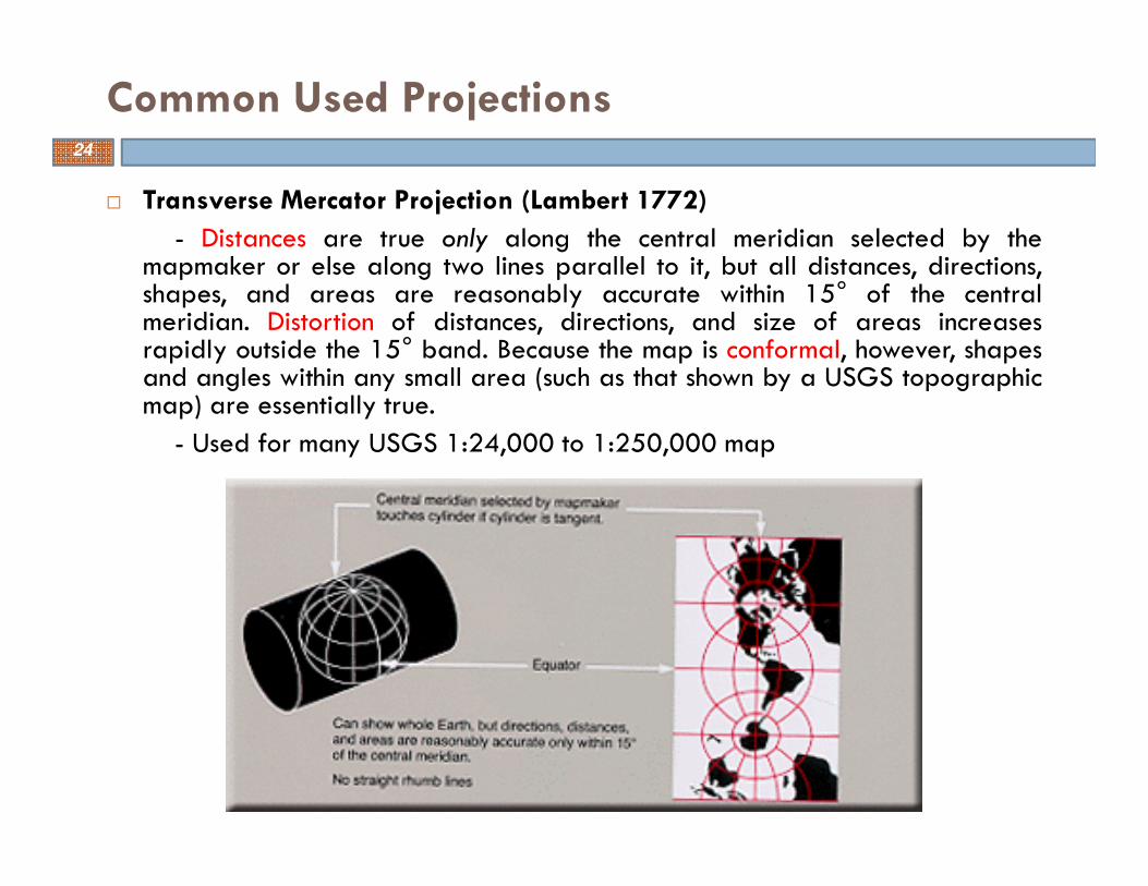
� Transverse Mercator Projection (Lambert 1772)
- Distances are true only along the central meridian selected by themapmaker or else along two lines parallel to it, but all distances, directions,shapes, and areas are reasonably accurate within 15° of the centralmeridian. Distortion of distances, directions, and size of areas increasesrapidly outside the 15° band. Because the map is conformal, however, shapesand angles within any small area (such as that shown by a USGS topographicmap) are essentially true.
- Used for many USGS 1:24,000 to 1:250,000 map
Common Used Projections24

� Albers Equal-Area Conic Projection (1805)
- All areas on the map are proportional to the same areas on the Earth. Directions are reasonably accurate in limited regions. Distances are true on both standard parallels. Maximum scale error is 1 1/4% on map of conterminous States with standard parallels of 29 1/2°N and 45 1/2°N. Scale true only along standard parallels
- Used for maps showing the conterminous United Stated.
Common Used Projections25

� Lambert Conformal Conic Projection (1772)
- Distances true only along standard parallels; reasonably accurate elsewhere in limited regions. Directions reasonably accurate. Distortion of shapes and areas minimal at, but increases away from standard parallels. Shapes on large-scale maps of small areas essentially true Used for maps of North America. USGS Base Maps for 48 conterminous States with standard parallels 33 N, and 45 N (maximum scale error 2 ½ %). for TOPO maps, standard parallels vary.
- Used for many topographic maps and for State Base Map series.
Common Used Projections26

LAMBERT CONIC PROJECTION (Northern Hemisphere)
North Standard
Parallel
South Standard
Parallel
Parallel of
Grid Origin
(Base Parallel)
Central MeridianPolar Axis
27

� Stereographic Projection
� This is a Azimuthal projection
� Directions true only from center point of projection. Scale increases away from center point. Any straight line through center point is a great circle. Distortion of areas and large shapes increases away from center point.
- Used for maps of Antarctica and Arctic, for TOPO maps and navigating in latitudes above 80º, and for some geophysical maps and NEXRAD precipitation products.
Common Used Projections28

Basic elements of a coordinate system
� an origin, then the
location of every
other point can be
stated in terms of
� a defined direction and
� a distance in the
direction
Coordinate Systems29

� There are many different coordinate systems, based on a variety of geodetic
datums, projections, and units in use
� Geographic coordinate systems (no projection): Spheroid (or Ellipsoid)-based systems, local systems.
� Projected coordinate systems: world, continental, polar, US National Grids, UTM, state plane.
Coordinate System30

Geographic Latitude/Longitude Coordinate System31

� Latitude
� Measured northward or southward from the equator to poles
� Ranging 0-900 north or south
� The measuring units are degrees, minutes, and seconds, 10 = 60’ and 1’=60”
� The length of one degree latitude is similar everywhere, ≈ 111km/69miles
� Longitude
� Measured eastward or westward from the Prime Meridian at Greenwich, England to the International Date Line
� Ranging 0-1800 east or west
� The measuring units
� Length of one degree longitude reduces toward poles
Geographic Latitude/Longitude Coordinate System32
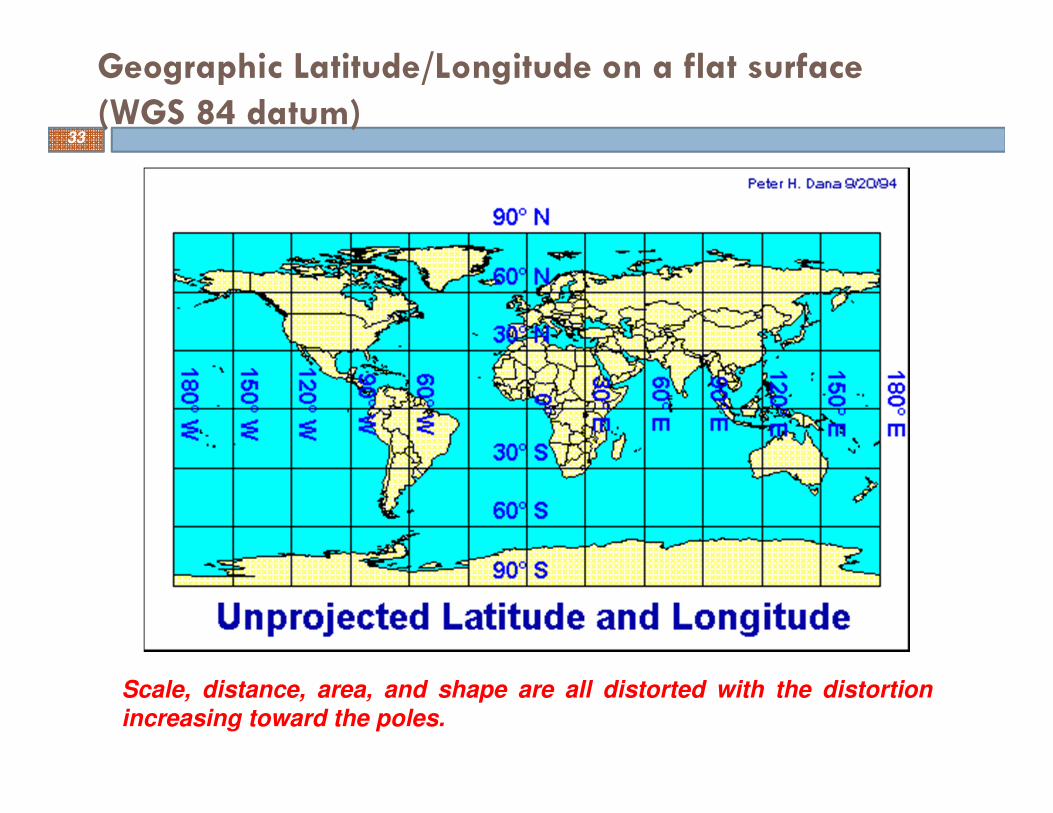
Geographic Latitude/Longitude on a flat surface
(WGS 84 datum)
Scale, distance, area, and shape are all distorted with the distortion
increasing toward the poles.
33

Geographic Latitude/Longitude in GIS system
-90 º
90º
-180 º
180 º
0 º
0 º
equator
Prim
e M
eridia
n
West East
North
South
open ArcGIS for a demo
34

Projected coordinate Systems
� It also referred to as Rectangular Coordinate Systems such as Planar, Cartesian, and Grid coordinate system
� It converts Earth’s curved surface onto a flat map surface
� The x value is given first and called easting, then the y value is given and called northing
35

� UTM system is transverse-secantcylindrical projection, dividing thesurface of the Earth into 6 degree zoneswith a central meridian in the center ofthe zone. each one of zones is a differentTransverse Mercator projection that isslightly rotated to use a differentmeridian.
� UTM zone numbers designate 6 degreelongitudinal strips extending from 80degrees South latitude to 84 degreesNorth latitude.
� UTM is a conformal projection, so smallfeatures appear with the correct shapeand scale is the same in all directions.(all distances, directions, shapes, andareas are reasonably accurate ).
� Scale factor is 0.9996 at the centralmeridian and at most 1.0004 at the edgesof the zones.
Universal Transverse Mercator (UTM) Coordinate System
Gerardus Mercator (1512-1594)
36

� UTM coordinates are in meters, making it easy to make accurate calculations of short distances between points (error is less than 0.04%)
� Used in USGS topographic map, and digital elevation models (DEMs)
� Although the distortions of the UTM system are small, they are too great for some accurate surveying.
� zone boundaries are also a problem in many applications, because they follow arbitrary lines of longitude rather than boundaries between jurisdictions.
Universal Transverse Mercator (UTM) Coordinate System
37
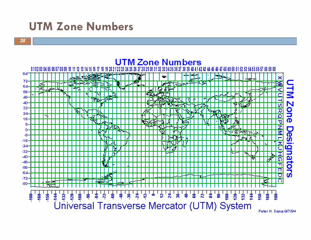
UTM Zone Numbers38

Transverse-secant Cylindrical (Mercator)Projection
CM: central meridian
AB: standard meridianDE: standard meridian
39

~0 mE ~1,000,000 mE
equator 0 mN or
10,000,000 mS
false easting
false northing
40

� The UPS is defined above 84 degrees north latitude and south of 80 degrees south latitude.
� The eastings and northings are computed using a polar aspect stereographic projection.
� Zones are computed using a different character set for south and north Polar regions
Universal Polar Stereographic (UPS) Coordinate System
41

42
� Albers:
- Albers Equal-Area Conic + NDA 27 (NDA 83, or WGS 84).
For example: USGS Hydrologic unit maps
� Lambert:
- Lambert Conformal Conic + NDA 27 (NDA 83, or WGS 84)
� Equidistant:
- Equidistant Conic: NDA 27 (NDA 83, or WGS 84)
Other common used projected coordinate systems43

� In one GIS project or database, all layers should have the same coordinate system
� We need to do conversions
� ArcToolbox has full functions to do this
Conversion of Projection, Datum, Coordinate System 44

Comments….
Questions….
Suggestions….
45
I am greatly thankful to all the information sources(regarding remote sensing and GIS) on internet that Iaccessed and utilized for the preparation of presentlecture.
Thank you !