Embed Size (px)
Citation preview
2013
Ahmed Bebars
Ericsson
5/19/2013
Step Procedure to install CN510

MLU Project
Introduction:
Thanks for everyone help me to write this document, and I hope that help site engineer
to know some information around one type of our actions in this project called Mini link
upgrade from Mini link to CN510
MLU Project
Contents 1. Before access site: ........................................................................................................ 4
2. Site Survey: ................................................................................................................... 5
3. Check your delivery Materials: ................................................................................... 14
4. Installation steps: ....................................................................................................... 15
5. Configure CN510: ........................................................................................................ 16
6. Drop E1 cable physical on ICF3 .................................................................................... 29
7. Call BEB team (review Phone list sheet): .................................................................... 29
8. Call NMC team to Activate sites .................................................................................. 29
APPENDIX A .................................................................................................................... 30
APPENDIX B .................................................................................................................... 31
APPENDIX C:................................................................................................................... 39
MLU Project
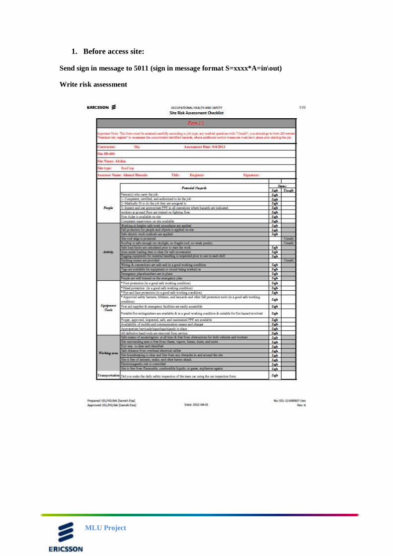
1. Before access site:
Send sign in message to 5011 (sign in message format S=xxxx*A=in\out)
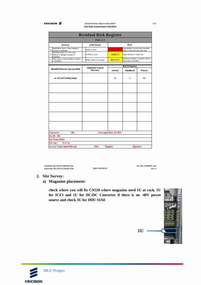
Write risk assessment
MLU Project
2. Site Survey:
a) Magazine placement:
check where you will fix CN510 where magazine need 1U at rack, 1U
for ICF3 and 1U for DC/DC Converter if there is no -48V power
source and check 3U for DDU SIAE
1U

MLU Project
b) Check Power Source:
PBC 6200:
At this case take two power cables and connect them with main Power cable
found with CN 510 by use I Power Connector (Review APPENDIX C) to
CN510
DC Box:
DC Box +24 V
Take two Power cables to DC/DC Converter then power cable to CN510
DC Box -48 V:
Take two power cables from DC Box to and make cable expansion as
show in fig and connect this cable with CN510
PBC 6200 CN510
DC/DC
Converter
DC Box +24 V DC/DC
Converter
CN510
DC Box +24 V CN510
MLU Project
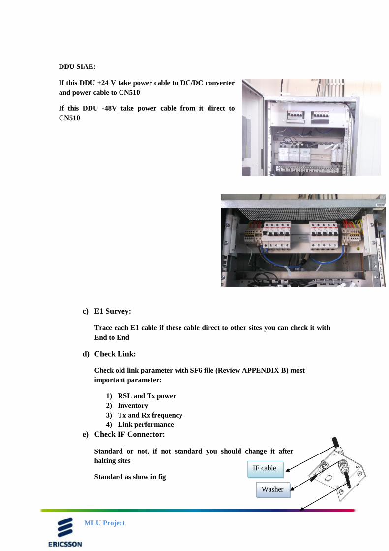
DDU SIAE:
If this DDU +24 V take power cable to DC/DC converter
and power cable to CN510
If this DDU -48V take power cable from it direct to
CN510
c) E1 Survey:
Trace each E1 cable if these cable direct to other sites you can check it with
End to End
d) Check Link:
Check old link parameter with SF6 file (Review APPENDIX B) most
important parameter:
1) RSL and Tx power
2) Inventory
3) Tx and Rx frequency
4) Link performance
e) Check IF Connector:
Standard or not, if not standard you should change it after
halting sites
Standard as show in fig
IF cable
Washer
MLU Project
At facing site:
1) Send Sign in message to 5011
2) Write Risk assessment
3) Site survey:
Check MMU position at TN
Check TN release (should be R4, if another please tells Site Supervisor)
Take needed P.S, report and Backup
Check old Link parameter with old SF6
Check RSL and Tx power
Check Rx and Tx frequency
Inventory
Link performance
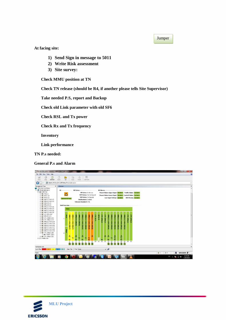
TN P.s needed:
General P.s and Alarm
Jumper
MLU Project
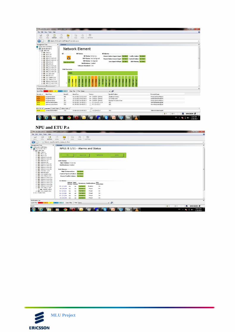
NPU and ETU P.s
MLU Project
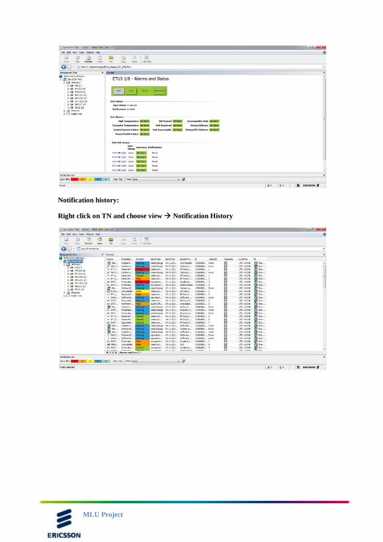
Notification history:
Right click on TN and choose view Notification History
MLU Project
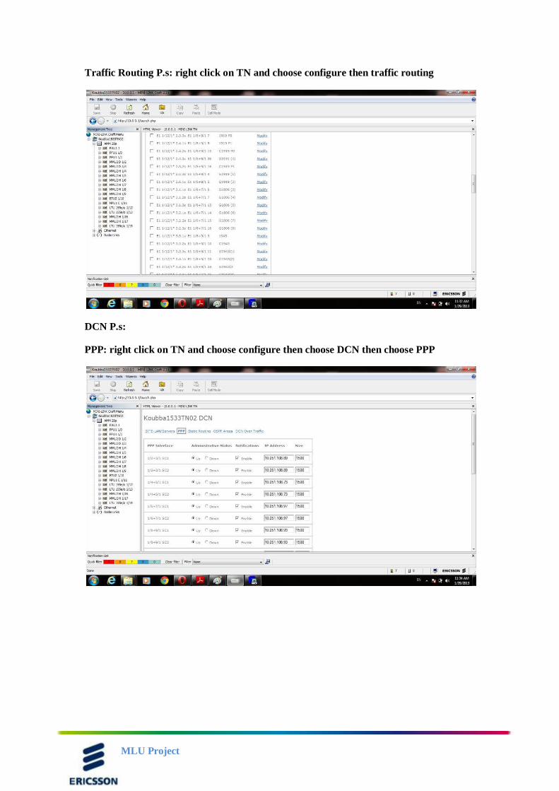
Traffic Routing P.s: right click on TN and choose configure then traffic routing
DCN P.s:
PPP: right click on TN and choose configure then choose DCN then choose PPP
MLU Project
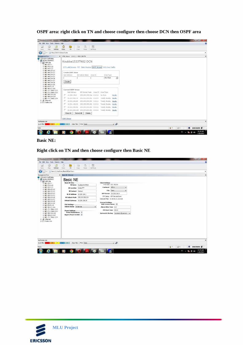
OSPF area: right click on TN and choose configure then choose DCN then OSPF area
Basic NE:
Right click on TN and then choose configure then Basic NE
MLU Project
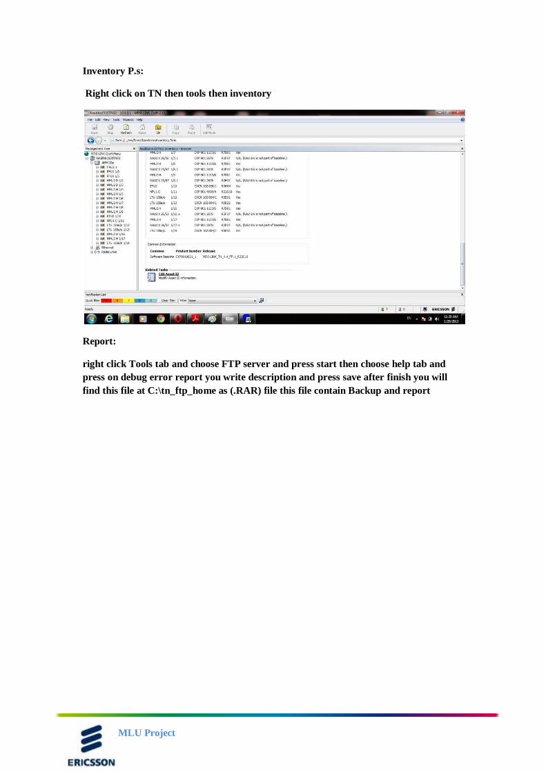
Inventory P.s:
Right click on TN then tools then inventory
Report:
right click Tools tab and choose FTP server and press start then choose help tab and
press on debug error report you write description and press save after finish you will
find this file at C:\tn_ftp_home as (.RAR) file this file contain Backup and report
MLU Project
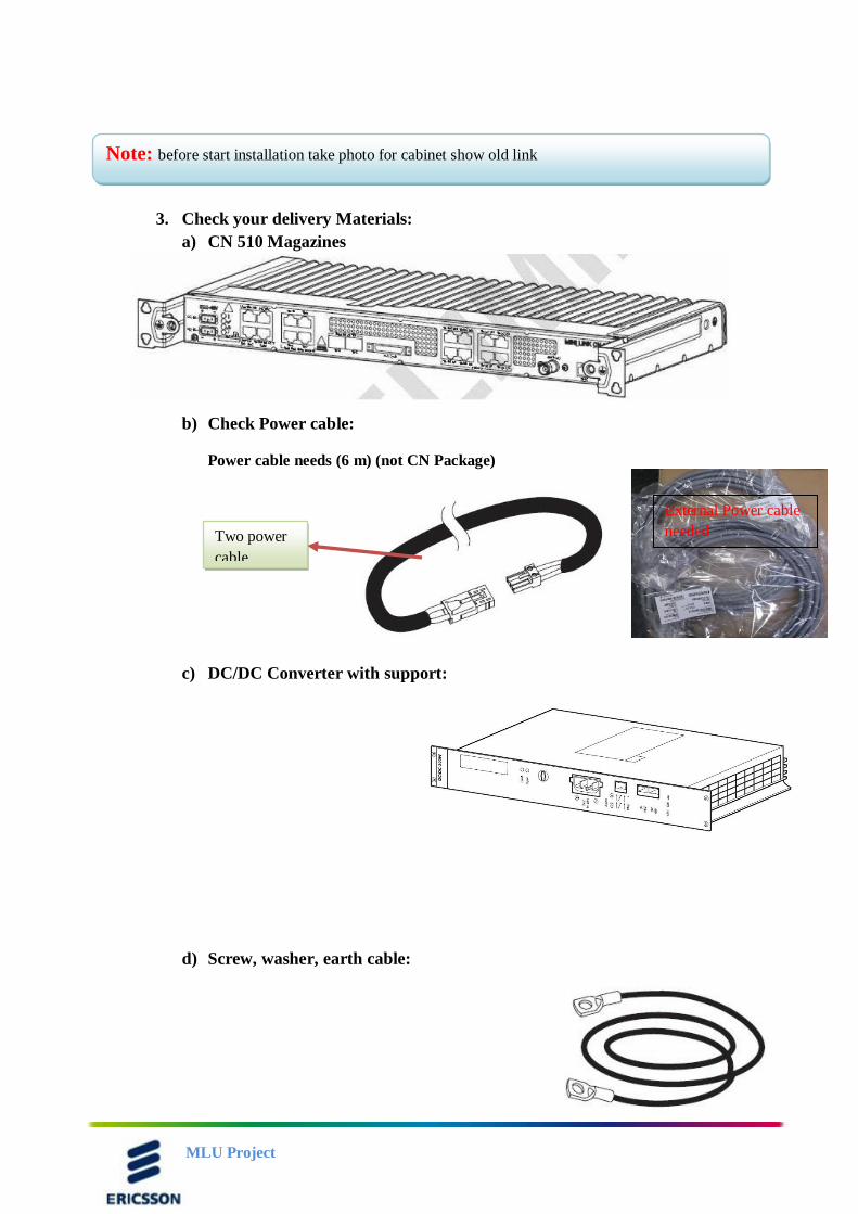
3. Check your delivery Materials:
a) CN 510 Magazines
b) Check Power cable:
Power cable needs (6 m) (not CN Package)
c) DC/DC Converter with support:
d) Screw, washer, earth cable:
Note: before start installation take photo for cabinet show old link
Two power
cable
External Power cable
needed
MLU Project
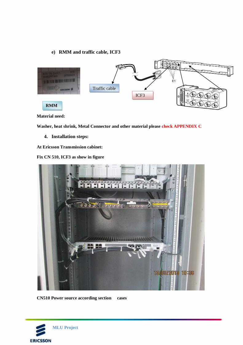
e) RMM and traffic cable, ICF3
Material need:
Washer, heat shrink, Metal Connector and other material please check APPENDIX C
4. Installation steps:
At Ericsson Transmission cabinet:
Fix CN 510, ICF3 as show in figure
CN510 Power source according section cases
Traffic cable
ICF3
RMM
rmm
MLU Project
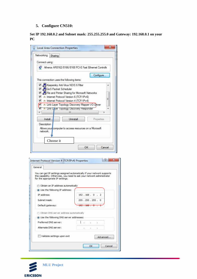
5. Configure CN510:
Set IP 192.168.0.2 and Subnet mask: 255.255.255.0 and Gateway: 192.168.0.1 on your
PC
Choose it
MLU Project
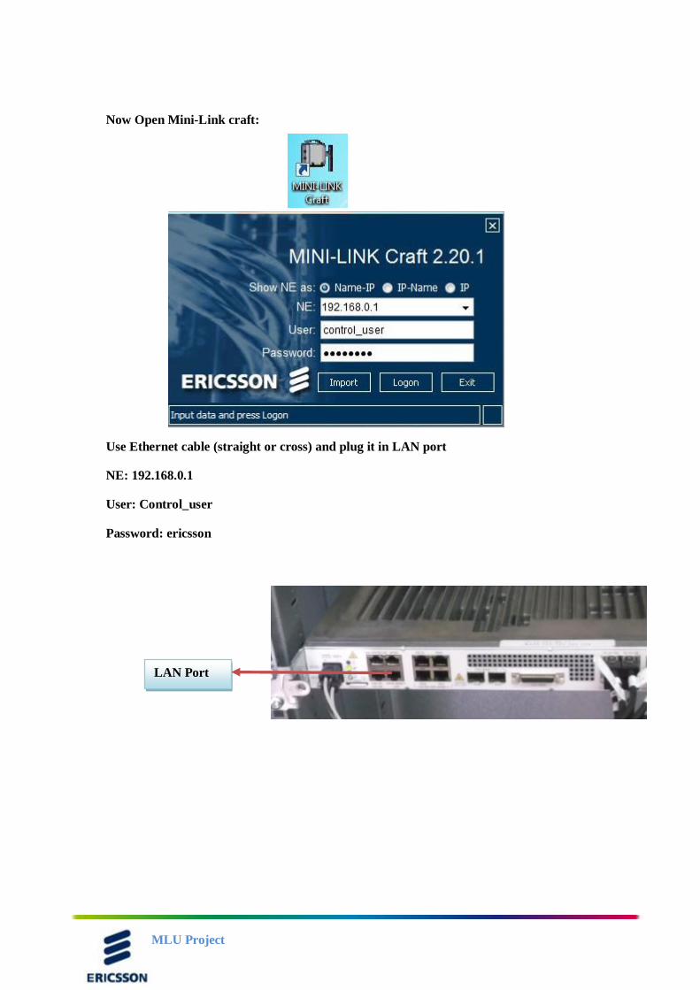
Now Open Mini-Link craft:
Use Ethernet cable (straight or cross) and plug it in LAN port
NE: 192.168.0.1
User: Control_user
Password: ericsson
LAN Port
MLU Project
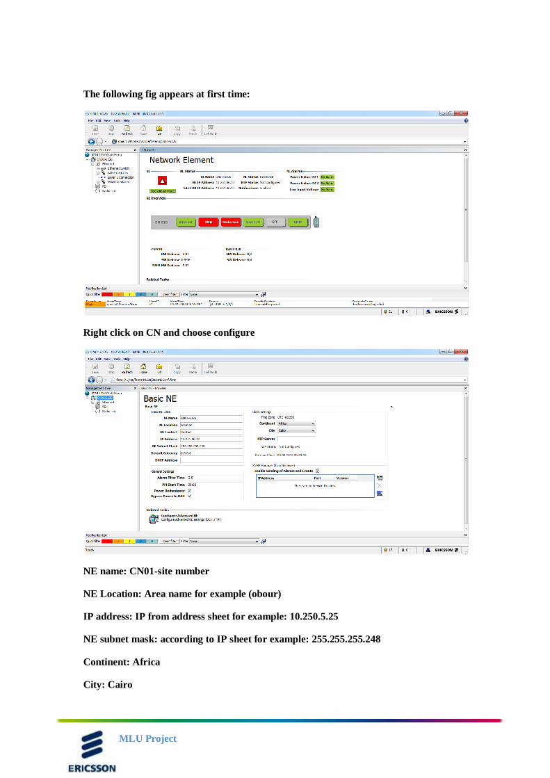
The following fig appears at first time:
Right click on CN and choose configure
NE name: CN01-site number
NE Location: Area name for example (obour)
IP address: IP from address sheet for example: 10.250.5.25
NE subnet mask: according to IP sheet for example: 255.255.255.248
Continent: Africa
City: Cairo
MLU Project
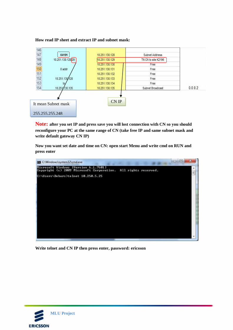
How read IP sheet and extract IP and subnet mask:
Note: after you set IP and press save you will lost connection with CN so you should
reconfigure your PC at the same range of CN (take free IP and same subnet mask and
write default gateway CN IP)
Now you want set date and time on CN: open start Menu and write cmd on RUN and
press enter
Write telnet and CN IP then press enter, password: ericsson
CN IP It mean Subnet mask
255.255.255.248
MLU Project
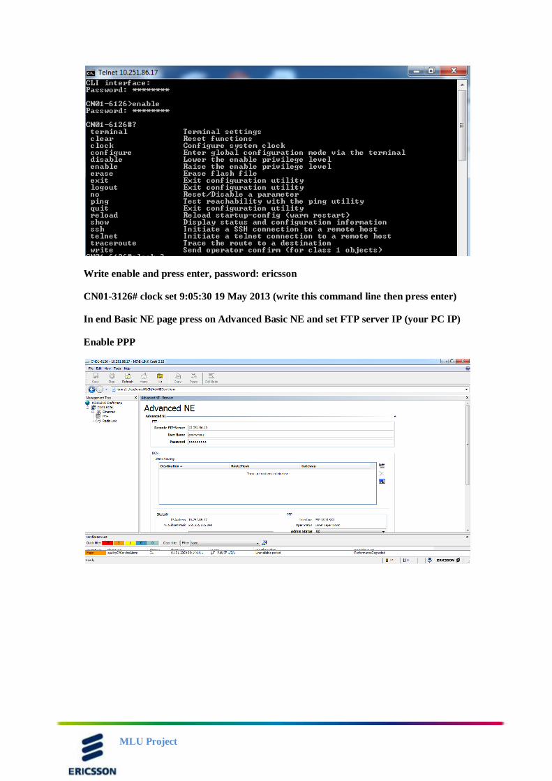
Write enable and press enter, password: ericsson
CN01-3126# clock set 9:05:30 19 May 2013 (write this command line then press enter)
In end Basic NE page press on Advanced Basic NE and set FTP server IP (your PC IP)
Enable PPP
MLU Project
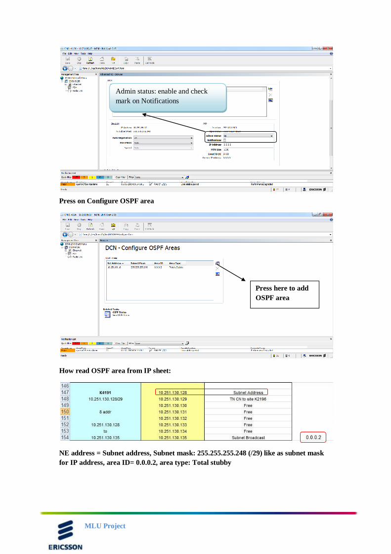
Press on Configure OSPF area
How read OSPF area from IP sheet:
NE address = Subnet address, Subnet mask: 255.255.255.248 (/29) like as subnet mask
for IP address, area ID= 0.0.0.2, area type: Total stubby
Admin status: enable and check
mark on Notifications
Press here to add
OSPF area
MLU Project
OSPF (Open shortest path first): this is one type of routing protocol used with PPP
(point to point protocol) to allow O&M access magazine remotely (Add magazine to
management)
OSPF depend on link state method to build routing table, this method depend on send
parameter that changed on route only not need send all routing table and send periodic
update every 30 min V.S RIP protocol that send all routing table information every
30Sec that contain heavy control traffic on link B.W
Call 2nd
line to send mail to BEB team, (review Phone number list)
Then you call BEB team to take Backup from TN at facing before any
work on it
At downtime case: call NMC team, (review Phone number list) at 2:00
Am to halt sites
After halt sites start the final step:
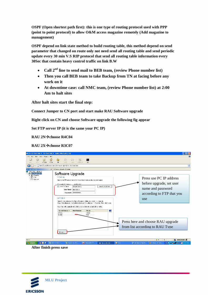
Connect Jumper to CN port and start make RAU Software upgrade
Right click on CN and choose Software upgrade the following fig appear
Set FTP server IP (it is the same your PC IP)
RAU 2Nchoose R4C04
RAU 2Xchoose R3C07
After finish press save
Press use PC IP address
before upgrade, set user
name and password
according to FTP that you
use
Press here and choose RAU upgrade
from list according to RAU Type
MLU Project
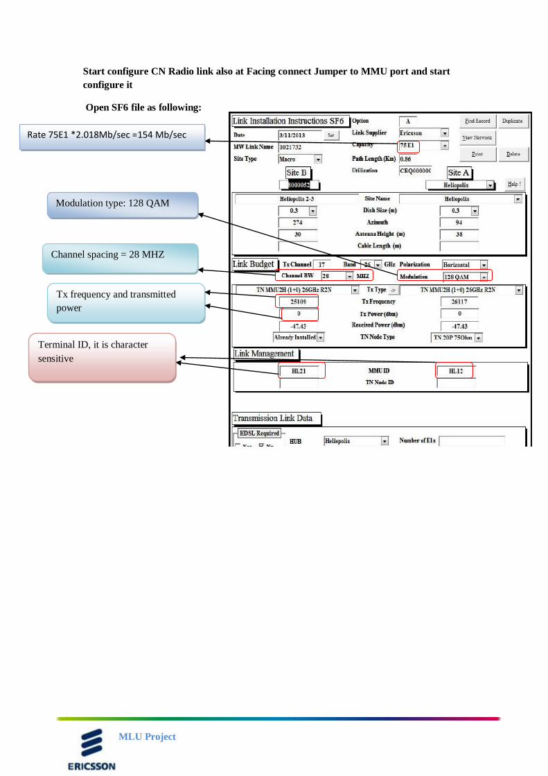
Start configure CN Radio link also at Facing connect Jumper to MMU port and start
configure it
Open SF6 file as following:
Rate 75E1 *2.018Mb/sec =154 Mb/sec
Modulation type: 128 QAM
Channel spacing = 28 MHZ
Tx frequency and transmitted
power
Terminal ID, it is character
sensitive
MLU Project
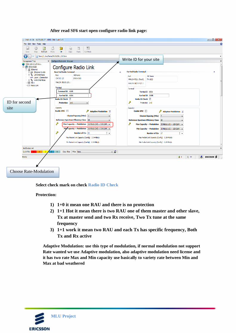
After read SF6 start open configure radio link page:
Select check mark on check Radio ID Check
Protection:
1) 1+0 it mean one RAU and there is no protection
2) 1+1 Hot it mean there is two RAU one of them master and other slave,
Tx at master send and two Rx receive, Two Tx tune at the same
frequency
3) 1+1 work it mean two RAU and each Tx has specific frequency, Both
Tx and Rx active
Adaptive Modulation: use this type of modulation, if normal modulation not support
Rate wanted we use Adaptive modulation, also adaptive modulation need license and
it has two rate Max and Min capacity use basically to variety rate between Min and
Max at bad weathered
Choose Rate-Modulation
Write ID for your site
ID for second
site
MLU Project
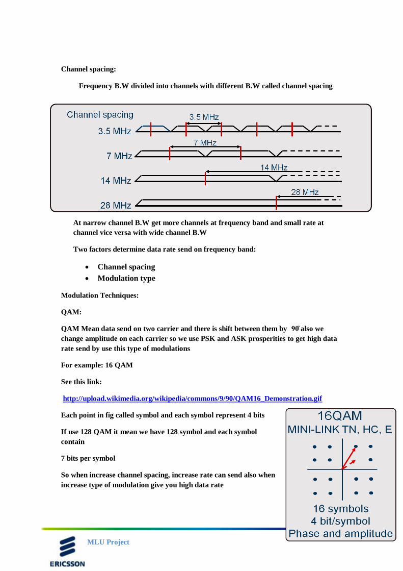
Channel spacing:
Frequency B.W divided into channels with different B.W called channel spacing
At narrow channel B.W get more channels at frequency band and small rate at
channel vice versa with wide channel B.W
Two factors determine data rate send on frequency band:
Channel spacing
Modulation type
Modulation Techniques:
QAM:
QAM Mean data send on two carrier and there is shift between them by 90̊ also we
change amplitude on each carrier so we use PSK and ASK prosperities to get high data
rate send by use this type of modulations
For example: 16 QAM
See this link:
http://upload.wikimedia.org/wikipedia/commons/9/90/QAM16_Demonstration.gif
Each point in fig called symbol and each symbol represent 4 bits
If use 128 QAM it mean we have 128 symbol and each symbol
contain
7 bits per symbol
So when increase channel spacing, increase rate can send also when
increase type of modulation give you high data rate
MLU Project
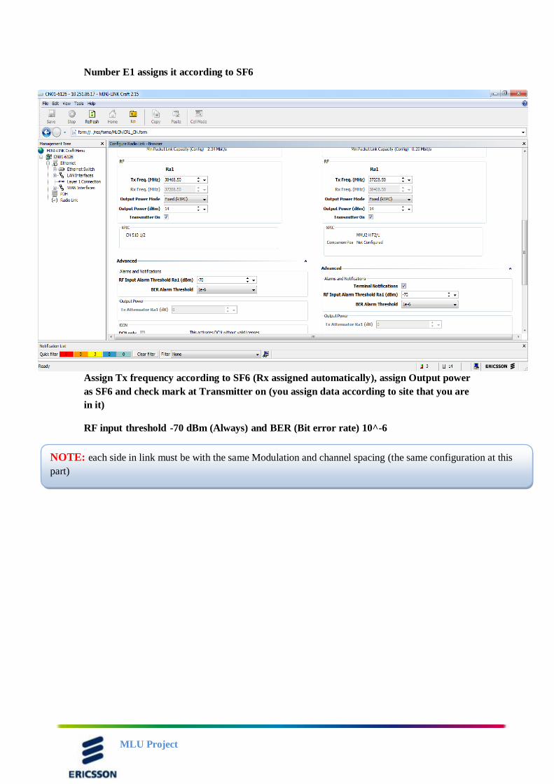
Number E1 assigns it according to SF6
Assign Tx frequency according to SF6 (Rx assigned automatically), assign Output power
as SF6 and check mark at Transmitter on (you assign data according to site that you are
in it)
RF input threshold -70 dBm (Always) and BER (Bit error rate) 10^-6
NOTE: each side in link must be with the same Modulation and channel spacing (the same configuration at this
part)
MLU Project
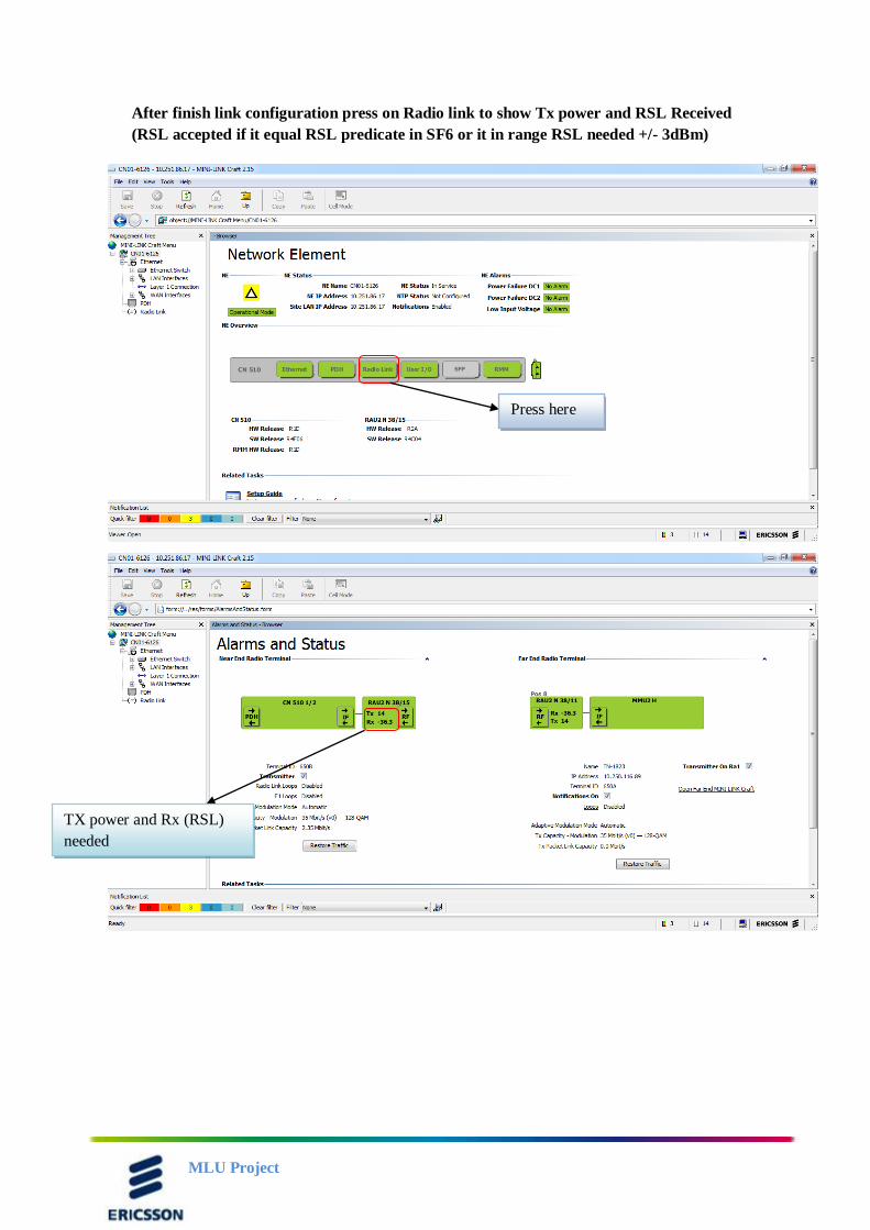
After finish link configuration press on Radio link to show Tx power and RSL Received
(RSL accepted if it equal RSL predicate in SF6 or it in range RSL needed +/- 3dBm)
Press here
TX power and Rx (RSL)
needed
MLU Project
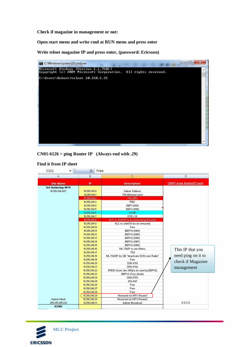
Check if magazine in management or not:
Open start menu and write cmd at RUN menu and press enter
Write telnet magazine IP and press enter, (password: Ericsson)
CN01-6126 > ping Router IP (Always end with .29)
Find it from IP sheet
This IP that you
need ping on it to
check if Magazine
management
MLU Project
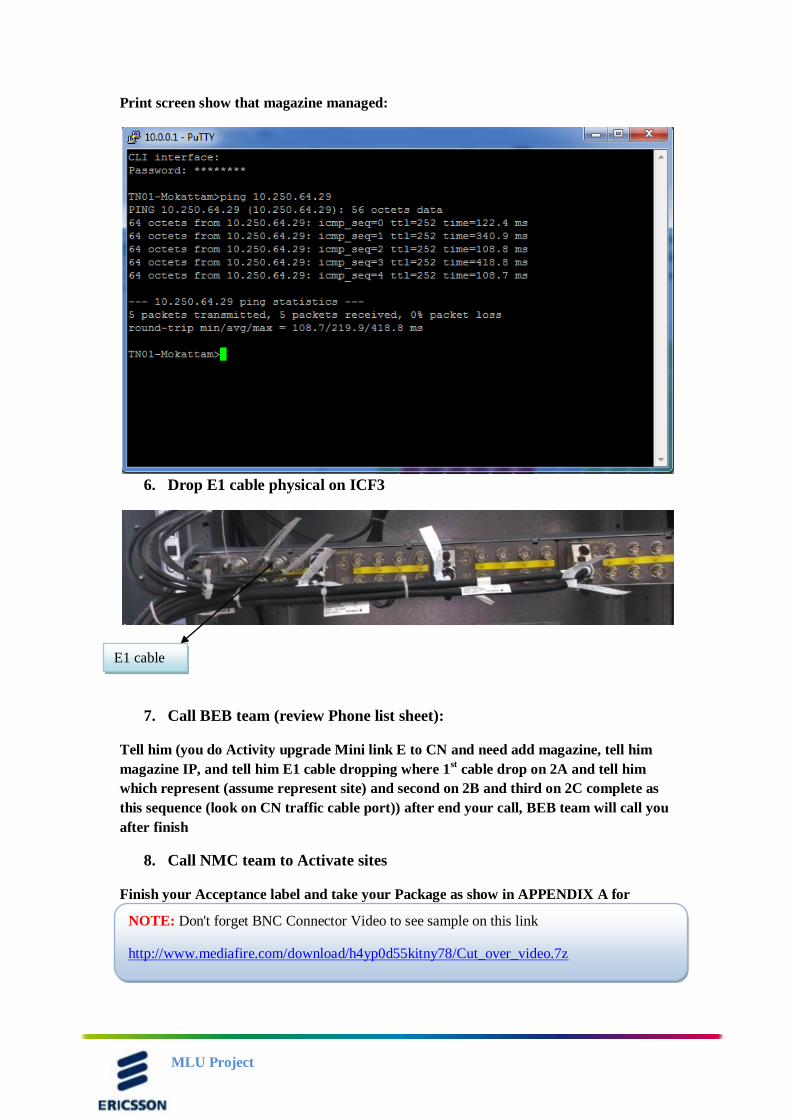
Print screen show that magazine managed:
6. Drop E1 cable physical on ICF3
7. Call BEB team (review Phone list sheet):
Tell him (you do Activity upgrade Mini link E to CN and need add magazine, tell him
magazine IP, and tell him E1 cable dropping where 1st cable drop on 2A and tell him
which represent (assume represent site) and second on 2B and third on 2C complete as
this sequence (look on CN traffic cable port)) after end your call, BEB team will call you
after finish
8. Call NMC team to Activate sites
Finish your Acceptance label and take your Package as show in APPENDIX A for
Acceptance
E1 cable
NOTE: Don't forget BNC Connector Video to see sample on this link
http://www.mediafire.com/download/h4yp0d55kitny78/Cut_over_video.7z
MLU Project
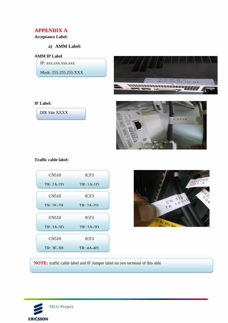
APPENDIX A
Acceptance Label:
a) AMM Label:
AMM IP Label
IF Label:
Traffic cable label:
IP: xxx.xxx.xxx.xxx
Mask: 255.255.255.XXX
DIR Site XXXX
CN510 ICF3
TR: 2A-2D TR: 1A-1D
CN510 ICF3
TR: 2E-2H TR: 2A-2D
CN510 ICF3
TR: 3A-3D TR: 3A-3D
CN510 ICF3
TR: 3E-3H TR: 4A-4D
NOTE: traffic cable label and IF Jumper label on two terminal of this able
MLU Project
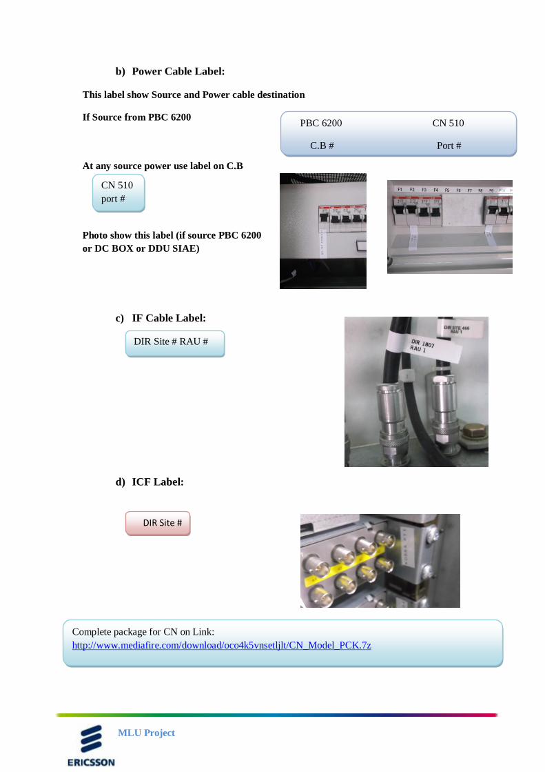
b) Power Cable Label:
This label show Source and Power cable destination
If Source from PBC 6200
At any source power use label on C.B
Photo show this label (if source PBC 6200
or DC BOX or DDU SIAE)
c) IF Cable Label:
d) ICF Label:
PBC 6200 CN 510
C.B # Port #
DIR Site # RAU #
CN 510
port #
DIR Site #
Complete package for CN on Link:
http://www.mediafire.com/download/oco4k5vnsetljlt/CN_Model_PCK.7z
MLU Project
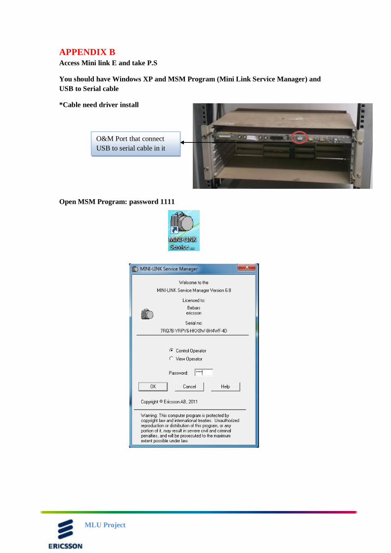
APPENDIX B
Access Mini link E and take P.S
You should have Windows XP and MSM Program (Mini Link Service Manager) and
USB to Serial cable
*Cable need driver install
Open MSM Program: password 1111
O&M Port that connect
USB to serial cable in it
MLU Project
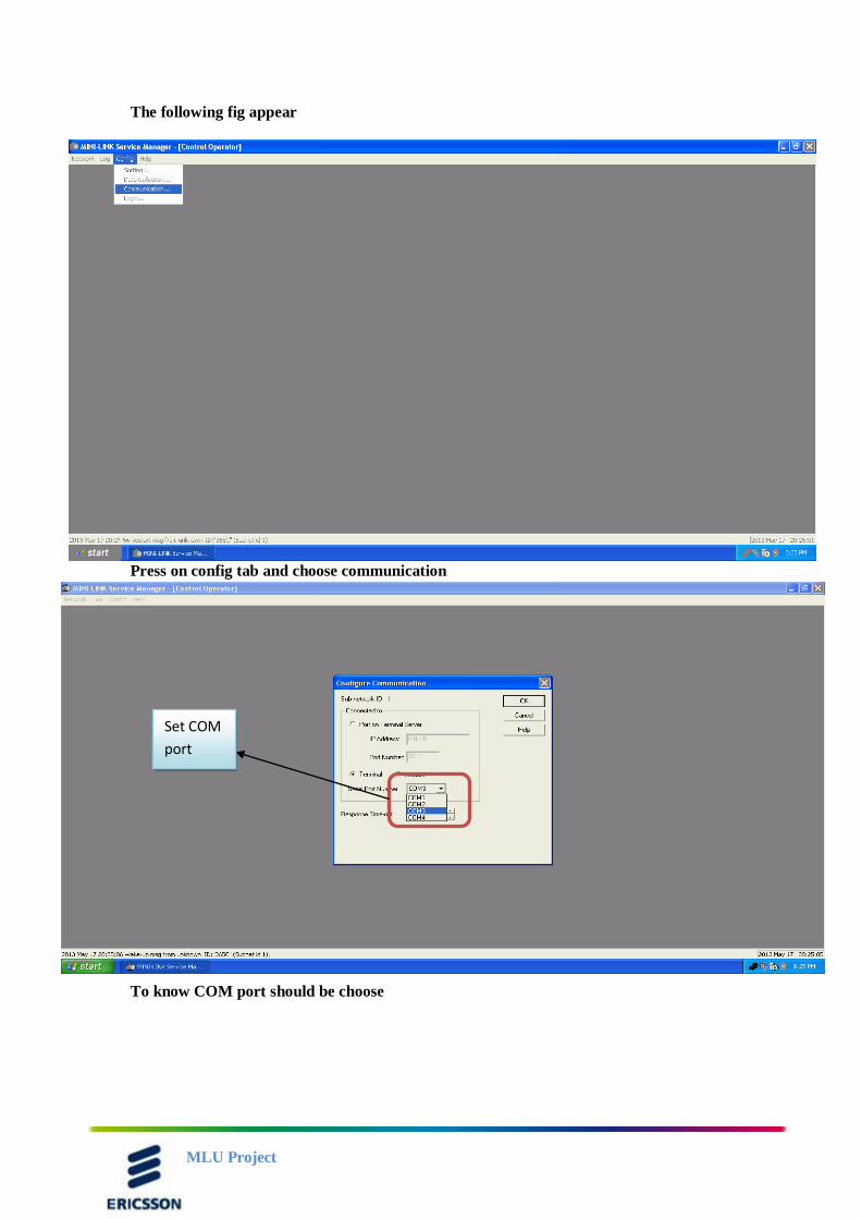
The following fig appear
Press on config tab and choose communication
To know COM port should be choose
Set COM
port
MLU Project
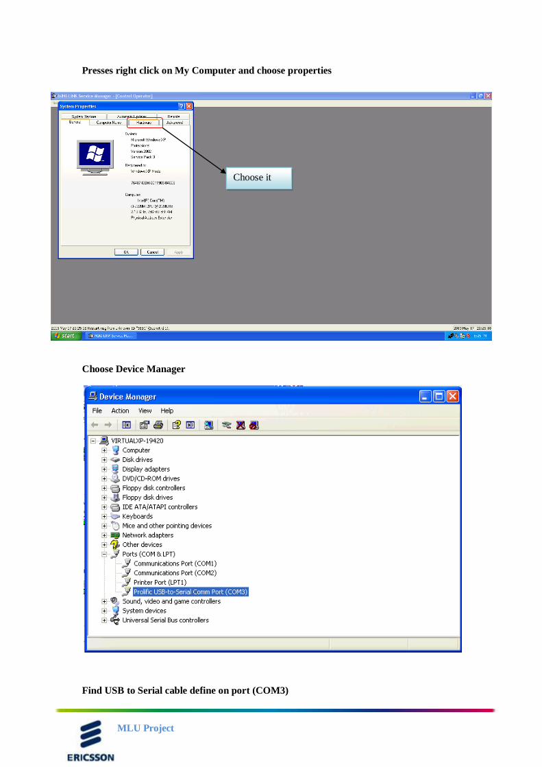
Presses right click on My Computer and choose properties
Choose Device Manager
Find USB to Serial cable define on port (COM3)
Choose it
MLU Project
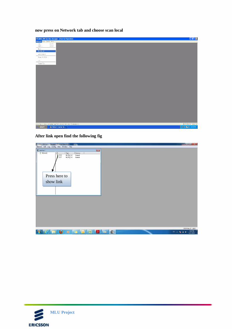
now press on Network tab and choose scan local
After link open find the following fig
Press here to
show link
MLU Project
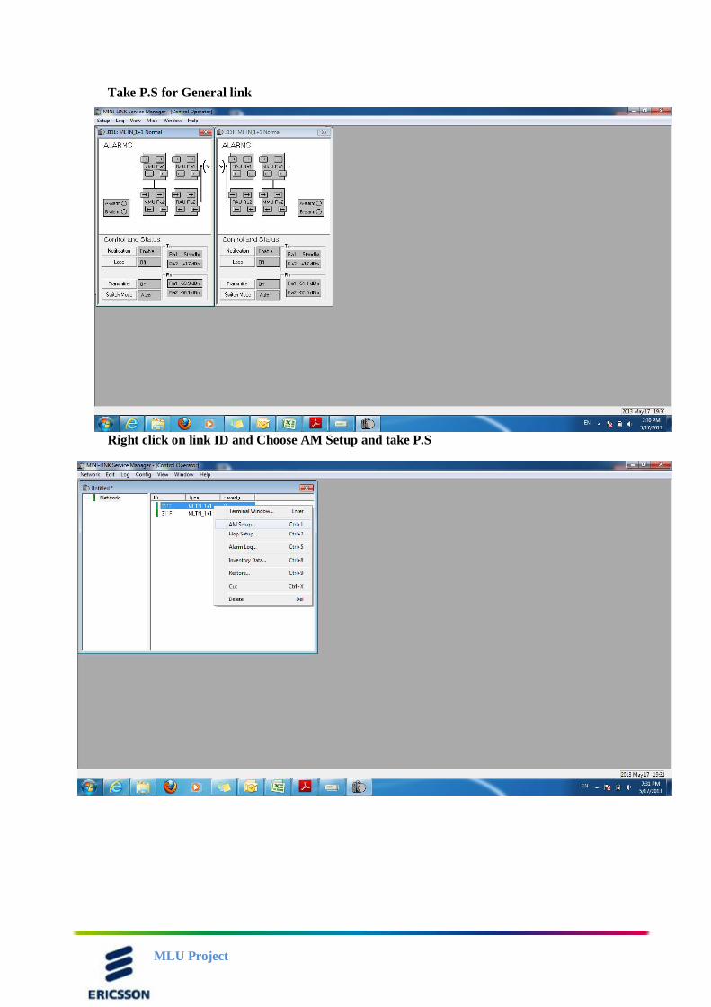
Take P.S for General link
Right click on link ID and Choose AM Setup and take P.S
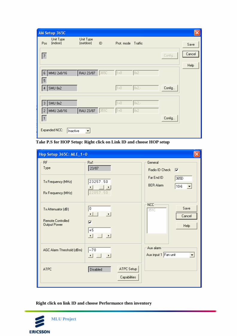
MLU Project
Take P.S for HOP Setup: Right click on Link ID and choose HOP setup
Right click on link ID and choose Performance then inventory
MLU Project
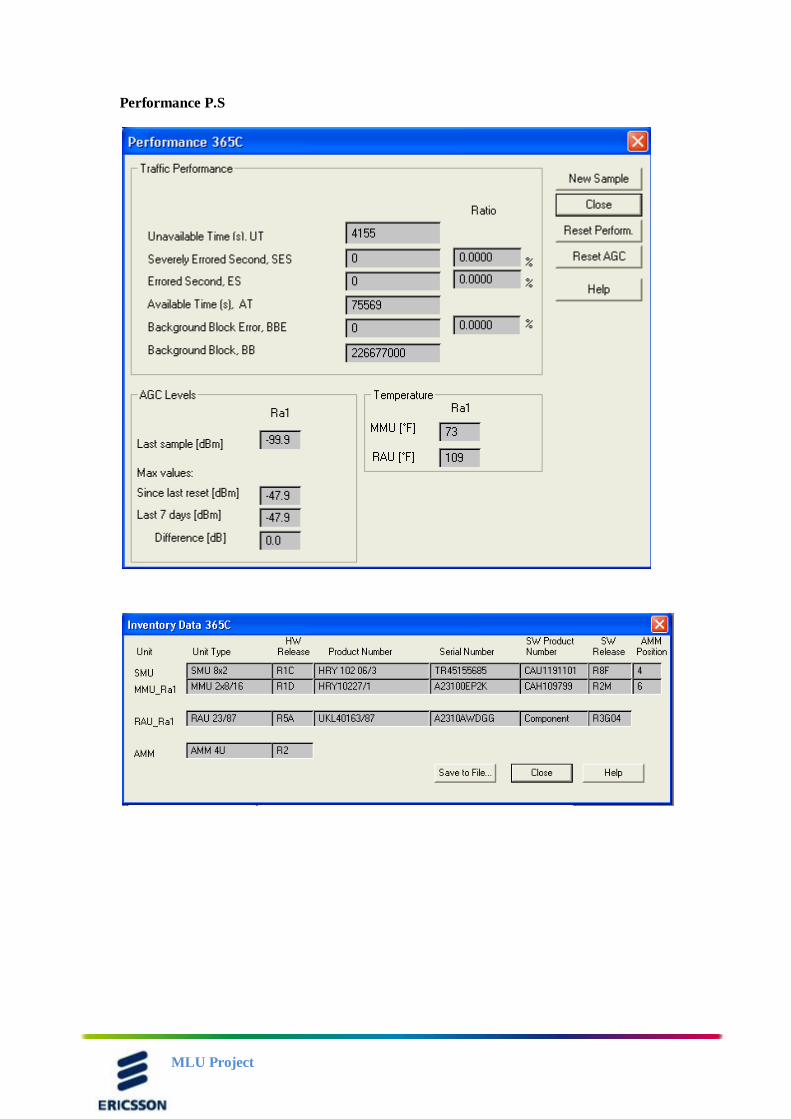
Performance P.S
MLU Project
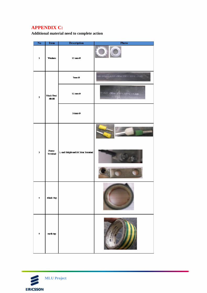
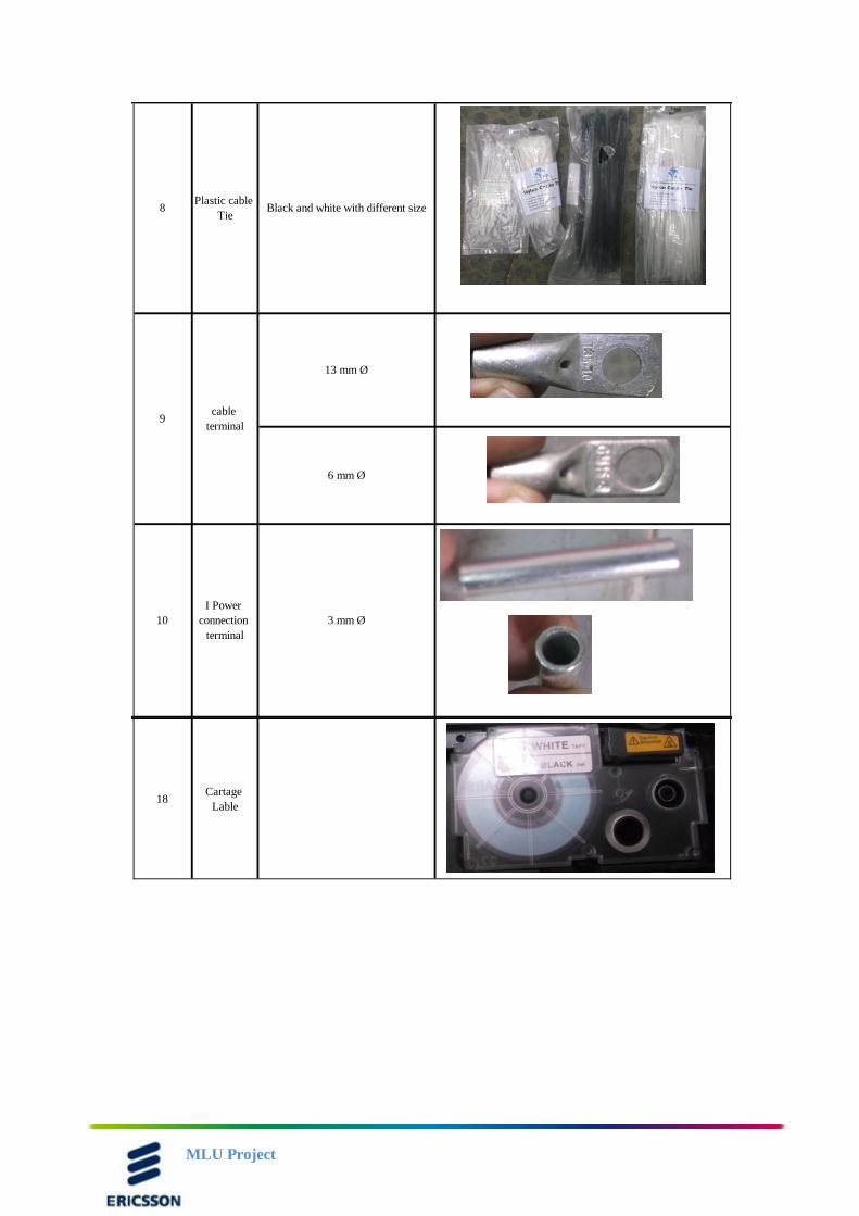
APPENDIX C:
Additional material need to complete action
MLU Project
18Cartage
Lable
10
I Power
connection
terminal
3 mm Ø
8Plastic cable
TieBlack and white with different size
9cable
terminal
13 mm Ø
6 mm Ø