Embed Size (px)
Citation preview


Key benefits are fuel flexibility, reduced emission and lower bed temperature.

Different Versions Industrial boilers ore developing with gradual change in their design of different
parts and to optimize the thermal efficiency, fuel multiplicity and to sustain with
environmental norms, with cost effectiveness for installation operation and
maintenance.
In our country early fifties and sixties small multi fuel boilers were used for process
industries and high pressure coal based boilers were used for power generation.
With decreasing trend of coal heat value boiler was constantly modified to reach the
present status of CFBC boiler from previous version of stationary furnaces type
chain grate type, spreader stoker type, PF type, AFBC type and CFBC type. CFBC
is a new generation coal fired fluidized bed boiler developed since 1950 has the
advantage of high efficiency low Sox and Nox. emission and higher turn down ratio.

CFBC BOILER Assume a container with an air supply plenum at the bottom , A distributer plate
that promotes even air flow through the bed and an upper chamber filled with
sand. If a small quantity of air flow through the distributer plate in to the bed , If
it will pass through the voids of an immobile mass of sand. For low velocity the
air does not exert much force on sand and they remain in place. This condition
is called fixed bed or static bed. By increasing a flow rate ,the air exert greater
force on the sand and thereby reduces the contact force between the sand
particle caused by gravity. By increasing the air flow further ,a point is reached
where the drag force on particle counter balance the gravity force and sand
particle become suspended in up flowing air steam. The point where the bed
start to behave as a fluid is called the minimum fluidization condition.

CFBC BOILER As the air increased further , the bed become less uniform bubbles of air start
to form and the bed becomes violent . At this condition bed is in expanded
condition, This is called bubbling fluidized bed and this occurs at
atmospheric condition. Hence, It is called as Atmospheric Fluidized Bed. As
the velocity of air further increased (around 10 m/sec.) a condition is
reached where in whole of bed material is in circulation from furnace to a
collection chamber (U beam hopper) and back to furnace. Thus resulting in
uniform temperature profile throughout the furnace. Because the whole bed
is in continuous circulation internally, This type of boiler is called IR-
CFBC. (Internal Re-circulating fluidized bed combustion).

CFBC BOILER TECHNOLOGY OFFERS
High combustion efficiency
Compact and economical design.
Higher reliability and availability.
Lower maintenance cost.
Reduced erosion.
Fuel flexibility.
Gas Velocities
CFBC - 4 - 6 m/sec.
AFBC - 2 - 3 mtr./sec.
PF - 8 - 10 mtr./sec.

IMPROVED PERFORMANCE AT REDUCED COST
CFBC boiler design as – Two stage particle separation system.
First - U beam impact separators.
Second – Mechanical dust collector or multi-cyclone dust collector.

DESCRIPTION OF CFBC BOILER CFBC boilers are compact natural circulation ,Top
supported ,Single drum unit. The primary and secondary particle separator is an integral part of boiler / furnace and connected to the particle return system.
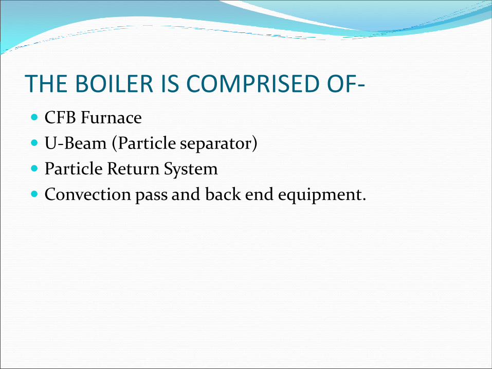
THE BOILER IS COMPRISED OF- CFB Furnace
U-Beam (Particle separator)
Particle Return System
Convection pass and back end equipment.

Internal Recirculation - Circulating Fluidized Bed Boilers

CFBC FURNACE The CFBC furnace construction is of all welded
membrane tube panels. Functionally the furnace is divided into three distinct zone .
A -Primary zones
B - Secondary zone
C - Free board zone

PRIMARY ZONE In the primary zone the fuel,sand,recycled material
and 50% to 60% of the air for combustion are introduced.
SECONDARY AND FREE BOARD ZONE
In secondary zone the balance of combustion air is introduced.
Combustion is completed in free board zone

CFBC BOILER
• The combustion air split correspond to the furnace zones . i.e. Primary , lower secondary
and upper secondary air flow zone.
lower secondary zone – Burner
upper secondary zone – OF (Over Fired)
• Primary air effects the actual fluidization of bed material and is supplied through a
distributor plate at the bottom of the furnace. lower secondary and upper secondary air are
supplied through nozzle located on both the front or rear furnace walls at two separate
elevations.
• The air distribution patterns in the furnace can be adjusted to provide for the best control
of Nox (Nitrous Oxide) formation.
• In addition to the enclosure walls , water cooled division walls for the entire height of the
furnace provides additional heating surface.

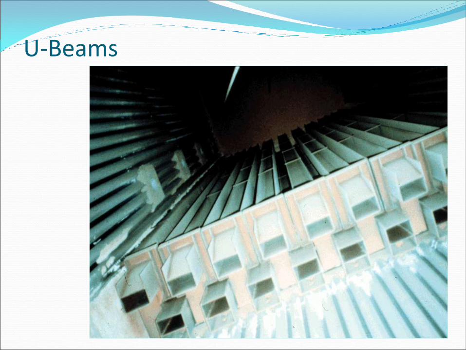
U-BEAM Flue gas and solids leaving the furnace passes through a high temperature
primary particle collector where nearly all of the solids are separated from
the flue gas. A unique feature of boiler is a particle separator made of
labyrinth type array of beam having a shape similar to the letter “U”. The U-
beam made from stainless steel alloy. Or fiber material for less weight &
cost and less erosion. The collector is designed to remove solids from dense
gas–solids mixture .the solids impacting the first two rows of beams fall by
gravity back down the rear of the furnace .Solids impacting the remaining
beams fall by gravity in two particle collector hopper located directly
beneath the array of beams and enters the rear furnace through particle
return system especially designed for this application.

Hot Cyclone CFBC

BOILER CONVECTION PASS The flue gas leaving the particle separator flows in to the
boiler convection pass which includes the superheated and
economizer banks . The gas velocity in these tube banks is
designed specifically to minimize the erosion . Gases
enters the air pre heater and then to the secondary particle
separator . Gas leaving air heater enters the ESP and then
to the stack through ID Fans.

U-Beam separators
© 2003 The Babcock & Wilcox Company, all rights reserved
U-Beam separators41
2
3Flue
Gas
&
Solid
Flow
Flue
Gas
1. Sidewallmembrane panel
2. U-beam - SS309H/ SS310H/RA253MA
3. Seal baffle
4. Refractory
U-Beams

Internal Recirculation - Circulating Fluidized Bed Boilers

Internal Recirculation Circulating Fluidized Bed Boilers
A simplified approach to improved flexibility and reliability
Design Features
High combustion efficiency
Compact, economical design
Higher reliability and availability
Lower maintenance costs
Reduced erosion
Fuel flexibility
Low emissions

Why CFBC Boiler ?
CFBC is a Fuel Flexible Technology
Accepts wide range of fuels
Volatile matter - >15 %
Ash - UP TO 60%
Heating value - > 2150 Kcal/kg
Moisture - < 10%
Use of lower rank fuels reduces fuel costs
Fuel flexibility - minimizes fuel supply uncertainties
Ability to burn low cost and waste fuels

Steam Flow Circuit Riser tubes are used to direct the steam water mixture from the outlet headers of each
water circuit to the steam drum.
The water steam mixture in drum is separated by cyclone separators and the primary and
secondary scrubber arrangement.
The saturated steam leaves the steam drum and enters primary super heater in let header
through supply pipes.Steam passes through the primary super heater coils and exits the
outlet header.Then steam enters the attemperator header for desuperheating.
The attemperator uses water from the high pressure feed water heater discharge to
control the secondary super heater outlet temperature.
From the attemperator the steam flow to the secondary super heater inlet header and to
the counter flow secondary super heater bank. Steam leaves the coils and exits from the
secondary super heater outlet header. Steam enters the turbine through main steam stop
valve and NRV.

Flue Gas Path CFBC boilers are balanced draft combustors. The pressure balance point is at the top
of the furnace, ahead of the front row of U beams, The flue gas flow path through is
as follows :
Gas carrying with large quantity of bed solids, flow into the in bed U beams, above
hopper U beams hot particle collector. The U beams removes most of the solids
entrained in gas. The flue gas leaves the U beams and flows through the secondary
super heater zone, primary super heater zone, Economizer, primary & secondary air
heaters. At the bottom of the air heaters gas enters secondary particle U beams
separators which collects the majorities of the remaining solids entrained in gas.
The cleaned gas then passes through ESP for final gas cleaning and stack through ID
fans. One stands by ID fanes is provided. Dampers are provided before and after the
ID fans for maintenance of fans. With the exception of the U beam and secondary
particle collection system below APH, The flue path is identical to what is found
conventional Unit.

CFBC BOILER
1st Pass
Fuel
2nd Pass
SH - 1
U Beam Section SH - 2
Bed Ash
3rd Pass
Economizer
APH
ESP
Fans
Ash
Recycle
Particle Transfer Hopper
PA air

IR-CFBC Boiler Reheat

IR-CFBC Advantages High Upper Furnace Heat Transfer Rate and Precise
furnace temperature control Result of high efficiency
solids collection and solids recycle control from the MDC
(Mechanical Dust Collection)
Extended turndown ratio (no oil/gas)
100% to 20% MCR (Maximum Continuous Rating)
Low auxiliary power requirements
Due to Low Flue Gas ΔP and no fluidizing blower

IR-CFBC Advantages
Fast shut down / cool down
80%+ of Bed material is drained during cooldown. Can
shutdown / cool / enter / re-start within a 24 hour period
compared to 2 to 3 times longer for competitor CFB designs.
Low Maintenance Costs
Less refractory or hot expansion joints, ‘RDZ’ at lower furnace
refractory interface, no fluidized sealing system, low furnace exit
velocity, low gas velocity in convective heating surfaces,...

The B&W IR-CFBC Two-Staged Solids Separation System
Benefits High overall solid collection efficiency ~ More than
99.7%
Precise furnace temperature control ~ By controlling solid recycle rate from the secondary collector
Extended turndown ratio without use of auxiliary fuel (oil/gas) ~ 100% to 20% MCR
Low auxiliary power requirements compared to competitor cyclone-based CFB technologies ~ 50-100 mm w.c.
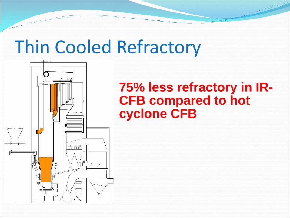
Thin Cooled Refractory
75% less refractory in IR-CFB compared to hot cyclone CFB

Difference Between CFBC & AFBC CFBC boiler Flue gas velocity-3.7 to 4.3 m/sec Over bed feeding U beam Technology No bed coil UBC-Less than 2% Efficiency high (88%) Clinker formation chances low Tube erosion high as compared
to AFBC Ash recycle (unburned heavy
particle) system. Fuel consumption is less as
compared to AFBC
AFBC boiler Flue gas velocity-1.5 to 2.0 m/sec Under bed feeding No U beam bed coil UBC-Less than 3 to 4% Efficiency low (84%) Clinker formation chances high Tube erosion low as compared to
CFBC No Ash recycle (unburned heavy
particle) system. Fuel consumption is more as
compared to CFBC

Conclusion With the changing environmental condition of Raw material
availability cost and sustainability of boilers are still under
modification stage with the effort of optimizing their efficiency and
reducing troubles.
Presently different versions of boiler are being installed by various
venders like IJT Foster Wheeler (USA) design with compact separator
model, Thyssen Krupp AG Germany Design for cold cyclone model.
CVL with water cooled “hot loop” cyclone. Songhai electric Alstom
design for cyclone & V type seal, Greensol Hungzhon, Wuxi etc with
steam cooled cyclone. In view of operation troubles all boiler designers’
are on the way to compete each other, with best possible designs and
constant innovation to become the leader of the market.