Embed Size (px)
Citation preview

LINEAR MEASURING DEVICES AND COMPARATORS
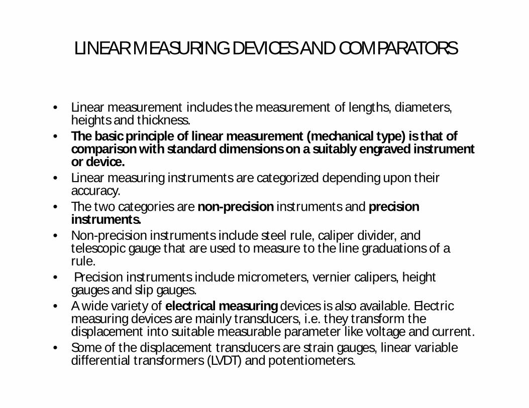
• Linear measurement includes the measurement of lengths, diameters, heights and thickness.
• The basic principle of linear measurement (mechanical type) is that of comparison with standard dimensions on a suitably engraved instrument or device.
• Linear measuring instruments are categorized depending upon their accuracy.
• The two categories are non-precision instruments and precision instruments.
• Non-precision instruments include steel rule, caliper divider, and telescopic gauge that are used to measure to the line graduations of a rule.
• Precision instruments include micrometers, vernier calipers, height gauges and slip gauges.
• A wide variety of electrical measuring devices is also available. Electric measuring devices are mainly transducers, i.e. they transform the displacement into suitable measurable parameter like voltage and current.
• Some of the displacement transducers are strain gauges, linear variable differential transformers (LVDT) and potentiometers.

NON-PRECISION MEASURING INSTRUMENTS • Non-precision instruments are limited to the measurement of parts to a
visible line graduation on the instrument used. They are used where high measurement accuracy is not required
Steel Rule • It is the simplest and most common measuring instruments in inspection. • The principle behind steel rule is of comparing an unknown length to the
one previously calibrated. • The rule must be graduated uniformly throughout its length. • there are rules that have got some attachment and special features with
them to make their use more versatile. • The degree of accuracy when measurements are made by a steel rule
depends upon the quality of the rule, and the skill of the user in estimating part of a millimeter.

Calipers • Calipers are used for measurement of the parts, which
cannot be measured directly with the scale. • they are accessories to scales. • The calipers consist of two legs hinged at top, and the
ends of legs span part to be inspected. • This span is maintained and transferred to the scale.• Calipers are of two types : spring type and firm joint
type.

Spring Type The two legs are attached with spring in this type of calipers. The working ends of each leg of a spring calipers should be identical in shape and have contact points equally distant from the fulcrum. The cross-section of the legs is either rectangular or circular in shape. The calipers are adjusted to set dimensions by means of either a knurled solid nut or a knurled quick action release nut operating in a finely threaded adjusting screw. The top portion of the legs are located in a flanged fulcrum roller and held in position by a spring in order to maintain the alignment of the working ends. The spring provides sufficient tension to hold the legs rigid at all points of the adjustment. A separate washer under the nut minimizes the friction between the adjusting nut and the leg.
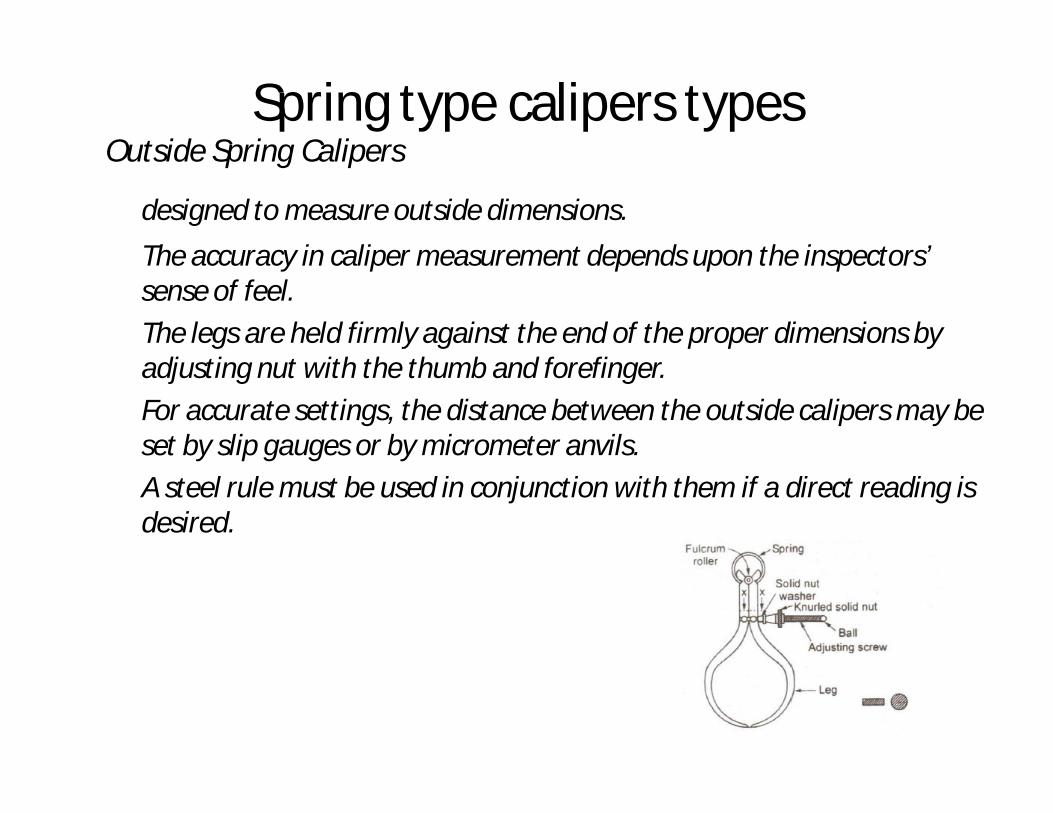
Spring type calipers typesOutside Spring Calipers
designed to measure outside dimensions. The accuracy in caliper measurement depends upon the inspectors’ sense of feel. The legs are held firmly against the end of the proper dimensions by adjusting nut with the thumb and forefinger. For accurate settings, the distance between the outside calipers may be set by slip gauges or by micrometer anvils. A steel rule must be used in conjunction with them if a direct reading is desired.

Inside Spring Calipers • They are designed to measure the inside dimensions. • An inside spring caliper is exactly similar to an outside caliper with its
legs bent outward. • Adjustment in them is generally made by knurled solid nut. • They are used for comparing or measuring hole diameters, distances
between shoulders, or other parallel surfaces of any inside dimensions. • To obtain a specific reading, steel scale must be used as with the
outside calipers.

Firm Joint Type • They work on the friction created at the junction of the legs. • The two legs are identical in shape with the contact points equally
distant from the fulcrum and are joined together by a rivet. • The component parts of the calipers should be free from seams, cracks
and must have smooth bright finish. • The distance between the rivet centre and the extreme working ends of
the legs is known as nominal size and these calipers are available in the nominal size of 100, 150, 200 and 300 mm.
Firm joint calipers are of following types : (i) Outside caliper (ii) Inside caliper (iii) Transfer caliper (iv) Hermaphrodite caliper

Outside Firm Joint Caliper • Unlike spring type outside calipers, it does not have any spring. • The construction is quite simple with two identical legs held firmly by the
fulcrum. • If direct reading is desired, a steel rule must be used in conjunction with
them. Inside Firm Joint Caliper • Inside firm joint calipers are almost similar to inside firm joint caliper with
the exception that it does not have any spring to hold the legs.

Transfer Caliper • These are used for measuring recessed areas from which the legs of
calipers can not be removed directly but must be collapsed after the dimension has been measured.
• Therefore, an auxiliary arm is provided with two legs so that it can preserve the original setting after the legs are collapsed.
• The nut N in Figure is first locked and the caliper opened or closed against the work.
• The nut is then loosened and the leg is swung to clear the obstruction leaving the auxiliary arm in position.
• The leg can be moved back to the auxiliary leg, where it will show the size previously measured.

Hermaphrodite Caliper • It is also known as odd leg caliper consisting of one divider and one
caliper leg. • It is used for layout work like scribing lines parallel to the edge of
the work and for finding the centre of a cylindrical work. • It can be with two types of legs, viz. notched leg or curved legs.

Divider • A divider is similar in construction to a caliper except that both legs are
straight with sharp hardened points at the end. • These are used for scribing arcs and circles and general layout work. • The distance between the fulcrum roller centre and the extreme working
end of one of legs is known as the nominal size.• Dividers are available in the sizes of 100, 200, 300 mm. • In practice, one point is placed in the centre position and the circle or arc
may then be scribed on the job with the other point. • A steel scale must be used with this instrument.

Telescopic Gauge • The telescopic gauge is used for the measurement of internal diameter of a
hole during machining operation. • It consists of a handle and two plungers, one telescopic into the other and
both under spring tension. • Ends of the plungers have spherical contacts. • The plunger can be locked in position by turning a knurled screw at the end
of the handle. • To measure the diameter of a hole, the plungers are first compressed and
locked in position. • Next, the plunger end is inserted in the hole and allowed to expand the
opposite edges. • Finally, they are locked in place, taken out of the hole, and measured by an
outside micrometer.

Depth Gauge • This tool is used to measure the depth of blind holes, grooves, slots, the
heights of shoulders in holes and dimensions of similar character. • This is essentially a narrow steel rule to which a sliding head is clamped
at the right angles to the rule. • The head forms a convenient marker in places where the rule must be
held in a distance from the point being measured.

PRECISION MEASURING INSTRUMENTS
• Since modern production processes is concerned with interchangeable products, precise dimensional control is required in industry.
• Precision measurement instruments use different techniques and phenomena to measure distance with accuracy.
Vernier Calipers • Vernier calipers are precision measuring instruments that give an accuracy of
0.1 mm to 0.01 mm. • The main scale carries the fixed graduations, one of two measuring jaws, a
vernier head having a vernier scale engraved on. • The vernier head carries the other jaw and slides on main scale. • The vernier head can be locked to the main scale by the knurled screw
attached to its head. • The vernier scale has got 20 divisions which equals to 19 divisions of the main
scale. • one smallest division of the vernier scale is slightly smaller than the smallest
division of the main scale. • This difference is called vernier constant for that particular vernier caliper and
when it is multiplied with the smallest unit of the main scale gives the least count of that vernier.


• To read a measurement from a vernier caliper, first the main scale reading up to the zero of the vernier scale is noted down.
• It will give accuracy up to the smallest division of the main scale.• Now, vernier number of vernier scale division from its zero, which coincides
exactly with the main scale is noted. • This number when multiplied with the vernier constant gives the vernier scale
reading. • The actual length is obtained when the vernier scale reading is added to the
main scale reading. • The caliper is placed on the object to be measured and the fine adjustment
screw is adjusted until the jaws tightly fit against the Workpiece. • There are vernier calipers that incorporate arrangements for measurement of
internal dimensions and depth. • The vernier calipers are designed to measure both internal and external
dimensions. • The lower jaws of a vernier scale are used for external measurement and the
upper jaws for the measurement of internal dimensions. • The rectangular rod carried by the movable jaw is used for the measurement
of depth.


Micrometers• Micrometer is one of the most widely used precision instruments. I• t is primarily used to measure external dimensions like diameters of
shafts, thickness of parts etc. to an accuracy of 0.01 mm. • The essential parts of the instruments consist of
(a) Frame (b) Anvil and spindle (c) Screwed spindle (d) Graduated sleeve or barrel (e) Thimble (f) Ratchet or friction stop (g) Spindle clamp

• The frame is made of steel, malleable cast iron or light alloy. • The anvil shall protrude from the frame for a distance of at least 3-mm
in order to permit the attachment of measuring wire support. • The spindle does the actual measuring and possesses the threads of 0.5
mm pitch. • The barrel has datum and fixed graduations • Thimble is tubular cover fastened with the spindle. The beveled edge of
the spindle is divided into 50 equal parts, every fifth being numbered. • The ratchet is a small extension to the thimble. It slips when the
pressure on the screw exceeds a certain amount. • It produces uniform reading and prevents damage or distortion of the
instruments. • The spindle clamp is used to lock the instrument at any desired setting.

Procedure for Reading in a Micrometer • The graduation on the barrel is in two parts divided by a line along the axis of
the barrel called the reference line. • The graduation above the reference is graduated in 1 mm intervals. The first
and every fifth are long and numbered 0, 5, 10, 15, etc. • The lower graduations are marked in 1 mm intervals but each graduation shall
be placed at the middle of the two successive upper graduations to be read 0.5 mm.
• The thimble advances a distance of 0.5 mm in one complete rotation. It is called the pitch of the micrometer.
• The thimble has a scale of 50 divisions around its circumference. Thus, one smallest division of the circular scale is equivalent to longitudinal movement of 0.5 X 1/50 mm = 0.01mm. It is the least count of the micrometer.
• The job is measured between the end of the spindle and the anvil that is fitted to the frame. When the micrometer is closed, the line marked zero on the thimble coincides with the line marked zero on the barrel. If the zero graduation does not coincide, the micrometer requires adjustment.
• To take a reading from the micrometer, (1) the number of main divisions in millimeters above the reference line, (2) the number of sub-divisions below the reference line exceeding only the upper graduation, and (3) the number of divisions in the thimble have to be noted down. For example if a micrometer shows a reading of 8.78 mm when

8 divisions above the reference line = 8.00 mm 1 division below the reference line = 0.50 mm 28 thimble divisions = 0.28 mm
= 8.78 mm The various important terms used in connection with micrometers are. Backlash • It is the lack of motion or lost motion of the spindle when the rotation
of thimble is changed in direction. Measuring Range • It is the total travel of the measuring spindle for a given micrometer. Cumulative Error • It is the deviation of measurement from the nominal dimension
determined at any optional point of the measuring range. • It includes the effect of all possible individual errors such as errors of
the thread, errors of measuring faces etc. • It can be determined by using slip gauges.

Types of micrometers.
Inside Micrometer Caliper • The measuring tips of inside micrometer are constituted by jaws
with contact surface, which are hardened and ground to a radius.• Unlike the conventional micrometer, an inside micrometer does
not have any U-shape frame and spindle. • One of the jaws is held stationary at the end and second one
moves by the movement of the thimble. • A locknut is provided to check the movement of the movable jaw.
• This facilitates the inspection of small internal dimension.

Inside Micrometer • The inside micrometer is intended for internal measurement to an accuracy of 0.001 mm. In
principle, it is similar to an external micrometer and is used for measuring holes with a diameter over 50 cm.
• It consists of : (a) measuring unit (b) extension rod with or without spacing collar, and (c) handle.
• The measuring screw has a pitch of 0.5 mm. • The barrel or sleeve is provided with a scale of 13 mm long and graduated into half-
millimeter and millimeter divisions as in the external micrometer. • A second scale is engraved on the beveled edge of the thimble. • The beveled edge of the thimble is divided into 50 scale divisions round the circumference. • one complete turn, the thimble moves forward or backward by a thread pitch of 0.5 mm,
and one division of its scale is, therefore, equivalent to a movement of 0.5 X 1/50 = 0.01 mm.
Stick Micrometers • Stick micrometers are used for measurement of longer internals length. • A series of extension rods will permit continuous range of measurement up to the required
length.• It is connected with a 150 mm or 300 mm micrometer unit fitted with a micrometer of 25
mm range and having rounded terminal faces. • Screw joints are used for joining the end-piece, extension rod and the measuring unit. • The extension rod is generally hollow and has minimum external diameter of 14 mm. • The accuracy of this instruments is in order of � 0.005 mm.

Stick Micrometers
• Stick micrometers are used for measurement of longer internals length. • A series of extension rods will permit continuous range of measurement
up to the required length.• It is connected with a 150 mm or 300 mm micrometer unit fitted with a
micrometer of 25 mm range and having rounded terminal faces. • Screw joints are used for joining the end-piece, extension rod and the
measuring unit. • The extension rod is generally hollow and has minimum external
diameter of 14 mm. • The accuracy of this instruments is in order of +/-0.005 mm.

Screw Thread Micrometer Caliper
• The shape of a Screw thread Micrometer is more or less like an ordinary micrometer with the difference that it is equipped with a pointed spindle and a double V-anvil, both correctly shaped to contact the screw thread of the work to be gauged.
• The angle of the V-anvil and the conical point at the end of the spindle correspond to the included angle of the profile of the thread.
• The extreme point of the cone is rounded so that it will not bear on the root diameter at the bottom of the thread, and similarly clearance is provided at the bottom of the groove in the V-anvil so that it will not bear on the thread crest.
• The spindle point of such a micrometer can be applied to the thread of any pitch provided the form or included angle is always same.

V-anvil Micrometer Caliper
• This is a special purpose micrometer used for checking out-of-roundness condition in centreless grinding and machining operations, odd-fluted taps, milling cutters, reamers etc.
• Use of special fixtures is eliminated in this type of micrometer. • The V equals 60 degrees and the tip of the Vee coincides with axis of
spindle. • The zero reading of micrometer starts from a point where the two sides
of the V meet.

Blade Type Micrometer • It is ideally suited for fast and accurate measurement of circular formed
tools, diameters and depth of all types of narrow grooves, slots, keyways, recesses etc.
• It has non-rotating spindle which advances to contact the work without rotation.
Bench Micrometer • A bench micrometer is a high precision micrometer with an anvil retractor
device for repeated measurement. • The worktable is adjustable and the indicator can measure up to 1 micron
meter.• The Anvil pressure is adjustable and linear friction transfer mechanism is used
between anvil and indicator for high accuracy.

Groove Micrometer • It is used for measuring grooves, recesses and shoulders located inside
a bore. • Standard discs with diameter 12.7 mm and 6.35 mm are used to
measure the locations inside a small bore.
• It is also capable of measuring an edge of a land and groove
• Digital Micrometer • Digital micrometer is capable of giving direct reading up to 0.001 mm. • The spindle thread is hardened, ground and lapped in this type of
micrometers. • The positive locking clamp ensures locking of spindle at any desired
setting. • Operation is very simple with push button controls for “Zero” reset and
indication “hold”.
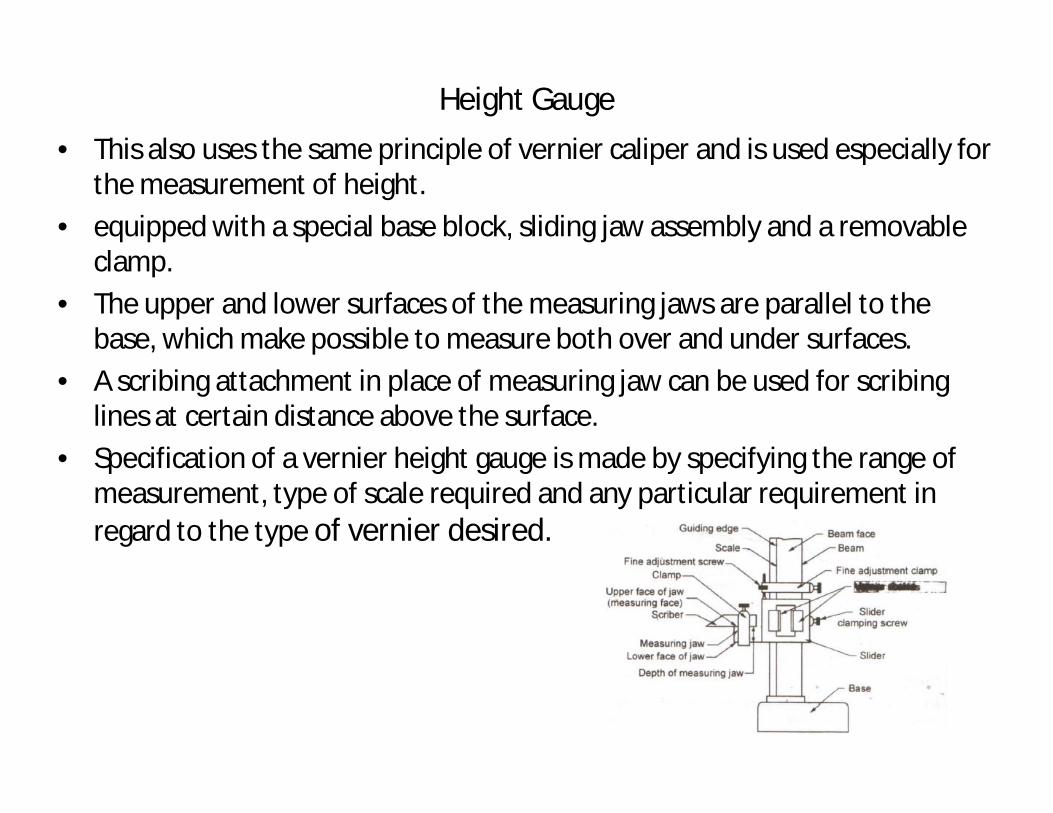
Height Gauge • This also uses the same principle of vernier caliper and is used especially for
the measurement of height. • equipped with a special base block, sliding jaw assembly and a removable
clamp. • The upper and lower surfaces of the measuring jaws are parallel to the
base, which make possible to measure both over and under surfaces. • A scribing attachment in place of measuring jaw can be used for scribing
lines at certain distance above the surface. • Specification of a vernier height gauge is made by specifying the range of
measurement, type of scale required and any particular requirement in regard to the type of vernier desired.

Slip Gauges
• Slip gauges are rectangular blocks of steel having a cross-section of about 30 by 10 mm.
• The essential purpose of slip gauges is to make available end standards of specific lengths by temporarily combining several individual elements, each representing a standard dimension, into a single gauge bar.
• The combination is made by pressing the faces into contact and then imparting a small twisting motion while maintaining the contact pressure. This is called wringing.
• Wringing occurs due to molecular adhesion between a liquid film and the mating surface.
• The combination made in that way can be used as reference for transferring the dimensions of the unit of length from the primary standard to gauge block of lower accuracy.
• It is also used for the verification and graduation of measuring apparatus and for direct measurement of linear dimensions of industrial components.
• For this purpose, control geometry of form such as flatness and parallelism of the surfaces and squareness of the gauging surfaces are essential.
• According to accuracy, the slip gauges can be graded into three categories, i.e. Grade 0, Grade I and Grade II. Generally, two sets of slip gauges are available.


Selection of Slip Gauges • Standard procedure is followed in selecting slip gauges.• It should be such that minimum number of slip gauges is chosen for
combination of blocks depending on the type of set available. example : • Let us consider the case where we have to arrange a dimension of 56.421
mm and normal sets of slip gauges are available. • Always the last decimal point is to be considered first, i.e. 0.001 mm. Since
gauge of 0.001 mm is not available, 1.001 mm slip gauge is to be selected. • The dimension left now is 56.421 – 1.001 = 55.42 mm. • Now considering the second decimal place, slip gauge with 1.02 mm
height is selected. The dimension left is 55.42 – 1.02 = 54.4 mm. • Next for 54.4 mm, slip gauge with 1.4 mm is to be chosen and then 3.0
mm gauge. Finally, 50 mm gauge is to be chosen. • Thus, we have 50.000 + 3.000 + 1.400 + 1.020 + 1.001 = 56.421 mm. All
these five slip gauges are wrung properly to get the required dimension. • If special set of gauges be used, the combination in this case would have
been 50.000 + 5.420 + 1.001 = 56.421 mm.