Embed Size (px)
Citation preview
2016-23rd IFHTSE Conference
Hot Hydroforging of Lightweight Bimaterial Gears and Hollow Products
Bulent Chavdar1, Robert Goldstein2, Lynn Ferguson3
1Eaton, Southfield, MI, USA2Fluxtrol Inc., Auburn Hills, MI, USA
3DANTE Solutions Inc., Cleveland, OH, USA
April 20, 2016

2
What is Hot hydroforging?
Definition: Hot forging of lightweight products from a hybrid billet of a metal shell and a low melting core.
Concept: Hot hydroforging is done at temperatures where the core material is in viscous state and builds up uniform pressure thereby enabling a uniform deformation of the metal shell.
Goal: Lightweight net shape forging with complex topologies
Viscous core
Core is squeezedout of center.
3
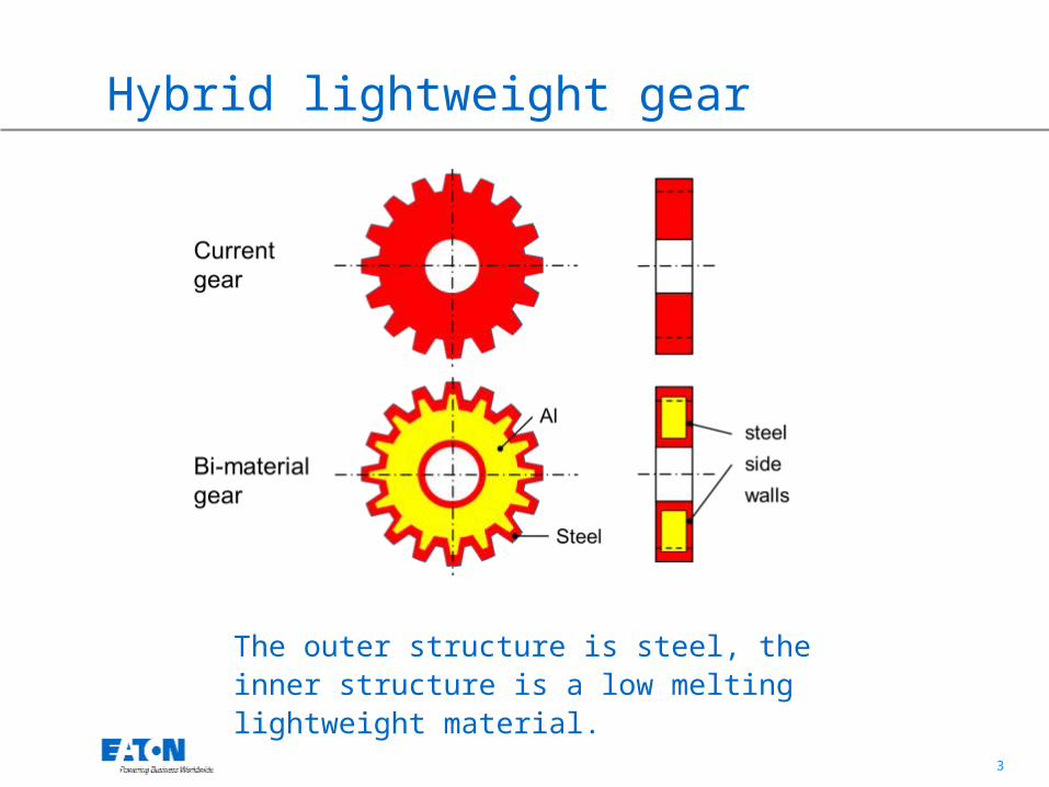
Hybrid lightweight gear
The outer structure is steel, the inner structure is a low melting lightweight material.

4
Objectives
• Forging light weight hybrid gears with net teeth and near net center.
• The hybrid gear has all steel outer structure. • Investment forging is enabled (molten core can be
emptied).• Press loads are reduced and larger gears can be
forged.• 30% to 50% weight reduction per gear is targeted.• 60% to 70% reduction in machining scrap rate due to
near net teeth.

5
Steels and low melting point materials
6
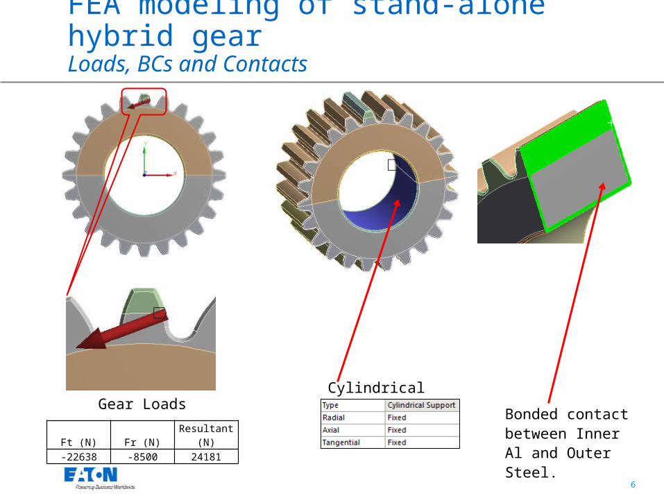
FEA modeling of stand-alone hybrid gearLoads, BCs and Contacts
Ft (N) Fr (N) Resultant (N)-22638 -8500 24181
Gear LoadsCylindrical support
Bonded contact between Inner Al and Outer Steel.
7
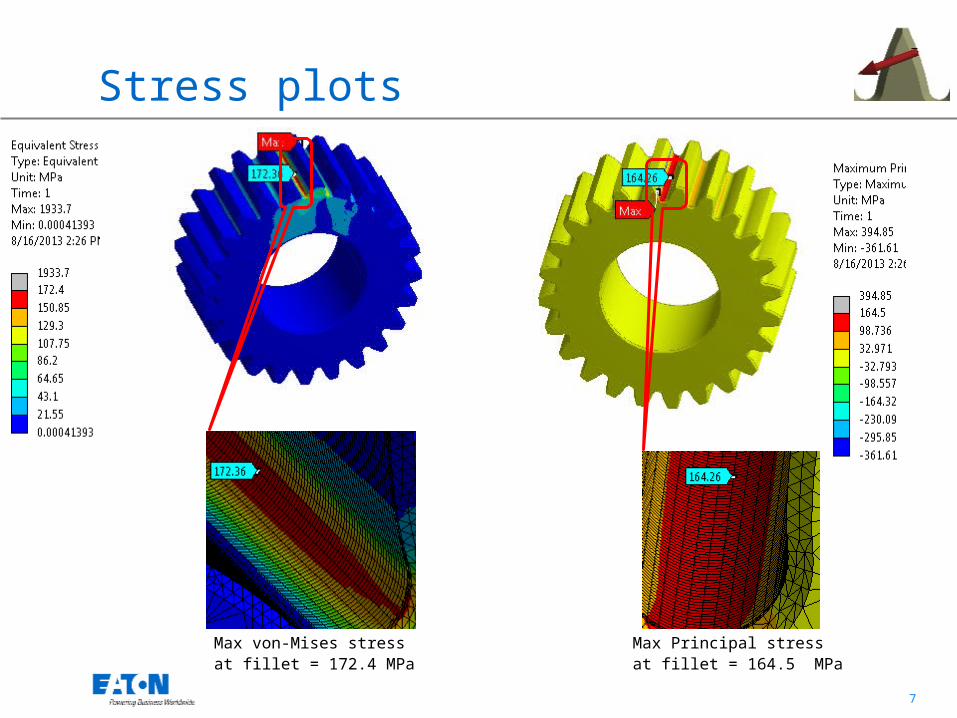
Stress plots
Max von-Mises stress at fillet = 172.4 MPa
Max Principal stress at fillet = 164.5 MPa
8
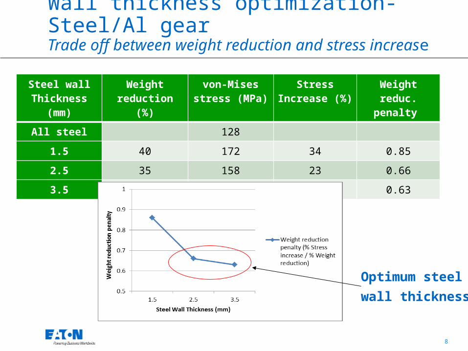
Wall thickness optimization-Steel/Al gearTrade off between weight reduction and stress increase
Steel wall Thickness (mm)
Weight reduction (%)
von-Mises stress (MPa)
Stress Increase (%)
Weight reduc. penalty
All steel 128
1.5 40 172 34 0.85
2.5 35 158 23 0.66
3.5 30 152 19 0.63
Optimum steelwall thickness
9
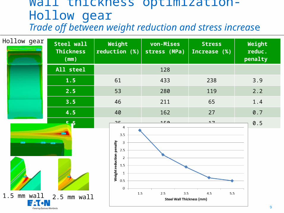
Wall thickness optimization-Hollow gearTrade off between weight reduction and stress increase
Steel wall Thickness (mm)
Weight reduction (%)
von-Mises stress (MPa)
Stress Increase (%)
Weight reduc. penalty
All steel 128
1.5 61 433 238 3.9
2.5 53 280 119 2.2
3.5 46 211 65 1.4
4.5 40 162 27 0.7
5.5 35 150 17 0.5
1.5 mm wall 2.5 mm wall
Hollow gear
10
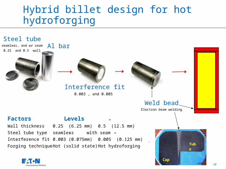
Hybrid billet design for hot hydroforging
Cap
Tube
Al barSteel tube
seamless, and w/ seam0.25” and 0.5” wall
Weld beadElectron beam welding
Interference fit0.003”, and 0.005”
Factors LevelsWall thickness 0.25” (6.25 mm) 0.5” (12.5 mm)Steel tube type seamless with seamInterference fit 0.003”(0.075mm) 0.005” (0.125 mm)Forging technique Hot (solid state) Hot hydroforging
11
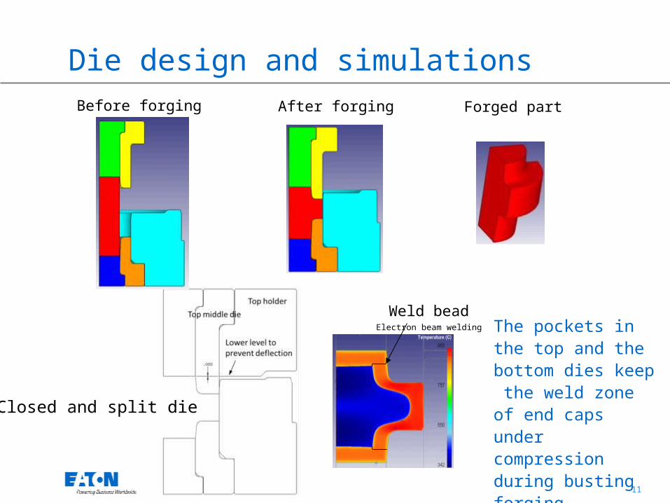
Die design and simulations
Weld beadElectron beam welding The pockets in the
top and the bottom dies keep the weld zone of end caps under compression during busting forging.
Before forging After forging Forged part
Closed and split die

12
Solid state hot forging simulations
Solid state forging simulations predicted folds, shrinkage gap and non-uniform steel wall thickness.

13
Forging trials
Erie 4000 ton mechanical press
Bi-Metal billets before forging10 kHz Induction heater
Heating Transferred to the die
Right after forging
A few seconds after forging
Forged parts
14
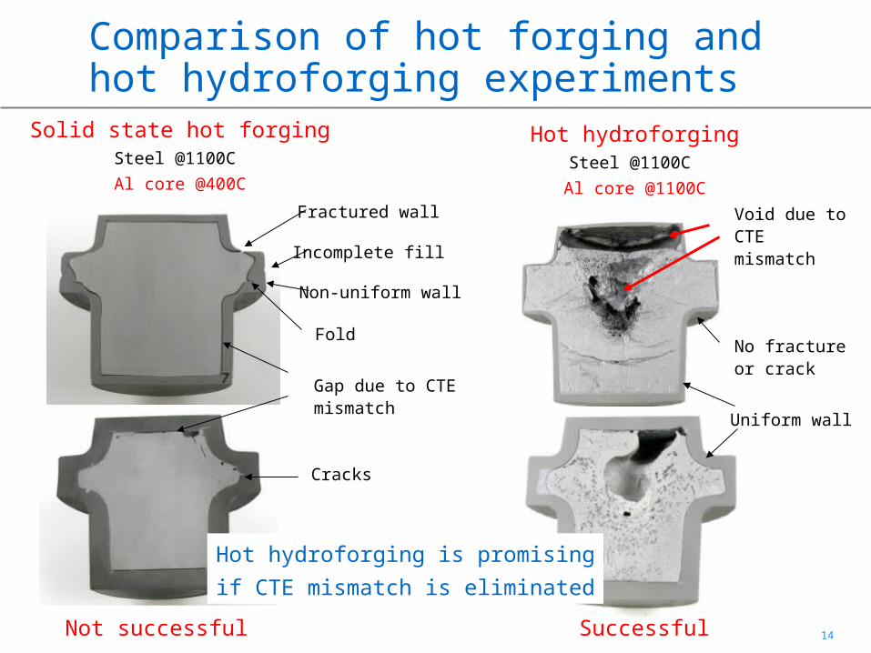
Comparison of hot forging and hot hydroforging experiments
Solid state hot forgingSteel @1100C Al core @400C
Hot hydroforgingSteel @1100C
Al core @1100CFractured wall
Incomplete fill
Fold
Non-uniform wall
Gap due to CTE mismatch
No fracture or crack
Cracks
Uniform wall
Void due to CTE mismatch
Hot hydroforging is promisingif CTE mismatch is eliminated
Not successful Successful
15
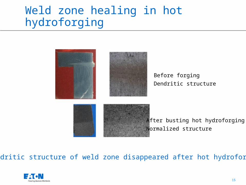
Weld zone healing in hot hydroforging
Before forgingDendritic structure
After busting hot hydroforgingNormalized structure
Dendritic structure of weld zone disappeared after hot hydroforging
16
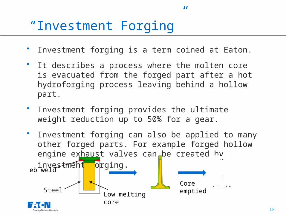
“Investment Forging”
• Investment forging is a term coined at Eaton.
• It describes a process where the molten core is evacuated from the forged part after a hot hydroforging process leaving behind a hollow part.
• Investment forging provides the ultimate weight reduction up to 50% for a gear.
• Investment forging can also be applied to many other forged parts. For example forged hollow engine exhaust valves can be created by investment forging.
Steel
eb weld
Core emptiedLow melting
core
17
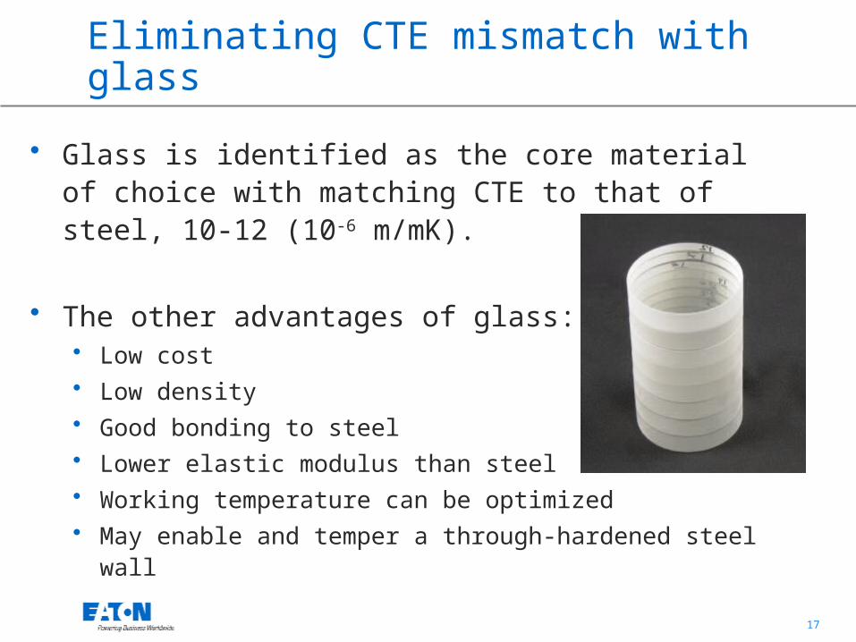
Eliminating CTE mismatch with glass
• Glass is identified as the core material of choice with matching CTE to that of steel, 10-12 (10-6 m/mK).
• The other advantages of glass:• Low cost• Low density• Good bonding to steel• Lower elastic modulus than steel • Working temperature can be optimized• May enable and temper a through-hardened steel wall

18
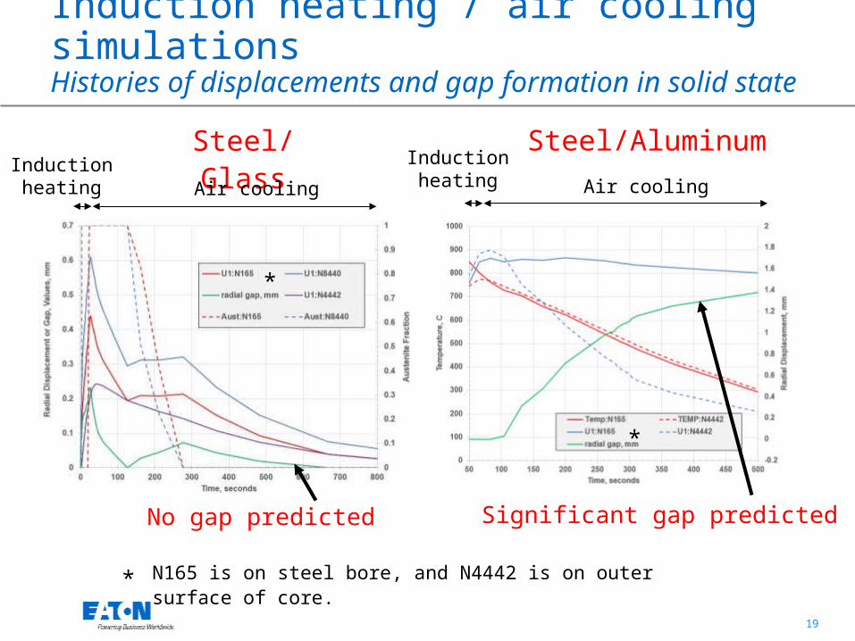
Induction heating / air cooling simulationsDisplacement and gap formation in solid state
Steel/Glass Steel/Aluminum
No gap predicted Significant gap predicted
Glass is a promising lightweight core material.
19
N165 is on steel bore, and N4442 is on outer surface of core.
Steel/Glass Steel/Aluminum
No gap predicted Significant gap predicted
*
*
*
Induction heating / air cooling simulationsHistories of displacements and gap formation in solid state
Air cooling
Inductionheating Air cooling
Inductionheating
20
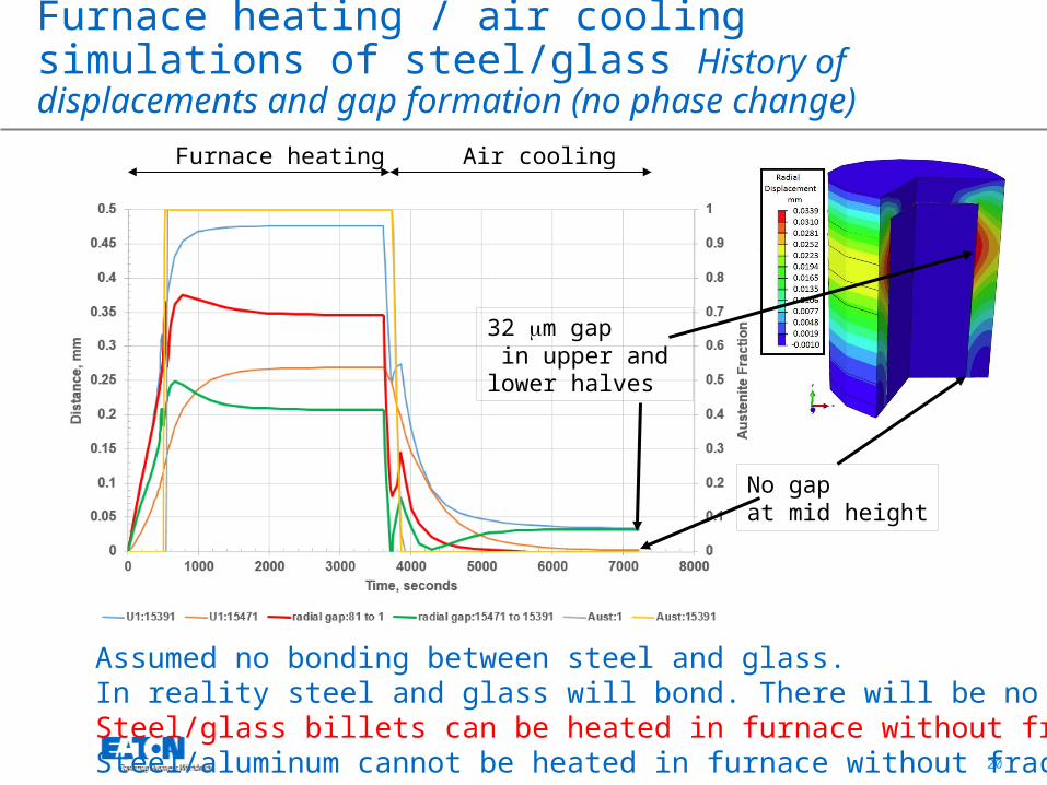
Furnace heating / air cooling simulations of steel/glass History of displacements and gap formation (no phase change)
No gap predicted
Assumed no bonding between steel and glass.In reality steel and glass will bond. There will be no gap. Steel/glass billets can be heated in furnace without fracture.Steel/aluminum cannot be heated in furnace without fracture.
Furnace heating Air cooling
No gapat mid height
32 mm gap in upper and lower halves
21
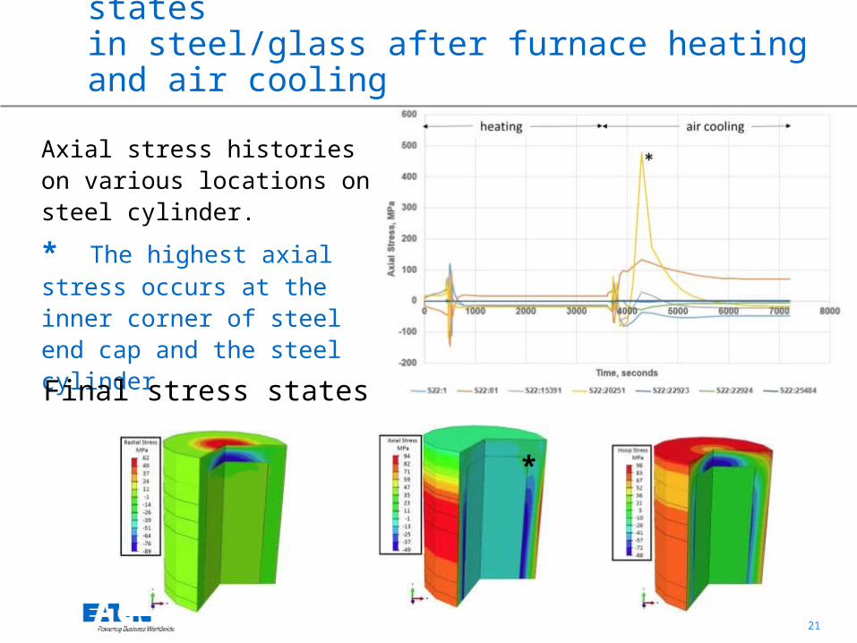
Stress histories and final stress states in steel/glass after furnace heating and air cooling
Axial stress histories on various locations on steel cylinder.
* The highest axial stress occurs at the inner corner of steel end cap and the steel cylinder
Final stress states
*

22
Conclusions
• Feasibility of hot hydroforging and investment forging for lightweighting, net shape forging and waste reduction are demonstrated.
• Steel/aluminum hybrid billets were prepared. Then, the billets were hot hydroforged in closed dies.
• A uniform steel wall thickness was observed all around the hot hydroforged part upon cross sectioning.
• Weld seams are healed (normalized) upon hot hydroforging.
• Steel/glass is a more promising hybrid than steel/aluminum for hot hydroforging due to the CTE match.
23
Back up slides
25
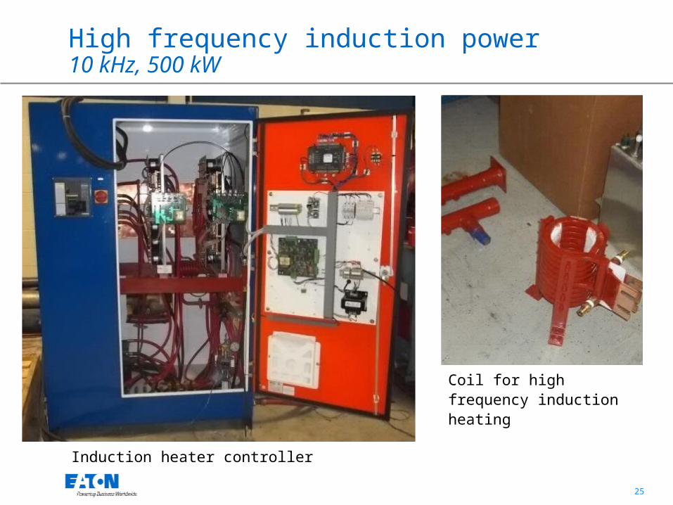
High frequency induction power10 kHz, 500 kW
Induction heater controller
Coil for high frequency induction heating
26
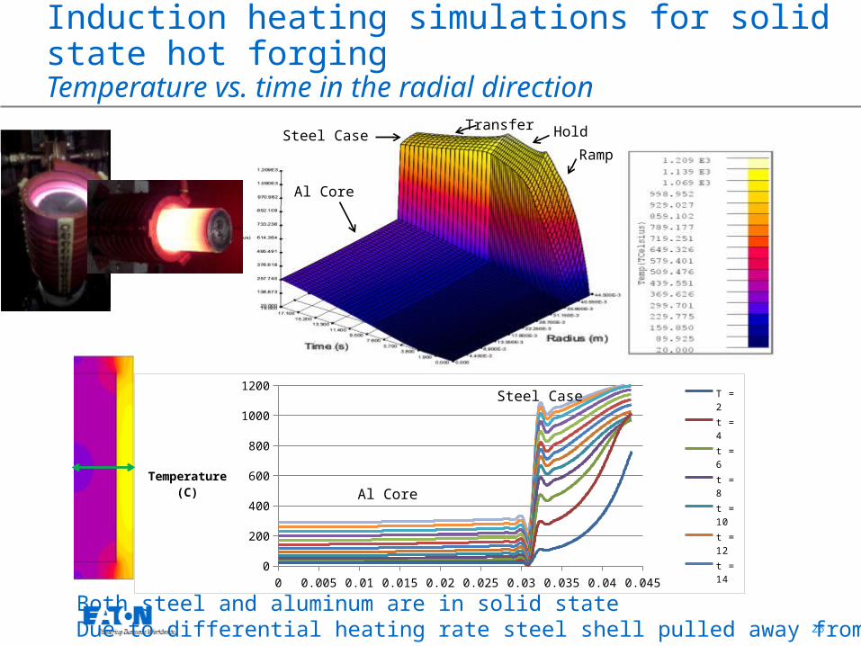
Induction heating simulations for solid state hot forgingTemperature vs. time in the radial direction
Ramp
HoldTransfer
Al Core
Steel Case
0 0.005 0.01 0.015 0.02 0.025 0.03 0.035 0.04 0.0450
200
400
600
800
1000
1200T = 2t = 4t = 6
t = 8t = 10t = 12t = 14t = 16
t = 18t = 20t = 22
t = 24
t = 26
Temperature(C) Al Core
Steel Case
Both steel and aluminum are in solid stateDue to differential heating rate steel shell pulled away from the core
27
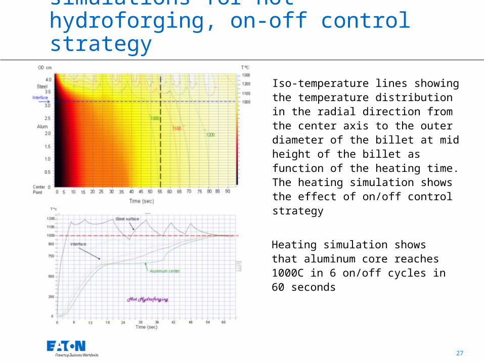
Billet induction heating simulations for hot hydroforging, on-off control strategy
Iso-temperature lines showing the temperature distribution in the radial direction from the center axis to the outer diameter of the billet at mid height of the billet as function of the heating time. The heating simulation shows the effect of on/off control strategy
Heating simulation shows that aluminum core reaches 1000C in 6 on/off cycles in 60 seconds
28
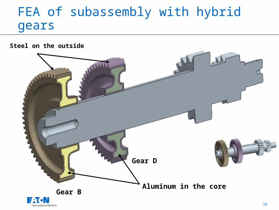
FEA of subassembly with hybrid gearsSteel on the outside
Aluminum in the coreGear B
Gear D

29
Force reactions at bearing supports and torsional spring at end face
Bearing Front
Torsional spring at end face
Bearing Rear
Global deformation of assembly reduces stress concentration
30
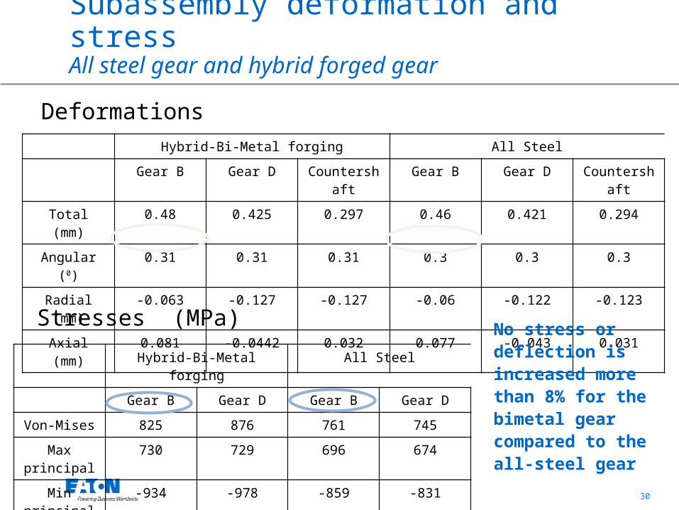
Subassembly deformation and stress All steel gear and hybrid forged gear
Hybrid-Bi-Metal forging All Steel
Gear B Gear D Countershaft Gear B Gear D Countershaft
Total (mm) 0.48 0.425 0.297 0.46 0.421 0.294
Angular (0) 0.31 0.31 0.31 0.3 0.3 0.3
Radial (mm) -0.063 -0.127 -0.127 -0.06 -0.122 -0.123
Axial (mm) 0.081 -0.0442 0.032 0.077 -0.043 0.031
Hybrid-Bi-Metal forging All Steel
Gear B Gear D Gear B Gear D
Von-Mises 825 876 761 745
Max principal
730 729 696 674
Min principal -934 -978 -859 -831
No stress or deflection is increased more than 8% for the bimetal gear compared to the all-steel gear
Deformations
Stresses (MPa)
31
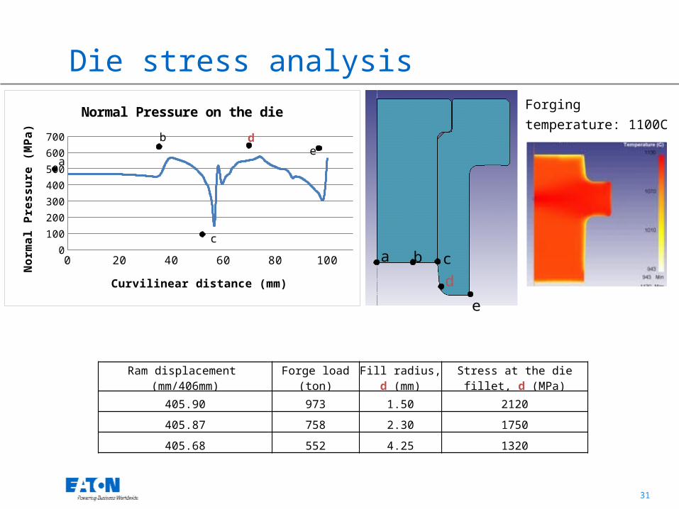
0 20 40 60 80 1000
100
200
300
400
500
600
700
Normal Pressure on the die
Curvilinear distance (mm)
Nor
mal
Pre
ssur
e (M
Pa)
a
b
c
de
e
dcba
Ram displacement (mm/406mm)
Forge load(ton)
Fill radius, d (mm)
Stress at the die fillet, d (MPa)
405.90 973 1.50 2120
405.87 758 2.30 1750
405.68 552 4.25 1320
Die stress analysisForging temperature: 1100C