Embed Size (px)
Citation preview
GAUGES By KANAKA RaZ

GAUGES
• Gauges perform an essential services in any scheme of quantity production on an interchangeable basis
• A gauge (or Limit Gauge) is a tool or instrument to measure or compare a component.
• It is employed in the sense of an instrument which having fixed dimension, is used to determine whether the size of some component exceeds or is less than the size of the gauge itself
Gauges are used for dimensional control of the component parts , their function being to establish whether or not surface levels lie within the zone specified by the designer.
Gauges must be manufactured & checked with reference to standard of length, which in turn is related to a fundamental length standard. The standard of length is then transferred through the gauge to the component
GAUGES (cont..)

The true value of a gauge is measured by its accuracy & service life which, in turn, depends on the workmanship & materials used in its manufacture. Since all gauges are continually subject to abrasive wear while in use, the selection of the proper material is of great importance
High carbon steel & alloy tool steels have been the principal materials for manufacture of such gauges
GAUGES (cont..)


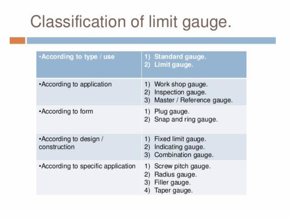

Classification
• According to design– single limit and double limit gauges– single ended and double ended gauges– fixed and adjustable gauges
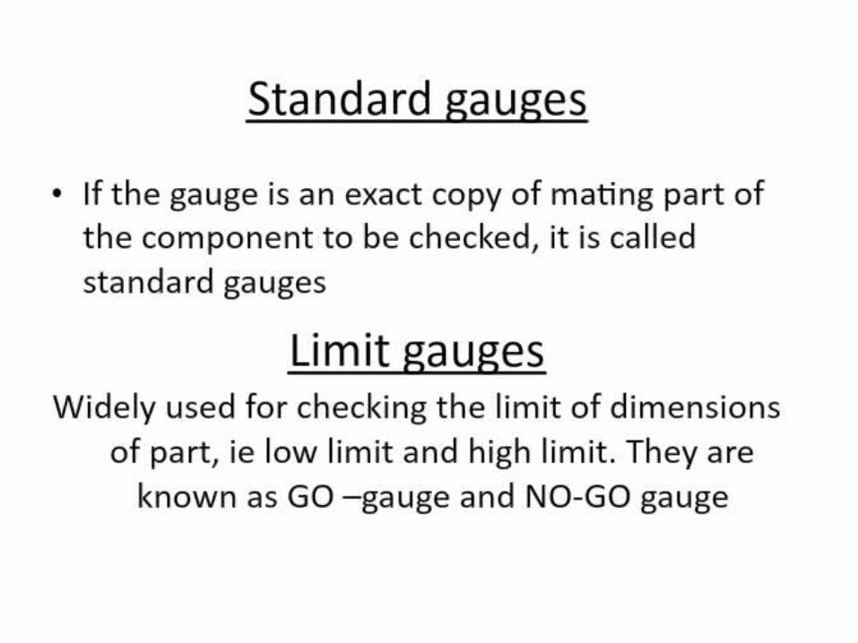
Standard gauge
• If a gauge is made as an exact copy of the mating part of the component to be checked
ex: bush for shaft

Limit gauge
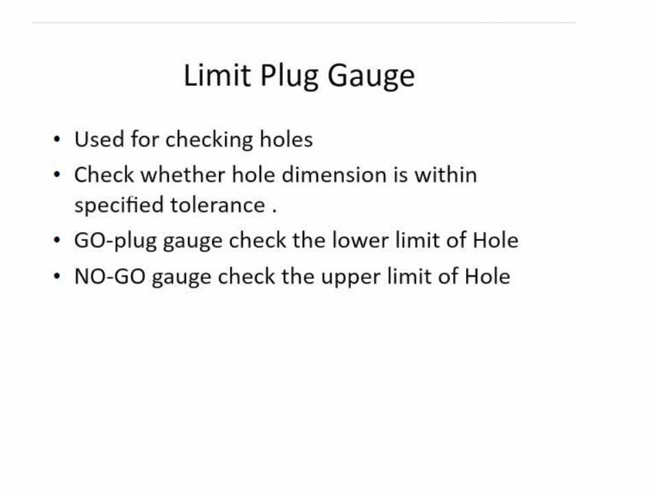
• Used widely in industries • For two permissible limits of the dimension of
a part• Two gauges are required for two limits• These are GO and NO GO gauges• GO gauge foe MML• NO GO for LML

Limit Gauge
• Limit gauges are made to the limits of the dimensions of the part to be tested. There are two limit of dimensions, so we need two limit gauge.
• ‘Go gauge’ should pass through or over a part while ‘Not Go gauge 'should not pass through or over the part.

Limit gauges

Limit gauges
Types of limit plug gauges
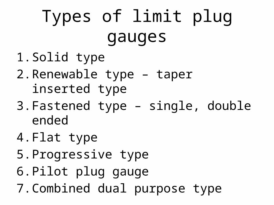
1. Solid type2. Renewable type – taper inserted type3. Fastened type – single, double ended4. Flat type5. Progressive type6. Pilot plug gauge7. Combined dual purpose type
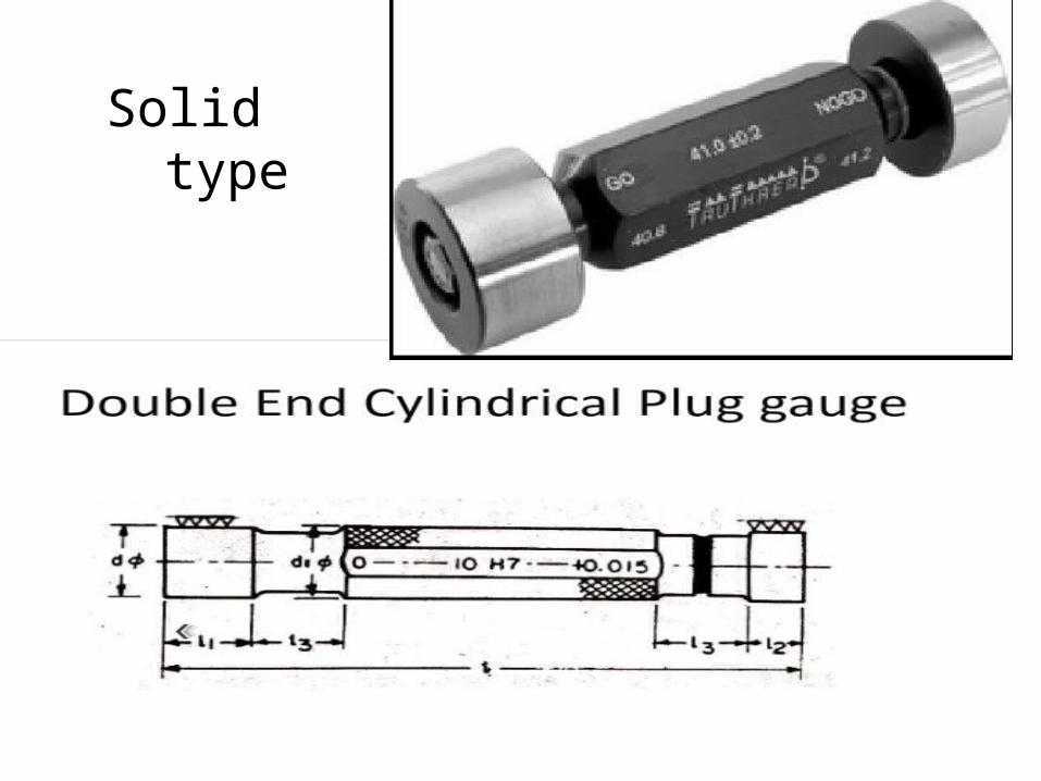
Solid type

Renewable type

Renewable type
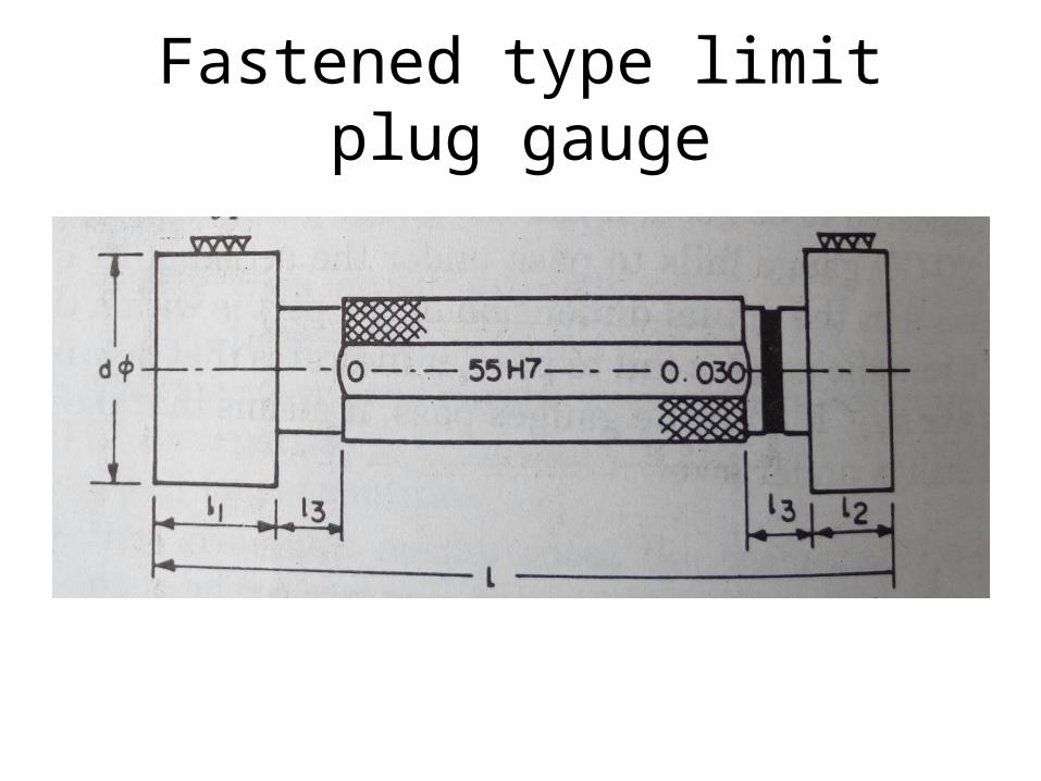
Fastened type limit plug gauge
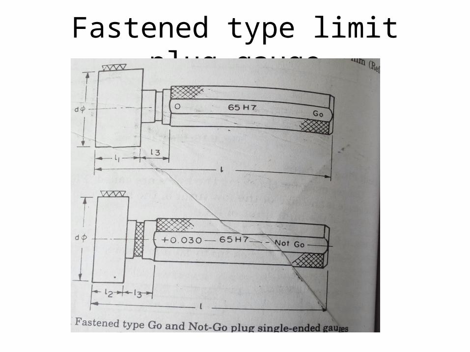
Fastened type limit plug gauge

Fastened type limit plug gauge
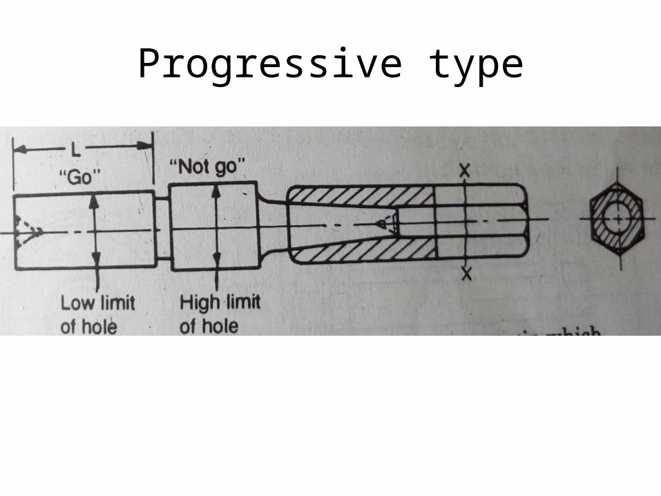
Progressive type

Flat type
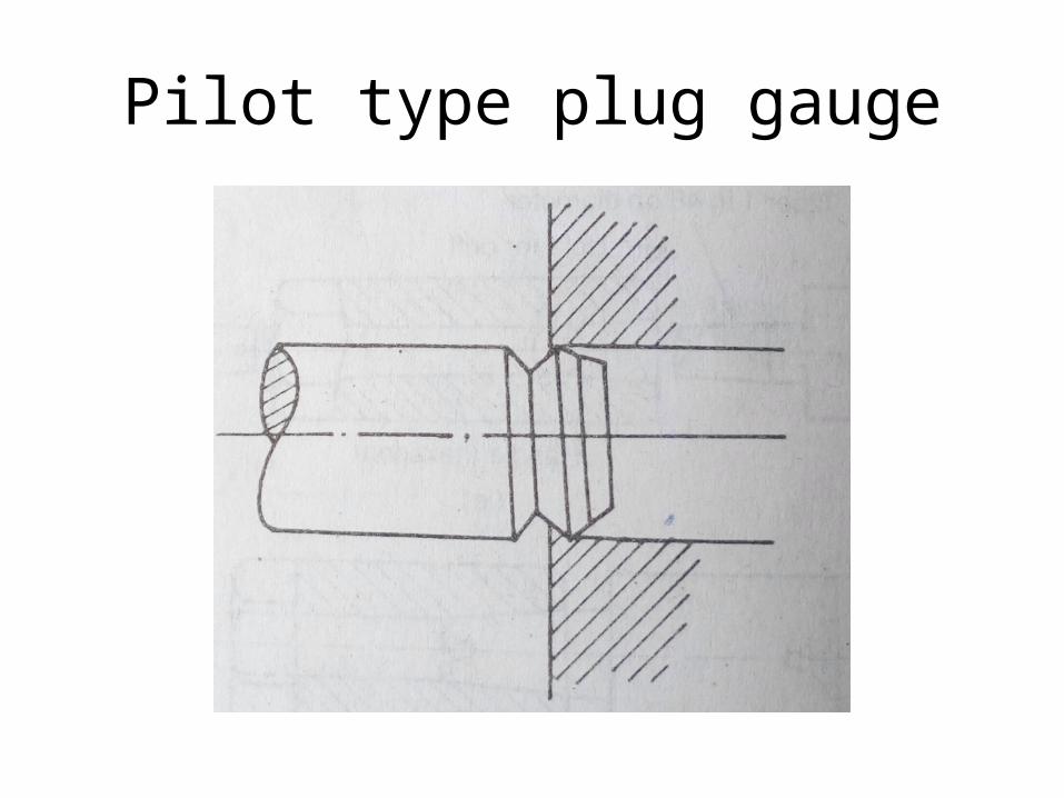
Pilot type plug gauge

Combined dual purpose limit gauge
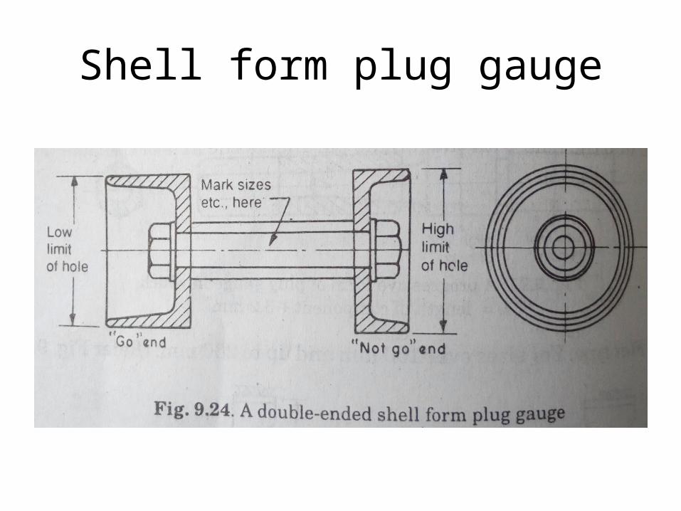
Shell form plug gauge


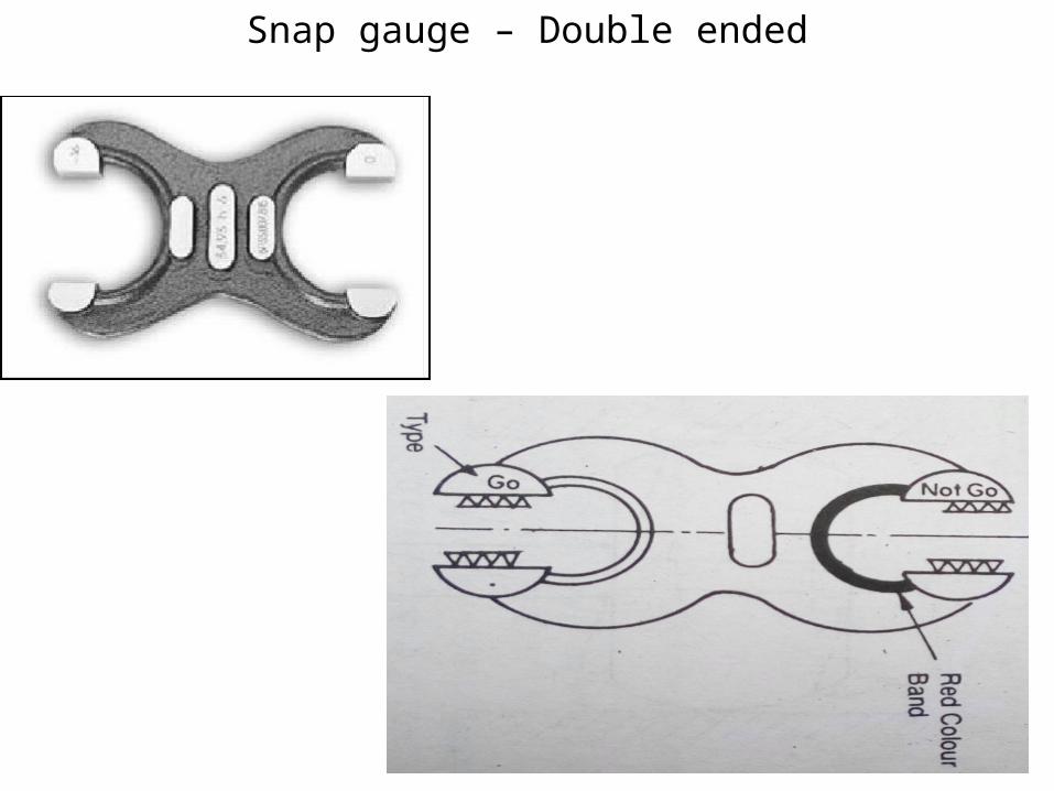
Snap gauge – Double ended

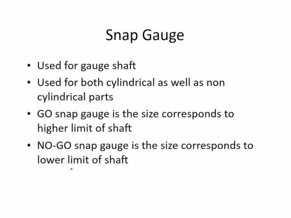
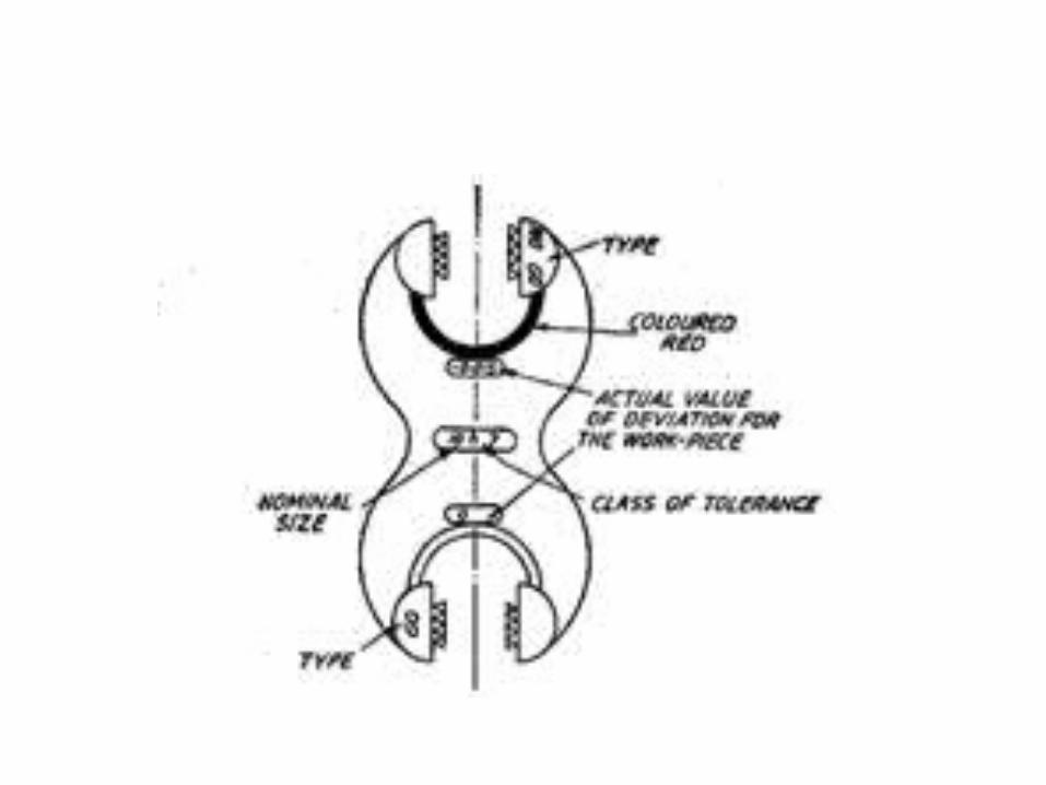
Snap gauge
Adjustable


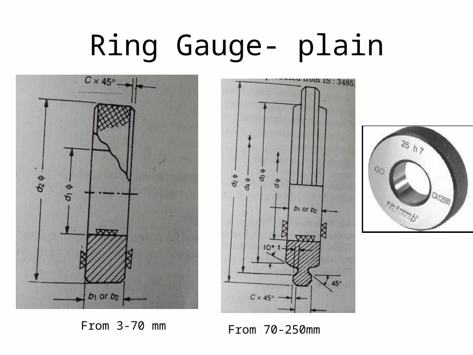
Ring Gauge- plain
From 3-70 mm From 70-250mm

Ring Gauge-
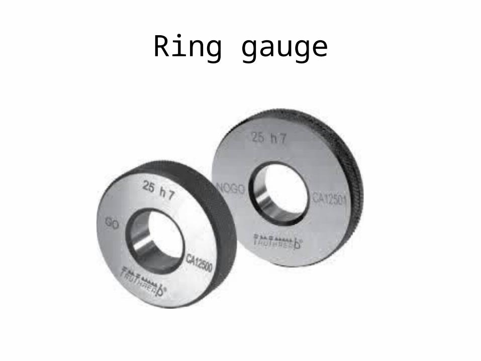
Ring gauge
TAPER GAUGE
• The most satisfactory method of testing a taper is to use taper gauges.
• They are also used to gauge the diameter of the taper at some point.
• Taper gauges are made in both the plug and ring styles and, in general, follow the same standard construction as plug and ring gauges.
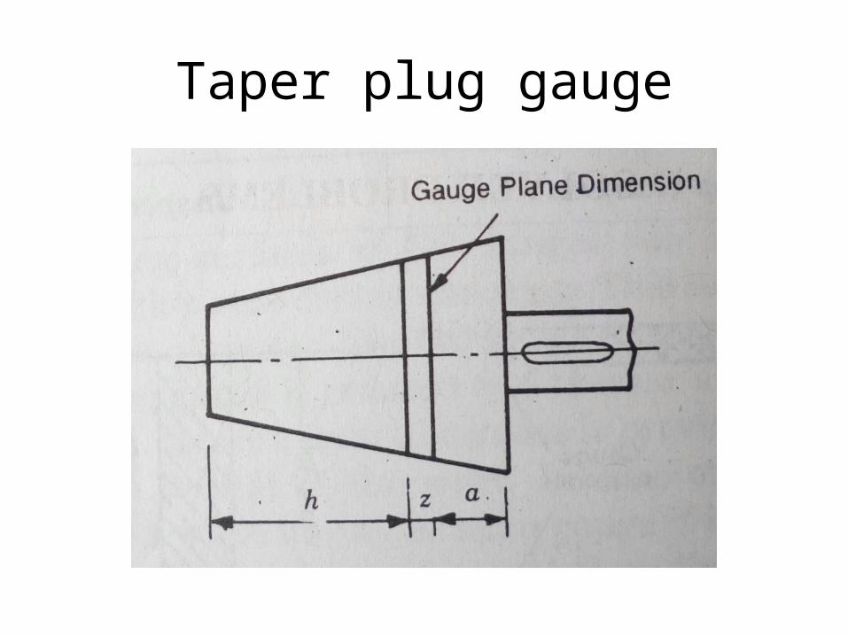
Taper plug gauge

TAPER GAUGE
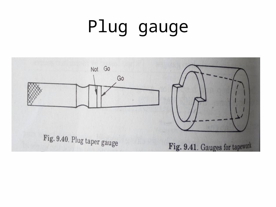
Plug gauge

THREAD GAUGE
• Thread gauges are used to check the pitch diameter of the thread.
• For checking internal threads (nut, bushes, etc.), plug thread gauges are used, while for checking external threads (screws, bolts, etc.), ring thread gauges are used.
• Single-piece thread gauges serve for measuring small diameters.
• For large diameters the gauges are made with removable plugs machined with a tang.
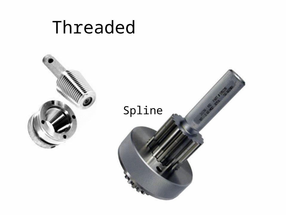
Threaded
Spline

THREAD GAUGE
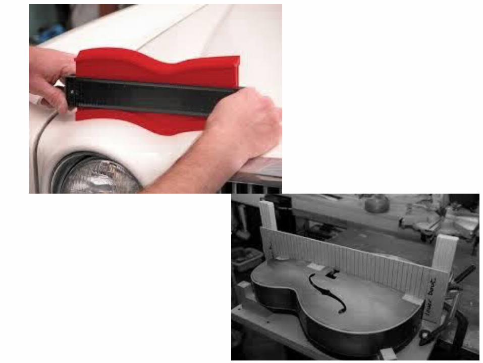
FORM GAUGE
• Form gauges may be used to check the contour of a profile of work piece for conformance to certain shape or form specifications.
Template Gauge• It is made from sheet steel. It is also called
profile gauge. A profile gauge may contain two outlines that represent the limits within which a profile must lie

SCREW PITCH GAUGE
• Screw pitch gauges are used in picking out a required screw and for checking the pitch of the screw threads.
• They consist of a number of flat blades which are cut out to a given pitch and pivoted in a holder.
• Each blade is stamped with the pitch or number of thread per inch and the holder bears an identifying number designing the thread it is intended for.
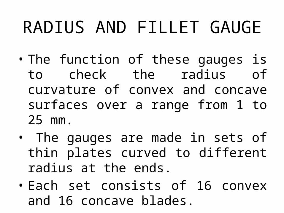
RADIUS AND FILLET GAUGE
• The function of these gauges is to check the radius of curvature of convex and concave surfaces over a range from 1 to 25 mm.
• The gauges are made in sets of thin plates curved to different radius at the ends.
• Each set consists of 16 convex and 16 concave blades.
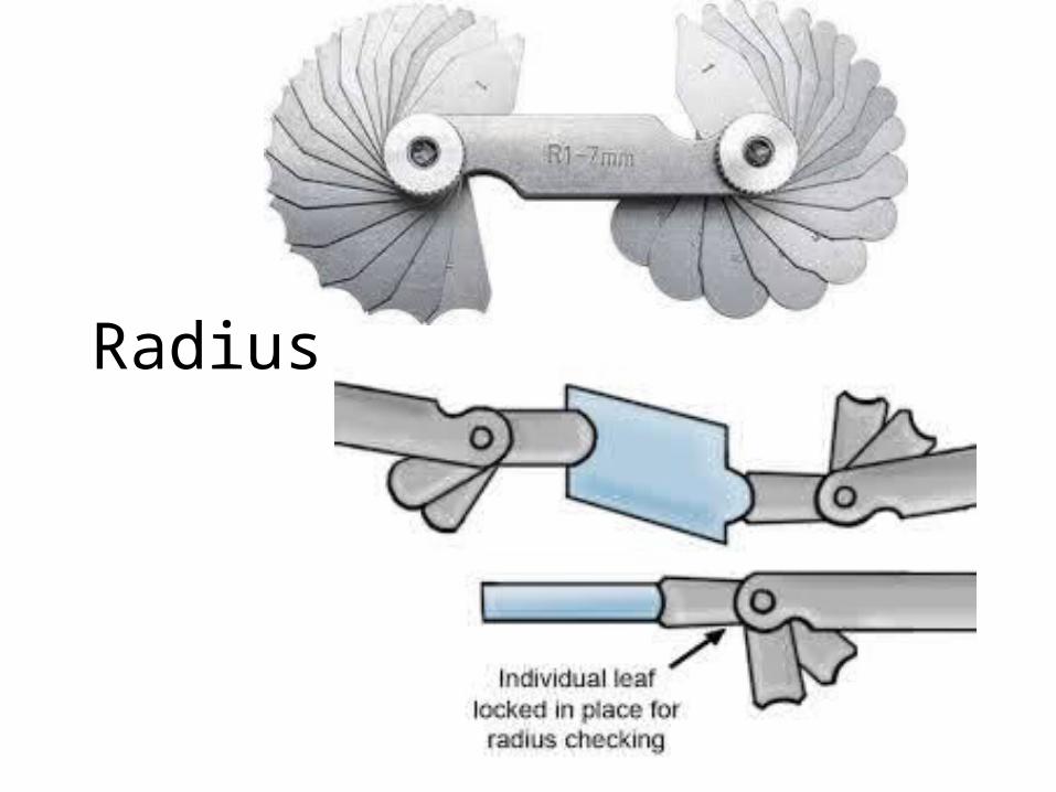
Radius

FEELER GAUGE
• Feeler gauges are used for checking clearances between mating surfaces.
• They are made in form of a set of steel, precision machined blade 0.03 to 1.0 mm thick and 100 mm long.
• Each blade has an indication of its thickness. • To find the size of the clearance, one or two blades
are inserted and tried for a fit between the contacting surfaces until blades of suitable thickness are found.

Feeler

INDICATING GAUGES
• Indicating gauges employ a means to magnify how much a dimension deviates, plus or minus, from a given standard to which the gauge has been set.
• They are intended for measuring errors in geometrical form and size, and for testing surfaces for their true position with respect to one another.
• Indicating gauges can be of a dial or lever type.

Materials which are used for making gauges are high carbon and alloy steels, cemented carbides, etc.
59
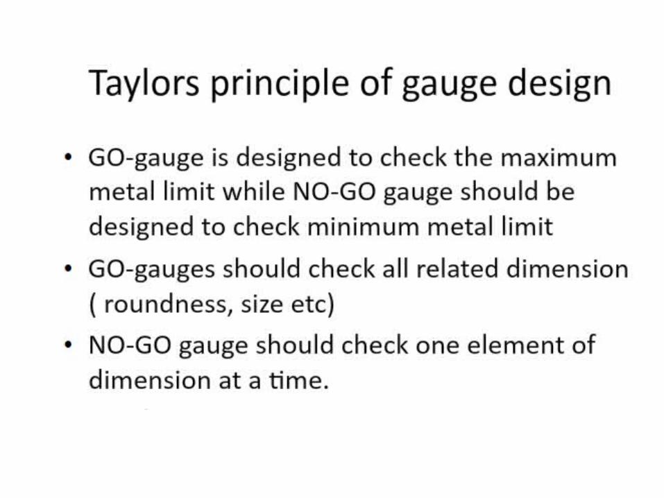
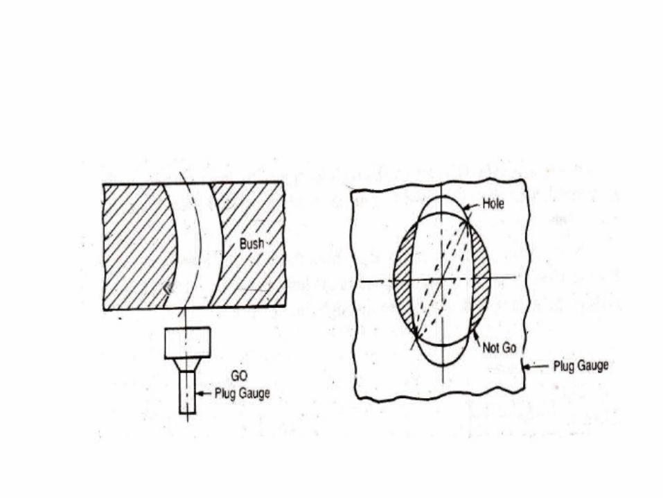
Taylor’s Principle• Go Gauge should always be so designed that it will cover the Maximum Metal Condition(MMC) of as many dimensions as possible in the same limit gauge,
whereas Not Go gauge to cover the minimum metal condition of one dimension only.

62
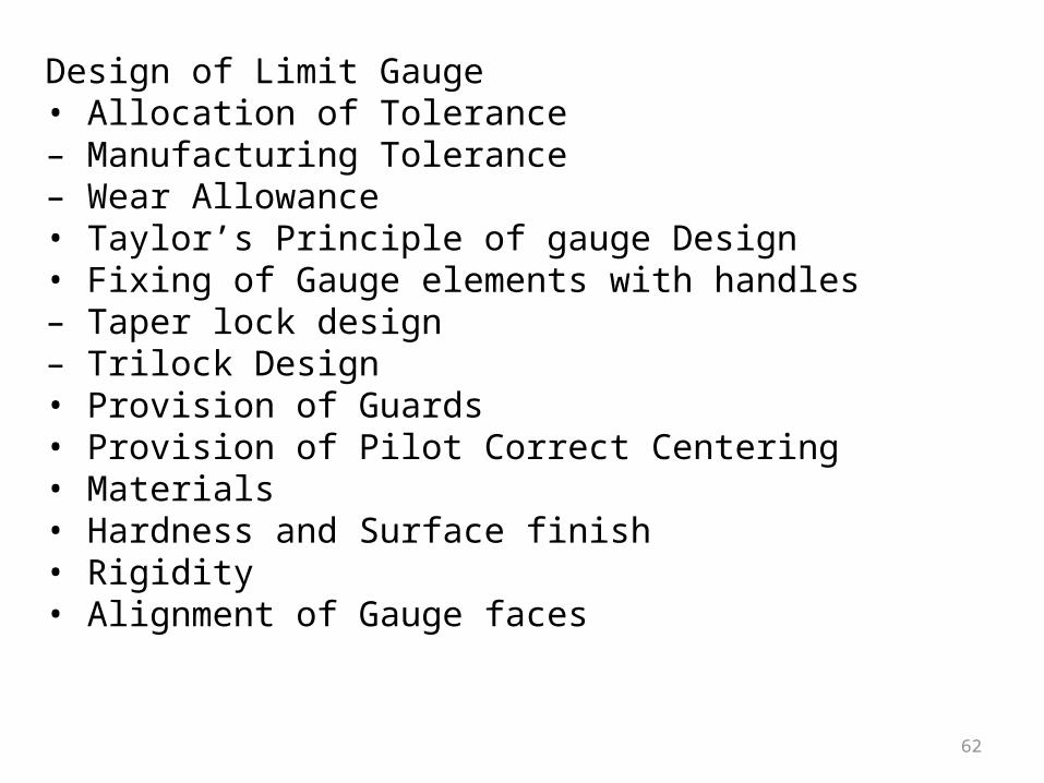
Design of Limit Gauge• Allocation of Tolerance– Manufacturing Tolerance– Wear Allowance• Taylor’s Principle of gauge Design• Fixing of Gauge elements with handles– Taper lock design– Trilock Design• Provision of Guards• Provision of Pilot Correct Centering• Materials• Hardness and Surface finish• Rigidity• Alignment of Gauge faces

63
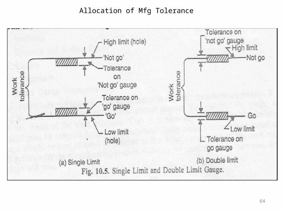
Allocation of ToleranceManufacturing Tolerance• It is economically impractical to attempt to make “Go” and “Not Go” gauges exactly to the two limits of work tolerance.
• Limit gauges are made 10 times more accurate than the tolerances they are going to control.
64
Allocation of Mfg Tolerance

65
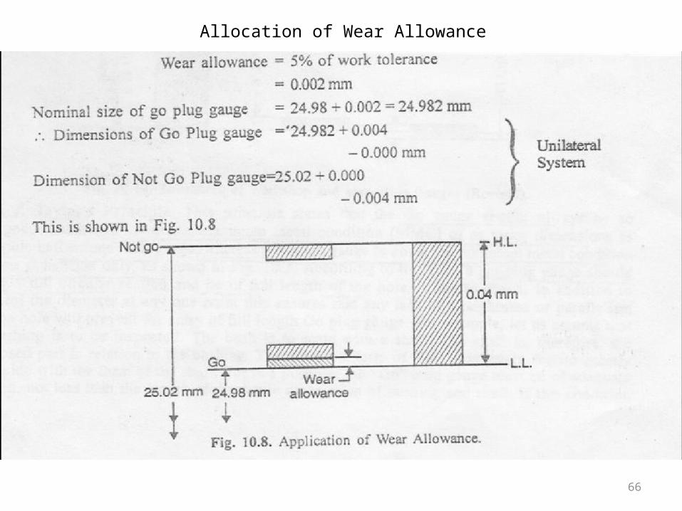
Allocation of ToleranceWear Allowance
• The surface of “Go” gauge is constantly rubagainst the surface of the part in inspection and loose their initial size.
• The size of plug gauge is reduced but size of snap gauge is increased.
• 10% wear allowance is provided only for the “GO” gauge if working tolerance is greater than 0.09 mm.
66
Allocation of Wear Allowance
67
KEY WORDS Standard Gauges : These are made to the nominal size of the parts to be tested. Limit Gauges : These are „go‟ and „no go‟ gauges. Plug Gauges : These are used for checking holes of many different shapes and sizes. Ring Gauges : External diameter measuring gauges. Taper Gauges : Taper testing gauges. Snap Gauges : These are used for checking shafts. Thread Gauges : These are used for pitch diameter of the thread. Form Gauges : These are used to check the contour of a profile. Feller Gauges : For checking the clearance between the mating surfaces. Indicating Gauges : To measure the position of the surfaces.