Embed Size (px)
Citation preview
24
Pressure gauges
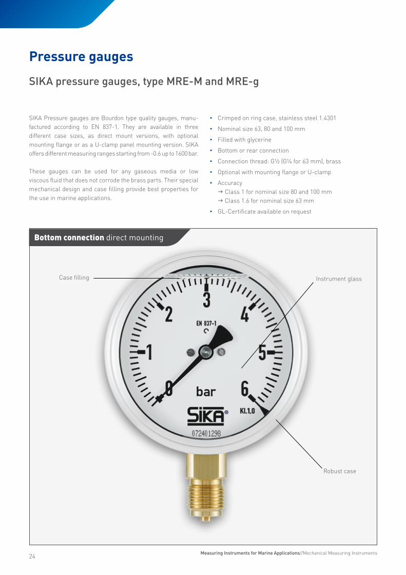
SIKA Pressure gauges are Bourdon type quality gauges, manu- factured according to EN 837-1. They are available in three different case sizes, as direct mount versions, with optional mounting flange or as a U-clamp panel mounting version. SIKA offers different measuring ranges starting from -0.6 up to 1600 bar.
These gauges can be used for any gaseous media or low viscous fluid that does not corrode the brass parts. Their special mechanical design and case filling provide best properties for the use in marine applications.
• Crimped on ring case, stainless steel 1.4301
• Nominal size 63, 80 and 100 mm
• Filled with glycerine
• Bottom or rear connection
• Connection thread: G½ (G¼ for 63 mm), brass
• Optional with mounting flange or U-clamp
• Accuracy J Class 1 for nominal size 80 and 100 mm J Class 1.6 for nominal size 63 mm
• GL-Certificate available on request
Case filling
Robust case
Instrument glass
SIKA pressure gauges, type MRE-M and MRE-g
Bottom connection direct mounting
Measuring Instruments for Marine Applications//Mechanical Measuring Instruments
25
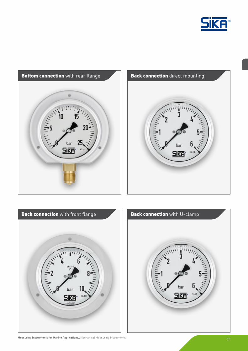
Bottom connection with rear flange Back connection direct mounting
Back connection with U-clamp Back connection with front flange
Measuring Instruments for Marine Applications//Mechanical Measuring Instruments
26
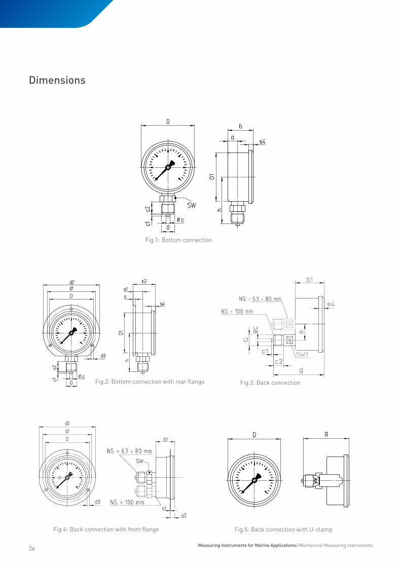
Fig.1: Bottom connection
Fig.2: Bottom connection with rear flange Fig.3: Back connection
NS = 63 + 80 mm
NS = 100 mm
Fig.4: Back connection with front flange
NS = 63 + 80 mm
NS = 100 mm
Fig.5: Back connection with U-clamp
Dimensions
Measuring Instruments for Marine Applications//Mechanical Measuring Instruments

27
Dimensions and order code
Order example MREM 1 1 1 305 00 G ISSA-Code IMPA-Code
MREM MREG
123
11522
13
305315505515525535545555015025035045055065075085095105115125135145155165175185
0010002030
G
61.232.10-61.232.15
65 15(general number)
Nominal size 63 mm (MREM) 80 mm (MREG) 100 mm (MREM)Bottom connection G¼ (63 mm)Bottom connection G½ (80 mm / 100 mm)Center back connection G¼ (63 mm)Center back connection G½ (80 mm)Lower back connection G½ (100 mm)Connection thread Brassmaterial Stainless steel (for 1000 / 1600 bar , only)Display range (bar) - 0.6...0 -1...0 -1...0.6 -1...1.5 -1...3 -1...5 -1...9 -1...15 0...0.6 0...1 0...1.6 0...2.5 0...4 0...6 0...10 0...16 0...25 0...40 0...60 0...100 0...160 0...250 0...400 0...600 0...1000* (only 100 mm dial size) 0...1600* (only 100 mm dial size)Bottom connection Direct mounting Back flangeBack connection Direct mounting Front flange U-clampCase filling Glycerine
NG D D1 a a1 b b1 b2 c c1 c2 d1 d2 d3 e G g h s s1 s3 SW
63 68 62 13 14 32 32 33 5 2 13 75 85 3.6 - G¼ 58 54 1 1 4.5 1480 86 79 16 19 41.5 36 44 6 3 20 95 110 4.8 - G½ 74 76 5 1 9 22100 107 99 15.5 14 48 48 49 6 3 20 115 132 5.1 30 G½ 81.5 87 1 1 6 22
* With stainless steel bourdon springed connection Please ask for customised specifications
Measuring Instruments for Marine Applications//Mechanical Measuring Instruments

28
Degree of protection according to EN 60529
IP65 for filled case with closed pressure equalisation insert
Dial
Aluminium, white with black scale markings.
Window
Instrument glass
Pointer movement
CrNi-Steel
Connection threads and materials
The pressure gauges have a brass connection thread and bronze Bourdon tube.
Temperature range
• Storage temperature -20...70 °C
• Ambient operating temperature -20...60 °C
• Media temperature Up to 160 °C
Ambient temperature sensivity
The pressure gauges are calibrated at a reference temperature of 20 °C. At other operating temperatures the maximum indication error is ±0.4 % of full scale value per 10 °C difference in accordance with EN 837-1.
Case type
The stainless steel case is available with a crimped-on ring. Case ventilation is provided by a pressure equalisation insert.
Display ranges
Multiple scales in bar, l/h and USg/h
SIKA manometers for separators with 63 mm stainless-steel housing are especially suitable for flow measurement depen-dent on the pressure on the separators. Depending on the se-parator, various display ranges are available.
• Pressure gauges compliant with EN 837-1
• Stainless steel case with crimped-on ring
• Brass threaded connection
• Connection at bottom G¼ B
• EN 837-1 accuracy class 1.6
• Protection class IP65 / EN 60529
• GL type approval certificate available
For separators for flow measurement, type MRE-g, nominal size 63 mm
Bourdon tube pressure gauges, special version
Type MRE-g
Maximum pressure load
Static load 75 % of full-scale value
Dynamic load 65 % of full-scale value
Overload 2-times of full-scale value
Display ranges
0...1 bar 150...400 l/h 40...100 USg/h
0...1 bar 300...800 l/h 80...200 USg/h
0...1 bar 400...1200 l/h 60...320 USg/h
0...1 bar 500...2500 l/h 180...660 USg/h
0...1 bar 500...4000 l/h 100...1100 USg/h
0...1 bar 1000...6000 l/h 300...1500 USg/h
0...1 bar 2000...12000 l/h 500...3200 USg/h
0...2.5 bar 2000...16000 l/h 1000...4300 USg/h
Measuring Instruments for Marine Applications//Mechanical Measuring Instruments
29
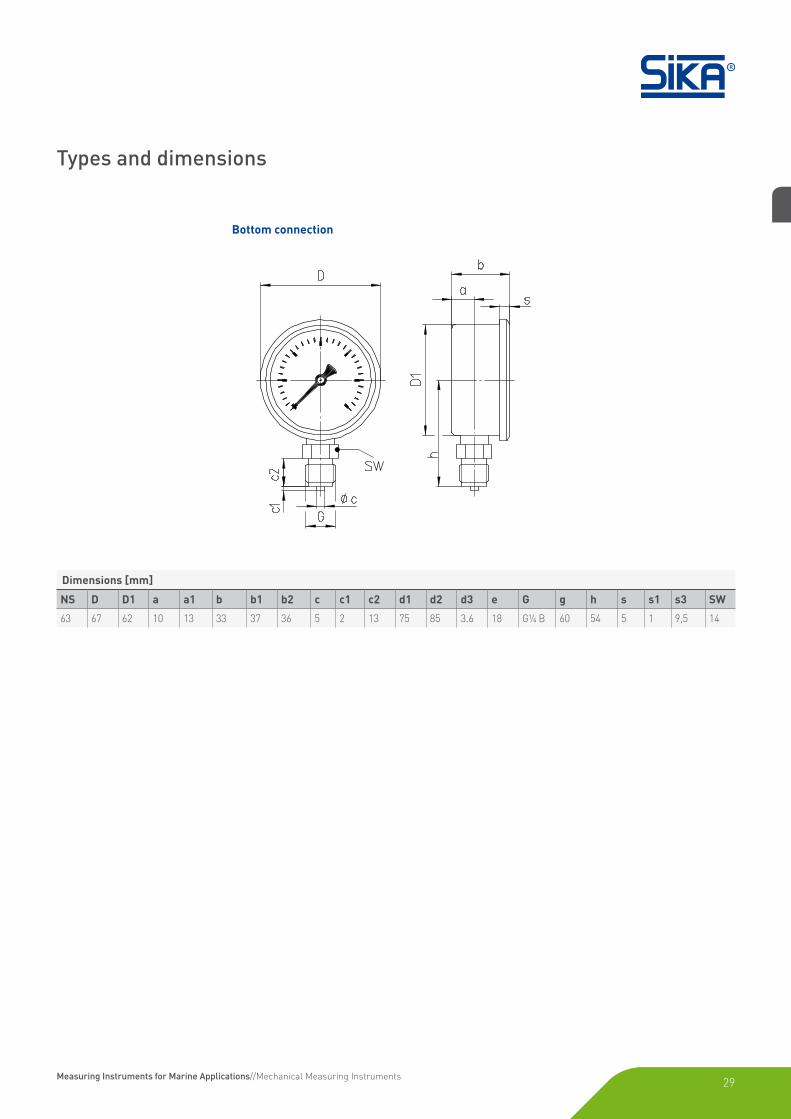
Bottom connection
Dimensions [mm]
NS D D1 a a1 b b1 b2 c c1 c2 d1 d2 d3 e G g h s s1 s3 SW
63 67 62 10 13 33 37 36 5 2 13 75 85 3.6 18 G¼ B 60 54 5 1 9,5 14
Types and dimensions
Measuring Instruments for Marine Applications//Mechanical Measuring Instruments
30
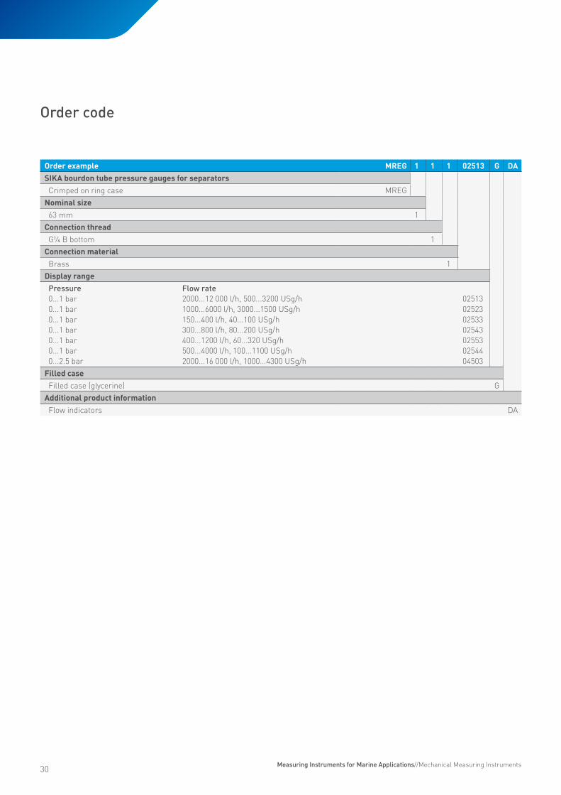
Order code
Order example MREG 1 1 1 02513 G DASIKA bourdon tube pressure gauges for separatorsCrimped on ring case MREG
Nominal size63 mm 1
Connection threadG¼ B bottom 1
Connection materialBrass 1
Display rangePressure Flow rate0...1 bar 2000...12 000 l/h, 500...3200 USg/h0...1 bar 1000...6000 l/h, 3000...1500 USg/h0...1 bar 150...400 l/h, 40...100 USg/h0...1 bar 300...800 l/h, 80...200 USg/h0...1 bar 400...1200 l/h, 60...320 USg/h0...1 bar 500...4000 l/h, 100...1100 USg/h0...2.5 bar 2000...16 000 l/h, 1000...4300 USg/h
02513025230253302543025530254404503
Filled caseFilled case (glycerine) G
Additional product informationFlow indicators DA
Measuring Instruments for Marine Applications//Mechanical Measuring Instruments

31
Measuring Instruments for Marine Applications//Mechanical Measuring Instruments
32
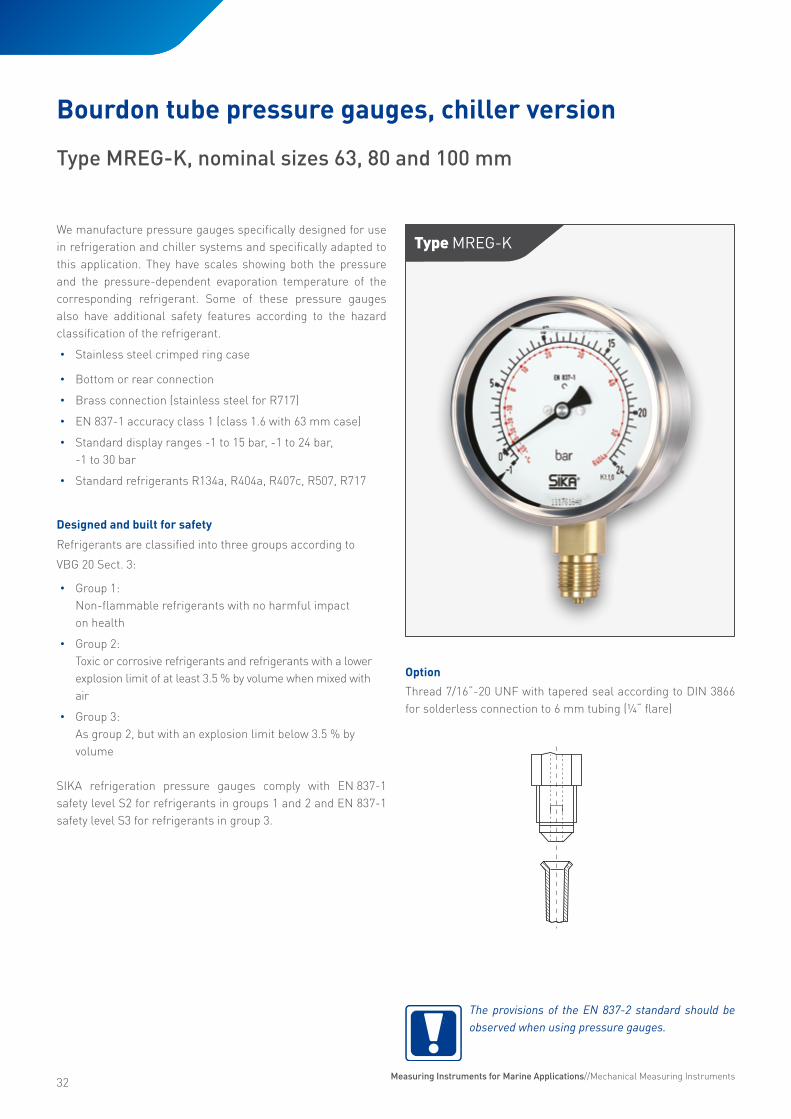
Type MREG-KWe manufacture pressure gauges specifically designed for use in refrigeration and chiller systems and specifically adapted to this application. They have scales showing both the pressure and the pressure-dependent evaporation temperature of the corresponding refrigerant. Some of these pressure gauges also have additional safety features according to the hazard classification of the refrigerant.
• Stainless steel crimped ring case
• Bottom or rear connection
• Brass connection (stainless steel for R717)
• EN 837-1 accuracy class 1 (class 1.6 with 63 mm case)
• Standard display ranges -1 to 15 bar, -1 to 24 bar, -1 to 30 bar
• Standard refrigerants R134a, R404a, R407c, R507, R717
Designed and built for safety
Refrigerants are classified into three groups according to
VBG 20 Sect. 3:
• Group 1: Non-flammable refrigerants with no harmful impact on health
• Group 2: Toxic or corrosive refrigerants and refrigerants with a lower explosion limit of at least 3.5 % by volume when mixed with air
• Group 3: As group 2, but with an explosion limit below 3.5 % by volume
SIKA refrigeration pressure gauges comply with EN 837-1 safety level S2 for refrigerants in groups 1 and 2 and EN 837-1 safety level S3 for refrigerants in group 3.
Bourdon tube pressure gauges, chiller version
Type MREG-K, nominal sizes 63, 80 and 100 mm
Option
Thread 7/16“-20 UNF with tapered seal according to DIN 3866 for solderless connection to 6 mm tubing (¼“ flare)
The provisions of the EN 837-2 standard should be observed when using pressure gauges.
Measuring Instruments for Marine Applications//Mechanical Measuring Instruments
33
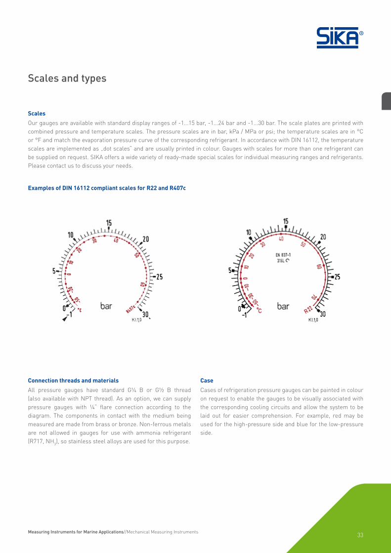
Scales
Our gauges are available with standard display ranges of -1...15 bar, -1...24 bar and -1...30 bar. The scale plates are printed with combined pressure and temperature scales. The pressure scales are in bar, kPa / MPa or psi; the temperature scales are in °C or °F and match the evaporation pressure curve of the corresponding refrigerant. In accordance with DIN 16112, the temperature scales are implemented as „dot scales“ and are usually printed in colour. Gauges with scales for more than one refrigerant can be supplied on request. SIKA offers a wide variety of ready-made special scales for individual measuring ranges and refrigerants. Please contact us to discuss your needs.
Connection threads and materials
All pressure gauges have standard G¼ B or G½ B thread (also available with NPT thread). As an option, we can supply pressure gauges with ¼“ flare connection according to the diagram. The components in contact with the medium being measured are made from brass or bronze. Non-ferrous metals are not allowed in gauges for use with ammonia refrigerant (R717, NH3), so stainless steel alloys are used for this purpose.
Scales and types
Examples of DIN 16112 compliant scales for R22 and R407c
Case
Cases of refrigeration pressure gauges can be painted in colour on request to enable the gauges to be visually associated with the corresponding cooling circuits and allow the system to be laid out for easier comprehension. For example, red may be used for the high-pressure side and blue for the low-pressure side.
Measuring Instruments for Marine Applications//Mechanical Measuring Instruments

34
Types and dimensions
Bottom connection Bottom connection with rear flange
Center back connection with front flangeLower back connection*
* Nominal size 80 mm has connection at centre back
Dimensions [mm]
NS D D1 a a1 b b1 b2 c c1 c2 d1 d2 d3 e G g h s s1 s3 SW
63 67 62 10 13 33 37 36 5 2 13 75 85 3.6 18 G¼ B 60 54 5 1 9.5 14
80 86 79 16 19 41.5 36 44 6 3 20 95 110 4.8 G½ B 74 76 5 1 9 22
100 106 99 20 23.5 54 54 57.5 6 3 20 116 132 4.8 30 G½ B 96 87 6 1 11.5 22
Measuring Instruments for Marine Applications//Mechanical Measuring Instruments
35
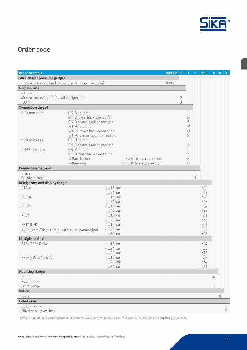
Order code
Order example MREGK 1 1 1 K13 0 0 0SIKA chiller pressure gauges
Crimped on ring case (standard with liquid-filled case) MREGKNominal size
63 mm80 mm (not available for all refrigerants)100 mm
123
Connection threadØ 63 mm case
Ø 80 mm case
Ø 100 mm case
G¼ B bottomG¼ B lower back connectionG¼ B center back connection¼ NPT bottom¼ NPT lower back connection¼ NPT center back connectionG½ B bottomG½ B center back connectionG½ B bottomG½ B lower back connection¼ flare bottom only with brass connection¼ flare rear only with brass connection
125MNS1212FU
Connection materialBrassStainless steel
13
Refrigerant and display rangeR134a
R404a
R407c
R507
R717 (NH3)
(NS 63 mm / NS 100 mm, with st. st. connection)
-1…15 bar-1…24 bar-1…15 bar-1…24 bar-1…15 bar-1…24 bar-1…15 bar-1…24 bar-1…15 bar-1…24 bar-1…30 bar
K13K14K16K17K39K41K42K43K01K02K03
Multiple scales*R12 / R22 / R134a
R22 / R134a / R404a
-1…15 bar-1…24 bar-1…30 bar -1…15 bar-1…24 bar-1…30 bar
K24K25K27K37K44K36
Mounting flangeNoneRear flangeFront flange
012
OptionNone 0
Filled caseUnfilled caseFilled case (glycerine)
0G
* Some refrigerant and display range options are not available with all case sizes. Please enquire regarding the required gauge types.
Measuring Instruments for Marine Applications//Mechanical Measuring Instruments


![CALIBRATION OF DIGITAL PRESSURE GAUGES, COMBINED …metrology-bg.org/fulltextpapers/360.pdf · pressure gauge and reference pressure according to [1]. Pressure gauges with class of](https://img.dokumen.tips/doc/110x75/5edfde0aad6a402d666b28ff/calibration-of-digital-pressure-gauges-combined-metrology-bgorgfulltextpapers360pdf.jpg)