Embed Size (px)
Citation preview

DSLIP 2015 Final Report DCC-SU-LAU Internship Program
Joanna Ding

2
ABSTRACT
The Dubai Contracting Company was founded in 1962 by the late
Hasan Abdallah Yabroudi. The company specializes in residential,
commercial, mixed-use buildings along with hospitality and leisure
complexes. The DCC-SU-LAU Internship Program started in 2008 in
honor of Dr. Samuel P. Clemence and Dr. James A. Mandel by DCC
CEO Mr. Abdallah Yabroudi. The internship brings together aspiring
civil engineers from Syracuse University and Lebanese American
University for a valuable learning experience in the booming city of
Dubai. In the summer of 2015, the DSLIP interns visited seven (7) DCC
project sites and ten (10) relevant offices/plants. This report will cover
all sites in descriptive and observational details in order to reflect
lessons learned from each visit.
3
Table of Contents JUMEIRAH VILLAGE RESIDENTIAL BUILDING .. . . . . . . . . . . . . . . . . . . . . . . . . . . . . . . . . . . . . . . . . . . . . . . . . . . . 5
INTRODUCTION .. . . . . . . . . . . . . . . . . . . . . . . . . . . . . . . . . . . . . . . . . . . . . . . . . . . . . . . . . . . . . . . . . . . . . . . . . . . . . . . . . . . . . . . . . . . . . . . . . . . . 5 PROJECT DETAILING . . . . . . . . . . . . . . . . . . . . . . . . . . . . . . . . . . . . . . . . . . . . . . . . . . . . . . . . . . . . . . . . . . . . . . . . . . . . . . . . . . . . . . . . . . . . . . 6 OUTSTANDING ISSUES . . . . . . . . . . . . . . . . . . . . . . . . . . . . . . . . . . . . . . . . . . . . . . . . . . . . . . . . . . . . . . . . . . . . . . . . . . . . . . . . . . . . . . . . . . . . 7
FAREED TOWER .. . . . . . . . . . . . . . . . . . . . . . . . . . . . . . . . . . . . . . . . . . . . . . . . . . . . . . . . . . . . . . . . . . . . . . . . . . . . . . . . . . . . . . . . . . . . . . . . 8
INTRODUCTION .. . . . . . . . . . . . . . . . . . . . . . . . . . . . . . . . . . . . . . . . . . . . . . . . . . . . . . . . . . . . . . . . . . . . . . . . . . . . . . . . . . . . . . . . . . . . . . . . . . . . 8 PROJECT DETAILING . . . . . . . . . . . . . . . . . . . . . . . . . . . . . . . . . . . . . . . . . . . . . . . . . . . . . . . . . . . . . . . . . . . . . . . . . . . . . . . . . . . . . . . . . . . . . . 9 SPECIAL FEATURES . . . . . . . . . . . . . . . . . . . . . . . . . . . . . . . . . . . . . . . . . . . . . . . . . . . . . . . . . . . . . . . . . . . . . . . . . . . . . . . . . . . . . . . . . . . . . . 10 HANDS-ON ACTIVITY . . . . . . . . . . . . . . . . . . . . . . . . . . . . . . . . . . . . . . . . . . . . . . . . . . . . . . . . . . . . . . . . . . . . . . . . . . . . . . . . . . . . . . . . . . . 11
BRIGHT START HOTEL . . . . . . . . . . . . . . . . . . . . . . . . . . . . . . . . . . . . . . . . . . . . . . . . . . . . . . . . . . . . . . . . . . . . . . . . . . . . . . . . . . . . . 12
INTRODUCTION .. . . . . . . . . . . . . . . . . . . . . . . . . . . . . . . . . . . . . . . . . . . . . . . . . . . . . . . . . . . . . . . . . . . . . . . . . . . . . . . . . . . . . . . . . . . . . . . . . . 12 PROJECT DETAILING . . . . . . . . . . . . . . . . . . . . . . . . . . . . . . . . . . . . . . . . . . . . . . . . . . . . . . . . . . . . . . . . . . . . . . . . . . . . . . . . . . . . . . . . . . . . 13 SPECIAL FEATURES . . . . . . . . . . . . . . . . . . . . . . . . . . . . . . . . . . . . . . . . . . . . . . . . . . . . . . . . . . . . . . . . . . . . . . . . . . . . . . . . . . . . . . . . . . . . . . 14 HANDS-ON ACTIVITY . . . . . . . . . . . . . . . . . . . . . . . . . . . . . . . . . . . . . . . . . . . . . . . . . . . . . . . . . . . . . . . . . . . . . . . . . . . . . . . . . . . . . . . . . . . 15
PRIVATE VILLA – PALM JUMEIRAH .. . . . . . . . . . . . . . . . . . . . . . . . . . . . . . . . . . . . . . . . . . . . . . . . . . . . . . . . . . . . . . . . . . 16
INTRODUCTION .. . . . . . . . . . . . . . . . . . . . . . . . . . . . . . . . . . . . . . . . . . . . . . . . . . . . . . . . . . . . . . . . . . . . . . . . . . . . . . . . . . . . . . . . . . . . . . . . . . 16 PROJECT DETAILING . . . . . . . . . . . . . . . . . . . . . . . . . . . . . . . . . . . . . . . . . . . . . . . . . . . . . . . . . . . . . . . . . . . . . . . . . . . . . . . . . . . . . . . . . . . . 17 SPECIAL FEATURES . . . . . . . . . . . . . . . . . . . . . . . . . . . . . . . . . . . . . . . . . . . . . . . . . . . . . . . . . . . . . . . . . . . . . . . . . . . . . . . . . . . . . . . . . . . . . . 18
KHALFAN VILLA .. . . . . . . . . . . . . . . . . . . . . . . . . . . . . . . . . . . . . . . . . . . . . . . . . . . . . . . . . . . . . . . . . . . . . . . . . . . . . . . . . . . . . . . . . . . . . . 19
INTRODUCTION .. . . . . . . . . . . . . . . . . . . . . . . . . . . . . . . . . . . . . . . . . . . . . . . . . . . . . . . . . . . . . . . . . . . . . . . . . . . . . . . . . . . . . . . . . . . . . . . . . . 19 PROJECT DETAILING . . . . . . . . . . . . . . . . . . . . . . . . . . . . . . . . . . . . . . . . . . . . . . . . . . . . . . . . . . . . . . . . . . . . . . . . . . . . . . . . . . . . . . . . . . . . 20 SPECIAL FEATURES . . . . . . . . . . . . . . . . . . . . . . . . . . . . . . . . . . . . . . . . . . . . . . . . . . . . . . . . . . . . . . . . . . . . . . . . . . . . . . . . . . . . . . . . . . . . . . 21 HANDS-ON ACTIVITY . . . . . . . . . . . . . . . . . . . . . . . . . . . . . . . . . . . . . . . . . . . . . . . . . . . . . . . . . . . . . . . . . . . . . . . . . . . . . . . . . . . . . . . . . . . 21
FOUR SEASONS HOTEL AND RESORT .. . . . . . . . . . . . . . . . . . . . . . . . . . . . . . . . . . . . . . . . . . . . . . . . . . . . . . . . . . . . . 22
INTRODUCTION .. . . . . . . . . . . . . . . . . . . . . . . . . . . . . . . . . . . . . . . . . . . . . . . . . . . . . . . . . . . . . . . . . . . . . . . . . . . . . . . . . . . . . . . . . . . . . . . . . . 22 PROJECT DETAILING . . . . . . . . . . . . . . . . . . . . . . . . . . . . . . . . . . . . . . . . . . . . . . . . . . . . . . . . . . . . . . . . . . . . . . . . . . . . . . . . . . . . . . . . . . . . 23 SPECIAL FEATURES . . . . . . . . . . . . . . . . . . . . . . . . . . . . . . . . . . . . . . . . . . . . . . . . . . . . . . . . . . . . . . . . . . . . . . . . . . . . . . . . . . . . . . . . . . . . . . 24 OUTSTANDING ISSUES . . . . . . . . . . . . . . . . . . . . . . . . . . . . . . . . . . . . . . . . . . . . . . . . . . . . . . . . . . . . . . . . . . . . . . . . . . . . . . . . . . . . . . . . . . 26

4
BURJ AL SALAM .. . . . . . . . . . . . . . . . . . . . . . . . . . . . . . . . . . . . . . . . . . . . . . . . . . . . . . . . . . . . . . . . . . . . . . . . . . . . . . . . . . . . . . . . . . . . . . 27
INTRODUCTION .. . . . . . . . . . . . . . . . . . . . . . . . . . . . . . . . . . . . . . . . . . . . . . . . . . . . . . . . . . . . . . . . . . . . . . . . . . . . . . . . . . . . . . . . . . . . . . . . . . 27 PROJECT DETAILING . . . . . . . . . . . . . . . . . . . . . . . . . . . . . . . . . . . . . . . . . . . . . . . . . . . . . . . . . . . . . . . . . . . . . . . . . . . . . . . . . . . . . . . . . . . . 28 SPECIAL FEATURES . . . . . . . . . . . . . . . . . . . . . . . . . . . . . . . . . . . . . . . . . . . . . . . . . . . . . . . . . . . . . . . . . . . . . . . . . . . . . . . . . . . . . . . . . . . . . . 29 OUTSTANDING ISSUES . . . . . . . . . . . . . . . . . . . . . . . . . . . . . . . . . . . . . . . . . . . . . . . . . . . . . . . . . . . . . . . . . . . . . . . . . . . . . . . . . . . . . . . . . . 30
ERGA PROGRESS ENGINEERING CONSULTANTS .. . . . . . . . . . . . . . . . . . . . . . . . . . . . . . . . . . . . . . . . . . . . 31
ROLEX TOWER .. . . . . . . . . . . . . . . . . . . . . . . . . . . . . . . . . . . . . . . . . . . . . . . . . . . . . . . . . . . . . . . . . . . . . . . . . . . . . . . . . . . . . . . . . . . . . . . . 31
READY MIX BETON .. . . . . . . . . . . . . . . . . . . . . . . . . . . . . . . . . . . . . . . . . . . . . . . . . . . . . . . . . . . . . . . . . . . . . . . . . . . . . . . . . . . . . . . . . 32
EXOVA .. . . . . . . . . . . . . . . . . . . . . . . . . . . . . . . . . . . . . . . . . . . . . . . . . . . . . . . . . . . . . . . . . . . . . . . . . . . . . . . . . . . . . . . . . . . . . . . . . . . . . . . . . . . . 33
ALBONIAN INTERNATIONAL .. . . . . . . . . . . . . . . . . . . . . . . . . . . . . . . . . . . . . . . . . . . . . . . . . . . . . . . . . . . . . . . . . . . . . . . . . . 33
E.CONSTRUCT .. . . . . . . . . . . . . . . . . . . . . . . . . . . . . . . . . . . . . . . . . . . . . . . . . . . . . . . . . . . . . . . . . . . . . . . . . . . . . . . . . . . . . . . . . . . . . . . . 34
DCC WORKSHOP .. . . . . . . . . . . . . . . . . . . . . . . . . . . . . . . . . . . . . . . . . . . . . . . . . . . . . . . . . . . . . . . . . . . . . . . . . . . . . . . . . . . . . . . . . . . . 35

5
Jumeirah Village Residential Building
Introduction
The Jumeirah Village Residential Building is a mid-rise residential building located in Al
Barsha South 4th, Dubai, U.A.E. The design-build project is developed by Rambyk
Properties Limited and designed by Erga Progress Engineering Consultants. The
original contract is valued at AED 53,543,000. The total plot area for the development
is 2,377 m2, and the total built-up area is 10,880.40 m2. The construction process will
last 16 months and be completed in July of 2016. Delays due to unwarranted
dewatering are expected to push back the completion date.
The B+G+5+R residential building consists of the following elements:
• Parking areas on the basement and ground level
• Retail areas on ground floor
• 61 apartments with balcony space from ground to 5th floor, including 31 one-
bedroom apts. and 30 two-bedroom apts.
• Two (2) passenger elevators
• One (1) gymnasium on 5th floor
• One (1) swimming pool with leisure deck at roof level
Figure 1. Jumeriah Vil lage Res identia l Building Rendering
6
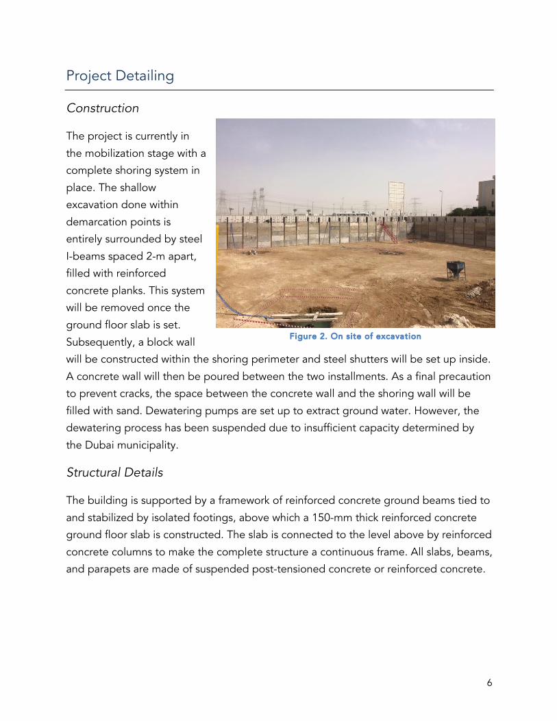
Project Detailing
Construction
The project is currently in
the mobilization stage with a
complete shoring system in
place. The shallow
excavation done within
demarcation points is
entirely surrounded by steel
I-beams spaced 2-m apart,
filled with reinforced
concrete planks. This system
will be removed once the
ground floor slab is set.
Subsequently, a block wall
will be constructed within the shoring perimeter and steel shutters will be set up inside.
A concrete wall will then be poured between the two installments. As a final precaution
to prevent cracks, the space between the concrete wall and the shoring wall will be
filled with sand. Dewatering pumps are set up to extract ground water. However, the
dewatering process has been suspended due to insufficient capacity determined by
the Dubai municipality.
Structural Details
The building is supported by a framework of reinforced concrete ground beams tied to
and stabilized by isolated footings, above which a 150-mm thick reinforced concrete
ground floor slab is constructed. The slab is connected to the level above by reinforced
concrete columns to make the complete structure a continuous frame. All slabs, beams,
and parapets are made of suspended post-tensioned concrete or reinforced concrete.
Figure 2. On site of excavat ion

7
Finishes
On the exterior, the structure is clad in thermal insulated blocks finished in plaster with
paint, aluminum window frames, doors and louvres pre-finished in paint, as well as
tempered glass in tinted and hermetically sealed double glazed units up to 34-mm
thick. The roofs are layered from concrete tiles, insulation, screed, down to the bottom
waterproofing membrane. Balcony balustrading is tempered-laminated glass and
pergola is galvanized steel on powder-coated aluminum cladding.
On the interior, standard concrete block construction with plaster finish constitutes the
internal partitioning system. Gypsum board suspended ceilings are adopted with
ceiling voids finished in Gypsum plaster to conceal all MEP services. Floors are
generally covered in tiles resting on the cement screed base.
Outstanding Issues
The unexpected halt to dewatering and the resulting delay in overall project
completion time has been the most
outstanding issue on the project site. The
project cannot be moved forward without
the enabling works fully finished and idle
labor is kept on the contractor’s payroll.
However, the nature of the delay dictates
that the contractor has the right to file for an
EOT or extension of time.
Figure 3. Excavat ion reveal ing water table level

8
Fareed Tower Introduction
The Fareed Tower is a high-rise luxury
residential building located in Business Bay,
Dubai, U.A.E. The building project is
developed by National Trading & Developing
Est. and carried out in design by dxb.Lab
Architecture as well as Erga Progress
Engineering Consultants. The original
contract is valued at AED 109,000,000. This
development consists of a total plot area of
2,141 m2 and a total built-up area of 18,119
m2. The construction is planned to take place
over a period of 22 months and to be
completed in April of 2016.
The 3B+G+22+R luxury residential building consists of the following elements:
• Parking areas on the three basement levels
• 20 apartments located on 20 separate levels
• One (1) smaller apartment on level 12 (including a technical area)
• Two (2) car lifts operating between the ground level and all three basement
levels
• One (1) swimming pool at roof level
• One (1) gymnasium on level 2
Figure 4. Fareed Tower Rendering

9
Project Detailing
Construction
The project is currently in the concrete works stage with a complete substructure and a
superstructure in progress. The dewatering process has been completed and the
structure is erected up to the 8th level. Plastering is in progress Due to project capacity
demand, the concrete used for cast-in-place columns are double pumped to higher
elevations.
Structural Details
In an effort to highlight the individuality of the
building design, the below-ground structures—
including the basement, podium, and canopy—
form a 5-sided plot shape while the tower itself is
rectangular. This is done primarily to suit end use
and lower the development cost without
diminishing the project’s originality.
The tower rests on a raft foundation and standard
shoring piles. The piles are only installed on
three of the five sides of the plot due to existing
ground levels and the project’s close proximity to
the road. Reinforced concrete retaining walls are
constructed at the basement level. The concrete
columns in the superstructure are made from
reinforced concrete and are constructed with
corbels to support the 200-mm thick precast
concrete floor slabs topped by a 6-mm layer of wire
mesh and a 75-mm layer of concrete. The columns
are integrated into the façade, providing sufficient
vertical structural support on the perimeter to
optimize the span of unobstructed internal space.
Core columns and shear walls have been poured to resist seismic and wind loads.
Figure 6. Steel reinforcing bars for precast concrete slabs
Figure 5. Shear walls in construction

10
Finishes
On the exterior, the façade is consisted of a curtain walling system from ground to
second floor level, above which individual glazing panels will be installed. Additional
aluminum features and integrated lighting are to be used to soften its appearance. The
materials used to finish entrance doors, vertical louvres, and balcony railings are
tempered glass and powder coated aluminum.
On the interior, all concrete block walls are to be constructed with autoclaved aerated
concrete (AAC) lightweight blocks to reduce the overall dead load. The block wall
finishes are standard plastering and painting. Standard gypsum boards are used for the
suspended ceilings with a 3.85-m story height to conceal all MEP services. Floors are in
engineered solid wood parquet with walnut joinery finishes to match the doors,
skirting, and cupboards. Common areas such as the lifts and the entrance lobby will be
enhanced with dimmed lighting and marble flooring. Basement floors will be layered
with traffic deck coating. Reflective pool features, glass partitions, and stone clad
walling will also be installed in the lobby. In the apartments, the bathrooms will have
high-end fixtures with marble finished walls and floors, while the kitchens will be
equipped with Siemens appliances and European cupboards, work-tops, and
accessories.
Special Features
While on site, the closely spaced concrete
columns become one of the most prominent
features. From a structural standpoint, the size
and amount of the concrete columns as vertical
support seem excessive for any type of dead or
live load. Instead, these columns act as distinct
architectural elements on the building façade as
cut-off points for window units. This particular
feature is unique in that it shifts the function of
traditionally structural elements like concrete
columns to an architectural one. Figure 7. Tightly knitted column perimeter

11
The use of car lifts in lieu of traditional car ramps is another special feature employed in
the building construction. The innovative car lifts are designed to maximize parking
spaces by eliminating the use of intra-level ramps that are traditionally used for vehicles
to travel between different basement levels. These hydraulic lifts used to raise or lower
cars directly onto different floor levels are both time and space efficient and are
beneficial to both the developer and the residents. The additional automatic
gatekeeping security system makes this development a prime example of IT
connectivity’s increasingly significant role in civil construction projects.
Hands-on Activity
Concrete block work
For a first-hand experience in construction of a building project, the interns were given
the opportunity of laying block work with lightweight AAC blocks on site. In order to
satisfy all standards, the process requires a specific set of techniques—marking,
preparing mortar, and fixing blocks. Reference points marked on site by surveyors were
set up and aligned with fishing lines to guide the intern’s block work. The markings are
transcribed from the construction
drawings are pivotal in precise
placement of block walls. Bags of mortar
consisted of cement and sand is poured
along with enough water to create a
workable mix. The mix should have an
even consistency and smoothly fill in the
100-mm wide gaps between the
concrete blocks. Once the mortar is set
and an entire row of blocks is placed,
inspection and adjustment of the block
alignment is carried out before placing the next layer.
Figure 8. DSLIP intern laying block work
12
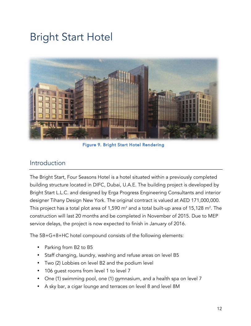
Bright Start Hotel
Introduction
The Bright Start, Four Seasons Hotel is a hotel situated within a previously completed
building structure located in DIFC, Dubai, U.A.E. The building project is developed by
Bright Start L.L.C. and designed by Erga Progress Engineering Consultants and interior
designer Tihany Design New York. The original contract is valued at AED 171,000,000.
This project has a total plot area of 1,590 m2 and a total built-up area of 15,128 m2. The
construction will last 20 months and be completed in November of 2015. Due to MEP
service delays, the project is now expected to finish in January of 2016.
The 5B+G+8+HC hotel compound consists of the following elements:
• Parking from B2 to B5
• Staff changing, laundry, washing and refuse areas on level B5
• Two (2) Lobbies on level B2 and the podium level
• 106 guest rooms from level 1 to level 7
• One (1) swimming pool, one (1) gymnasium, and a health spa on level 7
• A sky bar, a cigar lounge and terraces on level 8 and level 8M
Figure 9. Br ight Start Hotel Rendering
13
• Restaurants, bars, and coffee lounges on the podium level
• Meeting rooms on level B2
• Staff changing, laundry, washing and refuse areas on level B5
• Mechanical/technical rooms and staff areas on the hypocaust level
Project Detailing
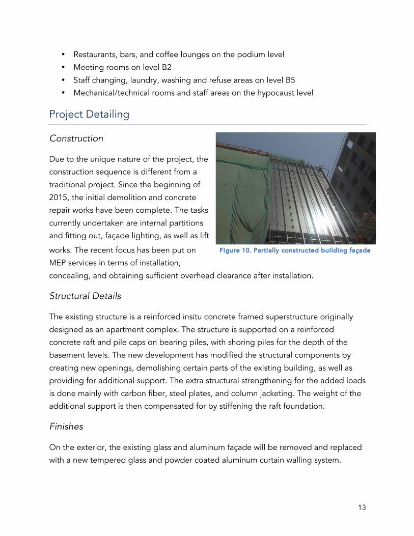
Construction
Due to the unique nature of the project, the
construction sequence is different from a
traditional project. Since the beginning of
2015, the initial demolition and concrete
repair works have been complete. The tasks
currently undertaken are internal partitions
and fitting out, façade lighting, as well as lift
works. The recent focus has been put on
MEP services in terms of installation,
concealing, and obtaining sufficient overhead clearance after installation.
Structural Details
The existing structure is a reinforced insitu concrete framed superstructure originally
designed as an apartment complex. The structure is supported on a reinforced
concrete raft and pile caps on bearing piles, with shoring piles for the depth of the
basement levels. The new development has modified the structural components by
creating new openings, demolishing certain parts of the existing building, as well as
providing for additional support. The extra structural strengthening for the added loads
is done mainly with carbon fiber, steel plates, and column jacketing. The weight of the
additional support is then compensated for by stiffening the raft foundation.
Finishes
On the exterior, the existing glass and aluminum façade will be removed and replaced
with a new tempered glass and powder coated aluminum curtain walling system.
Figure 10. Partially constructed building façade

14
On the interior, all AAC lightweight block walls are to be finished with plaster and
paint. The block walls finishes are standard plastering and painting. Ceilings are
suspended plain gypsum board ceilings finished with emulsion paint to conceal all MEP
services. Carpet flooring is used in guest rooms and corridors (some rooms are also to
receive parquet flooring with marine plywood backing), while Novelda cream limestone
is used in the bathrooms and marble in the main lobbies. The guest room walls are to
be finished in plaster under a layer of stucco, and finally covered in fabric wall covering;
bathrooms use the same cream limestone; and the corridors will receive vinyl
wallpapers.
Special Features
In order to reduce noise traveling between adjacent guest
rooms, insulation panels made of soft rubber material are
inserted between two 100-mm thick lightweight AAC block to
make up the soundproofing walls separating all guest rooms.
This insulation process is also done in the flooring panels to
muffle noises created by rapid movements. This unique feature
is included to specifically suit the building’s need as a hotel.
The finished look of a standard guest room is demonstrated
through an extensively decorated and neatly arranged mock up
room. The mock up room serves as a model unit showcasing the
materials and finishes to the client and the designer while
simultaneously providing as a sample for future construction and layout.
Figure 11. Insulat ion layer between block
wall panels
Figure 12. Mock-up room display
15
Hands-on Activity
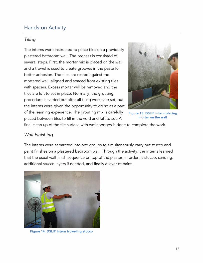
Tiling
The interns were instructed to place tiles on a previously
plastered bathroom wall. The process is consisted of
several steps. First, the mortar mix is placed on the wall
and a trowel is used to create grooves in the paste for
better adhesion. The tiles are rested against the
mortared wall, aligned and spaced from existing tiles
with spacers. Excess mortar will be removed and the
tiles are left to set in place. Normally, the grouting
procedure is carried out after all tiling works are set, but
the interns were given the opportunity to do so as a part
of the learning experience. The grouting mix is carefully
placed between tiles to fill in the void and left to set. A
final clean up of the tile surface with wet sponges is done to complete the work.
Wall Finishing
The interns were separated into two groups to simultaneously carry out stucco and
paint finishes on a plastered bedroom wall. Through the activity, the interns learned
that the usual wall finish sequence on top of the plaster, in order, is stucco, sanding,
additional stucco layers if needed, and finally a layer of paint.
Figure 13. DSLIP intern placing mortar on the wall
Figure 14. DSLIP intern troweling stucco

16
Private Villa – Palm Jumeirah
Introduction
The private villa is a single family dwelling situated on Frond N of the Palm Jumeirah in
Jumeirah 381, Dubai, U.A.E. The turnkey project is built for Mr. Abdul Hamied Ahmed
Qassim Seddiqi and designed by AS.Architecture-Studio and Erga Progress
Engineering Consultants. The original contract is valued at AED 27,500,000. This
development consists of a total plot area of 1,581.21 m2 and a total built-up area of
1177.3 m2 with 153 m2 of service/garage areas. The construction will take place for 18
months and be completed in October of 2015.
The G+1 villa consists of the following units:
• Two (2) living rooms on the ground level
• One (1) guest bedroom and one (1) children’s room on the ground level
• One (1) dining room on the ground level
• One (1) maid’s room with WC, shower, and kitchen on the ground level
• One (1) master suite with dressing room and library on level one
Figure 15. Palm Jumeirah Private Vil la Render ing

17
• Four (4) bedroom suites on level one
• One (1) family room and a gallery area on level one
• One (1) passenger lift with a six-passenger load capacity
• A two-car garage on the ground level
• A roof terrace and technical room on roof level
• A private beach, terracing/patio areas, and landscaping on the ground level
• Perimeter walling, gates, and fencing
Project Detailing
Construction
The project construction is in the façade and finishing stage with all concrete works in
place.
Structural Details
The villa rests on a 150-mm thick reinforced concrete ground floor slab supported by a
framework of reinforced concrete ground beams. The ground beams are tied into and
stabilized by pile cap foundations on 48 500-mm diameter piles driven to a depth of 16
meters. All floor and roof slabs, beams, and parapets are post-tensioned and
reinforced concrete, supported between the levels by reinforced concrete columns to
make the complete structure a continuous frame. The technical room on the roof is in
structural steel and concrete.
Façade Details
The building façade is consisted of
thermal insulated blocks finished in
limestone panels that are fluted in
the living room pod to create a
checker-board effect, aluminum
window frames, doors, and louvres
finished in baked on paint, and glass
up to 34-mm thick hermetically
sealed double glazed units tempered and tinted to meet highest performance Figure 16. Vil la façade

18
standards. The use of full-height glass panels connects the building’s interior
seamlessly to the outside environment. Roofs are concrete tiled on a layer of insulation
on a layer of screed on a layer of waterproofing membrane to provide protection
against both foot traffic and heat transference. Balcony balustrading is monolithic
tempered-laminated glass up to 19-mm thick.
Finishes
Internal partitioning is concrete block
construction with a plaster finish. The
walls in the formal living room are clad in
oakwood, while the casual living room is
finished in walnut. Ceilings on the interior
are gypsum board suspended ceilings
with bulkhead returns to facilitate the full
height external glazing. External ceilings are finished with calcium silicate for moisture
resistance. Floors have cement screed bases.
Stainless steel is used between different
finishes and marble finishes are
bookmatched. Waterproofing treatment is
applied to the ground floor as a safety
precaution against flooding.
Special Features
The villa is equipped with an Otis gearless passenger lift that has a load capacity of 450
kilograms, the equivalent of approximately 6 passengers. The cabin will be finished
with brush stainless steel for the walls and front return, safety glass framed in brush
stainless steel for the door, round type stainless steel finish for the handrail, Grigio vagli
scuro honed tiles for the floor, and walnut wood veneer with LED strip light and
spotlight for the ceiling.
Figure 17. Marble bookmatching
Figure 18. Shear resistant gypsum board ceil ing

19
Khalfan Villa
Figure 19. Rendering of Khalfan Vil la
Introduction
The Khalfan villa is a single family dwelling situated in Umm Suqeim, Dubai, U.A.E. The
project is built for Mr. Osama Ibrahim Ahmad Seddiqi and designed by Erga Progress
Engineering Consultants. The original contract is valued at AED 4,275,000. The villa
has a total plot area of 1393.5 m2 and a total built-up area of 505.9 m2 with 40.7 m2 of
service/garage areas. Project construction will last 12 months and is expected to finish
in November of 2015. Due to efficient planning and execution, the project will be
completed in June of 2015, nearly four months ahead of the predetermined schedule.
The G+1 villa consists of the following units:
• One (1) double height living room on the ground level
• One (1) foyer/office on the ground level
• One (1) kitchen and one (1) dining room on the ground level
• One (1) maid’s room with WC, shower, and kitchen on the ground level
• One (1) master suite with dressing room on level one
• Three (3) bedroom suites on level one
• One (1) family room on level one
• One (1) passenger lift with a six-passenger load capacity
• One (1) two-car garage on the ground level
20
• One (1) swimming pool and a roof terrace on external ground level
• Landscaping on the ground level
• Roof deck on the roof level
• Perimeter walling, gates, and fencing
Project Detailing
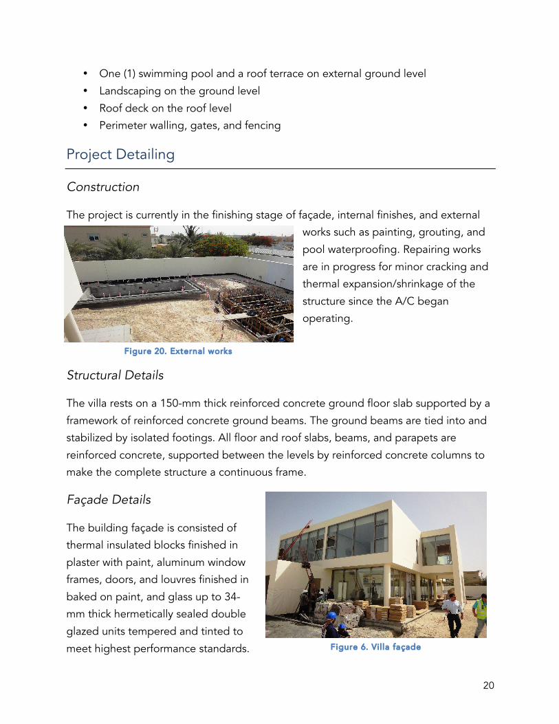
Construction
The project is currently in the finishing stage of façade, internal finishes, and external
works such as painting, grouting, and
pool waterproofing. Repairing works
are in progress for minor cracking and
thermal expansion/shrinkage of the
structure since the A/C began
operating.
Structural Details
The villa rests on a 150-mm thick reinforced concrete ground floor slab supported by a
framework of reinforced concrete ground beams. The ground beams are tied into and
stabilized by isolated footings. All floor and roof slabs, beams, and parapets are
reinforced concrete, supported between the levels by reinforced concrete columns to
make the complete structure a continuous frame.
Façade Details
The building façade is consisted of
thermal insulated blocks finished in
plaster with paint, aluminum window
frames, doors, and louvres finished in
baked on paint, and glass up to 34-
mm thick hermetically sealed double
glazed units tempered and tinted to
meet highest performance standards. Figure 6. Vil la façade
Figure 20. External works

21
The roofs are concrete tiled on a layer of insulation on a layer of screed on a layer of
waterproofing membrane to provide protection against both foot traffic and heat
transference.
Internal Finishes
Internal partitioning is concrete block construction with a plaster finish. Ceilings are
gypsum board suspended ceilings with bulkhead returns to facilitate the full height
external glazing. Floors have cement screed bases. Door frames and doors are lime
oak. The staircase and the first story corridor have
glass balustrading. The extensive use of glass on
the interior required installation of floor plugs.
Kitchens are equipped with white quartz
countertops, laminate cabinets with internal
lighting, and high-end Siemens appliances. The
bedrooms are finished with parquet flooring and
skirting. Wardrobes have white lacquer doors and
internal sensor lights. The side roof deck is lined
with calcium silica for insulation.
Special Features
The Khalfan Villa is built as an exact replica of the private villa located in Al Barsha as a
means of value engineering to expedite the completion of the project and eliminate
design complications. The villa is constructed for lease by the client and employs
neutral construction elements to suit a wide variety of interest. The garage door is also
removed due to existing perimeter fencing as a part of the contractor’s commitment to
value engineering.
Hands-on Activity
The interns were instructed to make a list of snags and outstanding works from each
room in the villa.
Figure 21. Inter ior glass finishes

22
Four Seasons Hotel and Resort
Figure 22. Outdoor view of the resort
Introduction
The luxurious beach resort comprised of a five-star hotel and ancillary buildings is
located on Jumeirah Beach Road, Dubai, U.A.E. The project is developed by H.H.
Investment and Development, operated by Bright Start L.L.C., and designed by DSA
Architects International along with Hyder Consulting Middle East Ltd. The original
contract is valued at AED 354,000,000, with AEW 187,000,000 being provisional sums
under the client’s control. This development consists of a total built-up area of 60,000
m2. The construction process takes place over a period of 25 months and is expected
to be complete in March 2014 according to the program of works. Due to various
changes of order for both construction material and landscaping design along with
sub-contractor inefficiencies, the project was delayed by 6 months. However, the hotel
operation commenced in December as scheduled.
The resort consists of the following units:
• 223 guest rooms including two (2) presidential suites and one (1) royal suite
• In-house restaurants, bars, and lounges
• Three (3) swimming pools including two (2) outdoors and on (1) in-house
• One (1) pool restaurant

23
• Three (3) ballrooms including one (1) in separate compound and two (2) in-house
• Cabanas and super-cabanas for hotel guest access only
• Private beach for hotel guest use only
• Outdoor facilities include lounge areas, grass areas, and tennis courts
• Underground car park
Project Detailing
Structural Details
The foundation of the main V-shaped hotel building consists of 939 piles, each 750 mm
in diameter and 22 m in length. The foundation is topped with pile caps and floor slabs
on grade under all wings of the compound. The structure is made of reinforced
concrete throughout, with the exception of the ball room in the North wing. Steel is
used in the ball room to increase its span and provide for a sizable space for large scale
events. The underground car park is formed on a 450-mm thick reinforced concrete raft
foundation. Retaining walls that support the basement area are cast-in-place reinforced
concrete.
Façade Details
The façade of the structure
is cavity-wall construction
with a plaster finish made
from glass reinforced
concrete (GRC) and carved
plaster. The GRC columns
are non-structural and are
constructed to give the
project a distinct theme.
The flat roof areas are
insulated with waterproofing membrane underneath a layer of aggregate. The pitched
roof areas are covered in themed roof tiles for aesthetic purposes. Other elements such
as special cast-aluminum balconies with paint finish and aluminum windows also reflect
the antiqued theme. Solar neutral glass is installed to reduce heat transference into the
building. Acoustic treatment is also done to minimize external noise distractions.
Figure 23. Bui lding façade and soft landscaping

24
Internal Finishes
All internal walls are plaster finished solid block construction, with the exception of the
ball room in the North wing. The steel structure is finished with high performance
insulation to provide the facility with a sound acoustic environment. Entrance finishes
include marble, themed carpets, and mosaics on the floor, polished plaster and
wallpaper on the walls, and gypsum and paint on the ceiling. Public areas throughout
the hotel have a combination of marble and carpet flooring, decorative paint finish and
timber paneling on the walls, and painted gypsum
ceiling with decorative mouldings.
Lifts are finished with marble flooring and timber
paneling on the walls. Flooring around the indoor
pool consists of black absolute granite specially
treated to be anti-slippery. Public bathrooms are
clad in anti-fungus and fire-rated vinyl wallpaper
for maintenance and safety purposes. Kitchens
are finished in vinyl with no 90° corners to suit the
maintenance needs of the facility. Wall guards are
installed to protect the kitchen walls from heavy
moving equipment.
In the guest rooms, flooring consists of themed
carpeting, marbled wet areas, and ceramic tiles on
the balconies. Wall finishes are paint, wallpaper, timber paneling, and marble. False
ceilings installed to conceal MEP services are finished in paint and trimmed with
decorative gypsum and timber cornices. The doors, wardrobes, wall paneling, and
vanity units are all timber with a factory applied paint finish.
Special Features
Upon entrance, guests encounter a full height glass window made of a 2-ton glass
panel from Belgium leading out to the beach area. The weight of the glass panel
required additional reinforcement in the surrounding wall.
Figure 24. Finishes in lobby area
25
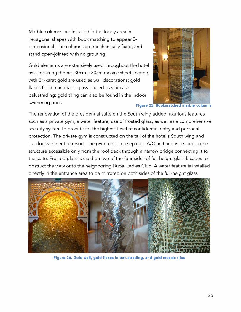
Marble columns are installed in the lobby area in
hexagonal shapes with book matching to appear 3-
dimensional. The columns are mechanically fixed, and
stand open-jointed with no grouting.
Gold elements are extensively used throughout the hotel
as a recurring theme. 30cm x 30cm mosaic sheets plated
with 24-karat gold are used as wall decorations; gold
flakes filled man-made glass is used as staircase
balustrading; gold tiling can also be found in the indoor
swimming pool.
The renovation of the presidential suite on the South wing added luxurious features
such as a private gym, a water feature, use of frosted glass, as well as a comprehensive
security system to provide for the highest level of confidential entry and personal
protection. The private gym is constructed on the tail of the hotel’s South wing and
overlooks the entire resort. The gym runs on a separate A/C unit and is a stand-alone
structure accessible only from the roof deck through a narrow bridge connecting it to
the suite. Frosted glass is used on two of the four sides of full-height glass façades to
obstruct the view onto the neighboring Dubai Ladies Club. A water feature is installed
directly in the entrance area to be mirrored on both sides of the full-height glass
Figure 25. Bookmatched marble columns
Figure 26. Gold wall, gold flakes in balustrading, and gold mosaic t i les

26
window. Considering the temperature difference on the two sides of the glass window,
the cutout glass panel design around the full
water feature is eliminated. Instead, a full glass
panel is installed and the water feature is cut in
half and aligned as one. Access to the corridor
outside the suite is restricted. The guest has the
option of bypassing public entrance and
entering through a private lift that leads out to a
private passageway directly opening up to the
suite through an aluminum sliding door.
Outstanding issues
The landscaping work on the exterior retaining walls constituted a major problem in
the later stages of construction. According to the
program of works, approximately 600 m2 of stones was
required to be put up each day and there was neither
sufficient stone supply nor labor force to fill the quota.
In order to resolve the issue, plaster mortar/concrete
mix was poured and molded into irregular stone
shapes and the “stones” were finished with spray paint
to create natural color tones. The solution not only met
the client’s specifications and reduced the time of
installation, but also proved to be very cost efficient.
Figure 27. Pr ivate gym in presidentia l suite
Figure 28. Spray painted concrete "stones"

27
Burj Al Salam Introduction
The mixed-use development comprised of
three adjoined towers and a separate car
park building is located in Trade Centre First,
Dubai, U.A.E. The project is developed by
Abdul Salam Al Rafi Group and designed by
Erga Progress Engineering Consultants along
with Meinhardt Consulting Engineers. The
original contract is valued at AED
849,992,250. The towers consist of a total
plot area of 6,283 m2 and a total built-up
area of 292,144 m2 while the car park has a
plot area of 3,025 m2 and a built-up area of
44,695 m2. The construction process takes
place over a period of 930 days and is
expected to be complete in March 2013
according to the program of works. Due to the employer’s subsequent agreement with
the hotel operator on structural alteration works and finishes, both the value and the
duration of the project have been prolonged. While the residential and the office
towers were finished on time, the hotel tower was delayed for approximately 20
months and began operation in December 2014.
The mixed-use development consists of the following units:
• Three (3) 4B+G+54 building towers
• One (1) 4B+12 car park structure connected to main building by foot and
vehicular bridges
• One (1) pool and one (1) gym on the roof of parking structure
• 54 stories of 510 apartments in the residential tower
• 50 stories of 281 offices in the office tower
• 54 stories of 483 guest rooms and 180 serviced apartments in the hotel tower
• 48 lifts in total in the main tower building
Figure 29. Rendering of Burj Al Salam

28
• Technical floors on level 30 and level 54 in all three towers
• One (1) swimming pool, one (1) gymnasium, and one (1) play area in the hotel
tower
• Four (4) basement and two (2) podium parking levels with 798 parking spaces
• Additional 1,170 parking spaces are offered in the car park structure
Project Detailing
Structural Details
Both the main tower building and the car park structure are supported by a raft
foundation on piles with reinforced concrete retaining walls at the basement levels. The
building superstructure is reinforced concrete, with post-tensioned slabs from level 7 to
the roof level for additional head room. The car park building has a structural steel
framed superstructure with steel decking topped by 7-cm concrete screed. Due to the
existing 6-story structure, steel reinforcement and carbon fiber strengthening are done
on the structure.
Façade Details
Unitized curtain walling glass in high
performance aluminum framed glazing and
travertine stone paneling is used for the
building façade. Distinctive features include
stainless steel louvers and LED lighting
boxes. The car park structure is clad in
precast concrete with 7-cm concrete screed
covered in fireproofing paint. Stainless steel,
glass, and powder coated aluminum is used
for entrance doors, vertical louvers, link
bridges, balcony partitions and balustrades.
Internal Finishes
All internal walls are lightweight block work with plaster and a layer of decorative paint
on top. In enclosed public areas, ceilings are suspended gypsum and floors are
Figure 30. Bui lding façade

29
typically porcelain with mosaic tiling in wet areas. The
residential lobby area has book-matched Calcutta
marble on the floor and the countertops. The partition
wall and decorative wall paneling in the entrance area
are white onyx with backlight with surrounding crown-
cut walnut veneer walls. Crown-cut walnut veneer
finish is also used on doors, wardrobes, vanities and
kitchen cabinets. The apartments are supplied with
high-end Siemens kitchen appliances and lift-and-slide
balcony doors for safety reasons.
Typical flooring in the office tower consists of
timber, plywood, acoustic material for
soundproofing, 50 mm of screed, and epoxy
and waterproofing treatment. The office lobby is
clad in gray marquina marble and decorated
with titanium paint finished steel water features.
Mirrors are used in certain ceiling areas to create
a sense of large open space. All doors are fire
rated at 60 minutes throughout the towers as a
safety precaution. In the technical room, all
pipes ducts resting on the floor are on elevated
grounds to control vibration from MEP services.
The floor on the technical level is acoustically
treated for the same consideration.
Special Features
Although the building is a continuous structure operating under a central building
manager, it is divided into three towers of different end uses. The division required
additional civil works on top of the 6-story existing structure, careful planning of MEP
services, as well as safety precautions such as intricate evacuation route designation.
The lift system used in the tower is designed in Switzerland and employs the
Destination Floor Reservation System (DFRS) where passengers are grouped into
different lifts by the floor level they indicate as their destination. The office portion of
Figure 31. Backli t onyx
Figure 32. Water feature

30
the project is delivered as “shell and core” to allow
for customization of the interior space and reduce
the work load for the main contractor. Due to
utility lines running under the building, trees and
other natural green features were not permitted.
Instead, green walls are installed at the entrance of
the residential tower as aesthetically pleasing and
sustainable soft landscaping.
Outstanding issues
Complaints from neighboring hotel about falling objects were one of the main
concerns during the construction process. Although precautions were taken for the
neighboring pool to be covered, the follow-up repair for damages and clean-up work
delayed the project for one (1) month.
Figure 33. Green wal l feature

31
Erga Progress Engineering Consultants Erga Progress Engineering Consultants is a consultancy, design and supervision
oriented firm originally founded in 1982 in Beirut, Lebanon. The company expanded to
establish its Dubai office in 2003 by Mr. Joseph Sawaya at the request of DCC CEO Mr.
Abdallah Yabroudi. The company has since completed over 380 projects in the U.A.E.,
90% of which are in collaboration with DCC. Although Erga Progress has established
itself as a reputable consultancy company over the greater Middle East region, their
most eminent projects are located in Dubai in collaboration with DCC, which include
the O14 Tower, the Rolex Tower, as well as the Burj Al Salam. During the visit, Mr. Elio
Gebrayel gave a short lecture on
industry standard procurement
strategy and contract selection. It
was particularly interesting to note
that he pinpointed the design-build
procurement strategy, where the
contractor and the designer are
selected as one, as the key to the
company’s successful business
relationship with DCC.
Rolex Tower The Rolex Tower is a mixed-use residential/commercial building completed in 2010
with collaborative effort from DCC, Skidmore, Owings & Merrill Architects and Erga
Progress. The owner of the tower is the largest local Rolex watch distributor Seddiqi &
Sons. The tower is very unique in that it is one of very few residential buildings in the
world that offer data connectivity through built-in services preinstalled by the owner.
As the founder of IT Works Mr. Amir Kolahzadeh explained, the IT industry has matured
thus far that connectivity is becoming the 4th utility and provides added value for
building structures. The tour of the tower showcased many of the building’s most
innovative IT infrastructure including the POP (Point of Presence), the IDF (Intermediate
Distribution Frame) on every two floors, the BMS (Building Management System), the
CCTV (Closed-Circuit Television), the RFID (Radio-Frequency Identification) Security
Figure 34. DSLIP interns at Erga Progress office

32
System, as well as an advanced intercom system. These components all come together
to provide recognition intelligence and connectivity, giving the residents a unique and
quality living experience.
Ready Mix Beton Ready Mix Beton is a concrete batch plant founded back in 1975 that keeps a close
business relationship with DCC as its main concrete supplier. Mainly using Type I and V
concrete, RMB is able to produce mixes with
compressive strength reaching 100MPa. During
the visit, Mr. Abel William took the time to
identify and discuss different cementitious
materials that are added to the mixes to improve
concrete performance while reducing
environmental impact. Some of the most
commonly used materials, aside from the OPC
(Ordinary Portland Cement) and the SRC (Sulfate
Resistance Cement), include fly ash, GGBS (Ground Granulated Blast Slag), and micro-
silica fume. Fly ash and GGBS are both known for their role in reducing the heat
dissipation and increasing the overall durability of the mix. Fly ash is typically used to
avoid thermal cracks and increase concrete
workability particularly in the process of
pumping. Microsilica also plays a significant
role in boosting durability. Concrete durability
is generally measured with four tests—Water
Absorption Test, RCP (Rapid Chloride
Permeability), Water Permeability Test, and the
ISAT (Initial Surface Absorption Test). Testing is
normally done on 150mm x 150mm cubes and
six (6) cubes are removed for testing at a time.
Additional additives include admixtures such as super plasticizers to generate
workability and ice flakes to reduce temperature. The plant produces a maximum of
100 m3 of concrete mix per hour, and up to 2500 m3 per day.
Figure 36. Standard concrete test ing cubes
Figure 35. Additive materials on display

33
Exova Exova is a global material testing laboratory that provides test results on the
performance, strength,
durability, and corrosion
resistance of materials. In the
civil laboratory, standard
concrete cubes are used in
grading, PI (Plastic Index), CBR
(California Bearing Ratio), and
vibration testings to measure
performance and durability.
Concrete cubes are kept in
curing tanks with water
temperature at around 20°C
before being removed for testing. In events of coring sampling and MEP works, cover
meters are used to locate the steel rebars before the drilling takes place. The chemistry
lab is responsible for water quality monitoring and testing, namely BOD, COD, and
alkalinity values. In addition, the company also specializes in façade testing where non-
loadbearing exteriors are replicated from real projects and tested against shear loads
and fire hazard. Addition performance testing for façades include air linkage, water
linkage, acoustics, and thermal testing.
Albonian International Albonian International was first established in Lebanon in 1987. It is currently
headquartered in Al Quoz Estate 3, Dubai and operates as the main MEP
subcontractor for DCC. During the office visit, Mr. Amir Rushdy and Mr. Ali Hammad
gave an informative presentation on how MEP services are installed and used in a
construction project and its sustainability aspect. The lecture familiarized the interns
with the how basic components of the MEP system such as electrical, mechanical,
plumbing, and the HVAC systems function in relation to building spaces. Mr. Rushdy
explained how these basic concepts translate to larger topics in civil engineering
projects such as fire protection, water supply, electricity distribution, and energy
Figure 37. Curing tanks in the civi l laboratory

34
efficient solar heating systems in order for civil engineers to thoroughly carry out
construction projects. A tour around the Bright Start Business Hotel was given later in
the day on MEP features such as distribution boards, A/C units, and water supply
pumps to help the interns visualize the lecture material.
e.Construct e.Construct is an international structural engineering consulting company that
specializes in structural design and value engineering. The interns were given a lecture
on precast conrete, prestressed concrete, as well as GFRC (Glass Fiber Reinforced
Concrete) by Mr. Jack Kara’a, Mr. Musa Alawneh, and Mr. Nasr Yahia, respectively. The
basic design, fabrication, and construction use of each type of concrete is explained
along with their advantages and disadvantages. A
case study was done on the precast bridge in the Abu
Dhabi Airport and one was done on the One
Thousand Museum in Miami, Florida. The precast
bridge is constructed with precaste concrete slabs
and beams to support large loads expected on the
decking. The One thousand Museum employs GFRC
cladding and permanent formwork as non-structural
elements that are innovatively integrated into the final
product. The
interns took a
visit to the
Arabian Profile GRC/GRP plant after the lectures
to witness the production process, and mock-up
products, and testing procedures of the material.
GRC/GRP are primarily used as decorative
façade elements and don’t serve any structural
functions.
Figure 38. GRP moulding
Figure 39. GRC façade display

35
DCC Workshop The DCC workshop is
situated in 22000 m2 of
storage area in Jebel Ali
for assorted crane
materials and mobile
units. DCC constructed
cranes have an average
freestanding height of 50
meters and lift from 1.5
tons to 6 tons of weight.
Storage manager Mr.
Bennet guided the interns
through the workshop,
which included working
areas for carpentry and
metal fabrication. The workshop is responsible for a variety of site facilities such as site
fencing, signage, offices, as well as scaffolding. The interns were given a demonstration
of the hydraulic mobile crane operation as well as a tour around the garage, where
construction vehicles for smaller working areas like backhoes and telehandlers were
closely examined.
Figure 40. Standard DCC tower crane