Embed Size (px)
Citation preview
Gas Turbine
Combustion and
Power Generation Dr. O.P. TIWARI
H.O.D, Mechanical Engg.
S.R.I.M.T
S.R.I.M.T
DEPARTMENT OF MECHANICAL ENGG. S.R.I.M.T,Lko
By-
DEPARTMENT OF MECHANICAL ENGG. S.R.I.M.T, Lko

Power Plant Engineering
Classification of Power Plants
Steam (Thermal) Power Plant
Hydro Electric Power plant
Nuclear power Plant
Gas Turbine Power Plant
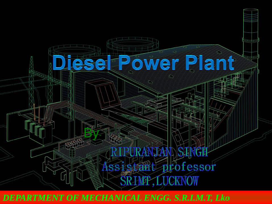
Diesel Power Plant
S.R.I.M.T
DEPARTMENT OF MECHANICAL ENGG. S.R.I.M.T,Lko

INTRODUCTION • A generating station in which diesel engine is used as
the prime mover for the generation of electrical energy is
known as diesel power station.
• The diesel burns inside the engine and the products of
this combustion act as the working fluid to produce
mechanical energy.
• The diesel engine drives alternator which converts
mechanical energy into electrical energy.
S.R.I.M.T
DEPARTMENT OF MECHANICAL ENGG. S.R.I.M.T,Lko
• As the generation cost is considerable due to high price
of diesel, therefore, such power stations are only used to
produce small power.
• Diesel electric plants in the range of 2 to 50 MW
capacity are used as central stations for small supply
authorities and works and they are universally adapted
to supplement hydro-electric or thermal stations where
stand-by generating plants are essential for starting from
cold and under emergency conditions
S.R.I.M.T
DEPARTMENT OF MECHANICAL ENGG. S.R.I.M.T,Lko

.
• Diesel engine power plants are installed where:-
1. Supply of coal and water is not available in desired
quantity.
2. Where power is to be generated in small quantity for
emergency services.
3. Standby sets are required for continuity of supply such
as in hospital, telephone exchange
S.R.I.M.T
DEPARTMENT OF MECHANICAL ENGG. S.R.I.M.T,Lko
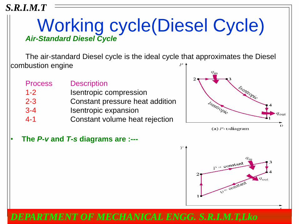
Working cycle(Diesel Cycle) Air-Standard Diesel Cycle
The air-standard Diesel cycle is the ideal cycle that approximates the Diesel
combustion engine
Process Description
1-2 Isentropic compression
2-3 Constant pressure heat addition
3-4 Isentropic expansion
4-1 Constant volume heat rejection
• The P-v and T-s diagrams are :---
S.R.I.M.T
DEPARTMENT OF MECHANICAL ENGG. S.R.I.M.T,Lko

7
Thermal efficiency of the Diesel cycle
th Dieselnet
in
out
in
W
Q
Q
Q, 1
Now to find Qin and Qout.
Apply the first law closed system to process 2-3, P = constant.
Thus, for constant specific heats
Q U P V V
Q Q mC T T mR T T
Q mC T T
net
net in v
in p
,
,
( )
( ) ( )
( )
23 23 2 3 2
23 3 2 3 2
3 2
S.R.I.M.T
DEPARTMENT OF MECHANICAL ENGG. S.R.I.M.T,Lko
8
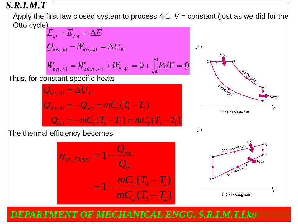
Apply the first law closed system to process 4-1, V = constant (just as we did for the
Otto cycle)
Thus, for constant specific heats
Q U
Q Q mC T T
Q mC T T mC T T
net
net out v
out v v
,
, ( )
( ) ( )
41 41
41 1 4
1 4 4 1
The thermal efficiency becomes
th Dieselout
in
v
p
Q
Q
mC T T
mC T T
,
( )
( )
1
1 4 1
3 2
S.R.I.M.T
DEPARTMENT OF MECHANICAL ENGG. S.R.I.M.T,Lko

9
th Dieselv
p
C T T
C T T
k
T T T
T T T
,
( )
( )
( / )
( / )
1
11 1
1
4 1
3 2
1 4 1
2 3 2
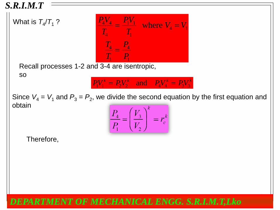
What is T3/T2 ?
PV
T
PV
TP P
T
T
V
Vrc
3 3
3
2 2
2
3 2
3
2
3
2
where
where rc is called the cutoff ratio, defined as V3 /V2, and is a measure of the duration
of the heat addition at constant pressure. Since the fuel is injected directly into the
cylinder, the cutoff ratio can be related to the number of degrees that the crank
rotated during the fuel injection into the cylinder.
S.R.I.M.T
DEPARTMENT OF MECHANICAL ENGG. S.R.I.M.T,Lko
10
What is T4/T1 ? PV
T
PV
TV V
T
T
P
P
4 4
4
1 1
1
4 1
4
1
4
1
where
Recall processes 1-2 and 3-4 are isentropic,
so
PV PV PV PVk k k k
1 1 2 2 4 4 3 3 and
Since V4 = V1 and P3 = P2, we divide the second equation by the first equation and
obtain
Therefore,
S.R.I.M.T
DEPARTMENT OF MECHANICAL ENGG. S.R.I.M.T,Lko

11
th Diesel
c
k
c
k
c
k
c
k
T T T
T T T
k
T
T
r
r
r
r
k r
,
( / )
( / )
( )
( )
11 1
1
11 1
1
11 1
1
1 4 1
2 3 2
1
2
1
What happens as rc goes to 1? Sketch the P-v diagram for the Diesel cycle and
show rc approaching 1 in the limit.
P
v
S.R.I.M.T
DEPARTMENT OF MECHANICAL ENGG. S.R.I.M.T,Lko

TYPES OF DIESEL ENGINES USED FOR
DIESEL POWER PLANTS
• The diesel engines are generally classified as four-stroke engines
and two-stroke engines.
• The four-stroke engine develops power after every two revolutions
of crank shaft whereas two-stroke engine develops power with each
revolution of crank shaft.
• Generally, two-stroke engines are favored for diesel power plants for
the advantages described later.
• Duel Fuel Engines. In duel fuel engines, gas and oil both are used
as fuels for the engines. The gas is used as main fuel and oil is used
as helper for ignition.
S.R.I.M.T
DEPARTMENT OF MECHANICAL ENGG. S.R.I.M.T,Lko

GENERAL LAYOUT OF
DIESEL POWER PLANT
S.R.I.M.T
DEPARTMENT OF MECHANICAL ENGG. S.R.I.M.T,Lko

The layouts of diesel power plants for high
capacity (50 MW and above)
S.R.I.M.T
DEPARTMENT OF MECHANICAL ENGG. S.R.I.M.T,Lko
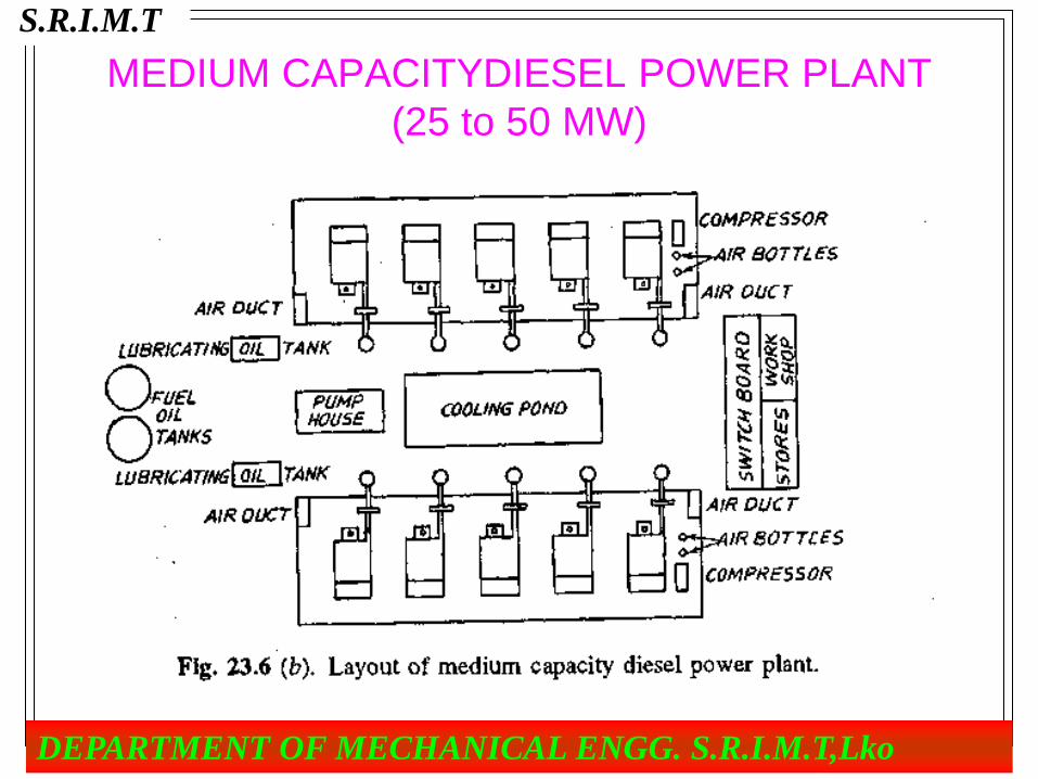
MEDIUM CAPACITYDIESEL POWER PLANT
(25 to 50 MW)
S.R.I.M.T
DEPARTMENT OF MECHANICAL ENGG. S.R.I.M.T,Lko
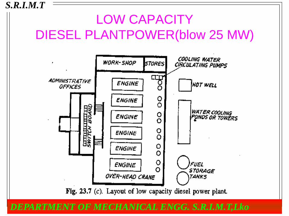
LOW CAPACITY
DIESEL PLANTPOWER(blow 25 MW)
S.R.I.M.T
DEPARTMENT OF MECHANICAL ENGG. S.R.I.M.T,Lko
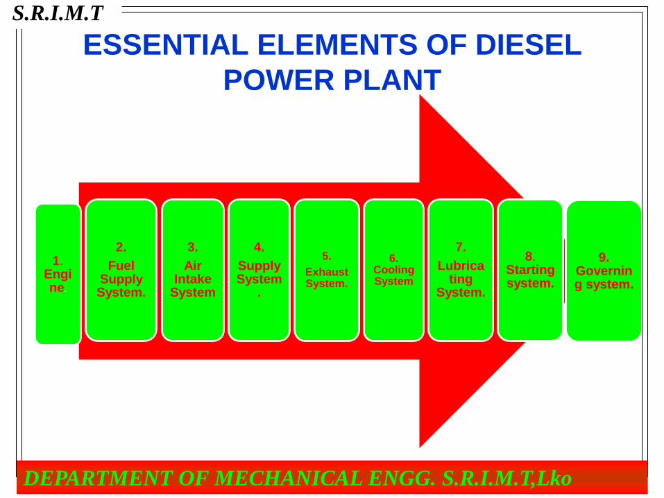
ESSENTIAL ELEMENTS OF DIESEL
POWER PLANT
1. Engine.
2.
Fuel Supply System.
3.
Air Intake
System
4.
Supply System
.
5.
Exhaust System.
6. Cooling System
7.
Lubricating
System.
8. Starting system.
9. Governing system.
S.R.I.M.T
DEPARTMENT OF MECHANICAL ENGG. S.R.I.M.T,Lko

1.Air Intake System. • A large diesel engine power plant requires considerable amount of
air as 4 to 8 m3/kW-hr.
• This system supplies necessary air to the engine for fuel
combustion. It consists of pipes for the supply of fresh air to the
engine manifold.
• Filters are provided to remove dust particles from air which may act
as abrasive in the engine cylinder.
• the air is sucked or bubbled through a housing that holds a bath of
oil such that the dirt in the air is removed by the oil in the filter.
S.R.I.M.T
DEPARTMENT OF MECHANICAL ENGG. S.R.I.M.T,Lko

• The air then flows through a screen-type material to
ensure any entrained oil is removed from the air.
• In a dry filter system, paper, cloth, or a metal screen
material is used to catch and trap dirt before it enters the
engine.
• In addition to cleaning the air, the intake system is
usually designed to intake fresh air from as far away
from the engine as practicable, usually just outside of the
engine’s building or enclosure.
S.R.I.M.T
DEPARTMENT OF MECHANICAL ENGG. S.R.I.M.T,Lko
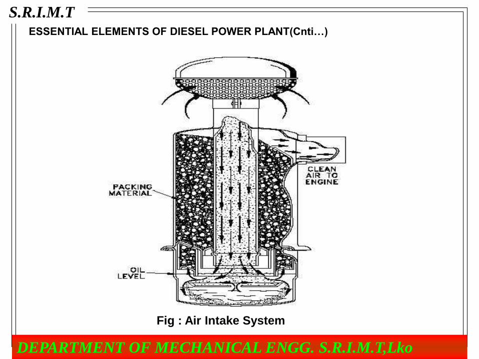
ESSENTIAL ELEMENTS OF DIESEL POWER PLANT(Cnti…)
Fig : Air Intake System
S.R.I.M.T
DEPARTMENT OF MECHANICAL ENGG. S.R.I.M.T,Lko

2.Fuel Storage and Fuel Supply System.
• The fuel storage and supply arrangement generally depend on the
type of fuel, size of plant and type of engine used and so on.
• The supply system is generally classified as:-
(a) Simple suction system and
(b) Transfer system.
S.R.I.M.T
DEPARTMENT OF MECHANICAL ENGG. S.R.I.M.T,Lko

• In a simple suction system, the oil is taken by a suction
pump driven by engines from service tank located a few
cm below the engine level. Such pump delivers constant
volume of fuel, therefore, an overflow line is required
back to the tank. This system is used for small capacity
plant.
• In transfer system, the motor driven pump takes the oil
from main storage and supply to the day storage tank.
The oil from day-storage tank flows under gravity to the
engine pump.
S.R.I.M.T
DEPARTMENT OF MECHANICAL ENGG. S.R.I.M.T,Lko

Transfer system type fuel storage and
supply arrangement.
S.R.I.M.T
DEPARTMENT OF MECHANICAL ENGG. S.R.I.M.T,Lko
S.R.I.M.T
DEPARTMENT OF MECHANICAL ENGG. S.R.I.M.T,Lko

3.FUEL INJECTION SYSTEM
• Fuel injection is a system for mixing fuel with air in an internal
combustion engine. A fuel injection system is designed and
calibrated specifically for the type of fuel it will handle.
• Most fuel injection systems are for diesel applications. With the
advent of electronic fuel injection (EFI), the diesel gasoline hardware
has become similar.
• The primary difference between carburetors and fuel injection is that
fuel injection atomizes the fuel by forcibly pumping it through a small
nozzle under high pressure, while a carburetor relies on low
pressure created by intake air rushing through it to add the fuel to
the air stream
S.R.I.M.T
DEPARTMENT OF MECHANICAL ENGG. S.R.I.M.T,Lko

Typical EFI Components
Animated cut through diagram of a typical fuel injector
Injectors
Fuel Pump
Fuel Pressure Regulator
ECM – Engine Control Module; includes a digital computer and circuitry to communicate with
sensors and control outputs
Wiring Harness
Various Sensors (Some of the sensors required are listed here)
Crank/Cam Position (Hall effect sensor)
Airflow (MAF sensor)
Exhaust Gas Oxygen (Oxygen sensor, EGO sensor, UEGO sensor).
S.R.I.M.T
DEPARTMENT OF MECHANICAL ENGG. S.R.I.M.T,Lko

Typical EFI
S.R.I.M.T
DEPARTMENT OF MECHANICAL ENGG. S.R.I.M.T,Lko

VARIOUS INJECTION SCHEMES
• 3.1 Throttle Body Injection Systems
• Throttle body injection is a form of continuous injection-one or two
injectors delivering fuel to the engine from one central point in the
intake manifold.
Fig :Throttle Body Injection Fig :Throttle Body Injection Unit
S.R.I.M.T
DEPARTMENT OF MECHANICAL ENGG. S.R.I.M.T,Lko

3.2 Continuous Fuel Injection Systems
• Continuous fuel injection systems provide a continuous spray of fuel
from each injector at a point before the intake valve. • They are used on gasoline engines only when more precise fuel
metering is desired.
• In the continuous system, fuel is delivered to the mixture control unit
by the fuel pump.
• The fuel pressure regulator maintains fuel line pressure by sending
excess fuel back to the gas tank.
• The mixture control unit regulates the amount of fuel that is sent to the
injectors, based on the amount of airflow through the intake and the engine
temperature.
• The mixture control unit on mechanical systems is operated by the
airflow sensing plate and the warm-up regulator.
S.R.I.M.T
DEPARTMENT OF MECHANICAL ENGG. S.R.I.M.T,Lko

Fig :-Continuous Injection system
S.R.I.M.T
DEPARTMENT OF MECHANICAL ENGG. S.R.I.M.T,Lko

3.3 Multi-point Fuel Injection
• Multi-point fuel injection injects fuel into the intake port just upstream
of the cylinder’s intake valve, rather than at a central point within an
intake manifold, referred to as SPFI, or single point fuel injection.
Stage 1 Stage 2
S.R.I.M.T
DEPARTMENT OF MECHANICAL ENGG. S.R.I.M.T,Lko
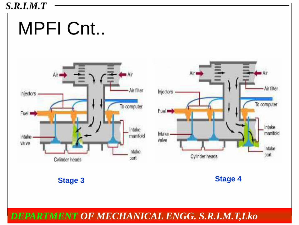
MPFI Cnt..
Stage 3 Stage 4
S.R.I.M.T
DEPARTMENT OF MECHANICAL ENGG. S.R.I.M.T,Lko

LUBRICATION SYSTEM • The system minimizes the wear of rubbing surfaces of the engine.
• It comprises of lubricating oil tank, pump, filter and oil cooler.
• The cost of the lubricating oil in the diesel plant is considerable
compared with other plants as the consumption is nearly 3 liters per
1000 kW-hr generated at full load conditions.
• Thus the lubricating oil consumption is nearly 1% of the fuel oil
consumption.
S.R.I.M.T
DEPARTMENT OF MECHANICAL ENGG. S.R.I.M.T,Lko

LUBRICATION SYSTEM cnt….
• The lubrication oil is drawn from the lubricating oil tank by the pump
and is passed through filter to remove impurities .
• The clean lubrication oil is delivered to the points which require
lubrication.
• The oil coolers incorporated in the system keep the temperature of
the oil low.
S.R.I.M.T
DEPARTMENT OF MECHANICAL ENGG. S.R.I.M.T,Lko

Methods of lubrication:-
• 1. Mechanical system – Splash lubrication
• 2. Pressure lubrication system.
a. Wet sump lubrication system
b. Dry sump lubrication system.
• 3. Semi pressure lubrication system.
S.R.I.M.T
DEPARTMENT OF MECHANICAL ENGG. S.R.I.M.T,Lko

1.Splash lubrication:
• In the splash lubrication system, the oil retained in the oil
pan is churned and splashed up by the internal parts of
the engine.
S.R.I.M.T
DEPARTMENT OF MECHANICAL ENGG. S.R.I.M.T,Lko
2.PRESSURE LUBRICATION SYSTEM
• In the pressure lubrication system, the lubricating oil is
pumped under pressure to the various engine bearings.
• The oil is delivered by an oil pump under a pressure of
1.30 to 1.40 kscm into an oil gallery or distributor duct.
• This gallery distributes oil to the various engine parts
and bearings.
• The oil pump is driven by the engine crankshaft or
camshaft.
S.R.I.M.T
DEPARTMENT OF MECHANICAL ENGG. S.R.I.M.T,Lko

S.R.I.M.T
DEPARTMENT OF MECHANICAL ENGG. S.R.I.M.T,Lko
S.R.I.M.T
DEPARTMENT OF MECHANICAL ENGG. S.R.I.M.T,Lko
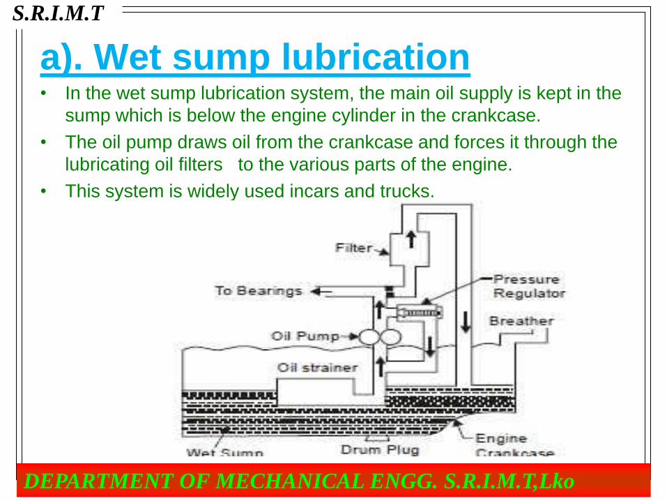
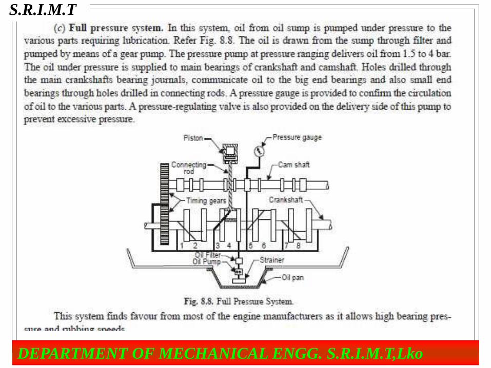
a). Wet sump lubrication • In the wet sump lubrication system, the main oil supply is kept in the
sump which is below the engine cylinder in the crankcase.
• The oil pump draws oil from the crankcase and forces it through the
lubricating oil filters to the various parts of the engine.
• This system is widely used incars and trucks.
S.R.I.M.T
DEPARTMENT OF MECHANICAL ENGG. S.R.I.M.T,Lko

b).Dry sump lubrication • The dry sump lubrication is used in more expensive cars.
• In the dry sump pressure lubrication system, there is no oil sump in the
crankshaft chamber.
• In this system, the oil is kept either in a separate tank or reservoir, provided
with cooling fins.
• Two pumps are used in this system.
• One pump sucks the oil from the reservoir and forces it under pressure to
the various bearings of the engine, as in the wet sump system.
• The other pump (also called scavenger oil pump) is of large capacity. This
pump sucks oil which drains down to the bottom of the crankshaft
chamber, and returns it to the oil reservoir
S.R.I.M.T
DEPARTMENT OF MECHANICAL ENGG. S.R.I.M.T,Lko

S.R.I.M.T
DEPARTMENT OF MECHANICAL ENGG. S.R.I.M.T,Lko

3.Semi pressure lubrication system
• The semi pressure lubrication system is a combination of
splash and pressure lubrication system.
• Most automotive engines use this system.
• This is more simple and less costly than the complete pressure
lubrication system.
• This system also enables bearing loads and engine speeds than
for the splash system.
S.R.I.M.T
DEPARTMENT OF MECHANICAL ENGG. S.R.I.M.T,Lko

Fig : - Semi pressure lubrication system
S.R.I.M.T
DEPARTMENT OF MECHANICAL ENGG. S.R.I.M.T,Lko

Lubricating System cant..
Figure : Lubricating System Layout of large power plant
S.R.I.M.T
DEPARTMENT OF MECHANICAL ENGG. S.R.I.M.T,Lko
cooling system
• Necessity for cooling:- In an internal combustion
engine, the fuel is burned within the engine cylinder. During combustion,
high temperatures are reached within the cylinder , for example in a
compression ignition engine as high as 2000-25000C is reached.
• Effects of over heating of the engine components:
• Setting up of thermal stresses
• Sticking of piston rings in the ring grooves, due to carbonization of the oil.
• Burning of piston crown.
• Burning and warping of exhaust valves.
• Reduction in volumetric efficient i.e. reduced weight of charge retained in
the cylinder.
S.R.I.M.T
DEPARTMENT OF MECHANICAL ENGG. S.R.I.M.T,Lko
Optimum cooling
• To avoid overheating, and the consequent ill effects mentioned
above, the heat transferred to an engine component (after a certain
level) must be removed as quickly as possible and be conveyed to
the atmosphere.
• It should be remembered that abstraction of heat from the working
medium by way of cooling the engine components is a direct
thermodynamic loss.
• Effects of excessive cooling:
• 1. Reduction in thermal efficiency.
• 2. Increased corrosion of engine parts.
• 3. Reduced mechanical efficiency.
• 4. Improper vaporization of fuel.
S.R.I.M.T
DEPARTMENT OF MECHANICAL ENGG. S.R.I.M.T,Lko

TYPES OFCOOLING SYSTEM
• Air cooling
• Liquid Cooling:-
1. Thermo syphon cooling system:
2.Forced circulation cooling system (or Pump circulation
cooling system):
S.R.I.M.T
DEPARTMENT OF MECHANICAL ENGG. S.R.I.M.T,Lko

1.Air cooling
• In air cooling, large quantities of air is circulated around the hot
engine components.
• where the engine is totally enclosed by the vehicle body, air is
forced by a fan or blower of generous capacity. The fan or blower is
fixed to the flywheel.
S.R.I.M.T
DEPARTMENT OF MECHANICAL ENGG. S.R.I.M.T,Lko

S.R.I.M.T
DEPARTMENT OF MECHANICAL ENGG. S.R.I.M.T,Lko

Advantages of air cooling: 1. Cylinder and cylinder head casting are less complicated.
2. Engine weight is reduced, because engine jackets are not there.
3. Cheaper to manufacture- both labor and material.
4. Volume or size (overall) may be reduced, as no device such as
radiator is required for re-cooling the coolant.
5. Engine warms up more quickly, and delivers its full power in
lesser time than the liquid cooled engines.
6. Quick starting of the engine is possible even in frosty weather.
7. Rate of coolant frost (ice) damage of the engine (jackets) is not
there.
S.R.I.M.T
DEPARTMENT OF MECHANICAL ENGG. S.R.I.M.T,Lko
Disadvantages of air cooling:
• Greater mechanical noise, particularly because of the
fan.
• Not suitable for multi-cylinder engines, unless a fan
(which absorbs some power) and suitable cowling are
used.
• Not suitable for engines to be mounted on vehicles
meant for agricultural and construction applications.
S.R.I.M.T
DEPARTMENT OF MECHANICAL ENGG. S.R.I.M.T,Lko

2.Liquid Cooling:
• 1. Thermo syphon cooling system:
S.R.I.M.T
DEPARTMENT OF MECHANICAL ENGG. S.R.I.M.T,Lko

2. Forced circulation cooling system (or Pump
circulation cooling system):
S.R.I.M.T
DEPARTMENT OF MECHANICAL ENGG. S.R.I.M.T,Lko

Water-cooling system in large power plant. • If the engines are not properly cooled, the temperature existing
inside engine would disintegrate the film of lubricating oil on the
liners and wrapping of valves and pistons takes place.
S.R.I.M.T
DEPARTMENT OF MECHANICAL ENGG. S.R.I.M.T,Lko

Starting system
• It is difficult to start even smallest diesel engine by hand cranking as
the compression pressures are extremely high.
• Therefore, some mechanical system must be used to start the
engine. Generally, compressed air, electric motors and auxiliary
gasoline engines are used 'for starting purposes. Compressed air
system is commonly used in big diesel power plants. Air starting
system uses valve arrangement to admit pressurized air at about 20
bar to a few of the
• cylinders, making them to act as reciprocating air motors to turn the
engine shaft. Admitting fuel oil to the remaining engine cylinder
helps the engine to start under its own power.
S.R.I.M.T
DEPARTMENT OF MECHANICAL ENGG. S.R.I.M.T,Lko
PERFORMANCE OF DIESEL POWER PLANT
• Diesel plants also run at part load conditions like other plants.
• Therefore, it is necessary to study the effect of part load running on
the characteristics of an engine like specific fuel consumption, brake
thermal efficiency, and mechanical efficiency.
• The effects of part loads on the engine characteristics are shown in
Fig.
S.R.I.M.T
DEPARTMENT OF MECHANICAL ENGG. S.R.I.M.T,Lko
SUPERCHARGING SYSTEM OF DIESEL
POWER PLANT
• The purpose of supercharging is to raise the volumetric
efficiency above that value which can be obtained by
normal aspiration.
• Since the I.H.P. produced by an I.C. engine is directly
proportional to the air consumed by the engine.
• greater quantities of fuel to be added by increasing the
air consumption permit and result in greater power
produced by the engine.
S.R.I.M.T
DEPARTMENT OF MECHANICAL ENGG. S.R.I.M.T,Lko

• So, it is, therefore, desirable that the engine
should take in the greatest possible mass of air.
• The supply of air is pumped into the cylinder at a
pressure greater than the atmospheric pressure
and is called supercharging.
• When greater quantity of air is supplied to an I.C. engine
it would be able to develop more power for the same
size and conversely a small size engine fed with extra air
would produce the same power as a larger engine
supplied with its normal air feed
S.R.I.M.T
DEPARTMENT OF MECHANICAL ENGG. S.R.I.M.T,Lko
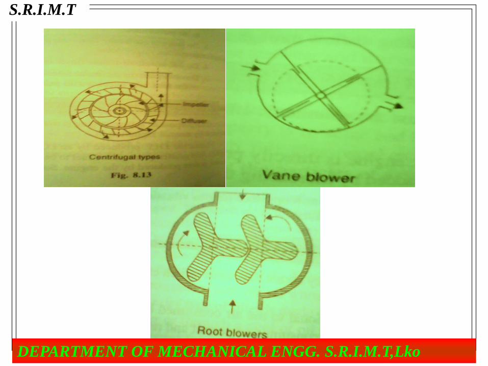
TYPES OF SUPERCHARGER- • Supercharging is done by means of compressor; there are two types
of compressors that may be used as super chargers.
They are as follows:-
1. Positive displacement type surchargers.
(a) Piston Cylinder type
(b) Roots blowers
(c) Vane blower
• 2. Centrifugal type super chargers or turbo type.
• 3. Turbo type super chargers.
S.R.I.M.T
DEPARTMENT OF MECHANICAL ENGG. S.R.I.M.T,Lko
S.R.I.M.T
DEPARTMENT OF MECHANICAL ENGG. S.R.I.M.T,Lko

ADVANTAGE OF SUPERCHARGING
1.
Power Increase.
2.
Fuel Economy.
3. Mechanical Efficiency.
4.
Fuel Knock.
5. Volumetric Efficiency.
S.R.I.M.T
DEPARTMENT OF MECHANICAL ENGG. S.R.I.M.T,Lko
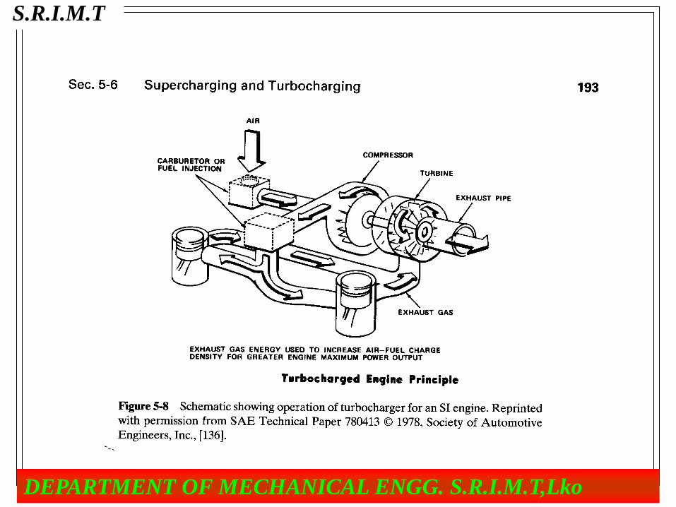
TURBOCHARGERS
• Turbocharger is a turbine driven air
compressor powered by exhaust gases from
the internal combustion engine.
The turbine basically expands the gas mixture,
which is at high temperature, and transfers
some of the energy into useful work.
S.R.I.M.T
DEPARTMENT OF MECHANICAL ENGG. S.R.I.M.T,Lko
S.R.I.M.T
DEPARTMENT OF MECHANICAL ENGG. S.R.I.M.T,Lko

ADVANTAGE OF TURBOCHAGING:-
no gearing require.
Suitable for high speed engine.
Low maintenance.
Utilization of exhaust gas.
• DISADVANTAGE OF TURBOCHAGING:-
• Increase fuel consumption at low power o/p.
• Total cost unit increases
S.R.I.M.T
DEPARTMENT OF MECHANICAL ENGG. S.R.I.M.T,Lko

• The part load increases the specific fuel consumption,
decreases the thermal and mechanical efficiency. But the effect
is not as predominant as in thermal plants.
S.R.I.M.T
DEPARTMENT OF MECHANICAL ENGG. S.R.I.M.T,Lko
Comparative study of diesel power plant
with steam power plant
ADVANTAGES OF DIESEL PLANTS OVER THERMAL PLANTS
1.The diesel power plants are more efficient than steam power plants in
the range of 150 MW capacity. They maintain high operating
efficiency in the load range of 50% to 100% of full load.
2.Diesel plants are cheaper in first cost than steam plants ; plant units
up to about 7 kW. Above this capacity, the diesel cost rises rapidly
while that of steam plants continues to fall.
3.It has no standby losses.
4.It can burn fairly wide range of fuels.
S.R.I.M.T
DEPARTMENT OF MECHANICAL ENGG. S.R.I.M.T,Lko

5. It can be quickly started up and brought into service (within one minute).
6 .Manufacturing periods are short, therefore, a diesel station may be rapidly
extended to keep pace with load growth by just adding the generating units
of suitable sizes.
7. The space required for diesel plant is considerably less than thermal plant
and, therefore, cost of foundation and buildings is less.
8. There is no problem of ash handling as there is practically no refuse.
9. They can be employed in all climatic zones.
10. Machine sets are readily available as standard sets in the range of 500
kW to 40 MW.
S.R.I.M.T
DEPARTMENT OF MECHANICAL ENGG. S.R.I.M.T,Lko

DISADVANTAGES OF DIESEL PLANTS OVER THERMAL PLANTS
1. The unit capacity of diesel engine is considerably low than the
thermal unit.
2. The repair and maintenance costs are generally much higher than
for steam plants. These costs are more or less fixed in case of
steam plants and more or less are proportional to output in the
case of diesel plants.
3. Life of 25 to 30 years is normal for thermal plant whereas the life of
diesel plant is hardly 2 to 5 years or less.
4. The diesel plants are not economical where fuel has to be
imported.
5. The noise is a serious problem in diesel plant.
6. Selected types of fuels are required in diesel engines whereas
there is more mobility in case of thermal plant.
7. The diesel plants are not guaranteed for continuous operation
under overloads whereas steam plants can work under 25%
overload continuously.
8. The lubrication cost is high.
S.R.I.M.T
DEPARTMENT OF MECHANICAL ENGG. S.R.I.M.T,Lko

Performance Testing of
Diesel Engine Power Plant
• The performance of the diesel engine focuses on the power and
efficiency.
• The engine performance varies with parameters of the engine like
piston speed, air-fuel ratio, compression ratio inlet air-pressure and
temperature.
.
S.R.I.M.T
DEPARTMENT OF MECHANICAL ENGG. S.R.I.M.T,Lko

• A series of tests are carried out on the engine to determine its
performance characteristics, such as : -
indicated power (I.P.), Brake power (B.P.),
Frictional Power (F.P.),
Mechanical efficiency (ηm),
thermal efficiency,
• fuel consumption and also specific fuel consumption etc The two usual
conditions under which I.C. engines are operated are:
(1) constant speed with variable load, and
(2) variable speed with variable load
S.R.I.M.T
DEPARTMENT OF MECHANICAL ENGG. S.R.I.M.T,Lko

1.Mean Effective Pressure and Torque
S.R.I.M.T
DEPARTMENT OF MECHANICAL ENGG. S.R.I.M.T,Lko

2.Indicated Horse Power (IHP)
The indicated horse power (IHP) of the engine can be calculated as
follows :
• where Pm = LM.E.P. in kg/cm2
• L = Length of stroke in metres
• A = Piston areas in cm2
• N = Speed in R.P.M.
• n = Number of cylinders
• k = 1 for two stroke engine
• = 2 for four stroke engine.
IHP = Pm. L. A. N. n
4500 × k
S.R.I.M.T
DEPARTMENT OF MECHANICAL ENGG. S.R.I.M.T,Lko

3.Brake Horse Power (BHP)
Brake horse power is defined as the net power available at the
crankshaft.
It is found by measuring the output torque with a dynamometer.
• T = Torque in kg.-m.
• N = Speed in R.P.NT..
4.Frictional Horse Power (FHP) :-
• The difference of IHP and BHP is called FHP. It is
utilized in overcoming frictional resistance of rotating and
sliding parts of the engine.
FHP = IHP – BHP
S.R.I.M.T
DEPARTMENT OF MECHANICAL ENGG. S.R.I.M.T,Lko

5.Indicated Thermal Efficiency (ηi)
S.R.I.M.T
DEPARTMENT OF MECHANICAL ENGG. S.R.I.M.T,Lko
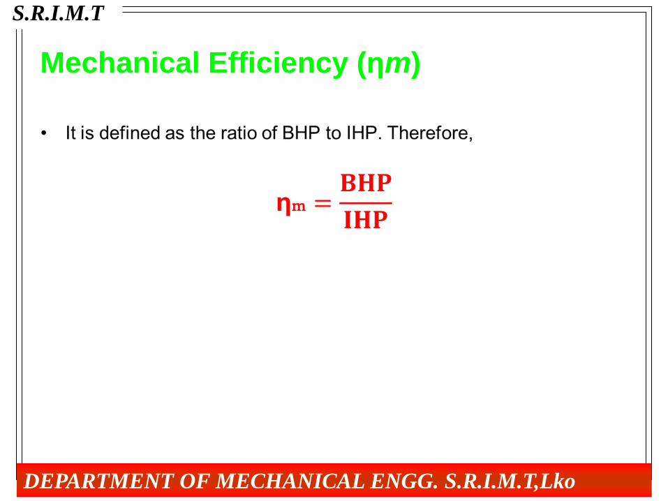
Mechanical Efficiency (ηm)
S.R.I.M.T
DEPARTMENT OF MECHANICAL ENGG. S.R.I.M.T,Lko

HEAT BALANCE SHEET • It is a useful method to watch the performance of the diesel power
plant. Among all the heat supplied to an engine only part of it is
converted into useful work, the remaining goes as waste.
• The heat balance of an engine depends on a number of factors
among which load is primary importance.
• Heat balance sheet is a useful method to watch the performance of
the plant.
• In order to draw the heat balance sheet of Diesel engine, the engine
is run at constant load and constant speed and the indicator diagram
is drawn with the help of indicator
S.R.I.M.T
DEPARTMENT OF MECHANICAL ENGG. S.R.I.M.T,Lko

• The following quantities are noted:
1. The quantity of fuel consumed during a given period.
2. Quantity of cooling water and its outlet and inlet temperatures.
3. Weight of exhaust gases.
4. Temperature of exhausts gases.
5. Temperature of flue gases supplied
To calculate the heat in various items proceed as follows:-
Let-
W = Weight of fuel consumed per minute in kg.
G = Lower calorific value of fuel, kcal per kg.
Then heat in fuel supplied per minute = WCV kcal.
• The energy supplied to Diesel engine in the form of fuel input is usually
broken into following items:
(A) Heat Energy Absorbed in I.H.P. The heat energy absorbed in indicated
horsepower, I.H.P. is found by the following expression:-
Heat in L.H.P. per minute
(I.H.P. × 4500)/J kcal
S.R.I.M.T
DEPARTMENT OF MECHANICAL ENGG. S.R.I.M.T,Lko
(B) Heat Rejected to Colling in Water:-
Let
W1 = Weight of cooling water supplied per minute (kg)
T1 = Inlet temperature of cooling water in °C
T2 = Output temperature of cooling water in °C
Then heat rejected to cooling water = W1(T2 – T1)
(C) Heat Carried Away by Exhaust Gases:-
Let W2 = Weight of exhaust gases leaving per minute in kg.
(sum of weight of air and fuel supplied)
T3 = Temperature of flue gases supplied per minute °C.
T4 = Temperature °C of exhaust gases.
KP = Mean specific heat at constant pressure of exhaust.
The heat carried away by exhaust gases = W2 × KP × (T4 – T3) kg cal.
S.R.I.M.T
DEPARTMENT OF MECHANICAL ENGG. S.R.I.M.T,Lko

(D) Heat Unaccounted for (Heat Lost Due to Friction, Radiation etc):-
The heat balance sheet is drawn as follows:-
A typical heat balance sheet at full load for Diesel cycle (compression ignition) is
as follows:
(1) Useful work = 30%
(2) Heat rejected to cooling water = 30%
(3) Heat carried away by exhaust gases = 26%
(4) Heat unaccounted (Heat lost due to friction, radiation etc.) = 10%.
S.R.I.M.T
DEPARTMENT OF MECHANICAL ENGG. S.R.I.M.T,Lko