Embed Size (px)
Citation preview

Buildings Practice Facilities Plants/Petrochemicals
Chapter 8 Building Design Concept
Page 1 of 71 2012 Int. P Eng Suraj Singh
Design General Specification
Structural Design Basis
1 Buildings, process structures, pipe racks, miscellaneous plant structures, vessels,
exchangers & general introduction 2 This specification gives minimum criteria for structural engineering and design
purpose necessary for structural engineering and design for framework & foundations
of all buildings, process structures, pipe racks and for foundations for vertical vessels, horizontal vessels, heat exchangers, storage tanks, vibrating equipment, grade and
elevated slabs & masonry structures, miscellaneous plant structures, such as pits, sumps and retaining walls etc.
Codes and Standards
Following codes, standards and specifications form part of this specification. 1 Only latest codes shall apply to all requirements.
2 Alternate codes, standards and specifications meeting requirements of these codes, may be used with approval by company.
3 Steel grade material S 275 JR to BS EN 10025 & bolts to BS 4190 and BS 4395 may
be used upon company approval. 4 Steel grade 43A to BS 4360 may be used for small access platforms without valves,
small pipe supports, handrail and ladders, subject to company approval. 5 American National Standards Institute (ANSI) may also, be used
List of possible applicable codes
Code Requirements for Reinforced Concrete 1 BS 4449 Carbon Steel Bars for Reinforcement of Concrete
2 BS 4483 Steel Fabric for Reinforcement of Concrete 3 BS 8004 Foundations 4 BS 8007 Design of Concrete Structures for Retaining Aqueous Liquids
5 BS 8110 Structural Use of Concrete 6 ASTM A185 Specification for Steel Welded Wire Fabric Plain for Concrete
Reinforcement 7 Uniform Building Code (UBC) 8 U.K. Concrete Society Technical Report No. 34: Concrete Industrial Ground Floors
9 Cement and Concrete Association Technical Report 550: Design of Floors on Ground 10 British Cement Association Interim Note 11: Design of Ground Supported Concrete
11 Industrial Ground Floors 12 CIRIA Special Publication 31: CIRIA Guide to Concrete Construction in Gulf Region 13 CIRIA Report No. 91 Early Age Thermal Crack Control in Concrete
14 Portland Cement Association (PCA) 15 ACI 301 Specifications for Structural Concrete for Buildings
16 ACI 302.1R Guide for Concrete Floor and Slab Construction 17 ACI 318M Building Code Requirements for Reinforced Concrete Commentary on
Building
18 American Concrete Institute (ACI) 19 ACI 325.3R Guide for Design of Foundations and Shoulders for Concrete Pavements
20 ACI 336.2R Suggested Analysis and Design Procedures for Combined Footings and Mats
21 ACI 350R Environmental Engineering Concrete Structures
22 ACI 530 Building Code Requirements for Concrete Masonry Structures 23 PCA IS 003D Rectangular Concrete Tanks
24 PCA IS 072D Circular Concrete Tanks without Pre-stressing

Buildings Practice Facilities Plants/Petrochemicals
Chapter 8 Building Design Concept
Page 2 of 71 2012 Int. P Eng Suraj Singh
25 National Concrete Masonry Association (NCMA)
26 NCMA TEK 59 Reinforced Concrete Masonry Construction. General
1 American Welding Society (AWS) 2 AWS D1.1 Structural Welding Code - Steel 3 AWS D1.4 Structural Welding Reinforcing Steel
4 American Petroleum Institute (API) 5 API 650 Appendix E
6 American Society For Non-Destructive Testing (ASNT) 7 ASNT-TC-IA Recommended Practice 8 Occupational Safety and Health Administration (OSHA)
9 OSHA - CR29 10 American Association Of State Highways And Transportation Official (AASHTO)
11 Standard Specifications for Highway Bridges 12 American Society For Testing And Materials (ASTM)
Structural Steel & others
1 ANSI A12.1 Safety Requirements for Floor and Wall Openings, Railings and Toe boards.
2 ANSI A14.3 Safety Requirement for Fixed Ladders. 3 ANSI A64.1 Requirements for Fixed Industrial Stairs 4 American Institute of Steel Construction (AISC)
5 ASCE 7 Minimum Design Loads for Buildings and other Structures 6 AISC Specification for Structural Steel Buildings
7 AISC Manual of Steel Construction 8 AISC Code of Standard Practice for Steel Buildings and Bridges 9 AISC Specification for Structural Joints Using ASTM A 325 or A 490 Bolts
10 ASTM A6 Specification for General Requirements for Rolled Steel Plates, Shapes, Sheet Piling and Bars for Structural Use
11 ASTM A36 Specification for Structural Steel 12 ASTM A53 Specification for Pipe, Steel, Blank and Hot-Dipped Zinc-Coated Welded
and Seamless.
13 ASTM A123 Specification for Zinc (Hot-Dip Galvanized) Coatings on Iron and Steel Products
14 ASTM A143 Recommended Practice for Safeguarding Against Embrittlement of Hot-Dip Galvanized Structural Steel Products and Procedures for Detecting Embrittlement
15 ASTM A193 Specification for Alloy-Steel Bolting Material for High Temperature Service
16 ASTM A307 Specification for Carbon Steel Bolts and Studs, 60,000 PSI Tensile Strength
17 ASTM A325 Specification for High Strength Bolts for Structural Steel Joints
(Including Suitable Nuts and Plain Hardened Washers) 18 ASTM A490 Specification for High-Strength Steel Bolts Classes 10.9 and 10.93 for
Structural Steel Joints (Metric) 19 ASTM A500 Specification for Cold-Formed Welded and Seamless Carbon Steel
Structural Tubing in Rounds and Shapes
20 ASTM A569M Specification for Steel with Carbon (0.15 Maximum Percent) Hot-Rolled-Sheet and Strip Commercial Quality
21 ASTM A786 Specification for Rolled Steel Floor Plates

Buildings Practice Facilities Plants/Petrochemicals
Chapter 8 Building Design Concept
Page 3 of 71 2012 Int. P Eng Suraj Singh
22 ASTM A830 Specification for Plates Carbon Steel Structural Quality Furnished to
Chemical Composition Requirements 23 ASTM C90 Specification for Load-Bearing Concrete Masonry Units
24 ASTM C270 Specification for Mortar for Unit Masonry 25 ASTM F436 Specification for Hardened Steel Washers 26 ASTM F959 Specification for Compressible-Washer-Type Direct Tension Indicator
for use with Structural Fasteners 27 UBC Latest Edition
28 BS 4 Structural Steel Sections Part 1 Specification for Hot Rolled Sections 29 BS 4190 Black hexagon bolts 30 BS 4360 Weldable structural steels
31 BS 4395 High Strength Friction Bolts and Associated Nuts and Washers for Structural Engineering
32 BS 4592 Grating 33 BS 4848 Hot-Rolled Structural Steel Sections Part 2: Specification for Hot-Finished
Hollow Sections
34 BS 5950 Structural Use of Steelwork in Buildings 35 BS 7419 Holding Down Bolts
36 BS EN 20898 Mechanical Properties of Fasteners Part 1: Bolts, Screws and Studs 37 BS EN 10025 Hot rolled products of now-alloy structural steels and their technical
delivery conditions
Quality Assurance/Quality Control
1 Contractor’s proposed quality system shall fully satisfy all elements of ISO 9001
Quality Systems 1 Model for Quality Assurance in Design / Development, Production, Installation and
Servicing” and ISO 9004-1987, “Quality Management and Quality System Elements
- Guidelines”. 2 Quality system shall provide for planned and systematic control of all quality related
activities performed during design. 3 Implementation of system shall be carried out in accordance with project contract
agreement, contractor’s quality manual and project specific quality plan.
4 Quality manual as well as, project specific quality plan shall be submitted to company for review, comment and approval.
Design Requirements
Reference codes and standards 1 All structural engineering design shall be carried out within parameters of documents
listed above, which constitute part of this design basis. Measurement
1 All dimensions, quantities and units of measurement, shown on drawings or used within specifications and calculations shall be in metric units, while pipe size may be in inches.
Site Survey and Soils Report 1 Company accepts no liability for information contained in site survey and soils report
(if any). Site survey
1 All design shall be worked out in accordance with horizontal and vertical controls
contained in survey report prepared by survey consultant. Soils report
1 All design shall base in line/accordance with recommendations contained in soils
Buildings Practice Facilities Plants/Petrochemicals
Chapter 8 Building Design Concept
Page 4 of 71 2012 Int. P Eng Suraj Singh
report prepared by geotechnical consultant.
Basic Design and Drawing Concepts 1 Design and calculations
Prior to starting detailed design, a basic design shall be made consisting of: 1 Basic sketch 2 Loading Derivation Calculation
3 Stability check 4 Main Structural members
Basic Sketch & 1 Sketch shall show proposed structure (in perspective and/or a series of cross
sections).
2 Structural members may be shown as single lines. 3 Sketch shall include foundations & all other parts of structures in structural steel or in
structural concrete framing. 4 All applied loads shall be shown on sketches excluding dead loads.
Loading derivation calculations
1 Calculations shall base on design philosophy and all loads including dead loads of relevant structural components.
2 Calculation shall state loads in main structural members (axial loads, bending moments, shear and possibly torsion, reactions, deflections) and shall include upward reaction loads on foundation (load per unit of area).
3 Calculation shall take into account soil investigation report. 4 If computer programs are to be used for detailed design, these shall be identified
during basic design stage, with all required documentation provided to demonstrate their adequacy & sufficiency.
Stability Check
1 Stability of structure shall be checked for both factored and non factored load combinations.
Main Structural Members 1 In assessment of sizes and dimensions of main structural members, most critical load
combination shall be considered.
2 Structural details, such as connections of steel beams and columns or details of reinforcing steel over full length of a reinforced concrete beam shall be designed and
detailed by designer. 3 Standard steel connection details may be designed by supplier, but must be checked
by designer duly certified by a Professional Engineer.
4 Or an equivalent duly registered complying with international standards of EMF.(Engineers Mobility Forum) (In Bharat/India, Institution Of Engineers India
represents EMF) Detailed Design
1 Detailed design shall be based on basic criteria as well as FEED.
Calculation shall clearly indicate: 1 Table of contents
2 Design philosophy employed on engineering assumptions 3 Applicable codes, formulas, graphs/tables 4 References to literature etc. for subjects not covered by applicable codes
5 Loading tables with loads location diagrams 6 If computer programs are used, following information shall be supplied:
a Logic and theory used

Buildings Practice Facilities Plants/Petrochemicals
Chapter 8 Building Design Concept
Page 5 of 71 2012 Int. P Eng Suraj Singh
b Analytical model of structure used for computer analysis
c Users manual pertinent software d A hand calculation to prove validity of computer analysis except if validated by
QA/QC system. e Loads and load combinations
Drawings and related documents
1 Drawings shall be of standard metric sizes, i.e. A0, A1, A2, A3, A4 2 Preferred computer aided design system is software used internationally, as well as,
designer’s in house developed or other software approved by company. 3 Drawings shall be suitably prepared to facilitate microfilming and incorporate a
numbering and indication of revision system.
4 Dimensions on drawings shall be in SI system, unless otherwise specified. 5 Levels shall be indicated in meters & all other dimensions in millimeters.
6 Layout drawings shall show highest point of grade as El. 100.00 and reference of this level to local datum level for process units, in off sites actual level shall be indicated.
7 All headings and notes shall be in English.
8 Each drawing shall bear following information in title block. a Order number of company, name of plant , name of unit , name of part of unit,
example: order number , catalytic cracking unit , compressor building Portal frames
1 Only drawings marked "Released for Construction (RFC)" or “Approved for
Construction (AFC)” shall be used for execution of works everywhere. 2 This mark "Released for Construction" can be given only, by designer responsible for
design and engineering. 3 Drawings shall be submitted together with relevant calculations including those
required for submission to local authorities.
4 Revisions to drawings shall be identified with symbols adjacent to alterations, a brief description in tabular form of each revision shall be given and if applicable, authority
and date of revision shall be listed. 5 Term “Latest Revision” shall not be used. 6 Claim to all drawings prepared by contractor under an order placed by company shall
be vested in company and later, shall have right to use these drawings for purpose on this project, without any obligation to contractor.
7 Contractor shall not disclose or issue to any third party, without obtaining written consent of company any documents, drawings etc. provided at his disposal by company or any documents prepared by, in connection with inquiries and orders for
purposes other than preparation of a quotation or carrying out these orders. Structural concrete
Plan drawing 1 On this drawing, general information/data shall be shown as general notes on right
hand side or another suitable location of drawing.
2 General notes shall state that: a Levels are expressed in meters with reference to highest point of grade
b Dimensions are expressed in millimeters c Bar diameters are expressed in millimeters 3 Furthermore, general notes shall list:
a quality (or qualities) of concrete b quality (or qualities) of steel reinforcing bars
c quality (or qualities) of cement to be used
Buildings Practice Facilities Plants/Petrochemicals
Chapter 8 Building Design Concept
Page 6 of 71 2012 Int. P Eng Suraj Singh
d Concrete blinding (location, quality and thickness)
e Polyethylene sheeting, if applicable (location and quality) f Concrete cover on bars (type of construction, location and thickness)
g List of reference drawings and related documents stating respective title and number
h Legend of contractor’s reinforcing bar call out
i Including an indication for which part(s) each quality is to be used. Detail drawings
1 On each of detail drawings, following information/data shall be listed: a For general notes, see Drawing #. ...... b This detail drawing refers to Drawing #. ......
c For bar bending list(s), see #. ......, sheet 1 to ....... d For weight list(s), see #. ........, sheet 1 to ........
e Quantity of concrete (for each quality of concrete separately) Bending and weight lists
1 These lists shall always be made by designer, unless explicitly stated otherwise.
2 Lists shall be prepared on detailed drawings or on separate sheets. Scale of drawings
1 Plan drawings shall be made to a scale of 1:50 and detail drawings to a scale of 1:20. Structural steel
1 Part of information/data supplied by company may be in form of one or more
instruction drawings. 2 If instruction drawings are provided, all dimensions shown on these drawings shall
also, appear on contractor’s drawings. General arrangement drawings
1 These drawing shall show complete structure to be supplied.
2 All main dimensions and section to be used shall be included. 3 All members to be fireproofed shall be marked with an appropriate symbol or FP
designation. 4 A fireproofing legend shall clearly identify symbols and designations with work to be
performed.
5 For preparation of general arrangement drawing, contractor may use a reproducible of instruction drawing(s).
6 For small and simple structures, this drawing may be combined with base plate drawing.
Base plate drawing
1 This drawing shall show all dimensions and details of base plate including anchor bolts, which be taken into account in design of (concrete) foundation.
2 When need for a slight adjustment of anchor bolts during erection is expected, this shall be indicated on drawing.
3 Scale for details shall be at least 1:10.
4 For small and simple structures, this drawing may be combined with general arrangement drawing.
Construction drawings 1 These drawings shall clearly show all constructional details of structure to be
supplied.
2 Location of various parts in structure shall be indicated. Scale of drawings
1 Drawings shall be made to an appropriate scale.
Buildings Practice Facilities Plants/Petrochemicals
Chapter 8 Building Design Concept
Page 7 of 71 2012 Int. P Eng Suraj Singh
Bills of material
1 Bills of material shall show weights of all large members from view point of transportation and erection at site as well as, total weight of structure.
Steel structures
1 Structural steel design shall be carried out in accordance with relevant project, general specifications and international codes.
2 Plastic design method in AISC manual shall not be used in steel design. 3 Steel structures shall be designed for loads and load combinations allowed in this
specification. 4 Normally, only pinned column bases shall be used in design of steel structures. 5 Use of fixed base plates for certain type of pipe racks and buildings may be necessary
because of deflection considerations. 6 Where headroom, access or equipment arrangements permit, wind and other lateral
loads on a steel structure shall preferably be transferred to foundations through vertical X-bracing or K-bracing included on transverse and longitudinal column lines of structure.
7 As a second choice, wind and other lateral loads on a structure should be transferred to foundations through moment resistant frames in one direction and vertical X-
braced or K-braced frames in other direction. 8 Structures that resist lateral load with rigid frame systems in two directions should be
avoided.
9 Method of bracing selected for a structure should generally, be used throughout structure.
10 Compression bracing for steel structures shall normally, be designed with wide flange and structural Tee shapes.
11 For tension bracing, single angle or structural Tees may be used.
12 Double angle bracing because of maintenance difficulties shall not be permitted for either compression or tension locations.
13 When using structural Tees in compression, design shall include bending induced by eccentrically, loaded connections.
14 Braces for structures subject to vibration from equipment shall be designed as
compression members. 15 Horizontal bracing shall be provided in plane of a floor, platform or walkway, when
necessary to resist lateral loads or to increase lateral stiffness of unit. 16 Floor grating shall not be allowed to resist lateral loads in diaphragm action without
having been investigated.
17 In a floor system, beam compression flanges should be considered to be fully braced, when a concrete slab is cast to match bottom face of compression flanges on both
sides or when chequered plate is bolted or welded to compression flanges or when grating or metal deck is welded to compression flanges.
18 Grating shall normally, be clipped or bolted and therefore, should not be considered
as adequate compression flange bracing. 19 In such cases, additional vertical and/or horizontal bracing in floor system shall be
provided. 20 Bar joist floor and roof systems are generally, considered to be too light for heavy
industrial plant work.
21 However, when approved by designer, bar joist systems may be used on a project. 22 Steel Structures shall be designed, so that surfaces of all parts should be readily
accessible for inspection, cleaning and painting.
Buildings Practice Facilities Plants/Petrochemicals
Chapter 8 Building Design Concept
Page 8 of 71 2012 Int. P Eng Suraj Singh
23 Pockets for depressions, which would hold water shall be provided drain holes or
otherwise protected. Connections for steel structures shall conform to following requirements:
1 Shop connections may be bolted or welded. 2 Field connections shall normally, be bolted however, when approved by designer,
welded field connections may be used.
3 Bolted connections for primary members shall utilize high strength bolts conforming to ASTM A325 or A490.
4 A minimum of 2 M20 bolts shall be used for all connections. 5 These connections shall be designed as bearing type. 6 Those connections subject to vibration or stress reversal shall be bearing type.
7 Loads for bearing type connections shall be based on threads excluded from shear plane.
8 Turn of nut method or load indicator washers shall be used for tightening all connections.
9 Bolted connections for secondary members (e.g. purlins, girts, stair framing etc.) shall
be made with A307 bolts with appropriate finish. 10 Connections shall normally, be designed by supplier and checked by designer in
accordance with project construction specifications and loads shown on drawings. 11 Moment connections and special connections, however, shall be worked by designer
duly shown on engineering drawings.
12 Moment connections can be bolted or welded type depending on type of structure and situation.
13 Designer shall determine type of connection to be used for each structure. 14 All shear connections shall be designed and detailed by Supplier and checked by
Designer.
15 Reactions shall be shown on engineering drawings or as per calculation note provided by Designer.
16 Plant area shall have primary structural connections continuously seal welded except high strength bolted field connections.
17 Primary structural connections include horizontal and vertical vessel supports, beams
and columns on major pipe racks, inaccessible maintenance areas etc. 18 Forces in truss members and all main bracing shall be shown on engineering
drawings with plus signs indicating tension and minus signs indicating compression or per calculation note provided by designer.
19 Minimum thickness of a structural steel plate or bar shall be 10 mm.
20 Gusset plates shall not be thinner than members to be connected and should have a thickness of at least 10 mm.
21 Welded steel grating for platform covering shall be 30 mm x 6 mm bearing bars at 30 mm on centre.
22 Cross bars shall be twisted square 6 mm on each side and spaced not over 100 mm
centre to centre, hot dip galvanized in accordance with ASTM A123 and A143 for corrosive environment.
23 E70xx welding electrodes shall be specified for all shop and field welding of structural steel.
24 All welds shall run continuous.
25 All bracing shall be arranged to minimize torsion and where practicable, be arranged concentrically, about resultant line of force.
26 Connections, wherever possible, shall be arranged, so that their centroid lies on

Buildings Practice Facilities Plants/Petrochemicals
Chapter 8 Building Design Concept
Page 9 of 71 2012 Int. P Eng Suraj Singh
resultant of forces those members intended or required to resist.
27 When condition cannot be achieved, members and connections shall be designed to resist a local bending due to eccentricity of force.
28 In practice, it is noticed that corroded steel plates and bolts limit expected movement, which may result in additional stresses.
29 Designer should consider this point to include sequential additional stresses in design
consideration. 30 Steel structures supporting equipment shall be fireproofed, where required by risk &
safety analysis.
Reinforced concrete structures and foundations
1 Cast in place or situ concrete structures shall be designed in accordance with ACI 318, except as indicated otherwise in this specification.
2 Cast in place or situ concrete structures shall be designed for loads and load combinations required according to codes requirements & description given elsewhere, in project documents.
3 Working strength design or limit state of serviceability design methods shall be used for structural design of concrete members, unless otherwise indicated.
4 Load combinations and load factors for all concrete design shall be adopted in accordance with ACI 318.
5 Design and details of cast in place concrete structures shall consider monolithic
nature of hardened concrete. 6 Construction joints in a concrete structure shall be located, so as to least impair
integrity and unity of structure. 7 Construction joints in beams at column or pedestal faces should be avoided. 8 Designer/contractor site management shall approve location of all construction joints
on site agreement. 9 Moving concentrated loads on elevated concrete beams and slabs shall be treated in
accordance with applicable recommendations of referenced AASHTO specifications. 10 Slabs at grade for buildings and process areas shall be designed in accordance with
publications ‘Concrete pavements for heavy storage areas’
11 Underground structures, such as basements, rectangular tanks, sumps and pits shall be designed in accordance with latest referenced PCA bulletins and/or BS8007.
12 Design of such structures shall include effects of ground water pressures and buoyancy.
13 A minimum factor of safety of 1.1 for buoyancy shall be used ignoring soil cohesion.
14 Concrete process treatment structures shall be designed in accordance with ACI 350 R.
15 For all liquid retaining structures, special precautions shall be taken for water tightness provisions in line to provisions pertinent BS 8007.
16 All joints shall be fully detailed by designer.
17 A corrosion allowance limiting to 3 mm shall be required for all anchor bolts. 18 Bolts shall be hot dip galvanized in accordance with ASTM A123 and A143.
19 Foundation design in addition to above applicable criteria shall meet following requirements:
a Foundations shall be designed in accordance with project geotechnical (soils) report.
b Foundations for structures shall be sized and stability determinations made using service loads only.
c Load factors shall not be included in these design operations.

Buildings Practice Facilities Plants/Petrochemicals
Chapter 8 Building Design Concept
Page 10 of 71 2012 Int. P Eng Suraj Singh
d Unless, there is a conflict with project soils report, individual foundations shall
normally, be used for major equipment. e If combined footing foundations are appropriate, centroid of bearing area should
coincide with resultant of applied operating load (excluding live load). f All foundations shall be placed on sealed blinding concrete on firm, undisturbed soil. g Some seal slabs, however, may be placed on well compacted earth fill, if approved by
Designer. h In such cases, engineering drawings shall specify kind of fill material and degree of
compaction required for fill material. i Spread footings, combined footings and mats should be designed assuming linear soil
pressure distribution.
j Where rigidity of foundation is questionable, an analysis considering interaction between flexibility of foundation and sub grade soil reaction should be considered.
k For mats particularly, this method of analysis may be in order. l ACI 336.2 R contains suggested design procedures. m Foundations shall be proportioned, so as to minimize general and differential
settlements. n In order to reduce overturning moment on individual footings of buildings and
process structures, transfer of column base shears into concrete grade slab should be considered.
o Frictional resistance provided by grade slab shall equal at least 1.15 times applied
column base shears. p For design purposes, a coefficient of friction of 0.2 may be assumed between concrete
slab and membrane. q If this design approach is used, grade slab thickness and joint details shall be properly
designed.
r Where seasonal changes in soil moisture content occur extremely, special details may be required to minimize foundation movements.
s Control of foundation movements is especially, critical for masonry structures. t Designer shall determine design parameters to control such movements. 20 Stability ratio (SR) based on service loads for isolated spread footings shall not be
less than 1.5 when determined as follows: a SR = D (P)/2M = D/2e, Where: D = Diameter or width of footing, P = Minimum
gravity load at bottom of footing (exclude equipment and live loads, include buoyancy), M = Maximum overturning moment at bottom of footing, e = Eccentricity = M / P
b Uplift factor of safety based on service loads shall not be less than 1.25. c This factor of safety must be maintained, when 70 percent of dead load is
combined with no reduction of wind load for uplift. 21 Stability ratio (SR) based on service loads for buildings, process structures and other
framed structures shall not be less than 1.5, when determined as follows.
a SR = Resisting Moment/Overturning Moment, Where Resisting Moment = Moment due to dead load of foundation and structure (include buoyancy), Overturning
Moment = Moment due to lateral loads b Overturning and resisting moments shall be computed about most critical axis of
rotation of foundation block at soil/concrete interface.
c There certainly may be more than one axis of rotation. 22 Stability ratio (SR) of retaining walls based on service loads shall not be less than
following.

Buildings Practice Facilities Plants/Petrochemicals
Chapter 8 Building Design Concept
Page 11 of 71 2012 Int. P Eng Suraj Singh
23 For sustained loading:
a SR = Resisting Moment/Overturning Moment= 3.5 for cohesive soils, = 2.0 for cohesionless soil material
24 For sustained loading combined with temporary loading: a SR = Resisting Moment/Overturning Moment= 2.0 for cohesive soils,= 1.5 for
cohesionless soil material
b Where: Resisting Moment = Moment due to dead load of wall and soil overburden (include buoyancy)
c Overturning Moment= Moment due to lateral loads d Resisting moment and overturning moment shall be taken about toe of retaining wall
and bottom of footing.
25 For all service load conditions, sliding resistance of foundations especially, retaining walls shall at least be equal to 1.5 times applied lateral loads.
26 Sliding resistance shall be developed by either friction between footing and membrane or by passive resistance of shear keys extending below bottom of footing in case of retaining walls.
27 In cases, where sliding resistance is developed by a combination of friction and passive resistance, it is recommended that a minimum factor of safety of 2.0 shall be
provided. 28 Stability calculations shall include weight of foundation concrete and soil
immediately, above footing(s).
29 Effects of buoyancy on concrete and soil weights shall be considered. 30 Passive earth pressures shall not be included in stability calculations, except in design
of retaining walls with keys. 31 In this case, only that pressure acting on key face shall be considered. 32 Foundation bottom level shall be defined taking into consideration geotechnical (soil)
report and other factors to be clearly noted on drawings. 33 Keep standard bottom of footing elevations, where possible.
34 Consideration shall be given to interferences with underground soil systems.
General
1 Region has been defined as being in an Ultra Hot Climate together with extremely heavy concentration of chlorides in both ground and atmosphere together with high
humidity, resulting in rapid degradation of Reinforced Concrete structures. 2 Degradation of concrete is principally, caused by reinforcement corrosion due to
ingress of chlorides and other aggressive salts, consequential increased volume of rust
produced, which commonly breaks off cover on reinforcement. 3 Failure of R.C member then becomes imminent.
4 Degradation of concrete arises also, from use of salt contaminated materials. 5 Durability and quality of concrete itself is of paramount importance. 6 Factors to increase durability, while designing shall be considered in concrete, such as
thermal insulation coating measures as recommended in “CIRIA Guide to Concrete in Gulf Region”.
7 Quality of concrete is achieved by good engineering and detailing proper materials and proportioning good construction techniques and concrete curing.
8 One of main characteristics influencing durability of concrete is its permeability to
ingress of chlorides, water, oxygen, carbon dioxide, windblown chloride contaminated dust and other deleterious substances.
9 Coatings shall be applied to all buried and exposed concrete surfaces as an essential

Buildings Practice Facilities Plants/Petrochemicals
Chapter 8 Building Design Concept
Page 12 of 71 2012 Int. P Eng Suraj Singh
protection against attack from chlorides, other harmful elements and to provide
concrete to develop a refined pore structure enhancing impermeability. 10 Coatings shall have crack bridging properties on flexural members.
11 Steel plates shall not be embedded in concrete. 12 Contractor shall develop a detail that allows attachment of plates to inserts embedded
in concrete.
13 A detail shall also, be developed to ensure an effective seal from exterior moisture is achieved around perimeter of plates at point of intersection, between concrete and
plate. 14 SCM such as PFA, GGBS & MS shall certainly replace Portland cement to produce
to some extent, an impermeable concrete allowing least rapid chloride penetration
below 1500 coulomb Crack prevention
1 Crack widths shall be controlled by an expeditious use of combinations of reinforcement sizes, spacing and cover.
2 Crack widths shall be calculated using applicable formula in BS 8007.
3 Calculation shall be based on long term, steady state loading. 4 For durability, it is not necessary to consider peak loadings, although this may affect
coating selection for requirement for crack bridging and flexural performance. 5 Crack widths apply at surface of concrete i.e. full depth of cover shall be utilized in
calculation.
6 Calculation of crack widths shall consider both loads (flexural) and restraint (due to thermal and shrinkage effects) induced cracking.
7 In order to reduce flexural cracking to acceptance limits, it shall be necessary to use reduced allowable stresses in reinforcement.
8 Calculation of crack widths shall not use ‘deemed to satisfy’ options of BS 8007, i.e.
do not calculate crack widths on PC and minimum reinforcement ratios. 9 Minimum external restraint factor (R) shall be 0.5.
10 Methods of calculating crack widths in relation to temperature and moisture effects are given in Appendix A - BS 8007.
11 Minimum fall in temperature between hydration peak and ambient (T1) shall not be
less than 31° C for walls and 21° C for ground slabs. 12 Seasonal temperature fall (T2) shall be considered, where continuous construction is
used - BS 8007 - Table 5.1 - Option 1, which shall be considered not less than 30° C. 13 Crack widths shall be limited as follows. a Crack width shall be = 0.15 mm for all buried, submerged and exposed concrete.
b Crack width shall be = 0.30 mm for all concrete located in an air conditioned and sealed environment.
c Crack widths shall be = 0.10 for all liquid retaining structures. Reinforcement
1 Use smaller diameter reinforcing bars at closer centers.
2 For sections = 500 mm thick and for outside 300 mm of large sections, reinforcement shall not be less than 0.35% of applicable gross cross sectional area of concrete
section. 3 Maximum spacing of reinforcement shall be 150 mm in all direction. 4 Use fabric reinforcement, where possible (‘nested’ where necessary) as this gives
better crack control. 5 Do not either bunch reinforcement or use in vertical or horizontal pairs.
6 Reinforcement shall be adequately, detailed to eliminate congested areas i.e. laps to
Buildings Practice Facilities Plants/Petrochemicals
Chapter 8 Building Design Concept
Page 13 of 71 2012 Int. P Eng Suraj Singh
be staggered.
7 Place reinforcement nearest to surface, where it is greatest restrained length, which means horizontal wall reinforcement shall be on outside of vertical reinforcement.
8 Ensure additional diagonal reinforcement is placed at each re entrant opening to prevent cracks emanating from corners.
9 All reinforcement shall be fully detailed by designer on bar bending schedules BBS
for fabrication. 10 BBS shall be worked out in line to either BS 4466 (old version) or BS 8666
11 All concrete sections with a thickness of 250 mm or more, reinforcing bars shall be placed on both faces over full section.
12 In addition, minimum reinforcement shall be placed in other two faces.
13 Reinforcing bars shall be transported in full length without bending 14 Reinforcing bars shall be rust free & well protected from ingress of moisture
15 When, epoxy coated bars are included, continuous touch up paint shall be applied on holidays, so that coating consistency is maintained
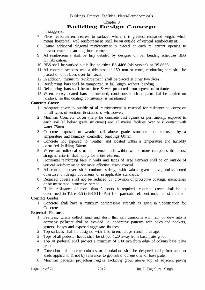
Concrete Cover
1 Adequate cover to outside of all reinforcement is essential for resistance to corrosion for all types of sections & situations whatsoever.
2 Minimum Concrete Cover (mm) for concrete cast against or permanently, exposed to earth soil (all below grade structures) and all marine facilities over or in contact with water 75mm
3 Concrete exposed to weather (all above grade structures not enclosed by a temperature and humidity controlled building) 60mm
4 Concrete not exposed to weather and located within a temperature and humidity controlled building 50mm
5 Where an individual structural element falls within two or more categories then most
stringent criteria shall apply for entire element. 6 Horizontal reinforcing bars in walls and faces of large elements shall be on outside of
vertical reinforcement for more effective crack control. 7 All concrete cover shall conform strictly, with values given above, unless noted
otherwise on design documents or in applicable standards.
8 Required covers shall not be reduced by provision of protective coatings, membranes or by membrane protective screed.
9 If fire resistance of more than 2 hours is required, concrete cover shall be as determined in Table 3.5 in BS 8110 Part 1 for particular element under consideration.
Concrete Grades
1 Concrete shall have a minimum compressive strength as given in Specification for Concrete
Externals Features
1 Features, which collect sand and dust, that can transform with rain or dew into a corrosive pollutant shall be avoided i.e. decorative patterns with holes and pockets,
gutters, ledges and exposed aggregate finishes. 2 Top surfaces shall be designed with falls to encourage runoff drainage.
3 Tops of all pedestal heads shall be sloped 1:20 away from base plate grout. 4 Top of pedestal shall project a minimum of 100 mm from edge of column base plate
grout.
5 Dimensions of concrete columns or foundations shall be designed taking into account loads applied to & not by reference to geometric dimensions of base plate.
6 Minimum pedestal projection heights excluding grout above top of adjacent paving

Buildings Practice Facilities Plants/Petrochemicals
Chapter 8 Building Design Concept
Page 14 of 71 2012 Int. P Eng Suraj Singh
shall be considered as follows:
a Structural Steel columns: 150 mm to 200 mm b Equipment (general): 100 mm to 300 mm
c Equipment (pumps): 100 mm to 300 mm 7 Grout is to be sloped 1:1 away from bottom outside corner of column base plate
grout.
8 Shear keys shall not be used on pedestals/plinths. Stress Raisers
1 Complicated plan shapes, which produce stresses, shall be avoided. 2 Large and sudden changes of cross section i.e. wall junctions and counter forts in
middle of bay lengths shall be avoided.
3 Locate joints adjacent to these stress producers or cast in two separate sections. 4 Provide appropriate extra reinforcement, where stress producers are unavoidable.
5 Casting in pipes, box outs, notches in middle of bay lengths shall be avoided 6 Locate joints adjacent to these stress producers, if possible.
Anchor Bolts
1 For small diameters, chemical type anchors or cast in anchors are preferred. 2 Where chemical anchors are used, hole must be properly cleaned in
compliance/according to manufacturer’s instructions. 3 Anchor bolts shall be designed for combined tension and shear per BS5950. 4 Minimum edge distance measured to outside of tube shall be 100 mm or 4 times bolt
diameter, whichever is greater. Shear Keys
1 For standard conventional structures, shear keys shall not be used. 2 For situations, where shear keys are required, back up design calculations and
justification shall be given for approval.
Pits and Tanks
1 As a minimum requirement, recommendations of BS 8007 - Section 5 ‘Design,
Detailing and Workmanship of Joints’ shall be adhered to regardless of whether or not, structure is liquid retaining.
2 All construction joints shall be designed, detailed and shown on drawings by designer
or subcontractor for construction with approval of contractor. 3 Where continuous construction is necessary, method of ‘Temporary Open Sections’
as specified in BS 8007 C1.5.5 shall be used. 4 Such open sections shall not be more than 1.0 m containing “Lapped’ section of
reinforcement.
5 Use of sequential bay wall construction shall not be permitted. 6 Unless roofs are insulated, these sections are subject to extremely high daytime
temperatures and lower night temperatures. 7 Consideration shall be given to use of insulation or reflective coatings (e.g.
aluminum).
8 All such structures (other than blast resistant structures) shall have an isolated roof slab on a sliding bearing (slip strip or equal approved).
9 Monolithic construction with supporting wall shall not be considered in such design. Paving
1 For ground slab paving construction, method used for design and construction shall
be by alternate ‘long strip method’ using a combination of transverse contraction joints (induced or formed).
2 Adjacent longitudinal strips shall be cast with longitudinal tied joints between each

Buildings Practice Facilities Plants/Petrochemicals
Chapter 8 Building Design Concept
Page 15 of 71 2012 Int. P Eng Suraj Singh
strip.
3 Recommendations for slab design and construction shall be complied with provisions in following publications:-
a Design of Floors on Ground by Cement and Concrete Assoc. Tech. Report 550. b Concrete Industrial Ground Floors by U.K. Concrete Society Technical Report #34. c Design of Ground Supported Concrete Industrial Ground Floors by British Cement
Assoc. Interim Note 11. d Guide for Concrete Floor and Slab Construction by ACI 302.1R.
4 Location of all joints shall be shown on drawings with accompanying details of each joint type.
5 Isolation joints are to be provided around all equipment foundations and pedestals.
Concrete Masonry Structures
1 Design of concrete masonry structures shall conform to ACI 530 and UBC.
2 Concrete masonry structures shall be designed for loads and load combinations specified
Grouting
1 All grout materials and application procedures shall be approved by designer and manufacturer.
2 Sand cement grout shall not be used for any project. 3 All grouting shall be in accordance with defined project specifications as well as,
proprietary standards.
4 Epoxy based non shrink grout shall be evaluated by contractor and manufacturer for each application for temperature creep as well as, strength and applied in accordance
with manufacturer's specification. 5 Grout material used below base plates for machinery, pipe racks, pumps, pipe
supports etc. shall not be placed higher than bottom of plate level and sloped outward
at a 1:1 slope away from bottom of base plate to prevent water accumulation near base plate as well as, to prevent cracking of grout as a result of corrosion formation
around base plate edge. 6 Contractor shall develop a detail to ensure an effective seal from exterior moisture is
achieved around perimeter of base plates at point of intersection between grout and
base plates. Fireproofing
Fireproofing zones 1 Only specific structures and equipment located within a fire proofing zone (FPZ)
shall be fireproofed, as described in specification for fireproofing
Loads
1 Buildings, process structures, pipe racks, miscellaneous plant structures, vessels,
exchangers and tanks 2 Following loads shall be considered:
Dead Load
1 Soil Load (include as part of dead load) 2 Operating (product) Load
3 Test Load Live Load
1 Sand Load (include as part of live load)
2 Surge Load (include as part of live load) 3 Truck Load
4 Wind Load

Buildings Practice Facilities Plants/Petrochemicals
Chapter 8 Building Design Concept
Page 16 of 71 2012 Int. P Eng Suraj Singh
5 Earthquake Load
6 Crane/Impact Load 7 Dynamic Load
8 Thermal Load 9 Erection Dead Load 10 Maintenance Load
11 Miscellaneous/Differential Settlement Load 12 Earth/Hydrostatic Load and Buoyancy
13 Blast Load 14 Future Load
Above loads are defined as follows.
Dead Load 1 Dead load is defined as weight of all permanent construction including walls,
foundations, floors, roofs, ceilings, partitions, stairways and fixed service equipment. 2 For heavy industrial work, this would include equipment, vessels & internals, pipes,
valves, accessories, electrical and lighting conduits, switchgear, instrumentation,
fireproofing, insulation, ladders, platforms and all other similar items. 3 Weight of equipment shall be extracted from manufacturer’s datasheets and include
auxiliary machinery, piping etc. 4 Equipment and piping should be considered empty of product load, when calculating
dead load.
5 Gravity weight of soil overburden shall be considered as dead load Soil Load (Dead Load)
1 Soil loads shall consist of lateral earth pressures. 2 Active and passive coefficients for lateral pressures shall be obtained from project
soils report.
Operating (Product) Load (Live Load)
1 Load shall be defined as gravity load imposed by liquid, solid or viscous materials in
vessels, tanks, equipment or piping during operation. 2 Unusual loading that occurs during regeneration or upset conditions shall also, be
considered.
Test Load (Live Load)
1 Test load shall be defined as gravity load imposed by a method necessary to test
vessels, tanks, equipment or piping. 2 When more than one vessel etc. is supported by one structure, structure requires only
be designed on basis that one vessel shall be tested at one time and that others shall
either be empty or still in operation. Live Load
1 Live load is defined as weight superimposed by use and occupancy of building or other structure, but not permanently attached to it.
2 For industrial design, live load can be defined as load produced by personnel,
moveable equipment, tools and other items placed on structure, but not permanently attached to it.
3 Unless specified otherwise, use minimum live load values given in table below. 4 Uniform loads and concentrated loads do not occur simultaneously.
Types of Structures Load (KN/m2)
1 Walkways (not used as operating) 2.0 (or 3.0 kN point load) 2 Operating platforms (other than compressor and generator platforms 5.0 (or 5.0 kN
point load)
Buildings Practice Facilities Plants/Petrochemicals
Chapter 8 Building Design Concept
Page 17 of 71 2012 Int. P Eng Suraj Singh
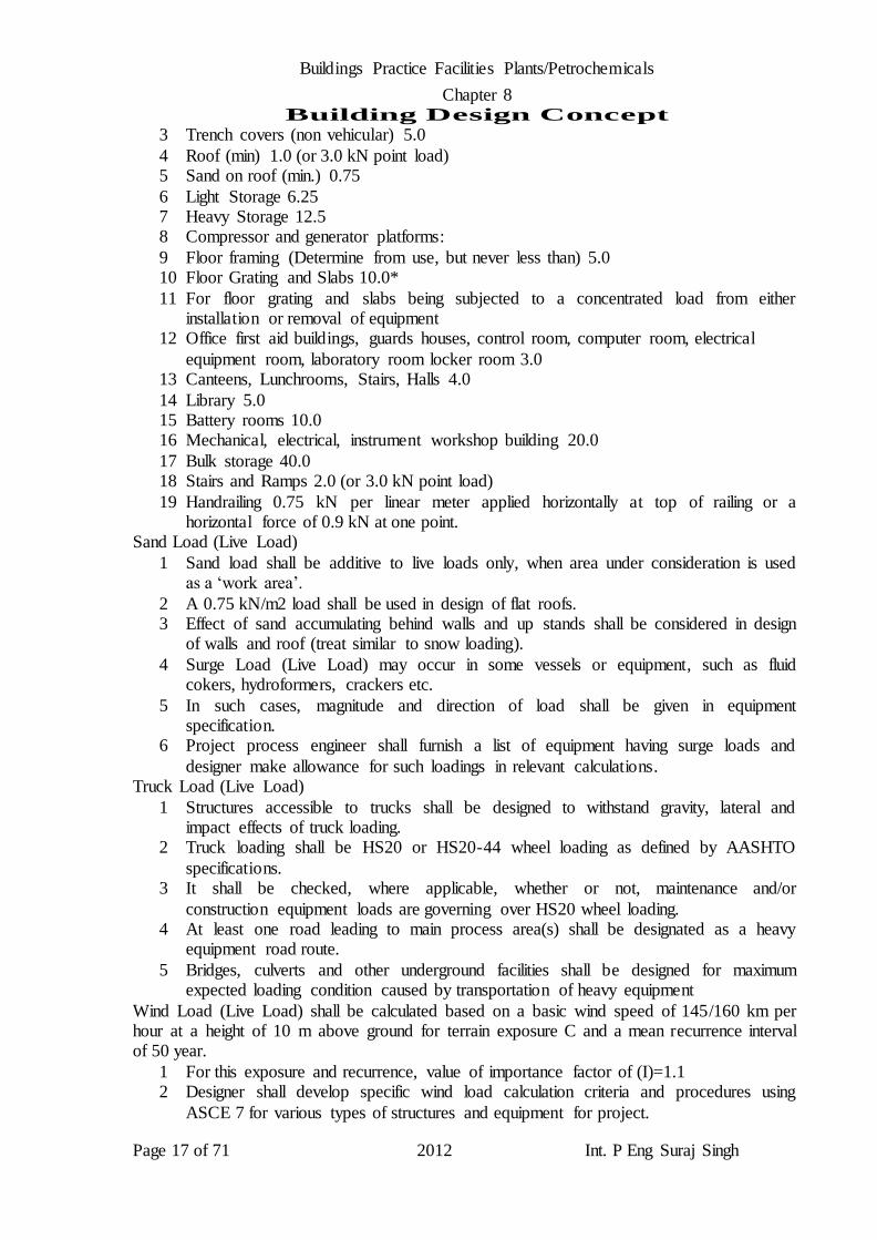
3 Trench covers (non vehicular) 5.0
4 Roof (min) 1.0 (or 3.0 kN point load) 5 Sand on roof (min.) 0.75
6 Light Storage 6.25 7 Heavy Storage 12.5 8 Compressor and generator platforms:
9 Floor framing (Determine from use, but never less than) 5.0 10 Floor Grating and Slabs 10.0*
11 For floor grating and slabs being subjected to a concentrated load from either installation or removal of equipment
12 Office first aid buildings, guards houses, control room, computer room, electrical
equipment room, laboratory room locker room 3.0 13 Canteens, Lunchrooms, Stairs, Halls 4.0
14 Library 5.0 15 Battery rooms 10.0 16 Mechanical, electrical, instrument workshop building 20.0
17 Bulk storage 40.0 18 Stairs and Ramps 2.0 (or 3.0 kN point load)
19 Handrailing 0.75 kN per linear meter applied horizontally at top of railing or a horizontal force of 0.9 kN at one point.
Sand Load (Live Load)
1 Sand load shall be additive to live loads only, when area under consideration is used as a ‘work area’.
2 A 0.75 kN/m2 load shall be used in design of flat roofs. 3 Effect of sand accumulating behind walls and up stands shall be considered in design
of walls and roof (treat similar to snow loading).
4 Surge Load (Live Load) may occur in some vessels or equipment, such as fluid cokers, hydroformers, crackers etc.
5 In such cases, magnitude and direction of load shall be given in equipment specification.
6 Project process engineer shall furnish a list of equipment having surge loads and
designer make allowance for such loadings in relevant calculations. Truck Load (Live Load)
1 Structures accessible to trucks shall be designed to withstand gravity, lateral and impact effects of truck loading.
2 Truck loading shall be HS20 or HS20-44 wheel loading as defined by AASHTO
specifications. 3 It shall be checked, where applicable, whether or not, maintenance and/or
construction equipment loads are governing over HS20 wheel loading. 4 At least one road leading to main process area(s) shall be designated as a heavy
equipment road route.
5 Bridges, culverts and other underground facilities shall be designed for maximum expected loading condition caused by transportation of heavy equipment
Wind Load (Live Load) shall be calculated based on a basic wind speed of 145/160 km per hour at a height of 10 m above ground for terrain exposure C and a mean recurrence interval of 50 year.
1 For this exposure and recurrence, value of importance factor of (I)=1.1 2 Designer shall develop specific wind load calculation criteria and procedures using
ASCE 7 for various types of structures and equipment for project.

Buildings Practice Facilities Plants/Petrochemicals
Chapter 8 Building Design Concept
Page 18 of 71 2012 Int. P Eng Suraj Singh
3 For overhead pipe tracks 4m wide or less, wind load on three largest pipes shall be
taken into account. 4 For overhead pipe tracks of over 4m wide, wind load on four largest pipes shall be
taken into account. 5 Following tabulated velocity pressures shall be used for calculating design wind
forces for design of all structures, buildings, equipment and their parts, portions and
appurtenances for project. 6 Pressure coefficient Cf = 0.8
7 Pipe racks 4 m wide or less: Wp = 0.8 qh (D1+D2+D3) or pipe racks wider than 4 m: Wp = 0.8 qh (D1+D2+D3+D4), Where Wp = Unit design wind load on piping, qh = Velocity pressure determined at piping elevation h, Dn = Diameter of pipe
a. Reference ASCE 7-1993 V - 145 km/hr 50 year mean recurrence, I = 1.1, Exposure C 8 Height Zone Above Grade (m), Z Velocity Pressure in Kg/m2, qz Gust Response
Factors 9 Gh and Gz a 0-6 107 1.29
b 6-9 114 1.26 c 9-12 125 1.25
d 12-15 134 1.22 e 15-18 142 1.21 f 18-24 151 1.18
g 24-30 164 1.17 h 30-36 173 1.15
i 36-45 183 1.14 j 45-60 198 1.12 k 60-90 219 1.10
l 90-120 241 1.08 10 Increase factors may be used to modify projected areas of vertical and horizontal
vessels (including insulation, if any) to allow for attachments, such as manholes, nozzles, piping, ladders and platforms.
11 ‘Shape increase factors’ may be used to modify projected areas of vertical and
horizontal vessels (including insulation, if any) to allow for attachments, such as manholes, nozzles, piping, ladders and platforms for which use Cf = 0.8
12 Wind loads shall be separately, computed for all supported equipment, ladders and stairs, except for vessels, where ‘projected area increase factors’ have already been accounted for these items.
13 Gust response factors G for main wind resisting systems of flexible buildings, structures and vertical vessels having a height exceeding five times least horizontal
dimension or a fundamental natural frequency less than 1.0 hertz shall be calculated. 14 Calculations shall be based on a rational analysis that incorporates dynamic properties
of main wind force resisting system.
15 One such procedure for determining gust response factor is described in ASCE 16 No reduction shall be made for shielding effect of vessels or structures adjacent to
structure being designed. 17 For main wind force resisting systems and walls, use Gh evaluated at height h (top) of
structure.
18 An exception is in various structural specifications for equipment, variable gust response factor Gz is used.
19 For components and cladding, use Gz evaluated at centroid height z above ground.
Buildings Practice Facilities Plants/Petrochemicals
Chapter 8 Building Design Concept
Page 19 of 71 2012 Int. P Eng Suraj Singh
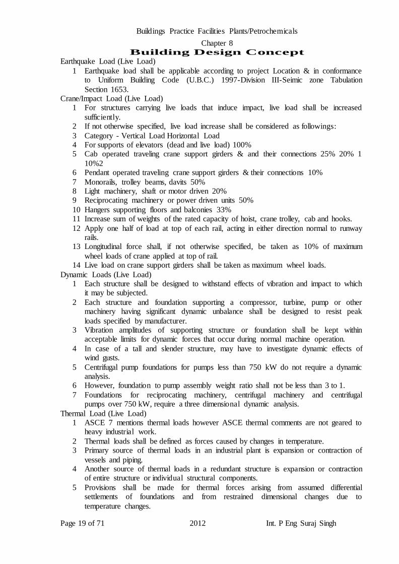
Earthquake Load (Live Load)
1 Earthquake load shall be applicable according to project Location & in conformance to Uniform Building Code (U.B.C.) 1997-Division III-Seimic zone Tabulation
Section 1653. Crane/Impact Load (Live Load)
1 For structures carrying live loads that induce impact, live load shall be increased
sufficiently. 2 If not otherwise specified, live load increase shall be considered as followings:
3 Category - Vertical Load Horizontal Load 4 For supports of elevators (dead and live load) 100% 5 Cab operated traveling crane support girders & and their connections 25% 20% 1
10%2 6 Pendant operated traveling crane support girders & their connections 10%
7 Monorails, trolley beams, davits 50% 8 Light machinery, shaft or motor driven 20% 9 Reciprocating machinery or power driven units 50%
10 Hangers supporting floors and balconies 33% 11 Increase sum of weights of the rated capacity of hoist, crane trolley, cab and hooks.
12 Apply one half of load at top of each rail, acting in either direction normal to runway rails.
13 Longitudinal force shall, if not otherwise specified, be taken as 10% of maximum
wheel loads of crane applied at top of rail. 14 Live load on crane support girders shall be taken as maximum wheel loads.
Dynamic Loads (Live Load) 1 Each structure shall be designed to withstand effects of vibration and impact to which
it may be subjected.
2 Each structure and foundation supporting a compressor, turbine, pump or other machinery having significant dynamic unbalance shall be designed to resist peak
loads specified by manufacturer. 3 Vibration amplitudes of supporting structure or foundation shall be kept within
acceptable limits for dynamic forces that occur during normal machine operation.
4 In case of a tall and slender structure, may have to investigate dynamic effects of wind gusts.
5 Centrifugal pump foundations for pumps less than 750 kW do not require a dynamic analysis.
6 However, foundation to pump assembly weight ratio shall not be less than 3 to 1.
7 Foundations for reciprocating machinery, centrifugal machinery and centrifugal pumps over 750 kW, require a three dimensional dynamic analysis.
Thermal Load (Live Load) 1 ASCE 7 mentions thermal loads however ASCE thermal comments are not geared to
heavy industrial work.
2 Thermal loads shall be defined as forces caused by changes in temperature. 3 Primary source of thermal loads in an industrial plant is expansion or contraction of
vessels and piping. 4 Another source of thermal loads in a redundant structure is expansion or contraction
of entire structure or individual structural components.
5 Provisions shall be made for thermal forces arising from assumed differential settlements of foundations and from restrained dimensional changes due to
temperature changes.

Buildings Practice Facilities Plants/Petrochemicals
Chapter 8 Building Design Concept
Page 20 of 71 2012 Int. P Eng Suraj Singh
6 Thermal loads and displacements caused by operating conditions shall be based on
design temperature of equipment rather than operating temperature. 7 Design atmospheric temperature ranges from a minimum of 5 deg C to a maximum of
58 deg C. 8 Low friction slide plates (Fluorogold, Teflon/PTFE or an approved equal) shall be
used if vessel operating condition weight is greater than 45 kN at sliding end.
9 For preliminary design, temperature drop of 1.9 deg C/mm from bottom of shell to bottom of saddle may be assumed.
10 Following friction coefficients shall be used for calculating frictional restraint due to temperature change or lateral loading on sliding surfaces:
Surface Friction Coefficient
1 Steel-to-steel (corroded) 0.35, Steel to concrete 0.50, Teflon to teflon a straight line variation of 0.17 to 0.08 for bearing stresses from 0.0 N/mm2 to 0.7 N/mm2,
respectively bearing stress greater than 0.7 N/mm2 0.17 to 0.08, Graphite to graphite 0.15
2 For computing friction loads due to effects of pipe expansion in pipe racks, use
following friction coefficients: 3 Number of Lines on Support Friction Coefficient
4 1–3 0.3, 1- 6 0.2, or more 0.1 5 For a given support, if considering only, larger lines and ignoring smaller lines,
results in greater loads.
6 These forces and associated friction coefficients shall be used instead of considering all lines.
7 A concrete pipe rack beam shall be designed for an arbitrary horizontal pipe anchor force of 15 kN acting at mid span, unless design calculations dictate a higher force and more locations.
8 Pipe anchor force shall not be distributed to foundations. 9 For pipe anchor forces transferred by longitudinal girders to structural anchors
(bracing), an arbitrary force of 5% of total pipe load per layer shall be taken into account, unless design calculations dictate a higher force.
10 These forces shall be distributed to foundations.
11 Foundations and structures, which are subject to temperature effects shall be designed for various loading conditions and also, for a temperature difference, which may
occur in parts of structural members. 12 Anchor and guide forces shall be obtained from designers piping engineering
department.
13 Structural steel pipe supports shall be designed in accordance with industry requirement/practice
Standard Structural Design Methods
Erection Dead Load
1 Erection dead load is weight of equipment at time of erection plus weight of foundation.
2 Foundation weight is combined weight of footing, pedestal, and overburden soil. 3 All possible loading conditions during erection shall be considered and for a member
of a structure, most unfavorable be considered.
4 Heavy equipment lowered onto a supporting structure can introduce extreme point loads on structural members exceeding an operating or a test load.
5 After placing equipment, exact positioning (lining out and leveling) can also,

Buildings Practice Facilities Plants/Petrochemicals
Chapter 8 Building Design Concept
Page 21 of 71 2012 Int. P Eng Suraj Singh
introduce extreme point loads.
6 Above should be interpreted on basis of contractor’s practical experience, manufacturer’s information and allowed for in design calculations accordingly.
7 Beams and floor slabs in multistory structures e.g. fire decks shall be designed to carry full construction loads imposed by props supporting structure immediately, above.
8 A note shall be added on relevant construction drawings to inform field engineer of adopted design philosophy.
Maintenance Loads (Live Load) 1 Maintenance loads are temporary forces caused by dismantling, repair or painting of
equipment.
2 Force required to remove tube bundle from a shell and tube heat exchanger shall be assumed to act along horizontal centerline of exchanger, with a value of 2 times
weight of bundle, but not less than 10 kN. Miscellaneous Loads (Live Load)
1 Miscellaneous loads shall be defined as loads that do not fit into categories listed in
this section. Earth/Hydrostatic Load and Buoyancy (Live Load)
1 Earth and hydrostatic water pressures on retaining walls and underground structures shall be determined.
2 Outward pressures on liquid retaining structures shall also, be considered.
3 Buoyancy load is equal to weight of volume of displaced water. Blast Load (Live Load)
Negligible Blast 1 Buildings located more than 610 m away from potential explosive sources, do not
require special provisions with regard to explosion resistance.
Blast Resilient
1 Buildings within the 200 m to 610 m distance from potential explosive sources shall
be designed to same loading conditions as specified for buildings beyond 610 m zone and in accordance with following design concepts:
a Building structural frame, roof, walls, bracing and connections shall be designed in
such a manner that large plastic deformations of major frame members as well as, external wall panels shall be allowed to occur without causing partial or total building
collapse. b Blast resilient buildings shall be designed and detailed in accordance with ACI 318,
Chapter 21, “Special Provisions for Seismic Design”.
c Building frame shall comprise of reinforced concrete or structural steel. d Building walls shall be constructed as reinforced concrete, reinforced masonry with
concrete filled cells or properly designed carbon steel cladding system. e Walls for these buildings shall not be used as mainframe members or to provide
structural stability and/or structural strength.
f Building roofs shall be constructed of monolithic reinforced concrete or a properly designed carbon steel roofing system.
g Loose lightweight concrete roof slabs or asbestos cement sheeting shall not be used. h Gravel as a protection of roofing finish or loose tiles for walkways on top of roof
finish shall not be used.
i For steel structures, structural steel bracing in roof and walls shall be provided. j Materials with a brittle behavior, such as masonry shall not be used in such a way that
provides strength.
Buildings Practice Facilities Plants/Petrochemicals
Chapter 8 Building Design Concept
Page 22 of 71 2012 Int. P Eng Suraj Singh
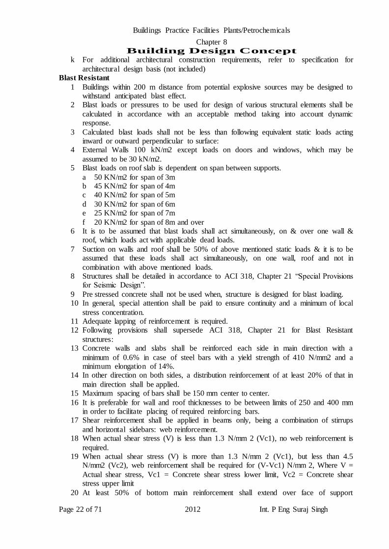
k For additional architectural construction requirements, refer to specification for
architectural design basis (not included) Blast Resistant
1 Buildings within 200 m distance from potential explosive sources may be designed to withstand anticipated blast effect.
2 Blast loads or pressures to be used for design of various structural elements shall be
calculated in accordance with an acceptable method taking into account dynamic response.
3 Calculated blast loads shall not be less than following equivalent static loads acting inward or outward perpendicular to surface:
4 External Walls 100 kN/m2 except loads on doors and windows, which may be
assumed to be 30 kN/m2. 5 Blast loads on roof slab is dependent on span between supports.
a 50 KN/m2 for span of 3m b 45 KN/m2 for span of 4m c 40 KN/m2 for span of 5m
d 30 KN/m2 for span of 6m e 25 KN/m2 for span of 7m
f 20 KN/m2 for span of 8m and over 6 It is to be assumed that blast loads shall act simultaneously, on & over one wall &
roof, which loads act with applicable dead loads.
7 Suction on walls and roof shall be 50% of above mentioned static loads & it is to be assumed that these loads shall act simultaneously, on one wall, roof and not in
combination with above mentioned loads. 8 Structures shall be detailed in accordance to ACI 318, Chapter 21 “Special Provisions
for Seismic Design”.
9 Pre stressed concrete shall not be used when, structure is designed for blast loading. 10 In general, special attention shall be paid to ensure continuity and a minimum of local
stress concentration. 11 Adequate lapping of reinforcement is required. 12 Following provisions shall supersede ACI 318, Chapter 21 for Blast Resistant
structures: 13 Concrete walls and slabs shall be reinforced each side in main direction with a
minimum of 0.6% in case of steel bars with a yield strength of 410 N/mm2 and a minimum elongation of 14%.
14 In other direction on both sides, a distribution reinforcement of at least 20% of that in
main direction shall be applied. 15 Maximum spacing of bars shall be 150 mm center to center.
16 It is preferable for wall and roof thicknesses to be between limits of 250 and 400 mm in order to facilitate placing of required reinforcing bars.
17 Shear reinforcement shall be applied in beams only, being a combination of stirrups
and horizontal sidebars: web reinforcement. 18 When actual shear stress (V) is less than 1.3 N/mm 2 (Vc1), no web reinforcement is
required. 19 When actual shear stress (V) is more than 1.3 N/mm 2 (Vc1), but less than 4.5
N/mm2 (Vc2), web reinforcement shall be required for (V-Vc1) N/mm 2, Where V =
Actual shear stress, Vc1 = Concrete shear stress lower limit, Vc2 = Concrete shear stress upper limit
20 At least 50% of bottom main reinforcement shall extend over face of support
Buildings Practice Facilities Plants/Petrochemicals
Chapter 8 Building Design Concept
Page 23 of 71 2012 Int. P Eng Suraj Singh
providing a good anchorage between supports.
21 Wind or earthquake loads shall not be combined with blast loads. Future Load (Dead or Live Loads)
1 Future loads including pipe rack extensions and building expansions shall be considered, when so directed by company.
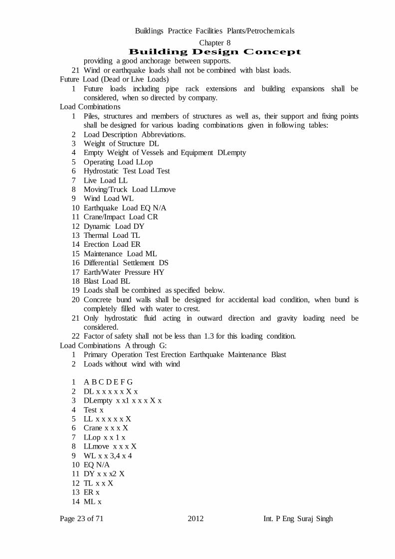
Load Combinations
1 Piles, structures and members of structures as well as, their support and fixing points shall be designed for various loading combinations given in following tables:
2 Load Description Abbreviations. 3 Weight of Structure DL 4 Empty Weight of Vessels and Equipment DLempty
5 Operating Load LLop 6 Hydrostatic Test Load Test
7 Live Load LL 8 Moving/Truck Load LLmove 9 Wind Load WL
10 Earthquake Load EQ N/A 11 Crane/Impact Load CR
12 Dynamic Load DY 13 Thermal Load TL 14 Erection Load ER
15 Maintenance Load ML 16 Differential Settlement DS
17 Earth/Water Pressure HY 18 Blast Load BL 19 Loads shall be combined as specified below.
20 Concrete bund walls shall be designed for accidental load condition, when bund is completely filled with water to crest.
21 Only hydrostatic fluid acting in outward direction and gravity loading need be considered.
22 Factor of safety shall not be less than 1.3 for this loading condition.
Load Combinations A through G: 1 Primary Operation Test Erection Earthquake Maintenance Blast
2 Loads without wind with wind
1 A B C D E F G
2 DL x x x x x X x 3 DLempty x x1 x x x X x
4 Test x 5 LL x x x x x X 6 Crane x x x X
7 LLop x x 1 x 8 LLmove x x x X
9 WL x x 3,4 x 4 10 EQ N/A 11 DY x x x2 X
12 TL x x X 13 ER x
14 ML x

Buildings Practice Facilities Plants/Petrochemicals
Chapter 8 Building Design Concept
Page 24 of 71 2012 Int. P Eng Suraj Singh
15 DS x x x X x
16 HY x x x x X x 17 BL x
18 ML x 19 DS x x x X x 20 HY x x x x X x
21 BL x 1 Most unfavorable load combination shall be taken into account.
2 Only if structure supports rotating equipment that shall be in operation, while a vessel is being tested with water.
3 Only 50% wind load shall be taken into account.
4 Effect of wind forces acting on temporary scaffolding erected during construction or later for maintenance, which requires to be transferred to vessel or column shall be
considered. 5 When considering these effects, actual projected area of scaffold members together
with correct shape factor and drag coefficient should be used.
6 As an initial approximation, overall width of scaffolding itself can be taken as 1.5 m on each side of vessel or column with 50% closed surface and shape factor 1.0
7 Blast condition shall be taken into account for blast resistant design of buildings where applicable.
8 In ultimate limit state design, due regard shall be given to different load factors for
various load combinations and adverse or beneficial effects of basic load cases. 9 Where imposed loads (live loads) have a beneficial effect, they shall be zero.
Structural Materials
General types of material to be used are defined below:
1 Structural Steel 2 Furnishing, fabricating and erecting structural steel and miscellaneous steel shall be
carried out in accordance with design general specifications. 3 Structural steel shapes and plates shall conform to ASTM A36 or to BS 4 or BS 4848
or BS EN 10025.
Cast in Place or situ Concrete
1 Cast in Place or situ Concrete shall have a minimum compressive strength in accordance with specification for concrete supply.
2 Upon approval of company, higher strength concrete may be used.
3 Precast concrete shall be carried out only, with approval of company. Reinforcing Steel
1 Requirement to prevent ‘stray current corrosion’ of steel in concrete (due to implementation of impressed current Cathodic Protection to nearby underground installation) shall be provided in accordance with specification– Material Selection
and Corrosion Monitoring Philosophy 2 Reinforcing steel shall conform to BS 4449 Grade 460.
3 Epoxy coating shall not be applicable, where Cathodic Protection CP is provided. 4 Welded wire fabric shall conform to BS 4848. 5 Epoxy coatings shall not be used on reinforcing bars applied with cathodic protection.
6 Reinforcing is not required to be electrically, continuous for any future cathodic protection of concrete structures.
Buildings Practice Facilities Plants/Petrochemicals
Chapter 8 Building Design Concept
Page 25 of 71 2012 Int. P Eng Suraj Singh
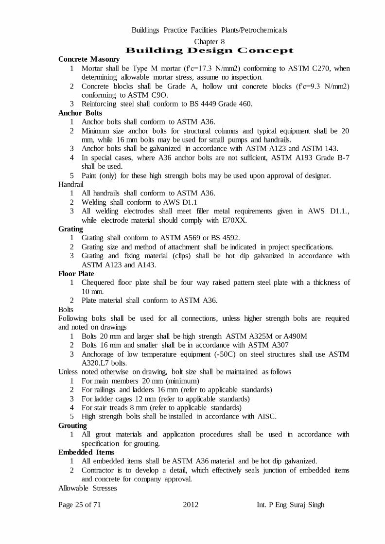
Concrete Masonry
1 Mortar shall be Type M mortar (f’c=17.3 N/mm2) conforming to ASTM C270, when determining allowable mortar stress, assume no inspection.
2 Concrete blocks shall be Grade A, hollow unit concrete blocks (f’c=9.3 N/mm2) conforming to ASTM C9O.
3 Reinforcing steel shall conform to BS 4449 Grade 460.
Anchor Bolts
1 Anchor bolts shall conform to ASTM A36.
2 Minimum size anchor bolts for structural columns and typical equipment shall be 20 mm, while 16 mm bolts may be used for small pumps and handrails.
3 Anchor bolts shall be galvanized in accordance with ASTM A123 and ASTM 143.
4 In special cases, where A36 anchor bolts are not sufficient, ASTM A193 Grade B-7 shall be used.
5 Paint (only) for these high strength bolts may be used upon approval of designer. Handrail
1 All handrails shall conform to ASTM A36.
2 Welding shall conform to AWS D1.1 3 All welding electrodes shall meet filler metal requirements given in AWS D1.1.,
while electrode material should comply with E70XX. Grating
1 Grating shall conform to ASTM A569 or BS 4592.
2 Grating size and method of attachment shall be indicated in project specifications. 3 Grating and fixing material (clips) shall be hot dip galvanized in accordance with
ASTM A123 and A143. Floor Plate
1 Chequered floor plate shall be four way raised pattern steel plate with a thickness of
10 mm. 2 Plate material shall conform to ASTM A36.
Bolts Following bolts shall be used for all connections, unless higher strength bolts are required and noted on drawings
1 Bolts 20 mm and larger shall be high strength ASTM A325M or A490M 2 Bolts 16 mm and smaller shall be in accordance with ASTM A307
3 Anchorage of low temperature equipment (-50C) on steel structures shall use ASTM A320.L7 bolts.
Unless noted otherwise on drawing, bolt size shall be maintained as follows
1 For main members 20 mm (minimum) 2 For railings and ladders 16 mm (refer to applicable standards)
3 For ladder cages 12 mm (refer to applicable standards) 4 For stair treads 8 mm (refer to applicable standards) 5 High strength bolts shall be installed in accordance with AISC.
Grouting
1 All grout materials and application procedures shall be used in accordance with
specification for grouting. Embedded Items
1 All embedded items shall be ASTM A36 material and be hot dip galvanized.
2 Contractor is to develop a detail, which effectively seals junction of embedded items and concrete for company approval.
Allowable Stresses

Buildings Practice Facilities Plants/Petrochemicals
Chapter 8 Building Design Concept
Page 26 of 71 2012 Int. P Eng Suraj Singh
Structural Steel
1 Allowable stresses specified in AISC specifications shall be used for design of structural steel.
Cast in Place Concrete 1 Allowable stresses specified in ACI 318M shall be used in design of concrete.
Masonry
Allowable stresses specified in ACI 530 and UBC shall be used for masonry design. Anchor Bolts and Base Plate Bearing
1 Allowable stress for anchor bolt shall conform to AISC and ACI Specifications. 2 Neither probability factors nor allowable stress increases shall be used for anchor bolt
design.
3 Calculated bolt diameter required to resist specified design loads shall be increased by 3 mm to provide an allowance for corrosion.
4 Permissible bearing stress under base plates shall be as given in ACI 318 Code. Stress Increase Allowable stresses specified in applicable codes given above for structural steel, concrete and
masonry shall apply for all design with following exceptions: 1 Increase in allowable stresses for all structural elements and their connections:
a 20% - Test without wind load b 33% - Including wind c Test load factor for concrete design
Deflection and Vibration/Allowable Deflections
Following sections give normally permissible deflection limits for steel and concrete structures.
1 Functional requirements of structure may impose stricter limits.
2 Systems should be reviewed for possible incompatible deflection behavior in piping, equipment or building components and support deflections.
Beam Deflections (Based on Live Loads Only) Maximum allowable deflection for beams supporting floor systems and equipment shall be considered as follows:
1 Max deflection = L/500 L=Span Maximum allowable deflection for beams supporting brittle finishes, such as plaster ceilings
shall be as follows: 1 Max deflection = L/360 L=Span
Maximum allowable deflection for purlins supporting roof system shall be as follows
1 Max deflection = L/400 L=Span Maximum allowable deflection for cantilever beams shall be as follows:
1 Max deflection = L/400 L=Overhang Length Maximum allowable deflection for beams supporting steel platforms, staircases, pipe racks etc.
1 Max deflection = L/300 L=Span Crane Runways
1 Max deflection = L/300 L=Span Overhead Traveling
1 Max deflection = L/600 L=Span
Monorails 1 Max deflection = L/400 L=Span
Buildings Practice Facilities Plants/Petrochemicals
Chapter 8 Building Design Concept
Page 27 of 71 2012 Int. P Eng Suraj Singh
Lateral Sway
Maximum allowable sway of buildings or structures shall be as follows: 1 Max deflection = H/300 H = Height - if equipment supported
2 H/200 H = Height - If equipment not supported Maximum allowable sway for pipe racks shall be as follows:
1 Max deflection = H/200 H = Height
Maximum allowable deflection for wall stanchions shall be as follows: 1 Max deflection = H/300 H = Height, h = height of story or height of structure
These limits apply to sway between stories and to structure as a whole. 1 Grating = L/250 (Maximum span 1.6 meter)
Vibration
Superstructure Vibration
1 Primary source of vibration in superstructures is harmonic unbalanced forces generated by rotating or reciprocating equipment.
2 Final design should be such that vibrations shall be neither intolerable nor troublesome to personnel and not cause damage to machine or structure or adjacent
foundations, structures or services. 3 As a general rule, none of natural frequencies of structure should be located within a
band of operating frequency of supported machinery.
4 Band recommended to be avoided is 1.414 above operating frequency and 0.707 below operating frequency.
5 To find structural natural frequencies, a computer analysis shall be required. 6 All natural frequencies below 2 times operating frequency for reciprocating
equipment and below 1.5 times operating frequency for rotating equipment shall be
calculated. 7 It shall be demonstrated that amplitudes at natural frequencies between 0.35 and 1.5
times operating frequency are within allowable values even assuming that, due to differences between actual structure and assumed model, resonance does occur.
8 In this case a reasonable amount of damping should be estimated.
9 Resonance condition requires a detailed three dimensional dynamic analysis. 10 Once a model analysis has been conducted, a harmonic response analysis shall be
performed. 11 Response analysis shall indicate anticipated amplitudes of vibration, velocity and
acceleration as well as, magnitudes of forces in structural members.
12 From above information, adequacy of design can be evaluated and if necessary, modifications may be made.
13 Maximum vibration amplitude of equipment shall not exceed lower of following values:
a Maximum allowable values stated by manufacturer of equipment.
b Amplitude (single amplitude) which causes effective velocity of vibration to exceed: 2 mm/s at location of machine bearing housings
2.5 mm/s at any location of structure 1 Dynamic amplitude of a part of foundation including a reciprocating compressor shall
be less than 80 µm single amplitude (80 x 10^-3mm).
2 Effective velocity is defined as square root of average of square of velocity, velocity being a function of time.
3 In case of a pure sinusoidal function, effective velocity is 0.71 times peak value of
Buildings Practice Facilities Plants/Petrochemicals
Chapter 8 Building Design Concept
Page 28 of 71 2012 Int. P Eng Suraj Singh
velocity.
4 Depth of a steel beam supporting large open floor areas free of partitions or other sources of damping should not be less than 1/20 of span to minimize perceptible
transient vibration due to pedestrian traffic. Foundation Vibration
1 Designer shall determine which vibrating equipment is to be analyzed by dynamic analysis.
Dynamic Analysis
1 For foundations of reciprocating machinery, centrifugal machinery and centrifugal
pumps 750 kW or over, a three dimensional dynamic analysis must be performed. 2 Foundation vibration generally, involves a grade foundation designed to support one
or more reciprocating or rotating machines. 3 Generally, same considerations for superstructure vibration also, apply to foundation
vibration.
4 Primary differences state that these foundations are often rigid blocks and that relevant soil behavior must be considered.
5 Rigid foundations supporting only, one major machine can readily be analyzed using hand calculations and concept of elastic half space theory.
6 For flexible foundations or foundations with many machines, a computer analysis
should be utilized along with concept of elastic half space theory. 7 Designer shall prepare an instruction for foundation vibration analysis, which
contains current state of art approaches, soil information, machine information, dynamic analysis aids, published response criteria, example solutions and a comprehensive list of references.
8 Dynamic amplitudes of a part of foundation including a reciprocating compressor shall be less than 80 µm (80 x 10^-3 mm) single amplitude.
9 For dynamic analysis, exciting forces shall be taken as maximum values that according to manufacturer of equipment shall occur during lifetime of equipment.
10 When exciting force is not given by manufacturer, it shall be determined from
11 Q (kN) = [Rotor Speed (rpm)/6000] x Rotor Weight (kN) 12 Dynamic calculations shall be based on a mechanical model, wherein weights and
elasticity of both structure as well as, foundation and weight of equipment to be represented in an appropriate way.
13 All natural frequencies below 2 times operating frequency for reciprocating
equipment and below 1.5 times operating frequency for rotating equipment shall be calculated.
14 It shall be demonstrated that amplitude of natural frequencies between 0.35 and 1.5 times operating frequency are within allowable values, even assuming that, due to differences between actual structure and assumed model, resonance does occur.
15 In this case, a reasonable amount of damping should be estimated. 16 Natural frequency of supporting structure shall not coincide with any resonant
frequency of equipment. 17 Static deformation for rotating equipment foundations shall be calculated and shown
to be within limits stated by manufacturer of equipment.
18 Calculations shall include, but not be limited to following causes of deformation. a Shrinkage and creep of concrete.
b Temperature effects caused by radiation and convection of heat or cold generated by

Buildings Practice Facilities Plants/Petrochemicals
Chapter 8 Building Design Concept
Page 29 of 71 2012 Int. P Eng Suraj Singh
machinery, piping and ducting.
c Elastic deformation caused by changing vapor pressure in condensers. d Elastic deformation caused by soil settlement.
Non Dynamic Analysis
1 For installations that do not warrant a dynamic analysis, (equipment weight less than
5000 kN), mass ratio concept is commonly used. 2 In design of equipment foundations subject to vibratory loading, where dynamic
analysis is not performed, foundations shall be proportioned as indicated below: a Rotating equipment mass ratio = weight of concrete weight of machine > 3 b Reciprocating equipment mass ratio = weight of concrete/weight of machine > 6
Miscellaneous design data Clearances and accessibility
1 Minimum clearances for equipment, structures, platforms and supports shall be in a accordance with table in specification for design, layout and drawing
Coefficients of Static Friction
Coefficients of static friction for various material combinations are listed as follows: 1 Steel to steel smooth, dry surfaced 0.3
2 Oxidizing steel 0.5 3 Steel to concrete or grout 0.5 4 Fluorogold, Teflon/PTFE and other similar materials as per manufacturer's
recommendations 5 Concrete to foundation materials
6 Clean sound rock 0.7 7 Clean gravel, gravel sand mixtures, coarse sand 0.55 8 Clean fine to medium sand, silty medium to coarse sand, silty or clay gravel 0.45
9 Clean fine sand, silty or clayey, fine to medium sand 0.35 10 Fine sandy silt, non plastic silt 0.30
11 Very stiff and hard residual or pre consolidated clay 0.40 12 Medium stiff and stiff clay and silty clay 0.30 13 Membrane sheet 0.20
Engineering Maintenance Manual
1 Designer shall prepare a detailed maintenance manual for use by operators, which manual shall contain following information:
Design Basis
1 A brief description of basis of design of all foundations, structures and buildings, including reference to detailed calculations for each to enable them to be retrieved if
necessary. Inspection
1 Recommendations for routine inspection of works to enable early detection of
potentially, dangerous deterioration, including guidelines regarding symptoms to be looked for, such as locations and types of cracking, which could be found in
reinforced concrete structures etc. 2 Routine forms for inspection are to be established.
Materials
1 A detailed listing of all materials used (both generic types and manufacturers' details) in works including concrete mix constituents, concrete surface coatings, steel grades,
painting details etc. to enable company to obtain compatible materials for future
Buildings Practice Facilities Plants/Petrochemicals
Chapter 8 Building Design Concept
Page 30 of 71 2012 Int. P Eng Suraj Singh
maintenance.
Maintenance and Repair Procedures
1 Details of recommended repair procedures for common types of failure, such as
breakdown or mechanical damage to concrete surface coatings, cracking of small foundations plinths due to reinforcement corrosion etc.
Finishing Material Manual
1 Additional list of all finishing materials used in project buildings including material catalogs and sources to enable company to obtain such material or equal for future
maintenance. Operational Requirements
Concrete asset management system (CAMS)
1 In view of continuous deterioration of reinforced concrete structures in plants, a computerized database system shall be developed by company to carry out periodical
inspections and monitor evaluation of disorder, if required. 2 Data related to new structures/foundations is required to be entered by contractor in
system in accordance with existing procedure.
Existing settlement check survey program
1 An existing computerized monitoring system for tanks and critical foundations
carrying large loads, rotating equipment foundations etc. shall be developed by Company.
2 As a result of this ongoing program, new tanks and critical foundations shall be
required to be monitored for future maintenance. 3 Contractor is required to provide following in this regard:
a Permanent bench marks to allow for future check surveys. b List of tanks and critical foundations/structures proposed for monitoring. c Monitoring devices (non corrosive material) embedded in concrete foundations and
fixed on tanks as required. d Plot plans showing locations of monitoring points and permanent bench marks.
e A computerized form filled with first readings of monitoring points surveyed at completion of project.
f Corrosion monitoring system for critical concrete structures
g Some critical concrete structures due to operational requirements cannot be shut down for inspection.
h A new technology exists, which allows for installation of metal sensors into concrete structures in order to monitor corrosion risk at regular intervals.
i In this way, protective measures can be taken before excessive damage occurs and
without any need of a shutdown for inspection. j Following structures are given as an example of types of structures to consider for
installation of sensors: a Below ground culverts b Outfall structures
c Brine tanks d Below ground tanks, such as sulfur pits
e Reinforced concrete or pre stressed pipes
1 Contractor is required to propose to company corrosion monitoring system to be used
and to propose to company critical structures, which should be equipped with system. 2 Contractor then is responsible to install agreed system to structures.

Buildings Practice Facilities Plants/Petrochemicals
Chapter 8 Building Design Concept
Page 31 of 71 2012 Int. P Eng Suraj Singh
Units of Measurement
1 All dimensions, quantities and units of measurement shown on drawings or used in specifications and calculation sketches shall be given in metric units except pipe size,
which could be given in English units of inches. 2 Refer to “Basic Engineering Design Data”. 3 Contractor shall design all buildings to adequate dimensions (lengths, widths and
heights) to accommodate necessary requirements inside. 4 However, following minimum criteria shall be followed.
a Corridors connecting rooms within buildings shall be wide enough to allow possible movement of equipment.
b Clear height of room from finished floor level to finished ceiling levels shall be
minimum 3500mm. c Space between equipment and walls shall be wide enough for a technician to walk
around with tools, instruments etc. d (Refer to Company/Client Electrical Specification) and carry out necessary
inspection/maintenance works.
e External doors of building shall be minimum 2400mm wide x 3000mm high plus a 300mm transom.
f Internal doors shall be 1100mm wide x 2100mm high. g HVAC system shall be direct expansion (DX) split system ducted and adequately,
sized for heat load inside buildings.
h Contractor shall follow requirement of space between equipment and walls per company/client electrical specification
i All civil/buildings works shall be of construction type as indicated below; Pump Pits (Substructure)
1 Shall be of reinforced concrete complete with impressed current cathodic protection
Receiving Basin 1 Shall be of reinforced concrete complete with impressed current cathodic protection
Outfall Structure 1 Shall be of reinforced concrete complete with impressed current cathodic protection
Discharge Channel
1 Shall be of reinforced concrete complete with impressed current cathodic protection. 2 Bottom slab of discharge channel shall be constructed with reinforced concrete.
Pump Houses 1 Steel frames with profiled metal sheet cladding with hot rolled steel section for all
structural members.
2 Metal sheeting shall be protected with lightning protection rods to avoid puncturing. Electro chlorination and Electrical Switchgear Building
1 Reinforced concrete with block work panel and storage area shall be structural steel framing, metallic roofing and siding complete with protection against lightning.
2 Electro chlorination building shall be fully covered structure steel building with metal
sheeting and provided with translucent sheet for lighting. 33kv Electrical Switch Gear Building for PH
1 Reinforced concrete frames with block work panels. VSDS Substation for PH
2 Reinforced concrete frame with block work panels.
Operation Building 3 Reinforced concrete frame with block work panels.
Local Lot Control Buildings

Buildings Practice Facilities Plants/Petrochemicals
Chapter 8 Building Design Concept
Page 32 of 71 2012 Int. P Eng Suraj Singh
1 Reinforced concrete frame with block work panels.
2 Contractor to design all LLCC’s for phases and to construct only phase LLCC’s. Gate Houses
1 Reinforced concrete frame with block work panels. Workshop Building
1 Structural framing with metallic roofing, complete with translucent sheets and
lightning protection. 2 Contractor shall allow for 3m high perimeter block wall and panels for offices and
other rooms. Warehouse/Workshop Building
1 Structural framing with metallic roofing, complete with translucent sheets and
lightning protection. 2 Contractor shall allow for 3m high perimeter block wall and panels for offices and
other rooms. Control Building (Extension)
1 Reinforced concrete frame with block work panels.
220 KV GIS Building 1 Reinforced concrete frame with block work panels.
Transformer Pens 1 Transformers shall be supported on reinforced concrete foundations in a room having
two sides as a minimum, covered with firewalls and front side with fence provided
with gates. 2 Top of transformer pan has to be covered with metal sheeting.
Foundation for Analyser houses 1 All concrete exposed to seawater or saline ground water shall be provided with
additional protection as appropriate, including cathodic protection to reinforcement,
water proofing system, extra cover to reinforcement, use of admixtures in concrete and protective paint on surface of concrete.
2 Corrosion Inhibitor shall be added to structural concrete mix at minimum rate of 10 litres/m3 for pump pits, receiving basins, discharge channel, outfall structure and to all structure foundations within water table or and below ± 0.0m nhd.
3 List of required buildings and their conceptual drawings with finishing material schedule are provided.
4 These building drawings are conceptual and have been developed based on preliminary building requirements and equipment sizing indicated during front end engineering design.
5 Contractor shall examine drawings in details, modify as necessary to accommodate final equipment selection and operational requirements.
Material Specifications 1 Selection of material is based on project specifications and all deviations shall be
subject to company/client's approval.
2 Contractor shall import rock for outfall structure. 3 Quarry for rocks shall be subject to company/client approval.
4 Concrete as specified in project specification shall have fly ash, microsilica, corrosion inhibitor and gabro/not limestone coarse aggregate.
HVAC and Plumbing
HVAC Sample Only 1 HVAC system design and sizing shall be worked out by contractor in accordance
with project specifications/meeting successful functional requirements, delivering all

Buildings Practice Facilities Plants/Petrochemicals
Chapter 8 Building Design Concept
Page 33 of 71 2012 Int. P Eng Suraj Singh
auxiliary systems and equipment detailed provisions.
Operation building HVAC System 1 Operation building shall be air conditioned by duty/standby direct expansion (DX)
split units to ensure 100% redundancy. 2 Treated air shall be supplied by 100 % capacity duty/standby air handling units
mixing fresh air and re circulating air.
3 Air handling units shall be located in HVAC plant room. 4 Duty/standby condensing units shall be located on operation building roof.
5 Procurement specification for DX condensing units/AHU's shall be drawn per company/client FEED specification/meeting other standards.
6 Each AHU shall have a ‘centrifugal fan of 100 % capacity’ chamber with back draft
and volume control/shut off dampers. 7 Fan shall have a minimum of 2 belts each.
8 Adequately sized hinged access doors shall be provided to access each section of AHU/CU. (AH= air handling unit, CU= condensing unit)
9 Electric heating coils and steam humidification sections shall be provided in AHU’s.
10 Twin duty/standby auto changeover fans shall be used for toilets, pantry and battery room exhaust.
11 Battery room twin fans shall be eexcl IIC, T6, non sparking type. 12 In battery room, loss of both fans shall inhibit boost charging of batteries. 13 All fresh air intakes shall have sand trap louvers/pre filters and motorised shut off
dampers. 14 Exhaust air outlet shall be fitted with weather louver.
VSDS Substation building PH, PH and 33 KV switchgear building HVAC system. 1 VSDS Substation Building PH, VSDS Substation Building PH and 33 KV Electrical
Switchgear building shall be air conditioned by independent HVAC system for each
building. 2 Each building shall be air conditioned by duty/standby direct expansion (DX) split
units to ensure 100% redundancy. 3 Treated air shall be supplied by 100 % capacity duty/standby air handling units
mixing fresh air and re circulating air.
4 Air handling units shall be located in HVAC plant room. 5 Duty/standby condensing units shall be located on respective building roofs.
6 Specification for DX condensing unit/AHU shall be per company/client specification/meeting other standards.
7 Each AHU shall have a ‘centrifugal fan of 100% capacity’ chamber with back draft
and volume control/shut off dampers. 8 Fan shall have a minimum of 2 belts each.
9 Adequately sized hinged access doors shall be provided to access each section of AHU/CU.
10 Electric heating coils and steam humidification sections shall be provided in AHU’s.
11 Twin duty/standby auto changeover fans shall be used for battery room exhaust. 12 Battery room twin fans shall be eexd IIC, T6, non sparking type.
13 In battery room, loss of both fans shall inhibit boost charging of batteries. 14 All fresh air intakes shall have sand trap louvers/prefilters and motorised shut off
dampers.
15 Exhaust air outlet shall be fitted with weather louver. Electro Chlorination Building HVAC System
1 Chlorination cells building and electrical substation building within electro

Buildings Practice Facilities Plants/Petrochemicals
Chapter 8 Building Design Concept
Page 34 of 71 2012 Int. P Eng Suraj Singh
chlorination building shall be air conditioned by independent HVAC systems.
2 Each sub building shall be air conditioned by duty/standby direct expansion (DX) split units ensuring 100% redundancy.
3 Treated air shall be supplied by 100 % capacity duty/standby air handling units mixing fresh air and re circulating air.
4 Air handling units shall be located in HVAC plant room.
5 Duty/standby condensing units shall be located on electro chlorination building roof. 6 Specification for DX condensing units CUs/AHUSs shall be per company/client
specification/meeting other standards. 7 Each AHU shall have a ‘centrifugal fan of 100 % capacity’ chamber with back draft
and volume control/shut off dampers.
8 Fan shall have a minimum of 2 belts each. 9 Adequately sized hinged access doors shall be provided to access each section of
AHU/CU. 10 Electric heating coils and steam humidification sections shall be provided in AHU’s. 11 Twin duty/standby auto changeover fans shall be used for battery room exhaust.
12 Battery room twin fans shall be eexd IIC, T6, non sparking type. 13 In battery room, loss of both fans shall inhibit boost charging of batteries.
14 All fresh air intakes shall have sand trap louvers/prefilters and motorised shut off dampers.
15 Exhaust air outlet shall be fitted with weather louver.
Control building (extension) HVAC System. 1 Control building (extension) shall be air conditioned independently by duty/standby
direct expansion (DX) split units to ensure 100% redundancy. 2 Treated air shall be supplied by 100 % capacity duty/standby air handling units
mixing fresh air and re circulating air.
3 Air handling units shall be located in HVAC plant room. 4 Duty/standby condensing units shall be located on control building (extension) roof.
5 Specification for DX condensing units CUs/AHU’s shall be per company/client specification and other standards.
6 Each AHU shall have a ‘centrifugal fan of 100 % capacity’ chamber with back draft
and volume control/shut off dampers. 7 Fan shall have a minimum of 2 belts each.
8 Adequately, sized hinged access doors shall be provided to access each section of AHU/CU.
9 Electric heating coils and steam humidification sections shall be provided in AHU’s.
10 Twin duty/standby auto changeover fans shall be used for toilets, pantry and battery room exhaust.
11 Battery room twin fans shall be eexd IIC, T6, non sparking type. 12 In battery room, loss of both fans shall inhibit boost charging of batteries. 13 All fresh air intakes shall have sand trap louvers/pre filters and motorised shut off
dampers. 14 Exhaust air outlet shall be fitted with weather louver.
15 Conversion of existing two rooms in to laboratory in existing control room is foreseen during FEED design.
16 Contractor shall re balance complete existing HVAC system for ground floor to
accommodate ventilation and cooling requirement of laboratories. 17 For construction of control room extension, existing HVAC condensing units shall be
either relocated and connected to ground floor existing AHU’s or secured to allow

Buildings Practice Facilities Plants/Petrochemicals
Chapter 8 Building Design Concept
Page 35 of 71 2012 Int. P Eng Suraj Singh
construction of first floor works, without any disturbance to function of ground floor
HVAC system. 18 Upon completion of first floor construction, new condensing units for existing ground
floor along with first floor shall be installed on first floor roof and connected to respective AHU’s.
Local Lot Control centres’ HVAC System.
1 Local lot control centres buildings shall be air conditioned independently, by duty/standby direct expansion (DX) split units to ensure 100% redundancy.
2 Treated air shall be supplied by 100 % capacity duty/standby air handling units mixing fresh air and re circulating air.
3 Air handling units shall be located in HVAC plant room.
4 Duty/standby condensing units shall be located on respective building roof. 5 Specification for DX condensing units CUs/AHU’s shall be per company/client
specification and other standards. 6 Each AHU shall have a ‘centrifugal fan of 100 % capacity’ chamber with back draft
and volume control/shut off dampers.
7 Fan shall have a minimum of 2 belts each. 8 Adequately, sized hinged access doors shall be provided to access each section of
AHU/CU. 9 Electric heating coils and steam humidification sections shall be provided in AHU’s. 10 Twin duty/standby auto changeover fan shall be used for battery room exhaust.
11 Battery room, twin fans shall be eexd IIC, T6, non sparking type. 12 In battery room, loss of both fans shall inhibit boost charging of batteries.
13 All fresh air intakes shall have sand trap louvers/prefilters and motorised shut off dampers.
14 Exhaust air outlet shall be fitted with weather louver.
Workshop/Warehouse building HVAC System 1 All offices and electrical room in workshop/warehouse building shall be treated with
wall mounted split units. 2 Air cooled condensing units shall be located on external walls. 3 Vendors’ standard indoor units shall be suitable for wall mounting.
4 Chemical/sensitive materials store (s) within warehouse shall be air conditioned independently by duty/standby direct expansion (DX) package units to ensure 100%
redundancy. 5 Total 100 % treated fresh air shall be supplied by 100 % capacity duty/standby
package units.
6 Duty/standby package units shall be located outside workshop/warehouse building on ground.
7 Specification for package units PUs/AHU’s shall be per company/client specification and other standards.
8 Each package unit shall have a ‘centrifugal fan of 100 % capacity’ chamber with back
draft and volume control/shut off dampers. 9 Fan shall have a minimum of 2 belts each.
10 Adequately, sized hinged access doors shall be provided to access each section of package unit.
11 Electric heating coils and steam humidification sections shall be provided in package
unit’s air handling section. 12 Twin duty/standby auto changeover fans shall be used for chemical/sensitive
materials store (s) pantry and toilets room exhaust.

Buildings Practice Facilities Plants/Petrochemicals
Chapter 8 Building Design Concept
Page 36 of 71 2012 Int. P Eng Suraj Singh
13 Chemical/sensitive materials store (s) twin fans shall be eexd IIC, T6, non sparking
type. 14 Warehouse storage area for mechanical items and electrical cables shall be ventilated
by 100 % capacity duty/standby exhaust fans installed on roof and air intake through wall opening at low levels.
15 Wall opening at low level shall be provided with sand trap louvers and G4 pre filters.
16 Workshop area shall be ventilated by 100 % capacity duty/standby exhaust fans installed on roof and air intake affected through wall opening at low levels.
17 Wall opening at low level shall be provided with sand trap louvers and G4 pre filters. Workshop building HVAC System
1 Offices area within workshop building including electrical room, electrical workshop,
instrument workshop, tool room, spares parts room, HVAC room and corridor shall be air conditioned independently, by duty/standby direct expansion (DX) split units to
ensure 100% redundancy. 2 Treated air shall be supplied by 100 % capacity duty/standby air handling units
mixing fresh air and re circulating air.
3 Air handling units shall be located in HVAC plant room. 4 Duty/standby condensing units shall be located outside workshop building on ground.
5 Specification for DX condensing units CUs/AHU’s shall be per company/client specification and other standards.
6 Each AHU shall have a ‘centrifugal fan chamber 100 % capacity’ with back draft and
volume control / shut off dampers. 7 Fan shall have a minimum of 2 belts each.
8 Adequately, sized hinged access doors shall be provided to access each section of AHU/CU.
9 Electric heating coils and steam humidification sections shall be provided in AHU’s.
10 Twin duty/standby auto changeover fan shall be used for toilets, pantry rooms and locker rooms exhaust.
11 All fresh air intakes shall have sand trap louvers / Pre filters and motorised shut off dampers.
12 Exhaust air outlet shall be fitted with weather louver.
13 Workshop area shall be ventilated by 100 % capacity duty/standby exhaust fans (i.e. four 50 % capacity fans) installed on roof and air intake affected through wall
opening at low levels. 14 Wall opening at low level shall be provided with sand trap louvers and G4 pre filters.
Gate house HVAC System
1 Gate house building (s) offices shall be air conditioned with cassette type ceiling mounted split units.
2 Air cooled condensing units shall be located on external walls or on gate house roof. 3 Vendors’ standard indoor units shall be suitable for wall mounting. 4 Twin duty/standby auto changeover fans shall be used for toilet exhaust.
220 KV switchgear and control buildings HVAC System 1 220 KV switchgear and control building shall be air conditioned by independent
HVAC system for each building. 2 Each building shall be air conditioned by duty/standby direct expansion (DX) split
units to ensure 100% redundancy.
3 Treated air shall be supplied by 100 % capacity duty/standby air handling units mixing fresh air and re circulating air.
4 Air handling units shall be located in HVAC plant room.
Buildings Practice Facilities Plants/Petrochemicals
Chapter 8 Building Design Concept
Page 37 of 71 2012 Int. P Eng Suraj Singh
5 Duty/standby condensing units shall be located on respective building roof.
6 Specification for DX condensing units CUs/AHU’s shall be per company/client specification and other standards.
7 Each AHU shall have a ‘centrifugal fan chamber of 100 % capacity’ with back draft and volume control/shut off dampers.
8 Fan shall have a minimum of 2 belts each.
9 Adequately, sized hinged access doors shall be provided to access each section of AHU/CU.
10 Electric heating coils and steam humidification sections shall be provided in AHU’s. 11 Twin duty/standby auto changeover fans shall be used for battery room exhaust. 12 Battery room twin fans shall be eexd IIC, T6, non sparking type.
13 In battery room, loss of both fans shall inhibit boost charging of batteries. 14 All fresh air intakes shall have sand trap louvers/pre filters and motorised shut off
dampers provided. 15 Exhaust air outlet shall be fitted with weather louver.
Plumbing
For all buildings 1 Contractor shall design, furnish, install and place in satisfactory operation, a chemical
waste sewer system with utilities for wash down of the battery room. 2 Battery room chemical waste sewer shall be provided with floor drain connected by
piping to a local storage system for truck removal.
3 Plumbing facilities including number of equipment and fixtures, which capacities shall be developed by contractor in accordance with project specification
4 Contractor shall allow for design, supply and installation of eyewash, complete with plumbing and drainage works for all battery rooms and electro chlorination area.
5 List of required buildings and their conceptual drawings with plumbing arrangement
are provided. 6 These plumbing drawings are conceptual and have been developed based on
preliminary building requirements/indicative sizing developed during Front End Engineering Design.
7 Contractor shall examine drawings in details and modify drawings as necessary to
accommodate final sanitary equipment selection and operational requirement. Roads
1 In principle no road cutting is allowed in State. 2 However, cutting for road/utility crossings for cooling water pipe work, identified
within scope of work, is acceptable to company/client.
3 For these crossings, contractor to design, procure and construct approved road diversions, so as not to disrupt traffic at any time.
4 Contractor shall reinstate roads/tracks/ground to its original specification/condition. 5 For all other crossings, contractor shall design and construct road crossings by way of
horizontal drilling, without cutting main asphalted road/without disturbing traffic.
6 All pipe crossings for existing roads and corridors shall be made through micro tunneling or cut & cover method, depending on availability of micro tunneling
equipment. 7 Road design and construction shall be conducted in line/according to National
Highway Design.
8 Road markings/road signs to be provided in both, local language and English. 9 Crash barriers along culvert, bridges, change of road direction and along
embankments such as ramps.
Buildings Practice Facilities Plants/Petrochemicals
Chapter 8 Building Design Concept
Page 38 of 71 2012 Int. P Eng Suraj Singh
10 Overhead steel pipe to be painted with sign warning and clearance.
Marking road edges. 1 Flush kerb stones shall be allowed for at change of road construction and change of
road direction. 2 Considerations for final grading and surface drainage shall allow excess water to flow
into open drainage and should include following requirements:
3 Open ditch system should be connected to storm water basin from which, water can be re routed to be disposed into sea.
4 Roads, other areas as necessary require to be paved. 5 In case of heavy rainfall, all buildings and equipment areas should be accessible. 6 Road levels shall be higher than adjacent graded level (as a minimum 500mm above
FGL-finished ground level) 7 Detailed engineering should be developed by contractor for following requirements:
8 Construction of lay down including temporary facilities, warehouse area, construction camp, site offices for company/client and contractor.
9 Access road to company/client site offices shall be asphalted.
10 Parking, road marking, traffic signs & information in both local language and English Handling Devices Structures
1 Rising pipes should be installed on structural steel pipe racks. 2 Road and utility crossing considered by indicative approximate sizes and elevation to
NHD shall be prepared by contractor.
3 Minimum requirement of clearance between walls/ bottom slab/soffit of top slab and pipe shall be 600mm.
4 Also, note that 5.5M minimum clearance is required between roads, whether existing or new and bottom of structures supporting pipes in utility crossings.
5 For consumer utility crossing involving whatever combination shall be designed and
built by contractor. 6 Contractor shall design all pipe bridges and utility crossings, required for phase and
construct only, phase bridges. 7 Minimum clearance shall be complied with as indicated on FEED drawings (6m).
Pipe Bridge Crossing Over Existing and New Discharge Channel
1 Contractor shall design and construct series of concrete support frames to support pipelines over new and existing discharge channels.
2 Corridor crossing occurs just upstream of road bridge. 3 Contractor shall construct foundation for pipe bridges, while each end user should
construct their own steel truss bridges for carrying pipes.
4 Required conceptual drawings pertinent pipe bridges are provided. 5 These drawings are conceptual and have been developed based on preliminary
requirements, while sizing developed during Front End Engineering Design. 6 Contractor shall examine all such drawings in details to modify drawings as necessary
to accommodate final pipe sizes and routes.
Oil Spill Control Equipment
1 Contractor to design and construct oil spill control equipment based on SOW (scope
of work) provided, however SOW provided is based on preliminary requirement of company/client, which requires to be modified based on/in line to, one constructed at phase for pump house
Electrical Engineering
1 Phase of project shall derive power at 220KV from a new 220KV substation as
further detailed below.

Buildings Practice Facilities Plants/Petrochemicals
Chapter 8 Building Design Concept
Page 39 of 71 2012 Int. P Eng Suraj Singh
2 Power supply for local lot control centers located at consumer premises receive and
distribute power at 415V. 3 At intermediate locations, power supplies for local lot control centers shall be derived
from existing 11KV network, by providing 11KV RMU units and 11KV/433V package substations and distributed at 415V.
4 At receiving basin and outfall areas, existing 11KV network shall be augmented by
providing 11KV RMU units and 11KV/433V package substations, while power supplies to LLCCS should be distributed at 415V.
5 Contractor shall provide following systems/facilities as a minimum. 220 KV Systems
1 Two 220KV/34.5KV, 165/220 MVA transformers (located near new 33KV
switchgear building) shall be provided. 2 A 220KV substation consisting of double bus switchgear shall be provided.
3 Existing two circuits of 220KV cables shall be cut and terminated to 220KV switchgear as incoming cables.
4 New 220KV cables shall be provided from 220KV switchgear to feed two existing
220/33KV transformers. 5 Also, new 220KV cables shall be provided for two new 220/34.5KV transformers.
6 GIS shall have provision for additional two 220KV feeder bays to receive power from a future electrical department substation.
33kv System
New 33KV double bus switchgear with gas insulated bus bars and vacuum circuit breakers shall be provided and located in 33KV switchgear building.
1 This shall include 33KV gas insulated bus ducts connecting transformers to 33KV switchgear.
2 Expansion of existing double bus approved make 33KV switchgear (gas insulated)
located in existing 33KV electrical switchgear building-1 to cater to phase loads located in phase area.
3 One 33KV, 1250A rated tie feeder connecting existing 33KV switchgear (feeder allotted from expansion portion) to new 33KV switchgear.
4 Two 33KV/6.9KV transformers (located near VSDS substation for PH area.
5 Two 33KV/6.9KV transformers (located near electro chlorination building). 6 Replacement of two existing 33KV /6.9KV transformers with higher MVA capacity
transformers (located near existing 33KV electrical switchgear building-2). 7 33KV XLPE cables along with termination kits and associated items for feeding
VSDS transformers and various other loads.
8 Harmonic filters connected to new 33KV switchgear and to existing 33KV switchgear.
11KV System
1 11KV/433V package substations (consisting of RMU’s, 11KV/433V transformers, LV switchboard etc.) for deriving power supply for LLCCS in MOV corridor area,
receiving basin and outfall area. 2 11KV XLPE cables with their termination kits and associated items for
modifications/additions in 11KV network. 6.6KV System
1 New 6.6KV metal clad draw out type switchgear with insulated (solid insulation) bus
bars and vacuum circuit breakers shall be provided and located in VSDS substation for PH building.
2 This shall include 6.6 KV bus ducts connecting transformers to 6.6KV switchgear.
Buildings Practice Facilities Plants/Petrochemicals
Chapter 8 Building Design Concept
Page 40 of 71 2012 Int. P Eng Suraj Singh
3 New 6.6KV metal clad draw out type switchgear with insulated (solid insulation) bus
bars and vacuum circuit breakers shall be provided and located in new electro chlorination building.
4 This shall include 6.6 KV bus ducts connecting transformers to 6.6KV switchgear. 5 Expansion of existing 6.6KV switchgear (approved make) located in existing 33KV
electrical switchgear building-2 to cater to phase loads located in phase area.
6 Four 6.6KV/433V transformers (located near VSDS substation for PH building). 7 Two 6.6KV/433V transformers (located near 220KV GIS Building)
8 Two 6.6KV/433V transformers (located near new electro chlorination building). 9 Two 6.6KV/433V transformers (located at operation building). 10 Two 6.6KV/433V transformers (located near VSDS substation for PH building).
11 6.6KV XLPE cables with their termination kits and associated items for feeding various loads.
415 V Systems New 415V switchgear–MCC assembly located in VSDS substation for PH building
1 This shall consist of an emergency section fed from an emergency diesel generator
and shall also, include 415V bus ducts connecting transformers to 415V switchgear. New 415V switchgear–MCC assembly located in VSDS substation for PH building
1 This shall also, include 415V bus ducts connecting transformers to 415V switchgear. New 415V switchgear–MCC located in new electro chlorination building.
1 This shall consist of an emergency section for feeding emergency loads and include
415V bus ducts connecting transformers to 415V switchgear. New 415V switchgear–MCC located in VSDS building for PH.
1 This shall consist of an emergency section fed from an emergency diesel generator and include 415V bus ducts connecting transformers to 415V switchgear.
New 415V switchgear–MCC assembly located in 220kv GIS building
1 This shall consist of an emergency section for feeding emergency loads and shall include 415V bus ducts connecting transformers to 415V switchgear.
New 415V switchgear–MCC assembly located in operation building 1 This shall consist of an emergency section for feeding emergency loads and include
415 bus ducts connecting transformers to 415 V switchgear
2 Modifications to existing 415V switchgear–MCC located in 33KV electrical switchgear building no-2 to add manual synchronizing for load testing of existing
emergency generator. New 415V switchgear–MCC assembly located at existing electro chlorination building to feed loads of power consumer.
1 This shall consist of an emergency section feeding emergency loads. 2 Modifications to existing 415V switchgear–MCC located in electro chlorination
building to provide power feeders to power – MCC indicated above. New 415V power distribution centres for sub distribution of 415V power supply (normal and emergency as applicable) at various load centres
1 New 415V switchgear–MCC located in each. 230V AC UPS System
New 230V, 50Hz, UPS system shall be provided at following locations: 1 UPS with battery banks for phase equipment located in phase-I area and located at
extension portion of control building.
2 UPS with battery banks for phase located in VSDS substation for PH building. 3 UPS with battery banks for each LLCC building located in end-user premises, MOV
corridor, receiving basin and outfall area.
Buildings Practice Facilities Plants/Petrochemicals
Chapter 8 Building Design Concept
Page 41 of 71 2012 Int. P Eng Suraj Singh
4 UPS with battery banks for 220kv GIS located in 220kv GIS building.
110V DC System
New 110V DC UPS system shall be provided at following locations:
1 UPS with battery banks for phase located in VSDS substation for PH building. 2 UPS with battery banks for phase located in 33KV switchgear building. 3 UPS with battery banks for phase located in electro chlorination building.
4 UPS with battery banks for 220KV GIS located in 220kv GIS building. Control, Protection and Alarm Systems
1 Contractor shall provide control, protection, interlocking and alarm systems for phase-II equipment as detailed below:
220KV System
1 Separate relay panels, control and annunciator panels shall be provided and located in 220KV GIS building.
33KV System
1 Separate relay, control and annunciator panels shall be provided for new switchgear and located in new 33KV electrical switchgear building.
2 Separate relay, control and annunciator panels for extension of existing 33KV switchgear shall be provided and located in existing 33KV electrical switchgear
building. 6.6KV System
1 Relays control and annunciation system shall be mounted on 6.6KV switchgear LV
compartment for new and modified switchgear. 11KV/433V Package substations
1 Relays control and annunciation system shall be mounted on 11KV RMUs LV compartment/415V switchgear compartment as applicable.
415V System
1 Relays control and annunciation system shall be mounted on 415V switchgear LV compartment as applicable.
Substation Control and Monitoring Systems (SCMS) and Power Management Systems
(PMS)
1 Contractor shall provide following requirements:
SCMS System FOR 220KV System
1 Separate SCMS system shall be provided for 220KV GIS.
2 This shall include all necessary control, signals (status and analog signals), alarms and alarm processing, event recording, fault disturbance recording, fault history and analysis.
3 One human machine interface (HMI) with necessary software and graphical interface shall be provided for 220KV GIS.
4 This shall have necessary gateways for electrical department, 33KV SCMS and power management system (PMS).
SCMS System FOR NEW 33KV System
1 Separate SCMS system shall be provided for new 33KV GIS. 2 This shall include all necessary control, signals (status and analog signals), alarms
and alarm processing, event recording, fault disturbance recording, fault history and analysis.
3 One human machine interface (HMI) with necessary software and graphical interface
shall be provided for 33KV GIS. 4 This shall have necessary gateways for electrical department and PMS.
Transformer Monitoring System

Buildings Practice Facilities Plants/Petrochemicals
Chapter 8 Building Design Concept
Page 42 of 71 2012 Int. P Eng Suraj Singh
1 Separate transformer monitoring system (equivalent to GE Faraday TMCS) shall be
provided. 2 This shall log all transformer signals from transformer monitoring devices.
PMS System
1 PMS shall be provided for overall control and monitoring of phase electrical system 2 PMS shall be linked to gateways of SCMS of 220KV and 33KV systems.
3 PMS shall be linked to data acquisition and control system of new VSDS and all control, signals shall be enabled in PMS.
4 PMS shall be linked to data acquisition and control system of existing VSDS and all control, signals shall be enabled in PMS.
5 PMS shall be linked to existing PMS and all control signals shall be enabled in new
PMS. 6 PMS shall be linked to transformer monitoring system and all signals and data shall
be available at PMS. 7 For 6.6KV all necessary control, signals (status and analog signals), alarms and alarm
processing, event recording, fault disturbance recording, fault history and analysis,
shall be provided. 8 For 415V system, signals (status and analog signals), alarms and alarm processing,
event recording, fault disturbance recording, fault history and analysis, shall be provided.
9 Control shall be provided for incomers, bus ties and feeders ties.
10 One (1) human machine interface (HMI) with necessary software and graphical interface shall be provided for PMS.
11 This shall be located in control building having a gateway facility to DCS Tariff Metering Systems
1 Tariff metering system shall be provided on incoming feeders of new 33KV
switchgear. 2 Metering scheme shall be subject to approval by electrical department.
3 Existing as well as, new metering signals require to be transmitted to NCC Lighting Systems
Contractor shall provide lighting systems as detailed below:
1 Indoor lighting systems for all buildings in phase. 2 Building external lighting (photocell controlled) shall also be provided.
3 Outdoor areas lighting systems (photocell controlled) for intake area of phase. Stilling basin
4 Additional lighting to be provided to enhance lighting (photocell controlled) to 150
lux at outer edge of stilling basin. 5 Security lighting (photocell controlled) system shall be provided for intake plant
overall perimeter fence. 6 This shall consist of pole mounted floodlights. 7 Poles shall be located inside perimeter fence.
8 Floodlights shall be provided with high pressure (HPSV) lamps with lighting level at fence to be 150 lux
Earthing Systems
1 Contractor shall provide earthing system for all installations in phase. 2 It shall consist of insulated earthing cables and stainless steel earth rods.
3 Earthing studies and calculations shall be conducted to establish parameters of earthing system design.
4 Contractor shall perform studies using CYME software to plot ground potential

Buildings Practice Facilities Plants/Petrochemicals
Chapter 8 Building Design Concept
Page 43 of 71 2012 Int. P Eng Suraj Singh
contours for 33KV and 220KV GIS installations to substantiate that touch and step
voltages are within tolerable limits. 5 Both electronic and hard copies shall be submitted to company/client as a part of final
documentation. Lightning Protection System
1 Lightning protection shall be provided for all buildings and tanks associated with
phase. 2 It shall also, include control building extension.
3 Contractor shall provide calculations to establish justified design of system. 4 Both electronic and hard copies shall be submitted to company/client a part of final
documentation.
Power System Studies
1 Following studies covering entire plant network shall be conducted.
2 Studies shall be conducted in accordance to company/client specification and harmonic requirements.
3 Studies shall be contracted for subletting to a company/client approved study
consultant. 4 All studies shall be carried out/conducted on Windows based CYME package except
insulation coordination study, which should be conducted using PSCD EMTP software.
5 VSDS vendor documentation shall also, be conducted using CYME software package
for analysis and reporting. 6 Other Specialized software may be used for insulation coordination studies, but shall
be subject to prior approval of company/client. Load flow studies
1 Load flow studies shall be performed to validate chosen equipment ratings
(continuous). 2 It shall include motor starting studies.
Short circuit studies
1 Short circuit studies shall be performed to validate chosen equipment (short time) ratings.
2 Actual fault levels at 220KV + plant substation shall be made available during detail design.
3 Fault level details shall be coordinated with company/client during detail design. Harmonic studies
1 As harmonic levels are in excess of stipulation mentioned within specifications,
contractor shall install necessary filters to mitigate harmonic levels to specified limits. 2 Following successful plant completion, contractor shall perform extensive site
verification tests to prove that limits imposed have not been exceeded. Protection coordination studies
1 Establish relay settings for all protection relays, which shall include protection
settings at all LLCCS Insulation coordination studies
1 Studies shall establish that insulation levels of equipment are adequate for probable surges in system with a safety margin.
2 Studies shall also, establish location, number and rating of surge arresters/surge
suppressors in system. 3 Both electronic and hard copies shall be submitted to company/client as part of final
documentation.

Buildings Practice Facilities Plants/Petrochemicals
Chapter 8 Building Design Concept
Page 44 of 71 2012 Int. P Eng Suraj Singh
Motor Starting
Substation Earthing LV Power and Control Cables
1 XLPE insulated copper cables shall be provided as required to distribute LV power, and for control, protection and annunciation requirements.
2 Contractor shall route cables in concrete troughs, trays, conduits, raceways,
underground trenches etc. as detailed on cable layout drawings. Emergency Diesel Generator
1 An emergency diesel engine driven generator with a minimum rating of 630KVA shall be provided to cater to loads of phase emergency loads and located in VSDS substation for PH.
2 Contractor shall size and verify rating based on various loads connected to emergency bus.
3 An emergency diesel engine driven generator with a minimum rating of 350KVA shall be provided to cater to loads of phase-II emergency loads located in phase area.
4 It shall be located in VSDS substation for PH.
5 Contractor shall size and verify rating based on various loads connected to emergency bus.
Bulk Materials 6 Contractor shall provide as required push button stations, receptacles (415V and
230V), local control panels, junction boxes etc. as required for each system.
Scope at Remote PLANT Substation and NCC
1 Contractor shall provide necessary facilities at remote end for tele signaling.
Coordination with PLANT and Electrical Department
1 Design, installation and commissioning of all 220KV equipment (including control and signaling to PLANT substation) shall require coordination/approval of
company/client, PLANT and electrical department. 2 Contractor shall take responsibility/lead in obtaining approval for interface facilities
with PLANT and electrical department. 3 Company/client shall facilitate coordination and interface by a letter of introduction. 4 Contractor shall engineer, connect and configure signals for monitoring and
controlling FACILITY pertaining to this project only. 5 Twenty percent (20%) quantity of spares shall be connected and configured as spares
as, detailed within specification provided. 6 Provision for expansion shall be made for connecting an additional signals (future).
Harmonic Filters
Harmonic filters shall be provided based on power system study requirements, which shall
consist of: 1 One set to cater to requirements of existing 33KV network connected to existing
33KV switchgear (in modified portion), further split into two groups.
2 Each group shall be connected to individual bus section. 3 One set to cater to requirements of new 33KV network and connected to new 33KV
switchgear. 4 It shall be further split into two groups each group should be connected to individual
bus section.
5 Filters shall require a minimum of manual intervention and should be designed for minimum energy losses.
6 Harmonic filter package shall be suitable for phase (existing).

Buildings Practice Facilities Plants/Petrochemicals
Chapter 8 Building Design Concept
Page 45 of 71 2012 Int. P Eng Suraj Singh
Tele protection System and RTU
1 Existing tele protection system (SWT-3000), in existing 33 KV switchgear room, shall be expanded to be made dual redundant.
2 Existing tele protection system in PLANT shall be expanded to be made dual redundant.
3 A new dual redundant tele protection system shall be provided for new incoming
cables in new 33 KV switchgear room and new 220 KV switchgear room. 4 Existing RTU and existing C30 controller located in existing 33KV switchgear room
shall be expanded to cater for additional feeders. 5 Tele protection systems at PLANT, existing 33KV, new 33 KV and new 220KV are
to be integrated into a network via redundant, dedicated optical fibre cables.
6 Network shall be configured, such that functions of certain redundant tele protection unit that fails, should automatically, be assumed by another tele protection unit,
within network. Tele signal Transfer
1 Existing communications system shall be extended and expanded in order to provide
voice and data links from new 220 KV substation to NCC. 2 A new SDH node, PDH and PCM multiplex and supervisory system at new 220 KV
substation connected to PLANT via redundant optical fiber cables shall be provided. 3 Telephone and hotline telephone facility at new 220 KV substation, shall be provided. 4 Existing SDH and associated equipment at PLANT and NCC shall be expanded,
including software upgrades, so as to cater for new and expansion of tele signaling and telecommunication requirements or a new, SDH equipment, should be provided.
5 Necessary software and hardware modifications, including map work, network display, etc. with additions shall be provided at NCC for new substation.
Miscellaneous Requirements
1 Reactive Power compensation equipment shall be provided if necessary, based on power system study requirements.
2 Design shall be based on a design life of 30 years for all equipment. 3 Fibre optical cables shall be provided for all networked equipment.
In order to coordinate with others, contractor shall provide following requirements:
1 Estimated annual load buildup for project based on available data on flow requirements and utilities.
2 This estimate shall be in tabular as well as, graphical format. 3 First submission shall be made within four months of award date and tabulation
should be regularly, revised every six months with development of project.
4 Priority shall be given to finalising load Schedules/load data for all end user LLCCS, so that an early coordination of LV power supplies can be undertaken with respective
end users. 5 Where new roads or maintenance tracks cross buried cables, contractor shall install
duct banks to safeguard buried assets.
6 Design of duct banks shall be suitable for a 30 Ton axle load. Pipelines and Distribution
1 Contractor to note that terminology ‘Piping’ or ‘Pipelines’ wherever, in this document refers to complete piping systems (both ‘on plot’ and ‘off plot’) including pumping station piping, manifolds, package piping, firewater piping, utility piping, cooling
water supply and return headers, piping from/to end users battery limits etc. General Requirements
1 Contractor shall check, validate and endorse all FEED documents, drawings and data
Buildings Practice Facilities Plants/Petrochemicals
Chapter 8 Building Design Concept
Page 46 of 71 2012 Int. P Eng Suraj Singh
during detail engineering as a part of its scope of work.
2 Contractor shall bring to notice of company/client in writing all contradictions/conflicts within provided FEED documentation.
3 All detail engineering deliverables shall fully comply with requirements of all relevant company/client standards/specifications and FEED documents.
Survey Requirements
1 Topographic and geotechnical survey for all cooling water corridors have been performed as part of FEED engineering, which survey report is included.
2 Contractor shall perform additional survey as required for detailed engineering to confirm pipeline routings, tie ins, fouling/interface with other facilities, collection of data for detailed engineering, installation of piping, road and utility crossings and
pipe supports. Detailed Engineering
1 Contractor shall perform detailed engineering for piping including, but not limited to following activities:
Basis of Design
1 FEED basis of design for piping shall be expanded as required for detailed engineering.
2 Change in basis of design shall be specifically, highlighted for obtaining company/client approval.
Specifications
1 All FEED specifications shall be developed to detailed engineering status. 2 All modifications from FEED specification shall be specifically, highlighted for
obtaining company/client approval. 3 Additional specifications, as required during detail engineering, shall be prepared by
contractor.
4 Additional specifications shall be standalone, self contained and project specific. Drawings
1 Review piping drawings included within appendix to produce complete piping general arrangement drawings (GAD’s), equipment layouts/plot plans, sections, piping standards etc. for engineering and construction covering all pipe work.
2 Verify that pipe routings indicated in FEED documentation have not been compromised or fouling with by ongoing works/projects.
3 Prepare key plans, which shall show facilities subdivided into geographic construction areas, sectors and their corresponding documentation.
4 Develop piping general arrangement drawings for entire facilities.
5 All drawings shall be produced from 3D CAD model/in AUTOCAD electronic format and shall conform to company/client drafting standard requirements.
6 Plot plans, key & area plot plans. 7 Overall pipe routing plans. 8 Fire water/fresh water routing & gads.
9 Prepare a list and drawings on special supports. Prepare piping isometrics for all piping having following information as a minimum:
1 Complete line from start to end with all components with full dimensions. 2 Complete bill of materials. 3 Information on type and thickness of insulation.
4 Information on process conditions and parameters. 5 Information on, whether or not, line is stress analysed, stress relieved, etc.
6 Information on pipe supports.
Buildings Practice Facilities Plants/Petrochemicals
Chapter 8 Building Design Concept
Page 47 of 71 2012 Int. P Eng Suraj Singh
7 Pipe supports to be shown on isometric drawings only for DN 50 and above piping.
8 Information on reference drawing Studies
1 Perform mechanical handling studies and prepare a report for company/client review. 2 Incorporate all changes required as a result of maintainability and operability study
Calculations
1 Contractor shall reconfirm selected material and wall thickness for all piping as part of detailed engineering activities.
2 Review and update all existing piping engineering calculations that have impact on project as appropriate and carry out new calculations, wherever required.
3 Contractor shall perform detailed flexibility analysis of all relevant piping based on
final pipe routing and design conditions. 4 CAESAR-II latest version shall be used for flexibility analysis.
5 Stress analysis of FRP piping shall be carried out by FRP pipe supplier utilizing specific properties of supplied pipes.
6 Contractor shall perform detailed support design and develop new project specific
support standard/drawings and lists, based on detailed engineering for all piping. 7 Carryout surge analysis for firewater (freshwater) system GRE piping.
8 Finite element analysis for critical components, supports, and manifold tees, reducers etc. using COSMO, ABAQUS or ANSYS softwares
3-D Model
1 Prepare a 3D PDS model for entire facilities. 2 Piping of all sizes shall be modeled.
3 3D model shall further include modeling of pipe supports for DN 50 and above piping, electrical and instrumentation items/cable trays, civil and structural information, all equipment etc.
4 Intelligent model to be submitted to company/client, updated to include as built status of installed facilities.
5 It shall be used by company/client for further engineering, during ultimate phase or future phase
Vendor data review.
1 Review, check and comment on all applicable vendor calculations, drawings and data and incorporate requirements in design and engineering.
Construction 1 Prepare all documentation for fabrication, erection, installation, inspection and testing
of piping.
Tie ins 1 Prepare piping Tie in schedule and details per P& I D’s and other project documents,
MTO and requisitions. 2 Perform and prepare material takeoffs/summaries for piping and support materials
including bulk material.
3 Prepare material/purchase requisitions (RFQ’s) for all piping and support materials. 4 Prepare technical evaluation summary reports for all piping items.
GRP piping 1 Coordinate between different GRP vendors.
As Built Documentation
1 Prepare and submit final “As built” documentation. Piping/Pipeline Deliverables
1 Electronic copies in native format (generic) and hard copies shall be supplied in final
Buildings Practice Facilities Plants/Petrochemicals
Chapter 8 Building Design Concept
Page 48 of 71 2012 Int. P Eng Suraj Singh
documentation for all disciplines.
Piping Basis of design 1 Piping material specification (piping classes).
2 Piping wall thickness calculations reports 3 Technical specifications for pipes, flanges, fittings, valves, rubber expansion joints,
bolts & nuts, gaskets etc. process/piping specialties specifications and datasheets.
4 Valve datasheets & valve schedule. 5 Specification for flexibility/stress analysis.
6 Specification for pipe supports. 7 Specification for fabrication, erection, installation, inspection and testing of piping. 8 Specification for hydrostatic pressure testing of piping.
9 MTO for piping and support materials. 10 Requisitions for all piping bulk items, valves, specialties etc.
11 Technical bid evaluation reports. 12 Mechanical handling study report. 13 Surge analysis report for firewater (freshwater) system GRE piping. (plot
plans/GADs/pipe routings) 14 Key plans & plot plans (overall & unit).
15 Piping general arrangement drawings (key plan, plans & sections/details). 16 Piping isometrics (AFC). 17 Tie in schedule and details.
18 Critical Line list for piping stress analysis. 19 Piping stress analysis calculation reports.
20 Standard pipe support drawings. 21 Special pipe support drawings. 22 Support schedule. 3D – PDS model (generic and intelligent).
23 Overall pipe routings 24 Reports/calculations notes etc.
25 As listed/as built drawings (for all above referenced drawings/documents) Specific Requirements
1 Design, fabrication and installation of FRP piping.
2 Detailed design and supply for FRP (GRE/GRP/GRV) piping are of specialist nature and hence, shall be subcontracted to specialist GRP and FRP pipe manufacturer
respectively. Detailed design shall include, but not limited to following:
1 All thickness calculations for pipes and piping components.
2 Update and issue of design and installation drawings. 3 Flow/surge calculations for system, as may be appropriate.
4 Static and dynamic stress calculations and analysis. 5 Design of jointing system based on design. 6 Design and location of supports, anchors and design data for anchor blocks.
7 Review all proposed field design changes, which may affect FRP pipe work or support throughout construction.
8 Supply of FRP piping and spool fabrication. 9 Supply of piping components, such as pipes, fittings, flanges etc.
For FRP piping system
1 Supply of pipe supports, such as saddles etc. 2 Supply of fabricated spools.
3 Further, FRP vendor shall furnish installation, inspection and testing procedures for
Buildings Practice Facilities Plants/Petrochemicals
Chapter 8 Building Design Concept
Page 49 of 71 2012 Int. P Eng Suraj Singh
FRP piping and would supervise site installation activities in order to ensure single
point responsibility of design, supply and installation. Instrumentation & Controls
1 Contractor shall be responsible for, but not limited to following: General
1 Contractor shall be fully responsible for design and provision of instrumentation and
associated control systems for project. 2 Responsibility extends to all required detailed design, material supply, engineering,
factory inspection and testing, packaging, logistics, calibration at site, installation, hook up and field verification.
3 All systems shall be supplied, configured and tested in accordance with relevant
project specifications. 4 Refer instrumentation & control basis of design, general instrumentation
specification, specification for package instrument installation 5 Contractor shall make a detailed site visit to study and familiarize existing
instrumentation & control system already implemented for existing phase
6 Site visit report shall be submitted to company/client. 7 Instrumentation and control system to be implemented for phase shall only, be
considered for project. 8 Phase related items would be a separate project in future.
Instrument scope shall include, but not be limited to items listed below:
Instrumentation Data base 1 Contractor shall develop a master database of instruments using ‘intools’.
2 This database shall cover details of all tagged instruments and their signals per company/client drafting & numbering system.
3 Basis for this list shall be P&ID.
4 This database shall be dynamic until ‘As built’ stage of project. 5 All features of intools e.g. index module, datasheet module, calculations, wiring,
instrument loop diagrams, hook ups etc. shall be utilized. 6 As a minimum, one license of ‘INTOOLS’ shall be made available for
company/client use during project stage and same license, complete database with
associated information shall be handed over to company/client at end of project. Instrument specifications & Datasheets
1 Contractor shall generate a standalone specification and/or datasheet for every instrument and control system.
2 These documents shall be regularly, updated until “As built” stage.
3 Specification shall cover minimum requirements, such as selection of type, material, requirements pertaining to manufacturing, QA/QC, inspection, painting, storage,
handling, transportation, maintenance & operations etc. 4 Datasheets shall cover complete details of individual instruments.
Installation drawings and Documents
1 Contractor shall develop detailed instrumentation installation related drawings to facilitate easy construction of instrument & control system.
2 These drawings shall include, but not be limited to instrument equipment layout in building, location layouts, cable block diagrams, cable routing layouts, cable schedule, hook up diagrams, bill of materials, MCT schedules, air supply distribution,
termination diagrams, loop diagrams etc. 3 Contractor shall develop a detailed specification for installation of instrumentation &
control system.
Buildings Practice Facilities Plants/Petrochemicals
Chapter 8 Building Design Concept
Page 50 of 71 2012 Int. P Eng Suraj Singh
4 Input to various disciplines/participation in various studies
5 Instrumentation shall provide inputs to various disciplines associated with project. 6 Proper coordination among all project team members is expected.
7 Instrumentation shall participate in various studies (e.g. hazop, constructability review etc.) during course of detail engineering.
Procurement
1 Contractor shall prepare detailed scope of supply (which includes documentation requirement etc.), material requisitions for each type of instrument and control
system. 2 Enquiries shall be floated to company/client approved suppliers only. 3 A detailed technical evaluation shall be carried out and technical bid analysis
submitted to company/client. 4 All relevant documents shall be updated to reflect make, model number of individual
instrument and submitted along with technical section of purchase order. Vendor Drawings approval
1 Contractor shall carry out detailed review and approval of all vendor drawings and
documents. 2 Vendor data books shall be submitted in format explained in relevant project
specification. Inspection & Testing
1 Inspection and testing shall be conducted as defined in relevant Project specification.
Distributed control system (DCS) 1 Control system for phase is emerson make delta – v system.
2 There are two options for phase, which require either this system to be extended to cater for expansions including phase or an independent third party distributed control system integrated with existing DCS through ‘OPC’ open system connectivity be
proposed. 3 It is intended that operator stations implemented for phase shall be continued to be in
use for phase and all future phases of project including phase. 4 Presently only, one additional operator station is planned to be added. 5 Contractor shall develop control philosophy and all relevant documents for system
supplier like functional design specification, control/logic narratives, i/o lists (hardwired & softwired), loop typicals, graphic specification, layout of individual
graphic pages, logic diagrams etc. 6 Contractor shall finalize hardware required for project and ensure smooth integration. 7 It should be noted that plant would continue to run during implementation of this
project. 8 Contractor shall submit detailed method statement for proper and uninterrupted
transition of new system. 9 A separate method statement shall be prepared for pre commissioning of control
system.
10 Depending on final architecture and routing of fiber optic cable, a sequential startup is expected.
11 Due care shall be taken to define and implement communication links to various subsystems like HVAC, machine monitoring systems, VSDS, switchgears, F&G systems, end users’ systems and various packages etc.
12 DCS shall have redundant F.O. network. 13 Refer specification for control system, specification for machine monitoring system,
control system architecture and various equipment layouts of buildings.

Buildings Practice Facilities Plants/Petrochemicals
Chapter 8 Building Design Concept
Page 51 of 71 2012 Int. P Eng Suraj Singh
Fire & Gas System
1 Fire and gas system to be used for phase shall work on a F.O. redundant network of single mode fibres.
2 Also, fire panel at each location shall communicate serially to DCS over redundant link.
3 Master fpanel shall be located in CCR.
4 Repeat signals shall be connected to panels in PLANT control at existing main gate house and fire station within PLANT .
5 Phase seawater pumping & distribution project has a ‘Cerberus’ make fire & gas system having one operator station in CCR and one in PLANT control in existing main gate house.
6 System has hardwired contacts to respective DCS sub controllers. 7 Also, this system is communicating over multimode fibers and not on single mode
fibers. In order to integrate phase systems, following two options are envisaged:
1 Communicate all phase alarms and signals to existing F&G operator stations located
in CCR and PLANT control at main gate house. 2 Replace phase system completely/bring phase and phase systems on to a single
platform. 3 In this option, for F&G panels in phase building, either existing telecommunication
F.O. network (single mode) shall be used or new connections be made to F&G panels
at nearest building that is being built in phase of project. 4 Every unmanned building shall have HSSD system.
5 Manned building shall have smoke detection and other associated detection system specified in relevant project specification.
6 Fire & gas detection and alarm systems for each building shall have a F&G panel.
7 All such F&G panels shall be connected to a new master F&G control panel to be located in existing control room, PLANT control located at main gate house (known
in phase as fire/incident control room) and fire station, which would communicate with operator station.
8 Two new gatehouses are planned in project, which shall also, have alarm panels as
defined in relevant specification. 9 Fire and gas system shall provide a fast, comprehensive/automatic means of
detecting, alarming and indicating presence of fire and combustible gas hazards. 10 System shall also, be connected to activate deluge of 220KV/33KVtransformers on
detection of fire.
11 System shall close inlet dampers in control room and other buildings, when toxic gas is detected.
12 Refer specification for F&G system and F&G system block diagram instrumentation on package equipment.
13 Contractor shall develop control strategy for individual packages, where
instrumentation and control system would be involved. 14 All interfaces between various systems shall be properly defined.
15 Refer specification for package equipment instrumentation. Flow meters
1 Contractor shall implement water metering system at discharge main header and each
consumer’s intake. 2 Dual beam multipath ultrasonic flow meters shall be used in line and have accuracy
equal to or less than 0.5%.
Buildings Practice Facilities Plants/Petrochemicals
Chapter 8 Building Design Concept
Page 52 of 71 2012 Int. P Eng Suraj Singh
3 Ultrasonic meters shall be clamp on type.
4 Mounting arrangement shall be such, that there shall not be any loss of signals. Analyzers
1 Analysers installed in analyser house/shelter shall be utilised for environmental monitoring at intake, outfall and at every consumer.
Control and On/Off Valves
1 All control and on/off valves for project shall have motorized actuators (with exception of certain pneumatic valves having independent instrument air system for
electro chlorination package). 2 Actuators shall be intelligent type and communicate on single pair cable forming a
network.
3 A master station shall be located in CCR/LLCC for certain number of MOVs based on manufacturer’s recommendation.
4 Output signal from DCS to control valves (FVSs and CCVS) shall be hardwired. 5 Combined check valves (CCVS) shall have electro hydraulic actuators. 6 Each CCV shall have an independent hydraulic system and control panel.
7 Contractor shall develop network and implement for project. Other Field Instrumentation
1 Contractor shall ensure that all field instruments are procured from suppliers listed in company/client supplier’s list.
2 Also, all instruments shall completely, comply with all project documents.
3 There is a special requirement to measure seawater temperature one meter below surface at outfall.
4 Temperature points shall be distributed in a semicircular fashion at a distance of 100 meter from discharge point.
5 A sensor attached to a floating buoy is a preferred arrangement.
6 Contractor may suggest some other alternatives for consideration by company/client. 7 Cables for these temperature sensors shall be sleeved with a pipe and precast concrete
blocks. 8 Alternatively, remote wireless sensors and transmitters can be considered. 9 Access shall be provided for sensors inspection/replacement.
Laboratory
1 Contractor shall design a laboratory, design, supply, install, test and commission
laboratory instruments per specification for laboratory instrumentation document and laboratory layout drawing.
2 Laboratory layout shows only, indicative minimum requirements and contractor shall
suggest all requirements pertinent additional equipment, space etc. 3 Instrument air required for laboratory shall be tapped and arranged from existing
instrument air compressor, located near electro chlorination package of phase F O Network
It is intended that a complete redundant fiber optic network shall be utilised for following:
1 DCS, F&G, MOV-Telecommunication 2 FO cables shall run on either side of cooling water pipelines.
3 Cable shall be supported over cable trays laid over pipe sleepers on above ground portion.
4 Cables shall be buried, where pipeline is also, buried.
5 In case, all pipes are not laid in defined pipeline corridor and second route of FO cable is not available due to this, contractor shall be allowed to commission system
on non redundant FO network temporarily as a special case.

Buildings Practice Facilities Plants/Petrochemicals
Chapter 8 Building Design Concept
Page 53 of 71 2012 Int. P Eng Suraj Singh
6 However, company/client approval shall be taken in advance and be properly
reflected within all documents. 7 Once second route is available, ‘redundancy’ shall be implemented.
Instrumentation Deliverables
1 All documents and drawings shall be continuously updated until ‘as built’ revisions. Following is a minimum list of instrumentation documents to be generated by contractor or
enhance FEED documents, where applicable for implementation of phase 1 Site visit report,
2 Instrumentation and control basis of design. 3 Specification of individual instrument; 4 Datasheet of every instrument;
5 Material requisitions; 6 Technical bid evaluation and recommendation;
7 Vendor data manual; 8 System specifications (DCS, F&G etc.); 9 Functional design specification/control narrative;
10 Loop diagrams showing terminal numbers and all elements of loop. 11 Logic description;
12 Flow chart derived from cause and effect matrix (developed under process discipline) or narratives for trip, shutdown or operation of equipment.
13 Instrumentation index (database);
14 I/O lists; 15 System architecture diagrams;
16 Logic diagrams and sequence charts; 17 Instrument cable block diagrams; 18 Cable routing layouts;
19 Instrument location layouts; 20 F&G detector layout,
21 Laboratory layout, 22 Instrument junction box wiring diagrams; 23 Instrument hook ups;
24 Installation MTO; 25 Instrument cable schedule;
26 MCT layouts for CCR and LLCCS; 27 MCT schedule, 28 Interface wiring diagrams;
29 Equipment layouts in buildings; 30 Instrument loop diagrams;
31 MODBUS address mapping details; 32 Instrument grounding layout; 33 Calculation of instrument air consumption, wherever applicable;
34 Power requirement calculations and distribution drawings; 35 I/O allocations,
36 Controller allocations; 37 Sizing calculations for valves, orifice plates, power supplies, instrument air
consumption;
38 Noise calculations; Following documents shall be generated by individual suppliers.
These shall be duly approved by contractor and submitted to company/client.

Buildings Practice Facilities Plants/Petrochemicals
Chapter 8 Building Design Concept
Page 54 of 71 2012 Int. P Eng Suraj Singh
1 Panel GA drawings;
2 Panel dimensional drawings; 3 Panel wiring diagrams;
4 Calibration procedure; 5 Calibration reports; 6 Operation manual;
7 Maintenance manual; 8 Spare part manual (manual shall include complete bill of materials with all parts that
have individual part numbers shall be listed in manual); 9 FAT and SAT procedures and completed dossier, where applicable for systems and
packages.
10 Contractor shall detail FAT and SAT already included within instrument specification documents.
Instrumentation software/s required
1 Contractor shall specify all proposed software to be used for project. Following is list of preferred software:
2 Database – intools; 3 Flow orifice sizing – instrucalc/intools;
4 Control valve/safety relief valve sizing – instrucalc/conval/intools; 5 Drawings – autocad
Telecommunication System
1 Contractor shall be responsible for complete design and provision of telecommunication facilities for project.
2 Responsibility extends to all required detailed design, material supply, engineering, factory inspection and testing, packaging, logistics, installation, hook up, integration and field verification.
3 All systems shall be supplied, configured and tested in accordance with all relevant project documents.
General
1 Contractor shall provide telecommunication facilities for existing central control room (CCR), other new buildings in intake area and local lot control centres (LLCCS)
being covered in phase of project. Refer to following contract documents
1 Telecommunication basis of design, document # 2 System diagram - overall telecommunication system, drawing # 3 Block diagram – overall telecommunication system, drawing # and
4 Equipment list – telecommunication system, document # a Contractor shall interface with existing telecommunication facilities in existing
buildings as stated within relevant documents. b Contractor is required to make self fully aware of all relevant standards and
regulations, so as to decide for, following which design and installation of
telecommunication system shall be based: Telecommunication Publications
IEEE wire regulations for electrical installations, ITU international telecommunication union, C electromagnetic radiations compatibility, company/client standards project documentation.
1 Contractor shall note that company/client standard, SD-ITN-001, cable infrastructure
standards of IT department is vendor limited in some cases and therefore, shall not be issued to vendors.
2 Contractor shall ensure that entire telecommunication works shall be carried out

Buildings Practice Facilities Plants/Petrochemicals
Chapter 8 Building Design Concept
Page 55 of 71 2012 Int. P Eng Suraj Singh
through a qualified telecommunication systems integrator.
3 Contractor and systems integrator shall attend, liaison & review progress meetings in nation on a monthly basis during design phase and weekly site meetings during
construction phase. 4 Monthly meetings during design phase to be conducted for a period of 3 days and
shall also, include site visits.
5 Company/client, at its discretion may choose to conduct certain monthly meetings via teleconference.
6 Weekly meeting during construction phase to be for a limited period as required and shall include a joint inspection of works ongoing/moving at that time.
7 Contractor shall study and revalidate FEED, both as a desktop exercise and via a
number of site visits to be conducted during initial stage of project progress to familiarize and study telecommunication system implemented as well as, changes
being implemented within plant. 8 Contractor shall make four (4) site visits for a period of two (2) full days each visit. 9 Contractor shall suggest an/all enhancements with rational explanation to FEED
following FEED verification in form of a report for approval of company/client. 10 Contractor shall submit for approval of company/client site visit reports for each site
visit. 11 Contractor shall provide load analysis on existing power supplies that should be
directly utilised as a part of this project and provide a report with rational and
recommendations, having considered all alternatives. 12 All systems shall be provided fully assembled, supplied, configured and tested in
accordance with relevant project specifications. 13 Also, contractor shall be responsible for interfacing new systems with existing
telecommunication systems, while required upgrade work on hardware/software of
existing system for this purpose shall be carried out by contractor. 14 Contractor shall obtain prior approval from company/client of detailed design before
proceeding with purchase of equipment and installation work. 15 Contractor shall participate in a formal design review in nation, six (6) weeks prior to
purchase of equipment and include appropriate company/client comments within
design. 16 Contractor shall obtain Tel ‘Type’ approval as required.
17 Contractor shall ensure adequate coordination between telecommunications system integrator and all other disciplines/activities on site ongoing/moving in order to ensure an efficient installation.
18 Contractor shall make provision and ensure common infrastructure like routing of fiber optic cables to include LLCCS/buildings planned to be implemented in future
phases e.g. by providing a coiled FOC length near phase LLCCS. 19 Contractor shall make aware that there is telecommunications effort associated with
new and existing electrical substations/existing electrical department network by
virtue of telecommunication-signaling transferring systems/telecommunication protection systems, which effort should be detailed in relevant clause pertinent
electrical engineering. 20 Contractor shall make aware that at present time optical transmission system in plant
industrial city telecommunication network comprises redundant SDH nodes at STM-1
(Alcatel SDH 1650 SMC) configured in a single ring on main and standby cables, while other interfacing contracts being performed by others should initially retain
single ring identified as PAB, POB, NTB, MGH, E2, RB, LNG 2, fire station # 3,

Buildings Practice Facilities Plants/Petrochemicals
Chapter 8 Building Design Concept
Page 56 of 71 2012 Int. P Eng Suraj Singh
IPP, W6, CB and PAB and then reconfigure single ring into three (3) rings of STM-1
namely, port ring, eastern ring and western ring. 21 Scope of work in phase is to implement a spur link from fire station # to LLCC MOV
corridor H and integrate with western ring and also, provide telecommunication system facilities and connectivity to various LLCCS as stated in telecommunication facility requirements/connectivity table – document #
22 Contractor shall make self aware of status pertinent various concurrent interfacing contracts and establish an impact to scope of work.
Following interfacing contracts are identified at this time: 1 Add a SDH/PDH node at fire station # 3. 2 This new node shall be connected to network via 2 x 24 core single mode fibre optic
cable routed to existing LNG 2 LLCC, which is closest node to fire station # and to LLCC in order to form a logical ring i.e. western ring.
3 A PDH node at metering station located close to IPP LLCC, which PDH node is being connected to network with a copper cable to IPP node.
4 Move SDH STM-1 from port administration building (PAB) to new control building
for berth 1A and 1B 5 (LPB-1). A new SDH STM-4 node Alcatel 1660, shall be installed in PAB together
with additional cross connect alcatel 1515 CXC and PDH multiplexer 1511 BA, which shall form another logical ring port ring.
6 Provide telecommunications facilities for LNG 1 from existing sub plant (S) and for
W 4 from fire station. Contractor shall perform following Scope of Work:
1 Interfacing to existing telecommunication systems at various levels including linking through fiber optic network and upgrading/re configuring (re programming) of existing alcatel system for additional facilities.
2 Supply of a compatible telecommunication system, which shall interface tie in to existing system/network/continue to have a closed loop configuration or multiple loop
configuration for existing STM-1 ring network and two new spur link locations, fire station # and MOV corridor H.
3 Supply of hardware and software upgrades as required for existing SDH system in
order that new terminal equipment shall be interfaced with existing equipment. 4 Supply of two (2) redundant plesiochronous digital hierarchy (PDH) equipments with
multiplexers and associated network management system (NMS). 5 Supply of fibre optic cable and accessories up to subscriber connectivity and software
configuration and upgrade.
6 Supply of a telephone system comprising a copper cable distribution and necessary IDF, junction boxes, patch panels etc. excluding PABX, which shall be supplied by
others together with a number of telephones, fax machines, audio multiplexers etc. 7 And a hotline telephone system operating between CCR and consumer control rooms. 8 Expansion of and reconfiguration of an existing public address/general alarm system,
including supply of all necessary hardware and software. 9 Connectivity to all other required utilities.
10 Providing technical input required to support other disciplines. 11 Providing documents and drawings including ‘as built revisions. 12 Interface with and obtain approvals from Tel, which shall include design for
telephone system infrastructure as well as any ‘Type’ approvals as necessary. 13 Provision of all data sheets for telecommunication systems, subsystems and
equipment.

Buildings Practice Facilities Plants/Petrochemicals
Chapter 8 Building Design Concept
Page 57 of 71 2012 Int. P Eng Suraj Singh
Evaluate and confirm adequacy of all existing systems to accommodate new systems,
subsystems and equipment.
1 Upgrade PC based telecommunication supervisory system to include new PDH
nodes. 2 Upgrade network management system to include new telecommunication
equipments.
3 Commission and Hand Over all systems, sub systems and equipment fully integrated. Telecommunication System Specifications & Datasheets
1 Contractor shall generate a standalone detailed specification and/or datasheet for each telecommunication system, subsystem and equipment
2 These documents shall regularly, be updated until ‘as built’ stage is reached.
3 Specification shall cover complete details of type selection, material, requirements pertaining to manufacturing, QA/QC, inspection, painting, storage, handling,
transportation and operations & maintenance etc. 4 Contractor shall use telecommunications specifications in appendix as an initial basis
to develop detailed engineering and specifications.
5 Design and specifications shall be submitted to company/client for approval. 6 Contractor shall ensure that every element in system shall have an associated mean
time between failure (MTBF) of better than 20,000 hours and that each subsystem shall have a mean time to repair (MTTR) of better than two (2) hours assuming appropriate spare part is available.
7 Availability of system shall be 99.999 % Scope of Work and Supply
Fibre Optic Cable & Accessories
1 For details of guideline specification refer specification for fibre optic cable and accessories, document #, main cable routing drawing document # and fibre optic
cable allocation drawing document # A duplicated (main and standby) single mode fibre optic fire retardant armoured cable
network with accessories shall be laid in order to provide transmission medium to facilitate instrumentation, telecommunication, fire & gas, electrical and security systems as indicated below:
a 2 x 36 core cables shall be laid in two (2) separate physical routes for embracing all LLCCS to be constructed to/from CCR in CB in a loop configuration.
b 2 x 12 core cables shall be laid within intake area to accommodate instrumentation requirements e.g. DCS at various buildings and pump houses to/from CCR in CB.
c 2 x 24 core cables shall be laid between substations in intake area to accommodate
electrical requirements e.g. telecommunication protection and telecommunication signal transferring.
d 4 x 6 core non duplicated cables shall be laid to/from telecom room in CB and four (4) hubs situated within intake area to cater for CCTV system.
1 Cables shall also, be laid between hub and its associated CCTV cameras. 2 Optical patch cords/connectors and fibre patch panels shall be supplied to support
above.
Optical Transmission System
For details of guideline specification, refer Specification for optical transmission system document # and system diagram - optical transmission system document
1 A redundant PDH spur optical link is to be implemented between fire station and
Buildings Practice Facilities Plants/Petrochemicals
Chapter 8 Building Design Concept
Page 58 of 71 2012 Int. P Eng Suraj Singh
MOV corridor H.
2 Each of FO transmitting stations shall be equipped with at least two (2) optical receivers and two (2) optical transmall
3 Necessary hardware and software modifications shall be made in existing SDH STM-1 western ring in order to ensure that phase II telecommunications facilities are seamlessly connected.
4 Existing SDH equipment shall be upgraded to provide CCTV camera(s) signal transport from intake area, LNG 2 and RB to CCTV monitors at CCR CB and to
monitors and system management and recording facilities at CR plant situated at main gate house (MGH).
5 An independent dual optical fibre single audio channel based telephone connection
shall be provided to four (4) LLCCS from a PABX to be implanted by others in telecom equipment room at CB on audio multiplexer systems.
PCM Multiplexes and Channel Interface
PCM multiplexers shall be provided in order to provide required telecommunication facilities associated with corridor H and shall be equipped with common equipment DC-DC converter
(from -48VDC), equipment controller board, alarm board, 25Hz generator with following user interfaces:
1 2W FXO channels, -2W FXS channels, 2 Terminal equipment shall be of alcatel make, type PCM 1511BA.
Cross Connect Equipment
1 Existing equipment (duplicated alcatel 1515 CXC connected in series) shall be reconfigured as necessary in order to complete system requirements.
Network Management System (NMS)
1 Existing alcatel 1320/1353 CT/CX network management system (NMS) for control and monitoring of all PDH/SDH nodes shall be upgraded with hardware for new sites,
latest version software and reconfigured as necessary to include new PDH nodes and other routing channels to provide connectivity across new LLCCS.
2 In addition, software shall be made available on two existing desktop personal computers in CCR CB and PAB and additionally, on two laptop personal computers, to be provided for maintenance personnel at site(s).
Telecommunication Equipment Supervisory System
1 For details of guideline specification, refer specifications for telecommunication
supervisory system document # 2 Existing hitachi make telecommunication equipment supervisory system, which
operates on a separate LAN, providing alarm monitoring of entire telecommunication
system shall be upgraded with hardware for new sites, latest version software and reconfigured as necessary to include new PDH nodes.
3 Further a laptop PC shall be provided, equipped with appropriate software and hardware accessories for programming fault detection and engineering purposes.
4 Remote supervisory unit(s) shall be modular consisting of one or more modules.
5 Each module shall include 32 x volts 6 Less contact shall be poured from 48V DC supply.
PA/GA System
1 For details of guideline specification, refer specification for public address and general alarm system, document# and PAGA field location layout drawing #
2 Existing PA/GA equipment is nova 2001, manufactured by gaitronics taly. 3 In order to ensure that adequate acoustical coverage shall be available in intake area,
an acoustical analysis should be conducted, including site investigation and
Buildings Practice Facilities Plants/Petrochemicals
Chapter 8 Building Design Concept
Page 59 of 71 2012 Int. P Eng Suraj Singh
measurement together with desktop calculations.
4 Analysis shall take into account, existing and future ambient noise levels. 5 Analysis shall be performed, utilising a procedure to be approved by company/client,
within three (3) months of effective date. 6 Results of analysis shall be used to optimize quantities and locations, which should be
included within a report pertinent coverage drawings, with rational explanations and
recommendations to be submitted for approval to company/client. 7 Report shall also, contain recommendations with rational on existing phase coverage.
8 Coverage in intake area shall be verified by measurement conforming to acoustic analysis, as part of commissioning procedure.
9 Existing system shall be extended and upgraded as necessary respecting both
hardware and software in order to provide coverage at new LLCCS and buildings in intake area.
10 System shall be re configured and re zoned for new and existing sites to meet operational needs of company/client.
11 Further a laptop PC shall be provided duly equipped with appropriate software and
hardware accessories for programming fault detection and for engineering purposes. Hotline Telephone System
1 For details of guideline specification, refer specification for hotline telephone system document # and system diagram hotline system drawing #.
2 Hotline telephones shall be installed between CCR in CB to two (2) new customer
sites associated with LLCCS LNG-1 and LNG-2. 3 Provision of hotline telephone service shall include telephones and PCM FXO/FXS
circuits. 4 Existing hotline console at CCR shall be upgraded to accommodate new handsets and
indicators refer hotline console layout drawing #.
5 In event, when customers sites are not available at commissioning time then commissioning shall effect at applicable LLCC.
Telephone & Data System
1 For details of guideline specification refer, specification for telephone system document #
2 A PABX, ericsson model MD 110 exists at PAB and all telephone users at existing LLCCS and at intake area operate as remote subscribers via FXS/FXO circuits on
SDH optical transmission system. 3 In 2nd quarter 2006 a PABX shall be provided by others at CB, 4 Therefore, all new LLCCS shall operate as remote subscribers from PABX at CB and
all users in intake area could operate as direct subscribers. 5 PABX at CB shall have sufficient capacity, duly equipped for all new subscribers in
intake area and remote subscribers at LLCCS 6 Active components of data network shall be supplied by others and LAN would be
commissioned by others.
7 All cables, structured cabling, IDFS, junction boxes, interfaces, interconnections etc. to affect a comprehensive infrastructure shall form part of this scope of work.
Telephones, Fax Machines and Audio Mux
1 For details of guideline specification, refer specification for telephones and fax machines document #
2 All telephone shall have RJ-45 connectors and types of telephones installed should be different for different areas and functions as tentatively defined on drawings and
relevant documents.

Buildings Practice Facilities Plants/Petrochemicals
Chapter 8 Building Design Concept
Page 60 of 71 2012 Int. P Eng Suraj Singh
3 Refer to equipment list telecommunication equipment, document # for quantities.
4 All fax machines model L-360 or later version from canon or equivalent shall have RJ-45 connectors to be installed in locations tentatively defined on drawings
documents, with four (4) audio mux with FXO/FSX capability would be required to provide individual telephone communications over dual optical fibre between PABX at CB and LLCCS.
Earthing
1 All telecommunication equipment shall be connected to telecom earth at existing
stations and a separate telecom clean earth of less than one (1) ohm at each new location.
Power Supplies
1 A fully redundant nominal - 48VDC battery/charger system with 8 hours autonomy shall be provided and used to supply all telecommunications related equipment at
LLCC MOV Corridor H. 2 Battery/charger system shall be designed in accordance with datasheet DC UPS
document # in order to supply power to telecommunication equipment and shall have
50% spare capacity. 3 A fully redundant nominal -48VDC battery/charger system with nominal 8 hours
autonomy shall be provided by others and used to supply all telecommunications related equipment at fire station.
4 PDH and associated equipment at fire station shall connect to this existing supply.
5 A fully redundant nominal -48VDC battery/charger system with nominal 8 hours autonomy, exists at each node in SDH/PDH optical transmission system and can be
utilized for like equipment. 6 Each new site shall contain a 230 V AC UPS, which shall be utilised for all new
PA/GA equipment.
Testing
1 Testing shall be conducted in order to demonstrate specifications of equipment,
subsystem/system have been achieved and as stated, in applicable system specifications.
Training
1 Training shall be provided as stated in applicable system specifications in appendix and is to be conducted at site.
2 Training shall be as conducted per manufacturer’s standard syllabus and should be conducted by manufacturer.
Documentation
1 Documentation shall be provided for design, purchase, installation, as built and O&M phases as stated in applicable system specifications in relevant appendix.
Security System
1 Contractor shall be responsible for delivering complete design and provision of security system for project.
2 Responsibility extends to all required detailed design, material supply, engineering, factory inspection and testing, packaging, logistics, installation, hook up, integration
and field verification. General
1 Security system for plant industrial city shall be highly confidential.
2 Details shall not be reproduced or/and copied. 3 Contractor shall provide a security system for intake area, along pipeline corridor and
at receiving basin (RB).
Buildings Practice Facilities Plants/Petrochemicals
Chapter 8 Building Design Concept
Page 61 of 71 2012 Int. P Eng Suraj Singh
4 Refer specification for security control system, document #, closed circuit television
system diagram, drawing #, card access control system diagram, drawing #, field location layout security system, drawing # and equipment layout security system
drawing # 5 Contractor is required to make itself fully aware of all relevant standards and
regulations, including company/client standards, base its design and installation on
those standards and regulations. 6 Contractor shall note that company/client standard, cable infrastructure standards of
IT department is vendor limited in some cases and therefore, shall not be issued to vendors.
7 Contractor shall ensure that entire security works shall be carried out through a
qualified security & telecommunications systems integrator. 8 Contractor and systems integrator shall attend, liaison, review progress meetings in
nation on a monthly basis during design phase and weekly site meetings during construction phase.
9 Monthly meetings during design phase to be conducted for a period of 3 days and
shall also, include site visits. 10 Company/client, at its discretion, may choose to conduct certain monthly meetings
via teleconference. 11 Weekly meeting during construction phase to be conducted for a limited period as
required and shall include a joint inspection of work conducted at that time.
12 Company/client shall agree to combine telecommunications meetings with those of security in event, same system integrator is chosen.
13 Contractor shall study and revalidate FEED, both as a desktop exercise and via a number of site visits to be conducted during initial stage of project to familiarize and study telecommunication system implemented as well as, changes being implemented
within plant city. 14 Contractor shall make four (4) site visits for a period of two (2) full days each visit.
15 Company/client shall agree to combine telecommunications site visits with those of security in event, same system integrator is chosen.
16 Contractor shall suggest whatever enhancements with rational explanation to FEED
following FEED verification in form of a report for approval of company/client. 17 Contractor shall submit for approval of company/client, site visit reports for each site
visit. 18 Contractor shall provide load analysis on existing power supplies that shall be directly
utilized, as part of this project and provide a report with rational explanation and
recommendations after having considered all alternatives. 19 Contractor shall be aware that existing CCTV system at plant is in process of being
upgraded to an IP ethernet based network and this is due for completion. 20 Coverage of existing and upgraded system does not include location areas that form
part of this scope of work.
21 All systems shall be provided fully assembled, supplied, configured and tested in accordance with relevant project specifications.
22 Also, contractor shall be responsible for interfacing new systems with existing telecommunication systems, whatever up grade work required on hardware/software of existing system for this purpose shall be carried out by contractor.
23 Contractor shall obtain prior approval from company/client of its detailed design before proceeding with purchase of equipment and installation work.
24 Contractor shall participate in a formal design review in Nation, six (6) weeks prior to

Buildings Practice Facilities Plants/Petrochemicals
Chapter 8 Building Design Concept
Page 62 of 71 2012 Int. P Eng Suraj Singh
purchase of equipment and include appropriate company/client comments in design.
25 Contractor shall ensure adequate coordination between security system integrator and all other disciplines/activities on site, conducted in order to ensure an efficient
installation. 26 Contractor shall perform following scope of work: 27 Provide a new CCTV system consisting of cameras, hubs/switches and monitors
interfacing to an upgraded existing CCTV System. 28 Provide a card access control system (CACS) at gate house # and gate house # to
automate inbound/outbound vehicle & personnel movements. 29 Provide security fencing and lighting around intake facility.
Security System Specifications & Datasheets
1 Contractor shall generate a standalone detailed specification and/or datasheet for each security system, subsystem and equipment.
2 These documents shall be regularly, updated until as built stage is reached. 3 Specification shall cover complete details of selection of type, materials, requirements
pertaining to manufacturing, QA/QC, inspection, painting, storage, handling,
transportation and operations & maintenance etc. 4 Contractor shall use specification for security control system, document # as an initial
basis of specifications to be developed. 5 Specifications shall be submitted to company/client for approval. 6 Contractor shall ensure that every element in system shall have an associated mean
time between failure (MTBF) of better than 20,000 hours and that each subsystem shall have a mean time to repair (MTTR) of better than two (2) hours, assuming
appropriate spare part is available. 7 Availability of system shall be 99.999 %
Scope of Work and Supply
Closed Circuit Television (CCTV) System
1 CCTV system shall include PTZ (pan/tilt/zoom) cameras at intake area, pipeline
corridor and receiving basin (RB) together with fixed cameras with alarm capability to accommodate provision of motion detection facilities around perimeter of intake area.
2 All cameras shall be IP standard. 3 Company/client is in process of evaluating whether or not, to proceed with motion
detection in intake area and consequently, security field layout drawing # show layouts, with and without motion detection.
4 There shall be a combination of fixed focus cameras and PTZ dome type cameras
around fence of intake area to provide a system capable of motion detection. 5 Only PTZ dome type cameras shall be utilised for a system with no motion detection.
6 In both systems, additional PTZ cameras for enhanced monitoring within intake area shall be installed
7 Refer equipment list telecommunication equipment, document # for quantities.
8 Contractor shall state in appendix, price reduction should motion detection not be implemented.
9 There shall be two (2) PTZ dome type cameras, installed at each pipeline corridor and RB.
10 Three (3) new monitors shall be installed in CCR in existing CB.
11 Signals from all cameras in intake area shall be available on these monitors. 12 These signals shall also, be monitored at four (4) new monitors located in plant CR at
main gate house (MGH) via existing upgraded CCTV network.

Buildings Practice Facilities Plants/Petrochemicals
Chapter 8 Building Design Concept
Page 63 of 71 2012 Int. P Eng Suraj Singh
13 System control shall be conducted from existing upgraded CCTV system.
14 Signals from CCTV cameras at pipeline corridor and receiving basin (RB) shall be monitored/controlled by existing upgraded CCTV system from plant CR at MGH.
15 Existing SDH optical transmission system shall be upgraded with ethernet modules to provide CCTV camera(s) signal transport from intake area, LNG2 and receiving basin (RB) to CCTV monitors at CCR CB and CR plant at main gate house and to existing
network video recording system at plant CR at MGH, which shall be upgraded to accommodate additional data to be received.
16 Existing upgraded CCTV System management shall be further upgraded, including software configuration in order to connect and activate peripherals e.g. cameras and monitors, as required to ensure a seamless integration of CCTV system at intake area,
pipeline corridor and RB. Card Access Control System (CACS)
1 CACS shall be a standalone system installed in gate houses of intake area. 2 Separate controllers shall be installed in each gate house, integrated together in order
to provide redundancy for each gate house.
Access control system shall have following facilities: 3 Card readers to enable in-bound and out-bound vehicle and personnel traffic.
4 Vehicle gates, turnstile gates, automatic opening and closure of vehicle gates and turnstiles
5 Controlled access by pre programmed access card(s) or by security personnel access
control. 6 Recording of time and date of in-bound and out-bound movement.
7 Card readers shall be compatible to existing CACS being used at main gate. Security Lighting
1 A photocell controlled, security lighting system shall be provided for intake area perimeter fence, which consists of pole mounted floodlights, poles being located
inside perimeter fence. 2 Flood lights with high pressure HPSV lamps shall be used for system. 3 Illumination level at fence shall be kept 150 lux with overlapping fields, facing
towards fence, so that failure of one lamp shall not create considerable dark area on fence.
4 Refer to perimeter security lighting layout, document #. Testing
1 Testing shall take place in order to demonstrate specifications of equipment, sub
system and system have been achieved Training
1 Training shall be provided as stated in applicable system specification for security control and is to be conducted at site.
2 Training shall be conducted by manufacturer per manufacturer’s standard syllabus.
Documentation
1 Documentation shall be provided for design, purchase, installation, as built and O&M
phases and as stated in specification for security control Safety, Fire Protection and Loss Prevention
General
1 Contractor shall be responsible for, but not be limited to following requirements: 2 Scope of work includes design, fabrication, procurement, installation testing and
commissioning of fire protection, fire & gas and safety systems described in project

Buildings Practice Facilities Plants/Petrochemicals
Chapter 8 Building Design Concept
Page 64 of 71 2012 Int. P Eng Suraj Singh
specifications, loss control philosophies and drawings in epic package, appendix and
company/client corporate philosophy for fire and safety company/client…. and other related documents.
Firewater Systems 1 Existing firewater (seawater) system is to be extended to all end user plots at plant
industrial city. Drawing reference…
2 A new firewater (freshwater) system is to be provided at intake area. 3 Power transformers (220/33 KV) located at intake area, both existing and new (to be
installed) are to be provided with deluge protection. 4 Existing collection pit shall therefore, have to be enlarged.
Contractor shall verify project specifications and drawings for following systems and
develop as required and implement them. Fire protection system including:
1 Fire water (freshwater) supply, storage and fire pumps (electric motor driven, diesel engine driven and jockey pumps).
2 Fire water distribution layouts (seawater & fresh water network systems) including
deluge system. 3 Fixed and portable, manual and mobile firefighting equipment (including hydrants,
hose reels, water spray nozzles and other specialised fire protection systems). 4 Fire protection of analyser houses 5 Fire and gas detection and alarm system
6 Fire and gas cause & effect charts 7 Contractor shall verify project specifications on fire and safety system/ fire alarm and
gas detection system, develop them as required and utilise HSSD (high sensitivity smoke detection) system.
8 Individual smoke detectors shall be ionisation type.
9 Contractor shall obtain necessary permits from supreme council and obtain import license for these detectors respecting to which support, company/client shall issue
recommendation letter to concerned authorities, if requested by contractor 10 Interface these fire alarm systems with DCS system to alarm at main control room,
existing plant fire/incident control room at main gatehouse and a fire station #.
11 All buildings, main control room, LLCC’s, substations, chlorination units etc. shall have fire, smoke detection and alarm systems, which shall be interfaced to DCS at
respective locations and eventually to CCR. 12 All information from phase system shall be available on operator desk in existing
control room, existing gate house and in new fire station #3.
13 Presently, all existing data & displays of phase are made available at plant fire/incident control room at main gatehouse through telephone link.
14 Location of this plant fire/incident control room is within security building located at main entrance of plant industrial city.
15 Fixed and portable personnel safety equipment, including safety showers and
face/eyewash stations are to be located at electro chlorination plant and 33KV switchgear building, while self contained eyewash stations are to be located at all
battery rooms and analyser houses. 16 Safety studies and calculation reports performed during FEED including operational
safety study and FMEA/FTA study shall be updated by contractor.
17 Contractor shall carry out in consultation with company/client, a complete and detailed HAZOP study during detailed engineering phase.
18 A third party independent chairman shall be appointed team leader, while HAZOP

Buildings Practice Facilities Plants/Petrochemicals
Chapter 8 Building Design Concept
Page 65 of 71 2012 Int. P Eng Suraj Singh
should be carried out per company/client requirement indicated within relevant
project specifications. 19 HAZOP review shall also, be carried out for vendor’s packages.
20 Contractor in a report issued to company/client for review and approval shall detail findings and actions of study.
21 Contractor shall incorporate as part of detailed engineering work, whatever
modifications in network design requested/required by company/client to comply with relevant portion of study actions.
22 Contractor shall verify storm water sewer systems taking into account appropriate firewater disposal in event of a fire break out, in accordance with project specification.
23 Contractor shall develop escape route drawings for buildings.
Fire Protection, Detection and Safety System
1 Contractor shall update, design and provide fire protection, detection and safety systems as developed during FEED.
2 Contractor shall be responsible for developing and establishing fire protection system,
avoiding interference with underground facilities. 3 Guidelines on number and types of firefighting equipment are given in
company/client corporate philosophy for fire & safety (company/client) and its references.
4 Contractor shall verify, finalise and provide number and types of fire protection,
detection and safety items shown/included as a minimum. Mechanical Equipment
1 Contractor shall be responsible for, but not be limited to following. Scope of work includes review and update of FEED specification and datasheets (as required for detail engineering development), fabrication, installation, testing and commissioning of
equipment installed at: 1 Mechanical cleaning plant, main cooling water pump packages (novated items),
utility services, electro chlorination plant, lifting equipment (for maintenance service),
2 Equipments installed at plant facilities are listed in equipment list of project phase.
3 All activities of procurement shall be carried out during detail engineering including development of material requisition/VDRL dossier.
4 Contractor shall verify FEED specifications, datasheets, drawings, and update/develop as required to implement them.
5 Contractor shall include in its work scope for development of equipment specification
and procurement engineering documentation as required, when not included (missing or detail engineering development) in equipment list of project phase.
Main Cooling Water Pump Packages 1 Contractor shall take full responsibility of owning novated main cooling seawater
pump packages (including electrical motor and VSDS system items) for phase in
accordance with contract, ensuring guaranteed pump performance. 2 Items included within above pumps package shall be per purchase order dossier,
while further procurement engineering up to commissioning shall be contractor’s responsibility with scope to include following requirements:
3 Expedite, review and approve vendor’s data sheets and drawings.
4 Participate and witness all required factory and/or site inspection and testing 5 Ensure TPC is made available for items of these packages.
6 Organizing/conducting pump physical model tests at pump vendor works to
Buildings Practice Facilities Plants/Petrochemicals
Chapter 8 Building Design Concept
Page 66 of 71 2012 Int. P Eng Suraj Singh
demonstrate pump selection/performance,
7 Organizing/conducting sump (pit) model tests at specified subcontractor works to demonstrate pump hydraulic performance with all required functional flexibility,
considering intake screening equipment verify intake sump and consequently, screening equipment to finalize intake sump (and consequently, pumps house dimensions).
8 Sump model tests shall be carried out in presence of company/client and pump vendor.
9 Contractor shall take full responsibility to design and construct sump pit in accordance with above results.
10 Findings of sump model test report conducted by subcontractor shall be endorsed and
implemented by contractor. 11 It may include provision for additional splitter, flow stabilizing device, a weir, etc. as
recommended in sump model test report. 12 Carry out string test at vendor’s shop for first two main cooling water pump packages
including pumps, drivers, VSDSS and associated auxiliaries.
13 For other identical pump models, required performance tests shall be carried out at pump vendor works using electrical test setup established for previous string test.
14 All necessary coordination with vendors and/or sub contractors for timely delivery of contracted scope.
15 Prepare all as built datasheets and drawings.
16 Carry out pre commissioning, commissioning and startup of pumps. Deionised Water for VSDS
1 First fill of deionised water used for VSDS cooling system shall be provided by pump packages supplier.
2 All further topping up requirements shall be accomplished by supply of deionised
water by contractor till contract completion. Electro Chlorination Plant
1 Verify and confirm chlorination package sizing and selection. 2 Prepare and update package datasheets and specifications. 3 Prepare material requisition packages.
4 Carry out bid evaluation and vendor recommendation. 5 Expedite review and approve vendor’s data sheets and drawings.
6 Participate and witness all required inspection and testing. 7 Prepare all as built datasheets and drawings. 8 Carry out pre commissioning, commissioning and start up of packages.
9 Coordination with vendors and subcontractors. Mechanical Cleaning Plant
1 Contractor shall procure these items in accordance with project specifications/data sheet included within FEED dossier (and covered in equipment list) after review, verification and detailed engineering and design.
2 Coarse screening shall be performed at fixed bar screens installed at screen yard upstream of pumps houses.
3 Common traversing trash rake (grab bucket cleaner) and debris collection system shall be installed as covered within applicable specifications/datasheets.
4 Screen bar material shall be required to accomplish detachment/retarding of marine
shells clinging to bars. 5 Rotary drum screens are to be installed for finer (mesh opening 3 x 3 mm) screening
before seawater (service fluid) is fed for further pumping and construction materials

Buildings Practice Facilities Plants/Petrochemicals
Chapter 8 Building Design Concept
Page 67 of 71 2012 Int. P Eng Suraj Singh
requirements are covered within applicable specifications/datasheets.
6 Contractor shall provide falling object protection for drum screens, respecting to that design approval of company/client shall be required.
Utility Services
1 Contractor shall procure these items in accordance with project specifications/datasheets included within FEED dossier (and covered in equipment
list) after review, verification and detailed engineering and design. 2 Utility services include instrument air compressor-dryer packages, portable
submersible pumps (for emptying compartments of pump sump pits, receiving basin) and pumps for draining of piping sections/manifolds.
Lifting Equipment
Pump Houses and Screen-Yard Cranes (Common crane and additional cranes): 1 In phase of project extending of existing 60t/40t capacity EOT crane at pump house
and 10T capacity semi portal crane at screen-yard is envisaged. 2 Common crane study report included in FEED dossier provides details of
modification to be implemented.
3 Besides this, an additional crane requirement at above two locations is subject to decision based on RAM study recommendation.
4 Contractor shall carryout RAM study to ensure/confirm requirement respecting additional cranes at pump house and screen yard.
5 Contractor shall procure these items in accordance with project
specifications/datasheets included within FEED dossier after review, verification and detailed engineering and design.
Manifold Area Cranes:
1 Phase II of project facilities envisages cranes to handle CCVS and isolation valves installed at manifold area.
2 This new facility requirement is addressed in material handling study report and FEED dossier equipment list, which documents cover required equipment to be
installed for servicing of manifold area items. Other Handling/Lifting Facility:
1 Contractor shall procure and supply all material handling items covered within
equipment list as stated within material handling study report, which shall be updated during detailed engineering stage after review and verification.
2 Contractor shall prepare procurement engineering dossier, when required for procurement of off shelf items, such as manual chain hoist with trolley on monorail beam etc. and supply same.
Mobile equipment viz. Mobile Crane, Fork Lifts etc 1 To assist transportation and handling of materials are not covered within equipment
list/material handling studies. 2 Being construction/operation aids, these mobile facilities are envisaged to be directly
purchased by company/client, while only, guiding specification/data shall be provided
by contractor per detail engineering developments. Noise Control
Contractor shall be responsible for, but not be limited to following: General requirements (refer to company/client corporate philosophy for fire & safety company/client- environment protection national law)
1 Contractor shall comply with all rules, guidelines, regulations, procedures, programmes and policies in ‘environmental guidelines & environmental protection
criteria for plant industrial city’ during execution of work.

Buildings Practice Facilities Plants/Petrochemicals
Chapter 8 Building Design Concept
Page 68 of 71 2012 Int. P Eng Suraj Singh
Environmental guidelines & environmental protection criteria for plant industrial city
1 Initial calculation shall be based on equipment meeting sound level and sound power level limits of company/client specification.
2 Final calculation shall be based on vendor quoted and tested equipment sound levels. 3 These calculations shall be included within an initial and final report, which should be
submitted for company/client approval.
Such reports shall contain following requirements: 1 Equipment list giving equipment physical data, such as size, speed, and power.
2 Equipment location. 3 Estimated industrial community sound level at company/client determined locations. 4 Estimated sound level contours including in plant areas, at fence line and at inner
edge of perimeter infrastructure road in 2.5-decibel (dba) increments. 5 Equipment sound power levels used in model.
6 Equipment sound levels at one meter. 7 Noise control treatments proposed. 8 Vendor sound level reports with vendor’s shop test reports.
9 Final report shall be called ‘noise control design basis - summary report’. 10 Contractor shall conduct a coordinated overall noise control program including cost
effect comparisons. 11 In addition, contractor shall recommend such alternative or additional acoustical
design features or treatment as necessary to meet functional & project requirements.
12 Contractor shall ensure that sound pressure level of cooling water pumps shall not exceed values specified within contract by applying whatever attenuation devices.
13 Contractor shall be responsible for identifying necessary required reduction of equipment sound level limits specified within company/client specification to ensure compliance with facility sound level provisions.
Environmental Control
1 Contractor shall be responsible for, but not be limited to following requirements:
General Design Requirements 1 Contractor shall finalise design documents incorporating design data including
emission data obtained from Vendor’s.
2 Contractor shall be responsible for compliance with local environmental control regulation and project specifications provided within contract.
3 In general, facility should be designed to meet ambient air quality and water quality guidelines meeting national regulations as specified within project specifications.
Engineering Evaluations
1 Contractor shall verify or finalise engineering evaluations ensuring that environmental control systems as designed comply with applicable regulations.
Cathodic Protection System
1 Contractor shall be responsible for pre design survey, design, detailed engineering, material supply, installation supervision, commissioning and startup of cathodic
protection systems. 2 An impressed current cathodic protection technique shall be utilized/applied to
provide corrosion protection for seawater screen equipments, earthing system, concrete reinforcing bars to be included within facility foundations/pipe support foundations adjacent to intake area.
3 Sacrificial anode cathodic protection technique shall be utilized/applied for protection of pipe support foundations in areas remote from intake are.
Cathodic Protection Systems shall cover following requirements:

Buildings Practice Facilities Plants/Petrochemicals
Chapter 8 Building Design Concept
Page 69 of 71 2012 Int. P Eng Suraj Singh
1 Seawater screen equipments-bar screens-drum screens-stop log guides-stop logs-
facility foundations-pump house pit concrete reinforcing bars-receiving basin concrete reinforcing bars-outfall structure concrete reinforcing bars including
discharge channels-all building foundations-all structure pipe supports/foundations within water table or/and below +/- 0.0 m - earthing systems -pump houses-building area at intake-receiving basin-manifold areas-LLCCS-detail design specifics
Contractor shall incorporate specific following requirements into detailed design scope of work.
1 Contractor shall engineer, connect and configure signals for monitoring and controlling facility pertaining to this project only.
2 Twenty percent (20%) of spares shall be connected and configured as spares as
detailed in specification provided under appendix. 3 Provision for expansion shall be made for connecting all additional signals (future).
4 Contractor to coordinate with plant and electrical authority through company/client. 5 Due to marine/dusty/humid environment at plant area, all transformers shall be
designed with suitable bushing /terminal enclosures or bus ducts to avoid pollution
and random tripping. 6 Contractor shall submit to company/client hydraulic models of phase along with
licensed software programme, spreadsheets & manuals used for analysis. 7 Company/client shall have access to simulation models, when simulation work is
conducted by contractor.
8 Contractor shall undertake hydraulic model studies and submit results during detail design stage.
Contractor shall comply with following when preparing hydraulic model: 1 ‘Marine works’ in particular ‘physical model requirement’ 2 Ensure that minimum flow of seawater is 300000 m3/hour.
3 Allow to clean up beach twice at start and at completion of works (at intake and outfall areas) for a distance of 500m extending both sides of intake and outfall areas,
i.e. total cleanable distance 3000m. 4 Allow for cut and fill complete with compaction to 100% maximum dry density
(MDD) as specified for full widths and lengths of pipe corridors.
5 Excavation may require blasting, which shall be carried out accordingly, in line to statutory regulations compliance.
6 Excavation in rock & varying materials and backfilling shall be carried out in phase. 7 All pipes shall be installed above finished grade on pipe supports/saddles (complete
with inserts) as design shall dictate.
8 Contractor shall develop and optimise pipe corridors to contain all phase pipes, mainly pipeline routing/layout.
9 Contractor shall carry out site grading for pipe corridors allowing flow of rain from surface drain out and spill water to surface water drainage.
10 Allow for grading area completely, around intake structure by cut/fill and compact to
receive phase structures. 11 Allow for design and construction of surface water drainage to cater for rain and spill
water. 12 Water shall be collected by a network of concrete paved ditches to discharge into sea. 13 V notch or trapezoid concrete paved ditches shall be designed and constructed.
14 Protection to ditches and warning signs shall be allowed for. 15 Design and install chain link fences around building and local control room areas as a
minimum.

Buildings Practice Facilities Plants/Petrochemicals
Chapter 8 Building Design Concept
Page 70 of 71 2012 Int. P Eng Suraj Singh
16 Covered car parking is required for operation building and as shown on drawing
attached in appendix 17 Contractor is to allow for design and construction, 10% extra for each building e.g.
Building X has to be minimum 500m2 to accommodate all personnel and equipment in accordance with best international standards.
18 Therefore, contractor shall have to design and construct building X to be 550 m2.
19 Allow for temporary access roads during construction, such as diversion roads. 20 Such roads shall be subject to company/client formal approval.
21 Allow for seismic loading, where appropriate in accordance with uniform building code for zone 1.
22 Allow for design and installation of access over cooling water piping, which number,
type and location are subject to company/client formal approval. 23 Allow for all concrete, whether mixed and placed in marine works and/or other
structures to comply with project specifications. 24 Design and construct roads as access to substations, chlorination building, control
building, pump house and other buildings as shown in plot plan.
25 Allow for surveying and relocating sand dunes within pipe corridors, intake and outfall areas.
26 All local control rooms at consumer lot interface as well as, other electrical installations shall have separate battery rooms and space for telecommunication equipment.
27 At consumer lots/interfaces, existing consumers have generally, agreed to provide required LV power supplies up to battery limit.
28 Contractor shall carry out a complete study on ‘material’ for entire phase project and produce a report for company/client’s approval during early stages of project.
29 Work shall be carried out by a third party consultant or by contractor itself, provided
it has in house capability to satisfaction of company/client. 30 Contractor shall implement whatever approved recommendation or findings of
studies carried out during FEED, such as RAM, FMEA, hydraulic studies by HRW, SYSOP, SAFOP, OPTAN etc.
31 Design of elevated floor slabs of substations shall be as per drawing.
Plant 11KV network is not part of CCWP phase I installation, therefore all works involving tapping into existing 11KV network of plant shall involve following requirements:
1 Collection of ‘as builts’ drawings and CYME calculations if so, from plant and verify that they are suitable for proposed modifications i.e. perform load survey, check protection settings etc.
2 Verify that new loads, when added shall not affect operations. 3 Calculations (using CYME) & report of load flow, protection settings etc. shall be
submitted to company/client for review. 4 Protection settings shall include 11KV source circuit breaker up to downstream LV
circuits of LLCCS.
5 On completion of proposed works, existing ‘as-built’ drawings shall be updated to reflect/incorporate new works performed by contractor.
6 Also, soft copy of CYME calculations shall be handed over as part of final documentation.
‘Sample Only’ Ends --------------------------------------------------------------------------------------------------------------

Buildings Practice Facilities Plants/Petrochemicals
Chapter 8 Building Design Concept
Page 71 of 71 2012 Int. P Eng Suraj Singh