Embed Size (px)
Citation preview
Waveshaping Circuits
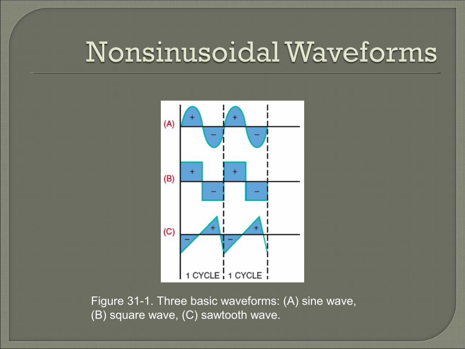
Figure 31-1. Three basic waveforms: (A) sine wave, (B) square wave, (C) sawtooth wave.
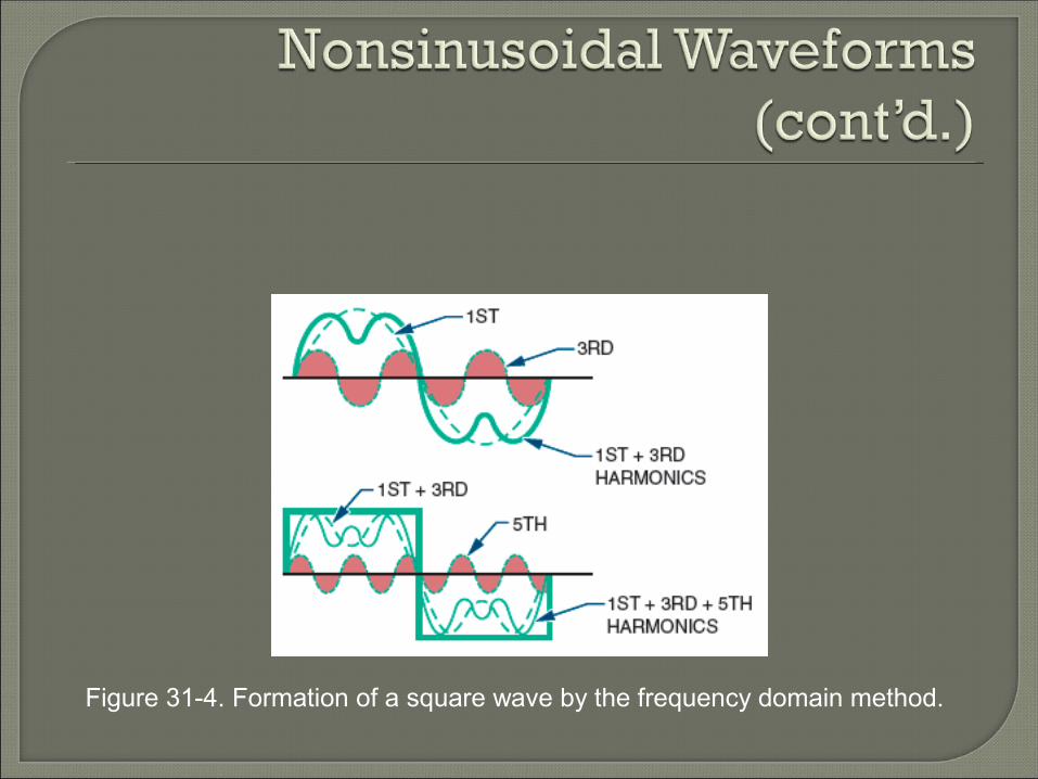
Figure 31-4. Formation of a square wave by the frequency domain method.
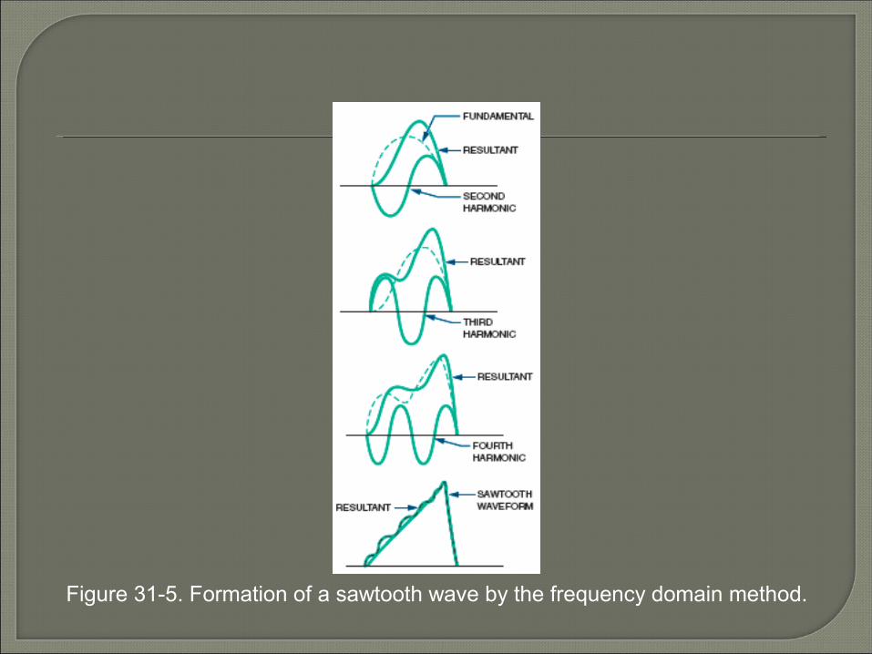
Figure 31-5. Formation of a sawtooth wave by the frequency domain method.

Figure 31-8. Pulse width of a waveform.
Nonsinusoidal Waveforms(cont’d.)
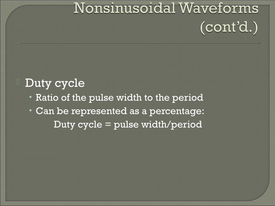
Duty cycle• Ratio of the pulse width to the period• Can be represented as a percentage:
Duty cycle = pulse width/period
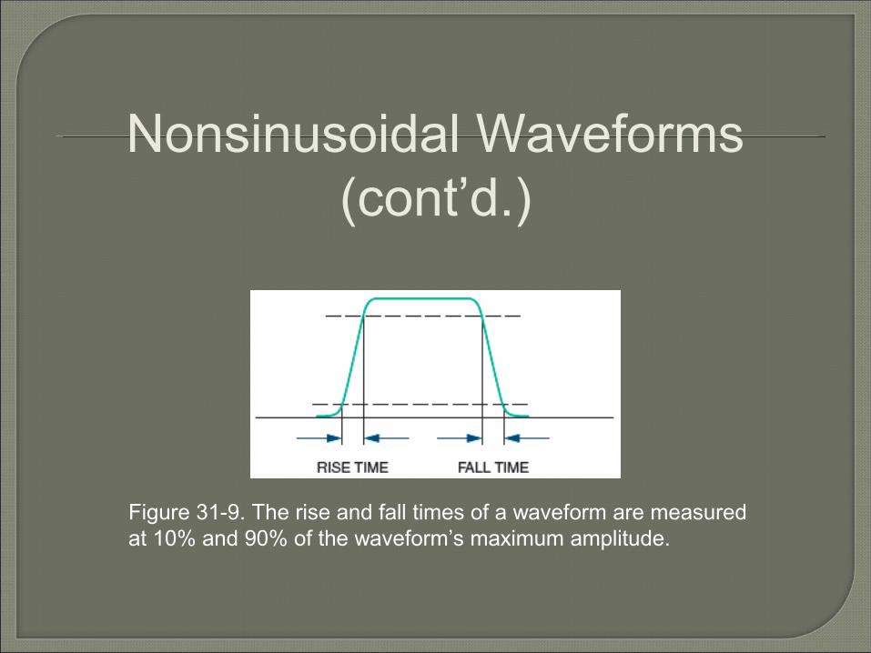
Figure 31-9. The rise and fall times of a waveform are measured at 10% and 90% of the waveform’s maximum amplitude.
Nonsinusoidal Waveforms(cont’d.)

Figure 31-10. Overshoot, undershoot, and ringing.
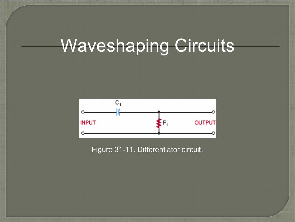
Figure 31-11. Differentiator circuit.
Waveshaping Circuits
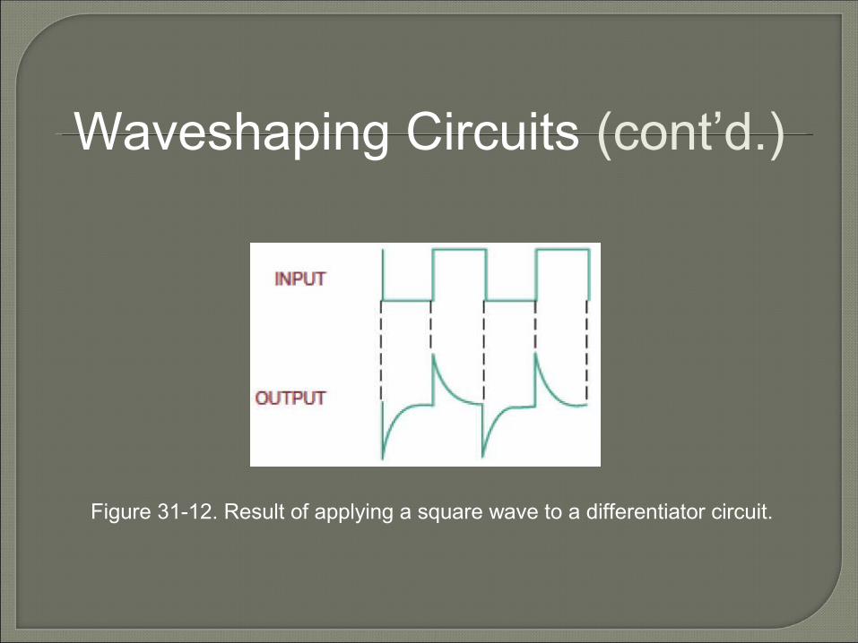
Figure 31-12. Result of applying a square wave to a differentiator circuit.
Waveshaping Circuits (cont’d.)

Figure 31-14. Integrator circuit.
Waveshaping Circuits (cont’d.)
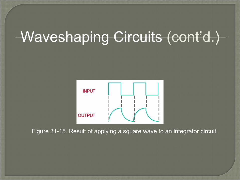
Figure 31-15. Result of applying a square wave to an integrator circuit.
Waveshaping Circuits (cont’d.)
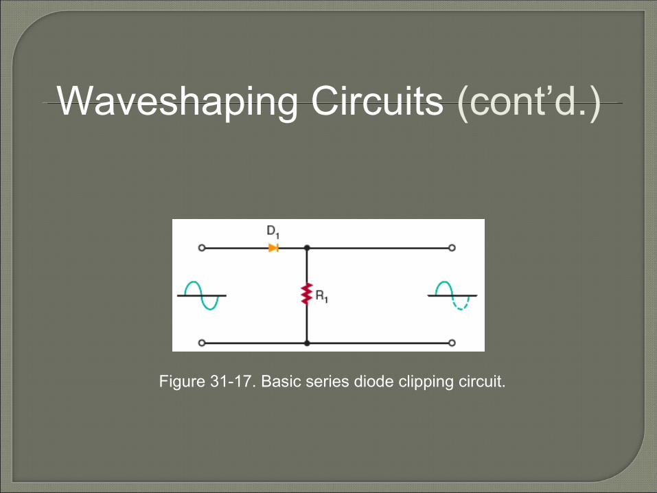
Figure 31-17. Basic series diode clipping circuit.
Waveshaping Circuits (cont’d.)

Figure 31-25. Clipping circuit used to limit both the positive and negative peaks.
Waveshaping Circuits (cont’d.)
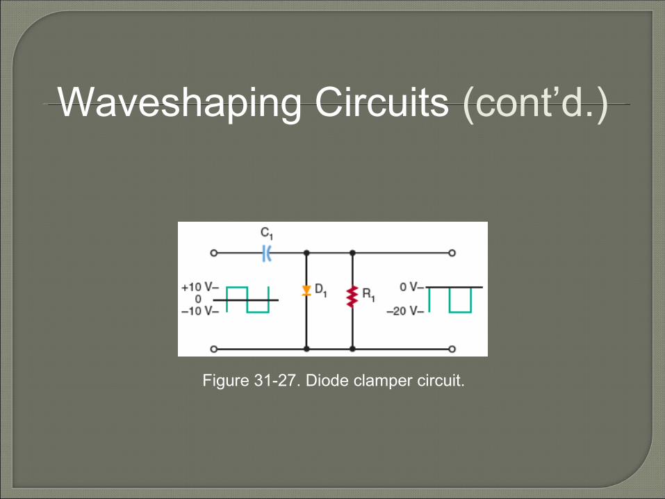
Figure 31-27. Diode clamper circuit.
Waveshaping Circuits (cont’d.)
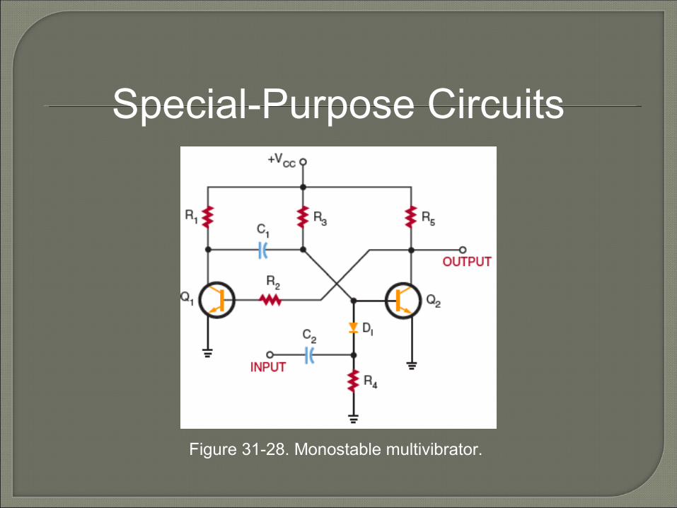
Figure 31-28. Monostable multivibrator.
Special-Purpose Circuits

Figure 31-29. Basic flip-flop circuit.
Special-Purpose Circuits (cont’d.)
Waveforms can be changed from one shape to another using electronic circuits
The frequency domain concept• All periodic waveforms are made of sine waves
Key concepts introduced in the chapter:• Pulse width, duty cycle, rise and fall time,
undershoot, overshoot, and ringing
An RC circuit can be used to change the shape of a complex waveform
A monostable multivibrator (one-shot multivibrator) produces one output pulse for each input pulse
Bistable multivibrators have two stable states and are called flip-flops


![Ece-III-Analog Electronic Ckts [10es32]-Notes](https://img.dokumen.tips/doc/110x75/55cf9da2550346d033ae7b1a/ece-iii-analog-electronic-ckts-10es32-notes.jpg)
![Eee-III-Analog Electronic Ckts [10es32]-Solution](https://img.dokumen.tips/doc/110x75/5529d0b54a7959fa768b45d8/eee-iii-analog-electronic-ckts-10es32-solution.jpg)
![Eee-III-Analog Electronic Ckts [10es32]-Notes](https://img.dokumen.tips/doc/110x75/577cd5561a28ab9e789a820d/eee-iii-analog-electronic-ckts-10es32-notes.jpg)


