Embed Size (px)
Citation preview


WELCOME
A WARM
TO ALL

M.RAMA CHANDRA RAO
RF CONTROL FOR POWER LINE DEVICES
Introduction
This Project “RF CONTROL FOR POWER LINE DEVICES” using
“PIC16F877A” is a reliable circuit that takes over the task of controlling the
Appliances and after checking and giving the output which we were giving
will perform very accurately and efficiently.
The total number of inputs that which we are giving is taking and givingthe output accurately. The PIC Microcontroller does the above job. Itreceives the signal from the Transmitter section and sent to receivingsection and the control of the Software is done through the Softwarewhich we have stored in ROM.
Microcontroller PIC16F877A continuously monitors and keeps on checking,whether any signal is passing through the RF modules Section.

BLOCK DIAGRAM OF RF:

PROCESS OF RECEIVING & TRANSMITTING SECTION:

DESCRIPTION OF RF BLOCK DIAGRAM:
The above Block diagram describes that when the input is given
then the given signals which we are giving is parallel signals thatparallel signals is encoded as Series and transmitted to thereceiver through the Transmitter. That transmitted signals areagain Decoded through the Decoder Ic and the parallel signals areagain decoded in to Parallel signals. Then the Home appliancescan be controlled as Wireless through the Remote.
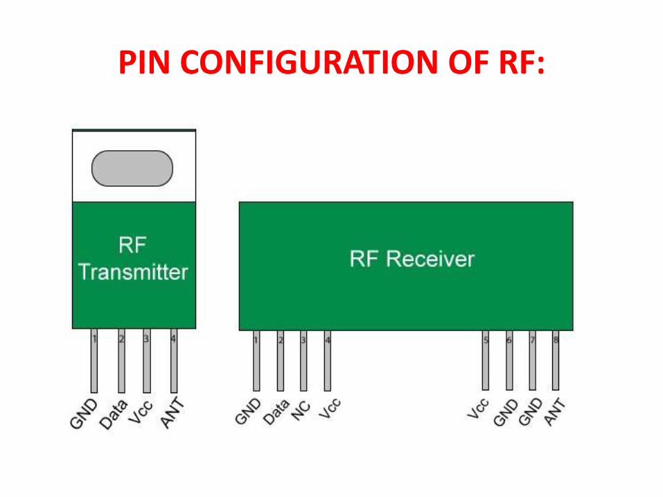
PIN CONFIGURATION OF RF:

ENCODER:
• An encoder is a device, circuit, transducer,software program, algorithm or personthat converts information from one formator code to another, for the purposes ofstandardization, speed, secrecy, securityor compressions.
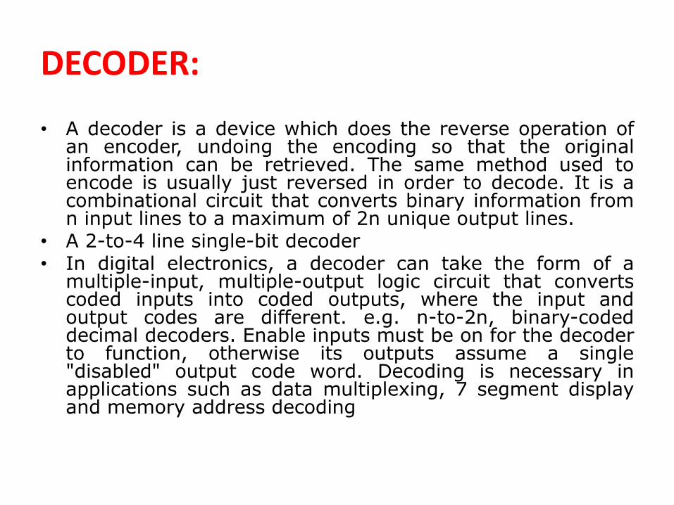
DECODER:
• A decoder is a device which does the reverse operation ofan encoder, undoing the encoding so that the originalinformation can be retrieved. The same method used toencode is usually just reversed in order to decode. It is acombinational circuit that converts binary information fromn input lines to a maximum of 2n unique output lines.
• A 2-to-4 line single-bit decoder• In digital electronics, a decoder can take the form of amultiple-input, multiple-output logic circuit that convertscoded inputs into coded outputs, where the input andoutput codes are different. e.g. n-to-2n, binary-codeddecimal decoders. Enable inputs must be on for the decoderto function, otherwise its outputs assume a single"disabled" output code word. Decoding is necessary inapplications such as data multiplexing, 7 segment displayand memory address decoding

CIRCUIT DIAGRAM

HARDWARE CONNECTION OF OUR PROJECT:

HERE WE HAVE
WRITTEN &
USED 2 ASM
PROGRAMS

1

• list p=16f877a• #include<p16f877a.inc>• __CONFIG 0x3F7A;CONFIGERATION BITS• ORG 000H• GOTO MAIN• ORG 0AH• MAIN:• CLRF PORTB• CLRF PORTD• BSF STATUS,RP0• CLRF TRISD• MOVLW 0FFH• MOVWF PORTB• BCF STATUS,RP0
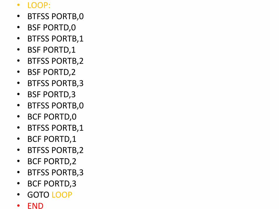
• LOOP:• BTFSS PORTB,0• BSF PORTD,0• BTFSS PORTB,1• BSF PORTD,1• BTFSS PORTB,2• BSF PORTD,2• BTFSS PORTB,3• BSF PORTD,3• BTFSS PORTB,0• BCF PORTD,0• BTFSS PORTB,1• BCF PORTD,1• BTFSS PORTB,2• BCF PORTD,2• BTFSS PORTB,3• BCF PORTD,3• GOTO LOOP• END

PIC16F877

PIC:
• A PIC Microcontroller is a single integrated circuit small enough to fit in palm of a hand.
• In PIC Microcontroller some EPROM program memory chip, some RAM memory and i/p o/p interface .
• All these functions are included with in one single package, making them cost effective and easy to use.
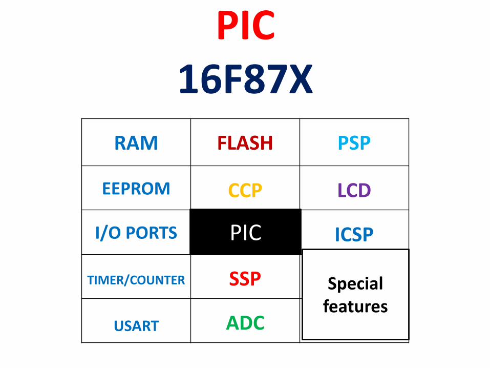
PIC16F87X
RAM FLASH PSP
EEPROM CCP LCD
I/O PORTS ICSP
TIMER/COUNTER SSP
USART ADC
Specialfeatures
PIC

PIN CONFIGURATION

WORKING OF HARD WARE


ANY QUERY ?


![RF Circuit Design - [Ch1-2] Transmission Line Theory](https://img.dokumen.tips/doc/110x75/55cef98fbb61eb2a028b485c/rf-circuit-design-ch1-2-transmission-line-theory.jpg)


![RF Module Design - [Chapter 7] Voltage-Controlled Oscillator](https://img.dokumen.tips/doc/110x75/55cebbaebb61eb912f8b45f9/rf-module-design-chapter-7-voltage-controlled-oscillator.jpg)