Embed Size (px)
Citation preview

Low voltage AC drives for HVAC applications
24A1-E-0012
HVACHigh performance enabled by the comprehensive use of Fuji technology.
Easy maintenance for the end-user.Maintains safety and protects the
environment.Opens up possibilities for the new generation.
Smile to the Environment

Ha Noi O�ce:No. 95 - TT4, My Dinh Urban Area, My Dinh, Nam Tu Liem, Hanoi.Tel: (84 4) 3568 3740Fax: (84 4) 3568 3741
Cambodia O�ce:#140, Room 1-B, St430, Sangkat Toul Tompuong II, Khan Chamkamon, PP.Tel: 855 2322 3635Fax: 855 2322 3645
Head O�ce:No 88, Vinh Phu 40, Hoa Long,Vinh Phu, Thuan An, Binh Duong.Tel: (84 650) 37 37 619Fax: (84 650) 37 37 620
1800 6547THINK TOGETHER
Nhà phân phối thiết bị điện công nghiệphàng đầu Việt Nam
T

Smile to the Environment
~ Energy Saving for the environment and our children's future ~
2
FRENIC-HVAC
The energy consumed in fans and pumps for HVAC operation can be significantly saved by using inverters. To achieve this purpose, the market demands higher functionality and performance to inverters. The FRENIC-HVAC series, Fuji Electric’s new product, controls water and air flow rates, pressure, and temperature with the fan and pump optimally, contributing a lot to saving electricity and cost reduction achieved by energy saving.
The first slim-type inverter specialized in energy-saving from Fuji Electric.Achieves a great effect on energy-saving of fans and pumps!Contributes drastically to cost reduction by cutting power consumption!

Stand aloneStand alone
Large Contribution to Reducing Global Warming(Environmental Protection) with Energy Saving
Wide variation in model capacity
Optimal control with energy-saving function
Slim body
3
Model can be selected from two model types.
The first slim body design among the Fuji Electric inverters. The size is the same between IP21 and IP55 (the first in the industry).
Functions suitable for HVAC use
Standard type (EMC filter built-in type)0.75 to 710kW (Protective structure IP21 or IP55 can be selected with the model between 0.75 and 90kW.)
• Linearization function • Temperature difference constant control and pressure difference constant control • Energy saving functions including wet-bulb temperature presumption control • Automatic energy-saving operation
• 4PID control • Fire mode (forced operation) • Pick-up operation function • Real time clock • Torque vector control • Filter clogging prevention function • Customized logic • User friendly, useful keypad • Password function
DCR built-in + EMC filter built-in type0.75 to 90kW (Protective structure IP21 or IP55 can be selected with the model between 0.75 and 90kW.)
50% of energy consumption in office buildings is related to air conditioning.The FRENIC HVAC series is the dedicated inverter for HVAC that features functions and performances offer the optimal thermal environment for the people working in the building by keeping the energy consumption in various devices (compressor, condenser water pump, AHU and others) to the minimum.Fuji Electric contributes largely to global environment by realizing carbon dioxide reduction with energy saving by the inverter.
0.75kW to 90kW
110kW to 710kW
Built-in
Built-in
Built-in
External
IP21/IP55
IP00
Inverter capacity EMC filter DC reactor Protective structure
* The models with inverter capacity 45kW to 710kW are coming soon.
• The inverter can be installed independently; no control panel is required.

4
Significant Energy Saving Realized!!
For an air-conditioning heat source system, the needed quantity of the cooling or heating water fluctuates generally in seasons or days and nights. Therefore, operations continuing in a water conveyance pressure constant control may lead to high operating unnecessary pressures on terminals at low operating state. Thus, the pump consumes an ineffectual electric power for maintaining the high water conveyance pressure.FRENIC-HVAC can perform an estimated terminal pressure control by linearization function which estimates target pressure from load flow rate.It is possible to reduce the ineffectual pump power consumption and to achieve a great energy-saving effect together with maintaining comfortable current air conditioning.
5
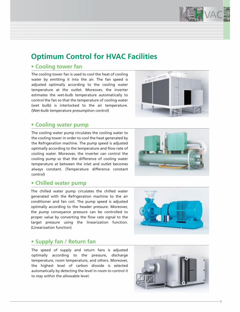
The cooling tower fan is used to cool the heat of cooling water by emitting it into the air. The fan speed is adjusted optimally according to the cooling water temperature at the outlet. Moreover, the inverter estimates the wet-bulb temperature automatically to control the fan so that the temperature of cooling water (wet bulb) is interlocked to the air temperature. (Wet-bulb temperature presumption control)
The cooling water pump circulates the cooling water to the cooling tower in order to cool the heat generated by the Refrigeration machine. The pump speed is adjusted optimally according to the temperature and flow rate of cooling water. Moreover, the inverter can control the cooling pump so that the difference of cooling water temperature at between the inlet and outlet becomes always constant. (Temperature difference constant control)
• Cooling tower fan
• Cooling water pump
The speed of supply and return fans is adjusted optimally according to the pressure, discharge temperature, room temperature, and others. Moreover, the highest level of carbon dioxide is selected automatically by detecting the level in room to control it to stay within the allowable level.
• Supply fan / Return fan
• Chilled water pumpThe chilled water pump circulates the chilled water generated with the Refrigeration machine to the air conditioner and fan coil. The pump speed is adjusted optimally according to the header pressure. Moreover, the pump conveyance pressure can be controlled to proper value by converting the flow rate signal to the target pressure using the linearization function. (Linearization function)
Optimum Control for HVAC Facilities
6
Optimal Structure Design
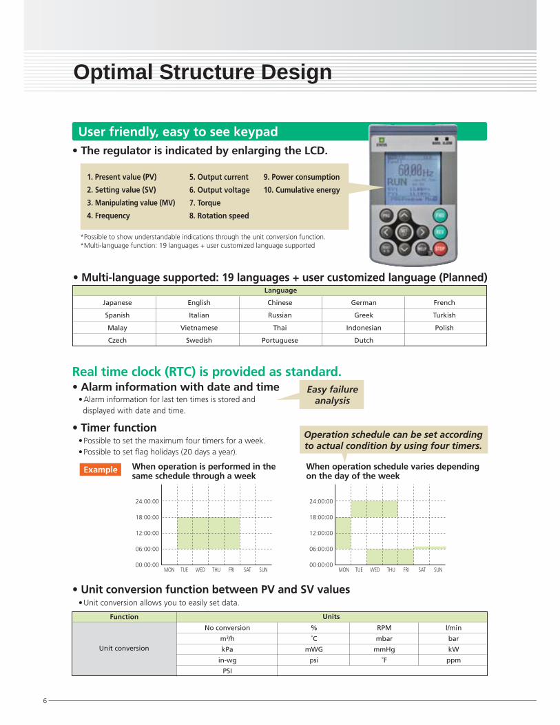
User friendly, easy to see keypad
1. Present value (PV)
2. Setting value (SV)
3. Manipulating value (MV)
4. Frequency
• Possible to set the maximum four timers for a week.• Possible to set flag holidays (20 days a year).
• Alarm information for last ten times is stored and displayed with date and time.
• Unit conversion allows you to easily set data.
• Alarm information with date and time
• Unit conversion function between PV and SV values
• Timer function
Real time clock (RTC) is provided as standard.
Language
When operation is performed in the same schedule through a week
When operation schedule varies depending on the day of the week
24:00:00
18:00:00
12:00:00
06:00:00
00:00:00
Example
Easy failureanalysis
Operation schedule can be set accordingto actual condition by using four timers.
• The regulator is indicated by enlarging the LCD.
*Possible to show understandable indications through the unit conversion function.*Multi-language function: 19 languages + user customized language supported
5. Output current
6. Output voltage
7. Torque
8. Rotation speed
9. Power consumption
10. Cumulative energy
• Multi-language supported: 19 languages + user customized language (Planned)
Japanese
Spanish
Malay
Czech
English
Italian
Vietnamese
Swedish
Chinese
Russian
Thai
Portuguese
German
Greek
Indonesian
Dutch
French
Turkish
Polish
No conversion
m3/h
kPa
in-wg
PSI
%
˚C
mWG
psi
RPM
mbar
mmHg
˚F
l/min
bar
kW
ppm
Unit conversion
Function Units
24:00:00
18:00:00
12:00:00
06:00:00
00:00:00MON TUE WED THU FRI SAT SUN MON TUE WED THU FRI SAT SUN

7
Multi-language supported, HELP function featured, unit setting with SV and PV values, data copy (three kinds), detachable and can be attached on the panel (using an optional cable)
Outputs the life prediction signal determining capacitor capacity drop and cumulative running hours. This allows the user to grasp replacement period.
USB port equipped, BACnet equipped as standard. Max. three types of built-in optional boards can be mounted all together.Optional battery connectionVarious communications options
Control board
The detachable control terminal block is adopted. This allows the unit to be replaced easily without disconnecting cables.
Control terminal block
Drastically reduces harmonic noise. Conforming to IEC/EN61000-3-2 and IEC/EN61000-3-12. Provided as standard (to models up to 90kW), and can be attached externally as an option (to models from 110kW to 710kW).
Capacitor board
Drastically reduces noise. Provided to units of all capacities. Conforming to IEC61800-3.
EMC filter
Easy replacement just by simply removing and attaching the part. Life prolongation is possible by controlling ON and OFF.
Cooling fan
3C2, IEC60721-3-3 supported
Support/analysis software by loader, RTC backup by battery (option)
DCR
Environmental immunity
Others
Standard equipment Optional equipment
• BACnet MS/TP• Modbus RTU • Metasys N2
• LonWorks• Ethernet• Profi bus
• DeviceNet• CANopen• CC-Link
User-friendly, easy to see dedicated keypad

8
This function estimates the target pressure using the load flow rate, which allows the estimated terminal pressure to be controlled. For an air-conditioning heat source system, the needed quantity of the cooling or heating water fluctuates generally in seasons or days and nights. Therefore, operations continuing in a water conveyance pressure constant control may lead to high operating unnecessary pressures on terminals at low operating state. Thus, the pump consumes an ineffectual electric power for maintaining the high water conveyance pressure.Based on the calculated value and water conveyance pressure of estimated terminal pressure using the detected load flow rate, PID control is performed.It is possible to reduce the ineffectual pump power consumption and to achieve a great energy-saving effect together with maintaining comfortable current air conditioning.
Functions Suitable for HVAC Use
Linearization function
100908020 30 40 50 60 7010
102030405060708090
100110120130140150160
0 110 120 130 [%]
[%]
Q-H curve
Wat
er c
on
veya
nce
pre
ssu
re [
kPa]
Load flow rate [m3/h]
70%
[%]
[%]
100908020 30 40 50 60 7010
10
20
30
40
50
60
70
80
90
100
110
120130
0 110 120 130
Q-P curve
Load flow rate [m3/h]
Mo
tive
po
wer
[kW
]
66% cut
Estimated terminal pressure control characteristics
Estimated terminal pressure control characteristics
Commercial power characteristics
70% power characteristics
Pump characteristics
70% Valve throttling
Water conveyance pressure constant control characteristics
70% Pump characteristics
25% cut
Power characteristic in the water conveyance pressure constant control
FRENIC-HVAC
Water conveyance pressure
Refrigeration machine
Coolingtower
Load flow rate
HeaderHeader
P
F

+
-
9
This function is optimal for controlling the fan of cooling tower. Since the wet-bulb temperature would become higher than the set temperature when the air temperature is particularly high, water temperature wil l not reach the set temperature. Therefore, the fan keeps rotating at high speed, failing in energy-saving operation. FRENIC-HVAC automatically estimates the wet-bulb temperature and controls the fan so that the cooling water is interlocked with the air temperature in order not to use unnecessary electric power.
This mode ignores (retry) the inverter protection function to continue the operation. In that way, the inverter keeps operating the fan and pump as much as possible in case of emergency such as fire.
This function detects clogging of the fan filter with dust or other materials using the output current and pressure sensor value. When clogging is detected, the fan is rotated in reverse to eject dust, and then resumes rotation in forward to blow air. In addition, the function notifies you of maintenance necessity with the alarm signal.
The customized logic interface function is provided to the inverter body. This enables forming of logic circuit and arithmetic circuit to the digital and analog input and output signals, allowing simple relay sequence to be built while processing the signals freely.
The 4PID control is featured as standard. One PID module is used to control the output frequency of the inverter, and the other three PIDs can be used to control the external system. To utilize all of four PIDs, the optional card (OPC-AIO) needs to be mounted.
Function codes can be read/write, displayed or hidden by setting the two passwords. This prevents erroneous operation or overwriting of function codes. In addition, if a wrong password was input exceeding the specified number of times, the inverter is restricted from operating as the user is regarded as improper.
The pick-up operation function enables smooth starts.If you wish to run a fan currently not run by the inverter and in idle mode, this function searches the speed regardless of the direction of rotation and pick up the motion smoothly. This function allows for smooth operation such as when switching the power supply from the commercial power to inverter in a momentary action.
Wet-bulb temperature presumption control
Filter clogging prevention function
Customized logic
Standard 4PID control Fire mode (forced operation)
PasswordPick-up operation function
Outputfrequency[Hz]
Temperature[˚C]
Wet-bulb temperature presumption control
Time
Time
Set temperature
Set temperature < air (wet-bulb) temperatureCooling water temperature can only be lowered to the air (wet-bulb) temperature.
Cooling watertemperature
Cut the unnecessary power.
Upperlimiter
Air (wet-bulb) temperature
Controlled to: cooling water = wet-bulb temperature
Control ON
Control OFF: fan high-speed operation
X1 terminal 12 terminal
C1 terminal
U04
U04
U05
LE1LE2
On-delay timer
Step 1
X2 terminalY1 outputterminal
Y3 outputterminal
Example
0.2[FDT]

10
Standard Specifications
3-phase, 400V series (0.75 to 55kW)
3-phase, 400V series (75 to 710kW)
Type
Braking
Nominal applied motor (Rated output) [kW] *1
EMC filter (IEC/EN 61800-3:2004)DC reactor (DCR)
Power factor(at rated load)
Efficiency (at rated load)Applicable safety standardsEnclosure (IEC/EN 60529)Cooling method
Weight/Mass [kg]
Out
put r
atin
gsIn
pu
t ra
tin
gs
*1) Fuji 4-pole standard motor.*2) Rated capacity is calculated by assuming the output rated voltage as 440 V.*3) Output voltage cannot exceed the power supply voltage.*4) The auxiliary power input is used as an AC power input when combining the unit to DC power supply such as high power factor PWM converter with power regenerative function. (Generally not to be used.)*5) Voltage unbalance [%] = (Max. voltage [V] - Min. voltage [V])/Three-phase average voltage [V] x 67 (See IEC61800-3.) If this value is 2 to 3%, use an optional AC reactor (ACR).*6) The value is calculated on assumption that the inverter is connected with a power supply 400V, 50Hz and Rsce=120.*7) Average braking torque for the motor running alone. (It varies with the efficiency of the motor.)
SpecificationsItemFRN AR1 -4A : HVACFRN AR1 -4E : HVAC
Rated capacity [kVA] *2
Rated voltage [V] *3
Rated current [A]Overload capabilityRated frequency [Hz]Main circuit power input : Phases, voltage, frequencyAuxiliary control power input : Phases, voltage, frequencyAuxiliary power input for main circuit :Phases, voltage, frequency *4
Voltage, frequency variationsRated current [A] *6
Required power supply capacity [kVA]Torque [%] *7
DC injection braking
Three-phase, 380 to 480 V (with AVR function)
110% - 1 min (Overload capability interval : IEC 61800-2 compliant)50, 60Hz
Single-phase 380 to 480 V,50/60 Hz
Voltage: +10 to -15% (Interphase voltage unbalance : 2% or less) *5, Frequency: +5 to -5%
Starting frequency:0.0 to 60.0Hz, Braking time:0.0 to 30.0s, Braking level:0 to 60%EMC standards compliance : Category C2 (emission) / 2nd Env. (Immunity)
Built-in (IEC/EN 61000-3-2, IEC/EN 61000-3-12)>0.98>=0.90
UL508C, IEC/EN 61800-5-1:2007IP21/IP55
Fan cooling
95%
20 10 to 15
96% 97%
Displacement P.F. (cosφ)True P.F.
IP21IP55
0.750.750.751.9
2.5
1.61.2
1010
1.51.51.53.1
4.1
3.02.1
1010
2.22.22.24.1
5.5
4.33.0
1010
3.74.0
3.7/4.06.8
9.0
7.45.2
1010
5.55.55.510
13.5
10.37.2
1010
7.57.57.514
18.5
13.99.7
1010
11111118
24.5
20.715
1818
15151524
32
27.920
1818
18.518.518.529
39
34.524
1818
22222234
45
41.129
1818
30303045
60
55.739
2323
37373757
75
69.449
2323
45454569
91
83.158
5050
55555585
112
10271
5050
Three-phase, 380 - 440 V, 50 HzThree-phase, 380 - 480 V, 60 Hz
Single-phase 380 - 440 V, 50 HzSingle-phase 380 - 480 V, 60 Hz
Type
Braking
Nominal applied motor (Rated output) [kW] *1
EMC filter (IEC/EN 61800-3:2004)DC reactor (DCR)
Power factor(at rated load)
Efficiency (at rated load)Applicable safety standardsEnclosure (IEC/EN 60529)Cooling method
Weight/Mass [kg]
Out
put r
atin
gsIn
pu
t ra
tin
gs
SpecificationsItemFRN AR1 -4A : HVACFRN AR1 -4E : HVAC
Rated capacity [kVA] *2
Rated voltage [V] *3
Rated current [A]Overload capabilityRated frequency [Hz]Main circuit power input : Phases, voltage, frequencyAuxiliary control power input : Phases, voltage, frequencyAuxiliary power input for main circuit :Phases, voltage, frequency *4
Voltage, frequency variationsRated current [A] *6
Required power supply capacity [kVA]Torque [%] *7
DC injection braking
Three-phase, 380 to 480 V (with AVR function)
110% - 1 min (Overload capability interval : IEC 61800-2 compliant)50, 60Hz
Three-phase, 380 to 440 V, 50 Hz Three-phase, 380 to 480 V, 60 HzSingle-phase 380 to 480 V,50/60 Hz
Single-phase 380 to 440 V, 50 Hz Single-phase 380 to 480 V, 60 HzVoltage: +10 to -15% (Interphase voltage unbalance : 2% or less) *5, Frequency: +5 to -5%
10~15Starting frequency:0.0 to 60.0Hz, Braking time:0.0 to 30.0s, Braking level:0 to 60%
>0.98>=0.90
UL508C, IEC/EN 61800-5-1:2007
Fan cooling
97% 98%
Built-in (IEC/EN61000-3-2, IEC/EN61000-3-12) Standard accessory (IEC/EN 61000-3-2, IEC/EN 61000-3-12)
C2/2nd. EMC standards compliance : Category C3 (emission) / 2nd Env. (Immunity)
-
-
Displacement P.F. (cosφ)True P.F.
IP21IP55IP00
IP21/IP55 IP00
Three-phase, 380 to 480 V, 50/60 Hz
-
315315315445
585
559388
245
757575
114
150
13695
7070
909090
134
176
162113
7070
110110110160
210
201140
62
132132132192
253
238165
64
160160160231
304
286199
94
200200200287
377
357248
98
220220220316
415
390271
129
280280280396
520
500347
140
355355355495
650
628436
245
400400400563
740
705489
245
500500500731
960
881611
330
630630630891
1170
1115773
530
7107107101044
1370
1256871
530

11
Common Specifications
RemarksItems Specifications
Ou
tpu
t
Sett
ing
ran
ge
Co
ntr
ol
Maximum frequency
Output frequencyAccuracy (Stability)
Setting resolution
Control method
Base frequencyStarting frequency
Carrier frequency
• 25 to 120 Hz• 25 to 120 Hz variable setting• 0.1 to 60.0 Hz variable setting
• Analog setting : ±0.2% of max. frequency (at 25 ± 10 )• Digital setting : ±0.01% of max. frequency (at -10 to +50 )
• Analog setting : 1/3000 of max. frequency (1/1500 with [V2] input)• Digital setting : 0.01 Hz (99.99 Hz or less), 0.1Hz (100.0 to 120 Hz)• Link setting : 1/20000 of max. frequency or 0.01 Hz (fixed)
• V/f control• Dynamic torque vector control• V/f control, the slip compensation is available.
Voltage/frequencycharacteristic
• Base frequency and max. output frequency can be set to 160 to 500V in common.• The AVR control ON/OFF can be selected.• Non-linear V/f setting (3 points) : Free voltage (0 to 500 V) and frequency (0 to 120 Hz) can be set.
Torque boost• Auto torque boost• Manual torque boost : Desired torque boost (0.0 to 20.0%) can be set.• Select application load with function code.(Constant torque load or variable torque load)
"+1 to +5 VDC"can be adjustedwith bias andanalog input gain.
Starting torque • 100% or higher/set frequency : 1.0 Hz Base frequency 50 Hz, Slip compensation and auto torque boost operation
Acceleration/deceleration time
Frequency limiter(Upper limit and lowerlimit frequencies)
Bias frequency
Analog input
• Setting range : 0.00 to 3600 s• Switch : The four types of accel./decel. time can be set or selected individually. (switchable during operation)• Acceleration/deceleration pattern : Linear accel./decel., S-shape accel./decel. (weak, strong), curvilinear accel./decel. (accel./decel. max. capacity of constant output)• Deceleration mode (coast-to-stop) : Coast-to-stop at the operation command OFF.
• Forcible stop decel. time : Deceleration stop by the forcible stop .
• Both upper and lower limit frequencies can be variably set in hertz.• It is possible to choose the operation done from continuous operation at lower limit frequency or operation stop when the set frequency drops below the lower limit.
• Bias of set reference frequency and PID command can be independently set. (setting range : 0 to ±100%)
• Gain : Setting in the range from 0 to 200%.• Off-set : Setting in the range from -5.0 to +5.0%.• Filter : Setting in the range from 0.00s to 5.00s.
Jump frequency • Actuation points (3 points) and their common jump widths (0 to 30 Hz) can be set.• Resonance points can be detected automatically and be set the jump frequency automatically.
Auto-restart aftermomentary power failure
• Trip at power failure : The inverter trips immediately after power failure.• Trip at power recovery : Coast-to-stop at power failure and trip at power recovery.• Continuous operation : Operation is continued using the load inertia energy.• Start at the frequency selected before momentary stop : Coast-to-stop at power failure and start after power recovery at the frequency selected before momentary stop.• Start at starting frequency : Coast-to-stop at power failure and start at the starting frequency after power recovery.
• Keypad : Start and stop with , and keys.
• External signals (digital inputs) : Forward (Reverse) rotation, stop command (capable of 3-wire operation), coast-to-stop command,external alarm, alarm reset, etc.• Link operation : Operation through RS-485 or field bus (option) communications.• Switching operation command : Remote/Local switching, link switching.
• Keypad : Can be set with and keys.
• External Volume : Can be Set with external potentiometer (1 to 5kΩ 1/2W).• Analog input : 0 to ±10 VDC (±5 VDC)/0 to ±100% (Terminals [12] and [V2]) 0 to +10 VDC (+5 VDC)/0 to +100% (Terminals [12] and [V2]) +4 to +20 mADC/0 to 100% (Terminal [C1]) 0 to +20 mADC/0 to 100% (Terminal [C1])• UP/DOWN operation : Frequency can be increased or decreased while the digital input signal is ON.• Multi-frequency : Selectable from 16 steps (step 0 to 15).• Link operation : Frequency can be set via RS-485 (Standard accessory).• Switching frequency setting : Frequency setting can be switched (2 settings) by external signal (digital input). Remote/local switching, link switching.• Auxiliary frequency setting : Terminal [12],[C1] or [V2] input can be selected respectively as an additional input.• Inverse operation : The setting "0 to +10 VDC/0 to 100%" can be switched to "+10 to 0 VDC/0 to 100%" by external command. The setting "+4 to +20 mADC/0 to 100%" can be switched to "+20 to +4 mADC/0 to 100%" by external command. The setting "0 to +20 mADC/0 to 100%" can be switched to "+20 to 0 mADC/0 to 100%" by external command.• Programmed PATTERN operation : Maximum 7 stages can be set.
• 0.75 to 16 kHz variable setting (0.75 kW to 37 kW)• 0.75 to 10 kHz variable setting (45 kW to 90 kW)• 0.75 to 6 kHz variable setting (110 kW to 630 kW)• 0.75 to 4 kHz variable setting (710 kW)NOTE: Frequency drops automatically to protect the inverter depending on environmental temperature and output current. (This auto drop function can be canceled.)
Start/stop operation
Frequency setting
Current limitby hardware
• Limiting the current by hardware to prevent overcurrent trip due to sharp load change or momentary power failure which cannot be controlled by software current limit. (This function can be cancelled.)
Operation bycommercial power supply
• With commercial power switching command, the inverter outputs 50Hz/60 Hz (SW50, SW60).• The inverter has the commercial power supply switching sequence.
Slip compensation • Compensates for decrease in speed according to the load.Torque limiter • Switchable between 1st or 2nd torque limit values.Current control (software current limit) • Automatically reduces the frequency so that the output current becomes lower than the preset operation level.

12
Common Specifications
RemarksItems Specifications
Co
ntr
ol
Dis
pla
y
Deceleration characteristic(improving braking ability)
• The motor loss is increased during deceleration to reduce the regenerative energy in the inverter to avoid overvoltage trip.
Automatic energy saving operation • The output voltage is controlled to minimize the total sum of the motor loss and inverter loss at a constant speed.Overload prevention control • If the ambient temperature or IGBT joint temperature increases due to overload, the inverter lowers the output frequency to avoid overload.Voltage ShortageAvoidance Operation • The continuous operation is available reducing output frequency during low voltage.Input Phase Loss Protection Avoidance Operation • Selectable from trip or continuous low power operation.Off-line tuning • Rotary type and non-rotary type are available for tuning the motor constant.
Universal DI • The status of external digital signal connected with the universal digital input terminal is transferred to the host controller.Universal DO • Digital command signal from the host controller is output to the universal digital output terminal.Universal AO • The analog command signal from the host controller is output to the analog output terminal.Rotation direction control • Preventing reverse rotation • Preventing forward rotationPreventing condensation in motorCustomized logic interface
• When the inverter is stopped, current is automatically supplied to the motor to keep the motor warm and avoid condensation.• Available in 14 steps with the functions of 2-input, 1-output, logical calculation, and timer function.
Fire mode • Continues operation without alarm by retry.Pattern operation • Pattern operation is available by inverter itself.
Timer operation • Set 4-timers for one week.Password function • Prevent improperly operation and/or data undisplayed available. (two level setting.)
Light-alarm • WARN. LED is lit and light-alarm factor is displayed.Trip mode • Displays the cause of trip.
LED display • LED for light-alarm or alarm occurrence.
Running or trip mode• Trip history : Saves and displays the cause of the last ten trips (with a code).• Detail data recorded : Saves and displays the detail data recorded on occurrence of the last four trips.• Saves and displays the date, hour and minute with RTC.
Cumulative running hours• Displays the inverter cumulative running hours, integrated power, cumulative motor running hours, and the number of operation start times.• Outputs the warning when the maintenance time or the number of start times has exceeded the preset value.• Displays the cumulative energy for unit of months, weeks, days and hours and running hours (with RTC).
Inverter life warning• Life judgment of the main circuit capacitor, electrolytic capacitor on printed circuit board, and cooling fan.• Life warning information can be output to an external device.• Ambient temperature : IP00/IP21 40 , IP55 30 , Load rate : inverter rated current 100%
Run/stop Speed monitor (set frequency, output frequency, motor speed, load shaft speed, line speed, and speed indication with percent), Output current [A], output voltage [V], calculated torque [%], input power [kW], PID reference value, PID feedback value, PID output, load [%], motor output [kW], analog input monitor, integral power consumption [kWh], integral power consumption [MWh], effective current value for each phase [A]
External PID control
• PID processor for process control / On / Off controller (3 channels) • Normal operation / inverse operation• PID command: Keypad, analog input (terminals [12], [C1] and [V2]), RS-485 • PID feedback value (terminals [12], [C1] and [V2])• Alarm output (absolute value alarm, deviation alarm) • PID feedback error detection • Sensor input amount scaling• Sensor input amount conversion / calculation • PID output limiter • Integration reset / hold • Anti-reset wind-up function
Pump control • Filter clogging prevention • Anti jam • Wet-bulb temperature presumption control
Cooling fanON/OFF control
• Detects inverter internal temperature of the inverter and stops the cooling fan when the temperature is low.• The fan control signal can be output to an external device.
Automatic deceleration
• If the DC link voltage or calculated torque exceeds the automatic deceleration level during deceleration, the inverter automatically prolongs the deceleration time to avoid overvoltage trip. (It is possible to select forcible deceleration actuated with more than three times longer deceleration.)• If the calculated torque exceeds automatic deceleration level during constant speed operation, the inverter avoids overvoltage trip by increasing the frequency.• Automatic deceleration level can be set.
Auto search for idlingmotor speed
• Estimates the speed of the motor running under no load and starts the motor without stopping it. (Motor electric constant needs tuning : Offline tuning)
PID control
• PID adjuster for process contro • Switchable between forward and reverse operations• PID command : Keypad panel, analog input (from terminals [12],[C1],[V2]), RS-485 communications• PID feedback value : Analog input (from terminals [12],[C1],[V2]) • Alarm output (absolute value alarm, deviation alarm)• PV level detection • Scaling for PV value • PV value conversion/calculation of analog input• PID output limiter • Integration reset/hold • Antireset windup • PID auto tuning
Real time clock (RTC) • Date, hour and alarm information with date and hour can be displayed, and timer operation can be used with RTC.• Daylight saving time auxiliary function.
Time can be maintained with battery (option).
Pro
tect
ive
fun
ctio
n
Guidance function • Needed information can be displayed by pushing "HELP" key.
Battery level display • Battery level can be displayed when the battery (option) is connected.LCD back-light • Set lighting time for LCD back-light during key operation only or unlit.
OC1,OC2,OC3
OU1,OU2,OU3
LU
Lin
Overcurrent protection • The inverter is stopped for protection against overcurrent.Short-circuit protection • The inverter is stopped for protection against overcurrent caused by a short circuit in the output circuit.Ground fault protection • The inverter is stopped for protection against overcurrent caused by a grounding fault in the output circuit. (37 kW or less)
Input phase loss protection
• The input phase loss is detected to protect or shut off the inverter.• When the load to be connected is small, a phase loss would not be detected.
Undervoltage protection • The voltage drop (400 VDC) in the DC link circuit is detected to stop the inverter. However, the alarm will not be issued when the re-starting after instantaneous stop is selected.
Overvoltage protection • An excessive voltage (800 VDC) in the DC link circuit is detected and the inverter is stopped. If an excessive voltage is applied unintended, the protection can not be guaranteed.
Multi language • Corresponded to Japanese, English, German, French, Spanish, Italian, Chinese, Russian, Greek, Turkish, Polish, Czech, Swedish, Portuguese, Dutch, Malay, Vietnamese, Thai and Indonesian. (Sequential correspond to User Customized Language.)
OPLOutput phase loss detection • Detects breaks in inverter output wiring at the start of running and during running and stop the inverter output.

OH3
13
RemarksItems Specifications
Pro
tect
ive
fun
ctio
nEn
viro
nm
ent
Mot
or p
rote
ctio
n
Er1
Er2
Er3Er4Er5
Er6
Er7
Er8
ErF
ErHErrCoF
ECLrLoFoLECF
PV1,PV2,PVA,PVb,PVC
ErP
OH1
OLUOH2
OL1
OH4
Overload protection • Stop the inverter output detecting a switching element temperature calculated with cooling fin temperature and the output current.External alarm input • With the digital input signal (THR), the inverter is stopped with an alarm.
Memory error • Data is checked upon power-on and data writing to detect any fault in the memory and stop the inverter if any.
CPU error • Stop the inverter detecting a CPU error or LSI error caused by noise.Option communications error • When each option is used, a fault of communication with the inverter main body is detected to stop the inverter.Option error • When each option is used, the option detects a fault to stop the inverter.
Tuning error • Stop the inverter output when tuning failure, interruption or any fault as a result of tuning is detected during tuning for motor constant.
Data save error upon undervoltage • When the undervoltage protection occurred, an alarm is displayed if the data is not properly saved.
Hardware error • Stop the inverter detecting a LSI error on the power printed circuit board caused by noise.Simulation error • Simulated alarm is output by the keypad panel operation.Current input wire break detection • Stop the inverter detecting a analog wire break detection (enable / disable selectable).PID feedback error detection • Stop the inverter output detecting a PID feedback line break. (Selectable valid/invalid.)Customized logic error detection • Alarm is output detecting a customized logic setting error.Anti jam protection • Display the error detecting the starting failure due to overcurrent.Filter clogging prevention • Display the error detecting the overload during PID control.Enable circuit failure detection • Diagnos the enable circuit condition and stop the inverter output detecting the circuit failure.
Surge protection • The inverter is protected against surge voltage intruding between the main circuit power line and ground.
Ambient humidity • 5 to 95 %RH (without condensation)Altitude • 1,000m or lower
Storage temperature • -25 to +70Storage humidity • 5 to 95 %RH (without condensation)
Vibration 90kW or less 110 to 710kW 3mm : 2 to less than 9 Hz 3mm : 2 to less than 9 Hz 1m/s2 : 55 to less than 200Hz 10m/s2 : 9 to less than 200Hz 2m/s2 : 9 to less than 55Hz
Installation location • Free from corrosive gases, flammable gases, dusts, oil mist, direct sunlight. (Pollution degree 2 (IEC60664-1)). Indoor use only.
Ambient temperature
• -10 to +50 (+50 to +60 : correspond with deleting) (-10 to +40 : installed side-by-side without clearance (37 kW or less))IP21
IP55
IP00
Command loss detected • A loss (breaking, etc.) of the frequency command is detected to output an alarm and the operation is continued at the preset frequency (set at a ratio to the frequency before detection).
Momentary power failure protection • If restart upon momentary power failure is selected, the inverter restarts upon recovery of the voltage within the set time.
Retry function • When the motor is tripped and stopped, this function automatically resets the tripping state and restarts operation. (Retry times, waiting time for reset, corresponding trip for retry and retry available time can be set.) It can be confirmed by communication the times of the restarting.
Stall prevention • Operates when the inverter output goes beyond the instantaneous overcurrent limiting level, and avoids tripping, during acceleration and constant speed operation.
Light-alarm (warning)
• Light- alarm is displayed when registered alarm or warning as light-alarm is occurred. (continuous running) Covered alarm : External alarm (OH2), Inverter overheat (OH3), Motor overheat (OH4), Motor overload (OL1), Keypad panel communication error (Er2), Optional communication error (Er4), Option error (Er5), RS-485 communication error (port 1)(Er8), RS-485 communication error (port 2)(ErP), DC fan lock detected, Overload early warning (for motor), Heatsink overheat early warning, Life early warning (DC link bus capacitor, electrolytic capacitor on printed circuit board, cooling fan), Reference command loss detected, PID warning output, Low torque detected, Thermistor detection (PTC), Machine life (cumulative motor run time error), Machine life (number of startups error), Current Input Wire Break Detection, PID feedback error detection, Low battery warning, Date&time information lost,
Alarm relay output(for any fault)
• The inverter outputs a relay contact signal when the inverter issues an alarm and stops the inverter output.
• The alarm stop state is reset by pressing the key or by the digital input signal (RST).
RS-485 communicationserror (port2)
• Stop the inverter output detecting the communication error between the inverter main unit and a mate when the RS-485 connection port of the [DX+], [DX-] are used to configure the network.
RS-485 communicationserror (port1)
• Stop the inverter output detecting the communication error between the inverter main unit and a mate when the RS-485 connection port of the keypad panel is used to configure the network.
Operation error
• key priority : Pressing the key on the keypad will forcibly decelerate, stop the motor and display "Er6" even if the running
command through signal input or communication is selected.• Start check : If the running command is being input when switching the running command method from power-on, alarm reset or the linked operation, the operation starts suddenly. This function prohibits running and displays "Er6".
Keypad panelcommunications error
• The keypad panel detects a communication fault between the keypad panel and the inverter main body during the run command from the keypad panel available and to stop the inverter.
PTC thermistor • PTC thermistor input stops the inverter to protect the motor. Connect a PTC thermistor between terminal [C1] and [11] and set the switch on control print board and the function code.
Overload early warning • Warning signal (OL) is output at the predetermined level befor with electronic thermal function.
Electronic thermal • The inverter is stopped with an electronic thermal function set to protect the motor. Protects the general-purpose motor and inverter motor over all frequency range. (The level and thermal time constant (0.5 to 75.0 min) can be set.)
Overheat protection • Stop the inverter output detecting inner temperature of the inverter unit for a cooling fan fault or overload.• Stop the inverter output detecting the cooling fan failure. • Stop the inverter output detecting the charging circuit fault.
• Stop the inverter output detecting excess cooling fin temperature in case of a cooling fan fault or overload.
• -10 to +40 (+40 to +50 : correspond with deleting) (-10 to +30 : installed side-by-side without clearance (37 kW or less))
• -10 to +50
*1 Detection of all circuit failures is not guaranteed (EN ISO 13849-1 Cat.3 compliant).*2 Alarm (ECF) is occurred when one of the inputs of EN1 or EN2 are OFF (If it exceeds 50 ms, it will be as disagreement.). Power supply reboot only to reset this alarm.*3 Apply by wire to turn off enable command and stop the inverter output with feedback signal assigned DECF signal of inverter

14
Model variation
How to read the model number
FRN 0.75 AR1 M - 4 A
Series name:FRN
Standard applicablemotor capacity
Applied for:AR:HVAC
Input power supply:4:400V
Protection structure:M:IP21L:IP55S:IP00
Destination:A:AsiaE:EuropeC:China
0.751.52.23.75.57.51115
18.522303745557590
110132160200220280315355400500630710
3-phase400V
Europe/Asia/China
(E/A/C)
RatedvoltageDestination TypeNominal applied
motor
A
C
E
G
I
B
D
F
H
J
150
203
203
265
300
530
680
880
1000
465
585
645
736
885
740
1000
1000
1400
1400
1550
262
262
262
284
367.9
315
360
360
440
440
500
162
162
162
184.5
240.8
135
180
180
260
260
313.2
115
158
158
180
215
430
290
260
300
17.5
22.5
22.5
42.5
50
50
50
49.5
451
571
631
716
855
710
970
970
1370
1370
1520
7
7
7
12
15.5
15.5
15.5
15.5
W W1 W2H H1 H2
-
8
14.5
14.5
14.5
14.5
H3
2x 8
2x 10
2x 15
2x 15
3x 15
4x 15
M
8
10
15
15
15
15
ND D1 D2
Outside dimensions (mm) Mounting dimensions (mm)
Dwg.no. Dwg.no.
100
100
100
99.5
127.1
180
180
180
186.8
FRN0.75AR1 -4#FRN1.5AR1 -4#FRN2.2AR1 -4#FRN3.7AR1 -4#FRN5.5AR1 -4#FRN7.5AR1 -4#FRN11AR1 -4#FRN15AR1 -4#FRN18.5AR1 -4#FRN22AR1 -4#FRN30AR1 -4#FRN37AR1 -4#FRN45AR1 -4#FRN55AR1 -4#FRN75AR1 -4#FRN90AR1 -4#FRN110AR1 -4#FRN132AR1 -4#FRN160AR1 -4#FRN200AR1 -4#FRN220AR1 -4#FRN280AR1 -4#FRN315AR1 -4#FRN355AR1 -4#FRN400AR1 -4#FRN500AR1 -4#FRN630AR1 -4#FRN710AR1 -4#
(Protective structure) : M : IP21, L : IP55(0.75 to 90kW), S : IP00(110 to 710kW)(Destination) : A : Asia, E : Europe, C : China

W2 W1
H2
H1H
H2
W
D
D1 D2
W2 W2
N
W1
H3
H1
H2
H
W
D
D1 D2
W2 W2
M
W1
NH2
H1H
H2
W
D
D1 D2
W2 W2
N
W1
H3
H1
H2
H
W
D
D1 D2
M
15
Outline drawing
A B
Body
Body
C D
A B
C D
Body
Body

M
16
Outline drawing
Body
E F
W2 W2W1 W1
H1
H3
H2
H
W
D
D1 D2
N
Body
G H
W2 W2
N
M
W1
H3
H1
H2
D
D1D2
H
W

M
(7)
17
Outline drawing
W2 W2
N
W1 W1 W1
H3
H1
D
D1 D2
H
W
H2
Body
I J
80 17.5 68.52×M3
5.8
8.2
711
1.6
111.
6
(13.
7)
128
(80)58
Panel cut part
8.2
15.1
(14.
6)
23
(128
)
2.5
(5.8) 68.5
15.2(53.8)
11.7(17)
11.4
8.1
Keypad
2× 4

18
Wiring Diagram
Basic configuration diagram(Factory shipped condition: with SINK mode input and enable input function)
M
Alarm relay output(for any fault)
AX terminalfunction
During operationFrequency (speed) agreementFrequency (speed) detectionMotor overload prediction
Common terminal(Shared between sink and source)
Data send/receive
RS-485 communications port 2 (terminal block)
RS-485 communications port 1(RJ-45 connector forkeypad connection)
Analogfrequency meter
Analogfrequency meter
0V+24VDC
0V+10VDC
Setting voltage input0~±10VDC
Setting voltage input(0~+10VDC)(0~±10VDC)
0~10VDC
3~
Setting current input4~20mADC
(0~20mADC)
4~20mADC(0~20mADC)
0~10VDC
4~20mADC(0~20mADC)
Control power AUX input *3
Power supply400V series380V~480V
50/60Hz
Ground terminal *4
Main circuit part
Ground terminal
Variable resistorpower supply
Magnetic contactor(MC) *2
L1/R
L2/S
L3/T
13
12111
3
2
R0T0
G G
U
V
W
FWD operation/stop command
Enable input 1Enable input 2
REV operation/stop command
Multi-step frequency selection (0~1steps)
Multi-step frequency selection (0~3steps)Self-hold selection
Coast-to-stop commandAlarm reset
Local (keypad) instruction selection
Frequency setting 2/frequency setting 1
Digital input common
Digital input common
REV
CM
CM
X1
X2
X3
X4
X5
X6
X7
FWD
EN1
PTC
FM1
CMY
Y2
Y1
30C
30C
30C
Y5C
Y5A
30
Y3
Y4
FM2
11
SD
V2
C1
C1
SW5
EN2
PLC
*8
*7
SW1
SOURCE
SINK
*7SW4
*7
SW6*7
SW3*7
*6
*5
SW2*7
MCCBor ELCB *1
*6
(+)(-)
(+)(-)
DX+DX-
USB connector
Motor
P(-) P(+) N(-)
Analog input
Dig
ital i
nput
Control circuit part
Contact point output
Transistoroutput*6

19
Basic configuration diagram(Factory shipped condition: with SOURCE mode input and enable input function)
M
Alarm relay output(for any fault)
AX terminalfunction
During operationFrequency (speed) agreementFrequency (speed) detectionMotor overload prediction
Common terminal(Shared between sink and source)
Data send/receive
RS-485 communications port 2 (terminal block)
RS-485 communications port 1(RJ-45 connector forkeypad connection)
Analogfrequency meter
Analogfrequency meter
0V+24VDC
0V+10VDC
Setting voltage input0~±10VDC
Setting voltage input(0~+10VDC)(0~±10VDC)
0~10VDC
3~
Setting current input4~20mADC
(0~20mADC)
4~20mADC(0~20mADC)
0~10VDC
4~20mADC(0~20mADC)
Control power AUX input *3
Power supply400V series380V~480V
50/60Hz
Ground terminal *4Ground terminal
Variable resistorpower supply
MCCBor ELCB *1
Magnetic contactor(MC) *2
L1/R
L2/S
L3/T
13
12111
3
2
R0T0
G G
U
V
W
FWD operation/stop command
Enable input 1Enable input 2
REV operation/stop command
Multi-step frequency selection (0~1steps)
Multi-step frequency selection (0~3steps)Self-hold selection
Coast-to-stop commandAlarm reset
Local (keypad) instruction selection
Frequency setting 2/frequency setting 1
REV
CM
CM
X1
X2
X3
X4
X5
X6
X7
FWD
EN1
PTC
FM1
CMY
Y2
Y1
30C
30C
30C
Y5C
Y5A
30
Y3
Y4
FM2
11
SD
V2
C1
C1
SW5
EN2
PLC
*8
*7
SW1
SOURCE
SINK
*7SW4
*7
SW6*7
SW3*7
*6
*5
SW2*7
*6
(+)(-)
(+)(-)
DX+DX-
USB connector
Motor
P(-) P(+) N(-)
Dig
ital i
nput
Transistoroutput*6
Main circuit part
Control circuit part
Contact point output
Analog input

20
Options
Relay output interface card (OPC-RY)
This is an optional card that converts the transistor output at terminals Y1 to Y4 on the inverter body to relay output (1c). Each card has two relay outputs, and four relay outputs are available by installing two cards. Note: When the card is mounted, the terminals Y1 to Y4 on the inverter body
Relay output:
Signal type:
Contact point capacity:
2 circuits built-in
1c
AC250V, 0.3A cos =0.
DC48V, 0.5A (Resistance load)
No. of connection nodes:
MAC ID:
Insulation:
Communications rate:
Network consumed power:
max. 64 units (including the master unit)
0~63
500V DC (photocoupler insulation)
500kbps/250kbps/125kbps
max. 80mA, 24V DC
Relay output interface card (OPC-RY2)
This optional card allows relay outputs (1a) to be added. When used in cascaded control, this card can control the seven motors. * By using the two relay outputs on the inverter body, max. 8 units and one unit (auxiliary pump) can be controlled.
Relay output:
Signal type:
Contact point capacity:
7 circuits built-in
1a
AC250V, 0.3A cos =0.
DC48V, 0.5A (Resistance load)
No. of connection units:
Communications method:
Communications rate:
42 units
CC-Link Ver1.10 and Ver2.0
156kbps~
Analog input interface card (OPC-AIO)
This card allows analog input and output to be used.Analog input:
Analog output:
1 analog voltage input point (0~±10V)
1 analog current input point (4~20mA)
1 analog voltage output point (0~±10V)
1 analog current output point (4~20mA)
Analog current output interface card (OPC-AO)
This card allows two analog current output (4 to 20mA) points to be used. The card cannot be used together with OPC-G1-AIO.
CC-Link communications card (OPC-CCL)
By connecting this card with the CC-Link master unit, the communications rate up to 10Mbps can be supported and the transmission distance is covered up to 1200 m in total.
DeviceNet communications card (OPC-DEV)
This card enables operation instruction and frequency command to be set from the DeviceNet master, allowing operation conditions to be monitored and all the function codes to be changed and checked.
Coming soon
Coming soon

21
Optional typeCB-5SCB-3SCB-1S
Length (m)531
Coming soon
PROFIBUS DP communications card (OPC-PDP2)
This card enables operation instruction and frequency command to be set from the PROFIBUS DP master, allowing operation conditions to be monitored and all the function codes to be changed and checked.
Communications rate:
Transmission distance:
Connection connector:
9.6kbps~12Mbps
~1,200m
2×6-pole terminal block
CANopen communications card (OPC-COP)
This card enables operation instruction and frequency command to be set from the CANopen master (such as PC and PLC), allowing all the function codes to be set and checked.
No. of connection nodes:
Communications rate:
Transmission distance:
127 units
20k, 50k, 125k, 250k, 500k, 800k, 1Mbps
~2,500m
Extension cable for remote operation (CB- S)
This cable is used in connection between the inverter body and the keypad.
LonWorks communications card (OPC-LNW)
Coming soon
Coming soon
This card allows peripheral equipment (including a master unit) that is connected via LonWorks to be connected with the inverter, enabling operation instruction and frequency command to be set from the master unit.
Battery
Used for the real time clock activated while the inverter power is off. The real time clock can be operated even when no power is supplied inverter at electric power interruption.
Ethernet communications card Coming soon
Pt100 temperature sensor input card (OPC-PT) Coming soon
This is an interface card for connecting FRENIC-HVAC with peripherals (such as a master) via Ethernet.
This card can connect FRENIC-HVAC with a mountable two-channel resistance temperature detector (hereinafter-called RTD) to convert temperature values into digital values. The following five types of mountable RTU are supported: JPt100, Pt100, Ni100, Pt1000, and Ni1000.
Coming soon

22
MEMO

23
MEMO
Gate City Ohsaki, East Tower, 11-2, Osaki 1-chome, Shinagawa-ku,Tokyo 141-0032, JapanPhone: +81-3-5435-7057 Fax: +81-3-5435-7420URL: http://www.fujielectric.com/
NOTESWhen running general-purpose motors• Driving a 400V general-purpose motor
When driving a 400V general-purpose motor with an inverter using extremely long cables, damage to the insulation of the motor may occur. Use an output circuit filter (OFL) if necessary after checking with the motor manufacturer. Fuji's motors do not require the use of output circuit filters because of their reinforced insulation.
• Torque characteristics and temperature riseWhen the inverter is used to run a general-purpose motor, the temperature of the motor becomes higher than when it is operated using a commercial power supply. In the low-speed range, the cooling effect will be weakened, so decrease the output torque of the motor. If constant torque is required in the low-speed range, use a Fuji inverter motor or a motor equipped with an externally powered ventilating fan.
• VibrationWhen the motor is mounted to a machine, resonance may be caused by the natural frequencies, including that of the machine. Operation of a 2-pole motor at 60Hz or more may cause abnormal vibration.* Study use of tier coupling or dampening rubber.* It is also recommended to use the inverter jump
frequency control to avoid resonance points.
• NoiseWhen an inverter is used with a general-purpose motor, the motor noise level is higher than that with a commercial power supply. To reduce noise, raise carrier frequency of the inverter. High-speed operation at 60Hz or more can also result in more noise.
When running special motors• Explosion-proof motors
When driving an explosion-proof motor with an inverter, use a combination of a motor and an inverter that has been approved in advance.
• Brake motorsFor motors equipped with parallel-connected brakes, their braking power must be supplied from the primary circuit (commercial power supply). If the brake power is connected to the inverter power output circuit (secondary circuit) by mistake, problems may occur.Do not use inverters for driving motors equipped with series-connected brakes.
• Geared motorsIf the power transmission mechanism uses an oil-lubricated gearbox or speed changer/reducer, then continuous motor operation at low speed may cause poor lubrication. Avoid such operation.
• Single-phase motorsSingle-phase motors are not suitable for inverter-driven variable speed operation. Use three-phase motors.
Environmental conditions• Installation location
Use the inverter in a location with an ambient temperature range of -10 to 50 C.The inverter and braking resistor surfaces become hot under certain operating conditions. Install the inverter on nonflammable material such as metal.Ensure that the installation location meets the environmental conditions specified in "Environment" in inverter specifications.
Combination with peripheral devices• Installing a molded case circuit breaker (MCCB)Install a recommended molded case circuit breaker (MCCB) or an earth leakage circuit breaker (ELCB) in the primary circuit of each inverter to protect the wiring. Ensure that the circuit breaker capacity is equivalent to or lower than the recommended capacity.
• Installing a magnetic contactor (MC) in the output (secondary) circuitIf a magnetic contactor (MC) is mounted in the inverter's secondary circuit for switching the motor to commercial power or for any other purpose, ensure that both the inverter and the motor are fully stopped before you turn the MC on or off. Remove the surge killer integrated with the MC.
• Installing a magnetic contactor (MC) in the input (primary) circuitDo not turn the magnetic contactor (MC) in the primary circuit on or off more than once an hour as an inverter fault may result. If frequent starts or stops are required during motor operation, use FWD/REV signals.
• Protecting the motorThe electronic thermal facility of the inverter can protect the general-purpose motor. The operation level and the motor type (general-purpose motor, inverter motor) should be set. For high-speed motors or water-cooled motors, set a small value for the thermal time constant to protect the motor.If you connect the motor thermal relay to the motor with a long cable, a high-frequency current may flow into the wiring stray capacitance. This may cause the relay to trip at a current lower than the set value for the thermal relay. If this happens, lower the carrier frequency or use the output circuit filter (OFL).
• Discontinuance of power-factor correcting capacitorDo not mount power factor correcting capacitors in the inverter (primary) circuit. (Use the DC REACTOR to improve the inverter power factor.) Do not use power factor correcting capacitors in the inverter output circuit (secondary). An overcurrent trip will occur, disabling motor operation.
• Discontinuance of surge killerDo not mount surge killers in the inverter output (secondary) circuit.
• Reducing noiseUse of a filter and shielded wires are typical measures against noise to ensure that EMC Directives are met.
• Measures against surge currentsIf an overvoltage trip occurs while the inverter is stopped or operated under a light load, it is assumed that the surge current is generated by open/close of the phase-advancing capacitor in the power system.We recommend connecting a DC REACTOR to the inverter.
• Megger testWhen checking the insulation resistance of the inverter, use a 500V megger and follow the instructions contained in the Instruction Manual.
Wiring• Wiring distance of control circuit
When performing remote operation, use the twisted shield wire and limit the distance between the inverter and the control box to 20m.
• Wiring length between inverter and motorIf long wiring is used between the inverter and the motor, the inverter will overheat or trip as a result of overcurrent (high-frequency current flowing into the stray capacitance) in the wires connected to the phases. Ensure that the wiring is shorter than 50m. If this length must be exceeded, lower the carrier frequency or mount an output circuit filter (OFL).When wiring is longer than 50m, and sensorless vector control or vector control with speed sensor is selected, execute off-line tuning.
• Wiring sizeSelect cables with a sufficient capacity by referring to the current value or recommended wire size.
• Wiring typeDo not use multicore cables that are normally used for connecting several inverters and motors.
• GroundingSecurely ground the inverter using the grounding terminal.
Selecting inverter capacity• Driving general-purpose motor
Select an inverter according to the applicable motor ratings listed in the standard specifications table for the inverter. When high starting torque is required or quick acceleration or deceleration is required, select an inverter with a capacity one size greater than the standard.
• Driving special motorsSelect an inverter that meets the following condition:Inverter rated current > Motor rated current.
Transportation and storageWhen transporting or storing inverters, follow the procedures and select locations that meet the environmental conditions that agree with the inverter specifications.
Printed in Japan 2012-08(H12/L11)CM 30 FOLS